instruction manual mi3123 - amt · the trade names metrel, smartec, eurotest, autosequence are...
TRANSCRIPT
Earth / Clamp
MI 3123 Instruction manual Version 1.2, Code no. 20 751 244
2
Distributor: Manufacturer: METREL d.d. Ljubljanska cesta 77 1354 Horjul Slovenia web site: http://www.metrel.si e-mail: [email protected]
Mark on your equipment certifies that this equipment meets the requirements of the EU (European Union) concerning safety and electromagnetic compatibility regulations
© 2008 METREL The trade names Metrel, Smartec, Eurotest, Autosequence are trademarks registered or pending in Europe and other countries. No part of this publication may be reproduced or utilized in any form or by any means without permission in writing from METREL.
MI 3123 Smartec Earth / Clamp Table of contents
3
1 Preface.........................................................................................................................5 2 Safety and operational considerations.....................................................................6
2.1 Warnings and notes...............................................................................................6 2.2 Battery and charging .............................................................................................7
2.2.1 New battery cells or cells unused for a longer period.....................................................8 2.3 Standards applied..................................................................................................9
3 Instrument description.............................................................................................10 3.1 Front panel ..........................................................................................................10 3.2 Connector panel ..................................................................................................11 3.3 Back site..............................................................................................................12 3.4 Display organization ............................................................................................13
3.4.1 Battery indication ..........................................................................................................13 3.4.2 Message field ...............................................................................................................13 3.4.3 Result field....................................................................................................................14 3.4.4 Other messages ...........................................................................................................14 3.4.5 Help screens.................................................................................................................14 3.4.6 Backlight and contrast adjustments..............................................................................15
3.5 Instrument set and accessories ...........................................................................16 3.5.1 Standard set .................................................................................................................16 3.5.2 Optional accessories ....................................................................................................16
4 Instrument operation................................................................................................17 4.1 Function selection................................................................................................17 4.2 Settings ...............................................................................................................18
4.2.1 Language......................................................................................................................18 4.2.2 Initial settings................................................................................................................18 4.2.3 Memory.........................................................................................................................19 4.2.4 Date and time ...............................................................................................................20 4.2.5 Length units ..................................................................................................................20
5 Measurements ..........................................................................................................21 5.1 Earth resistance...................................................................................................21
5.1.1 (Standard) earth resistance measurement (EARTH 4W) .............................................22 5.1.2 (Selective) earth resistance measurement with one current clamp..............................23 5.1.3 Contactless earthing resistance measurement (with two current clamps) ...................24 5.1.4 Specific earth resistance measurement .......................................................................25
5.2 Current ................................................................................................................27 6 Data handling............................................................................................................29
6.1 Memory organization ...........................................................................................29 6.2 Data structure ......................................................................................................29 6.3 Storing test results...............................................................................................30 6.4 Recalling test results ...........................................................................................30 6.5 Clearing stored data ............................................................................................32
6.5.1 Clearing complete memory content..............................................................................32 6.5.2 Clearing measurement(s) in selected location .............................................................32 6.5.3 Clearing individual measurements ...............................................................................33
6.6 Communication....................................................................................................34 7 Maintenance..............................................................................................................35
7.1 Cleaning ..............................................................................................................35 7.2 Periodic calibration ..............................................................................................35
MI 3123 Smartec Earth / Clamp Table of contents
4
7.3 Service ................................................................................................................35 8 Technical specifications ..........................................................................................36
8.1 Earth resistance...................................................................................................36 8.2 TRMS Clamp current...........................................................................................38 8.3 General data........................................................................................................38
MI 3123 Smartec Earth / Clamp Preface
5
1 Preface Congratulations on your purchase of the instrument and its accessories from METREL. The instrument Smartec Earth / Clamp was designed on basis of rich experience, acquired through many years of dealing with earth resistance test equipment. The hand-held installation tester Smartec Earth / Clamp is intended in general for the following tests and measurements:
Earth resistance, Specific earth resistance, Selective earth resistance measurement, Contactless earth resistance measurement, Leakage / TRMS current.
The graphic display with backlight offers easy reading of results, indications, measurement parameters and messages. The operation of the unit is clear and simple – the operator does not need any special training (except reading this instruction manual) to operate the instrument. In order for operator to be familiar enough with performing measurements in general and their typical applications it is advisable to read Metrel handbook Guide for testing and verification of low voltage installations. The instrument is equipped with all the necessary accessory for comfortable testing.
MI 3123 Smartec Earth / Clamp Warnings and notes
6
2 Safety and operational considerations 2.1 Warnings and notes In order to reach high level of operator’s safety while carrying out various tests and measurements using Smartec Earth / Clamp, as well as to keep the equipment undamaged, it is necessary to consider the following general warnings:
Warning on the instrument means »Read the Instruction manual with special care to safety operation«. The symbol requires an action!
If the test equipment is used in a manner not specified in this user manual the protection provided by the equipment might be impaired!
Read this user manual carefully, otherwise use of the instrument may be dangerous for the operator, for the instrument or for the equipment under test!
Do not use the instrument and accessories if any damage is noticed! Service intervention or adjustment and calibration procedure is allowed to be
carried out only by a competent authorized person! Use only standard or optional test accessories supplied by your distributor! Instrument contains rechargeable NiCd or NiMh battery cells. The cells should
only be replaced with the same type as defined on the battery placement label or in this manual. Do not use standard alkaline battery cells while power supply adapter is connected, otherwise they may explode!
Disconnect all test leads, remove the power supply cable and switch off the instrument before removing battery compartment cover.
All normal safety precautions have to be taken in order to avoid risk of electric shock when working on electrical installations!
The instrument is intended for using in systems with disconnected mains supply and discharged!
General notes related to measurement functions: General
Indicator means that the selected measurement can't be performed because of irregular conditions on input terminals.
PASS / FAIL indication is enabled when parameters are set. Apply appropriate limit value for evaluation of measurement results.
Earth resistance measurements shall be performed only on de-energized objects, i.e. voltage between test terminals should be lower than 10 V!
MI 3123 Smartec Earth / Clamp Battery and charging
7
2.2 Battery and charging The instrument uses six AA size alkaline or rechargeable Ni-Cd or Ni-MH battery cells. Nominal operating time is declared for cells with nominal capacity of 2100 mAh. Battery condition is always displayed in the lower right display part. In case the battery is too weak the instrument indicates this as shown in figure 2.1. This indication appears for a few seconds and then the instrument turns itself off.
Figure 2.1: Discharged battery indication
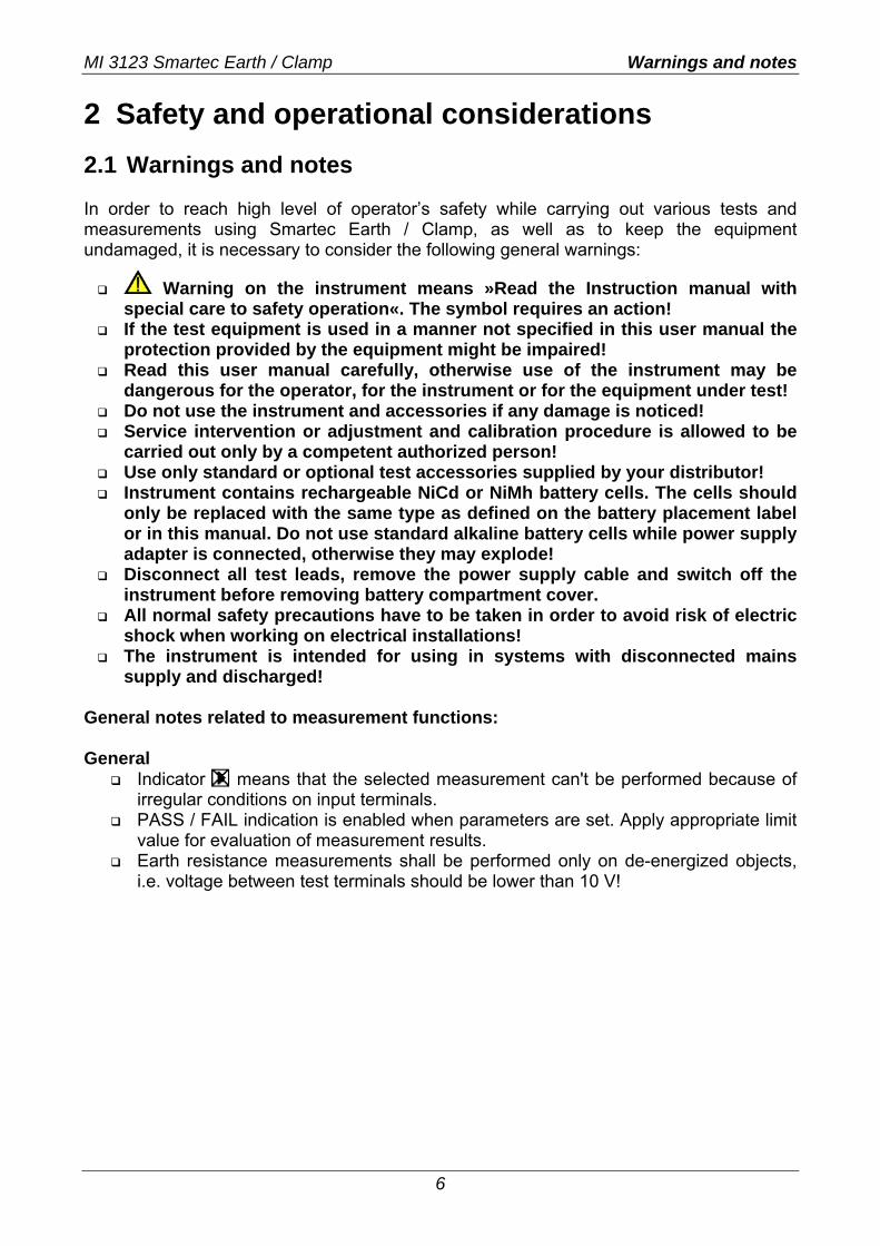
The battery is charged whenever the power supply adapter is connected to the instrument. Internal circuit controls charging assuring maximum battery lifetime. The power supply socket polarity is shown in figure 2.2.
+-
Figure 2.2: Power supply socket polarity
The instrument automatically recognizes the connected power supply adapter and begins charging.
Symbols:
Indication of battery charging
Figure 2.3: Charging indication
Before opening battery compartment cover disconnect all measuring accessories connected to the instrument and switch off the instrument.
Insert cells correctly, otherwise the instrument will not operate and the batteries could be damaged.
Remove all battery cells from the battery compartment if the instrument is not used for a long period of time.
Do not charge alkaline battery cells! Take into account handling, maintenance and recycling requirements that are
defined by related regulations and manufacturers of alkaline or rechargeable batteries!
Use only power supply adapter delivered from the manufacturer or distributor of the test equipment to avoid possible fire or electric shock!

MI 3123 Smartec Earth / Clamp Battery and charging
8
2.2.1 New battery cells or cells unused for a longer period Unpredictable chemical processes can occur during charging of new battery cells or cells that were unused for a longer period (more than 3 months). Ni-MH and Ni-Cd battery cells are affected to capacity degradation (sometimes called as memory effect). As a result the instrument operation time can be significantly reduced. Recommended procedure for recovering battery cells:
Procedure Notes Completely charge the battery. At least 14h with in-built charger.
Completely discharge the battery. Use the instrument for normal testing until the unit displays the “Bat” symbol on screen.
Repeat the charge / discharge cycle for at least twice. Four cycles are recommended.
Complete discharge / charge cycle can be performed automatically for each cell using external intelligent battery charger. Notes:
The charger in the instrument is a pack cell charger. This means that the battery cells are connected in series during the charging. The battery cells have to be equivalent (same charge condition, same type and age).
One different battery cell can cause an improper charging and incorrect discharging during normal usage of the entire battery pack (it results in heating of the battery pack, significantly decreased operation time, reversed polarity of defective cell,…).
If no improvement is achieved after several charge / discharge cycles, then each battery cell should be checked (by comparing battery voltages, testing them in a cell charger, etc). It is very likely that only some of the battery cells are deteriorated.
The effects described above should not be confused with the normal decrease of battery capacity over time. Battery also loses some capacity when it is repeatedly charged / discharged. This information is provided in the technical specification from battery manufacturer.
MI 3123 Smartec Earth / Clamp Standards applied
9
2.3 Standards applied The MI 3123 Smartec Earth / Clamp instrument is manufactured and tested according to the following regulations, listed below. Electromagnetic compatibility (EMC) IEC/ EN 61326-1 Electrical equipment for measurement, control and laboratory use -
EMC requirements - Part 1: General requirements Class B (Hand held equipment used in controlled EM environments)
IEC/EN 61326-2-2 Electrical equipment for measurement, control and laboratory use - EMC requirements - Part 2-2: Particular requirements - Test configurations, operational conditions and performance criteria for portable test, measuring and monitoring equipment used in low-voltage distribution systems
Safety (LVD) IEC/ EN 61010 - 1 Safety requirements for electrical equipment for measurement,
control, and laboratory use – Part 1: General requirements IEC/ EN 61010 - 031
Safety requirements for hand-held probe assemblies for electrical measurement and test
Functionality IEC/ EN 61557 Electrical safety in low voltage distribution systems up to 1000 V a.c. and
1500 V d.c. - Equipment for testing, measuring or monitoring of protective measures
Part 1 General requirements Part 5 Resistance to earth Part 10 Combined measuring equipment
MI 3123 Smartec Earth / Clamp Front panel
10
3 Instrument description 3.1 Front panel
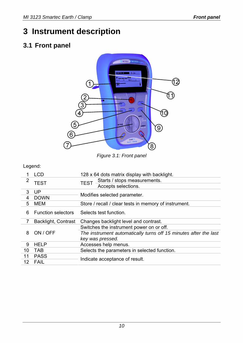
Figure 3.1: Front panel
Legend:
1 LCD 128 x 64 dots matrix display with backlight. Starts / stops measurements. 2 TEST TEST Accepts selections.
3 UP 4 DOWN Modifies selected parameter.
5 MEM Store / recall / clear tests in memory of instrument.
6 Function selectors Selects test function.
7 Backlight, Contrast Changes backlight level and contrast. Switches the instrument power on or off.
8 ON / OFF The instrument automatically turns off 15 minutes after the last key was pressed.
9 HELP Accesses help menus. 10 TAB Selects the parameters in selected function. 11 PASS 12 FAIL Indicate acceptance of result.
MI 3123 Smartec Earth / Clamp Connector panel
11
3.2 Connector panel
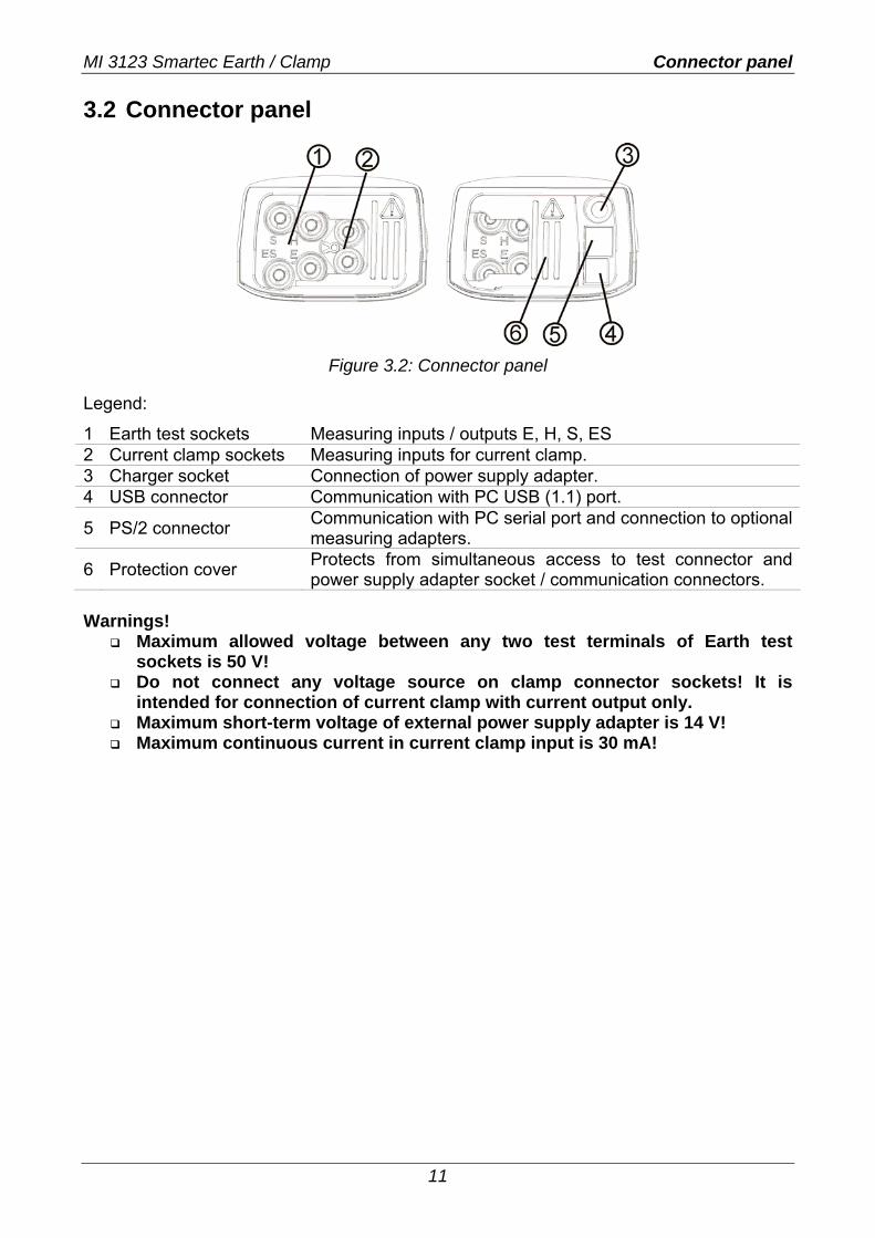
Figure 3.2: Connector panel
Legend:
1 Earth test sockets Measuring inputs / outputs E, H, S, ES 2 Current clamp sockets Measuring inputs for current clamp. 3 Charger socket Connection of power supply adapter. 4 USB connector Communication with PC USB (1.1) port.
5 PS/2 connector Communication with PC serial port and connection to optional measuring adapters.
6 Protection cover Protects from simultaneous access to test connector and power supply adapter socket / communication connectors.
Warnings!
Maximum allowed voltage between any two test terminals of Earth test sockets is 50 V!
Do not connect any voltage source on clamp connector sockets! It is intended for connection of current clamp with current output only.
Maximum short-term voltage of external power supply adapter is 14 V! Maximum continuous current in current clamp input is 30 mA!
MI 3123 Smartec Earth / Clamp Back panel
12
3.3 Back site
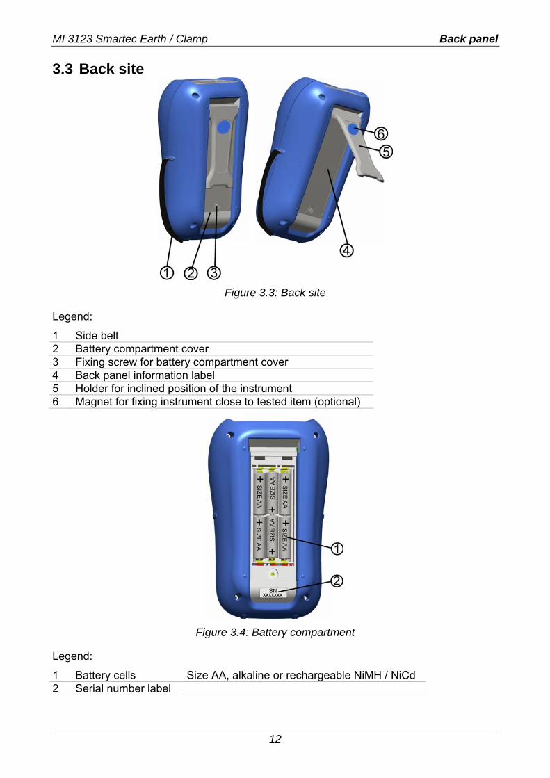
Figure 3.3: Back site
Legend:
1 Side belt 2 Battery compartment cover 3 Fixing screw for battery compartment cover 4 Back panel information label 5 Holder for inclined position of the instrument 6 Magnet for fixing instrument close to tested item (optional)
Figure 3.4: Battery compartment
Legend:
1 Battery cells Size AA, alkaline or rechargeable NiMH / NiCd 2 Serial number label
MI 3123 Smartec Earth / Clamp Display organization
13
3.4 Display organization
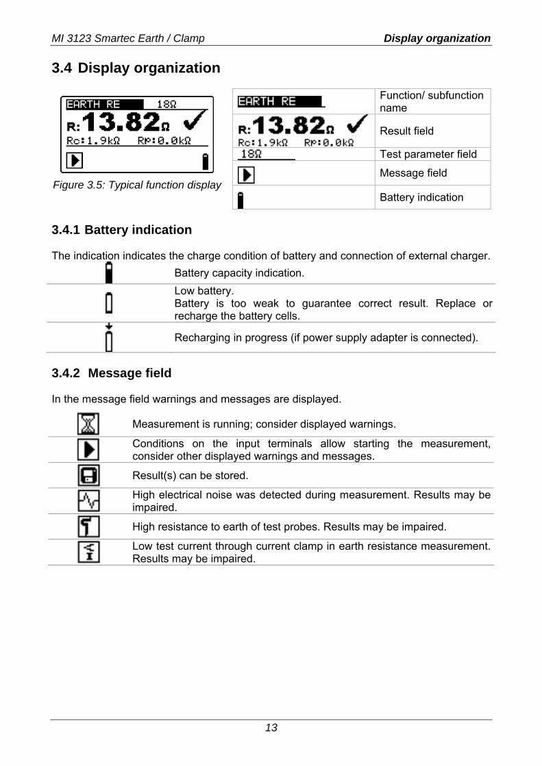
Figure 3.5: Typical function display
Function/ subfunction name
Result field
Test parameter field
Message field
Battery indication
3.4.1 Battery indication The indication indicates the charge condition of battery and connection of external charger.
Battery capacity indication.
Low battery. Battery is too weak to guarantee correct result. Replace or recharge the battery cells.
Recharging in progress (if power supply adapter is connected).
3.4.2 Message field In the message field warnings and messages are displayed.
Measurement is running; consider displayed warnings.
Conditions on the input terminals allow starting the measurement, consider other displayed warnings and messages.
Result(s) can be stored.
High electrical noise was detected during measurement. Results may be impaired.
High resistance to earth of test probes. Results may be impaired.
Low test current through current clamp in earth resistance measurement. Results may be impaired.
MI 3123 Smartec Earth / Clamp Display organization
14
3.4.3 Result field
Measurement result is inside pre-set limits (PASS).
Measurement result is out of pre-set limits (FAIL).
Measurement is aborted. Consider displayed warnings and messages.
3.4.4 Other messages
Initial settings Instrument settings and measurement parameters/limits are set to initial (factory) values.
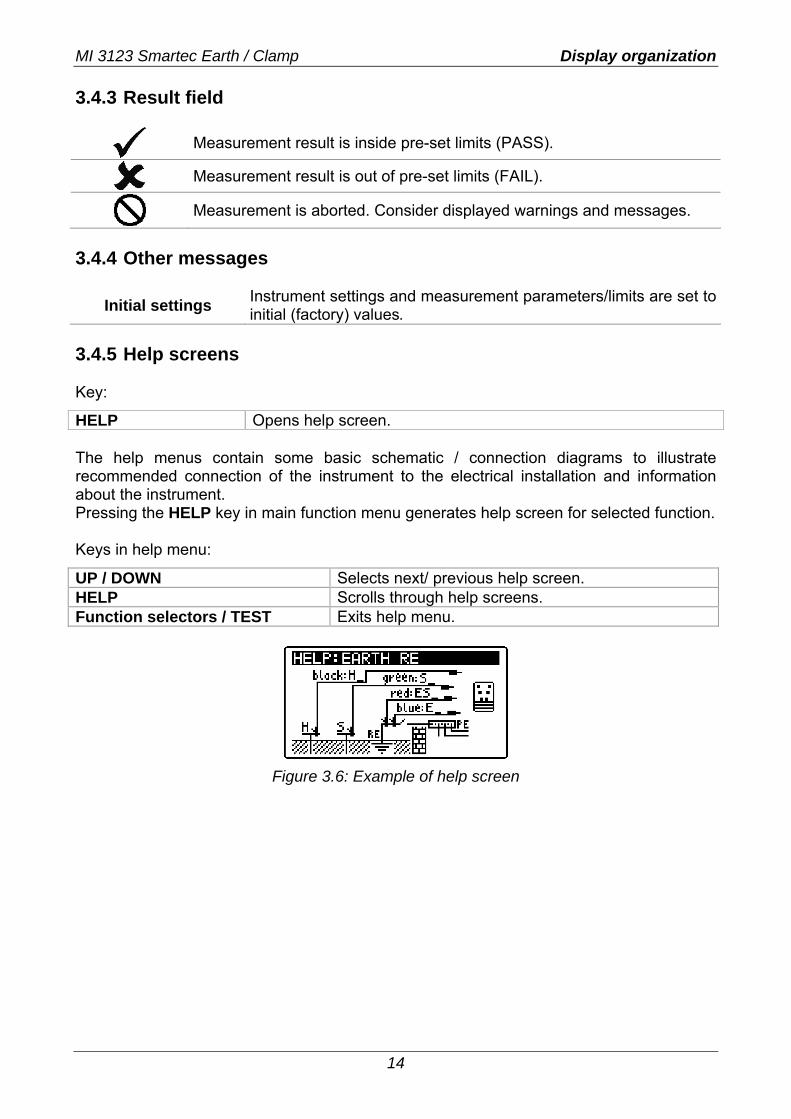
3.4.5 Help screens Key:
HELP Opens help screen. The help menus contain some basic schematic / connection diagrams to illustrate recommended connection of the instrument to the electrical installation and information about the instrument. Pressing the HELP key in main function menu generates help screen for selected function. Keys in help menu:
UP / DOWN Selects next/ previous help screen. HELP Scrolls through help screens. Function selectors / TEST Exits help menu.
Figure 3.6: Example of help screen
MI 3123 Smartec Earth / Clamp Display organization
15
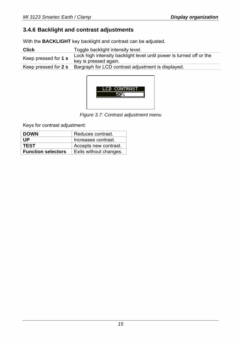
3.4.6 Backlight and contrast adjustments With the BACKLIGHT key backlight and contrast can be adjusted.
Click Toggle backlight intensity level.
Keep pressed for 1 s Lock high intensity backlight level until power is turned off or the key is pressed again.
Keep pressed for 2 s Bargraph for LCD contrast adjustment is displayed.
Figure 3.7: Contrast adjustment menu
Keys for contrast adjustment:
DOWN Reduces contrast. UP Increases contrast. TEST Accepts new contrast. Function selectors Exits without changes.
MI 3123 Smartec Earth / Clamp Instrument set and accessories
16
3.5 Instrument set and accessories 3.5.1 Standard set
Instrument Short instruction manual Product verification data Warranty declaration Declaration of conformity Test lead 4.5m (blue) Test lead 4.5m (red) Test lead 20 m (green)
Test lead 20 m (black) Earth rod, 4pcs Set of NiMH battery cells Power supply adapter CD with instruction manual, and
“Guide for testing and verification of low voltage installations” handbook
Soft hand strap 3.5.2 Optional accessories See the attached sheet for a list of optional accessories that are available on request from your distributor.
MI 3123 Smartec Earth / Clamp Function selection
17
4 Instrument operation 4.1 Function selection For selecting test function the FUNCTION SELECTOR shall be used. Keys:
Function selector
Selects test / measurement function:
<EARTH RE, 1 clamp, 2 clamps, ρ> measurements of resistance to earth.
<CURRENT TRMS> TRMS current measurement. <SETTINGS> General settings.
UP/DOWN Selects sub-function in selected measurement function. TAB Selects the test parameter to be set or modified. TEST Runs selected test / measurement function. MEM Stores measured results / recalls stored results. Keys in test parameter field:
UP/DOWN Changes the selected parameter. TAB Selects the next measuring parameter. FUNCTION SELECTOR Toggles between the main functions. MEM Stores measured results / recalls stored results. General rule regarding enabling parameters for evaluation of measurement / test result:
OFF No limit values. Parameter ON Value(s) – results will be marked as PASS or FAIL in
accordance with selected limit. See Chapter 5 for more information about the operation of the instrument test functions.
MI 3123 Smartec Earth / Clamp Settings
18
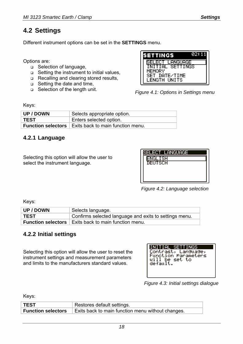
4.2 Settings Different instrument options can be set in the SETTINGS menu.
Options are: Selection of language, Setting the instrument to initial values, Recalling and clearing stored results, Setting the date and time, Selection of the length unit.
Figure 4.1: Options in Settings menu
Keys:
UP / DOWN Selects appropriate option. TEST Enters selected option. Function selectors Exits back to main function menu. 4.2.1 Language Selecting this option will allow the user to select the instrument language.
Figure 4.2: Language selection
Keys:
UP / DOWN Selects language. TEST Confirms selected language and exits to settings menu. Function selectors Exits back to main function menu. 4.2.2 Initial settings
Selecting this option will allow the user to reset the instrument settings and measurement parameters and limits to the manufacturers standard values.
Figure 4.3: Initial settings dialogue
Keys:
TEST Restores default settings. Function selectors Exits back to main function menu without changes.
MI 3123 Smartec Earth / Clamp Settings
19
Warning:
If the batteries are removed for more than 1 minute the custom made settings will be lost.
The default setup is listed below:
Instrument setting Default value Contrast As defined and stored by adjustment procedure Language English Length unit m
Function Sub-function Parameters / limit value
EARTH RE Maximum earth resistance: none selected EARTH one clamp Maximum earth resistance: none selected EARTH two clamps Maximum earth resistance: none selected EARTH specific resistance Distance between test probes: 2 m
CURRENT TRMS Maximum leakage current: 1 mA Note:
Initial settings (reset of the instrument) can be recalled also if the TAB key is pressed while the instrument is switched on.
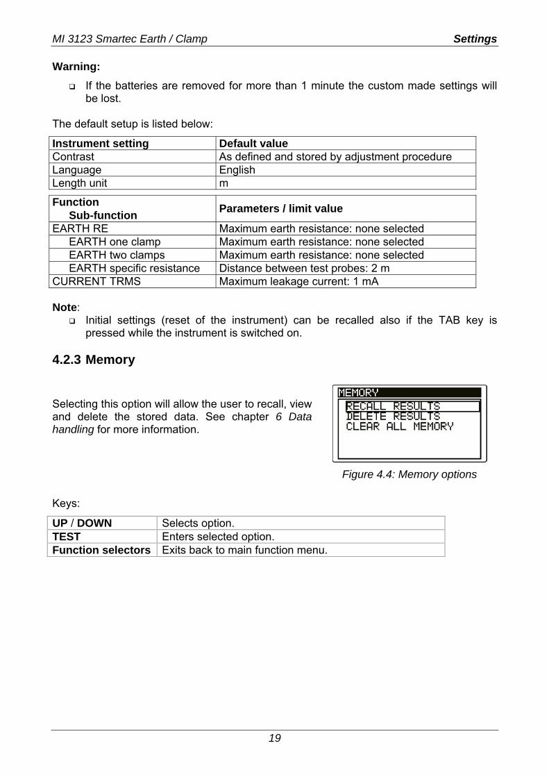
4.2.3 Memory Selecting this option will allow the user to recall, view and delete the stored data. See chapter 6 Data handling for more information.
Figure 4.4: Memory options
Keys:
UP / DOWN Selects option. TEST Enters selected option. Function selectors Exits back to main function menu.
MI 3123 Smartec Earth / Clamp Settings
20
4.2.4 Date and time Selecting this option will allow the user to set the date and time of the unit.
Figure 4.5: Setting date and time
Keys:
TAB Selects the field to be changed. UP / DOWN Modifies selected field. TEST Confirms new setup and exits. Function selectors Exits back to main function menu. Warning:
If the batteries are removed for more than 1 minute the set time and date will be lost.
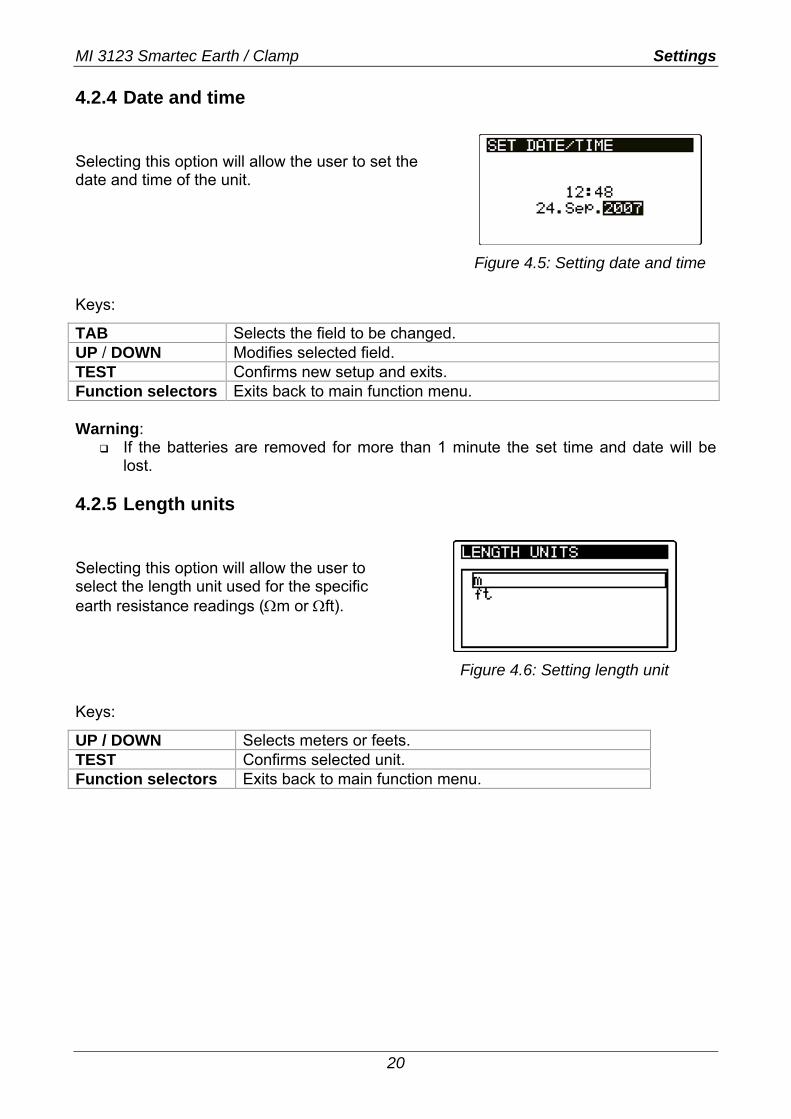
4.2.5 Length units Selecting this option will allow the user to select the length unit used for the specific earth resistance readings (Ωm or Ωft).
Figure 4.6: Setting length unit
Keys:
UP / DOWN Selects meters or feets. TEST Confirms selected unit. Function selectors Exits back to main function menu.
MI 3123 Smartec Earth / Clamp Earth resistance
21
5 Measurements 5.1 Earth resistance Earth resistance is one of the most important parameters for protection against electric shock. Main installation earthing arrangements, lightning systems, local earthings, soil resistivity etc can be verified with the Earth tester. All measurements conform to the EN 61557-5 standard. The Earth resistance main function is divided into four subfunctions:
4-wire earth resistance test RE for standard earth resistance tests with two earthing rods.
Selective earth resistance test with one current clamp, for measuring earth resistance of individual earthing rods.
Contactless earth resistance test with two current clamps (also recommended in IEC 60364-6 for urban areas), for measuring resistance to earth of individual earthing rods.
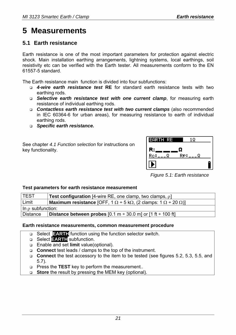
Specific earth resistance. See chapter 4.1 Function selection for instructions on key functionality.
Figure 5.1: Earth resistance
Test parameters for earth resistance measurement
TEST Test configuration [4-wire RE, one clamp, two clamps, ρ] Limit Maximum resistance [OFF, 1 Ω ÷ 5 kΩ, (2 clamps: 1 Ω ÷ 20 Ω)] In ρ subfunction: Distance Distance between probes [0.1 m ÷ 30.0 m] or [1 ft ÷ 100 ft] Earth resistance measurements, common measurement procedure
Select EARTH function using the function selector switch. Select EARTH subfunction. Enable and set limit value(optional). Connect test leads / clamps to the top of the instrument. Connect the test accessory to the item to be tested (see figures 5.2, 5.3, 5.5, and
5.7). Press the TEST key to perform the measurement.. Store the result by pressing the MEM key (optional).
MI 3123 Smartec Earth / Clamp Earth resistance
22
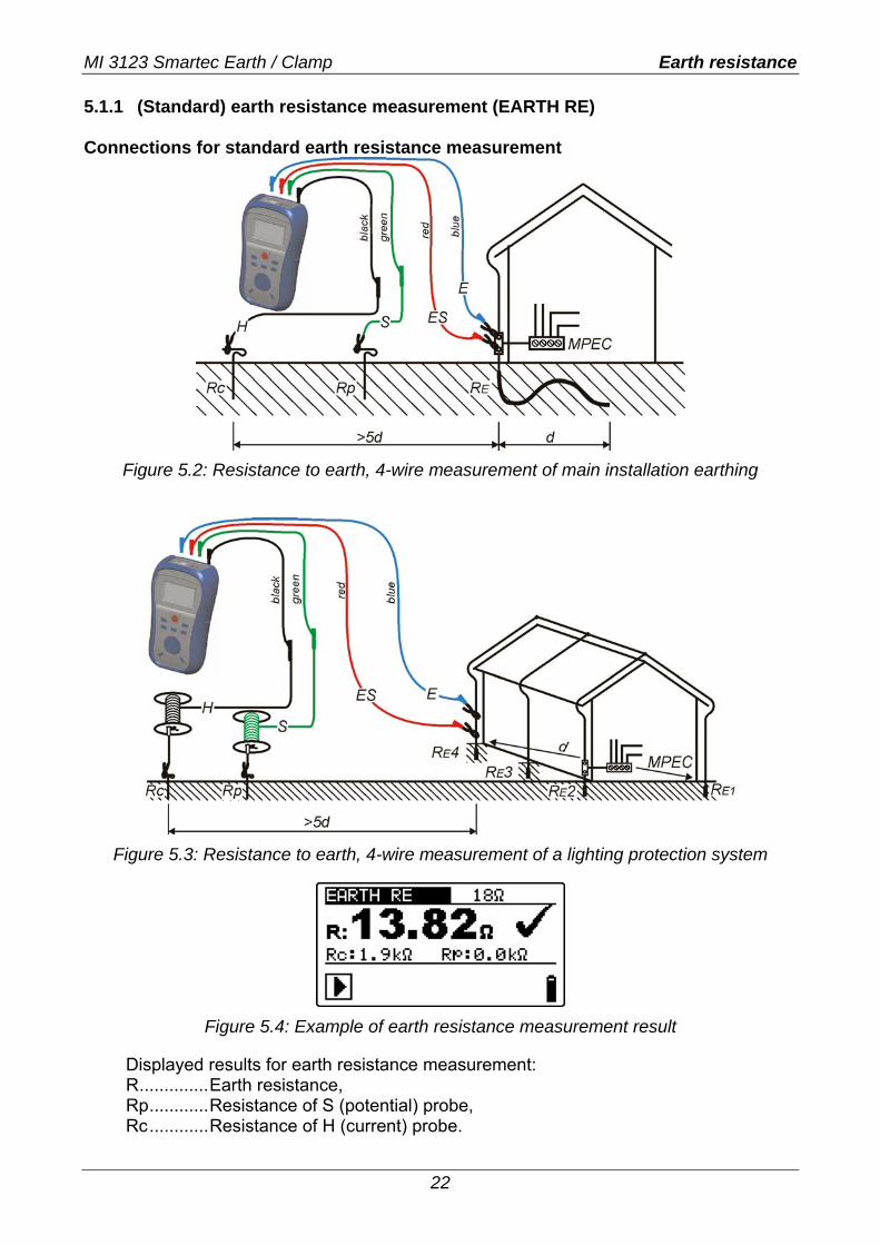
5.1.1 (Standard) earth resistance measurement (EARTH RE) Connections for standard earth resistance measurement
Figure 5.2: Resistance to earth, 4-wire measurement of main installation earthing
Figure 5.3: Resistance to earth, 4-wire measurement of a lighting protection system
Figure 5.4: Example of earth resistance measurement result
Displayed results for earth resistance measurement: R..............Earth resistance, Rp............Resistance of S (potential) probe, Rc............Resistance of H (current) probe.
MI 3123 Smartec Earth / Clamp Earth resistance
23
Notes: High resistance of S and H probes could influence the measurement results. In this
case, “Rp” and “Rc” warnings are displayed. There is no pass / fail indication in this case.
High noise currents and voltages in earth could influence the measurement results. The tester displays the “noise” warning in this case.
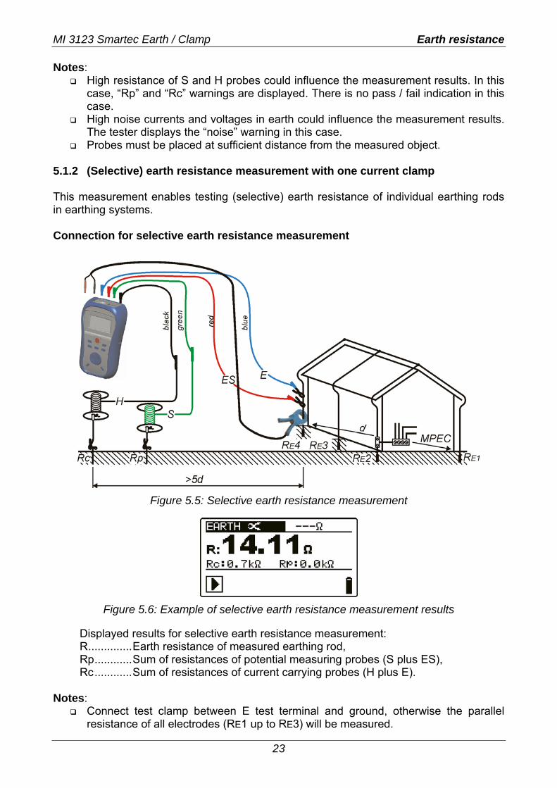
Probes must be placed at sufficient distance from the measured object. 5.1.2 (Selective) earth resistance measurement with one current clamp This measurement enables testing (selective) earth resistance of individual earthing rods in earthing systems. Connection for selective earth resistance measurement
Figure 5.5: Selective earth resistance measurement
Figure 5.6: Example of selective earth resistance measurement results
Displayed results for selective earth resistance measurement: R..............Earth resistance of measured earthing rod, Rp............Sum of resistances of potential measuring probes (S plus ES), Rc............Sum of resistances of current carrying probes (H plus E).
Notes:
Connect test clamp between E test terminal and ground, otherwise the parallel resistance of all electrodes (RE1 up to RE3) will be measured.
MI 3123 Smartec Earth / Clamp Earth resistance
24
High quality leakage current clamp (eg. METREL A1018) shall be used. In large systems the measured partial current is only a small portion of the test
current through the current clamp. The measuring accuracy for small currents of and immunity against noise currents must be considered. The tester displays the “low current” warning in this case.
High resistance of S and H probes could influence the measurement results. In this case, “Rp” and “Rc” warnings are displayed. There is no pass / fail indication in this case.
High noise currents and voltages in earth could influence the measurement results. The tester displays the “noise” warning in this case.
Probes must be placed at sufficient distance from the measured object.
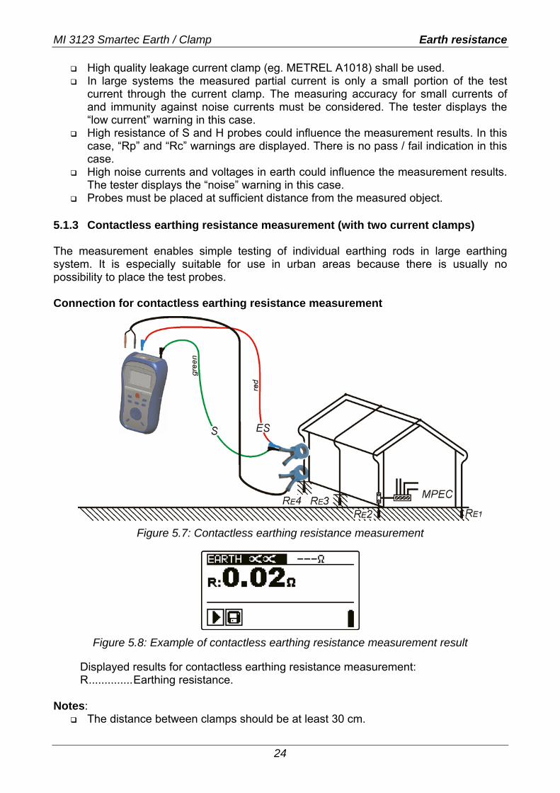
5.1.3 Contactless earthing resistance measurement (with two current clamps) The measurement enables simple testing of individual earthing rods in large earthing system. It is especially suitable for use in urban areas because there is usually no possibility to place the test probes. Connection for contactless earthing resistance measurement
Figure 5.7: Contactless earthing resistance measurement
Figure 5.8: Example of contactless earthing resistance measurement result
Displayed results for contactless earthing resistance measurement: R..............Earthing resistance.
Notes: The distance between clamps should be at least 30 cm.
MI 3123 Smartec Earth / Clamp Earth resistance
25
High noise currents and voltages in earth could influence the measurement results. The tester displays the “noise” warning in this case.
The measurement results are very accurate for resistances below 10 Ω . At higher values (several 10 Ω) the test current drops to few mA. The measuring accuracy for small currents of and immunity against noise currents must be considered! The tester displays the “low current” warning in this case.
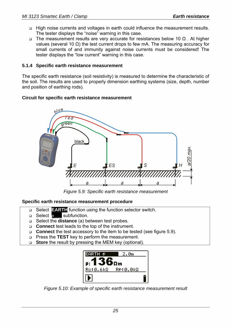
5.1.4 Specific earth resistance measurement The specific earth resistance (soil resistivity) is measured to determine the characteristic of the soil. The results are used to properly dimension earthing systems (size, depth, number and position of earthing rods). Circuit for specific earth resistance measurement
Figure 5.9: Specific earth resistance measurement
Specific earth resistance measurement procedure
Select EARTH function using the function selector switch. Select ρ___ subfunction. Select the distance (a) between test probes. Connect test leads to the top of the instrument. Connect the test accessory to the item to be tested (see figure 5.9). Press the TEST key to perform the measurement. Store the result by pressing the MEM key (optional).
Figure 5.10: Example of specific earth resistance measurement result
MI 3123 Smartec Earth / Clamp Earth resistance
26
Displayed results for earth resistance measurement: ρ...............Specific earth resistance. Rc.............Resistance of H,E (current) probes, Rp.............Resistance of S;ES (potential probe.
High resistance of S, H, ES, E probes could influence the measurement results. In this case, “Rp” and “Rc” warnings are displayed. There is no pass / fail indication in this case.
High noise currents and voltages in earthing could influence the measurement results. The tester displays the “noise” warning in this case.
MI 3123 Smartec Earth / Clamp Current
27
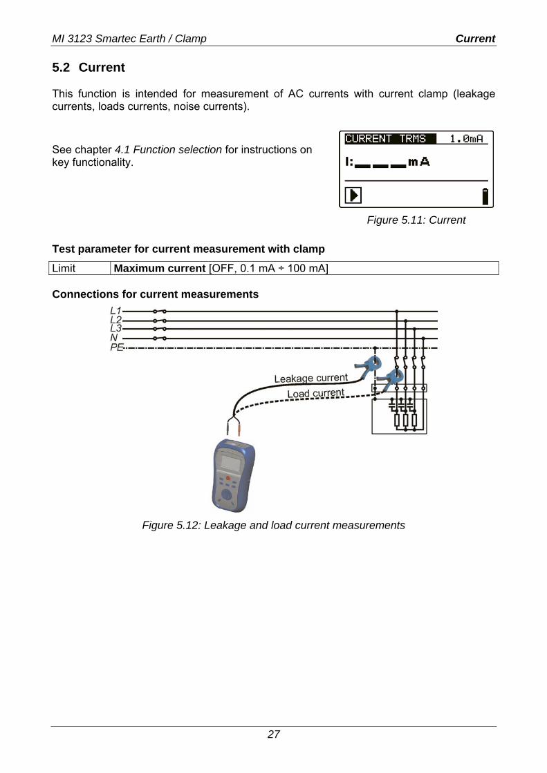
5.2 Current This function is intended for measurement of AC currents with current clamp (leakage currents, loads currents, noise currents). See chapter 4.1 Function selection for instructions on key functionality.
Figure 5.11: Current
Test parameter for current measurement with clamp
Limit Maximum current [OFF, 0.1 mA ÷ 100 mA] Connections for current measurements
Figure 5.12: Leakage and load current measurements
MI 3123 Smartec Earth / Clamp Current
28
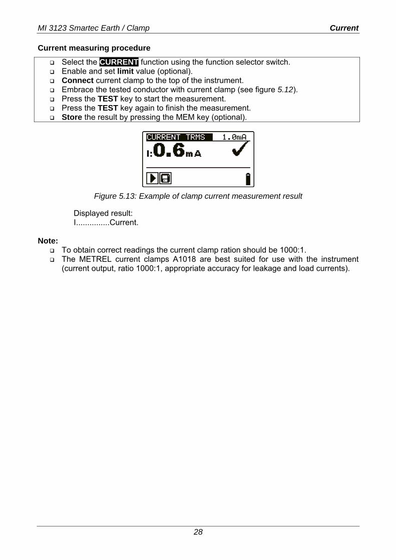
Current measuring procedure
Select the CURRENT function using the function selector switch. Enable and set limit value (optional). Connect current clamp to the top of the instrument. Embrace the tested conductor with current clamp (see figure 5.12). Press the TEST key to start the measurement. Press the TEST key again to finish the measurement. Store the result by pressing the MEM key (optional).
Figure 5.13: Example of clamp current measurement result
Displayed result: I...............Current.
Note:
To obtain correct readings the current clamp ration should be 1000:1. The METREL current clamps A1018 are best suited for use with the instrument
(current output, ratio 1000:1, appropriate accuracy for leakage and load currents).
MI 3123 Smartec Earth / Clamp Memory organization
29
6 Data handling
6.1 Memory organization Measurement results together with all relevant parameters can be stored in the instrument’s memory.
6.2 Data structure The instrument’s memory place is divided into 3 levels each containing 199 locations each. The number of measurements that can be stored into one location is not limited. The data structure field describes the identity of the measurement (which object, earthing system, earthing element). The measurement field contains information about type and number of measurements that belong to the selected structure element (object and system and element). This organization helps to handle with data in a simple and effective manner. The main advantages of this system are:
Test results can be organized and grouped in a structured manner that reflects the structure of typical earthing systems.
Simple browsing through structures and results. Test reports can be created with no or little modifications after downloading results
to a PC.
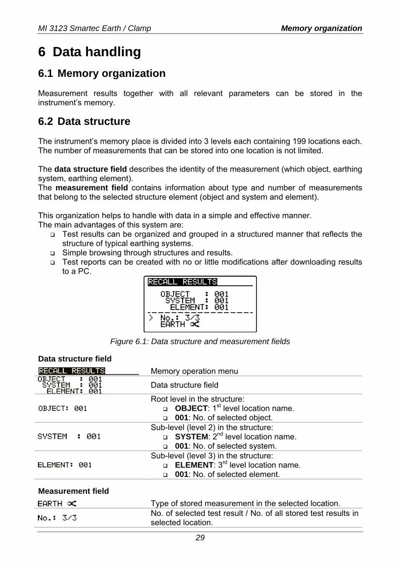
Figure 6.1: Data structure and measurement fields
Data structure field
Memory operation menu
Data structure field
Root level in the structure: OBJECT: 1st level location name. 001: No. of selected object.
Sub-level (level 2) in the structure:
SYSTEM: 2nd level location name. 001: No. of selected system.
Sub-level (level 3) in the structure:
ELEMENT: 3rd level location name. 001: No. of selected element.
Measurement field
Type of stored measurement in the selected location.
No. of selected test result / No. of all stored test results in selected location.
MI 3123 Smartec Earth / Clamp Storing and recalling test results
30
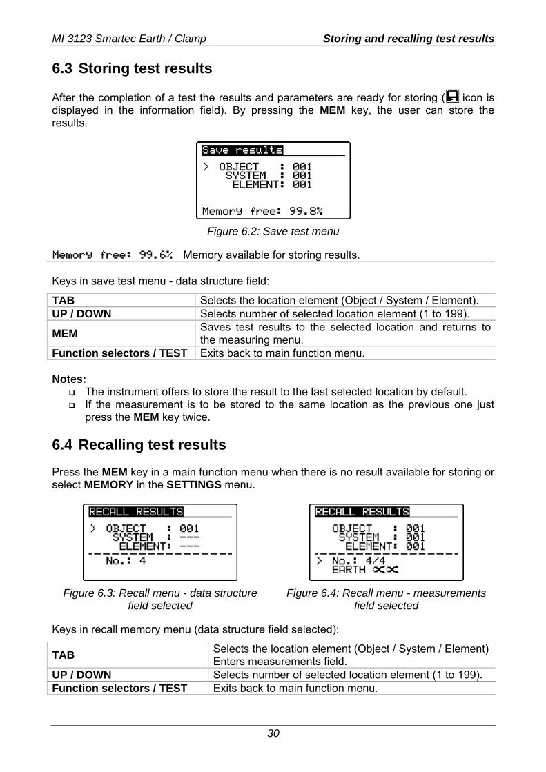
6.3 Storing test results After the completion of a test the results and parameters are ready for storing ( icon is displayed in the information field). By pressing the MEM key, the user can store the results.
Figure 6.2: Save test menu
Memory available for storing results. Keys in save test menu - data structure field:
TAB Selects the location element (Object / System / Element). UP / DOWN Selects number of selected location element (1 to 199).
MEM Saves test results to the selected location and returns to the measuring menu.
Function selectors / TEST Exits back to main function menu. Notes:
The instrument offers to store the result to the last selected location by default. If the measurement is to be stored to the same location as the previous one just
press the MEM key twice. 6.4 Recalling test results Press the MEM key in a main function menu when there is no result available for storing or select MEMORY in the SETTINGS menu.
Figure 6.3: Recall menu - data structure
field selected Figure 6.4: Recall menu - measurements
field selected
Keys in recall memory menu (data structure field selected):
TAB Selects the location element (Object / System / Element) Enters measurements field.
UP / DOWN Selects number of selected location element (1 to 199). Function selectors / TEST Exits back to main function menu.
MI 3123 Smartec Earth / Clamp Storing and recalling test results
31
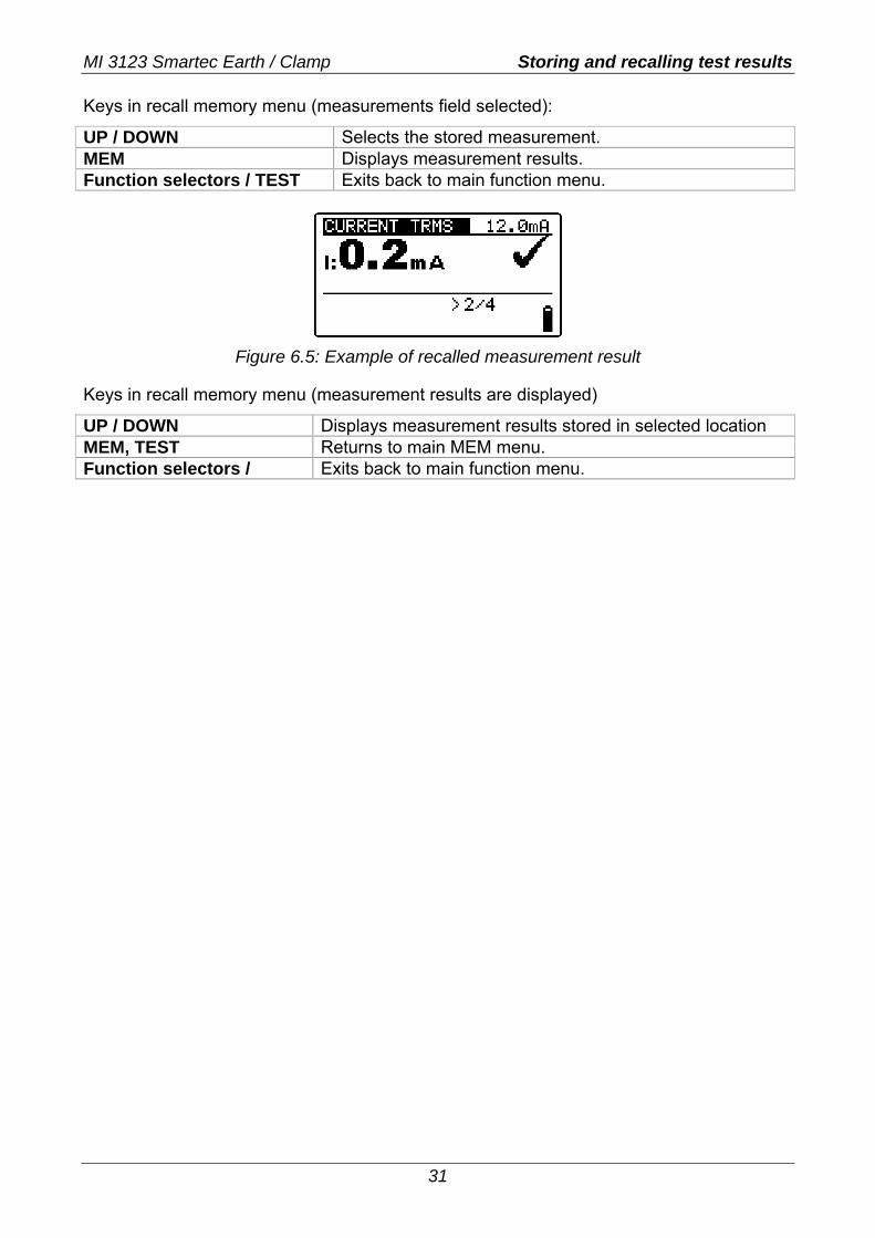
Keys in recall memory menu (measurements field selected):
UP / DOWN Selects the stored measurement. MEM Displays measurement results. Function selectors / TEST Exits back to main function menu.
Figure 6.5: Example of recalled measurement result
Keys in recall memory menu (measurement results are displayed)
UP / DOWN Displays measurement results stored in selected location MEM, TEST Returns to main MEM menu. Function selectors / Exits back to main function menu.

MI 3123 Smartec Earth / Clamp Clearing stored data
32
6.5 Clearing stored data 6.5.1 Clearing complete memory content Select CLEAR ALL MEMORY in MEMORY menu. A warning (see fig. 6.6) will be displayed.
Figure 6.6: Clear all memory
Keys in clear all memory menu
TEST Confirms clearing of complete memory content. Function selectors Exits back to main function menu without changes.
Figure 6.7: Clearing memory in progress
6.5.2 Clearing measurement(s) in selected location Select DELETE RESULTS in MEMORY menu.
Figure 6.8: Clear measurements menu (data structure field selected)
Keys in delete results menu (data structure field selected):
TAB Selects location element (Object / System / Element). Enters measurements field.
UP / DOWN Selects number of selected location element (1 to 199). Function selectors / MEM Exits back to main function menu.
TEST Opens dialog for confirmation to clear result in selected location.
MI 3123 Smartec Earth / Clamp Clearing stored data
33
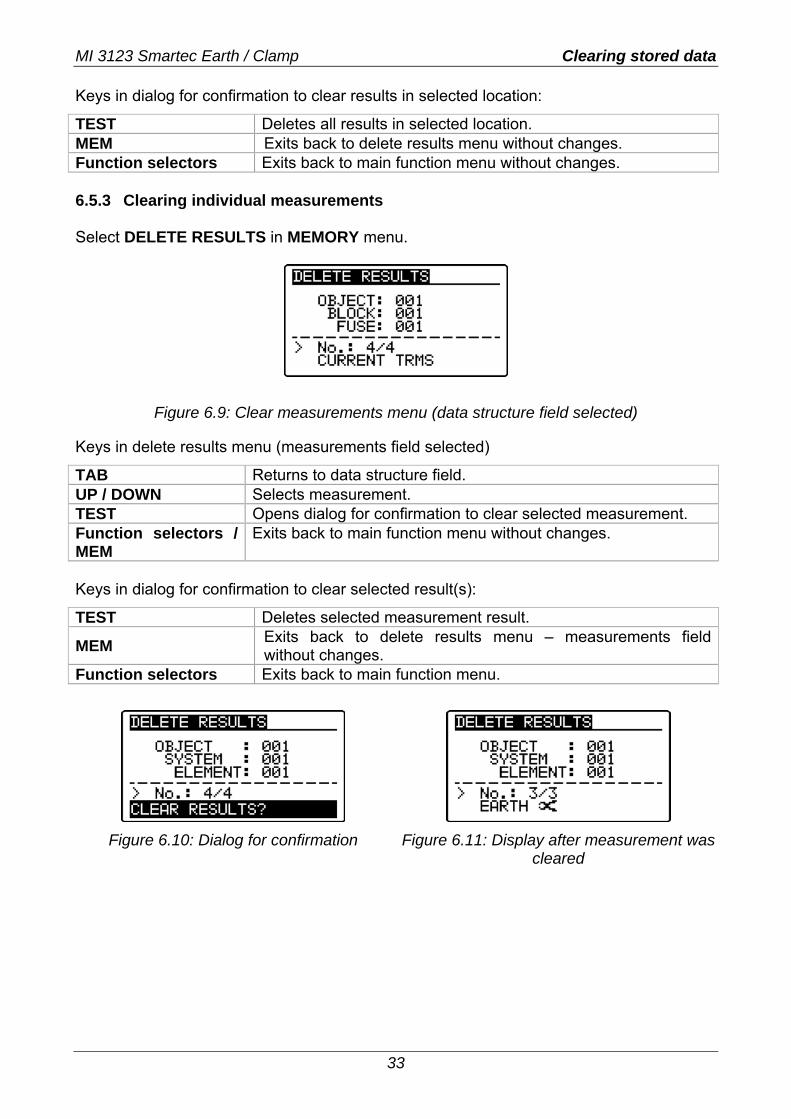
Keys in dialog for confirmation to clear results in selected location:
TEST Deletes all results in selected location. MEM Exits back to delete results menu without changes. Function selectors Exits back to main function menu without changes. 6.5.3 Clearing individual measurements Select DELETE RESULTS in MEMORY menu.
Figure 6.9: Clear measurements menu (data structure field selected)
Keys in delete results menu (measurements field selected)
TAB Returns to data structure field. UP / DOWN Selects measurement. TEST Opens dialog for confirmation to clear selected measurement. Function selectors / MEM
Exits back to main function menu without changes.
Keys in dialog for confirmation to clear selected result(s):
TEST Deletes selected measurement result.
MEM Exits back to delete results menu – measurements field without changes.
Function selectors Exits back to main function menu.
Figure 6.10: Dialog for confirmation
Figure 6.11: Display after measurement was
cleared
MI 3123 Smartec Earth / Clamp Communication
34
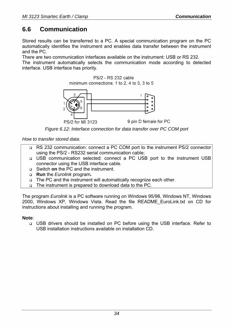
6.6 Communication Stored results can be transferred to a PC. A special communication program on the PC automatically identifies the instrument and enables data transfer between the instrument and the PC. There are two communication interfaces available on the instrument: USB or RS 232. The instrument automatically selects the communication mode according to detected interface. USB interface has priority.
Figure 6.12: Interface connection for data transfer over PC COM port
How to transfer stored data:
RS 232 communication: connect a PC COM port to the instrument PS/2 connector using the PS/2 - RS232 serial communication cable;
USB communication selected: connect a PC USB port to the instrument USB connector using the USB interface cable.
Switch on the PC and the instrument. Run the Eurolink program. The PC and the instrument will automatically recognize each other. The instrument is prepared to download data to the PC.
The program Eurolink is a PC software running on Windows 95/98, Windows NT, Windows 2000, Windows XP, Windows Vista. Read the file README_EuroLink.txt on CD for instructions about installing and running the program. Note:
USB drivers should be installed on PC before using the USB interface. Refer to USB installation instructions available on installation CD.
MI 3123 Smartec Earth / Clamp Cleaning, Calibration, Service
35
7 Maintenance Unauthorized persons are not allowed to open the Smartec Earth / Clamp instrument. There are no user replaceable components inside the instrument, except the battery under rear cover. 7.1 Cleaning No special maintenance is required for the housing. To clean the surface of the instrument use a soft cloth slightly moistened with soapy water or alcohol. Then leave the instrument to dry totally before use. Warnings:
Do not use liquids based on petrol or hydrocarbons! Do not spill cleaning liquid over the instrument!
7.2 Periodic calibration It is essential that the test instrument is regularly calibrated in order that the technical specification listed in this manual is guaranteed. We recommend an annual calibration. Only an authorized technical person can do the calibration. Please contact your dealer for further information. 7.3 Service For repairs under warranty, or at any other time, please contact your distributor.
MI 3123 Smartec Earth / Clamp D Technical informations
36
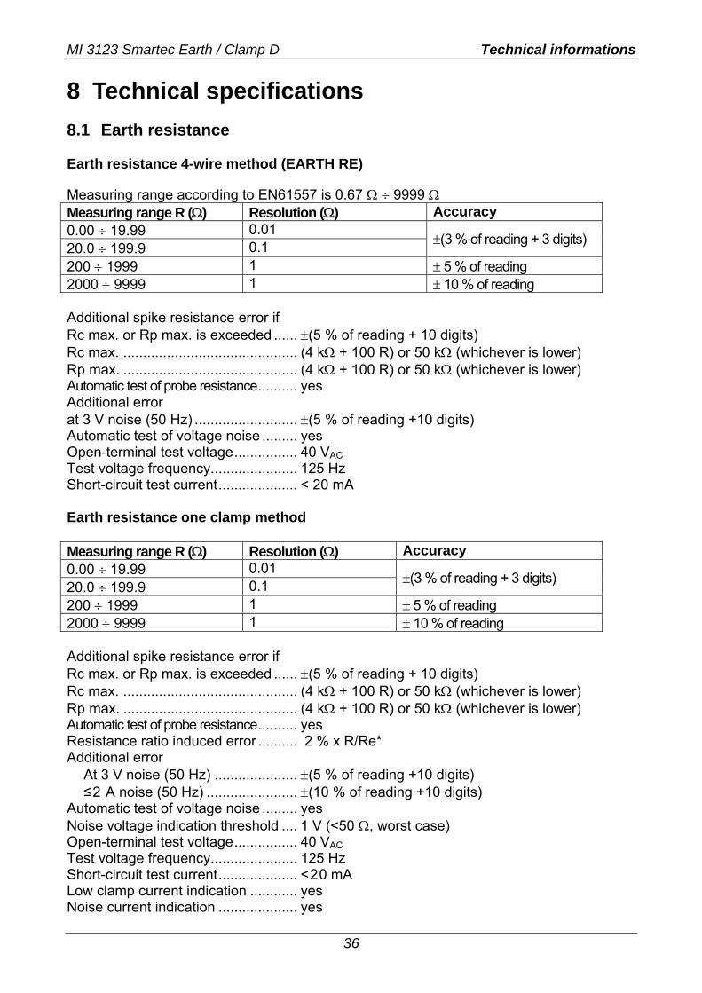
8 Technical specifications 8.1 Earth resistance Earth resistance 4-wire method (EARTH RE) Measuring range according to EN61557 is 0.67 Ω ÷ 9999 Ω Measuring range R (Ω) Resolution (Ω) Accuracy 0.00 ÷ 19.99 0.01 20.0 ÷ 199.9 0.1 ±(3 % of reading + 3 digits)
200 ÷ 1999 1 ± 5 % of reading 2000 ÷ 9999 1 ± 10 % of reading Additional spike resistance error if Rc max. or Rp max. is exceeded ...... ±(5 % of reading + 10 digits) Rc max. ............................................ (4 kΩ + 100 R) or 50 kΩ (whichever is lower) Rp max. ............................................ (4 kΩ + 100 R) or 50 kΩ (whichever is lower) Automatic test of probe resistance.......... yes Additional error at 3 V noise (50 Hz) .......................... ±(5 % of reading +10 digits) Automatic test of voltage noise ......... yes Open-terminal test voltage................ 40 VAC Test voltage frequency...................... 125 Hz Short-circuit test current.................... < 20 mA Earth resistance one clamp method Measuring range R (Ω) Resolution (Ω) Accuracy 0.00 ÷ 19.99 0.01 20.0 ÷ 199.9 0.1 ±(3 % of reading + 3 digits)
200 ÷ 1999 1 ± 5 % of reading 2000 ÷ 9999 1 ± 10 % of reading Additional spike resistance error if Rc max. or Rp max. is exceeded ...... ±(5 % of reading + 10 digits) Rc max. ............................................ (4 kΩ + 100 R) or 50 kΩ (whichever is lower) Rp max. ............................................ (4 kΩ + 100 R) or 50 kΩ (whichever is lower) Automatic test of probe resistance.......... yes Resistance ratio induced error .......... 2 % x R/Re* Additional error
At 3 V noise (50 Hz) ..................... ±(5 % of reading +10 digits) ≤2 A noise (50 Hz) ....................... ±(10 % of reading +10 digits)
Automatic test of voltage noise ......... yes Noise voltage indication threshold .... 1 V (<50 Ω, worst case) Open-terminal test voltage................ 40 VAC Test voltage frequency...................... 125 Hz Short-circuit test current.................... <20 mA Low clamp current indication ............ yes Noise current indication .................... yes
MI 3123 Smartec Earth / Clamp Technical informations
37
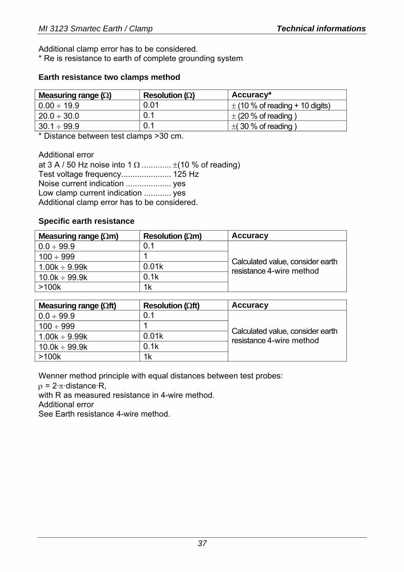
Additional clamp error has to be considered. * Re is resistance to earth of complete grounding system Earth resistance two clamps method Measuring range (Ω) Resolution (Ω) Accuracy* 0.00 ÷ 19.9 0.01 ± (10 % of reading + 10 digits) 20.0 ÷ 30.0 0.1 ± (20 % of reading ) 30.1 ÷ 99.9 0.1 ±( 30 % of reading ) * Distance between test clamps >30 cm. Additional error at 3 A / 50 Hz noise into 1 Ω ............. ±(10 % of reading) Test voltage frequency...................... 125 Hz Noise current indication .................... yes Low clamp current indication ............ yes Additional clamp error has to be considered. Specific earth resistance
Measuring range (Ωm) Resolution (Ωm) Accuracy 0.0 ÷ 99.9 0.1 100 ÷ 999 1 1.00k ÷ 9.99k 0.01k 10.0k ÷ 99.9k 0.1k >100k 1k
Calculated value, consider earth resistance 4-wire method
Measuring range (Ωft) Resolution (Ωft) Accuracy 0.0 ÷ 99.9 0.1 100 ÷ 999 1 1.00k ÷ 9.99k 0.01k 10.0k ÷ 99.9k 0.1k >100k 1k
Calculated value, consider earth resistance 4-wire method
Wenner method principle with equal distances between test probes: ρ = 2·π·distance·R, with R as measured resistance in 4-wire method. Additional error See Earth resistance 4-wire method.
MI 3123 Smartec Earth / Clamp Technical informations
38
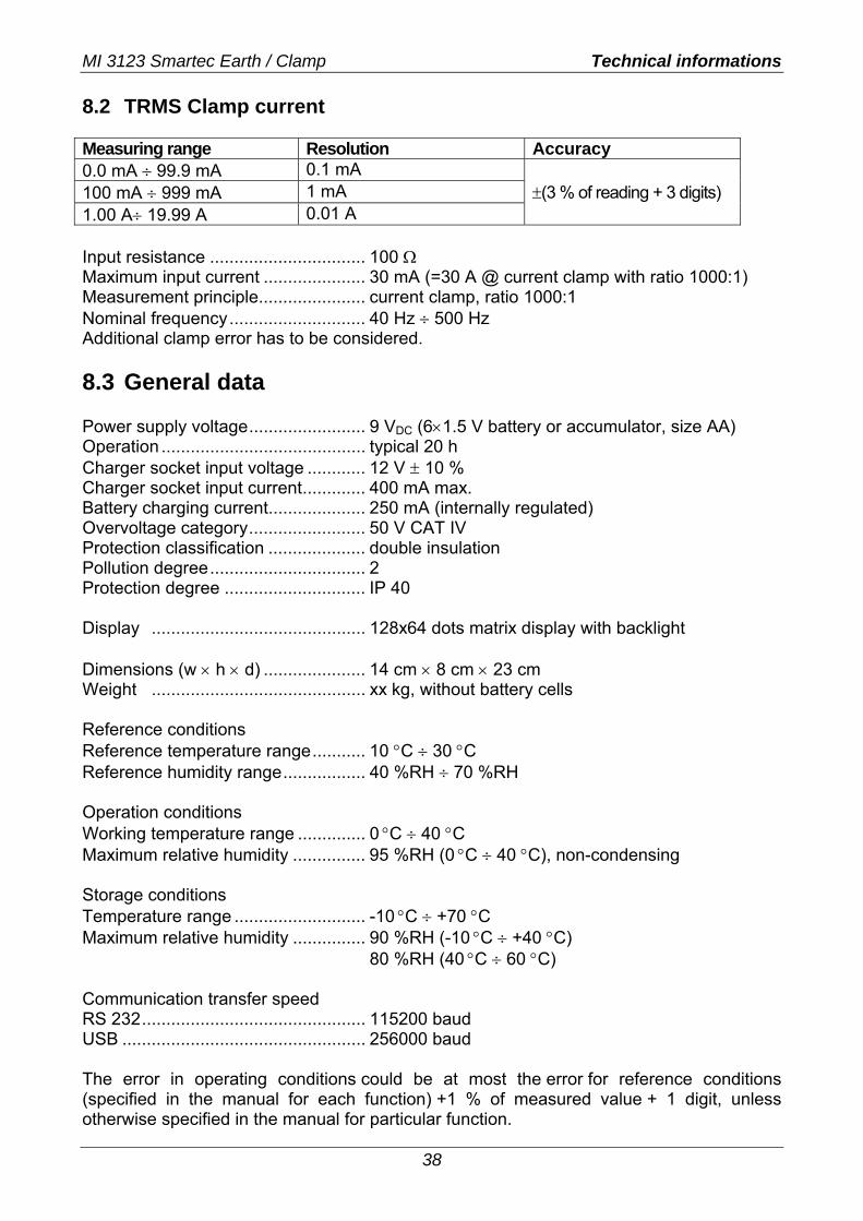
8.2 TRMS Clamp current Measuring range Resolution Accuracy 0.0 mA ÷ 99.9 mA 0.1 mA 100 mA ÷ 999 mA 1 mA 1.00 A÷ 19.99 A 0.01 A
±(3 % of reading + 3 digits)
Input resistance ................................ 100 Ω Maximum input current ..................... 30 mA (=30 A @ current clamp with ratio 1000:1) Measurement principle...................... current clamp, ratio 1000:1 Nominal frequency............................ 40 Hz ÷ 500 Hz Additional clamp error has to be considered. 8.3 General data Power supply voltage........................ 9 VDC (6×1.5 V battery or accumulator, size AA) Operation .......................................... typical 20 h Charger socket input voltage ............ 12 V ± 10 % Charger socket input current............. 400 mA max. Battery charging current.................... 250 mA (internally regulated) Overvoltage category........................ 50 V CAT IV Protection classification .................... double insulation Pollution degree................................ 2 Protection degree ............................. IP 40 Display ............................................ 128x64 dots matrix display with backlight Dimensions (w × h × d) ..................... 14 cm × 8 cm × 23 cm Weight ............................................ xx kg, without battery cells Reference conditions Reference temperature range........... 10 °C ÷ 30 °C Reference humidity range................. 40 %RH ÷ 70 %RH Operation conditions Working temperature range .............. 0 °C ÷ 40 °C Maximum relative humidity ............... 95 %RH (0 °C ÷ 40 °C), non-condensing Storage conditions Temperature range ........................... -10 °C ÷ +70 °C Maximum relative humidity ............... 90 %RH (-10 °C ÷ +40 °C) 80 %RH (40 °C ÷ 60 °C) Communication transfer speed RS 232.............................................. 115200 baud USB .................................................. 256000 baud The error in operating conditions could be at most the error for reference conditions (specified in the manual for each function) +1 % of measured value + 1 digit, unless otherwise specified in the manual for particular function.
MI 3123 Smartec Earth / Clamp Appendix A
39
A Appendix A - Accessories for specific measurements
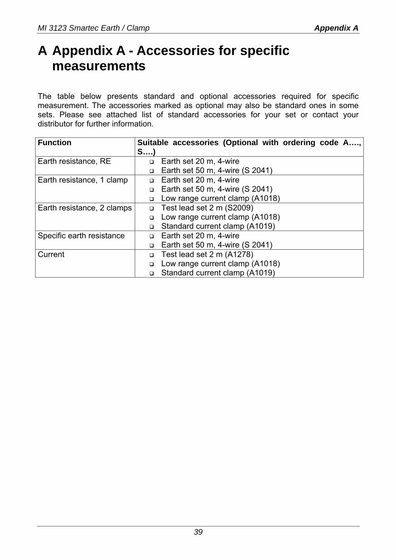
The table below presents standard and optional accessories required for specific measurement. The accessories marked as optional may also be standard ones in some sets. Please see attached list of standard accessories for your set or contact your distributor for further information. Function Suitable accessories (Optional with ordering code A….,
S….) Earth resistance, RE Earth set 20 m, 4-wire
Earth set 50 m, 4-wire (S 2041) Earth resistance, 1 clamp Earth set 20 m, 4-wire
Earth set 50 m, 4-wire (S 2041) Low range current clamp (A1018)
Earth resistance, 2 clamps Test lead set 2 m (S2009) Low range current clamp (A1018) Standard current clamp (A1019)
Specific earth resistance Earth set 20 m, 4-wire Earth set 50 m, 4-wire (S 2041)
Current Test lead set 2 m (A1278) Low range current clamp (A1018) Standard current clamp (A1019)

MI 3123 Smartec Earth / Clamp Appendix A
40