instruction manual - gamajet tank cleaning devices laval bladeclean.pdf · instruction manual ....
TRANSCRIPT
Instruction Manual Alfa Laval BladeClean
Covering: Standard Machines First published: 2015-08
ESE032025-EN1 2015-08
Original manual

Table of Contents
The information herein is correct at the time of issue but may be subject to change without prior notice 1. Safety............................................................................................................................................................. ….......... 1 1.1. Important information ………............................................................................................................................ 1 1.2. Warning signs ………....................................................................................................................................... 1 1.3. Safety precautions ………................................................................................................................................ 2 2. Introduction ……….......................................................................................................................................... 3 2.1. Description ………............................................................................................................................................ 3 3. Installation ………........................................................................................................................................... 4 3.1. Unpacking/delivery ………................................................................................................................................ 4 3.2. Installation ………............................................................................................................................................. 5 3.3. Recycling Information………............................................................................................................................ 8 4. Operation ………............................................................................................................................................... 9 4.1. Operation/Control ………................................................................................................................................. 9 4.2. Troubleshooting………………. ……….............................................................................................................. 10 4.3. Recommended Cleaning ………....................................................................................................................... 11 5. Maintenance ………........................................................................................................................................... 12 5.1. General Maintenance………............................................................................................................................. 12 5.2. General dismantling set up ………..................................................................................................................... 13 5.3. General dismantling ………............................................................................................................................... 14 5.4. Inspection and Service of Components ………................................................................................................. 15 5.5. Reassembly ………........................................................................................................................................... 16 6. Technical Data ………....................................................................................................................................... 17 6.1. Technical Data………....................................................................................................................................... 17 6.2. Performance Data……….................................................................................................................................. 18 6.3. Dimensions ………........................................................................................................................................... 19 7. Parts List and Service Kits ……….................................................................................................................. 20 7.1. BladeClean View ……….................................................................................................................................. 20 7.2. Assembly Drawings - 1 & 2 ……….................................................................................................................... 21 7.3. Parts List ………............................................................................................................................................ 23 7.4. Service Kit ………................................................................................................................................... …………24 Appendix A ………................................................................................................................................................. 25
1. Safety
1
Unsafe practices and other important information are emphasized in this manual. Warnings are emphasized by means of special signs. Always read the manual before using the tank cleaning machine! 1.1 Important information WARNING Indicates that special procedures must be followed to avoid serious personal injury. CAUTION Indicates that special procedures must be followed to avoid damage to the tank cleaning machine. NOTE Indicates important information to simplify or clarify procedures.
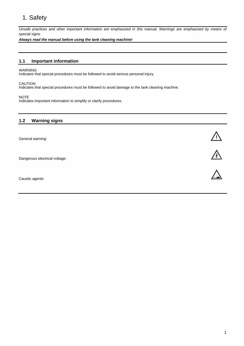
1.2 Warning signs General warning:
Dangerous electrical voltage:
Caustic agents:
1. Safety
2
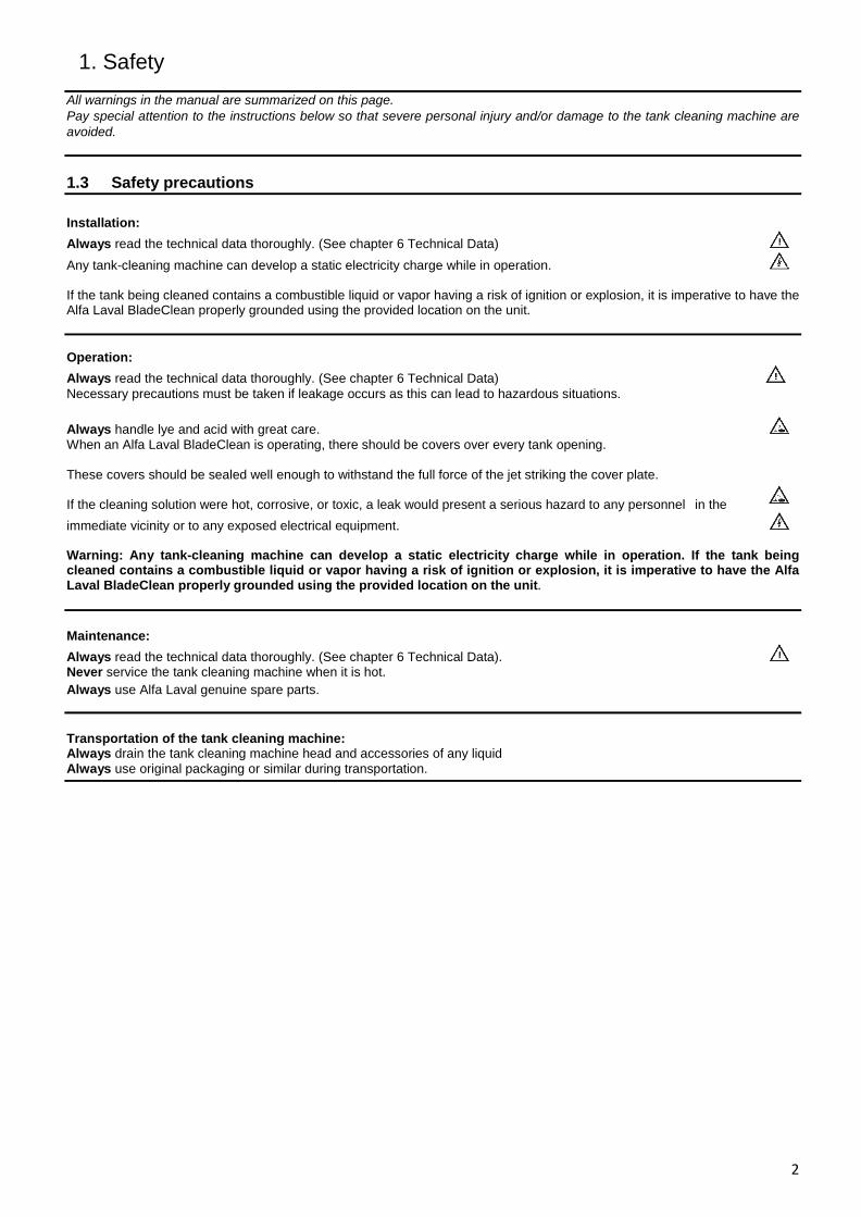
All warnings in the manual are summarized on this page. Pay special attention to the instructions below so that severe personal injury and/or damage to the tank cleaning machine are avoided. 1.3 Safety precautions Installation: Always read the technical data thoroughly. (See chapter 6 Technical Data) Any tank-cleaning machine can develop a static electricity charge while in operation. If the tank being cleaned contains a combustible liquid or vapor having a risk of ignition or explosion, it is imperative to have the Alfa Laval BladeClean properly grounded using the provided location on the unit. Operation: Always read the technical data thoroughly. (See chapter 6 Technical Data) Necessary precautions must be taken if leakage occurs as this can lead to hazardous situations. Always handle lye and acid with great care. When an Alfa Laval BladeClean is operating, there should be covers over every tank opening. These covers should be sealed well enough to withstand the full force of the jet striking the cover plate. If the cleaning solution were hot, corrosive, or toxic, a leak would present a serious hazard to any personnel in the immediate vicinity or to any exposed electrical equipment. Warning: Any tank-cleaning machine can develop a static electricity charge while in operation. If the tank being cleaned contains a combustible liquid or vapor having a risk of ignition or explosion, it is imperative to have the Alfa Laval BladeClean properly grounded using the provided location on the unit. Maintenance: Always read the technical data thoroughly. (See chapter 6 Technical Data). Never service the tank cleaning machine when it is hot. Always use Alfa Laval genuine spare parts. Transportation of the tank cleaning machine: Always drain the tank cleaning machine head and accessories of any liquid Always use original packaging or similar during transportation.
2. Introduction
3
2.1 Description The Alfa Laval BladeClean is a fluid driven machine designed for cleaning the difficult to reach surfaces of an agitator installed in various tanks and vessels. It is powered entirely by water and requires no electricity, compressed air or lubricant for operation. It has minimal moving parts and works on a simple spring mechanism. The water entering through the inlet lifts a plunger upwards against the spring force this allows a cone of water to impact the agitator. At lower pressures the plunger is retracted by the spring, closing the flow. In the closed position the plunger is flush with the outlet which prevents any debris from entering the Alfa Laval BladeClean. A positive metal stop is provided to prevent the plunger from being pushed down when the load of material within the tank would be acting on the top of the Alfa Laval BladeClean. A complete description of the technical specifications and construction of the stainless steel Alfa Laval BladeClean can be found ahead in the manual.
3. Installation
4
3.1 Unpacking/delivery Step 1 CAUTION Alfa Laval cannot be held responsible for incorrect unpacking.
Check the delivery for: 1. Complete Cleaning Machine 2. Delivery note
Step 2 Remove any packing material. Step 3 Inspect the tank cleaning machine for visible transport damage. Inspection!
3. Installation
5
Read the instructions carefully and pay special attention to the warnings! Always check the tank cleaning machine before operation. 3.2 Installation Step 1
Always read the technical data thoroughly.
(See chapter 6 Technical Data) Step 2 Assembly Every Alfa Laval Tank Cleaning Product is operationally tested before shipment and is ready to run after unpacking. No assembly is required prior to use. The Alfa Laval Tank Cleaning Product has been configured to meet the operating conditions (for the Alfa Laval Tank Cleaning Product, not at the pump) given to us, e.g. pressure, flow, temperature, cycle time, etc.
Note: Any change to the originally supplied operating conditions will affect the performance of the Alfa Laval Tank Cleaning Product accordingly.
Step 3 Inlet Connections The Alfa Laval BladeClean has a 1” tri clover connection on the inlet side. Custom sanitary connections are also available.
Step 4 Mounting Before mounting the Alfa Laval BladeClean, make sure the supply line has been adequately flushed. The Alfa Laval BladeClean shall be mounted on a rigid 1” tube using the tri clamp connection. In most applications, the Alfa Laval BladeClean will be mounted in the upright position (outlet connection pointing up), but it can be mounted in any orientation. The standard weld adapter (Hygienic Tank Connection) is provided in the kit. This adapter will help mount the Alfa Laval BladeClean at the bottom of the tank. Refer to Appendix A for installation instructions for HTC. The Alfa Laval BladeClean is not optimized for horizontal mounting and will not give the same impact. In the horizontal position, the cone of impact will not cover much of the agitator blades and optimal cleaning may not be achieved.
Step 5 Location inside Tank The Alfa Laval BladeClean should be placed below the agitator blades. The cone of impact has a tangential force at the point of impact on the blade. This force cleans the area surrounding the exact impact cone. Depending on the length of the blade, more than one Alfa Laval BladeClean may need to be installed for sufficient cleaning. As seen from the performance graphs (Chapter 6), depending on the pressure, the Alfa Laval BladeClean has a wetting distance of more than 6 feet (1.83 m). This allows second level agitator blades to possibly get cleaned using only one machine.
3. Installation
6
Read the instructions carefully and pay special attention to the warnings! Always check the tank cleaning machine before operation. Step 6 Entry Openings The Alfa Laval BladeClean should be placed at the bottom of the tank. Entry openings should be provided to accommodate the weld adapter attached to the Alfa Laval BladeClean. Depending on the position of the agitator blades, the mounting location of the Alfa Laval BladeClean should be adjusted.
Note: When in operation, the plunger of Alfa Laval BladeClean rises above the tank bottom to a height of about 5-7 mm. This might interfere with low level scrapers in certain tanks. Consult the nearest Alfa Laval office for more information.
Step 7 Vessel Drainage It is necessary to clean the floor of a vessel, standing liquid will diminish the effectiveness of the Alfa Laval BladeClean. Wherever possible, the tank floor should be pitched toward the drain and the drainage opening should be large enough to eliminate or reduce any liquid buildup or puddling. If gravity alone is insufficient, a scavenger or suction pump should be connected to the drain to suck out the excess wash fluid. If not drained, the water might accumulate and rise above the Alfa Laval BladeClean outlet, hampering the Alfa Laval BladeClean’s performance.
Step 8 Filters and Strainers All tank cleaning systems should be equipped with a filter or strainer that will trap solids 1/16"(1.6 mm) or larger, as these will clog the Alfa Laval BladeClean. These large particles will not harm the machine, but they can become caught in one of the internal passages. This would cause a reduction of its cleaning effectiveness due to a loss of flow. Disassembly of the Alfa Laval BladeClean then becomes a necessity to remove the blockage. In recirculating (closed-loop) cleaning or any other application where the cleaning solution may carry abrasive solids in suspension, adequate filtration is a must. These particles can be extremely destructive to the Alfa Laval BladeClean, pumps, valves, and other system components. Filters, properly installed and maintained, will more than pay for themselves with lower overall operating costs in these applications. Furthermore, to ensure that clogged filters or strainers are cleaned, we recommend using automatic self-cleaning models.
Step 9 Capacity of Supply Pump The Alfa Laval BladeClean can be used with either a centrifugal or positive displacement (constant volume), PD, style pump. The Alfa Laval BladeClean is tested for performance upto 150 Psi (10.3 Bar) and it can be operated at higher pressures as well depending upon sufficient drainage so as to avoid puddling. If the Alfa Laval BladeClean is to be used with a centrifugal pump, the end user must take all of the plumbing, elevation, and Alfa Laval BladeClean pressure/flow rate requirements into account. If PD style pumps (i.e. piston pump, plunger pump, or mechanical diaphragm pump, etc.) will supply the wash fluid to the Alfa Laval BladeClean, a different set of rules will apply. PD pumps are fixed volume pumps whose flow rate is dependent upon the speed of the pump; the pumps also have a pressure rating which is the maximum operating pressure. Note: Do not confuse the maximum operating pressure of a PD pump with the actual operating pressure. The actual operating pressure is dictated by the fixed flow rate of the pump and the plumbing system.
3. Installation
7
Read the instructions carefully and pay special attention to the warnings! Always check the tank cleaning machine before operation. Step 9 Safety WARNING: When Alfa Laval Tank Cleaning Products are operating, there should be covers over any tank openings. These covers should be sealed well enough to withstand the full force of the water striking the cover plate. If the cleaning solution is hot, corrosive, or toxic, a leak would present a serious hazard to any personnel in the immediate vicinity or to any exposed electrical equipment.
Any tank-cleaning machine can develop a static electric charge while in operation. If the tank being cleaned contains a combustible liquid or vapor having a risk of ignition or explosion, it is imperative to have the Alfa Laval Tank Cleaning Product properly grounded.
3. Installation
8
Read the instructions carefully and pay special attention to the warnings! Always check the tank cleaning machine before operation.
3.3 Recycling Information • Unpacking - Packing material consists of wood, plastics, cardboard boxes and in some cases metal straps. - Wood and cardboard boxes can be reused, recycled or used for energy recovery. - Plastics should be recycled or burnt at a licensed waste incineration plant. - Metal straps should be sent for material recycling. • Maintenance - All metal parts should be sent for material recycling. • Scrapping - At end of use, the equipment must be recycled according to relevant, local regulations. Beside the equipment itself, any hazardous residues from the process liquid must be considered and dealt with in a proper manner. When in doubt, or in the absence of local regulations, please contact your local Alfa Laval sales company.
4. Operation
9
Read the instructions carefully and pay special attention to the warnings! Always check the tank cleaning machine before operation.
4.1 Operation/Control Step 1
Always read the technical data thoroughly. See chapter 6 Technical Data CAUTION Alfa Laval cannot be held responsible for incorrect operation/control. Step 2 Never touch the tank cleaning machine or the pipelines when pumping hot liquids. Step 3 Initial Startup Every Alfa Laval BladeClean that ships is accompanied by a Birth Certificate. This document indicates how the Alfa Laval BladeClean performed in our testing tank before it shipped based on the operating conditions supplied to Alfa Laval Tank Equipment Inc. To ensure the longest possible life of the Alfa Laval Bladeclean, please verify the operating conditions.
4. Operation
10
Pay attention to possible faults Read the instructions carefully. 4.2 Troubleshooting Note: Part numbers appearing below may be used to identify parts in the exploded views in Chapter 7.
- WATER LEAKING OUT OF THE BOTTOM CAP
The Alfa Laval BladeClean has a seal (9) on the main body (7) to prevent any water from going down into the bottom cap (10). If water is seen leaking from the weep holes on the bottom cap, check this seal for any damage. If damaged, replace the seal with a new one. If not the seal, check the bearings (5) for any damages.
- PLUNGER NOT RECESSING
If the plunger does not operate smoothly, check the wave spring (14) in the bottom cap for any damage. Try running clean water through the Alfa Laval BladeClean to get rid of any debris causing the trouble. The O-ring on the plunger could also be getting in the way of the plunger; replace it if needed.
- POOR CLEANING PERFORMANCE
Check the flow and pressure at the Alfa Laval BladeClean inlet under actual operating conditions. Make sure to refer the pressure-flow table to reconfirm the operating conditions. Insufficient pressure may result from line losses when the machine is located far from the pump, so the line size must be increased accordingly for long runs.
Verify that the cleaning solution is the correct compound and in the concentration needed for the deposit being cleaned. If heating is necessary, also check that the solution is at the proper temperature.
Unscrew the Alfa Laval BladeClean and inspect for any debris. Determine if the deposit being cleaned requires greater impact or longer impact time for more thorough scrubbing. Contact Alfa Laval Tank Equipment Inc. for assistance, if needed.
Ensure that the vessel drains the effluent or used wash fluid at an equal or faster rate being sprayed in through the Alfa Laval BladeClean. Make sure the water collected is not covering the Alfa Laval BladeClean outlet, thus blocking the spray. The floor of the vessel should be sloped or pitched toward the drain and the drainage opening should be large enough to gravity-drain the effluent from the vessel. If you still have puddling, use some form of pump to suck out the effluent.
4. Operation
11
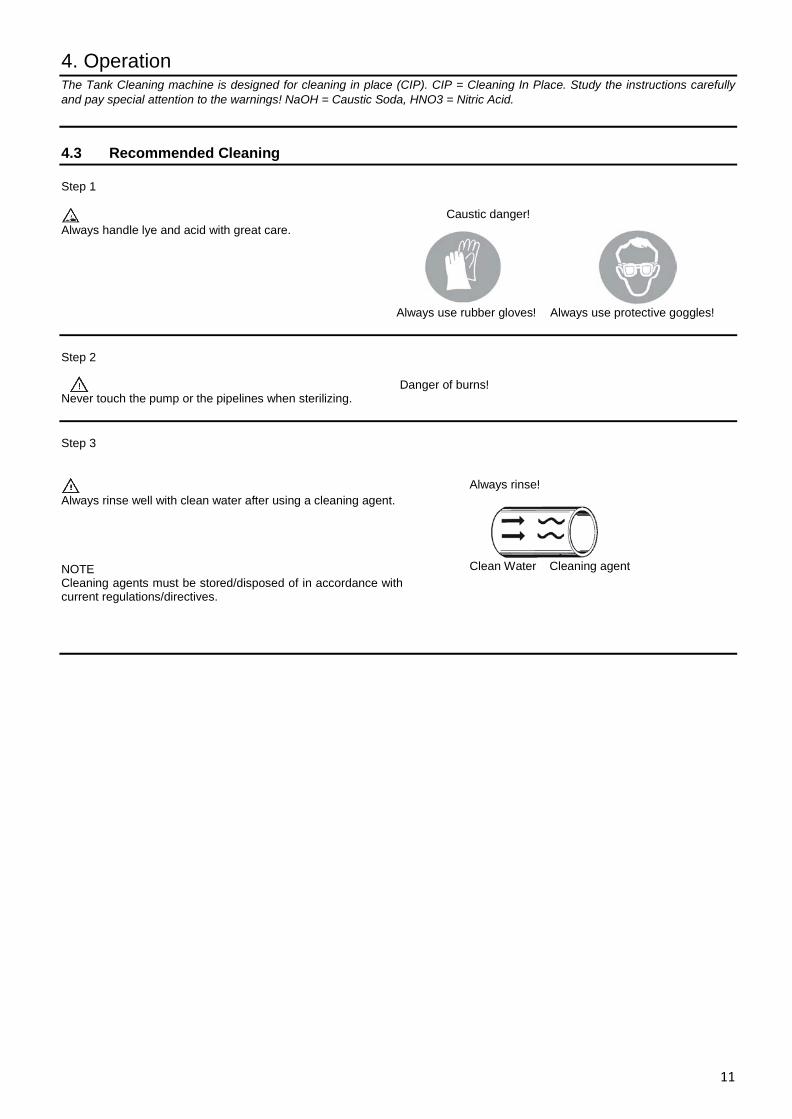
The Tank Cleaning machine is designed for cleaning in place (CIP). CIP = Cleaning In Place. Study the instructions carefully and pay special attention to the warnings! NaOH = Caustic Soda, HNO3 = Nitric Acid. 4.3 Recommended Cleaning Step 1
Always handle lye and acid with great care.
Caustic danger!
Always use rubber gloves! Always use protective goggles! Step 2 Never touch the pump or the pipelines when sterilizing.
Danger of burns!
Step 3
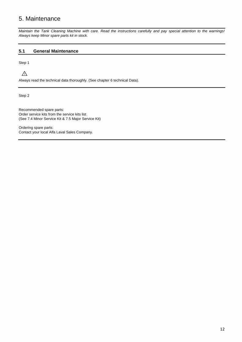
Always rinse well with clean water after using a cleaning agent. NOTE Cleaning agents must be stored/disposed of in accordance with current regulations/directives.
Always rinse!
Clean Water Cleaning agent
5. Maintenance
12
Maintain the Tank Cleaning Machine with care. Read the instructions carefully and pay special attention to the warnings! Always keep Minor spare parts kit in stock. 5.1 General Maintenance Step 1 Always read the technical data thoroughly. (See chapter 6 technical Data).
Step 2
Recommended spare parts: Order service kits from the service kits list (See 7.4 Minor Service Kit & 7.5 Major Service Kit) Ordering spare parts: Contact your local Alfa Laval Sales Company.
5. Maintenance
13
Maintain the Tank Cleaning Machine with care. Read the instructions carefully and pay special attention to the warnings! Always keep Minor spare parts kit in stock. 5.2 General Dismantling Set Up Step 1 NOTE A rigorously implemented preventative maintenance program will significantly reduce repair costs over the life of the Alfa Laval BladeClean. The foundation of such a program is regularly scheduled inspections to discover and replace worn or damaged parts before they can cause the failure of other, more costly, components. The inspection intervals required will depend on the severity of the application, but 100 hours of operation is recommended initially.
Step 2 STORAGE The Alfa Laval BladeClean should be washed out with clean water after each use to remove any foreign material or soft substances left in the machine that may harden during storage. A clean water rinse through the Alfa Laval BladeClean will also wash out any residues of chemical cleaners or recirculated wash water that could adversely affect the seals and O-rings during prolonged contact in storage. The best position to store the Alfa Laval BladeClean is standing upward with the outlet connection facing up. Step 3 INSPECTION INTERVALS An interval of 100 hours is recommended initially. If all of the components are found to be in acceptable condition after the first 100 hours, the Alfa Laval BladeClean may then be inspected and routine preventive maintenance should be performed every 500 hours of operation, depending on the severity of use.
Step 4 TIPS All the Bearings, Bushings, Seals and O-rings are wear parts. Ideally, they should all be replaced, as a group, every 500 hours of operation, depending on the severity of use. If just one Bearing or Seal is worn or damaged, replace both it and its mate, not just the worn or damaged part.
5. Maintenance
14
Maintain the Tank Cleaning Machine with care. Read the instructions carefully and pay special attention to the warnings! Always keep Minor spare parts kit in stock. 5.3 General Dismantling Step 1
Place a soft towel or an equivalent under the Alfa Laval BladeClean assembly to prevent it from getting scratched. Use a towel to hold the body extension tube.
Step 2
Remove the Bottom Cap (10) using the 18” (457.2 mm) long Adjustable Crescent Wrench. After the cap comes off, use the 3/8” (9.5 mm) Allen Screw T Handle to unscrew the Screw (13) from the Retainer (12), which holds the Plunger (11) and the Wave Spring (14) together. After removing each part, place them aside for inspection and reassembly.
WARNING: The spring is under compression and may cause harm if not unscrewed with care. Step 3
The Plunger (11) will slide out now. The Main Body (7) has a Bearing (5) and an O-ring (8) mounted, which can be removed to check for damages. The Main Body, Body Extension Tube (1) and the Outlet screw (4) all can be unscrewed manually. A bench vise and adjustable crescent wrench can be used if needed. The various O-rings and gaskets should be removed for inspection.
5. Maintenance
15
Read the instructions carefully. The items refer to the parts list and service kits section. 5.4 Inspection and Service of Components Drawing 1 & 2 Inspect all machined features and windows to be sure they are clear and free of debris. Especially check for debris in slots of outlet screw (4). Inspect the O-rings and the bearings (5) for deterioration (hardening or deformation) or damage and replace if necessary. Replace the seal (9) if damaged during operation or disassembly or doesn’t fit on the plunger correctly. Check the wave springs (14) and replace if any crests are damaged.
5. Maintenance
16
Read the instructions carefully. The items refer to the parts list and service kits section. 5.5 Reassembly General Notes All parts must be cleaned thoroughly before reassembling. Any deposits remaining on the parts can cause difficult disassembly the next time the Alfa Laval BladeClean needs servicing. Assemble each O-rings using water for lubrication. This will allow each O-ring to be compressed uniformly in each threaded joint assembly. Drawing 1 Start with the upper assembly. Press fit the bearing (5) into the outlet screw (4). Place the gasket (3) at the bottom of (4). Place the (4) into the Body Tube (1). Place the O-ring (2) into the extension tube (1). Screw the outlet screw (4) in the extension tube (1). Drawing 2 Place the seal (8) in the main body (7). Press fit the bearing (5) from the bottom into the main body. Screw the main body below the extension tube. Place the O-ring (12) on the plunger (11). Insert the plunger (11) through the top of outlet screw (4) all the way down. Place the spring (14) in position below the main body (7) and screw in the Retainer (12) with (13). Drawing 1 Make sure the plunger moves smoothly in the body and then place the Bottom Cap (10). Put on the O-ring (6) on the outside of outlet screw (4). Now the Alfa Laval BladeClean can be attached to the tank adapter (15) with the clamp (16) provided. This completes the assembly process.
6. Technical Data
17
It is important to observe the technical data during installation, operation and maintenance. Inform personnel about the technical data.
6.1 Technical Data The Alfa Laval BladeClean Tank Cleaning Machine is a highly efficient machine at a range of pressures and flows. The instruction manual is part of the delivery. Read the instructions carefully.
TECHNICAL DATA Lubricant . . . . . . . . . . . . . . . . . . . Self- lubricating Max. throw length . . . . . . . . . . . . .6-9 m (20 - 30 ft.) Pressure Working pressure . . . . . . . . . . . . . . 1.5 - 10 bar (22 - 145 PSI) Recommended pressure . . . . . . . . . 2 - 5 bar (29 - 73 PSI)
Certificate
Material Certificate
PHYSICAL DATA Materials 1.4404 (316L), FDA- approved EPDM, PTFE, PPS Weight …………………………………. 1.27 kg (2.8 lbs.) Surface finish ………………………….. 0.5 µm (20 Ra) Connections Standard thread ……………………….. 1” tri- clamp standard Alfa Laval connection Available option ……………………….. 1½” tube weld on Includes Mounting materials …………………… Alfa Laval Hygienic Tank Adapter, EPDM O-Ring, Clamp, Blind Cap
6. Technical Data
18
It is important to observe the technical data during installation, operation and maintenance. Inform personnel about the technical data.
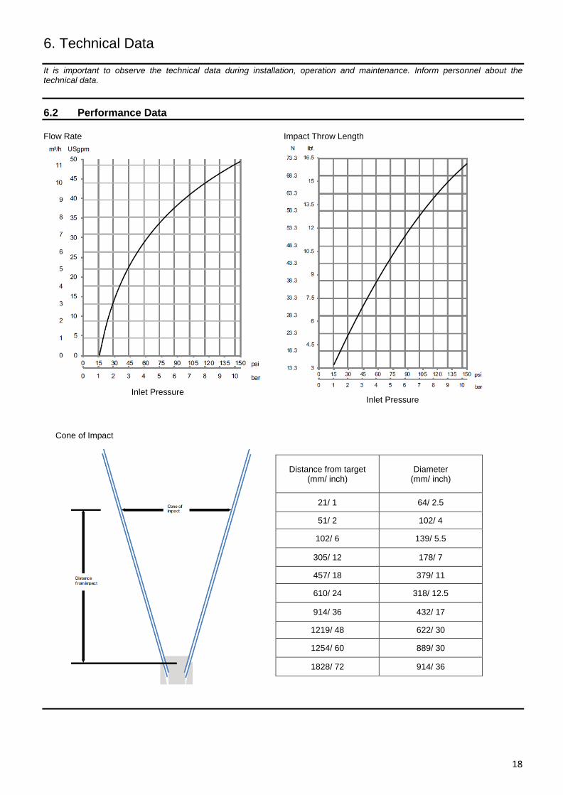
6.2 Performance Data Flow Rate Impact Throw Length
Distance from target (mm/ inch)
Diameter (mm/ inch)
21/ 1 64/ 2.5
51/ 2 102/ 4
102/ 6 139/ 5.5
305/ 12 178/ 7
457/ 18 379/ 11
610/ 24 318/ 12.5
914/ 36 432/ 17
1219/ 48 622/ 30
1254/ 60 889/ 30
1828/ 72 914/ 36
Inlet Pressure
Inlet Pressure
Cone of Impact

6. Technical Data
19
It is important to observe the technical data during installation, operation and maintenance. Inform personnel about the technical data.
6.3 Dimensions Dimensions Dimensions
A B C D E F
mm 140 53 112 68 104 68
in 5.5 2.1 4.4 2.7 4.1 2.7
7. Parts List and Service Kits
20
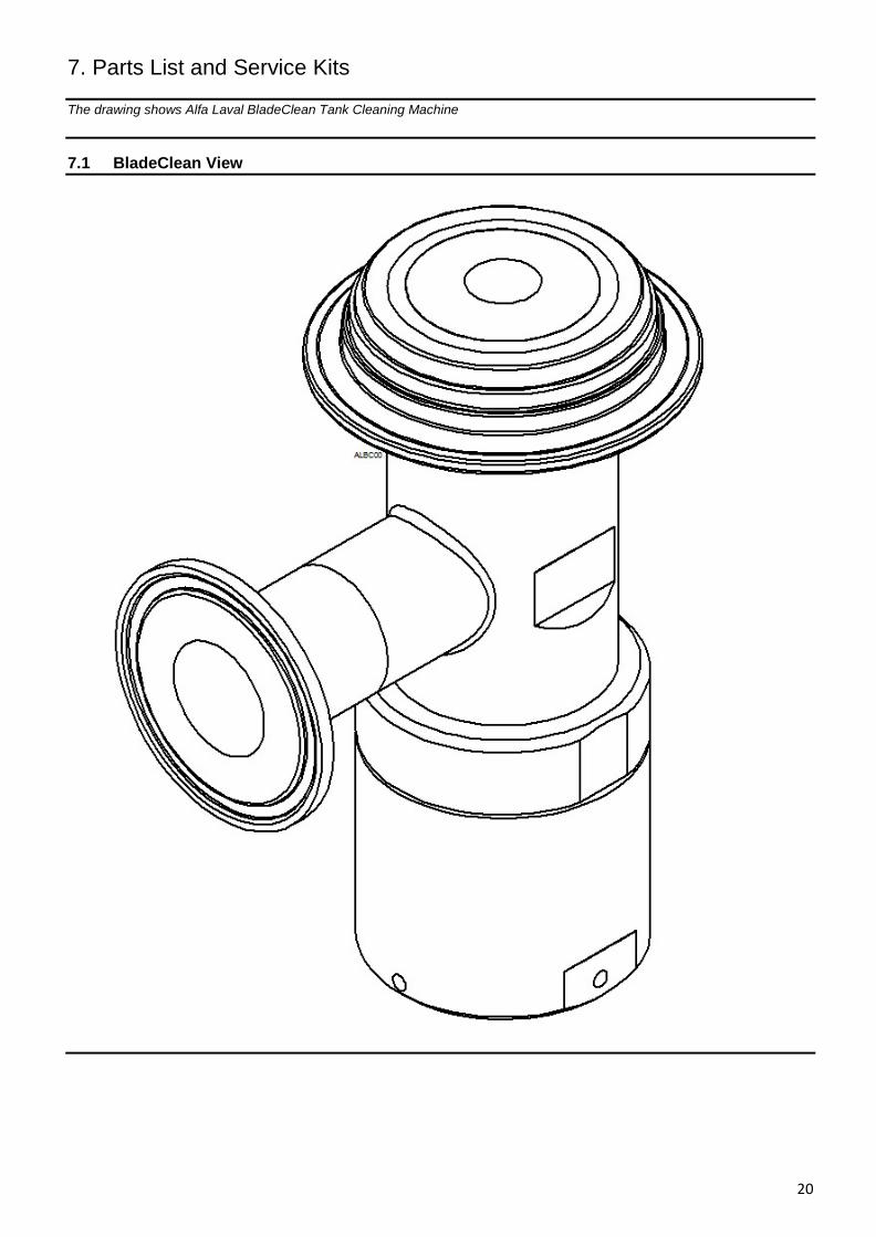
The drawing shows Alfa Laval BladeClean Tank Cleaning Machine
7.1 BladeClean View
7. Parts List and Service Kits
21
The drawing shows Alfa Laval BladeClean Tank Cleaning Machine
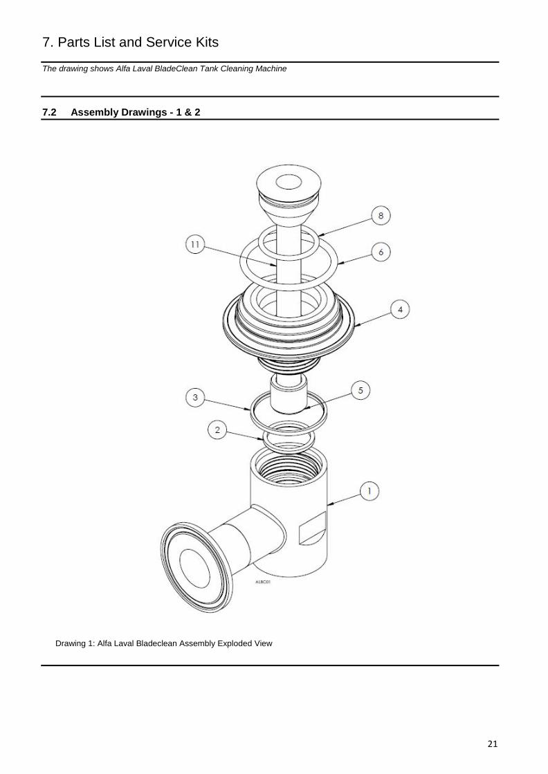
7.2 Assembly Drawings - 1 & 2
Drawing 1: Alfa Laval Bladeclean Assembly Exploded View
7. Parts List and Service Kits
22
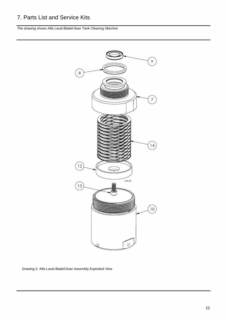
The drawing shows Alfa Laval BladeClean Tank Cleaning Machine
Drawing 2: Alfa Laval BladeClean Assembly Exploded View
7. Parts List and Service Kits
23
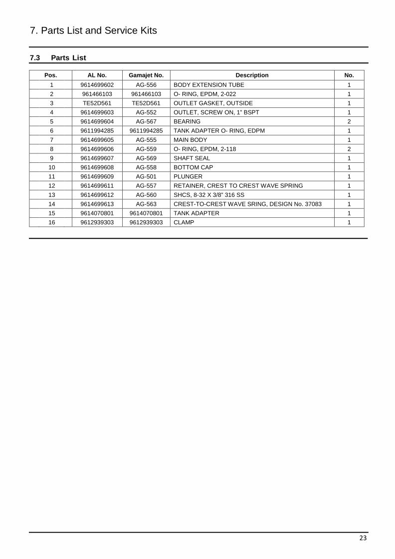
7.3 Parts List
Pos. AL No. Gamajet No. Description No.
1 9614699602 AG-556 BODY EXTENSION TUBE 1
2 961466103 961466103 O- RING, EPDM, 2-022 1
3 TE52D561 TE52D561 OUTLET GASKET, OUTSIDE 1
4 9614699603 AG-552 OUTLET, SCREW ON, 1” BSPT 1
5 9614699604 AG-567 BEARING 2
6 9611994285 9611994285 TANK ADAPTER O- RING, EDPM 1
7 9614699605 AG-555 MAIN BODY 1
8 9614699606 AG-559 O- RING, EPDM, 2-118 2 9 9614699607 AG-569 SHAFT SEAL 1 10 9614699608 AG-558 BOTTOM CAP 1
11 9614699609 AG-501 PLUNGER 1
12 9614699611 AG-557 RETAINER, CREST TO CREST WAVE SPRING 1
13 9614699612 AG-560 SHCS, 8-32 X 3/8” 316 SS 1
14 9614699613 AG-563 CREST-TO-CREST WAVE SRING, DESIGN No. 37083 1
15 9614070801 9614070801 TANK ADAPTER 1
16 9612939303 9612939303 CLAMP 1
7. Parts List and Service Kits
24
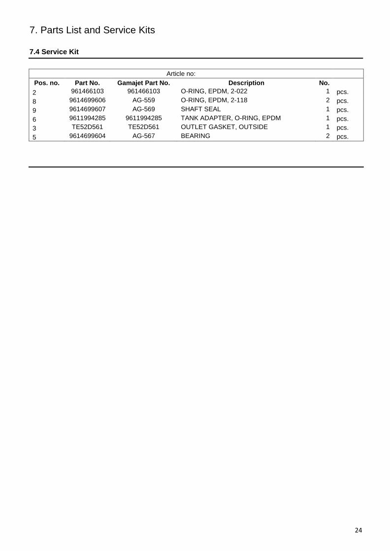
7.4 Service Kit
Article no: Pos. no. Part No. Gamajet Part No. Description No. 2 961466103 961466103 O-RING, EPDM, 2-022 1 pcs. 8 9614699606 AG-559 O-RING, EPDM, 2-118 2 pcs. 9 9614699607 AG-569 SHAFT SEAL 1 pcs. 6 9611994285 9611994285 TANK ADAPTER, O-RING, EPDM 1 pcs. 3 TE52D561 TE52D561 OUTLET GASKET, OUTSIDE 1 pcs. 5 9614699604 AG-567 BEARING 2 pcs.
Appendix A
25
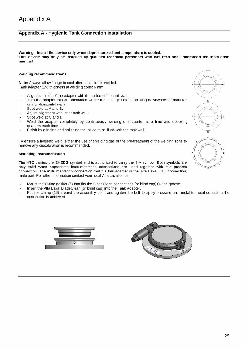
Appendix A - Hygienic Tank Connection Installation
Warning - Install the device only when depressurized and temperature is cooled. This device may only be installed by qualified technical personnel who has read and understood the instruction manual! Welding recommendations Note: Always allow flange to cool after each side is welded. Tank adapter (15) thickness at welding zone: 6 mm. - Align the inside of the adapter with the inside of the tank wall. - Turn the adapter into an orientation where the leakage hole is pointing downwards (if mounted
on non-horizontal wall). - Spot weld at A and B. - Adjust alignment with inner tank wall. - Spot weld at C and D. - Weld the adapter completely by continuously welding one quarter at a time and opposing
quarters each time. - Finish by grinding and polishing the inside to be flush with the tank wall.
To ensure a hygienic weld, either the use of shielding gas or the pre-treatment of the welding zone to remove any discoloration is recommended. Mounting instrumentation The HTC carries the EHEDG symbol and is authorized to carry the 3-A symbol. Both symbols are only valid when appropriate instrumentation connections are used together with this process connection. The instrumentation connection that fits this adapter is the Alfa Laval HTC connection, male part. For other information contact your local Alfa Laval office. - Mount the O-ring gasket (5) that fits the BladeClean connections (or blind cap) O-ring groove. - Insert the Alfa Laval BladeClean (or blind cap) into the Tank Adapter. - Put the clamp (16) around the assembly point and tighten the bolt to apply pressure until metal-to-metal contact in the
connection is achieved.

26
How to contact Alfa Laval Tank Equipment
For further information please feel free to contact:
Alfa Laval Tank Equipment
604 Jeffers Circle, Exton, PA 19341 USA
Tel switchboard: +01 610 408 9940 - Fax switchboard: +01 610 408 9945
http://www.gamajet.com, www.alfalaval.com, [email protected]
Contact details for all countries are continually updated on our websites.
© Alfa Laval Corporate AB This document and its contents is owned by Alfa Laval Corporate AB and protected by laws governing intellectual property and thereto related rights. It is the responsibility of the user of this document to comply with all applicable intellectual property laws. Without limiting any rights related to this document, no part of this document may be copied, reproduced or transmitted in any form or by any means (electronic, mechanical, photocopying, recording, or otherwise), or for any purpose, without the expressed permission of Alfa Laval Corporate AB. Alfa Laval Corporate AB will enforce its rights related to this document to the fullest extent of the law, including the seeking of criminal prosecution.