instruction manual - cole-parmer ph/ise meter instruction manual introduction 1 chapter i...
TRANSCRIPT
Benchtop pH and pH/ISE MetersModels 410Aplus
420Aplus
520Aplus
525Aplus
710Aplus
720Aplus
920Aplus
INSTRUCTION MANUAL
Benchtop pH/ISE Meter Instruction Manual
Introduction 1
Chapter IIntroductionThermo Orion provides pH and ISE meters for every application from pHmeasurements to advanced Ion Selective Electrode work. This manualdescribes the operation and use of the Thermo Orion Model 410ApluspH/Temperature Meter, Model 420Aplus pH/mV/Temperature Meter, theModel 520Aplus Advanced pH/mV/Temperature Meter, the Model525Aplus Dual Channel pH/mV/Temperature Meter, the Model 710ApluspH/ISE Meter, the Model 720Aplus Dual Channel pH/ISE Meter, and theModel 920Aplus Advanced pH/ISE Meter.
All meters are microprocessor-controlled and feature pH autocalibration,sealed keypads, simultaneous temperature display and many other features.
The Models 410Aplus, 420Aplus and 710Aplus feature a custom LCDdisplay. The Models 520Aplus, 525Aplus, 720Aplus, and 920Aplus featurea two color vacuum fluorescent display with a separate prompt line thatexplains each step during calibration and measurement.
How to Use This Manual
For more detail on the operation of any of the models, please refer to theTable of Contents for the page location of an operation of a particular metermodel. Troubleshooting instructions are common to all meters and thisinformation is located toward the end of this manual.
Explanation of key functions and additional reference information are notrequired for calibration and measurement can be found in the appendices.

2
Benchtop pH/ISE Meter Instruction Manual
Benchtop pH/ISE Meter Instruction Manual
General Information 3
Chapter IIGeneral InformationModels 410Aplus, 420Aplus, 710AplusGeneral Information
The Model 410Aplus is a pH/Temperature Meter, the Model 420Aplus is apH/mV/Temperature Meter and the Model 710Aplus is a pH/ISEmV/Temperature Meter for general laboratory use. These meters feature:(1) a custom LCD display, which simultaneously displays mode, resultsand temperature; (2) a sealed keypad with tactile and audible feedback;and (3) an RS232 port for use with the Thermo Orion 900A printer or otherserial peripheral devices.
Models 520Aplus, 525Aplus, 720Aplus, 920AplusGeneral Information
The Model 520Aplus is a pH/mV/Temperature Meter, Model 525Aplus is an Advanced pH/mV/Temperature Meter, 720Aplus is apH/ISE/mV/Temperature Meter and 920Aplus is an AdvancedpH/ISE/mV/Temperature meter for general or advanced laboratory use.These meters feature: (1) a two color vacuum fluorescent display; (2) asealed keypad with tactile and audible feedback; and (3) an RS232 port foruse with Thermo Orion 900A printer or other serial peripheral devices. TheModels 525Aplus, 720Aplus and 920Aplus feature dual electrode inputs.
SETUP CALIBRATE MEASURE
ready
ONOFF
°CATC
4 7 10 Man
timer
power
model 410
no
mode
yes
pH meter
SETUP:
RESOLUTIONSLOPEPRINT OPTIONSCAL BUFFER OPTION
S-1S-2S-3S-4
ERROR CODES:
OUT OF RANGEAUTO BUFFER ERRORCAL STANDARD ERRORBAD SLOPEPRINTER ERRORBAD VALUE
E-20E-21E-22E-23E-29E-31
See Manual for other Error Codes.
Benchtop pH/ISE Meter Instruction Manual
Set Up, Self-Test and Check-Out4
Chapter III Set Up, Self-Test and Check-OutProceduresA. Models 410Aplus Set Up and Self-Test
NOTE: Use this procedure when the instrument is first received and whenever troubleshooting becomes necessary.
1. Connect BNC shorting cap (Thermo Orion Catalog No. 090045)supplied with meter to sensing electrode input.
2. Disconnect the ATC probe.
3. Plug line (Thermo Orion Catalog No. 020125 for 110V, Thermo OrionCatalog No. 020130 for 220V) into an appropriate wall outlet thensecurely into meter power receptacle.
NOTE: Firmly push the power adapter into the jack on the back of the meter.
4. Press and hold yes while pressingpower. The instrument automatically performs electronic and hardware diagnostic tests. See the explanation in the Self-Test Section of the troubleshooting guide for a more detailed explanation.
a. When “O” appears in the lower field, press each key including power. A numeric digit will be displayed for each keypress.
b. During test 8, the meter will turn off. To restart meter press power.
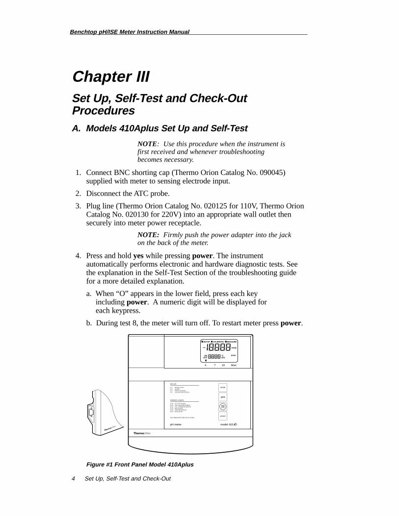
Figure #1 Front Panel Model 410Aplus
pH mV Rel mV Conc
SETUP CALIBRATE MEASURE
2ndreadybold
EXP
ONOFF
°CATC
pH / ISE meter
SETUP:
READYHOLDBEEPAUTOSHUTOFFSLOPERESOLUTIONISOPOINTRESETTIMER INTERVALREMAINING TIMESET REAL TIMESET DATEHIGH ALARM LIMITLOW ALARM LIMITPRINT MODE: 1 = MAN, 2 = READY, 3 = TIMEDPRINT INTERVALDATA LOG MODE: 1 = MAN, 2 = READY, 3 = TIMED, 0 = OFFDATA LOG INTERVALDOWNLOAD DATADATA CLEAR
1-11-21-31-42-12-22-32-43-13-23-33-44-H4-L5-15-26-16-26-36-4
See Manual for Error Codes.
power
yes
2nd
no
modecal
measureprint
setup
timer
model 710
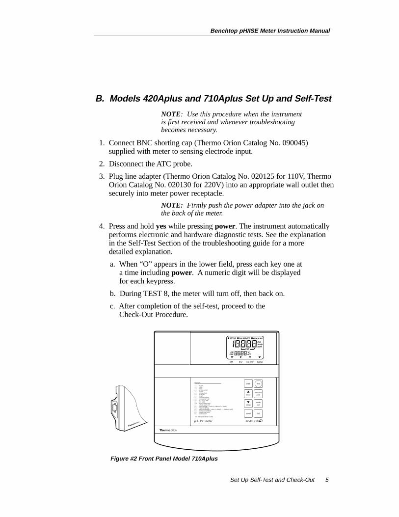
B. Models 420Aplus and 710Aplus Set Up and Self-Test
NOTE: Use this procedure when the instrument is first received and whenever troubleshooting becomes necessary.
1. Connect BNC shorting cap (Thermo Orion Catalog No. 090045)supplied with meter to sensing electrode input.
2. Disconnect the ATC probe.
3. Plug line adapter (Thermo Orion Catalog No. 020125 for 110V, ThermoOrion Catalog No. 020130 for 220V) into an appropriate wall outlet thensecurely into meter power receptacle.
NOTE: Firmly push the power adapter into the jack on the back of the meter.
4. Press and hold yeswhile pressing power. The instrument automaticallyperforms electronic and hardware diagnostic tests. See the explanation in the Self-Test Section of the troubleshooting guide for a more detailed explanation.
a. When “O” appears in the lower field, press each key one at a time including power. A numeric digit will be displayed for each keypress.
b. During TEST 8, the meter will turn off, then back on.
c. After completion of the self-test, proceed to the Check-Out Procedure.
Benchtop pH/ISE Meter Instruction Manual
Set Up Self-Test and Check-Out 5
Figure #2 Front Panel Model 710Aplus
C. Models 420Aplus and 710Aplus Check-Out Procedure
1. Perform the self-test.
2. After completing the self-test the meter will be in MEASURE mode. The legend MEASURE will be displayed.
a. Pressmodeuntil the pH mode indicator is displayed. Main displayshould read a steady 7.00 ± 0.02.
NOTE: If this is the first time this procedure has been performed the reading should be 7.00 ± 0.02.
b. If not, press 2nd cal. “P1” will appear. When “Ready” appears, press yes.
c. Press measure. The main display should read 100.0 with the legend SLP in the lower display. If so, press yes.
d. If not, scroll until the display reads 100.0 and then press yes. The meter advances to MEASURE and the display should now read steady 7.00.
NOTE: To change a value, press or . The first digit will flash, continue scrolling until the first digit equals the correct value, then press yes.The second digit will flash. Scroll to the correct value then press yes. When all digits have been changed, press yesto enter the new value.
3. Press mode to enter millivolt mode. Display should read 0.0 ± 0.2. If not, press 2nd cal then pressyesto enter the value 0.0. The meter will return to MEASURE mode.
4. Press mode to enter REL mV mode. Display should read 0.0 ± 0.2. If not, press 2nd cal then pressyesto enter the value 0.0. The meter will return to MEASURE mode.
Benchtop pH/ISE Meter Instruction Manual
Set Up, Self-Test and Check-Out6
▼▼
Benchtop pH/ISE Meter Instruction Manual
Set Up, Self-Test and Check-Out 7
For Model 420Aplus, the meter is now ready for use with electrodes.Remove the shorting cap.
5. For Model 710Aplus onlyWith the shorting cap still connected, press modeuntil the concentration mode indicator is displayed. The display should read 1.00.
NOTE: If this is the first time this procedure has been performed the reading should be 1.00.
a. If not, press 2nd cal.At the P1 prompt, scroll until the display reads 1.00. Pressyes.
b. Press measure.SLP and 59.2 should be displayed. If so,press yes.
c. If not, scroll until the display reads 59.2, then press yes.
6. After successfully completing steps 1 through 5, the meter is ready for use with electrodes. Remove the shorting cap.
model 525
yes
no
1st
2nd
4hold
1mode
2calibrate
5resolutionchannel
6slope
3measure
+ -date/time
beep
7print
data logmV
8activateset timer
0standbyoptions
data/printmodesalarm
9set temp
ready
.
Benchtop pH/ISE Meter Instruction Manual
Set Up, Self-Test and Check-Out 8
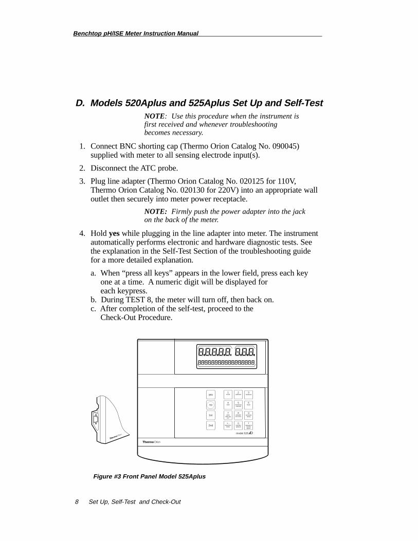
D. Models 520Aplus and 525Aplus Set Up and Self-TestNOTE: Use this procedure when the instrument is first received and whenever troubleshooting becomes necessary.
1. Connect BNC shorting cap (Thermo Orion Catalog No. 090045)supplied with meter to all sensing electrode input(s).
2. Disconnect the ATC probe.
3. Plug line adapter (Thermo Orion Catalog No. 020125 for 110V, Thermo Orion Catalog No. 020130 for 220V) into an appropriate walloutlet then securely into meter power receptacle.
NOTE: Firmly push the power adapter into the jack on the back of the meter.
4. Hold yeswhile plugging in the line adapter into meter. The instrument automatically performs electronic and hardware diagnostic tests. See the explanation in the Self-Test Section of the troubleshooting guide for a more detailed explanation.
a. When “press all keys” appears in the lower field, press each key one at a time. A numeric digit will be displayed for each keypress.
b. During TEST 8, the meter will turn off, then back on.c. After completion of the self-test, proceed to the
Check-Out Procedure.
Figure #3 Front Panel Model 525Aplus
Benchtop pH/ISE Meter Instruction Manual
Set Up, Self-Test and Check-Out 9
E. Models 520Aplus and 525Aplus Check-Out Procedure
1. Perform the self-test.
2. For 525Aplus onlyPress 2nd channeluntil channel 1 is selected
3. After completing the self-test the meter will be in MEASURE mode. The legend MEAS will be displayed.
NOTE: If this is the first time this procedure has been performed the reading should be 7.00 ± 0.02.
4. Press 1st mode to display pH.a. The prompt line on the display should read 25.0˚ C. If not, press
1st set temp and enter 25.0, then press yes.
b. Press 1st calibrate. Enter 1 buffer then press yes. Display should read 7.00 pH. If not, enter 7.00 and press yes.
c. Meter should display the slope as 100.0 PCT. If not, enter 100.0 and press yes.
d. Meter will return to measure mode. Display should read 7.00 ± 0.02.
5. Press mode to display mV. Display should 0.0 ± 0.2 mV. If not, enter 0.0 and press yes.
For Model 520Aplus the meter is now ready for use with electrodes.Remove the shorting cap.
6. For 525Aplus onlya. Press 2nd channelto select input channel 2.
b. Repeat steps 4 and 5 for input channel 2.
For Model 525Aplus the meter is now ready for use with electrodes.Remove the shorting cap.
model 920
yes
no
1st
2nd
4hold
incr tech
1mode
2calibratecal edit
5resolutionchannel
6slope
electrodeID
3measurestability
+ -date/time
beep
7print
data logmV
8activateset timer
0standbyoptions
data/printmodesalarm
9set temp
ready
.
Benchtop pH/ISE Meter Instruction Manual
Set Up Self-Test and Check-Out 10
F. Models 720Aplus and 920Aplus Set Up and Self-Test
NOTE: Use this procedure when the instrument is first received and whenever troubleshooting becomes necessary.
1. Connect BNC shorting cap (Thermo Orion Catalog No. 090045)supplied with meter to all sensing electrode input(s).
2. Disconnect the ATC probe.
3. Plug line adapter (Thermo Orion Catalog No. 020125 for 110V,Thermo Orion Catalog No. 020130 for 220V) into an appropriate walloutlet then securely into meter power receptacle.
NOTE: Firmly push the power adapter into the jack on the back of the meter.
4. Press and hold yes while connecting the power. The instrument automatically performs electronic and hardware diagnostic tests. See the explanation in the Self-Test Section of the troubleshooting guide for a more detailed explanation.
a. When “O” appears in the lower field, press each key one at a time.A numeric digit will be displayed for each keypress.
b. During TEST 8, the meter will turn off, then back on.
c. After completion of the self-test, proceed to the Check-Out Procedure.
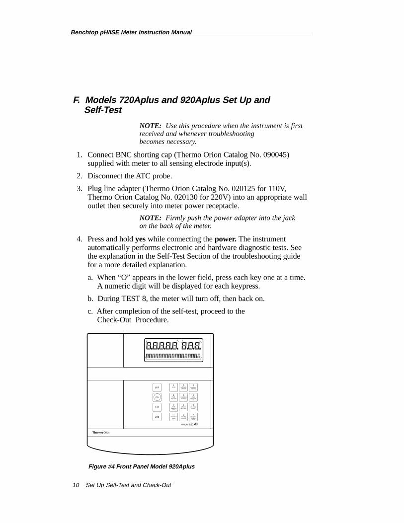
Figure #4 Front Panel Model 920Aplus
Benchtop pH/ISE Meter Instruction Manual
Set Up Self-Test and Check-Out 11
G. Models 720Aplus and 920Aplus Check-Out Procedure
1. Perform the self-test.
2. After completing the self-test the meter will be in MEASURE mode. The legend MEASURE will be displayed.
NOTE: If this is the first time this procedure has been performed the reading should be 7.000 ± 0.02.
3. Press modeuntil pH is displayed.a. Press 2nd channel until channel 1 is selected.b. The prompt line on the display should read 25.0˚ C. If not, press
1st set tempand enter 25.0, then press yes.
4. For 920Aplus only:Press 2nd electrode id. Press 1 for pH and press yes.
5. Press 1st calibrate.a. Press 1 buffer, then press yes.
b. Display should read 6.997. If not, enter 6.997 and press yesat the READY CAL AS prompt.
c. Meter should display the slope, 100.0 PCT. If not, enter 100.0 and press yes.
d. Meter will return to measure mode. Display should read 6.997 ± 0.02.
6. Press mode to display mV. Display should read 0.0 ± 0.2 mV.If not, enter 0.0 and press yes.
7. Press modeuntil CONC is displayed.a. For 920Aplus only:
Display should read CON and — . Press2nd electrode id.Enter 13, (Na+) then press yes.
b. Press calibrate. Enter 1 standard and press yes. c. Meter should display 1.00. If not, enter 1.00 and press yesat the
READY ENTER VALUE prompt.d. Meter should display the slope as 59.2 mV. If not, enter 59.2 and
press yes.e. Meter will return to measure mode. Display should read
1.00 ± 0.01.
8. Press mode to select pH.a. Press 2nd channelto select input channel 2.
b. Repeat steps 3 through 7 for input channel 2.
9. After successful completion of steps 1 through 7, the meter is ready for use with electrodes. Remove shorting caps.
Benchtop pH/ISE Meter Instruction Manual
Rear Panel and Electrode Connections12
Instrument Set Up
The meter can be adjusted to provide you an optimal viewing angle via theflip stand. To adjust the viewing angle, turn the instrument over and placeyour thumbs on the inside of the stand sides. As you lift the stand, gentlypush the sides of the stand out. This will lock the stand at a 90˚ angle,providing easy viewing from across the lab. To adjust to the last viewingangle, continue to gently push the sides of the stand out as you lift the standto its furthest point.
Power
ATC/DIN Ref. Input Rec. Gnd. ATC/DIN KF Input 1 Ref.1 Input 2 Ref. 29V DC
63
4 5
1
8
27
Benchtop pH/ISE Meter Instruction Manual
Rear Panel and Electrode Connections 13
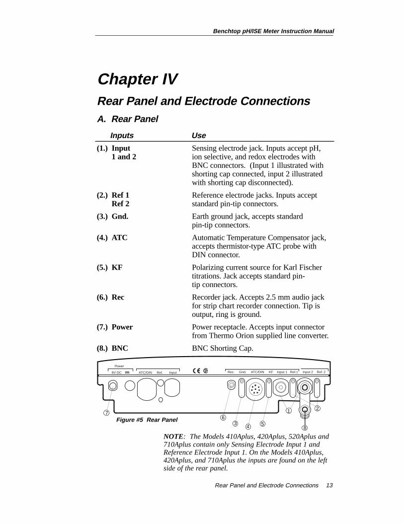
Chapter IV Rear Panel and Electrode Connections A. Rear Panel
Inputs Use
(1.) Input Sensing electrode jack. Inputs accept pH,1 and 2 ion selective, and redox electrodes with
BNC connectors. (Input 1 illustrated with shorting cap connected, input 2 illustrated with shorting cap disconnected).
(2.) Ref 1 Reference electrode jacks. Inputs acceptRef 2 standard pin-tip connectors.
(3.) Gnd. Earth ground jack, accepts standardpin-tip connectors.
(4.) ATC Automatic Temperature Compensator jack, accepts thermistor-type ATC probe with DIN connector.
(5.) KF Polarizing current source for Karl Fischer titrations. Jack accepts standard pin-tip connectors.
(6.) Rec Recorder jack. Accepts 2.5 mm audio jack for strip chart recorder connection. Tip is output, ring is ground.
(7.) Power Power receptacle. Accepts input connector from Thermo Orion supplied line converter.
(8.) BNC BNC Shorting Cap.
NOTE: The Models 410Aplus, 420Aplus, 520Aplus and 710Aplus contain only Sensing Electrode Input 1 and Reference Electrode Input 1. On the Models 410Aplus, 420Aplus, and 710Aplus the inputs are found on the left side of the rear panel.
Figure #5 Rear Panel

Benchtop pH/ISE Meter Instruction Manual
Calibration and Measurement of pH14
B. Electrode Connections
1. Attach electrodes with BNC connectors to sensor input by sliding connector onto input, pushing down and turning clockwise to lock intoposition. Connect reference electrodes with pin tip connectors by pushing connector straight into reference input.
NOTE: If using a combination electrode with a BNC connector, a reference electrode is not used.
2. Attach the ATC probe to the ATC jack by sliding the connector straight on until it is firmly in place. The connector has a special sealing mechanism, which is engaged, when the connector is properly attached.
Benchtop pH/ISE Meter Instruction Manual
Calibration and Measurement of pH 15
Chapter VCalibration and Measurement of pHA. General Information on pH Calibration
A one, two or multipoint (where available) calibration should be performedusing fresh buffers before pH is measured. It is recommended that a twobuffer calibration, using buffers that bracket the expected sample range, beperformed at the beginning of each day to determine the slope of theelectrode. This serves a dual purpose, determining if the electrode isworking properly and storing the slope value in memory. Perform a onebuffer calibration every two hours to compensate for electrode drift, using a fresh aliquot from one of the calibration buffers used in the initial calibration.
The instruments use a point-to-point calibration scheme, i.e. the meterstores in memory the different electrode slopes for each portion of thecalibration curve. When measuring in a particular region of the curve, theelectrode slope for that region is employed in the calculation of sample pH.After calibration, the average electrode slope for all the segments of theentire calibration curve is displayed. Use of this scheme increases accuracyin the different regions of the calibration curve. However, the electrodeslope may be lower than normal, especially if buffers from the pH extremes< 2.00 or > 12.00 are used. See Appendix C.
There are two ways of calibrating Thermo Orion Benchtop Meters,autocalibration or manual calibration. The following are descriptions andinstructions of each method, for each model.
For Best Results
It is recommended that an ATC probe be used. If an ATC probe is not used,all samples and standards should be at the same temperature or manualtemperature compensation should be used. Stir all buffers and samples witha magnetic stirrer while a measurement is being made.
NOTE: Some magnetic stirrers generate enough heat to change solution temperature. To avoid this, place a piece of cardboard, foam rubber or other insulating material between the stir plate and beaker.
Always use fresh aliquots of buffers whenever calibrating.
Benchtop pH/ISE Meter Instruction Manual
Calibration and Measurement of pH16
Temperature Compensation
pH measurements on the Model 410Aplus are made with AutomaticTemperature Compensation. pH measurements on the Models 420Aplus,520Aplus, 525Aplus, 710Aplus, 720Aplus, and 920Aplus may be madewith either Automatic or Manual Temperature Compensation.
For Automatic Temperature Compensation, an ATC probe must be used.Plug in the ATC probe and the meter will display temperature corrected pHresults in the main display.
For Manual Temperature Compensation withModels 520Aplus,525Aplus, 720Aplus, and 920Aplusdisconnect the temperature probe.Temperature values can be entered manually by pressing set temp.Temperature corrected pH values, based on the manually enteredtemperature, will be displayed in the main field.
For Manual Temperature Compensation with Models 420Aplus and710Aplusdisconnect the temperature probe. Temperature values can beentered manually by pressing or while in measure mode. The valuewill be displayed in the lower field. Temperature corrected pH values basedon the manually entered temperature will be displayed in the main field.
▼
▼
Benchtop pH/ISE Meter Instruction Manual
Calibration and Measurement of pH 17
B. Model 410Aplus pH Calibration and Measurement
Autocalibration
Autocalibration is a feature of the Model 410Aplus Meter that automaticallyrecognizes the standard buffers, 4.01, 7.00 and 10.01, within a range of ± 0.5 pH units. Simply select the buffer sequence that best fits yourapplication. Results greater than ± 0.5 pH units from the theoretical valuewill trigger an operator assistance code. During calibration, the user waitsfor a stable pH reading. Once the electrode is stable, the meterautomatically recognizes and displays the temperature-corrected value forthat buffer. Pressing yesenters the value into memory.
Manual Calibration
To calibrate with buffers other than 4.01, 7.00, or 10.01, use the manualcalibration technique. The chosen buffers must be greater than one (1) pHunit but less than four (4) pH units from the next closest buffer. Manualcalibration is selected through SETUP mode. The calibration sequence isthe same as autocalibration except that the buffer values are scrolled in andthen entered.
NOTE: For manual calibration use yesto accept or no to change each digit until the correct value, then press yes to accept.
Three Point pH Calibration
Up to a three (3) point calibration can be performed on the Model 410AplusMeter. Simply select the buffer sequence that best fits your application.
Benchtop pH/ISE Meter Instruction Manual
Calibration and Measurement of pH18
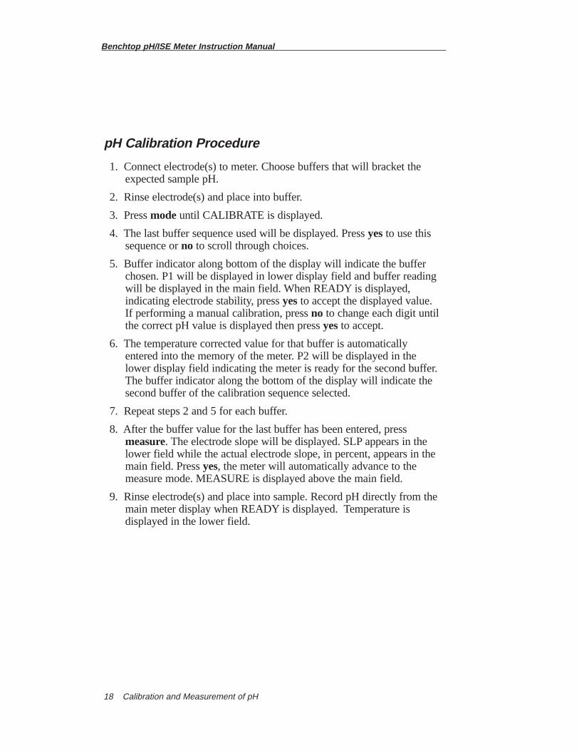
pH Calibration Procedure
1. Connect electrode(s) to meter. Choose buffers that will bracket the expected sample pH.
2. Rinse electrode(s) and place into buffer.
3. Press modeuntil CALIBRATE is displayed.
4. The last buffer sequence used will be displayed. Press yesto use this sequence orno to scroll through choices.
5. Buffer indicator along bottom of the display will indicate the buffer chosen. P1 will be displayed in lower display field and buffer reading will be displayed in the main field. When READY is displayed, indicating electrode stability, press yesto accept the displayed value. If performing a manual calibration, press no to change each digit until the correct pH value is displayed then press yesto accept.
6. The temperature corrected value for that buffer is automatically entered into the memory of the meter. P2 will be displayed in the lower display field indicating the meter is ready for the second buffer. The buffer indicator along the bottom of the display will indicate the second buffer of the calibration sequence selected.
7. Repeat steps 2 and 5 for each buffer.
8. After the buffer value for the last buffer has been entered, press measure. The electrode slope will be displayed. SLP appears in the lower field while the actual electrode slope, in percent, appears in the main field. Press yes, the meter will automatically advance to the measure mode. MEASURE is displayed above the main field.
9. Rinse electrode(s) and place into sample. Record pH directly from the main meter display when READY is displayed. Temperature is displayed in the lower field.
Benchtop pH/ISE Meter Instruction Manual
Calibration and Measurement of pH 19
C. Model 420Aplus pH Calibration and Measurement
Autocalibration
Autocalibration is the feature of the Model 420Aplus Meter thatautomatically recognizes three buffers, 4.01, 7.00, and 10.01, within arange of ± 0.5 pH units. Results greater than ± 0.5 pH units from thecorrect value will trigger an operator assistance code. At this point, amanual calibration can be performed or the calibration can be ended andrepeated with fresh buffers. During calibration the user waits for a stablepH reading. Once the electrode is stable, the meter automaticallyrecognizes and displays the temperature-corrected value for that buffer.Pressing yesenters the value into memory.
NOTE: Do not scroll when using autocalibration. If you want to exit the menu at any time, pressmeasure.
Manual Calibration
To calibrate with buffers other than 4.01, 7.00, or 10.01, use the manualcalibration technique. The chosen buffers must be greater than one (1) pHunit but less than four (4) pH units from the next closest buffer. Thecalibration sequence is the same as autocalibration except that the buffervalues are scrolled in and then entered.
NOTE: For manual calibration you must use or . Even if the value displayed is the correct value for your buffer, you must press ascroll key to start the editing process. Press yesto accept each digit. Otherwise the meter assumes autocalibration is being performed.
Three Point pH Calibration
Up to a three (3) point calibration can be performed on the Model420AplusMeter. Both autocalibration and manual calibrations may be used within thesame calibration curve. For example, autocalibration may be used with the7.00 and 10.01 buffers while manual calibration would be used with a 3.78 buffer.
▼
▼
Benchtop pH/ISE Meter Instruction Manual
Calibration and Measurement of pH20
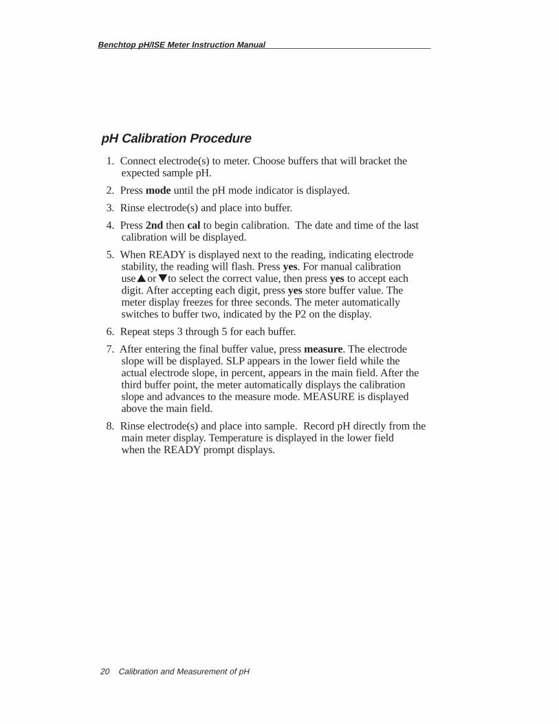
pH Calibration Procedure
1. Connect electrode(s) to meter. Choose buffers that will bracket the expected sample pH.
2. Press modeuntil the pH mode indicator is displayed.
3. Rinse electrode(s) and place into buffer.
4. Press 2nd then cal to begin calibration. The date and time of the last calibration will be displayed.
5. When READY is displayed next to the reading, indicating electrode stability, the reading will flash. Press yes. For manual calibration use or to select the correct value, then press yesto accept each digit. After accepting each digit, press yesstore buffer value. The meter display freezes for three seconds. The meter automatically switches to buffer two, indicated by the P2 on the display.
6. Repeat steps 3 through 5 for each buffer.
7. After entering the final buffer value, press measure. The electrode slope will be displayed. SLP appears in the lower field while the actual electrode slope, in percent, appears in the main field. After the third buffer point, the meter automatically displays the calibration slope and advances to the measure mode. MEASURE is displayed above the main field.
8. Rinse electrode(s) and place into sample. Record pH directly from themain meter display. Temperature is displayed in the lower field when the READY prompt displays.
▼
▼
Benchtop pH/ISE Meter Instruction Manual
Calibration and Measurement of pH 21
D. Model 520Aplus pH Calibration and Measurement
Autocalibration
Autocalibration is the feature of the Model 520Aplus Meter thatautomatically recognizes five buffers, 1.68, 4.01, 7.00, 10.01, and 12.46,within a range of ± 0.5 pH units. Results greater than ± 0.5 pH units fromthe correct value will trigger the prompt NO AUTOBUFFER and requireoperator intervention. At this point, a manual calibration can be performedor the calibration can be ended and repeated with fresh buffers. Duringcalibration, the user waits for a stable pH reading. Once the electrode isstable, the meter automatically recognizes and displays the temperaturecorrected value for that buffer. Press yesto the READY CAL AS prompt toenter the value in memory.
Manual Calibration
To calibrate with buffers other than 1.68, 4.01, 7.00, 10.01, or 12.46, usethe manual calibration technique. The calibration sequence is the same asautocalibration except that the buffer values are manually entered using thenumeric keypad. At the “READY CAL AS” prompt enter the value for thebuffer and press yesto enter.
Three Point pH Calibration
Up to a three (3) point calibration can be performed on the Model520Aplus Meter. Both autocalibration and manual calibrations may be usedwithin the same calibration curve. For example, autocalibration may beused with the 7.00 and 10.01 buffers while manual calibration would beused with a 3.78 buffer.
Benchtop pH/ISE Meter Instruction Manual
Calibration and Measurement of pH22
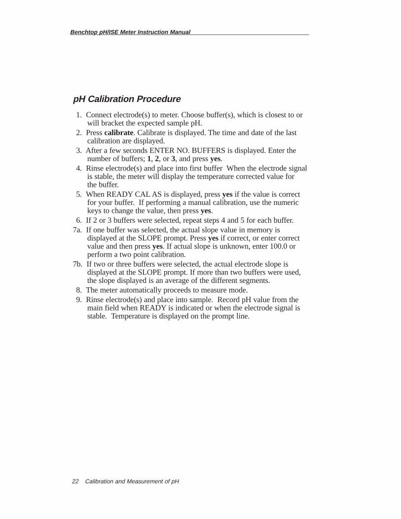
pH Calibration Procedure
1. Connect electrode(s) to meter. Choose buffer(s), which is closest to or will bracket the expected sample pH.
2. Press calibrate. Calibrate is displayed. The time and date of the last calibration are displayed.
3. After a few seconds ENTER NO. BUFFERS is displayed. Enter the number of buffers; 1, 2, or 3, and press yes.
4. Rinse electrode(s) and place into first buffer When the electrode signalis stable, the meter will display the temperature corrected value for the buffer.
5. When READY CAL AS is displayed, press yesif the value is correct for your buffer. If performing a manual calibration, use the numeric keys to change the value, then press yes.
6. If 2 or 3 buffers were selected, repeat steps 4 and 5 for each buffer.7a. If one buffer was selected, the actual slope value in memory is
displayed at the SLOPE prompt. Press yesif correct, or enter correct value and then press yes. If actual slope is unknown, enter 100.0 or perform a two point calibration.
7b. If two or three buffers were selected, the actual electrode slope is displayed at the SLOPE prompt. If more than two buffers were used, the slope displayed is an average of the different segments.
8. The meter automatically proceeds to measure mode.9. Rinse electrode(s) and place into sample. Record pH value from the
main field when READY is indicated or when the electrode signal is stable. Temperature is displayed on the prompt line.
Benchtop pH/ISE Meter Instruction Manual
Calibration and Measurement of pH 23
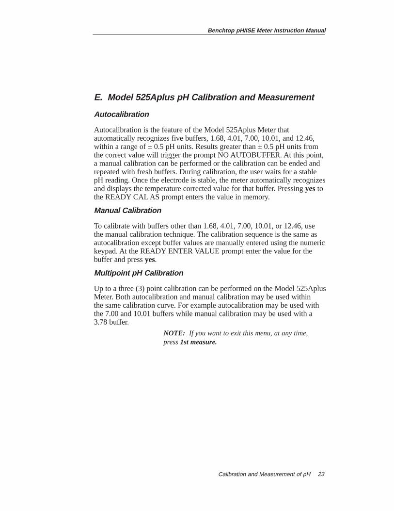
E. Model 525Aplus pH Calibration and Measurement
Autocalibration
Autocalibration is the feature of the Model 525Aplus Meter thatautomatically recognizes five buffers, 1.68, 4.01, 7.00, 10.01, and 12.46,within a range of ± 0.5 pH units. Results greater than ± 0.5 pH units fromthe correct value will trigger the prompt NO AUTOBUFFER. At this point,a manual calibration can be performed or the calibration can be ended andrepeated with fresh buffers. During calibration, the user waits for a stablepH reading. Once the electrode is stable, the meter automatically recognizesand displays the temperature corrected value for that buffer. Pressing yestothe READY CAL AS prompt enters the value in memory.
Manual Calibration
To calibrate with buffers other than 1.68, 4.01, 7.00, 10.01, or 12.46, usethe manual calibration technique. The calibration sequence is the same asautocalibration except buffer values are manually entered using the numerickeypad. At the READY ENTER VALUE prompt enter the value for thebuffer and press yes.
Multipoint pH Calibration
Up to a three (3) point calibration can be performed on the Model 525AplusMeter. Both autocalibration and manual calibration may be used within the same calibration curve. For example autocalibration may be used withthe 7.00 and 10.01 buffers while manual calibration may be used with a3.78 buffer.
NOTE: If you want to exit this menu, at any time, press 1st measure.
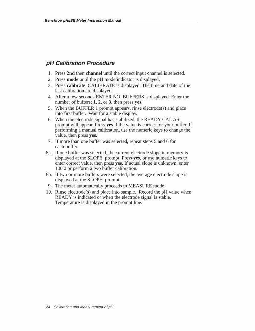
pH Calibration Procedure
1. Press 2nd thenchannel until the correct input channel is selected.2. Press modeuntil the pH mode indicator is displayed.3. Press calibrate. CALIBRATE is displayed. The time and date of the
last calibration are displayed.4. After a few seconds ENTER NO. BUFFERS is displayed. Enter the
number of buffers; 1, 2, or 3, then press yes. 5. When the BUFFER 1 prompt appears, rinse electrode(s) and place
into first buffer. Wait for a stable display.6. When the electrode signal has stabilized, the READY CAL AS
prompt will appear. Press yesif the value is correct for your buffer. If performing a manual calibration, use the numeric keys to change the value, then press yes.
7. If more than one buffer was selected, repeat steps 5 and 6 for each buffer.
8a. If one buffer was selected, the current electrode slope in memory is displayed at the SLOPE prompt. Press yes, or use numeric keys to enter correct value, then press yes. If actual slope is unknown, enter 100.0 or perform a two buffer calibration.
8b. If two or more buffers were selected, the average electrode slope is displayed at the SLOPE prompt.
9. The meter automatically proceeds to MEASURE mode.10. Rinse electrode(s) and place into sample. Record the pH value when
READY is indicated or when the electrode signal is stable. Temperature is displayed in the prompt line.
Benchtop pH/ISE Meter Instruction Manual
Calibration and Measurement of pH24
Benchtop pH/ISE Meter Instruction Manual
Calibration and Measurement of pH 25
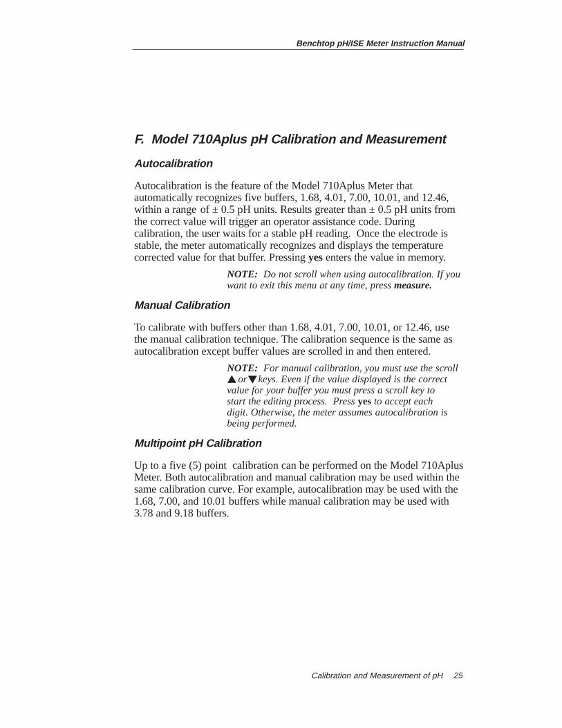
F. Model 710Aplus pH Calibration and Measurement
Autocalibration
Autocalibration is the feature of the Model 710Aplus Meter thatautomatically recognizes five buffers, 1.68, 4.01, 7.00, 10.01, and 12.46,within a range of ± 0.5 pH units. Results greater than ± 0.5 pH units fromthe correct value will trigger an operator assistance code. Duringcalibration, the user waits for a stable pH reading. Once the electrode isstable, the meter automatically recognizes and displays the temperaturecorrected value for that buffer. Pressing yesenters the value in memory.
NOTE: Do not scroll when using autocalibration. If you want to exit this menu at any time, press measure.
Manual Calibration
To calibrate with buffers other than 1.68, 4.01, 7.00, 10.01, or 12.46, usethe manual calibration technique. The calibration sequence is the same asautocalibration except buffer values are scrolled in and then entered.
NOTE: For manual calibration, you must use the scroll or keys. Even if the value displayed is the correct
value for your buffer you must press a scroll key to start the editing process. Press yesto accept each digit. Otherwise, the meter assumes autocalibration is being performed.
Multipoint pH Calibration
Up to a five (5) point calibration can be performed on the Model 710AplusMeter. Both autocalibration and manual calibration may be used within thesame calibration curve. For example, autocalibration may be used with the1.68, 7.00, and 10.01 buffers while manual calibration may be used with3.78 and 9.18 buffers.
▼
▼
Benchtop pH/ISE Meter Instruction Manual
Calibration and Measurement of pH26
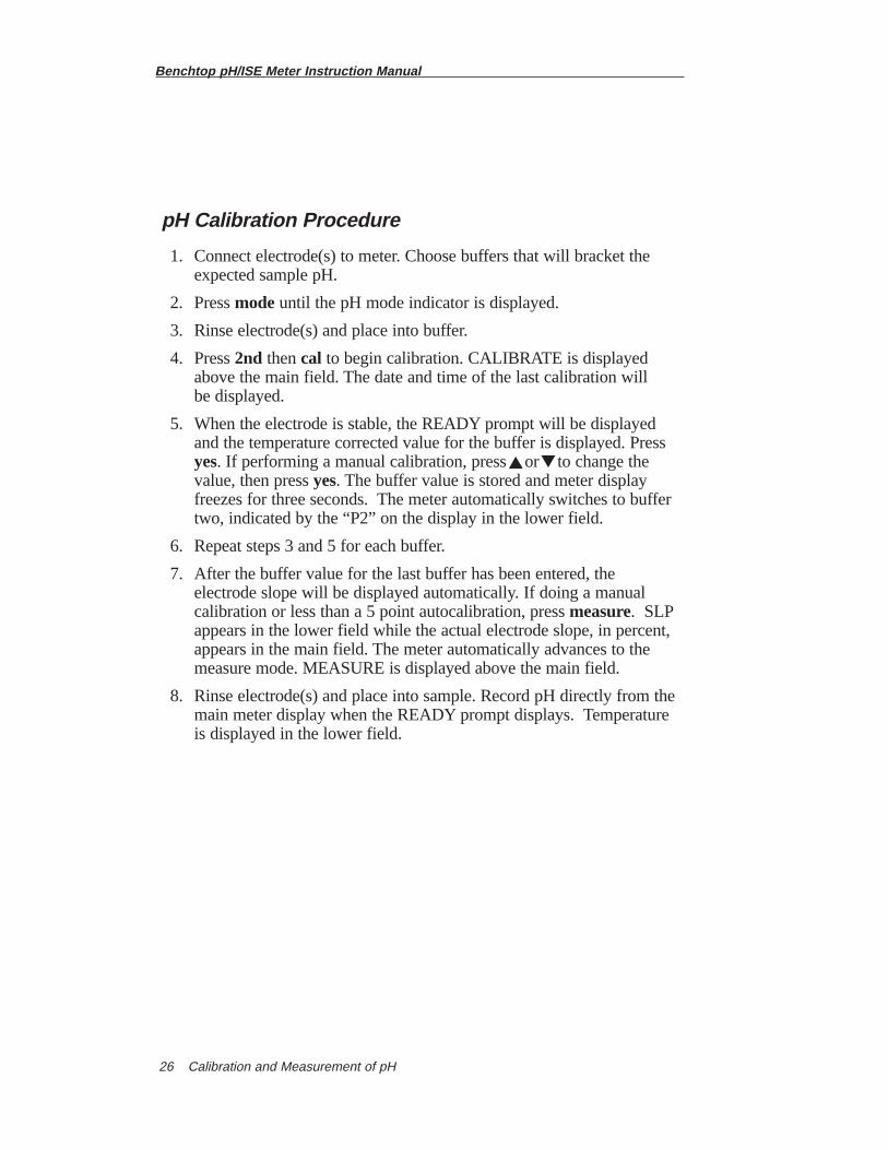
pH Calibration Procedure
1. Connect electrode(s) to meter. Choose buffers that will bracket the expected sample pH.
2. Press modeuntil the pH mode indicator is displayed.
3. Rinse electrode(s) and place into buffer.
4. Press 2nd then cal to begin calibration. CALIBRATE is displayed above the main field. The date and time of the last calibration will be displayed.
5. When the electrode is stable, the READY prompt will be displayed and the temperature corrected value for the buffer is displayed. Press yes. If performing a manual calibration, press or to change the value, then press yes. The buffer value is stored and meter display freezes for three seconds. The meter automatically switches to buffer two, indicated by the “P2” on the display in the lower field.
6. Repeat steps 3 and 5 for each buffer.
7. After the buffer value for the last buffer has been entered, the electrode slope will be displayed automatically. If doing a manual calibration or less than a 5 point autocalibration, press measure. SLPappears in the lower field while the actual electrode slope, in percent, appears in the main field. The meter automatically advances to the measure mode. MEASURE is displayed above the main field.
8. Rinse electrode(s) and place into sample. Record pH directly from the main meter display when the READY prompt displays. Temperature is displayed in the lower field.
▼
▼
Benchtop pH/ISE Meter Instruction Manual
Calibration and Measurement of pH 27
G. Model 720Aplus pH Calibration and Measurement
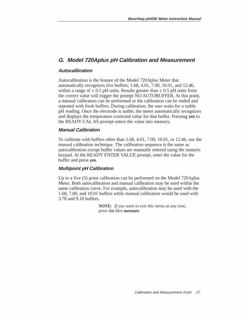
Autocalibration
Autocalibration is the feature of the Model 720Aplus Meter thatautomatically recognizes five buffers, 1.68, 4.01, 7.00, 10.01, and 12.46,within a range of ± 0.5 pH units. Results greater than ± 0.5 pH units fromthe correct value will trigger the prompt NO AUTOBUFFER. At this point,a manual calibration can be performed or the calibration can be ended andrepeated with fresh buffers. During calibration, the user waits for a stablepH reading. Once the electrode is stable, the meter automatically recognizesand displays the temperature corrected value for that buffer. Pressing yestothe READY CAL AS prompt enters the value into memory.
Manual Calibration
To calibrate with buffers other than 1.68, 4.01, 7.00, 10.01, or 12.46, use themanual calibration technique. The calibration sequence is the same asautocalibration except buffer values are manually entered using the numerickeypad. At the READY ENTER VALUE prompt, enter the value for thebuffer and press yes.
Multipoint pH Calibration
Up to a five (5) point calibration can be performed on the Model 720AplusMeter. Both autocalibration and manual calibration may be used within thesame calibration curve. For example, autocalibration may be used with the1.68, 7.00, and 10.01 buffers while manual calibration would be used with3.78 and 9.18 buffers.
NOTE: If you want to exit this menu at any time, press 1st thenmeasure.
Benchtop pH/ISE Meter Instruction Manual
Calibration and Measurement of pH28
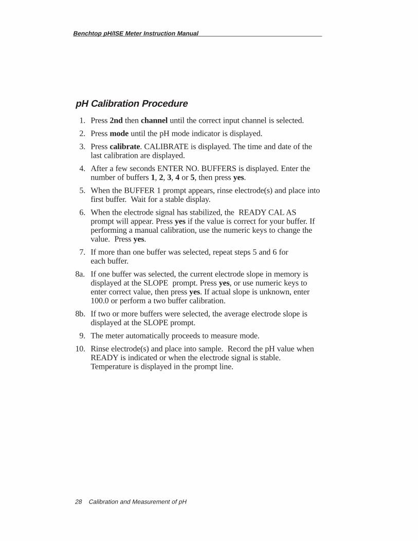
pH Calibration Procedure
1. Press 2nd thenchannel until the correct input channel is selected.
2. Press modeuntil the pH mode indicator is displayed.
3. Press calibrate. CALIBRATE is displayed. The time and date of the last calibration are displayed.
4. After a few seconds ENTER NO. BUFFERS is displayed. Enter the number of buffers 1, 2, 3, 4 or 5, then press yes.
5. When the BUFFER 1 prompt appears, rinse electrode(s) and place intofirst buffer. Wait for a stable display.
6. When the electrode signal has stabilized, the READY CAL AS prompt will appear. Press yes if the value is correct for your buffer. If performing a manual calibration, use the numeric keys to change the value. Press yes.
7. If more than one buffer was selected, repeat steps 5 and 6 for each buffer.
8a. If one buffer was selected, the current electrode slope in memory isdisplayed at the SLOPE prompt. Press yes, or use numeric keys to enter correct value, then press yes. If actual slope is unknown, enter 100.0 or perform a two buffer calibration.
8b. If two or more buffers were selected, the average electrode slope is displayed at the SLOPE prompt.
9. The meter automatically proceeds to measure mode.
10. Rinse electrode(s) and place into sample. Record the pH value when READY is indicated or when the electrode signal is stable. Temperature is displayed in the prompt line.

Benchtop pH/ISE Meter Instruction Manual
Calibration and Measurement of pH 29
H. Model 920Aplus pH Calibration and Measurement
Autocalibration
Autocalibration is the feature of the Model 920Aplus Meter thatautomatically recognizes five buffers, 1.68, 4.01, 7.00, 10.01, and 12.46,within a range of ± 0.5 pH units. Results greater than ± 0.5 pH units fromthe correct value will trigger the prompt NO AUTOBUFFER. At this point,a manual calibration can be performed or the calibration can be ended andrepeated with fresh buffers. During calibration, the user waits for a stablepH reading. Once the electrode is stable the meter automatically recognizesand displays the temperature-corrected value for that buffer. Press yestothe READY CAL AS prompt to enter the value in memory.
Manual Calibration
To calibrate with buffers other than 1.68, 4.01, 7.00, 10.01, or 12.46, usethe manual calibration technique. The calibration sequence is the same asautocalibration except buffer values are manually entered using the numerickeypad. At the READY ENTER VALUE prompt, enter the value for thebuffer and press yes.
Multipoint pH Calibration
Up to a five (5) point calibration can be performed on the Model 920AplusMeter. Both autocalibration and manual calibration may be used within thesame calibration curve. For example, autocalibration may be used with the1.68, 7.00, and 10.01 buffers while manual calibration may be used with3.78 and 9.18 buffers.
NOTE: If you want to exit this menu at any time, press 1st thenmeasure.
Benchtop pH/ISE Meter Instruction Manual
Calibration and Measurement of Concentration30
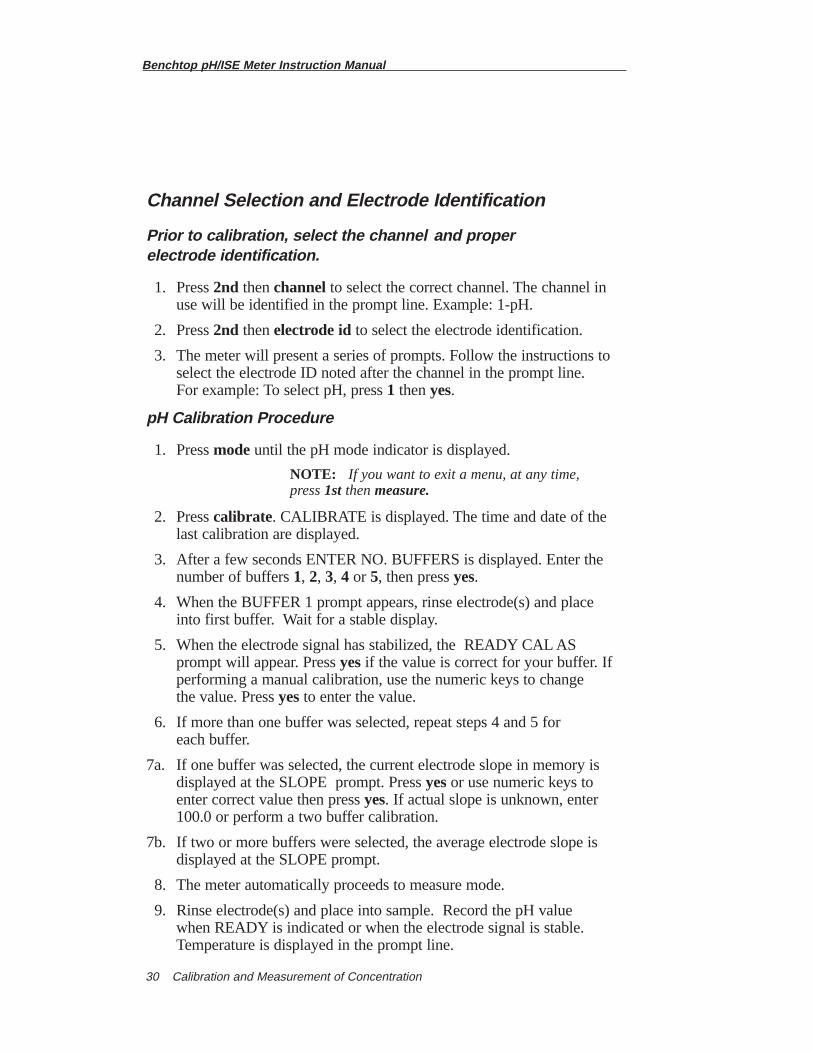
Channel Selection and Electrode Identification
Prior to calibration, select the channel and proper electrode identification.
1. Press 2nd thenchannel to select the correct channel. The channel in use will be identified in the prompt line. Example: 1-pH.
2. Press 2nd thenelectrode idto select the electrode identification.
3. The meter will present a series of prompts. Follow the instructions to select the electrode ID noted after the channel in the prompt line. For example: To select pH, press 1 then yes.
pH Calibration Procedure
1. Press modeuntil the pH mode indicator is displayed.
NOTE: If you want to exit a menu, at any time, press 1st thenmeasure.
2. Press calibrate. CALIBRATE is displayed. The time and date of the last calibration are displayed.
3. After a few seconds ENTER NO. BUFFERS is displayed. Enter the number of buffers 1, 2, 3, 4 or 5, then press yes.
4. When the BUFFER 1 prompt appears, rinse electrode(s) and place into first buffer. Wait for a stable display.
5. When the electrode signal has stabilized, the READY CAL AS prompt will appear. Press yesif the value is correct for your buffer. If performing a manual calibration, use the numeric keys to change the value. Press yesto enter the value.
6. If more than one buffer was selected, repeat steps 4 and 5 for each buffer.
7a. If one buffer was selected, the current electrode slope in memory is displayed at the SLOPE prompt. Press yesor use numeric keys to enter correct value then press yes. If actual slope is unknown, enter 100.0 or perform a two buffer calibration.
7b. If two or more buffers were selected, the average electrode slope is displayed at the SLOPE prompt.
8. The meter automatically proceeds to measure mode.
9. Rinse electrode(s) and place into sample. Record the pH value when READY is indicated or when the electrode signal is stable. Temperature is displayed in the prompt line.
Benchtop pH/ISE Meter Instruction Manual
Calibration and Measurement of Concentration 31
Chapter VICalibration and Measurement ofConcentrationModels 710Aplus, 720Aplus, 920Aplus
A. General Information
A one, two, or multipoint calibration should be performed beforeconcentration is measured. It is recommended that a two point standardcalibration be performed at the beginning of each day and every timeelectrodes are changed to determine the slope of the electrode. This serves adual purpose, determining if the electrode is working properly and storingthe slope value into memory. Perform a calibration with one standard everytwo hours to compensate for possible electrode drift. Use a fresh aliquotfrom one of the standards used in the initial calibration. During calibration,always use the most dilute standard first, the meter will automaticallyrecognize slope direction (i.e. will recognize anion or cation electrodes).Standards should bracket the sample range and be in the sameconcentration units.
Units
Any convenient units of concentration units can be used. For example:molarity, ppm, %, etc.
Temperature
Allow all samples and standards to reach the same temperature beforemeasurement, or use temperature compensation if the electrode isopotentialpoint is known. (Model 920Aplus only)
Benchtop pH/ISE Meter Instruction Manual
Calibration and Measurement of Concentration32
Slope
Up to a five point calibration may be performed. The instrument uses apoint-to-point calibration scheme. The meter stores, in memory, thedifferent electrode slopes for each portion of the calibration curve. Whenmeasuring in a particular region of the curve, the electrode slope for thatregion is employed in the calculation of sample concentration. Theelectrode slope, displayed after calibration, is the average slope for all thesegments of the entire calibration curve. Use of this scheme increasesaccuracy in the different regions of the calibration curve. However, theelectrode slope displayed may be lower than normal, especially if standardsclose to the electrode limit of detection are used in the calibration.
Autoblank Correction
Blank correction occurs automatically when calibrating with three or morestandards. This feature automatically calculates and corrects forbackground levels of the species of interest. The standards used forcalibration do not need to include a blank. This improves the resultsbecause typical blanks contain low levels of the species to be measured,making them unstable and difficult to measure accurately. To takeadvantage of this feature select three or more standards for calibration. Ifthe profile of the calibration curve does not indicate a background level ofion concentration, then blank correction will not be invoked and thestandard point-to-point scheme will be used. Refer to Appendix D for moredetailed information.
Benchtop pH/ISE Meter Instruction Manual
Calibration and Measurement of Concentration 33
B. Model 710Aplus Concentration Calibration and Measurement
Concentration Calibration Procedure
1. Press modeuntil the CONC mode indicator is displayed.
2. Add ionic strength adjuster, or pH adjuster, to the standards and samples as recommended in the appropriate electrode instruction manual.
3. Rinse electrode(s) and place into the least concentrated standard.
4. Press 2nd thencal. CALIBRATE and the time and date of the last calibration will be displayed. After a few seconds P1 will be displayed indicating the meter is ready for the first standard.
NOTE: If you want to exit this menu, at any time,press measure.
5. When the reading is stable, enter the value of the standard, press the scroll keys or . The value will flash. Press or again. The decimal point will flash. Position the decimal point using or , then press yes. The first digit will flash. Scroll to the desired value, then press yes.Continue for each digit on the display. There are 4 1/2 digits plus a polarity sign and decimal point. The display will freeze for three seconds, then P2 will be displayed in the lower field.
6. If two or more standards were selected, rinse electrode(s) and repeat step 5 for each standard. When the reading is stable, enter the value of the standard as above. The reading will freeze for three seconds, then P3 will be displayed in the lower field. The meter is now ready for the third standard.
7. After the last standard, press measure. The electrode slope will be displayed for a few seconds, then the meter advances to measure mode. If five (5) standards have been entered, the meter automaticallydisplays the slope, then advances to measure mode.
8. Rinse electrode(s) and place into sample. Wait for the RDY prompt to appear. Record concentration directly from the main meter display. Temperature is displayed in the lower field.
▼▼
▼▼
▼ ▼
Benchtop pH/ISE Meter Instruction Manual
Calibration and Measurement of Concentration34
C. Model 720Aplus Concentration Calibration and Measurement
Concentration Calibration Procedure
1. The number of the electrode input in use will appear on the prompt line. Example: CH-1. To select a different channel press 2ndthenchannel.
2. Press modeuntil the concentration mode indicator CON appears on the display.
3. Add ionic strength adjuster, or pH adjuster to the standard and samples,as recommended in the electrode instruction manual.
NOTE: If you want to exit this menu, at any time, press 1st then measure.
4. Press calibrate. CALIBRATE will be displayed as well as the time and date of the last calibration.
5. When ENTER NO. STDS prompt appears enter the number of standards to be used in the calibration and press yes.
6. Rinse electrode(s) and place into first standard (the least concentrated standard). Wait for stable display.
7. When the READY ENTER VALUE prompt appears, enter the concentration value of the standard and press yes.
8. If two or more standards were selected, repeat steps 6 and 7 for each standard.
9. If one standard was selected, the electrode slope in mV/decade will bedisplayed at the SLOPE prompt. Press yesif correct, or enter the correct value for the electrode.
NOTE: Make sure the correct polarity sign is entered for the electrode in use during a one point calibration. The sign should be + (positive) for cations, for example, Na+, and - (negative) for anions, for example F - .
10. If two or more standards were entered, the electrode slope is calculated and displayed.
11. The meter then advances to MEASURE mode.
12. Rinse and place electrode(s) into the sample. Record concentration directly from the meter display when the READY prompt appears. Temperature is displayed in the prompt line.
Benchtop pH/ISE Meter Instruction Manual
Calibration and Measurement of Concentration 35
D. Model 920Aplus Concentration Calibration and Measurement
Channel Selection and Electrode Identification
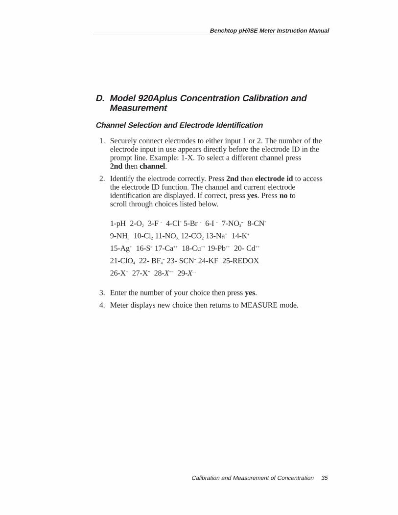
1. Securely connect electrodes to either input 1 or 2. The number of the electrode input in use appears directly before the electrode ID in the prompt line. Example: 1-X. To select a different channel press 2nd thenchannel.
2. Identify the electrode correctly. Press 2nd thenelectrode id to access the electrode ID function. The channel and current electrode identification are displayed. If correct, press yes. Press no to scroll through choices listed below.
1-pH 2-O2 3-F - 4-Cl- 5-Br - 6-I - 7-NO3- 8-CN-
9-NH3 10-Cl2 11-NOX 12-CO2 13-Na+ 14-K+
15-Ag+ 16-S= 17-Ca++ 18-Cu++ 19-Pb++ 20- Cd++
21-ClO4 22- BF4- 23- SCN- 24-KF 25-REDOX
26-X+ 27-X- 28-X++ 29-X- -
3. Enter the number of your choice then press yes.
4. Meter displays new choice then returns to MEASURE mode.
Benchtop pH/ISE Meter Instruction Manual
Special Features36
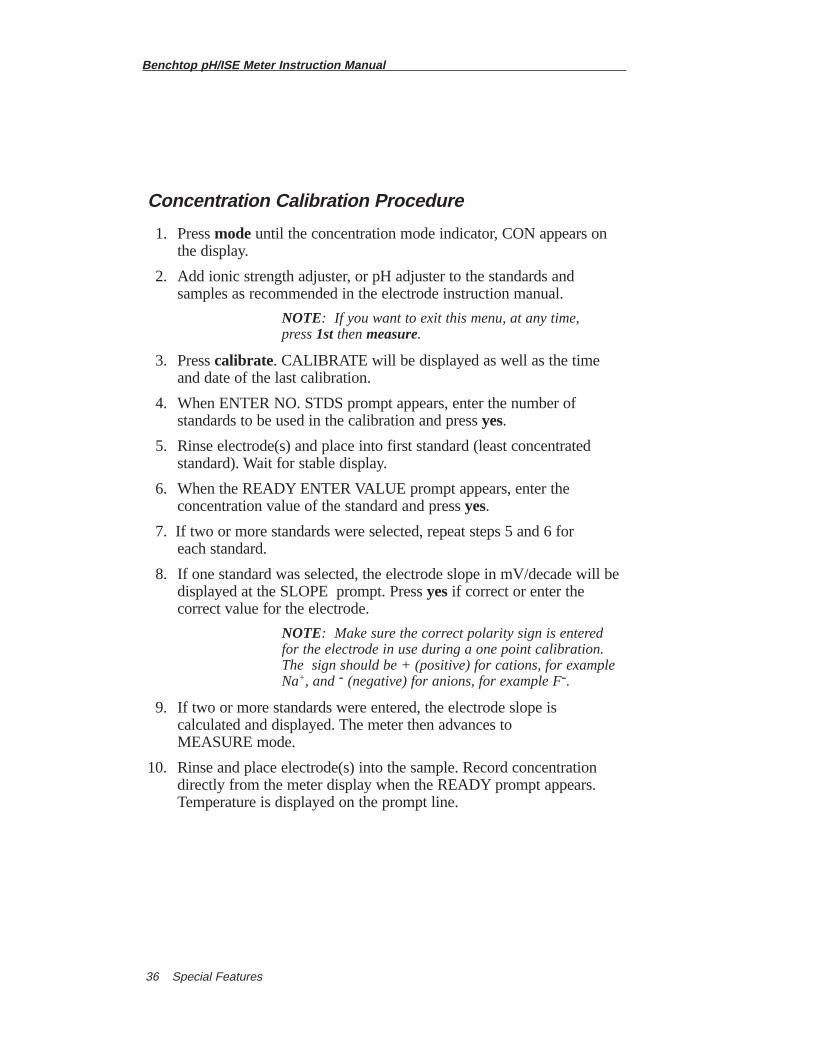
Concentration Calibration Procedure
1. Press modeuntil the concentration mode indicator, CON appears on the display.
2. Add ionic strength adjuster, or pH adjuster to the standards and samples as recommended in the electrode instruction manual.
NOTE: If you want to exit this menu, at any time, press 1st thenmeasure.
3. Press calibrate. CALIBRATE will be displayed as well as the time and date of the last calibration.
4. When ENTER NO. STDS prompt appears, enter the number of standards to be used in the calibration and press yes.
5. Rinse electrode(s) and place into first standard (least concentrated standard). Wait for stable display.
6. When the READY ENTER VALUE prompt appears, enter the concentration value of the standard and press yes.
7. If two or more standards were selected, repeat steps 5 and 6 for each standard.
8. If one standard was selected, the electrode slope in mV/decade will bedisplayed at the SLOPE prompt. Press yesif correct or enter the correct value for the electrode.
NOTE: Make sure the correct polarity sign is entered for the electrode in use during a one point calibration. The sign should be + (positive) for cations, for example Na+, and - (negative) for anions, for example F-.
9. If two or more standards were entered, the electrode slope is calculated and displayed. The meter then advances toMEASURE mode.
10. Rinse and place electrode(s) into the sample. Record concentration directly from the meter display when the READY prompt appears. Temperature is displayed on the prompt line.
Benchtop pH/ISE Meter Instruction Manual
Special Features 37
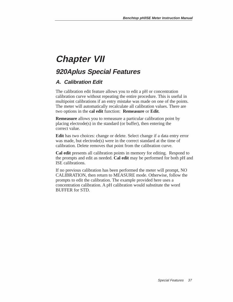
Chapter VII920Aplus Special FeaturesA. Calibration Edit
The calibration edit feature allows you to edit a pH or concentrationcalibration curve without repeating the entire procedure. This is useful inmultipoint calibrations if an entry mistake was made on one of the points.The meter will automatically recalculate all calibration values. There aretwo options in the cal edit function: Remeasureor Edit .
Remeasureallows you to remeasure a particular calibration point byplacing electrode(s) in the standard (or buffer), then entering the correct value.
Edit has two choices: change or delete. Select change if a data entry errorwas made, but electrode(s) were in the correct standard at the time ofcalibration. Delete removes that point from the calibration curve.
Cal edit presents all calibration points in memory for editing. Respond tothe prompts and edit as needed. Cal edit may be performed for both pH andISE calibrations.
If no previous calibration has been performed the meter will prompt, NOCALIBRATION, then return to MEASURE mode. Otherwise, follow theprompts to edit the calibration. The example provided here uses aconcentration calibration. A pH calibration would substitute the wordBUFFER for STD.
Benchtop pH/ISE Meter Instruction Manual
Special Features38
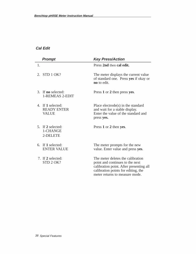
Cal Edit
Prompt Key Press/Action
1. Press 2nd thencal edit.
2. STD 1 OK? The meter displays the current value of standard one. Press yesif okay or no to edit.
3. If no selected: Press 1 or 2 then press yes. 1-REMEAS 2-EDIT
4. If 1 selected: Place electrode(s) in the standard READY ENTER and wait for a stable display.VALUE Enter the value of the standard and
press yes.
5. If 2 selected: Press 1 or 2 then yes.1-CHANGE 2-DELETE
6. If 1 selected: The meter prompts for the newENTER VALUE value. Enter value and press yes.
7. If 2 selected: The meter deletes the calibration STD 2 OK? point and continues to the next
calibration point. After presenting allcalibration points for editing, themeter returns to measure mode.
Benchtop pH/ISE Meter Instruction Manual
Special Features 39
B. Incremental Techniques General Information
The Model 920Aplus Meter includes two different incremental techniques:known addition and known subtraction. Both involve adding aliquots of astandard of known concentration to the sample. Single and doubleincremental techniques can be performed.
Advantages of incremental techniques are:
a. Speed and ease of measuring occasional samples.
b. Ability to analyze samples containing complexing agents.
c. Ability to analyze dilute samples, those varying widely in temperature, and samples for which stable standards do not exist.
d. Use as a quick check of direct measurement results.
Limitations of incremental techniques are:
a. Sample concentration must be known within an order of magnitude so the increment may be correctly chosen.
b. Sample and standard must be volumetrically determined.
c. Any complexing agent must be present in excess (at least 50 to 100 times) or not at all.
Double incremental techniques calculate electrode slope and sampleconcentration simultaneously. The advantages of the double techniques arethat the electrode slope will be determined directly in the sample. Thisresults in greater accuracy for samples with complex matrices, and greaterspeed with which the analysis may be made.
Known addition is a useful method for measuring samples containing anexcess of complexing agent, dilute samples, occasional samples, or as acheck of a direct measurement.
Known subtraction is useful as a quick version of a titration, or withspecies that stable standards do not exist. It is necessary to know thestoichiometric ratio between standard and sample.
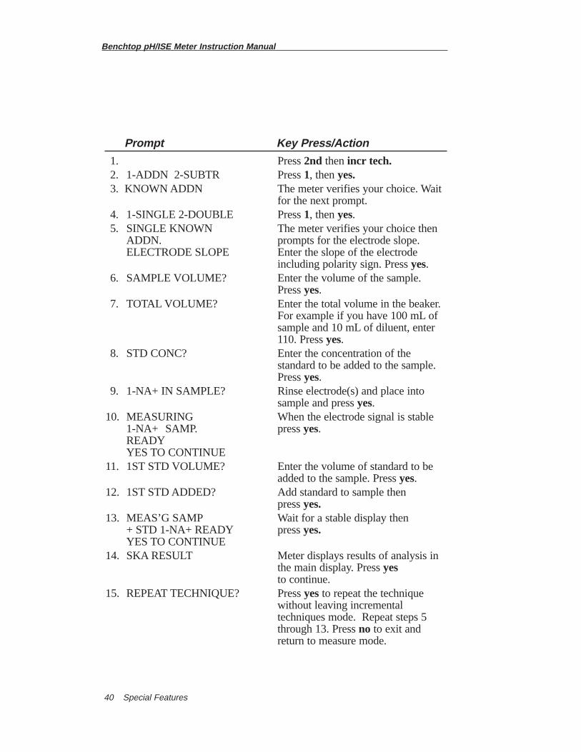
The following table is the sequence of keypresses and messages displayedwhen performing a known addition measurement. (Numbers and electrodeID used are for illustration purposes only.)
Benchtop pH/ISE Meter Instruction Manual
Special Features40
Prompt Key Press/Action
1. Press 2nd thenincr tech.2. 1-ADDN 2-SUBTR Press 1, then yes.3. KNOWN ADDN The meter verifies your choice. Wait
for the next prompt.4. 1-SINGLE 2-DOUBLE Press 1, thenyes. 5. SINGLE KNOWN The meter verifies your choice then
ADDN. prompts for the electrode slope.ELECTRODE SLOPE Enter the slope of the electrode
including polarity sign. Press yes.6. SAMPLE VOLUME? Enter the volume of the sample.
Press yes.7. TOTAL VOLUME? Enter the total volume in the beaker.
For example if you have 100 mL of sample and 10 mL of diluent, enter 110. Press yes.
8. STD CONC? Enter the concentration of the standard to be added to the sample. Press yes.
9. 1-NA+ IN SAMPLE? Rinse electrode(s) and place into sample and press yes.
10. MEASURING When the electrode signal is stable 1-NA+ SAMP. press yes.READYYES TO CONTINUE
11. 1ST STD VOLUME? Enter the volume of standard to be added to the sample. Press yes.
12. 1ST STD ADDED? Add standard to sample then press yes.
13. MEAS’G SAMP Wait for a stable display then + STD 1-NA+ READY press yes.YES TO CONTINUE
14. SKA RESULT Meter displays results of analysis in the main display. Press yesto continue.
15. REPEAT TECHNIQUE? Press yesto repeat the technique without leaving incremental techniques mode. Repeat steps 5 through 13. Pressno to exit and return to measure mode.
Benchtop pH/ISE Meter Instruction Manual
Special Features 41
Set-up
1. Refer to the appropriate electrode instruction manual for preparation of sensing and reference electrode(s), required solutions (ionic strengthadjusters, standards...), and any special requirements.
2. Securely connect electrode(s) to either input 1 or 2. The number of the input in use will appear directly before the electrode ID. For example, 1-Cl -. Select the appropriate input by pressing 2nd thenchannel.
3. Identify the electrode in use by pressing 2nd thenelectrode idand setup other instrument operating parameters.
4. If a single incremental technique is to be performed, determine the electrode slope from a previous calibration or as directed in the electrode instruction manual.
Single Incremental Techniques
Single incremental techniques are useful for occasional samples or sampleswith complex matrices. Another advantage of the single incrementaltechniques is that the electrodes are not moved from solution to solutionduring calibration and measurement. This eliminates errors due to solutioncarryover and static charge disturbance of the electrode membrane.
It is especially important to be sure that any complexing agent is present ingreat excess or not at all. The ratio of free ion to complexed ion mustremain constant over the addition. An indication that a complexing agent ispresent, but not in great enough quantity to maintain a constantfree/complexed ion ratio, is an abnormally high or low slope. If this is a suspected problem, an excess of complexing or decomplexing agent may be added to the original solution in the beaker prior to the incremental addition.
Benchtop pH/ISE Meter Instruction Manual
Special Features42
Electrode interferences should be at a minimum, the effect of theinterference may change as the concentration of the ion of interest changes.This situation may also result in high or low electrode slopes. It is possibleto reduce some electrode interferences. Consult the appropriate electrodeinstruction manual for specific information.
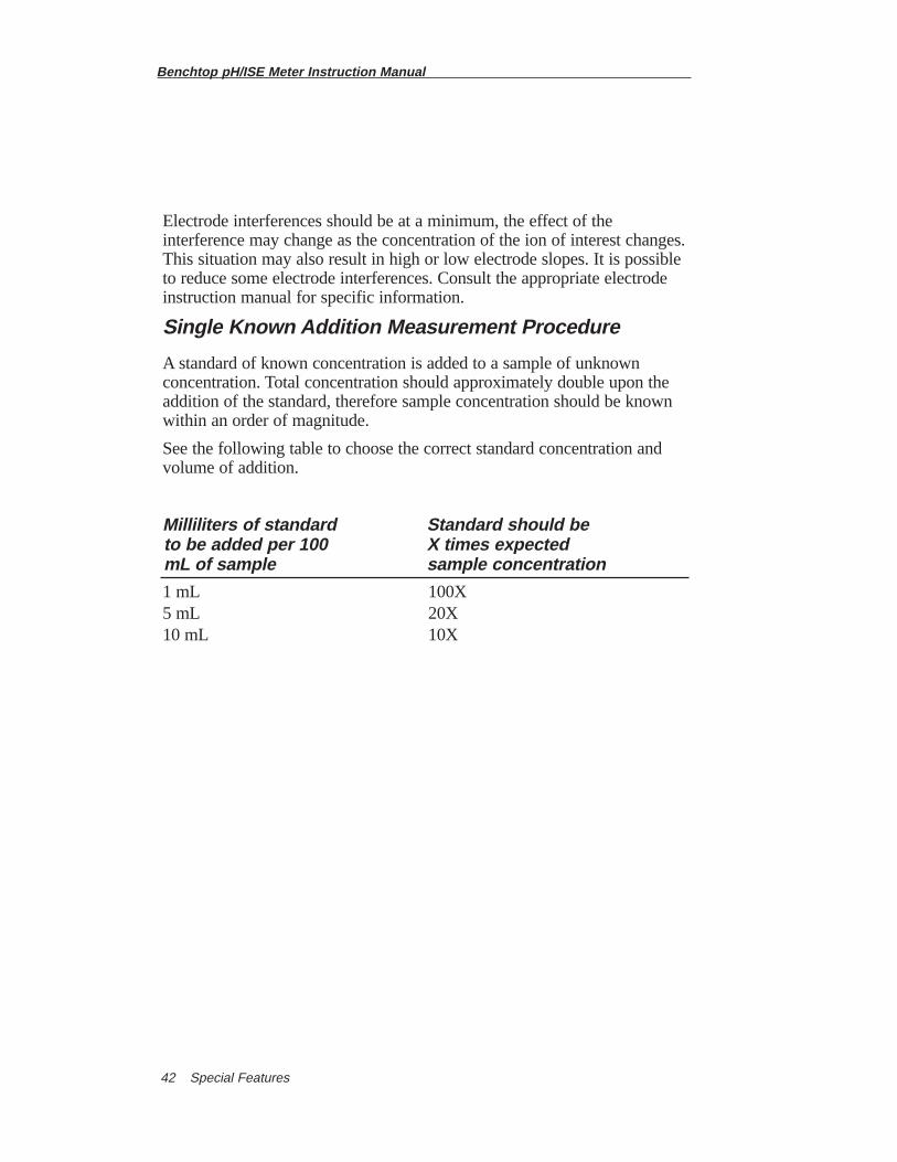
Single Known Addition Measurement Procedure
A standard of known concentration is added to a sample of unknownconcentration. Total concentration should approximately double upon theaddition of the standard, therefore sample concentration should be knownwithin an order of magnitude.
See the following table to choose the correct standard concentration andvolume of addition.
Milliliters of standard Standard should beto be added per 100 X times expected mL of sample sample concentration
1 mL 100X5 mL 20X10 mL 10X
Benchtop pH/ISE Meter Instruction Manual
Special Features 43
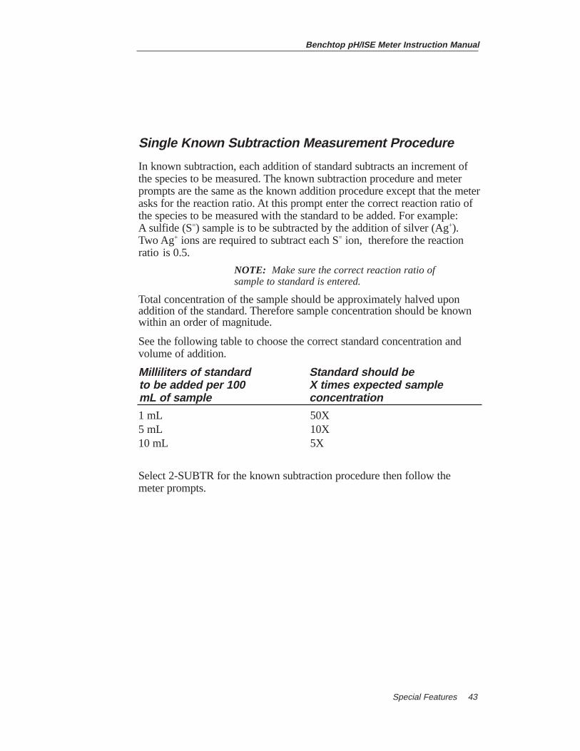
Single Known Subtraction Measurement Procedure
In known subtraction, each addition of standard subtracts an increment ofthe species to be measured. The known subtraction procedure and meterprompts are the same as the known addition procedure except that the meterasks for the reaction ratio. At this prompt enter the correct reaction ratio ofthe species to be measured with the standard to be added. For example: A sulfide (S=) sample is to be subtracted by the addition of silver (Ag+).Two Ag+ ions are required to subtract each S= ion, therefore the reactionratio is 0.5.
NOTE: Make sure the correct reaction ratio of sample to standard is entered.
Total concentration of the sample should be approximately halved uponaddition of the standard. Therefore sample concentration should be knownwithin an order of magnitude.
See the following table to choose the correct standard concentration andvolume of addition.
Milliliters of standard Standard should beto be added per 100 X times expected samplemL of sample concentration
1 mL 50X5 mL 10X10 mL 5X
Select 2-SUBTR for the known subtraction procedure then follow the meter prompts.
Benchtop pH/ISE Meter Instruction Manual
Special Features44
Double Incremental Techniques
Double incremental techniques allow sample concentration and electrodeslope to be determined simultaneously. This eliminates the requirement ofperforming a calibration or slope check before measurement as requiredwith direct measurement or single incremental techniques.
Double incremental techniques are useful for occasional samples orsamples with complex matrices. Another advantage of the doubleincremental techniques is that the electrodes are not moved from solutionto solution during calibration and measurement. This eliminates errors due to solution carryover and static charge disturbance of the electrode membrane.
It is especially important with double incremental techniques to be sure thatany complexing agent is present in great excess or not at all. The ratio offree ion to complexed ion must remain constant over both additions. Anindication that a complexing agent is present, but not in great enoughquantity to maintain a constant free/complexed ion ratio, is an abnormallyhigh or low slope. If this is a suspected problem, an excess of complexingor decomplexing agent may be added to the original solution in the beakerprior to the incremental additions.
Electrode interferences should be at a minimum, the effect of theinterference may change as the concentration of the ion of interest changes.This situation may also result in high or low electrode slopes. It is possibleto reduce some electrode interferences. Consult the appropriate electrodeinstruction manual for specific information.
Benchtop pH/ISE Meter Instruction Manual
Special Features 45
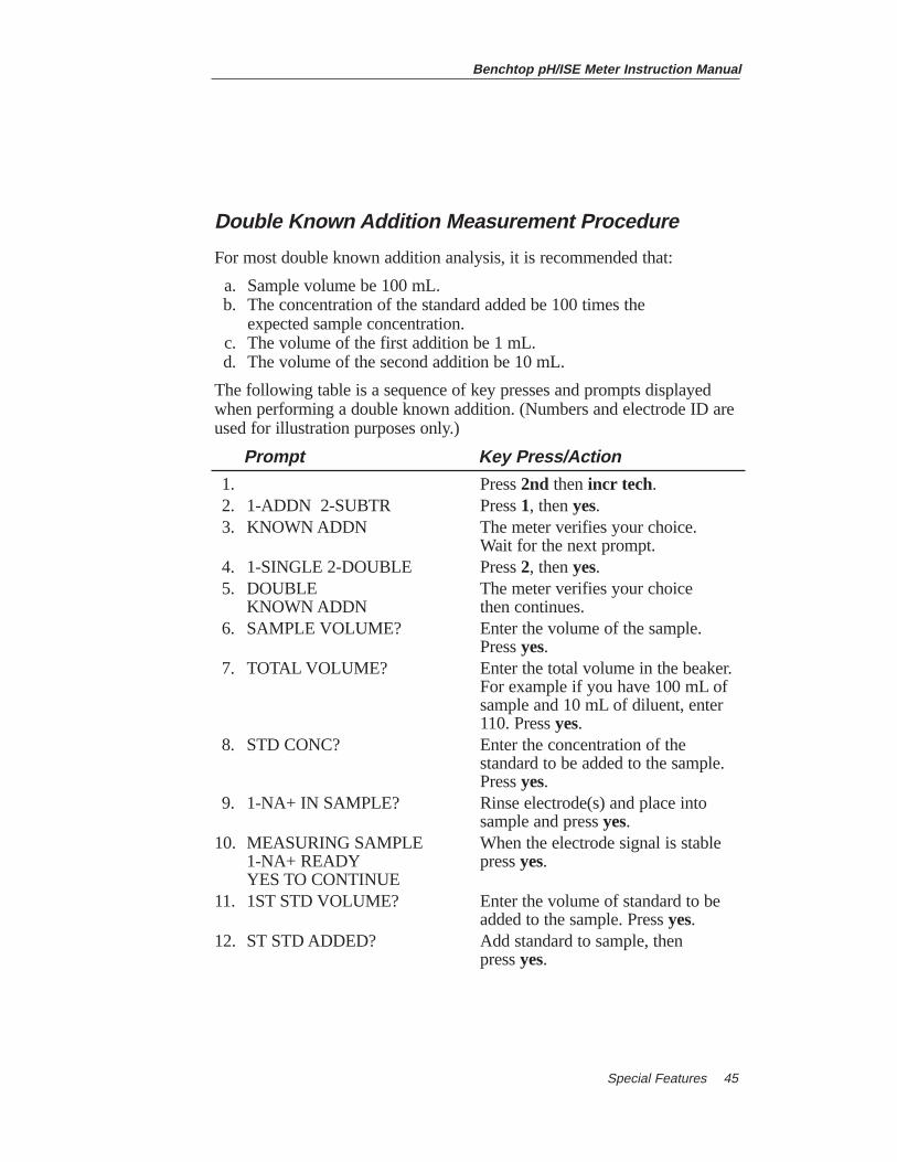
Double Known Addition Measurement Procedure
For most double known addition analysis, it is recommended that:
a. Sample volume be 100 mL.b. The concentration of the standard added be 100 times the
expected sample concentration.c. The volume of the first addition be 1 mL.d. The volume of the second addition be 10 mL.
The following table is a sequence of key presses and prompts displayedwhen performing a double known addition. (Numbers and electrode ID areused for illustration purposes only.)
Prompt Key Press/Action
1. Press 2nd thenincr tech.2. 1-ADDN 2-SUBTR Press 1, then yes.3. KNOWN ADDN The meter verifies your choice.
Wait for the next prompt.4. 1-SINGLE 2-DOUBLE Press 2, then yes.5. DOUBLE The meter verifies your choice
KNOWN ADDN then continues.6. SAMPLE VOLUME? Enter the volume of the sample.
Press yes.7. TOTAL VOLUME? Enter the total volume in the beaker.
For example if you have 100 mL of sample and 10 mL of diluent, enter 110. Press yes.
8. STD CONC? Enter the concentration of the standard to be added to the sample. Press yes.
9. 1-NA+ IN SAMPLE? Rinse electrode(s) and place into sample and press yes.
10. MEASURING SAMPLE When the electrode signal is stable 1-NA+ READY press yes.YES TO CONTINUE
11. 1ST STD VOLUME? Enter the volume of standard to be added to the sample. Press yes.
12. ST STD ADDED? Add standard to sample, then press yes.
Benchtop pH/ISE Meter Instruction Manual
Special Features46
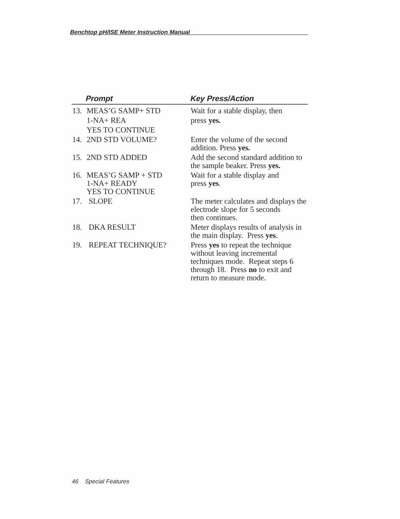
Prompt Key Press/Action
13. MEAS’G SAMP+ STD Wait for a stable display, then 1-NA+ REA press yes.YES TO CONTINUE
14. 2ND STD VOLUME? Enter the volume of the second addition. Pressyes.
15. 2ND STD ADDED Add the second standard addition to the sample beaker. Press yes.
16. MEAS’G SAMP + STD Wait for a stable display and 1-NA+ READY press yes. YES TO CONTINUE
17. SLOPE The meter calculates and displays theelectrode slope for 5 seconds then continues.
18. DKA RESULT Meter displays results of analysis in the main display. Pressyes.
19. REPEAT TECHNIQUE? Press yesto repeat the technique without leaving incremental techniques mode. Repeat steps 6 through 18. Press no to exit and return to measure mode.
Benchtop pH/ISE Meter Instruction Manual
Other Measurement Modes 47
Double Known Subtraction Measurement Procedure
In double known subtraction, each addition of standard subtracts anincrement of the species to be measured. The procedures and meterprompts are the same as for double known addition except the meterprompts for the reaction ratio. Enter the ratio at the meter prompt, thencontinue as usual.
Take care that subtraction ability of chosen standard concentration andvolume added does not exceed the concentration of sample.
For most double known subtraction analysis, it is recommended that:
a. Sample volume be 100 mL.
b. The concentration of the standard added be 50 times the expected sample concentration.
c. The volume of the first addition of standard be 1 mL.
d. The volume of the second addition of standard be 10 mL.
NOTE: Make sure the correct reaction ratio of sample to standard is entered.
For example: A sulfide (S=) sample is to be subtracted by the addition ofsilver (Ag+). Two Ag+ ions are required to subtract one S= ion, therefore thereaction ratio is 0.5.
Benchtop pH/ISE Meter Instruction Manual
Other Measurement Modes48
Chapter VIIIOther Measurement ModelsA. Temperature Measurement
The meters display temperature in the range -5.0 to +105˚C simultaneouslywith sample results. Whenever an ATC probe is connected, live temperaturemeasurements are displayed in the prompt line. For results greater than100˚C the tenth digit is deleted. On the Model 920Aplus Meter thetemperature appears after the channel designation and electrode ID.
Example: 1-pH 25.0˚C RDY.
For Temperature Compensation see pH Calibration.
Benchtop pH/ISE Meter Instruction Manual
Other Measurement Modes 49
B. Models 420Aplus, 710Aplus Millivolt Measurements
The Models 420Aplus and 710Aplus can be used to measure absolute orrelative millivolts. The millivolt modes are useful when performingpotentiometric titrations or preparing calibration curves. Detailedinstructions for any Thermo Orion electrode are given in the electrodeinstruction manual. Titration instructions are included in the Thermo OrionRedox Electrode (Model 9678 or 9778) Instruction Manual, or in standardanalytical chemistry texts.
Absolute Millivolts
Absolute millivolts are displayed with 0.1 mV resolution in the range of -1600.0 to +1600.0 mV.
Access the absolute millivolt mode by pressing mode until the mV modeindicator is displayed.
Relative Millivolts
Relative millivolts are displayed with 0.1 mV resolution over the range of-1999.9 to +1999.9 mV. (Absolute millivolt range ± 1600.0).
1. Access relative millivolt mode by pressing modeuntil the REL mVmode indicator is displayed.
2. Set the relative millivolt offset by pressing 2nd thencal. CALIBRATE and the current absolute millivolts will be displayed. Once the signal is stable, the meter displays 0.0. Use or to enter the desired value, or leave the setting at 0.0. Press yes. The meter automatically returns to MEASURE and all relative millivolt measurements will be based on the offset.
▼
▼
Benchtop pH/ISE Meter Instruction Manual
Other Measurement Modes50
C. Models 520Aplus, 525Aplus, 720Aplus, 920Aplus Millivolt Measurements
The Models 520Aplus, 525Aplus, 720Aplus, and 920Aplus may be used tomeasure absolute or relative millivolts. These modes may be used fortitrations, oxidation/reduction (redox) potential measurements or calibrationcurves. Detailed instructions for any Thermo Orion electrode are given inthe appropriate electrode instruction manual. Titration instructions areincluded in the Thermo Orion Redox Electrode (Model 9678 or 9778)instruction manual, or in standard analytical chemistry texts.
Absolute mV
To measure absolute millivolts, press modeuntil the mV mode indicator isdisplayed. The millivolt potential will be displayed in the main field andthe temperature will be displayed in the prompt line. The range is ±1600.0mV with a resolution of 0.1 mV.
Relative mV
The range is ± 1999.9 mV with the absolute range being ±1600.0 mV.
Relative mV Calibration
Prompt Key Press/Action
1. Press modeuntil RMV is displayed.2. 25.0˚C READY Press calibrate.3. CALIBRATE RMV Place electrode(s) in the standard.4. READING STANDARD Wait for a stable electrode response.5. READY 0.0 will be displayed in the
ENTER VALUE main display. Press yesif this is correct. Otherwise enter the desired value for the standard then press yes.
6. OFFSET IS 100.0 The offset is calculated and displayed.
7. 25.0˚C READY Rinse electrode(s) and place into sample.
NOTE: For Models 525Aplus, 720Aplus and 920Aplus, the channel number will be displayed in prompt line. For Model 920Aplus, the electrode ID will be displayed in prompt line.
Benchtop pH/ISE Meter Instruction Manual
Other Measurement Modes 51
D. Models 525Aplus, 720Aplus, 920Aplus Redox Measurements
Measurements with redox (oxidation-reduction potential) electrode(s) areperformed in the millivolt or relative millivolt modes. Perform the following steps
1. Securely connect electrode(s) to input 1 or 2.
2. For Model 920Aplus only:
a. Identify the electrode type as REDOX. Press 2nd thenelectrode id.
b. Select 25, redox, then press yes
3. Press modeuntil mV is displayed. Measure redox potentials directly from the meter display.
4. To set redox potential to a predetermined value, press modeuntil mV is displayed. Follow instructions for setting the relative millivolt offset.
Benchtop pH/ISE Meter Instruction Manual
Other Measurement Modes52
E. Model 410Aplus Dissolved Oxygen Measurements
Dissolved Oxygen measurements are displayed in ppm when the ThermoOrion Model 9708 Dissolved Oxygen Electrode (Cat. No. 970899) is usedwith the Thermo Orion Model 410Aplus Meter. Perform the followingsteps to prepare the meter and calibrate the electrode.
1. Connect the Model 9708 to meter and leave electrode mode switch “OFF”.
2. Disconnect ATC probe.
NOTE: ATC probe must notbe connected to the meter and the meter should be calibrated to pH 7 at 25.0˚C.
3. Press modeuntil MEASURE is displayed, if not already displayed.
4. Turn the mode switch on the electrode to BT CK. Good battery operation is indicated by a reading of 13.40 or greater on the meter.
5. Turn the mode switch on the electrode to ZERO. Use the zero calibration control on the electrode to set the meter to read 0.00.
6. Insert the reservoir (funnel) into a BOD bottle, containing enough water to just cover the bottom. Insert the electrode, making sure that the electrode tip is not immersed in the water and does not have water droplets clinging to the outside of the membrane. Let stand approximately 30 minutes to ensure water saturation of air in the BODbottle. This bottle should be used for storage between measurements.
7. Turn the electrode mode switch to the AIR position. If measurements are made at sea level, use the AIR calibration control on the electrode to set the pH meter reading to the prevailing barometric pressure in mm Hg (divided by 100). If the barometric pressure is unknown, the elevation is above sea level or the sample has a salinity greater than two parts per thousand, consult Table 1 found in the Model 9708 Instruction Manualto obtain the correct AIR setting.
8. Turn the electrode mode switch to H2O for sample analysis.
9. Record direct ppm reading from meter.
F. Model 420Aplus, 710Aplus Dissolved Oxygen Measurements
Dissolved Oxygen measurements are displayed in ppm when the Thermo OrionModel 9708 Dissolved Oxygen Electrode (Cat. No. 970899) is used with theThermo Orion Model 420Aplus and 710Aplus Meters. Perform the followingsteps to prepare the meter and calibrate the electrode.
Benchtop pH/ISE Meter Instruction Manual
Other Measurement Modes 53
1. Connect the Model 9708 to meter and leave electrode mode switch “OFF”.
2. Disconnect ATC probe.
NOTE: ATC probe must not be connected to the meter and the meter should be calibrated to pH 7 at 25.0˚C.
3. Press modeuntil the pH mode indicator is displayed.
4. If on, turn the hold feature (1-2 in the setup menu) off.
5. Press measure. Using or change the temperature value to 25.0˚C.
6. Press 2nd thencal. Enter the value 7.00 and press yes.
7. Press measure. The slope prompt, SLP, will be displayed in the lower field. Enter 100.0 and press yes. The meter automatically enters the measure mode.
8. Turn the mode switch on the electrode to BT CK. Good battery operation is indicated by a reading of 13.40 or greater on the meter.
9. Turn the mode switch on the electrode to ZERO. Use the zero calibration control on the electrode to set the meter to read 0.00.
10. Insert the reservoir (funnel) into a BOD bottle containing enough water to just cover the bottom. Insert the electrode, making sure that the electrode tip is not immersed in the water and does not have water droplets clinging to the outside of the membrane. Let stand approximately 30 minutes to ensure water saturation of air in the BOD bottle. This bottle should be used for storage between measurements.
11. Turn the electrode mode switch to the AIR position. If measurements are made at sea level, use the AIR calibration control on the electrode to set the pH meter reading to the prevailing barometric pressure in mm Hg (divided by 100). If the barometric pressure is unknown, the elevation is above sea level or the sample has a salinity greater than two parts per thousand, consult Table 1 found in the Model 9708 Instruction Manualto obtain the correct AIR setting.
12. Turn the electrode mode switch to H2O for sample analysis.
13. Record direct ppm reading from meter.
▼
▼
G. Models 520Aplus, 525Aplus, 720Aplus Dissolved Oxygen Measurements
Dissolved Oxygen measurements are displayed in ppm when the ThermoOrion 9708 Dissolved Oxygen Electrode (Cat. No. 970899) is used withthe Thermo Orion Models 520Aplus, 525Aplus and 720Aplus and920Aplus Meters. Perform the following steps to prepare the meter andcalibrate the electrode.
1. Connect the D.O. electrode Model 9708 to meter. Leave electrode mode switch “OFF”.
2. For the Models 525Aplus and 720Aplus select the correct channel by pressing 2nd thenchannel.
3. Disconnect ATC probe.
NOTE: ATC probe must notbe connected to the meter and the meter should be calibrated to pH 7 at 25.0˚C.
4. Press modeuntil pH mode indicator is displayed.
5. Press hold. Turn the hold feature off.
6. Pressmeasure. Press set temp. Enter 25.0 at the prompt and press yes.
7. Press calibrate. Enter 1 at the ENTER NO. OF BUFFER prompt and press yes.
8. Enter 7.00 to the CAL AS prompt and press yes.
9. At the slope prompt enter 100.0 and press yes.The meter automatically returns to measure mode.
10. Turn the mode switch on the electrode to BT CK. Good battery operation is indicated by a reading of 13.40 or greater on the meter.
11. Turn the mode switch on the electrode to ZERO. Use the zero calibration control on the electrode to set the meter to read 0.00.
Benchtop pH/ISE Meter Instruction Manual
Other Measurement Modes54
Benchtop pH/ISE Meter Instruction Manual
Other Measurement Modes 55
12. Insert the reservoir (funnel) into a BOD bottle containing enough water to just cover the bottom. Insert the electrode, making sure that the electrode tip is not immersed in the water and does not have water droplets clinging to the outside of the membrane. Let stand approximately 30 minutes to ensure water saturation of air in the BOD bottle. This bottle should be used for storage between measurements.
13. Turn the electrode mode switch to the AIR position. If measurements are being made at sea level, use the AIR calibration control on the electrode to set the pH meter reading to the prevailing barometric pressure in mm Hg (divided by 100). If the barometric pressure is unknown, the elevation is above sea level or the sample has a salinity greater than two parts per thousand, consult Table 1 found in the Model 9708 Instruction Manualto obtain the correct AIR setting. Turn the electrode mode switch to H2O for sample analysis.
14. Record direct ppm reading from meter.
Benchtop pH/ISE Meter Instruction Manual
Other Measurement Modes56
H. Model 920Aplus Dissolved Oxygen Measurements Dissolved Oxygen measurements are displayed in ppm when the Thermo Orion 9708 Dissolved Oxygen Electrode (Cat. No. 970899) is usedwith the Thermo Orion Model 920Aplus Meter. Perform the followingsteps to prepare the meter and calibrate the electrode.
1. Connect the D.O. electrode Model 9708 to meter. Leave electrode mode switch “OFF”.
2. Press 2nd thenchannel to select the correct channel.
3. Press 2nd thenelectrode id. Press 2 to select O2. Press yes.
4. Disconnect ATC probe.
NOTE: ATC probe must notbe connected to the meter and the meter should be calibrated to pH 7 at 25.0˚C.
5. Press mode until pH mode indicator is displayed.
6. Press hold. Turn thehold feature off.
7. Press measure. Press set temp. Enter 25.0 at the prompt and press yes.
8. Turn the mode switch on the electrode to BT CK. Good battery operation is indicated by a reading of 13.40 or greater on the meter.
9. Turn the mode switch on the electrode to ZERO. Use the zero calibration control on the electrode to set the meter to read 0.00.
10. Insert the reservoir (funnel) into a BOD bottle containing enough water to just cover the bottom. Insert the electrode, making sure that the electrode tip is not immersed in the water and does not have water droplets clinging to the outside of the membrane. Let stand approximately 30 minutes to ensure water saturation of air in the BOD bottle. This bottle should be used for storage between measurements.
11. Turn the electrode mode switch to the AIR position. If measurements are being made at sea level, use the AIR calibration control on the electrode to set the pH meter reading to the prevailing barometric pressure in mm Hg (divided by 100). If the barometric pressure is unknown, the elevation is above sea level or the sample has a salinity greater than two parts per thousand, consult Table 1 found in the Model 9708 Instruction Manualto obtain the correct AIR setting.
12. Turn the electrode mode switch to H2O for sample analysis.
13. Record direct ppm reading from meter.
Benchtop pH/ISE Meter Instruction Manual
Other Measurement Modes 57
I. Karl Fischer TitrationsA 10 microampere polarizing current is available for Karl Fischer or otherpolarized electrode titrations.
Use the Karl Fischer adapter, Thermo Orion Catalog Number 090048.
1. Insert KF electrode pin-tip connector into the KF adapter. Connect the other pin-tip of the electrode into the reference input.
2. Connect the BNC plug of the KF adapter to the BNC meter input.
3. Insert pin-tip connector of the KF adapter into KF input on the meter.
4. Select the mV mode and then press measure. On the Model 920Aplus identify the electrode as KF.
5. Perform titration.
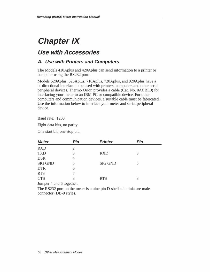
Benchtop pH/ISE Meter Instruction Manual
Other Measurement Modes58
Chapter IXUse with AccessoriesA. Use with Printers and Computers
The Models 410Aplus and 420Aplus can send information to a printer orcomputer using the RS232 port.
Models 520Aplus, 525Aplus, 710Aplus, 720Aplus, and 920Aplus have abi-directional interface to be used with printers, computers and other serialperipheral devices. Thermo Orion provides a cable (Cat. No. 0ACBL0) forinterfacing your meter to an IBM PC or compatible device. For othercomputers and communication devices, a suitable cable must be fabricated.Use the information below to interface your meter and serial peripheraldevice.
Baud rate: 1200.
Eight data bits, no parity
One start bit, one stop bit.
Meter Pin Printer Pin
RXD 2TXD 3 RXD 3DSR 4SIG GND 5 SIG GND 5DTR 6RTS 7CTS 8 RTS 8Jumper 4 and 6 together.The RS232 port on the meter is a nine pin D-shell subminiature maleconnector (DB-9 style).
Benchtop pH/ISE Meter Instruction Manual
Use with Accessories 59
Use with the 900A Printer
When used with the Thermo Orion 900A printer, the meter will provide aprinted record of results. The 900A printer can be battery operated orconnected to line power.
Plug the printer directly into the meter using the nine pin D shell connectoron the left side of the meter.
The meters have three print options:
Command Print
Prints current display.
Ready Print
Prints whenever the READY indicator is displayed.
Timed Print
Prints at selected timed intervals.
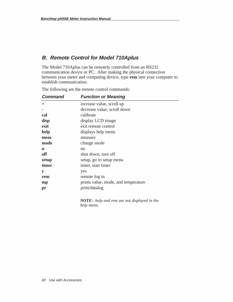
Benchtop pH/ISE Meter Instruction Manual
Use with Accessories60
B. Remote Control for Model 710Aplus
The Model 710Aplus can be remotely controlled from an RS232communication device or PC. After making the physical connectionbetween your meter and computing device, type rem into your computer toestablish communication.
The following are the remote control commands:
Command Function or Meaning
+ increase value, scroll up- decrease value, scroll downcal calibratedisp display LCD imageexit exit remote controlhelp displays help menumeas measuremode change moden nooff shut down, turn offsetup setup, go to setup menutimer timer, start timery yesrem remote log inmp prints value, mode, and temperaturepr print/datalog
NOTE: help and rem are not displayed in the help menu.
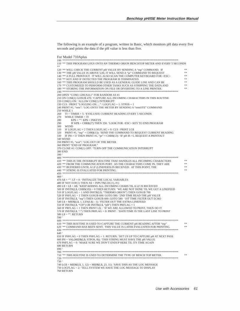
Benchtop pH/ISE Meter Instruction Manual
Use with Accessories 61
The following is an example of a program, written in Basic, which monitors pH data every fiveseconds and prints the data if the pH value is less than five.
For Model 710Aplus100 ‘************************************************************************************110 ‘** THIS PROGRAM LOGS ONTO AN THERMO ORION BENCHTOP METER AND EVERY 5 SECONDS **120 ‘** WILL CHECK THE CURRENT pH VALUE BY SENDING A “mp” COMMAND. IF **130 ‘** THE pH VALUE IS ABOVE 5.00, IT WILL SEND A “pr” COMMAND TO REQUEST **140 ‘** A FULL PRINTOUT. IT WILL ALSO SCAN THE COMPUTER KEYBOARD FOR <ESC> **150 ‘** KEY AND IF DETECTED THE PROGRAM IS TERMINATED. **160 ‘** THIS PROGRAM SHOULD BE USED AS A GENERAL GUIDE LINE AND CAN BE **170 ‘** CUSTOMIZED TO PERFORM OTHER TASKS SUCH AS STRIPPING THE DATA AND **180 ‘** STORING THE INFORMATION ON FILE OR DIVERTING TO A LINE PRINTER. **190 ‘************************************************************************************200 OPEN “COM1:1200,N,8,1” FOR RANDOM AS #1210 ON COM(1) GOSUB 470: ‘CAPTURE ALL INCOMING CHARACTERS IN THIS ROUTINE220 COM(1) ON: ‘ALLOW COM(1) INTERRUPT230 CLS : PRINT “LOGGING ON.....”: LOGFLAG = 1: STPOS = 1240 PRINT #1, “rem”: ‘LOG ONTO THE METER BY SENDING A “remOTE” COMMAND250 WHILE 1260 TI = TIMER + 5: ‘EVALUATE CURRENT READING EVERY 5 SECONDS270 WHILE TIMER < TI280 KP$ = “”: KP$ = INKEY$290 IF KP$ = CHR$(27) THEN 350: ‘LOOK FOR <ESC> KEY TO END PROGRAM300 WEND310 IF LOGFLAG = 2 THEN LOGFLAG = 0: CLS : PRINT LG$320 PRINT #1, “mp” + CHR$(13): ‘SEND THE COMMAND TO REQUEST CURRENT READING330 IF PH > 5! THEN PRINT #1, “pr” + CHR$(13): ‘IF pH IS >5, REQUEST A PRINTOUT340 WEND350 PRINT #1, “exit”: ‘LOG OUT OF THE METER360 PRINT “END OF PROGRAM.”370 CLOSE #1: COM(1) OFF: ‘TURN OFF THE COMMUNICATION INTERRUPT380 END390 ‘400 ‘************************************************************************************410 ‘** THIS IS THE INTERRUPT ROUTINE THAT HANDLES ALL INCOMING CHARACTERS **420 ‘** FROM THE COMMUNICATION PORT. AS THE CHARACTERS COME IN, THEY ARE **430 ‘** BUFFERED UNTIL A LF (LINEFEED) IS RECEIVED. AT THIS POINT, THE **440 ‘** STRING IS EVALUATED FOR PRINTING. **450 ‘************************************************************************************460 ‘470 A$ = “”: LF = 0: ‘INITIALIZE THE LOCAL VARIABLES480 IF NOT EOF(1) THEN A$ = INPUT$(LOC(1), #1)490 L$ = L$ + A$: ‘KEEP ADDING ALL INCOMING CHARS TIL A LF IS RECEIVED500 IF INSTR(L$, CHR$(10)) = 0 THEN RETURN: ‘WE ARE NOT DONE TIL WE GET A LINEFEED510 IF LOGFLAG = 1 AND INSTR(L$, “THERMO ORION”) THEN GOSUB 700520 IF PHFLAG = 1 THEN GOSUB 600: GOTO 580: ‘2ND TIME READ THE pH VALUE530 IF INSTR(L$, “mp”) THEN GOSUB 600: GOTO 580: ‘1ST TIME FILTER OUT ECHO540 L$ = MID$(L$, 1, LEN(L$) - 1): ‘FILTER OUT THE EXTRA LINEFEED550 IF INSTR(L$, “CH”) OR INSTR(L$, “pH”) THEN PRFLAG = 1560 IF PRFLAG = 1 THEN PRINT L$; : ‘IF WE ARE ALLOWED TO PRINT, THEN DO IT570 IF INSTR(L$, “:”) THEN PRFLAG = 0: PRINT : ‘DATE/TIME IS THE LAST LINE TO PRINT580 L$ = “”: RETURN590 ‘600 ‘************************************************************************************610 ‘** THIS ROUTINE IS USED TO CAPTURE THE CURRENT pH READING AFTER “mp” **620 ‘** COMMAND HAS BEEN SENT. THIS VALUE IS LATER EVALUATED FOR PRINTING. **630 ‘************************************************************************************640 ‘650 IF PHFLAG = 0 THEN PHFLAG = 1: RETURN: ‘SET US UP TO CAPTURE pH AT NEXT PASS660 PH = VAL(MID$(L$, STPOS, 8)): ‘THIS STRING MUST HAVE THE pH VALUE670 PHFLAG = 0: ‘MAKE SURE WE DON’T ENDUP HERE TIL ITS TIME AGAIN680 RETURN690 ‘700 ‘************************************************************************************710 ‘** THIS ROUTINE IS USED TO DETERMINE THE TYPE OF BENCH TOP METER. **720 ‘************************************************************************************730 ‘740 LG$ = MID$(L$, 1, 12) + MID$(L$, 23, 11): ‘SAVE THIS AS THE LOG MESSAGE750 LOGFLAG = 2: ‘TELL SYSTEM WE HAVE THE LOG MESSAGE TO DISPLAY760 RETURN
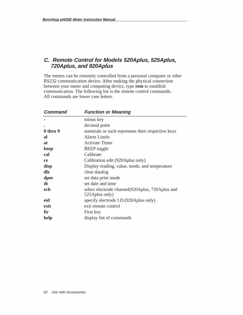
Benchtop pH/ISE Meter Instruction Manual
Use with Accessories62
C. Remote Control for Models 520Aplus, 525Aplus, 720Aplus, and 920Aplus
The meters can be remotely controlled from a personal computer or otherRS232 communication device. After making the physical connectionbetween your meter and computing device, type rem to establishcommunication. The following list is the remote control commands. All commands are lower case letters.
Command Function or Meaning
- minus key. decimal point0 thru 9 numerals or each represents their respective keysal Alarm Limitsat Activate Timerbeep BEEP togglecal Calibratece Calibration edit (920Aplus only)disp Display reading, value, mode, and temperaturedlz clear datalogdpm set data print modedt set date and timeech select electrode channel(920Aplus, 720Aplus and
525Aplus only)eid specify electrode I.D.(920Aplus only)exit exit remote controlfir First keyhelp display list of commands
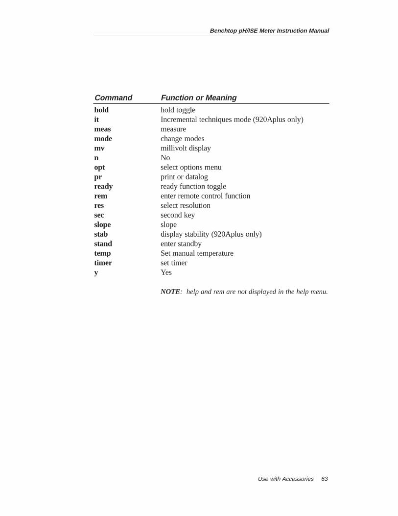
Benchtop pH/ISE Meter Instruction Manual
Use with Accessories 63
Command Function or Meaning
hold hold toggleit Incremental techniques mode (920Aplus only)meas measuremode change modesmv millivolt displayn Noopt select options menupr print or datalogready ready function togglerem enter remote control functionres select resolutionsec second keyslope slopestab display stability (920Aplus only)stand enter standbytemp Set manual temperaturetimer set timery Yes
NOTE: help and rem are not displayed in the help menu.
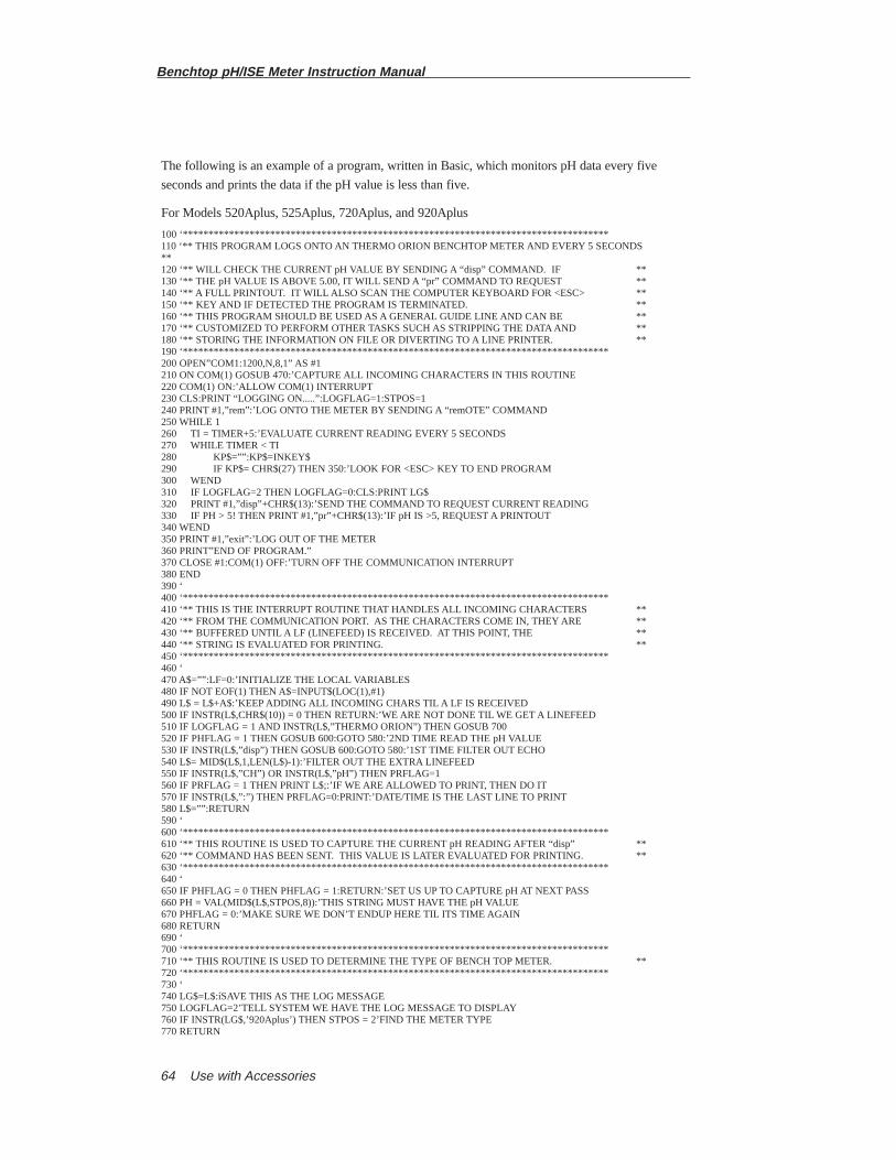
Benchtop pH/ISE Meter Instruction Manual
Use with Accessories64
The following is an example of a program, written in Basic, which monitors pH data every five
seconds and prints the data if the pH value is less than five.
For Models 520Aplus, 525Aplus, 720Aplus, and 920Aplus
100 ‘***********************************************************************************110 ‘** THIS PROGRAM LOGS ONTO AN THERMO ORION BENCHTOP METER AND EVERY 5 SECONDS ** 120 ‘** WILL CHECK THE CURRENT pH VALUE BY SENDING A “disp” COMMAND. IF ** 130 ‘** THE pH VALUE IS ABOVE 5.00, IT WILL SEND A “pr” COMMAND TO REQUEST ** 140 ‘** A FULL PRINTOUT. IT WILL ALSO SCAN THE COMPUTER KEYBOARD FOR <ESC> ** 150 ‘** KEY AND IF DETECTED THE PROGRAM IS TERMINATED. ** 160 ‘** THIS PROGRAM SHOULD BE USED AS A GENERAL GUIDE LINE AND CAN BE ** 170 ‘** CUSTOMIZED TO PERFORM OTHER TASKS SUCH AS STRIPPING THE DATA AND ** 180 ‘** STORING THE INFORMATION ON FILE OR DIVERTING TO A LINE PRINTER. ** 190 ‘***********************************************************************************200 OPEN”COM1:1200,N,8,1” AS #1 210 ON COM(1) GOSUB 470:’CAPTURE ALL INCOMING CHARACTERS IN THIS ROUTINE 220 COM(1) ON:’ALLOW COM(1) INTERRUPT230 CLS:PRINT “LOGGING ON.....”:LOGFLAG=1:STPOS=1240 PRINT #1,”rem”:’LOG ONTO THE METER BY SENDING A “remOTE” COMMAND250 WHILE 1260 TI = TIMER+5:’EVALUATE CURRENT READING EVERY 5 SECONDS270 WHILE TIMER < TI280 KP$=””:KP$=INKEY$290 IF KP$= CHR$(27) THEN 350:’LOOK FOR <ESC> KEY TO END PROGRAM300 WEND310 IF LOGFLAG=2 THEN LOGFLAG=0:CLS:PRINT LG$ 320 PRINT #1,”disp”+CHR$(13):’SEND THE COMMAND TO REQUEST CURRENT READING 330 IF PH > 5! THEN PRINT #1,”pr”+CHR$(13):’IF pH IS >5, REQUEST A PRINTOUT340 WEND 350 PRINT #1,”exit”:’LOG OUT OF THE METER360 PRINT”END OF PROGRAM.” 370 CLOSE #1:COM(1) OFF:’TURN OFF THE COMMUNICATION INTERRUPT380 END 390 ‘ 400 ‘*********************************************************************************** 410 ‘** THIS IS THE INTERRUPT ROUTINE THAT HANDLES ALL INCOMING CHARACTERS ** 420 ‘** FROM THE COMMUNICATION PORT. AS THE CHARACTERS COME IN, THEY ARE ** 430 ‘** BUFFERED UNTIL A LF (LINEFEED) IS RECEIVED. AT THIS POINT, THE ** 440 ‘** STRING IS EVALUATED FOR PRINTING. ** 450 ‘*********************************************************************************** 460 ‘ 470 A$=””:LF=0:’INITIALIZE THE LOCAL VARIABLES 480 IF NOT EOF(1) THEN A$=INPUT$(LOC(1),#1) 490 L$ = L$+A$:’KEEP ADDING ALL INCOMING CHARS TIL A LF IS RECEIVED 500 IF INSTR(L$,CHR$(10)) = 0 THEN RETURN:’WE ARE NOT DONE TIL WE GET A LINEFEED 510 IF LOGFLAG = 1 AND INSTR(L$,”THERMO ORION”) THEN GOSUB 700520 IF PHFLAG = 1 THEN GOSUB 600:GOTO 580:’2ND TIME READ THE pH VALUE530 IF INSTR(L$,”disp”) THEN GOSUB 600:GOTO 580:’1ST TIME FILTER OUT ECHO 540 L$= MID$(L$,1,LEN(L$)-1):’FILTER OUT THE EXTRA LINEFEED 550 IF INSTR(L$,”CH”) OR INSTR(L$,”pH”) THEN PRFLAG=1 560 IF PRFLAG = 1 THEN PRINT L$;:’IF WE ARE ALLOWED TO PRINT, THEN DO IT570 IF INSTR(L$,”:”) THEN PRFLAG=0:PRINT:’DATE/TIME IS THE LAST LINE TO PRINT580 L$=””:RETURN 590 ‘ 600 ‘*********************************************************************************** 610 ‘** THIS ROUTINE IS USED TO CAPTURE THE CURRENT pH READING AFTER “disp” ** 620 ‘** COMMAND HAS BEEN SENT. THIS VALUE IS LATER EVALUATED FOR PRINTING. ** 630 ‘*********************************************************************************** 640 ‘ 650 IF PHFLAG = 0 THEN PHFLAG = 1:RETURN:’SET US UP TO CAPTURE pH AT NEXT PASS 660 PH = VAL(MID$(L$,STPOS,8)):’THIS STRING MUST HAVE THE pH VALUE670 PHFLAG = 0:’MAKE SURE WE DON’T ENDUP HERE TIL ITS TIME AGAIN680 RETURN690 ‘700 ‘*********************************************************************************** 710 ‘** THIS ROUTINE IS USED TO DETERMINE THE TYPE OF BENCH TOP METER. **720 ‘***********************************************************************************730 ‘740 LG$=L$:íSAVE THIS AS THE LOG MESSAGE750 LOGFLAG=2’TELL SYSTEM WE HAVE THE LOG MESSAGE TO DISPLAY760 IF INSTR(LG$,’920Aplus’) THEN STPOS = 2’FIND THE METER TYPE770 RETURN
Benchtop pH/ISE Meter Instruction Manual
Use with Accessories 65
D. Use with Model 607 Electrode Switchbox
When the Model 607 electrode switchbox is connected to the 920AplusMeter, up to seven electrodes can be used. Up to seven differentcalibrations will be stored in memory until the user repeats a calibration.
1. Connect the BNC cable from the BNC output of the Switchbox to the No. 2 BNC jack on the rear of the 920Aplus Meter. Connect the grounding cable from the switchbox to the meter ground.
NOTE: Do not connect the RS232 cable that comes with the 607. This cable is not used in this application.
2. Plug an appropriate line converter into a standard 110V or 220V AC, 50/60 Hz wall outlet into the jack labeled power on the Switchbox.
3. Press 2nd thenoptions on the 920Aplus Meter to access the options menu. Identify the use of a switchbox in the options menu.
Once the instrument and switchbox have been interfaced, pressing 2nd thenchannelchanges channels on the meter. The meter will step through allchannels 1 through 7 in turn. Verify the calibration of each channel per the607 Instruction Manual. To change the channel on the switchbox presschannel selection on the front of the 607 until the channel indicatormatches the one on the meter, except for channel 1 that is not displayed onthe switchbox.
The Model 607 electrode switchbox may also be used with meter Models520Aplus, 525Aplus, and 720Aplus. However, these instruments will notstore calibration curves in memory. Connect the switchbox to channel one(520Aplus) or two (525Aplus and 720Aplus) then follow steps 1 and 2 above.
Benchtop pH/ISE Meter Instruction Manual
Use with Accessories66
E. Use with Strip Chart Recorders
The Models 520Aplus, 525Aplus, 720Aplus, and 920Aplus can be usedwith a strip chart recorder. The audio jack on the rear panel provides anoutput for a strip chart recorder of absolute millivolts independent ofoperating mode. On the 525Aplus, 720Aplus and 920Aplus this output isfor channel one only.
The voltage provided is a direct uncompensated readout of the electroderesponse, set at a one to one ratio.
To interface your recorder to the meter, a 2.5 mm phone plug is required.The tip (inner) connection should be wired to the high side of the recorderand the sleeve (outer) connection should be wired to the low side of therecorder. A Switchcraft type 850 or equivalent phone plug is suggested.
F. Use with DataCOLLECT™
DataCOLLECT can be used with Models 520Aplus, 525Aplus, 720Aplus,and 920Aplus.
DataCOLLECT is a program that can be easily installed for yourunattended PC to collect data from Thermo Orion’s family ISE, pH,Conductivity and Dissolved Oxygen (DO) meters from up to 4 serial portssimultaneously.
This software operates in Windows® 3.1†, Windows 95 an Windows NTversion 4 Platforms.
DataCOLLECT collects the data generated by the meter, which is passed tothe PC via RS232 output. The required computer interface cable, Cat.No.0ACBLO, is included with the DataCOLLECT software package.DataCOLLECT also allows you to export the data received into programssuch as Excel†, Lotus††, and Access† for your convenience.
(†Registered Trademark of Microsoft Corporation)(††Registered Trademark of Lotus Development Corporation)
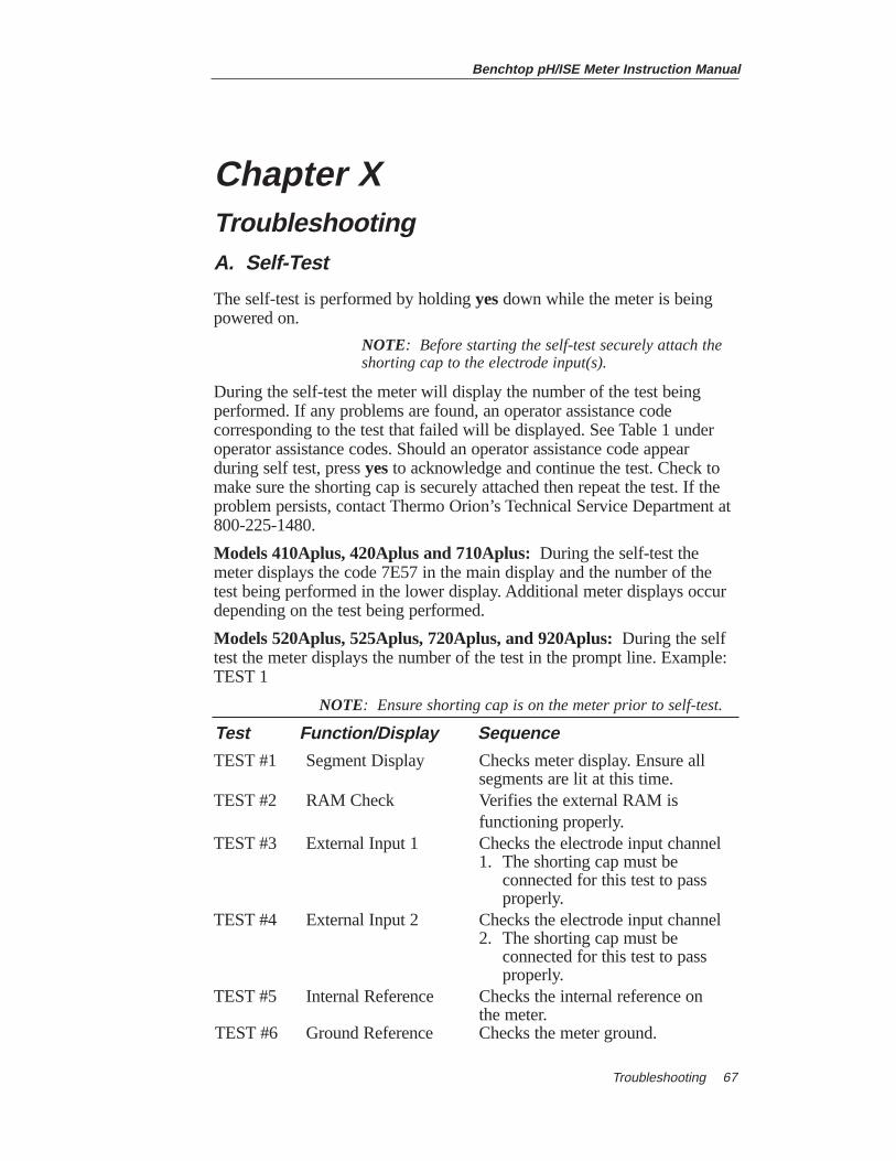
Benchtop pH/ISE Meter Instruction Manual
Troubleshooting 67
Chapter XTroubleshootingA. Self-Test
The self-test is performed by holding yesdown while the meter is beingpowered on.
NOTE: Before starting the self-test securely attach the shorting cap to the electrode input(s).
During the self-test the meter will display the number of the test beingperformed. If any problems are found, an operator assistance codecorresponding to the test that failed will be displayed. See Table 1 underoperator assistance codes. Should an operator assistance code appearduring self test, press yesto acknowledge and continue the test. Check tomake sure the shorting cap is securely attached then repeat the test. If theproblem persists, contact Thermo Orion’s Technical Service Department at 800-225-1480.
Models 410Aplus, 420Aplus and 710Aplus:During the self-test themeter displays the code 7E57 in the main display and the number of thetest being performed in the lower display. Additional meter displays occurdepending on the test being performed.
Models 520Aplus, 525Aplus, 720Aplus, and 920Aplus: During the selftest the meter displays the number of the test in the prompt line. Example:TEST 1
NOTE: Ensure shorting cap is on the meter prior to self-test.
Test Function/Display Sequence
TEST #1 Segment Display Checks meter display. Ensure all segments are lit at this time.
TEST #2 RAM Check Verifies the external RAM is functioning properly.
TEST #3 External Input 1 Checks the electrode input channel 1. The shorting cap must be
connected for this test to pass properly.
TEST #4 External Input 2 Checks the electrode input channel 2. The shorting cap must be
connected for this test to pass properly.
TEST #5 Internal Reference Checks the internal reference on the meter.
TEST #6 Ground Reference Checks the meter ground.

Benchtop pH/ISE Meter Instruction Manual
Troubleshooting68
Test Function/Display Sequence
TEST #7 Keypad Test Checks that the keypad is functioning properly. During this test, each key must be pressed, one at a time, at the 0 prompt for Models 410Aplus, 420Aplus and 710Aplus, and PRESSALL KEYS for Models 520Aplus, 525Aplus, 720Aplus and 920Aplus. If no keys are pressed, or there is a problem with a key, the meter will recognize an error and display E-7 for Models 420Aplus and 710Aplus, and ERROR 7 for Models 520Aplus, 525Aplus, 720Aplus, and 920Aplus. Press yesto continue.
TEST #8 Autoshutoff Test Checks the meter autoshutoff feature. The display clears then the meter shuts off. After a brief interval the meter will turn on again and resume normal operation.
NOTE: If any operator assistance codes appear make a note of each, then press yesto continue.
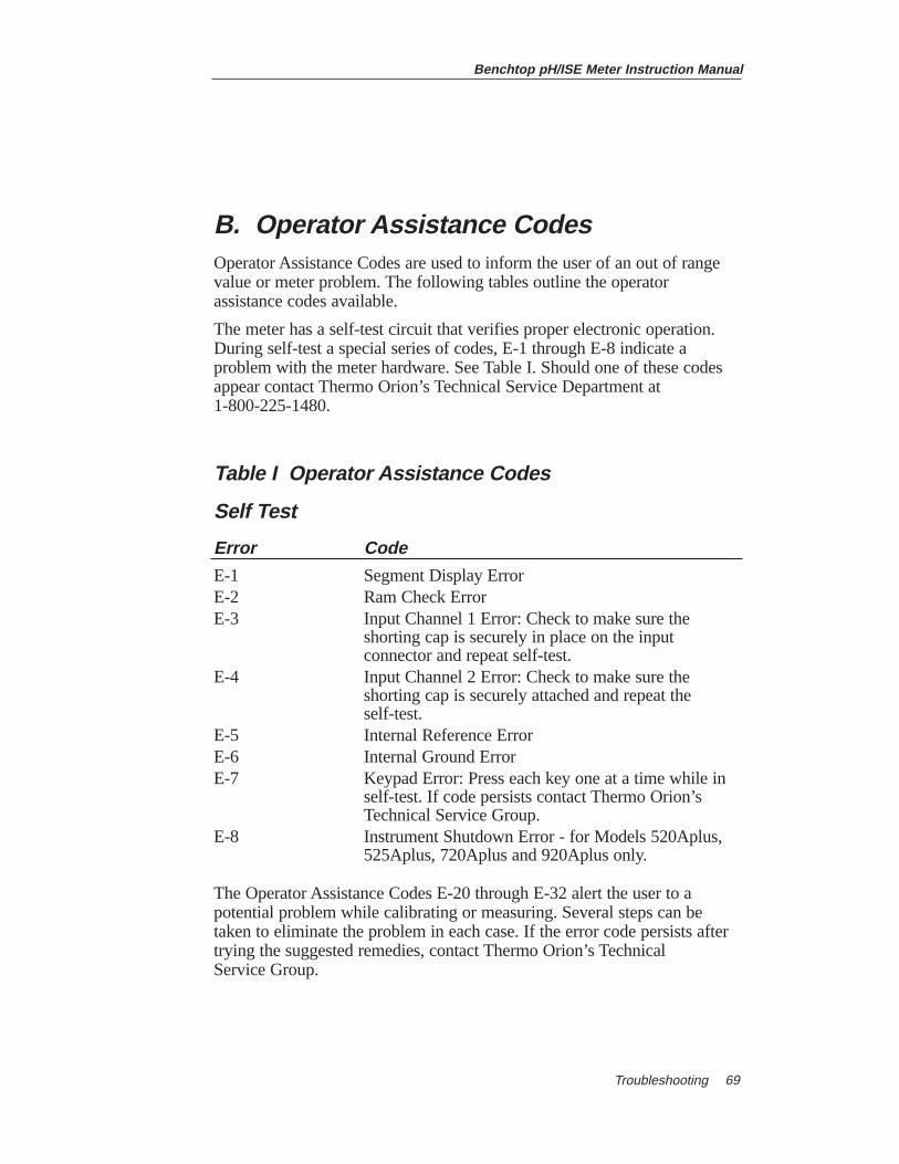
Benchtop pH/ISE Meter Instruction Manual
Troubleshooting 69
B. Operator Assistance CodesOperator Assistance Codes are used to inform the user of an out of rangevalue or meter problem. The following tables outline the operatorassistance codes available.
The meter has a self-test circuit that verifies proper electronic operation.During self-test a special series of codes, E-1 through E-8 indicate aproblem with the meter hardware. See Table I. Should one of these codesappear contact Thermo Orion’s Technical Service Department at 1-800-225-1480.
Table I Operator Assistance Codes
Self Test
Error Code
E-1 Segment Display ErrorE-2 Ram Check ErrorE-3 Input Channel 1 Error: Check to make sure the
shorting cap is securely in place on the input connector and repeat self-test.
E-4 Input Channel 2 Error: Check to make sure the shorting cap is securely attached and repeat the self-test.
E-5 Internal Reference ErrorE-6 Internal Ground ErrorE-7 Keypad Error: Press each key one at a time while in
self-test. If code persists contact Thermo Orion’sTechnical Service Group.
E-8 Instrument Shutdown Error - for Models 520Aplus, 525Aplus, 720Aplus and 920Aplus only.
The Operator Assistance Codes E-20 through E-32 alert the user to apotential problem while calibrating or measuring. Several steps can betaken to eliminate the problem in each case. If the error code persists aftertrying the suggested remedies, contact Thermo Orion’s Technical Service Group.
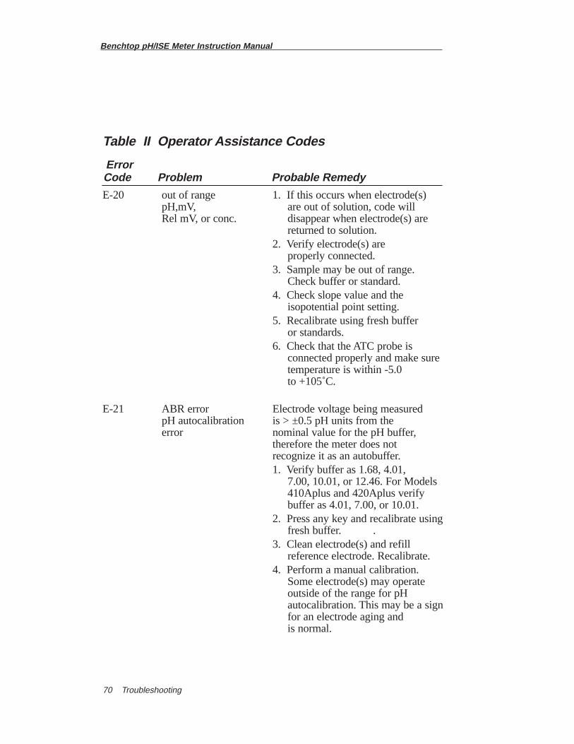
Table II Operator Assistance Codes
Error Code Problem Probable Remedy
E-20 out of range 1. If this occurs when electrode(s)pH,mV, are out of solution, code will Rel mV, or conc. disappear when electrode(s) are
returned to solution.2. Verify electrode(s) are
properly connected.3. Sample may be out of range.
Check buffer or standard.4. Check slope value and the
isopotential point setting.5. Recalibrate using fresh buffer
or standards.6. Check that the ATC probe is
connected properly and make sure temperature is within -5.0 to +105˚C.
E-21 ABR error Electrode voltage being measured pH autocalibration is > ±0.5 pH units from the error nominal value for the pH buffer,
therefore the meter does not recognize it as an autobuffer.1. Verify buffer as 1.68, 4.01,
7.00, 10.01, or 12.46. For Models 410Aplus and 420Aplus verify buffer as 4.01, 7.00, or 10.01.
2. Press any key and recalibrate using fresh buffer. .
3. Clean electrode(s) and refill reference electrode. Recalibrate.
4. Perform a manual calibration. Some electrode(s) may operate outside of the range for pH autocalibration. This may be a signfor an electrode aging and is normal.
Benchtop pH/ISE Meter Instruction Manual
Troubleshooting70
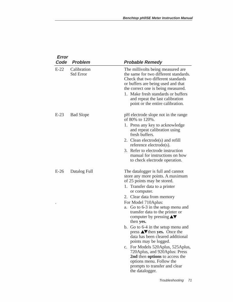
Benchtop pH/ISE Meter Instruction Manual
Troubleshooting 71
Error Code Problem Probable Remedy
E-22 Calibration The millivolts being measured are Std Error the same for two different standards.
Check that two different standards or buffers are being used and that the correct one is being measured.1. Make fresh standards or buffers
and repeat the last calibration point or the entire calibration.
E-23 Bad Slope pH electrode slope not in the range of 80% to 120%.1. Press any key to acknowledge
and repeat calibration using fresh buffers.
2. Clean electrode(s) and refill reference electrode(s).
3. Refer to electrode instruction manual for instructions on how to check electrode operation.
E-26 Datalog Full The datalogger is full and cannot store any more points. A maximum of 25 points may be stored.1. Transfer data to a printer
or computer.2. Clear data from memory
. For Model 710Aplus:a. Go to 6-3 in the setup menu and
transfer data to the printer or computer by pressing then yes.
b. Go to 6-4 in the setup menu and press then yes. Once the data has been cleared additional points may be logged.
c. For Models 520Aplus, 525Aplus,720Aplus, and 920Aplus: Press 2nd then options to access the options menu. Follow the prompts to transfer and clear the datalogger.
▼
▼
▼
▼
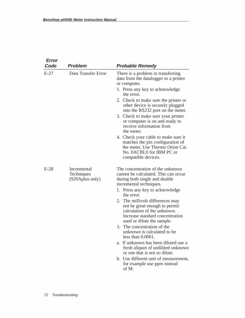
Benchtop pH/ISE Meter Instruction Manual
Troubleshooting72
Error Code Problem Probable Remedy
E-27 Data Transfer Error There is a problem in transferring data from the datalogger to a printer or computer.1. Press any key to acknowledge
the error.2. Check to make sure the printer or
other device is securely plugged into the RS232 port on the meter.
3. Check to make sure your printer or computer is on and ready to receive information from the meter.
4. Check your cable to make sure itmatches the pin configuration ofthe meter. Use Thermo Orion Cat.No. 0ACBL0 for IBM PC orcompatible devices.
E-28 Incremental The concentration of the unknown Techniques cannot be calculated. This can occur (920Aplus only) during both single and double
incremental techniques.1. Press any key to acknowledge
the error.2. The millivolt differences may
not be great enough to permit calculation of the unknown. Increase standard concentration used or dilute the sample.
3. The concentration of the unknown is calculated to be less than 0.0001.
a. If unknown has been diluted use a fresh aliquot of undilited unknownor one that is not so dilute.
b. Use different unit of measurement,for example use ppm instead of M.
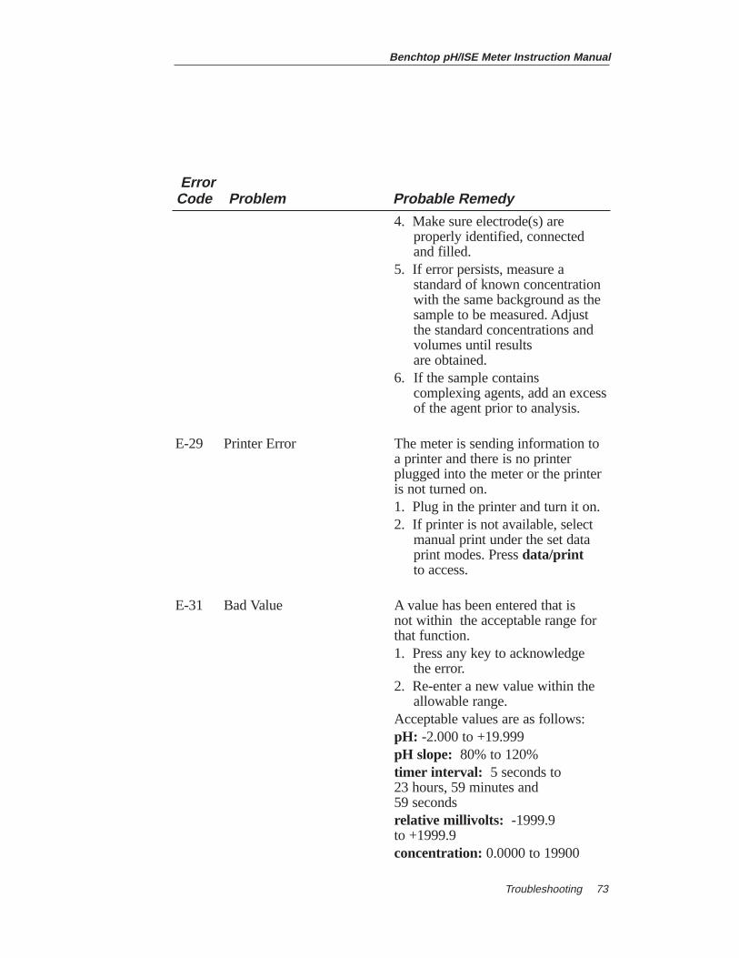
Benchtop pH/ISE Meter Instruction Manual
Troubleshooting 73
Error Code Problem Probable Remedy
4. Make sure electrode(s) are properly identified, connected and filled.
5. If error persists, measure a standard of known concentration with the same background as the sample to be measured. Adjust the standard concentrations and volumes until results are obtained.
6. If the sample contains complexing agents, add an excessof the agent prior to analysis.
E-29 Printer Error The meter is sending information to a printer and there is no printer plugged into the meter or the printer is not turned on.1. Plug in the printer and turn it on.2. If printer is not available, select
manual print under the set data print modes. Press data/printto access.
E-31 Bad Value A value has been entered that is not within the acceptable range for that function.1. Press any key to acknowledge
the error.2. Re-enter a new value within the
allowable range. Acceptable values are as follows:pH: -2.000 to +19.999pH slope: 80% to 120%timer interval: 5 seconds to 23 hours, 59 minutes and 59 seconds relative millivolts: -1999.9 to +1999.9 concentration: 0.0000 to 19900
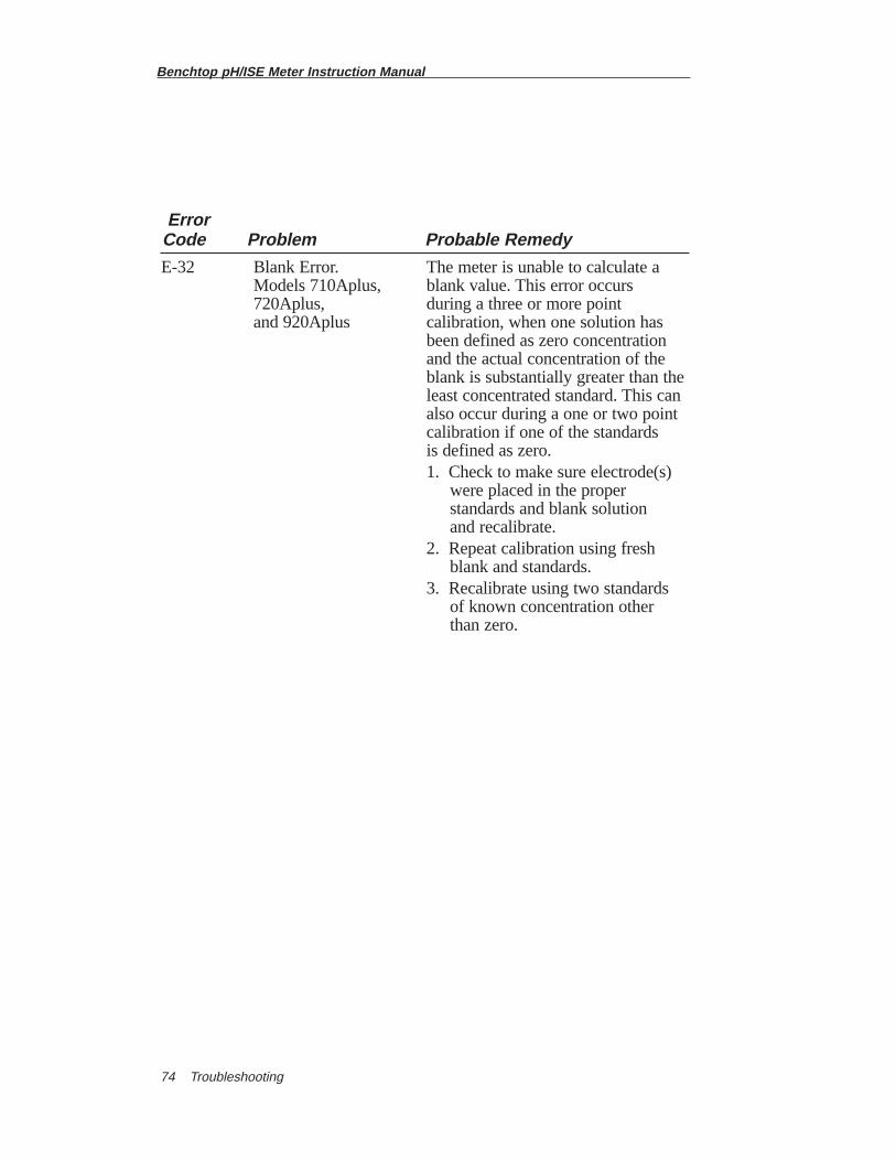
Benchtop pH/ISE Meter Instruction Manual
Troubleshooting74
Error Code Problem Probable Remedy
E-32 Blank Error. The meter is unable to calculate a Models 710Aplus, blank value. This error occurs 720Aplus, during a three or more point and 920Aplus calibration, when one solution has
been defined as zero concentration and the actual concentration of the blank is substantially greater than theleast concentrated standard. This can also occur during a one or two point calibration if one of the standards is defined as zero.1. Check to make sure electrode(s)
were placed in the proper standards and blank solution and recalibrate.
2. Repeat calibration using fresh blank and standards.
3. Recalibrate using two standards of known concentration other than zero.
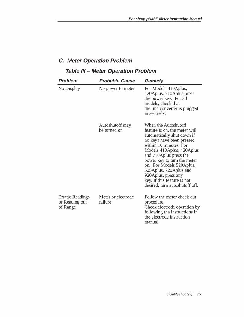
Benchtop pH/ISE Meter Instruction Manual
Troubleshooting 75
C. Meter Operation Problem
Table III – Meter Operation Problem
Problem Probable Cause Remedy
No Display No power to meter For Models 410Aplus, 420Aplus, 710Aplus press the power key. For all models, check that the line converter is plugged in securely.
Autoshutoff may When the Autoshutoff be turned on feature is on, the meter will
automatically shut down if no keys have been pressed within 10 minutes. For Models 410Aplus, 420Aplus and 710Aplus press the power key to turn the meter on. For Models 520Aplus, 525Aplus, 720Aplus and 920Aplus, press any key. If this feature is not desired, turn autoshutoff off.
Erratic Readings Meter or electrode Follow the meter check outor Reading out failure procedure.of Range Check electrode operation by
following the instructions inthe electrode instructionmanual.
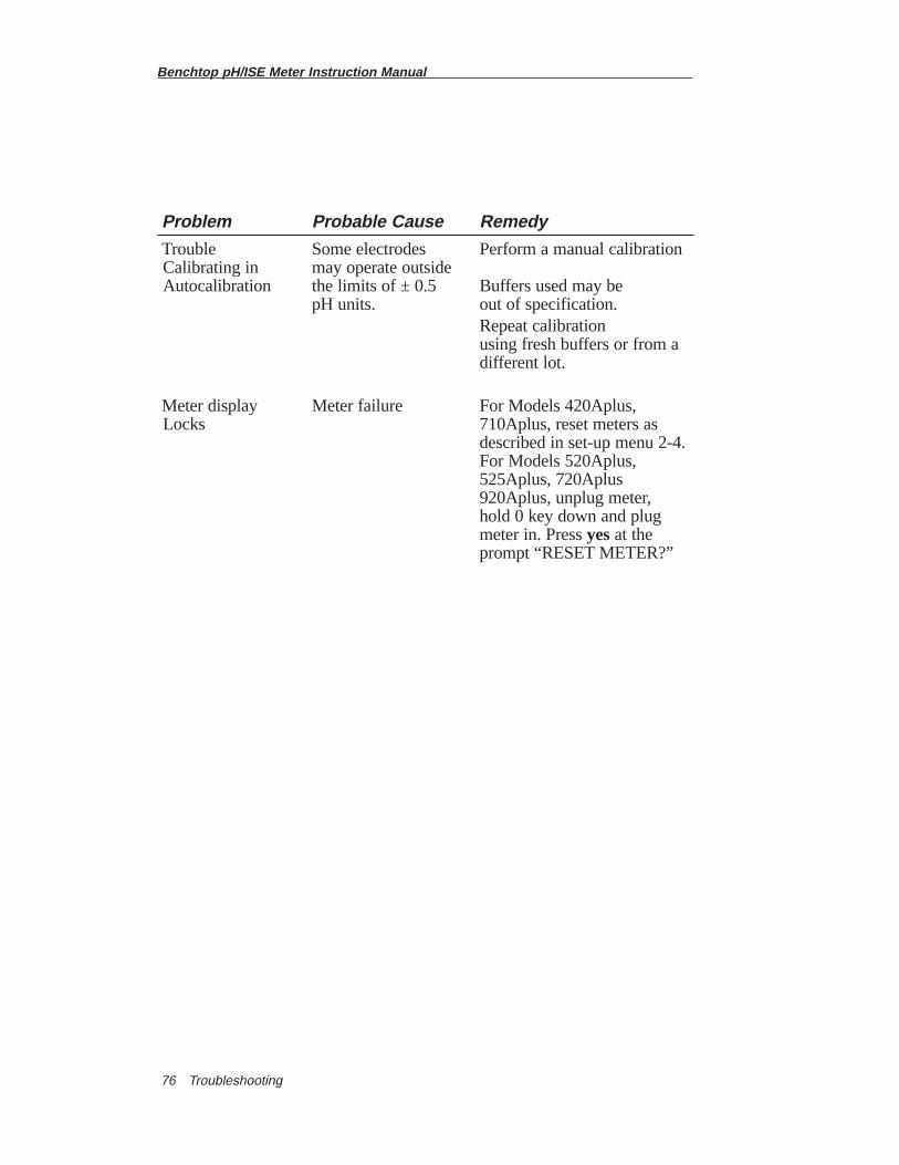
Benchtop pH/ISE Meter Instruction Manual
Troubleshooting76
Problem Probable Cause Remedy
Trouble Some electrodes Perform a manual calibrationCalibrating in may operate outsideAutocalibration the limits of ± 0.5 Buffers used may be
pH units. out of specification.Repeat calibration using fresh buffers or from a different lot.
Meter display Meter failure For Models 420Aplus, Locks 710Aplus, reset meters as
described in set-up menu 2-4.For Models 520Aplus, 525Aplus, 720Aplus920Aplus, unplug meter, hold 0 key down and plug meter in. Press yesat the prompt “RESET METER?”
Benchtop pH/ISE Meter Instruction Manual
Service and Repair 77
Chapter XI Service and RepairA Return Authorization Number must be obtained from Thermo OrionTechnical Service before returning any product for in-warranty or out-of-warranty repair, replacement, or credit.
Outside of North America consult your authorized Thermo Orion dealer,or:
Thermo Orion500 Cummings CenterBeverly, MA 01915-6199 USATel: 978-232-6000Dom. Fax: 978-232-6015Int’l. Fax: 978-232-6031
Thermo Orion Europe12-16 Sedgeway Business ParkWitchford, CambridgeshireEngland CB6 2HYTel: 44-1353-666111Int’l. Fax: 44-1353-666001
Thermo Orion EastRoom 904, Federal Building369 Lockhart RoadWanchai, Hong KongTel: 852-28360981Int’l. Fax: 852-28345160
Thermo Orion Customer SupportToll Free: 800-225-1480WWW: http://www.thermoorionres.com Dom. e-mail: [email protected]’l. e-mail: [email protected]
Benchtop pH/ISE Meter Instruction Manual
Notice of Compliance78
Chapter XIINotice of ComplianceThis equipment generates, uses, and can radiate radio frequency energy andif not installed and used in accordance with the instruction manual, maycause interference to radio communications. It has been tested and found tocomply with the limits for a Class A computing device pursuant to SubpartJ of Part 15 of FCC Rules, which are designed to provide reasonableprotection against such interference when operated in a commercialenvironment. Operation of this equipment in a residential area is likely tocause interference in which case the user, at his own expense, will berequired to take whatever measures may be required to correct theinterference.
“This digital apparatus does not exceed the (Class A) limits for radio noiseemissions from digital apparatus set out in the Radio InterferenceRegulations of the Canadian Department of Communications.”
“Le présent appareil numérique n’ émet pas de bruits radioélectriquesdépassant les limites applicables aux appareils numériques (de la class A)prescrites dans le Règlement sur le brouillage radioélectrique édicté par leministère des Communications du Canada.”
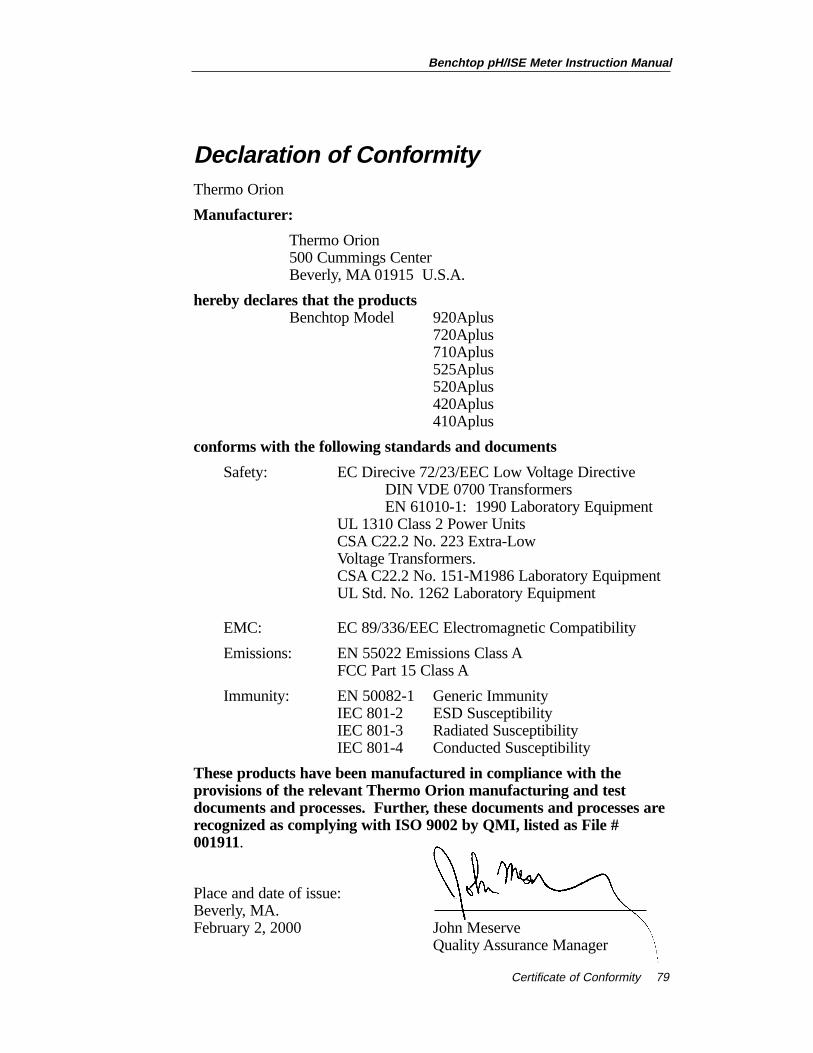
Benchtop pH/ISE Meter Instruction Manual
Certificate of Conformity 79
Declaration of ConformityThermo Orion
Manufacturer:
Thermo Orion500 Cummings CenterBeverly, MA 01915 U.S.A.
hereby declares that the productsBenchtop Model 920Aplus
720Aplus 710Aplus525Aplus520Aplus420Aplus410Aplus
conforms with the following standards and documents
Safety: EC Direcive 72/23/EEC Low Voltage DirectiveDIN VDE 0700 TransformersEN 61010-1: 1990 Laboratory Equipment
UL 1310 Class 2 Power UnitsCSA C22.2 No. 223 Extra-Low Voltage Transformers.CSA C22.2 No. 151-M1986 Laboratory EquipmentUL Std. No. 1262 Laboratory Equipment
EMC: EC 89/336/EEC Electromagnetic Compatibility
Emissions: EN 55022 Emissions Class AFCC Part 15 Class A
Immunity: EN 50082-1 Generic ImmunityIEC 801-2 ESD SusceptibilityIEC 801-3 Radiated SusceptibilityIEC 801-4 Conducted Susceptibility
These products have been manufactured in compliance with theprovisions of the relevant Thermo Orion manufacturing and testdocuments and processes. Further, these documents and processes arerecognized as complying with ISO 9002 by QMI, listed as File #001911.
Place and date of issue:Beverly, MA.February 2, 2000 John Meserve
Quality Assurance Manager

80
Benchtop pH/ISE Meter Instruction Manual
Certificate of Conformity
Benchtop pH/ISE Meter Instruction Manual
Instrument Warranty 81
Chapter XIIIInstrument Warranty
The Thermo Orion warranty covers failures due to manufacturer’sworkmanship or material defects from the date of purchase by the user.User should return the warranty card to Thermo Orion and retain proofof purchase. Warranty is void if product has been abused, misused, orrepairs attempted by unauthorized persons.
Warranties herein are for product sold/installed by Thermo Orion or itsauthorized dealers.
Any product sold by a U.S. or Canadian distributor must be returned toThermo Orion for any warranty work. A Return Authorization Numbermust be obtained from Thermo Orion Laboratory Technical Servicebefore returning any product for in-warranty repair or replacement.
In the event of failure within the warranty period, Thermo Orion will atThermo Orion’s option, repair or replace product not conforming to thiswarranty. There may be additional charges, including freight, forwarranty service performed in some countries. For service, call ThermoOrion (or its authorized dealer outside the United States and Canada).Thermo Orion reserves the right to ask for proof of purchase, such as theoriginal invoice or packing slip.
Laboratory pH Meters (Models 611 and 301), SensorLink®,PerpHecT® pH/ISE Meters, pHuture™ pH Meters (Models 610 and620), Sage™ Pumps, Cahn® Balances, 930 Ionalyzer™, 950 ROSS™
FAST QC™ Titrator, 960 Titrator PLUS ®, Karl Fischer Titrators,Autosamplers, Liquid Handling Devices, pHuture Conversion Box,Wine Master™, 607 Switchbox, rf link™, AQUAfast® II Colorimeters ,Vacuum Degasser, Flowmeter are warranted to be free from defects inmaterial and workmanship for a period of twelve (12) months from thedate of purchase by the user or eighteen (18) months from date ofshipment from Thermo Orion, whichever is earlier, provided use is inaccordance with the operating limitations and maintenance procedures inthe instruction manual and when not having been subjected to accident,alteration, misuse, or abuse.
The warranty period for 960 Titrator PLUS, 950 Fast QC Titrator, WineMaster and 930 Ionalyzer pumps is three (3) months from date ofpurchase.
Economy Line Electrodes, Models 91-05, 91-06, 91-15, 91-16, 91-25,91-26, 91-35, 91-36, 92-06, are warranted to be free from defects inmaterial and workmanship for a period of three (3) months from date ofpurchase by customer or six (6) months from date of shipment fromThermo Orion, whichever is earlier. Warranty also includes failure for anyreason (excluding breakage), except abuse, provided the electrode is notused in solutions containing silver, sulfide, perchlorate, or hydrofluoricacid; or in solutions more than one (1) Molar in strong acid or base attemperatures above 50 ˚C.
Ion Selective Electrodes, ionplus® Electrodes, ROSS™ Electrodes,Sure-Flow® Electrodes, PerpHecT® Electrodes, AquaPro ProfessionalElectrodes, Standard Line pH Electrodes, Tris pH Electrodes, ORPTriode (Cat. No. 9180BN), pHuture™ pH Probes (Cat. No. 616500)and pHuture MMS ™ Quatrode™ and Triode (Cat. Nos. 616600 and617900), Model 97-08 DO Probe, Series 100 ConventionalConductivity Cells, temperature probes and compensators (exceptthose models noted)are warranted to be free from defects in material andworkmanship for a period of twelve (12) months from the date ofpurchase by the customer or eighteen (18) months from date of shipmentfrom Thermo Orion, whichever is earlier, except for abuse or breakage ofelectrodes. 93 and 97 ionplus Series sensing modules are warranted togive six (6) months of operation if placed in service before the dateindicated on the package, except 93-07 and 97-07 Nitrate modules arewarranted to give ninety (90) days of operation if placed in service beforethe date indicated on the package.
Thermo Orion pHuture ™ (Cat. No. 615700) and pHuture MMS™
Pentrode™ (Cat. No. 617500), Quatrode™ (Cat. No. 617800) and Triode(Cat. No. 615800), Low Maintenance Triode™ (Cat. No. 9107BN), ORPLow Maintenance Triode (Cat. No. 9179BN), and PerpHecT LowMaintenance Triode (Cat. No. 9207BN), Waterproof Triode (Cat. No.9107WP, 9107WL, 9109WL, 9109WP), QuiKcheK™ Meters,Electrodesare warranted to be free from defects in material and
Benchtop pH/ISE Meter Instruction Manual
Instrument Warranty82
Benchtop pH/ISE Meter Instruction Manual
Instrument Warranty 83
workmanship for a period of six (6) months from date of purchase by thecustomer or twelve (12) months from date of shipment from ThermoOrion, whichever is earlier when used in accordance with the operatinglimitations and maintenance procedure in the instruction manual andwhen not having been subjected to accident, alteration, misuse or abuse.
Series 100 DuraProbe™ Conductivity Cells and Series 800 DissolvedOxygen Probesare warranted to be free from defects in material andworkmanship for a period of twenty-four (24) months from the date ofpurchase by the user or thirty (30) months from the date of shipmentfrom Thermo Orion, whichever is earlier, provided use is in accordancewith the operating limitations and maintenance procedures in theinstruction manual and when not having been subjected to accident,alteration, misuse, or abuse.
Waterproof meters (Models 630, 635, 830A, 835A, 260A, 261S, 265A,266S, 130A, 131S, 135A, 136S, 1230, 142 and 842), Conductivitymeters (Models 105Aplus™, 115Aplus, 125Aplus, 145Aplus, 150Aplusand 162A), pHuture MMS™ meters (Models 535A, 555A),pH/Conductivity meter (Model 550A), Dissolved Oxygen meters(Models 810Aplus, 850Aplus and 862A), are warranted to be free fromdefects in material and workmanship for a period of thirty-six (36)months from the date of purchase by the user or forty-two (42) monthsfrom date of shipment from Thermo Orion, whichever is earlier, provideduse is in accordance with the operating limitations and maintenanceprocedures in the instruction manual and when not having been subjectedto accident, alteration, misuse or abuse.
LabConnect™ and DataCOLLECT™ carry an “out-of-box” warranty.Should they fail to work when first used, contact Thermo Orionimmediately for replacement.
Thermo Orion Meter, Electrode, Analytical System Accessories,Solutions, AQUAfast Test Strips, AQUAfast II Reagent Kits andaccessories, Series 800 Dissolved Oxygen Probe Membranes and CahnBalance Accessories such as cables, printers, and line adapters carry an“out-of-box” warranty. Should they fail to work when first used, contactThermo Orion immediately for replacement. Should Thermo OrionSolutions or Buffers be unusable when first “out-of-box,” contact ThermoOrion immediately for replacement.
THE WARRANTIES DESCRIBED ABOVE ARE EXCLUSIVE ANDIN LIEU OF ALL OTHER WARRANTIES WHETHER STATUTORY,EXPRESS OR IMPLIED INCLUDING, BUT NO LIMITED TO, ANYIMPLIED WARRANTY OF MERCHANTABILITY OR FITNESS FORA PARTICULAR PURPOSE AND ALL WARRANTIES ARISINGFROM THE COURSE OF DEALING OR USAGE OF TRADE. THEBUYER’S SOLE AND EXCLUSIVE REMEDY IS FOR REPAIR ORREPLACEMENT OF THE NON-CONFORMING PRODUCT OR PARTTHEREOF, OR REFUND OF THE PURCHASE PRICE, BUT IN NOEVENT SHALL ORION (ITS CONTRACTORS AND SUPPLIERS OFANY TIER) BE LIABLE TO THE BUYER OR ANY PERSON FORANY SPECIAL, INDIRECT, INCIDENTAL, OR CONSEQUENTIALDAMAGES WHETHER THE CLAIMS ARE BASED IN CONTRACT,IN TORT (INCLUDING NEGLIGENCE), OR OTHERWISE WITHRESPECT TO OR ARISING OUT OF THE PRODUCT FURNISHEDHEREUNDER.
REPRESENTATION AND WARRANTIES MADE BY ANY PERSON,INCLUDING ITS AUTHORIZED DEALERS, REPRESENTATIVESAND EMPLOYEES OF ORION WHICH ALTER OR ARE INADDITION TO THE TERMS OF THIS WARRANTY SHALL NOT BEBINDING UPON ORION UNLESS IN WRITING AND SIGNED BYONE OF ITS OFFICERS.
Note: For in- or out-of-warranty repair or service, contactThermo Orion Technical Service (or its authorized dealer outsidethe United States and Canada). Technical Service will issue aReturn Authorization (RA) for all repair services. You must havean Thermo Orion RA prior to returning/forwarding any product toThermo Orion.
Benchtop pH/ISE Meter Instruction Manual
Instrument Warranty84
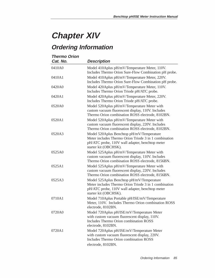
Chapter XIVOrdering InformationThermo OrionCat. No. Description
0410A0 Model 410Aplus pH/mV/Temperature Meter, 110V. Includes Thermo Orion Sure-Flow Combination pH probe.
0410A1 Model 410Aplus pH/mV/Temperature Meter, 220V. Includes Thermo Orion Sure-Flow Combination pH probe.
0420A0 Model 420Aplus pH/mV/Temperature Meter, 110V. Includes Thermo Orion Triode pH/ATC probe.
0420A1 Model 420Aplus pH/mV/Temperature Meter, 220V. Includes Thermo Orion Triode pH/ATC probe.
0520A0 Model 520Aplus pH/mV/Temperature Meter with custom vacuum fluorescent display, 110V. Includes Thermo Orion combination ROSS electrode, 8102BN.
0520A1 Model 520Aplus pH/mV/Temperature Meter with custom vacuum fluorescent display, 220V. Includes Thermo Orion combination ROSS electrode, 8102BN.
0520A3 Model 520Aplus Benchtop pH/mV/Temperature Meter includes Thermo Orion Triode 3 in 1 combination pH/ATC probe, 110V wall adapter, benchtop meter starter kit (OBCHSK).
0525A0 Model 525Aplus pH/mV/Temperature Meter with custom vacuum fluorescent display, 110V. Includes Thermo Orion combination ROSS electrode, 8156BN.
0525A1 Model 525Aplus pH/mV/Temperature Meter with custom vacuum fluorescent display, 220V. Includes Thermo Orion combination ROSS electrode, 8156BN.
0525A3 Model 525Aplus Benchtop pH/mV/Temperature Meter includes Thermo Orion Triode 3 in 1 combination pH/ATC probe, 110V wall adapter, benchtop meter starter kit (OBCHSK).
0710A1 Model 710Aplus Portable pH/ISE/mV/Temperature Meter, 110V. Includes Thermo Orion combination ROSS electrode, 8102BN.
0720A0 Model 720Aplus pH/ISE/mV/Temperature Meter with custom vacuum fluorescent display, 110V. Includes Thermo Orion combination ROSS electrode, 8102BN.
0720A1 Model 720Aplus pH/ISE/mV/Temperature Meter with custom vacuum fluorescent display, 220V. Includes Thermo Orion combination ROSS electrode, 8102BN.
Benchtop pH/ISE Meter Instruction Manual
Ordering Information 85
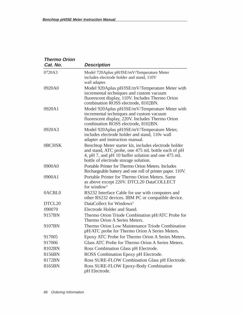
Benchtop pH/ISE Meter Instruction Manual
Ordering Information86
Thermo OrionCat. No. Description
0720A3 Model 720Aplus pH/ISE/mV/Temperature Meter includes electrode holder and stand, 110Vwall adapter.
0920A0 Model 920Aplus pH/ISE/mV/Temperature Meter withincremental techniques and custom vacuum fluorescent display, 110V. Includes Thermo Orion combination ROSS electrode, 8102BN.
0920A1 Model 920Aplus pH/ISE/mV/Temperature Meter withincremental techniques and custom vacuum fluorescent display, 220V. Includes Thermo Orion combination ROSS electrode, 8102BN.
0920A3 Model 920Aplus pH/ISE/mV/Temperature Meter, includes electrode holder and stand, 110v wall adapter and instruction manual.
0BCHSK Benchtop Meter starter kit, includes electrode holder and stand, ATC probe, one 475 mL bottle each of pH 4, pH 7, and pH 10 buffer solution and one 475 mLbottle of electrode storage solution.
0900A0 Portable Printer for Thermo Orion Meters. Includes Rechargeable battery and one roll of printer paper. 110V.
0900A1 Portable Printer for Thermo Orion Meters. Same as above except 220V. DTCL20 DataCOLLECTfor window®
0ACBL0 RS232 Interface Cable for use with computers and other RS232 devices. IBM PC or compatible device.
DTCL20 DataCollect for Windows®
090070 Electrode Holder and Stand.9157BN Thermo Orion Triode Combination pH/ATC Probe for
Thermo Orion A Series Meters.9107BN Thermo Orion Low Maintenance Triode Combination
pH/ATC probe for Thermo Orion A Series Meters.917005 Epoxy ATC Probe for Thermo Orion A Series Meters.917006 Glass ATC Probe for Thermo Orion A Series Meters.8102BN Ross Combination Glass pH Electrode.8156BN ROSS Combination Epoxy pH Electrode.8172BN Ross SURE-FLOW Combination Glass pH Electrode.8165BN Ross SURE-FLOW Epoxy-Body Combination
pH Electrode.
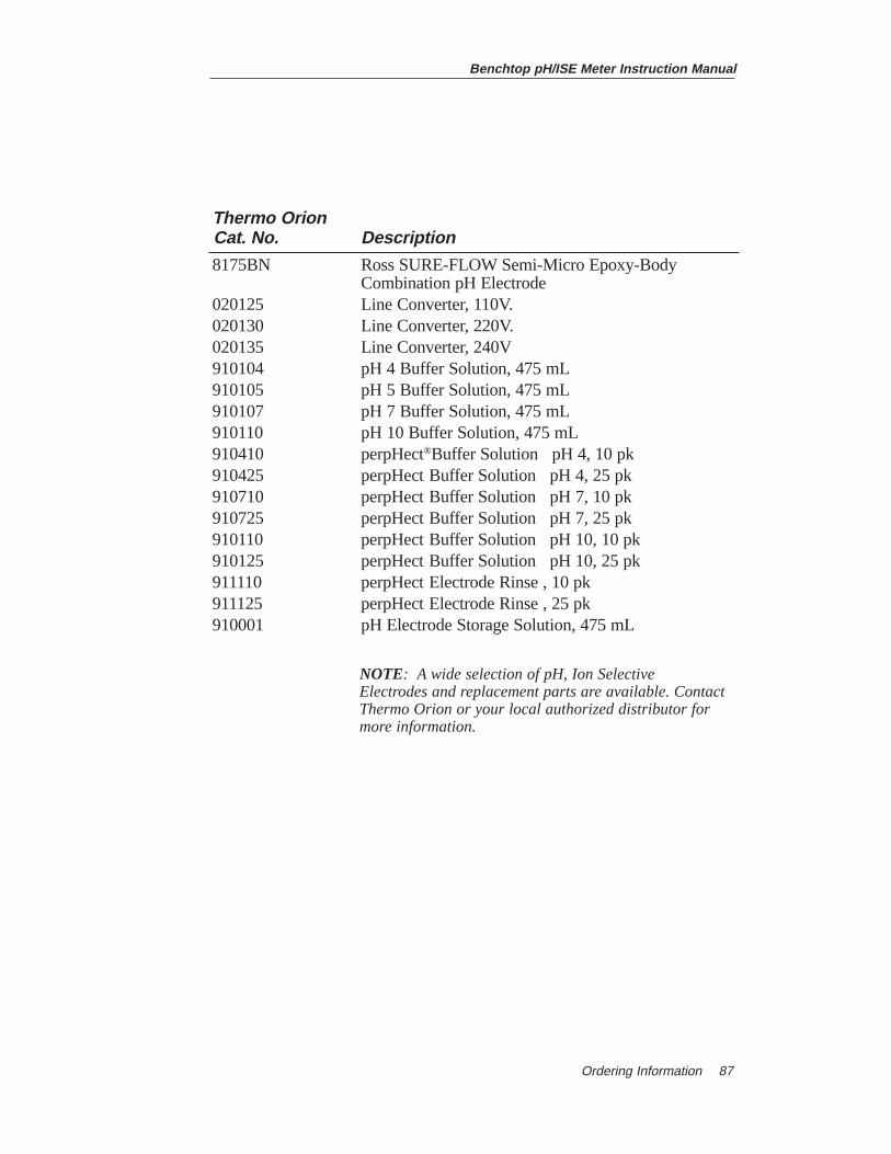
Benchtop pH/ISE Meter Instruction Manual
Ordering Information 87
Thermo OrionCat. No. Description
8175BN Ross SURE-FLOW Semi-Micro Epoxy-Body Combination pH Electrode
020125 Line Converter, 110V.020130 Line Converter, 220V.020135 Line Converter, 240V910104 pH 4 Buffer Solution, 475 mL910105 pH 5 Buffer Solution, 475 mL910107 pH 7 Buffer Solution, 475 mL910110 pH 10 Buffer Solution, 475 mL910410 perpHect®Buffer Solution pH 4, 10 pk910425 perpHect Buffer Solution pH 4, 25 pk910710 perpHect Buffer Solution pH 7, 10 pk910725 perpHect Buffer Solution pH 7, 25 pk910110 perpHect Buffer Solution pH 10, 10 pk910125 perpHect Buffer Solution pH 10, 25 pk911110 perpHect Electrode Rinse , 10 pk911125 perpHect Electrode Rinse , 25 pk910001 pH Electrode Storage Solution, 475 mL
NOTE: A wide selection of pH, Ion Selective Electrodes and replacement parts are available. ContactThermo Orion or your local authorized distributor formore information.

Benchtop pH/ISE Meter Instruction Manual
Ordering Information88
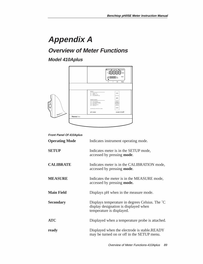
Appendix AOverview of Meter Functions Model 410Aplus
Front Panel Of 410Aplus
Operating Mode Indicates instrument operating mode.
SETUP Indicates meter is in the SETUP mode,accessed by pressing mode.
CALIBRATE Indicates meter is in the CALIBRATION mode, accessed by pressing mode.
MEASURE Indicates the meter is in the MEASURE mode, accessed by pressing mode.
Main Field Displays pH when in the measure mode.
Secondary Displays temperature in degrees Celsius. The ˚C display designation is displayed when temperature is displayed.
ATC Displayed when a temperature probe is attached.
ready Displayed when the electrode is stable.READYmay be turned on or off in the SETUP menu.
SETUP CALIBRATE MEASURE
ready
ONOFF
°CATC
4 7 10 Man
timer
power
model 410
no
mode
yes
pH meter
SETUP:
RESOLUTIONSLOPEPRINT OPTIONSCAL BUFFER OPTION
S-1S-2S-3S-4
ERROR CODES:
OUT OF RANGEAUTO BUFFER ERRORCAL STANDARD ERRORBAD SLOPEPRINTER ERRORBAD VALUE
E-20E-21E-22E-23E-29E-31
See Manual for other Error Codes.
Benchtop pH/ISE Meter Instruction Manual
Overview of Meter Functions-410Aplus 89
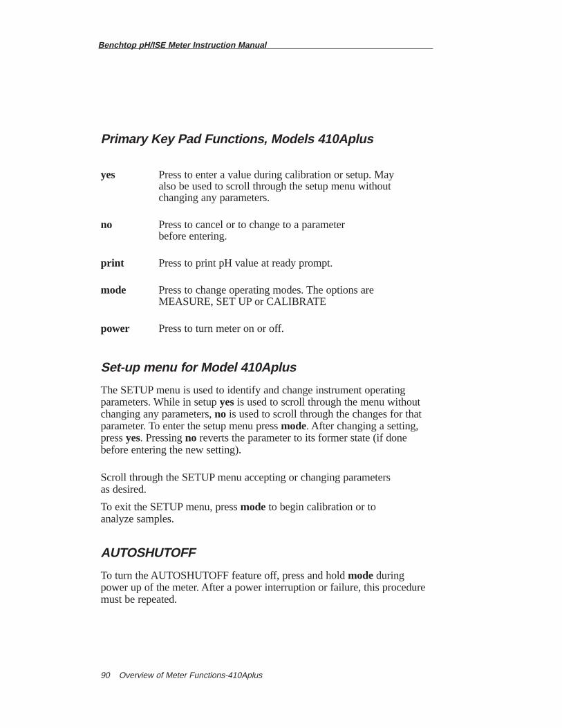
Benchtop pH/ISE Meter Instruction Manual
Overview of Meter Functions-410Aplus90
Primary Key Pad Functions, Models 410Aplus
yes Press to enter a value during calibration or setup. May also be used to scroll through the setup menu without changing any parameters.
no Press to cancel or to change to a parameter before entering.
print Press to print pH value at ready prompt.
mode Press to change operating modes. The options are MEASURE, SET UP or CALIBRATE
power Press to turn meter on or off.
Set-up menu for Model 410Aplus
The SETUP menu is used to identify and change instrument operatingparameters. While in setup yesis used to scroll through the menu withoutchanging any parameters, no is used to scroll through the changes for thatparameter. To enter the setup menu press mode. After changing a setting,press yes. Pressing no reverts the parameter to its former state (if donebefore entering the new setting).
Scroll through the SETUP menu accepting or changing parameters as desired.
To exit the SETUP menu, press mode to begin calibration or to analyze samples.
AUTOSHUTOFF
To turn the AUTOSHUTOFF feature off, press and hold modeduringpower up of the meter. After a power interruption or failure, this proceduremust be repeated.
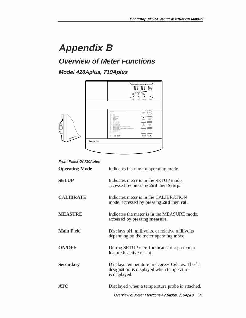
Appendix B Overview of Meter Functions Model 420Aplus, 710Aplus
Front Panel Of 710Aplus
Operating Mode Indicates instrument operating mode.
SETUP Indicates meter is in the SETUP mode.accessed by pressing 2nd then Setup.
CALIBRATE Indicates meter is in the CALIBRATION mode, accessed by pressing 2nd then cal.
MEASURE Indicates the meter is in the MEASURE mode, accessed by pressing measure.
Main Field Displays pH, millivolts, or relative millivolts depending on the meter operating mode.
ON/OFF During SETUP on/off indicates if a particular feature is active or not.
Secondary Displays temperature in degrees Celsius. The ˚C designation is displayed when temperature is displayed.
ATC Displayed when a temperature probe is attached.
pH mV Rel mV Conc
SETUP CALIBRATE MEASURE
2ndreadybold
EXP
ONOFF
°CATC
pH / ISE meter
SETUP:
READYHOLDBEEPAUTOSHUTOFFSLOPERESOLUTIONISOPOINTRESETTIMER INTERVALREMAINING TIMESET REAL TIMESET DATEHIGH ALARM LIMITLOW ALARM LIMITPRINT MODE: 1 = MAN, 2 = READY, 3 = TIMEDPRINT INTERVALDATA LOG MODE: 1 = MAN, 2 = READY, 3 = TIMED, 0 = OFFDATA LOG INTERVALDOWNLOAD DATADATA CLEAR
1-11-21-31-42-12-22-32-43-13-23-33-44-H4-L5-15-26-16-26-36-4
See Manual for Error Codes.
power
yes
2nd
no
modecal
measureprint
setup
timer
model 710
Benchtop pH/ISE Meter Instruction Manual
Overview of Meter Functions-420Aplus, 710Aplus 91
Benchtop pH/ISE Meter Instruction Manual
Overview of Meter Functions-420Aplus, 710Aplus92
2nd Displayed when 2nd has been pressed, indicating the meter is ready to perform a second function, cal, timer, setup, or print .
ready Displayed when the electrode is stable. READYmay be turned on or off in the SETUP menu.
hold Displayed when the pH reading is frozen after reaching stability. The HOLD feature may be turned on or off in the SETUP menu.
timer Displayed when the timer function has been activated.
Mode Designates instrument operating mode in Indicator pH, millivolts (mV), Relative millivolts (Rel mV),
Concentration (conc.) (with 710Aplus Meter only).
Benchtop pH/ISE Meter Instruction Manual
Overview of Meter Functions-420Aplus, 710Aplus 93
Primary Key Pad Functions, Models 420Aplus, 710Aplus
yes Press to enter a value during calibration or setup. May also be used to scroll through the setup menu without changing any parameters.
no Press to cancel or to change to a parameter before entering.
measure Press for sample analysis. Instrument will remain in measuremode until another key is pressed. Press to unlock HOLD during sample analysis or to exit SETUP menu.
mode Press to change operating modes. The options are pH, mV, or REL mV. (conc with 710Aplus Meter only)
2nd Press to access second functions (cal, timer, setup or print).
Press to increase value.
Press to decrease value.
power Press to turn meter on or off.
▼
▼
Benchtop pH/ISE Meter Instruction Manual
Overview of Meter Functions-420Aplus, 710Aplus94
Secondary Key Pad Functions, Models 420Aplus, 710Aplus
All second functions are accessed by first pressing 2nd then pressing one ofthe following:
cal Press to start calibration.
timer Press to start the timer. When the preset time has elapsed the instrument will beep for 1 minute (or until a key is pressed).
setup Press to access the setup menu. This is used for setting instrument operating parameters.
print Press to print current display data and/or enter data into the internal datalogger (Model 710Aplus only). Selection of either option or both can be made in the setup menu. At the end of each calibration all data is printed automatically. (Pressing print during calibration will cause data from the previous calibration to be printed until the calibration sequence is completed.)
Set-up menu for Models 420Aplus and 710Aplus
The SETUP menu is used to identify and change instrument operatingparameters. While in setup yesis used to scroll through the menu withoutchanging any parameters.
To enter the SETUP menu press 2nd then setup. 1-1 and READY will bedisplayed. The on or off indicator flashes indicating the current status. Pressyesto accept and continue through the menu. Press or , to change. Afterchanging a setting, pressyes. Pressingno reverts the parameter to its formerstate (if done before entering the new setting).
To change a numeric value press or ,the first digit will start flashing.Scroll until the first digit is the desired value, then press yes. The seconddigit will flash, scroll until the desired value is displayed then press yes.Continue in this manner until all digits have been changed to the desired value.
Scroll through the SETUP menu accepting or changing parameters as desired.
To exit the SETUP menu, press 2nd cal to begin calibration or measuretoanalyze samples.
▼
▼
▼
▼
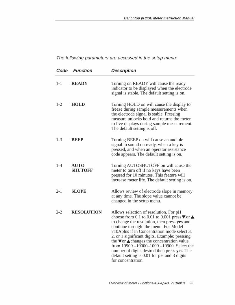
Benchtop pH/ISE Meter Instruction Manual
Overview of Meter Functions-420Aplus, 710Aplus 95
The following parameters are accessed in the setup menu:
Code Function Description
1-1 READY Turning on READY will cause the ready indicator to be displayed when the electrode signal is stable. The default setting is on.
1-2 HOLD Turning HOLD on will cause the display to freeze during sample measurements when the electrode signal is stable. Pressing measure unlocks hold and returns the meter to live displays during sample measurement.The default setting is off.
1-3 BEEP Turning BEEP on will cause an audible signal to sound on ready, when a key is pressed, and when an operator assistance code appears. The default setting is on.
1-4 AUTO Turning AUTOSHUTOFF on will cause the SHUTOFF meter to turn off if no keys have been
pressed for 10 minutes. This feature will increase meter life. The default setting is on.
2-1 SLOPE Allows review of electrode slope in memory at any time. The slope value cannot be changed in the setup menu.
2-2 RESOLUTION Allows selection of resolution. For pH choose from 0.1 to 0.01 to 0.001 press orto change the resolution, then press yesand continue through the menu. For Model 710Aplus if in Concentration mode select 3, 2, or 1 significant digits. Example: pressing the or changes the concentration value from 19900 –19000–1000 –19900. Select thenumber of digits desired then press yes.The default setting is 0.01 for pH and 3 digitsfor concentration.
▼
▼
▼
▼
Code Function Description
2-3 ISOPOTENTIAL Use to change the isopotential point POINT for a particular pH electrode. In pH mode
the default value is 7.00. The isopotential point may not be changed in any other mode.
NOTE: Setup function 2-3 Isopotential point is only accessible in pH mode. SETUP Functions 2-1 Slope and 2-2 Resolution are only accessible in pH and concentration modes (710Aplus).
2-4 RESET Allows all the setup options and calibration data to be set to factory default values. This is particularly useful during troubleshooting or prior to calibrating with new electrode. To RESET press ,ON will flash and the audio signal will ring rapidly. Press yes.
3-1 TIMER Sets the timer interval. The maximum INTERVAL interval that can be set is 23 hours, 59
minutes, and 59 seconds. The minimum interval is five (5) seconds. When the TIMER INTERVAL code, 3-1, is displayed the current interval hours setting is displayed in the main field (H 00). Press yesto accept,or press to change, then press yes. Next thecurrent interval minutes: seconds will be displayed (00:00). Press yesto accept currentsetting or press to desired value, then press yes. The default setting is 5 seconds.
3-2 TIME Allows review of the time remaining before the timer is set to go off.
3-3 SET REAL Set the actual time of day. The meter TIMEuses a 24 hour clock. When the code 3-3is displayed in the lower field, the current time (hours:minutes) is displayed in the mainfield. If correct press yes, otherwise change as required and then press yes.
▼
Benchtop pH/ISE Meter Instruction Manual
Overview of Meter Functions-420Aplus, 710Aplus96
▼
▼
Benchtop pH/ISE Meter Instruction Manual
Overview of Meter Functions-420Aplus, 710Aplus 97
Code Function Description
3-4 SET DATE Sets the current date. When the code 3-4 is displayed in the lower field, the current date (month: day) is displayed in the main field. Press yes, or change the date as needed, thenpress yes. Next the current year is displayed. Press yesor change as required, then press yes.
4-1 HIGH Sets the high alarm limit for the current ALARM measurement mode. When the readingLIMIT exceeds the set limit the alarm will(710Aplus only) ring. The maximum limits are 19.999 for
pH, 19900 for concentration, +1600.0 for mV, and +1999.9 for relative millivolts. Press or to change, then press yes.
4-2 LOW Sets the low alarm limit for the currentALARM measurement mode. When the reading fallsLIMIT below the set limit the alarm will ring.(710Aplus only) The minimum limits are -2.000 pH, 0.0
for Concentration, -1600.0 for mV and-1999.9 for relative millivolts. Press or to change, then press yes.
5-1 PRINT Sets the print mode. When 5-1 is displayed MODE in the lower field the current print mode is
displayed in the main field. The options are:1: manual print, indicates no automatic
output to the printer and the user may print on command by pressing 2nd thenprint.
2: Print on Ready, the meter will send information to the printer whenever the electrode signal reaches stability.
3: Print on a timed interval, printing occurs at a preset timed interval. Press
or to change, then press yes.The default setting is 1: manual print.
▼
▼
▼
▼
▼
▼
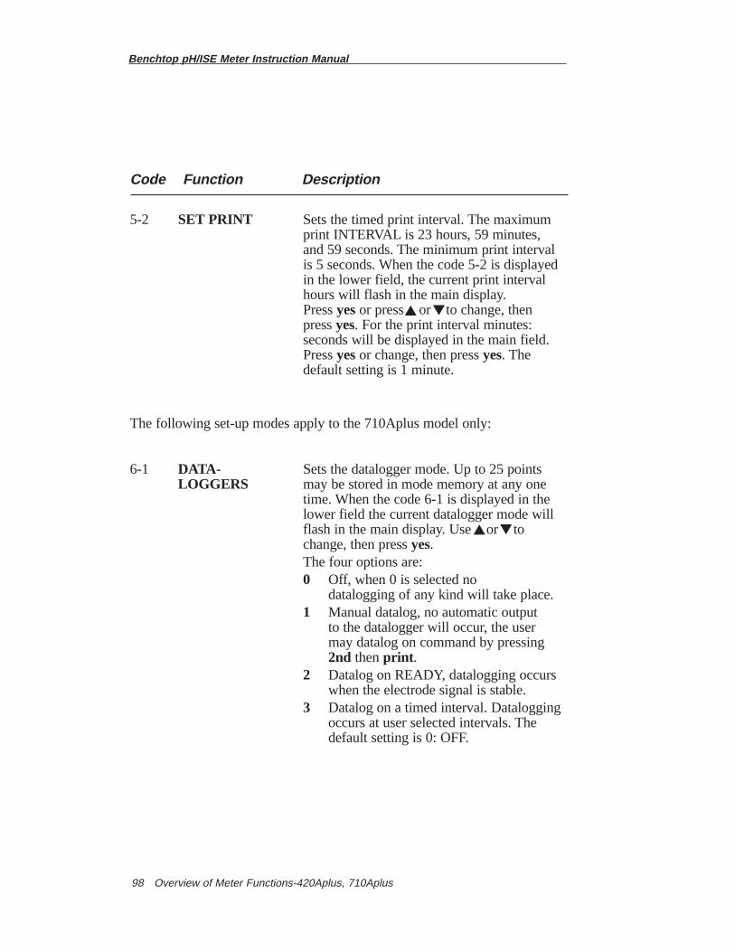
Benchtop pH/ISE Meter Instruction Manual
Overview of Meter Functions-420Aplus, 710Aplus98
Code Function Description
5-2 SET PRINT Sets the timed print interval. The maximum print INTERVAL is 23 hours, 59 minutes, and 59 seconds. The minimum print intervalis 5 seconds. When the code 5-2 is displayedin the lower field, the current print intervalhours will flash in the main display. Press yesor press or to change, then press yes. For the print interval minutes: seconds will be displayed in the main field. Press yesor change, then press yes. The default setting is 1 minute.
The following set-up modes apply to the 710Aplus model only:
6-1 DATA- Sets the datalogger mode. Up to 25 points LOGGERS may be stored in mode memory at any one
time. When the code 6-1 is displayed in the lower field the current datalogger mode will flash in the main display. Use or to change, then press yes. The four options are: 0 Off, when 0 is selected no
datalogging of any kind will take place. 1 Manual datalog, no automatic output
to the datalogger will occur, the user may datalog on command by pressing 2nd thenprint .
2 Datalog on READY, datalogging occurswhen the electrode signal is stable.
3 Datalog on a timed interval. Dataloggingoccurs at user selected intervals. The default setting is 0: OFF.
▼
▼
▼
▼
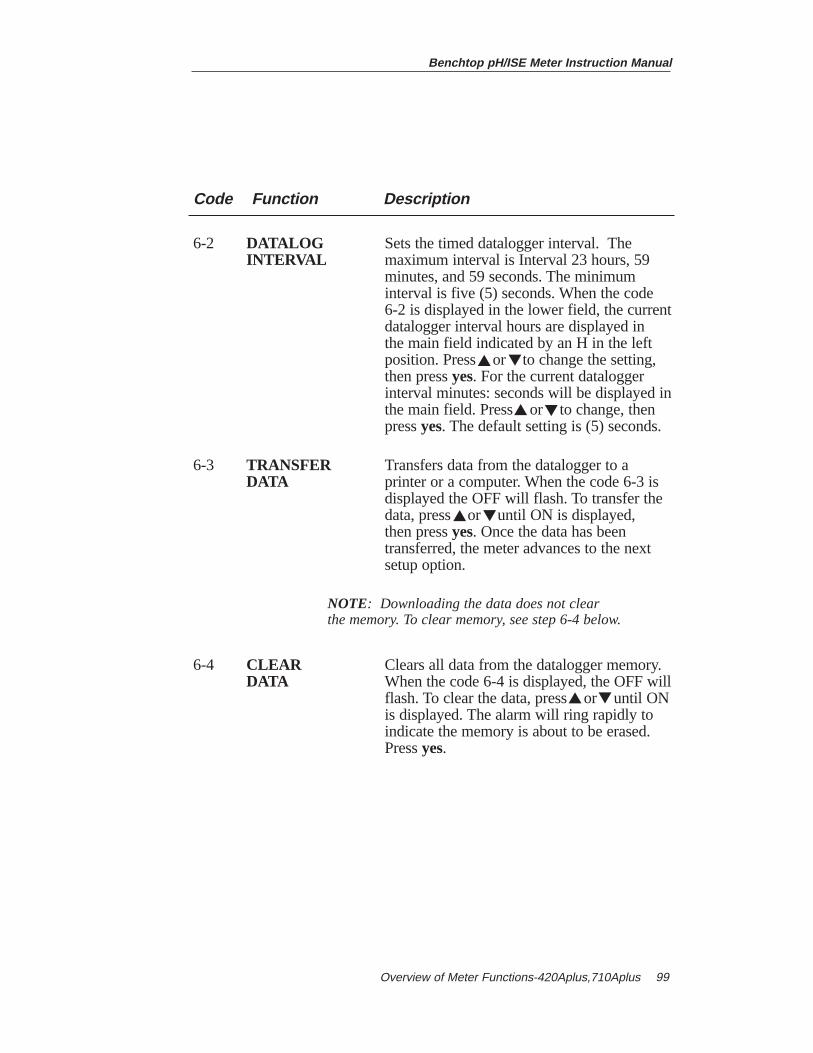
Benchtop pH/ISE Meter Instruction Manual
Overview of Meter Functions-420Aplus,710Aplus 99
Code Function Description
6-2 DATALOG Sets the timed datalogger interval. TheINTERVAL maximum interval is Interval 23 hours, 59
minutes, and 59 seconds. The minimum interval is five (5) seconds. When the code 6-2 is displayed in the lower field, the currentdatalogger interval hours are displayed inthe main field indicated by an H in the left position. Press or to change the setting, then press yes. For the current datalogger interval minutes: seconds will be displayed inthe main field. Press or to change, then press yes. The default setting is (5) seconds.
6-3 TRANSFER Transfers data from the datalogger to a DATA printer or a computer. When the code 6-3 is
displayed the OFF will flash. To transfer the data, press or until ON is displayed, then press yes. Once the data has been transferred, the meter advances to the nextsetup option.
NOTE: Downloading the data does not clear the memory. To clear memory, see step 6-4 below.
6-4 CLEAR Clears all data from the datalogger memory. DATA When the code 6-4 is displayed, the OFF will
flash. To clear the data, press or until ONis displayed. The alarm will ring rapidly to indicate the memory is about to be erased. Press yes.
▼
▼
▼
▼▼
▼
▼
▼

Benchtop pH/ISE Meter Instruction Manual
Overview of Meter Functions-420Aplus,710Aplus100
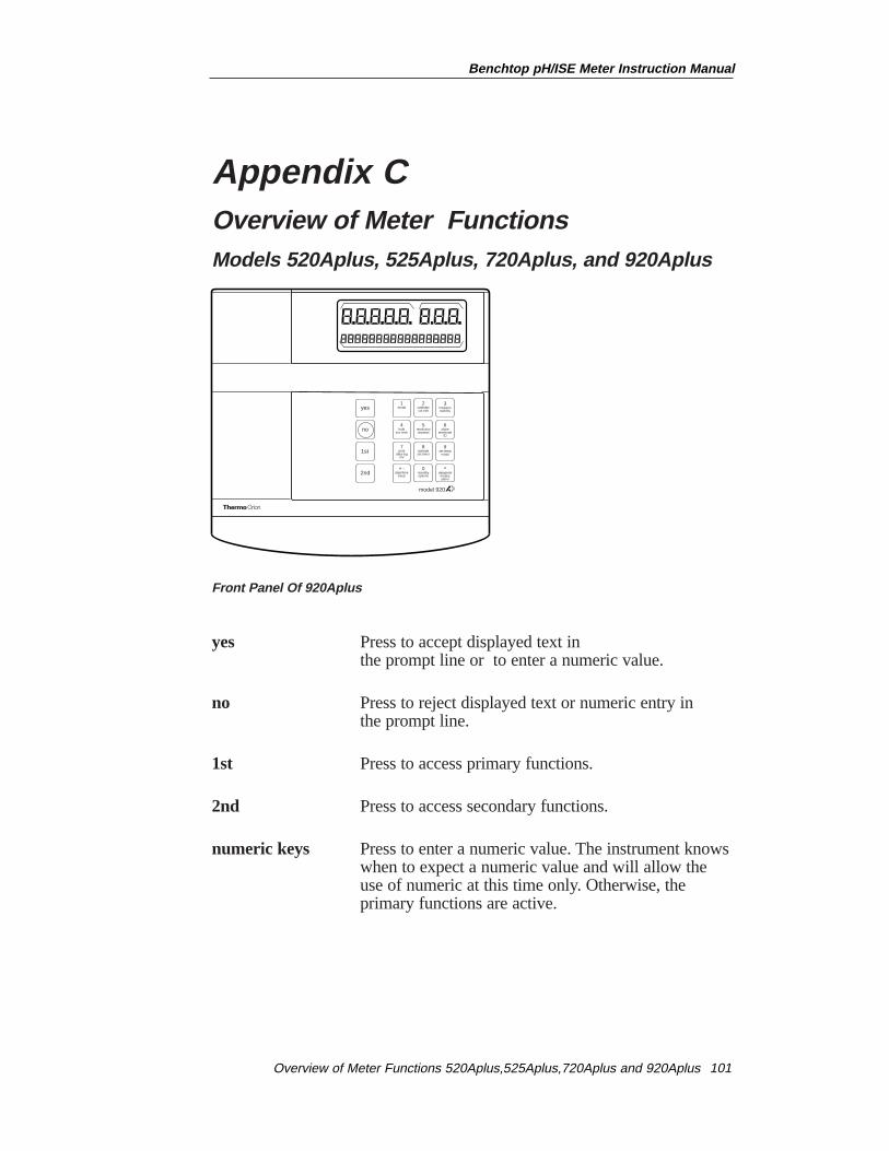
Appendix COverview of Meter Functions Models 520Aplus, 525Aplus, 720Aplus, and 920Aplus
Front Panel Of 920Aplus
yes Press to accept displayed text in the prompt line or to enter a numeric value.
no Press to reject displayed text or numeric entry in the prompt line.
1st Press to access primary functions.
2nd Press to access secondary functions.
numeric keys Press to enter a numeric value. The instrument knowswhen to expect a numeric value and will allow the use of numeric at this time only. Otherwise, the primary functions are active.
model 920
yes
no
1st
2nd
4hold
incr tech
1mode
2calibratecal edit
5resolutionchannel
6slope
electrodeID
3measurestability
+ -date/time
beep
7print
data logmV
8activateset timer
0standbyoptions
data/printmodesalarm
9set temp
ready
.
Benchtop pH/ISE Meter Instruction Manual
Overview of Meter Functions 520Aplus,525Aplus,720Aplus and 920Aplus 101
Benchtop pH/ISE Meter Instruction Manual
Overview of Meter Functions 520Aplus,525Aplus,720Aplus and 920Aplus102
Key 1 Mode
Pressing mode (1)changes the instrument operating mode. The currentoperating mode designation is displayed to the right of the main display.
Key 2 Calibrate
Pressing calibrate (2) starts a calibration. The time and date of the lastcalibration are displayed, then the instrument starts the calibrationsequence. See the individual meter sections for instructions on calibrationand measurement.
Cal Edit (920Aplus only)
Pressing2nd then cal edit(2)allows you to change or delete a calibrationpoint after the calibration has been completed. This is useful for multipointcalibrations. See the Model 920Aplus (special features) section for moreinformation.
Key 3 Measure
Pressing measure (3)returns the meter to measure mode for sampleanalysis. While in measure mode, the sample temperature, ready, and holdare displayed. The Model 525Aplus, 720Aplus and 920Aplus includechannel designation. The 920Aplus also displays the electrode I.D. When using hold, pressing measurewill unlock hold for additional sample analysis.
Stability (920Aplus only)
Pressing 2nd then stability (3) accesses the stability function on the920Aplus. The main readout will display the absolute drift rate of theelectrode in mV/minute. The prompt line displays mV/min and a graphicdepiction of stability in the form of a bar. As the electrode becomes morestable, more of the bar will be filled in. When the electrode reaches stabilityREADY replaces mV/min and the bar is completely filled.
Benchtop pH/ISE Meter Instruction Manual
Overview of Meter Functions 520Aplus,525Aplus,720A plus and 920Aplus 103
Key 4 Hold
Pressing hold (4) acts as a toggle changing the hold setting. This functionfreezes the display when the electrode signal is stable. The prompt lineverifies your selection then returns to the measure mode. Example: HOLD ON.
When hold is turned on, the ready mode is automatically turned on. Whenthe display is frozen, press measureto reactivate the display and analyzeanother sample.
The hold designation appears as HOLD (520Aplus) or HLD (525Aplus,720Aplus and 920Aplus) in the prompt line and replaces the RDYwhen itis displayed on the 920Aplus.
Incremental Techniques (920Aplus only)
Pressing 2nd then inc tech (4)accesses incremental techniques on the920Aplus. Incremental techniques are additional measurement techniquesfor analysis with ion selective electrodes. Both Single and Double KnownAddition and Known Subtraction can be performed using this function. Seethe 920Aplus (special features) section for a complete description.
Key 5 Resolution
Press resolution (5) for selection of resolution in pH mode. Up to threeplaces beyond the decimal may be selected. For example, the pH displaywill change from 7.000 to 7.0 to 7.00 to 7.000 with each keypress.
On the 720Aplus and 920Aplus, press resolution (5) for resolutionselection in concentration mode. Select up to three significant digits. Forexample, the display will change as follows: 1.45 to 1 to 1.5 to 1.45.
The lower the resolution selected, the faster the ready indicator will bedisplayed. The choice of greater accuracy, i.e. higher resolution, or greaterspeed, is up to the user and may be changed to suit the analysis being performed.
It is recommended that the display resolution be selected prior tocalibration and measurement. Calibration and measurement should takeplace at the same resolution. Calibrating at one resolution, then selecting ahigher resolution for measurement is not recommended.
Benchtop pH/ISE Meter Instruction Manual
Overview of Meter Functions 520Aplus,525Aplus,720Aplus and 920Aplus104
Channel (525Aplus, 720Aplus and 920Aplus only)
Press 2nd then channel (5)to change the electrode channel. On the525Aplus and 720Aplus the channels are designated as CH-1 or CH-2. Forthe 920Aplus, the channel designation appears before the electrode I.D., forexample, 1-pH or 2-F-. The instrument maintains separate calibrationcurves for each channel.
Key 6 Slope
Press slope (6) to display the electrode slope in memory for the currentoperating mode. After displaying the slope for a few seconds, theisopotential point will be displayed. The meter then returns to its measuremode. The Model 920Aplus is the only meter that displays an isopotentialpoint in concentration mode. See Appendix E for information pertaining tochanging an isopotential point in concentration mode.
The prompt line identifies the slope or isopotential point along with theelectrode channel (525Aplus, 720Aplus and 920Aplus), and electrode I.D.(920Aplus). Reviewing the slope and isopotential point is useful whendiagnosing measurement problems.
Electrode I.D. (920A only)
Press 2nd then electrode ID (6)to change the electrode identification onthe Model 920Aplus. A series of numbered choices are presented. The usertypes in the number of choice, then press yes. Press no to scroll throughchoices. This is a useful feature for keeping track of which electrode iscurrently in use. It is particularly useful when using an electrodeswitchbox.
Key 7 Print/Datalog
Press print /datalog(7) to print or datalog the current display data. Alongwith the operating mode and results, the temperature, millivolt output, time,and date are recorded. If the datalog function is turned off, only printingwill occur. Printing or datalogging on a keypress will occur even whenanother print or datalog function is selected. Whenever printing ordatalogging is set to take place at a preset timed interval, the hold functionis automatically turned off.
mV
Press 2nd then mV (7), to display the current millivolt output of theelectrode without changing modes. This is useful if you want to check amillivolt value during calibration or measurement. Press any key to returnto the previous function.
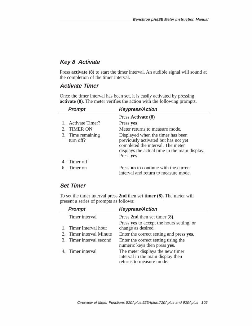
Key 8 Activate
Press activate (8)to start the timer interval. An audible signal will sound atthe completion of the timer interval.
Activate Timer
Once the timer interval has been set, it is easily activated by pressingactivate (8). The meter verifies the action with the following prompts.
Prompt Keypress/Action
Press Activate (8)1. Activate Timer? Press yes2. TIMER ON Meter returns to measure mode.3. Time remaining Displayed when the timer has been
turn off? previously activated but has not yet completed the interval. The meter displays the actual time in the main display. Press yes.
4. Timer off6. Timer on Press no to continue with the current
interval and return to measure mode.
Set Timer
To set the timer interval press2nd then set timer (8).The meter willpresent a series of prompts as follows:
Prompt Keypress/Action
Timer interval Press2nd then set timer (8).Press yesto accept the hours setting, or
1. Timer Interval hour change as desired.2. Timer interval Minute Enter the correct setting and press yes.3. Timer interval second Enter the correct setting using the
numeric keys then press yes.4. Timer interval The meter displays the new timer
interval in the main display then returns to measure mode.
Benchtop pH/ISE Meter Instruction Manual
Overview of Meter Functions 520Aplus,525Aplus,720Aplus and 920Aplus 105
Benchtop pH/ISE Meter Instruction Manual
Overview of Meter Functions 520Aplus,525Aplus,720Aplus and 920Aplus106
Key 9 Set Temp
Press set temp (9) to access the set tempfunction to manually set thetemperature. This is used for manual temperature compensation in pHmode and in concentration mode on the Model 920Aplus. If a temperatureprobe is in use, the meter will not allow a temperature to be set manually. If no temperature probe is in use, the main display will show 25.0 DEG andthe prompt line will show ENTER VALUE. Use the numeric keys to enterthe temperature of your solution, then press yes. The meter verifies yourentry, then returns to measure mode. See temperature compensation sectionfor more information on temperature.
Ready
Press 2nd then ready to access the ready function, which identifies whenthe electrode signal is stable. The ready signal may be turned on or off. Theprompt line verifies your selection then returns to measure mode. Example:READY OFF.
The ready function is tied to the resolution selected. The less resolutionselected the faster the ready signal will be displayed.
The ready signal appears in the prompt line as READY (520Aplus) orRDY (525Aplus, 720Aplus or 920Aplus).
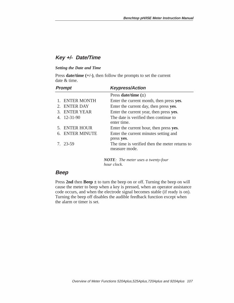
Benchtop pH/ISE Meter Instruction Manual
Overview of Meter Functions 520Aplus,525Aplus,720Aplus and 920Aplus 107
Key +/- Date/Time
Setting the Date and Time
Press date/time (+/-), then follow the prompts to set the current date & time.
Prompt Keypress/Action
Press date/time (±)1. ENTER MONTH Enter the current month, then press yes.2. ENTER DAY Enter the current day, then press yes.3. ENTER YEAR Enter the current year, then press yes.4. 12-31-90 The date is verified then continue to
enter time.5. ENTER HOUR Enter the current hour, then press yes.6. ENTER MINUTE Enter the current minutes setting and
press yes.7. 23-59 The time is verified then the meter returns to
measure mode.
NOTE: The meter uses a twenty-four hour clock.
Beep
Press 2nd then Beep ±to turn the beep on or off. Turning the beep on willcause the meter to beep when a key is pressed, when an operator assistancecode occurs, and when the electrode signal becomes stable (if ready is on).Turning the beep off disables the audible feedback function except whenthe alarm or timer is set.
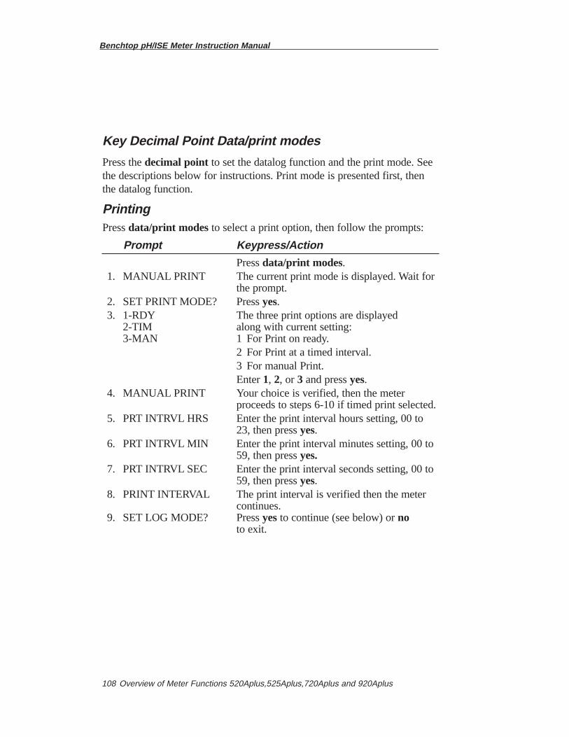
Benchtop pH/ISE Meter Instruction Manual
Overview of Meter Functions 520Aplus,525Aplus,720Aplus and 920Aplus108
Key Decimal Point Data/print modes
Press the decimal point to set the datalog function and the print mode. Seethe descriptions below for instructions. Print mode is presented first, thenthe datalog function.
PrintingPress data/print modes to select a print option, then follow the prompts:
Prompt Keypress/Action
Press data/print modes.1. MANUAL PRINT The current print mode is displayed. Wait for
the prompt.2. SET PRINT MODE? Press yes.3. 1-RDY The three print options are displayed
2-TIM along with current setting:3-MAN 1 For Print on ready.
2 For Print at a timed interval.3 For manual Print.Enter 1, 2, or 3 and press yes.
4. MANUAL PRINT Your choice is verified, then the meter proceeds to steps 6-10 if timed print selected.
5. PRT INTRVL HRS Enter the print interval hours setting, 00 to 23, then press yes.
6. PRT INTRVL MIN Enter the print interval minutes setting, 00 to 59, then press yes.
7. PRT INTRVL SEC Enter the print interval seconds setting, 00 to 59, then press yes.
8. PRINT INTERVAL The print interval is verified then the meter continues.
9. SET LOG MODE? Press yes to continue (see below) or noto exit.
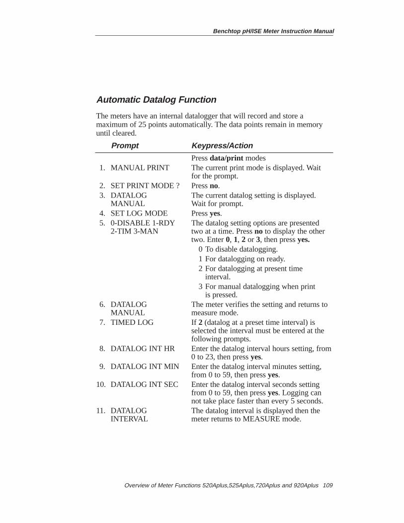
Benchtop pH/ISE Meter Instruction Manual
Overview of Meter Functions 520Aplus,525Aplus,720Aplus and 920Aplus 109
Automatic Datalog Function
The meters have an internal datalogger that will record and store amaximum of 25 points automatically. The data points remain in memoryuntil cleared.
Prompt Keypress/Action
Press data/print modes1. MANUAL PRINT The current print mode is displayed. Wait
for the prompt.2. SET PRINT MODE ? Press no.3. DATALOG The current datalog setting is displayed.
MANUAL Wait for prompt.4. SET LOG MODE Press yes.5. 0-DISABLE 1-RDY The datalog setting options are presented
2-TIM 3-MAN two at a time. Press no to display the other two. Enter 0, 1, 2 or 3, then pressyes.
0 To disable datalogging.1 For datalogging on ready.2 For datalogging at present time
interval.3 For manual datalogging when print
is pressed.6. DATALOG The meter verifies the setting and returns to
MANUAL measure mode.7. TIMED LOG If 2 (datalog at a preset time interval) is
selected the interval must be entered at the following prompts.
8. DATALOG INT HR Enter the datalog interval hours setting, from0 to 23, then press yes.
9. DATALOG INT MIN Enter the datalog interval minutes setting, from 0 to 59, then press yes.
10. DATALOG INT SEC Enter the datalog interval seconds setting from 0 to 59, then press yes. Logging can not take place faster than every 5 seconds.
11. DATALOG The datalog interval is displayed then the INTERVAL meter returns to MEASURE mode.
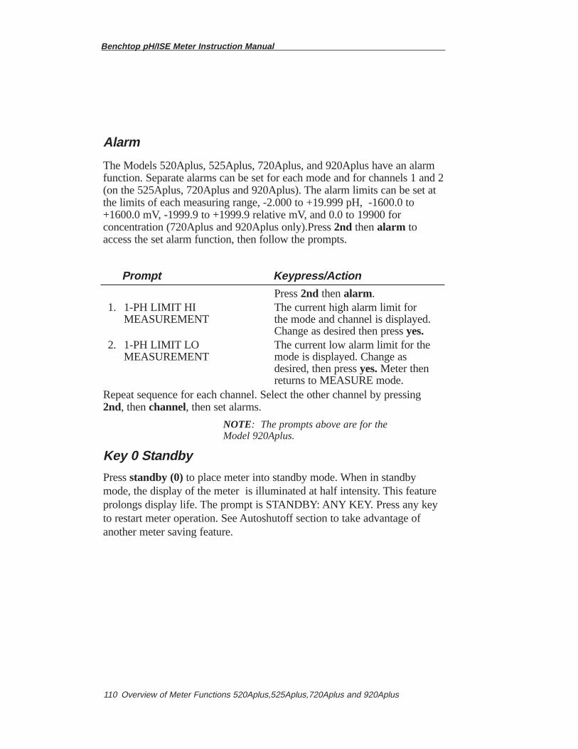
Benchtop pH/ISE Meter Instruction Manual
Overview of Meter Functions 520Aplus,525Aplus,720Aplus and 920Aplus110
Alarm
The Models 520Aplus, 525Aplus, 720Aplus, and 920Aplus have an alarmfunction. Separate alarms can be set for each mode and for channels 1 and 2(on the 525Aplus, 720Aplus and 920Aplus). The alarm limits can be set atthe limits of each measuring range, -2.000 to +19.999 pH, -1600.0 to+1600.0 mV, -1999.9 to +1999.9 relative mV, and 0.0 to 19900 forconcentration (720Aplus and 920Aplus only).Press 2nd then alarm toaccess the set alarm function, then follow the prompts.
Prompt Keypress/Action
Press 2nd then alarm.1. 1-PH LIMIT HI The current high alarm limit for
MEASUREMENT the mode and channel is displayed.Change as desired then press yes.
2. 1-PH LIMIT LO The current low alarm limit for the MEASUREMENT mode is displayed. Change as
desired, then press yes. Meter then returns to MEASURE mode.
Repeat sequence for each channel. Select the other channel by pressing2nd, then channel, then set alarms.
NOTE: The prompts above are for theModel 920Aplus.
Key 0 Standby
Press standby (0)to place meter into standby mode. When in standbymode, the display of the meter is illuminated at half intensity. This featureprolongs display life. The prompt is STANDBY: ANY KEY. Press any keyto restart meter operation. See Autoshutoff section to take advantage ofanother meter saving feature.
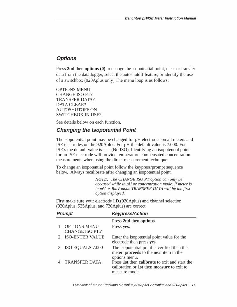
Benchtop pH/ISE Meter Instruction Manual
Overview of Meter Functions 520Aplus,525Aplus,720Aplus and 920Aplus 111
Options
Press 2nd then options (0)to change the isopotential point, clear or transferdata from the datatlogger, select the autoshutoff feature, or identify the useof a switchbox (920Aplus only) The menu loop is as follows:
OPTIONS MENUCHANGE ISO PT?TRANSFER DATA?DATA CLEAR?AUTOSHUTOFF ONSWITCHBOX IN USE?
See details below on each function.
Changing the Isopotential Point
The isopotential point may be changed for pH electrodes on all meters andISE electrodes on the 920Aplus. For pH the default value is 7.000. ForISE’s the default value is - - - (No ISO). Identifying an isopotential pointfor an ISE electrode will provide temperature compensated concentrationmeasurements when using the direct measurement technique.
To change an isopotential point follow the keypress/prompt sequencebelow. Always recalibrate after changing an isopotential point.
NOTE: The CHANGE ISO PT option can only be accessed while in pH or concentration mode. If meter is in mV or RmV mode TRANSFER DATA will be the first option displayed.
First make sure your electrode I.D.(920Aplus) and channel selection(920Aplus, 525Aplus, and 720Aplus) are correct.
Prompt Keypress/Action
Press2nd then options.1. OPTIONS MENU Press yes.
CHANGE ISO PT.?2. ISO-ENTER VALUE Enter the isopotential point value for the
electrode then press yes.3. ISO EQUALS 7.000 The isopotential point is verified then the
meter proceeds to the next item in the options menu.
4. TRANSFER DATA Press 1st then calibrate to exit and start the calibration or 1st then measureto exit tomeasure mode.
Benchtop pH/ISE Meter Instruction Manual
Overview of Meter Functions 520Aplus,525Aplus,720Aplus and 920Aplus112
Transfer Data
To transfer data from the internal datalogger to a printer or computer pressyesin response to the TRANSFER DATA? prompt. While the data is beingtransferred the prompt line will display DATA TRANSFER. On completionthe DATA TRANSFERRED prompt will be displayed followed by the nextoption in the menu.
Data ClearTransferring data from the datalogger does notclear the memory. Pressingyes to the DATA CLEAR? prompt will clear the datalogger memory. DATACLEARING followed by DATA CLEARED will be displayed. The meterthen displays the next option in the menu, AUTOSHUTOFF.
NOTE: Prior to using the datalogger for the very first time, it will be necessary to clear datalogger memory with the DATA CLEAR option.
Autoshutoff Feature
The meters have a special feature that will help to prolong meter life calledautoshutoff. When autoshutoff has been activated the meter will enterstandby mode if no keys have been pressed for ten minutes. To start themeter again, press any key.
Prompt Keypress/Action
Press 2nd then Options.1. OPTIONS MENU Press no.
CHANGE ISO PT?2. TRANSFER DATA? Press no.3. DATA CLEAR? Press no4. AUTOSHUTOFF ON Press yes.5. AUTOSHUTOFF OFF The meter verifies your
selection then proceeds to the next item in the options menu. (The 520Aplus, 525Aplus, and 720Aplus return to measure mode).
Benchtop pH/ISE Meter Instruction Manual
Overview of Meter Functions 520Aplus,525Aplus,720Aplus and 920Aplus 113
Use of a Switchbox (920Aplus)
The 920Aplus stores in memory calibration data for seven channels.Additional channels can be accessed when using the 920Aplus with theThermo Orion Model 607 electrode switchbox. Press the channel selectionswitch on the Model 607. Press 2nd, then channel (5)on the Model920Aplus, until the desired channel is selected on both the instrument andswitchbox. Use of a switchbox must be identified in the options menu toaccess the additional channels on the 920Aplus.
Prompt Keypress/Action
Press 2nd then Options.1. OPTIONS MENU Press no.
CHANGE ISO POINT?2. TRANSFER DATA? Pressno.3. DATA CLEAR? Press no.4. AUTOSHUTOFF ON Press yes.5. SWITCHBOX IN USE? Press yes.6. SWITCHBOX ENABLED The meter verifies the use of
a switch box then returns to measure mode.

Benchtop pH/ISE Meter Instruction Manual
Overview of Meter Functions 520Aplus,525Aplus,720Aplus and 920Aplus114
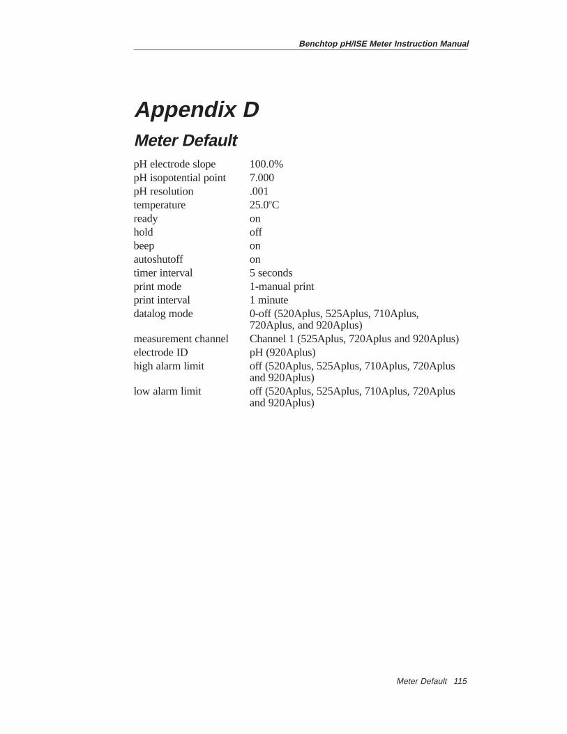
Benchtop pH/ISE Meter Instruction Manual
Meter Default 115
Appendix DMeter DefaultpH electrode slope 100.0%pH isopotential point 7.000 pH resolution .001 temperature 25.0oCready onhold offbeep onautoshutoff ontimer interval 5 secondsprint mode 1-manual printprint interval 1 minutedatalog mode 0-off (520Aplus, 525Aplus, 710Aplus,
720Aplus, and 920Aplus)measurement channel Channel 1 (525Aplus, 720Aplus and 920Aplus)electrode ID pH (920Aplus)high alarm limit off (520Aplus, 525Aplus, 710Aplus, 720Aplus
and 920Aplus)low alarm limit off (520Aplus, 525Aplus, 710Aplus, 720Aplus
and 920Aplus)

Benchtop pH/ISE Meter Instruction Manual
Meter Default116
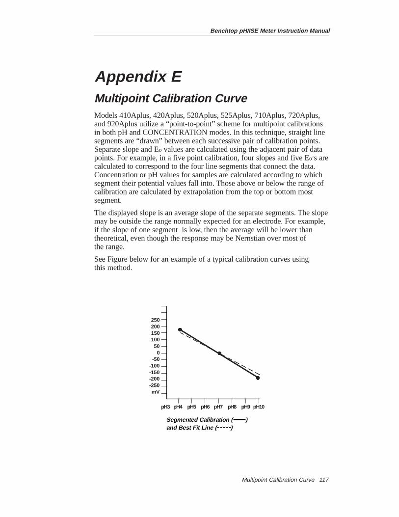
Benchtop pH/ISE Meter Instruction Manual
Multipoint Calibration Curve 117
Appendix EMultipoint Calibration CurveModels 410Aplus, 420Aplus, 520Aplus, 525Aplus, 710Aplus, 720Aplus,and 920Aplus utilize a “point-to-point” scheme for multipoint calibrationsin both pH and CONCENTRATION modes. In this technique, straight linesegments are “drawn” between each successive pair of calibration points.Separate slope and Eo values are calculated using the adjacent pair of datapoints. For example, in a five point calibration, four slopes and five Eo’s arecalculated to correspond to the four line segments that connect the data.Concentration or pH values for samples are calculated according to whichsegment their potential values fall into. Those above or below the range ofcalibration are calculated by extrapolation from the top or bottom mostsegment.
The displayed slope is an average slope of the separate segments. The slopemay be outside the range normally expected for an electrode. For example,if the slope of one segment is low, then the average will be lower thantheoretical, even though the response may be Nernstian over most of the range.
See Figure below for an example of a typical calibration curves using this method.
25020015010050
0-50
-100-150-200-250mV
pH3 pH4 pH5 pH6 pH7 pH8 pH9 pH10
Segmented Calibration ( ) and Best Fit Line ( )

Benchtop pH/ISE Meter Instruction Manual
Multipoint Calibration Curve118
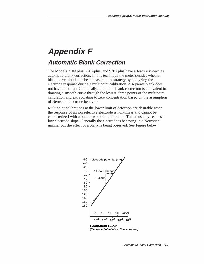
Benchtop pH/ISE Meter Instruction Manual
Automatic Blank Correction 119
Appendix FAutomatic Blank CorrectionThe Models 710Aplus, 720Aplus, and 920Aplus have a feature known asautomatic blank correction. In this technique the meter decides whetherblank correction is the best measurement strategy by analyzing theelectrode response during a multipoint calibration. A separate blank doesnot have to be run. Graphically, automatic blank correction is equivalent todrawing a smooth curve through the lowest three points of the multipointcalibration and extrapolating to zero concentration based on the assumptionof Nernstian electrode behavior.
Multipoint calibrations at the lower limit of detection are desirable whenthe response of an ion selective electrode is non-linear and cannot becharacterized with a one or two point calibration. This is usually seen as alow electrode slope. Generally the electrode is behaving in a Nernstianmanner but the effect of a blank is being observed. See Figure below.
10-1 10-2 10-3 10-4 10-5
0.1 1 10 100 1000
10 - fold change
~56mV
electrode potential (mV)-60-40-20
-020406080
100120140150160
Calibration Curve(Electrode Potential vs. Concentration)
Benchtop pH/ISE Meter Instruction Manual
Automatic Blank Correction120
This blank may be a true reagent blank, traces of analyte ion in thereagents, or it may be the “mud” value of the electrode. It could also be aninterferent in the reagents that becomes apparent at low levels of analyteion, or it could be any combination of these effects.
The expanded version of the Nernst equation traditionally used for blankcorrection is as follows:
E = Eo + S x log(C + b) where b is the blank.
In a multi-point calibration a set of equations is generated and therelationship between them evaluated.
For example the equations generated in a three point calibration would beas follows:
E1 = Eo + S x log (C1 + b )
E2 = Eo + S x log (C2 + b )
E3 = Eo + S x log (C3 + b )
The meter evaluates the relationships between the three potentials E1, E2,and E3 and the three concentrations C1, C2, and C3. If the relationshipsindicate that blank correction is desired, a blank will automatically becalculated, and the non-linearity will be corrected for in a Nernstianmanner. If the appropriate conditions are not met, the blank is set at zeroand each segment of the multipoint calibration is treated independently.
When all three of the following conditions are met, blank correction is invoked.
1. The concentration of the first standard is zero, or the slope of the electrode between the first and second standards is less than the slope between the second and third.
2. Potential differences between points are significant. For example:E3 - E1 > 10 mV
3. The blank correction algorithm converges at reasonable blank and slope values. Conditions in steps 1 and 2 prevent failure to converge inmost situations. However, the slope will attain any value necessary for convergence to a calculated blank value of 3 x C3.
Benchtop pH/ISE Meter Instruction Manual
Automatic Blank Correction 121
When blank correction is implemented, the slope value for the electrodemay be outside the range of values normally considered acceptable duringan ordinary calibration. For best results calibration standards should beclose in range to the expected sample concentrations and should bracketthe expected sample concentration.
When conditions 1, 2, and 3 above are not met, the calibration data ishandled by the multipoint calibration method described earlier.
NOTE: When a calibration standard is defined as zero and the meter cannot calculate a blank, the operator assistance code E-32 will be displayed. See Troubleshooting section.
In calibrations with more than three points, a combination of methods areutilized. Automatic blank correction is used if the lowest three pointssatisfy the criteria and multipoint calibration is used for the other points.The slope displayed after calibration is an average of the slope calculatedin the automatic blank correction algorithm and the slope(s) for eachadditional segment.

Benchtop pH/ISE Meter Instruction Manual
Automatic Blank Correction122
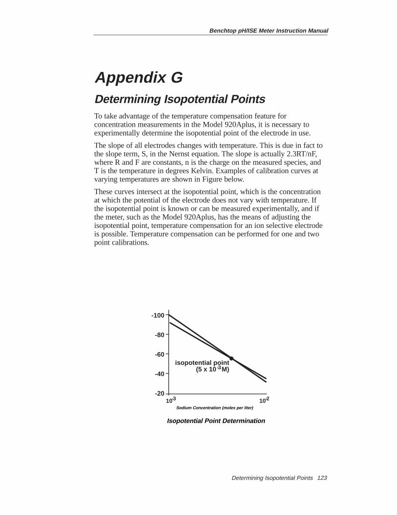
Benchtop pH/ISE Meter Instruction Manual
Determining Isopotential Points 123
Appendix GDetermining Isopotential PointsTo take advantage of the temperature compensation feature forconcentration measurements in the Model 920Aplus, it is necessary toexperimentally determine the isopotential point of the electrode in use.
The slope of all electrodes changes with temperature. This is due in fact tothe slope term, S, in the Nernst equation. The slope is actually 2.3RT/nF,where R and F are constants, n is the charge on the measured species, andT is the temperature in degrees Kelvin. Examples of calibration curves atvarying temperatures are shown in Figure below.
These curves intersect at the isopotential point, which is the concentrationat which the potential of the electrode does not vary with temperature. Ifthe isopotential point is known or can be measured experimentally, and ifthe meter, such as the Model 920Aplus, has the means of adjusting theisopotential point, temperature compensation for an ion selective electrodeis possible. Temperature compensation can be performed for one and twopoint calibrations.
isopotential point(5 x 10 M)
10-3 10-2
-100
-80
-60
-40
-20
sodium concentration, moles per liter
-3
Sodium Concentration (moles per liter)
Isopotential Point Determination
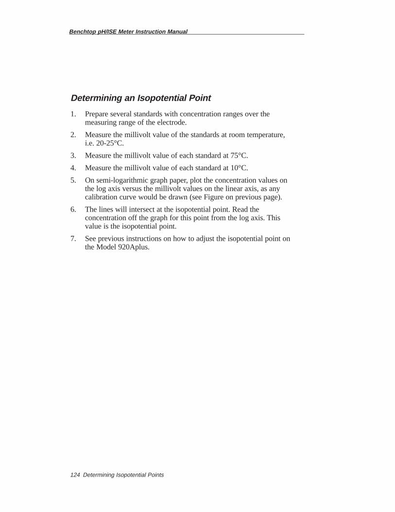
Benchtop pH/ISE Meter Instruction Manual
Determining Isopotential Points124
Determining an Isopotential Point
1. Prepare several standards with concentration ranges over the measuring range of the electrode.
2. Measure the millivolt value of the standards at room temperature, i.e. 20-25°C.
3. Measure the millivolt value of each standard at 75°C.
4. Measure the millivolt value of each standard at 10°C.
5. On semi-logarithmic graph paper, plot the concentration values on the log axis versus the millivolt values on the linear axis, as any calibration curve would be drawn (see Figure on previous page).
6. The lines will intersect at the isopotential point. Read the concentration off the graph for this point from the log axis. This value is the isopotential point.
7. See previous instructions on how to adjust the isopotential point on the Model 920Aplus.
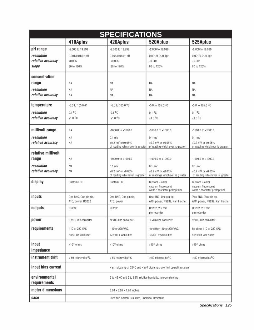
410Aplus 420Aplus 520Aplus 525ApluspH range -2.000 to 19.999 -2.000 to 19.999 -2.000 to 19.999 -2.000 to 19.999
resolution 0.001/0.01/0.1pH 0.001/0.01/0.1pH 0.001/0.01/0.1pH 0.001/0.01/0.1pH
relative accuracy ±0.005 ±0.005 ±0.005 ±0.005
slope 80 to 120% 80 to 120% 80 to 120% 80 to 120%
concentrationrange NA NA NA NA
resolution NA NA NA NA
relative accuracy NA NA NA NA
temperature -5.0 to 105.0oC -5.0 to 105.0 oC -5.0 to 105.0 oC -5.0 to 105.0 oC
resolution 0.1 oC 0.1 oC 0.1 oC 0.1 oC
relative accuracy ±1.0 oC ±1.0 oC ±1.0 oC ±1.0 oC
millivolt range NA -1600.0 to +1600.0 -1600.0 to +1600.0 -1600.0 to +1600.0
resolution NA 0.1 mV 0.1 mV 0.1 mV
relative accuracy NA ±0.2 mV or±0.05% ±0.2 mV or ±0.05% ±0.2 mV or ±0.05% of reading which ever is greater of reading which ever is greater of reading whichever is greater
relative millivolt range NA -1999.9 to +1999.9 -1999.9 to +1999.9 -1999.9 to +1999.9
resolution NA 0.1 mV 0.1 mV 0.1 mV
relative accuracy NA ±0.2 mV or ±0.05% ±0.2 mV or ±0.05% ±0.2 mV or ±0.05%of reading whichever is greater of readings whichever is greater of reading whichever is greater
display Custom LCD Custom LCD Custom 2-color Custom 2-colorvacuum fluorescent vacuum fluorescentwith17 character prompt line with17 character prompt line
inputs One BNC, One pin tip, One BNC, One pin tip, One BNC, One pin tip, Two BNC, Two pin tip,ATC, power, RS232 ATC, power ATC, power, RS232, Karl Fischer ATC, power, RS232, Karl Fischer
outputs RS232 RS232 RS232, 2.5 mm RS232, 2.5 mmpin recorder pin recorder
power 9 VDC line converter 9 VDC line converter 9 VDC line converter 9 VDC line converter
requirements 110 or 220 VAC. 110 or 220 VAC. for either 110 or 220 VAC. for either 110 or 220 VAC,
50/60 Hz walloutlet. 50/60 Hz walloutlet. 50/60 Hz wall outlet. 50/60 Hz wall outlet.
input >1012 ohms >1012 ohms >1012 ohms >1012 ohms
impedance
instrument drift < 50 microvolts/oC < 50 microvolts/oC < 50 microvolts/oC < 50 microvolts/oC
input bias current < ± 1 picoamp at 25oC and < ± 4 picoamps over full operating range
environmental 5 to 45 oC and 5 to 85% relative humidity, non-condensing
requirements
meter dimensions 8.08 x 3.26 x 1.90 inches
case Dust and Splash Resistant, Chemical Resistant
SPECIFICATIONS
Specifications 125
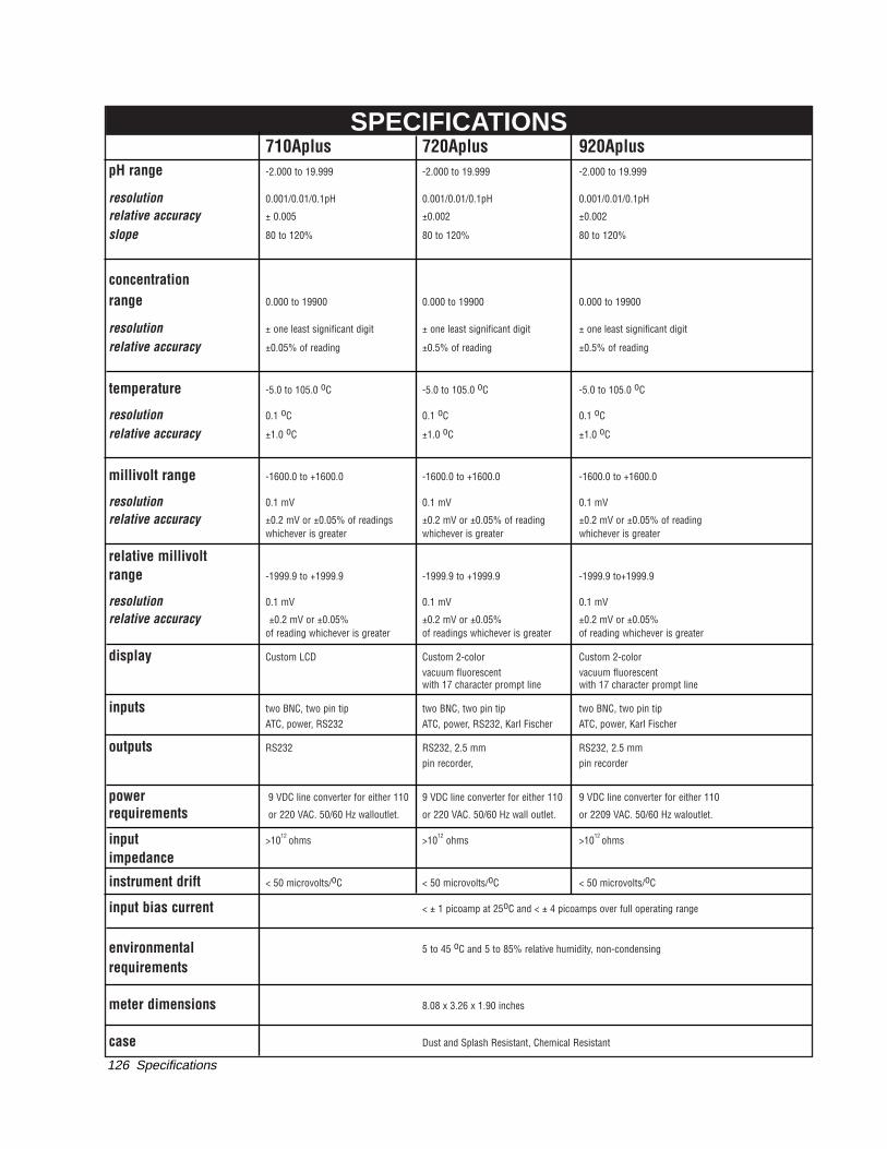
710Aplus 720Aplus 920ApluspH range -2.000 to 19.999 -2.000 to 19.999 -2.000 to 19.999
resolution 0.001/0.01/0.1pH 0.001/0.01/0.1pH 0.001/0.01/0.1pH
relative accuracy ± 0.005 ±0.002 ±0.002
slope 80 to 120% 80 to 120% 80 to 120%
concentrationrange 0.000 to 19900 0.000 to 19900 0.000 to 19900
resolution ± one least significant digit ± one least significant digit ± one least significant digit
relative accuracy ±0.05% of reading ±0.5% of reading ±0.5% of reading
temperature -5.0 to 105.0 oC -5.0 to 105.0 oC -5.0 to 105.0 oC
resolution 0.1 oC 0.1 oC 0.1 oC
relative accuracy ±1.0 oC ±1.0 oC ±1.0 oC
millivolt range -1600.0 to +1600.0 -1600.0 to +1600.0 -1600.0 to +1600.0
resolution 0.1 mV 0.1 mV 0.1 mV
relative accuracy ±0.2 mV or ±0.05% of readings ±0.2 mV or ±0.05% of reading ±0.2 mV or ±0.05% of readingwhichever is greater whichever is greater whichever is greater
relative millivoltrange -1999.9 to +1999.9 -1999.9 to +1999.9 -1999.9 to+1999.9
resolution 0.1 mV 0.1 mV 0.1 mV
relative accuracy ±0.2 mV or ±0.05% ±0.2 mV or ±0.05% ±0.2 mV or ±0.05% of reading whichever is greater of readings whichever is greater of reading whichever is greater
display Custom LCD Custom 2-color Custom 2-color vacuum fluorescent vacuum fluorescent with 17 character prompt line with 17 character prompt line
inputs two BNC, two pin tip two BNC, two pin tip two BNC, two pin tipATC, power, RS232 ATC, power, RS232, Karl Fischer ATC, power, Karl Fischer
outputs RS232 RS232, 2.5 mm RS232, 2.5 mmpin recorder, pin recorder
power 9 VDC line converter for either 110 9 VDC line converter for either 110 9 VDC line converter for either 110
requirements or 220 VAC. 50/60 Hz walloutlet. or 220 VAC. 50/60 Hz wall outlet. or 2209 VAC. 50/60 Hz waloutlet.
input >1012 ohms >1012 ohms >1012 ohms
impedance
instrument drift < 50 microvolts/oC < 50 microvolts/oC < 50 microvolts/oC
input bias current < ± 1 picoamp at 25oC and < ± 4 picoamps over full operating range
environmental 5 to 45 oC and 5 to 85% relative humidity, non-condensing
requirements
meter dimensions 8.08 x 3.26 x 1.90 inches
case Dust and Splash Resistant, Chemical Resistant
SPECIFICATIONS
Specifications126

AQUAfast, Cahn, EZFlash, Ionalyzer, ionplus, KNIpHE, ORION, perpHect, PerpHecT, PerpHecTion, pHISA, pHix, pHuture, Pure Water, Sage, Sensing the Future, SensorLink, Sure-Flow,Titrator PLUS, TURBO2 and Wine Master are registered trademarks of Thermo Orion.
1-888-pHAX-ION, A+, All in One, Aplus, AQUAsnap, AssuredAccuracy, AUTO-BAR, AUTOCAL, AUTO DISPENSER, Auto-ID, AUTO-LOG, AUTO-STIR, AUTO-READ, BOD AutoEZ, Cable-Free, CERTI-CAL, CISA, DataCOLLECT, DataPLUS, digital LogR, DirectCal, DuraProbe, Environmental Product Authority, Extra Easy/Extra Value, FAST QC, Flash GC, GAP, GLPcal,GLPcheck, GLPdoc, KAP, LabConnect, LogR, Minimum Stir Requirement, MSR, NISS, One-Touch, One-Touch Calibration, One-Touch Measurement, Optimum Results, Pentrode, pHutureMMS, pHuture Pentrode, pHuture Quatrode, pHuture Triode, Quatrode, QuiKcheK, rf link, ROSS, ROSS Resolution, SAOB, Stacked, Stat Face, The Enhanced Lab, ThermaSense, Triode,TRIUMpH, Unbreakable pH, Universal Access are trademarks of Thermo Orion.
Guaranteed Success and The Technical Edge are service marks of Thermo Orion.
PerpHecT meters are protected by U.S. patent 4,321,544.
ROSS and PerpHecT ROSS are protected by U.S. patent 4,495,050.
ORION Series A meters and 900A printer are protected by U.S. patents 5,108,578, 5,198,093, D334,208 and D346,753.
ORION 81, 82, 91, and 92 series glass electrodes are protected by U.S. patents 4,661,236 and 4,687,500.
Sure-Flow electrodes are protected by European Patent 278,979 and Canadian Patent 1,286,720.
ionplus electrodes and Optimum Results solutions have patents pending.
© Copyright 2001, Thermo Orion. All rights reserved.
The specifications, descriptions, drawings, ordering information and part numbers within this document are subject to change without notice.
This publication supersedes all previous publications on this subject.

A Thermo Electron business
Thermo Orion 500 Cummings CenterBeverly, MA 01915-6199 USATel: 978-232-6000Dom. Fax: 978-232-6015Int’l. Fax: 978-232-6031
Thermo Orion Europe12-16 Sedgeway Business ParkWitchford, CambridgeshireEngland, CB6 2HYTel: 44-1353-666111Fax: 44-1353-666001
Thermo Orion Far EastRoom 904, Federal Building369 Lockhart RoadWanchai, Hong KongTel: 852-2836-0981Fax: 852-2834-5160
Thermo Orion Customer Support Toll Free: 800-225-1480 www.thermoorion.com Dom. e-mail: [email protected]’l. e-mail: [email protected]
233541-001 Rev. B