installation & operation guide frame synchronizer/converter v1.1 vid 2-4 alarm . . . . . . . . ....
TRANSCRIPT
Installation & Operation GuideVersion 1.1Published: August 31, 2016
FS4
FS4 Frame Synchronizer/Converter v1.1 www.aja.com2
Table of Contents
Notices . . . . . . . . . . . . . . . . . . . . . . . . . . . . . . . . . . . . . . . . . . . . . . . . . . . . . . .10Trademarks . . . . . . . . . . . . . . . . . . . . . . . . . . . . . . . . . . . . . . . . . . . . . . . . . . . . . . . . . . . . . . . . . . . . . . 10Copyright . . . . . . . . . . . . . . . . . . . . . . . . . . . . . . . . . . . . . . . . . . . . . . . . . . . . . . . . . . . . . . . . . . . . . . . . 10Contacting Support . . . . . . . . . . . . . . . . . . . . . . . . . . . . . . . . . . . . . . . . . . . . . . . . . . . . . . . . . . . . . . 10
Chapter 1: Introduction . . . . . . . . . . . . . . . . . . . . . . . . . . . . . . . . . . . . . . .11Overview. . . . . . . . . . . . . . . . . . . . . . . . . . . . . . . . . . . . . . . . . . . . . . . . . . . . . . . . . . . . . . . . . . . . . . . . . 11
Video Features . . . . . . . . . . . . . . . . . . . . . . . . . . . . . . . . . . . . . . . . . . . . . . . . . . . . . . . . . . . . . . . 11Audio Features. . . . . . . . . . . . . . . . . . . . . . . . . . . . . . . . . . . . . . . . . . . . . . . . . . . . . . . . . . . . . . . 12Other Features . . . . . . . . . . . . . . . . . . . . . . . . . . . . . . . . . . . . . . . . . . . . . . . . . . . . . . . . . . . . . . . 12
FS4 Control . . . . . . . . . . . . . . . . . . . . . . . . . . . . . . . . . . . . . . . . . . . . . . . . . . . . . . . . . . . . . . . . . . . . . . 12Front Panel Control . . . . . . . . . . . . . . . . . . . . . . . . . . . . . . . . . . . . . . . . . . . . . . . . . . . . . . . . . . 12Remote Web Browser Control . . . . . . . . . . . . . . . . . . . . . . . . . . . . . . . . . . . . . . . . . . . . . . . . 13GPI Inputs and Outputs . . . . . . . . . . . . . . . . . . . . . . . . . . . . . . . . . . . . . . . . . . . . . . . . . . . . . . 13SNMP Interface Monitoring. . . . . . . . . . . . . . . . . . . . . . . . . . . . . . . . . . . . . . . . . . . . . . . . . . . 13
Technical Description. . . . . . . . . . . . . . . . . . . . . . . . . . . . . . . . . . . . . . . . . . . . . . . . . . . . . . . . . . . . . 13Four Channel Mode . . . . . . . . . . . . . . . . . . . . . . . . . . . . . . . . . . . . . . . . . . . . . . . . . . . . . . . . . . 13Single Channel Mode . . . . . . . . . . . . . . . . . . . . . . . . . . . . . . . . . . . . . . . . . . . . . . . . . . . . . . . . 14Video Processor(s) . . . . . . . . . . . . . . . . . . . . . . . . . . . . . . . . . . . . . . . . . . . . . . . . . . . . . . . . . . . 15Audio Processor. . . . . . . . . . . . . . . . . . . . . . . . . . . . . . . . . . . . . . . . . . . . . . . . . . . . . . . . . . . . . . 16
Optional FS4 Features . . . . . . . . . . . . . . . . . . . . . . . . . . . . . . . . . . . . . . . . . . . . . . . . . . . . . . . . . . . . 16SFP I/O . . . . . . . . . . . . . . . . . . . . . . . . . . . . . . . . . . . . . . . . . . . . . . . . . . . . . . . . . . . . . . . . . . . . . . 16
Operation Overview . . . . . . . . . . . . . . . . . . . . . . . . . . . . . . . . . . . . . . . . . . . . . . . . . . . . . . . . . . . . . . 16About Inputs and Outputs. . . . . . . . . . . . . . . . . . . . . . . . . . . . . . . . . . . . . . . . . . . . . . . . . . . . 16About Reference and Genlock Source. . . . . . . . . . . . . . . . . . . . . . . . . . . . . . . . . . . . . . . . . 16Retained Settings . . . . . . . . . . . . . . . . . . . . . . . . . . . . . . . . . . . . . . . . . . . . . . . . . . . . . . . . . . . . 17
In This Manual. . . . . . . . . . . . . . . . . . . . . . . . . . . . . . . . . . . . . . . . . . . . . . . . . . . . . . . . . . . . . . . . . . . . 17
Chapter 2: Controls, Indicators, and Connections. . . . . . . . . . . . . . . .18Overview. . . . . . . . . . . . . . . . . . . . . . . . . . . . . . . . . . . . . . . . . . . . . . . . . . . . . . . . . . . . . . . . . . . . . . . . . 18Front Panel Description. . . . . . . . . . . . . . . . . . . . . . . . . . . . . . . . . . . . . . . . . . . . . . . . . . . . . . . . . . . 18
Front Panel Layout and Operation . . . . . . . . . . . . . . . . . . . . . . . . . . . . . . . . . . . . . . . . . . . . 18Operational Summary . . . . . . . . . . . . . . . . . . . . . . . . . . . . . . . . . . . . . . . . . . . . . . . . . . . . . . . . 19
Multiple Part Parameter Editing . . . . . . . . . . . . . . . . . . . . . . . . . . . . . . . . . . . . . . . . . . 19Coarse Adjust Editing . . . . . . . . . . . . . . . . . . . . . . . . . . . . . . . . . . . . . . . . . . . . . . . . . . . . 19Undo a Change . . . . . . . . . . . . . . . . . . . . . . . . . . . . . . . . . . . . . . . . . . . . . . . . . . . . . . . . . . 19Reset to Factory Default: . . . . . . . . . . . . . . . . . . . . . . . . . . . . . . . . . . . . . . . . . . . . . . . . . 19
Alphanumeric Display . . . . . . . . . . . . . . . . . . . . . . . . . . . . . . . . . . . . . . . . . . . . . . . . . . . . . . . . 19Status Menus . . . . . . . . . . . . . . . . . . . . . . . . . . . . . . . . . . . . . . . . . . . . . . . . . . . . . . . . . . . . 19Parameter Menus . . . . . . . . . . . . . . . . . . . . . . . . . . . . . . . . . . . . . . . . . . . . . . . . . . . . . . . . 20
Control Knobs . . . . . . . . . . . . . . . . . . . . . . . . . . . . . . . . . . . . . . . . . . . . . . . . . . . . . . . . . . . . . . . 20Button Menus. . . . . . . . . . . . . . . . . . . . . . . . . . . . . . . . . . . . . . . . . . . . . . . . . . . . . . . . . . . . . . . . 20
System Buttons . . . . . . . . . . . . . . . . . . . . . . . . . . . . . . . . . . . . . . . . . . . . . . . . . . . . . . . . . . 21Channel Select Buttons . . . . . . . . . . . . . . . . . . . . . . . . . . . . . . . . . . . . . . . . . . . . . . . . . . 22Video Menu Group Buttons . . . . . . . . . . . . . . . . . . . . . . . . . . . . . . . . . . . . . . . . . . . . . . 22Audio Menu Group Buttons . . . . . . . . . . . . . . . . . . . . . . . . . . . . . . . . . . . . . . . . . . . . . . 23
Status LED Indicators . . . . . . . . . . . . . . . . . . . . . . . . . . . . . . . . . . . . . . . . . . . . . . . . . . . . . . . . . 23Incompatibility Alarms . . . . . . . . . . . . . . . . . . . . . . . . . . . . . . . . . . . . . . . . . . . . . . . . . . . . . . . 23
Example Reference and Video Incompatibility Alarms . . . . . . . . . . . . . . . . . . . . . 24Rear Panel Description. . . . . . . . . . . . . . . . . . . . . . . . . . . . . . . . . . . . . . . . . . . . . . . . . . . . . . . . . . . . 25
FS4 Frame Synchronizer/Converter v1.1 www.aja.com3
Connectors . . . . . . . . . . . . . . . . . . . . . . . . . . . . . . . . . . . . . . . . . . . . . . . . . . . . . . . . . . . . . . . . . . 25
Chapter 3: Installation & Configuration . . . . . . . . . . . . . . . . . . . . . . . . .27Installation Overview . . . . . . . . . . . . . . . . . . . . . . . . . . . . . . . . . . . . . . . . . . . . . . . . . . . . . . . . . . . . . 27
Installation Summary. . . . . . . . . . . . . . . . . . . . . . . . . . . . . . . . . . . . . . . . . . . . . . . . . . . . . . . . . 27Unpacking . . . . . . . . . . . . . . . . . . . . . . . . . . . . . . . . . . . . . . . . . . . . . . . . . . . . . . . . . . . . . . . . . . . . . . . 28
Shipping Box Contents . . . . . . . . . . . . . . . . . . . . . . . . . . . . . . . . . . . . . . . . . . . . . . . . . . . . . . . 28Installing Optional SFP I/O Modules . . . . . . . . . . . . . . . . . . . . . . . . . . . . . . . . . . . . . . . . . . . . . . . 28FS4 Chassis Installation . . . . . . . . . . . . . . . . . . . . . . . . . . . . . . . . . . . . . . . . . . . . . . . . . . . . . . . . . . . 28
Physical Requirements for Mounting the Chassis . . . . . . . . . . . . . . . . . . . . . . . . . . . . . . 28Chassis Dimensions . . . . . . . . . . . . . . . . . . . . . . . . . . . . . . . . . . . . . . . . . . . . . . . . . . . . . . 29Cabling and Cooling Requirements. . . . . . . . . . . . . . . . . . . . . . . . . . . . . . . . . . . . . . . 29
Power Requirements . . . . . . . . . . . . . . . . . . . . . . . . . . . . . . . . . . . . . . . . . . . . . . . . . . . . . . . . . 29Networking . . . . . . . . . . . . . . . . . . . . . . . . . . . . . . . . . . . . . . . . . . . . . . . . . . . . . . . . . . . . . . . . . . . . . . 29
FS4 Default Network Settings. . . . . . . . . . . . . . . . . . . . . . . . . . . . . . . . . . . . . . . . . . . . . . . . . 29Networking Using DHCP or Default Static IP. . . . . . . . . . . . . . . . . . . . . . . . . . . . . . . . . . . 30Networking the FS4 Using Your Own Static IP . . . . . . . . . . . . . . . . . . . . . . . . . . . . . . . . . 30Using Ping to Test the Network Connection . . . . . . . . . . . . . . . . . . . . . . . . . . . . . . . . . . . 31
Mac Ping Procedure . . . . . . . . . . . . . . . . . . . . . . . . . . . . . . . . . . . . . . . . . . . . . . . . . . . . . 31Windows PC Ping Procedure . . . . . . . . . . . . . . . . . . . . . . . . . . . . . . . . . . . . . . . . . . . . . 31
Web Browser Control . . . . . . . . . . . . . . . . . . . . . . . . . . . . . . . . . . . . . . . . . . . . . . . . . . . . . . . . . . . . . 31Software Update Installation. . . . . . . . . . . . . . . . . . . . . . . . . . . . . . . . . . . . . . . . . . . . . . . . . . . . . . 32
Download the Latest Software. . . . . . . . . . . . . . . . . . . . . . . . . . . . . . . . . . . . . . . . . . . . . . . . 32Unpack the Software . . . . . . . . . . . . . . . . . . . . . . . . . . . . . . . . . . . . . . . . . . . . . . . . . . . . . . . . . 32Uploading and Installing the Software to the FS4. . . . . . . . . . . . . . . . . . . . . . . . . . . . . . 32
System Cabling. . . . . . . . . . . . . . . . . . . . . . . . . . . . . . . . . . . . . . . . . . . . . . . . . . . . . . . . . . . . . . . . . . . 33System Video/Audio Cable Connections . . . . . . . . . . . . . . . . . . . . . . . . . . . . . . . . . . . . . . 33Four Channel Mode Configuration Examples. . . . . . . . . . . . . . . . . . . . . . . . . . . . . . . . . . 33
Four Channel Mode Input Examples . . . . . . . . . . . . . . . . . . . . . . . . . . . . . . . . . . . . . . 34Four Channel Mode Output Examples . . . . . . . . . . . . . . . . . . . . . . . . . . . . . . . . . . . . 36Four Channel Mode Conversion Examples . . . . . . . . . . . . . . . . . . . . . . . . . . . . . . . . 38
Single Channel Mode Configuration Examples . . . . . . . . . . . . . . . . . . . . . . . . . . . . . . . . 39Single Channel Mode Input Examples . . . . . . . . . . . . . . . . . . . . . . . . . . . . . . . . . . . . 40Single Channel Mode Output Examples . . . . . . . . . . . . . . . . . . . . . . . . . . . . . . . . . . 41
Single Channel Mode Conversion Examples. . . . . . . . . . . . . . . . . . . . . . . . . . . . . . . . . . . 43GPI Connections . . . . . . . . . . . . . . . . . . . . . . . . . . . . . . . . . . . . . . . . . . . . . . . . . . . . . . . . . . . . . 44
Stand Alone Tests . . . . . . . . . . . . . . . . . . . . . . . . . . . . . . . . . . . . . . . . . . . . . . . . . . . . . . . . . . . . . . . . 44First Power Up . . . . . . . . . . . . . . . . . . . . . . . . . . . . . . . . . . . . . . . . . . . . . . . . . . . . . . . . . . . . . . . 44
Setup. . . . . . . . . . . . . . . . . . . . . . . . . . . . . . . . . . . . . . . . . . . . . . . . . . . . . . . . . . . . . . . . . . . . 44Procedure . . . . . . . . . . . . . . . . . . . . . . . . . . . . . . . . . . . . . . . . . . . . . . . . . . . . . . . . . . . . . . . 44
Chapter 4: Display Menus. . . . . . . . . . . . . . . . . . . . . . . . . . . . . . . . . . . . . .46Overview. . . . . . . . . . . . . . . . . . . . . . . . . . . . . . . . . . . . . . . . . . . . . . . . . . . . . . . . . . . . . . . . . . . . . . . . . 46
FS4 Modes, System Parameters, and Video Parameters . . . . . . . . . . . . . . . . . . . . . . . . 46Presets and FS4 Operating Mode . . . . . . . . . . . . . . . . . . . . . . . . . . . . . . . . . . . . . . . . . . . . . 47Parameter Menus . . . . . . . . . . . . . . . . . . . . . . . . . . . . . . . . . . . . . . . . . . . . . . . . . . . . . . . . . . . . 47
STATUS Menu Group . . . . . . . . . . . . . . . . . . . . . . . . . . . . . . . . . . . . . . . . . . . . . . . . . . . . . . . . . . . . . 47System Status . . . . . . . . . . . . . . . . . . . . . . . . . . . . . . . . . . . . . . . . . . . . . . . . . . . . . . . . . . . . . . . . 47Vid 1/2 I/O . . . . . . . . . . . . . . . . . . . . . . . . . . . . . . . . . . . . . . . . . . . . . . . . . . . . . . . . . . . . . . . . . . . 48Vid 3/4 I/O . . . . . . . . . . . . . . . . . . . . . . . . . . . . . . . . . . . . . . . . . . . . . . . . . . . . . . . . . . . . . . . . . . . 48Vid I/O . . . . . . . . . . . . . . . . . . . . . . . . . . . . . . . . . . . . . . . . . . . . . . . . . . . . . . . . . . . . . . . . . . . . . . . 48Vid 1 Format . . . . . . . . . . . . . . . . . . . . . . . . . . . . . . . . . . . . . . . . . . . . . . . . . . . . . . . . . . . . . . . . . 48Vid 2-4 Format . . . . . . . . . . . . . . . . . . . . . . . . . . . . . . . . . . . . . . . . . . . . . . . . . . . . . . . . . . . . . . . 48Vid 1 Alarm . . . . . . . . . . . . . . . . . . . . . . . . . . . . . . . . . . . . . . . . . . . . . . . . . . . . . . . . . . . . . . . . . . 48
FS4 Frame Synchronizer/Converter v1.1 www.aja.com4
Vid 2-4 Alarm . . . . . . . . . . . . . . . . . . . . . . . . . . . . . . . . . . . . . . . . . . . . . . . . . . . . . . . . . . . . . . . . 48Vid Alarm . . . . . . . . . . . . . . . . . . . . . . . . . . . . . . . . . . . . . . . . . . . . . . . . . . . . . . . . . . . . . . . . . . . . 49SDI Input . . . . . . . . . . . . . . . . . . . . . . . . . . . . . . . . . . . . . . . . . . . . . . . . . . . . . . . . . . . . . . . . . . . . 49Monitor Output . . . . . . . . . . . . . . . . . . . . . . . . . . . . . . . . . . . . . . . . . . . . . . . . . . . . . . . . . . . . . . 49AES Input . . . . . . . . . . . . . . . . . . . . . . . . . . . . . . . . . . . . . . . . . . . . . . . . . . . . . . . . . . . . . . . . . . . . 49MADI In/Out . . . . . . . . . . . . . . . . . . . . . . . . . . . . . . . . . . . . . . . . . . . . . . . . . . . . . . . . . . . . . . . . . 49Power/Temp Alarm . . . . . . . . . . . . . . . . . . . . . . . . . . . . . . . . . . . . . . . . . . . . . . . . . . . . . . . . . . 49Caption Status . . . . . . . . . . . . . . . . . . . . . . . . . . . . . . . . . . . . . . . . . . . . . . . . . . . . . . . . . . . . . . . 50
REMOTE Menu Group . . . . . . . . . . . . . . . . . . . . . . . . . . . . . . . . . . . . . . . . . . . . . . . . . . . . . . . . . . . . 501 Remote Control . . . . . . . . . . . . . . . . . . . . . . . . . . . . . . . . . . . . . . . . . . . . . . . . . . . . . . . . . . . . 501.1 Authentication . . . . . . . . . . . . . . . . . . . . . . . . . . . . . . . . . . . . . . . . . . . . . . . . . . . . . . . . . . . 502.1–4 GPI IN 1–4 Response. . . . . . . . . . . . . . . . . . . . . . . . . . . . . . . . . . . . . . . . . . . . . . . . . . . . 51Interaction of Presets and GPIs . . . . . . . . . . . . . . . . . . . . . . . . . . . . . . . . . . . . . . . . . . . . . . . 52
Example of a Serial Recall . . . . . . . . . . . . . . . . . . . . . . . . . . . . . . . . . . . . . . . . . . . . . . . . 52Example of an Unintended Recall. . . . . . . . . . . . . . . . . . . . . . . . . . . . . . . . . . . . . . . . . 52
3.1–4 GPI 1–4 OUT . . . . . . . . . . . . . . . . . . . . . . . . . . . . . . . . . . . . . . . . . . . . . . . . . . . . . . . . . . . 53VIDEO Menu Group. . . . . . . . . . . . . . . . . . . . . . . . . . . . . . . . . . . . . . . . . . . . . . . . . . . . . . . . . . . . . . . 53
1 Output Frame Rate . . . . . . . . . . . . . . . . . . . . . . . . . . . . . . . . . . . . . . . . . . . . . . . . . . . . . . . . . 532 Genlock Source . . . . . . . . . . . . . . . . . . . . . . . . . . . . . . . . . . . . . . . . . . . . . . . . . . . . . . . . . . . . 533.1 Mon 2K Crop . . . . . . . . . . . . . . . . . . . . . . . . . . . . . . . . . . . . . . . . . . . . . . . . . . . . . . . . . . . . . 533.2 HDMI RGB Range . . . . . . . . . . . . . . . . . . . . . . . . . . . . . . . . . . . . . . . . . . . . . . . . . . . . . . . . . 533.3 Monitor Map . . . . . . . . . . . . . . . . . . . . . . . . . . . . . . . . . . . . . . . . . . . . . . . . . . . . . . . . . . . . . 544.1 SDI1 3G Detect . . . . . . . . . . . . . . . . . . . . . . . . . . . . . . . . . . . . . . . . . . . . . . . . . . . . . . . . . . . 544.2 SDI2 Input Protect . . . . . . . . . . . . . . . . . . . . . . . . . . . . . . . . . . . . . . . . . . . . . . . . . . . . . . . . 544.3, 4.5, 4.7 SDI3/5/7 3G Detect . . . . . . . . . . . . . . . . . . . . . . . . . . . . . . . . . . . . . . . . . . . . . . . 554.4, 4.6, 4.8 SDI4/6/8 Input Protect . . . . . . . . . . . . . . . . . . . . . . . . . . . . . . . . . . . . . . . . . . . . 555.1 VidProc Bypass . . . . . . . . . . . . . . . . . . . . . . . . . . . . . . . . . . . . . . . . . . . . . . . . . . . . . . . . . . . 55
CONFIG Menu Group . . . . . . . . . . . . . . . . . . . . . . . . . . . . . . . . . . . . . . . . . . . . . . . . . . . . . . . . . . . . . 551 System Name . . . . . . . . . . . . . . . . . . . . . . . . . . . . . . . . . . . . . . . . . . . . . . . . . . . . . . . . . . . . . . 55
Name Entry Procedure . . . . . . . . . . . . . . . . . . . . . . . . . . . . . . . . . . . . . . . . . . . . . . . . . . . 562 FS4 Mode . . . . . . . . . . . . . . . . . . . . . . . . . . . . . . . . . . . . . . . . . . . . . . . . . . . . . . . . . . . . . . . . . . 563.1 IP Config . . . . . . . . . . . . . . . . . . . . . . . . . . . . . . . . . . . . . . . . . . . . . . . . . . . . . . . . . . . . . . . . . 563.2 IP Address . . . . . . . . . . . . . . . . . . . . . . . . . . . . . . . . . . . . . . . . . . . . . . . . . . . . . . . . . . . . . . . . 56
Octet Value Entry Procedure . . . . . . . . . . . . . . . . . . . . . . . . . . . . . . . . . . . . . . . . . . . . . 563.3 Subnet Mask . . . . . . . . . . . . . . . . . . . . . . . . . . . . . . . . . . . . . . . . . . . . . . . . . . . . . . . . . . . . . 573.4 Default Gateway. . . . . . . . . . . . . . . . . . . . . . . . . . . . . . . . . . . . . . . . . . . . . . . . . . . . . . . . . . 573.5 MAC Address (view only). . . . . . . . . . . . . . . . . . . . . . . . . . . . . . . . . . . . . . . . . . . . . . . . . . 574 SNMP Enable Parameters . . . . . . . . . . . . . . . . . . . . . . . . . . . . . . . . . . . . . . . . . . . . . . . . . . . 57About FS4 Alarms . . . . . . . . . . . . . . . . . . . . . . . . . . . . . . . . . . . . . . . . . . . . . . . . . . . . . . . . . . . . 575.1, 5.2 Power Supply 1-2 Alarm . . . . . . . . . . . . . . . . . . . . . . . . . . . . . . . . . . . . . . . . . . . . . . 586 Vid Format Alarm. . . . . . . . . . . . . . . . . . . . . . . . . . . . . . . . . . . . . . . . . . . . . . . . . . . . . . . . . . . 586.1-6.4 Vid1-4 Format Alarm . . . . . . . . . . . . . . . . . . . . . . . . . . . . . . . . . . . . . . . . . . . . . . . . . . 587 Reference Alarm. . . . . . . . . . . . . . . . . . . . . . . . . . . . . . . . . . . . . . . . . . . . . . . . . . . . . . . . . . . . 588 Hidden Menus . . . . . . . . . . . . . . . . . . . . . . . . . . . . . . . . . . . . . . . . . . . . . . . . . . . . . . . . . . . . . 589 Screen Saver . . . . . . . . . . . . . . . . . . . . . . . . . . . . . . . . . . . . . . . . . . . . . . . . . . . . . . . . . . . . . . . 5810 Display Intensity . . . . . . . . . . . . . . . . . . . . . . . . . . . . . . . . . . . . . . . . . . . . . . . . . . . . . . . . . . 5911 Fan Speed . . . . . . . . . . . . . . . . . . . . . . . . . . . . . . . . . . . . . . . . . . . . . . . . . . . . . . . . . . . . . . . . 5912 Serial Number. . . . . . . . . . . . . . . . . . . . . . . . . . . . . . . . . . . . . . . . . . . . . . . . . . . . . . . . . . . . . 5913 Software Version . . . . . . . . . . . . . . . . . . . . . . . . . . . . . . . . . . . . . . . . . . . . . . . . . . . . . . . . . . 5914 Reboot . . . . . . . . . . . . . . . . . . . . . . . . . . . . . . . . . . . . . . . . . . . . . . . . . . . . . . . . . . . . . . . . . . . 59
AUDIO Menu Group . . . . . . . . . . . . . . . . . . . . . . . . . . . . . . . . . . . . . . . . . . . . . . . . . . . . . . . . . . . . . . 591 MADI Output Mode . . . . . . . . . . . . . . . . . . . . . . . . . . . . . . . . . . . . . . . . . . . . . . . . . . . . . . . . 592.1-2.8 SDI 1-8 SRC Mode . . . . . . . . . . . . . . . . . . . . . . . . . . . . . . . . . . . . . . . . . . . . . . . . . . . . . 602.9 AES SRC Mode . . . . . . . . . . . . . . . . . . . . . . . . . . . . . . . . . . . . . . . . . . . . . . . . . . . . . . . . . . . . 60
FS4 Frame Synchronizer/Converter v1.1 www.aja.com5
2.10 MADI BNC SRC Mode . . . . . . . . . . . . . . . . . . . . . . . . . . . . . . . . . . . . . . . . . . . . . . . . . . . . 602.11 MADI Fiber SRC Mode . . . . . . . . . . . . . . . . . . . . . . . . . . . . . . . . . . . . . . . . . . . . . . . . . . . 603.0 Mix Down 1 Mode . . . . . . . . . . . . . . . . . . . . . . . . . . . . . . . . . . . . . . . . . . . . . . . . . . . . . . . . 61
About Mix Down Mode . . . . . . . . . . . . . . . . . . . . . . . . . . . . . . . . . . . . . . . . . . . . . . . . . . 613.1 Mix Down Input . . . . . . . . . . . . . . . . . . . . . . . . . . . . . . . . . . . . . . . . . . . . . . . . . . . . . . 623.2 - 3-8 Mix Down Input Mapping (LF, RF, CTR, LR, RR, LS, RS) . . . . . . . . . . . . . 623.9 - 3.14 Mix Down Input Level . . . . . . . . . . . . . . . . . . . . . . . . . . . . . . . . . . . . . . . . . . 623.16 - 3.17 Mix Down Output Lft Rt Level. . . . . . . . . . . . . . . . . . . . . . . . . . . . . . . . . . 62
3.0 Mix Down 2 Mode . . . . . . . . . . . . . . . . . . . . . . . . . . . . . . . . . . . . . . . . . . . . . . . . . . . . . . . . 627 Mix Down Reset . . . . . . . . . . . . . . . . . . . . . . . . . . . . . . . . . . . . . . . . . . . . . . . . . . . . . . . . . . . . 638 Global Audio Output . . . . . . . . . . . . . . . . . . . . . . . . . . . . . . . . . . . . . . . . . . . . . . . . . . . . . . . 639 Reset Mapped Output . . . . . . . . . . . . . . . . . . . . . . . . . . . . . . . . . . . . . . . . . . . . . . . . . . . . . . 63
PRESET Menu Group. . . . . . . . . . . . . . . . . . . . . . . . . . . . . . . . . . . . . . . . . . . . . . . . . . . . . . . . . . . . . . 641 Factory Preset . . . . . . . . . . . . . . . . . . . . . . . . . . . . . . . . . . . . . . . . . . . . . . . . . . . . . . . . . . . . . . 641.1-1.40 Presets #1-#40 . . . . . . . . . . . . . . . . . . . . . . . . . . . . . . . . . . . . . . . . . . . . . . . . . . . . . . . 64Video with Audio Routing . . . . . . . . . . . . . . . . . . . . . . . . . . . . . . . . . . . . . . . . . . . . . . . . . . . . 65Interaction of Presets and GPIs . . . . . . . . . . . . . . . . . . . . . . . . . . . . . . . . . . . . . . . . . . . . . . . 65
Video Select Buttons VID1-VID4 . . . . . . . . . . . . . . . . . . . . . . . . . . . . . . . . . . . . . . . . . . . . . . . . . . . 65INPUT Menu Group. . . . . . . . . . . . . . . . . . . . . . . . . . . . . . . . . . . . . . . . . . . . . . . . . . . . . . . . . . . . . . . 65
1 Input. . . . . . . . . . . . . . . . . . . . . . . . . . . . . . . . . . . . . . . . . . . . . . . . . . . . . . . . . . . . . . . . . . . . . . . 652 Loss of Input . . . . . . . . . . . . . . . . . . . . . . . . . . . . . . . . . . . . . . . . . . . . . . . . . . . . . . . . . . . . . . . 663 Reverse Telecine . . . . . . . . . . . . . . . . . . . . . . . . . . . . . . . . . . . . . . . . . . . . . . . . . . . . . . . . . . . 66
About Reverse Telecine and Film Cadence . . . . . . . . . . . . . . . . . . . . . . . . . . . . . . . . 66FS4 Reverse Telecine Conditions . . . . . . . . . . . . . . . . . . . . . . . . . . . . . . . . . . . . . . . . . 66
4 Input Scan Format. . . . . . . . . . . . . . . . . . . . . . . . . . . . . . . . . . . . . . . . . . . . . . . . . . . . . . . . . . 67ANC Menu Group . . . . . . . . . . . . . . . . . . . . . . . . . . . . . . . . . . . . . . . . . . . . . . . . . . . . . . . . . . . . . . . . 68
1.1 AFD Out. . . . . . . . . . . . . . . . . . . . . . . . . . . . . . . . . . . . . . . . . . . . . . . . . . . . . . . . . . . . . . . . . . 681.2 AFD VANC Output Lines . . . . . . . . . . . . . . . . . . . . . . . . . . . . . . . . . . . . . . . . . . . . . . . . . . 681.3 Downconvert AFD dflt . . . . . . . . . . . . . . . . . . . . . . . . . . . . . . . . . . . . . . . . . . . . . . . . . . . . 692 Caption Xlator. . . . . . . . . . . . . . . . . . . . . . . . . . . . . . . . . . . . . . . . . . . . . . . . . . . . . . . . . . . . . . 693 SD Line 21 Blanking . . . . . . . . . . . . . . . . . . . . . . . . . . . . . . . . . . . . . . . . . . . . . . . . . . . . . . . . 70
COLOR Menu Group . . . . . . . . . . . . . . . . . . . . . . . . . . . . . . . . . . . . . . . . . . . . . . . . . . . . . . . . . . . . . . 701.0 Proc Amp Enable (YUV) . . . . . . . . . . . . . . . . . . . . . . . . . . . . . . . . . . . . . . . . . . . . . . . . . . . 70
1.1 Proc Amp Gain . . . . . . . . . . . . . . . . . . . . . . . . . . . . . . . . . . . . . . . . . . . . . . . . . . . . . . . 701.2 Proc Amp Black . . . . . . . . . . . . . . . . . . . . . . . . . . . . . . . . . . . . . . . . . . . . . . . . . . . . . . 711.3 Proc Amp Hue. . . . . . . . . . . . . . . . . . . . . . . . . . . . . . . . . . . . . . . . . . . . . . . . . . . . . . . . 711.4 Proc Amp Sat. . . . . . . . . . . . . . . . . . . . . . . . . . . . . . . . . . . . . . . . . . . . . . . . . . . . . . . . . 71
2.0 Color Corrector (RGB) . . . . . . . . . . . . . . . . . . . . . . . . . . . . . . . . . . . . . . . . . . . . . . . . . . . . . 712.1 Color Red Gain . . . . . . . . . . . . . . . . . . . . . . . . . . . . . . . . . . . . . . . . . . . . . . . . . . . . . . . 712.2 Color Red Black Level . . . . . . . . . . . . . . . . . . . . . . . . . . . . . . . . . . . . . . . . . . . . . . . . . 712.3 Color Red Gamma . . . . . . . . . . . . . . . . . . . . . . . . . . . . . . . . . . . . . . . . . . . . . . . . . . . . 712.4 -2.6 Color Green . . . . . . . . . . . . . . . . . . . . . . . . . . . . . . . . . . . . . . . . . . . . . . . . . . . . . . 712.7-2.9 Color Blue . . . . . . . . . . . . . . . . . . . . . . . . . . . . . . . . . . . . . . . . . . . . . . . . . . . . . . . . 71
3.0 Video Legalizer . . . . . . . . . . . . . . . . . . . . . . . . . . . . . . . . . . . . . . . . . . . . . . . . . . . . . . . . . . . 713.1 Legalizer White Clip . . . . . . . . . . . . . . . . . . . . . . . . . . . . . . . . . . . . . . . . . . . . . . . . . . 723.2 Legalizer Black Clip . . . . . . . . . . . . . . . . . . . . . . . . . . . . . . . . . . . . . . . . . . . . . . . . . . . 723.3 Legalizer Chroma Clip . . . . . . . . . . . . . . . . . . . . . . . . . . . . . . . . . . . . . . . . . . . . . . . . 72
FORMAT Menu Group . . . . . . . . . . . . . . . . . . . . . . . . . . . . . . . . . . . . . . . . . . . . . . . . . . . . . . . . . . . . 721 Output Format . . . . . . . . . . . . . . . . . . . . . . . . . . . . . . . . . . . . . . . . . . . . . . . . . . . . . . . . . . . . . 722.0 Link Config SDI1, 2, 3, 4 . . . . . . . . . . . . . . . . . . . . . . . . . . . . . . . . . . . . . . . . . . . . . . . . . . . 732.1 Level B SDI1, 2, 3, 4 . . . . . . . . . . . . . . . . . . . . . . . . . . . . . . . . . . . . . . . . . . . . . . . . . . . . . . . 732.0 Link Config SDI1-4 . . . . . . . . . . . . . . . . . . . . . . . . . . . . . . . . . . . . . . . . . . . . . . . . . . . . . . . . 733.0 Link Config SDI5-8 . . . . . . . . . . . . . . . . . . . . . . . . . . . . . . . . . . . . . . . . . . . . . . . . . . . . . . . . 744 Output Image Mapping . . . . . . . . . . . . . . . . . . . . . . . . . . . . . . . . . . . . . . . . . . . . . . . . . . . . 74

FS4 Frame Synchronizer/Converter v1.1 www.aja.com6
5 SD Aspect Ratio . . . . . . . . . . . . . . . . . . . . . . . . . . . . . . . . . . . . . . . . . . . . . . . . . . . . . . . . . . . . 746 Upconvert Mode . . . . . . . . . . . . . . . . . . . . . . . . . . . . . . . . . . . . . . . . . . . . . . . . . . . . . . . . . . . 757 Downconvert Mode . . . . . . . . . . . . . . . . . . . . . . . . . . . . . . . . . . . . . . . . . . . . . . . . . . . . . . . . 76
SCALE Menu Group. . . . . . . . . . . . . . . . . . . . . . . . . . . . . . . . . . . . . . . . . . . . . . . . . . . . . . . . . . . . . . . 77Custom Conversion Settings . . . . . . . . . . . . . . . . . . . . . . . . . . . . . . . . . . . . . . . . . . . . . . . . . 771.0 Custom Size/Pos. . . . . . . . . . . . . . . . . . . . . . . . . . . . . . . . . . . . . . . . . . . . . . . . . . . . . . . . . . 77
1.1 Custom Size. . . . . . . . . . . . . . . . . . . . . . . . . . . . . . . . . . . . . . . . . . . . . . . . . . . . . . . . . . 781.2 Custom Aspect . . . . . . . . . . . . . . . . . . . . . . . . . . . . . . . . . . . . . . . . . . . . . . . . . . . . . . . 781.3 Custom H Position. . . . . . . . . . . . . . . . . . . . . . . . . . . . . . . . . . . . . . . . . . . . . . . . . . . . 781.4 Custom V Position. . . . . . . . . . . . . . . . . . . . . . . . . . . . . . . . . . . . . . . . . . . . . . . . . . . . 781.5 Custom Left Crop. . . . . . . . . . . . . . . . . . . . . . . . . . . . . . . . . . . . . . . . . . . . . . . . . . . . . 781.6 Custom Right Crop . . . . . . . . . . . . . . . . . . . . . . . . . . . . . . . . . . . . . . . . . . . . . . . . . . . 781.7 Custom Top Crop . . . . . . . . . . . . . . . . . . . . . . . . . . . . . . . . . . . . . . . . . . . . . . . . . . . . 781.8 Custom Bottom Crop . . . . . . . . . . . . . . . . . . . . . . . . . . . . . . . . . . . . . . . . . . . . . . . . . 78
Region of Interest (ROI). . . . . . . . . . . . . . . . . . . . . . . . . . . . . . . . . . . . . . . . . . . . . . . . . . . . . . . 792.0 Region of Interest . . . . . . . . . . . . . . . . . . . . . . . . . . . . . . . . . . . . . . . . . . . . . . . . . . . . 792.1 ROI Left . . . . . . . . . . . . . . . . . . . . . . . . . . . . . . . . . . . . . . . . . . . . . . . . . . . . . . . . . . . . . . 792.2 ROI Right. . . . . . . . . . . . . . . . . . . . . . . . . . . . . . . . . . . . . . . . . . . . . . . . . . . . . . . . . . . . . 792.3 ROI Top . . . . . . . . . . . . . . . . . . . . . . . . . . . . . . . . . . . . . . . . . . . . . . . . . . . . . . . . . . . . . . 792.4 ROI Bottom . . . . . . . . . . . . . . . . . . . . . . . . . . . . . . . . . . . . . . . . . . . . . . . . . . . . . . . . . . 79
KEYER Menu Group. . . . . . . . . . . . . . . . . . . . . . . . . . . . . . . . . . . . . . . . . . . . . . . . . . . . . . . . . . . . . . . 791 Background Fill. . . . . . . . . . . . . . . . . . . . . . . . . . . . . . . . . . . . . . . . . . . . . . . . . . . . . . . . . . . . . 802 Sidebar Edge . . . . . . . . . . . . . . . . . . . . . . . . . . . . . . . . . . . . . . . . . . . . . . . . . . . . . . . . . . . . . . . 8011.1 Matte Luma . . . . . . . . . . . . . . . . . . . . . . . . . . . . . . . . . . . . . . . . . . . . . . . . . . . . . . . . . . . . . 8011.2 Matte Chroma. . . . . . . . . . . . . . . . . . . . . . . . . . . . . . . . . . . . . . . . . . . . . . . . . . . . . . . . . . . 8011.3 Matte Hue. . . . . . . . . . . . . . . . . . . . . . . . . . . . . . . . . . . . . . . . . . . . . . . . . . . . . . . . . . . . . . . 80
TIMING Menu Group. . . . . . . . . . . . . . . . . . . . . . . . . . . . . . . . . . . . . . . . . . . . . . . . . . . . . . . . . . . . . . 801 Output Timing H . . . . . . . . . . . . . . . . . . . . . . . . . . . . . . . . . . . . . . . . . . . . . . . . . . . . . . . . . . . 812 Output Timing V . . . . . . . . . . . . . . . . . . . . . . . . . . . . . . . . . . . . . . . . . . . . . . . . . . . . . . . . . . . 813 Frame Delay. . . . . . . . . . . . . . . . . . . . . . . . . . . . . . . . . . . . . . . . . . . . . . . . . . . . . . . . . . . . . . . . 82
TSTGEN Menu Group . . . . . . . . . . . . . . . . . . . . . . . . . . . . . . . . . . . . . . . . . . . . . . . . . . . . . . . . . . . . . 821 Test Pattern Gen . . . . . . . . . . . . . . . . . . . . . . . . . . . . . . . . . . . . . . . . . . . . . . . . . . . . . . . . . . . 822 Test Pattern . . . . . . . . . . . . . . . . . . . . . . . . . . . . . . . . . . . . . . . . . . . . . . . . . . . . . . . . . . . . . . . . 83
FREEZE Menu Group. . . . . . . . . . . . . . . . . . . . . . . . . . . . . . . . . . . . . . . . . . . . . . . . . . . . . . . . . . . . . . 831 Freeze Output. . . . . . . . . . . . . . . . . . . . . . . . . . . . . . . . . . . . . . . . . . . . . . . . . . . . . . . . . . . . . . 83
Audio Select Buttons EMBED, AES. . . . . . . . . . . . . . . . . . . . . . . . . . . . . . . . . . . . . . . . . . . . . . . . . 83LEVEL Menu Group . . . . . . . . . . . . . . . . . . . . . . . . . . . . . . . . . . . . . . . . . . . . . . . . . . . . . . . . . . . . . . . 83
EMBED Level Menus. . . . . . . . . . . . . . . . . . . . . . . . . . . . . . . . . . . . . . . . . . . . . . . . . . . . . . . . . . 841.0 SDI1 Level. . . . . . . . . . . . . . . . . . . . . . . . . . . . . . . . . . . . . . . . . . . . . . . . . . . . . . . . . . . . 841.1-1.16 SDI1 Level Ch 1 . . . . . . . . . . . . . . . . . . . . . . . . . . . . . . . . . . . . . . . . . . . . . . . . . . 842.0-8.0 SDI2-8 Level . . . . . . . . . . . . . . . . . . . . . . . . . . . . . . . . . . . . . . . . . . . . . . . . . . . . . . 849.0 SDI1 Phase . . . . . . . . . . . . . . . . . . . . . . . . . . . . . . . . . . . . . . . . . . . . . . . . . . . . . . . . . . . 849.1-9.16 SDI 1 Phase. . . . . . . . . . . . . . . . . . . . . . . . . . . . . . . . . . . . . . . . . . . . . . . . . . . . . . 8410.0 - 16.0 SDI2-8 Phase . . . . . . . . . . . . . . . . . . . . . . . . . . . . . . . . . . . . . . . . . . . . . . . . . . 84
AES/MADI Menus . . . . . . . . . . . . . . . . . . . . . . . . . . . . . . . . . . . . . . . . . . . . . . . . . . . . . . . . . . . . 85DELAY Menu Group . . . . . . . . . . . . . . . . . . . . . . . . . . . . . . . . . . . . . . . . . . . . . . . . . . . . . . . . . . . . . . 85
EMBED Delay Menus . . . . . . . . . . . . . . . . . . . . . . . . . . . . . . . . . . . . . . . . . . . . . . . . . . . . . . . . . 851.0 SDI1 Delay . . . . . . . . . . . . . . . . . . . . . . . . . . . . . . . . . . . . . . . . . . . . . . . . . . . . . . . . . . . 851.1 SDI 1 Delay Global. . . . . . . . . . . . . . . . . . . . . . . . . . . . . . . . . . . . . . . . . . . . . . . . . . . . 861.1-1.8 SDI 1 Channel Pair Delay . . . . . . . . . . . . . . . . . . . . . . . . . . . . . . . . . . . . . . . . . . 862.0 - 8.0 SDI2-8 Delay. . . . . . . . . . . . . . . . . . . . . . . . . . . . . . . . . . . . . . . . . . . . . . . . . . . . . 86
AES/MADI Delay Menus . . . . . . . . . . . . . . . . . . . . . . . . . . . . . . . . . . . . . . . . . . . . . . . . . . . . . . 861.0 AES Delay . . . . . . . . . . . . . . . . . . . . . . . . . . . . . . . . . . . . . . . . . . . . . . . . . . . . . . . . . . . . 862.0 MADI BNC Delay . . . . . . . . . . . . . . . . . . . . . . . . . . . . . . . . . . . . . . . . . . . . . . . . . . . . . 86
FS4 Frame Synchronizer/Converter v1.1 www.aja.com7
3.0 MADIFIB Delay . . . . . . . . . . . . . . . . . . . . . . . . . . . . . . . . . . . . . . . . . . . . . . . . . . . . . . . 86MAP Menu Group . . . . . . . . . . . . . . . . . . . . . . . . . . . . . . . . . . . . . . . . . . . . . . . . . . . . . . . . . . . . . . . . 86
About Audio Routing . . . . . . . . . . . . . . . . . . . . . . . . . . . . . . . . . . . . . . . . . . . . . . . . . . . . . . . . 861.0 Vid 1 Audio Out . . . . . . . . . . . . . . . . . . . . . . . . . . . . . . . . . . . . . . . . . . . . . . . . . . . . . . . . . . 87
1.1-1.16 SDI1 Output Channel . . . . . . . . . . . . . . . . . . . . . . . . . . . . . . . . . . . . . . . . . . . . 872.0-4.0 SDI2-4 Audio Out . . . . . . . . . . . . . . . . . . . . . . . . . . . . . . . . . . . . . . . . . . . . . . . . . . . . . 87
Chapter 5: Browser Remote Control . . . . . . . . . . . . . . . . . . . . . . . . . . . .88Remote FS4 Control Via a Web Browser . . . . . . . . . . . . . . . . . . . . . . . . . . . . . . . . . . . . . . . . . . . 88
General Web Browser Screen Description . . . . . . . . . . . . . . . . . . . . . . . . . . . . . . . . . . . . . 88Controlling Multiple FS4s. . . . . . . . . . . . . . . . . . . . . . . . . . . . . . . . . . . . . . . . . . . . . . . . . . . . . 89Resetting Values To Factory Default Settings . . . . . . . . . . . . . . . . . . . . . . . . . . . . . . . . . . 90Drop Down Parameter Operation. . . . . . . . . . . . . . . . . . . . . . . . . . . . . . . . . . . . . . . . . . . . . 90Slider Operation . . . . . . . . . . . . . . . . . . . . . . . . . . . . . . . . . . . . . . . . . . . . . . . . . . . . . . . . . . . . . 90Sub-Menus . . . . . . . . . . . . . . . . . . . . . . . . . . . . . . . . . . . . . . . . . . . . . . . . . . . . . . . . . . . . . . . . . . 90
Screen Descriptions . . . . . . . . . . . . . . . . . . . . . . . . . . . . . . . . . . . . . . . . . . . . . . . . . . . . . . . . . . . . . . 90Network Pane and Network Configuration Screen . . . . . . . . . . . . . . . . . . . . . . . . . . . . . . . . . 91
IP Address Type . . . . . . . . . . . . . . . . . . . . . . . . . . . . . . . . . . . . . . . . . . . . . . . . . . . . . . . . . . . . . . 91IP Address . . . . . . . . . . . . . . . . . . . . . . . . . . . . . . . . . . . . . . . . . . . . . . . . . . . . . . . . . . . . . . . . . . . 92Netmask . . . . . . . . . . . . . . . . . . . . . . . . . . . . . . . . . . . . . . . . . . . . . . . . . . . . . . . . . . . . . . . . . . . . . 92Default Gateway . . . . . . . . . . . . . . . . . . . . . . . . . . . . . . . . . . . . . . . . . . . . . . . . . . . . . . . . . . . . . 92
Alarm Configuration Screen . . . . . . . . . . . . . . . . . . . . . . . . . . . . . . . . . . . . . . . . . . . . . . . . . . . . . . 93Status Screen. . . . . . . . . . . . . . . . . . . . . . . . . . . . . . . . . . . . . . . . . . . . . . . . . . . . . . . . . . . . . . . . . . . . . 94Config Screen . . . . . . . . . . . . . . . . . . . . . . . . . . . . . . . . . . . . . . . . . . . . . . . . . . . . . . . . . . . . . . . . . . . . 96
System Name . . . . . . . . . . . . . . . . . . . . . . . . . . . . . . . . . . . . . . . . . . . . . . . . . . . . . . . . . . . . . . . . 96FS4 Mode . . . . . . . . . . . . . . . . . . . . . . . . . . . . . . . . . . . . . . . . . . . . . . . . . . . . . . . . . . . . . . . . . . . . 96SNMP Parameters . . . . . . . . . . . . . . . . . . . . . . . . . . . . . . . . . . . . . . . . . . . . . . . . . . . . . . . . . . . . 97Hidden Menus . . . . . . . . . . . . . . . . . . . . . . . . . . . . . . . . . . . . . . . . . . . . . . . . . . . . . . . . . . . . . . . 97Screen Saver . . . . . . . . . . . . . . . . . . . . . . . . . . . . . . . . . . . . . . . . . . . . . . . . . . . . . . . . . . . . . . . . . 97Display Intensity . . . . . . . . . . . . . . . . . . . . . . . . . . . . . . . . . . . . . . . . . . . . . . . . . . . . . . . . . . . . . 97Fan Speed . . . . . . . . . . . . . . . . . . . . . . . . . . . . . . . . . . . . . . . . . . . . . . . . . . . . . . . . . . . . . . . . . . . 97UPnP Host . . . . . . . . . . . . . . . . . . . . . . . . . . . . . . . . . . . . . . . . . . . . . . . . . . . . . . . . . . . . . . . . . . . 97UPnP Proxy . . . . . . . . . . . . . . . . . . . . . . . . . . . . . . . . . . . . . . . . . . . . . . . . . . . . . . . . . . . . . . . . . . 97
Video Screen . . . . . . . . . . . . . . . . . . . . . . . . . . . . . . . . . . . . . . . . . . . . . . . . . . . . . . . . . . . . . . . . . . . . . 98Audio Screen. . . . . . . . . . . . . . . . . . . . . . . . . . . . . . . . . . . . . . . . . . . . . . . . . . . . . . . . . . . . . . . . . . . . . 99Presets Screen . . . . . . . . . . . . . . . . . . . . . . . . . . . . . . . . . . . . . . . . . . . . . . . . . . . . . . . . . . . . . . . . . . 100
Presets Screen Controls . . . . . . . . . . . . . . . . . . . . . . . . . . . . . . . . . . . . . . . . . . . . . . . . . . . . . 100Factory Preset . . . . . . . . . . . . . . . . . . . . . . . . . . . . . . . . . . . . . . . . . . . . . . . . . . . . . . . . . . 100Recall. . . . . . . . . . . . . . . . . . . . . . . . . . . . . . . . . . . . . . . . . . . . . . . . . . . . . . . . . . . . . . . . . . . 101Store . . . . . . . . . . . . . . . . . . . . . . . . . . . . . . . . . . . . . . . . . . . . . . . . . . . . . . . . . . . . . . . . . . . 101Export . . . . . . . . . . . . . . . . . . . . . . . . . . . . . . . . . . . . . . . . . . . . . . . . . . . . . . . . . . . . . . . . . . 101Import. . . . . . . . . . . . . . . . . . . . . . . . . . . . . . . . . . . . . . . . . . . . . . . . . . . . . . . . . . . . . . . . . . 101Export Presets 1–40 (All) . . . . . . . . . . . . . . . . . . . . . . . . . . . . . . . . . . . . . . . . . . . . . . . . 101Import Presets 1–40 (All) . . . . . . . . . . . . . . . . . . . . . . . . . . . . . . . . . . . . . . . . . . . . . . . . 101
Interaction of Presets and GPIs . . . . . . . . . . . . . . . . . . . . . . . . . . . . . . . . . . . . . . . . . . . . . . 101Remote Screen . . . . . . . . . . . . . . . . . . . . . . . . . . . . . . . . . . . . . . . . . . . . . . . . . . . . . . . . . . . . . . . . . . 102Firmware Screen . . . . . . . . . . . . . . . . . . . . . . . . . . . . . . . . . . . . . . . . . . . . . . . . . . . . . . . . . . . . . . . . 103Video Channel Screens . . . . . . . . . . . . . . . . . . . . . . . . . . . . . . . . . . . . . . . . . . . . . . . . . . . . . . . . . . 103
Input Screen . . . . . . . . . . . . . . . . . . . . . . . . . . . . . . . . . . . . . . . . . . . . . . . . . . . . . . . . . . . . . . . . 104Format Screen . . . . . . . . . . . . . . . . . . . . . . . . . . . . . . . . . . . . . . . . . . . . . . . . . . . . . . . . . . . . . . 104Timing Screen . . . . . . . . . . . . . . . . . . . . . . . . . . . . . . . . . . . . . . . . . . . . . . . . . . . . . . . . . . . . . . 105Scale Screen . . . . . . . . . . . . . . . . . . . . . . . . . . . . . . . . . . . . . . . . . . . . . . . . . . . . . . . . . . . . . . . . 106Keyer Screen . . . . . . . . . . . . . . . . . . . . . . . . . . . . . . . . . . . . . . . . . . . . . . . . . . . . . . . . . . . . . . . . 106Test Gen Screen. . . . . . . . . . . . . . . . . . . . . . . . . . . . . . . . . . . . . . . . . . . . . . . . . . . . . . . . . . . . . 107
FS4 Frame Synchronizer/Converter v1.1 www.aja.com8
Color Screen . . . . . . . . . . . . . . . . . . . . . . . . . . . . . . . . . . . . . . . . . . . . . . . . . . . . . . . . . . . . . . . . 108ANC Screen . . . . . . . . . . . . . . . . . . . . . . . . . . . . . . . . . . . . . . . . . . . . . . . . . . . . . . . . . . . . . . . . . 108Freeze Screen . . . . . . . . . . . . . . . . . . . . . . . . . . . . . . . . . . . . . . . . . . . . . . . . . . . . . . . . . . . . . . . 109
Embedded Audio Channel Screens. . . . . . . . . . . . . . . . . . . . . . . . . . . . . . . . . . . . . . . . . . . . . . . 109Embed Level Screen. . . . . . . . . . . . . . . . . . . . . . . . . . . . . . . . . . . . . . . . . . . . . . . . . . . . . . . . . 110Embed Delay Screen . . . . . . . . . . . . . . . . . . . . . . . . . . . . . . . . . . . . . . . . . . . . . . . . . . . . . . . . 110Embed Map Screen . . . . . . . . . . . . . . . . . . . . . . . . . . . . . . . . . . . . . . . . . . . . . . . . . . . . . . . . . 111
AES (and MADI) Audio Channel Screens . . . . . . . . . . . . . . . . . . . . . . . . . . . . . . . . . . . . . . . . . . 111AES/MADI Level Screen . . . . . . . . . . . . . . . . . . . . . . . . . . . . . . . . . . . . . . . . . . . . . . . . . . . . . 111AES/MADI Delay Screen . . . . . . . . . . . . . . . . . . . . . . . . . . . . . . . . . . . . . . . . . . . . . . . . . . . . . 112AES/MADI Map Screen . . . . . . . . . . . . . . . . . . . . . . . . . . . . . . . . . . . . . . . . . . . . . . . . . . . . . . 112
Chapter 6: SNMP . . . . . . . . . . . . . . . . . . . . . . . . . . . . . . . . . . . . . . . . . . . . 113FS4 Simple Network Management Protocol . . . . . . . . . . . . . . . . . . . . . . . . . . . . . . . . . . . . . . 113SNMP Configuration. . . . . . . . . . . . . . . . . . . . . . . . . . . . . . . . . . . . . . . . . . . . . . . . . . . . . . . . . . . . . 113
AJA MIBs. . . . . . . . . . . . . . . . . . . . . . . . . . . . . . . . . . . . . . . . . . . . . . . . . . . . . . . . . . . . . . . . . . . . 113Front Panel SNMP Configuration . . . . . . . . . . . . . . . . . . . . . . . . . . . . . . . . . . . . . . . . . . . . 114
Front Panel Octet Value Entry Procedure . . . . . . . . . . . . . . . . . . . . . . . . . . . . . . . . 114Web Browser SNMP Configuration. . . . . . . . . . . . . . . . . . . . . . . . . . . . . . . . . . . . . . . . . . . 114
SNMP Configuration Parameters . . . . . . . . . . . . . . . . . . . . . . . . . . . . . . . . . . . . . . . . . . . . . . . . . 1154.0 SNMP Enable . . . . . . . . . . . . . . . . . . . . . . . . . . . . . . . . . . . . . . . . . . . . . . . . . . . . . . . . . . . . 1154.1 SNMP Trap Destination 1. . . . . . . . . . . . . . . . . . . . . . . . . . . . . . . . . . . . . . . . . . . . . . . . . 1154.2 SNMP Trap Port 1 . . . . . . . . . . . . . . . . . . . . . . . . . . . . . . . . . . . . . . . . . . . . . . . . . . . . . . . . 1154.3 SNMP Trap Destination 2. . . . . . . . . . . . . . . . . . . . . . . . . . . . . . . . . . . . . . . . . . . . . . . . . 1154.4 SNMP Trap Port 2 . . . . . . . . . . . . . . . . . . . . . . . . . . . . . . . . . . . . . . . . . . . . . . . . . . . . . . . . 115
Appendix A: FS4 Specifications . . . . . . . . . . . . . . . . . . . . . . . . . . . . . . 116Modes of Operation . . . . . . . . . . . . . . . . . . . . . . . . . . . . . . . . . . . . . . . . . . . . . . . . . . . . . . . . . . . . . 116Video Formats. . . . . . . . . . . . . . . . . . . . . . . . . . . . . . . . . . . . . . . . . . . . . . . . . . . . . . . . . . . . . . . . . . . 116Video Input Digital . . . . . . . . . . . . . . . . . . . . . . . . . . . . . . . . . . . . . . . . . . . . . . . . . . . . . . . . . . . . . . 116Video Output Digital . . . . . . . . . . . . . . . . . . . . . . . . . . . . . . . . . . . . . . . . . . . . . . . . . . . . . . . . . . . . 116Monitor Output Digital . . . . . . . . . . . . . . . . . . . . . . . . . . . . . . . . . . . . . . . . . . . . . . . . . . . . . . . . . . 117Video Processing . . . . . . . . . . . . . . . . . . . . . . . . . . . . . . . . . . . . . . . . . . . . . . . . . . . . . . . . . . . . . . . . 117Format Conversion . . . . . . . . . . . . . . . . . . . . . . . . . . . . . . . . . . . . . . . . . . . . . . . . . . . . . . . . . . . . . . 118Scaling . . . . . . . . . . . . . . . . . . . . . . . . . . . . . . . . . . . . . . . . . . . . . . . . . . . . . . . . . . . . . . . . . . . . . . . . . . 118Up-Conversion . . . . . . . . . . . . . . . . . . . . . . . . . . . . . . . . . . . . . . . . . . . . . . . . . . . . . . . . . . . . . . . . . . 118Down-Conversion . . . . . . . . . . . . . . . . . . . . . . . . . . . . . . . . . . . . . . . . . . . . . . . . . . . . . . . . . . . . . . . 118Aspect Ratio Conversion for SD to SD . . . . . . . . . . . . . . . . . . . . . . . . . . . . . . . . . . . . . . . . . . . . 118Audio Input Digital . . . . . . . . . . . . . . . . . . . . . . . . . . . . . . . . . . . . . . . . . . . . . . . . . . . . . . . . . . . . . . 118Audio Output Digital . . . . . . . . . . . . . . . . . . . . . . . . . . . . . . . . . . . . . . . . . . . . . . . . . . . . . . . . . . . . 119Audio Processing. . . . . . . . . . . . . . . . . . . . . . . . . . . . . . . . . . . . . . . . . . . . . . . . . . . . . . . . . . . . . . . . 119Reference Input . . . . . . . . . . . . . . . . . . . . . . . . . . . . . . . . . . . . . . . . . . . . . . . . . . . . . . . . . . . . . . . . . 119Genlock . . . . . . . . . . . . . . . . . . . . . . . . . . . . . . . . . . . . . . . . . . . . . . . . . . . . . . . . . . . . . . . . . . . . . . . . . 120Network Interface . . . . . . . . . . . . . . . . . . . . . . . . . . . . . . . . . . . . . . . . . . . . . . . . . . . . . . . . . . . . . . . 120Front Panel. . . . . . . . . . . . . . . . . . . . . . . . . . . . . . . . . . . . . . . . . . . . . . . . . . . . . . . . . . . . . . . . . . . . . . 120Presets . . . . . . . . . . . . . . . . . . . . . . . . . . . . . . . . . . . . . . . . . . . . . . . . . . . . . . . . . . . . . . . . . . . . . . . . . . 120GPI. . . . . . . . . . . . . . . . . . . . . . . . . . . . . . . . . . . . . . . . . . . . . . . . . . . . . . . . . . . . . . . . . . . . . . . . . . . . . . 120Size (w x d x h) . . . . . . . . . . . . . . . . . . . . . . . . . . . . . . . . . . . . . . . . . . . . . . . . . . . . . . . . . . . . . . . . . . 120Weight. . . . . . . . . . . . . . . . . . . . . . . . . . . . . . . . . . . . . . . . . . . . . . . . . . . . . . . . . . . . . . . . . . . . . . . . . . 120Power. . . . . . . . . . . . . . . . . . . . . . . . . . . . . . . . . . . . . . . . . . . . . . . . . . . . . . . . . . . . . . . . . . . . . . . . . . . 120Environment . . . . . . . . . . . . . . . . . . . . . . . . . . . . . . . . . . . . . . . . . . . . . . . . . . . . . . . . . . . . . . . . . . . . 121
Appendix B: FS4 Pinouts. . . . . . . . . . . . . . . . . . . . . . . . . . . . . . . . . . . . . 122GPI Pinouts. . . . . . . . . . . . . . . . . . . . . . . . . . . . . . . . . . . . . . . . . . . . . . . . . . . . . . . . . . . . . . . . . . . . . . 122Audio Connection Pinouts . . . . . . . . . . . . . . . . . . . . . . . . . . . . . . . . . . . . . . . . . . . . . . . . . . . . . . . 123
FS4 Frame Synchronizer/Converter v1.1 www.aja.com9
Digital Audio. . . . . . . . . . . . . . . . . . . . . . . . . . . . . . . . . . . . . . . . . . . . . . . . . . . . . . . . . . . . . . . . 123
Appendix C: Safety & Compliance . . . . . . . . . . . . . . . . . . . . . . . . . . . . 124Federal Communications Commission (FCC) Compliance Notices . . . . . . . . . . . . . . . . . 124
Class A Interference Statement . . . . . . . . . . . . . . . . . . . . . . . . . . . . . . . . . . . . . . . . . . . . . . 124FCC Caution . . . . . . . . . . . . . . . . . . . . . . . . . . . . . . . . . . . . . . . . . . . . . . . . . . . . . . . . . . . . . . . . 124
Canadian ICES Statement . . . . . . . . . . . . . . . . . . . . . . . . . . . . . . . . . . . . . . . . . . . . . . . . . . . . . . . . 124European Union and European Free Trade Association (EFTA) Regulatory Compliance. . . . . . . . . . . . . . . . . . . . . . . . . . . . . . . . . . . . . . . . . . . . . . . . . . . . . . . . . . 125
Declaration of Conformity . . . . . . . . . . . . . . . . . . . . . . . . . . . . . . . . . . . . . . . . . . . . . . . . . . . 125Recycling Notice . . . . . . . . . . . . . . . . . . . . . . . . . . . . . . . . . . . . . . . . . . . . . . . . . . . . . . . . . . . . 126
Korean KCC Compliance Statement . . . . . . . . . . . . . . . . . . . . . . . . . . . . . . . . . . . . . . . . . . . . . . 126Taiwan Compliance Statement . . . . . . . . . . . . . . . . . . . . . . . . . . . . . . . . . . . . . . . . . . . . . . . . . . 126Japanese Compliance Statement . . . . . . . . . . . . . . . . . . . . . . . . . . . . . . . . . . . . . . . . . . . . . . . . 126Translated Warning and Caution Messages. . . . . . . . . . . . . . . . . . . . . . . . . . . . . . . . . . . . . . . 127Before Operation Please Read These Instructions . . . . . . . . . . . . . . . . . . . . . . . . . . . . . . . . . 127
Warranty Information . . . . . . . . . . . . . . . . . . . . . . . . . . . . . . . . . . . . . . . 135Limited Warranty . . . . . . . . . . . . . . . . . . . . . . . . . . . . . . . . . . . . . . . . . . . . . . . . . . . . . . . . . . . . . . . . 135
Index. . . . . . . . . . . . . . . . . . . . . . . . . . . . . . . . . . . . . . . . . . . . . . . . . . . . . . . 136
www.aja.com10
FS4 Frame Synchronizer/Converter v1.1
Notices
TrademarksAJA® and Because it matters.® are registered trademarks of AJA Video Systems, Inc. for use with most AJA products. AJA™ is a trademark of AJA Video Systems, Inc. for use with recorder, router, software and camera products. Because it matters.™ is a trademark of AJA Video Systems, Inc. for use with camera products.
CION®, Corvid Ultra®, lo®, Ki Pro®, KONA®, KUMO®, ROI® and T-Tap® are registered trademarks of AJA Video Systems, Inc.
AJA Control Room™, FiDO™, KiStor™, Science of the Beautiful™, TruScale™, TruZoom™, V2Analog™ and V2Digital™ are trademarks of AJA Video Systems, Inc.
AirPort, Apple, Apple logo, AppleShare, AppleTalk, FireWire, iPod, iPod touch, Mac, Macintosh and ProRes, are registered trademarks of Apple Inc. Final Cut Pro, QuickTime and QuickTime logo are trademarks of Apple Inc.
Avid, Avid DNxHD and Media Composer are registered trademarks of Avid Technology, Inc.
Adobe is a registered trademark of Adobe Systems Incorporated in the United States and/or other countries.
HDMI, the HDMI logo and High-Definition Multimedia Interface are trademarks or registered trademarks of HDMI Licensing, LLC.
DVI is a registered trademark of DDWG.
TASCAM is a registered trademark of TEAC Corporation.
Dolby and the double-D Dolby logo are registered trademarks of Dolby Laboratories Licensing Corporation.
openGear® Ross, ROSS, ROSS®, and MLE are registered trademarks of Ross Video.
DashBoard Control System™ is a trademark of Ross Video.
All other trademarks are the property of their respective holders.
Copyright
Copyright © 2016 AJA Video Systems, Inc. All rights reserved. All information in this manual is subject to change without notice. No part of the document may be reproduced or transmitted in any form, or by any means, electronic or mechanical, including photocopying or recording, without the express written permission of AJA Video Systems, Inc.
Contacting Support
When calling for support, have all information at hand prior to calling. To contact AJA for sales or support, use any of the following methods:
Telephone: +1.530.271.3190
FAX: +1.530.271.3140
Web: http://www.aja.com
Support Email: [email protected]
Sales Email: [email protected]

www.aja.com11
FS4 Frame Synchronizer/Converter v1.1
Chapter 1: Introduction
Overview
FS4 is AJA’s flagship frame synchronizer and converter, offering incredible versatility and connectivity in a sleek and compact 1RU frame for all your 4K/UltraHD/2K/HD/SD conversion needs. Offering huge flexibility and the power to adapt to meet the needs of rapidly changing environments, FS4 offers two modes to deal with your 2K/HD/SD multichannel needs as well as your 4K/UltraHD pipelines.
In Four Channel Mode, FS4 can be used as four separate Frame Synchronizers/Format Converters for 2K/HD/SD projects with separate color correction and proc amp controls for each.
In Single Channel Mode you can handle a complete 4K/UltraHD/2K/HD/SD feature set including up, down, cross-conversion, 2SI compatibility and unparalleled video connectivity with I/O options for 4K/UltraHD including Quad 1.5Gb, Dual 3Gb, Quad 3Gb and 6Gb, 12Gb over optional SFP modules.
FS4’s extensive digital video connectivity is only matched by its expansive digital audio flexibility. The growth of 5.1 and 7.1 audio has increased the number of audio channels that must be managed in a production as well as needing to create stereo mixdowns from 5.1 and 7.1 sources. The MADI standard provides a convenient way to transport large numbers of audio channels along a single cable, simplifying the cabling demands for broadcasters, mobile trucks and production. FS4 supports both fiber and coax connections with 128-channel MADI input and output. An internal 277x208 audio matrix allows full routing of MADI, mixdowns and all audio coming from SDI, fiber and AES sources for an incredible amount of audio processing capability in a single box.
Video Features • Support for two modes: Four-channel 2K/HD/SD or Single-channel 4K/UltraHD/2K/HD/SD workflow support
• 4K/UltraHD/2K/HD/SD video processing and up, down, cross-conversion; easily frame sync any camera feed for UltraHD production
• Full range of I/O options for 4K/UltraHD include Dual 3Gb, Quad 3Gb, 6Gb, 12Gb over a range of SDI and optional SFP choices
• Single-link, dual-link, quad link conversion
• Automatic link timing alignment for dual and quad link SDI inputs
• Frame Synchronization
• Genlock to external loop through reference or SDI input
• YCbCr, 4:2:2, 10-bit
• HDMI monitoring output
www.aja.com12
FS4 Frame Synchronizer/Converter v1.1
• Frame Rate Conversion (3:2, 1:2, 2:1, but not for 4K/UHD converted to 4K/UHD)
• Quadrant and Two Sample Interleave (2SI) mapping conversion
• De-interlacing and Interlacing
• Video Proc Amp controls
• 3:2 cadence detection and removal for interlaced inputs and 3:2 cadence generation on interlaced outputs
• Built in Test Pattern Generators
• Crop/Fill controls
• Matte generators for background fill
• Closed caption conversion (CEA-608/CEA-708)
• Adjustable output timing and delay
Audio Features • 48kHz, 24 bit audio (20 bit for SD)
• Balanced AES I/O (16 ch input, 16 ch output)
• MADI I/O (128 ch input, 128 ch output, via BNC and Fiber)
• Embedded Audio (4x16 ch I/O in Four Channel Mode)
• 277x208 routable mono audio matrix
• Audio Sample Rate Conversion available on all audio inputs
• Independent level, phase, delay controls for each audio channel
• 5.1 and 7.1 to Stereo mixdown processors
Other Features • Simple operation, redesigned menu structure and quick access to features via front panel buttons or web UI
• Built in web server. Supports remote status and control and remote software updates
• Presets
• Redundant power
• Configurable Alarms
• EIA 19” Rack mountable 1RU frame, offering space, power and cost efficiencies ideal for outdoor broadcast trucks, post production or broadcast settings
• Five-year international warranty with unlimited technical support.
FS4 Control
FS4 operation can be monitored and changed in a number of ways. Feature sets in each of the control methods vary, although the front panel and web browser interfaces offer many of the same features.
Front Panel Control The FS4 front panel offers the most direct control, ideal for use in machine rooms or wherever quick changes and status checks must be made. The buttons and knobs control menus in the display, allowing you to fully configure the system according to your purposes. You can control inputs, outputs, processing paths, keying, and much more.
www.aja.com13
FS4 Frame Synchronizer/Converter v1.1
Remote Web Browser Control
The FS4 internally contains an optimized web server that allows remote monitoring and parameter setting via an Ethernet 10/100/1000 network-attached computer running a web-browser. Networks can be closed local area networks, a straight computer-to-FS4 cable, or for greatest flexibility, exposed through a firewall to a broadband WAN. From a network-connected computer you can communicate with one or more FS4 devices, and you can identify the one you are connected to via LEDs on the FS4’s front and rear panels.
GPI Inputs and Outputs
General Purpose Inputs and Outputs are available on the FS4 back panel to provide contact closure control. Using the inputs, an external contact closure activates a specified function on the FS4. Using the outputs, specific FS4 functions can produce a contact closure to activate any desired function on external equipment. The functions to be activated by an input or that can activate an output are set using the front panel and browser menus.
SNMP Interface Monitoring
SNMP offers remote network monitoring of alarm conditions.
Technical Description
The FS4 features an incredibly flexible architecture, offering powerful Video Processors for video conversion and processing, a separate Audio Processor, and input and output video and audio signal routing. The FS4 has two completely separate operating modes, selected with a menu parameter and then rebooting the unit.
Four Channel Mode In Four Channel Mode four independent HD/SD Video Processors are available, Frame synchronization, genlock, and up, down and cross conversion is available for a variety of video inputs and outputs. This mode also allows each Video Processor to use any one of the other Video Processor’s video as a background or sidebar key.
Each Video Processor routes its output to dedicated SDI output ports, depending on the transport configuration. For single link transport the output of Video Processor 1 is sent to SDI Out 1 and SDI Out 5 (for use with an optional SFP module). For dual link transport, the output of Video Processor 1 is routed to the SDI Out 1 and SDI Out 2 pair, and also to the SDI Out 5 and SDI Out 6 pair. In addition, any Video Processor output can be routed to the monitor BNC and HDMI outputs.
Four Channel Mode supports frame rate conversion within the same “family” of frame rates. These families are:
• 59.94/29.97/23.98
• 50/25
• 60/30/24
Audio processing is available for all input audio, and audio can be routed to any of the Video Processors for embedding, and to any of the audio output connectors.

www.aja.com14
FS4 Frame Synchronizer/Converter v1.1
Figure 1. FS4 Simplified Block Diagram, Four Channel Mode
Single Channel ModeIn Single Channel Mode a single 4K/UHD capable Video Processor is available. allowing up, down, and cross conversion between a variety of 4K, Ultra HD, 3G, HD, and SD video formats.
The same processed output signal is sent to all the FS4 output connectors, depending on transport configuration. For example, when in Quad Link mode, the same signal is routed to the SDI Out 1-4 connectors, and also to the SDI Out 5-8 connector.s (for use with optional SFP modules). In Dual Link mode four copies of the processed video are routed to the SDI Out 1 & 2 pair, SDI Out 3 & 4, SDI Out 5 & 6 and SDI Out 7 & 8. The Video Processor output is also available on the monitor BNC and HDMI ports, and will be downconverted if necessary.
In Single Channel Mode only matte and black sidebar keying is available. Scale, Position, Crop, and ROI are also available in Single Channel Mode for all formats except when both the input and output formats are 4K/UltraHD.
FS4 CPU
Inputs
PassiveReference
Loop
EmbeddedWeb Server
PanelControl
GPI Inputs(4)
GPI Outputs(4)
SDI In 3
MADIBNC In
SDI In 4
SDI In 1
SDI In 2
Video MonitorHDMI Out
Video MonitorSDI Out
VideoConverter
andFrame Sync
Video ProcAmp and
Color Corrector
Remote WebBrowserControl
SNMP Controlvia Command Line
Genlock
OutputsProcessing
HD/SD VIDEO PROCESSOR 1
HD/SD VIDEO PROCESSOR 2 (same as VP 1)
HD/SD VIDEO PROCESSOR 3 (same as VP 1)
HD/SD VIDEO PROCESSOR 4 (same as VP 1)
AUDIO PROCESSOR
Video Video
128 ch.Audio
MADIFiber In
OptionalSFP In 6
OptionalSFP In 5
OptionalSFP In 8
OptionalSFP In 7
SDI Out 3
SDI Out 4
SDI Out 1
SDI Out 2
OptionalSFP Out 5OptionalSFP Out 6
OptionalSFP Out 7OptionalSFP Out 8
Test SignalGenerator
Video withEmbedded Audio
Audio
AudioEmbedder
VideoInput
CrosspointMatrix
andAudio
De-Embedders
AudioRouter and
MapperL C R(Ls Rs)Lr Rr
ToneGenerator
R
Mix Down(2)
AES/EBUDigital
Audio In
MADIBNC Out
MADIFiber Out
AES/EBUDigitalAudio Out
LAN or WANEthernet
Video OutputDrivers
L
VideoSidebarKeyer
Audio Level,Phase, DelayAdjustment
16 ch.Audio64 ch.Audio
64 ch.Audio
4 x 16 ch. Audio
16 ch.Audio64 ch.Audio64 ch.Audio
HD/SD4 ChannelMode
BlackMatte
Other Video Proc

www.aja.com15
FS4 Frame Synchronizer/Converter v1.1
Single Channel Mode frame rate conversion within the same “family” of frame rates are supported for HD/SD signals, and for up and down format conversion only to or from 4K/UltraHD signals. These frame rate families are:
• 59.94/29.97/23.98
• 50/25
• 60/30/24
However, when the FS4’s input and output are both 4K or UltraHD, the frame rates must be the same even within the same family. For example, if the FS4 receives UltraHD 59.94, when it is configured for UltraHD output, that frame rate must also be 59.94.
Audio processing and routing in Single Channel Mode is similar to Four Channel Mode,
Figure 2. FS4 Simplified Block Diagram, Single Channel Mode
Video Processor(s) Each Video Processor performs format conversion, frame synchronization, signal processing, and keying operations. Conversion is done with very high quality scalers. De-interlacing is performed with high quality motion-adaptive processing including diagonal filters. The Processing Amplifier and Color Corrector supports video signal adjustment with standard Proc Amp controls and RGB-style color correction.
FS4 CPU
Inputs
PassiveReference
Loop
EmbeddedWeb Server
PanelControl
GPI Inputs(4)
GPI Outputs(4)
SDI In 3
MADIBNC In
SDI In 4
SDI In 1
SDI In 2
Video MonitorHDMI Out
Video MonitorSDI Out
VideoConverter
andFrame Sync
Video ProcAmp and
Color Corrector
Remote WebBrowserControl
SNMP Controlvia Command Line
Genlock
OutputsProcessing
4K/UltraHD VIDEO PROCESSOR
AUDIO PROCESSOR
Video Video
128 ch.Audio
MADIFiber In
*OptionalSFP In 6
*OptionalSFP In 8
*OptionalSFP In 7
SDI Out 3
SDI Out 4
SDI Out 1
SDI Out 2
**OptionalSFP Out 6
**OptionalSFP Out 7**OptionalSFP Out 8
Test SignalGenerator
Video withEmbedded Audio
Audio
AudioEmbedder
VideoInput
CrosspointMatrix
andAudio
De-Embedders
AudioRouter and
MapperL C R(Ls Rs)Lr Rr
ToneGenerator
R
Mix Down(1)
AES/EBUDigital
Audio In
MADIBNC Out
MADIFiber Out
AES/EBUDigitalAudio Out
LAN or WANEthernet
Video OutputDrivers
L
VideoSidebarKeyer
Audio Level,Phase, DelayAdjustment
16 ch.Audio64 ch.Audio
64 ch.Audio
16 ch. Audio
16 ch.Audio64 ch.Audio64 ch.Audio
4K/UltraHDSingle ChannelMode
Black
Matte
*OptionalSFP In 5
**OptionalSFP Out 5
*12/6G-SDI Capable Input **12/6G-SDI Capable Output
DownConverter
www.aja.com16
FS4 Frame Synchronizer/Converter v1.1
The FS4 can embed 16 channels of audio from any of the audio inputs to each complete video output. On multiple link outputs, the audio is embedded on the first link. When signals are duplicated on multiple outputs, the same embedded audio is present on the first link of all the duplicated outputs.
Audio Processor The Audio Processor accepts AES, MADI and embedded SDI audio and performs high quality sample rate conversions as required. Full audio channel mapping supports any mixture of inputs to outputs.
Dolby 5.1 and similar schemes of non-PCM digital encoded audio can be passed unaltered, provided the input is genlocked to the FS4 output.
Internal mixers are available that permit mixing down five inputs (5.1) or seven inputs (7.1) to a left/right stereo mix. Two Mixdown mixers are available in Four Channel Mode, and one Mixdown mixer is available in Single Channel Mode.
Optional FS4 Features
SFP I/O All FS4's SFP I/O ports support up to 3G SDI data rates. In addition, in Single Channel mode the FS4‘s SFP ports 5 through 8 In and Out also support 12G and 6G SDI, when equipped with a compatible SFP module.
The FS4 supports optional AJA Optical SFP I/O modules as follows:
• Single Input, LC connector (up to 3G)
• Single Input SC connector (up to 3G)
• Single Output LC connector (up to 3G)
• Single Output SC connector (up to 3G)
• Dual Input LC connectors (up to 12G)
• Dual Output LC connectors (up to 12G)
• Dual CWDM
• Dual HD-BNC connector (up to 3G)
• Dual Output HD-BNC connector (up to 3G)
Only AJA SFP modules are supported; use of other manufacturers' modules is not supported and may void the warranty.
Operation Overview
About Inputs and Outputs
In general, to use the FS4 for video conversion, select a Video Processor Channel, select an Output Format that is compatible with the current FS4 reference signal (see "About Reference and Genlock Source" below), and then select an Input port. The FS4 will automatically determine the selected input video format and convert it to the selected Output Video Format. The converted video is routed to the FS4 output ports.
About Reference and Genlock Source
A source being used by the FS4 for reference must be compatible with the FS4 video output format. These signals are compatible when they are both in the same frame rate family (59.94/29.97/23.98, or 50/25, or 60/30/24).

www.aja.com17
FS4 Frame Synchronizer/Converter v1.1
The FS4 can be configured to operate with one of a variety of references, including genlock to the signal from the Reference input connector, genlock to the current video input signal, or Free Run. Your choice of reference needs to meet your individual facility requirements, and must be accounted for when you configure an FS4 video output format.
Retained Settings The FS4 stores the current value of each operational parameter in non-volatile memory so that the system returns to the same state after a power cycle. Most of the settings for Single Channel mode are stored separately from those for Four Channel Mode, and vice-versa. These separate settings for each mode can be changed only when operating in that mode.
The FS4 also stores independent values for many settings, so that if the unit is configured for one operation, changed to a different operation, and then returned to that prior operation, the settings for that prior operation are restored.
For example, changing the Video Input selection automatically selects new values for Proc Amp parameters and RGB Proc Amp parameters. This is referred to as Source Memory. Each video source remembers its own Proc Amp settings.
Similarly, changing the Output Format selection automatically selects new values for H & V timing parameters. This is referred to as Output Timing Memory. Each Output Format mode remembers its own H & V timing settings.
As another example, Output Format Mapping stores the Output Format selected for any of the frame rates. That Mapped Output Format is recalled if the frame rate selection is changed.
Presets can also be used to restore the FS4 to a previous state. Many parameters can be individually reset to factory values using individual menus, or the entire FS4 can be reset to defaults (with the PRESET, Factory Preset menu). Presets for Single Channel mode are separate from those for Four Channel Mode. Preset changes made in one mode will not affect settings for the other mode.
In This Manual
Chapter 1: Introduction provides an overview and a list of box contents.
Chapter 2: Controls, Indicators, and Connections describes controls, indicators, and connections.
Chapter 3: Installation and Configuration provides complete instructions for installing and configuring the unit.
Chapter 4: Display Menus explains how to use the controls and display menus.
Chapter 5: Browser Control explains how to use the unit remotely via a web browser on a network-attached computer.
Chapter 6: SNMP discusses support of SNMP.
Appendix A: Specifications presents a list of technical specifications for the product.
Appendix B: Pinouts explains the rear panel connector pinouts.
Appendix C: Safety & Compliance provides regulatory compliance statements, advisories and warnings.
Index
www.aja.com18
FS4 Frame Synchronizer/Converter v1.1
Chapter 2: Controls, Indicators, and Connections
Overview
The controls, indicators, and connectors illustrated and described in this chapter allow you to connect, operate, and monitor the FS4 system and to troubleshoot problems if you encounter them. Becoming familiar with the front and rear panels also simplifies system installation, setup, and operation.
Front Panel Description
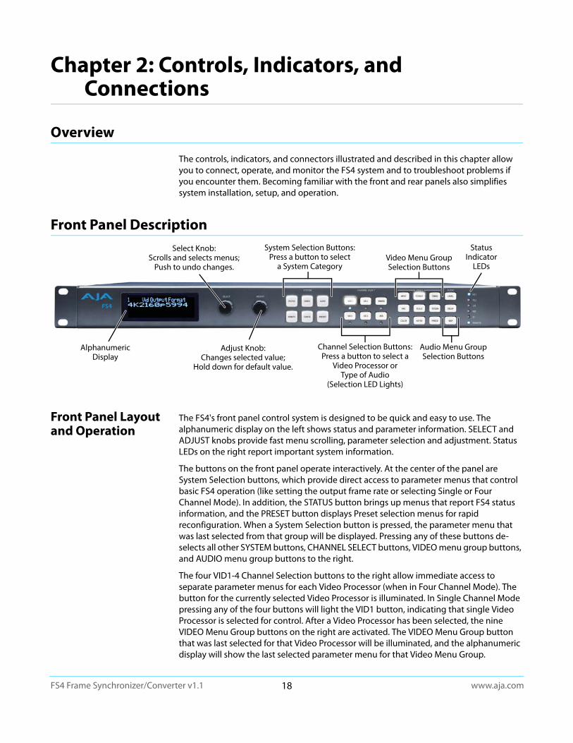
Front Panel Layout and Operation
The FS4's front panel control system is designed to be quick and easy to use. The alphanumeric display on the left shows status and parameter information. SELECT and ADJUST knobs provide fast menu scrolling, parameter selection and adjustment. Status LEDs on the right report important system information.
The buttons on the front panel operate interactively. At the center of the panel are System Selection buttons, which provide direct access to parameter menus that control basic FS4 operation (like setting the output frame rate or selecting Single or Four Channel Mode). In addition, the STATUS button brings up menus that report FS4 status information, and the PRESET button displays Preset selection menus for rapid reconfiguration. When a System Selection button is pressed, the parameter menu that was last selected from that group will be displayed. Pressing any of these buttons de-selects all other SYSTEM buttons, CHANNEL SELECT buttons, VIDEO menu group buttons, and AUDIO menu group buttons to the right.
The four VID1-4 Channel Selection buttons to the right allow immediate access to separate parameter menus for each Video Processor (when in Four Channel Mode). The button for the currently selected Video Processor is illuminated. In Single Channel Mode pressing any of the four buttons will light the VID1 button, indicating that single Video Processor is selected for control. After a Video Processor has been selected, the nine VIDEO Menu Group buttons on the right are activated. The VIDEO Menu Group button that was last selected for that Video Processor will be illuminated, and the alphanumeric display will show the last selected parameter menu for that Video Menu Group.
System Selection Buttons:Press a button to select
a System Category
Select Knob:Scrolls and selects menus;
Push to undo changes.Video Menu GroupSelection Buttons
Channel Selection Buttons:Press a button to select a
Video Processor or Type of Audio
(Selection LED Lights)
Audio Menu GroupSelection Buttons
Status Indicator
LEDs
Adjust Knob:Changes selected value;
Hold down for default value.
Alphanumeric Display
www.aja.com19
FS4 Frame Synchronizer/Converter v1.1
Similarly, the EMBED and AES Channel Select buttons selects either Embedded or AES audio, and activates the three AUDIO Menu Group buttons to the far right. The last selected AUDIO Menu Group button for that audio type will be illuminated and its last selected parameter menu will be displayed. Pressing an Audio Channel Select button deselects the Video Channel Select button, and vice-versa.
This design allows rapid menu access, reducing the number of menus to scroll through, and time is saved when button presses automatically return to their last selected menus.
Operational Summary
To change FS4 operational parameters with the front panel controls:
1. Select a system component and menu group for the alphanumeric display:
• For overall system control, press one of the six SYSTEM buttons,
• For control of a Video Processor, press one of the four VID1-4 Channel Select buttons and then press one of the VIDEO Menu Select buttons,
• For Embedded audio control, press the EMBED button and then press one of the AUDIO Menu Select Buttons,
• For AES or MADI audio control, press the AES button and then press one of the AUDIO Menu Select Buttons.
2. Scroll through menus in a group: Turn SELECT.
3. Edit a menu parameter: Stop SELECT on the menu, then turn ADJUST to set the value. Changes are applied immediately.
Multiple Part Parameter Editing
To edit a multiple part parameter, such as an IP address,:
1. Push the ADJUST knob momentarily (the value blinks).
2. To save the whole parameter after editing, push ADJUST momentarily again.
Coarse Adjust Editing To coarse adjust a value (for use with parameters that have more than 10 selections):
• 10x speed - Hold down the SYSTEM or currently active CHANNEL SELECT button (the button turns dark blue) and turn ADJUST. The values will change in approximately 10x increments.
• 100x speed (available for extremely wide-range parameters, like Audio Delay) - After enabling 10x speed above, momentarily release and press that group button a second time (the button turns light blue). Turning ADJUST will now change the value in approximately 100x increments.
Undo a Change To restore a previous setting:
• Push SELECT momentarily.
Reset to Factory Default:
To return to the factory default of a parameter:
• Hold down ADJUST for 4 seconds.
Alphanumeric Display
The four-line alphanumeric display shows either status menus that can be scrolled through but not altered, or parameter adjustment menus that are numbered and grouped by function, whose parameters can be altered.
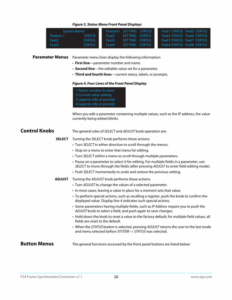
Status Menus Status menus generally have a feature on the left, and the current status or setting for that feature next to it. Information can generally be shown in two columns, three columns, or four columns (two columns side by side).
www.aja.com20
FS4 Frame Synchronizer/Converter v1.1
Figure 3. Status Menu Front Panel Displays
Parameter Menus Parameter menu lines display the following information:
• First line—parameter number and name.
• Second line—the editable value set for a parameter.
• Third and fourth lines—current status, labels, or prompts.
Figure 4. Four Lines of the Front Panel Display
When you edit a parameter containing multiple values, such as the IP address, the value currently being edited blinks.
Control Knobs The general rules of SELECT and ADJUST knob operation are:
SELECT Turning the SELECT knob performs these actions:
• Turn SELECT in either direction to scroll through the menus.
• Stop on a menu to enter that menu for editing.
• Turn SELECT within a menu to scroll through multiple parameters.
• Pause on a parameter to select it for editing. For multiple fields in a parameter, use SELECT to move through the fields (after pressing ADJUST to enter field editing mode).
• Push SELECT momentarily to undo and restore the previous setting.
ADJUST Turning the ADJUST knob performs these actions:
• Turn ADJUST to change the values of a selected parameter.
• In most cases, leaving a value in place for a moment sets that value.
• To perform special actions, such as recalling a register, push the knob to confirm the displayed value. Display line 4 indicates such special actions.
• Some parameters having multiple fields, such as IP Address require you to push the ADJUST knob to select a field, and push again to save changes.
• Hold down the knob to reset a value to the factory default; for multiple field values, all fields are reset to the default.
• When the STATUS button is selected, pressing ADJUST returns the user to the last mode and menu selected before SYSTEM -> STATUS was selected.
Button Menus The general functions accessed by the front panel buttons are listed below:
System NameFeature 1 STATUSFeat2 STATUSFeat3 STATUS
Feature1 SETTING STATUSFeat2 SETTING STATUSFeat3 SETTING STATUSFeat4 SETTING STATUS
Feat1 STATUS Feat5 STATUSFeat2 STATUS Feat6 STATUSFeat3 STATUS Feat7 STATUSFeat4 STATUS Feat8 STATUS
1 Param number & name2 Current value setting3 Legend, info or prompt4 Legend, info or prompt
www.aja.com21
FS4 Frame Synchronizer/Converter v1.1
System Buttons
STATUS Displays the Status Menu Group, which shows current machine status and error conditions:
• Video Input and status
• Caption status
• Reference and Genlock status
• Output status
• Power and Temperature status
• System Name display
• Alarms
REMOTE Displays the Remote Menu Group, which lets you select how to control the FS4:
• Control by local front panel only, remote sources only, or local and remote
• Authentication
• GPI input and output behavior
VIDEO Displays the System Video Menu Group, which lets you change or enable system wide video functions:
• Output frame rate selection
• Genlock reference source selection
• Monitor output settings
• Video input format settings, including 3G setup
CONFIG Displays the Config Menu Group, which lets you configure the FS4 for your environment:
• System Name setting
• FS4 Mode (Single Channel or Four Channel)
• IP settings, MAC address
• SNMP settings
• Alarm control
• Hidden Menus, Screen Saver, and Display intensity
• Fan speed
• System serial number and software version
• System reboot
AUDIO Displays the System Audio Menu Group, which lets you change or enable system audio functions:
• MADI Output mode
• Audio Input Sample Rate Conversion (Embedded, AES, MADI
• 5.1 and 7.1 Mixdown
• Global Audio Output
• Reset Channel Mapping (Embedded, AES, MADI)
PRESET Displays the Reg Menu Group, which accesses the memory registers:
• Store, Recall, and edit the names of Presets
• Factory Preset (defaults)

www.aja.com22
FS4 Frame Synchronizer/Converter v1.1
Channel Select Buttons
VID1-4 Selects which Video Processor the nine VIDEO buttons will access menus for control. In Single Channel Mode any button can be pressed.
Blue = A valid video source is present.
Red = An invalid video source is detected (unless the alarm has been suppressed, in which case the LED will be turned off).
Off = No video is present, or invalid video is detected and the alarm is suppressed.
NOTE: The FS4 operating mode can be determined by the VID 1-4 button tallies. In Four Channel Mode all four LEDs light, with the selected Video Processor high tally. In Single Channel Mode only the VID1 button tally is low tally or high tally.
EMBED Selects Embedded Audio for control by menus accessed by the three AUDIO Menu Group buttons.
Blue = Valid embedded audio is present on any video source.
Off = No embedded audio is detected.
AES Selects AES and MADI for control by menus accessed by the three AUDIO Menu Group buttons.
Blue = Valid AES or MADI audio is present.
Off = No AES or MADI audio is detected.
Video Menu Group Buttons
INPUT • Input source selections
• Loss of input selection
• Reverse Telecine
• Input scan format settings (PsF or interlaced)
• Input Image Mapping (Four Channel Mode only)
ANC • Active Format Descriptor (AFD) settings
• Caption translation selection
• SD line 21 blanking selection
COLOR • Proc amp and color corrector
• Legalizer settings
FORMAT • Output format
• Link Configuration
• SD Aspect Ratio
• Up and Down Convert settings
• Output Image Mapping (Single Channel Mode only)
SCALE • Custom Size and Position and ROI settings
KEYER • Background fill selection
• Sidebar Edge
• Matte adjustments
TIMING • H and V timing and delay settings

www.aja.com23
FS4 Frame Synchronizer/Converter v1.1
TSTGEN • Test Pattern settings
FREEZE • Freeze Output setting
Audio Menu Group Buttons
LEVEL • Audio level and phase settings
DELAY • Audio delay settings
MAP • Output mapping controls
Status LED Indicators
Indicators on the front panel are multi-state LEDs that light when a condition is present. The indicators and the conditions that cause them to light are as follows:
PS1/PS2 • Blue = Power Supply 1 or 2 is operational and receiving power. Both PS1 and PS2 LEDs must be lit blue to indicate redundant power is available.
• Red = Power supply is not receiving power or not operating within 10% of nominal value (unless the alarm has been suppressed, in which case the LED will be turned off).
• Off = Power supply alarm is suppressed and nominal power is not being received.
2SI • Blue = (Single Ch only) The processor's output mapping is set to 2SI (2 Sample Interleave).
• Off = In Single Channel Mode the processor's output mapping is set to Quadrant (Square Division). In Four Channel Mode this LED is always off.
REF • Blue = The FS4 is operating with a valid reference.
• Red = A reference alarm condition exists (unless the alarm has been suppressed, in which case the LED will be turned off).
ID Blinks blue on and off when you right-click on an FS4 system name and choose Identify in the web interface Network list. This action helps identify which system you’re controlling when multiple units are operated from a single computer. The ID LEDs on the front and rear panels perform the same function. No matter which side of a rack you’re facing, you’ll be able to see one of the LEDs.
REMOTE This multicolor LED indicates the current control mode:
• Blue= Local Only (front panel control only)
• Red = Remote Only (remote browser or panel control only)
• Purple = Local + Remote (front panel and remote control both enabled)
Incompatibility Alarms
The FS4 produces signal incompatibility alarms for a number of reasons. For example, incompatible conversion alarms can occur because the FS4 cannot convert between frame rate families (59.94/29.97/23.98, or 50/25, or 60/30/24).
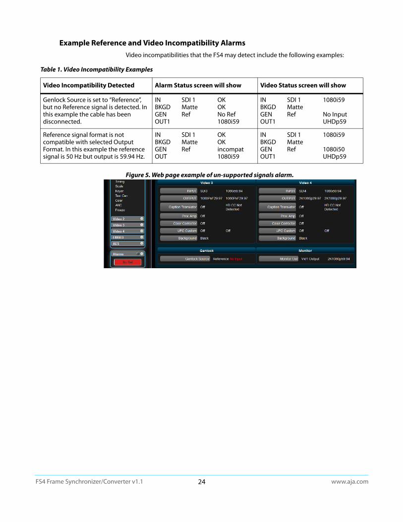
www.aja.com24
FS4 Frame Synchronizer/Converter v1.1
Example Reference and Video Incompatibility AlarmsVideo incompatibilities that the FS4 may detect include the following examples:
Figure 5. Web page example of un-supported signals alarm.
Table 1. Video Incompatibility Examples
Video Incompatibility Detected Alarm Status screen will show Video Status screen will show
Genlock Source is set to “Reference”, but no Reference signal is detected. In this example the cable has been disconnected.
IN SDI 1 OKBKGD Matte OKGEN Ref No RefOUT1 1080i59
IN SDI 1 1080i59BKGD MatteGEN Ref No InputOUT1 UHDp59
Reference signal format is not compatible with selected Output Format. In this example the reference signal is 50 Hz but output is 59.94 Hz.
IN SDI 1 OKBKGD Matte OKGEN Ref incompatOUT 1080i59
IN SDI 1 1080i59BKGD MatteGEN Ref 1080i50OUT1 UHDp59
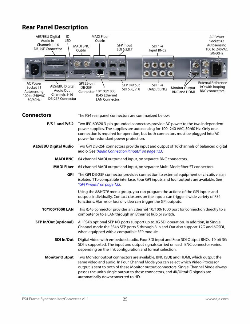
www.aja.com25
FS4 Frame Synchronizer/Converter v1.1
Rear Panel Description
Connectors The FS4 rear panel connectors are summarized below:
P/S 1 and P/S 2 Two IEC-60320 3-pin grounded connectors provide AC power to the two independent power supplies. The supplies are autosensing for 100–240 VAC, 50/60 Hz. Only one connection is required for operation, but both connectors must be plugged into AC power for redundant power protection.
AES/EBU Digital Audio Two GPI DB-25F connectors provide input and output of 16 channels of balanced digital audio. See “Audio Connection Pinouts” on page 123.
MADI BNC 64 channel MADI output and input, on separate BNC connectors.
MADI Fiber 64 channel MADI output and input, on separate Multi-Mode fiber ST connectors.
GPI The GPI DB-25F connector provides connection to external equipment or circuits via an isolated TTL-compatible interface. Four GPI inputs and four outputs are available. See “GPI Pinouts” on page 122.
Using the REMOTE menu group, you can program the actions of the GPI inputs and outputs individually. Contact closures on the inputs can trigger a wide variety of FS4 functions. Alarms or loss of video can trigger the GPI outputs.
10/100/1000 LAN This RJ45 connector provides an Ethernet 10/100/1000 port for connection directly to a computer or to a LAN through an Ethernet hub or switch.
SFP In/Out (optional) All FS4's optional SFP I/O ports support up to 3G SDI operation. In addition, in Single Channel mode the FS4‘s SFP ports 5 through 8 In and Out also support 12G and 6GSDI, when equipped with a compatible SFP module.
SDI In/Out Digital video with embedded audio. Four SDI input and Four SDI Output BNCs. 10 bit 3G SDI is supported. The input and output signals carried on each BNC connector varies, depending on the link configuration and format selection.
Monitor Output Two Monitor output connectors are available, BNC (SDI) and HDMI, which output the same video and audio. In Four Channel Mode you can select which Video Processor output is sent to both of these Monitor output connectors. Single Channel Mode always passes the unit’s single output to these connectors, and 4K/UltraHD signals are automatically downconverted to HD.
SDI 1-4Output BNCs10/100/1000
RJ45 EthernetLAN Connector
GPI 25-pinDB-25F
Connector
IDLED
External ReferenceI/O with loopingBNC connectors.
AC PowerSocket #2
Autosensing100 to 240VAC
50/60Hz
AC PowerSocket #1
Autosensing100 to 240VAC
50/60Hz
SFP InputSDI 6,5,8,7
SDI 1-4Input BNCs
Monitor Output BNC and HDMI
MADI BNCOut/In
MADI FiberOut/In
SFP OutputSDI 5, 6, 7, 8
AES/EBU DigitalAudio In
Channels 1-16DB-25F Connector
AES/EBU DigitalAudio Out
Channels 1-16DB-25F Connector
www.aja.com26
FS4 Frame Synchronizer/Converter v1.1
Ref Loop The Reference Loop BNCs accept an Output timing reference signal. The reference can be analog SD blackburst or HD tri-level sync. Examples of permissible reference video input signals:
• 525 Color Black
• 625 Color Black
• 1080i Tri-level Sync
• 720p Tri-level Sync
The 2 BNCs are a passive loop: one BNC is for the Input, and the remaining BNC can be connected to another piece of equipment in the reference chain or terminated.
NOTE: For proper operation the input Reference signal must be stable and properly terminated using a 75-ohm terminator on either the unused loop connector or the last piece of downstream equipment to which the Ref Video is connected.
www.aja.com27
FS4 Frame Synchronizer/Converter v1.1
Chapter 3: Installation & Configuration
Installation Overview
The installation and set up of an FS4 is very simple. Plug both AC supply cords into AC mains power (separate branch circuits for redundancy), connect the LAN connector to a LAN, WAN or local computer with a web-browser, and then connect source and destination video and audio equipment.
NOTE: The AJA FS4 should be plugged into 3-wire 100-240 VAC 50/60 Hz power (autosensing) before you make connections to other equipment. The AC cords provide a path to ground for accidental static discharge to protect system equipment. The unit has two fully independent and redundant power supplies and will operate with one or both AC power cords plugged into the unit. However, fault-tolerance exists only if both power supplies are connected and plugged into separate branch circuits. Then if power is lost on a branch or one of the supplies, the unit will continue to operate on the remaining circuit and power supply.
Installation Summary
All the steps of installation and configuration are documented in this chapter and are summarized as follows:
1. Unpack the shipping box, removing the FS4 and two power cords.
2. Install any physical options, such as SFP I/O modules.
3. Mount the physical chassis as desired: front rack, rear rack, or desk mount. If you are mounting multiple FS4 units, try to place them visually in the same area so you can use an attached computer to turn on and see the ID LED of the FS4 you’re communicating with. For physical installation details, see “FS4 Chassis Installation” on page 28.
4. Connect the two FS4 power cords to mains AC. For redundancy, use both power supplies and connect them to separate branch circuits so that the FS4 will continue to operate even if a circuit breaker opens on one branch.
5. If you plan to use remote control, connect your computer to the FS4 directly using an Ethernet cable, or connect both the computer and the FS4 to a local area network through an appropriate hub or router. Also set the FS4 IP address in the menus, and then use a computer to test (ping) the FS4 over the network connection to verify communication. For details, see “Networking” on page 29.
6. Install a web browser on the computer, if not already present, for accessing the FS4 web pages. You can access the pages simply by entering the FS4 IP address in the browser address field. See “Web Browser Control” on page 31 for details.
7. Connect the FS4 to system audio and video sources, including VTRs, monitors, DVD players, video switchers, and audio mixers. For details, see “System Cabling” on page 33.
8. Test the FS4 with all of your devices to verify everything is working.
Warning! To meet safety regulations for leakage current and to ensure redundancy in the event that a branch circuit breaker shuts off a branch, connect the dual power supplies to separate branch circuits.
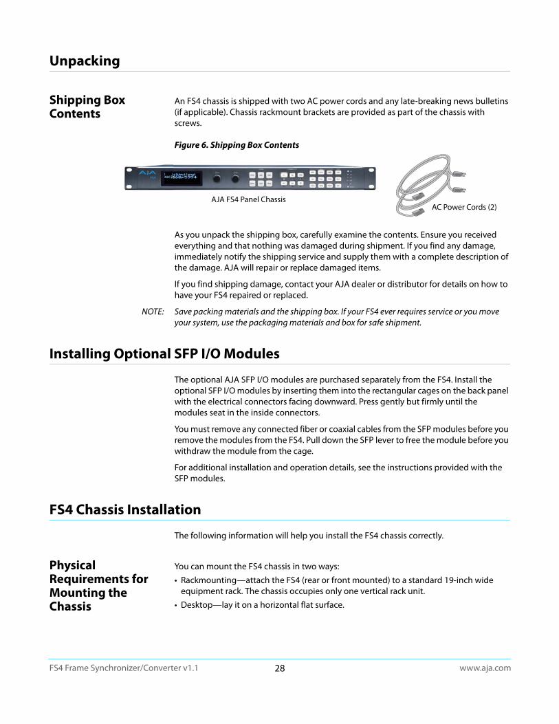
www.aja.com28
FS4 Frame Synchronizer/Converter v1.1
Unpacking
Shipping Box Contents
An FS4 chassis is shipped with two AC power cords and any late-breaking news bulletins (if applicable). Chassis rackmount brackets are provided as part of the chassis with screws.
Figure 6. Shipping Box Contents
As you unpack the shipping box, carefully examine the contents. Ensure you received everything and that nothing was damaged during shipment. If you find any damage, immediately notify the shipping service and supply them with a complete description of the damage. AJA will repair or replace damaged items.
If you find shipping damage, contact your AJA dealer or distributor for details on how to have your FS4 repaired or replaced.
NOTE: Save packing materials and the shipping box. If your FS4 ever requires service or you move your system, use the packaging materials and box for safe shipment.
Installing Optional SFP I/O Modules
The optional AJA SFP I/O modules are purchased separately from the FS4. Install the optional SFP I/O modules by inserting them into the rectangular cages on the back panel with the electrical connectors facing downward. Press gently but firmly until the modules seat in the inside connectors.
You must remove any connected fiber or coaxial cables from the SFP modules before you remove the modules from the FS4. Pull down the SFP lever to free the module before you withdraw the module from the cage.
For additional installation and operation details, see the instructions provided with the SFP modules.
FS4 Chassis Installation
The following information will help you install the FS4 chassis correctly.
Physical Requirements for Mounting the Chassis
You can mount the FS4 chassis in two ways:
• Rackmounting—attach the FS4 (rear or front mounted) to a standard 19-inch wide equipment rack. The chassis occupies only one vertical rack unit.
• Desktop—lay it on a horizontal flat surface.
AC Power Cords (2)AJA FS4 Panel Chassis
www.aja.com29
FS4 Frame Synchronizer/Converter v1.1
Chassis Dimensions When planning the equipment location, consider the chassis dimensions:
• Height—1 rack unit, 1.75 inches (4.5 cm)
• Depth—16 inches (40.65 cm)
• Width—17.5 inches (44.45cm)
• Weight—7.85 pounds, 3.56 kilograms
Cabling and Cooling Requirements
Observe these precautions when placing your FS4:
• Plan adequate space for cable routing from the back of the chassis. Ensure that cable connectors are not stressed and cables are not bent or crimped.
• When rack mounting or stacking multiple FS4 chassis, ensure adequate airspace for cooling around the FS4 units. Note the location of cooling vents on all equipment next to the FS4 and ensure none are obstructed.
NOTE: FS4 units can be stacked vertically without limit as long as there is an adequate supply of cool air around the FS4 side vents.
Power Requirements
The FS4 requires the following input voltage and power.
• Input Voltage—Chassis: autosensing 100VAC to 240VAC, 50/60Hz, fully redundant with both power supplies diode isolated.
• Power Consumption—55 Watts (70 Watts maximum)
Networking
You can network the FS4 directly to a laptop or other desktop computer using a single Ethernet cable (straight or cross-over), or connect it to a local area network (LAN). In either case, the FS4 connects via its 10/100/1000 Base-TX Ethernet connector. A LAN is a shared network that includes other Ethernet devices all attached via a hub or digital switch. LANs may be divided into zones separated by software or hardware routers. Routers may also be used to connect the LAN to an outside wide area network (WAN) such as the internet.
Devices on a LAN have IP addresses which may be fixed and permanent or dynamically assigned by the network (DHCP). When attaching the FS4 to a LAN, talk to your network administrator to find out how they want it connected (static IP or DHCP). Your IT department will be able to supply the information you need to install the FS4 on a LAN.
FS4 Default Network Settings
The FS4 ships from the factory set for DHCP networking, and can be manually reset to the following default network settings:
The following topics discuss two ways to set up the unit to communicate over a TCP/IP network connection: via DHCP or via a static IP address.
IP Address 192.168.0.2
Subnet Mask 255.255.255.0
Gateway 192.168.0.1

www.aja.com30
FS4 Frame Synchronizer/Converter v1.1
Networking Using DHCP or Default Static IP
The FS4 factory default configuration automatically looks for a DHCP server to issue an IP address. If your network includes a DHCP server, plug the FS4 into the network and connect with the unit as follows:
1. Press the CONFIG button.
2. Turn the SELECT knob to navigate to config parameter 3.2. Note on a piece of paper the DHCP-supplied IP address shown.
3. With your laptop or desktop computer connected to the same LAN as the FS4 and DHCP enabled, launch a web browser, type the IP address you noted on the FS4's display into the browser address field and press Enter. You should now see the FS4’s browser Status screen.
If the FS4 cannot get an IP address from the network DHCP server, the FS4 will automatically use a preset factory static IP address of 192.168.0.2. You can access the FS4 using the default static address as follows:
1. Set your computer's IP address to whatever address you prefer in the 192.168.0 (class C) network.
2. Set the computer’s Subnet mask to 255.255.255.0 (most PCs default to the proper netmask when the address is set).
3. Set the gateway address, if used, to match the FS4 default: 192.168.0.1. Alternatively, change the FS4 gateway address to match your gateway:
A. Press CONFIG, turn SELECT to 3.4 Default Gateway, push and then turn ADJUST to change the first group of digits.
B. Turn SELECT to advance to the next set of numbers, and turn ADJUST to set these numbers.
C. Continue using SELECT and ADJUST to set the full address.
D. When finished, push ADJUST momentarily to save the address.
4. Run a browser on the computer and type “192.168.0.2” (the factory static IP address). You should now see the FS4’s browser status screen.
When you can access the FS4 screens, see “Browser Remote Control” on page 88 for details about configuring the FS4 using a browser.
Networking the FS4 Using Your Own Static IP
If you don’t want to use DHCP or the default static IP address, you can set your own static IP address:
1. Select the CONFIG button and use the SELECT knob to navigate to parameter 2.1 IP CONFIG. Use the ADJUST knob to select Static.
2. Turn SELECT to navigate to parameter 3.2 IP ADDRESS. The display shows the default static IP address: 192.168.0.2.
3. Change the IP address as follows.
A. Push the ADJUST knob momentarily so that the first octet (set of numbers) blinks, and then turn ADJUST to change the numbers.
B. Turn SELECT to advance to the next set of numbers, and turn ADJUST to set these numbers.
C. Continue using SELECT and ADJUST to set the full address.
D. When finished, push ADJUST momentarily to save the address.
4. Turn SELECT to advance to 3.3 Subnet Mask. Use the SELECT and ADJUST knobs as in the previous step to set the desired subnet mask.

www.aja.com31
FS4 Frame Synchronizer/Converter v1.1
5. Turn SELECT to advance to 3.4 Default Gateway. Use the SELECT and ADJUST knobs as in the previous step to set the desired gateway address.
6. Run a browser on the computer and type in the IP address you set for the FS4. You should now see the FS4’s Status screen.
When you can access the FS4 screens, turn to “Browser Remote Control” on page 88 for details about configuring the FS4 using a browser.
Using Ping to Test the Network Connection
If you have connected the FS4 to a computer and set up the IP address and still do not see the FS4 screens in your browser, you can ping the network to verify the connection. Simply run the Ping utility from a Mac OS X or Windows PC computer attached directly or on the same LAN as the FS4 as described below:
Mac Ping Procedure 1. Find the Utilities Folder inside of the Applications Folder.
2. Locate the “Terminal” utility application and double-click it.
3. On the FS4, select the STATUS button and go to System Status menu (with the FS4 name) to read the unit’s currently configured IP address.
NOTE: The STATUS menu always shows the FS4’s current IP address. The IP address on the CONFIG menu is a database entry, which occasionally may not be the address the unit is using.
4. At the Mac terminal prompt, enter ping and the IP address noted in Step 3. For example: ping 192.168.0.2 (and press Return)
5. If successful, the ping utility will respond that packets were sent, received and how long it took. For example: 64 bytes from 192.168.0.2: icmp_seq=0 ttl=64 time=0.590 ms
6. If unsuccessful, check the FS4 network settings and resolve the problem with your IT administrator.
Windows PC Ping Procedure
1. From the Start button, select the All Programs menu.
2. Select Accessories/Command Prompt from the All Programs list.
3. On the FS4, select the STATUS button and go to System Status menu (with the FS4 name) to read the unit’s currently configured IP address.
NOTE: The STATUS menu always shows the FS4’s current IP address. The IP address on the CONFIG menu is a database entry, which occasionally may not be the address the unit is using.
4. In the PC Command Prompt utility, enter ping and the IP address noted in step 3. For example: ping 192.168.0.2 (and press Return)
5. If successful, the ping utility will respond that packets were sent, received and how long it took. For example: 64 bytes from 192.168.0.2: icmp_seq=0 ttl=64 time=0.590 ms
6. If unsuccessful, check the FS4 network settings and resolve the problem with your IT administrator.
Web Browser Control
To control the FS4 from a web browser on a network attached computer, enter the FS4 IP address as a URL in the browser. For example, if the FS4 IP address were “90.0.6.31”, you would then type into the web browser: http://90.0.6.31. This topic is explained in greater detail in Chapter 5: Browser Remote Control.

www.aja.com32
FS4 Frame Synchronizer/Converter v1.1
NOTE: The webUI (browser GUI) will keep up with most changes initiated at the front panel. However, the webUI may not reconnect (displays “Disconnected”) when network changes are initiated at the FS4 front panel. To manually reconnect, type the new IP address into the browser, or click the browser Refresh button. Sometimes the browser caches the old FS4 address. If you can't get the browser to connect, try clearing the Browser history to clear the cache, and then enter the new address again.
Software Update Installation
Although the FS4 comes from the factory pre-installed with software, it may not be as up-to-date as software posted on the AJA website. This topic describes the steps required to update the software in your AJA FS4.
Download the Latest Software
Current and past releases of FS4 software are available on the World Wide Web from AJA's website. To get the software, point your browser to the FS4 support page, which will contain helpful FS4 information and links to the updates:
https://www.aja.com/en/family/fs
Once you’re at the update page, you can select FS4 software files to download to your Mac or PC for upgrading your local FS4 machine.
Unpack the Software
FS4 software update files are “ZIP” files that you can open with a number of standard and third party file compression applications. The software image that you’ll install on the FS4 is a file with a name like FS4_ver_1.0.0.0.bin or similar.
NOTE: Depending on your PC or Mac operating system settings, the “.bin” extension may not be visible to you in a file directory.
Uploading and Installing the Software to the FS4
Uploading and installing the software update requires a PC or Mac that can “see” the FS4 via its Ethernet connection. Follow this procedure to install the software:
1. Point your browser at the FS4's upgrade page by clicking on the Firmware link at the bottom of the navigation box on the left-hand side of any FS4 web page. The FS4 web pages are discussed in Chapter 5.
Figure 7. Update Firmware Browser Screen.

www.aja.com33
FS4 Frame Synchronizer/Converter v1.1
2. Click the Browse... button to find and select the downloaded file. For example: FS4_ver_1.0.0.10.bin contained in the file downloaded from AJA.
3. Click OK when asked if you want to Upload Firmware. The file uploads to the FS4 and is tested for validity. Incomplete, corrupted, or non-FS4 files are rejected. Wait for the procedure to complete—it will take only a few minutes. Progress bars show upload progress.
4. Click Commit Uploaded Firmware when prompted after the upload is finished. Progress bars show progress as the file is written to flash memory.
5. Click Restart FS4 with New Firmware to restart the FS4. This will take the FS4 offline for a minute or two. During the restart, progress is shown in the connection area in the upper right corner of the FS4 Status screen. After restart, the FS4 will be running the new software.
6. Once these steps are complete, the FS4 will be running the software, and the Software Version on the Status screen shows the new version number. Check that the new software is running by bringing up the FS4 web page again; the software version is displayed at the top of all FS4 web screens. If the FS4 did not update successfully, run through the update steps again.
NOTE: The configuration of the FS4 prior to the upgrade is preserved. The unit returns to service exactly as it was before the upgrade.
If there is a power outage or glitch during the software download, the FS4 will boot the older software version and you can restart the upgrade process. This happens because the FS4 has been designed with a safety feature where an internal “safe” copy of the previous software is retained in the event the updating process fails.
System Cabling
System Video/Audio Cable Connections
When installing your system, you’ll make video and audio input/output connections. These connectors are explained individually in Chapter 2.
Four Channel Mode Configuration Examples
In Four Channel Mode each Video Processor can receive a different video signal and independently process that signal. All incoming embedded audio, even on inputs not routed to a Video Processor, are disembedded and sent to the Audio Processor.
NOTE: In the following examples, U, V, W, X, Y, and Z represent different complete signals, which may be carried on one or more connectors.
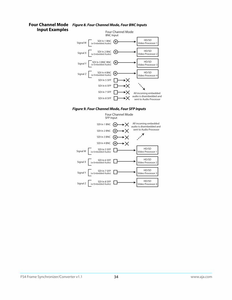
www.aja.com34
FS4 Frame Synchronizer/Converter v1.1
Four Channel Mode Input Examples
Figure 8. Four Channel Mode, Four BNC Inputs
Figure 9. Four Channel Mode, Four SFP Inputs
All incoming embedded audio is disembedded and
sent to Audio Processor
Signal W
Signal X
Signal Y
Signal Z
BNC InputFour Channel Mode
SDI !n 1 BNC(w Embedded Audio)
SDI !n 2 BNC(w Embedded Audio)
SDI !n 3 BNC BNC(w Embedded Audio)
SDI !n 4 BNC(w Embedded Audio)
HD/SDVideo Processor 1
HD/SDVideo Processor 2
HD/SDVideo Processor 3
HD/SDVideo Processor 4
SDI In 5 SFP
SDI In 6 SFP
SDI In 7 SFP
SDI In 8 SFP
Four Channel Mode
All incoming embedded audio is disembedded and
sent to Audio Processor
Signal W
Signal X
Signal Y
Signal Z
SFP Input
SDI In 1 BNC
SDI In 2 BNC
SDI In 3 BNC
SDI In 4 BNC
SDI In 5 SFP(w Embedded Audio)
SDI In 6 SFP(w Embedded Audio)
SDI In 7 SFP(w Embedded Audio)
SDI In 8 SFP(w Embedded Audio)
HD/SDVideo Processor 1
HD/SDVideo Processor 2
HD/SDVideo Processor 3
HD/SDVideo Processor 4
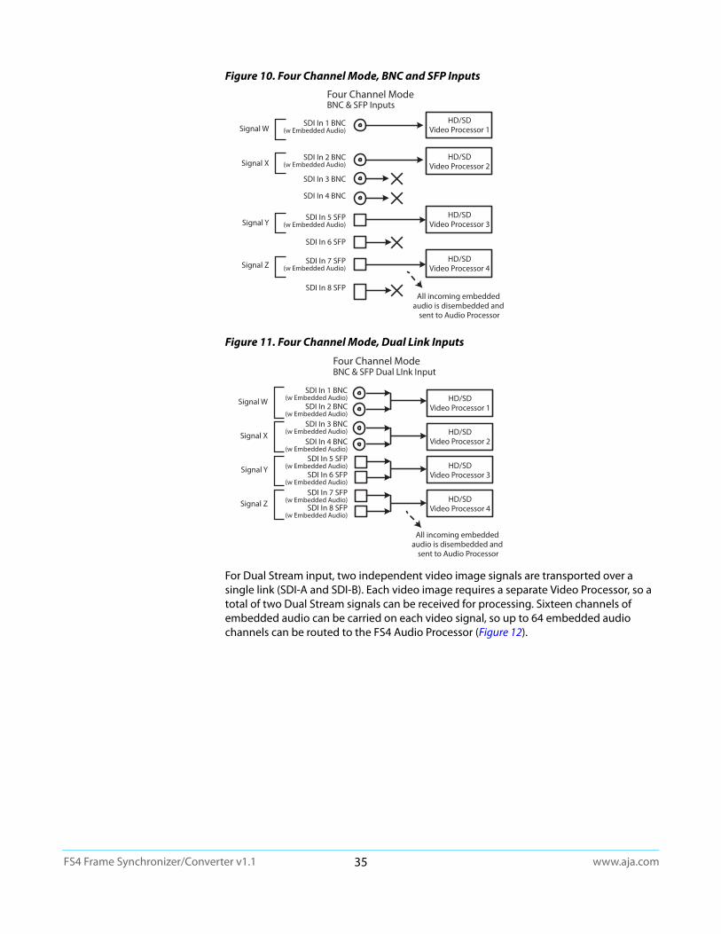
www.aja.com35
FS4 Frame Synchronizer/Converter v1.1
Figure 10. Four Channel Mode, BNC and SFP Inputs
Figure 11. Four Channel Mode, Dual Link Inputs
For Dual Stream input, two independent video image signals are transported over a single link (SDI-A and SDI-B). Each video image requires a separate Video Processor, so a total of two Dual Stream signals can be received for processing. Sixteen channels of embedded audio can be carried on each video signal, so up to 64 embedded audio channels can be routed to the FS4 Audio Processor (Figure 12).
All incoming embedded audio is disembedded and
sent to Audio Processor
Four Channel Mode
Signal W
Signal X
Signal Y
Signal Z
BNC & SFP Inputs
SDI In 1 BNC(w Embedded Audio)
SDI In 2 BNC(w Embedded Audio)
SDI In 3 BNC
SDI In 4 BNC
HD/SDVideo Processor 1
HD/SDVideo Processor 2
HD/SDVideo Processor 3
HD/SDVideo Processor 4
SDI In 5 SFP(w Embedded Audio)
SDI In 6 SFP
SDI In 7 SFP(w Embedded Audio)
SDI In 8 SFP
All incoming embedded audio is disembedded and
sent to Audio Processor
Signal W
Signal X
Signal Y
Signal Z
Four Channel ModeBNC & SFP Dual LInk Input
SDI In 1 BNC(w Embedded Audio)
SDI In 2 BNC(w Embedded Audio)
SDI In 4 BNC(w Embedded Audio)
SDI In 6 SFP(w Embedded Audio)
SDI In 8 SFP(w Embedded Audio)
SDI In 3 BNC(w Embedded Audio)
SDI In 5 SFP(w Embedded Audio)
SDI In 7 SFP(w Embedded Audio)
HD/SDVideo Processor 1
HD/SDVideo Processor 2
HD/SDVideo Processor 3
HD/SDVideo Processor 4
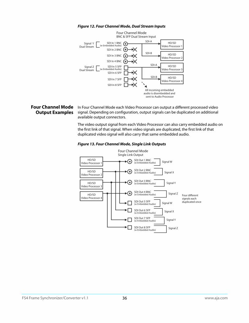
www.aja.com36
FS4 Frame Synchronizer/Converter v1.1
Figure 12. Four Channel Mode, Dual Stream Inputs
Four Channel Mode Output Examples
In Four Channel Mode each Video Processor can output a different processed video signal. Depending on configuration, output signals can be duplicated on additional available output connectors.
The video output signal from each Video Processor can also carry embedded audio on the first link of that signal. When video signals are duplicated, the first link of that duplicated video signal will also carry that same embedded audio.
Figure 13. Four Channel Mode, Single Link Outputs
All incoming embedded audio is disembedded and
sent to Audio Processor
Signal YDual Stream
Signal ZDual Stream
Four Channel ModeBNC & SFP Dual Stream Input
SDI In 1 BNC(w Embedded Audio)
SDI In 2 BNC
SDI In 4 BNC
SDI In 3 BNC
SDI In 6 SFP
SDI In 7 SFP
SDI In 8 SFP
SDI In 5 SFP(w Embedded Audio)
HD/SDVideo Processor 1
HD/SDVideo Processor 2
HD/SDVideo Processor 3
HD/SDVideo Processor 4
SDI-A
SDI-B
SDI-A
SDI-B
Four differentsignals eachduplicated once
Signal W
Signal X
Signal Y
Signal Z
Signal W
Signal X
Signal Y
Signal Z
Single Link OutputFour Channel Mode
SDI Out 5 SFP(w Embedded Audio)
SDI Out 6 SFP(w Embedded Audio)
SDI Out 1 BNC(w Embedded Audio)
SDI Out 2 BNC(w Embedded Audio)
SDI Out 3 BNC(w Embedded Audio)
SDI Out 4 BNC(w Embedded Audio)
SDI Out 7 SFP(w Embedded Audio)
SDI Out 8 SFP(w Embedded Audio)
HD/SDVideo Processor 1
HD/SDVideo Processor 2
HD/SDVideo Processor 3
HD/SDVideo Processor 4
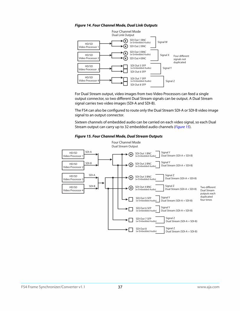
www.aja.com37
FS4 Frame Synchronizer/Converter v1.1
Figure 14. Four Channel Mode, Dual Link Outputs
For Dual Stream output, video images from two Video Processors can feed a single output connector, so two different Dual Stream signals can be output. A Dual Stream signal carries two video images (SDI-A and SDI-B).
The FS4 can also be configured to route only the Dual Stream SDI-A or SDI-B video image signal to an output connector.
Sixteen channels of embedded audio can be carried on each video signal, so each Dual Stream output can carry up to 32 embedded audio channels (Figure 15).
Figure 15. Four Channel Mode, Dual Stream Outputs
Four different signals not duplicated
Dual Link OutputFour Channel Mode
HD/SDVideo Processor 1
HD/SDVideo Processor 2
HD/SDVideo Processor 3
HD/SDVideo Processor 4
SDI Out 4 BNC
SDI Out 2 BNC
SDI Out 5 SFP(w Embedded Audio)
SDI Out 6 SFP
SDI Out 7 SFP(w Embedded Audio)
SDI Out 8 SFP
SDI Out 1 BNC(w Embedded Audio)
SDI Out 3 BNC(w Embedded Audio)
Signal W
Signal X
Signal Y
Signal Z
Two differentDual Streamputputs each duplicated four times
Dual Stream OutputFour Channel Mode
HD/SDVideo Processor 1
HD/SDVideo Processor 2
SDI Out 5 SFP(w Embedded Audio)
SDI Out 6 SFP(w Embedded Audio)
SDI Out 7 SFP(w Embedded Audio)
SDI Out 8(w Embedded Audio)
SDI Out 1 BNC(w Embedded Audio)
SDI Out 2 BNC(w Embedded Audio)
Signal YDual Stream (SDI-A + SDI-B)
Signal YDual Stream (SDI-A + SDI-B)
HD/SDVideo Processor 3
HD/SDVideo Processor 4
SDI Out 3 BNC(w Embedded Audio)
SDI Out 4 BNC(w Embedded Audio)
Signal ZDual Stream (SDI-A + SDI-B)
Signal ZDual Stream (SDI-A + SDI-B)
Signal YDual Stream (SDI-A + SDI-B)
Signal YDual Stream (SDI-A + SDI-B)
Signal ZDual Stream (SDI-A + SDI-B)
Signal ZDual Stream (SDI-A + SDI-B)
SDI-A
SDI-B
SDI-A
SDI-B

www.aja.com38
FS4 Frame Synchronizer/Converter v1.1
Four Channel Mode Conversion Examples
Figure 16. Four Channel Mode, Four Conversions Four Channel Mode
Signal W270Mb SD 525i
Signal X1.5G HD 1080i
Signal ZDual Link
3G 2K
SDI In 1 BNC(w Embedded Audio)
SDI In 2 BNC(w Embedded Audio)
SDI In 4 BNC
HD/SDVideo Processor 1
HD/SDVideo Processor 2
HD/SDVideo Processor 4
Signal X OutputDown Convert to270Mb SD 525i
SDI Out 2 BNC(w Embedded Audio)
SDI Out 3 BNC(w Embedded Audio)
SDI Out 4 BNC
Signal W OutputUp Convert to 1.5G HD 720p
Signal W OutputUp Convert to1.5G HD 720p
SDI Out 5 SFP(w Embedded Audio)
SDI Out 1 BNC(w Embedded Audio)
SDI Out 7 SFP(w Embedded Audio)
SDI Out 8 SFP
Signal Z OutputDown Convert to1.5G HD 1080p
SDI In 6 SFP
SDI In 5 SFP
HD/SDVideo Processor 3
SDI In 8 SFP(w Embedded Audio)
SDI In 7 SFP(w Embedded Audio)
All incoming embedded audio is disembedded and
sent to Audio Processor
Signal X OutputDown Convert to270Mb SD 525i
Signal Y OutputDown Convert to3G HD 1080p
Signal Y3G 2K
SDI In 3 BNC(w Embedded Audio)
SDI Out 6 SFP(w Embedded Audio)
Four Simultaneous Frame Sync Conversions
Table 5. FS4 Menu Settings for Figure 16
Channel Select Button Video Button Menu Name Setting
VID1 INPUT 1 Input SDI1
VID1 FORMAT 1 Output Format 720p 5994
VID1 FORMAT 2.0 Link Cfg SDI1 Sngl Link LvlA
VID2 INPUT 1 Input SDI2
VID2 FORMAT 1 Output Format 525i 5994
VID2 FORMAT 2.0 Link Cfg SDI1 Sngl Link LvlA
VID3 INPUT 1 Input SDI1
VID3 FORMAT 1 Output Format 1080P 5994
VID3 FORMAT 2.0 Link Cfg SDI1 Sngl Link LvlA
VID4 INPUT 1 Input SDI7/8 DualLink
VID4 FORMAT 1 Output Format 1080P 5994
VID4 FORMAT 2.0 Link Cfg SDI1 Sngl Link LvlA
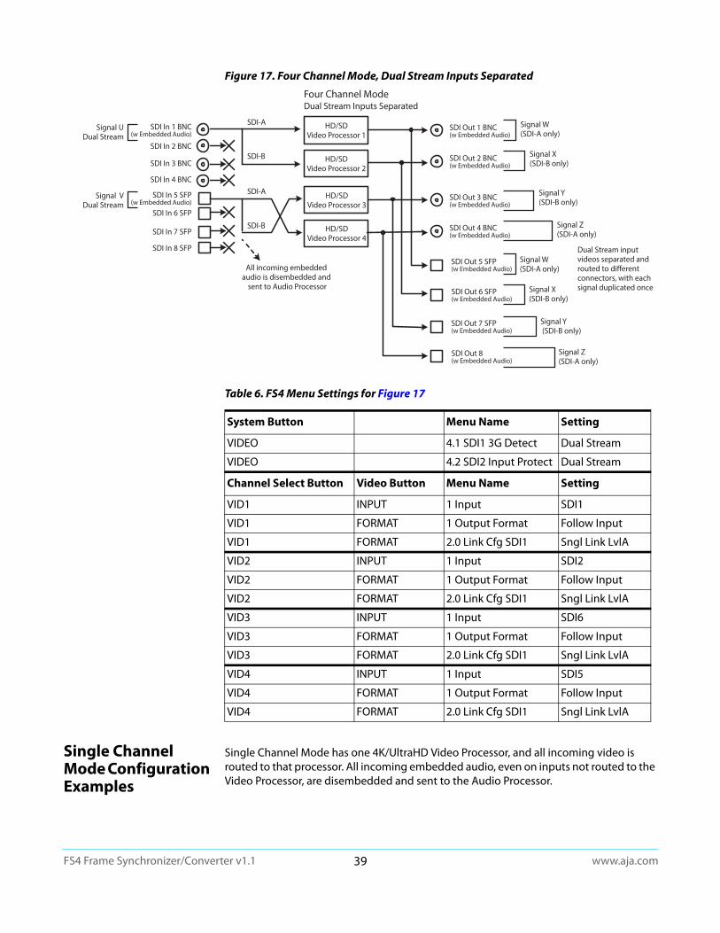
www.aja.com39
FS4 Frame Synchronizer/Converter v1.1
Figure 17. Four Channel Mode, Dual Stream Inputs Separated
Single Channel Mode Configuration Examples
Single Channel Mode has one 4K/UltraHD Video Processor, and all incoming video is routed to that processor. All incoming embedded audio, even on inputs not routed to the Video Processor, are disembedded and sent to the Audio Processor.
Dual Stream Inputs SeparatedFour Channel Mode
HD/SDVideo Processor 1
HD/SDVideo Processor 2
SDI Out 5 SFP(w Embedded Audio)
SDI Out 6 SFP(w Embedded Audio)
SDI Out 7 SFP(w Embedded Audio)
SDI Out 8(w Embedded Audio)
SDI Out 1 BNC(w Embedded Audio)
SDI Out 2 BNC(w Embedded Audio)
Signal W (SDI-A only)
Signal X (SDI-B only)
HD/SDVideo Processor 3
HD/SDVideo Processor 4
SDI Out 3 BNC(w Embedded Audio)
SDI Out 4 BNC(w Embedded Audio)
Signal Y(SDI-B only)
Signal Z(SDI-A only)
Signal W (SDI-A only)
Signal X (SDI-B only)
Signal Y (SDI-B only)
Signal Z(SDI-A only)
Dual Stream input videos separated and routed to different connectors, with each signal duplicated once
All incoming embedded audio is disembedded and
sent to Audio Processor
SDI In 1 BNC(w Embedded Audio)
SDI In 2 BNC
SDI In 4 BNC
SDI In 3 BNC
SDI In 6 SFP
SDI In 7 SFP
SDI In 8 SFP
SDI In 5 SFP(w Embedded Audio)
SDI-A
SDI-B
SDI-A
SDI-B
Signal VDual Stream
Signal UDual Stream
Table 6. FS4 Menu Settings for Figure 17
System Button Menu Name Setting
VIDEO 4.1 SDI1 3G Detect Dual Stream
VIDEO 4.2 SDI2 Input Protect Dual Stream
Channel Select Button Video Button Menu Name Setting
VID1 INPUT 1 Input SDI1
VID1 FORMAT 1 Output Format Follow Input
VID1 FORMAT 2.0 Link Cfg SDI1 Sngl Link LvlA
VID2 INPUT 1 Input SDI2
VID2 FORMAT 1 Output Format Follow Input
VID2 FORMAT 2.0 Link Cfg SDI1 Sngl Link LvlA
VID3 INPUT 1 Input SDI6
VID3 FORMAT 1 Output Format Follow Input
VID3 FORMAT 2.0 Link Cfg SDI1 Sngl Link LvlA
VID4 INPUT 1 Input SDI5
VID4 FORMAT 1 Output Format Follow Input
VID4 FORMAT 2.0 Link Cfg SDI1 Sngl Link LvlA
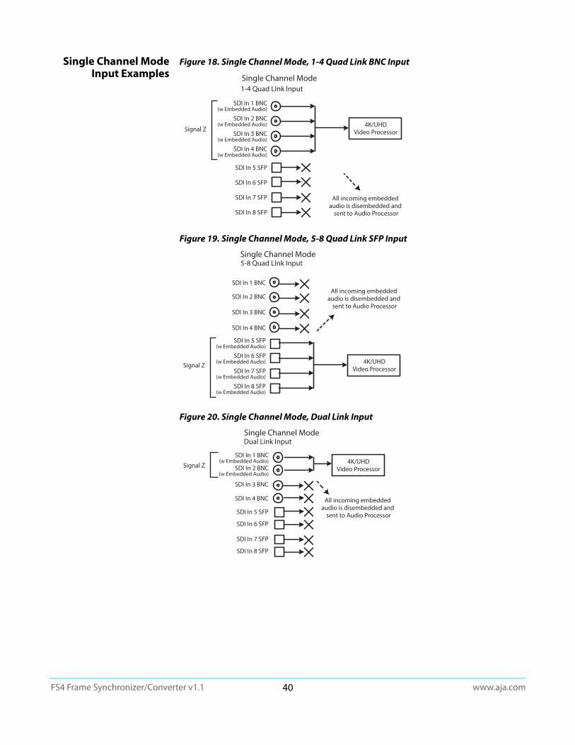
www.aja.com40
FS4 Frame Synchronizer/Converter v1.1
Single Channel Mode Input Examples
Figure 18. Single Channel Mode, 1-4 Quad Link BNC Input
Figure 19. Single Channel Mode, 5-8 Quad Link SFP Input
Figure 20. Single Channel Mode, Dual Link Input
Signal Z
All incoming embedded audio is disembedded and
sent to Audio Processor
1-4 Quad LInk InputSingle Channel Mode
4K/UHDVideo Processor
SDI In 1 BNC(w Embedded Audio)
SDI In 2 BNC(w Embedded Audio)
SDI In 3 BNC(w Embedded Audio)
SDI In 4 BNC(w Embedded Audio)
SDI In 5 SFP
SDI In 6 SFP
SDI In 7 SFP
SDI In 8 SFP
Signal Z
All incoming embedded audio is disembedded and
sent to Audio Processor
5-8 Quad LInk InputSingle Channel Mode
4K/UHDVideo Processor
SDI In 5 SFP(w Embedded Audio)
SDI In 6 SFP(w Embedded Audio)
SDI In 7 SFP(w Embedded Audio)
SDI In 8 SFP(w Embedded Audio)
SDI In 1 BNC
SDI In 2 BNC
SDI In 3 BNC
SDI In 4 BNC
All incoming embedded audio is disembedded and
sent to Audio Processor
Signal Z
Single Channel ModeDual Link Input
SDI In 1 BNC(w Embedded Audio)
SDI In 2 BNC(w Embedded Audio)
SDI In 3 BNC
SDI In 4 BNC
SDI In 5 SFP
SDI In 6 SFP
SDI In 7 SFP
SDI In 8 SFP
4K/UHDVideo Processor
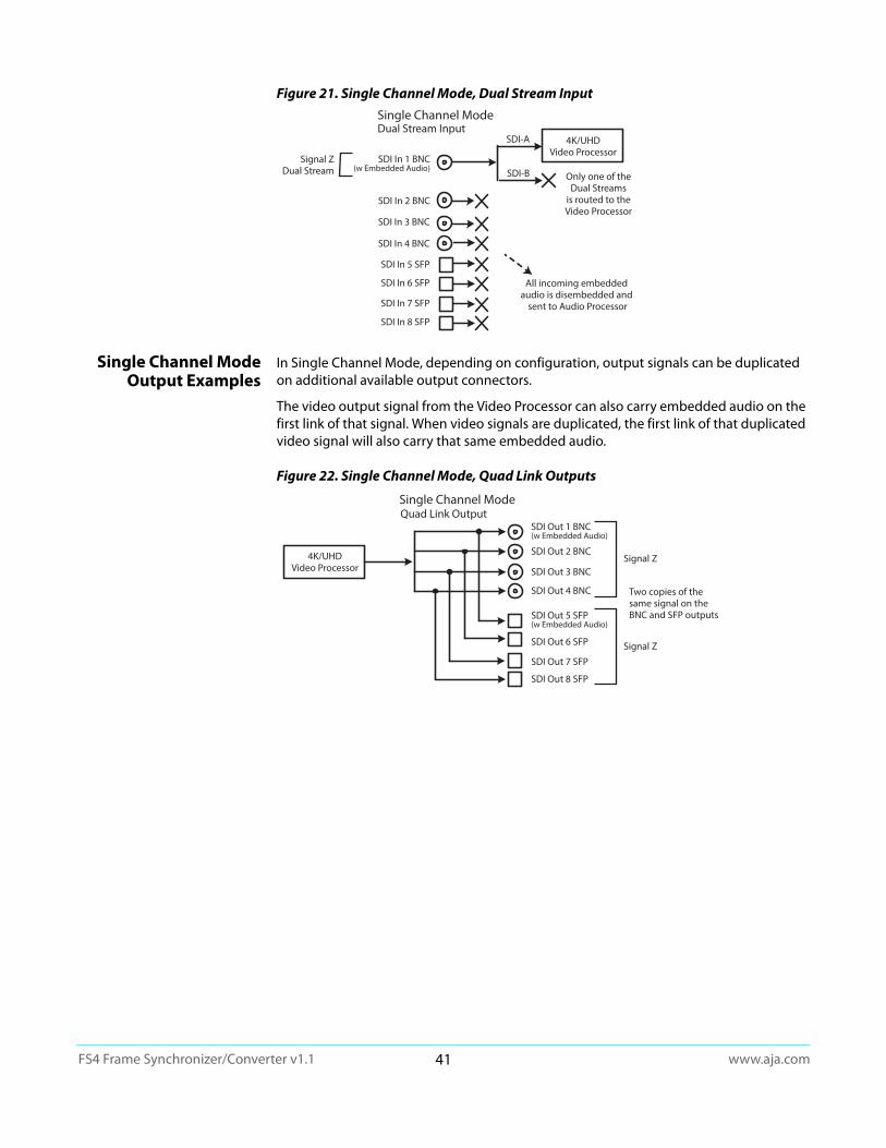
www.aja.com41
FS4 Frame Synchronizer/Converter v1.1
Figure 21. Single Channel Mode, Dual Stream Input
Single Channel Mode Output Examples
In Single Channel Mode, depending on configuration, output signals can be duplicated on additional available output connectors.
The video output signal from the Video Processor can also carry embedded audio on the first link of that signal. When video signals are duplicated, the first link of that duplicated video signal will also carry that same embedded audio.
Figure 22. Single Channel Mode, Quad Link Outputs
All incoming embedded audio is disembedded and
sent to Audio Processor
Signal ZDual Stream
Single Channel ModeDual Stream Input
SDI In 1 BNC(w Embedded Audio)
SDI In 2 BNC
SDI In 3 BNC
SDI In 4 BNC
SDI In 5 SFP
SDI In 6 SFP
SDI In 7 SFP
SDI In 8 SFP
4K/UHDVideo Processor
SDI-A
SDI-B Only one of the Dual Streams
is routed to the Video Processor
SDI Out 7 SFP
SDI Out 8 SFP
SDI Out 5 SFP(w Embedded Audio)
SDI Out 6 SFP
SDI Out 4 BNC
SDI Out 1 BNC(w Embedded Audio)
SDI Out 2 BNC
SDI Out 3 BNC
4K/UHDVideo Processor
Signal Z
Signal Z
Single Channel ModeQuad Link Output
Two copies of thesame signal on theBNC and SFP outputs
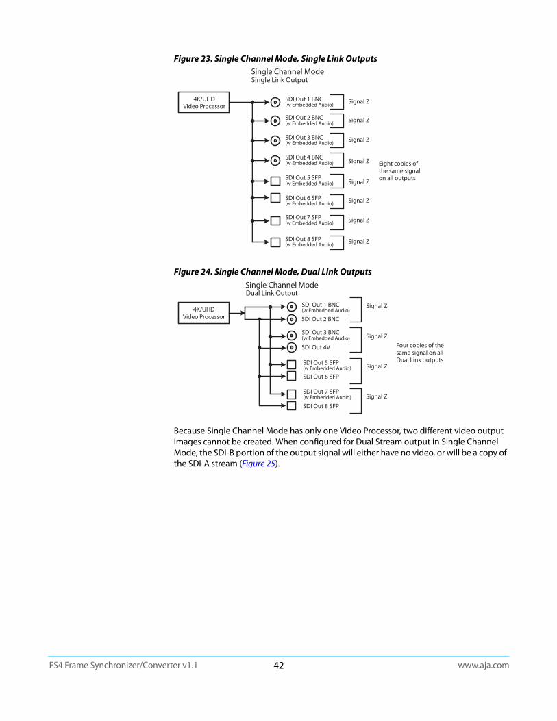
www.aja.com42
FS4 Frame Synchronizer/Converter v1.1
Figure 23. Single Channel Mode, Single Link Outputs
Figure 24. Single Channel Mode, Dual Link Outputs
Because Single Channel Mode has only one Video Processor, two different video output images cannot be created. When configured for Dual Stream output in Single Channel Mode, the SDI-B portion of the output signal will either have no video, or will be a copy of the SDI-A stream (Figure 25).
Single Channel Mode
4K/UHDVideo Processor
SDI Out 5 SFP(w Embedded Audio)
SDI Out 6 SFP(w Embedded Audio)
SDI Out 1 BNC(w Embedded Audio)
SDI Out 2 BNC(w Embedded Audio)
SDI Out 3 BNC(w Embedded Audio)
SDI Out 4 BNC(w Embedded Audio)
SDI Out 7 SFP(w Embedded Audio)
SDI Out 8 SFP(w Embedded Audio)
Single Link Output
Signal Z
Signal Z
Signal Z
Signal Z
Signal Z
Signal Z
Signal Z
Signal Z
Eight copies of the same signal on all outputs
Dual Link OutputSingle Channel Mode
4K/UHDVideo Processor
SDI Out 4V
SDI Out 2 BNC
SDI Out 5 SFP(w Embedded Audio)
SDI Out 6 SFP
SDI Out 7 SFP(w Embedded Audio)
SDI Out 8 SFP
SDI Out 1 BNC(w Embedded Audio)
SDI Out 3 BNC(w Embedded Audio)
Signal Z
Signal Z
Signal Z
Signal Z
Four copies of thesame signal on all Dual Link outputs
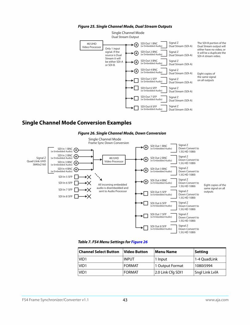
www.aja.com43
FS4 Frame Synchronizer/Converter v1.1
Figure 25. Single Channel Mode, Dual Stream Outputs
Single Channel Mode Conversion Examples
Figure 26. Single Channel Mode, Down Conversion
Dual Stream OutputSingle Channel Mode
4K/UHDVideo Processor
The SDI-B portion of the Dual Stream output will either have no video, or it will be a duplicate the SDI-A stream video.
SDI Out 5 SFP(w Embedded Audio)
SDI Out 6 SFP(w Embedded Audio)
SDI Out 1 BNC(w Embedded Audio)
SDI Out 2 BNC(w Embedded Audio)
SDI Out 3 BNC(w Embedded Audio)
SDI Out 4 BNC(w Embedded Audio)
SDI Out 7 SFP(w Embedded Audio)
SDI Out 8 SFP(w Embedded Audio)
Eight copies of the same signal on all outputs
Signal ZDual Stream (SDI-A)
Signal ZDual Stream (SDI-A)
Signal ZDual Stream (SDI-A)
Signal ZDual Stream (SDI-A)
Signal ZDual Stream (SDI-A)
Signal ZDual Stream (SDI-A)
Signal ZDual Stream (SDI-A)
Signal ZDual Stream (SDI-A)
Only 1 input signal. If the source is Dual Stream it will be either SDI-A or SDI-B.
4K/UHDVideo Processor
SDI In 1 BNC(w Embedded Audio)
SDI In 2 BNC(w Embedded Audio)
SDI In 3 BNC(w Embedded Audio)
SDI In 4 BNC(w Embedded Audio)
SDI In 5 SFP
SDI In 6 SFP
SDI In 7 SFP
SDI In 8 SFP
SDI Out 5 SFP(w Embedded Audio)
SDI Out 6 SFP(w Embedded Audio)
SDI Out 1 BNC(w Embedded Audio)
SDI Out 2 BNC(w Embedded Audio)
SDI Out 3 BNC(w Embedded Audio)
SDI Out 4 BNC(w Embedded Audio)
SDI Out 7 SFP(w Embedded Audio)
SDI Out 8 SFP(w Embedded Audio)
Signal ZQuad Llink UHD
3840x2160
Signal ZDown Convert to1.5G HD 1080i
Signal ZDown Convert to1.5G HD 1080i
Signal ZDown Convert to1.5G HD 1080i
Signal ZDown Convert to1.5G HD 1080i
Signal ZDown Convert to1.5G HD 1080i
Signal ZDown Convert to1.5G HD 1080i
Signal ZDown Convert to1.5G HD 1080i
Signal ZDown Convert to1.5G HD 1080i
Eight copies of thesame signal on all outputs
Frame Sync Down ConversionSingle Channel Mode
All incoming embedded audio is disembedded and
sent to Audio Processor
Table 7. FS4 Menu Settings for Figure 26
Channel Select Button Video Button Menu Name Setting
VID1 INPUT 1 Input 1-4 QuadLink
VID1 FORMAT 1 Output Format 1080i5994
VID1 FORMAT 2.0 Link Cfg SDI1 Sngl Link LvlA

www.aja.com44
FS4 Frame Synchronizer/Converter v1.1
Figure 27. Single Channel Mode, Up Conversion
GPI Connections The FS4 has four GPI inputs and four GPI outputs. The GPI inputs and outputs are electrically isolated from the power and ground on the FS4 frame. Electrical isolation is provided for up to four pieces of external equipment.
See “GPI Pinouts” on page 122 for information on how to wire the GPI connector to work with external devices that you want to use to control the FS4 or that you want the FS4 to control.
Stand Alone Tests
The stand alone tests can be performed without a computer, using the FS4 front panel controls and rear connections. The following procedures assume the FS4 is at factory defaults (taken from a newly opened box). If not set to defaults, the FS4 may behave differently.
NOTE: FS4 units are configured at the factory to operate in Four Channel Mode.
First Power Up The following workflow powers up a default FS4 and demonstrates some example alarms.
Setup • Ensure the FS4 is completely disconnected (all video, audio, network, and power connector ports are empty).
Procedure 1. Connect both FS4 power cords to mains AC and allow time for the unit to boot up. Observe the front panel LEDs.
SDI Out 7 SFP
SDI Out 8 SFP
SDI Out 5 SFP(w Embedded Audio)
SDI Out 6 SFP
SDI Out 4 BNC
SDI Out 1 BNC(w Embedded Audio)
SDI Out 2 BNC
SDI Out 3 BNC
4K/UHDVideo Processor
SDI In 1 BNC(w Embedded Audio)
SDI In 2 BNC
SDI In 3 BNC
SDI In 4 BNC
SDI In 5 SFP
SDI In 6 SFP
SDI In 7 SFP
SDI In 8 SFP
Signal Z1.5G HD 1080i
Signal ZUp Convert toQuad Link UHD
Signal ZUp Convert toQuad Link UHD
Two copies of thesame signal on theBNC and SFP outputs
Frame Sync Up ConversionSingle Channel Mode
Up to 16 channels ofembedded audio is
disembedded and sent to Audio Processor
Table 8. FS4 Menu Settings for Figure 26
Channel Select Button Video Button Menu Name Setting
VID1 INPUT 1 Input SDI1
VID1 FORMAT 1 Output Format UHD2160p5994
VID1 FORMAT 2.0 Link Cfg SDI1 QuadLink LvlA

www.aja.com45
FS4 Frame Synchronizer/Converter v1.1
• The REF LED will light red, indicating an alarm condition. By default the FS4 is configured to operate genlocked to an external reference signal.
2. Press the front panel STATUS button, then turn the SELECT knob to view various Status menus.
• The Status menu for Video Processor 1 will report No Input for IN1, the port is disconnected), and the GEN (Genlock) parameter will report Ref (configured for external reference) but will also report No Input.
3. Connect a 1080i59.94 HD tri-level sync reference signal to one of the FS4 Ref Loop BNCs, and connect a 75 ohm terminator to the other Ref BNC.• The REF LED will light blue, indicating the FS4 is genlocked to reference.
• The Status menu GEN parameters will report Ref and indicate the format of the incoming reference signal or OK.
• However, because the FS4 is still not receiving a compatible video input, No Input, will be reported for IN1.
4. Connect a 1080i59.94 SDI video source to the SDI 1 input BNC.
• The front panel will report 1080i59 and an OK status for SDI 1.
This indicates no alarm condition exists.
5. Disconnect one of the power cords, leaving the other attached.
• The front panel PWR LED will light red for the power supply with the removed cord.
• The PS status will report PS1 (or 2) OFF
6. Reconnect the power cable. The PWR LED for that power supply will light blue and the power supply status will report OK.
This workflow confirms the FS4 powers up successfully and reports reference and power supply alarms.
NOTE: FS4 Reference, Power Supply, and Video Format alarms can be disabled, if desired. This will prevent the LEDs from going red, but will not affect SNMP or front panel status displays.
Video Format Status screen Video Format Alarm Status screen
IN1 SDI 1 No InputBKGD Black 1080i59GEN Ref No InputOUT1 1080i59
IN1 SDI 1 OKBKGD Black OKGEN Ref No RefRate 59/29/23
Video Format Status screen Video Format Alarm Status screen
IN1 SDI 1 No InputBKGD Black 1080i59GEN Ref 1080i59OUT1 1080i59
IN1 SDI 1 OKBKGD Black OKGEN Ref OKRate 59/29/23
Video Format Status screen Video Format Alarm Status screen
IN1 SDI 1 1080i59BKGD Black 1080i59GEN Ref 1080i59OUT1 1080i59
IN1 SDI 1 OKBKGD Black OKGEN Ref OKOUT1 1080i59
www.aja.com46
FS4 Frame Synchronizer/Converter v1.1
Chapter 4: Display Menus
Overview
The FS4 is generally controlled using two different methods: (1) direct control using the front panel buttons, knobs, and display menus, (2) remote control using a web browser. This chapter describes the first, using the front panel controls, which is the most direct way to configure and use an FS4. The other method, using a computer, is described in the next chapter. A third method of FS4 control, using external GPI contacts, is described in various locations in this manual.
FS4 Modes, System Parameters, and Video Parameters
The FS4 also operates in two distinct modes, either Four Channel Mode or Single Channel Mode. Menu parameters settings made in one mode may or may not affect the operation of FS4 when it is set to the other mode. For example, in Single Channel Mode, setting Output Image Mapping to 2SI will not affect operations in Four Channel Mode, because that parameter only affects 4K or UltraHD formats that are not available in Four Channel mode. However, changing the IP Address Type (DHCP, Static) will affect FS4 operation in both modes regardless of the mode in which that parameter was adjusted.
In general, settings made for FS4 system operation, like IP address, Output Frame Rate, Genlock, etc. affect operation in both Four Channel and Single Channel mode. These front panel menu settings are accessed via the three System buttons (VIDEO, CONFIG, and AUDIO).
The Channel Select AES menus (and associated LEVEL and DELAY menu parameters for AES and MADI), also affect the FS4 in both operating modes. Separate MAP parameters for audio routing, however, are saved for each Video Processor, so changing mapping in one operating mode will not affect mapping in the other mode.
The Channel Select EMBED menus provide LEVEL, DELAY, and MAP menu parameters for embedded SDI audio. Because both operating modes use the same SDI inputs, adjustment to these parameters affects both modes.
Video parameter settings in the Channel Select VID1-4 menus (and associated VIDEO submenus) apply to only the current FS4 operating mode. In Four Channel Mode, each VID channel accesses separate settings for only that channel, allowing four different conversions to take place simultaneously. In Single Channel Mode, only one set of video parameters exists that apply to that single channel. Changing video parameters in Four Channel Mode will not affect any video settings stored in Single Channel Mode.
NOTE: One exception is in the REMOTE Menu Group. The Remote Control setting (Local, Remote) affects both Four Channel and Single Channel mode, but separate sets of GPI In and GPI Out settings exist for each operating mode. Single Channel Mode has only one set. Separate GPI inputs and outputs are needed for the different functionality available in these two modes.
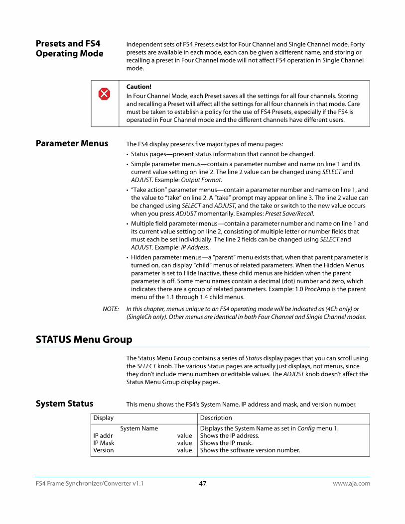
www.aja.com47
FS4 Frame Synchronizer/Converter v1.1
Presets and FS4 Operating Mode
Independent sets of FS4 Presets exist for Four Channel and Single Channel mode. Forty presets are available in each mode, each can be given a different name, and storing or recalling a preset in Four Channel mode will not affect FS4 operation in Single Channel mode.
Parameter Menus The FS4 display presents five major types of menu pages:
• Status pages—present status information that cannot be changed.
• Simple parameter menus—contain a parameter number and name on line 1 and its current value setting on line 2. The line 2 value can be changed using SELECT and ADJUST. Example: Output Format.
• “Take action” parameter menus—contain a parameter number and name on line 1, and the value to “take” on line 2. A “take” prompt may appear on line 3. The line 2 value can be changed using SELECT and ADJUST, and the take or switch to the new value occurs when you press ADJUST momentarily. Examples: Preset Save/Recall.
• Multiple field parameter menus—contain a parameter number and name on line 1 and its current value setting on line 2, consisting of multiple letter or number fields that must each be set individually. The line 2 fields can be changed using SELECT and ADJUST. Example: IP Address.
• Hidden parameter menus—a “parent” menu exists that, when that parent parameter is turned on, can display “child” menus of related parameters. When the Hidden Menus parameter is set to Hide Inactive, these child menus are hidden when the parent parameter is off. Some menu names contain a decimal (dot) number and zero, which indicates there are a group of related parameters. Example: 1.0 ProcAmp is the parent menu of the 1.1 through 1.4 child menus.
NOTE: In this chapter, menus unique to an FS4 operating mode will be indicated as (4Ch only) or (SingleCh only). Other menus are identical in both Four Channel and Single Channel modes.
STATUS Menu Group
The Status Menu Group contains a series of Status display pages that you can scroll using the SELECT knob. The various Status pages are actually just displays, not menus, since they don’t include menu numbers or editable values. The ADJUST knob doesn’t affect the Status Menu Group display pages.
System Status This menu shows the FS4's System Name, IP address and mask, and version number.
Caution! In Four Channel Mode, each Preset saves all the settings for all four channels. Storing and recalling a Preset will affect all the settings for all four channels in that mode. Care must be taken to establish a policy for the use of FS4 Presets, especially if the FS4 is operated in Four Channel mode and the different channels have different users.
Display Description
System NameIP addr valueIP Mask valueVersion value
Displays the System Name as set in Config menu 1.Shows the IP address.Shows the IP mask.Shows the software version number.
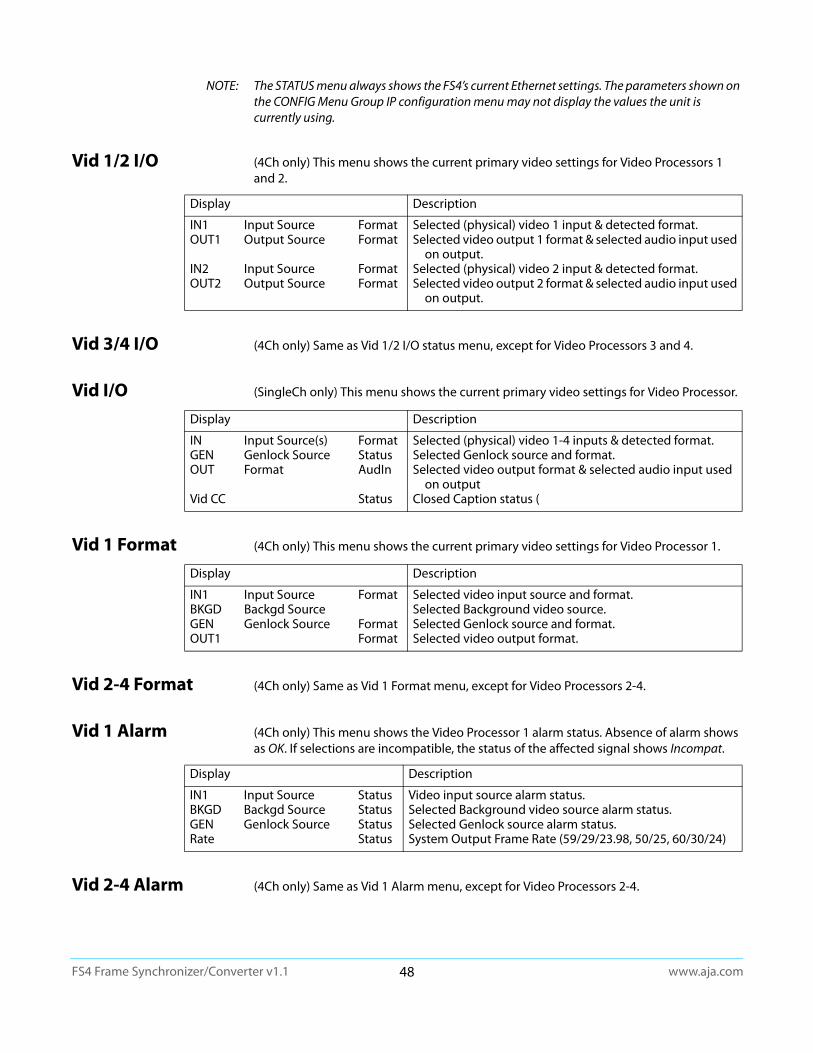
www.aja.com48
FS4 Frame Synchronizer/Converter v1.1
NOTE: The STATUS menu always shows the FS4’s current Ethernet settings. The parameters shown on the CONFIG Menu Group IP configuration menu may not display the values the unit is currently using.
Vid 1/2 I/O (4Ch only) This menu shows the current primary video settings for Video Processors 1 and 2.
Vid 3/4 I/O (4Ch only) Same as Vid 1/2 I/O status menu, except for Video Processors 3 and 4.
Vid I/O (SingleCh only) This menu shows the current primary video settings for Video Processor.
Vid 1 Format (4Ch only) This menu shows the current primary video settings for Video Processor 1.
Vid 2-4 Format (4Ch only) Same as Vid 1 Format menu, except for Video Processors 2-4.
Vid 1 Alarm (4Ch only) This menu shows the Video Processor 1 alarm status. Absence of alarm shows as OK. If selections are incompatible, the status of the affected signal shows Incompat.
Vid 2-4 Alarm (4Ch only) Same as Vid 1 Alarm menu, except for Video Processors 2-4.
Display Description
IN1 Input Source FormatOUT1 Output Source Format
IN2 Input Source FormatOUT2 Output Source Format
Selected (physical) video 1 input & detected format.Selected video output 1 format & selected audio input used
on output.Selected (physical) video 2 input & detected format.Selected video output 2 format & selected audio input used
on output.
Display Description
IN Input Source(s) FormatGEN Genlock Source StatusOUT Format AudIn
Vid CC Status
Selected (physical) video 1-4 inputs & detected format.Selected Genlock source and format.Selected video output format & selected audio input used
on outputClosed Caption status (
Display Description
IN1 Input Source FormatBKGD Backgd SourceGEN Genlock Source FormatOUT1 Format
Selected video input source and format.Selected Background video source.Selected Genlock source and format.Selected video output format.
Display Description
IN1 Input Source StatusBKGD Backgd Source StatusGEN Genlock Source StatusRate Status
Video input source alarm status.Selected Background video source alarm status.Selected Genlock source alarm status.System Output Frame Rate (59/29/23.98, 50/25, 60/30/24)
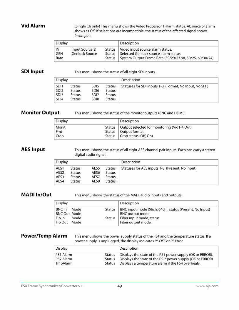
www.aja.com49
FS4 Frame Synchronizer/Converter v1.1
Vid Alarm (Single Ch only) This menu shows the Video Processor 1 alarm status. Absence of alarm shows as OK. If selections are incompatible, the status of the affected signal shows Incompat.
SDI Input This menu shows the status of all eight SDI inputs.
Monitor Output This menu shows the status of the monitor outputs (BNC and HDMI).
AES Input This menu shows the status of all eight AES channel pair inputs. Each can carry a stereo digital audio signal.
MADI In/Out This menu shows the status of the MADI audio inputs and outputs.
Power/Temp Alarm This menu shows the power supply status of the FS4 and the temperature status. If a power supply is unplugged, the display indicates PS OFF or PS Error.
Display Description
IN Input Source(s) StatusGEN Genlock Source StatusRate Status
Video input source alarm status.Selected Genlock source alarm status.System Output Frame Rate (59/29/23.98, 50/25, 60/30/24)
Display Description
SDI1 Status SDI5 StatusSDI2 Status SDI6 StatusSDI3 Status SDI7 StatusSDI4 Status SDI8 Status
Statuses for SDI inputs 1-8: (Format, No Input, No SFP)
Display Description
Monit StatusFmt StatusCrop Status
Output selected for monitoring (Vid1-4 Out)Output format.Crop status (Off, On).
Display Description
AES1 Status AES5 StatusAES2 Status AES6 StatusAES3 Status AES7 StatusAES4 Status AES8 Status
Statuses for AES inputs 1-8: (Present, No Input)
Display Description
BNC In Mode StatusBNC Out ModeFib In Mode StatusFib Out Mode
BNC input mode (56ch, 64ch), status (Present, No Input)BNC output modeFiber input mode, statusFiber output mode.
Display Description
PS1 Alarm StatusPS2 Alarm StatusTmpAlarm Status
Displays the state of the PS1 power supply (OK or ERROR).Displays the state of the PS 2 power supply (OK or ERROR).Displays a temperature alarm if the FS4 overheats.
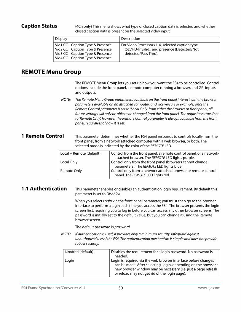
www.aja.com50
FS4 Frame Synchronizer/Converter v1.1
Caption Status (4Ch only) This menu shows what type of closed caption data is selected and whether closed caption data is present on the selected video input.
REMOTE Menu Group
The REMOTE Menu Group lets you set up how you want the FS4 to be controlled. Control options include the front panel, a remote computer running a browser, and GPI inputs and outputs.
NOTE: The Remote Menu Group parameters available on the front panel interact with the browser parameters available on an attached computer, and vice versa. For example, once the Remote Control parameter is set to 'Local Only' from either the browser or front panel, all future settings will only be able to be changed from the front panel. The opposite is true if set to 'Remote Only'. However the Remote Control parameter is always available from the front panel, regardless of how it is set.
1 Remote Control This parameter determines whether the FS4 panel responds to controls locally from the front panel, from a network attached computer with a web browser, or both. The selected mode is indicated by the color of the REMOTE LED.
1.1 Authentication This parameter enables or disables an authentication login requirement. By default this parameter is set to Disabled.
When you select Login via the front panel parameter, you must then go to the browser interface to perform a login each time you access the FS4. The browser presents the login screen first, requiring you to log in before you can access any other browser screens. The password is initially set to the default value, but you can change it using the Remote browser screen.
The default password is password.
NOTE: If authentication is used, it provides only a minimum security safeguard against unauthorized use of the FS4. The authentication mechanism is simple and does not provide robust security.
Display Description
Vid1 CC Caption Type & PresenceVid2 CC Caption Type & PresenceVid3 CC Caption Type & PresenceVid4 CC Caption Type & Presence
For Video Processors 1-4, selected caption type (SD/HD/Invalid), and presence (Detected/Not detected/Pass Thru).
Local + Remote (default)
Local Only
Remote Only
Control from the front panel, a remote control panel, or a network-attached browser. The REMOTE LED lights purple.
Control only from the front panel (browsers cannot change parameters). The REMOTE LED lights blue.
Control only from a network attached browser or remote control panel. The REMOTE LED lights red.
Disabled (default)
Login
Disables the requirement for a login password. No password is needed.
Login is required via the web browser interface before changes can be made. After selecting Login, depending on the browser a new browser window may be necessary (i.e. just a page refresh or reload may not get rid of the login page).

www.aja.com51
FS4 Frame Synchronizer/Converter v1.1
2.1–4 GPI IN 1–4 Response
The setting of this parameter determines what happens when a GPI trigger is received at the FS4’s GPI Inputs (1–4). A GPI Trigger is defined as a TTL low voltage level (0 to 0.8V with respect to its isolated ground pin). The GPI interface pinout and specifications are discussed in “GPI Pinouts” on page 122. Input video sources selected by GPI trigger remain selected until the trigger is released.
In Four Channel Mode, each FS4 Video Processor can be programmed to perform an action on each of the four GPI Inputs. This means the same GPI input trigger could cause different actions on each channel. In Single Channel Mode, each GPI input can only trigger one action on that Video Processor.
Caution! GPI Inputs can be used to trigger Presets. When you recall a Preset Configuration, the recalled preset immediately replaces the system’s existing configuration. All previous settings are lost unless you have previously stored them in another preset configuration or an exported file.
Caution! In Four Channel Mode, each Preset saves all the settings for all four channels. Storing and recalling a Preset will affect all the settings for all four channels in that mode. Care must be taken to establish a policy for the use of FS4 Presets, especially if the FS4 is operated in Four Channel mode and the different channels have different users.
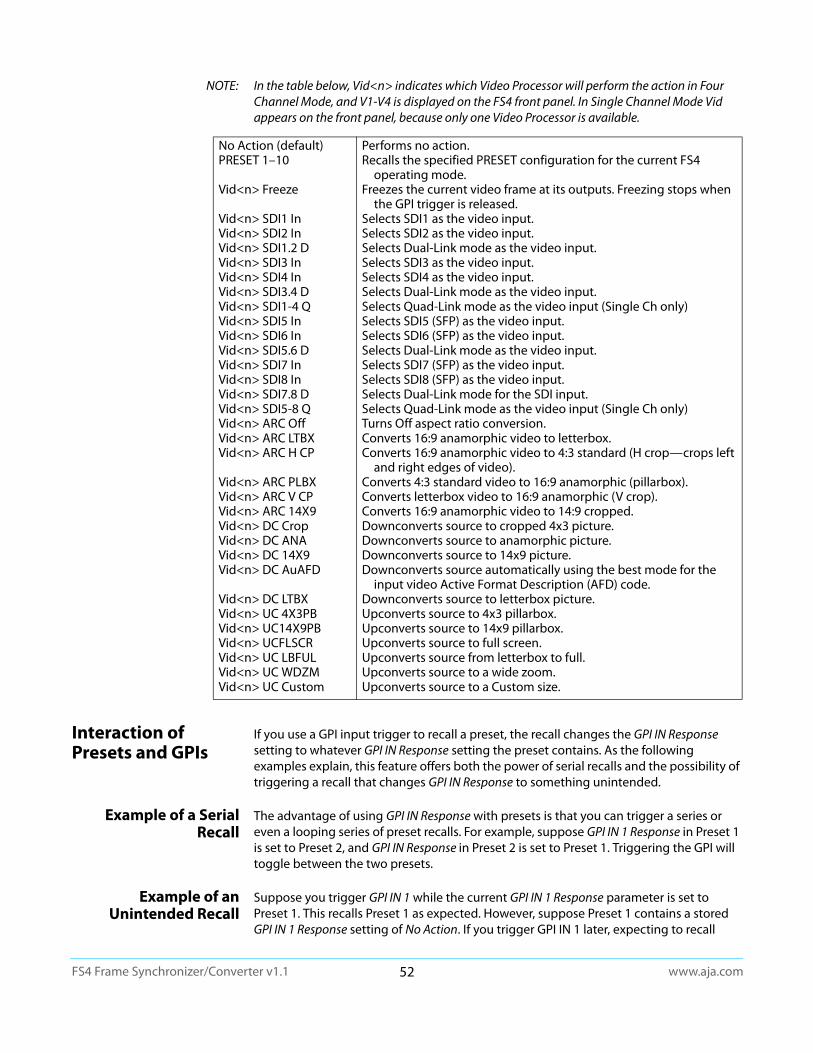
www.aja.com52
FS4 Frame Synchronizer/Converter v1.1
NOTE: In the table below, Vid<n> indicates which Video Processor will perform the action in Four Channel Mode, and V1-V4 is displayed on the FS4 front panel. In Single Channel Mode Vid appears on the front panel, because only one Video Processor is available.
Interaction of Presets and GPIs
If you use a GPI input trigger to recall a preset, the recall changes the GPI IN Response setting to whatever GPI IN Response setting the preset contains. As the following examples explain, this feature offers both the power of serial recalls and the possibility of triggering a recall that changes GPI IN Response to something unintended.
Example of a Serial Recall
The advantage of using GPI IN Response with presets is that you can trigger a series or even a looping series of preset recalls. For example, suppose GPI IN 1 Response in Preset 1 is set to Preset 2, and GPI IN Response in Preset 2 is set to Preset 1. Triggering the GPI will toggle between the two presets.
Example of an Unintended Recall
Suppose you trigger GPI IN 1 while the current GPI IN 1 Response parameter is set to Preset 1. This recalls Preset 1 as expected. However, suppose Preset 1 contains a stored GPI IN 1 Response setting of No Action. If you trigger GPI IN 1 later, expecting to recall
No Action (default)PRESET 1–10
Vid<n> Freeze
Vid<n> SDI1 InVid<n> SDI2 InVid<n> SDI1.2 DVid<n> SDI3 InVid<n> SDI4 InVid<n> SDI3.4 DVid<n> SDI1-4 QVid<n> SDI5 InVid<n> SDI6 InVid<n> SDI5.6 DVid<n> SDI7 InVid<n> SDI8 InVid<n> SDI7.8 DVid<n> SDI5-8 QVid<n> ARC OffVid<n> ARC LTBXVid<n> ARC H CP
Vid<n> ARC PLBXVid<n> ARC V CPVid<n> ARC 14X9Vid<n> DC CropVid<n> DC ANAVid<n> DC 14X9Vid<n> DC AuAFD
Vid<n> DC LTBXVid<n> UC 4X3PBVid<n> UC14X9PBVid<n> UCFLSCRVid<n> UC LBFULVid<n> UC WDZMVid<n> UC Custom
Performs no action.Recalls the specified PRESET configuration for the current FS4
operating mode.Freezes the current video frame at its outputs. Freezing stops when
the GPI trigger is released.Selects SDI1 as the video input.Selects SDI2 as the video input.Selects Dual-Link mode as the video input. Selects SDI3 as the video input.Selects SDI4 as the video input.Selects Dual-Link mode as the video input. Selects Quad-Link mode as the video input (Single Ch only)Selects SDI5 (SFP) as the video input.Selects SDI6 (SFP) as the video input.Selects Dual-Link mode as the video input.Selects SDI7 (SFP) as the video input.Selects SDI8 (SFP) as the video input.Selects Dual-Link mode for the SDI input. Selects Quad-Link mode as the video input (Single Ch only)Turns Off aspect ratio conversion.Converts 16:9 anamorphic video to letterbox.Converts 16:9 anamorphic video to 4:3 standard (H crop—crops left
and right edges of video). Converts 4:3 standard video to 16:9 anamorphic (pillarbox).Converts letterbox video to 16:9 anamorphic (V crop).Converts 16:9 anamorphic video to 14:9 cropped.Downconverts source to cropped 4x3 picture.Downconverts source to anamorphic picture.Downconverts source to 14x9 picture.Downconverts source automatically using the best mode for the
input video Active Format Description (AFD) code.Downconverts source to letterbox picture.Upconverts source to 4x3 pillarbox.Upconverts source to 14x9 pillarbox.Upconverts source to full screen.Upconverts source from letterbox to full.Upconverts source to a wide zoom. Upconverts source to a Custom size.

www.aja.com53
FS4 Frame Synchronizer/Converter v1.1
Preset 1 again, the FS4 instead performs No Action. To prevent unexpected changes in the GPI IN Response parameters, set these parameters as desired before storing presets; in the example, set GPI IN 1 to Preset 1 before you store Preset 1.
3.1–4 GPI 1–4 OUT The setting of this parameter determines whether certain FS4 events will generate a GPI trigger output at GPI outputs 1, 2, 3, or 4. The GPI interface pinout is presented in “GPI Pinouts” on page 122.
VIDEO Menu Group
The VIDEO Menu Group includes parameters for setting up various FS4 system related features (video formats, audio level standards, etc.
1 Output Frame Rate
This parameter selects the system output video frame rate family associated with the video standard.
NOTE: Changing the Output Frame Rate selection automatically selects a new value for “1 Output Format” on page 72. Each Frame Rates selection remembers its own Output Format settings.
2 Genlock Source This parameter selects the source of reference video used for genlock, either automatically or explicitly.
3.1 Mon 2K Crop This parameter selects whether to crop 2K HDMI monitor output rasters to 1920 wide (and has no effect on the SDI monitor output).
3.2 HDMI RGB Range
This parameter selects the output range for the HDMI monitor output (and has no effect on the SDI monitor output). Full allows a range of 0-255 and SMPTE limits the range to 16 to 235 (see note for details).
No Action (default)AlarmNo VideoNo Ref
Does not trigger a GPI output regardless of event.Generates a GPI out trigger if an internal alarm condition occurs.Generates a GPI out trigger if no video is detected at the input.Generates a GPI out trigger if no video is detected at the Ref input.
59/29/23 (default)50/2560/30/24
Selects the desired output frame rate family.
Reference (default)Free runInputSDI<n>
Use the signal on the Ref connector as the genlock source.Free run mode (FS4 syncs to its own timebase, not locked to an
external source)Use the selected SDI input signal as the genlock source.
Off (default)Crop
No cropping occurs on the Monitor Outputs.Left and right sides of the Monitor Outputs are cropped to 1920.
Full (default)SMPTE
Selects an HDMI output range of 0-255.Selects an HDMI output range of 16-235.

www.aja.com54
FS4 Frame Synchronizer/Converter v1.1
3.3 Monitor Map (Single Ch only) This parameter selects which Video Processor output will be sent to the Monitor output. The same video and embedded audio is sent to both the BNC and HDMI connectors.
4.1 SDI1 3G Detect This parameter configures 3G operation of the SDI 1 video input.
In Auto Detect mode, the hardware looks for SMPTE 352 Payload ID ANC data on the video inputs to determine whether there are two independent 1.5G signals (Dual Stream) or a single 1080p50/60 signal. If there is no SMPTE 352 data, the default is to assume 1080p50/60 (single), but you can manually instruct the FS4 to always assume either 1080p50/60 or Dual Stream by selecting one of those choices.
In 1080p50/60 mode, the system always assumes that the input is a single 1080p50/60 signal (even if there is SMPTE 352 data to the contrary).
In Dual Stream mode, the system always assumes that the input consists of two multiplexed independent video streams i.e. 3G-LvlB-DS (even if there is SMPTE 352 data to the contrary). The signals are demuxed as shown.
Figure 28. Dual Stream 3G DEMUX Schematic
See "Figure 12. Four Channel Mode, Dual Stream Inputs on page 36" and "Figure 21. Single Channel Mode, Dual Stream Input on page 41" for more information.
4.2 SDI2 Input Protect
This parameter allows you to protect Input SDI 2 from being taken by a Dual Stream selection made with SDI1 3G Detect above.
In the Normal setting (default), the SDI 2 video signal always comes from the SDI 2 physical input. Choosing Auto Detect or Dual Stream in SDI1 3G Detect does not switch away from the physical input.
VID1 Output (default)VID2 OutputVID3 OutputVID4 Output
Selects which Video Processor’s output appears on the Monitor Outputs.
Auto Detect (default)
1080p50/60Dual Stream
Automatically detects presence of 1080p50/60 or Dual Stream video.
Configures the SDI1 input for 1080p50/60 (single) video.Configures SDI 1 for Dual Stream 3G video (uses SDI 1
and SDI 2 in Input Crosspoint matrix).
3GDEMUX
SDI 1-A SDI 1
SDI 2
SDI 1-BDual Stream 3GSDI Video Input
SDI 1INPUT
SDI 2INPUT
TO INPUTCROSSPOINT
MATRIX
Switch controlled by SDI 1 3G Detect andSDI2 Input Protect menus
Normal (default)Dual Stream
SDI2 cannot be used by Dual Stream 3G SDI video on SDI Input 1. Allows SDI2 to be used by a Dual Stream 3G SDI input present on
SDI 1.
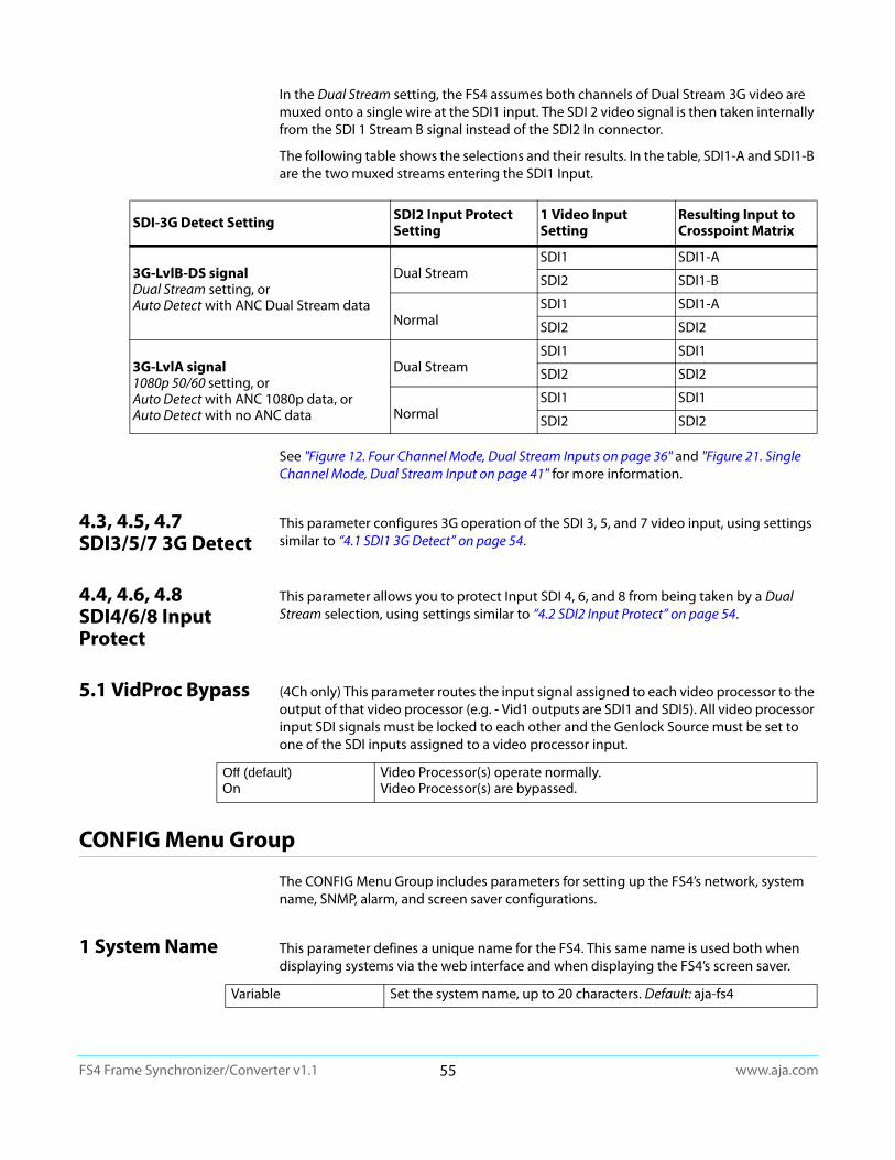
www.aja.com55
FS4 Frame Synchronizer/Converter v1.1
In the Dual Stream setting, the FS4 assumes both channels of Dual Stream 3G video are muxed onto a single wire at the SDI1 input. The SDI 2 video signal is then taken internally from the SDI 1 Stream B signal instead of the SDI2 In connector.
The following table shows the selections and their results. In the table, SDI1-A and SDI1-B are the two muxed streams entering the SDI1 Input.
See "Figure 12. Four Channel Mode, Dual Stream Inputs on page 36" and "Figure 21. Single Channel Mode, Dual Stream Input on page 41" for more information.
4.3, 4.5, 4.7 SDI3/5/7 3G Detect
This parameter configures 3G operation of the SDI 3, 5, and 7 video input, using settings similar to “4.1 SDI1 3G Detect” on page 54.
4.4, 4.6, 4.8 SDI4/6/8 Input Protect
This parameter allows you to protect Input SDI 4, 6, and 8 from being taken by a Dual Stream selection, using settings similar to “4.2 SDI2 Input Protect” on page 54.
5.1 VidProc Bypass (4Ch only) This parameter routes the input signal assigned to each video processor to the output of that video processor (e.g. - Vid1 outputs are SDI1 and SDI5). All video processor input SDI signals must be locked to each other and the Genlock Source must be set to one of the SDI inputs assigned to a video processor input.
CONFIG Menu Group
The CONFIG Menu Group includes parameters for setting up the FS4’s network, system name, SNMP, alarm, and screen saver configurations.
1 System Name This parameter defines a unique name for the FS4. This same name is used both when displaying systems via the web interface and when displaying the FS4’s screen saver.
SDI-3G Detect Setting SDI2 Input Protect Setting
1 Video Input Setting
Resulting Input to Crosspoint Matrix
3G-LvlB-DS signalDual Stream setting, or Auto Detect with ANC Dual Stream data
Dual StreamSDI1 SDI1-A
SDI2 SDI1-B
NormalSDI1 SDI1-A
SDI2 SDI2
3G-LvlA signal1080p 50/60 setting, orAuto Detect with ANC 1080p data, orAuto Detect with no ANC data
Dual StreamSDI1 SDI1
SDI2 SDI2
NormalSDI1 SDI1
SDI2 SDI2
Off (default)On
Video Processor(s) operate normally.Video Processor(s) are bypassed.
Variable Set the system name, up to 20 characters. Default: aja-fs4
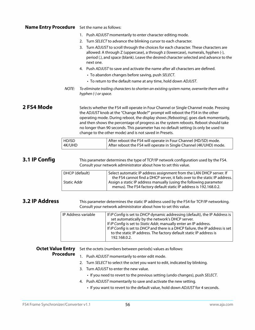
www.aja.com56
FS4 Frame Synchronizer/Converter v1.1
Name Entry Procedure Set the name as follows:
1. Push ADJUST momentarily to enter character editing mode.
2. Turn SELECT to advance the blinking cursor to each character.
3. Turn ADJUST to scroll through the choices for each character. These characters are allowed: A through Z (uppercase), a through z (lowercase), numerals, hyphen (-), period (.), and space (blank). Leave the desired character selected and advance to the next one.
4. Push ADJUST to save and activate the name after all characters are defined.
• To abandon changes before saving, push SELECT.
• To return to the default name at any time, hold down ADJUST.
NOTE: To eliminate trailing characters to shorten an existing system name, overwrite them with a hyphen (-) or space.
2 FS4 Mode Selects whether the FS4 will operate in Four Channel or Single Channel mode. Pressing the ADJUST knob at the “Change Mode?” prompt will reboot the FS4 in the other operating mode. During reboot, the display shows [Rebooting], goes dark momentarily, and then shows the percentage of progress as the system reboots. Reboot should take no longer than 90 seconds. This parameter has no default setting (is only be used to change to the other mode) and is not saved in Presets.
3.1 IP Config This parameter determines the type of TCP/IP network configuration used by the FS4. Consult your network administrator about how to set this value.
3.2 IP Address This parameter determines the static IP address used by the FS4 for TCP/IP networking. Consult your network administrator about how to set this value.
Octet Value Entry Procedure
Set the octets (numbers between periods) values as follows:
1. Push ADJUST momentarily to enter edit mode.
2. Turn SELECT to select the octet you want to edit, indicated by blinking.
3. Turn ADJUST to enter the new value.
• If you need to revert to the previous setting (undo changes), push SELECT.
4. Push ADJUST momentarily to save and activate the new setting.
• If you want to revert to the default value, hold down ADJUST for 4 seconds.
HD/SD4K/UHD
After reboot the FS4 will operate in Four Channel (HD/SD) mode.After reboot the FS4 will operate in Single Channel (4K/UHD) mode.
DHCP (default)
Static Addr
Select automatic IP address assignment from the LAN DHCP server. If the FS4 cannot find a DHCP server, it fails over to the static IP address.
Assign a static IP address manually (using the following parameter menus). The FS4 factory default static IP address is 192.168.0.2.
IP Address variable If IP Config is set to DHCP dynamic addressing (default), the IP Address is set automatically by the network's DHCP server.
If IP Config is set to Static Addr, manually enter an IP address.If IP Config is set to DHCP and there is a DHCP failure, the IP address is set
to the static IP address. The factory default static IP address is 192.168.0.2.

www.aja.com57
FS4 Frame Synchronizer/Converter v1.1
3.3 Subnet Mask This parameter determines the subnet mask used by the FS4 for TCP/IP networking. Consult your network administrator about how to set this value.
3.4 Default Gateway This parameter determines the gateway or router used on your LAN for TCP/IP networking. Consult your network administrator about how to set this value.
Without a properly configured default gateway (whether you have a router/gateway or not), the FS4 will be unable to see other FS units on the network, although you may still be able to control this unit via a web browser. Also, without a proper gateway defined, the discovery feature on the Network web page will fail to list other FS units on the network.
3.5 MAC Address (view only)
Selecting this parameter allows you to view the MAC address. The MAC address is a unique value associated with the FS4’s internal network adapter. MAC addresses are also known as hardware addresses or physical addresses. MAC addresses uniquely identify an Ethernet adapter on a LAN.
MAC address format: MM:MM:MM:SS:SS:SS The value is 12-digit hexadecimal, where the first half identifies the manufacturer and the second half identifies the unique serial number.
4 SNMP Enable Parameters
The following parameters are used to setup the FS4 SNMP (Simple Network Management Protocol) feature.
• 4.0 SNMP Enable
• 4.1 SNMP Trap Destination 1
• 4.2 SNMP Trap Port 1
• 4.3 SNMP Trap Destination 2
• 4.4 SNMP Trap Port 2
Refer to "Chapter 6: SNMP on page 113" for a description of SNMP and how the FS4 supports it.
About FS4 Alarms The following FS4 alarm parameters affect how the front panel LEDs and Web UI report error conditions. When suppressed, front panel LEDs will not light red, and the Web UI will not report that particular error status. Suppressed alarms do not affect the information reported on the FS4 front panel Status menus, and does not affect SNMP messaging.
Subnet Mask variable Enter a subnet mask compatible with your LAN. This is only needed for Static IP configurations.
If IP Config is set to DHCP, the Subnet Mask is set by the DHCP server and cannot be changed by the user.
If IP Config is set to Default Addr, the default Subnet Mask is 255.255.255.0
Gateway Address variable Enter the address of the gateway or router used to connect the FS4 to the network. Default: 192.168.0.1
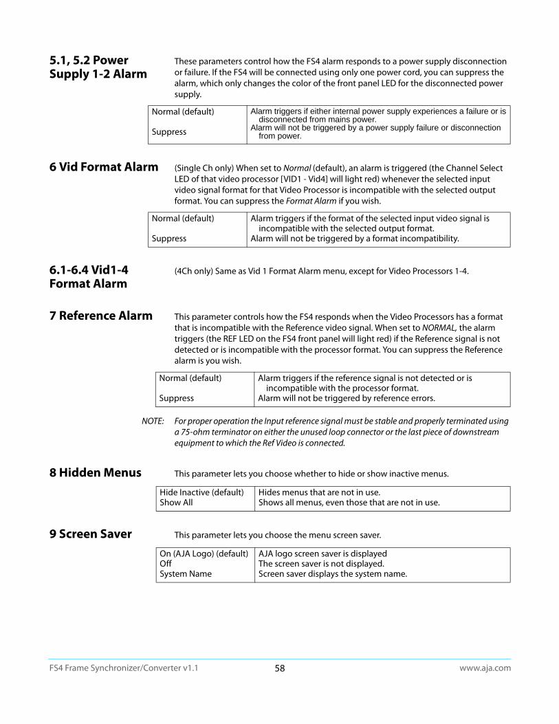
www.aja.com58
FS4 Frame Synchronizer/Converter v1.1
5.1, 5.2 Power Supply 1-2 Alarm
These parameters control how the FS4 alarm responds to a power supply disconnection or failure. If the FS4 will be connected using only one power cord, you can suppress the alarm, which only changes the color of the front panel LED for the disconnected power supply.
6 Vid Format Alarm (Single Ch only) When set to Normal (default), an alarm is triggered (the Channel Select LED of that video processor [VID1 - Vid4] will light red) whenever the selected input video signal format for that Video Processor is incompatible with the selected output format. You can suppress the Format Alarm if you wish.
6.1-6.4 Vid1-4 Format Alarm
(4Ch only) Same as Vid 1 Format Alarm menu, except for Video Processors 1-4.
7 Reference Alarm This parameter controls how the FS4 responds when the Video Processors has a format that is incompatible with the Reference video signal. When set to NORMAL, the alarm triggers (the REF LED on the FS4 front panel will light red) if the Reference signal is not detected or is incompatible with the processor format. You can suppress the Reference alarm is you wish.
NOTE: For proper operation the Input reference signal must be stable and properly terminated using a 75-ohm terminator on either the unused loop connector or the last piece of downstream equipment to which the Ref Video is connected.
8 Hidden Menus This parameter lets you choose whether to hide or show inactive menus.
9 Screen Saver This parameter lets you choose the menu screen saver.
Normal (default)
Suppress
Alarm triggers if either internal power supply experiences a failure or is disconnected from mains power.
Alarm will not be triggered by a power supply failure or disconnection from power.
Normal (default)
Suppress
Alarm triggers if the format of the selected input video signal is incompatible with the selected output format.
Alarm will not be triggered by a format incompatibility.
Normal (default)
Suppress
Alarm triggers if the reference signal is not detected or is incompatible with the processor format.
Alarm will not be triggered by reference errors.
Hide Inactive (default)Show All
Hides menus that are not in use.Shows all menus, even those that are not in use.
On (AJA Logo) (default)OffSystem Name
AJA logo screen saver is displayedThe screen saver is not displayed.Screen saver displays the system name.

www.aja.com59
FS4 Frame Synchronizer/Converter v1.1
10 Display Intensity This parameter determines the brightness of the alphanumeric display and front panel LEDs.
11 Fan Speed This parameter determines the speed (and sound level) of the FS4's internal cooling fans. For long term reliability, the fan speed should be set as high as possible, only lowering the speed if fan noise is a concern. At 25C (77F) ambient temperature any speed setting (1 to 10) provides adequate cooling. At 40C (104F) ambient, a fan speed of 5 or higher is recommended. The FS4 also has built-in thermal protection that will increase the fan speed automatically if necessary.
12 Serial Number This parameter displays the FS4’s unique serial number. Please reference this number if you contact AJA customer support.
13 Software Version This parameter displays the FS4’s software version number.
14 Reboot This parameter lets you reboot the FS4. Press and hold in both front panel knobs simultaneously to reboot.
During reboot, the display shows [Rebooting], goes dark momentarily, and then shows the percentage of progress as the system reboots. Reboot should take no longer than 90 seconds.
AUDIO Menu Group
The following descriptions explain the AUDIO Menu Group, which allows you to make adjustments to the FS4’s sample rate converters, Mix Down Modes, and some other system wide settings.
1 MADI Output Mode
This parameter controls the number of MADI channels sent to both the MADI BNC and Fiber output connectors, 64 or 56.
If the FS4 receives 56 channels and is set to output 64 channels, active silent channels 57 to 64 are added to the output. When the FS4 receives 64 channels and is set to output 56 channels, channels 57 to 64 are dropped on the output.
Variable Dim or brighten the alphanumeric display and activity indicator LEDs in steps from 1 (dim) to 8 (brightest). Default: 6
Variable Changes the fan speed in steps from 1 (slow) to 10 (fast). Default is 10.
64ch (default)56ch
Sixty four audio channels selected for MADI output.Fifty six audio channels selected for MADI output. MADI output
channels 57-64 will not be available.

www.aja.com60
FS4 Frame Synchronizer/Converter v1.1
2.1-2.8 SDI 1-8 SRC Mode
These parameters control the use of sample rate converters for the incoming SDI embedded audio. This setting affects all 16 embedded audio channels for that SDI input, if present.
In Auto mode, normal PCM audio passes through the Sample Rate Converters and gets converted, as appropriate. If any of the active input signals are non-PCM the SRC is turned off for all audio inputs.
2.9 AES SRC Mode These parameters control the use of sample rate converters for the incoming AES audio. This setting affects all 16 AES input channels.
NOTE: For SRC, all AES channels must be synchronous to AES1 (channel pair 1&2), or to the lowest numbered AES pair if AES1 is not present.
2.10 MADI BNC SRC Mode
These parameters control the use of sample rate converters for the incoming MADI BCN audio. This setting affects all 64 MADI BNC input channels
In Auto mode, normal PCM audio passes through the Sample Rate Converters and gets converted, as appropriate. If any of the active input signals are non-PCM the SRC is turned off for all audio inputs.
2.11 MADI Fiber SRC Mode
These parameters control the use of sample rate converters for the incoming MADI Fiber audio. This setting affects all 64 MADI Fiber input channels
In Auto mode, normal PCM audio passes through the Sample Rate Converters and gets converted, as appropriate. If any of the active signal pairs are non-PCM the SRC is turned off for all audio inputs.
Auto (default)
OnOff
The system decides how to handle sample rate conversion. PCM uses SRC, compressed data doesn't use SRC.
Sample rate conversion is always performed on the inputs.Sample rate conversion is never performed on the inputs.
Auto (default)
OnOff
The system decides how to handle sample rate conversion. PCM uses SRC, compressed data doesn't use SRC.
Sample rate conversion is always performed on the inputs.Sample rate conversion is never performed on the inputs.
Auto (default)
OnOff
The system decides how to handle sample rate conversion. PCM uses SRC, compressed data doesn't use SRC.
Sample rate conversion is always performed on the inputs.Sample rate conversion is never performed on the inputs.
Auto (default)
OnOff
The system decides how to handle sample rate conversion. PCM uses SRC, compressed data doesn't use SRC.
Sample rate conversion is always performed on the inputs.Sample rate conversion is never performed on the inputs.
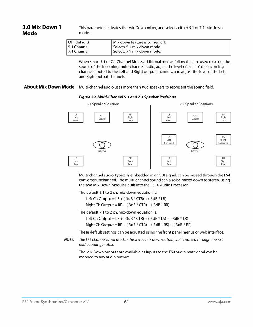
www.aja.com61
FS4 Frame Synchronizer/Converter v1.1
3.0 Mix Down 1 Mode
This parameter activates the Mix Down mixer, and selects either 5.1 or 7.1 mix down mode.
When set to 5.1 or 7.1 Channel Mode, additional menus follow that are used to select the source of the incoming multi-channel audio, adjust the level of each of the incoming channels routed to the Left and Right output channels, and adjust the level of the Left and Right output channels.
About Mix Down Mode Multi-channel audio uses more than two speakers to represent the sound field.
Figure 29. Multi-Channel 5.1 and 7.1 Speaker Positions
Multi-channel audio, typically embedded in an SDI signal, can be passed through the FS4 converter unchanged. The multi-channel sound can also be mixed down to stereo, using the two Mix Down Modules built into the FSI-X Audio Processor.
The default 5.1 to 2 ch. mix-down equation is:
Left Ch Output = LF + (-3dB * CTR) + (-3dB * LR)
Right Ch Output = RF + (-3dB * CTR) + (-3dB * RR)
The default 7.1 to 2 ch. mix-down equation is:
Left Ch Output = LF + (-3dB * CTR) + (-3dB * LS) + (-3dB * LR)
Right Ch Output = RF + (-3dB * CTR) + (-3dB * RS) + (-3dB * RR)
These default settings can be adjusted using the front panel menus or web interface.
NOTE: The LFE channel is not used in the stereo mix down output, but is passed through the FS4 audio routing matrix.
The Mix Down outputs are available as inputs to the FS4 audio matrix and can be mapped to any audio output.
Off (default)5.1 Channel7.1 Channel
Mix down feature is turned off.Selects 5.1 mix down mode.Selects 7.1 mix down mode.
5.1 Speaker Positions
RRRightRear
LRLeftRear
RF RightFront
CTRCenter
LFLeft
Front
Listener
7.1 Speaker Positions
RRRightRear
LRLeftRear
RSRight
Surround
LSLeft
Surround
RF RightFront
CTRCenter
LFLeft
Front
Listener
www.aja.com62
FS4 Frame Synchronizer/Converter v1.1
3.1 Mix Down Input When 5.1 Channel or 7.1 Channel is selected above, this parameter selects the source of the multi-channel audio coming into that mixer.
3.2 - 3-8 Mix Down Input Mapping (LF, RF,
CTR, LR, RR, LS, RS)
When Map is selected above, these menus permit the mapping of any FS4 audio input channel or signal generator to any of the mixer inputs (L Front, R Front, Center, L Rear, R Rear, and in 7.1 mode L Surround and R Surround). Each mixer input can also be turned Off (muted). Default setting is Off.
3.9 - 3.14 Mix Down Input Level
In Mix Down Mode, multi-channel input channels are mixed to the Left and Right output channels. The level of each input signal sent to its mixed output can be adjusted plus or minus 18 dB, in half dB increments, using these menu controls.
The default settings are set to the basic equations above, and are listed below.
NOTE: The LFE channel is not used in the stereo mix down output, but is passed through the FS4 audio routing matrix.
3.16 - 3.17 Mix Down Output Lft Rt Level
The level of the Left and Right mixer output signal can be adjusted plus or minus 18 dB, in half dB increments, using these menu controls. Default is 0 dB (unity).
3.0 Mix Down 2 Mode
(4Ch only) Same as Mix Down 1 Mode menu and related sub-menus, except for the Mix Down 2 mixer.
SDI 1(default)SDI 2-8
Selects the indicated source. The channel assignments are as follows. All unused channels are muted:
Input Ch 1 - Left FrontInput Ch 2 - Right FrontInput Ch 3 - CenterInput Ch 4 - Left RearInput Ch 5 - Right RearInput Ch 6 - LFE (not used in mix down output)Input Ch 7 - Left Surround (mute in 5.1 mode)Input Ch 8 - Right Surround (mute in 5.1 mode)
Sig Gen 1KHzSig Gen 400Hz
Routes the indicates signal generator to all the active multi-channel inputs.
Map This parameters activates a series of related menus to map a specific input channel to each of the 5 or 7 mixer input channels.
LF LevelRF LevelCTR LevelLR LevelRR LevelLS Level (7.1 mode only)RS Level (7.1 mode only)
0 dB (unity) to Left output.0 dB (unity) to Right output.-3 dB from unity to both the Left and Right outputs.-3 dB from unity to the Left output.-3 dB from unity to the Right output.-3 dB from unity to the Left output.-3 dB from unity to the Right output.
www.aja.com63
FS4 Frame Synchronizer/Converter v1.1
7 Mix Down Reset This parameter resets all of the mix down levels (five or seven input, two output) for the selected mixer to the factory defaults. Turn the ADJIUST knob to select the mixer. Two mixers are available in Four Channel Mode, and only one mixer is available in Single Channel mode. After selecting a mixer, press ADJ. An “Are you sure” prompt is displayed. Pressing ADJUST again resets that mixer...
8 Global Audio Output
This parameter allows routing the same source or set of sources to all the FS4 audio outputs. The rules used for Audio Out apply if the number of outputs do not match the number of inputs.
NOTE: No Global Map source is available.
9 Reset Mapped Output
This parameter resets the selected output map to the factory default values
Mix Down 1Mix Down 2 (4Ch only)
Resets the Mix Down 1 mixer levels to default settings. Resets the Mix Down 2 mixer levels to default settings.
Off (default) No Global output configuration is imposed. When Off all other AUDIO OUTPUT menus are enabled and displayed.
SDI1SDI2-8 (4Ch only)AES.EBUMADI BNCMADI Fiber
The selected source channels are routed to all the FS4 audio output channels.
Sig Gen 1KHzSig Gen 400HzMute
The selected tone or mute is routed to every FS4 audio output channel.
Mix Down 1 L:RMix Down 2 L:R (4Ch
only)
The stereo output of Mix Down module is routed to all the FS4 audio output channels. The Left mixer channel goes to FS4 output channel 1 and the Right mixer channel goes to output channel 2. If the output has more than two channels (i.e. embedded SDI), mute (silence) is routed to the higher numbered output channels.
Choose a Map (default) Prompt for selecting an Output to map.
SDI1SDI2-8 (4Ch only)AES.EBUMADI BNCMADI Fiber
After selecting an output, press ADJUST to reset that output to the factory default mapping (i.e. SDI1 to SDI1, SDI2 to SDI2, etc.).
All Sets all outputs to their factory default mappings.

www.aja.com64
FS4 Frame Synchronizer/Converter v1.1
PRESET Menu Group
The PRESET Menu Group provides the means of saving, editing the names of, and loading FS4 presets. A preset is a set of all System, Video, Audio, and most Config parameters as they were set at the time the preset was stored. .
During recall, the display reads, Recalling until the recall is finished. On recall completion, the displays shows the success or failure: Recalled, Failed, or Empty. A failed or empty recall does not recall anything and leaves the FS4 as it was. (Preset registers are empty until you store something in them.)
During a store, the display reads Storing until the store is finished. On store completion, the display shows Complete or Failed. A failed store does not store anything and leaves the preset register as it was. To retry a failed store, turn SELECT to another preset number and then back to the desired preset number.
1 Factory Preset This parameter recalls a read-only Factory Preset.
1.1-1.40 Presets #1-#40
These parameters let you recall, edit the name of, and store an FS4 preset configuration for the selected storage register. Forty storage registers are available.
Caution! When you recall a Preset Configuration, the recalled preset immediately replaces the system’s existing configuration. All previous settings are lost unless you have previously stored them in another preset configuration or an exported file.
Caution! In Four Channel Mode, each Preset saves all the settings for all four channels. Storing and recalling a Preset will affect all the settings for all four channels in that mode. Care must be taken to establish a policy for the use of FS4 Presets, especially if the FS4 is operated in Four Channel mode and the different channels have different users.
FactoryRecall
Recalls factory values for all System, Video, Audio, and most Config parameters. Push ADJUST for four seconds to perform the recall. The display reports “Factory values” during the recall. User preferences, network settings, and existing Presets are not affected by recalling the Factory Preset.
Preset #1–#40
[Preset Name]
Recall
Edit Name
Store
Shows the currently selected preset register number. Turn SELECT choose the desired register. Then turn ADJUST to choose Recall, Edit Name, or Store for the selected register.
Shows the name of the selected preset register, which can be edited.
Recalls that preset. Push ADJUST momentarily to perform (take) the recall. The display reports “Loading” and “Complete” during the recall.
Enables editing the name of the preset register. Push ADJUST to enable editing (blinking character), use the SELECT and ADJUST knobs to edit the name and then press ADJUST to save the edited preset register name.
Stores the current set of all System, Video, Audio, and most Config parameters to the selected preset register.
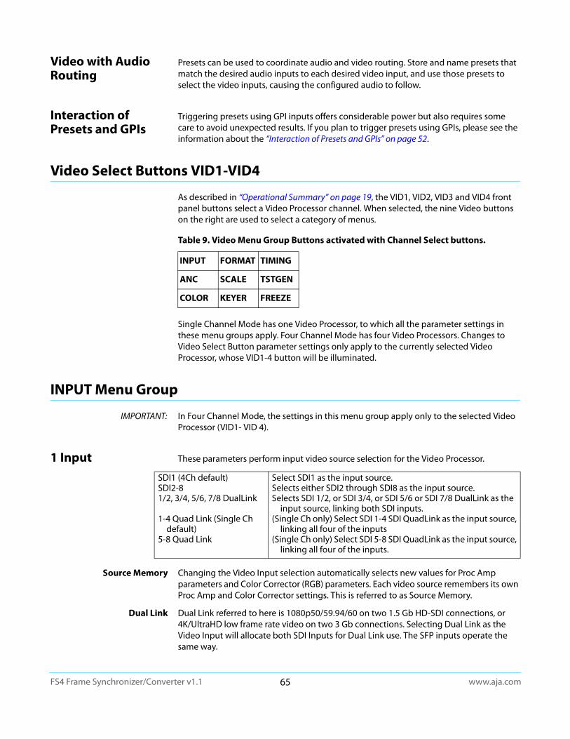
www.aja.com65
FS4 Frame Synchronizer/Converter v1.1
Video with Audio Routing
Presets can be used to coordinate audio and video routing. Store and name presets that match the desired audio inputs to each desired video input, and use those presets to select the video inputs, causing the configured audio to follow.
Interaction of Presets and GPIs
Triggering presets using GPI inputs offers considerable power but also requires some care to avoid unexpected results. If you plan to trigger presets using GPIs, please see the information about the “Interaction of Presets and GPIs” on page 52.
Video Select Buttons VID1-VID4
As described in “Operational Summary” on page 19, the VID1, VID2, VID3 and VID4 front panel buttons select a Video Processor channel. When selected, the nine Video buttons on the right are used to select a category of menus.
Single Channel Mode has one Video Processor, to which all the parameter settings in these menu groups apply. Four Channel Mode has four Video Processors. Changes to Video Select Button parameter settings only apply to the currently selected Video Processor, whose VID1-4 button will be illuminated.
INPUT Menu Group
IMPORTANT: In Four Channel Mode, the settings in this menu group apply only to the selected Video Processor (VID1- VID 4).
1 Input These parameters perform input video source selection for the Video Processor.
Source Memory Changing the Video Input selection automatically selects new values for Proc Amp parameters and Color Corrector (RGB) parameters. Each video source remembers its own Proc Amp and Color Corrector settings. This is referred to as Source Memory.
Dual Link Dual Link referred to here is 1080p50/59.94/60 on two 1.5 Gb HD-SDI connections, or 4K/UltraHD low frame rate video on two 3 Gb connections. Selecting Dual Link as the Video Input will allocate both SDI Inputs for Dual Link use. The SFP inputs operate the same way.
Table 9. Video Menu Group Buttons activated with Channel Select buttons.
INPUT FORMAT TIMING
ANC SCALE TSTGEN
COLOR KEYER FREEZE
SDI1 (4Ch default)SDI2-81/2, 3/4, 5/6, 7/8 DualLink
1-4 Quad Link (Single Ch default)
5-8 Quad Link
Select SDI1 as the input source.Selects either SDI2 through SDI8 as the input source.Selects SDI 1/2, or SDI 3/4, or SDI 5/6 or SDI 7/8 DualLink as the
input source, linking both SDI inputs.(Single Ch only) Select SDI 1-4 SDI QuadLink as the input source,
linking all four of the inputs(Single Ch only) Select SDI 5-8 SDI QuadLink as the input source,
linking all four of the inputs.
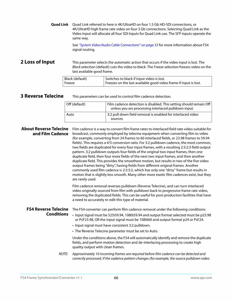
www.aja.com66
FS4 Frame Synchronizer/Converter v1.1
Quad Link Quad Link referred to here is 4K/UltraHD on four 1.5 Gb HD-SDI connections, or 4K/UltraHD high frame rate video on four 3 Gb connections. Selecting Quad Link as the Video Input will allocate all four SDI Inputs for Quad Link use. The SFP inputs operate the same way.
See “System Video/Audio Cable Connections” on page 33 for more information about FS4 signal routing.
2 Loss of Input This parameter selects the automatic action that occurs if the video input is lost. The Black selection (default) cuts the video to black. The Freeze selection freezes video on the last available good frame.
3 Reverse Telecine This parameters can be used to control film cadence detection.
About Reverse Telecine and Film Cadence
Film cadence is a way to convert film frame rates to interlaced field rate video suitable for broadcast, commonly employed by telecine equipment when converting film to video (for example, converting from 24 frames to 60 interlaced fields, or 23.98 frames to 59.94 fields). This requires a 4/5 conversion ratio. For 3:2 pulldown cadence, the most common, two fields are duplicated for every four input frames, with a resulting 2:3:2:3 field output pattern. 3:2 pulldown outputs four fields of the original two input frames, then one duplicate field, then four more fields of the next two input frames, and then another duplicate field. This provides the smoothest motion, but results in two of the five video output frames being “dirty”, having fields from different original frames. Another commonly used film cadence is 2:3:3:2, which has only one “dirty” frame but results in motion that is slightly less smooth. Many other more exotic film cadences exist, but they are rarely used.
Film cadence removal reverses pulldown (Reverse Telecine), and can turn interlaced video originally sourced from film with pulldown back to progressive frame rate video, removing the duplicated fields. This can be useful for post-production facilities that have a need to accurately re-edit this type of material.
FS4 Reverse Telecine Conditions
The FS4 converter can perform film cadence removal under the following conditions:
• Input signal must be 525i59.94, 1080i59.94 and output format selected must be p23.98 or PsF23.98, OR the input signal must be 1080i60 and output format p24 or PsF24.
• Input signal must have consistent 3:2 pulldown.
• The Reverse Telecine parameter must be set to Auto.
Under the conditions above, the FS4 will automatically identify and remove the duplicate fields, and perform motion detection and de-interlacing processing to create high quality output with clean frames.
NOTE: Approximately 10 incoming frames are required before film cadence can be detected and correctly processed. If the cadence pattern changes (for example, the source pulldown video
Black (default)Freeze
Switches to black if input video is lost.Freezes on the last available good video frame if input is lost.
Off (default) Film cadence detection is disabled. This setting should remain Off unless you are processing interlaced pulldown input.
Auto 3:2 pull down field removal is enabled for interlaced video sources.

www.aja.com67
FS4 Frame Synchronizer/Converter v1.1
may have been edited) that same approximately 10 frame interval is required after the discontinuity to detect and process the new cadence pattern.
4 Input Scan Format This parameter determines how the Deinterlacer handles interlaced vs. PsF inputs.
Normally, this control will only be used to indicate that a 1080PsF25 input is PsF and not interlaced.
Auto When Auto is selected, the system will look for clues in the source's SMPTE 352 (Payload ID) data and respond accordingly. If there is no SMPTE 352 information, the system will assume that 23.98/24 fps sources are PsF, and 25/29.97/30 fps sources are interlaced.
Progressive When Progressive is selected, the system will assume that all sources are PsF (even if there is SMPTE 352 data to the contrary).
Interlaced When Interlaced is selected, the system will assume that all sources are interlaced (even if there is SMPTE 352 data to the contrary)
Auto (default) Deinterlacer detects input source payload ID data and sets the processing format accordingly.
Progressive Assumes all input sources are progressive.
Interlaced Assumes all input sources are interlaced.

www.aja.com68
FS4 Frame Synchronizer/Converter v1.1
ANC Menu Group
IMPORTANT: In Four Channel Mode, the settings in this menu group apply only to the selected Video Processor (VID1- VID 4).
1.1 AFD Out These parameters determine if and where the Video Processor will insert a SMPTE 2016 Active Format Descriptor (AFD) packet into its output video. The inserted AFD code does not affect the Video Processor's conversion, but it may affect downstream video processing if the signal is later converted.
1.2 AFD VANC Output Lines
This parameter determines which video output lines have AFD VANC inserted on the output.
Off (default) The FS4 does not insert an AFD code into the output.
Auto If there is no AFD code on the input video, a “Full Frame” (8) code is inserted. If the FS4 is converting, the appropriate AFD code will be chosen based on the convert mode (see “6 Upconvert Mode” on page 75 and “7 Downconvert Mode” on page 76).
>16:9 Always inserts a “Box > 16:9 (center)” AFD code (4), which indicates that the image has an aspect ratio greater than 16:9 as a vertically centered letterbox within the 16:9 frame.
Full Frame Always inserts a “Full Frame” AFD code (8), which indicates that the image is full frame, with an aspect ratio that is 16:9.
Pillarbox Always inserts a “4:3 (center)” AFD code (9), which indicates that the image has a 4:3 aspect ratio as a horizontally center pillarbox image within the 16:9 frame.
Letterbox Always inserts a “16:9 (with complete 16:9 image protected)” AFD code (10), which indicates that the image is full frame, with a 16:9 aspect ratio and all image areas are protected.
14:9 Always inserts a “14:9 (center)” AFD code (11), which indicates that the image has a 14:9 aspect ratio as a horizontally centered pillarbox within the 16:9 frame.
4:3 Alt 14:9 Always inserts a “4:3 (with alternate 14:9 center)” AFD code (13), which indicates that the image has a 4:3 aspect ratio and with an alternative 14:9 centered pillarbox image within the 16:9 frame.
16:9 Alt 14:9 Always inserts a “16:9 (with alternative 14:9 center” AFD code (14), which indicates that the image has a 16:9 aspect ratio with an alternative 14:9 center within the 16:9 frame.
16:9 Alt 4:3 Always inserts a “16:9 (with alternative 4:3 center)” AFD code (15), which indicates that the image has a 16:9 aspect ratio with an alternative 4:3 center within the 16:9 frame.
10 (default)9–42
Adds AFD VANC to line 10.Select which line other than 10 will have AFD VANC added.
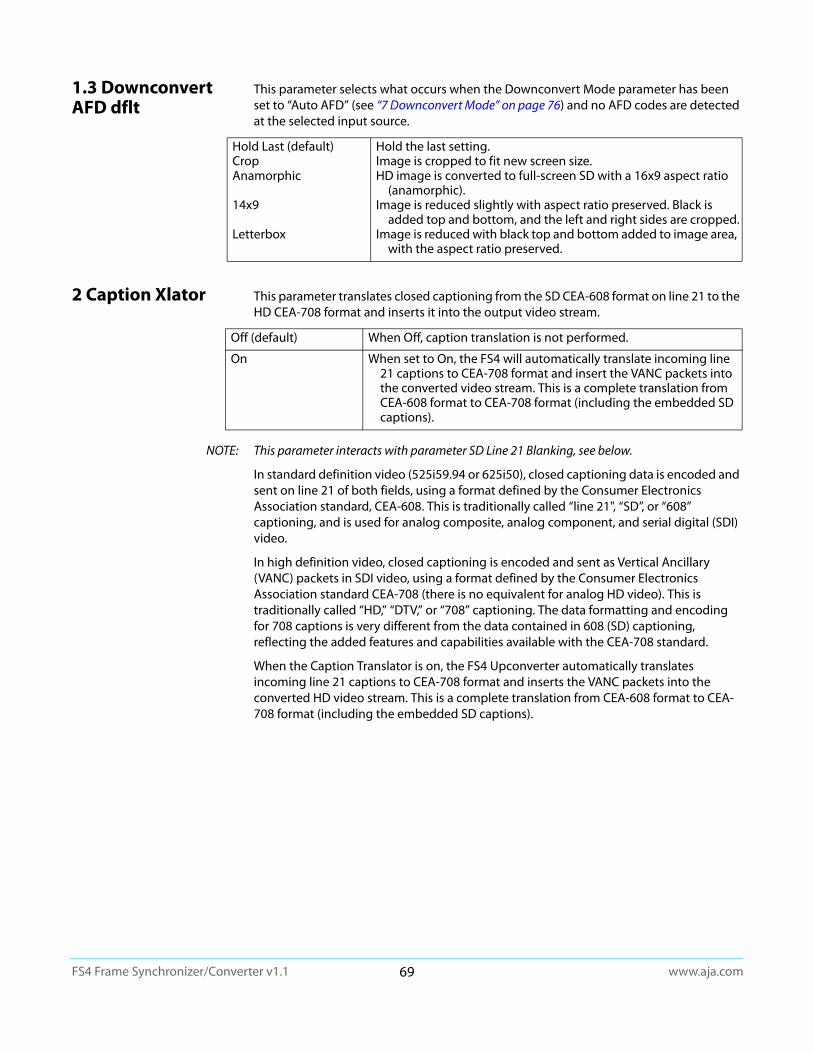
www.aja.com69
FS4 Frame Synchronizer/Converter v1.1
1.3 Downconvert AFD dflt
This parameter selects what occurs when the Downconvert Mode parameter has been set to “Auto AFD” (see “7 Downconvert Mode” on page 76) and no AFD codes are detected at the selected input source.
2 Caption Xlator This parameter translates closed captioning from the SD CEA-608 format on line 21 to the HD CEA-708 format and inserts it into the output video stream.
NOTE: This parameter interacts with parameter SD Line 21 Blanking, see below.
In standard definition video (525i59.94 or 625i50), closed captioning data is encoded and sent on line 21 of both fields, using a format defined by the Consumer Electronics Association standard, CEA-608. This is traditionally called “line 21", “SD”, or “608” captioning, and is used for analog composite, analog component, and serial digital (SDI) video.
In high definition video, closed captioning is encoded and sent as Vertical Ancillary (VANC) packets in SDI video, using a format defined by the Consumer Electronics Association standard CEA-708 (there is no equivalent for analog HD video). This is traditionally called “HD,” “DTV,” or “708” captioning. The data formatting and encoding for 708 captions is very different from the data contained in 608 (SD) captioning, reflecting the added features and capabilities available with the CEA-708 standard.
When the Caption Translator is on, the FS4 Upconverter automatically translates incoming line 21 captions to CEA-708 format and inserts the VANC packets into the converted HD video stream. This is a complete translation from CEA-608 format to CEA-708 format (including the embedded SD captions).
Hold Last (default)CropAnamorphic
14x9
Letterbox
Hold the last setting.Image is cropped to fit new screen size.HD image is converted to full-screen SD with a 16x9 aspect ratio
(anamorphic).Image is reduced slightly with aspect ratio preserved. Black is
added top and bottom, and the left and right sides are cropped.Image is reduced with black top and bottom added to image area,
with the aspect ratio preserved.
Off (default) When Off, caption translation is not performed.
On When set to On, the FS4 will automatically translate incoming line 21 captions to CEA-708 format and insert the VANC packets into the converted video stream. This is a complete translation from CEA-608 format to CEA-708 format (including the embedded SD captions).
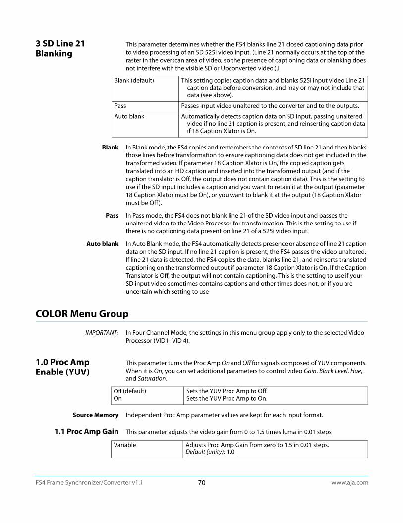
www.aja.com70
FS4 Frame Synchronizer/Converter v1.1
3 SD Line 21 Blanking
This parameter determines whether the FS4 blanks line 21 closed captioning data prior to video processing of an SD 525i video input. (Line 21 normally occurs at the top of the raster in the overscan area of video, so the presence of captioning data or blanking does not interfere with the visible SD or Upconverted video.).I
Blank In Blank mode, the FS4 copies and remembers the contents of SD line 21 and then blanks those lines before transformation to ensure captioning data does not get included in the transformed video. If parameter 18 Caption Xlator is On, the copied caption gets translated into an HD caption and inserted into the transformed output (and if the caption translator is Off, the output does not contain caption data). This is the setting to use if the SD input includes a caption and you want to retain it at the output (parameter 18 Caption Xlator must be On), or you want to blank it at the output (18 Caption Xlator must be Off ).
Pass In Pass mode, the FS4 does not blank line 21 of the SD video input and passes the unaltered video to the Video Processor for transformation. This is the setting to use if there is no captioning data present on line 21 of a 525i video input.
Auto blank In Auto Blank mode, the FS4 automatically detects presence or absence of line 21 caption data on the SD input. If no line 21 caption is present, the FS4 passes the video unaltered. If line 21 data is detected, the FS4 copies the data, blanks line 21, and reinserts translated captioning on the transformed output if parameter 18 Caption Xlator is On. If the Caption Translator is Off, the output will not contain captioning. This is the setting to use if your SD input video sometimes contains captions and other times does not, or if you are uncertain which setting to use
COLOR Menu Group
IMPORTANT: In Four Channel Mode, the settings in this menu group apply only to the selected Video Processor (VID1- VID 4).
1.0 Proc Amp Enable (YUV)
This parameter turns the Proc Amp On and Off for signals composed of YUV components. When it is On, you can set additional parameters to control video Gain, Black Level, Hue, and Saturation.
Source Memory Independent Proc Amp parameter values are kept for each input format.
1.1 Proc Amp Gain This parameter adjusts the video gain from 0 to 1.5 times luma in 0.01 steps
Blank (default) This setting copies caption data and blanks 525i input video Line 21 caption data before conversion, and may or may not include that data (see above).
Pass Passes input video unaltered to the converter and to the outputs.
Auto blank Automatically detects caption data on SD input, passing unaltered video if no line 21 caption is present, and reinserting caption data if 18 Caption Xlator is On.
Off (default)On
Sets the YUV Proc Amp to Off.Sets the YUV Proc Amp to On.
Variable Adjusts Proc Amp Gain from zero to 1.5 in 0.01 steps.Default (unity): 1.0
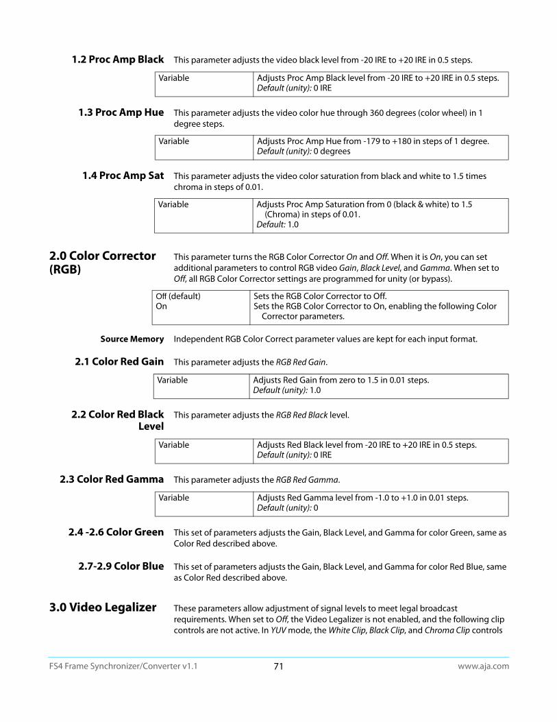
www.aja.com71
FS4 Frame Synchronizer/Converter v1.1
1.2 Proc Amp Black This parameter adjusts the video black level from -20 IRE to +20 IRE in 0.5 steps.
1.3 Proc Amp Hue This parameter adjusts the video color hue through 360 degrees (color wheel) in 1 degree steps.
1.4 Proc Amp Sat This parameter adjusts the video color saturation from black and white to 1.5 times chroma in steps of 0.01.
2.0 Color Corrector (RGB)
This parameter turns the RGB Color Corrector On and Off. When it is On, you can set additional parameters to control RGB video Gain, Black Level, and Gamma. When set to Off, all RGB Color Corrector settings are programmed for unity (or bypass).
Source Memory Independent RGB Color Correct parameter values are kept for each input format.
2.1 Color Red Gain This parameter adjusts the RGB Red Gain.
2.2 Color Red Black Level
This parameter adjusts the RGB Red Black level.
2.3 Color Red Gamma This parameter adjusts the RGB Red Gamma.
2.4 -2.6 Color Green This set of parameters adjusts the Gain, Black Level, and Gamma for color Green, same as Color Red described above.
2.7-2.9 Color Blue This set of parameters adjusts the Gain, Black Level, and Gamma for color Red Blue, same as Color Red described above.
3.0 Video Legalizer These parameters allow adjustment of signal levels to meet legal broadcast requirements. When set to Off, the Video Legalizer is not enabled, and the following clip controls are not active. In YUV mode, the White Clip, Black Clip, and Chroma Clip controls
Variable Adjusts Proc Amp Black level from -20 IRE to +20 IRE in 0.5 steps.Default (unity): 0 IRE
Variable Adjusts Proc Amp Hue from -179 to +180 in steps of 1 degree.Default (unity): 0 degrees
Variable Adjusts Proc Amp Saturation from 0 (black & white) to 1.5 (Chroma) in steps of 0.01.
Default: 1.0
Off (default)On
Sets the RGB Color Corrector to Off.Sets the RGB Color Corrector to On, enabling the following Color
Corrector parameters.
Variable Adjusts Red Gain from zero to 1.5 in 0.01 steps.Default (unity): 1.0
Variable Adjusts Red Black level from -20 IRE to +20 IRE in 0.5 steps.Default (unity): 0 IRE
Variable Adjusts Red Gamma level from -1.0 to +1.0 in 0.01 steps.Default (unity): 0

www.aja.com72
FS4 Frame Synchronizer/Converter v1.1
are enabled and clip any luma/chroma that exceed the set limits. In RGB mode only the White Clip and Black Clip controls are active and limit the R, G, and B values to those settings. RGB mode requires the video to pass through the RGB Proc Amp to be converted to and from RGB.
3.1 Legalizer White Clip When the Video Legalizer mode is YUV or RGB, this parameter limits the white level so that it does not exceed the adjusted limit. Limit can be set from +80 IRE to +120 IRE.
3.2 Legalizer Black Clip When the Video Legalizer mode is YUV or RGB, this parameter limits the black level to the adjusted limit. Limit can be set from -10 IRE to +20 IRE,.
3.3 Legalizer Chroma Clip
When the Video Legalizer mode is YUV, this parameter limits the maximum chroma level to the adjusted limit. The limit can be set from +60% to +140%,.
FORMAT Menu Group
IMPORTANT: In Four Channel Mode, the settings in this menu group apply only to the selected Video Processor (VID1- VID 4).
1 Output Format This parameter defines the output format of the Video Processor. Available choices depend on the frame rate selection.
Output Format Selection Constraint
Available frame rates depend on System menu “1 Output Frame Rate” on page 53 parameter setting.
Output Timing Memory Changing the Output Format selection automatically selects new values for H & V timing parameters (see “1 Output Frame Rate” on page 53). Each Output Format mode remembers its own H and V timing settings.
Output Format Mapping The Output Format selection is remembered for each of the frame rates. If you change the Output Frame Rate (“1 Output Frame Rate” on page 53), the Output Format setting associated with the newly selected frame rate is recalled.
See “System Video/Audio Cable Connections” on page 33 for more information about FS4 signal routing.
Off (default)YUVRGB
Disables the Video Legalizer.Enables the Video Legalizer to clip YUV to legal levels.Enables the Video Legalizer to clip RGB to legal levels.
Variable Adjusts white clip level from +80 IRE to +120 IRE in 0.5 steps.Default (unity): 100 IRE
Variable Adjusts black level limit from -10 IRE to +20 IRE in 0.5 steps.
Default (unity): 0 IRE
Variable Adjusts chroma clip level from +60% to +140% in 0.5 steps.
Default (unity): 100 IRE
Follow Input (default)Follow Ref<format><frame rate>
Match the output format to the incoming video format.Match the output format to the current Reference input. Select this format and frame rate as the output format.

www.aja.com73
FS4 Frame Synchronizer/Converter v1.1
2.0 Link Config SDI1, 2, 3, 4
(4Ch only) These parameters determine how 1080p50/60 signal transport is configured for the Video Processor output BNC connectors. The menu names and parameters available depend on the currently selected Video Processor. For example, if Video Processor 1 is selected, the menu title will be 2.0 Link Cfg SDI1 identifying the primary output BNC connector used by that Video Processor. For Video Processor 2 the menu title will be 2.0 Link Cfg SDI2, etc.
2.1 Level B SDI1, 2, 3, 4
(4Ch only) When Single Link Level B has been selected above, the parameters on the menu below become available for the selected Video Processor.
Figure 30. Dual Stream 3G MUX Schematic
See "Figure 15. Four Channel Mode, Dual Stream Outputs on page 37" for more information.
2.0 Link Config SDI1-4
(Single Ch only) These parameters determine how 1080p50/60 signal transport is configured for the Video Processor output BNC connectors.
Sngl Link LvlA (default)Dual Link
Sngl Link LvlB
Sets the output transport to 3Gb Level A (single connector).Sets the output transport to 1.5Gb Dual Link (two connectors,
ST 372).Sets the output transport to 3Gb Level B-DL (single
connector). When Level B is selected a sub menu becomes available to choose the Video Processor(s).
VID1 Vid1 (default)Vid1 + Vid 2
Selects only the Vid 1 Processor signal for output.Select both the Vid1 and Vid2 Processor signals for output
(Dual Stream).
VID2 Vid2 (default)Vid1 + Vid 2
Selects only the Vid 2 Processor signal for output.Select both the Vid1 and Vid2 Processor signals for output
(Dual Stream).
VID3 Vid3 (default)Vid3 + Vid 4
Selects only the Vid 3 Processor signal for output.Select both the Vid3 and Vid4 Processor signals for output
(Dual Stream).
VID4 Vid4 (default)Vid3 + Vid 4
Selects only the Vid 4 Processor signal for output.Select both the Vid3 and Vid4 Processor signals for output
(Dual Stream).
HD/SDVideo Processor 1
HD/SDVideo Processor 2
QuadLnk Lvl A (default)
QuadLnk LvlB
Sngl Lnk LvlADual LinkSngl Lnk LvlB
Sets the output transport to Quad Link Level A (four connectors).
Sets the output transport to Quad Link Level B-DL (four connectors).
Sets the output transport to 3Gb Level A (single connector).Sets the output transport to 1.5Gb Dual Link (two connectors)Sets the output transport to 3Gb Level B-DL (single
connector).
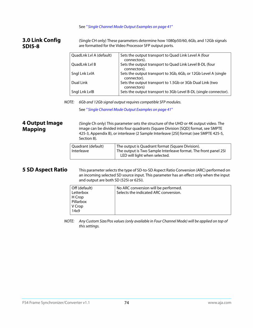
www.aja.com74
FS4 Frame Synchronizer/Converter v1.1
See " Single Channel Mode Output Examples on page 41"
3.0 Link Config SDI5-8
(Single CH only) These parameters determine how 1080p50/60, 6Gb, and 12Gb signals are formatted for the Video Processor SFP output ports.
NOTE: 6Gb and 12Gb signal output requires compatible SFP modules.
See " Single Channel Mode Output Examples on page 41"
4 Output Image Mapping
(Single Ch only) This parameter sets the structure of the UHD or 4K output video. The image can be divided into four quadrants (Square Division [SQD] format, see SMPTE 425-3, Appendix B), or interleave (2 Sample Interleave [2SI] format (see SMPTE 425-5, Section 8).
5 SD Aspect Ratio This parameter selects the type of SD-to-SD Aspect Ratio Conversion (ARC) performed on an incoming selected SD source input. This parameter has an effect only when the input and output are both SD (525i or 625i).
NOTE: Any Custom Size/Pos values (only available in Four Channel Mode) will be applied on top of this settings.
QuadLnk Lvl A (default)
QuadLnk Lvl B
Sngl Lnk LvlA
Dual Link
Sngl Lnk LvlB
Sets the output transport to Quad Link Level A (four connectors).
Sets the output transport to Quad Link Level B-DL (four connectors).
Sets the output transport to 3Gb, 6Gb, or 12Gb Level A (single connector).
Sets the output transport to 1.5Gb or 3Gb Dual Link (two connectors)
Sets the output transport to 3Gb Level B-DL (single connector).
Quadrant (default)Interleave
The output is Quadrant format (Square Division).The output is Two Sample Interleave format. The front panel 2SI
LED will light when selected.
Off (default)LetterboxH CropPillarboxV Crop14x9
No ARC conversion will be performed.Selects the indicated ARC conversion.
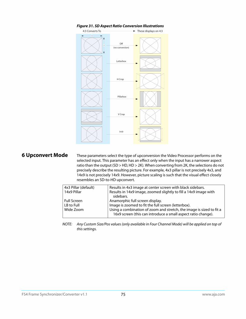
www.aja.com75
FS4 Frame Synchronizer/Converter v1.1
Figure 31. SD Aspect Ratio Conversion Illustrations
6 Upconvert Mode These parameters select the type of upconversion the Video Processor performs on the selected input. This parameter has an effect only when the input has a narrower aspect ratio than the output (SD > HD, HD > 2K). When converting from 2K, the selections do not precisely describe the resulting picture. For example, 4x3 pillar is not precisely 4x3, and 14x9 is not precisely 14x9. However, picture scaling is such that the visual effect closely resembles an SD-to-HD upconvert.
NOTE: Any Custom Size/Pos values (only available in Four Channel Mode) will be applied on top of this settings.
H Crop
Pillarbox
V Crop
14:9
Off
(no conversion)
Letterbox
4
3
4:3 Converts To These displays on 4:3
4x3 Pillar (default)14x9 Pillar
Full ScreenLB to FullWide Zoom
Results in 4x3 image at center screen with black sidebars.Results in 14x9 image, zoomed slightly to fill a 14x9 image with
sidebars.Anamorphic full screen display.Image is zoomed to fit the full screen (letterbox).Using a combination of zoom and stretch, the image is sized to fit a
16x9 screen (this can introduce a small aspect ratio change).
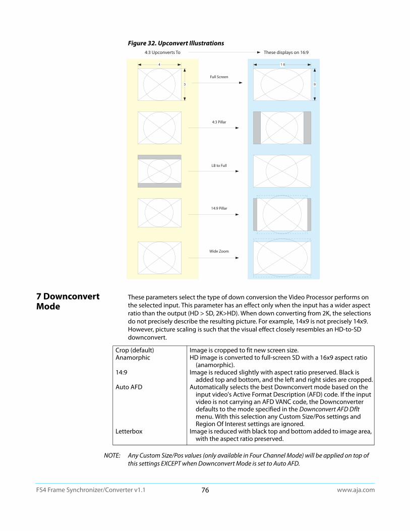
www.aja.com76
FS4 Frame Synchronizer/Converter v1.1
Figure 32. Upconvert Illustrations
7 Downconvert Mode
These parameters select the type of down conversion the Video Processor performs on the selected input. This parameter has an effect only when the input has a wider aspect ratio than the output (HD > SD, 2K>HD). When down converting from 2K, the selections do not precisely describe the resulting picture. For example, 14x9 is not precisely 14x9. However, picture scaling is such that the visual effect closely resembles an HD-to-SD downconvert.
NOTE: Any Custom Size/Pos values (only available in Four Channel Mode) will be applied on top of this settings EXCEPT when Downconvert Mode is set to Auto AFD.
Full Screen
4:3 Pillar
LB to Full
14:9 Pillar
Wide Zoom
1 6
9
4
3
4:3 Upconverts To These displays on 16:9
Crop (default)Anamorphic
14:9
Auto AFD
Letterbox
Image is cropped to fit new screen size.HD image is converted to full-screen SD with a 16x9 aspect ratio
(anamorphic).Image is reduced slightly with aspect ratio preserved. Black is
added top and bottom, and the left and right sides are cropped.Automatically selects the best Downconvert mode based on the
input video's Active Format Description (AFD) code. If the input video is not carrying an AFD VANC code, the Downconverter defaults to the mode specified in the Downconvert AFD Dflt menu. With this selection any Custom Size/Pos settings and Region Of Interest settings are ignored.
Image is reduced with black top and bottom added to image area, with the aspect ratio preserved.
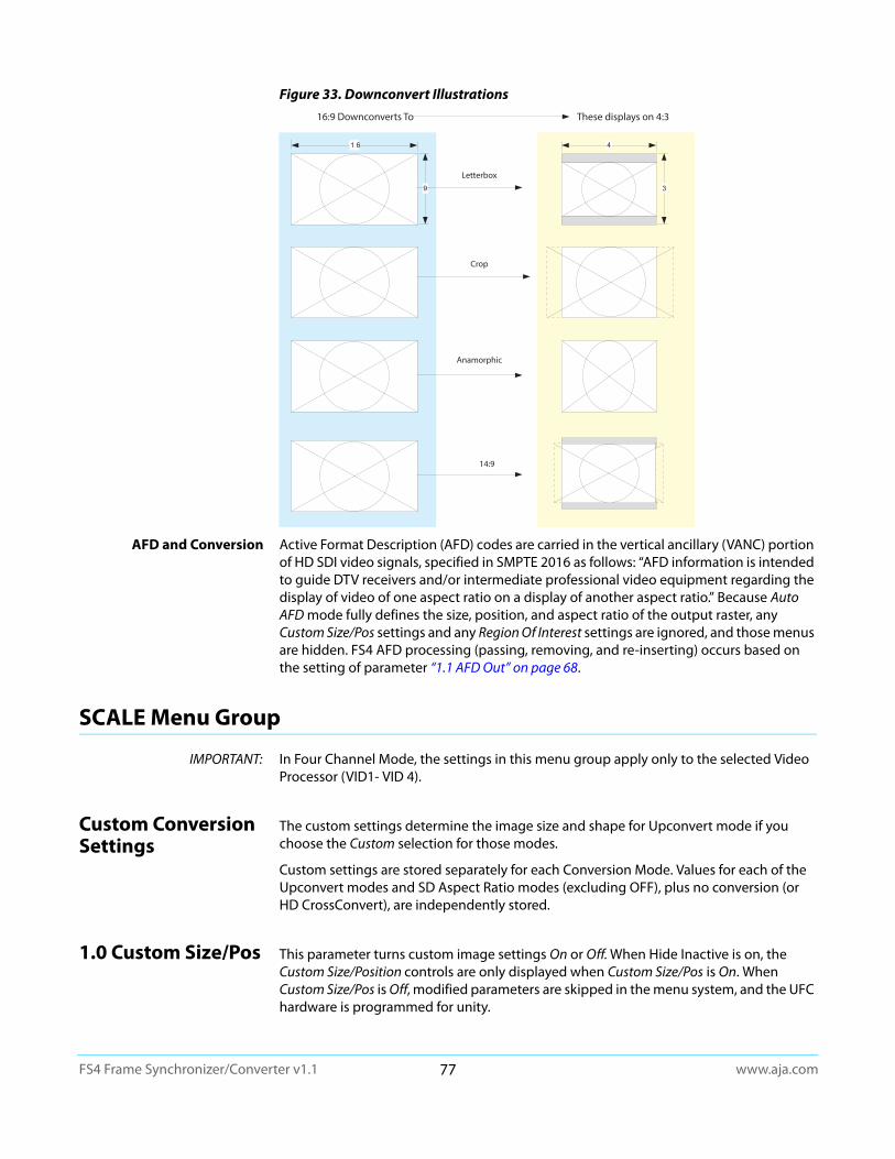
www.aja.com77
FS4 Frame Synchronizer/Converter v1.1
Figure 33. Downconvert Illustrations
AFD and Conversion Active Format Description (AFD) codes are carried in the vertical ancillary (VANC) portion of HD SDI video signals, specified in SMPTE 2016 as follows: “AFD information is intended to guide DTV receivers and/or intermediate professional video equipment regarding the display of video of one aspect ratio on a display of another aspect ratio.” Because Auto AFD mode fully defines the size, position, and aspect ratio of the output raster, any Custom Size/Pos settings and any Region Of Interest settings are ignored, and those menus are hidden. FS4 AFD processing (passing, removing, and re-inserting) occurs based on the setting of parameter “1.1 AFD Out” on page 68.
SCALE Menu Group
IMPORTANT: In Four Channel Mode, the settings in this menu group apply only to the selected Video Processor (VID1- VID 4).
Custom Conversion Settings
The custom settings determine the image size and shape for Upconvert mode if you choose the Custom selection for those modes.
Custom settings are stored separately for each Conversion Mode. Values for each of the Upconvert modes and SD Aspect Ratio modes (excluding OFF), plus no conversion (or HD CrossConvert), are independently stored.
1.0 Custom Size/Pos This parameter turns custom image settings On or Off. When Hide Inactive is on, the Custom Size/Position controls are only displayed when Custom Size/Pos is On. When Custom Size/Pos is Off, modified parameters are skipped in the menu system, and the UFC hardware is programmed for unity.
1 6
9
Anamorphic
Letterbox
4
3
16:9 Downconverts To These displays on 4:3
Crop
14:9
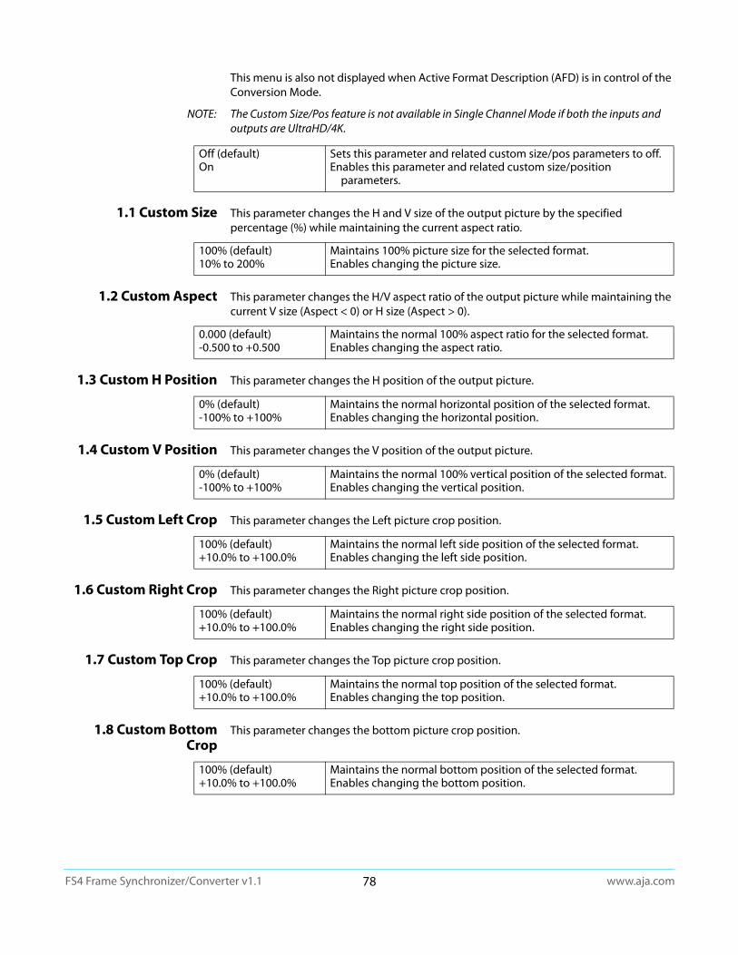
www.aja.com78
FS4 Frame Synchronizer/Converter v1.1
This menu is also not displayed when Active Format Description (AFD) is in control of the Conversion Mode.
NOTE: The Custom Size/Pos feature is not available in Single Channel Mode if both the inputs and outputs are UltraHD/4K.
1.1 Custom Size This parameter changes the H and V size of the output picture by the specified percentage (%) while maintaining the current aspect ratio.
1.2 Custom Aspect This parameter changes the H/V aspect ratio of the output picture while maintaining the current V size (Aspect < 0) or H size (Aspect > 0).
1.3 Custom H Position This parameter changes the H position of the output picture.
1.4 Custom V Position This parameter changes the V position of the output picture.
1.5 Custom Left Crop This parameter changes the Left picture crop position.
1.6 Custom Right Crop This parameter changes the Right picture crop position.
1.7 Custom Top Crop This parameter changes the Top picture crop position.
1.8 Custom Bottom Crop
This parameter changes the bottom picture crop position.
Off (default)On
Sets this parameter and related custom size/pos parameters to off.Enables this parameter and related custom size/position
parameters.
100% (default)10% to 200%
Maintains 100% picture size for the selected format.Enables changing the picture size.
0.000 (default)-0.500 to +0.500
Maintains the normal 100% aspect ratio for the selected format.Enables changing the aspect ratio.
0% (default)-100% to +100%
Maintains the normal horizontal position of the selected format.Enables changing the horizontal position.
0% (default)-100% to +100%
Maintains the normal 100% vertical position of the selected format.Enables changing the vertical position.
100% (default)+10.0% to +100.0%
Maintains the normal left side position of the selected format.Enables changing the left side position.
100% (default)+10.0% to +100.0%
Maintains the normal right side position of the selected format.Enables changing the right side position.
100% (default)+10.0% to +100.0%
Maintains the normal top position of the selected format.Enables changing the top position.
100% (default)+10.0% to +100.0%
Maintains the normal bottom position of the selected format.Enables changing the bottom position.
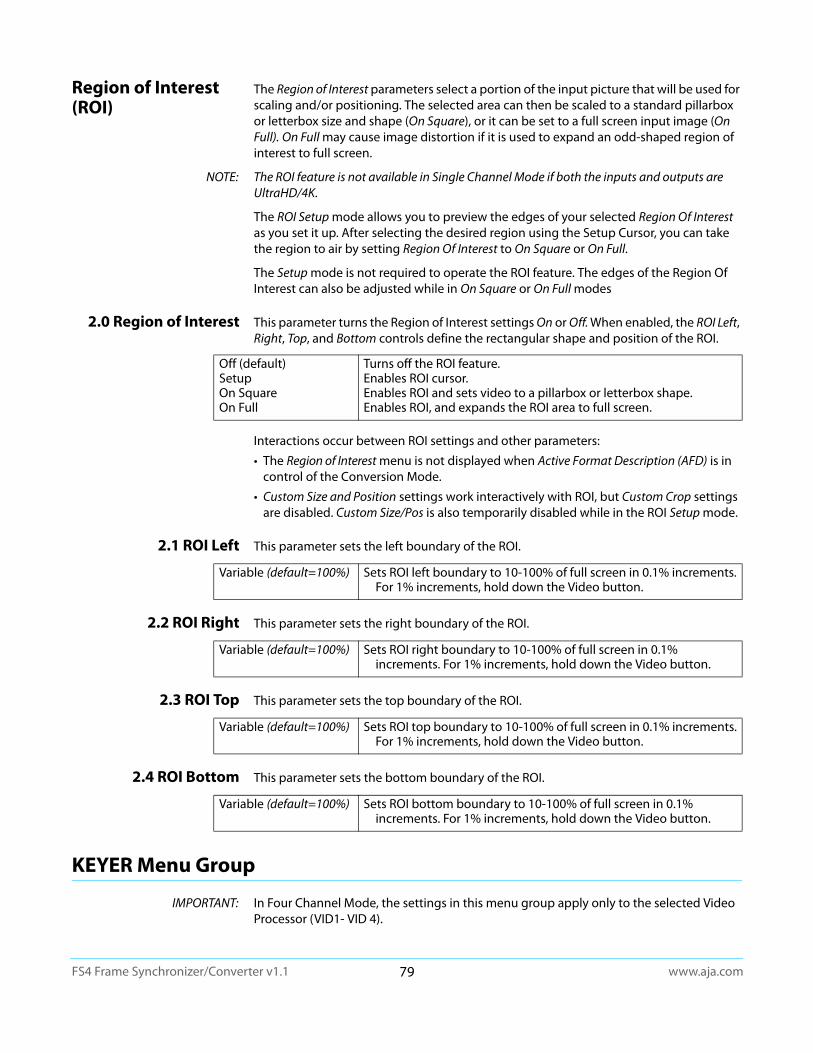
www.aja.com79
FS4 Frame Synchronizer/Converter v1.1
Region of Interest (ROI)
The Region of Interest parameters select a portion of the input picture that will be used for scaling and/or positioning. The selected area can then be scaled to a standard pillarbox or letterbox size and shape (On Square), or it can be set to a full screen input image (On Full). On Full may cause image distortion if it is used to expand an odd-shaped region of interest to full screen.
NOTE: The ROI feature is not available in Single Channel Mode if both the inputs and outputs are UltraHD/4K.
The ROI Setup mode allows you to preview the edges of your selected Region Of Interest as you set it up. After selecting the desired region using the Setup Cursor, you can take the region to air by setting Region Of Interest to On Square or On Full.
The Setup mode is not required to operate the ROI feature. The edges of the Region Of Interest can also be adjusted while in On Square or On Full modes
2.0 Region of Interest This parameter turns the Region of Interest settings On or Off. When enabled, the ROI Left, Right, Top, and Bottom controls define the rectangular shape and position of the ROI.
Interactions occur between ROI settings and other parameters:
• The Region of Interest menu is not displayed when Active Format Description (AFD) is in control of the Conversion Mode.
• Custom Size and Position settings work interactively with ROI, but Custom Crop settings are disabled. Custom Size/Pos is also temporarily disabled while in the ROI Setup mode.
2.1 ROI Left This parameter sets the left boundary of the ROI.
2.2 ROI Right This parameter sets the right boundary of the ROI.
2.3 ROI Top This parameter sets the top boundary of the ROI.
2.4 ROI Bottom This parameter sets the bottom boundary of the ROI.
KEYER Menu Group
IMPORTANT: In Four Channel Mode, the settings in this menu group apply only to the selected Video Processor (VID1- VID 4).
Off (default)SetupOn SquareOn Full
Turns off the ROI feature.Enables ROI cursor.Enables ROI and sets video to a pillarbox or letterbox shape.Enables ROI, and expands the ROI area to full screen.
Variable (default=100%) Sets ROI left boundary to 10-100% of full screen in 0.1% increments. For 1% increments, hold down the Video button.
Variable (default=100%) Sets ROI right boundary to 10-100% of full screen in 0.1% increments. For 1% increments, hold down the Video button.
Variable (default=100%) Sets ROI top boundary to 10-100% of full screen in 0.1% increments. For 1% increments, hold down the Video button.
Variable (default=100%) Sets ROI bottom boundary to 10-100% of full screen in 0.1% increments. For 1% increments, hold down the Video button.
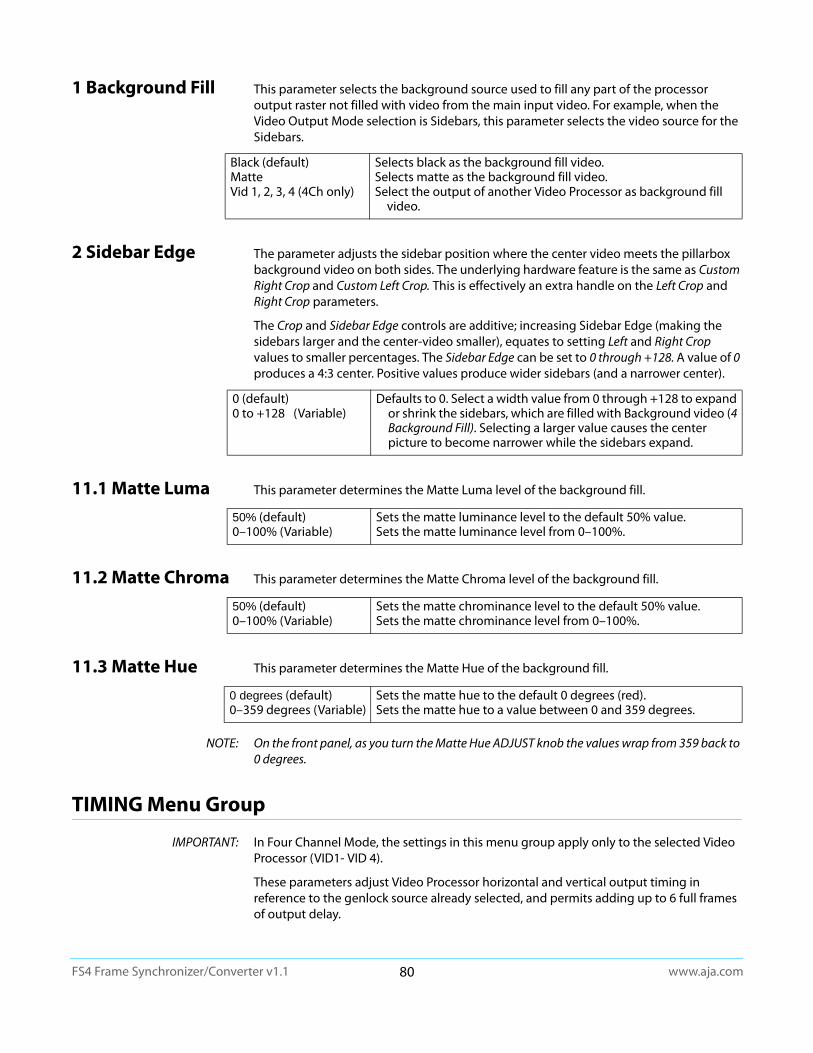
www.aja.com80
FS4 Frame Synchronizer/Converter v1.1
1 Background Fill This parameter selects the background source used to fill any part of the processor output raster not filled with video from the main input video. For example, when the Video Output Mode selection is Sidebars, this parameter selects the video source for the Sidebars.
2 Sidebar Edge The parameter adjusts the sidebar position where the center video meets the pillarbox background video on both sides. The underlying hardware feature is the same as Custom Right Crop and Custom Left Crop. This is effectively an extra handle on the Left Crop and Right Crop parameters.
The Crop and Sidebar Edge controls are additive; increasing Sidebar Edge (making the sidebars larger and the center-video smaller), equates to setting Left and Right Crop values to smaller percentages. The Sidebar Edge can be set to 0 through +128. A value of 0 produces a 4:3 center. Positive values produce wider sidebars (and a narrower center).
11.1 Matte Luma This parameter determines the Matte Luma level of the background fill.
11.2 Matte Chroma This parameter determines the Matte Chroma level of the background fill.
11.3 Matte Hue This parameter determines the Matte Hue of the background fill.
NOTE: On the front panel, as you turn the Matte Hue ADJUST knob the values wrap from 359 back to 0 degrees.
TIMING Menu Group
IMPORTANT: In Four Channel Mode, the settings in this menu group apply only to the selected Video Processor (VID1- VID 4).
These parameters adjust Video Processor horizontal and vertical output timing in reference to the genlock source already selected, and permits adding up to 6 full frames of output delay.
Black (default)MatteVid 1, 2, 3, 4 (4Ch only)
Selects black as the background fill video.Selects matte as the background fill video.Select the output of another Video Processor as background fill
video.
0 (default)0 to +128 (Variable)
Defaults to 0. Select a width value from 0 through +128 to expand or shrink the sidebars, which are filled with Background video (4 Background Fill). Selecting a larger value causes the center picture to become narrower while the sidebars expand.
50% (default)0–100% (Variable)
Sets the matte luminance level to the default 50% value.Sets the matte luminance level from 0–100%.
50% (default)0–100% (Variable)
Sets the matte chrominance level to the default 50% value.Sets the matte chrominance level from 0–100%.
0 degrees (default)0–359 degrees (Variable)
Sets the matte hue to the default 0 degrees (red).Sets the matte hue to a value between 0 and 359 degrees.

www.aja.com81
FS4 Frame Synchronizer/Converter v1.1
NOTE: Unlike most knob-adjustable parameters, on the front panel menu this parameter automatically wraps around from the maximum value to 0 (and vice versa).
1 Output Timing H When adjusting the horizontal timing (H), this parameter specifies a number of pixels to offset, from zero to full line width. Adjustment range increments from 0 to the width of the line in pixels. The maximum value varies, depending on the format already chosen.
2 Output Timing V When adjusting the vertical timing (V), this parameter specifies a number of lines to offset, moving the screen up to a half a frame up or down.
Output Timing Memory Independent horizontal and vertical timing values are kept for all available output formats.
Output Timing Ranges The table below lists the output timing ranges for various video frame rates.
Variable Adjustment range increments from 0 to the width of the line in pixels. The maximum varies, depending on the format chosen. Default: 0
Variable Adjustment range increments from half a frame up to a half a frame down in single line increments. The maximum varies, depending on the format already chosen.
Default: 0
Table 10. Output Timing Ranges
Output Frame RateHorizontal Vertical
Min Max Min MaxUHD23.98 0 2749 -562 562UHD24 0 2749 -562 562UHD25 0 2639 -562 562UHD29.97 0 2199 -562 562UHD50 0 2639 -562 562UHD59.94 0 2199 -562 5624K1080p23.98 0 2749 -562 5624K1080p24 0 2749 -562 5624K1080p25 0 2639 -562 5624K1080p29.97 0 2199 -562 5624K1080p50 0 2639 -562 5624K1080p59.94 0 2199 -562 5621080i50 0 2639 -562 562
1080i59.94, 1080i60 0 2199 -562 562
1080p23.98, 1080p24 0 2749 -562 562
1080p25 0 2639 -562 562
1080p29.97, 1080p30 0 2199 -562 562
1080p50 0 2639 -562 562
1080p59.94, 1080p60 0 2199 -562 562
1080psf23.98, 1080psf24 0 2749 -562 562
1080psf25 0 2639 -562 562
1080psf29.97, 1080psf30 0 2199 -562 562
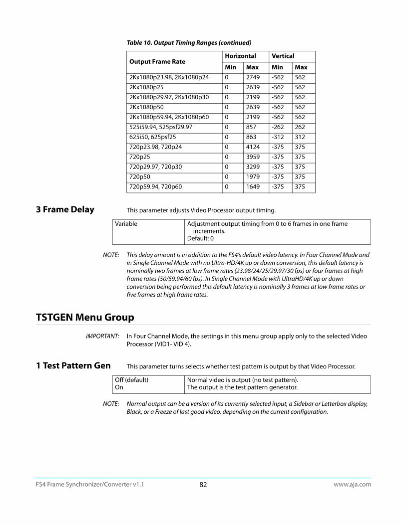
www.aja.com82
FS4 Frame Synchronizer/Converter v1.1
3 Frame Delay This parameter adjusts Video Processor output timing.
NOTE: This delay amount is in addition to the FS4’s default video latency. In Four Channel Mode and in Single Channel Mode with no Ultra-HD/4K up or down conversion, this default latency is nominally two frames at low frame rates (23.98/24/25/29.97/30 fps) or four frames at high frame rates (50/59.94/60 fps). In Single Channel Mode with UltraHD/4K up or down conversion being performed this default latency is nominally 3 frames at low frame rates or five frames at high frame rates.
TSTGEN Menu Group
IMPORTANT: In Four Channel Mode, the settings in this menu group apply only to the selected Video Processor (VID1- VID 4).
1 Test Pattern Gen This parameter turns selects whether test pattern is output by that Video Processor.
NOTE: Normal output can be a version of its currently selected input, a Sidebar or Letterbox display, Black, or a Freeze of last good video, depending on the current configuration.
2Kx1080p23.98, 2Kx1080p24 0 2749 -562 562
2Kx1080p25 0 2639 -562 562
2Kx1080p29.97, 2Kx1080p30 0 2199 -562 562
2Kx1080p50 0 2639 -562 562
2Kx1080p59.94, 2Kx1080p60 0 2199 -562 562
525i59.94, 525psf29.97 0 857 -262 262
625i50, 625psf25 0 863 -312 312
720p23.98, 720p24 0 4124 -375 375
720p25 0 3959 -375 375
720p29.97, 720p30 0 3299 -375 375
720p50 0 1979 -375 375
720p59.94, 720p60 0 1649 -375 375
Table 10. Output Timing Ranges (continued)
Output Frame RateHorizontal Vertical
Min Max Min Max
Variable Adjustment output timing from 0 to 6 frames in one frame increments.
Default: 0
Off (default)On
Normal video is output (no test pattern).The output is the test pattern generator.
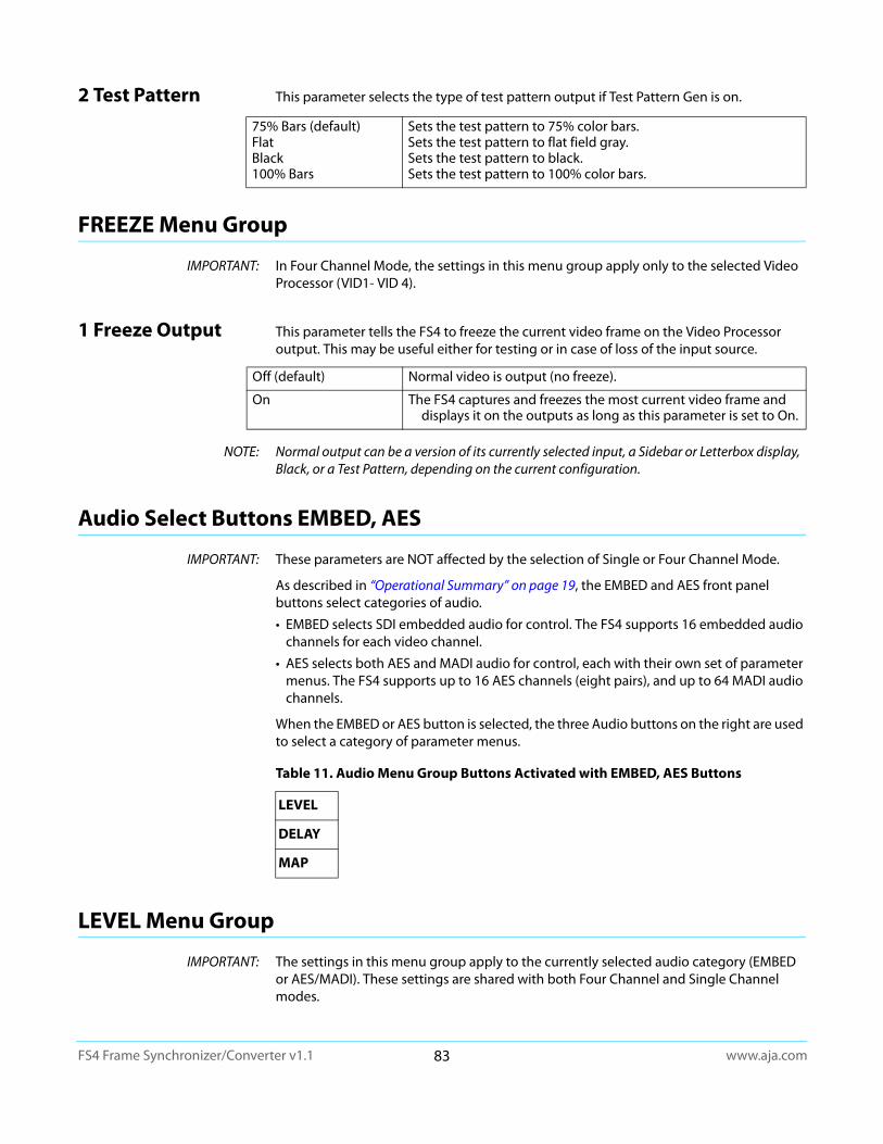
www.aja.com83
FS4 Frame Synchronizer/Converter v1.1
2 Test Pattern This parameter selects the type of test pattern output if Test Pattern Gen is on.
FREEZE Menu Group
IMPORTANT: In Four Channel Mode, the settings in this menu group apply only to the selected Video Processor (VID1- VID 4).
1 Freeze Output This parameter tells the FS4 to freeze the current video frame on the Video Processor output. This may be useful either for testing or in case of loss of the input source.
NOTE: Normal output can be a version of its currently selected input, a Sidebar or Letterbox display, Black, or a Test Pattern, depending on the current configuration.
Audio Select Buttons EMBED, AES
IMPORTANT: These parameters are NOT affected by the selection of Single or Four Channel Mode.
As described in “Operational Summary” on page 19, the EMBED and AES front panel buttons select categories of audio.
• EMBED selects SDI embedded audio for control. The FS4 supports 16 embedded audio channels for each video channel.
• AES selects both AES and MADI audio for control, each with their own set of parameter menus. The FS4 supports up to 16 AES channels (eight pairs), and up to 64 MADI audio channels.
When the EMBED or AES button is selected, the three Audio buttons on the right are used to select a category of parameter menus.
LEVEL Menu Group
IMPORTANT: The settings in this menu group apply to the currently selected audio category (EMBED or AES/MADI). These settings are shared with both Four Channel and Single Channel modes.
75% Bars (default)FlatBlack100% Bars
Sets the test pattern to 75% color bars.Sets the test pattern to flat field gray.Sets the test pattern to black.Sets the test pattern to 100% color bars.
Off (default) Normal video is output (no freeze).
On The FS4 captures and freezes the most current video frame and displays it on the outputs as long as this parameter is set to On.
Table 11. Audio Menu Group Buttons Activated with EMBED, AES Buttons
LEVEL
DELAY
MAP

www.aja.com84
FS4 Frame Synchronizer/Converter v1.1
The LEVEL menus provide Level and Phase adjustments for SDI Embedded, AES, MADI BNC, and MADI Fiber input audio.
EMBED Level Menus When EMBED is selected, the following SDI Embedded Audio menus are available.
1.0 SDI1 Level This parameter selects the Audio Level Mode for all 16 SDI1 audio input channels. The default Unity setting applies 0.0. db gain to all the input channels
When Adjust mode is selected:• After selecting an individual channel adjustment menu, the ADJUST knob changes the
value shown by 0.5 dB (up or down) for each knob detent.
• The range of adjustment is -18.0dB to +18.0dB.
• Switching from Unity to Adjust will apply the individual level values that were set in the Adjust mode to the input for each of the channels. Switching from Adjust to Unity will apply unity (0.0dB) to all channels.
1.1-1.16 SDI1 Level Ch 1 When Adjust is selected above, individual SDI 1 audio channel menus become available, permitting +/- 18.0 dB level adjustment to each input channel.
2.0-8.0 SDI2-8 Level Same as 1.0 SDI1 Level menu, except for SDI inputs 2 through 8, and similar level adjust submenus are available.
9.0 SDI1 Phase This parameter selects the Audio Phase Mode for all 16 SDI1 audio input channels The default Unity setting applies normal (non-inverted) phase to all the input channels.
When Adjust mode is selected:
• After selecting an individual channel adjustment menu, the ADJUST knob toggles the Phase value shown between Normal and Invert. When Invert is selected the phase of the audio input on that channel will be inverted.
Switching from Unity to Adjust will apply the individual Phase values that were set in the Adjust mode to the input for each of the channels. Switching from Adjust to Unity will apply unity (Normal) to all channels.
9.1-9.16 SDI 1 Phase When Adjust is selected above, individual SDI 1 audio channel menus become available, permitting inverting the phase of each input channel.
10.0 - 16.0 SDI2-8 Phase
Same as 9.0 SDI1 Phase menu, except for SDI inputs 2 through 8, and similar phase adjust submenus are available.
Unity (default)
Adjust
All 16 SDI1 audio input channels are set to 0.0 dB. Individual channel adjustment menus are hidden.
Each of the 16 SDI1 audio input channel adjusted values are applied to the audio processor, and the individual channel adjustment menus become available.
Unity (default)
Adjust
All 16 SDI1 audio input channels are set to Normal phase. Individual channel adjustment menus are hidden.
Each of the 16 SDI1 audio input Phase values (either Normal or Invert) are applied to the audio processor, and the individual channel adjustment menus become available.
www.aja.com85
FS4 Frame Synchronizer/Converter v1.1
AES/MADI Menus When AES is selected, Level and Phase parameter menus for AES and MADI input audio are displayed. These menus are the similar to those used for Embedded Audio SDI1 Level and Phase.
1.0 AES Level Sixteen AES Level menus (and related submenus) are available.
2.0 MADI BNC Level Sixty four MADI BNC Level (and related submenus) are available.
3.0 MADIFIB Level Sixty four MADI Fiber Level (and related submenus) are available.
NOTE: For level adjustment information, see “1.0 SDI1 Level” on page 84.
4.0 AES Phase Sixteen AES Phase menus (and related submenus) are available.
5.0 MADI BNC Phase Sixty four MADI BNC Phase (and related submenus) are available
6.0 MADIFIB Phase Sixty four MADI Fiber Phase (and related submenus) are available.
NOTE: For Phase adjustment information, see “9.0 SDI1 Phase” on page 84.
DELAY Menu Group
IMPORTANT: The settings in this menu group apply to the currently selected audio category (EMBED or AES/MADI). These settings are shared with both Four Channel and Single Channel modes.
The DELAY Menu Group provides delay adjustments for SDI Embedded, AES, MADI BNC, and MADI Fiber input audio. Delay adjustments are applied to audio channel pairs.
EMBED Delay Menus
When EMBED is selected, the following SDI Embedded Audio menus are available.
1.0 SDI1 Delay This parameter selects the Audio Delay Mode for the eight SDI1 audio input channel pairs. Delay operates on channel pairs only. Delay cannot be adjusted on any single channel. Channel pairs are grouped as: Channel 1 and 2, Channel 3 and 4,…, Channel 15 and 16. The default Global setting applies the currently set Global delay value to all eight input channel pairs. The factory default Global setting is 0 seconds delay, but whatever value the user changes this setting to will be applied when Global is selected.
When Channel Pair mode is selected:
• Each of the individual eight SDI1 audio input channel pair delay values are applied to the input delay of each channel pair.
• The range of delay is -128 to +12288 in units of samples where 48 samples = 1 millisecond.
Switching from Global to Channel Pair will apply the individual delay values that were set for each individual channel pair. Switching from Channel Pair to Global will apply the same currently set Global delay value to all the channel pairs.
Global (default)
Channel Pair
All eight SDI1 audio input channel pairs are set to the current Global delay value. Individual channel adjustment menus are hidden.
Each of the eight SDI1 audio input channel pairs delay values are applied to the input of each channel pair, and the channel pair adjustment menus become available.
www.aja.com86
FS4 Frame Synchronizer/Converter v1.1
1.1 SDI 1 Delay Global When Global is selected above, the individual SDI 1 audio channel pair menus are hidden.
1.1-1.8 SDI 1 Channel Pair Delay
When Channel Pair is selected above, eight individual SDI 1 audio channel pair menus become available, permitting adjusting the delay of each input channel pair.
• Delay adjustment range is -128 to +12288 in units of samples where 48 samples = 1 millisecond. The Front Panel displays the delay in milliseconds and as fractions of milliseconds in units of samples.
2.0 - 8.0 SDI2-8 Delay Same as 1.0 SDI1 Delay menu, except for SDI inputs 2 through 8, and similar delay adjust submenus are available.
AES/MADI Delay Menus
When AES is selected, Delay parameter menus for AES and MADI input audio are displayed. These menus are the similar to those used for Embedded Audio SDI1 Delay.
1.0 AES Delay Sixteen AES Level menus (and related submenus) are available.
2.0 MADI BNC Delay Sixty four MADI BNC Level (and related submenus) are available.
3.0 MADIFIB Delay Sixty four MADI Fiber Level (and related submenus) are available.
NOTE: For level adjustment information, see “1.0 SDI1 Delay” on page 85.
MAP Menu Group
IMPORTANT: The settings in this menu group apply to the currently selected audio category (EMBED or AES/MADI). These settings are NOT shared with both Four Channel and Single Channel modes.
The MAP menus provide FS4 audio routing controls. Any audio input can be routed to any audio output, except the Monitor output embedded audio always matches the monitored video.
About Audio Routing
The following menus control the FS4’s audio routing. The general routing procedure using the front panel is to select the menu of the audio output with the SELECT knob, and then select the input source you wish to route to that output with the ADJUST knob. Channel mapping allows different individual audio channels to be routed to different individual outputs.
See “System Video/Audio Cable Connections” on page 33 for more information about FS4 signal routing.
SDI 1 Delay Global The ADJUST knob sets the Global delay value. Adjustment range is -128 to +12288 in units of samples where 48 samples = 1 millisecond.
The Front Panel displays the delay in milliseconds and as fractions of milliseconds in units of samples.

www.aja.com87
FS4 Frame Synchronizer/Converter v1.1
1.0 Vid 1 Audio Out This parameter selects the audio input sources for the selected FS4 Video Processor’s audio output channels. The factory default for each output is the corresponding input: i.e. SDI1 to SDI1, SDI2 to SDI2, etc.
When set to SDI1-8, AES/EBU, or MADI:
• The selected source channels are routed to the corresponding output channels. For example, SDI1 input Ch n to SDI1 output Ch n, where n = 1 thru 16.
When set to Mix Down
• The stereo output of the Mix Down Module is routed to audio channels 1 and 2 of the SDI output. The other channels are muted.
When set to Sig Gen 1KHz, Sig Gen 400Hz or Mute:
• The selected source (tone or silence) is routed to every output channel.
When set to Map:
• The mapped source is routed to each output channel according to the last configured mapped source for each channel in the output.
• The following channel map menus become available via the SELECT knob.
1.1-1.16 SDI1 Output Channel
When Map is selected, each listed source can be mapped to each output channel of the currently selected output menu.
2.0-4.0 SDI2-4 Audio Out
See “1.0 Vid 1 Audio Out” on page 87
SDI1 - 8AES/EBUMADI BNCMADI Fiber
The selected source channels are routed to the corresponding output channels.
Mix Down 1 L:R The stereo output of the Mix Down 1 Module is routed to the output channels 1 and 2. The other channels are muted.
Mix Down 2 L:R (4Ch only) The stereo output of the Mix Down 2Module is routed to the output channels 1 and 2. The other channels are muted.
Sig Gen 1KHzSig Gen 400HzMute
The selected tone or mute is routed to every output channel of the selected Video Processor.
Map The currently configured mapping is applied to each output channel of the selected Video Processor. Channel mapping menus for each output become available.
SDI1 Output Ch 1throughSDI1 Output Ch 16
Select the source to route to the selected output from the following:-SDI1-8 Ch 1 - Ch 16-AES Ch 1-16-MADI BNC 1-64-MADI Fiber 1-64-Mix Down 1 L-Mix Down 1 R-Mix Down 2 L (4Ch only)-Mix Down 2 R (4Ch only)-Sig Gen 1kHz-Sig Gen 400Hz-Mute
www.aja.com88
FS4 Frame Synchronizer/Converter v1.1
Chapter 5: Browser Remote Control
Remote FS4 Control Via a Web Browser
The FS4 web interface consists of a built-in optimized web server that provides control via a web browser running on a network-attached computer. The browser screens are presented and described on the following pages, organized as they appear in the browser.
Supported browsers • Chrome (all platforms)
• Firefox (all platforms)
• Safari (OSX, Mobile)
• Internet Explorer (versions 10 and higher)
Other browsers are likely to work but are not guaranteed.
Supported RJ45 Ethernet network connections
• Closed local area network (LAN)
• Straight computer to FS4 cable connection
• Broadband wide area network (WAN) with the firewall opened for the FS4 (not recommended since anyone on the internet can then access the FS4)
Internally the FS4 senses and adapts to either a “straight-through” CAT 5 Ethernet cable or null-modem (crossover) cable using standard RJ45 connectors. No setup or strapping is needed to adapt to the cable.
Browser connection For browser access, enter the FS4 IP address in the browser's address field.
By default, the FS4 is set to automatically connect to your network's DHCP server to get an IP address and other network configuration data. You will find the IP address in the STATUS Menu Group as follows:
1. Press the STATUS button on the FS4 front panel.
2. Turn the SELECT knob until you reach status display with the FS4 name at the top.
3. Enter the IP address shown in the IP Addr field.
When the browser successfully connects to the FS4, the main Status screen is displayed. If the browser fails to connect, make sure CONFIG settings for IP, Subnet, and Gateway match the network setup of the browser host. You can either make the computer match the FS4, or make the FS4 match your computer.
General Web Browser Screen Description
The webpage screens are different, depending on the current FS4 operating mode. All FS4 screens share some common elements:
Menu On the left of each screen is a navigational list of the available screens. Click any of these items to jump to that screen. Collapse/expand buttons on the upper right of each menu lets you open and close that menu’s selection list.
Alarms The lower left side of the screen shows alarms that alert you to possible problem conditions, such as disconnected or failed power supplies and video format incompatibilities.
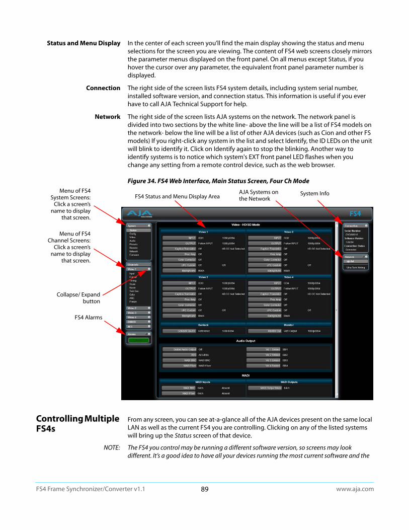
www.aja.com89
FS4 Frame Synchronizer/Converter v1.1
Status and Menu Display In the center of each screen you’ll find the main display showing the status and menu selections for the screen you are viewing. The content of FS4 web screens closely mirrors the parameter menus displayed on the front panel. On all menus except Status, if you hover the cursor over any parameter, the equivalent front panel parameter number is displayed.
Connection The right side of the screen lists FS4 system details, including system serial number, installed software version, and connection status. This information is useful if you ever have to call AJA Technical Support for help.
Network The right side of the screen lists AJA systems on the network. The network panel is divided into two sections by the white line- above the line will be a list of FS4 models on the network- below the line will be a list of other AJA devices (such as Cion and other FS models) If you right-click any system in the list and select Identify, the ID LEDs on the unit will blink to identify it. Click on Identify again to stop the blinking. Another way to identify systems is to notice which system's EXT front panel LED flashes when you change any setting from a remote control device, such as the web browser.
Figure 34. FS4 Web Interface, Main Status Screen, Four Ch Mode
Controlling Multiple FS4s
From any screen, you can see at-a-glance all of the AJA devices present on the same local LAN as well as the current FS4 you are controlling. Clicking on any of the listed systems will bring up the Status screen of that device.
NOTE: The FS4 you control may be running a different software version, so screens may look different. It’s a good idea to have all your devices running the most current software and the
Menu of FS4 System Screens:
Click a screen’s name to display
that screen.
AJA Systems on the Network
FS4 Alarms
FS4 Status and Menu Display Area System Info
Menu of FS4 Channel Screens:
Click a screen’s name to display
that screen.
Collapse/ Expand button
www.aja.com90
FS4 Frame Synchronizer/Converter v1.1
same version. Also, if the Default Gateway is not configured properly, other AJA devices will not be visible. If the display shows no devices found, check the gateway setting.
Resetting Values To Factory Default Settings
FS4 web browser screens feature many user controls that can be reset to factory default values by simply “right-clicking” on the parameter label. When you right-click, the browser displays a Reset to Factory popup that if clicked will cause the parameter to be reset.
NOTE: This reset procedure only works with computers that allow right-clicking. Some computers may not permit this operation.
You can perform a global reset to factory values of all System, Video, Audio, and most Config parameters (the same set of parameters acted on by a Preset Recall).
To perform a global reset:
1. Go to the Presets screen.
2. Click on the Recall button in the Factory Preset row.
User preferences, network settings, and existing Presets are not affected by recalling the Factory Preset.
Drop Down Parameter Operation
Most parameters available on the browser are selected from a drop-down list. The currently active parameter is displayed. Click on the down arrow symbol next to the parameter to display the list and select an alternative value. The FS4 will immediately operate with the new setting.
Slider Operation Some screens contain slider controls for setting values. To set a value, you can click on a slider to select it and then use the mouse to drag the slider to the position you desire. For fine tuning, while the slider is selected (highlighted by a blue border), use the keyboard left and right arrow keys to change the value one unit at a time. Or you can enter the value directly by clicking on the number displayed above the slider, type in your number then hit Enter to have it take effect. After setting a slider's position, click on the page's background area (blue highlight turns off ) to ensure the change is confirmed and saved.
Sub-Menus Some parameters, when activated, open sub-menus. The sub-menus are a lighter gray color and have a collapse/expand button on the parent selection. This lets you collapse the sub-menus to make it easier to configure the system. The collapsed setting only stays in effect until the user reconnects or refreshes the browser.
Screen Descriptions
Now that you have had an introduction to how the FS4 browser works and how to navigate the screens, each screen and its settings are described in detail (click to jump).
• “Network Pane and Network Configuration Screen” on page 91
• “Alarm Configuration Screen” on page 93
Caution! Recall Factory Preset changes the settings for both Single Channel and Four Channel FS4 operating modes to their factory default values.
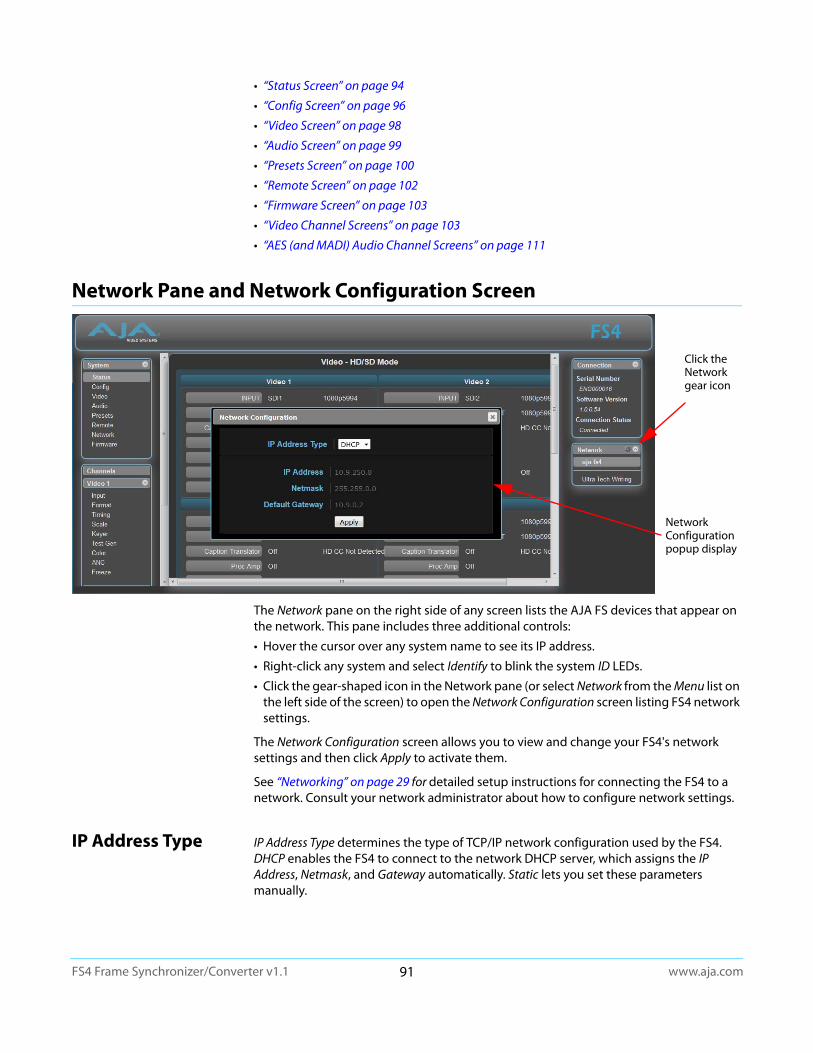
www.aja.com91
FS4 Frame Synchronizer/Converter v1.1
• “Status Screen” on page 94
• “Config Screen” on page 96
• “Video Screen” on page 98
• “Audio Screen” on page 99
• “Presets Screen” on page 100
• “Remote Screen” on page 102
• “Firmware Screen” on page 103
• “Video Channel Screens” on page 103
• “AES (and MADI) Audio Channel Screens” on page 111
Network Pane and Network Configuration Screen
The Network pane on the right side of any screen lists the AJA FS devices that appear on the network. This pane includes three additional controls:
• Hover the cursor over any system name to see its IP address.
• Right-click any system and select Identify to blink the system ID LEDs.
• Click the gear-shaped icon in the Network pane (or select Network from the Menu list on the left side of the screen) to open the Network Configuration screen listing FS4 network settings.
The Network Configuration screen allows you to view and change your FS4's network settings and then click Apply to activate them.
See “Networking” on page 29 for detailed setup instructions for connecting the FS4 to a network. Consult your network administrator about how to configure network settings.
IP Address Type IP Address Type determines the type of TCP/IP network configuration used by the FS4. DHCP enables the FS4 to connect to the network DHCP server, which assigns the IP Address, Netmask, and Gateway automatically. Static lets you set these parameters manually.
Click the Network gear icon
NetworkConfiguration popup display
www.aja.com92
FS4 Frame Synchronizer/Converter v1.1
NOTE: If the IP Address Type is DHCP, the IP Address, Netmask, and Default Gateway are gray, indicating they are set automatically and cannot be changed unless IP Address Type is first set to Static. Changes are saved and activated upon confirmation using the Apply button.
IP Address IP Address determines the static IP address used by the FS4 for TCP/IP networking. (Networking is discussed in Chapter 3, Network Connection.) Consult your network administrator about how to set this value.
Netmask Netmask determines the subnet mask used by the FS4 for TCP/IP networking.
Default Gateway Default Gateway determines the gateway or router used on your LAN for TCP/IP networking.
Without a properly configured default gateway (whether you have a router/gateway or not), the FS4 will be unable to see other AJA FS devices on the network, although you may still be able to control this FS4 via a web browser. Also, without a proper gateway defined, the discovery feature on the Network web page will not work correctly and list other FS devices on the network.
DHCP (default)
Static Addr
Select automatic IP address assignment from the LAN DHCP server. If the FS4 cannot find a DHCP server, it fails over to the static IP address.
Assign a static IP address manually. The factory default static IP address: 192.168.0.2
Variable If IP Address Type is set to DHCP, the IP address is set automatically by the network DHCP server and cannot be entered here.
If IP Address Type is set to Static, enter an IP address compatible with your LAN here. Also enter a netmask and default gateway address in the following two parameters. Click Apply when you are ready to apply all three entries to change the FS4's network addressing.
If IP Address Type is set to DHCP and there is a DHCP failure, the IP address is set to the static IP address. The default static IP address is 192.168.0.2
Variable Enter a subnet mask compatible with your LAN. This is only needed for Static IP configurations. The factory default Subnet Mask is 255.255.255.0
If IP Address Type is set to DHCP, the Subnet Mask is set by the DHCP server and cannot be changed by the user.
Variable Enter a default gateway or router address. This is only needed for Static IP configurations. The factory Default Gateway is 192.168.0.1.If IP Address Type is set to DHCP, the Default Gateway is set by the DHCP server and cannot be changed by the user.
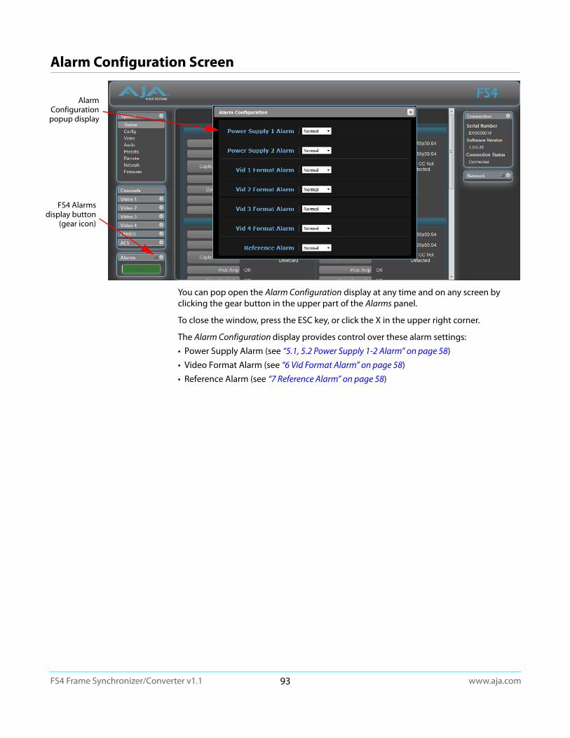
www.aja.com93
FS4 Frame Synchronizer/Converter v1.1
Alarm Configuration Screen
You can pop open the Alarm Configuration display at any time and on any screen by clicking the gear button in the upper part of the Alarms panel.
To close the window, press the ESC key, or click the X in the upper right corner.
The Alarm Configuration display provides control over these alarm settings:
• Power Supply Alarm (see “5.1, 5.2 Power Supply 1-2 Alarm” on page 58)
• Video Format Alarm (see “6 Vid Format Alarm” on page 58)
• Reference Alarm (see “7 Reference Alarm” on page 58)
Alarm Configuration popup display
FS4 Alarms display button
(gear icon)
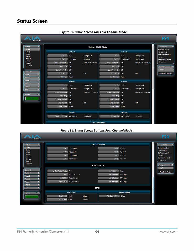
www.aja.com94
FS4 Frame Synchronizer/Converter v1.1
Status Screen
Figure 35. Status Screen Top, Four Channel Mode
Figure 36. Status Screen Bottom, Four Channel Mode

www.aja.com95
FS4 Frame Synchronizer/Converter v1.1
The Status screen displays overall FS4 operational status. You can right-click most video values to change them, allowing you to edit many parameters in one place. Parameters with format incompatibilities or other alarms are highlighted in red.
Figure 37. Status Screen, Single Channel Mode
Video 1-4
INPUTOUTPUT
Caption TranslatorFreeze Output
Proc AmpColor Corrector
UFC CustomBackground
Shows the input source and format.Shows the output video selection and format.Shows the caption selection and caption signal presence.Shows whether Freeze Output is On or Off.Shows whether the Proc Amp is On or Off.Shows whether the Color Corrector (RGB) is On or Off.Shows whether Custom conversion, AFD, and ROI are On or Off.Shows the current background signal (Black or Matte).
Genlock Genlock Source Shows the source of the genlock reference, and its format.
Video Input Status SDI 1 - 8 Shows the status of each Video input (BNCs and SFPs).
Audio Output
Global Audio Output Right-clicking on the Global Audio Out parameter value lets you select a global output. That same audio will be sent to all the FS4 audio outputs. When set to Off, the other Audio Outputs display their selected value, otherwise only the Global Audio Output setting is displayed.
AESMADI BNC
MADI Fiber Vid1-4 Embed
Each of these settings, when visible, reports the audio that is currently being routed to that audio output. Mute and Sig Gen is reported when all of that port’s outputs have that setting. Map is reported when the port’s outputs are mapped.
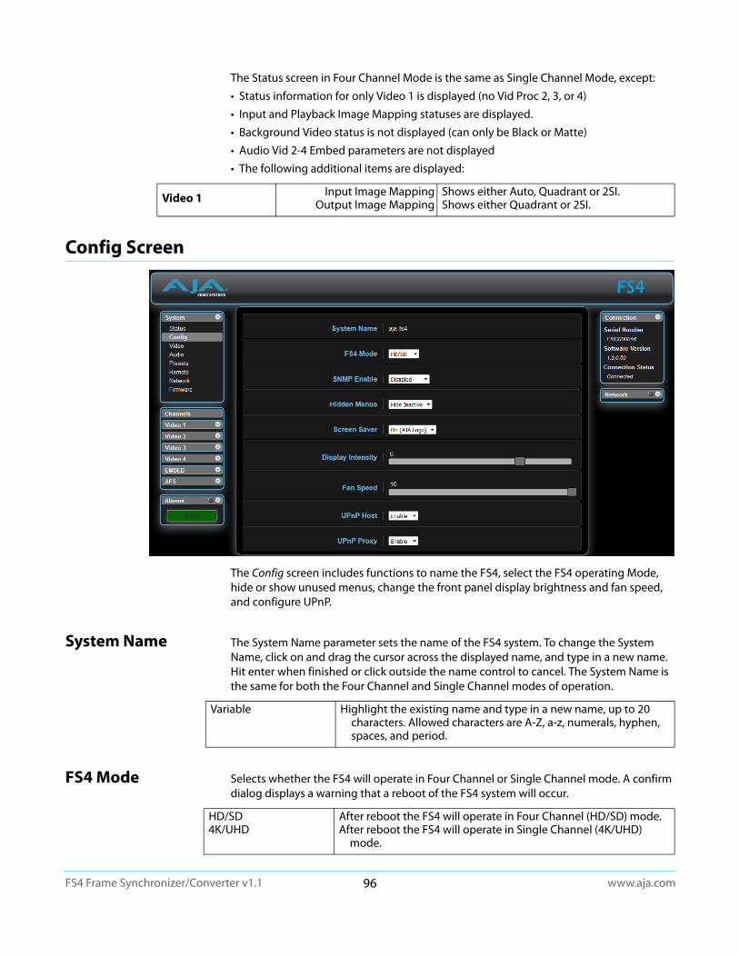
www.aja.com96
FS4 Frame Synchronizer/Converter v1.1
The Status screen in Four Channel Mode is the same as Single Channel Mode, except:
• Status information for only Video 1 is displayed (no Vid Proc 2, 3, or 4)
• Input and Playback Image Mapping statuses are displayed.
• Background Video status is not displayed (can only be Black or Matte)
• Audio Vid 2-4 Embed parameters are not displayed
• The following additional items are displayed:
Config Screen
The Config screen includes functions to name the FS4, select the FS4 operating Mode, hide or show unused menus, change the front panel display brightness and fan speed, and configure UPnP.
System Name The System Name parameter sets the name of the FS4 system. To change the System Name, click on and drag the cursor across the displayed name, and type in a new name. Hit enter when finished or click outside the name control to cancel. The System Name is the same for both the Four Channel and Single Channel modes of operation.
FS4 Mode Selects whether the FS4 will operate in Four Channel or Single Channel mode. A confirm dialog displays a warning that a reboot of the FS4 system will occur.
Video 1 Input Image MappingOutput Image Mapping
Shows either Auto, Quadrant or 2SI. Shows either Quadrant or 2SI.
Variable Highlight the existing name and type in a new name, up to 20 characters. Allowed characters are A-Z, a-z, numerals, hyphen, spaces, and period.
HD/SD4K/UHD
After reboot the FS4 will operate in Four Channel (HD/SD) mode.After reboot the FS4 will operate in Single Channel (4K/UHD)
mode.
www.aja.com97
FS4 Frame Synchronizer/Converter v1.1
SNMP Parameters The following parameters are used to setup the FS4 SNMP (Simple Network Management Protocol) feature.
• SNMP Enable
• SNMP Trap Dest 1
• SNMP Trap Port 1
• SNMP Trap Dest 2
• SNMP Trap Port 2
Refer to "Chapter 6: SNMP on page 113" for a description of SNMP and how the FS4 supports it.
Hidden Menus This selection lets you choose whether to hide or show inactive menus.
Screen Saver This parameter lets you choose the menu screen saver.
Display Intensity Display Intensity determines alphanumeric display and front panel LED brightness.
Fan Speed This parameter determines the speed (and sound level) of the FS4's internal cooling fans.
UPnP Host UPnP Host enables the FS4 to be discovered by a Windows network.
When this parameter is enabled, you can view the FS4 on a Windows Network by clicking these selections in Windows: Computer > Network (in left pane). Any FS4s on the network will be listed under Other Devices below Computers and Media Devices. If your system does not have network discovery enabled, you may need to enable it following the Windows help instructions to make network devices visible in the Windows Network window.
UPnP Proxy UPnP Proxy enables the FS4 to serve as a proxy for other AJA devices, allowing them to be discovered on a Windows network through the FS4. When enabled, the FS4 acts as a proxy for all the AJA devices that it is able to connect to that have not already been
Hide Inactive (default)Show All
Hides menus that are not in use.Shows all menus, even those that are not in use.
On (AJA Logo) (default)OffSystem Name
AJA logo screen saver is displayedThe screen saver is not displayed.Screen saver displays the system name.
Variable Use the slider to dim or brighten the alphanumeric display and activity indicator LEDs in steps from 1 (dim) to 8 (brightest). Default is 6
Variable Changes the fan speed in steps from 1 (slow) to 10 (fast). Default is 10.
Enable (default)Disable
Enables the FS4 to be discovered by a Windows network. Disables Windows network discovery of the FS4.

www.aja.com98
FS4 Frame Synchronizer/Converter v1.1
discovered on the network. The devices will be listed in the FS4 Network window. Once the devices appear on the network, they can connect directly to other devices and computers without involving the FS4.
Video Screen
The Video screen controls the FS4’s system wide video signal processing. The parameters available on the Video browser screen are essentially identical to the front panel display menus. The only difference is parameters are set using webpage controls (drop down menus, slider adjustments) instead of control knobs. Complete descriptions of these parameters are accessible using the following cross references:
• “1 Output Frame Rate” on page 53
• “2 Genlock Source” on page 53
• “3.1 Mon 2K Crop” on page 53
• “3.2 HDMI RGB Range” on page 53
• “3.3 Monitor Map” on page 54
• “4.1 SDI1 3G Detect” on page 54
• “4.2 SDI2 Input Protect” on page 54
• “4.3, 4.5, 4.7 SDI3/5/7 3G Detect” on page 55
Enable (default)
Disable
Enables the FS4 to connect other AJA devices to the network.
Disables the FS4 from serving as a proxy for AJA devices.
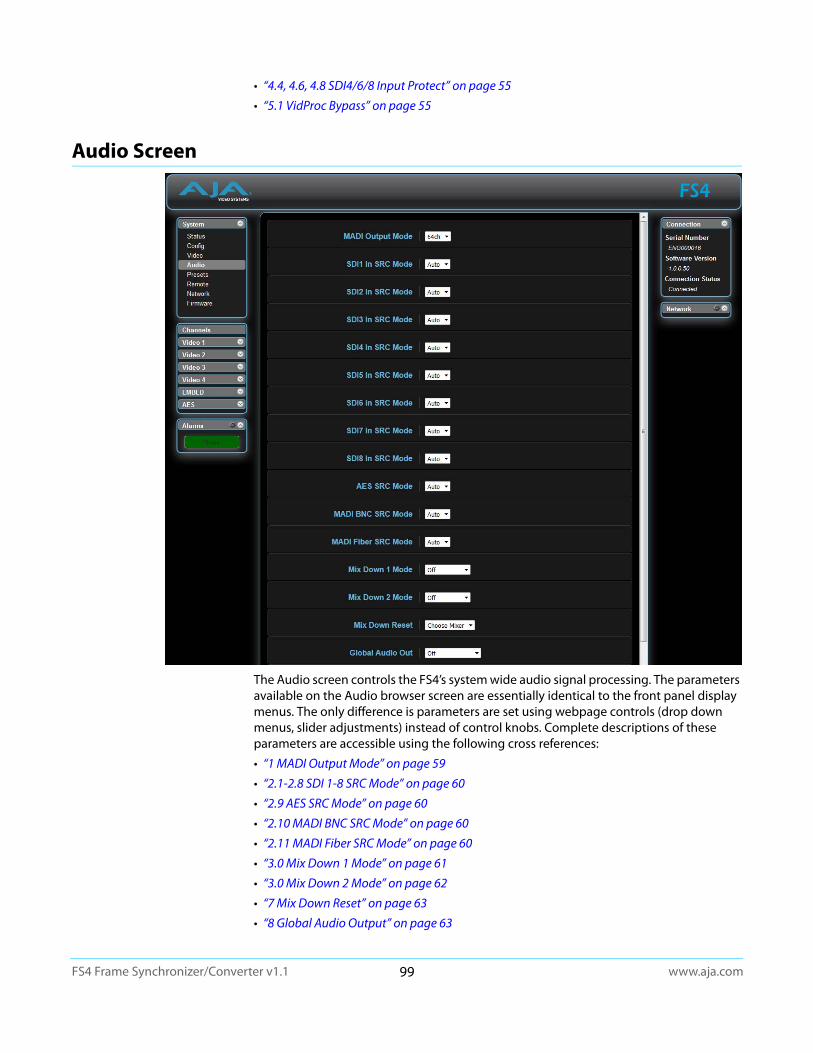
www.aja.com99
FS4 Frame Synchronizer/Converter v1.1
• “4.4, 4.6, 4.8 SDI4/6/8 Input Protect” on page 55
• “5.1 VidProc Bypass” on page 55
Audio Screen
The Audio screen controls the FS4’s system wide audio signal processing. The parameters available on the Audio browser screen are essentially identical to the front panel display menus. The only difference is parameters are set using webpage controls (drop down menus, slider adjustments) instead of control knobs. Complete descriptions of these parameters are accessible using the following cross references:
• “1 MADI Output Mode” on page 59
• “2.1-2.8 SDI 1-8 SRC Mode” on page 60
• “2.9 AES SRC Mode” on page 60
• “2.10 MADI BNC SRC Mode” on page 60
• “2.11 MADI Fiber SRC Mode” on page 60
• “3.0 Mix Down 1 Mode” on page 61
• “3.0 Mix Down 2 Mode” on page 62
• “7 Mix Down Reset” on page 63
• “8 Global Audio Output” on page 63
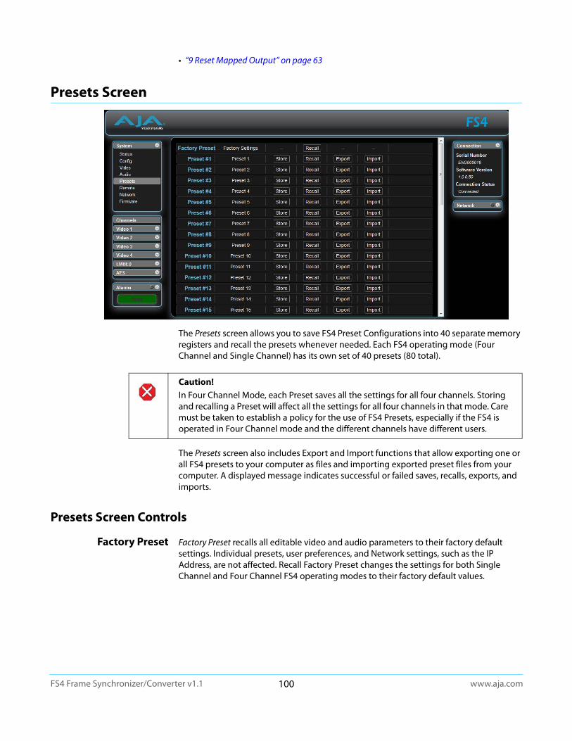
www.aja.com100
FS4 Frame Synchronizer/Converter v1.1
• “9 Reset Mapped Output” on page 63
Presets Screen
The Presets screen allows you to save FS4 Preset Configurations into 40 separate memory registers and recall the presets whenever needed. Each FS4 operating mode (Four Channel and Single Channel) has its own set of 40 presets (80 total).
The Presets screen also includes Export and Import functions that allow exporting one or all FS4 presets to your computer as files and importing exported preset files from your computer. A displayed message indicates successful or failed saves, recalls, exports, and imports.
Presets Screen Controls
Factory Preset Factory Preset recalls all editable video and audio parameters to their factory default settings. Individual presets, user preferences, and Network settings, such as the IP Address, are not affected. Recall Factory Preset changes the settings for both Single Channel and Four Channel FS4 operating modes to their factory default values.
Caution! In Four Channel Mode, each Preset saves all the settings for all four channels. Storing and recalling a Preset will affect all the settings for all four channels in that mode. Care must be taken to establish a policy for the use of FS4 Presets, especially if the FS4 is operated in Four Channel mode and the different channels have different users.
www.aja.com101
FS4 Frame Synchronizer/Converter v1.1
Recall The Recall buttons recall saved FS4 preset configurations.
Store The Store buttons let you save the current FS4 configuration into the preset register with the associated name and number. A preset is a set of all System, Video, Audio, and Output parameters as they were set at the time the preset was stored. Only editable parameters are saved in the presets. Non-editable parameters are not saved.
To change a preset name, click in the name's text field, type a new name, and press Enter to save the name. After entering text, you can click the mouse outside of the edit box to exit without changing the name.
Export The Export buttons save the associated preset contents to a file on your computer. The file gets exported to the default download location specified in your browser options. The file name is the same as the preset name with the suffix.presets. If you export multiple files for the same preset, a number gets appended to ensure a unique file name. The file size is small, usually less than 100 kilobytes.
Import The Import buttons let you browse for and import a preset file on your computer into the preset register associated with the selected button. A dialog box warns you that the operation will overwrite the current preset contents with the file contents. You can only import presets from a FS4.
Export Presets 1–40 (All)
Export All lets you save the contents of all presets to a file on your computer.
The file gets exported to the default download location specified in your browser options with the name all.presets. If you export multiple files, a number gets appended to ensure a unique file name.
Import Presets 1–40 (All)
Import All lets you browse for and import a previously exported all.presets file from your computer. A dialog box warns you that the operation will overwrite all 40 current preset contents with the contents stored in the file.
Interaction of Presets and GPIs
Triggering presets using GPI inputs offers considerable power but also requires some care to avoid unexpected results. If you plan to trigger presets using GPIs, please see the information about the “Interaction of Presets and GPIs” on page 52.
Caution! When you recall a Preset Configuration, the recalled preset immediately replaces the system’s existing configuration. All previous settings are lost unless you have previously stored them in another preset configuration or an exported file.
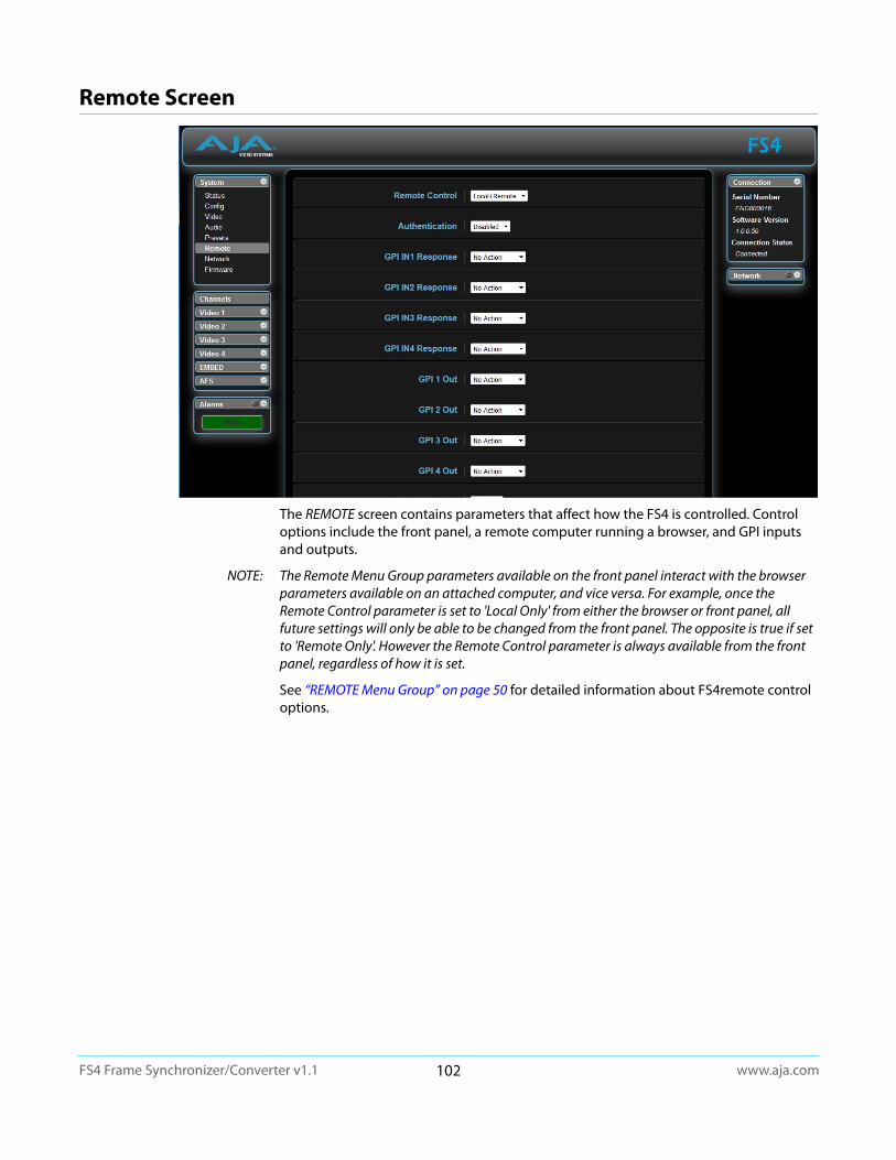
www.aja.com102
FS4 Frame Synchronizer/Converter v1.1
Remote Screen
The REMOTE screen contains parameters that affect how the FS4 is controlled. Control options include the front panel, a remote computer running a browser, and GPI inputs and outputs.
NOTE: The Remote Menu Group parameters available on the front panel interact with the browser parameters available on an attached computer, and vice versa. For example, once the Remote Control parameter is set to 'Local Only' from either the browser or front panel, all future settings will only be able to be changed from the front panel. The opposite is true if set to 'Remote Only'. However the Remote Control parameter is always available from the front panel, regardless of how it is set.
See “REMOTE Menu Group” on page 50 for detailed information about FS4remote control options.
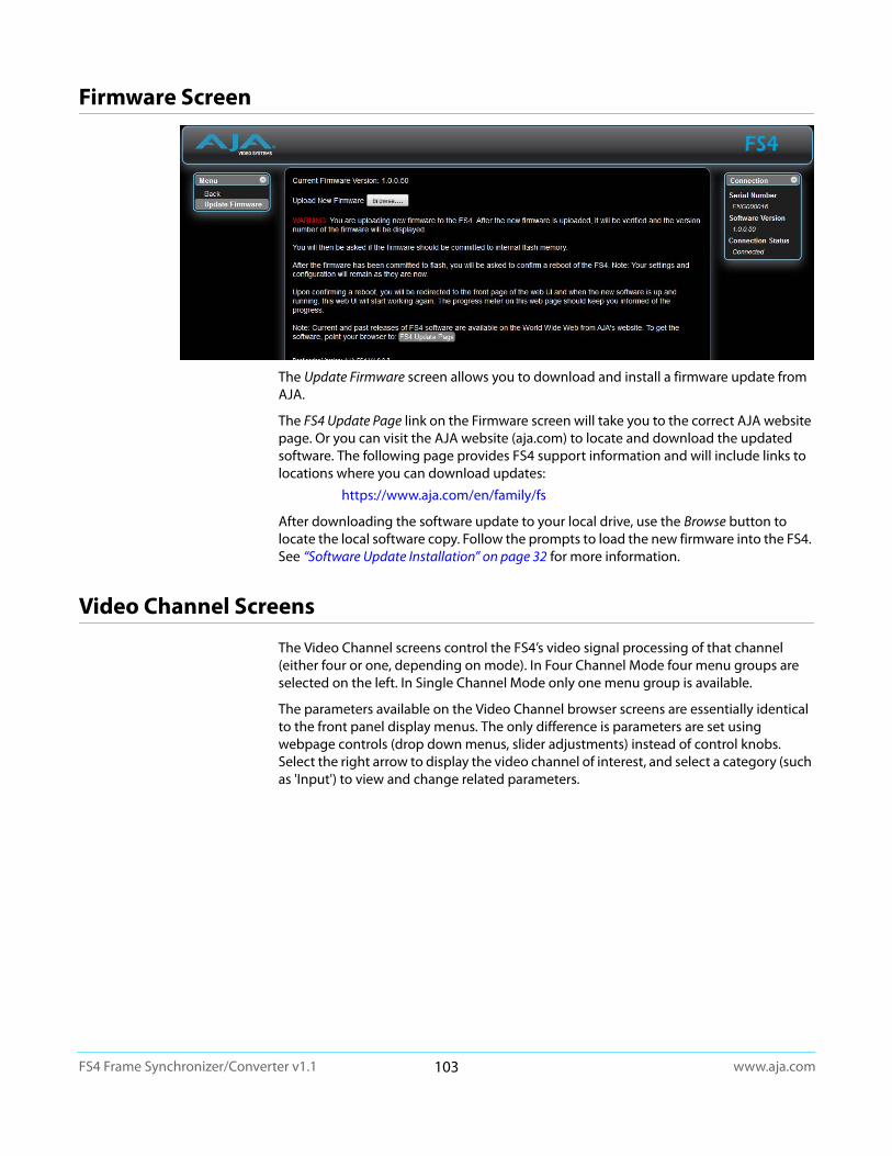
www.aja.com103
FS4 Frame Synchronizer/Converter v1.1
Firmware Screen
The Update Firmware screen allows you to download and install a firmware update from AJA.
The FS4 Update Page link on the Firmware screen will take you to the correct AJA website page. Or you can visit the AJA website (aja.com) to locate and download the updated software. The following page provides FS4 support information and will include links to locations where you can download updates:
https://www.aja.com/en/family/fs
After downloading the software update to your local drive, use the Browse button to locate the local software copy. Follow the prompts to load the new firmware into the FS4. See “Software Update Installation” on page 32 for more information.
Video Channel Screens
The Video Channel screens control the FS4’s video signal processing of that channel (either four or one, depending on mode). In Four Channel Mode four menu groups are selected on the left. In Single Channel Mode only one menu group is available.
The parameters available on the Video Channel browser screens are essentially identical to the front panel display menus. The only difference is parameters are set using webpage controls (drop down menus, slider adjustments) instead of control knobs. Select the right arrow to display the video channel of interest, and select a category (such as 'Input') to view and change related parameters.
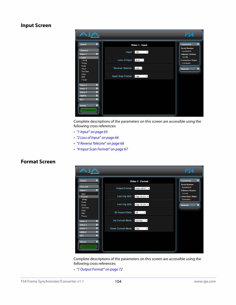
www.aja.com104
FS4 Frame Synchronizer/Converter v1.1
Input Screen
Complete descriptions of the parameters on this screen are accessible using the following cross references:
• “1 Input” on page 65
• “2 Loss of Input” on page 66
• “3 Reverse Telecine” on page 66
• “4 Input Scan Format” on page 67
Format Screen
Complete descriptions of the parameters on this screen are accessible using the following cross references:
• “1 Output Format” on page 72

www.aja.com105
FS4 Frame Synchronizer/Converter v1.1
• “2.0 Link Config SDI1, 2, 3, 4” on page 73
• “2.1 Level B SDI1, 2, 3, 4” on page 73
• “2.0 Link Config SDI1-4” on page 73
• “3.0 Link Config SDI5-8” on page 74
• “4 Output Image Mapping” on page 74
• “6 Upconvert Mode” on page 75
• “7 Downconvert Mode” on page 76
Timing Screen
Complete descriptions of the parameters on this screen are accessible using the following cross references:
• “1 Output Timing H” on page 81
• “2 Output Timing V” on page 81
• “3 Frame Delay” on page 82

www.aja.com106
FS4 Frame Synchronizer/Converter v1.1
Scale Screen
NOTE: If AFD is enabled, these parameters do not display
Complete descriptions of the parameters on this screen are accessible using the following cross references:
• “Custom Conversion Settings” on page 77
• “Region of Interest (ROI)” on page 79
Keyer Screen
Complete descriptions of the parameters on this screen are accessible using the following cross references:
• “1 Background Fill” on page 80
• “2 Sidebar Edge” on page 80
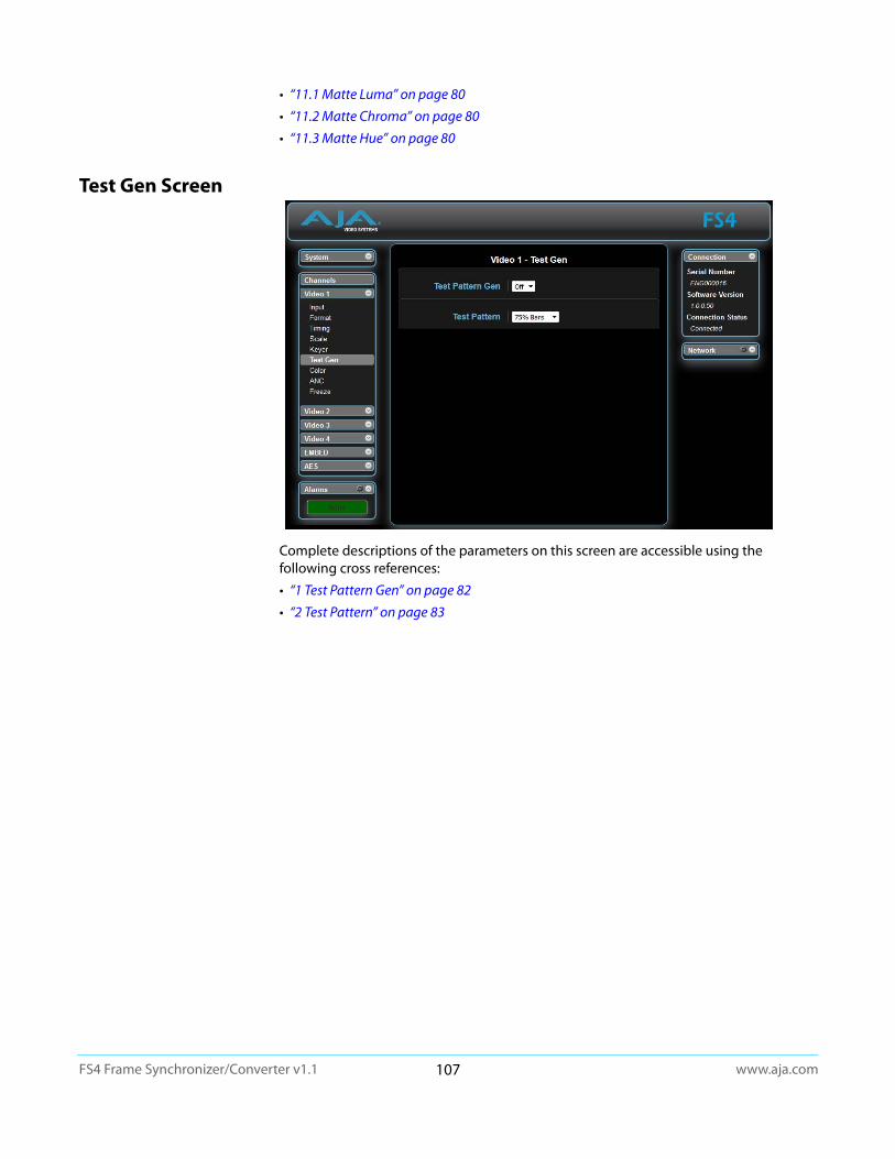
www.aja.com107
FS4 Frame Synchronizer/Converter v1.1
• “11.1 Matte Luma” on page 80
• “11.2 Matte Chroma” on page 80
• “11.3 Matte Hue” on page 80
Test Gen Screen
Complete descriptions of the parameters on this screen are accessible using the following cross references:
• “1 Test Pattern Gen” on page 82
• “2 Test Pattern” on page 83
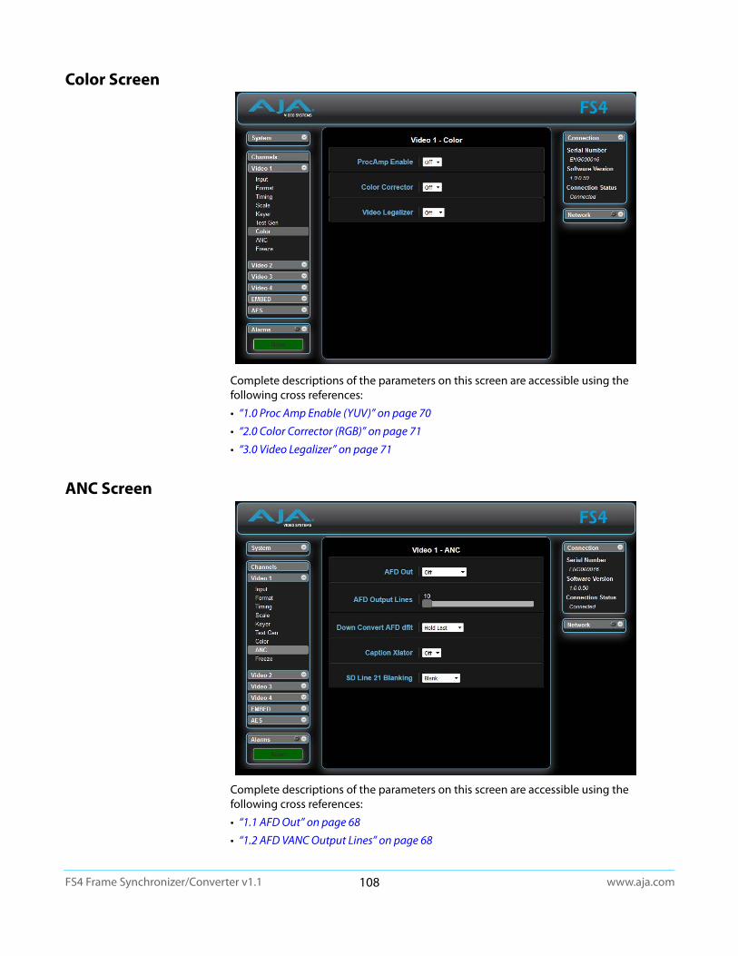
www.aja.com108
FS4 Frame Synchronizer/Converter v1.1
Color Screen
Complete descriptions of the parameters on this screen are accessible using the following cross references:
• “1.0 Proc Amp Enable (YUV)” on page 70
• “2.0 Color Corrector (RGB)” on page 71
• “3.0 Video Legalizer” on page 71
ANC Screen
Complete descriptions of the parameters on this screen are accessible using the following cross references:
• “1.1 AFD Out” on page 68
• “1.2 AFD VANC Output Lines” on page 68
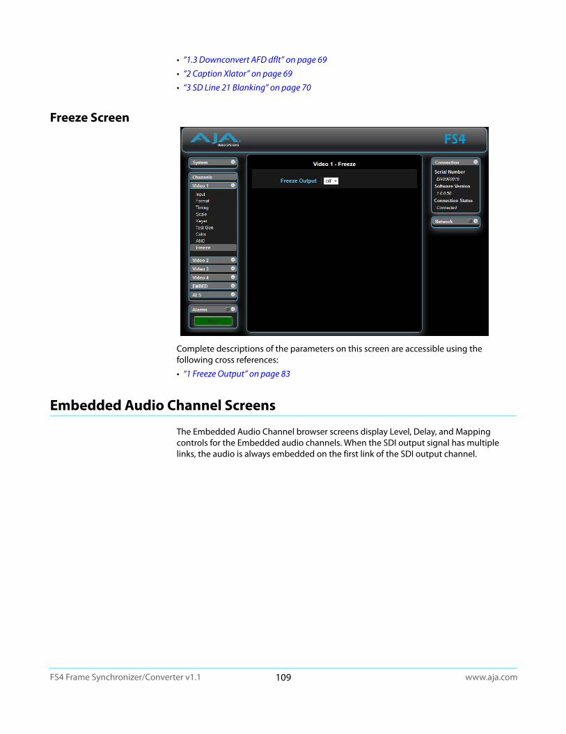
www.aja.com109
FS4 Frame Synchronizer/Converter v1.1
• “1.3 Downconvert AFD dflt” on page 69
• “2 Caption Xlator” on page 69
• “3 SD Line 21 Blanking” on page 70
Freeze Screen
Complete descriptions of the parameters on this screen are accessible using the following cross references:
• “1 Freeze Output” on page 83
Embedded Audio Channel Screens
The Embedded Audio Channel browser screens display Level, Delay, and Mapping controls for the Embedded audio channels. When the SDI output signal has multiple links, the audio is always embedded on the first link of the SDI output channel.

www.aja.com110
FS4 Frame Synchronizer/Converter v1.1
Embed Level Screen
Complete descriptions of the parameters on this screen are accessible using the following cross references:
• “EMBED Level Menus” on page 84
Embed Delay Screen
Complete descriptions of the parameters on this screen are accessible using the following cross references:
• “EMBED Delay Menus” on page 85
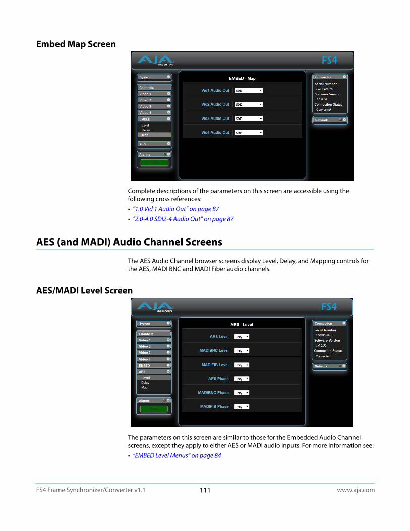
www.aja.com111
FS4 Frame Synchronizer/Converter v1.1
Embed Map Screen
Complete descriptions of the parameters on this screen are accessible using the following cross references:
• “1.0 Vid 1 Audio Out” on page 87
• “2.0-4.0 SDI2-4 Audio Out” on page 87
AES (and MADI) Audio Channel Screens
The AES Audio Channel browser screens display Level, Delay, and Mapping controls for the AES, MADI BNC and MADI Fiber audio channels.
AES/MADI Level Screen
The parameters on this screen are similar to those for the Embedded Audio Channel screens, except they apply to either AES or MADI audio inputs. For more information see:
• “EMBED Level Menus” on page 84
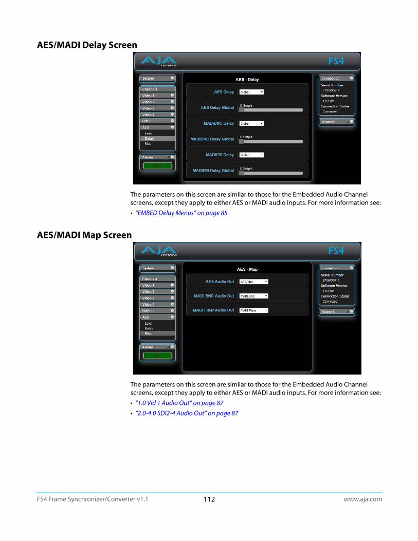
www.aja.com112
FS4 Frame Synchronizer/Converter v1.1
AES/MADI Delay Screen
The parameters on this screen are similar to those for the Embedded Audio Channel screens, except they apply to either AES or MADI audio inputs. For more information see:
• “EMBED Delay Menus” on page 85
AES/MADI Map Screen
The parameters on this screen are similar to those for the Embedded Audio Channel screens, except they apply to either AES or MADI audio inputs. For more information see:
• “1.0 Vid 1 Audio Out” on page 87
• “2.0-4.0 SDI2-4 Audio Out” on page 87
www.aja.com113
FS4 Frame Synchronizer/Converter v1.1
Chapter 6: SNMP
FS4 Simple Network Management Protocol
SNMP is defined as a “simple network management protocol” and was specified as a component of the internet protocol suite by the Internet Engineering Task Force (IETF). The FS4 can act as a network element that issues SNMP trap messages signaling a detected alarm condition or other system condition. A device’s trap messages are defined in MIB (Management Information Base) files. The trap messages are sent to a server-based external NMS (Network Management System) destination. For example, the FS4 could send a trap message if one of its redundant power supplies becomes unplugged. A client software agent that communicates with the NMS might then get a message telling the operator what has happened.
The FS4 must be configured for SNMP messaging. By default SNMP is disabled on the FS4. Besides activating SNMP, trap destinations must also be defined with fixed IP addresses.
When SNMP is enabled, one or more of these alarms may be sent by the FS4 to the client network management system (NMS) as a trap message:
• FS4 power supply 1 Alarm
• FS4 power supply 2 Alarm
• No Reference Alarm
• Incompatible Reference Alarm
• Format incompatibility Video Proc Alarm
• Format incompatibility Video Proc 1 Alarm
• Format incompatibility Video Proc 2 Alarm
• Format incompatibility Video Proc 3 Alarm
• Format incompatibility Video Proc 4 Alarm
• Video Proc 1 Background format Alarm
• Video Proc 2 Background format Alarm
• Video Proc 3 Background format Alarm
• Video Proc 4 Background format Alarm
• Video Proc 1 Background Timing Alarm
• Video Proc 2 Background Timing Alarm
• Video Proc 3 Background Timing Alarm
• Video Proc 4 Background Timing Alarm
• Over Temp Range Alarm
SNMP Configuration
AJA MIBs AJA provides two FS related MIB files for use with your NMS. One identifies AJA product types, and the other defines the trap messages for a specific AJA product. These MIB .txt files are included with the AJA software download package.
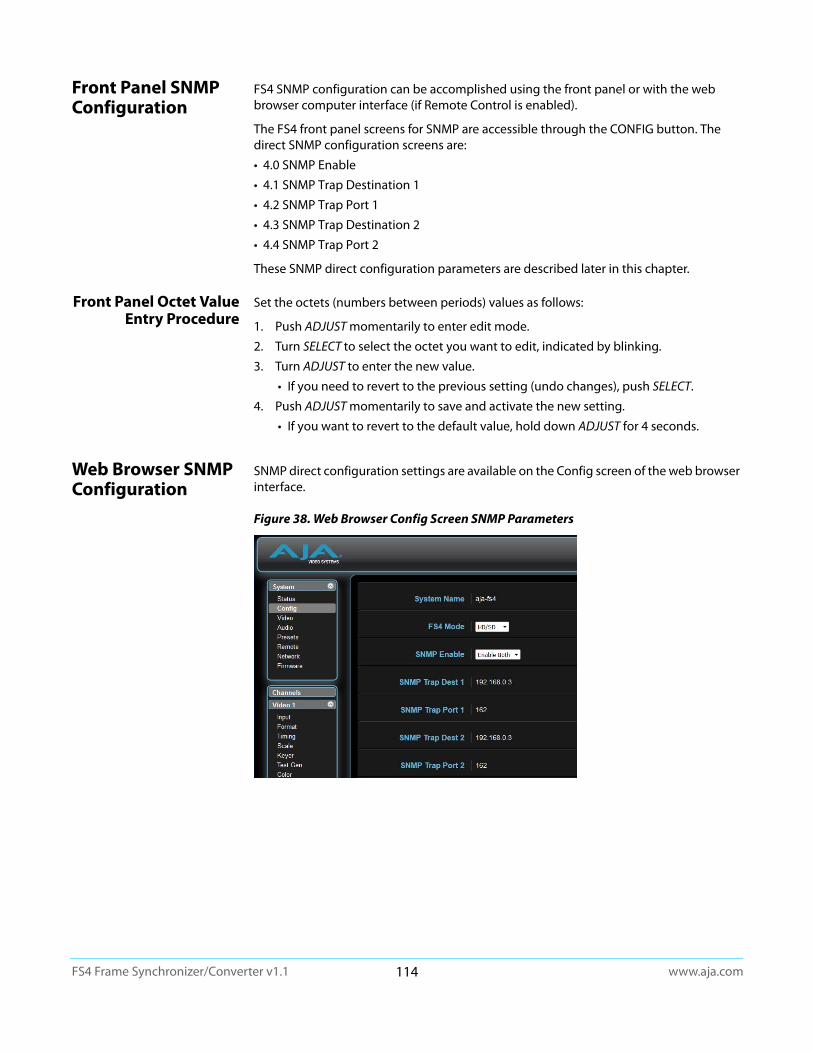
www.aja.com114
FS4 Frame Synchronizer/Converter v1.1
Front Panel SNMP Configuration
FS4 SNMP configuration can be accomplished using the front panel or with the web browser computer interface (if Remote Control is enabled).
The FS4 front panel screens for SNMP are accessible through the CONFIG button. The direct SNMP configuration screens are:
• 4.0 SNMP Enable
• 4.1 SNMP Trap Destination 1
• 4.2 SNMP Trap Port 1
• 4.3 SNMP Trap Destination 2
• 4.4 SNMP Trap Port 2
These SNMP direct configuration parameters are described later in this chapter.
Front Panel Octet Value Entry Procedure
Set the octets (numbers between periods) values as follows:
1. Push ADJUST momentarily to enter edit mode.
2. Turn SELECT to select the octet you want to edit, indicated by blinking.
3. Turn ADJUST to enter the new value.
• If you need to revert to the previous setting (undo changes), push SELECT.
4. Push ADJUST momentarily to save and activate the new setting.
• If you want to revert to the default value, hold down ADJUST for 4 seconds.
Web Browser SNMP Configuration
SNMP direct configuration settings are available on the Config screen of the web browser interface.
Figure 38. Web Browser Config Screen SNMP Parameters
www.aja.com115
FS4 Frame Synchronizer/Converter v1.1
SNMP Configuration Parameters
4.0 SNMP Enable The SNMP Enable parameter Enables or Disables SNMP messaging between the FS4 and an external client.
When Enabled, menus described below are available for configuration.
4.1 SNMP Trap Destination 1
This parameter determines the SNMP Trap Destination IP address where trap messages issued by the FS4 will be sent.
4.2 SNMP Trap Port 1
This parameter determines the SNMP Trap Port 1 used for sending destination #1 trap messages. UDP Port 162 is the default used for SNMP trap messages. However, if this port is being used by another protocol or service, you can change the setting by modifying this parameter.
NOTE: The SNMP Trap Port number does not blink when changed (as does the Trap Destination IP address); if you change the port number and exit the parameter, the port changes immediately to the new value.
4.3 SNMP Trap Destination 2
This parameter determines the secondary SNMP Trap Destination IP address where trap messages issued by the FS4 will be sent (if desired). This parameter is similar to "4.1 SNMP Trap Destination 1" above.The default is 192.168.0.3.
4.4 SNMP Trap Port 2
This parameter determines the SNMP Trap Port used for sending destination #2 trap messages, similar to "4.2 SNMP Trap Port 1" above. Default is 162.
Disabled (default)Enable 1
Enable Both
When set to Disabled, the FS4 will not issue SNMP trap messages.When set to Enable 1, the FS4 issues SNMP trap messages to Trap Destination 1 (parameter 4.1) and as defined in the MIB.When set to Enable Both, the FS4 issues SNMP trap messages to Trap Destination 1 and 2 (parameters 4.1 and 4.3) and as defined in the MIB.
IP Address Set the desired IP address where traps will be sent (usually a client on your LAN). Default: 192.168.0.3
Variable Select a UDP port for sending FS4 trap messages. Default: 162

www.aja.com116
FS4 Frame Synchronizer/Converter v1.1
Appendix A: FS4 Specifications
Modes of Operation
Four Channel Mode • Four Independent 2K, HD, or SD Video Processors
Single Channel Mode • One 4K, UltraHD, 2K, HD, or SD Video Processor
Video Formats• (4K) 4096 x 2160p 23.98, 24, 25, 29.97, 30, 50, 59.94, 60
• (UltraHD) 3840 x 2160p 23.98, 24, 25, 29.97, 30, 50, 59.94, 60
• (2K) 2048 x 1080p 23.98, 24, 25, 29.97, 30, 50, 59.94, 60
• (HD) 1920 x 1080p 23.98, 24, 25, 29.97, 30, 50, 59.94, 60
• (HD) 1920 x 1080PsF 23.98, 24, 25, 29.97, 30
• (HD) 1920 x 1080i 50, 59.94, 60 (fields)
• (HD) 1280 x 720p 50, 59.94, 60
• (SD) 625i 50 (fields)
• (SD) 525i 59.94 (fields)
• YCbCr, 4:2:2, 10-bit
Video Input Digital• 4 x 3G-SDI inputs, 4 x BNC
• 4 x 3G-SDI inputs, 4 x Fiber or BNC (optional SFP modules)
• SFP fiber modules, 3G-SDI, dual LC, single LC, or single SC, SMPTE-297
• SFP fiber module, 12G/6G-SDI, dual LC, SMPTE-297
• SFP coax module, 12G/6G-SDI, dual HD-BNC
• 12G/6G/3G/HD/SD, SMPTE-259/292/424/2081/2082
• Single Link 12G/6G-SDI (with optional SFP module)
• Quad Link 3G-SDI Level A or B-DL (4 x 3G), SMPTE-425-5
• Dual Link 3G-SDI Level B-DS (2 x 3G), SMPTE-425-3
• Single Link 3G-SDI Level A, B-DL, or B-DS, SMPTE 425
• Quad Link HD-SDI (4 x 1.5G)
• Dual Link HD-SDI (2 x 1.5G), SMPTE-372
• Single Link HD/SD
• Quadrant (Square Division) or 2SI (Two Sample Interleave) 4K/UltraHD input pixel mapping
• 8 x 1 selector feeds each video processor(s)
Video Output Digital• 4 X 3G-SDI outputs, 4 x BNC
www.aja.com117
FS4 Frame Synchronizer/Converter v1.1
• 4 x 3G-SDI outputs, 4 x fiber or HD-BNC (optional SFP modules)
• SFP fiber modules, 3G-SDI, Dual LC, Dual LC CWDM, Single LC, or Single SC, SMPTE-297
• SFP fiber module, 12G/6G-SDI, dual LC, SMPTE-297
• SFP coax module, 12G/6G-SDI, dual HD-BNC
• 12G/6G/3G/HD/SD, SMPTE-259/292/424/2081/2082
• Single Link 12G/6G-SDI (with optional SFP module)
• Quad Link 3G-SDI Level A or B-DL (4 x 3G), SMPTE-425-5
• Dual Link 3G-SDI Level B-DS (2 x 3G), SMPTE-425-3
• Single Link 3G-SDI Level A, B-DL, or B-DS, SMPTE 425
• Quad Link HD-SDI (4 x 1.5G)
• Dual Link HD-SDI (2 x 1.5G), SMPTE-372
• Single Link HD/SD
• Quadrant (Square Division) or 2SI (Two Sample Interleave) 4K/UltraHD output pixel mapping
Monitor Output Digital• 1 x BNC, 1 x 3G-SDI output
• 3G-SDI/HD/SD, SMPTE-259/292/424, 10-bits
• 1 x HDMI, 1 x HD output
• 2K/HD/SD, HDMI v1.4a
• Monitored Video Processor output (video and audio) is simultaneously output on both connectors
• 4K/UltraHD down-converted to 2K/HD
• Crop control on HDMI output
Video Processing• Motion adaptive deinterlacer
• Proc amp controls
• Color corrector
• Legalizer
• Framerate conversion/film cadence removal/insertion (3:2, 1:2, 2:1, 2:3), except when the input or output format is 4K/UltraHD)
• Adjustable delay of 0-6 frames with H and V timing controls in lines and pixels
• Closed Caption conversion (CEA-608/CEA-708)
• AFD input detection, down-convert control, and output pass through or overwrite
• Freeze (manual or on input signal loss) to black or last good frame
• Matte generator for background fill
• Video test generator
www.aja.com118
FS4 Frame Synchronizer/Converter v1.1
Format Conversion• Convert any supported input format to any supported output format, within the same
frame rate family. These three families are:
• 59.94, 29.97, 23.98
• 50, 25
• 60, 30, 24
Scaling• Supported in 2K/HD/SD formats
• Zoom in and out
• Reposition
• Region of Interest (ROI)
Up-Conversion• Hardware 10-bit
• Zoom 14:9: results in a 4:3 image zoomed slightly to fill a 14:9 image with black side bars
• Zoom Letterbox: results in image zoomed to fill fullscreen
• Zoom Wide: results in a combination of zoom and horizontal stretch to fill a 16:9 screen; this setting will introduce a small aspect ratio change
Down-Conversion• Hardware 10-bit
• Anamorphic: fullscreen
• Letterbox: image is reduced with black top and bottom added to image area with the aspect ratio preserved
• Crop: image is cropped to fit video output format
Aspect Ratio Conversion for SD to SD• Letterbox: Transforms SD anamorphic material to a letterboxed image
• H Crop: Produces a horizontally stretched effect on the image; transforms anamorphic SD to full frame
• SD Pillarbox: Produces an image in the center of the screen with black borders on the left and right sides and an anamorphized image in the center
• V Crop: Transforms SD letterbox material to an anamorphic image
Audio Input Digital• 48 kHz sample rate
• 8 x SDI embedded inputs (16-Channels each)
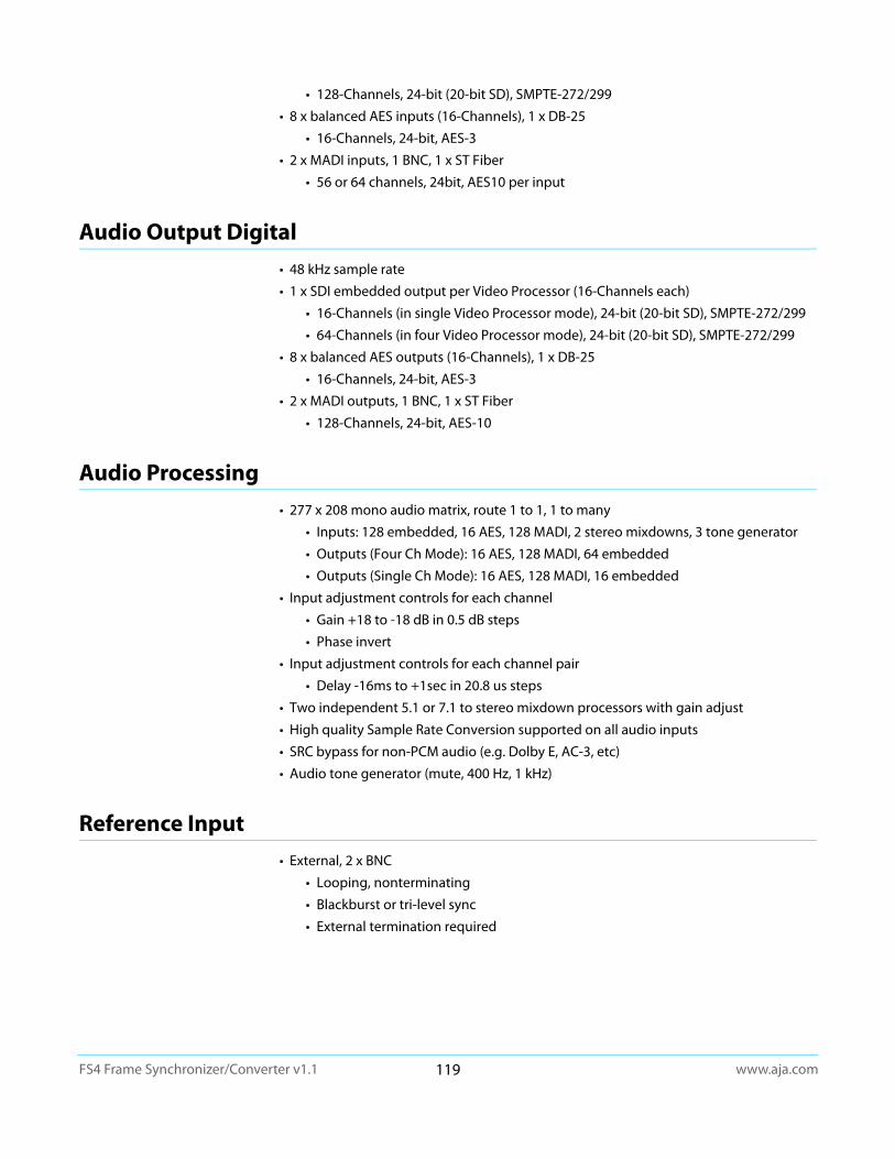
www.aja.com119
FS4 Frame Synchronizer/Converter v1.1
• 128-Channels, 24-bit (20-bit SD), SMPTE-272/299
• 8 x balanced AES inputs (16-Channels), 1 x DB-25
• 16-Channels, 24-bit, AES-3
• 2 x MADI inputs, 1 BNC, 1 x ST Fiber
• 56 or 64 channels, 24bit, AES10 per input
Audio Output Digital• 48 kHz sample rate
• 1 x SDI embedded output per Video Processor (16-Channels each)
• 16-Channels (in single Video Processor mode), 24-bit (20-bit SD), SMPTE-272/299
• 64-Channels (in four Video Processor mode), 24-bit (20-bit SD), SMPTE-272/299
• 8 x balanced AES outputs (16-Channels), 1 x DB-25
• 16-Channels, 24-bit, AES-3
• 2 x MADI outputs, 1 BNC, 1 x ST Fiber
• 128-Channels, 24-bit, AES-10
Audio Processing• 277 x 208 mono audio matrix, route 1 to 1, 1 to many
• Inputs: 128 embedded, 16 AES, 128 MADI, 2 stereo mixdowns, 3 tone generator
• Outputs (Four Ch Mode): 16 AES, 128 MADI, 64 embedded
• Outputs (Single Ch Mode): 16 AES, 128 MADI, 16 embedded
• Input adjustment controls for each channel
• Gain +18 to -18 dB in 0.5 dB steps
• Phase invert
• Input adjustment controls for each channel pair
• Delay -16ms to +1sec in 20.8 us steps
• Two independent 5.1 or 7.1 to stereo mixdown processors with gain adjust
• High quality Sample Rate Conversion supported on all audio inputs
• SRC bypass for non-PCM audio (e.g. Dolby E, AC-3, etc)
• Audio tone generator (mute, 400 Hz, 1 kHz)
Reference Input• External, 2 x BNC
• Looping, nonterminating
• Blackburst or tri-level sync
• External termination required

www.aja.com120
FS4 Frame Synchronizer/Converter v1.1
Genlock• Lock to External Reference
• Lock to SDI input 1 thru 8
• Free run based on Temperature Compensated Crystal Oscillator
Network Interface• 1 x RJ-45, 10/100/1000 Ethernet
• Embedded web server for remote control
Front Panel• Display
• Keypad with status LEDs
• Two rotary/push knobs
• Comprehensive alarm indicators
Presets• Each mode supports 40 Presets
GPI• 1 x 25-pin D-Connector
• Four optically isolated GPI inputs
• Four optically isolated GPO outputs
Size (w x d x h)• 17.5” x 16” x 1.75” (1RU) (444.5mm x 406.5mm x 44.45mm)
Weight• 7.9 lb (3.6 kg)
Power• 100-240 VAC 50/60 Hz (Dual, redundant power supplies), 55W typical; 70W max
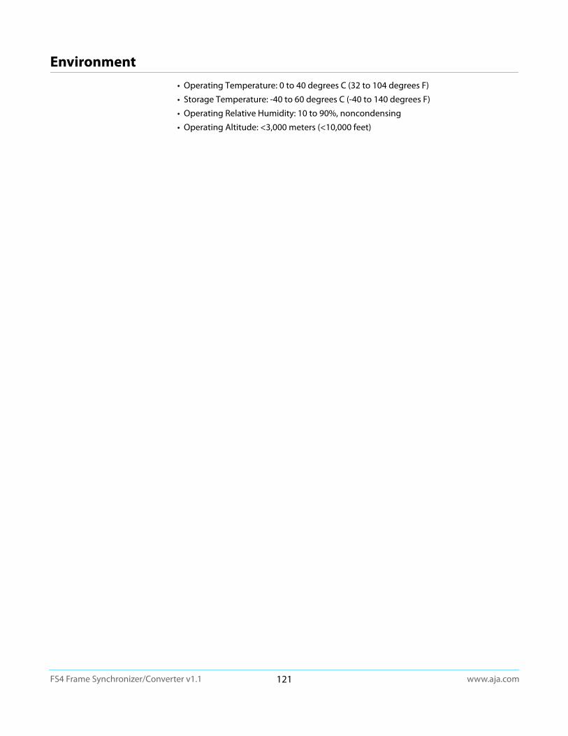
www.aja.com121
FS4 Frame Synchronizer/Converter v1.1
Environment• Operating Temperature: 0 to 40 degrees C (32 to 104 degrees F)
• Storage Temperature: -40 to 60 degrees C (-40 to 140 degrees F)
• Operating Relative Humidity: 10 to 90%, noncondensing
• Operating Altitude: <3,000 meters (<10,000 feet)
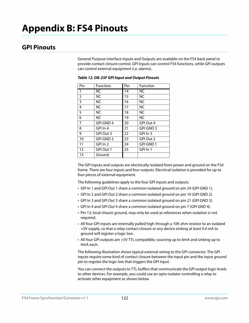
www.aja.com122
FS4 Frame Synchronizer/Converter v1.1
Appendix B: FS4 Pinouts
GPI Pinouts
General Purpose Interface Inputs and Outputs are available on the FS4 back panel to provide contact closure control. GPI Inputs can control FS4 functions, while GPI outputs can control external equipment (i.e. alarms).
The GPI inputs and outputs are electrically isolated from power and ground on the FS4 frame. There are four inputs and four outputs. Electrical isolation is provided for up to four pieces of external equipment.
The following guidelines apply to the four GPI inputs and outputs:
• GPI In 1 and GPI Out 1 share a common isolated ground on pin 24 (GPI GND 1),
• GPI In 2 and GPI Out 2 share a common isolated ground on pin 10 (GPI GND 2).
• GPI In 3 and GPI Out 3 share a common isolated ground on pin 21 (GPI GND 3).
• GPI In 4 and GPI Out 4 share a common isolated ground on pin 7 (GPI GND 4).
• Pin 13, local chassis ground, may only be used as references when isolation is not required.
• All four GPI inputs are internally pulled high through a 10K ohm resistor to an isolated +5V supply, so that a relay contact closure or any device sinking at least 0.4 mA to ground will register a logic low.
• All four GPI outputs are +5V TTL compatible, sourcing up to 6mA and sinking up to 4mA each.
The following illustration shows typical external wiring to the GPI connector. The GPI inputs require some kind of contact closure between the input pin and the input ground pin to register the logic low that triggers the GPI input.
You can connect the outputs to TTL buffers that communicate the GPI output logic levels to other devices. For example, you could use an opto-isolator controlling a relay to activate other equipment as shown below.
Table 12. DB-25F GPI Input and Output Pinouts
Pin Function Pin Function1 NC 14 NC2 NC 15 NC3 NC 16 NC4 NC 17 NC5 NC 18 NC6 NC 19 NC7 GPI GND 4 20 GPI Out 48 GPI In 4 21 GPI GND 39 GPI Out 3 22 GPI In 310 GPI GND 2 23 GPI Out 2 11 GPI In 2 24 GPI GND 112 GPI Out 1 25 GPI In 113 Ground
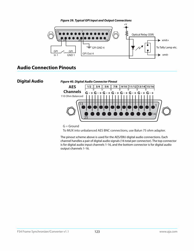
www.aja.com123
FS4 Frame Synchronizer/Converter v1.1
Figure 39. Typical GPI Input and Output Connections
Audio Connection Pinouts
Digital Audio Figure 40. Digital Audio Connector Pinout
The pinout scheme above is used for the AES/EBU digital audio connections. Each channel handles a pair of digital audio signals (16 total per connector). The top connector is for digital audio input channels 1-16, and the bottom connector is for digital audio output channels 1-16.
1
14202425
13 7
GPI Out 4
xmit+
xmit-
Optical Relay (SSR)
To Tally Lamp etc.GPI GND 4GPI
GND 1GPI In 1
+V
GG G
15/1613/14
G
5/6
G
1/2
G
9/10 11/12
G
7/8
G
3/4AESChannels
G = GroundTo MUX into unbalanced AES BNC connections, use Balun 75 ohm adapter.
110 Ohm Balanced - + - + - + - + - + - + - + - +

www.aja.com124
FS4 Frame Synchronizer/Converter v1.1
Appendix C: Safety & Compliance
Federal Communications Commission (FCC) Compliance Notices
Class A Interference Statement
This equipment has been tested and found to comply with the limits for a Class A digital device, pursuant to Part 15, Subpart B of the FCC Rules. These limits are designed to provide reasonable protection against harmful interference in a residential installation. This equipment generates, uses, and can radiate radio frequency energy and, if not installed and used in accordance with the instructions, may cause harmful interference to radio communications. However, there is no guarantee that interference will not occur in a particular installation. If this equipment does cause harmful interference to radio or television reception, which can be determined by turning the equipment off and on, the user is encouraged to try to correct the interference by one or more of the following measures:
• Reorient or relocate the receiving antenna.
• Increase the separation between the equipment and receiver.
• Connect the equipment into an outlet on a circuit different from that to which the receiver is connected.
• Consult the dealer or an experienced radio/TV technician for help.
FCC Caution This device complies with Part 15 of the FCC Rules. Operation is subject to the following two conditions: (1) This device may not cause harmful interference, and (2) this device must accept any interference received, including interference that may cause undesired operation.
Canadian ICES Statement
Canadian Department of Communications Radio Interference Regulations
This digital apparatus does not exceed the Class A limits for radio-noise emissions from a digital apparatus as set out in the Radio Interference Regulations of the Canadian Department of Communications. This Class A digital apparatus complies with Canadian ICES-003.
Règlement sur le brouillage radioélectrique du ministère des Communications
Cet appareil numérique respecte les limites de bruits radioélectriques visant les appareils numériques de classe A prescrites dans le Règlement sur le brouillage radioélectrique du ministère des Communications du Canada. Cet appareil numérique de la Classe A est conforme à la norme NMB-003 du Canada.

www.aja.com125
FS4 Frame Synchronizer/Converter v1.1
European Union and European Free Trade Association (EFTA) Regulatory Compliance
This equipment may be operated in the countries that comprise the member countries of the European Union and the European Free Trade Association. These countries, listed in the following paragraph, are referred to as The European Community throughout this document:
AUSTRIA, BELGIUM, BULGARIA, CYPRUS, CZECH REPUBLIC, DENMARK, ESTONIA, FINLAND, FRANCE, GERMANY, GREECE, HUNGARY, IRELAND, ITALY, LATVIA, LITHUANIA, LUXEMBOURG, MALTA, NETHERLANDS, POLAND, PORTUGAL, ROMANIA, SLOVAKIA, SLOVENIA, SPAIN, SWEDEN, UNITED KINGDOM, ICELAND, LICHTENSTEIN, NORWAY, SWITZERLAND
Declaration of Conformity
Marking by this symbol indicates compliance with the Essential Requirements of the EMC Directive of the European Union 2014/30/EU.
This equipment meets the following conformance standards:
Safety: EN 60065: 2002 + A1: 2006 + A11: 2008 + A2: 2010 + A12: 2011 (GS License)
IEC 60065: 2001 + A1: 2005 + A2: 2010 (CB Scheme Report/Certificate)
Additional licenses issued for specific countries available on request.
Emissions: EN 55032: 2012, CISPR 22: 2008, EN 55022: 2010, EN 61000-3-2: 2006 + A1:2009 + A2:2009, EN 61000-3-3:2008
Immunity: EN 55103-2: 2009, EN 61000-4-2:2009, EN 61000-4-3: 2006 + A1:2008 + A2:2010, EN 61000-4-4: 2004 + A1:2010, EN 61000-4-5:2006, EN 61000-4-6:2009, EN 61000-4-11:2004
Environments: E2, E3 and E4
The product is also licensed for additional country specific standards as required for the International Marketplace.
Laser: EN 60825-1: 2007 and EN 60825-2: 2004 +A2: 2010,
CDRH Compliant Class 1 (TUV Cert No. 50135086)
Also Licensed for Standards: FDA 21 CFR 1040.10 and 1040.11
Warning! This is a Class A product. In a domestic environment, this product may cause radio interference, in which case, the user may be required to take appropriate measures.
Achtung! Dieses ist ein Gerät der Funkstörgrenzwertklasse A. In Wohnbereichen können bei Betrieb dieses Gerätes Rundfunkstörungen auftreten, in welchen Fällen der Benutzer für entsprechende Gegenmaßnahmen verantwortlich ist.
Attention! Ceci est un produit de Classe A. Dans un environnement domestique, ce produit risque de créer des interférences radioélectriques, il appartiendra alors à l?utilisateur de prendre les mesures spécifiques appropriées.
www.aja.com126
FS4 Frame Synchronizer/Converter v1.1
Recycling Notice
Korean KCC Compliance Statement
Taiwan Compliance Statement
This is a Class A product based on the standard of the Bureau of Standards, Metrology and Inspection (BSMI) CNS 13438, Class A. In a domestic environment this product may cause radio interference in which case the user may be required to take adequate measures.
Japanese Compliance Statement
This is a Class A product based on the standard of the VCCI Council (VCCI V-3/2015.04). If this equipment is used in a domestic environment, radio interference may occur, in which case, the user may be required to take corrective actions.
This symbol on the product or its packaging indicates that this product must not be disposed of with your other household waste. Instead, it is your responsibility to dispose of your waste equipment by handing it over to a designated collection point for the recycling of waste electrical and electronic equipment. The separate collection and recycling of your waste equipment at the time of disposal will help conserve natural resources and ensure that it is recycled in a manner that protects human health and the environment. For more information about where you can drop off your waste for recycling, please contact your local authority, or where you purchased your product.
www.aja.com127
FS4 Frame Synchronizer/Converter v1.1
Translated Warning and Caution Messages
The following caution statements, warning conventions, and warning messages apply to this product and manual.
Before Operation Please Read These Instructions
Warning Symbol Hazard Warning Caution Symbol
Warning! Read and follow all warning notices and instructions marked on the product or included in the documentation.
Avertissement ! Lisez et conformez-vous à tous les avis et instructions d'avertissement indiqués sur le produit ou dans la documentation.
Warnung! Lesen und befolgen Sie die Warnhinweise und Anweisungen, die auf dem Produkt angebracht oder in der Dokumentation enthalten sind.
¡Advertencia! Lea y siga todas las instrucciones y advertencias marcadas en el producto o incluidas en la documentación.
Aviso! Leia e siga todos os avisos e instruções assinalados no produto ou incluídos na documentação.
Avviso! Leggere e seguire tutti gli avvisi e le istruzioni presenti sul prodotto o inclusi nella documentazione.
Warning! Do not use this device near water and clean only with a dry cloth.
Avertissement! N'utilisez pas cet appareil près de l'eau et nettoyez-le seulement avec un tissu sec..
Warnung! Das Gerät nicht in der Nähe von Wasser verwenden und nur mit einem trockenen Tuch säubern.
¡Advertencia! No utilice este dispositivo cerca del agua y límpielo solamente con un paño seco.
Aviso! Não utilize este dispositivo perto da água e limpe-o somente com um pano seco.
Avviso! Non utilizzare questo dispositivo vicino all'acqua e pulirlo soltanto con un panno asciutto.
www.aja.com128
FS4 Frame Synchronizer/Converter v1.1
Warning! Do not block any ventilation openings. Install in accordance with the manufacturer's instructions.
Avertissement ! Ne bloquez aucune ouverture de ventilation. Suivez les instructions du fabricant lors de l'installation.
Warnung! Die Lüftungsöffnungen dürfen nicht blockiert werden. Nur gemäß den Anweisungen des Herstellers installieren.
¡Advertencia! No bloquee ninguna de las aberturas de la ventilación. Instale de acuerdo con las instrucciones del fabricante.
Aviso! Não obstrua nenhuma das aberturas de ventilação. Instale de acordo com as instruções do fabricante.
Avviso! Non ostruire le aperture di ventilazione. Installare in conformità con le istruzioni del fornitore.
Warning! Do not install near any heat sources such as radiators, heat registers, stoves, or other apparatus (including amplifiers) that produce heat.
Avertissement ! N'installez pas l'appareil près d'une source de chaleur telle que des radiateurs, des bouches d'air de chauffage, des fourneaux ou d'autres appareils (amplificateurs compris) qui produisent de la chaleur.
Warnung! Nicht in der Nähe von Wärmequellen wie Heizkörpern, Heizregistern, Öfen oder anderen Wärme erzeugenden Geräten (einschließlich Verstärkern) aufstellen.
¡Advertencia! No instale cerca de fuentes de calor tales como radiadores, registros de calor, estufas u otros aparatos (incluidos amplificadores) que generan calor.
Aviso! Não instale perto de nenhuma fonte de calor tal como radiadores, saídas de calor, fogões ou outros aparelhos (incluindo amplificadores) que produzam calor.
Avviso! Non installare vicino a fonti di calore come termosifoni, diffusori di aria calda, stufe o altri apparecchi (amplificatori compresi) che emettono calore.
www.aja.com129
FS4 Frame Synchronizer/Converter v1.1
Warning! Refer all servicing to qualified service personnel. Servicing is required when the device has been damaged in any way, such as power-supply cord or plug is damaged, liquid has been spilled or objects have fallen into the device, the device has been exposed to rain or moisture, does not operate normally, or has been dropped.
Avertissement ! Référez-vous au personnel de service qualifié pour tout entretien. L'entretien est exigé quand l'appareil a été endommagé de quelque manière que ce soit, par exemple lorsque le cordon d'alimentation ou la prise sont endommagés, que du liquide a été versé ou des objets sont tombés dans l'appareil, que l'appareil a été exposé à la pluie ou à l'humidité, ne fonctionne pas normalement ou est tombé.
Warnung! Das Gerät sollte nur von qualifizierten Fachkräften gewartet werden. Eine Wartung ist fällig, wenn das Gerät in irgendeiner Weise beschädigt wurde, wie bei beschädigtem Netzkabel oder Netzstecker, falls Flüssigkeiten oder Objekte in das Gerät gelangen, das Gerät Regen oder Feuchtigkeit ausgesetzt wurde, nicht ordnungsgemäß funktioniert oder fallen gelassen wurde.
¡Advertencia! Consulte al personal calificado por cuestiones de reparación. El servicio de reparación se requiere cuando el dispositivo ha recibido cualquier tipo de daño, por ejemplo cable o espigas dañadas, se ha derramado líquido o se han caído objetos dentro del dispositivo, el dispositivo ha sido expuesto a la lluvia o humedad, o no funciona de modo normal, o se ha caído.
Aviso! Remeta todos os serviços de manutenção para o pessoal de assistência qualificado. A prestação de serviços de manutenção é exigida quando o dispositivo foi danificado mediante qualquer forma, como um cabo de alimentação ou ficha que se encontra danificado/a, quando foi derramado líquido ou caíram objectos sobre o dispositivo, quando o dispositivo foi exposto à chuva ou à humidade, quando não funciona normalmente ou quando foi deixado cair.
Avviso! Fare riferimento al personale qualificato per tutti gli interventi di assistenza. L'assistenza è necessaria quando il dispositivo è stato danneggiato in qualche modo, ad esempio se il cavo di alimentazione o la spina sono danneggiati, è stato rovesciato del liquido è stato rovesciato o qualche oggetto è caduto nel dispositivo, il dispositivo è stato esposto a pioggia o umidità, non funziona correttamente o è caduto.
Warning! Disconnect the external AC power supply line cord(s) from the mains power before moving the unit.
Avertissement! Retirez le ou les cordons d’alimentation en CA de la source d’alimentation principale lorsque vous déplacez l’appareil.
Warnung! Trennen Sie die Wechselstrom-Versorgungskabel vom Netzstrom, bevor Sie das Gerät verschieben.
¡Advertencia! Cuando mueva la unidad desenchufe de la red eléctrica el/los cable(s) de la fuente de alimentación CA tipo brick.
Advertência! Remova os cabos CA de alimentação brick da rede elétrica ao mover a unidade.
Avvertenza! Scollegare il cavo dell’alimentatore quando si sposta l’unità.

www.aja.com130
FS4 Frame Synchronizer/Converter v1.1
Hazard Warning! High Voltage. This situation or condition can cause injury due to electric shock.
Avertissement! Tension élevée. Cette situation ou condition peut causer des blessures dues à un choc électrique.
Warnung! Hochspannung. Diese Situation oder Bedingung kann zu Verletzungen durch Stromschlag führen.
¡Advertencia! Alto voltaje . Esta situación o condición puede causar lesiones debidas a una descarga eléctrica.
Aviso! Alta Tensão . Esta situação ou condição pode causar danos devido a choques elétricos.
Avviso! Alta tensione. Questa situazione o condizione può causare lesioni a causa di scosse elettriche.
Warning! Only use attachments and accessories specified and/or sold by the manufacturer.
Avertissement! Utilisez seulement les attaches et accessoires spécifiés et/ou vendus par le fabricant.
Warnung! Verwenden Sie nur Zusatzgeräte und Zubehör angegeben und / oder verkauft wurde durch den Hersteller.
¡Advertencia! Utilice solamente los accesorios y conexiones especificados y/o vendidos por el fabricante.
Aviso! Utilize apenas equipamentos/acessórios especificados e/ou vendidos pelo fabricante.
Avviso! Utilizzare soltanto i collegamenti e gli accessori specificati e/o venduti dal produttore.
www.aja.com131
FS4 Frame Synchronizer/Converter v1.1
Warning! Do not defeat the safety purpose of the polarized or grounding-type plug. A polarized plug has two blades with one wider than the other. A grounding type plug has two blades and a third grounding prong. The wide blade or the third prong are provided for your safety. If the provided plug does not fit into your outlet, consult an electrician for replacement of the obsolete outlet.
Avertissement! La sécurité de la prise polarisée ou de la prise de type mise à la terre ne doit en aucun cas être empêchée de fonctionner. Une prise polarisée a deux broches, l'une étant plus large que l'autre. Une prise de type mise à la terre a deux broches et une troisième broche pour la mise à la terre. La broche large ou la troisième broche sont fournies pour votre sécurité. Si la prise fournie ne s'insère pas dans votre prise femelle, consultez un électricien pour le remplacement de la prise femelle obsolète.
Warnung! Der Sicherheitszweck des gepolten bzw. Schukosteckers ist zu berücksichtigen. Ein gepolter Stecker verfügt über zwei Pole, von denen einer breiter als der andere ist. Ein Schukostecker verfügt neben den zwei Polen noch über einen dritten Pol zur Erdung. Der breite Pol bzw. der Erdungspol dienen der Sicherheit. Wenn der zur Verfügung gestellte Stecker nicht in Ihren Anschluss passt, konsultieren Sie einen Elektriker, um den veralteten Anschluss zu ersetzen.
¡Advertencia! No eche por tierra la finalidad del tipo de enchufe polarizado con conexión a tierra. Un enchufe polarizado tiene dos espigas, una más ancha que la otra. Un enchufe con conexión a tierra tiene dos espigas iguales y una tercera espiga que sirve para la conexión a tierra. La expiga ancha, o la tercera espiga, sirven para su seguridad. Si el enchufe suministrado no encaja en el tomacorriente, consulte con un electricista para reemplazar el tomacorriente obsoleto.
Aviso! Não anule a finalidade da segurança da ficha polarizada ou do tipo ligação terra. Uma ficha polarizada tem duas lâminas sendo uma mais larga do que a outra. Uma ficha do tipo de ligação à terra tem duas lâminas e um terceiro terminal de ligação à terra. A lâmina larga ou o terceiro terminal são fornecidos para sua segurança. Se a ficha fornecida não couber na sua tomada, consulte um electricista para a substituição da tomada obsoleta.
Avviso! Non compromettere la sicurezza della spina polarizzata o con messa a terra. Una spina polarizzata ha due spinotti, di cui uno più largo. Una spina con messa a terra ha due spinotti e un terzo polo per la messa a terra. Lo spinotto largo o il terzo polo sono forniti per motivi di sicurezza. Se la spina fornita non si inserisce nella presa di corrente, contattare un elettricista per la sostituzione della presa obsoleta.
www.aja.com132
FS4 Frame Synchronizer/Converter v1.1
Warning! Since the Mains plug is used as the disconnection for the device, it must remain readily accessible and operable.
Avertissement! Puisque la prise principale est utilisée pour débrancher l'appareil, elle doit rester aisément accessible et fonctionnelle.
Warnung! Da der Netzstecker als Trennvorrichtung dient, muss er stets zugänglich und funktionsfähig sein.
¡Advertencia! Puesto que el enchufe de la red eléctrica se utiliza como dispositivo de desconexión, debe seguir siendo fácilmente accesible y operable.
Aviso! Dado que a ficha principal é utilizada como a desconexão para o dispositivo, esta deve manter-se prontamente acessível e funcional.
Avviso! Poiché il cavo di alimentazione viene usato come dispositivo di sconnessione, deve rimane prontamente accessibile e operabile.
Warning! Protect the power cord from being walked on or pinched particularly at plugs, convenience receptacles, and the point where they exit from the device.
Avertissement! Protégez le cordon d'alimentation pour que l'on ne marche pas dessus ou qu'on le pince, en particulier au niveau des prises mâles, des réceptacles de convenance, et à l'endroit où il sort de l'appareil.
Warnung! Vermeiden Sie, dass auf das Netzkabel getreten oder das Kabel geknickt wird, insbesondere an den Steckern, den Steckdosen und am Kabelausgang am Gerät.
¡Advertencia! Proteja el cable de energía para que no se le pise ni apriete, en especial cerca del enchufe, los receptáculos de conveniencia y el punto del que salen del equipo.
Aviso! Proteja o cabo de alimentação de ser pisado ou de ser comprimido particularmente nas fichas, em tomadas de parede de conveniência e no ponto de onde sai do dispositivo.
Avviso! Proteggere il cavo di alimentazione in modo che nessuno ci cammini sopra e che non venga schiacciato soprattutto in corrispondenza delle spine e del punto in cui esce dal dispositivo.
Warning! Unplug this device during lightning storms or when unused for long periods of time.
Avertissement! Débranchez cet appareil pendant les orages avec éclairsou s'il est inutilisé pendant de longues périodes.
Warnung! Das Gerät ist bei Gewitterstürmen oder wenn es über lange Zeiträume ungenutzt bleibt vom Netz zu trennen.
¡Advertencia! Desenchufe este dispositivo durante tormentas eléctricas o cuando no se lo utilice por largos periodos del tiempo.
Aviso! Desconecte este dispositivo da tomada durante trovoadas ou quando não é utilizado durante longos períodos de tempo.
Avviso! Utilizzare soltanto i collegamenti e gli accessori specificati e/o venduti dal produttore, quali il treppiedi e l'esoscheletro.
www.aja.com133
FS4 Frame Synchronizer/Converter v1.1
Warning! Do not open the chassis. There are no user-serviceable parts inside. Opening the chassis will void the warranty unless performed by an AJA service center or licensed facility.
Avertissement! Ne pas ouvrir le châssis. Aucun élément à l’intérieur du châssis ne peut être réparé par l’utilisateur. La garantie sera annulée si le châssis est ouvert par toute autre personne qu’un technicien d’un centre de service ou d’un établissement agréé AJA.
Warnung! Öffnen Sie das Gehäuse nicht. Keine der Geräteteile können vom Benutzer gewartet werden. Durch das Öffnen des Gehäuses wird die Garantie hinfällig, es sei denn, solche Wartungsarbeiten werden in einem AJA-Service-Center oder einem lizenzierten Betrieb vorgenommen.
¡Advertencia! No abra el chasis. El interior no contiene piezas reparables por el usuario. El abrir el chasis anulará la garantía a menos que se lo haga en un centro de servicio AJA o en un local autorizado.
Advertência! Não abra o chassi. Não há internamente nenhuma peça que permita manutenção pelo usuário. Abrir o chassi anula a garantia, a menos que a abertura seja realizada por uma central de serviços da AJA ou por um local autorizado.
Avvertenza! Non aprire lo chassis. All’interno non ci sono parti riparabili dall’utente. L’apertura dello chassis invaliderà la garanzia se non viene effettuata da un centro ufficiale o autorizzato AJA.
Warning! To meet safety regulations for leakage current, connect the dual power supplies to separate branch circuits.
¡Advertencia! Para cumplir con las normas de seguridad para la corriente de fuga, conecte las dos fuentes de alimentación para circuitos derivados diferentes.
Attention! Pour répondre aux mesures de sécurité concernant le courant de fuite, raccorder les sources d'alimentation doubles à des circuits de dérivation distincts.
Warnung! Zur Erfüllung der Sicherheitsbestimmungen bezüglich Reststrom schließen Sie bitte die zwei Netzteile an unterschiedlichen Abzweigleitungen an.
Cuidado! Para atender aos regulamentos de segurança para correntes de fuga, conecte as fontes duplas a circuitos elétricos separados.
Attenzione! Per soddisfare le norme di sicurezza sulla corrente di perdita, collegare i doppi alimentatori a circuiti derivati separati.
www.aja.com134
FS4 Frame Synchronizer/Converter v1.1
Warning! Active fiber-optic cables emit radiation invisible to the human eye. Do not look directly at the end of an active fiber-optic cable or the fiber connector on a, FS1-X, FS2, FS3 or FS4; these models are Class 1 Laser Products.
Avertissement! Les câbles fibre optique émettent des radiations invisibles à l’oeil humain. Ne regardez pas directement l’extrémité d?un câble fibre optique ou d’un connecteur de fibre d’un FS1-X, FS2, FS3, ou FS4; ces modèles sont des produits laser de Classe 1.
Warnung! Glasfaserkabel emittieren im Betrieb Strahlung, die für das menschliche Auge unsichtbar ist. Nicht direkt in das Ende eines im Betrieb befindlichen Glasfaserkabels bzw. den Glasfaserkabelanschluss am FS1-X, FS2, FS3, oder FS4 schauen; diese Modelle sind Lasergeräte der Klasse 1.
¡Advertencia! Los cables de fibra óptica activos emiten radiación invisible al ojo humano. No mire directamente hacia el extremo de un cable de fibra óptica activo o hacia el conector de fibra óptica del FS1-X, FS2, FS3, o FS4; estos modelos están clasificados como Productos Láser Clase 1.
Advertência! Os cabos de fibra óptica emitem radiação invisível para o olho humano. Não olhe diretamente para a extremidade de um cabo de fibra óptica ativo ou para o conector da fibra em umFS1-X, FS2, FS3, ou FS4; esses modelos são Produtos de Laser Classe 1.
Avvertenza! I cavi a fibre ottiche emettono radiazioni invisibili all'occhio umano. Non guardare direttamente l'estremità di un cavo in fibra ottica attivo o il connettore in fibra su un FS1-X, FS2, FS3, o FS4; questi modelli sono prodotti laser di classe 1.
CLASS 1LASER
PRODUCT

www.aja.com135
FS4 Frame Synchronizer/Converter v1.1
Warranty Information
Limited Warranty
AJA Video Systems, Inc. (AJA Video) warrants that this product will be free from defects in materials and workmanship for a period of five years from the date of purchase. If a product proves to be defective during this warranty period, AJA Video, at its option, will either repair the defective product without charge for parts and labor, or will provide a replacement in exchange for the defective product.
In order to obtain service under this warranty, you the Customer, must notify AJA Video of the defect before the expiration of the warranty period and make suitable arrangements for the performance of service.The Customer shall be responsible for packaging and shipping the defective product to a designated service center nominated by AJA Video, with shipping charges prepaid. AJA Video shall pay for the return of the product to the Customer if the shipment is to a location within the country in which the AJA Video service center is located. Customer shall be responsible for paying all shipping charges, insurance, duties, taxes, and any other charges for products returned to any other locations.
This warranty shall not apply to any defect, failure or damage caused by improper use or improper or inadequate maintenance and care. AJA Video shall not be obligated to furnish service under this warranty a) to repair damage resulting from attempts by personnel other than AJA Video representatives to install, repair or service the product, b) to repair damage resulting from improper use or connection to incompatible equipment, c) to repair any damage or malfunction caused by the use of non-AJA Video parts or supplies, or d) to service a product that has been modified or integrated with other products when the effect of such a modification or integration increases the time or difficulty of servicing the product.
THIS WARRANTY IS GIVEN BY AJA VIDEO IN LIEU OF ANY OTHER WARRANTIES, EXPRESS OR IMPLIED. AJA VIDEO AND ITS VENDORS DISCLAIM ANY IMPLIED WARRANTIES OF MERCHANTABILITY OR FITNESS FOR A PARTICULAR PURPOSE. AJA VIDEO’S RESPONSIBILITY TO REPAIR OR REPLACE DEFECTIVE PRODUCTS IS THE WHOLE AND EXCLUSIVE REMEDY PROVIDED TO THE CUSTOMER FOR ANY INDIRECT, SPECIAL, INCIDENTAL OR CONSEQUENTIAL DAMAGES IRRESPECTIVE OF WHETHER AJA VIDEO OR THE VENDOR HAS ADVANCE NOTICE OF THE POSSIBILITY OF SUCH DAMAGES.
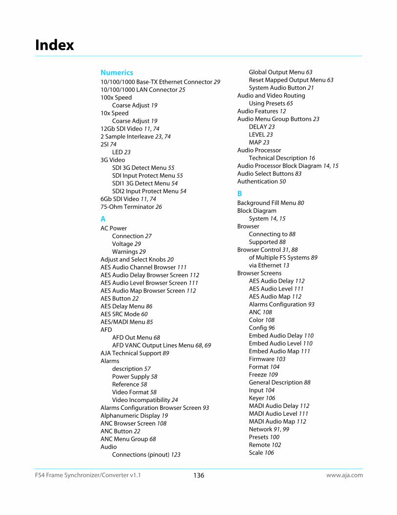
www.aja.com136FS4 Frame Synchronizer/Converter v1.1
Index
Numerics10/100/1000 Base-TX Ethernet Connector 2910/100/1000 LAN Connector 25100x Speed
Coarse Adjust 1910x Speed
Coarse Adjust 1912Gb SDI Video 11, 742 Sample Interleave 23, 742SI 74
LED 233G Video
SDI 3G Detect Menu 55SDI Input Protect Menu 55SDI1 3G Detect Menu 54SDI2 Input Protect Menu 54
6Gb SDI Video 11, 7475-Ohm Terminator 26
AAC Power
Connection 27Voltage 29Warnings 29
Adjust and Select Knobs 20AES Audio Channel Browser 111AES Audio Delay Browser Screen 112AES Audio Level Browser Screen 111AES Audio Map Browser Screen 112AES Button 22AES Delay Menu 86AES SRC Mode 60AES/MADI Menu 85AFD
AFD Out Menu 68AFD VANC Output Lines Menu 68, 69
AJA Technical Support 89Alarms
description 57Power Supply 58Reference 58Video Format 58Video Incompatibility 24
Alarms Configuration Browser Screen 93Alphanumeric Display 19ANC Browser Screen 108ANC Button 22ANC Menu Group 68Audio
Connections (pinout) 123
Global Output Menu 63Reset Mapped Output Menu 63System Audio Button 21
Audio and Video RoutingUsing Presets 65
Audio Features 12Audio Menu Group Buttons 23
DELAY 23LEVEL 23MAP 23
Audio ProcessorTechnical Description 16
Audio Processor Block Diagram 14, 15Audio Select Buttons 83Authentication 50
BBackground Fill Menu 80Block Diagram
System 14, 15Browser
Connecting to 88Supported 88
Browser Control 31, 88of Multiple FS Systems 89via Ethernet 13
Browser ScreensAES Audio Delay 112AES Audio Level 111AES Audio Map 112Alarms Configuration 93ANC 108Color 108Config 96Embed Audio Delay 110Embed Audio Level 110Embed Audio Map 111Firmware 103Format 104Freeze 109General Description 88Input 104Keyer 106MADI Audio Delay 112MADI Audio Level 111MADI Audio Map 112Network 91, 99Presets 100Remote 102Scale 106
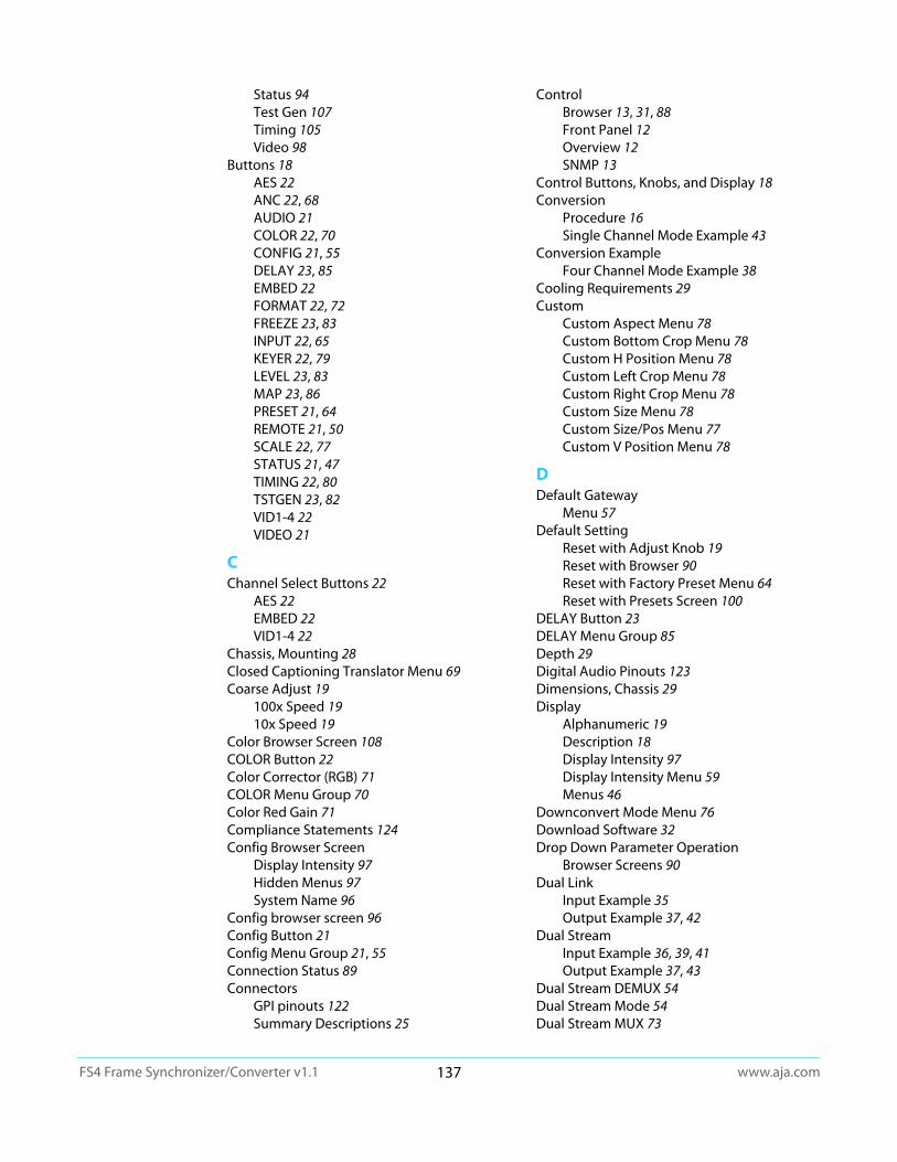
www.aja.com137FS4 Frame Synchronizer/Converter v1.1
Status 94Test Gen 107Timing 105Video 98
Buttons 18AES 22ANC 22, 68AUDIO 21COLOR 22, 70CONFIG 21, 55DELAY 23, 85EMBED 22FORMAT 22, 72FREEZE 23, 83INPUT 22, 65KEYER 22, 79LEVEL 23, 83MAP 23, 86PRESET 21, 64REMOTE 21, 50SCALE 22, 77STATUS 21, 47TIMING 22, 80TSTGEN 23, 82VID1-4 22VIDEO 21
CChannel Select Buttons 22
AES 22EMBED 22VID1-4 22
Chassis, Mounting 28Closed Captioning Translator Menu 69Coarse Adjust 19
100x Speed 1910x Speed 19
Color Browser Screen 108COLOR Button 22Color Corrector (RGB) 71COLOR Menu Group 70Color Red Gain 71Compliance Statements 124Config Browser Screen
Display Intensity 97Hidden Menus 97System Name 96
Config browser screen 96Config Button 21Config Menu Group 21, 55Connection Status 89Connectors
GPI pinouts 122Summary Descriptions 25
ControlBrowser 13, 31, 88Front Panel 12Overview 12SNMP 13
Control Buttons, Knobs, and Display 18Conversion
Procedure 16Single Channel Mode Example 43
Conversion ExampleFour Channel Mode Example 38
Cooling Requirements 29Custom
Custom Aspect Menu 78Custom Bottom Crop Menu 78Custom H Position Menu 78Custom Left Crop Menu 78Custom Right Crop Menu 78Custom Size Menu 78Custom Size/Pos Menu 77Custom V Position Menu 78
DDefault Gateway
Menu 57Default Setting
Reset with Adjust Knob 19Reset with Browser 90Reset with Factory Preset Menu 64Reset with Presets Screen 100
DELAY Button 23DELAY Menu Group 85Depth 29Digital Audio Pinouts 123Dimensions, Chassis 29Display
Alphanumeric 19Description 18Display Intensity 97Display Intensity Menu 59Menus 46
Downconvert Mode Menu 76Download Software 32Drop Down Parameter Operation
Browser Screens 90Dual Link
Input Example 35Output Example 37, 42
Dual StreamInput Example 36, 39, 41Output Example 37, 43
Dual Stream DEMUX 54Dual Stream Mode 54Dual Stream MUX 73
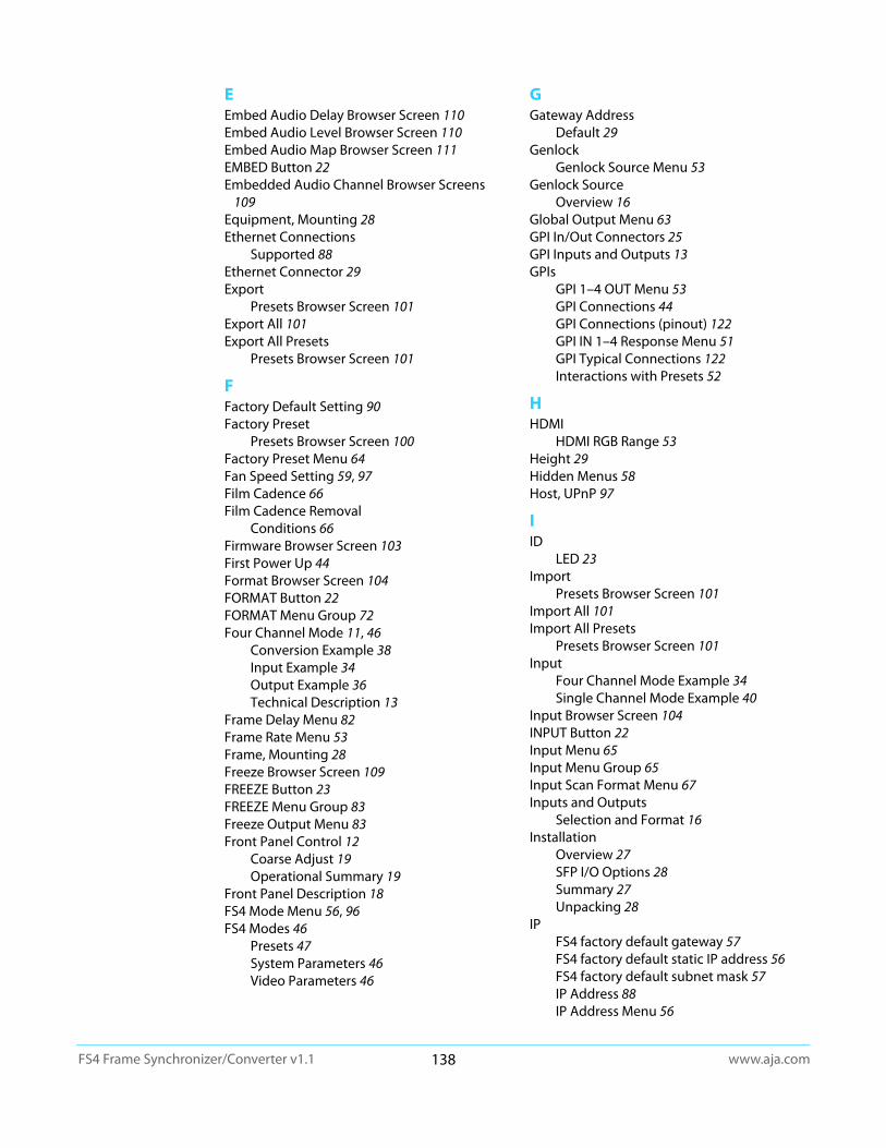
www.aja.com138FS4 Frame Synchronizer/Converter v1.1
EEmbed Audio Delay Browser Screen 110Embed Audio Level Browser Screen 110Embed Audio Map Browser Screen 111EMBED Button 22Embedded Audio Channel Browser Screens
109Equipment, Mounting 28Ethernet Connections
Supported 88Ethernet Connector 29Export
Presets Browser Screen 101Export All 101Export All Presets
Presets Browser Screen 101
FFactory Default Setting 90Factory Preset
Presets Browser Screen 100Factory Preset Menu 64Fan Speed Setting 59, 97Film Cadence 66Film Cadence Removal
Conditions 66Firmware Browser Screen 103First Power Up 44Format Browser Screen 104FORMAT Button 22FORMAT Menu Group 72Four Channel Mode 11, 46
Conversion Example 38Input Example 34Output Example 36Technical Description 13
Frame Delay Menu 82Frame Rate Menu 53Frame, Mounting 28Freeze Browser Screen 109FREEZE Button 23FREEZE Menu Group 83Freeze Output Menu 83Front Panel Control 12
Coarse Adjust 19Operational Summary 19
Front Panel Description 18FS4 Mode Menu 56, 96FS4 Modes 46
Presets 47System Parameters 46Video Parameters 46
GGateway Address
Default 29Genlock
Genlock Source Menu 53Genlock Source
Overview 16Global Output Menu 63GPI In/Out Connectors 25GPI Inputs and Outputs 13GPIs
GPI 1–4 OUT Menu 53GPI Connections 44GPI Connections (pinout) 122GPI IN 1–4 Response Menu 51GPI Typical Connections 122Interactions with Presets 52
HHDMI
HDMI RGB Range 53Height 29Hidden Menus 58Host, UPnP 97
IID
LED 23Import
Presets Browser Screen 101Import All 101Import All Presets
Presets Browser Screen 101Input
Four Channel Mode Example 34Single Channel Mode Example 40
Input Browser Screen 104INPUT Button 22Input Menu 65Input Menu Group 65Input Scan Format Menu 67Inputs and Outputs
Selection and Format 16Installation
Overview 27SFP I/O Options 28Summary 27Unpacking 28
IPFS4 factory default gateway 57FS4 factory default static IP address 56FS4 factory default subnet mask 57IP Address 88IP Address Menu 56
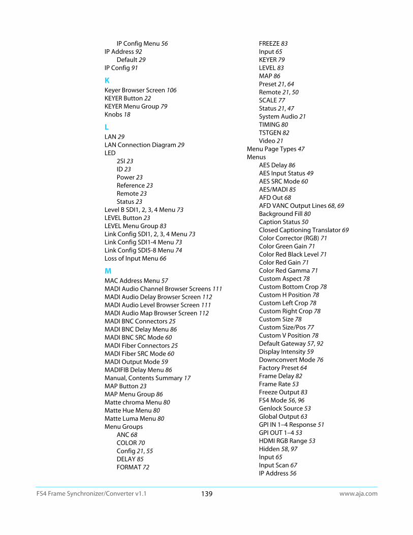
www.aja.com139FS4 Frame Synchronizer/Converter v1.1
IP Config Menu 56IP Address 92
Default 29IP Config 91
KKeyer Browser Screen 106KEYER Button 22KEYER Menu Group 79Knobs 18
LLAN 29LAN Connection Diagram 29LED
2SI 23ID 23Power 23Reference 23Remote 23Status 23
Level B SDI1, 2, 3, 4 Menu 73LEVEL Button 23LEVEL Menu Group 83Link Config SDI1, 2, 3, 4 Menu 73Link Config SDI1-4 Menu 73Link Config SDI5-8 Menu 74Loss of Input Menu 66
MMAC Address Menu 57MADI Audio Channel Browser Screens 111MADI Audio Delay Browser Screen 112MADI Audio Level Browser Screen 111MADI Audio Map Browser Screen 112MADI BNC Connectors 25MADI BNC Delay Menu 86MADI BNC SRC Mode 60MADI Fiber Connectors 25MADI Fiber SRC Mode 60MADI Output Mode 59MADIFIB Delay Menu 86Manual, Contents Summary 17MAP Button 23MAP Menu Group 86Matte chroma Menu 80Matte Hue Menu 80Matte Luma Menu 80Menu Groups
ANC 68COLOR 70Config 21, 55DELAY 85FORMAT 72
FREEZE 83Input 65KEYER 79LEVEL 83MAP 86Preset 21, 64Remote 21, 50SCALE 77Status 21, 47System Audio 21TIMING 80TSTGEN 82Video 21
Menu Page Types 47Menus
AES Delay 86AES Input Status 49AES SRC Mode 60AES/MADI 85AFD Out 68AFD VANC Output Lines 68, 69Background Fill 80Caption Status 50Closed Captioning Translator 69Color Corrector (RGB) 71Color Green Gain 71Color Red Black Level 71Color Red Gain 71Color Red Gamma 71Custom Aspect 78Custom Bottom Crop 78Custom H Position 78Custom Left Crop 78Custom Right Crop 78Custom Size 78Custom Size/Pos 77Custom V Position 78Default Gateway 57, 92Display Intensity 59Downconvert Mode 76Factory Preset 64Frame Delay 82Frame Rate 53Freeze Output 83FS4 Mode 56, 96Genlock Source 53Global Output 63GPI IN 1–4 Response 51GPI OUT 1–4 53HDMI RGB Range 53Hidden 58, 97Input 65Input Scan 67IP Address 56
www.aja.com140FS4 Frame Synchronizer/Converter v1.1
IP Config 56Level B SDI1, 2, 3, 4 73Link Config SDI1, 2, 3, 4 73Link Config SDI1-4 73Link Config SDI5-8 74Loss of Input 66MAC Address 57MADI BNC Delay 86MADI BNC SRC Mode 60MADI Fiber SRC Mode 60MADI In/Out Status 49MADI Output Mode 59MADI/FIB Delay 86Matte Chroma 80Matte Hue 80Matte Luma 80Mix Down Input 62Mix Down Input Level 62Mix Down Input Mapping 62Mix Down Mode 61, 62Mix Down Output Level 62Mix Down Reset 63Mon 2K Crop 53Monitor Map 54Monitor Output Status 49Output Format 72Output Timing H 81Output Timing V 81Power Supply Alarm 58Power/Temp Alarm Status 49Presets 1–40 64Proc Amp (YUV) 70Proc Amp Black 71Proc Amp Gain 70Proc Amp Hue 71Proc Amp Sat 71Reboot 59Reference Alarm 58Region of Interest 79Remote Control 50Reset Mapped Output 63Reverse Telecine 66Scan Format 67Screen Saver 58, 97SD Aspect Ratio 74SD Line 21 Blanking 70SDI 1-8 SRC Mode 60SDI Input Protect 55SDI Input Status 49SDI Output Channel 87SDI1 Channel Pair Delay 86SDI1 Delay 85SDI1 Delay Global 86SDI1 Level 84
SDI1 Phase 84SDI1-3G Detect 54, 55SDI2 Input Protect 54Serial Number 59Sidebar Edge 80SNMP Enable 115SNMP Trap Destination 1 115SNMP Trap Destination 2 115SNMP Trap Port 1 115SNMP Trap Port 2 115Software Version 59Subnet Mask 57System Name 55, 96System Status 47Test Pattern 83Test Pattern Gen 82Uplink Mode 75Vid 1 Audio Out 87Vid 1 Format Alarm Status 48Vid 1 Format Status 48Vid 1/2 I/O Status 48Vid 2-4 Format Alarm Status 48Vid 3/4 I/O Status 48Vid Format Alarm Status 49Vid Format Status 48Vid I/O Status 48Video Format Alarm 58Video Legalizer 71VidProc Bypass 55
Menus, Parameter 46MIB
AJA Products 113Mix Down Input Level Menu 62Mix Down Input Mapping Menu 62Mix Down Input Menu 62Mix Down Mode
description 61Mix Down Mode Menu 61, 62Mix Down Output Level Menu 62Mix Down Reset Menu 63Mode
FS4 46FS4 Four Channel Mode 56, 96FS4 Single Channel Mode 56, 96
MonitorMon 2K Crop Menu 53Monitor Map Menu 54
Monitor Output Connector 25Multi-Channel 5.1 Mixdown Default 61Multi-Channel 7.1 Mixdown Default 61Multi-Channel Speaker Positions 61Multiple FS Systems
Control with Browser 89

www.aja.com141FS4 Frame Synchronizer/Converter v1.1
NName Entry Procedure 56Network
Connection Diagram 29Default Gateway 92Default Gateway Address 29Default IP Address 29Default Subnet Mask 29IP Address 92IP Config 91Ping Test 31Subnet Mask 92UPnP Host 97UPnP Proxy 97
Network Browser Screen 91Network Screen 99Networking
Default Static IP Procedure 30HDCP Procedure 30User Static IP Procedure 30
OOctet Value Entry Procedure 56Operation Overview 16Operational Summary 19Output
Four Channel Mode Example 36Single Channel Mode Example 41
Output Format Menu 72Output Image Mapping Menu
MenusOutput Image Mapping 74
Output Timing H Menu 81Output Timing Memory 17Output Timing Ranges 81Output Timing V Menu 81Outputs and Inputs
Selection and Format 16Overview 11
System Block Diagram 14, 15Overview, Installation 27
PPanel
Description, Front 18Rear, Description 25
Parameter Menus 46Ping Mac 31Ping PC 31Ping Test, Network 31Pinouts
Audio 123Digital Audio 123GPI 122
PowerConnection 27Power Supply Alarm Menu 58PWR 1/2 LEDs 23Requirements and Warnings 29
Power Connectors 25Power Up
First Time 44Preset Button 21Preset Menu Group 21, 64Presets
FS4 Modes 47Interactions with GPIs 52Presets 1–40 Menu 64Routing Audio with Video 65
Presets Browser Screen 100Proc Amp
Proc Amp Black Menu 71Proc Amp Gain Menu 70Proc Amp Hue Menu 71Proc Amp Menu (YUV) 70Proc Amp Sat Menu 71
Proxy, UPnP 97PWR 1/2 LEDs 23
QQuad Link
Input Example 40Output Example 41
Quadrant 23, 74
RRear Panel Description 25Reboot Menu 59Recall
Presets Browser Screen 101Redundant Power Supplies 27REF LED 23Ref Loop Connectors 26Reference
Overview 16Reference Alarm Menu 58Termination 26
Region of Interest 79Region of Interest Menu 79REMOTE
LED 23Remote Browser Screen 102Remote Button 21Remote Control Menu 50Remote Menu Group 21, 50Reset
To Factory Default 19Reset Mapped Output Menu 63
www.aja.com142FS4 Frame Synchronizer/Converter v1.1
Restore Previous Setting 19Retained Settings 17Reverse Telecine 66
Conditions 66Reverse Telecine Menu 66RGB
Color Green Gain Menu 71Color Red Black Level Menu 71Color Red Gain 71Color Red Gamma Menu 71RGB Color Corrector Menu 71
SSafety Statements 124Scale Browser Screen 106SCALE Button 22SCALE Menu Group 77Scan Format Menu 67Screen Description
Browser 88Screen Saver Menu 58, 97SD Aspect Ratio Menu 74SD Line 21 Blanking Menu 70SDI
12Gb 11, 746Gb 11, 74
SDI 1-8 SRC Mode 60SDI In/Out Connectors 25SDI video
SFP 25SDI1 Delay Global Menu 86SDI1 Delay Menu 85SDI1 Level Menu 84SDI1 Output Channel Menu 87SDI1 Phase Menu 84SDI1Channel Pair Delay Menu 86Select and Adjust Knobs 20Serial Number 89Serial Number Menu 59Settings
Retained 17SFP
I/O Installation 28SDI video 25
SFP I/OFeatures 16
Shipping Box Contents 28Sidebar Edge Menu 80Single Channel Mode 11
Conversion Example 43Input Example 40Output Example 41Technical Description 14
Slider Operation
Browser Screens 90SNMP 113
MIB 113SNMP Alarm Traps 113SNMP Enable Menu 115SNMP Interface 13SNMP Trap Dest 1 & Dest 2 113SNMP Trap Destination 1 Menu 115SNMP Trap Destination 2 Menu 115SNMP Trap Port 1 Menu 115SNMP Trap Port 2 Menu 115
SoftwareDownload 32
Software Update Procedure 32Software Version 89Software Version Menu 59Source Memory 17Square Division 23, 74Stand Alone Tests 44Status
AES Input 49Caption Status 50MADI In/Out 49Monitor Output 49Power/Temp Alarm 49SDI Input 49Status Button 21, 47Status Menu Group 21, 47System Status 47Vid 1 Format 48Vid 1 Format Alarm 48Vid 1/2 I/O 48Vid 2-4 Format Alarm 48Vid 3/4 I/O 48Vid Format 48Vid Format Alarm 49Vid I/O 48
Status Browser Screen 94Status LED Indicators 23Store
Presets Browser Screen 101Subnet Mask 92
Default 29Subnet Mask Menu 57Summary, Installation 27Support, AJA Technical 89System
Block Diagram 14, 15System Name Menu 55Video Button 21
System AudioSystem Audio Menu Group 21
System Button 21System Cable Connections 33

www.aja.com143FS4 Frame Synchronizer/Converter v1.1
System ParametersFS4 Modes 46
TTASCAM-style Connector Pinout 123Technical Support, AJA 89Test Gen Browser Screen 107Test Pattern Gen Menu 82Test Pattern Menu 83Timing
Ranges 81Timing Browser Screen 105TIMING Button 22TIMING Menu Group 80TSTGEN Button 23TSTGEN Menu Group 82
UUndo Change 19Unpacking 28Upconvert Mode Menu 75Update Software 32UPnP Host 97UPnP Proxy 97
VVid 1 Audio Out Menu 87VID1-4 Button 22Video
System Menu Group 21Video Format Alarm Menu 58Video Incompatibility Alarms 24Video Legalizer Menu 71
Video Channel Browser Screens 103Video Conversion Procedure 16Video Features 11Video Menu Group Buttons 22
ANC 22COLOR 22FORMAT 22FREEZE 23INPUT 22KEYER 22SCALE 22TIMING 22TSTGEN 23
Video ParametersFS4 Modes 46
Video ProcessorTechnical Description 15
Video Processor Block Diagram 14, 15Video Screen 98Video with Audio Routing
Using Presets 65
VidProc Bypass 55Voltage, AC 29
WWarnings
AC Leakage Current 27AC Power 29Installation 27Safety 124
Web Browser Control 31, 88Width 29