installation of off- shore grp pipes
DESCRIPTION
Installation of Off- Shore GRP PipesTRANSCRIPT
APPENDIX IV TO TECHNICAL SPECIFICATION
PART IV – MECHANICAL WORKS
MATERIAL SPECIFICATION, GENERAL PROCEDURES AND WORK
INSTRUCTIONS FOR OFF-SHORE INSTALLATION OF GRP PIPES
Page 1 of 21
KUWAIT OIL COMPANY (K.S.C.) (Register of Commerce № 21835) APPENDIX IV -to- TECHNICAL SPECIFICATION
PART IV - MECHANICAL WORKS - for - FIRE WATER SYSTEM FOR NORTH PIER PUMPING AND METERING STATIONS
MATERIAL SPECIFICATION, GENERAL PROCEDURES AND WORK INSTRUCTIONS FOR OFF-SHORE INSTALLATION OF GRP PIPES
1.0 General
This section provides the optimal specifications for GRP pipes used as seawater intakes and outfalls, as found in power generation/desalination plants and petrochemical complex. These specifications are the result of the long and successful experience of Future Pipe Industries in the design, manufacturing and installation of seawater intakes and outfalls through the Arabian Gulf Area.
2.0 Scope This specification includes the minimum requirements for design, manufacture, workmanship, testing, inspection and installation of GRP pipes used for seawater intake and outfall.
2.1 Manufacturer Pre-qualification
GRP pipes shall be manufactured by a manufacturing facility purposely built for the production of GRP pipe. The same facilities shall have at least 5 years experience in the production of large diameter (1.0m and larger) pipe, fittings and related products. Evidence of previous large diameter experience shall be available. All facilities shall have an approved quality management system complying with BS EN ISO 9001: 2000, which shall cover all activities being undertaken during design manufacturing and testing of the pipe, fittings and related products.
2.2 Manufacturer Responsibility
Manufacturer shall be responsible for conducting a full pipeline engineering study, through an ISO 9001 pipe system consulting engineer, including: • Pipeline Layout Drawings • Pipeline Profile Drawings • Hydraulic Design • Detailed Piping Isometric Drawings • Pipeline Connections Details to Pump House / Intake Structure. • Stress Analysis for Critical Areas • Bill of Materials
GRP pipe manufacturer shall also provide an experienced site services team to supervise and assist in the onshore pipeline installation.
Page 2 of 21
APPENDIX IV` TO TECHNICAL SPECIFICATION
PART IV – MECHANICAL WORKS
FIRE WATER SYSTEM FOR NORTH PIER PUMPING AND METERING STATION
3.0 Applicable Codes and Standards
The following standards are referenced where appropriate.
AWWA C 950 Glass - Fiber - Reinforced - Thermosetting Resin Pressure
Pipe (2007).
AWWA M 45 Fiberglass Pipe Design (2nd edition).
BS EN1796 Plastics piping systems for water supply with or without
pressure Glass-reinforced thermosetting plastics (GRP)
based on unsaturated Polyester resin (UP).
4.0 GRP Pipe Description
4.1 General
GRP pipe shall be manufactured using the advancing mandrel process and consisting
of a corrosion resistant liner, a structural wall and a resin rich exterior layer.
a) Liner
GRP pipe shall have a resin rich liner reinforced with ‘C’ glass with a low
alkali content and impregnated with isophtalic polyester or epoxy based
vinylester resin. Resin content shall be 70% minimum of the liner weight. The
liner thickness shall not be less than 1.0 mm.
b) Structural Wall
The structural wall shall be as specified in AWWA C 950 for grades 1 through
4. Polyester resins shall be of the Isophthalic type.
c) External Layer
GRP pipes shall have a 0.25 mm thick resin rich exterior surface impregnated
with Polyester Resin (isophtalic).
4.2 Materials
a) Glass Reinforcements shall have a finish compatible with the impregnating
resin used.
b) Resins used shall be commercial high grade thermosetting polyester type as
specified above.
Page 3 of 21
APPENDIX IV` TO TECHNICAL SPECIFICATION
PART IV – MECHANICAL WORKS
FIRE WATER SYSTEM FOR NORTH PIER PUMPING AND METERING STATION
4.0 GRP Pipe Description (Cont’d)
c) No pigments shall be used. No additives shall be used except for viscosity
control.
d) Fine aggregates may be used and shall be high purity silica.
5.0 System Requirements
5.1 Wall Thickness
GRP pipes up to and including 4000 mm diameter are of the solid wall type. Ribbed
piping shall not be allowed in any case. The wall thickness required for each
size/pressure class is established by the GRP pipe manufacturer to meet the design
requirement. In no case the wall thickness is less than 0.01xDN, where DN is the
nominal pipe inside diameter.
The pipe working pressure class is based on the hydrostatic design basis (HDB) of the
pipe with a design (service) factor of 1.8 as specified in AWWA-M45.
5.2 Dimensions
Dimensions of GRP pipes, used as seawater intake and outfall, shall follow the
dimensions as mentioned in AWWA-C950 2007 for OD controlled series. For ID
controlled series, the pipe internal diameter should be equal to the pipe nominal
diameter.
5.3 Length
GRP Pipes shall be manufactured in standard laying lengths of 12 meters. Small sizes
(DN<400mm) can have shorter length. Random short lengths; if supplied shall not
exceed 10% of the quantity supplied for each size. The tolerance on the declared
laying length shall be ± 25 mm.
5.4 Stiffness
The minimum pipe stiffness shall be 2500 N/m², when tested in accordance with
AWWA C 950. higher stiffness may be required for pipes where the cover depth
exceed 4 mtrs depending on the site and soil conditions. The manufacturer should
submit design calculation as per AWWA-M45 showing that the offered stiffness class
is suitable for the actual design condition and burial depth requirements.
5.5 Beam Strength
GRP pipes shall meet the minimum longitudinal tensile strength requirements
specified in AWWA C 950 for the appropriate Pipe pressure rating.
Page 4 of 21
APPENDIX IV` TO TECHNICAL SPECIFICATION
PART IV – MECHANICAL WORKS
FIRE WATER SYSTEM FOR NORTH PIER PUMPING AND METERING STATION
5.0 System Requirements (Cont’d)
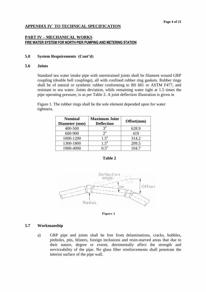
5.6 Joints
Standard sea water intake pipe with unrestrained joints shall be filament wound GRP
coupling (double bell couplings), all with confined rubber ring gaskets. Rubber rings
shall be of natural or synthetic rubber conforming to BS 681 or ASTM F477, and
resistant to sea water. Joints deviation, while remaining water tight at 1.5 times the
pipe operating pressure, is as per Table 2. A joint deflection illustration is given in
Figure 1. The rubber rings shall be the sole element depended upon for water
tightness.
Nominal
Diameter (mm)
Maximum Joint
Deflection Offset(mm)
400-500 3o 628.9
600-900 2o 419
1000-1200 1.5o 314.2
1300-1800 1.5o 209.5
1900-4000 0.5o 104.7
Table 2
5.7 Workmanship
a) GRP pipe and joints shall be free from delaminations, cracks, bubbles,
pinholes, pits, blisters, foreign inclusions and resin-starved areas that due to
their nature, degree or extent, detrimentally affect the strength and
serviceability of the pipe. No glass fiber reinforcements shall penetrate the
interior surface of the pipe wall.
Page 5 of 21
APPENDIX IV` TO TECHNICAL SPECIFICATION
PART IV – MECHANICAL WORKS
FIRE WATER SYSTEM FOR NORTH PIER PUMPING AND METERING STATION
5.0 System Requirements (Cont’d)
5.7 Workmanship (Cont’d)
b) Joint sealing surfaces shall be free of dents, gouges, delaminations, or other
surface irregularities that will affect the integrity of the joints.
c) GRP pipe shall be as uniform as commercially practicable in color, opacity,
density and other physical properties.
5.8 Fittings
a) GRP fittings such as bends, tees, junctions and reducers shall be equal or
superior in performance to the pipe of the same diameter and pressure. All
fittings shall be finished smoothly internally.
b) Large diameter fittings (Diameter greater than 400 mm) are of mitered
construction.
c) For gravity applications no thrust blocks are required at direction changes.
d) For the fittings, the deviation from the stated value of the angle of change of
direction of a bend, tee, junction etc. shall not exceed ± 1º.
e) The tolerance on declared length of fitting, shall be ± 10 mm taken from the
point of intersection to the end of the fitting or ± 10 mm on a straight fitting.
f) All fittings should be manufactured by the GRP pipe manufacturer.
6.0 Design Parameters
GRP pipes shall meet the following minimum design requirements:
6.1 Operating Pressure (Pw) As specified ; Min. 100 kPa
6.2 Additional Surge Pressure (Ps) 40% unless otherwise specified
6.3 Minimum earth cover for 1.0 m
buried pipe.
6.4 Initial Installed deflection 1.5 % Max. for ribbed pipe
for buried pipe
Page 6 of 21
APPENDIX IV` TO TECHNICAL SPECIFICATION
PART IV – MECHANICAL WORKS
FIRE WATER SYSTEM FOR NORTH PIER PUMPING AND METERING STATION
6.0 Design Parameters (Cont’d)
6.5 Long term installed deflection 3.0 % Max. for restrained pipe
for buried pipe 5.0% Max. for non-restrained pipe
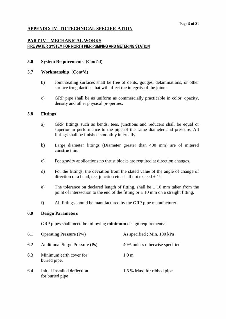
7.0 Quality Control
Quality control testing will include through checks for both pipe and fittings. The
following physical and dimension checks will be made:
Type of Test Each Pipe Once per shift Standard
Reference
Wall thickness x FPI
Visual inspection outside x FPI
Diameter spigot end x FPI
Length x FPI
Stiffness x ASTM D 2412
Barcol Hardness x ASTM D 2583
Loss on Ignition (LOI) x ASTM D 2584
Axial Tensile Strength x ASTM D 638
Table 3
Records of all testing on pipe sections will be maintained in house
8.0 Physical / Mechanical Properties
8.1 Dimensions
Laying Length (IL)
Standard length Random lengths
may be supplied not exceeding
10% of the order
12 – 18 m ± 25 mm
Roundness Deviation Pipe shall be round ±2 mm from nominal
diameter
End Squareness End shall be both square to the
axis of pipe and plane
±2 mm from nominal
diameter
8.2 Stiffness
Minimum specific stiffness shall not be less than 2500 N/m².
Page 7 of 21
APPENDIX IV` TO TECHNICAL SPECIFICATION
PART IV – MECHANICAL WORKS
FIRE WATER SYSTEM FOR NORTH PIER PUMPING AND METERING STATION
8.0 Physical / Mechanical Properties (Cont’d)
8.3 Thermal Expansion
The approximate axial coefficient of thermal expansion shall be 18 - 27 x 10-6 cm/cm
x ºC (measured according to ASTM D 696).
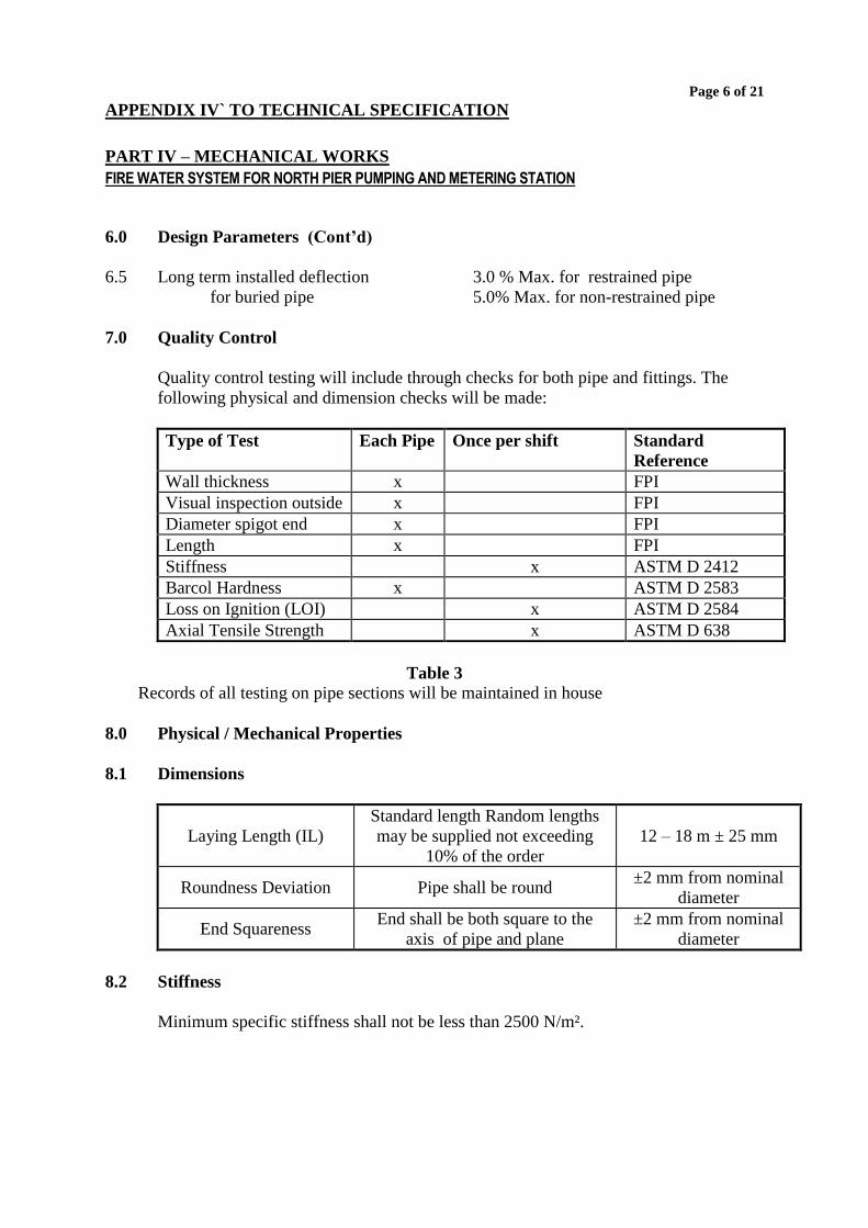
8.4 Burial Depth
The maximum burial depth per stiffness class shall be as follows:
Burial Depth
m
Stiffness
N/m2
Type of
Backfill
up to 3.0 m 2500 Sand/Gravel
up to 8.0 m 5000 Sand/Gravel
up to 10.0 m 10000 Sand/Gravel
Table 5
Note: All pipes passing Intake Structures and Outfall Structures shall be 10,000
N/m2.
8.5 Poisson’s Ratio
Poisson’s ratio’s due to hoop load 0.3
Poisson’s ratio’s due to longitudinal load 0.25
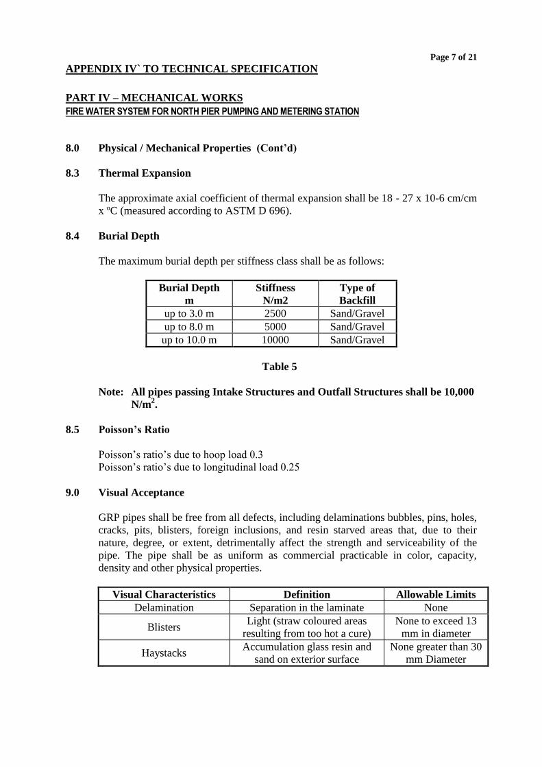
9.0 Visual Acceptance
GRP pipes shall be free from all defects, including delaminations bubbles, pins, holes,
cracks, pits, blisters, foreign inclusions, and resin starved areas that, due to their
nature, degree, or extent, detrimentally affect the strength and serviceability of the
pipe. The pipe shall be as uniform as commercial practicable in color, capacity,
density and other physical properties.
Visual Characteristics Definition Allowable Limits
Delamination Separation in the laminate None
Blisters Light (straw coloured areas
resulting from too hot a cure)
None to exceed 13
mm in diameter
Haystacks Accumulation glass resin and
sand on exterior surface
None greater than 30
mm Diameter
Page 8 of 21
APPENDIX IV` TO TECHNICAL SPECIFICATION
PART IV – MECHANICAL WORKS
FIRE WATER SYSTEM FOR NORTH PIER PUMPING AND METERING STATION
9.0 Visual Acceptance (Cont’d)
Visual Characteristics Definition Allowable Limits
Torn Edges End
Delaminations and End
Gouges
Tears and rips the edges of cuts
None which will
affect the integrity of
the joints
Ground Area
Area around lay-up which has
been abraded but lay-up doesn’t
cover or has not been coated
with resin
Not Permitted
Table 6
10.0 On-shore Buoyancy Considerations
Where the pipe is to be installed on-shore within water table level, proper
considerations have to be taken to prevent pipe flotation. In general, a minimum soil
cover equal to one pipe diameter should be kept above the pipe crown to prevent
flotation.
11.0 Highlights of joining GRP pipes for Onshore Operations
11.1 Clean Coupling:
Thoroughly clean the grooves inside the Double Bell Coupler and the Gasket Rings,
to avoid any dirt or oil present.
11.2 Install Gaskets:
Insert the gasket in to the grooves, leaving two to four uniform loops of rubber to
extend out of the groove. With uniform pressure push each gasket in to the gasket
groove. Tapping with a rubber hammer will be helpful in this mission.
11.3 Lubricate the gaskets
Using a clean cloth apply a thin layer of lubricant to the gaskets.
11.4 Clean and Lubricate the spigots:
Clean the Pipe spigot and apply a thin film of lubricant.
Page 9 of 21
APPENDIX IV` TO TECHNICAL SPECIFICATION
PART IV – MECHANICAL WORKS
FIRE WATER SYSTEM FOR NORTH PIER PUMPING AND METERING STATION
11.0 Highlights of joining GRP pipes for Onshore Operations (Cont’d)
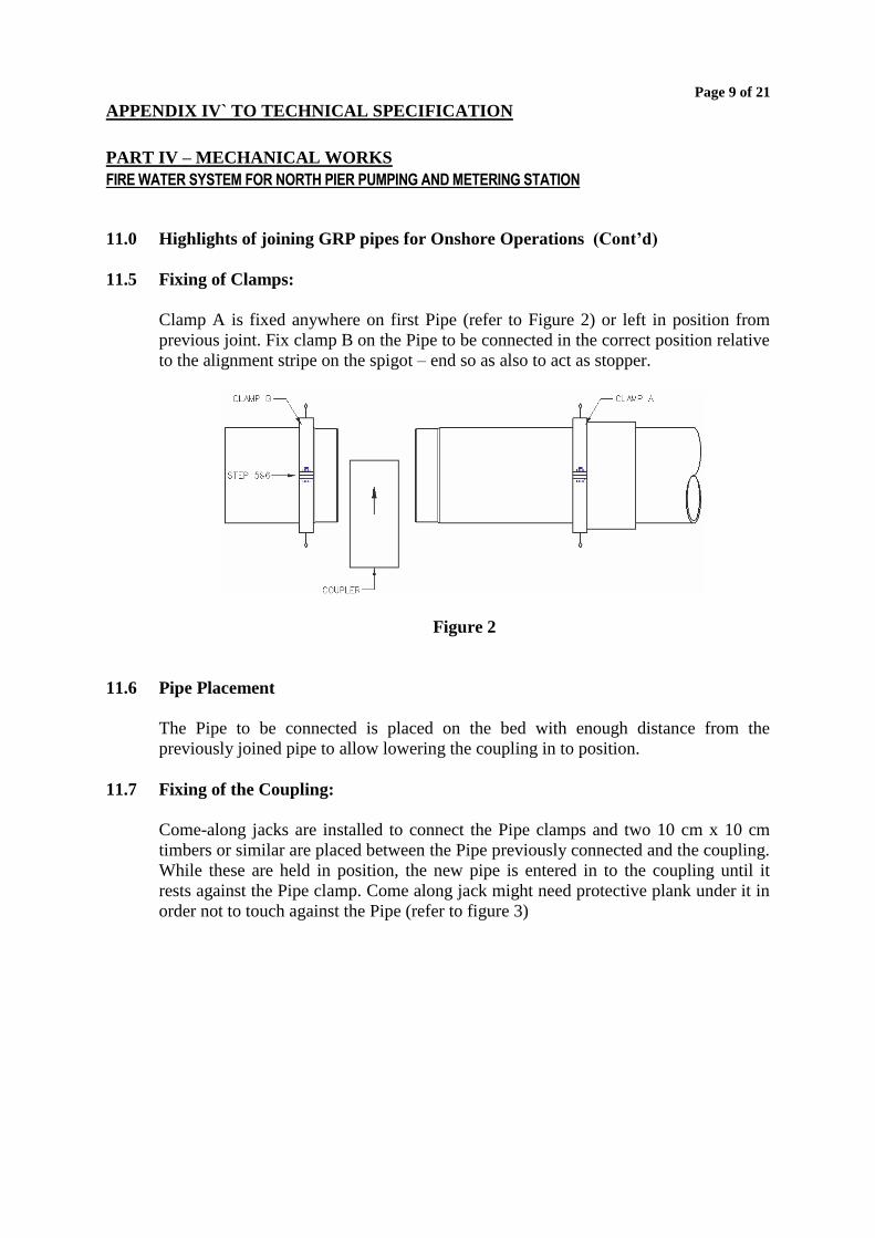
11.5 Fixing of Clamps:
Clamp A is fixed anywhere on first Pipe (refer to Figure 2) or left in position from
previous joint. Fix clamp B on the Pipe to be connected in the correct position relative
to the alignment stripe on the spigot – end so as also to act as stopper.
Figure 2
11.6 Pipe Placement
The Pipe to be connected is placed on the bed with enough distance from the
previously joined pipe to allow lowering the coupling in to position.
11.7 Fixing of the Coupling:
Come-along jacks are installed to connect the Pipe clamps and two 10 cm x 10 cm
timbers or similar are placed between the Pipe previously connected and the coupling.
While these are held in position, the new pipe is entered in to the coupling until it
rests against the Pipe clamp. Come along jack might need protective plank under it in
order not to touch against the Pipe (refer to figure 3)
Page 10 of 21
APPENDIX IV` TO TECHNICAL SPECIFICATION
PART IV – MECHANICAL WORKS
FIRE WATER SYSTEM FOR NORTH PIER PUMPING AND METERING STATION
11.0 Highlights of joining GRP pipes for Onshore Operations (Cont’d)
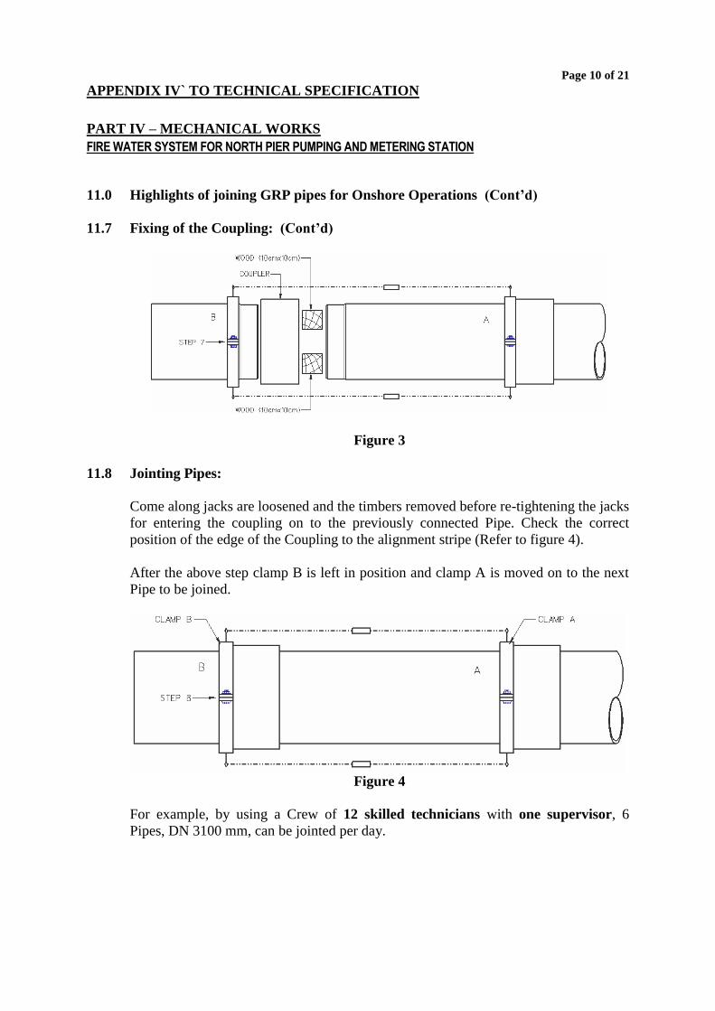
11.7 Fixing of the Coupling: (Cont’d)
Figure 3
11.8 Jointing Pipes:
Come along jacks are loosened and the timbers removed before re-tightening the jacks
for entering the coupling on to the previously connected Pipe. Check the correct
position of the edge of the Coupling to the alignment stripe (Refer to figure 4).
After the above step clamp B is left in position and clamp A is moved on to the next
Pipe to be joined.
Figure 4
For example, by using a Crew of 12 skilled technicians with one supervisor, 6
Pipes, DN 3100 mm, can be jointed per day.
Page 11 of 21
APPENDIX IV` TO TECHNICAL SPECIFICATION
PART IV – MECHANICAL WORKS
FIRE WATER SYSTEM FOR NORTH PIER PUMPING AND METERING STATION
12.0 Off-shore Installation of GRP Seawater Intake Pipes
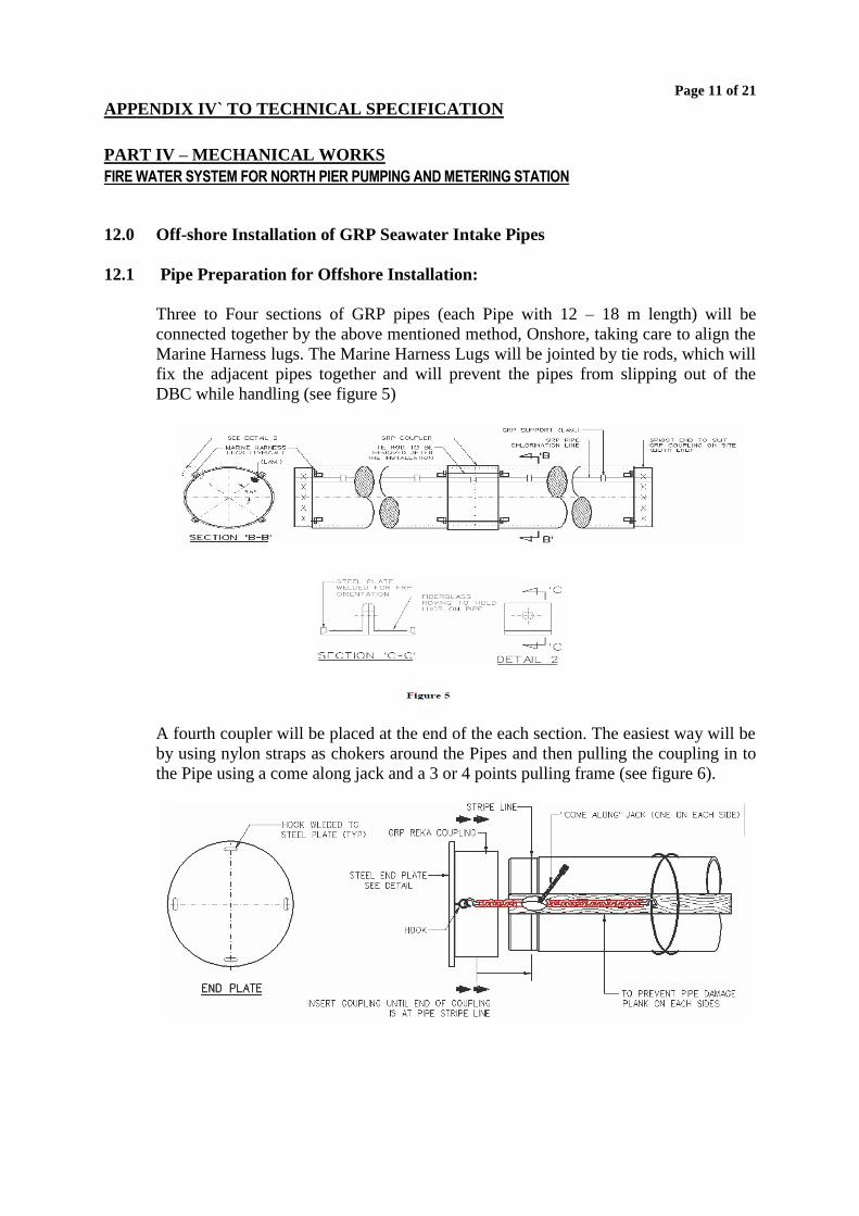
12.1 Pipe Preparation for Offshore Installation:
Three to Four sections of GRP pipes (each Pipe with 12 – 18 m length) will be
connected together by the above mentioned method, Onshore, taking care to align the
Marine Harness lugs. The Marine Harness Lugs will be jointed by tie rods, which will
fix the adjacent pipes together and will prevent the pipes from slipping out of the
DBC while handling (see figure 5)
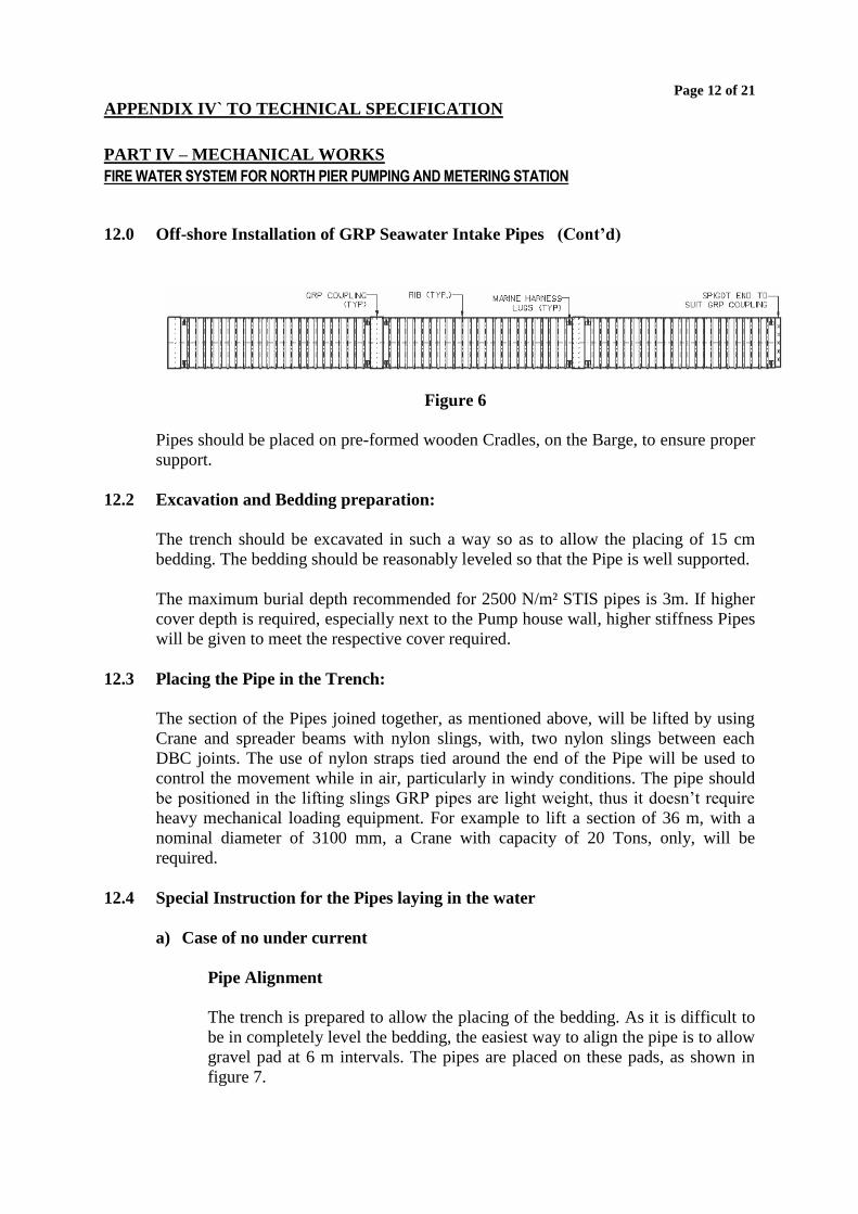
A fourth coupler will be placed at the end of the each section. The easiest way will be
by using nylon straps as chokers around the Pipes and then pulling the coupling in to
the Pipe using a come along jack and a 3 or 4 points pulling frame (see figure 6).
Page 12 of 21
APPENDIX IV` TO TECHNICAL SPECIFICATION
PART IV – MECHANICAL WORKS
FIRE WATER SYSTEM FOR NORTH PIER PUMPING AND METERING STATION
12.0 Off-shore Installation of GRP Seawater Intake Pipes (Cont’d)
Figure 6
Pipes should be placed on pre-formed wooden Cradles, on the Barge, to ensure proper
support.
12.2 Excavation and Bedding preparation:
The trench should be excavated in such a way so as to allow the placing of 15 cm
bedding. The bedding should be reasonably leveled so that the Pipe is well supported.
The maximum burial depth recommended for 2500 N/m² STIS pipes is 3m. If higher
cover depth is required, especially next to the Pump house wall, higher stiffness Pipes
will be given to meet the respective cover required.
12.3 Placing the Pipe in the Trench:
The section of the Pipes joined together, as mentioned above, will be lifted by using
Crane and spreader beams with nylon slings, with, two nylon slings between each
DBC joints. The use of nylon straps tied around the end of the Pipe will be used to
control the movement while in air, particularly in windy conditions. The pipe should
be positioned in the lifting slings GRP pipes are light weight, thus it doesn’t require
heavy mechanical loading equipment. For example to lift a section of 36 m, with a
nominal diameter of 3100 mm, a Crane with capacity of 20 Tons, only, will be
required.
12.4 Special Instruction for the Pipes laying in the water
a) Case of no under current
Pipe Alignment
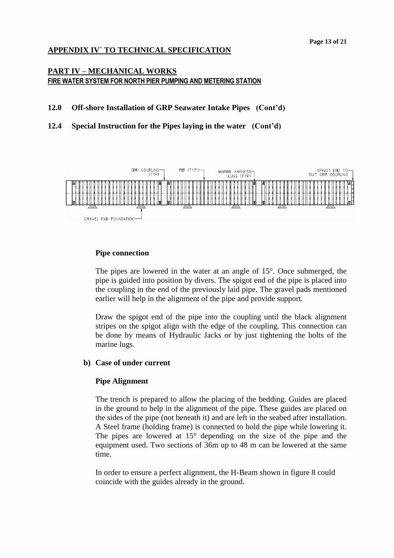
The trench is prepared to allow the placing of the bedding. As it is difficult to
be in completely level the bedding, the easiest way to align the pipe is to allow
gravel pad at 6 m intervals. The pipes are placed on these pads, as shown in
figure 7.
Page 13 of 21
APPENDIX IV` TO TECHNICAL SPECIFICATION
PART IV – MECHANICAL WORKS
FIRE WATER SYSTEM FOR NORTH PIER PUMPING AND METERING STATION
12.0 Off-shore Installation of GRP Seawater Intake Pipes (Cont’d)
12.4 Special Instruction for the Pipes laying in the water (Cont’d)
Pipe connection
The pipes are lowered in the water at an angle of 15°. Once submerged, the
pipe is guided into position by divers. The spigot end of the pipe is placed into
the coupling in the end of the previously laid pipe. The gravel pads mentioned
earlier will help in the alignment of the pipe and provide support.
Draw the spigot end of the pipe into the coupling until the black alignment
stripes on the spigot align with the edge of the coupling. This connection can
be done by means of Hydraulic Jacks or by just tightening the bolts of the
marine lugs.
b) Case of under current
Pipe Alignment
The trench is prepared to allow the placing of the bedding. Guides are placed
in the ground to help in the alignment of the pipe. These guides are placed on
the sides of the pipe (not beneath it) and are left in the seabed after installation.
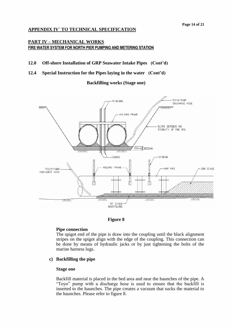
A Steel frame (holding frame) is connected to hold the pipe while lowering it.
The pipes are lowered at 15° depending on the size of the pipe and the
equipment used. Two sections of 36m up to 48 m can be lowered at the same
time.
In order to ensure a perfect alignment, the H-Beam shown in figure 8 could
coincide with the guides already in the ground.
Page 14 of 21
APPENDIX IV` TO TECHNICAL SPECIFICATION
PART IV – MECHANICAL WORKS
FIRE WATER SYSTEM FOR NORTH PIER PUMPING AND METERING STATION
12.0 Off-shore Installation of GRP Seawater Intake Pipes (Cont’d) 12.4 Special Instruction for the Pipes laying in the water (Cont’d)
Backfilling works (Stage one)
Figure 8
Pipe connection The spigot end of the pipe is draw into the coupling until the black alignment stripes on the spigot align with the edge of the coupling. This connection can be done by means of hydraulic jacks or by just tightening the bolts of the marine harness lugs.
c) Backfilling the pipe
Stage one Backfill material is placed in the bed area and near the haunches of the pipe. A “Toyo” pump with a discharge hose is used to ensure that the backfill is inserted to the haunches. The pipe creates a vacuum that sucks the material to the haunches. Please refer to figure 8.
Page 15 of 21
APPENDIX IV` TO TECHNICAL SPECIFICATION
PART IV – MECHANICAL WORKS
FIRE WATER SYSTEM FOR NORTH PIER PUMPING AND METERING STATION
12.0 Off-shore Installation of GRP Seawater Intake Pipes (Cont’d) 12.4 Special Instruction for the Pipes laying in the water (Cont’d)
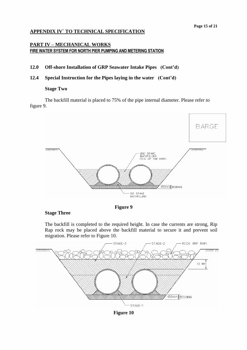
Stage Two
The backfill material is placed to 75% of the pipe internal diameter. Please refer to
figure 9.
Figure 9
Stage Three
The backfill is completed to the required height. In case the currents are strong, Rip
Rap rock may be placed above the backfill material to secure it and prevent soil
migration. Please refer to Figure 10.
Figure 10
Page 16 of 21
APPENDIX IV` TO TECHNICAL SPECIFICATION
PART IV – MECHANICAL WORKS
FIRE WATER SYSTEM FOR NORTH PIER PUMPING AND METERING STATION
12.0 Off-shore Installation of GRP Seawater Intake Pipes (Cont’d)
Note: Before jointing a new pipe section, the previous one should be partially
backfilled (stage 2) in order to allow no deviation in the alignment.
GRP pipes for offshore application are easy to install. For example, a crew of 8 divers
are required to handle pipe sections with a nominal diameter of 3100 mm, under the
water. The crew can perform the installation of 72 m, of the same pipes, per day.
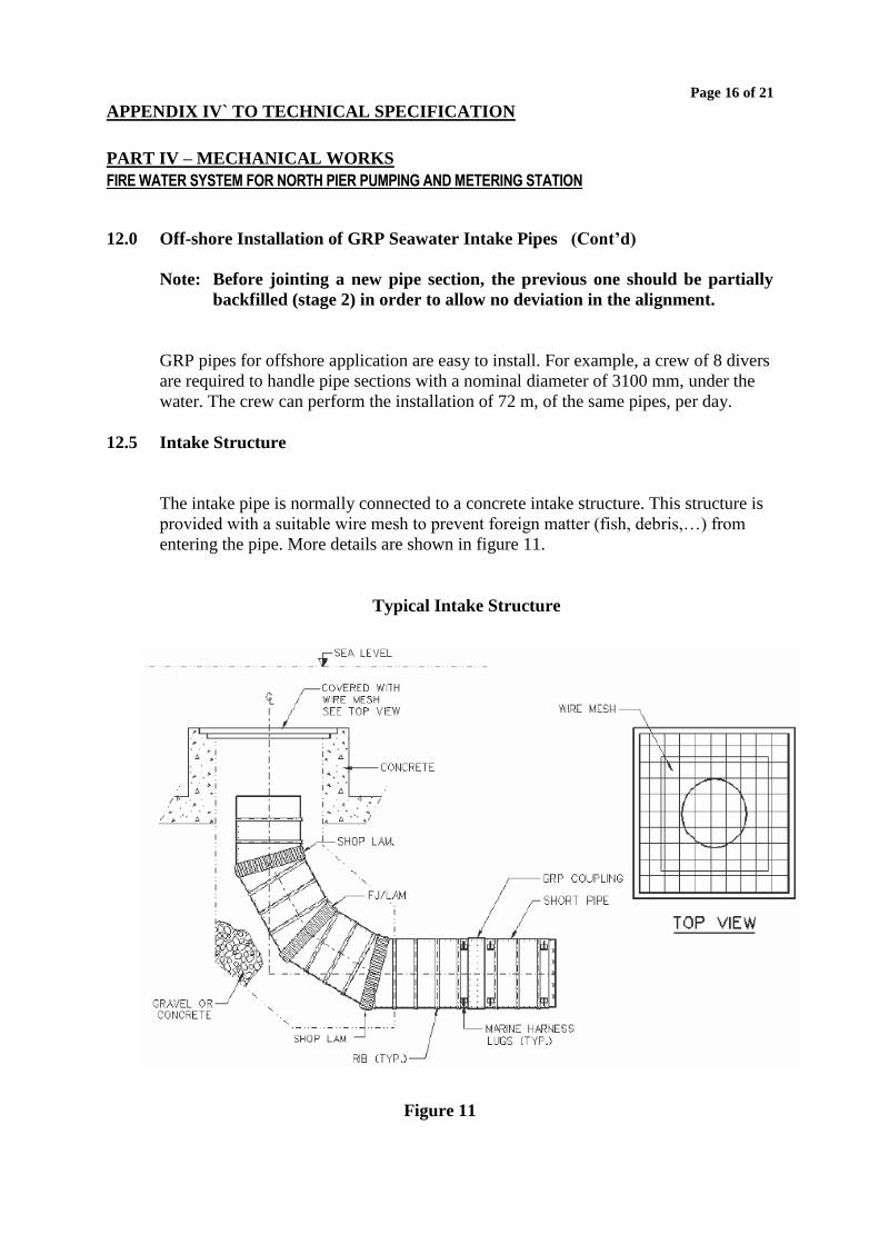
12.5 Intake Structure
The intake pipe is normally connected to a concrete intake structure. This structure is
provided with a suitable wire mesh to prevent foreign matter (fish, debris,…) from
entering the pipe. More details are shown in figure 11.
Typical Intake Structure
Figure 11
Page 17 of 21
APPENDIX IV` TO TECHNICAL SPECIFICATION
PART IV – MECHANICAL WORKS
FIRE WATER SYSTEM FOR NORTH PIER PUMPING AND METERING STATION
12.0 Off-shore Installation of GRP Seawater Intake Pipes (Cont’d)
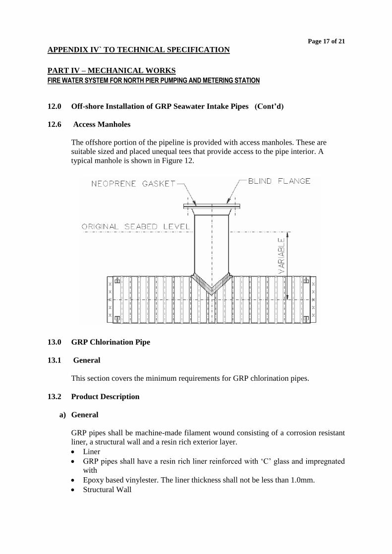
12.6 Access Manholes
The offshore portion of the pipeline is provided with access manholes. These are
suitable sized and placed unequal tees that provide access to the pipe interior. A
typical manhole is shown in Figure 12.
13.0 GRP Chlorination Pipe
13.1 General
This section covers the minimum requirements for GRP chlorination pipes.
13.2 Product Description
a) General
GRP pipes shall be machine-made filament wound consisting of a corrosion resistant
liner, a structural wall and a resin rich exterior layer.
Liner
GRP pipes shall have a resin rich liner reinforced with ‘C’ glass and impregnated
with
Epoxy based vinylester. The liner thickness shall not be less than 1.0mm.
Structural Wall
Page 18 of 21
APPENDIX IV` TO TECHNICAL SPECIFICATION
PART IV – MECHANICAL WORKS
FIRE WATER SYSTEM FOR NORTH PIER PUMPING AND METERING STATION
13.0 GRP Chlorination Pipe (Cont’d)
13.2 Product Description (Cont’d)
The pipe structural wall shall be as specified in AWWA C 950 for Grades 1
through 4.
Epoxy-based Vinyester resin should be used in the structural wall of the
chlorination line.
External Layer
Pipe shall have a 0.25 mm thick resin rich exterior surface impregnated with resin.
b) Materials
Glass reinforcements shall have a finish compatible with the impregnating resin
used.
Resins shall be a commercial high-grade thermosetting type as specified above.
No pigments shall be used in the GRP pipe or joints. No additives shall be used
except for viscosity control.
13.3 Requirements
a) Wall Thickness
The wall thickness required for each size/pressure class shall be established to
meet the design requirements but in no case shall the wall thickness be less
than 3.5 mm. The pipe working pressure class shall be based on the
Hydrostatic Design Basis (HDB) of the pipe with a design (service) factor of
0.5.
b) Length
The pipe shall be manufactured in standard laying lengths of not greater than
12 meters depending on diameter. Random short lengths: if supplied shall not
exceed 5% of the quantity supplied for each size. The tolerance on the
Manufacturers declared laying length shall not exceed ± 25mm.
c) Stiffness
The pipe stiffness shall be in no case be less than 5000 N/m2, when tested in
accordance with AWWA C950 or BS 5480.
Page 19 of 21
APPENDIX IV` TO TECHNICAL SPECIFICATION
PART IV – MECHANICAL WORKS
FIRE WATER SYSTEM FOR NORTH PIER PUMPING AND METERING STATION
13.0 GRP Chlorination Pipe (Cont’d)
d) Beam Strength
The offered pipes shall meet the minimum longitudinal tensile strength requirements
specified in AWWA C950 for the appropriate Pipe pressure class.
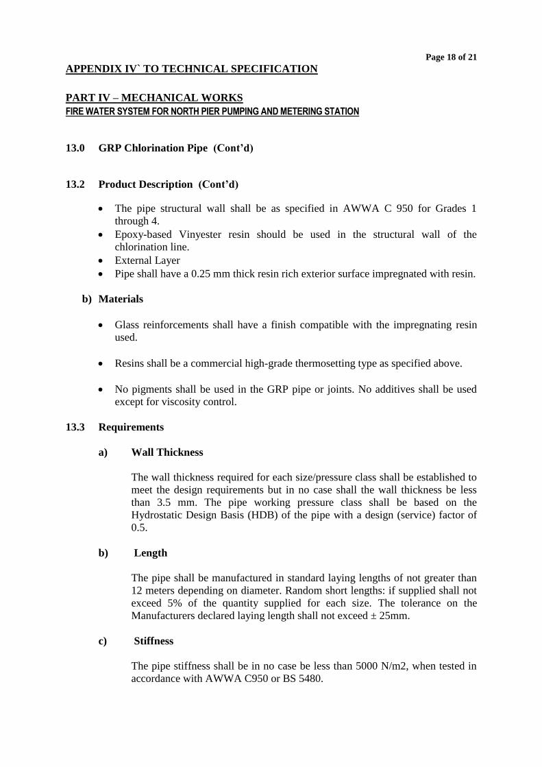
13.4 Joints
a) Flexible Joints
GRP pipes, used for chlorination, shall be joined with a restrained rubber seal lock
joint. The rubber ensures the sealing while the fixation rods secure the restrain. The
joints have to be stretched during installation.
Figure 13
b) Rigid Joints
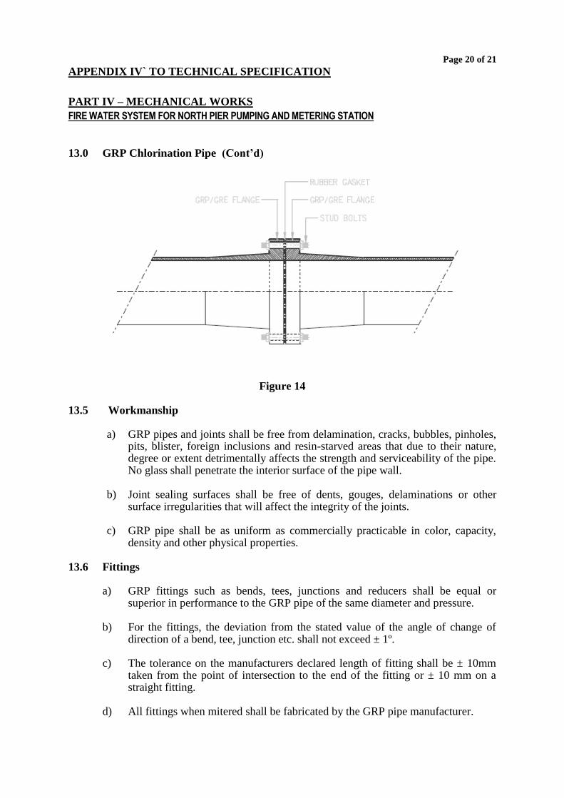
Flanges
GRP flanges are filament wound and drilled to standard ANSI B16.5 (150 lb Flanges)
dimensions depending upon pipe size. These flanges are designed to be used in pipe
systems, which incorporate thrust blocks. GRP flanges can be drilled to other
standards (DIN, ISO, BS etc...)
Page 20 of 21
APPENDIX IV` TO TECHNICAL SPECIFICATION
PART IV – MECHANICAL WORKS
FIRE WATER SYSTEM FOR NORTH PIER PUMPING AND METERING STATION
13.0 GRP Chlorination Pipe (Cont’d)
Figure 14
13.5 Workmanship
a) GRP pipes and joints shall be free from delamination, cracks, bubbles, pinholes,
pits, blister, foreign inclusions and resin-starved areas that due to their nature, degree or extent detrimentally affects the strength and serviceability of the pipe. No glass shall penetrate the interior surface of the pipe wall.
b) Joint sealing surfaces shall be free of dents, gouges, delaminations or other
surface irregularities that will affect the integrity of the joints.
c) GRP pipe shall be as uniform as commercially practicable in color, capacity, density and other physical properties.
13.6 Fittings
a) GRP fittings such as bends, tees, junctions and reducers shall be equal or
superior in performance to the GRP pipe of the same diameter and pressure. b) For the fittings, the deviation from the stated value of the angle of change of
direction of a bend, tee, junction etc. shall not exceed ± 1º. c) The tolerance on the manufacturers declared length of fitting shall be ± 10mm
taken from the point of intersection to the end of the fitting or ± 10 mm on a straight fitting.
d) All fittings when mitered shall be fabricated by the GRP pipe manufacturer.
Page 21 of 21
APPENDIX IV` TO TECHNICAL SPECIFICATION
PART IV – MECHANICAL WORKS
FIRE WATER SYSTEM FOR NORTH PIER PUMPING AND METERING STATION
13.0 GRP Chlorination Pipe (Cont’d)
13.7 Fixation
The chlorination pipe shall be fixed in the intake pipeline on cradles with Fiberglass
bolts. The cradles shall be fixed at 120º from vertical position.
13.8 Maintenance Requirements
For flushing the line a double flange piece is supplied at the manhole location. This
will allow to dismantling this part to flush the line for any residual flakes.