installation manual - us shift · throttle position sensor kit for edelbrock carburetors (tps kit...
TRANSCRIPT

Throttle Position Sensor Kit for Edelbrock Carburetors
(TPS KIT 3)
Installation Manual

US Shift Throttle Position Sensor Kit
for Edelbrock Carburetors
www.USshift.com
Baumann Electronic Controls, LLC.
Phone: (864) 646-8920
Email: [email protected]
Address: 207 Mistr Lane, Pickens, SC 29671
This work and the ideas and processes contained herein are the exclusive property
of Baumann Electronic Controls, LLC and may not be copied, reproduced, or
distributed in any form without the express written consent of Baumann Electronic
Controls, LLC or Karl Baumann. The technology and processes contained in this
product are proprietary and may be used only on a single unit basis or as defined by
the written permission of Baumann Electronic Controls, LLC.
V1.5 © Copyright 1997 - 2018 by Baumann Electronic Controls, LLC.
All rights reserved. Tools Needed
T-25 Torx Driver or 5/16” Flat Head Screwdriver (depending on your model carburetor) Long-nose pliers

Step 1 Unscrew the 2 bolts shown in the pictures below. These will either be T-25 Torx bolts or 5/16” flat head screws, depending on which model carburetor you have.
Step 2
Place the US Shift sensor bracket over the holes and screw it into place using the same bolts you removed.
Step 3
Hold the choke closed while simultaneously opening the throttle wide. This will provide clearance in the throttle linkage to allow the installation of the clevis pin. If there is no choke, you will need to hold the secondary throttle shut while holding the main throttle open. DO NOT remove the hex screw at the end of the throttle linkage.
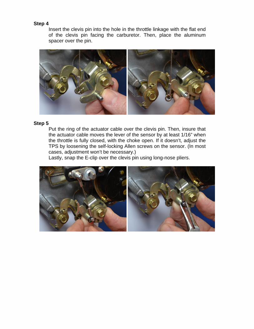
Step 4
Insert the clevis pin into the hole in the throttle linkage with the flat end of the clevis pin facing the carburetor. Then, place the aluminum spacer over the pin.
Step 5
Put the ring of the actuator cable over the clevis pin. Then, insure that the actuator cable moves the lever of the sensor by at least 1/16” when the throttle is fully closed, with the choke open. If it doesn’t, adjust the TPS by loosening the self-locking Allen screws on the sensor. (In most cases, adjustment won’t be necessary.) Lastly, snap the E-clip over the clevis pin using long-nose pliers.

Step 6 Plug the connector from the throttle position sensor into the included wiring harness.
Sensor Wire Colors
TPS Wiring Harness Colors
US Shift Vehicle Harness Pin #
Function
Yellow (Pin A) Black 16 Ground Red (Pin B) Green 3 Sensor Signal Green (Pin C) Orange 11 +5v Power Supply Step 7
Connect the wiring harness to the transmission controller or data logger. For US Shift controllers, the wiring color codes of the TPS harness will match those in the vehicle harness. For other applications, verify the function of each wire and insure that 5 volts DC is available for the sensor.

Step 8 (For US Shift Controllers with firmware v5.6 and up) Now you will need to set the throttle position. To do this, use the throttle position calibration option on the built-in tuning interface. When navigating the built-in tuning interface, use the knob to move through menu items and click to choose them. If you wait on an item, the long-form name will scroll across the screen.
To calibrate throttle position, the ignition should be on but the engine not running. Make sure the choke is fully open and off the fast idle cam before beginning. Turn the knob to “SET” (Set Up System) and click to enter the setup menu. “TPS” (Calibrate TPS) will be shown and you can click the knob again to enter calibration mode. It will begin detecting the idle throttle position right away, so leave the pedal untouched.
When the display scrolls “PRESS ACCEL PEDAL”, push the accelerator pedal all the way to the floor and hold it. After a few seconds, “RELEASE ACCL. PEDAL” will scroll on the screen and you can release the pedal. “TPS SUCCESSFUL” will scroll if the setting completed. Afterward, it will show the measured closed and full throttle voltages. If an error occurs during calibration, the display will show the error and abort calibration. If this happens, you can try running the calibration again. If errors continue, you may need to check your wiring for problems. Once the TPS calibration procedure is completed, the values are permanently stored in the controller and will be active for every tune written. TPS values displayed within individual tunes are then irrelevant. If you require TPS customization for individual tunes or are using a negative slope TPS, then the TPS values stored in the controller can be reset by double-clicking the knob while in TPS calibrate mode, causing the "TPS reset" message to be displayed. Our provided tuning software can then be used to calibrate TPS values for specific tunes.
Possible TPS Calibration Errors as shown on the built-in display:
ACCEL PEDAL NOT PRESSD / ACCEL PEDAL NOT HELD The throttle wasn’t pushed or held at maximum long enough for the test to complete. Accelerator pedal must be held for 3 seconds and voltage must not drop more than 0.168V below the maximum recorded value. ACCEL PEDAL NOT RELEASED The throttle wasn’t released within 5 seconds. The voltage must drop at least 0.96V below the maximum measured WOT value. TPS NOT STABLE The idle throttle position has changed values too drastically over the course of the calibration. The idle voltage is more than 0.6V greater than the lowest recorded value. ERROR TPS LO = 0.00 The voltage is below the minimum allowed 0.2V during any of the tests.

Step 8 (For US Shift Controllers with firmware before v5.6) Set the Closed Throttle and Full Throttle Positions. This step should be done with the ignition turned to “ON”, but the engine off. The engine should also be warm. Turn the knob to “Tune” (tnE) and click once. “Closed Throttle Position” (CtP) should be displayed. Leave the accelerator untouched. Click the knob once, then double-click to set the current Closed Throttle Position. Click again to exit.
Turn the knob to “Full Throttle Position” (FtP). Hold the accelerator all the way down. Click the knob once, then double-click to set the current Full Throttle Position. Click again to exit. Turn the knob to “Save and Exit” (SAE). Click once to save and exit.