installation manual corporation noritz...
TRANSCRIPT
Potential dangers from accidents during installation and use are divided into the following threecategories. Closely observe these warnings, they are critical to your safety.
ProhibitedDisconnectPower
Ground Be sure to do
WARNING: If the information in this manual is not followed exactly, a fire or explosion may resultcausing property damage, personal injury or death.
NORITZ AMERICACORPORATIONInstallation Manual
TANKLESS GAS WATER HEATERNR98-DVC (Indoor Installation)
DANGER indicates an imminently hazardous situation which,if not avoided, will result in death or serious injury.
WARNING indicates a potentially hazardous situation which,if not avoided, could result in death or serious injury.
CAUTION indicates a potentially hazardous situation which,if not avoided, may result in minor or moderate injury.
DANGERWARNINGCAUTION
SBA8350Rev. 09/09
Requests to Installers• In order to use the water heater safely, read this installation manual carefully, and follow the
installation instructions.• Failures and damage caused by erroneous work or work not as instructed in this manual are not
covered by the warranty.• Check that the installation was done properly in accordance with this Installation Manual upon
completion.• After completing installation, please either place this Installation Manual in a plastic pouch and
attach it to the side of the water heater (or the inside of the pipe cover or recess box if applicable),or hand it to the customer to retain for future reference. Also, be sure to fill in all of the requireditems on the warranty and to hand the warranty to the customer along with the Owner's Guide.
CAUTION
FOR USE IN RESIDENTIAL, COMMERCIAL, OR MANUFAC-TURED HOME APPLICATIONS.Installation must conform with local codes, or in the absence oflocal codes, the National Fuel Gas Code, ANSI Z223.1/NFPA 54-latest edition and/or CSA B149.1, Natural Gas and Propane In-stallation Code (NSCNGPIC).When applicable, installation must conform with the Manufac-tured Home Construction and Safety Standard, Title 24 CFR, Part3280 or the Canadian Standard CAN/CSA-Z240 MH MobileHomes, Series M86.Noritz America reserves the right to discontinue, or change at anytime, the designs and/or specifications of its products without notice.
CERTIFIEDR
Low NOxApproved by
SCAQMD
Accepted For UseCity of New York
Department of BuildingsMEA 19-03-E
*SBA8350*
2
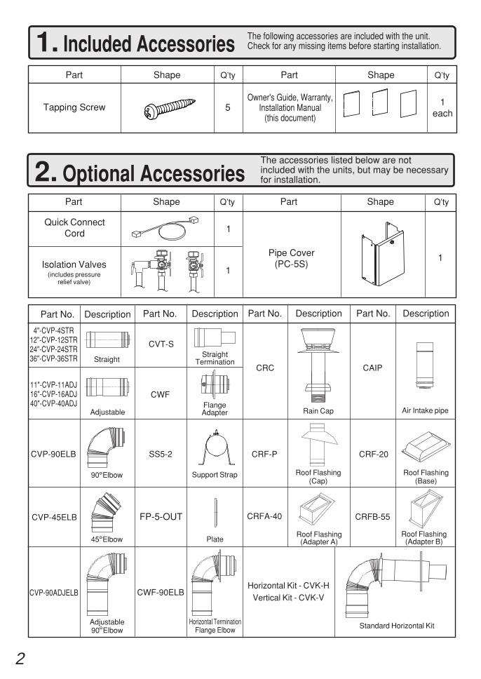
1. Included Accessories The following accessories are included with the unit.Check for any missing items before starting installation.
Q’tyShapePart
Tapping Screw 1each
Part Shape Q’ty
5
2. Optional AccessoriesThe accessories listed below are notincluded with the units, but may be necessaryfor installation.
Q’tyShapePartPart Shape Q’ty
1
Quick ConnectCord 1
1Isolation Valves
(includes pressurerelief valve)
Pipe Cover(PC-5S)
Owner's Guide, Warranty,Installation Manual
(this document)
Part No. Description
4"-CVP-4STR12"-CVP-12STR24"-CVP-24STR36"-CVP-36STR
Adjustable
Part No. Description
CVT-S
FlangeAdapter
Horizontal TerminationFlange Elbow
Part No. Description
CRC CAIP
90 Elbow
Adjustable90 Elbow
Support Strap
CVP-45ELB
CRF-P
Standard Horizontal Kit
FP-5-OUT
CRF-20
Part No. Description
Roof Flashing(Adapter A)
CRFB-55
StraightStraight
Termination
11"-CVP-11ADJ16"-CVP-16ADJ40"-CVP-40ADJ
Rain Cap
CWF
Air Intake pipe
Roof Flashing(Cap)
Roof Flashing(Base)
CVP-90ELB SS5-2
Roof Flashing(Adapter B)
CRFA-40
45 Elbow Plate
CVP-90ADJELB CWF-90ELBHorizontal Kit - CVK-H
Vertical Kit - CVK-V
3
G
Quick Connect Cord
Gas Supply Piping
Cold Water Supply
Hot Water
Remote Controller
*1
Cord Connector
Cord Connector
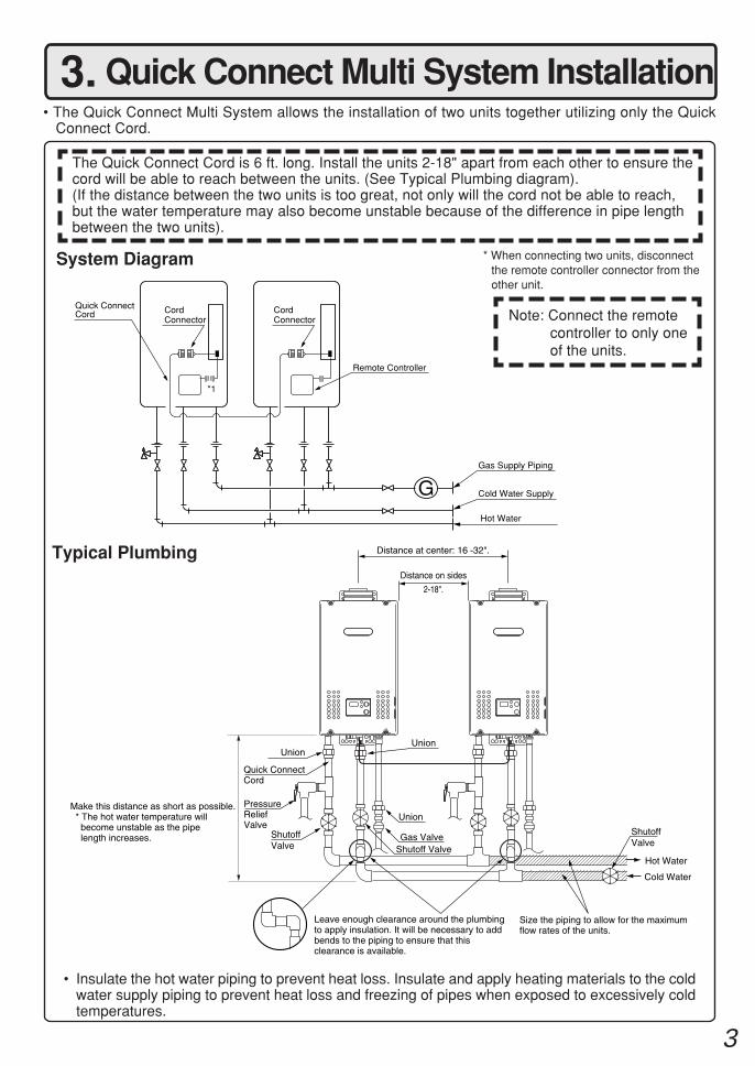
3. Quick Connect Multi System Installation• The Quick Connect Multi System allows the installation of two units together utilizing only the Quick
Connect Cord.
Typical Plumbing
The Quick Connect Cord is 6 ft. long. Install the units 2-18" apart from each other to ensure thecord will be able to reach between the units. (See Typical Plumbing diagram).(If the distance between the two units is too great, not only will the cord not be able to reach,but the water temperature may also become unstable because of the difference in pipe lengthbetween the two units).
* When connecting two units, disconnectthe remote controller connector from theother unit.
Note: Connect the remotecontroller to only oneof the units.
System Diagram
• Insulate the hot water piping to prevent heat loss. Insulate and apply heating materials to the coldwater supply piping to prevent heat loss and freezing of pipes when exposed to excessively coldtemperatures.
Leave enough clearance around the plumbing to apply insulation. It will be necessary to add bends to the piping to ensure that this clearance is available.
Size the piping to allow for the maximum flow rates of the units.
Distance at center: 16 -32".
Union
Hot Water
Shutoff Valve
Cold Water
Distance on sides
2-18".
Make this distance as short as possible. * The hot water temperature will become unstable as the pipe length increases.
Union
Quick ConnectCord
PressureReliefValve
ShutoffValve
Union
Gas ValveShutoff Valve
4
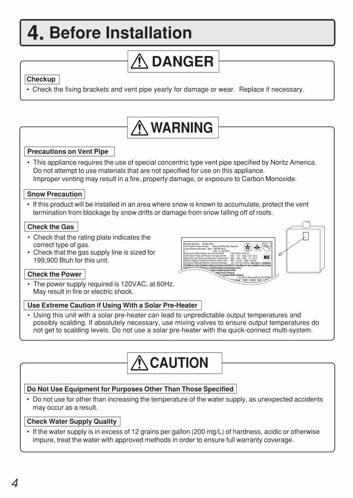
4. Before Installation
Checkup• Check the fixing brackets and vent pipe yearly for damage or wear. Replace if necessary.
DANGER
Do Not Use Equipment for Purposes Other Than Those Specified
• Do not use for other than increasing the temperature of the water supply, as unexpected accidentsmay occur as a result.
Check Water Supply Quality
• If the water supply is in excess of 12 grains per gallon (200 mg/L) of hardness, acidic or otherwiseimpure, treat the water with approved methods in order to ensure full warranty coverage.
WARNING
CAUTION
Check the Gas
• Check that the rating plate indicates thecorrect type of gas.
• Check that the gas supply line is sized for199,900 Btuh for this unit.
Check the Power• The power supply required is 120VAC, at 60Hz.
May result in fire or electric shock.
Use Extreme Caution if Using With a Solar Pre-Heater• Using this unit with a solar pre-heater can lead to unpredictable output temperatures and possibly scalding. If absolutely necessary, use mixing valves to ensure output temperatures do
not get to scalding levels. Do not use a solar pre-heater with the quick-connect multi-system.
Precautions on Vent Pipe
• This appliance requires the use of special concentric type vent pipe specified by Noritz America.Do not attempt to use materials that are not specified for use on this appliance.Improper venting may result in a fire, property damage, or exposure to Carbon Monoxide.
Snow Precaution• If this product will be installed in an area where snow is known to accumulate, protect the vent
termination from blockage by snow drifts or damage from snow falling off of roofs.
199,900
168,000
3.3
3.1" 3.1"
3.3
192,800
162,000
199,900 BTU11,000 BTU
2024.0
0.65 3.1"10.5"
750
10.3a-2007
15 150
4.3a-2007
2
NR98-DVC
5
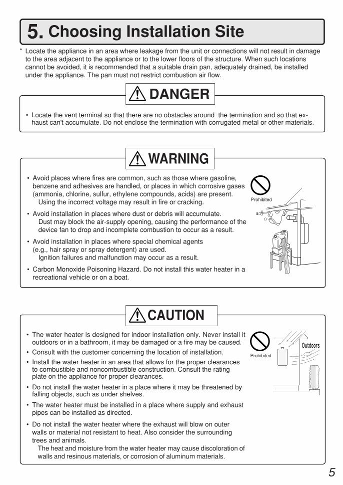
5. Choosing Installation Site* Locate the appliance in an area where leakage from the unit or connections will not result in damage
to the area adjacent to the appliance or to the lower floors of the structure. When such locationscannot be avoided, it is recommended that a suitable drain pan, adequately drained, be installedunder the appliance. The pan must not restrict combustion air flow.
• Locate the vent terminal so that there are no obstacles around the termination and so that ex-haust can't accumulate. Do not enclose the termination with corrugated metal or other materials.
• Avoid places where fires are common, such as those where gasoline,benzene and adhesives are handled, or places in which corrosive gases(ammonia, chlorine, sulfur, ethylene compounds, acids) are present. Using the incorrect voltage may result in fire or cracking.
• Avoid installation in places where dust or debris will accumulate.Dust may block the air-supply opening, causing the performance of thedevice fan to drop and incomplete combustion to occur as a result.
• Avoid installation in places where special chemical agents(e.g., hair spray or spray detergent) are used.
Ignition failures and malfunction may occur as a result.
• Carbon Monoxide Poisoning Hazard. Do not install this water heater in arecreational vehicle or on a boat.
• The water heater is designed for indoor installation only. Never install itoutdoors or in a bathroom, it may be damaged or a fire may be caused.
• Consult with the customer concerning the location of installation.
• Install the water heater in an area that allows for the proper clearancesto combustible and noncombustible construction. Consult the ratingplate on the appliance for proper clearances.
• Do not install the water heater in a place where it may be threatened byfalling objects, such as under shelves.
• The water heater must be installed in a place where supply and exhaustpipes can be installed as directed.
• Do not install the water heater where the exhaust will blow on outerwalls or material not resistant to heat. Also consider the surroundingtrees and animals.
The heat and moisture from the water heater may cause discoloration ofwalls and resinous materials, or corrosion of aluminum materials.
Prohibited
DANGER
WARNING
CAUTION
Prohibited
6
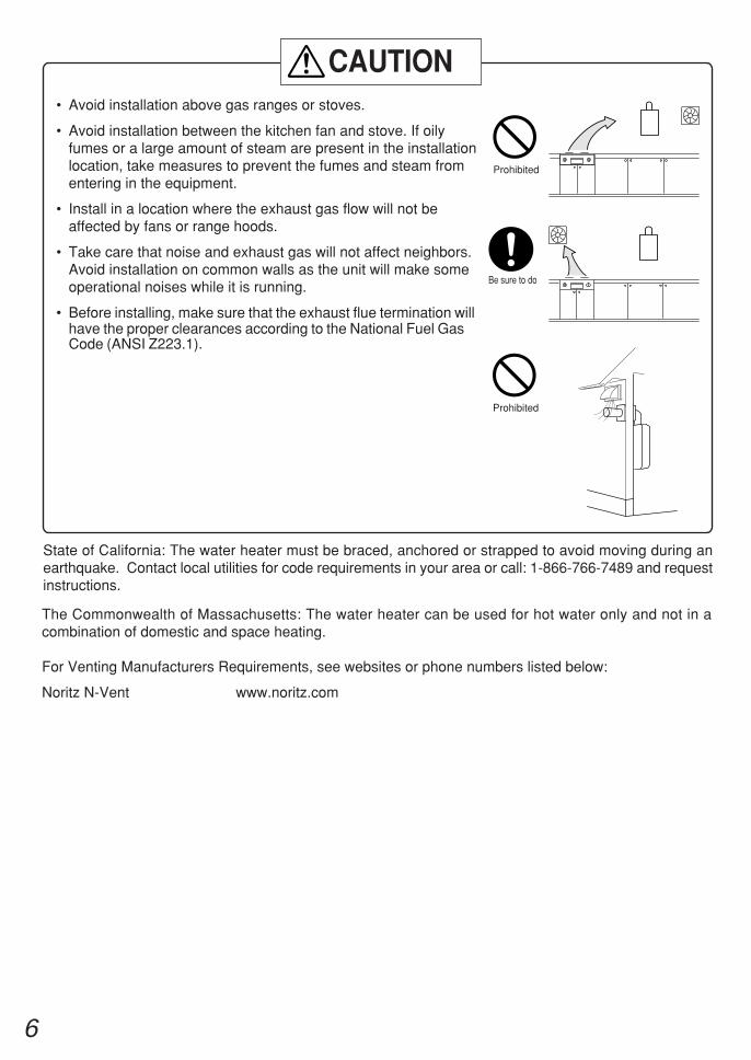
• Avoid installation above gas ranges or stoves.
• Avoid installation between the kitchen fan and stove. If oilyfumes or a large amount of steam are present in the installationlocation, take measures to prevent the fumes and steam fromentering in the equipment.
• Install in a location where the exhaust gas flow will not beaffected by fans or range hoods.
• Take care that noise and exhaust gas will not affect neighbors.Avoid installation on common walls as the unit will make someoperational noises while it is running.
• Before installing, make sure that the exhaust flue termination willhave the proper clearances according to the National Fuel GasCode (ANSI Z223.1).
State of California: The water heater must be braced, anchored or strapped to avoid moving during anearthquake. Contact local utilities for code requirements in your area or call: 1-866-766-7489 and requestinstructions.
Be sure to do
Prohibited
Prohibited
CAUTION
The Commonwealth of Massachusetts: The water heater can be used for hot water only and not in acombination of domestic and space heating.
For Venting Manufacturers Requirements, see websites or phone numbers listed below:
Noritz N-Vent www.noritz.com
7
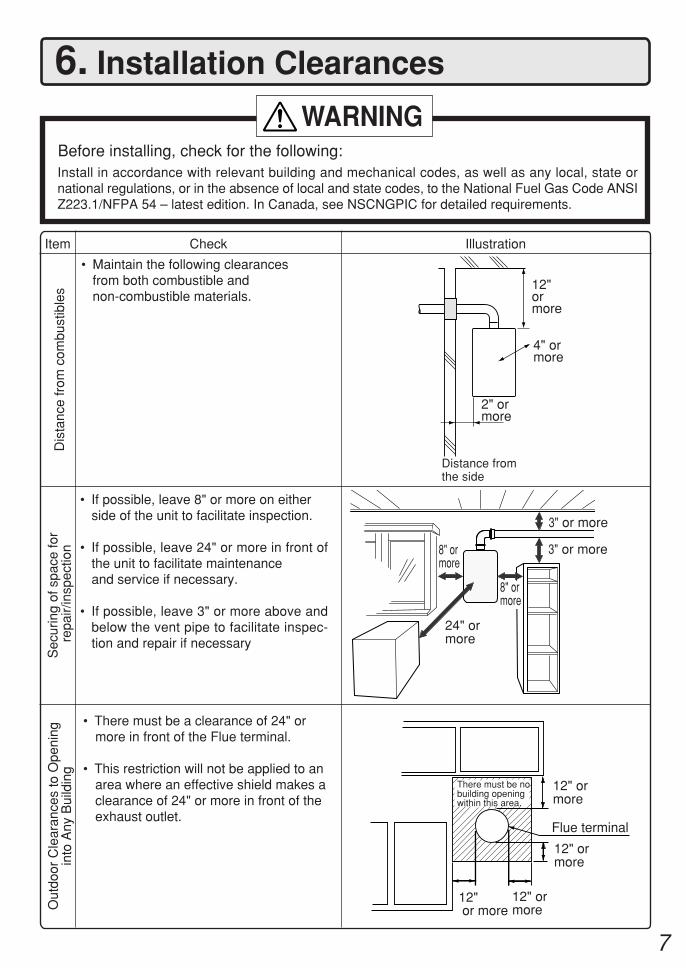
6. Installation Clearances
Before installing, check for the following:Install in accordance with relevant building and mechanical codes, as well as any local, state ornational regulations, or in the absence of local and state codes, to the National Fuel Gas Code ANSIZ223.1/NFPA 54 – latest edition. In Canada, see NSCNGPIC for detailed requirements.
WARNING
Item
Dis
tanc
e fr
om c
ombu
stib
les
• Maintain the following clearancesfrom both combustible andnon-combustible materials.
• There must be a clearance of 24" ormore in front of the Flue terminal.
• This restriction will not be applied to anarea where an effective shield makes aclearance of 24" or more in front of theexhaust outlet.
Check Illustration
• If possible, leave 8" or more on eitherside of the unit to facilitate inspection.
• If possible, leave 24" or more in front ofthe unit to facilitate maintenanceand service if necessary.
• If possible, leave 3" or more above andbelow the vent pipe to facilitate inspec-tion and repair if necessary
Sec
urin
g of
spa
ce fo
r r
epai
r/in
spec
tion
24" ormore
8" ormore
8" ormore
Out
door
Cle
aran
ces
to O
peni
ngin
to A
ny B
uild
ing
Distance fromthe side
12"ormore
2" ormore
12" or more
12" ormore
12" ormore
There must be nobuilding openingwithin this area.
12" ormore
Flue terminal
3" or more
3" or more
4" ormore
8
7. InstallationSecuring to the wall
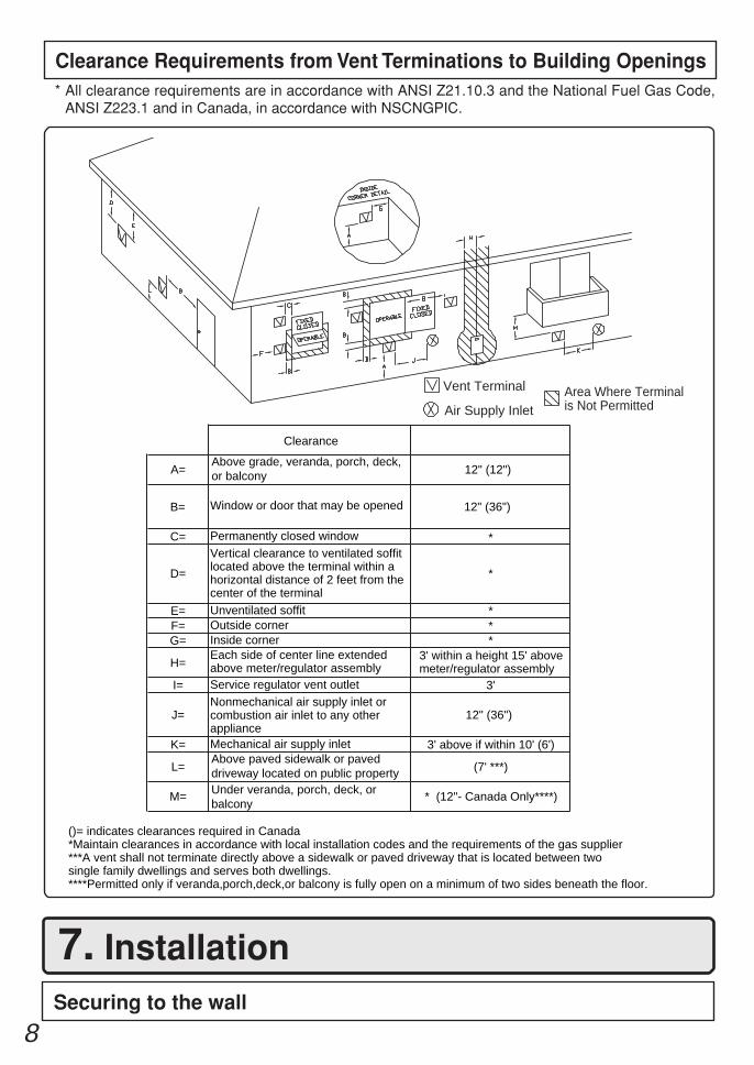
Clearance Requirements from Vent Terminations to Building Openings* All clearance requirements are in accordance with ANSI Z21.10.3 and the National Fuel Gas Code,
ANSI Z223.1 and in Canada, in accordance with NSCNGPIC.
Vent Terminal
Clearance
A=Above grade, veranda, porch, deck,or balcony
B= Window or door that may be opened 12" (36")
C= Permanently closed window
D=
Vertical clearance to ventilated soffitlocated above the terminal within ahorizontal distance of 2 feet from the center of the terminal
*
E= Unventilated soffit *F= Outside corner *G= Inside corner *
H=Each side of center line extended above meter/regulator assembly
3' within a height 15' abovemeter/regulator assembly
I= Service regulator vent outlet 3'
J=Nonmechanical air supply inlet or combustion air inlet to any other appliance
12" (36")
K= Mechanical air supply inlet 3' above if within 10' (6')
L=Above paved sidewalk or paveddriveway located on public propertyUnder veranda, porch, deck, or balcony
(7' ***)
M=
()= indicates clearances required in Canada*Maintain clearances in accordance with local installation codes and the requirements of the gas supplier***A vent shall not terminate directly above a sidewalk or paved driveway that is located between twosingle family dwellings and serves both dwellings.****Permitted only if veranda,porch,deck,or balcony is fully open on a minimum of two sides beneath the floor.
* (12"- Canada Only****)
*
12" (12")
Air Supply InletArea Where Terminalis Not Permitted
9
IllustrationCheck
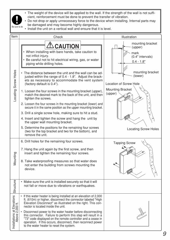
6. Drill holes for the remaining four screws.
7. Hang the unit again by the first screw, and theninsert and tighten the remaining four screws.
8. Take waterproofing measures so that water doesnot enter the building from screws mounting thedevice.
• Make sure the unit is installed securely so that it willnot fall or move due to vibrations or earthquakes.
• The distance between the unit and the wall can be ad-justed within the range of 0.4 - 1.8". Adjust the brack-ets as necessary to accommodate the vent system(factory default is 0.4").
1. Loosen the four screws in the mounting bracket (upper),match the desired mark to the back of the unit, and thentighten the screws.
2. Loosen the four screws in the mounting bracket (lower) andsecure it in the same position as the upper mounting bracket.
3. Drill a single screw hole, making sure to hit a stud.
4. Insert and tighten the screw and hang the unit bythe upper wall mounting bracket.
5. Determine the positions for the remaining four screws(two for the top bracket and two for the bottom), andremove the unit.
• The weight of the device will be applied to the wall. If the strength of the wall is not suffi-cient, reinforcement must be done to prevent the transfer of vibration.
• Do not drop or apply unnecessary force to the device when installing. Internal parts maybe damaged and may become highly dangerous.
• Install the unit on a vertical wall and ensure that it is level.
Loca
ting
Scr
ew H
oles
Mou
ntin
gS
truc
ture
• When installing with bare hands, take caution tonot inflict injury.
• Be careful not to hit electrical wiring, gas, or waterpiping while drilling holes.
Item
CAUTION
Be sure to do
Mounting Bracket(upper)
Tapping Screw
Location of Screw Hole
Locating Screw Holes
Inst
alla
tions
at E
leva
tions
Abo
ve 2
,000
ft.
• If this water heater is being installed at an elevation of 2,000ft. (610m) or higher, disconnect the connector labeled "HighElevation Disconnect" as illustrated on the right. This con-nector is located inside the unit.
HIGH
ELE
VATI
ON
DIS
CO
NN
EC
T
• Disconnect power to the water heater before disconnectingthis connector. Failure to perform this step will result in a"73" code displayed on the remote controller and a cease inoperation. If this occurs, disconnect, then reconnect powerto the water heater to reset the system.
0.4 - 1.8"
mounting bracket(upper)
mounting bracket(lower)
mark(0.4" intervals)
10
> 3"0.8"-3" < 0.8"
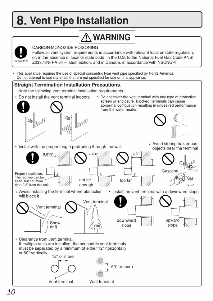
Straight Termination Installation Precautions.Note the following vent terminal installation requirements
• Do not install the vent terminal indoors
• Install the vent terminal with a downward slope
upwardslope
downwardslope
• Install with the proper length protruding through the wall • Avoid storing hazardousobjects near the terminal
Gasoline
GasProper installation.The red line can beseen, but not morethan 2.2" from the wall.
Vent terminalVent terminal
not farenough
too far
Snowdrift Tree
• Avoid installing the terminal where obstacleswill block it
• Do not cover the vent terminal with any type of protectivescreen or enclosure. Blocked terminals can causeabnormal combustion resulting in undesired performancefrom the water heater.
8. Vent Pipe Installation
• This appliance requires the use of special concentric type vent pipe specified by Noritz America.Do not attempt to use materials that are not specified for use on this appliance.
WARNING
Be sure to do
CARBON MONOXIDE POISONINGFollow all vent system requirements in accordance with relevant local or state regulation,or, in the absence of local or state code, in the U.S. to the National Fuel Gas Code ANSIZ233.1/NFPA 54 – latest edition, and in Canada, in accordance with NSCNGPI.
• Clearance from vent terminal. If multiple units are installed, the concentric vent terminals
must be separated by a minimum of either 12" horizontallyor 60" vertically.
Vent terminal Vent terminal
12" or more
60" or more
11
123456123456123456123456
123456123456123456
123456789012341234567890123412345678901234123456789012341234567890123412345678901234
123451234512345
123456123456123456123456
12345123451234512345
123456789012345678901234567890123456789012345678901234567890123456123456123456123456
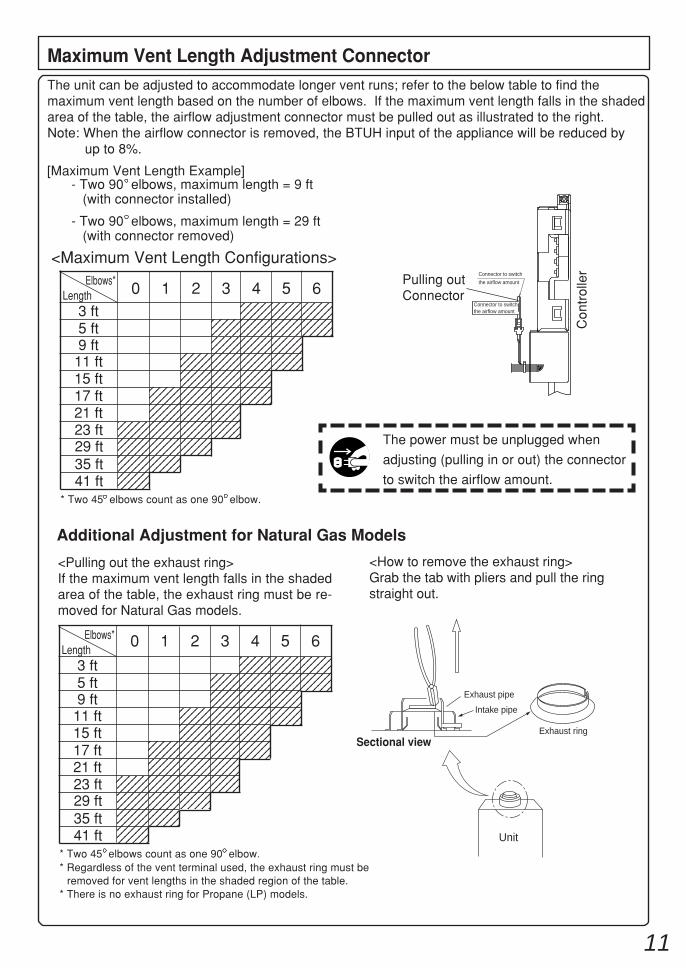
The power must be unplugged when
adjusting (pulling in or out) the connector
to switch the airflow amount.
<Maximum Vent Length Configurations>Pulling outConnector
Connector to switch
the airflow amount
Connector to switch the airflow amount
123456789012341234567890123412345678901234123456789012341234567890123412345678901234
123456789012341234567890123412345678901234123456789012341234567890123412345678901234
1234567890123412345678901234123456789012341234567890123412345678901234
3 ft
0 1 2 3 4 5 6Elbows*
Length
5 ft9 ft
11 ft15 ft17 ft21 ft
Con
trol
ler
23 ft29 ft35 ft41 ft
The unit can be adjusted to accommodate longer vent runs; refer to the below table to find themaximum vent length based on the number of elbows. If the maximum vent length falls in the shadedarea of the table, the airflow adjustment connector must be pulled out as illustrated to the right.Note: When the airflow connector is removed, the BTUH input of the appliance will be reduced by
up to 8%.
Maximum Vent Length Adjustment Connector
- Two 90 elbows, maximum length = 9 ft (with connector installed)
- Two 90 elbows, maximum length = 29 ft (with connector removed)
[Maximum Vent Length Example]
* Two 45 elbows count as one 90 elbow.
123456123456123456
123456123456123456123456
123456789012341234567890123412345678901234123456789012341234567890123412345678901234
12345123451234512345
123456123456123456
123451234512345
123456789012345678901234567890123456789012345678901234567890123456123456123456
123456789012341234567890123412345678901234123456789012341234567890123412345678901234
123456789012341234567890123412345678901234123456789012341234567890123412345678901234
123456789012341234567890123412345678901234123456789012341234567890123412345678901234
3 ft
Elbows*Length
5 ft9 ft
11 ft15 ft17 ft21 ft23 ft29 ft35 ft41 ft
* Two 45 elbows count as one 90 elbow.* Regardless of the vent terminal used, the exhaust ring must be
removed for vent lengths in the shaded region of the table.* There is no exhaust ring for Propane (LP) models.
<Pulling out the exhaust ring>If the maximum vent length falls in the shadedarea of the table, the exhaust ring must be re-moved for Natural Gas models.
Additional Adjustment for Natural Gas Models
<How to remove the exhaust ring>Grab the tab with pliers and pull the ringstraight out.
Exhaust pipe
Intake pipe
Exhaust ringSectional view
Unit
0 1 2 3 4 5 6
12
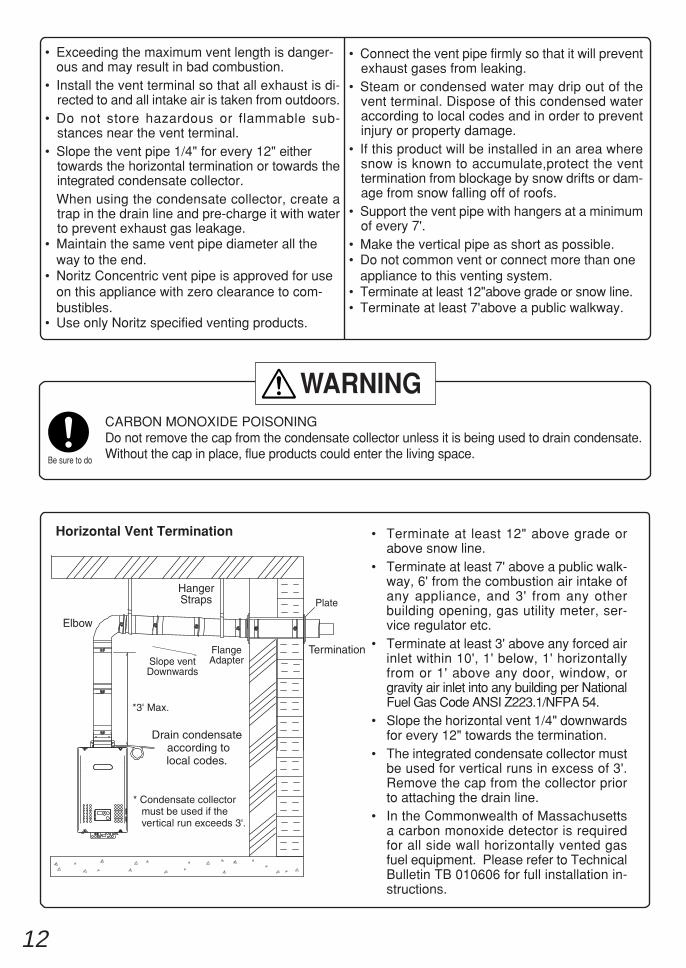
Horizontal Vent Termination • Terminate at least 12" above grade orabove snow line.
• Terminate at least 7' above a public walk-way, 6' from the combustion air intake ofany appliance, and 3' from any otherbuilding opening, gas utility meter, ser-vice regulator etc.
• Terminate at least 3' above any forced airinlet within 10', 1' below, 1' horizontallyfrom or 1' above any door, window, orgravity air inlet into any building per NationalFuel Gas Code ANSI Z223.1/NFPA 54.
• Slope the horizontal vent 1/4" downwardsfor every 12" towards the termination.
• The integrated condensate collector mustbe used for vertical runs in excess of 3'.Remove the cap from the collector priorto attaching the drain line.
• In the Commonwealth of Massachusettsa carbon monoxide detector is requiredfor all side wall horizontally vented gasfuel equipment. Please refer to TechnicalBulletin TB 010606 for full installation in-structions.
Elbow
HangerStraps
FlangeAdapter
Plate
Termination
*3' Max.
Slope ventDownwards
* Condensate collector must be used if the vertical run exceeds 3'.
Drain condensate according tolocal codes.
• Connect the vent pipe firmly so that it will preventexhaust gases from leaking.
• Steam or condensed water may drip out of thevent terminal. Dispose of this condensed wateraccording to local codes and in order to preventinjury or property damage.
• If this product will be installed in an area wheresnow is known to accumulate,protect the venttermination from blockage by snow drifts or dam-age from snow falling off of roofs.
• Support the vent pipe with hangers at a minimumof every 7'.
• Make the vertical pipe as short as possible.• Do not common vent or connect more than one
appliance to this venting system.• Terminate at least 12"above grade or snow line.• Terminate at least 7'above a public walkway.
• Exceeding the maximum vent length is danger-ous and may result in bad combustion.
• Install the vent terminal so that all exhaust is di-rected to and all intake air is taken from outdoors.
• Do not store hazardous or flammable sub-stances near the vent terminal.
• Slope the vent pipe 1/4" for every 12" eithertowards the horizontal termination or towards theintegrated condensate collector.When using the condensate collector, create atrap in the drain line and pre-charge it with waterto prevent exhaust gas leakage.
• Maintain the same vent pipe diameter all theway to the end.
• Noritz Concentric vent pipe is approved for useon this appliance with zero clearance to com-bustibles.
• Use only Noritz specified venting products.
WARNING
Be sure to do
CARBON MONOXIDE POISONINGDo not remove the cap from the condensate collector unless it is being used to drain condensate.Without the cap in place, flue products could enter the living space.
13
(Combustible material)
External wall,combustible material
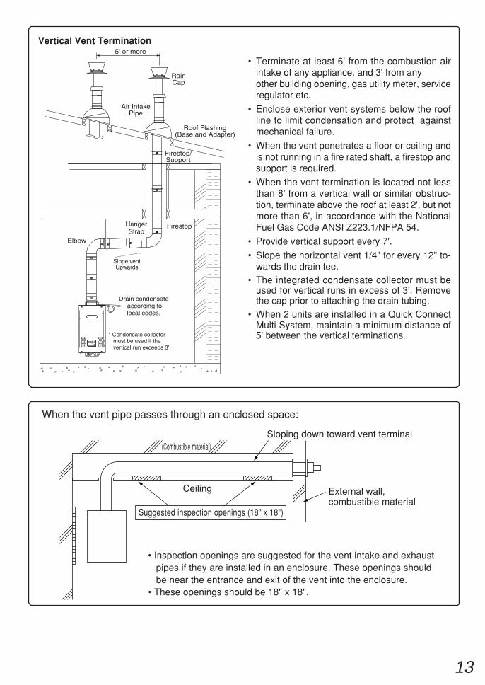
• Inspection openings are suggested for the vent intake and exhaustpipes if they are installed in an enclosure. These openings shouldbe near the entrance and exit of the vent into the enclosure.
• These openings should be 18" x 18".
Suggested inspection openings (18" x 18")
When the vent pipe passes through an enclosed space:
Ceiling
Sloping down toward vent terminal
Vertical Vent Termination
Firestop
Firestop/Support
Roof Flashing (Base and Adapter)
Air IntakePipe
RainCap
5' or more
HangerStrap
Elbow
Slope ventUpwards
* Condensate collector must be used if the vertical run exceeds 3'.
Drain condensate according tolocal codes.
• Terminate at least 6' from the combustion airintake of any appliance, and 3' from anyother building opening, gas utility meter, serviceregulator etc.
• Enclose exterior vent systems below the roofline to limit condensation and protect againstmechanical failure.
• When the vent penetrates a floor or ceiling andis not running in a fire rated shaft, a firestop andsupport is required.
• When the vent termination is located not lessthan 8' from a vertical wall or similar obstruc-tion, terminate above the roof at least 2', but notmore than 6', in accordance with the NationalFuel Gas Code ANSI Z223.1/NFPA 54.
• Provide vertical support every 7'.
• Slope the horizontal vent 1/4" for every 12" to-wards the drain tee.
• The integrated condensate collector must beused for vertical runs in excess of 3'. Removethe cap prior to attaching the drain tubing.
• When 2 units are installed in a Quick ConnectMulti System, maintain a minimum distance of5' between the vertical terminations.
14
Gas MeterSelect a gas meter capable of supplying the entirebtuh demand of all gas appliances in the building.
Gas Connection• Do not use piping with a diameter smaller than
the inlet diameter of the water heater.• Gas flex lines are not recommended unless they
are rated for 199,900 btuh.• Install a gas shutoff valve on the supply line.• Use only approved gas piping materials.
Follow the instructions from the gas supplier.
Gas PressureSize the gas line according to total btuh demandof the building and length from the meter orregulator so that the following supply pressuresare available even at maximum demand:
Natural Gas Supply PressureMin. 4" WCMax. 10.5" WC
LP Gas Supply PressureMin. 8" WCMax. 14" WC
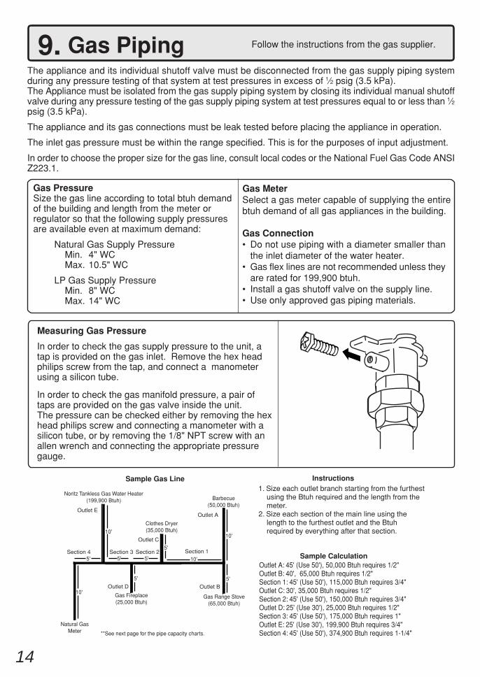
9. Gas PipingThe appliance and its individual shutoff valve must be disconnected from the gas supply piping systemduring any pressure testing of that system at test pressures in excess of 1⁄2 psig (3.5 kPa).The Appliance must be isolated from the gas supply piping system by closing its individual manual shutoffvalve during any pressure testing of the gas supply piping system at test pressures equal to or less than 1⁄2psig (3.5 kPa).
The appliance and its gas connections must be leak tested before placing the appliance in operation.
The inlet gas pressure must be within the range specified. This is for the purposes of input adjustment.
In order to choose the proper size for the gas line, consult local codes or the National Fuel Gas Code ANSIZ223.1.
Natural GasMeter **See next page for the pipe capacity charts.
Noritz Tankless Gas Water Heater(199,900 Btuh)
Clothes Dryer(35,000 Btuh)
Barbecue(50,000 Btuh)
Gas Range Stove(65,000 Btuh)
10'
10'
10'
10'
5'
5'
5'5'
Gas Fireplace(25,000 Btuh)
Instructions1. Size each outlet branch starting from the furthest using the Btuh required and the length from the meter.2. Size each section of the main line using the length to the furthest outlet and the Btuh required by everything after that section.
Sample Gas Line
Sample CalculationOutlet A: 45' (Use 50'), 50,000 Btuh requires 1/2"Outlet B: 40', 65,000 Btuh requires 1/2"Section 1: 45' (Use 50'), 115,000 Btuh requires 3/4"Outlet C: 30', 35,000 Btuh requires 1/2"Section 2: 45' (Use 50'), 150,000 Btuh requires 3/4"Outlet D: 25' (Use 30'), 25,000 Btuh requires 1/2"Section 3: 45' (Use 50'), 175,000 Btuh requires 1"Outlet E: 25' (Use 30'), 199,900 Btuh requires 3/4"Section 4: 45' (Use 50'), 374,900 Btuh requires 1-1/4"
Section 3 Section 2 Section 1
Outlet A
Outlet B
Outlet C
Outlet D
Outlet E
5' 5'Section 4
Measuring Gas Pressure
In order to check the gas supply pressure to the unit, atap is provided on the gas inlet. Remove the hex headphilips screw from the tap, and connect a manometerusing a silicon tube.
In order to check the gas manifold pressure, a pair oftaps are provided on the gas valve inside the unit.The pressure can be checked either by removing the hexhead philips screw and connecting a manometer with asilicon tube, or by removing the 1/8" NPT screw with anallen wrench and connecting the appropriate pressuregauge.
15
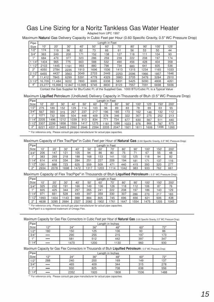
Gas Line Sizing for a Noritz Tankless Gas Water HeaterMaximum NaturNatural Gas Delivery Capacity in Cubic Feet per Hour (0.60 Specific Gravity, 0.5" WC Pressure Drop)
Contact the Gas Supplier for Btu/Cubic Ft. of the Supplied Gas. 1000 BTU/Cubic Ft. is a Typical Value
Maximum Liquified PLiquified Petroleum (Undiluted) Delivery Capacity in Thousands of Btuh (0.5" WC Pressure Drop)
Length in Feet
Length in Feet
PipeSize
PipeSize
1/2"
1/2"
3/4"
3/4"
1"
1"
1 1/4"
1 1/4"
1 1/2"
1 1/2"
2"
2"
2 1/2"3"
3 1/2"4"
10' 20' 30' 40' 50' 60' 70' 80' 90' 100' 125'
10' 20' 30' 40' 50' 60' 70' 80' 90' 100' 125' 150' 200'
174363684140421034050645511,41216,70923,277
1192494709651445278444377843
11,48415,998
9620037777511612235356362999222
12,847
Adapted from UPC 1997
82171323663993
1913304953917893
10,995
73152286588880
16962703477869959745
6613825953279815362449432963388830
61127239490734
14132253398358318123
56 53 50 44118 111 104 93222 208 197 174456683
13152096370554257557
428641
12341966347650907091
40460511651857328448086698
35853610331646291042615936
2755671071220533076221
189393732
149622994331
152315590
121218583465
129267504
103915592992
114237448913
14172646
103217409834
12752394
9619637877111812205
8918534672410862047
8317332267710231921
781623076309761811
69146275567866
1606
631322525117871496
55112213440675
1260
Maximum Capacity of Flex TracPipe in Cubic Feet per Hour of Natural Gas (0.60 Specific Gravity, 0.5" WC Pressure Drop)
Length in FeetPipeSize3/4"1"
1 1/4"1 1/2"
2"
10' 20' 30' 40' 50' 60' 70' 80' 90' 100' 150' 200'206383614
12612934
147269418888
2078
1212183347231698
105188284625
1472
94168251559
1317
861532275091203
80141209471
1114
75132194440
1042
71125181415983
67118171393933
5594
137320762
4882
116277661
R
Maximum Capacity of Flex TracPipe in Thousands of Btuh Liquified Petroleum ( 0.5" WC Pressure Drop)
Length in FeetPipeSize3/4"1"
1 1/4"1 1/2"
2"
10' 20' 30' 40' 50' 60' 70' 80' 90' 100' 150' 200'325605971
19934638
232425661
14043285
191344528
11432684
166297449988
2327
149265397884
2082
1362413598051902
126222330745
1761
118208307696
1647
112197286656
1554
106186270621
1475
871432175061205
76129183438
1045
R
** For reference only. Please consult gas pipe manufacturer for actual pipe capacities.
** For reference only. Please consult gas pipe manufacturer for actual pipe capacities.
Maximum Capacity for Gas Flex Connectors in Cubic Feet per Hour of Natural Gas (0.60 Specific Gravity, 0.5" WC Pressure Drop)
Length in InchesPipeSize1/2"3/4"1"
1 1/4"
12" 24" 36" 48" 60" 72"180 150
290581
1470
125255512
1200
106215442
1130
93197397960
86173347930
Length in InchesPipeSize1/2"3/4"1"
1 1/4"
12" 24" 36" 48" 60" 72"288 240
465930
2352
200409825
1920
169344708
1808
149315638
1536
137278556
1488
Maximum Capacity for Gas Flex Connectors in Thousands of Btuh Liquified Petroleum ( 0.5" WC Pressure Drop)
** For reference only. Please consult gas pipe manufacturer for actual pipe capacities.
TracPipe® is a registered trademark of Omega Flex.
16
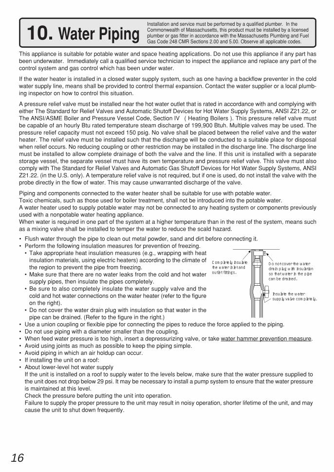
10. Water PipingThis appliance is suitable for potable water and space heating applications. Do not use this appliance if any part hasbeen underwater. Immediately call a qualified service technician to inspect the appliance and replace any part of thecontrol system and gas control which has been under water.
If the water heater is installed in a closed water supply system, such as one having a backflow preventer in the coldwater supply line, means shall be provided to control thermal expansion. Contact the water supplier or a local plumb-ing inspector on how to control this situation.
A pressure relief valve must be installed near the hot water outlet that is rated in accordance with and complying witheither The Standard for Relief Valves and Automatic Shutoff Devices for Hot Water Supply Systems, ANSI Z21.22, orThe ANSI/ASME Boiler and Pressure Vessel Code, Section IV ( Heating Boilers ). This pressure relief valve mustbe capable of an hourly Btu rated temperature steam discharge of 199,900 Btuh. Multiple valves may be used. Thepressure relief capacity must not exceed 150 psig. No valve shall be placed between the relief valve and the waterheater. The relief valve must be installed such that the discharge will be conducted to a suitable place for disposalwhen relief occurs. No reducing coupling or other restriction may be installed in the discharge line. The discharge linemust be installed to allow complete drainage of both the valve and the line. If this unit is installed with a separatestorage vessel, the separate vessel must have its own temperature and pressure relief valve. This valve must alsocomply with The Standard for Relief Valves and Automatic Gas Shutoff Devices for Hot Water Supply Systems, ANSIZ21.22. (in the U.S. only). A temperature relief valve is not required, but if one is used, do not install the valve with theprobe directly in the flow of water. This may cause unwarranted discharge of the valve.
Piping and components connected to the water heater shall be suitable for use with potable water.Toxic chemicals, such as those used for boiler treatment, shall not be introduced into the potable water.A water heater used to supply potable water may not be connected to any heating system or components previouslyused with a nonpotable water heating appliance.When water is required in one part of the system at a higher temperature than in the rest of the system, means suchas a mixing valve shall be installed to temper the water to reduce the scald hazard.
Installation and service must be performed by a qualified plumber. In theCommonwealth of Massachusetts, this product must be installed by a licensedplumber or gas fitter in accordance with the Massachusetts Plumbing and FuelGas Code 248 CMR Sections 2.00 and 5.00. Observe all applicable codes.
• Flush water through the pipe to clean out metal powder, sand and dirt before connecting it.• Perform the following insulation measures for prevention of freezing.
• Take appropriate heat insulation measures (e.g., wrapping with heatinsulation materials, using electric heaters) according to the climate ofthe region to prevent the pipe from freezing.
• Make sure that there are no water leaks from the cold and hot watersupply pipes, then insulate the pipes completely.
• Be sure to also completely insulate the water supply valve and thecold and hot water connections on the water heater (refer to the figureon the right).
• Do not cover the water drain plug with insulation so that water in thepipe can be drained. (Refer to the figure in the right.)
• Use a union coupling or flexible pipe for connecting the pipes to reduce the force applied to the piping.• Do not use piping with a diameter smaller than the coupling.• When feed water pressure is too high, insert a depressurizing valve, or take water hammer prevention measure.• Avoid using joints as much as possible to keep the piping simple.• Avoid piping in which an air holdup can occur.• If installing the unit on a roof:• About lower-level hot water supply
If the unit is installed on a roof to supply water to the levels below, make sure that the water pressure supplied tothe unit does not drop below 29 psi. It may be necessary to install a pump system to ensure that the water pressureis maintained at this level.Check the pressure before putting the unit into operation.Failure to supply the proper pressure to the unit may result in noisy operation, shorter lifetime of the unit, and maycause the unit to shut down frequently.
Completely insulate the water inlet and outlet fittings.
Insulate the water supply valve completely.
Do not cover the water drain plug with insulation so that water in the pipe can be drained.
17
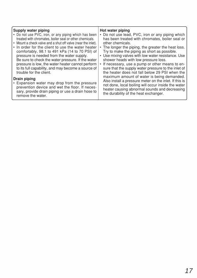
Supply water piping• Do not use PVC, iron, or any piping which has been
treated with chromates, boiler seal or other chemicals.• Mount a check valve and a shut off valve (near the inlet).• In order for the client to use the water heater
comfortably, 98.1 to 491 kPa (14 to 70 PSI) ofpressure is needed from the water supply.Be sure to check the water pressure. If the waterpressure is low, the water heater cannot performto its full capability, and may become a source oftrouble for the client.
Drain piping• Expansion water may drop from the pressure
prevention device and wet the floor. If neces-sary, provide drain piping or use a drain hose toremove the water.
Hot water piping• Do not use lead, PVC, iron or any piping which
has been treated with chromates, boiler seal orother chemicals.
• The longer the piping, the greater the heat loss.Try to make the piping as short as possible.
• Use mixing valves with low water resistance. Useshower heads with low pressure loss.
• If necessary, use a pump or other means to en-sure that the supply water pressure to the inlet ofthe heater does not fall below 29 PSI when themaximum amount of water is being demanded.Also install a pressure meter on the inlet. If this isnot done, local boiling will occur inside the waterheater causing abnormal sounds and decreasingthe durability of the heat exchanger.
18
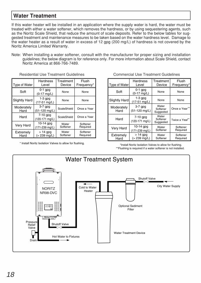
If this water heater will be installed in an application where the supply water is hard, the water must betreated with either a water softener, which removes the hardness, or by using sequestering agents, suchas the Noritz Scale Shield, that reduce the amount of scale deposits. Refer to the below tables for sug-gested treatment and maintenance measures to be taken based on the water hardness level. Damage tothe water heater as a result of water in excess of 12 gpg (200 mg/L) of hardness is not covered by theNoritz America Limited Warranty.
Note: When installing a water softener, consult with the manufacturer for proper sizing and installationguidelines; the below diagram is for reference only. For more information about Scale Shield, contactNoritz America at 866-766-7489.
Water Treatment
Water Treatment System
City Water Supply
PressureReliefValve
Hot Water to Fixtures
Shutoff Valve
Drain
Cold to WaterHeater
Optional Sediment Filter
Water Treatment Device
Shutoff Valve
Type of WaterHardness
LevelTreatment
DeviceFlush
Frequency* Type of WaterHardness
LevelTreatment
DeviceFlush
Frequency*
Soft0-1 gpg
1-3 gpg
(0-17 mg/L)
None None None
None
None
NoneSlightly Hard
(17-51 mg/L)None None
Moderately Hard
Hard
3-7 gpg (51-120 mg/L)
ScaleShield Once a Year Once a Year
Twice a YearOnce a Year
7-10 gpg (120-171 mg/L)
ScaleShield
Very Hard10-14 gpg
(171-239 mg/L)Water
SoftenerSoftener Required
Extremely Hard
Soft
Slightly Hard
Moderately Hard
Hard
Very Hard
ExtremelyHard
> 14 gpg (> 239 mg/L)
0-1 gpg
1-3 gpg
(0-17 mg/L)
(17-51 mg/L)
3-7 gpg(51-120 mg/L)
7-10 gpg(120-171 mg/L)
10-14 gpg(171-239 mg/L)
> 14 gpg(> 239 mg/L)
Water Softener
Softener Required
Water Softener
Softener Required
Water Softener
Softener Required
* Install Noritz Isolation Valves to allow for flushing.
Water Softener
Suggested
Water Softener
Suggested
**
**
*Install Noritz Isolation Valves to allow for flushing.**Flushing is required if a water softener is not installed.
Residential Use Treatment Guidelines Commercial Use Treatment Guidelines
NORITZNR98-DVC
19
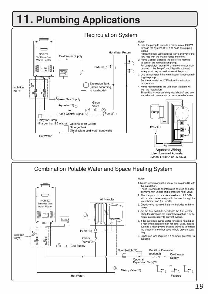
11. Plumbing ApplicationsRecirculation System
Combination Potable Water and Space Heating System
Cold Water Supply
IsolationKit(*4)
Gas Supply
Aquastat(*3)
Pump Control Signal(*2)
Relay for Pump(if larger than 85 Watts)
Hot Water
Optional 8-10 GallonStorage Tank(To alleviate cold water sandwich)
GlobeValve
Pump(*1)
Expansion Tank(Install accordingto local code)
Fixtures
Hot Water Return
R
B
W
Pump
120VAC
105
NeutralGroundLive
S
IsolationKit(*1)
Gas Supply
Backflow Preventer(optional)
CheckValve(*3)
Cold WaterSupply
Mixing Valve(*5)
Hot Water
Pump(*2)
Flow Switch(*4)
Fixtures
Air Handler
Use Honeywell Aquastat (Model L6006A or L6006C)
Aquastat Wiring
OptionalExpansion Tank(*6)
Notes:
Notes:
1. Noritz recommends the use of an Isolation Kit with the installation. These kits include an integrated shut-off and serv- ice valve with unions and a pressure relief valve.2. Size the pump to provide a maximum of 3 GPM with a head pressure equal to the loss through the water heater and Air Handler.3. Check valve required if it is not included with the pump.
4. Set the flow switch to deactivate the Air Handler when the domestic hot water flow reaches 3 GPM. Adjust as necessary to prevent cycling.
5. If the system requires water for space heating at a higher temperature than for other uses, means such as a mixing valve shall be provided to temper the water for the other uses to help prevent scald -ing.6. Expansion tank required if a backflow preventer is installed.
1. Size the pump to provide a maximum of 2 GPM through the system at 10 ft of head plus piping losses. Adjust the flow using a globe valve and verify the flow rate with the maintenance monitors.2. Pump Control Signal is the preferred method to control the recirculation pump. For pumps larger than 85W, a relay connection must be used. If the Pump Control Signal is not used, an Aquastat may be used to control the pump. 3. Use an Aquastat if the water heater is not control- ling the pump. Set the Aquastat to 10°F below the set output temperature. 4. Noritz recommends the use of an Isolation Kit with the installation. These kits include an integrated shut-off and serv- ice valve with unions and a pressure relief valve.
NORITZTankless GasWater Heater
NORITZTankless GasWater Heater
20
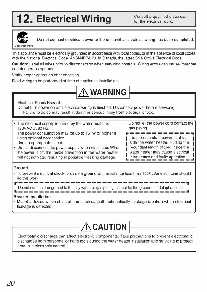
Do not connect electrical power to the unit until all electrical wiring has been completed.
Consult a qualified electricianfor the electrical work.12. Electrical Wiring
This appliance must be electrically grounded in accordance with local codes, or in the absence of local codes,with the National Electrical Code, ANSI/NFPA 70. In Canada, the latest CSA C22.1 Electrical Code.
Caution: Label all wires prior to disconnection when servicing controls. Wiring errors can cause improperand dangerous operation.
Verify proper operation after servicing.
Field wiring to be performed at time of appliance installation.
• The electrical supply required by the water heater is120VAC at 60 Hz.The power consumption may be up to 161W or higher ifusing optional accessories.Use an appropriate circuit.
• Do not disconnect the power supply when not in use. Whenthe power is off, the freeze prevention in the water heaterwill not activate, resulting in possible freezing damage.
• Do not let the power cord contact thegas piping.
Tie the redundant power cord out-side the water heater. Putting theredundant length of cord inside thewater heater may cause electricalinterference and faulty operation.
Disconnect Power
Electrical Shock HazardDo not turn power on until electrical wiring is finished. Disconnect power before servicing.
Failure to do so may result in death or serious injury from electrical shock.
WARNING
Electrostatic discharge can affect electronic components. Take precautions to prevent electrostaticdischarges from personnel or hand tools during the water heater installation and servicing to protectproduct’s electronic control.
CAUTION
Ground• To prevent electrical shock, provide a ground with resistance less than 100 . An electrician should
do this work.
Do not connect the ground to the city water or gas piping. Do not tie the ground to a telephone line.
Breaker Installation• Mount a device which shuts off the electrical path automatically (leakage breaker) when electrical
leakage is detected.
21
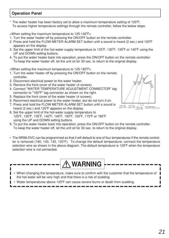
* The water heater has been factory set to allow a maximum temperature setting of 120 F.To access higher temperature settings through the remote controller, follow the below steps.
<When setting the maximum temperature to 125-140 F>1. Turn the water heater off by pressing the ON/OFF button on the remote controller.2. Press and hold the FLOW METER ALARM SET button until a sound is heard (2 sec.) and 120 F
appears on the display.3. Set the upper limit of the hot-water supply temperature to 125 F, 130 F, 135 F or 140 F using the
UP and DOWN setting buttons.4. To put the water heater back into operation, press the ON/OFF button on the remote controller.
To keep the water heater off, let the unit sit for 30 sec. to return to the original display.
<When setting the maximum temperature to 125-180 F>1. Turn the water heater off by pressing the ON/OFF button on the remote
controller.2. Disconnect electrical power to the water heater.3. Remove the front cover of the water heater (4 screws).4. Connect "WATER TEMPERATURE ADJUSTMENT CONNECTOR" tag
connector to "180 F" tag connector as shown on the right.5. Replace the front cover of the water heater (4 screws).6. Reconnect electrical power to the water heater, but do not turn it on.7. Press and hold the FLOW METER ALARM SET button until a sound is
heard (2 sec.) and 120 F appears on the display.8. Set the upper limit of the hot-water supply temperature to
125 F, 130 F, 135 F, 140 F, 145 F, 150 F, 160 F, 170 F or 180 Fusing the UP and DOWN setting buttons.
9. To put the water heater back into operation, press the ON/OFF button on the remote controller.To keep the water heater off, let the unit sit for 30 sec. to return to the original display.
• The NR98-DVC can be programmed so that it will default to one of four temperatures if the remote control-ler is removed (180, 140, 130, 120 F). To change the default temperature, connect the temperatureselection wire as shown in the above diagram. The default temperature is 120 F when the temperatureselection wire is not connected.
Operation Panel
• When changing the temperature, make sure to confirm with the customer that the temperature ofthe hot water will be very high and that there is a risk of scalding.
• Water temperatures above 125 F can cause severe burns or death from scalding.
WARNING
WAT
ER T
EMPE
RATU
RE
ADJU
STM
ENT
CONN
ECTO
R
WATER TEMPERATUREADJUSTMENT CONNECTOR(the back : 55 C) (the back : 60 C)
(the back : 83 C)
22
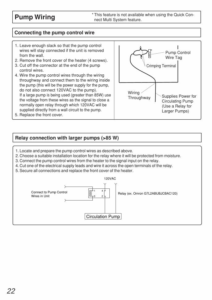
Connecting the pump control wire
1. Leave enough slack so that the pump controlwires will stay connected if the unit is removedfrom the wall.
2. Remove the front cover of the heater (4 screws).3. Cut off the connector at the end of the pump
control wires.4. Wire the pump control wires through the wiring
throughway and connect them to the wiring insidethe pump (this will be the power supply for the pump,do not also connect 120VAC to the pump).If a large pump is being used (greater than 85W) usethe voltage from these wires as the signal to close anormally open relay through which 120VAC will besupplied directly from a wall circuit to the pump.
5. Replace the front cover.
Pump Wiring * This feature is not available when using the Quick Con-nect Multi System feature.
Relay connection with larger pumps (>85 W)
1. Locate and prepare the pump control wires as described above.2. Choose a suitable installation location for the relay where it will be protected from moisture.3. Connect the pump control wires from the heater to the signal input on the relay.4. Cut one of the electrical supply leads and wire it across the open terminals of the relay.5. Secure all connections and replace the front cover of the heater.
Circulation Pump
120VAC
Relay (ex. Omron G7L2ABUBJCBAC120)Connect to Pump ControlWires in Unit 0
1
2
4
PU
MP
Crimping Terminal
WiringThroughway Supplies Power for
Circulating Pump(Use a Relay forLarger Pumps)
Pump ControlWire Tag
23
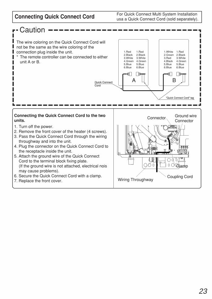
Connecting Quick Connect Cord
The wire coloring on the Quick Connect Cord willnot be the same as the wire coloring of theconnection plug inside the unit.* The remote controller can be connected to either
unit A or B.
Caution
For Quick Connect Multi System Installationusa a Quick Connect Cord (sold separately).
Quick ConnectCord
"Quick Connect Cord" tag
A B
1.Red2.Black3.White4.Green5.Blue6.Blue
1.Red2.Black3.White4.Green5.Blue6.Blue
1.Red2.Black3.White4.Green5.Blue6.Blue
1.White2.Green3.Red4.Black5.Blue6.Blue
Connecting the Quick Connect Cord to the twounits.
1. Turn off the power.2. Remove the front cover of the heater (4 screws).3. Pass the Quick Connect Cord through the wiring
throughway and into the unit.4. Plug the connector on the Quick Connect Cord to
the receptacle inside the unit.5. Attach the ground wire of the Quick Connect
Cord to the terminal block fixing plate.(If the ground wire is not attached, electrical noismay cause problems).
6. Secure the Quick Connect Cord with a clamp.7. Replace the front cover. Wiring Throughway
Coupling Cord
Clamp
Ground wireConnector
Connector
24
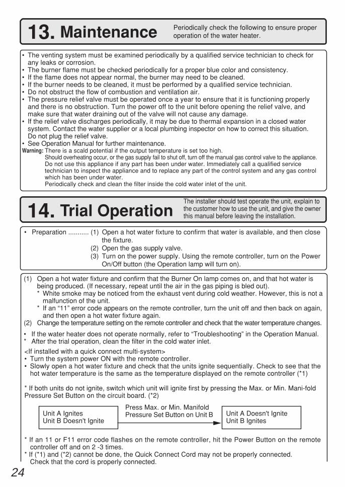
(1) Open a hot water fixture and confirm that the Burner On lamp comes on, and that hot water isbeing produced. (If necessary, repeat until the air in the gas piping is bled out).* White smoke may be noticed from the exhaust vent during cold weather. However, this is not a
malfunction of the unit.* If an “11” error code appears on the remote controller, turn the unit off and then back on again,
and then open a hot water fixture again.(2) Change the temperature setting on the remote controller and check that the water temperature changes.
• If the water heater does not operate normally, refer to “Troubleshooting” in the Operation Manual.* After the trial operation, clean the filter in the cold water inlet.
<If installed with a quick connect multi-system>• Turn the system power ON with the remote controller.• Slowly open a hot water fixture and check that the units ignite sequentially. Check to see that the
hot water temperature is the same as the temperature displayed on the remote controller (*1)
* If both units do not ignite, switch which unit will ignite first by pressing the Max. or Min. Mani-foldPressure Set Button on the circuit board. (*2)
* If an 11 or F11 error code flashes on the remote controller, hit the Power Button on the remotecontroller off and on 2 -3 times.
* If (*1) and (*2) cannot be done, the Quick Connect Cord may not be properly connected.Check that the cord is properly connected.
13. Maintenance Periodically check the following to ensure properoperation of the water heater.
• The venting system must be examined periodically by a qualified service technician to check forany leaks or corrosion.
• The burner flame must be checked periodically for a proper blue color and consistency.• If the flame does not appear normal, the burner may need to be cleaned.• If the burner needs to be cleaned, it must be performed by a qualified service technician.• Do not obstruct the flow of combustion and ventilation air.• The pressure relief valve must be operated once a year to ensure that it is functioning properly
and there is no obstruction. Turn the power off to the unit before opening the relief valve, andmake sure that water draining out of the valve will not cause any damage.
• If the relief valve discharges periodically, it may be due to thermal expansion in a closed watersystem. Contact the water supplier or a local plumbing inspector on how to correct this situation.Do not plug the relief valve.
• See Operation Manual for further maintenance.Warning: There is a scald potential if the output temperature is set too high.
Should overheating occur, or the gas supply fail to shut off, turn off the manual gas control valve to the appliance.Do not use this appliance if any part has been under water. Immediately call a qualified servicetechnician to inspect the appliance and to replace any part of the control system and any gas controlwhich has been under water.Periodically check and clean the filter inside the cold water inlet of the unit.
14. Trial OperationThe installer should test operate the unit, explain tothe customer how to use the unit, and give the ownerthis manual before leaving the installation.
Unit A IgnitesUnit B Doesn't Ignite
Press Max. or Min. ManifoldPressure Set Button on Unit B Unit A Doesn't Ignite
Unit B Ignites
• Preparation ........... (1) Open a hot water fixture to confirm that water is available, and then closethe fixture.
(2) Open the gas supply valve.(3) Turn on the power supply. Using the remote controller, turn on the Power
On/Off button (the Operation lamp will turn on).
25
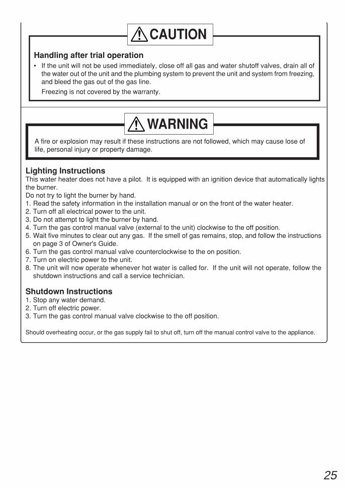
Lighting InstructionsThis water heater does not have a pilot. It is equipped with an ignition device that automatically lightsthe burner.Do not try to light the burner by hand.1. Read the safety information in the installation manual or on the front of the water heater.2. Turn off all electrical power to the unit.3. Do not attempt to light the burner by hand.4. Turn the gas control manual valve (external to the unit) clockwise to the off position.5. Wait five minutes to clear out any gas. If the smell of gas remains, stop, and follow the instructions
on page 3 of Owner's Guide.6. Turn the gas control manual valve counterclockwise to the on position.7. Turn on electric power to the unit.8. The unit will now operate whenever hot water is called for. If the unit will not operate, follow the
shutdown instructions and call a service technician.
Shutdown Instructions1. Stop any water demand.2. Turn off electric power.3. Turn the gas control manual valve clockwise to the off position.
Should overheating occur, or the gas supply fail to shut off, turn off the manual control valve to the appliance.
Handling after trial operation• If the unit will not be used immediately, close off all gas and water shutoff valves, drain all of
the water out of the unit and the plumbing system to prevent the unit and system from freezing,and bleed the gas out of the gas line.
Freezing is not covered by the warranty.
CAUTION
A fire or explosion may result if these instructions are not followed, which may cause lose oflife, personal injury or property damage.
WARNING
26
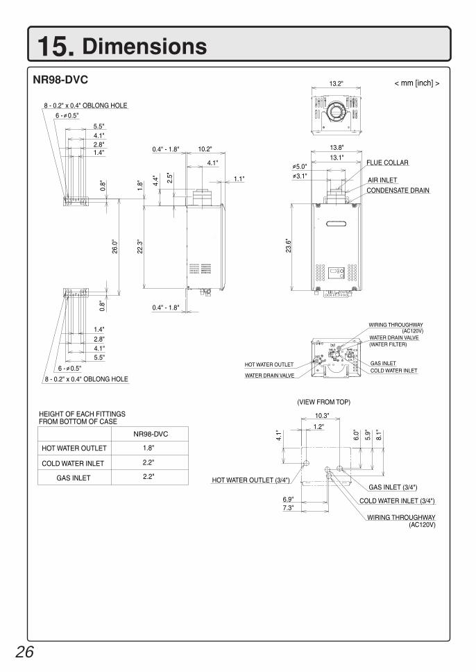
15. DimensionsNR98-DVC
1.8"
2.2"
23.6
"
8 - 0.2" x 0.4" OBLONG HOLE
6 - 0.5"
5.5"4.1"2.8"1.4"
5.5"4.1"2.8"1.4"
0.4" - 1.8" 10.2"
4.1"
1.1"
0.8"
1.8" 4.
4" 2.5"
26.0
"
22.3
"
0.8"
8 - 0.2" x 0.4" OBLONG HOLE
6 - 0.5"
HEIGHT OF EACH FITTINGSFROM BOTTOM OF CASE
2.2"
NR98-DVC
HOT WATER OUTLET
COLD WATER INLET
GAS INLET
0.4" - 1.8"
13.2"
5.0"3.1"
13.8"
13.1"FLUE COLLAR
CONDENSATE DRAIN
AIR INLET
< mm [inch] >
WIRING THROUGHWAY(AC120V)
HOT WATER OUTLET
WATER DRAIN VALVE
WATER DRAIN VALVE(WATER FILTER)
GAS INLETCOLD WATER INLET
(VIEW FROM TOP)
(AC120V)
6.9"7.3"
HOT WATER OUTLET (3/4")
WIRING THROUGHWAY
COLD WATER INLET (3/4")
GAS INLET (3/4")
4.1"
10.3"
1.2"
6.0"
5.9"
8.1"