installation instructions€¦ · · 2015-11-13installation instructions split system ... the...
TRANSCRIPT
INSTALLATION INSTRUCTIONSSplit System
Performance LineAC & HP Condensers
These instructions must be read and understood completely before attempting installation.
Installation / Startup Information & Warranty
WARNING
Installation or repairs made by unqualifiedpersons can result in hazards to you and others.Installation MUST conform with local buildingcodes or, in the absence of local codes, with thethe National Electrical Code NFPA 70/ANSIC1-1999 or current edition and CanadianElectrical Code Part 1 CSA C.22.1.
The information contained in this manual isintended for use by a qualified service technicianfamiliar with safety procedures and equippedwith the proper tools and test instruments.
Failure to carefully read and follow all instruc-tions in this manual can result in equipmentmalfunction, property damage, personal injuryand/or death.
After uncrating unit, inspect thoroughly for hiddendamage.If damage is found, notify the transportation company im-mediately and file a concealed damage claim.
CAUTION
Improper installation, adjustment, alteration, service ormaintenance can void the warranty.
The weight of the condensing unit requires caution andproper handling procedureswhen lifting ormoving to avoidpersonal injury. Use care to avoid contact with sharp orpointed edges.
Safety Precautions1. Always wear safety eye wear and work gloves when
installing equipment.2.Neverassumeelectrical power is disconnected.Check
with meter and disconnect.3. Keep hands out of fan areas when power is connected
to equipment.4. R--22 causes frost--bite burns.5. R--22 is toxic when burned.
NOTE TO INSTALLING DEALER: The Owners Instruc-tions and Warranty are to be given to the owner or promi-nently displayed near the indoor Furnace/Air Handler Unit.
Locating The Outdoor Unit:
Check local codes covering zoning, noise, platforms.
If practical, avoid locating next to fresh air intakes, vent orbedroomwindows. Noise may carry into the openings anddisturb people inside.
Placement of the unit should be in a well drained area orunit must be supported high enough so runoff will not enterthe unit.
Do not locate where heat, lint or exhaust fumes will be dis-charged on unit (as from dryer vents).
Roof top installations are acceptable providing the roof willsupport the unit and provisions are made for water drain-age and the noise or vibration through the structure.
Do not install the unit in a recessed or confined areawhererecirculation of discharge air may occur.
Heat Pumps Only: The top surface of platform must beaboveaveragewinter snow levels to prevent coil blockage.
Split System CondensersInstallation Instructions
2
Clearances:
Nominal operating clearances, where practical, are 60inches (150 cm) above unit for discharge air and 24 inches(40cm) around coil for intake air on three sides. Clearanceon one side (normally between unit and structure) may bereduced to 12 inches (30cm). Nominal clearances arebased from a solid parallel object, wall, roof overhang, etc.
Do Not install under roof overhangs without guttering. Aminimum vertical clearance of 60� is required to overhang.
The clearance may be reduced from a single object with asmall surface area, such as the end of a wall, outside cor-ner of a wall, fence section or a post, etc. As a general rulethewidthof theobject shouldequal theminimumclearancefrom the unit. For example, a 4 inch (10cm) fence postcould be 4 inches (10cm) from the unit.
Inside corner locations on single story structures requireevaluation. Large overhanging soffits may cause air recir-culation in a corner area even though recommended clear-ancesaremaintained.Asaguide locate theunit far enoughout so that half of the discharge grille is out from under thesoffit.
Two or more units may be spaced with 20 inches (50cm)between units.
A service clearance of 24 inches (60cm) is desirable fromcontrol box end or side. Control box and corner panel be-low it can be loosened and moved out to the side to facili-tate servicing. Internal components can be accessedthrough control box corner or top only.
Unit Support:
The unit must be level, and supported above grade bybeams, platformor apad.Platformor padcanbeof openorsolid construction but should be of permanent materialssuch as concrete, bricks, blocks, steel or pressure treatedtimbers approved for ground contact. Refer to Unit Clear-ances to help determine size of supports etc. Soil condi-tions should be considered so the platform or pad does notshift or settle excessively and leave the unit only partiallysupported.
CAUTIONInadequate support could cause excessive vibration andnoise or binding and stress on refrigerant lines resulting inequipment failure.
To minimize vibration or noise transmission, it is recom-mended that supports not be in contact with the buildingstructure. However, slabs on grade constructions with anextended pad are normally acceptable.
A. Ground Level Installation:If beams or an open platform are used for support it is rec-ommended that the soil be treated or area be graveled toretard the growth of grasses and weeds.
B. Roof Top Installation:
This type of installation is not recommended on woodframe structures where low noise levels are required.
Supporting structure or platform for theunitmust be level. Ifinstallation is on a flat roof the unit should be 4 inches(10cm.) above roof level. Four by four posts placed over aload bearing wall make a suitable mounting platform.
If possible, place the unit over one or more load bearingwalls. If there are several units, mount them on platformsthat are self--supporting and span load bearing walls.These suggestions are to minimize noise and vibrationtransmission through the structure. If the structure is ahome or apartment, avoid (if practical) locating the unitover bedrooms or study.
NOTE: When condensing unit is to be installed on abonded guaranteed roof, a release must be obtained fromthe building owner to free the installer from all liabilities.
Split System Condensers Installation Instructions
3
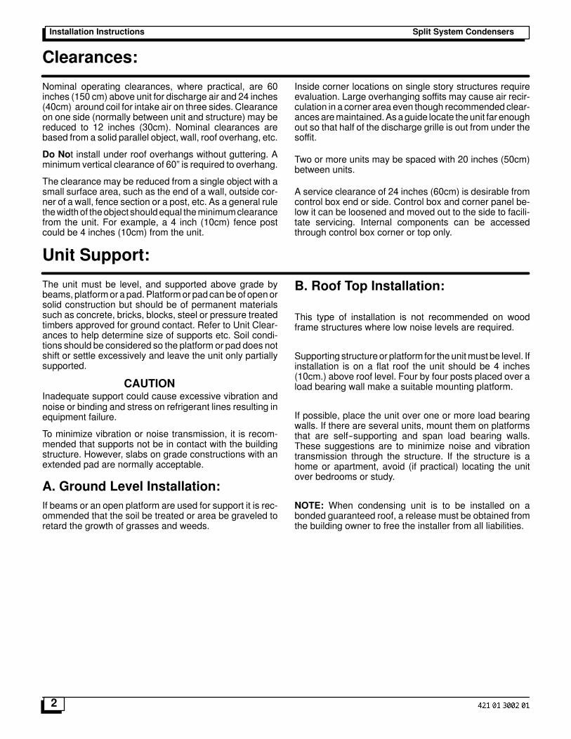
Figure 1 Dimensions
24--3/4
26--1/219
17
25
21
29--3/4
32--3/4
Chassis #1
Chassis #2
Minimum Mounting Pad Sizes with pad starting at15� from structure for minimum clearances
Chassis #1 20� W X 20� DChassis #2 24� W X 26� D
�H� = Ranges from 24� to 34�Refer to Specification Sheet
H
Line & LowVoltage WiringEntrance
Full Wall
Recommended Clearances
24�
24�
24�
24�
Full Wall
Mininumum Clearances
24�
12�
24�
24�
20�
Full Wall
Mininumum Clearances
12�
24�
24�
20�
12�
24�
24�
12�
24�
Full Wall
Mininumum Clearances
24�
12�
24�
24�
HalfWall
Full Wall
Mininumum Clearances
24�36�
24�
FullWall 24�
ClearancesFigure 2
6�6�Pipe
Split System CondensersInstallation Instructions
4
Installing Refrigerant Lines
Component MatchesCheck to see that you have the proper system compo-nents.APPROVEDMATCHEDSYSTEMCOMPONENTSMUSTBEUSED.Refer to theSalesSpecificationSheetor Split System Summary for match data and orificesizes.
The outdoor units are shipped with a refrigerant charge tomatch the indoor unit and 15 ft. (4.5m) of refrigerant line. Ifshorter or longer lines are used, the charge will have to beadjusted.
TOTAL LENGTHOF REFRIGERANT LINESMUST NOTEXCEED50 ft. WITHAMAXIMUMVERTICALSEPARA-TION OF 40 ft. BETWEEN THE OUTDOOR AND IN-DOOR UNITS.
Restrictor OrificeSome indoormatches use a restrictor orifice in the fitting atthe indoor coil. Some matches may require a different ori-fice for proper systemperformanceand itmust be changedbefore the refrigerant lines are connected.
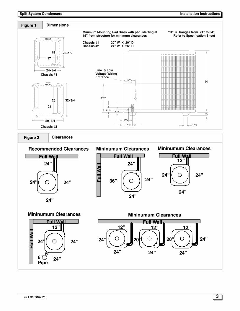
Changing the Restrictor OrificeThe restrictor orifice is located in a fitting in the liquid line.The fitting is actually the distributor end of the cap tube as-sembly.
1. Remove the liquid line fitting and replace restrictor ori-fice. (STANDARD RIGHT HAND THREAD)
2. Make sure the restrictor is installed with the roundedend toward the feeder tubes. See Figure 3.
Feeder Tubes
Rounded End
Nut and Liquid Linewith Strainer
Restrictor Orifice
Figure 3 Restrictor Orifice
Refrigeration Line SetsIf it is necessary toadd tubing in the field, usedehydratedordry sealed deoxidized copper refrigeration tube. DO NOTuse copper water pipe.
It is important that no tubing iscutorsealsbrokenuntilyou are ready to actually make connections to theevaporator and to the condenser section.
Do not remove rubber plugs or copper caps from thetube ends until ready tomake connections at evapora-tor and condenser.
PLEASE! UNDER NO CIRCUMSTANCES LEAVE THELINES OPEN TO THE ATMOSPHERE FOR ANYPERIOD OF TIME.
Be extra careful with sharp bends. This tubing can �kink�very easily, and if this occurs, the entire tube length willhave to be replaced. Extra care at this time will eliminatefuture service problems.
Suspension And Installation OfRefrigeration LinesDONOT fasten liquid or suction lines in direct contact withthe floor or ceiling joist. Use an insulated or suspensiontype of hanger. Keep both lines separate, and insulate thesuction line. Both lines should be insulated in long runs inan attic or underground in a raceway.
Do not let refrigerant lines come in direct contact withfoundation. When running refrigerant lines through thefoundation or wall, the openings should be made largeenough to allow for a sound absorbing material to beplaced or installed between the tubing and the foundation.This will prevent noise transmission between the tubingand the wall section (foundation) or the building.
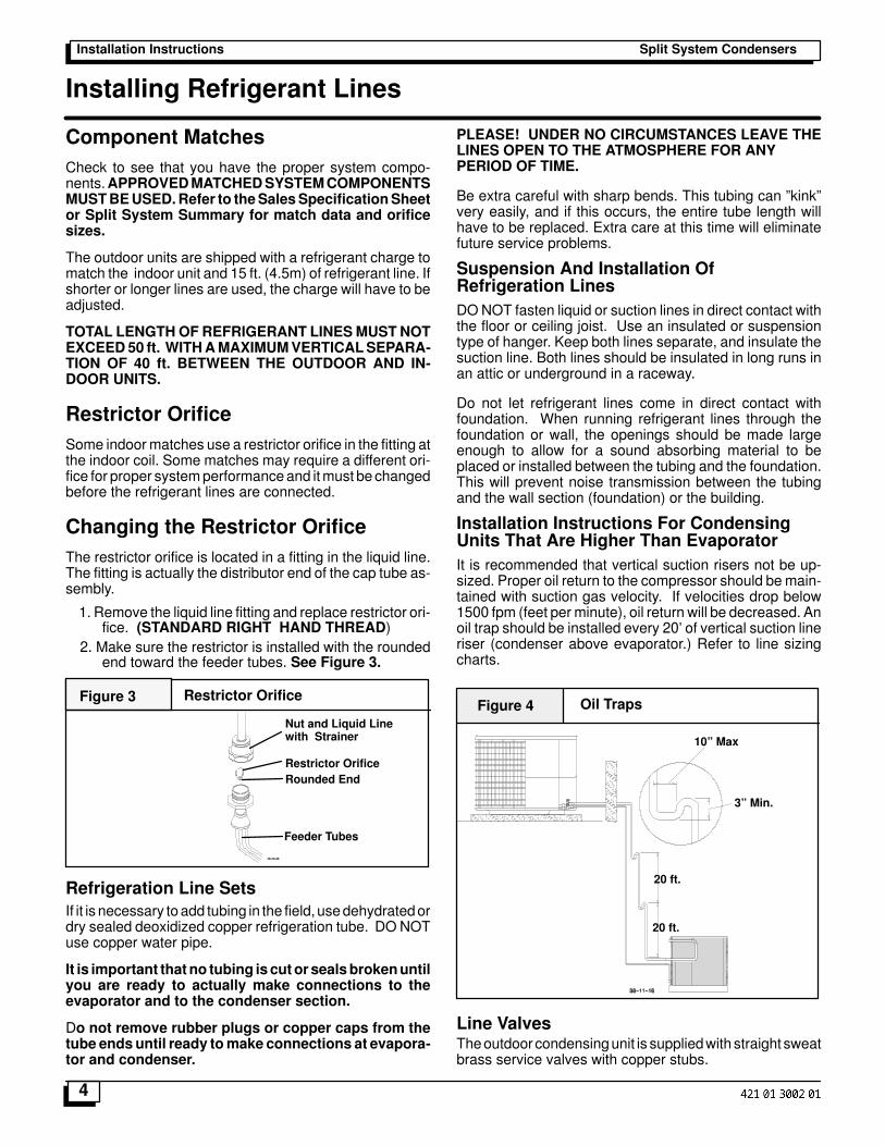
Installation Instructions For CondensingUnits That Are Higher Than EvaporatorIt is recommended that vertical suction risers not be up-sized. Proper oil return to the compressor should bemain-tained with suction gas velocity. If velocities drop below1500 fpm (feet per minute), oil return will be decreased. Anoil trap should be installed every 20� of vertical suction lineriser (condenser above evaporator.) Refer to line sizingcharts.
Oil TrapsFigure 4
20 ft.
20 ft.
10� Max
3� Min.
Line ValvesTheoutdoor condensingunit is suppliedwith straight sweatbrass service valves with copper stubs.
Split System Condensers Installation Instructions
5
All line valves are positioned to seal the refrigerant in thecondensing unit with gauge ports open to connecting lineswhen theSchraeder valve isdepressed. GaugeportshaveSchraeder installed and require use of charging hoseswithdepressors.
Brazing Connections
Fire Hazard
Refrigerant and oil mixture under pressure couldignite as it escapes and contacts brazing torchresulting in Fire. Make sure the refrigerant chargeis properly removed from both the high and lowsides of the system before brazing any compo-nent or lines.
FAILURE TO DO SO COULD RESULT IN BODILYINJURY OR DEATH.
Before making braze connections, be sure all joints areclean. Before heat is applied for brazing, nitrogen shouldbe flowing through the tubing to prevent oxidation andscale formation on the inside of the tubing.
Liquid & Suction LinesFully annealed refrigeration lines should be used wheninstalling the system.The following is the recommended method for makingbraze connections at the refrigerant line connections:1. Clean refrigerant tube end with emery cloth or steelbrush.2. Use a suitable brazing alloy for copper to copper joints.3. Insert tubing into swage fitting connection.4. Apply heat absorbing paste or heat sink product to pre-vent damage to the service valve.
CAUTIONDo not heat valve body above 250 degrees F.
5. Braze joint.6. Quench the joint and tubing with water using a wet rag.Leave rag on fitting body and re--wetwithwater to help coolarea.
Evacuating, And Charging InstructionsNOTE
Intentional release of CFC or HCFC Refrigerant to theAtmosphere violates Federal Law. It may also violateState and Local Codes. Check all Federal, State andLocal Codes before proceeding.These instructions are intended for use with condensingunits that are precharged at the factory with adequate re-frigerant to handle 15 feet.NOTE: Do not use any portion of the charge for purging orleak testing. It is mandatory that a thorough evacuation ofthe refrigerant in the piping and evaporator be performed.The liquid line and suction line service valves have beenclosed after final testing at the factory. Do not disturbthese valves until the lines have been leak checkedand evacuated or the charge in the unit may be lost.
Recommended Method Of Evacuating ASystem1. Connect the vacuum pump to the suction and liquid linegauge ports.2. If the evacuation is being performed on a new systeminstallation, the valves should be kept in the �front seated�(closed) position. This will allow themechanic to evacuatethe refrigeration lines and the indoor coil, without disturbingthe factory charge in the outdoor unit.3. Follow the vacuum pump manufacturer�s instructions.Allow the pump to operate until the system has been eva-cuated down to 300 microns. Allow the pump to continuerunning for anadditional 15minutes. Turnoff thepumpandleave the connections secured to the two service valves.After 5 minutes, if the system fails to hold 500 microns orless, check all connections for tight fit and repeat the evac-uation procedure.4. Isolate the vacuumpump from the systemby closing theshutoff valves on the gauge bar. Disconnect the vacuumpump.Valve Actuation: Service ValvesRemove the service valve cap, if there is amale valve stemsee instructions for Ball Valves. For the standard servicevalve there are two variations, but both have internalstems.The first style usesan internal snap ring to retain thevalve stem and the second has a rolled top and also hasfiner threadson thevalve cap.NOTE:Youmayencountermore than one type of valve on a unit.For service valves fully insert a hexwrench into the stem.Aback--up wrench is required on the valve body to open thevalve stem. Backout counterclockwise until the valve stemstops or just touches the retaining ring. NOTE: THIS ISNOT A BACKSEATING VALVE. For valves with retainerrings care must be taken to prevent dislodging them whenopening valve.The service valve cap is a primary seal for the valve andmust beproperly tightened toprevent leaks.Makesurecapis clean and apply refrigerant oil to threads and sealing sur-face of cap.For valves with retaining rings: Replace service valvecap and torque to; 8--11 ft. lbs. on 1/4� and 3/8� valves,12--16 ft. lbs. on 5/8� and3/4�, 15--21 ft. lbs on7/8� valves. Iftorque wrench is not available, tighten cap finger tight andthen tighten one (1) additional wrench flat or 1/6 of a turn.
For valves with rolled tops: Replace service valve captighten cap finger tight and then tighten one (1) additionalwrench flat or 1/6 of a turn to properly seat the sealing sur-faces. Subsequent installations will seat with 1/2 to 1wrench flat of turning.
Gauge Ports: All ValvesCheck for leaks at the schrader port and tighten valve coreif necessary. Install plastic caps finger tight.
Ball ValvesOn models with ball type valves use a 6� crescent wrenchto rotate the valve stem 90� counter clockwise. Retightenvalve cap to 6--8 ft. lbs. If torque wrench is not available,tighten cap finger tight and then tighten one (1/2) additionalwrench flat.
Split System CondensersInstallation Instructions
6
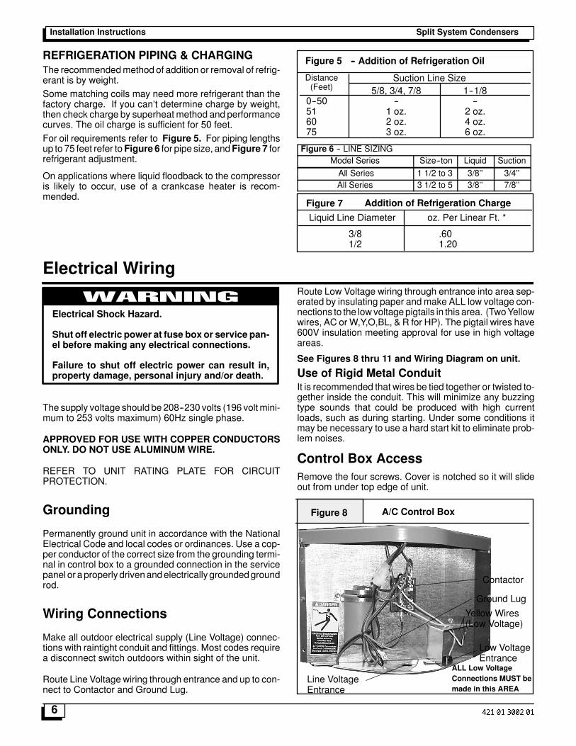
REFRIGERATION PIPING & CHARGINGThe recommendedmethod of addition or removal of refrig-erant is by weight.Some matching coils may need more refrigerant than thefactory charge. If you can�t determine charge by weight,then check charge by superheat method and performancecurves. The oil charge is sufficient for 50 feet.For oil requirements refer to Figure 5. For piping lengthsup to 75 feet refer toFigure 6 for pipe size, andFigure 7 forrefrigerant adjustment.
On applications where liquid floodback to the compressoris likely to occur, use of a crankcase heater is recom-mended.
Distance(Feet)
Suction Line Size5/8, 3/4, 7/8 1--1/8
0--50 -- --51 1 oz. 2 oz.60 2 oz. 4 oz.75 3 oz. 6 oz.
Figure 5 -- Addition of Refrigeration Oil
Figure 6 -- LINE SIZINGModel Series Size--ton Liquid Suction
All Series 1 1/2 to 3 3/8�� 3/4��All Series 3 1/2 to 5 3/8�� 7/8��
Figure 7 Addition of Refrigeration Charge
Liquid Line Diameter oz. Per Linear Ft. *
3/8 .601/2 1.20
Electrical Wiring
Electrical Shock Hazard.
Shut off electric power at fuse box or service pan-el before making any electrical connections.
Failure to shut off electric power can result in,property damage, personal injury and/or death.
WARNING
The supply voltage should be 208--230 volts (196 voltmini-mum to 253 volts maximum) 60Hz single phase.
APPROVED FOR USE WITH COPPER CONDUCTORSONLY. DO NOT USE ALUMINUM WIRE.
REFER TO UNIT RATING PLATE FOR CIRCUITPROTECTION.
Grounding
Permanently ground unit in accordance with the NationalElectrical Code and local codes or ordinances. Use a cop-per conductor of the correct size from the grounding termi-nal in control box to a grounded connection in the servicepanel or aproperly drivenandelectrically groundedgroundrod.
Wiring Connections
Make all outdoor electrical supply (Line Voltage) connec-tions with raintight conduit and fittings. Most codes requirea disconnect switch outdoors within sight of the unit.
Route Line Voltage wiring through entrance and up to con-nect to Contactor and Ground Lug.
Route Low Voltage wiring through entrance into area sep-erated by insulating paper and make ALL low voltage con-nections to the lowvoltagepigtails in this area. (TwoYellowwires, AC or W,Y,O,BL, & R for HP). The pigtail wires have600V insulation meeting approval for use in high voltageareas.
See Figures 8 thru 11 and Wiring Diagram on unit.
Use of Rigid Metal ConduitIt is recommended that wires be tied together or twisted to-gether inside the conduit. This will minimize any buzzingtype sounds that could be produced with high currentloads, such as during starting. Under some conditions itmay be necessary to use a hard start kit to eliminate prob-lem noises.
Control Box AccessRemove the four screws. Cover is notched so it will slideout from under top edge of unit.
A/C Control BoxFigure 8
Contactor
Yellow Wires(Low Voltage)
Line VoltageEntrance
Ground Lug
Low VoltageEntrance
ALL Low VoltageConnections MUST bemade in this AREA
Split System Condensers Installation Instructions
7
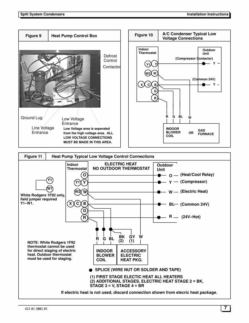
Figure 9 Heat Pump Control Box
Contactor
DefrostControl
Line VoltageEntrance
Ground Lug Low VoltageEntranceLow Voltage area is seperatedfrom the high voltage area. ALLLOW VOLTAGE CONNECTIONSMUST BE MADE IN THIS AREA.
Figure 10 A/C Condenser Typical LowVoltage Connections
Y
W
G
R
Y
INDOORBLOWERCOIL
R G BL
Y
W
Y1
W2
BCX
IndoorThermostat
OutdoorUnit
(Compressor Contactor)
(Common 24V)
ORGASFURNACE
Figure 11 Heat Pump Typical Low Voltage Control Connections
Y
W
G
R
Y
INDOORBLOWERCOIL
ACCESSORYELECTRICHEAT PKG.
R G BL
BL
WGYBK(2) (1)
ELECTRIC HEATNO OUTDOOR THERMOSTAT
SPLICE (WIRE NUT OR SOLDER AND TAPE)
(1) FIRST STAGE ELECTIC HEAT ALL HEATERS(2) ADDITIONAL STAGES, ELECTRIC HEAT STAGE 2 = BK,STAGE 3 = V, STAGE 4 = BR
Y1
W1
Y1
O O
W2
BCX
R
WWhite Rodgers 1F92 only,field jumper requiredY1--W1.
NOTE: White Rodgers 1F92thermostat cannot be usedfor direct staging of electricheat. Outdoor thermostatmust be used for staging.
IndoorThermostat
OutdoorUnit
(Heat/Cool Relay)
(Compressor)
(Electric Heat)
(Common 24V)
(24V--Hot)
If electric heat is not used, discard connection shown from elecric heat package.
Split System CondensersInstallation Instructions
8
Start--Up Procedure
Start--up Procedure1. Close electrical disconnects to energize system.
2. Energize crankcase heater on units so equipped.
3. Set Thermostat selector switch to OFF.
4. Set room thermostat at desired temperature. Be suresetpoint is below indoor ambient temperature for coolingand above indoor ambient for heating.
5. Set the system switch of the thermostat on COOL andfan switch for continuous operation or AUTO, as desired.Operate unit for 15--20 minutes, then check the system re-frigerant charge if it was necessary to adjust.
6. After the refrigerant charge has been adjusted, the sys-tem is now ready for continuous operation.
Final Refrigeration Charge AdjustmentSome matching coils may need more refrigerant than thefactory charge. For optimum heat pump performance atARI test conditions, the system should initially be chargedper cooling mode instructions (ARI �B� test conditions). Acheck in heating mode (ARI �High Heat� test conditions)should then be performed. Charge level may be adjustedper Heating Mode Charge instructions to ensure that highheat capacity is at or above 95%of ARI rating. ARI coolingtests may then be performed using the adjusted operatingcharge.
AirflowBefore any adjustment is made to the refrigerant charge, itis imperative that the air flow characteristics of the indoorblower be established.
When checking indoor air flow, it is important to rememberthat the blower will deliver a higher quantity of air across adry coil versus awet coil. Blower charts are calculated witha dry coil.
Recommendedair flow for installations of cooling units andheat pumps is 350--450 CFM per ton (12,000 BTUH)through a wet coil. Refer to indoor unit installation instruc-tions for propermethods of determining air flow and blowerperformance.
To Check System Refrigerant Charge(Superheat Method), Cooling Only1. Attach an accurate temperature sensing device to thesuction line approximately 4� -- 6� away from the suctionline service valve. The temperature sensing device shouldbe clamped securely to the suction line, on a horizontalplane (between 9 & 3 O�clock) and insulated. Record thesuction line temperature.
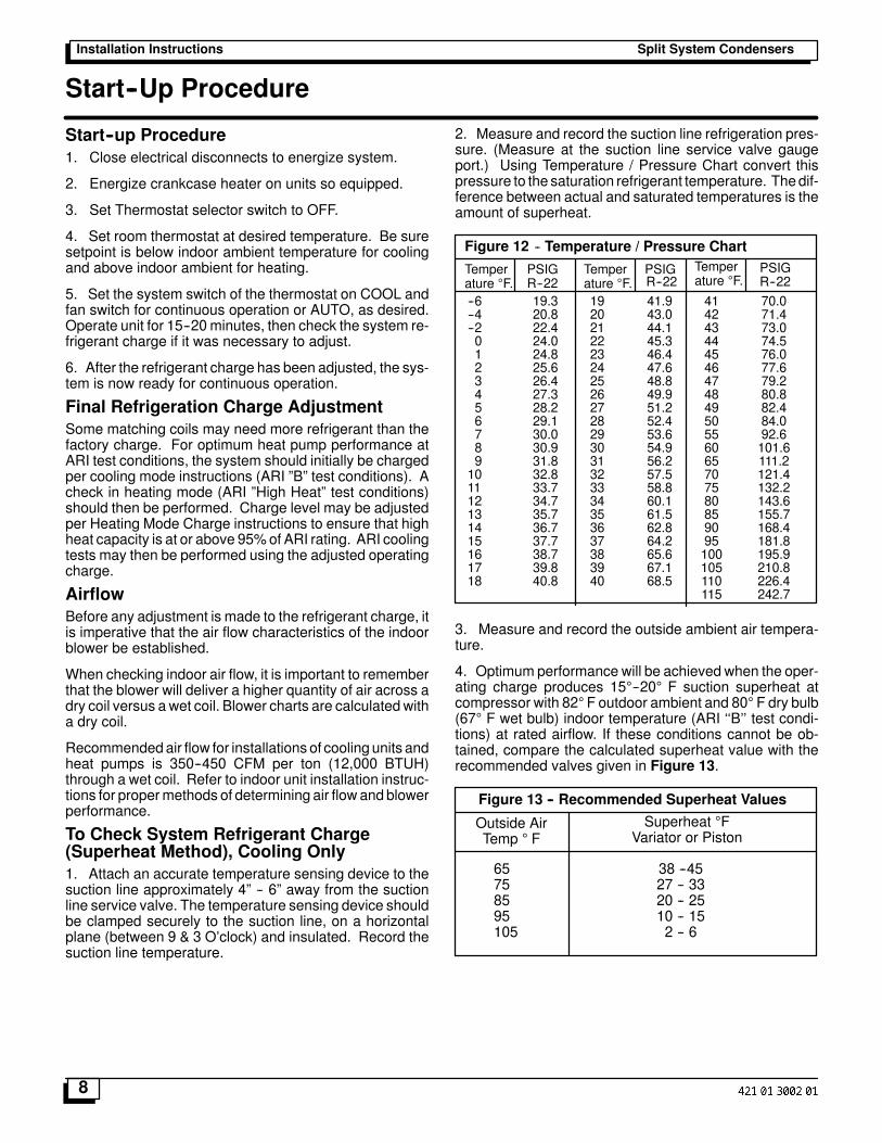
2. Measure and record the suction line refrigeration pres-sure. (Measure at the suction line service valve gaugeport.) Using Temperature / Pressure Chart convert thispressure to the saturation refrigerant temperature. Thedif-ference between actual and saturated temperatures is theamount of superheat.
-- Temperature / Pressure Chart
Temperature �F.
Temperature �F.
Temperature �F.R--22 R--22 R--22
--6 19.3 19 41.9 41 70.0--4 20.8 20 43.0 42 71.4--2 22.4 21 44.1 43 73.00 24.0 22 45.3 44 74.51 24.8 23 46.4 45 76.02 25.6 24 47.6 46 77.63 26.4 25 48.8 47 79.24 27.3 26 49.9 48 80.85 28.2 27 51.2 49 82.46 29.1 28 52.4 50 84.07 30.0 29 53.6 55 92.68 30.9 30 54.9 60 101.69 31.8 31 56.2 65 111.210 32.8 32 57.5 70 121.411 33.7 33 58.8 75 132.212 34.7 34 60.1 80 143.613 35.7 35 61.5 85 155.714 36.7 36 62.8 90 168.415 37.7 37 64.2 95 181.816 38.7 38 65.6 100 195.917 39.8 39 67.1 105 210.818 40.8 40 68.5 110 226.4
115 242.7
Figure 12
PSIG PSIG PSIG
3. Measure and record the outside ambient air tempera-ture.
4. Optimum performance will be achieved when the oper-ating charge produces 15�--20� F suction superheat atcompressor with 82�F outdoor ambient and 80� F dry bulb(67� F wet bulb) indoor temperature (ARI ��B�� test condi-tions) at rated airflow. If these conditions cannot be ob-tained, compare the calculated superheat value with therecommended valves given in Figure 13.
Outside AirTemp � F
Superheat �FVariator or Piston
65 38 --4575 27 -- 3385 20 -- 2595 10 -- 15105 2 -- 6
Figure 13 -- Recommended Superheat Values
Split System Condensers Installation Instructions
9
If the actual superheat readings are higher than shown, thesystem is most likely under--charged, and charge shouldbe added. Add charge in 4 ounce increments, and recalcu-late superheat values. Continue adjusting charge until theactual superheat approximately matches the recom-mended values.
If the actual superheat readings are lower than shown, thesystem is most likely over--charged, and charge should beremoved. Remove charge in 4 to 6 ounce increments, andrecalculate superheat values. Continue adjusting chargeuntil the actual superheat approximately matches the rec-ommended values.
NOTE: Each time that charge is added or removed fromthe system, allow the system to run approximately 15 min-utes before pressure and temperature readings are takenand superheat calculations made.
NOTE: Indoor Wet Bulb Temperature ( and Relative Hu-midity) will alter superheat values. All readings should beat 50% humidity inside and 350 to 450 CFM per ton acrossthe indoor coil.
Heating Checkout (Heat Pump Only)1. Turn thermostat heat--cool switch to OFF. Turn ther-
mostat fan switch to AUTO.2. Turn on all power except 230 volt line to outdoor sec-
tion.3. Turn fan switch on thermostat to ON. Blower should
run. Reset to AUTO; blower should turn off.4. Set thermostat below room temperature. Turn selec-
tor switch to heat. Move thermostat above room tem-perature. Blower should run on heating speed and aclick should be heard in the condensing unit outside(contactor closing). The sequencer coils for auxiliaryheat should be energized. After approximately 30seconds the contacts in the sequencers should closeand the electric heat elements start heating. Allow 3minutes for all heaters to come on.
5. Set system switch to OFF> Turn the thermostatabove room temperature. Turn on the 230 volt powerto the outdoor unit. Nothing apparent will be happen-ing, but the crankcase heater is now energized. If theoutdoor temperature is below 75 �F allow the unit tostay in this mode at least 6 hours. This is needed tovaporize any refrigerant that may be in the compres-sor oil.
6. Set the thermostat above room temperature. Movesystem switch to heat. Count to 5 (about 5 seconds).Turn the electric power off at the condensing unit dis-connect switch. Check that there is no clattering orunusual noises. The outdoor fan blade should havestarted turning and a humming noise should havebeen heard from the compressor. The indoor fanshould continue to run at its normal speed and elec-tric elements continue to heat.
7. Wait 2 minutes, then repeat the procedure and re-check thesame things in caseyoumissedsomethingduring the first power application.
8. With the unit operating, close all doors, windows,storm windows, and openings to the house. Set thethermostat to the desired setting. Set outdoor ther-mostat (if installed) to balance point of house. If tem-perature of house is at least two degrees belowthermostat setting, heat pump and auxiliary heat notcontrolled by outdoor thermostatswill continue to rununtil room temperature is approximately 2� belowthermostat set point. Auxiliary heat light should goout and auxiliary heat cycle off. Heat pump shouldcontinue to run until thermostat reaches set point.
To Check System Refrigerant Charge(Heating Mode)
Formodelswithanoutdoor restrictor orifice, optimumheat-ing performance will be achieved when the operatingcharge produces 10� -- 20� F suction superheat at com-pressor with 47� F outdoor ambient and 70� F dry bulb in-door temperature (ARI �HighHeat� test conditions) at ratedairflow.
The recommended method of addition or removal ofcharge in the heating mode is by weight. The system op-eration may be checked against the performance charts.Remember, indoor airflow must be approximately 400CFM per ton to compare operation to performance charts.
Defrost System (Heat Pump Only)
The defrost system is electronic with an adjustable time in-terval of 90, 60, or 30 minutes. It is factory set at 60 or 90minutes. At the selected time interval with the outdoor coiltemperature at approximately 28 �F, the system will de-frost. When the sensor sees a rise in the outdoor coil tem-perature to approximately 10 minutes, the defrost will beterminated.
In some areas, with high humidity, the time interval may re-quire adjustment for complete removal of ice from the coil.For best economy, always set to the longest interval thatwill keep the coil clear of ice.
NOTE: The term ice means hard but not frost. During nor-mal operation, the coils may become coatedwith frost untilthey are solid white. The time interval for the defrost shouldbe set so the frost and ice melt off completely without hardice building up on the coil.
Split System CondensersInstallation Instructions
10
Maintenance
Electrical Shock Hazard.
Shut off electric power at fuse box or service pan-el before making any electrical connections.
Failure to shut off electric power can result in,property damage, personal injury and/or death.
WARNING
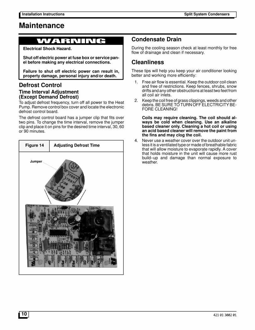
Defrost ControlTime Interval Adjustment(Except Demand Defrost)To adjust defrost frequency, turn off all power to the HeatPump. Remove control box cover and locate the electronicdefrost control board.The defrost control board has a jumper clip that fits overtwo pins. To change the time interval, remove the jumperclip and place it on pins for the desired time interval, 30, 60or 90 minutes.
Figure 14 Adjusting Defrost Time
Jumper
Condensate DrainDuring the cooling season check at least monthly for freeflow of drainage and clean if necessary.
CleanlinessThese tips will help you keep your air conditioner lookingbetter and working more efficiently:
1. Free air flow is essential. Keep the outdoor coil cleanand free of restrictions. Keep fences, shrubs, snowdrifts andanyother obstructionsat least two feet fromall coil air inlets.
2. Keep the coil freeof grass clippings,weedsandotherdebris. BESURETOTURNOFFELECTRICITYBE-FORE CLEANING!
Coils may require cleaning. The coil should al-ways be cold when cleaning. Use an alkalinebased cleaner only. Cleaning a hot coil or usingan acid based cleaner will remove the paint fromthe fins and may clog the coil.
4. Never use a weather cover over the outdoor unit un-less it is a ventilated typeormadeof breathable fabricthat will allow moisture to evaporate rapidly. A coverthat holds moisture in the unit will cause more rustbuild--up and damage than normal exposure toweather.