installation instructions - fireplace stove world gas fireplace manual.pdf · warning: if the...
TRANSCRIPT
WARNING: If the information in these instructions is not followed exactly, a fire or explosion may result causing property damage, personal injury or loss of life.
Warning: Improper installation, adjustment, alteration, service or maintenance can cause property damage, personal injury or loss of life. Refer to this manual. Installation and service must be performed by a qualified installer, service agency or the gas supplier.
Do not store or use gasoline or other flammable vapors and liquids in the vicinity of this or any other appliance.
What To Do If You Smell Gas Do not try to light any appliance.
Extinguish any open flame. Do not touch any electrical switch.
Do not use any phone in your building. Immediately call your gas supplier from a neighbour's phone.
If you can not reach your gas supplier, call the fire department.
For Propane Horizontal installations the venting must be a minimum of one foot vertical off the flue before going horizontal.
Installation Instructions Model Number ZDV3318, ZDV3622
Zero Clearance Direct Vent Fireplace Stock #’s: ZDV3318N, ZDV3318NE, ZDV3318LP, ZDV3318LPE
ZDV3622N, ZDV3622NE, ZDV3622LP, ZDV3622LPE ZDVRB3622NE, ZDVRB3622LPE
Certified to: ANSI Z21.88-2009, CSA 2.33-2009, CGA 2.17-M91
Stock #’s: ZDVRB3622N, ZDVRB3622LP Certified to: ANSI Z21.50b-2009, CSA 2.22b-2009, CGA 2.17-M91
Printed in Canada May 8, 2012 Part # 3318-MAN-II
FOR YOUR SAFETY
Read this complete manual before beginning installation. These instructions must be kept with the unit for future reference.
This appliance may be installed in an aftermarket permanently located, manufactured home (USA only) or mobile home, where not prohibited by local codes. This appliance is only for use with the type of gas indicated on the rating plate. This appliance is not convertible for use with other gases, unless a certified kit is used.
A Division of R-Co. Inc. 2340 Logan Avenue Winnipeg, Manitoba, Canada R2R 2V3 Ph: (204) 632-1962
INSTALLER: Leave this manual with the appliance. CONSUMER: Retain this manual for future reference.
Pre-installation Questions and Answers
About curing of the paint Your stove or fireplace has been painted with the highest quality silicone stove paint. This paint dries quickly in 15-20 minutes when first applied at the factory. However, due to the high temperature silicone components, the paint will cure when heat is applied to the appliance as it is first used. The following information applies to the curing process to get the paint fully hard and durable.
Fire the appliance four successive times for 10 minutes each firing and a 5 minute cool down between each. Be aware during log and firebox paint curing that a white deposit may be developing on the inside of the glass doors. It is important to remove this white deposit from the glass doors using a commercial fireplace glass cleaner.
• Babies, small children, pregnant women and pets should leave the area during the cure phase.
• Ventilate well, open doors and windows.
• Do not touch during curing.
Why does my fireplace or stove give off odour? It is normal for your fireplace to give off some odour. This is due to the curing of the paint, adhesives, silicones and any undetected oil from the manufacturing process as well as the finishing materials used with the installations (e.g. marble, tile and the adhesives used to adhere this product to the walls can react with heat and cause odours).
It is recommended that you burn your gas fireplace or stove for a minimum of four hours at a time with the fan off after the curing of the paint has been completed. These odours can last upward to 40 hours of burn time; keep burning at a minimum of four hours per use until odours dissipate.
Noise coming from the fireplace? Noise is caused by the expansion and contraction of metal as the appliance heats up and cools down. This is normal and is similar to the sounds produced by a furnace or heating duct. This noise does not affect the operation or longevity of your fireplace.
Operating Instructions
1. Be sure to read and understand all the instructions in this manual before operation of appliance.
2. Ensure all wiring is correct and properly enclosed to prevent possible shock.
3. Check for gas leaks.
4. Make sure the glass door is properly installed before operation. Never operate the appliance with the glass door
removed.
5. Make sure venting and termination cap are installed and unobstructed.
6. If brick or porcelain liners are used, ensure they are installed.
7. Verify that the pilot can be seen when lighting the appliance. If not, the log or rock placement is incorrect.
8. If the unit is turned off, you must wait a minimum of 60 seconds before re-lighting it.
2
Table of Contents Pre-installation Questions and Answers………………………………….. 2 Operating Instructions………………………………………………………. 2 Table of Contents…………………………………………………………… 3 Mobile Home/Manufactured Housing Installation……………………...... 4 Warnings, Installations, and Operations………………………………….. 5-6 Installation Requirements for the Commonwealth of Massachusetts… 6
ZDV3318 Locating your Appliance............................................................... 7 Fireplace Dimensions................................................................... 7 Framing for your Gas Fireplace................................................... 8 Framing and Facing Requirements............................................. 9 ZDV3622 Locating your Appliance............................................................... 10 Fireplace Dimensions................................................................... 10 Framing for your Gas Fireplace................................................... 11 Framing and Facing Requirements.............................................. 12
How To Install Clean View Kit (CVCK)................................................... 13 Clearances - ZDV3318/3622 - Mantels & Surrounds............................. 14 Mantel Leg Clearances........................................................................... 15 Clearance to Combustibles..................................................................... 16 Fan Kit Installation.................................................................................. 17 Split Receptacle- Fan Speed Control Outside of Fireplace.................... 18 Z3318 / Z3622PRL & Z3318ML / Z3622ML Installation Guide………… 19 Door and Glass Information................................................................... 20 Gas Line Installation………………………………………………………… 21 Millivolt System, Lighting, & Burner Control............................................ 22 Burner System Maintenance................................................................... 23 Conversion Kit Instructions – PART A.................................................... 24-25 Gas Conversion Kit For Top Convertible Pilot PART B.......................... 26 Gas Conversion for Modulator – PART C............................................... 27 IPI Electronic Ignition System................................................................. 28-32 IPI Lighting Instructions.......................................................................... 33 Trouble Shooting The Gas Control System............................................ 34 LOGC50 Log Assembly.......................................................................... 35-36 Accessories Available for Skyline & ZDVRB3622................................... 37-38 ULK2 Universal Light Kit (Optional Accent Lighting Kit)......................... 39-40 Vent Termination..................................................................................... 41 General Vent Installation Information...................................................... 42 Installation Of Side Wall Venting............................................................. 42 Venting Table.......................................................................................... 43 Vertical Venting....................................................................................... 44 Vertical Venting over 15 Feet.................................................................. 45 ZDV3318 Parts List................................................................................. 46 ZDV3622 Parts List................................................................................. 47 Kingsman Parts ZDV3318/3622............................................................. 48 Glass Safety / Termination Cap Safety -All Units-................................. 49 Limited Lifetime Warranty....................................................................... 50
3
Mobile Home/Manufactured Housing Installation
This Direct Vent System Appliance must be installed in accordance with the manufacturer’s installation instructions and theManufactured Home Construction and Safety Standard Title 24 CFR, Part 3280, or the current Standard for Fire SafetyCriteria for Manufactured Home Installations, Sites, and Communities ANSI/NFPA 501A, and with CAN/CSA Z240 MHMobile Home Standard in Canada.
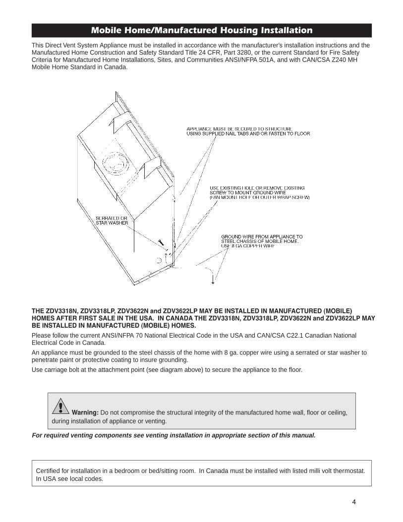
THE ZDV3318N, ZDV3318LP, ZDV3622N and ZDV3622LP MAY BE INSTALLED IN MANUFACTURED (MOBILE)HOMES AFTER FIRST SALE IN THE USA. IN CANADA THE ZDV3318N, ZDV3318LP, ZDV3622N and ZDV3622LP MAYBE INSTALLED IN MANUFACTURED (MOBILE) HOMES.
Please follow the current ANSI/NFPA 70 National Electrical Code in the USA and CAN/CSA C22.1 Canadian NationalElectrical Code in Canada.
An appliance must be grounded to the steel chassis of the home with 8 ga. copper wire using a serrated or star washer topenetrate paint or protective coating to insure grounding.
Use carriage bolt at the attachment point (see diagram above) to secure the appliance to the floor.
Warning: Do not compromise the structural integrity of the manufactured home wall, floor or ceiling,during installation of appliance or venting.
For required venting components see venting installation in appropriate section of this manual.
Certified for installation in a bedroom or bed/sitting room. In Canada must be installed with listed milli volt thermostat.In USA see local codes.
4
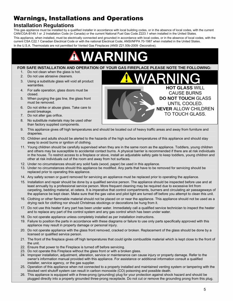
Warnings, Installations and Operations Installation Regulations This gas appliance must be installed by a qualified installer in accordance with local building codes, or in the absence of local codes, with the current CAN/CGA-B149.1 or .2 Installation Code (in Canada) or the current National Fuel Gas Code Z223.1 when installed in the United States. This appliance, when installed, must be electrically connected and grounded in accordance with local codes, or in the absence of local codes, with the current CSA C22.1 Canadian Electrical Code or with the national Electrical Code; ANSI/NFPA 70-1987 when installed in the United States. In the U.S.A. Thermostats are not permitted for Vented Gas Fireplaces (ANSI Z21.50b-2009 -Decorative).
WARNING
FOR SAFE INSTALLATION AND OPERATION OF YOUR GAS FIREPLACE PLEASE NOTE THE FOLLOWING: 1. Do not clean when the glass is hot. 2. Do not use abrasive cleaners. 3. Using a substitute glass will void all product
warranties. 4. For safe operation, glass doors must be
closed. 5. When purging the gas line, the glass front
must be removed. 6. Do not strike or abuse glass. Take care to
avoid breakage. 7. Do not alter gas orifice. 8. No substitute materials may be used other
than factory supplied components. 9. This appliance gives off high temperatures and should be located out of heavy traffic areas and away from furniture and
draperies. 10. Children and adults should be alerted to the hazards of the high surface temperatures of this appliance and should stay
away to avoid burns or ignition of clothing. 11. Young children should be carefully supervised when they are in the same room as the appliance. Toddlers, young children
and others may be susceptible to accidental contact burns. A physical barrier is recommended if there are at risk individuals in the house. To restrict access to a fireplace or stove, install an adjustable safety gate to keep toddlers, young children and other at risk individuals out of the room and away from hot surfaces.
12. Under no circumstances should any solid fuels (wood, paper) be used in this appliance. 13. Under no circumstances should this appliance be modified. Any parts that have to be removed for servicing should be
replaced prior to operating this appliance. 14. Any safety screen or guard removed for servicing an appliance must be replaced prior to operating the appliance. 15. Installation and repair should be done by a qualified service person. The appliance should be inspected before use and at
least annually by a professional service person. More frequent cleaning may be required due to excessive lint from carpeting, bedding material, et cetera. It is imperative that control compartments, burners and circulating air passageways of the appliance be kept clean. Make sure that the gas valve and pilot light are turned off before you attempt to clean this unit.
16. Clothing or other flammable material should not be placed on or near the appliance. This appliance should not be used as a drying rack for clothing nor should Christmas stockings or decorations be hung from it.
17. Do not use this heater if any part has been under water. Immediately call a qualified service technician to inspect the heater and to replace any part of the control system and any gas control which has been under water.
18. Do not operate appliance unless completely installed as per installation instructions. 19. Failure to position the parts in accordance with these diagrams or failure to use only parts specifically approved with this
appliance may result in property damage or personal injury. 20. Do not operate appliance with the glass front removed, cracked or broken. Replacement of the glass should be done by a
licensed or qualified service person. 21. The front of the fireplace gives off high temperatures that could ignite combustible material which is kept close to the front of
the unit. 22. Ensure that power to the Fireplace is turned off before servicing. 23. Do not operate this Fireplace without the glass front or with a broken glass. 24. Improper installation, adjustment, alteration, service or maintenance can cause injury or property damage. Refer to the
owner’s information manual provided with this appliance. For assistance or additional information consult a qualified installer, service agency, or the gas supplier.
25. Operation of this appliance when not connected to a properly installed and maintained venting system or tampering with the blocked vent shutoff system can result in carbon monoxide (CO) poisoning and possible death.
26. This appliance is equipped with a three-prong (grounding) plug for your protection against shock hazard and should be plugged directly into a properly grounded three-prong receptacle. Do not cut or remove the grounding prong from this plug.
WARNING
HOT GLASS WILL CAUSE BURNS
DO NOT TOUCH GLASS UNTIL COOLED.
NEVER ALLOW CHILDRENTO TOUCH GLASS.
5
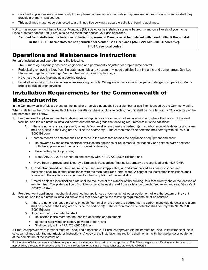
• Gas fired appliances may be used only for supplemental heat and/or decorative purposes and under no circumstances shall they provide a primary heat source.
• This appliance must not be connected to a chimney flue serving a separate solid-fuel burning appliance.
NOTE: It is recommended that a Carbon Monoxide (CO) Detector be installed in or near bedrooms and on all levels of your home. Place a detector about 15ft [4.5m] outside the room that houses your gas appliance.
Certified for installation in a bedroom or bed/sitting room. In Canada must be installed with listed millivolt thermostat. In the U.S.A. Thermostats are not permitted for Vented Gas Fireplaces (ANSI Z21.50b-2009 -Decorative).
In USA see local codes.
Operations and Maintenance Instructions For safe installation and operation note the following: • The Burner/Log Assembly has been engineered and permanently adjusted for proper flame control. • Periodically remove the logs from the grate assembly and vacuum any loose particles from the grate and burner areas. See Log
Placement page to remove logs. Vacuum burner parts and replace logs. • Never use your gas fireplace as a cooking device. • Label all wires prior to disconnection when servicing controls. Wiring errors can cause improper and dangerous operation. Verify
proper operation after servicing.
Installation Requirements for the Commonwealth of Massachusetts In the Commonwealth of Massachusetts, the installer or service agent shall be a plumber or gas fitter licensed by the Commonwealth. When installed in the Commonwealth of Massachusetts or where applicable codes; the unit shall be installed with a CO detector per the requirements listed below. 1. For direct-vent appliances, mechanical-vent heating appliances or domestic hot water equipment, where the bottom of the vent
terminal and the air intake is installed below four feet above grade the following requirements must be satisfied: A. If there is not one already present, on each floor level where there are bedroom(s), a carbon monoxide detector and alarm
shall be placed in the living area outside the bedroom(s). The carbon monoxide detector shall comply with NFPA 720 (2005 Edition).
B. A carbon monoxide detector shall be located in the room that houses the appliance or equipment and shall: • Be powered by the same electrical circuit as the appliance or equipment such that only one service switch services
both the appliance and the carbon monoxide detector; • Have battery back-up power;
• Meet ANSI./UL 2034 Standards and comply with NFPA 720 (2005 Edition); and
• Have been approved and listed by a Nationally Recognized Testing Laboratory as recognized under 527 CMR.
C. A Product-approved vent terminal must be used, and if applicable, a Product-approved air intake must be used. Installation shall be in strict compliance with the manufacturer’s instructions. A copy of the installation instructions shall remain with the appliance or equipment at the completion of the installation.
D. A metal or plastic identification plate shall be mounted at the exterior of the building, four feet directly above the location of vent terminal. The plate shall be of sufficient size to be easily read from a distance of eight feet away, and read “Gas Vent Directly Below”.
2. For direct-vent appliances, mechanical-vent heating appliances or domestic hot water equipment where the bottom of the vent terminal and the air intake is installed above four feet above grade the following requirements must be satisfied:
A. If there is not one already present, on each floor level where there are bedroom(s), a carbon monoxide detector and alarm shall be placed in the living area outside the bedroom(s). The carbon monoxide detector shall comply with NFPA 720 (2005 Edition).
B. A carbon monoxide detector shall: • Be located in the room that houses the appliance or equipment; • Be either hard-wired or battery powered or both; and • Shall comply with NFPA 720 (2005 Edition).
A Product-approved vent terminal must be used, and if applicable, a Product-approved air intake must be used. Installation shall be in strict compliance with the manufacturer instructions. A copy of the installation instructions shall remain with the appliance or equipment at the completion of the installation.
For the state of Massachusetts a T-handle gas shut-off valve must be used on a gas appliance. This T-handle gas shut-off valve must be listed and approved by the state of Massachusetts. This is in reference to the state of Massachusetts state code CMR238.
6
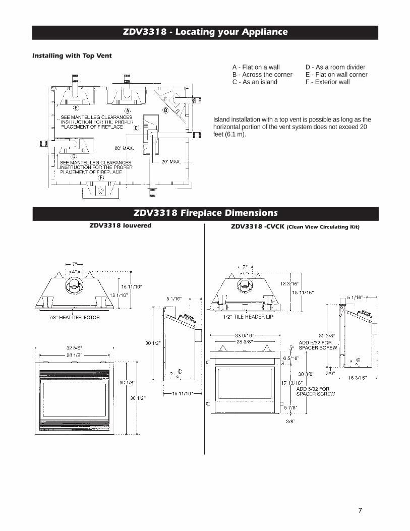
ZDV3318 - Locating your Appliance
ZDV3318 Fireplace Dimensions
Installing with Top Vent
Island installation with a top vent is possible as long as thehorizontal portion of the vent system does not exceed 20feet (6.1 m).
A - Flat on a wall D - As a room dividerB - Across the corner E - Flat on wall cornerC - As an island F - Exterior wall
ZDV3318 -CVCK (Clean View Circulating Kit)ZDV3318 louvered
7

For Propane Horizontal Installations the venting must be a minimum of one foot vertical off the flue before theelbow on any horizontal runs of one foot or greater. This allows for cleaner combustion and greatly reduces carbon-ing and cleaning of glass.
ZDV3318 - Framing for your Gas Fireplace
ZDV3318 Louvered ZDV3318 WITH CVCK (CLEAN VIEW CIRCULATING KIT)
4. When installing horizontal with a 90 degree bend maintain a minimumof two and a half (2.5”) inches above the bend in enclosures.
5. For a fireplace with louvers combustible floor can raise 1”above the bottom of the fireplace. For a fireplace with33CVCK (Clean view Circulating Kit) floor or hearth can raise7” above the bottom of the fireplace with portions being com-bustible and non combustible. See drawing on following page.
6. When installing MQSWF surround, the fireplace must beraised a minimum of 2 7/8” above the finished floors, toaccommodate the wall surround. The fireplace may be raisedhigher but the 60” clearance measured from the bottom of thefireplace to the ceiling must be maintained at all times. (i.e.For an 8 ft. ceiling the unit can be raised only 36 inches.)
Framing Specifications
1. Cold climate installation recommendation: When installing this fire-place against non insulated exterior wall or chase, it is recom -mended that the outer walls be insulated to conform to applicableinsulation codes. Drywall must be installed over insulation to preventcontact of insulation and unit.
2. Choose fireplace location and frame in accordance with the fireplaceframing dimensions specified (See Framing Diagrams). Bend nailingtabs forward on left and right of unit and place fireplace into framedenclosure. This allows for 1/2” in front of framing tabs for finishingmaterials.
3. Drywall or other material can extend flush with the appliance on thebottom, sides and top of fireplace. (louvered models only)
8
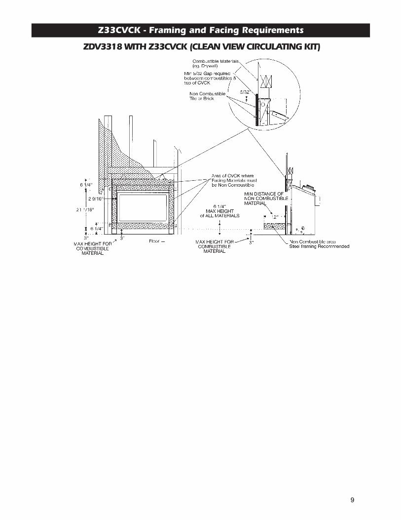
Z33CVCK - Framing and Facing Requirements
ZDV3318 WITH Z33CVCK (CLEAN VIEW CIRCULATING KIT)
Z33CVCK - with Wall Surround
9
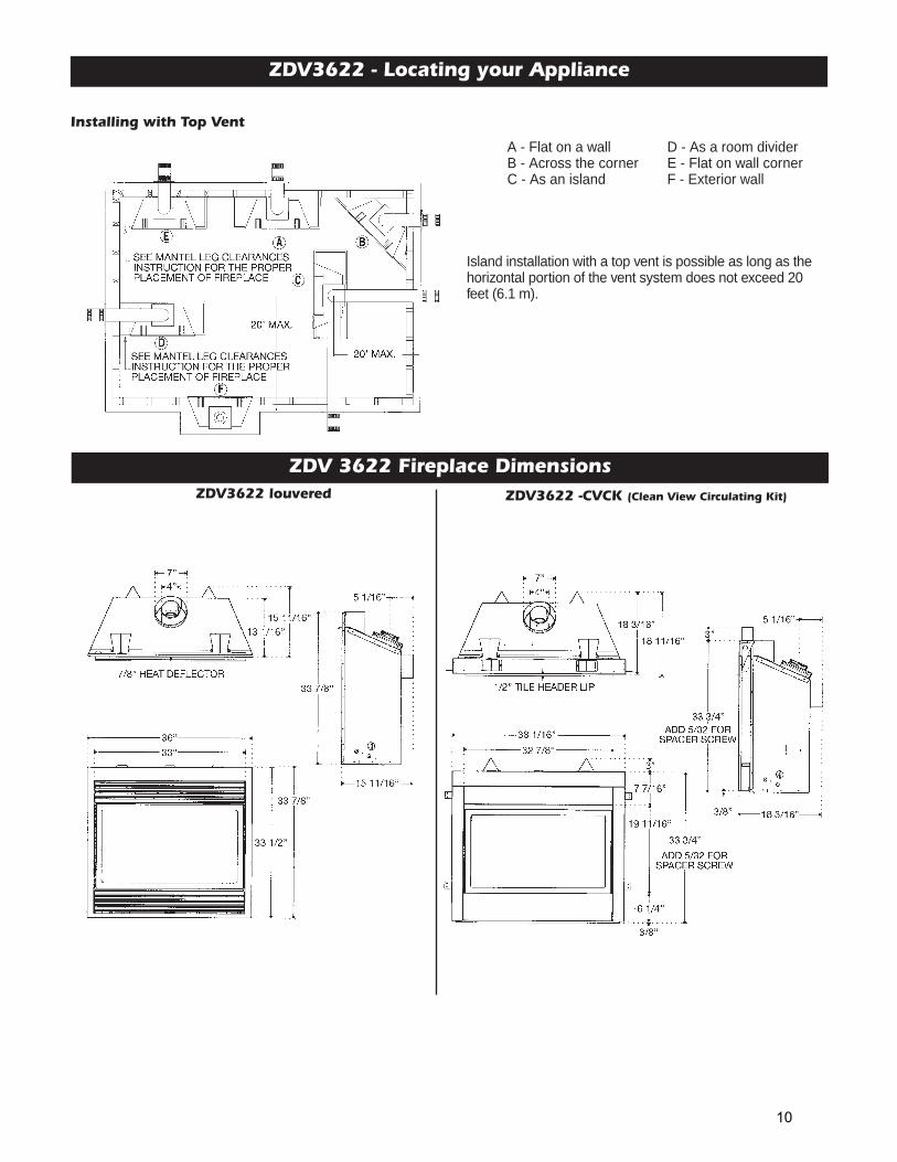
ZDV3622 - Locating your Appliance
ZDV 3622 Fireplace Dimensions
Installing with Top Vent
Island installation with a top vent is possible as long as thehorizontal portion of the vent system does not exceed 20feet (6.1 m).
A - Flat on a wall D - As a room dividerB - Across the corner E - Flat on wall cornerC - As an island F - Exterior wall
ZDV3622 -CVCK (Clean View Circulating Kit)ZDV3622 louvered
10
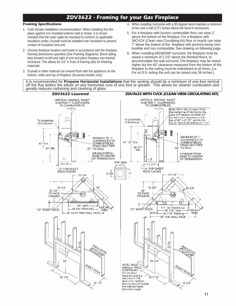
It is recommended for Propane Horizontal Installations that the venting should be a minimum of one foot verticaloff the flue before the elbow on any horizontal runs of one foot or greater. This allows for cleaner combustion andgreatly reduces carboning and cleaning of glass.
ZDV3622 - Framing for your Gas Fireplace
ZDV3622 Louvered ZDV3622 WITH CVCK (CLEAN VIEW CIRCULATING KIT)
4. When installing horizontal with a 90 degree bend maintain a minimumof two and a half (2.5”) inches above the bend in enclosures.
5. For a fireplace with louvers combustible floor can raise 1”above the bottom of the fireplace. For a fireplace with36CVCK (Clean view Circulating Kit) floor or hearth can raise7” above the bottom of the fireplace with portions being com-bustible and non combustible. See drawing on following page.
6. When installing MQ36SWF surround, the fireplace must beraised a minimum of 2 1/2” above the finished floors, toaccommodate the wall surround. The fireplace may be raisedhigher but the 60” clearance measured from the bottom of thefireplace to the ceiling must be maintained at all times. (i.e.For an 8 ft. ceiling the unit can be raised only 36 inches.)
Framing Specifications
1. Cold climate installation recommendation: When installing this fire-place against non insulated exterior wall or chase, it is recom -mended that the outer walls be insulated to conform to applicableinsulation codes. Drywall must be installed over insulation to preventcontact of insulation and unit.
2. Choose fireplace location and frame in accordance with the fireplaceframing dimensions specified (See Framing Diagrams). Bend nailingtabs forward on left and right of unit and place fireplace into framedenclosure. This allows for 1/2” in front of framing tabs for finishingmaterials.
3. Drywall or other material can extend flush with the appliance on thebottom, sides and top of fireplace. (louvered models only)
11
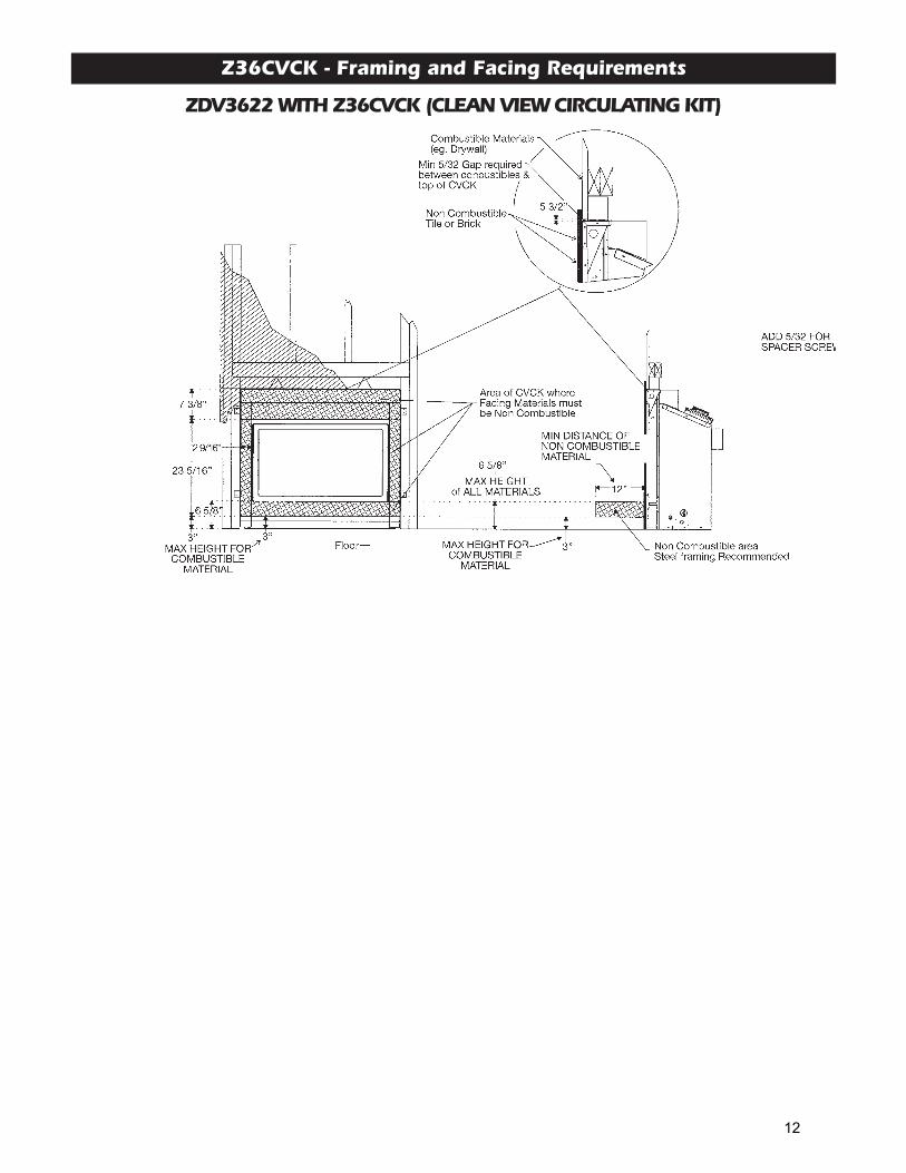
Z36CVCK - Framing and Facing Requirements
ZDV3622 WITH Z36CVCK (CLEAN VIEW CIRCULATING KIT)
Z36CVCK - with Wall Surround
12
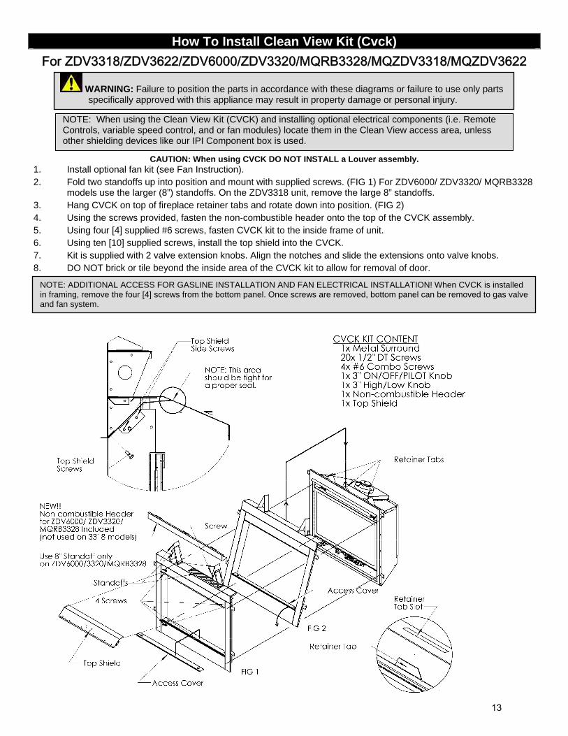
How To Install Clean View Kit (Cvck)
For ZDV3318/ZDV3622/ZDV6000/ZDV3320/MQRB3328/MQZDV3318/MQZDV3622
CAUTION: When using CVCK DO NOT INSTALL a Louver assembly. 1. Install optional fan kit (see Fan Instruction). 2. Fold two standoffs up into position and mount with supplied screws. (FIG 1) For ZDV6000/ ZDV3320/ MQRB3328
models use the larger (8”) standoffs. On the ZDV3318 unit, remove the large 8” standoffs. 3. Hang CVCK on top of fireplace retainer tabs and rotate down into position. (FIG 2) 4. Using the screws provided, fasten the non-combustible header onto the top of the CVCK assembly. 5. Using four [4] supplied #6 screws, fasten CVCK kit to the inside frame of unit. 6. Using ten [10] supplied screws, install the top shield into the CVCK. 7. Kit is supplied with 2 valve extension knobs. Align the notches and slide the extensions onto valve knobs. 8. DO NOT brick or tile beyond the inside area of the CVCK kit to allow for removal of door.
WARNING: Failure to position the parts in accordance with these diagrams or failure to use only parts specifically approved with this appliance may result in property damage or personal injury.
NOTE: When using the Clean View Kit (CVCK) and installing optional electrical components (i.e. Remote Controls, variable speed control, and or fan modules) locate them in the Clean View access area, unless other shielding devices like our IPI Component box is used.
NOTE: ADDITIONAL ACCESS FOR GASLINE INSTALLATION AND FAN ELECTRICAL INSTALLATION! When CVCK is installed in framing, remove the four [4] screws from the bottom panel. Once screws are removed, bottom panel can be removed to gas valve and fan system.
13
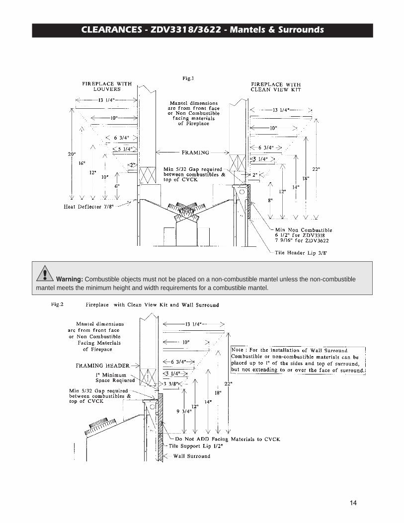
CLEARANCES - ZDV3318/3622 - Mantels & Surrounds
Warning: Combustible objects must not be placed on a non-combustible mantel unless the non-combustiblemantel meets the minimum height and width require ments for a combustible mantel.
14
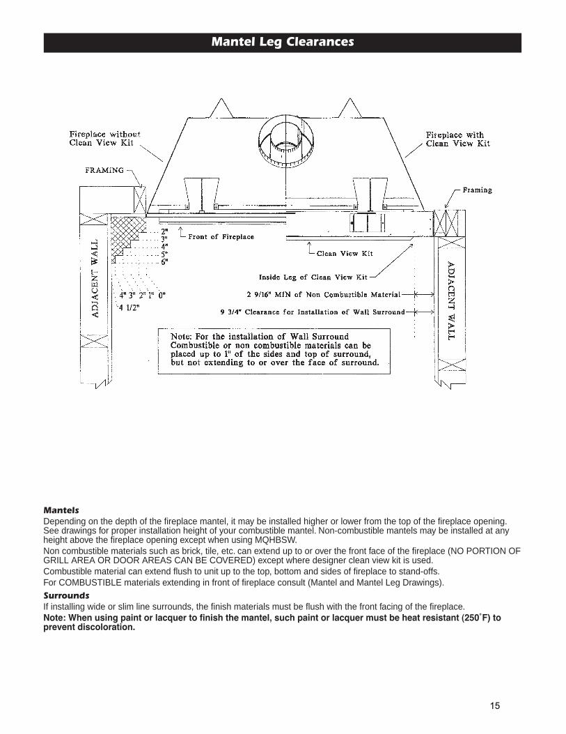
Mantel Leg Clearances
MantelsDepending on the depth of the fireplace mantel, it may be installed higher or lower from the top of the fireplace opening.See drawings for proper installation height of your combustible mantel. Non-combustible mantels may be installed at anyheight above the fireplace opening except when using MQHBSW.Non combustible materials such as brick, tile, etc. can extend up to or over the front face of the fireplace (NO PORTION OFGRILL AREA OR DOOR AREAS CAN BE COVERED) except where designer clean view kit is used.Combustible material can extend flush to unit up to the top, bottom and sides of fireplace to stand-offs.For COMBUSTIBLE materials extending in front of fireplace consult (Mantel and Mantel Leg Drawings).SurroundsIf installing wide or slim line surrounds, the finish materials must be flush with the front facing of the fireplace.Note: When using paint or lacquer to finish the mantel, such paint or lacquer must be heat resistant (250˚F) toprevent discoloration.
15
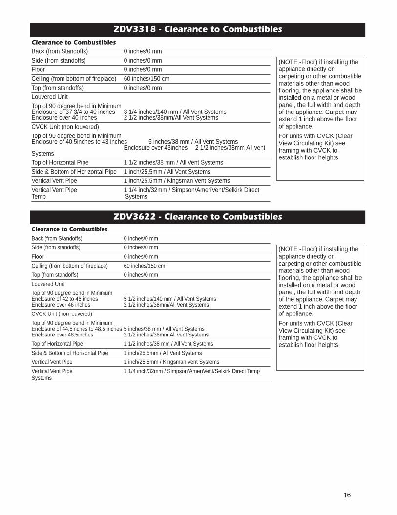
ZDV3318 - Clearance to CombustiblesClearance to CombustiblesBack (from Standoffs) 0 inches/0 mmSide (from standoffs) 0 inches/0 mmFloor 0 inches/0 mmCeiling (from bottom of fireplace) 60 inches/150 cm Top (from standoffs) 0 inches/0 mmLouvered UnitTop of 90 degree bend in MinimumEnclosure of 37 3/4 to 40 inches 3 1/4 inches/140 mm / All Vent Systems Enclosure over 40 inches 2 1/2 inches/38mm/All Vent SystemsCVCK Unit (non louvered)Top of 90 degree bend in MinimumEnclosure of 40.5inches to 43 inches 5 inches/38 mm / All Vent Systems
Enclosure over 43inches 2 1/2 inches/38mm All ventSystemsTop of Horizontal Pipe 1 1/2 inches/38 mm / All Vent SystemsSide & Bottom of Horizontal Pipe 1 inch/25.5mm / All Vent SystemsVertical Vent Pipe 1 inch/25.5mm / Kingsman Vent SystemsVertical Vent Pipe 1 1/4 inch/32mm / Simpson/AmeriVent/Selkirk DirectTemp Systems
(NOTE -Floor) if installing theappliance directly oncarpeting or other combustiblematerials other than woodflooring, the appliance shall beinstalled on a metal or woodpanel, the full width and depthof the appliance. Carpet mayextend 1 inch above the floorof appliance.
For units with CVCK (ClearView Circulating Kit) seeframing with CVCK toestablish floor heights
ZDV3622 - Clearance to CombustiblesClearance to Combustibles
Back (from Standoffs) 0 inches/0 mm
Side (from standoffs) 0 inches/0 mm
Floor 0 inches/0 mm
Ceiling (from bottom of fireplace) 60 inches/150 cm
Top (from standoffs) 0 inches/0 mm
Louvered Unit
Top of 90 degree bend in MinimumEnclosure of 42 to 46 inches 5 1/2 inches/140 mm / All Vent Systems Enclosure over 46 inches 2 1/2 inches/38mm/All Vent Systems
CVCK Unit (non louvered)
Top of 90 degree bend in MinimumEnclosure of 44.5inches to 48.5 inches 5 inches/38 mm / All Vent SystemsEnclosure over 48.5inches 2 1/2 inches/38mm All vent Systems
Top of Horizontal Pipe 1 1/2 inches/38 mm / All Vent Systems
Side & Bottom of Horizontal Pipe 1 inch/25.5mm / All Vent Systems
Vertical Vent Pipe 1 inch/25.5mm / Kingsman Vent Systems
Vertical Vent Pipe 1 1/4 inch/32mm / Simpson/AmeriVent/Selkirk Direct Temp Systems
(NOTE -Floor) if installing theappliance directly oncarpeting or other combustiblematerials other than woodflooring, the appliance shall beinstalled on a metal or woodpanel, the full width and depthof the appliance. Carpet mayextend 1 inch above the floorof appliance.
For units with CVCK (ClearView Circulating Kit) seeframing with CVCK toestablish floor heights
16
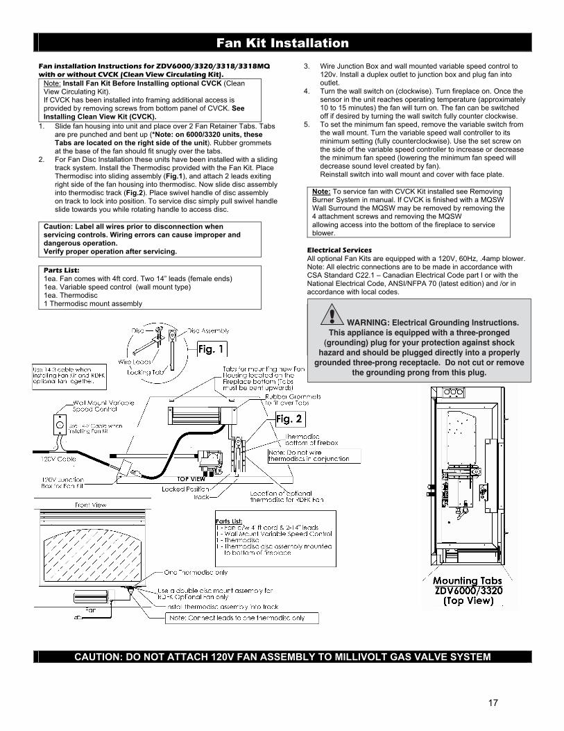
Fan Kit Installation Fan installation Instructions for ZDV6000/3320/3318/3318MQ with or without CVCK (Clean View Circulating Kit).
Note: Install Fan Kit Before Installing optional CVCK (Clean View Circulating Kit). If CVCK has been installed into framing additional access is provided by removing screws from bottom panel of CVCK. See Installing Clean View Kit (CVCK).
1. Slide fan housing into unit and place over 2 Fan Retainer Tabs. Tabs are pre punched and bent up (*Note: on 6000/3320 units, these Tabs are located on the right side of the unit). Rubber grommets at the base of the fan should fit snugly over the tabs.
2. For Fan Disc Installation these units have been installed with a sliding track system. Install the Thermodisc provided with the Fan Kit. Place Thermodisc into sliding assembly (Fig.1), and attach 2 leads exiting right side of the fan housing into thermodisc. Now slide disc assembly into thermodisc track (Fig.2). Place swivel handle of disc assembly on track to lock into position. To service disc simply pull swivel handle slide towards you while rotating handle to access disc.
Caution: Label all wires prior to disconnection when servicing controls. Wiring errors can cause improper and dangerous operation. Verify proper operation after servicing.
Parts List: 1ea. Fan comes with 4ft cord. Two 14” leads (female ends) 1ea. Variable speed control (wall mount type) 1ea. Thermodisc 1 Thermodisc mount assembly
3. Wire Junction Box and wall mounted variable speed control to 120v. Install a duplex outlet to junction box and plug fan into outlet.
4. Turn the wall switch on (clockwise). Turn fireplace on. Once the sensor in the unit reaches operating temperature (approximately 10 to 15 minutes) the fan will turn on. The fan can be switched off if desired by turning the wall switch fully counter clockwise.
5. To set the minimum fan speed, remove the variable switch from the wall mount. Turn the variable speed wall controller to its minimum setting (fully counterclockwise). Use the set screw on the side of the variable speed controller to increase or decrease the minimum fan speed (lowering the minimum fan speed will decrease sound level created by fan). Reinstall switch into wall mount and cover with face plate.
Note: To service fan with CVCK Kit installed see Removing Burner System in manual. If CVCK is finished with a MQSW Wall Surround the MQSW may be removed by removing the 4 attachment screws and removing the MQSW allowing access into the bottom of the fireplace to service blower.
Electrical Services All optional Fan Kits are equipped with a 120V, 60Hz, .4amp blower. Note: All electric connections are to be made in accordance with CSA Standard C22.1 – Canadian Electrical Code part I or with the National Electrical Code, ANSI/NFPA 70 (latest edition) and /or in accordance with local codes.
Warning: Electrical Grounding Instructions. This appliance is equipped with a three-pronged (grounding) plug for your protection against shock hazard and should be plugged directly into a properly grounded three-prong receptacle. Do not cut or remove the grounding prong from this plug.
CAUTION: DO NOT ATTACH 120V FAN ASSEMBLY TO MILLIVOLT GAS VALVE SYSTEM
WARNING: Electrical Grounding Instructions.This appliance is equipped with a three-pronged
(grounding) plug for your protection against shockhazard and should be plugged directly into a properly
grounded three-prong receptacle. Do not cut or removethe grounding prong from this plug.
17
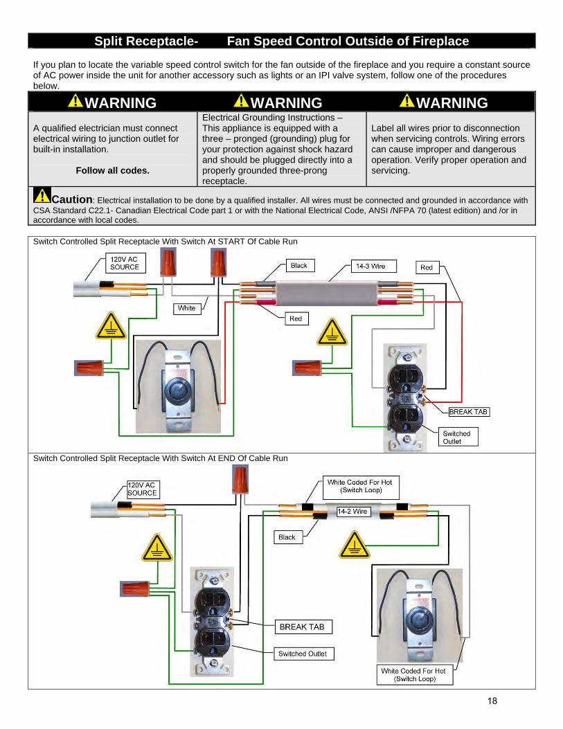
Split Receptacle- Fan Speed Control Outside of Fireplace
If you plan to locate the variable speed control switch for the fan outside of the fireplace and you require a constant source of AC power inside the unit for another accessory such as lights or an IPI valve system, follow one of the procedures below.
WARNING WARNING WARNING A qualified electrician must connect electrical wiring to junction outlet for built-in installation.
Follow all codes.
Electrical Grounding Instructions – This appliance is equipped with a three – pronged (grounding) plug for your protection against shock hazard and should be plugged directly into a properly grounded three-prong receptacle.
Label all wires prior to disconnection when servicing controls. Wiring errors can cause improper and dangerous operation. Verify proper operation and servicing.
Caution: Electrical installation to be done by a qualified installer. All wires must be connected and grounded in accordance with CSA Standard C22.1- Canadian Electrical Code part 1 or with the National Electrical Code, ANSI /NFPA 70 (latest edition) and /or in accordance with local codes. Switch Controlled Split Receptacle With Switch At START Of Cable Run
Switch Controlled Split Receptacle With Switch At END Of Cable Run
18
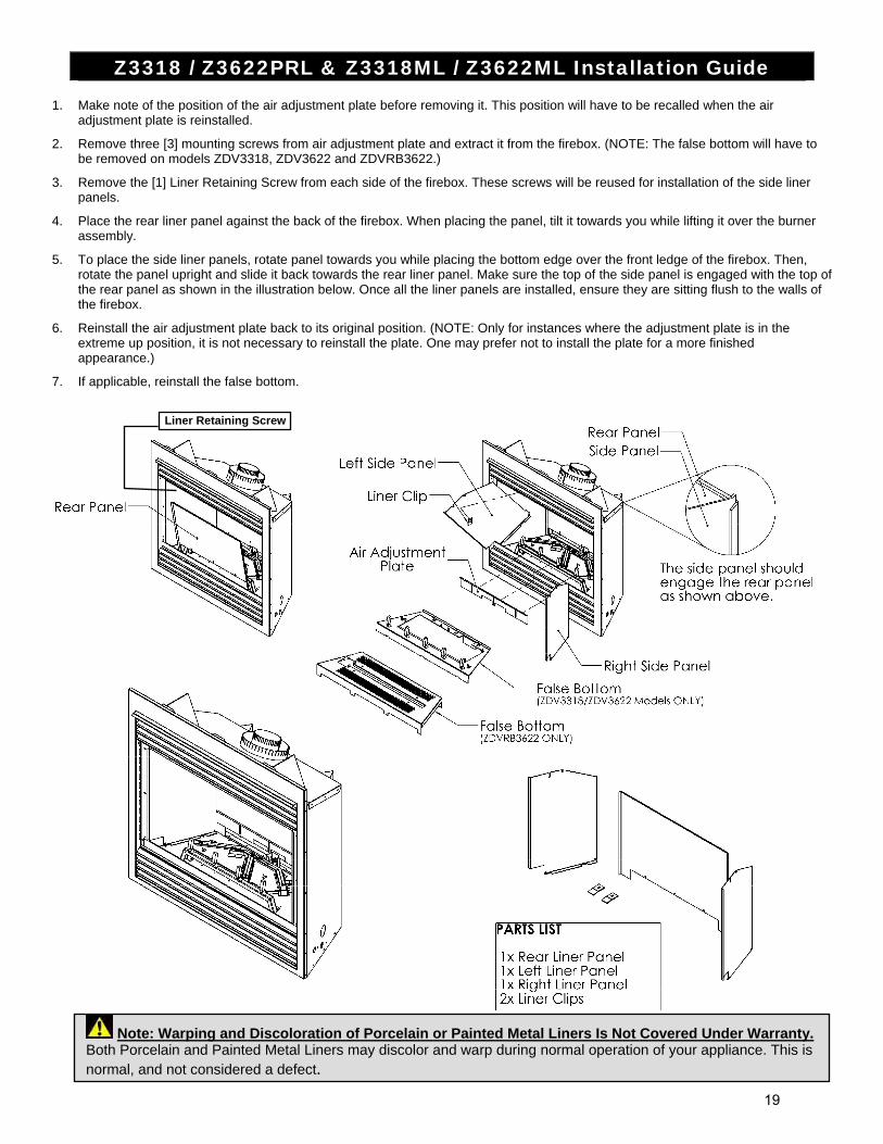
Z3318 / Z3622PRL & Z3318ML / Z3622ML Installation Guide 1. Make note of the position of the air adjustment plate before removing it. This position will have to be recalled when the air
adjustment plate is reinstalled.
2. Remove three [3] mounting screws from air adjustment plate and extract it from the firebox. (NOTE: The false bottom will have to be removed on models ZDV3318, ZDV3622 and ZDVRB3622.)
3. Remove the [1] Liner Retaining Screw from each side of the firebox. These screws will be reused for installation of the side liner panels.
4. Place the rear liner panel against the back of the firebox. When placing the panel, tilt it towards you while lifting it over the burner assembly.
5. To place the side liner panels, rotate panel towards you while placing the bottom edge over the front ledge of the firebox. Then, rotate the panel upright and slide it back towards the rear liner panel. Make sure the top of the side panel is engaged with the top of the rear panel as shown in the illustration below. Once all the liner panels are installed, ensure they are sitting flush to the walls of the firebox.
6. Reinstall the air adjustment plate back to its original position. (NOTE: Only for instances where the adjustment plate is in the extreme up position, it is not necessary to reinstall the plate. One may prefer not to install the plate for a more finished appearance.)
7. If applicable, reinstall the false bottom.
Liner Retaining Screw
Note: Warping and Discoloration of Porcelain or Painted Metal Liners Is Not Covered Under Warranty. Both Porcelain and Painted Metal Liners may discolor and warp during normal operation of your appliance. This is normal, and not considered a defect.
19
Glass Cleaning
Door and Glass Information
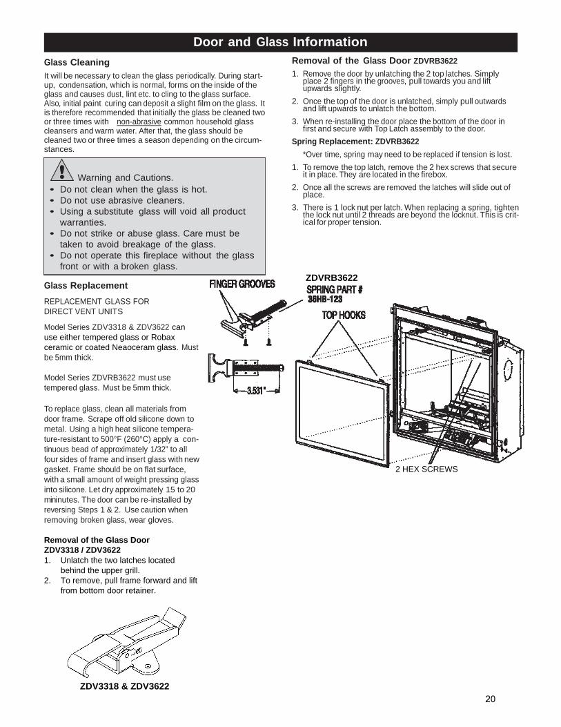
Removal of the Glass Door ZDVRB3622
It will be necessary to clean the glass periodically. During start- up, condensation, which is normal, forms on the inside of the glass and causes dust, lint etc. to cling to the glass surface. Also, initial paint curing can deposit a slight film on the glass. It is therefore recommended that initially the glass be cleaned two or three times with non-abrasive common household glass cleansers and warm water. After that, the glass should be cleaned two or three times a season depending on the circum- stances.
Warning and Cautions. • Do not clean when the glass is hot. • Do not use abrasive cleaners. • Using a substitute glass will void all product
warranties. • Do not strike or abuse glass. Care must be
taken to avoid breakage of the glass. • Do not operate this fireplace without the glass
front or with a broken glass.
1. Remove the door by unlatching the 2 top latches. Simply place 2 fingers in the grooves, pull towards you and lift upwards slightly.
2. Once the top of the door is unlatched, simply pull outwards
and lift upwards to unlatch the bottom. 3. When re-installing the door place the bottom of the door in
first and secure with Top Latch assembly to the door.
Spring Replacement: ZDVRB3622
*Over time, spring may need to be replaced if tension is lost. 1. To remove the top latch, remove the 2 hex screws that secure
it in place. They are located in the firebox. 2. Once all the screws are removed the latches will slide out of
place. 3. There is 1 lock nut per latch. When replacing a spring, tighten
the lock nut until 2 threads are beyond the locknut. This is crit- ical for proper tension.
Glass Replacement
REPLACEMENT GLASS FOR DIRECT VENT UNITS
Model Series ZDV3318 & ZDV3622 can use either tempered glass or Robax ceramic or coated Neaoceram glass. Must be 5mm thick. Model Series ZDVRB3622 must use tempered glass. Must be 5mm thick.
To replace glass, clean all materials from door frame. Scrape off old silicone down to metal. Using a high heat silicone tempera- ture-resistant to 500°F (260°C) apply a con- tinuous bead of approximately 1/32” to all four sides of frame and insert glass with new gasket. Frame should be on flat surface, with a small amount of weight pressing glass into silicone. Let dry approximately 15 to 20 mininutes. The door can be re-installed by reversing Steps 1 & 2. Use caution when removing broken glass, wear gloves. Removal of the Glass Door ZDV3318 / ZDV3622 1. Unlatch the two latches located
behind the upper grill. 2. To remove, pull frame forward and lift
from bottom door retainer.
2 HEX SCREWS
ZDVRB3622
ZDV3318 & ZDV3622 20
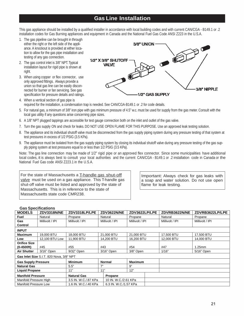
Gas Line Installation
This gas appliance should be installed by a qualified installer in accordance with local building codes and with current CAN/CGA - B149.1 or .2 installation codes for Gas Burning appliances and equipment in Canada and the National Fuel Gas Code ANSI Z223 in the U.S.A.
1. The gas pipeline can be brought in through either the right or the left side of the appli- ance. A knockout is provided at either loca- tion to allow for the gas pipe installation and testing of any gas connection.
2. The gas control inlet is 3/8” NPT. Typical installation layout for rigid pipe is shown at right.
3. When using copper or flex connector, use only approved fittings. Always provide a union so that gas line can be easily discon- nected for burner or fan servicing. See gas specification for pressure details and ratings.
4. When a vertical section of gas pipe is required for the installation, a condensation trap is needed. See CAN/CGA-B149.1 or .2 for code details.
5. For natural gas, a minimum of 3/8” iron pipe with gas minimum pressure of 4.5” w.c. must be used for supply from the gas meter. Consult with the local gas utility if any questions arise concerning pipe sizes.
6. A 1/8” NPT plugged tappings are accessible for test gauge connection both on the inlet and outlet of the gas valve.
7. Turn the gas supply ON and check for leaks. DO NOT USE OPEN FLAME FOR THIS PURPOSE. Use an approved leak testing solution.
8. The appliance and its individual shutoff valve must be disconnected from the gas supply piping system during any pressure testing of that system at test pressures in excess of 1/2 PSIG (3.5 KPa).
9. The appliance must be isolated from the gas supply piping system by closing its individual shutoff valve during any pressure testing of the gas sup- ply piping system at test pressures equal to or less than 1/2 PSIG (3.5 KPa).
Note: The gas line connection may be made of 1/2” rigid pipe or an approved flex connector. Since some municipalities have additional local codes, it is always best to consult your local authorities and the current CAN/CGA - B149.1 or .2 installation code in Canada or the National Fuel Gas code ANSI Z223.1 in the U.S.A.
For the state of Massachusetts a T-handle gas shut-off valve must be used on a gas appliance. This T-handle gas shut-off valve must be listed and approved by the state of Massachusetts. This is in reference to the state of Massachusetts state code CMR238.
Important: Always check for gas leaks with a soap and water solution. Do not use open flame for leak testing.
Gas SpecificationsMODELS ZDV3318N/NE ZDV3318LP/LPE ZDV3622N/NE ZDV3622LP/LPE ZDVRB3622N/NE ZDVRB3622LP/LPE Fuel Natural Propane Natural Propane Natural Propane Gas Control
Millivolt / IPI Millivolt / IPI Millivolt / IPI Millivolt / IPI Millivolt / IPI Millivolt / IPI
INPUT Maximum 19,000 BTU 18,000 BTU 21,000 BTU 21,000 BTU 17,500 BTU 17,500 BTU Low 12,100 BTU Low 11,900 BTU 14,200 BTU 16,200 BTU 12,000 BTU 14,000 BTU Orifice Size (0-4500ft)
#45
#55
#43
#54
#47
1.25mm
Air Shutter 3/16” Open 9/32” Open 3/16” Open 3/8” Open 1/16” 5/16” Open
Gas Inlet Size S.I.T. 820 Nova, 3/8” NPT
Gas Supply Pressure Minimum Normal Maximum
Natural Gas 5.5” 7” 9” Liquid Propane 11” 11” 12”
Manifold Pressure Natural Gas Propane Manifold Pressure High 3.5 IN. W.C./.87 KPa 10 IN. W.C./2.61 KPa Manifold Pressure Low 1.6 IN. W.C./.40 KPa 6.3 IN. W.C./1.57 KPa
21
Millivolt System, Lighting, and Burner Control
FOR YOUR SAFETY READ BEFORE LIGHTING
BEFORE LIGHTING A This appliance has a pilot which must be lighted by hand. When
lighting the pilot, follow these instructions exactly.
B Smell all around the appliance area for gas. Be sure to smell next to the floor because some gas is heavier than air and will settle on the floor.
WHAT TO DO IF YOU SMELL GAS
Do not try to light an appliance.
Do not touch any electrical switch; do not use any phone in your building.
Immediately call your gas supplier from a neighbour’s phone. Follow the gas supplier’s instructions.
If you cannot reach your gas supplier, call the fire department.
C Use only your hand to push or turn the gas control knob. Never use tools. If the knob will not push in or turn by hand, don’t try to repair it. Call a qualified technician. Force or attempted repair may result in a fire or explosion.
D Do not use the appliance if any part has been under water. Immediately call a qualified service technician to inspect the appliance and to replace any part of the control system which has been under water.
LIGHTING INSTRUCTIONS 1. Stop! Read the safety information above this label.
2. Set the thermostat to lowest setting.
3. Turn off all electrical power to the appliance.
4. Locate valve under the burner assembly.
5. If the control knob is not already in the off position, i.e. the word “OFF” in the 9 o’clock position, then push in the gas control knob slightly and turn clockwise to “OFF”. NOTE: Knob cannot be turned from “PILOT” to “OFF” unless knob is pushed in slightly. Do not use force.
6. Wait five [5] minutes to clear out any gas. If you then smell gas. STOP! Follow “B” in the safety information above on this label. If you don’t smell gas then go to the next step.
7. Now push in the control knob slightly and turn counter-clockwise to the “PILOT” position.
8. Push in the control knob all the way and hold it. With the other hand push in the red ignitor button until you hear a click. Now observe closely the pilot burner located on the rear center-left hand side of the main burner. If a flame has appeared then continue to depress the control knob for 20 seconds. If the flame did not appear then continue to depress the red ignitor button every 5 seconds until a flame is established. NOTE: If after 30 seconds a flame has not yet been established then turn the control knob back to the off position and repeat steps 5, 6 & 7.
9. Once the pilot has been established hold the control knob in the depressed position for approximately 25 seconds before releasing. If the flame goes out then repeat steps 7 and 8.
10. Now turn the control knob to the “ON” position. The burner will not light unless the wall switch thermostat or remote control is turned “ON” or in the case of the thermostat there is a call for heat.
11. Close the access door and turn all electrical power back to the appliance.
TO TURN OFF THE APPLIANCE 1. Set the thermostat to lowest setting.
2. Turn off all electric power to the appliance if service is to be performed.
3. Open the control access door.
4. Push in the gas control knob slightly and turn clockwise to the “OFF” position. Do not force.
5. Replace control access panel.
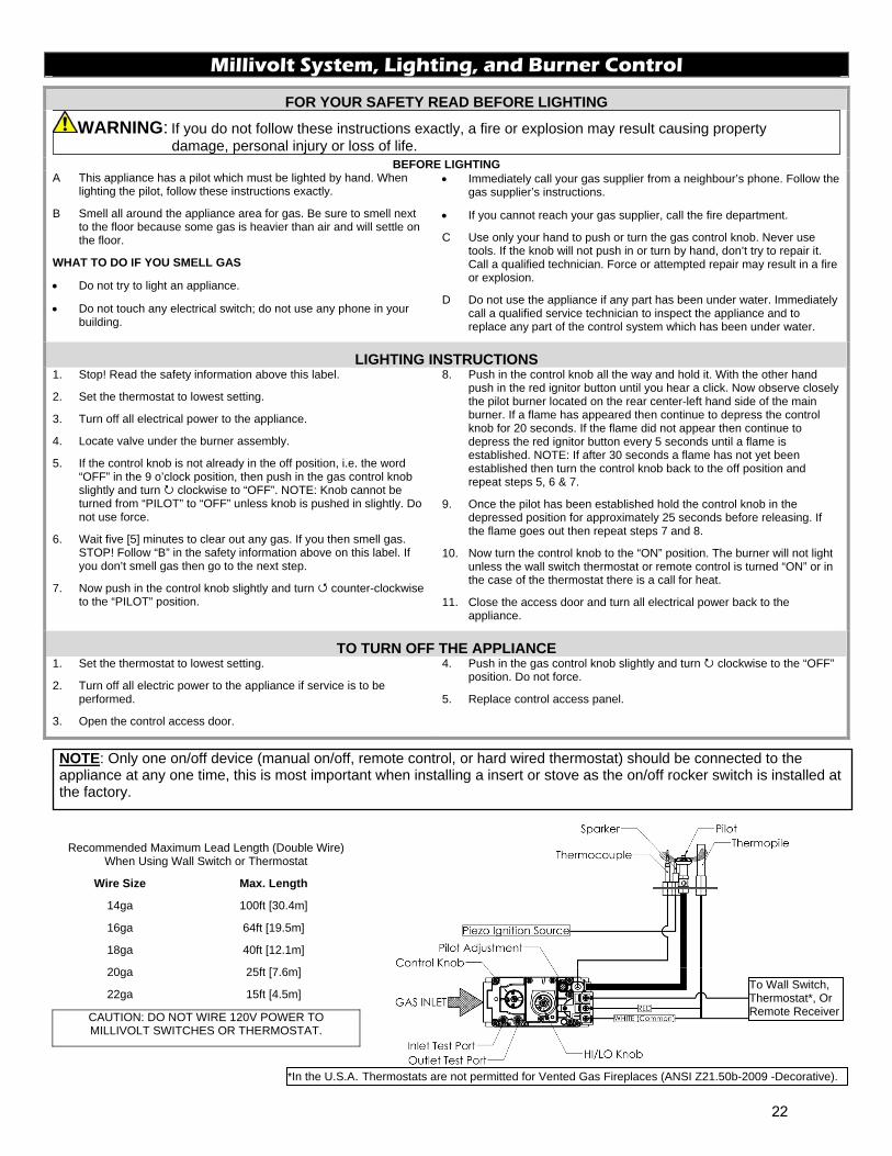
Recommended Maximum Lead Length (Double Wire) When Using Wall Switch or Thermostat
Wire Size Max. Length
14ga 100ft [30.4m]
16ga 64ft [19.5m]
18ga 40ft [12.1m]
20ga 25ft [7.6m]
22ga 15ft [4.5m]
CAUTION: DO NOT WIRE 120V POWER TO MILLIVOLT SWITCHES OR THERMOSTAT.
NOTE: Only one on/off device (manual on/off, remote control, or hard wired thermostat) should be connected to the appliance at any one time, this is most important when installing a insert or stove as the on/off rocker switch is installed at the factory.
WARNING: If you do not follow these instructions exactly, a fire or explosion may result causing property damage, personal injury or loss of life.
To Wall Switch, Thermostat*, Or Remote Receiver
*In the U.S.A. Thermostats are not permitted for Vented Gas Fireplaces (ANSI Z21.50b-2009 -Decorative).
22
Burner System Maintenance It is recommended to annually inspect and clean the Burner System to prevent malfunction and / or sooting. This operation should be performed by your dealer or a qualified technician.
-CAUTION- Before servicing the burner system ensure that the gas supply is turned OFF and disconnect all electrical connections to the appliance. Allow the appliance to cool to room temperature. Note that the pilot assembly may be hot in an intermittent or standing-pilot system—even if the main burner was never on. Exercise caution when working within the area.
-ALL WORK SHOULD BE PERFORMED BY A QUALIFIED AND CERTIFIED TECHNICIAN-
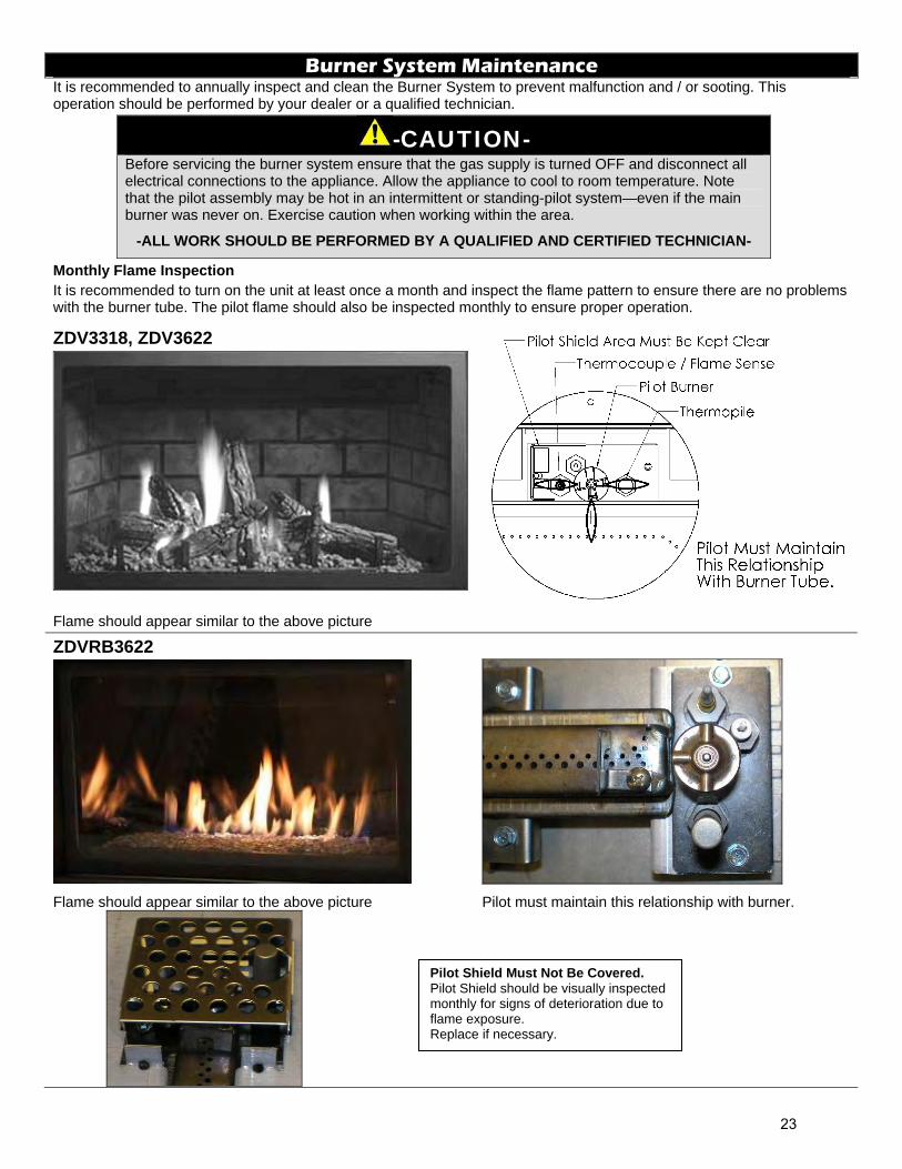
Monthly Flame Inspection It is recommended to turn on the unit at least once a month and inspect the flame pattern to ensure there are no problems with the burner tube. The pilot flame should also be inspected monthly to ensure proper operation.
ZDV3318, ZDV3622
Flame should appear similar to the above picture
ZDVRB3622
Flame should appear similar to the above picture Pilot must maintain this relationship with burner.
Pilot Shield Must Not Be Covered. Pilot Shield should be visually inspected monthly for signs of deterioration due to flame exposure. Replace if necessary.
23
Conversion Kit Instructions – PART A
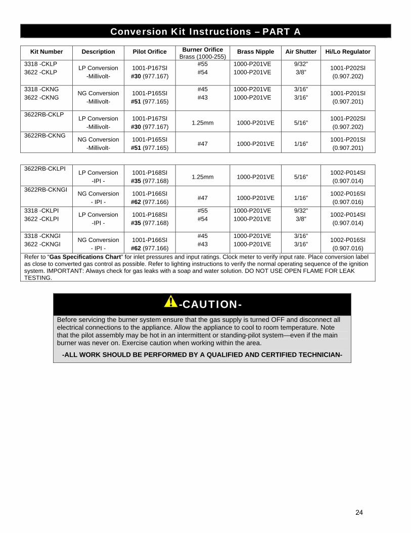
Kit Number Description Pilot Orifice Burner Orifice Brass (1000-255)
Brass Nipple Air Shutter Hi/Lo Regulator
3318 -CKLP 3622 -CKLP
LP Conversion -Millivolt-
1001-P167SI #30 (977.167)
#55 #54
1000-P201VE 1000-P201VE
9/32” 3/8”
1001-P202SI (0.907.202)
3318 -CKNG 3622 -CKNG
NG Conversion -Millivolt-
1001-P165SI #51 (977.165)
#45 #43
1000-P201VE 1000-P201VE
3/16” 3/16”
1001-P201SI (0.907.201)
3622RB-CKLP LP Conversion
-Millivolt- 1001-P167SI #30 (977.167)
1.25mm
1000-P201VE
5/16”
1001-P202SI (0.907.202)
3622RB-CKNG NG Conversion
-Millivolt- 1001-P165SI #51 (977.165)
#47
1000-P201VE
1/16”
1001-P201SI (0.907.201)
3622RB-CKLPI LP Conversion
-IPI - 1001-P168SI #35 (977.168)
1.25mm
1000-P201VE
5/16”
1002-P014SI (0.907.014)
3622RB-CKNGI NG Conversion
- IPI - 1001-P166SI #62 (977.166)
#47
1000-P201VE
1/16”
1002-P016SI (0.907.016)
3318 -CKLPI 3622 -CKLPI
LP Conversion -IPI -
1001-P168SI #35 (977.168)
#55 #54
1000-P201VE 1000-P201VE
9/32” 3/8”
1002-P014SI (0.907.014)
3318 -CKNGI 3622 -CKNGI
NG Conversion - IPI -
1001-P166SI #62 (977.166)
#45 #43
1000-P201VE 1000-P201VE
3/16” 3/16”
1002-P016SI (0.907.016)
Refer to “Gas Specifications Chart” for inlet pressures and input ratings. Clock meter to verify input rate. Place conversion label as close to converted gas control as possible. Refer to lighting instructions to verify the normal operating sequence of the ignition system. IMPORTANT: Always check for gas leaks with a soap and water solution. DO NOT USE OPEN FLAME FOR LEAK TESTING.
-CAUTION- Before servicing the burner system ensure that the gas supply is turned OFF and disconnect all electrical connections to the appliance. Allow the appliance to cool to room temperature. Note that the pilot assembly may be hot in an intermittent or standing-pilot system—even if the main burner was never on. Exercise caution when working within the area.
-ALL WORK SHOULD BE PERFORMED BY A QUALIFIED AND CERTIFIED TECHNICIAN-
24
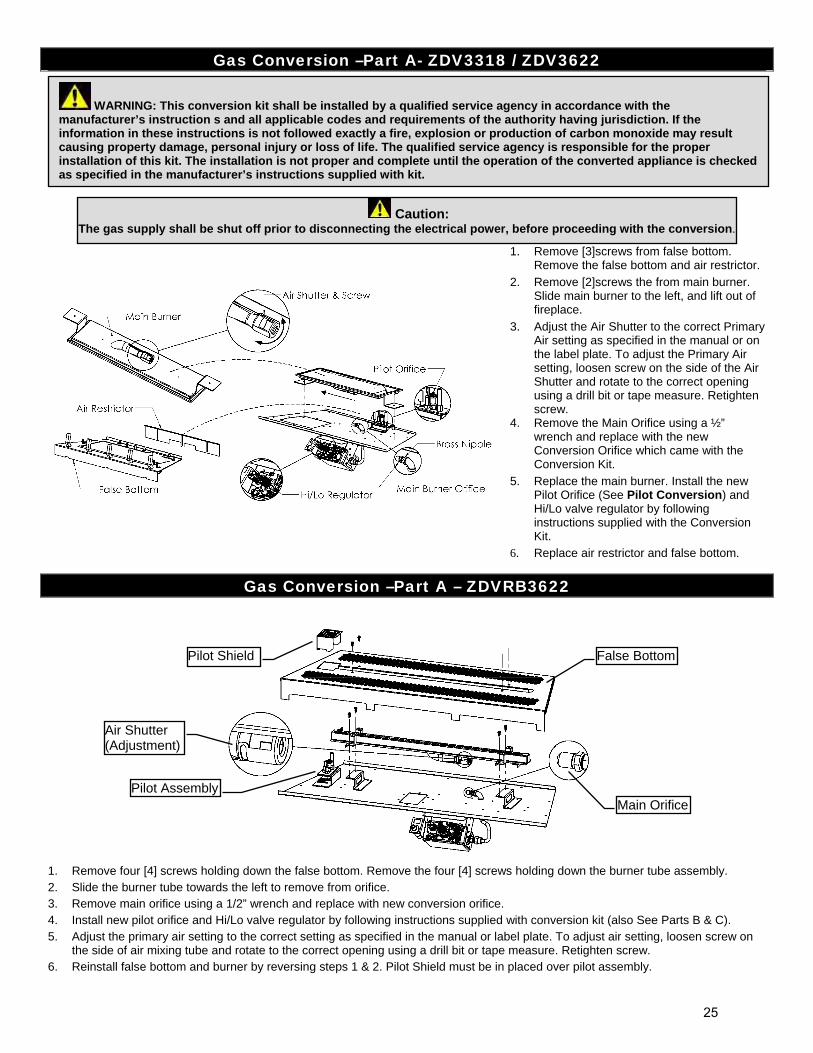
Gas Conversion –Part A- ZDV3318 / ZDV3622
1. Remove [3]screws from false bottom. Remove the false bottom and air restrictor.
2. Remove [2]screws the from main burner. Slide main burner to the left, and lift out of fireplace.
3. Adjust the Air Shutter to the correct Primary Air setting as specified in the manual or on the label plate. To adjust the Primary Air setting, loosen screw on the side of the Air Shutter and rotate to the correct opening using a drill bit or tape measure. Retighten screw.
4. Remove the Main Orifice using a ½” wrench and replace with the new Conversion Orifice which came with the Conversion Kit.
5. Replace the main burner. Install the new Pilot Orifice (See Pilot Conversion) and Hi/Lo valve regulator by following instructions supplied with the Conversion Kit.
6. Replace air restrictor and false bottom.
Gas Conversion –Part A – ZDVRB3622
1. Remove four [4] screws holding down the false bottom. Remove the four [4] screws holding down the burner tube assembly. 2. Slide the burner tube towards the left to remove from orifice. 3. Remove main orifice using a 1/2” wrench and replace with new conversion orifice. 4. Install new pilot orifice and Hi/Lo valve regulator by following instructions supplied with conversion kit (also See Parts B & C). 5. Adjust the primary air setting to the correct setting as specified in the manual or label plate. To adjust air setting, loosen screw on
the side of air mixing tube and rotate to the correct opening using a drill bit or tape measure. Retighten screw. 6. Reinstall false bottom and burner by reversing steps 1 & 2. Pilot Shield must be in placed over pilot assembly.
Caution: The gas supply shall be shut off prior to disconnecting the electrical power, before proceeding with the conversion.
WARNING: This conversion kit shall be installed by a qualified service agency in accordance with the manufacturer’s instruction s and all applicable codes and requirements of the authority having jurisdiction. If the information in these instructions is not followed exactly a fire, explosion or production of carbon monoxide may result causing property damage, personal injury or loss of life. The qualified service agency is responsible for the proper installation of this kit. The installation is not proper and complete until the operation of the converted appliance is checked as specified in the manufacturer’s instructions supplied with kit.
Air Shutter (Adjustment)
False Bottom
Main OrificePilot Assembly
Pilot Shield
25
Gas Conversion for Top Convertible Pilot (Series 019065X) – PART B
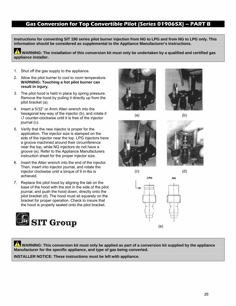
Instructions for converting SIT 190 series pilot burner injection from NG to LPG and from NG to LPG only. This information should be considered as supplemental to the Appliance Manufacturer’s Instructions.
WARNING: The installation of this conversion kit must only be undertaken by a qualified and certified gas appliance installer.
1. Shut off the gas supply to the appliance.
2. Allow the pilot burner to cool to room temperature. WARNING: Touching a hot pilot burner can result in injury.
3. The pilot hood is held in place by spring pressure. Remove the hood by pulling it directly up from the pilot bracket (a).
4. Insert a 5/32” or 4mm Allen wrench into the hexagonal key-way of the injector (b), and rotate it
counter-clockwise until it is free of the injector journal (c).
5. Verify that the new injector is proper for the application. The injector size is stamped on the side of the injector near the top. LPG injectors have a groove machined around their circumference near the top, while NG injectors do not have a groove (e). Refer to the Appliance Manufacturers instruction sheet for the proper injector size.
6. Insert the Allen wrench into the end of the injector. Then, insert into injector journal, and rotate the injector clockwise until a torque of 9 in-lbs is achieved.
7. Replace the pilot hood by aligning the tab on the base of the hood with the slot in the side of the pilot journal, and push the hood down, directly onto the pilot bracket (d). The hood must sit squarely on the bracket for proper operation. Check to insure that the hood is properly seated onto the pilot bracket.
(a)
(b)
(c)
(d)
(e)
WARNING: This conversion kit must only be applied as part of a conversion kit supplied by the appliance Manufacturer for the specific appliance, and type of gas being converted.
INSTALLER NOTICE: These instructions must be left with appliance.
26
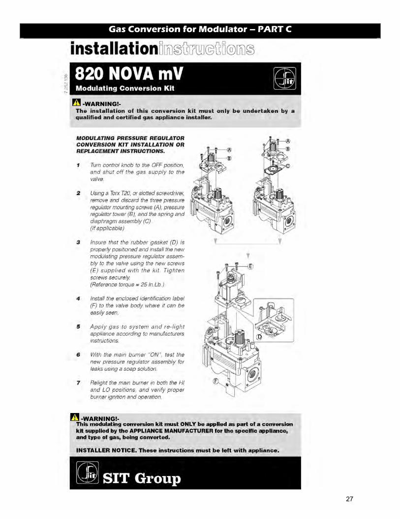
Gas Conversion for Modulator – PART C
-WARNING!-
-WARNING!-
27
IPI Electronic Ignition System
Overview
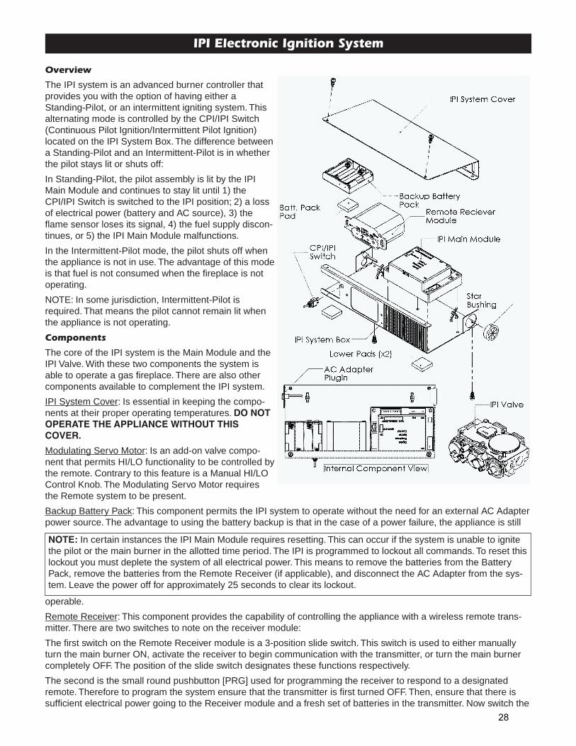
The IPI system is an advanced burner controller thatprovides you with the option of having either aStanding-Pilot, or an intermittent igniting system. Thisalternating mode is controlled by the CPI/IPI Switch(Continuous Pilot Ignition/Intermittent Pilot Ignition)located on the IPI System Box. The difference betweena Standing-Pilot and an Intermittent-Pilot is in whetherthe pilot stays lit or shuts off:
In Standing-Pilot, the pilot assembly is lit by the IPIMain Module and continues to stay lit until 1) theCPI/IPI Switch is switched to the IPI position; 2) a lossof electrical power (battery and AC source), 3) theflame sensor loses its signal, 4) the fuel supply discon-tinues, or 5) the IPI Main Module malfunctions.
In the Intermittent-Pilot mode, the pilot shuts off whenthe appliance is not in use. The advantage of this modeis that fuel is not consumed when the fireplace is notoperating.
NOTE: In some jurisdiction, Intermittent-Pilot isrequired. That means the pilot cannot remain lit whenthe appliance is not operating.
Components
The core of the IPI system is the Main Module and theIPI Valve. With these two components the system isable to operate a gas fireplace. There are also othercomponents available to complement the IPI system.
IPI System Cover: Is essential in keeping the compo-nents at their proper operating temperatures. DO NOTOPERATE THE APPLIANCE WITHOUT THISCOVER.
Modulating Servo Motor: Is an add-on valve compo-nent that permits HI/LO functionality to be controlled bythe remote. Contrary to this feature is a Manual HI/LOControl Knob. The Modulating Servo Motor requiresthe Remote system to be present.
Backup Battery Pack: This component permits the IPI system to operate without the need for an external AC Adapterpower source. The advantage to using the battery backup is that in the case of a power failure, the appliance is still
operable.
Remote Receiver: This component provides the capability of controlling the appliance with a wireless remote trans-mitter. There are two switches to note on the receiver module:
The first switch on the Remote Receiver module is a 3-position slide switch. This switch is used to either manuallyturn the main burner ON, activate the receiver to begin communication with the transmitter, or turn the main burnercompletely OFF. The position of the slide switch designates these functions respectively.
The second is the small round pushbutton [PRG] used for programming the receiver to respond to a designatedremote. Therefore to program the system ensure that the transmitter is first turned OFF. Then, ensure that there issufficient electrical power going to the Receiver module and a fresh set of batteries in the transmitter. Now switch the
NOTE: In certain instances the IPI Main Module requires resetting. This can occur if the system is unable to ignitethe pilot or the main burner in the allotted time period. The IPI is programmed to lockout all commands. To reset thislockout you must deplete the system of all electrical power. This means to remove the batteries from the BatteryPack, remove the batteries from the Remote Receiver (if applicable), and disconnect the AC Adapter from the sys-tem. Leave the power off for approximately 25 seconds to clear its lockout.
28
the slide switch to the middle [REMOTE] position and then push the small pushbutton to begin programming. Bringthe transmitter close to the receiver and then press the power button [R] on the transmitter. An audible beep willsound to indicate the system is programmed and ready to be used.
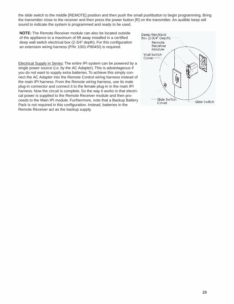
Electrical Supply in Series: The entire IPI system can be powered by asingle power source (i.e. by the AC Adapter). This is advantageous ifyou do not want to supply extra batteries. To achieve this simply con-nect the AC Adapter into the Remote Control wiring harness instead ofthe main IPI harness. From the Remote wiring harness, use its maleplug-in connector and connect it to the female plug-in in the main IPIharness. Now the circuit is complete. So the way it works is that electri-cal power is supplied to the Remote Receiver module and then pro-ceeds to the Main IPI module. Furthermore, note that a Backup BatteryPack is not required in this configuration. Instead, batteries in theRemote Receiver act as the backup supply.
NOTE: The Remote Receiver module can also be located outsideof the appliance to a maximum of 6ft away installed in a certifieddeep wall switch electrical box (2-3/4” depth). For this configurationan extension wiring harness (P/N: 1001-P904SI) is required.
29
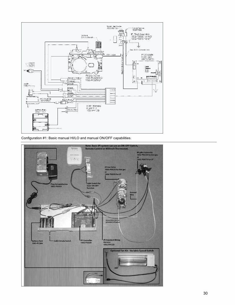
Configuration #1: Basic manual HI/LO and manual ON/OFF capabilities.
30
Receiver Module .584.523/521/221 1001-P221SI
Receiver Module.584.523/521/2211001-P221SI
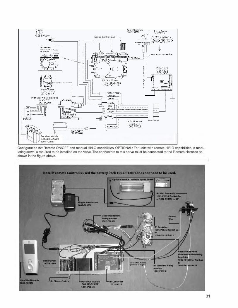
31
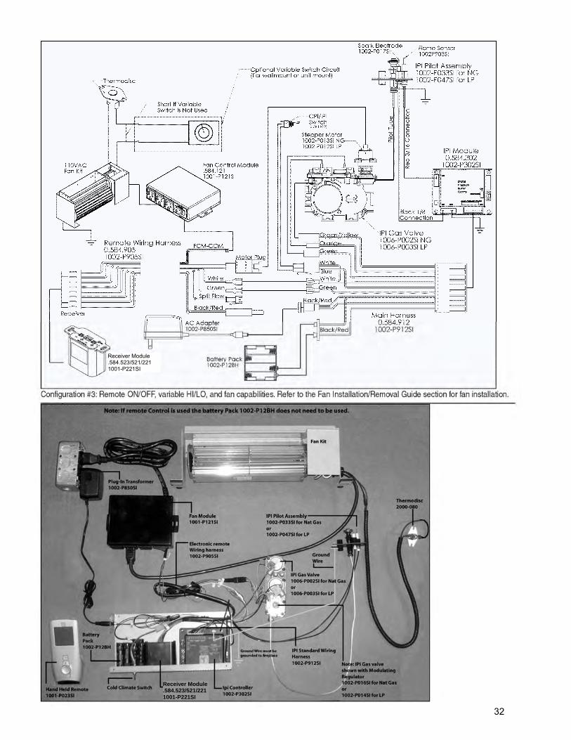
Receiver Module .584.523/521/221 1001-P221SI
Receiver Module .584.523/521/221 1001-P221SI
32
IPI Lighting Instructions
WARNING
1. If you do not follow these instructions exactly, a fire or explosion may result causing property damage,personal injury or loss of life.
2. Always light the pilot whether for the first time or if the gas supply has ran out with the glass door opened orremoved.
FOR YOUR SAFETY READ BEFORE LIGHTING
A. This fireplace is equipped with an ignition device which automatically lights the pilot. Do not try to light by hand.
B. Before operating smell all around the fireplace area for gas and next to the floor because some gas is heavierthan air and will settle on the floor.
C. Do not use this fireplace if any part has been under water. Immediately call a qualified service technician toinspect the fireplace and replace any part of the control system and any gas control which has been under water
WHAT TO DO IF YOU SMELL GAS
1. Turn off all gas to the fireplace.
2. Open windows.
3. Do not try to light any appliance.
4. Do not touch any electric switch; do not use anyphone in your building.
5. Immediately call your gas supplier from a neighbor'sphone. Follow the gas supplier's instructions.
6. If you cannot reach your gas supplier, call the firedepartment.
LIGHTING INSTRUCTIONS
1. STOP! Read the above safety information on this label.
2. Remove batteries from Receiver and/or Battery Backup Pack.
3. Turn off all electric power to the fireplace.
4. This fireplace is equipped with an ignition device which automatically lights the pilot. Do not try to light the pilotby hand.
5. Open the glass door.
6. Turn manual shutoff valve clockwise to OFF position (located behind the access panel).
7. Wait five [5] minutes to clear out any gas. If you smell gas including near the floor, STOP! Follow "B" in the abovesafety information on this label. If you don’t smell gas go to the next step.
8. Turn manual shutoff valve counter-clockwise to ON position.
9. Close the glass door.
10. Turn on all electric power to the fireplace, and re-install batteries into the Transmitter/Receiver and/or BatteryBackup Pack.
11. Turn ON the switch that operates the Main Burner. If using a Remote Control refer to Remote Control OperationManual for activation.
TO TURN OFF GAS
1. Turn OFF all electric power to the fireplace if service is to be performed, including removing batteries from theRemote Transmitter/Receiver and/or Battery Backup Pack.
2. Access door inside the firebox must be removed to access the manual shutoff valve.
3. If alternate shut-off valve was installed it can be shutoff instead of going through the fireplace to access the fire-place shut off valve.
33
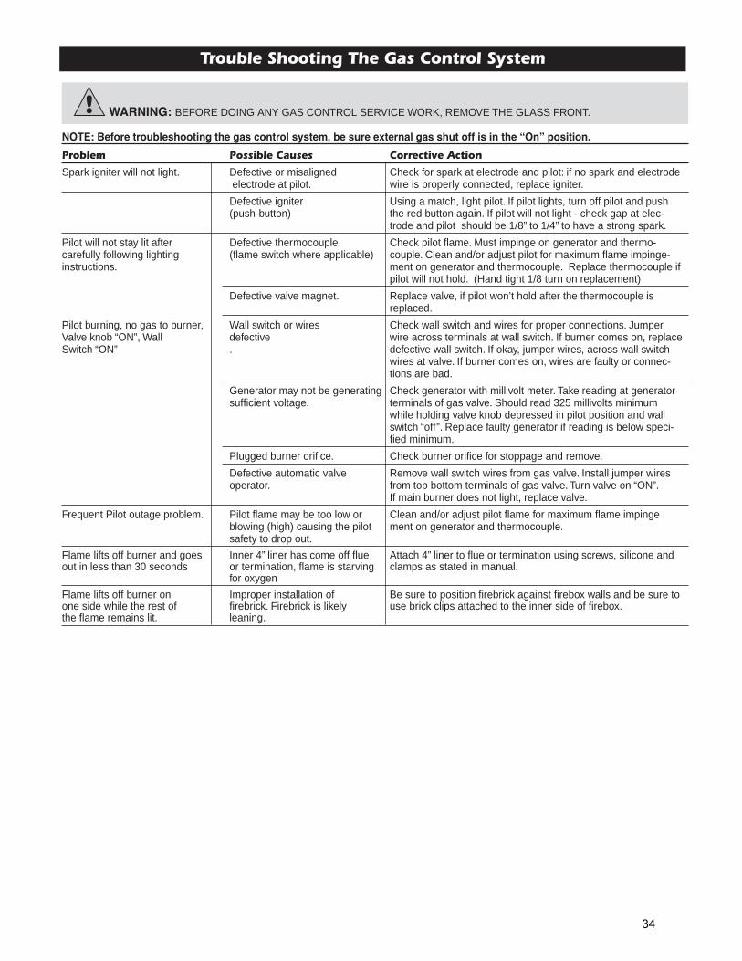
NOTE: Before troubleshooting the gas control system, be sure external gas shut off is in the “On” position.
Problem Possible Causes Corrective Action
Spark igniter will not light. Defective or misaligned Check for spark at electrode and pilot: if no spark and electrode electrode at pilot. wire is properly connected, replace igniter.
Defective igniter Using a match, light pilot. If pilot lights, turn off pilot and push (push-button) the red button again. If pilot will not light - check gap at elec-
trode and pilot should be 1/8” to 1/4” to have a strong spark.
Pilot will not stay lit after Defective thermocouple Check pilot flame. Must impinge on generator and thermo-carefully following lighting (flame switch where applicable) couple. Clean and/or adjust pilot for maximum flame impinge-instructions. ment on generator and thermocouple. Replace thermocouple if
pilot will not hold. (Hand tight 1/8 turn on replacement)
Defective valve magnet. Replace valve, if pilot won’t hold after the thermocouple is replaced.
Pilot burning, no gas to burner, Wall switch or wires Check wall switch and wires for proper connections. Jumper Valve knob “ON”, Wall defective wire across terminals at wall switch. If burner comes on, replaceSwitch “ON” . defective wall switch. If okay, jumper wires, across wall switch
wires at valve. If burner comes on, wires are faulty or connec-tions are bad.
Generator may not be generating Check generator with millivolt meter. Take reading at generator sufficient voltage. terminals of gas valve. Should read 325 millivolts minimum
while holding valve knob depressed in pilot position and wall switch “off”. Replace faulty generator if reading is below speci-fied minimum.
Plugged burner orifice. Check burner orifice for stoppage and remove.
Defective automatic valve Remove wall switch wires from gas valve. Install jumper wires operator. from top bottom terminals of gas valve. Turn valve on “ON”.
If main burner does not light, replace valve.
Frequent Pilot outage problem. Pilot flame may be too low or Clean and/or adjust pilot flame for maximum flame impingeblowing (high) causing the pilot ment on generator and thermocouple.safety to drop out.
Flame lifts off burner and goes Inner 4” liner has come off flue Attach 4” liner to flue or termination using screws, silicone andout in less than 30 seconds or termination, flame is starving clamps as stated in manual.
for oxygen
Flame lifts off burner on Improper installation of Be sure to position firebrick against firebox walls and be sure to one side while the rest of firebrick. Firebrick is likely use brick clips attached to the inner side of firebox.the flame remains lit. leaning.
Trouble Shooting The Gas Control System
WARNING: BEFORE DOING ANY GAS CONTROL SERVICE WORK, REMOVE THE GLASS FRONT.
34
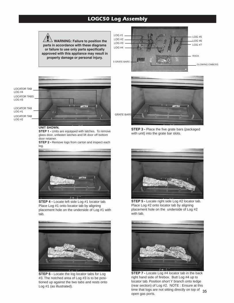
LOGC50 Log Assembly
UNIT SHOWN.STEP 1 - Units are equipped with latches. To removeglass door, unfasten latches and lift door off bottomdoor retainer.STEP 2 - Remove logs from carton and inspect eachlog.
STEP 7 - Locate Log #4 locator tab in the backright hand side of firebox. Butt Log #4 up tolocator tab. Position short Y branch onto ledge(rear section) of Log #2. NOTE : Ensure at thistime that logs are not sitting directly on top ofopen gas ports.
STEP 4 - Locate left side Log #1 locator tab.Place Log #1 onto locator tab by aligningplacement hole on the underside of Log #1 withtab.
STEP 5 - Locate right side Log #2 locator tab.Place Log #2 onto locator tab by aligningplacement hole on the underside of Log #2with tab.
STEP 6 - Locate the log locator tabs for Log#3. The notched area of Log #3 is to be posi-tioned up against the two tabs and rests ontoLog #1 (as illustrated).
STEP 3 - Place the five grate bars (packagedwith unit) into the grate bar slots.
LOG #1LOG #5
LOG #6
LOG #7
LOG #2LOG #3
LOG #4
5 GRATE BARS
ROCK
GLOWING EMBERS
LOCATOR TABLOG #4
LOCATOR TABSLOG #3
LOCATOR TABLOG #1
LOCATOR TABLOG #2
GRATE BARS
WARNING: Failure to position theparts in accordance with these diagramsor failure to use only parts specifically
approved with this appliance may result inproperty damage or personal injury.
35
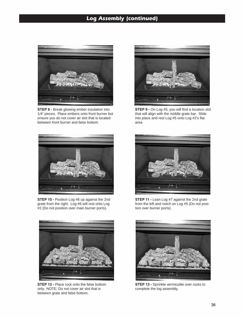
Log Assembly (continued)
STEP 8 - Break glowing ember insulation into1/4” pieces. Place embers onto front burner butensure you do not cover air slot that is locatedbetween front burner and false bottom.
STEP 9 - On Log #5, you will find a location slotthat will align with the middle grate bar. Slideinto place and rest Log #5 onto Log #2’s flatarea.
STEP 10 - Position Log #6 up against the 2ndgrate from the right. Log #6 will rest onto Log#2 (Do not position over main burner ports).
STEP 11 - Lean Log #7 against the 2nd gratefrom the left and notch on Log #5 (Do not posi-tion over burner ports).
STEP 12 - Place rock onto the false bottomonly. NOTE: Do not cover air slot that isbetween grate and false bottom.
STEP 13 - Sprinkle vermiculite over rocks tocomplete the log assembly.
36
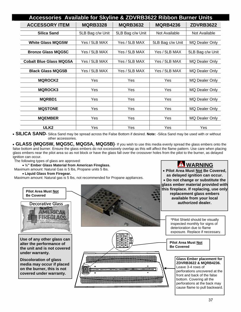
Accessories Available for Skyline & ZDVRB3622 Ribbon Burner Units
ACCESSORY ITEM MQRB3328 MQRB3632 MQRB4236 ZDVRB3622
Silica Sand 5LB Bag c/w Unit 5LB Bag c/w Unit Not Available Not Available
White Glass MQG5W Yes / 5LB MAX Yes / 5LB MAX 5LB Bag c/w Unit MQ Dealer Only
Bronze Glass MQG5C Yes / 5LB MAX Yes / 5LB MAX Yes / 5LB MAX 5LB Bag c/w Unit
Cobalt Blue Glass MQG5A Yes / 5LB MAX Yes / 5LB MAX Yes / 5LB MAX MQ Dealer Only
Black Glass MQG5B Yes / 5LB MAX Yes / 5LB MAX Yes / 5LB MAX MQ Dealer Only
MQROCK2 Yes Yes Yes MQ Dealer Only
MQROCK3 Yes Yes Yes MQ Dealer Only
MQRBD1 Yes Yes Yes MQ Dealer Only
MQSTONE Yes Yes Yes MQ Dealer Only
MQEMBER Yes Yes Yes MQ Dealer Only
ULK2 Yes Yes Yes Yes
SILICA SAND- Silica Sand may be spread across the False Bottom if desired. Note: -Silica Sand may be used with or without other accessories.
GLASS (MQG5W, MQG5C, MQG5A, MQG5B)- If you wish to use this media evenly spread the glass embers onto the false bottom and burner. Ensure the glass embers do not excessively overlap as this will affect the flame pattern. Use care when placing glass embers near the pilot area so as not block or have the glass fall over the crossover holes from the pilot to the burner, as delayed ignition can occur. The following types of glass are approved:
½” Ember Glass Material from American Fireglass. Maximum amount: Natural Gas is 5 lbs, Propane units 5 lbs.
Liquid Glass from Firegear. Maximum amount: Natural gas is 5 lbs, not recommended for Propane appliances.
Pilot Area Must Not Be Covered
*Pilot Shield should be visually inspected monthly for signs of deterioration due to flame exposure. Replace if necessary.
Glass Ember placement forZDVRB3622 & MQRB4236. Leave 3-4 rows of perforations uncovered at the front and back of the false bottom. Covering all the perforations at the back may cause flame to pull backward.
Use of any other glass can alter the performance of the unit and is not covered under warranty.
Discoloration of glass media may occur if placed on the burner, this is not covered under warranty.
WARNING Pilot Area Must Not Be Covered,
as delayed ignition can occur. Do not change or substitute the
glass ember material provided with this fireplace. If replacing, use only
replacement glass embers available from your local
authorized dealer.
Pilot Area Must NotBe Covered
37
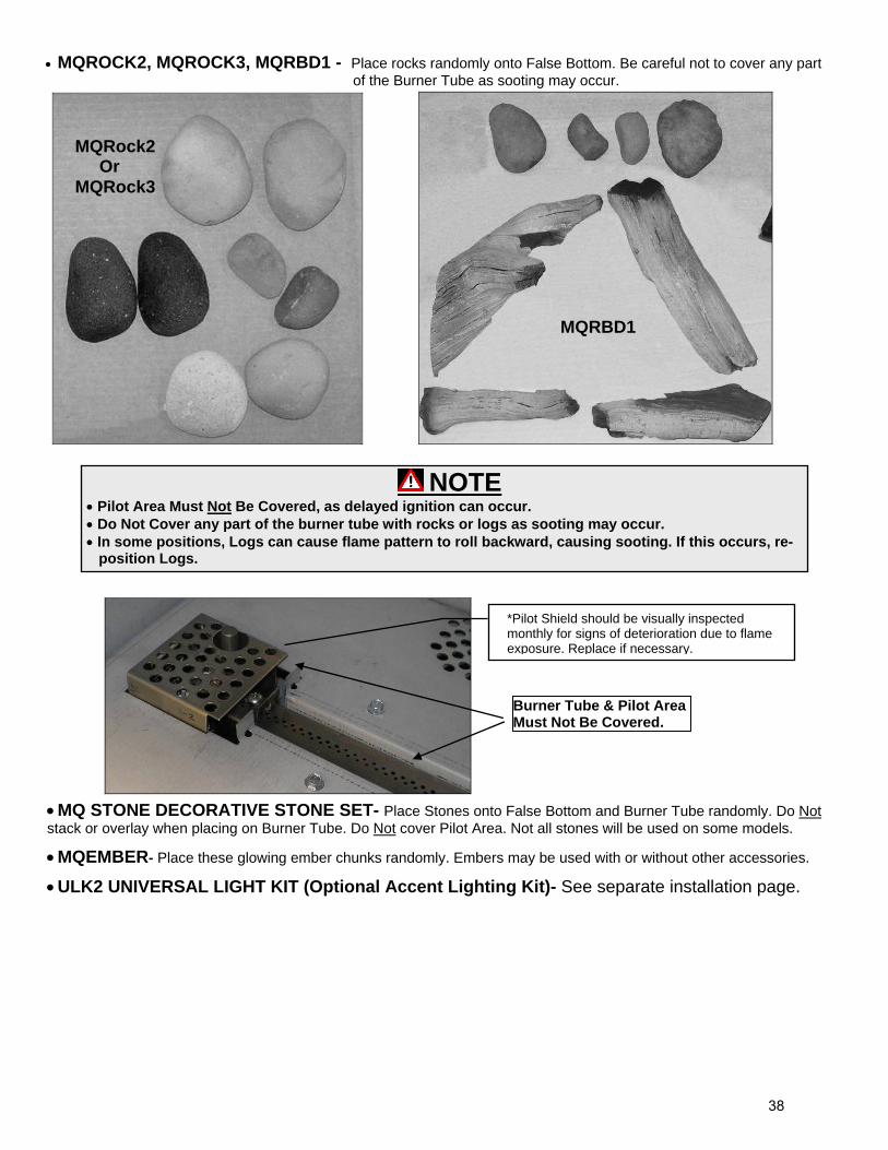
MQROCK2, MQROCK3, MQRBD1 - Place rocks randomly onto False Bottom. Be careful not to cover any part of the Burner Tube as sooting may occur.
MQ STONE DECORATIVE STONE SET- Place Stones onto False Bottom and Burner Tube randomly. Do Not stack or overlay when placing on Burner Tube. Do Not cover Pilot Area. Not all stones will be used on some models.
MQEMBER- Place these glowing ember chunks randomly. Embers may be used with or without other accessories.
ULK2 UNIVERSAL LIGHT KIT (Optional Accent Lighting Kit)- See separate installation page.
NOTE Pilot Area Must Not Be Covered, as delayed ignition can occur. Do Not Cover any part of the burner tube with rocks or logs as sooting may occur. In some positions, Logs can cause flame pattern to roll backward, causing sooting. If this occurs, re-
position Logs.
Burner Tube & Pilot Area Must Not Be Covered.
MQRBD1
*Pilot Shield should be visually inspected monthly for signs of deterioration due to flame exposure. Replace if necessary.
MQRock2 Or MQRock3
38
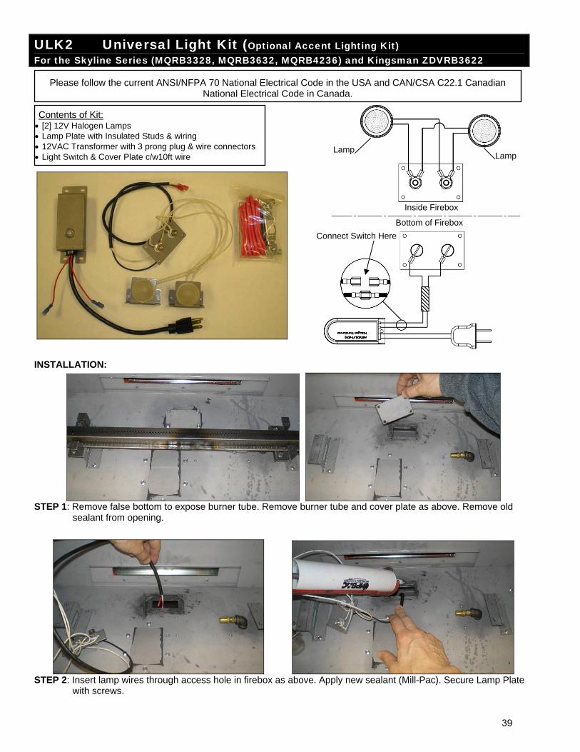
ULK2 Universal Light Kit (Optional Accent Lighting Kit) For the Skyline Series (MQRB3328, MQRB3632, MQRB4236) and Kingsman ZDVRB3622
INSTALLATION:
STEP 1: Remove false bottom to expose burner tube. Remove burner tube and cover plate as above. Remove old
sealant from opening.
STEP 2: Insert lamp wires through access hole in firebox as above. Apply new sealant (Mill-Pac). Secure Lamp Plate
with screws.
Please follow the current ANSI/NFPA 70 National Electrical Code in the USA and CAN/CSA C22.1 Canadian National Electrical Code in Canada.
Contents of Kit: [2] 12V Halogen Lamps Lamp Plate with Insulated Studs & wiring 12VAC Transformer with 3 prong plug & wire connectors Light Switch & Cover Plate c/w10ft wire
Inside Firebox
Bottom of Firebox
LampLamp
Connect Switch Here
39
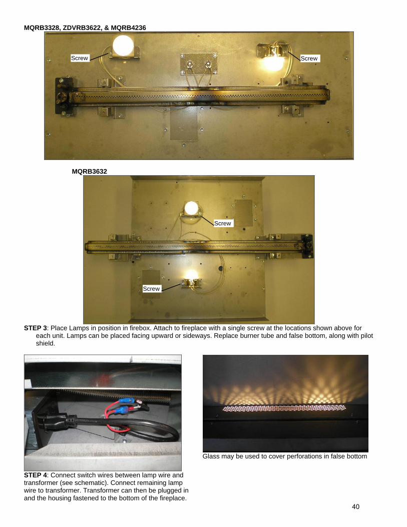
MQRB3328, ZDVRB3622, & MQRB4236
MQRB3632
STEP 3: Place Lamps in position in firebox. Attach to fireplace with a single screw at the locations shown above for
each unit. Lamps can be placed facing upward or sideways. Replace burner tube and false bottom, along with pilot shield.
STEP 4: Connect switch wires between lamp wire and transformer (see schematic). Connect remaining lamp wire to transformer. Transformer can then be plugged in and the housing fastened to the bottom of the fireplace.
Glass may be used to cover perforations in false bottom
Screw Screw
Screw
Screw
40
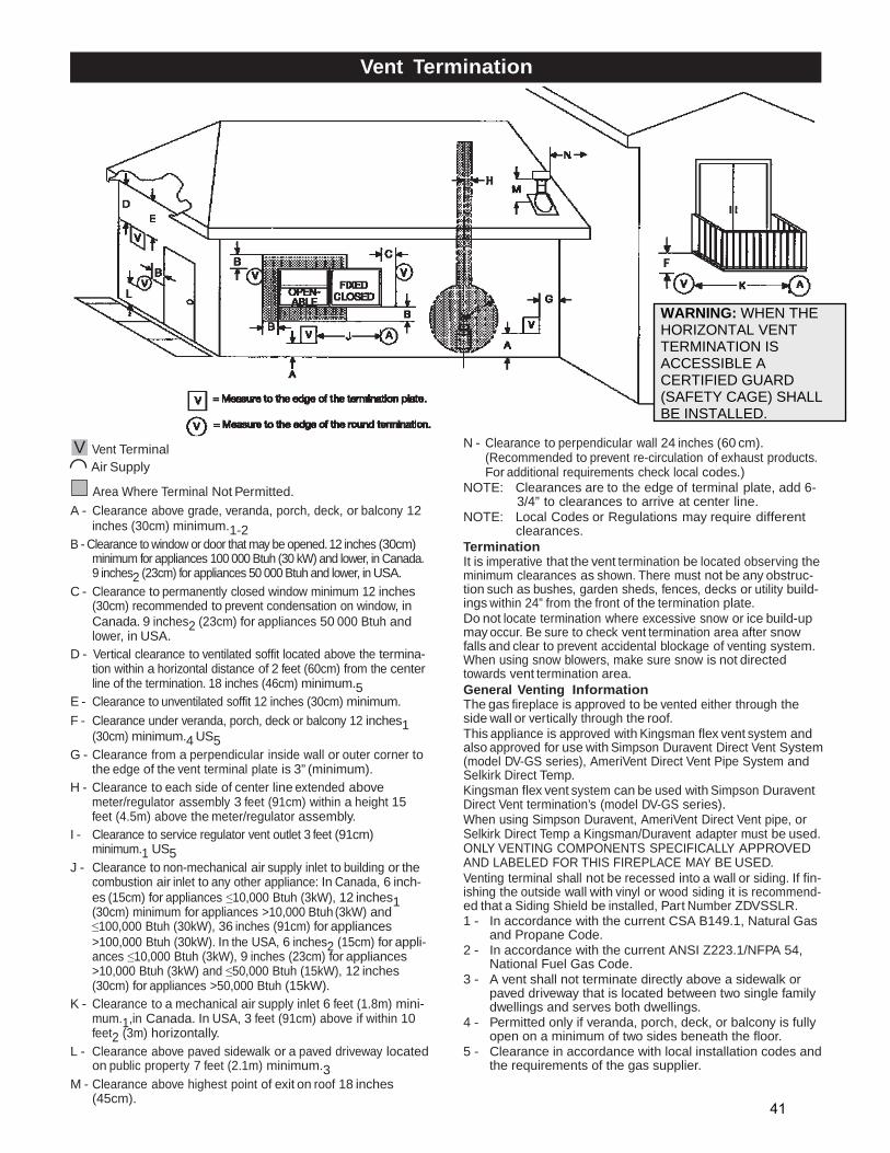
Vent Termination
V Vent Terminal Air Supply
Area Where Terminal Not Permitted.
A - Clearance above grade, veranda, porch, deck, or balcony 12 inches (30cm) minimum.1-2
B - Clearance to window or door that may be opened. 12 inches (30cm) minimum for appliances 100 000 Btuh (30 kW) and lower, in Canada. 9 inches2 (23cm) for appliances 50 000 Btuh and lower, in USA.
C - Clearance to permanently closed window minimum 12 inches (30cm) recommended to prevent condensation on window, in Canada. 9 inches2 (23cm) for appliances 50 000 Btuh and lower, in USA.
D - Vertical clearance to ventilated soffit located above the termina- tion within a horizontal distance of 2 feet (60cm) from the center line of the termination. 18 inches (46cm) minimum.5
E - Clearance to unventilated soffit 12 inches (30cm) minimum.
F - Clearance under veranda, porch, deck or balcony 12 inches1 (30cm) minimum.4 US5
G - Clearance from a perpendicular inside wall or outer corner to the edge of the vent terminal plate is 3” (minimum).
H - Clearance to each side of center line extended above meter/regulator assembly 3 feet (91cm) within a height 15 feet (4.5m) above the meter/regulator assembly.
I - Clearance to service regulator vent outlet 3 feet (91cm) minimum.1 US5
J - Clearance to non-mechanical air supply inlet to building or the combustion air inlet to any other appliance: In Canada, 6 inch- es (15cm) for appliances ≤10,000 Btuh (3kW), 12 inches1 (30cm) minimum for appliances >10,000 Btuh (3kW) and ≤100,000 Btuh (30kW), 36 inches (91cm) for appliances >100,000 Btuh (30kW). In the USA, 6 inches2 (15cm) for appli- ances ≤10,000 Btuh (3kW), 9 inches (23cm) for appliances >10,000 Btuh (3kW) and ≤50,000 Btuh (15kW), 12 inches (30cm) for appliances >50,000 Btuh (15kW).
K - Clearance to a mechanical air supply inlet 6 feet (1.8m) mini- mum.1,in Canada. In USA, 3 feet (91cm) above if within 10 feet2 (3m) horizontally.
L - Clearance above paved sidewalk or a paved driveway located on public property 7 feet (2.1m) minimum.3
M - Clearance above highest point of exit on roof 18 inches (45cm).
N - Clearance to perpendicular wall 24 inches (60 cm). (Recommended to prevent re-circulation of exhaust products. For additional requirements check local codes.)
NOTE: Clearances are to the edge of terminal plate, add 6- 3/4” to clearances to arrive at center line.
NOTE: Local Codes or Regulations may require different clearances.
Termination It is imperative that the vent termination be located observing the minimum clearances as shown. There must not be any obstruc- tion such as bushes, garden sheds, fences, decks or utility build- ings within 24” from the front of the termination plate. Do not locate termination where excessive snow or ice build-up may occur. Be sure to check vent termination area after snow falls and clear to prevent accidental blockage of venting system. When using snow blowers, make sure snow is not directed towards vent termination area. General Venting Information The gas fireplace is approved to be vented either through the side wall or vertically through the roof. This appliance is approved with Kingsman flex vent system and also approved for use with Simpson Duravent Direct Vent System (model DV-GS series), AmeriVent Direct Vent Pipe System and Selkirk Direct Temp. Kingsman flex vent system can be used with Simpson Duravent Direct Vent termination’s (model DV-GS series). When using Simpson Duravent, AmeriVent Direct Vent pipe, or Selkirk Direct Temp a Kingsman/Duravent adapter must be used. ONLY VENTING COMPONENTS SPECIFICALLY APPROVED AND LABELED FOR THIS FIREPLACE MAY BE USED. Venting terminal shall not be recessed into a wall or siding. If fin- ishing the outside wall with vinyl or wood siding it is recommend- ed that a Siding Shield be installed, Part Number ZDVSSLR. 1 - In accordance with the current CSA B149.1, Natural Gas
and Propane Code. 2 - In accordance with the current ANSI Z223.1/NFPA 54,
National Fuel Gas Code. 3 - A vent shall not terminate directly above a sidewalk or
paved driveway that is located between two single family dwellings and serves both dwellings.
4 - Permitted only if veranda, porch, deck, or balcony is fully open on a minimum of two sides beneath the floor.
5 - Clearance in accordance with local installation codes and the requirements of the gas supplier.
WARNING: WHEN THE HORIZONTAL VENT TERMINATION IS ACCESSIBLE A CERTIFIED GUARD (SAFETY CAGE) SHALL BE INSTALLED.
41
COMBUSTIBLE AIR INLET
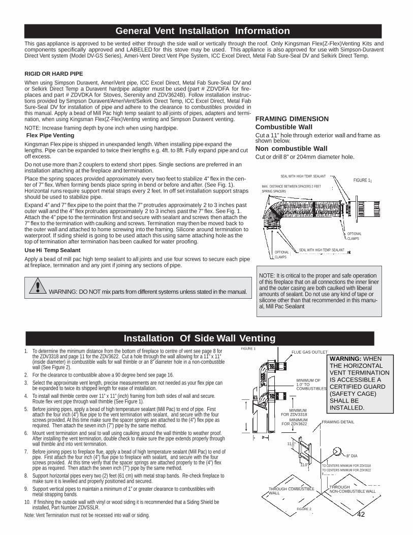
General Vent Installation Information
This gas appliance is approved to be vented either through the side wall or vertically through the roof. Only Kingsman Flex(Z-Flex)Venting Kits and components specifically approved and LABELED for this stove may be used. This appliance is also approved for use with Simpson-Duravent Direct Vent system (Model DV-GS Series), Ameri-Vent Direct Vent Pipe System, ICC Excel Direct, Metal Fab Sure-Seal DV and Selkirk Direct Temp.
RIGID OR HARD PIPE
When using Simpson Duravent, AmeriVent pipe, ICC Excel Direct, Metal Fab Sure-Seal DV and or Selkirk Direct Temp a Duravent hardpipe adapter must be used (part # ZDVDFA for fire- places and part # ZDVDKA for Stoves, Serenity and ZDV3624B). Follow installation instruc- tions provided by Simpson Duravent/AmeriVent/Selkirk Direct Temp, ICC Excel Direct, Metal Fab Sure-Seal DV for installation of pipe and adhere to the clearance to combustibles provided in this manual. Apply a bead of Mill Pac high temp sealant to all joints of pipes, adapters and termi- nation, when using Kingsman Flex(Z-Flex)Venting venting and Simpson Duravent venting.
NOTE: Increase framing depth by one inch when using hardpipe. Flex Pipe Venting
Kingsman Flex pipe is shipped in unexpanded length. When installing pipe expand the lengths. Pipe can be expanded to twice their lengths e.g. 4ft. to 8ft. Fully expand pipe and cut off excess.
Do not use more than 2 couplers to extend short pipes. Single sections are preferred in an installation attaching at the fireplace and termination.
Place the spring spaces provided approximately every two feet to stabilize 4” flex in the cen- ter of 7” flex. When forming bends place spring in bend or before and after. (See Fig. 1). Horizontal runs require support metal straps every 2 feet. In off set installation support straps should be used to stabilize pipe.
Expand 4” and 7” flex pipe to the point that the 7” protrudes approximately 2 to 3 inches past outer wall and the 4” flex protrudes approximately 2 to 3 inches past the 7” flex. See Fig. 1. Attach the 4” pipe to the termination first and secure with sealant and screws then attach the 7” flex to the termination with caulking and screws. Termination may then be moved back to the outer wall and attached to home screwing into the framing. Silicone around termination to waterproof. If siding shield is going to be used attach this using same attaching hole as the top of termination after termination has been caulked for water proofing.
FRAMING DIMENSION Combustible Wall Cut a 11” hole through exterior wall and frame as shown below. Non combustible Wall Cut or drill 8” or 204mm diameter hole.
SEAL WITH HIGH TEMP. SEALANT FIGURE 1
MAX. DISTANCE BETWEEN SPACERS 2 FEET SPRING SPACERS
OPTIONAL CLAMPS
Use Hi Temp Sealant
Apply a bead of mill pac high temp sealant to all joints and use four screws to secure each pipe at fireplace, termination and any joint if joining any sections of pipe.
OPTIONAL CLAMPS
SEAL WITH HIGH TEMP. SEALANT
WARNING: DO NOT mix parts from different systems unless stated in the manual.
NOTE: It is critical to the proper and safe operation of this fireplace that on all connections the inner liner and the outer casing are both caulked with liberal amounts of sealant. Do not use any kind of tape or silicone other than that recommended in this manu- al, Mill Pac Sealant
Installation Of Side Wall Venting
1. To determine the minimum distance from the bottom of fireplace to centre of vent see page 8 for the ZDV3318 and page 11 for the ZDV3622. Cut a hole through the wall allowing for a 11” x 11” (inside diameter) in combustible walls for wall thimble or an 8” diameter hole in a non-combustible wall (See Figure 2).
2. For the clearance to combustible above a 90 degree bend see page 16. 3. Select the approximate vent length, precise measurements are not needed as your flex pipe can
be expanded to twice its shipped length for ease of installation. 4. To install wall thimble centre over 11” x 11” (inch) framing from both sides of wall and secure.
Route flex vent pipe through wall thimble (See Figure 1). 5. Before joining pipes, apply a bead of high temperature sealant (Mill Pac) to end of pipe. First
attach the four inch (4”) flue pipe to the vent termination with sealant, and secure with the four screws provided. At this time make sure the spacer springs are attached to the (4”) flex pipe as
FIGURE 1 FLUE GAS OUTLET
MINIMUM OF 1.0" TO COMBUSTIBLES
MINIMUM FOR ZDV3318
MINIMUM
NOTE: See Pages 8,11 and 35 for prop- er framing dimensions.
required. Then attach the seven inch (7”) pipe by the same method. 6. Mount vent termination and seal to wall using caulking around the wall thimble to weather proof.
After installing the vent termination, double check to make sure the pipe extends properly through wall thimble and into vent termination.
7. Before joining pipes to fireplace flue, apply a bead of high temperature sealant (Mill Pac) to end of pipe. First attach the four inch (4”) flue pipe to fireplace with sealant, and secure with the four screws provided. At this time verify that the spacer springs are attached properly to the (4”) flex pipe as required. Then attach the seven inch (7”) pipe by the same method.
8. Support horizontal pipes every two (2) feet (61 cm) with metal strap bands. Re-check fireplace to make sure it is levelled and properly positioned and secured.
9. Support vertical pipes to maintain a minimum of 1” or greater clearance to combustibles with metal strapping bands.
10. If finishing the outside wall with vinyl or wood siding it is recommended that a Siding Shield be installed, Part Number ZDVSSLR.
Note: Vent Termination must not be recessed into wall or siding.
FOR ZDV3622
11.0"
11.0"
THROUGH COMBUSTIBLE WALL
FIGURE 2
FRAMING DETAIL
8" DIA TO CENTERS MINIMUM FOR ZDV3318 TO CENTERS MINIMUM FOR ZDV3622
THROUGH NON-COMBUSTIBLE WALL
WARNING: WHEN THE HORIZONTAL VENT TERMINATION IS ACCESSIBLE A CERTIFIED GUARD (SAFETY CAGE) SHALL BE INSTALLED.
42
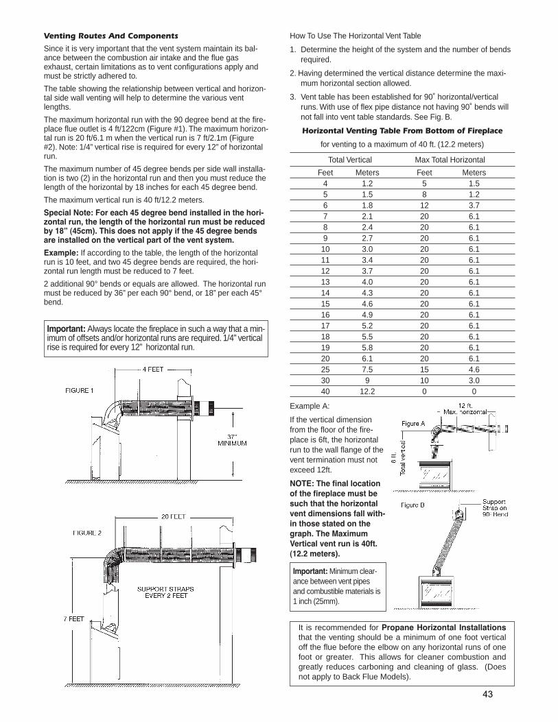
Venting Routes And Components
Since it is very important that the vent system maintain its bal-ance between the combustion air intake and the flue gasexhaust, certain limitations as to vent configurations apply andmust be strictly adhered to.
The table showing the relationship between vertical and horizon-tal side wall venting will help to determine the various ventlengths.
The maximum horizontal run with the 90 degree bend at the fire-place flue outlet is 4 ft/122cm (Figure #1). The maximum horizon-tal run is 20 ft/6.1 m when the vertical run is 7 ft/2.1m (Figure#2). Note: 1/4” vertical rise is required for every 12” of horizontalrun.
The maximum number of 45 degree bends per side wall installa-tion is two (2) in the horizontal run and then you must reduce thelength of the horizontal by 18 inches for each 45 degree bend.
The maximum vertical run is 40 ft/12.2 meters.
Special Note: For each 45 degree bend installed in the hori-zontal run, the length of the horizontal run must be reducedby 18” (45cm). This does not apply if the 45 degree bendsare installed on the vertical part of the vent system.
Example: If according to the table, the length of the horizontalrun is 10 feet, and two 45 degree bends are required, the hori-zontal run length must be reduced to 7 feet.
2 additional 90° bends or equals are allowed. The horizontal runmust be reduced by 36” per each 90° bend, or 18” per each 45°bend.
How To Use The Horizontal Vent Table
1. Determine the height of the system and the number of bendsrequired.
2. Having determined the vertical distance determine the maxi-mum horizontal section allowed.
3. Vent table has been established for 90˚ horizontal/verticalruns. With use of flex pipe distance not having 90˚ bends willnot fall into vent table standards. See Fig. B.
Horizontal Venting Table From Bottom of Fireplace
for venting to a maximum of 40 ft. (12.2 meters)
Total Vertical Max Total Horizontal
Feet Meters Feet Meters4 1.2 5 1.55 1.5 8 1.26 1.8 12 3.77 2.1 20 6.18 2.4 20 6.19 2.7 20 6.110 3.0 20 6.111 3.4 20 6.112 3.7 20 6.113 4.0 20 6.114 4.3 20 6.115 4.6 20 6.116 4.9 20 6.117 5.2 20 6.118 5.5 20 6.119 5.8 20 6.120 6.1 20 6.125 7.5 15 4.630 9 10 3.040 12.2 0 0
Example A:
If the vertical dimensionfrom the floor of the fire-place is 6ft, the horizontalrun to the wall flange of thevent termination must notexceed 12ft.
NOTE: The final locationof the fireplace must besuch that the horizontalvent dimensions fall with-in those stated on thegraph. The MaximumVertical vent run is 40ft.(12.2 meters).
Important: Always locate the fireplace in such a way that a min-imum of offsets and/or horizontal runs are required. 1/4” verticalrise is required for every 12” horizontal run.
Important: Minimum clear-ance between vent pipesand combustible materials is1 inch (25mm).
It is recommended for Propane Horizontal Installationsthat the venting should be a minimum of one foot verticaloff the flue before the elbow on any horizontal runs of onefoot or greater. This allows for cleaner combustion andgreatly reduces carboning and cleaning of glass. (Doesnot apply to Back Flue Models).
43
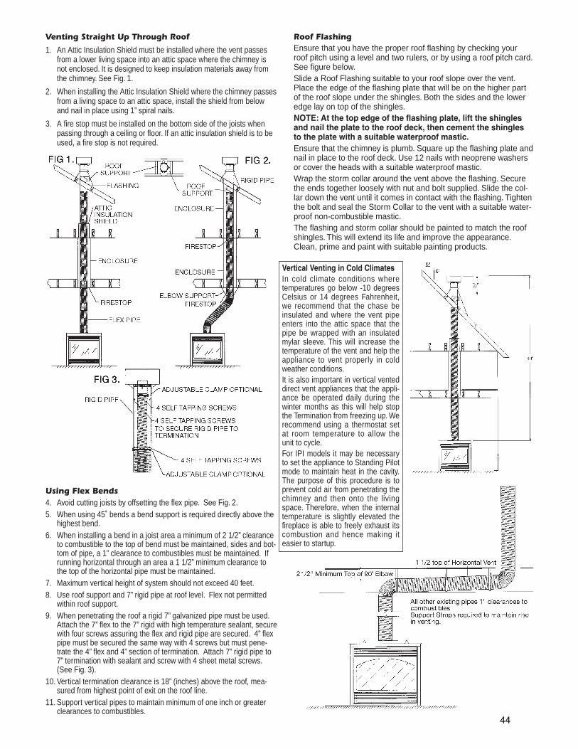
Using Flex Bends4. Avoid cutting joists by offsetting the flex pipe. See Fig. 2.5. When using 45˚ bends a bend support is required directly above the
highest bend.6. When installing a bend in a joist area a minimum of 2 1/2” clearance
to combustible to the top of bend must be maintained, sides and bot-tom of pipe, a 1” clearance to combustibles must be maintained. Ifrunning horizontal through an area a 1 1/2” minimum clearance tothe top of the horizontal pipe must be maintained.
7. Maximum vertical height of system should not exceed 40 feet.8. Use roof support and 7” rigid pipe at roof level. Flex not permitted
within roof support.9. When penetrating the roof a rigid 7” galvanized pipe must be used.
Attach the 7” flex to the 7” rigid with high temperature sealant, securewith four screws assuring the flex and rigid pipe are secured. 4” flexpipe must be secured the same way with 4 screws but must pene-trate the 4” flex and 4” section of termination. Attach 7” rigid pipe to7” termination with sealant and screw with 4 sheet metal screws.(See Fig. 3).
10. Vertical termination clearance is 18” (inches) above the roof, mea-sured from highest point of exit on the roof line.
11. Support vertical pipes to maintain minimum of one inch or greaterclearances to combustibles.
Venting Straight Up Through Roof
1. An Attic Insulation Shield must be installed where the vent passesfrom a lower living space into an attic space where the chimney isnot enclosed. It is designed to keep insulation materials away fromthe chimney. See Fig. 1.
2. When installing the Attic Insulation Shield where the chimney passesfrom a living space to an attic space, install the shield from belowand nail in place using 1” spiral nails.
3. A fire stop must be installed on the bottom side of the joists whenpassing through a ceiling or floor. If an attic insulation shield is to beused, a fire stop is not required.
Roof FlashingEnsure that you have the proper roof flashing by checking yourroof pitch using a level and two rulers, or by using a roof pitch card.See figure below.Slide a Roof Flashing suitable to your roof slope over the vent.Place the edge of the flashing plate that will be on the higher partof the roof slope under the shingles. Both the sides and the loweredge lay on top of the shingles.NOTE: At the top edge of the flashing plate, lift the shinglesand nail the plate to the roof deck, then cement the shinglesto the plate with a suitable waterproof mastic.Ensure that the chimney is plumb. Square up the flashing plate andnail in place to the roof deck. Use 12 nails with neoprene washersor cover the heads with a suitable waterproof mastic.Wrap the storm collar around the vent above the flashing. Securethe ends together loosely with nut and bolt supplied. Slide the col-lar down the vent until it comes in contact with the flashing. Tightenthe bolt and seal the Storm Collar to the vent with a suitable water-proof non-combustible mastic.The flashing and storm collar should be painted to match the roofshingles. This will extend its life and improve the appearance.Clean, prime and paint with suitable painting products.
Vertical Venting in Cold ClimatesIn cold climate conditions wheretemperatures go below -10 degreesCelsius or 14 degrees Fahrenheit,we recommend that the chase beinsulated and where the vent pipeenters into the attic space that thepipe be wrapped with an insulatedmylar sleeve. This will increase thetemperature of the vent and help theappliance to vent properly in coldweather conditions. It is also important in vertical venteddirect vent appliances that the appli-ance be operated daily during thewinter months as this will help stopthe Termination from freezing up. Werecommend using a thermostat setat room temperature to allow theunit to cycle.For IPI models it may be necessaryto set the appliance to Standing Pilotmode to maintain heat in the cavity.The purpose of this procedure is toprevent cold air from penetrating thechimney and then onto the livingspace. Therefore, when the internaltemperature is slightly elevated thefireplace is able to freely exhaust itscombustion and hence making iteasier to startup.
44
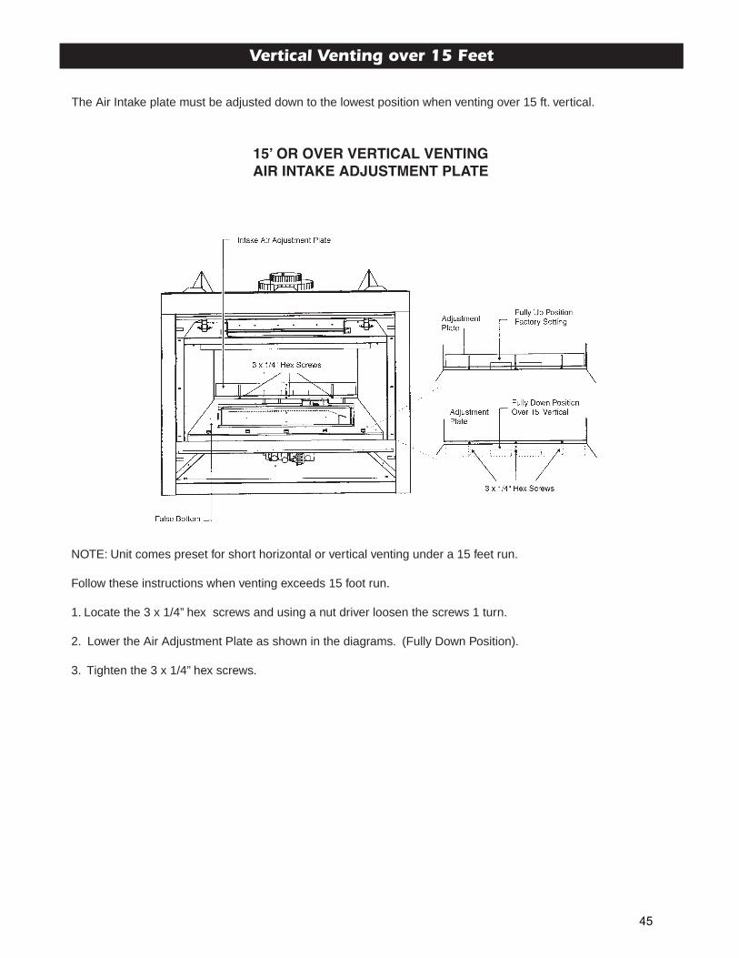
Vertical Venting over 15 Feet
The Air Intake plate must be adjusted down to the lowest position when venting over 15 ft. vertical.
15 ̓OR OVER VERTICAL VENTINGAIR INTAKE ADJUSTMENT PLATE
NOTE: Unit comes preset for short horizontal or vertical venting under a 15 feet run.
Follow these instructions when venting exceeds 15 foot run.
1. Locate the 3 x 1/4” hex screws and using a nut driver loosen the screws 1 turn.
2. Lower the Air Adjustment Plate as shown in the diagrams. (Fully Down Position).
3. Tighten the 3 x 1/4” hex screws.
45
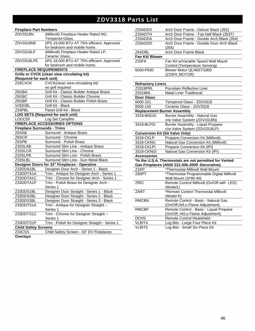
ZDV3318 Parts List
Fireplace Part Numbers ZDV3318N (Millivolt) Fireplace Heater Rated NG, Tempered Glass, ZDV3318NE (IPI) 19,000 BTU AT 75% efficient. Approved for bedroom and mobile home. ZDV3318LP (Millivolt) Fireplace Heater Rated LP, Ceramic Glass, ZDV3318LPE (IPI) 18,000 BTU AT 75% efficient. Approved for bedroom and mobile home. FIREPLACE REQUIREMENTS Grills or CVCK (clean view circulating kit) (Required for each unit) Z33CVCK CVCK(clean view circulating kit) no grill required Z6GBA Grill Kit - Classic Builder Antique Brass Z6GBC Grill Kit - Classic Builder Chrome Z6GBP Grill Kit - Classic Builder Polish Brass VI30GBL Grill Kit - Black Z33PBL Panel Grill Kit - Black LOG SETS (Required for each unit) LOGC50 Log Set Campfire FIREPLACE ACCESSORIES OPTIONS Fireplace Surrounds - Trims Z6SAB Surround - Antique Brass Z6SCR Surround - Chrome Z6SPB Surround - Polish Brass Z33SLAB Surround Slim Line - Antique Brass Z33SLCR Surround Slim Line - Chrome Z33SLPB Surround Slim Line - Polish Brass Z33SLBL Surround Slim Line - Gun Metal Black Designer Doors for 33” Fireplaces - Operative Z33DDA1BL Designer Door Arch - Series 1 - Black Z33DDTA1A Trim - Antique for Designer Arch - Series 1 Z33DDTA1C Trim - Chrome for Designer Arch - Series 1 Z33DDTA1P Trim - Polish Brass for Designer Arch - Series 1 Z33DDS1BL Designer Door Straight - Series 1 - Black Z33DDS2BL Designer Door Straight - Series 2 - Black Z33DDS3BL Designer Door Straight - Series 3 - Black Z33DDTS1A Trim - Antique for Designer Straight – Series 1 Z33DDTS1C Trim - Chrome for Designer Straight – Series 1 Z33DDTS1P Trim - Polish for Designer Straight - Series 1 Child Safety Screens Z33CSS Child Safety Screen - 33” DV Fireplaces Overlays
Z33ADDX Arch Door Frame - Deluxe Black (352) Z33ADTH Arch Door Frame - Top Half Black (353T) Z33ADDA Arch Door Frame - Double Arch Black (354) Z33ADDD Arch Door Frame - Double Door Arch Black (355) Z6ADBL Arch Door Frame Black Fan Kit/ Blower Z33FK Fan Kit w/Variable Speed Wall Mount Control (Temperature Sensing) 6000-P930 Blower Motor QLN657/1800 (Z33FK MOTOR) ZDV3318 Parts
Refractory Liners Z3318PRL Porcelain Reflective Liner Z3318ML Metal Liner Traditional Door Glass 6000-151 Tempered Glass - ZDV3318 6000-150 Ceramic Glass - ZDV3318 Replacement Burner Assembly 3318-BNGSI Burner Assembly - Natural Gas c/w Valve System (ZDV3318N) 3318-BLPSI Burner Assembly - Liquid Propane c/w Valve System (ZDV3318LP) Conversion Kit (Sit Valve Only) 3318-CKLP Propane Conversion Kit (Millivolt) 3318-CKNG Natural Gas Conversion Kit (Millivolt) 3318-CKLPI Propane Conversion Kit (IPI) 3318-CKNGI Natural Gas Conversion Kit (IPI) Accessories *In the U.S.A. Thermostats are not permitted for Vented Gas Fireplaces (ANSI Z21.50b-2009 -Decorative). Z1MT *Thermostat Millivolt Wall Mount Z80PT *Thermostat Programmable Digital Millivolt Wall Mount (1F80-40) ZIRC Remote Control Millivolt (On/Off with LED) (Model1) ZART *Remote Control Thermostat Millivolt (Model K) RMCBN Remote Control - Basic - Natural Gas (On/Off,Hi/Lo Flame Adjustment) RMCBP Remote Control - Basic - Liquid Propane (On/Off, Hi/Lo Flame Adjustment) DCHS Remote Control Heatshield VLBIT4 Log Bits - Large Four Piece Kit VLBIT6 Log Bits - Small Six Piece Kit
46
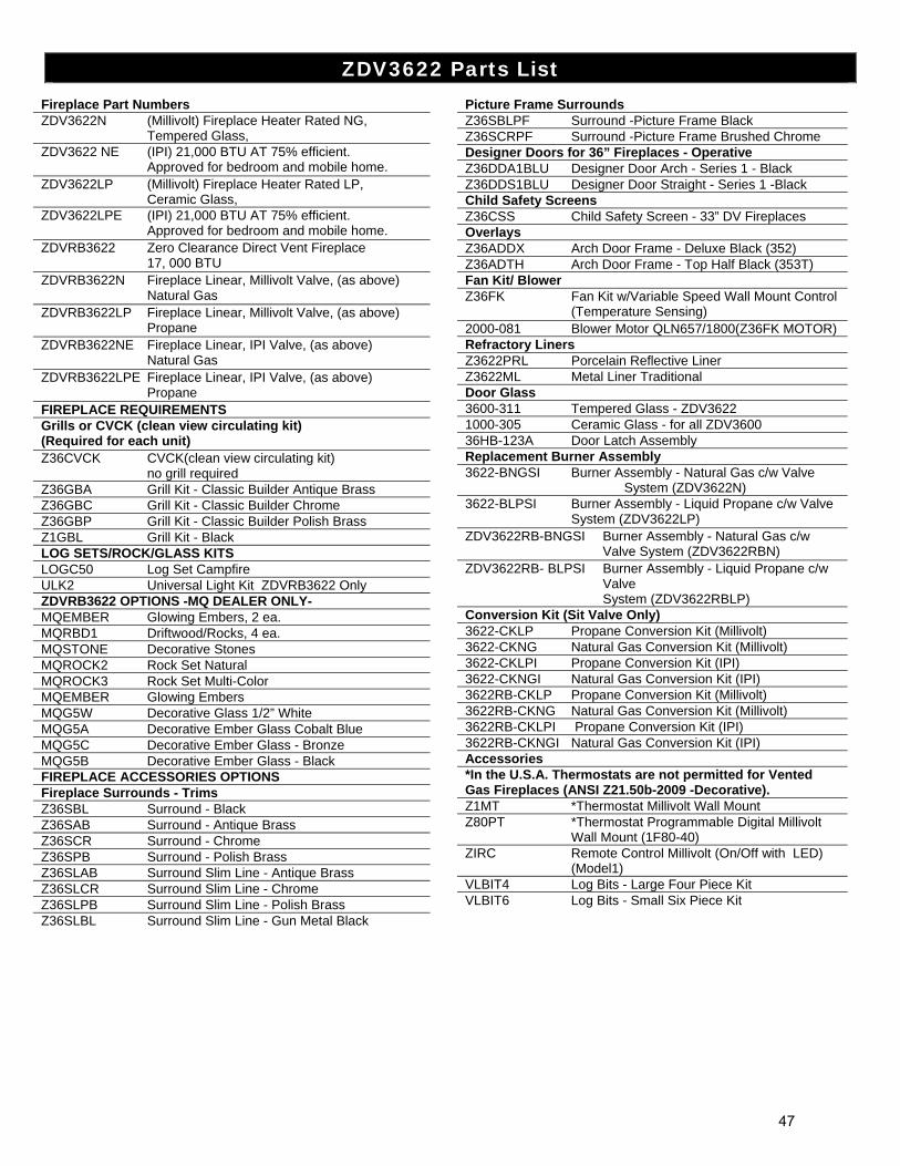
ZDV3622 Parts List
Fireplace Part Numbers ZDV3622N (Millivolt) Fireplace Heater Rated NG, Tempered Glass, ZDV3622 NE (IPI) 21,000 BTU AT 75% efficient. Approved for bedroom and mobile home. ZDV3622LP (Millivolt) Fireplace Heater Rated LP, Ceramic Glass, ZDV3622LPE (IPI) 21,000 BTU AT 75% efficient. Approved for bedroom and mobile home. ZDVRB3622 Zero Clearance Direct Vent Fireplace 17, 000 BTU ZDVRB3622N Fireplace Linear, Millivolt Valve, (as above) Natural Gas ZDVRB3622LP Fireplace Linear, Millivolt Valve, (as above) Propane ZDVRB3622NE Fireplace Linear, IPI Valve, (as above) Natural Gas ZDVRB3622LPE Fireplace Linear, IPI Valve, (as above) Propane FIREPLACE REQUIREMENTS Grills or CVCK (clean view circulating kit) (Required for each unit) Z36CVCK CVCK(clean view circulating kit) no grill required Z36GBA Grill Kit - Classic Builder Antique Brass Z36GBC Grill Kit - Classic Builder Chrome Z36GBP Grill Kit - Classic Builder Polish Brass Z1GBL Grill Kit - Black LOG SETS/ROCK/GLASS KITS LOGC50 Log Set Campfire ULK2 Universal Light Kit ZDVRB3622 Only ZDVRB3622 OPTIONS -MQ DEALER ONLY- MQEMBER Glowing Embers, 2 ea. MQRBD1 Driftwood/Rocks, 4 ea. MQSTONE Decorative Stones MQROCK2 Rock Set Natural MQROCK3 Rock Set Multi-Color MQEMBER Glowing Embers MQG5W Decorative Glass 1/2” White MQG5A Decorative Ember Glass Cobalt Blue MQG5C Decorative Ember Glass - Bronze MQG5B Decorative Ember Glass - Black FIREPLACE ACCESSORIES OPTIONS Fireplace Surrounds - Trims Z36SBL Surround - Black Z36SAB Surround - Antique Brass Z36SCR Surround - Chrome Z36SPB Surround - Polish Brass Z36SLAB Surround Slim Line - Antique Brass Z36SLCR Surround Slim Line - Chrome Z36SLPB Surround Slim Line - Polish Brass Z36SLBL Surround Slim Line - Gun Metal Black
Picture Frame Surrounds Z36SBLPF Surround -Picture Frame Black Z36SCRPF Surround -Picture Frame Brushed Chrome Designer Doors for 36” Fireplaces - Operative Z36DDA1BLU Designer Door Arch - Series 1 - Black Z36DDS1BLU Designer Door Straight - Series 1 -Black Child Safety Screens Z36CSS Child Safety Screen - 33” DV Fireplaces Overlays Z36ADDX Arch Door Frame - Deluxe Black (352) Z36ADTH Arch Door Frame - Top Half Black (353T) Fan Kit/ Blower Z36FK Fan Kit w/Variable Speed Wall Mount Control (Temperature Sensing) 2000-081 Blower Motor QLN657/1800(Z36FK MOTOR) Refractory Liners Z3622PRL Porcelain Reflective Liner Z3622ML Metal Liner Traditional Door Glass 3600-311 Tempered Glass - ZDV3622 1000-305 Ceramic Glass - for all ZDV3600 36HB-123A Door Latch Assembly Replacement Burner Assembly 3622-BNGSI Burner Assembly - Natural Gas c/w Valve System (ZDV3622N) 3622-BLPSI Burner Assembly - Liquid Propane c/w Valve System (ZDV3622LP) ZDV3622RB-BNGSI
Burner Assembly - Natural Gas c/w Valve System (ZDV3622RBN)
ZDV3622RB- BLPSI Burner Assembly - Liquid Propane c/w Valve System (ZDV3622RBLP)
Conversion Kit (Sit Valve Only) 3622-CKLP Propane Conversion Kit (Millivolt) 3622-CKNG Natural Gas Conversion Kit (Millivolt) 3622-CKLPI Propane Conversion Kit (IPI) 3622-CKNGI Natural Gas Conversion Kit (IPI) 3622RB-CKLP Propane Conversion Kit (Millivolt) 3622RB-CKNG Natural Gas Conversion Kit (Millivolt) 3622RB-CKLPI Propane Conversion Kit (IPI) 3622RB-CKNGI Natural Gas Conversion Kit (IPI) Accessories *In the U.S.A. Thermostats are not permitted for Vented Gas Fireplaces (ANSI Z21.50b-2009 -Decorative). Z1MT *Thermostat Millivolt Wall Mount Z80PT *Thermostat Programmable Digital Millivolt Wall Mount (1F80-40) ZIRC Remote Control Millivolt (On/Off with LED) (Model1) VLBIT4 Log Bits - Large Four Piece Kit VLBIT6 Log Bits - Small Six Piece Kit
47
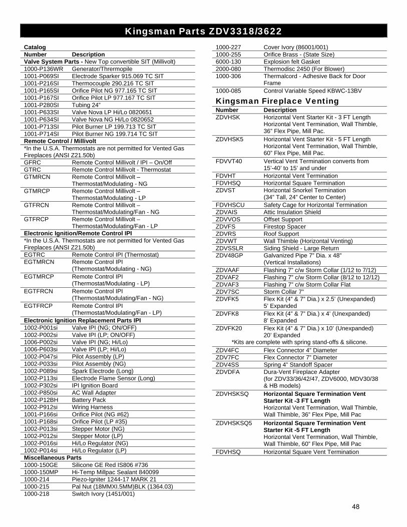
Kingsman Parts ZDV3318/3622
Catalog Number Description Valve System Parts - New Top convertible SIT (Millivolt) 1000-P136WR Generator/Thrermopile 1001-P069SI Electrode Sparker 915.069 TC SIT 1001-P216SI Thermocouple 290.216 TC SIT 1001-P165SI Orifice Pilot NG 977.165 TC SIT 1001-P167SI Orifice Pilot LP 977.167 TC SIT 1001-P280SI Tubing 24” 1001-P633SI Valve Nova LP Hi/Lo 0820651 1001-P634SI Valve Nova NG Hi/Lo 0820652 1001-P713SI Pilot Burner LP 199.713 TC SIT 1001-P714SI Pilot Burner NG 199.714 TC SIT Remote Control / Millivolt *In the U.S.A. Thermostats are not permitted for Vented Gas Fireplaces (ANSI Z21.50b) GFRC Remote Control Millivolt / IPI – On/Off GTRC Remote Control Millivolt - Thermostat GTMRCN Remote Control Millivolt – Thermostat/Modulating - NG GTMRCP Remote Control Millivolt – Thermostat/Modulating - LP GTFRCN Remote Control Millivolt – Thermostat/Modulating/Fan - NG GTFRCP Remote Control Millivolt – Thermostat/Modulating/Fan - LP Electronic Ignition/Remote Control IPI *In the U.S.A. Thermostats are not permitted for Vented Gas Fireplaces (ANSI Z21.50b) EGTRC Remote Control IPI (Thermostat) EGTMRCN Remote Control IPI (Thermostat/Modulating - NG) EGTMRCP Remote Control IPI (Thermostat/Modulating - LP) EGTFRCN Remote Control IPI (Thermostat/Modulating/Fan - NG) EGTFRCP Remote Control IPI (Thermostat/Modulating/Fan - LP) Electronic Ignition Replacement Parts IPI 1002-P001si Valve IPI (NG; ON/OFF) 1002-P002si Valve IPI (LP; ON/OFF) 1006-P002si Valve IPI (NG; Hi/Lo) 1006-P603si Valve IPI (LP; Hi/Lo) 1002-P047si Pilot Assembly (LP) 1002-P033si Pilot Assembly (NG) 1002-P089si Spark Electrode (Long) 1002-P113si Electrode Flame Sensor (Long) 1002-P302si IPI Ignition Board 1002-P850si AC Wall Adapter 1002-P12BH Battery Pack 1002-P912si Wiring Harness 1001-P166si Orifice Pilot (NG #62) 1001-P168si Orifice Pilot (LP #35) 1002-P013si Stepper Motor (NG) 1002-P012si Stepper Motor (LP) 1002-P016si Hi/Lo Regulator (NG) 1002-P014si Hi/Lo Regulator (LP) Miscellaneous Parts 1000-150GE Silicone GE Red IS806 #736 1000-150MP Hi-Temp Millpac Sealant 840099 1000-214 Piezo-Igniter 1244-17 MARK 21 1000-215 Pal Nut (18MMXI.5MM)BLK (1364.03) 1000-218 Switch Ivory (1451/001)
1000-227 Cover Ivory (86001/001) 1000-255 Orifice Brass - (State Size) 6000-130 Explosion felt Gasket 2000-080 Thermodisc 2450 (For Blower) 1000-306 Thermalcord - Adhesive Back for Door Frame 1000-085 Control Variable Speed KBWC-13BV
Kingsman Fireplace Venting Number Description ZDVHSK Horizontal Vent Starter Kit - 3 FT Length Horizontal Vent Termination, Wall Thimble, 36” Flex Pipe, Mill Pac. ZDVHSK5 Horizontal Vent Starter Kit - 5 FT Length Horizontal Vent Termination, Wall Thimble, 60” Flex Pipe, Mill Pac. FDVVT40 Vertical Vent Termination converts from 15’-40’ to 15’ and under FDVHT Horizontal Vent Termination FDVHSQ Horizontal Square Termination ZDVST Horizontal Snorkel Termination (34” Tall, 24” Center to Center) FDVHSCU Safety Cage for Horizontal Termination ZDVAIS Attic Insulation Shield ZDVVOS Offset Support ZDVFS Firestop Spacer ZDVRS Roof Support ZDVWT Wall Thimble (Horizontal Venting) ZDVSSLR Siding Shield - Large Return ZDV48GP Galvanized Pipe 7” Dia. x 48” (Vertical Installations) ZDVAAF Flashing 7” c/w Storm Collar (1/12 to 7/12) ZDVAF2 Flashing 7” c/w Storm Collar (8/12 to 12/12) ZDVAF3 Flashing 7” c/w Storm Collar Flat ZDV7SC Storm Collar 7” ZDVFK5 Flex Kit (4” & 7” Dia.) x 2.5’ (Unexpanded) 5’ Expanded ZDVFK8 Flex Kit (4” & 7” Dia.) x 4’ (Unexpanded) 8’ Expanded ZDVFK20 Flex Kit (4” & 7” Dia.) x 10’ (Unexpanded) 20’ Expanded
*Kits are complete with spring stand-offs & silicone. ZDV4FC Flex Connector 4” Diameter ZDV7FC Flex Connector 7” Diameter ZDV4SS Spring 4” Standoff Spacer ZDVDFA Dura-Vent Fireplace Adapter (for ZDV33/36/42/47, ZDV6000, MDV30/38 & HB models) ZDVHSKSQ Horizontal Square Termination Vent Starter Kit -3 FT Length Horizontal Vent Termination, Wall Thimble, Wall Thimble, 36” Flex Pipe, Mill Pac
ZDVHSKSQ5 Horizontal Square Termination Vent Starter Kit -5 FT Length Horizontal Vent Termination, Wall Thimble, Wall Thimble, 60” Flex Pipe, Mill Pac FDVHSQ Horizontal Square Vent Termination
48
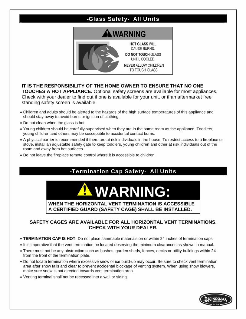
-Glass Safety- All Units
IT IS THE RESPONSIBILITY OF THE HOME OWNER TO ENSURE THAT NO ONE TOUCHES A HOT APPLIANCE. Optional safety screens are available for most appliances. Check with your dealer to find out if one is available for your unit, or if an aftermarket free standing safety screen is available. Children and adults should be alerted to the hazards of the high surface temperatures of this appliance and should stay away to avoid burns or ignition of clothing.
Do not clean when the glass is hot.
Young children should be carefully supervised when they are in the same room as the appliance. Toddlers, young children and others may be susceptible to accidental contact burns.
A physical barrier is recommended if there are at risk individuals in the house. To restrict access to a fireplace or stove, install an adjustable safety gate to keep toddlers, young children and other at risk individuals out of the room and away from hot surfaces.
Do not leave the fireplace remote control where it is accessible to children.
-Termination Cap Safety- All Units
WARNING: WHEN THE HORIZONTAL VENT TERMINATION IS ACCESSIBLE A CERTIFIED GUARD (SAFETY CAGE) SHALL BE INSTALLED.
SAFETY CAGES ARE AVAILABLE FOR ALL HORIZONTAL VENT TERMINATIONS.
CHECK WITH YOUR DEALER. TERMINATION CAP IS HOT! Do not place flammable materials on or within 24 inches of termination caps.
It is imperative that the vent termination be located observing the minimum clearances as shown in manual.
There must not be any obstruction such as bushes, garden sheds, fences, decks or utility buildings within 24" from the front of the termination plate.
Do not locate termination where excessive snow or ice build-up may occur. Be sure to check vent termination area after snow falls and clear to prevent accidental blockage of venting system. When using snow blowers, make sure snow is not directed towards vent termination area.
Venting terminal shall not be recessed into a wall or siding.
BASIC ONE YEAR WARRANTYDuring the first year after installation, we will provide a replacement for any component part of your unit found to be defective in materials or workmanship, including labour costs. Repair work requires prior approval by Kingsman, labour costs are based on a predetermined rateschedule and any repair work must be done through an authorized Kingsman dealer.
LIMITED LIFETIME WARRANTYThe heat exchanger, combustion chamber and burner of every Kingsman product excluding the Outdoor Firepit are warranted against materials or workmanship during the period the product is owned by the original owner. The part to be replaced must be returned to our distributor in exchange for the replacement part. Any labor, material, freight and/or handling charges associated with any repair or replacement pursuant to this Limited Lifetime Warranty will not be covered by this warranty.
GENERAL TERMSIn lieu of providing a replacement part, we may, at our option, provide the distributor's component purchase price from us or a credit equal to the distributors component purchase price from us toward the purchase of any new unit which we distribute. If a credit is given in lieu of a replacement part, the rating plate from the unit being replaced must be submitted on a warranty claim, and the unit beingreplaced must be made available to our distributor for disposition.
In establishing the date of installation for any purpose, including determination of the starting date for the term of this Limited LifetimeWarranty, reasonable proof of the original installation date must be presented*, otherwise the effective date will be based upon the date ofmanufacture plus thirty (30) days.
We will not be responsible for and you, the user, will pay for: (a) damages caused by accident, abuse, negligence, misuse, riot, fire, flood,or Acts of God (b) damages caused by operating the unit where there is a corrosive atmosphere containing chlorine, fluorine, or any other damaging chemicals (other than in a normal residential environment) (c) damages caused by any unauthorized alteration or repair of the unit affecting its stability or performance (d) damages caused by improper matching or application of the unit or the unit's components(e) damages caused by failing to provide proper maintenance and service to the unit (f) any expenses incurred for erecting, disconnecting or dismantling the unit (g) parts or supplies used in connection with service or maintenance (h) damage repairs, inoperation or inefficiencyresulting from faulty installation or application (i) electricity or fuel costs or any increase in electricity or fuel cost whatsoever including additional or unusual use of supplemental electric heat.
We shall not be liable for any incidental, consequential, or special damages or expenses in connection with any use or failure of this unit. We have not made and do not make any representation or warranty of fitness for a particular use or purpose, and there is no implied conditionof fitness for a particular use or purpose. We make no express warranties except as stated in this Limited Lifetime Warranty. No one is authorizedto change this Limited Lifetime Warranty or to create for us any other obligation or liability in connections with this unit. Any implied warranties shall last for one year after the original installation. Some states and provinces do not allow the exclusion or limitation of incidental or consequential damages or do not allow limitations on how long an implied warranty or condition lasts, so the above limitations or exclu-sions may not apply to you. The provisions of this limited warranty are in additions to and not a modification of or subtraction from any statu-tory warranties and other rights and remedies provided by law.
Save this certificate. It gives you specific legal rights, and you may also have other rights which may vary from state to state and province to province.
In the event your unit needs servicing, contact your dealer or contractor who installed or serviced your unit. When requesting service, please have the model and serial number from each unit readily available. If your dealer needs assistance, the distributor is available for supportand we, in turn support the distributor's efforts.
Fill in the installation date and model and serial numbers of the unit in the space provided below and retain this limited warranty for your files.
Model No. Serial No. Date installed
Dealer or Contractor Name:*To receive advantage of your warranty, you must retain the original records that can establish the installation date of your unit.
LIMITED LIFETIME WARRANTY
This Limited Lifetime Warranty applies only while the unit remains at the site of the originalinstallation and only if the unit is installed inside the continental United States, Alaska, Hawaii,and Canada. The warranty applies only if the unit is installed and operated in accordance with the printed instructions and in compliance with applicable installation and building codes and good trade practices.
The Ultimate in Design, Engineering & Quality