inspection and preventive maintenance procedures
TRANSCRIPT

Inspection and Preventive MaintenanceProceduresProcedure No. Procedure No.Anesthesia Unit Vaporizers . . . . . . . 436-0595Anesthesia Unit Ventilators . . . . . . . 461-0595Anesthesia Units . . . . . . . . . . . . . 400-0595Apnea Monitors . . . . . . . . . . . . . . 420-0595Argon Surgical Lasers . . . . . . . . . . 462-0595Aspirators . . . . . . . . . . . . . . . . . 433-0595Autotransfusion Units . . . . . . . . . . 449-0595Beds, Electric . . . . . . . . . . . . . . . 402-0595Blood Pressure Monitors, Electronic
Indirect . . . . . . . . . . . . . . . . . 454-0595Blood Pressure Monitors, Invasive . . . 434-0595Blood/Solution Warmers . . . . . . . . . 445-0595Capnometers and Multiple Medical
Gas Monitors . . . . . . . . . . . . . . 450-0595Carbon Dioxide Surgical Lasers . . . . . 446-0595Cardiac Resuscitators . . . . . . . . . . 421-0595Centrifuges . . . . . . . . . . . . . . . . 456-0595Circulating-Fluid Pumps . . . . . . . . . 412-0595Conductive Furniture and Floors . . . . 441-0595Critical Care Ventilators . . . . . . . . . 458-0595Cryosurgical Units . . . . . . . . . . . . 457-0595Defibrillator/Monitors . . . . . . . . . . 408-0595Defibrillators . . . . . . . . . . . . . . . 407-0595ECG Monitors . . . . . . . . . . . . . . . 409-0595Electrical Receptacles . . . . . . . . . . 437-0595Electrocardiographs . . . . . . . . . . . 410-0595Electrosurgical Units . . . . . . . . . . . 411-0595Frequency-Doubled Nd:YAG
Surgical Lasers . . . . . . . . . . . . 464-0595General Devices . . . . . . . . . . . . . . 438-0595Heart-Lung Bypass Units . . . . . . . . 430-0595Heated Humidifiers . . . . . . . . . . . . 431-0595Hemodialysis Units . . . . . . . . . . . . 413-0595Ho:YAG Surgical Lasers . . . . . . . . . 465-0595Hypo/Hyperthermia Units . . . . . . . . 414-0595
Infant Incubators . . . . . . . . . . . . . 415-0595Infusion Devices . . . . . . . . . . . . . 416-0595Intra-Aortic Balloon Pumps . . . . . . . 432-0595Isolated Power Systems . . . . . . . . . 439-0595Laparoscopic Insufflators . . . . . . . . . 466-0595Mammography Units . . . . . . . . . . . 467-0595Medical Gas/Vacuum Systems . . . . . . 440-0595Mobile C-arms . . . . . . . . . . . . . . 463-0595Mobile X-ray Units . . . . . . . . . . . . 468-0595Nd:YAG Surgical Lasers . . . . . . . . . 447-0595Oxygen-Air Proportioners . . . . . . . . 444-0595Oxygen Analyzers . . . . . . . . . . . . . 417-0595Pacemakers, External Invasive . . . . . 418-0595Pacemakers, External Noninvasive . . . 460-0595Peritoneal Dialysis Units . . . . . . . . . 455-0595Phototherapy Units . . . . . . . . . . . . 469-0595Physical Therapy Ultrasound Units . . . 470-0595Pneumatic Tourniquets . . . . . . . . . . 443-0595Portable Ventilators . . . . . . . . . . . 471-0595Pressure Transducers . . . . . . . . . . 435-0595Pulmonary Resuscitators,
Gas-Powered . . . . . . . . . . . . . . 448-0595Pulmonary Resuscitators, Manual . . . . 422-0595Pulse Oximeters . . . . . . . . . . . . . 451-0595Radiant Warmers . . . . . . . . . . . . . 419-0595Radiographic Units, General-Purpose . . 472-0595Radiographic/Fluoroscopic Units,
General-Purpose . . . . . . . . . . . . 473-0595Smoke Evacuators . . . . . . . . . . . . 452-0595Sphygmomanometers . . . . . . . . . . . 424-0595Suction Regulators . . . . . . . . . . . . 459-0595Temperature Monitors . . . . . . . . . . 425-0595Traction Units . . . . . . . . . . . . . . . 427-0595Transcutaneous O2/CO2 Monitors . . . . 453-0595Ultrasound Scanners . . . . . . . . . . . 474-0595
257941456-0595
A NONPROFIT AGENCY
5200 Butler Pike, Plymouth Meeting, PA 19462-1298, USATelephone +1 (610) 825-6000 Fax +1 (610) 834-1275 E-mail [email protected]
IPM Procedures

009006436-0595
A NONPROFIT AGENCY
5200 Butler Pike, Plymouth Meeting, PA 19462-1298, USATelephone +1 (610) 825-6000 Fax +1 (610) 834-1275 E-mail [email protected]
Anesthesia Unit VaporizersUsed For:Anesthesia Unit Vaporizers [10-144]
Also Called: By trade names (e.g., Fluotec 5, Vapor 19.1, Tec 6), which are registered trademarks and shouldbe used only when referring to the specific devices
Commonly Used In: Operating rooms, emergency rooms, delivery rooms, trauma rooms, and any areasrequiring the administration of an inhalation agent (with anesthesia units)
Scope: Applies to the various anesthesia vaporizers used to deliver a known concentration of vaporized liquidanesthetic
Risk Level: ECRI Recommended, High; Hospital Assessment,
ECRI-Recommended Interval UsedType Interval* By Hospital Time Required
Major 6 months months . hours
Minor NA months . hours
* Additional periodic calibration and preventive maintenance is normally required annually or biannually (seemanufacturer’s recommendation). Only qualified personnel trained and experienced in this function shouldperform this additional servicing.
OverviewAn anesthesia unit vaporizer is used to vaporize aliquid anesthetic agent and deliver a controlledamount to the patient.
According to the American Society for Testing andMaterials (ASTM)standard ASTM F1161-88, anestheticagent vaporizers are required to be concentration cali-brated (i.e., a calibrated knob controls the output con-centration). Older vaporizers, such as the CopperKettle and the Vernitrol, do not have a single controlfor selecting the concentration of anesthetic vapor.Where possible, these units should be removed fromservice. Contemporary concentration-calibrated va-porizers are of two types: variable bypass and heatedblender.
Conventional (variable-bypass) vaporizers. In avariable-bypass vaporizer, the total background gasflow that enters the unit is split into two streams. The
smaller stream, which acts as the carrier gas, passesthrough the vaporizing chamber containing the anes-thetic agent and becomes saturated with agent vapor;the remainder of the gas bypasses this chamber. Awick may be used in the vaporizing chamber to provideincreased surface area for efficient evaporation of thedrug and saturation of the carrier gas. The saturatedcarrier gas leaves the chamber and mixes with thebypass gas. One adjustment is made to set the desiredconcentration. This adjustment simultaneously bal-ances the carrier and bypass flows to produce the blendrequired for the set concentration. The mixture exitsthe vaporizer and is delivered from the anesthesiamachine as the fresh gas to be inspired by the patient.
Evaporation of the liquid agent contained in thechamber is driven by heat absorbed from the walls ofthe vaporizer; consequently, when evaporation is oc-curring, the vaporizer and its contents cool. Becausethe equilibrium vapor pressure of an agent changes
Procedure/Checklist 436-0595

with temperature, a temperature-sensitive mecha-nism is used to automatically adjust the carrier andbypass flows to compensate for temperature changes.Figure 1 presents a schematic of a variable-bypassvaporizer.
Desflurane (heated-blender) vaporizers. Desflu-rane, a volatile inhalation anesthetic marketed byOhmeda Pharmaceutical Products Division under thetrade name Suprane , has characteristics that differmarkedly from those currently in use — enflurane, ha-lothane, and isoflurane; for example, its low solubilityallows rapid induction of and emergence from anesthe-sia. Thus, by increasing the speed of recovery, desfluranehas the potential to shorten hospital stays (although thishas not yet been consistently demonstrated).
The boiling point of desflurane — 22.9°C at 760 mmHg — is just above room temperature; therefore, smallincreases in ambient temperature or decreases in atmos-pheric pressure can cause it to boil. Also, because ofdesflurane’s high minimum alveolar concentration, orMAC (i.e., its low potency), evaporation of sufficientagent to achieve a given anesthetic effect would requiremuch more heat absorption from the vaporizer thanoccurs with other agents. Furthermore, the change invapor pressure of desflurane per change in temperatureis as much as three times that for the other volatileagents at sea-level atmospheric pressure. These pro-found effects of temperature and ambient pressure onthe vapor pressure of desflurane make stabilizing thedelivered concentration at a set point extremely difficultin a passive mechanical system, such as a variable-by-
pass vaporizer. As a result, the variable-bypass designwas abandoned for desflurane, and Ohmeda developeda new vaporizer, the Tec 6, based on a heated-blenderdesign. Figure 2 shows a schematic of this vaporizer.
A version of the Tec 6 (also manufactured by Oh-meda) has been adapted for Drager machines and iscompatible with the Drager triple-exclusion interlocksystem. As of this writing, neither Drager nor Sie-mens has developed its own desflurane vaporizer.
A desflurane vaporizer requires electrical power toheat the agent to a thermostatically controlled 39°C,producing a stable, saturated vapor pressure of1,500 mm Hg. No wick is used, and no carrier gasenters the sump chamber. Instead, a stream of vaporunder pressure flows out of the sump; this streamblends with the background gas stream, which origi-nates from the anesthesia machine’s flowmeters, toachieve the desired concentration.
The background gas stream passes through a fixed-flow resistor, producing a back pressure upstream ofthis resistor that is proportional to the background gasflow. The desired desflurane concentration is set on thedial of the adjustable metering valve in the vaporstream; this setting produces a predetermined aper-ture. The pressure in the vapor upstream of the aper-ture and the back pressure in the background gasstream are continually sensed by a differential pres-sure transducer. The transducer controls a pressure-regulating valve in the vapor stream between the sump
Figure 2. Schematic illustrating the basic elements of theOhmeda Tec 6 vaporizer
Figure 1. Schematic illustrating the basic elements of avaiable-bypass vaporizer
Inspection and Preventive Maintenance System
Inspection and Preventive Maintenance System2 ©1995 ECRI. All Rights Reserved.

and the adjustable metering valve. The pressure-regu-lating valve permits only that flow from the sumpnecessary to cause the pressure upstream of the ad-justable metering valve to equal the back pressure inthe background gas stream. In this way, the ratio ofthe adjustable metering valve’s resistance to the resis-tance of the fixed-flow resistor determines the ratio ofthe flows in each stream, and therefore, the concentra-tion of vapor in the blended output. If the flow from theanesthesia machine’s flowmeters through the vapor-izer is altered, the flow of vapor from the sump isautomatically adjusted so that the pressures at the twomonitored points remain equal, the flow ratio does notchange, and the output concentration continues tomatch its setting.
The control circuits and heating elements in thevaporizer are turned on by the act of connecting thevaporizer to electrical power. The unit then heats toand remains at operating temperature as long as itreceives power, whether it is delivering agent or is inthe standby mode. Consequently, it is warm to thetouch while plugged into a live socket.
Citations from Health DevicesAvoiding anesthesia mishaps through pre-use checks,
1982 May; 11:210-3.
Water in halothane vaporizers [Hazard], 1985 Aug;14:326.
Anesthesia units with a flowmeter-controlled vapor-izer [Hazard], 1986 Dec; 15:336.
Vaporizer leak with Mapleson breathing circuits [Haz-ard], 1986 Dec; 15:344-5.
Concentration calibrated vaporizers [Hazard], 1987Mar-Apr; 16:112-3.
Pre-use anesthesia check fails to find faults [Hazard],1988 Sep; 17:274-6.
Desflurane (Suprane ): Considerations for introduc-ing the new inhalation anesthetic agent into clinicalpractice [Guidance article], 1994 Apr; 23:131-42.
Test apparatus and suppliesHalogenated anesthetics analyzer
Hoses and adapters
Special precautionsAs a general precaution, a vaporizer containing an
anesthetic agent should not be tipped. If such tippingoccurs, notify the user and follow the manufacturer’srecommended procedures for airing or drying the unit.
Do not fill a vaporizer with an inhalation agentunless you are qualified to do so. Always use a scav-enging system or appropriate ventilation when in-specting vaporizers. For personal safety, wheninspecting vaporizers alone, notify other personnel ofyour location. Be sure that filler ports are tightlycapped before passing gas through the vaporizer.
ProcedureBefore beginning an inspection, carefully read this
procedure and the manufacturer’s instruction and serv-ice manuals; be sure that you understand how to oper-ate the equipment and the significance of each controland indicator. Also determine whether any special in-spection or preventive maintenance procedures or fre-quencies are recommended by the manufacturer.
Note: This procedure should be done simultaneouslywith Anesthesia Units Procedure/Checklist 400,where leak testing of the vaporizer has been includedwith the anesthesia unit.
Each vaporizer should have a separate controlnumber. Inspection documentation for up to threevaporizers (on one anesthesia unit) can be included onone inspection form (record each control number), butsome hospitals may prefer to use a separate form foreach vaporizer.
Be sure that the anesthesia system is level andsecure. Check that all hoses and fittings are tight.
1. Qualitative tests
1.1 Chassis/Housing. Examine the exterior of theunit for cleanliness and general physical condi-tion. Be sure that housings are intact, that allassembly hardware is present and tight, andthat there are no signs of spilled liquids or otherserious abuse.
1.2 Mount/Fasteners. Check security of mounts orsupport mechanisms. Verify that the vaporizeris firmly mounted on the anesthesia unit.
1.4 AC Plug. If the unit is so equipped, examine theAC power plug for damage. Attempt to wigglethe blades to determine that they are secure.Shake the plug and listen for rattles that couldindicate loose screws. If any damage is sus-pected, open the plug and inspect it.
1.5 Line Cord. Inspect the cord, if so equipped, forsigns of damage. If damaged, replace the entirecord, or if the damage is near one end, cut out thedefective portion. Be sure to wire a new power cordor plug with the same polarity as the old one.
Anesthesia Unit Vaporizers
Inspection and Preventive Maintenance System©1995 ECRI. All Rights Reserved. 3

1.6 Strain Reliefs. Examine the strain reliefs atboth ends of the line cord, if so equipped. Be surethat they hold the cord securely.
1.7 Circuit Breaker/Fuse. If the device has aswitch-type circuit breaker, check that it movesfreely. If the device is protected by an externalfuse, check its value and type against thatmarked on the chassis, and ensure that a sparefuse is provided.
1.8 Tubes/Hoses. Check the condition of all tubingand hoses. Be sure that they are not cracked,kinked, or dirty.
1.10 Fittings/Connectors. Examine all gas and liq-uid fittings and connectors for general condition.Be sure all fittings are tight.
1.13 Controls. Before moving any controls, checktheir positions. If any of them appear inordinateor are left in the on position, consider the possi-bility of inappropriate clinical use or of incipientdevice failure.
Examine all controls for physical condition,secure mounting, and correct motion. Where acontrol should operate against fixed-limit stops,check for proper alignment, as well as positivestopping. During the course of the inspection, besure to check that each control performs itsproper function. Return all controls to the offposition following the test.
1.16 Fluid Levels. Check all fluid levels. If the fluidlevel is zero, we recommend that you have aqualified user fill the sump with anestheticagent to continue the inspection.
1.17 Battery. Inspect the physical condition of thebattery and battery connectors, if so equippedand readily accessible. Operate the battery-pow-ered functions of the unit for several minutes tocheck that the battery has an adequate charge.Check remaining battery capacity by activatingthe battery test function or measuring the out-put voltage. If it is necessary to replace a battery,label it with the date.
1.18 Indicators/Displays. During the course of theinspection, confirm the operation of all indica-tors and visual displays on the unit, if soequipped.
1.20 Alarms/Interlocks. Operate the device in sucha way as to activate each audible and visualalarm, if so equipped. If the device has an alarm-silence feature, check the method of reset (i.e.,
manual or automatic) against the manufac-turer’s specifications. Check that the vaporizerinterlock allows activation of only one vaporizerat a time.
1.21 Audible Signals. Operate the device in such away as to activate any audible signals. Confirmappropriate volume, as well as the operation ofa volume control, if so equipped.
1.22 Labeling. Check that all necessary placards, la-bels, conversion charts, and instruction cardsare present and legible.
1.24 Site Glass, O-Rings, Keyed Filler Mechanism. Ex-amine the physical condition of the site glass,O-rings, and keyed filler mechanism, if soequipped.
2. Quantitative tests2.1 Grounding Resistance. If the unit is electrically
powered, use an ohmmeter, electrical safety ana-lyzer, or multimeter with good resolution of frac-tional ohms to measure and record theresistance between the grounding pin of thepower cord and exposed (unpainted and not ano-dized) metal of the chassis. We recommend amaximum of 0.5 Ω
2.2 Leakage Current. For electrically poweredunits, measure chassis leakage current to thechassis of the device with the grounding conduc-tor of plug-connected equipment temporarilyopened. Operate the device in all normal modes,including On, Standby, and Off, and record themaximum leakage current. Leakage currentshould not exceed 300 µA.
2.10 Concentration Check. Data for up to three va-porizers can be recorded as Items 2.10, 2.11, and2.12. Record the type and control number of thevaporizer being tested under each item.
2.11 See Item 2.10
2.12 See Item 2.10
Because there are various types of halogen-ated anesthetic analyzers, follow the manufac-turer’s procedure for setup and use of theanalyzer.
Vaporizers should usually be tested with anoxygen flow of 4 to 5 L/min (nitrous oxide mayaffect the readings of some vapor analyzers).Test the vaporizers at low, medium, and highconcentration settings in the normal clinical userange (e.g., 0.5%, 1.0%, and 3.0% for halothane).
Inspection and Preventive Maintenance System
Inspection and Preventive Maintenance System4 ©1995 ECRI. All Rights Reserved.

At one concentration setting (e.g., 1.0% for ha-lothane, 10% for desflurane), test the vaporizerat another flow (e.g., 1 L/min). We recommendthat the concentration be ±0.3% vapor or ±10%of the measured value, whichever is greater. Iferrors in concentration are observed, allow thevaporizer to operate for a minute or two andrecheck the unit. Some units may require ashort stabilization period.
3. Preventive maintenance3.1 Clean the exterior.
3.2 Replace the battery, if so equipped (batteryshould be replaced at least once annually).
4. Acceptance tests
Conduct major inspection tests for incoming vapor-izers and, if a vaporizer is position sensitive, any timeit is demounted from an anesthesia unit.
Before returning to use
Return all controls to the off position, level andsecure the unit, and tighten all fittings and tubing.
Anesthesia Unit Vaporizers
Inspection and Preventive Maintenance System©1995 ECRI. All Rights Reserved. 5

238369461-0595
A NONPROFIT AGENCY
5200 Butler Pike, Plymouth Meeting, PA 19462-1298, USATelephone +1 (610) 825-6000 Fax +1 (610) 834-1275 E-mail [email protected]
Anesthesia Unit VentilatorsUsed For:Anesthesia Unit Ventilators [10-145]
Commonly Used In: Delivery rooms and operating rooms
Scope: Applies to ventilators used to deliver inhalation anesthetic agents during surgical procedures thatrequire general anesthesia
Risk Level: ECRI Recommended, High; Hospital Assessment,
ECRI-Recommended Interval UsedType Interval By Hospital Time Required
Major 6 months* months . hours
Minor NA months . hours
* Inspection and preventive maintenance intervals should be scheduled according to the manufacturer’srecommendations. However, units should have a major inspection at least every six months. Pre-use checksshould be performed before each case by the anesthetist who will be operating the equipment.
OverviewPatients undergoing surgery under general anesthesiaare routinely paralyzed with muscle relaxants to sta-bilize the surgical field. Consequently, they are unableto breathe on their own and must be mechanicallyventilated either manually by the anesthetist, whosqueezes a reservoir bag in the breathing circuit, orautomatically by an anesthesia ventilator. A switchvalve allows the choice of the method by which venti-lation is to be supported. The anesthesia ventilator istypically turned on and off independently of the switch-ing between manual and automatic ventilation.
Anesthesia ventilators use positive pressure to in-flate a patient’s lungs and deliver a prescribed mixtureof gases and vapors to them. This mixture is producedby the anesthesia machine. The ventilator can be builtinto the anesthesia machine or can be a stand-aloneunit connected to the machine by gas tubing and,perhaps, sensor cables. Some anesthesia ventilatorshave built-in displays and alarms; others rely on thesensors, displays, and alarms of the anesthesia ma-chine to monitor their performance.
In general, an anesthesia ventilator is less sophisti-cated than a critical care ventilator, having only acontrol mode of operation, with time cycling. (However,there is at least one ICU-type ventilator that can beused to administer inhalation anesthetics.) A pressurelimit prevents exposure of the lungs to excessive pres-sure. Several other breathing waveshape parameters(e.g., inspiratory:expiratory [I:E] ratio, tidal volume,minute volume, flow) are settable by the operator andcontrolled by the ventilator. Ventilators designedsolely for anesthetic administration typically do nothave compressors.
During extended procedures and procedures involv-ing open breathing circuit configurations, a humidifiermay be included in the breathing circuit. Otherwise, acircle system with an absorber, along with one-wayinspiratory and expiratory valves, is used, typicallywithout a humidifier. The ventilator’s pressure-reliefand limit valve(s) should be connected to a waste gasscavenging system.
Citations from Health DevicesAnesthesia systems [Evaluation], 1988 Jan; 17:3.
Procedure Checklist 461-0595

Who should service anesthesia equipment [User Expe-rience NetworkTM], 1988 Feb; 17:70.
Barotrauma from anesthesia ventilators [Hazard],1988 Nov; 17:354.
Damage to elastic components from Loctite [Hazard],1989 Jul-Aug; 18:288.
Risk of barotrauma and/or lack of ventilation withventilatorless anesthesia machines [Hazard], 1994Jan-Feb; 23:54.
Test apparatus and suppliesLung simulator with adjustable compliance or ven-tilator tester
Pressure gauge or meter with 2 cm H2O resolutionfrom -20 to +120 cm H2O
Various breathing circuit adapters
Leakage current meter or electrical safety analyzer
Ground resistance ohmmeter
Additional items as required for specific manufac-turers’ procedures
ProcedureBefore beginning an inspection, carefully read this
procedure and the manufacturer’s instruction andservice manuals; be sure that you understand how tooperate the equipment, the significance of each controland indicator, and the alarm capabilities. Also deter-mine whether any special inspection or preventivemaintenance procedures or frequencies are recom-mended by the manufacturer.
Manufacturers’ recommended procedures for in-spection and preventive maintenance of mechanicalanesthesia ventilators vary in both methods and re-quired accuracy. In addition, ventilator controls canvary greatly among manufacturers and models. Thisprocedure provides the basic framework for completeventilator inspection and preventive maintenance.Manufacturers’ recommended procedures should beadded where appropriate. References to specific pagesof the manufacturer’s manual should be added to thechecklist. (The checklist includes blank spaces for theinsertion of these reference numbers.)
IPM Task ManagerTM, the software component of theInspection and Preventive Maintenance System, en-ables easy production of customized procedures andchecklists for specific ventilator models and clinicalneeds. Items performed by outside vendors can beexcluded from the checklist; a separate checklist for
use by outside vendors can be produced to ensure thatthose items agreed upon are performed by the vendor.
The following framework should be supplementedby the manufacturer’s recommended preventive main-tenance procedures for mechanical ventilators.
1. Qualitative tests
1.1 Chassis/Housing. Examine the exterior of theunit for cleanliness and general physical condition.Be sure that plastic housings are intact, that allhardware is present and tight, and that there areno signs of spilled liquids or other serious abuse.
1.2 Mount/Fasteners. Check that ventilatorsmounted in anesthesia machines are properlyinstalled. If the device is mounted on a stand orcart, examine the condition of the mount. If it isattached to a wall or rests on a shelf, check thesecurity of this attachment. Check the mountingsecurity of all components.
1.3 Casters/Brakes. If the device moves on casters,check their condition. Verify that they turn andswivel, as appropriate, and look for accumula-tions of lint and thread around the casters.Check the operation of brakes and swivel locks,if the unit is so equipped.
1.4 AC Plug. Examine the AC power plug for dam-age, if so equipped. Attempt to wiggle the bladesto check that they are secure. Shake the plug andlisten for rattles that could indicate loose screws.If any damage is suspected, open the plug andinspect it.
1.5 Line Cord. Inspect the cord for signs of damage,if so equipped. If damaged, replace the entirecord or, if the damage is near one end, cut out thedefective portion. Be sure to wire a new powercord or plug with the correct polarity. Also checkline cords of battery chargers.
1.6 Strain Reliefs. Examine the strain reliefs atboth ends of the line cord, if so equipped. Be surethat they hold the cord securely.
1.7 Circuit Breaker/Fuse. If the device has a switch-type circuit breaker, check that it moves freely. Ifthe device is protected by an external fuse, checkits value and type against that marked on thechassis, and ensure that a spare is provided.
1.8 Tubes/Hoses. Check the condition of all tubingand hoses. Be sure that they are not cracked,kinked, or dirty. Check that they are connectedto the correct locations.
Inspection and Preventive Maintenance System
Inspection and Preventive Maintenance System2 ©1995 ECRI. All Rights Reserved.

1.9 Cables. Inspect any cables (e.g., for sensors) andtheir strain reliefs for general condition. Care-fully examine cables to detect breaks in the in-sulation and to ensure that they are securelygripped in the connectors at each end, which willprevent rotation or other strain. Where appro-priate, verify that there are no intermittentfaults by flexing cables near each end and look-ing for erratic operation or by using an ohmme-ter.
1.10 Fittings/Connectors. Examine all gas fittingsand connectors for general condition. Gas fit-tings should be tight and should not leak. Verifythat keyed connectors (e.g., pin-indexed gas con-nectors) are used where appropriate, that allpins are in place and secure, and that keying iscorrect. Connectors to hospital central pipedmedical gas systems should have the appropri-ate DISS or quick-connect fitting to eliminate theneed for adapters.
1.12 Filters. Check the condition of gas filters, if in-cluded in the unit. Check for corrosion residueindicative of liquid, gaseous, or solid particlecontaminants in the gas supply; if found, notifyappropriate personnel. Clean or replace if appro-priate, and indicate this on Lines 3.1 and 3.4 ofthe inspection form.
1.13 Controls/Switches. Before changing any con-trols or alarm limits, check their positions. If anysettings appear inordinate (e.g., alarm limits atthe ends of their range), consider the possibilityof inappropriate clinical use or of incipient devicefailure. Record the settings of those controls thatshould be returned to their original positionsfollowing the inspection.
Examine all controls and switches for physicalcondition, secure mounting, and correct motion.Check that control knobs have not slipped ontheir shafts. Where a control should operateagainst fixed-limit stops, check for proper align-ment, as well as positive stopping. Check mem-brane switches for damage (e.g., fromfingernails, pens). During the inspection, be sureto check that each control and switch performsits proper function.
1.15 Fan. Check physical condition and proper op-eration, if so equipped. Clean and lubricate ifrequired, according to the manufacturer’s in-structions, and note this on Lines 3.1 and 3.2 ofthe form.
1.17 Battery/Charger. Inspect the physical conditionof batteries and battery connectors, if so equippedand if readily accessible. Check operation ofbattery-operated power-loss alarms, if soequipped. Operate the unit on battery power forseveral minutes to check that the battery ischarged and can hold a charge. (The inspectioncan be carried out on battery power to helpconfirm adequate battery capacity.) Check bat-tery condition by activating the battery test func-tion or measuring the output voltage; forlead-acid batteries, measure the specific gravityand check the fluid level. Check the condition ofthe battery charger and, to the extent possible,confirm that it does, in fact, charge the battery.Be sure that the battery is recharged or chargingwhen the inspection is complete. When it is nec-essary to replace a battery, label it with the date.
1.18 Indicators/Displays. During the course of theinspection, confirm the operation of all lights,indicators, meters, gauges, and visual displayson the unit and charger (if so equipped). Be surethat all segments of a digital display function.Record the reading of an hour meter, if present.
1.20 Alarms/Interlocks. Inducealarm conditionstoac-tivate audible and visual alarms. Check that anyassociated interlocks function. If the unit has analarm-silence feature, check the method of reset(i.e., manual, automatic) against the manufac-turer’s specifications. It may not be possible tocheck out all alarms at this time since some mayrequire special conditions that must be establishedaccording to the manufacturer’s recommenda-tions; include these in Item 2.4. Verify that anyremote alarm indicator (e.g., within the main-frame anesthesia unit) functions properly.
1.22 Labeling. Check that all necessary placards, la-bels, and instruction cards are present and legible.
1.23 Accessories. Confirm the presence and conditionof accessories. Check the condition of reusableBain circuit and adapters, if available.
1.24 Bellows. Check the physical condition andproper operation of the bellows.
2. Quantitative tests
2.1 Grounding Resistance. Using an ohmmeter, elec-trical safety analyzer, or multimeter with goodresolution of fractional ohms, measure and recordthe resistance between the grounding pin of thepower cord and exposed (unpainted and not ano-dized) metal on the chassis of the ventilator or of
Anesthesia Unit Ventilators
Inspection and Preventive Maintenance System©1995 ECRI. All Rights Reserved. 3

the system in which the ventilator is mounted.We recommend a maximum of 0.5 Ω. If theventilator is a component within an anesthesiaunit, grounding and leakage current measure-ments can be referenced to that unit.
2.2 Leakage Current. Measure chassis leakage cur-rent to ground with the grounding conductor ofplug-connected equipment temporarily opened.Operate the device in all normal modes, includ-ing on, standby, and off, and record the maxi-mum leakage current.
Measure chassis leakage current with all ac-cessories normally powered from the same linecord connected and turned on and off. This in-cludes other equipment that is plugged into theprimary device’s accessory receptacles, as well asequipment plugged into a multiple-outlet strip(“Waber strip”) so that all are grounded througha single line or extension cord.
Chassis leakage current to ground should notexceed 300 µA.
2.3 Modes and Settings. Anesthesia ventilators areusually equipped only with a control mode. How-ever, specialized units may have additionalmodes such as assist/control and pressure sup-port. Adjustable positive end-expiratory pres-sure (PEEP) may also be available. The functionof these modes should be inspected and verifiedfor proper operation. Check the operation andaccuracy of ventilation controls, which may in-clude tidal volume, breath rate, inspiratory time,expiratory time, I:E ratio, pressure limit, or flow.Typically, these tests are performed by attachingthe ventilator to a lung simulator or ventilatortester and comparing measured values to set-tings on the ventilator. The manufacturer shouldrecommend the appropriate ventilator settings(e.g., tidal volume, rate, inspiratory time) to ver-ify proper operation and accuracy (generallywithin 10%).
2.4 Monitors and Alarms. The following breathingcircuit parameters may be monitored by the ven-tilator or by the system in which the ventilatoris mounted. They should be inspected for accu-racy (generally within 10%) according to themanufacturer’s specifications:
Breathing rate
Inspiratory time
Airway pressure (e.g., PIP, PEEP, MAP, ap-nea)
Volume (e.g., tidal volume, minute volume,apnea)
Fraction of inspired oxygen (FIO2; see OxygenAnalyzers Procedure/Checklist 417)
Alarm settings (e.g., high PIP, low MAP, lowpressure, low FIO2) should be inspected forproper and accurate activation.
2.5 Gas Supply.
Pneumatic lines (including air filters). Verifythat appropriate gas-specific connectors areused. Check gas filters, if so equipped andaccessible.
Gas cylinders (and gauges and regulators, if soequipped). Verify that these are present, se-curely mounted, and in good condition andthat there is an adequate gas supply. Verifythat one and only one washer is used to sealthe tank to its yoke. Verify that all index pinsare present and protruding to the properlength to engage the hole in the tank valvestem and in the correct positions for the gas tobe supplied through the yoke.
2.6 Patient Circuit.
Breathing circuit (including filters). Verify thatthese components are compatible with the ven-tilator according to the manufacturer’s recom-mendations (see Health Devices 1988 Apr;17:109). Check for leaks, the absence of obstruc-tions, and proper flow direction in the breathingcircuit, ensuring the proper assembly and func-tion of fittings, adapters, the CO2 absorber, in-spiratory and expiratory valves and PEEPvalves, the APL valve, the scavenger, and othercomponents. With the ventilator connected tothe anesthesia system, check for leaks in theentire system, including the breathing circuit.This does not have to be duplicated if done aspart of the Anesthesia Units procedure (seeProcedure/Checklist 400).
Humidifiers. See Heated Humidifiers Proce-dure/Checklist 431.
Pressure-Relief Mechanism. Check the properoperation of the pressure-relief mechanism byoccluding the breathing circuit and measuringthe resulting peak pressure on the pressuregauge. Verify that pressure is vented in thebreathing circuit.
Absorber. See Anesthesia Units Proce-dure/Checklist 400.
Inspection and Preventive Maintenance System
Inspection and Preventive Maintenance System4 ©1995 ECRI. All Rights Reserved.

3. Preventive maintenance3.1 Clean the exterior and interior, if needed.
3.3 Calibrate according to manufacturer’s instructions.
3.4 Replace components according to the manufac-turer’s instructions.
4. Acceptance testsConduct major inspection tests for this procedure
and the appropriate tests in the General Devices Pro-cedure/Checklist 438.
Before returning to useEnsure that all controls are set properly. Set alarms
loud enough to alert personnel in the area in which thedevice will be used. Other controls should be in theirnormal pre-use positions.
Attach a Caution tag in a prominent position so thatthe user will be aware that control settings may havebeen changed.
Recharge battery-powered devices, or equip themwith fresh batteries, if needed.
Anesthesia Unit Ventilators
Inspection and Preventive Maintenance System©1995 ECRI. All Rights Reserved. 5

009005400-0595
A NONPROFIT AGENCY
5200 Butler Pike, Plymouth Meeting, PA 19462-1298, USATelephone +1 (610) 825-6000 Fax +1 (610) 834-1275 E-mail [email protected]
Anesthesia UnitsUsed For:Anesthesia Units [10-134]
Also Called: Anesthesia machines, anesthesia workstations
Commonly Used In: Operating rooms, emergency departments, trauma rooms, delivery rooms, any areaswhere anesthetic agents are used
Scope: Applies to anesthesia units; includes leak testing of vaporizers and should be used in conjunction withAnesthesia Unit Vaporizers Procedure/Checklist 436 (in the very rare case where an anesthesia unit may stilluse flammable anesthetic agents, refer to Conductive Furniture and Floors Procedure/Form 441); does notapply to oxygen monitors with an alarm, spirometers, other monitors, or ventilators that might be part of thebreathing system (see Anesthesia Unit Ventilators Procedure/Checklist 461)
Risk Level: ECRI Recommended, High; Hospital Assessment,
ECRI-Recommended Interval UsedType Interval By Hospital Time Required
Major 6 months months . hours
Minor NA months . hours
Overview
Most surgical procedures are performed while the pa-tient is under general anesthesia. Usually, the patientis anesthetized by a narcotic or barbiturate injectionfollowed by administration of an inspired gas mixtureof oxygen, nitrous oxide, and the vapor of a volatileliquid anesthetic, typically a halogenated hydrocar-bon. The anesthesia unit administers this mixture ofanesthetic gases and life-sustaining oxygen, varyingthe proportions to control the patient’s level of con-sciousness. If respiratory assist is necessary (e.g., incases of muscular blockade), a ventilator may be con-nected to the patient breathing system to force the gasmixture into the patient’s lungs.
Improperly modified or inadequately maintainedanesthesia units have injured and killed patientsand hospital personnel. Gas leaks can adverselyaffect the accuracy of gas delivery to the patient, aswell as add anesthetic agents to the OR atmosphere.Trace levels of anesthetics have been implicated as
a health hazard to chronically exposed OR personneland unborn children. Inadvertent switching of gassupplies, failure of an alarm to respond to an exces-sively low oxygen pressure, and misconnected or im-properly calibrated flowmeters have also causedanesthesia-related accidents.
Because mishandling and mistakes can have severeconsequences, life-support devices such as anesthesiaunits should be operated and inspected only by quali-fied personnel who have a thorough knowledge of theunits and their functions. If you are unsure of anyaspect of the procedure, consult the manufacturer be-fore inspecting an anesthesia unit.
The anesthesia unit consists of four systems: the gassupply system, the gas control system, the vaporizers,and the breathing system.
Gas supply. This system delivers a variety of gasesto the patient. Cylinders containing oxygen and othergases at high pressure (see Table 1) are connected tothe high-pressure system of the anesthesia unit by
Procedure/Checklist 400-0595

yoke fittings that comply with the Compressed GasAssociation (CGA) pin-index safety system (see Figure1). Unique placements of pins and mating holes on thepin-index fittings prevent connection of a gas cylinderto the wrong inlet. Inside the unit, each high-pressuregas flows through a filter, a check valve (for one-wayflow), and a regulator that reduces the pressure toapproximately 45 psi.
Because oxygen and nitrous oxide are used in rela-tively large quantities, they are usually drawn fromthe hospital’s central gas supplies, which are moreconvenient and economical than compressed-gas cyl-inders. However, cylinders of these gases are also
normally attached to the anesthesia unit as a reservesource if the central supply fails or if central supplyoutlets are not available.
Centrally supplied gases are delivered directly to theintermediate-pressure gas control system at approxi-mately 50 psi through low-pressure hoses and connec-tors. These connectors may not comply with a universalstandard safety system, but each is designed to preventmismating the gas supply and the machine inlet.
Some units may provide an oxygen power outlet todrive auxiliary devices (e.g., a ventilator).
Gas control. This system regulates gas flow rates sothat the gases can be mixed and delivered under accu-rate, constantly metered control. The operator mustbe able to adjust the ratios or make rapid gross changesin flow rates without inducing system interactions thatcause temporary delivery of undesirable mixtures.
The flow of each gas is controlled by a valve andindicated by a glass-tube flowmeter. After gases passthe control valve and enter the low-pressure system,they can be administered to the patient.
A fail-safe provision in many anesthesia units pro-tects the patient against a fall in pressure of life-sus-taining oxygen. If the oxygen pressure drops belowabout 25 to 30 psi, some units shut off the flow of allother gases, while others reduce all gas flow rates inproportion to the drop in oxygen pressure. Neweranesthesia machines have additional safety systemsthat provide a minimum percent of oxygen (around25%) and/or deliver a minimum flow of oxygen (usually150 to 250 mL/min) (see Item 2.11).
Vaporizers. These devices add the vapor of a volatileliquid anesthetic (e.g., halothane, isoflurane, enflurane,sevoflurane, desflurane) to the gas mixture, when de-sired, and aid in controlling the vapor concentration.
According to the American Society for Testing andMaterials (ASTM) standard ASTM F1161-88, anes-thetic agent vaporizers are required to be concentra-tion calibrated (i.e., a calibrated knob controls the
TABLE 1. Gases Used in Anesthesia Machines
Gas ChemicalFormula
Color Code:U.S.
Color Code:International
Service Pressure,psi 21°C, Full Cylinder
Oxygen O2 Green White 1,800-2,400*Carbon Dioxide CO2 Gray Gray 838Nitrous Oxide N2O Blue Blue 745Helium He Brown Brown 1,600-2,000*Air Yellow White and Black 1,800
* Depends on cylinder size.
Figure 1. Pin-index safety system
Gas Index PinsCGA ConnectorNumber
Oxygen 2-5 870Nitrous Oxide 3-5 910O2 - CO2 (CO2<7%) 2-6 880O2 - CO2 (CO2>7%) 1-6 940O2 - HE (He > 80%) 4-6 930O2 - HE (He < 80%) 2-4 890Air 1-5 950
Inspection and Preventive Maintenance System
Inspection and Preventive Maintenance System2 ©1995 ECRI. All Rights Reserved.

output concentration). Older vaporizers, such as theCopper Kettle and the Vernitrol, do not have a singlecontrol for selecting the concentration of anestheticvapor. Where possible, these units should be removedfrom service. Contemporary concentration-calibratedvaporizers are of two types: variable bypass and heatedblender.
The variable-bypass (conventional) vaporizer isused for most volatile agents (e.g., halothane, isoflu-rane, enflurane, sevoflurane). The total backgroundgas flow that enters the unit is split into two streams.The smaller stream, which acts as the carrier gas,passes through the vaporizing chamber containing theanesthetic agent and becomes saturated with agentvapor; the remainder of the gas bypasses this chamber.A wick may be used in the vaporizing chamber toprovide increased surface area for efficient evapora-tion of the drug and saturation of the carrier gas. Thesaturated carrier gas leaves the chamber and mixeswith the bypass gas. One adjustment is made to set thedesired concentration. This adjustment simultane-ously balances the carrier and bypass flows to producethe blend required for the set concentration. The mix-ture exits the vaporizer and is delivered from theanesthesia machine as the fresh gas to be inspired bythe patient.
A heated-blender vaporizer is used only for desflu-rane. It requires electrical power to heat the agentto a thermostatically controlled 39°C, producing astable, saturated vapor pressure of 1,500 mm Hg. Nowick is used, and no carrier gas enters the sumpchamber. Instead, a stream of vapor under pressureflows out of the sump; this stream blends with thebackground gas stream, which originates from theanesthesia machine’s flowmeters, to achieve the de-sired concentration.
(Desflurane, a volatile inhalation anesthetic mar-keted by Ohmeda Pharmaceutical Products Divisionunder the trade name Suprane, and sevoflurane,marketed by Abbott under the trade name Ultane,have characteristics that differ markedly from thosecurrently in use — enflurane, halothane, and isoflu-rane. For example, their low solubilities allow rapidinduction of and emergence from anesthesia. Thus,by increasing the speed of recovery, desflurane andsevoflurane have the potential to shorten hospitalstays, although this has not yet been consistentlydemonstrated.)
Breathing system. Although it is designed primar-ily for sustained, efficient gas delivery to the patient,the breathing system may also remove carbon dioxideand provide mechanical or manual ventilation of a
patient who cannot breathe spontaneously, as well aspositive end-expiratory pressure (PEEP), if required.The breathing system typically includes a scavengingsystem to remove waste gases.
Two types of breathing systems are used to deliverthe anesthetic mixture from the unit to the patient,although they may assume a variety of configurations.
The T-piece or open system may be a nonrebreath-ing system consisting of a reservoir bag and a gas-de-livery hose connected through a nonrebreathing(one-way) valve to the face mask or endotracheal tube.The patient breathes the anesthetic mixture directlyfrom the machine, and exhaled gas is vented out of thesystem. T-piece systems that do not include the nonre-breathing valve may allow partial rebreathing, de-pending on the inflow of fresh gas.
The circle or closed system is a continuous loop inwhich check valves allow gas to flow in only one direc-tion. The patient inhales from and exhales into thesystem. Fresh gases from the anesthesia machineenter at one point, mix with previously exhaled gases,and pass to the patient, who inhales the mixture.Newly exhaled gases are channeled to a carbon dioxideabsorber, which removes almost all the carbon dioxideproduced by body metabolism and routes the scrubbedgases back toward the patient. En route, the scrubbedgases become mixed with fresh machine gases.
A scavenging system should be included to removewaste gas from the vent port of a T-piece breathingsystem or from the adjustable pressure-limiting (APL)valve and relief valve of a ventilator of a circle systemto reduce the quantity of gas that escapes into theoperating room. Such a scavenging system is neces-sary because trace levels of anesthetics are believed tocause an increased incidence of spontaneous abortion,congenital anomalies in offspring, and neoplastic dis-ease and may affect the mental and physical abilitiesof exposed personnel. The breathing system should bechecked before each use for leaking gases. It is alsorecommended that the concentration of waste anes-thetic gas in the operating room be surveyed quarterly.The scavenging system must include pressure-reliefmechanisms so that abnormal pressures cannot de-velop in the scavenging system and interfere withoperation of the breathing system.
Anesthesia units either come with physiologicalmonitors integrated into the unit or provide shelvingto support such monitors. Most also provide mountingfor a suction regulator and canister and other accesso-ries, along with storage for drugs, supplies, and relatedparaphernalia.
Anesthesia Units
Inspection and Preventive Maintenance System©1995 ECRI. All Rights Reserved. 3

Citations from Health DevicesAnesthesia units with a flowmeter-controlled vapor-
izer [Hazard], 1986 Dec; 15:336-7.
Vaporizer leak with Mapleson breathing systems[Hazard], 1986 Dec; 15:344-5.
Concentration calibrated vaporizers [Hazard], 1987Mar-Apr; 16:112-3.
Pre-use testing prevents “helpful” reconstruction ofanesthesia components [Hazard], 1987 May;16:178-9.
Anesthesia systems [Evaluation], 1988 Jan; 17:3-34.
Who should service anesthesia equipment [User Expe-rience NetworkTM], 1988 Feb; 17:70-1.
Pre-use anesthesia check fails to find faults [Hazard],1988 Sep; 17:274-6. (Contains pre-use checklist foranesthesia units.)
Anesthesia systems [Evaluation Update], 1988 Dec;17:366-7.
Anesthesia units and breathing systems [Standard],1989 Oct; 18:363.
Monitoring and anesthesia systems: integration and anew option, 1991 Mar-Apr; 20:131-2.
Use of inadequate (old) anesthesia scavenger inter-faces [Hazard], 1993 Dec; 22:592.
Anesthesia systems [Evaluation]. To be published in1996.
Test apparatus and suppliesPressure gauge or meter, -10 to +80 cm H2O (accu-racy ±5 cm H2O at 30 cm H2O)
Flowmeters with ranges of approximately 0.1 to 1.0L/min and 1 to 10 L/min, ±2% accuracy, calibratedseparately for each of the gases used with the anes-thesia machine, and one flowmeter for 10 to 100L/min (±10% of reading)
Stopwatch or watch with a second hand
Hoses and adapters for connecting pressure gaugesor meters and flowmeters to equipment being in-spected
Cylinder of each type of gas used with the unitbeing inspected; each cylinder on a unit that isready for use should be more than half full if thegas is normally stored in gaseous form (e.g., oxy-gen) and should contain some liquid if the gas isnormally liquefied for storage; cylinders should
have a minimum pressure of 745 psi for nitrousoxide and 1,000 psi for oxygen
Nondisposable corrugated breathing hose (dispos-able tubing may not provide reliable connections)
Test lung (reservoir bag with 3 or 5 L capacity)
Sphygmomanometer bulb with tubing and adapter
Leak-detecting solution
Conductive lubricant for conductive casters (e.g.,Dow No. 41, graphited oil)
Trichloroethylene cleaning solvent or solvent rec-ommended by the manufacturer (be sure to reviewthe manufacturer’s Material Safety Data Sheet andsee the special precautions below)
Lubricant as specified by manufacturer
Special precautionsECRI is aware of a number of incidents in which
improperly serviced ventilation or anesthesia equip-ment was implicated in patient injury or death. Do notperform any procedures, adjustments, repairs, ormodifications unless you thoroughly understand thedevice and have verified the appropriateness of theintended actions. Resolve any questions or uncertain-ties with the manufacturer, the anesthetist, or ECRIbefore placing a unit into use.
To avoid the adverse effects of exposure to anes-thetic gases, all testing should be done with an operat-ing scavenging system in place or an alternative meansto vent excess gases from the vicinity of inspectingpersonnel. If a flammable anesthetic is used, be sureall traces of the gas are cleared away before performingany electrical tests. Check that all valves, includingthe gas cylinder stem valves, are turned off at thebeginning of the inspection. Turn all valves off againwhen the inspection is complete.
When testing cyclopropane flowmeters, observenoted procedures to avoid a buildup of explosive levelsof cyclopropane.
Trichloroethylene is a common solvent particularlyrecommended for cleaning oxygen fittings because itdoes not leave a residue that is flammable in high-con-centration oxygen. However, this solvent reacts withthe soda lime used in carbon dioxide absorbers to formseveral poisonous gases, including phosgene. Al-though concentrations may not be lethal, the presenceof these gases to any degree is highly undesirable.
To prevent the generation of these gases, make surethat equipment recently cleaned with trichlo-roethylene is completely dry before using. When clean-
Inspection and Preventive Maintenance System
Inspection and Preventive Maintenance System4 ©1995 ECRI. All Rights Reserved.

ing parts of the anesthesia unit with this solvent, firstdisconnect the line to the carbon dioxide absorber.After cleaning, allow time for the solvent to evaporate.When the parts appear dry, take the added precautionof briefly flushing them with a high oxygen flow rate.
ProcedureBefore beginning an inspection, carefully read this
procedure and the manufacturer’s instruction andservice manuals; be sure that you understand how tooperate the equipment, the significance of each controland indicator, and the alarm capabilities. Also deter-mine whether any special inspection or preventivemaintenance procedures or frequencies are recom-mended by the manufacturer.
1. Qualitative tests
1.1 Chassis/Housing. Examine the exterior of theunit for cleanliness and general physical condi-tion. Be sure that plastic housings are intact,that all assembly hardware is present and tight,and that there are no signs of spilled liquids orother serious abuse.
1.2 Mount. Check any shelves, brackets, or sup-porting structures. Check the security of theattachments.
1.3 Casters/Brakes. If the device moves on casters,check their condition. Look for accumulations oflint and thread around the casters, and be surethat they turn and swivel as appropriate. Checkthe operation of brakes and swivel locks, if theunit is so equipped. Check that gas hoses do notlie on the floor or loop near the casters.
1.4 AC Plug/Receptacles. Examine the AC powerplug for damage. Attempt to wiggle the bladesto determine that they are secure. Shake theplug and listen for rattles that could indicateloose screws. If any damage is suspected, openthe plug and inspect it.
If the device has electrical receptacles for ac-cessories, insert an AC plug into each and checkthat it is held firmly. If accessories are pluggedand unplugged often, consider a full inspectionof the receptacle.
1.5 Line Cord. Inspect the cord for signs of damage.If damaged, replace the entire cord or, if thedamage is near one end, cut out the defectiveportion. Be sure to wire a new power cord or plugwith the correct polarity. Also check line cords ofbattery chargers.
1.6 Strain Reliefs. Examine the strain reliefs atboth ends of the line cord. Be sure that they holdthe cord securely.
1.7 Circuit Breaker/Fuse. If the device has aswitch-type circuit breaker, check that it movesfreely. If the device is protected by an externalfuse, check its value and type against thatmarked on the chassis, and ensure that a spareis provided.
1.8 Tubes/Hoses. Check the condition of all tubingand hoses. Be sure that they are not cracked,kinked, or dirty.
1.9 Cables. Inspect the cables (e.g., sensor, elec-trode) and their strain reliefs for general condi-tion. Examine cables carefully to detect breaksin the insulation and to ensure that they aregripped securely in the connectors of each end toprevent rotation or other strain.
1.10 Fittings/Connectors. Examine all gas and liq-uid fittings and connectors, as well as all electri-cal cable connectors and sockets, for generalcondition. Electrical contact pins or surfacesshould be straight, clean, and bright. Check thatpins used with the pin-index safety system com-ply (location and length of protrusion) and areintact. Check the yoke clamping screw andmake sure empty yokes have plugs. Check thatappropriate keyed or indexed fittings are beingused with corresponding gases.
1.12 Filters. Check the condition of all compressed-gas filters. Clean or replace as needed, and indi-cate this on Line 3.1 or 3.4 of the inspection form.
1.13 Controls/Switches. Before moving any controlsand alarm limits, check their positions. If any ofthem appear inordinate (e.g., a pressure alarmcontrol at maximum, alarm limits at the ends oftheir range), consider the possibility of inappro-priate clinical use or of incipient device failure.Record the settings of those controls that shouldbe returned to their original positions followingthe inspection.
Examine all controls and switches for physicalcondition, secure mounting, and correct motion.Where a control should operate against fixed-limit stops, check for proper alignment, as wellas positive stopping. During the course of theinspection, be sure to check that each control andswitch performs its proper function.
Anesthesia Units
Inspection and Preventive Maintenance System©1995 ECRI. All Rights Reserved. 5

Check that the concentration dial on eachvaporizer moves freely and that only one vapor-izer can be on at a time. Observe the float motionas its flow control valve is turned on. The valveshould turn smoothly with only slight drag.Each valve should have a definite shutoff posi-tion at which the float should be motionless atits zero level. Check for free play in the controlvalve by pushing, pulling, and gently rocking thestem from side to side without rotation. The stemshould feel firm, and the flowmeter float shouldnot move. The control valve knob should requireturning through at least 90° to change the flowrate from 10% to 100% of full scale. (Note: Allrecent anesthesia units should now have differ-ent sized and shaped knobs for oxygen and ni-trous oxide to aid in differentiating between thetwo controls.)
1.17 Battery/Charger. Inspect the physical condi-tion of batteries and battery connectors, if read-ily accessible. Check the battery-operatedpower-loss alarms on AC and pneumatic devices,if so equipped. Operate the unit on battery powerfor several minutes to check that the battery hasan adequate charge. Check remaining batterycapacity by activating battery test function ormeasuring the output voltage. If appropriate,check the condition of the battery charger and,to the extent possible, confirm that it does, infact, charge the battery. When it is necessary toreplace a battery, label it with the date.
1.18 Indicators/Displays. During the course of theinspection, confirm the operation of all lights,indicators, meters, gauges, and visual displayson the unit and charger, if so equipped. Be surethat all segments of a digital display function.
1.19 Directional Valves. Check that directionalvalves are free from cracks and chips and fitsmoothly against the valve seats. Check for freemovement by shaking or lightly squeezing thehose connecting the two valves. The valvesshould flutter up and down and should not stickto their seats.
Check for the possibility of reverse flowthrough directional valves by removing thebreathing hoses from the absorber and attach-ing a thin disposable reservoir bag to the exha-lation port. Attach a piece of hose to the bagmount, set the control for manual mode, closethe APL valve, and occlude the inspiratory portwith the palm of your hand. Then, connect a testlung to the hose and generate about 5 cm H2O
of pressure on the pressure gauge. Watch for anyinflation of the flattened bag as a sign of expira-tory valve leakage.
Reconnect the bag to the bag mount and thehose to the inhalation port. With your hand oc-cluding the expiratory port, use a test lung toagain generate about 5 cm H2O of pressure andcheck for inspiratory valve leakage by watchingfor any inflation of the bag.
1.20 Alarms/Interlocks. Operate the device in such away as to activate each audible and visual alarm.Check that any associated interlocks function(particularly the vaporizer interlocks, whichshould allow activation of only one vaporizer at atime). If the device has an alarm-silence feature,check the method of reset (i.e., manual or auto-matic) against the manufacturer’s specifications.
1.21 Audible Signals. Operate the device in such away as to activate all audible signals. Confirmappropriate volume, as well as the operation ofa volume control, if so equipped. Check that theaudible signals are appropriate for the test con-ditions used.
1.22 Labeling. Check that all necessary placards, la-bels, conversion charts, and instruction cardsare present and legible. Check for proper colorcoding for corresponding parts (e.g., green foroxygen, blue for nitrous oxide).
1.23 Accessories. Verify accuracy and function of anyaccessories (e.g., spirometer, sphygmomanome-ter gauge). (Inspect ventilators, vaporizers, andoxygen monitors separately using the appropri-ate procedures, and record on separate forms.)
1.24 Fail-Safe Oxygen Valves and Alarms. Close allcontrol valves. Open all cylinder stem valvesand external gas source valves. Connect gasscavenging or other evacuation system to com-mon gas outlet. Turn on the main gas control,and open the flow control valves until the flow-meter for each gas reads midscale. Then discon-nect or turn off all oxygen sources. The flow ofother gases should fall or stop as the oxygen flowdecreases to half its previous level. All gas flowshould cease when the oxygen flow reaches zero.(Cyclopropane flow rate normally falls moreslowly than the others.)
In addition to the automatic shutoff or reduc-tion of gas flow, audible or visual alarms signify-ing low oxygen pressure should have beenactivated, if the unit is so equipped. Silence the
Inspection and Preventive Maintenance System
Inspection and Preventive Maintenance System6 ©1995 ECRI. All Rights Reserved.

alarm by raising the oxygen pressure above thepreset alarm limit. If the unit has an alarm thatdoes not respond, check for exhausted batteriesor other source of the malfunction.
1.25 Common Outlet Back-Pressure Check Valve.Most anesthesia units manufactured after 1968with mounted bubble-through vaporizers have acheck valve in the gas delivery system to preventpressures at the outlet (e.g., produced by a ven-tilator) from being transmitted to other parts ofthe unit where they could affect the accuracy ofgas delivery and the concentration of anestheticgases.
To test this check valve, attach the -10 to +80cm H2O pressure gauge or meter to the commongas outlet. Turn off all vaporizers, either filledor empty. Adjust the oxygen flow control valve tomaintain an outlet pressure of 30 cm H2O. Turnon the vaporizer flow, and readjust, if necessary,to maintain 30 cm H2O. Carefully open thevaporizer filler cap (to prevent a sudden flow ofoxygen into the vaporizer) and observe the outletgauge pressure. A sudden pressure drop sug-gests a leaky check valve. If the check valve ismissing or defective, replace it or alert appropri-ate personnel to replace the valve to avoid apossible hazardous buildup of vapor. Note: Thistest may not be possible on newer machines thatalways maintain a minimum flow of oxygen. Onsuch devices, follow the manufacturer’s instruc-tions for testing the common outlet back-pres-sure check valve.
2. Quantitative tests
2.1 Grounding Resistance. Use an ohmmeter, elec-trical safety analyzer, or multimeter with goodresolution of fractional ohms to measure andrecord the resistance between the grounding pinof the power cord and exposed (unpainted andnot anodized) metal on the chassis. We recom-mend a maximum of 0.5 Ω.
If the device has an accessory outlet, check itsgrounding to the main power cord.
2.2 Leakage Current. Measure chassis and patientlead leakage current to the chassis of the devicewith the grounding conductor of plug-connectedequipment temporarily opened. Operate the de-vice in all normal modes, including on, standby,and off, with all monitors and accessories con-nected to the unit’s accessory power receptacle(s),and record the maximum leakage current.
Measure chassis leakage current with all ac-cessories normally powered from the same linecord connected and turned on and off. This in-cludes other equipment that is plugged into theprimary device’s accessory receptacles, as well asequipment plugged into a multiple-outlet strip(“Waber strip”) so that all are grounded througha single line or extension cord.
Leakage current should not exceed 300 µA.
2.3 Oxygen Flush Valve. Attach the 100 L/min flow-meter to the common outlet. Set the oxygen flowrate to a 2 L/min indication on the machine’soxygen flowmeter and actuate the oxygen flushcontrol. The rate should rise to between 35 and75 L/min. The machine flowmeter indicationshould remain near 2 L/min unless the manufac-turer’s specification shows otherwise. If it fallsmore than 1 L/min, check for an inadequateoxygen supply, a partially occluded oxygen linein the machine, or a dirty oxygen inlet filter.
Cycle the flush control slowly several times; itshould move smoothly and not have a tendencyto stick. Check that the oxygen flow returns to2 L/min within 2 sec each time the flush valve isclosed.
2.4 High-Pressure Leaks. Close all flow controlvalves on the machine. Open all cylinder stemvalves one full turn, noting any motion of theflowmeter floats. Float movement indicates aleaky flowmeter valve. Record pressure gauge ormeter readings, verifying that they are close tothe service pressure values listed in Table 1.Close the cylinder stem valves. The pressuredrop over 30 sec should be negligible. Excesspressure drop indicates an unacceptable leakthat should be located and repaired.
2.5 Intermediate Pressure System. Close all flowcontrol valves on the anesthesia unit. Connectthe hoses to the external pipeline gas source andtest the supply line hoses with leak-detectingsolution. Note the pressure on the pipeline/cen-tral gas supply pressure gauge. (Most machinesshould have such a gauge. If not, contact themanufacturer for instructions for testing the in-termediate pressure system.) Disconnect the gassupply line hose from the machine, and checkthat the pressure drop in 30 sec is negligible.Excessive pressure drop indicates an unaccept-able leak that should be located and repaired.
2.6 Low-Pressure Leaks. Attach the -10 to +80 cmH2O pressure gauge or meter to the unit’s common
Anesthesia Units
Inspection and Preventive Maintenance System©1995 ECRI. All Rights Reserved. 7

gas outlet and pressurize the outlet section, in-cluding vaporizers, to approximately 30 cm H2Oby opening the oxygen flow control valve slightly(this is about three times the average workingpressure). Now reduce the flow rate to 30mL/min. (Connect a flowmeter to the commongas outlet if necessary.) If the gauge or meterpressure continues to rise, the leak rate is lessthan 30 mL/min at 30 cm H2O (10 mL/min at 10cm H2O), which is acceptable. If the pressurefalls, the leakage rate is excessive. Locate theleak by shutting off all vaporizers and repeatingthe test with each vaporizer added in turn.
For anesthesia units for which low flow ratescannot be generated (units that deliver mini-mum flows of oxygen), the low-pressure systemcan be tested in combination with the breathingsystem. Connect the -10 to +80 cm H2O pressuregauge or meter to a piece of breathing systemtubing that is connected to the inspiratory andexpiratory valve outlets. Occlude the outlet tothe manual reservoir bag and close the APLvalve. Turn on the minimum flow of oxygen.The pressure gauge or meter should read at least30 cm H2O. A reading of less than 30 indicatesan unacceptable leak that should be corrected.Proceed to Item 2.7 to identify whether thebreathing system is the major source of the leak.Alternatively, follow the manufacturer’s recom-mendations for testing for low-pressure leaks.
2.7 Breathing System. Check the carbon dioxide ab-sorber housing for cracks or broken edges in theglass or plastic canister and in the check valvedomes.
Remove the canister from its holder, withoutinverting it, and inspect the gaskets for anyabsorbent dust and wear. Remove any dust fromthe bottom of the absorber. If the amount of dustseems excessive or if the canister appears seri-ously pitted, check for dust in the inspiratoryvalve and piping, and report the condition todepartment personnel.
Check the absorber-elevating mechanism andclamps for proper operation.
For anesthesia systems without minimumoxygen flows, connect a breathing hose from thepatient inspiration valve to the patient expirationvalve of the absorber. Close the pressure-limit-ing valve. Remove the reservoir bag, and replaceit with a -10 to +80 cm H2O pressure gauge ormeter. Pressurize the system with oxygen to a
steady 30 cm H2O, indicated on both the testgauge or meter and the pressure gauge in thebreathing system, and verify that both gaugeshave the same readings. The oxygen flow rateshould be less than 150 mL/min above the leakmeasured in Item 2.6.
For anesthesia systems with minimum oxy-gen flow, turn the anesthesia machine off andconnect the -10 to +80 cm H2O pressure gauge ormeter to a piece of breathing system tubing thatis connected to the inspiratory and expiratoryvalve outlets. Close the APL valve. Remove themanual reservoir bag. In its place, connect astopper with a fitting for a sphygmomanometersqueeze bulb. Use the bulb to pressurize thebreathing system to 50 cm H2O. It should takeat least 30 sec for the pressure to drop from 50to 30 cm H2O. Less time indicates a leak in thebreathing system that should be corrected.
Open the moisture-relief valve. (Note: Due todust and moisture, some of these valves on olderunits will not turn and might break when forceis applied.) The pressure should drop immedi-ately. If the pressure does not drop, clean thevalve of dried soda lime, repeat the pressuriza-tion, and open the relief valve again.
2.8 APL Valve. Leave the setup as in Item 2.7 butremove the pressure gauge or meter, replacing itwith the breathing bag, and restore the normalpressure-limiting valve setting.
If the APL valve is not the bleeding type,squeeze the bag and verify that the valve holdspressure until a specific level is exceeded, andthat it then opens. Check that the opening pres-sure is adjustable from approximately 1 to atleast 30 cm H2O. Other valves, such as theGeorgia and Drager valves, may operate in acompletely different manner and at a higherpressure and should be tested according to themanufacturer’s specified procedure.
2.9 Scavenging System. Insert the pressure gauge ormeter between the APL valve or exhaust port andthe scavenging system intake. Leave the setup asin Item 2.8, with the APL valve closed or in itsminimum-flow condition. With the scavengingsystem operating at maximum suction, the pres-sure gauge or meter reading should be between-0.5 and 0 cm H2O. Partially open the APL valve,and set a 10 L/min oxygen flow rate. With thescavenging system at the minimum vacuum, thegauge reading should be near ambient.
Inspection and Preventive Maintenance System
Inspection and Preventive Maintenance System8 ©1995 ECRI. All Rights Reserved.

Repeat the last measurement with the APLvalve fully open while occluding the vacuum hoseand activating the flush valve for 5 sec. Thepressure should remain at less than 10 cm H2O.
2.10 Flowmeters. The following procedure applies toeach flowmeter on the anesthesia unit. Recordthe data on Line 2.10 (i.e., oxygen, nitrous oxide,and air). If other flowmeters are provided (e.g.,helium, carbon dioxide), make similar checksand enter data on the back of the form.
Examine flowmeters for signs of damage orabuse (e.g., internal nicks, scratches, cracks,condensation, debris).
For each flowmeter, observe the float motionas the associated valve is turned. The floatshould rise and fall freely as the flow is raised orlowered. At maximum flow, the float should stillbe visible at the top of the flow tube.
Connect one of the calibrated flowmeters tothe common gas outlet with its discharge di-rected into the scavenging or other gas evacu-ation system. Level the flowmeter. For each gasin turn, set the flow rates at a high and lowsetting for each flowmeter that lies within therange of the calibrated flowmeter. Record thereadings of both the machine and the calibratedflowmeters. Repeat the tests with the secondcalibrated flowmeter and the second group offlow rates.
The readings on the unit’s flowmeters shouldagree with those on the calibrated flowmeters towithin 10% of set values or the manufacturer’sspecifications. If the error is excessive, check fordamaged, inverted, or interchanged flowmetertubes, condensation, or damaged floats.
2.11 Minimum Oxygen Flow and Percent. The follow-ing procedure applies to those systems that pro-vide a minimum flow of oxygen or a minimumpercent of oxygen.
Close the valve to the anesthesia unit’s oxy-gen flowmeter. Connect the 0.1 to 1.0 L/minoxygen flowmeter to the common gas outlet.The flowmeter should read the minimum flow
stipulated by the manufacturer (usually 100 to250mL/min).
Set the flow of oxygen to around 200 mL/min.Turn off the flow of nitrous oxide. Using anoxygen monitor, verify that at least the mini-mum percent of oxygen (stipulated by the manu-facturer) is delivered as the flow of nitrous oxideis increased.
2.12 PEEP Valve. Set up the breathing system witha test lung. Use the -10 to +80 cm H2O pressuregauge or meter to measure the airway pressureat the test lung. Manually ventilate the test lungwith the PEEP valve set to deliver 0 cm H2Owater pressure. The end-exhalation pressure inthe breathing system should be less than 1 cmH2O, although this depends on the fresh gas flowand APL valve setting.
If the PEEP valve is calibrated, set it to deliver5 and 10 cm H2O water pressure. The pressurein the breathing system at the end of exhalationshould be within 1.5 cm H2O of the set value.
3. Preventive maintenance
3.1 Clean any excess leak-detection solution fromthe exterior and interior of the unit; clean allcompressed-gas filters, if needed.
3.2 Lubricate per the manufacturer’s specifications.
3.4 Replace compressed-gas filters and alarm bat-teries, if needed.
4. Acceptance tests
Conduct major inspection tests for this procedureand the appropriate tests in the General Devices Pro-cedure/Checklist 438.
Before returning to useDepressurize external gas supply; return all flow-
meters to zero position; turn all vaporizers to off posi-tion; and reconnect all tubing (e.g., main common gasoutlet tubing). Return all controls to pre-use settings.Attach a Caution tag in a prominent position so theuser is aware that control settings may have beenchanged.
Anesthesia Units
Inspection and Preventive Maintenance System©1995 ECRI. All Rights Reserved. 9

Apnea MonitorsUsed For:Apnea Monitors [12-575]Apnea Monitors, Recording [17-885]Impedance Pneumograph Monitors [12-621]Respiration Monitors [12-662]
Also Called: Cardiorespiratory monitors, apnea alarms and respiration monitors, ventilatory effort monitors,apnea detectors
Commonly Used In: Pediatric departments, homes, critical care units, nurseries, delivery rooms, ambulances
Scope: Applies to apnea monitors, which alarm if a patient stops breathing, and respiration rate monitors,which display the patient’s breathing rate and alarm when previously selected high or low limits are exceeded;applies to adult and infant monitoring units or modules, as well as impedance-, motion-, thermistor-, andairway-pressure-type monitors; does not apply to other types of monitors with respiration monitoring functions(e.g., capnometers, pulse oximeters); some apnea monitors also include other monitoring capabilities (e.g.,ECG and blood pressure), which should be checked using the appropriate procedure/checklist unless thefunction is very limited (e.g., heart rate alarm without other ECG features)
Risk Level: ECRI Recommended, High; Hospital Assessment,
ECRI-Recommended Interval UsedType Interval By Hospital Time Required
Major 12 months months . hours
Minor 3 months * months . hours
* Minor interval applies only to units used for home care.
009007420-0595
A NONPROFIT AGENCY
5200 Butler Pike, Plymouth Meeting, PA 19462-1298, USATelephone +1 (610) 825-6000 Fax +1 (610) 834-1275 E-mail [email protected]
Procedure/Checklist 420-0595
OverviewOur evaluations of infant apnea monitors havestressed that apnea monitoring is still an imperfectscience. An ECRI poster (Poster HD 602-980) warnedof the susceptibility of these monitors to artifact andprovided succinct reminders and hints for clinical per-sonnel. An additional poster (Poster HD 625-290) andwarning notice (Health Devices 1990 Apr; 19:142-5)provide guidance for apnea monitors used in the home.
When inspecting these monitors, in addition tomaking a qualitative and quantitative inspection ofthe monitor itself, be alert to indications of incorrectequipment usage and misapplication. Confirm thatusers are aware of proper monitoring techniques andthe monitor’s limitations. See the device’s operating
manual and the Health Devices evaluations cited belowfor specific information.
Some apnea monitors have documentation capabili-ties that typically can record two or more channels ofpatient event data ranging from several hours to sev-eral months, depending on the amount and format ofdata and the parameters stored. Recorded data areavailable in two categories: patient (respiratory rate,heart rate) and equipment (power on/off, low battery).Patient data can be recorded and printed as eithertabular data or waveforms. These data can be used toensure that the monitor is being used properly, todistinguish true from false alarms, and to troubleshootequipment problems.

Activation of memory waveform recording can beautomatic or continuous. Automatic activation is trig-gered when an event occurs that exceeds preset moni-tor limits. In the continuous mode, all data from theselected channels are recorded for a specific duration.The data stored in the memory can be managed one ofthree ways. Some units overwrite the old data withmore recent events; others keep the data that satisfyspecific criteria based on the duration of the events;and some documentation monitors stop storing datawhen the memory is filled.
Citations from Health DevicesInfant apnea monitors [Evaluation], 1980 Aug-Sep;
9:247-83.
Connection of electrode lead wires to line power [Haz-ard], 1987 Feb; 16:44-6.
Infant apnea monitors [Evaluation], 1987 Mar-Apr;16:79-88.
Infant home apnea monitors [Evaluation update],1987 Dec; 16:385-7.
Infant home apnea monitors: Essential safety fea-tures and practices, 1990 Apr; 19:142-5.
Infant home apnea documentation monitors [Evalu-ation], 1992 Oct; 21(10):342-79.
Air-Shields System V Model HRRM71-2 heart rate andrespiration monitor [User Experience NetworkTM],1992 Oct; 21(10):383.
Risk of electric shock from patient monitoring cablesand electrode lead wires [Hazard], 1993 May-Jun;22(5-6):301-3.
Infant home apnea documentation monitors [Evalu-ation update], 1993 Dec; 22(12):564-5.
Infant home apnea monitors: Essential safety featuresand practices [Hazard update], 1993 Dec;22(12):598-601.
Loose-lead alarms resulting from dried-out disposableelectrodes [User Experience NetworkTM], 1994 Jul;23(7):309-10.
Test apparatus and suppliesLeakage current meter or electrical safety analyzer
Ground resistance ohmmeter
Stopwatch or watch with a second hand
Respiration simulator (needed for impedance-typemonitors only) that includes controls to vary therespiration rate, variable base impedance from 100
to 5,000 Ω, variable respiration resistance changeamplitude from 0.1 to 1 Ω, and an apnea function;simulators with fewer capabilities may be used forinspection, but additional equipment may be requiredto supplement missing functions
ECG simulator with variable rate may be required(may be part of the respiration simulator or may bea separate unit)
Memory interface and documentation hardwareand software (where applicable)
ProcedureBefore beginning an inspection, carefully read this
procedure and the manufacturer’s instruction andservice manuals; be sure that you understand how tooperate the equipment, the significance of each controland indicator, and the alarm capabilities. If the monitorhas memory and documentation capabilities, make surethe memory contents have been successfully downloadedand documented. Also, determine whether any specialinspection or preventive maintenance procedures orfrequencies are recommended by the manufacturer.
Do not test the monitor while it is in use. If asubstitute monitor is not available, ask the nursingstaff whether the patient can be temporarily removedfrom the unit. It may be necessary for someone towatch the patient in the interim. Alternatively, ar-range to be notified when the monitor is available.
1. Qualitative tests
When performing IPM on apnea monitors with mem-ory and documentation capabilities, a log identifying theorder, type, and duration of patient and equipmentalarms and events should be recorded (e.g., using theIPM checklist). At the end of the procedure, the memorycontents should be compared to the log contents.
1.1 Chassis/Housing. Examine the exterior of theunit for cleanliness and general physical condi-tion. Be sure that plastic housings are intact,that necessary assembly hardware is presentand tight, and that there are no signs of spilledliquids or other serious abuse. If there are signsof fluid spills, inspect the interior of the monitorfor intrusion of fluids into electronic circuitry.The monitor top should not be used as a storagearea for other material (e.g., formula).
1.2 Mount. If the unit is mounted on a stand or cart,check the mount’s condition. Be sure that allfasteners are tight and that the mount is sturdy.Apnea monitors should not be placed on top ofincubators where they can be easily dislodged
Inspection and Preventive Maintenance System
Inspection and Preventive Maintenance System2 ©1995 ECRI. All Rights Reserved.

or obscure the view of an infant. A wall-sup-ported shelf or bracket dedicated to the monitoris recommended.
1.4 AC Plug/Receptacles. Examine the AC powerplug for damage. Attempt to wiggle the bladesto determine that they are secure. Shake theplug and listen for rattles that could indicateloose screws. If any damage is suspected, openthe plug and inspect it. If the device has electri-cal receptacles for accessories, insert an AC pluginto each and check that it is held firmly. Ifaccessories are plugged and unplugged often,consider a full inspection of the receptacle.
1.5 Line Cord. Inspect the cord for signs of damage.If damaged, either replace the entire cord or, ifthe damage is near one end, cut out the defectiveportion. Be sure to wire the new power cord orplug with the same polarity as the old one. Also,check battery charger line cords.
1.6 Strain Reliefs. Examine the strain reliefs at bothends of the line cord. Be sure that they hold thecord securely. If the line cord is detachable (bythe user), affix the cord to the unit so that itcannot be removed by the operator. (See HealthDevices 1993 May-Jun; 22[5-6]:301-3.)
1.7 Circuit Breaker/Fuse. If the device has aswitch-type circuit breaker, check that it movesfreely. If the device is protected by an externalfuse, check its value and type against thatmarked on the chassis, and ensure that a sparefuse is provided.
1.9 Cables. Inspect the cables (e.g., patient sensor,remote alarm) and their strain reliefs for generalcondition. Examine cables carefully to detectbreaks in the insulation and to ensure that theyare gripped securely in the connectors of eachend to prevent rotation or other strain. Elec-trode leads and cables are often fragile and maylack adequate strain relief; intermittent contactcan provide false indications.
The lead-electrode connector should be of thetype that cannot be inadvertently plugged into a115 VAC outlet or power cord. Attach a pair ofelectrodes to the patient cable and hold the RA andLA electrodes face to face. Connect the patientcable to the monitor, turn the unit on at maximumsensitivity, and jiggle the leads. If either breathsor lead faults are indicated, suspect damaged ca-bles or weak contact with the electrodes.
For monitors using belts, bands, a thermistor,a mattress pad, or other sensor, connect thesensor to the monitor, turn on the monitor, andjiggle the sensor cable, being careful not to dis-turb the sensor in such a way as to simulate abreath. Observe the monitor for artifacts thatwould indicate a defective cable or connector.
1.10 Fittings/Connectors. Examine all fittings andconnectors, including electrical cable connectors,for general condition. Electrical contact pins orsurfaces should be straight, clean, and bright.
1.11 Electrodes/Transducers. Confirm that any nec-essary electrodes and/or transducers are on handand check their physical condition. If disposableelectrodes are used, be sure an adequate supplyis on hand.
Verify that the insulation on thermistor sen-sors is intact. Check that air mattresses are freeof leaks and that the tubing that connects thesegments of the mattress to the manifold fitswell, without the use of tape. Keep spare tubingon hand to make necessary repairs. Carefullyexamine sensor belts, bands, or pads (magnetic,capacitive, or pressure transducer) for intact in-sulation. If there are cracks or defects in theinsulation, remove the sensor from service.
1.13 Controls/Switches. Before moving any controlsand alarm limits, check their positions. If anyappear inordinate (e.g., a gain control at maxi-mum, alarm limits at the ends of their range),consider the possibility of inappropriate clinicaluse or of incipient device failure. Investigatequestionable control settings on a home caremonitor. Consult with the patient’s physician todetermine correct settings. The parents shouldreceive additional training if required. Recordthe settings of those controls that should bereturned to their original positions following theinspection. Examine all controls and switchesfor physical condition, secure mounting, and cor-rect motion. Where a control should operateagainst fixed-limit stops, check for proper align-ment, as well as positive stopping. Check mem-brane switches for membrane damage (e.g., fromfingernails, pens). During the course of the in-spection, be sure to check that each control andswitch performs its proper function.
1.17 Battery/Charger. Inspect the physical condi-tion of batteries and battery connectors, if read-ily accessible. Check operation ofbattery-operated power-loss alarms, if so
Apnea Monitors
Inspection and Preventive Maintenance System©1995 ECRI. All Rights Reserved. 3

equipped. Operate the unit on battery power forseveral minutes to check that the battery ischarged and can hold a charge. Check the condi-tion of the battery charger and, to the extent pos-sible, confirm that it does, in fact, charge thebattery. When it is necessary to replace a battery,label it with the date.
1.18 Indicators/Displays. During the course of theinspection, confirm the operation of all lights,indicators, and visual displays on the unit andcharger, if so equipped. Be sure that all seg-ments of a digital display function.
1.19 User Calibration. Confirm that the calibrationor test function operates.
1.20 Alarms/Interlocks. Operate the device in sucha way as to activate each audible and visualalarm. Check that any associated interlocksfunction. If the device has an alarm-silence fea-ture, check the method of reset (i.e., manual orautomatic) against the manufacturer’s specifica-tions. Some apnea alarms that reset automat-ically when breathing resumes have a separateindication that an apneic episode has occurred;this reminds clinical personnel that the patientneeds closer attention. To verify that this indica-tor functions properly, halt simulated respira-tion until the apnea alarm sounds, then resumethe simulated respiration. Check that the resetcontrol functions. If the unit is used with aremote alarm indicator, verify its function.
1.21 Audible Signals. Operate the device to activateany audible signals. Confirm appropriate vol-ume, as well as the operation of the volumecontrol, if so equipped.
1.22 Labeling. Check that all necessary placards, la-bels, and instruction cards are present and leg-ible.
1.23 Accessories. Verify that electrode gel, if used, isavailable.
1.24 CRT Display. If the unit includes a display ofrespiration waveform, check it for focus, slope,bow, baseline, position, burn spots, and 60 Hzinterference or other noise. Verify that the dis-play amplitude increases as the impedancechange setting of the simulator is increased.
2. Quantitative tests2.1 Grounding Resistance. Measure and record the
resistance between the grounding pin of thepower cord and exposed (unpainted and not ano-
dized) metal on the chassis with an ohmmeter,electrical safety analyzer, or multimeter withgood resolution of fractional ohms. We recom-mend a maximum of 0.5 Ω.
If the device has an accessory outlet, check itsgrounding to the main power cord.
2.2 Leakage Current. Measure chassis leakage cur-rent with the grounding conductor of plug-con-nected equipment temporarily opened. Operatethe device in all normal modes, including on,standby, and off.
Chassis leakage current to ground should notexceed 300 µA.
If a bedside or central station monitor isgrounded through system interconnections inaddition to power line grounding and is only usedin this configuration, then do not disconnect themonitor from the system to measure leakagecurrent during routine inspections. Verifyinglow grounding resistance is adequate.
2.3 Open Electrode Indicator. This check is for im-pedance-type monitors only. Connect the moni-tor to the respiration simulator. Vary the baseimpedance and determine the resistance valueat which the unit first indicates an electrodefault. This is usually in the range of 1,000 to2,000 Ω.
2.4 Sensitivity.
Impedance-type monitors. If the monitor has amanual sensitivity control, set it at maximumsensitivity. Connect the respiration simulatorand, if adjustable, set it for a base impedanceof 500 Ω, resistance change of 1 Ω, and breath-ing rate of 30 bpm (15 bpm for an adult moni-tor). Verify that the monitor detects eachresistance change. Decrease the resistancechange on the simulator and record the mini-mum value for which breaths are reliablydetected. Most monitors will detect resis-tance changes of 0.1 to 0.3 Ω at maximumsensitivity.
Increase the rate to 100 bpm and verify thatthe sensitivity does not change abnormally.
Discrepancies between similar monitors orfrom previous readings greater than 25% sug-gest significant deterioration of the monitorand should be investigated.
With the monitor set at maximum sensitiv-ity, verify that breaths are not detected when
Inspection and Preventive Maintenance System
Inspection and Preventive Maintenance System4 ©1995 ECRI. All Rights Reserved.

the simulator is set to 0 bpm or turned off.Some simulators, when turned off, may pre-sent a high base resistance to the monitor thatcan cause extraneous noise pickup.
Other types. Only qualitative tests of sensitivitycan be made with other types of sensors.Simulate breaths in the appropriate mannerfor each monitor, and observe that the sensi-tivity varies with the control setting. In somecases, sensitivity will vary with the simulatedrespiration rate. Confirm the absence of arti-facts at maximum sensitivity.
2.5 ECG Features. If the unit includes ECG andheart rate monitoring, perform trace quality andadditional testing as part of a separate ECGMonitors procedure. If the unit has limited ECGfeatures — such as a heart rate alarm — but noadditional ECG functions, test these as part ofthis procedure. If more extensive ECG tests arerequired, see ECG Monitors Procedure/Check-list 409.
2.10 Apnea Alarm Delay Time. Check the apneaalarm delay by stopping simulated respirations.Time the delay between cessation of respirationand apnea alarm. Measured times should agreewith indicated times within 20%. Check alltimes, if discrete times are available. If thecontrol is continuously variable, check bothshortest and longest times. Check the alarm-si-lence function, if so equipped.
2.11 Ratemeter Accuracy. Using the respirationsimulator, check the rate display on respirationrate monitors at low rate (about 15 bpm for adultunits and 30 bpm for infant units) and high rate(100 bpm). Read the ratemeter when it reachesequilibrium. Indicated rates should be accurateto within 10%.
If the ratemeter is digital, vary the simulatedrate to check for malfunctioning digits. A displayof “8” in the tens and units position will check allelements of a segmented or dot display; a “1” and“0” in the hundreds place is all that is needed there.
2.12 Rate Alarm Accuracy. Set the low and high res-piration rate alarms at 22 and 78 bpm, respec-tively. Simulate a respiration rate of about 30bpm, set the apnea delay to at least 10 sec, andreset any alarms that may have been triggeredduring setup. Slow down the simulated respira-tion rate to about 20 bpm. Observe the rateme-ter, and verify that the low-rate alarm is
activated when the indication falls below 22bpm. Some monitors have fixed alarm delays;check the instruction manual to determinewhether this feature is present.
Next, simulate a rate of about 60 bpm, resetany alarms, then increase the simulated rate to80 bpm or higher, and verify the operation of thehigh-rate alarm.
3. Preventive maintenance3.1 Clean the exterior of the unit with a damp cloth,
if needed.
4. Acceptance testsIn addition to other considerations, every apnea
monitor must include a heartbeat detector (or otherbackup mechanism to the primary apnea detectionfunction). If battery-powered, the unit must indicatewhether it is operating on battery power or is beingpowered (and charged) from line power. For home use,monitors must also include a power-loss alarm (non-battery-operated unit) and a remote alarm. (See HealthDevices 1990 Apr; 19:142-5 for further information.)
Conduct major inspection tests for this procedureand the appropriate tests in the General Devices Pro-cedure/Checklist 438. In addition, perform the follow-ing tests.
4.1 Sensitivity. Testing is similar to that describedin Item 2.4; however, record the actual sensitiv-ity at high and low breathing rates (at low,medium, and high sensitivity on manual units).Also, record the maximum sensitivity at a baseimpedance of 100 Ω.
4.2 Coincidence Circuit. Some monitors include co-incidence circuitry designed to compare breath-ing and heart rate signals or data and to rejectdetected breaths that may, in fact, be errone-ously detected QRS complexes. If possible, ver-ify operation of coincidence circuitry duringincoming inspection.
Before returning to useRemind clinical personnel of the limitations of the
monitor and be sure that they understand the operatingprinciples of that particular unit, since a hospital mayown more than one type of apnea monitor. Also, makesure that the audible alarm volume, including remotealarm if needed, is set so that it can be clearly heard. Ifthe monitor is being used at home, make sure that thecontrols are set correctly for the patient application.
Apnea Monitors
Inspection and Preventive Maintenance System©1995 ECRI. All Rights Reserved. 5

230380462-0595
A NONPROFIT AGENCY
5200 Butler Pike, Plymouth Meeting, PA 19462-1298, USATelephone +1 (610) 825-6000 Fax +1 (610) 834-1275 E-mail [email protected]
Argon Surgical LasersUsed For:Lasers, Surgical, Argon [16-941]
Also Called: Argon lasers, blue/green lasers, surgical lasers, bronchopulmonary lasers, gastroenterologylasers, high-power ophthalmic lasers, photocoagulator lasers
Commonly Used In: Operating rooms, short procedure areas, endoscopy laboratories, ophthalmic oper-ating rooms
Scope: Applies to general-purpose argon surgical lasers that include contact and/or noncontact flexiblefiberoptic delivery systems (either reusable or disposable), emit blue-green visible light energy at 514 and 488nm, and can provide sufficient power output to coagulate and vaporize tissue; applies to low- and high-powerargon surgical lasers that are typically used for general surgery, gastroenterology, bronchopulmonary,neurosurgery, gynecology, and ENT surgery procedures; does not apply to ophthalmic argon lasers, which aretypically low power (e.g., below 2 W); however, many of the tests listed herein can be used or modified forthese other lasers
Risk Level: ECRI-recommended, High; Hospital assessment,
ECRI-Recommended Interval UsedType Interval By Hospital Time Required
Major 12 months months . hours
Minor 6 months months . hours
Overview
Argon lasers are normally checked before each use bythe laser’s power-on self-test and by user examinationof the aiming beam and the delivery system to be used.This minimizes the need for frequent additional peri-odic testing.
Manufacturers or outside service vendors oftenmaintain lasers for hospitals. The extent and fre-quency of inspection by hospital personnel should becoordinated with these outside services.
Failure of an argon surgical laser can cause patientor staff injury, abrupt interruption of a surgical proce-dure, or damage to the laser system. These lasers mustbe meticulously maintained in order to ensure properand safe operation.
Argon surgical lasers affect tissue by deliveringblue-green visible light energy at a sufficient powerdensity to cause vaporization and/or coagulation. The488/514 nm argon energy is preferentially absorbed bypigmented tissue and hemoglobin and is typically ab-sorbed within 3 mm of the tissue surface. Argon surgi-cal laser fibers are most often used in contact with orclose to tissue to cause coagulation and vaporization.Moving the fiber tip away from the tissue to lower thepower density causes less tissue to be vaporized andcoagulated.
General-purpose argon surgical lasers have a lasertube containing an argon gas mixture that is caused toemit light energy by an electric field. This energyleaves the laser tube through a partially reflectingmirror and is typically directed into a flexible opticalfiber that transmits the laser energy to the tissue. Thefiber may be used with additional devices (e.g., through
Procedure/Checklist 462-0595

an endoscope), with a headpiece and lens, and/or witha laser handpiece or a laser micromanipulator (used tointerface the laser with the surgical microscope).These attachments may focus the energy into a smallspot size at a known working distance and/or a specificbeam direction to accomplish special tasks (e.g., energycan be emitted from the surgeon’s headpiece througha handheld lens and focused on the patient’s retina).In addition, argon lasers can emit a single pulse or atrain of pulses.
Like most lasers, argon lasers are inefficient inconverting electrical energy into laser energy. As aresult, excess heat is generated in the laser cavity,requiring a cooling system. Most argon lasers usewater/air cooling systems that are self-contained, con-nected to a freestanding chiller system, or connectedto a water supply and drain.
Citations from Health DevicesLaser use and safety [Guidance article], 1992 Sep;
21(9):306-10.
Surgical lasers [Evaluation], 1991 Jul-Aug; 20(7-8):239-316.
Test apparatus and suppliesLeakage current meter or electrical safety analyzer
Ground resistance ohmmeter
New, unused fiber delivery system
Black Delrin block 1⁄2″ or more thick, 1″ or more wide,about 3″ to 4″ long; tongue depressors; or firebrick
Laser radiometer (power meter)
Laser safety signs
Laser safety eyewear specifically designed for usewith argon surgical lasers and of sufficient opticaldensity to protect the wearer’s eye from laser injury
Vise with padded jaws or ring stand with paddedclamp
Pressure gauges and coolant system tee fitting
Outlet test fixture (optional)
Insulating gloves, high voltage (optional)
Grounding strap (optional)
Calibrated flowmeter
Special precautionsInspecting and maintaining lasers is a dangerous as
well as necessary process, and far greater care isrequired than with most devices. Personnel who in-spect or service lasers should receive special training
from the manufacturer or from a qualified alternativetraining source.
Laser energy can cause serious injury, particularlywhen the internal interlock is overridden or in anyother situation in which the energy does not divergesignificantly over long distances. Under some circum-stances, the beam may not diverge significantly, evena full room length or more away from the laser (andcan harm tissue or burn material even at this dis-tance). Therefore, exercise great care whenever a laserbeam is accessible. Area security and use of personnelprotective devices and practices should be consistentwith hospitalwide laser safety procedures and/orshould be approved by the laser safety committee.
In addition, windows should be covered with nonre-flective material to prevent transmission of laser en-ergy to other areas.
Wear appropriate laser safety eyewear at all timeswhenever the laser is in the Operating mode. WARN-ING: Do not stare directly into the aiming system beamor the therapeutic laser beam, even when wearing lasersafety eyewear. Avoid placing the laser beam path ateye level (i.e., kneeling, sitting, or standing).
Do not perform these procedures when a patient ispresent or clinical staff is working, and do not aim thelaser across a path that a person might normally useas a thoroughfare. Furthermore, at minimum, postdoors to the room with appropriate laser safety signsstating that the laser is in use and that it is unsafe toenter the room without authorization by the serviceperson performing the procedure. A second personshould be present, especially during procedures of rec-ognized risk, to summon help in case of an accident.
The laser should remain in the off position when notin use. When in use, it should be in the standby/dis-abled mode. Do not switch it to the operating modeuntil the procedure is about to begin and the laser andits delivery system are properly positioned. If the pro-cedure must be interrupted, disconnect the laser fromline voltage, and remove the laser operation key andstore it in a controlled location.
Do not use the laser in the presence of flammableanesthetics or other volatile substances or materials(e.g., alcohol), or in oxygen-rich atmospheres, becauseof the serious risk of explosion and fire. Remove fromthe working area or cover with flame-resistant opaquematerial all reflective surfaces likely to be contactedby the laser beam. Whenever possible, use a firebrickor other nonflammable material behind the target mate-rial (e.g., black Delrin) when the laser is to be activated.Target materials will ignite when exposed to high laser
Inspection and Preventive Maintenance System
Inspection and Preventive Maintenance System2 ©1995 ECRI. All Rights Reserved.

energies; use short durations when practical. A CO2
fire extinguisher should be readily available.
Some surgical lasers use high voltages (e.g., 20 kV),which can be lethal. Capacitors may store charges longafter the device has been disconnected from line volt-age. Consult the manufacturer’s recommended proce-dures for servicing high-voltage laser circuits, andavoid contact with any portion of the high-voltagecircuit until you are certain that the charge has beendrained. In such instances, a good ground must bepresent; preferably, use a redundant ground strap ifyou must enter the laser cabinet. When possible, dis-connect the laser from line voltage before entering thelaser cabinet, and use insulated gloves for those proce-dures in which contact with a high-voltage source ispossible (and the gloves are not otherwise contraindi-cated). Ensure that equipment intended to be used tomeasure, drain, or insulate high voltages carries theappropriate insulation rating (e.g., above 20 kV).
Where possible, perform tests with the unit turnedoff. Because of the presence of high voltage, performthe Grounding Resistance test (Item 2.1) before anyother test that requires operation of the laser.
WARNING: Do not use an anesthesia or other simi-lar bag that may have a mold-release agent (e.g., starch,talc) on its inside surface because the agent couldcontaminate the gas recirculation system of the laserand ultimately contaminate a patient wound during asubsequent procedure.
Report any laser accident immediately to the lasersafety officer or equivalent, as well as to the hospitalrisk manager.
ProcedureBefore beginning the inspection, carefully read this
procedure and the manufacturer’s operator instruc-tions and service manual; be sure that you understandhow to operate the equipment, the significance of eachcontrol and indicator, and precautions needed to en-sure safety and avoid equipment damage. Also, deter-mine whether any special inspection or preventivemaintenance procedures or frequencies are recom-mended by the manufacturer.
1. Qualitative tests
1.1 Chassis/Housing.
General. Verify that the key has not been left inthe laser. (Remove it if it has been, and informusers of the importance of storing the key in acontrolled location.) Examine any externalgas tanks that may be in use with the laser,
and ensure that they have been turned offafter the last use. Examine the exterior of theunit for cleanliness and general physical con-dition. Be sure that all housings are intact andproperly aligned, that assembly hardware ispresent and tight, that any retractable partsslide easily and lock in place if so constructed,that there are no signs of spilled liquids orother evidence of abuse, and that there are noobvious signs of water or oil leakage.
Shutters. If manual shutters for the aiming sys-tem or the therapeutic lasers are accessible,ensure that they operate smoothly and cor-rectly. Be sure to leave the shutter in theproper position for normal operation.
1.2 Mounts/Holders. Check that the mounts se-curely contain any gas cylinders that may be inuse. Be sure that mounts or holders intended tosecure the fiber to the fiber support (to protectthe fiber when in use) are present, in good work-ing order, and being used. Similarly, checkmounts or holders for other devices (e.g., exter-nal power meters, footswitches).
If the device is mounted on a stand or a cart,examine the condition of the mount. Verify thatthe mounting apparatus is secure and that allhardware is firmly in place.
1.3 Casters/Brakes. Verify that the casters roll andswivel freely. Check the operation of brakes andswivel locks.
1.4 AC Plug/Receptacle. Examine the AC powerplug for damage. Wiggle the blades to deter-mine whether they are secure. Shake the plug,and listen for rattles that could indicate loosescrews. If damage is suspected, open the plugand inspect it.
1.5 Line Cords. Inspect line cords for signs of dam-age. If a cord is damaged, replace the entire cord,or, if the damage is near one end, cut out thedefective portion. Be sure to wire a new powercord or plug with the correct polarity.
1.6 Strain Reliefs. Examine the strain reliefs atboth ends of the line cord. Be sure that they gripthe cord securely.
1.7 Circuit Breakers/Fuses. If the device has aswitch-type circuit breaker, check that it movesfreely. If the device is protected by an externalfuse(s), check its value and type against what ismarked on the chassis or noted in the instruction
Argon Surgical Lasers
Inspection and Preventive Maintenance System©1995 ECRI. All Rights Reserved. 3

service manual. Ensure that a spare is providedor readily available.
1.8 Tubes/Hoses. Check the condition of all cool-ing-system hoses and any other hoses or tubingthe laser may have (e.g., drain, gas). Check thatthey are of the correct type; that they have notbecome cracked and do not show other signs ofsignificant abuse; that they are connected cor-rectly and positioned so that they will not leak,kink, trail on the floor, or be caught in movingparts; and that they are secured adequately toany connectors.
1.9 Cables. Inspect all cables and their channels orstrain reliefs for general physical condition. Ex-amine cables carefully to detect breaks in insu-lation and to ensure that they are grippedsecurely in the connectors at each end to preventstrain on the cable.
1.10 Fittings/Connectors. Examine all optical (e.g.,fiber), gas, liquid, and electrical fittings and con-nectors for general physical condition. Gas andliquid fittings should be tight and should notleak. Electrical contacts should be straight,clean, and bright.
There should be no visible dirt or residue inthe optical path of the laser aperture. Ensurethat any mechanism to close off the laser aper-ture (fiber port) is clean, operates smoothly, andis in use.
If external gas tanks or wall-supply outletscan be used, gas-specific connectors should bepresent. Be sure that no pins are missing fromyokes and that the keying and indexing of con-nectors for each gas to be used is correct. A laserthat connects to a central piped medical gassystem or to a freestanding medical gas systemshould have the matching DISS or quick-connectfitting for the gas that it is to be used with. Verifythat suitable unique connectors are supplied sothat adapters are not required.
1.12 Filters. Check the condition of all liquid and airfilters. Some argon surgical lasers require deion-ized water, and most require special filtration.Measuring the pressure drop across a liquidfilter can be helpful in determining whether thefilter should be replaced. Clean or replace filtersaccording to the manufacturer’s recommenda-tions (e.g., replace if the pressure drop is >5 psi),and indicate this in the preventive maintenancesection of the inspection form. Clean or replaceair filters that are obviously dirty.
1.13 Controls/Switches.
General. Before moving any controls, check andrecord their positions. If any position appearsinordinate, consider the possibility of inappro-priate use or of incipient device failure. Exam-ine all controls and switches for physicalcondition, secure mounting, and correct mo-tion. If a control has fixed-limit stops, checkfor proper alignment as well as positive stop-ping. Check membrane switches for tape resi-due and for membrane damage (e.g., fromfingernails, pens, or surgical instruments). Ifyou find such evidence, notify users to avoidusing tape and sharp instruments. During theinspection, be sure that each control andswitch works properly.
Remote. Examine the exterior of the control forcleanliness and general physical condition. Besure that housings are intact, that assemblyhardware is present and tight, and that thereare no signs of spilled liquids or other seriousabuse. If the remote control is attached bycable to the laser, ensure that the cable andany connectors are in good condition. Examineall controls and switches for general physicalcondition, secure mounting, correct motion,and intended range of settings. Where a con-trol should operate against fixed-limit stops,check for proper alignment as well as positivestopping. During the course of the inspection,be sure to check that each control and switchperforms properly.
Footswitch. Examine the footswitch for generalphysical condition, including evidence ofspilled liquids. Footswitches for lasers includean internal switch that activates according tothe depth of pedal depression. It is usuallypossible to feel the vibration caused by closureof the switch, even through a shoe. Check thatthe internal switch is operating and that thefootswitch does not stick in the on position.Some footswitches include two internalswitches; in this case, verify the operation ofboth. Some footswitches also include a switchto operate the liquid- or gas-cooling system.Check to be sure that this switch operatesreliably.
During the procedure, check to be sure thatthe laser activates consistently when the foot-switch is depressed and that the fiber-coolantsystem operates properly when the fiber-cool-ant switch is activated and deactivated. Flexthe cable at the entry to the switch, and, using
Inspection and Preventive Maintenance System
Inspection and Preventive Maintenance System4 ©1995 ECRI. All Rights Reserved.

an ohmmeter, check for internal wire breaksthat cause intermittent operation. Confirmthat strain reliefs are secure.
Examine the male and female connectorsfor attaching the footswitch to the lasercabinet to be sure that no pins are bent andthat no other damage is present. Ensurethat the connector secures acceptably to thelaser cabinet.
1.15 Motors/Pumps/Fans/Compressors. Check thephysical condition and proper operation of thesecomponents, if present. If lubrication is required,note this in the preventive maintenance sectionof the form.
1.16 Fluid Levels. Check all fluid (e.g., coolant) lev-els. Refill or change the fluid according to themanufacturer’s recommendations, and note thisin the preventive maintenance section of theinspection form. If an external water supply is inuse, ensure that the water pressure is properlyregulated and at the appropriate pressure andthat the supply and drain system is properlyconfigured (e.g., filters are oriented for properflow, drain hoses are positioned in a sink ordrain).
1.17 Battery. Inspect the physical condition of batter-ies and battery connectors, if readily accessible.If a remote control or display is battery powered,check or replace the battery (periodic prophylac-tic battery replacement is often preferred to risk-ing battery failure during use). When it isnecessary to replace a battery, label it with thedate.
1.18 Indicators/Displays. During the course of theinspection, verify proper operation of all lights,indicators, meters, gauges, and visual displayson the unit and remote control. Ensure that allsegments of a digital display function. Note anyerror messages displayed during the power-onself-test.
If primary and remote-control indicators anddisplays can be used at the same time or if controlcan be switched from one to the other during thecourse of a procedure, verify that the same infor-mation (e.g., settings, displays) is indicated onboth control panels during laser operation.
If display screens or digital displays are pro-vided for user prompts or for viewing accumulatedinformation (e.g., pulse or accumulated energycounter), ensure that each display provides the
information expected. Ensure that user promptsoccur in the proper sequence. Store some sampleinformation, and verify that it is correct. If afeature to manually reset this information isavailable, ensure that it works.
1.19 Laser Delivery System Calibration. Some argonsurgical lasers include a user-accessible calibra-tion port or power meter that allows output cali-bration and/or testing of the laser fiber. Thisfeature is provided because transmission of laserenergy through a fiber may change as a result offiber use. Based on the measurement from thecalibration power meter, the laser may automat-ically recalibrate itself and/or adjust displays sothat the power indicated to be delivered to thepatient will be correct; or it may require the userto do this manually. Verify that this feature isfunctioning by using the manufacturer’s recom-mended calibration procedure to test one deliv-ery system (e.g., fiber, handpiece) that themanufacturer indicates can be acceptably cali-brated using these procedures. A good-quality(e.g., >85% transmissibility, undamaged sheath)fiber or handpiece should be used for this test.
1.20 Alarms/Interlocks. Operate the device in amanner that will activate the self-check feature,if present, and verify that all visual and audiblealarms activate according to the manufacturer’sdocumentation. If no self-check feature is pre-sent, operate the laser in a manner that willactivate each audible and visual alarm; be sureto test only those alarms that will not causedamage to the laser or present an unnecessaryrisk of laser beam exposure to the user or by-standers.
If a door or window interlock is used, ensurethat it deactivates the laser properly. (Do notdisassemble major parts of the laser to test in-ternal interlocks.) After deactivating the laserand reclosing the door or window, check to besure that the laser will restart. Be sure to checkthe interlocks in all locations where the laser isused. (For some lasers, the function of the inter-locks can be checked using an ohmmeter.)
If the laser is equipped with an emergency“kill” switch, test this feature to be sure that itdeactivates the laser and that the laser willsubsequently restart.
1.21 Audible Signals. Operate the device to activateany audible signals (e.g., laser emission, settingchange). Check for proper operation, and verify
Argon Surgical Lasers
Inspection and Preventive Maintenance System©1995 ECRI. All Rights Reserved. 5

that the signal can be heard in the environmentin which the laser will be used.
1.22 Labeling. Check that all placards, labels, andinstruction cards noted during acceptance test-ing are present and legible. Check to see that aninstruction manual is kept with the laser or isreadily available.
1.23 Accessories.
General. Verify that all necessary accessoriesare available and in good physical condition.Set up reusable accessories with the laser toensure compatibility and proper functioning.
Checking all fibers or accessories during asingle inspection and preventive mainte-nance procedure is unnecessary as long asaccessories are routinely checked by the per-son(s) responsible for laser setup and opera-tion. In addition, many of the accessories aresterile and would require resterilization be-fore use, making the laser potentially un-available. Be sure to check with the personresponsible for scheduling the use of the laserbefore beginning the procedure.
Fibers. For the test fiber or before each use,examine the connector, cable, and tip of eachfiber that may be used, as well as the fibersupport, for cleanliness and general physicalcondition. Be sure that all hardware (e.g.,laser gas tubing channels) is present, in goodcondition, and firmly attached. Ensure thatthe connector properly seats into the laseraperture of the laser cabinet. Examine thedistal end of fibers to ensure that any connect-ing mechanisms (e.g., threads) are in properworking order.
If a fiber appears to be dirty or damaged,remove it from service. If a fiber is reusable,notify the person(s) responsible for fiber re-pair. The fiber should be repaired and/orcleaned according to the manufacturer’s rec-ommendations. Verify fiber performance.
Handpieces. Examine each handpiece compo-nent (e.g., body, tips, lenses) for cleanlinessand general physical condition. Examine in-dividually only those components that areintended for removal during normal use andstorage. (Do not remove other parts that arepress-fit or attached by screws, bolts, orsnap-rings.) If lenses are detachable, be surenot to touch the lens surface; handle lensesby the edges only. Consult the manufacturer’s
recommendations for the procedures andcleaning agents to use to clean lenses.
Ensure that major subcomponents of thehandpiece, when assembled, are secure. En-sure that the mechanisms used to connect thehandpiece(s) to the fiber are in good workingorder and that they reliably secure each hand-piece to the fiber.
Microscope micromanipulator. Examine the mi-croscope micromanipulator for cleanlinessand general physical condition. Be sure tohandle it by the main body; do not hold it bythe joystick, and do not touch the reflectinglenses in the body. Inspect micromanipulatorsprovided by both the laser manufacturer andthe laser accessory manufacturer.
Ensure that the reflecting lenses are intactand clean. Consult the manufacturer’s recom-mendations for the procedures and cleaningagents to use to clean reflecting lenses.
Examine the joystick to ensure that it isfirmly attached and that it freely moves thereflecting lens. If a finger rest is present,ensure that it is firmly attached and properlyoriented.
If a zoom focus feature is present, be surethat it turns easily and does not slip. Examineeach objective lens to ensure that it is intactand clean. Do not touch the lens surface. Con-sult the manufacturer’s recommendations forthe procedures and cleaning agents to use toclean the objective lenses. Carefully inserteach lens into the micromanipulator, and en-sure that it fits snugly.
Inspect the mechanism used to attach themicromanipulator to the microscope to ensurethat all parts are present and that it is in goodworking order. Connect the micromanipula-tor to the microscope to check for a secureconnection.
Safety filters. Verify operation of safety filtersin the microscope and endoscope deliverysystems.
1.24 Aiming Beam. Argon lasers typically use an at-tenuated therapeutic beam as the aiming beam.Activate the aiming beam (without the therapeu-tic beam), and verify that it produces a round,uniformly bright spot, with no halo. For hand-pieces that provide adjustable spot sizes, verifythat the spot size changes as expected and stillremains uniform.
Inspection and Preventive Maintenance System
Inspection and Preventive Maintenance System6 ©1995 ECRI. All Rights Reserved.

1.25 Laser Aperture.
WARNING: Make this inspection with the la-ser powered off. Remove and inspect the protec-tive window (e.g., blast shield) behind the laseraperture. It should be clean and undamaged;replace if needed. There should be no visible dirtor residue in the optical path of the laser aper-ture.
1.26 Gas Regulators. Examine any gas regulators forcleanliness and general physical condition. En-sure that the gauges on the regulators are notbroken. During the procedure, ensure that theregulator and the gauge operate as expected.Verify that the correct gas is attached to eachregulator. Be sure that a key or wrench to facili-tate changing the gas supply is with the unit orreadily available.
If the laser includes a gas recirculation sys-tem, ensure proper operation by allowing it tocontrol the gas supply into and out of a sealedplastic bag.
WARNING: Do not use an anesthesia or othersimilar bag that may have a mold-release agent(e.g., starch, talc) on its inside surface because theagent could contaminate the gas recirculationsystem of the laser and ultimately contaminate apatient wound during a subsequent procedure.
If proper operation is questionable, considerusing a calibrated flowmeter to measure actualgas flow.
2. Quantitative tests
2.1 Grounding Resistance. Use an ohmmeter, elec-trical safety analyzer, or multimeter with goodresolution of fractional ohms to measure andrecord the resistance between the grounding pinon the power cord and exposed (unpainted andnot anodized) metal on the chassis, accessoryoutlet, ground pins, and footswitch. We recom-mend a maximum of 0.5 Ω. (If the footswitch isof low voltage, grounding is not required.)
2.2 Leakage Current.
WARNING: Do not reverse power conductorsfor this or any other test. Improper attachment ofconductors may damage the laser.
With the laser attached to a grounded power-distribution system, measure the leakage currentbetween the chassis and ground with the unitgrounded and ungrounded. The leakage current
on the chassis should not exceed 300 µA; in nocase should it exceed 500 µA. Where it is greaterthan 300 µA, ensure that appropriate groundingis present.
2.3 Exposure Duration. Some laser power meterscan measure pulse duration. If the power metercan react to pulse duration (this is the preferredcircumstance), test the laser at each setting.However, if the laser power meter does not meas-ure pulse duration, use the following less prefer-able alternative.
Place and secure the laser fiber, handpiece, ormicromanipulator with the aiming system fo-cused on the black Delrin or a tongue depressor.With the laser set to about 10 W and the expo-sure set at a minimum duration, activate thelaser and create a burn. Carefully move theDelrin to expose a clean area, maintaining thesame distance. Adjust the exposure setting inincrements of 0.1 sec or the next longest dura-tion, and activate the laser at each setting. Con-tinue this process until you have tested allexposure settings, except continuous, and havedeveloped a series of burns. Compare the burnsto verify that progressively larger burns oc-curred as the exposure duration increased.
2.4 Repeat Pulse. If the unit includes a repeat pulsefeature, which repeats the pulse at a fixed oradjustable rate, test this feature with the laserset at the minimum, median, and maximumrepeat pulse settings, if adjustable. Some laserpower meters can react quickly enough to beused to test this feature of the laser. If you areusing such a power meter, test the laser to besure that the correct power is repeatedly deliv-ered over the correct time period.
If your laser power meter cannot be used forthis test, use the following alternative testmethod. Set the laser to about 10 W and a 0.1sec exposure duration with the fiber, handpiece,or micromanipulator attached, and verify thatthe repeat pulse feature operates as expected bymoving the Delrin or the colored tongue depres-sor slightly between each pulse. Be extremelycareful to keep hands out of the laser beam path.If the number or duration between repeat pulsesis adjustable, test that setting changes madethroughout the range result in the expectedperformance.
2.5 Footswitch Exposure Control. Set the outputtime for about 5 sec, activate the unit, and re-
Argon Surgical Lasers
Inspection and Preventive Maintenance System©1995 ECRI. All Rights Reserved. 7

lease the footswitch after about 1 sec. Verify thatthe beam turns off when the footswitch is re-leased.
2.10 Power Output. Select one delivery system (e.g.,fiber, handpiece, micromanipulator), and per-form the manufacturer’s recommended user cali-bration procedure. Secure the delivery system atthe appropriate distance from the detector of thelaser power meter to meet spot-size require-ments specified in the instructions for the meter.(Do not focus the beam to a small spot on thepower meter. Some power meters require thatthe unfocused or a defocused laser beam be pro-jected into the power meter to cover the majorityof the absorber surface. If the laser beam isfocused on the detector of such meters, the metermay be damaged.)
WARNING: Accessing the unfocused laserbeam may require defeating internal interlocks.Because of the heightened risk associated with anunfocused, nondiverging laser beam, exercisegreat care if the interlocks are to be defeated.
With the laser set at low (e.g., 10% of fullscale), medium (e.g., 50% of full scale), and maxi-mum output, activate the laser for a sufficientperiod to acquire acceptable readings. (Powermeters use different time constants to acquire anacceptable reading, and you must know and me-ticulously follow them.) Compare the readingwith the power display of the laser; the measuredand displayed values should all be within 10% ofone another. In addition, compare the readingobtained with the reading taken on incomingacceptance testing, at the last preventive main-tenance procedure, or after the last service pro-cedure. If the laser includes a low-power (e.g.,mW) feature, test it in a similar fashion with apower meter of appropriate resolution in thelow-power range.
3. Preventive maintenance
Verify that all daily preventive maintenance proce-dures recommended by the manufacturer are carriedout.
3.1 Clean the exterior. Clean accessible optical com-ponents (e.g., blast shield, microscope lenses), ifnecessary, using techniques and cleaning solu-tions recommended by the manufacturer.
3.2 Lubricate any motor, pump, fan, compressor orprinter components as recommended by themanufacturer.
3.3 Calibrate/adjust any components (e.g., printer)according to the manufacturer recommenda-tions. Only appropriately trained personnelshould attempt laser adjustments. Ensure thatall hoses and tubes are tight.
3.4 Replace filters if needed. Check all fluid levelsand supplement or replace fluids if needed.
4. Acceptance Testing
Conduct major inspection tests for this procedureand the appropriate tests in the General Devices Pro-cedure/Checklist 438.
WARNING: Lasers may be damaged by switchingbetween normal and reverse polarity while the device ison. If reverse-polarity leakage current measurementsare made, turn off the unit being tested before switchingpolarity. Also, lasers powered by three-phase electricalsystems may be damaged if proper electrical phaseconnections are not made initially and maintainedthereafter. Thus, do not switch conductor connectionsor wiring configurations for any tests, including leak-age current measurement. Do not conduct electricalleakage current tests with reversed-polarity wiring.
Also test the ability of the laser to deliver laserenergy as expected in all configurations and with allprovided laser accessories. In addition, perform thefollowing tests.
4.1 Areas of Use. Visit the area(s) in which the laseris to be used and ensure that laser signs,eyewear, and window coverings are availableand being used and that safety interlocks fordoors or windows, if present, are functioningproperly.
4.2 Casters/Mounts/Holders. Ensure that the as-sembly is stable and that the unit will not tipover when pushed or when a caster is jammed onan obstacle (e.g., a line cord, threshold), as mayoccur during transport. If the device is designedto rest on a shelf, ensure that it has nonslip legsor supports.
4.3 Labeling. Examine the unit and note the pres-ence, location, and content of all labels. Labelinginformation is typically found in the laser’s op-erator manual.
4.4 Electrical Wiring Configuration. Ensure thatthe branch circuits and the outlets for the laserare properly wired and rated for use with thelaser. Examine the receptacles at each locationwhere the laser is to be used to ensure that theproper electrical configuration (e.g., proper
Inspection and Preventive Maintenance System
Inspection and Preventive Maintenance System8 ©1995 ECRI. All Rights Reserved.

neutral and ground connections, proper phaserotation) has been installed. Verify proper wir-ing and connect the laser to each receptacle andconfirm that the laser operates properly, specifi-cally confirming that motors are operating in theproper direction.
4.5 AC Plug. Verify that the plug is acceptable foruse with the maximum current and voltagespecifications for operating the laser. (ConsultNational Electrical Manufacturers Association[NEMA] configurations for general-purpose non-locking and locking connectors if in doubt.)
4.6 Pulse Duration. Verify that progressive in-creases in pulse duration throughout its range ofadjustment result in progressively larger burns.
4.7 Repeat Pulse. If the unit includes a Repeat Pulsefeature, test this feature as described in Item 2.4,but over the full range of available settings.
4.8 Power Range. Using the technique described inthe Power Output test (Item 2.10), test the power
output accuracy at several low, medium, andhigh settings.
4.9 Laser Delivery System Calibration. Use themanufacturer’s recommended calibration proce-dure to test each new reusable delivery system(e.g., fiber, handpiece) that the manufacturerindicates can be acceptably calibrated usingthese procedures. Note the fiber transmission foreach delivery system tested if this information isprovided by the laser. Or, you can calculate itusing the following formula:
% Transmission =Delivered power
Power entering the fiber× 100%
Delivery systems with less than the manufac-turer-recommended transmission (typically>80%) should be returned to the manufacturer.
Before returning to useBe sure to return controls to their starting position,
and place a Caution tag in a prominent position so thatthe next user will be careful to verify control settings,setup, and function before using the unit.
Argon Surgical Lasers
Inspection and Preventive Maintenance System©1995 ECRI. All Rights Reserved. 9

009008433-0595
A NONPROFIT AGENCY
5200 Butler Pike, Plymouth Meeting, PA 19462-1298, USATelephone +1 (610) 825-6000 Fax +1 (610) 834-1275 E-mail [email protected]
AspiratorsUsed For:Aspirators [10-208]Aspirators, Emergency [15-016]Aspirators, Low-Volume [10-215]Aspirators, Surgical [10-217]Aspirators, Thoracic [10-218]Aspirators, Tracheal [10-219]Aspirators, Uterine [10-222]Pumps, Breast [10-485]
Also Called: Portable suction units, gastric aspirators (low-volume aspirators), pleural aspirators (thoracicaspirators), Gomco (a registered trademark of Allied Healthcare Products, Inc. to be used only when referringto that device)
Commonly Used In: Ambulances, critical care units, emergency departments, operating rooms; trachealaspirators also found on “code carts” and low-volume (or intermittent) aspirators frequently used inmedical-surgical units
Scope: Applies to virtually all electric-powered portable and mobile suction sources; does not apply to suctionregulators (see Procedure/Checklist 459)
Risk Level: ECRI Recommended, High for Emergency and Tracheal Aspirators, Medium for Surgical, Thoracic,and Uterine Aspirators, Low for Low-volume Aspirators and Breast Pumps; Hospital Assess-ment, for Breast Pumps, for Emergency Aspirators, forLow-volume Aspirators, for Surgical Aspirators, for Thoracic Aspira-tors, for Tracheal Aspirators, for Uterine Aspirators
ECRI-Recommended Interval UsedType Interval By Hospital Time Required
Major 12 months months . hours
Minor 6 months* months . hours
* Emergency and tracheal aspirators only.
Overview
Aspirators are among the most common types of clinicalequipment in use within the hospital; some (e.g., emer-gency and tracheal) are critical for life support. Aspira-tors are categorized by their vacuum levels as follows:
Thoracic aspirators, 0 to 45 mm Hg
Low-volume aspirators, 0 to 150 mm Hg
Emergency, surgical, and tracheal (high-vacuum)aspirators, 0 to 200 mm Hg
Multipurpose high-vacuum aspirators, 0 mm Hg to>400 mm Hg
Low-volume aspirators typically operate intermit-tently, cycling between atmosphere and 120 mm Hg. Inhospitals with central vacuum systems, suction regula-tors are commonly used as an alternative to aspirators.
Procedure/Checklist 433-0595

Suction, or aspiration, is used to remove obstructingsecretions, blood, or vomitus from a patient’s airway tokeep air passages to the lungs open and to allowspontaneous or mechanical ventilation. Suctioning canbe either oropharyngeal (to prepare for emergencyintubation or to remove secretions from the upperairway above the glottis) or tracheal (to remove ob-structions from the trachea of an intubated patient).
In emergency medical services (EMS) use (in ambu-lances and in the field), portable aspirators are usuallyused for oropharyngeal suctioning. However, more andmore emergency medical technicians (EMTs) andparamedics are being trained in intubation and ad-vanced airway maintenance in which, after suctioning,a rescuer intubates the clear airway with an endotra-cheal tube. Since the cuff of that tube interferes withthe natural evacuation of mucus, tracheal aspirationis also used to remove obstructions after intubation.Tracheal aspiration may also be required during inter-hospital (nonemergency) transport of intubated pa-tients.
Portable emergency aspirators are used by EMSpersonnel outside the hospital and on bedside standsin the hospital. They draw power for charging theirbatteries from an AC line, an ambulance DC-to-ACinverter, or the ambulance’s 12 VDC electrical system.
Data gathered during ECRI surveys of hospitalsindicate that even serious performance degradation insuction apparatus is often not apparent to clinicalpersonnel. This emphasizes the need for periodic in-spection. Critical performance parameters for suctionapparatus are vacuum, vacuum rise, and, in sometypes, free airflow. A supply of clean catheters, suctiontips, and tubing should be stored near the aspirator orkept readily available.
Citations from Health DevicesSuction canisters [Evaluation], 1983 Apr; 12:127-49.
Portable emergency aspirators [Evaluation], 1991 Feb;20:55-72.
Should vacuum pump effluent be treated? [User Expe-rience NetworkTM], 1994 Jul; 23:310.
Test apparatus and suppliesGround resistance ohmmeter with resolution of 0.1 Ω
Leakage current meter or electrical safety analyzer
Stopwatch or watch with a second hand
Vacuum gauge, 0 to 760 mm Hg, ±3%, or pressuremeter with equivalent capabilities
Flowmeter, 10 to 50 L/min, ±5%
Tubing and adapters for connecting vacuum gaugeor pressure meter and flowmeter (a T fitting isneeded)
Disposable suction canister (if applicable)
Special precautionsAspirators may be contaminated with contagious
microorganisms from contaminated aspirant. Keepyour face away from the exhaust port of the unit.Never place your mouth on any part of the regulator toblow or suck as a qualitative test of operation or to blowdirt out of a part. Wash hands thoroughly after inspec-tion, especially if any accessories were disassembled.
When it is necessary to disassemble an aspirator forrepair, wear latex gloves, wrap cellophane or anothernonpermeablebarrieraroundthehandlesofall tools,andwork on a surface that can be easily disinfected. Disposeof gloves and tool handle wrappings as infectious waste.
ProcedureBefore beginning an inspection, carefully read this
procedure and the manufacturer’s instruction and serv-ice manuals; be sure that you understand how to oper-ate the equipment and the significance of each controland indicator. Also determine whether any special in-spection or preventive maintenance procedures or fre-quencies are recommended by the manufacturer.
It is vital to identify the type and/or application ofthe aspirator to be inspected in order to define theperformance criteria for the inspection. This is oftendifficult because most devices bear only a model orcatalog number. Obtain this information from themanufacturer’s literature, previous inspection forms,or clinical personnel. Once the type of aspirator hasbeen identified or when new units are purchased, enterthis information on the equipment control or inventoryrecord so that it can be determined quickly from thecontrol number on the device in future inspections.
1. Qualitative tests
1.1 Chassis/Housing. Examine the exterior of theunit for cleanliness and general physical condi-tion. Be sure that housings are intact, that allassembly hardware is present and tight, and thatthere are no signs of spilled liquids or other abuse.
1.2 Mount. If the device is mounted on a stand orcart, examine the condition of the mount.
1.3 Casters/Brakes. If the device moves on casters,check their condition. Look for accumulations of
Inspection and Preventive Maintenance System
Inspection and Preventive Maintenance System2 ©1995 ECRI. All Rights Reserved.

lint and thread around the casters, and be surethat they both turn and swivel, as appropriate.Check the operation of brakes and swivel locks,if the unit is so equipped.
1.4 AC Plug. Examine the AC power plug for dam-age. Attempt to wiggle the blades to determinethat they are secure. Shake the plug and listenfor rattles that could indicate loose screws.
1.5 Line Cord. Inspect the cord for signs of damage.If damaged, replace the entire cord or, if thedamage is near one end, cut out the defectiveportion. Be sure to wire a new power cord or plugwith the same polarity as the old one. Also checkline cords of battery chargers.
1.6 Strain Reliefs. Examine the strain reliefs atboth ends of the line cord. Be sure that they holdthe cord securely.
1.7 Circuit Breaker/Fuse. If the device has aswitch-type circuit breaker, check that it movesfreely. If the device is protected by an externalfuse, check its value and type against thatmarked on the chassis, and ensure that a sparefuse is provided.
1.8 Tubes/Hoses. Check the condition of all tubingand hoses. Be sure that they are not cracked,kinked, or dirty. Replace if needed and indicatethis on Line 3.4 of the inspection form.
1.10 Fittings/Connectors. Examine all fittings andconnectors for general condition. Replace ifneeded and indicate this on Line 3.4 of the form.
1.12 Filters. Check the condition of all liquid andpneumatic (air) filters. Replace if needed andindicate this on Line 3.4 of the form.
1.13 Controls/Switches. Before moving any controls,check their positions. If any of them appear inordi-nate, consider the possibility of inappropriate clini-cal use or of incipient device failure. Record thesettings of those controls that should be returned totheir original positions following the inspection.
Examine all controls and switches for physicalcondition, secure mounting, and correct motion.Where a control should operate against fixed-limit stops, check for proper alignment, as well asfor positive stopping. Check membrane switchesfor membrane damage (e.g., from fingernails,pens). During the course of the inspection, be sureto check that each control and switch performs itsproper function.
If the device has an adjustable suction level,verify that the control is usable over the full rangeof vacuum settings. Although generally adjust-able over a much wider range, tracheal aspiratorsshould normally be operated at about 150 mm Hgduring tracheal aspiration. Therefore, confirmthat the unit is easily adjusted to this vacuumlevel (with the patient port occluded).
1.15 Motor/Pump. Confirm physical condition andproper operation. Lubricate if required, andnote this on Line 3.2 of the form (but do notcheck 3.2 until you have completed all necessarylubrication).
1.17 Battery/Charger. Inspect the physical conditionof batteries and battery connectors, if readily ac-cessible. Check operation of battery-operatedpower-loss alarms, if so equipped. Operate the uniton battery power for several minutes to check thatthe battery is charged and can hold a charge.Check remaining battery capacity by activatingthe battery test function or measuring the outputvoltage. Check the condition of the battery chargerand, to the extent possible, confirm that it does, infact, charge the battery. When it is necessary toreplace a battery, label it with the date.
1.18 Indicators/Displays. During the course of the in-spection, confirm the operation of all lights, indica-tors, meters, gauges, and visual displays on the unitand charger if so equipped. Inspect the vacuumgauge for cracks and scale visibility. Make sure theindicator resets on zero without vacuum applied.
1.22 Labeling. Check that all necessary placards, la-bels, conversion charts, and instruction cardsare present and legible.
1.23 Accessories. Verify that clean canisters, suctioncatheters, suction tips, and tubing are available.
1.24 Overflow Protection. To verify operation of theoverflow protection on units so equipped, liquidmust be aspirated into the collection bottle untilthe protective device is activated. (Observe whiledoing so that liquid will not be aspirated into thepump if the mechanism fails.) Place a bucket ofwater on the floor adjacent to the device beingtested, connect a short length of hose to the patientfitting on the machine, and suction the water intothe collection bottle. In units with relatively lowflow rates (e.g., low-volume aspirators used forgastric suction), this test is expedited by pouringwater directly into the collection bottle until it isnearly full, then reassembling the system andsuctioning the remainder from the bucket. In
Aspirators
Inspection and Preventive Maintenance System©1995 ECRI. All Rights Reserved. 3

devices where overflow protection is provided bya hollow plastic ball (e.g., a table tennis ball), theball will not function reliably if it is dented orcracked or has solids adhering to it. Conduct thistest only on units with reusable suction canistersor overflow mechanisms. Do not test completelydisposable systems.
2. Quantitative tests
2.1 Grounding Resistance. Using an ohmmeter,electrical safety analyzer, or multimeter withgood resolution of fractional ohms, measure andrecord the resistance between the grounding pinof the power cord and exposed (unpainted andnot anodized) metal on the chassis. We recom-mend a maximum of 0.5 Ω.
2.2 Leakage Current. Measure chassis leakage cur-rent to ground with the grounding conductor ofplug-connected equipment temporarily opened.Record the maximum leakage current with theunit off and on. Leakage current should notexceed 300 µA.
2.3 Maximum Flow. Measure the maximum freeairflow with the flowmeter and compare it withrecommended values in the table. (This meas-urement need not be made on low-volume suc-tion machines, since their flows are generallyvery low.) Set the unit for maximum suction.Test the aspirator with the collection bottle(s) orcanister(s) in place, but without patient cathe-ters. Use a short piece of large-diameter tubingfrom the flowmeter to the device, with the correctsize adapters inserted at the aspirator end. Anyrestrictions (e.g., internal adapters) will tend toreduce the free airflow.
2.4 Rate of Vacuum Rise. This test is necessary onlyon tracheal, emergency, and intrauterine aspira-tors, where rapid vacuum rise is essential. Connectthe vacuum gauge or pressure meter to one side ofa T fitting and attach the T to the canister orcollection bottle patient connector. Turn the uniton and set the unit for maximum suction. Occludethe open port of the T with a finger while using astopwatch or watch with a second hand to measurethe time required to reach maximum vacuum.Refer to the Aspirator Performance Values table todetermine acceptable rise time values.
2.5 Maximum Vacuum. Connect the vacuum gaugeor pressure meter to the canister or collectionbottle patient connector. Turn on the aspirator,adjust it to provide maximum vacuum, and record
this value. If a unit does not provide the ex-pected maximum vacuum (see the Aspirator Per-formance Values table above), look for air leaks,especially in the collection bottle caps and hoses.Some low-volume aspirators have “low” and“high” settings; record the vacuum attained foreach, measuring the low level first. Thermalintermittent aspirators (e.g., Gomco Models764/5, 200/2000) do not reach maximum vacuumduring the first few cycles, and it is necessary towait 5 to 10 min until maximum vacuum isreached.
2.6 Vacuum Gauge Accuracy. Check the accuracy ofthe vacuum gauges on units so equipped at avacuum level typical for primary usage. Tomake this measurement, connect the vacuumgauge or pressure meter to the fitting on thecollection bottle intended for the patient catheteror tubing. Turn the unit on and adjust it to thedesired vacuum reading on the machine’s gauge.Record this reading and that of the test gauge ormeter. Readings should be within 10%.
3. Preventive maintenance3.1 Clean the exterior and interior, if needed.
3.2 Lubricate the motor and pump, if needed.
3.4 Replace filter(s), hoses/tubing, fittings/connec-tors, if needed.
4. Acceptance testsConduct major inspection tests for this procedure
and the appropriate tests in the General Devices Pro-cedure/Checklist 438.
Before Returning to UseRecharge battery-powered devices, or equip them
with fresh batteries, if needed.
Aspirator Performance ValuesThese performance values represent best current opinion on clinicalneed and typical aspirator capability, not optimal design criteria. Dis-cuss units unable to meet these criteria with clinical staff and sched-ule them for replacement or repair.
Type
MaximumVacuum(mm Hg)
Rise Time(sec/mm Hg)
MaximumFree Flow(L/min)
Emergency >400 <4/300 25Low Volume >40 <30/30 NASurgical >400 <4/300 25Thoracic >40 <4/30 20Tracheal >400 <4/300 25Uterine >400 <3/300 30Breast Pump >200 <2/150 NA
Inspection and Preventive Maintenance System
Inspection and Preventive Maintenance System4 ©1995 ECRI. All Rights Reserved.

084750449-0595
A NONPROFIT AGENCY
5200 Butler Pike, Plymouth Meeting, PA 19462-1298, USATelephone +1 (610) 825-6000 Fax +1 (610) 834-1275 E-mail [email protected]
Autotransfusion UnitsUsed For:Autotransfusion Units, Blood Processing [17-537]
Also Called: Cell Saver (a registered trademark of Haemonetics Corp. to be used only when referring tothat device)
Commonly Used In: Operating rooms
Scope: Applies to machines used for intraoperative separation and cleaning of red blood cells recovered fromsurgical sites
Risk Level: ECRI Recommended, High; Hospital Assessment,
ECRI-Recommended Interval UsedType Interval By Hospital Time Required
Major 6 months months . hours
Minor NA months . hours
Overview
Autotransfusion, or autologous transfusion, is theprocess of reinfusing a patient’s own blood rather thanrelying on banked stores of homologous blood. Severaltypes of intraoperative autotransfusion devices areavailable today. The simpler systems consist of collec-tion canisters or cardiotomy reservoirs that are filledthrough suction tubing originating at the operativesite. These systems generally include a means of in-fusing proportioned quantities of anticoagulant asblood is aspirated, and a filtration system to removeclotted blood and other debris that may be aspiratedwith the blood. Processing systems use a centrifuge toseparate, wash, and pack the red blood cells (RBCs)extracted from salvaged whole blood.
This procedure applies to blood processing systemsthat employ a centrifuge to separate RBCs from wholeblood aspirated from the surgical site. Currently mar-keted units perform essentially the same proceduresin separating cells from whole blood; differencesamong the units are related primarily to the degree ofmachine automation. Prices of the units reflect thatdegree of automation.
During autotransfusion with these machines, bloodthat pools in the operative site is aspirated and simul-taneously mixed with an anticoagulant, then depositedin a cardiotomy reservoir. After coarse filtration, theblood is either pumped or drained into the spinningcentrifuge bowl. The lighter plasma separates fromthe RBCs and is discarded in a waste bag. Automatedsystems monitor the level of RBCs in the bowl withoptical sensors and stop the centrifuge once the cellshave filled the bowl. In manual operation, the operatormust determine when the centrifuge bowl is full andinitiate the next phase of processing, generally theRBC wash.
During the RBC wash, cellular debris from rupturedcells, clots, and other contaminants are removed. RBCwashing is accomplished by introducing normal salineinto the full, spinning centrifuge bowl. Because salineis less dense than the RBCs, it disperses the cells andrises up through them, carrying debris out and into thewaste bag. Automated systems will deliver a predeter-mined volume of saline during the wash phase; manualsystems require that the operator monitor the clarityof the waste leaving the centrifuge bowl. When thewaste fluid is clear, the wash phase is terminated.
Procedure/Checklist 449-0595

The final stage of processing involves pumping thepacked and washed cells into an infusion bag. Thefilled infusion bag is hung with an infusion line and amicroaggregate filter to reinfuse the cells into thepatient. The infusion bags are generally provided(without infusion lines or filters) with the disposablecentrifuge bowls and tubing sets for each autotransfu-sion machine.
While intraoperative autologous transfusion may besafer than donor transfusion, which carries the risk ofcross infection and transfusion reactions, autologoustransfusion is not without risk. Some rare complica-tions currently associated with autotransfusion in-clude air embolism, kidney dysfunction, anddisseminated intravascular coagulation. Of these com-plications, the latter two are thought to be related toblood damage that occurs during the processing. Ex-cessive centrifuge speed, overheating of the blood, andexcessive vacuum applied during aspiration can causeRBC damage. Air embolism has generally been asso-ciated with the use of pressure infusors for reinfusionof recovered cells or infusion occurring concurrentlywith processing. Some autotransfusion machines areequipped with air-in-line detectors that are designedto detect air in the reinfusion line returning packedcells to the patient. (For more details about the risksassociated with autotransfusion, refer to the HealthDevices articles cited below.)
Citations from Health DevicesAir embolism from autotransfusion units [Hazard],
1986 Jul; 15:210-2.
Automated intraoperative processing autotransfusionmachines [Evaluation], 1988 Aug; 17:219-42.
Autotransfusion machines [Evaluation update], 1988Dec; 17:371.
Hemolysis and renal dysfunction associated withautotransfusion, 1990 Jan; 19:25-7.
Test apparatus and suppliesLeakage current meter or electrical safety analyzer
Ground resistance ohmmeter
Leak-detect solution
1,000 mL graduated cylinder
Stopwatch or watch with a second hand
Bucket with capacity of at least 1 L
Set of disposables for autotransfusion unit
Stroboscopic tachometer
Vacuum gauge, 0 to 600 mm Hg, or pressure meterwith equivalent capabilities
The following may be necessary during acceptancetesting:
Citrate solution to anticoagulate 2 L of blood, suchas 80 g sodium citrate in 200 mL normal saline orCPD (citrate phosphate dextrose) anticoagulant so-lution (consult with pharmacy to determine correctconcentration)
2 L of whole, fresh pig or cow blood anticoagulatedwith citrate (because of the risk of bloodborne patho-gens, human blood should not be used for the proce-dures; animal blood may be obtained from a localslaughterhouse)
Special precautionsAlthough the disposable components of the
autotransfusion machines are intended to containblood during processing, blood may be spilled on themachine housing or components during processing.When working on external components (including thecentrifuge well) and the machine housing where bloodmay have been spilled, it is prudent to wear examina-tion gloves. If a unit is contaminated with blood,especially if the blood is still liquid, it should be decon-taminated (preferably by a machine operator or centralsupply personnel). Verify that the centrifuge well isclean before working on the unit. In addition to gloves,wear a gown and eye protection while the machine iscleaned. (See Infection Control in the “IPM Safety”article behind the Guidance Tab in this binder foradditional precautions and suggestions.)
ProcedureBefore beginning the inspection, carefully read this
procedure and the manufacturer’s instruction andservice manuals; be sure that you understand how tooperate the equipment, the significance of each controland indicator, and the alarm capabilities. Also, deter-mine if any special inspection or preventive mainte-nance procedures or frequencies are recommended bythe manufacturer. For software-driven units, note thesoftware revision number on Line 1.19 (System Self-Test) of the inspection form.
1. Qualitative tests
1.1 Chassis/Housing. Examine the exterior of theunit for cleanliness and general physical condi-tion. Be sure that plastic housings are intact,that all hardware is present and tight, and thatthere are no signs of spilled liquids or otherserious abuse. (See Special Precautions.)
Inspection and Preventive Maintenance System
Inspection and Preventive Maintenance System2 ©1995 ECRI. All Rights Reserved.

1.3 Casters/Brakes. If the device moves on casters,check their condition. Verify that they turn andswivel, as appropriate, and look for accumula-tions of lint and thread around the casters.Check the operation of brakes and swivel locks,if the unit is so equipped. Conductivity checks,where appropriate, are usually done more effi-ciently as part of a check of all equipment andfurniture of an area. (See Procedure/InspectionForm 441.)
1.4 AC Plug/Receptacles. Examine the AC powerplug for damage. Attempt to wiggle the bladesto check that they are secure. Shake the plugand listen for rattles that could indicate loosescrews. If any damage is suspected, open theplug and inspect it.
If the device has electrical receptacles for ac-cessories, verify presence of line power, insert anAC plug into each, and check that it is held firmly.If accessories are plugged and unplugged often,consider a full inspection of the receptacles.
1.5 Line Cord. Inspect the cord for signs of damage.If damaged, replace the entire cord or, if thedamage is near one end, cut out the defectiveportion. Be sure to wire a new power cord or plugwith correct polarity.
1.6 Strain Reliefs. Examine the strain reliefs atboth ends of the line cord. Be sure that they holdthe cord securely. If the line cord is detachable(by the user), affix the cord to the unit so that itcannot be removed by the operator. (See HealthDevices 1993 May-Jun; 22[5-6]:301-3.)
1.7 Circuit Breaker/Fuse. If the device has aswitch-type circuit breaker, check that it movesfreely. If the device is protected by an externalfuse, check its value and type against thatmarked on the chassis and ensure that a spareis provided.
1.8 Tubes/Hoses. Check the condition of all tubingand hoses in the unit. Be sure that they are notcracked, kinked, or dirty.
1.9 Cables. Inspect any cables and their strain re-liefs for general condition. Carefully examinecables to detect breaks in the insulation and toensure that they are gripped securely in theconnectors at each end to prevent rotation orother strain. Verify that there are no intermit-tent faults by flexing electrical cables near eachend and looking for erratic operation or by usingan ohmmeter.
1.10 Fittings/Connectors. Examine all gas and liq-uid fittings and connectors, as well as electricalcable connectors, for general condition. Electri-cal contact pins or surfaces should be straight,clean, and bright. Verify that connections aresecure. Gas fittings should be tight and shouldnot leak. (If in doubt, check fittings using aleak-detect solution.)
1.12 Filters. Check the condition of all air filters.Clean or replace as appropriate and indicate thison Lines 3.1 or 3.4 of the inspection form.
1.13 Controls/Switches. Before changing any con-trols or alarm limits, check their positions. Ifany settings appear inordinate, consider the pos-sibility of inappropriate clinical use or of incipi-ent device failure. Record the settings of thosecontrols that should be returned to their originalpositions following the inspection. Some unitsmay store modifications of standard processingprocedures in memory even when the power isshut off; consult the operator’s manual if there isany question about the effect of changing con-trols if they are not set back to their originalpositions. (If in doubt, have the machine opera-tor review settings before using the unit.)
Examine all controls and switches for physicalcondition, secure mounting, and correct motion.Check that control knobs have not slipped ontheir shafts. Where a control should operateagainst fixed-limit stops, check for proper align-ment, as well as positive stopping. Check mem-brane switches for membrane damage (e.g., fromfingernails, pens). During the course of the in-spection, be sure to check that each control andswitch performs its proper function.
1.15 Motor/Pump/Fan/Compressor. Check the phy-sical condition and proper operation of thesecomponents. Clean and lubricate as required,and note this on Lines 3.1 and 3.2 of the inspec-tion form. (However, do not check these itemsuntil all necessary cleaning and lubrication iscompleted.) Inspect brushes (if present) ofpump, centrifuge, and compressor motors forwear. If worn, replace. If drive belts are present,check them for wear and replace if needed.
1.18 Indicators/Displays. During the course of theinspection, confirm the operation of all lights,indicators, meters, gauges, and visual displayson the unit and charger (if so equipped). Be surethat all segments of a digital display function(see Item 1.19).
Autotransfusion Units
Inspection and Preventive Maintenance System©1995 ECRI. All Rights Reserved. 3

1.19 System Self-Test. Many automated autotransfu-sion units have a software-based self-check fea-ture that performs several diagnostic tests whenthe machine is powered up. Record the softwareversion on the inspection form when the programis started. Verification of proper display andindicator function may also be checked during theself-check.
1.20 Alarms. Autotransfusion machines may havealarms, depending on the degree of automationof the unit. Some alarm conditions that shouldbe checked (where appropriate) include fullwaste bag, empty wash reservoir, and open cen-trifuge cover. Induce alarm conditions to activateaudible and visual alarms. Full waste bagalarms (present on some units) may be triggeredby the weight of the bag or by the system’svolume-accounting system, which keeps track ofhow much fluid has been pumped into the wastebag. Empty reservoir alarms are typically trig-gered when the air-in-line detector senses thatno fluid is in the line during the washing phaseof processing. (Testing this alarm will also verifythat the air-in-line detector is functioning.)Some autotransfusion machines may have cen-trifuge-cover interlocks that prevent the openingof the cover while the centrifuge is spinning; theymay not alarm to warn that the cover is open.Consult the operator’s manual or the manufac-turer to determine if the unit being tested has analarm to detect an open centrifuge cover. (Noneof the tests in this section will require blood;water or saline may be used if fluid is required.)
1.21 Audible Signals. Operate the device to activateany audible signals. Confirm appropriate vol-ume, as well as the operation of a volume control,if so equipped. If audible alarms have been si-lenced or the volume set too low, alert clinicalstaff to the importance of keeping alarms at theappropriate level.
1.22 Labeling. Check that all necessary placards, la-bels, conversion charts, and instruction cardsare present and legible.
1.23 Accessories. Confirm the presence and conditionof accessories, such as tools, separate air-in-linesensors, and cardiotomy reservoir clamps.
1.24 Clamp Valves. Inspect clamp valves on eachunit, if so equipped, to determine if they are cleanand in good condition. If material has accumu-lated on the clamps, clean as needed.
Using the disposable autotransfusion set (ortubing of the same size and hardness), verify thatthe clamp valves work by installing the tubingin the valves so that at least 3 ft of tubing isavailable on one side of the valve. With the 3 ftsection of tubing held in a vertical position andthe clamp valve closed, fill the tubing with waterto verify that water will not leak through thevalve.
Next, trigger the valve to open by operatingthe unit (consult manufacturer if it is not clearhow to trigger valves to open). If clamps do notopen or open sluggishly, consult the service man-ual or have the manufacturer repair or clean thevalve.
1.25 Centrifuge Chuck. Inspect centrifuge chuck forwear or damage. Inspect entire centrifuge wellfor presence of debris. Install a centrifuge bowlin the chuck according to the operator’s manual,verify that the bowl is firmly seated and that,when the centrifuge is spinning, the bowl re-mains fairly quiet. If the chuck employs O-ringsto secure the bowl, inspect the O-rings for wearor nicks; replace as necessary.
2. Quantitative tests
2.1 Grounding Resistance. Using an ohmmeter,electrical safety analyzer, or multimeter withgood resolution of fractional ohms, measure andrecord the resistance between the grounding pinof the power cord and exposed (unpainted andnot anodized) metal on the chassis. We recom-mend a maximum of 0.5 Ω. If the system ismodular or composed of separate components,verify grounding of the mainframe and eachmodule or component. If the device is doubleinsulated, grounding resistance need not bemeasured; indicate “DI” instead of the groundresistance value.
If the device has an accessory receptacle,check its grounding to the main power cord.
2.2 Leakage Current. Measure chassis leakage cur-rent to ground with the grounding conductor ofplug-connected equipment temporarily opened.Operate the device in all normal modes, includ-ing on, standby, and off, and record the maxi-mum leakage current.
Measure chassis leakage current with all ac-cessories normally powered from the same linecord connected and turned on and off. This in-cludes other equipment that is plugged into the
Inspection and Preventive Maintenance System
Inspection and Preventive Maintenance System4 ©1995 ECRI. All Rights Reserved.

primary device’s accessory receptacles, as well asequipment plugged into a multiple-strip outlet(“Waber strip”), so that all are grounded througha single line or extension cord.
Chassis leakage current to ground should notexceed 300 µA.
2.3 Roller Pumps. Check the rollers on pumps tomake sure that they are running smoothly andthat there are no unusual noises from bearingsor other indications of excessive bearing wear.
Using tubing of the correct size and hardnessin the pump, immerse both ends of the tubing ina bucket of saline solution or water at atmos-pheric pressure and turn on the pump. (Thismay require triggering of some sensors for themore automated units; contact the manufacturerif it is not clear how to get the pump to run.) Tocheck pump accuracy, set it to deliver 500 and1,000 mL/min, and collect the volume for a con-venient time interval in a calibrated 1,000 mLgraduated cylinder. Flows should be accurate towithin 5% of the setting or the manufacturer’sspecifications.
2.4 Vacuum Pump. Check the accuracy of vacuumpump regulation on units equipped with vacuumpumps by connecting a length of tubing to thevacuum port and to a vacuum gauge. Vacuumlevels should be within 50 mm Hg of the dis-played value at full vacuum.
2.5 Centrifuge Speed. Measure centrifuge speedwith a stroboscope tachometer illuminating thecentrifuge bowl chuck while the centrifuge isspinning. A piece of tape may be applied to thechuck to facilitate speed determination. Centri-fuge speed should be within 10% of the specifiedspeed or within the range specified by the manu-facturer. If centrifuge speed is outside of accept-able specification, contact the manufacturer toinquire about adjustment.
3. Preventive maintenance3.1 Clean exterior and clamps, as needed.
3.2 Lubricate per manufacturer’s instructions.
3.4 Replace motor brushes, drive belts, and centri-fuge bowl O-rings, as appropriate.
4. Acceptance tests
Conduct major inspection tests for this procedureand the appropriate tests in the General Devices Pro-cedure/Checklist 438. In addition, consider perform-ing the following test.
4.1 Cycle Function. If a manufacturer-recom-mended procedure is available, verify that theblood-level detection system (in automatedunits) and the rest of the autotransfusion unitfunctions properly through one or more completecycles. For the manufacturer-recommended testprotocol, contact your representative. If themanufacturer does not provide a way to performthis test, use pig or cow blood to confirm completefunctioning; other solutions will not activate sen-sors. Since there is no history of problems re-ported for new units, testing with animal bloodis optional. If the autotransfusion machine isnew to your clinical staff, and you will be testingwith blood, consider including this testing aspart of in-service instruction.
To test with animal blood, install the dispos-able components, then suction fresh citratedblood into the collection reservoir. Blood shouldbe collected in a solution of 8 g of sodium citratedissolved in 200 mL of normal saline for every 2L of blood required. Generally, 2 L of blood ismore than adequate for testing. Operate the unitaccording to the operator’s manual, verifying thatthe system will detect the packed RBC level.
Before returning to useMake sure that all controls are set properly. Set
alarms loud enough to alert personnel in the area inwhich the device will be used. Other controls shouldbe in their normal pre-use positions.
Attach a Caution tag in a prominent position to alertusers that control settings may have been changed.
Autotransfusion Units
Inspection and Preventive Maintenance System©1995 ECRI. All Rights Reserved. 5

Beds, ElectricUsed For:Beds, Air-Fluidized [16-889]Beds, Birthing [15-732]Beds, Circle Electric [10-345]Beds, Electric [10-347]Beds, Electric, Obese [15-760]Beds, Flotation Therapy [10-348]Beds, Low-Air-Loss [17-593]Beds, Rocking [10-363]Beds, Tilt [16-991]Tables, Examination/Treatment [13-958]
Commonly Used In: Most patient care areas
Scope: Applies to electrically operated patient beds, treatment tables (not including OR tables), flotationtherapy beds, turning frames, and a variety of specialty electric beds designed for prevention or treatmentof pressure sores (decubitus ulcers) or burns, with additional tests for special features of these units
Risk Level: ECRI Recommended, Low for most Electric Beds, Medium for Special Care Beds; HospitalAssessment, for most Electric Beds, for Special Care Beds
ECRI-Recommended Interval UsedType Interval By Hospital Time Required
Major 12 months months . hours
Minor NA* months . hours
* Special care beds — including rocking beds (also called kinetic treatment tables), turning frames, circle beds,and air-fluidized and low-air-loss flotation therapy beds — should receive a minor inspection at least every sixmonths, in addition to the annual major inspection (see Health Devices 1988 Jan; 17:3).
OverviewElectrically operated beds are in widespread use inmost hospitals. Properly used and maintained, theycan provide long service, save much nursing staff time,and afford the patient comfort and convenience.
Periodic inspection of electric beds is necessary,primarily because of their potential electrical risks.Electric motors tend to have leakage currents thatincrease with age and use, and the line cord, plugs, andcontrol units on beds are often subject to abuse bypatients and personnel. Periodic inspection of all beds,nonelectric as well as electric, can often detect impend-ing failures at a stage where correction is relatively
simple (e.g., bed rails can be checked and repairedbefore they fail to restrain a patient; a missing IV polecan be replaced before it is urgently needed).
Inspection of electric beds must be correlated withbed occupancy and coordinated with nursing personnelor the admissions office. If a bed is occupied at the timeits inspection is due and the patient cannot leave thebed for the few minutes required for the inspection,request that the floor nurse advise the maintenancedepartment when the inspection can be performed.
In most hospitals, responsibility for inspection andpreventive maintenance of electric beds rests with theplant or facilities engineering department, rather than
009032402-0595
A NONPROFIT AGENCY
5200 Butler Pike, Plymouth Meeting, PA 19462-1298, USATelephone +1 (610) 825-6000 Fax +1 (610) 834-1275 E-mail [email protected]
Procedure/Checklist 402-0595

with clinical engineering. However, because these bedsare also medical devices, it is important that the docu-mentation of their inspection be thorough and consis-tent with that of the clinical engineering department.
Citations from Health DevicesElectrical safety of electrical beds, 1978 Apr-May;
7:152-3.
Water mattresses on electric beds [Consultant’s Cor-ner], 1978 Sep; 7:290.
Electric beds in pediatric areas [Consultant’s Corner],1982 Sep; 11:302.
Electric beds — A status report, 1983 May; 12:177.
Electric beds and the pediatric patient [Hazard], 1983Jun; 12:203-7.
Hill-Rom electric beds [User Experience NetworkTM],1986 Jun; 15:177.
Electric beds [Evaluation], 1986 Nov; 15:299-316. (Seealso Erratum, 1987 Jan; 16:33.)
Amedco electric hospital beds [Hazard], 1986 Nov;15:317-8.
Electric beds can kill children [Hazard update], 1987Mar-Apr; 16:109-10.
Electrical safety of electric beds [User Experience Net-workTM], 1987 Mar-Apr; 16:118.
Special care beds require special attention [Hazard],1988 Mar; 17:101-2.
Electric beds can kill children [Hazard update], 1989Sep; 18:323-5.
Electric beds: Do not use in psychiatric wards [Haz-ard], 1991 Dec; 19:495-6.
Test apparatus and suppliesLeakage current meter or electrical safety analyzer
Ground resistance ohmmeter
Lubricants (20-weight low-detergent oil, graphitedoil, grease)
Special precautionsKeep fingers and clothing away from all moving
parts during inspection. Perform parts inspection,cleaning, and lubrication with the power cord un-plugged. Never get underneath a bed while the con-trols are being operated. Some controls will causecontinued motion even after the switch is released
(e.g., walkaway down) that could result in potentiallyserious crushing injuries.
ProcedureBefore beginning an inspection, carefully read this
procedure and the manufacturer’s instruction andservice manuals; be sure that you understand how tooperate the equipment and the significance of eachcontrol and indicator. Also determine whether anyspecial inspection or preventive maintenance proce-dures or frequencies are recommended by the manu-facturer.
1. Qualitative tests
1.1 Frame. Examine the bed frame for cleanlinessand general physical condition. Be sure that allassembly hardware is present and tight. Verifysmooth and secure operation of siderails. Checkmechanical integrity and degradation (weldcracks, loose fasteners, caster security, strippedthreads), especially on special care beds.
1.3 Casters/Brakes. If the bed moves on casters,check their condition. Look for accumulations oflint and thread around the casters, and be surethat they turn and swivel, as appropriate. Checkthe operation of brakes and swivel locks, if thebed is so equipped.
1.4 AC Plug. Electric bed plugs are especially sub-ject to physical abuse. Therefore, carefully ex-amine the plug and use Hospital Grade plugs onall electric beds. Examine the AC power plug fordamage. Attempt to wiggle the blades to deter-mine that they are secure. Shake the plug andlisten for rattles that could indicate loose screws.If any damage is suspected, open the plug andinspect it.
1.5 Line Cord. Inspect the cord for signs of damage.If damaged, replace the entire cord or, if thedamage is near one end, cut out the defectiveportion. Be sure to wire a new power cord or plugwith the same polarity as the old one.
1.6 Strain Reliefs. Examine the strain reliefs atboth ends of the line cord. Be sure that they holdthe cord securely.
1.7 Circuit Breaker/Fuse. If the unit has a switch-type circuit breaker, check that it moves freely.If the device is protected by an external fuse,check its value and type against that marked onthe chassis, and ensure that a spare is provided.
Inspection and Preventive Maintenance System
Inspection and Preventive Maintenance System2 ©1995 ECRI. All Rights Reserved.

1.9 Cables. Inspect the cables (e.g., pendants, inter-connecting) and their strain reliefs for generalcondition. Examine cables carefully to detectbreaks in the insulation and to ensure that theyare gripped securely in the connectors of eachend to prevent rotation or other strain.
1.10 Fittings/Connectors. Examine all electrical ca-ble connectors for general condition, as well asall gas and liquid fittings and connectors, if pre-sent (e.g., in special care beds). Electrical contactpins or surfaces should be straight, clean, andbright.
1.13 Controls/Switches. Before moving any controls,check their positions. Examine all controls andswitches, both patient and nurse actuated, forphysical condition, secure mounting, and correctmotion. Check membrane switches for mem-brane damage (e.g., from fingernails or pens).
1.15 Motors/Mechanisms. Inspect for general clean-liness, condition, and freedom from accumulateddirt and lint. Follow manufacturer’s recommen-dations for lubrication (but do not check Line 3.2on the inspection form until all necessary lubri-cation has been completed).
1.22 Labeling. Check that all necessary placards, la-bels, and instruction cards are present and leg-ible.
1.23 Accessories. Note the general condition of thebed and mattress. If the bed should be equippedwith an IV pole or a manual handcrank (e.g.,stored behind the headboard), verify its presenceand condition. The IV pole’s elevating latch orthumbscrew should function easily. Inspect IVsockets for cleanliness, alignment, and mechani-cal integrity.
1.24 Function and Limits of Nurse Controls/Lock-outs. Operate each of the controls in both direc-tions to the full extent of its limits. Note anyunusual sounds or other deviations from normalperformance of the controls themselves, the mo-tors, or the limits. Verify operation of patientlockout switches.
Pedestal-style electric beds should not have awalkaway down feature unless the bed has UL-listed controls. The bed should descend only aslong as the down button is pressed; motionshould stop as soon as the button is released.This applies to all areas of the hospital. If indoubt about new beds, verify with the manufac-
turer that they meet the requirements for pro-tection against tampering set forth in UL 544,Section 23C4. For older beds, check with themanufacturer to determine the modification pro-cedure to disable the feature. This recommenda-tion is based on incidents in which children havebeen fatally crushed (see Health Devices, 1987Mar-Apr; 16:109-10 and 1989 Sep; 18:323-5).Walkaway down capability can be included onfour-poster beds.
1.25 Function and Limits of Patient Controls. Oper-ate each of the controls in both directions to thefull extent of its limits. Note any unusual soundsor other deviations from normal performance ofthe controls themselves, the motors, or the lim-its.
2. Quantitative tests
2.1 Grounding Resistance. Using an ohmmeter,electrical safety analyzer, or multimeter withgood resolution of fractional ohms, measure andrecord the resistance between the grounding pinof the power cord and exposed (unpainted andnot anodized) metal on the chassis. We recom-mend a maximum of 0.5 Ω.
2.2 Leakage Current. Measure chassis leakage cur-rent to the chassis of the unit with the groundingconductor of plug-connected equipment tempo-rarily opened. Operate the device in all normalmodes, including on, standby, and off, and recordthe maximum leakage current. Leakage currentfrom the bed frame should not exceed 300 µA.This limit applies whether the bed is used in ageneral or special care area.
2.3 Supplemental Tests. Check any special featuresof the particular model for condition and operation.
3. Preventive maintenance
3.1 Clean the exterior and interior (e.g., motors,mechanisms).
3.2 Lubricate motors, mechanisms.
4. Acceptance tests
Conduct major inspection tests for this procedureand the appropriate tests in the General Devices Pro-cedure/Checklist 438.
Before returning to usePlace the bed in its lowest position.
Beds, Electric
Inspection and Preventive Maintenance System©1995 ECRI. All Rights Reserved. 3

084753454-0595
A NONPROFIT AGENCY
5200 Butler Pike, Plymouth Meeting, PA 19462-1298, USATelephone +1 (610) 825-6000 Fax +1 (610) 834-1275 E-mail [email protected]
Blood Pressure Monitors, Electronic IndirectUsed For:Sphygmomanometers, Electronic [16-157]Sphygmomanometers, Electronic, Automatic [16-173]Sphygmomanometers, Electronic, Manual [16-174]
Also Called: Noninvasive blood pressure (NIBP) units
Commonly Used In: All patient care areas
Scope: Applies to electronic noninvasive blood pressure monitors with either automatic or manual inflation;does not include manual sphygmomanometers (see Procedure/Checklist 424) or invasive blood pressuremonitors or transducers (see Procedure/Checklist 434 or 435, respectively); can be used on physiologicmonitoring systems and vital signs monitors that include NIBP measurement
Risk Level: ECRI Recommended, Medium; Hospital Assessment,
ECRI-Recommended Interval UsedType Interval By Hospital Time Required
Major 12 months months . hours
Minor NA months . hours
OverviewElectronic sphygmomanometers noninvasively meas-ure and display a patient’s arterial blood pressure.The use of these devices may help to overcome some ofthe problems associated with manual sphygmoma-nometry, such as variations in user techniques andhearing acuity and the difficulty of obtaining measure-ments on hypotensive patients. In addition, manyautomatic blood pressure units can be programmed forreadings at regular intervals and will sound an alarmif a patient’s blood pressure exceeds preset limits.Some units can display heart rates based on the bloodpressure waveform.
Arterial blood pressure measurement is an essen-tial indicator of physiologic condition. As one of themost frequently used diagnostic tests, it is critical tothe ongoing management of patients under anesthesiaor undergoing drug and other therapies to determinethe need for blood, a volume substitute (e.g., plasmaexpander), or a change in medication. Although inva-sive techniques for measuring blood pressure may
provide greater accuracy and permit continuous meas-urement during cardiac and respiratory cycles, nonin-vasive techniques are most often used because of theirlow risk and simplicity, and they have proven suffi-ciently accurate for many clinical applications.
Two primary methods of determining blood pres-sure are used with noninvasive electronic blood pres-sure monitors. The auscultatory method uses atransducer under the occluding cuff to detect arterialsounds (Korotkoff sounds) as cuff pressure is graduallylowered from above the systolic pressure. This enablesthe system to directly determine both systolic anddiastolic values but not mean arterial pressure (MAP).Some of these units display a MAP that is calculatedfrom the systolic and diastolic values using an empiri-cally derived algorithm. Hypotensive patients andpatients about to go into shock can be very difficult tomonitor with this method because the Korotkoffsounds are difficult to detect at low pressures.
The oscillometric method of determining arterialblood pressure does not require a transducer under the
Procedure/Checklist 454-0595

occluding cuff and is the most common method used.This method detects volume displacements that origi-nate within the artery (as cuff pressure is reduced) andthat are sensed as pressure oscillations in the occlud-ing cuff. The point of maximal oscillation correspondsto the MAP. Systolic and diastolic pressures may bedetermined by special measurement techniques orclinically tested algorithms. This method may be morereliable than auscultation on hypotensive patients andpatients who are likely to become hypotensive.
A third method, the differential sensor technique, isa composite of the two techniques described above.This method typically uses a dual-head sensor that islocated under the occluding cuff. One side of the sensoris positioned above the artery and detects the signalgenerated by the Korotkoff sounds and the oscillomet-ric pressure wave. The opposite side of the transducerdetects only the oscillometric signal. By subtractingthese two signals, this method filters out extraneoussignals from the Korotkoff sounds, isolating the signalthat identifies the systolic and diastolic pressures.The oscillometric method is used to measure MAP,even when Korotkoff sounds may be too weak to meas-ure systolic and diastolic pressures.
There are several oscillometric NIBP simulators onthe market, costing approximately $4,000 to $5,000.These devices attempt to simulate the dynamic signalsthat the occlusive cuff would sense if placed on a patient’sarm. The devices also have a test mode that can providean easier means of performing the static accuracy test,leak test, and overpressure test. If the simulator does notuse the NIBP monitor’s patient cuff (i.e., the simulatorhas an internal bladder), then the leak test will need tobe repeated with the patient cuff in place.
Simulators also provide a means of evaluating thedynamic performance of the NIBP monitor. However,while they are useful in looking at long-term trends ofdevice performance, they are not necessarily useful inevaluating device accuracy. Since NIBP monitors calcu-late their readings based on an algorithm, and the simu-lators use a similar algorithm to generate their signals,if the two algorithms are not exactly matched, then whatthe simulator states the pressure should be may differfrom the pressure that the monitor indicates. It is alsonecessary to take several readings at each setting andaverage them; this average, over time, should remainconstant for each individual NIBP monitor.
Citations from Health DevicesAutomatic sphygmomanometers [Evaluation], 1986
Jul; 15:187-208. (See also 1986 Aug; 15:247 and1986 Nov; 15:317.)
Physiologic monitoring and the standard of care, 1991Mar-Apr; 20:79-80.
Physiologic patient monitors [Evaluation], 1991 Mar-Apr; 20:81-136.
Test apparatus and suppliesLeakage current meter or electrical safety analyzer
Ground resistance ohmmeter
Calibrated pressure gauge or meter (0 to 300 mm Hg)
Y connector compatible with cuff tubing connectors
Cylindrical object to simulate an arm (e.g., can orpipe) with a 3 in to 4 in outer diameter
Stopwatch or watch with a second hand
NIBP simulator
ProcedureBefore beginning an inspection, carefully read this
procedure and the manufacturer’s instruction andservice manuals; be sure that you understand how tooperate the equipment, the significance of each controland indicator, and the alarm capabilities. Also deter-mine whether any special inspection or preventivemaintenance procedures or frequencies are recom-mended by the manufacturer.
1. Qualitative tests1.1 Chassis/Housing. Examine the exterior of the
unit for cleanliness and general physical condition.Be sure that plastic housings are intact, that allhardware is present and tight, and that there areno signs of spilled liquids or other serious abuse.
1.2 Mount/Fasteners. If the device is mounted on astand or cart, examine the condition of themount. If it is attached to a wall or rests on ashelf, check the security of this attachment.
1.3 Casters/Brakes. If the device is mounted on acart or stand, check the condition of its casters.Verify that they turn and swivel, as appropriate,and look for accumulations of lint and threadaround the casters. Check the operation of brakesand swivel locks, if the unit is so equipped.
1.4 AC Plug. ExaminetheAC powerplug for damage.Attempt to wiggle the blades to check that they aresecure. Shake the plug and listen for rattles thatcould indicate loose screws. If any damage is sus-pected, open the plug and inspect it.
1.5 Line Cord. Inspect the cord for signs of damage.If damaged, replace the entire cord or, if thedamage is near one end, cut out the defective
Inspection and Preventive Maintenance System
Inspection and Preventive Maintenance System2 ©1995 ECRI. All Rights Reserved.

portion. Be sure to wire a new power cord or plugwith correct polarity. Also check line cords ofbattery chargers.
1.6 Strain Reliefs. Examine the strain reliefs atboth ends of the line cord. Be sure that they holdthe cord securely.
1.7 Circuit Breaker/Fuse. If the device has a switch-type circuit breaker, check that it moves freely. Ifthe device is protected by an external fuse, checkits value and type against that marked on thechassis and ensure that a spare is provided.
1.8 Tubes/Hoses/Bulbs. Check the condition of alltubing, all hoses, the cuff, and the bulb (if pre-sent). Be sure that they are not cracked, kinked,or dirty. Replace loose or cracked tubing.
1.10 Fittings/Connectors. Examine all fittings andconnectors for general condition. Fittingsshould be tight (or within manufacturer’s speci-fications) and should not leak. If keyed connec-tors are used, make sure that the keying iscorrect.
1.11 Transducers (non-oscillometric units). Confirmthat any necessary transducers are on hand andcheck their physical condition.
1.13 Controls/Switches. Before changing any con-trols or alarm limits, check their positions. Ifany settings appear inordinate (e.g., alarm limitsat the ends of their range), consider the possibil-ity of inappropriate clinical use or incipient de-vice failure. Record the settings of those controlsthat should be returned to their original posi-tions following the inspection.
Examine all controls and switches for physicalcondition, secure mounting, and correct motion.Check that control knobs have not slipped ontheir shafts. Where a control should operateagainst fixed-limit stops, check for proper align-ment, as well as positive stopping. Check mem-brane switches for membrane damage (e.g., fromfingernails, pens). During the course of the in-spection, be sure to check that each control andswitch performs its proper function.
1.15 Pump. Check the physical condition and properoperation of this component.
1.17 Battery. Inspect the physical condition of batter-ies and battery connectors, if readily accessible.Check operation of battery-operated power-lossalarms, if so equipped. Operate the unit on bat-tery power for several minutes to check that the
battery is charged and can hold a charge. (Theinspection can be carried out on battery power tohelp confirm adequate battery capacity.) Checkbattery condition by activating the battery testfunction or measuring the output voltage. Con-firm the operation of a charging indicator. Besure that the battery is recharged or chargingwhen the inspection is complete. If it is necessaryto replace a battery, label it with the date.
1.18 Indicators/Displays. During the course of theinspection, confirm the operation of all lights,indicators, meters, gauges, and visual displayson the unit. Be sure that all segments of a digitaldisplay function.
1.19 User Calibration. Verify that the calibrationfunction operates.
1.20 Alarms. Induce alarm conditions to activateaudible and visual alarms. Check that any asso-ciated interlocks (e.g., auto deflate) function. Ifthe unit has an alarm-silence feature, check themethod of reset (i.e., manual or automatic)against the manufacturer’s specifications. Itmay not be possible to check out all alarms atthis time, since some may require abnormal op-erating conditions that will be simulated later inthis procedure.
1.21 Audible Signals. Operate the device to activateany audible signals. Confirm appropriate vol-ume, as well as the operation of a volume control,if so equipped. If audible alarms have been si-lenced or the volume set too low, alert clinicalstaff to the importance of keeping alarms at theappropriate level.
1.22 Labeling. Check that all necessary placards, la-bels, conversion charts, and instruction cardsare present and legible.
1.23 Accessories. Use of an improperly sized cuff cancause significant errors in measuring blood pres-sure. Clinical personnel should be instructednever to substitute an improper cuff. Verify thatappropriate cuff sizes either are stored with theunit or are readily available (e.g., at a nearbynursing station). These should correspond tophysical characteristics of the patients on whomthe instrument is likely to be used (e.g., smallercuffs in a pediatric area).
All cuffs should be clean and in good conditionwith no torn stitching. Look for signs of degra-dation or cracking of the bladder. Check thatVelcro closures hold firmly.
Blood Pressure Monitors, Electronic Indirect
Inspection and Preventive Maintenance System©1995 ECRI. All Rights Reserved. 3

If the unit has a printer/recorder, check to seethat it operates when it is supposed to, that thepaper folds smoothly, and that the printout isaccurate and legible.
1.24 Deflation Switch. Confirm the operation of thecontrol that enables manual deflation.
1.25 Operation on Volunteer. Apply the cuff to your-self or a volunteer, activate the unit, and verifythat it cycles through the measurement cor-rectly. Perform Item 2.4 at the same time (formajor inspection).
2. Quantitative tests
2.1 Grounding Resistance. Using an ohmmeter,electrical safety analyzer, or multimeter withgood resolution of fractional ohms, measure andrecord the resistance between the grounding pinof the power cord and exposed (unpainted andnot anodized) metal on the chassis. We recom-mend a maximum of 0.5 Ω. If the system ismodular or composed of separate components,verify grounding of the mainframe and eachmodule or component. If the device is doubleinsulated, grounding resistance need not bemeasured; indicate “DI” instead of the groundresistance value.
2.2 Leakage Current. Measure chassis leakage cur-rent to ground with the grounding conductor ofplug-connected equipment temporarily opened.Operate the device in all normal modes, includ-ing on, standby, and off, and record the maxi-mum leakage current.
Chassis leakage current to ground should notexceed 300 µA.
2.3 Air Leakage. Wrap the cuff around a simulatedlimb. Inflate the cuff (use the calibration func-tion) to about the maximum scale indication.Read the indicator after 1 min to determine therate of pressure loss in mm Hg/min. This rateshould not exceed 15 mm Hg/min. If it does,recheck all fittings and repeat the test.
If a unit does not allow testing this way, analternative leakage measurement can be used.Wrap the cuff around a simulated limb. Connectthe blood pressure set to a calibrated gauge ormeter as shown in Figure 1. The deflation rateshould be 2 to 6 mm Hg/sec, unless the device hasan algorithm that interpolates the reading be-tween pulses. If the rate is faster, check allfittings and repeat the test.
2.4 Heart Rate. Connect the cuff to yourself or avolunteer. Displayed heart rate should corre-spond to manually palpated rate within 10%.
2.10 Pressure Accuracy. Connect the blood pressureset to a pressure gauge or meter as shown inFigure 1. Inflate the system to around 200 mmHg with either the squeeze bulb or the unit’scalibration mode. The readings on the unit andthe standard gauge should not differ by morethan 3 mm Hg. Repeat the test for a pressurearound 120 mm Hg and 80 mm Hg.
3. Preventive maintenance3.1 Clean as needed.
3.2 Lubricate per manufacturer’s instructions.
3.3 Calibrate per manufacturer’s instructions.
3.4 Replace tubing, hoses, connectors, cuffs, and bat-teries if needed.
4. Acceptance testsConduct major inspection tests for this procedure
and the appropriate tests in the General Devices Pro-cedure/Checklist 438. In addition, perform the follow-ing test.
4.1 Accuracy on Volunteer. Check the unit’s per-formance by comparing measurements made bya nurse to the blood pressure readings with theunit. The nurse’s reading and the unit’s readingshould not differ by more than 10% mm Hg.Differences in readings may be due to technique,cuff location (i.e., right or left arm), and time (if not
Figure 1. Test setup.
Inspection and Preventive Maintenance System
Inspection and Preventive Maintenance System4 ©1995 ECRI. All Rights Reserved.

taken simultaneously). If significant differencesare obtained on repetitive tries, consider havinganother qualified person obtain the manualreading before contacting the manufacturer.
4.2 Auto Deflate Function. Using the simulatedlimb setup in Figure 1, inflate the cuff to thepoint of auto deflation activation. It should de-flate at a point no higher than 330 mm Hg.
Before returning to useMake sure that all controls are set properly. Set
alarms loud enough to alert personnel in the area inwhich the device will be used. Other controls shouldbe in their normal pre-use positions.
Recharge battery-powered devices or equip withfresh batteries if needed.
Blood Pressure Monitors, Electronic Indirect
Inspection and Preventive Maintenance System©1995 ECRI. All Rights Reserved. 5

Blood Pressure Monitors, InvasiveUsed For:Pressure Monitors, Blood, General/Invasive [16-764]Manometer Sets, Venous, Central/Peripheral [10-776]
Commonly Used In: Special care units, emergency department, operating rooms, cardiac catheterizationlaboratories; often included as a component of physiological monitoring systems
Scope: Applies to invasive blood pressure monitors and is adaptable to other physiologic pressure monitors(e.g., uterine pressure monitors used in conjunction with fetal heart monitors) that use the same measurementprinciples; does not apply to noninvasive, indirect manual blood pressure measuring units (see Proce-dure/Checklist 424) or electronic indirect blood pressure monitors (see Procedure/Checklist 454); bloodpressure transducers are covered in Procedure/Checklist 435
Risk Level: ECRI Recommended, High; Hospital Assessment,
ECRI-Recommended Interval UsedType Interval By Hospital Time Required
Major 12 months months . hours
Minor NA months . hours
OverviewMonitoring blood pressure in addition to the ECGprovides a more comprehensive view of cardiovascularstatus than the ECG alone can provide. However,invasive blood pressure monitoring requires more skilland involves greater risk. Blood pressure monitors areused to monitor systolic, diastolic, or mean arterialpressures, central venous pressures, and pulmonaryartery wedge pressures.
Citations from Health DevicesBlood pressure readings — Cuff versus monitor [Con-
sultant’s Corner], 1977 Jul; 6:236.
Air embolism during calibration of invasive blood pres-sure monitoring systems [Hazard], 1982 Nov; 12:22-5.
Alternative in-use calibration techniques, 1982 Nov;12:24.
Patient monitoring systems [Evaluation], 1985 Mar-Apr; 14:143.
Electrical isolation of blood pressure channels [UserExperience NetworkTM], 1986 Dec; 15:331.
Test apparatus and suppliesLeakage current meter or electrical safety analyzer
Ground resistance ohmmeter
Transducer simulator
Transducer connector (without transducer at-tached) or small-diameter probe for leakage currentmeter to gain access to terminals on monitor (accep-tance testing only)
ProcedureBefore beginning the inspection, carefully read this
procedure and the manufacturer’s instruction andservice manuals; be sure you understand how to oper-ate the equipment, the significance of each control andindicator, and the alarm capabilities. Also determinewhether any special inspection and preventive main-tenance procedures or frequencies are recommendedby the manufacturer.
009009434-0595
A NONPROFIT AGENCY
5200 Butler Pike, Plymouth Meeting, PA 19462-1298, USATelephone +1 (610) 825-6000 Fax +1 (610) 834-1275 E-mail [email protected]
Procedure/Checklist 434-0595

This procedure is applicable to a stand-alone bloodpressure monitor or a pressure module or a section of amultiple-parameter physiologic patient monitor. Youneed not perform Items 1.2 through 1.7 each time adifferent monitoring function of a multiple parametermonitor is inspected; these tests are usually performedduring the ECG Monitors inspection (see Proce-dure/Checklist 409) and are recorded on that form.
For efficiency, test all the monitors in one area with atransducer simulator (these devices were evaluated inHealth Devices 1980 Jan; 9:59) or one transducer that isknown to be accurate; then test all the transducers inthat area (see Procedure/Checklist 435) using one moni-tor.
When filling in the identifying information at thetop of the form, include the control or serial number ofthe transducer used to test the monitor (unless asimulator is used).
Testing the accuracy of blood pressure monitorsand transducers presents a practical problem. Clini-cal requirements for blood pressure measurementscall for an accuracy of ±5% for arterial pressure rangesand ±2 mm Hg for venous or pulmonary pressuremeasurements. Since the criteria apply to the meas-urement system, both the monitor and the transducermust be more accurate than this. Therefore, we rec-ommend using a pressure simulator for testing pres-sure monitors. The simulator can be used to testmonitor accuracy alone, without the need to maintaina well-calibrated pressure transducer. Moreover, thecost of a basic static pressure simulator is less thanthe cost of a pressure transducer. Also, a transduceralone cannot be used to establish the accuracy of themonitor. As long as the transducer-monitor combina-tion is accurate to within 5% or ±2 mm Hg of a givenstatic pressure, the monitor and transducer can beconsidered acceptably accurate. We have found thatmost pressure monitor and transducer problems re-sult in either complete failure of the unit or relativelylarge errors.
1. Qualitative tests
1.1 Chassis/Housing. Examine the exterior of theunit for cleanliness and general physical condi-tion. Be sure that plastic housings are intact,that necessary assembly hardware is presentand tight, and that there are no signs of spilledliquids or other serious abuse.
1.2 Mount. If the device is mounted on a stand orcart, examine the condition of the mount. If it is
attached to a wall or rests on a shelf, check thesecurity of this attachment.
1.4 AC Plug. ExaminetheAC powerplug for damage.Attempt to wiggle the blades to determine thatthey are secure. Shake the plug and listen forrattles that could indicate loose screws. If anydamage is suspected, open the plug and inspect it.
1.5 Line Cord. Inspect the cord for signs of damage.If damaged, replace the entire cord or, if thedamage is near one end, cut out the defectiveportion. Be sure to wire a new power cord or plugwith the same polarity as the old one.
1.6 Strain Reliefs. Examine the strain reliefs atboth ends of the line cord. Be sure that they holdthe cord securely.
1.7 Circuit Breaker/Fuse. If the device has a switch-type circuit breaker, check that it moves freely.If the device is protected by an external fuse,check its value and type against that marked onthe chassis, and ensure that a spare is provided.
1.9 Cables. Inspect the cables (e.g., reusable cablesfor disposable transducers) and their strain re-liefs for general condition. Examine cables care-fully to detect breaks in the insulation and toensure that they are gripped securely in theconnectors of each end to prevent rotation orother strain.
1.10 Fittings/Connectors. Verify that the connectorfor the transducer cable is secure, clean, and lacksany signs of damage (e.g., cracks, bent connectorpins, excessively worn pin receptacles).
1.11 Transducers. If they are normally stored withthe unit, confirm that transducers are on hand,and check their physical condition.
1.13 Controls/Switches. Before moving any controlsand alarm limits, check their positions. If any ofthem appear inordinate (e.g., a gain control atmaximum, alarm limits at the ends of their range),consider the possibility of inappropriate clinicaluse or of incipient device failure. Record the set-tings of those controls that should be returned totheir original positions following the inspection.
Examine all controls and switches for physicalcondition, secure mounting, and correct motion.Where a control should operate against fixed-limit stops, check for proper alignment, as wellas positive stopping. Check membrane switchesfor membrane damage (e.g., from fingernails,pens). During the course of the inspection, be
Inspection and Preventive Maintenance System
Inspection and Preventive Maintenance System2 ©1995 ECRI. All Rights Reserved.

sure to check that each control and switch per-forms its proper function.
1.18 Indicators/Displays. During the inspection,confirm the operation of all lights, indicators,meters, gauges, and visual displays. Be surethat all segments of the digital display function.
1.19 User Calibration. Verify that the zero-adjust-ment and any calibration controls function prop-erly.
Zero the monitor with a transducer ortransducer simulator attached, making surethat the zero adjustment is not at an extremesetting. Confirm that the calibration functionoperates and that the calibration or gain adjust-ment, if user adjustable, provides an adequaterange on both sides of the correct adjustmentpoint.
Some monitors have a calibration resistor in-side the transducer cable connector. With suchunits, the monitor’s calibration function will notoperate with a transducer simulator, which doesnot usually include this calibration resistor. Usethe transducer intended for use with the monitorfor this test.
1.20 Alarms. Operate the device in such a way as toactivate each audible and visual alarm. If themonitor has an alarm-silence feature, check themethod of reset (i.e., manual or automatic) againstthe manufacturer’s specifications. Although itmay not be possible to verify the operation of allalarms at this time (e.g., high blood pressure), it isimportant to understand all of the alarm capabili-ties and remember to check them at the appropri-ate time during the procedure.
1.24 Pressure Modes. Verify that the monitor cor-rectly indicates systolic, diastolic, and mean ar-terial pressures by switching the transducersimulator between two pressure settings andnoting that the indicated pressure in the systolicmode is highest, the mean pressure lower, andthe diastolic pressure lowest. The pulse pres-sure, if available, should be the difference be-tween the systolic and diastolic pressures. (Amore quantitative and reproducible test can beperformed if a transducer simulator with a dy-namic pressure waveform output is available.However, the qualitative test is adequate, andwe do not recommend purchasing a dynamicsimulator solely for this purpose.)
Because some monitors do not compute thetrue mean, the indicated mean value may varydepending on the waveform and monitor used.
2. Quantitative tests
2.1 Grounding Resistance. Using an ohmmeter,electrical safety analyzer, or multimeter withgood resolution of fractional ohms, measure andrecord the resistance between the grounding pinof the power cord and exposed (unpainted andnonanodized) metal on the chassis. We recom-mend a maximum resistance of 0.5 Ω. If thesystem is modular, verify grounding of the main-frame and each module.
If the device has an accessory outlet, check itsgrounding to the main power cord.
2.2 Leakage Current. Measure the leakage currentfrom the monitor chassis with the groundingconductor temporarily opened. Check the moni-tor while on and off and record the maximumleakage current. Chassis leakage current toground should not exceed 300 µA.
2.10 Accuracy, High (Arterial) Pressure Range. Thistest checks the monitor’s accuracy and linearity.The most convenient method for testing themonitor’s accuracy is with a transducer simula-tor that contains a resistive network. Plug thetransducer simulator into the monitor and zeroit. Test pressures are 100 mm Hg and maximum(or 200 mm Hg) for the systolic, diastolic, andmean arterial modes. Normally, the monitor willread approximately the same in each mode. Re-cord values from only one mode (the least accu-rate), and indicate on the form which mode wasrecorded. When using a pressure simulator, thepressure monitor should measure to within 2%of a given static pressure (or 1 mm Hg at pres-sures below 50 mm Hg).
Although considerably less convenient, an ac-curate pressure transducer, a 0 to 300 mm Hgpressure gauge or meter, a sphygmomanometersqueeze bulb, a Y connector, and tubing may besubstituted for the transducer simulator. Con-nect the stem of the Y connector to thetransducer and the Y connector arms to thesphygmomanometer squeeze bulb and pressuregauge (see Figure 1). The monitor should bezeroed as it normally is during clinical use (withthe transducer open to atmospheric pressure).Be sure that the dome is properly attached to the
Blood Pressure Monitors, Invasive
Inspection and Preventive Maintenance System©1995 ECRI. All Rights Reserved. 3

transducer, especially if a disposable dome isused. Test the monitor as described previously.
The overall accuracy of the transducer moni-tor system should be within 5% of a given staticpressure (or 2 mm Hg at pressures below 50 mmHg). If the error is excessive, determine whetherit is introduced by the transducer, monitor, orboth by using another transducer (or pressuresimulator) to test the monitor or another monitorto test the transducer.
2.11 Accuracy, Low Pressure Range. Repeat the pres-sure accuracy test, as described in Item 2.10, forthe venous and pulmonary ranges. Be sure themonitor is accurately zeroed in each range beforetaking measurements. Suggested test pressuresare 10 mm Hg and maximum (or 20 mm Hg).Accuracy should be within 1 mm Hg if a bloodpressure transducer is used or 2 mm Hg if atransducer is used.
2.12 Alarm Accuracy. Set the alarm at appropriatelow and high settings (e.g., 100 and 180 mm Hg,
respectively), and test for the actual alarm val-ues by varying the applied or simulated pres-sure. Record the actual values on the form.Alternatively, set appropriate applied or simu-lated pressures and raise and lower the high andlow alarm settings, respectively, until the alarmactivates. The unit should alarm within 5% ofthe set value.
Many monitors have an alarm delay (up toabout 11 sec), which must be taken into accountwhen conducting this test. If the alarm delay isexcessive, compare it to the manufacturer’sspecification and arrange for adjustment or re-pair, if appropriate.
3. Preventive maintenance3.1 Clean the exterior.
4. Acceptance testsConduct major inspection tests for this procedure
and the appropriate tests in the General Devices Pro-cedure/Checklist 438. Determine whether the unit isof an isolated input design to decide on appropriateleakage current limits from each transducer connectorterminal to ground. If not labeled on the front panel,check with the manufacturer to see if the monitor israted for this type of isolation test before proceeding.
Perform the isolation test only if your monitor isdesigned with patient input isolation from ground.Some blood pressure monitors rely upon isolation atthe transducer, rather than having isolated electroniccircuitry; performing this test on such a monitor maydamage the unit. If it is of isolated design, measure thecurrents to each transducer connector terminal.
Before returning to useReturn alarms and other controls to their preinspec-
tion settings.
Figure 1. Pressure accuracy test
Inspection and Preventive Maintenance System
Inspection and Preventive Maintenance System4 ©1995 ECRI. All Rights Reserved.

016703445-0595
A NONPROFIT AGENCY
5200 Butler Pike, Plymouth Meeting, PA 19462-1298, USATelephone +1 (610) 825-6000 Fax +1 (610) 834-1275 E-mail [email protected]
Blood/Solution WarmersUsed For:Warmers, Blood/Solution [10-447]
Also Called: Blood warmers, fluid warmers, solution warmers
Commonly Used In: Operating rooms, anesthesia departments, emergency departments, critical care areas,blood banks
Scope: Applies to all types of warmers that heat blood or solutions in-line as they pass from the fluid bag orinfusion device to the patient; does not apply to unregulated water bath warmers (i.e., those with little or nocontrol over bath temperature) typically used for warming and/or thawing blood products in the clinicallaboratory or to pretransfusion microwave (radio-frequency) warmers
Risk Level: ECRI Recommended, Medium; Hospital Assessment,
ECRI-Recommended Interval UsedType Interval By Hospital Time Required
Major 12 months months . hours
Minor NA months . hours
Overview
Blood/solution warmers are typically categorized by themethod of in-line heat transfer they use to warm incom-ing solutions. Types of heat exchangers include coun-tercurrent fluid flow, dry heat, forced air, microwave,and regulated water bath technologies. Countercurrentdevices pump heated water around the blood or solutionin a direction opposite to its flow. Dry heat warmers usea disposable cassette, pouch, or tubing set positionedagainst one or two heated metal surfaces. Forced airunits utilize convective warming by pumping heated airaround a disposable tubing set. Microwave devices con-trol blood or solution temperature through the use ofnoninvasive radiometric sensing, allowing immediatepower adjustment. Regulated water bath units typi-cally consist of a disposable bag or coiled tubing im-mersed in a controlled temperature bath.
Blood/solution warmers are generally used in theoperating room by the anesthesia staff. Cliniciansdisagree on when a blood/solution warmer should beused for patient thermoregulation. Only under certain
circumstances, such as during massive (generally ac-cepted to be five units or more) and/or rapid transfu-sion, is it widely agreed that blood/solution warmersshould be used. In these applications, effectiveblood/solution warmer operation is crucial.
Should a temperature controller malfunction andallow the blood to overheat, damaged or lysed red bloodcells can be delivered to the patient. Although overtem-perature alarms are considered a necessary feature,some units lack them. Hospitals should replace suchunits with units equipped with alarms. Failure of theheater to adequately warm blood could significantlylower body temperature and further compromise thepatient. Thus, periodic inspection of these units isparticularly important to detect a malfunction likelyto escape the user’s attention.
Manufacturers should provide fluid output tem-perature data as a function of flow rate through adisposable set. Clinicians use such information in con-sidering the actual contribution of a blood/solutionwarmer to patient thermoregulation. Although notrequired as a routine inspection procedure, assess-
Procedure/Checklist 445-0595

ment of this performance characteristic is covered inan acceptance test (Item 4.2). Data from this testingshould be used in evaluating a unit for purchase.
Citations from Health DevicesBlood warmers [Evaluation], 1984 Jul; 13:191-219.
Test apparatus and suppliesGround resistance ohmmeter
Leakage current meter or electrical safety analyzer
A mercury-in-glass calibration thermometer or elec-tronic thermometer accurate to at least ±0.2°C overthe range of 30° to 45°C
Blood/solution warmer disposable set
Wire or jumper leads
Silicone heat sink compound or other thermallyconductive medium (use on thermometer or tem-perature probe for better contact with heat ex-changer in dry heat warmers)
Hot (50° to 60°C) and room temperature water
General-purpose infusion pump and infusion set
Fluid container (0.5 to 1.0 L) filled with refrigerated(4° to 6°C) saline
Special precautionsCaution: Treat blood warmers as contaminated de-
vices. Follow manufacturer-recommended decontami-nation procedures; also see “IPM Safety,” behind theGuidance Tab of this binder, for infection control guide-lines.
Many warmers have special temperature measure-ment ports or accessories to assist biomedical person-nel in determining heat exchanger temperature andalarm settings. However, even when properly used,these options may not correctly reflect the actual heatexchanger temperature, and the measurements ob-tained by these methods will not necessarily agreewith the unit’s displayed temperatures. When usingthese options during quantitative inspections to deter-mine display accuracy and alarm settings, check theservice manual for correct thermometer or tempera-ture probe placement and for allowable differencesbetween measured and expected readings. Use a sili-cone heat sink compound to improve the contact be-tween the thermometer or temperature probe and themeasured surface. Be sure to remove the compound assoon as measurements are completed. If you find aslightly larger difference than expected between yourmeasurements and the temperature values providedby the manufacturer, do not immediately remove the
unit from use; this may be due to test error or subtledifferences in test methods. Contact the manufacturerto determine whether such a difference (e.g., >0.5°Cbeyond service manual limits) is acceptable.
Testing alarms and thermostatic settings may re-quire disassembly of the unit and temporary modifica-tion of the wiring. We hesitate to recommend suchaction as part of a routine inspection procedure be-cause unskilled personnel may inadvertently damagethe unit; however, there may be no other way to deter-mine whether the backup thermostat or overtempera-ture alarms are functional. Unfortunately, for someunits, temporarily bypassing the primary thermostator similar control is the only way to determine whetherbackup or safety thermostats are functioning properly.Personnel responsible for inspecting blood/solutionwarmers must recognize their own limitations and,where appropriate, seek qualified help when perform-ing this test. Return the unit to its normal operatingcondition immediately after completing the test. Per-form the operating temperature test (Item 2.10 or 2.11)after the temperature protection test (Item 2.3) to helpensure that the device has been correctly returned toits proper operating condition.
ProcedureBefore beginning an inspection, carefully read this
procedure and the manufacturer’s instruction andservice manuals; be sure that you understand how tooperate the equipment, the significance of each controland indicator, and the alarm capabilities. Also deter-mine whether any special inspection or preventivemaintenance procedures or frequencies are recom-mended by the manufacturer.
1. Qualitative tests
1.1 Chassis/Housing. Examine the exterior of theunit for cleanliness and general physical condi-tion. Be sure that plastic housings are intact andare not cracked, that necessary assembly hard-ware is present and tight, and that there are nosigns of spilled liquids or other serious abuse.Check that all doors, hinges, and closure mecha-nisms work properly. Examine the interior sur-faces where the disposable set will contact theheat exchange medium. Remove any corrosion,debris, or fungal buildup that may interfere withthe temperature-sensing mechanism or heatingof fluid in the disposable set.
1.2 IV Pole Mount. Examine mounting clamps,bolts, and other mechanisms for cracks and asecure fit. Verify that a water bath warmer is
Inspection and Preventive Maintenance System
Inspection and Preventive Maintenance System2 ©1995 ECRI. All Rights Reserved.

reasonably stable when filled with water andmounted on the IV pole.
1.3 Base Supports. If the warmer has a freestand-ing capability, check that all rubber feet or othersupports are securely in place. Remount orreglue any loose supports to ensure stability andadequate clearance for any components (e.g.,overtemperature alarms, reset features) thatmay be located on the base of the warmer.
1.4 AC Plug. Examine the AC power plug for dam-age. Attempt to wiggle the blades and determinewhether they are secure. Check for fluid infiltra-tion in the plug. Shake the plug and listen forrattles that could indicate loose screws. If anydamage is suspected, open the plug and inspectit fully.
1.5 Line Cord. Inspect the cord for signs of damage.If damaged, replace the entire cord or, if thedamage is near one end, cut out the defectiveportion. Be sure to wire a new power cord or plugwith the correct polarity. After any modifica-tions, make sure that the line cord is long enoughto preclude the need for an extension cord.
1.6 Strain Reliefs. Examine the strain reliefs atboth ends of the line cord; be sure that they holdthe cord securely and that they have not becomedislodged from the chassis of the unit.
1.7 Circuit Breaker/Fuse. If the warmer has aswitch-type circuit breaker, check that it movesfreely. If the warmer is protected by a fuse,check its value and type (as well as those of anyspares provided) against that marked on thechassis or in the instruction manual.
1.11 Temperature Sensor (water bath units). Thetemperature sensor of a water bath unit may belocated at the base of the water well. Inspect itssheath or surface for corrosion and mechanicalintegrity. Many units provide some form of pro-tection or grid to isolate the disposable set fromthe temperature sensor and/or heaters. Confirmthat the grid is in place and fits properly. Re-place the grid if it is excessively corroded.
1.13 Controls/Switches. Examine all controls andswitches for physical condition, secure mount-ing, and correct motion. Where a control shouldoperate against fixed-limit stops, check forproper alignment, as well as positive stopping.Check membrane switches for membrane dam-age (e.g., from fingernails, pens). During thecourse of the inspection, be sure to check that
each control and switch performs its proper func-tion. If the switch has a protective boot to guardagainst fluid infiltration, make sure that the bootis intact and protects the switch.
1.14 Heater(s). If the heater component is readilyavailable for visual inspection without disassem-bly, examine its physical condition (e.g., corro-sion of its sheath, deteriorated insulation).Operate the warmer to ensure that it does heatup and that the display follows a reasonablepattern of increasing temperature. If the unithas an indicator light to show that the heater isoperating, check that it functions normally.
1.18 Indicators/Displays. During the course of theinspection, confirm the operation of all lights,indicators, meters, gauges, and visual displayson the unit. Be sure that all segments of a digitaldisplay function.
1.20 Alarms. Many warmers have an alarm-test fea-ture that activates their audible and visualalarms. If so equipped, operate the warmer, ac-tuate this feature, and ensure operation of thehigh-temperature alarm. Otherwise, circulatehot water (50° to 60°C) through an installed dis-posable set, and verify that the alarm activatesand that the heater cycles off. Most water bathunits do not have an alarm-test feature, but theovertemperature alarm can be easily triggered byfilling the well with hot water (50° to 60°C).
1.21 Audible Signals. Operate the device to activateany audible signals. Confirm the adequacy ofalarm volume.
1.22 Labeling. Check that all necessary placards, la-bels, conversion charts, and instruction cardsare present and legible.
1.24 Alignment Features for Disposable Sets. Checkfor loose or missing pins, blocked channels, ormissing guides that may hinder placement of thedisposable set. Using the manufacturer’s in-structions, position the disposable set and checkthat it is secure.
2. Quantitative tests
2.1 Grounding Resistance. Using an ohmmeter,electrical safety analyzer, or multimeter withgood resolution of fractional ohms, measure andrecord the resistance between the grounding pinof the power cord and exposed bare (not paintedor anodized) metal on the chassis. We recom-mend a maximum of 0.5 Ω.
Blood/Solution Warmers
Inspection and Preventive Maintenance System©1995 ECRI. All Rights Reserved. 3

2.2 Leakage Current. Measure chassis leakage cur-rent to ground with correct and reversed polaritywiring and with the grounding conductor tempo-rarily opened. Operate the device in all normalmodes, including on (while the heater cycles onand off) and off, and record the maximum leak-age current. Leakage current should not exceed300 µA.
2.3 High-Temperature Protection. Determine thewarmer’s various means of protection againstoverheating blood. If the manufacturer has pro-vided a detailed method by which backup con-trollers and alarms can be tested, follow thisprocedure. Otherwise, obtain schematics and/orinstructions to bypass the primary temperaturecontrol (see Special Precautions).
If there are no procedures available, first by-pass the primary temperature control in thewarmer (by shorting or opening it, as appropri-ate) and turn on the warmer so that the heater iscontrolled by the backup mechanism. Follow themanufacturer’s recommended procedure for set-ting up the blood/solution warmer. With the ther-mometer or temperature probe in place withinthe heat exchanger, confirm that alarms go off atintended set points and that power to the heateris cut off at the intended settings. At no timeshould heat exchanger temperatures exceed 42°C.The difference between the values for alarm setpoints and backup control as given by the manu-facturer and those observed on the blood warmertemperature display should not exceed 0.5°C.The difference may be greater for some units withalarms and backup control based on a thermostatwith a lag. In these cases, check that the unit isnot alarming at a point different from the pointobserved in acceptance testing, measure the ac-tual heat exchanger temperature in several loca-tions, and ensure that it does not exceed 42°Cupon activation of the alarm.
Caution: Remove any bypasses installed for thistest. If any recalibration is carried out involvingsealed potentiometer or thermostat screws, resealthem. When reassembling the unit, reseal theback or bottom plates or panels into place withsilicone compound to prevent fluid infiltration.
2.10 Display Accuracy and Temperature Control.Most temperature displays on blood warmersindicate heat exchanger temperature, not theexiting temperature of blood or fluid. Therefore,in most units, it is necessary to measure only theheat exchanger temperature and compare it
with the displayed temperature to ascertainproper functioning of the display temperaturesensors.
(Applying power to some warmers when theylack a fluid flow through the unit’s disposable setmay result in temperature overshoot and alarmsthat make assessing temperature sensor accu-racy difficult. If, after reading the service man-ual, you find it necessary to establish a cold fluidflow through the disposable set before proceed-ing, perform Item 2.11 to determine display ac-curacy and temperature control.)
To determine display accuracy and tempera-ture control, position the thermometer or tem-perature probe against or within the unit’s heatexchange medium (some units require specialaccessories or have built-in ports for this pur-pose). If possible, position probes at three sepa-rate points within the heat exchanger and, ifnecessary, use a silicone heat sink compound toestablish better thermal contact. (Remember toremove this compound and thermometer or tem-perature probe from the unit when finished.) Theheat exchanger should be at room temperaturebefore proceeding. Turn the unit on and comparethe unit’s displayed temperature with the probetemperature(s) as the unit heats up and reachesa steady state. These temperatures should bewithin 1.0°C during warm-up and within 0.5°Cduring steady state. Observe the unit for 5 minat steady state for proper maintenance of heatexchanger temperature. Allow a total of 15 to 20min to observe temperatures, because somewarmers require 10 to 12 min to warm up andreach a stable heat exchanger temperature.
2.11 Temperature Controller Performance. (This pro-cedure need not be followed if Item 2.10 can besuccessfully used to determine accuracy and tem-perature control.) Position the temperature probeagainst or within the heat exchanger, using anyspecial adapters or ports designated for this pur-pose but insulated from the disposable set. Userefrigerated (4° to 6°C) saline and maintain a flowof 500 mL/hr through the unit with an infusionpump. During heat exchanger warm-up, comparethe temperature displayed on the warmer with thethermometer at three separate points. If the probehas been successfully insulated from sensing thetemperature of the cold fluid, the display and theheat exchanger temperature measurementsshould be within 1.0°C. Allow the warmer tostabilize for 5 min, and compare probe tempera-
Inspection and Preventive Maintenance System
Inspection and Preventive Maintenance System4 ©1995 ECRI. All Rights Reserved.

ture with the displayed temperature; the dis-crepancy should be within 0.5°C. Check that theoperating range of the warmer, as determinedfrom the display, conforms to values specified bythe manufacturer.
3. Preventive maintenance
3.1 Clean the unit’s exterior and heating plates orbath. Clean debris from door hinges. The inte-rior of water bath units should be rinsed anddried after each use.
3.3 Calibrate if needed.
4. Acceptance tests
Conduct major inspection tests for this procedureand the appropriate tests in the General Devices Pro-cedure/Checklist 438. In addition, perform the follow-ing tests.
4.1 Patient Lead Leakage Current. Prime the dis-posable set with saline, and allow a drip flowthrough the warmer. Measure the patient leadleakage current from a steel-hub hypodermicneedle on the distal connector of the administra-tion set to ground with correct polarity but withan open grounding pin. Operate the device in allmodes, including on (while the heater cycles onand off) and off. Patient lead leakage currentshould not exceed 100 µA.
4.2 Fluid Temperature. (This procedure is optional,but may be particularly useful in evaluating aunit for purchase. It can be used to provide fluidoutput temperature data as a function of fluidflow.)
To assess the warmer’s heating capability, se-lect its maximum temperature setting and allowthe unit to stabilize. Monitor and record ambienttemperature (i.e., 18° to 22°C) for future compari-son of results. Use a thermometer or temperatureprobe to measure the outflow temperature ofrefrigerated (4° to 6°C) saline at various flowrates corresponding to intended clinical applica-tions or the manufacturer’s recommendations foruse. Fluid temperature measurement should beat the end of the manufacturer’s disposable set orat the outlet of any extension tubing required toaccurately simulate a clinical setting. Ideally, theunit should deliver fluids at 37° to 42°C at thehighest flow setting that clinicians expect to usewith this unit. If the unit’s heat exchanger ex-ceeds 42°C, also measure the output fluid tem-perature as close to the heat exchanger aspossible to verify that it does not exceed 42°C, aswell. Record all output fluid temperatures andthe corresponding flows for future reference.
Before returning to useVerify that any control circuits that were bypassed
or deactivated for testing purposes have been returnedto their normal operating conditions.
Blood/Solution Warmers
Inspection and Preventive Maintenance System©1995 ECRI. All Rights Reserved. 5

Capnometers and Multiple Medical GasMonitors
Used For:Carbon Dioxide Monitors, Exhaled Gas [16-938]Multiple Medical Gas Monitors [17-443]Multiple Medical Gas Monitors, Respired [17-444]Multiple Medical Gas Monitors, Respired/Anesthetic [17-445]
Also Called: Capnographs, end-tidal CO2 monitors
Commonly Used In: Operating rooms, critical care units, emergency departments; portable units may beused by EMS
Scope: Applies to monitors that analyze concentrations of respired and/or anesthetic gases, and that mayalso be equipped with additional capabilities, such as pulse oximetry or airway pressure and minute and tidalvolume monitoring (inspection of the pulse oximetry capability is covered in Pulse Oximeters Proce-dure/Checklist 451)
Risk Level: ECRI Recommended, High; Hospital Assessment,
ECRI-Recommended Interval UsedType Interval By Hospital Time Required
Major 12 months* months . hours
Minor NA months . hours
* Some manufacturers may recommend calibration at a semiannual or monthly interval.
OverviewCarbon dioxide (CO2) monitors (e.g., capnometers) useinfrared spectrometry to measure CO2 concentrations.Currently, CO2 monitors are used primarily in theoperating room to monitor patients during anesthesia;the devices alert physicians to inadequate ventilation(i.e., minute volume that is too low), patient circuitdisconnections, and airway leaks. CO2 monitoring canalso detect ventilator failure and the inadvertentplacement of the endotracheal tube in the esophagus.
Interest in applying CO2 monitoring to intensivecare mechanical ventilation is increasing, primarily toevaluate the effects of changing ventilation modes, ofbronchodilator treatment effectiveness, and of the pa-tient’s ability to breathe spontaneously after ventilatorsupport is discontinued.
Capnometers, which are battery powered and light-weight, are suitable for emergency medicine (e.g.,prehospital use, emergency departments, crash carts)and patient transport. These units are used clinicallyto detect esophageal intubation, monitor for and de-tect complete loss of ventilation or apnea, and assessrespiration.
Multiple medical gas monitors (MMGMs) incorporatemonitoring of several gases, including CO2, along withother parameters such as pulse oximetry, respirationrate, and airway pressure. Information provided byMMGMs is easier to review, and an MMGM’s cost islower than the combined cost of the monitors it replaces.
Two types of MMGMs are available. Respired-gasMMGMs are used in critical care areas to monitorventilation of mechanically ventilated patients and to
084776450-0595
A NONPROFIT AGENCY
5200 Butler Pike, Plymouth Meeting, PA 19462-1298, USATelephone +1 (610) 825-6000 Fax +1 (610) 834-1275 E-mail [email protected]
Procedure/Checklist 450-0595

assess the adequacy of their parenteral nutrient intakeby tracking their metabolic rate. MMGMs that monitorrespired and anesthetic gases are intended for use inthe OR and can indicate malfunctions or disconnec-tions in the gas delivery system and abnormalities inthe uptake, removal, and delivery of gases.
Citations from Health DevicesCarbon dioxide monitors [Evaluation], 1986 Sep-Oct;
15:255-85. (See also 1986 Nov; 15:316.)
Marquette Series 7000 capnometer [Update], 1987Feb; 16:56.
Hewlett-Packard Model 47210A capnometers [UserExperience NetworkTM], 1987 Jun; 16:219. (See also1987 Jul; 16:251.)
Multiple medical gas monitors, respired/anesthetic[Evaluation], 1990 Feb; 20:43-54.
Test apparatus and suppliesLeakage current meter or electrical safety analyzer
Ground resistance ohmmeter
Calibration gas
Stopwatch or watch with a second hand
Flowmeter (0 to 1 L/min air)
Special precautionsExposure to waste anesthetic gas can be hazardous.
Gases containing inhalated anesthetics (e.g., N2O, ha-logenated agents) should be scavenged.
ProcedureBefore beginning an inspection, carefully read this
procedure and the manufacturer’s instruction andservice manuals; be sure that you understand how tooperate the equipment, the significance of each controland indicator, and the alarm capabilities. Also deter-mine whether any special inspection or preventivemaintenance procedures or frequencies are recom-mended by the manufacturer.
1. Qualitative tests
1.1 Chassis/Housing. Examine the exterior of theunit for cleanliness and general physical condition.Be sure that plastic housings are intact, that allhardware is present and tight, and that there areno signs of spilled liquids or other serious abuse.
1.2 Mount/Fasteners. If the device is mounted on astand or cart, examine the condition of the
mount. If it is attached to a wall or rests on ashelf, check the security of this attachment.
1.4 AC Plug. ExaminetheAC powerplug for damage.Attempt to wiggle the blades to check that they aresecure. Shake the plug and listen for rattles thatcould indicate loose screws. If any damage is sus-pected, open the plug and inspect it.
1.5 Line Cord. Inspect the cord for signs of damage.If damaged, replace the entire cord, or if thedamage is near one end, cut out the defectiveportion. Be sure to wire a new power cord or plugwith the correct polarity.
1.6 Strain Reliefs. Examine the strain reliefs atboth ends of the line cord. Be sure that they holdthe cord securely. If the line cord is detachable(by the user), affix the cord to the unit so that itcannot be removed by the operator. (See HealthDevices 1993 May-Jun; 22:301-3.)
1.7 Circuit Breaker/Fuse. If the device has a switch-type circuit breaker, check that it moves freely.If the device is protected by an external fuse,check its value and type against that marked onthe chassis, and ensure that a spare is provided.
1.9 Cables. Inspect any cables and their strain re-liefs for general condition. Carefully examinecables to detect breaks in the insulation and toensure that they are gripped securely in theconnectors at each end to prevent rotation orother strain. Verify that there are no intermit-tent faults by flexing electrical cables near eachend and looking for erratic operation or by usingan ohmmeter.
1.10 Fittings/Connectors. Examine gas sample inletand exhaust port connectors, as well as electricalcable connectors, for general condition. Electri-cal contact pins or surfaces should be straight,clean, and bright. Verify that sensors and sam-pling lines are firmly gripped in their appropri-ate connectors. Fittings should be tight andshould not leak.
1.11 Sensors/Sampling Lines. Examine these forgeneral condition. If disposable sampling lines areused, verify that an adequate supply is available.
1.12 Filters. Check the condition of all gas (air) fil-ters. Clean or replace if appropriate, and indicatethis on Line 3.1 or 3.4 of the inspection form.
1.13 Controls/Switches. Before changing any con-trols or alarm limits, check their positions. If anysettings appear inordinate (e.g., a gain control at
Inspection and Preventive Maintenance System
Inspection and Preventive Maintenance System2 ©1995 ECRI. All Rights Reserved.

maximum, alarm limits at the ends of theirrange), consider the possibility of inappropriateclinical use or of incipient device failure. Recordthe settings of those controls that should bereturned to their original positions following theinspection.
Examine all controls and switches for physicalcondition, secure mounting, and correct motion.Check that control knobs have not slipped ontheir shafts. Where a control should operateagainst fixed-limit stops, check for proper align-ment, as well as positive stopping. Check mem-brane switches for membrane damage (e.g., fromfingernails, pens). During the course of the in-spection, be sure to check that each control andswitch performs its proper function.
1.15 Pump. Check the physical condition and properoperation of the pump. Clean and lubricate ifrequired, and note this on Lines 3.1 and 3.2 ofthe inspection form. (However, do not checkthese items until all necessary cleaning and lu-brication are completed.)
1.17 Battery/Charger. Inspect the physical condi-tion of batteries and battery connectors, if read-ily accessible. Check operation ofbattery-operated power-loss alarms, if soequipped. Operate the unit on battery power forseveral minutes to check that the battery ischarged and can hold a charge. (The inspectioncan be carried out on battery power to helpconfirm adequate battery capacity.) Check bat-tery condition by activating the battery test func-tion or measuring the output voltage. Check thecondition of the battery charger, and to the ex-tent possible, confirm that it does in fact chargethe battery. Be sure that the battery is re-charged or charging when the inspection is com-plete. When it is necessary to replace a battery,label it with the date.
1.18 Indicators/Displays. During the course of theinspection, confirm the operation of all lights,indicators, meters, gauges, and visual displayson the unit and charger (if so equipped). Be surethat all segments of a digital display functionand that the unit displays waveforms and trend-ing information. Observe a signal on a CRT dis-play, if present, and check its quality (e.g.,distortion, focus, 60 Hz noise).
Connect a clean airway adapter and samplingline to the unit, and blow several breaths into theadapter before stopping. Verify that the monitor
displays a respiration rate and that the CO2
waveform indicates the breaths.
1.19 User Calibration. Verify that the calibrationfunction operates.
1.20 Alarms. Induce each alarm condition with eachprocedure below, and verify that the unit acti-vates an audible and visual alarm for each alarmlimit that has been exceeded. If the unit has analarm-silence feature, check the method of reset(i.e., manual or automatic) against the manufac-turer’s specifications. Verify that reset silencedalarms reactivate within the manufacturer’sspecified time. It may not be possible to check outall alarms at this time, since some may requireabnormal operating conditions that will be simu-lated later in this procedure.
Gas concentration alarms. Set the gas alarmlimits so that the concentration in the calibra-tion gas will exceed the limits (i.e., set thehigh-concentration alarm limits below thecalibration gas concentrations and the low-concentration alarm limits above the calibra-tion gas concentrations). Deliver thecalibration gas to the monitor. Verify thatvisual and audible high-concentration andlow-concentration alarms activate.
Occlusion alarm. Block the sampling line, andobserve the alarm.
Other alarms. If the unit indicates any otheralarm condition, induce the alarm, and verifythat the alarm condition is indicated by the unit.
1.21 Audible Signals. Operate the device to activateany audible signals. Confirm appropriate vol-ume, as well as the operation of a volume control,if so equipped. If audible alarms have been si-lenced or the volume set too low, alert clinicalstaff to the importance of keeping alarms at theappropriate level.
1.22 Labeling. Check that all necessary placards, la-bels, conversion charts, and instruction cardsare present and legible.
1.23 Accessories. Confirm the presence and conditionof breathing circuit adapters and sampling linesand, when applicable, water traps and filters.
2. Quantitative tests
2.1 Grounding Resistance. Using an ohmmeter,electrical safety analyzer, or multimeter withgood resolution of fractional ohms, measure andrecord the resistance between the grounding pin
Capnometers and Multiple Medical Gas Monitors
Inspection and Preventive Maintenance System©1995 ECRI. All Rights Reserved. 3

of the power cord and exposed (unpainted andnot anodized) metal on the chassis. We recom-mend a maximum of 0.5 Ω. If the system ismodular or composed of separate components,verify grounding of the mainframe and eachmodule or component. If the device is doubleinsulated, grounding resistance need not bemeasured; indicate “DI” instead of the groundresistance value.
2.2 Leakage Current. Measure chassis leakage cur-rent to ground with the grounding conductor ofplug-connected equipment temporarily opened.Operate the device in all normal modes, includ-ing on, standby, and off, and record the maxi-mum leakage current.
Measure chassis leakage current with all ac-cessories normally powered from the same linecord connected and turned on and off. This in-cludes other equipment that is plugged into theprimary device’s accessory receptacles, as well asequipment plugged into a multiple-outlet strip(“Waber strip”) so that all are grounded througha single line or extension cord.
Chassis leakage current to ground should notexceed 300 µA.
2.3 Oxygen (O2) Concentration Display Accuracy.Deliver calibration gas containing O2 to the unit,and record the delivered and displayed O2 con-centrations on the inspection form. The displayshould be within 2 vol% or within 5%, whicheveris greater, of the delivered concentration. If thegas concentration display is inaccurate, calibratethe unit.
Note: Vol% refers to the absolute value ver-sus % of value. For example, a 5% (of value) errorat 40 vol% of O2 is the same as a 2 vol% error.
2.4 Carbon Dioxide (CO2) Concentration Display Ac-curacy. Deliver calibration gas containing CO2
to the unit, and record the delivered and dis-played CO2 concentrations on the inspectionform. The display should be within 0.4 vol% (±3mm Hg) or within 10%, whichever is greater, ofthe delivered concentration. If the gas concentra-tion display is inaccurate, calibrate the unit.
2.5 Halogenated Agent Concentration Display Accu-racy. Select an agent on the monitor, and deliver
calibration gas containing that agent to the unit.Record the delivered and displayed agent con-centrations on the inspection form. The displayshould be within 0.25 vol% of the delivered con-centration. If the gas concentration display isinaccurate, calibrate the unit.
2.6 Nitrous Oxide (N2O) Concentration Display Ac-curacy. Deliver calibration gas containing N2Oto the unit, and record the delivered and dis-played N2O concentrations on the inspectionform. The display should be within 5 vol% orwithin 10%, whichever is greater, of the deliv-ered concentration. If the gas concentration dis-play is inaccurate, calibrate the unit.
2.7 Sampling Flow Accuracy. Attach a flowmeter tothe sampling inlet, and verify the sampling flowat the highest flow setting. The flow rate shouldbe within the manufacturer’s specified range. Ifthe manufacturer’s information is unavailable,the flow should be within 20% of the flow setting.Calibrate the unit per the manufacturer’s in-structions, if the flow is inaccurate.
3. Preventive maintenance3.1 Clean if needed, including the internal sampling
line if specified by the manufacturer.
3.2 Lubricate pump if required.
3.3 Calibrate if required per the manufacturer’s in-structions.
3.4 Replace O2 cell, air filters, water traps, and theCO2 absorber, if needed. Record the replace-ment date on the O2 cell label before installing itin the monitor.
4. Acceptance testsConduct major inspection tests for this procedure
and the appropriate tests in the General Devices Pro-cedure/Checklist 438.
Before returning to useMake sure that all controls are set properly. Set
alarms loud enough to alert personnel in the area inwhich the device will be used. Other controls shouldbe in their normal pre-use positions.
Recharge battery-powered devices or equip themwith fresh batteries if needed.
Inspection and Preventive Maintenance System
Inspection and Preventive Maintenance System4 ©1995 ECRI. All Rights Reserved.

042241446-0595
A NONPROFIT AGENCY
5200 Butler Pike, Plymouth Meeting, PA 19462-1298, USATelephone +1 (610) 825-6000 Fax +1 (610) 834-1275 E-mail [email protected]
Carbon Dioxide Surgical LasersUsed For:Lasers, Surgical, Carbon Dioxide [16-942]
Also Called: CO2 lasers, surgical lasers, gynecology lasers, ENT lasers, neurosurgical lasers
Commonly Used In: Operating rooms, short procedure areas, physicians’ offices
Scope: Applies to general-purpose CO2 surgical lasers that include an articulating arm, emit mid-infrared energyat 10,600 nm, and provide sufficient power output to vaporize tissue; also applies to low- and high-power CO2
surgical lasers that are typically used for general surgery, gynecology, ENT, neurosurgery, podiatry, and dermatologyprocedures; does not apply to handheld CO2 lasers, other infrared lasers, Nd:YAG and argon lasers, and ophthalmiclasers; however, many of the tests listed herein can be used or modified for these other lasers
Risk Level: ECRI Recommended, High; Hospital Assessment,
ECRI-Recommended Interval UsedType Interval By Hospital Time Required
Major 12 months months . hours
Minor 6 months months . hours
Overview
CO2 lasers are normally checked before each use by thelaser’s power-on self-test and by user examination ofthe aiming beam and calibration of the system with thedelivery system to be used. This minimizes the needfor frequent additional periodic testing.
Failure of a CO2 surgical laser can cause patient orstaff injury, an abrupt interruption of a surgical pro-cedure, or damage to the laser system. CO2 surgicallasers must be meticulously maintained to ensureproper and safe operation.
CO2 surgical lasers affect tissue by focusing invis-ible, far-infrared energy at a sufficient power density tocause vaporization. This energy heats the water in thecells to the boiling point, which in turn vaporizes thetissue. The wavelength is readily absorbed by waterand has little scatter in tissue. It cannot be transmittedthrough liquids (e.g., water, blood). CO2 surgical lasersare considered good cutting instruments.
General-purpose CO2 surgical lasers have a flowing-gas laser tube or a sealed or semisealed gas tube.Energy leaving the laser tube through a partially re-flecting mirror is typically directed into an articulatingarm. This arm contains a series of hollow tubes con-nected by knuckles at the ends to allow 360° rotation,with mirrors in the knuckles to redirect the energydown the next tube. A laser handpiece or a lasermicromanipulator (used to interface the laser with thesurgical microscope) is usually attached to the lasttube of the articulating arm; these attachments focusthe energy into a small spot size at a known workingdistance. Because the mid-infrared energy emitted bythe CO2 laser is invisible, a second, nontherapeuticaiming helium-neon (He-Ne) laser emitting visible redlight simultaneously traverses the articulating armand is focused coincident (i.e., at the same point) withthe CO2 laser beam. Some newer lasers have orange oryellow aiming beams.
Like most lasers, CO2 lasers are somewhat ineffi-cient in converting electrical energy from their stan-dard 115 VAC source into laser energy of 0 to 100 W.
Procedure/Checklist 446-0595

As a result, excess heat is generated in the laser tube,requiring a cooling system. Some CO2 lasers use aircooling, although most use a combination water/air cool-ing system. Flowing-gas tube lasers require regulation ofthe pressure and flow of special gas mixtures. Hence,either an internal orexternal gasregulation system mustbe included. Flowing and semisealed lasers typically usea vacuum pump to maintain tube pressure.
Citations from Health DevicesLasers in medicine: An introduction, 1984 Jun; 13:151-
78.
Lasers as investigational devices: Appendix A, 1984Jun; 13:167-9.
Lasers: Model policy and procedures statement: Ap-pendix B, 1984 Jun; 13:169-71.
Sharplan 733 carbon dioxide surgical lasers [User Ex-perience NetworkTM], 1984 Sep; 13:291.
Surgilase CO2 lasers [Hazard], 1987 May; 16:176.
Lack of pin-indexing on laser gas supplies [Hazard],1987 Jun; 16:216.
Lack of pin-indexing on laser gas supplies [Hazardupdate], 1987 Aug; 16:286.
Power requirements for Coherent Excelase 55 CO2
laser [User Experience NetworkTM], 1989 Oct;18:365.
Surgical lasers [Evaluation], 1991 Jul-Aug; 20:239-316.
Loose caster screws on Sharplan lasers, 1992 Feb;21:79.
Test apparatus and suppliesLeakage current meter or electrical safety analyzer
Ground resistance ohmmeter
Black Delrin block ≥1⁄2″ thick, ≥1″ wide, about 3″ to4″ long; or firebrick
Laser beam imaging media (e.g., thermal imagingpaper, thermal imaging plates; wood tongue depres-sors may be an acceptable alternative)
Laser radiometer (power meter)
Laser safety signs
Laser safety eyewear specifically designed for usewith CO2 surgical lasers and of sufficient opticaldensity to protect the wearer’s eyes from laser injury
Vise with padded jaws or ring stand with paddedclamp
Outlet test fixture (optional)
Insulating gloves, high voltage (optional)
Grounding strap (optional)
Special precautionsInspecting and maintaining lasers is a dangerous as
well as necessary process, and far greater care isrequired than with most devices. Personnel who in-spect or service lasers should receive special trainingfrom the manufacturer or from a qualified alternativetraining source.
Laser energy can cause serious injury, particularlywhen the internal interlock is overridden or in anyother situation in which the energy does not divergesignificantly over long distances. Under some circum-stances, the beam may not diverge significantly, evena full room length or more away from the laser (andcan harm tissue or burn material even at this dis-tance). Therefore, exercise great care whenever a laserbeam is accessible. Area security and use of personnelprotective devices and practices should be consistentwith hospitalwide laser safety procedures and/orshould be approved by the laser safety committee.
Wear appropriate laser safety eyewear at all timeswhenever the laser is in the Operating mode. WARN-ING: Laser safety eyewear may not protect the wearerfrom the aiming system light. Do not stare directly intothe aiming system beam or the therapeutic laser beam,even when wearing laser safety eyewear. Avoid placingthe laser beam path at eye level (i.e., when kneeling,sitting, or standing). (Window covers are not necessarywith carbon dioxide lasers.)
Do not perform these procedures when a patient ispresent or when clinical staff is working, and do not aimthe laser across a path that a person might normallyuse as a thoroughfare. Furthermore, at minimum, postdoors to the room with appropriate laser safety signsstating that the laser is in use and that it is unsafe toenter the room without authorization by the serviceperson performing the procedure. A second personshould be present, especially during procedures of rec-ognized risk, to summon help in case of an accident.
The laser should remain in the Off position whennot in use. When in use, it should be in theStandby/Disabled mode. Do not switch it to the Oper-ating mode until the procedure is about to begin andthe laser and its delivery system are properly posi-tioned. If the procedure must be interrupted, discon-nect the laser from line voltage, and remove the laseroperation key and store it in a controlled location.
Do not use the laser in the presence of flammableanesthetics or other volatile substances or materials
Inspection and Preventive Maintenance System
Inspection and Preventive Maintenance System2 ©1995 ECRI. All Rights Reserved.

(e.g., alcohol) or in an oxygen-enriched atmospherebecause of the serious risk of explosion and fire. Re-move from the working area or cover with flame-resis-tant opaque material all reflective surfaces likely to becontacted by the laser beam. Whenever possible, usea firebrick or other nonflammable material behind thetarget material (e.g., black Delrin) when the laser is tobe activated. A CO2 fire extinguisher should be readilyavailable.
Some surgical lasers use high voltages (e.g., 20 kV),which can be lethal. Capacitors may store chargeslong after the device has been disconnected from linevoltage. Consult the manufacturer’s recommendedprocedures for servicing high-voltage laser circuits,and avoid contact with any portion of the high-voltagecircuit until you are certain that the charge has beendrained. In such instances, a good ground must bepresent; preferably, use a redundant ground strap ifyou must enter the laser cabinet. When possible, dis-connect the laser from line voltage before entering thelaser cabinet, and use insulated gloves for those proce-dures in which contact with a high-voltage source ispossible (and the gloves are not otherwise contraindi-cated). Ensure that equipment intended to be used tomeasure, drain, or insulate high voltages carries theappropriate insulation rating (e.g., above 20 kV).
Where possible, perform tests with the unit turnedoff. Because of the presence of high voltage, performthe Grounding Resistance Test (Item 2.1) before anyother item that requires operation of the laser.
Report any laser accident immediately to the lasersafety officer or equivalent, as well as to the hospitalrisk manager.
ProcedureBefore beginning an inspection, carefully read this
procedure and the manufacturer’s instruction andservice manuals; be sure that you understand how tooperate the equipment, the significance of each controland indicator, and precautions needed to ensure safetyand to avoid equipment damage. Also, determinewhether any special inspection or preventive mainte-nance procedures or frequencies are recommended bythe manufacturer.
1. Qualitative tests1.1 Chassis/Housing.
General. Verify that the key has not been left inthe laser. (Remove it if it has, and informusers of the importance of storing the key in acontrolled location.) Examine any externalgas tanks that may be in use with the laser,
and ensure that they have been turned offafter the last use. Examine the exterior of theunit for cleanliness and general physical con-dition. Be sure that all housings are intactand properly aligned, that assembly hard-ware is present and tight, that any retractableparts slide easily and lock in place if so con-structed, that there are no signs of spilledliquids or other evidence of abuse, and thatthere are no obvious signs of water or oilleakage.
Articulating arm. Examine the exterior of thearticulating arm for cleanliness and generalphysical condition. Be sure that all hardware(e.g., laser gas tubing channels) is present, ingood condition, and firmly attached. Ensurethat the arm is properly counterbalanced andmaintains its position without any motion af-ter it has been moved and released. Ensurethat each knuckle of the arm moves easily ineach direction. Examine the distal end of thearticulating arm to ensure that the mecha-nism (e.g., threads or quick-connect fitting) isin proper working order.
Shutters. If manual shutters for the aiming ortherapeutic laser are accessible, ensure thatthey operate smoothly and correctly. Be sureto leave the shutter in the proper position fornormal operation.
Telescoping columns. Examine the exterior ofthe telescoping column for cleanliness andgeneral physical condition. Ensure that thecolumn can be adjusted through its full range.If lubrication is required, note this on Line 3.2of the inspection form.
1.2 Mounts/Holders. Check that the mounts se-curely contain the gas cylinders. Be sure thatmounts or holders intended to secure the articu-lating arm to the chassis (to protect the armwhen the unit is not in use) are present, in goodworking order, and being used. Similarly, checkmounts or holders for other devices (e.g., exter-nal power meters, footswitch).
If the device is mounted on a stand or a cart,examine the condition of the mount. Verify thatthe mounting apparatus is secure and that allhardware is firmly in place.
1.3 Casters/Brakes. Verify that the casters roll andswivel freely. Check the operation of brakes andswivel locks.
Carbon Dioxide Surgical Lasers
Inspection and Preventive Maintenance System©1995 ECRI. All Rights Reserved. 3

1.4 AC Plug/Receptacle. Examine the AC powerplug for damage. Wiggle the blades to determineif they are secure. Shake the plug, and listen forrattles that could indicate loose screws. If yoususpect damage, open the plug and inspect it.
1.5 Line Cords. Inspect line cords for signs of dam-age. If a cord is damaged, replace the entire cordor, if the damage is very near one end, cut outthe defective portion. Be sure to wire a newpower cord or plug with the correct polarity.
1.6 Strain Reliefs. Examine the strain reliefs atboth ends of the line cord. Be sure that they gripthe cord securely.
1.7 Circuit Breakers/Fuses. If the device has aswitch-type circuit breaker, check that it movesfreely. If the device is protected by an externalfuse(s), check its value and type against what ismarked on the chassis or noted in the instructionor service manual. Ensure that a spare is pro-vided or readily available.
1.8 Tubes/Hoses. Check the condition of all cooling-system hoses and any other hoses or tubing thelaser may have (e.g., drain, gas). Check that theyare of the correct type; that they have not becomecracked and do not show other signs of signifi-cant abuse; that they are connected correctly andpositioned so they will not leak, kink, trail on thefloor, or be caught in moving parts; and that theyare secured adequately to any connectors.
1.9 Cables. Inspect all cables and their channels orstrain reliefs for general physical condition. Ex-amine cables carefully to detect breaks in insu-lation and to ensure that they are grippedsecurely in the connectors at each end to preventstrain on the cable.
1.10 Fittings/Connectors. Examine all gas and liq-uid fittings and connectors, as well as all electri-cal connectors, for general physical condition.Gas and liquid fittings should be tight and notleak. Electrical contacts should be straight,clean, and bright. Pin indexed gas connectorsshould be present. Ensure that no pins are miss-ing and that the keying and indexing for each gasto be used is correct.
If other hospital equipment will be attachedto the connector, be sure that the connectorsmatch. Lasers that connect to the central pipedmedical gas system or to a freestanding medicalgas system should have the matching DISS orquick-connect fitting for the gas that it is to be
used with. Verify that suitable connectors aresupplied so that adapters are not required.
1.12 Filters. Check the condition of all liquid and airfilters. Clean or replace filters according to themanufacturer’s recommendations (e.g., replaceif the pressure drop is >5 psi), and indicate thisin the preventive maintenance section of theinspection form. Clean or replace air filters andradiators that are obviously dirty.
1.13 Controls/Switches.
General. Before moving any controls, check andrecord their positions. If any position appearsunusual, consider the possibility of inappro-priate use or of incipient device failure. Ex-amine all controls and switches for physicalcondition, secure mounting, and correct mo-tion. If a control has fixed-limit stops, checkfor proper alignment, as well as positive stop-ping. Check membrane switches for tape resi-due and for membrane damage (e.g., fromfingernails, pens, or surgical instruments). Ifyou find such evidence, notify users to avoidusing tape and sharp instruments. During theinspection, be sure that each control andswitch works properly.
Remote. Examine the exterior of the control forcleanliness and general physical condition.Be sure that plastic housings are intact, thatassembly hardware is present and tight, andthat there are no signs of spilled fluids or otherserious abuse. If the remote control is at-tached by cable to the laser, ensure that thecable and any connectors are in good condi-tion. Examine all controls and switches forgeneral physical condition, secure mounting,correct motion, and intended range of set-tings. Where a control should operate againstfixed-limit stops, check for proper alignment,as well as positive stopping. During thecourse of the inspection, be sure to check thateach control and switch performs properly.
Footswitch. Examine the footswitch for generalphysical condition, including evidence ofspilled fluids. Footswitches for lasers includeinternal switches that activate according tothe depth of pedal depression. It is usuallypossible to feel the vibration caused by clo-sure of the switch, even through a shoe.Check that the internal switch is operatingand that the footswitch does not stick in theOn position. Some footswitches include two
Inspection and Preventive Maintenance System
Inspection and Preventive Maintenance System4 ©1995 ECRI. All Rights Reserved.

internal switches; in this case, verify the op-eration of both.
During the procedure, check to be sure thatthe laser activates consistently when the foot-switch is depressed. Flex the cable at theentry to the switch, and using an ohmmeter,check for internal wire breaks that mightcause intermittent operation. During the pro-cedure, check to be sure that the laser acti-vates consistently when the footswitch isdepressed. Confirm that strain reliefs are se-cure.
Examine the male and female connec-tors for attaching the footswitch to the la-ser cabinet to be sure that no pins are bentand that no other damage is present. En-sure that the connector secures acceptablyto the laser cabinet.
1.15 Motors/Pumps/Fans/Compressors. Check thephysical condition and proper operation of thesecomponents. If lubrication is required, note thisin the preventive maintenance section of theform. Clean any obvious dust from thesecomponents.
1.16 Fluid Levels. Check all fluid (e.g., coolant) lev-els. Refill or change the fluid according to themanufacturer’s recommendations, and note thisin the preventive maintenance section of theform.
1.17 Battery. If the remote control is battery pow-ered, check or replace the battery (periodic pro-phylactic battery replacement is often preferredto risking battery failure during use). When it isnecessary to replace a battery, label it with thedate.
1.18 Indicators/Displays. During the course of theinspection, verify proper operation of all lights,indicators, meters, gauges, and visual displayson the unit and the remote control. Ensure thatall segments of a digital display function. Noteany messages displayed during the power-onself-test.
If primary and remote-control indicators anddisplays can be used at the same time or if controlcan be switched from one to the other during aprocedure, operate the laser in a way that willverify that the same information (e.g., settings,displays) is indicated on both controls.
If display screens or digital displays are pro-vided for user prompts or for viewing accumulated
information (e.g., pulse or accumulated energycounter), ensure that each display provides theinformation expected. Ensure that user promptsoccur in the proper sequence. Store some sampleinformation, and verify that it is correct. If afeature to manually reset this information isavailable, ensure that it works.
1.20 Alarms/Interlocks. Operate the device in amanner that will activate the self-check feature,if present, and verify that all visual and audiblealarms activate according to the manufacturer’sdocumentation. If no self-check feature is pre-sent, operate the laser in a manner that willactivate each audible and visual alarm; be sureto test only those alarms that will not causedamage to the laser or present an unnecessaryrisk of laser beam exposure to yourself or by-standers.
If a door or window interlock is used, ensurethat it properly deactivates the laser. (Do notdisassemble major parts of the laser to test in-ternal interlocks.) After deactivating the laserand reclosing the door or window, check to besure that the laser will restart. Be sure to checkthe interlocks in all locations where the laser isused. (For some lasers, the function of the inter-locks can be checked using an ohmmeter.)
If the laser is equipped with an emergency“kill” switch, test this feature to be sure that itdeactivates the laser and that the laser willsubsequently restart.
1.21 Audible Signals. Operate the device to activateany audible signals (e.g., laser emission, settingchange). Check for proper operation, and verifythat the signal can be heard in the environmentin which the laser will be used.
1.22 Labeling. Check that all placards, labels, andinstruction cards noted during acceptance test-ing (see Item 4.3) are present and legible. Checkto see that an instruction manual is kept withthe laser or is readily available.
1.23 Accessories.
General. Verify that all necessary accessories areavailable and in good physical condition. Setup each accessory with the laser to ensurecompatibility and proper functioning.
Checking all accessories during a singleinspection and preventive maintenance pro-cedure is unnecessary as long as accessoriesare routinely checked by the person(s) respon-
Carbon Dioxide Surgical Lasers
Inspection and Preventive Maintenance System©1995 ECRI. All Rights Reserved. 5

sible for laser setup and operation. In addi-tion, many of the accessories are sterile andwould require resterilization before use, mak-ing the laser potentially unavailable. Be sureto check with the person responsible forscheduling the use of the laser before begin-ning the procedure.
Handpieces. Examine each handpiece compo-nent (e.g., body, tips, lenses) for cleanlinessand general physical condition. Examine in-dividually only those components that are in-tended for removal during normal use andstorage. (Do not remove other parts that arepress-fit or attached by screws, bolts, or snap-rings.) If lenses are detachable, be sure not totouch the lens surface; handle lenses by theedges only. Consult the manufacturer’s rec-ommendations for the procedures and clean-ing agents to use to clean lenses. Avoidexposing the lenses to water, since most CO2
lens materials are soluble in water.
Ensure that major subcomponents of thehandpiece, when assembled, are secure. En-sure that the mechanisms used to connect thehandpiece(s) to the articulating arm are ingood working order and that they reliablysecure each handpiece to the arm.
Microscope micromanipulator. Examine the mi-croscope micromanipulator for cleanlinessand general physical condition. Be sure tohandle it by the main body; do not hold it bythe joystick, and do not touch the reflectinglenses in the body. Inspect micromanipulatorsprovided by both the laser manufacturer andthe laser accessory manufacturers.
Ensure that the reflecting lenses are intactand clean. Consult the manufacturer’s recom-mendations for the procedures and cleaningagents to use to clean reflecting surfaces andlenses.
Examine the joystick to ensure that it isfirmly attached and that it freely moves thereflecting lens. If a finger rest is present, ensurethat it is firmly attached and properly oriented.
If a zoom focus feature is present, be surethat it turns easily and does not slip. Examineeach objective lens to ensure that it is intactand clean. Do not touch the lens surface. Con-sult the manufacturer’s recommendations forthe procedures and cleaning agents to use toclean the objective lenses. Avoid exposing thelenses to water, since most CO2 lens materials
are soluble in water. Carefully insert eachlens into the micromanipulator, and ensurethat it fits snugly.
Inspect the mechanism used to attach themicromanipulator to the microscope to ensurethat all parts are present and that it is in goodworking order. Connect the micromanipulator tothe microscope to check for a secure connection.
Inspect the mechanism used to attach themicromanipulator to the articulating arm toensure that it is in good working order. Con-nect the micromanipulator to the articulatingarm to check for a secure connection.
1.24 Aiming Beam. Activate the aiming beam (with-out the therapeutic beam), and verify that itproduces a round, uniformly bright spot with nohalo. For handpieces that provide adjustablespot sizes, verify that the spot size changes asexpected and still remains uniform. Check thatthe intensity control, if present, does change thebrightness of the aiming beam. Similarly, checkpulsing controls to verify that the aiming beamcan be pulsed. If several color choices are avail-able for the aiming beam, verify that each coloris present and working properly.
1.25 Gas Regulators. Examine the gas regulators (ifexternal to the cabinet) for cleanliness and gen-eral physical condition. Ensure that the gaugeson the regulators are not broken. While per-forming the preventive maintenance items, en-sure that the regulator and the gauge operate asexpected. Verify that the correct gas is attachedto each regulator. Be sure that a key or wrenchto facilitate changing the gas supply is with theunit or readily accessible.
2. Quantitative tests
2.1 Grounding Resistance. Use an ohmmeter, elec-trical safety analyzer, or multimeter with goodresolution of fractional ohms to measure andrecord the resistance between the grounding pinon the power cord and exposed (unpainted andnot anodized) metal on the chassis, accessoryoutlet, ground pins, and footswitch. We recom-mend a maximum of 0.5 Ω. (If the footswitch isof low voltage, grounding is not required.)
2.2 Leakage Current.
WARNING: Do not reverse power conductorsfor this or any other test. Improper attachmentof conductors may damage the laser.
Inspection and Preventive Maintenance System
Inspection and Preventive Maintenance System6 ©1995 ECRI. All Rights Reserved.

With the laser attached to a grounded power-distribution system, measure the leakage cur-rent between the chassis and ground with theunit grounded and ungrounded. The leakagecurrent on the chassis should not exceed 300 µA;in no case should it exceed 500 µA. Where it isgreater than 300 µA, ensure that appropriategrounding is present.
2.3 Exposure Duration. Some laser power meterscan measure pulse duration. If the power meterscan react to pulse duration (this is the preferredcircumstance), test the laser at each setting.However, if the laser power meter does not meas-ure pulse duration, use the following less prefer-able alternative.
Place and secure the laser handpiece with theaiming beam focused on the target material (e.g.,black Delrin, a tongue depressor). With the laserset to about 5 W and the exposure setting at itsminimum duration, activate the laser and createa burn. Carefully move the target material toexpose a clean area, maintaining the same dis-tance. Adjust the exposure setting in incrementsof 0.1 sec or the next longest duration, and acti-vate the laser at each setting. Continue thisprocess until you have tested all exposure set-tings, except continuous, and developed a seriesof burns. Compare the burns to verify that pro-gressively larger burns occurred as the exposureduration increased (see Fig. 1).
2.4 Repeat Pulse. If the unit includes a Repeat Pulsefeature, which repeats the pulse at a fixed oradjustable rate, test this feature with the laserset at the minimum, median, and maximum
Repeat Pulse settings, if adjustable. Some laserpower meters can react quickly enough to beused to test this feature of the laser. If you areusing such a power meter, test the laser to besure that the correct power is repeatedly deliv-ered over the correct time period.
If your laser power meter cannot be used forthis test, use the following alternative testmethod. Set the laser to about 5 W and a 0.1 secexposure duration with the fiber, handpiece, ormicromanipulator attached, and verify that theRepeat Pulse feature operates as expected bymoving the target material slightly betweeneach pulse. Be extremely careful to keep handsout of the laser beam path. You should obtain aseries of burn spots of similar density and size aslong as you maintain the same handpiece-to-tongue-depressor distance and angle relation-ships for each exposure and as long as the laseris operating properly. If the number or durationbetween repeat pulses is adjustable, test thatsetting changes made throughout the range re-sult in the expected performance.
2.5 Footswitch Exposure Control. Set the outputtime for about 5 sec, activate the unit, and re-lease the footswitch after about 1 sec. Verify thatthe beam turns off when the footswitch is re-leased.
2.6 Therapeutic and Aiming Beam Coincidence. CO2
surgical lasers include a He-Ne aiming laser and aCO2 therapeutic laser. These two lasers shouldcreate a spot at the same location. (It may beconvenient to perform this test in conjunction withItem 2.7, since all reusable accessories will need tobe checked for both coincidence and pattern.)
First check beam coincidence and patternwith the microscope manipulator, since this willbe more sensitive to misalignment and distortionproblems. To check concentricity of the two la-sers, position the micromanipulator so the lasingbeam is perpendicular to the face of the woodentongue depressor and focused to its smallest spoton the depressor. Circle the spot created by theaiming laser. With the laser set at about 5 Wand an exposure duration of about 0.5 sec, acti-vate the therapeutic laser, and compare the burncreated by the therapeutic laser on the tonguedepressor with the circled area. The burn andthe circled area should overlap (although notnecessarily be of the same size), and the centerof the burn and the center of the circle should bein virtually the same location (see Fig. 2). The
Figure 1. Tongue depressor with laser burns producedduring progressive exposure durations
Carbon Dioxide Surgical Lasers
Inspection and Preventive Maintenance System©1995 ECRI. All Rights Reserved. 7

more the centers of the burn and circle diverge,the poorer the alignment, and the greater therisk that a surgeon will inadvertently irradiateunintended tissue.
Lasers using mirrors in articulating arms aresubject to beam wander, in which concentricityof the aiming and therapeutic laser may changeas the physical orientation of the articulatingarm (e.g., the angle or degree of rotation of onearm section in relation to another section or thechassis) changes. Hence, repeat this test withthe articulating arm in several physical configu-rations. If the aiming and therapeutic lasersdiverge significantly during any test, the systemrequires complete alignment. (Alignment is verydifficult and should be performed only by quali-fied personnel.)
Repeat this testing with each reusable acces-sory, including handpieces, laser laparoscopes,and laser bronchoscopes. Handpieces can be po-sitioned and secured in the vise or ring stand. Itis not necessary to test the effect of manipulatingthe articulating arm for each accessory. If aproblem is found in beam alignment or patternwithout a corresponding problem with the micro-manipulator, the source of the problem is prob-ably in the accessory.
2.7 Laser Beam Pattern. The spot created by atherapeutic laser beam perpendicular to the tar-get should be circular, and the energy through-out the spot should be fairly uniform. Laser beampattern is a measure of how well the mirrors ofthe laser tube, articulating arm, and handpieceare aligned and performing. A misaligned or
dirty mirror can disturb the beam pattern sig-nificantly and can affect the clinical performanceof the laser.
It is possible for the aiming and therapeuticlasers to appear to be concentric and to developan even burn, despite a poor beam pattern; er-rors in mirror adjustment or dirt on the mirrorscan qualitatively seem to cancel each other. (Inthis case, the maximum power [see Item 2.10]that can be developed usually drops. Comparingthe results of this item’s testing with those ofItem 2.10 can help to pinpoint the source of theproblem.)
Beam pattern can be roughly assessed byevaluating the uniformity of a burn on a tonguedepressor (as described in Item 2.6) or laserthermal imaging paper or by using thermal im-aging plates.
The surface of the thermal imaging plate isexposed to an ultraviolet light, and the surfacefluoresces. When the therapeutic laser impactsthe surface, the thermal energy creates a beampattern that appears as a brown spot. Thermalimaging plates may provide an indication ofbeam pattern but do not provide a permanentrecord for later comparison, may be difficult toview with the aiming beam on, and may be easilydamaged if accidentally overexposed. The platesare designed to respond to different power den-sities of CO2 laser energy. To minimize the riskof damaging a plate’s surface, always start withthe least sensitive surface. Also, do not focus thebeam on the surface.
Position the target beyond the point of focusto expand the spot, thereby decreasing the powerdensity in the spot. The beam must be perpen-dicular to the target surface. When using laserpaper, the laser should be set at about 5 W andoperated in the Pulsed mode at a 0.1 sec exposuresetting or the nearest available setting. The burn(or spot on an imaging plate) should be fairlyconsistent in darkness throughout and circularin shape (see Fig. 3).
Some laser delivery systems (e.g., microma-nipulators) provide features that allow the userto change the spot size. Measuring absolute spotsize from a laser is difficult, results are notalways comparable, and the cost of equipmentexceeds the expected benefits to an inspectionprogram. However, measuring relative changein spot size caused, for example, by changing
Figure 2. Circled He-Ne aiming beam spot (shaded) andtherapeutic laser spot (dark), demonstrating concentricalignment (left) and poor alignment (right)
Inspection and Preventive Maintenance System
Inspection and Preventive Maintenance System8 ©1995 ECRI. All Rights Reserved.

lenses or the aperture setting on micromanipu-lators is worthwhile and can be accomplishedwithout undue cost.
You can evaluate the change in relative spotsize using either of the test methods detailedabove (i.e., using a thermal imaging plate orlaser paper). If you use different lenses tochange the spot size, expose the thermal imagingplate or laser paper to the focused beam createdwhen using each lens, and compare the relativespot size, spot shape, and beam uniformity of theimages or imprints. If you use fixed points orcontinuously variable aperture control to changethe spot size, expose the thermal imaging plateor laser paper to the focused beam created whenthe aperture control is set at its minimum, me-dian, and maximum aperture settings. Comparerelative spot size, spot shape, and beam uniform-ity.
2.10 Power Output. Place and secure the laser hand-piece or aperture of the articulating arm at theappropriate distance from the laser power me-ter to meet spot-size requirements specified inthe instructions with the meter. (Some powermeters require that the aperture of the articu-lating arm be inserted into or placed in directcontact with the power meter. If the handpieceis used on these meters, the meter may be dam-aged by the high power density caused by thefocused beam.)
WARNING: Accessing the unfocused laserbeam may require defeating internal interlocks.
Because of the heightened risk associated with anunfocused, nondiverging laser beam, exercisegreat care if the interlocks are to be defeated.
With the lasersetata low(e.g., 10%of full scale),medium (e.g., 50% of full scale), and maximumoutput, activate the laser for a sufficient period toacquire acceptable readings. (Power meters usedifferent time constants to acquire an acceptablereading, and you must know and meticulouslyfollow the power meter’s instructions for use.)Compare the reading obtained with the powerdisplay of the laser; the measured and displayedvalues should all be within 10% of one another. Inaddition, compare the reading with the readingtaken on incoming acceptance testing, at the lastpreventive maintenance procedure, or after thelast service procedure; a significant change in out-put may indicate the need for service. If the laserincludes a low-power (e.g., mW) feature, test it ina similar fashion with a power meter of appropri-ate low-power resolution.
3. Preventive maintenance
Verify that all daily preventive maintenance proce-dures recommended by the manufacturer are carriedout.
3.1 Clean the exterior. Clean accessible optical com-ponents (e.g., microscope lenses) if necessary,using techniques and cleaning solutions recom-mended by the manufacturer.
3.2 Lubricate the telescoping column and any mo-tor, pump, fan, compressor, or printer compo-nents with the lubricant recommended by themanufacturer.
3.3 Calibrate/adjust any components (e.g., printer)according to manufacturer recommendations.Only appropriately trained personnel should at-tempt laser adjustments. Ensure that all hosesand tubes are tight.
3.4 Replace filters, if needed. Check all fluid levelsand supplement or replace fluids if needed.
4. Acceptance tests
Conduct major inspection tests for this procedureand the appropriate tests in the General Devices Pro-cedure/Checklist 438.
WARNING: Lasers may be damaged by switchingbetween normal and reverse polarity while the device ison. If reverse-polarity leakage current measurementsare made, turn off the unit being tested before switching
Figure 3. Acceptable therapeutic beam pattern (left) andunacceptable (right)
Carbon Dioxide Surgical Lasers
Inspection and Preventive Maintenance System©1995 ECRI. All Rights Reserved. 9

polarity. Also, lasers powered by three-phase electricalsystems may be damaged if proper electrical phaseconnections are not made initially and maintainedthereafter. Thus, do not switch conductor connectionsor wiring configurations for any tests, including leak-age current measurement. Do not conduct electricalleakage current tests with reversed-polarity wiring.
The handpiece (which could conceivably come intocontact with a patient’s heart) should meet the criteriafor isolated input devices.
Also test the ability of the laser to deliver laserenergy as expected in all configurations and with allprovided laser accessories. In addition, perform thefollowing tests.
4.1 Areas of Use. Visit the area(s) in which the laseris to be used, and ensure that laser signs, lasersafety eyewear, and window coverings are avail-able and being used and that safety interlocksfor doors or windows, if present, are functioningproperly.
4.2 Casters/Mounts/Holders. Ensure that the as-sembly is stable and that the unit will not tipover when pushed or when a caster is jammed onan obstacle (e.g., a line cord threshold), as mayoccur during transport. If the device is designedto rest on a shelf, ensure that it has nonslip legsor supports.
4.3 Labeling. Examine the unit and note the pres-ence, location, and content of all labels. Labelinginformation is typically found in the laser’s op-erator manual.
4.4 Electrical Wiring Configuration. Ensure thatthe branch circuits and the outlets for the laserare properly wired and rated for use with thelaser. Examine the receptacles at each locationwhere the laser is to be used to ensure that the
proper electrical configuration (e.g., proper neu-tral and ground connections, proper phase rota-tion) has been installed. Connect the laser toeach receptacle and confirm that the laser oper-ates properly, specifically confirming that mo-tors are operating in the proper direction.
4.5 AC Plug. Verify that the plug is acceptable foruse with the maximum current and voltagespecifications for operating the laser. (ConsultNational Electrical Manufacturers Association[NEMA] configurations for general-purpose non-locking connectors if in doubt.)
4.6 Pulse Duration. If the laser includes an en-hanced pulse feature and the pulse duration isadjustable, verify that progressive increases inpulse duration throughout its range of adjust-ment result in progressively larger burns.
4.7 Repeat Pulse. If the laser includes a RepeatPulse feature, test this feature as described inItem 2.4, but over the full range of availablesettings.
4.8 Power Range. Test the power output accuracy,using the technique described in Item 2.10, atseveral low, medium, and high settings. If thelaser includes an enhanced pulse feature, verifythat adjusting the power setting incrementallythrough its full range produces the expectedeffect on a tongue depressor. For all tests usinghigh continuous-wave or Superpulse, it is par-ticularly important to use a firebrick behind thetongue depressor for added safety.
Before returning to useBe sure to return controls to their starting position,
and place a Caution tag in a prominent position so thatthe next user will be careful to verify control settings,setup, and function before using the unit.
Inspection and Preventive Maintenance System
Inspection and Preventive Maintenance System10 ©1995 ECRI. All Rights Reserved.

Cardiac ResuscitatorsUsed For:Resuscitators, Cardiac [13-361]
Also Called: External cardiac compressor, Thumper (registered trademark of Michigan Instruments, Inc., tobe used only when referring to that device)
Commonly Used In: Emergency departments, critical care areas, ambulances
Scope: Applies to cardiac resuscitators; does not apply to cardiac presses that are not pneumatically powered
Risk Level: ECRI Recommended, High; Hospital Assessment,
ECRI-Recommended Interval UsedType Interval By Hospital Time Required
Major 12 months* months . hours
Minor NA months . hours
*An interval of 6 months should be considered if a resuscitator is frequently used and/or located in an ambulance.
OverviewPneumatically powered cardiac resuscitators are usedduring emergency cardiopulmonary resuscitation(CPR) as an alternative to manual cardiac compres-sion. They can provide consistent cardiac compression,with adequate sternal depression and rhythmic com-pression rates, as well as oxygen-enriched ventilation.By eliminating the need to rotate personnel for thefatiguing task of cardiac compression, these devicesreduce the number of people required to maintainsupport of the patient.
Use of pneumatically powered cardiac resuscita-tors does not eliminate the need to train hospital andambulance personnel in effective airway mainte-nance, manual external cardiac compression, andmouth-to-mouth breathing. In all cases, the patientmust be maintained by manual techniques until thecardiac resuscitator is available, applied, and placedin operation.
Citations from Health DevicesExternal cardiac compressors [Evaluation], 1973 Apr;
2:136-50.
Test apparatus and suppliesPressure gauge or meter with a range of at least0 to 80 cm H2O
Spirometer or gasometer
Beam balance patient floor scale
Stopwatch or watch with a second hand
Ruler
Special precautionsNever oil any part of an oxygen-powered cardiac
compressor. Oil in the presence of oxygen is a danger-ous fire and explosion hazard.
ProcedureBefore beginning an inspection, carefully read this
procedure and the manufacturer’s instruction and serv-ice manuals; be sure that you understand how to oper-ate the equipment and the significance of each controland indicator. Also determine whether any special in-spection or preventive maintenance procedures or fre-quencies are recommended by the manufacturer.
009010421-0595
A NONPROFIT AGENCY
5200 Butler Pike, Plymouth Meeting, PA 19462-1298, USATelephone +1 (610) 825-6000 Fax +1 (610) 834-1275 E-mail [email protected]
Procedure/Checklist 421-0595

1. Qualitative tests
1.1 Chassis/Housing. Examine the exterior of theunit for cleanliness and general physical condi-tion. Be sure that plastic housings are intact,that all assembly hardware is present and tight,and that there are no signs of spilled liquids orother serious abuse.
1.2 Mount. If the device is mounted on a stand orcart, examine the condition of the mount.
1.8 Tubes/Hoses. Check the condition of all tubingand hoses. Be sure that they are not cracked,kinked, or dirty.
1.10 Fittings/Connectors. Confirm that appropriatequick-connect fittings are being used with corre-sponding gases. Observe that pin-index safetysystem pins are present and intact.
1.13 Controls/Switches. Before moving any controls,check their positions. If any of them appearinordinate, consider the possibility of inappro-priate clinical use or of incipient device failure.Record the settings of those controls that shouldbe returned to their original positions followingthe inspection.
Examine all controls and switches for physicalcondition, secure mounting, and correct motion.Where a control should operate against fixed-limit stops, check for proper alignment as well aspositive stopping. During the course of the in-spection, be sure to check that each control andswitch performs its proper function.
1.18 Indicators/Displays. During the course of theinspection, confirm the operation of all indica-tors, gauges, and visual displays on the unit.
1.22 Labeling. Check that all necessary placards, la-bels, conversion charts, and instruction cardsare present and legible.
1.23 Accessories. List the accessories that are to bestored with each resuscitator. Check that theitems on the accessories list are found with theresuscitator at each inspection. Examine all acces-sories for cleanliness and mechanical integrity.
Cylinders. If an oxygen cylinder is stored withthe resuscitator, check the amount of oxygenit contains. Maintain a full cylinder with theunit. A cylinder wrench should be chained tothe regulator and yoke assembly.
Masks. An assortment of masks (e.g., adult, in-fant) should be stored with the resuscitator to
make it more versatile for a wider range ofpatients.
Use only transparent masks with resusci-tators. If opaque masks are in use, ordertransparent replacements but do not removeopaque masks from use until replacementsare available and the change has been dis-cussed with users.
Inspect the masks for signs of deterioration.Reinflate inflatable rims if they are collapsed,and check for leaksordamageby immersing themask in water. Replace if necessary.
1.24 Ventilation Hose Fitting. Verify that the venti-lation hose terminates at the patient end in astandard 15/22 mm coupling to allow connectionto a standard ventilator mask and tracheal ortracheostomy tube. If it does not, an adaptershould be provided.
2. Quantitative tests
2.3 Compression Rate with Ventilation. Using astopwatch or watch with a second hand, count thenumber of compressions over a 1 min period. Ifthe unit includes a ventilator, count the numberof compressions per minute with it operating. Thecompression rate, unless otherwise specified bythe manufacturer, should be in accordance withAHA/ARC two-person CPR standards (i.e., 60 to80/min).
2.4 Piston Displacement. With the unit not operat-ing, check that the compression piston movesfreely in and out of its cylinder. The maximumdisplacement should not exceed 5 cm (2 in).
2.5 Compression Force. Position the compressionpiston on the weighing platform of a conven-tional patient floor scale by tilting the scale backand sliding the compressor base plate under theplatform. If the scale is at a significant anglefrom its original position, use blocks or otherobjects to level it again.
Connect the compressor to its normal oxygensource. Set the scale to 45 kg (100 lb) and adjustthe compression force control to its maximumpoint. Activate the compressor. It should raisethe balance beam.
2.6 Ventilator Regulation. Determine if the ventila-tion gauge measures pressure (cm H2O) or vol-ume (cc). If the gauge measures pressure,connect the ventilator output to a pressure gaugeor meter or a water manometer and compare the
Inspection and Preventive Maintenance System
Inspection and Preventive Maintenance System2 ©1995 ECRI. All Rights Reserved.

measured ventilation pressure to that indicatedon the gauge at 30 and 50 cm H2O. If the gaugemeasures volume, connect the ventilator outputto a spirometer or gasometer. Compare themeasured ventilation volume to that indicatedon the unit’s gauge at the 1 L setting. Thedifference between measured and indicated val-ues should not exceed 20%. (Such high errorsare tolerable in short-term emergency equip-ment but would not be acceptable in other venti-lators.)
2.7 Inspiratory Pressure. Connect the patient end ofthe ventilator tubing to a pressure gauge ormeter. Adjust the ventilator control to its maxi-mum setting and measure the maximum venti-latory pressure. It should not exceed 60 cm H2O.This test confirms operation of the inspiratorypressure-relief valve.
2.8 Ventilator Volume Output. Connect the outputof the ventilator to a spirometer or gasometer.Adjust the ventilator control to its maximum
setting and measure the maximum inspiratoryvolume. It should be at least 1.5 L.
2.9 Compression/Ventilation Ratio. With the com-pressor and ventilator operating, count thenumber of piston thrusts between each venti-lation. There should be five compressions perventilation.
3. Preventive maintenance
3.1 Clean the exterior.
4. Acceptance tests
Conduct major inspection tests for this procedure.
Before returning to useMake sure controls are set at normal positions and
oxygen cylinders are turned off. Place a Caution tagin a prominent position so that the next user will becareful to verify control settings, setup, and functionbefore use.
Cardiac Resuscitators
Inspection and Preventive Maintenance System©1995 ECRI. All Rights Reserved. 3

CentrifugesUsed For:Centrifuges [10-778]Centrifuges, Blood Bank [15-115]Centrifuges, Cell Washing, Automatic [16-815]Centrifuges, Cytological [16-765]Centrifuges, Floor [15-116]Centrifuges, Floor, Nonrefrigerated [17-177]Centrifuges, Microhematocrit [10-779]Centrifuges, Refrigerated [15-117]Centrifuges, Tabletop [10-780]Microcentrifuges [17-452]Ultracentrifuges [15-193]
Commonly Used In: General clinical laboratories, as well as specific laboratory departments (e.g., bloodbank, hematology, clinical chemistry)
Scope: Applies to all types of centrifuges
Risk Level: ECRI Recommended, Medium; Hospital Assessment,
ECRI-Recommended Interval UsedType Interval By Hospital Time Required
Major 12 months months . hours
Minor NA months . hours
OverviewCentrifuges use centrifugal force to separate suspendedparticles from a liquid or to separate liquids of variousdensities. These liquids can include body fluids (blood,serum, urine), commercial reagents, or combinations ofthe two with other additives. Centrifugation is used formost sample preparations in a clinical laboratory.
There are three general classifications of centrifuges:low speed (≤6,000 rpm), high speed (6,000 to 25,000 rpm),and ultraspeed (25,000 to 110,000 rpm). These three typesof centrifugesareavailableas tabletopand/or floormodels,and some are refrigerated units. Microhematocrit centri-fuges are specialized centrifuges used in a hematologydepartment to determine an accurate packed cell volumeof red blood cells. The speed of a microhematocrit centri-fuge ranges from 7,000 to 15,000 rpm.
Certain hazards are associated with the operation ofcentrifuges. Sample tubes may break; breakage is mostlikely to occur if manufacturers’ instructions, such asusing correct tube sizes and locations and usingcushions,are not followed. Rotors may detach or fail, possiblybecause of a loose retaining nut or imbalanced tubeplacement; rotor or tube failures may result in operatorexposure to physical or infectious hazards. Aerosols maybe created from the samples. Or the operator may beharmed while attempting to slow down or stop the rotorby hand. Therefore, the lid should never be opened whilethe rotor is spinning, and safety inner protective lidsshould be used when available.
Hazards also exist when the centrifuge is not inoperation; for example, broken glass, possibly contami-nated with blood, may be found inside the centrifugeduring cleaning or IPM.
236945456-0595
A NONPROFIT AGENCY
5200 Butler Pike, Plymouth Meeting, PA 19462-1298, USATelephone +1 (610) 825-6000 Fax +1 (610) 834-1275 E-mail [email protected]
Procedure/Checklist 456-0595

In addition to careful adherence to use and mainte-nance instructions, equipment with appropriate safe-guards should be used. As a minimum, units shouldhave a lid and a latch that will prevent the lid fromopening in the event of a failure while the rotor isspinning. A safety interlock, which permits the lid tobe opened only after the rotor has stopped (or reacheda very low speed), is preferred, and all new units shouldhave this feature.
Laboratory personnel are required by the College ofAmerican Pathologists (CAP) to do the following:
Clean and properly maintain all centrifuges. (Note:Contact the manufacturer for guidance if the opera-tor’s manual does not specify cleaning or disinfect-ing agents. Prolonged contact with somedisinfection solutions [e.g., 10% sodium hypo-chlorite] may damage the rotor and other centrifugecomponents; ensure that such solutions are re-moved by rinsing well with water.)
Check and record timer accuracy monthly.
Check and record speed (rpm) accuracy monthly(critical use) or quarterly.
Check and record built-in tachometer monthly.
(Note: Operators should refer to CAP’s LaboratoryInstrument Evaluation Verification & MaintenanceManual, 4th edition, 1989.)
Citations from Health DevicesTabletop centrifuges [User Experience NetworkTM],
1987 Feb; 16(2):55.
IEC DPR-6000 refrigerated centrifuges [User Experi-ence NetworkTM], 1987 Jul; 16(7):255.
Missing roll pin from Beckman Spinchron centrifugerotor [User Experience NetworkTM], 1992 May;21(5):182.
Risks from centrifuges [Hazard], 1992 Aug; 21(8):290.
Improper sealing of Baxter Megafuge C1725-2 centri-fuges [Hazard], 1992 Sep; 21(9):331.
Centrifuges [Hazard summary], 1992 Dec; 21(12):459.
Centrifuges [Hazard report summary], 1995 Apr; 24:158-9.
Test Apparatus and SuppliesWrench to tighten the rotor nut
Leakage current meter or electrical safety analyzer
Ground resistance ohmmeter
Stopwatch or watch with a second hand
Electronic thermometer accurate to 0.5°C (forrefrigerated units only)
Tachometer or phototachometer
Special PrecautionsCheck with laboratory personnel before performing
any maintenance or shipping centrifuges to the manu-facturer for repair. Laboratory personnel should haveproperly decontaminated the centrifuge. A centrifugeshould be vacuumed out before any testing is started.(Broken glass, which may be contaminated with blood,is sometimes found inside. In addition, visible bloodmay be located on or in the centrifuge.)
Be careful not to touch a spinning rotor if an inter-lock fails or if you are operating the unit with the lidopen. NEVER attempt to stop a moving rotor with yourhands or with a tool or object.
Ensure that the centrifuge tubes are properly bal-anced and that the speed and tube length are in accord-ance with the tube and centrifuge manufacturers’recommendations. Use proper-sized tubes for the ro-tor. If using a swinging-bucket rotor, ensure that thetubes are placed in accordance with the manufac-turer’s instructions; long tubes (e.g., 100 mm) placedin the corner tube holders closest to the rotor shaft willprobably break when the rotor buckets swing out.
ALWAYS follow universal precautions when centri-fuging blood or body fluids. These precautions includewearing gloves, face protection (e.g., shields), gowns orlaboratory coats, and plastic aprons, and are describedin detail in the National Committee for Clinical Labo-ratory Standards (NCCLS) Document M29-T2, Vol. 11,No. 14, Protection of Laboratory Workers from Infec-tious Disease Transmitted by Blood, Body Fluids, andTissue (tentative guideline),* as well as in the Occupa-tional Safety and Health Administration’s (OSHA)bloodborne pathogens standard.**
ProcedureBefore beginning an inspection, carefully read this
procedure and the manufacturer’s instruction andservice manuals; be sure that you understand how tooperate the equipment, the significance of each controland indicator, and the alarm capabilities. Also deter-mine whether any special inspection or preventivemaintenance procedures or frequencies are recom-mended by the manufacturer.
* This document can be obtained from the NCCLS, 771 E. LancasterAve., Villanova PA 19085; (610) 525-2435.** Occupational exposure to bloodborne pathogens. Fed Regist 1991Dec 6; 56(235):64004-182.
Inspection and Preventive Maintenance System
Inspection and Preventive Maintenance System2 ©1995 ECRI. All Rights Reserved.

1. Qualitative tests
1.1 Chassis/Housing. Examine the exterior of theunit for cleanliness and general physical condi-tion. Be sure that plastic housings are intact,that all hardware is present and tight, and thatthere are no signs of spilled liquids or otherserious abuse.
1.2 Mount/Fasteners. If the device is mounted on astand, examine its condition. If it rests on a shelf,check the security of the shelf. If units havesuction-type feet, check the integrity of the feet.
1.4 AC Plug. ExaminetheAC powerplug for damage.Attempt to wiggle the blades to check that they aresecure. Shake the plug and listen for rattles thatcould indicate loose screws. If any damage is sus-pected, open the plug and inspect it.
1.5 Line Cord. Inspect the cord for signs of damage.If damaged, replace the entire cord or, if thedamage is near one end, cut out the defectiveportion. Be sure to wire a new power cord or plugwith the correct polarity.
1.6 Strain Reliefs. Examine the strain reliefs atboth ends of the line cord. Be sure that they holdthe cord securely. If the line cord is detachable(by the user), attach the cord to the unit so thatit cannot be easily removed. (See Health Devices1993 May-Jun; 22[5-6]:301-3.)
1.7 Circuit Breaker/Fuse. If the device has aswitch-type circuit breaker, check that it movesfreely. If the device is protected by an externalfuse, check its value and type against thosemarked on the chassis and ensure that a spareis provided.
1.13 Controls/Switches. Before changing any con-trols, consider the possibility of inappropriateclinical use or of incipient device failure. Recordthe settings of those controls that should bereturned to their original positions following theinspection.
Examine all controls and switches for physicalcondition, secure mounting, and correct motion.Check that control knobs have not slipped ontheir shafts. Where a control should operateagainst fixed-limit stops, check for proper align-ment, as well as positive stopping. Check mem-brane switches for membrane damage (e.g., fromfingernails, pens). During the course of the in-spection, be sure to check that each control andswitch performs its proper function.
1.15 Motor/Rotor/Pump. Check the physical condi-tion and proper operation of these components.Check the brushes, commutator, and bearings ofthe motor. Check the condition of gaskets, seals,and mounts. Check the rotor for balance and thecondition of trunnion bearings, and check therotor attachment for tightness and excessivewear. (Note: If using an ultraspeed centrifuge,follow the manufacturer’s derating schedule forthe rotor. It should be outlined in the operator’smanual.) Clean and lubricate components as re-quired, and note this on Lines 3.1 and 3.2 of theinspection form (however, do not check theseitems until all necessary cleaning and lubrica-tion are completed). If a unit has a vacuum ordiffusion pump, check its condition, and performappropriate maintenance according to themanufacturer’s specifications.
1.18 Indicators/Displays. During the course of theinspection, confirm the operation of all lights,indicators, meters, gauges, and visual displayson the unit. Be sure that all segments of a digitaldisplay illuminate and function properly.
1.20 Alarms/Interlocks. Induce alarm conditions,and verify that alarms are activated. Refriger-ated units should indicate whether the unit is atthe appropriate temperature. Check the lidlatching mechanism for wear, and verify that itholds the lid securely. A lid interlock shouldeither shut off the motor when the lid is openedor keep the lid latched until the rotor hasstopped. The centrifuge should not start with thelid open. If the lid can be opened with the rotorspinning at high speed, check for appropriatelabeling on or near the centrifuge, warning theoperator not to open the centrifuge lid duringoperation. If the lid can be opened while thecentrifuge rotor spins at a low speed, the bucketsor rotor should have an inner protective lid.Replace or modify any centrifuges that lack alatch. Do not use centrifuges that lack a lid; if alid is retrofitted, it should have a safety latch.
1.21 Audible Signals. Operate the device to activateany audible signals. Confirm appropriate vol-ume, as well as the operation of a volume control,if so equipped.
1.22 Labeling. Check that all necessary placards, la-bels, conversion charts, and instruction cardsare present and legible.
1.23 Accessories. Confirm the presence and conditionof accessories (e.g., sample buckets, sample
Centrifuges
Inspection and Preventive Maintenance System©1995 ECRI. All Rights Reserved. 3

holders). Check for the proper type of accessory(e.g., proper-sized tubes for the buckets used).Check that every tube holder has a cushion. Ifprotective lids for the buckets or the rotor (innersafety lid) are available for that model centri-fuge, verify that they are kept with the centri-fuges and are routinely used; also ensure thatthe protective lids form a tight seal and posi-tively lock onto the bucket.
1.24 Brake. Check the action of the mechanical orelectrical brake. When the brake is applied (e.g.,by pushing the STOP button), the centrifugeshould decelerate smoothly.
2. Quantitative tests2.1 Grounding Resistance. Using an ohmmeter,
electrical safety analyzer, or multimeter withgood resolution of fractional ohms, measure andrecord the resistance between the grounding pinof the power cord and exposed (unpainted and notanodized) metal on the chassis. We recommend amaximum of 0.5 Ω. If the device is double insu-lated, grounding resistance need not be meas-ured; indicate “DI” instead of the groundresistance value.
2.2 Leakage Current. Measure chassis leakage cur-rent to ground with the grounding conductor ofplug-connected equipment temporarily opened.Operate the device in all normal modes, includ-ing on, standby, and off, and record the maxi-mum leakage current. If the unit has heatingand cooling modes, set the thermostats so thateach operates while taking measurements.Chassis leakage current to ground should notexceed 500 µA.
2.10 Temperature Accuracy. Check the temperaturecontrol on refrigerated centrifuges using an elec-tronic thermometer. Place the electronic ther-mometer probe in the centrifuge bowl near theautomatic temperature control sensor. (Refer tothe manufacturer’s specifications to determinewhere the temperature control sensor is located.)Close the centrifuge, sealing the gasket aroundthe thermometer cable. Compare the tempera-ture control with the electronic thermometer ateach setting or at the settings being used. Thereadings should not differ by more than ±3°C.
2.11 Timer Accuracy. Check the timer against a stop-watch or watch with a second hand. A centrifuge
should not vary by more than ±10%. Dependingon various state regulations, this value may needto be recorded on the inspection tag.
2.12 Accuracy of Speed Setting. Determine the rangeof speeds at which the centrifuge is used and atypical load (e.g., number of filled containers). Setthe centrifuge to two or three speeds, and meas-ure the different speeds using a tachometer. If aunit has an opaque cover, refer to the manufac-turer’s service manual to check the speed accu-racy. (Note: A vibrating reed-type tachometermay be used with most centrifuges with opaquecovers.) The measured speed should not vary bymore than ±10% of the displayed speed. (Note: Ifbrushes have been changed, check speed settingsafter brushes are properly replaced.)
3. Preventive maintenance
3.1 Clean exterior (interior if appropriate).
3.2 Lubricate per manufacturer’s instructions.
3.4 Replace brushes, brake, gaskets, seals, and vac-uum pump, if needed. (For the proper procedurefor replacing brushes, refer to the manufac-turer’s manual and to the CAP Laboratory Instru-ment Evaluation Verification & MaintenanceManual.)
4. Acceptance tests
Conduct major inspection tests for this procedureand the appropriate tests in the General Devices Pro-cedure/Checklist 438. All new centrifuges should havea lid and a safety interlock that prevents the lid frombeing opened while the rotor is spinning at highspeeds. Purchase only those centrifuges on which therotor stops completely before the lid can be openedand/or, for units that operate at a low speed, those thathave a protective lid for the buckets or an inner safetylid for the rotor. Give preference to those centrifugesthat have protective lids for the buckets or rotor. If theunits being purchased allow the lid to be opened whilethe rotor is spinning at low speeds, protective lidsshould be included.
Before Returning to UseMake sure controls are set in their normal pre-use
positions.
Attach a caution tag in a prominent position to alertthe user that control settings may have been changed.
Inspection and Preventive Maintenance System
Inspection and Preventive Maintenance System4 ©1995 ECRI. All Rights Reserved.

009064412-0595
A NONPROFIT AGENCY
5200 Butler Pike, Plymouth Meeting, PA 19462-1298, USATelephone +1 (610) 825-6000 Fax +1 (610) 834-1275 E-mail [email protected]
Circulating-Fluid PumpsUsed For:Pumps, Circulating-Fluid, Localized Heat [17-647]
Also Called: Heating pads; K-Module, a registered trademark of Baxter to be used only when referring tothat device; T-Pump, a registered trademark of Gaymar Industries Inc. to be used only when referring to thatdevice
Commonly Used In: Most patient care areas
Scope: Applies to circulating-fluid heating pad pumps
Risk Level: ECRI Recommended, Low; Hospital Assessment,
ECRI-Recommended Interval UsedType Interval By Hospital Time Required
Major 12 months months . hours
Minor NA months . hours
OverviewCirculating-fluid pumps and pads are used for apply-ing long-term mild heating to the skin.
A fluid pump consists of a reservoir that holds asupply of distilled water; a heater, mounted in thereservoir, that warms the fluid; a pump that circulatesthe fluid to the heating pad; a controller that main-tains the fluid temperature; and safety devices thatdeactivate the unit if the fluid temperature exceedsthe maximum allowable temperature limit. Thepump circulates the distilled water through a plasticpad; the pad is placed under or on the skin to allowconductive heat flow.
Heating pads are available in three types: all-plas-tic single-patient-use, some of which can be reused;covered single-patient-use, which have a layer of fab-ric bonded to their surface; and all-plastic reusable,made from thick plastic sheets to resist wear andimprove durability (these come with a repair kit).Pads are constructed from two plastic sheets that areheat-sealed together; each manufacturer uses aunique flow pattern.
Citations from Health DevicesCirculating-fluid pumps and heating pads [Evalu-
ation], 1989 May; 18:154-73.
Circulating-fluid pumps and heating pads [EvaluationUpdate], 1989 Dec; 18:418.
Circulating-fluid pumps: Do not use for ECMO [Haz-ard], 1992 Jan; 21:39.
Test apparatus and suppliesGround resistance ohmmeter
Leakage current meter or electrical safety analyzer
Shunt thermometer with appropriate connectors toinstall in series with the pump and heating pad tocheck the temperature of the circulating fluid (tem-perature calibration assemblies may be availablefrom manufacturers of circulating-fluid pumps andmay be used in place of the temperature-measuringprocedure described in Item 2.4)
Flowmeter (0 to 20 gallons per hour [gph] range)with water
Heating pad
Procedure/Checklist 412-0595

Special precautionsSome testing requires disabling temperature control
circuits; to avoid damage to the unit, this testing shouldbe performed only by qualified personnel familiar withunit design. Although we hesitate recommending suchwiring modifications as part of a routine inspectionprocedure because unskilled personnel may inadver-tently damage the unit, there may be no other way todetermine whether the backup thermostat or overtem-perature alarms are functional. Personnel responsiblefor inspecting heating pads must recognize their ownlimitations and, where appropriate, seek qualified helpwhen performing this test. Return the unit to its normaloperating condition immediately after completing thetest. Performing the operating temperature test (Item2.4) after the high-temperature protection test (Item2.3) will help ensure that the device has been correctlyreturned to its proper operating condition.
ProcedureBefore beginning an inspection, carefully read this
procedure and the manufacturer’s instruction andservice manuals; be sure that you understand how tooperate the equipment, the significance of each controland indicator, and the alarm capabilities. Also deter-mine whether any special inspection or preventivemaintenance procedures or frequencies are recom-mended by the manufacturer.
1. Qualitative tests
1.1 Chassis/Housing. Examine the exterior of theunit for cleanliness and general physical condi-tion. Be sure that plastic housings are intact,that necessary assembly hardware is presentand tight, and that there are no signs of spilledliquids or other serious abuse.
1.2 Mount/Fasteners. If the device is mounted on astand or bracket, examine the condition of themount. Verify that the mounting apparatus issecure and that all hardware is firmly in place.Check for weld cracks. Ensure that the assem-bly is stable.
1.4 AC Plug. Examine the AC power plug for dam-age. Attempt to wiggle the blades to determinethat they are secure. Shake the plug and listenfor rattles that could indicate loose screws. Ifany damage is suspected, open the plug andinspect it.
1.5 Line Cord. Inspect the cord for signs of damage.If damaged, replace the entire cord, or, if thedamage is near one end, cut out the defective
portion. Be sure to wire a new power cord or plugwith the correct polarity.
1.6 Strain Reliefs. Examine the strain reliefs atboth ends of the line cord. Be sure that they holdthe cord securely.
1.7 Circuit Breaker/Fuse. If the device has aswitch-type circuit breaker, check that it movesfreely. If the device is protected by an externalfuse, check its value and type against thatmarked on the chassis, and ensure that a spareis provided.
1.8 Tubes/Hoses. Check the condition of all tubingand hoses. Be sure that they are not cracked,kinked, or dirty.
1.10 Fittings/Connectors. Examine liquid fittingsand connectors, as well as all electrical cableconnectors, for general condition.
1.13 Controls/Switches. Before moving any controls,check their positions. If any of them appearinordinate (e.g., a temperature control at maxi-mum), consider the possibility of inappropriateclinical use or of incipient device failure. Recordthe settings of those controls that should bereturned to their original positions following theinspection.
Examine all controls and switches for physicalcondition, secure mounting, and correct motion.Where a control should operate against fixed-limit stops, check for proper alignment, as wellas positive stopping. Check membrane switchesfor membrane damage (e.g., from fingernails,pens). During the course of the inspection, besure to check that each control and switch per-forms its proper function.
1.14 Heater. Operate it to be sure that its controlsfunction properly (e.g., that a variable tempera-ture control does, in fact, determine the amountof heating; that On/Off controls work). Verifythat the pad warms up when the unit is operatedto ensure that the heater and the pump arefunctioning.
1.15 Motor/Pump/Fan. Check physical conditionand for proper operation.
1.16 Fluid Levels. Check all fluid levels. Replenishany fluids that are low.
1.18 Indicators/Displays. During the course of theinspection, confirm the operation of all lights,indicators, or visual displays on the unit.
Inspection and Preventive Maintenance System
Inspection and Preventive Maintenance System2 ©1995 ECRI. All Rights Reserved.

1.20 Alarms. Many units have low-water-level andhigh-temperature alarms. Operate the unit insuch a way as to activate the low-water-levelalarm and any other audible and visual alarms(e.g., tilt). Verification of the high-temperaturealarm requires abnormal operating conditionsthat will be simulated in Item 2.3.
1.22 Labeling. Check that all necessary placards, la-bels, and instruction cards are present and legible.
1.23 Accessories. Verify that the pad is clean, free ofleaks, and stored without sharp folds or creases.Also verify the presence and operation of a keyfor adjusting fluid temperature.
2. Quantitative tests2.1 Grounding Resistance. Using an ohmmeter,
electrical safety analyzer, or multimeter withgood resolution of fractional ohms, measure andrecord the resistance between the grounding pinof the power cord and exposed (unpainted andnot anodized) metal on the chassis. We recom-mend a maximum of 0.5 Ω.
2.2 Leakage Current. Measure chassis leakage cur-rent to the chassis of the device with the ground-ing conductor temporarily opened. Operate thedevice in all normal modes, including on (withthe heater operating) and off, and record themaximum leakage current. Leakage currentshould not exceed 300 µA.
2.3 High-Temperature Protection. Circulating-fluidpumps should have high-temperature protection(backup thermostats) to limit the water tem-perature if the main temperature control fails.
Determine from the manufacturer’s literaturehow backup thermostats can be tested. Connectthe shunt thermometer in series with the inputline to the heating pad. Record the maximumwater temperature for each backup thermostat,and note any alarms or indicators. Maximumtemperatures should be within the manufac-turer’s specified range, but should not exceed43°C. Remove any bypasses installed for this test.
2.4 Operating Temperature. Operate the pump at37°C and at maximum control settings with thethermometer shunt still installed as in Item 2.3.Actual water temperature should be within 1°Cof the set temperatures.
2.5 Flow. Remove the temperature shunt, and placea flowmeter (0 to 20 gph range) in series with theinput line to the heating pad. Record the flowrate. The flow should exceed the minimum flowspecified by the manufacturer.
3. Preventive maintenance3.1 Clean the exterior.
3.4 Flush/fill the reservoir, if needed.
4. Acceptance testsConduct major inspection tests for this procedure
and the appropriate tests in the General Devices Pro-cedure/Checklist 438.
Before returning to useVerify that any control circuits that were bypassed
or deactivated for testing purposes have been returnedto their normal operating condition.
Circulating-Fluid Pumps
Inspection and Preventive Maintenance System©1995 ECRI. All Rights Reserved. 3

010828441-0595
A NONPROFIT AGENCY
5200 Butler Pike, Plymouth Meeting, PA 19462-1298, USATelephone +1 (610) 825-6000 Fax +1 (610) 834-1275 E-mail [email protected]
Conductive Furniture and FloorsUsed For:Flooring, Conductive [15-832]
Used In: Operating rooms, other flammable anesthetizing locations
Scope: Complies with the requirements for periodic testing of conductive casters on equipment and furnitureused in flammable anesthetizing locations and conductive flooring installed in these areas
ECRI-Recommended Interval UsedType Interval By Hospital Time Required
Major 1 month* months . hours
Minor NA months . hours
* This procedure is not required in areas where flammable anesthetics are no longer used and where the floorshave been treated to make them nonconductive.
Overview
Some inhalation anesthetics (e.g., cyclopropane, di-ethyl ether, ethyl chloride, ethylene) are flammableand pose a considerable fire and explosion risk whenmixed with air, oxygen, and nitrous oxide. The mostlikely ignition source for these gas mixtures in theoperating room or other flammable anesthetizing loca-tions is a spark caused by an electrostatic (static elec-tricity) discharge. Other possible sources of ignitioninclude heating or sparking in electrically powereddevices, electrosurgical or electrocautery equipment,and percussion sparks.
Conductive floors and electrical interconnection ofall furniture and devices with conductive surfacesminimize the risk of electrostatic charge accumulationand resultant spark. NFPA 99, Standard for HealthCare Facilities, 1993 Edition, Section 12-4.1.3, con-tains requirements calling for all furniture and deviceslocated in a flammable anesthetizing location to haveconductive casters (or equivalent means) to ensurecontinuity with the conductive flooring.
Unlike the requirements for grounding medical de-vices to ensure safety from electrical shock, low resis-tance is not required for conductivity established forthe purpose of electrostatic control. Rather, it is some-times preferable to ensure that a certain minimumlevel of resistance be maintained to minimize electricshock hazards. For example, conductive flooring forthis purpose is required to offer an average resistanceof at least 25,000 Ω and less than 1 MΩ.
Flammable anesthetics were once a necessary partof surgery; however, nonflammable inhalation anes-thetics are now available and are used in most cases.Flammable anesthetics are used only for rare circum-stances (e.g., where a flammable anesthetic is claimedto offer some pharmacologic advantage or a physicianis familiar with a flammable anesthetic and unwillingto change technique).
In areas designated and posted for the use of onlynonflammable anesthetics, antistatic precautions arenot required. Equipment or furniture with conductivecasters can be used in nonflammable anesthetizinglocations, but conductivity need not be maintained or
Procedure/Form 441-0595

measured. Conductive floors in nonflammable anes-thetizing locations, unless they are treated to makethem nonconductive, must be inspected to ensure thateach of the five floor-resistance measurements in eachroom yields a reading of 10,000 Ω or more to minimizeelectric shock risk from an excessively conductive floor.No further testing is required once this criterion is met.ECRI recommends treating or replacing floors to makethem nonconductive, especially if the power supply ischanged from isolated to grounded.
Test apparatus and suppliesHigh-voltage megohmmeter intended for this typeof application, which has an open-circuit voltage of500 VDC and meets the requirements of NFPA 99
Two 5 lb, 21⁄2″ diameter circular electrodes thatmeet the requirements of NFPA 99
Metal plate and insulating plate or sheet (for casterconductivity tests)
Special precautionsThe megohmmeter used for this testing is capable
of shocking personnel. Never touch the leads or equip-ment under test when the ohmmeter is activated.
ProcedureEquipment/Furniture. Inspect leg tips, casters, or
other conductive devices on furniture and equipmentto ensure that they are free of wax, lint, or othermaterials that interfere with conductivity.
Lubricate casters if needed with dry graphite orgraphited oil. Avoid excessive lubrication, since thiscan cause accumulations of oil and grime on casterwheels and sides.
Test conductive casters, chains, or other mechanismsby placing one caster on a metal plate that is insulatedfrom the floor. The resistance between the metal plate
and metal frame or chassis should not exceed250,000 Ω. Only one caster need meet this requirementto ensure continuity and to conform with NFPA 99;however, we recommend testing all casters during initialacceptance testing of the device or furniture.
For convenience, perform routine periodic tests offurniture and equipment conductivity by placing oneof the 5 lb electrodes on the conductive floor and an-other on the furniture or equipment. Unplug the de-vice (and remove any nonpermanent groundingstraps). The resistance should not exceed 5 MΩ; if itdoes, perform the entire inspection procedure. Indicateon the form whether floor-to-frame or caster-to-frametests were performed. It is not necessary to record theresistance value, but space is provided on the form ifit is desired in the event of a failure.
Conductive floors. Make sure that the floor is cleanand dry. Place the electrodes 3 ft apart on the floor,and measure and record the resistance between thetwo electrodes and from one electrode to a ground point(e.g., grounding jack, grounded exposed metal in theroom). Measure the resistance at five different loca-tions in the room, and average each set of five readings.
Each of the five individual floor resistance readingsshould be no greater than 5 MΩ and no less than10,000 Ω, and the average should be no greater than1 MΩ and at least 25,000 Ω. Each measurement fromthe floor to a ground point should be at least 10,000 Ω,and the average resistance should be at least 25,000Ω.
Conductive flooring is not required in nonflamma-ble anesthetizing locations. However, if a conductivefloor is present, test as above. No individual readingshould be less than 10,000 Ω. If the floor does not meetthis criterion, test the floor conductivity every monthuntil the condition is corrected. No further testing isrequired once the criterion is met.
Inspection and Preventive Maintenance System
Inspection and Preventive Maintenance System2 ©1995 ECRI. All Rights Reserved.

Conductive Furniture and Floors
Inspection and Preventive Maintenance System©1995 ECRI. All Rights Reserved. 3

232575458-0595
A NONPROFIT AGENCY
5200 Butler Pike, Plymouth Meeting, PA 19462-1298, USATelephone +1 (610) 825-6000 Fax +1 (610) 834-1275 E-mail [email protected]
Critical Care VentilatorsUsed For:Ventilators, Intensive Care [17-429]Ventilators, Intensive Care, Neonatal/Pediatric [14-361]Ventilators, Pressure-Cycled [14-360]Ventilators, Transport [18-098]
Also Called: Respirators
Commonly Used In: Critical care units, general medical/surgical units, emergency departments
Scope: Applies to all ventilators except jet ventilators, negative-pressure ventilators, portable ventilators(see Procedure/Checklist 471), and anesthesia unit ventilators (see Procedure/Checklist 461)
Risk Level: ECRI Recommended, High; Hospital Assessment,
ECRI-Recommended Interval UsedType Interval By Hospital Time Required
Major 6 months* months . hours
Minor NA months . hours
* Inspection and preventive maintenance intervals should be scheduled according to the manufacturer’srecommendations, which may be related to hours of use. However, units should have a major inspection atleast every six months. Pre-use checks should be performed by a respiratory therapist or respiratory equipmenttechnician.
OverviewMechanical ventilators are used to compensate fordeficiencies in normal breathing. A ventilator may aidor augment spontaneous breathing or may completelyregulate a prescribed breathing pattern for patientswho cannot breathe for themselves. Most modern ven-tilators use positive-pressure inflation of the lungs toaccomplish these functions.
Ventilators are classified according to the method inwhich ventilation is accomplished. Most adult ventila-tors are volume cycled, in that they are set to deliver apredefined volume of gas to the patient. Most infantventilators are time cycled, in that they are set todeliver gas for a predefined inspiratory time. A pres-sure-cycled ventilator delivers gas until a predefinedpressure is reached. Volume- and time-cycled ventila-tors also have a pressure-limit control to prevent the
attainment of dangerous pressures in the patient’slungs.
The ventilator provides direct control of the patient’sventilatory variables, as well as other variables (e.g., theconcentrationof inspiredoxygen),andthe limitsoncertainvariables for safe operation. All these controls allow theclinician to provide better patient management, even forpatients with serious respiratory impairments.
A mechanical ventilator is composed of four basicsubsystems: the ventilator and its controls; monitorsand alarms; gas supply; and patient circuit (whichincludes the breathing circuit and may include a humidi-fier and nebulizer). Each subsystem requires its owninspection and preventive maintenance procedures.
Many microprocessor-controlled ventilators haveself-diagnostic programs. When the ventilator’s
Procedure/Checklist 458-0595

hardware (e.g., solenoid valves, transducers) ischecked by its own software, manual inspection itemscan be eliminated.
Citations from Health DevicesInadequate pressure relief in infant ventilators [Haz-
ard], 1983 Apr; 12:150-1.
Leaving ventilator-dependent patients unattended[Hazard], 1986 Apr; 15:102-3.
Infant ventilators [Evaluation], 1986 Aug; 15:219-46.
Remote alarms for ventilators and other life-supportequipment, 1986 Dec; 15:323-4.
Microprocessor-controlled third-generation criticalcare ventilators [Evaluation], 1989 Feb; 18:59-83.
Test apparatus and suppliesLung simulator with adjustable compliance or ven-tilator tester
Pressure gauge or meter with 2 cm H2O resolutionfrom -20 to +120 cm H2O
Various breathing circuit adapters
Leakage current meter or electrical safety analyzer
Ground resistance ohmmeter
Additional items as required for specific manufac-turers’ procedures
ProcedureBefore beginning an inspection, carefully read this
procedure and the manufacturer’s instruction andservice manuals; be sure that you understand how tooperate the equipment, the significance of each controland indicator, and the alarm capabilities. Also deter-mine whether any special inspection or preventivemaintenance procedures or frequencies are recom-mended by the manufacturer.
Manufacturers’ recommended procedures for inspec-tion and preventive maintenance of mechanical ventila-tors vary in both methods and required accuracy. Inaddition, ventilation modes, controls, and algorithms forcalculated variables vary greatly according to manufac-turer and model. This procedure provides the basicframework for complete ventilator inspection and pre-ventive maintenance. Manufacturers’ recommendedprocedures should be added where appropriate. Refer-ences to specific pages of the manufacturer’s manualshould be added to the checklist. (The checklist includesblank spaces for the insertion of these page references.)
IPM Task ManagerTM, the software component of theInspection and Preventive Maintenance System, en-ables easy production of customized procedures andchecklists for specific ventilator models and clinicalneeds. Items performed by outside vendors can beexcluded from the checklist; a separate checklist foruse by outside vendors can be produced to ensure thatthose items agreed upon are performed by the vendor.
The following framework should be supplementedby the manufacturer’s recommended preventive main-tenance procedures for mechanical ventilators.
1. Qualitative tests1.1 Chassis/Housing. Examine the exterior of the
unit for cleanliness and general physical condi-tion. Be sure that plastic housings are intact,that all hardware is present and tight, and thatthere are no signs of spilled liquids or otherserious abuse.
1.2 Mount/Fasteners. If the device is mounted on astand or cart, examine the condition of themount. If it is attached to a wall or rests on ashelf, check the security of this attachment.Check the mounting security of all componentsor attached monitors.
1.3 Casters/Brakes. If the device moves on casters,check their condition. Verify that they turn andswivel, as appropriate, and look for accumula-tions of lint and thread around the casters.Check the operation of brakes and swivel locks,if the unit is so equipped.
1.4 AC Plug. Examine the AC power plug for dam-age. Attempt to wiggle the blades to check thatthey are secure. Shake the plug and listen forrattles that could indicate loose screws. If anydamage is suspected, open the plug and inspect it.
1.5 Line Cord. Inspect the cord for signs of damage.If damaged, replace the entire cord or, if thedamage is near one end, cut out the defectiveportion. Be sure to wire a new power cord or plugwith the correct polarity. Also, check line cordsof battery chargers.
1.6 Strain Reliefs. Examine the strain reliefs atboth ends of the line cord. Be sure that they holdthe cord securely. If the line cord is detachable(by the user), affix the cord to the unit so that itcannot be removed by the operator. (See HealthDevices 1993 May-Jun; 22:301-3.)
1.7 Circuit Breaker/Fuse. If the device has aswitch-type circuit breaker, check that it moves
Inspection and Preventive Maintenance System
Inspection and Preventive Maintenance System2 ©1995 ECRI. All Rights Reserved.

freely. If the device is protected by an externalfuse, check its value and type against thatmarked on the chassis and ensure that a spareis provided.
1.8 Tubes/Hoses. Check the condition of all tubingand hoses. Be sure that they are not cracked,kinked, or dirty.
1.9 Cables. Inspect any cables and their strain re-liefs for general condition. Carefully examinecables to detect breaks in the insulation and toensure that they are securely gripped in theconnectors at each end, which will prevent rota-tion or other strain. Where appropriate, verifythat there are no intermittent faults by flexingcables near each end and looking for erraticoperation or by using an ohmmeter.
1.10 Fittings/Connectors. Examine all gas fittingsand connectors for general condition. Gas fit-tings should be tight and should not leak. Verifythat keyed connectors (e.g., pin-indexed gas con-nectors) are used where appropriate, that allpins are in place and secure, and that keying iscorrect. Connectors to hospital central pipedmedical gas systems should have the appropri-ate DISS or quick-connect fitting to eliminate theneed for adapters.
1.12 Filters. Check the condition of gas filters. Checkfor corrosion residue indicative of liquid, gase-ous, or solid particle contaminants in the gassupply; advise appropriate personnel if found.Clean or replace if appropriate, and indicate thison Lines 3.1 and 3.4 of the inspection form.
1.13 Controls/Switches. Before changing any con-trols or alarm limits, check their positions. If anysettings appear inordinate (e.g., alarm limits atthe ends of their range), consider the possibilityof inappropriate clinical use or of incipient devicefailure. Investigate questionable control settingson a home care unit. Consult with the patient’sphysician to determine correct settings. The pa-tient or caregiver should receive additionaltraining, if required. Record the settings of thosecontrols that should be returned to their originalpositions following the inspection.
Examine all controls and switches for physicalcondition, secure mounting, and correct motion.Check that control knobs have not slipped ontheir shafts. Where a control should operateagainst fixed-limit stops, check for proper align-ment, as well as positive stopping. Check mem-brane switches for damage (e.g., from
fingernails, pens). During the inspection, be sureto check that each control and switch performsits proper function.
1.14 Heater (for heated portions of the breathing cir-cuit). Check the physical condition and properoperation of the heater.
1.15 Fan/Compressor. Check the physical conditionand proper operation of these components.Check for automatic activation of the compressorwhen the piped gas supply pressure falls belowoperating pressure. Clean or replace fan and/orcompressor filters and lubricate as required, ac-cording to the manufacturer’s instructions, andnote this on Lines 3.1 and 3.2 of the form.
1.17 Battery/Charger. Inspect the physical condi-tion of batteries and battery connectors if readilyaccessible. Check operation of battery-operatedpower-loss alarms, if so equipped. Operate theunit on battery power for several minutes tocheck that the battery is charged and can hold acharge. (The inspection can be carried out onbattery power to help confirm adequate batterycapacity.) Check battery condition by activatingthe battery test function or measuring the outputvoltage; for lead-acid batteries, measure the spe-cific gravity and check the fluid level. Check thecondition of the battery charger and, to the ex-tent possible, confirm that it does, in fact, chargethe battery. Be sure that the battery is rechargedor charging when the inspection is complete.When it is necessary to replace a battery, labelit with the date.
1.18 Indicators/Displays. Confirm the operation of alllights, indicators, meters, gauges, and visual dis-plays on the unit and charger (if so equipped). Besure that all segments of a digital display function.Record reading of an hour meter, if present.
1.20 Alarms/Interlocks. Induce alarm conditions toactivate audible and visual alarms. Verify alarmmessages on displays. Check that any associatedinterlocks function. If the unit has an alarm-si-lence feature, check the method of reset (i.e.,manual or automatic) against the manufacturer’sspecifications. It may not be possible to check outall alarms at this time, since some may requirespecial conditions that must be established ac-cording to the manufacturer’s recommendations;include these in Item 2.4. Verify that the remotealarm indicator functions properly.
1.21 Audible Signals. Operate the device to activateany audible signals. Confirm appropriate volume,
Critical Care Ventilators
Inspection and Preventive Maintenance System©1995 ECRI. All Rights Reserved. 3

as well as the operation of a volume control, ifso equipped. If audible alarms have been si-lenced or the volume set too low, alert clinicalstaff to the importance of keeping alarms at theappropriate level.
1.22 Labeling. Check that all necessary placards, la-bels, and instruction cards are present and leg-ible.
1.23 Accessories. Confirm the presence and conditionof accessories, including the humidifier and thenebulizer (see Procedure/Checklist 431 forheated humidifiers).
2. Quantitative tests
2.1 Grounding Resistance. Using an ohmmeter, elec-trical safety analyzer, or multimeter with goodresolution of fractional ohms, measure and recordthe resistance between the grounding pin of thepower cord and exposed (unpainted and not ano-dized) metal on the chassis. We recommend amaximum of 0.5 Ω. If the system is modular orcomposed of separate components, verifygrounding of the mainframe and each module orcomponent.
2.2 Leakage Current. Measure chassis leakage cur-rent to ground with the grounding conductor ofplug-connected equipment temporarily opened.Operate the device in all normal modes, includ-ing on, standby, and off, and record the maxi-mum leakage current.
Measure chassis leakage current with all ac-cessories normally powered from the same linecord connected and turned on and off. This in-cludes other equipment that is plugged into theprimary device’s accessory receptacles, as well asequipment plugged into a multiple-outlet strip(“Waber strip”) so that all are grounded througha single line or extension cord.
Chassis leakage current to ground should notexceed 300 µA.
2.3 Modes and Settings. The following modes arecommonly found on most ventilators: control,assist/control, intermittent mandatory ventila-tion/synchronized intermittent mandatory ven-tilation (IMV/SIMV), pressure support, andcontinuous positive airway pressure/positiveend-exhalation pressure (CPAP/PEEP). Thefunction of these modes should be inspected andverified for proper operation. Check the opera-tion and accuracy of ventilation controls, which
may include tidal volume, respiration rate, inspi-ratory time, expiratory time, inspiratory:expira-tory (I:E) ratio, flow, and waveshape, amongothers. Typically, these tests are performed byattaching the ventilator to a lung simulator orventilator tester and comparing measured val-ues of pressure, flow, and/or volume and time tosettings on the ventilator. The manufacturershould recommend the appropriate ventilatorsettings (e.g., tidal volume, rate, inspiratorytime) at which to verify proper operation andaccuracy (generally within 10%). Check the ac-curacy of flowmeters on infant ventilators.
2.4 Monitors and Alarms. The following parame-ters are commonly monitored and should be in-spected for accuracy (generally within 10%)according to the manufacturer’s specifications:
Breathing rate
Inspiratory time
Peak inspiratory pressure (PIP)
Peak or mean inspiratory flow
PEEP
Mean airway pressure (MAP)
Volume (both tidal and minute volume)
Fraction of inspired oxygen (FIO2); see Oxy-gen Analyzers Procedure/Checklist 417
Temperature of inspired air
Other monitors
Alarm settings (e.g., high PIP, low MAP, lowpressure, low FIO2) should be inspected forproper and accurate activation.
2.5 Gas Supply.
Oxygen-air proportioner. See Procedure/Check-list 444.
Compressor. Test according to the manufac-turer’s recommendations.
Pneumatic lines (including air filters). Verify thatappropriate gas-specific connectors are used.
Gas cylinders, gauges, and regulators (for trans-port ventilators). Verify that these componentsare present, securely mounted, and in good con-dition and that there is adequate gas supply.
2.6 Patient Circuit.
Breathing circuit (including filters). Verify thatthese components are compatible with theventilator according to the manufacturer’srecommendations (see Health Devices 1988
Inspection and Preventive Maintenance System
Inspection and Preventive Maintenance System4 ©1995 ECRI. All Rights Reserved.

Apr; 17:109). Check for leaks in the breathingcircuit, ensuring that fittings, adapters, andother components (e.g., exhalation valves,H-valves, PEEP valves, water traps, nebu-lizers) are properly assembled and func-tioning correctly.
Humidifiers. See Heated Humidifiers Proce-dure/Checklist 431.
Pressure-relief Mechanism. Check the properoperation of the pressure-relief mechanism byoccluding the breathing circuit and measuringthe resulting peak pressure on the pressuregauge. Verify that pressure is vented in thebreathing circuit.
3. Preventive maintenance3.1 Clean the exterior, interior, and components if
needed.
3.3 Calibrate according to the manufacturer’s in-structions.
3.4 Replace components according to the manufac-turer’s instructions.
4. Acceptance testsConduct major inspection tests for this procedure
and the appropriate tests in the General Devices Pro-cedure/Checklist 438.
Before returning to useEnsure that all controls are set properly. Set alarms
loud enough to alert personnel in the area in which thedevice will be used. Other controls should be in theirnormal pre-use positions. If the unit is being used athome, ensure that controls are set correctly before it isreturned to the patient.
Attach a Caution tag in a prominent position so thatthe user will be aware that control settings may havebeen changed.
Recharge battery-powered devices, or equip themwith fresh batteries, if needed.
Critical Care Ventilators
Inspection and Preventive Maintenance System©1995 ECRI. All Rights Reserved. 5

Cryosurgical UnitsUsed For:Cryometers [11-066]Cryosurgical Units [11-067]Cryosurgical Units, Ophthalmic [11-068]
Also Called: CSUs
Commonly Used In: Operating rooms; OB/GYN, urology, proctology, and dermatology professional offices;surgical clinics
Scope: Applies to all cryosurgical units, except disposable ophthalmic cryoextractors; portions of thisprocedure are applicable to tissue-temperature and tissue-impedance cryometers that may be integral to aCSU
Risk Level: ECRI Recommended, Medium; Hospital Assessment,
ECRI-Recommended Interval UsedType Interval By Hospital Time Required
Major 12 months months . hours
Minor NA months . hours
OverviewCryosurgical units (CSUs) apply a gaseous or liquidrefrigerant (cryogen) to freeze target tissue eitherthrough direct application of liquid cryogen (open-sys-tem CSUs) or indirectly through contact with a cryo-gen-cooled probe (closed-system CSUs). Cryosurgicallytreated tissue is usually allowed to become necrotic andslough off. The advantages of cryosurgery for tissuedestruction include ease of use, the need for little or noanesthesia, the avoidance of hemorrhage, and rela-tively few postoperative complications.
Cryosurgery is used in dermatology, oral surgery,gynecology, urology, ophthalmology, otolaryngology, andproctology. Although some CSUs and their probe tips aredesigned for use within only one specialty (e.g., ophthal-mology, gynecology), most units have a wide range ofapplications and associated interchangeable tips.
The two types of CSUs — those that use liquid ni-trogen and those that use N2O or CO2 — have signifi-cantly different freezing capabilities. Liquid nitrogenunits can attain temperatures as low as -196°C and are
suitable for both benign and malignant tumors. N2Oand CO2 units are most suitable for benign and inflam-matory diseases, although they have been used suc-cessfully to treat small malignancies; the lowestprobe-tip temperatures they can attain are -89° and-79°C, respectively.
Liquid nitrogen CSUs deliver the cryogen to the tipas a liquid, where its rapid vaporization cools theprobe. In closed-system N2O units and CO2 units,cooling occurs through the Joule-Thompson effect, inwhich a compressed gas (often at or near room tem-perature) is allowed to expand suddenly through asmall aperture inside the probe tip, causing a consid-erable drop in gas temperature and liquefaction ofsome of the cryogen. The vaporization of the liquefiedcryogen from the interior of the tip, combined with thedrop in gas temperature caused by expansion, lowersthe tip temperature to near the boiling point of thecryogen.
Cryogen flows through an insulated probe shaft,cooling the tip, and exhausts back through the probe(closed-system design) or is applied directly to the
085109457-0595
A NONPROFIT AGENCY
5200 Butler Pike, Plymouth Meeting, PA 19462-1298, USATelephone +1 (610) 825-6000 Fax +1 (610) 834-1275 E-mail [email protected]
Procedure/Checklist 457-0595

target tissue (open-system design). CSUs using N2O orCO2 are not usually suitable for use as open systemsbecause cryogen “snow” builds up on target tissue andinsulates the lesion from the cryogen spray. Liquidnitrogen CSUs can be either open or closed.
Most closed-system CSUs have active defrosting of theprobe tip to allow its safe and rapid removal from thetarget tissue. Active defrosting warms the probe fromwithin and allows the tip to be removed safely andquickly, usually within seconds; it can be achieved usingan electric heater within the probe tip, exhaust occlusion(resulting in gas pressure buildup in the tip that causesthe cryogen to heat up), or gas flooding of the tip withlow-pressure cryogen at room temperature.
CSUs are available in three basic configurations: con-sole, stand-alone, and handheld. Consoles are freestand-ing units that typically contain the cryogen gas cylinders,pressure regulators, indicators, and operating controls.Stand-alone units are freestanding cryogen tanks oncarts without controls or displays. Handheld units arelightweight, portable CSUs that use liquid nitrogen asthe cryogen. Gun-type and pencil-shaped probes attachto both console and stand-alone units.
To ensure that the unit is freezing properly, theprobe tips on many console CSUs contain a cryometer(usually incorporating a thermocouple) to measureprobe-tip temperature. This reading, however, doesnot directly reflect the cryolesion temperature and isnot used as the definitive indicator of the depth andtemperature of the frozen tissue. Some console CSUsalso have a tissue-temperature cryometer; hypodermicthermocouples are used to monitor the target-tissuetemperature. Alternatively, the unit may be equippedwith an impedance cryometer, which uses hypodermicneedle electrodes to assess the extent of freeze.
Questions have arisen over whether it is advisable,practical, or safe for a hospital to repair its own cryo-surgical equipment. We do not recommend such apractice; the units operate at very high pressures, andundetected probe damage can result in explosion andserious patient injury. Furthermore, the equipmentneeded to safely service and inspect CSUs is expensive.However, clinical engineering staff should performannual routine general equipment inspections to de-tect any impending problem or improper scavenging ofexhausted N2O.
Scavenging exhausted N2O from CSUs is essential.N2O is both teratogenic and mutagenic; the reportedlong-term hazards of exposure to this and other anes-thetic gases include increased rate of spontaneous abor-tion, increased incidence of hepatic and renal disorders,
and cancer. Because exposure of clinical engineeringpersonnel to the gas will be only occasional, a more acuteconcern for their safety during the inspection is to guardagainst temporary N2O intoxication.
Most older N2O CSUs expose personnel to levelswell in excess of the 25 parts per million time-weightedaverage concentration limit of N2O gas recommendedby the National Institute of Occupational Safety andHealth (NIOSH). In addition, the flow of gas fromCSUs is much higher than that from anesthesia ma-chines, so the total quantity of N2O used during acryosurgical procedure or inspection is substantial andpotentially very dangerous. We recommend switchingto CO2 as the cryogen. Alternatively, the hospital mustscavenge all N2O from CSUs and vent it to the outside,away from air-intake ducts; N2O should never bevented into a sink, drain trap, or the piped medical/sur-gical suction system. Users should contact the manu-facturer of their unit and request information onscavenging the N2O exhaust; the manufacturer or alocal supplier can probably order the proper size andtype of exhaust hose for equipment with an N2O scav-enging port. An N2O CSU should not be used or testedunless its exhaust is properly scavenged.
If an N2O CSU is used in an OR with 100% outside airventilation, one end of the exhaust hose should be placed1 to 2 ft into the room air exhaust vent (permanentinstallation of a short length of exhaust hose through thevent grill is advisable if vents are inconveniently located[e.g., near the ceiling]), and the exposed hose end shouldbe equipped with a connector appropriate for attachmentto the exhaust hose. If the OR has a dedicated system forventing scavenged anesthetic gases with a flow capacity100 L/min (3.5 ft3/min), the N2O exhaust can be ventedthrough this system rather than the return air system ifit is more convenient. For treatment rooms in clinics andoffices (and for ORs where the N2O cannot be vented asdiscussedabove),N2Ocanbeventedtotheoutsidethrougha window or small hole drilled in the window frame or thewall of the room where the equipment is used.
CO2 should be used for CSUs if scavenged N2Ocannot be safely or conveniently vented or if N2Ocannot be scavenged because of the design of the CSU.Facilities that can operate with either N2O or CO2
should strongly consider using CO2 — even if scaveng-ing is possible — because it is intrinsically safer. N2Ounits that cannot be scavenged or converted for usewith CO2 should be removed from use and only CO2
units purchased. If an unscavenged N2O CSU must beused while awaiting proper scavenging modificationsor before switching to a CO2 CSU, it should be used inan extremely well-ventilated area, such as a hospital
Inspection and Preventive Maintenance System
Inspection and Preventive Maintenance System2 ©1995 ECRI. All Rights Reserved.

operating room. Pregnant staff members should neverbe present during use or testing of an unscavengedN2O CSU.
Citations from Health DevicesNitrous oxide exhausted from cryosurgical units [Haz-
ard], 1979 Oct; 8:293.
Update: Nitrous oxide exhausted from cryosurgicalunits, 1980 May; 9:180.
Siphon gas cylinders and cryosurgical units [Hazard],1980 May; 9:187.
Personnel exposure to waste anesthetic gases, 1983May; 12:169-77.
Frigitronics Model CCS-100 cryosurgical cart [UserExperience NetworkTM], 1986 Jan; 15:24.
Should hospitals repair cryosurgical units? [User Ex-perience NetworkTM], 1986 Dec; 15:332-3.
N2O cryosurgical units must be scavenged [Hazardupdate], 1987 Dec; 16:407-9.
Surgical devices omitted from equipment control pro-grams [Hazard], 1989 Feb; 18:86.
Test apparatus and suppliesLeakage current meter or electrical safety analyzer
Ground resistance ohmmeter
10× loupe
Stopwatch or watch with a second hand
Cup filled with tap water (temperature not critical)
Special precautionsLiquid nitrogen must be handled with care to prevent
operator injury. Read and follow the precautions andwarnings for handling liquid nitrogen presented in theequipment manual for any CSU using this cryogen.
All N2O CSUs must have their exhaust safely scav-enged during inspections to prevent acute physical andpsychological impairment and possible long-term ad-verse health effects to the inspector.
Siphon-type gas cylinders used with liquid N2OCSUs can be mistakenly installed on a CSU designedfor gaseous N2O use if the cylinders are mislabeled orif medical personnel are unaware that siphon cylindersshould not be used with gas units. Very few N2O CSUsare designed to accept siphon cylinders of liquid N2O.If a siphon cylinder is fitted to a gas unit, liquid N2Ocan leak from the fittings or seals of the cryoprobe,resulting in patient or operator injury. In the United
States, liquid N2O tanks are usually blue with a silverneck; gaseous N2O tanks are entirely blue. All cylin-ders should be tested before they are connected to theCSU. First, make sure that the valve is not pointedtoward anyone. Then, open the valve one half to onefull turn for 2 to 4 sec; no mist should be seen. If acontinuous mist is observed, the cylinder contains asiphon and should be used only with CSUs specifiedfor liquid N2O use.
ProcedureBefore beginning an inspection, carefully read this
procedure and the manufacturer’s instruction andservice manuals; be sure that you understand how tooperate the equipment, the significance of each controland indicator, and the alarm capabilities. Also deter-mine whether any special inspection or preventivemaintenance procedures or frequencies are recom-mended by the manufacturer.
Although many CSUs are gas powered, we haveincluded tests for electrical safety and special func-tions for use on those units that are so equipped.
1. Qualitative tests1.1 Chassis/Housing. Examine the exterior of the
unit for cleanliness and general physical condi-tion. Be sure that plastic housings are intact,that all hardware is present and tight, and thatthere are no signs of spilled liquids or otherserious abuse.
1.2 Mount/Fasteners. If the device is mounted on astand or cart, examine the condition of themount. If it is attached to a wall or rests on ashelf, check the security of this attachment. Gascylinder mounts should securely fasten the cyl-inders to the CSU stand or console.
1.3 Casters/Brakes. If the device moves on casters,check their condition. Verify that they turn andswivel, as appropriate, and look for accumula-tions of lint and thread around the casters.Check the operation of brakes and swivel locks,if the unit is so equipped.
1.4 AC Plug/Receptacles. Examine the AC powerplug for damage. Attempt to wiggle the blades tocheck that they are secure. Shake the plug andlisten for rattles that could indicate loose screws.If any damage is suspected, open the plug andinspect it.
If the device has electrical receptacles for acces-sories, verify presence of line power; insert an ACplug into each and check that it is held firmly. If
Cryosurgical Units
Inspection and Preventive Maintenance System©1995 ECRI. All Rights Reserved. 3

accessories are plugged and unplugged often,consider a full inspection of the receptacles.
1.5 Line Cord. Inspect the cord for signs of damage.If damaged, replace the entire cord or, if thedamage is near one end, cut out the defectiveportion. Be sure to wire a new power cord or plugwith the correct polarity. Also check line cords ofbattery chargers.
1.6 Strain Reliefs. Examine the strain reliefs atboth ends of the line cord. Be sure that they holdthe cord securely. If the line cord is detachable(by the user), we recommend that the cord beaffixed to the unit so that it cannot be removedby the operator. (See Health Devices 1993 May-Jun; 22[5-6]:301-3.)
1.7 Circuit Breaker/Fuse. If the device has aswitch-type circuit breaker, check that it movesfreely. If the device is protected by an externalfuse, check its value and type against thatmarked on the chassis, and ensure that a spareis provided.
1.8 Tubes/Hoses. Check the condition of all tubingand hoses. Be sure that they are not cracked,kinked, or dirty.
1.9 Cables. Inspect any cables (e.g., sensor, elec-trode, remote control) and their strain reliefs forgeneral condition. Carefully examine cables todetect breaks in the insulation and to ensure thatthey are gripped securely in the connectors ateach end to prevent rotation or other strain. Ver-ify that there are no intermittent faults by flexingelectrical cables near each end and looking forerratic operation or by using an ohmmeter.
1.10 Fittings/Connectors. Examine all gas and liq-uid fittings and connectors, as well as electricalcable connectors, for general condition. Electri-cal contact pins or surfaces should be straight,clean, and bright. Verify that leads and hosesare firmly gripped in their appropriate connec-tors. Gas and liquid fittings should be tight andshould not leak; listen for audible leaks and lookfor dripping cryogen. Complaints of excessivegas usage indicate that the CSU may have a leakbetween the cryogen gas cylinder and the con-sole/regulator.
Pin-indexed gas cylinder yokes should be pre-sent. Make sure that no keying pins are missingand that the keying is correct for the gas that isused. If a yoke has no keying pins — which somemanufacturers have omitted, in violation of ac-
cepted safety standards — immediately replacethe yoke with one correctly keyed for that gas.Destroy and discard the unkeyed yoke.
1.11 Probes and Probe Tips. Confirm that appropri-ate probes and probe tips are on hand and checktheir physical condition. For ophthalmic probetips, use a 10× loupe to inspect them. Theyshould not have any cracks, abrasion, corrosion,kinks, dents, or evidence of bending. The pres-ence of such damage suggests that these delicateprobes have been bent or crushed and must bereplaced.
Operate the unit for about 30 sec with each tipimmersed in water (water temperature is notcritical) and check to make sure that ice formson the tip. During each tip test, make sure thatthere is no leakage of cryogen (seen as bubblesin the water) from the probe/tip connector. Ex-amine the probe shaft thermal insulation forcracks or signs of degradation.
1.12 Filters. Check the condition of all liquid and gas(air) filters. Clean or replace as appropriate andindicate this on Lines 3.1 and 3.4 of the inspec-tion form.
1.13 Controls/Switches. Before changing any con-trols or alarm limits, check their positions. Ifany settings appear inordinate, consider the pos-sibility of inappropriate clinical use or of incipi-ent device failure. Record the settings of thosecontrols that should be returned to their originalpositions following the inspection. Also, makesure that users turn off the gas cylinder valvesbetween uses. This will minimize the chance ofhigh-pressure leaks.
Examine all controls and switches for physicalcondition, secure mounting, and correct motion.Check that control knobs have not slipped ontheir shafts. Where a control should operateagainst fixed-limit stops, check for proper align-ment, as well as positive stopping. Check mem-brane switches for membrane damage (e.g., fromfingernails, pens). During the course of the in-spection, be sure to check that each control andswitch performs its proper function.
1.17 Battery/Charger. Inspect the physical condi-tion of batteries and battery connectors if readilyaccessible, including battery-operated cryometers.Check the condition of the battery charger, if pre-sent, and, to the extent possible, confirm that itdoes in fact charge the battery. When it is neces-sary to replace a battery, label it with the date.
Inspection and Preventive Maintenance System
Inspection and Preventive Maintenance System4 ©1995 ECRI. All Rights Reserved.

1.18 Indicators/Displays. During the course of theinspection, confirm the operation of all lights,indicators, meters, gauges, and visual displayson the unit. Check that gas pressure gauges andflowmeters read zero when the gas is not turnedon. Be sure that all segments of a digital displayfunction. Record reading of an hour meter, ifpresent.
1.19 User Calibration. Verify that the self-test func-tion operates and indicates normal operation, ifso equipped.
1.20 Alarms. Induce alarm conditions to activateaudible and visual alarms. Check that any asso-ciated interlocks function. If the unit has analarm-silence feature, check the method of reset(e.g., manual or automatic) against the manufac-turer’s specifications. It may not be possible tocheck all alarms at this time, since some mayrequire abnormal operating conditions that willbe simulated later in this procedure.
1.21 Audible Signals. Operate the device to activateany audible signals. Confirm appropriate vol-ume, as well as the operation of a volume control,if so equipped.
1.22 Labeling. Check that all necessary placards, la-bels, conversion charts, and instruction cardsare present and legible.
1.24 Defrost Control. Verify that the defrost featureoperates. An ice ball on a tip should dislodgewithin approximately 30 sec after activation ofthe defrost mode.
1.25 Scavenger. For N2O CSUs, verify the presenceof a scavenging attachment and hose. An N2OCSU should not be used or tested unless itsexhaust is properly scavenged.
2. Quantitative tests2.1 Grounding Resistance. Using an ohmmeter,
electrical safety analyzer, or multimeter withgood resolution of fractional ohms, measure andrecord the resistance between the grounding pinof the power cord and exposed (unpainted andnot anodized) metal on the chassis. We recom-mend a maximum of 0.5 Ω. If the system ismodular or composed of separate components,verify grounding of the mainframe and eachmodule or component. If the device is doubleinsulated, grounding resistance need not bemeasured; indicate “DI” instead of the groundresistance value.
If the CSU console has an accessory recepta-cle, check its grounding to the main power cord.
2.2 Leakage Current. Measure chassis leakage cur-rent to ground with the grounding conductor ofplug-connected equipment temporarily opened.Operate the device in all normal modes, includ-ing on, standby, and off, and record the maxi-mum leakage current.
Measure chassis leakage current with all ac-cessories normally powered from the same linecord connected and turned on and off.
Chassis leakage current to ground should notexceed 300 µA.
2.3 Probe-Tip Cryometer. Repeat the defrost controltest described in Item 1.24. The ice ball shouldrelease from the probe tip when the tip tempera-ture readout indicates 0°C, ±1°C.
2.4 Tissue-Temperature Cryometer. Touch a tissue-temperature probe to the probe tip and immersethem both in water. Activate the CSU at itsmaximum freezing power (if adjustable) for ap-proximately 3 min. The tissue-temperatureprobe and probe tip will freeze within the ice ball.The tissue temperature and probe-tip tempera-ture should be within 5°C of each other.
2.5 Elapsed-Time Meter/Timer. Where present,verify the accuracy of a timing mechanism witha stopwatch or watch with a second hand for 5min. The error should not exceed 10 sec.
3. Preventive maintenance
3.1 Clean exterior (interior if appropriate).
3.3 Calibrate cryometer, if needed.
3.4 Replace probe-tip O-rings, if needed.
4. Acceptance tests
Conduct major inspection tests for this procedureand the appropriate tests in the General Devices Pro-cedure/Checklist 438.
Before returning to useMake sure that all controls are set properly. Set
alarms loud enough to alert personnel in the area inwhich the device will be used. Other controls shouldbe in their normal pre-use positions. Be sure that theinspection did not deplete the cryogen supply to a levelthat disables the unit. Turn off the cryogen gas cylin-der valves after completing the inspection.
Cryosurgical Units
Inspection and Preventive Maintenance System©1995 ECRI. All Rights Reserved. 5

009020408-0595
A NONPROFIT AGENCY
5200 Butler Pike, Plymouth Meeting, PA 19462-1298, USATelephone +1 (610) 825-6000 Fax +1 (610) 834-1275 E-mail [email protected]
Defibrillator/MonitorsUsed For:Defibrillator/Monitors, Line-Powered [15-029]Defibrillator/Monitor/Pacemakers [17-882]
Commonly Used In: Coronary and special care areas, emergency departments, operating rooms, resusci-tation carts, ambulances, patient care areas
Scope: Applies to battery- and line-powered defibrillator/monitors; does not apply to defibrillators or ECGmonitors (see Defibrillators Procedure/Checklist 407 and ECG Monitors Procedure/Checklist 409); seePacemakers, External Noninvasive Procedure 460 for units with this accessory
Risk Level: ECRI Recommended, High; Hospital Assessment,
ECRI-Recommended Interval UsedType Interval By Hospital Time Required
Major 12 months months . hours
Minor 6 months months . hours
OverviewDefibrillator/monitors combine the functions of anECG monitor and defibrillator into a single unit, whichallows the operator to quickly assess and monitor theECG and apply a defibrillating pulse, if appropriate.Most units are battery-powered so that they can beused during transport within a hospital or in an am-bulance or carried into the field.
Defibrillator/monitors are critical resuscitation in-struments. Their failure to perform effectively mayresult in the death of a patient undergoing resuscita-tion or cause further cardiac damage or even death ina patient undergoing elective cardioversion or emer-gency cardioversion of a life-threatening arrhythmia.
Failure to successfully defibrillate a patient mayoccur for a number of reasons, including inadequatepredefibrillation cardiopulmonary resuscitation(CPR) technique, operator error (e.g., poor paddleapplication), or depleted or defective batteries (themost common cause of defibrillator failure with bat-tery-powered units). There is no time to troubleshootor correct even minor difficulties during emergencies,
since every minute of delay significantly decreases theprobability of a successful resuscitation attempt.
In addition to periodic inspections, clinical staffshould perform visual inspections and ensure thatbatteries are charging at the beginning of each workshift and after each use of the device. They should alsoperform discharge testing at least once a week. A UserChecklist for Defibrillators/Monitors/Pacemakers isincluded in Health Devices 1993 May-Jun; 22:291-2.
Citations from Health DevicesUser error and defibrillator discharge failures [Haz-
ard], 1986 Dec; 15:340.
Deteriorating insulation on internal defibrillator pad-dles [Hazard], 1987 Feb; 16:46.
Defibrillator paddle resistance (continuity) testing[User Experience NetworkTM], 1987 Feb; 16:55.
Battery-powered defibrillator/monitors [Evaluation],1987 Jun; 16:183-216. (See also 1987 Jul; 16:251.)
Mains (AC Line) power switches on battery-poweredequipment [Hazard], 1987 Sep-Oct; 16:345.
Procedure/Checklist 408-0595

Battery-powered defibrillator/monitors [EvaluationUpdate], 1987 Dec; 16:389.
Misuse of “Quick Look” defibrillator paddles [Hazard],1988 Feb; 17:68.
Lifepak 8 defibrillator/monitors [Hazard], 1988 Aug;17:244.
Lifepak 8 defibrillator/monitors [Hazard Update],1988 Sep; 17:273.
Physio-Control Lifepak 6 and 6s defibrillator/monitors[Hazard], 1988 Aug; 17:245.
Physio-Control develops Mains Power switch cover[Hazard Update], 1988 Nov; 17:356.
Battery pins on Lifepak 5 defibrillator/monitors [Haz-ard], 1989 Feb; 18:84.
Porta Fib III defibrillator/monitor paddles [Hazard],1989 May; 18:175.
Mismatch of CCP R2 181-239 cables and HP43100defibrillators [Hazard], 1989 Jun; 18:233.
Maintenance and user errors with the Physio-ControlLifepak 8 [User Experience NetworkTM], 1990 Feb;19:59.
Replacement batteries for the Physio-Control Lifepak6 and 7 [User Experience NetworkTM], 1990 Feb;19:61.
Disposable difibrillator pads and electrodes [Evalu-ation], 1990 Feb; 19:33-56.
Hewlett-Packard defibrillator/monitors and Darox R2electrodes [User Experience NetworkTM], 1990 Jul;19:246.
Alarm lockup on ZMI PD 1200 defibrillator/monitors[Hazard], 1990 Aug; 19:293-4.
Heart-rate alarms on ZMI ZOLL PD 1200 pace-maker/defibrillators [Hazard], 1990 Dec; 19:455-6.
Physio-Control Lifepak 10 defibrillator/monitor Syncmode [User Experience NetworkTM], 1991 Jan;20:30-1.
ECG artifact and defibrillator/monitors [User Experi-ence NetworkTM], 1991 Mar-Apr; 20:141.
Internal defibrillator paddles [User Experience Net-workTM], 1991 Dec; 20:497-8.
Use of Physio-Control Lifepak 8 defibrillator/monitorswith optional QUIK-PACE pacing cassette [UserExperience NetworkTM], 1992 May; 21:183.
Overheating of replacement batteries in Physio-ControlLifepak 6, 6s, and 7 defibrillator/monitors [HazardUpdate], 1992 Jun-Jul; 21:250.
Defibrillator/monitors and external noninvasive pace-makers [Evaluation], 1993 May-Jun; 22:212-94.
Defibrillator/monitors and external noninvasive pace-makers [Evaluation Update], 1993 Dec; 22:579-82.
Misalignment of mating cable and defib cassette con-nectors on Physio-Control Lifepak 8 defibrilla-tor/monitor [Hazard], 1993 Dec; 22:595-7.
Sparking during discharge testing on Physio-ControlLifepak 9 defibrillator/monitors [User ExperienceNetworkTM], 1994 Mar; 23:98-9.
Fires from defibrillation during oxygen administration[Hazard], 1994 Jul; 23:307-9.
Difficulty synchronizing with Zoll PD 1200 defibrilla-tor/monitor/pacemaker [User Experience Net-workTM], 1994 Aug-Sep; 23:374-5.
Spontaneous charging of Hewlett-Packard 43100A de-fibrillator/monitor used with anterior/posterior pad-dle set during monopolar electrosurgery [Hazard],1994 Oct-Nov; 23:455-6.
Test apparatus and suppliesDefibrillator analyzer
ECG simulator (calibrated output amplitudes andrates are required for some tests)
Ground resistance ohmmeter
Leakage current meter or electrical safety analyzer
Stopwatch or watch with a second hand
The following equipment is necessary during accep-tance testing only:
Function generator
Attenuator
Oscilloscope
Transparent metric scale
Isolation test supply (included in some electricalsafety analyzers)
Special precautionsCAUTION: The high voltage present on defibrillator
paddles during discharge is extremely dangerous andpossibly lethal. Never perform tests alone. A secondperson must be present to summon help and/or applyCPR in the event of an emergency. Never hold orcontact the conductive electrode portion of the paddles
Inspection and Preventive Maintenance System
Inspection and Preventive Maintenance System2 ©1995 ECRI. All Rights Reserved.

unless you have confirmed that the defibrillator isdisarmed (not charged) and preferably off.
Testing input isolation requires the use of a linevoltage source. Although this source should include acurrent-limiting resistor, use caution to avoid contactwith any portion of the circuit while it is energized.
A defibrillator/monitor must always be available inthe event of an emergency during the inspection.Thus, perform the inspection in the vicinity of theunit’s usual storage location, or ensure that a unit thatthe clinical staff is familiar with is available as asubstitute.
Inspection testing may deplete the battery of bat-tery-powered units. Ensure that a replacement unitor a fully charged battery is available before you begintesting. Do not test all the units in an area at one time,since this will leave the staff inadequately equipped tohandle emergencies.
ProcedureBefore beginning an inspection, carefully read this
procedure and the manufacturer’s instruction andservice manuals; be sure that you understand how tooperate the equipment, the significance of each controland indicator, and the alarm capabilities. Also deter-mine whether any special inspection or preventivemaintenance procedures or frequencies are recom-mended by the manufacturer.
Defibrillator energies may be specified in eitherjoules (J) or watt-seconds; these are equivalent units(i.e., 1 J = 1 watt-second).
1. Qualitative tests
1.1 Chassis/Housing. Examine the exterior of theunit for cleanliness and general physical condi-tion. Be sure that plastic housings are intact,that all assembly hardware is present and tight,and that there are no signs of spilled liquids orother serious abuse.
1.2 Mount. If the device is mounted on a stand orcart, examine the condition of the mount. If it isattached to a wall or rests on a shelf, check thesecurity of this attachment.
1.3 Casters/Brakes. If the device moves on casters,check their condition. Look for accumulation oflint and thread around the casters, and be surethat they turn and swivel, as appropriate. Checkthe operation of brakes and swivel locks, if theunit is so equipped.
1.4 AC Plug. Examine the AC power plug for dam-age. Attempt to wiggle the blades to determinethat they are secure. Shake the plug and listenfor rattles that could indicate loose screws. Ifany damage is suspected, open the plug andinspect it.
If the device is mounted on a cart that haselectrical receptacles for additional equipment,insert an AC plug into each, and check that itholds firmly. Inspect resuscitation cart recepta-cles, including testing for wiring (e.g., using anoutlet tester) and tension of all three connec-tions. Also inspect the resuscitation cart plug fordamage as described above.
1.5 Line Cord. Inspect the cord (including resusci-tation cart line cord, if appropriate) for signs ofdamage. If damaged, replace the entire cord, orif the damage is near one end, cut out the defec-tive portion. Be sure to wire a new power cordor plug with the same polarity as the old one.Check line cords of battery chargers.
1.6 Strain Reliefs. Examine the strain reliefs atboth ends of the line cord. Be sure that they holdthe cord securely.
1.7 Circuit Breaker/Fuse. If the device has aswitch-type circuit breaker, check that it movesfreely. If the device is protected by an externalfuse, check its value and type against thatmarked on the chassis, and ensure that a spareis provided.
1.9 Cables. Inspect the cables of internal and exter-nal paddles, disposable defibrillation electrodes(if applicable), and ECG electrodes for theirstrain reliefs and general condition. Examinecables carefully to detect breaks in the insulationand to ensure that they are gripped securely inthe connectors at each end to prevent rotation orother strain. Verify that an ECG can be dis-played with either paddles or ECG leads used asinput. Wiggle, bend, and pull the cable to checkthat continuity is not affected.
1.10 Fittings/Connectors. Examine all cable connec-tors for general condition. Electrical contactpins or surfaces should be straight and clean.Verify that leads and electrodes are firmlygripped in their appropriate connectors. Duringmajor inspections, disconnect the paddle connec-tors and look for misaligned pins, damaged re-ceptacles, and carbon deposits from arcing.
Defibrillator/Monitors
Inspection and Preventive Maintenance System©1995 ECRI. All Rights Reserved. 3

1.11 Paddles/Electrodes. Confirm that special pad-dles (e.g., pediatric, internal) and electrodes(e.g., disposable difibrillation electrodes) areavailable, if appropriate. Examine all paddlesfor physical condition and cleanliness. Alertclinical personnel responsible for the instrumentto the presence of dried electrode gel, physiologicfluids, or debris on the paddle surface or handles.Dirty electrodes prevent good electrical contactand can cause burns. Electrode gel or otherdebris on the insulating portion of the paddle cancause operator shocks. Clean the paddles, ifneeded, including the electrode surface and han-dle seams, and make sure that they are com-pletely dry before proceeding with any furthertesting.
Confirm that an adequate supply of ECG elec-trodes and disposable defibrillation electrodes (ifused) are available and that they are storedproperly and are within their expiration dates.
1.13 Controls/Switches. Examine all controls andswitches for physical condition, secure mount-ing, and correct motion. Where a control shouldoperate against fixed-limit stops, check forproper alignment as well as positive stopping.Check membrane switches for membrane dam-age (e.g., from fingernails, pens). During thecourse of the inspection, check that each controland switch performs its proper function.
If the unit has redundant control functions(e.g., a charge button on the front panel and ona paddle), ensure that both controls functionproperly. Verify that activating just one paddledischarge button will not cause the unit to dis-charge. A front-panel discharge button shouldcontrol only internal paddles (or disposable defi-brillator electrodes, on some units) and shouldnot cause discharge when external paddles areconnected.
1.17 Battery/Charger. Inspect the physical condi-tion of batteries and battery connectors, if read-ily accessible. Verify that the charger ofbattery-operated units is plugged into a live ACoutlet and that the charger is attached to thedefibrillator (i.e., charger cable is attached, unitis firmly seated into charging stand or mount,instrument end of line cord is attached, andcharging light is on). For units with removeablebatteries that are charged in a separate charger,verify that the batteries are properly installedand that the charging, or ready, light is on.
If the monitor can be separated from the defi-brillator, make sure that it is securely connectedto the defibrillator. Inform clinical personnel ofany deficiencies so that problems can be avoidedin the future.
Perform the inspection with the unit on bat-tery power to check that monitor and defibrilla-tor batteries are charged and can hold a charge.Check battery capacity by activating the batterytest function or measuring the battery-poweredoperating time. When it is necessary to replacea battery, label it with the date.
Some batteries require periodic deep dis-charges and recharging to maintain maximumbattery capacity. If the manufacturer recom-mends this procedure, verify that it is beingperformed on schedule.
1.18 Indicators/Displays. During the course of theinspection, confirm the operation of all lights,indicators, meters, and visual displays on theunit and charger. Be sure that all segments of adigital display function.
Observe a simulated ECG signal on the dis-play, and verify compliance with the followingcriteria:
The baseline should stay in focus across thedisplay.
The baseline should be horizontal and shouldnot be noticeably sloped or bowed.
The pulses from an ECG simulator should beregularly spaced (uneven spacing indicates asweep nonlinearity).
All portions of a simulated ECG waveformshould be clear and visible, including theP-wave and QRS.
When the vertical position of the baseline isvaried by adjusting the vertical position con-trol, the baseline should move throughoutmost of the vertical height of the display.There should be no distortion in the baselineas it is moved up or down on the screen. Inmonitors that incorporate a self-centeringbaseline and therefore lack a position control,the baseline should be correctly positioned.
Ambient light should not affect the visibility ofthe trace. (If monitors are located so that ambi-ent light reflects from the face of the display,making the ECG difficult to see, control theambient light or use a filter over the display.)
Inspection and Preventive Maintenance System
Inspection and Preventive Maintenance System4 ©1995 ECRI. All Rights Reserved.

“Burn spots” should not be visible on the cath-ode-ray tube. (The phosphor may “burn” if theintensity is set too high. The cathode-ray tubeface will be discolored if this condition exists.)
Sixty-hertz or other noise (interference)should not be superimposed on the baselinewith the ECG simulator attached. Baselineinterference may be apparent as a thick base-line at high gain settings, but should be invis-ible throughout the lower two-thirds of thegain control range.
1.19 1 mV Step Response. Depress and hold the 1 mVcalibration button (or apply an external 1 mVpulse) for about 3 sec. The trace should exhibit asharp, square-cornered leading edge that is nei-ther rounded nor spiked (up to 10% spike orovershoot is acceptable but will usually not beobserved in a unit that is functioning optimally;see Figure 1). After 1 to 2 sec, the pulse shouldhave decayed to no more than half its originalamplitude (see Figure 2).
With the gain set to yield about 20 mm deflec-tion for a 1 mV input (×2 or 0.5 mV/div), comparethe amplitude of the internal calibration pulseand an external 1 mV signal (from a calibratedECG simulator). At a 20 mm deflection, theyshould be within about 2 mm (10%) of each other.
1.20 Alarms. Operate the device in such a way as toactivate each audible and visual alarm (e.g.,heart rate alarm, if so equipped). Check for ade-quate alarm tone volume and any associatedfeatures (e.g., automatic direct writer activation,display freeze function). If the device has an
alarm-silence feature, check the method of reset(i.e., manual or automatic) against the manufac-turer’s specifications.
1.21 Audible Signals. Operate the device to activateany audible signals (e.g., charge tone). Confirmappropriate volume, as well as the operation ofa volume control.
1.22 Labeling. Check that all necessary placards, la-bels, and instruction cards are present and leg-ible.
1.23 Accessories (gel, pads, or electrodes). Verify thatdefibrillator gel, disposable defibrillator pads, ordisposable defibrillator electrodes are storedwith the unit and are within their expirationdates. Confirm that defibrillator gel is beingused, not skin lubricant or ultrasound or TENSgel. Notify appropriate clinical personnel if anyaccessories are missing.
1.24 Internal Discharge of Stored Energy. To protectpersonnel from accidental shock, it should bepossible to discharge the stored energy safely inthe event that the operator decides not to use thedefibrillator after it has been charged. Verifythat the unit rapidly releases the stored energywhen the power is turned off. If the unit also hasa front-panel button for this purpose, verify itsoperation.
Figure 1. The calibration pulse or step response leadingedge should have square corners (left). Slight rounding(middle) or small overshoot is acceptable. Excessiverounding or overshoot (right) indicates the need foradjustment.
Figure 2. Sag time is measured to the half-amplitudepoint. The upper trace indicates a low-frequency re-sponse of about 0.05 Hz. The lower trace indicates alow-frequency response of between 0.07 and 0.09 Hz.
Defibrillator/Monitors
Inspection and Preventive Maintenance System©1995 ECRI. All Rights Reserved. 5

1.25 Special Features.
Synchronizer (major inspection only). If the unithas a synchronization mode, verify that theunit will not discharge while in this modewhen no ECG signal is present and that it willdischarge when a simulated ECG is applied.
Recorder. If the unit has a recorder, confirm thatit operates smoothly, that the paper feedsevenly and does not stray from side to side,and that the trace is of good quality (i.e., darkand thin) at all paper speeds. Perform the 1mV step response test (Item 1.19) on the re-corder.
2. Quantitative tests
2.1 Grounding Resistance. Using an ohmmeter,electrical safety analyzer, or multimeter withgood resolution of fractional ohms, measureand record the resistance between the ground-ing pin of the power cord (if so equipped) andexposed (unpainted and not anodized) metal onthe defibrillator chassis. Repeat this test forthe charger, if applicable. We recommend amaximum of 0.5 Ω.
2.2 Chassis Leakage Current. Measure chassisleakage current to ground with the groundingconductor of plug-connected equipment tempo-rarily opened and the unit off, on, charging, andcharged. Record the maximum leakage current.Chassis leakage current to ground should notexceed 300 µA.
2.3 Paddle Continuity. Paddle continuity is typi-cally checked by verifying the presence of anECG signal obtained through the paddles (Item1.9). However, if additional paddles or disposabledefibrillation electrodes are available for usewith the defibrillator (e.g., internal or pediatricpaddles), these must be checked. Either attachthe paddles or electrode cable to the unit (e.g., inconjunction with Item 2.6) and verify continuitywith an ECG signal, or use an ohmmeter to verifycontinuity from each paddle or electrode connec-tor to the appropriate pin of the connector. Wig-gle, bend, and pull the cable, especially near thepaddle and connector, to check that continuity isnot affected. (Current may jump across a smallbreak in the paddle lead and may not be detectedduring defibrillator output tests. A continuitytest will detect such a defect before it gets worse.)This check should also be done for the reusablecable used with disposable defibrillation electrodes.Internal paddles may require more frequent
continuity checks. The resistance from the paddleor electrode connector to the appropriate pin of theconnector should not exceed 0.15 Ω.
2.4 Rate Calibration. Using a simulated ECG withrates of 60 and 120 pulses per minute, verify thatthe heart rate indicator displays a rate within5% or 5 bpm, whichever is greater, of the set rate(55 to 65 bpm, 119 to 126 bpm). Verify that theQRS visual and audible indicators are function-ing.
2.5 Rate Alarm. The setup remains the same as forthe previous test. Verify that the alarm activateswhen the input rate is set just below or abovetypical low and high rate alarm settings (e.g., 40and 120 bpm, respectively). The difference be-tween the rate displayed on the rate indicatorand that at which the alarm activates should notexceed 5% or 5 bpm, whichever is greater.
2.6 Internal Paddle Energy Limit. When used withinternal paddles for application of the defibrilla-tor output directly to the heart, the energyshould not exceed 50 J. Test this feature on anyunit that is located where it may be used withinternal paddles or that may be moved to such alocation. Connect the internal paddles, chargethe defibrillator to maximum energy, and dis-charge it into the defibrillator analyzer. Verifythat the output does not exceed 50 J.
2.10 Output Energy. During major inspections,measure output energy at minimum, intermedi-ate, and maximum energy settings. If the defi-brillator is commonly used for cardioversion, a50 J level is satisfactory for the intermediaterange.
At each energy level, record the control set-ting, indicated energy (on the unit’s energy me-ter), and delivered energy (measured by adefibrillator analyzer) after discharging the de-fibrillator into the analyzer as soon as it ischarged.
At its maximum setting, the unit should beable to deliver at least 250 J. The output energyshould be within 4 J at low settings (below 25 J)or 15% of the set energy (and indicated energy ifso equipped) at higher energies.
If the output of a defibrillator is unusually lowat very low control settings, check for a break inthe cables or a defective connector.
Inspection and Preventive Maintenance System
Inspection and Preventive Maintenance System6 ©1995 ECRI. All Rights Reserved.

During minor inspections, verify output atonly one energy level. Use the defibrillator’s in-ternal test load, if so equipped. Typically, thisprovides either a numeric or a pass/fail indicatorto verify that energy was delivered.
2.11 Energy After 60 Sec. Deterioration of the energystorage capacitors in some defibrillators resultsin charge leakage after the charging circuit hasbeen de-energized. In these units, it is possiblefor the available energy to decrease if the unit isnot discharged at the earliest possible moment.The following test will identify this deficiency.
Charge the defibrillator to its maximum set-ting, but do not discharge for 1 min. The deliv-ered energy should be at least 85% of thatobtained when the unit is discharged immedi-ately (as in Item 2.10) and should meet manufac-turer specifications for charge leakage. (Notethat some units are designed to intentionallybleed or discharge the capacitor charge if thedefibrillator is not discharged within a set timeperiod. These units should meet manufacturerspecifications.)
2.12 Charge Time and Max Energy (10th Charge). Inresuscitation attempts, it is not uncommon forthe operator to call for multiple defibrillationshocks in rapid succession. Battery-powered de-fibrillators may not have sufficient energy left intheir batteries to deliver 10 shocks. These defi-ciencies are best discovered during periodic in-spections, rather than during clinical use.
Charge battery-powered units to maximumenergy and discharge 10 times through the ana-lyzer (verify that the analyzer load will not bedamaged by repeated discharge). On the 10thcycle, record the charging time (i.e., the time forthe meter to equilibrate or for the ready light tocome on) and the delivered energy. To avoidexcessive battery depletion, stop the test andrecord the number of discharges and the valuesmeasured if the charging time exceeds 15 secbefore the 10th discharge. Also stop the test ifthe battery-condition meter indicates a weakbattery or, on some defibrillators, if the internalcircuitry terminates the charge early.
The time to charge to maximum energy shouldnot exceed 15 sec. The output energy shouldremain within 4 J or 15% of the selected energythroughout the test.
CAUTION: Do not perform this test on allbattery-operated defibrillators in an area on the
same day unless provisions are made for backupunits or spare charged batteries. Batteries maytake considerable time to recharge, and a fullycharged unit must be available for emergencies.
3. Preventive maintenance
3.1 Clean the exterior, paddles, rollers, and platen.
3.2 Lubricate the chart recorder paper drive per themanufacturer’s recommendations, if required.
3.4 Replace the battery if any of the test proceduresindicate it is weak or defective, even after charg-ing for 12 hr or more.
Some users have also reported that periodicprophylactic battery replacement, either annu-ally or every other year, increases reliability anddecreases service calls. In this case, mark thedate of the battery replacement on the battery orunit and check it during each inspection. Per-form the inspection after battery replacementand a suitable charge period.
Some units have more than one battery (e.g.,one for the monitor and one for the defibrillator,batteries that can be switched by the user). Besure that all batteries are checked, maintained,and replaced as required.
4. Acceptance tests
Conduct major inspection tests for this procedureand the appropriate tests in the General Devices Pro-cedure/Checklist 438.
CAUTION: Do not measure paddle leakage currentwith the unit charged or charging or during discharge.
Most ECG monitors should meet the requirementsfor isolated input devices for ECG lead-to-ground, in-terlead, and input isolation tests. Interlead testingshould include both ECG-to-ECG and ECG-paddletests. AAMI DF-2-1989, Standard for Cardiac Defibril-lator Devices, calls for applying isolated input riskcurrent tests (source, sink, and interlead) to defibrilla-tor paddles, but with limits of 100 µA for externalpaddles and 50 µA for internal paddles.
In addition, perform the following tests.
4.1 Synchronizer Operation. Check the synchroniz-ers of units so equipped. The thoroughness ofthis test will depend upon the availability of testequipment.
Set the defibrillator to deliver low output en-ergy (50 J or less). Use an ECG signal to trigger
Defibrillator/Monitors
Inspection and Preventive Maintenance System©1995 ECRI. All Rights Reserved. 7

the synchronizer and fire the defibrillator into a50 Ω load (e.g., a defibrillator analyzer). Confirmthat, with the ECG simulator off, the defibrilla-tor does not discharge. With a signal applied,confirm that the synchronizer marker or otherindicator is functioning properly.
Use a dual-channel oscilloscope to note the timedelay between the peak of a QRS pulse (from anECG simulator) and the defibrillator pulse (from adefibrillator analyzer). Use the ECG signal to trig-ger the oscilloscope’s sweep. Some defibrillatoranalyzers have synchronizer test functions. Withan ECG amplitude sufficient to activate themarker or indicator and the discharge buttonsdepressed, the defibrillator should discharge in60 msec or less following the R-wave peak. Mostunits will trigger on the first QRS pulse after thebuttons are depressed, although some units aredesigned to delay until the second or third QRS toavoid unintentional discharges.
4.2 Internal Paddle Energy Limit. During accep-tance testing, perform Item 2.6 on all unitsequipped with this feature, regardless of in-tended location for the device.
4.3 Integral Output Tester. Check the operation andaccuracy of any integral defibrillator test load, ifso equipped.
4.4 Common Mode Rejection Ratio (CMRR). TheECG monitor includes a differential amplifier sothat it can display the voltage difference betweentwo electrodes (the RA and LA in Lead 1) whileusing a third (RL) as a reference. If the same, orcommon, voltage is applied to RA and LA simul-taneously, there should be no output from thedifferential amplifier because the voltage differ-ence between the two inputs is zero. The extentto which a differential amplifier produces nooutput when the same signal is applied to bothinputs is called its common mode rejection ratio.
Common mode rejection is needed in monitorsbecause of the presence of stray signals, commonto all input leads primarily at power-line frequency(60 Hz). While these signals are too minute to behazardous, they can interfere with the ECG dis-play of a monitor with a low CMRR at 60 Hz.
The CMRR is defined as:
CMMR =Differential mode deflection factor, or DMD (mm ⁄ mV)Common mode deflection factor, or CMD (mm ⁄ mV)
Calculate the common mode deflection factor bydividing the resultant deflection (in mm) by the
input signal (in mV). The CMRR may then becalculated as the differential mode deflection fac-tor divided by the common mode deflection factor.
A deflection factor is the change in trace po-sition corresponding to a given input voltage tothe monitor. Use an unbalanced CMRR meas-urement that has a 5,000 Ω resistor in serieswith one of the input leads to the monitor. Thissimulates unequal impedances in the elec-trode/skin interface of the monitor electrodes, ascommonly exists in practice.
Since most common mode voltage in the hos-pital is at 60 Hz, it is most significant to measurethe CMRR at or near that frequency. (A fre-quency of 55 Hz is often used to minimize inter-ference from power-line frequency noise.) Usingthe test setup shown in Figure 3, apply a sinusoidtest signal of 1 mV peak-to-peak at about 60 Hzto the monitor. Turn up the monitor gain so thatthe deflection is at least 20 mm. Measure thedeflection in millimeters, and record it on theinspection form as the differential mode deflec-tion factor. Since the input signal for this meas-urement was 1 mV, the differential modedeflection factor expressed in mm/mV is numeri-cally equal to the resultant deflection in millime-ters. Do not vary the gain of the monitor or thesignal frequency for the remainder of this test.Record the frequency on the form.
Use the test setup shown in Figure 4 for thesecond part of this measurement. Note thatthere is only one connection from the output ofthe attenuator to the patient leads. The otheroutput terminal is grounded. It is essential thatall instruments used in this test be connected toa common ground to minimize noise.
Figure 3. Signal input test setup.
Inspection and Preventive Maintenance System
Inspection and Preventive Maintenance System8 ©1995 ECRI. All Rights Reserved.

Increase the amplitude of the sinusoid signal(up to 10 V peak-to-peak) until some measurabledeflection is observed on the monitor.
If the unit has an ungrounded or plastic case,measure the CMRR with the unit resting on agrounded metal plate. CMRR should meet themanufacturer’sspecificationandbeatleast10,000:1.
4.5 Gain. Apply a 2 mV signal at a gain setting of10 mV/mm (or ×1) and measure the displayedamplitude with a transparent scale. Verify thatthe displayed signal size changes appropriately(within 10%) as the gain setting is changed. Forexample, if a 2 mV signal produces a 20 mmdeflection at a ×1 gain, the deflection should be36 to 44 mm at ×2. Test both the monitor displayand recorder.
4.6 QRS Sensitivity. If the monitor includes a QRSindicator or beeper or a heart rate meter, verifythat the QRS detector circuit is functioning prop-erly. Connect an ECG simulator with variableoutput to the monitor, and set it for a rate of60 bpm. Vary the output amplitude over arange of 0.5 to 5 mV (use the monitor, display toestimate amplitude if the simulator does nothave a calibrated output). The monitor shouldreliably detect all beats and should not double-count. It should not detect QRS amplitudes ofless than 0.15 mV. If the unit has a manualsensitivity control, check that it is functioningproperly as evidenced by the need to change thesetting during this test.
4.7 Paper Speed. On units with a chart recorder, usean ECG simulator set to 60 bpm or a signal or pulsegenerator set to1 Hz thathas beensetor calibratedwith a counter. If the interval between pulses isnot within 10 msec of 1,000 msec, an appropriate
correction should be made in calculating paperspeed. The paper speed should be accurate towithin 2% (although 5% is allowed by some or-ganizations). At a chart speed of 25 mm/sec anda pulse interval of 1,000 msec (60 bpm on an ECGsimulator), the distance between the first andlast of 5 successive peaks should be 100 ±2 mm;ata chart speedof50mm/sec, thedistancebetweenthe first and last of 5 successive peaks should be200 ±4 mm.
4.8 Alarm Delay. In addition to checking rate alarmaccuracy (Item 2.5), use the same test setup todetermine alarm delay. First, set the high ratealarm to 100 bpm and the ECG simulator to 60bpm. Quickly change the simulator rate to 120bpm, and use a stopwatch or watch with a secondhand to measure the time until the alarmsounds. Check the low rate alarm similarly (setalarm for 40 bpm, change rate from 60 to 30bpm). Generally, alarm delays should not ex-ceed about 10 sec.
4.9 Repeated Discharge and Operating Time.Verifythat the battery meets hospital or manufacturerspecifications for number of defibrillation shocksand monitor operating time. Units should meetrequirements with all functions operating (includ-ing alarms sounding) unless otherwise specified.
Perform Item 2.12 on line-powered units toverify that each unit is able to provide at least 10sequential defibrillation shocks.
Before returning to useReturn the energy select control to its normal set-
ting. Before connecting the charger on battery-poweredunits, check the battery condition to verify that thereis adequate battery charge. If there is not, or if doubtexists, ensure that a suitable replacement defibrillatoris available, and allow the unit just inspected to chargein an out-of-the-way location (i.e., where it will not betaken for use by clinical personnel). Battery-poweredunits should be connected to the charger, with thecharger plugged into a wall outlet and the charginglight on. For units with removable batteries that arecharged in a separate charger, replace the battery usedduring testing with a fully charged battery, and placethe used battery in the charger for proper charging.
Conduct a performance verification check, includ-ing pressing all the front-panel function buttons, toverify that the unit is in a standard service mode.Performance-verification procedures are often in-cluded in the service manual.
Figure 4. Common mode rejection ratio test setup.
Defibrillator/Monitors
Inspection and Preventive Maintenance System©1995 ECRI. All Rights Reserved. 9

009021407-0595
A NONPROFIT AGENCY
5200 Butler Pike, Plymouth Meeting, PA 19462-1298, USATelephone +1 (610) 825-6000 Fax +1 (610) 834-1275 E-mail [email protected]
DefibrillatorsUsed For:Defibrillators, Battery-Powered [11-134]Defibrillators, Line-Powered [11-137]
Also Called: Cardioverters
Commonly Used In: Coronary and special care areas, emergency departments, operating rooms, resusci-tation carts, patient care areas, emergency medical vehicles
Scope: Applies to battery- and line-powered defibrillators used with external and internal paddles and/ordisposable defibrillation electrodes; does not apply to units that have both defibrillation and monitoringfunctions (see Defibrillator/Monitors Procedure/Checklist 408)
Risk Level: ECRI Recommended, High; Hospital Assessment,
ECRI-Recommended Interval UsedType Interval By Hospital Time Required
Major 12 months months . hours
Minor 6 months months . hours
OverviewDefibrillators are critical resuscitation instruments.Their failure to perform effectively may result in thedeath of a patient undergoing resuscitation or causefurther cardiac damage or even death in a patientundergoing elective cardioversion or emergencycardioversion of a life-threatening arrhythmia.
Failure to successfully defibrillate a patient mayoccur for a number of reasons, including inadequatepredefibrillation cardiopulmonary resuscitation (CPR)technique, operator error (e.g., poor paddle applica-tion), or depleted or defective batteries (the most com-mon cause of defibrillator failure with battery-poweredunits). There is no time to troubleshoot or correct evenminor difficulties during emergencies, since every m-inute of delay significantly decreases the probability ofa successful resuscitation attempt.
In addition to periodic inspection, clinical staffshould perform inspections and ensure that battery-powered units are charging at the beginning of eachwork shift and after each use of the device. They should
also perform discharge testing at least once a week. AUser Checklist for Defibrillator/Monitor/Pacemakersis included in Health Devices 1993 May-Jun; 22:291-2.
Citations from Health DevicesDaily checks of defibrillators [Consultant’s Corner],
1983 Mar; 12:120-1.
Line-powered defibrillators [Evaluation], 1983 Oct;12:291-314.
Defibrillating patients connected to electrocardio-graphs [Evaluation], 1984 Aug; 13:254.
User error and defibrillator discharge failures [Haz-ard], 1986 Dec; 15:340.
Deteriorating insulation on internal defibrillator pad-dles [Hazard], 1987 Feb; 16:46.
Defibrillator paddle resistance (continuity) testing[User Experience NetworkTM], 1987 Feb; 16:55.
Disposable defibrillator pads and electrodes [Evalu-ation], 1990 Feb; 19:33-56.
Procedure/Checklist 407-0595

Hewlett-Packard defibrillator/monitors and Darox R2electrodes [User Experience NetworkTM], 1990 Jul;19:246.
ECG artifact and defibrillator/monitors [User Experi-ence NetworkTM], 1991 Mar-Apr; 20:141.
Internal defibrillator paddles [User Experience Net-workTM], 1991 Dec; 20:497-8.
Use of Physio-Control Lifepak 8 defibrillator/monitorswith optional QUIK-PACE pacing cassette [UserExperience NetworkTM], 1992 May; 21:183.
Overheating of replacement batteries in Physio-Con-trol Lifepak 6, 6s, and 7 defibrillator/monitors [Haz-ard Update], 1992 Jun-Jul; 21:250.
Defibrillator/monitors and external noninvasive pace-makers [Evaluation], 1993 May-Jun; 22:212-94.
Defibrillator/monitors and external noninvasive pace-makers [Evaluation Update], 1993 Dec; 22:579-82.
Misalignment of mating cable and defib cassette con-nectors on Physio-Control Lifepak 8 defibrilla-tor/monitor [Hazard], 1993 Dec; 22:595-7.
Fires from defibrillation during oxygen administration[Hazard], 1994 Jul; 23:307-9.
Spontaneous charging of Hewlett-Packard 43100A de-fibrillator/monitor used with anterior/posterior pad-dle set during monopolar electrosurgery [Hazard],1994 Oct-Nov; 23:455-6.
Test apparatus and suppliesDefibrillator analyzer
Ground resistance ohmmeter
Leakage current meter or electrical safety analyzer
Stopwatch or watch with a second hand
ECG simulator and ECG monitor (only for unitswith synchronization capability)
Oscilloscope (acceptance testing only)
Isolation test supply (included in some electricalsafety analyzers; acceptance testing only)
Special precautionsCAUTION: The high voltage present on defibrillator
paddles during discharge is extremely dangerous andpossibly lethal. Never perform testing alone. A secondperson must be present to summon help and/or applyCPR in the event of an emergency. Never hold or contactthe conductive electrode portion of the paddles unless
you have confirmed that the defibrillator is disarmed(not charged) and preferably off.
Testing input isolation requires the use of a linevoltage source. Although this source should include acurrent-limiting resistor, use caution to avoid contactwith any portions of the circuit while it is energized.
A defibrillator must be available in the event thatan emergency occurs during the inspection. Thus,perform the inspection in the vicinity of the unit’susual storage location, or ensure that a similar unitthat the clinical staff is familiar with is available as asubstitute.
Battery depletion may occur as a result of the in-spection testing of battery-powered units. Ensure thata replacement unit or a fully charged battery is avail-able before you begin testing. Do not test all battery-powered units in an area at the same time, since thiswill leave the staff inadequately equipped to handleemergencies until the batteries recharge.
ProcedureBefore beginning an inspection, carefully read this
procedure and the manufacturer’s instruction and serv-ice manuals; be sure that you understand how to oper-ate the equipment and the significance of each controland indicator. Also determine whether any special in-spection or preventive maintenance procedures or fre-quencies are recommended by the manufacturer.
Defibrillator energies may be specified in eitherjoules (J) or watt-seconds; these are equivalent units(i.e., 1 J = 1 watt-second).
1. Qualitative tests
1.1 Chassis/Housing. Examine the exterior of theunit for cleanliness and general physical condi-tion. Be sure that plastic housings are intact,that all assembly hardware is present and tight,and that there are no signs of spilled liquids orother serious abuse.
1.2 Mount. If the device is mounted on a stand orcart, examine the condition of the mount. If it isattached to a wall or rests on a shelf, check thesecurity of this attachment.
1.3 Casters/Brakes. Check the condition of cartcasters. Look for accumulations of lint andthread around the casters, and be sure that theyturn and swivel, as appropriate. Check the op-eration of brakes and swivel locks, if the cart isso equipped.
Inspection and Preventive Maintenance System
Inspection and Preventive Maintenance System2 ©1995 ECRI. All Rights Reserved.

1.4 AC Plug. Examine the AC power plug for dam-age. Attempt to wiggle the blades to determinethat they are secure. Shake the plug and listenfor rattles that could indicate loose screws. Ifany damage is suspected, open the plug andinspect it.
If the device is mounted on a cart that haselectrical receptacles for additional equipment,insert an AC plug into each and check that it isheld firmly. Inspect resuscitation cart recepta-cles, including testing for wiring (e.g., using anoutlet tester) and tension of all three connec-tions. Also inspect the resuscitation cart plug fordamage as described above.
1.5 Line Cord. Inspect the cord (including resusci-tation cart line cord, if appropriate) for signs ofdamage. If damaged, replace the entire cord or,if the damage is near one end, cut out the defec-tive portion. Be sure to wire a new power cord orplug with the correct polarity. Check line cordsof battery chargers.
1.6 Strain Reliefs. Examine the strain reliefs atboth ends of the line cord. Be sure that they holdthe cord securely.
1.7 Circuit Breaker/Fuse. If the device has a switch-type circuit breaker, check that it moves freely. Ifthe device is protected by an external fuse, checkits value and type against that marked on thechassis, and ensure that a spare is provided.
1.9 Cables. Inspect the cables of internal and exter-nal paddles, disposable defibrillation electrodes(if applicable), and synchronizer cables for theirstrain reliefs and general condition. Examinecables carefully to detect breaks in the insulationand to ensure that they are gripped securely inthe connectors at each end to prevent rotation orother strain.
1.10 Fittings/Connectors. Examine all cable connec-tors for general condition. Electrical contactpins or surfaces should be straight and clean.Verify that leads and electrodes are firmlygripped in their appropriate connectors. Duringmajor inspections, disconnect the paddle connec-tors and look for misaligned pins, damaged re-ceptacles, and carbon deposits from arcing.
1.11 Paddles/Electrodes. Confirm that special pad-dles (e.g., pediatric, internal) and electrodes(e.g., disposable defibrillation electrodes) areavailable if appropriate for the area of use. Ex-amine all paddles for physical condition and
cleanliness. Alert clinical personnel responsiblefor the instrument to the presence of dried elec-trode gel, physiologic fluids, or debris on thepaddle surface or handles. Dirty electrodes pre-vent good electrical contact and often causeburns. Electrode gel or other debris on the insu-lating portion of the paddle can cause operatorshocks. Clean the paddles if needed, includingelectrode surfaces and handle seams, and ensurethat they are completely dry before proceedingwith any testing.
Confirm that an adequate supply of ECG elec-trodes and disposable defibrillation electrodes (ifused) are available and that they are storedproperly and are within their expiration dates.
1.13 Controls/Switches. Examine all controls andswitches for physical condition, secure mount-ing, and correct motion. Where a control shouldoperate against fixed-limit stops, check forproper alignment, as well as positive stopping.Check membrane switches for membrane dam-age (e.g., from fingernails, pens). During thecourse of the inspection, check that each controland switch performs its proper function.
If the unit has redundant control functions(e.g., a charge button on the front panel and ona paddle), ensure that both controls functionproperly. Verify that activating just one paddledischarge button will not discharge the unit(both buttons must be pressed simultaneously todischarge). A front-panel discharge buttonshould control only internal paddles (or dispos-able defibrillator electrodes on some units) andshould not cause discharge when external pad-dles are connected.
1.17 Battery/Charger. Inspect the physical condi-tion of batteries and battery connectors, if read-ily accessible. Verify that the charger ofbattery-operated units is plugged into a live ACoutlet and that the charger is attached to thedefibrillator (i.e, charger cable is attached, unitis firmly seated into charging stand or mount,instrument end of line cord is attached, andcharging light is on). For units with removablebatteries that are charged in a separate charger,verify that the batteries are properly installedand that the charging, or ready, light is on.Inform clinical personnel of any deficiencies orimproper use.
Perform the inspection with the unit on batterypower to check that the defibrillator batteries are
Defibrillators
Inspection and Preventive Maintenance System©1995 ECRI. All Rights Reserved. 3

charged and can hold a charge. Check batterycapacity by activating the battery test functionor measuring the battery-powered operatingtime. When it is necessary to replace a battery,label it with the date.
Some batteries require periodic deep dis-charges and recharging to maintain maximumcapacity. If the manufacturer recommends thisprocedure, verify that it is being performed onschedule.
1.18 Indicators/Displays. During the course of theinspection, confirm the operation of all lights,indicators, meters, gauges, and visual displayson the unit and charger, if so equipped. Be surethat all segments of a digital display function.
1.21 Audible Signals. Operate the device to activateany audible signals (e.g., charge tone). Confirmappropriate volume, as well as the operation ofa volume control.
1.22 Labeling. Check that all necessary placards, la-bels, and instruction cards are present and leg-ible.
1.23 Accessories (gel, pads, or electrodes). Verify thatdefibrillator gel, disposable defibrillator pads, ordisposable defibrillator electrodes are storedwith the unit and that they are within theirexpiration dates. Confirm that defibrillator gelis being used, not skin lubricant or ultrasound orTENS gel. Notify appropriate clinical personnelif any accessories are missing.
1.24 Internal Discharge of Stored Energy. To protectpersonnel from accidental shock, it should bepossible to discharge the stored energy safely inthe event that the operator decides not to use thedefibrillator after it has been charged. Verifythat the unit releases the stored energy when thepower is turned off. If the unit has a front-panelbutton for this purpose, verify proper operation.
1.25 Synchronizer. If the unit has a synchronizationmode, verify that the unit will not dischargewhile in this mode when no ECG signal is pre-sent and that it will discharge when a simulatedECG signal is applied.
2. Quantitative tests2.1 Grounding Resistance. Using an ohmmeter,
electrical safety analyzer, or multimeter withgood resolution of fractional ohms, measure andrecord the resistance between the grounding pinof the power cord (or charger power cord) and
exposed (unpainted and not anodized) metal onthe defibrillator chassis (and charger if applica-ble). We recommend a maximum of 0.5 Ω.
2.2 Chassis Leakage Current. Measure chassisleakage current to ground with the groundingconductor of plug-connected equipment tempo-rarily opened and the unit off, on, charging, andcharged. Record the maximum leakage current.Leakage current from chassis to ground shouldnot exceed 300 µA.
2.3 Paddle Continuity. Use an ohmmeter to verifycontinuity from each paddle (internal and exter-nal) to the appropriate pin of the paddle connec-tor. Wiggle, bend, and pull the cable, especiallynear the paddle and connector, to check thatcontinuity is not affected. (Current may jumpacross a small break in the paddle lead and maynot be detected during defibrillator output tests.An ohmmeter test will detect such a discontinuitybefore it gets worse.) This check should also bedone for the reusable cable used with disposabledefibrillation electrodes. Internal paddles mayrequire more frequent continuity checks. Theresistance from the paddle to the appropriate pinof the paddle connector should not exceed 0.15 Ω.
2.4 Energy After 60 Sec. Deterioration of the energystorage capacitors in some defibrillators resultsin charge leakage after the charging circuit hadbeen deenergized. In these units, it is possiblefor the available energy to decrease if the unit isnot discharged at the earliest possible moment.Use the following test to identify this deficiency.
Charge the defibrillator to its maximum set-ting, but do not discharge it for 1 min. Thedelivered energy should be at least 85% of thatobtained when the unit is discharged immedi-ately (as in Item 2.10) and should meet manu-facturer specifications for charge leakage.(Some units are designed to intentionally bleedor discharge the capacitor charge if the defibril-lator is not discharged within a set time period.These units should meet the manufacturer’sspecifications.)
2.5 Internal Paddle Energy Limit. Defibrillator out-put, when used with internal paddles, should notexceed 50 J. Test this feature on any unit that islocated where it may be used with internal pad-dles or that is portable and may be moved to sucha location. Connect the internal paddles, chargethe unit to maximum energy, and discharge it
Inspection and Preventive Maintenance System
Inspection and Preventive Maintenance System4 ©1995 ECRI. All Rights Reserved.

into the defibrillator analyzer. Verify that theoutput does not exceed 50 J.
2.10 Output Energy. During major inspections,measure output energy at minimum, intermedi-ate, and maximum energy settings. If the defi-brillator is commonly used for cardioversion, a50 J level would be satisfactory for the interme-diate range.
At each energy level, record the control set-ting, indicated energy (on the unit’s energy me-ter), and delivered energy (measured by ananalyzer) after discharging the defibrillator intothe analyzer as soon as it is charged.
At its maximum setting, the unit should beable to deliver at least 250 J. The output energyshould be within 4 J at low settings (below 25 J)or 15% of the set energy (and the indicated en-ergy, if so equipped) at higher energies.
If the output is unusally low at very low con-trol settings, check for a break in the cables or adefective connector.
During minor inspections, verify output atonly one energy level. Use the defibrillator’sinternal test load, if so equipped. Typically, thisprovides a numeric or a pass/fail indicator toverify that energy was delivered.
2.11 Charge Time and Max Energy (10th Charge). Inresuscitation attempts, it is not uncommon forthe operator to call for multiple defibrillationshocks in rapid succession. Battery-powered de-fibrillators may not have sufficient energy left intheir batteries to deliver 10 shocks. These defi-ciencies are best discovered during periodic in-spections, rather than during clinical use.
Charge battery-powered units to maximumenergy and discharge 10 times through the ana-lyzer (but first verify that the analyzer load willnot be damaged by repeated discharge). On the10th cycle, record the charging time (i.e., thetime it takes the meter to equilibrate or the readylight to come on) and the delivered energy. Toavoid excessive battery depletion, stop the testand record the number of discharges and thevalues measured if the charging time exceeds 15sec before the 10th discharge. Also stop the testif the battery-condition meter indicates a weakbattery or, on some defibrillators, if the internalcircuitry terminates the charge early.
The time to charge to maximum energy shouldnot exceed 15 sec. The output energy shouldremain within 4 J or 15% of the selected energythroughout the test.
CAUTION: Do not perform this test on allbattery-operated defibrillators in an area on thesame day unless provisions are made for backupunits or spare charged batteries. Batteries maytake considerable time to recharge, and a fullycharged unit must be available for emergencies.
3. Preventive maintenance
3.1 Clean the exterior and paddles.
3.4 Replace the battery if any of the test proceduresindicate a weak or defective battery, even aftercharging for 12 hr or more.
Some users have also reported that periodicprophylactic battery replacement, either annu-ally or every other year, increases reliability anddecreases service calls. In such a case, mark thedate of the battery replacement on the battery orunit and check it during each inspection. Per-form the inspection after battery replacementand a suitable charge period.
Since some units have more than one battery,be sure that all batteries are checked, main-tained, and replaced as required.
4. Acceptance tests
Conduct major inspection tests for this procedureand the appropriate tests in the General Devices Pro-cedure/Checklist 438.
CAUTION: Do not measure paddle leakage currentwith the unit charged or charging or during discharge.
AAMI DF-2-1989, Standard for Cardiac Defibrilla-tor Devices, calls for applying isolated input risk cur-rent tests (source, sink, and interlead) to defibrillatorpaddles, but with limits of 100 µA for external paddlesand 50 µA for internal paddles.
In addition, perform the following tests.
4.1 Synchronizer Operation. Check the synchroniz-ers of units so equipped. An independent monitormust be used in conjunction with the defibrilla-tor to allow synchronized operation (althoughthis can be done, AAMI does not recommend it).The thoroughness of this test will depend uponthe availability of test equipment. Connect themonitor that will be used clinically to the defi-brillator. Supply an ECG signal from an ECG
Defibrillators
Inspection and Preventive Maintenance System©1995 ECRI. All Rights Reserved. 5

simulator to the monitor to trigger the dischargeof the defibrillator into a 50 Ω load (e.g., a defi-brillator analyzer). Set the defibrillator to de-liver low output energy (50 J or less). Confirmthat, with the ECG simulator off, the defibrilla-tor does not discharge. With a signal applied,confirm that the synchronizer marker or otherindicator is functioning properly.
Use a dual-channel oscilloscope to note thetime delay between the peak of a QRS pulse(from an ECG simulator) and the defibrillatorpulse (from a defibrillator analyzer). Use theECG signal to trigger the oscilloscope’s sweep.Some defibrillator analyzers have synchronizertest functions. With an ECG amplitude sufficientto activate the marker or indicator, the defibril-lator should discharge within 60 msec or lessfollowing the peak of the R wave, after the dis-charge buttons are depressed. The monitorshould provide its synchronizing signal within35 msec of the R wave peak. The delay timebetween the application of the most recent syn-chronizing signal from the monitor and the dis-charge should not exceed 25 msec. Thus, theoverall delay from the defibrillator and monitorshould not exceed 60 msec.
Most units will trigger on the first QRS afterdepressing buttons, although some units are de-signed to delay until the second or third QRS toavoid unintentional discharges.
4.2 Internal Paddle Energy Limit. During accep-tance testing, perform Item 2.5 on all unitsequipped with this feature, regardless of thelocation intended for the device.
4.3 Repeated Discharge. Verify that the batterymeets hospital or manufacturer specificationsfor the number of defibrillator shocks that can bedelivered. Perform Item 2.11 on line-poweredunits to verify that the unit is able to provide atleast 10 sequential defibrillation discharges.
4.4 Integral Output Tester. Check the operation andaccuracy of any integral defibrillator test load, ifso equipped.
Before returning to useReturn the energy-select control to its normal set-
ting. Before connecting the charger on battery-pow-ered units, check the battery condition to verify thatthere is an adequate battery charge. If there is not, orif doubt exists, ensure that a suitable replacementdefibrillator is available, and allow the unit just in-spected to charge in an out-of-the-way location (i.e.,where it will not be taken for use by clinical personnel).Otherwise, connect battery-powered units to thecharger, plug the charger into a wall outlet, and verifythat the charging light is on.
For units with removable batteries that are chargedin a separate charger, replace the battery used duringtesting with a fully charged battery and place the usedbattery in the charger for proper charging.
Inspection and Preventive Maintenance System
Inspection and Preventive Maintenance System6 ©1995 ECRI. All Rights Reserved.

009026409-0595
A NONPROFIT AGENCY
5200 Butler Pike, Plymouth Meeting, PA 19462-1298, USATelephone +1 (610) 825-6000 Fax +1 (610) 834-1275 E-mail [email protected]
ECG MonitorsUsed For:ECG Monitors [12-599]
Also Called: Cardiac monitors
Commonly Used In: Operating rooms, emergency rooms, critical care units as part of a physiologicmonitoring system, other special care areas, cardiac catheterization laboratories
Scope: Primarily applies to stand-alone ECG monitors (line or battery powered); appropriate for use inconjunction with other procedures when inspecting physiologic monitoring systems that include multiplephysiologic parameters; adaptable for use with ECG telemetry systems and systems with central stations; alsoapplies to rate meters and direct writers for monitors with these features; does not apply to ECG arrhythmiamonitors or to monitors in defibrillator/monitor units (use Defibrillator/Monitors Procedure/Checklist 408)
Risk Level: ECRI Recommended, High; Hospital Assessment,
ECRI-Recommended Interval UsedType Interval By Hospital Time Required
Major 12 months* months . hours
Minor NA months . hours
* This procedure is generally not required for a permanently installed system if the hospital routinely performsa visual inspection of the area, paying reasonable attention to the monitors.
OverviewECG monitors are routinely used on patients withknown or suspected cardiac arrhythmias. The moni-tors display the patient’s electrocardiogram so thatthose attending the patient may continuously observethe electrical activity of the heart. Since the monitor isused only to observe the patient’s basic cardiacrhythm, it need not meet the accuracy and fidelitycriteria expected of an electrocardiograph.
Citations from Health DevicesArtifacts from piezoelectric voltages [Consultant’s Cor-
ner], 1982 Nov; 12:27.
Patient monitoring systems [Evaluation], 1985 Mar-Apr; 14:143.
GIGO: A compendium of ECG monitoring problems,1985 Mar-Apr; 14:158.
Physiologic patient monitors [Evaluation], 1991 Mar-Apr; 20:81.
ECG artifact in the OR [User Experience NetworkTM],1991 Mar-Apr; 20:140.
Thermal injuries and patient monitoring during MRIstudies [Hazard], 1991 Sep; 20:362.
Physiologic patient monitors [Evaluation update],1992 Mar-Apr; 21:123-8.
Risk of electric shock from patient monitoring cablesand electrode lead wires [Hazard], 1993 May-Jun;22:301.
Test apparatus and suppliesECG simulator (calibrated output amplitudes andrates may be required for some tests)
Leakage current meter or electrical safety analyzer
Procedure/Checklist 409-0595

Ground resistance ohmmeter
The following equipment is necessary during accep-tance testing only:
Signal generator
Attenuator
Oscilloscope
Transparent metric scale
Stopwatch or watch with a second hand
Special precautionsTesting monitor isolation requires the use of a line
voltage source. Although this source should include acurrent-limiting resistor, use caution to avoid contactwith any portions of the energized circuit.
Inspection testing may deplete the battery of bat-tery-powered units. Ensure that a replacement unit ora fully charged battery is available before you begintesting. Do not test all the units in an area at one time,since this will leave the staff inadequately equipped.
ProcedureBefore beginning an inspection, carefully read this
procedure and the manufacturer’s instruction andservice manuals; be sure that you understand how tooperate the equipment, the significance of each controland indicator, and the alarm capabilities. Also deter-mine whether any special inspection or preventivemaintenance procedures or frequencies are recom-mended by the manufacturer.
Enter cross-referenced data related to the ECGmonitor at the top of the inspection form. Since themonitor may be installed in a mainframe along withother removable modules (e.g., blood pressure unit,body temperature unit, recorder), assign a separatecontrol number to the mainframe and to each discretemodule. Enter the mainframe control number in theControl No. space of the inspection form to identify theentire device. This will help you locate the whole moni-tor or an individual module if follow-up action isneeded. Enter all module control numbers in the Sys-tem Components box on the form, and indicate whichare covered on separate forms.
If the device is configured (i.e., different functionsare not in removable modules but are contained withina single integral housing), assign only one controlnumber. In the System Components box, list any func-tions that will be inspected but recorded on separateinspection forms (e.g., blood pressure), and note theuse of other forms.
Some monitors or monitoring systems provide mul-tilead ECG signal processing and display (simultane-ous display of two ECG leads). Conduct display qualityand performance tests on each channel. On single-channel units that have lead switching, except whereotherwise indicated, all tests can be performed in onelead, using the appropriate electrode leads (e.g., leadI, using LA and RA as inputs).
When a monitor is part of a system with a remote orcentral station display, use a separate inspection formto record results for each display. Verify interactivefunctions from each bedside (e.g., central station alarmsounds, chart recorder activates when heart rate ex-ceeds set limits). Test displays for each bedside sepa-rately, but test common elements (e.g., quality ofcentral chart recorder tracing) from only one bedside.This is most easily accomplished with two people.
1. Qualitative tests
1.1 Chassis/Housing. Examine the exterior of theunit for cleanliness and general physical condi-tion. Be sure that plastic housings are intact,that all assembly hardware is present and tight,and that there are no signs of spilled liquids orother serious abuse.
1.2 Mount. If the device is mounted on a stand orcart, examine the condition of the mount. If it isattached to a wall or rests on a shelf, check thesecurity of this attachment.
1.3 Casters/Brakes. If the device moves on casters,check their condition. Look for accumulations oflint and thread around the casters, and be surethat they turn and swivel, as appropriate. Checkthe operation of brakes and swivel locks, if theunit is so equipped. Conductivity checks, whereappropriate, are usually done more efficiently aspart of a check of all equipment and furniture ofan area (see Procedure/Form 441, ConductiveFurniture and Floors).
1.4 AC Plug. Examine the AC power plug for dam-age. Attempt to wiggle the blades to determinethat they are secure. Shake the plug and listenfor rattles that could indicate loose screws. Ifany damage is suspected, open the plug andinspect it.
1.5 Line Cord. Inspect the cord for signs of damage.If damaged, replace the entire cord or, if thedamage is near one end, cut out the defectiveportion. Be sure to wire a new power cord or plugwith the same polarity as the old one. Also checkline cords of battery chargers.
Inspection and Preventive Maintenance System
Inspection and Preventive Maintenance System2 ©1995 ECRI. All Rights Reserved.

1.6 Strain Reliefs. Examine the strain reliefs atboth ends of the line cord. Be sure that they holdthe cord securely.
1.7 Circuit Breaker/Fuse. If the device has aswitch-type circuit breaker, check that it movesfreely. If the device is protected by an externalfuse, check its value and type against thatmarked on the chassis, and ensure that a spareis provided.
1.9 Cables. Inspect the patient cable and leads andtheir strain reliefs for general condition. Exam-ine cables carefully to detect breaks in the insu-lation and to ensure that they are grippedsecurely in the connectors of each end to preventrotation or other strain. Connect the unit to anECG simulator and verify that an adequate traceis received at each patient lead selection. Flexthe patient cable near each end to verify thatthere are no intermittent faults.
1.10 Fittings/Connectors. Examine all cable connec-tors for general condition. Electrical contactpins or surfaces should be straight and clean.Verify that leads and electrodes are firmlygripped in their appropriate connectors.
1.11 Electrodes. Confirm that an adequate supply ofelectrodes is on hand, and check the electrodes’physical condition.
1.13 Controls/Switches. Before moving any controlsand alarm limits, check their positions. If any ofthem appear inordinate (e.g., a gain control atmaximum, alarm limits at the ends of their range),consider the possibility of inappropriate clinicaluse or of incipient device failure. Record the set-tings of those controls that should be returned totheir original positions following the inspection.
Examine all controls and switches for physicalcondition, secure mounting, and correct motion.Check that control knobs have not slipped ontheir shafts. Where a control should operateagainst fixed-limit stops, check for proper align-ment, as well as positive stopping. Check mem-brane switches for membrane damage (e.g., fromfingernails, pens). During the course of the in-spection, check that each control and switch per-forms its proper function.
Check alignment of touchscreen sensors. Ver-ify that functions are activated when the centerof the desired function box is touched.
1.17 Battery/Charger. Inspect the physical condi-tion of batteries and battery connectors, if read-ily accessible. Check operation ofbattery-operated power-loss alarms, if soequipped.
Perform the inspection with the unit on bat-tery power or operate the unit on battery powerfor several minutes to check that the batteriesare charged and can hold a charge. Check batterycapacity by activating the battery test functionor measuring the output voltage. When it isnecessary to replace a battery, label it with thedate. Check the condition of the battery chargerand, to the extent possible, confirm that it does,in fact, charge the battery.
Some batteries require periodic deep dischargesand recharging to maintain maximum battery ca-pacity. If this is recommended by the manufac-turer, verify that it is being performed on schedule.
1.18 Indicators/Displays. During the course of the in-spection, confirm the operation of all lights, indi-cators, meters, and visual displays on the unit andthe charger (if appropriate). Be sure that all seg-ments of a digital display function. Observe asimulated ECG signal on a CRT display, and verifycompliance with the following criteria:
The baseline should stay in focus across thedisplay.
The baseline should be horizontal and shouldnot be noticeably sloped or bowed.
The pulses from an ECG simulator should beregularly spaced (uneven spacing indicates asweep nonlinearity).
All portions of a simulated ECG waveformshould be clear and visible, including the P-wave and QRS.
When the vertical position of the baseline isvaried by adjusting the vertical position con-trol, the baseline should move throughoutmost of the vertical height of the display.There should be no distortion in the baselineas it is moved up or down on the screen. Inmonitors that incorporate a self-centeringbaseline (and thus lack a position control), thebaseline should be correctly positioned.
Ambient light should not affect the visibilityof the trace. (If monitors are located so thatambient light reflects from the face of thedisplay, making the ECG difficult to see, con-
ECG Monitors
Inspection and Preventive Maintenance System©1995 ECRI. All Rights Reserved. 3

trol the light or use a filter over the displayfaceplate.)
“Burn spots” should not be visible on the cath-ode ray tube. (If the intensity is set too high,the phosphor may “burn”; the cathode-raytube face will be discolored if this conditionexists.)
60 Hz or other noise (interference) should notbe superimposed on the baseline with theECG simulator attached. Baseline interfer-ence may be apparent as a thick baseline athigh gain settings but should not be visiblethroughout the lower two-thirds of the gaincontrol range.
1.19 1 mV Step Response. Depress and hold the 1 mVcalibration button for about 3 sec (or apply anexternal 1 mV pulse if the unit does not have acalibration pulse). The trace should exhibit asharp square-cornered leading edge that is nei-ther rounded nor spiked (any spike should be lessthan 10%). After 1 sec, the pulse should havedecayed no more than half its original amplitude(see Figure 1). With the gain set to yield about20 mm deflection for a 1 mV input (×2 or 1/2mV/div), compare the amplitude of the internalcalibration pulse and an external 1 mV signal(from a calibrated ECG simulator). At a 20 mmdeflection, they should be within 2 mm (±10%) ofeach other.
1.20 Alarms. Operate the device in such a way as toactivate each audible and visual alarm. Checkfor adequate alarm tone volume and any asso-ciated features, such as automatic directwriter activation or display freeze function. Ifthe device has an alarm-silence feature, checkthat the unit resets automatically or that themanual reset functions. Check bed-to-bed andbed-to-central station alarm networking(where appropriate).
1.21 Audible Signals. Operate the device to activateany audible signals. Confirm appropriate vol-ume, as well as the operation of a volume control.
1.22 Labeling. Check that all necessary placards, la-bels, and instruction cards are present and leg-ible.
1.24 Direct Writer. If the unit has a direct writer,confirm that it operates smoothly, that the paperfeeds evenly and does not stray from side to side,and that the trace is of good quality (i.e., darkand thin) at all paper speeds. Perform the 1 mV
step response test (Item 1.19) on the directwriter.
2. Quantitative tests
2.1 Grounding Resistance. Using an ohmmeter,electrical safety analyzer, or multimeter withgood resolution of fractional ohms, measure andrecord the resistance between the grounding pinof the power cord and exposed (unpainted andnot anodized) metal on the defibrillator chassis(and charger chassis if appropriate). We recom-mend a maximum of 0.5 Ω. If the system ismodular, verify grounding of the mainframe andeach module.
2.2 Chassis Leakage Current. Measure chassisleakage current to ground with the groundingconductor of plug-connected equipment tempo-rarily opened. Operate the device in all normalmodes, including on, standby, and off, and recordthe maximum leakage current. Chassis leakagecurrent to ground should not exceed 300 µA.
If a bedside or central station monitor isgrounded through system interconnections inaddition to power-line grounding (and is usedonly in this configuration), do not disconnect themonitor from the system to measure chassisleakage current during routine inspections.Verifying low grounding resistance is adequate.
2.10 Rate Calibration. Using simulated ECG rates of60 and 120 pulses per minute, verify that theheart rate indicator displays a rate within 5% or5 bpm, whichever is greater, of the set rate (55to 65 bpm, 119 to 126 bpm). Verify that the QRSvisual and audible indicators are functioning.
Figure 1. The calibration pulse or step response leadingedge should have square corners (left). Slight rounding(middle) or small overshoot is acceptable. Excessiverounding or overshoot (right) indicates the need foradjustment.
Inspection and Preventive Maintenance System
Inspection and Preventive Maintenance System4 ©1995 ECRI. All Rights Reserved.

2.11 Rate Alarm. Use the same setup as for the pre-vious test. For typical low- and high-rate alarmsettings of 40 and 120 bpm, respectively, verifythat the alarm activates when the input rate isset just below or above the respective rate alarmsettings. The difference between the rate dis-played on the rate indicator and that at whichthe alarm is activated should not exceed 5% or 5bpm, whichever is greater.
3. Preventive maintenance
3.1 Clean the exterior, rollers, and platen, if needed.
3.2 Lubricate the chart recorder paper drive per themanufacturer’s recommendations, if required.
3.4 Replace filters and batteries, if required. Someunits have air filters that accompany the coolingfan. These filters should be checked and replacedif needed.
If any of the test procedures indicate a weakor defective battery, even after charging for 12hr or more, replace the battery. Some users havealso reported that periodic, prophylactic batteryreplacement, either annually or every otheryear, increases reliability and decreases servicecalls. If the battery is replaced, mark the date ofthe replacement on the battery or unit. Performthe inspection after battery replacement and asuitable charge period.
4. Acceptance tests
Conduct major inspection tests for this procedureand the appropriate tests in the General Devices Pro-cedure/Checklist 438. Most ECG monitors should meetthe requirements for isolated input devices for ECGlead-to-ground, interlead, and input isolation tests.
In addition, perform the following tests.
4.1 Common Mode Rejection Ratio (CMRR). TheECG monitor includes a differential amplifier sothat it can display the voltage difference betweentwo electrodes (the RA and LA in lead 1) whileusing a third electrode (RL) as a reference. If thesame, or common, voltage is applied to RA andLA simultaneously, there should be no outputfrom the differential amplifier because the volt-age difference between the two inputs is zero.The extent to which a differential amplifier pro-duces no output when the same signal is appliedto both inputs is called its common mode rejec-tion ratio.
Common mode rejection is needed in monitorsbecause of the presence of stray signals commonto all input leads primarily at power-line fre-quency (60 Hz). While these signals are too m-inute to be hazardous, they can interfere withthe ECG display of a monitor with a low CMRRat 60 Hz.
The CMRR is defined as:
CMRR =Differential mode deflection factor or DMD (MM / mV)Common mode deflection factor or CMD (MM / mV)
A deflection factor is the change in trace posi-tion corresponding to a given input voltage to themonitor. Use an unbalanced CMRR measure-ment that includes a 5,000 Ω resistor in serieswith one of the input leads to the monitor, tosimulate unequal impedances in the elec-trode/skin interface of the monitor electrodes, ascommonly occurs in practice.
Since most common mode voltage in the hos-pital is at 60 Hz, it is most significant to measurethe CMRR at or near that frequency. Using thetest setup shown in Figure 2, apply a sinusoidtest signal of 1 mV peak-to-peak at about 60 Hzto the monitor. A frequency of 55 Hz is oftenused to minimize interference from line fre-quency noise. Turn the monitor gain so that thedeflection is at least 20 mm. Measure the deflec-tion (mm), and record it on the inspection formas the differential mode deflection factor. Sincethe input signal for this measurement is 1 mV,the differential mode deflection factor expressedin mm/mV is numerically equal to the resultantdeflection in mm. Do not vary the gain of themonitor or the signal frequency for the remain-der of this test. Record the frequency on theinspection form.
Figure 2. Signal input test setup.
ECG Monitors
Inspection and Preventive Maintenance System©1995 ECRI. All Rights Reserved. 5

Use the test setup shown in Figure 3 for thesecond part of this measurement. Note thatthere is only one connection from the output ofthe attenuator to the patient leads. The otheroutput terminal is grounded. It is essential thatall instruments used in this test be connected to
a common ground to minimize noise.
Increase the amplitude of the sinusoid signal(10 V peak-to-peak) until some measurable de-flection is observed on the monitor. Calculate thecommon mode deflection factor by dividing theresultant deflection (in mm) by the input signal(in mV). The CMRR can then be calculated as thedifferential mode deflection factor divided by thecommon mode deflection factor.
If the unit has an ungrounded or plastic case,measure the CMRR with the unit resting on agrounded metal plate. CMRR should meet themanufacturer’s specification and be at least10,000:1.
4.2 Gain. Apply a 2 mV signal at a gain setting of10 mV/mm (or ×1) and measure the displayedamplitude with a transparent scale. Verify thatthe displayed signal size changes appropriately(within 10%) as the gain setting is changed. Forexample, if a 2 mV signal produces a 20 mmdeflection (at a ×1 gain), the deflection should be36 to 44 mm at ×2. Test both the monitor displayand recorder.
4.3 QRS Sensitivity. If the monitor has a QRS indi-cator or beeper or a heart rate meter, verify thatthe QRS detector circuit is functioning properly.
Connect an ECG simulator with variable outputto the monitor and set it for a rate of 60 bpm.Vary the output amplitude over a range of 0.5 to5 mV (use the monitor display to estimate ampli-tude if the simulator does not have a calibratedoutput). The monitor should reliably detect allbeats and should not double-count. It should notdetect QRS amplitudes of less than 0.15 mV. Ifthe unit has a manual sensitivity control, checkthat it is functioning properly as evidenced bythe need to change the setting during this test.
4.4 Paper Speed. Use an ECG simulator set to 60bpm or a signal or pulse generator that has beenset to 1 Hz with a calibrated counter. If theinterval between pulses is not within 10 msec of1,000 msec, an appropriate correction should bemade in calculating paper speed. Paper speedshould be accurate to within 2%. At a chart speedof 25 mm/sec and a pulse interval of 1,000 msec(60 bpm on an ECG simulator), the distancebetween the first and last of five successive peaksshould be 100 ±2 mm; at a chart speed of 50mm/sec, the distance between the first and thelast of five successive peaks should be 200 ±4 mm.
4.5 Alarm Delay. In addition to checking ratealarm accuracy (Item 2.11), use the same testsetup to determine alarm delay. First, set thehigh-rate alarm to 100 bpm and the ECG simu-lator to 60 bpm. Quickly change the simulatorrate to 120 bpm and use a stopwatch or a watchwith a second hand to measure the time until thealarm sounds. Check the low-rate alarm simi-larly (set alarm for 40 bpm, change rate from 60to 30 bpm). Generally, alarm delays should notexceed 10 sec.
4.6 Battery Operating Time. If the unit can operateon battery power, verify that it meets hospital ormanufacturer specifications for operating time.Units should meet requirements with all func-tions operating (including alarms sounding) un-less otherwise specified by the manufacturer.
Before returning to useReturn controls and alarm limits to their original
positions, and make sure that the unit is not left in aservice mode. Check the battery condition meter indi-cator on battery-powered units to verify that there isadequate charge.
Figure 3. Common mode rejection ratio test setup.
Inspection and Preventive Maintenance System
Inspection and Preventive Maintenance System6 ©1995 ECRI. All Rights Reserved.

094735437-0595
A NONPROFIT AGENCY
5200 Butler Pike, Plymouth Meeting, PA 19462-1298, USATelephone +1 (610) 825-6000 Fax +1 (610) 834-1275 E-mail [email protected]
Electrical ReceptaclesUsed For:Receptacles, Hospital Grade [15-859]
Also Called: Electrical outlets
Scope: Applies to three-wire parallel-blade grounding-type electrical receptacles used in grounded electricaldistribution systems throughout the hospital; does not apply to explosion-proof or other special types ofreceptacles (for information on testing of isolated power systems, see Procedure/Form 439)
Risk Level: ECRI Recommended, Low; Hospital Assessment,
ECRI-Recommended Interval: See Overview below for NFPA requirements and ECRI recommendations
OverviewA defective or deteriorating electrical system exposespatients and staff to the risk of electrical shock andpotential interruption of power required to operatemedical equipment. A periodic inspection programdesigned to detect and correct deficiencies at eachreceptacle is required to reduce these risks.
NFPA 99, 1993 Edition, specifies that receptacles ingeneral care areas be tested every 12 months and thatthose in critical care areas and designated wet locationsbe tested every 6 months. (See the Patient Care Areasbox for explanations of the italicized terms used in theNFPA standard.) NFPA permits extending the inter-vals if documented performance data justify longerintervals. Initially, inspections should be conducted atthe specified 12- and 6-month intervals. The data ob-tained during these initial inspections should then beexamined and used to determine appropriate intervals.
Although there is no formal guideline on an acceptablenumber of defects, ECRI believes that the testing inter-val can be extended if fewer than 2% of the receptaclesin an area require replacement or other corrective action.A recent study by ECRI of more than 800,000 receptaclesinspected between 1987 and 1994 indicates that morethan 13% failed to meet one or more of the criteria in thisprocedure. However, little is known about the history ofthese receptacles. Annual testing should be adequate inareas where receptacles receive frequent use; other areasmay require even less frequent testing. (Note that NFPA
99 requires semiannual testing in wet areas in existingfacilities that are not supplied with special protectivesystems, such as ground fault circuit interrupters[GFCIs] or isolated power.)
NFPA 99, Section 3.5.2.1, specifies that voltage andimpedance tests be performed to measure the effective-ness or quality of the grounding system. This sectionspecifies that these tests be performed before acceptanceon all new construction and when the electrical systemhas been altered or replaced. Sections 3.5.2.2 and3.6.2.3.1 require that the physical integrity, polarity,retention force of the grounding blade, and continuity ofthe grounding circuit of each receptacle be verified every12 months in general care and wet locations and every 6months in critical care areas. The ECRI proceduresgiven in the sections on Ground Potentials and Ground-ing Resistance below cover both of these requirements.
A power plug and receptacle combination should:
Provide a safe, reliable means of connecting anddisconnecting an electrically powered device
Permit only devices intended for use with that sup-ply to be connected
Allow only one orientation of plug contacts in thereceptacle
Have low electrical contact resistance between theplug and the receptacle
Withstand normal use and reasonable mechanicalabuse
Procedure/Form 437-0595

Ensure that the grounding pin on the plug cap is thefirst to engage and the last to disengage in thereceptacle at all angles of entry and withdrawal
Provide strain relief for the power cord where itenters the plug cap
Several plug and receptacle configurations areavailable for specific applications. The two-pole,three-wire, parallel-blade grounding-type receptacleis most familiar because of its widespread use. Thisconfiguration can be made to satisfy the require-ments for a reliable plug-receptacle combination.Other receptacle configurations, which generally
have higher current or voltage ratings, are used inhospitals for housekeeping equipment, food carts, andmobile x-ray units. Explosion-proof plugs and recepta-cles are required in operating rooms where flammableanesthetics are used and in other areas where arcingwhen inserting or removing a plug could ignite flam-mable gases.
Only two conductors are required to operate a 120 Vdevice, and two-wire parallel-blade plugs and receptacleshave been in common use for many years. One of theseconductors is connected to earth ground near the pointwhere the power enters the building. This conductor,colored white, is commonly called the neutral wire but isfrequently referred to in codes as the grounded conduc-tor. The other conductor, carrying power to the recepta-cles, is called the hot conductor and is usually coloredblack. Its voltage is approximately 120 V with respect tothe neutral conductor or ground reference.
The third conductor in a three-wire power cord forconventional equipment does not carry normal loadcurrent. At the equipment end of the cord, it connectsto the chassis and exposed metal. When the plug isinserted into a properly installed three-slot groundingreceptacle, the third wire is connected to ground. Thisgrounding wire (not to be confused with groundedconnector), usually green, is intended to carry nor-mally small leakage currents, as well as large faultcurrents resulting from shorts, from the hot conductorto the chassis. By connecting the equipment chassis toground, this third wire protects people touching thechassis against electric shocks. Because load currentdoes not normally flow through it, the green wire willbe closer to ground potential than the neutral wire.
The grounding slot of the receptacle is attached to theyoke with which the receptacle mounts in its box, and thebox is grounded through the metal conduit throughwhich the wires run. The receptacle ground terminal canalso be grounded by a separate grounding conductorconnected to the grounding point in the electrical distri-bution system panel board. The separate wire, or pulledground, is a more reliable means of grounding, becausethe conduit is made of a material that can corrode andhas mechanical joints that can loosen. Current electricalcodes for new construction require that the ground ter-minals of all receptacles in patient care areas be con-nected to ground by a separate insulated copperconductor. An exception to the code allows existing con-struction that does not use a separate grounding conduc-tor to continue in use provided it meets the specifiedgrounding performance requirements.
The common three-slot, parallel-blade, grounding-type receptacle is intended for branch circuits rated at
Patient Care AreasIn specifying testing requirements for electricalreceptacles, NFPA refers to general care areas,critical care areas, and wet locations; these termsare explained below.
General care areas are patient bedrooms, ex-amining rooms, treatment rooms, clinics, andsimilar areas in which it is intended that thepatient shall come into contact with ordinaryappliances, such as a nurse call system, electricbeds, examining lamps, a telephone, and enter-tainment devices. In such areas, it may also beintended that patients be connected to elec-tromedical devices (e.g., heating pads, electrocar-diographs, drainage pumps, monitors, otoscopes,ophthalmoscopes, peripheral intravenous lines).
Critical care areas are those special care units,intensive care units, coronary care units, angiog-raphy laboratories, cardiac catheterization labo-ratories, delivery rooms, operating rooms, andsimilar areas in which patients are intended to besubjected to invasive procedures and connected toline-operated electromedical devices.
Wet locations are patient care areas that arenormally subject to wet conditions while patientsare present; this includes standing fluids on thefloor or drenching of the work area, either ofwhich condition is intimate to the patient or staff.Routine housekeeping procedures and incidentalspillage of liquids do not define a wet location.(Note: Areas that may typically be designated aswet locations include hydrotherapy areas, dialy-sis units, and certain wet laboratories. Operatingrooms, even though there may be significantamounts of spilled fluids, are generally not con-sidered wet areas.)
Inspection and Preventive Maintenance System
Inspection and Preventive Maintenance System2 ©1995 ECRI. All Rights Reserved.

15 A, which is adequate for most 120 V devices. Re-ceptacles and plugs of a slightly different configurationare available for branch circuits and equipment thatrequire between 15 and 20 A. The 20 A receptacle isdesigned to accept both the 20 A and 15 A plugs, butthe 20 A plug cannot be used in a 15 A receptacle.
The conventional three-prong plug and three-slotreceptacle are polarized so that they will mate in onlyone direction. Assuming that the receptacle andequipment are wired correctly, the polarization en-sures that the hot, neutral, and ground wires in thepower cord connect to their counterparts in the recep-tacle. The conventional two-slot receptacle providesfor polarization by the difference in the size of thereceptacle slots (the hot wire slot is smaller than theneutral slot). Thus, equipment requiring polarizationis equipped with plugs that have blades of differentsizes.
Citations from Health DevicesGround fault circuit interrupters [Evaluation], 1973
Mar; 2:112-5.
Hospital Grade duplex receptacles [Evaluation], 1978Nov; 8:3-18.
OR renovations and the use of isolated power andexplosion-proof plugs [User Experience NetworkTM],1992 Sep; 21:334.
Electrical outlets in anesthesizing locations, 1993 Aug-Sep; 22:420.
Test apparatus and suppliesThree-lamp receptacle wiring polarity tester
AC voltmeter, range 100 to 140 V
Low-resistance ohmmeter, resolution to 0.01 Ω inthe 0 to 0.2 Ω range
Leakage current meter or voltmeter capable ofmeasuring 20 to 500 MV
Receptacle tension tester
Leads and adapters to connect receptacle and otherground points
GFCI tester (electrical safety analyzer or isolatedpower tester)
Defective receptacle tags
Test equipment that combines the function of theabove test devices or that automates the testing de-scribed in this procedure is available and may besubstituted.
Special precautionsTesting in occupied areas must not pose a hazard to
patients. Devices used to determine ground quality orgrounding impedance apply power to the groundingcircuit. To minimize risks to the patient and equip-ment in the testing area and potentially in other areasserved by the same circuit, the output of the testingdevices should be limited to 500 mV RMS (1.4 V peakto peak) or 1.4 VDC even under open-circuit conditions.
Receptacles should be tested with all equipmentunplugged. Consult clinical personnel before discon-necting patients from devices or unplugging equip-ment and before turning off a branch circuit breakerto correct defective receptacles. Do not attempt tounplug life support and critical monitoring devicesthat are in use; return when the bed is unoccupied oroccupied by a patient better able to withstand thetransfer of devices to alternate power sources.
ProcedureBefore beginning the receptacle inspections, deter-
mine the extent to which inspecting personnel shouldcorrect deficiencies on the spot. Certainly, such minordefects as a loose screw on the cover plate should becorrected. Inspecting personnel might also carry a sup-ply of new receptacles and cover plates and replace andretest defective receptacles as identified. Alternatively,inspectors can identify defective receptacles with “Defec-tive — Do Not Use” tags; qualified personnel can followup by correcting defective receptacles and retesting.
Because the Universal Inspection Form does notapply, use the special Electrical Receptacles Form 437included with this procedure.
Identify the area to be tested; this may be a room,special care area, corridor, or an area with many recep-tacles (e.g., coronary care unit, isolated power system). Iffailures occur, note these on the form and identify thelocation of the receptacle. Using a standard method fornumbering the receptacles in an area will prove helpful.One way is to enter the area and start to the left of thedoor, proceeding clockwise around the area. If a defectivereceptacle is not repaired or replaced at the time ofinspection, put a “Defective — Do Not Use” tag on it.
Exception reporting can save time when using theform. If no defects are encountered in an area or room,indicate the area, room, and outlet on the form, write OKin the “Status” box and check off the “Exception Report-ing Used” box. You need only record measurements thatfall outside the criteria for any test in the appropriate boxon the form. If you are planning to adjust the inspectionintervals, record the total number of outlets inspected
Electrical Receptacles
Inspection and Preventive Maintenance System©1995 ECRI. All Rights Reserved. 3

(use the margin) so that the percentage of defectivereceptacles can be determined.
Inspect every receptacle in the area with all equip-ment unplugged from the receptacle under test. Cau-tion: Consult clinical personnel before unplugging anyequipment.
If deficiencies are found, identify the defective outleton the form and indicate the need for corrective actionin the “Comments” column. If the space provided onthe form is inadequate, write “See note” in the blockand use the back of the form. Be sure to include thereceptacle number on all such notes. If more than oneform is needed for an area, number each sheet, andattach them together.
To save time, you may want to perform all of thetests, except Ground Potentials and Grounding Resis-tance, on each individual receptacle in a room or area,then proceed with the remaining tests on all receptacles.
Mechanical condition
Visually inspect the receptacle and cover plate forphysical damage and security of physical mounting of thereceptacle and outlet box. Replace the receptacle if itsface is badly chipped or broken. Replace the cover plateif it is cracked. Correct any defects in physical mounting.
If any sensation of heat is noted when touching thesurface of the receptacle or when unplugging con-nected equipment, investigate further. Heating withinthe receptacle can be caused by several deficiencies,including high resistance at the receptacle contact dueto wear, damage, or loose wiring, especially if impropertechniques have been used with aluminum wiring.Rarely will a receptacle develop internal leakage. Be-fore condemning the receptacle, rule out any defect inthe equipment that causes it to draw excessive currentor poor connections in the plug cap.
Wiring polarity
Check each receptacle for wiring errors with a three-lamp polarity tester. This tester will indicate loss fromhot, neutral, or ground wires and whether hot andneutral or hot and ground wires have been inter-changed. It does not detect neutral/ground reversaland does not verify that grounding is adequate to carryfault currents. Correct any wiring errors. Look forflickering of the tester’s lights as it is inserted, jiggledmoderately in place, and withdrawn. Such flickeringmay indicate poor contacts and should be investigated.
Line voltage
The following line voltage tests are not required byNFPA 99. We have included them as optional tests.These tests should be performed following new con-struction, renovations, or major repairs to the electri-cal distribution system to ensure that voltage taps areset correctly on distribution transformers. Repeatingthe tests after typical loads are applied or in existingfacilities may indicate poor wiring or inadequate sys-tem capacity. The tests may also be helpful in diag-nosing suspected problems and indicating whether amore extensive investigation of the electrical distribu-tion system is necessary.
Use an AC voltmeter to measure the hot-to-neutralvoltages at representative receptacles in an area or inthe branch circuit panel board. The hot-to-neutralvoltage should normally be within the 115 to 125 Vrange. It should not fall below 100 V with heavy loadson the circuit or rise above 130 V during no-loadconditions. A significant difference in line voltages toreceptacles taken under typical load conditions indi-cates overloaded circuits or faulty wiring and requiresfurther investigation. An optional means of testing foradequate wiring is to measure the line voltage withand without a load connected to the other half of theduplex receptacle being tested.
Measure the AC voltage between the neutral andground connections. A reading of above 4 V indicatespossible miswiring of the neutral and/or ground sys-tems or excessive resistance in the wiring.
Ground potentials
The purpose of this test is to determine whethervoltage differences exist between points that should beat ground potential. These voltage differences couldbe caused by high ground-to-ground resistances and/orheavy currents flowing through the ground system.
For new construction, NFPA 99 requires that thevoltage limit between a reference point and groundingcontact of each receptacle in the patient vicinity notexceed 20 mV. In existing construction, the voltageshould not exceed 500 mV in general care areas and 40mV in critical care areas. However, voltages in modernconstruction are usually less than 10 mV; voltagesexceeding 20 mV may indicate a deteriorating condi-tion and should be investigated. It should be under-stood that these limits are not precise, and differencesof less than 20% should be considered insignificant.
Measure ground potentials with a voltmeter or leak-age current meter. Leakage current readings can beconverted to millivolts if the leakage current meter’s
Inspection and Preventive Maintenance System
Inspection and Preventive Maintenance System4 ©1995 ECRI. All Rights Reserved.

impedance is known. (Most leakage current metershave a 1,000 Ω impedance at line frequency; the read-ing in µA is then numerically equivalent to the voltagein mV.) Connect one lead of the meter to a referenceground point that is known to be securely grounded. Itis usually most convenient to use the ground contactof one receptacle, but a ground plug or structuralmember can also be used. Do not use the cover platescrew because this may not be adequately grounded.Connect the other lead to the ground contact of eachreceptacle in turn. To save time, measure groundpotentials on an entire room or area at one time, ratherthan while performing other tests on each receptacle.
Ground potentials will not be constant with time butwill depend on what equipment is connected and oper-ating at the time of measurement. A high groundpotential measurement at a receptacle grounding con-tact may indicate that the ground and the neutralconductor in the receptacle wiring are reversed. Thethree-lamp testers will not detect such reversal (which,in fact, will often be undetected during ground poten-tial measurements, since the outlet ground contact willusually be grounded through the conduit).
Neutral-to-ground resistance
The safety provided by a good ground system can becompromised if the neutral wires of the receptacles arenot properly connected to the grounding system at anappropriate location. For example, if a device pluggedinto a receptacle with high neutral-to-ground resis-tance develops a hot-wire-to-chassis short circuit, then120 V would exist as a shock hazard to anyone touchingthat chassis. If the neutral-to-ground resistance werelow, then the heavy currents flowing from thegrounded chassis back to the neutral wire would tripthe receptacle’s circuit breaker. ECRI suggests a mini-mum of 1.0 Ω between the neutral and ground contactof each receptacle.
Grounding resistance
The three-lamp testers used to check receptaclewiring as part of the basic inspection will indicate thecomplete lack of ground. However, a ground whoseresistance is as high as several thousand ohms may beconsidered acceptable by these testers. The purpose ofthe grounding resistance test is to determine whetherthe grounding circuit resistance is low enough to serveits intended function.
Originally, the ground contact in a receptacle wasdesigned to prevent the chassis of connected equip-ment from becoming energized in the event of a line-to-chassis fault. In this application, the ground must
carry sufficient current to quickly blow the branch fuseor circuit breaker. More recently, the grounding sys-tem has been called upon to drain leakage current andfault currents not large enough to blow a fuse orbreaker and to protect hospital patients against mi-croshock under these conditions. In this application,the grounding system resistance must be low enoughto prevent dangerous voltages when anticipated leak-age or fault currents flow through it.
To avoid risk to patients in the area in which testingis being conducted and in areas distant from the test-ing site, any device used to determine ground qualityor grounding resistance on occupied patient care areasmust limit the output to 500 mV RMS (1.4 V peak topeak) or 1.4 VDC. Several test devices are availableusing different measurement methodologies. Any ofthese special-purpose devices or an ohmmeter withresolution to 0.01 Ω may be used. For periodic meas-urement in existing construction, the measurementcurrent can be either AC or DC.
Select a ground reference point (such as that usedfor the ground potential test), and measure the resis-tance between each receptacle ground contact and thereference. The resistance should not exceed 0.2 Ω and,in new construction, should not exceed 0.1 Ω.
Action required as a result of ground potential andgrounding resistance failures may not be restricted toreplacement of a receptacle but may involve the entirearea’s wiring and grounding. The need for correctiveaction should be discussed with the plant engineer orother responsible person.
When performing ground potential and resistancetests on new construction and renovations, note theappropriate criteria for new construction included inthose test methods. NFPA 99 requires the use of anAC measuring source for postconstruction impedancemeasurement (but allows the use of AC or DC deviceson existing construction).
Contact tension
Contact tension — the force with which the springcontacts of the receptacle grip the blades of the plug —affects the performance of the plug/receptacle combi-nation both electrically and mechanically. If contacttension is insufficient, reliable, low-resistance electri-cal connections cannot be assured. High resistance inthe hot and neutral connections can cause internalheating of the receptacle. Plugs with bent blades maynot make electrical contact at all. This will be easilyrecognized with the hot and neutral blades, since theequipment will not function. However, loss of contact
Electrical Receptacles
Inspection and Preventive Maintenance System©1995 ECRI. All Rights Reserved. 5

on the ground will not be obvious and will compromisethe safety of the equipment.
In addition, the contact tension must be sufficientto prevent the plug from inadvertently coming out ofthe receptacle. On the other hand, contact tensionshould not be so great that the plug cannot be easilyinserted or withdrawn. Also, in the event that some-one trips over a line cord, the plug should withdrawfrom the outlet, rather than the equipment beingpulled down or the line cord severing.
It has been shown that good electrical contact re-quires a lower gripping force than is needed to graspthe plug firmly. Thus, a mechanical test of tension issufficient.
Measure contact tension on each receptacle whilewithdrawing the tester straight and smoothly from theoutlet. Retention force on the ground prong must be 4oz or more. We recommend measuring the retentionforce on the hot and neutral prongs, although this isnot required. A retention force of 4 oz is also adequatefor the hot and neutral prongs, and forces of 2 to 4 ozare satisfactory if the plug brand in use tends tostabilize at this value and does not continue to deterio-rate. (See the Contact Tension Testers box.)
GFCIsA GFCI is a device designed to interrupt the electri-
cal circuit to the load when a fault current to groundexceeds some predetermined value that is less thanthat required to operate the overcurrent protectivedevice (fuse or circuit breaker) of the supply circuit.The device is usually installed as part of the electricalwiring supplying power to a receptacle. In many cases,it is an integral component of the power receptacle.
The GFCI continuously senses the difference incurrent flow between the hot and neutral wire of thereceptacle circuit. Normally, this difference is quitesmall. However, under fault conditions, current re-turns to the source by a path other than the neutralwire, thus causing the difference to increase. Whenthe GFCI senses that this difference is greater thansome critical value (usually 6 mA), it interrupts thecircuit to the receptacle.
GFCIs are used for added protection againstmacroshock hazards in areas where the risk of thesehazards is increased due to environmental conditions,such as the presence of water. The use of GFCIs is anacceptable method of reducing macroshock hazards inareas designated as wet locations. NFPA 99 specifiesthat GFCIs used in wet locations be tested at leastevery 12 months. The GFCI test procedure is included
as an additional test that applies only to receptaclesprotected by a GFCI.
NFPA specifies that a device or component thatcauses 6 mA of current to flow to ground shall bemomentarily connected between the energized conduc-tor of the power distribution circuit being protectedand ground to verify that the GFCI does indeed inter-rupt the power. Many GFCIs have a built-in test circuitand reset button. We believe this is an adequate testfor routine testing. If such a circuit is not built into thereceptacle or for a more accurate validation, manyelectrical safety analyzers and isolated power test de-vices have a built-in test for GFCIs, and simple GFCItest devices are available commercially.
Contact Tension Testers
Contact tension testers are available in manyconfigurations and brands. Inaccurate probesizes and surface finishes, measurement inaccu-racies, and poor repeatability can cause errone-ous results. Also, many testers are not ruggedenough to survive transport in a tool box.
We offer the following suggestions for pur-chase and use of these devices:
Check for an appropriate test range of up to atleast 8 oz. Make sure that the tester has aspecified accuracy or is accurate to within 10%.
Ask the manufacturer about probe sizes andfinishes. They should be made of tool steel or ametal of equivalent hardness. Though directedat manufacturers, UL and ANSI values mayserve as guidelines for hospitals:
— Ground probe — cylindrical, 0.4674 to0.4826 cm (0.184 to 0.190 in) diameter, 8 µin finish (UL).
— Power probe — 0.1397 to 0.1651 cm (0.055to 0.065 in) thick (ANSI).
Before each receptacle inspection, calibratethe tester to ensure accuracy. Suspend aknown weight from the tester, check its scalereading, and adjust if necessary.
When using the tester, be sure the probes areclean and dry. Inadvertent lubrication can sig-nificantly affect readings. Carry alcohol wipesand clean the probes periodically.
Inspection and Preventive Maintenance System
Inspection and Preventive Maintenance System6 ©1995 ECRI. All Rights Reserved.

009028410-0595
A NONPROFIT AGENCY
5200 Butler Pike, Plymouth Meeting, PA 19462-1298, USATelephone +1 (610) 825-6000 Fax +1 (610) 834-1275 E-mail [email protected]
ElectrocardiographsUsed For:Electrocardiographs, Interpretive [16-231]Electrocardiographs, Multichannel [11-411]Electrocardiographs, Single-Channel [11-413]
Also Called: EKG units, ECG units, EKG machines
Commonly Used In: Electrocardiography departments, emergency departments, and most patient careareas
Scope: Applies to single-channel and multichannel electrocardiographs typically used for recording anelectrocardiogram on paper; may also be adapted for some systems that digitally store data and later providehard-copy tracings; not suitable for verifying performance of automated diagnostic functions; does not applyto strip-chart recorders or direct writers, which should be inspected with the ECG monitor or thedefibrillator/monitor they are used in conjunction with (use ECG Monitors Procedure/Checklist 409 andDefibrillator/Monitors Procedure/Checklist 408, respectively)
Risk Level: ECRI Recommended, Medium; Hospital Assessment,
ECRI-Recommended Interval UsedType Interval By Hospital Time Required
Major 12 months months . hours
Minor NA months . hours
Overview
An electrocardiograph detects the electrical activity ofthe heart and produces a graphic record, an electrocar-diogram (ECG), of voltage versus time. Each portion ofthe ECG is directly related to an electrical cardiacevent, and variations or abnormalities seen in the ECGcan often be traced to a particular site in the heart.Each ECG trace, which is derived from the electricalactivity detected by two or more electrodes placed atcertain points on the patient’s skin surface, is called alead. A full-lead ECG records 12 leads derived from 10electrode locations.
By using a high-fidelity recording of multiple leads,it is possible to accurately examine and quantifyrhythm and waveform morphology. Voltage levels andtiming between events are measured with calipers orautomatically by the electrocardiograph. Comparing
the various lead signals provides a more specific andaccurate diagnosis than would be possible with a sin-gle-lead recording.
Several standards and guidelines include perform-ance criteria to ensure that recording errors do notinterfere with accurate interpretation of the ECG.While verification that an electrocardiograph meetsthese criteria is an important part of a prepurchaseevaluation program and should be included as part ofacceptance testing, experience indicates that most ofthese characteristics do not change on modern electro-cardiographs unless there is a major (and usuallyobvious) equipment failure. Therefore, the inspectionprocedure has been designed to reduce the amount oftesting required.
Portable and mobile electrocardiographs deservespecial attention; rough handling may change circuit
Procedure/Checklist 410-0595

characteristics and adversely affect recording orsafety. Mishandling frequently damages the delicatewriting stylus, galvanometer, chart drive or paperfeed, and power cords and plugs.
Citations from Health DevicesSingle-channel electrocardiographs [Evaluation],
1973-74 Dec-Jan; 3:31-56.
Three-channel electrocardiographs [Evaluation], 1984Aug; 13:235.
Defibrillating patients connected to electrocardio-graphs, 1984 Aug; 13:254.
Signal-averaging ECGs: An update, 1990 Sep; 19:328-30.
12-lead multichannel interpretive electrocardiographs[Evaluation], 1991 Oct; 20:367-408.
Test apparatus and suppliesECG simulator with calibrated output amplitudesand rates
Ground resistance ohmmeter
Leakage current meter or electrical safety analyzer
Contact cleaner and lubricant
Counter (optional)
The following equipment is necessary during accep-tance testing only:
Function generator
Attenuator
Oscilloscope
Transparent metric scale
Isolation test supply (included in some electricalsafety analyzers)
Special precautionsTesting input isolation requires the use of a line-
voltage source. Although this source should include acurrent-limiting resistor, use caution to avoid contactwith any portions of the energized circuit.
ProcedureBefore beginning an inspection, carefully read this
procedure and the manufacturer’s instruction and serv-ice manuals; be sure that you understand how to oper-ate the equipment and the significance of each controland indicator. Also determine whether any special in-spection or preventive maintenance procedures or fre-quencies are recommended by the manufacturer.
Some older electrocardiographs may fail to meetcurrent criteria for performance and safety. Whileunits that show deteriorating performance or safetyshould be repaired or replaced, those that meet theiroriginal design specifications may still be suitable foruse. When evaluating these units, take into accountclinical needs, realistic levels of safety, and fundingpriorities. Because this Procedure/Checklist coverselectrocardiographs used in their conventional appli-cation and not as components of larger systems, auxil-iary inputs or outputs of the writer are not tested here.If these are used, test them for performance charac-teristics that pertain to the specific application. En-courage ECG technicians to check their instrumentsat the start of each shift and to ensure that the unitsare clean when returned.
1. Qualitative tests
1.1 Chassis/Housing. Examine the exterior of theunit for cleanliness and general physical condi-tion. Be sure that plastic housings are intact,that necessary assembly hardware is presentand tight, and that there are no signs of spilledliquids or other serious abuse.
1.2 Mount. If the device is mounted on a stand orcart, examine the condition of the mount. If it isattached to a wall or rests on a shelf, check thesecurity of this attachment.
1.3 Casters/Brakes. If the device moves on casters,check their condition. Look for accumulations oflint and thread around the casters, and be surethat they turn and swivel, as appropriate. Checkthe operation of brakes and swivel locks, if theunit is so equipped.
1.4 AC Plug. Examine the AC power plug for dam-age. Attempt to wiggle the blades to determinethat they are secure. Shake the plug and listenfor rattles that could indicate loose screws. Ifany damage is suspected, open the plug andinspect it.
1.5 Line Cord. Inspect the cord for signs of damage.If damaged, replace the entire cord or, if thedamage is near one end, cut out the defectiveportion. Be sure to wire a new power cord or plugwith the same polarity as the old one. Also checkline cords of battery chargers, if applicable.
1.6 Strain Reliefs. Examine the strain reliefs atboth ends of the line cord. Be sure that they holdthe cord securely.
Inspection and Preventive Maintenance System
Inspection and Preventive Maintenance System2 ©1995 ECRI. All Rights Reserved.

1.7 Circuit Breaker/Fuse. If the device has aswitch-type circuit breaker, check that it movesfreely. If the device is protected by an externalfuse, check its value and type against thatmarked on the chassis, and ensure that a spareis provided.
1.9 Cables. Inspect the cables and leads for theirstrain reliefs and general condition. Examinecables carefully to detect breaks in the insulationand to ensure that they are gripped securely inthe connectors of each end to prevent rotation orother strain.
Connect the unit to an ECG simulator, andverify that an adequate trace is received at eachpatient lead selection. (Checking all leads insome units will require either a 12-lead simula-tor or connection and disconnection of everylead.) Flex the patient cable near each end toverify that there are no intermittent faults.
1.10 Fittings/Connectors. Examine all cable connec-tors for general condition. Electrical contactpins or surfaces should be straight and clean.Leads and electrodes should be firmly gripped intheir appropriate connectors.
1.11 Electrodes. Confirm that an adequate supply ofECG electrodes is available, and check theirphysical condition and that they are within theirexpiration dates.
1.13 Controls/Switches. Before moving any controls,check their positions. If any appear inordinate(e.g., a filter switch in the monitor mode ratherthan the diagnostic mode), consider the possibil-ity of inappropriate clinical use or of incipientdevice failure. Record the settings of those con-trols that should be returned to their originalpositions following the inspection.
Examine all controls and switches for physicalcondition, secure mounting, and correct motion.Check that control knobs have not slipped ontheir shafts. Where a control should operateagainst fixed-limit stops, check for proper align-ment, as well as positive stopping. Check mem-brane switches for membrane damage (e.g., fromfingernails, pens). During the course of the in-spection, be sure to check that each control andswitch performs its proper function.
1.17 Battery/Charger. Inspect the physical condi-tion of batteries and battery connectors, if read-ily accessible. Check operation of
battery-operated power-loss alarms, if soequipped.
Perform the inspection with the unit on bat-tery power or operate the unit on battery powerfor several minutes to check that the battery ischarged and can hold a charge. Check batterycapacity by activating the battery test functionor measuring the battery-powered operatingtime. When it is necessary to replace a battery,label it with the date.
Check the condition of the battery charger,and to the extent possible, confirm that it does,in fact, charge the battery.
Some batteries require periodic deep dis-charges and recharging to maintain maximumbattery capacity. If this is recommended by themanufacturer, verify that it is being performedon schedule.
1.18 Indicators/Displays. During the course of theinspection, confirm the operation of all lights,indicators, and visual displays on the unit andcharger, if so equipped. Be sure that all seg-ments of a digital display function.
1.19 1 mV Step Response. Depress and hold the 1 mVcalibration button (or apply an external 1 mVpulse) for about 3 sec. The trace should exhibit asharp, square-cornered leading edge that is nei-ther rounded nor spiked. (Up to 10% spike orovershoot is acceptable but will usually not beobserved in a unit that is functioning optimally;see Figure 1.) After 2 sec (50 mm of paper at aspeed of 25 mm/sec), the pulse should have de-
Figure 1. The calibration pulse or step response leadingedge should have square corners (left). Slight rounding(middle) or small overshoot is acceptable. Excessiverounding or overshoot (right) indicates the need foradjustment.
Electrocardiographs
Inspection and Preventive Maintenance System©1995 ECRI. All Rights Reserved. 3

cayed to no more than half its original amplitude(see Figure 2 on page 4).
1.22 Labeling. Check that all necessary placards, la-bels, and instruction cards are present and leg-ible.
1.23 Accessories. Verify that an adequate supply ofelectrodes and paper and a fuse are stored withthe device or in the nursing unit for those elec-trocardiographs that remain in a fixed location.A spare patient cable and stylus (or pen) may bekept with units on crash carts.
1.24 Trace Quality. Observe the tracing with the unitin the standard lead select position (no input)and in lead I with a simulated ECG signal ap-plied. Verify compliance with the following cri-teria:
The baseline should have constant thickness;it should be horizontal and not drift vertically.It should be possible to move the baseline fromthe lower to the upper border of the chartpaper with the vertical position control, excepton those units where mechanical stops pre-vent such travel.
The baseline should remain within 1 mm of itsinitial position upon pushing the reset control.
If so equipped, the operator-adjustable stylusheat control should function and should not
need to be set near either extreme to obtain asatisfactory setting.
All portions of a simulated ECG waveformshould be clearly visible, including the P waveand QRS.
There should be no 60 Hz noise when the leadselector switch is set to the lead 0 or standardposition and the chart motor is activated.
1.25 Paper Transport. Verify that the paper movessmoothly and without hesitation at all paperspeeds. Problems might be caused by the trans-port mechanism or by a roll of paper that iswound too tightly. The paper should not driftsideways in the transport mechanism. If a for-matted output is used (i.e., unit prints a singleformatted sheet for each electrocardiogram),verify that all alphanumerics and tracings ap-pear in the correct location and that the paperstarts and stops at the correct points.
2. Quantitative tests
2.1 Grounding Resistance. Using an ohmmeter,electrical safety analyzer, or multimeter withgood resolution of fractional ohms, measure andrecord the resistance between the grounding pinof the power cord and exposed (unpainted andnot anodized) metal on the chassis. We recom-mend a maximum of 0.5 Ω.
2.2 Chassis Leakage Current. Measure chassisleakage current to ground with the groundingconductor of plug-connected equipment tempo-rarily opened. Operate the device in all normalmodes, including on, standby, and off, and recordthe maximum leakage current. Chassis leakagecurrent to ground should not exceed 300 µA.
2.3 Calibration. This test determines the accuracyof both the sensitivity control and the internal 1mV calibration signal and requires the use of anexternal source of known amplitude (e.g., cali-brated ECG simulator). If this calibration sourceis battery powered, check its output with a preci-sion voltmeter or similar instrument to confirmthat the output is not affected by changing bat-tery voltage. An ECG simulator can be used,even if its output is not precisely 1 or 2 mV,provided its amplitude is accurately known andappropriate corrections are made in interpretingthe results.
With sensitivity at 20 mm/mV, record a 1 mVpulse from the external reference generator andone from the internal 1 mV calibration signal of
Figure 2. Sag time is measured to the half-amplitudepoint. The upper trace indicates a low-frequency re-sponse of about 0.05 Hz. The lower trace indicates alow-frequency response of between 0.07 and 0.09 Hz.
Inspection and Preventive Maintenance System
Inspection and Preventive Maintenance System4 ©1995 ECRI. All Rights Reserved.

the writer. For an externally generated pulse ofexactly 1 mV, the tracing should be between 19and 21 mm. Deviation greater than this canoften be corrected with the variable gain control(a screwdriver adjustment in many units). If theinternally generated pulse and a 1 mV externalpulse produce tracings of heights that differ bymore than 0.5 mm, the internal calibrator is notwithin the recommended 5% accuracy.
Next, record 1 mV pulses, either from theinternal calibrator or the reference generator, atsensitivity settings of 2.5, 5, 10, and 20 mm/mV.At each setting, the trace should double in height(within 5%). Because of the difficulty in resolvingsmall errors, investigate any deviation of morethan 0.5 mm.
2.6 Linearity. Apply a calibrated 2 mV input to thewriter. Record the deflection at 10 mm/mV. Itshould be twice the deflection (within 5%) ob-served for a 1 mV signal.
2.7 Paper Speed. Use an ECG simulator set to 60bpm or a signal or pulse generator set to 1 Hzthat has been set or calibrated with a counter. Ifthe interval between pulses is not within 10 msecat a pulse interval of 1,000 msec, an appropriatecorrection should be made in calculating paperspeed. The speed should be accurate to within2%. At a chart speed of 25 mm/sec and a pulseinterval of 1,000 msec (60 bpm on an ECG simu-lator), the distance between the first and last offive successive peaks should be 100 ±2 mm; at achart speed of 50 mm/sec, the distance betweenthe first and last of five successive peaks shouldbe 200 ±4 mm.
3. Preventive maintenance
3.1 Clean the exterior (including front panel con-trols), all rollers, paper guides, and knife edges,if needed.
3.2 Lubricate the recorder mechanism and paperdrive per the manufacturer’s specifications.
3.3 Calibrate damping and stylus, if required.
3.4 Replace filters and batteries, if required. Someunits have air filters that accompany the coolingfan. Check and replace these filters, if needed.If any of the test procedures indicate a weak ordefective battery, even after charging for 12 ormore hours, replace the battery.
4. Acceptance tests
Conduct major inspection tests for this procedureand the appropriate tests in the General Devices Pro-cedure/Checklist 438. Electrocardiographs shouldmeet the requirements for isolated input devices forECG lead-to-ground, interlead, and input isolationtests. In addition, perform the following tests.
4.1 Frequency Response. Use the test setup shownin Figure 3. Set the function generator and at-tenuator for a sinusoidal output of 2 Hz with apeak-to-peak amplitude of 1 mV. Set the electro-cardiograph gain to 10 mm/mV to obtain a peak-to-peak deflection of 1 cm. (The deflectionamplitude is not critical. If your signal gener-ator output is not easily adjusted, set the outputfor any convenient peak-to-peak display and notethe height.) Measure between the extreme topand bottom of the trace. Increase the outputfrequency from the sinusoidal generator until thedisplay drops to 0.7 cm peak-to-peak, or 0.7 timesthe 2 Hz deflection. (The waveform may beslightly distorted.) Record this frequency as theupper 3 dB point. When changing the outputfrequency of the function generator, measure theoutput amplitude peak-to-peak with the oscillo-scope (DC response) to ensure that a constant-amplitude sinusoid, 1 mV peak-to-peak, isdelivered to the electrocardiograph throughoutthe bandwidth.
The low-frequency response point can be deter-mined in a similar way by decreasing the fre-quency from 2 Hz until the display again drops to0.7 cm peak-to-peak, or 0.7 times the 2 Hz deflec-tion. However, it is much simpler to determine thelow-frequency response point using the step re-sponse test (see Item 1.19), Figure 2, and the
Figure 3. Signal input test setup.
Electrocardiographs
Inspection and Preventive Maintenance System©1995 ECRI. All Rights Reserved. 5

Relationship Between Sag and Low-FrequencyResponse table on page 6. While the techniquemay not accurately predict the low-frequencyresponse of all units, it does provide an equally(if not more) clinically relevant response test.
Some units have selectable frequency re-sponse modes. In the Filter In mode, low- andhigh-frequency components of the electrocardio-gram are attenuated. This mode can be used toreduce baseline wander and high-frequencynoise, but because small distortions of the ECGcan occur, it should not be used when recordingdiagnostic ECGs. The diagnostic response modeprovides an expanded bandwidth, as recom-mended by the American Heart Association.This should produce a display that reproducesmore of the low- and high-frequency qualities ofthe electrocardiogram than the Filter In (or moni-tor) mode. The electrocardiograph should nor-mally be operated in the diagnostic mode.
The manufacturer’s specification for each fre-quency response mode should be used as a refer-ence. The diagnostic mode bandwidth should beat least 0.67 to 100 Hz.
Some units include a notch filter to minimize 60Hz noise. On such units, confirm the notch filter’soperation by sweeping past 60 Hz on the signalgenerator and looking for a sharp dip in the re-sponse. If the response increases as the frequencyis increased past the notch filter frequency, thenthe upper 3 dB point may be above the notchfilter frequency rather than occurring where thefilter begins to attenuate.
4.2 Common Mode Rejection Ratio (CMRR). Theelectrocardiograph includes a differential ampli-fier so that it can display the voltage differencebetween two electrodes (the RA and LA in Lead1) while using a third (RL) as a reference. If thesame, or common, voltage is applied to RA and
LA simultaneously, there should be no outputfrom the differential amplifier because the volt-age difference between the two inputs is zero.The extent to which a differential amplifier pro-duces no output when the same signal is appliedto both inputs is called its common mode rejec-tion ratio.
Common mode rejection is needed because ofthe presence of stray signals common to all inputleads primarily at power-line frequency (60 Hz).While these signals are too minute to be hazard-ous, they can interfere with the ECG recordingon a unit with a low CMRR at 60 Hz.
The common mode rejection ratio is defined as:
CMMR =Differential mode deflection factor, or DMD (mm ⁄ mV)Common mode deflection factor, or CMD (mm ⁄ mV)
A deflection factor is the change in trace posi-tion corresponding to a given input voltage. Usean unbalanced CMRR measurement that in-cludes a 5,000 Ω resistor in series with one ofthe input leads. This simulates the unequal im-pedances that usually exist in the electrode/skininterfaces.
Since most common-mode voltage in the hos-pital is at 60 Hz, it is most significant to measurethe CMRR at or near that frequency. (A fre-quency of 55 Hz is often used to minimize inter-ference from line-power frequency noise.) Usingthe test setup shown in Figure 3, apply a sinusoidtest signal of 1 mV peak-to-peak at about 60 Hzto the electrocardiograph. Set the gain to 20mm/mV, measure the deflection in mm, and re-cord it on the inspection form as the differentialmode deflection factor. Since the input signal forthis measurement was 1 mV, the differentialmode deflection factor expressed in mm/mV is
Figure 4. Common mode rejection ratio test setup.
Relationship Between Sag and Low-FrequencyResponse
Distance toHalf Amplitude
Lower 3 dBFrequency
10 mm 0.27 Hz20 0.1330 0.09240 0.06950 0.05555 0.05060 0.04680 0.034
Inspection and Preventive Maintenance System
Inspection and Preventive Maintenance System6 ©1995 ECRI. All Rights Reserved.

numerically equal to the resultant deflection inmm. Do not change the gain setting or the signalfrequency for the remainder of this test. Recordthe frequency.
Use the test setup shown in Figure 4 for thesecond part of this measurement. Note thatthere is only one connection from the output ofthe attenuator to the patient leads. The otheroutput terminal is grounded. It is essential thatall instruments used in this test be connected toa common ground to minimize noise.
Increase the amplitude of the sinusoid signal(up to 10 V peak-to-peak) until some measurabledeflection is observed on the recorder. Calculatethe common mode deflection factor by dividingthe resultant deflection (in mm) by the inputsignal (in mV). The CMRR may then be calcu-lated as the differential mode deflection factordivided by the common mode deflection factor.
If the unit has an ungrounded or plastic case,measure the CMRR with the unit resting on agrounded metal plate. CMRR should meet themanufacturer’s specification and be at least10,000:1.
4.3 Linearity. In addition to the linearity test de-scribed in Item 2.6, test the effect of baselineposition on linearity and linear input range.
Baseline position. Vary the centering or positioncontrol to change baseline position, if possible.
Using the internal calibration button, gener-ate a pulse with the baseline set at the bottommargin of the chart, another with the baselineat the middle of the chart, and a third with thebaseline as close to the top margin of the paperas possible while still allowing the pulse toremain on the ruled chart. The height of thecalibration pulse should not vary more than0.5 mm with baseline position.
Display range. The monitor should be able tofaithfully display signals of up to 5 mV. Usingthe test setup shown in Figure 3 (signal gen-erator set to about 2 Hz) or an ECG simulatorwith an appropriate output range, apply a5 mV peak-to-peak signal, and observe thetrace using gain and position settings thatkeep the trace on the recording paper rulings.Note any distortion or clipping of the signal.
4.4 Crosstalk. Verify that activation of time andevent markers does not cause a deflection on theECG trace. Check for channel crosstalk on mul-tichannel electrocardiographs by attaching anECG simulator to one lead pair while the othersare shorted together. There should be no visibletrace deflection in any of the channel tracingsexcept the one with the simulated ECG.
Before returning to useSet all controls to their original settings, and re-
charge the battery, if needed.
Electrocardiographs
Inspection and Preventive Maintenance System©1995 ECRI. All Rights Reserved. 7

094428411-0595
A NONPROFIT AGENCY
5200 Butler Pike, Plymouth Meeting, PA 19462-1298, USATelephone +1 (610) 825-6000 Fax +1 (610) 834-1275 E-mail [email protected]
Electrosurgical UnitsUsed For:Electrosurgical Units [11-490]Electrosurgical Units, General-Purpose [16-137]Electrosurgical Units, Specialty [16-138]
Also Called: ESUs, electrocautery units (although this term more appropriately refers to a different type ofsurgical device), Bovie (a registered trademark of MDT Diagnostic Co. to be used only when referring to thatdevice)
Commonly Used In: Operating rooms, outpatient surgical units
Scope: Applies to units that perform surgical functions (e.g., cutting, coagulation) by using high-frequencyelectrical currents that pass through the body (units may include other functions such as insufflation); does notapply to electrocautery units that use an electrical current to heat a tip for surgical effects
Risk Level: ECRI Recommended, High; Hospital Assessment,
ECRI-Recommended Interval UsedType Interval By Hospital Time Required
Major 12 months months . hours
Minor 6 months months . hours
Overview
Surgical use of high-frequency current dates back tothe early 1900s. Tesla and Oudin coil resonators inconjunction with spark gaps produced high voltages atvery low currents, which were used to destroy superfi-cial tissue with a spray of sparks from the activeelectrode (fulguration). No return connection was pro-vided between the patient and the electrosurgical unit.Vacuum tubes were later introduced and providedcontinuous sinusoidal wave generation. Circuits couldthen be designed to produce lower voltages but highercurrents. However, the higher currents required areliable conductive path to complete the circuit, andthe dispersive electrode (also called the butt, safety,patient, or ground plate, or return or indifferent elec-trode) was introduced.
Most currently marketed units are solid-state de-vices that permit size reduction and the generation ofa variety of waveforms without the use of a spark gap.
They also incorporate microprocessor-controlled cir-cuitry to monitor unit performance, adjust power set-tings, and, in some units, interrogate the quality ofcontact of the return electrode.
Undamped, continuous sinusoidal currents (about0.2 to 3.0 MHz) cut tissue with a cutting electrode orloop with minimal coagulation. The intense heat ex-plodes and volatilizes tissue cells. This type of currentcan also be used to coagulate with large surface elec-trodes or hemostats. Damped waves and currentbursts coagulate, fulgurate, and desiccate with mini-mal cutting by generating heat in a wider region oftissue immediately surrounding the active electrode.The dry, fibrous residue left by the rapid dehydrationof cells blocks vessels and prevents bleeding. A combi-nation of damped and undamped waveforms cuts andcoagulates simultaneously.
In electrosurgery, the heat that destroys tissue isnot produced by a heated wire as in electrocautery, but
Procedure/Checklist 411-0595

by conversion of the high-frequency electrical energyin the tissue. Current density and duration determinethe amount of heat generated and tissue destroyed atand near the electric arc. Active electrodes have smalltips to increase the current density at the surgical site.Electrodes used specifically for cutting have smallpoints or edges to concentrate the electrosurgical cur-rent; coagulation electrodes have larger surface areas.Both characteristics can be combined into a singleelectrode (a blade type) so that electrodes need not bechanged during shifts between cutting and coagula-tion. Since no tissue heating is desired elsewhere, thedispersive electrode must contact a much larger areaof the patient’s skin to reduce the return current den-sity to harmless levels.
Periodic inspection is not a substitute for routinepre-use verification of electrosurgical unit safety fea-tures and current use practices. Reusable active elec-trodes and accessories, such as bipolar and laparoscopicforceps and leads, should be inspected periodically, butthey are not usually readily available with the electro-surgical unit. Where practical, users or processing per-sonnel should routinely inspect these items.
Citations from Health DevicesElectrosurgical units [Evaluation], 1977 Jan-Feb;
6:59-86. (See also: 1977 Jun; 6:194.)
Electrosurgical unit safety, 1977 Mar; 6:119-21.
Fires during surgery of the head and neck area[Hazard], 1979 Dec; 9:50.
Fires during surgery of the head and neck area[Hazard update], 1980 Jan; 9:82.
Adapters and cables for electrosurgical dispersiveelectrodes [Hazard], 1981 Jan; 10:74-5.
Adapters and cables for disposable electrosurgical dis-persive electrodes [Hazard update], 1981 Feb;10:99.
Using two ESUs on one patient [Consultant’s Corner],1982 Sep; 11:301-2.
ESU return electrode contact quality monitors [Evalu-ation], 1985 Feb; 14:115.
Electrosurgical unit activation tone control [Hazard],1985 Nov; 14:407.
Isolated incidents: Electrosurgical units [User Experi-ence NetworkTM], 1986 May; 15:143.
Hand-switched electrosurgical active electrode pencils[Evaluation], 1986 Jun; 15:151.
Ellman International Manufacturing Surgitron andSurgitron FFPF [Hazard], 1986 Aug; 15:248.
ESU burns from poor return electrode site preparation[Hazard], 1987 Jan; 16:35.
Electrosurgical units [Evaluation], 1987 Sep-Oct;16:291-333.
Return electrode monitors: Assessing your needs [Riskanalysis], 1987 Sep-Oct; 16:335-7.
Controlling the risks of electrosurgery [Risk analysis],1987 Sep-Oct; 16:337-9.
Bovie CSV: Still accepted? 1987 Sep-Oct; 16:340-1.
Do ESU output characteristics affect instrument per-formance? 1987 Sep-Oct; 16:341-2.
Pacemakers and electrosurgery: What precautions areneeded? 1987 Sep-Oct; 16:342.
Electrosurgical units [Evaluation update], 1988 Dec;17:363-5.
Update: Controlling the risks of electrosurgery [Riskanalysis], 1989 Dec; 18:430-2.
Electrosurgery checklist, 1989 Dec; 18:432.
Update: ESU return electrode contact quality monitors[Risk analysis], 1989 Dec; 18:433-6.
Argon beam coagulation systems [Evaluation], 1990Sep; 19:299-320.
Argon beam coagulation systems [Evaluation update],1990 Dec; 19:444-5.
Stryker Surgical microsurgical drills: Activation byESUs [Hazard], 1991 Oct; 20:409-10.
Stryker Surgical microsurgical drills: Activation byESUs [Hazard update], 1991 Nov; 20:446.
Stryker Surgical microsurgical drills: Activation byESUs [Hazard update], 1991 Dec; 20:496-7.
Birtcher 4400 electrosurgical units and 6400 argonbeam coagulation systems [Hazard], 1992 Jun-Jul;21:249-50.
Burns and fires from electrosurgical active electrodes[Hazard update], 1993 Aug-Sep; 22:421-2.
ESU burns from poor dispersive electrode site prepa-ration [Hazard], 1993 Aug-Sep; 22:422-3.
Burns and fires from electrosurgical active electrodes[Hazard update correction], 1993 Oct; 22:502.
Inspection and Preventive Maintenance System
Inspection and Preventive Maintenance System2 ©1995 ECRI. All Rights Reserved.

Use of an incompatible footswitch with Aspen Excali-bur, Birtcher 5000, and Valleylab Force electrosur-gical units [Hazard], 1993 Dec; 22:593-4.
Electrosurgical units with accessory outputs [User Ex-perience NetworkTM], 1993 Dec; 22:601-2.
Fatal gas embolism caused by overpressurization dur-ing laparoscopic use of argon enhanced coagulation[Hazard], 1994 Jun; 23:257-9.
Risk of electrosurgical burns at needle electrode sites[Hazard], 1994 Aug-Sep; 23:373-4.
Monopolar electrosurgical safety during laparoscopy[Guidance article], 1995 Jan; 24:6-27.
Misconnection of bipolar electrosurgical electrodes[Hazard], 1995 Jan; 24:34-5.
Test apparatus and suppliesLeakage current meter or electrical safety analyzer
Ground resistance ohmmeter
High-resistance (20 MΩ) ohmmeter
Connectors, adapters, active electrode and/or returnelectrode, as required; open-circuited dispersiveelectrode connector may be required
Electrosurgical unit analyzer
Oscilloscope and high-voltage probe (acceptancetesting only)
Special precautionsElectrosurgical units deliver high voltage and high
power that can cause serious electrical burns. Be surethat all connections are secure and well insulatedbefore performing any power output test. Do not con-tact either the active or dispersive electrode while theunit is activated (under some circumstances, burns canoccur even from contact with the dispersive electrode).When making connections and whenever testing is notbeing performed, make sure the unit is off or in thestandby mode.
Never operate any electrosurgical unit for prolongedperiods during testing, especially at maximum controlsettings. Electrosurgical units can be damaged by suchoperation.
Hazardous high voltages are present inside elec-trosurgical units. Do not open the electrosurgicalunits for inspection or adjustment unless you arequalified to do so.
Never activate the unit with the active and disper-sive electrodes connected together (short-circuited),since this may damage the unit.
ProcedureBefore beginning an inspection, carefully read this
procedure and the manufacturer’s instruction andservice manuals; be sure that you understand how tooperate the equipment, the significance of each controland indicator, and the alarm capabilities. Also deter-mine whether any special inspection or preventivemaintenance procedures or frequencies are recom-mended by the manufacturer.
Use an electrosurgical unit analyzer with appropri-ate load resistances for measuring electrosurgical unitoutput. A number of methods for testing electrosurgi-cal output have been suggested, including the use oflight-bulb loads, sparking the active electrode to thereturn electrode, and cutting a slice of beef placed onthe return electrode. However, none of these providequantitative performance data, and some methodsmay damage the electrosurgical unit.
When measuring output (e.g., Items 2.3 and 2.10),do not use excessive lead lengths or coil the leadsbecause either may affect measurement accuracy.
1. Qualitative tests1.1 Chassis/Housing. Examine the exterior of the
unit for cleanliness and general physical condi-tion. Be sure that plastic housings are intact,that assembly hardware is present and tight,and that there are no signs of spilled liquids orother serious abuse.
1.2 Mount. If the device is mounted on a stand orcart, examine the condition of the mount. If it isattached to a wall or rests on a shelf, check thesecurity of this attachment.
1.3 Casters/Brakes. If the device moves on casters,check their condition. Look for accumulations oflint and thread around the casters, and be surethat they turn and swivel, as appropriate. Checkthe operation of brakes and swivel locks, if theunit is so equipped.
1.4 AC Plug/Receptacles. Examine the AC powerplug for damage. Attempt to wiggle the bladesto determine that they are secure. Shake theplug and listen for rattles that could indicateloose screws. If any damage is suspected, openthe plug and inspect it. If the device has electri-cal receptacles for accessories, insert an AC pluginto each, and check that it is held firmly. If
Electrosurgical Units
Inspection and Preventive Maintenance System©1995 ECRI. All Rights Reserved. 3

accessories are plugged and unplugged often,consider a full inspection of the receptacle.
1.5 Line Cord. Inspect the cord for signs of damage.If damaged, replace the entire cord, or, if thedamage is near one end, cut out the defectiveportion. Be sure to wire a new power cord or plugwith the same polarity as the old one.
1.6 Strain Reliefs. Examine the strain reliefs atboth ends of the line cord. Be sure that they holdthe cord securely.
1.7 Circuit Breaker/Fuse. If the device has aswitch-type circuit breaker, check that it movesfreely. If the device is protected by an externalfuse, check its value and type against thatmarked on the chassis, and ensure that a spareis provided.
1.9 Cables. Inspect the cables (e.g., footswitch) andtheir strain reliefs for general condition. Exam-ine cables carefully to detect breaks in the insu-lation and to ensure that they are grippedsecurely in the connectors at each end to preventrotation or other strain.
1.10 Fittings/Connectors. Examine electrical connec-tors for general condition. Electrical contact pinsor surfaces should be straight, clean, and bright.
1.11 Dispersive Electrodes. Inspect reusable disper-sive electrode cables carefully for any breaks inthe insulation and other obvious damage. Ex-amine the electrosurgical unit and return elec-trode connectors for signs of damage. Confirmthat their strain reliefs are secure. Check thatseveral dispersive electrodes and dispersive elec-trode cables (separate or preattached) are storedwith the electrosurgical unit. (If reusable disper-sive electrodes are in use, replace them withsingle-use dispersive electrodes with preat-tached adhesive. Using disposable dispersiveelectrodes with preattached adhesive is muchless likely to result in patient burns.)
1.12 Filters. Check the condition of all filters. Cleanor replace if needed, and indicate this on Line 3.1or 3.4 of the inspection form.
1.13 Controls/Switches. Before moving any controls,check their positions. If any of them appearinordinate (e.g., a control set at maximum out-put), consider the possibility of inappropriateclinical use or of incipient device failure. Recordthe settings of those controls that should bereturned to their original positions following the
inspection. Examine all controls and switchesfor physical condition, secure mounting, and cor-rect motion. Where a control should operateagainst fixed-limit stops, check for proper align-ment, as well as positive stopping. Check mem-brane switches for membrane damage (e.g., fromfingernails, pens). During the course of the in-spection, be sure to check that each control andswitch performs its proper function.
1.18 Indicators/Displays. During the course of theinspection, confirm the operation of all lights,indicators, meters, gauges, and visual displayson the unit. Be sure that all segments of a digitaldisplay function.
1.20 Dispersive Cable Continuity Monitor. Confirmthat this sentry triggers an audible (and on someunits, a visual) alarm if continuity of the returncable is interrupted. The electrosurgical unitshould be locked out of activation in this alarmmode.
To test the cable continuity monitor, turn alloutput controls to minimum, disconnect any ac-tive electrodes, connect a complete cable anddispersive electrode assembly to the electrosur-gical unit, and turn the unit on but do not operateit. Suspend the dispersive electrode in the air sothat it does not touch any metal surface or objectthat might provide a ground pathway back to theelectrosurgical unit. Do not touch the electrode.The alarm should not sound.
A loose panel connection to the dispersivecable often causes the return cable continuitymonitor’s alarm to sound, which may annoy theOR staff. Wiggle the dispersive cable connectionat the unit. If this cable motion sets off thealarm, suspect a weak connector, and arrangefor repairs.
Unplug or unscrew the cable connector fromthe dispersive electrode. The unit should alarmimmediately and should resist activation. If thisdoes not occur, the return cable may be shortedor the alarm itself may be defective. To deter-mine the cause, unplug the dispersive electrodecord from the electrosurgical unit. If the alarmdoes not activate, it is defective and needs repair.If the alarm activates, the dispersive cable isdefective and should be replaced.
If the dispersive electrode is permanently at-tached to the dispersive cable and the electrosur-gical unit is designed to automatically disablethe buzzer alarm when the dispersive cable is
Inspection and Preventive Maintenance System
Inspection and Preventive Maintenance System4 ©1995 ECRI. All Rights Reserved.

unplugged, use an open-circuited connector totest the alarm.
1.21 Audible Signals. Operate the device to activateany audible signals (e.g., activation indicator,dispersive cable continuity monitor). Confirmappropriate volume, as well as the operation ofa volume control. Serious injury has been asso-ciated with warning signals (e.g., activation in-dicator) whose volume controls had been set sothat the signals were not audible. If volumecontrols have been set too low, discuss this prob-lem with users so that clinical practices can becorrected. Units that lack audible activation in-dicators should be removed from service. Unitswith audible activation indicators that can be setto inaudible levels should also be removed fromservice or modified by the manufacturer so thatthe alarm cannot be set to an inaudible level.
1.22 Labeling. Check that all necessary placards,labels, and instruction cards are present andlegible.
1.23 Accessories.
Footswitch. Examine the footswitch for generalcondition, including evidence of spilled fluids.Check for any tendency of the footswitch tostick in the On position. Activate the switchin both the Cut and Coagulation modes andflex the cable at the entry to the switch tocheck for internal wire breaks that may causeintermittent device operation.
1.24 Special Protective Features. Test alternativeprotective features according to instructionsfrom the manufacturer’s literature. These in-clude features intended to monitor the integrityof the patient circuit (e.g., dispersive electrodecontact quality monitors), ensure absence of in-advertent ground contacts (e.g., return faultmonitors), or minimize injury from active elec-trode insulation failures or capacitive coupling(e.g., monopolar electrode shielding devices).These features can be either integral to the elec-trosurgical unit or add-on devices.
2. Quantitative tests
2.1 Grounding Resistance. Measure and record theresistance between the grounding pin of thepower cord and exposed (unpainted and not ano-dized) metal on the chassis, accessory outlet,ground pins, and footswitch. We recommend amaximum of 0.5 Ω.
Dispersive electrode grounding resistance.Measure the resistance between the dispersiveelectrode and the ground pin of the power cord.This measurement should indicate an opencircuit (exceeding 20 MΩ or largest reading ofthe ohmmeter) for isolated-output units orgrounded units equipped with a capacitor be-tween the dispersive electrode and ground; thelatter are called ground-referenced units. Avalue less than 20 MΩ for ground-referencedunits suggests a defective capacitor betweenthe dispersive electrode and ground inside theelectrosurgical unit. An initial low resistancethat drifts up to a value over 20 MΩ is accept-able; this phenomenon is due to a chargingcapacitor. There should be a short circuit (ap-proximately 0.15 Ω) for grounded-output unitswithout a capacitor. ECRI recommends thatunits with the dispersive electrode connecteddirectly to ground be replaced with isolated-output or ground-referenced units.
2.2 Chassis Leakage Current. While electrosurgicalunits are generally operated from isolated powersystems in the operating room, power line fre-quency and leakage current measurements mustbe made with the unit connected to a grounded(conventional) power supply to obtain valid read-ings. This is most readily accomplished by remov-ing the electrosurgical unit from the operatingsuite to an area with grounded power distribution.An adapter cord will be needed if the unit isequipped with a specialized operating room plug.
Before measuring the leakage currents, turnall the unit’s power controls to zero. Connect areturn electrode if the unit cannot be activatedwithout one. Connect one lead of the leakagecurrent meter to ground, and position the meteraway from the electrosurgical unit. With theother lead of the leakage current meter in thevicinity of the electrosurgical unit but not incontact, activate the unit in its various operatingmodes, keeping the output at the minimum set-tings. Any significant reading on the leakagecurrent meter indicates that the meter is suscep-tible to high-frequency interference and cannotbe used when the electrosurgical unit is acti-vated. A 0.1-microfarad capacitor connectedacross the leakage current meter terminals mayreduce this interference and will not unduly af-fect the line frequency leakage current readings.
CAUTION: Never measure 60 Hz leakage cur-rents from the active electrode while the unit is
Electrosurgical Units
Inspection and Preventive Maintenance System©1995 ECRI. All Rights Reserved. 5

activated. Also, when testing an isolated outputelectrosurgical unit, do not measure currents fromthe return electrode when the unit is activated.These measurements can expose you to high volt-age and can damage the leakage current meter.
Measure chassis leakage current to groundwith the grounding conductor of plug-connectedequipment temporarily opened. Measure withthe unit off, on (standby), and activated in eachmode (e.g., Cut 1, Cut 2) with power controls setat minimum. Record the value for the mode thatyields the highest leakage current. Leakage cur-rents from the chassis should not exceed 300 µA.
2.3 Output Isolation. This test is intended for iso-lated output units to determine whether theisolation has been degraded. Do not perform thistest on units with directly grounded dispersiveelectrodes or with dispersive electrodes con-nected to ground through a capacitor. Consultthe unit’s manual if you are uncertain whetherit is an isolated output device. The isolation testis normally conducted after the output powermeasurement (Item 2.10).
If the tester has an Isolation Test mode, followthe tester’s instructions. Otherwise, connect theoutput current/power meter between the activecable and a ground (e.g., the chassis of the unit).The dispersive cable and dispersive electrode ofthe electrosurgical unit must not be in contactwith ground. If the unit has no dispersive circuitmonitor, unplug the dispersive cable from theunit. If the unit has a dispersive sentry, suspendthe dispersive electrode in the air by hanging thedispersive cable over a hook.
CAUTION: To avoid the possibility of burns,do not touch the electrode.
With the unit in the Pure Cut or Cut 1 mode,increase the controls gradually to one of themoderate levels used in the output power testand record the power to ground. The extent ofoutput reduction, compared with the output re-corded in Item 2.10, is an indication of the degreeof isolation.
Isolation % = 1 –P ower (W ) of isolation test (Item 2.3)
Output power (W ) at the sam e setting (Item 2.10)x 100%
or = 1 –Current2 (amps) of isolation test (Item 2.3)
Output current2 (amps) of same setting (Item 2.10)x 100%
Isolation should meet the manufacturer’sspecifications or be ≥80%. As before, do not oper-
ate the unit for long periods or at maximumcontrol settings, since this will stress the unit.
2.10 Output Current/Power. Connect the output cur-rent or power meter to the active and dispersiveconnections on the electrosurgical unit. On unitswith a return electrode continuity monitor, usea dispersive electrode or an appropriately wiredadapter.
Output power should be tested according tothe manufacturer’s recommendations. If theelectrosurgical analyzer in use does not have theload resistance suggested by the manufacturer,it can still be used, but output powers may bedifferent from those given in the service manual(some manuals may indicate how output varieswith load resistance). Record the load resistanceof the output meter on the inspection form.
Test the unit at the manufacturer’s recom-mended output settings or at a typical clinicalsetting (or at a dial setting about one-third ofmaximum and at maximum). Using all the oper-ating modes available on the electrosurgical unit,record the output current or power from the meter.Confirm that power is delivered to secondary mo-nopolar terminals. Also measure output at bipolarterminals. The output should increase smoothlyfrom zero or nearly zero to maximum. Do notoperate the unit at high control settings for pro-longed periods, since this places an unrealistic andunnecessary strain on both the electrosurgical unitand the tester. It will not be possible to readlow-current values precisely. Compare outputpower to the manufacturer’s specifications. Er-ratic output power in spark-gap units suggeststhat spark gaps may need maintenance or adjust-ment. This should be done only by qualified, expe-rienced personnel. Use Lines 2.11 and 2.12 of theinspection form as needed for additional outputpower measurements.
3. Preventive maintenance3.1 Clean the exterior and interior, if needed.
3.4 Replace the filter.
4. Acceptance testsConduct major inspection tests for this procedure
and the appropriate tests in the General Devices Pro-cedure/Checklist 438.
CAUTION: Never measure 60 Hz leakage currentsfrom the active electrode while the unit is activated.Also, when testing an isolated output electrosurgical
Inspection and Preventive Maintenance System
Inspection and Preventive Maintenance System6 ©1995 ECRI. All Rights Reserved.

unit, do not measure currents from the return electrodewhen the unit is activated. These measurements canexpose you to high voltage and can damage the leakagecurrent meter. Leakage current from the active andreturn electrode should not exceed 50 µA. In addition,perform the following tests.
4.1 Waveform Analysis. If a manufacturer has pro-vided output waveform characteristics (e.g., fre-quency, waveform repetition or burst rate,waveform on-off time), these may be studied anddocumented by using an oscilloscope connectedto the appropriate jack on the output power/cur-rent meter. This test is optional. A high-voltageprobe should be used for these measurements toprevent damage to the oscilloscope and to viewthe full waveforms.
4.2 Output Isolation (for isolated output units only).In addition to the test described in Item 2.3, makea similar power measurement from dispersiveelectrode to ground, preferably with a hand-switched active handle connected to the unit.This will ensure that excessive power is not avail-able from the dispersive electrode. Set the unitto Pure Cut, maximum output. Power exceeding5 W suggests a fault or design deficiency.
Before returning to use
Ensure that the volume of audible activation indi-cators can be clearly heard, turn off the main powerswitch, rotate the power control knobs to zero, neatlycoil and store all cables, and store all accessories.
Electrosurgical Units
Inspection and Preventive Maintenance System©1995 ECRI. All Rights Reserved. 7

230376464-0595
A NONPROFIT AGENCY
5200 Butler Pike, Plymouth Meeting, PA 19462-1298, USATelephone +1 (610) 825-6000 Fax +1 (610) 834-1275 E-mail [email protected]
Frequency-Doubled Nd:YAG Surgical LasersUsed For:Lasers, Surgical, Nd:YAG, Frequency-Doubled [17-729]
Also Called: KTP lasers, 532 lasers, green lasers, surgical lasers, endoscopic lasers
Commonly Used In: Operating rooms, short procedure areas, endoscopy laboratories
Scope: Applies to general-purpose frequency-doubled Nd:YAG surgical lasers that include contact and/ornoncontact flexible fiberoptic delivery systems (either reusable or disposable), emit visible green light energyat 532 nm, and can provide sufficient power output to coagulate and vaporize tissue; applies to low- andhigh-power frequency-doubled Nd:YAG surgical lasers that are typically used for general surgery, gastroen-terology, bronchopulmonary, neurosurgery, gynecology, and ENT surgery procedures; does not apply tofrequency-doubled Nd:YAG lasers used solely for ophthalmic surgery; also does not apply to other ophthalmiclasers or to CO2 lasers, Nd:YAG lasers, argon lasers, or other surgical lasers; however, many of the tests listedherein can be used or modified for these other lasers
Risk Level: ECRI Recommended, High; Hospital Assessment,
ECRI-Recommended Interval UsedType Interval By Hospital Time Required
Major 12 months months . hours
Minor 6 months months . hours
OverviewFrequency-doubled Nd:YAG surgical lasers are nor-mally checked before each use by the laser’s power-onself-test and by user examination of the aiming beamand the delivery system to be used. This minimizes theneed for frequent additional periodic testing.
Manufacturers or outside service vendors oftenmaintain lasers for hospitals. The extent and fre-quency of inspection by hospital personnel should becoordinated with these outside services.
Failure of a frequency-doubled Nd:YAG surgicallaser can cause patient or staff injury, abrupt interrup-tion of a surgical procedure, or damage to the lasersystem. These lasers must be meticulously maintainedto ensure proper and safe operation.
Frequency-doubled Nd:YAG surgical lasers affecttissue by delivering green visible light energy at a
sufficient power density to cause vaporization and/orcoagulation. The 532 nm light energy is preferentiallyabsorbed by hemoglobin and is typically absorbedwithin 3 mm of the tissue surface. Frequency-doubledNd:YAG surgical laser fibers are most often used incontact with or close to tissue to cause coagulation orvaporization. Moving the fiber tip away from the tissuelowers the power density, causing less tissue to bevaporized or coagulated.
General-purpose frequency-doubled Nd:YAG surgi-cal lasers direct the beam of an Nd:YAG laser througha crystal that halves the 1,064 nm wavelength (i.e.,doubles the frequency) to 532 nm. (The Nd:YAG laseruses an yttrium-aluminum-garnet [YAG] crystallinerod that is doped with neodymium [Nd].) Energy exitingthe crystal is typically directed into a flexible opticalfiber that transmits the laser energy to the tissue. Thefiber may be used with additional devices (e.g., throughan endoscope) and/or with a laser handpiece or a laser
Procedure/Checklist 464-0595

micromanipulator (used to interface the laser with thesurgical microscope). These attachments can focus theenergy into a small spot size at a known workingdistance and/or a specific beam direction to accomplishspecial tasks. In addition, frequency-doubled Nd:YAGlasers can emit a train of pulses or a single pulse.
Like most lasers, frequency-doubled Nd:YAG lasersare inefficient in converting electrical energy into laserenergy. As a result, excess heat is generated in thelaser cavity and doubling crystal, requiring a coolingsystem. Most frequency-doubled Nd:YAG lasers usewater/air cooling systems that are self-contained, con-nected to a freestanding chiller system, or connectedto a water supply and drain.
With frequency-doubled Nd:YAG surgical lasers,unlike those lasers that use mirror delivery systems(e.g., articulating arms on CO2 lasers), it is not neces-sary to periodically verify coincidence of the aimingand therapeutic beam or to assess the therapeuticbeam pattern (e.g., TEM00) within the beam or spot.Since the therapeutic and aiming laser beams aretransmitted through a single optical fiber, these twobeams are coincident as they exit the fiber. Any beampattern distortion at the fiber entrance would be elimi-nated as the laser beams travel through the fiberbecause of internal reflections within the fiber. Mis-alignment of the beam at the fiber entrance wouldresult in decreased power output or loss or distortionof the aiming beam. In a well-aligned system, anysignificant problem with the therapeutic beam patternintroduced by an accessory would be apparent by ex-amining the visible aiming beam.
Citations from Health DevicesLaser use and safety [Guidance article], 1992 Sep;
21(9):306-10.
Surgical lasers [Evaluation], 1991 Jul-Aug; 20(7-8):239-316.
Test apparatus and suppliesLeakage current meter or electrical safety analyzer
Ground resistance ohmmeter
New, unused fiber delivery system
Black Delrin block 1⁄2″ or more thick, 1″ or morewide, about 3″ to 4″ long; tongue depressors; orfirebrick
Laser radiometer (power meter)
Laser safety signs
Laser safety eyewear specifically designed for usewith frequency-doubled Nd:YAG surgical lasers and
of sufficient optical density to protect the wearer’seyes from laser energy
Vise with padded jaws or ring stand with paddedclamp
Pressure gauges and coolant system tee fitting
Outlet test fixture (optional)
Insulating gloves, high voltage (optional)
Grounding strap (optional)
Calibrated flowmeter
Special precautionsInspecting and maintaining lasers is a dangerous as
well as necessary process, and far greater care isrequired than with most devices. Personnel who in-spect or service lasers should receive special trainingfrom the manufacturer or from a qualified alternativetraining source.
Laser energy can cause serious injury, particularlywhen the internal interlock is overridden or in anyother situation in which the energy does not divergesignificantly over long distances. Under some circum-stances, the beam may not diverge significantly, evena full room length or more away from the laser (andcan harm tissue or burn material even at this dis-tance). Therefore, exercise great care whenever a laserbeam is accessible. Area security and use of personnelprotective devices and practices should be consistentwith hospitalwide laser safety procedures and/orshould be approved by the laser safety committee.
In addition, windows should be covered with nonre-flective material to prevent transmission of laser en-ergy to other areas.
Wear appropriate laser safety eyewear at all timeswhenever the laser is in the Operating mode. WARN-ING: Do not stare directly into the aiming system beamor the therapeutic laser, even when wearing laser safetyeyewear. Avoid placing the laser beam path at eye level(i.e., when kneeling, sitting, or standing).
Do not perform these procedures when a patient ispresent or clinical staff is working, and do not aim thelaser across a path that a person might normally useas a thoroughfare. Furthermore, at minimum, postdoors to the room with appropriate laser safety signsstating that the laser is in use and that it is unsafe toenter the room without authorization by the serviceperson performing the procedure. A second personshould be present, especially during procedures of rec-ognized risk, to summon help in case of an accident.
Inspection and Preventive Maintenance System
Inspection and Preventive Maintenance System2 ©1995 ECRI. All Rights Reserved.

The laser should remain in the Off position whennot in use. When in use, it should be in theStandby/Disabled mode. Do not switch it to the Oper-ating mode until the procedure is about to begin andthe laser and its delivery system are properly posi-tioned. If the procedure must be interrupted, discon-nect the laser from line voltage, and remove the laseroperation key and store it in a controlled location.
Do not use the laser in the presence of flammableanesthetics or other volatile substances or materials(e.g., alcohol), or in oxygen-enriched atmospheres, be-cause of the serious risk of explosion and fire. Removefrom the working area or cover with flame-resistantopaque material all reflective surfaces likely to becontacted by the laser beam. Whenever possible, use afirebrick or other nonflammable material behind thetarget material (e.g., black Delrin) when the laser is tobe activated. Target materials will ignite when ex-posed to high laser energies; use short durations whenpractical. A CO2 fire extinguisher should be readilyavailable.
Some surgical lasers use high voltages (e.g., 20 kV),which can be lethal. Capacitors may store charges longafter the device has been disconnected from line volt-age. Consult the manufacturer’s recommended proce-dures for servicing high-voltage laser circuits, andavoid contact with any portion of the high-voltagecircuit until you are certain that the charge has beendrained. In such instances, a good ground must bepresent; preferably, use a redundant ground strap ifyou must enter the laser cabinet. When possible, dis-connect the laser from line voltage before entering thelaser cabinet, and use insulated gloves for those proce-dures in which contact with a high-voltage source ispossible (and the gloves are not otherwise contraindi-cated). Ensure that equipment intended to be used tomeasure, drain, or insulate high voltages carries theappropriate insulation rating (e.g., above 20 kV).
Where possible, perform tests with the unit turnedoff. Because of the presence of high voltage, performthe Grounding Resistance test (Item 2.1) before anyother test that requires operation of the laser.
WARNING: Do not use an anesthesia or other simi-lar bag that may have a mold-release agent (e.g., starch,talc) on its inside surface because the agent couldcontaminate the gas recirculation system of the laserand ultimately contaminate a patient wound during asubsequent procedure.
Report any laser accident immediately to the lasersafety officer or equivalent, as well as to the hospitalrisk manager.
ProcedureBefore beginning the inspection, carefully read this
procedure and the manufacturer’s operator instruc-tions and service manual; be sure that you understandhow to operate the equipment, the significance of eachcontrol and indicator, and precautions needed to en-sure safety and avoid equipment damage. Also, deter-mine whether any special inspection or preventivemaintenance procedures or frequencies are recom-mended by the manufacturer.
1. Qualitative tests
1.1 Chassis/Housing.
General. Verify that the key has not been left inthe laser. (Remove it if it has been, and informusers of the importance of storing the key in acontrolled location.) Examine the exterior ofthe unit for cleanliness and general physicalcondition. Be sure that all housings are intactand properly aligned, that assembly hard-ware is present and tight, that any retractableparts slide easily and lock in place if so con-structed, that there are no signs of spilledliquids or other evidence of abuse, and thatthere are no obvious signs of water or oilleakage.
Shutters. If manual shutters for the aiming sys-tem or the therapeutic laser are accessible,ensure that they operate smoothly and cor-rectly. Be sure to leave the shutter in theproper position for normal operation.
1.2 Mounts/Holders. Check that the mounts se-curely contain any gas cylinders that may be inuse. Be sure that mounts or holders intended tosecure the fiber to the fiber support (to protectthe fiber when in use) are present, in good work-ing order, and being used. Similarly, checkmounts or holders for other devices (e.g., exter-nal power meters, footswitches).
If the device is mounted on a stand or a cart,examine the condition of the mount. Verify thatthe mounting apparatus is secure and that allhardware is firmly in place.
1.3 Casters/Brakes. Verify that the casters roll andswivel freely. Check the operation of brakes andswivel locks.
1.4 AC Plug/Receptacle. Examine the AC power plugfor damage. Wiggle the blades to determinewhether they are secure. Shake the plug, andlisten for rattles that could indicate loose screws.
Frequency-Doubled Nd:YAG Surgical Lasers
Inspection and Preventive Maintenance System©1995 ECRI. All Rights Reserved. 3

If damage is suspected, open the plug and inspectit.
1.5 Line Cords. Inspect line cords for signs of dam-age. If a cord is damaged, replace the entire cord,or, if the damage is near one end, cut out thedefective portion. Be sure to wire a new powercord or plug with same polarity as the old one.
1.6 Strain Reliefs. Examine the strain reliefs atboth ends of the line cord. Be sure that they gripthe cord securely.
1.7 Circuit Breakers/Fuses. If the device has aswitch-type circuit breaker, check that it movesfreely. If the device is protected by an externalfuse(s), check its value and type against what ismarked on the chassis or noted in the instructionor service manual. Ensure that a spare is pro-vided or readily available.
1.8 Tubes/Hoses. Check the condition of all cooling-system hoses and any other hoses or tubing thelaser may have (e.g., drain, gas). Check that theyare of the correct type; that they have not becomecracked and do not show other signs of signifi-cant abuse; that they are connected correctlyand positioned so that they will not leak, kink,trail on the floor, or be caught in moving parts;and that they are secured adequately to anyconnectors.
1.9 Cables. Inspect all cables and their channels orstrain reliefs for general physical condition. Ex-amine cables carefully to detect breaks in insu-lation and to ensure that they are grippedsecurely in the connectors at each end to preventstrain on the cable.
1.10 Fittings/Connectors. Examine all optical (e.g.,fiber), liquid, and electrical fittings and connec-tors for general physical condition. Liquid fittingsshould be tight and should not leak. Electricalcontacts should be straight, clean, and bright.
There should be no visible dirt or residue inthe optical path of the laser aperture. Ensurethat any mechanism to close off the laser aper-ture (fiber port) is clean, operates smoothly, andis in use.
1.12 Filters. Check the condition of all liquid and airfilters. Some frequency-doubled Nd:YAG surgi-cal lasers require deionized water, and mostrequire special filtration. Measuring the pres-sure drop across a liquid filter can be helpful indetermining whether the filter should be re-
placed. Clean or replace filters according to themanufacturer’s recommendations (e.g., replaceif the pressure drop is >5 psi), and indicate thisin the preventive maintenance section of theinspection form. Clean or replace air filters andradiators that are obviously dirty.
1.13 Controls/Switches.
General. Before moving any controls, check andrecord their positions. If any position appearsunusual, consider the possibility of inappro-priate use or of incipient device failure. Exam-ine all controls and switches for physicalcondition, secure mounting, and correct mo-tion. If a control has fixed-limit stops, checkfor proper alignment, as well as positive stop-ping. Check membrane switches for tape resi-due and for membrane damage (e.g., fromfingernails, pens, surgical instruments). Ifyou find such evidence, notify users to avoidusing tape and sharp instruments. During theinspection, be sure that each control andswitch works properly.
Remote. Examine the exterior of the control forcleanliness and general physical condition. Besure that housings are intact, that assemblyhardware is present and tight, and that thereare no signs of spilled liquids or other seriousabuse. If the remote control is attached bycable to the laser, ensure that the cable andany connectors are in good condition. Examineall controls and switches for general physicalcondition, secure mounting, correct motion,and intended range of settings. Where a con-trol should operate against fixed-limit stops,check for proper alignment as well as positivestopping. During the inspection, be sure tocheck that each control and switch performsproperly.
Footswitch. Examine the footswitch for generalphysical condition, including evidence ofspilled liquids. Footswitches for lasers includean internal switch that activates according tothe depth of pedal depression. It is usuallypossible to feel the vibration caused by closureof the switch, even through a shoe. Check thatthe internal switch is operating and that thefootswitch does not stick in the on position.Some footswitches include two internalswitches; in this case, verify the operation ofboth. Some footswitches also include a switchto operate the liquid- or gas-cooling system.
Inspection and Preventive Maintenance System
Inspection and Preventive Maintenance System4 ©1995 ECRI. All Rights Reserved.

Check to be sure that this switch operatesreliably.
During the procedure, check to be surethat the laser activates consistently when thefootswitch is depressed and that the fiber-cool-ant system operates properly when the fiber-coolant switch is activated and deactivated.Flex the cable at the entry to the switch, and,using an ohmmeter, check for internal wirebreaks that cause intermittent operation.Confirm that strain reliefs are secure.
Examine the male and female connectors forattaching the footswitch to the laser cabinet tobe sure that no pins are bent and that no otherdamage is present. Ensure that the connectorsecures acceptably to the laser cabinet.
1.15 Motors/Pumps/Fans/Compressors. Check thephysical condition and proper operation of thesecomponents, if present. If lubrication is required,note this in the preventive maintenance sectionof the form. Clean any obvious dust from thesecomponents.
1.16 Fluid Levels. Check all fluid (e.g., coolant) levels.Refill or change the fluid according to the manu-facturer’s recommendations, and note this on thepreventive maintenance section of the inspectionform. If an external water supply is in use, ensurethat the water pressure is properly regulated andat the appropriate pressure and that the supplyand drain system is properly configured (e.g.,filters are oriented for proper flow, drain hosesare positioned in a sink or drain).
1.17 Battery. Inspect the physical conditionofbatteriesand battery connectors, if readily accessible. If aremote control or display is battery powered, checkor replace the battery (periodic prophylactic bat-tery replacement is often preferred to risking bat-tery failure during use). When it is necessary toreplace a battery, label it with the date.
1.18 Indicators/Displays. During the inspection,verify proper operation of all lights, indicators,meters, gauges, and visual displays on the unitand remote control. Ensure that all segments ofa digital display function. Note any error mes-sages displayed during the power-on self-test.
If primary and remote-control indicators anddisplays can be used at the same time or if controlcan be switched from one to the other during aprocedure, verify that the same information
(e.g., settings, displays) is indicated on both con-trol panels.
If display screens or digital displays are pro-vided for user prompts or for viewing accumu-lated information (e.g., pulse or accumulatedenergy counter), ensure that each display pro-vides the information expected. Ensure that userprompts occur in the proper sequence. Storesome sample information, and verify that it iscorrect. If a feature to manually reset this infor-mation is available, ensure that it works.
1.19 Laser Delivery System Calibration. Some fre-quency-doubled Nd:YAG surgical lasers includea user-accessible calibration port or power meterthat allows output calibration and/or testing ofthe laser fiber. This feature is provided becausetransmission of laser energy through a fiber maychange as a result of fiber use. Based on themeasurement from the calibration power meter,the laser may automatically recalibrate itselfand/or adjust displays so that the power indi-cated to be delivered to the patient will be cor-rect, or it may require the user to do thismanually. Verify that this feature is functioningby using the manufacturer’s recommended cali-bration procedure to test one delivery system(e.g., fiber, handpiece) that the manufacturerindicates can be acceptably calibrated usingthese procedures. A good-quality (e.g., >85%transmissibility, undamaged sheath) fiber orhandpiece should be used for this test.
1.20 Alarms/Interlocks. Operate the device in amanner that will activate the self-check fea-ture, if present, and verify that all visual andaudible alarms activate according to the manu-facturer’s documentation. If no self-check fea-ture is present, operate the laser in a mannerthat will activate each audible and visualalarm; be sure to test only those alarms thatwill not cause damage to the laser or presentan unnecessary risk of laser beam exposure toyourself or bystanders.
If a door or window interlock is used, ensurethat it deactivates the laser properly. (Do notdisassemble major parts of the laser to test in-ternal interlocks.) After deactivating the laserand reclosing the door or window, check to besure that the laser will restart. Be sure to checkthe interlocks in all locations where the laser isused. (For some lasers, the function of the inter-locks can be checked using an ohmmeter.)
Frequency-Doubled Nd:YAG Surgical Lasers
Inspection and Preventive Maintenance System©1995 ECRI. All Rights Reserved. 5

If the laser is equipped with an emergency“kill” switch, test this feature to be sure that itdeactivates the laser and that the laser willsubsequently restart.
1.21 Audible Signals. Operate the device to activateany audible signals (e.g., laser emission, settingchange). Check for proper operation, and verifythat the signal can be heard in the environmentin which the laser will be used.
1.22 Labeling. Check that all placards, labels, andinstruction cards noted during acceptance test-ing are present and legible. Check to see that aninstruction manual is kept with the laser or isreadily available.
1.23 Accessories.
General. Verify that all necessary accesso-ries are available and in good physical con-dition. Set up reusable accessories withthe laser to ensure compatibility and properfunctioning.
Checking all fibers or accessories during asingle inspection and preventive mainte-nance procedure is unnecessary as long asaccessories are routinely checked by the per-son(s) responsible for laser setup and opera-tion. In addition, many of the accessories aresterile and would require resterilization be-fore use, making the laser potentially un-available. Be sure to check with the personresponsible for scheduling the use of the laserbefore beginning the procedure.
Fibers. For the test fiber and before each use,examine the connector, cable, and tip of eachfiber to be used, as well as the fiber support,for cleanliness and general physical condition.Ensure that the connector properly seats intothe laser aperture in the laser cabinet. Exam-ine the distal end of fibers to ensure that anyconnecting mechanisms (e.g., threads) are inproper working order.
If a fiber appears to be dirty or damaged,remove it from service. If a fiber is reusable,notify the person(s) responsible for fiber re-pair. The fiber should be repaired and/orcleaned according to the manufacturer’s rec-ommendations. Verify fiber performance.
Handpieces. Examine each handpiece compo-nent (e.g., body, tips, lenses) for cleanlinessand general physical condition. Examineindividually only those components thatare intended for removal during normal
use and storage. (Do not remove other partsthatarepress-fitorattachedbyscrews,bolts,or snap-rings.) If lenses are detachable, besure not to touch the lens surface; handlelenses by the edges only. Consult the manu-facturer’s recommendations for the proce-dures and cleaning agents to use to cleanlenses.
Ensure that major subcomponents of thehandpiece, when assembled, are secure. En-sure that the mechanisms used to connect thehandpiece(s) to the fiber are in good workingorder and that they reliably secure each hand-piece to the fiber.
Microscope micromanipulator. Examine the mi-croscope micromanipulator for cleanlinessand general physical condition. Be sure tohandle it by the main body; do not hold it bythe joystick, and do not touch the reflectinglenses in the body. Inspect micromanipulatorsprovided by both the laser manufacturer andthe laser accessory manufacturer.
Ensure that the reflecting surfaces andlenses are intact and clean. Consult themanufacturer’s recommendations for the pro-cedures and cleaning agents to use to cleanreflecting surfaces and lenses.
Examine the joystick to ensure that it isfirmly attached and that it freely moves thereflecting lens. If a finger rest is present,ensure that it is firmly attached and properlyoriented.
If a zoom focus feature is present, be surethat it turns easily and does not slip. Examineeach objective lens to ensure that it is intactand clean. Do not touch the lens surface. Con-sult the manufacturer’s recommendations forthe procedures and cleaning agents to use toclean the objective lenses. Carefully inserteach lens into the micromanipulator, and en-sure that it fits snugly.
Inspect the mechanism used to attach themicromanipulator to the microscope to ensurethat all parts are present and that it is in goodworking order. Connect the micromanipula-tor to the microscope to check for a secureconnection.
Safety filters. Verify operation of safety filtersin the microscope and endoscope deliverysystems.
Inspection and Preventive Maintenance System
Inspection and Preventive Maintenance System6 ©1995 ECRI. All Rights Reserved.

1.24 Aiming Beam. Frequency-doubled Nd:YAG sur-gical lasers typically use an attenuated thera-peutic beam as the aiming beam. Activate theaiming beam (without the therapeutic beam),and verify that it produces a round, uniformlybright spot, with no halo.
1.25 Laser Aperture.
WARNING: Make this inspection with the laserpowered off. Remove and inspect the protectivewindow (e.g., blast shield) behind the laser aper-ture. It should be clean and undamaged; replaceif needed. There should be no visible dirt orresidue in the optical path of the laser aperture.
2. Quantitative tests2.1 Grounding Resistance. Use an ohmmeter, elec-
trical safety analyzer, or multimeter with goodresolution of fractional ohms to measure andrecord the resistance between the grounding pinon the power cord and exposed (unpainted andnot anodized) metal on the chassis, accessoryoutlet, ground pins, and footswitch. We recom-mend a maximum of 0.5 Ω. (If the footswitch isof low voltage, grounding is not required.)
2.2 Leakage Current.
WARNING: Do not reverse power conductorsfor this or any other test. Improper attachment ofconductors may damage the laser.
With the laser attached to a grounded power-distribution system, measure the leakage cur-rent between the chassis and ground with theunit grounded and ungrounded. The leakage cur-rent on the chassis should not exceed 300 µA; inno case should it exceed 500 µA. Where it isgreater than 300 µA, ensure that appropriategrounding is present.
2.3 Exposure Duration. Some laser power meterscan measure pulse duration. If the power metercan react to pulse duration (this is the preferredcircumstance), test the laser at each setting.However, if the laser power meter does not meas-ure pulse duration, use the following less prefer-able alternative.
Place and secure the laser fiber, handpiece, ormicromanipulator with the aiming system fo-cused on the target material (e.g., black Delrinor a tongue depressor). With the laser set toabout 10 W and the exposure set at minimumduration, activate the laser and create a burn.Carefully move the target material to expose a
clean area, maintaining the same distance. Ad-just the exposure setting in increments of 0.1 secor the next longest duration, and activate thelaser at each setting. Continue this process untilyou have tested all exposure settings, exceptcontinuous, and have developed a series ofburns. Compare the burns to verify that progres-sively larger burns occurred as the exposureduration increased.
2.4 Repeat Pulse. If the unit includes a Repeat Pulsefeature, which repeats the pulse at a fixed oradjustable rate, test this feature with the laserset at the minimum, median, and maximumRepeat Pulse settings, if adjustable. Some laserpower meters can react quickly enough to beused to test this feature of the laser. If you areusing such a power meter, test the laser to besure that the correct power is repeatedly deliv-ered over the correct time period.
If your laser power meter cannot be used forthis test, use the following alternative testmethod. Set the laser to about 10 W and a 0.1 secexposure duration with the fiber, handpiece, ormicromanipulator attached, and verify that theRepeat Pulse feature operates as expected bymoving the target material slightly betweeneach pulse. Be extremely careful to keep handsout of the laser beam path. If the number orduration between repeat pulses is adjustable,test that setting changes made throughout therange result in the expected performance.
2.5 Footswitch Exposure Control. Set the outputtime for about 5 sec, activate the unit, and re-lease the footswitch after about 1 sec. Verify thatthe beam turns off when the footswitch is re-leased.
2.10 Power Output. Select one delivery system (e.g.,fiber, micromanipulator), and perform themanufacturer’s recommended user calibrationprocedure. Secure the delivery system at theappropriate distance from the detector of thelaser power meter to meet spot-size require-ments specified in the instructions for the meter.(Do not focus the beam to a small spot on thepower meter. Some power meters require thatthe unfocused or a defocused laser beam be pro-jected into the power meter to cover the majorityof the absorber surface. If the laser beam isfocused on the receiver of such meters, the metermay be damaged.)
Frequency-Doubled Nd:YAG Surgical Lasers
Inspection and Preventive Maintenance System©1995 ECRI. All Rights Reserved. 7

WARNING: Accessing the unfocused laserbeam may require defeating internal interlocks.Because of the heightened risk associated with anunfocused, nondiverging laser beam, exercisegreat care if the interlocks are to be defeated.
With the laser set at low (e.g., 10% of fullscale), medium (e.g., 50% of full scale), and maxi-mum output, activate the laser for a sufficientperiod to acquire acceptable readings. (Powermeters use different time constants to acquire anacceptable reading, and you must know and me-ticulously follow them.) Compare the readingwith the power display of the laser; the measuredand displayed values should all be within 10% ofone another. In addition, compare the readingobtained with the reading taken on incomingacceptance testing, at the last preventive main-tenance procedure, or after the last service pro-cedure. If the laser includes a low-power (e.g.,mW) feature, test it in a similar fashion with apower meter of appropriate resolution in thelow-power range.
3. Preventive maintenance
Verify that all daily preventive maintenance proce-dures recommended by the manufacturer are carriedout.
3.1 Clean the exterior. Clean accessible optical com-ponents (e.g., blast shield, microscope lenses), ifnecessary, using techniques and cleaning solu-tions recommended by the manufacturer.
3.2 Lubricate any motor, pump, fan, compressor, orprinter components as recommended by themanufacturer.
3.3 Calibrate/adjust any components (e.g., printer)according to the manufacturer’s recommenda-tions. Only appropriately trained personnelshould attempt laser adjustments. Ensure thatall hoses and tubes are tight.
3.4 Replace filters as needed. Check all fluid levelsand supplement or replace fluids as needed.
4. Acceptance Testing
Conduct major inspection tests for this procedureand the appropriate tests in the General Devices Pro-cedure/Checklist 438.
WARNING: Lasers may be damaged by switchingbetween normal and reverse polarity while the device ison. If reverse-polarity leakage current measurementsare made, turn off the unit being tested before switching
polarity. Also, lasers powered by three-phase electricalsystems may be damaged if proper electrical phaseconnections are not made initially and maintainedthereafter. Thus, do not switch conductor connectionsor wiring configurations for any tests, including leak-age current measurement. Do not conduct electricalleakage current tests with reversed-polarity wiring.
Also test the ability of the laser to deliver laserenergy as expected in all configurations and with allprovided laser accessories. In addition, perform thefollowing tests.
4.1 Areas of Use. Visit the area(s) in which the laseris to be used and ensure that laser signs,eyewear, and window coverings are availableand being used and that safety interlocks fordoors or windows, if present, are functioningproperly.
4.2 Casters/Mounts/Holders. Ensure that the as-sembly is stable and that the unit will not tip overwhen pushed or when a caster is jammed on anobstacle (e.g., a line cord, threshold), as may occurduring transport. If the device is designed to reston a shelf, ensure that it has nonslip legs orsupports.
4.3 Labeling. Examine the unit and note the pres-ence, location, and content of all labels. Labelinginformation is typically found in the laser’s Op-erator Manual.
4.4 Electrical Wiring Configuration. Ensure thatthe branch circuits and the outlets for the laserare properly wired and rated for use with thelaser. Examine the receptacles at each locationwhere the laser is to be used to ensure that theproper electrical configuration (e.g., proper neu-tral and ground connections, proper phase rota-tion) has been installed. Connect the laser toeach receptacle and confirm that the laser oper-ates properly, specifically confirming that mo-tors are operating in the proper direction.
4.5 AC Plug. Verify that the plug is acceptable foruse with the maximum current and voltagespecifications for operating the laser. (ConsultNational Electrical Manufacturers Association[NEMA] configurations for general-purpose non-locking and locking connectors if in doubt.)
4.6 Pulse Duration. Verify that progressive increasesin pulse duration throughout its range of adjust-ment result in progressively larger burns.
Inspection and Preventive Maintenance System
Inspection and Preventive Maintenance System8 ©1995 ECRI. All Rights Reserved.

4.7 Repeat Pulse. If the unit includes a Repeat Pulsefeature, test this feature as described in Item 2.4,but over the full range of available settings.
4.8 Power Range. Using the technique described inItem 2.10, test the power output accuracy atseveral low, medium, and high settings.
4.9 Laser Delivery System Calibration. Use themanufacturer’s recommended calibration proce-dure to test each new reusable delivery system(e.g., fiber, handpiece) that the manufacturerindicates can be acceptably calibrated usingthese procedures. Note the fiber transmission foreach delivery system tested if this information is
provided by the laser. Or, you can calculate itusing the following formula:
% Transmission =Delivered power
Power entering the fiber× 100%
Delivery systems with less than the manufac-turer-recommended transmission (typically>85%) should be returned to the manufacturer.
Before returning to useBe sure to return controls to their starting position
and place a Caution tag in a prominent position so thatthe next user will be careful to verify control settings,setup, and function before using the unit.
Frequency-Doubled Nd:YAG Surgical Lasers
Inspection and Preventive Maintenance System©1995 ECRI. All Rights Reserved. 9

095674438-0595
A NONPROFIT AGENCY
5200 Butler Pike, Plymouth Meeting, PA 19462-1298, USATelephone +1 (610) 825-6000 Fax +1 (610) 834-1275 E-mail [email protected]
General DevicesCommonly Used In: Patient and nonpatient areas
Risk Level and Inspection intervals depend on device and circumstances
Type Interval Time Required
Major months . hours
Minor months . hours
OverviewThis procedure provides guidance for inspection of anydevice for which no specific procedure is applicable; italso provides more detailed instructions for some taskscommonly encountered in other procedures, along withgeneral acceptance tests for all devices. It can be usedas is for many simpler devices. Other devices willrequire additional performance checks derived frommanufacturer-supplied information and the clinicalengineer’s or technician’s understanding of the deviceand its clinical application.
Test apparatus and suppliesLeakage current meter or electrical safety analyzer
Ground resistance ohmmeter with a resolution ofabout 0.1 Ω to around 0.5 Ω
Hydrometer
Special precautionsIf there is evidence of blood or body fluid contami-
nation, submit the device for cleaning and decontami-nation before inspecting it.
See the article on IPM Safety, behind the GuidanceTab of this binder, for additional precautions andguidelines.
ProcedureDo not feel constrained to follow the order of items
in this or the device-specific procedures and checklists.If a different order is more convenient, feel free to adopt
it, even if it entails doing part of one test early and therest of it later. However, do not check the Pass or Failcolumn until the item has been completed. To theextent possible, perform preventive maintenancetasks first; the inspection will reveal any deficienciesthat may have been introduced by improper or inade-quate maintenance. If the inspection indicates theneed for maintenance, reconfirm the functioning andaccuracy of the affected portions of the device followingthe repair.
Before beginning any inspection, carefully read thisprocedure and the manufacturer’s instruction andservice manuals; be sure that you understand how tooperate the equipment, the significance of each controland indicator, and the alarm capabilities. Also deter-mine whether any special inspection or preventivemaintenance procedures are recommended by themanufacturer. Skip items that are not relevant to thedevice being inspected. Modify or add items if needed.
1. Qualitative tests
1.1 Chassis/Housing. Examine the exterior of theunit for cleanliness and general physical condi-tion. Ensure that plastic housings are intact, thatall assembly hardware (e.g., screws, fasteners) ispresent and tight, and that there are no signs ofspilled liquids (e.g., stains, dried patches), physi-cal damage, or other serious abuse.
1.2 Mount/Fasteners. If the device is mounted onthe wall or on a stand, IV pole, or cart, examinethe condition of the mount. Verify that the
Procedure/Checklist 438-0595

mounting apparatus is secure and that all hard-ware is firmly in place. Check for weld cracks.Ensure that the assembly is stable.
1.3 Casters/Brakes. If the device moves on casters,check their condition. Check that the casters rolland swivel freely. Check the operation of brakesand swivel locks. Conductivity checks, if neces-sary, are generally conducted as part of a checkof all furniture or devices within an area (seeConductive Furniture and Floors Proce-dure/Form 441).
1.4 AC Plug/Receptacles. Examine the AC powerplug for damage. Attempt to wiggle the blades todetermine if they are secure. Shake nonmoldedplugs and listen for rattles that could indicateloose screws. If damage is suspected, open theplug and inspect it.
If the device has electrical accessory outlets,inspect them for damage and insert an AC pluginto each to check that it is held firmly. If theoutlets are used for critical devices (e.g., outletson a resuscitation cart) or devices are pluggedand unplugged frequently, consider more exten-sive testing. Use a tension tester to measure thetension of each contact. With the device pluggedin, use an outlet test fixture to verify that theaccessory outlet is energized and correctly wired.See Electrical Receptacles Procedure/Form 437for more information.
1.5 Line Cord. Inspect all line cords, including thebattery charger line cord, for signs of damage orinappropriate repairs (e.g., taped sections). If re-placement is necessary, be sure to wire the newpower cord or plug with the correct polarity. (Re-versed hot and neutral wiring may pose a hazardto service personnel since the on/off switch may notopen the hot line in the off position.)
1.6 Strain Reliefs. Examine the strain reliefs atboth ends of the line cord. Be sure that they holdthe cord securely.
1.7 Circuit Breaker/Fuse. If the device has aswitch-type circuit breaker, check that it movesfreely. If the device is protected by an externalfuse, check its current rating and type againstthat marked on the chassis.
If there is a spare fuse holder, verify that afuse of the same rating and type is provided. Ifthe spare fuse is missing, advise clinical person-nel that a spare fuse is provided primarily toexpedite a rapid return of the device to operation
and that the clinical engineering (or other appro-priate) department should be notified when afuse blows so that it can investigate the causeand provide another spare fuse.
1.8 Tubes/Hoses. Check the condition of all tubingand hoses. Check that they are correctly con-nected and positioned so they will not kink, becaught by moving parts, interfere with the op-erator, or be damaged during operation.
1.9 Cables. Inspect any cables (e.g., sensor, elec-trode, remote control) and their strain reliefs forgeneral condition. Carefully examine cables todetect breaks in the insulation and to ensurethat they are securely gripped in the connectorsat each end, which will prevent rotation or otherstrain. Where appropriate, verify that there areno intermittent faults by flexing electrical cablesnear each end and looking for erratic operationor by using an ohmmeter.
1.10 Fittings/Connectors. Examine all gas and liq-uid fittings and connectors, as well as all electri-cal cable connectors, for general condition.Electrical contacts should be straight, clean, andbright. Gas and liquid fittings should be tightand should not leak. Cracked or brittle O-ringsshould be replaced. If keyed connectors are used(e.g., pin-indexed gas connectors), ensure that nopins are missing and that the keying is correct.Keying pins should be securely seated in “blind”holes so that they cannot be forced in farther.
1.11 Electrodes/Transducers. Verify that all elec-trodes, transducers, and probes are available,including spares and optional units and — espe-cially for emergency and resuscitation devices —an adequate supply of disposables. Check thatappropriate transducers and probes are beingused; the use of incorrect probes (e.g., those fromanother manufacturer) has caused patient in-jury and erroneous results. Examine the physi-cal condition of reusable units.
1.12 Filters. Check the condition of all liquid andgas (air) filters. Clean or replace as appropri-ate, and indicate this on Line 3.1 or 3.4 of theinspection form.
1.13 Controls/Switches. Before moving any controlsand alarm limits, check their positions. If any ofthem appear inordinate (e.g., a gain control atmaximum, alarm limits at the ends of theirrange), consider the possibility of inappropriateclinical use or incipient device failure. Recordthe settings of those controls that should be
Inspection and Preventive Maintenance System
Inspection and Preventive Maintenance System2 ©1995 ECRI. All Rights Reserved.

returned to their original positions following theinspection.
Check parameters that may be set on “hidden”user or service menus, including special modesand alarm on/off, volume, and default values.
Examine all controls and switches for physicalcondition, secure mounting, and correct motion.Check that control knobs have not slipped ontheir shafts. If a control has fixed-limit stops,check for proper alignment, as well as positivestopping. Check membrane switches for mem-brane damage (e.g., from fingernails, pens). Dur-ing the course of the inspection, ensure that eachcontrol and switch performs its proper function.
1.14 Heater. Examine the heater for damage (e.g.,corrosion of its sheath, deteriorated insulation).To the extent possible, operate the heater toverify that its controls function properly (e.g.,that a variable temperature control does, in fact,control heater power).
1.15 Motor/Pump/Fan/Compressor. Check the physi-cal condition and proper operation of these compo-nents. Check mechanical alignment and properadjustment of any pulleys, gears, belts, chains, etc.Look for any signs of improper or excessive wear,such as metal filings. Lubricate if required, andnote this on Line 3.2 of the form. (However, do notcheck the line until all lubrication is completed.)
1.16 Fluid Levels. Check all fluid levels, includingthose in lead-acid batteries.
1.17 Battery/Charger. Inspect the physical condi-tion of all batteries and battery connectors ifreadily accessible. Disposable carbon zinc bat-teries may leak and must be inspected. We arenot aware of significant leakage problems withmost other battery types.
Check operation of battery-maintained mem-ory and battery-operated power-loss alarms, if soequipped.
Operate the unit on battery power for severalminutes to verify that the battery is charged andcan hold a charge. Activate the battery test func-tion (if so equipped), or measure the output volt-age with the unit on to assess battery capacity.(The inspection can be carried out on batterypower to help confirm adequate battery capac-ity.) Measure the specific gravity of lead-acidbatteries. When it is necessary to replace a bat-tery, label it with the date.
Check the condition of the battery charger, andverify that battery charge indicators function.
1.18 Indicators/Displays. During the course of theinspection, verify the operation of any lights,indicators, meters, gauges, and visual displays onthe unit and charger. Ensure that all segments ofa digital display function. Observe a signal on awaveform display, and note any problems (e.g.,distortion, poor focus, 60 Hz interference).
1.19 Calibration/Self-Test. Verify that the calibra-tion function operates. (Where a quantitativecheck is required, add it to the quantitative sec-tion.) Activate self-test or service-mode functionsthat allow simple performance verification.
1.20 Alarms/Interlocks. Induce alarm conditions toactivate audible and visual alarms. Check thatall associated interlocks or features function (e.g.,an infusion pump initiates KVO rate uponalarm). If the device has an alarm-silence feature,check the method of reset (i.e., manual or auto-matic) against the manufacturer’s specifications.
Verify that alarms are loud, distinctive,and/or bright enough to be noticed in the envi-ronment in which the device will normally beused. If a remote alarm-indicator is required,verify that it is available and functioning. Audi-ble alarm-volume controls should not allow thealarm to be turned off or lowered to an indiscern-ible volume.
Check alarm parameters that may be set onhidden menus (see Item 1.13).
If inspections repeatedly reveal that alarmshave been turned off or silenced or that thevolume has been adjusted too low, inappropriateuse is indicated, and user in-service training isrequired.
1.21 Audible Signals. Operate the device to activateany audible signals (e.g., QRS beeper). Check forproper operation of the volume control, and ver-ify that the signal can be easily heard in the areain which the device will be used.
1.22 Labeling. Check that all necessary placards, la-bels, conversion charts, and instruction cardsare present, legible, and easy to understand.
1.23 Accessories. Verify that all necessary accesso-ries are available and in good condition. A copyof the instruction manual should be readilyavailable to the user.
General Devices
Inspection and Preventive Maintenance System©1995 ECRI. All Rights Reserved. 3

2. Quantitative tests
Most quantitative tests are device specific. Appro-priate tests are listed in the individual procedures orshould be derived from device specifications and anunderstanding of the device’s clinical application anddesign. However, the following electrical safety testsare common to all line-powered devices. (Refer to thearticle on Electrical Safety, behind the Guidance Tabof this binder, for the rationale, recommended inter-vals, and additional discussion of electrical safety test-ing requirements.)
2.1 Ground Resistance. Using an ohmmeter, elec-trical safety analyzer, or multimeter with goodresolution of fractional ohms, measure and re-cord the resistance between the grounding pin ofthe power cord and exposed metal on the chassis.Conductive portions of the chassis or housingthat may become energized must be grounded.Metal trim, nameplates, and handles that areunlikely to be exposed to current-carrying com-ponents of the device need not be grounded.
Since poor test lead contact can increaseground resistance measurements, ensure thatboth test leads are in firm contact with a portionof the ground prong or chassis that is clean andshiny (e.g., unpainted and not anodized). Alsocheck that the ohmmeter reads zero when theleads are shorted together.
Verify that all modules or cable-connectedparts of a system are grounded. If the device hasan accessory outlet, check its grounding to themain power cord.
Although a stable grounding resistance ashigh as 0.5 Ω is acceptable, an increase ingrounding resistance from one inspection to an-other may indicate a loosening connection. Openthe unit or plug, look for the cause of the increase(e.g., a loose or corroded connection), and repairit.
Double-insulated devices may or may not begrounded. ECRI believes that either design issatisfactory. Do not measure grounding resis-tance of double-insulated devices unless designedto be grounded; just indicate “DI” on the inspec-tion form. Some double-insulated devices mayhave a three-prong plug, but the grounding prongmay be unconnected; this poses no safety risk.
Some devices are powered (or recharged) byan AC adapter that plugs into a wall outlet andcarries a low voltage to the instrument by a
connecting cord. The instrument is not usuallygrounded. Assuming that the device has metincoming inspection requirements, grounding isnot required.
2.2 Chassis Leakage Current. With the polarity ofthe power line normal and the equipment groundwire disconnected, measure chassis leakage cur-rent with the device operating in all normalmodes, including on, standby, and off. If the unithas heating and cooling modes, set the thermo-stats so that each operates while readings aretaken. Record the maximum leakage current; itshould not exceed 300 µA for equipment used inpatient care areas or 500 µA for devices in non-patient care locations (e.g., nurses’ station, clini-cal laboratory).
The measurements should be made with allaccessories that are normally powered from thesame line cord connected and turned on. Thisapplies to devices that are plugged into accessoryoutlets on the device and to devices that areplugged into a multiple-outlet strip (“Waberstrip”) so that the devices are grounded througha single line or extension cord.
Leakage current must be measured with thedevice powered by a conventional (grounded)power system, even if it is normally used in anarea with isolated power. If the device has aspecial plug (e.g., explosion proof), a correspond-ing adapter is required.
During routine inspections, it is necessary totest leakage current only in the correct-polarity,ungrounded mode. If testing in the reversed-po-larity mode, remember that some devices, espe-cially those incorporating a microprocessor,motor, or compressor, may be damaged byswitching polarity while the device is on. Toavoid damage, turn off the unit until the motorstops or for at least 10 sec before switchingpolarity. Routine lead leakage current measure-ments are also not required.
Interference from stray radio-frequency (RF)fields or currents produced by some high-fre-quency devices (e.g., electrosurgical units, dia-thermy units) may cause erroneous leakagecurrent readings. Two signs of such interferenceare readings obtained with the leakage currentprobe held near (but not contacting) the deviceand needle deflection that does not change ac-cordingly as the meter scales are changed. In theevent of interference, try a different leakage
Inspection and Preventive Maintenance System
Inspection and Preventive Maintenance System4 ©1995 ECRI. All Rights Reserved.

current meter, place a small capacitor (0.1 µf)across the leakage current meter input termi-nals, or measure leakage currents with the RFgenerator off.
Though confirmation of grounding integrityprovides reasonable assurance of safety for de-vices with permanent redundant grounding(e.g., a bedside monitor grounded through theline cord and its central station connection),NFPA 99 calls for measurement of chassis leak-age current with the redundant ground intact.
2.2. (Alternative) Ground Voltage (For Installed Equip-ment). Chassis leakage current of permanentlywired equipment cannot be readily measured afterinstallation is completed. Though confirmation ofgrounding integrity provides reasonable assur-ance of safety, NFPA 99 calls for voltage measure-ments for installed devices in the patient vicinity.Using a voltmeter, electrical safety analyzer, ormultimeter with appropriate resolution, measureand record the voltage between a referencegrounding point (e.g., the grounding pin of anelectrical receptacle or some other known ground)and exposed (i.e., unpainted and not anodized)metal on the chassis. A voltage reading of 500 mVis acceptable for general care areas, and 40 mV isacceptable in critical care areas.
3. Preventive maintenance
Most preventive maintenance tasks are device spe-cific. Appropriate tasks are called out in the individualprocedures or should be derived from device specifica-tions and an understanding of the device’s clinicalapplication and design. However, the following itemsshould be considered and incorporated as appropriate.
3.1 Clean.
Exterior and accessories. Cleaning the exteriorof the equipment is normally the responsibil-ity of the user; however, some users growcomplacent or accustomed to the appearanceof the equipment. Thus, a periodic extra effortmay be required to maintain the appearanceand prevent operational problems. Refer tothe article on Preventive Maintenance andCleaning, behind the Guidance Tab of thisbinder, for guidelines on the appropriatecleaning solvents and techniques.
Clean filters as appropriate (most filters aredisposable and should be replaced as needed).
Flush fluid lines and reservoirs as necessary.
Inspect/clean interior. Opening the housing forinternal cleaning is unnecessary and not rec-ommended for many devices. Where appro-priate (e.g., units with ventilation fanswithout air filters, units with evidence ofspilled fluids that may have entered the unit,some units with high DC voltages), inspect theinterior of the unit and look for accumulationsof dirt, dust, spilled fluids, foreign objects,excessive lubrication, and signs of mechanicalwear. Clean as necessary. Refer to the Pre-ventive Maintenance and Cleaning article, be-hind the Guidance Tab of this binder, forguidelines on the selection of cleaning sol-vents and appropriate techniques.
3.2 Lubricate. Lubricate mechanical componentssuch as motors, bearings, chains, wheels, hinges,latches, etc. that have friction points. Excessiveor inappropriate lubrication can cause damage;refer to the manufacturer’s literature for lubri-cation requirements. Refer to the PreventiveMaintenance and Cleaning article, behind theGuidance Tab of this binder, for additional infor-mation on lubrication.
3.3 Calibrate/Adjust.
Electrical components. Perform calibration andadjustments as recommended by the manu-facturer or indicated by inspection results.
Mechanical components. Verify the integrityand proper operation of all mechanical com-ponents and hardware. Inspect for looseand worn components, and tighten as neces-sary. Align and tighten external controlknobs, switches, and indicators. Ensure theproper operation of mechanical brakes andinterlocks.
3.4 Replace. Replace liquid, gas, and ventilation(air) filters; deteriorating, cracked, or dry-rottedtubing; motor brushes; missing spare fuses; O-rings; and other components as needed or atintervals recommended by the manufacturer.
4. Acceptance tests
Upon initial receipt of a device or following repair,make a thorough visual inspection. Add the followingsupplemental items to the qualitative and quantitativetests that would be conducted during a major inspec-tion. In addition, conduct appropriate specific tests asindicated in the individual inspection procedures andas required to verify purchase order and manufacturerspecifications.
General Devices
Inspection and Preventive Maintenance System©1995 ECRI. All Rights Reserved. 5

A.1 Qualitative acceptance testsA.1.1 Chassis/Housing. Check for shipping damage;
report any damage to the manufacturer, ship-per, or service organization, and arrange forrepair or replacement.
Check that the unit is suitably constructed towithstand normal hospital use and abuse. Forinstance, a unit with venting on the top of thehousing or poorly protected or sealed controlsand indicators may be prone to fluid entry. (Suchdesign deficiencies should usually be recognizedduring prepurchase evaluation. However, if anyare evident, discuss corrective action with themanufacturer. If not correctable, warn users ortake other preventive measures.)
A.1.2 Mount. Ensure that the assembly and weightdistribution is stable and that the unit will nottip over when pushed or when a caster isjammed on an obstacle (e.g., line cord thresh-old), as may occur during transport. If the de-vice is designed to rest on a shelf, ensure thatit has nonslip legs or supports.
Inspect wall-mounted devices at the time ofinstallation to verify that the mounting techniqueis appropriate for the weight of the device. Attach-ing the unit to wallboard (e.g., with Molly bolts)is unacceptable except for very light devices. Gen-erally, objects should not be mounted over a pa-tient. The device should be mounted in a positionand height where it can be easily viewed, ad-justed, and used by clinical personnel and whereit will not be bumped or hinder access to thepatient for routine or emergency care. If the unithas a heating element, keep hoses, wires, andcables away from the unit and place the unit sothat patients, staff, and visitors are protectedagainst contact with hot surfaces.
A.1.3 Casters/Brakes. Verify that the correct castershave been supplied with the unit (e.g., size,correct swivel). (ECRI recommends 5 in [12.7cm] diameter casters for mobile devices to re-duce shock to the unit and to minimize the effortrequired to roll the unit across elevator thresh-olds and other uneven surfaces.) Verify brakeoperation.
A.1.4 AC Plug/Receptacles. Verify that the plug isHospital Grade (identifiable by a green dotand/or labeling). (A plug of good quality, even ifnot Hospital Grade, may be left on a device thatis plugged and unplugged infrequently. Right-angle plugs are unacceptable for devices that are
moved frequently. A good quality two-prongplug is acceptable for double-insulated devices.)If a special plug is required (e.g., explosionproof), it should be of suitable type and quality.Replace the plug or have the supplier replace itif it is not Hospital Grade or otherwise suitable.Hospital Grade molded plugs are acceptable.
If the device has electrical accessory outlets,use an outlet test fixture, and with the deviceplugged in, verify that the accessory outlet isenergized and correctly wired.
A.1.5 Line Cord. Ensure that the line cord is longenough for the unit’s intended application; anextension cord should not be required. (A lengthof 10 ft [3 m] is suitable for most applications,although 18 ft [5.5 m] has been suggested foroperating room equipment.)
The cord should be of suitable quality andcurrent-carrying capacity. Hard Service (SO,ST, or STO), Junior Hard Service (SJO, SJT, orSJTO), or an equivalent-quality cord should beused.
If the line cord is operator detachable, affixthe cord to the unit so that it cannot be removedby the operator, or at least label the cord promi-nently (e.g., 120 V), especially for devices thatare used in the vicinity of monitors that usepatient leads. (Electrode lead wires have beeninserted into line-cord connectors; see HealthDevices 1993 May-Jun; 22:301-3.)
A.1.7 Circuit Breaker/Fuse. If the device is protectedby an external fuse, verify that the fuse type islabeled and that all fuses and spares are theproper current rating and type. If the value andtype are not labeled, check the manual for theproper current rating and type and perma-nently mark this information on the unit hous-ing near the fuse holder. If no spare fuse isprovided, consider attaching a fuse clip andspare fuse, particularly for high-risk devices.
Especially for critical or life-support devices,verify that accessory outlets have independentovercurrent protection (fuse or circuit breaker)so that a short in a device plugged into theaccessory outlet or an accessory overload willnot disable the primary device. If this is notavailable, then consider labeling the primarydevice to clearly indicate where the unit’s fuseor circuit breaker is located, and/or install afused Hospital Grade (or similar quality) plugon any commonly used accessories that are not
Inspection and Preventive Maintenance System
Inspection and Preventive Maintenance System6 ©1995 ECRI. All Rights Reserved.

already provided with suitable overcurrentprotection.
A.1.10 Fittings/Connectors. Verify that other hospitalequipment or systems to which the device is to beconnected have the matching connectors. Devicesthat connect to the central piped medical gassystem should have the matching DISS or quick-connect fitting for the appropriate gas. Verifythat suitable connectors are supplied with thedevice so that adapters are not required.
A.1.13 Controls/Switches. Verify that software setupparameters accessible through hidden or servicemenus are correctly set for the appropriate appli-cation and are consistent for all units. Instructionand service manuals may contain instructionsregarding such modes. If they do not, contact themanufacturer. Discuss appropriate settings withthe department head and users. If alarm capa-bilities are included, see Item A.1.20.
A.1.17 Battery/Charger. To determine operatingtime, charge the battery overnight (or installfresh batteries), then operate the device on bat-tery power with all commonly used functionsactivated. For critical care monitors and thera-peutic devices, it may be desirable to disconnectthe battery and determine if the device stilloperates on line power.
A.1.20 Alarms. Verify that critical alarms cannot beturned off, silenced, or defeated without ade-quate warning to the operator or automaticalarm reactivation after a short delay (seeHealth Devices 1987 Feb; 16:39-44 and 1989Dec; 18:426-7.) Such deficiencies should usuallybe recognized during prepurchase evaluation.However, if any are found, review the justifica-tion for purchasing this device and discuss cor-rective action with the manufacturer. (Alarmfeatures may be optional or programmable.) Ifno remedy is available, a user training programshould be instituted to reduce the risk of incor-rect use. A warning label on the device or aposter in the area of use may be appropriate.
A.1.23 Accessories. Verify that all necessary featuresand accessories (e.g., transducers) have beensupplied with the unit. At least one copy each(two are generally preferred) of the instructionand service manuals, including schematics,should be shipped with the unit and filed in thecentral equipment file. A copy of the instructionmanual should be kept with the unit and readby all operators before the device is put in use.
A.2 Quantitative acceptance testsA.2.2 Chassis Leakage Current.
Note: Some devices (especially devices incorpo-rating a microprocessor, motor, or compressor)may be damaged by switching polarity while thedevice is on. If you perform reverse polarity test-ing, turn off the unit until the motor stops or for atleast 10 sec before switching polarity.
Measure chassis leakage current as de-scribed in Item 2.2. Reversed polarity testingis not required, although some hospitals per-form this measurement; it may be advisable ona device of questionable quality or on devicesused in the home.
Be alert for leakage current of the device inthe off mode that is greater than about 30 µAand is greater than or equal to the leakagecurrent in the on mode. Although this may benormal and proper for the device, it may indi-cate that the on/off switch is incorrectly wiredin the neutral (instead of the hot) line. Incor-rect switch wiring poses a risk to service per-sonnel who believe that the power isdisconnected when the switch is off. Check thewiring, or contact the manufacturer.
Inspect AC adapters used to power (or re-charge) certain devices for UL (or other testinglaboratory) listing and to verify that it is labeledto identify the device with which it is to be used.ECRI recommends testing of adapters, particu-larly those that are not listed, by measuring theleakage current from each secondary (low volt-age) connection to ground. The leakage currentshould not exceed the limits for the device chas-sis leakage current to ground (300 µA in patientcare areas, 500 µA in nonpatient care areas).See the article on Electrical Safety, behind theGuidance Tab of this binder, for further detailsand a discussion of the use of these devices inhospitals.
Measure chassis leakage current of perma-nently installed (hardwired) equipment duringinstallation only. Before connecting the equip-ment to ground, measure the leakage currentfrom chassis to ground. The ungrounded leak-age current should be less than 5 mA.
Experience has not demonstrated the need for leadleakage and input isolation testing (Items 4.1 through4.3) on a routine basis. NFPA 99 specifically excludes
General Devices
Inspection and Preventive Maintenance System©1995 ECRI. All Rights Reserved. 7

the need for periodic lead leakage current testing. Werecommend that these tests be performed only duringacceptance testing or following input circuitry repairs.
4.1 Lead-to-Ground Leakage Current. Measureleakage current from patient leads (or other ap-plied parts, such as probes) to ground on anyelectrical device that has leads that are inten-tionally attached to or held against the patientor on any device that has a conductive invasiveconnection. Perform the test with the device onand with the ground wire intact and open, in allnormal operating modes.
If the device is of nonisolated design and is notintended to be connected to the heart by a con-ductive lead or fluid-filled catheter, leakage cur-rent should be 100 µA or less, measured from allthe leads connected together to ground.
If the device has isolated patient connections(see the article on Electrical Safety, behind theGuidance Tab of this binder, for a discussion ofisolation), it should be labeled “Isolated” on thefront panel by the manufacturer or have the IECsymbol signifying isolation (a heart within asquare). These units are designed to be safe foruse when connected to a conductive lead or fluid-filled catheter that is within, or in contact with,the heart. Normally, only one lead of the devicewill be in contact with the heart (or create aconductive path to the heart); individually testeach lead that may be connected to confirm thatleakage current to ground is 10 µA or less withthe unit ground intact and 50 µA or less with theground open (the open ground limit is a changeintroduced in the 1990 version of NFPA 99).
If the device housing is not grounded, measureleakage current from each lead to the housing.
4.2 Interlead Leakage Current. Measure the leakagecurrent between leads on devices with multiplepatient leads or contacts. Measure between eachlead (except ground). Perform the test with thedevice on and with the ground wire both intact andopen, in all normal operating modes. For noniso-lated connections, the leakage current should notexceed 50 µA (grounded or ungrounded). For iso-lated input connections, the leakage currentshould not exceed 10 µA with the device groundintact or 50 µA with the ground open.
4.3 Lead Input Isolation. This test should be per-formed only during acceptance testing or follow-ing input circuit repairs.
WARNING: Testing input isolation requiresthe use of a line voltage source. Perform this testonly with an electrical safety analyzer or othersetup that allows safe application of the voltageto the patient leads. Be sure that a current-limit-ing resistor is included in the setup, but continueto be careful not to contact any exposed leads,since it is still possible to receive a shock.
Apply 120 VAC (line voltage applied througha current-limiting resistor) to each isolated pa-tient connection individually, and measure theresulting current (sink current) with the unitturned on and operating and the power cordgrounding connector intact. The current shouldnot exceed 50 µA at the patient end of the cable.
Before returning to useEnsure that all controls are set properly. Set alarms
loud enough to attract attention in the area in whichthe device will be used. Other controls should be intheir normal pre-use positions.
Attach a Caution tag in a prominent position onlife-support equipment or any other device where theuser must be aware that control settings may havebeen changed.
With battery-powered devices, either recharge thebattery or equip the device with fresh batteries. Whena new battery is installed, label it with the date.
General Devices Checklist TemplateThe checklist associated with this procedure is a
template that can be used to develop checklists andaccompanying procedures for any device. The GeneralDevices procedure is the foundation for the templateand will provide many of the IPM ingredients commonto line- or battery-powered devices. The first step inusing the template is to place a check mark in theMajor column for each item that applies to the device.The second step is to determine the specific IPMelements that will ensure the safe and effective opera-tion of the device. This task focuses on identifyingunique accessories and any parameters requiringmeasurement (e.g., temperature, pressure, flow). Atthis point, the author of a new IPM procedure mustspecify performance criteria, methods for assessingthe criteria, and the frequency for conducting themajor and, if needed, minor IPM procedures. IPMTask ManagerTM, the software component of the IPMSystem, can then be used to prepare a final procedureand device-specific checklist.
Inspection and Preventive Maintenance System
Inspection and Preventive Maintenance System8 ©1995 ECRI. All Rights Reserved.

Heart-Lung Bypass UnitsUsed For:Heart-Lung Bypass Units [11-969]Pumps, Extracorporeal Perfusion [13-203]
Also Called: Cardiopulmonary perfusion equipment, heart-lung machines, heart-lung pumps, bypass machines
Commonly Used In: Operating rooms for cardiac surgery
Risk Level: ECRI Recommended, High; Hospital Assessment,
ECRI-Recommended Interval UsedType Interval By Hospital Time Required
Major * months . hours
Minor NA months . hours
* Heart-lung machines and accessories should be inspected after every 100 hours of use or quarterly, whichevercomes first, barring specific hospital circumstances or manufacturer recommendations to the contrary. Theperfusionist should check pump occlusion before each procedure.
OverviewCardiopulmonary perfusion equipment, commonly re-ferred to as heart-lung machines, provides cardiopul-monary support for a patient during open-heartsurgery, permitting cardiovascular surgeons to isolatethe heart from the circulatory system to perform car-diac repairs or valve replacements. The great vesselsreturning to (venae cavae) and leaving (aorta) theheart are cannulated, allowing an external circuit toprovide circulation and oxygenation while the heartand lungs are bypassed. (For more detailed informa-tion on the procedure, see: Reed CC, Stafford T. Car-diopulmonary bypass. 2nd ed. Houston: Texas MedicalPress, 1985.)
Cardiopulmonary perfusion systems usually consistof blood pumps; control and monitoring devices; and adisposable oxygenator, cardiotomy reservoir, tubingset, and filters.
Blood pumps. Blood pumps propel blood through theextracorporeal circuit and return extravascular blood tothe circulating volume using suction (e.g., autotransfu-sion, intracardiac suction). The arterial pump propelsblood through the oxygenator to the patient and may
operate at up to 6 L/min, depending on patient require-ments. A backup arterial pump is usually provided.Venous blood normally requires no pumping becauseit flows by means of gravity to a reservoir. Membraneoxygenators (the most common variety; bubble oxy-genators are rarely used today) require that the arte-rial pump be positioned between the venous reservoirand the oxygenator and that it actively pump bloodfrom the reservoir to the oxygenator. Because continu-ous operation is imperative, the arterial pump must beconnected to a battery pack, as well as to the emer-gency power system. As an additional precaution, ahand crank should be kept with each pump in the eventof a power failure.
Control and monitoring devices. A number of acces-sories are needed for controlling and monitoring per-fusion. Blood temperature in the extracorporealcircuit is regulated to produce hypothermia or nor-mothermia. Oxygenators typically incorporate a heatexchanger, and water must be delivered to the ex-changer at a specified temperature. A mixer valveregulates hot and cold water delivered to the heatexchanger; it usually has a thermometer and waterpressure relief valves to prevent overpressurizing the
009070430-0595
A NONPROFIT AGENCY
5200 Butler Pike, Plymouth Meeting, PA 19462-1298, USATelephone +1 (610) 825-6000 Fax +1 (610) 834-1275 E-mail [email protected]
Procedure/Checklist 430-0595

exchanger part of the oxygenator. A separate electri-cally powered heater/cooler may be used instead of amixer to provide temperature-regulated water to theheat exchanger.
Oxygen is delivered to venous blood from tanks or acentral oxygen supply. A flowmeter and bacteriologicfilter are usually incorporated in the oxygen circuit.Blood oxygen and carbon dioxide concentrations areusually monitored by blood gas determinations fromdrawn samples, but they may be monitored using anin-line differential oxygen monitor. An oxygen satura-tion meter may be used to assess oxygenation. Otherdevices may be used to provide blood chemistry infor-mation throughout the perfusion.
Temperature monitors may be used, with probesplaced at various points on the patient or in the extra-corporeal blood circuit.
Level detectors may be used to monitor the level ofblood in the reservoirs. These detectors are oftenequipped with audible and visual alarms and may alsostop the arterial blood pump to avoid pumping air intothe patient in the event of a low blood level in areservoir or to avoid too much blood volume in theextracorporeal circuit in the event of a high blood level.A special valve may be incorporated in the arterialtubing to prevent infusion of large amounts of air. Airbubble detectors give audible and visual alarms andmay also stop the arterial blood pump if air is detectedin the arterial line.
Pressure monitors record left atrial, pulmonary ar-tery, and arterial pressures. These monitors, whichmay be included in the console, the drive pressuretransducers, or the monitors, may be slaved to otherpressure monitoring equipment.
Blood contact with foreign surfaces requires that thecoagulation (clotting) mechanism of the blood be con-trolled to a point where coagulation is inhibited, but ina reversible manner. Heparin is the anticoagulantused in perfusion, and its level must be monitoredthroughout the perfusion to prevent clot formation oroverheparinization.
Oxygenator, cardiotomy reservoir, filters, and tub-ing set. These disposable components form the extra-corporeal blood circuit. The perfusionist usually laysout the circuit, which is made up as a sterile custompack by a manufacturer.
Blood taken from the venae cavae normally flows bygravity (a venous clamp may be used to regulate flow)to a venous reservoir and is then pumped through theoxygenator. After leaving the oxygenator, blood flows
to the patient, usually after passing through a blood-line filter in the arterial line. A shunt around theblood-line filter permits continued flow if a cloggedfilter must be changed. Some perfusionists incorpo-rate a filter in this shunt line as well, since releasingclamps to change filters may cause unloading of thefiltrates.
Suction pumps recover blood at the surgical site andreturn it to the circulating volume. Intracardiac suc-tion returns extravascular blood to the cardiotomyreservoir, where it is filtered and then drained orpumped to the venous side of the oxygenator. Suctionfor ventricular vents may also be controlled by suctionpumps. Blood from the cardiotomy reservoir may bepassed through an additional blood-line filter beforereturning to the oxygenator.
Citations from Health DevicesHeart-lung bypass machines, 1973 Apr; 2:152.
Sarns air bubble detector system [Evaluation], 1981Jan; 10:55.
Delta automatic shutoff valve [Evaluation], 1981 Jan;10:62.
Improper bulb replacement causes Sarns model 7000MDX heart-lung bypass pump failure [Hazard],1987 Jun; 16:218-9.
Test apparatus and suppliesGround resistance ohmmeter
Leakage current meter or electrical safety analyzer
Equipment for inspecting blood pressure monitorsand pressure transducers, as specified in BloodPressure Monitors, Invasive Procedure/Checklist434 and Pressure Transducers Procedure/Checklist435, respectively
Thermometer accurate to at least 0.5°C over a rangeof 15° to 43°C (a temperature-monitoring devicemade of a thermometer sealed into one leg of a Y orT connector, such as is used for the inspection ofhypo/hyperthermia units, may also be used)
Stopwatch or watch with a second hand
Hydrometer
Oxygen flowmeter with 1 to 10 L/min range and 2%accuracy
Graduated cylinder with at least 1 L capacity (afluid flowmeter with 0 to 10 L/min range and 5%accuracy may be used)
Large bucket (5 L) for collecting fluid when checkinghigh flow settings
Inspection and Preventive Maintenance System
Inspection and Preventive Maintenance System2 ©1995 ECRI. All Rights Reserved.

Disposable supplies, such as tubing and assortedfittings for connecting tubing and test equipment
Conductive lubricant, such as Dow #41 graphited oilor the equivalent, for conductive casters
Torque measurement device for checking pump (ifrequired)
ProcedureBefore beginning an inspection, carefully read this
procedure and the manufacturer’s instruction andservice manuals; be sure that you understand how tooperate the equipment, the significance of each controland indicator, and the alarm capabilities. Also deter-mine whether any special inspection or preventivemaintenance procedures or frequencies are recom-mended by the manufacturer.
Because some inspection items require multipledata points and several pumps need to be checked,enter additional data on the reverse side of the inspec-tion form.
1. Qualitative tests
1.1 Chassis/Housing. Examine the exterior of theunit for cleanliness and general physical condi-tion. Be sure that plastic housings are intact,that necessary assembly hardware is presentand tight, and that there are no signs of spilledliquids or other serious abuse.
1.2 Mount/Fasteners. Examine each pump moduleand any other accessories mounted to the cart orconsole for security of attachment. Check theintegrity of all special mounting hardware foroxygenators and cardiotomy reservoirs.
1.3 Casters/Brakes. If the device moves on casters,check their condition. Look for accumulations oflint and thread around the casters, and be surethat they turn and swivel, as appropriate. Checkthe operation of brakes and swivel locks, if theunit is so equipped. Conductivity checks, whereappropriate, are usually done more effectively aspart of a check of all equipment and furniture ofan area.
1.4 AC Plug/Receptacles. Examine the AC powerplug for damage. Attempt to wiggle the bladesto determine that they are secure. Shake theplug and listen for rattles that could indicateloose screws. If any damage is suspected, openthe plug and inspect it.
If the device has electrical receptacles for ac-cessories, insert an AC plug into each, and check
that it is held firmly. If accessories are pluggedand unplugged often, consider a full inspectionof the receptacle.
1.5 Line Cord. Inspect the cord for signs of damage.If damaged, replace the entire cord, or if thedamage is near one end, cut out the defectiveportion. Ensure that the line cord is of sufficientlength to preclude the use of extension cords. Besure to wire a new power cord or plug with thesame polarity as the old one. Also check linecords of battery chargers.
1.6 Strain Reliefs. Examine the strain reliefs atboth ends of the line cord and all accessory cords.Be sure that they hold the cord securely.
1.7 Circuit Breaker/Fuse. If the device has aswitch-type circuit breaker, check that it movesfreely. If the device is protected by an externalfuse, check its value and type against thatmarked on the chassis, and ensure that a spareis provided.
1.8 Tubes/Hoses. Check the condition of all tubingand hoses in the water mixer. Be sure that theyare not cracked, kinked, or dirty. Check forevidence of leaking.
1.9 Cables. Inspect the cables of the level sensor andbubble detector and oxygen, temperature, andpressure monitors, if so equipped, and theirstrain reliefs for general condition. Examinecables carefully to detect breaks in the insulationand to ensure that they are gripped securely inthe connectors at each end to prevent rotation orother strain.
1.10 Fittings/Connectors. Check the general condi-tion of all gas and liquid fittings and connectors,such as those on the oxygen flowmeter and watermixer, as well as all electrical cable connectors.Electrical contact pins or surfaces should bestraight, clean, and bright.
1.11 Electrodes/Transducers. Confirm that neces-sary electrodes and/or transducers are on hand,and check their physical condition.
1.13 Controls/Switches. Before moving any controlsand alarm limits, check their positions. If any ofthem appear inordinate, consider the possibilityof inappropriate clinical use or of incipient devicefailure. Record the settings of those controlsthat should be returned to their original posi-tions following the inspection.
Heart-Lung Bypass Units
Inspection and Preventive Maintenance System©1995 ECRI. All Rights Reserved. 3

Examine all controls and switches for physicalcondition, secure mounting, and correct motion.Where a control should operate against fixed-limit stops, check for proper alignment, as wellas positive stopping. Check membrane switchesfor membrane damage (e.g., from fingernails,pens). During the course of the inspection, besure to check that each control and switch per-forms its proper function.
1.14 Heater/Mixer. If the unit uses a heater for tem-perature control, examine the heater for physicalcondition (e.g., verify that a variable tempera-ture control does, in fact, determine the amountof heating; verify that on/off controls work).
If the unit uses a mixer valve for temperaturecontrol, examine the valve for proper operation.If a high-temperature cutoff is incorporated inthe valve, check its function. Be sure that hotand cold connectors are adequately placarded toprevent cross connection.
1.15 Motors/Pumps. Confirm the physical conditionand proper operation of all pump heads and theirassociated motors and transmissions. Eccentric-ity of rollers, belt tension, and occlusion mecha-nisms should be within the manufacturer’sspecifications. Lubricate bearings if required,and note this on Line 3.2 of the inspection form.Ensure that an emergency hand crank is at-tached to the unit and that the hand crank willturn the pump when power is disconnected.
1.16 Fluid Levels. Check all fluid levels, includingthose in lead-acid batteries. Replenish if low.
1.17 Battery/Charger. Inspect the physical condi-tion of batteries and battery connectors, if read-ily accessible. Check operation ofbattery-operated power-loss alarms, if soequipped. Operate the unit on battery power forseveral minutes to check that the battery ischarged and can hold a charge. Check remain-ing battery capacity by activating battery testfunction or by measuring the output voltage; forlead-acid batteries, measure the specific gravity.For sealed lead-acid batteries, it may be neces-sary to perform a capacity test by running theequipment until the batteries are depleted.Check the condition of the battery charger and,to the extent possible, confirm that it does, infact, charge the battery. When it is necessary toreplace a battery, label it with the date.
1.18 Indicators/Displays. During the course of theinspection, confirm the operation of all lights,
indicators, meters, gauges, and visual displays onthe unit and the charger, if so equipped. Be surethat all segments of a digital display function.
Examine the oxygen flowmeter for signs ofdamage or abuse, such as internal nicks,scratches, cracks, condensation, or debris. Thevalves on some machines do not have a fixed-endstop; take care not to overtighten. Check for freeplay in the control valve by pushing, pulling, androcking the stem from side to side with rotation.The stem should feel firm, and the flowmeterfloat should not move.
1.20 Alarms/Interlocks. Operate the device in such away as to activate each audible and visual alarm.Check that any associated interlocks function.Check that, once the alarm condition has beencorrected, the pumps will start and function prop-erly. If the device has an alarm-silence feature,check themethodofreset (e.g.,manualorautomat-ic) against the manufacturer’s specifications.
1.21 Audible Signals. Operate the device to activateany audible signals. Confirm appropriate vol-ume, as well as the operation of a volume control.
1.22 Labeling. Check that all necessary placards, la-bels, conversion charts, and instruction cardsare present and legible.
1.23 Accessories. Confirm the presence and conditionof such accessories as a level sensor and anoxygenator light. If a venous line clamp is used,check that it operates smoothly.
1.24 Water Supply. If the water supply used for tem-perature control has gauges, check for appropri-ate water pressure and temperature. Verify thatincoming water temperature and pressure con-trollers or limitation devices are in place, and ifpossible, verify that they are functioning. (Apressure-relief valve should be used to preventoverpressurizing the oxygenator.)
2. Quantitative tests
2.1 Grounding Resistance. Using an ohmmeter,electrical safety analyzer, or multimeter withgood resolution of fractional ohms, measure andrecord the resistance between the grounding pinof the power cord and exposed (unpainted andnot anodized) metal on the chassis. We recom-mend a maximum of 0.5 Ω. If the device has anaccessory outlet, check its grounding to the mainpower cord.
Inspection and Preventive Maintenance System
Inspection and Preventive Maintenance System4 ©1995 ECRI. All Rights Reserved.

2.2 Leakage Current. Measure chassis leakage cur-rent to ground with the grounding conductor ofplug-connected equipment temporarily opened.(Be sure that connections at the inlet or outletports or conductive casters on a conductive floordo not establish alternate ground paths.) Oper-ate the device in all normal modes, including on,standby, and off, and record the maximum leak-age current. If the unit has heating and coolingmodes, be sure that thermostats permit eachmode to operate while taking readings.
Measure chassis leakage current with all ac-cessories normally powered from the same linecord connected and turned on and off. This in-cludes other equipment that is plugged into theprimary device’s accessory receptacles, as well asequipment plugged into a multiple-outlet strip(“Waber strip”) so that all are grounded througha single line or extension cord.
Chassis leakage current should not exceed300 µA.
2.3 Pressure Monitors/Transducers. Perform theblood pressure monitor (Procedure/Checklist434) and pressure transducer (Procedure/Check-list 435) inspection and preventive maintenanceprocedures on the respective components. Useseparate inspection forms, but record the sys-tem’s pass/fail determination on the heart-lungbypass units inspection form.
2.4 Thermometer Accuracy. To check the accuracyof thermometers in heater/coolers or water mix-ers, connect the outflow of the heater or mixer tothe temperature-monitoring device. For heater/coolers, connect the in-line temperature-moni-toring device, allow the unit to stabilize for 15min, and compare temperatures. When check-ing water mixers, connect the outflow of thetemperature-monitoring device to a drain, andcompare temperatures. Thermometers shouldagree within 1°C. Check at low, medium, andhigh points in the temperature range (29°, 34°,and 38°C).
2.5 Temperature Alarms. For units incorporatinghigh-temperature alarms, keep the tempera-ture-monitoring device where it was for the pre-vious test. For heater/coolers, place hot water inthe reservoir, and record the alarm value. Formixers, alter the water mixture, and record thealarm value. Alarms should occur at 42° ±1°C orwithin manufacturer’s specifications. Examine
any associated interlocks (e.g., stop flow, turn offheater) or alarms at this time.
2.9 Blood Pump Occlusion. In order to operate cor-rectly, the pump rollers must occlude the tubingthroughout its travel across the backplate.Check tube occlusion with a section of tubinginstalled in the pump and filled with water to aheight of about 76 cm (30 in) above the pump.Leave the other end of the pump open and empty.
Any drop in level should be less than 1 cm/minor within the manufacturer’s specifications.Check occlusion at various roller positions on theback plate.
2.10 Blood Pumps. Check the rollers on each pump toensure that they are running smoothly and thatthere are no unusual noises from the bearings orother indications of excessive bearing wear. If themanufacturer provides torque specifications forthe pump, check this with torque measuring tools.
With correct-size tubing in the pump, im-merse both ends of the tubing in a tank of salinesolution or water at atmospheric pressure, andturn on the pump. For greater accuracy, attacha cannula to the outflow side of the pump tosimulate back pressure. To check the pump ac-curacy at a mid-range flow setting, set it todeliver 3 L/min, and collect the volume for aconvenient time interval in a graduated cylinder(a fluid flowmeter may also be used). Also checkoperation at low and high flow settings. Athigher settings, it may be necessary to collectfluid in a large bucket and measure out volumein the graduated cylinder. Flows should be accu-rate to within 5% of the setting or the manufac-turer’s specifications.
For centrifugal pumps, used on some units,operate with saline and measure flow rate bypumping saline from a “reservoir” into thegraduated cylinder. Compare this flow rate withthe electronically determined rate, and makesure it is within 5%.
When checking blood pump flow on pumpswithout direct flow setting indication, it may beuseful to draw a graph of flow setting versus dialsetting and placard it on the pump. Be sure toindicate tubing size and brand on the graph.
2.11 Oxygen Flowmeter. Check the accuracy of theflowmeter by connecting it in series with the cali-brated flowmeter. Set it to deliver a known flow,and compare this flow to that of the calibrated
Heart-Lung Bypass Units
Inspection and Preventive Maintenance System©1995 ECRI. All Rights Reserved. 5

meter. Check low, medium, and high ranges. Thevalve should turn smoothly, with only slight drag,and the float should rise and fall freely as the flowis raised or lowered. Accuracy of the machineflowmeters should agree within 5% of full scale orthe manufacturer’s specifications. Alsocheckotherflowmeters (e.g., CO2), if so equipped.
2.12 Temperature Monitors. Check the accuracy ofall probes with the temperature monitor. Testthe accuracy of thermometers in a water bathof known temperature or with a patient probesimulator. Accuracy should be checked at20°C, 37°C, and 39°C. Check thermometersintended for wide temperature range applica-tion (e.g., hypothermia monitoring) at tem-peratures near the high and low extremes ofthe range. Thermometers should be accuratewithin 0.5°C or within the manufacturer’sspecifications. It may be necessary to allow forerrors in the measuring system.
3. Preventive maintenance3.1 Clean the exterior.
3.2 Lubricate casters and motors.
3.3 Calibrate if required.
4. Acceptance tests
Conduct major inspection tests for this procedureand the appropriate tests in the General Devices Pro-cedure/Checklist 438.
It may be useful to indicate with luminous tape orpaint the direction that the hand crank should beturned for normal pump rotation in the event of powerfailure.
Before returning to use
Ensure that controls are set at normal positions andthat alarm volumes (if adjustable) are set loud enoughto be heard in the clinical setting. Place a Caution tagin a prominent position so that the next user will becareful to verify control settings, setup, and functionbefore using the unit.
Inspection and Preventive Maintenance System
Inspection and Preventive Maintenance System6 ©1995 ECRI. All Rights Reserved.
009073431-0595
A NONPROFIT AGENCY
5200 Butler Pike, Plymouth Meeting, PA 19462-1298, USATelephone +1 (610) 825-6000 Fax +1 (610) 834-1275 E-mail [email protected]
Heated HumidifiersUsed For:Humidifiers, Heated [12-050]
Commonly Used In: Respiratory care area, critical care areas, recovery rooms, nurseries, operating rooms
Scope: Applies to servo-controlled units, units used in combination with separate temperature controllers(servo control), and non-servo-controlled units
Risk Level: ECRI Recommended, High; Hospital Assessment,
ECRI-Recommended Interval UsedType Interval By Hospital Time Required
Major 12 months months . hours
Minor NA months . hours
Overview
During normal inspiration, the mouth, nose, andpharynx warm and humidify air. However, duringlong-term ventilatory support or anesthesia whenthe patient is intubated with an oral or nasal tra-cheal tube or tracheostomy tube, this natural hu-midification process is bypassed; dry, cool gases aredelivered directly to the trachea and lungs, thusincreasing heat and moisture demand on the lowerrespiratory tract. As water is vaporized to increaseinspired water vapor concentration and the inspiredgas is warmed by convection, tracheal mucosa losesheat and moisture. As the mucosa dries and itstemperature drops, secretions thicken and ciliaryactivity is reduced, and the ability to clear mucusand debris is diminished. The formation of thickmucus plugs can result in atelectasis (i.e., collapseof the alveoli) or obstruction of the airway.
Using an artificial means to heat and humidifyinspired gases minimizes the complications associatedwith artificial airways. Usually, an electricallyheated, water-filled humidifier is applied to the inspi-ratory gas line. The humidifier simultaneously sup-plies heat and humidity when the gas passes over a
heated wet surface; efficient design ensures saturationof the gas mixture leaving the humidifier. The gascools as it flows to the patient, producing rainout(condensation), and is inspired saturated and at areduced temperature.
The simplest units heat water by means of a thermo-statically controlled heat transfer surface in contactwith a body of water, which in turn heats the gasstream. Controlling the temperature of the heaterprevents excessive water and gas temperatures. Mostunits have a control for varying the gas temperature;servo-controlled units use a temperature sensor in thepatient circuit for more reliable temperature control ofthe gas delivery to the patient.
There is a risk of hyperthermia and respiratorytract burns if the inspired gas exceeds 40°C for anextended period of time. Increases in temperature andexposure time correspondingly increase this risk.Thus, we recommend monitoring inspiratory air tem-perature during every heated humidifier application,and we prefer units that regulate the temperature bymeans of a patient circuit probe, rather than readingwater or heater surface temperature.
Procedure/Checklist 431-0595

Citations from Health DevicesHeated humidifiers [Evaluation], 1987 Jul; 16:223-50.
Heated humidifiers can burn infants during CPAP[Hazard], 1987 Dec; 16:404.
Heated wires can melt disposable breathing circuits[Hazard], 1989 May; 18:174.
Test apparatus and suppliesThermometer (bimetallic or electronic) accurate toat least 0.5°C over a range of 30° to 45°C
T-adapter for positioning a thermometer in serieswith the patient inspiratory temperature sensor ofthe humidifier
Leakage current meter or electrical safety analyzer
Ground resistance ohmmeter
Source of medical compressed air or oxygen capableof providing a flow rate of approximately 10 L/min
Distilled water for filling the humidifier
Patient circuit or tubing for use with the humidifier
Pressure gauges or meters with ranges of 0 to 30 cmH2O and 0 to 100 cm H2O (such as those providedby a pneumatic tester) with adapters for varioushumidifiers to be inspected (acceptance testing only)
Large syringe or sphygmomanometer bulb andadapter that can be connected to the humidifierinput for pressurizing it to 30 cm H2O (acceptancetesting only)
Special precautionsWhen inspecting heated humidifiers (and other
thermostatically controlled equipment), verify that theunit is not operating on its backup or secondarythermostat. If the normal (primary) thermostat failsin the on condition, the secondary thermostat will limitthe temperature to protect the heater from burningout, but the heater may still generate a temperatureexcessive for the patient. Thus, if output temperatureis high and the control thermostat does not appear toadjust it properly, the unit may be operating on itsbackup thermostat. Most units do not have an alarmto alert the user to this condition.
CAUTION: Heater surfaces may be hot.
ProcedureBefore beginning an inspection, carefully read this
procedure and the manufacturer’s instruction andservice manuals; be sure that you understand how tooperate the equipment, the significance of each control
and indicator, and the alarm capabilities. Also deter-mine whether any special inspection or preventivemaintenance procedures or frequencies are recom-mended by the manufacturer. Test the humidifier,temperature monitor, and alarm together.
1. Qualitative tests1.1 Chassis/Housing. Examine the exterior of the
unit for cleanliness and general physical condi-tion. Check that plastic housings are intact withno cracks or poor seals that spilled fluid canpenetrate, that necessary assembly hardware ispresent and tight, and that there are no signs ofspilled liquids or other serious abuse. Check fordiscoloration, peeling, melted plastic, or swellingthat may indicate overheating.
1.2 Mount/Fasteners. Examine the mounting secu-rity of the humidifier and associated accessories.
1.4 AC Plug. Examine the AC power plug for signsof damage. Attempt to wiggle the blades to de-termine that they are secure. Shake the plugand listen for rattles that could indicate loosescrews. If any damage is suspected, open theplug and inspect it.
1.5 Line Cord. Inspect the line cord for signs ofdamage. If damaged, either replace the entirecord or, if damage is near one end, cut out thedefective portion. Be sure to wire the new powercord or plug with the same polarity as the oldone. Ensure that the line cord is sufficiently longto preclude the need for extension cords.
1.6 Strain Reliefs. Examine the strain reliefs atboth ends of the line cord. Be sure that they holdthe cord securely.
1.7 Circuit Breaker/Fuse. If the unit has a switch-type circuit breaker, check that it moves freely. Ifthe unit is protected by an external fuse, check itsvalue and type against that marked on the chassis,and ensure that a spare fuse is provided. If thereis no provision for a spare fuse, consider installinga simple spring clip or old fuse holder. If the unithas a separate fuse for the heated circuit, be sureto check it (its type and rating are critical).
1.8 Tubes/Hoses. Check the condition of all tubingand hoses in the unit. Be sure that they are notcracked, kinked, brittle, or dirty. Check for anyevidence of leaking.
1.9 Cables. Inspect the controller and temperaturesensor cables, if any, as well as their strain reliefs,for general condition. Check reusable heated
Inspection and Preventive Maintenance System
Inspection and Preventive Maintenance System2 ©1995 ECRI. All Rights Reserved.

wires for cracks, kinks, and brittleness. Verifythat the wires are compatible with this unit.
1.10 Fittings/Connectors. Examine all gas and liq-uid fittings and connectors (e.g., patient circuit,water supply, electrical cable connectors) forgeneral condition.
1.11 Transducers/Temperature Sensor. Check thatthe patient inspiratory temperature sensor ispresent and properly fitted into the center of itsadapter for use in the patient circuit.
1.13 Controls/Switches. Before moving any controlsand alarm limits, check their positions. If any ofthem appear inordinate (e.g., temperature con-trol at maximum, alarm limits at the ends oftheir range), consider the possibility of inappro-priate clinical use or of incipient device failure.Record the settings of those controls that shouldbe returned to their original positions followingthe inspection.
Examine all controls and switches for physicalcondition, secure mounting, and correct motion.Where a control should operate against fixed-limit stops, check for proper alignment, as wellas positive stopping. Check membrane switchesfor membrane damage (e.g., from fingernails,pens). During the course of the inspection, besure to check that each control and switch per-forms its proper function.
1.14 Heater. Examine the heater or heat transfersurface for physical condition (e.g., corrosion orpitting of its sheath, deteriorated insulation).
1.16 Fluid Levels. Check that the maximum fluidlevel is marked and clearly visible.
1.18 Indicators/Displays. During the course of theinspection, confirm the operation of all lights,indicators, and visual displays. If the unit has adigital temperature display, be sure that all itssegments function.
1.20 Alarms. Operate the unit in such a way as toactivate audible and visual alarms. High-tempera-ture alarms may need to be checked during Item2.11. If the unit has a probe-disconnect alarm,verify that it is activated and that the heater isturned off when the probe is disconnected.
1.21 Audible Signals. Operate the unit to activateany audible signals. Confirm appropriate vol-ume, as well as the operation of a volume control,if so equipped.
1.22 Labeling. Check that all necessary placards, la-bels, flow rate and temperature calibrationcharts, and instruction cards are present andlegible.
1.23 Accessories. Confirm the presence and conditionof such accessories as separate controllers, tem-perature sensors, and water supplies. Makesure all necessary parts are present (e.g., valveflaps, removable stoppers).
1.24 Flow/Output. With distilled water in the humi-difier, connect it to a source of medical com-pressed air and its output to the patient circuittubing. Set the unit for a mid-range temperatureand the gas source for 10 L/min, and turn on thehumidifier and gas source. Confirm that the gasflow in a bubble-type unit actually bubbles upthrough the water. Also check that gas is beinghumidified after the unit has warmed up, asevidenced by condensation in the output hose.(During major procedures, perform Items 2.1and 2.2 before this test, so that it will be possibleto proceed directly to 2.10 after this test.)
2. Quantitative tests
Perform the following tests (except Item 2.1) withdistilled water added to the unit before applying powerto the heater.
2.1 Grounding Resistance. Measure and record theresistance between the grounding pin of thepower cord and all exposed metal on the unit(including heater sheath or surface) exceptsmall external trim pieces. Tug and flex bothends of the line cord and any connected acces-sory cords while making the measurement. Werecommend that the resistance not exceed 0.5 Ω.Grounding resistance and leakage currentmeasurements are not required if the unit isconstructed primarily of plastic and has no ex-posed metal surfaces.
2.2 Leakage Current. Measure chassis leakage cur-rent with the grounding connection temporarilyopened. Obtain measurements with the unit offand on and with the unit on and the heater cycleon and off, and record the maximum leakagecurrent. Leakage current should not exceed300 µA. (Since only water vapor and condensatereach the patient through the inspiratory hose,special measurements of leakage current fromthe water reservoir are not required. However, ifthe water supply is readily accessible for leakagecurrent measurement, this will provide further
Heated Humidifiers
Inspection and Preventive Maintenance System©1995 ECRI. All Rights Reserved. 3

assurance of heater insulation integrity, espe-cially if the sheath or heater surface is not of agrounded design.)
2.3 Low-Temperature Alarms. Verify the functionsand the accuracy of low-temperature alarms andindicators. Some units alarm if they detectroom-temperature gas (although this may notoccur until after several minutes of operation onsome units); other units have a user-selectablelow-temperature alarm.
2.10 Output Temperature. Connect the humidifierinput to a medical compressed-air source and theoutput to the patient circuit or tubing. Attach thetest thermometer adapters and the humidifier’stemperature sensor at the patient Y as close toeach other as the adapters will permit.
Set the temperature controller to low or midrange (35° to 40°C), set the gas source for 10L/min, and turn on the humidifier and the gassource. When the thermometer equilibrates,record the output temperature and the tem-perature indicated by the unit’s temperaturemonitor or controller. Also, record the control-ler or thermostat setting. Repeat the test at themaximum temperature setting. Verify thatthe output temperature changes when the set-ting is changed to maximum. If it does not, theprimary temperature control may not be func-tioning, and the unit may be operating on itsbackup thermostat.
Temperature monitor andtemperaturesettings(if so equipped) should be accurate within 1°C forservo-controlled units (other units are not cali-brated). The maximum temperature of any unitshould not be higher than that specified by themanufacturer. (We believe that the maximumobtainable temperature should not exceed 40°C.However, many units are capable of deliveringgases at considerably higher temperatures.)
2.11 High-Temperature Alarms. Using the samesetup as in 2.10, verify that the high-tempera-ture alarm activates whenever the output gastemperature exceeds the alarm set point by morethan 1°C. If the unit has an adjustable high-tem-perature alarm, verify alarm function at a lowand high alarm setting.
3. Preventive maintenance
3.1 Clean the exterior and heat transfer surface witha damp cloth. (Be sure that the heat transfersurface is cool.)
4. Acceptance tests
Conduct major inspection tests for this procedureand the appropriate tests in the General Devices Pro-cedure/Checklist 438. In addition, perform the follow-ing tests.
4.1 Pressure Drop. With a T-adapter in the humidi-fier input, connect the 0 to 10 cm H2O pressuregauge or meter to measure the input pressure tothe unit. Measure the pressure drop with 10L/min gas flow exhausting to the atmosphere.The pressure drop should be less than 5 cm H2Ofor bubble-type humidifiers and much less forother units. (This measurement can be per-formed while the humidifier is warming up forthe output temperature tests.) This test need notbe performed on units that use disposable hu-midity chambers or units that allow completevisual inspection of the flow path, since the ab-sence of any constriction can be verified.
4.2 Leaks. Attach the syringe or sphygmomanome-ter bulb and 0 to 100 cm H2O pressure gauge ormeter to the input and the output to seal thehumidifier. Pressurize it to 30 cm H2O and ob-serve the pressure drop over 1 min. The pres-sure drop multiplied by the unit’s internalcompliance (specified by the manufacturer)should not exceed 6 mL. For example, if theunit’s internal compliance is 0.4 mL/cm H2O andthe pressure drop over 1 min is 10 cm H2O, theleakage is 4 mL and within the 6 mL limit.
To determine nonspecified internal compli-ance, occlude one end of the humidifier, inject 50mL of air through the open humidifier port witha syringe, and measure the increase in pressurein cm H2O. The internal compliance equals 50mL divided by the pressure increase. Record thisvalue for future use.
Before returning to useAdjust the temperature setting to minimum or nor-
mal. Empty or remove the water reservoir. If the unitis equipped with an adjustable alarm volume, ensurethat the volume is appropriate for a clinical setting.Return the unit for processing (e.g., cleaning, steriliz-ing) to prepare it for patient use.
Inspection and Preventive Maintenance System
Inspection and Preventive Maintenance System4 ©1995 ECRI. All Rights Reserved.

009068413-0595
A NONPROFIT AGENCY
5200 Butler Pike, Plymouth Meeting, PA 19462-1298, USATelephone +1 (610) 825-6000 Fax +1 (610) 834-1275 E-mail [email protected]
Hemodialysis UnitsUsed For:Dialysate Delivery Systems, Multipatient [11-211]Dialysate Delivery Systems, Single-Patient [11-213]Hemodialysis Units [11-218]
Also Called: Dialysis machines, dialysis units, artificial kidney machines, hemodialyzers (which more appro-priately applies to the dialyzer component of the machine)
Commonly Used In: Hemodialysis departments, critical care units, freestanding hemodialysis treatmentcenters, patient homes
Scope: Primarily applies to single-patient hemodialysis units, although portions may be applied to centralhemodialysis systems; also see Peritoneal Dialysis Units Procedure/Checklist 455
Risk Level: ECRI Recommended, High; Hospital Assessment,
ECRI-Recommended Interval UsedType Interval* By Hospital Time Required
Major 12 months months . hours
Minor 3 months months . hours
* Temperature, conductivity, and pH (if applicable) monitors should be checked by the operator before eachdialysis.
Overview
Hemodialysis is used to remove accumulated wasteproducts, organic salts, and water from the blood of apatient with impaired kidney function or to removetoxins in cases of blood poisoning. Hemodialysis unitsconsist of an extracorporeal blood delivery unit (bloodcircuit), a dialysate delivery unit (dialysate circuit), adialyzer, and monitoring units.
Blood circuit. In the blood circuit, blood is takenfrom an artery, circulated through the dialyzer by ablood pump, cleansed, and returned to a vein. Usually,one or two needles inserted in an arteriovenous (A-V)fistula (the linking of an artery and vein) in the pa-tient’s arm provide access to the circulatory system.The single-needle technique halves the number ofpunctures but requires either a Y connection and acontroller to alternate withdrawal and infusion of
blood, or a special single-needle access catheter. Hepa-rin is infused into the arterial (inflow) side of the bloodcircuit to prevent clotting.
Blood pressure sensors on the venous side of thedialyzer (and sometimes also on the arterial side) mayalarm and stop the blood pump when pressure isoutside preset limits. Most units have an air-bubbleand/or foam detector or blood-level detector, whichclamps the venous blood line and stops the blood pumpif air is detected in the venous line to prevent infusingair emboli into the patient. Newer units may combineair-bubble, foam, and blood-level detectors in onemonitor unit.
Dialyzer. In the dialyzer, a semipermeable mem-brane separates the blood from the dialysate solution.Substances from the blood pass through the membraneinto the dialysate solution by diffusion, ultrafiltration,
Procedure/Checklist 413-0595

and osmosis. The dialysate solution initially containsnone of the waste substances to be removed from theblood. The resulting concentration gradients acrossthe membrane promote selective diffusion from the bloodto the dialysate solution. Substances that should remainin the blood are present in equivalent concentrations inthe dialysate solution. The dialysate solution has a lowerhydrostatic pressure than the blood to promote removalof excess water from the blood by ultrafiltration.
Dialysate circuit. Dialysate solution, a mixture oftreated (purified) water and concentrated dialysate, ispumped through the dialyzer at a prescribed tempera-ture, concentration, and flow rate. Dialysate solution isprepared continuously in some machines by a propor-tioning system that meters and mixes precise propor-tions of concentrated dialysate and treated water (acommon ratio is 1 part dialysate to 34 parts water). Thisproportioning system may be a fixed ratio (i.e., propor-tioning a known volume of concentrate and water)or maybe servocontrolled, using a control sensor to regulate theflow of dialysate concentrate. A built-in conductivitymeter continuously monitors the solution before itreaches the dialyzer. Newer machines may have specialproportioning and monitoring systems for different typesof dialysate (e.g., variable bicarbonate, variable sodium).
The dialysate solution for other machines is preparedby the simple “batch” method, but enough solution for theentire procedure must be mixed before the start of dialy-sis. Portable conductivity meters are used to check batchmixtures of dialysate solution. The formulation of thedialysate solution is prescribed by the physician and maybe varied to meet each patient’s needs.
The dialysate circuit may be housed in a single-pa-tient unit or divided between a central unit and anumber of bedside stations. A central unit may allowthe bedside apparatus to be smaller and less costlythan single-patient units. However, a central unitdoes not permit individual prescription of dialysatesolution concentration.
Depending on the unit used, monitoring devices inthe dialysate circuit may sense dialysate temperature,conductivity, flow rate, negative pressure, ultrafiltra-tion rate, and blood circuit leaks. Some monitors andalarms include fail-safe controls that interrupt thedialysis procedure to prevent injury.
For more detailed information on dialysis, consultthe Health Devices citations, particularly the 1980evaluation of hemodialysis machines and the improperdialysate hazard, as well as Review of Hemodialysis forNurses and Dialysis Personnel (Gutch CF, Stoner MH,Corea AL. 5th ed. St. Louis, MO: C.V. Mosby, 1993).
Citations from Health DevicesSingle-patient hemodialysis machines [Evaluation],
1980 Feb-Mar; 9:87-130.
Update: Gambro dialysis unit, 1980 Apr; 9:162.
Reusing dialyzers and tubing sets: Pros and cons, 1980Nov; 10:22-4.
Improper dialysate [Hazard], 1983 Oct; 12:315-8.
Electrical safety of subclavian catheters used inhemodialysis, 1983 Nov; 13:18-20.
Peritoneal dialysis compared with hemodialysis, 1986Feb-Mar; 15:34-5.
Hemodialysis water purification [User ExperienceNetworkTM], 1988 Aug; 17:247.
Cobe Centry 2 and Centry 2Rx hemodialysis units[Hazard], 1988 Oct; 17:313-4.
Air embolism associated with hemodialysis [Hazard],1989 Nov; 18:406-7.
Technical overview: Hemodialysis machines, 1991Jun; 20:187.
Test apparatus and suppliesGround resistance ohmmeter
Leakage current meter
Thermometer accurate to at least 0.1°C over a rangeof at least 30° to 45°C; a temperature monitoringdevice made of a thermometer sealed into one leg ofa Y or T connector may also be used (similar fixturesare used for hypothermia unit testing, although aseparate fixture should be used for dialysis testingto avoid possible contamination)
Stopwatch or watch with a second hand
Syringe of the type used in the heparin pump
Syringe (at least 30 cc) to generate pressure of 300mm Hg
Pressure gauge or meter capable of reading vacuumand pressure over a range of about -600 to +400 mmHg; accuracy should be at least 5 mm Hg over the-100 to +100 mm Hg range and 5% over the remain-der; necessary range depends on type of hemodia-lysis unit being inspected
Graduated cylinder with a 1,000 mL capacity forchecking flowmeter and blood pump
Conductivity meter, accurate to at least 1% or stand-ard solution to check concentration monitor
Inspection and Preventive Maintenance System
Inspection and Preventive Maintenance System2 ©1995 ECRI. All Rights Reserved.

Expendable supplies for the device being inspected,including isolators or fluid barriers for pressuregauges or meters, blood lines, syringes, clamps, dia-lyzers, and dialysate solution (some of these suppliesare expensive; to reduce costs, a single set of expend-able supplies can be used repeatedly for inspections,except for units dedicated for isolation patients or thatare suspected of having been used on patients withhepatitis or AIDS; expendables used with such unitsshould be properly disposed of after use)
Assorted fittings for connecting tubing and gauges
Vacuum cleaner
pH meter or standard test solutions if unit undertest has pH monitor
Special precautionsFor some hemodialysis units, especially the more
sophisticated ones, it will be impossible to performquantitative checks on all monitoring and alarm cir-cuits. Refer to the service manual for suggestions whenthe procedures described below cannot be carried outin a straightforward manner.
Dialysis-grade water should be used for all inspec-tion and preventive maintenance procedures.
CAUTION: For protection against HBV and HIV,wear rubber gloves, a long-sleeved gown, and safetyglasses or goggles when disassembling or testing dialy-sis units. Contact the infection control practitionerresponsible for the hemodialysis unit to review insti-tutional policies and procedures regarding protectionfrom HIV and HBV. Treat machines as though theywere contaminated, and consider maintaining sepa-rate, dedicated tool sets for servicing. To minimize thechance of oral contamination, do not eat or smoke inthe test area. (For more information on infection con-trol during IPM activities, see the article in this bindertitled “IPM Safety.”)
Since there may be water on the floor of mainte-nance areas, consider using ground fault circuit inter-rupters for electric shock protection in areas where thisequipment will be tested and serviced.
ProcedureBefore beginning an inspection, carefully read this
procedure and the manufacturer’s instruction andservice manuals; be sure that you understand how tooperate the equipment, the significance of each controland indicator, and the alarm capabilities. Also deter-mine whether any special inspection or preventivemaintenance procedures or frequencies are recom-mended by the manufacturer.
Some components covered by the following proce-dure (e.g., blood pump) are not built into certain oldermodels of dialysis machines but are accessories thatmust be supplied by the user. Note the serial numbersof these components on the inspection form.
Record the time elapsed indicated on the hour me-ter, if so equipped. This will help indicate appropriate-ness of preventive maintenance frequency and whatpreventive maintenance procedures to do.
1. Qualitative tests
1.1 Chassis/Housing. Examine the exterior of theunit for cleanliness and general physical condi-tion. Be sure that plastic housings are intact,that all assembly hardware is present and tight,and that there are no signs of spilled liquids orother serious abuse. Dialysate has a high saltconcentration that will corrode and tarnish.
1.2 Mount. If the device is mounted on a stand orcart, examine the condition of the mount. If it isattached to a wall or rests on a shelf, check thesecurity of this attachment.
1.3 Casters/Brakes. If the device moves on casters,check their condition. Look for accumulations oflint and thread around the casters, and be surethat they turn and swivel, as appropriate. Checkthe operation of brakes and swivel locks, if theunit is so equipped.
1.4 AC Plug/Receptacles. Examine the AC powerplug for damage from abuse. Attempt to wigglethe blades to determine that they are secure.Shake the plug and listen for rattles that couldindicate loose screws. If any damage is sus-pected, open the plug and inspect it.
Hospital Grade plugs are strongly recom-mended for hemodialysis units. Base selection ofplugs on their resistance to fluid infiltration;Hospital Grade plugs molded onto the line cordmight be considered.
If the device has electrical receptacles for ac-cessories, insert an AC plug into each and checkthat it is held firmly. If accessories are frequentlyplugged and unplugged, consider a full inspectionof the receptacle. Check for corrosion.
1.5 Line Cord. Inspect the cord for signs of damage.If damaged, replace the entire cord or, if thedamage is near one end, cut out the defectiveportion. Be sure to wire a new power cord or plugwith the same polarity as the old one. Also checkline cords of battery chargers.
Hemodialysis Units
Inspection and Preventive Maintenance System©1995 ECRI. All Rights Reserved. 3

1.6 Strain Reliefs. Examine the strain reliefs atboth ends of the line cord. Be sure that they holdthe cord securely.
1.7 Circuit Breaker/Fuse. If the device has aswitch-type circuit breaker, check that it movesfreely. If the device is protected by an externalfuse, check its value and type against thatmarked on the chassis and ensure that a spareis provided.
1.8 Tubes/Hoses. It may be necessary to disassem-ble the unit to examine all tubing and connectorsto ensure that they fit correctly. The tubingshould not be kinked or mounted near rotatingcomponents, sharp edges, and fastener ends. Ifdeaerators are used, check them for proper fluidlevels and venting. Check that all seals, grom-mets, gaskets, and couplings are in good condi-tion and are correctly installed. Tubing and fluidconnectors should not show signs of aging, fa-tigue, or stress (e.g., discoloration, cracks);should not contain foreign material; and shouldnot leak. Look for signs of leaks (e.g., corrosionor dried dialysate near a connector). Make re-pairs if any of the above defects are present.Ensure that all fluid path components are se-curely mounted to the unit.
1.9 Cables. Inspect the cables (e.g., sensor) andtheir strain reliefs for general condition. Exam-ine cables carefully to detect breaks in the insu-lation and to ensure that they are grippedsecurely in the connectors at each end to preventrotation or other strain.
1.10 Fittings/Connectors. Examine all gas and liq-uid fittings and connectors, as well as all electri-cal cable connectors, for general condition.Electrical contact pins or surfaces should bestraight, clean, and bright. Color-coded or spe-cial connectors may be used to avoid inappropri-ate connections (e.g., a “bicarbonate” dialysateconcentrate to a “sodium” concentrate circuit).Verify that these safeguards have not been ig-nored or violated by the use of adapters.
1.11 Transducers. Confirm that any necessarytransducers are on hand, and check their physi-cal condition.
1.12 Filters. Check the condition of all liquid and gas(air) filters. Clean or replace and indicate this onLine 3.1 or 3.4 of the inspection form.
1.13 Controls/Switches. Before moving any controlsand alarm limits, check their positions. If any of
them appear inordinate (e.g., a conductivity orflow control at maximum, alarm limits at theends of their range), consider the possibility ofinappropriate clinical use or incipient device fail-ure. Record the settings of those controls thatshould be returned to their original positionsfollowing the inspection.
Examine all controls and switches for physicalcondition, secure mounting, and correct motion.Where a control should operate against fixed-limit stops, check for proper alignment, as wellas positive stopping. Check membrane switchesfor membrane damage (e.g., from fingernails,pens). During the course of the inspection, checkthat each control and switch performs its properfunction.
1.14 Heater. Examine the heater for physical condi-tion (e.g., corrosion of its sheath, deterioratedinsulation). Operate it to ensure that its controlsfunction properly (e.g., that a variable tempera-ture control does, in fact, determine the amountof heating; that on/off controls work).
1.15 Motor/Pump/Fan. Check all pumps (e.g., dia-lysate, recirculating, drain, proportioning, blood,heparin) for proper operation. Make sure theydeliver fluid properly and are not excessively hotto the touch while operating. Motors should havesmooth and free-running bearings and should notbe excessively noisy. Check for leaks around pumpseals and coupling, and make sure that pumpheads and motors are clean. Clean and lubricatepumps, fans, motors, and other moving parts ac-cording to manufacturer’s recommendations, andnote this on Lines 3.1 and 3.2 of the form.
On batch-type units, make sure the drainscreen of the dialysate delivery pump is intactand clean. Replace it if damaged.
1.16 Fluid Levels. Check all fluid levels. Test thewater-loss alarm by momentarily turning off thewater while the unit is running.
1.17 Battery. Inspect the physical condition of batter-ies and battery connectors, if readily accessible.Check operation of battery-operated power-lossalarms, if so equipped. The power-loss alarmshould sound if the plug is pulled out duringoperation or when the unit is off and is thenturned on. Check power-loss alarm batteries.When it is necessary to replace a battery, labelit with the date.
Inspection and Preventive Maintenance System
Inspection and Preventive Maintenance System4 ©1995 ECRI. All Rights Reserved.

1.18 Indicators/Displays. During the course of theinspection, confirm the operation of all lights,indicators, flowmeters, temperature/pressuregauges or meters, and visual displays or indica-tors on the unit and charger, if so equipped.Ensure that all segments of any digital displaysfunction.
1.20 Alarms/Interlocks. Operate the device in sucha way as to activate each audible and visualalarm. Check that any associated interlocksfunction. If the device has an alarm-silence fea-ture, check that it silences the alarm only for theperiod of time specified by the manufacturer.
Verify that venous line clamps apply enoughforce to completely occlude the line.
1.21 Audible Signals. Operate the device to activateall audible signals. Confirm appropriate volume,as well as the operation of a volume control.
1.22 Labeling. Check that all necessary placards, la-bels, conversion charts, and instruction cardsare present and legible.
1.23 Accessories. Verify that an emergency handcrank for the blood pump is supplied with the unit.
1.24 Deaeration. It is difficult to quantitatively assessdeaeration ability in dialysis machines. One ofthe primary components of the deaeration systemis the deaeration (vacuum) pump; deterioration ofits performance can adversely affect deaeration.To check vacuum pumps used in deaeration sys-tems, we suggest measuring the vacuum gener-ated by the pump with a pressure gauge or meter.Consult the manufacturer for the best measur-ing point and acceptable vacuum levels or forother recommended tests.
2. Quantitative Tests
2.1 Grounding Resistance. Using an ohmmeter,electrical safety analyzer, or multimeter withgood resolution of fractional ohms, measure andrecord the resistance between the grounding pinof the power cord and exposed (unpainted and notanodized) metal on the chassis. Verify that a lowresistance exists from the ground pin to variouspoints on the unit, including all accessory mod-ules, to ensure that interconnections are ade-quate. We recommend a maximum of 0.5 Ω.
If the device has an accessory outlet, check itsgrounding to the main power cord.
2.2 Leakage Current. Measure chassis and patientlead leakage current to ground with the ground-ing conductor temporarily opened. Operate thedevice in all normal modes, including on,standby, and off, and record the maximum leak-age current. Obtain a reading with the heatercycled on and with it cycled off. Chassis leakagecurrent should not exceed 300 µA.
Measure chassis leakage current with all ac-cessories normally powered from the same linecord connected and turned on and off. This in-cludes other equipment that is plugged into theprimary device’s accessory receptacles, as well asequipment plugged into a multiple-outlet strip(“Waber strip”) so that all are grounded througha single line or extension cord.
Hemodialysis is sometimes performedthrough a subclavian catheter. Ideally, anyhemodialysis machine connected to a subclaviancatheter should have an isolated patient connec-tion due to the risk of microshock from accidentalmigration of the catheter tip into the heart.However, most units are not designed for thisapplication; thus, we have not included a test offluid path isolation. For subclavian hemodia-lysis, we recommend using hemodialysis unitswith leakage current levels below 50 µA or modi-fied units with redundant grounding or an isola-tion transformer.
2.3 Air/Foam (Blood-Level) Detector. Check this de-tector for proper operation. Ensure that all visualand audible alarm indicators operate properly.Clean sensors according to manufacturer’s recom-mendations, and follow the suggested test proce-dure. Other interlocked functions (e.g., venousline clamp, shutoffs, bypasses) should operateproperly when an alarm is indicated. Check sen-sitivity based on manufacturer’s information, andverify proper operating range. If the unit has analarm-test switch, check that it works correctly,but be aware that it does not test the sensor.
Some blood-level, air, or foam detectors mayrequire opaque fluid in the lines in order tofunction. Check the manufacturer’s recommen-dations for testing these units.
2.4 Blood-Leak Detector. Check this detector forproper operation. Ensure that all visual and audi-ble alarm indicators operate properly. Clean sen-sors according to manufacturer’s recommen-dations, and follow the suggested test procedure.Other interlocked functions (e.g., venous line
Hemodialysis Units
Inspection and Preventive Maintenance System©1995 ECRI. All Rights Reserved. 5

clamp, shutoffs, bypasses) should operate prop-erly when an alarm is indicated. Check sensitiv-ity based on manufacturer’s information, andverify proper operating range. If the unit has analarm-test switch, check that it works correctly,but be aware that it does not test the sensor.
On some units, the blood-leak alarm can betested by injecting air or milk past the photocelldetector. Check the manufacturer’s recommen-dations for testing these units.
2.5 Temperature.
Accuracy. Set the temperature to 37°C on unitswith a temperature control. Set the flow rateto 500 mL/min or according to manufacturer’srecommendations. Record the reading of theunit’s temperature indicator and that indi-cated by the precision thermometer (actualtemperature) after the unit equilibrates. Onunits with a coil dialyzer, measure the tem-perature of the dialysate in the canister. Forunits with parallel-flow or hollow-fiber capil-lary dialyzers, connect the temperature moni-toring device to the dialysate line at theentrance to the dialyzer (a T connection allowsdialysate to keep flowing during the measure-ment).
When the heaters are initially turned on,the temperature in some units may overshootthe desired setting and trigger a high-tem-perature alarm. Allow 15 min for temperaturestabilization. Remember that dialysate coolsbetween the heater and the dialyzer; someunits may compensate for this cooling by in-creasing the temperature of the dialysate inthe unit above the set temperature. The tem-perature control and/or indicator should beaccurate within 0.5°C or within the manufac-turer’s specifications.
Alarms. Keep the precision thermometer in thesame position as it was for the previous test.Test low-temperature alarms by turning theheaters off and allowing the dialysate to coolor by adjusting the limits to cause an alarm.Record the temperature at which the alarmoccurs. Verify the operation of the low-tem-perature alarm and any other interlockedfunctions.
Test the high-temperature alarm functionsby setting the temperature control to a valuehigher than the alarm limits or by the over-shoot when the heaters are initially turned on(see Accuracy). Record the actual alarm tem-
perature, and compare alarm temperatureswith the manufacturer’s specifications. (Onunits where this cannot be done, it may bepossible to test temperature alarms qualita-tively by infusing a bolus of hot or cold waterinto the dialysate line.) Verify proper functionof high-temperature indicators and any otherinterlocked function (e.g., dialysate bypass).Return the temperature control to the normaloperating temperature.
2.6 Conductivity.
CAUTION: Incorrect dialysate conductivitymay be fatal (see Health Devices 1983 Oct; 12:315).
Accuracy. Examine and clean the conductivityprobe, and ensure that the monitor ismounted correctly according to the manufac-turer’s recommendations.
Although conductivity readings can be mostaccurately verified by laboratory tests, this isinconvenient on a routine basis. Comparisonto a conductivity meter or standard solutionsis an acceptable alternative. The conductivitymeter used for this test should have an accu-racy of at least 1% and should be checkedfrequently against a standard solution. Moni-tors are calibrated in milliequivalents/L ofchloride (although they measure total ionicconcentration), percent deviation, or mil-liohms/cm. If the unit is calibrated in percentdeviation, be aware that this corresponds toonly one concentration of dialysate. If physi-cians at your hospital prescribe other concen-trations, check for appropriate deviationreadings.
While the unit is running at normal oper-ating temperature, use the manufacturer’srecommended method to take samples. Besure to flush the conductivity meter severaltimes with the solution to be tested beforetaking readings, and take the average con-ductivity of three samples. If the conductiv-ity monitor error is greater than themanufacturer’s specification, verify that it isnot due to temperature effects before adjust-ing the conductivity meter. A fill lineshould be marked on the batch tank. If not,establish the line and mark it on the tank.
Alarms. Verify that low- and high-conductivityalarm indicators function properly. See the in-struction or service manual on how to conductthis test, or test the high-conductivity alarm byinfusing a bolus of dialysate into the water line
Inspection and Preventive Maintenance System
Inspection and Preventive Maintenance System6 ©1995 ECRI. All Rights Reserved.

and test the low alarms by disconnecting thedialysate supply. Verify that all other inter-locked alarms function properly.
2.7 Blood Circuit Pressure.
Monitor. Check the accuracy of blood circuitpressure monitors by connecting an accuratepressure gauge or meter and the existing pres-sure monitor to a T or Y connector (see Sphyg-momanometers Procedure/Checklist 424).Connect the sphygmomanometer bulb to theremaining port of the connector, increase thepressure, and read the pressure on both themonitor and the test gauge or meter. The moni-tor should be tested at three different pres-sures to ensure that it is accurate over theentire range. The monitor should be accuratewithin 10 mm Hg or 10% of the reading, which-ever is greater, or within manufacturer’s speci-fications. If there is more than one monitor,repeat the test for the other monitors.
Alarms. With the pressure gauge or meter stillconnected, verify that the appropriate audibleand visual alarms function when the low andhigh blood pressure alarm limits are reached.Confirm that other interlocked functions op-erate properly. Record the values at whichthe alarms occur, and check that they arewithin the manufacturer’s specifications.
2.8 Heparin Pump. Check heparin pump accuracywith a saline-, water-, or heparin-filled syringeof the type actually used with the unit. Set thepump to a rate typical of actual use, and operateit for a measured time interval. Calculate thedelivery rate from the syringe graduations. Ac-curacy should be within 10%. Check that thepump alarms and turns off when the plungerreaches the end of its travel.
2.9 Blood Pump Occlusion. Check tube occlusion byconnecting a T fitting to the outflow end of thetubing. On one side of the T connect a pressuregauge or meter. Occlude the tubing segmentwith one roller of the pump, and pressurize thetubing to 300 mm Hg with a syringe attached tothe remaining port of the T or Y fitting. Any dropin pressure should be within the manufacturer’sspecifications. Repeat this procedure for theother roller.
2.10 Blood Pump Flow Rate. Check rollers to makesure that they function smoothly and that thereare no unusual noises from the bearings or otherindications of excessive bearing wear. With cor-
rect size tubing in the pump, immerse both endsof the tubing in a tank of saline solution or waterand start the pump. Check the accuracy of thepump at a mid-range flow rate by setting it todeliver 200 to 250 mL/min and collecting thevolume in a 1,000 mL graduated cylinder for aspecified interval. Also check operation at lowand high flow settings. Flows should be accurateto within 10% or the manufacturer’s specifica-tions.
On pumps without direct reading of flow rate,it may be useful to draw a graph of flow rateversus dial setting and placard it on the pump.Indicate tubing size and brand on the graph.
Ensure that an emergency hand crank is at-tached to the unit. Disconnect the power andverify that the hand crank will turn the pump.
2.11 Dialysate Flow Rate. Check that all markingsare legible. Check the accuracy of the flowmeterby setting it to deliver a known flow rate(vol/min) and collect the dialysate flow via thedrain line in a 1,000 mL graduated cylinder fora specified period. Machines with fixed flowrates or single-pass converters may be checkedsimilarly. Check dialysate flow rate at low (mini-mum), medium, and high (maximum) flow set-tings. Flowmeter accuracy should be within 10%or within the manufacturer’s specifications.
2.12 Negative Pressure.
Monitor. Check the negative pressure monitor atlow, medium, or high levels with a vacuumgauge or pressure meter and a Y or T connector(some units have a sampling port in the dia-lysate line that can be used). The readingshould be accurate within 10 mm Hg or withinthe manufacturer’s specifications. Refer to themanufacturer’s manual to determine where toplace the gauge or meter for this test. Theposition of the gauge or meter relative to thedialyzer is important, since elevation errorsare approximately 20 mm Hg/ft. To preventcontamination, use a standard transducerprotector (isolator) when making these meas-urements.
Alarms. Verify that the appropriate audible andvisual alarms function when the dialysatepressure exceeds the preset high and low lim-its. Verify that other interlocked functionsoperate properly.
Hemodialysis Units
Inspection and Preventive Maintenance System©1995 ECRI. All Rights Reserved. 7

2.13 Additional Features. Test additional features(e.g., ultrafiltration [UFR], variable sodium andbicarbonate features, pH meters, single-needlecontrollers) according to the manufacturer’sspecifications. If quantitative testing of UFR me-ters is not possible, confirm that they are func-tioning. Testing of the ultrafiltration control isessential for high-flux machines. Test the pHmonitor in a manner similar to Item 2.6. Thevariable sodium and bicarbonate features maybe inconvenient to test, but both of these parame-ters of prepared dialysate may be compared tovalues obtained by a laboratory blood gas/elec-trolyte analyzer. (Use reverse side of inspectionform to record test results.)
3. Preventive maintenance3.1 Clean the exterior and interior of the unit. Vac-
uum air vents and cooling fans, if so equipped.Clean or replace fan filters. Clean flowmeters, ifrequired, according to the manufacturer’s in-structions.
3.2 Lubricate where appropriate. Lubricate motorand pump heads according to the manufac-turer’s specifications.
3.4 Replace any tubing segments or other items ac-cording to the manufacturer’s recommendations.Replace lights if necessary.
4. Acceptance tests
Conduct major inspection tests for this procedureand the appropriate tests in the General Devices Pro-cedure/Checklist 438.
Before returning to useDisinfect the device as recommended by the manu-
facturer. Make sure controls are set at normal posi-tions and alarm volumes, if adjustable, are set loudenough to be heard in the clinical use area.
Place a Caution tag in a prominent position so thatthe next user will be careful to verify control settings,setup, and function before use.
Inspection and Preventive Maintenance System
Inspection and Preventive Maintenance System8 ©1995 ECRI. All Rights Reserved.

232619465-0595
A NONPROFIT AGENCY
5200 Butler Pike, Plymouth Meeting, PA 19462-1298, USATelephone +1 (610) 825-6000 Fax +1 (610) 834-1275 E-mail [email protected]
Ho:YAG Surgical LasersUsed For:Lasers, Surgical, Holmium:YAG [16-943]
Also Called: Ho:YAG lasers, YAG lasers (incorrectly), holmium lasers, surgical lasers, arthroscopic lasers,urology lasers, angioplasty lasers, thulium:YAG lasers, orthopedic lasers
Commonly Used In: Operating rooms, short procedure areas, cystoscopy rooms, catheterization labora-tories, endoscopy laboratories, orthopedic operating rooms
Scope: Applies to general-purpose holmium:YAG surgical lasers that include contact and/or noncontactflexible fiberoptic delivery systems (either reusable or disposable), emit near-infrared energy at 2,100 nm, andcan provide sufficient power output to coagulate and vaporize tissue; applies to low- and high-powerholmium:YAG surgical lasers that are typically used for general surgery, orthopedic surgery, urology, cardio-vascular surgery, gastroenterology, bronchopulmonary, neurosurgery, gynecology, and ENT surgery proce-dures; does not apply to holmium:YAG lasers used solely for ophthalmic surgery; also does not apply to otherophthalmic lasers or to CO2 lasers, Nd:YAG lasers, argon lasers, or other surgical lasers; however, many ofthe tests listed herein can be used or modified for these other lasers
Risk Level: ECRI-recommended, High; Hospital assessment,
ECRI-Recommended IntervalType Interval Used By Hospital Time Required
Major 12 months months . hours
Minor 6 months months . hours
OverviewHo:YAG lasers are normally checked before each useby the laser’s power-on self-test and by user examina-tion of the aiming beam and the delivery system to beused. This minimizes the need for frequent additionalperiodic testing. Manufacturers or outside service ven-dors often maintain lasers for hospitals. The extentand frequency of inspection by hospital personnelshould be coordinated with these outside services.
Failure of a Ho:YAG surgical laser can cause patientor staff injury, abrupt interruption of a surgical proce-dure, or damage to the laser system. These lasers mustbe meticulously maintained to ensure proper and safeoperation.
Ho:YAG surgical lasers affect tissue by deliveringinvisible, mid-infrared energy at a sufficient power
density to cause vaporization and/or coagulation. The2,100 nm, mid-infrared Ho:YAG energy is preferen-tially absorbed by water and is typically absorbedwithin 0.5 mm of the tissue surface. Ho:YAG surgicallaser fibers are most often used in contact with or closeto tissue to cause vaporization. Moving the fiber tipaway from the tissue lowers the power density, causingless tissue to be vaporized and allowing some coagula-tion effect.
In addition, Ho:YAG lasers emit a train of energypulses; both the energy per pulse and pulse rate areuser settable. Cutting hard tissue may require highenergy per pulse, while a smooth cut may require a fastpulse rate. However, the range of energy per pulse andthe number of pulse rate combinations are limited bythe laser’s power capability. The output power of thelaser is the product of the energy per pulse times the
Procedure/Checklist 465-0595

pulse rate — for example, 0.5 J × 10 Hz and 1.0 J × 5Hz are both 5 watts. A 5-watt laser may allow both ofthese settings, but not 1.0 J and 10 Hz, which wouldrequire a 10-watt laser. This differs from most otherlasers, which deliver a range of power through a vari-able energy and fixed pulse rate that is faster thanHo:YAG’s.
General-purpose Ho:YAG surgical lasers have a la-ser cavity that houses an yttrium-aluminum-garnet(YAG) crystalline rod doped with holmium (Ho). (Inmost Ho:YAG lasers, the YAG crystal is also dopedwith thulium [Tm] and chromium [Cr], which improvethe laser’s efficiency.) Energy leaving the laser tubethrough a partially reflecting mirror is typically di-rected into a flexible optical fiber that transmits thelaser energy to the tissue. The fiber may be used withadditional devices (e.g., through an endoscope), withspecial tips, and/or with a laser handpiece or a lasermicromanipulator (used to interface the laser with thesurgical microscope). These attachments can be usedto focus the energy into a small spot size at a knownworking distance and or a specific beam direction toaccomplish a special task (e.g., focused energy emis-sion at a right angle to the fiber for sclerostomy).
Because the mid-infrared energy emitted by theHo:YAG laser is invisible, a second, nontherapeuticaiming helium-neon (He-Ne) laser or laser diode,which emits visible light (typically red), simultane-ously traverses the fiber and is coincident (i.e., travelsthe same path) with the Ho:YAG laser beam.
Like most lasers, Ho:YAG lasers are inefficient inconverting electrical energy into laser energy. As aresult, excess heat is generated in the laser cavity,requiring a cooling system. Most Ho:YAG lasers usewater/air cooling systems that are self-contained, con-nected to a freestanding chiller system, or connectedto a water supply and drain.
With Ho:YAG lasers, unlike those lasers that usemirror delivery systems (e.g., articulating arms on CO2
lasers), it is not necessary to periodically verify coinci-dence of the aiming and therapeutic beam or to assessthe therapeutic beam pattern (e.g., TEM00) within thebeam or spot. Since the therapeutic and aiming laserbeams are transmitted through a single optical fiber,these two beams are coincident as they exit the fiber.Any beam pattern distortion at the fiber entrancewould be eliminated as the laser beams travel throughthe fiber because of internal reflections within thefiber. Misalignment of the beam at the fiber entrancewould result in decreased power output or loss ordistortion of the aiming beam. In a well-aligned sys-tem, any significant problem with the therapeutic
beam pattern introduced by an accessory would beapparent by examining the visible aiming beam.
Citations from Health DevicesLaser use and safety [Guidance article], 1992 Sep;
21:306-10.
Ho:YAG surgical lasers [Evaluation], 1995 Mar; 24:92-122.
Test apparatus and suppliesLeakage current meter or electrical safety analyzer
Ground resistance ohmmeter
New, unused fiber delivery system
Black Delrin block 1⁄2″ or more thick, 1″ or more wide,about 3″ to 4″ long; tongue depressors; or firebrick
Laser radiometer (power meter)
Laser safety signs
Laser safety eyewear specifically designed for usewith Ho:YAG surgical lasers and of sufficient opticaldensity to protect the wearer’s eye from laser injury
Vise with padded jaws or ring stand with paddedclamp
Pressure gauges and coolant system tee fitting
Outlet test fixture (optional)
Insulating gloves, high voltage (optional)
Grounding strap (optional)
Special precautionsInspecting and maintaining lasers is a dangerous as
well as necessary process, and far greater care isrequired than with most devices. Personnel who in-spect or service lasers should receive special trainingfrom the manufacturer or from a qualified alternativetraining source.
Laser energy can cause serious injury, particularlywhen the internal interlock is overridden or in anyother situation in which the energy does not divergesignificantly over long distances. Under some circum-stances, the beam may not diverge significantly, evena full room length or more away from the laser (andcan harm tissue or burn material even at this dis-tance). Therefore, exercise great care whenever a laserbeam is accessible. Area security and use of personnelprotective devices and practices should be consistentwith hospitalwide laser safety procedures and/orshould be approved by the laser safety committee.
Inspection and Preventive Maintenance System
Inspection and Preventive Maintenance System2 ©1995 ECRI. All Rights Reserved.

In addition, windows should be covered with nonre-flective material to prevent transmission of laser en-ergy to other areas.
Users should wear appropriate laser safety eyewearat all times whenever the laser is in the Operatingmode. WARNING: Laser safety eyewear does not pro-tect the wearer from the aiming system light. Do notstare directly into the aiming system beam or the thera-peutic laser, even when wearing laser safety eyewear.Avoid placing the laser beam path at eye level (i.e.,when kneeling, sitting, or standing).
Do not perform these procedures when a patient ispresent or clinical staff is working, and do not aim thelaser across a path that a person might normally useas a thoroughfare. Furthermore, at minimum, postdoors to the room with appropriate laser safety signsstating that the laser is in use and that it is unsafe toenter the room without authorization by the serviceperson performing the procedure. A second personshould be present, especially during procedures of rec-ognized risk, to summon help in case of an accident.
The laser should remain in the Off position whennot in use. When in use, it should be in theStandby/Disabled mode. Do not switch it to the Oper-ating mode until the procedure is about to begin andthe laser and its delivery system are properly posi-tioned. If the procedure must be interrupted, discon-nect the laser from line voltage, and remove the laseroperation key and store it in a controlled location.
Do not use the laser in the presence of flammableanesthetics or other volatile substances or materials(e.g., alcohol), or in oxygen-enriched atmospheres, be-cause of the serious risk of explosion and fire. Removefrom the working area or cover with flame-resistantopaque material all reflective surfaces likely to becontacted by the laser beam. Whenever possible, use afirebrick or other nonflammable material behind thetarget material (e.g., black Delrin) when the laser is tobe activated. Target materials will ignite when ex-posed to high laser energies; use short durations whenpractical. A CO2 fire extinguisher should be readilyavailable.
Some surgical lasers use high voltages (e.g., 20 kV),which can be lethal. Capacitors may store charges longafter the device has been disconnected from line volt-age. Consult the manufacturer’s recommended proce-dures for servicing high-voltage laser circuits, andavoid contact with any portion of the high-voltagecircuit until you are certain that the charge has beendrained. In such cases, a good ground must be present;preferably, use a redundant ground strap if you must
enter the laser cabinet. When possible, disconnect thelaser from line voltage before entering the laser cabi-net, and use insulated gloves for those procedures inwhich contact with a high-voltage source is possible(and the gloves are not otherwise contraindicated).Ensure that equipment intended to be used to meas-ure, drain, or insulate high voltages carries the appro-priate insulation rating (e.g., above 20 kV).
Where possible, perform tests with the unit turnedoff. Because of the presence of high voltage, performthe Grounding Resistance test (Item 2.1) before anyother test that requires operation of the laser.
Report any laser accident immediately to the lasersafety officer or equivalent, as well as to the hospitalrisk manager.
ProcedureBefore beginning the inspection, carefully read this
procedure and the manufacturer’s operator instruc-tions and service manual; be sure that you understandhow to operate the equipment, the significance of eachcontrol and indicator, and precautions needed to en-sure safety and avoid equipment damage. Also, deter-mine whether any special inspection or preventivemaintenance procedures or frequencies are recom-mended by the manufacturer.
1. Qualitative tests
1.1 Chassis/Housing.
General. Verify that the key has not been left inthe laser. (Remove it if it has been, and informusers of the importance of storing the key in acontrolled location.) Examine the exterior ofthe unit for cleanliness and general physicalcondition. Be sure that all housings are intactand properly aligned, that assembly hard-ware is present and tight, that any retractableparts slide easily and lock in place if so con-structed, that there are no signs of spilledliquids or other evidence of abuse, and thatthere are no obvious signs of water or oilleakage.
Shutters. If manual shutters for the aiming sys-tem or the therapeutic laser are accessible,ensure that they operate smoothly and cor-rectly. Be sure to leave the shutter in theproper position for normal operation.
1.2 Mounts/Holders. Check that mounts or holdersintended to secure the fiber to the fiber support(to protect the fiber when in use) are present, ingood working order, and being used. Similarly,
Ho:YAG Surgical Lasers
Inspection and Preventive Maintenance System©1995 ECRI. All Rights Reserved. 3

check mounts or holders for other devices(e.g., external power meters, footswitch).
If the device is mounted on a stand or a cart,examine the condition of the mount. Verify thatthe mounting apparatus is secure and that allhardware is firmly in place.
1.3 Casters/Brakes. Check that the casters roll andswivel freely. Check the operation of brakes andswivel locks.
1.4 AC Plug/Receptacle. Examine the AC powerplug for damage. Wiggle the blades to deter-mine whether they are secure. Shake the plug,and listen for rattles that could indicate loosescrews. If you suspect damage, open the plugand inspect it.
1.5 Line Cords. Inspect line cords for signs of dam-age. If a cord is damaged, replace the entire cordor, if the damage is near one end, cut out thedefective portion. Be sure to wire a new powercord or plug with the correct polarity.
1.6 Strain Reliefs. Examine the strain reliefs atboth ends of the line cord. Be sure that they gripthe cord securely.
1.7 Circuit Breakers/Fuses. If the device has aswitch-type circuit breaker, check that it movesfreely. If the device is protected by an externalfuse(s), check its value and type against what ismarked on the chassis or noted in the instructionor service manual. Ensure that a spare is pro-vided or readily available.
1.8 Tubes/Hoses. Check the condition of all cooling-system hoses and any other hoses or tubing thelaser may have (e.g., drain). Check that they areof the correct type; that they have not becomecracked and do not show other signs of significantabuse; that they are connected correctly and po-sitioned so that they will not leak, kink, trail onthe floor, or be caught in moving parts; and thatthey are secured adequately to any connectors.
1.9 Cables. Inspect all cables and their channels orstrain reliefs for general physical condition. Ex-amine cables carefully to detect breaks in insu-lation and to ensure that they are grippedsecurely in the connectors at each end to preventstrain on the cable.
1.10 Fittings/Connectors. Examine all optical (e.g.,fiber), liquid, and electrical fittings and connec-tors for general physical condition. Liquid fit-tings should be tight and should not leak.
Electrical contacts should be straight, clean, andbright.
There should be no visible dirt or residue inthe optical path of the laser aperture. Ensurethat any mechanism to close off the laser aper-ture (fiber port) is clean, operates smoothly, andis in use.
1.12 Filters. Check the condition of all liquid and airfilters. Some Ho:YAG surgical lasers requiredeionized water, and most require special filtra-tion. Measuring the pressure drop across a liquidfilter can be helpful in determining whether thefilter should be replaced. Clean or replace filtersaccording to the manufacturer’s recommenda-tions (e.g., replace if the pressure drop is >5 psi),and indicate this in the preventive maintenancesection of the inspection form. Clean or replaceair filters and radiators that are obviously dirty.
1.13 Controls/Switches.
General. Before moving any controls, check andrecord their positions. If any position appearsinordinate, consider the possibility of inappro-priate use or of incipient device failure. Exam-ine all controls and switches for physicalcondition, secure mounting, and correct mo-tion. If a control has fixed-limit stops, checkfor proper alignment as well as positive stop-ping. Check membrane switches for tape resi-due and for membrane damage (e.g., fromfingernails, pens, surgical instruments). Ifyou find such evidence, notify users to avoidusing tape and sharp instruments. During theinspection, be sure that each control andswitch works properly.
Remote. Examine the exterior of the control forcleanliness and general physical condition. Besure that housings are intact, that assemblyhardware is present and tight, and that thereare no signs of spilled liquids or other seriousabuse. If the remote control is attached bycable to the laser, ensure that the cable andany connectors are in good condition. Examineall controls and switches for general physicalcondition, secure mounting, correct motion,and intended range of settings. Where a con-trol should operate against fixed-limit stops,check for proper alignment as well as positivestopping. During the course of the inspection,be sure to check that each control and switchperforms properly.
Inspection and Preventive Maintenance System
Inspection and Preventive Maintenance System4 ©1995 ECRI. All Rights Reserved.

Footswitch. Examine the footswitch for generalphysical condition, including evidence ofspilled liquids. Footswitches for lasers includean internal switch that activates according tothe depth of pedal depression. It is usuallypossible to feel the vibration caused by closureof the switch, even through a shoe. Check thatthe internal switch is operating and that thefootswitch does not stick in the On position.Some footswitches include two internalswitches; in this case, verify the operation ofboth.
During the procedure, check to be sure thatthe laser activates consistently when the foot-switch is depressed. Flex the cable at theentry to the switch, and using an ohmmeter,check for internal wire breaks that cause in-termittent operation. Confirm that strain re-liefs are secure.
Examine the male and female connectorsfor attaching the footswitch to the laser cabi-net to be sure that no pins are bent and thatno other damage is present. Ensure that theconnector secures acceptably to the lasercabinet.
1.15 Motors/Pumps/Fans/Compressors. Check thephysical condition and proper operation of thesecomponents, if present. If lubrication is required,note this in the preventive maintenance sectionof the inspection form. Clean any obvious dustfrom these components.
1.16 Fluid Levels. Check all fluid (e.g., coolant) lev-els. Refill or change the fluid according to themanufacturer’s recommendations, and note thisin the preventive maintenance section of theinspection form.
1.17 Battery. Inspect the physical condition of batter-ies and battery connectors, if readily accessible.If a remote control or display is battery powered,check or replace the battery (periodic prophylac-tic battery replacement is often preferred to risk-ing battery failure during use). When it isnecessary to replace a battery, label it with thedate.
1.18 Indicators/Displays. During the course of theinspection, verify proper operation of all lights,indicators, meters, gauges, and visual displayson the unit and remote control. Ensure that allsegments of a digital display function. Note anyerror messages displayed during the power-onself-test.
If primary and remote-control indicators anddisplays can be used at the same time or if controlcan be switched from one to the other during thecourse of a procedure, verify that the same infor-mation (e.g., settings, displays) is indicated onboth control panels during laser operation.
If display screens or digital displays are pro-vided for user prompts or for viewing accumu-lated information (e.g., pulse or accumulatedenergy counter), ensure that each display pro-vides the information expected. Ensure that userprompts occur in the proper sequence. Storesome sample information, and verify that it iscorrect. If a feature to manually reset this infor-mation is available, ensure that it works.
1.19 Laser Delivery System Calibration. Some hol-mium:YAG surgical lasers include a user-acces-sible calibration port or power meter that allowsoutput calibration and/or testing of the laserfiber. This feature is provided because transmis-sion of laser energy through a fiber may changeas a result of fiber use. Based on the measure-ment from the calibration power meter, the lasermay automatically recalibrate itself and/or ad-just the displays so that the power indicated tobe delivered to the patient will be correct, or itmay require the user to do this manually. Verifythat this feature is functioning by using themanufacturer’s recommended calibration proce-dure to test one delivery system (e.g., fiber, hand-piece) that the manufacturer indicates can beacceptably calibrated using these procedures. Agood-quality (e.g., >85% transmissibility, un-damaged sheath) fiber or handpiece should beused for this test.
1.20 Alarms/Interlocks. Operate the device in amanner that will activate the self-check feature,if present, and verify that all visual and audiblealarms activate according to the manufacturer’sdocumentation. If no self-check feature is pre-sent, operate the laser in a manner that willactivate each audible and visual alarm; be sureto test only those alarms that will not causedamage to the laser or present an unnecessaryrisk of laser beam exposure to yourself or by-standers.
If a door or window interlock is used, ensurethat it deactivates the laser properly. (Do notdisassemble major parts of the laser to test in-ternal interlocks.) After deactivating the laserand reclosing the door or window, check to besure that the laser will restart. Be sure to check
Ho:YAG Surgical Lasers
Inspection and Preventive Maintenance System©1995 ECRI. All Rights Reserved. 5

the interlocks in all locations where the laser isused. (For some lasers, the function of the inter-locks can be checked using an ohmmeter.)
If the laser is equipped with an emergency“kill” switch, test this feature to be sure that itdeactivates the laser and that the laser willsubsequently restart.
1.21 Audible Signals. Operate the device to activateany audible signals (e.g., laser emission, settingchange). Check for proper operation, and verifythat the signal can be heard in the environmentin which the laser will be used.
1.22 Labeling. Check that all placards, labels, andinstruction cards noted during acceptance test-ing (see Item 4.3) are present and legible. Checkto see that an instruction manual is kept withthe laser or is readily available.
1.23 Accessories.
General. Verify that all necessary accessoriesare available and in good physical condition.Set up reusable accessories with the laser toensure compatibility and proper functioning.
Checking all fibers or accessories during asingle inspection and preventive mainte-nance procedure is unnecessary as long asaccessories are routinely checked by the per-son(s) responsible for laser setup and opera-tion. In addition, many of the accessories aresterile and require resterilization before use,making the laser potentially unavailable. Besure to check with the person responsible forscheduling the use of the laser before begin-ning the procedure.
Fibers. For the test fiber or before each use,examine the connector, cable, and tip of eachfiber to be used, as well as the fiber support,for cleanliness and general physical condi-tion. Be sure that all hardware (e.g., coolantchannels) is present, in good condition, andfirmly attached. Ensure that the connectorproperly seats into the laser aperture of thelaser cabinet. Examine the distal end of fibersto ensure that any connecting mechanisms(e.g., threads) are in proper working order.
If a fiber appears to be dirty or damaged,remove it from service. If a fiber is reusable,notify the person(s) responsible for fiber re-pair. The fiber should be repaired and/orcleaned according to the manufacturer’s rec-ommendations. Verify fiber performance.
Handpieces. Examine each handpiece compo-nent (e.g., body, tips, lenses) for cleanlinessand general physical condition. Examine indi-vidually only those components that are in-tended for removal during normal use andstorage. (Do not remove other parts that arepress-fit or attached by screws, bolts, or snap-rings.) If lenses are detachable, be sure not totouch the lens surface; handle lenses by theedges only. Consult the manufacturer’s rec-ommendations for the procedures and clean-ing agents to use to clean lenses.
Ensure that major subcomponents of thehandpiece, when assembled, are secure. En-sure that the mechanisms used to connect thehandpiece(s) to the fiber are in good workingorder and that they reliably secure each hand-piece to the fiber.
Microscope micromanipulator. Examine themicroscope micromanipulator for cleanli-ness and general physical condition. Be sureto handle it by the main body; do not hold itby the joystick, and do not touch the reflect-ing surfaces or lenses in the body. Inspectmicromanipulators provided by both the la-ser manufacturer and the laser accessorymanufacturer.
Ensure that the reflecting surfaces andlenses are intact and clean. Consult themanufacturer’s recommendations for the pro-cedures and cleaning agents to use to cleanreflecting surfaces and lenses.
Examine the joystick to ensure that it isfirmly attached and that it freely moves thereflecting lens. If a finger rest is present,ensure that it is firmly attached and properlyoriented.
If a zoom focus feature is present, be surethat it turns easily and does not slip. Examineeach objective lens to ensure that it is intactand clean. Do not touch the lens surface. Con-sult the manufacturer’s recommendations forthe procedures and cleaning agents to use toclean the objective lenses. Carefully inserteach lens into the micromanipulator, and en-sure that it fits snugly.
Inspect the mechanism used to attach themicromanipulator to the microscope to ensurethat all parts are present and that it is in goodworking order. Connect the micromanipula-tor to the microscope to check for a secureconnection.
Inspection and Preventive Maintenance System
Inspection and Preventive Maintenance System6 ©1995 ECRI. All Rights Reserved.

Safety filters. Verify operation of safety filtersin the microscope and endoscope deliverysystems.
1.24 Aiming Beam. Activate the aiming beam (with-out the therapeutic beam), and verify that itproduces a round, uniformly bright spot, with nohalo. For handpieces that provide adjustablespot sizes, verify that the spot size changes asexpected and still remains uniform. Check thatthe intensity control, if present, does change thebrightness of the aiming beam. Similarly, checkpulsing controls to verify that the aiming beamcan be pulsed. If several color choices are avail-able for the aiming beam, verify that each coloris present and working properly.
1.25 Laser Aperture.
WARNING: Make this inspection with the la-ser powered off. Remove and inspect the protec-tive window (e.g., blast shield) behind the laseraperture. It should be clean and undamaged;clean or replace if needed. There should be novisible dirt or residue in the optical path of thelaser aperture.
2. Quantitative tests2.1 Grounding Resistance. Use an ohmmeter, elec-
trical safety analyzer, or multimeter with goodresolution of fractional ohms to measure andrecord the resistance between the grounding pinon the power cord and exposed (unpainted andnot anodized) metal on the chassis, accessoryoutlet, ground pins, and footswitch. We recom-mend a maximum of 0.5 Ω. (If the footswitch isof low voltage, grounding is not required.)
2.2 Leakage Current.
WARNING: Do not reverse power conductorsfor this or any other test. Improper attachment ofconductors may damage the laser.
With the laser attached to a grounded power-distribution system, measure the leakage cur-rent between the chassis and ground with theunit grounded and ungrounded. The leakage cur-rent on the chassis should not exceed 300 µA; inno case should it exceed 500 µA. Where it isgreater than 300 µA, ensure that appropriategrounding is present.
2.3 Exposure Duration. Some laser power meterscan measure pulse duration. If the power metercan react to pulse duration (this is the preferredcircumstance), test the laser at each setting.
However, if the laser power meter does not meas-ure pulse duration, use the following less prefer-able alternative.
Place and secure the laser fiber, handpiece, ormicromanipulator with the aiming system fo-cused on the target material (e.g., black Delrinor a tongue depressor). With the laser set toabout 10 W and the exposure set at minimumduration, activate the laser and create a burn.Carefully move the target material to expose aclean area, maintaining the same distance. Ad-just the exposure setting in increments of 0.1 secor the next longest duration, and activate thelaser at each setting. Continue this process untilyou have tested all exposure settings, exceptcontinuous, and have developed a series ofburns. Compare the burns to verify that progres-sively larger burns occurred as the exposureduration increased.
2.4 Repeat Pulse. If the unit includes a Repeat Pulsefeature, which repeats the pulse at a fixed oradjustable rate, test this feature with the laserset at the minimum, median, and maximumrepeat pulse settings, if adjustable. Some laserpower meters can react quickly enough to beused to test this feature of the laser. If you areusing such a power meter, test the laser to besure that the correct power is repeatedly deliv-ered over the correct time period.
If your laser power meter cannot be used forthis test, use the following alternative testmethod. Set the laser to about 10 W and a 0.1 secexposure duration with the fiber, handpiece, ormicromanipulator attached, and verify that therepeat pulse feature operates as expected bymoving the target material slightly betweeneach pulse. Be extremely careful to keep handsout of the laser beam path. If the number orduration between repeat pulses is adjustable,test that setting changes made throughout therange result in the expected performance.
2.5 Footswitch Exposure Control. Set the outputtime for about 5 sec, activate the unit, andrelease the footswitch after about 1 sec. Verifythat the beam turns off when the footswitch isreleased.
2.6 Pulse Rate. This test can be done in conjunctionwith power output measurements with somepower meters. Should your power meter be inca-pable of measuring pulse rates, output from ahigh-speed IR photodiode circuit and oscilloscope
Ho:YAG Surgical Lasers
Inspection and Preventive Maintenance System©1995 ECRI. All Rights Reserved. 7

can be used to measure the number of pulses persecond. Alternately, low-power illumination ofthermal paper in a chart recorder will createmarks on the paper that can be compared to thelaser pulse rate.
With the laser set at minimum and maximumpulse rates and at one mid-range setting betweenthe minimum and maximum pulse rates, activatethe laser at its minimum power setting for asufficient period to acquire acceptable readings.Compare the reading with the pulse rate displayof the laser; the measured and displayed valuesshould all be within 10% of one another. In addi-tion, compare the reading obtained with the read-ing taken on incoming acceptance testing, at thelast preventive maintenance procedure, or afterthe last service procedure.
2.10 Power Output. Select one delivery system (e.g.,fiber, handpiece, micromanipulator), and per-form the manufacturer’s recommended user cali-bration procedure. Secure the delivery system atthe appropriate distance from the detector of thelaser power meter to meet spot-size require-ments specified in the instructions for the meter.(Do not focus the beam to a small spot on thepower meter. Some power meters require thatthe unfocused or a defocused laser beam be pro-jected into the detector to cover the majority ofthe absorber surface. If the laser beam is focusedon the detector, it may be damaged.)
WARNING: Accessing the unfocused laserbeam may require defeating internal interlocks.Because of the heightened risk associated with anunfocused, nondiverging laser beam, exercisegreat care if the interlocks are to be defeated.With the laser set at low (e.g., 10% of full scale),medium (e.g., 50% of full scale), and maximumoutput, activate the laser for a sufficient periodto acquire acceptable readings. (Power metersuse different time constants to acquire an accept-able reading, and you must know and meticu-lously follow the power meter’s instructions foruse.) Compare the reading with the power dis-play of the laser; the measured and displayedvalues should all be within 10% of one another.In addition, compare the reading obtained withthe reading taken on incoming acceptance test-ing, at the last preventive maintenance proce-dure, or after the last service procedure. If thelaser includes a low-power (e.g., mW) feature,test it in a similar fashion with a power meter ofappropriate resolution in the low-power range.
3. Preventive maintenanceVerify that all daily preventive maintenance proce-
dures recommended by the manufacturer are carriedout.
3.1 Clean the exterior. Clean accessible optical com-ponents (e.g., blast shield, microscope lenses), ifnecessary, using techniques and cleaning solu-tions recommended by the manufacturer.
3.2 Lubricate any motor, pump, fan, compressor, orprinter components as recommended by themanufacturer.
3.3 Calibrate/adjust any components (e.g., printer)according to the manufacturer’s recommenda-tions. Only appropriately trained personnelshould attempt laser adjustments. Ensure thatall hoses and tubes are tight.
3.4 Replace filters if needed. Check all fluid levels,and supplement or replace fluids if needed.
4. Acceptance TestsConduct major inspection tests for this procedure
and the appropriate tests in the General Devices Pro-cedure/Checklist 438.
WARNING: Lasers may be damaged by switchingbetween normal and reverse polarity while the device ison. If reverse-polarity leakage current measurementsare made, turn off the unit being tested before switchingpolarity. Also, lasers powered by three-phase electricalsystems may be damaged if proper electrical phaseconnections are not made initially and maintainedthereafter. Thus, do not switch conductor connectionsor wiring configuration for any tests, including leakagecurrent measurement. Do not conduct electrical leakagecurrent tests with reversed-polarity wiring.
Also test the ability of the laser to deliver laserenergy as expected in all configurations and with allprovided laser accessories. In addition, perform thefollowing tests.
4.1 Areas of Use. Visit the area(s) in which the laseris to be used, and ensure that laser signs,eyewear, and window coverings are availableand being used and that safety interlocks fordoors or windows, if present, are functioningproperly.
4.2 Casters/Mounts/Holders. Ensure that the as-sembly is stable and that the unit will not tipover when pushed or when a caster is jammed onan obstacle (e.g., a line cord, threshold), as mayoccur during transport. If the device is designed
Inspection and Preventive Maintenance System
Inspection and Preventive Maintenance System8 ©1995 ECRI. All Rights Reserved.

to rest on a shelf, ensure that it has nonslip legsor supports.
4.3 Labeling. Examine the unit and note the pres-ence, location, and content of all labels. Labelinginformation is typically found in the laser’s op-erator manual.
4.4 Electrical Wiring Configuration. Ensure thatthe branch circuits and the outlets for the laserare properly wired and rated for use with thelaser. Examine the receptacles at each locationwhere the laser is to be used to ensure that theproper electrical configuration (e.g., proper neu-tral and ground connections, proper phase rota-tion) has been installed. Connect the laser toeach receptacle and confirm that the laser oper-ates properly, specifically confirming that mo-tors are operating in the proper direction.
4.5 AC Plug. Verify that the plug is acceptable foruse with the maximum current and voltagespecifications for operating the laser. (ConsultNational Electrical Manufacturers Association[NEMA] configurations for general-purpose non-locking and locking connectors if in doubt.)
4.6 Pulse Duration. Verify that progressive in-creases in pulse duration throughout its range ofadjustment result in progressively larger burns.
4.7 Repeat Pulse. If the unit includes a Repeat Pulsefeature, test this feature as described in Item 2.4,but over the full range of available settings.
4.8 Power Range. Using the technique describedin the Power Output test, test the power outputaccuracy at several low, medium, and highsettings.
4.9 Laser Delivery System Calibration. Use themanufacturer’s recommended calibration proce-dure to test each new reusable delivery system(e.g., fiber, handpiece) that the manufacturerindicates can be acceptably calibrated usingthese procedures. Note the fiber transmission foreach delivery system tested if this information isprovided by the laser. Or you can calculate itusing the following formula:
% Transmission = Delivered powerPower entering the fiber
× 100%
Delivery systems with less than the manufac-turer-recommended transmission (typically>80%) should be returned to the manufacturer.
Before returning to useBe sure to return controls to their starting position,
and place a Caution tag in a prominent position so thatthe next user will be careful to verify control settings,setup, and function before using the unit.
Ho:YAG Surgical Lasers
Inspection and Preventive Maintenance System©1995 ECRI. All Rights Reserved. 9

009075414-0595
A NONPROFIT AGENCY
5200 Butler Pike, Plymouth Meeting, PA 19462-1298, USATelephone +1 (610) 825-6000 Fax +1 (610) 834-1275 E-mail [email protected]
Hypo/Hyperthermia UnitsUsed For:Hyperthermia Units, Circulating-Fluid [17-648]Hypothermia Units [12-078]Hypo/Hyperthermia Units, Central [12-074]Hypo/Hyperthermia Units, Mobile, General-Purpose [12-075]Hypo/Hyperthermia Units, Mobile, Heart-Lung Bypass [17-206]
Also Called: Hypothermia units, hyperthermia units, heating pads, heater/cooler units
Commonly Used In: Special care units, operating rooms, general medical/surgical areas, emergency departments
Scope: Applies to mobile units that provide both heating and cooling; adaptable for devices that provide heatonly and for central hypo/hyperthermia units; does not apply to smaller circulating-fluid pump/heating pad units,which should be inspected using Circulating-Fluid Pumps Procedure/Checklist 412
Risk Level: ECRI Recommended, High; Hospital Assessment,
ECRI-Recommended Interval UsedType Interval By Hospital Time Required
Major 12 months* months . hours
Minor NA months . hours
*Flush and refill reservoir, if necessary, at a six-month interval.
Overview
Hypo/hyperthermia units are used primarily to raisethe body temperature of victims of accidental hy-pothermia, maintain normal temperature (normother-mia) in patients during and after surgery, lower thebody temperature for certain surgical procedures, andlower and stabilize the body temperature of febrilepatients. The utility of hypo/hyperthermia units forsome of these applications has been questioned.
Hypo/hyperthermia units can typically operate inthe following two modes:
Manual. The operator selects the temperature offluid to be delivered to the blanket for heating orcooling the patient. The selected and actual fluid tem-peratures are displayed. Some units also monitorpatient temperature.
Automatic (servo). The operator selects the desiredpatient temperature. The machine senses the actualpatient temperature through a rectal, skin, or esopha-geal temperature probe and delivers heated or cooledfluid accordingly. The machine displays actual andselected patient and fluid temperatures in this mode.(See Health Devices 1988 Nov; 17:320-46 for additionalinformation on applications and operation of hypo/hyperthermia units.)
Hypo/hyperthermia units are relatively complexdevices. They are among the heaviest and bulkiestpieces of mobile hospital equipment and are oftensubjected to rough handling. The water or antifreezesolutions used in them can corrode interior parts if theunits are treated carelessly. All too often, patientsbeing heated or cooled by units that use an automaticcontrol mode are not observed as carefully as thosewhose temperature is being controlled manually.
Procedure/Checklist 414-0595

Thus, accurate and reliable operation of hypo/ hyper-thermia units, particularly in the automatic mode, iscrucial.
Hypo/hyperthermia units have been implicatedin a number of cases of patient injury or death.Investigation of these incidents reveals that somecould have been avoided with adequate inspectionand maintenance.
Citations from Health DevicesHypo/hyperthermia machines and blankets [Evalu-
ation], 1988 Nov; 17:320-46.
Test apparatus and suppliesGround resistance ohmmeter
Leakage current meter or electrical safety analyzer
Calibration thermometer, accurate to at least±0.3°C over the range of the hypo/hyperthermiaunit’s electronic thermometer, and cups of hot andcold water (a temperature probe simulator suitablefor use with the hypo/hyperthermia unit to be in-spected may be used instead of the thermometer andthe cups of water, but the water and the thermome-ter will be required to check temperature probes)
Temperature-monitoring device that consists of anaccurate dial thermometer to check the tempera-ture of the circulating fluid, some clear tubing, andappropriate connectors for installing the device inseries with the blanket. (These devices, sometimesreferred to as shunt thermometers, are availablefrom some hypo/hyperthermia unit manufacturers,or they can be constructed; see User-constructedTest Equipment behind the Test Equipment andSupplies Tab.)
Hydrometer with scales suitable for the type ofantifreeze used in the unit (required only if the unitcirculates an alcohol or ethylene glycol solutionthrough the blanket); inexpensive antifreeze testersare available from automotive parts suppliers.
Short-circuited patient temperature probe plug (re-quired only if the unit has an automatic controlmode and circulates an alcohol or ethylene glycolsolution through the blanket)
Cup of saline solution and strip of aluminum foil formeasuring probe leakage current (acceptance test-ing only)
Special precautionsSome units have undertemperature and/or
overtemperature protection to avoid damage to theheating element compressor or other parts of the unit.
Such a device does not normally limit water tempera-ture to a clinically safe level, but it should not bedeactivated since unit damage can result.
Some of the items in this procedure differ from mostother procedures in that they may require opening theunit and temporarily modifying the wiring. We hesi-tate to recommend such wiring modifications as partof a routine inspection procedure because unskilledpersonnel may inadvertently damage the unit; how-ever, there is no other way to determine whether thebackup thermostats are functional. Personnel respon-sible for inspecting hypo/hyperthermia units who lackthe technical expertise to perform this test must rec-ognize their own limitations and seek qualified help.Performing the fluid temperature indicator test (Item2.10) after the high- and low-temperature protectiontests (Items 2.3 and 2.4) will help ensure that thedevice has been correctly returned to its proper oper-ating condition.
ProcedureBefore beginning an inspection, carefully read this
procedure and the manufacturer’s instruction andservice manuals; be sure that you understand how tooperate the equipment, the significance of each controland indicator, and the alarm capabilities. Also deter-mine whether any special inspection or preventivemaintenance procedures or frequencies are recom-mended by the manufacturer.
1. Qualitative tests1.1 Chassis/Housing. Examine the exterior of the
unit for overall condition. The chassis should beclean and free of rust and corrosion. Exteriorscrews should be tight.
1.2 Mount. If the unit is mounted on a stand or cart,examine the condition of the mount.
1.3 Casters/Brakes. If the unit moves on casters,check their condition. Look for accumulations oflint and thread around the casters, and be surethat they turn and swivel, as appropriate. Checkthe operation of brakes and swivel locks, if theunit is so equipped.
1.4 AC Plug. Examine the AC power plug for dam-age. Attempt to wiggle the blades to determinethat they are secure. Shake the plug, and listenfor rattles that could indicate loose screws. Ifany damage is suspected, open the plug andinspect it.
1.5 Line Cord. Inspect the cord for signs of damage.If damaged, replace the entire cord or, if the
Inspection and Preventive Maintenance System
Inspection and Preventive Maintenance System2 ©1995 ECRI. All Rights Reserved.

damage is near one end, cut out the defectiveportion. Be sure to wire a new power cord or plugwith the correct polarity.
1.6 Strain Reliefs. Examine the strain reliefs atboth ends of the line cord. Be sure that they holdthe cord securely.
1.7 Circuit Breaker/Fuse. If the unit has a switch-type circuit breaker, check that it moves freely.If the unit is protected by an external fuse, checkits value and type (as well as those of any sparesprovided) against that marked on the chassis.
1.8 Tubes/Hoses. Check the condition of all tubingand hoses. Be sure that they are not cracked,kinked, or dirty.
1.10 Fittings/Connectors. Attach a blanket to eachpair of connectors on the unit to ensure that theunit operates smoothly and does not leak. Exam-ine all fittings and connectors, as well as allelectrical cable connectors, for general condition.Electrical contact pins or surfaces should bestraight, clean, and bright.
1.11 Probes. Confirm that patient temperatureprobes are on hand, and check that they areclean and are not cracked, brittle, or otherwisedeteriorated.
1.12 Filters. Check the condition of the fluid filters,if so equipped. Clean or replace them as needed,and indicate this on Line 3.1 or 3.4 of the inspec-tion form.
1.13 Controls/Switches. Before moving any controlsor alarm limits, check their positions. If any ofthem appear inordinate (e.g., a temperature con-trol that is at the end of its range), consider thepossibility of inappropriate clinical use or of in-cipient device failure. Record the settings ofthose controls that should be returned to theiroriginal positions following the inspection.
Examine all controls and switches for physicalcondition, secure mounting, and correct motion.Where a control should operate against fixed-limit stops, check for proper alignment, as wellas positive stopping. Check membrane switchesfor membrane damage (e.g., from fingernails orpens). During the course of the inspection, besure to check that each control and switch per-forms its proper function.
1.14 Heater. Examine the heater for physical condi-tion (e.g., corrosion of its sheath, deterioratedinsulation). Operate it to verify that its controls
function properly (e.g., that a variable tempera-ture control does, in fact, determine the amountof heating; that on/off controls function).
1.15 Motor/Pump/Fan/Compressor. Check thephysical condition, and verify proper operationof these components. Lubricate them if re-quired, and note this on Line 3.2 of the form(but do not check 3.2 until you have completedall necessary lubrication).
1.16 Fluid Levels. Check the circulating fluid level inthe reservoir with a blanket connected, and addfluid as needed. Consult the operator’s manualto determine the proper level. If fluid is needed,add distilled water or the manufacturer’s recom-mended alcohol-and-water or antifreeze-and-water mixture. If the unit uses distilled water,add a disinfectant according to the manufac-turer’s instructions. If it uses antifreeze, checkits specific gravity with a hydrometer, with thefluid at about room temperature.
1.18 Indicators/Displays. During the course of theinspection, confirm the operation of all lights,indicators, meters, gauges, and visual displayson the unit and charger, if so equipped. Be surethat all segments of a digital display function.
1.20 Alarms. Operate the unit in such a way as toactivate each audible and visual alarm. Checkthat any associated interlocks function. If theunit has an alarm-silence feature, check themethod of reset (e.g., manual or automatic)against the manufacturer’s specifications. It willnot be possible to check out all alarms at thistime, since some of them require abnormal oper-ating conditions that will be simulated later inItems 2.3 and 2.4.
1.21 Audible Signals. Operate the unit to activateany audible signals. Confirm appropriate vol-ume, as well as the operation of the volumecontrol, if so equipped.
1.22 Labeling. Check that all necessary placards, la-bels, conversion charts, and instruction cardsare present and legible.
1.23 Accessories.
Blankets. Check each reusable blanket for leaks,connector operation, and general cleanliness.Since blankets do not usually have serialnumbers on them and may be interchangedbetween units, it is not possible to associate theblanket inspection with any one unit. Never-theless, the hospital should know how many
Hypo/Hyperthermia Units
Inspection and Preventive Maintenance System©1995 ECRI. All Rights Reserved. 3

reusable blankets it owns and should inspecteach one regularly. Check for leaks with theblanket connected to an operating hypo/hy-perthermia unit because this produces thehighest pressure within the blanket tubing.Blankets that pass inspection should betagged “Inspected,” with the date and inspec-tor’s initials noted. Roll, rather than fold,stored blankets to prolong their life.
2. Quantitative tests
2.1 Grounding Resistance. Using an ohmmeter,electrical safety analyzer, or multimeter withgood resolution of fractional ohms, measure andrecord the resistance between the grounding pinof the power cord and exposed (unpainted andnot anodized) metal on the chassis. If a redun-dant ground is provided, either as a second plugor an alligator clip, check its resistance to thechassis. We recommend a maximum of 0.5 Ω.
If the device has an accessory outlet, check itsgrounding to the main power cord.
2.2 Leakage Current. Measure the maximum leak-age current between the chassis and ground withthe ground wire temporarily opened and anyredundant ground removed. Check the follow-ing operating modes with the grounding conduc-tor interrupted: off, manual cooling, manualheating, and circulate only. Record the highestleakage current; it should not exceed 300 µA.
2.3 High-Temperature Protection. This test con-firms the operation of the high-temperaturebackup (and secondary backup, if present) andshould be performed on all units regardless ofthe type of circulating fluid. Identify the backupthermostats or other devices. If the unit does nothave an automatic mode, consult the manufac-turer to determine how to test backup protection.If the unit has an automatic mode with twobackup high-temperature cutoffs, check both.
Install a jumper across the thermostat;check the service manual for information onhow to do this. Operate the hypo/hyperther-mia unit in the automatic mode with a tem-perature-monitoring device connected in serieswith the input line to the blanket. Set thecontrol temperature to room air, and exposethe patient temperature probe to a value aboveroom ambient temperature. The hypo/ hyper-thermia unit should heat the circulating fluiduntil it is limited by the backup cutoff. Record
themaximumreadingof thetemperature-moni-toring device, and note any overheating or high-temperature alarms. If the unit has a secondarybackup device, bypass the primary high-tem-perature backup and repeat the test. The maxi-mum temperature(s) should agree with themanufacturer’s specification for the primary(and secondary) backup device, but should notexceed43°C.
Caution: Remove any bypasses installed forthis test.
Repeat the test with the patient temperatureprobe unplugged. The temperature should go nohigher than before; some units will indicate thefailure with a Probe Open alarm, and the unitwill not operate.
2.4 Low-Temperature Protection. This test is simi-lar to Item 2.3, except that it confirms the opera-tion of the primary low-temperature backup (andsecondary backup, if present) and should be per-formed only if the unit circulates alcohol or eth-ylene glycol through the blanket and has anautomatic control mode. Low-temperaturebackup cutoffs are intended to protect the pa-tient against excessive cooling if the tempera-ture-control circuitry or probe fails. Beforeperforming this test, obtain a schematic of thehypo/hyperthermia unit and determine whetherthe unit has low-temperature backup protection(a thermostat or other cutoff).
Install a jumper across the main thermostat.Check the service manual for information on howto do this. Operate the hypo/hyperthermia unitin the automatic mode with a temperature-moni-toring device connected in series with the inputline to a blanket. Set the control temperature toits lowest value, and expose the patient tempera-ture probe to room air. The hypo/hyperthermiaunit should cool the circulating fluid until it islimited by the backup cutoff. Record the lowesttemperature indicated by the temperature-monitoring device, and note any alarms. If theunit has a secondary low-temperature backup,bypass the primary low-temperature backupsand repeat the test. The recorded temperature(s)should agree with the manufacturer’s specifica-tion for the primary backup (and secondarybackup) device (usually ≥1°C).
Repeat the test with a shorted patient tem-perature probe plug substituted for the probeitself. Observe the operation of a Probe Shorted
Inspection and Preventive Maintenance System
Inspection and Preventive Maintenance System4 ©1995 ECRI. All Rights Reserved.

alarm, if so equipped. If the machine operates atall, the minimum fluid temperature should belimited by the primary backup cutoff.
Caution: Remove any bypasses installed forthis test.
2.10 Fluid Temperature Indicator. Operate the unitin the manual mode with the temperature-moni-toring device in the input line to the blanket.Select the lowest blanket temperature setting,and wait until the temperature stabilizes (thisshould take 3 to 10 min). Record the setting ofthe control knob, the reading of the fluid tem-perature indicator, and the reading of the tem-perature-monitoring device; it should not dropbelow 1°C. The first two should be within 1°C ofthe temperature-monitoring device. Repeat thistest with the manual control set at its highesttemperature; it should not exceed 43°C.
2.11 Patient Temperature Indicator and Probe. Thistest applies only to units with an automatic modeof operation. Fill a cup with tap water at about30°C, as measured with the calibration ther-mometer. Be sure that the thermometer is im-mersed to an adequate depth to provide anaccurate reading. Place the calibration ther-mometer and the unit’s patient temperatureprobe in the water near each other. Record thetwo readings on the form. (It may be necessary tooperate the unit in order to read the thermome-ter.) Repeat the test with cups of water at tem-peratures of about 37°C and 41°C. Thetemperatures, in all cases, should be within 1°C.Repeat this test with each probe. Save the warm-est and coldest cups of water for the next test.
A patient temperature probe simulator, ifavailable, is more convenient for determining theaccuracy of the patient temperature indicator.However, because the simulator tests only thecircuitry and not the probe itself, probe accuracymust also be verified. A convenient test methodis to dip all probes simultaneously into one body-temperature water bath, allow them to equili-brate, and successively plug each into the samepretested temperature unit or module. Allprobes should give the same temperature read-ing. (Some variation is normal because the watertemperature varies slightly with location in thebath and the water gradually cools with time.)
2.12 Automatic Controller Switching. This test ap-plies only to units with an automatic mode. Keepthe patient temperature probe immersed in the
cup of 41°C water used in the last test, andoperate the unit in the automatic mode with thetemperature-monitoring device in the input lineto a blanket and the control point set to 37°C.The temperature of the circulating fluid shoulddrop to the low level recorded in Item 2.10. Next,transfer the patient temperature probe to thecup of cooler water saved from the previous test(it is not necessary to recheck the temperatureof that water), and observe both the temperatureindicator and the Heat and Cool indicators (if soequipped) on the unit. Note the reading on thepatient temperature indicator when the unitswitches from cooling to heating. It should bewithin 0.5°C of the 37°C set-point temperature.If the unit lacks indicators for the heating andcooling modes, listen for a change in sound as thecooling compressor stops. The circulating fluidtemperature should equilibrate at the high valuerecorded in Item 2.10. This test can also beperformed using a patient temperature probesimulator, if available.
3. Preventive maintenance3.1 Clean the exterior, interior, and fluid filter, if
necessary. Remove dirt that has accumulated invents and cooling fans within the unit with avacuum cleaner or compressed air hose. This willusually require removal of a chassis panel.
3.2 Lubricate the circulating pump, if required.
3.3 Calibrate, if needed.
3.4 Flush/refill the reservoir and replace the fluidfilter, if necessary.
4. Acceptance testsConduct major inspection tests for this procedure
and the appropriate tests in the General Devices Pro-cedure/Checklist 438. In addition, perform the follow-ing tests.
4.1 Probe Leakage Current. If the unit has a patienttemperature probe, measure leakage currentfrom all available probes in every operatingmode. Wrap the probe loosely with aluminum foil,clip the lead from the leakage current meter tothe foil, and immerse the probe and foil in a saltwater solution (normal saline or about a teaspoonof table salt per cup of water). Leakage currentgreater than 100 µA suggests a damaged probe.
Alternatively, measure probe circuit leakagecurrent directly from each probe electrical leadcontact (using an appropriate plug) on units that
Hypo/Hyperthermia Units
Inspection and Preventive Maintenance System©1995 ECRI. All Rights Reserved. 5

do not use ground-referenced probe circuits. Ifthe leakage current to ground from each lead ofthe connector is less than 100 µA in each operat-ing mode, then it is unnecessary to check leakagecurrent from the probe itself. (An appropriateresistance to simulate the thermistor may berequired on some units that have protective cir-cuits to turn off heater power in the event of aprobe malfunction.) However, thoroughly exam-ine the probe for defects (Item 1.11).
4.2 Hysteresis. This test will determine the differ-ence between the set-point temperature and thereset temperature of the high-temperaturethermostat. This test need be performed only inthe manual mode. If a problem is found in thismode, it would consequently also be present inthe automatic mode.
Connect a blanket and/or test hose shunt to theunit. (Some units require that fluid circulate whilethe unit is operating.) Allow the unit to warm upfor at least 15 min in the manual mode with thewater temperature set to 40°C. After warm-up,set the water temperature selector to its highestsetting. The Heat light should come on, indicating
that the water is being warmed. Watch thewater temperature indicator and the Heat light,and record the water temperature reading atwhich the Heat light goes out. This is the set-point temperature of the primary high-tempera-ture thermostat. This temperature should agreewith the manufacturer’s specification.
Allow the unit to continue running in themanual mode with the water temperature selec-tor set to its highest setting. The water tempera-ture will begin to slowly drop. Observe the watertemperature indicator, and record the tempera-ture at which the Heat light comes back on; thisis the reset temperature of the thermostat. Thedifference between the set-point temperatureand the reset temperature is the hysteresis. Themaximum hysteresis should be 3°C. Thus, thereset temperature range will typically be 39° to41°C.
Before returning to useVerify that any control circuits that were bypassed
or deactivated for testing purposes have been returnedto their normal operating conditions.
Inspection and Preventive Maintenance System
Inspection and Preventive Maintenance System6 ©1995 ECRI. All Rights Reserved.

Infant IncubatorsUsed For:Incubators, Infant, Mobile [17-432]Incubators, Infant, Transport [12-114]
Commonly Used In: Delivery rooms, neonatal ICUs, nurseries, ambulances, and aircraft
Scope: Does not apply to radiant warmers or transport radiant warmers (see Procedure/Checklist 419)
Risk Level: ECRI Recommended, High; Hospital Assessment,
ECRI-Recommended Interval UsedType Interval By Hospital Time Required
Major 12 months months . hours
Minor NA* months . hours
* Minor intervals for transport incubators should be every 3 months.
OverviewInfant and transport incubators provide warmth tohelp an infant maintain a normal body temperatureand are often essential for an infant’s survival. Mostincubators warm the infant by a forced or natural flowof heated air. One type, no longer in production, sup-plements air convection with radiant infrared energyfrom heated bassinet and hood walls.
Infant incubators are designed primarily for in-hos-pital use at specific locations, operate on AC line powerin a temperature-controlled indoor environment, andrest on relatively high movable stands. Transportincubators provide thermal support during transferwithin the hospital or by car, ambulance, or aircraft toanother hospital. Transport incubators are both port-able and mobile; operate from a variety of powersources, including self-contained batteries; havestands that are relatively low or adjustable in heightto fit into vehicles with restricted overhead clearance;and may be required to operate in ambient conditionsmuch colder than those found in a hospital.
Deaths and injuries to neonates have occurred inincubators. Reports include thermostat failures thatcaused incubator overheating and infant hyperther-mia, malfunctions or design defects that produced fires
and presented electrical shock hazards, and poortransport incubator performance or power failure dueto improperly maintained batteries or unreliable bat-tery-charge-level indicators. Because incubators arebulky and mobile, they routinely receive rough han-dling (especially transport units) that may degradeperformance and physical condition. Periodic inspec-tion may reveal hazardous deficiencies that couldharm patients.
Citations from Health DevicesMercury contamination in incubators and elsewhere,
1981 Dec; 11:65-8.
Transport incubators [Evaluation], 1982 May; 11:179-91.
Infant incubators [Evaluation], 1982 May; 11:191-9.
Update: Transport incubators, 1982 Sep; 11:301.
Air-Shields C-300-1, C300-2, and TI-100 infant incu-bators [Hazard], 1986 Jul; 15:212-3.
Air-Shields Vickers C100 and C200 infant incubators[Hazard], 1987 Jul; 16:253-4.
Air-Shields C-86, C-100, and C-200 infant incubators[Hazard], 1987 Nov; 16:376-7.
009078415-0595
A NONPROFIT AGENCY
5200 Butler Pike, Plymouth Meeting, PA 19462-1298, USATelephone +1 (610) 825-6000 Fax +1 (610) 834-1275 E-mail [email protected]
Procedure/Checklist 415-0595

Air-Shields Vickers C-86 infant incubators [Hazard],1988 Oct; 17:314-5.
Mallinckrodt incuTemp 4 skin temperature probes andAir-Shields Vickers C-100 incubators [Hazard],1990 Jul; 19:245.
Thermometer holders detaching from hoods of Oh-meda Air-Vac transport incubators, 1994 Oct-Nov;23:457-8.
Test apparatus and suppliesGround resistance ohmmeter
Leakage current meter or electrical safety analyzer
Patient-probe simulator capable of simulating arange of temperatures as well as open- and short-circuited probe conditions (for incubators that usepatient temperature probes)
Plastic 6 to 8 oz cup
Source of varied-temperature water; a temperaturesimulator will simplify some device tests, but atleast one cup of water will be needed to verify probeaccuracy and probe leakage current
Calibrated glass or electronic thermometer accurateto within 0.1°C in the clinical range
Oxygen source and flowmeter
Hot-air gun or hair dryer
For transport incubators with lead-acid batteries:hydrometer to measure specific gravity of the bat-teries; float markings should cover the range from1.240 to 1.280 to within 0.001 accuracy (availablefrom any scientific apparatus supplier) (Note: auto-motive hydrometers that indicate only GOOD orBAD without numerical specific gravity indicationsare not suitable.)
Special precautionsExamine all mercury-in-glass thermometers and
high-temperature thermostats. If broken, replace andclean the unit carefully using appropriate precautionsfor mercury spills (see Health Devices 1981 Dec; 11:65and the “IPM Safety” article behind the Guidance Tabin this binder). ECRI recommends replacing all mer-cury-containing components in infant incubators.
CAUTION: Mercury and its vapors are toxic. Do notallow mercury to contact an open cut.
ProcedureBefore beginning an inspection, carefully read this
procedure and the manufacturer’s instruction andservice manuals; be sure that you understand how to
operate the equipment, the significance of each controland indicator, and the alarm capabilities. Also deter-mine whether any special inspection or preventivemaintenance procedures or frequencies are recom-mended by the manufacturer.
If it is necessary to inspect several incubators thathave patient probes, it may be convenient to use apatient-probe simulator to test indicator accuracy andtemperature control effectiveness of all probes simul-taneously. The procedure is essentially the same asthat used in Temperature Monitors Procedure/Check-list 425. It may be necessary to use different connec-tors to accommodate the probes of the incubators beinginspected.
If an incubator to be inspected is in use, ask clinicalpersonnel if they can use a temporary substitute, orrequest that they notify you when the incubator is freefor inspection.
1. Qualitative tests
1.1 Chassis/Housing. Examine the overall exteriorcondition of the chassis. Check that the controlunit is clean, that all labels and markings arelegible, and that no adhesive tape or tape residueis present. Remove any tape. Check all rubberor plastic gaskets in the incubator for signs ofdeterioration (e.g., cracks).
The hood condition is important for propercontrol of the infant’s environment. Ensure thatthe hood is free of cracks, warping, or other signsof deterioration. Determine whether any partsare missing or incorrectly assembled. Examineall ports for proper alignment and sealing.
Consult the instruction manual for a generalexploded diagram of the incubator; remove thehood, bed, baffle, main deck, and other parts andthoroughly inspect the interior for foreign objects,deterioration, or misassembly of internal compo-nents that could interfere with performance. Lookfor contamination of the air supply and blocked airand/or humidity passages caused by improperplacement of the humidity tray or gaskets.
Examine the humidity apparatus for deterio-ration, contamination, and missing or incor-rectly assembled parts.
1.2 Mount/Fasteners. Check that all screws, nuts,and fasteners are tight. Sometimes a loose screwmay not be easy to detect visually. Use a screw-driver and systematically try to tighten everyscrew on the hood.
Inspection and Preventive Maintenance System
Inspection and Preventive Maintenance System2 ©1995 ECRI. All Rights Reserved.

Operate iris-type port closures to ensureproper function. Examine the iris diaphragmsand port sleeves for tears. A torn or otherwisedamaged iris reduces the integrity of the closed-chamber system. Consult the manual to deter-mine if the irises are disposable types that shouldbe discarded after each incubator use. You neednot replace torn disposable irises, since they willbe routinely replaced when the interior is steril-ized for the next incubator application. Verifywith clinical personnel that this practice is en-forced and that disposable irises are not reused.
1.3 Casters/Brakes. If the device moves on casters,check their condition. Remove accumulations oflint and thread from around the casters, and besure that they turn and swivel, as appropriate.Check the operation of brakes and swivel locksif the unit is so equipped. Conductivity checks,where appropriate, are usually done more effi-ciently as part of a check of all equipment andfurniture in an area.
1.4 AC Plug/Receptacles. Examine the AC powerplug for damage. Attempt to wiggle the blades todetermine that they are secure. Shake the plugand listen for rattles that could indicate loosescrews. If any damage is suspected, open theplug and inspect it.
If the device has electrical receptacles for ac-cessories, insert an AC plug into each and checkthat it is held firmly. If accessories are pluggedand unplugged often, consider a full inspectionof the receptacle.
1.5 Line Cord. Inspect the cord for signs of damage.If damaged, replace the entire cord or, if thedamage is near one end, cut out the defectiveportion. Be sure to wire a new power cord or plugwith the same polarity as the old one. Check linecords of battery chargers.
1.6 Strain Reliefs. Examine the strain reliefs atboth ends of the line cord. Be sure that they holdthe cord securely.
1.7 Circuit Breaker/Fuse. If the device has a circuitbreaker, check that it operates freely. If thedevice is protected by an external fuse, check itsvalue and type against that marked on the chas-sis, and ensure that a spare is provided.
1.8 Tubes/Hoses. Check the condition of all tubingand hoses. Be sure that they are not cracked,kinked, or dirty. Inspect all oxygen orifices to
make sure that they are clear and free of foreignmatter.
1.9 Cables. Inspect the cables (e.g., sensor, elec-trode, remote control) and their strain reliefs forgeneral condition. Examine cables carefully todetect breaks in the insulation and to ensurethat they are gripped securely in the connectorsof each end to prevent rotation or other strain.
1.10 Fittings/Connectors. Examine all electrical ca-ble connectors for general condition. Electricalcontact pins or surfaces should be straight,clean, and bright.
1.11 Probes. Examine all patient probes to ensurethat they are clean and are not cracked, brittle,or otherwise deteriorated. If the hospital hasmore than one type of infant incubator, ensurethat probe labels clearly identify the associatedunits. Improperly interchanged probes of differ-ent types or from different manufacturers mayadversely affect temperature control.
1.12 Filters. Inspect the air filter for signs of clog-ging; if the filter looks dirty, replace it and notethis on Line 3.4 of the inspection form. Check theair-filter assembly to ensure that airflow is un-impeded. Clogged or improperly installed filterscan raise the oxygen concentration above safelevels. Change filters regularly according to themanufacturer’s recommendations, and recordthe date you install a new filter.
Attach an oxygen source with a flowmeter toeach oxygen port and use your hand to feel thatgas is flowing into the chamber. Vary the oxygenflow and check that manufacturer-specifiedmaximum and minimum flow rates can beachieved.
1.13 Controls/Switches. Before moving any controlsand alarm limits, check their positions. If any ofthem appear inordinate (e.g., a temperature con-trol turned to the end of its range), consider thepossibility of inappropriate clinical use or incipi-ent device failure. Record the settings of thosecontrols that should be returned to their originalpositions following the inspection.
Examine all controls and switches for physicalcondition, secure mounting, and correct motion.Where a control should operate against fixed-limit stops, check for proper alignment, as wellas positive stopping. Check membrane switchesfor membrane damage (e.g., from fingernails,pens). During the course of the inspection, be
Infant Incubators
Inspection and Preventive Maintenance System©1995 ECRI. All Rights Reserved. 3

sure to check that each control and switch per-forms its proper function.
1.14 Heater. Disassemble the heating unit enough toexpose the heating element. Examine the ele-ment for severe discoloration or foreign deposits.Heating elements normally change color withuse, but dark, distinct surface spotting may in-dicate that material has come into contact withthe element, possibly after falling through theair duct. Foreign matter touching the hot surfacecould cause a fire or the generation of noxiousfumes. If you find such discoloration, examinethe control unit compartment for signs of over-heating (e.g., darkening, blistering). If screwterminals connect the heating element to thecontrol circuitry, check that they are tight.
Operate the heater to verify that heater con-trols function properly (e.g., that a variable tem-perature control does, in fact, cycle the heater offand on as the set point is varied).
1.15 Motor/Fan. Inspect the fan blades for deterio-ration or damage, such as melting (if plastic),warping, or lost blades. Ensure that the fan issecurely attached to its drive shaft and that thecoupling is present and intact. Check that clear-ance between the fan and its housing is adequateby looking for signs of rubbing. In some cases,an improperly inserted control module andheater assembly in the incubator base has bentand disabled the fan, preventing air circulationand causing overheating.
Check the service manual to determine if thefan motor requires lubrication. Oil as recom-mended and note on Line 3.2 of the inspectionform. Check the sound level inside the incubator;noisy operation may indicate that the fan motoror housing assembly needs service.
In some incubators, the fan is visible at theback of the control module if the module is re-moved. If possible, expose the fan and operateit, and watch for wobbling or excessive vibration.If possible, spin the fan with your finger (with thepower off) and make sure that it turns smoothly.
1.16 Fluid Levels. Check all fluid levels, includingthose in lead-acid batteries.
1.17 Battery/Charger. Inspect the physical condi-tion of batteries and battery connectors if readilyaccessible. Check operation of battery-operatedpower-loss alarms if so equipped. Each batteryshould have an identification number and an
accurate log of operating time, recharges, serv-ice, and inspections to permit early detection ofdeteriorating performance. Operate the unit onbattery power for several minutes to check thatthe battery is charged and can hold a charge.Check remaining battery capacity by activatingthe battery test function. Check the condition ofthe battery charger, and to the extent possible,confirm that it does, in fact, charge the battery.When it is necessary to replace a battery, labelit with the date.
A liquid-electrolyte lead-acid battery locatedin the same case as the charging circuitry cancause problems unless the battery is kept clean.Wash off acid and other materials that maycollect on top of the battery. If there is electrolyteor a yellow-white powder on the battery, checkfor contaminating deposits on components of thecharging circuit; these may cause rapid deterio-ration. Wipe components clean, or replace thecharging circuit if it appears corroded. Check forobstructions in the vent caps and associatedventing system. If necessary, clear the ventingsystem with a stiff wire, or blow out the tubesthrough a straw inserted into the vent hole.
1.18 Indicators/Displays. During the course of theinspection, confirm the operation of all lights,indicators, meters, gauges, and visual displayson the unit and charger, if so equipped. Verifythat all segments of a digital display function.
1.19 User Calibration/Self Test. Verify operation ofthese features, where applicable.
1.20 Alarms. Operate the device in such a way as toactivate each audible and visual alarm. Checkthat any associated interlocks function.
Check the action of the disconnected-probealarm, if the unit is so equipped. Also, if it hasalarms for open- or short-circuited patient tem-perature probes, test these with open- and short-circuited probe plugs. If the device has analarm-silence feature, check the method of reset(i.e., manual or automatic) against the manufac-turer’s specifications.
1.21 Audible Signals. Operate the device to activateany audible signals. Confirm appropriate vol-ume, as well as operation of volume controls.
1.22 Labeling. Check that labels clearly and con-cisely identify the functions of all controls,switches, and connectors. Because incubatorsmay administer supplemental oxygen, they
Inspection and Preventive Maintenance System
Inspection and Preventive Maintenance System4 ©1995 ECRI. All Rights Reserved.

should carry a WARNING — FIRE HAZARDplacard, since textiles, oils, and other combusti-bles ignite easily and burn intensely in oxygen-enriched air. Exposing an infant to high oxygenconcentrations may cause retrolental fibroplasiaand possible blindness. Thus, incubator labelingshould also include the following: WARNING:EXPOSING INFANTS TO ELEVATED OXY-GEN CONCENTRATIONS MAY CAUSEBLINDNESS.
1.23 Accessories.
Hood thermometer. Check the hood thermome-ter for cracked glass and separation of theliquid column. If the liquid column has sepa-rated, it might be possible to consolidate it byremoving the thermometer and carefully dip-ping it in hot water. If the thermometer hasan expanded space at the top, the liquid willpool in the small reserve chamber. When thegap in the column disappears into the pool,cool the thermometer and recheck it for col-umn separations. Repeat the process if neces-sary. If the thermometer does not havereserve space at the top, the heated liquid willexpand until it completely fills the thermome-ter, after which pressure will build up. Thepressure may eliminate the column separa-tion, but it may also break the thermometer.Even with a reserve space, overheating thethermometer may break it. In either case, donot heat the thermometer too fast or to toohigh a temperature while attempting to con-solidate the column. Replace the thermometerif it is cracked.
Mattress. If the mattress position is adjustable,check the ease of motion and security of thelocking mechanism. Examine the mattress forcleanliness. If the unit is to be used in thepresence of flammable anesthetics, check thata conductive mattress cover is being used.
2. Quantitative tests
2.1 Grounding Resistance. Using an ohmmeter,electrical safety analyzer, or multimeter withgood resolution of fractional ohms, measure andrecord the resistance between the grounding pinof the power cord and exposed (unpainted andnot anodized) metal on the chassis. We recom-mend a maximum of 0.5 Ω. If the system ismodular, verify grounding of the mainframe andeach module.
If the device has an accessory outlet, check itsgrounding to the main power cord.
2.2 Leakage Current. Measure the leakage currentto ground from the incubator chassis and, if theunit has a battery charger, from the chargerchassis in all operating modes, including off, andduring battery operation. Measure while all ac-cessories (e.g., examining and phototherapylamps) are operating. Chassis leakage shouldnot exceed 300 µA. (Note that the chassis leak-age of transport incubators may vary with thestate of battery charge.)
Measure chassis leakage current with all ac-cessories normally powered from the same linecord connected and turned on and off. This in-cludes other equipment that is plugged into theprimary device’s accessory receptacles, as well asequipment plugged into a multiple-outlet strip(“Waber strip”), so that all are grounded througha single line or extension cord.
2.3 Temperature Control. Check the action of theprimary and safety thermostats with the incuba-tor fully assembled. Although this is time-con-suming, it is essential, since proper thermostaticoperation depends on the presence of normalairflow patterns. Test the thermostats accord-ing to the manufacturer’s instructions, and re-cord on the form the temperature at which thesafety or backup thermostat turns off the heater.If the manufacturer does not provide instruc-tions, use the following methods, which test bothmanual and automatic temperature controls.
In the manual mode, the primary thermostatcycles the heater on and off or provides propor-tional heating to maintain a constant hood tem-perature. The operator can adjust thetemperature by changing a setting. In the auto-matic mode, a patient probe senses the infant’sskin temperature, and electronic circuits controlthe heater to keep the skin temperature constantat a clinically desirable level.
To test manual controls, position the cali-brated glass or electronic thermometer 10 cm(4 in) above the center of the mattress, close thehood, set the temperature control to mid range,allow the incubator to warm up to thermal equi-librium, and record the hood thermometer read-ing and the true mid-hood air temperature inItem 2.7. Then, alternately raise and lower thetemperature setting. If the primary thermostat
Infant Incubators
Inspection and Preventive Maintenance System©1995 ECRI. All Rights Reserved. 5

is operating properly, the heater will turn on andoff, respectively.
To check automatic controls, first test theaccuracy of the patient-probe temperature indi-cator. Place the probe and a calibrated ther-mometer into a cup of water preheated toapproximately 35°C. Stir to reduce temperaturegradients, allow the temperature readings tostabilize, and record the patient-probe tempera-ture indication and the true bath temperature inItem 2.8. If the two readings do not agree within0.3°C, the probe may be defective. Substitute aprobe known to be accurate, and repeat the test.If the two readings still disagree, the measuringcircuit or meter is defective and requires recali-bration or repair.
Confirm the operation of the temperature con-trol circuit by alternately dipping the probe intocold and hot water, well below and above theskin-temperature set point, respectively. Theheater should activate when the probe is cold andturn off when the probe is hot.
2.4 Skin-Temperature Alarms. If the incubator isequipped with high and low skin-temperaturealarms, verify that these alarms function. Adjustthe skin temperature set point to 36°C. Place thesensor in the incubator and allow the tempera-ture to stabilize. Remove the sensor from theincubator, and verify that the low skin-tempera-ture alarm activates.
To verify the high skin-temperature alarm,place the sensor in a water bath set at 36°C andgradually increase the water bath temperature.Note the point at which the high alarm responds.
2.5 Safety Thermostat To test the operation of thesafety thermostat and the high-temperaturealarm, disable the primary thermostat or discon-nect it from the control circuit (consult the man-ual to determine the necessary procedure) sothat the heater remains on continuously. Insome cases, this can be achieved by turning thetemperature control to its maximum setting. Itis possible to speed up the air-temperature riseby supplementing the incubator heater outputwith a hot-air gun or hair dryer. Record the hoodthermometer indication and the true mid-hoodair temperature at which the safety thermostatand high-temperature alarm respond. Be carefulnot to heat the hood air too rapidly with thehot-air blower, or the mid-hood air temperatureat the alarm point will be erroneously high. This
is because the safety thermostat is often at somedistance from the mid-hood area, downstream inthe airflow, so that its temperature lags behindthe mid-hood air temperature. Also, avoid blow-ing hot air directly at the thermometers. If ablower is used, deliver intermittent bursts ofheat and pause for thermal stabilization. Recon-nect the primary thermostat that had been dis-abled in the above procedure (consult theoperator’s manual to determine the necessaryprocedure).
2.6 Air-Temperature Alarms. If the incubator isequipped with high and low air-temperaturealarms other than those that are controlled by asecondary temperature controller, verify thatthe alarms are functional. Adjust the air-tem-perature set point to 36°C and allow the airtemperature to stabilize. Verify that the lowair-temperature alarm (if so equipped) activateswhen the incubator hood is opened.
To verify the high air-temperature alarm, setthe air-temperature set point to 36°C and slowlyincrease the air temperature with an externalheat source (e.g., hair dryer or heat gun). Notewhen the high alarm responds.
2.7 Hood Air Temperature. The mid-hood air tem-perature and hood thermometer readings takenin Item 2.3 should agree within 1°C.
2.8 Patient Probe. The patient-probe temperatureindication and true water bath temperature, alsorecorded during performance of Item 2.3, shouldagree within 0.3°C.
2.9 Portable Power Supply (transport incubatorsonly). The portable power supply usually con-sists of a rechargeable battery, a recharging cir-cuit, and associated wiring and connectors. It isessential to keep all parts in good condition toensure the safe, effective operation of the trans-port incubator.
Battery types vary, and each requires a differ-ent inspection and preventive maintenance pro-cedure. Types commonly used are lead-acid witha liquid or sealed gelled-electrolyte, nickel-cad-mium, and alkaline batteries. Sealed batteriesrequire less maintenance than types to whichfluid must occasionally be added to compensatefor evaporation.
Measure the specific gravity of lead-acid bat-teries with a hydrometer, but not while the bat-tery is charging. If the battery is charging at
Inspection and Preventive Maintenance System
Inspection and Preventive Maintenance System6 ©1995 ECRI. All Rights Reserved.

inspection time, disconnect the charger and waitat least 15 min before testing the battery. Beforetaking a reading, rapidly fill and empty the hy-drometer several times to thoroughly mix the elec-trolyte, taking care to avoid splashing or spilling.The specific gravity of a fully charged batteryshould be 1.265. (It may be necessary to check theelectrolyte level and measure the specific gravityof lead-acid batteries as frequently as every twoweeks, depending on use and age of battery.)
If the liquid level is low, add distilled ordemineralized water to bring the level to the splitring in each cell. Do not overfill. Excess watermay boil over and damage the battery case andnearby charging circuits. If the battery has beenon a constant trickle charge and the specificgravity is too low and battery voltage is lowerthan 12.6 V, then the battery is defective or thecharger circuit is at fault. The charging circuitmay need readjustment.
If the incubator uses nickel-cadmium orgelled-electrolyte lead-acid batteries, turn the
heater on after the batteries are fully charged,and measure the voltage under load initially andafter 15 min of operation. Record the two values.If the voltage decreases more than 10% duringthis period, replace the battery.
3. Preventive maintenance
3.1 Clean the exterior and interior.
3.2 Lubricate the fan assembly if required.
3.3 Calibrate if needed.
3.4 Replace filter and battery if needed.
4. Acceptance tests
Conduct major inspection tests for this procedureand the appropriate tests in the General Devices Pro-cedure/Checklist 438.
Before returning to useSet all controls to their normal positions.
Infant Incubators
Inspection and Preventive Maintenance System©1995 ECRI. All Rights Reserved. 7

009060416-0595
A NONPROFIT AGENCY
5200 Butler Pike, Plymouth Meeting, PA 19462-1298, USATelephone +1 (610) 825-6000 Fax +1 (610) 834-1275 E-mail [email protected]
Infusion DevicesUsed For:Infusion Controllers [11-010]Infusion Pumps, Ambulatory [16-491]Infusion Pumps, General-Purpose [13-215]Infusion Pumps, Micro [16-722]Infusion Pumps, Multichannel [17-634]Infusion Pumps, Patient-Controlled Analgesic [16-924]Infusion Pumps, Syringe [13-217]Pumps, Enteral Feeding [13-209]
Commonly Used In: All patient care areas, homes
Scope: Applies to most types of electromechanical devices that regulate the delivery of fluids to a patient,including general-purpose infusion pumps, multichannel pumps, microinfusion pumps, patient-controlledanalgesic (PCA) pumps, syringe pumps, ambulatory pumps, enteral feeding pumps, infusion controllers
Risk Level: ECRI Recommended, High; Hospital Assessment,
ECRI-Recommended Interval UsedType Interval By Hospital Time Required
Major 12 months months . hours
Minor NA months . hours
OverviewInfusion devices are often used when accurate deliveryrates are required over long periods of time. General-purpose infusion pumps and controllers are used formany of the same applications and have similar alarmfeatures. However, infusion pumps infuse under pres-sure, whereas controllers regulate a gravity infusion.Most general-purpose infusion pumps have a flowrange of 1 to 999 mL/hr, while most controllers regulateflow in a range of 3 to 300 mL/hr. Multichannel infusiondevices consist of two or more general-purpose pumpsand/or controllers within one chassis. Microinfusionpumps are similar to general-purpose pumps but havegreater flow resolution and lower flow settings; they arecommonly used in neonatal critical care areas. PCApumps deliver pain medication on patient demand byhandswitch activation; they are programmed for drugconcentration and dose volume, lockout interval, andmaximum dose. Syringe pumps are typically used to
infuse small volumes at rates less than 100 mL/hr bydepressing the plunger or sliding the barrel of a con-ventional syringe installed in the pump. Ambulatorypumps are small and do not rely on line power orgravity for operation. They are commonly used to in-fuse antibiotics, analgesics, chemotherapeutic agents,and total parenteral nutrition solutions. Enteral feed-ing pumps are typically used to deliver enteral solutionor food mixtures to a patient’s stomach or small intes-tine through an enteral feeding tube.
Citations from Health DevicesEnteral feeding pumps [Evaluation], 1984 Nov; 13:9-30.
Infusion controllers [Evaluation], 1985 May; 14:219-56.
Undetected upstream occlusions in volumetric infu-sion pumps [Hazard], 1986 Jun; 15:182-4.
Syringe infusion pumps [Evaluation], 1987 Jan; 16:3-32.
Procedure/Checklist 416-0595

Ambulatory insulin infusion pumps [Evaluation], 1987Nov; 16:351-76.
Patient-controlled analgesic pumps [Evaluation], 1988May; 17:137-66.
General-purpose infusion pumps [Evaluation], 1989Mar-Apr; 18:92-133.
Ambulatory infusion pumps [Evaluation], 1991 Sep;20:324-58.
IV free-flow — still a cause for alarm [Perspectives],1992 Sep; 21:323-8.
ECRI responds to FDA Public Health Advisory on IVfree-flow [Hazard], 1994 Jun; 23:256-7.
Test apparatus and suppliesGeneral:
Ground resistance ohmmeter
Leakage current meter or electrical safety analyzer
At least one IV tubing set, cassette, syringe, and/orother disposable specified for the pump or controllerbeing inspected
Fluid container of outdated (i.e., clinically unusable)IV solution or degassed water
IV pole
Pressure meter (0 to 50 psi)
U-100 insulin syringe and needle
For determining flow accuracy at settings ≥1 mL/hr:50 mL graduated cylinder with 1 mL graduationsand stopwatch or watch with a second hand, or
Infusion pump analyzer
For determining flow accuracy at settings <1 mL/hr:Electronic balance with a 200 g range and resolutionto 0.1 mg and small beaker, or
10 mL pipette with 0.1 mL graduations and verticalmounting stand
ProcedureBefore beginning an inspection, carefully read this
procedure and the manufacturer’s instruction andservice manuals; be sure that you understand how tooperate the equipment, the significance of each controland indicator, and the alarm capabilities. Also deter-mine whether any special inspection or preventivemaintenance procedures or frequencies are recom-mended by the manufacturer.
1. Qualitative tests1.1 Chassis/Housing. Examine the unit for overall
condition. The chassis should be clean and freefrom IV or enteral solution residue, especiallynear moving parts (e.g., thumbwheel switches,pump or controller mechanisms). Also check fordried solution deposits on accessible air-in-linesensors, pressure sensing mechanisms, and in-fusion set/cassette locking mechanisms. Checkthat labels and markings are legible.
1.2 Mount. Screws and brackets that attach theunit to an IV pole should be secure and function-ing. If the device is mounted on a stand or cart,examine the condition of the mount. Also exam-ine the pole, stand, or cart.
1.3 Casters/Brakes. If the unit is mounted on adedicated IV pole, stand, or cart that moves oncasters, check their condition. Look for accumu-lations of lint and thread around the casters andbe sure that they turn and swivel, as appropri-ate. Check the operation of brakes and swivellocks, if the unit is so equipped.
1.4 AC Plug/Receptacles. Examine the AC powerplug for damage. Attempt to wiggle the bladesto determine that they are secure. Shake theplug and listen for rattles that could indicateloose screws. If any damage is suspected, openthe plug and inspect it.
If the device or its IV pole has electrical recep-tacles for accessories, inspect them by insertingan AC plug into each and checking that it is heldfirmly. If accessories are plugged and unpluggedoften, consider a full inspection of the receptacle.
1.5 Line Cord. Inspect the cord for signs of damage.If damaged, either replace the entire cord or, ifthe damage is near one end, cut out the defectiveportion. Be sure to wire the new power cord orplug with the correct polarity.
1.6 Strain Reliefs. Examine the strain reliefs atboth ends of the line cord. Be sure that they holdthe cord securely.
1.7 Circuit Breaker/Fuse. If the unit has a switch-type circuit breaker, check that it moves freely.If the unit is protected by an external fuse, checkits value and type against that marked on thechassis, and ensure that a spare fuse is provided.
1.9 Cables. Inspect drop sensors and remote air-in-line detector cables for general condition. Exam-ine cables carefully to detect breaks in the
Inspection and Preventive Maintenance System
Inspection and Preventive Maintenance System2 ©1995 ECRI. All Rights Reserved.

insulation. Ensure that they are gripped se-curely in the connectors at each end to preventrotation or other strain.
1.10 Fittings/Connectors. Examine any electrical ca-ble connectors (e.g., drop sensor, nurse call) forgeneral condition. Electrical contact pins or sur-faces should be straight and clean. Check anyspill-protection connector caps for signs of damage.
1.13 Controls/Switches. Before moving any controlswitches, dials, or knobs, check their positions.If any appear inordinate (e.g., volume-infusedcounter or audible alarm level at the end of itsrange), consider the possibility of inappropriateclinical use or of incipient device failure. Recordthe settings of those controls (e.g., occlusion pres-sure limits) that should be returned to theiroriginal positions following the inspection. Ex-amine all controls and switches for physical con-dition, secure mounting, and correct motion.Where a control should operate against fixed-limit stops, check for proper alignment, as wellas positive stopping. Check membrane switchesfor membrane damage (e.g., from fingernails,pens). During the course of the inspection, besure to check that each control and switch per-forms its proper function.
1.17 Battery. Inspect the physical condition of batter-ies and battery connectors, if readily accessible.Operate the unit on battery power during itsentire inspection to check that the battery hasbeen charged and can hold a charge. If a low-bat-tery alarm occurs, check to ensure that it isproperly displayed and then continue the inspec-tion using line power. Note how long the unit hasbeen operating and the conditions under whichthe low-battery alarm occurred. Fully charge thebattery before returning the unit to use. When itis necessary to replace a battery, label it with thedate.
1.18 Indicators/Displays. During the course of theinspection, confirm the operation of all lights,indicators, meters, gauges, visual displays, anddisplay backlighting, if so equipped. Be surethat all segments of a digital display function.(Many infusion devices automatically check in-dicator and display function when turned on orduring a manually activated self-test.)
1.20 Alarms. Many of the alarm capabilities of infu-sion pumps and controllers can be checked quali-tatively. The following procedures include testsfor the most common alarm conditions. Check
the instruction manual to see how the alarmshould work. When an alarm occurs, check to seethat both audible and visual alarms are acti-vated and that flow stops or is reduced to akeep-vein-open rate (e.g., <5 mL/hr). Confirmappropriate alarm volume, as well as the opera-tion of any volume control.
Set up the infusion device according to themanufacturer’s instructions, using an IV pole, acontainer of outdated IV solution or degassedwater, and the specified IV set. Be sure that theset is properly primed and that bubbles are re-moved.
Air-in-line. In some units, this alarm is thesame as the empty-container alarm. Test itsfunction by introducing a small air bubble intothe system by righting the fluid containerbriefly or by injecting air into an injection portof the IV tubing with a syringe between thecontainer and the air-in-line detector. (Sensi-tivity to air volumes of less than 50 µL is likelyto result in nuisance alarms; most devices willtrigger an alarm for greater than 100 µL air;50 and 100 µL volumes can be approximatedby 5 and 10 units, respectively, from a U-100insulin syringe.)
Empty container. Simulate an empty fluid con-tainer while the device is infusing. The simu-lation method will depend on the type ofsensor that is used in the alarm system. Formost units, turning the fluid container up-right will cut off the supply, empty the tubingleading from the container, and trigger thealarm. For units that rely on a drop sensor oran empty container detector to determinefluid depletion, simply remove the sensor de-tector from the drop chamber.
Occlusion. See Item 2.11.
Infusion complete. If the total volume to be in-fused can be preset, set it to a low volume (e.g.,10 mL), and operate the pump at a high-flowsetting.
Open door/misloaded infusion set. Check thisalarm during setup and operation.
Nurse call. Some pumps have a relay contactclosure that activates a nurse-call systemwhen an alarm condition occurs. This re-quires a special cable that connects the pumpto the nurse-call system. If the unit has thiscapability and it is used in any clinical loca-tion, connect the cable, and simulate one or
Infusion Devices
Inspection and Preventive Maintenance System©1995 ECRI. All Rights Reserved. 3

more of the above alarm conditions to deter-mine whether they activate the nurse call.Alternatively, use an ohmmeter to check thata change in resistance (either low to high orhigh to low) occurs between the two conduc-tors of the cable when an alarm condition iscreated.
1.21 Audible Signals. Operate the device (e.g., pressrate switches) to activate any audible signals.Confirm appropriate volume, as well as the op-eration of the volume control, if so equipped.
1.22 Labeling. Check that all necessary placards, la-bels, conversion charts, and instruction cardsare present and legible.
1.23 Accessories. Check the condition of external air-in-line and drop sensors, if so equipped. Cleansensors according to the manufacturer’s instruc-tions. After cleaning the drop sensor, confirmoperation by passing a pen or finger between thesensor while watching for activation of the dropindicator, if present.
1.24 Flow-Stop Mechanism(s). Turn the power offwith the infusion set primed and loaded in thedevice. With all tubing clamps open and the fluidcontainer two feet or more above the device,verify that no fluid flows out of the set.
If the device incorporates a mechanism thatautomatically closes the set or requires the set tobe manually closed before it is removed from thedevice, verify the operation of this mechanism.
1.25 Lockout Interval. (This test applies only to PCApumps.) Program the unit for its minimum lock-out interval (typically 1 to 5 min). Activate adose, and then verify that a second dose cannotbe activated until the programmed lockout timehas elapsed.
2. Quantitative tests
2.1 Grounding Resistance. Measure and record theresistance between the grounding pin of thepower cord and exposed (unpainted and not ano-dized) metal on the chassis with an ohmmeter,electrical safety analyzer, or multimeter withgood resolution of fractional ohms. We recom-mend a maximum of 0.5 Ω.
If the device or its IV pole has an accessoryoutlet, check its grounding to the main powercord.
2.2 Leakage Current. Measure leakage current be-tween the chassis and ground with the ground-ing conductor temporarily opened. Measurechassis leakage current with all accessories nor-mally powered from the same line cord connectedand turned on and off. This includes other equip-ment that is plugged into the primary device’saccessory receptacles, as well as equipmentplugged into a multiple-outlet strip (“Waberstrip”) so that all are grounded through a singleline or extension cord.
Chassis leakage current to ground should notexceed 300 µA.
2.10 Flow Accuracy. It may be desirable to record thetype of tubing, pump chamber or syringe brandand size (where user selectable), solution used,and any other test variables to facilitate thecomparison of results with those obtained duringfuture inspections.
Flow settings ≥1 mL/hr: Use an infusion pumpanalyzer or collect the output in a graduatedcylinder. Determine the flow accuracy at twoor more typical clinical flow settings (e.g., 10and 100 mL/hr). (Choose the correct fluid codewhen testing volumetric controllers.) Use astopwatch or a watch with a second hand totime the delivery into the graduated cylinderuntil at least 10 mL is collected. Record thetime interval and volume collected, and calcu-late the delivery rate in mL/hr.
Flow settings <1 mL/hr: If an electronic bal-ance is available, gravimetrically determinedevice accuracy by weighing a small beaker(covered with a film of plastic wrap to mini-mize evaporative losses) before and after col-lecting a mass of at least 1.5 g. Convert themass to volume (1 g H2O = 1 mL; 1 g/mL canbe used for most other test solutions [e.g.,normal saline], although the mass per unitvolume of some fluids may differ signifi-cantly). Divide the calculated volume by thecollection time in hours (e.g., 1.5 mL ÷ 15 hr= 0.1 mL/hr). Follow this procedure to deter-mine bolus volume accuracy of PCA pumps;for pumps programmed in volume units (e.g.,mL), collect and determine the average valueof three 1.5 mL boluses; for pumps pro-grammed in mass units (e.g., mg), select aconcentration of 1.0 mg/mL and a 1.5 mgbolus, and then collect and determine theaverage value of three boluses.
Inspection and Preventive Maintenance System
Inspection and Preventive Maintenance System4 ©1995 ECRI. All Rights Reserved.

If an electronic balance is not available, use asmall length of rubber hose to connect the infusionset to the base of a vertically mounted, graduated5 mL pipette (resolution to 0.1 mL). Divide thecollected volume (1.5 mL, minimum) by the collec-tion time to calculate the infusion rate.
To calculate flow error, use the followingformula:
% Error =Actual rate − Desired rate
Desired rate× 100%
Exercise extreme care during measuring toensure accurate test results. Although most in-travenous infusion pumps are specified to de-liver within 5% of the flow setting, 10% isacceptable for most applications; for critical ap-plications, the error should not exceed 5%. (Note:Negative and positive flow error represents un-derdelivery and overdelivery, respectively.) Ex-pect greater delivery errors (up to 15%) withenteral feeding pumps. Infusion controllers aretypically specified to deliver within 10% of theflow setting or drop rate. Be sure that infusiondevices are used appropriately (e.g., infusioncontrollers should not be used for critical intra-venous infusions).
If the unit is designed to count drops and thedelivery rate can be set only in drops/min, do notattempt to convert to mL/hr. Converting drops tomilliliters is complex and only grossly assessesthe device’s ability to deliver fluid volumes. In-stead, operate the device for 3 to 5 min at amidrange rate setting, and then count the dropsfalling into the drip chamber for 2 min. Operatethe device for several more minutes, and repeatthe count. Calculate the number of drops perminute for each trial, and average the two ratesif they are different. (Slight variations may bedue to the control circuitry correcting for errors.)
2.11 Maximum Pressure/Occlusion Alarms. (Excludeinfusion controllers from these tests because oftheir inherently low operating pressures.) Deter-mine the unit’s specified downstream occlusion
alarm pressure(s). The maximum pressure ofnewer pumps is typically 20 psi or less.
Connect the distal end of the primed admini-stration set to a pressure meter, and start theinfusion. Test alarm pressures at two commonlyused flow settings (e.g., 10 and 100 mL/hr). If thepressures are outside the unit’s specifications,consult the service manual for making the nec-essary corrections. For units that have adjust-able occlusion alarm pressures, test at high andlow settings.
If the device delivers from an external fluidcontainer, verify upstream occlusion detectionby activating infusion with the tubing clampedjust below the container. (Some pumps do nothave this capability; see Health Devices 1986Jun; 15:182-4.)
3. Preventive maintenance
3.1 Clean the exterior and the interior of the unit, ifrequired. Pay particular attention to solutiondeposits on mechanical infusion control mecha-nisms, drop and air-in-line detectors, and occlu-sion or pressure-sensing mechanisms.
3.3 Calibrate per the manufacturer’s specifications.
3.4 Replace the battery, if necessary.
4. Acceptance tests
Conduct major inspection tests for this procedureand the appropriate tests in the General Devices Pro-cedure/Checklist 438. In addition, perform the follow-ing test.
4.1 Flow Accuracy. Determine flow accuracy atminimum and maximum flow settings, followingthe procedures in Item 2.10.
Before returning to useEnsure that the unit’s battery is fully charged and
that the case is properly reassembled to minimize therisk of fluid entry.
Infusion Devices
Inspection and Preventive Maintenance System©1995 ECRI. All Rights Reserved. 5

Intra-Aortic Balloon PumpsUsed For:Circulatory Assist Units, Intra-Aortic Balloon [10-846]
Also Called: IABPs, counterpulsation units
Commonly Used In: Critical care units, catheterization labs, operating rooms
Scope: Applies to all intra-aortic balloon pumps; ECG and pressure monitors in these units should be inspectedusing the appropriate Inspection and Preventive Maintenance Procedures
Risk Level: ECRI Recommended, High; Hospital Assessment,
ECRI-Recommended Interval UsedType Interval By Hospital Time Required
Major 6 months months . hours
Minor NA months . hours
OverviewAn intra-aortic balloon is placed in the descendingaorta and controlled by a complex electromechanicalsystem in an attempt to lower the pressure the hearthas to work against and to provide better coronary andsystemic perfusion.
Intra-aortic balloon pumps have been used for sev-eral types of heart disease. Their most frequent andsuccessful use has been with cardiac surgery, appliedas a preoperative, intraoperative, or postoperative aidto open-heart surgery; for patients with unstable an-gina who are not responding to medication and whomay be helped by revascularization surgery; as a pre-caution before revascularization surgery after arte-riography has indicated a coronary lesion; in high-riskpatients (patients with left main coronary artery occlu-sion or poor left ventricular function); and for weaningpatients with low cardiac output from cardiopulmon-ary bypass.
Citations from Health DevicesIntra-aortic balloon pumps [Evaluation], 1981 Nov;
11:3-39.
Intra-aortic balloon pumps [Evaluation], 1987 May;16:135-76. (See also 1987 Jun; 16:216.)
Inaccurate blood pressure readings on IABP patients[Hazard], 1989 Mar-Apr; 18:138.
Test apparatus and suppliesAortic simulator (see the “Test Equipment” sectionof this binder)
Transducer simulator (or pressure transducer andaccurate pressure source); these devices were evalu-ated in Health Devices 1980 Jan; 9:59
ECG simulator
Leakage current meter or electrical safety analyzer
Ground resistance ohmmeter
Expendable supplies such as a stopcock and syringeand other tubing and fittings for connecting testequipment
Leak-detecting solution
Transducer connector (may be required to gain accessto monitor terminals) (acceptance inspection only)
093755432-0595
A NONPROFIT AGENCY
5200 Butler Pike, Plymouth Meeting, PA 19462-1298, USATelephone +1 (610) 825-6000 Fax +1 (610) 834-1275 E-mail [email protected]
Procedure/Checklist 432-0595

Isolation test supply; this feature may be includedin some electrical safety analyzers (acceptance in-spection only)
ProcedureBefore beginning an inspection, carefully read this
procedure and the manufacturer’s instruction andservice manuals; be sure that you understand how tooperate the equipment, the significance of each controland indicator, and the alarm capabilities. Also deter-mine whether any special inspection or preventivemaintenance procedures or frequencies are recom-mended by the manufacturer.
Since available intra-aortic balloon pumps differconsiderably and are relatively complicated life-sup-port devices, be familiar with the operation of the unitto be inspected. Inspection test methodology and cri-teria may vary from unit to unit; customize this proce-dure as required. For specific instructions on how toperform tests or inspections, consult the operator’smanuals or manufacturers. Record the hour meterreading and (when applicable) note the software ver-sion before beginning the inspection.
1. Qualitative tests
1.1 Chassis/Housing. Examine the exterior of theunit for cleanliness and general physical condi-tion. Be sure that plastic housings are intact,that all assembly hardware is present and tight,and that there are no signs of spilled liquids orother serious abuse.
1.2 Mount/Fasteners. If unit components (e.g.,ECG, blood pressure monitors) are independentmodules on the console, check mounting of mod-ules to ensure that they are securely attached.
1.3 Casters/Brakes. If the device moves on casters,check their condition. Look for accumulations oflint and thread around the casters, and be surethat they turn and swivel, as appropriate. Checkthe operation of brakes and swivel locks, if the unitis so equipped. Conductivity checks, where appro-priate, are usually done more efficiently as part ofa check of all equipment and furniture in an area.
1.4 AC Plug/Receptacles. Examine the AC powerplug for damage. Attempt to wiggle the bladesto determine that they are secure. Shake theplug and listen for rattles that could indicateloose screws. If any damage is suspected, openthe plug and inspect it. If the device has electricalreceptacles for accessories, insert an AC pluginto each and check that it is held firmly. If
accessories are plugged and unplugged often,consider a full inspection of the receptacle.
1.5 Line Cord. Inspect the cord for signs of damage.If damaged, replace the entire cord, or if thedamage is near one end, cut out the defectiveportion. Be sure to wire a new power cord or plugwith the same polarity as the old one. Also checkline cords of battery chargers.
1.6 Strain Reliefs. Examine the strain reliefs atboth ends of the line cord. Be sure that they holdthe cord securely.
1.7 Circuit Breaker/Fuse. If the device has aswitch-type circuit breaker, check that it movesfreely. If the device is protected by an externalfuse, check its value and type against thatmarked on the chassis, and ensure that a sparefuse is provided.
1.8 Tubes/Hoses/Moisture. Check the condition ofall tubing in the unit. Be sure that tubing is notcracked, kinked, or dirty. Check that tubing issecured away from any elements that may be-come hot and that it has proper strain relief.Clean or replace as necessary.
Be sure no moisture has accumulated in thepneumatic pathway. Inspect the patient isola-tion system, where applicable, for moisture. Ifthe isolation system is not transparent, brieflyoperate the balloon pump with the tubing at-tached to determine if there is moisture in theunit. See the operator’s manual for specific in-structions on how to clear moisture. If moistureis in the tubing, either dry it or replace thetubing. After clearing moisture, inform IABPusers that moisture has accumulated during useand instruct them to clear the system of moistureafter each use.
1.9 Cables. Inspect ECG electrode and pressuretransducer cables and any interconnecting ca-bles between modules for neat and secure rout-ing, condition, and strain reliefs. If additionalcables are provided for slaving pressure or ECGsignals to other units, check their function andcondition. Spare ECG and pressure cablesshould be kept with the unit. Check cable (ECGand blood pressure ports) on consoles to ensurethat connectors are in good condition (e.g., nobent pins or cracked connectors).
1.10 Fittings/Connectors. Check the condition of allgas manifolds, fittings, and connectors in thepneumatic pathway. Examine all gauges and
Inspection and Preventive Maintenance System
Inspection and Preventive Maintenance System2 ©1995 ECRI. All Rights Reserved.

valves for general condition. If leaks are sus-pected, check tubing and high-pressure regula-tor connections for leaks using a leak-detectingsolution. If pneumatic systems pass near elec-tronic portions of the units, be careful not to spillor drip the solution on electronic components.
1.11 Electrodes/Transducers. Verify that ECG elec-trodes and pressure transducers and disposabledomes, if used, are on hand and in good physicalcondition.
1.12 Filters. Check the condition of air filters in thepneumatic pathway associated with the com-pressor or vacuum pump and filters associatedwith fans for cooling electronic components.Clean or replace as required and indicate this onLines 3.1 and 3.4 of the form.
1.13 Controls/Switches. Before moving any controlsand alarm limits, check their positions. If any ofthem appear inordinate, consider the possibility ofinappropriate clinical use or incipient device fail-ure. Record the settings of those controls thatshould be returned to their original positions fol-lowing the inspection. Examine all controls andswitches for physical condition, secure mounting,and correct motion. Where a control should oper-ate against fixed-limit stops, check for properalignment, as well as positive stopping. Checkmembrane switches for membrane damage (e.g.,from fingernails, pens). During the course of theinspection, be sure to check that each control andswitch performs its proper function.
1.15 Motor/Pump/Fan. Inspect and confirm thephysical condition and proper operation of vac-uum and pressure pumps, drive solenoids, andcooling fans. Replace pump diaphragms, valves,or gaskets, lubricate as required, and note thison Lines 3.2 and 3.4 of the inspection form.
1.16 Fluid Levels. Check fluid levels in lead-acid bat-teries where appropriate. Check the fluid levelin the dome and syringe of the Mansfield (nowBoston Scientific) unit, and refill with distilledor sterile water, if necessary. (The dome shouldbe full when the syringe is empty.)
1.17 Battery/Charger. Inspect the physical condi-tion of batteries and battery connectors, if read-ily accessible. Check operation ofbattery-operated power-loss alarms, if soequipped. Check the battery date code, if pro-vided, for expiration. (Depending on how heav-ily your hospital relies on rechargeable batteriesfor IABP operation, annual battery replacement
may prove to be cost-effective, since it eliminatesmost battery failures and the problems of un-scheduled battery replacement. This is particu-larly true for transport models.) Whereappropriate, check the specific gravity of lead-acid batteries.
Operate the unit on battery power for severalminutes to check that the battery is charged andcan hold a charge. Check that charging lights orbattery status meters are operative. Verifyautomatic switchover to battery power, if pro-vided. Check the condition of the batterycharger, and to the extent possible, confirm thatit charges the battery. When not in use, alwaysleave the unit plugged in so that batteries maycharge. The unit should be placarded LEAVEPLUGGED IN AT ALL TIMES.
To further assess rechargeable battery capac-ity, most of the inspection procedure can beperformed with the unit operating on batterypower. Before operating the unit on batterypower for a prolonged period, be sure there isadequate time for recharging or that an alter-nate unit is available.
If required, replace the batteries during theinspection procedure (unless the operator’s man-ual requires more frequent replacement). Whenit is necessary to replace a battery, label it withthe date.
1.18 Indicators/Displays. During the course of theinspection, confirm the operation of all lights,indicators, meters, gauges, and visual displays.If the unit has digital displays, be sure that allsegments of the display function properly. Ex-amine all regulators and pressure gauges ormeters for signs of damage or abuse.
1.19 User Calibration. Confirm that the ECG andpressure monitors’ calibration functions operateproperly.
1.20 Alarms/Interlocks. Operate the device in sucha way as to activate audible and visual alarms(e.g., heart rate, leak detectors, trigger loss, vac-uum or pressure loss, trigger change, balloondisconnect). Check the function of any associatedinterlocks (e.g., balloon deflation).
1.21 Audible Signals. Operate the device to activateany audible signals. Confirm appropriate vol-ume, as well as operation of the volume control,if so equipped. If audible alarms have been si-
Intra-Aortic Balloon Pumps
Inspection and Preventive Maintenance System©1995 ECRI. All Rights Reserved. 3

lenced, alert clinical personnel to the importanceof keeping alarms at the appropriate level.
1.22 Labeling. Check that all necessary placards, la-bels, timing adjustment charts, and instructioncards are present and legible.
1.23 Accessories. Confirm the presence and conditionof safety chambers, patient isolator, and magnet(i.e., for Mansfield [now Boston Scientific] “Tele-wire” transmitter).
1.24 Gas Supplies. Check pressure of gas tanks;make sure that the location of spares is pla-carded on the unit. If helium pressure is below250 psi or if the IABPs indicate that the gas islow, replace the gas tanks with full tanks andarrange to have them refilled. If CO2 is usedwith your unit, tanks should be replaced if thepressure is below 850 psi. (Since CO2 maintainsa constant pressure of 850 psi at room tempera-ture until all the liquid is converted to gas, apressure of less than 850 indicates that replace-ment is required.) Recheck the pressure after anew tank is installed to verify that it is full andthat the gauge or meter is functioning properly.
2. Quantitative tests2.1 Grounding Resistance. Using an ohmmeter,
electrical safety analyzer, or multimeter withgood resolution of fractional ohms, measure andrecord the resistance between the grounding pinof the power cord and exposed (unpainted andnot anodized) metal on the chassis. We recom-mend a maximum of 0.5 Ω. If the system ismodular, verify grounding of the mainframe andeach module. If the device has an accessory out-let, check its grounding to the main power cord.
2.2 Leakage Current. Measure chassis current toground with the grounding conductor temporar-ily opened. Operate the device in all normalmodes, including on, standby, and off, and recordthe maximum leakage current. Leakage currentshould be 300 µA or less.
2.3 Pressure Monitor. Follow Item 2.10 in BloodPressure Monitors Procedure/Checklist 434.
2.4 ECG Monitor. Follow ECG Monitors Procedure/Checklist 409. (If a pacemaker is incorporatedand is intended to be used, also follow ExternalPacemakers Procedure/Checklist 418.)
2.5 Leak Detector. Using the aortic simulator, inserta T-piece in the balloon catheter and connect a25 cc syringe to the third port on the T. Be sure
that the diameter of the orifice through the T-piece is not significantly smaller than the cathe-ter diameter; otherwise, the back pressurecreated by the restriction may trigger alarms onsome units. The test method will vary with themodel being tested. The following describes testsappropriate for units currently in common use.
Aries and Datascope pumps. Operate in Automode. (Operation of the Aries in Manual andthe Datascope 90 in Manual-fill mode willdisable leak alarms.)
Datascope and Mansfield (now Boston Scientific)pumps. Withdraw gas in 1 cc increments untila leak alarm sounds. Typically, 11 to 12 cc ofgas must be withdrawn before the units willalarm. The Aries leak alarm circuitry is de-signed to trigger if the system detects a gasleak rate exceeding 3 cc per min. Test the unitby withdrawing gas at a rate of approximately4 cc per min to verify that the alarm is operat-ing. (At leak rates of 3 cc per min or less, theAries will automatically compensate for thegas loss by repriming the system with helium.Kontron IABPs are also designed to detectleakage by leak rate; contact Kontron or con-sult the operator’s manual to determine theappropriate rate for the model being tested.)
2.6 Frequency Weaning. Check the operation of theweaning control by applying a simulated ECGsignal and setting the unit for 1:1 pumping;observe the response when the setting for pump-ing frequency is changed to alternate settings(e.g., 1:2, 1:3). Verify that the frequency is whatis indicated on the control knob position.
2.7 Triggering/Timing. Using the aortic simulatorand an ECG simulator, confirm the proper op-eration of the controls for timing and triggeringof the balloon pumping on each unit. Set theECG simulator to a heart rate of 90 bpm andobserve the ECG signal on a monitor. Set timingcontrols for several settings and confirm changesin the balloon inflation point, inflation duration,and the deflation point.
2.8 Driving System. Using a 40 cc balloon in theaortic simulator, confirm proper vacuum andpressure levels during operation at high heartrates. Balloon should completely deflate andinflate (depending on timing control position)even at high rates (e.g., 120 bpm).
2.10 Volume Displacement. Set the IABP to fully in-flate the 40 cc balloon in the simulator. Leave
Inspection and Preventive Maintenance System
Inspection and Preventive Maintenance System4 ©1995 ECRI. All Rights Reserved.

the chamber open to the atmosphere, start thepump, and observe the fluid displaced in thesimulator. It should be within 10% of the set-ting. Check displacement again at volumes of 30and 20 cc. (Run the test with a low trigger rateto aid in measuring the displacement.) Close thechamber to the atmosphere and increase pres-sure in the simulator to 40 and then to 60 mmHg. Observe the displaced volume when fullyinflating the balloon. If significant decreases indisplaced volume occur (40%), the unit may notpump effectively. Contact the manufacturer.
3. Preventive maintenance3.1 Clean the exterior.
3.2 Lubricate per the manufacturer’s instructions.
3.4 Replace pump diaphragms, valves, gaskets, gasline filters, ventilation filters, safety chambers,and diaphragm isolators, if needed.
Check the number of hours of use since the lastinspection and the hours of use on safety chambers(Datascope), VLDs (Aries), or diaphragm isolators(Mansfield/Boston Scientific). Replace these accord-ing to the manufacturer’s recommendations (Ariesevery 2,000 hours or every year; Datascope every 1,000hours or by the expiration date; Mansfield/Boston Sci-entific every 250 hours). On the inspection form, notethe date installed and the hour meter reading at instal-lation. Be sure clinical personnel know how to changethese components.
4. Acceptance testsIn addition to the tests described in the major in-
spection procedure, conduct the appropriate tests inthe General Devices Procedure/Checklist 438 and ac-ceptance tests for ECG and blood pressure monitorsand pacemakers (ECG Monitors Procedure/Checklist409, Blood Pressure Monitors Procedure/Checklist
434, External Pacemakers Procedure/Checklist 418).In addition, perform the following test.
4.1 Compatibility with ECG and BP monitors. Wehave received several reports of difficulties usershave experienced when trying to interface moni-tors with IABPs. While we generally recommendagainst slaving IABPs off separate patient moni-toring systems, we recognize that this is a rela-tively common practice. If your hospitalinterfaces IABPs with monitors, verify that theIABPs purchased are compatible with the moni-tors to which they may be connected. Using anECG or arterial pressure waveform simulator,connect IABPs to monitors as they are commonlyconnected in your hospital and attempt to triggerthe pump. (This type of test will not guaranteeequipment compatibility, but should identifyunits that are grossly incompatible. As furtherverification, contact the IABP manufacturer toobtain its recommendations.)
Before returning to use
Make sure controls are set at normal positions andthat alarm volumes, if adjustable, are set loud enoughto be heard in the clinical setting. Verify that coolingfans are drawing air through the console housing oncethe panels are back in place. Be sure that the batteryis charged or the unit is charging. (Note: After runningthe unit on battery during this inspection procedure,it is prudent to allow the IABP to fully recharge beforereturning the unit to use. Be sure that an alternateIABP is available during the interim for clinical use.)Place a CAUTION tag in a prominent position so thatthe next user will be careful to verify control settings,setup, and function before using. If any gas hoses wereremoved or replaced during inspection or servicing, besure to verify that the unit works properly by attachingand pumping a 40 cc balloon in the aortic simulator.
Intra-Aortic Balloon Pumps
Inspection and Preventive Maintenance System©1995 ECRI. All Rights Reserved. 5

009081439-0595
A NONPROFIT AGENCY
5200 Butler Pike, Plymouth Meeting, PA 19462-1298, USATelephone +1 (610) 825-6000 Fax +1 (610) 834-1275 E-mail [email protected]
Isolated Power SystemsUsed For:Isolated Power Systems [15-817]Line Isolation Monitors [12-361]
Also Called: Isolated power centers
Commonly Used In: Operating rooms and special care areas
Scope: Applies to isolated power systems with dynamic line isolation monitors; in addition, most items areapplicable to older static ground fault detectors, which usually do not have meters to monitor the total hazardindex but which will give audible and/or visual indication after the limit has been exceeded (exceptions notedin the text)
Risk Level: ECRI Recommended, Low; Hospital Assessment,
ECRI-Recommended Interval UsedType Interval By Hospital Time Required
Major 6 months months . hours
Minor NA months . hours
Overview
Isolated power systems are nonspecialized power dis-tribution systems in which neither load conductor isdirectly grounded and a detection device (a line isola-tion monitor [LIM] or ground fault detector) is incor-porated to determine the extent of degradation ofisolation. These systems have been widely installed inoperating rooms and may also be found in other areasof the hospital (e.g., critical care units, special proce-dures laboratories, emergency rooms). Until recently,codes and standards have required their installationin all anesthetizing locations.
Although appropriate applications of isolated powersystems continue to be debated, these systems arecurrently required in operating rooms only if the oper-ating room is not designated as a nonflammable anes-thetizing location. Isolated power systems oralternative protective mechanisms are also required in“wet” (as defined in NFPA 99, 1993 Edition, Section3-5.2.4) locations (such as hydrotherapy areas). Peri-odic inspection and appropriate record keeping is
required for all installed systems, even in areas inwhich they are not currently required.
Once isolated power systems are installed, theirperformance is generally taken for granted, and deg-radation in isolation can go unnoticed. The front-paneltest button and the alarms on many systems willindicate certain faults. However, we have examinedisolated power systems in which even these featureswere not functioning properly.
NFPA requirements call for a monthly test that canbe easily accomplished using the front-panel test button.The requirements also call for a more thorough inspec-tion when the systems are first installed, after anyrequired maintenance, and semiannually thereafter.Our inspection procedure meets these requirements.
The term “total hazard index” is used throughout thisprocedure to refer to the meter reading on the LIM. Thisterm is commonly used to denote the current that themeter predicts will flow through a line-to-ground short,should one develop. The total hazard index is the greaterof the currents measured when a leakage current meter
Procedure/Form 439-0595

is connected, in turn, between each load conductor andground.
The terms “Line 1” and “Line 2” are used to refer tothe power-carrying (load) conductors of an isolatedsystem. The designation is strictly arbitrary and maynot appear on the wiring itself within the system. Itserves merely to establish a polarity convention. Innewer systems, one line is wired with orange insulatedwire; the other line has brown insulation.
Citations from Health DevicesIsolated power systems [Evaluation], 1974 Aug-Sep;
3:243-58.
Electrical safety analyzers [Evaluation], 1988 Oct;17:283-309.
Isolated power systems [User Experience NetworkTM],1988 May; 17:170-1.
Electrical outlets in anesthetizing locations, 1993 Aug-Sep; 22:420.
Test apparatus and suppliesIsolated power system analyzer (optional for routineinspections); can be a stand-alone device or one thatconnects to a leakage current meter, electricalsafety analyzer, or voltmeter (see Special Precau-tions and Health Devices 1988 Oct; 16:283-309); ifused, many of the following items will not be neces-sary; for routine major inspections, a safely con-structed test fixture with a single resistor (2W) and athree-position switch — Line 1 to ground; off; Line 2to ground — can be used (resistance value specifiedin Item 7)
AC voltmeter for measuring line voltage
Leakage current meter or voltmeter capable ofmeasuring 10 to 500 mV
Adapters that plug into the power receptacles (e.g.,parallel blade, twist-lock, explosion proof, x-ray)used in the systems to be inspected, and allow safeconnection to test equipment without exposed con-ductive surfaces that could pose a shock hazard
Adapters that plug into the power receptacles (e.g.,twist-lock, explosion proof, x-ray) used in the systemthat have an exposed ground connection and can behooked to a trouble light or some other load to verifythe presence of AC power (120-240 V)
Grounding cable that plugs into special groundingreceptacles used in the system to be checked
Ground resistance ohmmeter (to avoid risk to pa-tients in the area in which testing is being conducted
and in areas distant from the testing site, any deviceused to determine ground quality or grounding re-sistance on occupied patient care areas must limitthe output to 500 mV RMS [1.4 V peak-to-peak] or1.4 VDC; several test devices using different meas-urement methodologies are available; any of thesespecial-purpose devices, or simply an ohmmeter, issatisfactory, so long as it meets the above outputlimits and has adequate resolution and accuracy forthe test; for periodic measurement in existing con-struction, the measurement current can be eitherAC or DC; an AC measuring source is required forpostconstruction tests)
Parallel-blade receptacle tension tester (optional)
Long lead with probe (long enough to reach from acontrol grounding point to all areas of the room)
Special precautionsBecause checking isolated power requires that
measurements be made on energized power lines, it ispossible for personnel to contact full line voltage. Iso-lated power systems deliver substantial currentsthrough line-to-line contacts, and, depending on thecondition of the system, contacts from line to groundmay yield hazardous currents. Exercise the same pre-cautions used when testing or working with a conven-tional grounded system. We strongly recommend thatisolated power systems be inspected by a team of atleast two people so that, in the event of an accident,one can summon help or begin CPR. The second per-son will also prove invaluable for testing remote indi-cator panels and circuit breakers.
In the past, it was necessary to use separate metersand variable resistances that were interconnectedthrough a variety of test leads and adapters with theisolated power system by the person(s) doing the in-spection. Several manufacturers currently make de-vices that can be used in conjunction with electricalsafety analyzers, leakage current meters, and volt-meters to inspect isolated power systems. The use ofsuch devices significantly decreases the risk of shock,expedites the inspection process, and alleviates theneed for many of the previously required extra wiresand adapters. Hospitals that intend to inspect isolatedpower systems on a regular basis should purchase anduse these types of devices.
Never test isolated power supplies that serve oper-ating rooms, catheterization labs, or special proce-dures rooms while procedures are underway. If it isnecessary to test systems in other areas of the hos-pital while patients are present, check with clinical
Inspection and Preventive Maintenance System
Inspection and Preventive Maintenance System2 ©1995 ECRI. All Rights Reserved.

personnel to ensure that tripped circuit breakers willnot compromise patient support or safety in the area.
ProcedureThe Universal Inspection Form is not applicable to
this procedure. Use the special Isolated Power SystemForm 439.
For new installations, fill in the required identifica-tion information at the top of the form. This includesnameplate data on the isolated power system, locationof remote indicators and alarms, and type of powerreceptacle. In addition, list all fixed or permanentlyconnected equipment (e.g., overhead lighting, x-rayview boxes, clocks) that is powered by the isolatedpower system. A box is provided on the form to sketchthe layout of the room or area served by the isolatedpower system to identify the location of defective com-ponents or receptacles. The sketch should providesome orientation (e.g., location of bed or operatingtable, doors). (An otherwise blank form, with this in-formation filled in, can be copied for routine inspec-tions; verify that no changes have been made since theacceptance inspection. The sketch is not required ifreceptacles are assigned identification numbers andlabeled during acceptance testing.)
Items 1 through 9 constitute a simple operationalcheck of the system to be performed routinely. Theseand the remaining items constitute an acceptance pro-cedure. Although they are listed separately for clarity,checks of several items (e.g., lights, meters, alarms)can be performed simultaneously.
Qualitative and quantitative tests1. Physical Condition. Check the physical condi-
tion of display and circuit-breaker panels, in-cluding indicators, meters, and circuit breakers.Verify that they are not cracked or broken, thatthey do not show signs of fluid entry, and thatviewing and access are not obstructed.
2. Lights. Check all indicator lights, including anyremote indicators, to verify that they are func-tioning. It may be necessary to actuate the testfeature to check certain lights. Ensure that col-ored lenses over the indicator lights are intact.If a light is burned out, replace it or note the typeon the inspection form to facilitate replacement.
3. Meters. Be sure that the LIM meter is in goodcondition. The needle should not be bent andshould advance smoothly when the test buttonis pressed. If it is possible to disable the LIM(e.g., by removing its fuse), check that the needle
pivots to nominal zero. (Note: The left end of thescale corresponding to the de-energized metermay not be labeled “0.”)
4. Alarms and SilencingFeature. Most LIMshaveatleast two buttons or switches — one to test thealarms and one to silence the audible alarms.Actuate both to verify proper function. Record thereading on the LIM when the alarm test button isactuated. This value can be helpful in diagnosingfailures in the LIM (normally, it should advance tothe trip level). When the alarm-silence button isactuated, there should be a visible indicationeither that the system is still in alarm or that thealarm is silenced. Remember to test all remoteindicators. Be sure that the audible and visualalarms reset following this test. The audible alarmmay or may not automatically reset upon resolu-tion of the alarm condition.
5. Fuses. If the LIM has accessible fuses, examinethem for condition and rating. Their ratingshould be placarded near the fuseholder. If it isnot placarded, do not assume that a fuse of thecorrect value is installed; check the specifica-tions for the LIM. Be sure that the fuseholdersare in good condition.
6. Circuit Breakers. Examine and manually oper-ate each primary and secondary circuit breakerassociated with the isolated power system. If thecircuit-breaker panel is usually locked, deter-mine whether this is a necessary precaution. Inmost cases, especially if the breakers are locatedin the same room that they serve, a lockedbreaker panel is inappropriate because it willdelay restoration of power following a fault.
7. Confirmation of LIM Function. (Note: This testdoes not confirm LIM accuracy and does not needto be performed during acceptance testing whenItem 10 is conducted.) Connect a 24 kΩ resistance(for 120 V system or 48 kΩ for a 240 V system)between Line 1 and ground. Repeat the test withthis same resistance connected between Line 2and ground. (An isolated power analyzer or acalibrated, adjustable resistance can be used forthis test. However, it may be more convenient tomake a test fixture by wiring an appropriate plugwith a 24, or 48, kΩ resistor that can be switchedfrom ground to Line 1 or Line 2.) Confirm thatthe visual and audible alarm indicators are acti-vated for each of these connections. This testconfirms that an alarm will occur for a faultthat would result in a 5 mA hazard current. Aproportionately higher resistance may be used
Isolated Power Systems
Inspection and Preventive Maintenance System©1995 ECRI. All Rights Reserved. 3

for confirmation at the 2 mA level (e.g., 60 kΩfor 120 V systems, 120 kΩ for 240 V systems). Ifan analyzer with adjustable trip point adjust-ment is used, the alarm should activate at resis-tances at or above those specified here. If leakagereadings are used, the alarm should activate atreadings no greater than 5 mA (or 2 mA for2 mA LIM).
8. Receptacles. Check explosion-proof and x-rayreceptacles. Replace chipped or broken recepta-cles and cracked faceplates. Parallel-blade du-plex receptacles can be checked either as part ofthe isolated power inspection procedure or dur-ing routine inspection of duplex receptacles inthat area of the hospital (see Electrical Recepta-cles Procedure/Form 437).
It is only necessary to record any defectiveoutlets that are found. If all outlets are satisfac-tory, check Pass. If the test is postponed becauseit will be included as part of the receptacle in-spection procedure, put a line through both thePass and Fail columns.
Measure the retention force of parallel-blade outlets with a receptacle tension tester.Be sure that withdrawal of the tester from theoutlet is straight and smooth. Retention forceon the ground prong must be 4 oz or more.Although measurement of retention force onthe power-carrying prongs is not required, werecommend that this be measured. A reten-tion force of 4 oz is also adequate for theseprongs, and forces of 2 to 4 oz are satisfactoryif the plug brand in use tends to stabilize atthis value and does not continue to deteriorate.Replace any outlet with less than 2 oz reten-tion force on any prong. (See Procedure/ Form437 for additional information.)
A quantitative test of contact quality cannotbe made in most locking receptacles. Instead,make a qualitative test of the power contactsby plugging a movable floor lamp or troublelight into the receptacle, either directly orthrough an adapter (a 240 V bulb will beneeded for x-ray outlets). Jiggle the plug andpull on it after it has been inserted and noticewhether the light flickers. The insertion andremoval of the plug should be smooth. If thereceptacle is explosion proof, check that thelamp does not go on until the appropriate ac-tion is taken (e.g., twisting the plug in thereceptacle, rotating the cover plate).
Verify that each receptacle has power by plug-ging a lamp or trouble light into the receptacle(a 240 V bulb is needed for x-ray outlets). Checkthe grounding contact of each receptacle. A du-plex to locking receptacle adapter (or duplex tox-ray) may be required. It may be possible tocombine the grounding contact test with thepower test if a light with an accessible groundingpoint is used.
For new construction, NFPA 99 requiresthat the voltage limit between a referencepoint and grounding contact of each receptaclein the patient vicinity not exceed 20 mV. Inexisting construction, the voltage should notexceed 500 mV in general care areas and 40 mVin critical care areas. However, voltages inmodern construction are usually <10 mV; volt-ages >20 mV may indicate a deteriorating con-dition and should be investigated. It should beunderstood that these limits are not precise,and differences of <20% should be consideredinsignificant.
Measure ground potentials with a voltmeteror leakage current meter. Leakage current read-ings can be converted to millivolts (mV) if theleakage current meter’s impedance is known.(Most leakage current meters have a 1,000 Ωimpedance at line frequency; the reading in µAis then numerically equivalent to the voltage inmV.) Connect one lead of the meter to a referenceground point that is known to be securelygrounded. It is usually most convenient to usethe ground contact of one receptacle, but aground plug or structural member can also beused. Do not use the cover plate screw, becausethis may not be adequately grounded. Connectthe other lead to the ground contact of eachreceptacle in turn.
Measure the resistance between the ground-ing terminal of the receptacle (accessed throughthe adapter) and ground, and verify that it is <0.2Ω (or 0.1 Ω in new construction) and does notvary as the plug is jiggled in the receptacle.
9. Grounding Jacks. Examine all installedgrounding jacks for general physical condition.Insert a cable intended for that type of receptacleto make sure that there are no obstructions (e.g.,broken locking pins) in the receptacle or otherdamage that prevents insertion or retention ofthe plug.
Inspection and Preventive Maintenance System
Inspection and Preventive Maintenance System4 ©1995 ECRI. All Rights Reserved.

Check ground potentials and resistance asdescribed in Item 8; the same criteria apply.
Acceptance testsItems 10-14 should be done only after the system is
first installed or if major modifications or repair havebeen performed on the system.
10. Line Voltage. Line voltage tests are not requiredby NFPA 99. These tests should be performedfollowing new construction, renovations, or ma-jor repairs to the electrical distribution systemto ensure that voltage taps are set correctly.Testing after typical loads are applied or testingin existing facilities may indicate poor wiring orinadequate system capacity.
Measure and record the output voltage of thesystem between Line 1 and Line 2. The meas-ured value should conform, within reasonablelimits, to the value specified on the nameplate.Any significant deviation requires further inves-tigation. However, it may reflect the relativelypoor accuracy of many AC voltmeters, so checkyour meter before blaming the system.
11. Alarm Levels. This test verifies that the alarmwill function when a suitable fault from one lineto ground occurs, verifies the accuracy of the LIMmeter, and provides a measure of the degree ofisolation from each line to ground.
Unplug all cord-connected equipment andturn off all fixed equipment (e.g., x-ray view box)from the system. Connect the analyzer and set itto apply a resistance between Line 1 and ground.Reduce the resistance from a high value (e.g.,200 kΩ) until the alarm sounds. Record thisresistance value and the total hazard index (LIMmeter reading).
If the analyzer does not indicate the actualresistance used during this particular test, it isnot imperative that this value be obtained andrecorded. However, it is important to performthe procedure for determining system leakage(Item 12) and to record system leakage values.The resistance between a single power line andground that can cause an alarm varies, depend-ing on the isolation of that line. The resistancerequired to cause an alarm and the system leak-age current are both indications of the isolationof the system, and either value is sufficient.
For a 2 mA, 120 V system, resistance valuesbetween 60 and 120 kΩ indicate adequate isolation
(24 to 48 kΩ for a 5 mA, 120 V system). If aresistance higher than this value activates analarm, it is indicative of inadequate isolation. Thiscan result in nuisance alarms.
If resistances significantly below the expectedvalue are required to generate an alarm, thenmalfunction or miscalibration of the line isola-tion monitor is likely; this condition should becorrected before the inspection continues.
Static LIMs may not alarm until the resis-tance is about 20 kΩ, and LIMs with other alarmlevels may be encountered. Examine the speci-fications of these special systems; the systemsshould operate within those specifications.
(If the hazard index is above 5 mA, do notattempt the next step [measuring total hazardcurrent] unless your meter is protected againstline voltage.) Measure the resulting total hazardcurrent with the resistance in place on Line 1 byswitching the analyzer meter to read from Line2 to ground (the LIM meter will go to full scale).Record this current reading. This currentshould not exceed 2 mA (5 mA on 5 mA systems)and should agree, within 20%, with the LIMmeter reading before the leakage current meterwas connected. To satisfy current codes, itshould not be, under any circumstances, signifi-cantly higher than 5 mA.
Static ground fault detectors may have alarmlevels above 5 mA or more and may be beyondthe range of some meters. In addition, staticdetectors do not recognize balanced faults.
Older dynamic line isolation monitors scanbetween Lines 1 and 2 at rates that can introducemarked fluctuations in meter readings. Whenthe scanning rate is slow enough that two dis-tinct readings can be distinguished on the meter,record the greater of the two values. Otherwise,record the average current.
Repeat this sequence of tests, connecting theresistance from Line 2 to ground, adjusting ituntil the alarm sounds, and measuring the totalhazard current from Line 1 to ground with aleakage current meter.
12. System Leakage. These measurements checksystem integrity and give further information onLIM meter accuracy. While not essential if Item10 is performed, the information obtained maybe helpful in assessing a new installation and infuture troubleshooting. Comparing the readings
Isolated Power Systems
Inspection and Preventive Maintenance System©1995 ECRI. All Rights Reserved. 5

with values obtained in previous inspectionsmay indicate degradation of the isolation oftransformers, wiring, or other components.
Record the hazard index indicated on the LIMwith the isolated power system on, all cord-con-nected devices unplugged, and individual branchcircuit breakers or switches integral to the unitturned on. Installed lighting powered by thesystem (e.g., overhead surgical lights, x-ray viewboxes) should be turned on or off, whicheveryields the higher hazard index.
Measure the system leakage with the lineisolation monitor connected. Connect the leak-age current meter between Line 1 and groundand note the reading. This represents leakagecaused by impedance from Line 2 to ground.Repeat the measurement with the meter con-nected between Line 2 and ground. Record thetwo values and compare the greater one to thereading recorded for the LIM meter. A signifi-cant difference suggests a line isolation moni-tor malfunction. To ensure that there will beadequate leeway on the system to cope withconnected loads, this value should be <1 mA for2 mA systems and <2.5 mA for 5 mA systems.
If the fuses of the LIM can be removed, if thegrounding wire of the LIM can be disconnected,or if the breaker serving the LIM can be turnedoff, repeat system leakage measurements. Thisvalue measures the collective leakage of in-stalled wiring, transformer, and associatedcomponents, but without the degradation ofisolation caused by the LIM; thus, it is a betterindication of wiring degradation. NFPA 99states that the isolation must be >200,000 Ω;therefore, system leakage (mA) should be <0.6
mA for a 120 V system (1.2 mA for a 240 Vsystem).
13. Grounding of Exposed Metal. NFPA 99-1993calls for testing of installed, permanently at-tached, electrically conductive surfaces thatmight become electrically energized and thatmight be touched by the patient or personstouching the patient. Testing is required follow-ing significant modifications and is recom-mended (but not required) at one-year intervals.However, NEC (1993) no longer requires ground-ing of such surfaces. We recommend performingthis test after new construction and significantmodifications.
Tests and criteria are the same as for Item 8.It is not necessary to be concerned about resis-tance to ground of isolated exposed metal as longas the potentials measured above are accept-ably low.
14. Circuit Breaker Function and Labeling. Deter-mine the correspondence between circuit break-ers and receptacles. Turn off all secondarycircuit breakers and plug a light, voltmeter, orother indicating device into one receptacle. Mo-mentarily turn on one breaker at a time until thebreaker controlling the receptacle is identified.Repeat this for all receptacles served by theisolated power system. As you go through thearea, check that the receptacles and breakers arelabeled (preferably by numbering) to indicate therelationship between them. This can facilitaterestoration of power should a breaker trip. Ifthey are not labeled, arrange to permanently tageach receptacle with the number of the circuitbreaker that controls it. If more than one recep-tacle is served by a breaker, use letter suffixes(e.g., 8A, 8B).
Inspection and Preventive Maintenance System
Inspection and Preventive Maintenance System6 ©1995 ECRI. All Rights Reserved.

Isolated Power Systems
Inspection and Preventive Maintenance System©1995 ECRI. All Rights Reserved. 7

Inspection and Preventive Maintenance System
Inspection and Preventive Maintenance System8 ©1995 ECRI. All Rights Reserved.

234107466-0595
A NONPROFIT AGENCY
5200 Butler Pike, Plymouth Meeting, PA 19462-1298, USATelephone +1 (610) 825-6000 Fax +1 (610) 834-1275 E-mail [email protected]
Laparoscopic InsufflatorsUsed For:Insufflators, Laparoscopic [16-849]
Also Called: CO2 Insufflators
Commonly Used In: Operating rooms, short procedure and ambulatory surgery areas
Scope: Applies to pneumatically and electronically controlled insufflators intended for introduction of CO2
or N2O gas into the peritoneal space. Does not apply to insufflators for hysteroflation (i.e., insufflation of theuterus).
Risk Level: ECRI Recommended, Medium; Hospital Assessment,
ECRI-Recommended Interval UsedType Interval By Hospital Time Required
Major 12 months months . hours
Minor NA months . hours
Overview
Insufflators are used to establish and maintain thepneumoperitoneum during laparoscopic procedures.Gas, typically CO2, introduced into the peritoneal cav-ity distends the abdominal wall to provide a viewingand working space within the abdomen.
The primary function of the insufflator is to act asa pressure-controlled gas flow regulator. The insuffla-tor takes in compressed gas from a supply cylinder(700 to 850 psi) or wall outlet (50 to 100 psi) anddelivers it to the patient, typically at 10 to 15 mm Hg(0.2 to 0.3 psi). In pneumatic insufflators, abdominalpressure control is accomplished by limiting the pres-sure of gas delivered to the patient. Electronic insuf-flators typically deliver gas at a pressure higher thanthat desired in the pneumoperitoneum; these unitslimit abdominal pressure by slowing and then sus-pending flow when intermittent abdominal pressuremeasurements approach and reach a user-selectedpressure. For electronic insufflators to accuratelymeasure abdominal pressure, flow is briefly sus-pended so that pressure in the abdomen, insufflatortubing, and the patient outlet port of the insufflator
can stabilize, allowing the pressure in the transducerinside the insufflator to equalize with the abdominalpressure. Both pneumatic and electronic insufflatorsfeature controls for setting the pressure and maximumflow rate. They feature displays, gauges, or other indi-cators for set and detected abdominal pressure andflow, volume of gas consumed, and external gas cylin-der pressure or volume remaining. In pneumatic insuf-flators, flow is typically specified as high or low. Inelectronic insufflators, flow rates are specified eitheras a time-averaged flow or as an instantaneous flow.The maximum flow possible from a given insufflatorvaries depending on flow resistance introduced by in-line tubing filters and by the stopcock connectionthrough which the insufflator is connected to thepatient.
Citations from Health Devices
Laparoscopic insufflators [Evaluation], 1992 May;21:143-73.
Entry of abdominal fluids into laparoscopic insuffla-tors [Hazard], 1992 May; 21:180-1.
Procedure/Checklist 466-0595

Fatal gas embolism caused by overpressurization dur-ing laparoscopic use of argon enhanced coagulation[Hazard], 1994 Jun; 23:257-9.
High-flow laparoscopic insufflators [Evaluation], 1995Jul; 24:252-85.
Test apparatus and suppliesLeakage current meter or electrical safety analyzer
Ground resistance ohmmeter
Pressure meter or gauge (range 0 to 75 mm Hg;mercury manometers are not suitable)
Large-bore (20 ga or larger) hypodermic needle
Empty 500 mL and 3 L (one each) IV and/or anes-thesia solution bags with at least two ports
Trocar cannula or IV stopcock
Stopwatch or watch with second hand
ProcedureBefore beginning an inspection, carefully read this
procedure and the manufacturer’s instruction andservice manuals; be sure that you understand how tooperate the equipment, the significance of each controland indicator, and the alarm capabilities. Also deter-mine whether any special inspection or preventivemaintenance procedures or frequencies are recom-mended by the manufacturer.
1. Qualitative tests
1.1 Chassis/Housing. Examine the exterior of theunit for cleanliness and general physical condi-tion. Be sure that plastic housings are intact,that all hardware is present and tight, and thatthere are no signs of spilled liquids or otherserious abuse. Inspect the gas outlet port forevidence of fluid entry, which can indicate con-tamination by body fluids.
1.2 Mount/Fasteners. If the device is mounted on astand or cart, examine the condition of themount. If it is attached to a wall or rests on ashelf, check the security of this attachment.
1.4 AC Plug/Receptacles. Examine the AC powerplug for damage. Attempt to wiggle the blades tocheck that they are secure. Shake the plug andlisten for rattles that could indicate loose screws.If any damage is suspected, open the plug andinspect it.
1.5 Line Cord. Inspect the cord for signs of damage.If damaged, replace the entire cord or, if the
damage is near one end, cut out the defectiveportion.
1.6 Strain Reliefs. Examine the strain reliefs atboth ends of the line cord. Be sure that they holdthe cord securely. If the line cord is detachable(by the user), affix the cord to the unit so that itcannot be removed by the operator. (See HealthDevices 1993 May-Jun; 22:301-3.)
1.7 Circuit Breaker/Fuse. If the device has an ex-ternal circuit breaker, check that it operatesfreely. If the device is protected by an externalfuse, check its value and type against thatmarked on the chassis and ensure that a spareis provided.
1.8 Tubes/Hoses. Check the condition of reusablepatient tubing and gas-supply hoses. Be surethat they are not cracked, kinked, or dirty.
1.10 Pneumatic Connectors. Verify that the high-pressure hose is pin-indexed for the appropriategas (e.g., CO2 or N2O).
Examine all external gas fittings and connec-tors, as well as electrical cable connectors, forgeneral condition. Electrical contact pins or sur-faces should be straight, clean, and bright. Verifythat leads and electrodes are firmly gripped intheir appropriate connectors. Gas fittings shouldbe tight and should not leak.
1.11 Electrodes/Transducers. Confirm that any nec-essary electrodes and/or transducers are onhand, and check their physical condition.
1.12 Filters. Check the condition of internal gas fil-ters. Clean or replace as appropriate, and indi-cate this in Section 3 of the inspection form.Follow the manufacturer’s recommended inter-val for service of internal filters (typically 2years) and instructions for replacement.
1.13 Controls/Switches. Before changing any con-trols or alarm limits, check their positions. If anysettings appear inordinate (e.g., a pressure con-trol at maximum), consider the possibility ofinappropriate clinical use or of incipient devicefailure. Record the setting of those controls thatshould be returned to their original positionsfollowing the inspection.
Examine all controls and switches for physicalcondition, secure mounting, and correct motion.Check that control knobs have not slipped ontheir shafts. Where a control should operateagainst fixed-limit stops, check for proper
Inspection and Preventive Maintenance System
Inspection and Preventive Maintenance System2 ©1995 ECRI. All Rights Reserved.

alignment, as well as positive stopping. Duringthecourseof the inspection,besuretocheckthateachcontrolandswitchperformsitsproperfunc-tion.
1.18 Indicators/Displays. During the course of theinspection, confirm the operation of all lamps,indicators, meters, gauges, and visual displayson the unit. Be sure that all segments of a digitaldisplay function.
1.19 User Calibration. Verify that any calibrationfunction operates.
1.20 Alarms. Induce alarm conditions to activateaudible and visual alarms. Check that any asso-ciated interlocks function. If the unit has analarm silence feature, check the method of reset(e.g., manual or automatic) against the manufac-turer’s specifications. It may not be possible tocheck out all alarms at this time, since some mayrequire abnormal operating conditions that willbe simulated later in this procedure.
1.21 Audible Signals. Operate the device to activateany audible signals. Confirm appropriate vol-ume, as well as the operation of a volume controlif so equipped. If audible alarms have been si-lenced or the volume set too low, alert clinicalstaff to the importance of keeping alarms at theappropriate level.
1.22 Labeling. Check that all necessary placards, la-bels, conversion charts, and instruction cardsare present and legible.
2. Quantitative tests2.1 Grounding Resistance. For line-powered units,
use an ohmmeter, electrical safety analyzer, ormultimeter with good resolution of fractionalohms to measure and record the resistance be-tween the grounding pin of the power cord andexposed (unpainted and not anodized) metal onthe chassis. We recommend a maximum of 0.5 Ω.If the system is modular or composed of separatecomponents, verify grounding of the mainframeand each module or component. If the device isdouble insulated, grounding resistance need notbe measured; indicate “DI” instead of the groundresistance value.
If the device has an accessory receptacle,check its grounding to the main power cord.
2.2 Leakage Current. For line-powered units, meas-ure chassis leakage current to ground with thegrounding conductor of plug-connected equip-
ment temporarily opened. Operate the device inall normal modes, including on, standby, and off;record the maximum leakage current.
Measure chassis leakage current with all ac-cessories normally powered from the same linecord connected and turned on and off. This in-cludes other equipment that is plugged into theprimary device’s accessory receptacles, as well asequipment plugged into a multiple outlet strip(“Waber strip”) so that all are grounded througha single line or extension cord.
Chassis leakage current to ground should be300 µA or less.
2.3 Set Pressure Accuracy. Connect the insufflatorto an empty 3 L solution bag. Introduce a large-bore hypodermic needle through an injectionport on the bag. Connect the pressure meter orgauge to the hypodermic needle, and measurethe gas pressure in the bag after it has stabilized.Measurements should be taken at maximum,minimum, and a pressure setting in the range of12 to 15 mm Hg and should be within 3 mm Hgof the pressure setting.
2.4 Displayed Pressure Accuracy. During the pre-ceding test (Item 2.3), compare the displayedpressure with pressure measured with thepressure meter or gauge; displayed pressureshould be within 3 mm Hg of the measuredpressure. Manually compress the bag to pro-duce pressure in excess of the set pressure, andverify that displayed pressure remains within3 mm Hg or 10% of measured pressure, which-ever is greater.
2.5 Pressure Relief Mechanism. An insufflatorshould limit delivered pressure to a manufac-turer-specified maximum value. In addition to apressure-relief valve, some units also have ventsthat are electronically opened if the detectedpressure exceeds a threshold value (e.g., 30 mmHg) or if the detected pressure exceeds the se-lected pressure by a certain value. In manycases, these vents activate after a delay of sev-eral seconds. With the insufflator connected to afilled 3 L solution bag, manually compress thebag so that pressure is slowly increased 5 mm Hgat a time until pressure relief is activated. Notethe bag pressure at which pressure relief occursas indicated by the pressure meter or gauge alsoconnected to the bag.
2.6 High-Pressure Alarms. During the precedingtwo tests (Items 2.4 and 2.5), note the bag
Laparoscopic Insufflators
Inspection and Preventive Maintenance System©1995 ECRI. All Rights Reserved. 3

pressures at which intermittentandcontinuousaudible alarms and visual indicators are acti-vated.
2.10 Maximum Flow. With the insufflator set to itsmaximum flow setting, measure the time re-quired to fill a 3 L solution bag to a typicalpressure setting (e.g., 15 mm Hg) through thetubing/filter set intended for use with the insuf-flator, and compare it to the flow established forthat unit during acceptance testing. For this test,compute the flow using the following formula:
flow (L⁄min) =(3 L) × (60 sec⁄min)
fill time (sec)
(This measurement may differ markedly fromthe manufacturer’s specified maximum flow rateif it is specified as an instantaneous flow or is notadjusted for flow resistance of the tubing set andfilter. It is important to minimize flow resistancein the connection between the insufflator tubingset and the reservoir bag [e.g., do not use aVeress or hypodermic needle for this connection].If a trocar cannula or IV stopcock is used for thisconnection, it should be maintained as a perma-nent test device because flow resistance of stop-cocks and cannulae varies significantly.)
2.11 Low Flow. With the insufflator set to minimumflow setting, measure the time required to fill a500 mL IV reservoir bag to a typical pressuresetting (e.g., 15 mm Hg) through the tubing/filter
set intended for use with the insufflator, andcompare it to the flow established for that unitduring acceptance testing. Insufflators shouldhave a setting that delivers flow in the range of1 to 2 L/min. For this test, compute the flow usingthe following formula:
flow (L⁄min) =(0.5 L) × (60 sec⁄min)
fill time (sec)
3. Preventive Maintenance3.1 Clean the exterior (interior, if required).
3.2 Lubricate per the manufacturer’s instructions.
3.3 Calibrate pressure settings, if required.
3.4 Replace filters, if required.
4. Acceptance testsConduct major inspection tests for this procedure
and the appropriate tests in the General Devices Pro-cedure/Checklist 438.
Before returning to useEnsure that all controls are set properly. Set alarms
loud enough to alert personnel in the area in which thedevice will be used. Other controls should be in theirnormal pre-use positions.
Attach a Caution tag in a prominent position so thatthe user will be aware that control settings may havebeen changed.
Inspection and Preventive Maintenance System
Inspection and Preventive Maintenance System4 ©1995 ECRI. All Rights Reserved.

237588467-0595
A NONPROFIT AGENCY
5200 Butler Pike, Plymouth Meeting, PA 19462-1298, USATelephone +1 (610) 825-6000 Fax +1 (610) 834-1275 E-mail [email protected]
Mammography UnitsUsed For:Radiographic Units, Mammographic [12-425]
Commonly Used In: Radiology departments, breast clinics
Scope: Applies to mobile and stationary screening x-ray mammography units that use a screen-film receptor;xeroradiographic and digital receptor systems are not covered here specifically, although many of the followingtests will apply to these systems; biopsy systems are also not covered in this procedure
Risk Level: ECRI Recommended, High; Hospital Assessment,
ECRI-Recommended Interval UsedType Interval By Hospital Time Required
Major 12 months months . hours
Minor 6 months months . hours
OverviewMammography units use x-rays to produce a film imageof the breast (a mammogram) that provides informa-tion about breast morphology, normal anatomy, andgross pathology. Mammography is primarily used todetect and diagnose breast cancer, as well as to evaluatepalpable masses and nonpalpable breast lesions.
A mammographic radiographic system consists ofan x-ray generator, an x-ray tube, a positioning assem-bly, a compression system, a Bucky grid to reducescatter radiation, a radiation shield, and an imagerecording system. X-ray generators for mammographyare usually high-frequency (they convert the 50- or60-cycle input voltage to a frequency as high as 100kilohertz) or constant-potential (they supply a ripple-free, continuous voltage to the x-ray tube, regardlessof the input power). For screen-film mammography,the kilovoltage (kV) settings range from 20 to 35 kV;this narrow range accentuates the subtle density dif-ferences in breast tissue.
X-rays are produced by the x-ray tube, which usuallyhas a rotating anode that dissipates heat produced dur-ing exposure. A molybdenum (Mo), tungsten (W), orrhodium (Rh) target on the anode receives the electron
beam from the cathode and emits x-rays. Mo, alumi-num (Al), and/or Rh filters are placed in the path ofthe x-ray beam to absorb unwanted x-rays. The x-raysthat pass through the filter are shaped by a collima-tor or by cone apertures. Currently, five target/filtercombinations for screen-film mammography areavailable: Mo/Mo, W/Mo, W/Rh, Mo/Rh, and Rh/Rh.The target/filter combination selected for imagingdepends on the thickness and density of the breastafter compression.
An automatic exposure control (AEC) device isused to terminate x-ray generation when a radiationsensor behind the film cassette senses the properexposure. AEC devices can automatically compen-sate for technique variance and patient anatomy(breast thickness), thereby reducing radiation expo-sure and retakes.
The positioning assembly is capable of vertical androtational movement to adjust for different patientheights and breast sizes and to permit the acquisitionof images from various angles around the breast(e.g., craniocaudal, mediolateral). A compression sys-tem, either automatic or manually operated, is used touniformly reduce the thickness of the breast to facilitate
Procedure/Checklist 467-0595

x-ray beam penetration and maximize the amount oftissue imaged.
In screen-film mammography, the image recordingsystem uses high-detail fluorescent screens that con-vert x-rays to light photons and that are in contact witha single- or double-emulsion film. Xeromammography,a method of electrostatic image recording usingcharged photoconductive plates, is still available onsome mammography units.
Citations from Health DevicesMammography units [Evaluation], 1989 Jan; 18(1):3-53.
Quality assurance in screening mammography [Clini-cal perspective], 1990 May-Jun; 19(5-6):152.
Mammography units [Evaluation], 1990 May-Jun;19(5-6):153-98.
Test apparatus and suppliesGround resistance ohmmeter
Leakage current meter or electrical safety analyzer
Noninvasive mammographic kVp meter
Noninvasive timer (may be included with the kVpmeter)
Ionization chamber with electrometer, or a combi-nation exposure meter, capable of making exposuremeasurements in the mammography energy rangeand specifically calibrated for this purpose
Five high-purity (>99%) aluminum filters measur-ing 10 cm × 10 cm × 0.1 cm
10 cm of stiff wire
Four coins or lead markers
One dozen sheets of 18 cm × 24 cm mammographyfilm from same batch
One dozen sheets of 24 cm × 30 cm mammographyfilm from same batch
One 18 cm × 24 cm mammography cassette withscreen
One 24 cm × 30 cm mammography cassette withscreen
Densitometer
Ten pieces of 15 cm × 15 cm × 1 cm plexiglass
American College of Radiology (ACR) accreditationmammography phantom
Oscilloscope (calibration only)
High-voltage divider (calibration only)
Special precautionsWear a lead apron during all radiation testing and
maintain a safe distance between yourself and thex-ray tube. It should not be necessary to place handsor fingers in the x-ray beam; if this is unavoidable,wear lead gloves. For repeated exposures, as requiredby some of the tests in this procedure, allow adequatetime between exposures to prevent the x-ray tube fromoverheating. Do not remove high-voltage cables fromthe wells with the power on. When removing them,ensure that the cables are completely discharged byrepeatedly contacting the conductor to the ground assoon as the cables are removed from the wells.
For tests of the AEC and of image quality, it isimperative that an optimally performing film proces-sor be used. This film processor should be the one thatis normally used to process all mammograms. Also, thetechnical tests should be undertaken using the samescreen-film combination that is used for acquiringmammograms.
ProcedureBefore beginning an inspection, carefully read this
procedure and the manufacturer’s instruction andservice manuals; be sure that you understand how tooperate the equipment, the significance of each controland indicator, and the alarm capabilities. Also deter-mine whether any special inspection or preventivemaintenance procedures or frequencies are recom-mended by the manufacturer.
This procedure is intended to ensure adequate sys-tem performance and maintenance. It should not beconstrued as providing full compliance with the re-quirements of all governmental regulations and ac-creditation standards of professional associations.Such regulations and standards may include testingbeyond that provided below and may also require docu-mentation by a certified medical physicist.
For acceptance testing, we strongly recommend con-tracting with a medical physicist. Acceptance testingis crucial because it generates data on baseline per-formance of the device.
1. Qualitative tests
1.1 Chassis/Housing. Examine the exterior of themammography unit for cleanliness and generalphysical condition. Be sure that all hardware ispresent and secure and that there are no signs ofserious abuse. Check the movements of the C-arm assembly, both for rotation and verticalmovements, ensuring that all of its movements
Inspection and Preventive Maintenance System
Inspection and Preventive Maintenance System2 ©1995 ECRI. All Rights Reserved.

are smooth and that the locks function ade-quately. Also check during these tests that thefilm cassette is retained securely but that it isnot difficult to insert or remove. Check the con-dition of the operator shield and the patient faceshield.
1.2 Mounts/Fasteners. Ensure that the mammog-raphy unit is securely mounted on the floor sothat it is not likely to become unstable when apatient is leaning on the breast platform or whenthe technologist is moving the C-arm assembly.
1.3 Casters/Brakes. For mobile mammographyunits, verify that the wheels turn and swivel, asappropriate, and look for accumulations of dirtand grime around the wheels. Also, check theoperation of brakes and the adequacy of the parkpositions of the C-arm assembly and of any othercomponents likely to move during transport.
1.4 AC Plug/Receptacles. For line-powered mam-mography units, examine the AC power plug fordamage. Attempt to wiggle the blades to checkthat they are secure. Shake the plug and listenfor rattles that could indicate loose screws. If anydamage is suspected, open the plug and inspectit. If the unit has electrical receptacles for acces-sories (e.g., printers), verify the presence of linepower and insert an AC plug into each and checkthat it is held firmly. If accessories are pluggedand unplugged often, consider a full inspectionof the receptacles.
1.5 Line Cord. Inspect the cord for signs of damage.If damaged, replace the entire cord or, if thedamage is near one end, cut out the defectiveportion. Be sure to wire a new power cord or plugwith correct polarity. Also check line cords ofbattery chargers.
1.6 Strain Reliefs. Examine the strain reliefs atboth ends of the line cord. Be sure that they holdthe cord securely.
1.7 Circuit Breaker/Fuse. If the device has an exter-nal circuit breaker, check that it operates freely. Ifthe device is protected by an external fuse, checkits value and type against that marked on thechassis and ensure that a spare is provided.
1.9 Cables. Inspect any cables (e.g., from the AECdetectors to the generator, cable to footswitches)and their strain reliefs for general condition.Carefully examine cables to detect breaks in theinsulation and to ensure that they are grippedsecurely in the connectors at each end to prevent
rotation or other strain. Verify that there are nointermittent faults by flexing electrical cablesnear each end and looking for erratic operationor by using an ohmmeter.
1.10 Fittings/Connectors. Examine all electrical ca-ble connectors for general condition. Electricalcontact pins or surfaces should be straight,clean, and bright. Verify that leads and elec-trodes are firmly gripped in their appropriateconnectors. If keyed connectors are used, makesure that no pins are missing and that the keyingis correct. Also, check the mechanical connec-tions, particularly of the compression paddlesand of the magnification platforms. Ensure thatthe connections permit safe and adequate at-tachment of these devices.
1.13 Controls/Switches. Before changing any con-trols or alarm limits, check their positions. If anysettings appear inordinate (e.g., very large presetdensity change or a kVp that is too low), considerthe possibility of inappropriate clinical use or ofincipient device failure. Record the setting ofthose controls that should be returned to theiroriginal positions following the inspection.
Examine all controls and switches (x-ray in-itiation, technique selection, filter selection, focalspot selection, compression and decompressionswitches, preset density change, etc.) for physi-cal condition, secure mounting, and correct mo-tion. Check that control knobs, if present, havenot slipped on their shafts. Where a controlshould operate against fixed-limit stops, check forproper alignment, as well as positive stopping.During the inspection, be sure to check that eachcontrol and switch performs its proper function.
For the radiographic exposure switches, en-sure that they do not stick and that continuouspressure is required to continue exposure. Re-lease of pressure should immediately terminateexposure. Also pay close attention to the opera-tion of the compression and decompressionswitches. Ensure that, where provided, automat-ic decompression follows exposure.
1.15 Motor/Pump/Fan/Compressor. Check the phys-ical condition of the motor-driven compressionmechanism. Also, ensure that thecooling fan in thetube head assembly is clean and operates ade-quately. Clean and lubricate if necessary and notethis in Items 3.1 and 3.2 of the inspection form.
1.18 Indicators/Displays. During the inspection,confirm the operation of all lamps, indicators,
Mammography Units
Inspection and Preventive Maintenance System©1995 ECRI. All Rights Reserved. 3

meters, gauges, and visual displays on the unit.Examples of indicators and displays are tech-nique settings, choice of focal spots, filter in use,breast thickness, source-to-image distance(SID), and C-arm rotation indicators. Includechecks of the light field in this test.
1.20 Alarms. Induce conditions to activate audible andvisualalarms (forexample,x-rayexposure,backuptimer activation). Check that any associated inter-locks (e.g., no exposure if there is no film cassettein the Bucky) function. If the unit has an alarmsilence feature, check the method of reset (e.g.,manual or automatic) against the manufacturer’sspecifications. It may not be possible to check outall alarms at this time, since some may requireabnormal operating conditions (e.g., long exposuretimes). Instruct users to document activation ofthese alarms to ensure that they are functional.
1.21 Audible Signals. Operate the device to activateany audible signals (for example, radiographicexposure). Confirm appropriate volume.
1.22 Labeling. Check that all necessary certificationlabels, warning labels, technique charts, andinstruction cards are present and legible.
1.23 Accessories. Confirm the presence and conditionof accessories (e.g., full and spot compressionpaddles, grids, magnification platform, dia-phragms, and cones).
2. Quantitative tests
2.1 Grounding Resistance. Using an ohmmeter,electrical safety analyzer, or multimeter withgood resolution of fractional ohms, measure andrecord the resistance between the ground pin (orthe ground for hard-wired systems) and the ac-cessible conductive surfaces on the mammogra-phy unit. The resistance should not exceed0.5 Ω. Handswitches and footswitches that arepowered from low voltages need not be grounded.
Although confirmation of grounding integrityprovides reasonable assurance of safety, NFPA99 calls for voltage measurements for installeddevices in the patient vicinity. Using a voltmeter,measure and record the voltage between a refer-ence grounding point (e.g., the grounding pin ofan electrical receptacle or some other knownground) and exposed (i.e., unpainted and notanodized) metal on the chassis. A voltage read-ing below 500 mV is acceptable for general careareas in existing construction.
2.2 Leakage Current. For mobile mammographyunits, use a safety analyzer to measure leakagecurrent. The chassis leakage current to groundshould not exceed 300 µA. Note that for existingmobile units, leakage currents of up to 500 µA aredeemed not to pose a hazard, but, if the leakagecurrent is between 300 and 500 µA, a documentedmaintenance schedule should be implemented toensure the integrity of the grounding connection.Permanently wired equipment should be testedbefore installation. With all grounds lifted, leak-age current should not exceed 5 mA.
2.3 Accuracy of kVp. Use a noninvasive kVp metercapable of making measurements in the mam-mographic energy range. The kVp meter shouldhave been previously calibrated against a high-voltage divider on the type of generator that pow-ers the mammography unit. Use the kVp meter inaccordance with the recommendations of the me-ter’s manufacturer (e.g., the distance at which thekVp meter has to be placed).
Make measurements at a minimum of threekVp settings that span the range normally usedat your facility. For units that have two focalspots, measurements should be made using eachfocal spot at the tube current setting appropriatefor the focal spot in use. After appropriate cor-rections have been applied to the measured kVpreadings (e.g., for filtration), the measured kVpshould be within ±5% of the preset kVp.
If a consistent significant error between thepreset kVp and the measured kVp is detected,further testing with a high-voltage divider maybe required to identify the problem.
2.4 Timer Accuracy. Use a noninvasive timer tomeasure the accuracy of the time settings. If thenoninvasive kVp meter also displays exposuretimes, it is acceptable for this test. Follow themanufacturer’s recommended technique formaking time measurements.
Measure at a minimum of three time settingsspanning the range normally used at your facility.For all measurements, use a fixed tube voltagesetting of 28 kVp. If the time settings are notdisplayed on the mammography unit, calculatethem from the mAs values by factoring out the mAthe unit uses at 28 kVp for that focal spot. Makemeasurements for both focal spots, where avail-able. The difference between the measured timeand the preset time should not exceed ±1 msec or±5% of the preset time, whichever is greater.
Inspection and Preventive Maintenance System
Inspection and Preventive Maintenance System4 ©1995 ECRI. All Rights Reserved.

2.5 Linearity of mAs. Use an ionization chamberwith an electrometer (or a combination exposuremeter) to measure the exposure in mR for thistest. The devices should have been specificallycalibrated using mammographic energy ranges.The ionization chamber should be placed centrallyin the x-ray beam, with the compression paddleremoved.
Dial up a midrange kVp setting (e.g., 28 kVp).Make radiographic exposures at this fixed kVp,using a minimum of at least three mAs settingsthat span the range normally used. Record theexposure values (in mR) from the electrometer orexposure meter for each exposure. Calculate themR/mAs for each exposure and average the cal-culations. Each individual mR/mAs value shouldbe within ±10% of the average mR/mAs value.
2.6 Exposure Reproducibility. Use one of the abovemR/mAs values at 28 kVp as the one value to beused for evaluating short-term and long-termreproducibility of the mammography unit. Forthe short-term test, make a minimum of fourexposures at the same mAs over a span of 15minutes. The mR/mAs values should have a co-efficient of variation no larger than 5%. Forlong-term reproducibility, simply mark the cur-rent average mR/mAs value on a trend charttogether with values recorded at previous tests.
It is critical that identical test conditions(e.g., same chamber-electrometer, chamber atsame distance from focal spot, same technique,absence of compression paddle) be maintainedfor accurate assessment of long-term reproduci-bility. Long-term reproducibility should bewithin ±5% of the average.
2.7 Half-Value Layer (HVL). Use high-purity alu-minum filters for this test. This test should beconducted with the compression paddle in placeand at a kVp setting commonly used to image acompressed breast 4 cm thick so that the derivedHVL may be used to calculate the average glan-dular dose (see Item 2.14). Position the compres-sion paddle as close as possible to the x-ray tube.Place the ionization chamber on the cassettetable, roughly 4 cm in from the patient edge ofthe table. Collimate the beam so that only thesensitive area of the chamber is fully exposed.Check this with the light field. Set the mammog-raphy unit to operate at the kVp setting thatwould be commonly used to image a compressedbreast 4 cm thick (e.g., 28 kVp). Select the mAsvalue that produces an exposure of around 500
mR with no added filters in the beam. These kVp,mAs values should be held constant during thewhole course of this test.
Record the initial exposure value (in mR)with nothing in the primary beam (i.e., 0 mm ofaluminum). Then add aluminum filters in 0.1mm steps up to a total of 0.5 mm, and obtain anexposure reading for each 0.1 mm addition. PlotmR values against aluminum thickness onsemilog paper (mR vertically on log scale). Readthe amount of aluminum thickness required todrop the initial mR value by 50%. This is theHVL. The measured HVL should comply with thefollowing equation:
HVL ≥ [(kVp/100) + 0.03] mm Al
For example, at 28 kVp, the HVL should be aminimum of 0.31 mm of aluminum. PreviousHVL values should be compared with the currentmeasurement; a change in HVL may indicatetube deterioration.
2.8 Collimation. Place an 18 cm × 24 cm film cassettein the cassette tray. Place a larger nonscreen film(24 cm × 30 cm) on top of the cassette table, suchthat it extends beyond the patient edge of thecassette table by about 4 cm. Position a 10 cm stiffwire on the larger film such that it is aligned withthe patient edge of the cassette table. Next, turnon the light field and place one coin at each of theother three sides of the field defined by the lightfield. The outer edges of the coins should mark theedges of the light field. Finally, place a fourth coinin the bottom left corner of the light field to provideorientation information. (See Figure 1 for wireand coin placement.)
Record the SID in use on the mammographyunit. Then make an exposure and process bothfilms. On the 18 cm × 24 cm film, ensure that noarea beyond the outer edgesof the coinscanbeseenon the film. On the larger film, measure the dis-tance from the wire edge to the edge of the x-rayfield. This distance should be no greater than 2%of the SID. Note that this 2% criterion is valid onlyfor the side that is adjacent to the patient’s chest.
Repeat this test for the 24 cm × 30 cm film sizein the cassette table and for all collimators in useon the system. The same criteria apply to all filmsizes and for all collimators.
2.9 AEC Object Thickness Compensation. Place 4 cmof 15 cm × 15 cm plexiglass on the cassette table.Ensure that it covers the AEC detectors. Bring the
Mammography Units
Inspection and Preventive Maintenance System©1995 ECRI. All Rights Reserved. 5

compression paddle down to touch the top of thestack. Set the mammography unit to operate atthe commonly used kVp for imaging a com-pressed breast 4 cm thick (e.g., 28 kVp). Use thestandard screen-film combination utilized atyour facility as the receptor in the cassetteholder.
Make an AEC-controlled exposure. Processthe film on the standard film processor used toprocess all mammography films, havingchecked that it is performing optimally. Use adensitometer to measure the optical density ofthe phantom image at a point about 4 cm infrom the edge of the phantom. The opticaldensity should measure in the range of 1.2-1.4OD, or some other value that the radiologistshave had programmed into the unit. Periodicchecks should result in optical density changeswithin ±0.1 OD.
If the measured optical density falls withinthe acceptable range, repeat the test using iden-tical setup conditions but with varying amountsof plexiglass on the cassette table. At a mini-mum, check the optical density at 2 and 6 cm ofplexiglass. All films used in this test should comefrom the same batch, and for each check the filmmust be loaded into the same cassette for thewhole test. The optical density of all processedfilms should agree to within ±0.3 OD of theoptical density at 4 cm of plexiglass. Repeat thistest using the magnification imaging mode on themammography unit. The same criteria apply.
2.10 AEC kVp Compensation. Place 4 cm of plexiglasson the cassette table. Ensure that it covers theAEC detectors. Bring the compression paddledown to touch the top of the plexiglass stack. Loada standard film-screen cassette into the cassetteholder for all checks in this test.
Make a series of AEC-controlled exposuresof the 4 cm thick plexiglass at different kVpvalues. At a minimum, use four kVp settingsthat span the range commonly used. For eachexposure at a given kVp, process the film on anoptimally performing processor. Read the opti-cal density of the phantom image using a den-sitometer. The optical density of all films at allkVp settings checked should agree to within±0.3 OD. Repeat this test using the magnifica-tion imaging mode.
2.13 Image Quality. Place the ACR accreditationtest phantom on the cassette table. Bring thecompression paddle down to touch the top of thephantom. Load a standard screen-film cassetteinto the Bucky. Dial up 28 kVp on the mammog-raphy unit (or the kVp commonly used at yourfacility for this thickness of compressed breast)and acquire an image using an AEC-controlledexposure. Process the film using the standardfilm processor used for all mammography films,having first ensured that it is performing opti-mally. Once processed, the film should beviewed on the viewbox normally used to displaymammograms. It should be possible to see aminimum of four fibrils, three speck clusters,and three masses.
Figure 1. Collimation test setup
Inspection and Preventive Maintenance System
Inspection and Preventive Maintenance System6 ©1995 ECRI. All Rights Reserved.

2.14 Average Glandular Dose to Standard Breast.The average glandular dose is determined byusing the HVL value measured in Item 2.7 to-gether with the entrance exposure measured inair for imaging the ACR mammography accredi-tation phantom.
To measure the entrance exposure, place thephantom on the cassette table, ensuring that thephantom completely covers the sensitive area ofthe AEC detectors. Next, set the ionizationchamber at one side of the phantom such that itscenter is 4 cm in from the patient edge of thecassette table and also vertically in alignmentwith the top of the accreditation phantom. Se-cure the chamber in this position. Make surethat the x-ray field completely envelops both thephantom and the ionization chamber. Lower the
compression paddle so that it is just in contactwith the chamber and the phantom. Set themammography system at the kVp setting com-monly used to image a compressed breast 4 cmthick (note that this kVp should match the valueused for measuring the HVL in Item 2.7), andengage the AEC system. For a mammographysystem provided with a variable SID, record theSID together with the technique settings.
Make an exposure of the phantom and recordthe mR value. This is the entrance exposure forthe mammography phantom. Using the HVLmeasured in Item 2.7 and the entrance exposuremeasured in this test, the average glandulardose may be calculated as follows:
a. Determine the target/filter combination ofthe system under test. If it is a Mo/Mo system
TABLE 1. Glandular Dose (in mrad) for 1 Roentgen Entrance Exposure to a 4.2 cm Breast Thickness —50% Adipose/50% Glandular Breast Tissue Using a Mo/Mo or W/Al Target Filter Combination
X-Ray Tube Voltage (kVp)
HVL 23 24 25 26 27 28 29 30 31 32 33 W/AlTarget-FilterCombination
0.23 116
0.24 121 124
0.25 126 129 131
0.26 130 133 135 138
0.27 135 138 140 142 143
0.28 140 142 144 146 147 149
0.29 144 146 148 150 151 153 154
0.30 149 151 153 155 156 157 158 159 170
0.31 154 156 157 159 160 161 162 163 164 175
0.32 158 160 162 163 164 166 167 168 168 170 171 180
0.33 163 165 166 168 169 170 171 173 173 174 175 185
0.34 168 170 171 172 173 174 175 176 177 178 179 190
0.35 174 175 176 177 178 179 180 181 182 183 194
0.36 179 181 182 183 184 185 185 186 187 199
0.37 185 186 187 188 189 190 191 191 204
0.38 190 191 192 193 194 195 195 208
0.39 196 197 198 198 199 200 213
0.40 201 202 203 204 204 217
0.41 206 207 208 208 221
0.42 211 212 212 225
0.43 215 216 230
0.44 220 234
0.45 238
Source: American College of Radiology. Mammography quality control manual. Revised ed. 1994:163.
Mammography Units
Inspection and Preventive Maintenance System©1995 ECRI. All Rights Reserved. 7

or a W/Al system, use Table 1. For Mo/Rh andRh/Rh systems, use Table 2 and Table 3,respectively.
b. Go down the first column in the table until youfind the HVL value measured in Item 2.7.
c. Progress along the row at this HVL until youare in the column headed by the kVp settingused to measure the entrance exposure in thistest.
d. The value at the intersection of the HVL rowand the kVp column is the normalized glan-dular dose (i.e., the dose that applies to anentrance exposure of 1 R). Multiply the nor-malized glandular dose by the entrance expo-sure measured in this test. The valueobtained is the average glandular dose for thesystem under test.
The average glandular dose for the systemunder test should not exceed 300 mrad (3 mGy).
TABLE 2. Glandular Dose (in mrad) for 1 Roentgen Entrance Exposure to a 4.2 cm Breast Thickness —50% Adipose/50% Glandular Breast Tissue Using a Mo/Rh Target Filter Combination
X-Ray Tube Voltage (kVp)
HVL 25 26 27 28 29 30 31 32 33 34 35
0.28 149 151 154
0.29 154 156 158 159
0.30 158 160 162 162 163
0.31 163 164 166 166 167 167
0.32 167 169 171 171 171 172 172
0.33 171 173 175 176 176 176 176 177
0.34 176 178 179 179 180 180 180 181 181
0.35 180 181 183 183 184 185 185 186 187
0.36 185 186 187 187 188 188 189 190 191 191
0.37 189 190 191 191 192 193 193 194 195 195
0.38 193 194 196 196 197 197 197 198 199 199 200
0.39 198 199 200 200 201 201 202 202 203 203 204
0.40 202 203 204 204 205 205 206 207 208 208 208
0.41 206 207 208 208 209 209 210 211 212 212 212
0.42 211 211 212 212 213 213 214 215 216 216 217
0.43 215 216 217 217 218 218 219 219 220 220 221
0.44 220 220 221 221 222 222 223 223 224 224 225
0.45 224 224 225 225 226 226 227 227 228 228 229
0.46 228 229 229 230 231 231 232 233 233 234
0.47 233 233 234 235 235 236 237 237 238
0.48 238 238 239 240 240 241 241 242 242
0.49 242 243 243 244 244 245 245 246
0.50 247 247 248 248 249 250 251
0.51 251 252 253 254 254 255
0.52 257 257 258 258 259
0.53 261 261 262 263 264
0.54 265 266 267 268
0.55 269 270 271 272
0.56 275 276 276
0.57 279 280 281
0.58 284 285
0.59 288 289
0.60 293
Source: American College of Radiology. Mammography quality control manual. Revised ed. 1994:164.
Inspection and Preventive Maintenance System
Inspection and Preventive Maintenance System8 ©1995 ECRI. All Rights Reserved.
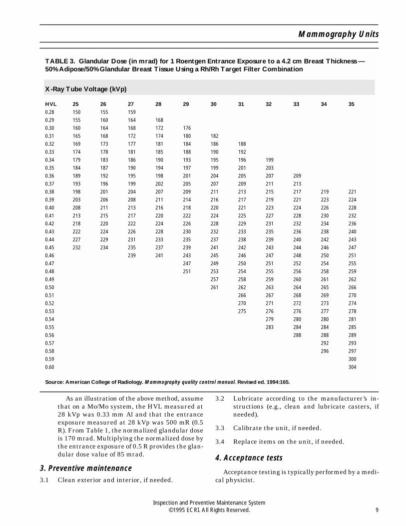
As an illustration of the above method, assumethat on a Mo/Mo system, the HVL measured at28 kVp was 0.33 mm Al and that the entranceexposure measured at 28 kVp was 500 mR (0.5R). From Table 1, the normalized glandular doseis 170 mrad. Multiplying the normalized dose bythe entrance exposure of 0.5 R provides the glan-dular dose value of 85 mrad.
3. Preventive maintenance3.1 Clean exterior and interior, if needed.
3.2 Lubricate according to the manufacturer’s in-structions (e.g., clean and lubricate casters, ifneeded).
3.3 Calibrate the unit, if needed.
3.4 Replace items on the unit, if needed.
4. Acceptance tests
Acceptance testing is typically performed by a medi-cal physicist.
TABLE 3. Glandular Dose (in mrad) for 1 Roentgen Entrance Exposure to a 4.2 cm Breast Thickness —50% Adipose/50% Glandular Breast Tissue Using a Rh/Rh Target Filter Combination
X-Ray Tube Voltage (kVp)
HVL 25 26 27 28 29 30 31 32 33 34 35
0.28 150 155 159
0.29 155 160 164 168
0.30 160 164 168 172 176
0.31 165 168 172 174 180 182
0.32 169 173 177 181 184 186 188
0.33 174 178 181 185 188 190 192
0.34 179 183 186 190 193 195 196 199
0.35 184 187 190 194 197 199 201 203
0.36 189 192 195 198 201 204 205 207 209
0.37 193 196 199 202 205 207 209 211 213
0.38 198 201 204 207 209 211 213 215 217 219 221
0.39 203 206 208 211 214 216 217 219 221 223 224
0.40 208 211 213 216 218 220 221 223 224 226 228
0.41 213 215 217 220 222 224 225 227 228 230 232
0.42 218 220 222 224 226 228 229 231 232 234 236
0.43 222 224 226 228 230 232 233 235 236 238 240
0.44 227 229 231 233 235 237 238 239 240 242 243
0.45 232 234 235 237 239 241 242 243 244 246 247
0.46 239 241 243 245 246 247 248 250 251
0.47 247 249 250 251 252 254 255
0.48 251 253 254 255 256 258 259
0.49 257 258 259 260 261 262
0.50 261 262 263 264 265 266
0.51 266 267 268 269 270
0.52 270 271 272 273 274
0.53 275 276 276 277 278
0.54 279 280 280 281
0.55 283 284 284 285
0.56 288 288 289
0.57 292 293
0.58 296 297
0.59 300
0.60 304
Source: American College of Radiology. Mammography quality control manual. Revised ed. 1994:165.
Mammography Units
Inspection and Preventive Maintenance System©1995 ECRI. All Rights Reserved. 9

Before returning to useEnsure that all controls are set properly. Set alarms
loud enough to alert personnel in the area in which thedevice will be used. Other controls should be in theirnormal pre-use positions. If the unit is being used at
home, ensure that all controls are set correctly beforeit is returned to the patient.
Attach a Caution tag in a prominent position so thatthe user will be aware that control settings may havebeen changed.
Inspection and Preventive Maintenance System
Inspection and Preventive Maintenance System10 ©1995 ECRI. All Rights Reserved.

241434440-0595
A NONPROFIT AGENCY
5200 Butler Pike, Plymouth Meeting, PA 19462-1298, USATelephone +1 (610) 825-6000 Fax +1 (610) 834-1275 E-mail [email protected]
Medical Gas/Vacuum SystemsUsed For:Alarms, Central Gas System [15-824]Medical Gas and Vacuum Systems [18-046]Medical Gas Outlets [17-682]Valves, Medical Gas and Vacuum [18-044]
Also Called: Piped medical gas systems, medical-surgical gas systems, nonflammable medical gas systems,vacuum systems
Commonly Used In: Most patient care areas and some laboratories
Scope: Applies to any piped medical gas system (including oxygen, air, and nitrous oxide) and central vacuumsystem; does not replace full testing according to NFPA 99, Standard for Health Care Facilities, which must beconducted following any new construction or modification; does not apply to medical air compressors, dryers,contaminant monitors, or purification systems, which must receive regular IPM for safe and reliable operation(see Medical gas and vacuum systems, Health Devices [Guidance article], 1994 Jan-Feb; 23:4-41)
ECRI-Recommended Interval UsedType Interval By Hospital Time Required
Major After any renovations, Months Approximately 100modifications, and/or additions outlets/day in occupied
to the medical gas system areas; 250 outlets/dayin unoccupied areas
Minor 12 months* Months Same as above
* Although we recommend that a major inspection (Items 2, 3, 5, 6, 7, and 8) be performed annually for medicalgas and vacuum systems, we understand that, for some hospitals, this may not be practical. Increasing theinspection interval up to but not more than two years is acceptable in these cases. However, some frequentlyused outlets and inlets (e.g., in the emergency room) are subject to wear, and more frequent performance ofItems 5 and 6 should be considered to ensure their safe operation. Where alarm-system test buttons areprovided, audible and visual alarm indicators should be tested monthly (NFPA 99, Appendix C, Section C-4.2.17).
Overview
In an actual case, workers renovating an emergencyroom inadvertently cross-connected the nitrous oxideand oxygen supply lines. As a result, 20 outlets labeled“oxygen” actually delivered nitrous oxide for more thansix months before the hospital’s chief anesthesiologistdiscovered the error. We are also aware of other casesin which similar incidents have occurred. Mix-ups inmedical gas connections have caused deaths, including
multiple fatalities in some institutions, in at least 15hospitals in North America.
Piped gas systems present certain characteristichazards, usually related to their original construction,modification, or repair. However, problems can de-velop during the working lifetime of the systems, par-ticularly in medical compressed air systems, outlets,and vacuum inlets. The hazards include plumbingerrors, as described above; use and degradation ofmaterials incompatible with the gases to be delivered;
Procedure/Forms 440-0595

obstruction of flow by migration of material left in thepipelines; gas contamination by residual debris or ac-cumulated foreign matter (e.g., scale, hydrocarbons,microorganisms, moisture, or dirt in medical com-pressed air pipelines); gas contamination due to chemi-cal interaction, including fire and explosion, betweenthe gases and pipeline components or foreign matter;and gas contamination due to a contaminated source(e.g., air intake near diesel exhausts). (See Cleaningcontaminated MGVSs, Health Devices 1994 Jan-Feb;23:34-5.) Problems related to how the system is usedand maintained during its lifetime include leakingoutlet seals, clogged vacuum inlets and piping (e.g., bydust or by body fluids), inadequate particulate filtra-tion, corrosion of automatic condensate drains, wearor embrittlement of valve seals, physically damaged orloose outlets, wear of compressor or pump seals andbearings, and pressure sensor drift.
NFPA 99, which is mandatory in some localities,states in Chapter 4, the section on gas and vacuumsystems, that the piping systems must be tested fol-lowing new construction, addition, renovation, or re-pair. (In this procedure, references to NFPA 99 referto the 1993 edition, unless otherwise specified.) Itspecifies tests for zone-valve and alarm-system func-tion, leaks, and cross-connections (in addition to otheritems) and provides specific criteria for gas analysisand monitoring. Installers are required to performsome testing of new or modified systems; independenttesting of these systems before they are used for pa-tient care is recommended. NFPA 99 also calls for thehealthcare facility to develop and implement proce-dures for testing medical gas and vacuum systems andtheir related alarm systems; this IPM procedureshould satisfy this requirement for piping and alarmsystems testing. The standard also requires thatproper medical gas concentration be verified and thatthe supply systems be tested after any breach of ormodification to the system.
Also, in its 1995 Accreditation Manual for Hospitals,the Joint Commission on Accreditation of HealthcareOrganizations (JCAHO) requires that the hospitalhave documented plans and procedures for routinetesting, inspection, and maintenance of utility systems(e.g., medical gas and vacuum systems) to ensure thatthese systems operate properly and will continue tooperate in an emergency. The JCAHO manual alsoindirectly refers to NFPA 99 through NFPA 101, LifeSafety Code, and the American Institute of Architects’Guidelines for Construction and Equipment of Hospi-tal and Medical Facilities, which base design andsafety requirements on NFPA 99. Also, because medi-cal gases are drugs, the JCAHO manual, in its section
on medications, requires that medications (i.e., drugs)be prepared, delivered, and administered according toappropriate laws and standards of practice, whichagain indirectly refers to NFPA 99.
Hospitals should insist that those responsible forconstruction document the test methods and results asrequired in NFPA 99; this documentation, as well asdocumentation from analytical tests, should be kept onpermanent record. Hospitals should also obtain docu-mentation verifying the purity of medical gases fromsuppliers. In addition, the hospital should performacceptance inspection and testing of the medical gasand vacuum systems independently of tests conductedby the installing contractor. The hospital’s facilityengineering, anesthesia, clinical engineering, or respi-ratory therapy department may perform this testing.If adequate personnel, experience, or equipment islacking, an independent testing organization that spe-cializes in this type of activity can be employed.
In a typical hospital, piped medical gas and vacuumsystems are frequently repaired, modified, and ex-panded. These activities may include replacing defec-tive outlets or inlets, valves, or piping; relocatingoutlets; and adding outlets to the existing system. Iden-tification plates and other labels are often removedduring this activity, increasing the probability of error.Major changes to systems (e.g., construction of a build-ing addition) are not included in this category.
ECRI knows of no procedure other than this one thatenables the hospital to safely, easily, accurately, andcompletely inspect only the modified portion of thesystem. The procedures outlined in NFPA 99 areclearly intended to test newly constructed systemsthat have not yet been put into service. The processdescribed by that standard requires testing at differ-ent stages of installation before proceeding with addi-tional installation. For example, both the 150 psigpressure test (Section 4-5.1.2.1) and the blow-down (orinitial purging) test (Section 4-5.1.2.2) must be per-formed before system components, such as pressure-actuating alarm switches, alarms, manifolds, pressuregauges, and pressure relief valves, are installed.*
Pressure testing and purging of the completed systemmust also be performed. The hospital should have thecontractor who installs the system and an outside testingorganization provide documentation of conformance
* Pressure is measured relative toone of two reference points: standardatmospheric pressure (14.7 psia) or zero absolute pressure; psig refersto gauge pressure (i.e., the reference pressure to which the measuringdevice is calibrated, typically standardatmosphericpressure),andpsiarefers to absolute pressure (i.e., reference pressure of zero).
Inspection and Preventive Maintenance System
Inspection and Preventive Maintenance System2 ©1995 ECRI. All Rights Reserved.

with all portions of NFPA 99, Chapter 4, for all newmedical gas and vacuum system construction.
Performing certain portions of the NFPA 99 testingprocedure requires a complete shutdown of the system.Thus, the hospital must provide a large number ofalternative gas or vacuum sources (e.g., cylinders withregulators, portable suction systems) and may need tominimize gas or vacuum usage (e.g., by reschedulingsurgery) to test the entire medical gas or vacuumsystem following modifications.
Because of the difficulty and expense entailed andthe possible compromise of patient care, hospitals arereluctant to fully test modified systems, except aftermajor modifications or additions. However, failure tofully test systems can allow serious problems(e.g., cross-connections, which are usually thought ofas problems associated only with new systems) to goundetected.
ECRI has developed a simple technique that per-mits testing and inspection both of existing systemsand of modified portions without affecting the entirehospital at once; this procedure also allows detectionof most problems that can develop during system modi-fication or system operation.
Citations from Health DevicesRestricted draw in Schrader-type vacuum inlets [User
Experience NetworkTM], 1993 Aug-Sep; 22:426-7.
Color-coded compressed medical gas hose changescolor [Hazard], 1986 Apr; 15:106-7.
Medical gas and vacuum systems [Guidance article],1994 Jan-Feb; 23:4-41.
Should vacuum pump effluent be treated? [User Expe-rience NetworkTM], 1994 Jul; 23:310.
Use of filters on medical gas system outlets and vac-uum system inlets [User Experience NetworkTM],1994 Dec; 23:494-5.
Soldered medical gas piping [User Experience Net-workTM], 1995 Mar; 24:127.
Test Apparatus and SuppliesOxygen analyzer that will remain accurate in thepresence of and not be damaged by nitrous oxide(analyzers used with anesthesia units are probablysatisfactory)
Vacuum measuring device, 0 to 30 inches of mercury(in Hg; 0 to 760 mm Hg), with 5% accuracy
Pressure measuring devices, 0 to 100 and 0 to 400psig, with 5% accuracy
Flowmeter, 0 to 250 L/min, with 5% accuracy (flow-meter manufacturers usually supply calibrationcurves for a range of common gases with each in-strument); alternatively, if a flowmeter calibratedfor the gas being measured is not available, use thefollowing formula:
Corrected Flow = Indicated Flow√Density (Design Gas)
Density (Test Gas)
Flow control valve(s)
Test equipment that combines the functions of theabove test devices or that automates the testing de-scribed in this procedure is available and may besubstituted. Also, portable pneumatic calibrators oranesthesia machine calibrator/analyzers may be suit-able alternatives.
Note: Medical gas systems may contain contami-nants that may affect test instruments; periodic clean-ing, in addition to calibration, may be needed.
Source of oil-free dry nitrogen with a pressure regu-lator to supply a test gas (see the section on com-pressed gases in “IPM Safety” behind the GuidanceTab of this binder)
Hoses and adapters to connect the pressure or vac-uum measuring device and test gas cylinder to eachgas outlet
Hand tools, such as screwdrivers, wrenches (includ-ing Allen wrenches), and pliers
Labels, such as “Do Not Use” and “System UnderTest”
Sampling bottles and filters for collecting samplesfor analysis; typically, these are obtained from thelaboratory that will conduct the analysis
Special PrecautionsGeneral. Before testing, alert clinical personnel,
and ensure that an adequate supply of appropriate gascylinders and/or vacuum sources is available in theimmediate area as a backup for piped gases. Provideample preparation time, especially if a system or zonemust be shut down for testing.
Never disconnect or test any medical gas outlet,vacuum inlet, or system serving a patient or patientcare area without the approval of clinical personnel.
Do not perform any test that may interfere with thegas supply to patients (e.g., turn off zone valves,pressurize with another gas or to a pressure different
Medical Gas/Vacuum Systems
Inspection and Preventive Maintenance System©1995 ECRI. All Rights Reserved. 3

from the usual supply pressure) while that sectionof the system is in use for patients.
Never use oxygen as a test gas (e.g., pressuretest) — use only oil-free dry nitrogen.
Do not allow smoking or other open sources of igni-tion in the immediate test area, especially in thepresence of nitrous oxide or oxygen.
Because of high pressure, take special care wheninserting and disconnecting adapters from the out-let under test. Also, before testing, make certainthat the adapter is securely locked into the outlet.
Never pressurize (i.e., apply a test gas to) a vacuumsystem with gauges in the section of the system tobe pressurized; this could damage the vacuumgauges. Overpressurizing compressed gas lines, asrequired for certain sensors (e.g., newly installed ormodified systems), can also damage certain sensors,alarm switches, and outlets in these systems. Cer-tain pressure tests must be conducted before thesecomponents are installed in the system per NFPA99, Section 4-5.1.2.1.
Purging. When using the test gas (oil-free dry nitro-gen) to inspect an alarm panel or to pressurize a pipingsystem, purge the test gas from the system beforeusing it for patients. With the appropriate zone valveclosed, open an outlet to depressurize the system. Afterdepressurization, close that outlet; then open the zonevalve and each outlet in the zone in order, starting withthe outlet nearest the zone valve. You can turn off anoutlet before opening the next outlet in the line. Whereappropriate (e.g., with oxygen and medical compressedair pipelines), use an oxygen analyzer to verify properoxygen content at each outlet, or flush each outlet withits labeled gas for approximately 1 min (except nitrousoxide — see the precautions below — and also notethat an oxygen analyzer, by definition, will not detectnitrogen or nitrous oxide).
Nitrous Oxide. Take special precautions when test-ing or purging nitrous oxide systems to minimize ex-posure to the exhausted gas. Although occasional acuteexposure to nitrous oxide, which might occur duringannual testing, has not been shown to be hazardous,we recommend that you still take reasonable precau-tions to minimize exposure. For example:
Women of childbearing age should not routinelyperform this procedure or be in the area during theprocedure.
Use a length of corrugated tubing (about one inch indiameter) to direct the exhausted gas away frompersonnel and, where practical, into a ventilationreturn duct or out a window.
Limit purging and flow measurement times fromeach outlet to 10 sec. (About 200 ft of piping can bepurged in this time; correspondingly shorter purgetimes can be used for shorter piping runs.)
Purge the nitrous oxide system last, and leave theroom after turning off the outlets. Restrict person-nel from entering the room to allow the exhaustedgas to dissipate. In a typical operating room, 15 minis adequate. In smaller rooms with lower ventilationroom-air exchange rates, such as delivery rooms,dissipation may require 1 hr. Restrict unnecessaryentry into the room during this time; the room maybe used if essential for patient care.
ProcedureThis procedure was developed to help hospitals find
and correct hazards associated with existing and modi-fied piped medical gas and vacuum systems. It does notreplace the full testing required by NFPA 99; it con-firms safe operation and is recommended for use by thehospital for independent confirmation of safety andperformance only after the construction, tests, andinspection per NFPA 99 have been completed and onan annual basis thereafter.
You must perform all items in the procedure on anyportion of the system that is repaired or modifiedbefore that portion of the system is put into service.
Before beginning the inspection, carefully read thisprocedure; be sure you understand how the gas systemand associated equipment are intended to operate, thesignificance of all controls and indicators, and thealarm capabilities. Begin the inspection procedure byidentifying the area to be tested. This may be a room,a special care area, or an area with many outlets. Werecommend that each gas outlet be identified with anumbered label or an engraved number on the face-plate. One systematic numbering method consists ofstarting to the left of a given doorway from a positionfacing into the room and proceeding clockwise, num-bering the outlet stations in the room (see Figure 1).Include ceiling columns (e.g., as in an operating room),as well as surface-mounted stations. Each outlet at agiven station is then numbered from left to right.
Disconnect equipment from each outlet before per-forming the inspection of that outlet station. If you areinspecting a system that is already in operation, con-sult clinical personnel before disconnecting any pa-tient care equipment being used. Inspect every outletat each station in the area.
Because the Universal Inspection Form is not ap-plicable, use the special three-part Medical Gas and
Inspection and Preventive Maintenance System
Inspection and Preventive Maintenance System4 ©1995 ECRI. All Rights Reserved.

Vacuum System Inspection Form provided. Part A ofthe form is for alarm-panel and zone-valve inspections,and Part B is for medical gas outlet and vacuum inletinspections. Part C is for documenting medical gaspurity analysis.
On the appropriate part of the inspection form (onParts A and B), record the test data and the actionsneeded and taken. If deficiencies detected during theinspection are serious enough to preclude using anoutlet until it is repaired, check both the Action Neededand the Do Not Use columns; label the outlet so that itwill not be used and so that it can be quickly identifiedfor future repairs. If the outlet is in an area being used,inform clinical personnel, and make sure that an ade-quate alternative gas supply is available. If the outletis usable, check only the Action Needed column. Toclearly identify defective outlets on the inspectionform, circle unacceptable values, or note specific de-fects in the Comments section at the bottom of theform.
The Status box in the upper right corner of eachform provides a quick indication of the condition of theoutlets or alarms and valves listed. Check the appro-priate box after completing the inspection. If even oneoutlet, alarm, or valve on the sheet requires servicing,check the Service Required box. The individual whocompletes the repairs should record the date and hisor her initials in the Action Taken column; check theOK column after confirming the satisfactory conditionand performance of that item. Check the Passed box inthe Status area only after all repairs for all items onthat form are complete.
1. Pressure Testing. All new or modified systemsshould be pressure tested per NFPA 99, Sections4-5.1.2.1 and 4-5.1.2.3. We recommend that thefollowing acceptance test be performed by thehospital or an independent agency before a newsystem or modified portion of the existing systemis put into use.
When all components of the system have beeninstalled and the system is ready to be used, pres-surize the appropriate section of the medical gasor vacuum system to 100 psig with oil-free drynitrogen. On additions and modifications, close theappropriate zone valve before pressurizing so thatthe section to be tested is isolated from the rest ofthesystem.We recommend using100psig (insteadof 150 psig, as required by NFPA 99 during theinitial pressure test) for testing to reduce the riskof damaging system components. (Verify that com-ponents [e.g., pressure sensors] will not be dam-aged by this test pressure.) However, this does notsubstitute for pressure testing according to NFPA99 during installation. Measure the pressure im-mediately after pressurization to 100 psig andagain 1 hr later. After correcting for any tempera-ture changes, confirm that there has been nochange in line pressure after the 1 hr period. Tocorrect for temperature changes, use the followingformula:
PFinal=PInitial × TFinal
TInitial
where T = absolute temperature measured inkelvins or degrees Rankine*
2. Area Pressure Alarms. Area pressure alarmsshould be activated when line pressure varies20% from normal system pressure.
To test the high-pressure alarm, close theappropriate zone valve, and apply oil-free drynitrogen through a pressure measuring device toone outlet in the zone until the alarm is acti-vated. Measure and record the alarm pressure.To test the low-pressure alarm, bleed systempressure with the zone valve closed until thelow-pressure alarm is activated. Measure andrecord the alarm activation pressures on the topportion of Part A of the Medical Gas/VacuumSystems Inspection Form. (Note: This test canbe performed in conjunction with Item 3.)
Check area signal panels, remote indicators(if present), and appropriate gauges for proper
* To obtain a temperature in kelvins or degrees Rankine, add 273.2to degrees Celsius and 459.7 to degrees Fahrenheit, respectively.
Figure 1. Sample room with 6 stations, numbered clock-wise from left, and 18 outlets.
Medical Gas/Vacuum Systems
Inspection and Preventive Maintenance System©1995 ECRI. All Rights Reserved. 5

labeling and function or accuracy. Also checkaudible alarm-silence systems during alarm ac-tivation — a visual alarm light should remainon. In addition, check signal panels for deactiva-tion after returning the system to normal pres-sure. Before placing the system in service, purgeit as described in the Special Precautions sectionand in accordance with NFPA 99, Section4-5.1.3.9. (Other testing may be completed withthe test gas before purging; see the precautionsregarding nitrous oxide.)
If the alarm panel has test buttons, retestingof audible and visual alarms should be donemonthly.
3. Zone Valves. Zone valves are tested to ensurethat the branch served by the zone valve will beclosed and isolated in the event of an emergency.
Check each zone valve for a label or placard thatlists the gas it controls and the area it serves. Alsocheck that a line-pressure gauge is present down-stream of the zone valve and that it correctly readsthe system pressure by comparing it with a pres-sure measuring device at an outlet in that area.Close the valve, and bleed the branch to zeropressure. Confirm that the system gauge and pres-sure measuring device read zero. Record findingson the bottom portion of Part A of the MedicalGas/Vacuum System Inspection Form.
Perform a leakage test on all threaded compo-nents of the pressurized zone valve using a testsolution listed as safe for use with oxygen.
4. Cross-Connection Testing. This test should onlybe performed on new systems or following anysystem modifications. The test must be per-formed after all outlets are completely installed,including labels, cover plates, and fittings. Thiswill ensure that outlets are connected to andlabeled for the appropriate gas system. Do notrely on testing done before final attachment oflabels and other identification plates that iden-tify gas outlets.
To test new systems or major modificationsto existing systems where gas sources can beshut down without disrupting existing patientcare, use the following procedure. Reduce allpipelines to atmospheric pressure. Disconnectall sources of test gas from all of the systemswith the exception of the one system to bechecked. Pressurize this system to 50 psig withoil-free dry nitrogen to avoid disruption to andpossible contamination of the existing services.
With appropriate adapters (which should matchoutlet labels), check each individual outlet ofeach gas and vacuum system to determine thattest gas is not present at any outlet other thanthe one connected to the pressurized supply.Disconnect the source of the test gas, and reducethe first system to atmospheric pressure. Repeatthis test by pressurizing each additional pipingsystem, one at a time, including vacuum (unlessgauges are present). Purge all tested systems inaccordance with NFPA 99, Section 4-5.1.3.9, andthe special precautions noted previously.
To avoid disrupting patient care when testingmodifications to existing systems that are in use,use the oxygen concentration measuring proce-dure described in Item 5.
5. Medical Gas Outlets (medical compressed air,nitrogen, nitrous oxide, oxygen, carbon dioxide,and other gases if piped). Examine the conditionof the outlet. Check that each outlet is properlylabeled with the name of the dispensed gas andthat its cover plate is securely fastened. Ensurethat color coding is consistent with standards forthe gas supplied to each outlet (e.g., green foroxygen, yellow for medical compressed air).Make sure that the adapter specific for the gasdispensed locks securely into the outlet, that theoutlet does not leak with the adapter installed,that the adapter is easily removed, and that thevalve closes when the adapter is removed. Listenfor leaks before and after inserting adapters.Leaks may be corrected by replacing seals(e.g., O-rings, gaskets) in the valve assembly.
Attach an oxygen analyzer, a pressure meas-uring device, and a flowmeter or pneumatic ana-lyzer to the outlet; measure and record the flowand pressure at that flow on Part B of the Medi-cal Gas/Vacuum System Inspection Form. NFPA99 requires that piping systems be able to deliverflows at the pressures listed in Table 1, Recom-mended Pressures and Flows.
Open the flow-control valve until a flow of 100L/min is seen. Pressure at that outlet should not
Table 1. Recommended Pressures and Flows*Medical Gas Pressure, psig Flow, L/min
Oxygen 50 to 55 ≥100Nitrous Oxide 50 to 55 ≥100Medical Air 50 to 55 ≥100Carbon Dioxide 50 to 55 ≥100Nitrogen ≥160 ≥145*Pressures and flows per NFPA 99, Section 4-5.1.3.8.
Inspection and Preventive Maintenance System
Inspection and Preventive Maintenance System6 ©1995 ECRI. All Rights Reserved.

drop below 50 psig for all gases except nitrogen,which should not drop below 160 psig at a flowof at least 145 L/min. Some older systems maynot be able to meet these requirements. However,if the pressure drops to below 80% of the listedvalues in older systems or below the requiredvalues in newer systems or if the required flowscannot be obtained, corrective action is required.Unacceptable pressure or flow may indicate ablockage in either the distribution piping or theoutlet check valve(s). Blowing the piping clearwith the outlet removed and cleaning the outletcheck valve(s) will usually resolve this problem.(Minimize exposure to nitrous oxide; see SpecialPrecautions.) If the above measures do not re-solve the problem, the outlet may have to bereplaced or, depending on the severity of therestriction, a portion of the system may need tobe modified. Consult with clinical staff to deter-mine the minimum acceptable flow for clinicalneeds, including the safe operation of life-sup-port equipment. Also consider whether simulta-neous use of multiple outlets will furtherdegrade performance. ECRI can provide adviceon the most appropriate action to take should aflow-restriction problem exist.
Measure and record (on Part B of the MedicalGas/Vacuum Systems Inspection Form) the oxy-gen concentration to determine that the outlet isdelivering the proper medical gas. The oxygenconcentration should be 100% at oxygen outletsand 21% at medical compressed air outlets.NFPA 99, Section 4-5.1.3.9, requires the use ofgas-specific analyzers for initial testing of newand renovated systems, but for routine testing ofinstalled systems, nitrogen, nitrous oxide, andcarbon dioxide outlets should read 0% on anoxygen analyzer. Note that, in an operating sys-tem, nitrogen will be at a higher pressure thannitrous oxide. This test can also serve to checkfor cross-connection in existing systems.
In some hospitals, hoses extend from ceilingconnectors to outlets that are suspended at alower, more accessible height. Although the ceil-ing connector and suspended outlets may haveproper labels and unique fittings for each gas toprevent incorrect connections, the end connec-tions of the hoses and the pipelines to the gasfittings and outlets may be identical. Thus, itmay be possible to attach an outlet or connectorto the wrong hose. If you have such an installa-tion, make sure that the ceiling connector andoutlet linked by a given hose have the same gas
label. This problem may also arise if you useextension hoses to connect equipment to a wallor ceiling outlet. Recheck each time service per-sonnel remove a hose for repair, maintenance, orreplacement.
Gas hoses should have appropriate connectorsfor attachment to equipment. Avoid using spe-cial adapters for connecting hoses (e.g., DISS toquick-connect fittings) to minimize problemssuch as gas leaks at the connectors. Color-codedhoses are recommended for this application toreduce the risk of misconnection. Be aware thatthe color of gas hoses can change over a period oftime (see Color-coded compressed medical gashose changes color [Hazard], Health Devices1986 Apr; 15:106-7.) Replace any hoses that havechanged color or faded.
6. Vacuum Inlets (vacuum and evacuation vac-uum). Inspect the condition of each inlet, asdescribed in Item 5.
Attach the vacuum measuring device to aninlet and a flowmeter to an adjacent inlet. Meas-ure and record the pressure and flow on Part Bof the Medical Gas/Vacuum System InspectionForm. NFPA 99, Section 4-11.2.1.3, requires thatthe vacuum pressure be at least 12 in Hg (305mm Hg) while 85 L/min (3 standard cubic feetper minute) flow is being drawn at an adjacentinlet. We recommend that, where practical, thetwo inlets be on the same branch and that thepressure be measured at an inlet beyond theinlet at which the flow is established. In addition,we recommend noting the maximum flow. Mostnewer systems will be able to provide 85 L/minat an inlet, although such high flows may not berequired for many applications. Some older sys-tems may not be able to meet these criteria; it isthen necessary to determine whether correctiveaction (e.g., cleaning the pipeline) is required tomeet clinical needs.
For inlets that have reduced vacuum draw,inspect the interior of each vacuum inlet foraccumulated dust or other debris from leakingseals or poor suctioning procedures. Clean theinlet, if necessary, by removing the inlet valveassembly and washing it in warm soapy water(see the section on infection control in “IPMSafety” behind the Guidance Tab in this binder).Using a piece of tubing, suck about a liter of thewash water into the disassembled inlet to cleandebris from the inlet section of the pipeline.Rinse the inlet valve assembly with clean water
Medical Gas/Vacuum Systems
Inspection and Preventive Maintenance System©1995 ECRI. All Rights Reserved. 7

and reassemble the inlet. Remeasure vacuumpressure and flow at the cleaned inlet. Inade-quate flow may indicate other problems in thevacuum system (e.g., a clogged pipe).
7. Master Alarm Panel. Refer to NFPA 99, Section4-4.1.1.2 and Appendix C-4, for required compo-nents and recommended test intervals. Section4-6.2.3.9 of NFPA 99 requires periodic retestingof audible and visual alarms to determinewhether they are functioning properly, and Sec-tion C-4.2.16 recommends annual testing of allcomponents of warning systems if testing can beperformed without changing system line pres-sure. Refer to the manufacturer’s instructionsfor component testing.
8. Medical Gas Analysis. Acceptance testing ofmedical gas purity is not usually required ifpurity testing required by NFPA 99 is conductedby an independent test organization when thesystem is completed.
Obtain certificates of purity showing all test-ing performed by the gas manufacturer for eachshipment of gas.
For oxygen, nitrous oxide, nitrogen, and carb-on dioxide, verify that certificates of purity havebeen received and filed for each gas shipment,and note this on the Confirmation of Puritysection of the inspection form. Include the sourceof any certificate of purity and the date of thecertificate. After installation of a new system,the piping system for these gases should also betested for gaseous and liquid hydrocarbons, aswell as for particulates and gas concentration.We recommend taking gas samples from an out-let nearest the gas source and at the outlet mostremote from the source. Refer to Table 2 forrecommended maximum allowable levels of con-taminants for these gases.
NFPA 99, Section 4-3.1.9.8, requires that thequality of the medical compressed air generatedon-site be monitored continuously for dew pointand carbon monoxide. A gas sampling portdownstream of the system pressure regulatorsis used for this purpose. Reciprocating (oil-less)
compressors must also be monitored for liquid(continuously) and gaseous (quarterly) hydro-carbons. Piped medical compressed air systemsshould also be tested annually for particulates.Independent dew point and carbon monoxidetests should be conducted at least annually forall medical compressed air systems, preferablyin the summer when these contaminants aremost prevalent, to verify monitor performance.More frequent analyses may be warranted inhospitals with medical compressed air problemsuntil those problems are resolved.
For medical compressed air analysis, obtainsampling bottles (as well as instructions for theiruse) from an analytical laboratory. For annualinspections, sampling can be done at an outletclose to the source. To determine the cause of anyproblem, it may be necessary to monitor thequality of the outside air at the medical air com-pressor intake. For all other analyses, take asample at the farthest outlet locations from thecompressor in the piped medical compressed airsystem.
Enter the results of the medical air analysison Part C of the inspection form. Compare theresults to the values listed in Table 2, in whichmost allowable values meet or exceed the con-taminant limits of most of the various concernedagencies. ECRI chose the values listed in thetable because we believe they are reasonable toobtain and safe for the particular gas and con-taminant based on our review of the severaldocuments that define the composition of medi-cal gases.
Judging the level of a particular contaminantrelative to this table should be done with caution.Such factors as the measurement accuracy, thesampling location, the sampling technique, andthe contaminant itself will affect what should bedone. Regardless, a second test, independent ofthe first, should be made to verify any suspectedcontamination. Determination of the source ofthe contamination will direct the course of cor-rective action (e.g., change of source, purge ofpipeline).
Inspection and Preventive Maintenance System
Inspection and Preventive Maintenance System8 ©1995 ECRI. All Rights Reserved.

Medical Gas/Vacuum Systems
Inspection and Preventive Maintenance System©1995 ECRI. All Rights Reserved. 9

Inspection and Preventive Maintenance System
Inspection and Preventive Maintenance System10 ©1995 ECRI. All Rights Reserved.

Medical Gas/Vacuum Systems
Inspection and Preventive Maintenance System©1995 ECRI. All Rights Reserved. 11

Inspection and Preventive Maintenance System
Inspection and Preventive Maintenance System12 ©1995 ECRI. All Rights Reserved.

241477463-0595
A NONPROFIT AGENCY
5200 Butler Pike, Plymouth Meeting, PA 19462-1298, USATelephone +1 (610) 825-6000 Fax +1 (610) 834-1275 E-mail [email protected]
Mobile C-armsUsed For:Radiographic/Fluoroscopic Units, Mobile [11-758]
Also Called: Portable C-arms, surgical C-arms
Commonly Used In: Critical care areas, emergency departments, and operating rooms
Scope: Applies to mobile C-arms capable of fluoroscopy and radiography
Risk Level: ECRI Recommended, High; Hospital Assessment,
ECRI-Recommende Interval UsedType Interval By Hospital Time Required
Major 12 months months . hours
Minor 6 months months . hours
OverviewC-arms provide radiographic and fluoroscopic imag-ing in surgical, orthopedic, critical care, and emer-gency care procedures. They are used to imagepatients in radiolucent beds, stretchers, or tableswhen it is not feasible to transport the patient to theradiology department. The fluoroscopic feature allowsreal-time imaging, which permits quick diagnoses andminimal patient time under anesthesia during surgi-cal procedures.
C-arms are used in a variety of general surgical,cardiac, and neurological applications, including aneu-rysm repair, pacemaker implantation, hip replace-ment, fracture reduction, foreign-body location, needlebiopsy, catheter placement, percutaneous lithotripsy,and brachytherapy. These devices also enable specialstudies, such as the diagnosis of swallowing disordersin patients who cannot readily sit on a standard fluoro-scopic table or stand on a footboard. Mobile C-arms canalso be equipped with a variety of digital hardware andsoftware options for use in angioplasty, interventionalneuroradiology, neurosurgery, and trauma care.
Compact, scaled-down fluoroscopic imaging sys-tems called mini C-arms are designed for extremityimaging in the emergency room, the operating room,
the physician’s office, the industrial site, and the ath-letic field. The user can quickly acquire projections ofthe patient’s anatomy from various angles while con-tinuously viewing the fluoroscopic images. Radio-graphic imaging capability may not be provided.
Citations from Health DevicesMobile C-arm units [Evaluation], 1990 Aug; 19: 251-91.
International Medical Systems Exposcop Plus mobileC-arm system [Evaluation], 1993 Mar; 22:103-21.
FluoroScan Mini C-arm unit [Evaluation], 1995 Feb;25:44-70.
Test apparatus and suppliesGround resistance ohmmeter
Leakage current meter or electrical safety analyzer
Noninvasive kVp meter (compatible with the x-raygenerator being inspected)
Noninvasive timer (may be included with kVpmeter)
Ionization chamber with electrometer or a combina-tion exposure meter
Procedure/Checklist 463-0595

Five filters of 10 cm × 10 cm × 1 mm Type 1100aluminum
Ruler with leaded 1 cm or 1⁄2″ markers
Large-format x-ray film (30 cm × 30 cm)
Patient simulator material (e.g., 8 pieces of 30 × 30× 2.5 cm plexiglass, or appropriate thickness ofaluminum or copper) to bring the unit to midrangetechnique under automatic brightness stabilization(ABS) control
Six pieces of 30 cm × 30 cm × 1 mm lead
High-contrast resolution line-pair phantom to 5lp/mm minimum
Low-contrast phantom consisting of two 3/4″ (2 cm)aluminum plates, 7 × 7″ (18 × 18 cm), and one sheetof 1.0 mm aluminum, 7 × 7″ (18 × 18 cm), with twosets of four holes of the following sizes: 1/16″, 1/8″,3/16″, and 1/4″ (1.0, 3.0, 5.0, and 7.0 mm) (using analternative low-contrast phantom is acceptable pro-vided that it can be reproducibly used for assessinglong-term performance; use the criterion applicableto the phantom selected)
Oscilloscope (calibration only)
High-voltage divider (calibration only of rotatinganode type x-ray tubes)
Special precautionsWear a lead apron and thyroid shield at all times
during x-ray exposure. Maintain the greatest possiblereasonable distance from the x-ray source and all scat-tering material. It should not be necessary to placehands or fingers in the x-ray beam; if unavoidable, wearlead gloves. Keep x-ray exposure time to a minimum.
Do not remove the high-voltage cables from thewells with the power on. Ensure that high-voltagecables are completely discharged by repeatedly touch-ing the conductor to ground as soon as it is removedfrom the well. Wear rubber gloves or other appropriateprotection when exposed to blood or other body fluids.
For repeated exposures, allow adequate time be-tween exposures to prevent overheating of the x-raytube.
ProcedureBefore beginning an inspection, carefully read this
procedure and the manufacturer’s instructions andservice manuals; ensure that you understand how tooperate the equipment, the significance of each controland indicator, and the alarm capabilities. Also deter-mine whether any special inspection or preventive
maintenance procedures or frequencies are recom-mended by the manufacturer.
This procedure is intended to ensure adequate sys-tem performance and maintenance. It should not beconstrued as providing full compliance with the re-quirements of all governmental regulations and ac-creditation standards of professional associations.Such regulations and standards may include testingbeyond that provided below and may also require docu-mentation by a certified medical physicist.
For acceptance testing, we strongly recommend con-tracting with a medical physicist. Acceptance testingis crucial because it generates data on baseline per-formance of the device.
1. Qualitative tests1.1 Chassis/Housing. Examine the exterior of all
components of the C-arm for cleanliness andgeneral physical condition. Be sure that all hard-ware is present and tight and that there are nosigns of spilled liquids or other serious abuse.External collimators should be checked for pool-ing of blood and be cleaned, if necessary. The gridand image intensifier housing should be checkedfor blood and cleaned, if necessary.
Check the mechanical operation of the C-arm,including up/down motion, rotation, andwig/wag, ensuring that all movements aresmooth; ensure that the arm locks securely ateach position.
1.3 Casters/Brakes. Verify that the casters turnand swivel freely. Check the ease of steering ofthe C-arm stand and the display cart. Ensurethat caster brakes secure the stand from move-ment.
1.4 AC Plug/Receptacles. Examine the AC powerplug for damage. Attempt to wiggle the blades tocheck that they are secure. Shake the plug, andlisten for rattles that could indicate loose screws.If any damage is suspected, open the plug andinspect it.
If the device has electrical receptacles for ac-cessories, verify the presence of line power. In-sert an AC plug into each receptacle, and checkthat it is held firmly. If accessories are pluggedand unplugged often, consider a full inspectionof the receptacles.
1.5 Line Cord. Inspect the cord for signs of damage.If damaged, replace the entire cord or, if thedamage is near one end, cut out the defective
Inspection and Preventive Maintenance System
Inspection and Preventive Maintenance System2 ©1995 ECRI. All Rights Reserved.

portion. Ensure that the remaining length isadequate. Be sure to wire a new power cord orplug with correct polarity.
1.6 Strain Reliefs. Examine the strain reliefs atboth ends of the line cord. Be sure that they holdthe cord securely.
1.7 Circuit Breaker/Fuse. If the device has an ex-ternal circuit breaker, check that it operatesfreely. If the device is protected by an externalfuse, check its value and type against thatmarked on the chassis, and ensure that a spareis provided.
1.9 Cables. Inspect any cables (e.g., between theC-arm stand and display cart, from the C-arm,connecting the footswitch) and their strain re-liefs for general condition. Carefully examinecables to detect breaks in the insulation and toensure that they are gripped securely in theconnectors at each end to prevent rotation orother strain. Verify that there are no intermit-tent faults by flexing cables for the display neareach end and looking for erratic operation.
For units with rotating anode tubes, the high-voltage cables should be removed from the wells,and the ends and the wells should be cleaned,coated with high-voltage compound, reinserted,and tightened securely.
1.10 Fittings/Connectors. Examine all electrical ca-ble connectors for general condition. Electricalcontact pins or surfaces should be straight,clean, and bright. Verify that leads and elec-trodes are firmly gripped in their appropriateconnectors. If keyed connectors are used, makesure that no pins are missing and that the keyingis correct.
1.13 Controls/Switches. Before changing any con-trols or alarm limits, check their positions. If anysetting appears inordinate (e.g., high mA set-ting), consider the possibility of inappropriateclinical use or of incipient device failure. Recordthe settings of those controls that should bereturned to their original positions following theinspection.
Examine all controls and switches (x-ray in-itiation, collimation, image manipulation, tech-nique selection, size of image, etc.) for physicalcondition, secure mounting, and correct motion.Check that control knobs, if present, have notslipped on their shafts. Where a control shouldoperate against fixed-limit stops, check for
proper alignment, as well as positive stopping.During the course of the inspection, be sure tocheck that each control and switch performs itsproper function. For the fluoroscopic and radio-graphic exposure switches, ensure that they donot stick and that continuous pressure is re-quired to continue exposure. Release of pressureshould immediately terminate exposure.
1.18 Indicators/Displays. During the course of theinspection, confirm the operation of all lamps,indicators, meters, gauges, and visual displayson the unit. Examples of indicators and displaysare technique settings, image modes, fluoro-scopic exposure time, x-rays on, display monitortext, and image storage numbers.
1.20 Alarms. Induce conditions to activate audibleand visual alarms (e.g., x-rays on). Check thatany associated interlocks (e.g., fluoroscopy inhi-bition) function. If the unit has an alarm silencefeature, check the method of reset (e.g., manualor automatic) against the manufacturer’s speci-fications. It may not be possible to check out allalarms at this time, since some may requireabnormal operating conditions (e.g., long expo-sure times). Instruct users to document activa-tion of these alarms to ensure that they arefunctional.
1.21 Audible Signals. Operate the device to activateany audible signals (e.g., radiographic exposure,boost or high-level control fluoroscopy). Confirmappropriate volume. If audible alarms have beensilenced or the volume set too low, adjust alarmvolume to the appropriate level.
1.22 Labeling. Check that all necessary certificationlabels, warning labels, technique charts, andinstruction cards are present and legible.
1.23 Accessories. Confirm the presence and conditionof accessories (e.g., film cassette holder, digitalacquisition systems, multiformat cameras, videoprinters).
2. Quantitative tests
2.1 Grounding Resistance. Using an ohmmeter,electrical safety analyzer, or multimeter withgood resolution of fractional ohms, measure andrecord the resistance between common groundand exposed metal on the C-arm, the controlstand, and the display cart. We recommend amaximum resistance of 0.5 Ω. The footswitchdoes not need to be grounded if it operates fromlow voltages.
Mobile C-arms
Inspection and Preventive Maintenance System©1995 ECRI. All Rights Reserved. 3

2.2 Leakage Current. Measure chassis leakage cur-rent to ground with the grounding conductor ofplug-connected equipment temporarily opened.Operate the device in all normal modes, includ-ing on, standby, during exposure, and off; recordthe maximum leakage current. Chassis leakagecurrent should be 300 µA or less. For older C-arms, leakage current up to 500 µA is acceptable,provided that a documented maintenance sched-ule is established to ensure grounding integrity;a three-month interval is a nominal period, butmay be adjusted depending on intensity of useand previous experience.
2.3 Accuracy of kVp. Use a noninvasive kVp meterthat has previously been calibrated against ahigh-voltage divider on the type of generatorthat powers the C-arm system. Use the kVpmeter in accordance with the recommendationsof the manufacturer of the kVp meter. (Thesemay include the kind of filters to use and thedistance at which the kVp meter has to be placed.Some meters require that the user specify thetype of generator being tested and the amount offiltration present in the primary x-ray beam.)
Take measurements in the radiographic andfluoroscopic modes of operation of the C-arm atlow, medium, and high settings (e.g., 60, 80, and100 kVp). After the appropriate corrections havebeen applied to the measured kVp readings (e.g.,for filtration), the difference between the meas-ured kVp and the preset kVp should not exceed5% of the preset kVp. If a consistent significanterror between the preset kVp and the measuredkVp is detected, further testing with a high-volt-age divider may be required to identify the prob-lem.
2.4 Timer Accuracy. Use a noninvasive timer tomeasure the accuracy of the timer settings avail-able on the C-arm system when it is operated inthe radiographic mode. Most noninvasive kVpmeters also display exposure times. Follow themanufacturer’s recommended technique formaking time measurements. Cover the imageintensifier with 6 mm thick lead plate to protectthe image intensifier and TV camera system.
Once the unit has been appropriately set up,dial up a midrange kVp setting (e.g., 70 kVp).The mobile C-arm may have a display only ofmAs rather than exposure time. If this is thecase, consult the C-arm manuals to find out whatmA is being used at 70 kVp in the radiographicmode. The exposure time readings can then be
calculated from the mAs values. Conduct meas-urements at typically used low, medium, andhigh time settings. As a general rule, the differ-ence between the measured time and the presettime should not exceed 1 ms or 5%, whichever isgreater.
2.5 Linearity of mAs. Use an ionization chamberwith an electrometer (or a combination exposuremeter) to measure the exposure in mR for thistest. The ionization chamber should be placedcentrally in the x-ray beam. The image intensi-fier should be covered with a lead plate to protectit from excessive radiation.
Dial up a midrange kVp setting (e.g., 80 kVp)with the C-arm set to operate in the radiographicmode. Make radiographic exposures at this fixedkVp, and record the exposure values (in mR)from the electrometer or exposure meter at aminimum of three settings that span the rangetypically used. Calculate the mR/mAs at eachsetting, and average the calculations. Each indi-vidual mR/mAs value should be within 10% ofthe average.
2.6 Exposure Reproducibility. Use one of the abovemR/mAs values as the one value to be used forevaluating short-term and long-term reproduci-bility of the x-ray tube and the generator combi-nation. For the short-term test, make aminimum of four exposures at the same mAsover a span of approximately 15 minutes. ThemR/mAs value should have a coefficient of vari-ation no larger than 10%. For long-term repro-ducibility, simply record the current averagemR/mAs value from the four values above andcompare this with the value recorded during thepreceding inspection. It is critical that identicaltest conditions be used for assessing reproduci-bility. For example, the same chamber-to-sourcedistance should be used, and the technique (kVp,mAs) should be the same. Long-term reproduci-bility should be within ±10% of the average.
2.7 Half-Value Layer (HVL). Use an ionizationchamber, electrometer, and Type 1100 alumi-num filters for this test. Place the ionizationchamber on the image intensifier or at about 60cm from the focal spot. Under fluoroscopic guid-ance, adjust the collimation on the C-arm so thatthe x-ray field just encompasses the ionizationchamber.
Set the C-arm to operate in the radiographicmode at 80 kVp. Select a midrange mAs value.
Inspection and Preventive Maintenance System
Inspection and Preventive Maintenance System4 ©1995 ECRI. All Rights Reserved.

These kVp and mAs values should be held con-stant during the whole course of this test.
Record the initial exposure value (in mR) withnothing in the primary beam (i.e., 0 mm of alu-minum). Then record the exposure reading withaluminum thickness of 2 mm and 4 mm. Thethickness of aluminum required to reduce theinitial exposure reading by half is the half-valuelayer of the beam. The HVL is most accuratelyread by plotting the measurements on semiloggraphing paper. Plot the exposure values on thelogarithmic scale against the thickness of alumi-num on the linear scale. At 80 kVp, the HVLshould be a minimum of 2.3 mm of aluminum.The HVL measurement should be compared tomeasurements from previous inspections, sincea change in HVL may indicate tube deteriora-tion.
2.8 Collimation. Place a ruler with leaded 1 cm or1/2″ markers on the image intensifier housing,and measure the visual field size (length andwidth) of the image intensifier on the displaymonitor during a fluoroscopic exposure using thelargest available mode on the image intensifier.Next, place a large-format x-ray film (30 cm by30 cm minimum) on the image intensifier hous-ing and make a fluoroscopic exposure, still usingthe largest available mode on the image intensi-fier. A fluoroscopic exposure of about five sec-onds is likely to provide sufficient filmdarkening. After the film has been processed,ensure that the dimensions of the x-ray beammeasured on the film do not differ from thedimensions of the fluoroscopic image measuredwith the lead ruler by more than 3% of thesource-to-image distance (SID).
2.11 Standard Fluoroscopic Exposure Rate. In addi-tion to verifying that the unit meets exposurerequirements, this test also verifies functioningof the ABS system.
Use an ionization chamber with an electrome-ter (or a combination exposure meter) capable ofmeasuring exposure rate. Place the chamber orthe meter 30 cm above the image intensifierinput plane. Place sufficient patient simulatormaterial on the image intensifier that the tech-nique tracks to about midrange (e.g., 70 kVp) inthe automatic fluoroscopic mode.
Run a fluoroscopic exposure, and record theexposure rate. Check for consistency of the expo-sure rate with those made during previous
inspections. The typical exposure rate is 1 R/min(with a range of 0.5 to 2.0 R/min). If the exposurerate has increased from that of previous inspec-tions, further testing should be performed todetermine the reason for the required increasein radiation.
2.12 Maximum Fluoroscopic Exposure Rate. Use anionization chamber with an electrometer (or acombination exposure meter) capable of measur-ing exposure rate. Place a thick lead plate (atleast 6 mm thick) over the image intensifierhousing. Ensure that the whole input face of theimage intensifier is covered by the lead plate.Place the ionization chamber 30 cm above theimage intensifier input plane.
Record the exposure rate on the electrometeror exposure meter during a fluoroscopic expo-sure in the automatic mode, as well as in themanual mode at the highest technique. If theC-arm also has a “boost” or “high-level” controlmode, record the exposure rate during a fluoro-scopic exposure in this mode. For units that haveonly manually selectable kVp and mA settings,the exposure rate at the highest settings shouldnot exceed 5 R/min. For units that have automat-ic kVp and mA control, the exposure rate shouldnot exceed 10 R/min.
There are no governmental regulations thatlimit exposure rates under boost mode for de-vices in use now. However, for devices manufac-tured in 1996 and after, the exposure rate in theboost or high-level control mode should not ex-ceed 20 R/min.
2.13 Image Quality.
High-Contrast Resolution. Place the line-pairphantom on the grid. It should be placed at a45-degree angle to the grid lines and rasterlines of the TV system. At low kVp (ABS withnothing other than the line-pair phantom inthe field), determine the maximum line-pairresolution for all available field sizes. It maybe necessary to alter the brightness and con-trast settings on the TV monitor to optimizethe display for the visualized object. Resolu-tion should be at or above 1.2 lp/mm for a 22cm (9″) field of view (FOV) and 1.7 lp/mm fora 15 cm (6″) FOV.
Low-Contrast Resolution. Ensure that the 1 mmpiece of aluminum is next to the grid. Place thelow-contrast phantom on the grid. The thickeraluminum pieces should be on top of the 1 mm
Mobile C-arms
Inspection and Preventive Maintenance System©1995 ECRI. All Rights Reserved. 5

thick plate. Initiate a fluoroscopic exposureunder ABS control. On the 15 cm (6″) FOV,the three smallest holes should be visible. Itmay be necessary to alter the brightness andcontrast settings on the TV monitor to opti-mize the display for the visualized object.
3. Preventive Maintenance3.1 Clean the exterior, as well as the interior if needed.
3.2 Lubricate per the manufacturer’s instructions.
3.3 Calibrate per the manufacturer’s instructions.Adjust caster brakes and arm locks, if needed.
4. Acceptance TestsAcceptance testing is typically performed by a medi-
cal physicist.
Before returning to useEnsure that all controls are set properly. Set alarms
loud enough to alert personnel in the area in which thedevice will be used. Other controls should be in theirnormal pre-use positions.
Attach a Caution tag in a prominent position so thatthe user will be aware that control settings may havebeen changed.
Inspection and Preventive Maintenance System
Inspection and Preventive Maintenance System6 ©1995 ECRI. All Rights Reserved.

241473468-0595
A NONPROFIT AGENCY
5200 Butler Pike, Plymouth Meeting, PA 19462-1298, USATelephone +1 (610) 825-6000 Fax +1 (610) 834-1275 E-mail [email protected]
Mobile X-ray UnitsUsed For:Radiographic Units, Mobile [13-272]
Also Called: Mobile radiographic systems, portable x-ray machines
Commonly Used In: Patient rooms, surgical suites
Scope: Applies to portable radiographic systems powered from or charged by a standard 115 VAC receptacle
Risk Level: ECRI Recommended, High; Hospital Assessment,
ECRI-Recommended Interval UsedType Interval By Hospital Time Required
Major 12 months months . hours
Minor 6 months months . hours
Overview
Mobile x-ray units are used for radiographic imagingof patients who cannot be moved to the radiologydepartment and who are in areas, such as intensivecare units or emergency rooms, that lack standard,fixed radiographic equipment. These units consist ofan x-ray generator, an x-ray tube and tubestand, colli-mators, and a film cassette storage drawer. Battery-powered units also contain a battery and chargingsystem, and self-propelled units contain a motor drive.
One of three different types of x-ray generators canbe used: a line-powered transformer, a capacitor-dis-charge generator, or a battery-powered transformer.Line-powered transformers use 120 or 220 VAC forx-ray production. A step-up transformer increases thevoltage, and a rectifier converts the AC to the DCrequired by the x-ray tube. In a capacitor-dischargegenerator, 110 or 220 VAC power is fed into a step-uptransformer; the output is then rectified and used tocharge a large capacitor or group of capacitors, whichare then discharged through a grid-controlled x-raytube. Because the capacitors are charged to the samepotential, each exposure begins at the same peak kilo-voltage (kVp), but the kV will decrease during expo-sure as the capacitor discharges. At the end of each
exposure, the capacitor(s) must be recharged. In abattery-powered generator, line power is used tocharge lead-acid batteries; the fully charged unit canthen be operated independently of an outside powersource until the batteries need to be recharged. Bat-tery-powered generators supply a constant kV andcurrent throughout the exposure.
The x-ray tube assembly, which includes the x-raytube and collimator, is attached to a tubestand thatcan be rotated about its base or moved horizontally andvertically. The x-ray tube anode is either stationary orrotating. Filters are placed in the path of the x-raybeam to absorb the less penetrating x-rays. After thebeam passes through the filters, a set of collimatorsconfines the primary beam to the size and shape thatwill cover the area of diagnostic interest.
Because of design constraints, tube current inmobile units is often lower than in stationary radio-graphic systems. Therefore, radiographs taken withmobile units are usually of poorer quality. Further-more, because patient positioning and film placementare more difficult with bedside radiography, the over-all image quality is lower, as well. Mobile radiographicunits are designed for use only when patient transportis contraindicated; the radiology department, with
Procedure/Checklist 468-0595

fixedradiographic equipment, offers a more controlled,optimal setting for imaging.
Test apparatus and suppliesGround resistance ohmmeter
Leakage current meter or electrical safety analyzer
Noninvasive kVp meter (compatible with the x-raygenerator being inspected)
Noninvasive timer (may be included with the kVpmeter)
Ionization chamber with electrometer or a combina-tion exposure meter
Five filters of 10 cm × 10 cm × 1 mm Type 1100aluminum
Collimator alignment template marked in centime-ters or inches
Medium-format x-ray film (25 cm × 30 cm or 10″ × 12″)
Ten pieces of 30 cm × 30 cm × 2.5 cm plexiglass (oranother patient-simulating material for testing theautomatic exposure control [AEC])
Densitometer
Oscilloscope (calibration only)
High-voltage divider (calibration only)
Special precautionsWear a lead apron and thyroid shield. Maintain the
greatest possible reasonable distance from the x-raysource and all scattering material during all x-rayexposures. It should not be necessary to place hands orfingers in the x-ray beam. If this is unavoidable, wearlead gloves.
Do not remove the high-voltage cables from thewells with the power on. Ensure that high-voltagecables are completely discharged by repeatedly touch-ing the conductor to ground as soon as it is removedfrom the well.
Wear rubber gloves or other appropriate protectionwhen exposed to blood or other body fluids.
Allow adequate time between repeated exposures toprevent overheating of the x-ray tube.
ProcedureBefore beginning an inspection, carefully read this
procedure and the manufacturer’s instruction andservice manuals; ensure that you understand how tooperate the equipment, the significance of each controland indicator, and the alarm capabilities. Also deter-mine whether any special inspection or preventive
maintenance procedures or frequencies are recom-mended by the manufacturer.
This procedure is intended to ensure adequate sys-tem performance and maintenance. It should not beconstrued as providing full compliance with the re-quirements of all governmental regulations and ac-creditation standards of professional associations.Such regulations and standards may include testingbeyond that provided below and may also require docu-mentation by a certified medical physicist.
For acceptance testing, we strongly recommend us-ing a medical physicist. Acceptance testing is crucialbecause it generates data on baseline performance ofthe device.
1. Qualitative tests
1.1 Chassis/Housing. Examine the exterior of allcomponents of the portable x-ray unit for clean-liness and general physical condition. Be surethat all hardware is present and tight, and thatthere are no signs of spilled liquids, deepscratches, dents, or other serious abuse. Checkthe mechanical operation of all moving parts toinclude any film storage compartment, as well asall movements of the x-ray tube, x-ray tube sup-port, and collimator, ensuring that all move-ments are smooth with no binding or undueresistance.
1.3 Casters/Brakes. Verify that the casters turnand swivel freely. Look for accumulations of dirtand grime around the casters. Check the ease ofsteering. Check the brake or locking device foreach movement of the x-ray tube, x-ray tubesupport, and collimator. Ensure that all locksfunction properly and hold securely.
1.4 AC Plug/Receptacles. Examine the AC powerplug for damage and ensure that the AC plug isclamped securely to the line cord. If you findevidence that the plug is being removed from thereceptacle by pulling on the cord, caution usersagainst this practice. Attempt to wiggle theblades to check that they are secure. Shake theplug and listen for rattles that could indicateloose screws. If any damage is suspected, openthe plug and inspect it.
1.5 Line Cord. Inspect the cord for signs of damage.If damaged, replace the entire cord or, if thedamage is near one end, cut out the defectiveportion. Ensure that the remaining length isadequate. Be sure to wire a new power cord orplug with correct polarity.
Inspection and Preventive Maintenance System
Inspection and Preventive Maintenance System2 ©1995 ECRI. All Rights Reserved.

1.6 Strain Reliefs. Examine the strain reliefs atboth ends of the line cord. Be sure that they holdthe cord securely.
1.7 Circuit Breaker/Fuse. If the device has an exter-nal circuit breaker, check that it operates freely. Ifthe device is protected by an external fuse, checkits value and type against that marked on thechassis and ensure that a spare is provided.
1.9 Cables. Inspect any cables (e.g., collimator ca-bles, high-voltage cables) and their strain reliefsfor general condition. Carefully examine cablesto detect breaks in the insulation and to ensurethat they are gripped securely in the connectorsat each end to prevent rotation or other strain.For cables other than high-voltage cables, verifythat there are no intermittent faults by flexingelectrical cables near each end and looking forerratic operation. Use an ohmmeter if a problemis suspected. High-voltage cables should be re-moved from the wells (at the x-ray tube ends),cleaned, coated with high-voltage compound, re-inserted, and tightened securely. The high-volt-age transformer end should not require routineinspection if the wells are vertical and high-volt-age oil is used.
1.10 Fittings/Connectors. Examine all electrical cableconnectors for general condition. Electrical contactpins or surfaces should be straight, clean, andbright. If keyed connectors are used, make surethat no pins are missing and that keying is correct.
1.12 Filters. Check the condition of any air filterspresent in the systems. Clean or replace asneeded.
1.13 Controls/Switches. Before changing any con-trols or alarm limits, check their positions. Ifany settings appear inordinate (e.g., high mAsetting), consider the possibility of inappropri-ate clinical use or of incipient device failure.Record the setting of those controls that shouldbe returned to their original positions followingthe inspection. Examine all controls andswitches (x-ray initiation, collimation, tech-nique selection, etc.) for physical condition, se-cure mounting, and correct motion. Check thatcontrol knobs, if present, have not slipped ontheir shafts. Where a control should operateagainst fixed-limit stops, check for proper align-ment, as well as positive stopping. During theinspection, be sure to check that each controland switch performs its proper function. Ensurethat radiographic exposure switches do not
stick, that continuous pressure is required tocontinue exposure, and that release of pressureimmediately terminates exposure. Ensure theproper operation of the two-position exposureswitch (i.e., ensure that the x-ray exposure is notreleased by the first trigger only), if present.
1.17 Battery/Charger. Using a multimeter, measurethe battery voltage. (Consult the manufacturer’sdocumentation for appropriate measuringpoints.) Verify that the level of charge is accu-rately represented by the level-of-charge indica-tor on the operator’s panel. Verify that thebattery charger automatically stops chargingwhen the appropriate state of charge is reached.Ensure that any cooling or ventilation fans oper-ate properly.
1.18 Indicators/Displays. During the inspection,confirm the operation of all lamps, indicators,meters, gauges, and visual displays on the unit.Examples of indicators and displays are tech-nique settings, exposure time, and x-ray on. In-spect the source-to-image distance (SID)indicator (usually a tape measure). Ensure thatit is present, operates smoothly, and is accurate.
1.20 Alarms. Induce conditions to activate audible andvisual alarms (e.g., x-ray on). Check that any asso-ciated interlocks (e.g., x-ray tube park) function. Ifthe unit has an alarm silence feature, check themethod of reset (e.g., manual or automatic)againstthe manufacturer’s specifications. It may not bepossible to check out all alarms at this time, sincesome may require abnormal operating conditions.Instruct users to document activation of thesealarms to ensure that they are functional.
1.21 Audible Signals. Operate the device to activateany audible signals (e.g., radiographic exposure,audible signal during motorized drive if applica-ble). Confirm appropriate volume. If audiblealarms have been silenced or the volume set toolow, adjust alarm volume to the appropriate level.
1.22 Labeling. Check that all necessary certificationlabels, warning labels, technique charts, andinstruction cards are present and legible.
1.23 Accessories. Confirm the presence and conditionof accessories (e.g., film cassette holder).
1.24 Drive Mechanism (for motor-powered units only).Ensure that the drive system operates smoothly,does not pull to one side or the other, and makesno unusual noises (e.g., apparent binding,squeaking). If there are variable-speed controls
Mobile X-ray Units
Inspection and Preventive Maintenance System©1995 ECRI. All Rights Reserved. 3

present, test their operation. Verify that thebumper switches disable the drive circuitry forboth forward and reverse motions. Verify thatany interlocks associated with the drive circuitryare functional (e.g., that an x-ray tube not inpark position allows slow drive only, that themain drive handle must be depressed orsqueezed to allow movement).
2. Quantitative tests
2.1 Grounding Resistance. Using an ohmmeter,electrical safety analyzer, or multimeter withgood resolution of fractional ohms, measure andrecord the resistance between common groundand exposed metal on the portable x-ray unit. Werecommend a maximum resistance of 0.5 Ω.
2.2 Leakage Current. Measure chassis leakage cur-rent to ground with the grounding conductor ofplug-connected equipment temporarily opened.Operate the device in all normal modes, includ-ing on, standby, exposure, and off, and record themaximum leakage current. Chassis leakage cur-rent should be 300 µA or less. For older portablex-ray units, up to 500 µA is acceptable, providedthat a documented maintenance schedule is es-tablished to ensure grounding integrity; threemonths is an acceptable interval, but may beadjusted depending on the intensity of use andon previous experience.
2.3 Accuracy of kVp. Use a noninvasive kVp meterthat has previously been calibrated against a high-voltage divider on the type of generator that pow-ers the portable x-ray unit. Use the meter inaccordance with the manufacturer’s recommenda-tions. (These may include the kind of filters to useand the distance at which the kVp meter has to beplaced. Some meters require that the user specifythe type of generator being tested and the amountof filtration present in the primary x-ray beam.)Make measurements at low, medium, and highsettings (e.g., 60, 80, 100 kVp). After the appropri-ate corrections have been applied to the measuredkVp readings (e.g., for filtration), the differencebetween the measured kVp and the preset kVpshould not exceed ±5% of the preset kVp.
2.4 Timer Accuracy. Use a noninvasive timer tomeasure the accuracy of the time settings avail-able on the unit when it is operated in theradiographic mode. Most noninvasive kVp me-ters also display exposure times. Follow themanufacturer’s recommended technique formaking time measurements. Once the unit has
been appropriately set up, dial up a midrangekVp setting (e.g., 80 kVp). The unit may have adisplay only of mAs rather than exposure time.If this is the case, consult the instruction andservice manuals to find out what mA is beingused at 80 kVp. The exposure time readings canthen be calculated from the mAs values. Conductmeasurements at typical low, medium, and highsettings. The difference between the measuredtime and the preset time should not exceed ±1msec or ±5%, whichever is greater.
2.5 Linearity of mAs. Use an ionization chamberwith an electrometer (or a combination exposuremeter) to measure the exposure in mR for thistest. The ionization chamber should be placedcentrally in the x-ray beam at a known standarddistance from the focal spot (e.g., 100 cm). Dialup a midrange kVp setting (e.g., 80 kVp). Makeradiographic exposures at this fixed kVp andrecord the exposure values (in mR) from theelectrometer or exposure meter at a minimum ofthree mA settings that span the range commonlyused for a generator with variable mA. Also usethree mAs settings for constant mA generators.Calculate the mR/mAs at each setting and aver-age the calculations. Each individual mR/mAsvalue should be within 10% of the average.
2.6 Exposure Reproducibility. Use one of the abovemR/mAs values as the one value to be used forevaluating short-term and long-term reproduci-bility of exposure. For the short-term test, makea minimum of four exposures at the same mAsover a span of 15 minutes. The mR/mAs valuesshould have a coefficient of variation no largerthan 10%. For long-term reproducibility, simplyrecord the current average mR/mAs value, andcompare it with the value recorded during thepreceding inspection. It is critical that identicaltest conditions be used for assessing reproduci-bility. For example, the same chamber-to-sourcedistance should be used, and the technique (kVp,mAs) should be the same. Long-term reproduci-bility should be within ±10% of the average.
2.7 Half-Value Layer (HVL). Use an ionizationchamber, electrometer, and Type 1100 alumi-num filters for this test. Place the ionizationchamber in the center of the x-ray beam at about100 cm from the focal spot. Collimate so that thex-ray field just encompasses the ionizationchamber. Set the unit to operate at 80 kVp.Select a midrange mAs value. These kVp, mAsvalues should be held constant during the whole
Inspection and Preventive Maintenance System
Inspection and Preventive Maintenance System4 ©1995 ECRI. All Rights Reserved.

course of this test. Record the initial exposurevalue (in mR) with nothing in the primary beam(i.e., 0 mm of aluminum). Then record the expo-sure reading with aluminum thicknesses of 2 mmand 4 mm. The thickness of aluminum requiredto reduce the initial exposure reading by half isthe HVL of the beam. The HVL is most accuratelyread by plotting the measurements on semiloggraphing paper. Plot the exposure values on thelogarithmic scale against the thickness of alumi-num on the linear scale. At 80 kVp, the HVLshould be a minimum of 2.3 mm of aluminum.The HVL measurement should be compared tomeasurements from previous inspections since achange in HVL may indicate tube deterioration.
2.8 Collimation. Place a medium-format x-ray film(25 cm × 30 cm or 10″ × 12″), at an SID of 100 cm(40″). Ensure that the x-ray film is perpendicularto the x-ray beam. Precisely center the collimatoralignment tool on the cassette. Turn on the col-limator light and collimate to an area of 20 cm ×20 cm. Ensure that the light beam is exactlycentered on the collimator alignment tool. Notethe exact readout of the exposure area size indi-cators. Record the exact size of the illuminatedboundaries from the collimator alignment tool.Make an x-ray exposure (for a film/screen speedof 400, a technique of 55 kVp and 5 mAs shouldbe sufficient), and process the x-ray film.
Congruence of the light field to the x-ray field.Measure the distances L1, L2, W1, and W2 on
the processed film. The sum of W1 + W2 + L1
+ L2 is the total misalignment between thelight field and the x-ray field. This sum mustnot exceed 2% of the SID; that is, at an SID of100 cm, the misalignment should not exceed2 cm. See Figure 1.
Field size indicators versus actual exposed area.Measure the length and width of the exposedarea on the exposed film. Compare the actualsize of the exposed area to the readout of theexposure area size indicators noted earlier.The dimensions of the exposed area must bewithin 2% of the SID — that is, 2 cm at an SIDof 100 cm.
2.9 AEC Object Thickness Compensation (for unitsprovided with an AEC system). This test is to beconducted on each available radiographic imagereceptor holder (e.g., spot-film, table Bucky, wallBucky). Place 20 cm of 30 cm × 30 cm plexiglasson the table or support it up against the wallBucky. (It is acceptable to use another patientsimulating material for AEC tests, such as alu-minum.) Ensure that the plexiglass covers theAEC detectors. Set the unit to operate at 80 kVp(or some other setting commonly used to image amedium-sized patient). Load a cassette of a sizecommonly used with the standard film used atthe facility, and place this into the receptor holderbeing tested. Then make an AEC-controlled ex-posure. Process the film on a processor that haspreviously been verified as operating optimally.
″ ″
Figure 1. Schematic showing misalignment of the light field with respect to the x-ray field
Mobile X-ray Units
Inspection and Preventive Maintenance System©1995 ECRI. All Rights Reserved. 5

Use a densitometer to measure the optical den-sity of the radiograph in the center of the image.If the optical density falls within the range cho-sen by the radiologists (typically 1.2-1.4 OD),repeat the test using identical setup conditionsbut with varying amounts of plexiglass in thebeam. At a minimum, check the optical densityat 15 cm and 25 cm of plexiglass. All films usedin this test should come from the same batch,and only one cassette is to be used for all expo-sures. The optical density of all the processedfilms should agree to within ±0.3 OD of theoptical density at 20 cm.
2.10 AEC kVp Compensation (for units provided withan AEC system). This test should also be con-ducted on each available radiographic image re-ceptor holder (spot-film, table Bucky, and wallBucky). Place 20 cm of plexiglass (or some otherpatient simulating material) on the table or sup-port it up against the wall Bucky. Ensure thatthe AEC detectors are covered by the plexiglass.Use the most common size of films in the samecassette holder for all checks in this test. Makea series of AEC-controlled exposures of the 20 cmof plexiglass at different kVp values. At a mini-mum, use three kVp settings (e.g., 60, 80, 100kVp). For each exposure, process the film on anoptimally performing processor. Read the opticaldensity of the radiograph using a densitometer.
The optical density of the films at all kVp set-tings checked should agree to within ±0.3 OD.
3. Preventive maintenance3.1 Clean the exterior and interior. Take precau-
tions when dealing with body fluids.
3.2 Lubricate per the manufacturer’s instructions.
3.3 Calibrate the system to ensure performancewithin the manufacturer’s specifications, at in-tervals recommended by the manufacturer or asindicated by inspection results. Adjust all brakesand locks to ensure proper performance.
3.4 Replace components if needed.
4. Acceptance TestsAcceptance testing is typically performed by a medi-
cal physicist.
Before returning to useEnsure that all controls are set properly. Set alarms
loud enough to alert personnel in the area in which thedevice will be used. Other controls should be in theirnormal pre-use positions. Attach a Caution tag in aprominent position so that the user will be aware thatcontrol settings may have been changed. Rechargebattery-powered devices or equip them with fresh bat-teries, if needed.
Inspection and Preventive Maintenance System
Inspection and Preventive Maintenance System6 ©1995 ECRI. All Rights Reserved.

046828447-0595
A NONPROFIT AGENCY
5200 Butler Pike, Plymouth Meeting, PA 19462-1298, USATelephone +1 (610) 825-6000 Fax +1 (610) 834-1275 E-mail [email protected]
Nd:YAG Surgical LasersUsed For:Lasers, Surgical, Nd:YAG [16-943]
Also Called: YAG lasers (incorrectly), continuous-wave YAG lasers, surgical lasers, urology lasers,angioplasty lasers, bronchopulmonary lasers, gastroenterology lasers, neurosurgical lasers, photocoagulatorlasers
Commonly Used In: Operating rooms, short procedure areas, cystology rooms, catheterization labora-tories, endoscopy laboratories, radiology areas
Scope: Applies to general-purpose Nd:YAG surgical lasers that include contact (e.g., sapphire tip) and/ornoncontact flexible fiberoptic delivery systems (either reusable or disposable), emit near-infrared energy at1,064 nm, and can provide sufficient power output to coagulate and vaporize tissue; applies to low- andhigh-power Nd:YAG surgical lasers that are typically used for general surgery, urology, cardiovascular surgery,gastroenterology, bronchopulmonary, neurosurgery, gynecology, ENT, and plastic surgery procedures; appliesto the Nd:YAG portion of units that combine the Nd:YAG wavelength with other wavelengths (e.g., KTP orCO2); does not apply to ophthalmic Nd:YAG lasers or to Nd:YAG lasers that are, for example, frequency-doubled and do not emit energy for delivery to the patient at 1,064 nm (frequency-doubled units are coveredin Procedure/Checklist 464); also does not apply to CO2 lasers, argon lasers, or other ophthalmic lasers;however, many of the tests listed herein can be used or modified for these other lasers
Risk Level: ECRI Recommended, High; Hospital Assessment,
ECRI-Recommended Interval UsedType Interval By Hospital Time Required
Major 12 months months . hours
Minor 6 months months . hours
OverviewNd:YAG lasers are normally checked before each useby the laser’s power-on self-test and by user examina-tion of the aiming beam and calibration of the systemwith the delivery system to be used. This minimizesthe need for frequent additional periodic testing.
Manufacturers or outside service vendors oftenmaintain lasers for hospitals. The extent and fre-quency of inspection by hospital personnel should becoordinated with these outside services.
Failure of an Nd:YAG surgical laser can cause pa-tient or staff injury, abrupt interruption of a surgicalprocedure, or damage to the laser system. These la-
sers must be meticulously maintained to ensure properand safe operation.
Nd:YAG surgical lasers affect tissue by deliveringinvisible near-infrared energy at a sufficient power den-sity to cause photocoagulation, thermal denaturation,and/or vaporization of tissue. The 1,064 nm Nd:YAGenergy is not well absorbed by any tissue and is typicallyscattered over a 5 mm depth within tissue. Nd:YAGsurgical lasers are frequently used to cause photocoagu-lation or thermal denaturation of tissue in the noncon-tact mode or with quartz or sapphire contact tips.
General-purpose Nd:YAG surgical lasers have alaser cavity that houses an yttrium-aluminum-garnet(YAG) crystalline rod that is doped with neodymium
Procedure/Checklist 447-0595

(Nd). Energy leaving the laser tube through a partiallyreflecting mirror is typically directed into a flexible opti-cal fiber that transmits the laser energy to the tissue.Thefiber may be used with additional connectors (e.g.,through an endoscope), with contact tips or contact-tipfibers connected, and/or with a laser handpiece or a lasermicromanipulator (used to interface the laser with thesurgical microscope) connected. These attachments canfocus the energy into a small spot size at a knownworking distance or a specific beam pattern to accom-plish a specific task. In a few cases (e.g., the TrimedyneLaserprobes SLT contact tips), the laser energy is trans-formed into thermal energy to heat a catheter tip, whichthencauses theclinical effect; in this case, no or very littledirect laser irradiation of tissue occurs.
Because the near-infrared energy emitted by theNd:YAG laser is invisible, a second, nontherapeuticaiming helium-neon (He-Ne) laser — which emits vis-ible red light — a red diode laser, or a xenon lamp withfilters to emit white or blue light simultaneously trave-rses the fiber and is coincident (i.e., travels the samepath) with the Nd:YAG laser beam.
Like most lasers, Nd:YAG lasers are inefficient inconverting electrical energy into laser energy of 0 to 140W. As a result, excess heat is generated in the lasertube, requiring a cooling system. Some Nd:YAG lasersuse internal water/air cooling systems, while othersrequire external connection to a water source and drainor to a freestanding cooling system. Most Nd:YAG laserfibers require gas or liquid cooling as well for certainapplications. As a result, gas compressors/regulatorsand/or fluid pumps are typically integral or attached tothese lasers. Because Nd:YAG laser fibers may be usedin body cavities (e.g., during gastroscopy), some lasersmay include a gas recirculation system that inserts gasto cool the fiber and/or insufflate the cavity and with-draw gas to limit pressure and avoid distension.
With Nd:YAG lasers, unlike those lasers that usemirror delivery systems (e.g., articulating arms on CO2
lasers), it is not necessary to periodically verify coinci-dence of the aiming and therapeutic beam or to assessthe therapeutic beam pattern (e.g., TEM00) within thebeam or spot. Since the therapeutic and aiming laserbeams are transmitted through a single optical fiber,these two beams are coincident as they exit the fiber.Any beam pattern distortion at the fiber entrancewould be eliminated as the laser beams travel throughthe fiber because of internal reflections within thefiber. Misalignment of the beam at the fiber entrancewould result in decreased power output or loss ordistortion of the aiming beam. In a well-aligned sys-tem, any significant problem with the therapeutic
beam pattern introduced by an accessory would beapparent by examining the visible aiming beam.
Citations from Health DevicesLasers in medicine: An introduction, 1984 Jun;
13:151-78.
Lasers as investigational devices: Appendix A, 1984Jun; 13:167-9.
Lasers: Model policy and procedures statement: Ap-pendix B, 1984 Jun; 13:169-71.
Loss of metal nozzle on Nd:YAG surgical laser fibers[User Experience NetworkTM], 1987 Mar-Apr; 16:115.
Fatal gas embolism associated with intrauterine lasersurgery [Hazard], 1989 Sep; 18:325-6.
Surgical lasers [Evaluation], 1991 Jul-Aug; 20:239-316.
Test apparatus and suppliesLeakage current meter or electrical safety analyzer
Ground resistance ohmmeter
New, unused fiber delivery system
Black Delrin block ≥1⁄2″ thick, ≥1″ wide, about 3″ to4″ long; tongue depressors; or firebrick
Laser radiometer (power meter)
Laser safety signs
Laser safety eyewear specifically designed for usewith Nd:YAG surgical lasers and of sufficient opti-cal density to protect the wearer’s eyes from laserinjury
Vise with padded jaws or ring stand with paddedclamp
Pressure gauges and coolant system tee fitting
Outlet test fixture (optional)
Insulating gloves, high voltage (optional)
Grounding strap (optional)
Calibrated flowmeter
Special precautionsInspecting and maintaining lasers is a dangerous as
well as necessary process, and far greater care isrequired than with most devices. Personnel who in-spect or service lasers should receive special trainingfrom the manufacturer or from a qualified alternativetraining source.
Laser energy can cause serious injury, particularlywhen the internal interlock is overridden or in anyother situation in which the energy does not diverge
Inspection and Preventive Maintenance System
Inspection and Preventive Maintenance System2 ©1995 ECRI. All Rights Reserved.

significantly over long distances. Under some circum-stances, the beam may not diverge significantly, evena full room length or more away from the laser (andcan harm tissue or burn material even at this dis-tance). Therefore, exercise great care whenever a laserbeam is accessible. Area security and use of personnelprotective devices and practices should be consistentwith hospitalwide laser safety procedures and/or beapproved by the laser safety committee.
In addition, windows should be covered with nonre-flective material to prevent transmission of laser en-ergy to other areas.
Wear appropriate laser safety eyewear at all timeswhenever the laser is in the Operating mode. WARN-ING: Laser safety eyewear may not protect the wearerfrom the aiming system light. Do not stare directly intothe aiming system beam or the therapeutic laser beam,even when wearing laser safety eyewear. Avoid placingthe laser beam path at eye level (i.e., when kneeling,sitting, or standing).
Do not perform these procedures when a patient ispresent or clinical staff is working, and do not aim thelaser across a path that a person might normally useas a thoroughfare. Furthermore, at minimum, postdoors to the room with appropriate laser safety signsstating that the laser is in use and that it is unsafe toenter the room without authorization by the serviceperson performing the procedure. A second personshould be present, especially during procedures of rec-ognized risk, to summon help in case of an accident.
The laser should remain in the Off position whennot in use. When in use, the laser should be in theStandby/Disabled mode. Do not switch it to the Oper-ating mode until the procedure is about to begin andthe laser and its delivery system are properly posi-tioned. If the procedure must be interrupted, discon-nect the laser from line voltage, and remove the laseroperation key and store it in a controlled location.
Do not use the laser in the presence of flammableanesthetics or other volatile substances or materials(e.g., alcohol), or in an oxygen-enriched atmosphere, be-cause of the serious risk of explosion and fire. Removefrom the working area or cover with flame-resistantopaque material all reflective surfaces likely to be con-tacted by the laser beam. Whenever possible, use afirebrick or other nonflammable material behind thetarget material (e.g., black Delrin) when the laser is tobe activated. Target materials will ignite when exposedto high laser energies; use short durations when practi-cal. A CO2 fire extinguisher should be readily available.
Some surgical lasers use high voltages (e.g., 20 kV),which can be lethal. Capacitors may store chargeslong after the device has been disconnected from linevoltage. Consult the manufacturer’s recommendedprocedures for servicing high-voltage laser circuits,and avoid contact with any portion of the high-voltagecircuit until you are certain that the charge has beendrained. In such instances, a good ground must bepresent; preferably, use a redundant ground strap ifyou must enter the laser cabinet. When possible, dis-connect the laser from line voltage before entering thelaser cabinet, and use insulated gloves for those proce-dures in which contact with a high-voltage source ispossible (and the gloves are not otherwise contraindi-cated). Ensure that equipment intended to be used tomeasure, drain, or insulate high voltages carries theappropriate insulation rating (e.g., above 20 kV).
Where possible, perform tests with the unit turnedoff. Because of the presence of high voltage, performthe Grounding Resistance test (Item 2.1) before anyother item that requires operation of the laser.
WARNING: Do not use an anesthesia or other simi-lar bag that may have a mold-release agent (e.g., starch,talc) on its inside surface because the agent couldcontaminate the gas recirculation system of the laserand ultimately contaminate a patient wound during asubsequent procedure.
Report any laser accident immediately to the lasersafety officer or equivalent, as well as to the hospitalrisk manager.
ProcedureBefore beginning the inspection, carefully read this
procedure and the manufacturer’s instruction and serv-ice manual; be sure that you understand how to operatethe equipment, the significance of each control and indi-cator, and precautions needed to ensure safety and avoidequipment damage. Also determine whether any specialinspection or preventive maintenance procedures or fre-quencies are recommended by the manufacturer.
1. Qualitative tests1.1 Chassis/Housing.
General. Verify that the key has not been left inthe laser. (Remove it if it has, and informusers of the importance of storing the key in acontrolled location.) Examine any externalgas tanks that may be in use with the laser,and ensure that they have been turned offafter the last use. Examine the exterior of theunit for cleanliness and general physical con-dition. Be sure that all housings are intact
Nd:YAG Surgical Lasers
Inspection and Preventive Maintenance System©1995 ECRI. All Rights Reserved. 3

and properly aligned, that assembly hardwareis present and tight, that any retractable partsslide easily and lock in place if so constructed,that there are no signs of spilled liquids or otherevidence of abuse, and that there are no obvioussigns of water or oil leakage.
Shutters. If manual shutters for the aiming sys-tem or therapeutic laser are accessible, en-sure that they operate smoothly and correctly.Be sure to leave the shutter in the properposition for normal operation.
1.2 Mounts/Holders. Check that the mounts se-curely contain any gas cylinders that may be inuse. Be sure that mounts or holders intended tosecure the fiber to the fiber support (to protectthe fiber when in use) are present, in good work-ing order, and being used. Similarly, checkmounts or holders for other devices (e.g., exter-nal power meters, footswitches).
1.3 Casters/Brakes. Check that the casters roll andswivel freely. Check the operation of brakes andswivel locks.
1.4 AC Plug/Receptacle. Examine the AC powerplug for damage. Wiggle the blades to deter-mine whether they are secure. Shake the plug,and listen for rattles that could indicate loosescrews. If you suspect damage, open the plugand inspect it.
1.5 Line Cords. Inspect line cords for signs of dam-age. If a cord is damaged, replace the entire cord,or, if the damage is very near one end, cut outthe defective portion. Be sure to wire a newpower cord or plug with the correct polarity.
1.6 Strain Reliefs. Examine the strain reliefs atboth ends of the line cord. Be sure that they gripthe cord securely.
1.7 Circuit Breakers/Fuses. If the device has aswitch-type circuit breaker, check that it movesfreely. If the device is protected by an externalfuse(s), check its value and type against what ismarked on the chassis or noted in the instructionor service manual. Ensure that a spare is pro-vided or readily available.
1.8 Tubes/Hoses. Check the condition of all cool-ing-system hoses and any other hoses or tubingthe laser may have (e.g., drain, gas). Check thatthey are of the correct type; that they have notbecome cracked and do not show other signs ofsignificant abuse; that they are connected cor-rectly and positioned so that they will not leak,
kink, trail on the floor, or be caught in movingparts; and that they are secured adequately toany connectors.
1.9 Cables. Inspect all cables and their channels orstrain reliefs for general physical condition. Ex-amine cables carefully to detect breaks in insu-lation and to ensure that they are grippedsecurely in the connectors at each end to preventstrain on the cable.
1.10 Fittings/Connectors. Examine all optical(e.g., fiber), gas, liquid, and electrical fittingsand connectors for general physical condition.Gas and liquid fittings should be tight and notleak. Electrical contacts should be straight,clean, and bright.
There should be no visible dirt or residue inthe optical path of the laser aperture. Ensurethat any mechanism to close off the fiber laseraperture (fiber port) is clean, operates smoothly,and is in use.
If external gas tanks or wall-supply outletscan be used, gas-specific connectors should bepresent. Be sure that no pins are missing fromyokes and that the keying and indexing of con-nectors for each gas to be used is correct. A laserthat connects to a central piped medical gassystem or to a freestanding medical gas systemshould have the matching DISS or quick-connectfitting for the gas that it is to be used with.Verify that suitable connectors are supplied sothat adapters are not required.
1.12 Filters. Check the condition of all liquid and airfilters. Some Nd:YAG surgical lasers requiredeionized water, and most require special filtra-tion. Measuring the pressure drop across a liquidfilter can be helpful in determining whether thefilter should be replaced. Clean or replace filtersaccording to the manufacturer’s recommenda-tions (e.g., replace if the pressure drop is >5 psi),and indicate this in the preventive maintenancesection of the inspection form. Clean or replaceair filters and radiators that are obviously dirty.
1.13 Controls/Switches.
General. Before moving any controls, check andrecord their positions. If any position ap-pears unusual, consider the possibility of in-appropriate use or of incipient device failure.Examine all controls and switches for physicalcondition, secure mounting, and correct mo-tion. If a control has fixed-limit stops, check
Inspection and Preventive Maintenance System
Inspection and Preventive Maintenance System4 ©1995 ECRI. All Rights Reserved.

for proper alignment, as well as positive stop-ping. Check membrane switches for tape resi-due and for membrane damage (e.g., fromfingernails, pens, surgical instruments). Ifyou find such evidence, notify users to avoidusing tape and sharp instruments. During theinspection, be sure that each control andswitch works properly.
Remote. Examine the exterior of the control forcleanliness and general physical condition.Be sure that housings are intact, that assem-bly hardware is present and tight, and thatthere are no signs of spilled liquids or otherserious abuse. If the remote control is at-tached by cable to the laser, ensure that thecable and any connectors are in good condi-tion. Examine all controls and switches forgeneral physical condition, secure mounting,correct motion, and intended range of set-tings. Where a control should operate againstfixed-limit stops, check for proper alignment,as well as positive stopping. During the in-spection, be sure to check that each controland switch performs properly.
Footswitch. Examine the footswitch for generalphysical condition, including evidence ofspilled liquids. Footswitches for lasers in-clude an internal switch that activates accord-ing to the depth of pedal depression. It isusually possible to feel the vibration causedby closure of the switch, even through a shoe.Check that the internal switch is operatingand that the footswitch does not stick in theOn position. Some footswitches include twointernal switches; in this case, verify the op-eration of both. Some footswitches also in-clude a switch to operate the liquid- orgas-cooling system. Check to be sure that thisswitch operates reliably.
During the procedure, check to be sure thatthe laser activates and deactivates consistentlywhen the footswitch is depressed and that thefiber-coolant system operates properly whenthe fiber-coolant switch is activated and deacti-vated. Flex the cable at the entry to the switch,and, using anohmmeter, checkfor internalwirebreaks that cause intermittent operation. Con-firm that strain reliefs are secure.
Examine the male and female connectors forattaching the footswitch to the laser cabinet tobe sure that no pins are bent and that no otherdamage is present. Ensure that the connectorsecures acceptably to the laser cabinet.
1.15 Motors/Pumps/Fans/Compressors. Check thephysical condition and proper operation of thesecomponents, if present. If lubrication is required,note this in the preventive maintenance sectionof the inspection form. Clean any obvious dustfrom these components.
1.16 Fluid Levels. Check all fluid (e.g., coolant) levels.Refill or change the fluid according to the manu-facturer’s recommendations, and note this in thepreventive maintenance section of the inspectionform. If an external water supply is in use, ensurethat the water pressure is properly regulated andat the appropriate pressure and that the supplyand drain system is properly configured (e.g.,filters are oriented for proper flow, drain hosesare positioned in a sink or drain).
1.17 Battery. If a remote control or display is batterypowered, check or replace the battery (periodicprophylactic battery replacement is often pre-ferred to risking battery failure during use).Other batteries, such as those used to provideadditional power for 110 VAC Nd:YAG lasers,should be inspected according to the manufac-turer’s recommendations. When it is necessaryto replace a battery, label it with the date.
1.18 Indicators/Displays. During the course of the in-spection, verify proper operation of all lights, indi-cators, meters, gauges, and visual displays on theunit and remote control. Ensure that all segmentsof a digital display function. Note any error mes-sages displayed during the power-on self-test.
If primary and remote-control indicators anddisplays can be used at the same time or ifcontrol can be switched from one to the otherduring a procedure, operate the laser in a waythat will verify that the same information (e.g.,settings, displays) is indicated on both controls.
If display screens or digital displays are pro-vided for user prompts or for viewing accumu-lated information (e.g., pulse or accumulatedenergy counter), ensure that each display pro-vides the information expected. Ensure that userprompts occur in the proper sequence. Storesome sample information, and verify that it iscorrect. If a feature to manually reset this infor-mation is available, ensure that it works.
1.19 Laser Delivery System Calibration. Nd:YAG surgi-cal lasers typically include a user-accessible calibra-tion port leading to an internal power meter thatallows output calibration and testing of the laserfiber. This feature is provided because transmis-
Nd:YAG Surgical Lasers
Inspection and Preventive Maintenance System©1995 ECRI. All Rights Reserved. 5

sion of laser energy through a fiber can changein response to fiber use. Based on the measure-ment from the calibration power meter, the lasermay automatically recalibrate itself and/or ad-just displays so that the power indicated to bedelivered to the patient will be correct; or it mayrequire the user to do this manually. Verify thatthis feature is functioning by using the manufac-turer’s recommended calibration procedure totest one delivery system (e.g., fiber, handpiece)that the manufacturer indicates can be accept-ably calibrated using these procedures. (Contacttips cannot be calibrated using the laser’s cali-bration power meter.)
1.20 Alarms/Interlocks. Operate the device in a man-ner that will activate the self-check feature, ifpresent, and verify that all visual and audiblealarms activate according to the manufacturer’sdocumentation. If no self-check feature is present,operate the laser in a manner that will activateeach audible and visual alarm; be sure to test onlythose alarms that will not cause damage to thelaser or present an unnecessary risk of laser beamexposure to yourself or bystanders.
If a door or window interlock is used, ensurethat it properly deactivates the laser. (Do notdisassemble major parts of the laser to test in-ternal interlocks.) After deactivating the laserand reclosing the door or window, check to besure that the laser will restart. Be sure to checkthe interlocks in all locations where the laser isused. (For some lasers, the function of the inter-locks can be checked using an ohmmeter.)
If the laser is equipped with an emergency“kill” switch, test this feature to be sure that itdeactivates the laser and that the laser willsubsequently restart.
1.21 Audible Signals. Operate the device to activateany audible signals (e.g., laser emission, settingchange). Check for proper operation, and verifythat the signal can be heard in the environmentin which the laser will be used.
1.22 Labeling. Check that all placards, labels, andinstruction cards noted during acceptance testing(see Item 4.3) are present and legible. Check tosee that an instruction manual is kept with thelaser or is readily available.
1.23 Accessories.
General. Verify that all necessary accessoriesare available and in good physical condition.
Set up reusable accessories with the laser toensure compatibility and proper functioning.
Checking all fibers or accessories during asingle inspection and preventive mainte-nance procedure is unnecessary as long asaccessories are routinely checked by the per-son(s) responsible for laser setup and opera-tion. In addition, many of the accessories aresterile and would require resterilization be-fore use, making the laser potentially un-available. Be sure to check with the personresponsible for scheduling the use of the laserbefore beginning the procedure.
Fibers. For the test fiber and before each use,examine the aperture connector, cable, andtip of each fiber to be used, as well as the fibersupport, for cleanliness and general physicalcondition. Be sure that all hardware (e.g.,laser gas tubing channels) is present, in goodcondition, and firmly attached. Ensure thatthe aperture connector properly seats into thelaser aperture of the laser cabinet. Examinethe distal end of fibers to ensure that anyconnecting mechanisms (e.g., threads) are inproper working order.
If a fiber appears to be dirty or damaged,remove it from service. If a fiber is reusable,notify the person(s) responsible for fiber re-pair. The fiber should be repaired and/orcleaned according to the manufacturer’s rec-ommendations. Verify fiber performance.
Contact tips. Examine each tip that may be usedwith the laser fibers for cleanliness and gen-eral physical condition. Be sure that themechanism to connect a tip to a fiber is inproper working order and forms a secure con-nection. If a tip appears to be dirty or dam-aged, remove it from service and notify theperson(s) responsible for tip repair or replace-ment. Some tips may look dirty after a singleuse, but remain acceptable for use; if you areunsure about the need to clean or repair a tip,consult with the person(s) responsible for tiprepair or replacement and with the manufac-turer, if necessary.
Handpieces. Examine each handpiece component(e.g., body, tips, lenses) for cleanliness and gen-eral physical condition. Examine individuallyonly those components that are intended forremoval during normal use and storage. (Donot remove other parts that are press-fit orattached by screws, bolts, or snap-rings.) If
Inspection and Preventive Maintenance System
Inspection and Preventive Maintenance System6 ©1995 ECRI. All Rights Reserved.

lenses are detachable, be sure not to touch thelens surface; handle lenses by the edges only.Consult the manufacturer’s recommenda-tions for the procedures and cleaning agentsto use to clean lenses.
Ensure that major subcomponents of thehandpiece, when assembled, are secure. En-sure that the mechanisms used to connect thehandpiece(s) to the fiber are in good workingorder and that they reliably secure each hand-piece to the fiber.
Microscope micromanipulator. Examine the mi-croscope micromanipulator for cleanlinessand general physical condition. Be sure tohandle it by the main body; do not hold it bythe joystick, and do not touch the reflectinglenses in the body. Inspect micromanipulatorsprovided by both the laser manufacturer andthe laser accessory manufacturer.
Ensure that the reflecting surfaces andlenses are intact and clean. Consult themanufacturer’s recommendations for the pro-cedures and cleaning agents to use to cleanreflecting surfaces and lenses.
Examine the joystick to ensure that it isfirmly attached and that it freely moves thereflecting lens. If a finger rest is present, ensurethat it is firmly attached and properly oriented.
If a zoom focus feature is present, be surethat it turns easily and does not slip. Examineeach objective lens to ensure that it is intactand clean. Do not touch the lens surface. Con-sult the manufacturer’s recommendations forthe procedures and cleaning agents to use toclean the objective lenses. Carefully inserteach lens into the micromanipulator, and en-sure that it fits snugly.
Inspect the mechanism used to attach themicromanipulator to the microscope to ensurethat all parts are present and that it is in goodworking order. Connect the micromanipulator tothe microscope to check for a secure connection.
Safety filters. Verify operation of safety filters inmicroscope and endoscope delivery systems.
1.24 Aiming Beam. Activate the aiming beam (with-out the therapeutic beam), and verify that itproduces a round, uniformly bright spot, with nohalo. For handpieces that provide adjustablespot sizes, verify that the spot size changes asexpected and still remains uniform. Check thatthe intensity control, if present, does change the
brightness of the aiming beam. Similarly, checkpulsing controls to verify that the aiming beamcan be pulsed. If several color choices are avail-able for the aiming beam, verify that each coloris present and working properly.
1.25 Laser Aperture.
WARNING: Make this inspection with the la-ser powered off. Remove and inspect the protec-tive window (e.g., blast shield) behind the laseraperture. It should be clean and undamaged;clean or replace if needed. There should be novisible dirt or residue in the optical path of thelaser aperture.
1.26 Gas Regulators. Examine any gas regulators forcleanliness and general physical condition. En-sure that the gauges on the regulators are notbroken. During the procedure, ensure that theregulator and the gauge operate as expected.Verify that the correct gas is attached to eachregulator. Be sure that a key or wrench to facili-tate changing the gas supply is with the unit orreadily available.
If the laser includes a gas recirculation system,ensure proper operation by allowing it to controlthe gas supply into and out of a sealed plastic bag.
WARNING: Do not use an anesthesia or othersimilar bag that may have a mold-release agent(e.g., starch, talc) on its inside surface because theagent could contaminate the gas recirculationsystem of the laser and ultimately contaminate apatient wound during a subsequent procedure.
If proper operation is questionable, considerusing a calibrated flowmeter to measure actualgas flow.
2. Quantitative tests
WARNING: In general, do not use liquid fiber coolingfor tests unless specifically described in the item. Use ofthis kind of cooling rather than gas fiber cooling maydamage test equipment or cause erroneous test results.
2.1 Grounding Resistance. Use an ohmmeter, elec-trical safety analyzer, or multimeter with goodresolution of fractional ohms to measure andrecord the resistance between the grounding pinon the power cord and exposed (unpainted andnot anodized) metal on the chassis, accessoryoutlet, ground pins, and footswitch. We recom-mend a maximum of 0.5 Ω. (If the footswitch isof low voltage, grounding is not required.)
Nd:YAG Surgical Lasers
Inspection and Preventive Maintenance System©1995 ECRI. All Rights Reserved. 7

2.2 Leakage Current.
WARNING: Do not reverse power conductorsfor this or any other test. Improper attachmentof conductors may damage the laser.
With the laser attached to a grounded power-distribution system, measure the leakage cur-rent between the chassis and ground with theunit grounded and ungrounded. The leakagecurrent on the chassis should not exceed 300 µA;in no case should it exceed 500 µA. Where it isgreater than 300 µA, ensure that appropriategrounding is present.
2.3 Exposure Duration. Some laser power meterscan measure pulse duration. If the power metercan react to pulse duration (this is the preferredcircumstance), test the laser at each setting.However, if the laser power meter does not meas-ure pulse duration, use the following less prefer-able alternative.
Place and secure the laser fiber, handpiece, ormicromanipulator with the aiming system fo-cused on the target material (e.g., black Delrinor a tongue depressor). With the laser set toabout 10 W and the exposure set at minimumduration, activate the laser and create a burn.Carefully move the target material to expose aclean area, maintaining the same distance. Ad-just the exposure setting in increments of 0.1 secor the next longest duration, and activate thelaser at each setting. Continue this process untilyou have tested all exposure settings, exceptcontinuous, and have developed a series ofburns. Compare the burns to verify that progres-sively larger burns occurred as the exposureduration increased.
2.4 Repeat Pulse. If the unit includes a Repeat Pulsefeature, which repeats the pulse at a fixed oradjustable rate, test this feature with the laserset at the minimum, median, and maximumRepeat Pulse settings, if adjustable. Some laserpower meters can react quickly enough to beused to test this feature of the laser. If you areusing such a power meter, test the laser to besure that the correct power is repeatedly deliv-ered over the correct time period.
If your laser power meter cannot be used forthis test, use this alternative test method. Setthe laser to about 10 W and a 0.1 sec exposureduration with the fiber, handpiece, or microma-nipulator attached, and verify that the Repeat
Pulse feature operates as expected by moving thetarget material slightly between each pulse. Beextremely careful to keep hands out of the laserbeam path. If the number or duration betweenrepeat pulses is adjustable, test that settingchanges made throughout the range result in theexpected performance.
2.5 Footswitch Exposure Control. Set the outputtime for about 5 sec, activate the unit, and releasethe footswitch after about 1 sec. Verify that thebeam turns off when the footswitch is released.
2.10 Power Output. Select one delivery system (e.g.,fiber, handpiece, micromanipulator), and per-form the manufacturer’s recommended user cali-bration procedure. Secure the delivery system atthe distance from the laser power meter to meetspot-size requirements specified in the instruc-tions for the meter. (Do not focus the beam to asmall spot on the power meter. Some powermeters require that the unfocused or a defocusedlaser beam be projected into the power meter tocover the majority of the absorber surface. If thelaser beam is focused on the receiver of suchmeters, the meter may be damaged.)
WARNING: Accessing the unfocused laserbeam may require defeating internal interlocks.Because of the heightened risk associated with anunfocused, nondiverging laser beam, exercisegreat care if the interlocks are to be defeated.
With the laser set at low (e.g., 10% of full scale),medium (e.g., 50% of full scale), and maximumoutput, activate the laser for a sufficient period toacquire acceptable readings. (Power meters usedifferent time constants to acquire an acceptablereading, and you must know and meticulouslyfollow them.) Compare the reading with the powerdisplay of the laser; the measured and displayedvalues should all be within 10% of one another. Inaddition, compare the reading obtained with thereading taken on incoming acceptance testing, atthe last preventive maintenance procedure, or af-ter the last service procedure. If the laser includesa low-power (e.g., mW) feature, test it in a similarfashion with a power meter of appropriate resolu-tion in the low-power range.
3. Preventive maintenance
Verify that all daily preventive maintenance proce-dures recommended by the manufacturer are carried out.
3.1 Clean the exterior. Clean cooling system fibersand accessible optical components (e.g., blast
Inspection and Preventive Maintenance System
Inspection and Preventive Maintenance System8 ©1995 ECRI. All Rights Reserved.

shield, microscope lenses), if necessary, usingtechniques and cleaning solutions recommendedby the manufacturer.
3.2 Lubricate any motor, pump, fan, compressor, orprinter components as recommended by themanufacturer.
3.3 Calibrate/adjust any components (e.g., printer)according to manufacturer recommendations.Only appropriately trained personnel should at-tempt laser adjustments. Ensure that all hosesand tubes are tight.
3.4 Replace filters if needed. Check all fluid levelsand supplement or replace fluids if needed.
4. Acceptance testsConduct major inspection tests for this procedure
and the appropriate tests in the General Devices Pro-cedure/Checklist 438.
WARNING: Lasers may be damaged by switchingbetween normal and reverse polarity while the device ison. If reverse-polarity leakage current measurementsare made, turn off the unit being tested before switchingpolarity. Also, lasers powered by three-phase electricalsystems may be damaged if proper electrical phaseconnections are not made initially and maintainedthereafter. Thus, do not switch conductor connectionsor wiring configurations for any tests, including leak-age current measurement. Do not conduct electricalleakage current tests with reversed-polarity wiring.
Also test the ability of the laser to deliver laserenergy as expected in all configurations and with allprovided laser accessories. In addition, perform thefollowing tests.
4.1 Areas of Use. Visit the area(s) in which the laseris to be used and ensure that laser signs, eyewear,and window coverings are available and beingused and that safety interlocks for doors or win-dows, if present, are functioning properly.
4.2 Casters/Mounts/Holders. Ensure that the as-sembly is stable and that the unit will not tip overwhen pushed or when a caster is jammed on anobstacle (e.g., a line cord threshold), as may occurduring transport. If the device is designed to reston a shelf, ensure that it has nonslip legs orsupports.
4.3 Labeling. Examine the unit and note the pres-ence, location, and content of all labels. Labelinginformation is typically found in the laser’s op-erator manual.
4.4 Electrical Wiring Configuration. Ensure thatthe branch circuits and the outlets for the laserare properly wired and rated for use with thelaser. Examine the receptacles at each locationwhere the laser is to be used to ensure that theproper electrical configuration (e.g., proper neu-tral and ground connections, proper phase rota-tion) has been installed. Connect the laser toeach receptacle and confirm that the laser oper-ates properly, specifically confirming that mo-tors are operating in the proper direction.
4.5 AC Plug. Verify that the plug is acceptable foruse with the maximum current and voltagespecifications for operating the laser. (ConsultNational Electrical Manufacturers Association[NEMA] configurations for general-purpose non-locking and locking connectors if in doubt.)
4.6 Pulse Duration. Verify that progressive in-creases in pulse duration throughout its range ofadjustment result in progressively larger burns.
4.7 Repeat Pulse. If the unit includes a Repeat Pulsefeature, test this feature as described in Item 2.4,but over the full range of available settings.
4.8 Power Range. Using the technique described inItem 2.10, test the power output accuracy atseveral low, medium, and high settings.
4.9 Laser Delivery System Calibration. Use the manu-facturer’s recommended calibration procedure totest each new reusable delivery system (e.g., fiber,handpiece) that the manufacturer indicates can beacceptably calibrated using these procedures.(Contact tips cannot be calibrated using the laser’scalibration power meter.) Note the fiber transmis-sion for each delivery system tested if this infor-mation is provided by the laser. Or, you cancalculate it using the following formula:
% Transmission = Delivered powerPower entering the fiber
× 100%
Delivery systems with less than the manufac-turer-recommended transmission (typically80%) should be discarded if they are disposable,or repaired if they are reusable and intended forrepair.
Before returning to useBe sure to return controls to their starting position,
and place a Caution tag in a prominent position so thatthe next user will be careful to verify control settings,setup, and function before using the unit.
Nd:YAG Surgical Lasers
Inspection and Preventive Maintenance System©1995 ECRI. All Rights Reserved. 9

022999444-0595
A NONPROFIT AGENCY
5200 Butler Pike, Plymouth Meeting, PA 19462-1298, USATelephone +1 (610) 825-6000 Fax +1 (610) 834-1275 E-mail [email protected]
Oxygen-Air ProportionersUsed For:Oxygen-Air Proportioners [12-876]
Also Called: Oxygen blenders, oxygen controllers, oxygen-air mixers
Commonly Used In: Critical care units, NICUs; occasionally used in operating rooms and most other patientcare areas
Scope: Applies to external oxygen-air proportioners; can be adapted for proportioners that are built intoventilators
Risk Level: ECRI Recommended, Medium; Hospital Assessment,
ECRI-Recommended Interval UsedType Interval By Hospital Time Required
Major 12 months months . hours
Minor NA months . hours
Overview
Oxygen-air proportioners are designed to mix com-pressed air and oxygen to user-selectable oxygen con-centrations varying from 21% to 100% at high- orlow-output flows. Their mixed-gas output is oftenpassed through a humidifier or a nebulizer and deliv-ered to patients through ventilators, tracheostomytubes, endotracheal tubes, oxygen tents, oxygen hoods,or masks at flows ranging from 1 to more than 100L/min. Oxygen-mixing devices are built into ventila-tors or supplied as stand-alone units. This procedurecovers the stand-alone units but can be adapted forother units.
Oxygen-air proportioners operate by receiving airand oxygen from central gas pipelines in the hospitalor from other compressed-gas sources, such as tanksor portable air compressors. Ideally, the two input gassources are regulated at equal pressures (usually 50psi). However, because this is often not the case,proportioners have their own pressure-regulatingmechanisms to match input supply pressures or adjust
them to preset levels at or below inlet supply levels.At these matched or preset pressures, air and oxygenenter a mixing valve that regulates their proportionsas they flow out of the unit.
When input pressures drop too low or differ greatly,proportioners cannot deliver accurate concentrations.For this reason, proportioners have built-in reedalarms that sound when there are large pressure dif-ferentials at the gas inlets or when there are low inletor outlet pressures.
The most common problems related to these unitsinvolve the contamination of oxygen or air sources dueto backflow of the other gas and the delivery of inaccu-rate oxygen concentrations. These problems are mostoften caused by buildup of moisture or particulatesinside the units from the compressed-gas lines. Alongwith regular preventive maintenance schedules, hos-pitals can maintain accuracy and reliability by install-ing water-trap filters at the gas inlets and using gasfiltration and drying systems at compressed-gassources.
Procedure/Checklist 444-0595

Citations from Health DevicesOxygen-air proportioners [Evaluation], 1985 Jul;
14:263-76.
Using a double flowmeter assembly in lieu of an oxygenblender [User Experience NetworkTM], 1985 Nov;14:401.
Inaccurate O2 concentrations from oxygen-air propor-tioners [User Experience NetworkTM], 1989 Oct;18:366.
Test apparatus and suppliesAlthough this procedure can be performed using
only the common tools and materials listed below,some manufacturers sell special service kits for theirunits. This procedure, as well as service and repair,may be facilitated by these kits; consult your servicemanual to determine if a kit is available. See Figure 1for a typical test setup.
High-flow flowmeters with a range of 0 to 100 L/min(accurate to within 10% of reading)
Flowmeters with ranges of approximately 0 to50 mL/min and 1 to 15 L/min with 10% accuracy
Hoses and adapters for connecting pressure gaugesand flowmeters to equipment being inspected
Cylinders of oxygen and air with pressure gaugesthat can be regulated between 0 and 100 psi; cylin-der pressures should be at least 1,000 psi
Nondisposable corrugated breathing hose (dispos-able tubing may be used only if it provides reliableconnections)
Oxygen analyzer with at least ±3% accuracy andwith a “T” adapter for sensor head
Flow-control valve
Teflon tape
Cleaning solvent recommended by the manufac-turer
Lubricant specified by the manufacturer
Special precautionsAll testing should be done with pressure gauges and
flowmeters specified for oxygen or medical gas useonly. Turn off all pressurized gas sources when theyare no longer in use.
ProcedureBefore beginning an inspection, carefully read this
procedure and the manufacturer’s instruction and serv-ice manuals; be sure that you understand how to operate
the equipment, the significance of each control andindicator, and the alarm capabilities. Also, determineif any special inspection or preventive maintenanceprocedures are recommended by the manufacturer.
1. Qualitative tests
1.1 Chassis/Housing. Examine the exterior of theunit for cleanliness and general physical condi-tion. Be sure that plastic housings are intact,that all connectors are present and tight, andthat there are no signs of spilled liquids or otherserious abuse.
1.2 Mount/Fasteners. If the device is mounted on astand or cart, examine the condition of themount. If it is attached to a wall or rests on ashelf, check the security of this attachment.
Figure 1. Typical test setup
Inspection and Preventive Maintenance System
Inspection and Preventive Maintenance System2 ©1995 ECRI. All Rights Reserved.

1.8 Tubes/Hoses. Check the condition of all tubingand hoses. Be sure that they are not cracked,kinked, or dirty and that they do not leak.
1.10 Fittings/Connectors. Examine the condition of allgas fittings. They should be tight and should notleak. If keyed connectors (e.g., DISS gas connectors)are used, make sure that the keying is correct.
1.12 Filters. Clean or replace inlet gas filters whereappropriate, and indicate this on Lines 3.1 and3.4 of the form. Replace filters if their time of usehas exceeded the manufacturer’s recommendedinterval or if the proportioner’s performance in-dicates that they need to be changed (see Item2.3). Use Teflon tape to ensure sealing whenreplacing any pipe-thread fittings that were re-moved for filter replacements.
1.13 Controls/Switches. If the proportioner has ad-justments for anything other than O2 concentra-tion (e.g., alarm limits, output pressure), checktheir positions. If they appear to be set to un-usual values, consider the possibility of inappro-priate clinical use. Record the settings of thosecontrols that should be returned to their originalpositions following the inspection.
Examine all controls and switches for physicalcondition, secure mounting, and correct motion.Check that control knobs have not slipped on theirshafts. Where a control should operate againstfixed-limit stops, check for proper alignment aswell as positive stopping. During the course of theinspection, be sure to check that each control andswitch performs its proper function.
1.18 Indicators/Displays. During the course of theinspection, confirm the operation of all gaugesand visual displays on the unit.
1.22 Labeling. Check that all necessary placards andlabels are present and legible.
1.23 Accessories. Confirm the presence and conditionof accessories, including high-pressure hoses,flowmeters, and water-trap filters. High-pres-sure hoses should be supplied with the appropri-ate oxygen and air DISS fittings to match theiroutlet fittings. Water-trap filters should beclean and drained of all fluid.
1.24 Low-Flow Bleeds. Some proportioners have low-flow continuous bleeds to the atmosphere to im-prove accuracy. Inspect the proportioners toensure that the bleed outputs are not blocked orclogged by tape or dirt.
2. Quantitative tests2.3 Maximum Flow Rate. Using a high-flow flow-
meter, measure the maximum flow rate out ofthe proportioner. If the proportioner has twooutlets, measure the flow from its high-flow out-let. Unless designed specifically to deliver lowflows (e.g., below 15 L/min), the proportionershould be able to deliver at least 80 L/min fromits high-flow outlet when the concentration is setat 60%. Also, measure the maximum flow ratewhen the concentration is set to 21% and 100%.The flows at these concentration settings shouldnot differ by more than 10 L/min. Flow differ-ences greater than 10 L/min indicate a restric-tion at one of the inlets and probably the need toreplace an inlet filter.
2.4 Alarms. Adjust input pressures to the propor-tioner’s specified alarm conditions. Verify thatthe alarms can be heard clearly and that the unitdelivers accurate concentrations before thealarm sounds.
2.5 Flow with Loss of an Input Source. Turn off oneof the input supplies and verify that the unitcontinues to alarm and deliver adequate flowsat all concentration settings. With the loss of aninput source, the proportioner should be able todeliver at least 30 L/min from its high-flowoutput and 15 L/min from its low-flow output.Note that not all proportioners have the samealarm conditions; check the manufactureralarm specifications.
2.6 Check-Valve Leakage. Apply 5 psi to one inputsource and attach a flowmeter to the secondsource. With the output disconnected, no morethan 0.1 L/min should leak from the second inputsource. Repeat this procedure with the otherinput source.
2.10 Accuracy. Adjust input pressures to 50 psi; us-ing an oxygen analyzer, measure the concentra-tion from the proportioner output at settings of21%, 60%, and 100% with the flowmeters ad-justed to deliver flows over the range that wouldtypically be used (e.g., 5 and 30 L/min). Accuracyshould be within 3%.
3. Preventive maintenance3.1 Clean the exterior and interior, if needed.
3.2 Lubricate per the manufacturer’s instructions.Never use lubricants that will react with oxygen.
3.3 Calibrate per the manufacturer’s instructions.
Oxygen-Air Proportioners
Inspection and Preventive Maintenance System©1995 ECRI. All Rights Reserved. 3

3.4 Replace tubing, hoses, dirty filters, and damagedcomponents if needed.
4. Acceptance tests
Conduct major inspection tests for this procedure.
Before returning to useDepressurize all external gas supplies and make sure
that alarms and controls are set to appropriate levels.
Where appropriate, attach a Caution tag in a promi-nent position to alert users that alarm or control set-tings may have been changed.
Inspection and Preventive Maintenance System
Inspection and Preventive Maintenance System4 ©1995 ECRI. All Rights Reserved.

010106417-0595
A NONPROFIT AGENCY
5200 Butler Pike, Plymouth Meeting, PA 19462-1298, USATelephone +1 (610) 825-6000 Fax +1 (610) 834-1275 E-mail [email protected]
Oxygen AnalyzersUsed For:Oxygen Analyzers [12-858]Oxygen Monitors [12-863]
Also Called: Oxygen monitors
Commonly Used In: Operating rooms and critical care units
Scope: Applies to oxygen analyzers/monitors intended to monitor the level of oxygen being delivered to apatient, which may be measured at or near the airway (e.g., endotracheal tube) or in the oxygen delivery device(e.g., oxygen hood); also applies to devices used to calibrate or verify the oxygen concentration in certainmedical gases, and to devices used to calibrate and verify performance of oxygen-mixing devices (seeOxygen-Air Proportioners Procedure/Checklist 444)
Risk Level: ECRI Recommended, High; Hospital Assessment,
ECRI-Recommended Interval UsedType Interval By Hospital Time Required
Major 12 months months . hours
Minor NA months . hours
Overview
For several years, ECRI has recommended that allanesthesia patient circuits incorporate oxygen concen-tration analyzers/monitors (hereafter referred to sim-ply as oxygen analyzers) with alarms. We considerthis essential to protect patients from hypoxia, sincethe analyzer senses the oxygen concentration in theinspiratory line of the patient circuit rather than at theoxygen flowmeter or common gas outlet of the anesthe-sia unit where oxygen concentration may be higherthan in the patient circuit. Use of a properly function-ing oxygen analyzer in conjunction with the anesthe-siologist’s educated hand (on the reservoir bag) and ear(listening to breath sounds) greatly increases the like-lihood that an adequately oxygenated mixture will bedirected into the patient’s lungs.
Continuous monitoring of oxygen concentrationmay also be required in applications of critical careventilators or other oxygen administration equipment.For example, when ventilating some infants, it is often
essential to collect and store data on the concentrationof inspired oxygen and the total time duration at eachlevel. An oxygen analyzer should also be used regu-larly to check the accuracy of ventilator settings.
Most oxygen analyzers for breathing circuits oper-ate on electrochemical principles and use po-larographic electrodes or galvanic cells. Someparamagnetic oxygen analyzers are also used. Oxygenanalyzers can accurately measure oxygen concentra-tions, as demonstrated in our evaluations of the de-vices. However, anesthesiology departments need torealize that the instruments require more care andmaintenance than the anesthesia machines on whichthey are used. The devices are too often found withtheir batteries or sensors depleted. Daily checks bythe user are essential to ensure accuracy and response.
The reliability of oxygen sensors can also be affectedby other factors. Nitrous oxide can be reduced by apolarographic electrode, but at a higher voltage thanthat required by oxygen. In the past, some analyzers
Procedure/Checklist 417-0595

exhibited a sensitivity to nitrous oxide immediatelybefore battery depletion. (The voltage of mercury bat-teries peaks just before depletion and is then highenough to cause the reaction to proceed with nitrousoxide at the electrode.) Such interference resulted inindications of a higher-than-actual oxygen concentra-tion, but was corrected by limiting cell voltage to avalue where nitrous oxide interference was insignifi-cant. Early galvanic cells were also structurally dis-torted by nitrous oxide and lost calibration. Newergalvanic cell designs resist this distortion and can beused with anesthetic gas mixtures.
Halothane can also be reduced by polarographicelectrodes and, if permitted to enter the cell, maygenerate significant error signals that increase overthe duration of anesthesia administration.
Citation from Health DevicesOxygen analyzers for breathing circuits [Evaluation],
1983 Jun; 12:183-97.
Test apparatus and suppliesGround resistance ohmmeter (for line-operatedunits only)
Leakage current meter (for line-operated units only)
Oxygen source capable of providing about 4 L/minflow
Gas manifold or T adapter
Stopwatch or watch with a second hand
Special precautionsDo not touch or puncture the membrane surface.
ProcedureBefore beginning the inspection, carefully read this
procedure and the manufacturer’s instruction and serv-ice manuals; be sure you understand how to operate theequipment, the significance of each control and indicator,and the alarm capabilities. Also determine whether anyspecial inspection or preventive maintenance proceduresare recommended by the manufacturer.
1. Qualitative tests1.1 Chassis/Housing. Examine the exterior of the
unit for cleanliness and general physical condi-tion. Be sure that plastic housings are intact,that all assembly hardware is present and tight,and that there are no signs of spilled liquids orother serious abuse.
1.2 Mount/Fasteners. Check the security of themounting mechanism.
1.4 AC Plug. Examine the AC power plug for dam-age. Attempt to wiggle the blades to determinethat they are secure. Shake the plug and listenfor rattles that could indicate loose screws. Ifany damage is suspected, open the plug andinspect it.
1.5 Line Cord. Inspect the cord for signs of damage.If damaged, replace the entire cord or, if thedamage is near one end, cut out the defectiveportion. Be sure to wire a new power cord or plugwith the same polarity as the old one. Also checkline cords of battery chargers.
1.6 Strain Reliefs. Examine the strain reliefs atboth ends of the line cord. Be sure that they holdthe cord securely.
1.7 Fuse. If the device is protected by an externalfuse, check its value and type against thatmarked on the chassis and ensure that a sparefuse is provided.
1.9 Cables. Inspect the cables (e.g., sensor) andtheir strain reliefs for general condition. Exam-ine carefully to detect breaks in the insulationand to ensure that they are gripped securely inthe connectors of each end to prevent rotation orother strain.
1.10 Fittings/Connectors. Examine all gas fittingsand connectors, as well as all electrical cableconnectors, for general condition. Electrical con-tact pins or surfaces should be straight, clean,and bright. Confirm that the transducer fitstightly into the manifold fittings.
1.11 Electrodes/Transducers. Examine the sensorfor salt accumulation that might indicate elec-trode leakage. Check the condition and place-ment of O-rings. Check electrolyte level ofpolarographic electrodes; replenish it if neededand note this on Line 3.4 of the inspection form.
1.13 Controls/Switches. Before changing any con-trols and alarm limits, check their positions. Ifany of them appear inordinate (e.g., a calibrationcontrol at maximum, alarm limits at the ends oftheir range), consider the possibility of inappro-priate clinical use or of incipient device failure.Record the settings of those controls that shouldbe returned to their original positions followingthe inspection.
Examine all controls and switches for physicalcondition, secure mounting, and correct motion.Where a control should operate against fixed-limit
Inspection and Preventive Maintenance System
Inspection and Preventive Maintenance System2 ©1995 ECRI. All Rights Reserved.

stops, check for proper alignment, as well aspositive stopping. Check membrane switches formembrane damage (e.g., from fingernails, pens).During the course of the inspection, be sure tocheck that each control and switch performs itsproper function.
1.17 Battery/Charger. Inspect the physical conditionof all batteries and battery connectors. Checkoperation of battery-operated power-loss alarms,if so equipped. Operate the unit on battery powerfor several minutes to check that the battery ischarged and can hold a charge. Check remainingbattery capacity by activating the battery testfunction or measuring the output voltage. Checkthe condition of the battery charger if so equippedand, to the extent possible, confirm that it does,in fact, charge the battery. When it is necessaryto replace a battery, label it with the date.
1.18 Indicators/Displays. During the course of theinspection, confirm the operation of all lights,indicators, meters, and visual displays on theunit. Be sure that all segments of a digitaldisplay function.
1.19 User Calibration. Confirm that the calibrationfunction operates. Calibrate the unit before pro-ceeding to the quantitative tests. If it cannot beadjusted according to manufacturers’ instruc-tions, it may need sensor replacement or renewalor battery replacement or recharging. Replaceas needed and note this on Line 3.4 of the form.
1.20 Alarms. Operate the unit in such a way as toactivate each audible and visual alarm. Wherethe device has an alarm-silence feature, checkthe method of reset (e.g., manual or automatic)against the manufacturer’s specifications. Anoxygen analyzer for continuous monitoringshould have a low alarm that cannot be set below18% oxygen. If the device has a lower alarmlimit, alert the user to this condition and con-sider replacing the unit.
1.21 Audible Signals. Operate the device to activateany audible signals. Confirm appropriate vol-ume, as well as the operation of a volume control.
1.22 Labeling. Check that all necessary labels arepresent and legible.
1.23 Accessories. Verify that replacement sensors,membranes, batteries, and electrolyte solutionor gel are available. Confirm that the expirationdate is current and that all packages are prop-erly sealed.
2. Quantitative tests
2.1 Grounding Resistance. Using an ohmmeter,electrical safety analyzer, or multimeter withgood resolution of fractional ohms, measure andrecord the resistance between the grounding pinof the power cord and exposed (unpainted andnot anodized) metal on the chassis. We recom-mend a maximum of 0.5 Ω.
2.2 Leakage Current. Measure chassis leakage cur-rent to ground with the grounding conductor ofplug-connected equipment temporarily opened.Operate the device in all normal modes, includ-ing on, standby, and off, and record the maxi-mum leakage current. Leakage current shouldnot exceed 300 µA.
2.3 Accuracy. The analyzer should indicate the oxy-gen level in a dry gas mixture in the circuit towithin 3% oxygen. Check the accuracy at 21%(room air) or 100% oxygen concentration, which-ever was not used in adjusting the unit’s calibra-tion (in Item 1.19). Use the gas manifold if 100%oxygen is needed.
2.4 Response Time. Analyzers should rapidly indi-cate changes in oxygen concentration. The re-sponse time, including alarm delay, should bewithin the manufacturer-specified time, butwith a time constant (time for 63% of a change)of less than 20 sec.
An excessively long time constant usually in-dicates that the sensor needs replacement orrenewal.
With low alarms set at 50% oxygen, circulate100% oxygen until the reading stabilizes, thenterminate oxygen flow, remove the sensor, andexpose it to room air. (The 50% alarm settingrepresents approximately 63% of the changefrom 100% to 21% oxygen.) Measure the time toindicate the change to 50% and alarm with astopwatch or watch with a second hand andrecord this value.
2.10 Alarms. Alarms should activate when the indi-cated oxygen level is within 2% oxygen of the setalarm value for the range 15% to 40% oxygen,which is most critical for patient safety, andwithin 5% oxygen for the range 40% to 100%oxygen.
Vary the indicated oxygen concentration (byvaryingthecalibrationadjustment)aboveorbelowthe alarm settings of 21% (low-alarm setting) and
Oxygen Analyzers
Inspection and Preventive Maintenance System©1995 ECRI. All Rights Reserved. 3

50% (high-alarm setting) oxygen and recordwhether the alarm points are within the re-quired limits. If the unit’s design does not allowthe above method to be used, then check the lowalarm by increasing the alarm setting from 21%(with the sensor exposed to room air) until thealarm is activated. Test the high alarm simi-larly, but expose the sensor to 100% oxygen inthe manifold and decrease the alarm settingfrom 100%.
3. Preventive maintenance
3.1 Clean the exterior.
3.3 Calibrate if required.
3.4 Replace the battery and sensor, if needed.
4. Acceptance testsConduct major inspection tests for this procedure
and the appropriate tests in the General Devices Pro-cedure/Checklist 438.
Before returning to useIf there are indications of improper daily mainte-
nance, misuse, or nonuse (e.g., deteriorated sensor,depleted battery, low alarm set below 20%), alert ap-propriate clinical personnel (users and/or chief of an-esthesiology). Stress the importance of dailymaintenance and monitoring oxygen concentrationswhenever inhalation anesthesia is administered. Pa-tient deaths have occurred that could have beenaverted if a properly operating oxygen analyzer hadbeen used.
Inspection and Preventive Maintenance System
Inspection and Preventive Maintenance System4 ©1995 ECRI. All Rights Reserved.

009018418-0595
A NONPROFIT AGENCY
5200 Butler Pike, Plymouth Meeting, PA 19462-1298, USATelephone +1 (610) 825-6000 Fax +1 (610) 834-1275 E-mail [email protected]
Pacemakers, External InvasiveUsed For:Pacemakers, Cardiac, External Invasive [12-912]
Also Called: Temporary pacemakers, transvenous pacemakers
Commonly Used In: Critical care units, emergency rooms, operating rooms, electrophysiology labs
Scope: Primarily applies to single- and dual-chamber external (transvenous) pacemakers used for temporarydemand or asynchronous pacing; does not apply to noninvasive (transcutaneous) pacemakers (see Pacemakers,External Noninvasive Procedure/Checklist 460)
Risk Level: ECRI Recommended, High; Hospital Assessment,
ECRI-Recommended Interval UsedType Interval By Hospital Time Required
Major 12 months months . hours
Minor 6 months months . hours
OverviewThe heart has its own pacemaker — a group of special-ized cells that produces a rhythmic train of electricalpulses. These pulses are carried by specialized con-ducting cells to cardiac muscle cells in the atria andventricles, stimulating them to contract at the propertimes. In some patients, the intrinsic pacemaker orthe conduction network fails. Unless the heart muscleis stimulated by some other means, the heart may beaterratically or stop.
A pacemaker is used to control these arrhythmias(irregular heart rhythms) by applying a repetitive elec-trical stimulus to the heart. Temporary external pacingis used to control the heart until it reverts (or is revertedthrough other therapy) to a satisfactory rhythm or untila permanent pacemaker can be implanted. Temporarypacing is also usedwhen patientswithahistoryof certaincardiac disturbances must undergo major surgery.
The most common method of temporary pacing isthrough an electrical lead, or catheter, positioned in theheart. The lead, which is usually inserted in a vein inthe arm or neck, has a metal tip and a metal ring thatact as electrodes to deliver a stimulus produced by a
battery-powered external pulse generator. An epicardiallead can also be placed during open-heart surgery.
In the asynchronous, or fixed-rate, pacing mode, thepacemaker emits a stimulus at regular intervals, re-gardless of cardiac activity. Asynchronous pacing isoften used when a pacemaker is initially connected, oris used periodically to confirm that the signal ampli-tude is adequate to capture, or pace, the heart. Theasynchronous mode is also used for continuous pacingwhen the heart is unlikely to spontaneously revert toa normal sinus rhythm during pacing.
If an asynchronous pacemaker is used, and theheart reverts to its own rhythm, competition may occurbetween the pacemaker stimuli and the natural car-diac signals. This may cause ventricular fibrillation ora decrease in cardiac output. To avoid this possibility,the demand, or ventricular inhibited, mode of opera-tion can be used. In this mode, the pacemaker cir-cuitry senses the heart’s intrinsic electrical signal andattempts to pace the heart only if the intrinsic signalis too infrequent or absent.
Although most temporary pacing is performedwith demand or asynchronous ventricular pacing,
Procedure/Checklist 418-0595

dual-chamber pacemakers are also available for atrial-ventricular (A-V) sequential pacing. In addition, somepacemakers are capable of fast-rate pacing for overrid-ing certain cardiac rhythms.
Citations from Health DevicesExternal pacemakers [Evaluation], 1974 Feb; 3:75-90.
External pacemakers [Evaluation], 1974 Aug-Sep;3:268-74.
Undetected pacemaker spike signals in IABP patients[Hazard], 1989 Dec; 18:441.
Test apparatus and suppliesA variable amplitude and rate ECG simulator withat least several millivolts QRS output amplitudeand range of rates to 75 pulses per minute
500 Ω resistor
Connector or connector pins to attach leads to pace-maker
Oscilloscope (to be used to determine the rate accu-racy of the pacemaker and thus requiring an accu-rate sweep speed verified by periodic calibration; anECG monitor or electrograph should not be used todetermine the output amplitude of a pacemaker,since the limited frequency response of these instru-ments may distort the waveform and result in erro-neous amplitude readings)
Pacing system analyzer (optional)
Note: A pacing system analyzer, used to testpacemakers and leads during an implantation pro-cedure, has features that greatly facilitate inspec-tion of external (invasive) pacemakers. It may bepossible to borrow a pacing system analyzer fromthe cardiology or surgery department for this in-spection. Of course, a unit must always be availablefor their use. As an alternative, a pacing systemanalyzer may be purchased (see Health Devices1993 May-Jun; 22:260). Pacemaker device analyz-ers (for external pacemakers only) will performmany of the qualitative tests and some of the quan-titative tests in this procedure and may be useful forquick confirmation of a pacemaker’s performance.Although they may not directly perform all of therecommended tests, they may be equipped with anoscilloscope output to facilitate these tests.
Special precautionsBefore performing an inspection, notify clinical staff
if the pacemaker will be removed from its normalstorage area or if the unit will be out of service for evena few minutes. While the results of a specific test may
indicate a deficiency, they may not justify removingthe pacemaker from use unless a replacement unit isreadily available. (For example, if the rate is inaccu-rate but still covers the necessary range, notify theclinical staff of the problem, suggest that another unitbe used if possible, and contact the manufacturer toarrange for repair or replacement. However, if theunit cannot be inhibited in the ventricular inhibitedmode, immediately remove it from use.)
ProcedureBefore beginning an inspection, carefully read this
procedure and the manufacturer’s instruction andservice manuals; be sure that you understand how tooperate the equipment and the significance of eachcontrol and indicator, as well as the alarm capabilities.Also determine whether any special inspection or pre-ventive maintenance procedures or frequencies arerecommended by the manufacturer.
1. Qualitative tests1.1 Chassis/Housing. Examine the exterior of the
unit for cleanliness and general physical condi-tion. Be sure that plastic housings are intact,that all assembly hardware is present and tight,and that there are no signs of spilled liquids orother serious abuse.
1.9 Cables. Extension leads (cables) are sometimesused to allow more remote placement of the pace-maker (e.g., during a surgical procedure). A cablemay be kept with the pacemaker, or all extensioncables may be kept in one central location.
Inspect the cables and their strain reliefs forgeneral condition. Examine cables carefully todetect breaks in the insulation and to ensurethat they are gripped securely in the connectorsof each end to prevent rotation or other strain.The cable connectors should provide an insu-lated connection. Replace older, noninsulatedconnectors, and avoid using alligator clip connec-tors.
If cables are sterile, ensure that they are in-spected with each use and have them resteril-ized.
1.10 Terminals. Inspect the output terminal insula-tion for cracks or signs of deterioration.
1.13 Controls/Switches. Before moving any controlsand alarm limits, check their positions. If any ofthem appear inordinate (e.g., a maximum ratesetting), consider the possibility of inappropriateclinical use or of incipient device failure. Record
Inspection and Preventive Maintenance System
Inspection and Preventive Maintenance System2 ©1995 ECRI. All Rights Reserved.

the settings of those controls that should bereturned to their original positions following theinspection.
Examine all controls and switches for physicalcondition, secure mounting, and correct motion.Where a control should operate against fixed-limit stops, check for proper alignment, as wellas positive stopping. During the course of theinspection, be sure to check that each control andswitch performs its proper function.
1.17 Battery. Inspect the physical condition of batter-ies and battery connectors. Open the batterycompartment and examine it for signs of corro-sion. If corrosion residues are apparent, or ifthere is evidence of spilled liquid in the batterycompartment, clean the compartment and re-place the battery.
Discuss appropriate battery replacement in-tervals and procedures with users. If the batteryhas been in use for the maximum recommendedtime, or if it is time for routine replacement,install an appropriate new battery. Label it withthe date, if appropriate. Most manufacturersrecommend alkaline, mercury, or lithium batter-ies, although some manufacturers state a pref-erence.
Battery connectors should be clean and shiny.If they are dirty, clean them with a paper towelor a rubber pencil eraser, and wipe them after-ward with a clean, soft cloth. Do not use emerycloth, steel wool, or liquids to clean the contactsbecause this may leave conductive residues thatcould interfere with pacemaker function. Checkthat battery connectors securely grip the batteryand correct, if necessary.
1.18 Indicators/Displays. Verify that all indicatorsand markings are easy to read. The pacing indi-cator should indicate pacing pulses when thepacemaker is turned on. Verify that the pacingindicator rate varies as the pacing rate control isadjusted.
If the indicator is designed to show only pulsecurrents delivered to the heart, provide a com-plete current path by either connecting the pace-maker to the 500 Ω load or short-circuiting theoutput terminals of the pacemaker. If a shortedlead is used, remove it following the test.
To verify that the QRS sensing indicator func-tions, set the pacemaker to its maximum sensi-tivity (lowest setting). Connect an ECG
simulator to the pacemaker output terminal,adjust the ECG rate higher than the pacing rate,observe the sensing indicator, and note the ces-sation of the pacing indicator.
1.22 Labeling. Check that all necessary placards, la-bels, and instruction cards are present and leg-ible.
1.23 Accessories. Verify that limb straps, a spare bat-tery, and a screwdriver (if one is needed to replacethe battery) are readily accessible for each unit.A sterile catheter and an extension cable mayalso be kept with each unit. Insulating caps tocover the lead connectors when the pacemaker isdisconnected should also be included. Check thatstraps are clean and untangled. Do not storespare batteries in areas with high temperaturesor where the terminals could be shorted.
1.24 Battery Test Feature. Check the battery condi-tion with the battery test feature of the unit.This may be either a meter reading obtained bypushing a button or an observation that thepacing indicator is functioning when the unit isturned on. Check the unit’s instruction manualfor details.
2. Quantitative tests
If a dual-chamber pacemaker is being tested, recordappropriate quantitative results for both pacemakerchannels.
2.3 Pulse Width. Use the test setup shown in Figure1, or connect the pacemaker to a pacemakeranalyzer to determine the pacemaker outputpulse width. Set the pacemaker to approxi-mately 5 mA (2.5 V) at 60 bpm. The oscilloscopesweep speed should be about 0.2 msec per divi-sion, and the trace should be set to trigger at thebeginning of the pacemaker pulse so that thewaveform covers most of the oscilloscope’s view-ing area. Use consistent start and end points(i.e., manufacturer’s specifications or 90% ampli-tude points) when measuring pulse width. Typi-cal pulse widths are 0.5 to 2.0 msec.
If pulse widths are user adjustable, selectmaximum and minimum settings and verifythat they are within 10% of the manufacturer’sspecifications.
2.4 Atrial-Ventricular Delay. For dual-chamberunits with A-V delay, check the delay. Use thetest setup shown in Figure 1 with the atrial andventricular outputs connected together, or use a
Pacemakers, External Invasive
Inspection and Preventive Maintenance System©1995 ECRI. All Rights Reserved. 3

pacing system analyzer with this capability. Us-ing the same output settings as in Item 2.3,measure and record the time delay between thestart of the atrial pulse output and the start ofthe ventricular pulse output. If the delay is ad-justable, confirm that minimum and maximumare within specification (±10%); record this addi-tional result as Item 2.5 on the inspection form.
2.6 Direct Current Leakage. Connect a 500 Ω loadacross the output terminals of the pacemaker asshown in Figure 1. With the pacemaker turned off,measure the DC voltage with a voltmeter acrossthe 500 Ω load; it should not exceed 5 mV. Turnthe pacemaker on and, using an oscilloscope,measure the voltage across the 500 Ω load duringthe nonpaced activity period just before the outputpulse. Again, it should not exceed 5 mV. Thesetests should be repeated for both the atrial andventricular channels in dual-chamber pacemak-ers.
Additionally, for dual-chamber units, connecttwo 500 Ω loads between the positive and negativeoutput and connect a third 500 Ω load between theA+ and V+ terminals. Set the pacing mode to DDD,and measure the voltage across this third resistorduring the nonpaced activity period using an oscil-loscope; it should not exceed 5 mV.
2.10 Rate Accuracy. Use the pacemaker analyzer ortest setup shown in Figure 1. Set the pacemakeroutput to approximately 5 mA (2.5 V) in theasynchronous mode. Most pacemakers shouldbe checked at rates of 60 and 120 bpm (corre-sponding to periods of 1.0 and 0.5 sec), althoughspecial-purpose high-rate units should bechecked at higher rates. Measure and recordeither the actual rate or period of the pacemaker.To determine the rate, divide 60 by the period(i.e., 60/period [sec]).
Rate accuracy within 5% is considered to besatisfactory.
2.11 Amplitude Accuracy. Using the test setupshown in Figure 1, set the pacemaker rate toabout 60 bpm and the output amplitude to 1 mA(0.5 V on those units calibrated in volts). Verifythat pulses are of the correct polarity. Calculatethe average amplitude as indicated in Figure 2.Record either voltage or current amplitude. Re-peat this test with the pacemaker set to 5 mA(2.5 V) and 10 mA (5 V) or maximum. Amplitudeaccuracies should be within 10%.
2.12 Sensing Sensitivity. This test will determine thepacemaker sensitivity to an externally appliedpulse. The external ECG test signal is not equiva-lent to the intracardiac electrical signal thatwould appear on the pacemaker catheter; there-fore, pacemaker response may not be identical to
Figure 1. Pacemaker pulse width, rate, and amplitude setup. Figure 2. Pulse amplitude calculation.
Inspection and Preventive Maintenance System
Inspection and Preventive Maintenance System4 ©1995 ECRI. All Rights Reserved.

that obtained during actual use. A 40 or 20 msecsine-squared pulse is often used (in pacing sys-tem analyzers) to provide a standard signal forcomparison among units or between results oftests at two different times; however, a variable-amplitude ECG simulator is also adequate forinspection purposes. Because ECG waveformsmay differ among simulators, note the model ofthe simulator used, and use the same modelsimulator when testing this and other pacemak-ers in the future.
With the pacemaker in the ventricular inhib-ited mode and at maximum sensitivity, connectthe ECG simulator output to the pacemaker, andmonitor the signal on the oscilloscope (see Figure3). Allow the oscilloscope sweep to free-run (auto-matic trigger) at 1 sec per division. The pace-maker should be set at approximately 60 bpmand 5 mA output. The ECG simulator should beset for a 75 bpm rate. Slowly increase the simu-lator output from zero until the pacemaker iscompletely inhibited (pacemaker output is notobserved on the oscilloscope or pacemaker out-put indicator). From the oscilloscope display,measure and record the QRS peak amplitude bythe scope at the pacemaker terminals. Repeatthe test at a midrange sensitivity to ensure thatthe sensing control is functioning.
Pacemaker sensitivity should meet the manu-facturer’s specifications. At maximum sensitiv-ity, most units will begin to sense at 1 to 2 mV.Some units have sensitivity knobs graduated inmillivolts; these are usually only approximatebecause of the poor resolution provided.
To test units with a ventricular synchronousmode of operation, instead of looking for the pace-maker pulse to disappear, look for the pacemakerpulse to coincide with each pulse generator pulse,and record the amplitude of the pulse generator
pulse. It may be necessary to turn the pace-maker off to accurately measure the pulse am-plitude.
3. Preventive maintenance3.1 Clean the exterior.
3.4 Replace the battery, if necessary.
4. Acceptance testsConduct major inspection tests for this procedure.
If a pacing system analyzer with appropriate testfunctions is available, test the following feature.
4.1 Refractory Period. Follow the analyzer manu-facturer’s instructions for performing this test.
Before returning to useEnsure that all controls are set properly in their
normal pre-use positions. Attach a Caution tag in aprominent position on life-support equipment or anyother device for which the user must be aware thatcontrol settings may have been changed.
Either recharge the battery, or equip the device withfully charged batteries.
Figure 3. Pacemaker sensitivity test setup.
Pacemakers, External Invasive
Inspection and Preventive Maintenance System©1995 ECRI. All Rights Reserved. 5

249434460-0595
A NONPROFIT AGENCY
5200 Butler Pike, Plymouth Meeting, PA 19462-1298, USATelephone +1 (610) 825-6000 Fax +1 (610) 834-1275 E-mail [email protected]
Pacemakers, External NoninvasiveUsed For:Defibrillator/Monitor/Pacemakers [17-882]Pacemakers, Cardiac, External Noninvasive [16-516]
Also Called: Noninvasive pacemakers, temporary pacemakers, transcutaneous pacemakers, transthoracicpacemakers
Commonly Used In: Critical care units, emergency rooms, operating rooms, ambulances
Scope: Applies to pacemakers used for temporary pacing through adhesive electrodes applied to the skin;includes pacemakers that are integral to a defibrillator/monitor; does not apply to implanted, transesophageal,or transvenous pacemakers. (See Procedure/Checklist 418 for Pacemakers, External Invasive.)
This procedure is intended to be used in conjunction with the procedures for ECG monitors and defibrilla-tor/monitors. For noninvasive pacemakers with an integral monitor, see ECG Monitors Procedure/Checklist409. For noninvasive pacemakers that are integral to a defibrillator/monitor, see Defibrillator/MonitorsProcedure/Checklist 408.
Risk Level: ECRI Recommended, High; Hospital Assessment,
ECRI-recommended Interval UsedType Interval By Hospital Time Required
Major 12 months months . hours
Minor 6 months months . hours
OverviewThe heart has its own pacemaker — a group of special-ized cells that produce a rhythmic train of electricalpulses. These pulses are carried by specialized con-ducting cells to cardiac muscle cells in the atria andventricles, stimulating them to contract in a coordi-nated pumping action. In some patients, the intrinsicpacemaker or the conduction network fails. Underthese circumstances, unless the heart muscle is stimu-lated by some other means, the heart may beat errati-cally, slow down, or stop.
A pacemaker is used to control these arrhythmias(irregular heart rhythms) by applying a repetitiveelectrical stimulus to the heart. Temporary externalpacing is used to control the heart until it reverts (oris reverted through other therapy) to a satisfactoryrhythm or until a permanent pacemaker can be
implanted. Temporary pacing is also used whenpatients with a history of certain cardiac disordersmust undergo major surgery. In addition, it can beused to induce cardiac stress during diagnosis of car-diac ailments.
Noninvasive pacemakers conduct pacing currentthrough the patient’s thorax using a pair of adhesiveelectrodes placed on the chest or on the chest and back.These are connected to the pacemaker with a cable.Most noninvasive pacemakers are integrated into adefibrillator/monitor.
In the fixed-rate pacing mode, the pacemaker emitsa stimulus at regular intervals, regardless of cardiacactivity. Fixed-rate pacing is sometimes used when apacemaker is initially set up to confirm that the signalamplitude is adequate to capture, or pace, the heart.
Procedure/Checklist 460-0595

If fixed-rate pacing is used and the heart reverts toits own rhythm, competition may occur between thepacemaker stimuli and the natural cardiac signals.This may cause ventricular fibrillation or a decrease incardiac output. To minimize this possibility, the de-mand, or ventricular-inhibited, mode of operation isusually used. In this mode, the pacemaker circuitrysenses the heart’s intrinsic electrical signal and at-tempts to pace the heart only if the intrinsic signal istoo infrequent or absent. When the heart rate is abovethe set pacing rate, pacemaker output is inhibited.
Citations from Health DevicesPace*Aid Model 50C external transcutaneous pace-
maker [Evaluation], 1983 Nov; 13:3-13.
Transcutaneous pacemakers [Guidance article], 1988Feb; 17:39-47.
Defibrillator/monitors and external noninvasive pace-makers [Evaluation], 1993 May-Jun; 22:213-94.
Noninvasive pacemaker testers, 1993 May-Jun;22:260-1.
Test apparatus and suppliesGround resistance ohmmeter
Leakage current meter or electrical safety analyzer
Noninvasive pacemaker tester (optional)
Note: Pacemaker analyzers can be used to per-form many of the tests in this procedure and may beuseful for quick confirmation of a pacemaker’s per-formance. For some tests, it may be necessary to usean oscilloscope. Analyzers intended for implantableor transvenous pacemakers are not suitable for test-ing noninvasive pacemakers unless specifically de-signed with this capability. The items listed belowmay not be required if an analyzer is available.
ECG simulator with variable amplitude (≤0.5 mV)and rate settings (from 30 to 200 ppm)
Adapters for connecting pacing cable leads to testequipment (these can be easily made using theconnectors of an electrode pair)
200 to 1,000 Ω noninductive load, 5 W (see manu-facturer’s specifications)
Oscilloscope
Special precautionsBefore performing an inspection, notify clinical staff
if the pacemaker will be removed from its normalstorage area or if the unit will be out of use for even afew minutes; this is particularly crucial in the case of
defibrillator/monitor/pacemaker units. While the re-sults of a specific test may indicate a deficiency, theymay not justify removing the pacemaker from useunless a replacement unit is readily available. Forexample, if the rate is inaccurate but still covers thenecessary range, notify the clinical staff of the prob-lem, suggest that another unit be used if possible, andarrange for repair or replacement. However, if the unitcannot be inhibited in the demand mode, immediatelyremove it from use.
Caution should be used when the unit is deliveringoutput. Noninvasive pacemakers can typically gener-ate impulses of up to 300 V.
Do not monitor through multifunction electrodesduring demand-mode and sensitivity tests. Monitoringthrough the output electrodes is not possible duringpacing because the impulses will saturate the monitor.
ProcedureBefore beginning an inspection, carefully read this
procedure and the manufacturer’s instruction andservice manuals; be sure that you understand how tooperate the equipment, the significance of each controland indicator, and the alarm capabilities. Determinewhether any special IPM procedures or frequencies arerecommended by the manufacturer. Many units haveself-test or service-mode functions that allow supple-mental performance verification.
1. Qualitative Tests
1.1 Chassis/Housing. Examine the exterior of theunit for cleanliness and general physical condi-tion. Be sure that plastic housings are intact,that all assembly hardware is present and tight,and that there are no signs of spilled liquids orother serious abuse.
1.2 Mount/Fasteners. If the device is mounted onthe wall or on a stand, IV pole, or cart, examinethe condition of the mount. Verify that themounting apparatus is secure and that all hard-ware is firmly in place. Check for weld cracks.Ensure that the assembly is stable.
1.3 Casters/Brakes. If the device moves on casters,check their condition and make sure they rolland swivel freely. Check the operation of brakesand swivel locks.
1.4 AC Plug. Examine the AC power plug for dam-age. Attempt to wiggle the blades to determineif they are secure. Shake nonmolded plugs, andlisten for rattling, which could indicate loose
Inspection and Preventive Maintenance System
Inspection and Preventive Maintenance System2 ©1995 ECRI. All Rights Reserved.

screws. If damage is suspected, open the plugand inspect it.
1.5 Line Cord. Inspect all line cords, including thebattery charger line cord, for signs of damage orinappropriate repairs (e.g., taped sections). Ifreplacement is necessary, be sure to wire thenew power cord or plug with the correct polarity.
1.6 Strain Reliefs. Examine the strain reliefs atboth ends of the line cord. Be sure that they holdthe cord securely.
1.7 Circuit Breaker/Fuse. If the device has aswitch-type circuit breaker, check that it movesfreely. If the device is protected by an externalfuse, check the fuse’s current rating and typeagainst that marked on the chassis.
If the unit has a spare fuse holder, verify thata fuse of the same rating and type is provided. Ifthe spare fuse is missing, advise clinical person-nel that it is important to have a spare fuse toexpedite the return of the device to operationwhen a fuse blows. They should also be advisedto notify clinical engineering or another appro-priate department whenever a fuse is blown sothat the appropriate personnel can investigatethe cause and provide another spare fuse.
1.9 Cables. Inspect the cables and their strain re-liefs for general condition. Examine cables care-fully to detect breaks in the insulation and toensure that they are gripped securely in theconnectors of each end to prevent rotation orother strain. The cable connectors should pro-vide an insulated connection. Replace damagedcables (e.g., loose connectors).
1.10 Connectors. Inspect the pacing output energyport for insulation and signs of deterioration.Connect the pacing and/or multifunction cablesto the appropriate output ports, and verify easyand secure connection to the unit.
1.11 Electrodes. Confirm that an adequate supply ofECG and pacemaker electrodes is available.Check the expiration dates of electrodes andreplace as necessary.
1.13 Controls/Switches. Before adjusting any con-trols and alarm limits, check their positions;these settings will sometimes be stored in asetup menu. If any of them appear inordinate(e.g., a maximum rate setting), consider the pos-sibility of inappropriate clinical use or of incipi-ent device failure. Record the settings of those
controls that should be returned to their originalpositions following the inspection. It is most ap-propriate to set the output current (mA) and rate(ppm) controls of noninvasive pacemakers tozero or their minimum values to minimize therisk of inadvertent activation.
Examine all controls and switches for physicalcondition, secure mounting, and correct motion.Check controls that should operate against fixed-limit stops for proper alignment, as well as posi-tive stopping. During the course of the inspection,be sure to check that each control and switchperforms its proper function.
1.17 Battery/Charger. Inspect the physical condi-tion of batteries and battery connectors, if read-ily accessible. For units with internal batteries,open the battery compartment, and examine itfor signs of corrosion. If corrosion residues areapparent or if there is evidence of liquid spillagein the battery compartment, clean the compart-ment and replace the battery. Consult the unit’sservice manual for battery condition self-tests.
Verify that the unit or charger is plugged intoline power and that all batteries are eithercharged or charging. Discuss appropriate bat-tery cycling and replacement intervals and pro-cedures with users. For units with removablebatteries, verify that an adequate number ofbatteries are being maintained at full charge.
If the battery has been in use for the maxi-mum recommended time or if it is due for routinereplacement, install an appropriate, fullycharged, new battery. Label it with the date, ifappropriate.
1.18 Indicators/Displays. Verify that all visual indi-cators and displays, including power, mode, paceindicator, and leads-off message, are working.Verify that control labels and markings are easyto read.
Connect the monitoring leads to an ECGsimulator or pacemaker analyzer. Connect thepacing cable to an appropriate test load or apacemaker analyzer, start the pacemaker, andprint a strip. Verify that a pacing pulse markerappears on the monitor and strip. Verify that thepacing marker rate varies as the pacing ratecontrol is adjusted.
1.19 User Calibration/Self-Test. Activate self-test orservice-mode functions that allow supplementalperformance verification.
Pacemakers, External Noninvasive
Inspection and Preventive Maintenance System©1995 ECRI. All Rights Reserved. 3

1.21 Audible Signals. Activate all audible signals,including QRS detector, heart-rate alarm, andlead faults. Verify that the signal can be easilyheard in the environment in which the devicewill be used.
1.22 Labeling. Check that all necessary placards, la-bels, and instruction cards are present and leg-ible.
1.24 Demand-Mode Activation/Inhibition. Thepacemaker should inhibit demand-mode pacingwhenever a heart rate greater than the set pac-ing rate is detected. With a test load across thepacemaker output, use an ECG simulator toapply a normal sinus rhythm to the ECG input.Verify that pacing is inhibited when the simu-lated heart rate (bpm) exceeds the set pacingrate (ppm) and that pacing activates when thesimulated heart rate falls below the set pacingrate. A difference of up to 10 bpm between inhi-bition and activation rates is common.
2. Quantitative Tests
2.1 Grounding Resistance. Using an ohmmeter,electrical safety analyzer, or multimeter withgood resolution of fractional ohms, measure andrecord the resistance between the grounding pinof the power cord and exposed (unpainted andnot anodized) metal on the chassis. We recom-mend a maximum grounding resistance of 0.5 Ω.
2.2 Chassis Leakage Current. With the groundingconductor of plug-connected equipment tempo-rarily opened, measure chassis leakage currentto ground. Operate the device in all normalmodes, including on, standby, and off; record themaximum leakage current. Chassis leakage cur-rent to ground should not exceed 300 µA.
2.3 Pulse Width. To determine the pacemaker out-put pulse width, either use the test setup shownin Figure 1 or connect the pacemaker to a pace-maker analyzer. Set the pacemaker to approxi-mately 100 mA at 60 bpm. The oscilloscopesweep speed should be at least 5 msec per divi-sion, and the trace should be set to trigger at thebeginning of the pacemaker pulse so that thewaveform covers most of the oscilloscope’s view-ing area. Use consistent start and end points(i.e., manufacturer’s specifications or 90% ampli-tude points) when measuring pulse width. Typi-cal pulse widths are 20 and 40 msec. A pulsewidth within 10% of the device’s specified widthis satisfactory.
2.10 Rate Accuracy. Use the pacemaker analyzer ortest setup shown in Figure 1. Set the pacemakeroutput to approximately 100 mA in the fixed-ratemode; for demand-mode-only units, either con-nect ECG leads to an ECG simulator set to a ratelower than the set pacing rate or short all moni-toring leads together, which will simulateasystole. Pacemakers should be checked at theirmaximum and minimum rates and at 60 ppm.Measure and record either the actual rate orperiod of the pacemaker. To determine the ratein pulses per minute, divide 60 sec/min by theperiod in sec/cycle (i.e., rate [in ppm] = 60/period[in sec]). Rate accuracy within 5% is consideredto be satisfactory.
2.11 Amplitude Accuracy. Use the pacemaker ana-lyzer or the test setup shown in Figure 1. Set thepacemaker rate to about 60 ppm and the outputamplitude to 50 mA. If viewing the output on anoscilloscope, also verify that no DC voltage ispresent. Record the peak amplitude and eithervoltage or current amplitude. Repeat this testwith the pacemaker set to 100 mA and its maxi-mum current. Amplitude accuracies should bewithin 10%.
3. Preventive Maintenance
3.1 Clean the exterior.
3.3 Calibrate per the manufacturer’s specifications.
3.4 Replace the battery, if necessary.
4. Acceptance Tests
Conduct major inspection tests for this procedureand the appropriate tests in the General Devices Pro-cedure/Checklist 438. In addition, perform the follow-ing test.
4.1 Demand-Mode Sensitivity. Pacemaker sensitivityshould meet the manufacturer’s specifications;
Figure 1. Pacemaker pulse width, rate, and amplitude setup.
Inspection and Preventive Maintenance System
Inspection and Preventive Maintenance System4 ©1995 ECRI. All Rights Reserved.

most units will begin to sense an ECG waveformwith a QRS complex of 0.5 mV or less. Therefore,a variable-amplitude ECG simulator that gener-ates waveforms with R-wave amplitudes lessthan or equal to 0.5 mV should be used. BecauseECG waveforms may differ on different simula-tors, note the model of the simulator used, anduse the same model when testing all pacemak-ers, both in the present and in the future.
Using the setup in Figure 1, connect the ECGcable to the simulator with its output set to mini-mum amplitude or asystole. Set the pacemaker fordemand mode, and adjust the monitor for maxi-mum sensitivity or gain. Set the pacemaker to arate lower than that of the simulated heart rate,and start pacing. Verify pacing output on the oscil-loscope and pacing markers on the monitor andrecorder. Gradually increase the amplitude of the
simulated ECG waveform, and note the ampli-tude at which pacing is inhibited.
Before returning to useEnsure that all controls are set properly. Set alarms
loud enough to attract attention in the area in whichthe device will be used. Other controls should be intheir normal pre-use positions. It is most appropriateto set the output current (mA) and rate (ppm) controlsof noninvasive pacemakers to zero or their minimumvalues to minimize the risk of inadvertent activation.
Attach a Caution tag in a prominent position onlife-support equipment or any other device for whichthe user must be aware that control settings may havebeen changed.
Either recharge the battery, or equip the device withfully charged batteries.
Pacemakers, External Noninvasive
Inspection and Preventive Maintenance System©1995 ECRI. All Rights Reserved. 5

085110455-0595
A NONPROFIT AGENCY
5200 Butler Pike, Plymouth Meeting, PA 19462-1298, USATelephone +1 (610) 825-6000 Fax +1 (610) 834-1275 E-mail [email protected]
Peritoneal Dialysis UnitsUsed For:Peritoneal Dialysis Units [11-226]
Also Called: Peritoneal dialysis cyclers, PD cyclers
Commonly Used In: Dialysis units, patient homes
Scope: Applies to automatic peritoneal dialysis cyclers that can be used in dialysis units and in the home
Risk Level: ECRI Recommended: High; Hospital Assessment,
ECRI-Recommended Interval UsedType Interval By Hospital Time Required
Major 12 months months . hours
Minor 6 months months . hours
Overview
Peritoneal dialysis (PD) is one of several therapiesused to remove metabolic wastes from the blood in thetreatment of renal failure. The purpose of dialysis is topartially replace kidney function. Although dialysisdoes not perform the endocrine functions of healthykidneys and does not promote kidney function or heal-ing, it slows down the deterioration of other organsystems by ridding the blood of metabolic wastes andexcess water.
In PD, dialysate is infused directly into the perito-neal cavity through a catheter and a sterile disposabletubing system. Usually, a permanently implantedcatheter provides access to the peritoneal cavity for aseries of dialysis sessions, although temporary cathe-ters are used for acute dialysis. Diffusion of metabolicwastes from the blood occurs within the abdominalcavity through the pores and intracellular channels ofthe peritoneum, the membrane covering the abdomi-nopelvic walls and organs. PD is based on the princi-ples of diffusion and osmosis. Through diffusion,solutes (e.g., toxic metabolic wastes, electrolytes)readily move from an area of greater concentration(the blood) to an area of lesser concentration (thedialysate) until equilibrium is reached. Through
osmosis, solvents (e.g., water) move across thesemipermeable peritoneal membrane from an area oflesser solute concentration to one of greater soluteconcentration. To provide a concentration gradient fordiffusion and osmosis, the dialysate contains no me-tabolic wastes and a higher concentration of solutemolecules (e.g., dextrose) than the blood.
PD can be administered by manual or automatedmeans. Manual PD can be self-administered and isgravity dependent. Using aseptic technique, the pa-tient instills dialysate into the peritoneal cavity.The dialysate remains in the peritoneum for 30 minto 8 hr, depending on selected treatment protocol,and is then drained by positioning the bag lower thanthe abdomen. Automated PD requires the use of aPD unit, but is still gravity dependent. This deviceconsists primarily of a dialysate heater and timingmechanisms to actuate valves that start and stop theflow of fluid into and draining from the peritonealcavity. Most current units include additional fea-tures, such as electronic scales, drain alarms, tem-perature alarms, and flow alarms.
Citations from Health DevicesPeritoneal dialysis cyclers [Evaluation], 1986 Feb-
Mar; 15:31-59.
Procedure/Checklist 455-0595

Baxter PAC-X automated PD cyclers [User ExperienceNetworkTM], 1988 May; 17:169.
Test apparatus and suppliesLeakage current meter or electrical safety analyzer
Ground resistance ohmmeter
Thermometer accurate to at least 0.5°C over a rangeof 30° to 43°C, or a temperature monitoring devicemade of a thermometer sealed into one leg of a Y orT connector (see the Test Equipment and SuppliesTab in this binder)
Stopwatch or watch with a second hand
Large graduated cylinder (2 L capacity preferred)
Consumable supplies as required by machine type,including a tubing set, one or two 2 L bags of dia-lysate solution (can be expired), and two drain bags(3 L or larger). (To reduce costs, a single set ofconsumable supplies can be used repeatedly forinspections. If expired dialysate solution is notavailable, an empty dialysate bag can be filled with2 L of tap water. This may require the use of afunnel connected to a piece of tubing with a spike onone end. Place the spike into the empty dialysatebag, and connect the other end of the tubing to thefunnel. The water can then be poured easily intothe bag. After the bag is filled, clamp it at the top,then remove the tubing and funnel. Conspicuouslymark the bag so that it will not be used for a patient.)
Tubing clamp
ProcedureBefore beginning the inspection, carefully read this
procedure and the manufacturer’s instruction andservice manuals; be sure that you understand how tooperate the equipment, the significance of each controland indicator, and the alarm capabilities. Also deter-mine whether any special inspection or preventivemaintenance procedures or frequencies are recom-mended by the manufacturer.
In some units, especially the more sophisticatedones, it will be impossible to perform quantitativechecks on all monitoring and alarm circuits. Refer tothe manufacturer’s service manual for suggestionswhen the procedures described below cannot be carriedout in a straightforward manner.
1. Qualitative tests1.1 Chassis/Housing. Examine the exterior of the
unit for cleanliness and general physical condi-tion. Be sure that plastic housings are intact,that all hardware is present and tight, and that
there are no signs of spilled liquids or otherserious abuse.
1.2 Mount/Fasteners. If the device is mounted on astand or cart, examine the condition of themount. Also examine the stand or cart, includ-ing examination of the height-adjustmentmechanism, if present.
1.3 Casters/Brakes. If the device is mounted on astand or cart that moves on casters, check theircondition. Verify that they turn and swivel, asappropriate, and look for accumulations of lint andthread around the casters. Check the operation ofbrakes and swivel locks, if the unit is so equipped.
1.4 AC Plug. ExaminetheAC powerplug for damage.Attempt to wiggle the blades to check that they aresecure. Shake the plug and listen for rattles thatcould indicate loose screws. If any damage is sus-pected, open the plug and inspect it.
1.5 Line Cord. Inspect the cord for signs of damage.If damaged, replace the entire cord or, if thedamage is near one end, cut out the defectiveportion. Be sure to wire a new power cord or plugproperly. Also check line cords of battery charg-ers, if present.
1.6 Strain Reliefs. Examine the strain reliefs atboth ends of the line cord. Be sure that they holdthe cord securely.
1.7 Circuit Breaker/Fuse. If the device has a switch-type circuit breaker, check that it operates freely.If the device is protected by an external fuse,check its value and type against that marked onthe chassis, and ensure that a spare is provided.
1.9 Cables. Inspect any cables (e.g., from heatingunit to main unit) and their strain reliefs forgeneral condition. Carefully examine cables todetect breaks in the insulation and to ensure thatthey are gripped securely in the connectors ateach end to prevent rotation or other strain.Verify that there are no intermittent faults byflexing electrical cables near each end and look-ing for erratic operation or by using an ohmmeter.
1.10 Fittings/Connectors. Examine all electrical ca-ble connectors for general condition. Electricalcontact pins or surfaces should be straight,clean, and bright. If keyed connectors (e.g.,pin-indexed gas connectors) are used, make surethat no pins are missing and that the keying iscorrect. Verify that tubing segments from dis-posable tubing sets fit securely in pinch valves.
Inspection and Preventive Maintenance System
Inspection and Preventive Maintenance System2 ©1995 ECRI. All Rights Reserved.

1.13 Controls/Switches. Before changing any con-trols or alarm limits, check their positions. Ifany settings appear inordinate (e.g., alarm lim-its at the ends of their range), consider the pos-sibility of inappropriate clinical use or incipientdevice failure. Record the settings of those con-trols that should be returned to their originalpositions following the inspection.
Examine all controls and switches for physicalcondition, secure mounting, and correct motion.Check that control knobs have not slipped ontheir shafts. Where a control should operateagainst fixed-limit stops, check for proper align-ment, as well as positive stopping. Check mem-brane switches for membrane damage (e.g., fromfingernails, pens). During the course of the in-spection, be sure to check that each control andswitch performs its proper function.
1.14 Heater. Examine the heater for physical condi-tion (e.g., corrosion of its sheath, deterioratedinsulation).
1.15 Motor/Pump. Check the physical condition andproper operation of these components, if present.Clean and lubricate as required, and note this onLines 3.1 and 3.2 of the inspection form. (How-ever, do not check 3.1 and 3.2 until all necessarycleaning and lubrication are completed.)
1.17 Battery/Charger. Inspect the physical conditionof batteries and battery connectors, if readilyaccessible. Check operation of battery-operatedpower loss alarms, if so equipped. Operate theunit on battery power for several minutes tocheck that the battery is charged and can hold acharge. Check battery condition by activating thebattery test function or measuring the outputvoltage; for lead-acid batteries, measure the spe-cific gravity. Check the condition of the batterycharger if present, and to the extent possible,confirm that it does, in fact, charge the battery.Be sure that the battery is recharged or chargingwhen the inspection is complete. When it is nec-essary to replace a battery, label it with the date.
1.18 Indicators/Displays. During the course of theinspection, confirm the operation of all lights,indicators, meters, gauges, and visual displayson the unit and charger (if so equipped). Be surethat all segments of a digital display function.Record the reading of an hourmeter if present.
1.20 Alarms. Induce alarm conditions to activateaudible and visual alarms. Check that any asso-ciated interlocks function. Test the power-failure
alarm by unplugging the device at any pointduring the PD cycle. If the unit has an alarm-si-lence feature, check the method of reset (i.e.,manual or automatic) against the manufac-turer’s specifications. It may not be possible tocheck out all alarms at this time, since some mayrequire abnormal operating conditions that willbe simulated later in this procedure.
1.21 Audible Signals. Operate the device to activateany audible signals. Confirm appropriate vol-ume, as well as the operation of a volume control,if so equipped. If audible alarms have been si-lenced or the volume set too low, alert clinicalstaff to the importance of keeping alarms at theappropriate level.
1.22 Labeling. Check that all necessary placards, la-bels, conversion charts, and instruction cardsare present and legible.
1.24 Pinch Valves. If pinch valves are present, checkthem for mechanical integrity. Make sure theymove freely, are clean, and properly occlude thetubing when activated. Check occlusion pres-sure as recommended by the manufacturer.Pinch valves on some devices may need to becalibrated or checked with a calibration kit sup-plied by the manufacturer. If so, obtain the kitand follow the manufacturer’s recommended in-terval for calibration or calibration checks.
2. Quantitative tests
2.1 Grounding Resistance. Using an ohmmeter,electrical safety analyzer, or multimeter withgood resolution of fractional ohms, measure andrecord the resistance between the grounding pinof the power cord and exposed (unpainted and notanodized) metal on the chassis. We recommenda maximum of 0.5 Ω. If the system is modular orcomposed of separate components, verify ground-ing of the mainframe and each module or compo-nent. If the device is double insulated, groundingresistance need not be measured; indicate “DI”instead of the ground resistance value.
2.2 Leakage Current. Measure chassis leakage cur-rent to ground with the grounding conductor ofplug-connected equipment temporarily opened.Operate the device in all normal modes, includingon, standby, and off, and record the maximumleakage current. Set the thermostats so that theheater operates while taking measurements.
Chassis leakage current to ground should notexceed 300 µA.
Peritoneal Dialysis Units
Inspection and Preventive Maintenance System©1995 ECRI. All Rights Reserved. 3

2.3 Fluid Temperature. Set up the PD unit accord-ing to the manufacturer’s instructions, using the2 L dialysate bag filled with expired dialysate ortap water (at room temperature) and the tubingset. Connect the thermometer or temperaturemeasuring device to the end of the dialysate lineusing a T connector, and place the open end ofthe T into an empty graduated cylinder. Set theinfusion volume at a volume typical of the unit’sclinical usage (e.g., 2 L for adult use, 500 mL or1 L for pediatric use). After a dialysate warmingperiod (15 to 30 min), the patient fill line willopen, and the dialysate will flow from the bag,through the tubing, and into the graduated cyl-inder. Record the temperature of the dialysateas it flows past the thermometer in the T connec-tion. The temperature should be 32° to 37°C.
2.4 Infusion Volume Accuracy. Measure the volumeof fluid collected in the graduated cylinder dur-ing the dialysate temperature measurement de-scribed above. Be sure to wait until the infusioncycle is completed before measuring the volume.
Alternatively, infusion volume accuracy canbe verified using calibrated weights rather thanfluid on some PD units. Scale accuracy verifica-tion procedures may be described in the opera-tor’s or service manual.
A 10% fill volume accuracy appears to be accept-able for safe and effective treatment; however, amaximum error of 5% is needed if fill and drainvolumes are used to calculate ultrafiltration (UF).
2.5 Temperature Alarm. The high-temperaturealarm can be tested using the same testing con-figuration used for the temperature control test-ing described above, but use warm tap water(about 40°C or consistent with manufacturer’sspecifications), instead of room-temperature dia-lysate or tap water. Verify that dialysate cannotbe delivered to the patient in a high-temperaturealarm condition. A low-temperature alarm isusually not present because dialysate at roomtemperature is adequately warmed during theheating phase to prevent patient discomfort.This has already been checked in Item 2.3.
2.6 Cycle Timing. Set up the unit according tomanufacturer’s instructions using a 2 L dia-lysate bag filled with expired dialysate or water,the tubing set, and the two drain bags, onesimulating the patient’s peritoneal cavity andthe other the drain. To the “patient” bag, add aknown volume (e.g., 500 mL) of additional fluid
(expired dialysate or tap water). Set the infusionvolume to 1 L and dwell and drain times tominimal values. After a dialysate warming pe-riod, the solution will flow from the dialysatebag, through the tubing, and into the “patient”bag. Using a stopwatch or watch with a secondhand, measure the dwell time and drain time(time from end of dwell to next fill). Cycle timeshould be within ±10% of set times.
2.7 Ultrafiltration Monitor (if present). After com-pletion of the cycle-timing procedure describedabove, allow all of the fluid to collect in the drainbag. The ultrafiltration monitor should displaya volume within 5% of the known volume of fluidadded to the “patient” bag at the beginning of thecycle-timing procedure. Alternatively, ultrafil-tration accuracy can be verified by confirmingthe accuracy of the infusion volume and drainscales. Overall, ultrafiltration accuracy shouldbe within 10%. Individual scale accuracies, ifused for determining ultrafiltration, should bewithin 5%.
2.8 Fill Alarm. This alarm can be tested in thesecond cycle, following the cycle-timing proce-dure described above. While the fluid is flowingfrom the dialysate bag into the “patient” bag,clamp the tubing between the two bags to oc-clude the flow. (Note: Fill and drain alarms maywork along with a timing mechanism — thealarm may occur only if the proper volume offluid fails to reach a specific point in a givenperiod of time. As a result, the alarm may notoccur until several minutes after the tubing isoccluded.)
2.9 Drain Alarm. The drain alarm can similarly betested when the fluid is flowing from the “pa-tient” bag to the drain bag. Clamp the tubingbetween the two bags to occlude the flow.
3. Preventive maintenance3.1 Clean the exterior and interior, if needed. Pay
particular attention to solution deposits. Vac-uum the air vents and cooling fans, if needed.
3.2 Lubricate per the manufacturer’s instructions.
3.3 Calibrate per the manufacturer’s instructions.
4. Acceptance testsConduct major inspection tests for this procedure
and the appropriate tests in the General Devices Pro-cedure/Checklist 438. In addition, perform the follow-ing tests.
Inspection and Preventive Maintenance System
Inspection and Preventive Maintenance System4 ©1995 ECRI. All Rights Reserved.

4.1 Leakage Current from Dialysate Line toGround. If the chassis leakage current meas-ured in Item 2.2 exceeds 50 µA, measure theleakage current from the patient dialysis line toground. Test with the unit in all normal operat-ing modes and with the unit off.
If the device housing is not grounded, measureleakage currents from the patient dialysis line tothe housing.
Leakage current from the patient dialysis lineshould not exceed 50 µA.
4.2 Cold-Fluid Protection. Most units have amechanism that prevents infusion if the dia-
lysate has not heated sufficiently. This featurecan be tested by the same testing configurationdescribed in Item 2.3 but using cold (refriger-ated) water instead of room-temperature water.
Before returning to useSet alarms loud enough to alert personnel in the
area in which the device will be used.
Attach a Caution tag in a prominent position so theuser is aware that control settings may have beenchanged.
Recharge battery-powered devices or equip themwith fresh batteries if needed.
Peritoneal Dialysis Units
Inspection and Preventive Maintenance System©1995 ECRI. All Rights Reserved. 5

232562469-0595
A NONPROFIT AGENCY
5200 Butler Pike, Plymouth Meeting, PA 19462-1298, USATelephone +1 (610) 825-6000 Fax +1 (610) 834-1275 E-mail [email protected]
Phototherapy UnitsUsed For:Phototherapy Units, Visible Light, Hyperbilirubinemia [17-515]
Also Called: Bili-lights, phototherapy lamps (lights), blue lamps (lights)
Commonly Used In: Neonatal intensive care units, hospital nurseries, homes
Scope: Applies to phototherapy units with overhead lamps or fiberoptic pads and phototherapy lights integralwith incubators or radiant warmers
Risk Level: ECRI Recommended, Medium; Hospital Assessment,
ECRI-Recommended Interval UsedTime Type Interval By Hospital Required
Major 12 months* months . hours
Minor NA months . hours
* For overhead lamps with fluorescent tubes, the spectral irradiance may need to be measured at more frequentintervals, depending on the level of use and the types of tubes used. However, other tasks of this IPM proceduretypically need not be performed on a more frequent basis.
OverviewHyperbilirubinemia is characterized by elevated levelsof bilirubin (a pigment in the blood derived from hemo-globin). The condition is typically associated with jaun-dice — a yellowish skin discoloration that affectsmany newborns. Phototherapy units are used to re-duce bilirubin levels in the blood. These units emitvisible light, which photodegrades bilirubin into ex-cretable photoproducts. Blue light (420 to 480 nm) isconsidered most effective.
Overhead phototherapy lamps can be one of twotypes: a bank of fluorescent tubes or a tungsten-halo-gen spotlight. Fluorescent tubes that are typicallyused include (1) wide-spectrum white light (e.g., day-light, cool white), (2) regular wide-spectrum blue light(designated F20T12/B), or (3) narrow-spectrum bluelight (e.g., Special, or Super, Blue; F20T12/BB). Tung-sten-halogen bulbs are filtered for maximum lightoutput within the blue spectrum. Light intensity canbe controlled by changing the distance between thepatient and the light source.
Fiberoptic phototherapy systems apply therapeuticlight using a plastic pad. The light is delivered from atungsten-halogen bulb through a fiberoptic cable andis emitted from the sides and ends of the fibers insidethe pad. Filters are used to maximize light outputwithin the blue spectrum. Some systems provide lightintensity controls to adjust the irradiance levels of thelight sources.
Any ultraviolet (UV; 280 to 400 nm) or near-infrared(IR; 780 to 1,400 nm) radiation that is emitted by theselight sources must be filtered because both UV and IRradiation, at high enough levels or for long exposureperiods, can damage the eyes (retina and cornea) andthe skin. Fluorescent tubes emit mostly UV; in unitswith fluorescent tubes, the UV is blocked by the Plexi-glas cover. Tungsten-halogen bulbs emit UV and IR;in units with these bulbs, the radiation is blocked byUV/IR filters or heat-reflecting mirrors.
Radiometers are used to measure the light perform-ance of phototherapy units in a clinical setting. Thesedevices take a single measurement across a relatively
Procedure/Checklist 469-0595

wide band of wavelengths concentrated in the regionconsidered most therapeutically effective. The readings(displayed in units of µW/cm2/nm) are intended to pro-vide an effective irradiance measurement that userscan relate to the light’s ability to degrade bilirubin. Nostandards currently specify phototherapy treatmentlevels. However, a minimum average spectral irradi-ance of 4 µW/cm2/nm in the range of 425 to 475 nm hasbeen suggested. Most medical textbooks recommendaverage levels in the range of 6 to 12 µW/cm2/nm.
Citations from Health DevicesFreestanding phototherapy units [Evaluation], 1981
Apr-May; 10:133-51.
Fiberoptic phototherapy systems [Evaluation], 1995Apr; 24:134-52.
Test Equipment and SuppliesLeakage current meter or electrical safety analyzer
Ground resistance ohmmeter
Radiometer that measures spectral irradianceacross the wavelength band of 425 to 475 nm
Note: A radiometer’s reading depends on the uniquespectral response characteristics of each model pho-totherapy device and radiometer. Therefore, only irra-diance readings for a particular lightsource/radiometer combination can be compared.Readings from different manufacturers’ radiometersfor the same light source cannot be compared. It is notnecessary to use a phototherapy unit manufacturer’sradiometer.
Special precautionsPlexiglas covers, for phototherapy units with fluo-
rescent tubes, must be put back in place after tubereplacement.
ECRI has received reports of inappropriate replace-ment of fluorescent phototherapy tubes with UV tubes.Although these UV light sources may emit some bluelight and may have the same pin bases and dimensionsas the correct tubes, they are not intended for pho-totherapy of hyperbilirubinemia and may expose in-fants to hazardous levels of UV radiation.
Do not touch the glass of tungsten-halogen bulbs.Hold the bulb with a cloth during installation.
ProcedureBefore beginning an inspection, carefully read this
procedure and the manufacturer’s instruction andservice manuals; be sure that you understand how to
operate the equipment, the significance of each controland indicator, and the alarm capabilities. Also deter-mine whether any special inspection or preventivemaintenance procedures or frequencies are recom-mended by the manufacturer.
1. Qualitative tests1.1 Chassis/Housing. Examine the exterior of the
unit for cleanliness and general physical condi-tion. Be sure that plastic housings are intact,that all hardware is present and tight, and thatthere are no signs of spilled liquids or otherserious abuse.
1.2 Mount/Fasteners. If the device is mounted on astand or cart, examine the condition of themount. If it is attached to a wall or rests on ashelf, check the security of this attachment.
1.3 Casters/Brakes. If the device moves on casters,check their condition. Verify that they turn andswivel, as appropriate, and look for accumula-tions of lint and thread around the casters.Check the operation of brakes and swivel locks,if the unit is so equipped. Conductivity checks,where appropriate, are usually done more effi-ciently as part of a check of all equipment andfurniture in an area.
1.4 AC Plug/Receptacles. Examine the AC powerplug for damage. Attempt to wiggle the blades tocheck that they are secure. Shake the plug andlisten for rattles that could indicate loose screws.If any damage is suspected, open the plug andinspect it.
1.5 Line Cord. Inspect the cord for signs of damage.If damaged, replace the entire cord or, if thedamage is near one end, cut out the defectiveportion.
1.6 Strain Reliefs. Examine the strain reliefs atboth ends of the line cord. Be sure that they holdthe cord securely. If the line cord is detachable(by the user), affix the cord to the unit so that itcannot be removed by the operator. (See HealthDevices 1993 May-Jun; 22:301-3.)
1.7 Circuit Breaker/Fuse. If the device has an ex-ternal circuit breaker, check that it operatesfreely. If the device is protected by an externalfuse, check its value and type against thatmarked on the chassis and ensure that a spareis provided.
1.8 Fiberoptic Pads/Cables. Inspect any fiberopticpads and cables associated with the phototherapy
Inspection and Preventive Maintenance System
Inspection and Preventive Maintenance System2 ©1995 ECRI. All Rights Reserved.

unit for general condition. Check that there areno unusual dark spots across the pad when thelight unit is turned on. Carefully examine insu-lation of cables for broken fibers.
1.10 Fiberoptic Cable Connector. Verify that the fi-beroptic cable is firmly gripped by its cableconnector.
1.12 Filters/Heat-Reflecting Mirrors. In pho-totherapy units with tungsten-halogen bulbs,check the condition of the IR/UV filter for anynoticeable scratches or flaking. Clean withmanufacturer-recommended solutions. In pho-totherapy units with fluorescent tubes, checkthat the Plexiglas cover (UV filter) is clean andin place.
1.13 Controls/Switches. Examine all controls andswitches for physical condition, secure mount-ing, and correct motion. Check that controlknobs have not slipped on their shafts. Where acontrol should operate against fixed-limit stops,check for proper alignment, as well as positivestopping. During the course of the inspection, besure to check that each control and switch per-forms its proper function.
1.14 Heater. If the unit is integral with a radiantwarmer, refer to the Radiant Warmers Proce-dure/Checklist 419.
1.15 Fan. Check the physical condition and properoperation of the fan, if so equipped. Clean andlubricate as required, and note this on Line 3.1and 3.2 of the inspection form.
1.18 Indicators/Displays. During the course of theinspection, confirm the operation of all indica-tors on the unit. Be sure that all segments of adigital display function. Record reading of anhourmeter, if present.
1.20 Alarms. Induce alarm conditions to activateaudible and visual alarms.
1.21 Audible Signals. Operate the device to activateany audible signals.
1.22 Labeling. Check that all necessary placards,labels, and instruction cards are present andlegible.
1.23 Accessories. Verify that user-operated radiome-ters are returned for manufacturer calibrationat least annually.
2. Quantitative tests
2.1 Grounding Resistance. Using an ohmmeter,electrical safety analyzer, or multimeter withgood resolution of fractional ohms, measure andrecord the resistance between the grounding pinof the power cord and exposed (unpainted andnot anodized) metal on the chassis. We recom-mend a maximum of 0.5 Ω. If the system ismodular or composed of separate components,verify grounding of the mainframe and eachmodule or component. If the device is doubleinsulated, grounding resistance need not bemeasured; indicate “DI” instead of the groundresistance value.
If the device has an accessory receptacle,check its grounding to the main power cord.
2.2 Leakage Current. Measure chassis leakage cur-rent to ground with the grounding conductor ofplug-connected equipment temporarily opened.Operate the device in all normal modes, includ-ing on, standby, and off; record the maximumleakage current. If the unit has heating andcooling modes, set the thermostats so that eachoperates while taking measurements.
Measure chassis leakage current with all ac-cessories normally powered from the same linecord connected and turned on and off. This in-cludes other equipment that is plugged into theprimary device’s accessory receptacles, as wellas equipment plugged into a multiple outlet strip(“Waber strip”) so that all are grounded througha single line or extension cord.
Chassis leakage current to ground should be300 µA or less.
2.10 Spectral Irradiance. Measure spectral irradi-ance with a radiometer, and determine an aver-age of at least three measurements. Use the samemodel radiometer and sensor head with the samephototherapy unit and the same method of meas-urement as used to obtain baseline readings dur-ing acceptance testing (see Item 4.1). Comparethe average irradiance with the average valuedetermined during acceptance inspection.
Replace fluorescent tubes if light has dropped20% to 30% below the baseline value (the se-lected level should be no lower than 4µW/cm2/nm) or after the manufacturer-specifiednumber of operating hours. When the spectralirradiance level is marginal, it may be desirableto determine that it is not due to low line voltage
Phototherapy Units
Inspection and Preventive Maintenance System©1995 ECRI. All Rights Reserved. 3

(i.e., below 105 VAC). Replace fluorescent tubeshaving output below acceptable levels, as well astungsten-halogen bulbs when they have burnedout, and indicate this on Line 3.4 of the inspec-tion form.
3. Preventive maintenance3.1 Clean the exterior (interior, if appropriate).
3.2 Lubricate the fan, if necessary.
3.4 Replace tube(s)/bulb, if necessary.
4. Acceptance testsConduct major inspection tests for this procedure
and the appropriate tests in the General Devices Pro-cedure/Checklist 438. In addition, perform the follow-ing test:
4.1 Baseline Spectral Irradiance. Measure spectralirradiance with a radiometer and determine anaverage of at least three measurements. Unitswith variable intensity should be adjusted to themaximum setting. Measure and record line volt-age supplied to the phototherapy unit and, for
units with fluorescent tubes, note the type oftube(s) and tube combinations that are used.Also, record the model of the radiometer andidentification (control and/or serial number) ofthe sensor head. To ensure consistent measure-ments in future inspections, it is important todescribe the position of measurement in relationto the light source (a diagram may be useful) andthe method of averaging data. Otherwise, meas-ure at a normal operating distance (e.g., 20 in)from an overhead lamp, along a line that marksthe central axis. For fiberoptic phototherapy sys-tems, measure irradiance on the surface of a padat a central position.
Determine if the manufacturer recommendsinspection and/or tube/bulb replacement at aspecified interval.
Before returning to use
Ensure that all controls are set properly. If the unitis being used at home, ensure that all controls are setcorrectly before it is returned to the patient.
Inspection and Preventive Maintenance System
Inspection and Preventive Maintenance System4 ©1995 ECRI. All Rights Reserved.

232563470-0595
A NONPROFIT AGENCY
5200 Butler Pike, Plymouth Meeting, PA 19462-1298, USATelephone +1 (610) 825-6000 Fax +1 (610) 834-1275 E-mail [email protected]
Physical Therapy Ultrasound UnitsUsed For:Ultrasound Units, Physical Therapy [11-248]Ultrasound Units/Neuromuscular Stimulators, Physical Therapy [17-908]
Also Called: Therapeutic Ultrasound
Commonly Used In: Physical therapy departments and clinics
Scope: Tabletop, portable, and cart- or wall-mounted therapeutic ultrasound units and combination ultra-sound/neuromuscular stimulator units
Risk Level: ECRI Recommended, Low; Hospital Assessment,
ECRI-Recommended Interval UsedType Interval By Hospital Time Required
Major 12 months* months . hours
Minor NA months . hours
* Output power should be tested following any user report that a transducer has been dropped, has beenoperated without proper coupling to a patient, or is generating heat. It is also generally necessary to calibrateoutput power following transducer replacement or repair to the ultrasound unit.
OverviewTherapeutic ultrasound units convert electromagneticenergy to high-frequency (i.e., 1 or 3 megahertz [MHz])sound waves that penetrate tissues to produce painrelief through thermal and nonthermal physiologicreactions. This conversion of energy occurs in thetransducer, or sound or treatment head, of the ma-chine. Ultrasound as a modality can be used inde-pendently or in conjunction with a neuromuscularstimulator to enhance pain-relief mechanisms.
A therapeutic ultrasound unit has two basic compo-nents — a generator and a transducer. The electricaloutput of the generator is applied through a flexiblecable to a piezoelectric crystal in the transducer. Theelectrical energy is converted into sound energythrough the reverse piezoelectric effect: as the voltagealternates across it, the crystal expands and contracts,creating vibrations. This sound energy exits thetransducer in a collimated beam pattern. A specialcoupling gel is used to facilitate transmission of theultrasound beam from the transducer to the patient’s
skin. Not using gel or using an inadequate amount willcause heat at the transducer/skin interface instead ofthe underlying tissues, possibly burning the patient.
Most units allow selection of a continuous mode, inwhich the output power is constant, or a pulsed mode,in which the output is switched on and off; the pulserate is typically 60 to 120 pulses per second (pps),although some units operate at a higher or lower rate.Pulsed waves are further characterized by the dutycycle, the percentage of time that ultrasound waves arepresent during a pulsed period. Typical duty cyclesrange from 20% to 50%. Because the output power ofa pulsed waveform averaged over the on and off phaseof the cycle is lower, it causes less heating than acontinuous output on the same setting.
Since there is no direct indicator of internal tissuetemperature, the operator depends on patient feed-back to adjust the intensity of the treatment andprevent burns. The operator can, however, estimatethe output strength by knowing the transducer’s effec-tive radiating area (ERA), the sound wave frequency,
Procedure/Checklist 470-0595

and the length of treatment. Ultrasound units specifyoutput as power (watts) and/or as intensity (powerdivided by a transducer’s ERA in cm2 [watts/cm2]. Themaximum output of most units does not exceed 20watts.
Some units have an automatic shutoff that discontin-ues therapy and stops the unit’s treatment timer whenthere is insufficient coupling between the transducer andthe patient; they can also have an audible and/or visiblealarm to alert the user to the problem. Some units alsoaccommodate the use of two transducers at a time, eitherto treat two separate areas on one patient or to treat twopatients at once. In addition, some vendors offer water-tight transducers for use in underwater therapy.
In a neuromuscular electrical stimulator, an elec-tronic generator transmits pulses of energy throughthe sound head, which acts as the active electrode, andinto the tissue. Pulse waveforms are monophasic(either positive or negative) or biphasic; typically, abiphasic waveform is used in conjunction with theultrasound therapy. The pulse rate is variable; gener-ally, 80-150 pps are used therapeutically. The pulseamplitude is adjusted separately for each modality,allowing the maximum benefit from both modalitieswhile maintaining patient comfort.
Neuromuscular stimulation produces some localthermal and chemical changes in the patient; however,it is most often used to create a muscle contraction.When electrical stimulation is used in conjunction withultrasound, the active electrode can be manipulated toproduce a rhythmic contraction/release episode in themuscle or muscle group that is most affected by theinjury. The contraction/release acts as a pump andpromotes the removal of metabolic by-products, whichhelps reduce spasm and pain.
Test apparatus and suppliesLeakage current meter or electrical safety analyzer
Ground resistance ohmmeter
Stopwatch
Ultrasound power balance or meter (1 to 30 watts, 5%)
50 to 500 mL degassed water
Manufacturer-specified test load (for units withneuromuscular stimulators)
Oscilloscope (for units with neuromuscular stimula-tors)
ProcedureBefore beginning an inspection, carefully read
this procedure and the manufacturer’s instruction
andservicemanuals; besure that youunderstandhowto operate the equipment and know the significance ofeach control and indicator. Also determine whetherany special inspection or preventive maintenanceprocedures or frequencies are recommended by themanufacturer.
Note: To prevent damage to the transducer, it mustbe connected to the load of the power meter/balance anytime that the ultrasound unit is operating during thisprocedure (e.g., for leakage current or timer accuracymeasurements).
Reliable ultrasound power measurements require asignificant amount of user technique to properly posi-tion and couple the transducer to the test device. Mosttest devices require degassed water (water with lessthan 5 ppm dissolved oxygen) for a coupling medium.In hospitals, this requirement can frequently be metby using sterile distilled water prepared by most cen-tral sterile supply/materials management depart-ments (the water should be sealed in an airtightcontainer immediately after preparation). Water isusually sufficiently degassed after boiling for 30 min-utes and sealing the container. Boiling the water in aflask makes it easy to seal and cool in a refrigerator.(Some users find it convenient to store and transportdegassed water in 2 L plastic soft drink bottles.) Gen-tly pour the degassed water into the test cavity of thepower meter/balance, avoiding turbulent flow.
1. Qualitative tests
1.1 Chassis/Housing. Examine the exterior of theunit for cleanliness and general physical condi-tion. Be sure that plastic housings are intact,that all hardware is present and tight, and thatthere are no signs of spilled liquids or otherserious abuse.
1.2 Mount/Fasteners. If the device is mounted on astand or cart, examine the condition of themount. If it is attached to a wall or rests on ashelf, check the security of this attachment.
1.3 Casters/Brakes. If the device moves on casters,check their condition. Verify that they turn andswivel, as appropriate, and look for accumula-tions of lint and thread around the casters.Check the operation of brakes and swivel locks,if the unit is so equipped.
1.4 AC Plug/Receptacles. Examine the AC powerplug for damage. Attempt to wiggle the blades tocheck that they are secure. Shake the plug andlisten for rattles that could indicate loose screws.
Inspection and Preventive Maintenance System
Inspection and Preventive Maintenance System2 ©1995 ECRI. All Rights Reserved.

If any damage is suspected, open the plug andinspect it.
1.5 Line Cord. Inspect the cord for signs of damage.If damaged, replace the entire cord or, if thedamage is near one end, cut out the defectiveportion. Be sure to wire a new power cord or plugwith the correct polarity.
1.6 Strain Reliefs. Examine the strain reliefs atboth ends of the line cord. Be sure that they holdthe cord securely. If the line cord is detachable(by the user), we recommend that the cord beaffixed to the unit so that it cannot be removedby the operator.
1.7 Circuit Breaker/Fuse. If the device has an ex-ternal circuit breaker, check that it operatesfreely. If the device is protected by an externalfuse, check its value and type against thatmarked on the chassis.
1.9 Cables. Inspect any cables (e.g., sensor, elec-trode, remote control) and their strain reliefs forgeneral condition. Carefully examine cables todetect breaks in the insulation and to ensure thatthey are gripped securely in the connectors ateach end to prevent rotation or other strain.Verify that there are no intermittent faults byflexing electrical cables near each end and look-ing for erratic operation or by using an ohmmeter.
1.10 Fittings/Connectors. Examine all electrical ca-ble connectors for general condition. Electricalcontact pins or surfaces should be straight,clean, and bright. Verify that leads and elec-trodes are firmly gripped in their appropriateconnectors. If keyed connectors are used, makesure that no pins are missing and that the keyingis correct.
1.11 Transducers/Electrodes. Confirm that any nec-essary transducers and/or electrodes are onhand and check their physical condition.
1.13 Controls/Switches. Before changing any con-trols or alarm limits, check their positions. If anysettings appear inordinate (e.g., a gain control atmaximum, alarm limits at the ends of theirrange), consider the possibility of inappropriateclinical use or of incipient device failure. Recordthe setting of those controls that should be re-turned to their original positions following theinspection.
Examine all controls and switches for physicalcondition, secure mounting, and correct motion.
Check that control knobs have not slipped ontheir shafts. Where a control should operateagainst fixed-limit stops, check for proper align-ment, as well as positive stopping. During thecourse of the inspection, be sure to check thateach control and switch performs its proper func-tion.
1.18 Indicators/Displays. During the course of theinspection, confirm the operation of all lamps,indicators, meters, gauges, and visual displayson the unit. Be sure that all segments of a digitaldisplay function.
1.19 User Calibration. Verify that the calibrationfunction operates, if so equipped.
1.21 Audible Signals. Operate the device to activateany audible signals. Confirm appropriate vol-ume, as well as the operation of a volume control,if so equipped.
1.22 Labeling. Check that all necessary placards, la-bels, conversion charts, and instruction cardsare present and legible.
1.23 Accessories. Confirm the presence and conditionof accessories, such as ultrasound coupling gel(check the expiration date), different size/fre-quency transducers, and neuromuscular stimu-lator electrodes and probes.
2. Quantitative tests2.1 Grounding Resistance. Using an ohmmeter,
electrical safety analyzer, or multimeter withgood resolution of fractional ohms, measure andrecord the resistance between the grounding pinof the power cord and exposed (unpainted andnot anodized) metal on the chassis. We recom-mend a maximum of 0.5 Ω. If the system ismodular or composed of separate components,verify grounding of the mainframe and eachmodule or component. If the device is double-in-sulated, grounding resistance need not be meas-ured; indicate “DI” instead of the groundresistance value.
2.2 Leakage Current. For units that are not double-insulated, measure chassis leakage current toground with the grounding conductor temporar-ily opened. Operate the device in all normalmodes, including on, standby, and off, and recordthe maximum leakage current. Chassis leakagecurrent to ground should be 300 µA or less.
2.3 Timer. Connect the transducer to the power me-ter/balance. At a timer setting of 1 minute and at
Physical Therapy Ultrasound Units
Inspection and Preventive Maintenance System©1995 ECRI. All Rights Reserved. 3

maximum output, verify that output is switchedoff (i.e., the power meter/balance indicates nooutput) in 1 min ±10 sec. (At settings above 5 min,timers should be accurate to within 10%.)
2.10 Ultrasound Power. Identify the power meter/balance used for this test and its specified testerror in the “Notes” section of the inspectionform, and carefully follow all manufacturer di-rections for its use. With the ultrasound unitselected for continuous output, measure outputpower at maximum, midrange, and low settings(e.g., 20, 10, and 5 watts). (If the unit has outputindicated and displayed only in units of intensity[watts/cm2], it will be necessary to convert towatts by multiplying each intensity setting bythe value of the transducer’s area. For example,at an intensity setting of 5 watts/cm2, a 4 cm2
transducer should emit 20 watts.) Measured val-ues should be within 20% at each setting (25%would be acceptable, allowing for a test error of5%). If the unit has more than one transducerand/or frequency, perform this test at both fre-quencies for each transducer, recording thetransducer serial number and the selected fre-quency for each test.
2.11 Stimulator Voltage or Current. Connect theleads of the neuromuscular stimulator to a resis-
tive load specified by the stimulator manufac-turer (commonly, a precision 1,000 Ω, ≥1⁄4-wattresistor) and to an oscilloscope. At maximum,midrange, and low stimulator output settings,determine the voltage from the oscilloscope forthe corresponding waveforms. Compare the volt-ages or derived currents (voltage ÷ test loadresistance) to those set on and/or displayed bythe stimulator at each setting. Refer to themanufacturer’s accuracy specification, althoughthe measured output for most units can be ex-pected to be within 10%.
3. Preventive maintenance
3.1 Clean the exterior and interior, if needed.
3.3 Calibrate per the manufacturer’s instructions.
4. Acceptance tests
Conduct major inspection tests for this procedureand the appropriate tests in the General Devices Pro-cedure/Checklist 438.
Before returning to useMake sure that power controls are set to zero output
level.
Inspection and Preventive Maintenance System
Inspection and Preventive Maintenance System4 ©1995 ECRI. All Rights Reserved.

017859443-0595
A NONPROFIT AGENCY
5200 Butler Pike, Plymouth Meeting, PA 19462-1298, USATelephone +1 (610) 825-6000 Fax +1 (610) 834-1275 E-mail [email protected]
Pneumatic TourniquetsUsed for:Tourniquets, Pneumatic [14-074]
Also Called: Surgical tourniquets, automatic tourniquets, arterial tourniquets
Commonly Used In: Operating rooms
Scope: Applies to pneumatic tourniquets used during limb surgery
Risk Level: ECRI Recommended, High; Hospital Assessment,
ECRI-Recommended Interval UsedType Interval By Hospital Time Required
Major 12 months months . hours
Minor 6 months months . hours
OverviewPneumatic tourniquets are primarily used to occludeblood flow and maintain a bloodless surgical field dur-ing limb surgery. Inflating the tourniquet cuff to asuprasystolic pressure compresses the arteries andarrests circulation. The fundamental objective of apneumatic tourniquet is to reliably maintain the mini-mum pressure necessary to stop blood flow in the limb.
These devices have four basic components: a cuffthat is usually applied around the proximal portion ofa limb, a means for inflating the cuff bladder (e.g.,compressed gas, hand or electric pump), an indicatorfor monitoring cuff pressure, and a means of regulatingthis pressure. Some tourniquet controllers also havea timer or elapsed-time meter.
In addition to providing a bloodless surgical field, apneumatic tourniquet used during intravenous re-gional anesthesia (IVRA) prevents infused local anes-thetic (e.g., lidocaine) from flowing out of the limb untilmost of the infusion has been absorbed by limb tissues(about 20 min). This technique usually employs adual-bladder cuff and a control valve for interfacing astandard tourniquet controller with the dual-bladdercuff. Because the various anesthetics used for IVRAare potentially toxic, at least one of the two bladders
must remain inflated until the infused agent has beensufficiently absorbed.
Nerve damage, although rarely permanent, is themost common tourniquet-related injury. Injury islikely to result from extended application time and/orexcessive cuff pressure. Tourniquet literature sug-gests that the application period be limited to 1 hr onarms and 11⁄2 hr on legs.
Sudden depressurization — such as would occur ifa connector came loose — or insufficient pressure froma slow leak may also cause injury. If cuff pressure fallsbelow the patient’s systolic pressure during the first20 min of IVRA, serious adverse reactions (e.g., cardio-vascular collapse, convulsions, coma) or death canresult from the anesthetic entering the circulatorysystem. Venous congestion or edema may also occur ifcuff pressure falls between systolic and diastolic.
Tourniquets inflated with oxygen or nitrous oxidepresent a fire risk. Nevertheless, we continue to seeoxygen routinely used for this purpose, and some tour-niquet manufacturers sanction oxygen inflation intheir operator’s manuals and sell oxygen fittings. Weemphasize that tourniquets should never be inflatedwith oxygen or nitrous oxide; rather, compressed airor nitrogen should be used.
Procedure/Checklist 443-0595

Citations from Health DevicesPneumatic tourniquets [Evaluation], 1984 Oct; 13:299.
Maintaining pneumatic tourniquets: Who is responsi-ble? 1984 Oct; 13:316.
Test apparatus and suppliesLeakage current meter or electrical safety analyzer(line-powered units only)
Ground resistance ohmmeter
Pressure gauges or meter to ≥1,000 mm Hg
Hoses, T fittings, and adapters for connectingsqueeze bulb and pressure gauge or meter
Cylindrical object to simulate an arm (1 lb coffee canor a pipe with 3 to 4 in outer diameter)
Squeeze bulb with bleed valve
Stopwatch or watch with a second hand
ProcedureBefore beginning an inspection, carefully read this
procedure and the manufacturer’s instruction andservice manuals; be sure that you understand how tooperate the equipment, the significance of each controland indicator, and the alarm capabilities. Also deter-mine whether any special inspection or preventivemaintenance procedures or frequencies are recom-mended by the manufacturer.
Although most units are gas powered and have few(if any) alarms, we have included electrical safety andelectronic component functional tests for use on thoseunits, where appropriate.
1. Qualitative tests
1.1 Chassis/Housing. Examine the exterior of theunit for cleanliness and general physical condi-tion. Be sure that plastic housings are intact,that all hardware is present and tight, and thatthere are no signs of spilled liquids or otherserious abuse.
1.2 Mount/Fasteners. If the device is mounted on astand or cart, examine the condition of themount.
1.3 Casters/Brakes. If the device moves on casters,check their condition. Look for accumulations oflint and thread around the casters, and be surethat they turn and swivel, as appropriate. Checkthe operation of brakes and swivel locks, if theunit is so equipped.
1.4 AC Plug. Examine the AC power plug for dam-age. Attempt to wiggle the blades to determinethat they are secure. Shake the plug and listenfor rattles that could indicate loose screws. Ifany damage is suspected, open the plug andinspect it.
1.5 Line Cord. Inspect the cord for signs of damage.If damaged, replace the entire cord or, if thedamage is near one end, cut out the defectiveportion. Be sure to wire a new power cord or plugobserving correct polarity.
1.6 Strain Reliefs. Examine the strain reliefs atboth ends of the line cord. Be sure that they holdthe cord securely.
1.7 Circuit Breaker/Fuse. If the device has aswitch-type circuit breaker, check that it movesfreely. If the device is protected by an externalfuse, check its value and type against thatmarked on the chassis, and ensure that a spareis provided.
1.8 Tubes/Hoses. Check the condition of all tubingand hoses. Be sure that they are not stretched,cracked, kinked, or dirty. If the device has hosebarbs, ensure that tubing/hoses fit tightly and arenot stretched at these sites. Because seriousconsequences can result from sudden cuff depres-surization, replace any questionable hoses.
1.10 Fittings/Connectors. Examine all fittings andconnectors for general condition. Gas fittingsshould lock tightly and should not leak. If keyedconnectors (e.g., pin-indexed gas connectors) areused, make sure that no pins are missing andthat the keying is correct. Gas source connectorsshould not be compatible with oxygen or nitrousoxide supplies.
1.13 Controls/Switches. Before moving any controlsor alarm limits, check their positions. If any ofthem appear inordinate (e.g., a cuff pressure setat maximum), consider the possibility of inappro-priate clinical use or of incipient device failure.
Examine all controls and switches for physicalcondition, secure mounting, and correct motion.Check that control knobs have not slipped ontheir shafts. If a control should operate againstfixed-limit stops, check for proper alignment, aswell as positive stopping. Check membraneswitches for membrane damage (e.g., from fin-gernails, pens). During the course of the inspec-tion, be sure to check that each control andswitch performs its proper function.
Inspection and Preventive Maintenance System
Inspection and Preventive Maintenance System2 ©1995 ECRI. All Rights Reserved.

1.15 Motor/Pump. Check the proper operation ofthese components (line-powered units only).
1.17 Battery/Charger. Inspect the physical condi-tion of batteries and battery connectors, if read-ily accessible. Check operation ofbattery-operated power-loss alarms, if soequipped. Operate the unit on battery power fora minimum of 15 min to check that the batteryis charged and can hold a charge. (The inspec-tion of controller stability [Item 2.4] or timer[Item 2.5] may be carried out simultaneously onbattery power to help confirm adequate batterycapacity.) Check battery condition by activatingthe battery test function, if so equipped. Checkthe condition of the battery charger, and to theextent possible, confirm that it does, in fact,charge the battery. Be sure that the battery isrecharged or charging when the inspection iscomplete. When it is necessary to replace a bat-tery, label it with the date.
1.18 Indicators/Displays. During the course of theinspection, confirm the operation of all lights,indicators, meters, gauges, and visual displayson the unit and charger (if so equipped). Be surethat all segments of a digital display functionand that gauges read zero with no pressure ap-plied.
1.20 Alarms. Where possible, induce alarm condi-tions (e.g., kinked tube, cuff underpressure andoverpressure) to activate audible and visualalarms. Disconnect the cuff to simulate under-pressurization, and squeeze the inflated cuff toproduce an overpressure. If the unit has analarm-silence feature, check the method of reset(i.e., manual or automatic) against the manufac-turer’s specifications.
1.21 Audible Signals. Operate the device to activateany audible signals, including elapsed time indi-cators. Confirm appropriate volume, as well asthe operation of a volume control, if so equipped.If audible alarms have been silenced or the vol-ume set too low, alert clinical staff to the impor-tance of keeping alarms at the appropriate level.
1.22 Labeling. Check that all necessary placards, la-bels, and instruction cards are present and leg-ible.
1.23 Accessories. Confirm the presence and conditionof all cuffs. Verify that fittings lock securely andthat the bladders and tubing are not stretched,cracked, kinked, or dirty. The covers should beclean, and the fastening mechanisms should
operate properly and hold securely. Velcro-typefasteners should be clean, since excessive dirt orlint may affect their ability to fasten securely.
Test the cuffs for leaks by wrapping eacharound a cylindrical object and connecting it topressure gauge or meter with a T fitting. Use asqueeze bulb to inflate the cuff to 300 mm Hg.Cuff pressure should remain unchanged after 1min. (This procedure may be performed simulta-neously with Item 2.4 or 2.5.) Leak test bothbladders of dual-bladder cuffs.
1.24 Dual-Bladder Control Valve. Verify that tubingand connectors are secure and in good condition.Check that fittings are secure and do not leakand that tubing is not stretched, cracked,kinked, or dirty. Connect the control valve to thetourniquet controller and a dual-bladder cuff.Verify correct functioning of the control valve,including ability to sequentially have one cuff(proximal) inflated, both cuffs inflated, and onecuff (distal) inflated.
2. Quantitative tests
2.1 Grounding Resistance. Using an ohmmeter,electrical safety analyzer, or multimeter withgood resolution of fractional ohms, measure andrecord the resistance between the grounding pinof the power cord and exposed (unpainted andnot anodized) metal on the chassis. We recom-mend a maximum of 0.5 Ω.
2.2 Leakage Current. Measure chassis leakage cur-rent to ground with the grounding conductor ofplug-connected equipment temporarily opened.Check the unit while on and off, and record themaximum leakage current. Chassis leakage cur-rent to ground should not exceed 300 µA.
2.3 Maximum Cuff Pressure. Disconnect the cufffrom the tourniquet controller, and in its placeconnect a T fitting attached to the pressuregauge or meter and a squeeze bulb. Adjust thecontroller for maximum cuff pressure, then at-tempt to exceed this pressure with the squeezebulb. Verify that the maximum pressure doesnot exceed 550 mm Hg or is within 50 mm Hg ofthe manufacturer’s specified maximum pres-sure. While we recommend that maximum pres-sure not exceed 550 mm Hg, many units aredesigned to allow higher pressures.
2.4 Controller Stability. When testing pressure in-dicator accuracy (Item 2.10), observe each pres-sure reading for 2 min to verify that the pressure
Pneumatic Tourniquets
Inspection and Preventive Maintenance System©1995 ECRI. All Rights Reserved. 3

remains stable. Because experience indicatesthat the Kidde Model 400 may develop a valveleak that permits excess reservoir pressure intothe cuff, verify the stability of this controller.Using the same setup as used in the previoustest, adjust the gauge or meter pressure to 400mm Hg from 0 mm Hg. This pressure shouldnot vary more than 10 mm Hg after 15 min.
2.5 Elapsed-Time Meter/Timer. Verify the accu-racy of a timing mechanism, where present, us-ing a stopwatch or watch with a second hand fora period of 15 min. The error should not exceed2 min.
2.10 Cuff Pressure Indicator Accuracy. With the con-troller still connected to the pressure gauge ormeter, verify indicator accuracy at settings of200 and 450 mm Hg. Observe each pressurereading for 2 min. The cuff pressure indicatorshould be accurate to within 5%.
3. Preventive maintenance
3.1 Clean the exterior, if needed.
3.2 Lubricate per manufacturer’s instructions.
3.3 Calibrate per manufacturer’s specifications.
3.4 Replace tubing, hoses, cuffs, and batteries, ifneeded.
4. Acceptance tests
Conduct major inspection tests for this procedureand the appropriate tests in the General Devices Pro-cedure/Checklist 438.
Before returning to useReturn controls to their preinspection or normal
pre-use settings. Either recharge batteries or equipbattery-powered devices with fresh batteries.
Inspection and Preventive Maintenance System
Inspection and Preventive Maintenance System4 ©1995 ECRI. All Rights Reserved.

233036471-0595
A NONPROFIT AGENCY
5200 Butler Pike, Plymouth Meeting, PA 19462-1298, USATelephone +1 (610) 825-6000 Fax +1 (610) 834-1275 E-mail [email protected]
Portable VentilatorsUsed For:Ventilators, Portable [17-423]
Also Called: Respirators, home care ventilators
Commonly Used In: Home care and hospital or emergency vehicle transport
Scope: Applies to ventilators that are physically compact, totally powered by battery or AC line cord andthat have an internal chamber in which a piston driven by an internal motor pressurizes air that is deliveredto the breathing circuit; these ventilators may use external O2 source attachments for delivering supplementalO2 therapy, external positive end-expiratory pressure (PEEP) valves, heated humidifiers, and external monitorsor remote alarms; does not apply to anesthesia units and critical care ventilators (see Procedure/Checklists461 and 458, respectively)
Risk Level: ECRI Recommended, High; Hospital Assessment,
ECRI-Recommended Interval UsedType Interval By Hospital Time Required
Major 6 months* months . hours
Minor NA months . hours
* Inspection and preventive maintenance intervals should be scheduled according to the manufacturer’srecommendations, which may be related to hours of use. However, units should have a major inspection atleast every six months. Pre-use checks should be performed by a respiratory therapist or respiratory equipmenttechnician.
OverviewAs technological advances continue to prolong life forcritically ill patients and make life possible for bothchildren and adults with otherwise fatal conditions, alarge, rapidly growing patient population needs long-term ventilatory support. To meet these needs, somehospitals have special care areas, such as intermediatecare or prolonged respiratory care units, where stableventilator-dependent patients can remain indefinitelyor be cared for until they are weaned from ventilatorysupport, moved to another facility, or sent home. Thesepatients do not need to be in an ICU and do not requirecomplex critical care ventilators and are insteadplaced on portable ventilators.
Mechanical ventilators are used to compensate fordeficiencies in normal breathingbyaidingoraugmenting
spontaneous breathing or by completely regulating aprescribed breathing pattern for a patient who cannotbreathe without assistance. Dependence on theamount and type of mechanical support varies accord-ing to the disorder and the presence of any pulmonarycomplications; therefore, ventilation needs may rangefrom occasional ventilator use to complete ventilatordependency. Patients who require long-term mechani-cal ventilation include adults and children who haveimpaired or total loss of ventilatory function resultingfrom a variety of etiologies, such as neuromusculardiseases, restrictive and chronic obstructive lung dis-eases, and spinal cord injuries, as well as children whowere born with premature or neonatal lung disease.
Portable ventilators are available with varying de-grees of sophistication to meet the spectrum of needs
Procedure/Checklist 471-0595

of long-term ventilator users. For example, to controlcosts, some ventilators have limited capability for pa-tients with limited needs. Other ventilators have ad-ditional features for pediatric use and for patients whomay be more difficult to treat. Thus, portable ventila-tors offer some features that are usually available onlyon critical care ventilators (e.g., nonphysiologic breath-ing patterns, such as inverse inspiratory:expiratory[I:E] ratio), while retaining simplicity of operation,portability, and low cost.
Citations from Health DevicesLeaving ventilator-dependent patients unattended
[Hazard], 1986 Apr; 15:102-3.
Remote alarms for ventilators and other life-supportequipment, 1986 Dec; 15:323-4.
Portable volume ventilators [Evaluation], 1988 Apr;17:107-31.
Portable volume ventilators [Evaluation], 1992 Aug;21:255-89.
Disposal breathing circuits [Evaluation], 1993 Jul;22:311-31.
Test apparatus and suppliesLung simulator with expandable bellows
Pressure gauge or meter with 2 cm H2O resolutionfrom -20 to +120 cm H2O
Syringe with a volume of at least 1.5 L or a volumemonitor
Stopwatch
Ventilator tester (optional)
Various breathing circuit adapters, including a con-nector that can occlude the breathing circuit’s exha-lation port
Leakage current meter or electrical safety analyzer
Ground resistance ohmmeter
Additional items as required for a specific manufac-turer’s procedures
ProcedureBefore beginning an inspection, carefully read this
procedure and the manufacturer’s instruction andservice manuals; be sure that you understand how tooperate the equipment, the significance of each controland indicator, and the alarm capabilities. Also deter-mine whether any special inspection or preventivemaintenance procedures or frequencies are recom-mended by the manufacturer. If the battery is fully
charged, the inspection can be carried out on batterypower to help confirm adequate battery capacity.
Manufacturers’ recommended procedures for in-spection and preventive maintenance of mechanicalventilators vary in both methods and required accu-racy. In addition, ventilation modes, controls, and al-gorithms for calculated variables vary greatlyaccording to manufacturer and model. This procedureprovides the basic framework for complete ventilatorinspection and preventive maintenance. Manufactur-ers’ recommended procedures should be added whereappropriate. References to specific pages of the manu-facturer’s manual should be added to the checklist.(The checklist includes blank spaces for the insertionof these page references.)
IPM Task ManagerTM, the software component of theInspection and Preventive Maintenance System, en-ables easy production of customized procedures andchecklists for specific ventilator models and clinicalneeds. Items performed by outside vendors can beexcluded from the checklist; a separate checklist foruse by outside vendors can be produced to ensure thatthose items agreed upon are performed by the vendor.
1. Qualitative tests
1.1 Chassis/Housing. Examine the exterior of theunit for cleanliness and general physical condi-tion. Be sure that plastic housings are intact,that all hardware is present and tight, and thatthere are no signs of spilled liquids or otherserious abuse.
1.2 Mount/Fasteners. If the device is mounted on abracket or wheelchair tray, examine the condi-tion of the mount. If it rests on a shelf, check thesecurity of this attachment. Check the mountingsecurity of all components (e.g., supplemental O2
equipment, heated humidifiers) or attachedmonitors.
1.4 AC Plug. Examine the AC power plug for dam-age. Attempt to wiggle the blades to check thatthey are secure. Shake the plug and listen forrattles that could indicate loose screws. If anydamage is suspected, open the plug and inspectit.
1.5 Line Cord. Inspect the cord for signs of damage.If damaged, replace the entire cord or, if thedamage is near one end, cut out the defectiveportion. Be sure to wire a new power cord or plugwith the correct polarity.
Inspection and Preventive Maintenance System
Inspection and Preventive Maintenance System2 ©1995 ECRI. All Rights Reserved.

1.6 Strain Reliefs. Examine the strain reliefs atboth ends of the line cord. Be sure that they holdthe cord securely. If the line cord is detachable(by the user), affix the cord to the unit so that itcannot be removed by the operator. (See HealthDevices [Hazard], 1993 May-Jun; 22:301-3.)
1.7 Circuit Breaker/Fuse. If the device has aswitch-type circuit breaker, check that it movesfreely. If the device is protected by an externalfuse, check its value and type against thatmarked on the chassis and ensure that a spareis provided.
1.8 Tubes/Hoses. Check the condition of all tubingand hoses. Be sure that they are not cracked,kinked, or dirty.
1.9 Cables. Inspect any cables (e.g., remote alarmcable) and their strain reliefs for general condi-tion. Carefully examine cables to detect breaksin the insulation and to ensure that they aresecurely gripped in the connectors at each end,which will prevent rotation or other strain.Where appropriate, verify that there are no in-termittent faults by flexing cables near each endand looking for erratic operation or by using anohmmeter.
1.10 Fittings/Connectors. Examine all gas fittingsand connectors for general condition. Gas fit-tings should be tight and should not leak. Con-nectors to hospital central piped medical gassystems for delivering supplemental oxygenshould have the appropriate DISS or quick-con-nect fitting to eliminate the need for adapters.
1.12 Filters. Check the condition of gas (e.g., air-in-let) filters. Check for corrosion residue indicativeof liquid, gaseous, or solid particle contaminantsin the gas supply; advise appropriate personnelif found. Clean or replace if appropriate, andindicate this on Lines 3.1 and 3.4 of the inspec-tion form.
1.13 Controls/Switches. Before changing any con-trols or alarm limits, check their positions. If anysettings appear inordinate (e.g., alarm limits atthe ends of their range), consider the possibilityof inappropriate clinical use or of incipient devicefailure. Investigate questionable control settingson a home care unit. Consult with the patient’sphysician to determine correct settings. The pa-tient or caregiver should receive additionaltraining, if required. Record the settings of thosecontrols that should be returned to their originalpositions following the inspection.
Examine all controls and switches for physicalcondition, secure mounting, and correct motion.Check that control knobs have not slipped ontheir shafts. Where a control should operateagainst fixed-limit stops, check for proper align-ment, as well as positive stopping. Check mem-brane switches for damage (e.g., fromfingernails, pens). During the course of the in-spection, be sure to check that each control andswitch performs its proper function.
1.15 Fan/Motor. Check the physical condition andproper operation of these components. Clean andlubricate if required, according to the manufac-turer’s instructions, and note this on Lines 3.1and 3.2 of the form.
1.17 Power Sources/Internal Battery Charger. Inspectthe physical condition of the internal battery andbattery connectors.
Verify that, the ventilator operates on ACpower and that the AC power indicator is lit.Disconnect the device from AC power.
If an external battery is connected, verify thatthe ventilator switches to its external batteryand continues to operate without interruption.Verify that the external power and powerswitchover indicators light and that the audiblealarm activates. Usually, this is a continuousalarm that can be reset by pressing the alarm-silence button. Disconnect the external battery.
Verify that if no external battery is connectedor if the external battery is disconnected, theventilator switches to its internal battery andcontinues to operate without interruption. Ver-ify that the internal battery and powerswitchover indicators light and that the audi-ble alarm activates. Usually, this is a continu-ous alarm that can be reset by pressing thealarm-silence button.
Operate the unit on internal battery power.Check battery condition by activating the bat-tery test function or measuring the output volt-age. Verify that the battery is charged and canhold a charge and that the device operates for atleast 20 minutes.
Reconnect the external battery, if available,then plug the ventilator back to AC power, andverify that the ventilator switches from internalto external battery and then to AC power.
Portable Ventilators
Inspection and Preventive Maintenance System©1995 ECRI. All Rights Reserved. 3

Turn the ventilator off and verify that thebattery charging indicator is lit. A battery charg-ing control may need to be set on some models.
Be sure that the battery is recharged orcharging when the inspection is complete. Whenit is necessary to replace a battery, label it withthe date.
1.18 Indicators/Displays. During the course of theinspection, confirm the operation of all lights,indicators, meters, gauges, and visual displayson the unit. Be sure that all segments of a digitaldisplay function. Record the reading of an hourmeter, if present.
1.20 Alarms/Interlocks. Induce the high- and low-pressure alarms as described below and anyother alarm conditions to activate audible andvisual alarms. Check that any associated inter-locks function. If the unit has an alarm-silencefeature, check the method of reset (i.e., manualor automatic) against the manufacturer’s speci-fications. Verify that the remote alarm indicatorfunctions properly.
Disconnect the breathing circuit at the tra-cheostomy tube connector to activate the low-pressure alarm. Verify that the low-pressurealarm activates audibly and visually and thatthe alarm activates within the manufacturer’sspecified time delay. Reattach the breathing cir-cuit and verify that the indicator remains lituntil manually reset.
To activate the high-pressure alarm, adjustthe high-pressure alarm limit to 5 cm H2O belowthe peak inspiratory pressure (PIP). Verify thatthe high-pressure alarm activates audibly andvisually and that the displayed pressure does notexceed the high-pressure alarm limit. Return thehigh-pressure alarm limit to its original settingand verify that the indicator remains lit untilmanually reset.
1.21 Audible Signals. Operate the device to activateany audible signals. Confirm appropriate vol-ume, as well as the operation of a volume control,if so equipped. If audible alarms have been si-lenced or the volume set too low, alert clinicalstaff to the importance of keeping alarms at theappropriate level.
1.22 Labeling. Check that all necessary placards, la-bels, and instruction cards are present and legible.
1.23 Accessories. Confirm the presence and conditionof accessories, including the humidifier (seeHeated Humidifiers Procedure/Checklist 431)and the nebulizer.
Verify that all external devices are connectedinto the breathing circuit or to the ventilatorcorrectly.
Verify that all breathing circuit components(including filters) are compatible with the ventila-tor according to the manufacturer’s recommenda-tions (see Health Devices 1988 Apr; 17:109). Checkthat all breathing circuit components that wereretained are assembled correctly.
1.24 Modes. Set the ventilator to operate in controlmode. Verify that the ventilator can deliverbreaths to the test lung. Set the ventilator tooperate in the intermittent mandatory ventila-tion (IMV) mode, if so equipped, and verify thatthe ventilator delivers breaths to the test lung.
Set the ventilator to operate in Assist/Controlmode (or Assist mode) and simulate spontaneousbreaths by expanding the bellows of the testlung. Verify that an assisted breath is deliveredin response to a breathing effort when thebreathing circuit exceeds the sensitivity setting.Adjust the sensitivity control to 1 cm H2O abovethe end-expiratory pressure, and verify that theventilator autocycles.
Set the ventilator to operate in synchronizedIMV (SIMV) mode. Simulate several breathingefforts. Verify that a single assisted breath isdelivered followed by spontaneous unassistedbreaths.
Set the ventilator to operate in pressure-cy-cled mode, if available, and set the high-pressurealarm limit 5 cm H2O below the peak airwaypressure. Verify that the ventilator cycles toexhalation when the breathing circuit pressureon the ventilator’s display reaches the high-pres-sure alarm limit.
2. Quantitative tests
2.1 Grounding Resistance. Using an ohmmeter,electrical safety analyzer, or multimeter withgood resolution of fractional ohms, measure andrecord the resistance between the grounding pinof the power cord and exposed (unpainted andnot anodized) metal on the chassis. We recom-mend a maximum of 0.5 Ω. If the system ismodular or composed of separate components,
Inspection and Preventive Maintenance System
Inspection and Preventive Maintenance System4 ©1995 ECRI. All Rights Reserved.

verify grounding of the mainframe and eachmodule or component.
2.2 Leakage Current. Measure chassis leakage cur-rent to ground with the grounding conductor ofplug-connected equipment temporarily opened.Operate the device in all normal modes, includingon, standby, and off, and record the maximumleakage current.
Measure chassis leakage current with all ac-cessories normally powered from the same linecord connected and turned on and off. This in-cludes other equipment that is plugged into theprimary device’s accessory receptacles, as wellas equipment plugged into a multiple outlet strip(“Waber strip”) so that all are grounded througha single line or extension cord.
Chassis leakage current to ground should notexceed 300 µA.
2.3 System Leakage. Refer to the manufacturer’smanual for ventilator settings. To check thatthere are no leaks in the breathing circuit or inthe tubing within the ventilator, occlude theexhalation port and verify that the pressure doesnot fall more than 10 cm H2O below the PIPbetween breaths. If the ventilator fails this test,detach the breathing circuit and repeat the testwhile covering the ventilator’s air outlet with agloved hand.
2.4 Pressure Display. Record the PIP from the ven-tilator’s pressure display and from the pressuregauge or meter at the inlet of the test lung. Theventilator display should be the within 10% or±3 cm H2O (whichever is greater) of the pressuremeasured at the test lung. Verify that both pres-sure readings return to zero during exhalation.
2.5 Control Settings. Check the operation and accu-racy of ventilation controls. Typically, these testsare performed by attaching the ventilator to a lungsimulator and comparing measured values to set-tings on the ventilator. The manufacturer shouldrecommend the appropriate ventilator settings(e.g., tidal volume, rate, inspiratory time) to verifyproper operation and accuracy (generally within10%).Theprocedures for checking the tidalvolumeand respiration rate control are listed below. Aventilator tester or some other method to recordthe pressure and flow waveform is required toverify the accuracy of the other controls, whichmay include inspiratory time, expiratory time, I:Eratio, % O2 concentration, or flow.
Record the tidal volume measured by thevolume monitor at the outlet of the exhalationvalve or the PEEP valve, if used. (Volume canalso be confirmed by calculating the deliveredtidal volume from the product of the test lungand breathing circuit compliance [C] and thePIP [V = C × PIP]. To determine the compliance,deliver a set volume [same volume that theventilator is set to deliver] to the breathingcircuit and test lung with a large syringe, andrecord the resultant change in pressure at theinlet of the test lung. The compliance is thedelivered volume divided by the recorded pres-sure.) The measured volume should be within10% of the set tidal volume.
Press the sigh button, if available, to activatethe sigh mode and verify that the sigh indicatorilluminates. Record the delivered sigh volumeand verify that it is within 10% of the volumespecified by the manufacturer for the set sighvolume.
Record the number of breaths delivered dur-ing a 1-minute period. Verify that the measuredrate is within 1 breath/min of the set respirationrate (may be ±2 breaths/min at high set rates).
2.6 Pressure-Relief Mechanism. If the ventilatorhas an adjustable pressure-relief valve, adjustthe control to its maximum setting. Remove thetest lung. Check for proper operation of the ven-tilator’s internal pressure-relief mechanism byoccluding the breathing circuit’s exhalation portand measuring the resulting peak pressure onthe pressure gauge. The pressure should notexceed the value specified by the manufacturer.Remove the occlusion from the exhalation portand reattach the test lung. Decrease the adjust-able pressure-relief setting to its lowest settingduring delivery of a machine breath and verifythat the breathing circuit pressure lowers.
3. Preventive maintenance
3.1 Clean the exterior, interior, and components, ifneeded.
3.2 Lubricate the fan and/or motor, if required.
3.3 Calibrate according to the manufacturer’s in-structions.
3.4 Replace components according to the manufac-turer’s instructions.
Portable Ventilators
Inspection and Preventive Maintenance System©1995 ECRI. All Rights Reserved. 5

4. Acceptance testsConduct major inspection tests for this procedure
and the appropriate tests in the General Devices Pro-cedure/Checklist 438.
Before returning to useEnsure that all controls are set properly. Set alarms
loud enough to alert personnel in the area in which thedevice will be used. Other controls should be in their
normal pre-use positions. If the unit is being used athome, ensure that controls are set correctly before it isreturned to the patient.
Attach a Caution tag in a prominent position so thatthe user will be aware that control settings may havebeen changed.
Recharge battery-powered devices or equip themwith fresh batteries, if needed.
Inspection and Preventive Maintenance System
Inspection and Preventive Maintenance System6 ©1995 ECRI. All Rights Reserved.

009091435-0595
A NONPROFIT AGENCY
5200 Butler Pike, Plymouth Meeting, PA 19462-1298, USATelephone +1 (610) 825-6000 Fax +1 (610) 834-1275 E-mail [email protected]
Pressure TransducersUsed For:Transducers, Pressure [14-119]
Commonly Used In: Special care units, emergency rooms, operating rooms, cardiac catheterizationlaboratories
Scope: Applies to reusable pressure transducers used for blood pressure and other physiologic pressuremonitoring; can be adapted for the purpose of verifying performance of disposable pressure transducers
Risk Level: ECRI Recommended, Medium; Hospital Assessment,
ECRI-Recommended Interval UsedType Interval By Hospital Time Required
Major 12 months* months . hours
Minor NA months . hours
* If users routinely use an external pressure source to verify the performance of each transducer/monitor pairbefore use on a patient and if transducers are well maintained during use and processing, periodic inspectionmay not be required or may be reduced to qualitative checks only.
OverviewPressure transducers are used in conjunction withphysiologic monitors to sense a pressure and convert itinto an electrical signal that is processed by the monitorand displayed on a digital or waveform display. Bloodpressure transducers are generally used with a fluid-filled catheter to transmit the pressure from a point inthe circulatory system to the transducer located outsidethe body. Catheter-tip transducers that are placedwithin the body and have electrical leads that leave thebody through the catheter are also available.
In addition to being used to monitor blood pressure,transducers are also used to monitor uterine and in-tracranial pressure.
Citations from Health DevicesPhysiological pressure transducers [Evaluation], 1979
Jul; 8:199.
Air embolism during calibration of invasive blood pres-sure monitoring systems [Hazard], 1982 Nov; 12:22.
Alternative in-use calibration techniques, 1982 Nov;12:24.
Disposable pressure transducers [Evaluation], 1984Sep; 13:268.
Electrical isolation of blood pressure channels [UserExperience NetworkTM], 1986 Dec; 15:331.
Disposable pressure transducers [Evaluation], 1988Mar; 17:75.
Pre-use pressure transducer calibration procedure,1988 Sep; 17:278.
Disposable pressure transducers and multipressurechannel physiologic monitors [User Experience Net-workTM], 1988 Nov; 17:357.
Test apparatus and suppliesLeakage current meter or electrical safety analyzer
Ground resistance ohmmeter
Pressure gauge or meter (range to 300 mm Hg)
Sphygmomanometer squeeze bulb
Procedure/Checklist 435-0595

Y connector
Accurate pressure monitor
Mating connector for the transducer or small-di-ameter probe to gain access to transducer connectorterminals (acceptance testing only; may be part ofan electrical safety analyzer)
Container of 0.9% saline solution
Special precautionsThe transducer diaphragm is extremely delicate
and easily damaged. Do not touch the diaphragm orallow any tools to contact it. We recommend againstthe use of a mercury manometer for pressure measure-ments because of the associated mercury contamina-tion risks.
ProcedureBefore beginning an inspection, carefully read this
procedure and the manufacturer’s instruction andservice manuals. Also determine whether any specialinspection or preventive maintenance procedures orfrequencies are recommended by the manufacturer.
We recommend assigning each transducer a sepa-rate equipment control number independent of themonitor, since any particular transducer may be usedwith more than one monitor. (Because it is difficult topermanently tag a transducer, the serial number maybe used instead of an assigned control number.)
Testing the accuracy of blood pressure monitors andtransducers presents a practical problem. Clinicalrequirements for blood pressure measurements call foran accuracy of 5% on arterial pressure ranges and±2 mm Hg on venous or pulmonary pressure meas-urements. Because the criteria apply to the measure-ment system, the individual components must havegreater accuracy. Thus, we recommend using a pres-sure simulator to verify the accuracy of the pressuremonitor to be used to test the transducer.
For efficiency, first test all of the monitors in onearea with a transducer simulator or one transducerthat is known to be accurate. Then, test all thetransducers in that area using one monitor. Recordthe control number of the monitor used to test thetransducer. As long as the transducer/monitor combi-nation is accurate to within 5% or ±2 mm Hg of a givenstatic pressure, the monitor and transducer can beconsidered acceptably accurate. Most pressure moni-tor and transducer problems result in complete failureof the unit or relatively large errors.
Proper calibration and use of test equipment willincrease the quality of testing.
1. Qualitative tests1.1 Chassis/Housing. Examine the exterior of the
transducer for cleanliness and general physicalcondition. Be sure that plastic housings are intact,that necessary assembly hardware is present andtight, and that there are no signs of spilled liquidsor other serious abuse. Examine — but do nottouch — the surface of the sensing diaphragm fornicks or dents. The transducer should be storedwith a dome attached or in such a way that thetransducer diaphragm is protected from damage.
1.2 Mount. If the transducer is mounted on a standor IV pole, examine the condition of the mount.
1.9 Cables. Inspect the cable for cracks, cuts, orpinching. Examine the strain reliefs at bothends of the cable; be sure that they hold the cablesecurely.
1.19 User Calibration. Connect the transducer to amonitor that has been inspected and is known tobe accurate. Perform any necessary zero andcalibration functions. The pressure reading withno pressure applied should be within 2 mm Hgof zero (and will usually read exactly zero). If themonitor has a calibration function, it should givea pressure reading within 5 mm Hg of the pres-sure specified by the monitor manufacturer.
1.23 Accessories. Confirm that monitoring kits areavailable or that adequate stopcocks, tubing, con-nectors, and continuous flushing devices are avail-able. Metal stopcocks and connectors provide aconductive pathway to the saline in the catheter,which, in turn, could provide a conductive pathwayto the heart. Advise users to replace any metalconnectors and stopcocks with plastic ones.
If the transducer is used with disposabledomes, make sure that an adequate supply ofsterile domes is available. If the transducer hasa metal case and is not isolated, use disposablediaphragm domes where blood pressure meas-urements are made (see Health Devices 1979 Jul;8:206).
2. Quantitative tests2.10 Pressure Accuracy. Connect the transducer to a
monitor that has been inspected and is known tobe accurate. Connect the stem of the Y connectorto the transducer; connect the sphygmomanome-ter squeeze bulb and the pressure gauge or meter
Inspection and Preventive Maintenance System
Inspection and Preventive Maintenance System2 ©1995 ECRI. All Rights Reserved.

to the arms of the Y connector. Be sure to attachthe transducer dome (especially a disposable dia-phragm dome) to the transducer according to themanufacturer’s recommendations. Carefullyzero the transducer. Test the transducer at 20,100, and maximum (or 200) mm Hg. Use themonitor’s mean arterial pressure range for thehigher measurements and the venous range forthe lower measurements. The transducer andmonitor combination should be accurate towithin ±2 mm Hg or 5%, whichever is greater,for a given pressure.
If the transducer is being tested as part of amonitor/transducer pair, replace this test withItems 2.10 and 2.11 in the Blood Pressure Moni-tors Procedure/Checklist 434.
3. Preventive maintenance3.1 Clean the transducer case and cable, if neces-
sary, with a damp cloth. Do not attempt to cleanthe diaphragm other than by soaking and rinsingaccording to the manufacturer’s instructions.
4. Acceptance testsConduct major inspection tests for this procedure
and the appropriate tests in the General Devices Pro-cedure/Checklist 438. In addition, perform the follow-ing test.
4.1 Isolation. Disposable diaphragm domes, if used,provide electrical isolation and may eliminate theneed for checking transducer isolation. This testshould be performed on isolated transducersonly.
The diaphragm is very delicate. Do not con-tact it directly with a probe. Some transducershave metal cases that are in continuity with thesensing diaphragm and can be easily contactedwithout danger of damaging the diaphragm.Otherwise, it is necessary to make electricalcontact through saline solution. This is mostconveniently done by suspending the transducerso that the diaphragm is immersed in a noncon-ductive pan or cup of saline solution. The sitewhere the cable enters the transducer case shouldbe kept out of the solution.
The test setup is shown in Figure 1. Connectthe saline solution to the grounded side of theisolation test supply to minimize the hazard tothe inspector. CAUTION: To avoid electricshock, do not touch any part of the transducer,transducer connector case, saline solution, or ex-posed wires or probes. To simplify testing, aconnector may be made with all terminals andthe connector shell shorted together and at-tached to a single lead; this lead can then beconnected to the isolation test supply. Measurethe current flow when 120 volts are applied tothe lead of this adapter cable. Flow through anisolated transducer should be less than 20 µA.
Before returning to use
Submit the transducer for disinfection or steriliza-tion according to the hospital’s standard policy. (Thisis not usually required if disposable diaphragm domesare used.)
Figure 1. Transducer isolation test
Pressure Transducers
Inspection and Preventive Maintenance System©1995 ECRI. All Rights Reserved. 3

060258448-0595
A NONPROFIT AGENCY
5200 Butler Pike, Plymouth Meeting, PA 19462-1298, USATelephone +1 (610) 825-6000 Fax +1 (610) 834-1275 E-mail [email protected]
Pulmonary Resuscitators, Gas-PoweredUsed For:Resuscitators, Pulmonary, Gas-Powered [13-366]
Also Called: Pulmonary resuscitators, oxygen-powered resuscitators, demand valves
Commonly Used In: Critical care areas, recovery rooms, emergency rooms, patient care areas, ambulances
Scope: Applies to manually cycled, pressure-limited gas-powered resuscitators; does not apply to manuallyoperated resuscitators (see Procedure/Checklist 422); also does not apply to pressure-cycled gas-poweredresuscitators, which are considered inappropriate for use during cardiopulmonary resuscitation (CPR) by theAmerican Heart Association (AHA) and the National Research Council (NRC) because these units can betriggered into exhalation by regular chest compressions
Risk Level: ECRI Recommended, High; Hospital Assessment,
ECRI-Recommended Interval UsedType Interval* By Hospital Time Required
Major 12 months months . hours
Minor NA months . hours
* These units should be routinely checked (see Items 1.1 and 1.25) following each use (after cleaning andreassembly).
Overview
Pulmonary resuscitators are relatively simple devices,yet ECRI frequently receives reports of failures thathave led to unsuccessful resuscitations. The failureswe have investigated were caused by incorrect assem-bly following cleaning or repair or by mechanical fail-ure. Because these devices are frequently needed forlifesaving procedures, users have no time and may lackthe expertise to troubleshoot, repair, and reassembleunits. Resuscitators must immediately function prop-erly whenever they are needed.
All earlier recommendations called for greater than100 L/min outlet flow. However, the most recent AHA-recommended maximum flow criterion for gas-poweredresuscitators is 40 L/min (JAMA 1986; 255[21]:2934).Many current gas-powered resuscitators and all gas-powered resuscitators manufactured before 1985 willexceed this criterion (keep this in mind when performing
this inspection procedure). Such units should be modi-fied to meet AHA’s recommendations. Unless in-structed otherwise by the manufacturer, return theunits to be modified to the manufacturer during sched-uled inspection and preventive maintenance periods.Do not attempt to modify or repair gas-powered resus-citators unless instructed to do so by the manufacturer.When purchasing new gas-powered resuscitators, buyunits that perform according to the criteria set forth inthis procedure.
Citations from Health DevicesGas-powered resuscitators [Evaluation], 1978 Dec;
8:24-38.
Gas-powered resuscitators [Hazard], 1988 Nov;17:352-4.
Gas-powered pulmonary resuscitators [Standards up-date], 1989 Oct; 18:362-3.
Procedure/Checklist 448-0595

Test apparatus and suppliesPressure gauge or meter (0 to 60 cm H2O)
Lung simulator
50 psi oxygen source capable of providing at least100 L/min flow
100 L/min oxygen flowmeter with less than 10 cmH2O back pressure (or gasometer or spirometer andstopwatch or watch with a second hand)
ProcedureCAUTION: Inspect units only after appropriate
cleaning and disinfection.
Before beginning an inspection, carefully read thisprocedure and the manufacturer’s instruction andservice manuals; be sure that you understand how tooperate the equipment and the significance of eachcontrol and indicator. Also determine whether anyspecial inspection or preventive maintenance proce-dures or frequencies are recommended by the manu-facturer. Take appropriate precautions when workingwith pure oxygen (e.g., no open flames).
1. Qualitative tests
1.1 Housing. Examine the exterior of the unit forcleanliness and general physical condition. Besure that plastic and metal housings are intact,that necessary assembly hardware is presentand fits tightly together, and that there are nosigns of spilled liquids, cracks, or other seriousabuse.
Examine the resuscitator’s components toverify that they are not from other similar modelresuscitators. Even if components appear to besimilar, they may not function as the originalcomponents. For this reason, use only partsfrom the unit’s manufacturer. In addition, thehospital should stock only one model of manualand gas-powered resuscitators to prevent inad-vertent mixing of components.
1.2 Mount. If the unit is attached to a wall or restson a shelf, check the security of the attachment.The unit should be available for immediate use.
1.8 Tubes/Hoses. Check the condition of all tubingand hoses, especially at connectors. Be sure thatthey are not cracked, kinked, or dirty.
1.10 Fittings/Connectors. Verify that gas-poweredresuscitators are fitted with an oxygen supplyhose and have an appropriate connector for anoxygen source, usually a DISS (Diameter Index
Safety System) threaded body fitting. Check thatthe fitting threads are clean and free of burrs ormetal particles. If the threaded fitting is at-tached to an adapter, verify that the connectionis tight and that the adapter is clean and com-patible only with oxygen fittings.
1.13 Controls. Examine any controls for physicalcondition and verify that each control performsits proper function.
1.22 Labeling. Check that all necessary placards, la-bels, conversion charts, and instruction cardsare present and legible.
1.23 Accessories. Check all accessories stored withthe resuscitator. List the accessories thatshould accompany each resuscitator, and checkthem against the list at each inspection. Exam-ine all accessories for cleanliness and mechani-cal integrity.
Oxygen cylinders. If the resuscitator is storedwith an oxygen cylinder, check the amount ofoxygen in the cylinder. Replace the cylinderwhen it is less than half full. A cylinderwrench should be chained to the regulator andyoke assembly.
Transparent face masks. An assortment of masksizes (e.g., adult, pediatric) should be storedwith the resuscitator to allow its use with awide range of patients.
Use only transparent masks with resusci-tators. If the hospital has opaque masks,order transparent replacements, but do notremove opaque masks from use until the re-placement masks are in stock and the changehas been discussed with users. Inspect masksand their connectors for signs of deterioration(e.g., embrittlement). Rein-flate collapsed in-flatable rims, and check for leaks or damageby immersing the mask in water. Replace ifnecessary.
1.24 Valve Assembly.
CAUTION: Before proceeding with this item,be certain that you are familiar with the correctvalve assembly. Misassembly will likely cause theresuscitator to fail, which may result in patientdeath. Verify valve operation (Item 1.25) afterreassembly.
Ideally, the valve should require no disassem-bly for cleaning. However, some models must bepartially disassembled. Therefore, disassemblethe valve only to the extent recommended by the
Inspection and Preventive Maintenance System
Inspection and Preventive Maintenance System2 ©1995 ECRI. All Rights Reserved.

manufacturer for effective cleaning. Keep partsof a unit together and separate from other unitsby placing each disassembled unit in its ownmesh bag for machine cleaning and disinfection.After disinfecting, inspect the components forsigns of wear or damage. Confirm that the flap-per-valve device (present on some gas-poweredresuscitators) that directs the gas flow is not tornor damaged. Carefully reassemble the valve, andverify correct assembly.
Valves that are disassembled for cleaningshould also be disassembled during periodic in-spections to verify cleanliness, condition (asabove), and correct assembly.
1.25 Operation. Connect the resuscitator to a 50 psioxygen source capable of providing at least 100L/min flow. A gas-powered resuscitator shouldfill a lung simulator of equivalent volume quicklyand, upon releasing the trigger, should allowpassive exhalation. If the resuscitator does notfill quickly, verify that the gas source is not atfault. Pressure regulators may not be capable ofproviding adequate flow because of impropercalibration or varying tank pressures. Simi-larly, a hospital oxygen wall outlet may provideless than the necessary flow because of hiddenline or outlet restrictions.
2. Quantitative tests2.3 Maximum Working Pressure. Connect the re-
suscitator outlet to a pressure gauge or meter.Fully depress the resuscitator’s trigger, and re-cord the maximum pressure reading. (It may benecessary to partially crimp the tubing betweenthe resuscitator and a gauge to prevent pressureoscillation.) Pressure should be 55 to 65 cm H2O.If a unit fails to meet this criterion, return it tothe manufacturer for repair. Some units testedwith a low-compliance gauge attached directly tothe resuscitator may generate a pressure spikebefore pressure limiting occurs. Test these unitswith a lung simulator (adult setting) to permit amore realistic delay time for pressure limiting tooccur.
2.4 Maximum Flow Rate. To determine the maxi-mum flow rate, connect the resuscitator’s outletto a flowmeter with less than 10 cm H2O backpressure at 100 L/min to the outlet (flowmetersthat produce higher back pressure will affect theflow significantly). Alternatively, a gasometer orspirometer can be used along with a stopwatchor a watch with a second hand to measure the
volume of gas expelled over a given time period.The outlet flow with full depression of the resus-citator trigger should be 35 to 45 L/min. (TheAHA-recommended maximum flow rate is 40L/min; we allow ±5 L/min for measurement er-ror.) If a unit fails this test, contact the manu-facturer to determine if a flow-limit modificationis available.
2.5 Continuous Flow Rate. Using the flowmeter,measure the flow of inhalator-type gas-poweredresuscitators that allow continuous oxygen flowto spontaneously breathing patients. On adjust-able units, check minimum, middle, and maxi-mum settings for accuracy (to ±20%).
2.6 Demand Valve Function.
CAUTION: Items 2.3 and 2.4 must be per-formed before attempting the following test. Also,be certain that the unit has been properly cleanedand disinfected.
When inspecting units incorporating demandvalves (a feature of some gas-powered resuscita-tors that supply a flow of oxygen in response tothe patient’s inspiratory effort in addition tomanually triggered flow), inhale deeply from themask or patient connector with the oxygenturned on as well as turned off. With the oxygenon, it should be possible to hear the flow throughthe demand valve upon inhalation. When inha-lation is complete, flow should cease and permitexhalation. When the oxygen is turned off (i.e.,simulating an exhausted supply), it should bepossible to inhale room air through the valve. Ineither case, minimal resistance should be feltduring inhalation.
3. Preventive maintenanceCleaning, disinfecting, and parts replacement are
usually conducted by central service, the respiratorytherapy department, or the user department after eachuse and thus should not be required during periodicinspections. Resuscitator operation should always beverified after processing.
4. Acceptance testsConduct major inspection tests for this procedure.
Before returning to useReturn inspected units to use in a clean, clear plastic
bag. Following major inspection in which contamina-tion may have occurred (e.g., Item 2.6), the unit shouldbe submitted for processing just as after clinical use.
Pulmonary Resuscitators, Gas-Powered
Inspection and Preventive Maintenance System©1995 ECRI. All Rights Reserved. 3

009082422-0595
A NONPROFIT AGENCY
5200 Butler Pike, Plymouth Meeting, PA 19462-1298, USATelephone +1 (610) 825-6000 Fax +1 (610) 834-1275 E-mail [email protected]
Pulmonary Resuscitators, ManualUsed For:Resuscitators, Pulmonary, Manual, Reusable [17-591]
Also Called: Pulmonary resuscitators, manual resuscitators, bag resuscitators, bag-valve-mask units, Ambubags (Ambu is a registered trademark of Ambu of Denmark to be used only when referring to that device)
Commonly Used In: Critical care areas, recovery rooms, emergency rooms, patient care areas, ambulances
Scope: Applies to manually operated models; does not cover gas-powered resuscitators (use PulmonaryResuscitators, Gas-Powered Procedure/Checklist 448)
Risk Level: ECRI Recommended, High; Hospital Assessment,
ECRI-Recommended Interval UsedType Interval* By Hospital Time Required
Major 12 months months . hours
Minor NA months . hours
* These units should be routinely checked (see Items 1.1 and 1.25) following each use (after cleaning andreassembly).
Overview
Pulmonary resuscitators are relatively simple devices,yet ECRI frequently receives reports of failures thathave led to unsuccessful resuscitations. The failureswe have investigated were caused by incorrect assem-bly following cleaning or repair or by mechanical fail-ure. Because these devices are frequently needed forlifesaving procedures, users have no time and may lackthe expertise to troubleshoot, repair, and reassembleunits. Resuscitators must immediately function prop-erly whenever they are needed.
Citations from Health Devices
Reprocessing and inspection of manual pulmonary re-suscitators [Hazard], 1987 Nov; 16:378-9.
Exhaled-air pulmonary resuscitators (EAPRs) and dis-posable manual pulmonary resuscitators (DMPRs)[Evaluation], 1989 Oct; 18:331-52.
Test apparatus and supplies
Pressure gauge or meter (0 to 60cm H2O)
Lung simulator
Stopwatch or watch with a second hand
50 psi oxygen source with flowmeter for connectionto resuscitator (for acceptance test only)
Procedure
CAUTION: Inspect units only after appropriatecleaning and disinfection.
Before beginning an inspection, carefully read thisprocedure and the manufacturer’s instruction and serv-ice manuals; be sure that you understand how to oper-ate the equipment and the significance of each controland indicator. Also determine whether any special in-spection or preventive maintenance procedures or fre-quencies are recommended by the manufacturer.
Procedure/Checklist 422-0595

1. Qualitative tests
1.1 Housing/Bag. Examine the exterior of the unitfor cleanliness and general physical condition.Be sure that plastic and metal housings areintact, that necessary assembly hardware is pre-sent and fits tightly together, and that there areno signs of spilled liquids or other serious abuse.
Inspect the resuscitator for overall physicalcondition. It should be clean and free of cracks orother signs of damage. Carefully inspect resus-citator bags, especially while compressing them.There should be no tears, holes, or flaking; theyshould compress easily and not leak, reexpandfully and quickly, and have no permanent set.
Examine resuscitator components to verifythat there are no components from other similarmodel resuscitators. Even if components appearto be similar, they may not function like theoriginal components. For this reason, use onlyparts from the unit’s manufacturer. In addition,the hospital should stock only one model each ofmanual and gas-powered resuscitators to pre-vent inadvertent mixing of components.
Verify that the unit is placed in a sealedplastic bag and that if the bag seal is broken, theunit is submitted for cleaning and reinspection.
1.2 Mount. If the unit is attached to a wall or restson a shelf, check the security of this attachment.The unit should be available for immediate use.
1.8 Tubes/Hoses. Check the condition of all tubingand hoses, especially at connectors. Be sure thatthey are not cracked, kinked, or dirty.
1.10 Fittings/Connectors. Examine all gas fittingsand connectors for general condition.
1.22 Labeling. Check that all necessary placards, la-bels, conversion charts, and instruction cardsare present and legible.
1.23 Accessories. Check all accessories stored withthe resuscitator. List the accessories thatshould accompany each resuscitator, and checkthem against the list at each inspection. Exam-ine all accessories for cleanliness and mechani-cal integrity.
Transparent face masks. An assortment of masksizes (i.e., adult, infant) should be stored withthe resuscitator to allow its use with a widerange of patients.
Use only transparent masks with resuscita-tors. If the hospital has opaque masks, ordertransparent replacements, but do not removeopaque masks from use until the replacementmasks are in stock and the change has beendiscussed with users. Inspect masks and theirconnectors for signs of deterioration (e.g., em-brittlement). Reinflate collapsed inflatable rims,and check for leaks or damage by immersing themask in water. Replace if necessary.
1.24 Valve Assembly.
CAUTION: Before proceeding with this item,be certain you are familiar with the correct valveassembly. Misassembly will likely cause the re-suscitator to fail, which may result in patientdeath. Verify valve operation (Item 1.25) afterreassembly.
Disassemble the valve to the extent requiredfor effective cleaning, and examine it for cleanli-ness, condition, and correct assembly. Inspectthe components for signs of wear or damage.Confirm that the valve device that directs thegas flow is not torn or damaged. Some resusci-tators have a separate valve assembly associatedwith their oxygen reservoir and/or air inlet. In-spect this in the same manner. Reassemble theunit.
1.25 Operation. Compressing the bag should fill thelung simulator, and releasing the bag shouldallow passive exhalation. By placing your handin front of the exhalation port to feel the flow ofescaping gas, check that gas escapes from theexhalation port of the resuscitator and is notretained in the compression bag. Test the inletvalve by occluding the patient connector andsqueezing the compression bag. No air shouldescape from the inlet valve.
Operate the resuscitator connected to a lungsimulator (with proper adult or pediatric set-tings, if adjustable) to confirm proper opera-tion of the resuscitator, particularly its valveassembly.
2. Quantitative tests
2.3 Cycling Rate. Connect the resuscitator to a lungsimulator of equivalent volume, and compress itfully with one hand as rapidly as possible for 1min while counting the number of cycles. Recordthe maximum cycling rate. A rate of less than50/min for adult models or 70/min for infantmodels, while higher than that used during
Inspection and Preventive Maintenance System
Inspection and Preventive Maintenance System2 ©1995 ECRI. All Rights Reserved.

resuscitation efforts, indicates deterioration ofthe compression bag or a malfunctioning inletvalve. Check the valve for proper assembly,adequate cleaning, or any damage. After check-ing the valve, retest the cycling rate. If stillunacceptable, replace the compression bag andverify proper operation.
Occlude the oxygen inlet connector with yourfinger, and verify that room air is admitted andthat there is no impediment to cycling rate orease of bag compression.
2.4 Maximum Pressure. Some units (e.g., Ambu,Hope) have pressure-relief mechanisms or pop-off valves. To determine the actual operatingpressure of a pressure-relief mechanism, con-nect the patient outlet of the nonrebreathingvalve to a pressure gauge or meter, and recordthe maximum pressure that activates the reliefmechanism as you fully compress the bag.Check the reading against the manufacturer’sspecifications. The mechanism should activateat from 50 to 60 cm H2O for adult bags. (Thespecification for some models may be as low as45 cm H2O.)
3. Preventive maintenanceCleaning, disinfecting, and parts replacement are
usually conducted by central service, the respiratory
therapy department, or the user department after eachuse and thus should not be required during periodicinspections. Resuscitator operation should always beverified after processing.
4. Acceptance tests
Conduct major inspection tests for this procedure.In addition, perform the following test.
4.1 Cycling rate with High O2 Flow. In addition toperforming the tests in Item 2.3, verify that thecycling rate is not affected by high oxygen flowrates. Connect a source of oxygen to the oxygeninlet (if provided), set the flowmeter to its maxi-mum (flush) rate, and cycle the resuscitator intothe lung simulator with various combinations ofsmall, medium, or large compressions and slow,average, or fast cycling rates. The nonrebreath-ing valve should not jam, the maximum cyclingrate should not be significantly reduced, andexcess oxygen should be vented to the atmos-phere. Carefully check models that have a valveassembly associated with an oxygen reservoirbag.
Before returning to use
Resubmit unit for normal cleaning and processing.
Pulmonary Resuscitators, Manual
Inspection and Preventive Maintenance System©1995 ECRI. All Rights Reserved. 3

084826451-0595
A NONPROFIT AGENCY
5200 Butler Pike, Plymouth Meeting, PA 19462-1298, USATelephone +1 (610) 825-6000 Fax +1 (610) 834-1275 E-mail [email protected]
Pulse OximetersUsed For:Oximeters, Pulse [17-148]
Also Called: Oximeters, ear oximeters, finger oximeters, oxygen saturation monitors, O2 sat monitors
Commonly Used In: All patient care areas, including emergency vehicles; most commonly used in operatingrooms, recovery rooms, critical care units, NICUs
Scope: Applies to stand-alone pulse oximeters and to pulse oximeter modules built into patient monitoringsystems, anesthesia machines, or ventilators, as well as to devices that combine pulse oximeters with otherdevices (e.g., capnometers) to serve as multiple-purpose respiration monitors (for capnometers and multiplemedical gas monitors; see Procedure/Checklist 450)
Risk Level: ECRI Recommended, High; Hospital Assessment,
ECRI-Recommended Interval UsedType Interval By Hospital Time Required
Major 12 months months . hours
Minor NA months . hours
Overview
Through continuous, noninvasive monitoring, pulseoximetry provides rapid indication of a patient’schanging level of oxygenation, before significant hy-poxia occurs. Pulse oximeters are very easy to under-stand and use, and have reduced the frequency ofarterial blood analysis, thereby eliminating manycostly procedures.
Pulse oximeters use the principle of differentiallight absorption to determine the percent oxygen satu-ration of hemoglobin in arterial blood (spO2; this valueis referred to as saO2 when determined from an arterialblood sample). Two different wavelengths of light aretransmitted from a probe through a pulsating arterialbed, usually in the fingertip or earlobe. Both dispos-able (single use) and reusable probes are available;some attach to the ear, nose, or toe of adults and thehand or foot of infants. Probes that are based onreflectance (rather than transmittance) are also avail-able and typically attach to the forehead.
The two wavelengths of light (red and infrared) usedby the pulse oximeter are differentially absorbed byoxygenated hemoglobin (O2Hb) and deoxygenated he-moglobin (HHb). The absorption characteristics ofO2Hb and HHb differ markedly at the red wavelengthand are more similar at the infrared wavelength.Based on the relative absorption of the two wavelengthsin the measurement site, the pulse oximeter deter-mines the relative amount of oxygenated and deoxygen-ated hemoglobin and displays the calculated spO2.
Pulse oximeters also display pulse rate and someindication of the amplitude or quality of the pulsesignal. This is usually in the form of a flashing LEDor a bar-graph display, which changes with each pulse,or a plethysmogram waveform that corresponds to thepatient’s pulse waveform. The plethysmogram wave-form is typically generated from the signal received(after processing) from the infrared LED. Pulse oxime-ters also have alarms for high and low spO2 and pulserate and for probe disconnections.
Procedure/Checklist 451-0595
Some pulse oximeter manufacturers sell pulsewaveform simulators for approximately $500 that at-tach to the unit to verify internal calibration. Thesesimulators input signals that correspond to one ormore specific spO2 and pulse rate values.
Other pulse oximeter test devices are available forapproximately $3,500 that simulate spO2 and pulserate. These devices can be used to verify proper opera-tion and dynamic performance of various model pulseoximeters and probes. One simulator produces variousspO2 and pulse rate values at several different signalstrengths, which are intended to simulate conditionssuch as weak pulse or motion artifact. Pulse oximetersand probes cannot be tested independently with thisunit. Another simulator has independent inputs for thepulse oximeter and probe and is used to independentlyverify internal calibration of the oximeter and probe.Signals are input to the pulse oximeter that correspondto various spO2 and pulse rate values and waveforms.Parameters such as LED outputs are analyzed from theprobe. Simulators do not test the clinical accuracy ofpulse oximeters, since the signals generated by thesimulators are based on pulse oximeter specificationsand are not true simulations of patient conditions.Although simulators provide added convenience whenperforming this inspection procedure, they are expen-sive and are not required for this procedure.
Citations from Health DevicesUsing an oxygen monitor with a pulse oximeter during
anesthesia [User Experience NetworkTM], 1986 Sep-Oct; 15:294-5.
Pulse oximeter interference from surgical lighting[Hazard], 1987 Feb; 16:50-1.
Ambient light interference with pulse oximeters [UserExperience NetworkTM], 1987 Sep-Oct; 16:346-7.
Pulse oximeters [Evaluation], 1989 Jun; 18:184-230.
Test apparatus and suppliesGround resistance ohmmeter
Leakage current meter or electrical safety analyzer
Pulse waveform simulator (if available from themanufacturer)
spO2 and pulse rate simulator (optional)
ProcedureBefore beginning an inspection, carefully read this
procedure and the manufacturer’s instruction andservice manuals; be sure that you understand how tooperate the equipment, the significance of each control
and indicator, and the alarm capabilities. Also deter-mine whether any special inspection or preventivemaintenance procedures or frequencies are recom-mended by the manufacturer.
1. Qualitative tests1.1 Chassis/Housing. Examine the exterior of the
unit for cleanliness and general physical condi-tion. Be sure that plastic housings are intact,that all hardware is present and tight, and thatthere are no signs of spilled liquids or otherserious abuse.
1.2 Mount/Fasteners. If the device is mounted on astand or cart, examine the condition of themount. If it is attached to a wall or rests on ashelf, check the security of this attachment.
1.4 AC Plug/Receptacles. Examine the AC powerplug for damage. Attempt to wiggle the blades tocheck that they are secure. Shake the plug andlisten for rattles that could indicate loose screws.If any damage is suspected, open the plug andinspect it.
If the device has electrical receptacles for ac-cessories, verify presence of line power; insert anAC plug into each and check that it is held firmly.If accessories are plugged and unplugged often,consider a full inspection of the receptacles.
1.5 Line Cord. Inspect the cord for signs of damage.If damaged, replace the entire cord or, if thedamage is near one end, cut out the defectiveportion. Be sure to wire a new power cord or plugwith the correct polarity. Also check the linecords of battery chargers.
1.6 Strain Reliefs. Examine the strain reliefs atboth ends of the line cord. Be sure that they holdthe cord securely. If the line cord is detachable(by the user), we recommend that the cord beaffixed to the unit so that it cannot be removedby the operator. (See Health Devices 1993 May-Jun; 22:301-3.)
1.7 Circuit Breaker/Fuse. If the device has aswitch-type circuit breaker, check that it movesfreely. If the device is protected by an externalfuse, check its value and type against thatmarked on the chassis and ensure that a spareis provided.
1.9 Cables. Inspect any cables (e.g., probe) and theirstrain reliefs for general condition. Carefully ex-amine cables to detect breaks in the insulation andto ensure that they are gripped securely in the
Inspection and Preventive Maintenance System
Inspection and Preventive Maintenance System2 ©1995 ECRI. All Rights Reserved.

connectors at each end to prevent rotation or otherstrain. Verify that there are no intermittent faultsby flexing cables near each end and looking forerratic operation or by using an ohmmeter.
1.10 Connectors. Examine all electrical cable connec-tors for general condition. Electrical contact pins orsurfaces should be straight, clean, and bright. Ver-ify that probe cable connectors are firmly gripped intheir appropriate connectors. If keyed connectorsare used, make sure that the keying is correct.
1.11 Probes. If disposable probes are used, confirmthat an adequate supply is available. Check theintegrity of all reusable probes (see also Item1.9). Confirm that any necessary electrodesand/or transducers (e.g., for multigas monitors)are on hand and check their physical condition.
1.13 Controls/Switches. Before changing any con-trols or alarm limits, check their positions. Ifany settings appear inordinate (e.g., alarm lim-its at the ends of their range), consider the pos-sibility of inappropriate clinical use or ofincipient device failure. Record the settings ofthose controls that should be returned to theiroriginal positions following the inspection.
Examine all controls and switches for physicalcondition, secure mounting, and correct motion.Check that control knobs have not slipped ontheir shafts. Where a control should operateagainst fixed-limit stops, check for proper align-ment, as well as positive stopping. Check mem-brane switches for membrane damage (e.g., fromfingernails, pens). During the course of the in-spection, be sure to check that each control andswitch performs its proper function.
1.17 Battery/Charger. Inspect the physical condi-tion of batteries and battery connectors, if read-ily accessible. Check operation ofbattery-operated power-loss alarms, if soequipped. Operate the unit on battery power forseveral minutes to check that the battery ischarged and can hold a charge. (The inspectioncan be carried out on battery power to helpconfirm adequate battery capacity.) Check bat-tery condition by activating the battery test func-tion or measuring the output voltage. Check thecondition of the battery charger and, to the ex-tent possible, confirm that it does, in fact, chargethe battery. Be sure that the battery is re-charged or charging when the inspection is com-plete. When it is necessary to replace a battery,label it with the date.
1.18 Indicators/Displays. During the course of theinspection, confirm the operation of all lights,indicators, and visual displays on the unit andcharger, if so equipped. Be sure that all segmentsof a digital display function properly. Observe asignal on a CRT display and check its quality(e.g., distortion, focus, 60 Hz noise). Verify thefunction of integral or accessory printers and thequality of any output. Also verify that the unitcan be set to produce an audible tone with eachdetected pulse, if so equipped.
Connect the pulse oximeter probe to your fin-ger or earlobe (whichever is appropriate) or to asimulator, and verify that a reasonable spO2 andpulse rate are displayed. The spO2 for a healthyadult should fall between 95% and 100%. If asimulator is used, test at several spO2 and pulserate values, if available. The displayed pulse rateshould correspond to your manually palpatedpulse (within 10%). If a plethysmogram wave-form is displayed, confirm that the signal corre-sponds to waveforms displayed in the operator’smanual and that no excessive noise is present.If a pulse waveform simulator is available, verifythat the oximeter displays appropriate SpO2 andpulse rates when attached to it.
1.20 Alarms. Attach a probe to your finger or earlobeor to a simulator, and set pulse rate and spO2 alarmlimits so that visual and audible alarms are acti-vated. Verify that the alarm occurs within 1% spO2
or 1 beat per minute of the setting. If the unit hasan alarm-silence feature, check themethodof reset(e.g., manual or automatic) against the manufac-turer’s specifications. Remove the probe from yourfinger and verify that a probe disconnect or similaralarm occurs.
1.21 Audible Signals. Operate the device to activateany audible signals. Confirm appropriate vol-ume, as well as the operation of a volume control,if so equipped. If audible alarms have been si-lenced or the volume set too low, alert clinicalstaff to the importance of keeping alarms at theappropriate level.
1.22 Labeling. Check that all necessary placards, la-bels, conversion charts, and instruction cardsare present and legible.
2. Quantitative tests2.1 Grounding Resistance. Using an ohmmeter,
electrical safety analyzer, or multimeter withgood resolution of fractional ohms, measure andrecord the resistance between the grounding pin
Pulse Oximeters
Inspection and Preventive Maintenance System©1995 ECRI. All Rights Reserved. 3

of the power cord and exposed (unpainted andnot anodized) metal on the chassis. We recom-mend a maximum of 0.5 Ω. If the system ismodular or composed of separate components,verify grounding of the mainframe and each mod-ule or component. If the device is double insulated,grounding resistance need not be measured; indi-cate “DI” instead of the ground resistance value.
If the device has an accessory receptacle,check its grounding to the main power cord.
2.2 Leakage Current. Measure chassis leakage cur-rent to ground with the grounding conductor ofplug-connected equipment temporarily opened.Operate the device in all normal modes, includ-ing on, standby, and off, and record the maxi-mum leakage current.
Chassis leakage current to ground should notexceed 300 µA.
3. Preventive maintenance3.1 Clean the exterior, if needed.
4. Acceptance testsConduct major inspection tests for this procedure
and the appropriate tests in the General Devices Pro-cedure/Checklist 438.
Before returning to useMake sure that all controls are set properly. Set
alarms loud enough to alert personnel in the area inwhich the device will be used. Other controls shouldbe in their normal pre-use positions.
Attach a Caution tag in a prominent position to alertthe user that control settings may have been changed.
Recharge battery-powered devices or equip withfresh batteries if needed.
Inspection and Preventive Maintenance System
Inspection and Preventive Maintenance System4 ©1995 ECRI. All Rights Reserved.

009084419-0595
A NONPROFIT AGENCY
5200 Butler Pike, Plymouth Meeting, PA 19462-1298, USATelephone +1 (610) 825-6000 Fax +1 (610) 834-1275 E-mail [email protected]
Radiant WarmersUsed For:Warmers, Radiant, Adult [13-249]Warmers, Radiant, Infant [13-250]Warmers, Radiant, Infant, Stationary [17-956]Warmers, Radiant, Infant, Transport [13-251]
Also Called: Infant warmers, Krieselman (a registered trademark to be used only when referring to thatdevice) warming beds, warming lamps
Commonly Used In: Nurseries, delivery rooms, recovery rooms, PACUs
Scope: Applies to infant or adult, bassinet- or freestanding-type overhead warmers
Risk Level: ECRI Recommended, High for Infant Warmers, Medium for Adult Warmers; Hospital Assess-ment, for Adult Warmers, for Infant Warmers
ECRI-Recommended Interval UsedType Interval By Hospital Time Required
Major 12 months months . hours
Minor NA months . hours
OverviewRadiant warmers are designed to provide thermalsupport for patients while permitting free access to thepatient for treatment and nursing care.
Radiant warmers are typically overhead heatingunits consisting of a lamp, a skin temperature sensor,an automatic (servo) control unit, and visual and audi-ble alarms. Some warmers are used exclusively in themanual (nonservo) mode and generally include a heat-ing unit, a timer to limit the heating time, and analarm to prompt reassessment of the patient’s status.Most radiant warmers with an automatic mode allowthe operator to select the manual mode, as well.
Typical heating elements are quartz tubes or incan-descent lamps, which are broadband energy sourcesthat generate a significant amount of radiant energy inthe far infrared (IR) wavelength region (longer thanthree microns, to avoid damaging a patient’s retina andcornea). The radiant output of the heating unit is alsolimited to prevent thermal damage to the patient’s skin.
Radiant warmers are available in four configura-tions: freestanding, integral bassinet, detachable, andwall or ceiling mounted. Freestanding units are de-signed for mobility and provide continuous thermalsupport for infants in conventional bassinets or duringdiagnostic or therapeutic treatment. The integral bas-sinet unit provides a total system for continuous ther-mal support of a sick infant and may also act as ashort-term resuscitation platform in the delivery suiteor operating room. The detachable unit is essentiallya freestanding warmer that can be mounted on anoptional bassinet. For mobility, warmers are mountedon casters, which may be equipped with brakes. Wall-mounted units are situated directly over a bassinet,table, or bed; some are jointed to allow horizontalmovement from a center position, as well as forretractability.
ECRI does not recommend use of manually operatedunits except for short, closely monitored periods be-cause of the increased danger of overheating or under-heating the patient.
Procedure/Checklist 419-0595

Other problems with radiant warmers include fail-ures within the unit. Mechanical failure of the heatersupport mechanism or the heating source can put thepatient in contact with a hot surface or material thathas fallen onto the mattress. Electronic circuit failurecan result from metal particles falling onto a circuitboard, failure of a solder run to a metal chassis sup-port, and contaminated solder flux. In addition, firescan result from flammable objects (e.g., oxygen hoses,drapes) placed close to a radiant heat source, arcing ina laminated plastic canopy, or heat aging of wire insu-lation. Eliminating these hazards requires good pre-purchase evaluation and selection of equipment,proper user training, and periodic inspection and pre-ventive maintenance.
Citations from Health DevicesInfant radiant warmers [Evaluation], 1984 May;
13:119-44.
Heat loss from infants, 1984 May; 13:130-1.
Manual and automatic (skin) temperature control,1984 May; 13:138-40.
Plastic thermal blankets [Hazard], 1984 Aug; 13:261-3.
Temperature probe jacks on Ohmeda infant radiantwarmers [User Experience NetworkTM], 1990 Dec;19:456.
Test apparatus and suppliesGround resistance ohmmeter
Leakage current meter or electrical safety analyzer
Patient probe simulator, capable of simulating arange of temperatures as well as open- and short-circuited probe conditions (for testing units withpatient-temperature probes)
Calibration thermometer, accurate to at least±0.3°C over the range of at least 30° to 45°C
Controlled-temperature water bath or cups of water
Wire or twist ties
ProcedureBefore beginning the inspection, carefully read this
procedure and the manufacturer’s instruction andservice manuals; be sure you understand how to oper-ate the equipment, the significance of each control andindicator, and the alarm capabilities. Also determinewhether any special inspection or preventive mainte-nance procedures or frequencies are recommended bythe manufacturer.
1. Qualitative tests
1.1 Chassis/Housing/Bassinet. Examine the exte-rior for overall condition. Check that the tem-perature control unit is clean, that all labels andmarkings are legible, and that no adhesive tapeor tape residue is present. Remove any adhesivetape, paper, or other combustibles attached toany potentially hot surface.
1.2 Mount. If the device is mounted on a stand orcart, examine the condition of the mount. If it isattached to a wall or rests on a shelf, check thesecurity of the attachment. If the heater canopyis designed to rotate, test the security at thefarthest points of travel and check for positivestopping at fixed-stop points.
1.3 Casters/Brakes. If the device moves on casters,check their condition. Look for accumulations oflint and thread around the casters, and be surethat they turn and swivel, as appropriate. Checkthe operation of brakes and swivel locks, if soequipped. Conductivity checks, where appropri-ate, are usually done more efficiently as part ofa check of all equipment and furniture in an area(see Procedure/Form 441, Conductive Furnitureand Floors).
1.4 AC Plug/Receptacles. Examine the AC powerplug for damage. Attempt to wiggle the blades todetermine that they are secure. Shake the plugand listen for rattles that could indicate loosescrews. If any damage is suspected, open theplug and inspect it.
If the device has electrical receptacles for ac-cessories, insert an AC plug into each and checkthat it is held firmly. If accessories are pluggedand unplugged often, consider a full inspectionof the receptacle.
1.5 Line Cord. Inspect the cord for signs of damage.If damaged, replace the entire cord or, if thedamage is near one end, cut out the defectiveportion. Be sure to wire a new power cord or plugwith the same polarity as the old one. Also, checkline cords of battery chargers.
1.6 Strain Reliefs. Examine the strain reliefs atboth ends of the line cord. Be sure that they holdthe cord securely.
1.7 Circuit Breaker/Fuses. If the device has aswitch-type circuit breaker, check that it movesfreely. If the device is protected by an externalfuse, check its value and type against that
Inspection and Preventive Maintenance System
Inspection and Preventive Maintenance System2 ©1995 ECRI. All Rights Reserved.

marked on the chassis, and ensure that a spareis provided.
1.9 Cables. Inspect the cables (e.g., sensor, elec-trode, remote control) and their strain reliefs forgeneral condition. Examine cables carefully todetect breaks in the insulation and to ensurethat they are gripped securely in the connectorsof each end to prevent rotation or other strain.
1.10 Fittings/Connectors. Examine all pneumaticfittings and connectors, as well as all electricalcable connectors, for general condition. Electri-cal contact pins or surfaces should be straight,clean, and bright.
1.11 Probes. Carefully examine the unit’s patientprobes. If the hospital has more than one modelof radiant warmer, be sure that probes are prop-erly identified for use with the appropriate unit.Interchanging probes may result in hazardousoperation. Replace probes that are cracked ordeteriorating.
1.13 Controls/Switches. Before moving any controlsand alarm limits, check their positions. If any ofthem appear inordinate (e.g., alarm limits at theends of their range), consider the possibility ofinappropriate clinical use or incipient device fail-ure. Record the settings of those controls thatshould be returned to their original positionsfollowing the inspection.
Examine all controls and switches for physicalcondition, secure mounting, and correct motion.Where a control should operate against fixed-limit stops, check for proper alignment, as wellas positive stopping. Check membrane switchesfor membrane damage (e.g., from fingernails orpens). During the course of the inspection, besure to check that each control and switch per-forms its proper function.
1.14 Heating Element. If the heating element is areplaceable lamp, check that it is the correct typeand wattage. Verify that filters or metallizedlenses in front of the heating element are notcracked or scratched. The heating element can-opy or housing, as well as all shields and protec-tive devices, should be adequately secured.Check all plastic mounting components in theheating element and canopy for heat deforma-tion. Check for asbestos or loose fiberglass par-ticles that can fall on the patient when theheating element or its shield is tapped or jarred.(If asbestos is detected, contact ECRI or themanufacturer for information on health risks
associated with asbestos in medical devices.)Clean any residue or dirt from reflectors, lenses,and heating element. Operate the warmer toverify that all sections of the heater operate.
1.17 Battery/Charger. Inspect the physical condi-tion of the batteries and battery connectors, if soequipped. Operate the unit on battery power forseveral minutes to check that the battery ischarged and can hold a charge. Check the re-maining battery capacity by activating the bat-tery test function or measuring the outputvoltage. For lead-acid batteries, measure thespecific gravity. Check the condition of the bat-tery charger and, to the extent possible, confirmthat it does, in fact, charge the battery.
The unit can be operated on battery powerduring performance testing to ensure adequatebattery capacity. However, be sure that an alter-nate unit is available while the unit under testis being recharged. When it is necessary to re-place a battery, label it with the date.
1.18 Indicators/Displays. During the course of theinspection, confirm the operation of all lights,indicators, gauges, and visual displays on theunit and charger, if so equipped. Be sure that allsegments of a digital display function.
1.19 Self-Test. Verify operation of the self-test func-tion, if so equipped.
1.20 Alarms. Operate the device in such a way as toactivate each audible and visual alarm. Checkthat any associated interlocks function. If thedevice has an alarm-silence feature, check themethod of reset (e.g., manual, automatic)against the manufacturer’s specifications. If theunit has alarms for open- and short-circuitedpatient probes, check their operation by insert-ing open- and short-circuited probe plugs. Alsocheck for a disconnected-probe alarm, and verifythat it operates.
1.21 Audible Signals. Operate the device to activateany audible signals. Confirm appropriate vol-ume, as well as the operation of a volume control.
1.22 Labeling. It is essential that radiant warmersinclude adequate placards warning of possiblepatient burns and other injury that can resultfrom misuse of the equipment. If no such plac-ard exists, make one and prominently attach iton the warmer. We suggest the following word-ing: WARNING: UNATTENDED OR IM-PROPER USE OF THE WARMER CAN
Radiant Warmers
Inspection and Preventive Maintenance System©1995 ECRI. All Rights Reserved. 3

OVERHEAT OR BURN THE PATIENT OR RE-SULT IN SIGNIFICANT WATER LOSS.CHECK PATIENT TEMPERATURE ATLEAST EVERY 15 MIN.
1.23 Accessories. Inspect examination lights andphototherapy lamps for proper size, ease of posi-tioning, and general condition. Check oxygencylinders for adequate supply and appropriatefittings. Check flowmeters for proper operation.Inspect resuscitators and aspirators using aseparate procedure if they were not tested aftertheir last use.
1.24 Bassinet/Mattress. Examine the bassinet’s sidepanels for general condition and warping, andcheck that they can be easily raised and lowered.Check that hinges are clean and that panellatches hold the panels securely. Suspect defec-tive latches if adhesive tape is being used tosecure the panels.
If the mattress position is adjustable, checkthe ease of motion and security of the lockingmechanism. Examine the mattress for cleanli-ness. If the unit is to be used in the presence offlammable anesthetics, check that a conductivemattress cover is being used.
2. Quantitative tests
2.1 Grounding Resistance. Using an ohmmeter,electrical safety analyzer, or multimeter withgood resolution of fractional ohms, measure andrecord the resistance between the grounding pinof the power cord and exposed (unpainted andnot anodized) metal on the chassis. Verify thatvarious sections of the unit (e.g., control unit,heater, canopy, bassinet, stand) are allgrounded. We recommend a maximum of 0.5 Ω.If the device has an accessory outlet, check itsgrounding to the main power cord.
2.2 Leakage Current. Measure chassis and patientprobe leakage currents in all modes of operation.Chargers of battery-powered units should be at-tached and plugged into line power. If the frameand chassis of the unit is not grounded through thepower cord, ground them with a clip lead. Recordthe highest value of leakage and the operatingmode with which it is associated. Check the unitin the automatic and manual heating modes andwith the heater on and off. Also measure leakagewith all accessories that plug into accessory outletson the warmer (e.g., examining lamps, pho-totherapy lamps) on and off.
Measure chassis leakage current with all ac-cessories normally powered from the same linecord connected and turned on and off. This in-cludes other equipment that is plugged into theprimary device’s accessory receptacles, as wellas equipment plugged into a multiple-outletstrip (“Waber strip”) so that all are groundedthrough a single line or extension cord.
Chassis leakage current should not exceed300 µA.
2.10 Temperature Accuracy. This test checks the ac-curacy of the patient probe and temperaturereadout, as well as the heater control circuit onwarmers with an automatic mode.
Connect the probe simulator to the warmerand set it for 34° or 35°C. If the warmer displayspatient probe temperature, record the indicatedreading and the simulated (actual) temperatureon Item 2.10 of the form. Raise the control set-point temperature gradually, and record thevalue at which the heater activates (as indicatedeither by a Heater On light or by slight deflectionof a heater power meter). Now, lower the set-point temperature, and record the temperaturesetting at which the heater turns off. (On unitswith proportional control of the heater power,the heater will turn off at virtually the sametemperature at which it activated.)
Repeat this procedure at a simulated probetemperature of 36°C, and enter these data on theform. Then set the simulator to 39°C, and checkthe accuracy of the display (do not check controlleroperation at this temperature). We have foundthat the patient probe temperature is generallywithin 0.3°C of the actual value, and the activationand deactivation points of the automatic controlare well within 0.5°C of the probe temperature.
Because the simulator tests only the circuitryand not the probe itself, probe operation andaccuracy must still be tested for at least onetemperature. A convenient method is to dip allprobes simultaneously into one body-tempera-ture water bath, allow them to equilibrate, andsuccessively plug each into the same pretestedtemperature unit or module. All probes shouldgive the same temperature reading. However,some variation is normal because the water tem-perature varies slightly with location in the bathand because the water gradually cools with time.
If a patient probe simulator is not available,test indicator accuracy and controller switching
Inspection and Preventive Maintenance System
Inspection and Preventive Maintenance System4 ©1995 ECRI. All Rights Reserved.

using cups of water at about 34°, 36°, and 39°C.Tie the probe to the calibration thermometer(with wire or twist ties), and insert them into thecup to obtain the actual and indicated readings.
2.11 Alarm Accuracy. Check the high- and low-tem-perature alarms with the unit set to 37°C. If anappropriate temperature probe simulator isavailable, set it to 37°C and verify that the alarmis activated as the simulated temperature isincreased or decreased beyond the alarm limits.
If a probe simulator is not available, use oneof the following methods to check the high- andlow-temperature alarms of warmers with auto-matic control.
If the unit displays patient probe tempera-ture, operate the warmer in the automatic modewith the control point set at 37°C. Place theconnected patient probe on the bassinet mat-tress or similar surface. After the heater hasbeen on for a minute or two, raise the probe andhold it close to the heater. Record the tempera-ture reading at which the high-temperaturealarm activates. This technique will work onlybecause the heater has some degree of thermalinertia and continues to put out heat even afterthe control unit cuts off power to it. However, ifthe probe is not held close enough to the heater,this inertia will not be sufficient to raise theprobe temperature to the alarm point. Shouldthis happen, move the probe out of the range ofthe heater, and wait for it to cool off. Once theheater comes back on for a minute or two, holdthe probe closer to it than before, and record thetemperature at which the high-temperaturealarm comes on.
If the unit under test has no patient-tempera-ture display, prepare a cup of water at about37°C, measured with the calibration thermome-ter, with room in the cup to add more water.Insert the patient probe in the cup, close to thethermometer (tie them together with wire ortwist ties, if necessary). Rest the cup on themattress or hold it away from the heat, which-ever is more convenient. Operate the warmer in
the automatic mode, and set the control tem-perature to 37°C. Add small quantities of hotwater to the cup to raise its temperature, stirringthe water in the cup frequently. Record the tem-perature at which the high-temperature alarmcomes on. Be careful not to add too much hotwater at once, or you will overshoot the alarmtemperature.
If the unit has a low-temperature alarm andpatient-temperature display, determine thealarm point by first heating the probe until thereis no alarm, and then removing it from the influ-ence of the heater and noting the temperature atwhich the alarm comes on.
If the unit has a low-temperature alarm but nopatient-temperature display, follow a proceduresimilar to that described for the high-tempera-ture alarm limit, but add cold water to the cup.
Compare the high- and low-temperaturealarm thresholds against the manufacturer’sspecifications. The thresholds may be fixed ormay vary with the control setting. In either case,the measured values should agree with themanufacturer’s specifications, typically ≤0.5°C.
3. Preventive maintenance3.1 Clean the exterior, including vents and cooling
fans. Clean residue or dirt from reflectors,lenses, and heating element.
3.3 Calibrate if needed.
3.4 Replace the battery if needed.
4. Acceptance testsConduct major inspection tests for this procedure
and the appropriate tests in the General Devices Pro-cedure/Checklist 438.
Before returning to useInappropriate use of radiant warmers can cause
patient burns. Any inordinate control settings or fail-ures observed during inspection that may indicateincorrect use of the warmer should be discussed withappropriate clinical personnel.
Radiant Warmers
Inspection and Preventive Maintenance System©1995 ECRI. All Rights Reserved. 5

241480472-0595
A NONPROFIT AGENCY
5200 Butler Pike, Plymouth Meeting, PA 19462-1298, USATelephone +1 (610) 825-6000 Fax +1 (610) 834-1275 E-mail [email protected]
Radiographic Units, General-PurposeUsed For:Radiographic Units, General-Purpose [13-271]
Also Called: General radiographic room, rad room
Commonly Used In: Radiology departments, remote clinics, physicians’ offices
Scope: Applies to general-purpose radiographic systems and associated components with ceiling-suspendedor integrated x-ray tube supports
Risk Level: ECRI Recommended, High; Hospital Assessment,
ECRI-Recommended Interval UsedType Interval By Hospital Time Required
Major 12 months months . hours
Minor 6 months months . hours
OverviewGeneral-purpose radiographic table systems are usedto perform routine diagnostic x-ray procedures. Somesystems can be enhanced with optional modular com-ponents for fluoroscopy and linear tomography. A gen-eral-purpose radiographic system consists of a table, aBucky film tray and grid, an x-ray tube with housingand suspension, and an x-ray generator.
The table consists of a rectangular steel or metalalloy pedestal base or an open frame that supports atabletop constructed of carbon fiber or plastic or woodlaminate. Tableside and footplate controls allow thetable to be raised or lowered for transferring patientsor accommodating different imaging procedures. Tablemovement is usually power assisted. Some tables canbe tilted without moving the patient. Most tables canalso be equipped with handgrips, headrests, compres-sion bands, footrests, and other accessories necessaryduring certain radiographic procedures.
The Bucky film tray and grid are located under thetabletop. The grid is used to reduce scatter radiation.Bucky systems are usually fully automatic and canaccommodate film cassettes up to 35 × 43 cm (14″ × 17″)in size. Most systems also include automatic exposure
control (AEC) to automatically terminate the exposurewhen a sufficient x-ray intensity has reached the filmcassette.
The x-ray generator is usually three phase, highfrequency, or constant potential, depending on themanufacturer. The x-ray tube has either a stationaryor rotating anode and is housed in either an integratedtubestand or an overhead tube suspension. Beam re-strictors (collimators) are used to regulate the shapeand size of the x-ray beam to cover only the area ofdiagnostic interest.
Test apparatus and suppliesElectrical multimeter
Noninvasive kVp meter (compatible with the x-raygenerator being inspected)
Noninvasive timer (may be included with the kVpmeter)
Ionization chamber with electrometer or a combina-tion exposure meter
Five filters of 10 cm × 10 cm × 1 mm Type 1100aluminum
Procedure/Checklist No. 472-0595

Collimator alignment template marked in centime-ters or inches
Large (35 cm × 43 cm or 14″ × 17″), medium (25 cm× 30 cm or 10″ × 12″), and small (20 cm × 24 cm or8″× 10″) format x-ray cassette and film
Ten pieces of 30 cm × 30 cm × 2.5 cm plexiglass (oranother patient-simulating material for testing theAEC)
Densitometer
Oscilloscope (calibration only)
High-voltage divider (calibration only)
Special precautionsWear a lead apron and thyroid shield, and maintain
the greatest possible reasonable distance from thex-ray source and all scattering material during allx-ray exposures. It should not be necessary to placehands or fingers in the x-ray beam; if this is unavoid-able, wear lead gloves.
Do not remove the high-voltage cables from thewells with the power on. Ensure that high-voltagecables are completely discharged by repeatedly touch-ing the conductor to ground as soon as it is removedfrom the well.
Wear rubber gloves or other appropriate protectionwhen exposed to blood or other body fluids.
Allow adequate time between repeated exposures toprevent overheating of the x-ray tube.
ProcedureBefore beginning an inspection, carefully read this
procedure and the manufacturer’s instruction andservice manuals; ensure that you understand how tooperate the equipment, the significance of each controland indicator, and the alarm capabilities. Also deter-mine whether any special inspection or preventivemaintenance procedures or frequencies are recom-mended by the manufacturer.
This procedure is intended to ensure adequate sys-tem performance and maintenance. It should not beconstrued as providing full compliance with the re-quirements of all governmental regulations and ac-creditation standards of professional associations.Such regulations and standards may include testingbeyond that provided below and may also require docu-mentation by a certified medical physicist.
For acceptance testing, we strongly recommend con-tracting with a medical physicist. Acceptance testing
is crucial because it generates data on the baselineperformance of the device.
1. Qualitative tests
1.1 Chassis/Housing. Examine the exterior of allequipment items (e.g., table, tube support, x-raygenerator console and equipment cabinets, up-right cassette holders) for cleanliness and gen-eral physical condition. Be sure that allhardware is present and tight and that there areno signs of spilled liquids, deep scratches, dents,or other serious abuse. Check the mechanicaloperation of all moving parts on all items, includ-ing the x-ray tube, x-ray tube support, collima-tor, tabletop, vertical table movement ifapplicable, and upright cassette holders. Ensurethat all movements are smooth and easy, withno binding or undue resistance.
1.3 Brakes. Check the brake or locking device foreach movement of the x-ray tube, x-ray tubesupport, collimator, tabletop, upright cassetteholders, etc. Ensure that all locks function prop-erly and hold securely.
1.6 Strain Reliefs. Examine the strain reliefs at bothends of all cables subjected to movement andstress. Be sure that they hold the cord securely.
1.7 Circuit Breaker/Fuse. If the device has an exter-nal circuit breaker, check that it is accessible (notblocked by cabinets, covered with clipboards, orout of reach because of the presence of tables,counters, etc.) and operates freely.
1.9 Cables. Inspect any cables (e.g., collimator ca-bles, high-voltage cables, exposed interconnectcables) and their strain reliefs for general condi-tion. Carefully examine cables to detect breaks inthe insulation and to ensure that they are grippedsecurely in the connectors at each end to preventrotation or other strain. For cables other thanhigh-voltage cables, verify that there are no in-termittent faults by flexing electrical cables neareach end and looking for erratic operation. Usean ohmmeter if a problem is suspected. High-voltage cables should be removed from the wells(at the x-ray tube ends), cleaned, coated withhigh-voltage compound, reinserted, and tight-ened securely. The high-voltage transformer endshould not require routine inspection if the wellsare vertical and high-voltage oil is used.
1.10 Fittings/Connectors. Examine all electrical cableconnectors for general condition. Electrical contactpins or surfaces should be straight, clean, and
Inspection and Preventive Maintenance System
Inspection and Preventive Maintenance System2 ©1995 ECRI. All Rights Reserved.

bright. If keyed connectors are used, make sure thatno pins are missing and that keying is correct.
1.12 Filters. Check the condition of any air filters pre-sent in the systems. Clean or replace as needed.
1.13 Controls/Switches. Before changing any con-trols or alarm limits, check their positions. If anysettings appear inordinate (e.g., high mA set-ting), consider the possibility of inappropriateclinical use or of incipient device failure. Recordthe setting of those controls that should be re-turned to their original positions following theinspection. Examine all controls and switches(x-ray initiation, collimation, technique selection,etc.) for physical condition, secure mounting, andcorrect motion. Check that control knobs, if pre-sent, have not slipped on their shafts. Where acontrol should operate against fixed-limit stops,check for proper alignment, as well as positivestopping. During the course of the inspection, besure to check that each control and switch per-forms its proper function. Ensure that the fluoro-scopic and radiographic exposure switches do notstick, that continuous pressure is required tocontinue exposure, and that release of pressureimmediately terminates exposure. Ensure theproper operation of the two-position exposureswitch (i.e., ensure that the x-ray exposure is notreleased with the first trigger only).
1.18 Indicators/Displays. During the inspection,confirm the operation of all lamps, indicators,meters, gauges, and visual displays on the unit.Examples of indicators and displays are tech-nique settings, exposure time, x-ray on, and fieldsize indicators on the collimator. Inspect thesource-to-image distance (SID) indicator. If atape measure is present, ensure that it operatessmoothly and is accurate.
1.20 Alarms. Induce conditions to activate audible andvisual alarms (for example, x-ray on). Check thatany associated interlocks (e.g., x-ray exposure isinhibited if the x-ray tube is not aligned with theimage receptor) function. If the unit has an alarmsilence feature, check the method of reset (e.g.,manual or automatic) against the manufacturer’sspecifications. It may not be possible to check outall alarms at this time since some may requireabnormal operating conditions (e.g., long exposuretimes). Instruct users to document activation ofthese alarms to ensure that they are functional.
1.21 Audible Signals. Operate the device to activateany audible signals (for example, radiographic
exposure). Confirm appropriate volume. If audi-ble alarms have been silenced or the volume settoo low, adjust the alarm volume to the appropri-ate level.
1.22 Labeling. Check that all necessary certificationlabels, warning labels, technique charts, andinstruction cards are present and legible.
1.23 Accessories. Confirm the presence and conditionof accessories (e.g., clamp-on devices such ashandgrips for the tabletop).
1.24 Positive Beam Limitation. On units providedwith positive beam limitation (automatic colli-mation), ensure proper operation by making vis-ual checks of the light field with different-sizecassettes in the Bucky and with the orientationof the cassettes changed. The light field shouldbe limited to the size and orientation of thecassettes.
2. Quantitative tests
2.1 Grounding Resistance. Using an ohmmeter ormultimeter with good resolution of fractionalohms, measure and record the resistance be-tween common ground and exposed metal on theunit. We recommend a maxium resistance of 0.5Ω. Handswitches and footswitches that are pow-ered from low voltages need not be grounded.Although confirmation of grounding integrityprovides reasonable assurance of safety, NFPA99 calls for voltage measurements for installeddevices in the patient vicinity.* Using a voltme-ter, measure and record the voltage between areference grounding point (e.g., the groundingpin of an electrical receptacle or some otherknown ground) and exposed (i.e., unpainted andnot anodized) metal on the chassis. A voltagereading below 500 mV is acceptable for generalcare areas in existing construction.
2.2 Leakage Current. Chassis leakage current ofpermanently wired equipment cannot be readilymeasured after installation is completed. Per-manently wired appliances in the patient vicin-ity should be tested before installation, while theequipment is temporarily insulated fromground. The leakage current from frame toground of permanently wired appliances in-stalled in general or critical patient care areasshould not exceed 5 mA with all grounds lifted.
*Patient vicinity is defined as a space within six feet beyond theperimeter of the patient support in its normal location and extendingseven-and-a-half feet above the floor.
Radiographic Units, General-Purpose
Inspection and Preventive Maintenance System©1995 ECRI. All Rights Reserved. 3

2.3 Accuracy of kVp. Perform this test on all x-raytubes. Use a noninvasive kVp meter that haspreviously been calibrated against a high-volt-age divider on the type of generator being tested.Use the kVp meter in accordance with the manu-facturer’s recommendations. These may includethe kind of filters to use and the distance at whichthe kVp meter has to be placed. Some metersrequire that the user specify the type of generatorbeing tested and the amount of filtration presentin the primary x-ray beam. Make measurementsat low, medium, and high settings (e.g., 60, 80,100 kVp). After the appropriate corrections havebeen applied to the measured kVp readings (e.g.,for filtration), the difference between the meas-ured kVp and the preset kVp should not exceed±5% of the preset kVp.
2.4 Timer Accuracy. Use a noninvasive timer tomeasure the accuracy of the time settings. Mostnoninvasive kVp meters also display exposuretimes. Once the unit has been appropriately setup, dial up a midrange kVp setting (e.g., 80 kVp).The x-ray unit may display in mAs; if this is thecase, calculate the time by factoring out the mA.Conduct measurements at typical low, medium,and high settings. The difference between themeasured time and the preset time should notexceed ±1 msec or ±5%, whichever is greater.
2.5 Linearity of mAs. This test must be performedon all x-ray tubes. Use an ionization chamberwith an electrometer (or a combination exposuremeter) to measure the exposure in mR for thistest. The ionization chamber should be placedcentrally in the x-ray beam at a known standarddistance from the focal spot (e.g., 100 cm). Dialup a midrange kVp setting (e.g., 80 kVp). Makeradiographic exposures at this fixed kVp, andrecord the exposure values (in mR) from theelectrometer or exposure meter at a minimum ofthree mA settings that span the range commonlyused. Use an exposure time that is in the mid-range for each mA value. Calculate the mR/mAsat each setting and average the calculations.Each individual mR/mAs value should be within±10% of the average.
2.6 Exposure Reproducibility. Use one of theabove mR/mAs values as the one value to beused for evaluating short-term and long-termreproducibility of the x-ray tube and generatorcombination. For the short-term test, make aminimum of four exposures at the same mAsover a span of 15 minutes. The mR/mAs values
should have a coefficient of variation no largerthan 10%. For long-term reproducibility, simplyrecord the current average mR/mAs value fromthe four measurements above, and compare thiswith the value recorded during the precedinginspection. It is critical that identical test condi-tions be used for assessing reproducibility. Forexample, the same chamber-to-source distanceshould be used, and the technique (kVp, mAs)should be the same. Long-term reproducibilityshould be within ±10% of the average.
2.7 Half-Value Layer (HVL). This test must be per-formed on all x-ray tubes. Use an ionization cham-ber, electrometer, and Type 1100 aluminum filtersfor this test. Place the ionization chamber in thecenter of the x-ray beam at about 100 cm from thefocal spot. Collimate so that the x-ray field justencompasses the ionization chamber. Set the unitto operate at 80 kVp. Select a midrange mAs value.ThesekVpandmAsvaluesshouldbeheldconstantduring the whole course of this test. Record theinitial exposure value (in mR) with nothing in theprimary beam (i.e., 0 mm of aluminum). Thenrecord the exposure reading with aluminum thick-nesses of 2 mm and 4 mm. The thickness of alumi-num required to reduce the initial exposurereading by half is the half-value layer of the beam.The HVL is most accurately read by plotting themeasurements on semilog graphing paper. Plotthe exposure values on the logarithmic scaleagainst the thickness of aluminum on the linearscale. At 80 kVp, the HVL should be a minimumof 2.3 mm of aluminum. The HVL measurementshould be compared to measurements from pre-vious inspections since a change in HVL may indi-cate tube deterioration.
2.8 Collimation. This test must be performed on allcollimators and all receptor sizes. Place a me-dium-format x-ray film (25 cm × 30 cm or 10″ ×12″) at an SID of 100 cm (40″). Ensure that thex-ray film is perpendicular to the x-ray beam.Ensure that the x-ray tube is in the detent foralignment with the receptor or aligned using acentering light if there is no detent. Preciselycenter the collimator alignment tool on the cas-sette. Turn on the collimator light, and collimateto an area of 20 cm × 20 cm. Note the exactreadout of the exposure area size indicators.Ensure that the light beam is exactly centeredon the collimator alignment tool. Record theexact boundaries of the illuminated area fromthe collimator alignment tool. Make an x-rayexposure (for a film/screen speed of 400, a tech-
Inspection and Preventive Maintenance System
Inspection and Preventive Maintenance System4 ©1995 ECRI. All Rights Reserved.

nique of 55 kVp and 5 mAs should be sufficient),and process the x-ray film.
Congruence of the light field to the x-ray field.Measure the distances of L1, L2, W1, and W2
on the processed film. The sum of W1 + W2 +L1 + L2 is the total misalignment between thelight field and the x-ray field. This sum mustnot exceed 2% of the SID; that is, at an SID of100 cm, the misalignment should not exceed2 cm (see Figure 1).
Alignment of the x-ray source to the receptor.Mark the exact center of the exposed area onthe film by drawing diagonals from corner tocorner of the exposed area. Mark the exactcenter of the film by drawing diagonals fromcorner to corner of the film. Measure the dis-tance between the two centers; this must notbe more than 2% of the SID — that is, at anSID of 100 cm, the centers should be mis-aligned no more than 2 cm. Also, ensure thatthe exposed area is square to the film.
Field size indicators versus actual exposed area.Measure the length and width of the exposedarea on the exposed film. Compare the actualsize of the exposed area with the readout ofthe exposure area size indicators noted earlier.The dimensions of the exposed area must bewithin 2% of the SID — that is, 2 cm at an SIDof 100 cm.
2.9 AEC Object Thickness Compensation. This test isto be conducted on each available radiographicimage receptor holder (e.g., spot film, table Bucky,wall Bucky). Place 20 cm of 30 cm × 30 cmplexiglass on the table, or support it up against thewallBucky. (It isacceptable touseanotherpatient-simulating material for AEC tests, such as alumi-num.) Ensure that the plexiglass covers the AECdetectors. Set the unit to operate at 80 kVp (orsome other setting commonly used to image amedium-size patient). Load a cassette of a sizecommonly used with the standard film used at thefacility, and place this into the receptor holderbeing tested. Then make an AEC-controlled expo-sure. Process the film on a processor that haspreviously been verified as operating optimally.Use a densitometer to measure the optical densityof the radiograph in the center of the image. If theoptical density falls within the range chosen by theradiologists (typically 1.2 to 1.4 OD), repeat thetest using identical setup conditions but with vary-ing amounts of plexiglass in the beam. At a mini-mum, check the optical density at 15 cm and 25 cmof plexiglass. All films used in this test should comefrom the same batch, and only one cassette is to beused for all exposures. The optical density of all theprocessed films should agree to within ±0.3 OD ofthe optical density at 20 cm.
2.10 AEC kVp Compensation. This test should alsobe conducted on each available radiographic
″ ″
Figure 1. Collimation test setup
Radiographic Units, General-Purpose
Inspection and Preventive Maintenance System©1995 ECRI. All Rights Reserved. 5

image receptor holder (spot film, table Bucky,and wall Bucky). Place 20 cm of plexiglass (orsome other patient-simulating material) onthe table, or support it up against the wallBucky. Ensure that the AEC detectors arecovered by the plexiglass. Use the most com-mon size of films in the same cassette holderfor all checks in this test. Make a series ofAEC-controlled exposures of the 20 cm ofplexiglass at different kVp values. At a mini-mum, use three kVp settings (e.g., 60, 80, 100kVp). For each exposure, process the film onan optimally performing processor. Read theoptical density of the radiograph using a den-sitometer. The optical density of the films atall kVp settings checked should agree towithin ±0.3 OD.
3. Preventive maintenance
3.1 Clean the exterior and interior. Take precau-tions when dealing with body fluids.
3.2 Lubricate per the manufacturer’s instructions.
3.3 Calibrate the system to ensure performancewithin the manufacturer’s specifications, at in-tervals recommended by the manufacturer or asindicated by inspection results. Adjust allbrakes, locks, and bearings to ensure properperformance.
3.4 Replace air filters, if needed.
4. Acceptance testsAcceptance testing is typically performed by a medi-
cal physicist.
Before returning to useEnsure that all controls are set properly. Set alarms
loud enough to alert personnel in the area in which thedevice will be used. Other controls should be in theirnormal pre-use positions. Attach a Caution tag in aprominent position so that the user will be aware thatcontrol settings may have been changed.
Inspection and Preventive Maintenance System
Inspection and Preventive Maintenance System6 ©1995 ECRI. All Rights Reserved.

241481473-0595
A NONPROFIT AGENCY
5200 Butler Pike, Plymouth Meeting, PA 19462-1298, USATelephone +1 (610) 825-6000 Fax +1 (610) 834-1275 E-mail [email protected]
Radiographic/Fluoroscopic Units,General-Purpose
Used For:Radiographic/Fluoroscopic Table Systems [16-885]
Also Called: Fluoro room, R/F room
Commonly Used In: Radiology, urology
Scope: Applies to radiographic/fluoroscopic table systems with a spot-film tower, an overhead radiographicx-ray tube, and associated components
Risk Level: ECRI Recommended, High; Hospital Assessment,
ECRI-Recommended Interval UsedType Interval By Hospital Time Required
Major 12 months months . hours
Minor 6 months months . hours
OverviewRadiographic/fluoroscopic (R/F) table systems are usedfor diagnostic radiographic and fluoroscopic examina-tions — for example, gastrointestinal studies,myelography, and studies that require the use of con-trast media. R/F systems can be purchased in a varietyof configurations. A typical R/F system includes atable, a spot-film device (SFD), an undertable and/orover-table x-ray tube and housing, an x-ray generator,an image intensifier, and a Bucky film tray and grid.
The table base contains a motor drive unit for tiltingthe tabletop and provides support for the tabletop, theundertable x-ray tube, the SFD, and the image intensi-fier. Table models are generally described according totheir degree of positive/negative tilting capability, suchas +90/-90, +90/-45, or +90/-15. The tabletop is con-structed of carbon fiber or a laminate material. Head-rests, footrests, handgrips, harnesses, and otheraccessories for certain imaging procedures are available.
The SFD usually accepts a variety of cassette sizesand is capable of variable film formatting, which allows
a number of film images to be exposed on a singlecassette. Digital photospot cameras are available froma number of manufacturers; they are used to convertx-ray images to digital format for immediate viewingand storage.
X-ray tubes generally are located under the table forfluoroscopy and over the table for radiography. Theovertable tube requires an overhead tube support,which allows the tube to be parked out of the way whennot in use. The x-ray tube has a rotating anode to moreeffectively dissipate heat. Different types of x-ray gen-erators are usually available for use with the system;three-phase, high-frequency, and constant-potentialgenerators are most commonly used.
The image intensifier is used to convert radiation tolight, which it then amplifies. A television camera tubeconverts the light image to an electron pattern, then toan electric current that varies in proportion to thedifferent light intensities of the original image. Theelectrical information is then converted for viewing ona TV monitor. Image intensifiers are described in termsof their input phosphor diameter — for example, 9″ or
Procedure/Checklist No. 473-0595

12″. Different sizes are used, depending on the procedureand field of view required. Some vendors offer dual,triple, or quad mode image intensifiers. The image inten-sifier is mounted over the table in conventional tablesystems, and under the table in remote table systems.
The Bucky film tray and grid are located under thetabletop. The grid is used to reduce scatter radiation.Bucky systems are usually fully automatic and canaccommodate film cassettes up to 35 cm × 43 cm (14″× 17″) in size. Most systems also include automaticexposure control (AEC) to automatically terminate theexposure when a sufficient x-ray intensity has reachedthe film cassette.
Function controls can be located on the SFD console,at tableside, or in a remote location. Controls includex-ray exposure, cassette positioning and reloading,film format selection, rapid exposures, image intensi-fier mode selection, and table tilt.
Test apparatus and suppliesElectrical multimeter
Noninvasive kVp meter (compatible with the x-raygenerator being inspected)
Noninvasive timer (may be included with the kVpmeter)
Ionization chamber with electrometer or a combina-tion exposure meter
Five filters of 10 cm × 10 cm × 1 mm Type 1100aluminum
Collimator alignment template marked in centime-ters or inches
Ruler with leaded 1 cm or 1/2″ marker
Ten pieces of 30 cm × 30 cm × 2.5 cm plexiglass (oranother patient-simulating material for testing theautomatic exposure control)
Densitometer
Large (35 cm × 43 cm or 14″ × 17″), medium (25 cm× 30 cm or 10″ × 12″), and small (20 cm × 24 cm or8″ × 10″) format x-ray cassettes and films
Six pieces of 30 cm × 30 cm × 1 mm lead
A medium-size box approximately 12″ × 12″ × 12″ orplastic bucket approximately 12″ to 14″ high (thiswill be used to support a film cassette and imagequality phantoms below the spot film tower)
High-contrast resolution line-pair phantom to 5 lp/mm minimum
Low-contrast phantom consisting of two 3/4″ (2 cm)aluminum plates, 7″ × 7″ (18 cm × 18 cm), and one
sheet of 1.0 mm aluminum, with two sets of fourholes of the following sizes: 1/16″, 1/8″, 3/16″, and1/4″ (1.0, 3.0, 5.0, and 7.0 mm) (use of an alternativelow-contrast phantom is acceptable, provided thatit can be reproducibly used for assessment of long-term performance; use the criterion applicable tothe phantom selected)
Oscilloscope (calibration only)
High-voltage divider (calibration only)
Special precautionsWear a lead apron and thyroid shield and maintain
the greatest possible reasonable distance from thex-ray source and all scattering material during allx-ray exposures. It should not be necessary to placehands or fingers in the x-ray beam; if this unavoidable,wear lead gloves.
Do not remove the high-voltage cables from thewells with power on. Ensure that high-voltage cablesare completely discharged by repeatedly touching theconductor to ground as soon as they are removed fromthe well.
Wear rubber gloves or other appropriate protectionwhen exposed to blood or other body fluids.
Allow adequate time between repeated exposures toprevent overheating of the x-ray tube.
ProcedureBefore beginning an inspection, carefully read this
procedure and the manufacturer’s instruction andservice manuals; ensure that you understand how tooperate the equipment, the significance of each controland indicator, and the alarm capabilities. Also deter-mine whether any special inspection or preventivemaintenance procedures or frequencies are recom-mended by the manufacturer.
This procedure is intended to ensure adequate sys-tem performance and maintenance. It should not beconstrued as providing full compliance with the re-quirements of all governmental regulations and ac-creditation standards of professional associations.Such regulations and standards may include testingbeyond that provided below and may also require docu-mentation by a certified medical physicist.
For acceptance testing, we strongly recommend con-tracting with a medical physicist. Acceptance testingis crucial because it generates data on baseline per-formance of the device.
Inspection and Preventive Maintenance System
Inspection and Preventive Maintenance System2 ©1995 ECRI. All Rights Reserved.

1. Qualitative tests
1.1 Chassis/Housing. Examine the exterior of allequipment items (e.g., table, tube support, x-raygenerator console and equipment cabinets, up-right cassette holders) for cleanliness and generalphysical condition. Be sure that all hardware ispresent and tight and that there are no signs ofspilled liquids, deep scratches, dents, or otherserious abuse. Check the mechanical operation ofall moving parts on all items, including the x-raytube, x-ray tube support, collimator, tabletop,table tilt, spot-film tower, and upright cassetteholders. Ensure that all movements are smoothand easy, with no binding or undue resistance.
1.3 Brakes. Check the brake or locking device foreach movement of the x-ray tube, x-ray tubesupport, collimator, tabletop, spot-film tower,upright cassette holders, etc. Ensure that alllocks function properly and hold securely.
1.6 Strain Reliefs. Examine the strain reliefs at bothends of all cables subjected to movement andstress. Be sure that they hold the cord securely.
1.7 Circuit Breaker/Fuse. If the device has an ex-ternal circuit breaker, check that it is accessible(i.e., not blocked by cabinets, covered with clip-boards, out of reach behind tables, counters, etc.)and operates freely.
1.9 Cables. Inspect any cables (e.g., collimator ca-bles, high-voltage cables, exposed interconnectcables) and their strain reliefs for general condi-tion. Carefully examine cables to detect breaksin the insulation and to ensure that they aregripped securely in the connectors at each end toprevent rotation or other strain. For cables otherthan high-voltage cables, verify that there are nointermittent faults by flexing the cables neareach end and looking for erratic operation. Usean ohmmeter if a problem is suspected. High-voltage cables should be removed from the wells(at the x-ray tube end), cleaned, coated withhigh-voltage compound, reinserted, and tight-ened securely. The high-voltage transformer endshould not require routine inspection if the wellsare vertical and high-voltage oil is used.
1.10 Fittings/Connectors. Examineallelectrical cableconnectors for general condition. Electrical contactpins or surfaces should be straight, clean, andbright. If keyed connectors are used, make surethat no pins are missing and that keying is correct.
1.12 Filters. Check the condition of any air filters pre-sent in the systems. Clean or replace if needed.
1.13 Controls/Switches. Before changing any controlsor alarm limits, check their positions. If any set-tings appear inordinate (e.g., high mA setting),consider the possibility of inappropriate clinicaluse or of incipient device failure. Record the settingof those controls that should be returned to theiroriginal positions following the inspection.
Examine all controls and switches (i.e., x-rayinitiation, collimation, technique selection, etc.)for physical condition, secure mounting, and cor-rect motion. Check that control knobs, if present,have not slipped on their shafts. Where a controlshould operate against fixed-limit stops, check forproper alignment, as well as positive stopping. Besure to check that each control and switch per-forms its proper function. Ensure that the fluoro-scopic and radiographic exposure switches do notstick, that continuous pressure is required tocontinue exposure, and that release of pressureimmediately terminates exposure. Ensure theproper operation of the two-position exposureswitch (i.e., that the x-ray exposure is not re-leased with the first trigger only).
1.18 Indicators/Displays. Confirm theoperationofalllamps, indicators, meters, gauges, and visual dis-plays on the unit. Examples of indicators anddisplays are technique settings, exposure time,x-ray on, field size indicators on the collimator,cassette size, and format selection on the spot-filmtower. Inspect the source-to-image (SID) indicatorfor the overtable tube. If a tape measure is present,ensure that it operates smoothly and is accurate.
1.20 Alarms. Induce conditions to activate audibleand visual alarms (e.g., five-minute fluoroscopicalarm, no cassette in Bucky). Check that anyassociated interlocks (e.g., x-ray exposure is in-hibited if x-ray tube is not aligned with imagereceptor) function. If the unit has an alarm si-lence feature, check the method of reset (e.g.,manual, automatic) against the manufacturer’sspecifications. It may not be possible to check outall alarms at this time, since some may requireabnormal operating conditions (e.g., long expo-sure times). Instruct users to document activa-tion of these alarms to ensure that they arefunctional.
1.21 Audible Signals. Operate the device to activateany audible signals (e.g., radiographic exposure).Confirm appropriate volume. If audible signals
Radiographic/Fluoroscopic Units, General-Purpose
Inspection and Preventive Maintenance System©1995 ECRI. All Rights Reserved. 3

have been silenced or the volume set too low,adjust alarm volume to the appropriate level.
1.22 Labeling. Check that all necessary certificationlabels, warning labels, technique charts, andinstruction cards are present and legible.
1.23 Accessories. Confirm the presence and conditionof accessories (e.g., handgrips, footrests, straps).
1.24 Positive Beam Limitation. On units providedwith positive beam limitation (automatic collima-tion), ensure proper operation by making visualchecks of the light field with different-sized cas-settes in the Bucky and with the orientation of thecassettes changed. The light field should be limitedto the size and orientation of the cassettes.
2. Quantitative tests
2.1 Grounding Resistance. Using an ohmmeterwith good resolution of fractional ohms, measureand record the resistance between commonground and exposed metal on the unit. We rec-ommend a maximum resistance of 0.5 Ω. Hand-switches and footswitches powered from lowvoltages need not be grounded. Although confir-mation of grounding integrity provides reason-able assurance of safety, NFPA 99 calls forvoltage measurements for installed devices inthe patient vicinity.*Using a voltmeter, measureand record the voltage between a referencegrounding point (e.g., the grounding pin of anelectrical receptacle, some other known ground)and exposed (i.e., unpainted and not anodized)metal on the chassis. A voltage reading below500 mV is acceptable for general care areas inexisting construction.
2.2 Leakage Current. Chassis leakage current ofpermanently wired equipment cannot be readilymeasured after installation is completed. Per-manently wired appliances in the patient vicin-ity should be tested before installation, while theequipment is temporarily insulated fromground. The leakage current from frame toground of permanently wired appliances in-stalled in general or critical patient care areasshould not exceed 5 mA with all grounds lifted.
2.3 Accuracy of kVp. Perform this test on all x-raytubes for both radiographic and fluoroscopicmodes. Use a noninvasive kVp meter that haspreviously been calibrated against a high-voltage
divider on the type of generator being tested. Usethe kVp meter in accordance with the manufac-turer’s recommendations. These may include thekind of filters to use and the distance at whichthe kVp meter must be placed. Some metersrequire that the user specify the type of gener-ator being tested and the amount of filtrationpresent in the primary x-ray beam. Make meas-urements at low, medium, and high kVp settings(e.g., 60, 80, 100 kVp). After the appropriatecorrections have been applied to the measuredkVp readings (e.g., for filtration), the differencebetween the measured kVp and the preset kVpshould, as a general rule, not exceed ±5% of thepreset kVp.
2.4 Timer Accuracy. Use a noninvasive timer tomeasure the accuracy of the time settings. Mostnoninvasive kVp meters also display exposuretimes. Once the unit has been appropriately setup, dial up a midrange kVp setting (e.g., 80 kVp).The x-ray unit may display in mAs; if so, calcu-late the time by factoring out the mA. Conductmeasurements at typically used low, medium,and high settings. The difference between themeasured time and the preset time should notexceed ±1 ms or ±5%, whichever is greater.
2.5 Linearity of mAs. This test should be performedon all x-ray tubes. Use an ionization chamberwith an electrometer (or a combination exposuremeter) to measure the exposure in mR for thistest. The ionization chamber should be placedcentrally in the x-ray beam at a known standarddistance from the focal spot (e.g., 100 cm).
Dial up a midrange kVp setting (e.g., 80 kVp).Make radiographic exposures at this fixed kVp,and record the exposure values (in mR) from theelectrometer or exposure meter at a minimum ofthree mA settings that span the range commonlyused. Use an exposure time that is in the mid-range for each mA value. Calculate the mR/mAsat each setting, and average the calculations.Each individual mR/mAs value should be within±10% of the average.
2.6 Exposure Reproducibility. Use one of the abovemR/mAs values as the one value to be used forevaluating short-term and long-term reproduci-bility of the x-ray tube and generator combina-tion. For the short-term test, make a minimumof four exposures at the same mAs over a span of15 minutes. The mR/mAs values should have acoefficient of variation no larger than 10%. Forlong-term reproducibility, simply record the
* Patient vicinity is defined as a space within six feet of the perimeterof the patient support in its normal location and extending sevenand one-half feet above the floor.
Inspection and Preventive Maintenance System
Inspection and Preventive Maintenance System4 ©1995 ECRI. All Rights Reserved.

current average mR/mAs value from the fourmeasurements above and compare this with thevalue recorded during the preceding inspection.It is critical that identical test conditions be usedfor assessing reproducibility. For example, thesame chamber-to-source distance should be usedand the technique (kVp, mAs) should be thesame. Long-term reproducibility should bewithin ±10% of the average.
2.7 Half-Value Layer (HVL). Perform this test on allx-ray tubes. Use an ionization chamber, elec-trometer, and Type 1100 aluminum filters forthis test. Place the ionization chamber in thecenter of the x-ray beam at about 100 cm fromthe focal spot. Collimate so that the x-ray fieldjust encompasses the ionization chamber. Setthe unit to operate at 80 kVp. Select a midrangemAs value. These kVp and mAs values should beheld constant throughout this test. Record theinitial exposure value (in mR) with nothing inthe primary beam (i.e., 0 mm of aluminum).Record the exposure reading with aluminumthicknesses of 2 mm and 4 mm. The thickness ofaluminum required to reduce the initial expo-sure reading by half is the HVL of the beam. TheHVL is most accurately read by plotting themeasurements on semilog graphing paper. Plotthe exposure values on the logarithmic scaleagainst the thickness of aluminum on the linearscale. At 80 kVp, the HVL should be a minimumof 2.3 mm of aluminum. Compare the HVLmeasurement with measurements from pre-
vious inspections, since a change in HVL mayindicate tube deterioration.
2.8 Collimation. This test must be performed on allcollimators and all receptor sizes.
Radiographic X-ray Tubes (overhead tubes).
Place a medium-format x-ray film (25 cm × 30cm or 10″ × 12″) at an SID of 100 cm (40). Ensurethat the x-ray film is perpendicular to the x-raybeam. Ensure that the x-ray tube is in the detentfor alignment with the receptor or aligned usinga centering light if there is no detent. Preciselycenter the collimator alignment tool on the cas-sette. Turn on the collimator light, and collimateto an area of 20 cm × 20 cm. Note the exactreadout of the exposure area size indicators.Ensure that the light beam is exactly centeredon the collimator alignment tool. Record theexact boundaries of the illuminated area fromthe collimator alignment tool. Make an x-rayexposure (for a film/screen speed of 400, a tech-nique of 55 kVp and 10 mAs should be sufficient),and process the x-ray film.
Congruence of the light field to the x-rayfield. Measure the distance L1, L2, W1, andW2 on the processed film. The sum of W1 + W2
+ L1 + L2 is the total misalignment betweenthe light field and the x-ray field. This summust not exceed 2% of the SID; that is, at anSID of 100 cm, the misalignment should notexceed 2 cm. See Figure 1.
Figure 1. Schematic showing misalignment of the light field with respect to the x-ray field
″ ″
Radiographic/Fluoroscopic Units, General-Purpose
Inspection and Preventive Maintenance System©1995 ECRI. All Rights Reserved. 5

Alignment of the x-ray source to the receptor. Toevaluate the alignment of the x-ray source tothe film receptor, mark the exact center of theexposed area on the film by drawing diagonalsfrom corner to corner of the exposed area.Mark the exact center of the film by drawingdiagonals from corner to corner of the film.Measure the distance between the two cen-ters; this must not be more than 2% of the SID.At an SID of 100 cm, the centers should bemisaligned no more than 2 cm. For this test,also ensure that the exposed area is square tothe film.
Field size indicators versus actual exposed area.Measure the length and width of the exposedarea on the exposed film. Compare the actualsize of the exposed area to the readout of theexposure area size indicators noted earlier.The dimensions of the exposed area must bewithin 2% of the SID (that is, 2 cm at an SIDof 100 cm).
Fluoroscopic X-ray Tubes (undertable tubes).
Collimation to the image intensifier during fluo-roscopy. Place the box or plastic bucket (up-side down) on the tabletop below the spot-filmtower. Place a ruler with leaded 1 cm or 1/2″markers on top of the box, and lower thespot-film tower until the underside comes incontact with the ruler. While performing fluo-roscopy, using the largest available mode on theimage intensifier, measure the visual field size(length and width). Next, raise the spot-filmtower, remove the leaded ruler, and replace itwith a large-format x-ray film (35 cm × 43 cm)on the underside of the spot-film tower andmake a fluoroscopic exposure, still using thelargest available mode on the image intensi-fier. A fluoroscopic exposure of about 5 sec-onds is likely to provide sufficient filmdarkening. After the film has been processed,ensure that the dimensions of the exposedarea measured on the film do not differ fromthe dimensions of the fluoroscopic imagemeasured with the lead ruler by more than 3%of the SID. At an SID of 100 cm, the maximumdeviation is 3 cm.
Collimation of x-ray field size to spot film. Placea ruler with leaded 1 cm or 1/2″ markers ontop of the box or plastic bucket, and lower thespot-film tower until the underside comes incontact with the ruler. Place a medium-for-mat x-ray film (25 cm × 30 cm or 10″ × 12″) inthe spot-film tower, and place the film in the
park position. Select a 4 on 1 format. Whileperformingfluoroscopy,usingtheappropriatemode on the image intensifier, measure thevisual field size (length and width). The fluoroimage should be square, limited by the 4 on 1mask. Make a spot-film exposure (for afilm/screen speed of 400, a technique of 55 kVpand 10 mAs should be sufficient if photo tim-ing is not available or results in film that istoo dark). After the film has been processed,ensure that the dimensions of the x-ray beammeasured on the film do not differ from thedimensions of the fluoroscopic image meas-ured with the lead ruler by more than 3% ofthe SID to the spot film.
Alignment of source to receptor. Place a medium-format x-ray film (25 cm × 30 cm or 10″ × 12″)in the spot-film tower, and place the film in thepark position. Collimate to an area of approxi-mately 10 cm × 10 cm (an area small enoughthat you can visualize the entire edge of thecollimator blades). Ensure that the system isin the mode of operation that will allow thecollimator blades to remain as positioned un-der fluoroscopy and that a 1 on 1 format isselected. Make a spot-film exposure (for afilm/screen speed of 400, a technique of 55 kVpand 10 mAs should be sufficient if photo timingis not available or results in film that is toodark), and process the film. Mark the exactcenter of the exposed area on the film bydrawing diagonals from corner to corner of theexposed area. Mark the exact center of thefilm by drawing diagonals from corner to cor-ner of the film. Measure the distance betweenthe centers; this must not be more than 2% ofthe SID. Also, ensure that the exposed area issquare to the film.
2.9 AEC Object Thickness Compensation. This testis to be conducted on each available radiographicimage receptor holder (e.g., spot-film, table Bucky,wall Bucky). Place 20 cm of 30 cm × 30 cmplexiglass on the table or support it up against thewall Bucky. (It is acceptable to use another patientsimulating material for AEC tests, such as alumi-num.) Ensure that the plexiglass covers the AECdetectors. Set the unit to operate at 80 kVp (orsome other setting commonly used to image amedium-sized patient). Load a cassette of a sizecommonly used with the standard film used at thefacility, and place this into the receptor holderbeing tested. Then make an AEC-controlled expo-sure. Process the film on a processor that has
Inspection and Preventive Maintenance System
Inspection and Preventive Maintenance System6 ©1995 ECRI. All Rights Reserved.

previously been verified as operating optimally.Use a densitometer to measure the optical den-sity of the radiograph in the center of the image.If the optical density falls within the range cho-sen by the radiologists (typically 1.2 to 1.4 OD),repeat the test using identical setup conditionsbut with varying amounts of plexiglass in thebeam. At a minimum, check the optical densityat 15 cm and 25 cm of plexiglass. All films usedin this test should come from the same batch,and only one cassette is to be used for all expo-sures. The optical density of all the processedfilms should agree to within ±0.3 OD of theoptical density at 20 cm.
2.10 AEC kVp Compensation. This test should alsobe conducted on each available radiographicimage receptor holder (e.g., spot-film, tableBucky, wall Bucky). Place 20 cm of plexiglass (orsome other patient simulating material) on thetable or support it up against the wall Bucky.Ensure that the AEC detectors are covered bythe plexiglass. Use the most common size offilms in the same cassette holder for all checksin this test. Make a series of AEC-controlledexposures of the 20 cm of plexiglass at differentkVp values. At a minimum, use three kVp set-tings (e.g., 60, 80, and 100 kVp). For each expo-sure, process the film on an optimallypreforming processor. Read the optical densityof the radiograph using a densitometer. Theoptical density of the films at all kVp settingschecked should agree to within ±0.3 OD.
2.11 Standard Fluoroscopic Exposure Rate. In addi-tion to verifying that the unit meets exposurerequirements, this test also verifies functioningof the ABS. Use an ionization chamber with anelectrometer (or a combination exposure meter)capable of measuring exposure rate.
The chamber position depends on the type ofsystem being tested: For an undertable x-raytube with a spot-film tower, place the chamber 1cm above the tabletop. Position a box, with acutout for the chamber, over the chamber. For anoverhead x-ray tube, such as a remote imagingsystem, place the chamber 30 cm above tabletop,and position the tube as close as possible to thechamber. Then, for an undertable x-ray tube,place sufficient patient simulator material on thebox such that the fluoroscopic kVp tracks toaround 70 kVp under ABS. For an overhead x-raytube, place the simulator material on the tabletop.
Determining the necessary amount of patient-simulating material will require some experi-mentation, but about 1.5 mm of copper is likelyto work well. Once the type and amount of simu-lator material have been determined, use thosefor all inspections.
Run a fluoroscopic exposure, and record theexposure rate. Check for consistency of the ratewith exposures made during previous inspec-tions. The typical rate is 1 R/min (with a typicalrange of 0.5 to 2.0 R/min). The rate will dependgreatly on the image quality demands of theuser. However, if comparisons to previous in-spections indicate an increasing level, furthertests should be performed to explain the requiredincrease in radiation.
2.12 Maximum Fluoroscopic Exposure Rate. Main-tain the test setup used for Item 2.11. However,this time, replace the patient simulator materialwith at least 6 mm of lead. See Figure 2.
Ensure that the whole input face of the imageintensifier is covered by the lead plate. Record theexposure rate on the electrometer or exposuremeter during a fluoroscopic exposure, in the auto-matic mode as well as in the manual mode, at thehighest technique. If the system also has a boostor high-level control mode, record the exposurerate during a fluoroscopic exposure in this mode.For units that have only manually selectable kVp,mA settings, the exposure rate at the highestsettings should not exceed 5 R/min. For units thathave automatic kVp, mA control, the exposure rateshould not exceed 10 R/min.
There are no governmental regulations thatlimit exposure rates under boost mode for devices
Figure 2. Test setup for measuring maximum fluoro-scopic exposure rate
Radiographic/Fluoroscopic Units, General-Purpose
Inspection and Preventive Maintenance System©1995 ECRI. All Rights Reserved. 7

in use now. But devices manufactured in 1996and after will be required to limit boost exposurerates to under 20 R/min.
2.13 Image Quality.
High-Contrast Resolution. Raise the spot-filmtower, and place the line-pair phantom on thebottom of the spot-film surface. It should beplaced at a 45° angle to the grid lines andraster lines of the TV system. Center theline-pair phantom using fluoroscopy. Lowerthe spot-film tower until it contacts the line-pair phantom. At low kVp (ABS with nothingother than the line-pair phantom in the field),determine the maximum line-pair resolutionfor all available field sizes. Resolution in the9-inch mode should be a minimum of 1.2lp/mm. For the high-contrast resolution test,it may be necessary to alter the brightnessand contrast settings on the TV monitor tooptimize the display for the object being visu-alized. Be sure to mark and return the set-tings to the levels set for clinical use.
Low-Contrast Resolution. Place the low-con-trast phantom on the grid. Ensure that the 1mm piece of aluminum is next to the grid. Thethicker aluminum pieces should be on top ofthe 1 mm thick plate. Initiate a fluoroscopicexposure under ABS control. On the 15 cm (6)
FOV, the three smallest holes should be visible.It may be necessary to alter the brightnessand contrast settings on the TV monitor tooptimize the display for the visualized object.
3. Preventive maintenance3.1 Clean the exterior (interior if needed).
3.2 Lubricate per the manufacturer’s instructions.
3.3 Calibrate the system to ensure performancewithin the manufacturer’s specifications, at in-tervals recommended by the manufacturerand/or as indicated by inspection results. Adjustall brakes, locks, and bearings to ensure properperformance.
3.4 Replace air filters, if needed.
4. Acceptance testsAcceptance testing is typically performed by a medi-
cal physicist.
Before returning to useEnsure that all controls are set properly. Set alarms
loud enough to alert personnel in the area in which thedevice will be used. Other controls should be in theirnormal pre-use positions. Attach a Caution tag in aprominent position so that the user will be aware thatcontrol settings may have been changed.
Inspection and Preventive Maintenance System
Inspection and Preventive Maintenance System8 ©1995 ECRI. All Rights Reserved.

084827452-0595
A NONPROFIT AGENCY
5200 Butler Pike, Plymouth Meeting, PA 19462-1298, USATelephone +1 (610) 825-6000 Fax +1 (610) 834-1275 E-mail [email protected]
Smoke EvacuatorsUsed For:Smoke Evacuation Systems, Surgical [16-262]
Also Called: Laser smoke evacuators
Commonly Used In: Operating rooms or ambulatory surgery rooms in which laser surgery is performed
Risk Level: ECRI Recommended, Low; Hospital Assessment,
ECRI-Recommended Interval UsedType Interval By Hospital Time Required
Major 12 months months . hours
Minor 1 month months . hours
OverviewA smoke evacuator is used during surgery to removethe smoke that may result from laser or electrosurgicalinteraction with tissue. Smoke evacuation provides aclear view of the surgical site, in addition to removalof potential mutagens. The smoke evacuator is basi-cally a vacuum pump with a sophisticated filtrationsystem, which may include a charcoal filter and one ormore particulate filters to remove gaseous elementsand particles in the smoke.
The components of the filtration system have afinite life span and must be replaced. Many manufac-turers list the expected life of the filters in the opera-tor’s manual; however, these expectations are onlyapproximations and can vary with evacuator use. Themore an evacuator is used, the more frequently itsfilter components must be replaced.
As a particulate filter becomes loaded with parti-cles, its flow resistance increases, which results indecreased effectiveness. Some evacuators have pres-sure gauges or test cycles to measure the pressure dropacross the filtration system. However, few evacuatorshave an indicator that signals the need for filter re-placement. For evacuators that lack an integralmechanism for determining filter integrity, we recom-mend that the hospital institute a standardized
assessment (see Item 2.3); users experienced with thisassessment may be able to identify when filter re-placement is required. The assessment will also beuseful in investigating operator complaints.
Charcoal filters also have a finite lifetime and mustbe replaced after a specified time period. Because mostevacuators lack hour meters, filter use must be logged,or the time must be estimated from the hospital’saverage use.
Filter inspection and replacement intervals shouldbe determined by reviewing the manufacturer’s recom-mendations and considering the typical frequency ofuse. Depending on the degree of difficulty, require-ment for tools, and availability of appropriate staff,filter inspection and replacement may be performed byOR or clinical engineering staff. In either case, respon-sibility for testing and replacement must be clearlyestablished. When a unit includes a pressure gauge, orthe manufacturer supplies a test procedure, inspectionshould be performed by the OR staff before each use(or at the end of each day). Clinical engineering per-sonnel should supplement this testing on a monthlybasis to ensure that it is taking place. If no simple testis available, filters should be replaced at regular inter-vals, according to the manufacturer’s recommenda-tions or as determined by the procedure outlined
Procedure/Checklist 452-0595

above. Indicating the next date for filter replacementon a label or inspection sticker will facilitate routinereplacement.
Citations from Health DevicesGeneral-purpose surgical laser smoke evacuation sys-
tems [Evaluation], 1990 Jan; 19:5-19.
Special precautionsBecause the charcoal and particle filters contain
potentially infectious material, technicians should useinfection control procedures (e.g., wearing gloves andmasks) during filter replacement. Used filters shouldbe treated as potentially infectious waste. (For moredetails on infection control, see the “IPM Safety” arti-cle in this binder.)
Test apparatus and suppliesLeakage current meter or electrical safety analyzer
Ground resistance ohmmeter
Vacuum gauge (0 to 50 mm Hg) or pressure meterwith equivalent capabilities
Nozzle (e.g., an evacuation tip) for vacuum gauge orpressure meter; always use the same type of tip forinspections (results may change if the tip type ischanged)
“T” piece and adapters or tubing for connectinggauge (meter) and tip to evacuator
ProcedureBefore beginning an inspection, carefully read this
procedure and the manufacturer’s instruction andservice manuals; be sure that you understand how tooperate the equipment, the significance of each controland indicator, and the alarm capabilities. Also deter-mine whether any special inspection or preventivemaintenance procedures or frequencies are recom-mended by the manufacturer.
1. Qualitative tests
1.1 Chassis/Housing. Examine the exterior of theunit for cleanliness and general physical condi-tion. Be sure that plastic housings are intact,that all hardware is present and tight, and thatthere are no signs of spilled liquids or otherserious abuse.
1.2 Mount/Fasteners. If the device is mounted on astand or cart, examine the condition of themount. If it is attached to a wall or rests on ashelf, check the security of this attachment.
1.3 Casters/Brakes. If the device moves on casters,check their condition. Verify that they turn andswivel, as appropriate, and look for accumula-tions of lint and thread around the casters.Check the operation of brakes and swivel locks,if the unit is so equipped.
1.4 AC Plug/Receptacles. Examine the AC powerplug for damage. Attempt to wiggle the blades tocheck that they are secure. Shake the plug andlisten for rattles that could indicate loose screws.If any damage is suspected, open the plug andinspect it.
If the device has electrical receptacles for ac-cessories, verify the presence of line power, in-sert an AC plug into each, and check that it isheld firmly. If accessories are plugged and un-plugged often, consider a full inspection of thereceptacles.
1.5 Line Cord. Inspect the cord for signs of damage.If damaged, replace the entire cord or, if thedamage is near one end, cut out the defectiveportion. Be sure to wire a new power cord or plugwith the correct polarity.
1.6 Strain Reliefs. Examine the strain reliefs atboth ends of the line cord. Be sure that they holdthe cord securely.
1.7 Circuit Breaker. If the device has a switch-typecircuit breaker, check that it moves freely. If thedevice is protected by an external fuse, check itsvalue and type against that marked on the chas-sis and ensure that a spare is provided.
1.8 Tubes/Hoses. Check the condition of all hoses.Be sure that they are not cracked, kinked, ordirty.
1.15 Pump. Check the physical condition and properoperation of the pump. Clean if needed and notethis on Line 3.1 of the inspection form. (However,do not check this item until all necessary clean-ing is completed.)
1.18 Indicators/Displays. During the course of theinspection, confirm the operation of all lights,indicators, meters, gauges, and visual displayson the unit. Record reading of an hour meter, ifpresent.
1.22 Labeling. Check that all necessary placards, la-bels, conversion charts, and instruction cardsare present and legible.
Inspection and Preventive Maintenance System
Inspection and Preventive Maintenance System2 ©1995 ECRI. All Rights Reserved.

1.23 Accessories. Confirm the presence and conditionof accessories (e.g., footswitch, aspirator tubing,adapter, canister).
2. Quantitative tests
2.1 Grounding Resistance. Using an ohmmeter,electrical safety analyzer, or multimeter withgood resolution of fractional ohms, measure andrecord the resistance between the grounding pinof the power cord and exposed (unpainted andnot anodized) metal on the chassis. We recom-mend a maximum of 0.5 Ω. If the system ismodular or composed of separate components,verify grounding of the mainframe and eachmodule or component. If the device is doubleinsulated, grounding resistance need not bemeasured; indicate “DI” instead of the groundresistance value.
If the device has an accessory receptacle,check its grounding to the main power cord.
2.2 Leakage Current. Measure chassis leakage cur-rent to ground with the grounding conductor ofplug-connected equipment temporarily openedwith the device on and off. Maximum chassis leak-age current to ground should not exceed 300 µA.
2.3 Filters. Checkparticleandcharcoal filtersaccord-ing to manufacturer recommendations. For unitswithout an integral mechanism (e.g., pressuregauge, filter test mode) for assessing the filter, usethe following test to roughly quantify performanceand provide a basis for comparison from one in-spection to the next. (First perform the test on theunit with new filters to obtain a benchmark forfuture inspections.)
Remove accessory tubing from the evacuator.Attach a standard nozzle, such as an evacuationtip, and a vacuum gauge or pressure meter to twoports of a “T” adapter. Connect the third port tothe evacuator (see Figure 1). Set the unit to itshighest flow setting and record the vacuum level.
With experience, it is possible to correlatevacuum levels to the amount of use and to smokeevacuation performance during clinical use.Typically, a drop to 75% of the initial vacuumlevel should be considered significant.
This measurement and the functioning of in-tegral monitors would be affected by a damaged(e.g., torn) filter. Such damage may cause anabnormal or misleading reading.
Replace filter(s) if needed and indicate this onLine 3.4 of the inspection form. If, followingfilter replacement, the gauge reading does notreturn to the expected value, consider the possi-bility of other occlusions (e.g., additional filtersor canisters that require replacement) or pumpdeterioration.
3. Preventive maintenance3.1 Clean exterior; clean interior if needed.
3.4 Replace filters if needed.
4. Acceptance testsConduct major inspection tests for this procedure
and the appropriate tests in the General Devices Pro-cedure/Checklist 438.
Before returning to useReturn controls to their preinspection or normal
pre-use settings.
Figure 1. Test setup for filter inspections.
Smoke Evacuators
Inspection and Preventive Maintenance System©1995 ECRI. All Rights Reserved. 3

009086424-0595
A NONPROFIT AGENCY
5200 Butler Pike, Plymouth Meeting, PA 19462-1298, USATelephone +1 (610) 825-6000 Fax +1 (610) 834-1275 E-mail [email protected]
SphygmomanometersUsed For:Sphygmomanometers, Aneroid [16-156]Sphygmomanometers, Mercury [16-158]
Also Called: Aneroid or mercury sphygmomanometers
Commonly Used In: All patient care areas
Scope: Applies to manual aneroid and mercury sphygmomanometers, including the manometer, cuff, squeezebulb, and associated tubing; does not apply to automated or invasive blood pressure monitoring devices (seeProcedure/Checklist 454 or 434, respectively)
Risk Level: ECRI Recommended, Low; Hospital Assessment,
ECRI-Recommended Interval UsedType Interval By Hospital Time Required
Major 12 months months . hours
Minor NA months . hours
OverviewThe blood pressure of a hospitalized patient is rou-tinely measured upon admittance, throughout the day,and during and after surgery. Blood pressure is alsomeasured in the emergency room and outpatientareas.
A sphygmomanometer — the prefix “sphygmo”means “relating to pulse” — consists of an inflatablecompression bag enclosed in a relatively inelastic butflexible covering called the cuff; a squeeze bulb withvalves for inflating and deflating the compression bag;a manometer (pressure-measuring device); and con-necting tubing. The manometer can be a mercury oraneroid (nonliquid) type.
A mercury sphygmomanometer includes a narrow,vertical, constant-bore glass or plastic tube, connectedat its bottom end to a large-diameter well containingmercury. When the system is unpressurized, both thewell and the tube have the same mercury level, marked“0” on the tube’s graduated scale. Squeezing the bulbapplies pressure to the inflatable bag and the mercurywell, forcing mercury up the tube to a height indicating
the pressure of mercury (mm Hg) on the graduatedscale. Air displaced by the rising mercury column isvented at the top of the tube through a filter, whichkeeps the mercury from spilling out and filters the air.
In an aneroid sphygmomanometer, pressure extendsa bellows or flexes a diaphragm. Through a mechanicallinkage, this movement rotates a pointer on a gradu-ated dial gauge to the appropriate pressure reading.
The bulbs, valves, cuffs, compression bags, and tub-ing of mercury and aneroid blood pressure sets aresimilar and have similar maintenance requirements.The manometers have basic differences in operatingprinciples. The accuracy of a mercury manometer de-pends on dimensions that are fixed at the time ofmanufacture; on the free flow of air above the mercurycolumn in the glass tube; on the cleanliness of the tube;and on the amount of mercury in the system. Once aninitial calibration has shown the bore of the glass tubeto be uniform and the graduated scale to be true, onlysimple maintenance is needed to ensure lifetime accu-racy of the instrument.
Procedure/Checklist 424-0595

Aneroid gauges are dependent on deflection of adiaphragm within the meter. These units are prone toerror due to overpressurization, mechanical vibration,and shock received during normal use. Their reliabilityis highly dependent on periodic inspection. Mercurysphygmomanometers are traditionally consideredmore accurate and reliable in high-use hospital set-tings, but newer, high-quality, wall-mounted aneroidgauges are available that are more reliable than earlierdesigns.
Advise clinical personnel to have the units checkedfollowing abuse (e.g., an accidental drop) that might havecaused damage. This will minimize the risk of spilledmercury or inaccurate aneroid gauge readings. Replace-ment of mercury sphygmomanometers on a high-prioritybasis is not cost-effective or justified if there are adequateprocedures for handling mercury. However, plannedelimination of mercury sphygmomanometers to reducethe risk of mercury exposure is recommended.
Citations from Health DevicesSphygmomanometers [Evaluation], 1971 Aug; 1:99-104.
Sphygmomanometers [Evaluation], 1975 Aug; 4:227-39.
Test apparatus and suppliesPressure gauge or meter (not required for testingmercury sphygmomanometers except for initial in-spection or when glass tube is replaced)
Y connector
Cylindrical object to simulate an arm (e.g., 1 lbcoffee can or pipe with 3 to 4 in outside diameter)
Stopwatch or watch with a second hand
Mercury column filler and mercury may be required
Special precautionsCAUTION! Mercury and its vapors are toxic. All
workers who use, clean, or maintain mercury sphyg-momanometers should understand the properties ofmercury and its associated hazards and should beinstructed in safe handling procedures. Specific poli-cies and procedures must be established for mercuryspill cleanup, and specific areas should be designatedfor maintenance activities.
The room used for sphygmomanometer calibrationand repair should be well-ventilated and reserved forthe exclusive task of handling mercury; traffic throughthe area should be limited. There should be no smok-ing, drinking, or eating in the room. The floor shouldnot be carpeted, and a workbench should be equippedwith troughs to collect mercury spills. Personnel
should remove all jewelry, especially gold or gold-plated jewelry (mercury readily combines with gold)and should wear a mercury-vapor respirator and dis-posable gloves. In high-use areas, workers shouldwear disposable gowns and shoe coverings to minimizeskin and clothing contamination, which can increaseworker exposure and carry mercury to other areas ofthe healthcare facility.
We recommend against hospitals cleaning and proc-essing their own mercury, since this increases mercuryexposure risks. Dirty mercury should be stored insealed, break-resistant containers until properly dis-posed of or delivered to a mercury refinery. (For moreinformation on mercury contamination and control,see the section on IPM Safety behind the Guidance Tabof this binder.)
ProcedureBefore beginning the inspection, carefully read this
procedure and the manufacturer’s instructions. Alsodetermine whether any special inspection or preven-tive maintenance activities or frequencies are recom-mended by the manufacturer.
Many sphygmomanometers lack serial numbers ora convenient area to place a control-number tag. Thecontrol number can be engraved on the back of theaneroid gauge or along the edge of a mercury manome-ter scale.
1. Qualitative tests
1.1 Chassis/Housing. Examine the exterior of theunit for cleanliness and general physical condi-tion. Be sure that plastic housings are intact,that necessary assembly hardware is presentand tight, and that there are no signs of spilledliquids or other serious abuse. Examine mer-cury column tubes for cracks. Remove damagedtubes from service, even if not currently leakingor affecting performance, to avoid the possibilityof mercury spills. Examine aneroid gauge hous-ings for dents and loose parts.
1.2 Mount. If the device is mounted on a stand orcart, examine the condition of the mount. If it isattached to a wall or rests on a shelf, check thesecurity of this attachment.
1.3 Casters/Brakes. If the device moves on casters,check their condition. Look for accumulations oflint and thread around the casters, and be surethat they turn and swivel, as appropriate. Checkthe operation of brakes and swivel locks, if theunit is so equipped. Conductivity checks, where
Inspection and Preventive Maintenance System
Inspection and Preventive Maintenance System2 ©1995 ECRI. All Rights Reserved.

appropriate, are usually done more efficiently aspart of a check of all equipment and furniture inan area.
1.8 Tubes/Hoses/Bulb. Check the condition of alltubing and hoses and the bulb. Be sure that theyare not cracked, kinked, or dirty. Replace looseor cracked tubing.
1.10 Fittings/Connectors. Examine all fittings andconnectors for general condition.
1.12 Filters. Check the condition of mercury columnfilters. Replace as needed and indicate on Line3.4 of the inspection form.
1.13 Bleed Valve. It should be possible to quickly andaccurately adjust the bleed valve to a rate of 2 to3 mm Hg/sec. Pressurize the system and checkthe valve to see if it can be easily adjusted to thisbleed rate. A bleed valve with a damaged seatwill open too quickly, and it will be difficult toadjust the rate accurately.
1.18 Indicators/Displays. Meter and scale markingsshould be clear and easy to read, and the coverglass on an aneroid gauge should be intact.
1.19 Zero Pressure Setting. With no pressure in thecuff, the aneroid gauge or mercury level shouldread zero (±1 mm Hg). If a mercury manometerdoes not read zero, add or remove mercury care-fully until it does. Discard aneroid gauges thatcannot be reset to read zero.
1.22 Labeling. Check that all necessary placards, la-bels, conversion charts, and instruction cardsare present and legible.
1.23 Accessories.
Cuffs. Use of an improperly sized cuff can causesignificant measurement errors. Clinical per-sonnel should be instructed never to substi-tute an improper cuff for lack of one of propersize. Record the cuff sizes that are eitherstored with the manometer or are readilyavailable (e.g., at a nearby nursing station) onthe inspection form. These should correspondto physical characteristics of the patients onwhom the instrument is likely to be used (e.g.,smaller cuffs in a pediatric area). All cuffsshould be clean and in good condition with notorn stitching. Look for signs of degradationor cracking of the bladder. Check that Velcroclosures hold firmly.
1.24 Gauge/Column. Ensure that the pointer of ananeroid gauge falls smoothly throughout itsscale and does not stick or bind. In a mercurymanometer, the glass tube and mercury shouldbe clean. Check that the mercury column risesand moves smoothly. Mercury “dancing” or“clinging” to the walls of the tube indicates adirty tube and filter. If the tube appears dirty,remove it and clean it with an oversized pipecleaner. Before removing the glass tube forcleaning, be sure that all the mercury is in thereservoir either by tilting the unit or, on someunits, by unlatching the locking mechanism. Re-place dirty mercury. CAUTION: Mercury istoxic (see Special Precautions).
2. Quantitative tests
2.3 Pressure Leakage. Wrap the cuff around a simu-lated limb (coffee can or pipe, 3 to 4 in diameter).Close the bleed valve, and inflate the cuff toabout the maximum scale indication. Read thescale indicator after 1 min to determine the rateof pressure loss in mm Hg/min. This rate shouldnot exceed 15 mm Hg/min. If it does, recheck allfittings, especially Luer taper fittings, and re-peat the test.
2.10 Gauge Accuracy. Periodically check the accu-racy of aneroid gauges. This test need not bedone on mercury sphygmomanometers exceptduring incoming inspection or when the glasstube has been replaced.
Connect the blood pressure set to a pressuregauge or meter using a Y connector, as shownin Figure 1. Inflate the system to 200 mm Hg
Figure 1. Test setup.
Sphygmomanometers
Inspection and Preventive Maintenance System©1995 ECRI. All Rights Reserved. 3

on the gauge or meter and record the reading ofthe unit under testing. It should not differ bymore than 3 mm Hg from the true pressure.Aneroid gauges should be accurate in all posi-tions in which they are likely to be held whilebeing read. Repeat the test for pressures of 120and 60 mm Hg. Record pressures only when thesystem is at equilibrium (i.e., the pressure is notvarying).
3. Preventive maintenance3.1 Clean exterior and mercury tube, if needed.
3.2 Lubricate casters, swivel wall mount.
3.4 Replace mercury column filters and mercury, ifdirty.
4. Acceptance tests
Conduct major inspection tests for this procedure.
Before returning to useEnsure that no mercury has been spilled on the
device and that the cuff is reconnected to the unit.
Inspection and Preventive Maintenance System
Inspection and Preventive Maintenance System4 ©1995 ECRI. All Rights Reserved.

084751459-0595
A NONPROFIT AGENCY
5200 Butler Pike, Plymouth Meeting, PA 19462-1298, USATelephone +1 (610) 825-6000 Fax +1 (610) 834-1275 E-mail [email protected]
Suction RegulatorsUsed For:Regulators, Suction, Low-Volume [13-329]Regulators, Suction, Surgical [15-051]Regulators, Suction, Thoracic [13-332]Regulators, Suction, Tracheal [13-333]
Also Called: Vacuum regulators, suction controllers
Commonly Used In: Operating rooms, short-procedure or same-day surgery areas, emergency depart-ments, critical care units, medical-surgical units
Scope: Applies to virtually all types of suction regulators used with central vacuum systems; does not applyto aspirators (see Procedure/Checklist 433)
Risk Level: ECRI Recommended, High for Tracheal Suction Regulators, Medium for Surgical and ThoracicSuction Regulators, and Low for Low-Volume Suction Regulators; Hospital Assessment, forLow-Volume Suction Regulators, for Surgical Suction Regulators, for Tho-racic Suction Regulators, and for Tracheal Suction Regulators
ECRI-Recommended Interval UsedType Interval By Hospital Time Required
Major 12 months* months . hours
Minor NA months . hours
* Regulators in emergency departments, the OR, and some critical care units may require a six-monthinspection interval if they are the only source of tracheal suction. It may be efficient to inspect suction regulatorsduring the annual testing of the institution’s medical gas/vacuum system (Procedure/Inspection Form 440).
Overview
Suction by means of a regulated central vacuum sys-tem (and/or aspirator) is widely used in hospitals toremove secretions such as vomitus, mucus, or bloodduring surgical procedures or to remove secretions inwound cavities following surgery. Clinical examplesinclude surgical site suctioning, tracheal suctioning,wound drainage, gastric and uterine aspiration, andemergency airway clearance.
A suction regulator works on the same principle asa compressed gas regulator: a diaphragm that is linkedto a control valve continuously senses the vacuum ofthe suction channel. A spring works against the sensing
diaphragm and dictates the pressure at which thediaphragm will open or close the vacuum control valve.
The vacuum level of a suction regulator depends onits application, as follows: thoracic suction, 0 to 45 mmHg; low-volume (gastric) suction, 0 to 150 mm Hg; andsurgical, tracheal, and uterine suction, 0 to >300 mmHg. (The maximum vacuum of most central systems is>400 mm Hg.) Low-volume regulators typically oper-ate intermittently, cycling between atmosphere and120 mm Hg, but some also have a continuous-flowmode.
Regulators generally have a tiny bleed hole in thepatient port chamber that allows the suction system torespond to changing conditions. Because the bleed hole
Procedure/Checklist 459-0595

is typically only a fraction of a millimeter in diameter,it can be clogged by dirt, lint, or other fine particlessuspended in the air; some regulators have a bleed holefilter. The bleed hole (and filter) should be examinedwhenever a regulator is opened for repair.
Citations from Health DevicesFilters in suction lines, 1982 Jan-Feb; 11:97-8.
Suction canisters [Evaluation], 1983 Apr; 12:127-49.
General purpose wall vacuum regulators [Evaluation],1985 May; 14:191-209.
Should vacuum pump effluent be treated? [User Expe-rience NetworkTM], 1994 Jul; 23:310.
Use of filters on medical gas system outlets and vac-uum system inlets [User Experience NetworkTM],1994 Dec; 23:494-5.
Test apparatus and suppliesVacuum gauge, 0 to 760 mm Hg, ±3%, or pressuremeter with equivalent capabilities
Flowmeter, 10 to 50 L/min, ±5%
Tubing and adapters for connecting vacuum gaugeor pressure meter and flowmeter (a T fitting isneeded)
Special precautionsNever place your mouth on any part of the regulator
to blow or suck as a qualitative test of operation or toblow dirt out of a part.
Suction regulators should be used with an overflowsafety trap/filter, and most suction canisters are de-signed to prevent escape of suctioned material; still,contamination of the regulator can occur. Becausecontamination cannot be easily ascertained, the deviceshould be sterilized before it is opened. Follow themanufacturer’s instructions for sterilization; the regu-lator knob will usually need to be adjusted to maxi-mum suction setting. Check the regulator filtercondition following sterilization. (Note: Gas steriliza-tion may not be effective if there is fluid inside theregulator.) If the regulator cannot be sterilized, wearlatex gloves, wrap cellophane or another nonperme-able barrier around the handles of all tools, and workon a surface that can be easily disinfected. Dispose ofgloves and tool handle wrappings with infectiouswaste.
ProcedureBefore beginning the inspection, carefully read this
procedure and the manufacturer’s instruction and
service manuals; be sure that you understand how tooperate the equipment and the significance of eachcontrol and indicator. Also determine whether anyspecial inspection or preventive maintenance proce-dures or frequencies are recommended by the manu-facturer.
It is vital to identify the type and/or application ofthe suction regulator to be inspected in order to definethe performance criteria for the inspection. In addi-tion, the inspector must know if the regulator has afactory-set limit that is below the operating vacuumlevel of the system. (A minimum system vacuum of300 mm Hg [12 in Hg] is required, but many systemscycle between 400 and 600 mm Hg; tracheal suctionregulators may have an upper limit of 200 mm Hg.)This information may be difficult to obtain becausesome regulators bear only a model or catalog number.Obtain device specifications from the manufacturer’sliterature, previous inspection forms, or clinical per-sonnel. Once the type of regulator has been identifiedor when new units are purchased, enter this informa-tion on the equipment control or inventory record sothat it can be determined quickly in future applica-tions.
1. Qualitative tests
1.1 Chassis/Housing. Examine the exterior of theunit for cleanliness and general physical condi-tion. Be sure that housings are intact, that allhardware is present and tight, and that there areno signs of spilled liquids or other abuse.
1.8 Tubes/Hoses. Check the condition of all tubingand hoses. Be sure that they are not cracked,kinked, or dirty. Replace if needed and indicatethis on Line 3.4 of the inspection form.
1.10 Fittings/Connectors. Examine all fittings andconnectors for general condition and, where ap-plicable, for the presence of O-rings, gaskets,etc.; verify that they are securely attached. Re-place if needed and indicate this on Line 3.4 ofthe inspection form. Examine the patient andvacuum port connectors for liquids or residuefrom dried aspirant. If keyed connectors (e.g.,pin-indexed gas connectors) are used, make surethat no pins are missing and that the keying iscorrect.
1.12 Filters. Check the condition of all filters, espe-cially after the regulator has been sterilized.Replace if necessary and indicate this on Line 3.4of the form.
Inspection and Preventive Maintenance System
Inspection and Preventive Maintenance System2 ©1995 ECRI. All Rights Reserved.

1.13 Controls/Switches. Examine all controls andswitches for physical condition, secure mount-ing, and correct motion. Check that controlknobs have not slipped on their shafts. Where acontrol should operate against fixed-limit stops,check for proper alignment, as well as positivestopping. Verify dynamic regulator operation byadjusting for maximum suction level, occludingthe catheter line until the vacuum level peaks,and then adjusting for 100 mm Hg. Check forany leaks through the regulator by turning it offand observing the gauge with the patient portoccluded; if there are no leaks, the gauge needlewill indicate a zero reading.
1.18 Indicators/Displays. During the course of theinspection, confirm the operation of gauges andvisual displays on the unit. Ensure that theneedle returns to zero when the regulator isturned off.
1.22 Labeling. Check that all necessary placards, la-bels, conversion charts, and instruction cardsare present and legible.
1.24 Overflow Protection. Confirm the presence andcondition of the overflow safety trap/filter as-sembly. In devices where overflow protection isprovided by a hollow plastic ball, the ball will notfunction reliably if it is dented or cracked or hasdried aspirate solids adhering to it. (To verifyoperation of the overflow protection, water mustbe aspirated into the protective device until itactivates; such testing is not necessary for accep-tance or routine inspections. If it is performed,clear tubing should be used between the overflowprotection device and the regulator; be preparedto immediately turn off the regulator if the pro-tective mechanism fails and fluid enters theregulator’s input tubing.)
1.25 Intermittent Operation. If the regulator has anintermittent mode, verify that cyclical suctionoccurs (e.g., on 15 sec, off 8 sec) and that vacuumreaches the preselected level.
2. Quantitative tests2.4 Maximum Flow. Measure the maximum free
airflow with the flowmeter and compare it withrecommended values in the table. (This meas-urement need not be made in the intermittentmode of operation.) Set the regulator for maxi-mum suction. Perform the test with collectionbottle or canister in place, but without patientcatheters. Use either a direct coupling or a short
piece of large-diameter tubing from the flowme-ter to the device, with the correct size adaptersinserted at the regulator end. Any restrictions(e.g., small-bore adapters) will tend to reduce thefree airflow.
2.5 Maximum Vacuum. Connect the vacuum gaugeor pressure meter to the collection bottle or can-ister patient connector with thick-walled tubing.Adjust the regulator for maximum suction andrecord this value. If the expected value (see theSuction Regulator Performance Values tableabove) is not obtained, look for air leaks, espe-cially in the collection bottle/canister and over-flow safety trap caps and hoses.
2.6 Vacuum Gauge Accuracy. Check the accuracy ofthe vacuum gauge by comparing it to the testmeasurement device at low, medium, and highsettings. Readings should be within 10% of full-scale deflection.
3. Preventive maintenance
3.1 Clean the exterior (do not immerse) and interiorof the suction regulator and overflow safety trap,if needed. Overflow protection mechanisms inreusable collection bottles and safety traps areespecially likely to require disassembly andcleaning. Wear latex gloves when cleaning orrepairing a regulator. Verify patency of thebleed hole during repair.
3.2 Lubricate per manufacturer’s instructions.
3.3 Calibrate gauge and timing of intermittentmode, if needed.
3.4 Replace filter(s), O-rings, gaskets, diaphragms,if needed.
4. Acceptance tests
Conduct major inspection tests for this procedure.
Suction Regulator Performance ValuesThese performance values represent best current opinion on clinical needand typical regulator capability, not optimal design criteria. Units unable tomeet these criteria should be discussed with clinical staff and scheduled forreplacement or repair.
TypeMaximum Vacuum(mm Hg)
Maximum Flow(L/min)
Low Volume >40 NASurgical >300 >30Thoracic >40 >20Tracheal >300 >30Uterine >300 >30
Suction Regulators
Inspection and Preventive Maintenance System©1995 ECRI. All Rights Reserved. 3

009088425-0595
A NONPROFIT AGENCY
5200 Butler Pike, Plymouth Meeting, PA 19462-1298, USATelephone +1 (610) 825-6000 Fax +1 (610) 834-1275 E-mail [email protected]
Temperature MonitorsUsed For:Temperature Monitors [12-672]Thermometers, Electronic, Continuous [14-034]Thermometers, Electronic, Intermittent [14-035]Thermometers, Infrared, Ear [17-887]
Also Called: Electronic thermometers; infrared ear units are often referred to as “tympanic” thermometers,although most units detect ear canal temperature and do not focus on the tympanic membrane
Commonly Used In: Operating rooms, nurseries, critical care units, emergency departments, patient carerooms
Scope: Applies to line- or battery-powered thermometers
Risk Level: ECRI Recommended, Low; Hospital Assessment,
ECRI-Recommended Interval UsedType Interval By Hospital Time Required
Major 12 months months . hours
Minor NA months . hours
OverviewElectronic thermometer designs range from a simpletemperature-sensing probe and readout to more com-plex systems with alarms and calibration checks. Anelectronic thermometer has a temperature probe thatcontains a sensing element (thermistor) whose resis-tance to the flow of electrical current varies with tem-perature. The resistance is measured by an electroniccircuit, and the corresponding temperature is dis-played on an analog or digital meter. The circuits anddisplay may be powered by line voltage, a rechargeablebattery, or a primary (nonrechargeable) battery.
Many electronic thermometers use a cable with athermistor in the tip. A disposable cover is placed overthe tip or probe before each use. Cable/probe thermis-tor unit temperature measuring sites include themouth, rectum, and axilla.
Infrared (IR) ear thermometers utilize an opticalsystem to focus the IR radiation emitted by the earcanal or, in some cases, the tympanic membrane onto
a special integrated circuit (typically, a matrix of smallthermocouples). Probe covers are part of the opticalsystem and must be used for all readings because earwax buildup will produce inaccurate readings.
Some clinical applications and/or patient conditionsrequire continuous temperature monitoring (e.g., pa-tients under general anesthesia or suffering from anycondition that depresses the body’s ability to regulateits own temperature, such as shock and septicemia).Infants whose temperature-regulating mechanismshave not fully developed are often monitored. Bodytemperature should also be monitored during artificialheating or cooling. Monitors may stand alone or maybe incorporated into multiparameter physiologic moni-toring systems, infant incubators, and hypo/hyper-thermia machines.
The vast majority of temperature measurements inhealthcare facilities are taken periodically along withother vital signs (e.g., once or twice during an eight-hour shift). Most electronic thermometers used for
Procedure/Checklist 425-0595

intermittent or discrete measurements are designed toreduce the time required to obtain a reading by pre-dicting patient temperature from the rate of tempera-ture rise after inserting the probe. For thermometerswith cable/probe thermistors, predictive mode meas-urement time is typically within 15 to 60 sec. Some IRear thermometers predict temperatures at alternativesites and produce a reading within 3 sec.
Cable/probe thermistors are available with a vari-ety of physical and electrical characteristics. Gener-ally, the electrical characteristics of all probesdesigned for a given instrument will be similar, butprobe shapes may differ to facilitate temperaturemeasurements at various anatomic sites. Probes in-tended for use with different model units may not beinterchangeable, even though both are designed for thesame anatomic site.
Citations from Health DevicesIntermittent-use electronic thermometers [Evalu-
ation], 1982 Nov; 12:3-20.
Infrared ear thermometry [Guidance article], 1991Nov; 20:431-41.
Test apparatus and suppliesLeakage current meter or electrical safety analyzer.
Ground resistance ohmmeter.
Reference thermometer, accurate within 0.1°C(0.2°F) over a range of at least 30° to 45°C (86° to113°F); an equivalent Fahrenheit thermometer canbe used if the units to be tested include Fahrenheitscales. Precision mercury-in-glass thermometerstraceable to the National Institute of Science andTechnology (NIST) are available from chemical sup-ply houses. Alternatively, another electronic ther-mometer of known accuracy may be used, but it mayrequire more frequent calibration.
Constant temperature water bath with a tempera-ture range of 30° to 45°C.
Certified emmisivity black body or the thermometermanufacturer’s dedicated calibration device (for IRear thermometers).
Patient probe simulator (optional for cable/probethermistor thermometers).
ProcedureBefore beginning an inspection, carefully read this
procedure and the manufacturer’s instruction andservice manuals; be sure that you understand how tooperate the equipment, the significance of each controland indicator,and the alarm capabilities. Alsodetermine
whether any special inspection or preventive mainte-nance procedures or frequencies are recommended bythe manufacturer.
1. Qualitative tests1.1 Chassis/Housing. Examine the exterior of the
unit for cleanliness and general physical condi-tion. Be sure that plastic housings are intact,that all assembly hardware is present and tight,and that there are no signs of spilled liquids orother serious abuse.
1.2 Mount. If the device is mounted on a stand orcart, examine the condition of the mount. If it isattached to a wall or rests on a shelf, check thesecurity of this attachment.
1.4 AC Plug. Examine the AC power plug for dam-age. Attempt to wiggle the blades to determinethat they are secure. Shake the plug and listenfor rattles that could indicate loose screws. Ifany damage is suspected, open the plug andinspect it.
1.5 Line Cord. Inspect the cord for signs of damage.If damaged, replace the entire cord, or if thedamage is near one end, cut out the defectiveportion. Be sure to wire a new power cord or plugwith the correct polarity. Check line cords ofbattery chargers.
1.6 Strain Reliefs. Examine the strain reliefs atboth ends of the line cord. Be sure that they holdthe cord securely.
1.7 Circuit Breaker/Fuse. If the unit has a switch-type circuit breaker, check that it moves freely.If the unit is protected by an external fuse, checkits value and type against that marked on thechassis, and ensure that a spare is provided.
1.9 Cables. Inspect cables (e.g., sensor) and theirstrain reliefs for general condition. Examinecables carefully to detect breaks in the insulationand to ensure that they are gripped securely inthe connectors of each end to prevent rotation orother strain.
1.10 Connectors. Examine all electrical connectorsfor general condition. Electrical contact pins orsurfaces should be straight, clean, and bright.
1.11 Probes. Check that all probes are clean and notcracked, brittle, or otherwise damaged.
1.13 Controls/Switches. Before moving any controlsand alarm limits, check their positions. If any ofthem appear inordinate (e.g., a zeroing control
Inspection and Preventive Maintenance System
Inspection and Preventive Maintenance System2 ©1995 ECRI. All Rights Reserved.

or alarm limits at the ends of their range), con-sider the possibility of inappropriate clinical useor of incipient device failure. Record the settingsof those controls that should be returned to theiroriginal positions following the inspection.
Examine all controls and switches for physicalcondition, secure mounting, and correct motion.Where a control should operate against fixed-limit stops, check for proper alignment, as wellas positive stopping. Check membrane switchesfor membrane damage (e.g., from fingernails,pens). During the course of the inspection, besure to check that each control and switch per-forms its proper function.
1.17 Battery/Charger. Inspect the physical conditionof batteries and battery connectors, if readilyaccessible. Check operation of battery-operatedpower-loss alarms, if so equipped. Operate theunit on battery power for several minutes tocheck that the battery is charged and can hold acharge. Check remaining battery capacity byactivating the battery test function. Check thecondition of the battery charger and, to the extentpossible, confirm that it does, in fact, charge thebattery. When it is necessary to replace a battery,label it with the date.
1.18 Indicators/Displays. During the course of theinspection, confirm the operation of all lights,indicators, meters, and visual displays on theunit and charger, if so equipped.
Check that all digits light in digital displayseither by observing the changing temperaturereadings as the probes warm during the waterbath accuracy test or by varying the probe simu-lator through its range. A display of “8” in thetens and units positions will check all elementsof a segmented or dot display. Confirm that a “1”can be displayed in the hundreds position of aFahrenheit display.
1.19 User Calibration. Confirm that the calibrationfunction operates. If the unit has an externalcalibration adjustment, verify that the controlcan be set to a point that brings the unit withincalibration and that this setting is not near theend of its range. A setting near the end of itsrange may indicate that the unit requires bat-tery replacement or an internal adjustment.
1.20 Alarms. Visual alarms should function prop-erly. Confirm appropriate volume, as well as theoperation of a volume control. Check the probe-disconnect alarm, if so equipped, by unplugging
the probe. It may not be possible to verify theoperation of all alarms at this time (e.g., high andlow temperature), but you should know all thealarm capabilities and remember to check themat the appropriate time.
1.22 Labeling. Check that all necessary placards, la-bels, conversion charts, and instruction cardsare present and legible.
1.23 Accessories. Probe covers should be stored withthe unit. Notify clinical personnel if the covers aremissing or are stored incorrectly (e.g., in a mannerthat will not protect their cleanliness). A usedcover should not be left on the probe after testing.
2. Quantitative tests
2.1 Grounding Resistance. Using an ohmmeter,electrical safety analyzer, or multimeter withgood resolution of fractional ohms, measure andrecord the resistance between the grounding pinof the power cord and exposed (unpainted andnot anodized) metal on the chassis. We recom-mend a maximum of 0.5 Ω. If the system ismodular, verify grounding of the mainframe andeach module. If the device has an accessory out-let, check its grounding to the main power cord.
2.2 Leakage Current. Measure chassis and patientlead leakage current to ground with the ground-ing conductor temporarily opened. Operate thedevice in all normal modes, including on,standby, and off. Leakage current should notexceed 300 µA.
2.10 Temperature Accuracy (cable/probe thermistorthermometers).
Predictive mode. Check approximate accuracy bytaking an oral temperature. Compare theelectronic thermometer reading with thereading taken with a mercury thermometeron the same person at about the same time.Expect discrepancies of several tenths of adegree Celsius with this method. Larger er-rors or inconsistent results may result fromimproper user technique with either ther-mometer. Improper technique may includefailure to leave the mercury thermometer inplace long enough (3 to 8 min), incorrect place-ment of the probe and/or the glass thermome-ter, repeating an electronic thermometermeasurement before the probe has cooled suf-ficiently, and repeating an electronic ther-mometer measurement without replacing theprobe cover.
Temperature Monitors
Inspection and Preventive Maintenance System©1995 ECRI. All Rights Reserved. 3

Thermometers that also allow operation in asteady-state mode facilitate assessment of thepredictive mode and can be tested with a waterbath. However, this steady-state test does notcheck all of the predictive circuitry. See theunit’s operating manual for specific instructionsfor activating the steady-state mode and forspecifications and directions for testing.
Steady-state mode. Test the accuracy of the ther-mometer in a water bath of known tempera-ture or with a patient probe simulator. Checkaccuracy at 35°C (95°F), 37°C (98.6°F), and39°C (102.2°F). Check thermometers in-tended for wide temperature range applica-tions (e.g., hypothermia monitoring) attemperatures near the high and low extremesof the range.
If a patient probe simulator is not avail-able, use a thermostatically controlled con-stant temperature water bath for accuracymeasurements. Alternatively, hot and coldtap water can be mixed in an insulated cup orbeaker or a thermos flask to achieve the de-sired test temperatures. Use a precision ther-mometer to measure the water temperature.If a mercury-in-glass calibration thermome-ter is used, submerge it to the recommendeddepth to ensure a correct reading. Vary thetemperature by adding hot or cold water asneeded. Stir the water frequently and allowsufficient time for the temperature probe andthe calibration thermometer to equilibrate atthe water temperature before taking readingsand comparing them. Fluctuating or decreas-ing water bath temperature may cause errorsif the response times of the electronic ther-mometer being tested and the calibrationthermometer differ greatly or if the ther-mometer being tested is the type that readsthe maximum temperature during a meas-urement. When inspecting multiple units,use three vessels to establish the three testtemperatures at the same time to avoid thenecessity of changing the temperature. Also,if conditions permit, save time by placing theprobes of all the thermometers to be tested inthe same bath simultaneously.
If a patient probe simulator is used, remem-ber that the simulator tests only the circuitryand not the probe itself; therefore, probe op-eration and accuracy must still be tested for atleast one temperature. A convenient methodis to dip all probes simultaneously into one
body-temperature water bath, allow them toequilibrate, and successively plug each intothe same pretested thermometer unit or mod-ule. All probes should give the same tempera-ture reading. Some variation is normalbecause the water temperature variesslightly with location in the bath and thewater gradually cools with time.
Steady-state thermometers should be ac-curate within 0.3°C (0.5°F) or within manu-facturers’ specifications, with some allowancefor possible errors in the measuring system.Correct reading inaccuracies according to themanufacturer’s recommended calibrationprocedure.
2.11 Temperature Accuracy (IR ear thermometers). Itmay be necessary to put the thermometer into acalibration or “unadjusted” mode. Test meas-urements are made using a black body heated totemperatures in the range of 35°C to 39°C. Theblack body must have an orifice that matessnugly with the probe of the ear thermometer. Ifa black body float is used, place it in a water bathadjusted to 37°C. While agitating the bath suffi-ciently to ensure thermal uniformity, measurethe bath temperature by positioning the calibra-tion thermometer so that its tip is positionednear the center of the bath without touching thesides or bottom; allow one minute for a reliablereading and to ensure that the temperature hasequilibrated. Insert the probe of the thermome-ter into the black body so that it occludes the coneof the float. IR thermometer readings should bewithin 0.3°C of the bath temperature or othercalibration device.
2.12 Temperature Alarms. This test checks the high-and low-temperature alarms of monitoring mod-ules. Set the low-temperature alarm below 35°Cand dip the probe in a 35°C water bath, or set thesimulator at the equivalent resistance. Slowlyincrease the alarm setting until the alarm acti-vates. Record the final alarm setting and theactual water bath temperature. They should bewithin 0.6°C.
Set the high-temperature alarm above 39°C,and place the probe in a 39°C water bath or usethe probe simulator. Slowly decrease the alarmsetting until the alarm activates. Record thealarm setting and the actual water bath tem-perature. They should also be within 0.6°C.
Inspection and Preventive Maintenance System
Inspection and Preventive Maintenance System4 ©1995 ECRI. All Rights Reserved.

3. Preventive maintenance3.1 Clean the exterior of all units and the probe lens
of IR units, if needed.
4. Acceptance testsConduct major inspection tests for this procedure
and the appropriate tests in the General Devices Pro-cedure/Checklist 438. In addition, perform the follow-ing test.
4.1 Patient Probe Leakage Current. This test ap-plies only to units that can operate on line powerwith probes that are not ground referenced.Measure probe circuit leakage current directlyfrom each probe electrical lead contact (using anappropriate connector). If the leakage current toground from each lead of the connector is less
than 100 µA, then it is unnecessary to checkleakage current from the probe itself.
If the preceding method is inconvenient or if theleakage current obtained exceeds 100 µA, measurepatient probe leakage current by dipping the probe intoa container of water. Do not immerse the probe abovethe handle or allow the solution to enter any connec-tors. Leakage currents should not exceed 100 µA.However, a reading above a few microamperes mayindicate deterioration of the probe covering and a needto replace the probe.
Before returning to useReturn alarms and other controls to their pre-in-
spection or normal pre-use setting. Recharge batteriesor equip with fresh batteries if needed.
Temperature Monitors
Inspection and Preventive Maintenance System©1995 ECRI. All Rights Reserved. 5

009089427-0595
A NONPROFIT AGENCY
5200 Butler Pike, Plymouth Meeting, PA 19462-1298, USATelephone +1 (610) 825-6000 Fax +1 (610) 834-1275 E-mail [email protected]
Traction UnitsUsed For:Traction Units, Intermittent [14-106]Traction Units, Intermittent, Mobile [14-108]
Also Called: Intermittent traction units, powered traction units
Commonly Used In: Physical therapy departments and clinics, orthopedic clinics
Scope: Applies to powered traction units used for cervical and lumbar traction; does not apply to statictraction devices consisting of pulleys and weights
Risk Level: ECRI Recommended, Medium; Hospital Assessment,
ECRI-Recommended Interval UsedType Interval By Hospital Time Required
Major 12 months months . hours
Minor NA months . hours
Overview
Traction units powered by hydraulics or an electricmotor apply traction to the cervical or lumbar spineby means of harnesses attached to a patient’s heador pelvic area. The traction force widens the inter-vertebral spaces, thus relieving nerve root compres-sion by intervertebral disks and the associated painand burning or tingling sensations in the neck,shoulders, and arms (when the cervical spine isinvolved) or in the back, buttocks, legs, and feet(when the lumbar spine is involved).
Traction was traditionally provided with staticweights attached to a harness worn by a patient whileimmobilized in bed. Research has demonstrated thatconsiderably more force is required to widen interver-tebral spaces than can be provided with such a system;however, the required forces are too high to be toler-ated for long periods. Studies showed that intermit-tent or cycled traction provided sufficient, effectiveforce but was relatively comfortable. Studies alsoproved that conventional traction applied with a pelvicbelt to the lumbar region of a patient lying in bed wasineffective since friction of the lower half of the body
against the bed dissipated all of the linear force beforeit could widen the lumbar intervertebral spaces. Thus,split beds were developed that allowed the lower halfof the bed to roll back and forth several inches on aframe, eliminating the friction and permitting tractionforce to be transmitted directly to the lumbar region.
Traction units usually have a timer to set treatmentduration and automatically turn off the machine at theend of the treatment session; the units also have controlsfor adjusting cycling rate and the ratio of traction andrelaxation. All units provide a method for adjusting thetraction force, which is usually calibrated in pounds.
Cervical traction units are typically wall mountedbut can also be mounted overhead, on floor stands, oron standards associated with or integrated into specialchairs. Lumbar traction units may be integrated intospecial beds or tables. Mobile, hydraulically poweredunits can be used with most beds or special tables.Universal models can be mounted overhead for cervi-cal traction or attached to a bed or special table foreither cervical or lumbar traction. The greatest safetyproblems are related to mounting security; ceiling- andwall-mounted units present the greatest hazard.
Procedure/Checklist 427-0595

Most of the hazards associated with powered unitsinvolve mechanical safety. Machine components (e.g.,cables, spreader bars, linkages, and scales that applyand measure traction forces) have broken or separatedfrom their mounts and fallen on patients. Improperlysecured mounts have caused entire machines to fall ortopple, sometimes on patients. Foreign objects andclothing have been caught in moving parts, and fingershave been pinched.
Test apparatus and suppliesGround resistance ohmmeter
Leakage current meter or electrical safety analyzer
Weights (five 10 lb, one 50 lb), accurate to at least5% and a connector for attaching them to the trac-tion unit
100 lb spring scale or dynamometer, accurate to 5%(for horizontally mounted units that cannot be re-moved and mounted for testing in the vertical plane;optional for vertically mounted units)
Stopwatch or watch with a second hand
Lubricants recommended by the manufacturer
ProcedureBefore beginning an inspection, carefully read this
procedure and the manufacturer’s instruction andservice manual; be sure you understand how to operatethe equipment, the significance of each control andindicator, and the alarm capabilities. Also determinewhether any special inspection or preventive mainte-nance procedures or frequencies are recommended bythe manufacturer.
1. Qualitative tests1.1 Chassis/Housing. Examine the exterior of the
unit for cleanliness and general physical condi-tion. Be sure that plastic housings are intact,that necessary assembly hardware is presentand tight, and that there are no signs of spilledliquids or other serious abuse. If required, cleanand lubricate (Items 3.1 and 3.2) at this time.
1.2 Mount/Fasteners. Inspect the chassis and allstress-bearing members. Carefully examine thebasic structure for evidence of undue stress, in-cluding metal fatigue; fractures; integrity of welds;size, condition, and tightness of fasteners; condi-tion and characteristics of mounting substructure(i.e., wall, backing board or plate, chair structure);and corrosion. Tighten loose fasteners.
Wall-mounted units should employ backingplates to spread forces over a large area. If lag
screws are used, verify that the stress is distrib-uted to two or more studs. Molly bolts, plasticshield screws, wood screws, and direct mountingon plaster or drywall are unacceptable.
Test the mounting integrity of verticallymounted units by hanging a 100 lb weight fromthe patient cable or lever several inches abovethe floor for 5 min, and examine mounts, fix-tures, welds, and mounting surfaces for stress.While this test is under way, continue with theremainder of the visual inspection, but do notstand or sit under the unit.
1.3 Casters/Brakes. If the device moves on casters,check their condition. Check the operation ofbrakes and swivel locks, if the unit is soequipped.
1.4 AC Plug. Examine the AC power plug for dam-age. Attempt to wiggle the blades to determinethat they are secure. Shake the plug and listenfor rattles that could indicate loose screws. Ifany damage is suspected, open the plug andinspect it.
1.5 Line Cord. Inspect the cord for signs of damage.If damage is present, replace the entire cord, orif the damage is near one end, cut out the defec-tive portion. Be sure to wire a new power cordor plug with the correct polarity.
1.6 Strain Reliefs. Examine the strain reliefs atboth ends of the line cord. Be sure that they holdthe cord securely.
1.7 Circuit Breaker/Fuse. If the device has aswitch-type circuit breaker, check that it movesfreely. If the device is protected by an externalfuse, check its value and type against thatmarked on the chassis, and ensure that a sparefuse is provided.
1.13 Controls/Switches. Before moving any controlsand alarm limits, check their positions. If any ofthem appear inordinate, consider the possibilityof inappropriate clinical use or of incipient devicefailure. Record the settings of those controlsthat should be returned to their original posi-tions following the inspection.
Examine all controls and switches for physicalcondition, secure mounting, and correct motion.Where a control should operate against fixed-limit stops, check for proper alignment, as wellas positive stopping. Check membrane switchesfor membrane damage (e.g., from fingernails,
Inspection and Preventive Maintenance System
Inspection and Preventive Maintenance System2 ©1995 ECRI. All Rights Reserved.

pens). During the course of the inspection, besure to check that each control and switch per-forms its proper function.
1.15 Motor. Confirm physical condition and properoperation. Perform lubrication, if required; notethis in Item 3.2 (but do not check until all neces-sary lubrication has been completed).
1.18 Indicators/Displays. During the course of theinspection, confirm the operation of all lights,indicators, meters, gauges, and visual displayson the unit. Be sure that all segments of a digitaldisplay function.
1.20 Alarms. Test the activation of alarms, if soequipped.
1.22 Labeling. Check that all necessary placards, la-bels, conversion charts, and instruction cardsare present and legible.
1.23 Accessories. Carefully examine operating lev-ers, cables, chains, ropes, and spreader bars usedto transfer the machine’s linear motion to thepatient harness. Examine ropes for wear andfraying. Cables should be clean, free of corro-sion, and without fishhooks or other evidence ofbroken strands, sharp bends, kinks, or unstrand-ing that would weaken the cable. Examine theintegrity of cable connections, whether splices,thimbles, press sleeves, or clevis or eye fittings.Be sure that clevis or eye-fitting pins have cotterpins or bolts with stop nuts to ensure security.Check S-hooks, chain links, and spreader barsfor cracks, bends, and other evidence of weak-ness. Tighten, repair, or replace components asnecessary.
1.24 Patient Pendant Control. Examine the pendantswitch housing and its electrical cable and strainrelief for wear and damage. Check that theswitch functions properly and that it overridesall other on/off switches and the treatment dura-tion timer.
2. Quantitative tests2.1 Grounding Resistance. Using an ohmmeter,
electrical safety analyzer, or multimeter withgood resolution of fractional ohms, measure andrecord the resistance between the grounding pinof the power cord and exposed (unpainted andnot anodized) metal on the chassis. We recom-mend a maximum of 0.5 Ω.
2.2 Leakage Current. Measure chassis and patientpendant control leakage current to ground with
the grounding conductor temporarily opened.Operate the unit in all normal modes, includingon, standby, and off, and record the maximumleakage current. Leakage current should notexceed 300 µA.
2.3 Timer Accuracy. Check the timer accuracy witha stopwatch or a watch with a second hand. Theerror should be less than 10%.
2.10 Traction Control Accuracy. The machine shoulddeliver forces accurate to within 10% of the indi-cated value. Test vertically mounted tractionunits at 10, 50, and 100 lb by placing the appro-priate weights on a chair under the unit andattaching them to a coupling device. Take intoaccount the weight of the weight carriers,spreader bar, and other parts that contribute tothe total load. Set the machine’s force control tothe equivalent force in each case; set its controlsfor hold (dwell) and rest times for 20 sec. Themachine should just lift each weight off the chair.Many table-mounted traction units can be easilyremoved and clamped to the top of a door fortesting in the vertical plane. Alternatively, theycan be left in place and tested with a spring scaleor dynamometer. In either case, these unitsshould also be tested at 10, 50, and 100 lb.Recalibrate the unit according to the manufac-turer’s instructions, if necessary, and indicatethis on Line 3.3 of the inspection form.
2.11 Intermittent Traction. Verify correct operationwhen intermittent traction is selected, using thesame test setup as in Item 2.10. The rope/cableshould slacken after 20 sec, setting theweight backon the chair, or causing the spring scale/dyna-mometer reading to fall to zero. After anotherperiod of 20 sec, the force should be resumed.
3. Preventive maintenance3.1 Clean the exterior.
3.2 Lubricate the gearboxes, cams, and motor ac-cording to the manufacturer’s instructions.
3.3 Calibrate, if necessary.
4. Acceptance testsConduct major inspection tests for this procedure
and the appropriate tests in the General Devices Pro-cedure/Checklist 438.
Before returning to useReturn controls to their preinspection or normal
pre-use settings.
Traction Units
Inspection and Preventive Maintenance System©1995 ECRI. All Rights Reserved. 3

084828453-0595
A NONPROFIT AGENCY
5200 Butler Pike, Plymouth Meeting, PA 19462-1298, USATelephone +1 (610) 825-6000 Fax +1 (610) 834-1275 E-mail [email protected]
Transcutaneous O2/CO2 MonitorsUsed For:Carbon Dioxide Monitors, Transcutaneous [15-970]Oxygen Monitors, Transcutaneous [12-592]
Commonly Used In: NICUs
Scope: Applies to devices that assess blood gas levels noninvasively from a skin-surface probe
Risk Level: ECRI Recommended, High; Hospital Assessment,
ECRI-Recommended Interval UsedType Interval By Hospital Time Required
Major 12 months month . hours
Minor NA month . hours
Overview
Transcutaneous carbon dioxide (tcpCO2) and oxygen(tcpO2) monitors provide noninvasive methods formeasuring the partial pressure of carbon dioxide andoxygen at the skin surface. These measurements arenot always equal to the arterial partial pressure ofcarbon dioxide (paCO2) and oxygen (paO2), but theycan be useful indicators of changes in these values.
Transcutaneous monitoring is done primarily oninfants in the neonatal intensive care unit (NICU).Since these infants often experience respiratory dis-tress, tcpO2 monitoring is critical for avoiding hypox-emia (low paO2, which can lead to brain damage) andhyperoxemia (high paO2, which can cause blindness).Persistent hypercapnia (high paCO2) in the infant mayindicate potentially life-threatening pulmonary com-plications. Hypocapnia (low paCO2) might be sympto-matic of infantile asthma or of a pulmonary embolismlimiting blood flow to the lungs; it might also resultfrom mechanical overventilation of the lungs, whichcreates an excessive minute respiratory volume (i.e.,the volume of new air moving into the lungs eachminute). Prenatally, tcpO2 measurements can alsomonitor maternal and fetal oxygenation.
Citations from Health Devices
Transcutaneous oxygen monitors [Evaluation], 1983Jul-Aug; 12:213-51.
Test apparatus and supplies
Leakage current meter or electrical safety analyzer
Ground resistance ohmmeter
Manufacturer’s recommended calibration equip-ment
Water bath or manufacturer’s patient simulator
Procedure
Before beginning an inspection, carefully read thisprocedure and the manufacturer’s instruction andservice manuals; be sure that you understand how tooperate the equipment, the significance of each controland indicator, and the alarm capabilities. Also deter-mine whether any special inspection or preventivemaintenance procedures or frequencies are recom-mended by the manufacturer.
Procedure/Checklist 453-0595

1. Qualitative tests
1.1 Chassis/Housing. Examine the exterior of theunit for cleanliness and general physical condi-tion. Be sure that plastic housings are intact,that all hardware is present and tight, and thatthere are no signs of spilled liquids or otherserious abuse.
1.2 Mount/Fasteners. If the device is mounted on astand or cart, examine the condition of themount. If it is attached to a wall or rests on ashelf, check the security of this attachment.
1.4 AC Plug. ExaminetheAC powerplug for damage.Attempt to wiggle the blades to check that they aresecure. Shake the plug and listen for rattles thatcould indicate loose screws. If any damage is sus-pected, open the plug and inspect it.
1.5 Line Cord. Inspect the cord for signs of damage.If damaged, replace the entire cord, or, if thedamage is near one end, cut out the defectiveportion. Be sure to wire a new power cord or plugwith the correct polarity. Also check line cords ofbattery chargers.
1.6 Strain Reliefs. Examine the strain reliefs atboth ends of the line cord. Be sure that they holdthe cord securely. If the line cord is detachable(by the user), we recommend that the cord beaffixed to the unit so that it cannot be removedby the operator. (See Health Devices 1993 May-Jun; 22:301-3.)
1.7 Circuit Breaker/Fuse. If the device has aswitch-type circuit breaker, check that it movesfreely. If the device is protected by an externalfuse, check its value and type against thatmarked on the chassis and ensure that a spareis provided.
1.9 Cables. Inspect probes and their strain reliefs forgeneral condition. Carefully examine cables todetect breaks in the insulation and to ensure thatthey are gripped securely in the connectors ateach end to prevent rotation or other strain.Verify that there are no intermittent faults byflexing electrical cables near each end and look-ing for erratic operation or by using an ohmmeter.
1.10 Fittings/Connectors. Examine all electricalconnectors for general condition. Electrical con-tact pins or surfaces should be straight, clean,and bright. Verify that probe leads are firmlygripped in their appropriate connectors.
1.11 Probes. Confirm that any necessary probes areon hand and check their physical condition.
1.13 Controls/Switches. Before changing any con-trols or alarm limits, check their positions. Ifany settings appear inordinate (e.g., a gain con-trol at maximum, alarm limits at the ends oftheir range), consider the possibility of inappro-priate clinical use or of incipient device failure.Record the settings of those controls that shouldbe returned to their original positions followingthe inspection.
Examine all controls and switches for physicalcondition, secure mounting, and correct motion.Check that control knobs have not slipped ontheir shafts. Where a control should operateagainst fixed-limit stops, check for proper align-ment, as well as positive stopping. Check mem-brane switches for membrane damage (e.g., fromfingernails, pens). During the course of the in-spection, be sure to check that each control andswitch performs its proper function.
1.17 Battery/Charger. Inspect the physical condi-tion of batteries and battery connectors if readilyaccessible. Check operation of battery-operatedpower-loss alarms, if so equipped. Operate theunit on battery power for several minutes tocheck that the battery is charged and can hold acharge. (The inspection can be carried out onbattery power to help confirm adequate batterycapacity.) Check battery condition by activatingthe battery test function or measuring the out-put voltage. Check the condition of the batterycharger and, to the extent possible, confirm thatit does, in fact, charge the battery. Be sure thatthe battery is recharged or charging when theinspection is complete. When it is necessary toreplace a battery, label it with the date.
1.18 Indicators/Displays. During the course of theinspection, confirm the operation of all lights,indicators, meters, gauges, and visual displayson the unit and charger (if so equipped). Be surethat all segments of a digital display function.Observe a signal on a CRT display, if present,and check its quality (e.g., distortion, focus, 60Hz noise).
1.19 User Calibration. Verify that the calibrationfunction operates.
1.20 Alarms. Induce alarm conditions with each pro-cedure below, and verify that the unit operatesproperly and activates an audible and visualalarm for each alarm limit that has been exceeded.
Inspection and Preventive Maintenance System
Inspection and Preventive Maintenance System2 ©1995 ECRI. All Rights Reserved.

If the unit has an alarm-silence feature, check themethod of reset (i.e., manual or automatic) againstthe manufacturer’s specifications. Verify that re-set silenced alarms reactivate within the manufac-turer’s specified time. It may not be possible tocheck out all alarms at this time, since some mayrequire abnormal operating conditions that will besimulated later in this procedure.
Gas concentration alarms. Set the high- andlow-concentration alarm limits so that theyare exceeded when the probe is exposed toeither ambient air or an exhaled breath. Thesensor may have to be exposed to a zero gas(e.g., N2) to activate the low tcpO2 alarm.Observe alarms.
Site-timer alarm. Verify that the site timer isoperational and activates an alarm.
Other alarms. If the unit indicates any otheralarm condition, induce the alarm and verifythat the alarm condition is indicated by theunit.
1.21 Audible Signals. Operate the device to activateany audible signals. Confirm appropriate vol-ume, as well as the operation of a volume control,if so equipped. If audible alarms have been si-lenced or the volume set too low, alert clinicalstaff to the importance of keeping alarms at theappropriate level.
1.22 Labeling. Check that all necessary placards, la-bels, conversion charts, and instruction cardsare present and legible.
1.23 Accessories. Confirm the presence of probe ap-plication kits.
1.24 Chart Recorder. If the unit has a chart recorder,confirm that it operates smoothly, that the paperfeeds evenly and does not stray from side to side,and that the trace is of good quality at all paperspeeds. The trace should be dark and thin.
2. Quantitative tests
2.1 Grounding Resistance. Using an ohmmeter,electrical safety analyzer, or multimeter withgood resolution of fractional ohms, measure andrecord the resistance between the grounding pinof the power cord and exposed (unpainted andnot anodized) metal on the chassis. We recom-mend a maximum of 0.5 Ω. If the system ismodular or composed of separate components,verify grounding of the mainframe and eachmodule or component. If the device is double
insulated, grounding resistance need not bemeasured; indicate “DI” instead of the groundresistance value.
2.2 Leakage Current. Measure chassis leakage cur-rent to ground with the grounding conductor ofplug-connected equipment temporarily opened.Operate the device in all normal modes, includ-ing heater on and off, standby, and off, andrecord the maximum leakage current.
Chassis leakage current to ground should be300 µA or less.
2.3 Temperature Control. If a patient simulator isavailable from the manufacturer, secure theprobe to the simulator. If a simulator is notavailable, a water bath can be used to simulatethe patient’s skin temperature. Select a com-monly used set-point temperature on the moni-tor. With the simulator temperature initially setat 30°C, verify that the heater indicator showsthat the heater is on. Increase the temperatureof the simulator. When the simulator tempera-ture reaches the set-point temperature (within0.1°C), the heater indicator should be off.
2.4 Temperature Display Accuracy. The surfacetemperature display should be within 0.1°C ofthe simulator temperature. Record the simula-tor temperature and the displayed temperatureon the inspection form.
2.5 High-Temperature Alarm. Using the test de-scribed in Item 2.3, continue to increase thesimulator temperature; the high-temperaturealarm should activate when the simulator tem-perature exceeds the set point by 0.5°C.
2.6 Low-Temperature Alarm. Detach the probefrom a simulator that has heated to the unit’s settemperature, and verify that the low-tempera-ture alarm activates when the displayed tem-perature is 0.5°C below the set temperature.
2.7 tcpO2 Display Accuracy. Expose the probe tocalibration gas containing O2 and verify that thedisplay is within ±5 mm Hg or 10%, whichever isgreater, of the actual concentration. If the dis-play is inaccurate, calibrate the unit.
2.8 tcpCO2 Display Accuracy. Expose the probe tocalibration gas containing CO2 and verify thatthe display is within ±5 mm Hg or 10%, which-ever is greater, of the actual concentration. If thedisplay is inaccurate, calibrate the unit.
Transcutaneous O2/CO2 Monitors
Inspection and Preventive Maintenance System©1995 ECRI. All Rights Reserved. 3

3. Preventive maintenance
3.1 Clean the exterior, interior, chart recorder, androllers if needed and the probe if recommended.
3.2 Lubricate the chart recorder paper drive permanufacturer’s instructions.
3.3 Calibrate according to the manufacturer’s rec-ommended procedure.
3.4 Replace filter, printer paper, battery, and cali-bration gas tanks, if needed.
4. Acceptance testsConduct major inspection tests for this procedure
and the appropriate tests in the General Devices Pro-cedure/Checklist 438.
Before returning to useMake sure that all controls are set properly. Set
alarms loud enough to alert personnel in the area inwhich the device will be used. Other controls shouldbe in their normal pre-use positions.
Recharge battery-powered devices or equip withfresh batteries, if needed.
Inspection and Preventive Maintenance System
Inspection and Preventive Maintenance System4 ©1995 ECRI. All Rights Reserved.

238196474-0595
A NONPROFIT AGENCY
5200 Butler Pike, Plymouth Meeting, PA 19462-1298, USATelephone +1 (610) 825-6000 Fax +1 (610) 834-1275 E-mail [email protected]
Ultrasound ScannersUsed For:Scanners, Ultrasonic, Abdominal [16-241]Scanners, Ultrasonic, Cardiac [17-422]Scanners, Ultrasonic, Dedicated Linear Array [16-747]Scanners, Ultrasonic, General-Purpose [15-976]Scanners, Ultrasonic, Intravascular [17-746]Scanners, Ultrasonic, Mammographic [15-656]Scanners, Ultrasonic, Obstetric/Gynecologic [15-657]Scanners, Ultrasonic, Ophthalmic [11-389]Scanners, Ultrasonic, Small-Parts [18-052]Scanners, Ultrasonic, Vascular [15-957]
Also Called: Real-time scanners, 2-D scanners, duplex scanners, echocardiographs, cardiac ultrasoundimagers, vascular ultrasound imagers
Commonly Used In: Cardiology, diagnostic imaging, OB/GYN, ophthalmology, radiology, surgery, vascular lab
Scope: This procedure covers all diagnostic ultrasound scanners, including general-purpose and dedicatedsystems; this procedure does not cover nonimaging diagnostic ultrasound systems such as Doppler blood-flowdetectors and Doppler fetal heart monitors
Risk Level: ECRI Recommended, Medium; Hospital Assessment,
ECRI-Recommended Interval UsedType Interval By Hospital Time Required
Major 12 months* months . hours
Minor NA months . hours
* Scanners with a mechanically steered transducer should probably be inspected semiannually. It is alsonecessary to perform Items 2.3 to 2.8/2.9 whenever a new or repaired transducer is to be used.
OverviewUltrasound scanners provide 2-D images of soft tissuefor abdominal, obstetric/gynecologic, cardiac, small-parts, and vascular examinations. With specially de-signed probes, they can also be used for intravascularand intraoperative applications.
Ultrasound refers to sound waves emitted at fre-quencies above the level of human hearing. For diag-nostic imaging, frequencies ranging from 2 to 10 MHzare typically used. Ultrasound waves are mechanical
vibrations that require a medium for transmission.Because they exhibit the normal wave properties ofreflection, refraction, and diffraction, they can be pre-dictably aimed, focused, and reflected. Echoes are pro-duced whenever the beam encounters an interface ofdifferent acoustic impedances, such as the soft-tissue/bone interface. Large differences in tissue acousticimpedance characteristics result in a high degree ofreflection.
A transducer, which consists of one or more piezo-electric elements, is placed on the skin after an acoustic
Procedure/Checklist 474-0595

coupling gel is applied. The transducer converts anelectrical signal into ultrasonic energy that can betransmitted into tissues. When this ultrasonic energyis reflected back from the tissues, the transducer re-converts it to an electrical signal. The scanner systemmeasures the intensity of the echoes, the time betweenthem, and their direction. This information is thenprocessed and used to generate a display in one ofseveral modes. A scan converter system displays theimage on a high-resolution TV monitor. During scan-ning, the converter assigns discrete shades of gray(gray scale) to the returning echo amplitude levels; thenumber of shades depends on how many bits of infor-mation can be stored for each horizontal and verticalpoint of image memory. Some scanners offer user-se-lectable preprocessing and postprocessing featuresthat permit the operator to optimize the image qualityby altering the texture and gray-scale emphasis withinthe image.
A data-entry keyboard permits information, such aspatient name, date, and type of study, to be enteredand displayed along with the scanned image. In somesystems, an alphanumeric keyboard interacts with acomputer to permit manipulation of the displayed im-age or system operating parameters. In cardiac andvascular studies, the Doppler effect is used to deter-mine the direction and speed of blood flow. This prin-ciple states that sound waves increase in frequencywhen they echo from objects (in this case, red bloodcells) moving toward the transducer and decrease infrequency when they echo from objects moving awayfrom it. This change in frequency, which is related tothe velocity of the moving red blood cells, is thenmeasured and used to determine blood flow velocity.
Doppler color flow mapping (CFM) simultaneouslyassesses the direction and relative velocity of blood flowat multiple points along multiple beam paths. Theresult is an image of the hemodynamics of the heart andgreat vessels, which is useful for detecting stenoses andvalve defects. As conventional 2-D real-time techniquesdisplay the heart’s anatomic features in black andwhite, color superimposed on this image visually de-picts the direction and velocity of blood flow. CFMcomplements and enhances the diagnostic value of con-ventional 2-D real-time images; it also provides moreinformation about and enables better quantification ofthe direction and velocity of blood flow abnormalities.
Citations from Health Devices
Duplex ultrasound scanners [Evaluation], 1990 Nov;19:379-422.
Test apparatus and suppliesMultipurpose ultrasound phantom (see Specifica-tions for a Multipurpose Ultrasound Phantom)
Doppler ultrasound phantom (required only for acomprehensive evaluation of ultrasound scannersthat have Doppler capabilities; see Specificationsfor a Doppler Ultrasound Phantom)
Blood flow simulator (required if only the basicoperation of ultrasound scanners with Doppler isbeing checked; see Specifications for a Doppler Ul-trasound Phantom)
ECG simulator (required for cardiology ultrasoundsystems or general-purpose systems with cardiacoptions)
Leakage current meter or electrical safety analyzer
Ground resistance ohmmeter
Specifications for a multipurpose ultrasoundphantom
A multipurpose phantom is required to comprehen-sively evaluate the performance of diagnostic ultra-sound imaging systems. Some multipurpose phantomsdo not contain all of the recommended capabilities. Toevaluate both general-purpose and small-parts scan-ners, it may be necessary to acquire more than onephantom to perform all of the recommended tests.
General testing capabilities of the phantom shouldinclude:
Dead-zone or ring-down
Vertical and horizontal measurement calibration
Focal zone
Sensitivity
Axial and lateral resolution
Functional resolution
Gray scale and displayed dynamic range
The phantom should be designed with a combina-tion of monofilament line targets and tissue-mimick-ing cylindrical targets of varying sizes and contrasts.The monofilament line targets should have a diameterof 0.1 mm to 0.5 mm to optimize the displayed imageat frequencies typically used on general-purpose scan-ners. Monofilament line targets with diameters of ap-proximately 0.5 mm should be present to optimize thedisplayed image at the high ultrasound frequenciestypically used on small-parts scanners.
Inspection and Preventive Maintenance System
Inspection and Preventive Maintenance System2 ©1995 ECRI. All Rights Reserved.

For dead-zone or ring-down evaluation, at least 6monofilament line targets should be present at depthsranging from 2 mm to 10 mm.
For vertical distance measurement calibration, themonofilament line targets should have an intervalspacing of 1 cm at a depth of 1 cm to a total depth of atleast 18 cm. To evaluate small-parts scanners, aninterval spacing of 0.5 cm is recommended.
For horizontal distance measurement calibration,the monofilament line targets should have an intervalspacing of 1 or 2 cm. To evaluate small-parts scanners,an interval spacing of 0.5 cm is recommended. Targetsshould be available at more than one depth for accu-rate determination of horizontal distance measure-ment calibration.
For axial and lateral resolution evaluation, multiplemonofilament line targets are required with intervalspacings of 1 mm, 2 mm, 3 mm, 4 mm, and 5 mm orless. To evaluate small-parts scanners, the smallerinterval space should be 0.5 mm or less. Targets shouldbe available at more than one depth to properly evalu-ate lateral resolution.
The phantom should contain multiple anechoic(nonechogenic) cylindrical target structures of varyingsizes from 2 mm to at least 6 mm. Anechoic targetstructures with a 1 mm diameter are recommendedwhen evaluating ultrasound scanners that are rou-tinely used for small parts.
The phantom should contain multiple gray-scale(echogenic) cylindrical targets, calibrated in decibels(dB), to evaluate the displayed dynamic range andgray-scale processing performance.
The phantom should be constructed of a tissue-mim-icking material with a recommended attenuation coef-ficient of 0.5 dB/cm/MHz or 0.7 dB/cm/MHz.
The velocity calibration of the tissue-mimicking ma-terial should be 1,540 meters per second.
The dimensions of the scanning surface should besufficiently large to permit evaluation of the longestflat linear-array transducer.
The phantom should be contained in a protectivehousing. A built-in scanning well is recommended topermit the use of water or a low-viscosity gel as thecoupling agent. A deep scanning well, either built-in orremovable, is recommended for proper evaluation ofsome endoscanning transducers.
Specifications for a Doppler ultrasoundphantom
A calibrated Doppler flow phantom is required for acomprehensive evaluation of ultrasound scanners thatincorporate continuous-wave, pulsed-wave, or color-flow Doppler capabilities. Some Doppler phantoms aredesigned specifically for evaluating either peripheralvascular or cardiac systems.
General testing capabilities of the phantom shouldinclude:
Flow velocity
Location of flow
Directional discrimination
The phantom can be either the tissue-mimickingtype with one or more fluid-flow channels (containinga nondegradeable blood-mimicking solution with cali-brated reflecting targets) or the type that incorporatesa moving string target within a fluid-filled container.The string phantom provides greater accuracy for flowvelocity calibration.
For peripheral vascular system evaluation, thetarget(s) within the phantom should move parallelto the phantom’s scanning surface (perpendicular tothe transducer’s beam path). For cardiac systemevaluation, the target(s) within the phantom shouldmove at an angle of approximately 45° to the phan-tom’s scanning surface. Although not optimum,phantoms designed specifically for cardiac systemevaluation can be used to evaluate peripheral vascu-lar systems.
The phantom should provide user-variable velocityof the moving target(s).
To check only basic Doppler operation, it is notnecessary to use the calibrated Doppler phantomsdescribed above. A less-costly blood-flow simulatormay be purchased, or one may be constructed using afluid pump and flexible tubing submerged within afluid-filled container. In lieu of the nondegradeableblood-mimicking solution with calibrated reflectingtargets, any echogenic fluid, such as a detergent-watersolution, may be used.
ProcedureBefore beginning an inspection, carefully read
this procedure and the manufacturer’s instructionand service manuals; be sure that you understandhow to operate the equipment and the significance ofeach control and indicator. Also determine whetherany special inspection or preventive maintenance
Ultrasound Scanners
Inspection and Preventive Maintenance System©1995 ECRI. All Rights Reserved. 3

procedures or frequencies are recommended by themanufacturer. This procedure should be documentedwith the ultrasound scanners inspection form no. 474.
1. Qualitative tests1.1 Chassis/Housing. Examine the exterior of the
unit for cleanliness and general physical condition.Be sure that plastic housings are intact, that allhardware is present and tight, and that there areno signs of spilled liquids or other serious abuse.
1.2 Mount/Fasteners. If the device is mounted on astand or cart, examine the condition of themount. If it rests on a shelf, check the security ofthis attachment.
1.3 Casters/Brakes. If the device moves on casters,check their condition. Verify that they turn andswivel, as appropriate, and look for accumula-tions of lint and thread around the casters.Check the operation of brakes and swivel locks,if the unit is so equipped. Conductivity checks,where appropriate, are usually done more effi-ciently as part of a check of all equipment andfurniture in an area.
1.4 AC Plug/Receptacles. Examine the AC powerplug for damage. Attempt to wiggle the blades tocheck that they are secure. Shake the plug andlisten for rattles that could indicate loose screws.If any damage is suspected, open the plug andinspect it.
If the device has electrical receptacles for acces-sories, verify the presence of line power, and insertan AC plug into each and check that it is heldfirmly. If accessories are plugged and unpluggedoften, consider a full inspection of the receptacles.
1.5 Line Cord. Inspect the cord for signs of damage.If damaged, replace the entire cord or, if thedamage is near one end, cut out the defectiveportion. Be sure to wire a new power cord or plugwith the correct polarity.
1.6 Strain Reliefs. Examine the strain reliefs atboth ends of the line cord. Be sure that they holdthe cord securely. If the line cord is detachable(by the user), affix the cord to the unit so that itcannot be removed by the operator. (See HealthDevices 1993 May-Jun; 22:301.)
1.7 Circuit Breaker/Fuse. If the device has a switch-type circuit breaker, check that it moves freely. Ifthe device is protected by an external fuse, check itsvalue and type against that marked on the chassis,and ensure that a spare is provided.
1.8 Cables. Inspect any cables (e.g., transducer, elec-trode, remote control) and their strain reliefs forgeneral condition. Carefully examine cables to de-tect breaks in the insulation and to ensure thatthey are gripped securely in the connectors at eachend to prevent rotation or other strain. Verify thatthere are no intermittent faults by flexing electri-cal cables near each end and looking for erraticoperation or by using an ohmmeter.
1.9 Fittings/Connectors. Examine all electrical cableconnectors for general condition. Electrical contactpins or surfaces should be straight, clean, andbright. Verify that leads and electrodes are firmlygripped in their appropriate connectors. If keyedconnectors are used, make sure that no pins aremissing and that the keying is correct.
1.10 Transducers. Check the surface areas of ultra-sound transducers for deterioration, cracks, ordents in the membrane. Check the acoustic fluidof mechanically steered transducers; refill withthe recommended fluid if air bubbles are presentand indicate this in section 3 of the inspectionform.
1.11 Filters. Check the condition of all air vents andfilters. Clean or replace filters, if appropriate, andindicate this in section 3 of the inspection form.
1.12 Controls/Switches. Before changing any controls,check their positions. If any settings appear inor-dinate (e.g., a gain control at maximum), considerthe possibility of inappropriate clinical use or ofincipient device failure. Record the setting of thosecontrols that should be returned to their originalpositions following the inspection.
Examine all controls and switches for physicalcondition, secure mounting, and correct motion.Check that control knobs have not slipped on theirshafts. Where a control should operate againstfixed-limit stops, check for proper alignment, aswell as positive stopping. During the course of theinspection, be sure to check that each control andswitch performs its proper function.
1.13 Fans. Check the physical condition and properoperation of the system’s cooling fan(s), if present.Clean and lubricate the fan(s) if required, and notethis in Items 3.1 and 3.2 of the inspection form.
1.14 Indicators/Displays. During the course of theinspection, confirm the operation of all lamps,indicators, meters, gauges, and visual displayson the unit. Be sure that all segments of a digitaldisplay function. Observe an image on the CRT
Inspection and Preventive Maintenance System
Inspection and Preventive Maintenance System4 ©1995 ECRI. All Rights Reserved.

display, and check its quality (e.g., distortion,focus, 60 Hz noise). Record the reading of an hourmeter, if present.
1.15 User Calibration. Verify that any calibrationfunctions are operating. (Where a quantitativecheck is required, it will be included in Section2, Quantitative Tests.)
1.16 Audible Signals. Operate the device to activateany audible signals. Confirm appropriate vol-ume, as well as the operation of a volume control,if so equipped.
1.17 Labeling. Check that all necessary placards, la-bels, conversion charts, and instruction cardsare present and legible.
1.18 System Performance. Use the multipurpose ul-trasound phantom to evaluate the overallperform-ance of the scanner. Use the test object’s multiplegray-scale (echogenic) targets to evaluate the dis-played dynamic range and gray-scale processingperformance. Use the multiple anechoic (nonecho-genic) cylindrical targets to observe the absence ofechogenicity. The anechoic target should be clearlyresolved. Higher-frequency transducers shouldproduce the clearest images of the smalleranechoic targets. Using normal gain and outputpower settings, check for sensitivity/penetrationrelative to the frequency of the transducer beingused. (See the table below.)
Use a blood-flow simulator to check the basicoperation of the Doppler system, if installed.
1.19 ECG. Using an ECG simulator, verify normaloperation of ultrasound scanners configured forechocardiography, according to the followingcriteria:
The baseline should have constant thickness;it should be horizontal and not drift vertically.On systems equipped with a position control,check the range of movement.
All portions of a simulated ECG waveformshould be clearly visible, including the P waveand QRS complex.
60 Hz noise should not be present.
The accuracy of intervals between the timingmarks displayed by the scanner should be con-sistent with the timing of the ECG simulator.
1.20 Accessories. Confirm the presence and conditionof accessories (e.g., electrodes and coupling gel).Verify that expiration dates have not been ex-ceeded.
2. Quantitative tests2.1 Grounding Resistance. Using an ohmmeter,
electrical safety analyzer, or multimeter withgood resolution of fractional ohms, measure andrecord the resistance between the grounding pinof the power cord and exposed (unpainted and notanodized) metal on the chassis. We recommend amaximum of 0.5 Ω. If the system is modular orcomposed of separate components, verify ground-ing of the mainframe and each module or compo-nent. If the device is double insulated, groundingresistance need not be measured; indicate “DI”instead of the ground resistance value.
If the device has an accessory receptacle,check its grounding to the main power cord.
2.2 Leakage Current. Measure chassis leakage cur-rent to ground with the grounding conductor ofplug-connected equipment temporarily opened.Operate the device in all normal modes, includ-ing on, standby, and off, and record the maxi-mum leakage current. (Many leakage currentmeters cannot be used because of the high-cur-rent demands (e.g., greater than 10 amps) of thelarger, more complex ultrasound scanners.)
Measure chassis leakage current to groundwith all accessories normally powered from thesame line cord connected and turned on and off.This includes other equipment that is pluggedinto the primary device’s accessory receptacles,as well as equipment plugged into a multipleoutlet strip (“Waber strip”) so that all aregrounded through a single line or extension cord.
Chassis leakage current to ground should notexceed 300 µA.
2.3 Transducer Identification and Scanner Set-tings for Tests with the Multipurpose Ultra-sound Phantom. Before performing tests 2.4 to2.8/2.9, record transducer identification and
Typical sensitivity/penetration of a multipurposephantom
Transducer Frequency Penetration
1.9 MHz 20 cm2.3 MHz 18 cm3.0 MHz 16 cm3.5 MHz 15 cm5.0 MHz 8 cm7.5 MHz 5 cm
10.0 MHz 3 cm
Ultrasound Scanners
Inspection and Preventive Maintenance System©1995 ECRI. All Rights Reserved. 5

instrument settings as noted in the table belowfor each transducer on the back of the ultrasoundscanners inspection form no. 474. Set the controlsfor optimum penetration and image quality foreach transducer to be tested. A picture or printoutshould be made to document the image obtainedwith each transducer. Most equipment parame-ters will be displayed on these hard-copy record-ings. See Figure 1 for reference scanner images.
2.4 Dead Zone. Place the transducer over the deadzone line target group. Determine the minimumdistance (in mm) at which the scanner can re-solve individual structures.
2.5 Axial Resolution. Place the transducer over oneof the axial resolution line target groups. Deter-mine the minimum reflector separation (in mm)along the axis of the transducer beam requiredto produce separate reflections.
2.6 Lateral Resolution. Place the transducer overeach lateral resolution line target group. Deter-mine the minimum reflector separation (in mm)perpendicular to the sound path needed to pro-duce discrete reflections. Because lateral resolu-tion can vary with depth, multiple transducerlocations should be used. Record the lateral reso-lution for each depth checked. If the transducerhas adjustable transmit focus, verify its opera-tion and perform each lateral resolution meas-urement in the respective focal zone, if possible.
2.7 Vertical Distance. Place the transducer over avertical distance calibration line target group.Use the scanner’s digital calipers and/or markergrids to determine the accuracy of linear meas-urements along the axis of the transducer beamat 20 mm and 100 mm measured distances.
2.8 Horizontal Distance. Place the transducer overa horizontal distance calibration line targetgroup. Use the scanner’s digital calipers and/ormarker grids to determine the accuracy of linearmeasurements perpendicular to the sound path.On images produced by flat sequenced linear-ar-ray transducers, check at 20 mm and 60 mmmeasured distances, using any left to right loca-tion. On images produced by sector transducers,check at 20 mm and 60 mm measured distances,but at multiple left to right positions. If thetransducer has adjustable transmit focus, performmeasurements within the focal zone, if possible.
2.9 Doppler Calibration. If a calibrated Doppler ul-trasound phantom is available, verify the accu-racy of flow velocity, directional discrimination,and, if applicable, pulsed-Doppler gate position-ing. Measurement parameters and display qual-ity should not vary between inspections with thesame transducer configuration, scanner set-tings, and technique.
3. Preventive maintenance3.1 Clean the scanner exterior, as well as the interior
if needed. Use only manufacturer-approved solu-tions on the scanning surfaces of transducers.Clean the exterior and the interior of image record-ing devices, including multi-image cameras, videopage printers, and videocassette recorders.
3.2 Lubricate moving parts, including wheels, cast-ers, and drawer slides.
3.3 Refill mechanically steered transducers with therecommended acoustic fluid if air bubbles arepresent.
3.4 Clean air vents and or filters, if required.
4. Acceptance testsConduct major inspection tests for this procedure
and the appropriate tests in the General DevicesProcedure/Checklist 438. In addition, perform thefollowing test.
4.1 Record baseline image values determined initems 2.4 to 2.8/2.9 for comparison with valuesdetermined in subsequent inspections.
Before returning to useEnsure that all controls are set properly. Controls
should be in their normal pre-use positions.
Transducer IdentificationType/ConfigurationSerial No.Frequency MHz
Scanner SettingsPower dBGain dBDynamic Range dBPreprocessingPostprocessingPersistenceTransmit Focus cmOther:
Inspection and Preventive Maintenance System
Inspection and Preventive Maintenance System6 ©1995 ECRI. All Rights Reserved.

Figure 1. MultipurposePhantom linetargetgroupsandcorresponding scanner images (For Items2.4 to2.8)
A. Dead Zone: Nine line targets, positioned 2 mm thru10 mm from the scanning surface.
B. Axial Resolution: Six line targets, positioned with 1 mm,2 mm, 3 mm, 4 mm, and 5 mm separations.
C. Lateral Resolution: Six line targets, positioned with 1 mm,2 mm, 3 mm, 4 mm, and 5 mm separations.
D. Vertical Distance: Eleven line targets, positioned with10 mm separations.
E. Horizontal Distance: Seven line targets, positioned with10 mm separations.
Image showing 4 mm dead zone, 1 mm axial resolution,and 3 mm lateral resolution. See Items 2.4, 2.5, and 2.6.
Scanning Surface
Image with all line target groups displayed.
Image showing normal horizontal-distance calibration.See Item 2.8.
Image showing normal vertical-distance calibration. SeeItem 2.7.
Ultrasound Scanners
Inspection and Preventive Maintenance System©1995 ECRI. All Rights Reserved. 7