innovative engineered timber building systems for non- …€¦ · innovative engineered timber...
TRANSCRIPT

PROJECT NUMBER: PNA012- 0708
MARKET ACCESS & DEVELOPMENT
MAY 2010
Innovative engineered timber building systems for non-residential applications, utilising timber concrete composite flooring capable of spanning up to 8 to 10m
This report can also be viewed on the FWPA website
www.fwpa.com.auFWPA Level 4, 10-16 Queen Street,
Melbourne VIC 3000, AustraliaT +61 (0)3 9927 3200 F +61 (0)3 9927 3288
E [email protected] W www.fwpa.com.au

Innovative engineered timber building systems for non-residential applications, utilising timber
concrete composite flooring capable of spanning up to 8 to 10m
Prepared for
Forest & Wood Products Australia
by
K. Crews, S. John, C. Gerber, A. Buchanan, T. Smith and S. Pampanin

Publication: Innovative engineered timber building systems for non-residential applications, utilising timber concrete composite flooring capable of spanning up to 8 to 10m Project No: PNA012-0708 © 2010 Forest & Wood Products Australia Limited. All rights reserved. Forest & Wood Products Australia Limited (FWPA) makes no warranties or assurances with respect to this publication including merchantability, fitness for purpose or otherwise. FWPA and all persons associated with it exclude all liability (including liability for negligence) in relation to any opinion, advice or information contained in this publication or for any consequences arising from the use of such opinion, advice or information. This work is copyright and protected under the Copyright Act 1968 (Cth). All material except the FWPA logo may be reproduced in whole or in part, provided that it is not sold or used for commercial benefit and its source (Forest & Wood Products Australia Limited) is acknowledged. Reproduction or copying for other purposes, which is strictly reserved only for the owner or licensee of copyright under the Copyright Act, is prohibited without the prior written consent of Forest & Wood Products Australia Limited. ISBN: 978-1-920883-99-7
Principal Researcher: Prof Keith Crews – Centre for Built Infrastructure Research, University of Technology Sydney Mr Stephen John – University of Canterbury Dr Christophe Gerber– Centre for Built Infrastructure Research, University of Technology Sydney Prof Andrew Buchanan – University of Canterbury Mr Tobias Smith – University of Canterbury A/Prof Stefano Pampanin – University of Canterbury Final report received by FWPA in May, 2010
Forest & Wood Products Australia Limited Level 4, 10-16 Queen St, Melbourne, Victoria, 3000 T +61 3 9927 3200 F +61 3 9927 3288 E [email protected] W www.fwpa.com.au

Executive Summary This project represents the first stage of a multi-stage R&D initiative, focusing on development of efficient and innovative structural systems utilizing timber that will provide a competitive alternative to steel and concrete products which currently dominate building solutions in the non residential market sector. This particular project has focused on developing enabling technologies for prefabricated structural systems constructed from engineered wood products for floors and building frames, suitable for application in medium rise commercial and multi-residential buildings up to 8 stories in height. This report presents the outcomes of the fourth and final phase and associated deliverables for the subject research project. It has involved a number of distinct stages, including:
Collating all the previous R&D work to produce a preliminary design procedure for Timber Concrete Composite (TCC) floors,
undertaking a comprehensive review of competitive flooring systems, including costs, developing a virtual design for a multi-storey timber building in NZ and undertaking an assessment of the structural and environmental performance and
potential advantages of such a building. Whilst the project has highlighted the need for further research and development (which has commenced), these outcomes provide significant potential benefit to industry because they provide tools for design and specification professionals to be able to utilise timber products in the non residential building sector. In particular, the development of an interim design procedure for TCC floors and the LCA assessment of a virtual multi-storey commercial timber building are significant useable outcomes. During the final phase of this work (July 2008 to April 2009), a research company (the Structural Timber Innovation Company or STIC) has been created that will enable the work undertaken in this project to be built upon and extended into prototype buildings. STIC will fund $10m (NZD) over 5 years as a research consortium whose purpose is to develop sustainable construction of new building solutions which greatly reduce environmental impacts. The focus is on large-span timber buildings for a wide range of uses in New Zealand, Australia and other export markets. The Research & Development will be undertaken by the University of Technology Sydney, working with University of Auckland, University of Canterbury and a number of industry research partners including: Carter Holt Harvey, Nelson Pine Industries, NZ Pine Manufactures Association, BRANZ, and Forest and Wood Products Australia. Large span and multi-storey timber buildings will be pre-manufactured from high quality engineered timber including glulam and LVL (laminated veneer lumber). Initial developments will be large span low-rise buildings, moving on to open plan buildings up to 10 storeys or more. The UTS research will focus specifically on timber floors for multi-storey timber buildings which will ensure high quality, long term structural, acoustic and fire performance. In order for the timber industry to take advantage of these R&D outcomes, it is essential that producers (particularly of Engineered Wood Products) develop capacity to prefabricate structural timber system components, such as flooring units and cultivate alliances with Contractors for integrated fabrication, supply and installation of building systems.
i
TABLE OF CONTENTS:
Executive Summary ............................................................................................................... i 1 – Introduction ..................................................................................................................... 1 2 – Design of a Virtual Multi-Storey Timber Building......................................................... 1
2.1 Background ........................................................................................................... 1 2.2 Design Options...................................................................................................... 2 2.3 Seismic Design of a Virtual Hybrid Timber Six Storey Building......................... 3
2.3.1 Floor Design.................................................................................................. 4 2.3.2 Member design.............................................................................................. 5 2.3.3 Connection design ......................................................................................... 5
2.4 Construction .......................................................................................................... 7 2.5 Cost...................................................................................................................... 10
2.5.1 Elements considered in the cost analysis .................................................... 10 2.5.2 Potential cost reductions from optimisation of timber members ................ 11 2.5.3 Cost of Prefabrication.................................................................................. 11
2.6 Life Cycle Analysis and Environmental Considerations .................................... 12 2.6.1 Carbon Sequestration .................................................................................. 13 2.6.2 Global Warming Potential........................................................................... 14
2.7 Conclusions – Multi-Storey Timber Buildings ................................................... 17 2.7.1 Structural Viability...................................................................................... 17 2.7.2 Environmental Benefits............................................................................... 17
3 – Review of Commercial Flooring Systems .................................................................... 19 3.1 Background and Context..................................................................................... 19 3.2 Summary of Findings .......................................................................................... 20 3.3 Conclusions ......................................................................................................... 24
4 – Interim Design Procedures for TCC Floors .................................................................. 25 4.1 Essential Performance Criteria............................................................................ 25
4.1.1 Introduction ................................................................................................. 25 4.1.2 Design requirements.................................................................................... 25
4.2 Fundamentals of Connection Behaviour ............................................................. 27 4.3 Design Example .................................................................................................. 31
4.3.1 Verification of Ultimate Limit States (Strength)......................................... 35 4.3.2 Verification of Serviceability Limit States.................................................. 38
4.4 Design Scenarios ................................................................................................. 39 4.5 Conclusions ......................................................................................................... 41
5 – General Conclusions ..................................................................................................... 42 6 – References ..................................................................................................................... 43 Acknowledgements: ............................................................................................................ 46 Appendix A – Summary of Characteristic Properties for TCC Connections ..................... 47
ii

1 – Introduction The first part of this report presents the development of a virtual building designed using structural timber, based on an actual six-storey 4,247 m2 floor area building being constructed in concrete at the University of Canterbury. Construction details were developed as part of this virtual modelling and these provided useful information that will be necessary for future buildings constructed using the types of advanced timber technologies developed in the process of the current FWPA R&D project. A Life Cyclic Analysis was also undertaken, along with detailed assessment of carbon store, process and operational energy requirements. The second section presents a summary of research work undertaken to review flooring systems currently used in Australia for commercial buildings, with a view to identifying issues that need to be addressed by timber alternative systems. The final section of this report presents a preliminary design method for TCC floors, drawing on all the previously reported results of testing, undertaken during the current R&D project.
2 – Design of a Virtual Multi-Storey Timber Building
2.1 Background The case study building used for the project is a six storey structure that is to be built at the University of Canterbury in pre-cast concrete. The building has two distinct lateral resisting systems in both the north-south and east-west direction. In the long (east-west) direction a moment resisting frame will be used. In the short (north-south) direction structural walls will be used. Whilst the focus of this report is to present the timber alternative, the case project involved modelling the performance of four similar office buildings described as Concrete, Steel, Timber and TimberPlus designs, to investigate the influence of construction materials on life cycle energy use and global warming potential. Full details of this study are presented elsewhere (John et al. – 2009). The structure has been designed to be in the Christchurch region in what can be considered a moderate seismic zone. The foundations are in reasonably good conditions (shallow soil). For all the design the current New Zealand design codes have been used. Where these have not been adequate, particularly in the case of the timber structure, other relevant international codes such as the Eurocode 5 have been utilised. Although the overall structure has been maintained (with the exception of the removal of the basement level) in the three separate structural designs, some changes were necessary, as described in the next section. A floor plan of this new building is shown in Figure 2.1 along with an architectural rendering of the original structure.
1

a) b) Figure 2.1: a) New architectural floor plan of case study building18;
b) Architectural rendering of original structure.
2.2 Design Options In the case of the concrete structure the original concrete design will be principally used with a few minor changes (Figure 2.2a). Resisting lateral and vertical loading systems are made from pre-cast concrete frames and walls. Three precast seismic frames are used (east-west), in combination with concrete thermomass panels in the opposing direction. The use of hollow core units spanning in the north-south direction will remain. The steel structure (Figure 2.2b) had the most significant change in its structural form among the three buildings. The seismic resisting frames and walls are removed and replaced with Eccentrically Braced Frames (EBF’s) in both directions. Four of these frames are used in the long and two in the short direction. The remaining members are designed to be only vertically loaded. The flooring will be a Comfloor steel concrete system which places 150mm of reinforced concrete on a 0.9mm corrugated steel decking. The original structural design of this building was performed by Steel Construction New Zealand (SCNZ) and later Holmes Consulting Group was employed to alter and check the lateral resistance design. The first author performed the gravity design of the structure.
a) b) c) Figure 2.2: a) Concrete structure; b) Steel structure; c) Timber structure
2

The basic form of the Timber building (Figure 2.2c) will remain similar to that of the concrete structure with the use of frames and walls. The structural system will be altered to use the new hybrid laminated veneer lumber (LVL) connection, which is described in Section 2.3. The floor units are timber-concrete composite with 65mm of reinforced concrete poured onto 17mm ply sheets which are supported by LVL joists. Further details of this design are presented in the next section.
2.3 Seismic Design of a Virtual Hybrid Timber Six Storey Building As the use of post-tensioned timber in construction of multi-storey long-span timber structures is new, new methods of design are necessary. Further to this, during the design of the gravity system it was discovered that due to the increased flooring span of the structure, considerably larger gravity loadings were present, when compared to traditional methods of timber construction. It was also required, therefore, to revise current design methods accounting for these increased loadings. A structural layout of the building is shown in Figure 2.3.
Figure 2.3: Structural layout of the timber building
Testing on subassemblies components of this new LVL hybrid system carried out at the University of Canterbury have proved to be very successful and have shown the system to represent a viable option for multi-storey timber buildings (Palermo et al. - 2005, 2006a, 2006b; Smith - 2007). An extensive and ongoing experimental programme is being carried out on beam-to-column, column-to-foundation and wall-to-foundation subassemblies as well as proposed larger scale testing for the implementation of LVL hybrid solutions. The results of these tests, some of which are presented in Figure 2.4 below, have proved extremely pleasing. An extensive number of rocking connection options have been considered with internal and external attachment of the dissipation devices as well as post-tensioned only connections.
3

a) b)
c) d)
e) f) Figure 2.4: a) Beam-to-column test with internal dissipation7; b) Beam-to-column test with
external dissipation; c) Wall-to-foundation test with external dissipation
2.3.1 Floor Design
Based on the outcomes of the previously reported experimental work (Crews et al. – 2007, 2008a; 2008b), a semi-prefabricated floor system has been developed, made up of units consisting of timber panels prefabricated off-site with 65 mm concrete topping cast in situ atop of a nailed plywood sheet. Notches cut in the joists will be filled by concrete during the concrete casting to provide the composite behaviour, with a significant increase in the stiffness of the system. The concrete topping also improves the acoustic separation between floors, as required between tenancies, and provides excellent diaphragm behaviour whilst at the same time increasing the thermal mass of the floor. The latter is important in order to reduce the energy demand for heating and cooling of the building, and augments the fire resistance of the floor.
4

2.3.2 Member design
In order to calculate the applied lateral forces on the structure a Direct Displacement Based Design (DDBD – Priestly, 2002) approach was used (with slight alterations accounting for the use of LVL – Newcombe, 2008). Base shear forces in both directions were calculated and distributed up the building in accordance with the assumed first mode displacement of the structure. Internal actions were calculated using a linear elastic analysis programme. From these internal forces, the column, beam and wall members of the lateral load resisting systems were designed. The geometry of these members is shown in Figure 2.5.
3,5 or 7mm Tendons
Figure 2.5: Structural Members for the lateral load resisting systems of the Hybrid Timber
Building (measures in mm)
50mm diameter MacAlloy Bar
Wall Section
The timber member sizes are comparable to those of the original concrete structure. As the beam sizes are controlled by the moment demand at the interface of the connection it is possible to remove a large portion of wood from the centre of the beam at mid-span, reducing the amount of LVL required, in turn reducing the weight and cost of the member. Figure 2.5 also shows that there are no tendons required in the solid timber column member. This is due to adequate re-centring force being provided by the gravity loading on the columns in addition to the moment induced by the post-tensioned beams.
2.3.3 Connection design
Due to the anisotropic nature of timber, the connection detailing for the building has presented a challenging problem in the design of this system. In general it is desirable to load wood in compression parallel to the grain, rather than in compression perpendicular to the grain, to obtain greater strength and stiffness. This is even more important if wood is loaded in tension in order to prevent weak and brittle splitting failures. Although clearly it was necessary to design all of the connection details for the structure (Smith - 2008), only two of the more significant solutions are presented.
5

One major aim in the design of the connection details was to ensure that the system is as modular as possible enabling rapidity of construction. Due to these considerations, a joist hanger, shown in Figure 2.6, was devised. The gravity forces in the joist are carried to the beam through bearing and Tek-screws are used to fasten the hanger to the face of the gravity beam. A similar principle was used in the design of the supports for the interior beams. Due to the large span of these floor joists, considerable gravity loading must be transferred into the adjacent columns.
Figure 2.6: Joist hanger
Corbels, shown in Figure 2.7, were designed to carry the combined gravity loading of factored permanent and imposed load of 320kN. As Figure 2.7 shows, it was necessary to place screws to resist tensile stresses developed in the top part of the corbel due to the bending moment induced by the gravity load coming from the beam.
Timber corbel
Beam
Column
Type 17 screws
Figure 2.7: Timber gravity corbel
In a timber-concrete composite flooring system, the in-plane shear due to diaphragm action will be transferred through the concrete topping. It is therefore necessary to connect this concrete topping into the seismic resistant system. In order to achieve this, two systems were used as shown in Figure 2.8, using coach screws inserted in the lateral face of the beam; and reinforcing bars connected to fasteners in the solid wall using threaded couplers.
6

Experimental testing (Smith – 2008) has shown that the coach screw can reach a minimum of 20kN before any slip occurs. Once this slip does occur, the concrete fails and ductile behaviour is exhibited. In order to calculate the shear capacity of the coach screw or steel dowel, a modified version of Johansson’s yield theory was used.
Figure 2.8: a) Floor to wall shear transfer; b) Floor to frame shear transfer
a) b)
2.4 Construction Constructability of any new system is seen as being crucial to the feasibility of that specific construction method. On completion of the building designs, the necessary construction time for the pre-cast concrete and timber structures was considered and compared. Some assumptions were made and applied to both structures in order to evaluate this time. Well planned construction methodology can dramatically reduce the amount of time taken in the assembly of a structure. It is crucial that the construction method utilises the off-site prefabrication of the timber members as this is perceived as being one of the key advantages of the post-tensioned timber framing and TCC flooring systems. This is also important in terms of connection details for on-site construction, since unlike domestic building where carpentry trades are prevalent, it is riggers who generally assemble the building elements on commercial projects. In order to assist the rapidity of construction, the building was separated into three sections enabling workers to perform tasks on separate sections without conflict. The proposed construction procedure is detailed in the following paragraphs and represented graphically in Figure 2.9. Clearing of the site and its surroundings is necessary in order to start work on the buildings foundations. Work on the building will progress east to west in direction, working down the building. Once the site clearing of Section One is complete, the foundation trenches are dug, formwork and reinforcing is placed and the foundation is poured. Subsequently, the foundations in Section Two and Section Three are poured as work progresses down the building.
7

Figure 2.9: Construction comparison between timber (left) and concrete (right)
Case study buildings Once the foundation has cured sufficiently, the first of the walls and columns are placed. Section One is constructed first. As the flooring is placed in this section, the plywood attached to the flooring units gives the section some rigidity. By creating this stable base, to which Section Two and Section Three can be supported, the amount of lateral propping required to stabilise the wall and columns members is greatly reduced. Once the flooring
8

units for Section One are attached, the Section Two and Section Three floor units are erected. Once all the sections of the first floor have been positioned, the floor mesh is placed, propping is positioned at mid span and the concrete topping is poured. Before completion of level one, the second level can be started once Section Two of the first floor is placed. The assembly of level two and three proceeds in the same manner as level one. Due to the size of the floor area, two pours are necessary for the floor. It is likely that from this stage the architectural features, such as external cladding, windows and interior walls on the levels below will begin to be placed. On completion of Section Two of level three, work is begun on splicing the wall and column members. As with the level one assembly, it is necessary to lay the flooring on Section One to create a sturdy floor section to which the remaining sections can be braced. Once all of the columns and walls are spliced, construction proceeds in the same manner as the floors below. On completion of the roof level, the final architectural fit-out is completed. The construction of the alternative concrete structure would proceed in a similar manner to that of the timber structure, as both consist largely of prefabricated members. The same ‘section’ construction technique will be adopted. The major variation between the two buildings is that the wall and columns of the concrete structure are only of a single storey in height. From Figure 2.9 above, it can be seen that the overall construction time for the concrete building is 67 days and 69 days for the timber building. The first floor of each structure takes the longest time as the foundations must cure adequately (taking approximately one third of the total construction time). On completion of the first level, the rapidity of pre-fabricated construction is evident. Construction time between floors is approximately 4 days with each floor taking approximately 15 days to complete. As the comparison was drawn between the new system and a pre-cast concrete structure, with both systems utilizing off-site prefabrication of both members and flooring units, the similarities in construction time are expected. The major point of difference between the two buildings is the method of construction used. The use of the balloon construction method means that the timber structure only places vertical members at two points during construction, compared to the concrete structure which must place wall and column members at each floor (due to the increased weight of the material). The concrete assembly negates this issue by using pre-fabricated members containing both column and beam elements, and as less members are required on each floor a similar time can be achieved. A direct comparison between the two construction times shows little difference in time meaning that comparable construction times can be achieved with the proposed post-tensioned timber construction.
9

2.5 Cost The total perceived cost of the building in NZ$ was estimated by a graduate student at the University of Canterbury with advice from a professional Quantity Surveyor assisting on the project. Considerations were also made with respect to possible savings and issues relating to the total cost calculation of a new method of construction. As described previously, four buildings were designed in order to compare the characteristics of the different materials used, for both structural and architectural applications. A comparative summary of the difference in cost between the concrete, steel, and timber structural options, is presented and discussed below.
2.5.1 Elements considered in the cost analysis
Substructure; structural frames and walls; flooring (structural) and roof; exterior walls and finishes; and architectural interior (i.e windows and exterior doors, interior walls and doors, floor and ceiling finishing, stairs and balustrades, fire protection, electrical services and plumbing, heating and ventilation, vertical and horizontal transportation, drainage and eExternal works), sundries at 15% margin is also applied as standard practice. Table 1 shows the results and a comparison of the costs.
Table 2.1: Cost estimations for concrete, steel, timber and timber plus structures (NZ$)
Concrete Steel Timber
Substructure $ 217,800 $ 218,400 $ 215,900 Structural frames and walls $1,630,000 $1,576,500 $ 1,914,200 Flooring and Roofing $ 880,900 $ 673,800 $ 846,000 Exterior walls and finishes $1,219,800 $1,370,200 $ 1,402,800 Architectural interior $1,107,800 $1,162,100 $ 1,188,700 Sundries $3,146,600 $3,146,600 $ 3,146,600 GRAND TOTAL (+15%) $9,433,300 $9,369,800 $10,021,300
As shown in the Table 2.1 the timber building would cost approximately $600,000 (6% of the total cost) more than the concrete and steel structures. The first item of cost difference was that of the difference in the substructure. It can be seen that this difference is negligible as the size of the foundation is governed by the overturning moment resistance required and not by the weight of the structure. However, the small saving is due to the lighter nature of the timber structure. It is clear that the major cost difference between the structures is that of the structural elements and flooring system. The timber structural system (frame, wall, and gravity) is calculated to cost $360,000 (24%) more than that of the steel option and $300,000 (19%) more than the concrete systems. These are significant differences and represent the major portion of the buildings overall cost differences. The composite flooring system is calculated to be $689,000, which is less than the concrete flooring ($724,000) but greater than the steel ($516,000). In addition to this, significant cost saving occurs in the concrete solution by comparing the wall cladding necessary in the timber, concrete and steel structures. The use of the ‘thermomass’ panels for the concrete building means that cladding is not needed while the
10
steel and timber structural walls must be protected and therefore cladding is essential. This adds significant cost to the structure with extra costs of $360,000 and $430,000 for the steel and timber buildings, respectively.
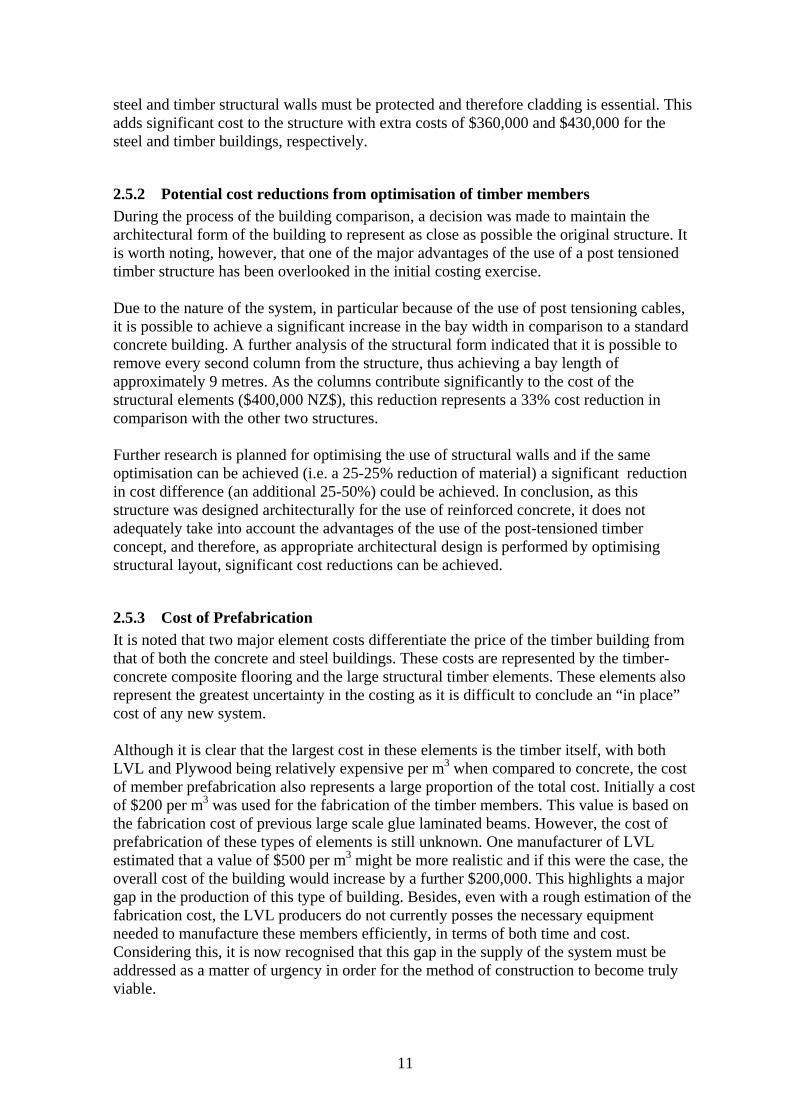
2.5.2 Potential cost reductions from optimisation of timber members
During the process of the building comparison, a decision was made to maintain the architectural form of the building to represent as close as possible the original structure. It is worth noting, however, that one of the major advantages of the use of a post tensioned timber structure has been overlooked in the initial costing exercise. Due to the nature of the system, in particular because of the use of post tensioning cables, it is possible to achieve a significant increase in the bay width in comparison to a standard concrete building. A further analysis of the structural form indicated that it is possible to remove every second column from the structure, thus achieving a bay length of approximately 9 metres. As the columns contribute significantly to the cost of the structural elements ($400,000 NZ$), this reduction represents a 33% cost reduction in comparison with the other two structures. Further research is planned for optimising the use of structural walls and if the same optimisation can be achieved (i.e. a 25-25% reduction of material) a significant reduction in cost difference (an additional 25-50%) could be achieved. In conclusion, as this structure was designed architecturally for the use of reinforced concrete, it does not adequately take into account the advantages of the use of the post-tensioned timber concept, and therefore, as appropriate architectural design is performed by optimising structural layout, significant cost reductions can be achieved.
2.5.3 Cost of Prefabrication
It is noted that two major element costs differentiate the price of the timber building from that of both the concrete and steel buildings. These costs are represented by the timber-concrete composite flooring and the large structural timber elements. These elements also represent the greatest uncertainty in the costing as it is difficult to conclude an “in place” cost of any new system. Although it is clear that the largest cost in these elements is the timber itself, with both LVL and Plywood being relatively expensive per m3 when compared to concrete, the cost of member prefabrication also represents a large proportion of the total cost. Initially a cost of $200 per m3 was used for the fabrication of the timber members. This value is based on the fabrication cost of previous large scale glue laminated beams. However, the cost of prefabrication of these types of elements is still unknown. One manufacturer of LVL estimated that a value of $500 per m3 might be more realistic and if this were the case, the overall cost of the building would increase by a further $200,000. This highlights a major gap in the production of this type of building. Besides, even with a rough estimation of the fabrication cost, the LVL producers do not currently posses the necessary equipment needed to manufacture these members efficiently, in terms of both time and cost. Considering this, it is now recognised that this gap in the supply of the system must be addressed as a matter of urgency in order for the method of construction to become truly viable.
11

2.6 Life Cycle Analysis and Environmental Considerations All four buildings in this study were designed for a 60 year lifetime and had very similar, low operational energy consumption. The concrete and steel buildings employed conventional design and construction methods. The timber buildings proposed innovative post-tensioning structural designs using engineered LVL and the TimberPlus design further increased the use of timber in architectural features such as exterior cladding, windows and ceilings. Further research was also undertaken to determine the extent and type of differences in the environmental impacts of using concrete, steel or wood as the main structural building material in multi-storey buildings. This focused on investigating the influence of construction materials on energy use and global warming potential (GWP), but did not consider other environmental impacts, such as ozone depletion, water quality, indoor air quality, etc. By designing all buildings with very similar low operational energy consumption (average 85kWh/m2/yr), the research was able to investigate both the short-term (initial-embodied energy and GWP of the materials) and the long-term environmental impacts over the full (predicted) 60-year lifetime of the buildings. The study employed rigorous Life Cycle Assessment (LCA) methodology using the European-based Gabi modelling software and considered the full life cycle of the buildings including embodied energy and GWP of the materials, building maintenance, transport, operational energy and two end-of-life scenarios, where deconstructed materials were either land-filled or reutilised. An alternative end-of-life scenario which assumed permanent storage of carbon in wood materials was also modelled. The very similar operational phase of all the buildings – that is, the actual, normal day-to-day use and consumption of energy and resources of the buildings and their occupants – has by far the biggest influence on the lifetime environmental impacts, over-shadowing differences which occur in the initial embodied energy and GWP of the different construction materials (see Table 2.2 and 2.3). However, it should be noted that as buildings continue to become much more energy efficient (and thus the percentage contribution of operational energy falls), the initial embodied energy and GWP of the different construction materials will play an increasingly important role in LCA analysis.
12

Table 2.2: Percentage of operational, initial embodied and maintenance related embodied energy to total energy over the full lifetime of the buildings.
Concrete Steel Timber TimberPlus Operational energy to total lifetime energy (%)
89 87 91 94
Initial embodied energy to total lifetime energy (%)
9 11 7 5
Maintenance related embodied energy to total lifetime energy (%)
1 1 1 1
Note: This table does not show percentages for transport or end-of-life energy – hence, figures do not necessarily total to 100%. Table 2.3: Percentage of operational GWP, initial embodied GWP and maintenance
related embodied GWP to total GWP emissions over the full lifetime of the buildings. Concrete Steel Timber TimberPlus Operational GWP to total lifetime GWP (%)
72 73 86 95
Initial embodied GWP to total lifetime GWP (%)
23 23 16 11
Maintenance related embodied GWP to total lifetime GWP (%)
2 2 2 2
Note that this table does not show percentage contributions from GWP due to transport, end-of-life or carbon storage. The apparent anomaly of the emissions from operational, initial embodied and maintenance adding up to more than 100% is offset by carbon storage in the timber materials in the landfill.
2.6.1 Carbon Sequestration
The importance of the assumptions made in an LCA study, as to what happens to the building materials on deconstruction of the buildings after 60 years, has a significant impact on the GWP, as timber and timber products have the ability to sequester carbon for long periods. Assuming all deconstruction materials are land-filled, Tables 2.2 and 2.3 show that the steel building has the greatest embodied energy (11%) and GWP contributions (23%), mainly caused by the large quantity of structural steel, which has a high embodied energy and GWP. The TimberPlus building has the relatively lowest overall embodied energy (5%) and GWP (11%) contributions because it contains less aluminium and steel compared to the other building types, instead substituting timber-based products, such as Western Red Cedar louvres and pine cladding. The main impact contributors for all building in terms of building components were those which contained relatively large quantities of aluminium (louvres and windows) and steel (structure). A ‘benefit’ would accrue to all buildings – including concrete and steel structures - by increasing the amounts of timber finishing materials. As noted above, the end-of-life scenario for a building and its components / materials is very important. The embodied energy and GWP in the material reutilisation end-of-life scenario (recycling of steel and concrete and burning of wood waste for energy recovery and displacement of other fossil fuels) was estimated to be less than the land-filling
13

scenario. Even though carbon is stored through land-filling, the total reduction in GWP impact compared to material reutilisation is minimal if methane is allowed to escape into the atmosphere. However, it is important to note that modern land-filling technology and the increasing capture and utilisation of land-fill generated methane will significantly reduce the environmental impacts of using timber, which is then disposed of in land-fill, thus providing even greater benefits to the use of timber over concrete and steel.
2.6.2 Global Warming Potential
Material reutilisation potentially enables a significant recovery of energy and reduction in GWP for the steel and concrete building types. Material reutilisation recovered a proportion of the embodied energy of the wood that would otherwise be wasted if the wood was land-filled. The building with the largest energy recovery was the TimberPlus building, as this building is composed largely from wooden materials that can be combusted for energy recovery. The steel building also had a significant reduction when the structural steel was recycled. However, the reduction is still less than recovering energy from combusting wood. Recycling the steel and concrete in the reutilisation scenario would be more beneficial than simply land-filling these materials because this displaces the need to use new primary materials with high initial embodied energy and GWP. In all cases, at present, whilst reutilisation is desirable, it does not appear to reduce GWP any more than land-filling (noting that this would change if methane was captured and used, as discussed above). If the assumption is made that 100% of the carbon in timber and timber products is permanently stored – equivalent to carbon being permanently removed from the atmosphere - then there is a significantly larger reduction in GWP for the timber and TimberPlus buildings. Under this scenario, considering only the impact of the materials over the life cycle of the buildings, net GWP emissions for the timber building are just 5% of those from the concrete and steel buildings.(Figure 2.10). This is because the carbon stored in the wood-based building materials balances out nearly all of the GWP of the materials emitted in the manufacture of all the other materials in the building.
14

-1000
-800
-600
-400
-200
0
200
400
600
800
1000
1200
1400
1600
1800
Con
cret
e
Stee
l
Tim
ber
Tim
berP
lus
ton
ne
s C
OWood
Other
Aluminium
Steel
Concrete
Figure 2.10: GWP emissions for the materials in the four buildings, assuming permanent
storage of carbon in wood products. Data from Gabi coefficients (John et al – 2009) . For the TimberPlus building, there is an even more noticeable impact - net storage of carbon, over 630 tonnes of CO2 equivalent. The storage of carbon more than cancels out all the greenhouse gases emitted in the manufacturing process of all the other building materials. Figure 2.11 shows the full life cycle GWP emissions of different buildings (that is including operational, maintenance, transport phases) under a permanent carbon storage scenario. The advantages of utilising more timber are less pronounced than when looking only at the initial effects but are still significant.
0
1000
2000
3000
4000
5000
6000
7000
8000
Concrete Steel Timber TimberPlus
ton
ne
s C
O2
Figure 2.11: Net lifecycle GWP emissions for the four buildings, assuming permanent storage of carbon in wood products.
15

The ‘ranking’ of the buildings in terms of environmental impacts is shown below. ____________________________________________________________________ Initial embodied energy Best (least embodied energy) TimberPlus of materials Timber Concrete Worst (most embodied energy) Steel _____________________________________________________________________ _____________________________________________________________________ Initial embodied CO2-eq. Best (lowest GWP emissions) TimberPlus of materials Timber Concrete Worst (highest GWP emissions) Steel _____________________________________________________________________ _____________________________________________________________________ Total primary energy use Best (least total energy used) TimberPlus of building over full lifecycle Concrete - landfill scenario Timber Worst (most total energy used) Steel _____________________________________________________________________ _____________________________________________________________________ Total GWP emissions Best (least total GWP emissions) TimberPlus of building over full lifecycle Timber Steel - reutilisation scenario Worst (most total GWP emissions) Concrete
16

2.7 Conclusions – Multi-Storey Timber Buildings
2.7.1 Structural Viability
The aim of the virtual building project was to evaluate the overall feasibility of the use of post-tensioned LVL and TCC floors in the construction of medium rise commercial or residential type structures. This was achieved through the selection of a case study building to be built in reinforced concrete at the University of Canterbury and the subsequent redesign of two alternate structures in either steel or post-tensioned timber solution. Two principal factors were selected as being ‘key indicators’ of the systems potential in an already extremely competitive structural market:
the first of these was the time required for the construction of the building, and the second being the cost of the ‘as finished’ structure.
Calculation of the construction time needed was performed through a scheduling of the placement and connection of structural elements in both the timber and concrete buildings. It was discovered that due to the modular nature of both construction methods, the construction time required was almost exactly the same. In order to calculate the cost of construction, which was the second ‘key indicator’, an external consultant was used to ensure that realistic calculations and hence, conclusions were made. Direct comparisons of the costs showed that the cost of the timber building will be approximately $600,000 NZD more than that of the steel and concrete options with a total cost of $10,000,000 NZD. However various considerations, such as optimisation of the timber structure, and possible reductions in both material and fabrication costs, indicate that this result is slightly conservative. The study has clearly shown that it is entirely feasible to construct a large multi-storey office building in predominantly timber materials, which are both durable and sourced from sustainably managed and certified forests. Construction times for the timber buildings were estimated to be similar to both the concrete and steel structures. All four buildings in this study were designed for a 60 year lifetime and had very similar low operational energy consumption.
2.7.2 Environmental Benefits
The LCA study considered the full life cycle of the buildings including embodied energy of the materials and maintenance, transport, operational energy and two end-of-life scenarios, where deconstructed materials were either land filled or reutilised. Increasing the amount of timber used in the buildings resulted in decreased embodied energy and significantly decreased GWP of materials and decreased total energy consumption and GWP over the 60 year lifetime. In all cases, the TimberPlus design clearly had the lowest environmental impact, whilst the steel building had the highest impacts - apart from the case of considering the reutilisation of material scenario over the full lifetime - where concrete was the worst.
17
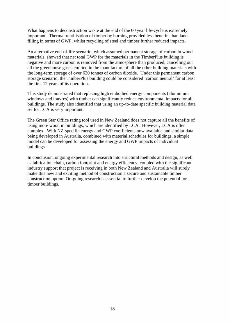
What happens to deconstruction waste at the end of the 60 year life-cycle is extremely important. Thermal reutilisation of timber by burning provided less benefits than land filling in terms of GWP, whilst recycling of steel and timber further reduced impacts. An alternative end-of-life scenario, which assumed permanent storage of carbon in wood materials, showed that net total GWP for the materials in the TimberPlus building is negative and more carbon is removed from the atmosphere than produced, cancelling out all the greenhouse gases emitted in the manufacture of all the other building materials with the long-term storage of over 630 tonnes of carbon dioxide. Under this permanent carbon storage scenario, the TimberPlus building could be considered ‘carbon neutral’ for at least the first 12 years of its operation. This study demonstrated that replacing high embodied energy components (aluminium windows and louvres) with timber can significantly reduce environmental impacts for all buildings. The study also identified that using an up-to-date specific building material data set for LCA is very important. The Green Star Office rating tool used in New Zealand does not capture all the benefits of using more wood in buildings, which are identified by LCA. However, LCA is often complex. With NZ-specific energy and GWP coefficients now available and similar data being developed in Australia, combined with material schedules for buildings, a simple model can be developed for assessing the energy and GWP impacts of individual buildings. In conclusion, ongoing experimental research into structural methods and design, as well as fabrication chain, carbon footprint and energy efficiency, coupled with the significant industry support that project is receiving in both New Zealand and Australia will surely make this new and exciting method of construction a secure and sustainable timber construction option. On-going research is essential to further develop the potential for timber buildings.
18

3 – Review of Commercial Flooring Systems During the second half of 2008, a study was undertaken at UTS to look at the various different flooring systems that are currently in use in Australia. This involved considering both design and construction issues, and also looking at Building Code of Australia (BCA) requirements for the building type to provide an insight into the current market and gain an understanding of the “drivers” for selecting a particular type of floor. The study looked at both the traditional cast in-situ flooring systems and also precast systems, and compared these different construction types. It is interesting to note that the construction industry in Australia tends to be fairly entrenched in that it tends to stay with the more traditional “tried and tested methods” of construction and is often reluctant to embrace change – in this case, prefabricated flooring systems.
3.1 Background and Context The construction industry in Australia is highly competitive and is characterised by a plethora of products, with each manufacturer looking to increase their market share. The success of certain materials and methods of design and construction has often led to the stifling of innovation, due to aggressive protection of existing market share and the “fossilisation” of design and construction methodology within the industry. Both designers and contractors are often resistant to change and this presents significant challenges for any company that has developed a new product to penetrate existing markets. However, as developers and contractors seek to reduce costs to the bare minimum, competitive advantage can often only occur through the use of new structural systems that can combine project design requirements with innovation, flexibility and reduced costs for design, fabrication and installation. Recent initiatives to produce “green” buildings, with varying emphases on LCA and efficient “environmental performance”, has also become a driver for innovation – although it must be recognised that many producers of traditional building materials, systems and products are now promoting their environmental credentials – with varying degrees of acceptance. Proprietary design and construction systems are often patented – which in itself can be an obstacle to market acceptance. A significant barrier to the adoption of new products in the construction industry can be attributed to the reluctance of builders to try new systems. Interviews conducted in the course of this study identified that the willingness of industry personnel to adopt new products varies across the different states of Australia. The state most open to trialling new products is Queensland, with New South Wales and Victoria being the most resistant to change. The focus of this study was on the commercial flooring market, particularly in New South Wales, and after discussions with engineers, architects and builders, five different slab systems were identified as the main “players” competing for market share within the state. These five systems can be broadly categorised into three distinct types: reinforced concrete, prestressed concrete and metal deck. Under these three headings, traditionally reinforced slabs, post tensioned slabs, Ultrafloor, Hollowcore and a variety of metal deck products, including Bondek, Kingflor and Condeck, have been reviewed.
19

Each of the three types of slab systems have been investigated, with the information being categorised into sections reflecting design and detailing, fabrication and transportation, construction and structural performance issues. The study has provided an insight into current market conditions, and highlights some of the advantages and disadvantages of each system through a comparative analysis of the proprietary products and a traditional reinforced concrete floor slab.
3.2 Summary of Findings Details of the full study are presented elsewhere (Nugteren and Smith – 2008). In order to compare the various systems, a design was undertaken for all the flooring types reviewed in this report, using a common floor grid, where the floor is a one way slab as pictured in Figure 3.1. The floor has been designed for a permanent load of self weight plus 1 kPa and an imposed load of 3 kPa. All floors have been designed using the relevant Australian standards, including AS1170.0, AS1170.1, AS3600, AS4100 and AS1720, to comply with the BCA requirements for a Class 5 Building (Office building for professional or commercial purposes) – including fire rating and consideration of acoustic performance. However, this costing analysis is limited to the structural elements only (not the finished floor) and does not include additional building components required to all BCA requirements.
Figure 3.1: Typical floor layout used for the one way slabs designed in this project.
20

For the pre-fabricated floor systems, the manufacturer’s design manuals and/or programs have been used to assist in design. This typical design enabled the development of a bill of quantities for each floor type, listing the installed cost of the floor, the weight of the floor, crane hours and truck loads of materials. These values provide a relative comparison of each system. All prices, where necessary, were obtained from Rawlinsons Australian Construction Handbook Edition 26, 2008, with a full list of all the assumed rates included below.
Table 3.1 - Assumed Costs Material / Resource Installed Cost Formwork, including propping and installation. $72 / m2
Concrete, including pumping costs $239 / m3
Reinforcement Steel (bars), supplied and installed $1770 / tonne
Reinforcement Steel (ties), supplied and installed $2020 / tonne
1.0 mm BONDEK, including propping and installation $95 / m2
Post Tensioning Cable, including installation & tensioning $8,300 / tonne
Structural Steel $5,125 / tonne
200/7/9.3(41) Hollowcore planks, including installation $165 / m2
200C-500 Ultrafloor beams, including installation $150 / m2
Double 400x63 LVL Hyspan beams, including installation $175 / m
S200/1200 Ultrashell beam, including installation $420 / m
S100/1200 Ultrashell beam, including installation $340 / m
17 mm Ply form $46.40 / m2
Fibre Cement form boards $35 / m2
Table 3.2 - Assumed Crane Usage Rates
Material Quantity per load Cranage Time Reinforcement (longitudinal bars, ties and post tensioning cable)
0.5 T 10 min
Structural Steel 0.5 T 20 min Hollowcore Planks 8 m2 15 min Ultrafloor Beams 4.7 m2 15 min Ultrashell beams 6.7 m 20 min Fibre Cement Boards 90 m2 10 min 400x63 LVL 26 m 15 min Formwork and propping (or metal deck)
100 placements per floor
10 min per placement
21

Table 3.3 - Assumed Truck Delivery Quantities Material Quantity per load Reinforcement (longitudinal bars, ties and post tensioning cable) 10 T Structural Steel 15 T Hollowcore Planks 52 m2 Ultrafloor Beams 130 m2 Ultrashell beams 60 m Fibre Cement Boards 350 m2 400x63 LVL 100 m Formwork and propping (or metal deck) 100 m2 Concrete 6 m3 Part F5 of the BCA covers Sound Transmission and Insulation of buildings. It is interesting to note that this requirement of the code applies only to Class 2, 3 or 9c buildings, all of which are residential buildings. This means for a Class 5 Commercial building there are no specific Sound Transmission or Insulation requirements listed in the BCA. However, most of the flooring types assessed in this study is often used in Class 2, 3 and 9c buildings, and when used for this type of building, they will need to meet the BCA requirements. There are two types of sound transmission that need to be satisfied, namely airborne sound transmission and impact noise. The parameter used for measuring the resistance of floors to airborne sound transmission is the Sound Reduction Index rating, typically known as the Rw rating. This is a single number measure of the sound transmission loss of airborne sound through the material. The larger the Rw, the superior the sound insulation of the floor is. A negative adjustment factor, Ctr is used to compensate for low frequency sounds in the environment. The parameter used for measuring the impact sound insulation is the Normalised Impact Sound Pressure Level, typically denoted by (Ln,w + C1). This is a single figure rating of the overall impact sound insulation performance of a floor-ceiling assembly. Impact noises are very dependent on the floor surface, as the most effective way to arrest the sound is at the impact point. As this is the case, the flooring systems assessed in this report will have varying (Ln,w + C1) values depending on the floor surface. For example, carpet provides very good impact sound insulation, whereas tiles do not provide good impact sound insulation. The relevant BCA requirements for sound transmission ratings are indicated in Table 3.4, whilst the actual claimed ratings are shown in Table 3.5.
Table 3.4 – BCA Requirements for STC Sound Class 2 or 3 Building Class 9c Building
Rw + Ctr (airborne) 50 45 Ln,w+C1 (impact) 62 62
The following assumptions have been made in estimating the ratings in Table 3.5, noting the previous comment that these items have not been included in the cost estimates, indicated in Table 3.6.
1. Floors will have carpet with an underlay installed.
2. Floors will have a suspended ceiling from the soffit of the floor
22

Table 3.5 – Claimed Acoustic Ratings
Current Sound Transmission and insulation ratings Product
Rw + Ctr (airborne) Ln,w+C1 (impact) Reinforced Concrete 56 Above 62 Post Tensioned Concrete 53 Above 62 Bondek with concrete frame
50 Not available
Bondek with steel frame 50 Not available Hollowcore with pre-cast beams
58 70 +
Ultrafloor with pre-cast beams
52 70 +
Timber Concrete Composite with pre-cast beams
Not available Not available
Table 3.6 – Estimated Cost of Floor (Structure only)
Product Weight of
Floor Cost of System
Cranage time
Truck Deliveries
to site
Cost per m2
Reinforced Concrete 1,930T $577,797 48 hrs 168 $202
Post Tensioned Concrete
1,420T $540,782 38 hrs 135 $189
Bondek with concrete beams
1,688T $549,922 38 hrs 149 $192
Bondek with steel beams
1,133T $891,441 54 hrs 105 $311
Hollowcore with pre-cast beams
1,673T $779,628 110 hrs 108 $272
Ultrafloor with pre-cast beams
1,511T $821,677 167 hrs 101 $287
Timber Concrete Composite with pre-cast beams (1)
1,100T $836,757 73 hrs 84 $292
Timber Concrete Composite with LVL beams (2)
720T $681,670 62 hrs 75 $238
Timber Concrete Composite with non permanent forms and LVL beams (3)
710T $681,670 60 hrs 70 $202
TCC Notes: (1) – This included a topping coat @ $20 / m2 (2) – No topping and use of 600x400 LVL beams (3) – Non permanent formwork, no topping and use of 600x400 LVL beams Costings for (2) and (3) were undertaken subsequent to the 2008 study and are not included in the original report .
23

3.3 Conclusions Information from various designers, who may specialise in one particular system or be reasonably competent with each, established that the more often each system is designed by an individual, the more competent they become and the faster the design can be completed. A consequence of this improved efficiency is greater resistance to adopting a new system requiring a different design method. When asked which method is ‘easiest’ to design, each consultant identified their area of specialisation or the product with which they had the most experience. Similar observations were noted for contractors who clearly develop efficiency and expertise in the construction of a particular system, relying on “their” team of sub contractors. The lack of a clear industry standard, coupled with the multiple and varied advantages and disadvantages of each flooring system, makes it is impossible to identify a single “best” commercial flooring system available. However, it was noted that the final design decision is influenced by numerous factors, including the functional requirements, the structural design requirements, the type of structural frame, the shape in plan and the column grid / dimensions of spans. The costs prepared for the TCC / LVL options are not well established in the construction industry for commercial buildings and it is imperative that more detailed investigations – particularly of fabrication and erection costs are undertaken as a matter of urgency. This will need to be undertaken in consultation with both timber industry suppliers and quantity surveyors. Finally, the study does highlight the fact that there is considerable potential for prefabricated TCC floors to be cost competitive with systems currently used by the industry and given the fact that the integral formwork currently provides no enhancement of structural performance, the efficiencies of removable formwork need to be investigated.
24

4 – Interim Design Procedures for TCC Floors
4.1 Essential Performance Criteria
4.1.1 Introduction
In order to implement TCC construction reliably, it is necessary to utilise a thorough design procedure that addresses the strength and serviceability requirements of the structure. Whilst rigorous verification of these design aspects can be demanding and time consuming due to the complexity of TCC systems, several simplified design procedures which are reasonably straightforward are presented in the literature. This section presents an interim design procedure that incorporates the results of all research completed to-date within the scope of the current R&D program. It is proposed that an updated and more rigorous version will be prepared in 2012 as an output from the Structural Timber Innovation Company, which commenced at the conclusion of this project. In Eurocode 5 (EC5) and Timber Engineering STEP 2, design guidelines have been put forward, essentially developed by Ceccotti (1995). Elsewhere, Natterer (1996) detailed design principles which were based on assumptions of quasi-fully composite behaviour and these are similar to those of Ceccotti. The EC5 design procedure has also been considered for implementation in New Zealand (Yeoh et al. 2008) and Yeoh also provides a thorough demonstration of this design approach through a worked example. Ceccotti’s approach (1995) addresses the verification of strength (ULS) for all elements in a TCC floor system, including the connection, and serviceability (SLS) in consideration of both the short- and long-term deflections. This procedure also provides a methodology for determination of the vibration sensitivity of a structure as required by AS/NZS 1170.0 (2002), which considers the differential deflection arising from a concentrated load of 1.0 kN at mid-span; where by the deflection should not exceed 2.0 mm. As presented in a previous report of this research project (Crews et al. 2007), a design approach proposed by McCutcheon, first put forward in 1977 (McCutcheon 1977) and subsequently refined in 1986 (McCutcheon 1986), may offer a suitable and simpler alternative for designing TCC structures. In this approach McCutcheon proposed a manipulation of the stiffness of the composite structure in order to account for the slip between the members of the composite sections. Both Cecotti’s (1995) and McCutcheon’s (1977; 1986) approaches assume that the behaviour of all members forming the composite section remain linear-elastic, and the connection stiffness is markedly lower than that of the “solid” members.
4.1.2 Design requirements
Any limit states design procedure must address both the strength and serviceability responses of the structure, to ensure that the functional requirements are met. In the Australian and New Zealand context, AS/NZS 1170 series indicates the load type and magnitude as well as the relevant load factors and combinations for both limit states. For example, one “normal” load case of the ultimate limit state demands accumulating the permanent and imposed loads in the form: 1.2G + 1.5Q, where G includes the self weight and all permanent loads and Q is the imposed load.
25

The limit states that must be assessed and resisted can be summarised as follows: 1. The short-term ultimate limit state, where the structure’s response to the maximum load is analysed. It generally corresponds to an imposed (occupancy) load of large magnitude, with a defined duration of occurrence. 2. The long-term ultimate limit state. This requires analysis of the structural response to permanent loading and particularly aims at avoiding failure due to duration of load effects in the timber member. 3. The end-of-life ultimate limit state. In this scenario, the residual strength capacity of the structure is assessed taking into account the durability and reliability of the structure. 4. The short-term serviceability limit state, corresponding to the instantaneous deflection of the floor under an imposed load. 5. The long-term or end-of-life serviceability limit state. This analysis aims to identify the service life behaviour of structure considering the time-dependent variations of the material properties; in particular creep. Yeoh (2008) proposes a graphical summary of the design (refer to Figure 4.1).
Figure 4.1: Short- and long-term limit states for TCC design (Yeoh et al. 2008).
26

4.2 Fundamentals of Connection Behaviour The shear connection between the concrete floor and timber beams is a critical element in any TCC structure, since it creates the inherent composite action that permits the system to be structurally efficient. Both the stiffness and strength of the connection must be quantified and considered during the design process, particularly in regard to any flexibility that the connection exhibits. Figure 4.2 illustrated the various “states” of the composite action; from (a) full – no slip between the members, (b) partial – some slip or flexibility, (c) and zero composite action.
(a)
(b)
(c)
Figure 4.2: Degrees of composite action (Yeoh et al. 2008).
TCC structures constructed with notched and coach screw connections have been observed to exhibit partial composite action (refer to Crews et al. - 2008a; 2007; 2008b for details on these connections). This means that some measure of slip occurs between the concrete and timber elements in the cross-section so it is important that optimisation of the section proportions (principally the timber-concrete depth ratio), is undertaken to ensure that the concrete member remains completely in compression. In an attempt to ensure this effect, Möhler (1956) devised a series of formulae based on the assumption of linear-elastic behaviour in each component of a TCC member. However, this assumption failed to accurately model the non-linear behaviour of TCC connections – particularly when resisting ULS loads. Cecotti (1995) proposed a more refined approach to take account of this non linear behaviour in the shear interface (concrete to timber) by simulating the connection behaviour using two defined values of the stiffness modulus –respectively at 40% and 60% of the ultimate load of the connection (Figure 4.3).
27

Figure 4.3: Slip moduli of a connection for ultimate and service limit states (Yeoh et al.
2008) Note: the assessment/approximation of the ultimate strength and stiffness moduli of a connection may require the completion of a comprehensive laboratory investigation (push-out tests). Several research programs involving push out tests on connections to determine the relevant properties have been completed at UTS (Crews et al. 2008a; Crews et al. 2008b). Equations for the elastic design method are listed below.
1) The first step involves determination of the cross-section characteristics:
2( )ef c c t t c c c c t t t t2EI E I E I E A a E A a (Eq 1)
(Note: The subscripts c and t refer to concrete ant timber respectively.)
where:
3
12c c
c
b hI
3
12t t
t
b hI (Eq 2a); (Eq 2b)
2
2
1
1c
c c efE A s
Kl
1t (Eq 3a); (Eq 3b)
c cA b h c tt tA b h (Eq 4a); (Eq 4b)
28

t t tc
c c c t t t
E A Ha
E A E A
c c ct
c c c t t t
E A Ha
E A E A
(Eq 5a); (Eq 5b)
in which:
2 2c th h
H a (Eq 6)
(Eq 8) min max0.75 0.25efs s s
E = Young’s modulus of the materials, I = Moment of Inertia of the cross-section member, A = area of the cross-section member, K = slip modulus of the connection, l = span of the structure, b = width of the cross-section member, h = depth of the cross-section member, smin = minimum spacing of the connectors, smax = maximum spacing of the connectors.
2) Secondly, the stresses in the cross-section are checked. For bending stress:
,
( )1( )
2 ( )i i i d
b ief
E h M xx
EI
(Eq 9a)
that is,
,
( )1( )
2 ( )c c c d
b cef
E h M xx
EI
,
( )1( )
2 ( )t t t d
b tef
E h M xx
EI
(Eq 9b); (Eq 9c)
And for axial stress:
( )
( )( )
i i i di
ef
E a M xx
EI
(Eq 10a)
that is,
( )
( )( )
c c c dc
ef
E a M xx
EI
( )
( )( )
t t t dt
ef
E a M xx
EI
(Eq 10b); (Eq 10c)
3) Using this, the internal forces are approximated:
,( ) ( )i m i iM x x Z (Eq 11a)
that is,
,( ) ( )c m c cM x x Z ,( ) ( )t m t tM x x Z (12a); (12b)
a) & ( ) ( )t dV x V x( )
( ) ( )( )
c c c cd
ef
E A a s xF x V x
EI d
(13) & (14)
a) it is assumed that the timber beam resist the entire shear force.
29

( ) ( )c cN x x Ac ( ) ( )t tN x x At (Eq 15a); (Eq 15b)
(Note: (x) is the abscissa along the beam longitudinal axis.)
σm = stress component due to the bending moment in the cross-section member, Md = design bending moment, σ = stress component due to axial force in the cross-section member, Z = is the section modulus, V = internal shear force (timber), Fd = design load combination (uniformly distributed load), N = internal axial force.
l = span of the structure, b = width of the cross-section member, h = depth of the cross-section member, smin = minimum spacing of the connectors, smax = maximum spacing of the connectors.
4) Finally, the serviceability of the TCC floor is checked:
45
384( )s
ef
F lu
EI (Eq 16)
For the assessment of the long-term responses, EIef is manipulated to accommodate the long-term aspects of the material such as shrinkage and creep.
30

4.3 Design Example The following design example illustrates the design of a simply supported TCC floor system for a commercial application using a live (imposed) load of 3.0 kPa, with the floor beams spanning 8.0m. The procedure is based on the EC5 design methodology. The TCC “beam” corresponds to an M-section structure (Figure 4.4) where the centre segment of the cross-section is the focus of the design (Figure 4.5). The overall width and depth of the M-section is 2400mm (based on standard lengths for plywood sheets used in formwork) and total depth = 442mm, assuming a 350mm deep LVL beam, 17mm thick formwork and a 75mm thick concrete slab). Further details on the material properties of the members are provided below.
CS 16 x 200 mm
CS 16 x 200 mmCS 16 x 200 mm
Concrete
Formwork
LVL beam
Figure 4.4: Cross-section of TCC element M-section, (dimensional detailing in mm).
The centre segment of the TCC element, which is analysed in the design scenario, is detailed in Figure 4.5. In this example, the concrete slab has a tributary width of 1200 mm, with two LVL beams, screwed together, to form the timber beam (126 x 350 mm2), and two connections working together to create the shear transfer between the concrete and the timber.
CS 16 x 200 mmConcrete
Formwork
LVL beam
Figure 4.5: Cross-section of the T-section (dimensions in mm).
31

Details of the free-body diagram and complementary information about the T-section are depicted in Figure 4.6
Figure 4.6: FBD and cross-section of the centre beam (T-section) (Yeoh et al. 2008).
32

Table 4.1 summarises the dimensions of the structural system depicted in Figures 4.4 and 4.5, as well as the relevant loading considerations.
Table 4.1: Structure Characteristics & Loading
Structure characteristics (T-section) Referencespan 8.000 mbearing length 0.150 "beam spacing 1.200 "concrete thickness 0.075 "formwork thickness 0.017 "beam depth 0.350 ""single" beam width 0.063 ""effective" beam width 0.126 " ''double'' beamtributary width 1.200 " DIN 1052
Loadingimposed loads 3.60 kN/m 3.0 kPa AS/NZS 1170permanent loads 1.20 " 1.0 kPa Yeoh et al.density of concrete 2.12 " 23.5 kN/m3density of LVL 0.33 " 7.5 kN/m3density of plywood 0.15 " 7.5 kN/m3
ULS combination 1: 1.35G 5.13 kN/m selfweigths and permanent loadingULS combination 2: 1.2G + 1.5Q 9.96 " selfweigths, permanent & imposed loading
Ultimate bending moment, Md 41.07 79.71 kNm
Ultimate shear force, V d 20.53 39.85 kN
Ultimate shear force @ L/4, V L/4 10.27 19.93 "
SLS combination 1: Q 3.60 kN/m imposed loadingSLS combination 2: G + 0.4Q 15.38 " selfweigths, permanent & imposed loading
short-term SLS limit ie. L/300 300 –
long-term SLS limit ie. L/400 400 – Note: The beam depth is entered in 50mm increments.
Table 4.2: Connection Characteristics
Connection Reference
type 25d-slanted-facet notch Crews et al. 2008bULS stiffness 102200 N/mm 0.6Pmax – test dataSLS stiffness 99000 " 0.4Pmax – test datastiffness modification coefficient 5characteristic strength 190000 N 5th percentile value – test datanotch profile – width 126 mm dimensional/geometrical characteristicsnotch profile – depth 30 "notch profile – length 150 "maximum notch spacing 800 "minimum notch spacing 400 "
The connection characteristics are detailed in Table 4.2. 25d-slanted-facet connections have been chosen for this design exercise, whose main characteristics are: 30mm deep, 150mm long and 25° slanted facets; with a coach screw (Ø 16mm, 200mm long) that acts as mechanical fastener (Figure 4.7). The utilisation of this particular connection is based on
33

push-out investigations completed at UTS, the results of which have been reported in previous milestone reports (Crews et al. 2008a; Crews et al. 2008b). Figure 4.7 also shows the slot carved in the formwork - in this case oversized by 100mm on each side of the notch.
CS 16 x 200 mm
ConcreteFormwork
LVL beam
Figure 4.7: Connection geometry and dimensions in mm.
Table 4.3 lists the material properties. The concrete compressive strength of 29.6MPa (N32) is consistent with the strength of the concrete used in the push-out tests, whilst the properties of the LVL beam are those published by the manufacturer (CHH Futurebuild). Modifications of the characteristics strengths have been applied in accordance with AS 1720.1 and AS 3600–2001 for the timber and concrete members, respectively, with appropriate assumptions being made as required for stiffness, (for example, for the reduction of the long-term modulus of elasticity in the LVL to account for creep).
34

Table 4.3: Material Properties
Material properties Referenceconcrete MOE 37.6 GPa AS 3600effective concrete MOE 2.8 "concrete compression strength 29.6 MPa test dataconcrete tensile strength 2.2 "reinforcement MOE 200.0 GPareinforcement design strength 250.0 MPatimber MOE 13.2 GPaeffective timber MOE 6.6 " load duration 0.50timber tensile strength 33.0 MPa characteristic value CHH Ltdtimber bending strength 48.0 " "timber shear strength 5.3 " "timber compression 12.0 " "timber compression 45.0 " "
Timber design coefficientsmaterial safety 0.90 AS 1720.1
short-term long-termload duration, k1 0.80 0.57 AS 1720.1moisture condition, k4 1.00 " " temperature, k6 1.00 " "
bending tension compress. shearlength and position of bearing, k7 1.00 AS 1720.1sharing between parallel members 1.00 " " size factor, k11 0.97 0.87 1.00 " " stability factor, k12 1.00 " "
Connection design coefficientsconnection safety 0.70 AS 1720.1
load duration coefficient, k1 0.80 " " moisture condition, k4 1.00 " "
Tables 4.4 to 4.7 present the limit-states verification of the TCC deck. The analysis indicates that the long-term deflection governs the design (Table 4.7) and as such, the structure possesses adequate strength (Tables 4.4 and 4.5). In Table 4.6, the analysis of the short-term deflection demonstrates that the structure has sufficient stiffness to avoid any vibration issues. This design also indicates that the overall depth of the deck at 442mm is reasonable, since the span over depth ratio is 8000 / 442 = 18.1.
4.3.1 Verification of Ultimate Limit States (Strength)
Summary of short-term strength considerations (Table 4.4):
The critical strength limit state is the longitudinal shear strength with a capacity ratio of 0.693 – length between the support and the first notch
It is noted that the lower edge of the concrete member is subjected to a minor tensile stress of (1.47 MPa).
35

Table 4.4: Verification of Ultimate limit state – short-term strength
Gamma coefficients Referenceconcrete 0.281 – Eq 3a EC5, Annex Btimber 1.000 " Eq 3b " " "
Distancesconcrete 87.060 mm Eq 5a EC5, Annex Btimber 142.440 " Eq 5b " " "
Effective flexural stiffness
composite section 2.6558E+13 Nmm2
Concrete strength verifications effective capacity unit checknormal stress due to axial force -2.76 MPa Eq 10bnormal stress due to bending moment 4.23 " Eq 9b
normal stress at slab upper edge -7.00 -29.60 MPa 0.236normal stress at slab lower edge 1.47 2.18 " 0.674
Timber strength verificationsnormal stress due to axial force 5.64 20.63 MPa Eq 10cnormal stress due to bending moment 6.93 33.68 " Eq 9c
normal stress at beam upper edge -1.29normal stress at beam lower edge 12.58
corresponding timber axial force 248.85 909.56 kN Eq 15bcorresponding timber bending moment 17.83 86.65 kNm Eq 12b
tangential shear stress 1.36 3.82 MPa 0.355
compression stress at bearing area 2.11 8.64 MPa 0.244
Connection strength verificationsshear force at maximum shear 49770 106400 N 0.468shear force in connection at L/4 49770 106400 " 0.468
longitudinal shear at beam ends 2.63 3.82 MPa 0.690
0.479
36

Summary of long-term strength considerations (Table 4.5): The long term effects are essentially the same as for the short term load events Except that the capacity ratio for the longitudinal shear strength equals 0.499 (0.50)
Table 4.5: Verification of Ultimate limit state – long-term strength
Gamma coefficients Referenceconcrete 0.281 – Eq 3a EC5, Annex Btimber 1.000 " Eq 3b " " "
Distancesconcrete 87.060 mm Eq 5a EC5, Annex Btimber 142.440 " Eq 5b " " "
Effective flexural stiffness
composite section 2.6558E+13 Nmm2
Concrete strength verifications effective capacity unit checknormal stress due to axial force -1.42 MPa Eq 10bnormal stress due to bending moment 2.18 " Eq 9b
normal stress at slab upper edge -3.61 -29.60 MPa 0.122normal stress at slab lower edge 0.76 2.18 " 0.347
Timber strength verificationsnormal stress due to axial force 2.91 14.70 MPa Eq 10cnormal stress due to bending moment 3.57 24.00 " Eq 9c
normal stress at beam upper edge -0.66normal stress at beam lower edge 6.48
corresponding timber axial force 128.22 648.06 kN Eq 15bcorresponding timber bending moment 9.19 61.74 kNm Eq 12b
tangential shear stress 0.70 2.72 MPa 0.257
compression stress at bearing area 1.09 6.16 MPa 0.176
Connection strength verificationsshear force at maximum shear 25644 106400 N 0.241shear force in connection at L/4 25644 106400 " 0.241
longitudinal shear at beam ends 1.36 2.72 MPa 0.499
0.347
37

4.3.2 Verification of Serviceability Limit States
Summary of short-term serviceability considerations (Table 4.6):
The satisfactory response of the deck to a 1.0 kN concentrated load indicates that vibrations are not problematic.
The instantaneous deflection generated by short term loading is not critical.
Table 4.6: Verification of Serviceability limit state – short-term.
Gamma coefficients Referenceconcrete 0.275 – Eq 3a EC5, Annex Btimber 1.000 " Eq 3b " " "
Distancesconcrete 88.305 mm Eq 5a EC5, Annex Btimber 141.195 " Eq 5b " " "
Effective flexural stiffness
composite section 2.6392E+13 Nmm2
Deflection verifications effective capacity unit check1.0 kN load for vibrations 0.40 2.00 mm 0.202
instantaneous – imposed load just applied 7.27 26.67 mm Eq 16 0.273 Summary of long-term serviceability considerations (Table 4.7):
The long-term deflection governs the design of the TCC structures. Concrete shrinkage and creep and timber creep are all significant contributors to the long-term response of TCC construction.
For this design, a timber beam with a 350mm depth also meets the design requirement of the long-term serviceability.
Table 4.7: Verification of Serviceability limit state – long-term.
Gamma coefficients Reference
concrete 0.509 – Eq 3a EC5, Annex Btimber 1.000 " Eq 3b " " "
Distancesconcrete 160.148 mm Eq 5a EC5, Annex Btimber 69.352 " Eq 5b " " "
Effective flexural stiffness
composite section 5.4518E+13 Nmm2
Deflection verifications effective capacity unit checklong-term 15.05 20.00 mm Eq 16 0.752
38

4.4 Design Scenarios As an illustration of the potential of TCC structures, a series of TCC deck designs have been developed based on the M-section details used in the design example in Section 4.3. All loads have been assumed to be 3.0 kPa for use in commercial conditions spanning 8.0, 10.0 or 12.0 metres. In each case the depth of the concrete slab and height of the LVL beam are adjusted in order to meet the limit states design requirements.
The results of the design scenarios are detailed in Table 4.7 and can be summarised as follows:
a TCC deck spanning 8m requires a 75mm concrete slab and 350x63mm LVL beams. The span-depth ratio is equal to 18.1.
a TCC deck spanning 10m requires a 90mm concrete slab and 450x63mm LVL beams. The span-depth ratio is equal to 18.
a TCC deck spanning 12m requires a 120mm concrete slab and 550x63mm LVL beams. The span-depth ratio is equal to 17.5.
Table 4.7a – Design Summary for 8m span TCC floor
eight – metre TCC deck
Construction characteristics (T-section)beam spacing 1200 mmtributary width 1200 ''concrete thickness 75 ''formwork thickness 17 '' beam depth 350 ''beam width 126 ''
Verification summary
short-term loading short-term loading0.236 0.674 0.479 0.355 0.244 0.468 0.468 0.690
long-term loading long-term loading0.347 0.257 0.176 0.241 0.241 0.499
1.0 kN instant. long-term loading0.202 0.273 0.752
ULS concrete ULS timber ULS connection
SLS short-term SLS long-term
39

Table 4.7b – Design Summary for 10m span TCC floor
ten – metre TCC deck
Construction characteristics (T-section)beam spacing 1200 mmtributary width 1200 ''concrete thickness 90 ''formwork thickness 17 '' beam depth 450 ''beam width 126 ''
Verification summary
short-term loading short-term loading0.241 0.446 0.517 0.367 0.324 0.500 0.500 0.738
long-term loading long-term loading0.400 0.284 0.251 0.276 0.276 0.571
1.0 kN instant. long-term loading0.190 0.256 0.778
ULS concrete ULS timber ULS connection
SLS short-term SLS long-term
Table 4.7c – Design Summary for 10m span TCC floor
twelve – metre TCC deck
Construction characteristics (T-section)beam spacing 1200 mmtributary width 1200 ''concrete thickness 120 ''formwork thickness 17 '' beam depth 550 ''beam width 126 ''
Verification summary
short-term loading short-term loading0.253 0.675 0.557 0.399 0.430 0.542 0.542 0.800
long-term loading long-term loading0.474 0.339 0.366 0.329 0.329 0.681
1.0 kN instant. long-term loading0.170 0.230 0.798
ULS concrete ULS timber ULS connection
SLS short-term SLS long-term
40
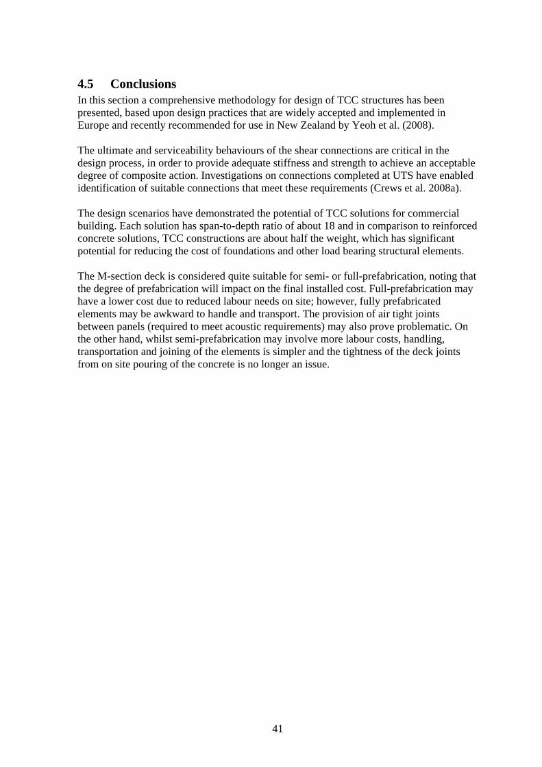
4.5 Conclusions In this section a comprehensive methodology for design of TCC structures has been presented, based upon design practices that are widely accepted and implemented in Europe and recently recommended for use in New Zealand by Yeoh et al. (2008). The ultimate and serviceability behaviours of the shear connections are critical in the design process, in order to provide adequate stiffness and strength to achieve an acceptable degree of composite action. Investigations on connections completed at UTS have enabled identification of suitable connections that meet these requirements (Crews et al. 2008a). The design scenarios have demonstrated the potential of TCC solutions for commercial building. Each solution has span-to-depth ratio of about 18 and in comparison to reinforced concrete solutions, TCC constructions are about half the weight, which has significant potential for reducing the cost of foundations and other load bearing structural elements. The M-section deck is considered quite suitable for semi- or full-prefabrication, noting that the degree of prefabrication will impact on the final installed cost. Full-prefabrication may have a lower cost due to reduced labour needs on site; however, fully prefabricated elements may be awkward to handle and transport. The provision of air tight joints between panels (required to meet acoustic requirements) may also prove problematic. On the other hand, whilst semi-prefabrication may involve more labour costs, handling, transportation and joining of the elements is simpler and the tightness of the deck joints from on site pouring of the concrete is no longer an issue.
41

5 – General Conclusions This report is the culmination of 2 years of R&D that was possible due to the generous funding support of Forest and Wood Products Australia. The main objectives and deliverables envisaged at the commencement of this project have been achieved and the viability of timber based flooring systems and in particular, timber concrete composite systems, has been proven. The testing undertaken during this R&D project has confirmed that timber-concrete composite floors are a viable and effective alternative to other flooring systems for commercial applications in terms of short term structural performance. Ongoing work will quantify both long term and dynamic performance, but initial results indicate that performance criteria for these serviceability limit states can be addressed satisfactorily. A study investigating “total cost” for design, fabrication, construction and installation of commercial flooring systems that currently hold a significant market share for commercial and industrial buildings in Sydney has been presented in Section 3. A comparison of these systems with preliminary designs and installed costs of TCC flooring options has confirmed the viability and potential of the alternative “timber based” structural systems for this market. The Life Cost Analysis of a 6 storey virtual timber building presented in Section 2 has highlighted the potential “triple bottom line” advantages of timber based building systems for commercial applications. The formation of the Structural Timber Innovation Company and the significant financial support being provided by Forest and Wood Products Australia, will also ensure that the outcomes of this project will be enhanced and further developed, to enable the implementation of timber building systems in non-residential buildings in Australia and New Zealand in the immediate future.
42

6 – References ANSYS Inc. 2005, ANSYS®, Release 10.0 edn, Canonsburg (PA), USA, < http://www.ansys.com/ >. Australian Standard 1997, Timber Structures, Part 1: Design Methods, vol. AS 1720.1–1997, Standards Australia, Homebush (NSW), Australia. Australian Standard 2001, Concrete Structures, vol. AS 3600–2001, Standards Australia, Homebush (NSW), Australia. Australian/New Zealand Standard 2002, Structural Design Actions, Part 0: General Principles, vol. AS/NZS 1170.0:2002, Standards Australia, Homebush (NSW), Australia. BSI (1991), Timber structures. Joints made with mechanical fasteners. General principles for the determination of strength and deformation characteristics, vol. BS EN 26891:1991, BSI British Standards, London, UK. Cecotti, A. 1995, 'Timber-concrete composite structures', in H.J. Blass, P. Aune, B.S. Choo, R. Görlacher, D.R. Griffiths, B.O. Hilson, P. Racher & G. Steck (eds), Timber Engineering – STEP 2, Centrum Hout, Almere, The Netherlands. Ceccotti, A., Follesa, M., Lauriola, M.P., and Sandhaas, C; 2006. “Which seismic behaviour factor for multi-storey buildings made of cross-laminated wooden panels?” Proceedings, CIB Working Commission W18-Timber Structures, Florence (Italy), Paper No. CIB-W18/39-15-4; 2006. 8pp Chan, T. 2007, An experimental study of timber concrete connection Capstone Thesis, Univeristy of Technology, Sydney. CHHfuturebuild 2005, Limit state design with Hyspan, Box Hill (VIC), Australia. Crews, K., Gerber, C., Choi, F. C., Buchanan, A. & Fragiacomo, M. 2007, Innovative Engineered Timber Building Systems for non residential applications Preliminary report (concept design) and literature review for Forest and Wood Product Australia, University of Technology, Sydney. Crews, K., Gerber, C., Buchanan, A. & Fragiacomo, M. 2008a, Innovative Engineered Timber Building Systems for non residential applications Report Of Test Specification And Results - Prototype Components (Milestone 3) for Forest and Wood Products Australia, University of Technology, Sydney (May 2008). Crews, K., Gerber, C., Yeoh, D; Buchanan, A. & Fragiacomo, M. 2008b, Innovative Engineered Timber Building Systems for non residential applications Report Of Test Specification And Results - Prototype Components (Milestone 4) for Forest and Wood Products Australia, University of Technology, Sydney (September 2008).
43

European Committee for Standardisation 1995, Design of Timber Structures — General Rules and Rules for Buildings, vol. Eurocode 5 (ENV 1995-1-1), European Committee for Standardisation CEN, Brussels, Belgium. John, S; Nebel, B; Perez, N; Buchanan, A; Environmental Impacts of Multi-Storey Buildings Using Different Construction Materials, University of Canterbury, Christchurch - Research Report 2008-02 – April 2009 McCutcheon, W. J. 1977, Method for Predicting the Stiffness of Wood-Joist Floor Systems with Partial Composite Action, Research Paper, Report No. FPL 289, U.S. Department of Agriculture, Forest Service, Forest Products Laboratory, Madison (WI), USA. McCutcheon, W. J. 1986, 'Stiffness of Framing Members with Partial Composite Action', Journal of Structural Engineering, vol. 112, no. 7, pp. 1623–1637. Möhler, K. 1956, Über das Tragverhalten von Biegeträgern und Druckstäben mit Zusammengesetzten Querschnitten und Nachgiebigen Verbindungsmitteln, Habilitationsschrift, Universität Karlsruhe, Karlsruhe, Germany. Naterer, J., Hamm, J. & Favre, P.-A. 1996, 'Composite wood-concrete floors for multi-story buildings', paper presented to the International Wood Engineering Conference, New Orleans (LA), USA. Newcombe M. 2008.,Seismic Design of Multistorey Post-Tensioned Timber Buildings. Master Thesis, University of Pavia, Pavia, Italy, 2008 Nugteren B, Smith A; Investigating The Potential Of Timber Concrete Composite Floors For Commerical Buildings In Australia – Final year Undergraduate Thesis - University of Technology, Sydney 2008 O’Neill, J. 2007, A Study of the Connections in Timber-Concrete Composite Systems, University of Canterbury, Christchurch. Palermo A., Pampanin S., Buchanan A. And Newcombe M. . Seismic design of multi-storey buildings using laminated veneer lumber (LVL). Proceedings of the NZSEE Conference, Wairakei, New Zealand, 2005, CD. Palermo A., Pampanin S., Fragiacomo M., Buchanan A. And Deam B. L. . Innovative seismic solutions for multi-storey LVL timber buildings. Proceedings of the 9th World Conference on Timber Engineering WCTE 2006, Portland (U.S.A.), 2006a, 8 pp., CD. Palermo A., Pampanin S. And Buchanan A.. Experimental investigations on LVL seismic resistant wall and frame subassemblies. Proceedings of the First European Conference on Earthquake Engineering and Seismology, Geneva, Switzerland, 2006b, CD. Priestley M. J. N. Direct displacement-based design of precast/prestressed concrete buildings. PCI Journal, 2002, 47, No. 6, 66-78. Smith T., Feasibility of Multi Storey Post-Tensioned Timber Buildings: Detailing, Cost and Construction Master Thesis, University of Canterbury, New Zealand, 2008
44

Smith T., Ludwig F., Pampanin S., Fragiacomo M., Buchanan A. And Deam B. L. Seismic response of hybrid-LVL coupled walls under quasi-static and pseudo-dynamic testing. , Proceedings of the NZSEE Conference, Palmerston North, New Zealand, 2007, CD. Yeoh, D., Fragiacomo, M., Buchanan, A. & Crews, K. 2008, 'A semi-prefabricated LVL-concrete composite floor system for the Australasian market', Australian Journal of Structural Engineering (under review).
45

Acknowledgements: The authors would like to thank the following persons for their assistance in producing this report: Barbara Nebel (Scion) Nicolas Perez (Victoria University of Wellington) Benjamin Nugteren (UTS) Alex Smith (UTS) David Yeoh (UC) A/Prof Massimo Fragiacomo (Uni Sassari)
46

Appendix A – Summary of Characteristic Properties for TCC Connections TEST DATA OF 2nd TEST SERIES Strength summary
Series Ref. Nr.
60% ultimate load(kN)
40% ultimate load(kN)
S-170/30-WS
S-170/30-CS
90d-300/50-CS
41.39
S29
S26
S25
B-60d/60-CS
S27
S28
55.47
45d-150/30-WS
25d-150/30-WS
25d-150/30-CS
35d-150/30-WS
39.89
24.00
20.43
29.41
S24
S30
23.00
19.00
26.61
37.89
90d-150/25-CSS21
S23
15d-150/30-WS
S22
17.74
13.62
19.61
15.33
12.67
16.00
27.59
26.59
25.26
36.98
Slope summary
Series Ref. Nr.
Slope @ 0.6Pmax(kN/mm)
S-170/30-WS
S-170/30-CS
90d-300/50-CS
S29
S26
S25
B-60d/60-CS
S27
S28
S22
34.83
36.18
60.81
33.55
35.19
37.45
S24
S30
ND
47.27
47.70
26.39
19.31
28.73
31.50
28.89
33.82
26.15
45d-150/30-WS
90d-150/25-CSS21
S23
15d-150/30-WS
25d-150/30-WS
25d-150/30-CS
35d-150/30-WS
36.44
42.09
46.69
ND
55.40
27.22
23.98
28.39
39.31
37.25
67.49
39.33
Slope @ 0.4Pmax(kN/mm)
41.50
52.20
38.24
39.13
29.72
32.80
24.70
24.01
28.03
21.69
32.35
39.34
47

Slope summary @ 0.6Pmax Series
Ref. Nr.
S-170/30-WS
S-170/30-CS
90d-300/50-CS
S29
S26
S25
B-60d/60-CS
S27
S28
S22
34.83
36.18
60.81
33.55
35.19
37.45
S24
S30
Slope @ 0.6Pmax(kN/mm)
ND
47.27
47.70
26.39
19.31
28.73
31.50
28.89
33.82
26.15
45d-150/30-WS
90d-150/25-CSS21
S23
15d-150/30-WS
25d-150/30-WS
25d-150/30-CS
35d-150/30-WS
36.44
2.74
18.0%
12.6%
15.2%
7.9%
5.01
8.00
ND
8.50
1.02
4.05
23.98
3.6%
10.3%
28.39
39.31
2.61
12.19
16.7%
7.2%
20.0%
16.6%
14.2%
21.4%
ND
0.3%
11.9%
27.4%
Standarddeviation
Coefficientof variation
17.5%
11.4%
5.56
6.00
5.52
12.0%
0.07
4.04
7.15
2.89
4.41
3.37
3.26
3.47 11.0%
Slope summary 0.4Pmax
Series Ref. Nr.
7.3%
2.39
3.68
6.55
1.75
3.98
3.77
4.01
3.87 9.8%
Standarddeviation
Coefficientof variation
17.4%
12.4%
3.50
6.01
4.76
ND
8.0%
11.2%
26.5%
15.0%
8.4%
17.5%
18.8%
3.20
24.01
1.2%
8.2%
27.22
39.13
2.29
10.10
14.2%
6.1%
2.89
8.3%
11.5%
12.4%
7.4%
7.38
8.78
ND
4.61
0.32
24.70
45d-150/30-WS
90d-150/25-CSS21
S23
15d-150/30-WS
25d-150/30-WS
25d-150/30-CS
35d-150/30-WS
38.24
Slope @ 0.4Pmax(kN/mm)
ND
55.40
52.20
28.03
21.69
32.35
39.34
29.72
32.80
39.33
37.25
67.49
41.50
42.09
46.69
S24
S30 S-170/30-WS
S-170/30-CS
90d-300/50-CS
S29
S26
S25
B-60d/60-CS
S27
S28
S22
Stiffness summary
Series Ref. Nr.
30.25
37.92
Stiffness @ 0.4Pmax(kN/mm)
41.74
54.42
40.22
39.46
32.71
25.53
27.36
27.67
24.52
28.49
39.85
39.14
68.98
40.95
28.83
24.02
20.9141.38
44.18
ND
56.27
90d-150/25-CSS21
S23
15d-150/30-WS 35.94
36.91
36.92
S24
S30
ND
48.13
26.59
19.73
S22
37.30
37.17
62.94
45d-150/30-WS
25d-150/30-WS
25d-150/30-CS
35d-150/30-WS
37.41
S29
S26
S25
B-60d/60-CS
S27
S28
Stiffness @ 0.6Pmax(kN/mm)
S-170/30-WS
S-170/30-CS
90d-300/50-CS
49.22
28.19
31.15
28.41
33.56
26.61
48

Stiffness summary @ 0.6Pmax Series
Ref. Nr.
7.4%
1.12
3.96
6.81
1.82
4.18
3.10
3.81
3.06 9.8%
Standarddeviation
Coefficientof variation
15.7%
13.5%
4.27
5.96
5.59
ND
3.9%
11.8%
25.6%
18.2%
11.9%
13.0%
23.7%
4.09
24.52
3.1%
10.3%
28.49
39.85
2.48
11.49
15.7%
6.7%
1.01
13.3%
12.1%
14.9%
2.7%
4.81
8.77
ND
6.40
0.90
26.61
45d-150/30-WS
90d-150/25-CSS21
S23
15d-150/30-WS
25d-150/30-WS
25d-150/30-CS
35d-150/30-WS
37.41
Stiffness @ 0.6Pmax(kN/mm)
ND
48.13
49.22
26.59
19.73
28.19
31.15
28.41
33.56
37.30
37.17
62.94
35.94
36.91
36.92
S24
S30 S-170/30-WS
S-170/30-CS
90d-300/50-CS
S29
S26
S25
B-60d/60-CS
S27
S28
S22
Stiffness summary 0.4Pmax
Series Ref. Nr.
S-170/30-WS
S-170/30-CS
90d-300/50-CS
S29
S26
S25
B-60d/60-CS
S27
S28
S22
40.95
39.14
68.98
41.74
41.38
44.18
S24
S30
Stiffness @ 0.4Pmax(kN/mm)
ND
56.27
54.42
27.36
20.91
30.25
37.92
28.83
32.71
25.53
45d-150/30-WS
90d-150/25-CSS21
S23
15d-150/30-WS
25d-150/30-WS
25d-150/30-CS
35d-150/30-WS
40.22
8.4%
6.11
9.54
ND
5.44
0.43
24.02
1.5%
9.1%
27.67
39.46
2.94
9.66
15.2%
7.5%
3.44
ND
5.4%
12.4%
23.7%
14.0%
9.4%
14.8%
21.6%
9.7%
10.7%
Standarddeviation
Coefficientof variation
17.2%
15.6%
3.92
5.82
4.54
3.58
11.3%
7.9%
1.56
4.04
6.04
1.90
4.17
3.59
4.73
3.99 10.5%
49

TEST DATA OF 3rd TEST SERIES Strength summary
Series Ref. Nr.
60% ultimate load(kN)
40% ultimate load(kN)
37.08
52.10
S34
55.62
78.15
52.08
25d 150-30 FW-250 CS+XX
S31
S32
S33
25d-150/30 no-FW CS+XX
25d-150/30 no-FW CS+WS
25d 150-30 FW-150(P) CS+XX
57.15
60.96
75.29
34.72
38.10
25d 150-30 FW-350 CS+XX
25d 150-30 FW-350 CS+WS
40.64
50.19
S35
S36
Slope summary
Series Ref. Nr.
41.06
46.14
33.60
37.06
Slope @ 0.4Pmax(kN/mm)
64.13
74.14
S34
62.09
72.82
50.71
25d 150-30 FW-250 CS+XX
S31
S32
S33
25d-150/30 no-FW CS+XX
25d-150/30 no-FW CS+WS
25d 150-30 FW-150(P) CS+XX
51.41
60.82
35.00
37.34
Slope @ 0.6Pmax(kN/mm)
S35
S36
57.75
65.72
70.84
39.52
42.76
43.18
47.66
25d 150-30 FW-350 CS+XX
25d 150-30 FW-350 CS+WS
69.60
73.92
38.91
42.05
50

Slope summary @ 0.6Pmax Series
Ref. Nr.
26.0%
12.8%
3.82
0.15
2.47
3.59
7.1%
9.6%
0.4%
1.2%
Standarddeviation
Coefficientof variation
8.4%
7.3%
5.25
5.34
8.8%
0.3%
S34
62.09
72.82
50.71
25d 150-30 FW-250 CS+XX
S31
S32
S33
25d-150/30 no-FW CS+XX
25d-150/30 no-FW CS+WS
25d 150-30 FW-150(P) CS+XX
13.16
7.39
35.00
37.34
Slope(kN/mm)
S35
S36
57.75
65.72
70.84
39.52
42.76
43.18
47.66
25d 150-30 FW-350 CS+XX
25d 150-30 FW-350 CS+WS
8.5%
10.8%
5.61
7.68
0.17
0.52
Slope summary @ 0.4Pmax
Series Ref. Nr.
25d 150-30 FW-350 CS+XX
25d 150-30 FW-350 CS+WS
12.4%
14.0%
8.62
10.33
0.51
0.25
Slope(kN/mm)
S35
S36
60.82
69.60
73.92
38.91
42.05
41.06
46.14
25d 150-30 FW-150(P) CS+XX
16.27
10.55
33.60
37.06S34
64.13
74.14
51.41
25d 150-30 FW-250 CS+XX
S31
S32
S33
25d-150/30 no-FW CS+XX
25d-150/30 no-FW CS+WS
Standarddeviation
Coefficientof variation
10.2%
12.8%
6.52
9.47
11.3%
0.4%
8.0%
9.4%
1.3%
0.6%
31.7%
17.4%
4.64
0.17
2.69
3.50
Stiffness summary
Series Ref. Nr.
25d 150-30 FW-350 CS+XX
25d 150-30 FW-350 CS+WS
72.03
76.18
38.74
42.14
Stiffness @ 0.6Pmax(kN/mm)
S35
S36
57.90
67.56
71.90
39.33
42.54
42.44
47.36
53.99
61.99
35.46
36.91
S33
25d-150/30 no-FW CS+XX
25d-150/30 no-FW CS+WS
25d 150-30 FW-150(P) CS+XX
Stiffness @ 0.4Pmax(kN/mm)
64.88
76.58
S34
63.00
73.61
52.84
25d 150-30 FW-250 CS+XX
S31
S32
40.40
46.53
34.45
36.89
51

Stiffness summary @ 0.6Pmax
Series Ref. Nr.
26.2%
16.0%
3.29
0.54
2.13
3.47
6.0%
9.4%
1.6%
1.9%
Standarddeviation
Coefficientof variation
8.5%
9.0%
5.33
6.65
7.8%
1.1%
S34
63.00
73.61
52.84
25d 150-30 FW-250 CS+XX
S31
S32
S33
25d-150/30 no-FW CS+XX
25d-150/30 no-FW CS+WS
25d 150-30 FW-150(P) CS+XX
13.82
9.26
35.46
36.91
Stiffness(kN/mm)
S35
S36
57.90
67.56
71.90
39.33
42.54
42.44
47.36
25d 150-30 FW-350 CS+XX
25d 150-30 FW-350 CS+WS
13.1%
13.3%
8.85
9.60
0.62
0.82
Stiffness summary @ 0.4Pmax
Series Ref. Nr.
25d 150-30 FW-350 CS+XX
25d 150-30 FW-350 CS+WS
17.6%
16.7%
12.65
12.71
0.02
0.78
Stiffness(kN/mm)
S35
S36
61.99
72.03
76.18
38.74
42.14
40.40
46.53
25d 150-30 FW-150(P) CS+XX
16.99
10.31
34.45
36.89S34
64.88
76.58
53.99
25d 150-30 FW-250 CS+XX
S31
S32
S33
25d-150/30 no-FW CS+XX
25d-150/30 no-FW CS+WS
Standarddeviation
Coefficientof variation
10.7%
13.5%
6.94
10.31
9.7%
0.6%
7.4%
7.3%
0.0%
1.9%
31.5%
16.6%
3.92
0.26
2.54
2.69
52