innovative building materials - green building council...
TRANSCRIPT
Project Leader: Mikhail Shandalovich Co-Authors:Zachary Hawkins, Deniz Löktas, Peteris Putelis
Innovative Building Materials:
A Report on Oriented Strand Board, Plywood, CO2
Absorbing Concrete, and Reactive Powder Concrete
Helsinki Metropolia University of Applied Sciences Bachelour of Science, Sustainable Building and Engineering
Report to the Finnish Green Building Council
7/5/2012
Abstract
Author(s) Title Number of Pages Date
Mikhail Shandalovich, Zachary Hawkins, Deniz Löktas, Peteris Putelis Innovative Building Materials: A Report on Oriented Strand Board, Plywood, CO2 Absorbing Concrete, and Reactive Powder Concrete 36 pages + 0 appendices 7/5/2012
Degree Program Bachelor of Science, Sustainable Building and Engineering
Client
Finnish Green Building Council
The purpose of this report is to investigate what are some emerging building materials which could be of benefit in helping Finland’s Building Environment reach the goals set forth for greener buildings and their construction. In this report we set forth a definition of what makes a building material sustainable and what is makes such materials either fit or unfit for the Finnish Building Environment. Our main body of research was divided into four categories: Oriented Strand Board, Ply-wood Materials, CO2 Absorbing Concrete, and Reactive Powder Concrete. Based on the results of our research and we can make a recommend that all four of these materials fit out definition of not only what makes a material sustainable or “Green” , but also that they all four have applications which will be of benefit in the Finnish Building En-vironment. Most of these products utilize materials that are currently considered to be a waste material and do so in such a way as to provide a product that performs as well as or better than more traditional building materials. This is not to say that we feel these prod-ucts are able to entirely replace their traditional counterparts, There are still applications where either through cost or requirements, traditional building materials will still provide the needed service in a more efficient manner. However we feel these materials are a step in a greener direction, and ready for use now.
Keywords Innovative Building Materials, Oriented Strand Board, Plywood,
CO2 Absorbing Concrete, Reactive Powder Concrete
Contents
1 Introduction 3
2 What Makes a Material Sustainable 3
2.1 Sustainable Material 3
2.1.1 Life Cycle 3
3 Oriented Strand Board 5
3.1 History of OSB 5
3.2 Production process 8
3.3 Materials and characteristics 9
3.3.1 OSB classification 10
3.3.2 Measurements6 11
3.4 Use of oriented strand boards in construction nowadays and sustainability 11
3.5 Future aspects 11
4 Plywood Materials 12
4.1 Plywood 12
4.2 Advantages of Plywood 13
4.3 Cross Laminated Timber 14
4.4 The Carbon Footprint of Plywood 15
4.5 The Sustainability of Forests 16
4.6 Fire Performance and Today´s Uses of Plywood 17
4.7 The Most Innovative Ways of Using Plywood 18
4.8 Conclusions 19
4.9 Interviews 19
5 CO2 Absorbing Concrete 21
5.1 Introduction 21
5.2 Concrete manufacturing 22
5.3 Use of supplementary cementing materials 23
5.4 Utilization of concrete wastes 26

6 Reactive Powder Concrete 27
6.1 What is Reactive Powder Concrete? 27
6.2 Why is it a Sustainable Material? 30
6.3 What are its Projected Uses? 32
7 Conclusions 33
8 References 34
1 Introduction
It is well-known that wood and concrete are two very old and basic product of con-
struction environment. Keeping that fact in mind, we have to be aware of that they are
improved all the time, and new materials are produced, and the traditional materials
are manufactured in different technics to achieve a better quality, strength and envi-
ronmental and economic impact.
Wood and concrete finishes in existing buildings provide opportunities for physical and
psychological benefits and can tap into our biophilic desires, leading to interiors that
are often described as warm and homey. In this report we are trying to emphasize
some technical facts about these materials, their history and sustainability aspects.
2 What Makes a Material Sustainable
2.1 Sustainable Material
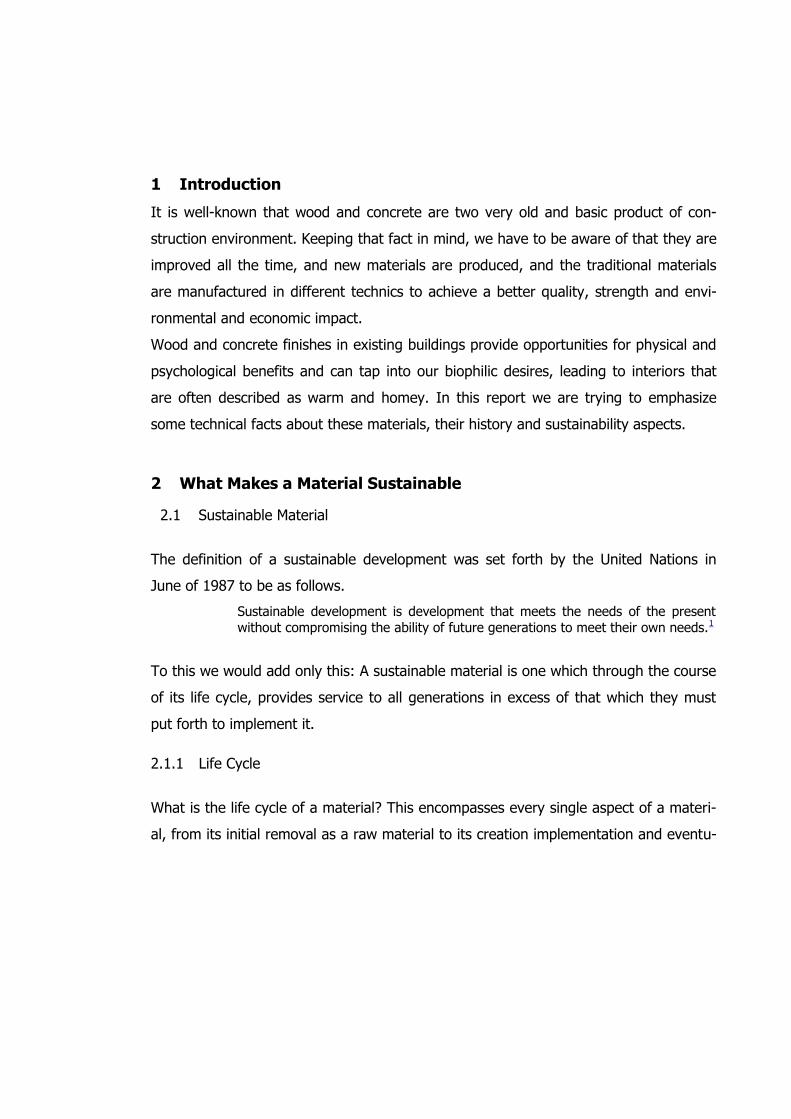
The definition of a sustainable development was set forth by the United Nations in
June of 1987 to be as follows.
Sustainable development is development that meets the needs of the present
without compromising the ability of future generations to meet their own needs.1
To this we would add only this: A sustainable material is one which through the course
of its life cycle, provides service to all generations in excess of that which they must
put forth to implement it.
2.1.1 Life Cycle
What is the life cycle of a material? This encompasses every single aspect of a materi-
al, from its initial removal as a raw material to its creation implementation and eventu-
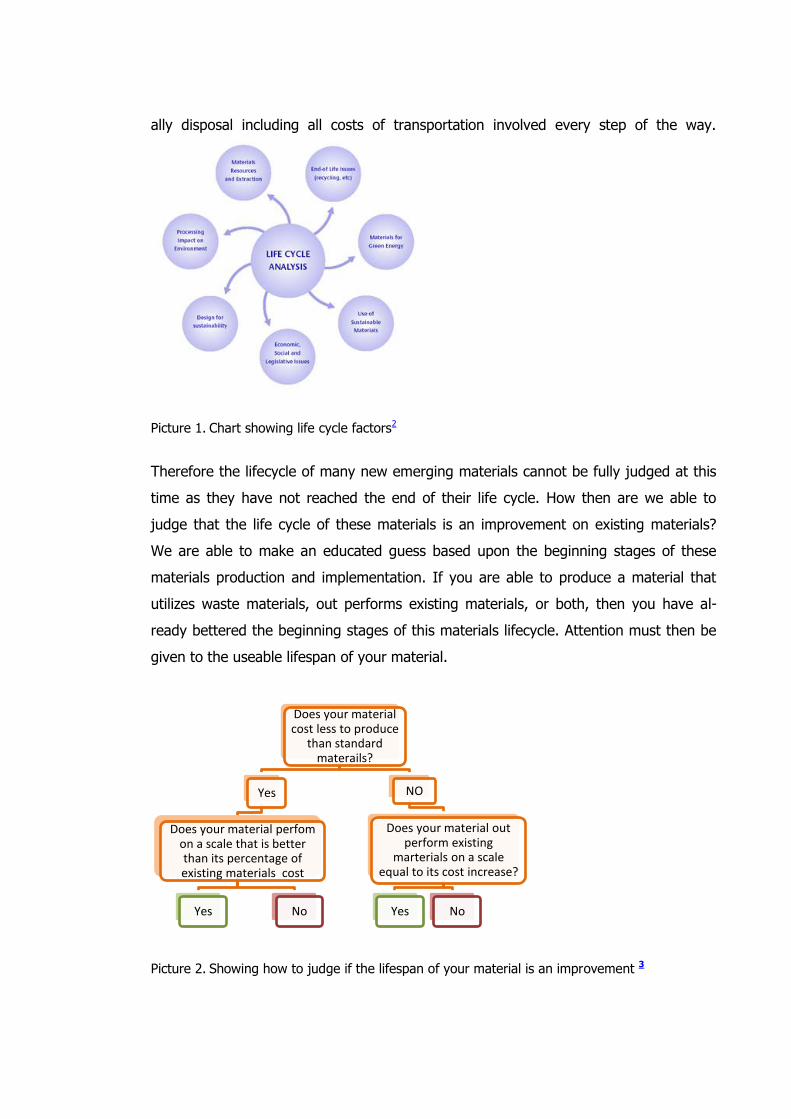
ally disposal including all costs of transportation involved every step of the way.
Picture 1. Chart showing life cycle factors2
Therefore the lifecycle of many new emerging materials cannot be fully judged at this
time as they have not reached the end of their life cycle. How then are we able to
judge that the life cycle of these materials is an improvement on existing materials?
We are able to make an educated guess based upon the beginning stages of these
materials production and implementation. If you are able to produce a material that
utilizes waste materials, out performs existing materials, or both, then you have al-
ready bettered the beginning stages of this materials lifecycle. Attention must then be
given to the useable lifespan of your material.
Picture 2. Showing how to judge if the lifespan of your material is an improvement 3
Does your material cost less to produce
than standard materails?
Yes
Does your material perfom on a scale that is better than its percentage of existing materials cost
Yes No
NO
Does your material out perform existing
marterials on a scale equal to its cost increase?
Yes No
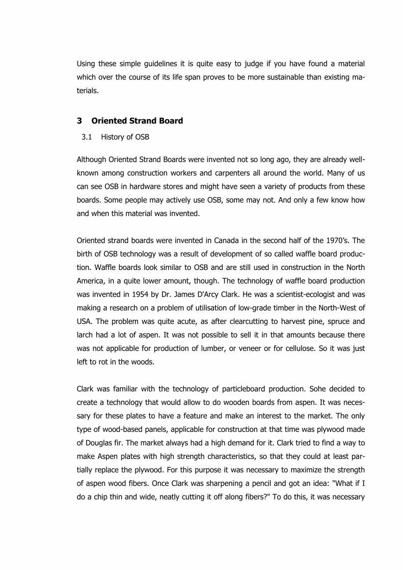
Using these simple guidelines it is quite easy to judge if you have found a material
which over the course of its life span proves to be more sustainable than existing ma-
terials.
3 Oriented Strand Board
3.1 History of OSB
Although Oriented Strand Boards were invented not so long ago, they are already well-
known among construction workers and carpenters all around the world. Many of us
can see OSB in hardware stores and might have seen a variety of products from these
boards. Some people may actively use OSB, some may not. And only a few know how
and when this material was invented.
Oriented strand boards were invented in Canada in the second half of the 1970’s. The
birth of OSB technology was a result of development of so called waffle board produc-
tion. Waffle boards look similar to OSB and are still used in construction in the North
America, in a quite lower amount, though. The technology of waffle board production
was invented in 1954 by Dr. James D'Arcy Clark. He was a scientist-ecologist and was
making a research on a problem of utilisation of low-grade timber in the North-West of
USA. The problem was quite acute, as after clearcutting to harvest pine, spruce and
larch had a lot of aspen. It was not possible to sell it in that amounts because there
was not applicable for production of lumber, or veneer or for cellulose. So it was just
left to rot in the woods.
Clark was familiar with the technology of particleboard production. Sohe decided to
create a technology that would allow to do wooden boards from aspen. It was neces-
sary for these plates to have a feature and make an interest to the market. The only
type of wood-based panels, applicable for construction at that time was plywood made
of Douglas fir. The market always had a high demand for it. Clark tried to find a way to
make Aspen plates with high strength characteristics, so that they could at least par-
tially replace the plywood. For this purpose it was necessary to maximize the strength
of aspen wood fibers. Once Clark was sharpening a pencil and got an idea: "What if I
do a chip thin and wide, neatly cutting it off along fibers?" To do this, it was necessary
to upgrade a chipping machine, which was used for CPD production. By that time no-
body had ever tried to produce a board from a thin chip only. So, he upgraded the
machine so that it produced chips 50mm wide, 70mm long and 0.7-0.8 thick.4
In the mid-50s of the 20th century first waffle boards were born. The test results ex-
ceeded all expectations. Waffle boards were much stronger than the CPD and could
really be used in construction.
Clark’s chief, inspired by the invention, soon built a small plant in Idaho, where he be-
gan producing the first waffle boards and selling them to local builders.
7 years later, in 1961, several businessmen from Saskatchewan (province in Canada),
who wanted to use cheap aspen, which is abundant in northern Canada, bought the
patent from James Clark. A little later, they organized a company "Vicewood Limited",
which began producing waffle boards in industrial quantities. Plant for the production
of waffle boards was built in Hudson Bay, in the northern forests of Canada. The gov-
ernment, wishing to strengthen the economy of low-income agricultural province, pro-
vided the company with an excessive amount of very good quality timber.
However, everything went not as it was planned. Plywood sellers, who felt a threat to
their business from cheaper waffle boards, refused to deal with them on the market,
so that "Vicewood Limited" soon went bankrupt and the company was sold in 1963 to
“Macmillan Bloedel Limited” – the biggest manufacturer of cellulose, lumber and ply-
wood in Canada. 4
The "Macmillan Bloedel Limited" had a well-developed marketing system across Cana-
da, as well as ability to conduct all necessary product tests for much-needed construc-
tion certificates. This made it possible for the company to start production of waffle
boards and successfully start the production. The plant in Saskatchewan, by the way,
was equipped with a huge hot press, that allowed to make a board size 1220 × 4880
mm. Press, dryer, chip mixers and a line of molding equipment were modernized from
the CPD production line. As a chipboard machine they used modernized chipper, which
was more accurate when cutting the chips from wood chocks of 600 mm lenght. Nev-
ertheless, waffle boards, coming on the market under the brand name "AspenitTM"
had good strength and performance, and they were cheaper than plywood. Soon "As-
penitTM" boards achieved considerable success and recognition in the market.
In the central Canada "Macmillan Bloedel" promoted "AspenitTM" as a building material
for roofing, cladding walls and flooring. Material was actively sold for the construction
of storage facilities for various purposes, livestock farms, garages, other buildings. In
addition, "AspenitTM" was used in the construction of protective fences, temporary
quick-construction, construction of grain storage in the production of packaging, and
billboards. The research group of "Macmillan Bloedel" developed a tongue and groove
joint boards for siding, concrete work and floor decking. The product quickly gained
recognition among architects, engineers, designers and builders. Many builders who
have begun to use waferboard in the 60 years of the twentieth century, still buy "As-
penitTM" today.
In the mid 1970’s the idea of board particles division in different layers, while produc-
tion of boards, was born. A chip in each of these layers oriented in mutually perpen-
dicular directions. In addition, to improve the strength characteristics of the board, it
was decided to change the geometry of the chip. They made it longer and narrower,
compared to that was manufactured before. So, gradually, was born the concept of
production of a new kind of board materials, that is known nowadays as Oriented
Strand Board.
The first plant, that began producing real Oriented Strand Boards, appeared in 1982,
although the production of oriented strand waffle boards had already began in the late
70's.4
In fact, Oriented Strand Boards are waffle boards of the second generation. The first
real OSB-board was made in Alberta (Canada) by “Edison OSB” plant, owned by the
company "Pelican Somilz Limited". The first product test had shown a result of im-
provements in technology of physical mechanical characteristics of the new material
caught up with the characteristics of softwood plywood. This allowed the “Edison OSB”
plant to place OSB in the market as a complete analogue of the plywood and the mate-
rial of a higher class than the waffle board.
3.2 Production process
The new material was called oriented strand board, because it had a difference from all
known wood-based panels: the size of the chip and its orientation in the structure of
the board. The chip was long and narrow compared to the chip waffle boards: the
average size of the chip was 25 × 150 mm. Each board consisted of three layers. All
the chips in a layer were placed parallel to each other and perpendicular to the chip in
the neighboring layers. Thanks to the orientation of the chip in each of the layers, the
OSB acquired unique properties that soon opened it a range of new applications.4
The process of production nowadays has some aspects that need to be mentioned:
orienting head of a forming machine for the outer layer of chips looks very similar to
the farmer harrows. It consists of a series of circular discs, which direct the falling
chips, aligning them parallel to the direction of travel of the chip mat on the conveyor.
Orienting head of the inner chip layer is composed of clips in the form of stars with flat
blades. Spinning, they align parallel to the width of the chip mat and perpendicular to
the direction of the conveyor. Size of the components of orienting head and the dis-
tance between them is adjusted to the size of chips. Adjustment is performed so that
the chips fall through the revolving wheels or rollers before they make it out of the
orienting head.
Layers of oriented strand board are laid down on a moving conveyor sequentially, one
after the other. The orientation of the chips in alternate layers as follows: longitudinal,
transverse and longitudinal. Each layer is formed by orienting a separate head and
spread out forming a separate machine. The accuracy of the orientation of the chips in
the process of forming the carpet is a very important issue. This is very significant for a
chip of the outer layers. The accuracy of chip orientation in layers directly affects the
strength characteristics of the finished product.
A lot of problems for engineers are caused by the task of qualitative resinification of
chips before molding. In the manufacture of OSB the same resin is used, that is used
in the manufacture of waterproof plywood. But how accurately can you mix the thin-
nest chips with minimal damage? Thanks to the creative approach the issue was soon
resolved. In modern mixer chips with the adhesive resin are sprayed with a rotating
disk. The design of the was borrowed from painting cars. This simple at first glance
decision was a breakthrough in resinification process, and allowed not only to reduce
damage to the chips, but also significantly reduce the flow of resin.
The advent of the first Canadian OSB production caused widespread interest around
the world. The research bagan in Japan and even in China.
3.3 Materials and characteristics
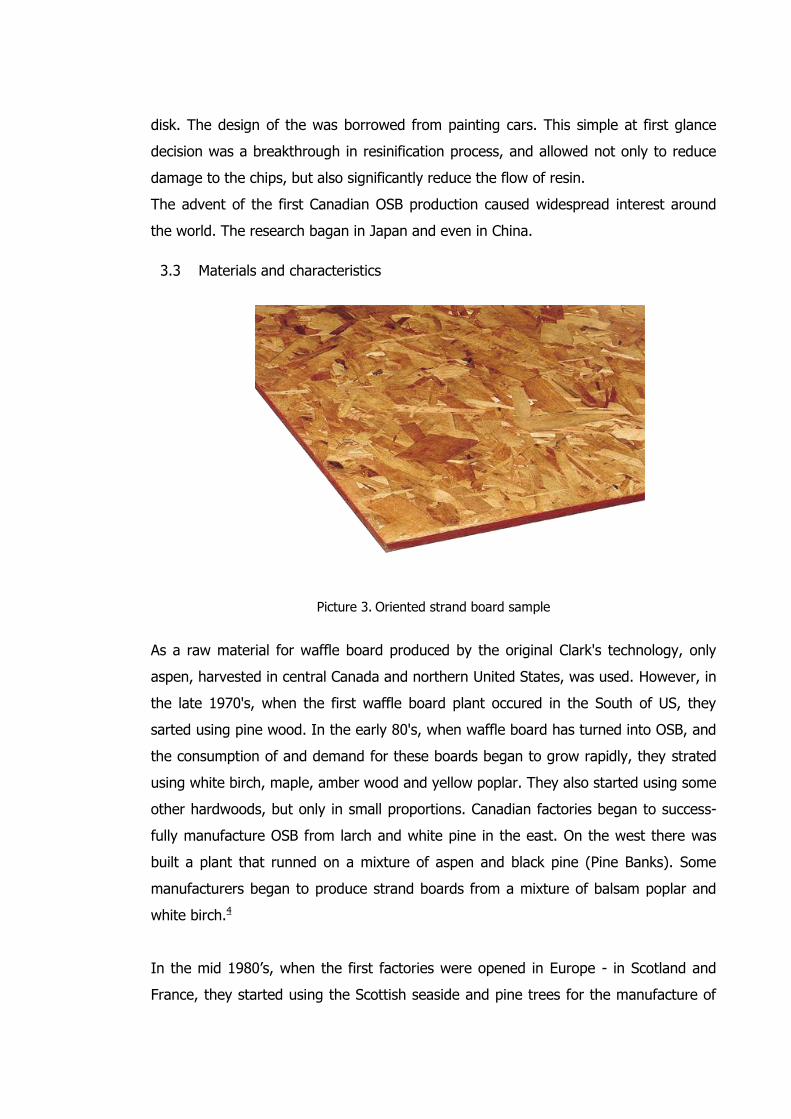
Picture 3. Oriented strand board sample
As a raw material for waffle board produced by the original Clark's technology, only
aspen, harvested in central Canada and northern United States, was used. However, in
the late 1970's, when the first waffle board plant occured in the South of US, they
sarted using pine wood. In the early 80's, when waffle board has turned into OSB, and
the consumption of and demand for these boards began to grow rapidly, they strated
using white birch, maple, amber wood and yellow poplar. They also started using some
other hardwoods, but only in small proportions. Canadian factories began to success-
fully manufacture OSB from larch and white pine in the east. On the west there was
built a plant that runned on a mixture of aspen and black pine (Pine Banks). Some
manufacturers began to produce strand boards from a mixture of balsam poplar and
white birch.4
In the mid 1980’s, when the first factories were opened in Europe - in Scotland and
France, they started using the Scottish seaside and pine trees for the manufacture of
OSB. One of the last OSB plants, built in Chile, uses pine Radiata. OSB plants in Asia
and Australia are working on the raw materials from the rubber tree and eucalyptus.
3.3.1 OSB classification
There are four kinds of oriented strand boards depending from bending strength and
moisture resistance:5
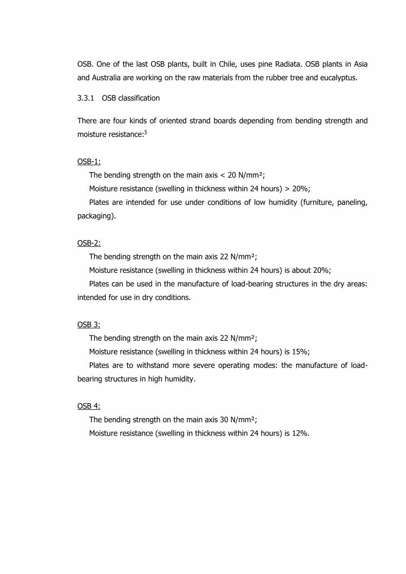
OSB-1:
The bending strength on the main axis < 20 N/mm²;
Moisture resistance (swelling in thickness within 24 hours) > 20%;
Plates are intended for use under conditions of low humidity (furniture, paneling,
packaging).
OSB-2:
The bending strength on the main axis 22 N/mm²;
Moisture resistance (swelling in thickness within 24 hours) is about 20%;
Plates can be used in the manufacture of load-bearing structures in the dry areas:
intended for use in dry conditions.
OSB 3:
The bending strength on the main axis 22 N/mm²;
Moisture resistance (swelling in thickness within 24 hours) is 15%;
Plates are to withstand more severe operating modes: the manufacture of load-
bearing structures in high humidity.
OSB 4:
The bending strength on the main axis 30 N/mm²;
Moisture resistance (swelling in thickness within 24 hours) is 12%.
3.3.2 Measurements6
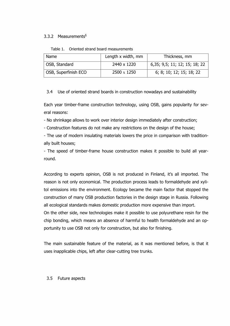
Table 1. Oriented strand board measurements
Name Length x width, mm Thickness, mm
OSB, Standard 2440 x 1220 6,35; 9,5; 11; 12; 15; 18; 22
OSB, Superfinish ECO 2500 х 1250 6; 8; 10; 12; 15; 18; 22
3.4 Use of oriented strand boards in construction nowadays and sustainability
Each year timber-frame construction technology, using OSB, gains popularity for sev-
eral reasons:
- No shrinkage allows to work over interior design immediately after construction;
- Construction features do not make any restrictions on the design of the house;
- The use of modern insulating materials lowers the price in comparison with tradition-
ally built houses;
- The speed of timber-frame house construction makes it possible to build all year-
round.
According to experts opinion, OSB is not produced in Finland, it’s all imported. The
reason is not only economical. The production process leads to formaldehyde and xyli-
tol emissions into the environment. Ecology became the main factor that stopped the
construction of many OSB production factories in the design stage in Russia. Following
all ecological standards makes domestic production more expensive than import.
On the other side, new technologies make it possible to use polyurethane resin for the
chip bonding, which means an absence of harmful to health formaldehyde and an op-
portunity to use OSB not only for construction, but also for finishing.
The main sustainable feature of the material, as it was mentioned before, is that it
uses inapplicable chips, left after clear-cutting tree trunks.
3.5 Future aspects
Experts predict a great future for OSB. In New Zealand there is a research institute for
development of new wood composites. Oriented strand composites are assigned to be
one of the most promising areas. Currently being developed, in the nearest future
there will be an increase in use of OSB for the furniture industry, the door industry,
particularly stressed building structures, etc. So-called on-line quality control systems
are developed. They will allow to test all the volume of production in real time. And
finally, in matters of production and resinification chips, the accuracy of its orientation
when forming a mat, and pressing the mat there is still enough room for the research
work.
Very soon new oriented strand materials will be able to compete with all known struc-
tural and non-structural board wooden materials.4
4 Plywood Materials
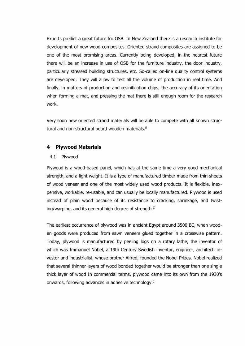
4.1 Plywood Plywood is a wood-based panel, which has at the same time a very good mechanical
strength, and a light weight. It is a type of manufactured timber made from thin sheets
of wood veneer and one of the most widely used wood products. It is flexible, inex-
pensive, workable, re-usable, and can usually be locally manufactured. Plywood is used
instead of plain wood because of its resistance to cracking, shrinkage, and twist-
ing/warping, and its general high degree of strength.7
The earliest occurrence of plywood was in ancient Egypt around 3500 BC, when wood-
en goods were produced from sawn veneers glued together in a crosswise pattern.
Today, plywood is manufactured by peeling logs on a rotary lathe, the inventor of
which was Immanuel Nobel, a 19th Century Swedish inventor, engineer, architect, in-
vestor and industrialist, whose brother Alfred, founded the Nobel Prizes. Nobel realized
that several thinner layers of wood bonded together would be stronger than one single
thick layer of wood In commercial terms, plywood came into its own from the 1930’s
onwards, following advances in adhesive technology.8
Picture 4. The look of layers in Plywood (by Deniz Löktas 2012)
4.2 Advantages of Plywood • Saving of wood: waste is confined to the small core and bark that remain after peel-
ing away the strips.
• Strength: Generally speaking, wood is more strong (about 24-25 times stronger)
along the grains than across the grain. In plywood, the alternate layers are at 90° to
each other. This ensures that the weight per weight, plywood is stronger than wood.
• Reduced shrinkage, swelling and warping: The balanced construction of plywood
(with the grain direction of adjacent plies at 90° to each other) equalizes cross layer
stress. This in turn reduces shrinkage, swelling and warping.
• Compared to solid wood, the chief advantages of plywood are that the properties
along the length of the panel are more nearly equal to properties along the width.
• Plywood offers greater resistance to splitting.
• Plywood can be molded into different shapes and sizes.
• Improved utilization of wood - plywood can cover large areas with a minimum
amount of wood fiber.
• Plywood has high strength-to--weight and strength-to-thickness ratios.
• The stiffness and strength of plywood is more equal in length and width than that of
solid wood.
• Plywood makes an excellent choice for users that call for fasteners to be placed very
near the edges of a panel because of its alternating grain direction that significantly
reduces splitting.
• Plywood comes in convenient sizes.9
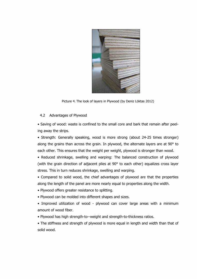
Picture 5. There could be any material added between the layers or the Plywood could be coat-
ed with any other preserving material. (by Deniz Löktas 2012)
4.3 Cross Laminated Timber If we are talking about Plywood, we have to talk about Cross Laminated Timber, so
called X-Lam, too. The idea they are produced are the same, layers of wood panels
glued on and on each other.
X-Lam is made by gluing wooden boards in a 90 degrees crossed way (like a plywood
panel but with plies thick as much as 2 cm). It has been invented 12 years ago in
Germany and soon developed in Austria. Compensating the physical-mechanical behav-
ior of wood on two cross dimensions, it is possible to obtain wooden panels almost
indestructible, with an excellent and suitable mechanical behavior. Simply genial.10
In fact, X-Lam panels are extremely strong and stiff, considering their low density; they
are also quite easy to process and to assembly with ordinary tools; the quick erection
of solid and durable structures – even in seismic areas – is possible even fir non-highly-
skilled manpower. The good thermal insulation and a fairly good behavior in case of
fire are added benefits deriving from the massive wood structure.10
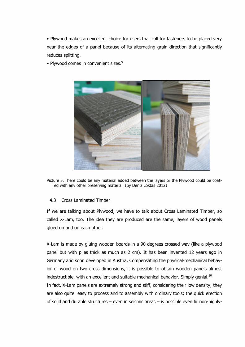
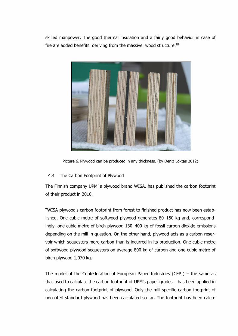
Picture 6. Plywood can be produced in any thickness. (by Deniz Löktas 2012)
4.4 The Carbon Footprint of Plywood The Finnish company UPM´s plywood brand WISA, has published the carbon footprint
of their product in 2010.
“WISA plywood's carbon footprint from forest to finished product has now been estab-
lished. One cubic metre of softwood plywood generates 80−150 kg and, correspond-
ingly, one cubic metre of birch plywood 130−400 kg of fossil carbon dioxide emissions
depending on the mill in question. On the other hand, plywood acts as a carbon reser-
voir which sequesters more carbon than is incurred in its production. One cubic metre
of softwood plywood sequesters on average 800 kg of carbon and one cubic metre of
birch plywood 1,070 kg.
The model of the Confederation of European Paper Industries (CEPI) − the same as
that used to calculate the carbon footprint of UPM's paper grades − has been applied in
calculating the carbon footprint of plywood. Only the mill-specific carbon footprint of
uncoated standard plywood has been calculated so far. The footprint has been calcu-
lated from forest to mill gate, and therefore emissions arising from transportation to
customers are not included.
The carbon profile of plywood has been calculated according to the amount of carbon
sequestered in the product itself. Fossil CO2 emissions arising from plywood production
and from the manufacture and transportation of raw materials, and from raw materials
other than wood-based ones, for example, adhesives are included. The energy con-
sumed in production is included as well.
The carbon footprint of plywood arises mainly from fossil CO2 emissions from energy
used in the manufacturing process. Another significant addition is caused by emissions
other than those from wood-based raw material production.11
4.5 The Sustainability of Forests The most important raw material for plywood is a renewable natural resource - wood.12
So, the sustainability of the world forests must be taken care very seriously. Green-
peace Organisation has a very serious report on illegal plywood and forest destruction
products sold in UK. There could be found:
“Demand for tropical hardwood plywood in the UK and internationally is one of the
main causes of illegal and destructive logging in the rainforests of countries such as
Brazil and Indonesia. This deforestation is causing the loss of biodiversity, displacing
local communities and contributing to climate change.
There are no laws yet in place to prevent illegal timber from entering Europe. As a re-
sult, large quantities of illegally logged timber still make their way into the UK. The
construction industry is the biggest consumer of timber in the country which is why it
is vital for contractors, architects and builders to source timber from environmentally
and socially responsible sources such as those certified by the Forest Stewardship
Council (FSC).13
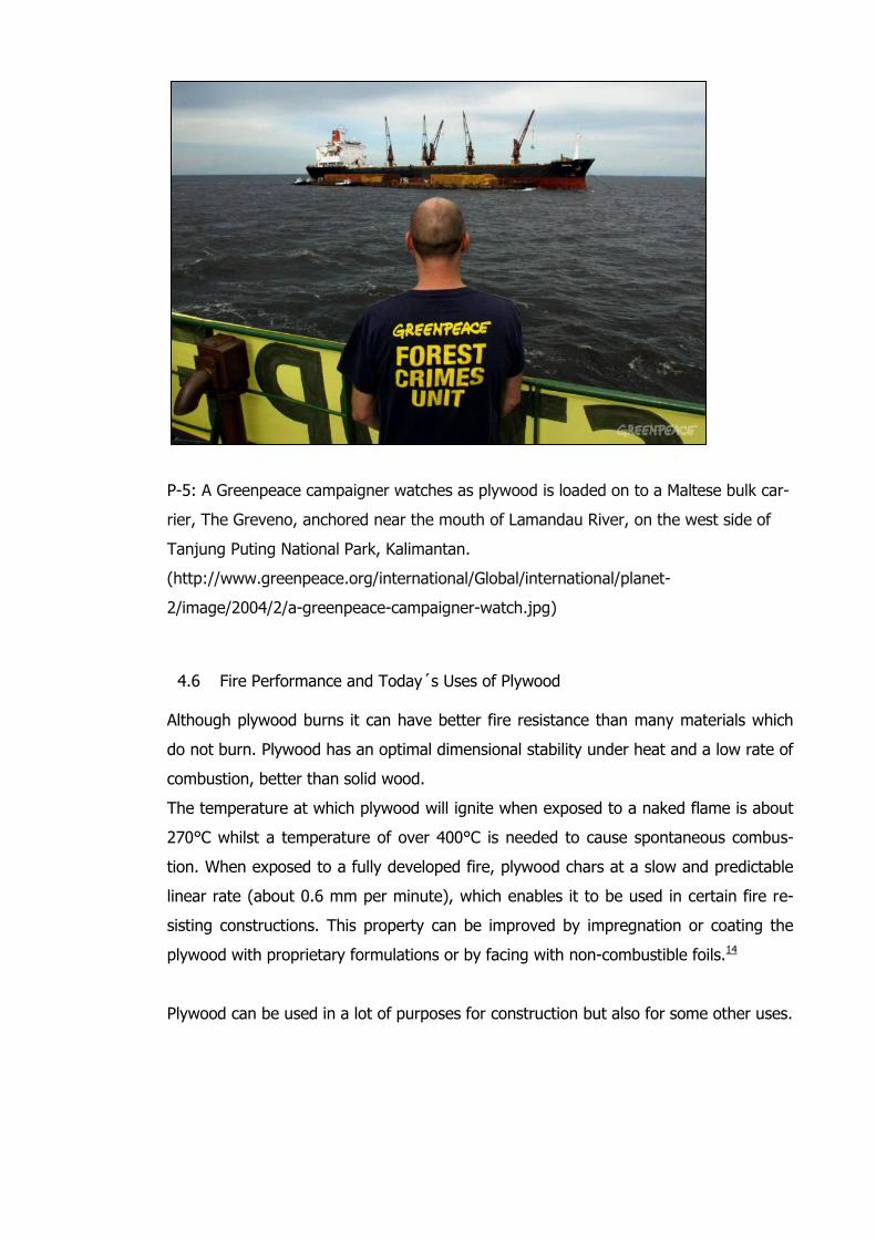
P-5: A Greenpeace campaigner watches as plywood is loaded on to a Maltese bulk car-
rier, The Greveno, anchored near the mouth of Lamandau River, on the west side of
Tanjung Puting National Park, Kalimantan.
(http://www.greenpeace.org/international/Global/international/planet-
2/image/2004/2/a-greenpeace-campaigner-watch.jpg)
4.6 Fire Performance and Today´s Uses of Plywood Although plywood burns it can have better fire resistance than many materials which
do not burn. Plywood has an optimal dimensional stability under heat and a low rate of
combustion, better than solid wood.
The temperature at which plywood will ignite when exposed to a naked flame is about
270°C whilst a temperature of over 400°C is needed to cause spontaneous combus-
tion. When exposed to a fully developed fire, plywood chars at a slow and predictable
linear rate (about 0.6 mm per minute), which enables it to be used in certain fire re-
sisting constructions. This property can be improved by impregnation or coating the
plywood with proprietary formulations or by facing with non-combustible foils.14
Plywood can be used in a lot of purposes for construction but also for some other uses.
Examples of end uses:
• kitchen cabinets, door mirrors
• partition walls, sight screens
• furniture parts
• sound insulation latticework
• toys, souvenirs, cards
• models
• musical instruments
• interiors
• saddles
• icehockey sticks15
In some structures, plywood is used for sound insulation. Sound is transmitted through
air and through structures. Airborne sound insulation is dependent on the density of
the insulating material. Plywood is a good insulating material in relation to its weight.
For these reasons plywood is a good material for acoustic improvement solutions.16
4.7 Emission of formaldehyde
Formaldehyde emission from phenol formaldehyde resin adhesive bonded plywood is
very low and measured values are below even the tightest national requirements in
Finland. When determined according to EN 717-2, the formaldehyde emission from
unsurfaced exterior birch plywood is 0.4 mg HCHO/(m2·h), significantly lower than the
requirements of class E1 (the best class). Also Finnish plywood meets requirements of
the formaldehyde emis- sion limits of EN 1084, release class A (the best class).
4.8 The Most Innovative Ways of Using Plywood Today, out of the typical uses like walls and floors, plywood is mostly used for making
noise barriers nearby the highways, with special claddings against moisture. But there
is a very interesting experiment conducted by Professor Ario Ceccotti, Civil Engineer,
Prof. of Structural Engineering, from University of Venice. He designed an X-Lam 7
storey building for seismic safety and tested it in Japan in 2007.
Test results have confirmed that X-Lam building is a self-centering construction system
that can be safely and easily designed against earthquakes to avoid not only loss of
lives but also loss of property, according to the rules anticipated by CNR-IVALSA (Na-
tional Research Council of Italy).17
Some similar researches are made in USA by National Science Foundation, under the name of NEESWood.
4.9 Conclusions Plywood is definitely a good material when it is produced with good requirement ele-
ments up to where it will be used. It has advantages and disadvantages compared to
concrete but for low-storey construction and some special parts of the building, it is a
very good material. But the construction sector is in the beginning of everything, the
wood has been started to be considered as a strong contrition material for the last
decades in today´s modern construction sector, except the low-storey family housing.
The most important point in this concept is to show people how wood is a good mate-
rial and it has a long life period. This technology will continue to improve as it has been
and will be a very popular material in future.
4.10 Interviews
JOUNI KALLIOMÄKI: Head of Structural Engineering, MSc Metropolia University of Ap-
plied Sciences, Degree Programme in Civil Engineering
ERIC POLLOCK: Lecturer and Coordinator, Sustainable Building Engineering, Lecturer
Metropolia University of Applied Sciences
LARS OSTENFELD RIEMANN: Group Market Director, Buildings at Ramboll
*How can you use plywood to make more sustainable buildings?
JOUNI KALLIOMÄKI: Plywood is not the best for structure. For manufacturing, it needs
more heat and that requires more energy.
ERIC POLLOCK: More than plywood, first I have to say that wood is used because the
production requires less energy and wood is a carbon sink. Less energy to erect, to
use and it is nontoxic except if it is not glued. There are some problems, as 2 mains,
Moisture and fire. Moisture is solved with using a covering material. Fire is solved with
gypsum board cover.
LARS OSTENFELD RIEMANN: Plywood should be used everywhere in a building where
it suits the purpose better than other materials. This could be as structural components
where plywood is feasible as shear plates, facades structures, roof structures and in-
ternal walls.
*If you compare plywood to concrete?
JK: Easier to apply, cut, manufacture. Concrete is a very heavy material.
EP: A benefit of concrete is fireproof. Also it is possible to use the viscosity to give
shapes. The quality of it is high. Acoustic and light is good. ABOUT wood, the com-
pression is good. Also it is light in weight. But tension is not good. In the direction of
grain, it is very weak. Wood has a direction, concrete not.
LOR: Concrete structures have advantages to timber in terms of fire resistance, acous-
tic damping and strength. However timber structures can be designed to fulfill all such
requirements so at the end of the day it is a question of choosing the option that has
the lowest costs taking into account a number of other factors such as architecture,
weather conditions, environment, deflection limits, skills of the contractors etc.
*What about the CO2 footprints?
EP: For wood, it is much much less. Concrete requires 1600 degrees used producing
cement. Wood is a perfect carbon sink.
LOR: Unless you choose to emit a lot of CO2 in fabrication, transportation and installa-
tion the Carbon Footprint of Plywood would normally be positive as you help removing
CO2 from the atmosphere by using and thereby storing plywood in building structures.
*What about their lifecycle?
JK: Under the maintenance, it might be even 1oo years too.
EP: WE do not know so well. IT is up to the maintenance program. In Finland, it is
guaranteed by law that you should present your maintenance program when you have
a building project.
*What kind of maintenance does it need?
JK: The most important thing is to keep them dry. It also should be used in the right
places. It is also a very good material for wind barriers.
EP: The maintenance starts already in the beginning. Changes in moisture, deflection,
rusting in the steel, all the structural maintenance are needed concerning these. Wood
structures are good to renew several times easily. In future we will have more
knowledge because the wood buildings are made now and in use.
LOR: Depending on very you use it. Any maintenance is dictated by the environment
especially the water and humidity. Outside usage limits any maintenance lifetime to
very few years, which is not the most feasible way to use plywood. For such environ-
ment other materials should be considered. For inside usage plywood requires almost
no maintenance and has unlimited lifetime.
*In the final of the lifelong period, what is done with plywood? Is it burnt or recycled
into some other material?
JK: It is reusable material and sometimes even more stronger than the newer material.
EP: After the demolition, the beams could be used low storey contruction or pedestrian
bridges. They should be used again because if it is burnt, the carbon will be released.
Availablity of the source is important also.
LOR: Burnt in an incineration plant (Waste-to-Energy).
*What can you say about the most innovative ways of using plywood?
JK: First of all the most traditional ways are floors and walls, furnitures, building truck
backs, boats if waterproof etc. The most innovative I saw is an earthquake research
made by an Italian professor Ario Ceccotti, they made a 7 storey wood building and
tested in Japan.
EP: Outer facades using is very new for wood materials.
5 CO2 Absorbing Concrete
5.1 Introduction
Concrete is the most widely used building material in the world because of its beauty,
strength and durability, among other benefits. Concrete is used in nearly every type of
construction, including homes, buildings, roads, bridges, airports and subways, just to
name a few. And in an era of increased attention on the environmental impact of con-
struction, concrete performs well when compared to other building materials. As with
any building product, production of concrete and its ingredients does require energy
that in turn results in the generation of carbon dioxide, or CO2. The amount of CO2
produced during manufacturing and the net impact of using concrete as a building ma-
terial is relatively small. The following features of concrete construction help minimize
its carbon footprint:
• Concrete is resource efficient and the ingredients require little processing.
• Most materials for concrete are acquired and manufactured locally which minimizes
transportation energy.
• Concrete building systems combine insulation with high thermal mass and low air
infiltration to make homes and buildings more energy efficient.
• Concrete has a long service life for buildings and transportation infrastructure, there-
by increasing the period between reconstruction, repair and maintenance and the as-
sociated environmental impact.
• Concrete, when used as pavement or exterior cladding, helps minimize the urban
heat island effect thus reducing the energy required to heat and cool our homes and
buildings.
• Concrete incorporates recycled industrial byproducts such as fly ash, slag and silica
fume which helps reduce embodied energy, carbon footprint and quantity of land filled
materials.
• Concrete absorbs CO2 throughout its lifetime through a process called carbonation,
helping reduce its carbon footprint.
5.2 Concrete manufacturing
Cement is made by heating limestone and other raw materials to 1400 – 1450 oC in a
rotary kiln. Fossil fuels such as coal and oil have usually been used to provide heat for
the burning process. In the process, limestone (CaCO3) first breaks down to calcium
oxide (CaO) and carbon dioxide (CO2). CaO then further reacts to form the “portland
clinker.” The clinker is ground with a small amount of gypsum into a product (i.e., ce-
ment). Some types of cement also include other constituents in addition to clinker and
gypsum, such as limestone filler, ground granulated blast furnace slag, fly ash, or other
mineral by- products from industrial processes. The most important environmental ef-
fects of cement production are the use of energy (fossil fuel and electricity), emission
of carbon dioxide, and the use of natural raw materials (mainly limestone). The manu-
facture of cement requires about 4 GJ of energy per ton of finished produce and the
about 1 ton of CO2 emissions per ton of cement. The worldwide production of cement
accounts for almost 7 percent of the total world CO2 emissions18. Since the early 90’s,
the cement industry has made major strides in reducing energy consumption by some
20%19. This has been achieved primarily by placing wet production facilities with mod-
ern dry-processing plants. Modernization of cement plants and machinery has de-
creased the electricity consumption during milling of cement, with consequent reduc-
tion of CO2 emission from power plants. Using certain wastes as alternative fuels in
the cement kiln eliminate wastes that would otherwise be incinerated or land filled.
Waste materials that the cement industry has used as alternative fuels include petrole-
um coke, used tires, rubber, paper waste, waste oils, sewage sludge, plastics, and
spent solvent. Apart from recovering the thermal energy of the waste, this leads to
significant reductions in the emissions of CO2. As an example, up to 20% of the total
thermal energy requirement at a New Zealand’s cement factory has been routinely
replaced by the used oil, making possible a very significant reduction in the consump-
tion of non-renewable coal20. Supplementary cementing material (SCM) including waste
products from other industries, such as fly ash and ground granulated blast furnace
slag, can be ground with clinker to produce blended cement. Increasing the use of
SCM, and thus reducing the cement content, represents a technically-proven approach
to reducing greenhouse gas and air pollutant emission. Limestone filler is being in-
creasingly used in Europe in the clinkering and grinding phases of Portland cement
production21. These materials also have the added advantages of reducing energy con-
sumption, using materials otherwise destined for landfill, and increasing plant capacity
without installing new kilns, and improved concrete performance.
5.3 Use of supplementary cementing materials
Supplementary cementing material (SCM), such as fly ash, ground-granulated blast-
furnace (GGBF) slag, or silica fume, is one of the most sustainable construction materi-
als because it
• Recovers an industrial byproduct through beneficial use when incorporated into con-
crete,
• Avoids disposal of industrial byproducts,
• Reduces Portland cement content in concrete, resulting in decreased emission of
greenhouse gas and decreased use of natural raw materials, and
• Increases structure service life by improving the durability of concrete.
The current annual production of fly ash is on the order of 900 million tons worldwide,
with major production occurring in China, India, and the U. S.21. The use rate and the
way fly ash is batched in concrete vary from country to country. One of the major de-
velopments in the area of fly ash utilization in concrete has been the technology of
high performance, high-volume fly ash concrete22,23. Studies have shown that, when
the water-cementitious materials ratio (w/cm) is maintained at 0.30 or less in the su-
perplasticized concrete mixtures, up to 60 percent of portland cement can be replaced
by ASTM Class F or Class C fly ash to obtain excellent long-term mechanical and dura-
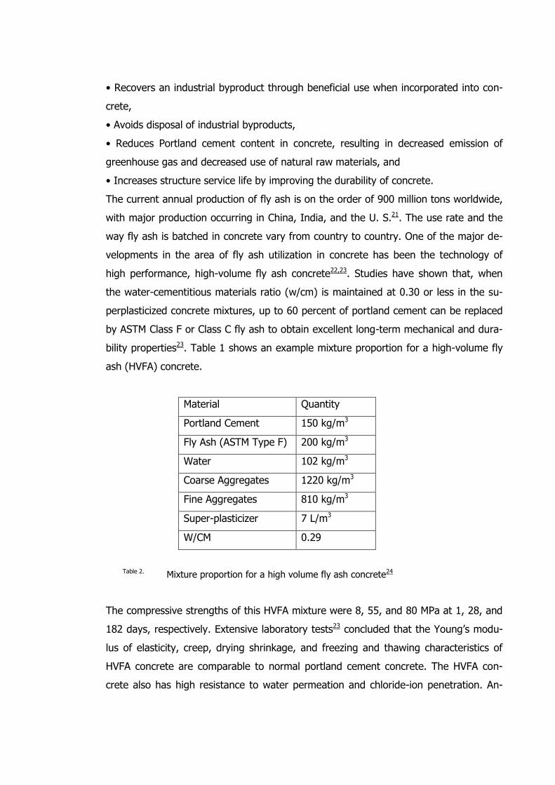
bility properties23. Table 1 shows an example mixture proportion for a high-volume fly
ash (HVFA) concrete.
Material Quantity
Portland Cement 150 kg/m3
Fly Ash (ASTM Type F) 200 kg/m3
Water 102 kg/m3
Coarse Aggregates 1220 kg/m3
Fine Aggregates 810 kg/m3
Super-plasticizer 7 L/m3
W/CM 0.29
Table 2. Mixture proportion for a high volume fly ash concrete24
The compressive strengths of this HVFA mixture were 8, 55, and 80 MPa at 1, 28, and
182 days, respectively. Extensive laboratory tests23 concluded that the Young’s modu-
lus of elasticity, creep, drying shrinkage, and freezing and thawing characteristics of
HVFA concrete are comparable to normal portland cement concrete. The HVFA con-
crete also has high resistance to water permeation and chloride-ion penetration. An-
other by-product that is useful for cement substitution is ground-granulated blast-
furnace (GGBF) slag. Although the world production of this slag is approximately 100
million tons per year, only approximately 25 million tons of slag are processed into the
granulated form that has the cementitious properties25. Because GGBF slag is derived
as a by-product from the blast-furnaces manufacturing iron, its use has environmental
benefits. The use of GGBF slag in concrete significantly reduces the risk of damages
caused by alkali-silica reaction, provides higher resistance to chloride ingress, reduces
the risk of reinforcement corrosion, and provides high resistance to attacks by sulfate
and other chemicals. The use of GGBF slag in concrete has increased in recent years
and this trend is expected to continue. Laboratory work by Lang and Geiseler26 on a
German blast furnace slag cement (405 m2/kg specific surface area) containing 77.8
percent slag showed that excellent mechanical and durability characteristics were
achieved in super-plasticized concrete mixtures with 455 kg/m3 cement content and
0.28 w/cm. The compressive strengths at ages 1, 2, 7, and 28 days were 13, 37, 58,
and 91 MPa, respectively. The concrete also showed good resistance to carbonation,
penetration of organic liquids, freezing and thawing cycles (without air entrainment),
and salt scaling. Approximately 5 million tons of GGBF slag were used in concrete mix-
tures annually in Taiwan. Up to 55% of the portland cement (ASTM Type V) had been
replaced by GGBF slag in concrete mixtures where high sulfate resistance is required.
In the moderate sulfate resistance applications, 45% of portland cement (ASTM Type
II) can be replaced by GGBF slag with excellent performance. Concrete containing 45-
50% of GGBF slag was commonly used for concrete slurry wall constructions in Tai-
wan. Silica fume is a by-product resulting from the reduction of high-purity quartz with
coal or coke and wood chips in an electric arc furnace during the production of silicon
metal or ferrosilicon alloys. The condensed silica fume contains between 85 and 98
percent silicon dioxide and consists of extremely fine spherical glassy particles (the
average particle size is less than 0.1μm). Because of its extreme fineness and high
silicon dioxide content, condensed silica fume is a very efficient pozzolanic material.
The worldwide production of silica fume is estimated to be about 2 million tons21. Be-
cause of limited availability and the current high price relative to portland cement and
other pozzolans or slag, silica fume is being used primarily as a property enhancing
material27. In this role, silica fume has been used to provide concrete with very high
compressive strength or with very high level of durability or both. It has been used to
produce concretes with reduced permeability for applications such as parking struc-
tures and bridge decks and for repair of abrasion damaged hydraulic structures. One of
the major barriers against the use of large quantities of fly ash and other supplemen-
tary cementing materials in concrete is the current prescriptive-type of specifications
and codes. The prescriptive-type of specifications generally place limits on the maxi-
mum percentage of the cement that can be replaced by the supplementary cementing
materials. For example, in U.S. ACI 318 Building Code limits the maximum percentage
of fly ash or other pozzolans to not exceed 25% of the total cementitious materials by
mass for concrete exposed to deicing chemicals. High performance concrete mixtures
being produced with HVFA concrete prove that prescriptive specifications hinder the
widespread use of fly ash and other supplementary cementing materials. Replacing the
prescriptive-type of specifications and codes with performance-based specifications and
codes will accelerate the rate of utilization of fly ash and other supplementary cement-
ing materials and can provide economic and environmental benefits.
5.4 Utilization of concrete wastes
It is estimated that 1 billion tons of construction and demolition (C&D) waste are gen-
erated annually worldwide. Whether C&D waste originates from clearing operations
after natural disasters (e.g., major earthquakes) or from human-controlled activities,
the utilization of such waste by recycling can provide economic and environmental
benefits. In recent years, utilizing C&D waste for new construction through recycling
and reuse has received increased attention throughout the world, especially in the Eu-
ropean countries, Japan, U. S., and Taiwan. Practical and economic experiences from
Japan and Denmark suggest that road base and sub-base materials are expected to be
the most important area of use of C&D waste. When used for such purposes, C&D
waste (primarily of broken concrete, bricks, and stone) can substitute for up to 20% of
the consumption of natural sand, gravel, and crushed stone, thereby saving natural
resources28. At present, more than 95% of C&D waste is being recycled and used
mainly as road base material in Japan29. Recycled concrete has also been used as par-
tial replacement of coarse aggregate for the concrete structures and concrete pave-
ments. For example, 35% of the coarse aggregate was replaced with recycled concrete
aggregate for the cast in-place concrete for all foundations and 50% of the basement
walls and columns in a new high school outside Oslo19. Extensive testing of hardened
concrete properties indicated that they were comparable to all natural aggregate con-
crete. The use of recycled concrete aggregate did not cause any noticeable increase in
cracking and other durability problems19. Since the 1990s, other by-products have been
successfully used in concrete. These materials include used foundry sand and cupola
slag from metal-casting industries, post-consumer glass, wood ash from pulp mills,
sawmills, and wood-product manufacturing industries, sludge from primary clarifiers at
pulp and paper mills, and de-inking solids from paper-recycling companies30,31. Alt-
hough recycled concrete aggregate has been successfully used as road base and fill
material and as aggregate in new concrete, a significant amount of C&D waste is still
disposed of in landfills. However, the future outlook for recycling concrete is favorable
because the local natural aggregate sources and the suitable landfill sites for industrial
waste are becoming scarce. Furthermore, improvements in demolition, processing, and
handling technologies will improve the quality and decrease the cost of recycled con-
crete aggregates.
6 Reactive Powder Concrete
6.1 What is Reactive Powder Concrete?
Reactive Powder Concrete (RPC), also known as Ultra High Performance Concrete is
one of a number of cement based building materials that have emerged in the last two
decades. Its creation is credited to the French Bouygues laboratory in the early 1990’s
and has since been used in an increasing number of applications around the globe.
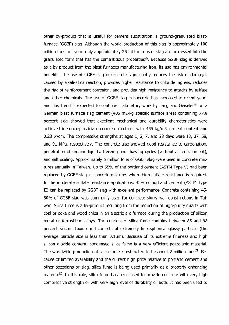
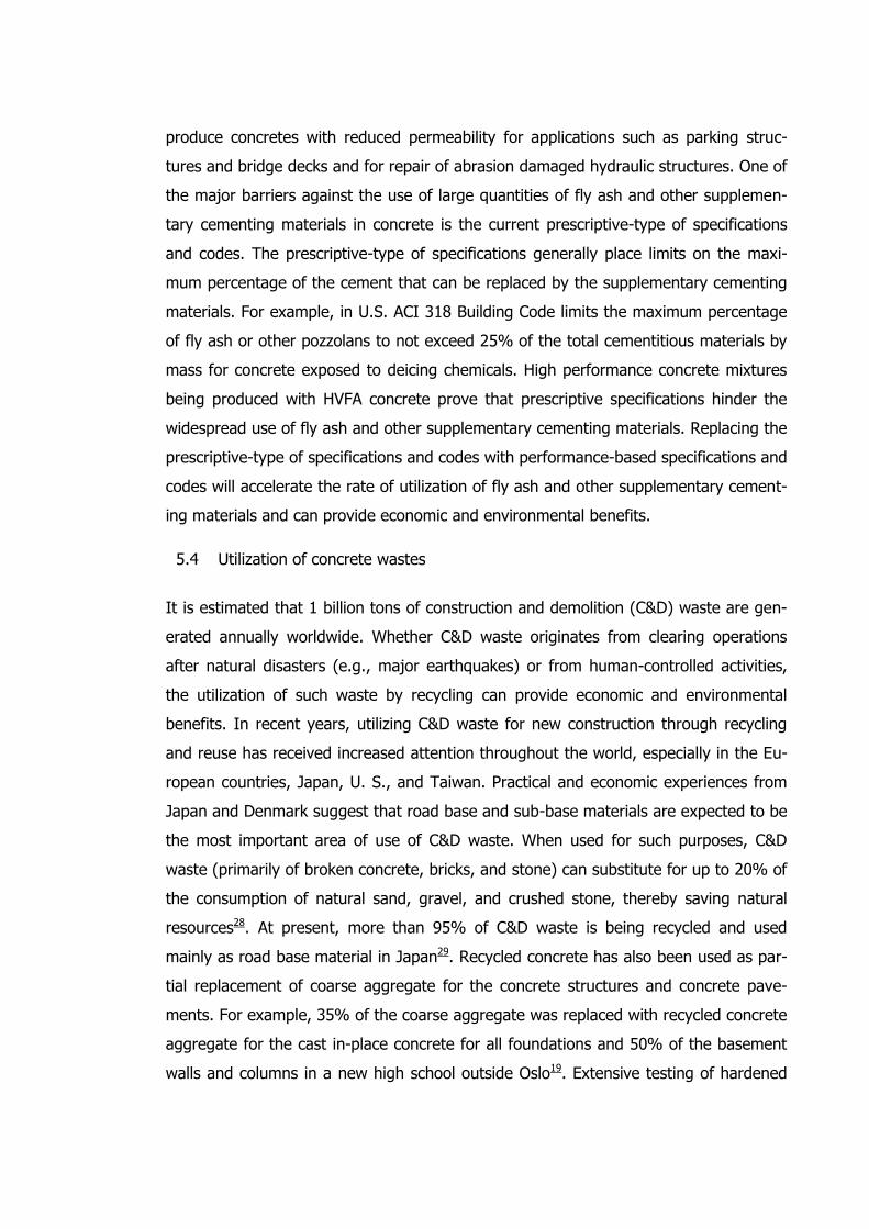
Picture 7. Electron micrograph of silica fume.
RPC is defined as a concrete mixture whose density is maximized through the utiliza-
tion of a precise gradation of all particles in the mix. It differs however from standard
concrete in the size of the particles used. RPC contains sand with a diameter between
100 to 600 µm (.1 - .6 mm) in place of the larger aggregates used in standard con-
crete, these standardly being between 10-20mm in diameter, and where standard con-
crete mixtures use sand , RPC goes even finer still, using silica fume with an average
diameter of only .5µm (5 x 10⁻⁴ mm) as illustrated in Picture 7. The result of this is a
concrete that is far denser than can be achieved otherwise.
This higher density results in a product which can easily achieve compressive strengths
of 200 MPa and in certain cases have tested as high as 800 MPa. This high compres-
sive strength, in comparison with the standard 50-100 MPa of high-performance con-
crete, enables RPC to carry loads equal to those required of today’s high performance
and standard concrete mixtures with a much smaller profile, meaning less product
used. Reinforcing material is also used in RPC; however it also is orders of magnitude
smaller than that used in traditional concrete structures. Steel fibers with a diameter of
only 200 µm (.2 mm) and a maximum length between 11-15 mm are placed within the
concrete at the time of mixing. These reinforcing fibers allow the material to not only
achieve a tensile strength between 6 – 13 MPa, but to maintain this after its first crack-
ing. This in comparison to the strength of 2-4 MPa found in standard concretes which
is lost after first cracking occurs.
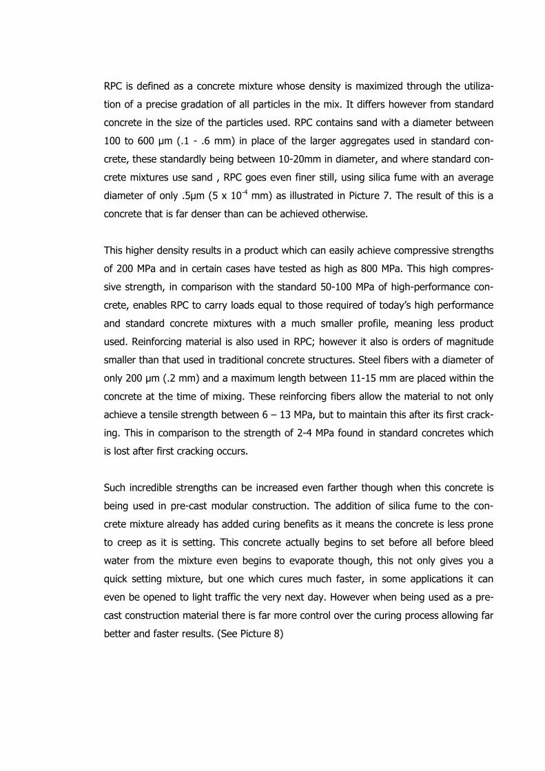
Such incredible strengths can be increased even farther though when this concrete is
being used in pre-cast modular construction. The addition of silica fume to the con-
crete mixture already has added curing benefits as it means the concrete is less prone
to creep as it is setting. This concrete actually begins to set before all before bleed
water from the mixture even begins to evaporate though, this not only gives you a
quick setting mixture, but one which cures much faster, in some applications it can
even be opened to light traffic the very next day. However when being used as a pre-
cast construction material there is far more control over the curing process allowing far
better and faster results. (See Picture 8)
Picture 8. Chart showing the influence of curing regime.
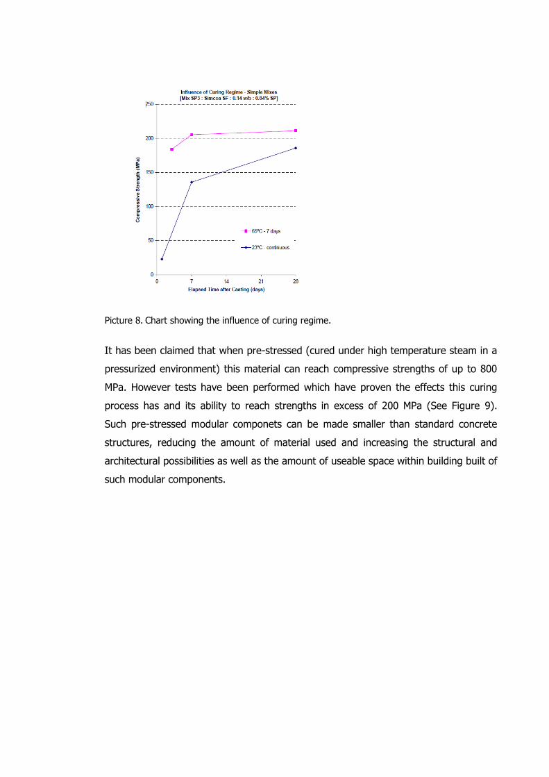
It has been claimed that when pre-stressed (cured under high temperature steam in a
pressurized environment) this material can reach compressive strengths of up to 800
MPa. However tests have been performed which have proven the effects this curing
process has and its ability to reach strengths in excess of 200 MPa (See Figure 9).
Such pre-stressed modular componets can be made smaller than standard concrete
structures, reducing the amount of material used and increasing the structural and
architectural possibilities as well as the amount of useable space within building built of
such modular components.
Picture 9. Chart showing the Performance of RPC products.
None of this comes without an increase in cost though; after all standard concrete
prices have doubled in the last decade and not will continue to do so with the rising
costs of fuel and energy used to produce this product. RPC is created with a variety of
highly specific and exactly sized materials so it is not a large surprise that its per yard
cost comes in at an average of 5 to 10 times the cost of a yard of standard concrete.
So with such a disparity of cost why are we interested in this material? What makes
this a truly sustainable material and not simply a novelty item?
6.2 Why is it a Sustainable Material?
To start with it is possible to produce RPC form simple poured concrete applications
with existing manufacturing facilities; it requires no change to existing infrastructure or
equipment. This means that with the same carbon footprint for transportation and im-
plementation as standard concrete you are achieving a much better product. How a
better product? The increased density of RPC makes it far more durable than standard
concrete or eve High Performance concrete. Denser material is less susceptible to pen-
etration by moisture, meaning that reinforcing fibers retain their strength over the
course of the materials use. Less moisture in the material means that it is less suscep-
tible freeze and thaw conditions, as well as being less prone to explosive spalling in
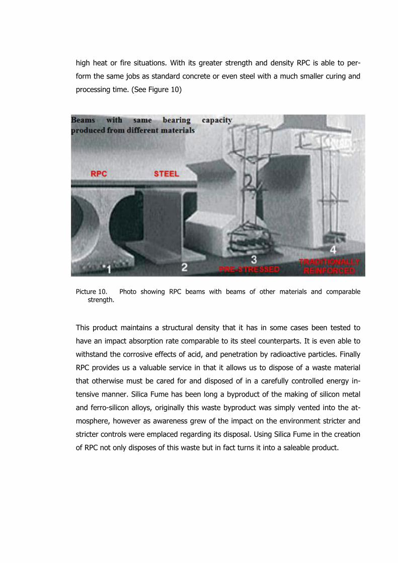
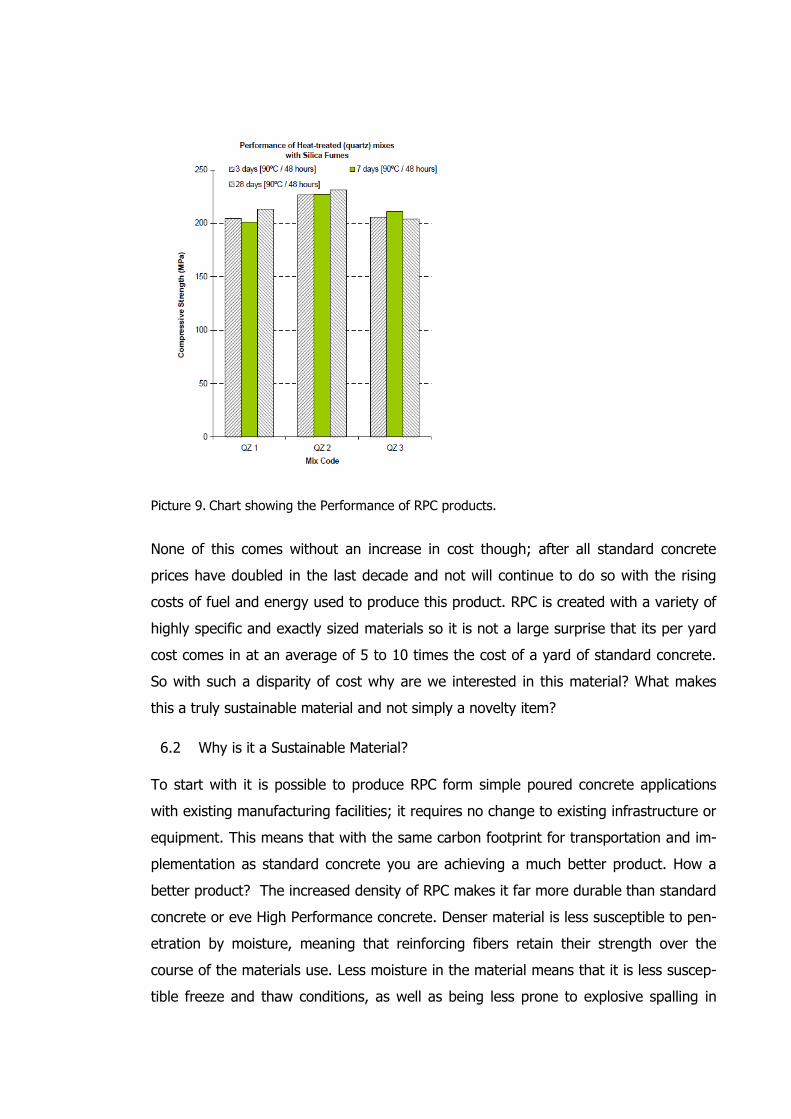
high heat or fire situations. With its greater strength and density RPC is able to per-
form the same jobs as standard concrete or even steel with a much smaller curing and
processing time. (See Figure 10)
Picture 10. Photo showing RPC beams with beams of other materials and comparable
strength. This product maintains a structural density that it has in some cases been tested to
have an impact absorption rate comparable to its steel counterparts. It is even able to
withstand the corrosive effects of acid, and penetration by radioactive particles. Finally
RPC provides us a valuable service in that it allows us to dispose of a waste material
that otherwise must be cared for and disposed of in a carefully controlled energy in-
tensive manner. Silica Fume has been long a byproduct of the making of silicon metal
and ferro-silicon alloys, originally this waste byproduct was simply vented into the at-
mosphere, however as awareness grew of the impact on the environment stricter and
stricter controls were emplaced regarding its disposal. Using Silica Fume in the creation
of RPC not only disposes of this waste but in fact turns it into a saleable product.
6.3 What are its Projected Uses?
RPC has many possible uses in the Construction field, its incredible strength means
that it can be used to shore up or patch existing structures with only thin layers of ma-
terial being added to previous construction, this means that many structures can con-
tinue to be reused as they are with out the expensive costs of demolition and disposal
shortening their life cycles. As a structural support it has many advantages, pushing
the boundries of what Concrete as a building material can accomplish. Consider the
photos below.
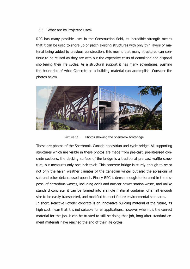
Picture 11. Photos showing the Sherbrook footbridge
These are photos of the Sherbrook, Canada pedestrian and cycle bridge, All supporting
structures which are visible in these photos are made from pre-cast, pre-stressed con-
crete sections, the decking surface of the bridge is a traditional pre cast waffle struc-
ture, but measures only one inch thick. This concrete bridge is sturdy enough to resist
not only the harsh weather climates of the Canadian winter but also the abrasions of
salt and other deicers used upon it. Finally RPC is dense enough to be used in the dis-
posal of hazardous wastes, including acids and nuclear power station waste, and unlike
standard concrete, it can be formed into a single material container of small enough
size to be easily transported, and modified to meet future environmental standards.
In short, Reactive Powder concrete is an innovative building material of the future, its
high cost mean that it is not suitable for all applications, however when it is the correct
material for the job, it can be trusted to still be doing that job, long after standard ce-
ment materials have reached the end of their life cycles.

7 Conclusions
In conclusion we would like to recommend that all four of these materials would be
useful in advancing of the sustainability of the Finnish building environment. Each ma-
terial possesses applications in which it outperforms traditional or standard building
materials. it is our feeling that by encouraging usage of these materials in projects her
in Finland it will be easier to not only meet the future requirements for buildings in
Finland, but to surpass them. As we are looking forward to new projects and goals we
must remember our definition of what is sustainability, fulfilling the requirements of the
Finland of today, without hampering the ability of the Finland of Tomorrow.
8 References
1. Quotation (UN Documents [available on the Internet] Our Common Future,
Chapter2: Towards Sustainable Development [updated 24 November 2010, cited
7 May 2012] Available from: http://www.un-documents.net/ocf-02.htm
2. Figure 1. Chart showing life cycle factors. (UK Centre for Materials Educa-
tion[homepage on the Internet].[updated 7 May 2012, cited 7 May 2012]. Avail-
able from: http://www.materials.ac.uk/guides/environmental.asp
3. Figure 2. Hierarchy Chart showing how to judge a sustainable material (Created
by Authors)
4. Research Paper: Construction of Energy-saving timber structure houses. Author:
M.Shandalovich. Civil Engineering department, Petrozavodsk State University,
Karelia, Russia, 2009
5. http://o-s-b.ru/index.php?show_aux_page=7
6. http://www.genetrade.net/en.php?k=115946
7. Gelfand and Duncan, Sustainable Renovation, “Strategies for Commercial Build-ing Systems and Envelope”, John Wiley and Sons Inc, Canada, pp 153.
8. APA HDO/MDO Plywood Product Guide, Form no B360P, The Engineered Wood Association, pp 1.
9. http://www.apextera.com/article/what-plywood
10. http://www.stta.org.uk/News/gettingitright.html
11. http://www.mutharathod.com/advantages-plywood.html
12. Internationales Holzbauforum (IHF 2008) Proceedings Book, “Seismic Safety In
Seven-Storey Building” , Vertrieb Fraunhofer IRB Verlag, Stuttgart, pp 3.
13. The Griffin UPM Customer Magazine, Text by Tuovi Similä 2/2010
14. Handbook Of Finnish Plywood, Finnish Forest Industries Federation, Kirjapaino
Markprint Oy, Finland, 2002, pp 1.
15. http://www.greenpeace.org.uk/forests/alternatives-to-illegal-and-unsustainable-
plywood
16. Handbook Of Finnish Plywood, Finnish Forest Industries Federation, Kirjapaino
Markprint Oy, Finland, 2002, pp 25.
17. http://www.koskisen.fi/node/111
18. Handbook Of Finnish Plywood, Finnish Forest Industries Federation, Kirjapaino
Markprint Oy, Finland, 2002, pp 25.
19. Internationales Holzbauforum (IHF 2008) Proceedings Book, “Seismic Safety In
Seven-Storey Building” , Vertrieb Fraunhofer IRB Verlag, Stuttgart, pp 4.
20. Malhotra, V. M.: “Making Concrete “Greener” with Fly Ash,” ACI Concrete Inter-
national, Vol. 21, No. 5, May 1999.
21. “Concrete for the Environment,” Newsletter, Danish Technological Institute,
June 2003.
22. “Concrete in Sustainable Development,” Cement and Concrete Association of
New Zealand, Wellington, New Zealand, 2007.
23. Malhotra, V. M.: “Reducing CO2 Emissions,” ACI Concrete International, Vol. 28,
No.9, 2006.
24. Malhotra, V. M. and Ramezanianpour, A. R.: “Fly Ash in Concrete,” 2nd Edition,
CANMET, Energy, Mines and Resources Canada, Ottawa, 1994.
25. Malhotra, V. M.: “CANMET Investigations Dealing with High-Volume Fly Ash
Concrete,” Advances in Concrete Technology, 2nd Edition, CANMET, Ottawa,
Canada, 1994.
26. Metha, P. Kumar: “Advancements in Concrete Technology,” ACI Concrete Inter-
national, Vol. 21, No. 6, June 1999.
27. Mehta, P. Kumar, “Concrete Technology for Sustainable Development,” ACI
Concrete International, Vol. 21, No. 11, 1999, pp 47-53.
28. Lang, E. and Geisler, J. F.: “Use of Blast Furnace Slag Cement With High Slag
Content for High-Performance Concrete,” Concrete in the Service of Mankind –
Radical Concrete Technology, editors: R. K. Dhir and P. C. Hewlett, E&FN Spon,
1996, pp 67-76.
29. ACI Committee 234: “Guide for the Use of Silica Fume in Concrete,” ACI 234-96
Report (Reapproved 2000), American Concrete Institute, Farmington Hills, MI,
2000.
30. Hansen T. C. and Lauritzen, E. K.: “Concrete Waste in a Global Perspective,” Re-
cycling Concrete and Other Materials for Sustainable Development, ACI SP 219,
Edited by Tony C. Liu and Christian Meyer, 2004, pp 35-46.
31. Kasai, Y.: “Recent Trends in Recycling of Concrete Waste and Use of Recycled
Aggregate Concrete in Japan,” Recycling Concrete and Other Materials for Sus-
tainable Development, ACI SP 219, Edited by Tony C. Liu and Christian Meyer,
2004, pp 11-34.
32. Naik, T. R.: “Greener Concrete Using Recycled Materials,” ACI Concrete Interna-
tional, Vol. 24, No.7, July 2002, pp 45-49.
33. “Recycling Concrete and Other Materials for Sustainable Development,” ACI SP
219 Edited by Tony C. Liu and Christian Meyer, 2004.
34. Images taken from Ductal Co. website http://www.ductal-
lafarge.com/wps/portal/ductal/HomePage
35. Silica Fume in Concrete [available on the Internet] Andrew Dunster 2009
http://www.concrete.elkem.com/dav/2c7d946881.pdf
36. Study Report: Reactive Powder Concrete [Available on the Internet] published
2006, N.P. Lee & D.H. Chisolm
http://www.branz.co.nz/cms_show_download.php?id=58b96f3b1316d9c1a8c0a
ea4259a02d5f9497fa7
37. Handbook Of Finnish Plywood, Finnish Forest Industries Federation, Kirjapaino
Markprint Oy, Finland, 2002, pp 26.