inkjet printing technology
TRANSCRIPT
41
August 1998 OKI Technical Review Vol. 64
Special Issue on Printers: UDC 681.327.54’22 : [681.612.94 : 532.525.2] : [681.527.3 : 537.226.86]
Inkjet Printing TechnologyKotaro YOSHIMURA*, Mitsura KISHIMOTO**, Toshiro SUEMUNE***
AbstractTo support color and high printing quality of a printer, we developed a piezoelectric type inkjet print head. In this systemwe adopted piezoelectric share mode, which is superb in ink drop control and can be applied to many fields.
1. Introduction
As the Internet extends the sharing of information byelectronic mail, making it an everyday experience, print-ers, the output machines of information, are becomingeven more important. For printers used for this purpose,color and high resolution printing are critical, targetingquality of photographs, and inkjet printers are suitable forthis purpose.
To meet this demand, Okidata is developing an inkjetprint head.
Inkjet printing methods are roughly divided into thepiezoelectric type and thermal type, and as Table 1 shows,each type has advantages and disadvantages. This paper intro-duces the piezoelectric type, which has the following features.1. Ink delivery quantity can be adjusted by drive control.
Drop size control is easy and high print quality, based ongrayscale representation, is possible.
2. Printer does not deteriorate and can be used almostindefinitely because heat is not generated. Reliabilityis superb.
3. Suitable for increased speedsWe targeted the direction of our development to a
piezoelectric permanent type inkjet head, which is superbin grayscale representation and is non-disposable, and areconducting various types of experiments.
This time we report on the basic operation of a shearmode type inkjet head utilizing the shear mode deforma-tion force of piezoelectric elements which are not generallyused, drop diameter control, and the measurement technol-ogy required for this development.
2. Print head
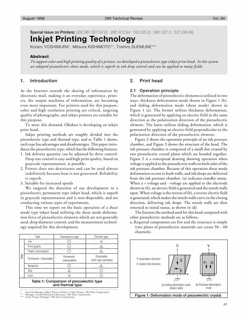
2.1 Operation principleThe deformation of piezoelectric elements is utilized in twoways, thickness deformation mode shown in Figure 1 (b),and sliding deformation mode (shear mode) shown inFigure 1 (a). The former utilizes thickness deformation,which is generated by applying an electric field in the samedirection as the polarization direction of the piezoelectricelement. The latter utilizes sliding deformation, which isgenerated by applying an electric field perpendicular to thepolarization direction of the piezoelectric element.
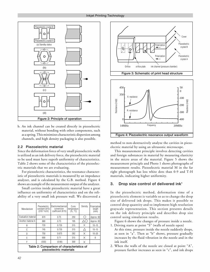
Figure 2 shows the operation principle of an ink pressurechamber, and Figure 3 shows the structure of the head. Theink pressure chamber is comprised of a small slot created bytwo piezoelectric crystal plates which are bonded together.Figure 2 is a conceptual drawing showing operation whenvoltage is applied to the piezoelectric walls on both sides of theink pressure chamber. Because of this operation shear modedeformation occurs to both walls, and ink drops are deliveredfrom the ink pressure chamber. (a) indicates standby status.When a + voltage and - voltage are applied to the electrodeshown in (b), an electric field is generated and the nozzle wallsopen. When voltage is the reverse of (b), a reverse electric fieldis generated, which makes the nozzle walls curve in the closingdirection, delivering ink drops. The nozzle walls are thenreturned to initial status, as shown in (d).
The features the method used for this head compared withother piezoelectric methods are as follows.a. Required components are few and the structure is simple
(two plates of piezoelectric materials can create 50 ~ 60channels).
* General Manager, Inkjet Process Owner / Color Project, Oki Data Corporation** Manager, Second Research Laboratory, Oki Data Corporation*** Color Project Manager, Oki Data Corporation
Table 1: Comparison of piezoelectric type and thermal type
Type
Life
Print quality
Power consumption
Permanent / disposable
Reliability
Size
Cost
Head
Piezoelectric type
Permanent (replaceable)
Disposable (refill type available)
Thermal type
V
EP
V
E
P
Figure 1: Deformation mode of piezoelectric crystal
P: polarization direction
E: electric field direction
(a) sliding deformation mode (shear mode)
(b) thickness deformation mode
42
Inkjet Printing Technology
b. An ink channel can be created directly in piezoelectricmaterial, without bonding with other components, suchas a spring. This minimizes characteristic dispersion amongchannels, and high density packaging is also possible.
2.2 Piezoelectric materialSince the deformation force of very small piezoelectric wallsis utilized as an ink delivery force, the piezoelectric materialto be used must have superb uniformity of characteristics.Table 2 shows some of the characteristics of the piezoelec-tric materials that we are evaluating.
For piezoelectric characteristics, the resonance character-istic of piezoelectric materials is measured by an impedanceanalyzer, and is calculated by the G.B. method. Figure 4shows an example of the measurement output of the analyzer.
Small cavities inside piezoelectric material have a greatinfluence on uniformity of characteristics and on the reli-ability of a very small ink pressure wall. We discovered a
method to non-destructively analyze the cavities in piezo-electric material by using an ultrasonic microscope.
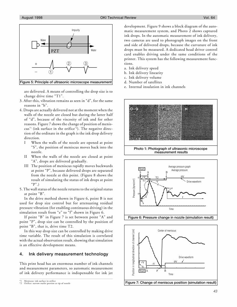
This measurement principle involves detecting cavitiesand foreign substances in material by measuring elasticityin the micro areas of the material. Figure 5 shows themeasurement principle and Photo 1 shows photographs ofmeasurement results. Piezoelectric material M in the farright photograph has less white dots than 0-9 and T-Hmaterials, indicating higher uniformity.
3. Drop size control of delivered ink1
In the piezoelectric method, deformation time of apiezoelectric element is variable so as to change the dropsize of delivered ink drops. This makes it possible tocontrol drop quantity and to implement high resolutiongrayscale representation. This section presents detailson the ink delivery principle and describes drop sizecontrol using simulation results.
Figure 6 shows the changes of pressure inside a nozzle.1. Driving starts at point “S” (walls of nozzle open)
At this time, pressure inside the nozzle suddenly drops,as seen in “a”. Then as “b” shows, pressure graduallyincreases by the fluid vibration in the nozzle and in theink itself.
2. When the walls of the nozzle are closed at point “A”,pressure further increases as seen in “c”, and ink drops
Table 2: Comparison of characteristics of piezoelectric materials
Manufacturer
Evaluation material
Another material A
Piezoelectric constant (d15)
(310–12m/V)
Curie temperature
(Tc, °C)
B
C
D
E
F
Electromechanical conversion
coefficient (K15)
Density Polarization length(mm)
870
880
720
745
750
690
(550)
0.75
0.73
0.735
0.735
0.675
0.71
(0.66)
250
195
315
315
282
315
300
Approx. 60
Approx. 65
10~15
10~15
10~20
8
(b)
(c)
(d)
0 0
0 0
+V -V
-V +V
Piezoelectric crystal B
Piezoelectric crystal A
(a) Standby status
Figure 2: Principle of operation
Figure 3: Schematic of print head structure
Polarization
Polarization
Cover
Piezoelectric crystal B
Piezoelectric crystal A
Orifice orifice plate ink channel (pressure chamber)
14MHz
450 500
-100
-200
-300
-400
350
0
20MHz
Figure 4: Piezoelectric resonance output waveform
Resis
tance
[mΩ
]
Reac
tance
[mΩ
]
X: reactance
R: resistance
Frequency
43
August 1998 OKI Technical Review Vol. 64
are delivered. A means of controlling the drop size is tochange drive time “T1”.
3. After this, vibration remains as seen in “d”, for the samereasons in “b”.
4. Drops are actually delivered not at the moment when thewalls of the nozzle are closed but during the latter halfof “d”, because of the viscosity of ink and for otherreasons. Figure 7 shows the change of position of menis-cus*1 (ink surface in the orifice*2). The negative direc-tion of the ordinate in the graph is the ink drop deliverydirection.I When the walls of the nozzle are opened at point
“S”, the position of meniscus moves back into thenozzle.
II When the walls of the nozzle are closed at point“A”, drops are delivered gradually.
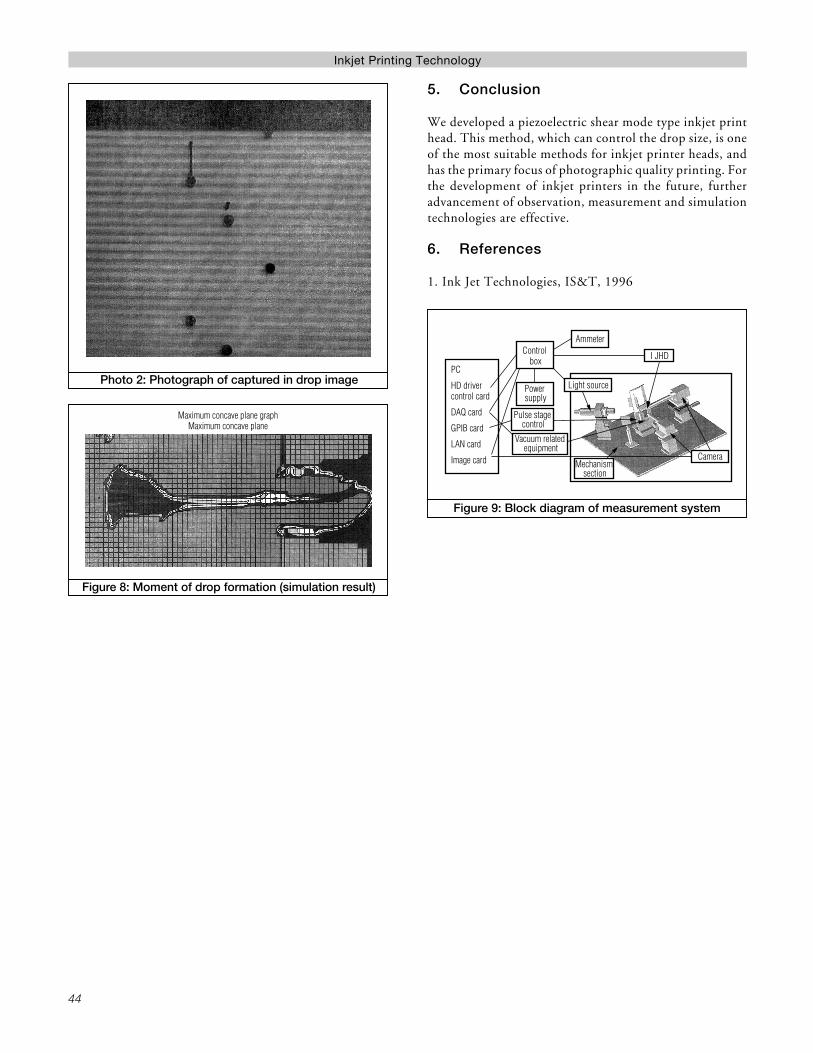
III The position of meniscus rapidly moves backwardsat point “P”, because delivered drops are separatedfrom the nozzle at this point. (Figure 8 shows theresult of simulating the status of ink drops at point“P”.)
5. The wall status of the nozzle returns to the original statusat point “B”.In the drive method shown in Figure 6, point B is not
used for drop size control but for attenuating residualpressure vibration (for enabling continuous driving) in thesimulation result from “e” to “f” shown in Figure 6.
If point “B” in Figure 7 is set between point “A” andpoint “P”, drop size can be controlled by the position ofpoint “B”, that is, drive time T2.
In this way drop size can be controlled by making drivetime variable. The result of this simulation is correlatedwith the actual observation result, showing that simulationis an effective development means.
4. Ink delivery measurement technology
This print head has an enormous number of ink channelsand measurement parameters, so automatic measurementof ink delivery performance is indispensable for ink jet
*1 Meniscus: ink surface in orifice*2 Orifice: narrow outlet portion at tip of nozzle
Figure 6: Pressure change in nozzle (simulation result)
StartA
0
0
T2
-V
0V
T1+V
S B
e
f
a
dc
b
Average pressure graphAverage pressure
Pres
sure
[dyn
e/cm
2 ]
Drive waveform
Time
Figure 7: Change of meniscus position (simulation result)
Start
0
BA
+V -V0V
S
P
Center of meniscus
Posit
ion
in lo
ngitu
dina
l dire
ction
of c
hann
el [c
m]
Drive waveform
Time
Photo 1: Photograph of ultrasonic microscope measurement results
development. Figure 9 shows a block diagram of the auto-matic measurement system, and Photo 2 shows capturedink drops. In the automatic measurement of ink delivery,two cameras are used to photograph images on the frontand side of delivered drops, because the curvature of inkdrops must be measured. A dedicated head driver controlcard enables driving under the same conditions of theprinter. This system has the following measurement func-tions.a. Ink delivery speedb. Ink delivery linearityc. Ink delivery volumed. Number of satellitese. Internal insulation in ink channels
Figure 5: Principle of ultrasonic microscope measurement
PZT
+
–
Impurity
Water
Water
44
Inkjet Printing Technology
5. Conclusion
We developed a piezoelectric shear mode type inkjet printhead. This method, which can control the drop size, is oneof the most suitable methods for inkjet printer heads, andhas the primary focus of photographic quality printing. Forthe development of inkjet printers in the future, furtheradvancement of observation, measurement and simulationtechnologies are effective.
6. References
1. Ink Jet Technologies, IS&T, 1996
Figure 8: Moment of drop formation (simulation result)
Figure 9: Block diagram of measurement system
PC
HD driver control card
DAQ card
GPIB card
LAN card
Image card
Control box
Ammeter
Power supply
Pulse stage control
Vacuum related equipment
Light source
Mechanism section
I JHD
Camera
Photo 2: Photograph of captured in drop image