influence of the thin layers thickness, deposited by pvd ... · pdf fileinfluence of the thin...
TRANSCRIPT
9
Nonconventional Technologies Review 2015 Romanian Association of Nonconventional Technologies Romania, June, 2015
INFLUENCE OF THE THIN LAYERS THICKNESS, DEPOSITED BY PVD
METHOD ON DURABILITY OF THE CUTTING INSERTS
Ana Bădănac1, Dragoş Paraschiv
2, Octavian Lupescu
3, Mădălina Popa
4 and Sorin Popa
5
1“Gheorghe Asachi” Technical University of Iasi, Romania, [email protected]
2“Gheorghe Asachi” Technical University of Iasi-Romania, [email protected]
3“Gheorghe Asachi” Technical University of Iasi-Romania, [email protected]
4“Gheorghe Asachi” Technical University of Iasi-Romania, [email protected]
5SNTFC ”CFR” Călători S.A., Bucharest, Romania, [email protected]
ABSTRACT: Deposition of some materials as thin layers on cutting tools, to increase the wear resistance of these, has become a
major interest for the cutting tool industry in recent years. Coating the cutting inserts with some different materials improves their
wear resistance and prolongs the life. There are known many researches concerning the cutting inserts coated with materials by the
vacuum deposition, using methods as: physical vapor deposition (vacuum thermal evaporation and condensation from the vapor
phase, ionic plating and pulverization) or chemical vapor deposition. In this study it is measured the influence of coatings thickness
deposited by the physical vapor deposition (PVD), namely by ionic plating method on the machining performance of the cutting
inserts.
KEY WORDS: physical vapor deposition, cutting inserts, ionic plating method, thin layers, durability.
1. INTRODUCTION
Due to the mechanical loading (the cutting efforts
unevenness), to variation of temperature (occurs
plastic deformation phenomenon), of the chemical
reactions which exist between cutting tool and
worpiece, but also because of the abrasion
phenomenon and of the adhesion phenomenon, the
cutting tools surfaces are subject to wear. In the last
period there was an increased interest for surface
treatments, which reduce the reconditioning cost of
the cutting tools surfaces. Depositions of thin layers
are applied on cutting tools in order to improve the
desired properties of the surface, such as corrosion
resistance, wear resistance, hardness, or friction.
The research problems regarding the production of
coatings are one of the most important surface
engineering development directions, ensuring the
production of coatings with superior properties in
the field of applications to the mechanical
characteristics and wear resistance [1, 2].
For those surfaces of the cutting tools, which are the
most exposed to wear, to be used at maximum
capacity, they can be hardened by several methods,
of which there are mentioned the coatings processes:
physical vapor phase deposition (PVD) and chemical
vapor phase deposition (CVD). These are efficient
thermo-chemical treatments by which there were
realized coatings compounds such as aluminum
titanium nitride (AlTiN or TiAlN), titanium carbide
(TiC), titanium-chromium nitride (TiCrN) and
titanium nitride (TiN). The coatings realized by
physical vapor phase deposition (PVD) or chemical
vapor phase deposition (CVD), have gained special
attention because of their unique physical and
chemical properties, for example, extremely high
hardness (40-80 GPa), corrosion resistance,
excellent resistance to oxidation at high
temperatures, as well as high abrasion and erosion
resistance. The main characteristics which must be
checked in the deposition process of thin layers are:
composition, structure, thickness, adherence,
hardness, wear resistance, corrosion resistance,
porosity [3, 4].
2. METHOD AND EQUIPMENT USED FOR
DEPOSITION
This study presents some researches made by the
authors regarding the thickness influence of the thin
layers deposition one of titanium and one of titanium
aluminum, deposed by PVD method, namely the ion
plating, on the cutting inserts durability. The ion
plating is the method that combines an arc
evaporation process with ion bombardment during
the coating deposition, which helps to achieve better
stoichiometric ally balance within the coating. For
the deposition of titanium layer and the titanium
aluminum, it was used the equipment DREVA 400,
presented in figure 1, which includes: a rotary table,
a vacuum chamber, supports of supply (air, water,
gas), components for completing the installation and
the electrical equipments. The deposition of the
titanium a layer takes place inside the recipient in which
a certain vacuum is generated, where the material that
must be deposited on the substrate (workpiece to be
covered, meaning the cutting insert), being in solid

10
state, is brought in vapor state as a result of its
heating, up to evaporation of the target (Ti) and re-
condensation on the substrate, when its temperature
is lower than that of the vapors [5].
Figure 1. General view of the equipment DREVA 400
3. METHOD AND EQUIPMENT USED FOR
THICKNESS DETERMINATION
The determination of the layer thickness of coatings
and layer systems was realized by means of
indentation and ball-cratering, kaloMax (figure 2),
tests. The adhesion and surface quality was
qualitatively analyzed by means of microscopic
examination of the coating fracture, which occurred
under heavy load, using Rockwell adhesion test and
by morphology for the coatings.
Figure 2. General view of the installation kaloMAX
The kaloMax of BAQ is a spherical cap grinder,
originally developed for the determination of the
coating thickness. The result of the grinding process
depends on both parts of the tribosystem, of the
sample and kaloMax. The kaloMax parameters,
which influence the result, are the following:
grinding paste, number of revolutions, grinding
period, diameter and normal force exerted by the
ball (figure 3). The advantage of kaloMax is the
construction of the driveshaft, preventing horizontal and
vertical movement of the ball, which greatly reduces the
uncertainty of measurement [6, 7].
Figure 3. Operating scheme of ball-cratering test
h- desired layer thickness; R- radius of the ball;
D- diameter of the spherical cap at the
surface of the sample; d-diameter of the boundary
between coating and base material; T- total penetration
depth of the ball; t-depth of penetration in
the base material
With a rotating steel ball and an abrasive slurry, a
spherical cap is ground through the coating into the
base material of the sample. At the examination with
the microscope, the layer/base material interface
appears as a circle. The layer thickness can be
calculated from the diameters of these circles and
the diameter of the grinding ball.
4. RESEARCH AND RESULTS
In the experimental researches, there were used
some cutting inserts coated with titanium layer (Ti)
and some coated with titanium aluminum (AlTiN).
The cutting inserts were used in turning different
surfaces (radius, chamfers and profiled surfaces).
After the cutting inserts were used, their thickness
was measured with ball-cratering, kaloMax.
According to [7], to calculate the thickness of the
titanium thin layer from the cutting inserts, first
there was found the diameter of the spherical cap at
the surface of the sample (D), then the diameter of
the boundary between coating and base material (d)
and after that calculated the total penetration depth
of the ball (T) using the equation (1) and the depth of
penetration in the base material (t) using equation
(2). The thickness of the titanium layer results from
the difference between total penetration depth of the
ball (T) and the depth of penetration in the base
11
material (t) shown in equation (3), or like in
equation (4).
(1)
(2)
(3)
(4)
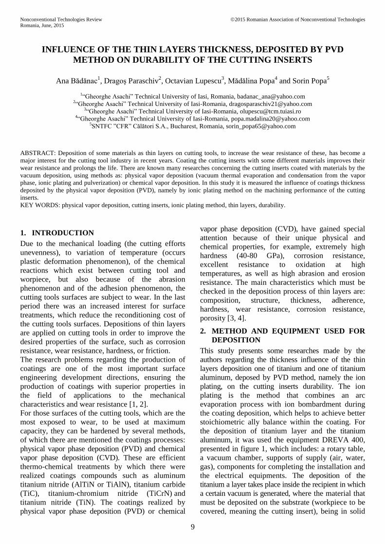
In figure 4 it is shown a cutting insert coated with
titanium thin layer and in the figure 5 there are
shown the measurements made with kaloMax for the
diameter of the spherical cap at the surface of the
sample (D) and the diameter of the boundary
between coating and base material (d), in order to
calculate the cutting inserts thickness.
Figure 4. Cutting insert with titanium deposition
Figure 5. Measurements for cutting insert coated with Ti
In figure 6, it is shown another cutting insert coated
with titanium thin layer and in the figure 7 it is
shown the measurement made with installation
kaloMAX for the diameter of the spherical cap at the
surface of the sample (D) and the diameter of the
boundary between coating and base material (d), in
order to calculate the cutting inserts thickness.
Figure 6. Cutting insert coated with titanium
Figure 7. Measurements for cutting insert
coated with titanium
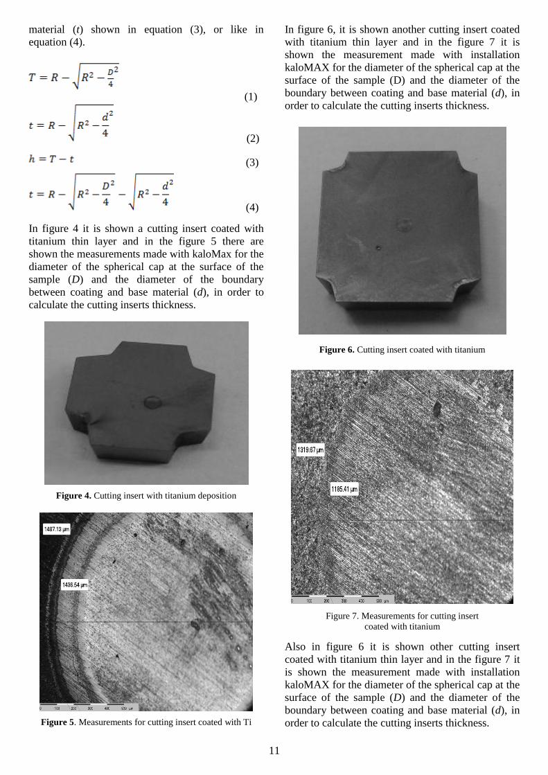
Also in figure 6 it is shown other cutting insert
coated with titanium thin layer and in the figure 7 it
is shown the measurement made with installation
kaloMAX for the diameter of the spherical cap at the
surface of the sample (D) and the diameter of the
boundary between coating and base material (d), in
order to calculate the cutting inserts thickness.
12
Figure 7. Cutting insert coated with Ti
Figure 8. Measurements for cutting insert with
titanium deposition
In figure 9, it is shown a different cutting insert,
namely an insert coated with titanium and aluminum
thin layer. Figure 10 shows the measurements made
with installation kaloMax for the diameter of the
spherical cap at the surface of the sample (D) and
the diameter of the boundary between coating and
base material (d), in order to calculate the cutting
inserts thickness.
Figure 9. Cutting insert with AlTiN deposition
Figure 10. Measurements for cutting insert
coated with AlTiN
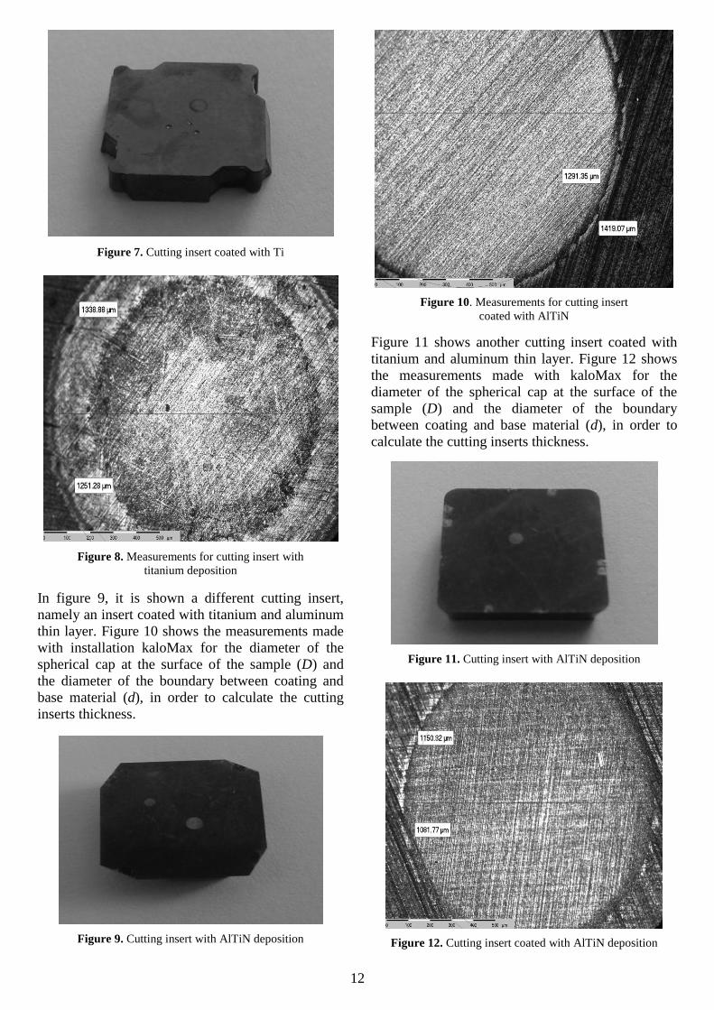
Figure 11 shows another cutting insert coated with
titanium and aluminum thin layer. Figure 12 shows
the measurements made with kaloMax for the
diameter of the spherical cap at the surface of the
sample (D) and the diameter of the boundary
between coating and base material (d), in order to
calculate the cutting inserts thickness.
Figure 11. Cutting insert with AlTiN deposition
Figure 12. Cutting insert coated with AlTiN deposition

13
Table 1. The values obtained for thickness layer
Type of layer
deposited
Revolutions
per minute
Grinding
period
Layer
thickness
(μm)
Ball
diameter
D
(μm)
d
(μm)
R
(μm)
Durability
tested
[min]
TiN 500 1/min 25 s 1.23 30 1487.13 1436.54 15000 6’40”
TiN 500 1/min 25 s 2.80 30 1319.67 1185.41 15000 9’47”
TiN 500 1/min 25 s 1.89 30 1338.88 1251.28 15000 21’33”
AlTiN 500 1/min 25 s 2.88 30 1419.07 1291.35 15000 48”30”
AlTiN 500 1/min 25 s 1.275 30 1150.32 1081.77 15000 33’49’
Values obtained for thickness are shown in Table 1,
the cutting inserts showing a remarkable durability
growth of the cutting inserts undergo the process of
thin TiN coating and thin AlTiN coating by a PVD
process, for all types of used cutting inserts.
Measurements made allowed also a graphical
representation of how is the variation in time of the
cutting inserts wear (fig. 13).
Figure 13. Graphical representation of how is the
variation in time
5. CONCLUSION
The results obtained open new opportunities for
continuing the studies in this domain, future
researches following: diversification of the
qualitative types of cutting inserts coated with thin
layers of titanium and titanium-aluminium through a
PVD process and the study of their behavior in the
processes of turning; realization of coatings and with
other types of layers: Ti-Cr, Ti-Al, Ti-Cr-Al and the
analyze of their influence on the hardness increase
and, implicitly, the durability of the cutting tools;
determination of hardness, micro hardness, of
deposited layers and determining their optimum
values (depending on the layer structure), which
allow achieving the highest values of durability.
6. REFERENCES
1. Dobrzanski, L.A., Lukaszkowicz, K., Zarychta,
A., Cunha, L., Corrosion resistance of multilayer
coatings deposited by PVD techniques on to the
brass substrate, Journal of Materials Processing
Technology, vol. 164-165, pp. 816-821, ISSN
0924-0136, (2005).
2. Lukaszkowicz, K., Dobrzanski, L.A., Structure
and mechanical properties of gradient coatings
deposited by PVD technology on to
X40CrMoV5-1 steel substrate, Journal of
Materials Science, vol. 43, pp. 3400-3407, ISSN
0022-2461, (2008).
3. Veprek, S., Mannling, H.D., Karvankova, P.,
Prochazka, J., The issue of the reproducibility of
deposition of super hard nan composites with
hardness of ≥ 50 GPa., Surface and Coatings
Technology, vol. 201, pp. 6064-6070, ISSN
0257-8972, (2006).
4. Zou, C.W., Wang, H.J., Li, M., Yu, J.F., Liu,
C.S., Guo, L.P, Fu, D.J., Characterization and
properties of TiN-containing amorphous Ti-Si-N
nan composite coatings prepared by arc assisted
middle frequency magnetron sputtering Vacuum,
vol. 84, pp. 817-822, ISSN 0042-207X, (2010).
5. Bădănac, A., Lupescu, O., Manole, V., Rusu, O.
T., Researches to improving durability of the
cutting inserts coated with titanium thin layers,
Academic Journal of Manufacturing
Engineering, Vol. 12, pp 6-11, ISSN: 1583-
7904, (2014).
6. Podgursky, V., Gregor, A., Adoberg, E., Kulu,
P., Wear of hard coatings, valuated by means of
kaloMax, Proc. Estonian Acad. Sci. Eng., 12, 4,
419–426, (2006).
7. The BAQ kaloMax Manual, Version 1.01.
8. Cat, A.-S., Mice, M.O., Cheese, G., Night
behaviours, 6th
International Conference on the
Management of Behavioural Changes, Vol. II,
pp. 191-199, City, State, (2009).