influence of silicon and silicon/sulfur-containing ... · pdf fileinfluence of silicon and...
TRANSCRIPT

Influence of Silicon and Silicon/Sulfur-Containing Additives on Coke Formationduring Steam Cracking of Hydrocarbons
Jidong Wang,† Marie-Francoise Reyniers,* Kevin M. Van Geem, and Guy B. Marin
LaboratoriumVoor Petrochemische Techniek, UniVersiteit Gent, Krijgslaan 281 S5, B-9000 Gent, Belgium
The influence of the combination of two Si-containing additives, BTMS and TEOS, with DMDS on cokeformation during steam cracking has been evaluated both on a laboratory scale and in a pilot plant unit.Under the optimal presulfidation conditions (T ) 1023 K, H2O ) 20 g h-1, DMDS in H2O ) 750 ppm wt,duration) 1 h), the combination of Si pretreatment+ presulfidation+ continuous addition of 2 ppm wtDMDS results in a decrease in the rate of coke formation up to 40% when hexane is cracked in the lab-scaleunit. Under similar conditions in the pilot plant the coke formation is decreased by 70%, while the COproduction decreases by more than 90%. Moreover, the suppressing effect on coke formation remains significanteven after several coking/decoking cycles. Simulations of an industrial ethane cracker indicate that theapplication of Si- and S-containing compounds as additives for the suppression of coke formation can potentiallydouble the run length of industrial steam crackers.
1. Introduction
Steam cracking of hydrocarbons is the major source of lightolefins, diolefins, and aromatics. The typical capacity of anethylene plant has reached 600 000 tons of ethylene/year. Insteam cracking, two side reaction products, CO and cokeformation on the inner surface of the cracking coils and thetransfer line heat exchangers (TLE), detrimentally influence theprocess operation and profit margins. Using steam as a diluentresults in the formation of CO, which is a poison for the metalcatalysts used in the downstream hydrogenation units. To ensureon-spec ethylene production, fluctuations in the CO content ofthe effluent must be avoided. Accumulation of coke on thereactor wall reduces the open cross section of the tubes, resultingin an increase of the pressure drop over the reactor coil. Cokedeposition also hampers the heat transfer from the furnace tothe process stream. To maintain the product yields, the skintemperature of the cracking coils must be increased withincreasing time on stream. When the allowable maximumpressure drop or the maximum skin temperature is reached, thefurnace must be taken out of service to remove the coke viacontrolled burning off with an air-steam mixture. This lowersthe production capacity.
In steam cracking, the reactor coils are usually constructedfrom heat-resistant alloys that contain Fe, Ni, and Cr as themajor constituents. An inherent problem with these materialsis their tendency to promote the production of CO and cokedeposition.1-3 To control the production of CO, S-containingcompounds, usually dimethyl disulfide (DMDS), are applied.For ethane cracking, a large dose of DMDS is used to presulfidethe coil surface with steam as a carrier before the admission ofethane to the reactor coils. Then a small maintenance dose ofDMDS is added continuously with the ethane feed during thecracking. For naphtha cracking, only a presulfidation is applied;the sulfur contained in the naphtha feed is relied upon tomaintain a low and stable CO production. Control of CO and
coke is critical for the economy of the steam cracking process.Sulfur-containing compounds have been successfully used tocontrol the CO production. For the suppression of coke, a lotof effort has been made in the past 30 years to find appropriatemethods and additives.4-24 Investigations concerning the effectof S-containing compounds have been carried out in laboratory-scale reactors. The reported effect is contradictory.2,26-31 BesidesS-containing compounds, other chemicals have been proposedas additives to suppress coke formation in steam cracking. Thesemainly include phosphorus-containing compounds,4-10 silicon-containing compounds,11-18 alkali and alkaline earth metal saltbased additives,19,20and tin- and antimony-based additives.21-24
By now none of these additives have been widely applied insteam cracking.
For the application of additives, three methods can bedistinguished, i.e., pretreatment of the inner surface of thecracking coils, continuous addition of the additives duringcracking, and the combination of pretreatment followed bycontinuous addition. The optimal application method for aspecific additive depends mainly on the properties of theadditives. Si-containing compounds have been reported to beable to suppress coke formation in steam cracking.10-17 Theseadditives are commonly used to pretreat the inner surface ofthe cracking coils. This method offers the advantage that thepretreatment with silicon and silicon/sulfur-containing additivescan be carried out at conditions similar to the decoking/crackingoperations. In this study, the influence of two Si-containingcompounds, bis-trimethylsilyl sulfide (BTMS) and tetraethylorthosilicate (TEOS), applied by pretreatment of the Incoloy800HT surface, on the coke formation during steam crackingof hexane is evaluated in a CSTR setup. Considering the factthat naphtha generally contains sulfur, the effect of Si pretreat-ment combined with DMDS is also investigated. Based on theexperimental results in the CSTR, the effect of Si pretreatmentand the combination of Si pretreatment with DMDS is evaluatedin a pilot plant setup. Under the conditions used in the CSTR,cracking of hexane produces mainly light gaseous componentssimilar to those of ethane cracking. Therefore, in the pilot plantethane is used as the feed. Steam cracking of the hydrocarbonsis carried out at conditions relevant to industrial ethylenefurnaces.
* To whom correspondence should be addressed. Tel.: 0032/9/26456 77. Fax: 0032/9/264 49 99. E-mail: [email protected].
† Current address: College of Chemical Engineering, BeijingUniversity of Chemical Technology, 15 BeiSanhuan East Road,ChaoYang District, Beijing, 100029, People’s Republic of China.
1468 Ind. Eng. Chem. Res.2008,47, 1468-1482
10.1021/ie070970w CCC: $40.75 © 2008 American Chemical SocietyPublished on Web 01/29/2008

2. Experimental Section
2.1. CSTR Setup.The CSTR setup has been describedpreviously by Reyniers and Froment2 and Wang et al.31 Thereactor is made of Incoloy 800HT with a volume of 5.23×10⁻⁶ m3. Distilled water and hexane are evaporated, mixed, andthen preheated to about 843 K before entering the reactor. Todetermine the rate of coke formation, the electrobalancetechnique is used.2,32A hollow cylinder made of Incoloy 800HTwith a surface area of 7.5× 10⁻⁴ m2 is suspended at the armof a Cahn 2000 electrobalance and positioned in the center ofthe reactor. The initial coking rate is calculated based on theamount of coke deposited between 15 and 30 min; theasymptotic coking rate is calculated based on the amount ofcoke deposited during the last 120 min. After cracking, theeffluent is cooled, but not condensed, and led to a cyclone, inwhich tar and coke particles are separated from the gas. Next,nitrogen is added as internal standard for the gas chromato-graphic analysis. The conversion and product yields arecalculated based on the absolute flow rate of the effluentcomponents using eqs 1 and 2.
whereFA0 is the mass flow rate of the reactant;FA is the mass
flow rate of the reactant in the effluent;X is the conversion ofthe reactant;Fi is the mass flow rate of producti; Yi is the yieldof product i. The concentration of CO in the effluent iscontinuously measured with an infrared analyzer. For thispurpose, the effluent is cooled with three water coolers and amethanol cooler at 263 K to remove the heavy components.Based on the volumetric flow rate of the effluent and the COconcentration, the yield of CO is calculated.
2.2. Experimental Procedures and Conditions in the CSTRSetup. 2.2.1. Preoxidation of the Incoloy 800HT Cylinders.In industrial practice, a cracking run is usually started afterdecoking. This implies that the surface of the cracking coils isin an oxidized state. To be in line with industrial practice, thecleaned Incoloy 800HT cylinders as such or after beingpretreated with Si (see 2.2.2) are oxidized in air (13 NL/h) for14 h at 1023 K prior to cracking or to presulfidation followedby cracking. The preoxidized surface state is denoted as “O”.
2.2.2. Application of the Si Additives.In the CSTR setup,the Si-containing additives, BTMS (Fluka,g98%) and TEOS(Fluka,g98%), are applied by the dipping method. A cleanedand preweighted Incoloy 800HT cylinder is immersed in a pureSi-containing additive or in a mixture (BTMS:TEOS) 1:1 (wt))of them for 1 min. Next the immersed cylinder is dried atambient conditions for 20 min in the case of BTMS or for 40min in the cases of TEOS and the mixture of BTMS/TEOS.
Then the immersion and drying steps are repeated once. Thecylinder that bears the additive is dried in air at 573 K for 3 h.After cooling to room temperature, the cylinder is reweighedto determine the amount of the additive on it. The surface stateafter the Si pretreatment is denoted as “Si”. After mountinginto the reactor, the Si-pretreated cylinder is oxidized at thepreoxidation conditions (see 2.2.1) prior to a cracking run. Thissurface state is denoted as “Si+ O”.
2.2.3. Application of DMDS. Presulfidation with DMDS(Aldrich, 99.0%) is carried out in steam. DMDS is dissolved inwater and is fed to the evaporator using a syringe pump (ISCO500D). The flow rate of water is 20 g h-1. For the combinationof preoxidation followed by presulfidation, the surface state isdenoted as “O+ S”. For the combination of Si pretreatmentfollowed by preoxidation followed by presulfidation, the surfacestate is denoted as “Si+ O + S”. After presulfidation, thetemperature of the reactor is brought to the cracking temperaturein a nitrogen stream in approximate 1 h. Then a cracking run isstarted. For continuous addition, DMDS is directly dissolvedin the hexane feed. The detailed conditions for the applicationof DMDS in the CSTR setup are given in Table 1. Thecombination of preoxidation with continuous addition of DMDSis expressed by “O+ CA Z”. The combination of Si pretreat-ment followed by preoxidation followed by presulfidation withcontinuous addition of DMDS is expressed by “Si+ O + S +CA Z”. “ Z” represents the concentration of continuously addedDMDS in wt ppm based on the hexane feed.
2.2.4. Cracking of Hexane.In the CSTR setup, hexane iscracked at 1123 K and at 1148 K with a feeding rate of hexaneof 40 g h-1 and a steam dilution of 0.5 kg of steam/kg of hexane.All data reported in this study are reproduced in at least tworepeat runs, and the values reported pertain to the mean valuesover the repeat runs. Mass balances closed within 3%.
2.2.5. Decoking in the CSTR.The coke deposited on thesurface of the CSTR and the cylinder is burnt off at 1073 Kwith a mixture of air (13 NL h-1) and nitrogen (13 NL h-1) for
Table 1. Application Conditions of DMDS in CSTR Setup
application method
presulfidation+ continuous addition
presulfidation presulfidation continuous addition
FH2O (g h-1) 20 20DMDS (ppm) 500-1000 750 2-80FDMDS (g h-1) 1.0× 10⁻²-2.0× 10⁻² 1.5× 10⁻² 8.0× 10⁻⁵-3.2× 10⁻³
temperature (K) 973-1123 1123 1148duration (h) 0.5-3 1
X )FA
0 - FA
FA0
100 (1)
Yi )Fi
FA0
100 (2)
Table 2. Experimental Conditions in the Pilot Plant Setup
TEOSpretreatment presulfidation cracking
temperature profileCIT cell 3 (K) 823 823 973COT cell 3 (K) 873 873 1023COT cell 4 (K) 1023 1023 1063COT cell 5 (K) 1093 1093 1093COT cell 6 (K) 1113 1113 1113COT cell 7 (K) 1143 1143 1143
COP (MPa) 0.17 0.17 0.17Fsteam(g h-1) 4000 4000 1155TEOS (g h-1) 10DMDS in steam (ppm) 0 750g of DMDS m-2 h-1 a 8.82duration (h) 1 1 6Fethane(g h-1) 3003steam dilution (kg kg-1) 0.385
a Surface area used to calculate g of DMDS m-2 h-1 is 0.34 m2.
Ind. Eng. Chem. Res., Vol. 47, No. 5, 20081469

15 min to remove most of the coke. Then the nitrogen flow isstopped and only air (13 NL h-1) is used for 15 min. Finally,the temperature is raised to 1173 K in 15 min and maintainedat this temperature for 30 min. The completion of decoking isfollowed by the mass loss of the cylinders.
2.3. Pilot Plant Setup.The pilot plant unit has been describedin previous papers.31,32The furnace, built of silica/alumina brick(Li23), is fired by means of 90 premixed gas burners, arrangedon the side walls in such a way as to provide a uniformdistribution of heat. In this study, the cracking coil is made ofIncoloy 800HT. It is 12.8 m long and has an internal diameterof 9 mm. These dimensions are chosen to achieve turbulentflow conditions in the coil with reasonable feed flow rates.Twenty thermocouples and five manometers are mounted alongthe coil to measure the temperature and pressure of the reactinggas. After cracking, a precisely known amount of nitrogen isinjected into the effluent, serving as an internal standard forthe gas chromatographic analysis. The product yields andconversion are calculated similarly as in the CSTR setup. Afterremoval of the heavy components, the CO and CO2 concentra-tion in the effluent is measured continuously by means ofinfrared analyzers.
2.4. Experimental Procedures and Conditions in the PilotPlant Setup. 2.4.1. Pretreatment with TEOS.Before thepretreatment with TEOS, the surface of the cracking coil is inan oxidized state, which is realized by the decoking after theprevious cracking run. The reactor is heated from the nightregime at 773 K to the temperature profile as specified in Table2 (TEOS) in the presence of 4 kg h-1 steam in 2 h. To addTEOS uniformly and precisely, a 30 wt % TEOS solution inhexane is used. When the temperature profile for the pretreat-ment with TEOS is reached, the TEOS solution is introducedinto the cracking coil at the inlet of cell 3 using an ISCO 500Dsyringe pump, where TEOS is mixed with high-temperaturesteam. The inlet temperature of cell 3 is kept at around 823 Kto prevent blockage of the injection tube. During the pretreat-ment, the flow rate of steam is maintained at 4 kg h-1. Thedetailed conditions for TEOS pretreatment in the pilot plant aregiven in Table 2.
2.4.2. Presulfidation.To add DMDS precisely and uniformly,a 20 wt % DMDS solution in hexane is used. The solution isintroduced at the inlet of cell 1 using an ISCO 500D syringepump. The detailed conditions for the presulfidation in the pilotplant are given in Table 2. For the presulfidation in the pilotplant setup, the concentration of DMDS in steam is maintainedat 750 ppm for 1 h.
2.4.3. Cracking. In the radiant coil, cracking and cokedeposition are considered to occur only in the cells whereT >873 K. For the temperature profiles used in this study, the reactorsurface area available for coke deposition amounts to 0.34 m2.Ethane with a purity of 99.5% (Air Liquide) is used as thehydrocarbon feed. After pretreatment, the cracking coil is heatedunder a steam flow of 4 kg h-1 to the set temperature profile asspecified in Table 2 (cracking). When the specified temperatureprofile is reached, the flow rate of steam is set to the desiredvalue for cracking and ethane is introduced. Upon the introduc-tion of ethane, the temperature in the cracking coil decreasesby about 20 K due to the endothermic nature of the cracking
reactions. After about 20 min, the temperature of the crackingcoil returns to the set value. Ethane is cracked at a COP of0.17 MPa, a coil outlet temperature (COT) of 1142 K, and asteam dilution of 0.385 kg of steam/kg of ethane. The crackingconditions are maintained for 6 h.
2.4.4. Decoking.Decoking of the cracking coil is performedwith a steam/air mixture at the conditions specified in Table 3.At the start of the procedure, the cracking coil is heated to 1073K under a nitrogen flow, and then steam is introduced. After 3min, the nitrogen flow is stopped, and air is admitted. Oncemost of the coke is removed, the temperature of the coil isincreased to 1173 K. When practically all the coke is burnt off,the steam flow is stopped, and further decoking occurs in aironly. The standard decoking time is 100 min. During decoking,the CO and CO2 concentration in the effluent is determined bymeans of infrared analyzers. The volumetric flow rate of theeffluent is measured using a metal tube flow meter. Theconcentration of CO and CO2 and the flow rate of the effluentare automatically recorded every 10 s. These data are used todetermine the total amount of coke deposited on the reactorsurface. Note that the coke deposited on the reactor wall doesnot entirely consist of carbon.28,33-35 Typical carbon contentsof the coke layer are 99 wt % or higher,28,33-35 although a valueof 90% has been reported on Ni surfaces.35
2.5. Scanning Electron Microscope and Energy DispersiveX-ray Analysis. The morphologies of the coke samples arestudied using scanning electron microscopy (SEM). The surfacecomposition of the alloy treated at various conditions and themetal content in the coke layer are determined using energydispersive X-ray (EDX) analysis. EDX analysis is carried outwith an accelerating voltage of 10 kV and an acquisition timeof 15 min.32 The penetration depth of the electron beam isestimated using the empirical formula as proposed by Kanaya-Okayama.36
whereh is the penetration depth (µm); Wa is the molar weightof the element (g mol-1); Z is the atomic number;F is the densityof the material (g cm-3); E is the energy of the electron beam(kV). According to eq 3, the penetration depth differs for eachelement. The typical values for various elements atE ) 10 kVare for C,h ) 1.7 µm; for Cr, h ) 0.56µm; for Fe,h ) 0.50µm; and for Ni,h ) 0.44µm; resulting in a penetration depthof approximately 0.5µm for the metals concerned in this work.The thickness of the coke layer is determined using eq 4:
where L is the thickness of the coke layer (µm); MC is theamount of coke deposited on the cylinders (g);d is the densityof coke (1.78× 10⁶ g m-3); S is the surface area of the cylinder(7.565 × 10⁻⁴ m2). The density of the coke is taken fromBennett and Price.37
Table 3. Decoking Conditions in the Pilot Plant Setup
FH2O (kg h-1) Fair (NL h-1) FN2 (NL h-1) Tout,cell3(K) Tout,cell4(K) Tout,cell5(K) Tout,cell6(K) Tout,cell7(K)
pre-start 0 0 662 1023 1073 1073 1073 1073start 1.008 662 0 1023 1073 1073 1073 1073CO2 < 1 mol % 1.008 662 0 1023 1173 1173 1173 1173CO2 < 0.1 mol % 0 662 0 1023 1173 1173 1173 1173
h )0.0276Wa E1.67
Z 0.89F(3)
L )MC
d S10-6 (4)
1470 Ind. Eng. Chem. Res., Vol. 47, No. 5, 2008
3. Results and Discussion
3.1. Influence of Si Additives on Coke Formation. 3.1.1.Influence of Si Additives on Coke Formation in the CSTR.In this study, the influence of the Si additives, BTMS, TEOS,and their mixture on the coke formation in steam cracking isfirst evaluated in the CSTR setup using hexane as feed. BTMSand TEOS are applied by pretreating the cleaned Incoloy 800HTcylinder (see 2.2.2). The amount of the Si-containing additivesdeposited on the cylinders ranges from 0.13 to 0.39 g m-2. Thiscorresponds to a thickness of a silica layer of 49-147 nm
assuming that the density of silica is 2.65× 10³ kg m-3.38
Cracking tests are carried out at 1123 and 1148 K with a feedingrate of hexane of 40 g h-1 and a steam dilution of 0.5 kg ofsteam/kg of hexane. To determine the influence of the additives,blank runs in which the Incoloy 800HT surface is preoxidizedonly are first carried out.
As shown previously32 at the beginning of the cracking runs,the coking rate is high due to heterogeneous catalytic cokeformation. With increasing time on stream, the coking ratedecreases and reaches a stable value, the so-called asymptotic
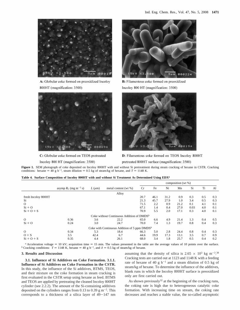
Figure 1. SEM photograph of coke deposited on Incoloy 800HT with and without Si pretreatment during steam cracking of hexane in CSTR. Crackingconditions: hexane) 40 g h-1, steam dilution) 0.5 kg of steam/kg of hexane, andT ) 1148 K.
Table 4. Surface Composition of Incoloy 800HT with and without Si Treatment As Determined Using EDXa
composition (wt %)
asympRC (mg m-2 s) L (µm) metal content (wt %) Cr Fe Ni Mn Si Ti Al
Alloyfresh Incoloy 800HT 20.7 46.1 31.2 0.9 0.3 0.5 0.3Si 21.3 45.7 27.9 1.0 3.4 0.5 0.3O 71.5 2.2 0.9 21.2 0.1 4.1 0.1Si + O 67.1 1.4 0.4 27.0 0.03 4.0 0.1Si + O + S 70.9 5.5 2.0 17.1 0.3 4.0 0.1
Coke without Continuous Addition of DMDSb
O 0.36 3.6 22.2 65.0 6.6 4.9 21.4 1.3 0.4 0.5Si + O 0.24 3.0 24.7 70.0 7.4 1.3 19.7 0.8 0.4 0.3
Coke with Continuous Addition of 5 ppm DMDSb
O 0.34 5.3 18.4 66.3 5.0 2.8 24.4 0.8 0.4 0.3O + S 3.5 42.4 6.7 44.6 19.9 17.3 13.1 3.5 0.7 0.9Si + O + S 0.35 4.4 26.1 68.0 3.4 1.8 25.7 0.5 0.4 0.2
a Acceleration voltage) 10 kV; acquisition time) 15 min. The values presented in the table are the average values of 10 points over the surface.b Cracking conditions:T ) 1148 K, hexane) 40 g h-1, andδ ) 0.5 kg of steam/kg of hexane.
Ind. Eng. Chem. Res., Vol. 47, No. 5, 20081471

coking rate, corresponding to the heterogeneous noncatalyticcoke formation stage. The amount of coke deposited on thecylinders and the coking rate increase with increasing crackingtemperature.32 Heterogeneous catalytic coke formation is as-sociated with the metal wall of the cracking coils. A significantcharacteristic of catalytic coke formation is filamentous coke,as shown in Figure 1. The filamentous coke (Figure 1B) formedat 1148 K has a diameter of 3-5 µm and a length of 10-30µm and is scattered on the surface which has been in contactwith the gas stream. Besides the coke filaments, coke globuleswith a diameter of 1-2 µm are also formed (Figure 1A). Mostof the surface in contact with the gas stream is covered by theglobular coke. For the catalytic coke formation, the nature ofthe material on which coke is deposited is an important factor.Coke deposition on different materials has been found to proceedwith different rates.39,40 Next to this, the composition of themetal surface is also important. The surface composition of apreoxidized Incoloy 800HT cylinder as determined by EDX isgiven in Table 4. Preoxidation results in a significant enrichmentof Cr, Mn, and Ti and a significant depletion of Fe and Ni onthe surface. As reported previously,32 the surface compositionupon preoxidation indicates the formation of an oxide layer thatcontains mainly MnCr2O4 and Cr2O3, which is consistent withliterature reports.41,42Formation of such an oxide layer is desiredfor the protection of the alloy. With increasing time on stream,the metal surface is encapsulated by coke and the catalyticactivity of the metal wall decreases. The main route for cokeformation then shifts to the heterogeneous noncatalytic mech-anism, where coke is formed via reactions of coke precursorsin the gas phase with active sites located in the coke matrix.43-46
Heterogeneous noncatalytic coke formation is the most importantcoking mechanism since it operates practically over the entirecracking run. Coke formation via the homogeneous noncatalyticmechanism, so-called gas-phase coking,33-48 can be neglectedwhen light feedstocks are cracked.
In Figure 2, the conversion and the yields of the main productsare shown relative to the values observed during the blank runat 1148 K. Application of these additives causes a small butnot unimportant change in the conversion of hexane and in theproduct distribution. The conversion at 1148 K changes from38% in the blank run32 to 37% when BTMS is used, to 38%when TEOS is used, and to 39% when TEOS and BTMS areused. The changes for the methane yield, the ethylene yield,and the propylene yield compared to the value in the blank run
all are limited to at most 10% at 1148 K. The most importantdifferences are observed for CO, as can be seen from Figure 2.CO is formed via the noncatalytic gasification of coke by steamand via metal-catalyzed removal of carbonaceous intermediatesand/or coke by steam reforming.1 As observed by Dhuyvetter,31
different pretreatment methods and/or continuous addition ofDMDS can reduce the CO production by some 50%. Thepretreatment with silicon additives also has a strong effect onthe initial and asymptotic coking rate. As can be seen fromFigure 3, pretreatment of the Incoloy 800HT cylinder withBTMS, TEOS, and their mixture results in a significant decreaseof the amount of coke deposited on the cylinder and a decreaseof the coking rate as compared to a blank run. On average,application of the Si additives results in a reduction of the initialcoking rate by 48% and of the asymptotic coking rate by 31%at 1123 K. At 1148 K, the reduction in the initial and theasymptotic coking rates is practically the same, amounting to24%. The data in Figure 3 indicate that there is no significantdifference between BTMS and TEOS concerning the suppress-ing effect on the coke formation. This implies that BTMS andTEOS decrease the coke formation via the same mechanismand the sulfur contained in BTMS does not seem to play animportant role. BTMS is a very unstable compound that readilydecomposes, even at ambient conditions, releasing H2S. Afterbeing dipped in BTMS, the cylinders are exposed to ambientfor 20 min. Therefore, some of the sulfur in BTMS is probablyalready released at room temperature and adsorbed sulfur mayexist on the surface of the Incoloy 800HT cylinder. Prior totheir use in the cracking run, the Si-pretreated cylinders arepreoxidized in air at 1023 K for 14 h. Under these conditionsit can be assumed that sulfur is completely removed from thesurface of the Incoloy 800HT cylinder and that the Si isconverted to silicon oxide.
The data in Figure 3 also indicate that the amount of Si onthe cylinder has a small influence on the observed reduction incoking rate. In general, higher amounts of additives used in thepretreatment lead to a smaller decrease of the coking rate. Thisseems to imply that the suppressing effect of TEOS and BTMSdoes not originate from the formation of a silica layer on thesurface as in that case the degree of reduction would be expectedat the very least to remain constant when more additives areused. To figure out the mechanism for the reduced cokeformation upon the Si pretreatment, the surface composition ofthe Si-pretreated Incoloy 800HT cylinders has been determinedusing EDX and is given in Table 4. Compared to the preoxidizedsurface, Si pretreatment results in a reduction of Cr, Fe, and Niand an increase of Mn in the oxide layer. It can be noticed thatthe content of Si is even lower compared to the oxidized surfacewithout Si pretreatment. This also seems to imply that thesuppressing effect of the Si pretreatment via the dipping methodon the coke formation does not originate from the formation ofa silica layer. The composition of the oxide layer formed uponoxidation of the Si-pretreated cylinder has been estimated usingthe thermodynamic calculation program, EKVICALC.43 Thecalculation result indicates that the equilibrium molar composi-tion of the oxide layer contains 65.7% MnCr2O4, 20.9% Cr2O3,10.0% TiO2 (rutile), 1.7% Fe2O3, 0.9% NiTiO3, 0.6% SiO2, and0.3% Al2TiO5. Compared to preoxidation alone,32 the oxide layerwith Si pretreatment contains more MnCr2O4, TiO2 (rutile), andAl2TiO5, but less Cr2O3, NiTiO3, and Fe2O3. The content ofSiO2 is practically the same.
The influence of Si on the composition and structure of theoxide layer formed during the oxidation of alloys has been notedfor a long time. Fe-Ni-Cr alloys are frequently used at high
Figure 2. Influence of additives on yields and conversion during steamcracking of hexane in the CSTR setup. Yields and conversion relative toblank run values. Cracking conditions: hexane) 40 g h-1, δ ) 0.5 kg ofsteam/kg of hexane, andT ) 1148 K. Presulfidation:T ) 1123 K, H2O )20 g h-1, DMDS in H2O ) 750 ppm, and duration) 1 h.
1472 Ind. Eng. Chem. Res., Vol. 47, No. 5, 2008

temperatures and in corrosive atmospheres. Anticorrosion ofthese alloys relies on the formation of a protective Cr2O3 layer.Generally, at least 20 wt % Cr is required to ensure the formationof a Cr2O3 layer during oxidation.48,49Before being exposed tothe process stream, preoxidation of an alloy is carried out toform a protective oxide layer on the alloy surface. Thecomposition and the structure of the oxide layer depend mainlyon the bulk composition, on the type and amount of the minoralloy elements, and on the oxidation conditions.50 For heat-resistant alloys containing Fe, Cr, and Ni, formation of a Cr2O3
layer during preoxidation is preferred due to its good stability.49
Si is believed to facilitate the formation of a Cr2O3 layer and toimprove the resistance to oxidation.51-53 Based on studiesconcerning the oxidation of Fe-24% Cr-24% Ni alloy, Baxteret al.51 proposed that the effect of SiO2 on the formation of aCr2O3 layer is to provide additional sites for the lateral growthof the Cr2O3 layer and to promote a rapid growth of a continuousCr2O3 layer. Huntz et al.52 investigated the effect of Si on theoxidation of a 9% Cr steel. Without addition of Si, an oxidelayer consisting of mainly iron oxides is formed upon oxidationat 873 and 1273 K in 0.1 MPa of O2. In contrast, addition of2-4% Si, results in the formation of a Cr2O3 film of iron oxides.The effect of Si is attributed to the segregation of Si at the outer
surface and to the formation of a thin SiO2 film in the earlystage of the oxidation. In the further stage of the oxidation, theSiO2 film only allows the formation of a layer containing Crand Mn oxides as the oxygen activity, thermodynamicallyimposed by the silica, is too small for developing iron oxide.Addition of Si to the alloy surface by some surface modificationtechniques such as by ion implantation has also been found tohave a beneficial effect on the formation of the Cr2O3 layerduring oxidation of alloys.53 The effect of Si is likely to formSiO2 in the initial oxidation stage. The SiO2 particles at thesurface then act as nucleation sites for the formation of Cr2O3
layer. For Fe-Ni-Cr alloys containing a minimal amount ofMn and Si, the oxide layer formed during oxidation generallyhas a layered structure with MnCr2O4 on top of Cr2O3.54,55 Siis found in the form of SiO2, which can be a continuous ordiscontinuous layer beneath Cr2O3.50 Although the structure ofthe oxide layer is not analyzed in detail this study, based onthe composition of the oxide layer as determined using EDX,it is believed that the Si applied by the pretreatment methodhas been covered by an oxide layer consisting of mainlyMnCr2O4 and Cr2O3 during the preoxidation procedure. Ac-cordingly, the suppressing effect of the oxidized Si-pretreatedIncoloy 800HT on the coke formation in the stream cracking
Figure 3. Influence of additives on the initial and asymptotic coking rate during steam cracking of hexane in the CSTR setup. Cracking conditions: hexane) 40 g h-1, andδ ) 0.5 kg of steam/kg of hexane. Presulfidation:T ) 1123 K, H2O ) 20 g h-1, DMDS in H2O ) 750 ppm, and duration) 1 h.
Ind. Eng. Chem. Res., Vol. 47, No. 5, 20081473

of hexane can then be attributed to the modification of thecomposition and the structure of the oxide layer and to adecreased diffusion of metals into the coke layer duringcracking.
The metal content and the metal composition of the coke layerin contact with the gas phase are also determined with EDXand are shown in Table 4. In the coke layer deposited on thepreoxidized Incoloy 800HT surface, the main metal constituentsare Cr, Mn, Fe, and Ni. These metals are also the mainconstituents in the coke layer deposited on the oxidizedSi-pretreated Incoloy 800HT surface. Previously32 an inversecorrelation between the metal content and the thickness of thecoke layer has been found for the coke formed in the blankruns. According to this correlation, the metal content in a cokelayer having a thickness of 3µm can be estimated to be 29.0wt %. The experimentally determined metal content in the cokelayer formed with TEOS pretreatment amounts to 24.7 wt %.This may imply that TEOS pretreatment somewhat suppressesthe diffusion of metals into the coke layer. In addition, TEOSpretreatment also results in a change of the metal distributionin the coke layer. The most pronounced change is found forNi, which is one of the most active elements for the catalyticcoke formation. Upon the TEOS pretreatment, the content ofNi in the coke layer decreases by 73%.
Baker et al.56 investigated the influence of Si on the growthof filamentous coke on a Fe-Ni surface during the decomposi-tion of acetylene using controlled atmosphere electron micros-copy. They found that the growth rate and the length offilamentous coke are significantly reduced on a Si-pretreatedFe-Ni alloy. The suppressing effect of Si on the growth ofcoke filaments was attributed to the reduced diffusion of cokethrough the metal particles, the rate-limiting step for the cokeformation. The morphology of coke deposited at 1148 K onthe Incoloy 800HT cylinder with and without the TEOSpretreatment has been examined using SEM. Representativemicrophotographs are shown in Figure 1. Upon the pretreatmentwith TEOS, the coke still consists mainly of globular coke(Figure 1C) with a diameter of 1-3 µm and needle-shaped cokefilaments (Figure 1D) with a diameter of 1-2 µm and a typicallength of 5-15 µm. Compared to the coke deposited on thepreoxidized Incoloy 800HT surface, TEOS pretreatment doesnot cause a significant change in the diameter of the globularcoke but causes a decrease in its population. Moreover, thediameter and the length of the needle shaped filamentous cokeare decreased. These findings are consistent with the observa-tions of Baker et al.56 Moreover, the more pronounced reductionof the initial coking rate compared to the reduction of theasymptotic coking rate also shows that the Si pretreatment hasa more pronounced effect on the catalytic coke formation. Uponthe pretreatment with the Si additives, the initial coking ratedecreases by 48% at 1123 K; see Figure 3. At 1148 K itdecreases by 24%, which is 50% less than that at 1123 K. At1123 K, Si pretreatment decreases the asymptotic coking rateby 31%. At 1148 K it decreases by 24%, which is 23% lessthan that at 1123 K. These observations also imply that Sipretreatment has a stronger effect on the catalytic coke formationthan on the heterogeneous coke formation, in agreement withthe influence of Si on the composition and the structure of thesurface layer mentioned above.
3.1.2. Influence of TEOS on the Steam Cracking of Ethanein a Pilot Plant. The influence of one of the Si-containingadditives, TEOS, on the coke formation and CO production insteam cracking of ethane has been evaluated in a pilot plantsetup. Since BTMS and TEOS do not show a significant
difference in the suppressing effect on coke formation in steamcracking of hexane, in the pilot test TEOS is used due to itsmuch lower price and ease of handling compared to BTMS. Inan industrial ethylene furnace, a temperature profile exists alongthe cracking coils. To simulate this situation, during pretreatmentwith TEOS, a temperature profile is set along the cracking coilin the pilot plant setup (Table 2, TEOS pretreatment). In thepilot plant, TEOS is applied by pretreatment of the oxidizedIncoloy 800HT surface obtained by decoking of a previouscoking run. Hence, in the pilot plant the sequence consists in1, decoking; and 2, TEOS treatment. This is different from thesequence in the CSTR, where it is 1, TEOS; and 2, oxidation.The different sequence used in the pilot plant is of course dueto that the fact that it is impossible to use a new reactor coil ineach run. The results with the application of TEOS, togetherwith those of a blank run, are summarized in Table 5.
In the blank run, the conversion of ethane amounts to 70%;the yield of ethylene and CO is 52 and 1.7 wt %, respectively.The total amount of coke deposited on the inner surface of thecracking coil during 6 h cracking is 1.56 g. Upon thepretreatment with TEOS, no significant change in the conversionof ethane and in the product selectivities are observed. The yieldof CO decreases to 0.2 wt %, which is 88% lower compared tothe values observed in the blank run. The amount of cokedeposited during 6 h amounts to 0.63 g, which is 60% lowercompared to that of the blank. The CO content in the effluentas a function of time on stream is shown in Figure 4. Upon theTEOS pretreatment, the CO spike appearing at the beginningof the blank run is completely eliminated. The CO concentrationin the effluent remains almost constant over the entire run.
After the run with TEOS pretreatment, four cracking runs,the so-called memory test runs (Si-M-I to Si-M-IV), are carriedout in order to evaluate the durability of the effect of TEOS onthe coke formation and CO production. In these memory testruns, no significant variation in the conversion of ethane andthe main product yield are noticed, as illustrated by the data inTable 5 (Si-M-I). The amount of coke and the CO yield as afunction of the number of the memory test run are given inFigure 5. After four coking/decoking cycles, the amount of cokeand the yield of CO does not completely return to the value ofthe blank run. The decrease in the coke formation still amountsto 20%. The decrease in the yield of CO still amounts to 40%.
Unlike in the CSTR, application of TEOS in the pilot reactorresults in a significant reduction not only in the coke formationbut also in the CO production. The amount of TEOS used duringthe pretreatment in the pilot plant is 10 g, which can produce2.89 g of SiO2. Assuming that all the SiO2 is uniformly depositedon the inner surface of the cracking coil of the pilot plant setup,the thickness of the SiO2 layer is 3.2µm. Therefore, it is likelythat in the pilot plant pretreatment of the cracking coil withTEOS would form a thin layer of SiO2 on its inner surface.The formation of a SiO2 layer on the metal surface upon thepretreatment with Si-containing additives has been demonstratedby Brown et al.11,12 and Woerde et al.17 It is thought that thislayer of SiO2 acts as a physical barrier to prevent direct contactbetween the process gas stream and the alloy that shows a highcatalytic activity for the formation of coke and CO production.
In the memory test runs, the SiO2 layer still shows asuppressing effect on coke formation and CO production.However, the effect on the CO production decreases withincreasing number of coking/decoking cycles. One of theimportant reasons is likely the spalling off of the SiO2 layer,which is caused by the thermal shock in the coking/decokingoperation.
1474 Ind. Eng. Chem. Res., Vol. 47, No. 5, 2008

3.2. Influence of Si/DMDS on the Coke Formation ofSteam Cracking. 3.2.1. Influence of Si/DMDS on the CokeFormation of Hexane Cracking in the CSTR. To evaluatethe effect of the combination of Si+ DMDS on the cokeformation in steam cracking of hexane in the CSTR setup, anIncoloy 800HT cylinder is first pretreated with one of the Siadditives by the dipping method (see 2.2.2). Then it is mountedinto the reactor and oxidized at the preoxidation conditions (see2.2.1). Finally it is presulfidized with DMDS in the presenceof steam (see 2.2.3). After presulfidation, a cracking run withor without continuous addition of DMDS is carried out.
3.2.1.1. Influence of Si Pretreatment+ Presulfidation inthe CSTR.To determine the optimal presulfidation conditionsunder which the least amount of coke is formed, the influenceof the concentration of DMDS in steam, the temperature, andthe duration used for the presulfidation on the coke formationduring steam cracking of hexane has been investigated In theseexperiments, BTMS is used to pretreat the Incoloy surface.
BTMS pretreatment followed by presulfidation does not havea significant influence on the conversion of hexane, and themain product yields are only marginally influenced as shownin Figure 2. Compared to the blank runs and the Si-pretreatmentrun, the CO concentration in the effluent does not show asignificant difference from that of the Si-pretreatment run.
The influence of the presulfidation conditions on the cokedeposition on the BTMS-pretreated Incoloy 800HT surface ispresented in Table 6. In this table the effect of the BTMSpretreatment+ presulfidation on the coke formation is expressedin terms of the relative coking rate, which is the ratio of thecoking rate observed for BTMS pretreatment+ presulfidationto that of a blank. Presulfidation of the BTMS-pretreated Incoloy800HT surface atT ) 1073 K for 1 h with a concentration ofDMDS ranging from 500 to 1000 ppm in steam results in anincrease in both the initial and the asymptotic coking rates. AtT ) 1073 K, a minimum coking rate is found at 750 ppmDMDS. When presulfidation is carried out with 750 ppm DMDSfor 1 h, at 973 and 1023 K, the initial coking rate decreases by40% while the asymptotic coking rate decreases by about 70%.When presulfidation is carried out with 750 ppm DMDS at 1073and 1123 K, the initial coking rate increases by 10-20% andthe asymptotic coking rate increases by 15-20%. Whenpresulfidation is carried out at 1023 K with 750 ppm DMDSfor a duration of 1-3 h, the initial coking rate decreases by11-39% and the asymptotic coking rates decreases by 6-33%.With regard to minimal coke formation, the optimal presulfi-dation conditions for the combination of BTMS pretreatmentfollowed by presulfidation are H2O ) 20 g h-1, T ) 1023 K,DMDS in H2O ) 750 ppm, and duration) 1 h. Under theseconditions, the initial coking rate is reduced by 39% and theasymptotic coking rate is reduced by 33% compared to that ofa blank.
The composition of the TEOS-pretreated+ preoxidized+presulfided Incoloy 800HT surface as determined using EDXis presented in Table 4 (Si+ O + S). It can be seen thatpresulfidation of TEOS-pretreated followed by preoxidation of
Table 5. Conversion, Main Product Yields, and Coke Formation of Ethane Steam Cracking in the Pilot Plant Setup
run name blank TEOS Si-M-I Si/S-I Si/S-M-I Si/S-IITEOS (g h-1) 0 10 0 10 0 10presulfidationa no yes no yes no nocontinuous addition of DMDS (ppm) 0 0 0 2 0 2ethane (g h-1) 3003 3003 3003 3003 3003 3003steam dilution (kg kg-1) 0.387 0.383 0.384 0.383 0.385 0.383COT (K) 1142 1142 1142 1142 1142 1142COP (MPa) 0.17 0.17 0.17 0.16 0.16 0.16conversion (%) 69.8 70.2 69.4 69.7 68.2 70.0residence time (s) 0.28 0.29 0.29 0.29 0.29 0.29duration of cracking (h) 6 6 6 6 6 6product yield (wt %)
H2 5.1 5.0 4.9 4.9 5.0 4.9CO 1.7 0.2 0.5 0.1 0.3 0.1methane 3.7 3.8 3.7 3.7 3.5 3.8acetylene 0.5 0.6 0.6 0.6 0.6 0.6ethylene 52.0 53.2 52.6 52.8 53.0 52.6propane 0.1 0.1 0.1 0.1 0.1 0.1propylene 1.1 1.1 1.1 1.1 1.1 1.1n-butane 0.2 0.2 0.2 0.2 0.2 0.21,3-butadiene 2.0 2.1 2.1 2.0 2.1 2.1benzene 0.4 0.6 0.5 0.5 0.5 0.5toluene 0.1 0.1 0.1 0.1 0.1 0.1
burnt coke (g) 1.31 0.34 0.91 0.34 0.85 0.38coke in filter (g) 0.25 0.29 0.19 0.15 0.15 0.27total amount of coke (g) 1.56 0.63 1.10 0.49 1.00 0.65reduction of coke (%) 60 29 69 36 58reduction of CO yield (%) 86 71 94 81 92
a Presulfidation conditions: steam) 4 kg h-1, DMDS in steam) 750 ppm, and duration) 1 h.
Figure 4. CO content in effluent as a function of time on stream duringethane cracking in the pilot setup. Cracking conditions: ethane) 3003 gh-1, steam dilution) 0.385 kg steam/kg ethane, COT) 1142 K, COP)0.17 MPa.
Ind. Eng. Chem. Res., Vol. 47, No. 5, 20081475

Incoloy 800HT at the optimal conditions results in an enrichmentof Cr, Fe, Ni, and Si and a depletion of Mn in the surface layercompared to the Si+ O pretreatment. The change in the surfacecomposition caused by presulfidation of a preoxidized Incoloy800HT surface, i.e., without TEOS pretreatment, has beendetermined previously.32 Presulfidation of a preoxidized Incoloy800HT surface at 973 K with 500 ppm DMDS for 0.5 h resultsin a significant depletion of Mn and a significant enrichmentof Fe and Ni compared to preoxidation alone. It can thus bestated that the effect of presulfidation on the “Si+ O” surfaceis the same as on the “O” surface. These results are in agreementwith the influence of sulfidation on the composition of the oxidelayer that is preformed during oxidation of alloys (Fe-25 wt% Cr-20 wt % Ni) as reported by Baxter et al.57
In a previous paper,32 the possibility of the formation of metalsulfides from the preoxidized Incoloy 800HT surface has beendiscussed based on phase diagrams and thermodynamic calcula-tions using EKVICALC.43 Presulfidation of the preoxidizedIncoloy 800HT surface at 973-1123 K with 500-1000 ppmDMDS for 0.5-2 h does not lead to the formation of stablemetal sulfides; only adsorbed sulfur is present on the surface.The suppressing effect of presulfidation on the coke formationin steam cracking of hexane was attributed to the chemisorbedsulfur, which weakens/blocks the adsorption of hydrocarbonmolecules and suppresses the diffusion of metals into the cokelayer. In this study, the same method as in the previous paper32
has been used to evaluate the possible presulfidation productsfrom the Si-pretreated followed by preoxidized Incoloy 800HTsurface. As for the preoxidized Incoloy 800HT surface, pre-sulfidation of the Si-pretreated followed by preoxidized Incoloy
800HT surface does not lead to the formation of stable metalsulfides; only adsorbed sulfur is present on the surface. In thiscase, too, the reduced coke formation upon presulfidation canthus be attributed to the presence of adsorbed sulfur at thesurface.
3.2.1.2. Influence of Si Pretreatment+ Presulfidation +Continuous Addition of DMDS in the CSTR. To evaluatethe effect of Si pretreatment+ presulfidation+ continuousaddition of DMDS, a series of tests have been carried out withcontinuous addition of DMDS (2-80 ppm) in the hexane feed.For the Si pretreatment, TEOS is used. Presulfidation isperformed at the optimal conditions as discussed in the previoussection, i.e.,T ) 1023 K, H2O ) 20 g h-1, DMDS in H2O )750 ppm, and duration) 1 h. Figure 2 shows that applicationof these additives does not have a significant influence on theconversion of hexane. Compared to the blank run, a slightdecrease of the hydrogen yield and a slight increase of theethylene yield and propylene yield can be noticed. The COconcentration is significantly lower than that observed in theblank run, in the Si-pretreatment run, and in the Si-pretreatment+ presulfidation run. Figure 2 clearly indicates that thesignificantly reduced CO production upon the application of Sipretreatment+ presulfidation+ continuous addition of 80 ppmDMDS in the CSTR is due to the continuously added DMDS.The reduced production of H2 and CO and the increasedproduction of ethylene and propylene are in agreement withthe effect of continuously added DMDS reported previously,32
indicating that DMDS suppresses steam reforming reactions thatlead to the formation of H2 and CO from hydrocarbons.
Figure 5. Amount of coke deposited on the surface and CO yield as a function of number of the memory test run during the steam cracking of ethane inthe pilot plant setup. Cracking conditions: ethane) 3003 g h-1, steam dilution) 0.385 kg of steam/kg of ethane, COT) 1142 K, COP) 0.17 MPa, andduration) 6 h.
Table 6. Influence of Presulfidation Conditions on the Coke Deposition on the Oxidized BTMS-Pretreated Incoloy 800HT Surfacea
presulfidation relative coking rate to blank
T (K) DMDS (ppm) t (h) initial asymptotic
1073 500 1 1.32 1.521073 750 1 1.18 1.211073 1000 1 1.39 1.58973 750 1 0.61 0.70
1023 750 1 0.61 0.671123 750 1 1.11 1.151023 750 2 0.68 0.781023 750 3 0.89 0.94
a Cracking conditions:T ) 1148 K, hexane) 40 g h-1, and steam dilution) 0.5 kg kg-1.
1476 Ind. Eng. Chem. Res., Vol. 47, No. 5, 2008

The effect of continuously added DMDS on the asymptoticcoking rate on the TEOS-pretreated and presulfided Incoloy800HT surface during steam cracking of hexane is presentedin Figure 6. As can be seen from this figure, continuous additionof 2 ppm DMDS results in a further decrease of 7% of theasymptotic coking on the TEOS-pretreated and presulfidizedIncoloy 800HT surface. Compared to the blank run, TEOSpretreatment+ presulfidation+ continuous addition of 2 ppmDMDS results in a decrease of the asymptotic coking rate by40%. TEOS pretreatment+ presulfidation+ continuous addi-tion of 5 ppm DMDS gives practically the same coking rate asthe blank. When the continuously added DMDS is higher than5 ppm, the coking rate is higher than that of the blank andincreases with increasing amount of continuously added DMDS.The asymptotic coking rate with TEOS pretreatment+ pre-sulfidation+ continuous addition of 80 ppm DMDS is 11 timeshigher than that of the blank. From the study on the effect ofSi pretreatment+ presulfidation + continuous addition ofDMDS on the coke formation during steam cracking of hexanein the CSTR, it can be stated thatthe optimal conditionsconcerning the coke formation for the combination of Siadditives with DMDS are Si pretreatment+ presulfidation+continuous addition of 2 ppm DMDS.
The results presented above indicate that the influence ofDMDS on the coke formation in the combination of Si andDMDS depends on the application method as well as on theamount of DMDS used. Presulfidation of the Si-pretreatedIncoloy 800HT surface (TEOS+ PreS) under optimal conditionsresults in a decrease of 33% of the asymptotic coking ratecompared to that on the Si-pretreated Incoloy 800HT surface(TEOS). Continuous addition of 2 ppm wt DMDS furtherdecreases the asymptotic coking rate on the Si-pretreated+presulfided Incoloy 800HT surface by 7%. Continuous additionof higher amounts of DMDS increases the coking rate on theSi-pretreated+ presulfided Incoloy 800HT surface. The pro-motional effect of the continuously added DMDS is in agree-ment with the observations on presulfided Incoloy 800HT inthe absence of Si pretreatment.32
It is interesting to know if the suppressing effect of Sipretreatment of the Incoloy 800HT on coke formation can stillbe maintained in the presence of DMDS in the feedstock. Thiscan be determined by comparing the coking rate observed forSi pretreatment+ presulfidation + continuous addition of
DMDS (Si + PreS+ CA S) to that observed for presulfidation+ continuous addition of DMDS (PreS+ DMDS) which hasbeen reported in the previous paper.32 Taking the coking rateobserved on presulfidation followed by continuous addition ofDMDS (PreS+ CA S) as a reference, the relative coking rateas a function of the amount of continuously added DMDS isshown in Figure 7. The suppressing effect of Si pretreatmenton coke formation with the application of DMDS is clearlydemonstrated. When no DMDS is added continuously with thefeed, it can be seen that silylation of the surface with TEOSprior to the presulfidation treatment results in a decrease of thecoking rate of approximately 20% compared to presulfidationonly. The magnitude of the effect of silylation depends on theamount of continuously added DMDS. The most pronouncedreduction is observed when 5 ppm wt DMDS is addedcontinuously with the feed, where silylation of the surface withTEOS prior to the presulfidation treatment results in reductionof the coking rate of approximately 90% compared to thepresulfidation treatment only.
The morphology of the coke deposited at 1148 K on theIncoloy 800HT cylinder with application of TEOS pretreatment+ presulfidation+ continuous addition of DMDS has beenexamined using SEM. Representative microphotographs areshown in Figure 8. Figure 8A,B shows the images of the cokeformed with the application of Si pretreatment+ DMDS at the
Figure 6. Influence of TEOS and TEOS/DMDS on coke formation during steam cracking of hexane in the CSTR. Presulfidation (optimal conditions): H2O) 20 g h-1, DMDS in H2O ) 750 ppm wt,T ) 1023 K, andt ) 1 h. Cracking conditions: hexane) 40 g h-1, steam dilution) 0.5 kg of steam/kg ofhexane, andT ) 1148 K.
Figure 7. Effect of Si pretreatment on coke deposition in the presence ofDMDS during steam cracking of hexane. Presulfidation: optimal conditions,DMDS in H2O ) 750 ppm wt, H2O ) 20 g h-1, T ) 1023 K, andt ) 1h. Cracking conditions: hexane) 40 g h-1, steam dilution) 0.5 kg ofsteam/kg of hexane, andT ) 1148 K.
Ind. Eng. Chem. Res., Vol. 47, No. 5, 20081477

optimal conditions, i.e., Si pretreatment+ presulfidation+continuous addition of 2 ppm DMDS. Two kinds of coke canbe distinguished: globular coke and needle-shaped filamentouscoke. This is the same as observed for the coke formed in theblank run as shown in Figure 1. However, the diameter of theglobular coke particles is much smaller. Moreover, the popula-tion of the globular coke particles is much less compared tothat of the blank. The needle-like coke filaments typically havea diameter of 1-2 µm and a length of 5-15 µm, which is alsosignificantly smaller than that observed for the filamentous cokein the blank run. The changes in the coke morphology areconsistent with the reduced coke formation under the optimalapplication conditions of the Si pretreatemnt+ DMDS. Withcontinuous addition of a higher amount of DMDS (>5 ppm),only a porous type of coke is observed on the sulfidedSi-pretreated surface. Figure 8C shows an image of the cokesurface with the application of Si pretreatment+ presulfidation+ continuous addition of 30 ppm DMDS, which is very similarto the coke deposited on the preoxidized and presulfided Incoloy800HT with continuous addition of a higher amount of DMDS.32
The mechanism explaining the increase in coking rate withcontinuous addition of the higher amount of DMDS has beendiscussed in a previous paper.2,32 It mainly originates from theinterference of HS radical, derived from the decomposition of
DMDS, with the heterogeneous noncatalytic radical reactionsresponsible for the growth of the coke layer in the asymptoticstage.
The results presented above indicate that continuously addingDMDS results in pronounced changes in the coke depositionon the Incoloy 800HT surface pretreated at different conditions.In an attempt to figure out a possible reason, the metal contentin the coke layers deposited on Incoloy 800HT surfaces, whichare pretreated at different conditions, i.e., preoxidation (O),preoxidation+ presulfidation (O+ S), and Si pretreatment+preoxidation+ presulfidation (Si+ O + S), with continuousaddition of 5 ppm DMDS has been determined with EDX andis presented in Table 4. It can be seen that the content of Feand Ni in the coke deposited on the preoxidized+ presulfidizedsurface is the highest; on these surfaces the higher coking ratesare observed. On the Si-pretreated+ preoxidized+ presulfidedsurface, the content of Fe and Ni is the lowest; on these surfacesthe lower coking rates are observed. Therefore, it seemsreasonable to assume that, in the presence of sulfur-containingspecies in the feed, the rate of coke formation is correlated tothe amount of Fe and Ni in the coke layers. The suppressingeffect of Si pretreatment on coke formation can then, at leastpartially, be attributed to the suppression of the diffusion of Feand Ni into the coke layer.
Figure 8. SEM photograph of coke formed with application of TEOS treatment+ presulfidation+ continuous addition of DMDS during steam crackingof hexane in the CSTR. Cracking conditions: hexane) 40 g h-1, steam dilution) 0.5 kg of steam/kg of hexane, andT ) 1148 K.
1478 Ind. Eng. Chem. Res., Vol. 47, No. 5, 2008

3.2.2. Influence of Si/S-Containing Additives on the SteamCracking of Ethane in the Pilot Plant. The influence of oneof the Si additives, TEOS, in combination with DMDS on thesteam cracking of ethane has been evaluated in the pilot plant.In these tests, the oxidized Incoloy 800HT surface obtained bydecoking of a previous run is silylated using TEOS. Thus inthe pilot the sequence is 1, decoking; 2, TEOS treatment; and3, sulfidation. In the CSTR it is 1, TEOS; 2, oxidation; and 3,sulfidation. DMDS is applied at the optimal conditions asdetermined in the CSTR setup, i.e., presulfidation with 750 ppmDMDS in steam for 1 h followed by continuous addition of 2ppm DMDS. To be in line with the industrial practice, atemperature profile is set along the cracking coil during TEOSpretreatment and presulfidation. The detailed conditions for theTEOS pretreatment, presulfidation, and cracking in the pilotplant are given in Table 2.
The conversion of ethane, the main product yields, and theamount of coke deposited on the inner surface upon theapplication of TEOS and DMDS are given in Table 5 (Si/S-I).Application of the Si/S additives at the above-mentionedconditions does not have a significant influence on the conver-sion of ethane and the main product yields. The amount of cokedeposited on the inner surface during 6 h decreases by 69%compared to the blank run. The yield of CO decreases by 94%.If no presulfidation is used, more coke is deposited on the reactorwall (Si/S-II). The amount of coke deposited on the inner surfaceduring 6 h ofcracking decreases with 58% compared with theblank run. The CO concentration in the effluent as a functionof time on stream is shown in Figure 4. Upon the applicationof TEOS pretreatment+ presulfidation+ continuous additionof 2 ppm wt DMDS (Si/S-I), the CO spike appearing at thebeginning of the blank run completely disappears. The COconcentration in the effluent remains almost constant over theentire cracking run.
After the application of TEOS pretreatment+ presulfidation+continuous addition of 2 ppm wt DMDS, four memory test runsare carried to evaluate the durability of the effect of the additives.The conversion of ethane and the main product yields are givenin Table 5 (Si/S-M-I). No significant change in the conversionof ethane and the main product yields is noticed compared tothe blank. Figure 4 shows that, similar to the additive run Si/S-I, no CO spike appears at the beginning of the run and that
the CO production remains low and stable over the entirecracking run. This behavior of CO production is maintainedfor three memory test runs, though the yield of CO increasesslightly with increasing run number. The amount of cokedeposited on the cracking coil during 6 h cracking of ethaneand the yield of CO as a function of the number of the memorytest run are shown in Figure 9. The amount of coke depositedand the CO yield increase with increasing number of thememory test run. After four coking/decoking cycles, the amountof coke is still 14% lower than the value observed for the blank,while the CO yield is still 35% lower.
The pilot plant runs with Si-containing compounds can alsobe compared with the current industrial practice, i.e., presulfiding+ continuous addition of DMDS.1 Figure 9 also contains theresults reported by Wang et al.32 (DMDS) for presulfidationwith DMDS and continuous addition of 2 ppm DMDS. Thepresulfidation conditions and cracking conditions in Wang etal.32 are identical to those used in this study. Pretreatment with
Figure 9. Amount of coke and yield of CO as a function of memory test run number after application of TEOS pretreatment+ presulfidation+ continuousaddition of 2 ppm DMDS in the pilot plant. Cracking conditions: COT) 1443 K, COP) 1.7 bar, and steam dilution) 0.385 kg kg-1. DMDS: pretreatmentwith 750 ppm DMDS+ 2 ppm CA of DMDS (Wang et al.32).
Table 7. Characteristics of the Ethane Furnace and OperatingConditions
Furnacelength (m) 9.304height (m) 13.450depth (m) 2.100thickness of refractory material (m) 0.230thickness of insulation material (m) 0.050number of burners 128
Operating Conditionstotal hydrocarbon flow rate (ton h-1) 14inlet temperature (K) 873process gas outlet pressure (MPa) 0.18steam dilution (kg of steam/kg of ethane) 0.35
Cracking Coilnumber of reactors 4type swaged coilspasses 8total length 100.960internal diameter (m)
passes 1-6 0.124passes 7 and 8 0.136
external diameter (m)passes 1-6 0.140passes 7 and 8 0.152
tube wall thickness (m) 0.008
Ind. Eng. Chem. Res., Vol. 47, No. 5, 20081479
DMDS only resulted in higher CO yields compared to the valuesobserved when only TEOS is used for pretreatment. Comparedto the blank runs, a decrease of 65% is observed with DMDSpretreatment while the decrease amounts to 90% with TEOSpretreatment. For coke formation it has been shown previ-ously2,31,32 that the combination of pretreatment with DMDSand continuous addition of DMDS does not lead to a decreaseof the amount of coke formed in the reactor. Figure 9 showsthat presulfiding+ continuous addition of 2 ppm DMDS(DMDS) leads to an increase of the amount of coke formed of25%. Continuous addition of higher amounts of DMDS resultsin a drastic increase of the amount of coke.32 This shows thatthe combination of Si-containing additives and continuousaddition of DMDS is beneficial compared to the currently usedindustrial practice for suppressing coke.
3.2.3. Simulation of the Run Length of an IndustrialEthane Cracker with the Application of the Si/S Additives.To evaluate the effect of the Si/S additives on the coke formationin an industrial ethane cracker, simulation of the coke formationand run length has been performed using the simulationpackages available at the Laboratorium voor PetrochemischeTechniek, Universiteit Gent.60,61 The characteristics of thefurnace and the detailed operation conditions of the crackingcoils are given in Table 7. The furnace is a rectangular firebox.Its walls are made of refractory material. The heat required forthe thermal cracking of ethane is provided by 128 radiationburners which are located in the side walls of the furnace onboth sides of the coils. The burners are arranged in eight rows,and each row has eight burners. In the center of the furnace,four coils are suspended side by side. Each coil makes eightpasses through the furnace. The internal diameter of the coilsin the first six passes is 0.14 m; in the last two passes it is0.152 m. The cracking coils are made of Incoloy 800H (31 Ni/21 Cr). The total flow rate of ethane is 14 tons h-1. The inlettemperature of the process gas is 873 K. The outlet pressure is0.18 MPa. During cracking a steam dilution of 0.35 kg of steam/kg of ethane is applied. The semiempirical coking model ofPlehiers58 is used for simulating the coking rate. The cokingrate is then calculated via the following equation:
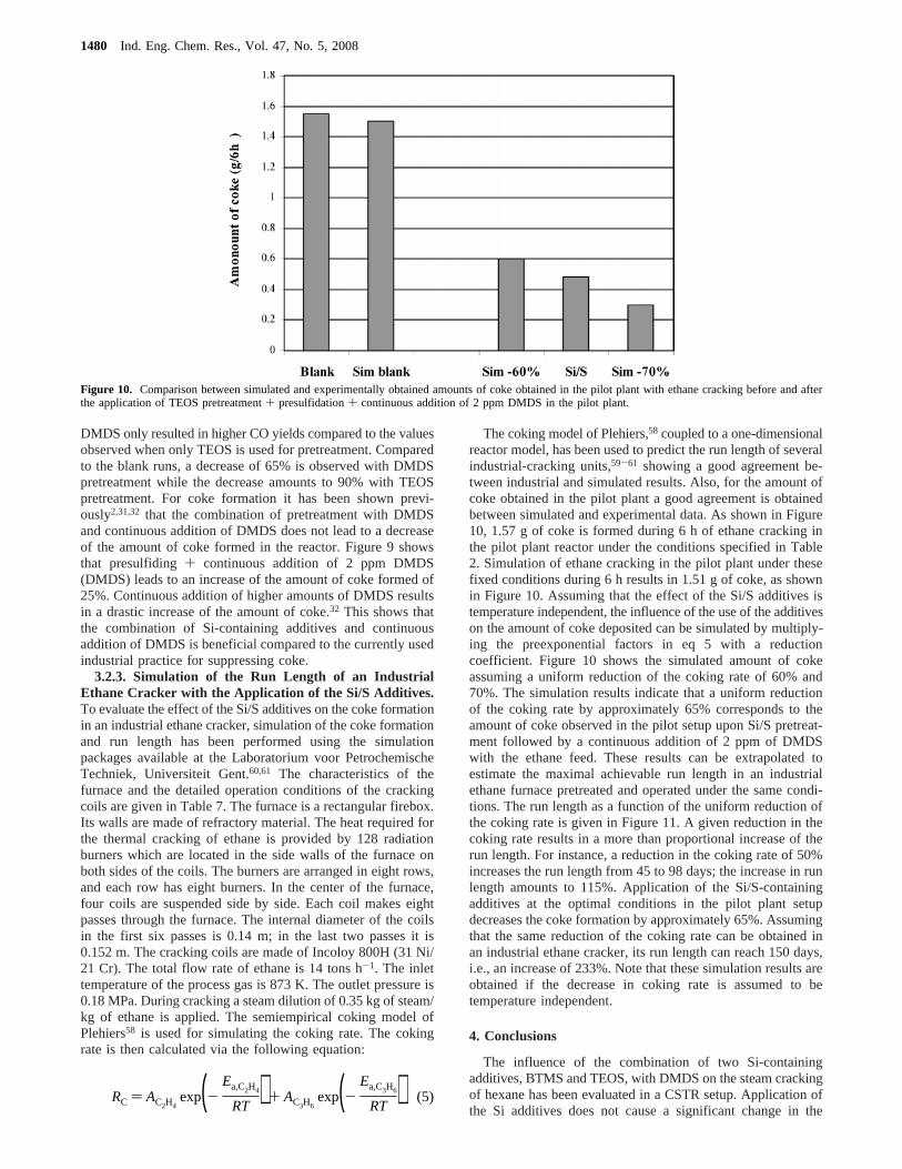
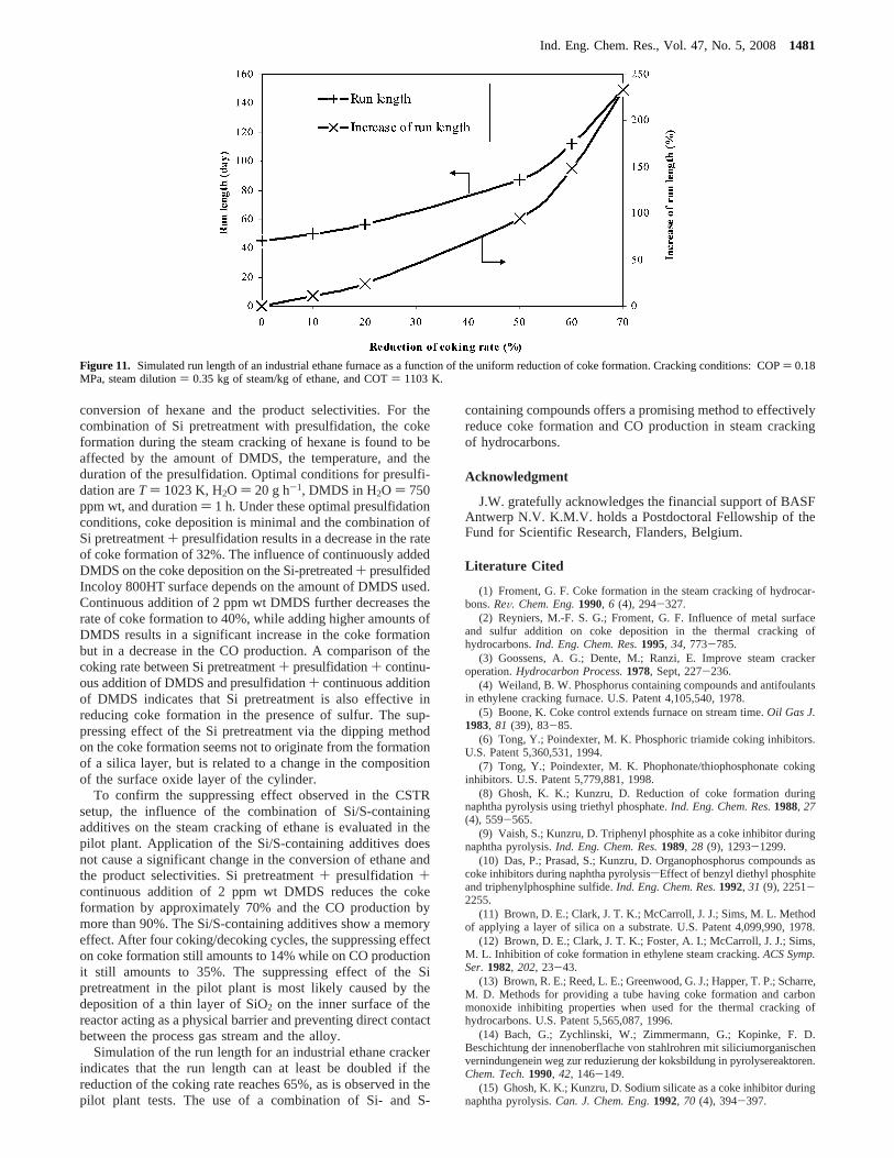
The coking model of Plehiers,58 coupled to a one-dimensionalreactor model, has been used to predict the run length of severalindustrial-cracking units,59-61 showing a good agreement be-tween industrial and simulated results. Also, for the amount ofcoke obtained in the pilot plant a good agreement is obtainedbetween simulated and experimental data. As shown in Figure10, 1.57 g of coke is formed during 6 h of ethane cracking inthe pilot plant reactor under the conditions specified in Table2. Simulation of ethane cracking in the pilot plant under thesefixed conditions during 6 h results in 1.51 g of coke, as shownin Figure 10. Assuming that the effect of the Si/S additives istemperature independent, the influence of the use of the additiveson the amount of coke deposited can be simulated by multiply-ing the preexponential factors in eq 5 with a reductioncoefficient. Figure 10 shows the simulated amount of cokeassuming a uniform reduction of the coking rate of 60% and70%. The simulation results indicate that a uniform reductionof the coking rate by approximately 65% corresponds to theamount of coke observed in the pilot setup upon Si/S pretreat-ment followed by a continuous addition of 2 ppm of DMDSwith the ethane feed. These results can be extrapolated toestimate the maximal achievable run length in an industrialethane furnace pretreated and operated under the same condi-tions. The run length as a function of the uniform reduction ofthe coking rate is given in Figure 11. A given reduction in thecoking rate results in a more than proportional increase of therun length. For instance, a reduction in the coking rate of 50%increases the run length from 45 to 98 days; the increase in runlength amounts to 115%. Application of the Si/S-containingadditives at the optimal conditions in the pilot plant setupdecreases the coke formation by approximately 65%. Assumingthat the same reduction of the coking rate can be obtained inan industrial ethane cracker, its run length can reach 150 days,i.e., an increase of 233%. Note that these simulation results areobtained if the decrease in coking rate is assumed to betemperature independent.
4. Conclusions
The influence of the combination of two Si-containingadditives, BTMS and TEOS, with DMDS on the steam crackingof hexane has been evaluated in a CSTR setup. Application ofthe Si additives does not cause a significant change in the
Figure 10. Comparison between simulated and experimentally obtained amounts of coke obtained in the pilot plant with ethane cracking before and afterthe application of TEOS pretreatment+ presulfidation+ continuous addition of 2 ppm DMDS in the pilot plant.
RC ) AC2H4exp(-
Ea,C2H4
RT ) + AC3H6exp(-
Ea,C3H6
RT ) (5)
1480 Ind. Eng. Chem. Res., Vol. 47, No. 5, 2008
conversion of hexane and the product selectivities. For thecombination of Si pretreatment with presulfidation, the cokeformation during the steam cracking of hexane is found to beaffected by the amount of DMDS, the temperature, and theduration of the presulfidation. Optimal conditions for presulfi-dation areT ) 1023 K, H2O ) 20 g h-1, DMDS in H2O ) 750ppm wt, and duration) 1 h. Under these optimal presulfidationconditions, coke deposition is minimal and the combination ofSi pretreatment+ presulfidation results in a decrease in the rateof coke formation of 32%. The influence of continuously addedDMDS on the coke deposition on the Si-pretreated+ presulfidedIncoloy 800HT surface depends on the amount of DMDS used.Continuous addition of 2 ppm wt DMDS further decreases therate of coke formation to 40%, while adding higher amounts ofDMDS results in a significant increase in the coke formationbut in a decrease in the CO production. A comparison of thecoking rate between Si pretreatment+ presulfidation+ continu-ous addition of DMDS and presulfidation+ continuous additionof DMDS indicates that Si pretreatment is also effective inreducing coke formation in the presence of sulfur. The sup-pressing effect of the Si pretreatment via the dipping methodon the coke formation seems not to originate from the formationof a silica layer, but is related to a change in the compositionof the surface oxide layer of the cylinder.
To confirm the suppressing effect observed in the CSTRsetup, the influence of the combination of Si/S-containingadditives on the steam cracking of ethane is evaluated in thepilot plant. Application of the Si/S-containing additives doesnot cause a significant change in the conversion of ethane andthe product selectivities. Si pretreatment+ presulfidation+continuous addition of 2 ppm wt DMDS reduces the cokeformation by approximately 70% and the CO production bymore than 90%. The Si/S-containing additives show a memoryeffect. After four coking/decoking cycles, the suppressing effecton coke formation still amounts to 14% while on CO productionit still amounts to 35%. The suppressing effect of the Sipretreatment in the pilot plant is most likely caused by thedeposition of a thin layer of SiO2 on the inner surface of thereactor acting as a physical barrier and preventing direct contactbetween the process gas stream and the alloy.
Simulation of the run length for an industrial ethane crackerindicates that the run length can at least be doubled if thereduction of the coking rate reaches 65%, as is observed in thepilot plant tests. The use of a combination of Si- and S-
containing compounds offers a promising method to effectivelyreduce coke formation and CO production in steam crackingof hydrocarbons.
Acknowledgment
J.W. gratefully acknowledges the financial support of BASFAntwerp N.V. K.M.V. holds a Postdoctoral Fellowship of theFund for Scientific Research, Flanders, Belgium.
Literature Cited
(1) Froment, G. F. Coke formation in the steam cracking of hydrocar-bons.ReV. Chem. Eng.1990, 6 (4), 294-327.
(2) Reyniers, M.-F. S. G.; Froment, G. F. Influence of metal surfaceand sulfur addition on coke deposition in the thermal cracking ofhydrocarbons.Ind. Eng. Chem. Res.1995, 34, 773-785.
(3) Goossens, A. G.; Dente, M.; Ranzi, E. Improve steam crackeroperation.Hydrocarbon Process.1978, Sept, 227-236.
(4) Weiland, B. W. Phosphorus containing compounds and antifoulantsin ethylene cracking furnace. U.S. Patent 4,105,540, 1978.
(5) Boone, K. Coke control extends furnace on stream time.Oil Gas J.1983, 81 (39), 83-85.
(6) Tong, Y.; Poindexter, M. K. Phosphoric triamide coking inhibitors.U.S. Patent 5,360,531, 1994.
(7) Tong, Y.; Poindexter, M. K. Phophonate/thiophosphonate cokinginhibitors. U.S. Patent 5,779,881, 1998.
(8) Ghosh, K. K.; Kunzru, D. Reduction of coke formation duringnaphtha pyrolysis using triethyl phosphate.Ind. Eng. Chem. Res.1988, 27(4), 559-565.
(9) Vaish, S.; Kunzru, D. Triphenyl phosphite as a coke inhibitor duringnaphtha pyrolysis.Ind. Eng. Chem. Res.1989, 28 (9), 1293-1299.
(10) Das, P.; Prasad, S.; Kunzru, D. Organophosphorus compounds ascoke inhibitors during naphtha pyrolysissEffect of benzyl diethyl phosphiteand triphenylphosphine sulfide.Ind. Eng. Chem. Res.1992, 31 (9), 2251-2255.
(11) Brown, D. E.; Clark, J. T. K.; McCarroll, J. J.; Sims, M. L. Methodof applying a layer of silica on a substrate. U.S. Patent 4,099,990, 1978.
(12) Brown, D. E.; Clark, J. T. K.; Foster, A. I.; McCarroll, J. J.; Sims,M. L. Inhibition of coke formation in ethylene steam cracking.ACS Symp.Ser.1982, 202, 23-43.
(13) Brown, R. E.; Reed, L. E.; Greenwood, G. J.; Happer, T. P.; Scharre,M. D. Methods for providing a tube having coke formation and carbonmonoxide inhibiting properties when used for the thermal cracking ofhydrocarbons. U.S. Patent 5,565,087, 1996.
(14) Bach, G.; Zychlinski, W.; Zimmermann, G.; Kopinke, F. D.Beschichtung der innenoberflache von stahlrohren mit siliciumorganischenvernindungenein weg zur reduzierung der koksbildung in pyrolysereaktoren.Chem. Tech.1990, 42, 146-149.
(15) Ghosh, K. K.; Kunzru, D. Sodium silicate as a coke inhibitor duringnaphtha pyrolysis.Can. J. Chem. Eng.1992, 70 (4), 394-397.
Figure 11. Simulated run length of an industrial ethane furnace as a function of the uniform reduction of coke formation. Cracking conditions: COP) 0.18MPa, steam dilution) 0.35 kg of steam/kg of ethane, and COT) 1103 K.
Ind. Eng. Chem. Res., Vol. 47, No. 5, 20081481

(16) Zimmermann, G.; Zychlinski, W. Process for producing thermallycracked products from hydrocarbons. U.S. Patent 5,849,176, 1998.
(17) Zimmermann, G.; Zychlinski, W. Apparatus and process forreducing coking of heat exchange surface. U. S. Patent 5922192, 1999.
(18) Woerde, H. M.; Barendregt, S.; Humblot, F.; Brun, C. Mitigatecoke formation.Hydrocarbon Process.2002, March, 45-50.
(19) Anonymous. New additive retards coke formation in ethylenefurnace.Oil Gas J.1994, 92 (19), 73-75.
(20) Jo, H. K. Method for retarding corrosion and coke formation anddeposition during pyrolytic hydrocarbon processing. U.S. Patent 5,567,-305, 1996.
(21) Porter, R. A.; Reed, L. E. Antifoulants for thermal crackingprocesses. U.S. Patent 4,545,893, 1985.
(22) Porter, R. A.; Reed, L. E. Antifoulants for thermal crackingprocesses. U.S. Patent 4,687,567, 1987.
(23) Porter, R. A.; Reed, L. E. Antifoulants for thermal crackingprocesses. U.S. Patent 4,692,234, 1987.
(24) Porter, R. A.; Reed, L., E. Antifoulants comprising titanium forthermal cracking processes. U.S. Patent 5,015,358, 1991.
(25) Bajus, M.; Vesely, V. Pyrolysis of hydrocarbons in the presenceof elemental sulfur.Collect. Czech. Chem. Commun.1980, 45 (1), 238-253.
(26) Bajus, M.; Vesely, V.; Baxa, J.; Leclercq, P. A.; Rijks, J. A. Steamcracking of hydrocarbons. 5. Effect of thiophene on reaction kinetics andcoking. Ind. Eng. Chem. Prod. Res. DeV. 1981, 20 (4), 741-745.
(27) Bajus, M.; Baxa, J.; Leclercq, P. A.; Rijks, J. A. Steam crackingof hydrocarbons. 6. Effect of dibenzyl sulfide and dibenzyl disulfide onreaction kinetics and coking.Ind. Eng. Chem. Prod. Res. DeV. 1983, 22(2), 335-343.
(28) Bajus, M.; Baxa, J. Coke formation during the pyrolysis ofhydrocarbons in the presence of sulfur compounds.Collect. Czech. Chem.Commun.1985, 50, 2093-2909.
(29) Depeyre, D.; Filcoteaux, C.; Blouri, B.; Ossebi, J. G. Pure normal-nonane steam cracking and the influence of sulfur-compounds.Ind. Eng.Chem. Process Des. DeV. 1985, 24 (4), 920-924.
(30) Velenyi, L. J.; Song, Y. H.; Fagley, J. C. Carbon deposition inethane pyrolysis reactors.Ind. Eng. Chem. Res.1991, 30 (8), 1708-1712.
(31) Dhuyvetter, I.; Reyniers, M.-F. S. G.; Froment, G. F.; Marin, G.B. The influence of dimethyl disulfide on naphtha steam cracking.Ind.Eng. Chem. Res.2001, 40 (20), 4353-4326.
(32) Wang, J.; Reyniers, M.-F.; Marin, G. B. The influence of dimethyldisulfide on the coke formation during steam cracking of hydrocarbons.Ind. Eng. Chem. Res.2007, 46 (12), 4134-4148.
(33) Lahaye, J.; Badie, P.; Ducret, J. Mechanism of carbon formationduring steam-cracking of hydrocarbons.Carbon1977, 15 (2), 87-93.
(34) Trimm, D. L. Control of coking.Chem. Eng. Process.1984, 18(3), 137-148.
(35) Jackson, S. D.; Thomson, S. J.; Webb, G. Carbonaceous depositionon nickel.J. Catal.1981, 70, 249-263.
(36) Kanaya, K.; Okayama, S.Scanning Electron Microscopy and X-RayMicro-analysis, 2nd ed.; Goldstein, J. J., et al., Eds.; Plenum Press: NewYork and London, 1992.
(37) Bennett, M. J.; Price, J, B. A physical and chemical examinationof an ethylene steam cracker coke and of the underlying pyrolysis tube.J.Mater. Sci.1981, 16, 170-188.
(38) Lide, D. R.Handbook of chemistry and physics, 84th ed.; CRCPress: Boca Raton, FL, 2003-2004.
(39) Trimm, D. L.; Turner, C. J. The pyrolysis of propane: 2. Effect ofhydrogen sulfide.J. Chem. Technol. Biotechnol.1981, 31, 285-289.
(40) Browne, J.; Broutin, P.; Ropital, F. Coke deposition under steamcracking conditionssStudy of the influence of the feedstock conversionby micropilots experiments.Mater. Corros.1998, 49, 360-366.
(41) Adam, R. O. A review of the stainless steel surface.J. Vac. Sci.Technol., A1983, 1 (1), 12-18.
(42) Lobning, R. E.; Grabke, H. J. Mechanism of simultaneous sulfi-dation and oxidation of Fe-Cr and Fe-Cr-Ni alloys and of the failure ofProtective chromia scale.Corros. Sci.1990, 30 (10), 1045-1071.
(43) Nolang, B. I. EKVICALC. Ph.D. Thesis, Institute of Chemistry,University of Uppsala, Sweden, 1985.
(44) Wauters, S.; Marin, G. B. Kinetic modeling of coke formationduring steam cracking.Ind. Eng. Chem. Res.2002, 41 (10), 2379-2391.
(45) Kopinke, F. D.; Zimmermann, G.; Reyniers, G. C.; Froment, G. F.Relative rates of coke formation from hydrocarbons in steam cracking ofnaphtha. 2. Paraffins, naphthenes, mono-, di-, and cycloolefins, andacetylenes.Ind. Eng. Chem. Res.1993, 32 (1), 56-61.
(46) Kopinke, F. D. Zimmermann, G.; Reyniers, G. C.; Froment, G. F.Relative rates of coke formation from hydrocarbons in steam cracking ofnaphtha. 3. Aromatic hydrocarbons.Ind. Eng. Chem. Res.1993, 32 (11),2620-2625.
(47) Lahaye, L. Particulate carbon from the gas phase.Carbon 1992,30 (3), 309-314.
(48) Pramanik, M.; Kunzru, D. Coke formation in the pyrolysis ofn-hexane.Ind. Eng. Chem. Process Des. DeV. 1985, 24, 1275-1281.
(49) Grabke, H. J. Fundamental aspects of oxidation, sulfidation,chloridation and carburization in the gasifier environment.Mater. HighTemp.1993, 11 (1-4), 23-29.
(50) Stott, F. H.; Gabriel, G. J.; Wood, G. C. The influence of siliconon the high-temperature oxidation of nickel.Oxid. Met.1987, 28 (5/6),329-345.
(51) Baxter, D. J.; Derricott, R. T.; Hurst, R. C. The influence of siliconand yttrium on isothermal scaling of an austenitic Fe-Cr-Ni alloy (IN 519)at 1000°C. Werkst. Korros.1983, 34, 446-450.
(52) Huntz, A. M.; Bague, V.; Beauple´, G.; Haut, C.; Se´verac, C.;Lecour, P.; Longaygue, X.; Ropital, F. Effect of silicon on the oxidationresistance of 9% Cr steels.Appl. Surf. Sci.2003, 207, 255-275.
(53) Perez, F. J.; Otero, E.; Hierro, M. P.; Go´mez, C.; Pedraza, F.; deSegovia, J. L. Roma´n, E. High temperature corrosion protection of austeniticAISI 304 stainless steel by Si, Mo, and Ce iron implantation.Surf. Coat.Technol.1998, 108-109, 127-131.
(54) Baker, R. T. K.; Chludzinski, J. J. Filamentous carbon growth onnickel-iron surfacessthe effect of various oxide additives.J. Catal.1980,64 (2), 464-478.
(55) Baxter, D. J.; Natesan, K. Breakdown of chromium oxide scalesin sulfur-containing environment at elevated temperature.Oxid. Met.1989,31 (3/4), 305-323.
(56) Jian, P.; Jian, L.; Bing, H.; Xie, G. Y. Oxidation kinetics and phaseevolution of a Fe-16Cr alloy in simulated SOFC cathode atmosphere.J.Power Sources2006, 158 (1), 354-360.
(57) Hansson, A. N.; Somers, M. A. J. Influence of the oxidationenvironment on scale morphology and oxidation rate of Fe-22Cr.Mater.High Temp.2005, 22 (3-4), 223-229.
(58) Plehiers, P. M., Rigoureuze modellen voor de simulatie vanfornuizen voor de thermische kraking van lichte koolwaterstoffen. Ph.D.Thesis, Ghent University, 1989.
(59) Plehiers, P. M.; Froment, G. F. Firebox simulation of olefin units.Chem. Eng. Commun.1989, 80, 81-99.
(60) Froment, G. F. Kinetics and Reactor Design in the ThermalCracking for Olefin Production.Chem. Eng. Sci.1992, 47, 2163-2177.
(61) Van Geem, K. M.; Heynderickx, G. J.; Marin, G. B. A Comparisonof One and Two-dimensional Reactor Models for Steam Cracking: Effecton Yields and Coking rate.AIChE J.2004, 50, 173-183.
ReceiVed for reView July 17, 2007ReVised manuscript receiVed November 8, 2007
AcceptedNovember 8, 2007
IE070970W
1482 Ind. Eng. Chem. Res., Vol. 47, No. 5, 2008