infinity analyze user’s manual - microscope world · lumenera infinity analyze user’s manual...
TRANSCRIPT

INFINITY ANALYZE User’s Manual

Lumenera INFINITY ANALYZE User’s Manual Release 4.6.0
Page 2 Copyright © 2008
Copyright Notice: Release 4.6.0
Copyright © 2008 Lumenera Corporation. All rights reserved.
The contents of this document may not be copied nor duplicated in any form, in whole or in part, without prior written consent from Lumenera Corporation. Lumenera makes no warranties as to the accuracy of the information contained in this document or its suitability for any purpose. The information in this document is subject to change without notice.
License Agreement (Software): This Agreement states the terms and conditions upon which Lumenera Corporation ("Lumenera") offers to license to you (the "Licensee") the software together with all related documentation and accompanying items including, but not limited to, the executable programs, drivers, libraries, and data files associated with such programs (collectively, the "Software").
The Software is licensed, not sold, to you for use only under the terms of this Agreement.
Lumenera grants to you the right to use all or a portion of this Software provided that the Software is used only in conjunction with Lumenera's family of products.
In using the Software you agree not to:
a) decompile, disassemble, reverse engineer, or otherwise attempt to derive the source code for any Product (except to the extent applicable laws specifically prohibit such restriction);
b) remove or obscure any trademark or copyright notices.
Limited Warranty (Hardware and Software): ANY USE OF THE SOFTWARE OR HARDWARE IS AT YOUR OWN RISK. THE SOFTWARE IS PROVIDED FOR USE ONLY WITH LUMENERA'S HARDWARE AND OTHER RELATED SOFTWARE. THE SOFTWARE IS PROVIDED FOR USE "AS IS" WITHOUT WARRANTY OF ANY KIND. TO THE MAXIMUM EXTENT PERMITTED BY LAW, LUMENERA DISCLAIMS ALL WARRANTIES OF ANY KIND, EITHER EXPRESS OR IMPLIED, INCLUDING, WITHOUT LIMITATION, IMPLIED WARRANTIES OR CONDITIONS OF MERCHANTABILITY, QUALITY AND FITNESS FOR A PARTICULAR PURPOSE. LUMENERA IS NOT OBLIGATED TO PROVIDE ANY UPDATES OR UPGRADES TO THE SOFTWARE OR ANY RELATED HARDWARE.
Limited Liability (Hardware and Software): In no event shall Lumenera or its Licensor's be liable for any damages whatsoever (including, without limitation, incidental, direct, indirect, special or consequential damages, damages for loss of business profits, business interruption, loss of business information, or other pecuniary loss) arising out of the use or inability to use this Software or related Hardware, including, but not limited to, any of Lumenera's family of products.
Product Warranty Lumenera Corporation warrants to the original purchaser that our cameras are guaranteed to be free from manufacturing defects for a period of one (1) year from the original date of purchase.

Lumenera INFINITY ANALYZE Release 4.6.0 User’s Manual
Copyright © 2008 Page 3
Should the unit fail during the warranty period, Lumenera will, at its option, repair or replace the failed unit. Repaired or replaced units will be covered under warranty for the remainder of the original one (1) year warranty period.
This warranty does not apply to units that, after being inspected by Lumenera, have been found to have failed due to customer abuse, accidents, mishandling, tampering/alteration, improper installation, improper power source, negligence, opening of the enclosure, or if the serial number has been removed or damaged. This warranty does not cover labor or incurred charges required in removing or installing the unit, any business interruption, loss of profits/revenues, or any consequential damages.
Units returned to Lumenera beyond the warranty period will be repaired, if possible, and all appropriate material and labor charges will apply.
Any returning product, specifically those being returned under warranty, must follow the Returned Material Authorization (RMA) process. Any units being returned are to be properly packaged (in original packing – if possible). Lumenera will not cover damage sustained in shipping due to improper packing.
For RMA instructions, please refer to our website at www.lumenera.com.
RoHS/WEEE Compliance Statement The Restriction of Hazardous Substances in Electrical and Electronic Equipment (RoHS) Directive was passed into law by the European Union (E.U.). It affects manufacturers, sellers, distributors and recyclers of electrical and electronic equipment containing lead, cadmium, mercury, hexavalent chrome, polybrominated biphenyl (PBB) and polybrominated diphenyl ether (PBDE). After July 1, 2006 the use of these materials will be banned in new products sold in Europe. The RoHS Directive complements the WEEE Directive. China is expected to adopt similar legislation within a similar timeline.
The Waste Electrical and Electronic Equipment Directive (WEEE) aims to reduce the waste arising from electrical and electronic equipment and to improve the environmental performance of all those involved in the life cycle of these products.
Lumenera is committed to protecting people and the environment and we are working on identifying any materials used in our processes that could pose a potential hazard to our employees, customers or the environment.
For this reason we are committed to have all our products comply with the RoHS and WEEE directives. We are constantly improving our compliance with these directives. For more information on our compliance or to track our progress please refer to our website.
Trademarks and Proprietary Names: Lumenera Scientific, INFINITY X, INFINITY 1, INFINITY 2, INFINITY 3, INFINITY 4, INFINITY 5, and DeltaVU are trademarks of Lumenera Corporation. This manual may refer to other product names, which may be trademarked by their respective companies, and are used herein for identification purposes only.

Lumenera INFINITY ANALYZE User’s Manual Release 4.6.0
Page 4 Copyright © 2008
Federal Communications Commission (FCC) Statement This equipment has been tested and found to comply with the limits of a Class B digital device, pursuant to Part 15 of the FCC Rules. These limits are designed to provide reasonable protection against harmful interference when the equipment is operated in a residential environment. This equipment generates, uses, and radiates radio frequency energy, and if not installed and used in accordance with the instructions, may cause harmful interference. However, there is no guarantee that interference will not occur. If this equipment does cause interference to radio or television reception, which can be determined by turning the equipment off and on, the user is encouraged to correct the interference by one of the following measures:
• Reorient or relocate the receiving antenna. • Increase separation between the equipment and receiver. • Connect the equipment into an outlet on a circuit different from which the receiver is
connected. • Consult the dealer or an experienced radio/TV technician.
Any changes or modification to said product not expressly approved by Lumenera could void the user's authority to operate this device. Shielded and grounded cables and connectors must be used to meet FCC emission limits. Lumenera takes no responsibility for any radio or television interference caused by using cables or connectors other than those recommended. This device complies with part 15 of the FCC Rules. Operation is subject to the following two conditions: (1) This device may not cause harmful interference, and (2) this device must accept any interference received, including interference that may cause undesired operation.
European Community (CE) Statement Products: INFINITY 1, 2, 3, 4, 5, X, Lu1175, Lu1175X, Lu1205, Lu1135, Lu1165, Lw1235, Lu1275, Lu1335, Lu1375 and Lw1625 USB Scientific Cameras. Directives: 2001/59/EC (General Product Safety Directive) Self-declared 89/336/EEC (EMC Directive). Standards to which conformity is declared: EN55024: 1998
EN55022: 1998 (Class B) EN61000-3-2: 1995 EN61000-3-3: 1995
Manufacturer’s Name and Address: Lumenera Corporation
7 Capella Court Ottawa, ON K2E 8A7 Canada
Type of Equipment: USB 2.0 Scientific Digital Camera First Year of CE Conformity: 2003 This is to certify that the Lumenera USB 2.0 Scientific Cameras meet or exceed the standards for CE compliance per the Council Directives noted above. All equipment is built at Lumenera Corporation, and pertinent testing documentation is available for verification.
Lumenera INFINITY ANALYZE Release 4.6.0 User’s Manual
Copyright © 2008 Page 5
Table of Contents TABLE OF CONTENTS ..................................................................................................... 5
INTRODUCTION............................................................................................................. 9
GETTING STARTED .................................................................................................... 10 2.1 IMAGE .............................................................................................................. 10
2.1.1 Color Models ........................................................................................... 10 2.1.2 Raster Images and Vector Graphics........................................................ 12 2.1.3 The Layers............................................................................................... 13 2.1.4 The Active Image..................................................................................... 13 2.1.5 The Empty Image Window....................................................................... 15
2.2 WORKSPACE..................................................................................................... 15 2.2.1 Menu........................................................................................................ 15 2.2.2 Toolbar .................................................................................................... 15 2.2.3 Status Bar................................................................................................ 15 2.2.4 Auxiliary Window ..................................................................................... 16
MENU COMMANDS ..................................................................................................... 24
3.1 THE FILE MENU................................................................................................. 25 3.1.1 New for Video Preview ............................................................................ 25 3.1.2 Open........................................................................................................ 26 3.1.3 Close ....................................................................................................... 27 3.1.4 Save ........................................................................................................ 27 3.1.5 Save As ................................................................................................... 27 3.1.6 Print Setup............................................................................................... 28 3.1.7 Print Image Layout................................................................................... 28 3.1.8 Print Preview............................................................................................ 30 3.1.9 Print ......................................................................................................... 32 3.1.10 Auto Exposure Control............................................................................. 32 3.1.11 White Balance.......................................................................................... 33 3.1.12 Manual White Balance............................................................................. 34 3.1.13 Light Source ............................................................................................ 34 3.1.14 Toggle Preview........................................................................................ 38 3.1.15 Capture.................................................................................................... 39 3.1.16 Time Lapse Capture ................................................................................ 43 3.1.17 Lookup Table ........................................................................................... 45 3.1.18 Exit........................................................................................................... 46
3.2 THE EDIT MENU ................................................................................................ 47 3.2.1 Undo ........................................................................................................ 47 3.2.2 Redo ........................................................................................................ 47 3.2.3 Copy to Clipboard .................................................................................... 47
3.3 THE VIEW MENU ............................................................................................... 47 3.3.1 Toolbars and Auxiliary Windows.............................................................. 47 3.3.2 Status Bar................................................................................................ 48

Lumenera INFINITY ANALYZE User’s Manual Release 4.6.0
Page 6 Copyright © 2008
3.3.3 Auxiliary Window Captions ...................................................................... 48 3.3.4 Image Window Tabs ................................................................................ 48 3.3.5 Overlay .................................................................................................... 49 3.3.6 Overlay Color ........................................................................................... 49 3.3.7 Overlay Size............................................................................................. 53 3.3.8 Centre ...................................................................................................... 54 3.3.9 Corner...................................................................................................... 54 3.3.10 Fit to Window ........................................................................................... 54 3.3.11 Zoom Preview.......................................................................................... 55 3.3.12 Screen Gamma........................................................................................ 56 3.3.13 Equivalent Commands............................................................................. 56
3.4 THE DATABASE MENU........................................................................................ 57 3.4.1 Store ........................................................................................................ 57 3.4.2 Load.........................................................................................................59 3.4.3 Delete ...................................................................................................... 59 3.4.4 Refresh .................................................................................................... 60
3.5 THE FIELD MENU............................................................................................... 60 3.5.1 Open ........................................................................................................ 60 3.5.2 Save......................................................................................................... 61 3.5.3 Import....................................................................................................... 61 3.5.4 Export ...................................................................................................... 62 3.5.5 Append .................................................................................................... 62 3.5.6 Load.........................................................................................................62 3.5.7 Move Up .................................................................................................. 63 3.5.8 Move Down.............................................................................................. 63 3.5.9 Clear ........................................................................................................ 63 3.5.10 Clear All ................................................................................................... 64 3.5.11 Show Previous ......................................................................................... 64 3.5.12 Show Next ............................................................................................... 64 3.5.13 Panorama Landscape.............................................................................. 65 3.5.14 Panorama Portrait.................................................................................... 66 3.5.15 Multi-Focus Composition ......................................................................... 67 3.5.16 Math......................................................................................................... 69 3.5.17 Color Composition ................................................................................... 72
3.6 THE ADJUST MENU............................................................................................ 73 3.6.1 Image Gamma ......................................................................................... 73 3.6.2 Area Based White Balance ...................................................................... 74 3.6.3 Interactive ................................................................................................ 75 3.6.4 More......................................................................................................... 77 3.6.5 Less ......................................................................................................... 77 3.6.6 Increments ............................................................................................... 77 3.6.7 Mirror ....................................................................................................... 78 3.6.8 Rotate ...................................................................................................... 78 3.6.9 Magnification............................................................................................ 79 3.6.10 Micrometer > Calibration.......................................................................... 80

Lumenera INFINITY ANALYZE Release 4.6.0 User’s Manual
Copyright © 2008 Page 7
3.6.11 Micrometer > Burn into Image ................................................................. 82 3.6.12 Micrometer > Burn into Image Options .................................................... 82
3.7 THE ENHANCE MENU......................................................................................... 83 3.7.1 Flatfield Correction................................................................................... 83 3.7.2 Flatfield Correction Options ..................................................................... 84 3.7.3 Denoise ................................................................................................... 85 3.7.4 Remove Bad Pixels ................................................................................. 86 3.7.5 Unsharp ................................................................................................... 87 3.7.6 Unsharp Options...................................................................................... 88 3.7.7 Max Contrast ........................................................................................... 90 3.7.8 Sketch...................................................................................................... 91 3.7.9 Adaptive Edge Emphasis......................................................................... 92 3.7.10 Equalization ............................................................................................. 93 3.7.11 Amplitude Depletion................................................................................. 94 3.7.12 Darkfield Simulation................................................................................. 95 3.7.13 Photometric Transform ............................................................................ 96 3.7.14 Spherical Aberration Correction............................................................... 98 3.7.15 Spherical Aberration Correction Options ................................................. 99
3.8 THE MEASURE MENU ........................................................................................ 99 3.8.1 Reset ..................................................................................................... 100 3.8.2 Abort ...................................................................................................... 100 3.8.3 Grid........................................................................................................ 100 3.8.4 Grid Options .......................................................................................... 101 3.8.5 Light Density .......................................................................................... 101 3.8.6 Counting ................................................................................................ 103 3.8.7 Angle ..................................................................................................... 104 3.8.8 Polyline .................................................................................................. 105 3.8.9 Circle from 3 Points ............................................................................... 106 3.8.10 Area Perimeter....................................................................................... 107 3.8.11 Caliper ................................................................................................... 108 3.8.12 Polygon.................................................................................................. 109
3.9 THE ANNOTATION MENU .................................................................................. 109 3.9.1 Enable ................................................................................................... 110 3.9.2 Line........................................................................................................ 110 3.9.3 Rectangle .............................................................................................. 113 3.9.4 Round Rectangle ................................................................................... 115 3.9.5 Ellipse .................................................................................................... 116 3.9.6 Polygon.................................................................................................. 116 3.9.7 Arrow ..................................................................................................... 117 3.9.8 Text........................................................................................................ 119 3.9.9 External ................................................................................................. 120 3.9.10 Select..................................................................................................... 121 3.9.11 Select All................................................................................................ 121 3.9.12 Delete .................................................................................................... 121 3.9.13 Properties .............................................................................................. 121

Lumenera INFINITY ANALYZE User’s Manual Release 4.6.0
Page 8 Copyright © 2008
3.9.14 Move to Uppermost................................................................................ 122 3.9.15 Move to Lowermost................................................................................ 122 3.9.16 Move Upper ........................................................................................... 122 3.9.17 Move Lower ........................................................................................... 122 3.9.18 Burn into Image...................................................................................... 122
3.10 THE WINDOW MENU ........................................................................................ 123 3.10.1 Cascade................................................................................................. 123 3.10.2 Tile Horizontally ..................................................................................... 123 3.10.3 Tile Vertically.......................................................................................... 123 3.10.4 Arrange Icon .......................................................................................... 123
3.11 THE HELP MENU ............................................................................................. 123 3.11.1 Settings.................................................................................................. 124 3.11.2 Database Settings.................................................................................. 124 3.11.3 Manual ................................................................................................... 126 3.11.4 Online Help ............................................................................................ 126 3.11.5 About Analyze........................................................................................ 126
OTHER COMMANDS ................................................................................................. 127
4.1 IMAGING CONTROL .......................................................................................... 127 4.1.1 Capture Control...................................................................................... 129 4.1.2 Time Lapse ............................................................................................ 132 4.1.3 Image Orientation .................................................................................. 134 4.1.4 Capture Options..................................................................................... 135 4.1.5 Light Source........................................................................................... 138 4.1.6 Camera Control Extended ..................................................................... 139
DATABASE ................................................................................................................. 141 4.1.7 Store ...................................................................................................... 141 4.1.8 Load....................................................................................................... 144 4.1.9 Delete .................................................................................................... 144 4.1.10 Refresh .................................................................................................. 145 4.1.11 Query ..................................................................................................... 145

Lumenera INFINITY ANALYZE Release 4.6.0 User’s Manual
Copyright © 2008 Page 9
1 1 Introduction The INFINITY ANALYZE application package is designed to work exclusively with the Lumenera INFINITY camera models. It provides all of the functions necessary to control all available camera settings, for both the live video preview and the capture of still images. In addition, ANALYZE provides a comprehensive set of measurement and analytical operations useful in many clinical, laboratory, and inspection operations. For details on the features and performance of a particular INFINITY camera model, refer to the INFINITY CAPTURE Users Manual

Lumenera INFINITY ANALYZE User’s Manual Release 4.6.0
Page 10 Copyright © 2008
2 Getting Started It is assumed that the users of INFINITY ANALYZE and the readers of this document have a working knowledge of microscope, digital camera and Microsoft Windows. INFINITY ANALYZE may be used for both compound and stereo microscopes. It also contains a few functions specifically designed for fluorescent imaging. INFINITY ANALYZE conforms to the Microsoft Windows User Interface Guideline and so is similar to other programs in opening files and mouse operations. This section lays a background for image capture and analysis with INFINITY ANALYZE.
2.1 Image
2.1.1 Color Models Digital images record colors by numbers. Different color models are used to interpret the digital values representing pixel intensity readings. INFINITY ANALYZE uses a number of color models for image acquisition, display, processing and printing. In most cases the underlying color model is transparent to users. Where they are explicit, an understanding of RGB and HSI models suffices for the purpose of working with INFINITY ANALYZE. RGB A large portion of the visible spectrum can be represented by mixing three basic components of colored light in various proportions and intensities. The primary components used are the colors: red, green and blue (RGB). Computer screens use an RGB model to display graphics and images. Most 8-bit image processing programs, including INFINITY ANALYZE, employ a triplet of integers in the range [0,255] to represent a color being described by the RGB model.

Lumenera INFINITY ANALYZE Release 4.6.0 User’s Manual
Copyright © 2008 Page 11
HSI Human beings understand colors by their three fundamental characteristics: hue, saturation and intensity (HSI). Hue is the wavelength or frequency of light reflected from or transmitted through an object. Most often hue is identified by the name of the color such as orange or purple. Saturation is the strength or purity of the color and represents the amount of gray in proportion to the hue. Intensity stands for the relative lightness or darkness of the color. It is the energy contained in the color. As in the case of the RGB model, INFINITY ANALYZE uses a triplet of integers of the range [0,255] to represent a color based on the HSI model. However, a particular camera supported by INFINITY ANALYZE may implement a camera-specific range of values for hue, saturation or intensity and may not use integers to represent the value. For example, some cameras allow the adjustment of saturation in the range [0, 2]. In this situation, it is understood that the real number in the range [0, 2] will be scaled to [0, 255] and added to the saturation component of pixels in each frame of the video from that camera. Luminance is sometimes used in place of intensity in describing a color in the HSI model. In camera terminology gain has the greatest similarity to intensity. Whenever gain is involved, it is multiplicative instead of additive as in the processing of a still image. Grayscale and Indexed Color When dealing with a monochrome camera or image, the Grayscale model is used to represent the values from colored objects. In this case, a single integer in the range [0, 255] is used to describe the energy content of a color, corresponding to the intensity channel of HSI model. The other color model that uses a single number to describe the color is the Indexed Color which is based on a palette of 256 colors. INFINITY ANALYZE does not attempt to interpret the color in an image of indexed color. Whenever it reads a file of indexed color image, it converts the image to grayscale by simply mapping the indices to the intensities of a grayscale image. Color Components and Channels In the RGB model, each of the red, blue or green values is referred to as a component or channel of the color. Color component and color channel terms that are used interchangeably in this document. The same is true for the HSI model and the Grayscale model. A color described by the HSI model has three components or channels, namely the hue channel, the saturation channel and the intensity or luminance channel. A color described by Grayscale model has only one channel, namely the intensity channel.

Lumenera INFINITY ANALYZE User’s Manual Release 4.6.0
Page 12 Copyright © 2008
The triplet used by the RGB and the HSI models, and the single number used by Grayscale model, are called the color value. Color Model Conversions RGB and HSI are equivalent means to describe colors. The main reason to use multiple color models is to facilitate the understanding of image processing of INFINITY ANALYZE. The internal conversion between the two models is handled implicitly and needs no user input. RGB and HSI may also be used to represent a monochrome image as Grayscale model does. In this situation, the three channels of RGB are set equal, and the hue and saturation channels of HSI are set to zero.
2.1.2 Raster Images and Vector Graphics The components that make up the scene on a computer screen fall into two main categories: raster images and vector graphics. Raster images use a grid of small squares, known as pixels, to represent pictures. Each pixel in a raster image has a specific location and color value assigned to it. When working with raster images, groups of pixels rather than objects or shapes are being edited. Because they can represent subtle gradations of shades and color, raster images are the most common electronic medium for continuous-tone pictures such as photomicrographs. The terms raster image and pixel array are used interchangeably in this document. In fact, a raster image may also be described as a matrix of points. The distance between neighboring points on a row is referred to as the horizontal sampling interval. The distance between neighboring points on a column is referred to as the vertical sampling interval. Sampling interval multiplied by the number of columns and rows is exactly the size of the field of view over which the image has been captured. Vector graphics consist of lines and curves defined by mathematical objects called vectors, which describe pictures according to their geometric characteristics. The lines or curves of an object can be painted with a specific color. The interior of the shape enclosed by these lines and curves may also be painted with a specific color. Vector graphics can have only a limited number of colors and cannot represent natural scenes. They are mainly useful in annotating raster images. Raster images are resolution-dependent, that is, they represent a fixed number of pixels and can appear jagged and lose detail if they are scaled on-screen, or if they are printed at a higher resolution than they were created for. On the other hand, vector graphics are

Lumenera INFINITY ANALYZE Release 4.6.0 User’s Manual
Copyright © 2008 Page 13
resolution-independent; that is, they are defined by analytical formulas and so can be scaled arbitrarily to appear crisp and sharp on any output device at any resolution. INFINITY ANALYZE works with both raster images and vector graphics. The images obtained from cameras are raster images. The annotation objects created with INFINITY ANALYZE are vector graphics. In a broad sense, both raster images and vector graphics are considered digital images or digital pictures. Vector graphics are always converted to raster images for purpose of display, a process known as digitization. INFINITY ANALYZE can also burn vector graphics into raster images. This is the same as digitization but is irreversible.
2.1.3 The Layers For any image processing program that is more sophisticated than a simple image viewer, additional information is stored with the pixel data. For example, sampling intervals and magnification settings are also recorded in an image within INFINITY ANALYZE. In fact, even the pixels have to be organized into layers. Each layer is either a raster image or a vector graphics object. Layers may be combined in various ways to produce specific presentations of an image within INFINITY ANALYZE. The presentation itself is a simple raster image. An image in INFINITY ANALYZE has three layers. The bottommost layer is the pixel array, also called the pictorial layer. The topmost layer is the overlay, where the graphics generated by measurement operations and micrometer are placed. In between is the mask layer. This layer is used by advanced editions of INFINITY ANALYZE to hold segmentation results. In displaying an image, its pictorial layer is drawn first. The layers above the pictorial layer are drawn later and may obscure the pictorial layer. When INFINITY ANALYZE is running, there can be temporary layers hosting annotation objects. Each annotation object occupies a temporary layer by itself. The temporary layers are above any other types of layers. Annotation objects may be burned into the image, where the pictorial layer is modified according to the vector graphics of the temporary layers. Unburned annotation objects, i.e. temporary layers, are discarded when the image is closed.
2.1.4 The Active Image With INFINITY ANALYZE, many images can be open simultaneously. However, only one of them may receive input focus. This image is referred to as the active image. In this document, the active image, the current image, or sometimes the active image window, are used interchangeably.
Lumenera INFINITY ANALYZE User’s Manual Release 4.6.0
Page 14 Copyright © 2008
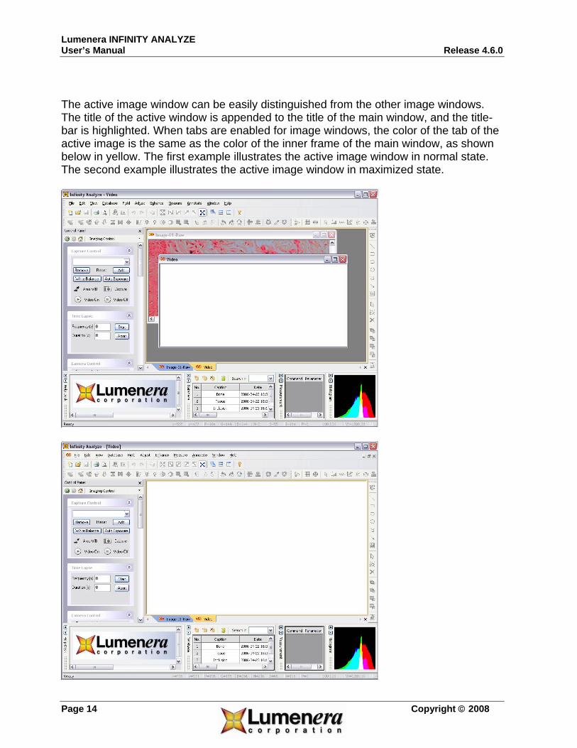
The active image window can be easily distinguished from the other image windows. The title of the active window is appended to the title of the main window, and the title-bar is highlighted. When tabs are enabled for image windows, the color of the tab of the active image is the same as the color of the inner frame of the main window, as shown below in yellow. The first example illustrates the active image window in normal state. The second example illustrates the active image window in maximized state.

Lumenera INFINITY ANALYZE Release 4.6.0 User’s Manual
Copyright © 2008 Page 15
2.1.5 The Empty Image Window INFINITY ANALYZE employs an empty image window to display live images from the camera. The live image may pan and scroll in the same way as a still image, i.e. the hand tool is also available for live image. Use the Fit to Window icon to change between Full Field of View and a selected Region of Interest (ROI), for pan and scroll functionality. A new preview window can be opened from the File menu, or from an icon in the toolbar, if the current one is closed.
2.2 Workspace
Besides image windows, many other windows or user interface elements reside within the main window of INFINITY ANALYZE. These include menus, toolbars, status bar and auxiliary windows providing additional information about the images or control of the camera.
2.2.1 Menu The menu can be either docked or floating. Double-click its grip or caption bar to toggle between the two states. When the menu is docked, it can be docked to any of the four sides of the main window. Drag the grip or caption of the menu to adjust its position or to dock it to a particular side of the main window. The grip of the menu is the dot matrix at the left or top of the menu in docked state.
2.2.2 Toolbar INFINITY ANALYZE has four toolbars. Each toolbar can be either shown or hidden. When a toolbar is shown, it can be either docked or floating. Double-click its grip or caption to toggle between the two states. When a toolbar is docked, it can be docked to any of the four sides of the main window. Drag the grip or caption of a toolbar to adjust its position or to dock it to a particular side of the main window. The grip of a toolbar is the dot matrix at the left or top of the toolbar in docked state.
2.2.3 Status Bar

Lumenera INFINITY ANALYZE User’s Manual Release 4.6.0
Page 16 Copyright © 2008
The status bar is located at the bottom of the main window. Depending on whether a still image or the video is being displayed in the active image window, the status bar provides different information. The status bar is divided into thirteen panes from left to right. The information displayed in each pane is as follows: Pane Index Still Image Live Image
1 (Leftmost)
Command prompt Command Prompt
2 Mouse position in horizontal direction, in pixels, relative to the top left corner of the active image.
The horizontal offset of the region of interest on the camera.
3 Mouse position in vertical direction, in pixels, relative to the top left corner of the active image.
The vertical offset of the region of interest on the camera.
4 The red component of the pixel at the mouse position.
The width of live image, in pixels.
5 The green component of the pixel at the mouse position.
The height of live image, in pixels.
6 The blue component of the pixel at the mouse position.
The number of columns of the pixel array of the camera.
7 The hue component of the pixel at the mouse position.
The number of rows of the pixel array of the camera.
8 The saturation component of the pixel at the mouse position.
The current gain of the camera.
9 The intensity component of the pixel at the mouse position.
The current exposure time, in milliseconds, of the camera.
10 The phase index of the pixel at the mouse position.
The current frame rate of the camera.
11 The magnification of the active image. The magnification setting of the system micrometer.
12 The width of the active image, in microns. The width of the whole field of view, in microns.
13 (Rightmost)
The height of the active image, in microns. The height of the whole field of view, in microns.
2.2.4 Auxiliary Window INFINITY ANALYZE has five auxiliary windows: Control Panel, Help Desk, Database, Measurement and Histogram. Each of these auxiliary windows can be either visible or hidden. When an auxiliary window, except Control Panel, is shown, it can be either docked or floating. Double-click the grip or caption of an auxiliary window to toggle

Lumenera INFINITY ANALYZE Release 4.6.0 User’s Manual
Copyright © 2008 Page 17
between the two states. When an auxiliary window is docked, it can be docked to any of the four sides of the main window. Drag its grip or caption to adjust the position of an auxiliary window or to dock it to a particular side of the main window. The grip of an auxiliary window is the dot matrix at the left or top of the caption bar of the window in docked state. All the auxiliary windows can be resized in the same way as an ordinary window. Control Panel The Control Panel provides access to all camera functions and image acquisition commands. It also controls image capture options and how acquired images are cached. Two panes, Imaging Control and Field Group, comprise the Control Panel. The Imaging Control Panel is further divided into seven sub-panes for specific aspects of the image display and capture process. Sub-panes are collapsible. To collapse a sub-pane, click the arrow in its top right corner. To expand a collapsed sub-pane, click the arrows in the top right corner again. The arrows at the top left corner of a sub-pane point upward to indicate the expanded state and downward to indicate the collapsed state. When INFINITY ANALYZE is launched, the displayed panes in the Control Panel are restored to the state they were in when the application was last closed.
Click to hide Control Panel.
Click to go to the previous pane.
Click to go to the next pane.
Click to go to Field Group.

Lumenera INFINITY ANALYZE User’s Manual Release 4.6.0
Page 18 Copyright © 2008
Click to go to a pane directly.
Help Desk
The Help Desk provides context sensitive information for commands that involve extended mouse actions. Database
The Database panel provides full control over the built-in database. Some commands may only be available from this auxiliary window. For example, click a column header to sort the list. This command is not accessible from the application menu. Measurement

Lumenera INFINITY ANALYZE Release 4.6.0 User’s Manual
Copyright © 2008 Page 19
This auxiliary window is used to hold measurement results. A row is also referred to as an entry. As illustrated above, an entry consists of three cells, namely the command that generates the entry, the parameter that is being measured, and the measurement result. A measurement command may generate more than one entry because two types of parameters may be measured with a single command. Entries in the Measurement window may be highlighted using the mouse and dragged to an external spreadsheet program for further processing. With the external program already running, drag the highlighted measurement data over the program icon in the task tray at the bottom of the screen. This brings the spreadsheet program to the foreground where the measurement data can be dragged to the desired location. Release the mouse button to paste the selected data into the spreadsheet at the mouse pointer location. Histogram
A histogram is a graphic representation of the number of pixels at each brightness level in an image. INFINITY ANALYZE plots histograms for all three channels of the active image based on RGB color model. In the black square box, the x axis represents the color value from darkest (0) at the far left to brightest (255) at the far right; the y axis

Lumenera INFINITY ANALYZE User’s Manual Release 4.6.0
Page 20 Copyright © 2008
represents the frequency, i.e. the total number of pixels with that value; the origin of the histogram is the bottom left corner of the black box. Note that histograms of red, green and blue channels are shown in the same coordination system as red, green and blue bars and so they may overlap. The following table helps to tell the overlapping range of the histograms.
Red and Green
Red and Blue
Green and Blue
Red and Green and Blue
The histogram can be shown for both still and live images. For a still image, its histogram is updated whenever the image itself is being modified in any way, including the way it is being displayed. For a live image, its histogram is updated every three seconds. In both cases, the histogram is only for the part of the active image that is visible on computer screen. Look-Up Table
The title bar of the histogram pane includes icons used to access Look-up Table (LUT) functions. When enabled the LUT is applied to the live preview window providing instant feedback based on the Red, Green, and Blue channel manipulations. Each channel can be modified individually, or all three channels can be set to be the same. The LUT can be enabled or disabled as desired. Use the File menu to access the option that applies the active LUT to a captured image. The horizontal axis of the histogram represents the image input intensity values from minimum (0) on the left, up to maximum (255) on the right. The vertical axis represents

Lumenera INFINITY ANALYZE Release 4.6.0 User’s Manual
Copyright © 2008 Page 21
the corresponding output intensity value from minimum (0) at the base, up to maximum (255) at the top. The line displayed across the histogram represents the point at which an input intensity value is transitioned to the corresponding output intensity value. Therefore, a line sloping upwards from the bottom left corner to the top right corner represents a neutral LUT definition, where each input value maps to the identical output value. An inverse look-up table is shown by a line sloping down from the upper left corner to the bottom right corner, resulting in all minimum input values being transitioned to maximum output values (and vice versa), such that the channel becomes a negative representation of the original.
The LUT can be modified either graphically or numerically. To define the LUT graphically, click the mouse on the one end of the line displayed on the histogram. There are two control points available to manipulate into a slope that produces the desired result. Each of the control points can be manipulated individually by clicking either on the square icons on the line, or on the line itself to the outside of the control points. Click on the line between the control points and drag the graphic to perform translational adjustments to the line slope. The histogram is adjusted to display the LUT adjusted image pixel intensities.
Enable / Disable the LUT on the Live Image
Reset the active LUT channel
Open the LUT editing dialog
Make the Red channel active
Make the Green channel active
Make the Blue channel active
Activate all three channels

Lumenera INFINITY ANALYZE User’s Manual Release 4.6.0
Page 22 Copyright © 2008
The dialog above is displayed when the icon is clicked in the histogram panel. Use this panel to select a specific LUT channel or to apply changes to all three channels at the same time. It provides an easy option to generate an inverse LUT, and can be used to specify the actual coordinates for control points on a relative scale from (0,0) to (1,1).
Enter the (x,y) coordinate of the first control point
Enter the (x,y) coordinate of the second control point
Invert the current LUT
Select the active channel or all channels
Click OK to save the modifications and close the dialog
Rollback any changes made to the dialog settings and close the dialog

Lumenera INFINITY ANALYZE Release 4.6.0 User’s Manual
Copyright © 2008 Page 23
The LUT menu is accessed from the File -> Lookup Table menu. Each function represented with an icon beside has been explained in the table above. Use the Apply to Still Image option on this menu to apply the LUT to the active image in the ANALYZE working area. Use the Load… and Save.. options to restore or save an LUT definition.

Lumenera INFINITY ANALYZE User’s Manual Release 4.6.0
Page 24 Copyright © 2008
3 Menu Commands Most commands are accessible from the menu. Some of the more frequently invoked commands also have toolbar buttons and/or shortcut key combinations associated with them. Those commands that are not accessible from the menu are described in Section 3 -Other Commands. Relating a toolbar icon to a menu item The toolbar icons denote the button functions available on the various toolbars. The same icons appear to the left of the corresponding menu items on the dropdown menus. Relating a shortcut key combination to a menu item A short textual description of the shortcut key combination is shown to the right of the corresponding menu item. INFINITY ANALYZE has 7 major menus:
1. Document Menu 2. Main Frame Menu 3. OLE Container Menu 4. OLE Server Menu 5. Field Group Context Menu 6. Image Window Tab Context Menu 7. Toolbar and Auxiliary Window Context Menu
Most work will be carried out by commands in the Document Menu, which is the default menu when INFINITY ANALYZE starts up. The Main Frame Menu will replace the Document Menu whenever there is no image window in the main window. The commands contained in this menu are mainly useful in creating a new image window, by New for Video Preview or Open, or to exit from INFINITY ANALYZE, by selecting Exit. The Main Frame Menu will not appear when there is an image window in the main window.
Lumenera INFINITY ANALYZE Release 4.6.0 User’s Manual
Copyright © 2008 Page 25
The OLE Container Menu will be called up only in the image annotation process when an external object is inserted and the server of this object is activated. In this situation, The OLE Container Menu will merge with the object’s server menu. The OLE Server Menu will be invoked when a native image object of INFINITY ANALYZE is embedded into a document of another container program and is being edited. INFINITY ANALYZE will load the embedded image into its own image window. When this image is the active image, the OLE Server Menu will be used. The Field Group Context Menu may be brought up by right-click anywhere within Field Group. The Image Window Tab Context Menu may be brought up by a right-click anywhere within the tab area of image windows. The Toolbar and Auxiliary Window Context Menu may be brought up by a right-click in any area of the main window that is not occupied by other menus, toolbars, auxiliary windows or image windows. In the following paragraphs only the Document Menu is described. The other menus often duplicate part of the Document Menu to provide a level of convenience. Where they are unique, they typically represent simple commands that are self-explanatory.
3.1 The File Menu
The File menu commands are used to open, save, print and capture images. Some of the camera manipulation commands also reside here.
3.1.1 New for Video Preview Use the New for Video Preview command to create an empty image window to display live images from the camera. The caption of the created window is the model or name of the camera presently attached to the computer. If no camera is connected or none of the connected cameras is working properly, the caption of the created window is “Video”. The camera serial number is appended to the window caption, after a dash.

Lumenera INFINITY ANALYZE User’s Manual Release 4.6.0
Page 26 Copyright © 2008
3.1.2 Open Use the Open command to load existing image files. Multiple images from a single folder can be opened simultaneously, whether they are the same or in different image formats. Besides the native image format (*.sif), numerous commonly used image formats are supported. Files of unsupported formats will be filtered out and will not be visible in the dialog box. Equivalent Commands
• Drag one or more selected files in Windows Explorer and drop them in the main window of INFINITY ANALYZE.
• Double-click a file of native image format (*.sif) in Windows Explorer. The application recognizes the following image file formats: Format File
Extension Remark
Native SIF Contains complete information including calibration data
Bitmap BMP Including both Windows and OS/2 bitmaps. Independent JPEG Group
JPG Least loss and highest quality when decompressing.
Tagged Image File Format
TIF Reading the first page only.
Portable Bitmap PBM Reading both ASCII and binary formats. Portable Gray Map PGM Reading both ASCII and binary formats. Portable Network Graphics
PNG
Portable Pixel Map PPM Targa File TGA Dr. Halo CUT Windows Icon ICO Reading the first page only. Amiga IFF IFF/LBM JPEG Network Graphics JNG Commodore 64 Koala Format
KOA
Multiple Network Graphics
MNG
Kodak Photo CD PCD Extracting only maximum resolution. PCX Bitmap Format PCX Adobe Photoshop PSD SUN Raster File RAS

Lumenera INFINITY ANALYZE Release 4.6.0 User’s Manual
Copyright © 2008 Page 27
Wireless Bitmap WBMP X11 Bitmap Format XBM X11 Pixmap Format XPM Metallograph MEG Containing calibration and magnification
information. Note the native format (*.sif) preserves the most complete information for images acquired by INFINITY ANALYZE, including sampling interval and magnification settings. The Metallograph format (*.meg) also contains such information. However, the other formats do not contain metrical information and cannot be used for taking further measurements when re-opened, unless re-calibrated. When such a file is opened, the sampling interval is assumed to be 1 micron and the magnification is assumed to be 100X.
3.1.3 Close Use the Close command to remove the active image window. If the active image window is the only image window, closing this window will cause INFINITY ANALYZE to switch to Main Frame Menu. To go back to Document Menu, choose File > New for Video Preview to create an empty image window, or choose File > Open to load an image file.
3.1.4 Save Use the Save command to store the active image onto disk in the native format. If the active image has been previously saved in the native format (*.sif), this command will simply update the corresponding file. If the image has never been saved in the native format, this command will act as File > Save As.
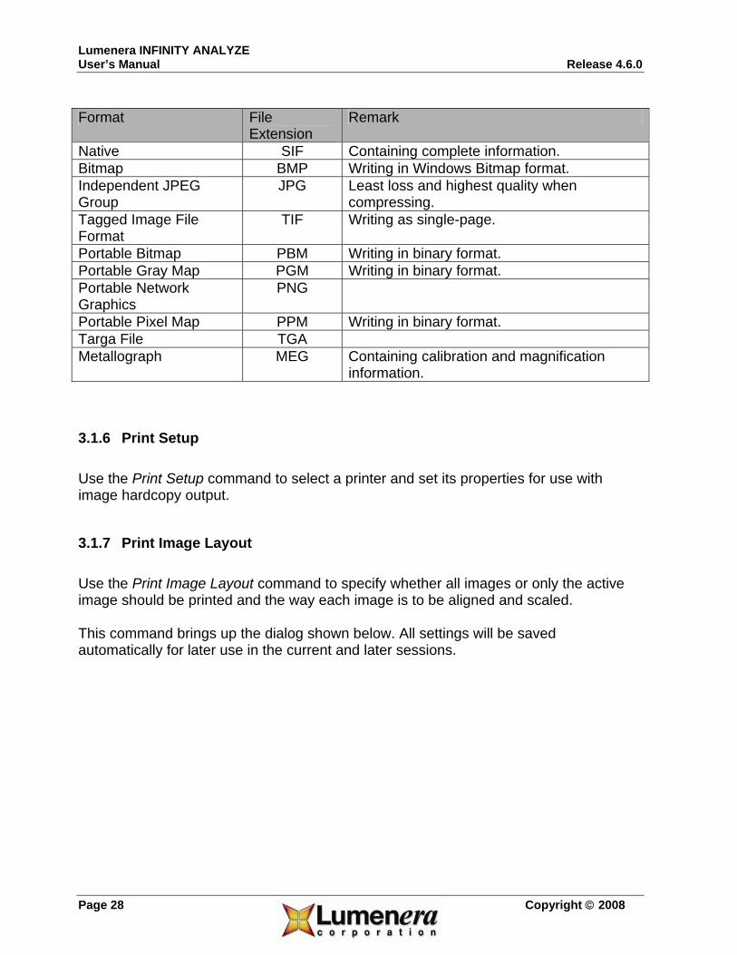
3.1.5 Save As Use the Save As command to store the active image onto disk with a new file name or in a new format. The native image format (*.sif) and Metallograph format (*.meg) retains both pictorial and metrical information and are the best for archival purpose. The other image formats keep pictorial information only. The supported image formats are listed below.
Lumenera INFINITY ANALYZE User’s Manual Release 4.6.0
Page 28 Copyright © 2008
Format File Extension
Remark
Native SIF Containing complete information. Bitmap BMP Writing in Windows Bitmap format. Independent JPEG Group
JPG Least loss and highest quality when compressing.
Tagged Image File Format
TIF Writing as single-page.
Portable Bitmap PBM Writing in binary format. Portable Gray Map PGM Writing in binary format. Portable Network Graphics
PNG
Portable Pixel Map PPM Writing in binary format. Targa File TGA Metallograph MEG Containing calibration and magnification
information.
3.1.6 Print Setup Use the Print Setup command to select a printer and set its properties for use with image hardcopy output.
3.1.7 Print Image Layout Use the Print Image Layout command to specify whether all images or only the active image should be printed and the way each image is to be aligned and scaled. This command brings up the dialog shown below. All settings will be saved automatically for later use in the current and later sessions.

Lumenera INFINITY ANALYZE Release 4.6.0 User’s Manual
Copyright © 2008 Page 29
Alignment This section determines whether all images or only the active image might be printed. Three modes are defined by INFINITY ANALYZE: AAA (All Images Automatically Aligned), CAP (Current Image Absolutely Positioned) and CFP (Current Image Fit to Paper).
• AAA. Under this mode, all images except empty ones would be printed. The layout and pagination of images are fully automatic. A zoom factor may be applied to all images before the final page layout is calculated. The zoom factor is specified in Zoom for AAA and CAP. The titles would also be printed under images.
• CAP. Under this mode, the active image would be printed if it is not empty. The size and position of the printed image may be modified. The image may be zoomed according to the factor specified in Zoom for AAA and CAP. The image can be placed anywhere on the paper. The position of the printed image refers to the horizontal and vertical offset of the top left corner of the image with respect to the top left corner of the printable area of the paper, in millimeters. The offsets are specified in Displacement for CAP (mm).
• CFP. Under this mode, the active image would be printed if it is not empty. The image is automatically scaled to fill the width or height of the paper, depending on aspect ratios of the image and paper. The aspect ratio of the image is kept constant. If the image could not occupy the whole printable area of the paper, it

Lumenera INFINITY ANALYZE User’s Manual Release 4.6.0
Page 30 Copyright © 2008
will be placed to the top side as far as possible but centered horizontally on the paper.
Zoom for AAA and CAP This section specifies a zoom ratio of the images for use with printing under AAA and CAP modes. Displacement for CAP (mm) This section specifies offsets of the image for use with printing under CAP mode. The origins of the image and paper are their top left corners. Horizontal displacement is defined as the distance between the leftmost column of the image and the left side of the paper’s rectangular printable area. Vertical displacement is defined as the distance between topmost row of the image and the top of the paper’s rectangular printable area. The distance is measured in millimeters. The Print Image Layout command is used to configure the printing but it does not initiate a printing process.
3.1.8 Print Preview Use the Print Preview command to simulate image printing on computer screen. In this mode, INFINITY ANALYZE menu, toolbars, auxiliary windows except the Control Panel are hidden as illustrated below.

Lumenera INFINITY ANALYZE Release 4.6.0 User’s Manual
Copyright © 2008 Page 31
Note that an enhanced print preview toolbar appears. There are seven buttons, the function of each is explained below.
Click to start the actual printing.
Click to view the next page
Click to view the last page
Click to toggle between two-page view and single-page view.
Click to zoom in the image
Click to zoom out the image
Click to exit the print preview mode. This is equivalent to pressing Esc key.
The status bar will display the page number of the image being previewed.
Lumenera INFINITY ANALYZE User’s Manual Release 4.6.0
Page 32 Copyright © 2008
The main window shows the print layout of the images. Print preview has incorporated configurations set by both Print Setup and Print Image Layout.
3.1.9 Print Use the Print command to output a hardcopy of the active image or all opened images. This command only initiates the printing process and does not specify how the printing should be done. The printer selection and configuration is carried out by Print Setup. The digital zoom factor, position and alignment of images are specified by Print Image Layout.
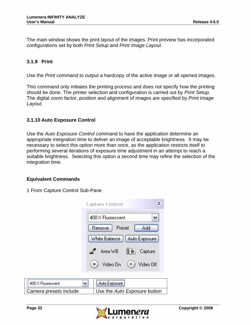
3.1.10 Auto Exposure Control Use the Auto Exposure Control command to have the application determine an appropriate integration time to deliver an image of acceptable brightness. It may be necessary to select this option more than once, as the application restricts itself to performing several iterations of exposure time adjustment in an attempt to reach a suitable brightness. Selecting this option a second time may refine the selection of the integration time. Equivalent Commands 1 From Capture Control Sub-Pane
Camera presets include Use the Auto Exposure button

Lumenera INFINITY ANALYZE Release 4.6.0 User’s Manual
Copyright © 2008 Page 33
exposure setting. If a preset, for example 400 X Fluorescent, is selected, the camera will be directed to integrate according to the time value recorded in that preset. The position of the Exposure slider in the Camera Control Sub-Pane will be updated to synchronize with the current exposure setting.
to initiate an analysis and automatic exposure adjustment. INFINITY ANALYZE performs a limited number of exposure adjustments, while analyzing the average scene brightness. It may be necessary to click the Auto Exposure button a second time to obtain the ideal image intensity. The preset will be deselected to reflect the change. The position of the Exposure slider will also be updated to synchronize with the current setting.
3.1.11 White Balance Use the White Balance command to correct color reproduction aberration of the camera. The color correction is based on the visible portion of the live images. For the best results, it is advised to perform white balance when imaging a white (gray or colorless) and bright (but not saturated) object. This command initiates a one-push effort to reproduce the right colors. It might be necessary to repeat the process until the desirable state is reached. Equivalent Commands 1 From Settings File Upon startup, INFINITY ANALYZE automatically loads and applies the camera color correction settings used last time. These settings, and many others, are specific to each camera and are stored in a file that is uniquely identifiable by the serial number of the camera. When INFINITY ANALYZE exits, it automatically updates the settings file. 2 From Capture Control Sub-Pane

Lumenera INFINITY ANALYZE User’s Manual Release 4.6.0
Page 34 Copyright © 2008
Camera presets include camera color correction settings. If a preset, for example 400 X Fluorescent, is selected, the camera will be directed to amplify each color channel of the video stream by respective parameters recorded in that preset.
When White Balance button is pressed, INFINITY ANALYZE examines the most recently grabbed frame and adjusts the color channel gains of the camera in an effort to reproduce the colors in the best way. The preset will be deselected to reflect the change.
3.1.12 Manual White Balance Use the Manual White Balance command to adjust the gain setting used on each color channel to manipulate the color output of the camera. This feature can be used to fine tune the color appearance of the camera image, when necessary.
3.1.13 Light Source Use the Light Source command to tune the color reproduction of the camera. The same object may appear slightly different in color under different lighting conditions. The reason for this change in camera response is due to the light source itself, which can have varied chromatic content, called temperature. It is measured in Kelvin. When describing a light source as having a Kelvin rating, it refers to a light source that emits

Lumenera INFINITY ANALYZE Release 4.6.0 User’s Manual
Copyright © 2008 Page 35
energy across the entire visible range from 300nm to 700nm. Sunlight and incandescent lamps fit to this model conveniently. However, all fluorescent and discharge lamps have interrupted spectra, where Kelvin temperature is only used in a loose sense to describe wavelength distributions of the light sources.
Light Source Kelvin
Clear Blue Sky 8000 to 27000
Rainy, Misty Daylight 7200 to 8500
Overcast Daylight 6500 to 7200
Direct Sun + Clear Blue Sky 5700 to 6500
Summer Sunlight (9am to 3pm) 5400 to 5700
Summer Sunlight (before 9am or after 3pm) 4900 to 5600
DAYLIGHT
Electronic Flash (Typical) 6200 to 6800
Xenon Arc (unfiltered) 6000
White Flame Carbon Arc 5000
ARC LAMP
Yellow Flame Carbon Arc 3200
'True Daylight' Color Match Tubes 6500
'Daylight' Cool White Tubes 4300
FLUORESCENT LAMP
'Warm White' Tubes 3000
Photoflood & 3400K Tungsten-Halogen 3400
Tungsten-Halogen and Photo Lamps 3200
Projection Lamps (500 to 1000 Watts) 2900 to 3000
General Purpose Lamps (200 to 500 Watts) 2900
Household Lamps (100 to 150 Watts) 2850
Household Lamps (60 Watts) 2800
TUNGSTEN LAMP
Household Lamps (40 Watts) 2750
Standard Candle 2000 CANDLE
Candle Flame 1500

Lumenera INFINITY ANALYZE User’s Manual Release 4.6.0
Page 36 Copyright © 2008
The camera itself or INFINITY ANALYZE cannot possibly determine the temperature of the light source from live images alone and has to rely on user input to generate the digital image that best matches human perception.
Select to indicate to INFINITY ANALYZE that the light source has an interrupted spectrum.
Select to indicate to INFINITY ANALYZE to add more red.
Select to indicate to INFINITY ANALYZE to add even more red.
Select to indicate to INFINITY ANALYZE to add more blue.
Select to indicate to INFINITY ANALYZE to add more red and blue.
Select to indicate to INFINITY ANALYZE no color temperature should be incorporated in image formation.
Push to close the dialog and keep the just specified light source temperature.
Push to close the dialog and discard any modification to light source temperature.

Lumenera INFINITY ANALYZE Release 4.6.0 User’s Manual
Copyright © 2008 Page 37
Equivalent Commands 1 From Settings File Upon startup, INFINITY ANALYZE automatically loads and applies the light source color temperature setting used last time. The color temperature setting, and many other settings, are specific to each camera and are stored in a file that is uniquely identifiable by the serial number of the camera. When INFINITY ANALYZE exits, it automatically updates the settings file. 2 From Capture Control Sub-Pane
Camera presets include light source setting. If a preset, for example 400 X Fluorescent, is selected, the camera will be directed to modify the directly captured image to add a tint typical of objects illuminated with a light source of a temperature recorded in that preset. The Light Source Sub-Pane will be updated to synchronize with the current settings. 3 From Light Source Sub-Pane

Lumenera INFINITY ANALYZE User’s Manual Release 4.6.0
Page 38 Copyright © 2008
Select to indicate to INFINITY ANALYZE that the light source has an interrupted spectrum.
Select to indicate to INFINITY ANALYZE to add more red.
Select to indicate to INFINITY ANALYZE to add even more red.
Select to indicate to INFINITY ANALYZE to add more blue.
Select to indicate to INFINITY ANALYZE to add more red and blue.
Select to indicate to INFINITY ANALYZE no color temperature should be incorporated in image formation.
3.1.14 Toggle Preview Use the Toggle Preview command to turn video streaming on or off. INFINITY ANALYZE employs an empty image window to display live images. Such a window is created automatically upon program startup. To create a new empty image window, choose File > New for Video Preview. The caption of the window indicates the model and serial number of the currently connected camera. Only one empty image window can be used to preview video. Choose Toggle Preview again to shutdown the video. If it is desired to preview video in a particular empty image window, make that image window the active image window and choose Toggle Preview. Equivalent Commands From Capture Control Sub-Pane

Lumenera INFINITY ANALYZE Release 4.6.0 User’s Manual
Copyright © 2008 Page 39
Push to turn on live image preview on an empty image window. If there is currently no empty image window, a new one will be created.
Push to turn off live image preview.
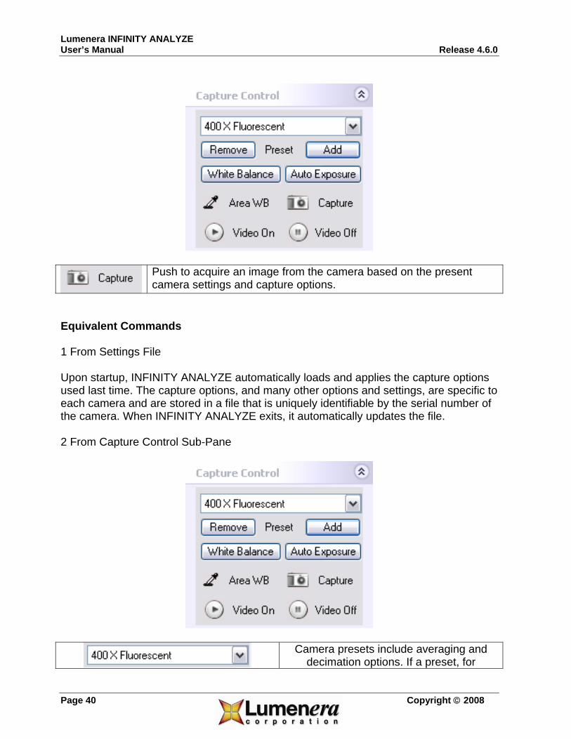
3.1.15 Capture Use the Capture command to acquire an image from the camera based on the present camera settings and capture options. The camera settings include exposure time, global gain, color gains, Gamma, saturation, hue, brightness, contrast, image orientations, and light source temperature. For more details please refer to respective commands that set these parameters. The capture options include frame averaging, decimation, where to store the captured images and so on. For more details please refer to the Capture Options command. Equivalent Commands 1 Shortcut Double-click the empty image window that is displaying video to initiate an image capture. The resulting camera image will be stored directly to file, into the field group, or both places based on the settings selected. If the option to preview the captured image is selected, then the resulting camera image will be opened in a new window. 2 From Capture Control Sub-Pane
Lumenera INFINITY ANALYZE User’s Manual Release 4.6.0
Page 40 Copyright © 2008
Push to acquire an image from the camera based on the present camera settings and capture options.
Equivalent Commands 1 From Settings File Upon startup, INFINITY ANALYZE automatically loads and applies the capture options used last time. The capture options, and many other options and settings, are specific to each camera and are stored in a file that is uniquely identifiable by the serial number of the camera. When INFINITY ANALYZE exits, it automatically updates the file. 2 From Capture Control Sub-Pane
Camera presets include averaging and
decimation options. If a preset, for

Lumenera INFINITY ANALYZE Release 4.6.0 User’s Manual
Copyright © 2008 Page 41
example 400 X Fluorescent, is selected, the camera will be directed to average
incoming frames and decimate the averaged image according to settings recorded in that preset. The Capture Options Sub-Pane will be updated to synchronize with the current setting.
3 From Capture Options Sub-Pane
Select the number of frames to be averaged. If 1 is selected, no frame averaging will be performed. If 2 is selected, two successive frames will be summed and then divided by two to create the intermediate image that is the input to subsequent post-capture processing. 4 and 8 are similarly defined. Frame averaging reduces noise. If n frames are averaged, the energy of the noise will be 1/n of its original level. Frame averaging is performed only when capturing

Lumenera INFINITY ANALYZE User’s Manual Release 4.6.0
Page 42 Copyright © 2008
full field of view.
Sub-sample the output image. If 1 is selected, no sub-sampling will be done. If 2 is selected, the number of columns and number of rows of the image will be reduced by a factor of two by merging every two consecutive columns and rows. 3 and 4 are similarly defined. Subsampling reduces the noise level much like averaging. The way INFINITY ANALYZE performs subsampling also helps to avoid aliasing. Subsampling is performed only when capturing full field of view. Pixel-Shift Cameras Pixel-shifting cameras such as INFINITYX-21 and INFINITYX-32 shift the sensor position from the original location. Use this option to specify the pixel shifting steps to use when completing an image capture.
Select the destinations of the acquired image. If File is selected, the image will be stored to disk under that file path specified below. If Field Group is selected, the image will be appended to Field Group if there is still room. If Both is selected, the image will be stored as a file on disk and also appended to Field Group.
Show the file name to be used when the acquired image is to store on disk. A new file name may be entered directly.
Push to bring out a File Save As dialog to specify the file name to be used when the acquired image is to store on disk.
If checked, the image of the full field view will be captured regardless of the preview state. If unchecked, only the image that is being previewed will be captured. This can be a sub-region of the full field of view, or lower-resolution image which INFINITY ANALYZE is using for display purpose.
If checked, a new image window will be created to load a copy of the acquired image.

Lumenera INFINITY ANALYZE Release 4.6.0 User’s Manual
Copyright © 2008 Page 43
If checked and the captured image is to store in a file, a File Save As dialog will be brought up after each image is acquired. The file name contained in the dialog is initially set to the previously specified file name such as “e:\report\specimen.jpg”. However, it is free to change the file name, or instruct INFINITY ANALYZE not to save this image at all.
If checked and the acquired image is to store in a file, the file name will be changed by INFINITY ANALYZE after the current image has been saved. The new file name will be used for the next acquired image. The new file name will have a integer appended to the original text and this integer will be incremented by one each time a new file name is generated by INFINITY ANALYZE.
3.1.16 Time Lapse Capture Use the Time Lapse Capture command to acquire a sequence of images at equally spaced temporal points. This command brings up a dialog box where time interval and total time length can be specified.
Once the time lapse capture begins, the progress will be given upon the completion of each capture, as shown below.

Lumenera INFINITY ANALYZE User’s Manual Release 4.6.0
Page 44 Copyright © 2008
Time interval, in seconds.
Time duration, in seconds.
Push to start time lapse capture. Video preview might be necessary if not to capture full fields of view. The dialog is dismissed automatically upon the completion of time lapse capture.
Push to abort the time lapse capture and dismiss the dialog. The progress of the time lapse capture.
Equivalent Commands From Time Lapse Sub-Pane

Lumenera INFINITY ANALYZE Release 4.6.0 User’s Manual
Copyright © 2008 Page 45
Time interval, in seconds.
Time duration, in seconds.
Push to initiate time lapse capture. Video preview might be necessary if not to capture full fields of view.
Push to abort the time lapse capture.
The progress of the time lapse capture. Both the number of captured images and the estimated time, in seconds, needed to complete the task, are given.
Time lapse capture depends on the current camera settings and capture options. When the Time Lapse Capture command is in execution, these settings and options are locked until all requested images have been acquired. However, it is possible to change camera settings and capture options during a time lapse capture operation initiated from Time Lapse Sub-Pane. It is even possible to capture separate or additional images, or to carry out any other tasks which INFINITY ANALYZE is able to do, because the time lapse capture is in background processing.
3.1.17 Lookup Table The Lookup Table function provides access to the dynamic lookup table controls. The functionality of the controls is explained in detail in section 2.2.4 on the histogram pane.

Lumenera INFINITY ANALYZE User’s Manual Release 4.6.0
Page 46 Copyright © 2008
Enable / Disable the LUT on the Live Image
Reset the active LUT channel
Open the LUT editing dialog
Make the Red channel active
Make the Green channel active
Make the Blue channel active
Activate all three channels
3.1.18 Exit Use the Exit command to close INFINITY ANALYZE. This command prompts to save modified documents. INFINITY ANALYZE considers an image as a modified document if it has never been saved in native format or it has been processed or measured after the last time it was saved. Viewing an image in different ways, measurement in progress (not yet completed) and annotating an image (before the annotation objects are burned into images) are not considered as modifying an image.

Lumenera INFINITY ANALYZE Release 4.6.0 User’s Manual
Copyright © 2008 Page 47
3.2 The Edit Menu
INFINITY ANALYZE maintains a processing history for each image. The processing history is a chain of internal buffers holding the states of the image. A new state of the image is automatically created and appended to the processing history after each operation that has modified that image. Viewing an image in different ways, measurement in progress (not yet completed) and annotating an image (before the annotation objects are burned into images) are not considered as modifying an image.
3.2.1 Undo Use the Undo command to reverse the most recent action that has modified the image. The possible number of undo steps is the length of processing history.
3.2.2 Redo Use the Redo command to undo an Undo operation.
3.2.3 Copy to Clipboard Use the Copy to Clipboard command to convert a copy of the active image to Windows Bitmap format and place it on the clipboard.
3.3 The View Menu
The commands in this group are used to customize the appearance of user interface elements, images and computer screen.
3.3.1 Toolbars and Auxiliary Windows Use the Toolbars and Auxiliary Windows commands to toggle the visibility of each toolbar or auxiliary window. Toolbar Auxiliary Window

Lumenera INFINITY ANALYZE User’s Manual Release 4.6.0
Page 48 Copyright © 2008
Standard Control Panel Image Processing Help Desk Image Measurement Database Image Annotation Measurement Histogram A toolbar can be either visible or hidden. When it is visible, it can be either docked or floating. The menu can also be docked or floating, although it cannot be hidden. Drag its grip to adjust the position of a toolbar or the menu. Double-click on its grip to toggle the dock state of a toolbar or the menu. Control Panel can be visible or hidden. However, it is always docked to the left side of the main window. Control Panel can be resized but cannot be floating or docked to any other side of the main window. The other auxiliary windows can be either visible or hidden. When they are visible, they can be either docked or floating. Drag their captions to adjust their positions. Double-click on their captions to toggle their dock states.
3.3.2 Status Bar Use the Status Bar command to toggle the visibility of the status bar.
3.3.3 Auxiliary Window Captions Use the Auxiliary Window Captions command to turn on or off the Windows Themes on all the auxiliary windows. INFINITY ANALYZE is able to draw the captions of the auxiliary windows in its own way but also accepts Windows Themes for its auxiliary windows. If Auxiliary Window Captions is unchecked as is the default, INFINITY ANALYZE will draw the captions of auxiliary windows in its own way which in a sense is more convenient to use. However, if Auxiliary Window Captions is checked, INFINITY ANALYZE will draw the captions of auxiliary windows according to the current Windows Themes. This command merely affects the appearance of the auxiliary windows and does not limit their functionalities.
3.3.4 Image Window Tabs

Lumenera INFINITY ANALYZE Release 4.6.0 User’s Manual
Copyright © 2008 Page 49
Use the Image Window Tabs command to toggle the visibility of image window tabs. Image windows can have or have not tabs. When an image window has a tab, the tab can either appear on top or at bottom of the main window. Choose Image Window Tabs to hide the tabs if the image windows currently have tabs. Choose Image Window Tabs to show the tabs if the image windows currently do not have tabs. Equivalent Commands Image Window Tab Context Menu Use Hide Tabs to remove image window tabs currently shown in the main window.
3.3.5 Overlay Use the Overlay command to toggle the visibility of measurement and micrometer overlays. A successful measurement operation creates graphics overlay on the image. This overlay is on a separate layer from pixels. The overlay layer can be either shown or hidden. Choose Overlay to remove the overlay view currently superimposed on the picture. Choose Overlay again to restore. This command affects the visibility of the overlay layer only and does not delete the overlay.
3.3.6 Overlay Color Use the Overlay Colors command to set a new color for the overlay layer. The overlay layer can be shown in different colors after it have been created. To select a new color, choose Overlay Colors and pick up a desirable one. This command is special in that a dialog appears in place of a popup menu item, as shown below.

Lumenera INFINITY ANALYZE User’s Manual Release 4.6.0
Page 50 Copyright © 2008
The dialog is initially docked to the menu item Overly Color, however, if desired it can be made floating by dragging its grip.
The dialog in two different dock states behaves in exactly the same way. Click “Automatic” to select the color white as the overlay color. Click any of the color boxes to select that color as the overlay color. Click “More Colors” for more choices or to create a new color. Click “More Colors” will bring up another dialog as shown next.

Lumenera INFINITY ANALYZE Release 4.6.0 User’s Manual
Copyright © 2008 Page 51
Again, click a hexagon to pick up its color as the new overly color. The present overlay color is shown in a box at the bottom right corner of the dialog box. The present selection is shown in the box above the present overly color box. Push OK to dismiss the dialog and set the new color as overlay color. Push Cancel to dismiss the dialog with overlay color remaining the original. If it becomes necessary to create a unique color, click “Custom” to switch to the other tab of this two-tab dialog box, as shown below.

Lumenera INFINITY ANALYZE User’s Manual Release 4.6.0
Page 52 Copyright © 2008
Click or drag to adjust hue and saturation of the currently selected color.
Click or drag to adjust luminance (intensity) of the currently selected color.
Show the hue of the currently selected color. The hue value can also be entered directly or adjusted with the spin buttons. The hue is in the range [0,255].
Show the saturation of the currently selected color. The saturation value can also be entered directly or adjusted with the spin buttons. The saturation is in the range [0,255].
Show the luminance or intensity of the currently selected color. The luminance or intensity can also be entered directly or adjusted with the spin buttons. The luminance or intensity is in the range [0,255].
Show the red of the currently selected color. The red value can also be entered directly or adjusted with the spin buttons.

Lumenera INFINITY ANALYZE Release 4.6.0 User’s Manual
Copyright © 2008 Page 53
The red is in the range [0,255].
Show the green of the currently selected color. The green value can also be entered directly or adjusted with the spin buttons. The green is in the range [0,255].
Show the blue of the currently selected color. The blue value can also be entered directly or adjusted with the spin buttons. The blue is in the range [0,255].
Show the currently selected color.
Show the currently overlay color.
Push to dismiss the dialog and set the selected/created color as the new color for displaying overlay.
Push to dismiss the dialog and discard any changes made during the dialog.
3.3.7 Overlay Size Use the Overlay Size command to change the line width and font size for graphics generated by subsequent measurement operations. All measurement operations generate graphical overlays. Most of the measurement operations also generate textual annotation objects describing the quantitative output of the measurement. In addition, measurement may be carried out in either “browsing” mode or “focusing” mode of image display. In browsing mode, the full field of view is visible, albeit possibly in a reduced resolution. In focusing mode, maximal details are shown, although the field of view may be partially visible.

Lumenera INFINITY ANALYZE User’s Manual Release 4.6.0
Page 54 Copyright © 2008
A relative scale of the pen width for graphical overlay.
A relative scale of font for textual annotation objects generated during measurement process.
If checked, both line pitch and text size will be re-scaled according to zoom ratio currently used for displaying the image being measured.
Push to close the dialog and apply the settings to subsequent measurement.
Push to close the dialog and discard the changes to overlay size made during the dialog.
3.3.8 Centre Use the Centre command to place the centre of the image at the centre of the image window.
3.3.9 Corner Use the Corner commands to place a corner of the image at the centre of the image window.
3.3.10 Fit to Window Use the Fit to Window command to toggle between browsing and focusing mode of image display.

Lumenera INFINITY ANALYZE Release 4.6.0 User’s Manual
Copyright © 2008 Page 55
In browsing mode, the full field of view is visible, albeit possibly in a reduced resolution. In focusing mode, maximum image details are shown, although the field of view may be reduced to a sub-window. The image display is in focusing mode whenever scroll bars are provided along the bottom edge and right side of the image. Browsing mode is best for finding the right field of view to capture. Focusing mode is best for a rapid response to focus adjustments.
3.3.11 Zoom Preview Use the Zoom Preview command to toggle the visibility of the zoom preview window.
The zoom preview window is a floating window created automatically by INFINITY ANALYZE upon startup. It magnifies a small region of an image. The magnification rate is adjustable with the slider at the bottom of the zoom preview window. The zoom preview window works on both still image and live image. The region to magnify is set by current mouse position.

Lumenera INFINITY ANALYZE User’s Manual Release 4.6.0
Page 56 Copyright © 2008
3.3.12 Screen Gamma Use the Screen Gamma command to adjust the Gamma of the computer screen.
Use the slider to set a new Gamma value.
The minimal allowable screen Gamma, corresponding to the physical value 0.01.
The current screen Gamma, scaled up by 100.
The maximal allowable screen Gamma, corresponding to the physical value 4.
Push to dismiss the dialog and keep the screen Gamma setting.
Push to dismiss the dialog and discard any modification to screen Gamma made during the dialog.
3.3.13 Equivalent Commands 1 From Settings File Upon startup INFINITY ANALYZE will load the screen Gamma setting used last time. Upon exit INFINITY ANALYZE will store the screen Gamma value to a private settings file. 2 From Help > Settings Any change made to screen Gamma will be shown when this dialog is open. Any change made to screen Gamma during this dialog will be effective when INFINITY ANALYZE runs next time.

Lumenera INFINITY ANALYZE Release 4.6.0 User’s Manual
Copyright © 2008 Page 57
3.4 The Database Menu
A full-featured database system has been built into INFINITY ANALYZE. The database is accessible whenever INFINITY ANALYZE is running. All the information content of an image, together with its quantitative result of measurement, date of creation, author, and textual description may be archived in the built-in database. INFINITY ANALYZE uses a caption to uniquely identify each record in the database. User specifies a caption for each image that is being stored to database. Besides the caption, there are three other fields in each record. Date is the time of creation of the record. Author is the name of the operator that has captured or processed the image. Description is a single line of text usually explaining the image or the measurement performed over the image. When a new record is created for an image, the quantitative result of any measurement done so far for the image, as shown in the auxiliary window Measurement, will also be saved to database. The built-in database is fully controlled from the corresponding auxiliary window. The menu duplicates some of the more frequently used commands.
3.4.1 Store Use the Store command to save the active image and its measurement result to the built-in database.

Lumenera INFINITY ANALYZE User’s Manual Release 4.6.0
Page 58 Copyright © 2008
Specify a caption for the record to create. Must be a single line of text. The title of the active image is initially displayed but it is free to specify a different one. The caption should be unique within the database. Otherwise a warning message appears as shown below. Answer Yes to replace the existing record with the same caption. Answer No to abort the storing operation.
Specify the date of creation of the record. The date initially shown is that of the computer. Click to pick up another date as illustrated below.
A date may also be entered directly.
Specify the name of the person who is responsible for the acquisition, processing or measurement of the active image. Must

Lumenera INFINITY ANALYZE Release 4.6.0 User’s Manual
Copyright © 2008 Page 59
be a single line of text. Specify a single line of text as a note, remark or comment.
Push to add the new record to database.
Push to exit the dialog and do not modify the database.
3.4.2 Load Use the Load command to open the selected record in the database. Note that a record in the database must have been selected for this command to work. Otherwise a warning message will appear as the following.
When a record is successfully loaded, a new image window will be created to hold the image data from that record. If the image has been measured before, measurement information will also be loaded into the auxiliary window Measurement.
3.4.3 Delete Use the Delete command to delete the selected records in the database. For this command to work, at lease one record has to be selected. Otherwise, the following warning message appears.

Lumenera INFINITY ANALYZE User’s Manual Release 4.6.0
Page 60 Copyright © 2008
A deleted recorded cannot be restored.
3.4.4 Refresh Use the Refresh command to reset the record list to its default state. Upon startup, the auxiliary window Database shows the most recently added records, up to 100 entries. After a query has been made on the database, the auxiliary window Database shows the query result. Choose Refresh to list the records in order of their creation.
3.5 The Field Menu
The Field Group of INFINITY ANALYZE is a buffer of images with a thumbnail displayed for each image. Field Group can be a destination of acquired images. Images in Field Group can also act as the input to a multi-operand image processing operation. The Field Group is a complementary means of image organization. While an image in an Image Window can be more readily viewed or processed, the Field Group provides the concept and infrastructure of an ordered set of images. INFINITY ANALYZE has a mechanism for exchanging data between Field Group and Image Window.
3.5.1 Open Use the Open command to load images from a Field Group File (*.fov). A Field Group File (*.fov) is a file format used to hold the content of the Field Group. Successfully loaded images from a Field Group file will be appended to the Field Group. Note that images in Field Group File are also properly ordered as in the Field Group, so the successfully loaded images will be appended to the Field Group in that order.

Lumenera INFINITY ANALYZE Release 4.6.0 User’s Manual
Copyright © 2008 Page 61
3.5.2 Save Use the Save command to store the content of Field Group to a Field Group File (*.fov). A Field Group File (*.fov) is a file format used to hold the content of the Field Group.
3.5.3 Import Use the Import command to load image files to Field Group. This command is capable of opening multiple image files, subject to the conditions that these files reside in the same folder and are in the same format. The acceptable file formats are listed below. Windows Bitmap *.bmp JPEG *.jpg TIFF *.tif Load first page only. Dr. Halo *.cut Icon *.ico Load first page only. Amiga IFF *.iff, *.lbm JPEG Network Graphics *.jng Commodore 64 Koala Format *.koa Multiple Network Graphics *.mng Portable Bitmap *.pbm Recognize both text and binary format.Kodak Photo CD *.pcd Load maximal resolution only. PCX Bitmap *.pcx Portable Graymap *.pgm Recognize both text and binary format.Portable Network Graphics *.png Portable Pixelmap *.ppm Recognize both text and binary format.Adobe Photoshop *.psd Sun Rasterfile *.ras Targa *.tga Wireless Bitmap *.wbmp X11 Bitmap *.xbm X11 Pixmap *.xpm

Lumenera INFINITY ANALYZE User’s Manual Release 4.6.0
Page 62 Copyright © 2008
3.5.4 Export Use the Export command to save images in Field Group to disk. The images in the Field Group will be saved in turn. For each image a File Save As dialog is open with a default file name. It is possible to change file name, format and location on disk separately for each image. The acceptable file formats are listed below. Windows Bitmap *.bmp Independent JPEG Group *.jpg Least compression applied.TIFF *.tif Save as single page. Portable Bitmap *.pbm Save in binary format only. Portable Graymap *.pgm Save in binary format only. Portable Network Graphics *.png Portable Pixelmap *.ppm Targa *.tga
3.5.5 Append Use the Append command to add the active image to the end of Field Group. The Field Group is limited in both pre-allocated memory and number of thumbnails. When there is no room for another image, the Append command fails quietly. The Field Group retains all information of the image, including metrical and magnification settings. Equivalent Command Double-click within the active image window.
3.5.6 Load Use the Load command to open the selected image in Field Group. A new image window will be created to hold a copy of the image in Field Group. The image in Field Group will not be removed. Equivalent Command Double-click within the thumbnail of the image in Field Group.

Lumenera INFINITY ANALYZE Release 4.6.0 User’s Manual
Copyright © 2008 Page 63
Selecting an image in Field Group 1 Click within the thumbnail. 2. Hover over the thumbnail for 2 or more seconds.
3.5.7 Move Up Use the Move Up command to swap the selected image in Field Group with the preceding one. Equivalent Command Right click the thumbnail to bring up Field Group Context Menu, and choose Move Up. Selecting an image in Field Group 1 Click the thumbnail. 2. Hover over the thumbnail for 2 or more seconds.
3.5.8 Move Down Use the Move Down command to swap the selected image in Field Group with the following one. Equivalent Command Right click the thumbnail to bring up Field Group Context Menu, and choose Move Down. Selecting an image in Field Group 1 Click the thumbnail. 2. Hover over the thumbnail for 2 or more seconds.
3.5.9 Clear Use the Clear command to remove the selected image from the Field Group. Equivalent Command

Lumenera INFINITY ANALYZE User’s Manual Release 4.6.0
Page 64 Copyright © 2008
Right click the thumbnail to bring up Field Group Context Menu, and choose Clear. Selecting an image in Field Group 1 Click the thumbnail. 2. Hover over the thumbnail for 2 or more seconds.
3.5.10 Clear All Use the Clear All command to empty the Field Group. Equivalent Command Right click the thumbnail to bring up Field Group Context Menu, and choose Clear All. Selecting an image in Field Group 1 Click the thumbnail. 2. Hover over the thumbnail for 2 or more seconds.
3.5.11 Show Previous Use the Show Previous command to display the currently selected image of Field Group in the active image window and then select the preceding image in Field Group. For this command to work, the selected image in the Field Group must have the same numbers of columns and rows of pixels and number of color channels as the active image, otherwise, the command fails quietly but the internal index will be decremented, so next time the command is executed it can find the right image to display. The Show Previous command replaces the image in the active image window by the selected image in the Field Group. Note that only pictorial data are replaced and the other layers such as graphical overly are kept intact. This facilitates the comparing of multiple images.
3.5.12 Show Next Use the Show Next command to display the currently selected image of Field Group in the active image window and then select the following image in Field Group.

Lumenera INFINITY ANALYZE Release 4.6.0 User’s Manual
Copyright © 2008 Page 65
For this command to work, the selected image in the Field Group must have the same numbers of columns and rows of pixels and number of color channels as the active image, otherwise, the command fails quietly but the internal index will be incremented, so next time the command is executed it can find the right image to display. The Show Next command replaces the image in the active image window by the selected image in the Field Group. Note that only pictorial data are replaced and the other layers such as graphical overly are kept intact. This facilitates the comparing of multiple images.
3.5.13 Panorama Landscape Use the Panorama Landscape command to stitch a row of images. The images to stitch should have been stored in Field Group, and ordered correctly. All images in Field Group participate in the operation. These images must be identical in the numbers of columns and rows of pixels and the number of color channels. The first image in Field Group should be the leftmost image of the row of images to be aligned. The last image in Field Group should be the rightmost image of the row of images to be aligned. There must be at least two valid images in Field Group. In addition, any two adjacent images must have at least 20% non-overlapping areas and at least 32 overlapping columns of pixels. The images are allowed to shift vertically but the shift has to be limited to 16 rows of pixels. A new image window will be created to hold the output panorama image. The output image copies the sampling intervals and magnification setting from the first input image from Field Group. Due to the overlapping of the input images, the number of columns of the output image would be less than those of input images summed. Due to possible vertical shift of the input images, the number of rows of the output image might also be less than that of an input image. The cropping is automatic and transparent to users. The example below illustrates the process. The first three images are stitched to create the forth image.

Lumenera INFINITY ANALYZE User’s Manual Release 4.6.0
Page 66 Copyright © 2008
3.5.14 Panorama Portrait Use the Panorama Portrait command to stitch a column of images. The images to stitch should have been stored in Field Group, and ordered correctly. All images in Field Group participate in the operation. These images must be identical in the numbers of columns and rows of pixels and the number of color channels. The first image in Field Group should be the topmost image of the column of images to be aligned. The last image in Field Group should be the bottommost image of the column of images to be aligned. There must be at least two valid images in Field Group. In addition, any two adjacent images must have at least 20% non-overlapping areas and at least 32 overlapping rows of pixels. The images are allowed to shift horizontally but the shift has to be limited to 16 columns of pixels. A new image window will be created to hold the output panorama image. The output image copies the sampling intervals and magnification setting from the first input image from Field Group. Due to the overlapping of the input images, the number of rows of the output image would be less than those of input images summed. Due to possible horizontal shift of the input image, the number of columns of the output image might also be less than that of an input image. The cropping is automatic and transparent to users. The example below illustrates the process. The three images on the left are stitched to create the image on the right.

Lumenera INFINITY ANALYZE Release 4.6.0 User’s Manual
Copyright © 2008 Page 67
3.5.15 Multi-Focus Composition Use the Multi-Focus Composition command to create a best focused image from partially focused images in Field Group. The partially focused images, at least two, must have been cached in Field Group. All images in Field Group will contribute to the focus of the output image. These input images must be identical in the numbers of columns and rows of pixels and the number of color channels. For the multi-focus composition to work, the active image must also have the same number of columns and rows of pixels and the same number of color channels. When the computation starts, the active image will be replaced by the first image in the field group. As the following images in field group are aligned and fused with the previous ones, the active image will be replaced by the current state of the focus combination. There are two concatenated stages of multi-focus composition. The first stage is the registration of the two adjacent images and the second stage is the fusion of two images. The registration is the process to correct the image displacement. It is used only when imaging with stereomicroscopes. The fusion is the heart of multi-focus composition and is common to all types of microscopy. The Multi-Focus Composition command brings up the following dialog box. For images acquired from compound microscopes (with vertical objectives), simple press “Start”

Lumenera INFINITY ANALYZE User’s Manual Release 4.6.0
Page 68 Copyright © 2008
button. To fuse images acquired from stereomicroscopes, a single parameter, “Maximum Step Displacement”(MSD) needs to be set before pressing “Start” button. This parameter should be set as an upper bound of the translation, in pixels, between any two adjacent images. Note it is not absolutely necessary to specify a precise value for the MSD as it is used only as a hint to the computation process for efficiency purpose.
After the “Start” button is pressed, the computation starts. The intermediate results are given in both the dialog box and the active image, as shown below. First of all, the “Start” button changes to the “Abort” button. If it is pressed, the computation will be terminated with whatever the intermediate image left as the active image. The table in the middle of the dialog box shows the displacements detected from the input images. The first column shows the index of the image in Field Group that has just been registered and fused. The second column shows the horizontal displacement detected and the third column shows the vertical displacement detected. The fourth column shows the time, in milliseconds, used for the registration and fusion. When 0 is specified as the MSD, i.e. when fusing images acquired from a compound microscope, no registration is performed and 0 is set as displacement. When a non-zero MSD is specified, i.e. when fusing images acquired from a stereomicroscope, and when the detected displacement is equal to MSD, the specified controlling parameter might be too small and the computation should probably be terminated and re-started with a greater MSD. The progress of the computation is shown at the bottom of the dialog box.

Lumenera INFINITY ANALYZE Release 4.6.0 User’s Manual
Copyright © 2008 Page 69
A new image window will be created to hold the output image. The output image has the same metrical and magnification settings as those of the first image in the Field Group. The example below illustrates the process. The two images on the left are the first and the last of a stack of 29 images gathered over the same field of view, and the image on the right is the fusion of the image stack.
3.5.16 Math The Math functions provide the ability to perform operations on images stored in the Field Group.
3.5.16.1 Combine Use the Combine command to compose a color image from the last three images in the Field Group.

Lumenera INFINITY ANALYZE User’s Manual Release 4.6.0
Page 70 Copyright © 2008
The last three images are assumed to be the red, green and blue channels of a color image. As such, they must be identical in the numbers of columns and rows of pixels. It is not required that these images are all color or all monochrome. If a color image is in place, only its first channel, i.e. red, will be extracted. A new image window will be created to hold the output image. The output image has the same metric and magnification setting as those of the last image in the Field Group.
3.5.16.2 Split Use the Split command to decompose a color image into three monochrome images representing its red, green and blue channels. The output images are appended to the Field Group.
3.5.16.3 Subtract Use the Subtract command to subtract the active image from each image in Field Group. For this command to work, each image in the Field Group must have the same numbers of columns and rows of pixels and number of color channels as those of the active image. The output images will replace those corresponding images in the Field Group. Negative pixel values are truncated to zero.
3.5.16.4 Divide Use the Divide command to divide each image in Field Group by the active image. For this command to work, each image in the Field Group must have the same numbers of columns and rows of pixels and number of color channels as those of the active image. The output images will replace those corresponding images in the Field Group. If there is a zero pixel in the active image this command fails quietly. The output image will be scaled in intensity to make it approximately the same brightness as those of the input images.
3.5.16.5 Max
Use the Max command to create a pixel-wise channel-wise maximal value image from all images in the Field Group.

Lumenera INFINITY ANALYZE Release 4.6.0 User’s Manual
Copyright © 2008 Page 71
For this command to work, all images in Field Group must be identical in the numbers of columns and rows of pixels and the number of color channels, and there must be at least two images in the Field Group. A new image window will be created to hold the output image. The output image has the same numbers of columns and rows of pixels and the same number of color channels. The value of each color component (channel) of each pixel of the output image is set as the greatest of all corresponding values from all images in the Field Group. The output image has the same sampling intervals and magnification setting as those of the first image in the Field Group.
3.5.16.6 Min Use the Min command to create a pixel-wise channel-wise minimal value image from all images in the Field Group. For this command to work, all images in Field Group must be identical in the numbers of columns and rows of pixels and the number of color channels, and there must be at least two images in the Field Group. A new image window will be created to hold the output image. The output image has the same numbers of columns and rows of pixels and the same number of color channels. The value of each color component (channel) of each pixel of the output image is set as the least of all corresponding values from all images in the Field Group. The output image has the same sampling intervals and magnification setting as those of the first image in the Field Group. The example below illustrates the process. The first image is pure green simulating a microscope filter. The second image is a raw image captured for a specimen. The third image is the output of the Min operation with the previous two images as input.

Lumenera INFINITY ANALYZE User’s Manual Release 4.6.0
Page 72 Copyright © 2008
3.5.16.7 Average Use the Average command to create a pixel-wise channel-wise mean value image from all images in the Field Group. For this command to work, all images in Field Group must be identical in the numbers of columns and rows of pixels and the number of color channels, and there must be at least two images in the Field Group. A new image window will be created to hold the output image. The output image has the same numbers of columns and rows of pixels and the same number of color channels. The value of each color component (channel) of each pixel of the output image is set as the mean of all corresponding values from all images in the Field Group. The output image has the same sampling intervals and magnification setting as those of the first image in the Field Group.
3.5.17 Color Composition For a description of the Color Composition function – see the technical Note in the INFINITY ANALYZE documentation folder - typically located here: C:\Program Files\Lumenera Corporation\INFINITY Software\INFINITY ANALYZE\Documentation

Lumenera INFINITY ANALYZE Release 4.6.0 User’s Manual
Copyright © 2008 Page 73
3.6 The Adjust Menu
3.6.1 Image Gamma Use the Image Gamma command to adjust the Gamma of the active image or the camera.
Use the slider to specify a factor to be multiplied to the original Gamma of the active image.
The minimal allowable multiplier.
Show the current factor being multiplied to the original Gamma of the active image. A value can also be entered directly.
The maximal allowable multiplier.
Push to dismiss the dialog and finalize the modification to the Gamma of the active image.
Push to dismiss the dialog and discard any modification to the active image.
If the active image is an empty image and the active image window is streaming video, the Image Gamma command actually sets the Gamma value of the camera.
Use the slider to set the Gamma of the camera.
The minimal Gamma value applicable to the present camera.
Show the current Gamma setting of the camera. A value can also be entered directly.
The maximal Gamma value applicable to the present camera.

Lumenera INFINITY ANALYZE User’s Manual Release 4.6.0
Page 74 Copyright © 2008
Push to dismiss the dialog and keep the new Gamma setting for the camera.
Push to dismiss the dialog and discard any change to the camera settings during the dialog.
3.6.2 Area Based White Balance Use the Area Based White Balance command to correct color aberration of the active image or the camera. Correction of color reproduction is based on the values of a small rectangular neighbourhood of pixels. These pixels should be colorless but instead are showing a tint. INFINITY ANALYZE will calculate the relative strength of each color component and adjust the color gains accordingly. Click a pixel within the active image to indicate to INFINITY ANALYZE the centre of the neighbourhood on which color correction will be based. If the active image window is displaying live images from the camera, this command performs area based white balance for the camera. Equivalent Commands From Camera Control Sub-Pane
Push to perform white balance based on a small rectangle within the visible portion of the live image. The operation is completed by a click on the live image, which specified the center of the rectangle on which the white balance will be based. The width and height of the rectangle is the smallest region of interest that is supported by the

Lumenera INFINITY ANALYZE Release 4.6.0 User’s Manual
Copyright © 2008 Page 75
camera.
3.6.3 Interactive Use the Interactive command to adjust the intensity, saturation and hue of the active image or the camera.
Indicate the intensity of the image is being adjusted. The intensity of a pixel is in the range [0,255]. Values out of the range will be truncated.
Indicate the saturation of the image is being adjusted. The saturation of a pixel is in the range [0,255]. Values out of the range will be truncated.
Indicate the hue of the image is being adjusted. The hue of a pixel is in the range [0,255] and is cyclic with a period of 256.
Use the slider to adjust a color component.
Minimal allowable amount that can be added to a color component.
Show the current amount that is being added to a certain color component of all pixels. A value may be entered directly.
Maximal allowable amount that can be added to a color component.
Push to close the dialog and finalize the adjustments to the active image.
Push to close the dialog and discard any modification to the active image.
If the active image window is empty and is streaming video, the Interactive command adjusts the gain, saturation and hue of the camera.

Lumenera INFINITY ANALYZE User’s Manual Release 4.6.0
Page 76 Copyright © 2008
Indicate the gain of the camera is being adjusted. The gain of the camera is equivalent to a multiplier of the intensity channel of a still image.
Indicate the saturation of the camera is being adjusted. The saturation value 1 for the camera does not modify the images coming from the camera.
Indicate the hue of the camera is being adjusted. Note the hue of a camera is cyclic with a period of 360. That is, adding 180 is equivalent to subtracting 180. The hue value 180 for the camera is equivalent to the hue value of 128 for a still image.
Use the slider to adjust the gain, saturation or hue of the camera.
The minimal gain applicable to the present camera.
Show the current gain of the camera. A value may also be entered directly.
The maximal gain applicable to the camera.
The minimal saturation applicable to the camera. When the saturation of a color camera is set to 0, it delivers monochrome images.
Show the current saturation of the camera. A value may also be entered directly. The default value 1 does not modify the saturation of the camera.
The maximal saturation applicable to the camera.
The minimal hue applicable to the camera.
Show the current hue of the camera. A value may also be entered directly.
The maximal hue applicable to the camera.

Lumenera INFINITY ANALYZE Release 4.6.0 User’s Manual
Copyright © 2008 Page 77
Push to dismiss the dialog and commit the changes of settings to the present camera.
Push to dismiss the dialog and discard any change of settings to the present camera.
3.6.4 More Use the More commands to increment, by a predefined amount, the intensity, saturation or hue of the active image or the camera. When the active image is an empty image and is being used to display video streams, the commands increment the gain, saturation and hue settings of the presently connected camera instead of the intensity, saturation and hue of a still image. The amount of change for each color channel may be specified by the Increments command.
3.6.5 Less Use the Less commands to decrement, by a predefined amount, the intensity, saturation or hue of the active image or the camera. When the active image is an empty image and is being used to display video streams, the commands decrement the gain, saturation and hue settings of the presently connected camera instead of the intensity, saturation and hue of a still image. The amount of change for each color channel may be specified by the Increments command.
3.6.6 Increments Use the Increments command to set the amount of change made by More and Less commands.

Lumenera INFINITY ANALYZE User’s Manual Release 4.6.0
Page 78 Copyright © 2008
Still Image Live Image
The intensity of a pixel is in the range [0,255]. Values out of the range will be truncated.
The range of applicable gain values is specific to each model of camera. The increment of gain is proportional to that of the intensity of a still image.
The saturation of a pixel is in the range [0,255]. Values out of the range will be truncated.
The saturation of a camera is in the range [0, 2]. The increment of saturation of the camera is proportional to that of a still image.
The hue of a pixel is in the range [0,255] and is cyclic with a period of 256.
The hue of a camera is in the range [-180, 180]. The increment of hue of the camera is proportional to that of the hue of a still image.
Push to dismiss the dialog and commit the new settings.
Push to dismiss the dialog and discard any changes.
3.6.7 Mirror Use the Mirror commands to flip the active image. When the active image window is showing the video, the command actually flips the live images.
3.6.8 Rotate Use the Rotate commands to rotate the active image.

Lumenera INFINITY ANALYZE Release 4.6.0 User’s Manual
Copyright © 2008 Page 79
When the active image window is showing the video, the command actually rotates the live images.
3.6.9 Magnification Use the Magnification command to synchronize calibration with objective switching. For correct measurement and printing, INFINITY ANALYZE needs to know the sampling intervals and magnification of the digital image. Horizontal sampling interval, vertical sampling interval and magnification comprise a micrometer. Each image acquired with INFINITY ANALYZE has a micrometer associated with it. This micrometer is the basis of correct measurement and printing and cannot be modified after the image has been created. INFINITY ANALYZE also maintains a system micrometer. When an image is being captured, the system micrometer is duplicated and set as the micrometer of that image. The process that sets up the system micrometer is referred to as calibration. In the simplest sense, calibration can be done for a single objective and use the Magnification command to adapt to different objectives or magnifications. A successful calibration will correctly set up the sampling intervals and magnification for use with that objective. When a new objective and/or some other intermediate lenses are in place, the Magnification command records the updated magnification and scales the sampling intervals accordingly.
The present horizontal sampling interval, in microns, kept in system micrometer. The present vertical sampling interval, in microns, kept in system micrometer. The present magnification kept in system micrometer. The new magnification should be entered here.

Lumenera INFINITY ANALYZE User’s Manual Release 4.6.0
Page 80 Copyright © 2008
Push to dismiss the dialog. The newly entered magnification will be accepted and the sampling intervals will be scaled accordingly.
Push to dismiss the dialog and discard any change to system micrometer.
Equivalent Commands 1 From Settings File Upon startup, INFINITY ANALYZE automatically loads and applies the system micrometer used last time. When INFINITY ANALYZE exits, it automatically updates the settings file. 2 From Capture Control Sub-Pane
Camera presets include micrometer setting. If a preset, for example 400 X Fluorescent, is selected, the system micrometer will be replace by the one stored in the preset and all subsequently acquired images will be calibrated according to the system micrometer stored in that preset. This helps to avoid measurement errors induced by system error of the magnification power of the objectives.
3.6.10 Micrometer > Calibration Use the Micrometer > Calibration command to set up system micrometer.

Lumenera INFINITY ANALYZE Release 4.6.0 User’s Manual
Copyright © 2008 Page 81
The system micrometer consists of the sampling intervals in horizontal and vertical directions, and the magnification intended for printing this image. In the calibration process only one of the two sampling intervals will be calculated as modern cameras all have square pixels. INFINITY ANALYZE derives the sampling interval from the length of a straight line segment on the image of a calibration slide. An image of calibration slide may be captured with INFINITY ANALYZE as illustrated below. Click on the two endpoints to specify a line segment on the image of the calibration slide.
In the Micrometer Calibration dialog, specify the length of the line, in microns, and the intended magnification.
Enter the length of the line, in microns, not counting magnification factor.

Lumenera INFINITY ANALYZE User’s Manual Release 4.6.0
Page 82 Copyright © 2008
Enter the nominal magnification. The magnification is used in printing only where the image appears magnified on paper. All measurements are done in microns and have nothing to do with magnifying factor.
Push to close the dialog and commit the new settings of system micrometer.
Push to close the dialog and discard any change to system micrometer.
IMPORTANT
Calibration should be done on an image captured at Full Field of View with no subsampling.
3.6.11 Micrometer > Burn into Image Use the Burn into Image command to place a graphical representation of micrometer on the active image. The graphical representation of the active image’s micrometer will be placed on the overlay layer of the active image.
3.6.12 Micrometer > Burn into Image Options Use the Burn into Image Options command to customize the graphical representation of the micrometer.

Lumenera INFINITY ANALYZE Release 4.6.0 User’s Manual
Copyright © 2008 Page 83
The length of the scale bar, in microns, to be drawn on the overlay layer of the active image. The text to appear under the scale bar.
The distance, in pixels, between the right side of the scale bar and the right side of the active image. The distance, in pixels, between the bottom of the scale bar and the bottom of the active image.
Push to dismiss the dialog and put the new options for burning micrometer in effect.
Push to dismiss the dialog and discard any change to options for burning micrometer.
3.7 The Enhance Menu
3.7.1 Flatfield Correction Use the Flatfield Correction command to filter the active image to make appear as if having been evenly illuminated. The example below illustrates the process.

Lumenera INFINITY ANALYZE User’s Manual Release 4.6.0
Page 84 Copyright © 2008
3.7.2 Flatfield Correction Options Use the Flatfield Correction Options command to customize the filter employed in Flatfield Correction.

Lumenera INFINITY ANALYZE Release 4.6.0 User’s Manual
Copyright © 2008 Page 85
The support of the Gaussian filter that will be used to detect illumination distribution. Intuitively, it is the radius, in pixels, of the biggest circle within which illumination remains even. The default value 31 should work well in most cases. A greater value may be specified if the illumination is flatter. A smaller value may be specified if the illumination varies more abruptly.
Push to dismiss the dialog and update the parameter for use with Flatfield Correction.
Push to dismiss the dialog and keep the original parameter of Flatfield Correction.
3.7.3 Denoise Use the Denoise command to suppress noise in the active image. The example below illustrates the process.

Lumenera INFINITY ANALYZE User’s Manual Release 4.6.0
Page 86 Copyright © 2008
3.7.4 Remove Bad Pixels Use the Remove Bad Pixels command to detect and make up malfunctioning pixels. The example below illustrates the process. The first image is captured with a camera having defective pixels. The second image is result of the operation. The third image is the result of the command executed twice.

Lumenera INFINITY ANALYZE Release 4.6.0 User’s Manual
Copyright © 2008 Page 87
3.7.5 Unsharp Use the Unsharp command to do the generalized unsharp mask filtering for the active image. The example below illustrates the process.

Lumenera INFINITY ANALYZE User’s Manual Release 4.6.0
Page 88 Copyright © 2008
3.7.6 Unsharp Options Use the Unsharp Options command to set up parameters for Unsharp. Unsharp masking is a traditional film compositing technique used to sharpen edges in and improve the contrast of an image. INFINITY ANALYZE generalizes this technique to make it more powerful. The generalized unsharp masking, also known as latitude reduction, uses a Gaussian filter to separate an image into two images, one is the low-frequency part, called background image, and the other is the high-frequency part, called contrast image. The background image, representing the latitude or dynamic range of the image, may be reduced by multiplying a coefficient smaller than unity. Latitude reduction actually improves the contrast without enhancing noise. If the image is free of noise, the contrast image may also be multiplied by a coefficient greater than unity to augment contrast in a straightforward manner. This process is referred to as high boost. Finally there is a visual psychology factor to be considered. Boosted contrast in dark areas of an image may be interpreted as noise. To make the processed image appear natural, the intensities of background image pixels can be used as weights when the contrast image is being added back to the background image to form the output image of the latitude reduction operation. The process of adding contrast image to the background image is called back-projection.

Lumenera INFINITY ANALYZE Release 4.6.0 User’s Manual
Copyright © 2008 Page 89
The support of the Gaussian filter to separate the active image into background and contrast. The coefficient by which the background image will be multiplied. 0.5 corresponds to latitude reduction by 1 bit. 0.25 corresponds to latitude reduction by 2 bits. Any value may be entered here. However, if a number greater than 1 is given, the contrast of the image will be decreased. The coefficient by which the contrast image will be multiplied. Any value may be entered here. However, if a number smaller than 1 is given, the image will be smoothed. Specify how the background image and contrast image are combined. Valid values are in the range [0, 1]. If 0 is entered, the background image and the contrast image will be simply added. If 1 is entered, only the brightest pixels of the background

Lumenera INFINITY ANALYZE User’s Manual Release 4.6.0
Page 90 Copyright © 2008
image will be modified by adding corresponding pixels from the contrast image. The parameter determines the dependency of back-projection on background image.
Push to dismiss the dialog and keep the parameters for Unsharp.
Push to dismiss the dialog and discard any change to parameters for Unsharp.
3.7.7 Max Contrast Use the Max Contrast command to linearly scale the intensities of the active image so that they span the whole dynamic range. The following two images, together with their histograms, illustrate the process.

Lumenera INFINITY ANALYZE Release 4.6.0 User’s Manual
Copyright © 2008 Page 91
3.7.8 Sketch Use the Sketch to generate a pencil drawing from the active image. The example below illustrates the process.

Lumenera INFINITY ANALYZE User’s Manual Release 4.6.0
Page 92 Copyright © 2008
3.7.9 Adaptive Edge Emphasis Use the Adaptive Edge Emphasis to enhance edges in the active image. The example below illustrates the process.

Lumenera INFINITY ANALYZE Release 4.6.0 User’s Manual
Copyright © 2008 Page 93
3.7.10 Equalization Use the Equalization command to manipulate the histogram of the active image to make it as flat as possible. The following two images, together with their histograms, illustrate the process.

Lumenera INFINITY ANALYZE User’s Manual Release 4.6.0
Page 94 Copyright © 2008
3.7.11 Amplitude Depletion Use the Amplitude Depletion command to extract the texture of the active image. The example below illustrates the process.

Lumenera INFINITY ANALYZE Release 4.6.0 User’s Manual
Copyright © 2008 Page 95
3.7.12 Darkfield Simulation Use the Darkfield Simulation command to generate a darkfield representation of a brightfield image. The example below illustrates the process.

Lumenera INFINITY ANALYZE User’s Manual Release 4.6.0
Page 96 Copyright © 2008
3.7.13 Photometric Transform Use the Photometric Transform commands to generate a grayscale or inverted representation of the active image. The Monochrome command removes color information from the active image and leaves only intensity information, as shown below.

Lumenera INFINITY ANALYZE Release 4.6.0 User’s Manual
Copyright © 2008 Page 97
The Negative command reverses the lookup table of the active image to produce an image that is complementary in color with the original image, as shown below.

Lumenera INFINITY ANALYZE User’s Manual Release 4.6.0
Page 98 Copyright © 2008
3.7.14 Spherical Aberration Correction Use the Spherical Aberration Correction to reduce the haze over the active image due to spherical aberration of the optical system. The example below illustrates the process.

Lumenera INFINITY ANALYZE Release 4.6.0 User’s Manual
Copyright © 2008 Page 99
3.7.15 Spherical Aberration Correction Options Use the Spherical Aberration Correction Options command to specify to what degree the spherical aberration will be corrected.
There is only one parameter to control the spherical aberration correction. Acceptable values for this parameter are in the range [1, 200]. Setting the parameter to a number less than 100 will cause haze to be removed from the image. Setting the parameter to a number greater than 100 will smooth the image.
3.8 The Measure Menu
The measuring operations of INFINITY ANALYZE are the digital version of the more traditional planimetry with microscopes. A measuring operation of INFINITY ANALYZE generates one, two or three pieces of output information. Each operation results at least in some graphics on the overlay layer of the image. Most operations also create textual annotation objects describing the quantitative outcome of the measuring operations, and entries in the table of the auxiliary window Measurement holding the quantities.

Lumenera INFINITY ANALYZE User’s Manual Release 4.6.0
Page 100 Copyright © 2008
An image of INFINITY ANALYZE can have many layers. At the bottom is the pictorial layer, which is similar to an ordinary image consisting of pixels. Above the pictorial layer is the mask layer. The mask layer is useful to image segmentation and mathematical morphology. The next layer is the overlay. The micrometer, when burned into image, will be placed on this layer. The graphics generated by measurement operations will also be placed on the overlay layer. An annotation object is a temporary layer on top of all permanent layers. When annotation objects are being burned into image, they will be placed on the pictorial layer. Those annotation objects that have not yet been burned when the image is closed will be discarded. The graphical output of a measuring operation is placed on overlay layer. The textual output of a measuring operation is a text box, exactly as that can be created manually with annotation commands except the textual description of measurement result is generated by INFINITY ANALYZE. The quantitative output of a measuring operation is one or more new entries in the auxiliary window Measurement. Each entry or record has three fields, the first field is the name of the command that has generated the entry, the second field is the parameter that is being measured, and the third field is the numerical result of the measurement operation. If some measurement has been done for an image, the measurement results will also be saved when the image is stored to the database. When the image is again loaded from the database, the previous measurement results will also be loaded.
3.8.1 Reset Use the Reset command to clear overlay layer and measurement result of the active image.
3.8.2 Abort Use the Abort command to terminate the present measuring operation. Equivalent command Right button double click on the active image being measured.
3.8.3 Grid Use the Grid commands to draw a lattice on the active image. The Grid > Line draws a rectangular lattice on the overlay layer of the active image.

Lumenera INFINITY ANALYZE Release 4.6.0 User’s Manual
Copyright © 2008 Page 101
The Grid > Circle draws co-centric circles on the overlay layer of the active image.
3.8.4 Grid Options Use the Grid Options command to specify how grids are to be drawn.
The distance, in microns, between neighboring parallel lines of the rectangular grid. The radius, in microns, of the innermost circle of the co-centric circular grid. The difference of radius, in microns, of neighboring circles of the co-centric circular grid.
Push to close the dialog and keep the settings.
Push to close the dialog and discard any change to grid options.
3.8.5 Light Density

Lumenera INFINITY ANALYZE User’s Manual Release 4.6.0
Page 102 Copyright © 2008
Use the Light Density command to profile the intensity distribution of a row of pixels. Push down the left button of the mouse to start profiling. A horizontal line will be drawn, passing through the position of mouse cursor. The intensity distribution of those pixels of the active image on this line will be profiled. This line also stands for the half of the dynamic range, i.e. 128. Another line, being drawn below, stands for 0. The curve, drawn over the image, stands for the intensities of the pixels. Move the mouse, while keeping the left button of the mouse pressed, to preview other rows of pixels. Release the left button of the mouse to finalize the profiling. Repeat the above procedure for more profiles. The Light Density command generates graphical output only. The examples below illustrate the process.

Lumenera INFINITY ANALYZE Release 4.6.0 User’s Manual
Copyright © 2008 Page 103
3.8.6 Counting Use the Counting command to simulate a tally machine. Click to count. A temporary mark appears with each click. Right button double click to finish counting. The visited locations will be marked with serial numbers. These graphics appear on the overlay layer of the image. The Counting command also generates an entry in the auxiliary window Measurement. The example below illustrates the process.

Lumenera INFINITY ANALYZE User’s Manual Release 4.6.0
Page 104 Copyright © 2008
3.8.7 Angle Use the Angle command to measure angles. Click to specify three controlling points. The angle made by the line passing through the 1st and the 2nd point, and the line passing the 2nd and 3rd point, will be measured. The Angle command, if successfully executed, generates three types of output. The angle will be shown as graphics on the overlay layer. A short description of the angle will appear in a text box annotation object over the image. The auxiliary window Measurement will also have a new entry added. The following example illustrates the process.

Lumenera INFINITY ANALYZE Release 4.6.0 User’s Manual
Copyright © 2008 Page 105
3.8.8 Polyline Use the Polyline command to measure the lengths of connected line segments. Click to specify endpoints of the connected line segment. Right button double click to signify that all endpoints have been added and the Polyline command has been completed. The total and average length of the line segments will be calculated. The line segments will appear on the overlay layer of the active image. A short description of the total and average length of the line segments will appear in a text box annotation object. Two entries will be appended to the auxiliary window Measurement. One entry is the total length of the line segments. The other entry is the average length of the line segments. The example below illustrates the process.

Lumenera INFINITY ANALYZE User’s Manual Release 4.6.0
Page 106 Copyright © 2008
3.8.9 Circle from 3 Points Use the Circle from 3 Points command to measure the radius of a circle. Click to specify three points. If these points are not collinear, a circle can be unique determined which passes through the three points. The circle will appear on the overlay layer of the image. A short text describing the quantity of its radius will appear in a text box annotation object. A new entry will be made to the auxiliary window Measurement recording the value of the radius. Repeat the above procedure to measure more circles. The example below illustrates the process.
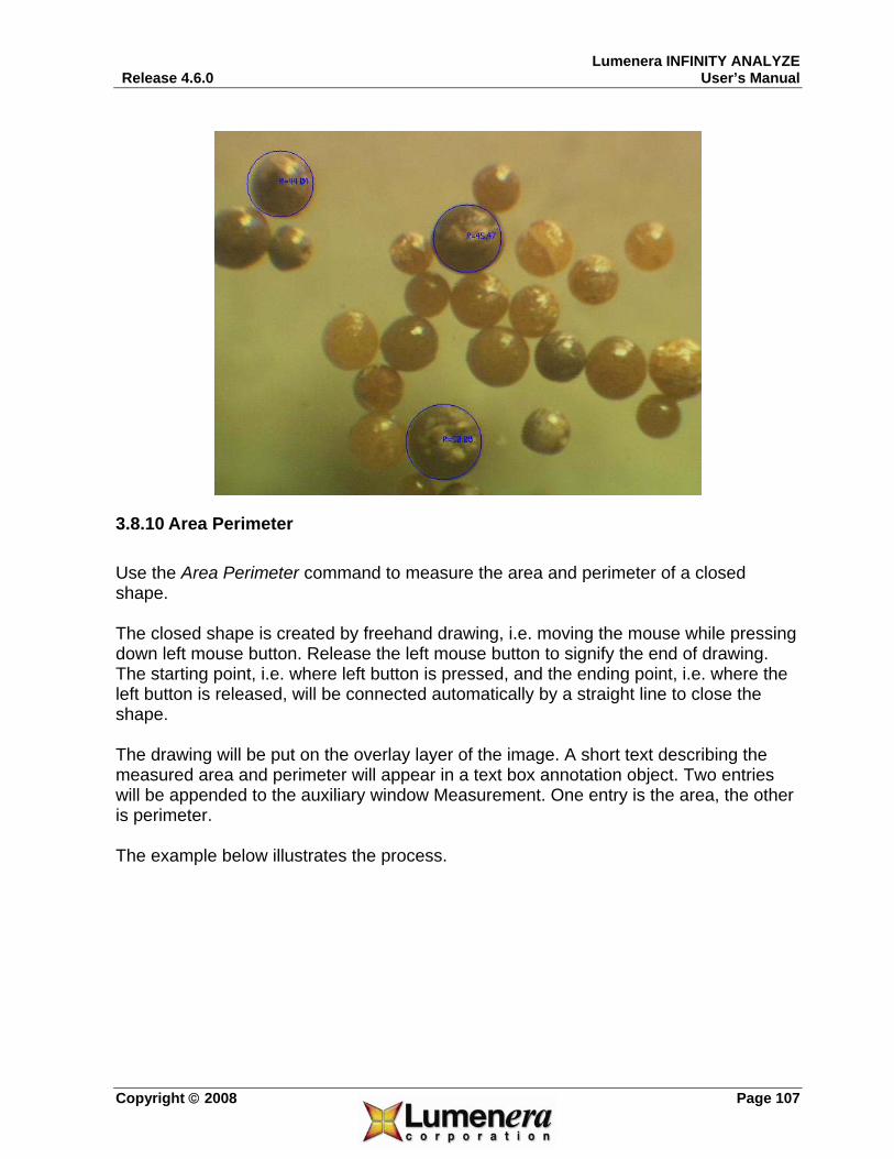
Lumenera INFINITY ANALYZE Release 4.6.0 User’s Manual
Copyright © 2008 Page 107
3.8.10 Area Perimeter Use the Area Perimeter command to measure the area and perimeter of a closed shape. The closed shape is created by freehand drawing, i.e. moving the mouse while pressing down left mouse button. Release the left mouse button to signify the end of drawing. The starting point, i.e. where left button is pressed, and the ending point, i.e. where the left button is released, will be connected automatically by a straight line to close the shape. The drawing will be put on the overlay layer of the image. A short text describing the measured area and perimeter will appear in a text box annotation object. Two entries will be appended to the auxiliary window Measurement. One entry is the area, the other is perimeter. The example below illustrates the process.

Lumenera INFINITY ANALYZE User’s Manual Release 4.6.0
Page 108 Copyright © 2008
3.8.11 Caliper Use the Caliper command to measure the distance between two points or two parallel lines. Click to specify two points. After the first click a rubber band with two perpendicular legs is being drawn to connect the first point and the current mouse position. Use the legs to align with parallel lines. The second click ends the measurement. The caliper will be placed on the overlay layer of the image. A short description showing the distance will appear in a text box annotation object. A new entry will be appended to the auxiliary window Measurement to hold the value of the distance. The example below illustrates the process.
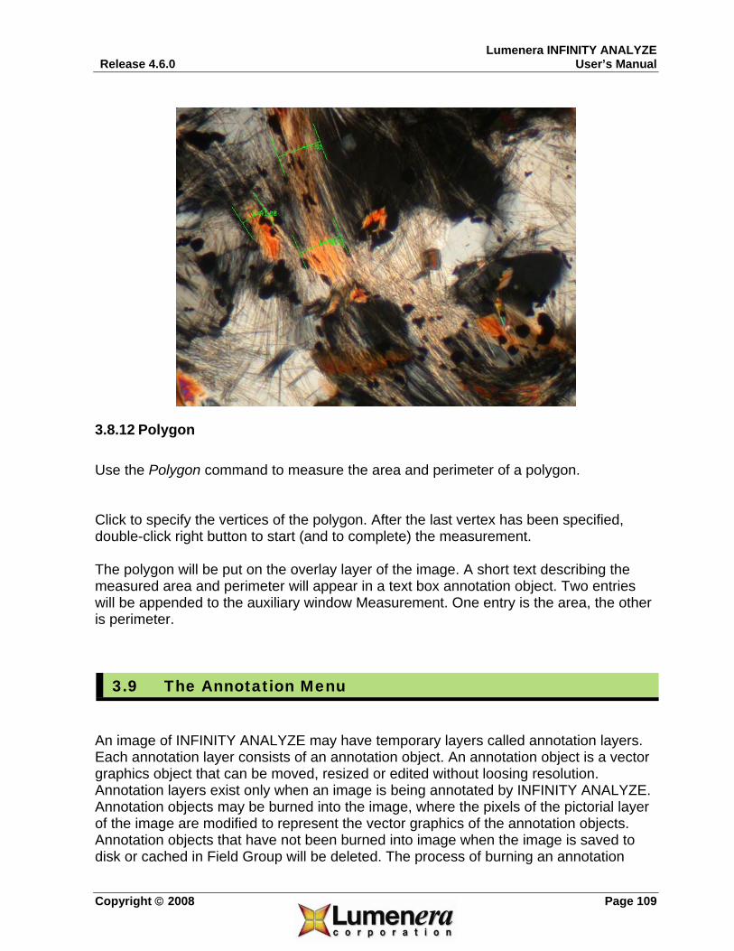
Lumenera INFINITY ANALYZE Release 4.6.0 User’s Manual
Copyright © 2008 Page 109
3.8.12 Polygon Use the Polygon command to measure the area and perimeter of a polygon. Click to specify the vertices of the polygon. After the last vertex has been specified, double-click right button to start (and to complete) the measurement. The polygon will be put on the overlay layer of the image. A short text describing the measured area and perimeter will appear in a text box annotation object. Two entries will be appended to the auxiliary window Measurement. One entry is the area, the other is perimeter.
3.9 The Annotation Menu
An image of INFINITY ANALYZE may have temporary layers called annotation layers. Each annotation layer consists of an annotation object. An annotation object is a vector graphics object that can be moved, resized or edited without loosing resolution. Annotation layers exist only when an image is being annotated by INFINITY ANALYZE. Annotation objects may be burned into the image, where the pixels of the pictorial layer of the image are modified to represent the vector graphics of the annotation objects. Annotation objects that have not been burned into image when the image is saved to disk or cached in Field Group will be deleted. The process of burning an annotation

Lumenera INFINITY ANALYZE User’s Manual Release 4.6.0
Page 110 Copyright © 2008
object includes deleting that temporal layer. Annotation layers are topmost layers of an image of INFINITY ANALYZE and may obscure pictorial and overlay layers. Annotation is possible only when INFINITY ANALYZE is in annotating mode. To enter the annotating mode, choose Annotate > Enable. To leave the annotating mode, choose that menu item again. In annotating mode, those measurement commands that involves extended mouse actions will be disabled. The hand tool for image pan and scroll and the micrometer calibration are also disabled in annotating mode. One or more annotation objects can be selected. Click to select an object in the annotating mode. Shift + Click to select an additional object. To select all the annotation objects, press Ctrl + A. To deselect all the annotation objects, double-click anywhere that is not occupied by an annotation object. Selected objects can be moved together. To move selected objects, drag any one of them. Selected objects can also be cloned. To clone selected objects, click any one of them while pressing down the Ctrl key. When a selected object is the only selected object, it may be resized. To resize an annotation object, drag its resizing handles. An annotation object can have as many as nine resizing handles located on the bounding rectangle of the annotation object. Resizing handles usually reside at the four corners or the center of line segments. To detect a resizing handle, hover the mouse over the bounding rectangle and wait for the change of cursor. If a resizing cursor appears, it means the mouse is over a resizing handle. Note the bounding rectangle will not appear until the object is selected. Each annotation object has a set of properties associated with it. The properties may be edited through popup dialogs. To change the properties of an annotation object, double-click that object.
3.9.1 Enable Use the Enable command to toggle annotating mode. In the annotating mode of INFINITY ANALYZE, all mouse actions over the active image, except those for annotation, are disabled.
3.9.2 Line Use the Line command to add line objects. Each line object is defined by two endpoints. Press left mouse button to specify one of the endpoints. Move the mouse to the other endpoint, while keeping the left mouse

Lumenera INFINITY ANALYZE Release 4.6.0 User’s Manual
Copyright © 2008 Page 111
button pressed, to draw the line. Release the left mouse button to complete the line drawing. The above procedure may be repeated to create more lines. A line object has two resizing handles, located at the two endpoints.
Show the color to draw the line. Click to pick up a new color from the popup palette as illustrated below.

Lumenera INFINITY ANALYZE User’s Manual Release 4.6.0
Page 112 Copyright © 2008
Push Automatic to specify the light gray color. Push More Colors to bring up the Windows Color Picker Dialog for more and customized colors.
Show the width of line. A new value may be entered directly. Or use the spin buttons to adjust the setting.
Show the style of the line. Click to pick up a new style from the popup style selector as illustrated below.
If checked, the endpoints of the line will be drawn as solid balls.

Lumenera INFINITY ANALYZE Release 4.6.0 User’s Manual
Copyright © 2008 Page 113
3.9.3 Rectangle Use the Rectangle command to add rectangle objects. Each rectangle is specified by two diagonal vertices. Press down left mouse button to specify one vertex. Move the mouse to the other vertex while keeping left mouse button pressed to draw the rectangle. Release left mouse button to complete the creation of this rectangle. Repeat the procedure above to add more rectangle objects. A rectangle object has eight resizing handles as illustrated below. Drag the handles at the four corners to adjust width and height of the rectangle simultaneously. Drag the other handles to adjust width or height but not both. Drag anywhere else within the rectangle to move the rectangle object.
Double-click a rectangle to edit its properties. As illustrated below, the properties of a rectangle object consist of those properties of those four lines that make up the rectangle and the properties that specify how the interior of the rectangle is to be painted.

Lumenera INFINITY ANALYZE User’s Manual Release 4.6.0
Page 114 Copyright © 2008
For line properties, please refer to the Line command. The painting of the interior of a rectangle is defined by the Fill sector of the above dialog.
Show the present color to fill the interior of the rectangle. Click to pick up a new color as shown below.
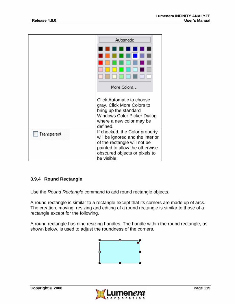
Lumenera INFINITY ANALYZE Release 4.6.0 User’s Manual
Copyright © 2008 Page 115
Click Automatic to choose gray. Click More Colors to bring up the standard Windows Color Picker Dialog where a new color may be defined.
If checked, the Color property will be ignored and the interior of the rectangle will not be painted to allow the otherwise obscured objects or pixels to be visible.
3.9.4 Round Rectangle Use the Round Rectangle command to add round rectangle objects. A round rectangle is similar to a rectangle except that its corners are made up of arcs. The creation, moving, resizing and editing of a round rectangle is similar to those of a rectangle except for the following. A round rectangle has nine resizing handles. The handle within the round rectangle, as shown below, is used to adjust the roundness of the corners.

Lumenera INFINITY ANALYZE User’s Manual Release 4.6.0
Page 116 Copyright © 2008
A round rectangle has limited line properties. The line styles other than the solid cannot be specified for a round rectangle.
3.9.5 Ellipse Use the Ellipse command to add ellipse objects. An ellipse is fully specified by its minimum bounding rectangle. The creation of an ellipse object is identical to that of its minimum bounding rectangle, as illustrated below, although the rectangle is not visible when the ellipse is not selected.
An ellipse is moved, resized in the same way as a rectangle object. The properties of an ellipse are identical to those of a round rectangle, i.e. only solid line style is applicable.
3.9.6 Polygon Use the Polygon command to add polygon objects. There are two ways to create a polygon object, by clicks and by freehand drawing. By Clicks A polygon is specified by its vertices. Click to add a new vertex. Double-click to add the last vertex. By Freehand Drawing Press down the left mouse button to start drawing. Move the mouse while keeping left button pressed to draw a polygon. Double-click to finish drawing. If a polygon has been created by clicks, each vertex is a resizing handle. If a polygon has been created by freehand drawing, each point on the drawing is a resizing handle. See below for an illustration. The polygon on the left is created by clicks; the one on the right is created by freehand drawing.

Lumenera INFINITY ANALYZE Release 4.6.0 User’s Manual
Copyright © 2008 Page 117
A polygon has an identical set of properties to that of an ellipse.
3.9.7 Arrow Use the Arrow command to add arrow objects. An arrow is made up of an arrow head, an arrow trailer, and a line connecting the arrow head and trailer. The arrow head and arrow trailer are shapes consisting of enclosing lines and interiors. The lines enclosing arrow head and arrow trailer, and the line connecting the arrow head and arrow trailer, have full line properties associated with them. The interiors of arrow head and arrow trailer have full fill properties associated with them. An arrow is created, moved and resized in the same way as a line. The properties of an arrow include, besides line and fill properties, the shape and size of arrow head and arrow trailer as shown below.

Lumenera INFINITY ANALYZE User’s Manual Release 4.6.0
Page 118 Copyright © 2008
Click to pick up a new style of the arrow head.

Lumenera INFINITY ANALYZE Release 4.6.0 User’s Manual
Copyright © 2008 Page 119
The style of the arrow trailer is set in a similar way. The shapes of arrow trailer are mirrors of those of arrow head. Use the spin button to adjust the size of arrow head or arrow trailer. The size is defined as diameter of the bounding circle of the shape measured in pixels.
3.9.8 Text Use the Text command to add text box objects. Click to add a text box object. Unlike other annotation commands the property dialog appear immediately upon the creation of a text box object, as illustrated below.
Push to open the standard Windows Font Dialog where a font, including its style, size, and effects, may be specified

Lumenera INFINITY ANALYZE User’s Manual Release 4.6.0
Page 120 Copyright © 2008
for the text in the annotation object.
Enter the text for the annotation object. Show how the bounding rectangle of the text appears. Click the drop list to specify whether the bounding rectangle is to be displayed straight as a rectangle, or a round rectangle, or an ellipse, or not to be displayed at all. Show how the text is positioned in the bounding rectangle. Click the drop list to specify whether the text is to be left justified, right justified, or to be placed in the center.
If the bounding rectangle is to be shown, the line and fill properties apply to the bounding rectangle. If the bounding rectangle is to be shown as rectangle, full line properties apply. If the bounding rectangle is to be shown as round rectangle or ellipse, line style is forced to be solid and the other line style settings will be ignored.
3.9.9 External Use the External command to insert an OLE object. This command opens the standard Windows Insert Object Dialog as shown below. All servers currently installed on the system are listed where an object may be created anew or from a file.

Lumenera INFINITY ANALYZE Release 4.6.0 User’s Manual
Copyright © 2008 Page 121
3.9.10 Select Use the Select command to select one or more annotation objects. Click to select an annotation object. Shift + Click to select additional objects. It is also possible in this mode to draw a rectangle to select all objects covered by the rectangle. Click anywhere within the active image window that is not occupied by any annotation object to deselect all objects.
3.9.11 Select All Use the Select All command to select all annotation objects.
3.9.12 Delete Use the Delete command to delete selected annotation objects.
3.9.13 Properties Use the Properties command to edit the properties of a selected object.

Lumenera INFINITY ANALYZE User’s Manual Release 4.6.0
Page 122 Copyright © 2008
3.9.14 Move to Uppermost Use the Move to Uppermost command to make the selected object the topmost layer.
3.9.15 Move to Lowermost Use the Move to Lowermost command to make the selected object the bottommost layer.
3.9.16 Move Upper Use the Move Upper command to move the selected object one layer above.
3.9.17 Move Lower Use the Move Lower command to move the selected object one layer down.
3.9.18 Burn into Image Use the Burn into Image command to create a pixel representation of all the annotation objects on the pictorial layer and delete all the annotation objects. Annotation objects are temporary and cannot be saved into a file.

Lumenera INFINITY ANALYZE Release 4.6.0 User’s Manual
Copyright © 2008 Page 123
3.10 The Window Menu
3.10.1 Cascade Use the Cascade command to make all image windows the same size and stacked from top left to bottom right of the main window.
3.10.2 Tile Horizontally Use the Tile Horizontally command to make all image windows aligned edge to edge horizontally and the same size if possible.
3.10.3 Tile Vertically Use the Tile Vertically command to make all image windows aligned edge to edge vertically and the same size if possible.
3.10.4 Arrange Icon Use the Arrange Icon command to align the icons of image windows at the bottom of the main window.
3.11 The Help Menu

Lumenera INFINITY ANALYZE User’s Manual Release 4.6.0
Page 124 Copyright © 2008
3.11.1 Settings Use the Settings command to tune the performance of INFINITY ANALYZE.
The number of thumbnails in Field Group. The size of the memory, in MB, that has been allocated to Field Group. The maximum length of processing history for each image. The Gamma of computer screen, in hundredth.
Push to dismiss the dialog and to apply the settings when INFINITY ANALYZE runs again.
Push to dismiss the dialog and not to change any setting.
3.11.2 Database Settings Use the Database Settings command to choose an alternate location and file for the INFINITY ANALYZE database record and the storage location of the the performance of INFINITY ANALYZE.

Lumenera INFINITY ANALYZE Release 4.6.0 User’s Manual
Copyright © 2008 Page 125
Select this option to use the default database stored in the same location where INFINITY ANALYZE is installed
Select this option to specify an alternate location for the database file and image storage Identify the location and filename of the remote database. It can be on a network drive, or in another local folder, as desired. Hint: Copy the default database file from the INFINITY ANALYZE folder location to this new location prior to invoking this feature
Browse to select the folder location Identify the folder location where database images are to be stored
Browse to select the folder location
Select to accept the settings and close the dialog
Select to cancel the changes

Lumenera INFINITY ANALYZE User’s Manual Release 4.6.0
Page 126 Copyright © 2008
3.11.3 Manual Use the Manual command to open this User’s Guide from within INFINITY ANALYZE.
3.11.4 Online Help Use the Online Help to connect to the Lumenera website.
3.11.5 About Analyze Use the About Analyze command to read copyright notice and version information.

Lumenera INFINITY ANALYZE Release 4.6.0 User’s Manual
Copyright © 2008 Page 127
4 3 Other Commands This section details the commands that are not accessible from menu. Specifically, the Infinity cameras and built-in database are most conveniently controlled from Control Panel and Database Window.
4.1 Imaging Control
The camera presently connected to INFINITY ANALYZE, and the whole image acquisition process, can be fully controlled from within the Imaging Control Pane of the Control Panel. Image acquisition will be based on the current camera settings and capture options which are configured by the seven sub-panes of the Imaging Control Pane described in detail below. Camera settings refer to those parameters that are necessary to put the camera into a specific state. Capture options refers to what INFINITY ANALYZE will do to the frames grabbed from video stream of the camera, including calibration for purpose of measurement and printing. In fact, system micrometer has to be properly scaled before applying to the newly formed image, according to the decimation factor specified in capture options. The contents of camera settings, capture options and calibration information are listed below.
Exposure Gain Gamma Saturation Hue Brightness Contrast White Balance Rotation Flip
Camera Settings
Light Source Temperature

Lumenera INFINITY ANALYZE User’s Manual Release 4.6.0
Page 128 Copyright © 2008
Frame Averaging Decimation Destination Where to store the acquired images. It can be
Field Group, disk files, or both. A new image window may also be created to hold a newly acquired image.
File Name The path of the file that may be used to store a newly acquired image.
Capture Full Field of View
INFINITY ANALYZE may be directed to exploit the full pixel array of the camera for the image acquisition, or just to grab a frame from current video stream, which may be sub-sampled or only part of the field of view.
Preview Captured Image
A new image window may be created to hold a copy of the just acquired image.
Verify File Name on Capture
Show a File Save As dialog box for each acquired image that is to be stored to a file. This option may be used to prevent overwriting an existing file or to convert the image to another format.
Capture Options
Auto Increment File Name
INFINITY ANALYZE may be directed to name the files automatically to store the acquired images. It does so by appending a serial number to the initially specified file name.
Sampling interval in horizontal direction
Sampling interval in vertical direction
Calibration Information (Micrometer)
Magnification

Lumenera INFINITY ANALYZE Release 4.6.0 User’s Manual
Copyright © 2008 Page 129
4.1.1 Capture Control
Presets A preset consists of a complete set of parameters for controlling the camera, a subset of capture options and image calibration information as detailed below.
Exposure Gain Gamma Saturation Hue Brightness Contrast White Balance Rotation Flip
Camera Settings
Light Source Temperature Frame Averaging Capture Options Subsampling Sampling Intervals Calibration Information
(Micrometer) Magnification INFINITY ANALYZE maintains a list of presets. A preset is identified by a name and by its position in the list if the name is not unique. A present name is a single line of text, which is entered when a preset is created and added to the preset list, as shown below.

Lumenera INFINITY ANALYZE User’s Manual Release 4.6.0
Page 130 Copyright © 2008
Show the name of the preset that is currently applied. Click to apply another preset. A special preset, named “Default”, will be created by INFINITY ANALYZE whenever a new camera is attached. It is always the first in the preset list and contains factory settings.
Push to remove the current preset from the preset list. Note that the present camera settings, capture options and system micrometer will not be affected. Just that the preset is deleted from the list.
Push to create a new preset and add it to the preset list. The name of the preset is specified in the dialog above. The content of the preset is derived from the current camera settings, capture options and system micrometer.
Use the Update button to apply a change in camera settings to an existing Preset
Most Important Camera Settings Color reproduction and overall brightness dictate image quality. The color reproduction of a camera is controlled by gains applied to color channels of the camera. It is most convenient to let INFINITY ANALYZE determine the necessary gains from live images, a process known as white balance. White balance may be based on either the whole live image that is currently being displayed or a small area therein. INFINITY ANALYZE uses the term White Balance for the operation based on the whole image and Area-Based White Balance (Area WB) for the operation based on a small area within the live
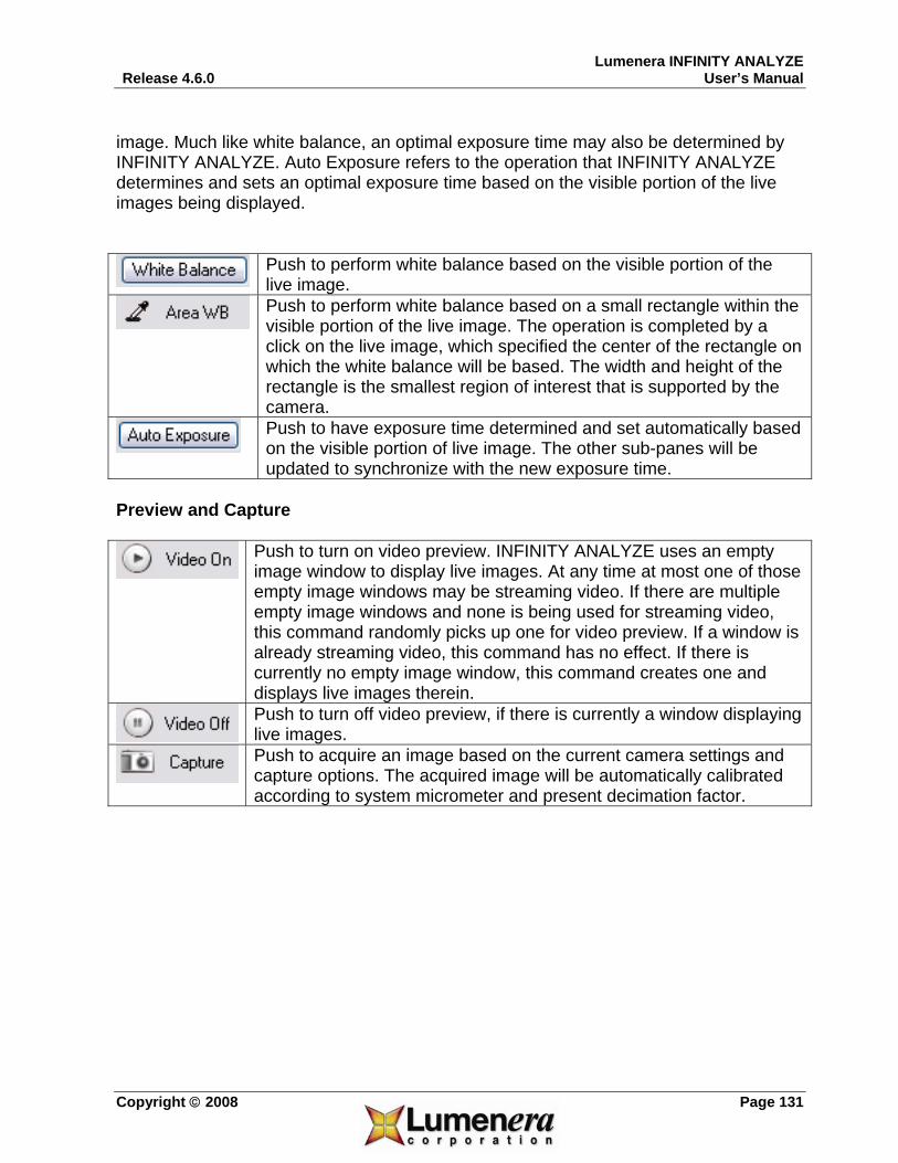
Lumenera INFINITY ANALYZE Release 4.6.0 User’s Manual
Copyright © 2008 Page 131
image. Much like white balance, an optimal exposure time may also be determined by INFINITY ANALYZE. Auto Exposure refers to the operation that INFINITY ANALYZE determines and sets an optimal exposure time based on the visible portion of the live images being displayed.
Push to perform white balance based on the visible portion of the live image.
Push to perform white balance based on a small rectangle within the visible portion of the live image. The operation is completed by a click on the live image, which specified the center of the rectangle on which the white balance will be based. The width and height of the rectangle is the smallest region of interest that is supported by the camera.
Push to have exposure time determined and set automatically based on the visible portion of live image. The other sub-panes will be updated to synchronize with the new exposure time.
Preview and Capture
Push to turn on video preview. INFINITY ANALYZE uses an empty image window to display live images. At any time at most one of those empty image windows may be streaming video. If there are multiple empty image windows and none is being used for streaming video, this command randomly picks up one for video preview. If a window is already streaming video, this command has no effect. If there is currently no empty image window, this command creates one and displays live images therein.
Push to turn off video preview, if there is currently a window displaying live images.
Push to acquire an image based on the current camera settings and capture options. The acquired image will be automatically calibrated according to system micrometer and present decimation factor.

Lumenera INFINITY ANALYZE User’s Manual Release 4.6.0
Page 132 Copyright © 2008
4.1.2 Time Lapse INFINITY ANALYZE is able to acquire a sequence of images automatically, an operation referred to as time lapse capture. Two parameters have to be specified to start a time lapse capture, one is the time interval, at which the images will be acquired, and the other is the span, referred to as duration, of the time which is needed for the whole sequence of images to be captured. An image of the sequence will be acquired according to the camera settings and capture options at the time when the acquisition action occurs. Each captured image will also be calibrated according to the system micrometer and sub-sampling factor at the time when the acquisition action occurs. Note that the time lapse capture initiated from this sub-pane will be carried out in the background. Other functions within INFINITY ANALYZE may still be accessible during the time lapse capture.
Time interval, in seconds.
Time duration, in seconds.
Push to initiate time lapse capture. Video preview might be necessary if not to capture full field of view.
Push to abort the time lapse capture.
The progress of the time lapse capture. Both the number of captured images and the estimated time, in seconds, needed to complete the task, are given.
The interval between sequential image captures will depend on the camera model, and camera settings that dictate the frame rate performance of the camera. In addition, the ANALYZE application imposes a certain amount of processing overhead. It may not be
possible to obtain images at a requested interval shorter than a few seconds.

Lumenera INFINITY ANALYZE Release 4.6.0 User’s Manual
Copyright © 2008 Page 133
Camera Control The exposure, global gain and Gamma of the camera may be set from this sub-pane.
Use the slider to adjust the exposure time of the camera. The exposure is in milliseconds and is adjusted logarithmically.
The minimal exposure time allowable for the camera.
Show the current exposure time of the camera. A new value may also be entered directly. The exposure is in milliseconds.
The maximal exposure time allowable for the camera.
Use the slider to adjust the global gain of the camera. The global gain of a camera is the factor multiplied to the intensity channel of each raw pixel.
The minimal gain allowable for the camera.
Show the current gain. A new value may also be entered directly.
The maximal gain allowable for the camera.
Use the slider to adjust the Gamma of the camera.
Minimal Gamma allowable for the camera.
Show the current Gamma of the camera. A new value may also be entered directly.

Lumenera INFINITY ANALYZE User’s Manual Release 4.6.0
Page 134 Copyright © 2008
Maximal Gamma allowable for the camera.
On any INFINITY3-1 camera model, this feature option will be available. Select the checkbox to enable the cooling function on the camera. When cooling is activated, the fan will be audible on the camera, and the blue LED on the front of the camera housing will illuminate. De-select the checkbox to turn off the cooling function.
4.1.3 Image Orientation Depending on the model of the camera being connected, the live image may be rotated or flipped. The image orientation, i.e. rotation and flip, may be controlled from this sub-pane.
Show the angle by which the live image is currently being rotated. Click to specify a new value.
Show whether horizontal or vertical or both flips have been applied to the live image. Click to set or reset a flip state.

Lumenera INFINITY ANALYZE Release 4.6.0 User’s Manual
Copyright © 2008 Page 135
4.1.4 Capture Options
Select the number of frames to be averaged. If 1 is selected, no frame averaging will be performed. If 2 is selected, two successive frames will be summed and then divided by two to create the intermediate image that is the input to subsequent post-capture processing. 4 and 8 are similarly defined. Frame averaging reduces noise. If n frames are averaged, the energy of the noise will be 1/n of its original level. Frame averaging is performed only when capturing full field

Lumenera INFINITY ANALYZE User’s Manual Release 4.6.0
Page 136 Copyright © 2008
of view.
For either the INFINITYX-21 or INFINITYX-32 camera models, the Subsampling option is replaced by the following:
Subsample the output image. If 1 is selected, no sub-sampling will be done. If 2 is selected, the number of columns and number of rows of the image will be reduced by a factor of two by merging every two consecutive columns and rows. 3 and 4 are similarly defined. Subsampling reduces the noise level much like averaging. The way INFINITY ANALYZE performs subsampling also helps to avoid aliasing. Subsampling is performed only when capturing full field of view. Pixel-Shift Cameras Instead of decimating pixels, pixel-shift cameras such as Infinity X are decimating the original sampling interval, which actually leads to an increase of pixel numbers in each row and column by the decimation factor.
Select a destination of the acquired images. If File is selected, the image will be stored to disk under that file path specified below. If Field Group is selected, the image will be appended to Field Group if there is still room. If Both is selected, the image will be stored as a file on disk and also appended to Field

Lumenera INFINITY ANALYZE Release 4.6.0 User’s Manual
Copyright © 2008 Page 137
Group.
Show the file name to be used when the captured image is to store on disk. A new file name may be entered directly.
Push to bring out a File Save As dialog to specify the file name to be used when the captured image is to store on disk.
If checked, the image of the full field view will be captured regardless of the preview state. If unchecked, only the image that is being previewed will be captured. This can be a sub-region of the full field of view, or lower-resolution image which INFINITY ANALYZE is using for display purpose.
If checked, a new image window will be created to load a copy of the acquired image.
If checked and the acquired image is to store in a file, a File Save As dialog will be brought up after each image is acquired. The file name contained in the dialog is initially set to the previously specified file name such as “e:\report\specimen.jpg”. However, it is free to change the file name, or instruct INFINITY ANALYZE not to save this image to disk at all.
If checked and the captured image is to store in a file, the file name will be changed by INFINITY ANALYZE after the current image has been saved. The new file name will be used for the next captured image. The new file name will

Lumenera INFINITY ANALYZE User’s Manual Release 4.6.0
Page 138 Copyright © 2008
have a integer appended to the original text and this integer will be incremented by one each time the new file name is generated by INFINITY ANALYZE.
4.1.5 Light Source The temperature of the light source may be advised to INFINITY ANALYZE to aid color reproduction of the camera. The same specimen may appear different under different lighting environment because of the different spectral distribution of the light source. The camera may incorporate the factor of light source to produce the right colors comfortable with human perception.
Select to indicate to INFINITY ANALYZE that the light source has a broken spectrum.
Select to indicate to INFINITY ANALYZE to add more red.
Select to indicate to INFINITY ANALYZE to add even more red.
Select to indicate to INFINITY ANALYZE to add more blue.
Select to indicate to INFINITY ANALYZE to add more red and blue.
Select to indicate to INFINITY ANALYZE no color temperature should be incorporated in image formation.

Lumenera INFINITY ANALYZE Release 4.6.0 User’s Manual
Copyright © 2008 Page 139
4.1.6 Camera Control Extended The saturation, hue, brightness and contrast of the camera may be controlled from this sub-pane. Note that adjusting saturation of a camera means to modify the saturation of each pixel in each frame of the video stream from that camera by the specified amount. Note also that the range of saturation of a camera must be scaled to match that of a pixel, which is always [0, 255]. The same is true for hue. Brightness and contrast are purely camera-specific. All these parameters of the camera are adjusted independently of the others, that is, each type of adjustment is separately applied to the raw video frames of the camera.
Use the slider to adjust the saturation of the camera.
The minimal saturation allowable for the camera. If set to 0, a color camera appears to be delivering monochrome images. This is equivalent to subtracting 256

Lumenera INFINITY ANALYZE User’s Manual Release 4.6.0
Page 140 Copyright © 2008
from the saturation of each pixel in a still image.
Show the current saturation of the camera. A new value may also be entered here. The default setting is 1 where the saturation of the raw image is not modified.
The maximal saturation allowable for the camera. This is equivalent to adding 256 to the saturation of each pixel in a still image.
Use the slider to adjust the hue of the camera. Hue is adjusted independently of saturation.
The minimal hue allowable for the camera. This is equivalent to subtracting 128 from the hue of each pixel in a still image.
Show the current hue that is added to that of the images from the camera. A new value may also be entered here. Note that for a camera the hue is cyclic with a period of 360.
The maximal hue allowable for the camera. This is equivalent to adding 128 to the hue of each pixel in a still image.
Use the slider to adjust the brightness that is being added to that of the images from the camera.
The minimal brightness allowable for the camera.
Show the current brightness that is being added to that of the images from the camera. A new value may also be entered here. The default value is 0 where the

Lumenera INFINITY ANALYZE Release 4.6.0 User’s Manual
Copyright © 2008 Page 141
brightness of raw images is not modified.
The maximal brightness allowable for the camera.
Use the slider to adjust the contrast of the camera.
The minimal contrast allowable for the camera.
Show the current contrast of the camera. A new value may also be entered directly here. The default setting is 1.
The maximal contrast allowable for the camera.
Database
The management of the built-in database, and the interaction of the active image and the database, may be carried out from the auxiliary window Database.
4.1.7 Store
Push to save the active image and its measurement result to the built-in database.
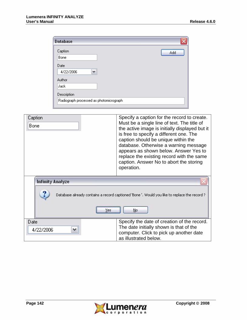
Lumenera INFINITY ANALYZE User’s Manual Release 4.6.0
Page 142 Copyright © 2008
Specify a caption for the record to create. Must be a single line of text. The title of the active image is initially displayed but it is free to specify a different one. The caption should be unique within the database. Otherwise a warning message appears as shown below. Answer Yes to replace the existing record with the same caption. Answer No to abort the storing operation.
Specify the date of creation of the record. The date initially shown is that of the computer. Click to pick up another date as illustrated below.

Lumenera INFINITY ANALYZE Release 4.6.0 User’s Manual
Copyright © 2008 Page 143
A date may also be entered directly.
Specify the name of the person who is responsible for the acquisition, processing or measurement of the active image. Must be a single line of text. Specify a single line of text as a note, remark or comment.
Push to add the new record to database.
Push to exit the dialog and do not modify the database in any way.
The user account must have write privilege on the folder where the database is located, otherwise adding records to the database will not be successful. Typically the database file is in the same location as the INFINITY ANALYZE application, however it is also possible to specify an alternate file folder
location for the database, if required.

Lumenera INFINITY ANALYZE User’s Manual Release 4.6.0
Page 144 Copyright © 2008
4.1.8 Load
Push to open the selected record in the database. Note a record in the database must have been selected for this command to work. Otherwise a warning message appears as the following.
When a record is successfully loaded, a new image window will be created to hold the image data from that record. If the image has been measured before, measurement information will also be loaded into the auxiliary window Measurement.
4.1.9 Delete
Push to delete the selected records in the database. Note for this command to work, at least one record has to be selected. Otherwise, the following warning message will appear.
A deleted record cannot be restored.
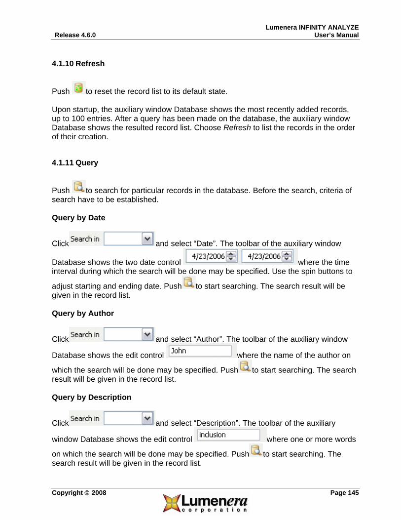
Lumenera INFINITY ANALYZE Release 4.6.0 User’s Manual
Copyright © 2008 Page 145
4.1.10 Refresh
Push to reset the record list to its default state. Upon startup, the auxiliary window Database shows the most recently added records, up to 100 entries. After a query has been made on the database, the auxiliary window Database shows the resulted record list. Choose Refresh to list the records in the order of their creation.
4.1.11 Query
Push to search for particular records in the database. Before the search, criteria of search have to be established. Query by Date
Click and select “Date”. The toolbar of the auxiliary window
Database shows the two date control where the time interval during which the search will be done may be specified. Use the spin buttons to
adjust starting and ending date. Push to start searching. The search result will be given in the record list. Query by Author
Click and select “Author”. The toolbar of the auxiliary window
Database shows the edit control where the name of the author on
which the search will be done may be specified. Push to start searching. The search result will be given in the record list. Query by Description
Click and select “Description”. The toolbar of the auxiliary
window Database shows the edit control where one or more words
on which the search will be done may be specified. Push to start searching. The search result will be given in the record list.
