inferential motion control: identification and robust … inferential motion control:...
TRANSCRIPT
1
Inferential Motion Control: Identification and Robust ControlFramework for Positioning an Unmeasurable Point of Interest
Tom Oomen, Member, IEEE, Erik Grassens, Ferdinand Hendriks
Abstract—Performance requirements in precision motion sys-tems, including those used in IC manufacturing and printingsystems, are ever increasing. For instance, internal deformationscannot be neglected anymore. As a result, measured signals atsensor locations cannot be used directly to evaluate performanceat the point of interest. The aim of this paper is to develop aninferential motion control framework that explicitly distinguishesbetween performance variables and measured variables. In theproposed framework, a dynamic model is used to infer theperformance variables from the measured variables. As theinferred performance variables depend on the model quality, anidentification for robust inferential control approach is pursuedthat tightly captures the uncertainty. Experimental results on aprototype motion system reveal that ignoring internal deforma-tions using traditional motion control design approaches can leadto disastrous performance at the point of interest. In addition, itis shown that the proposed inferential motion control frameworkleads to high performance at the unmeasurable point of interest.
I. INTRODUCTION
Increasing performance in precision motion systems ne-cessitates distinguishing between performance and measuredvariables. Herein, measured variables refer to the sensor signalsthat are accessible by the feedback controller. The performancevariables are the signals that are directly related to the system’sperformance but are not directly accessible to the controller.These variables are not identical in inferential motion controlproblems, as the following examples reveal.
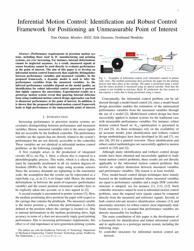
A first example arises in the production of integratedcircuits (ICs), see Fig. 1. Here, a silicon disc is exposed in aphotolithographic process. This wafer, which is a silicon disc,must be repeatedly positioned in all six motion degrees-of-freedom (DOFs) by the wafer stage using accurate sensors.Since the accuracy demands are tightening to the nanometerscale, the assumption that the system can be represented as arigid-body, e.g., as in [1], is no longer valid. Hence, the internaldeformations in between the point-of-exposure (performancevariable) and the sensor position (measured variable) have tobe explicitly taken into account, as is also argued in [2].
A second example is encountered in printer systems [3]. Here,the medium positioning drive positions the paper with respect tothe carriage that contains the printheads. The measured variableis the motor position y, whereas the performance is clearlydefined at the position where the carriage is located (z). Dueto internal deformations in the medium positioning drive, highaccuracy in terms of y does not necessarily imply good printingperformance. Due to increasing performance requirements, thiseffect is of vital importance in next-generation printing systems.
The authors are with the Eindhoven University of Technology, Departmentof Mechanical Engineering, Control Systems Technology group, Eindhoven,The Netherlands, [email protected].
print surfaceprint surface
paper
motor
scanner, zpcarriage
encoder, yp
Sensor
Fig. 1. Examples of inferential control. Left: inferential control in printer(side view). The medium positioning drive positions the paper for the printingprocess that takes place at the carriage. The paper is positioned using a motorand the motor position is measured using an optical encoder. Note that thescanner is not available in real-time. Right: IC production. the lens system ontop exposes a wafer that is being positioned using a sensor.
Conceptually, the inferential control problem can be ad-dressed through a model-based control [4], since a model-baseddesign procedure enables the estimation of the unmeasuredperformance variables from the measured variables throughthe use of a model [2]. Model-based control design has beensuccessfully applied to motion systems for the traditional casewith measurable performance variables. For instance, robustmotion control based on H∞-optimization is presented in[1] and [5]. As these techniques rely on the availability ofan accurate model, joint identification and (robust) controldesign methodologies have been developed in [6] and [7], seealso [8], [9] for a general overview. These identification androbust control methodologies are successfully applied to motioncontrol in [10] and [2].
Although many identification and (robust) control designresults have been obtained and successfully applied to tradi-tional motion control problems, these results are not directlyapplicable to the inferential motion control problems thatinvolve an explicit distinction between measured variablesand performance variables. The reason is at least twofold.
First, model-based control design techniques have mainlyfocused on the traditional situation where measured variablesare equal to performance variables and a single DOF controllerstructure is adopted, see for instance [1], [11], [12]. Suchcontroller structures cannot be used in inferential motion controlproblems, since the required error signals cannot be computeddirectly from the measured and reference signals. Second, inboth control-relevant iterative identification schemes [13] anduncertainty structures for robust control, most importantly dual-Youla structures, it is assumed that performance variables aredirectly measurable for feedback.
The main contribution of this paper is the development ofa framework for identification and robust inferential controland its application to a prototype motion system, including thefollowing steps:S1 controller structures for inferential motion control are
derived;
2
ÀÃ
Á
Â
Ä
Å
Æ
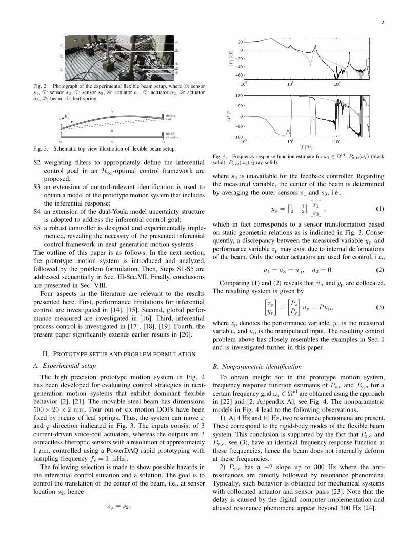
Ç
Fig. 2. Photograph of the experimental flexible beam setup, where À: sensors1, Á: sensor s2, Â: sensor s3, Ã: actuator a1, Ä: actuator a2, Å: actuatora3, Æ: beam, Ç: leaf spring.
s1 s2 s3
yp
zp
duringtask
initialsituation
x
ϕ
Fig. 3. Schematic top view illustration of flexible beam setup.
S2 weighting filters to appropriately define the inferentialcontrol goal in an H∞-optimal control framework areproposed;
S3 an extension of control-relevant identification is used toobtain a model of the prototype motion system that includesthe inferential response;
S4 an extension of the dual-Youla model uncertainty structureis adopted to address the inferential control goal;
S5 a robust controller is designed and experimentally imple-mented, revealing the necessity of the presented inferentialcontrol framework in next-generation motion systems.
The outline of this paper is as follows. In the next section,the prototype motion system is introduced and analyzed,followed by the problem formulation. Then, Steps S1-S5 areaddressed sequentially in Sec. III-Sec.VII. Finally, conclusionsare presented in Sec. VIII.
Four aspects in the literature are relevant to the resultspresented here. First, performance limitations for inferentialcontrol are investigated in [14], [15]. Second, global perfor-mance measured are investigated in [16]. Third, inferentialprocess control is investigated in [17], [18], [19]. Fourth, thepresent paper significantly extends earlier results in [20].
II. PROTOTYPE SETUP AND PROBLEM FORMULATION
A. Experimental setup
The high precision prototype motion system in Fig. 2has been developed for evaluating control strategies in next-generation motion systems that exhibit dominant flexiblebehavior [2], [21]. The movable steel beam has dimensions500 × 20 × 2 mm. Four out of six motion DOFs have beenfixed by means of leaf springs. Thus, the system can move xand ϕ direction indicated in Fig. 3. The inputs consist of 3current-driven voice-coil actuators, whereas the outputs are 3contactless fiberoptic sensors with a resolution of approximately1 µm, controlled using a PowerDAQ rapid prototyping withsampling frequency fs = 1 [kHz].
The following selection is made to show possible hazards inthe inferential control situation and a solution. The goal is tocontrol the translation of the center of the beam, i.e., at sensorlocation s2, hence
zp = s2,
100
101
102
−60
−40
−20
0
20
|P|[dB]
100
101
102
−180
−90
0
90
180
6P
[]
f [Hz]
Fig. 4. Frequency response function estimate for ωi ∈ Ωid: Pz,o(ωi) (blacksolid), Py,o(ωi) (gray solid).
where s2 is unavailable for the feedback controller. Regardingthe measured variable, the center of the beam is determinedby averaging the outer sensors s1 and s3, i.e.,
yp =[
12
12
] [s1
s3
], (1)
which in fact corresponds to a sensor transformation basedon static geometric relations as is indicated in Fig. 3. Conse-quently, a discrepancy between the measured variable yp andperformance variable zp may exist due to internal deformationsof the beam. Only the outer actuators are used for control, i.e.,
a1 = a3 = up, a2 = 0. (2)
Comparing (1) and (2) reveals that up and yp are collocated.The resulting system is given by[
zp
yp
]=
[Pz
Py
]up = Pup, (3)
where zp denotes the performance variable, yp is the measuredvariable, and up is the manipulated input. The resulting controlproblem above has closely resembles the examples in Sec. Iand is investigated further in this paper.
B. Nonparametric identification
To obtain insight for in the prototype motion system,frequency response function estimates of Pz,o and Py,o for acertain frequency grid ωi ∈ Ωid are obtained using the approachin [22] and [2, Appendix A], see Fig. 4. The nonparametricmodels in Fig. 4 lead to the following observations.
1) At 4 Hz and 10 Hz, two resonance phenomena are present.These correspond to the rigid-body modes of the flexible beamsystem. This conclusion is supported by the fact that Pz,o andPy,o, see (3), have an identical frequency response function atthese frequencies, hence the beam does not internally deformat these frequencies.
2) Py,o has a −2 slope up to 300 Hz where the anti-resonances are directly followed by resonance phenomena.Typically, such behavior is obtained for mechanical systemswith collocated actuator and sensor pairs [23]. Note that thedelay is caused by the digital computer implementation andaliased resonance phenomena appear beyond 300 Hz [24].
3
3) The resonance phenomenon at 32 Hz is observed differ-ently for Pz,o than it is for Py,o. As the slope of Pz,o tends from−2 towards −4, this behavior corresponds to noncollocatedactuator and sensor pairs [23]. This is supported by the fact thata1 and a3 are used for excitation, whereas sensor s2 is used asoutput here. It is hypothesized that the resonance phenomenonat 32 Hz corresponds to a deformation of the beam that canbe visualised by the mode shape depicted in Fig. 3, since• the resonance phenomenon causes a 180 phase difference
between Pz,o and Py,o, which corresponds to the deformationdepicted in Fig. 3.
• based on a first principles model of a free-free beam [25],this is the first mode shape beyond the suspended rigid-bodymodes at 4 Hz and 10 Hz.
C. Problem formulation
The goal of the inferential servo problem is the minimizationof zref − zp, given the reference signal zref , by the design ofan appropriate controller
up = C(zref , yp). (4)
To facilitate the exposition, the focus is on the optimal designof a feedback controller as defined next.
Definition 1. Given the true system Po and interconnectiondefined by (3) and (4), determine
Copt = arg minCJ 9(Po, C),
where J 9(P,C) is the control criterion, which is a functionof the system P and controller C.
In J 9, the superscript 9 will become clear in Sec. IV-A. Be-fore proceeding to specifying J 9(P,C) in view of penalizingthe inferential servo error zref − zp, the general identificationand robust control framework is presented.
D. General approach: system identification and robust control
The considered inferential motion control framework relieson models , since the performance variable zp is not measurableduring normal operation and must be predicted using real-timemeasurements. Of course, at a certain point in the proceduresome system knowledge is essential to obtain this model. Thefollowing assumption is imposed.
Assumption 1. During identification, both zp and yp aremeasured, whereas the controller only has access to yp duringnormal operation of the system.
Assumption 1 is required to obtain the part of the model thatcorresponds to the performance variable zp, since it cannotbe measured in real-time and will thus be inferred using themodel. This assumption is non-restrictive in many applications,including those in Fig. 1, and can also be relaxed by pursuinggrey-box modeling.
The mathematical model of the true beam system in Fig. 2is necessarily an approximation, since any physical system istoo complex to be represented exactly by means of a model.In the inferential control case, the model quality is especially
crucial, since the quality of the inferred performance variableshinges on the model quality. Model uncertainty is taken intoaccount to guarantee that the model-based controller performswell when implemented on the true system. As in standardrobust control designs [4], the model set P(P ,∆) is built upfrom a nominal model P and model uncertainty ∆, where itis assumed that
Po ∈ P(P ,∆). (5)
Associated with the model set is a worst-case control criterion
J 9WC(P, C) = sup
P∈PJ 9(P,C), (6)
hence using (5), the performance guarantee
J 9(Po, C) ≤ J 9WC(P, C)
is obtained. This leads to the following robust control design.
Definition 2. Given the model set P(P ,∆), determine
CRP9 = arg minCJ 9
WC(P, C). (7)
The resulting robust controller (7) highly depends on theshape of the model set P(P ,∆). For instance, if the model setis large in some sense, an unnecessarily conservative controldesign results. Hence, the model set should be tight to achievehigh performance. In this paper, this is done by consideringthe dual problem to the robust control synthesis problem inDefinition 2, leading to the following robust-control-relevantmodel set identification problem.
Definition 3. Given a controller Cexp that is used during theidentification experiment, determine
PRCR = arg minPJ 9
WC(P, Cexp) (8)
subject to Po ∈ P.Several remarks are appropriate. First, the identification
setting associated with (8) depends on the experimentalconditions which are specified in the next sections. Second, in[6] and [7], related approaches have been presented that arerestricted to the case where the set of measured variables isequal to the set of performance variables. Third, PRCR in (8)depends on Cexp. For the considered application, the standardPID controller in Fig. 9 is used. The performance can beiteratively and monotonously improved by alternating betweenidentifying a model set and synthesising a robust controller,as in [6] and [7]. Fourth, as already mentioned in Sec. I, theidentification of a nominal model P and quantification of modeluncertainty ∆ will be dealt with separately. In Sec. VI, it willbe shown that these independent steps jointly minimize thecriterion in Definition 3.
III. CONTROLLER STRUCTURES FOR INFERENTIAL MOTIONCONTROL
The inferential control problem imposes additional require-ments on the controller structure that are not encountered intraditional control applications. Suitable controller structuresfor inferential motion control are presented in this section,constituting Step S1 in Sec. I.

4
In the inferential servo control situation, the control goal isto let performance variable zp track a certain reference zref ,given measurements yp. Note that in the typical non-inferentialcontrol situation, where yp = zp, this is equivalent to theminimization of zref − yp, in which case a suitable controlstructure is obtained by using the error signal zref−yp as inputto the controller, as a result the single DOF feedback controllerin Fig. 5 (a) is obtained. Here, r2 should be selected as zref ,whereas r1 is an additional signal used in the further analysis.
However, the single DOF controller structure is inadequatein the inferential servo problem, since
1) in general dim zp 6= dim yp, e.g., both s1 and s2 can beused as measured signals, in which case an error signal cannotbe computed based on a difference between zref and yp; and
2) even in case dim zp = dim yp, then minimizationof zref − yp does not imply that zref − zp is minimized.For example, the scaling of yp in (1) is arbitrary, henceminimization of zref − yp is not sensible in general.
3) joint tracking and disturbance attenuation may not beachievable. In particular, assume that PyC contains a factor1s , i.e., an integrator. Then, application of a step in either r1
or r2 leads to limt→∞ yp = 0. Next, it can be immediatelyverified that application of a step in r1 leads to limt→∞ zp = 0,whereas a step in r2 leads to limt→∞ zp = Pz(0)
Py(0)r2.The deficiencies of single DOF controller structures in view ofthe inferential control problem are further elaborated on andexemplified in [26, Sec. 3.3].
Extended controller structures that can deal with the infer-ential servo control problem are depicted in Fig. 5 (b) andFig. 5 (c). In Fig. 5 (b), also referred as the indirect approach,controller Ca
2 transforms the reference zref for zp to a referenceCa
2 zref for yp. Clearly, this can resolve a scaling differencein the zp and yp variables. In addition, it appropriately dealswith the situation dim zp 6= dim yp. Similarly, the situation inFig. 5 (c) corresponds to the case where Cb
2 reconstructs theperformance variable zp from the measured variable yp.
Although the controller structures in Fig. 5 (b) and (c)and Fig. 5 (d) can deal with inferential servo control andare intuitive to comprehend, a more detailed analysis ofthese controller structures reveals that these cannot be useddirectly in conjunction with standard optimization-based controlalgorithms [4]. Therefore, the unifying controller structureC =
[C1 C2
], see also Fig. 5 (d), is adopted in the framework
in this paper, since it encompasses (a), (b), and (c), and itenables the use of standard controller synthesis algorithms.
IV. H∞-OPTIMAL INFERENTIAL CONTROL FRAMEWORK
A. Towards a nine-block setup
In this section, the general setup is presented and weightingfilters are selected, thereby constituting Step S2 of this paper.The design of H∞-optimal robust motion controllers involvesthe specification of the control goal in terms of exogenoussignals and associated weighting filters. As the inferentialproblem is a significant extension of traditional motion controlproblems, including [1], [11], several modifications are required.Two requirements are imposed. The exogenous signals shouldbe selected such that i) internal stability is guaranteed, and ii)
C P
r2
r3
r1 up
yp
zp
ez−
−
Tr
Fig. 6. Unweighted exogenous inputs and outputs.
various control requirements, e.g., loop-shaping requirements,can be appropriately specified. This extends pre-existing designstrategies, including [4], [12], [1], [11], to the proposedcontroller structure in Sec. III and the explicit distinctionbetween zp and yp.
A selection of these inputs and outputs is presented in Fig. 6.Regarding the general weighting filter selection, the exogenoussignals can be given the following interpretation: r1 representsdisturbances at the system input that have to be attenuated,r2 represents measurement noise that should not be tracked,and r3 represents the reference signal. In addition, ez is thetracking error, yp is the system output, and up is the systeminput. Here, yp and up should also remain bounded in view ofinternal stability of the feedback loop. The closed-loop transferfunction matrices are given by
z = M(P,C)w
M(P,C) =
[Pz
Py
I
](I + C2Py)−1 [C1 C2 I]−
[Tr 0 00 0 00 0 0
](9)
w =
[r3r2r1
]z =
[ezyp
up
].
In (9), Tr ∈ RH∞ is a reference model, which ensures asensible problem formulation. Due to the specific structure inM(P,C), the problem is referred to as a nine-block problem.The reasons for the specific structure are threefold.
First, the condition M ∈ RH∞ is equivalent to internalstability of the closed-loop system, which is a basic requirementfor a satisfactory control system. Second, the specific formula-tion directly fits in the standard plant formulation, enabling theuse of standard optimization algorithms. Let G(P ) be definedby[zy
]= G(P )
[wu
], hence M(P,C) = Fl(G(P ), C).
Third, the setup in Fig. 6 enables a general weighting filterselection. In particular, the setup in Fig. 6 generally has tobe extended with weighting filters to pose a sensible controlproblem. Let
W =
[We 0 00 Wy 00 0 Wu
], V =
[V3 0 00 V2 00 0 V1
],
be bistable weighting filters and define
z = Wz, w = V w (10)
M(P,C) = WM(P,C)V, (11)
J 9(P,C) = ‖M(P,C)‖∞. (12)
The control criterion in (12) is considered throughout. Theselection of inferential weighting filters is presented next inSec. IV-B.
B. Weighting filter selection
In this section, weighting filter selection is considered, whichis required prior to the control-relevant parametric identificationprocedure in Sec. V. The presented framework and associated
5
Cr2
yp
−Py
Pz
zpr1
Ca1
zrefyp
−Py
Pz
zp
Ca2 Cb
1
zrefyp
−Py
Pz
zp
Cb2
C2
zref ypPy
Pz
zp
C1
(d)(c)(b)(a)
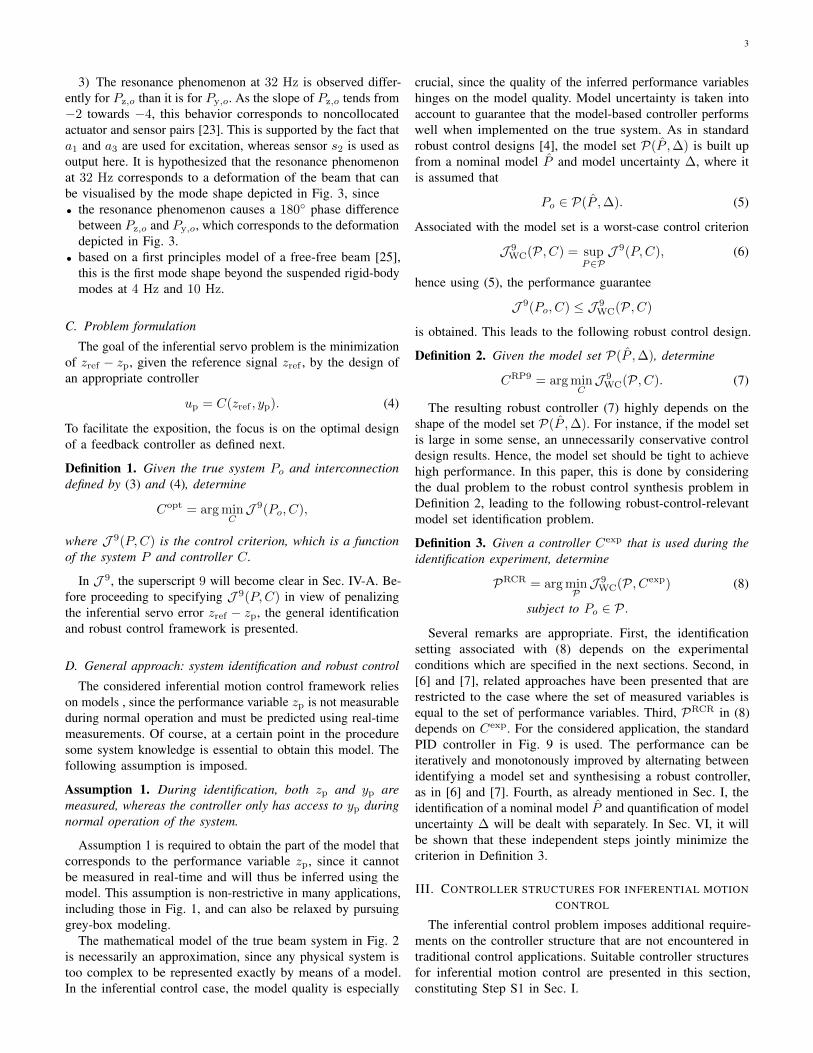
Fig. 5. Controller structures: (a) single DOF applied to inferential control, (b) indirect two DOF inferential structure, (c) inferential two DOF inferentialstructure, and (d) general two DOFs controller structure used in this paper.
control criterion enable a large freedom in the selection ofthe control goal. In this paper, the focus is on loop-shapingfeedback control and the weighting filters are designed suchthat these achieve similar control properties as in the design ofsingle DOF feedback controllers, see [11] and [1]. Alternativesignal-based approaches are pursued in [4].
The following steps lead to the design of the weighting filters.Throughout, the matrix M(P,C) is partitioned according tothe signals in (10), i.e.,
M(P,C) =
[M11 M12 M13
M21 M22 M23
M31 M32 M33
]. (13)
I) The weighting filters Wy , Wu, V1, V2 are designed usingstandard loop-shaping techniques as in [12], [11], and [1]. Inparticular, W1 and W2 are used to specify the desired loop-shape W2PW1 and are absorbed into the system to enablecontroller roll-off and integral action. Note that
Wy = W2, Wu = W−11 , V2 = W−1
2 , V1 = W1.
As loop-shaping requires knowledge of the system, the non-parametric estimate in Fig. 4 is employed for designing theweighting functions, see Fig. 7. This is in sharp contrast topre-existing approaches, including [12].
II) We allows for additional scaling. Due to the fact that zp
and yp are defined in the same unit and have approximatelythe same scaling, see (1) and Fig. 4, no additional scaling ofthe M12 and M13 blocks is required.
III) A suitable reference model Tr is selected. To enforcesimilar feedback properties for the two DOF controller asfor the four-block problem, which is used in the traditionalsituation, including [12], [11], and the single DOF controller, areference model Tr is chosen to have a low-pass characteristicwith a bandwidth that corresponds to the desired closed-loopbandwidth in Step I. In addition, a sufficiently high roll-offrate is selected to avoid a nonproper optimal C1.
IV) Next, weighting filters We = β1, V3 = β2 are defined,where β1, β2 ∈ R. These constants are set to β1 = β2 = 1.25to emphasize the importance of the block M11 in (13).
By the specific selection of weighting filters, all blocks are(indirectly) scaled. The lower-right block in (13) representsthe standard feedback controller part, whereas the upper-leftblock directly affects the inferential servo part, which can berelatively weighted using β1 and β2 as in [27].
V. PARAMETRIC SYSTEM IDENTIFICATION
The inferential controller will (implicitly) incorporate amodel to predict the performance variables from the measuredvariables through the use of a model. Indeed, optimal controllersare typically observer-based [28], where the identified modelis directly used. In this section, a new approach to identify asuitable model for (robust) inferential control is presented andapplied to the prototype motion system, constituting Step S3.
100
101
102
−80
−60
−40
−20
0
20
40
60
|P|[dB]
f [Hz]
Fig. 7. Shaped system W2Py,o(ωi)W1 (black solid), nonparametricfrequency response function estimate Py,o(ωi) (gray solid).
A. Control-Relevant Identification
As is motivated in Sec. II-C, a control-relevant nominalmodel is estimated by virtue of Definition 3. However, control-relevant identification techniques, including the procedures in[13] and [7] are restricted to single DOF controller structuresand to the situation where the set of performance variablesequals the set of measured variables. Therefore, control-relevantidentification techniques are extended appropriately, and theinferential-control-relevant identification criterion
‖M(Po, Cexp)−M(P , Cexp)‖∞ (14)
is considered, which is to be minimized over P . Here,M(Po, C
exp) is the closed-loop transfer function matrix definedin (11), where M in fact has already been identified to obtainthe results in Fig. 4. In particular, since the system operates inclosed-loop with Cexp implemented, M(Po, C
exp) is identifiedfor a certain frequency grid ωi ∈ Ωid using the approach in[22] and [2, Appendix A]. By appropriate manipulation ofM(Po, C
exp), frequency response function estimates of Pz,o
and Py,o have been obtained for ωi ∈ Ωid, see Fig. 4.Note that details on the derivation of (14) are provided in
[29]. In Sec. VI, it will be shown that the criterion in (14)indeed is useful to determine a robust-control-relevant modelset PRCR in view of Definition 3.
B. Control-Relevant Coprime Factor Identification
To appropriately extend the identified nominal model P ofthe beam system with a perturbation model that representsmodel uncertainty, the internal structure of the model P shouldbe carefully specified. To anticipate on the model uncertaintystructure in Sec. VI, the model is represented as a factorization
P =
[Nz
N
]D−1, (15)
where Nz ∈ RH∞ and N , D constitute a coprime factorizationof Py over RH∞. Substitution of (15) into (14) reveals thatthe control-relevant identification criterion in (14) is invariantunder a change of internal structure of the model P . Followingthe developments in [29, Proposition 8], a particular coprimefactorization results in a connection to the control-relevant
6
100
101
102
−80
−60
−40
−20
0
20
|Py|[dB]
f [Hz]
100
101
102
−80
−60
−40
−20
0
20
|Pz|[dB]
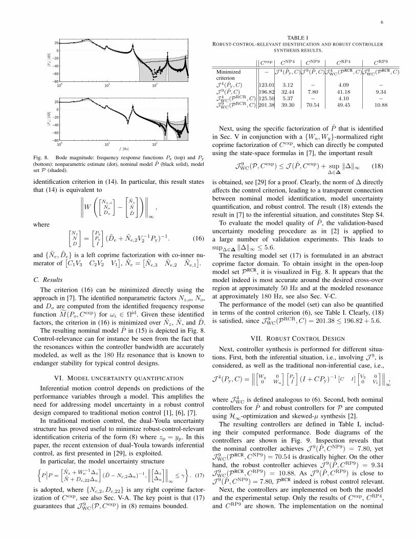
Fig. 8. Bode magnitude: frequency response functions Pz (top) and Py
(bottom): nonparametric estimate (dot), nominal model P (black solid), modelset P (shaded).
identification criterion in (14). In particular, this result statesthat (14) is equivalent to∥∥∥∥∥W
([Nz,o
No
Do
]−[Nz
N
D
])∥∥∥∥∥∞,
where [Nz
ND
]=
[Pz
Py
I
](De + Ne,2V
−12 Py)−1. (16)
and Ne, De is a left coprime factorization with co-inner nu-merator of
[C1V3 C2V2 V1
], Ne =
[Ne,3 Ne,2 Ne,1
].
C. Results
The criterion (16) can be minimized directly using theapproach in [7]. The identified nonparametric factors Nz,o, No,and Do are computed from the identified frequency responsefunction M(Po, C
exp) for ωi ∈ Ωid. Given these identifiedfactors, the criterion in (16) is minimized over Nz , N , and D.
The resulting nominal model P in (15) is depicted in Fig. 8.Control-relevance can for instance be seen from the fact thatthe resonances within the controller bandwidth are accuratelymodeled, as well as the 180 Hz resonance that is known toendanger stability for typical control designs.
VI. MODEL UNCERTAINTY QUANTIFICATION
Inferential motion control depends on predictions of theperformance variables through a model. This amplifies theneed for addressing model uncertainty in a robust controldesign compared to traditional motion control [1], [6], [7].
In traditional motion control, the dual-Youla uncertaintystructure has proved useful to minimize robust-control-relevantidentification criteria of the form (8) where zp = yp. In thispaper, the recent extension of dual-Youla towards inferentialcontrol, as first presented in [29], is exploited.
In particular, the model uncertainty structureP∣∣P =
[Nz +W−1
e ∆z
N +Dc,22∆u
](D −Nc,2∆u)−1,
∥∥∥∥[∆z
∆u
]∥∥∥∥∞≤ γ
. (17)
is adopted, where Nc,2, Dc,22 is any right coprime factor-ization of Cexp, see also Sec. V-A. The key point is that (17)guarantees that J 9
WC(P, Cexp) in (8) remains bounded.
TABLE IROBUST-CONTROL-RELEVANT IDENTIFICATION AND ROBUST CONTROLLER
SYNTHESIS RESULTS.
Cexp CNP4 CNP9 CRP4 CRP9
Minimizedcriterion
− J 4(Py, C)J 9(P , C)J 4WC(PRCR, C)J 9
WC(PRCR, C)
J 4(Py, C) 123.01 3.12 − 4.09 −J 9(P , C) 196.82 32.44 7.80 41.18 9.34J 4WC(PRCR, C) 125.50 5.37 − 4.10 −J 9WC(PRCR, C) 201.38 39.30 70.54 49.45 10.88
Next, using the specific factorization of P that is identifiedin Sec. V in conjunction with a Wu,Wy-normalized rightcoprime factorization of Cexp, which can directly be computedusing the state-space formulas in [7], the important result
J 9WC(P, Cexp) ≤ J (P , Cexp) + sup
∆∈∆‖∆‖∞ (18)
is obtained, see [29] for a proof. Clearly, the norm of ∆ directlyaffects the control criterion, leading to a transparent connectionbetween nominal model identification, model uncertaintyquantification, and robust control. The result (18) extends theresult in [7] to the inferential situation, and constitutes Step S4.
To evaluate the model quality of P , the validation-baseduncertainty modeling procedure as in [2] is applied toa large number of validation experiments. This leads tosup∆∈∆ ‖∆‖∞ ≤ 5.6.
The resulting model set (17) is formulated in an abstractcoprime factor domain. To obtain insight in the open-loopmodel set PRCR, it is visualized in Fig. 8. It appears that themodel indeed is most accurate around the desired cross-overregion at approximately 50 Hz and at the modeled resonanceat approximately 180 Hz, see also Sec. V-C.
The performance of the model (set) can also be quantifiedin terms of the control criterion (6), see Table I. Clearly, (18)is satisfied, since J 9
WC(PRCR, C) = 201.38 ≤ 196.82 + 5.6.
VII. ROBUST CONTROL DESIGN
Next, controller synthesis is performed for different situa-tions. First, both the inferential situation, i.e., involving J 9, isconsidered, as well as the traditional non-inferential case, i.e.,
J 4(Py, C) =∥∥∥[Wy 0
0 Wu
] [Py
I
](I + CPy)−1 [C I]
[V2 00 V1
]∥∥∥∞,
where J 4WC is defined analogous to (6). Second, both nominal
controllers for P and robust controllers for P are computedusing H∞-optimization and skewed-µ synthesis [2].
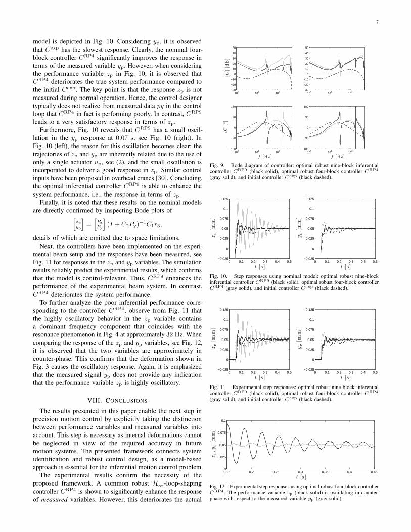
The resulting controllers are defined in Table I, includ-ing their computed performance. Bode diagrams of thecontrollers are shown in Fig. 9. Inspection reveals thatthe nominal controller achieves J 9(P , CNP9) = 7.80, yetJ 9
WC(PRCR, CNP9) = 70.54 is drastically higher. On the otherhand, the robust controller achieves J 9(P , CRP9) = 9.34J 9
WC(PRCR, CRP9) = 10.88. As J 9(P , CRP9) is close toJ 9(P , CNP9) = 7.80, PRCR indeed is robust control relevant.
Next, the controllers are implemented on both the modeland the experimental setup. Only the results of Cexp, CRP4,and CRP9 are shown. The implementation on the nominal
7
model is depicted in Fig. 10. Considering yp, it is observedthat Cexp has the slowest response. Clearly, the nominal four-block controller CRP4 significantly improves the response interms of the measured variable yp. However, when consideringthe performance variable zp in Fig. 10, it is observed thatCRP4 deteriorates the true system performance compared tothe initial Cexp. The key point is that the response zp is notmeasured during normal operation. Hence, the control designertypically does not realize from measured data py in the controlloop that CRP4 in fact is performing poorly. In contrast, CRP9
leads to a very satisfactory response in terms of zp.Furthermore, Fig. 10 reveals that CRP9 has a small oscil-
lation in the yp response at 0.07 s, see Fig. 10 (right). InFig. 10 (left), the reason for this oscillation becomes clear: thetrajectories of zp and yp are inherently related due to the use ofonly a single actuator up, see (2), and the small oscillation isincorporated to deliver a good response in zp. Similar controlinputs have been proposed in overhead cranes [30]. Concluding,the optimal inferential controller CRP9 is able to enhance thesystem performance, i.e., the response in terms of zp.
Finally, it is noted that these results on the nominal modelsare directly confirmed by inspecting Bode plots of[
zpyp
]=[Pz
Py
](I + C2Py)−1C1r3,
details of which are omitted due to space limitations.Next, the controllers have been implemented on the experi-
mental beam setup and the responses have been measured, seeFig. 11 for responses in the zp and yp variables. The simulationresults reliably predict the experimental results, which confirmsthat the model is control-relevant. Thus, CRP9 enhances theperformance of the experimental beam system. In contrast,CRP4 deteriorates the system performance.
To further analyze the poor inferential performance corre-sponding to the controller CRP4, observe from Fig. 11 thatthe highly oscillatory behavior in the zp variable containsa dominant frequency component that coincides with theresonance phenomenon in Fig. 4 at approximately 32 Hz. Whencomparing the response of the zp and yp variables, see Fig. 12,it is observed that the two variables are approximately incounter-phase. This confirms that the deformation shown inFig. 3 causes the oscillatory response. Again, it is emphasizedthat the measured signal yp does not provide any indicationthat the performance variable zp is highly oscillatory.
VIII. CONCLUSIONS
The results presented in this paper enable the next step inprecision motion control by explicitly taking the distinctionbetween performance variables and measured variables intoaccount. This step is necessary as internal deformations cannotbe neglected in view of the required accuracy in futuremotion systems. The presented framework connects systemidentification and robust control design, as a model-basedapproach is essential for the inferential motion control problem.
The experimental results confirm the necessity of theproposed framework. A common robust H∞-loop-shapingcontroller CRP4 is shown to significantly enhance the responseof measured variables. However, this deteriorates the actual
100
101
102
−30
−20
−10
0
10
20
30
40
50
|C|[dB]
100
101
102
−30
−20
−10
0
10
20
30
40
50
100
101
102
−180
−90
0
90
180
6C
[]
f [Hz]10
010
110
2−180
−90
0
90
180
f [Hz]
Fig. 9. Bode diagram of controller: optimal robust nine-block inferentialcontroller CRP9 (black solid), optimal robust four-block controller CRP4
(gray solid), and initial controller Cexp (black dashed).
0 0.1 0.2 0.3 0.4 0.5−0.025
0
0.025
0.05
0.075
0.1
0.125
t [s ]
zp[m
m]
0 0.1 0.2 0.3 0.4 0.5−0.025
0
0.025
0.05
0.075
0.1
0.125
t [s ]
yp[m
m]
Fig. 10. Step responses using nominal model: optimal robust nine-blockinferential controller CRP9 (black solid), optimal robust four-block controllerCRP4 (gray solid), and initial controller Cexp (black dashed).
0 0.1 0.2 0.3 0.4 0.5−0.025
0
0.025
0.05
0.075
0.1
0.125
t [s ]
zp[m
m]
0 0.1 0.2 0.3 0.4 0.5−0.025
0
0.025
0.05
0.075
0.1
0.125
t [s ]
yp[m
m]
Fig. 11. Experimental step responses: optimal robust nine-block inferentialcontroller CRP9 (black solid), optimal robust four-block controller CRP4
(gray solid), and initial controller Cexp (black dashed).
0.15 0.2 0.25 0.3 0.35 0.4 0.450
0.025
0.05
0.075
0.1
t [s ]
zp,yp[m
m]
Fig. 12. Experimental step responses using optimal robust four-block controllerCRP4: The performance variable zp (black solid) is oscillating in counter-phase with respect to the measured variable yp (gray solid).
8
performance variables. This is a potentially dangerous situationin high-precision systems, since the poor performance cannotbe directly detected from the measured signals.
The proposed inferential motion framework effectivelydeals with the distinction between measured and performancevariables. The key step is to use model knowledge to infer theperformance variables from the measured variables.
This paper focuses on inferential feedback control, whichis achieved through a reference model. This can be furtherenforced by a two-stage approach [31], structured controlleroptimisation, or designing a separate observer in the controlstructure of Fig. 5 (c) as is done in [32]. In addition, thepresent paper focusses on H∞-based control design, sincemodel uncertainty is of key importance in motion controlsystems and the uncertainty in the model to predict the zp
variable has been explicitly addressed.The results can be directly generalised. For instance, direct
extensions along the lines of [33], [34] are immediate, whereasimplications towards ILC are recently investigated in [35].Furthermore, the results in this paper might shed new lighton ongoing challenges in motion systems, see [36], [37],[38], [2] for an overview. Current research focuses on theuse of overactuation [21] to enhance inferential performance,addressing position dependent effects induced by positionvarying measurement of the mode shapes, and recently progresshas been made on inferential control for thermal aspects inlithographic applications.
Acknowledgment: Joost Bolder, Okko Bosgra, Robbert vanHerpen, Maarten Steinbuch, and Marc van de Wal are gratefullyacknowledged for their contribution, as well as support fromPhilips Eindhoven and NWO/STW VENI grant 13073.
REFERENCES
[1] M. van de Wal, G. van Baars, F. Sperling, and O. Bosgra, “MultivariableH∞/µ feedback control design for high-precision wafer stage motion,”Contr. Eng. Prac., vol. 10, no. 7, pp. 739–755, 2002.
[2] T. Oomen, R. van Herpen, S. Quist, M. van de Wal, O. Bosgra, andM. Steinbuch, “Connecting system identification and robust control fornext-generation motion control of a wafer stage,” IEEE Trans. Contr.Syst. Techn., vol. 22, no. 1, pp. 102–118, 2014.
[3] J. Bolder, T. Oomen, S. Koekebakker, and M. Steinbuch, “Using iterativelearning control with basis functions to compensate medium deformationin a wide-format inkjet printer,” Mechatronics, To appear, 2014.
[4] S. Skogestad and I. Postlethwaite, Multivariable Feedback Control:Analysis and Design, 2nd ed. West Sussex, UK: John Wiley & Sons,2005.
[5] A. Sebastian and S. M. Salapaka, “Design methodologies for robustnano-positioning,” IEEE Trans. Contr. Syst. Techn., vol. 13, p. 6, 2005.
[6] R. A. de Callafon and P. M. J. Van den Hof, “Suboptimal feedbackcontrol by a scheme of iterative identification and control design,” Math.Mod. Syst., vol. 3, no. 1, pp. 77–101, 1997.
[7] T. Oomen and O. Bosgra, “System identification for achieving robustperformance,” Automatica, vol. 48, no. 9, pp. 1975–1987, 2012.
[8] M. Gevers, “Identification for control: From the early achievements tothe revival of experiment design,” Eur. J. Contr., vol. 11, no. 4-5, pp.1–18, 2005.
[9] H. Hjalmarsson, “System identification of complex and structuredsystems,” Eur. J. Contr., vol. 15, no. 3-4, pp. 275–310, 2009.
[10] R. A. de Callafon and P. M. J. Van den Hof, “Multivariable feedbackrelevant system identification of a wafer stepper system,” IEEE Trans.Contr. Syst. Techn., vol. 9, no. 2, pp. 381–390, 2001.
[11] M. Steinbuch and M. L. Norg, “Advanced motion control: An industrialperspective,” Eur. J. Contr., vol. 4, no. 4, pp. 278–293, 1998.
[12] D. C. McFarlane and K. Glover, Robust Controller Design UsingNormalized Coprime Factor Plant Descriptions, ser. LNCIS. Berlin,Germany: Springer-Verlag, 1990, vol. 138.
[13] R. J. P. Schrama, “Accurate identification for control: The necessity ofan iterative scheme,” IEEE Trans. Automat. Contr., vol. 37, no. 7, pp.991–994, 1992.
[14] J. S. Freudenberg, C. V. Hollot, R. H. Middleton, and V. Toochinda,“Fundamental design limitations of the general control configuration,”IEEE Trans. Automat. Contr., vol. 48, no. 8, pp. 1355–1370, 2003.
[15] J. Hong and D. S. Bernstein, “Bode integral constraints, colocation, andspillover in active noise and vibration control,” IEEE Trans. Contr. Syst.Techn., vol. 6, no. 1, pp. 111–120, 1998.
[16] S. Moheimani, D. Halim, and A. J. Fleming, Spatial Control of Vibration:Theory and Experiments. Singapore: World Scientific, 2003.
[17] J. R. Parrish and C. B. Brosilow, “Inferential control applications,”Automatica, vol. 21, no. 5, pp. 527–538, 1985.
[18] F. J. Doyle, III, “Nonlinear inferential control for process applications,”J. Proc. Cont., vol. 8, no. 5-6, pp. 339–353, 1998.
[19] J. H. Lee, P. Kesavan, and M. Morari, “Control structure selection androbust control system design for a high-purity distillation column,” IEEETrans. Contr. Syst. Techn., vol. 5, no. 4, pp. 402–416, 1997.
[20] T. Oomen, E. Grassens, F. Hendriks, R. van Herpen, and O. Bosgra,“Inferential motion control: Identification and robust control with unmea-sured performance variables,” in Proc. CDC, Orlando, FL, 2011, pp.964–969.
[21] R. van Herpen, T. Oomen, E. Kikken, M. van de Wal, W. Aangenent,and M. Steinbuch, “Exploiting additional actuators and sensors for nano-positioning robust motion control,” Mechatronics, vol. 24, no. 6, pp.619–631, To appear, 2014.
[22] R. Pintelon and J. Schoukens, System Identification: A Frequency DomainApproach, 2nd ed. New York, NY: IEEE Press, 2012.
[23] A. Preumont, Vibration Control of Active Structures: An Introduction,2nd ed., ser. Solid Mechanics and Its Applications. New York, NY:Kluwer Academic Publishers, 2004, vol. 96.
[24] T. Oomen, “Controlling aliased dynamics in motion systems? Anidentification for sampled-data control approach,” Int. J. Contr., 2014.
[25] S. G. Kelly, Fundamentals of Mechanical Vibrations, 2nd ed. Singapore:McGraw-Hill, 2000.
[26] T. Oomen, “System identification for robust and inferential control withapplications to ILC and precision motion systems,” Ph.D. dissertation,Eindhoven University of Technology, Eindhoven, The Netherlands, 2010.
[27] D. J. N. Limebeer, E. M. Kasenally, and J. D. Perkins, “On the designof robust two degree of freedom controllers,” Automatica, vol. 29, no. 1,pp. 157–168, 1993.
[28] K. Zhou, J. C. Doyle, and K. Glover, Robust and Optimal Control.Upper Saddle River, NJ: Prentice Hall, 1996.
[29] T. Oomen, O. Bosgra, and M. van de Wal, “Identification for robustinferential control,” in Proc. CDC, Shanghai, China, 2009, pp. 2581–2586.
[30] T. Singh and W. Singhose, “Tutorial on input shaping/time delay controlof maneuvering flexible structures,” in Proc. ACC, Anchorage, AK, 2002,pp. 1717–1731.
[31] I. Yaesh and U. Shaked, “Two-degree-of-freedom H∞-optimization ofmultivariable feedback systems,” IEEE Trans. Automat. Contr., vol. 36,no. 11, pp. 1272–1276, 1991.
[32] S. L. H. Verhoeven, “Improving inferential performance of flexiblemotion systems,” Master’s thesis, Eindhoven University of Technology,Eindhoven, The Netherlands, 2010, report DCT 2010.006, APT536-10-0060.
[33] F. Boeren, D. Bruijnen, N. van Dijk, and T. Oomen, “Joint input shapingand feedforward for point-to-point motion: Automated tuning for anindustrial nanopositioning system,” Mechatronics, vol. 24, no. 6, pp.572–581, 2014.
[34] M. J. Grimble, “3 12
DOF polynomial solution of the inferential H2/H∞control problem with application to metal rolling,” J. Dyn. Syst., Meas.,and Contr., vol. 120, no. 4, pp. 445–455, 1998.
[35] J. Bolder, T. Oomen, and M. Steinbuch, “On inferential iterative learningcontrol: with example on a printing system,” in Proc. ACC, Portland,OR, 2014, pp. 1827–1832.
[36] S. Devasia, E. Eleftheriou, and S. Moheimani, “A survey of control issuesin nanopositioning,” IEEE Trans. Contr. Syst. Techn., vol. 15, no. 5, pp.802–823, 2007.
[37] G. Cherubini, C. C. Chung, W. C. Messner, and S. Moheimani,“Introduction to the special section on advanced servo control for emergingdata storage systems,” IEEE Trans. Contr. Syst. Techn., vol. 20, no. 2,pp. 292–295, 2012.
[38] S. Moheimani and E. Eleftheriou, “Dynamics and control of micro- andnanoscale systems,” IEEE Contr. Syst. Mag., vol. 33, no. 6, pp. 42–45,2013.