inelastic bending capacity in cold-formed steel members · inelastic bending capacity in...
TRANSCRIPT

Published in Annual SSRC Stability Conference 2007
Inelastic Bending Capacity in Cold-Formed Steel Members
Y. Shifferaw1, B.W. Schafer2
ABSTRACT Inelastic bending capacity exists in cold-formed steel beams, despite their fundamentally thin-walled nature. In this paper a simple design procedure to account for this increased bending capacity is proposed as an extension to the Direct Strength Method of cold-formed steel member design. Using an experimental test database of over 500 flexural tests on cold-formed steel beams approximately 100 tests are found where the bending capacity reaches 95%My or greater including observations as high as 118%My, where My is the moment at first yield. Using elementary beam mechanics, and assuming elastic-perfectly plastic material, the inelastic compressive strain at failure is back-calculated for the tested members. The tested members are augmented by a detailed finite element study of inelastic local and distortional buckling and the inelastic strains as well as the peak moments sustained are examined. The models demonstrate the limitations of the elementary mechanics model which can predict average membrane strains in the compressive flange reasonably well, but maximum membrane strains and surface strains are significantly larger. Simple relationships between local and distortional cross-section slenderness to predict average inelastic strain demands and a relationship between average strain demand and inelastic bending strength are established. These relationships are combined to provide direct design expressions that connect cross-section slenderness in local or distortional buckling with the inelastic bending strength of cold-formed steel beams. 1 Graduate Research Assistant, Department of Civil Engineering, Johns Hopkins University, Baltimore, MD 21218, [email protected] 2 Associate Professor, Department of Civil Engineering, Johns Hopkins University, Baltimore, MD 21218, [email protected]
Published in Annual SSRC Stability Conference 2007
INTRODUCTION In hot-rolled steel, braced beams commonly develop inelastic bending capacity as high as the fully plastic moment, Mp, or depending on the slenderness of the constituent elements a capacity between first yield, My, and Mp. In cold-formed steel (CFS), bending capacity is often presumed to not even reach My, due to local, distortional, and/or global buckling limit states. In practice, CFS beams do reach and exceed My.
Early research on inelastic bending reserve in CFS beams (Reck et al. 1975) studied: (i) inelastic section strength and (ii) inelastic moment redistribution, but only (i) is discussed here. Reck et al. (1975) also discussed the hot-rolled steel provisions, but noted differences between CFS and hot-rolled sections: higher web to flange area, greater use of unsymmetric sections resulting in first yield occurring in the tension flange, and the inability of CFS sections to sustain high compressive strains. Through testing, provisions for the maximum compressive strain that stiffened CFS elements could sustain, predicted as a function of element slenderness, were developed (Yener and Peköz 1983, 1985) and adopted as may be found in current CFS specifications (NAS 2001). Recently, Bambach and Rasmussen (2004) extended the NAS (2001) approach to cover inelastic reserve for unstiffened elements under a stress gradient with the free edge in tension.
Although recent research has been conducted on inelastic reserve and ductility in hot-rolled steel beams (primarily for seismic applications) inelastic reserve has not been studied further for CFS beams. The extent to which inelastic reserve exists in commonly used CFS sections, and the typical increases one achieves in capacity are not widely known. Existing design provisions do not apply to the most commonly used beams (C’s and Z’s) and the new Direct Strength Method (DSM) (Schafer 2006, NAS 2004 Appendix 1) has not been extended to cover inelastic bending reserve. Further, modern CFS seismic design requires an understanding of inelastic bending from an overstrength standpoint, and eventually a ductility (both rotation capacity and material limits) standpoint. Finally, potential extension of DSM concepts to hot-rolled steel require a closer examination of inelastic bending, due to the much more common nature of this mode of behavior in hot-rolled beams.

Published in Annual SSRC Stability Conference 2007
ELEMENTARY MECHANICS FOR INELASTIC RESERVE The moment in a cross-section may be readily determined by the integration of the longitudinal stress, σ, times the distance from the neutral axis, y, over the cross-section, A, via
∫σ=A
ydAM (1)
The neutral axis location from the bottom of the section, y’, may be determined for a cross-section of depth, h, by enforcing equilibrium via
0dxdydxdyh
'y
'y
0
=σ+σ ∫ ∫∫ ∫ (2)
Now, consider a nonlinear (uniaxial) material, where the stress is a function of the strain, but still assuming elementary mechanics where the strain varies linearly across the section: σ = f(ε) and ε = (y/ylim)εmax (3) where ylim is the maximum distance to the extreme fiber of the cross-section from the neutral axis, i.e., ylim= max(y’, h-y’), and εmax is the strain sustained at that location. The moment M is then
( )∫∫ ε=ε=A
maxlimA
ydA)yy(fydA)(fM (4)
Thus, the moment in the section is a function of the maximum strain sustained. For uniaxial treatment of an elastic-perfectly plastic material f(ε) ≡ σ = Eε for ε<εy and σ = fy for ε>εy (5) So, for the case of εmax = εy, we have the classic moment at first yield:
( ) SfyIfdAyyEydA)yy(EM yA
limy2
limyA
ylimy ==ε=ε= ∫∫ (6)
Further, for the case εmax=∞
∫ ==A
yyp ZfydAfM (7)
In general for εy< εmax < ∞ the moment follows Eq. 4. Note, that Eq. 2 must be enforced uniquely for each εmax to determine the current neutral axis location (y’). CFS sections have some inelastic reserve capacity, but not Mp; hence the moment sustained is determined by the maximum strain, typically defined in terms of the yield strain:
Published in Annual SSRC Stability Conference 2007
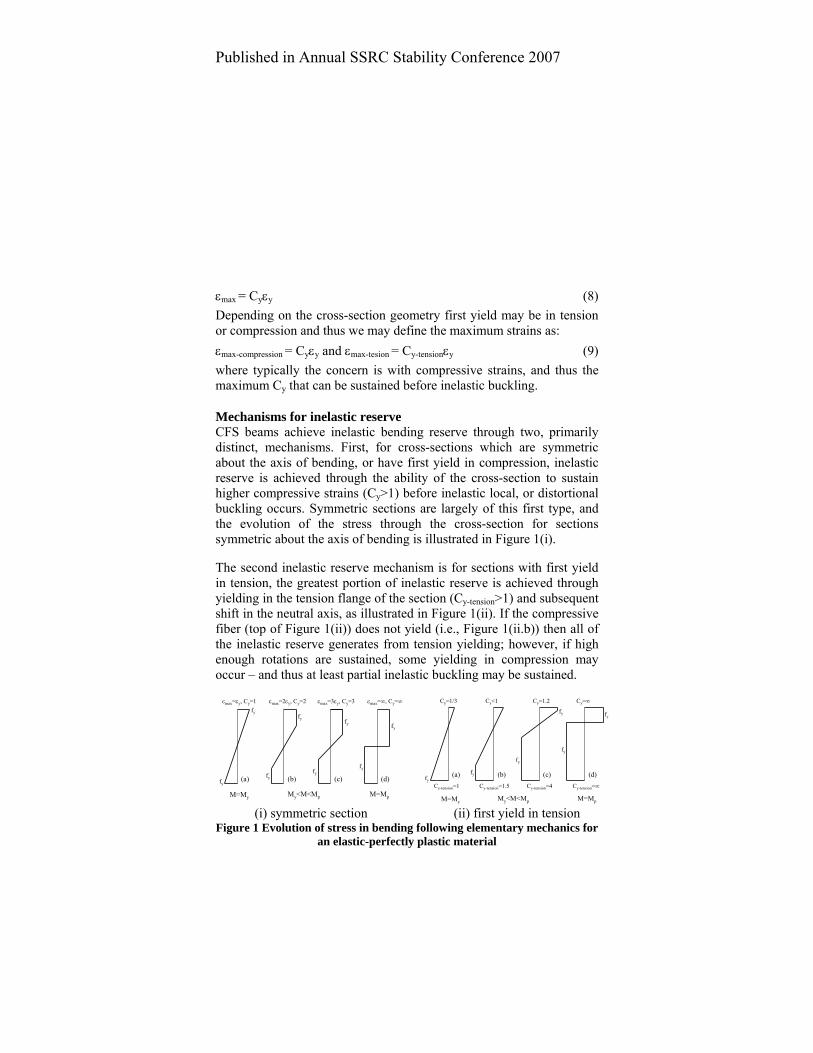
εmax = Cyεy (8) Depending on the cross-section geometry first yield may be in tension or compression and thus we may define the maximum strains as: εmax-compression = Cyεy and εmax-tesion = Cy-tensionεy (9) where typically the concern is with compressive strains, and thus the maximum Cy that can be sustained before inelastic buckling.
Mechanisms for inelastic reserve CFS beams achieve inelastic bending reserve through two, primarily distinct, mechanisms. First, for cross-sections which are symmetric about the axis of bending, or have first yield in compression, inelastic reserve is achieved through the ability of the cross-section to sustain higher compressive strains (Cy>1) before inelastic local, or distortional buckling occurs. Symmetric sections are largely of this first type, and the evolution of the stress through the cross-section for sections symmetric about the axis of bending is illustrated in Figure 1(i).
The second inelastic reserve mechanism is for sections with first yield in tension, the greatest portion of inelastic reserve is achieved through yielding in the tension flange of the section (Cy-tension>1) and subsequent shift in the neutral axis, as illustrated in Figure 1(ii). If the compressive fiber (top of Figure 1(ii)) does not yield (i.e., Figure 1(ii.b)) then all of the inelastic reserve generates from tension yielding; however, if high enough rotations are sustained, some yielding in compression may occur – and thus at least partial inelastic buckling may be sustained.
fy
fyfy
fy
εmax=2εy, Cy=2 εmax=3εy, Cy=3 εmax=∞, Cy=∞
M=My M=MpMy<M<Mp
εmax=εy, Cy=1
fy fy
fyfy
(a) (b) (c) (d)
Cy-tension=1.5 Cy-tension=4 Cy-tension=∞Cy-tension=1
Cy<1 Cy=1.2 Cy=∞Cy=1/3
fy
fy
fy
fy
fy fy
M=My M=MpMy<M<Mp
(a) (b) (c) (d)
(i) symmetric section (ii) first yield in tension
Figure 1 Evolution of stress in bending following elementary mechanics for an elastic-perfectly plastic material

Published in Annual SSRC Stability Conference 2007
OBSERVED INELASTIC RESERVE IN CFS BEAMS A significant number of CFS beams with inelastic reserve capacity were observed during the development of DSM, as shown in Figure 2. Further, in recent tests on industry available CFS C and Z sections, focusing distinctly on local and distortional buckling failures inelastic reserve capacity was also observed (Yu and Schafer 2003, 2006). As indicated in Figure 2, by the plateau in the prediction lines at Mtest/My=1.0, DSM ignores inelastic reserve capacity in CFS beams.
0
0.5
1
1.5
0 1 2 3
cross-section slenderness
DSM local buckling DSM distortional bucklingExperiments failing in local modeExperiments failing in distortional modeElastic buckling
λmax = M My cr
MM
test
y
transition in inelastic regime, where Mn>My has not been explored for cold-formed sections.
Figure 2 Development of DSM expressions for local and distortional
buckling of beams with possible inelastic transition curve highlighted.
To further study inelastic reserve in CFS beams, all sections having a capacity greater than 95%My were selected from Figure 2, as summarized in Table 1. The maximum observed inelastic reserve capacity in tested section is 18%. Further, although CFS beams are generally considered thin-walled and even laterally braced beams are typically assumed to suffer from significant loss in strength due to local and/or distortional buckling, greater than 15% of all beams tested and reported in the literature have strength greater than 95% of My.

Published in Annual SSRC Stability Conference 2007
Table 1 Observed inelastic reserve in CFS beams Section and Researcher
count Mtest>0.95My
max Mtest/My
min Mp/My
max Mp/My
Hats and Deck Sections Acharya (1997) 12 1.04 1.10 1.31 Desmond (1977) 2 1.01 1.25 1.25 Hoglund (1980) 36 1.16 1.15 1.26 Papazian (1994) 8 1.12 1.13 1.29 Winter (1946) 3 1.15 1.28 1.32 C and Z Sections Cohen (1987) 7 1.05 1.24 1.26 LaBoube and Yu (1978) 10 1.04 1.14 1.19 Rogers (1995) 17 1.15 1.16 1.31 Shan (1994) 6 1.17 1.15 1.23 Yu and Schafer (2003) 8 1.18 1.14 1.20 Yu and Schafer (2006) 4 1.06 1.14 1.23
Plastic moment and shape factor The sections of Table 1 were analyzed to determine their plastic moment capacity, and the range of shape factors (Mp/My or Z/S) is reported in the last two columns of Table 1. The variation in shape factors for CFS beams is relatively large, and maximum observed shape factors are significantly greater than maximum observed inelastic reserve. Further, shape factors in CFS beams are generally higher than those observed in hot-rolled wide flange sections.
Inelastic buckling or tension yielding For the cross-sections of Table 1, given the tested moment at failure, the strain at failure (i.e., Cy and Cy-tension at Mtest), as predicted by elementary mechanics (Eq.’s 2, 4, and 8) may be back-calculated. Examination of the strain at failure, as shown in Figure 3 reveals the different types of inelastic reserve observed. The three regimes identified in Figure 3 are (1) no inelastic reserve, i.e., the case where strain at failure does not exceed the yield strain in either tension or compression, (2) tension yielding, the maximum tensile strain exceeds the yield strain (Cy-tension > 1) but the compressive strain never reaches yield , and (3) inelastic buckling, where the maximum compressive

Published in Annual SSRC Stability Conference 2007
strain exceeds yield (Cy>1) at failure. Inelastic buckling may occur in sections where first yield occurs in compression, on or below the diagonal line of Figure 3 (i.e., Figure 1(i)b), or in sections where first yield occurs in tension, above the diagonal line (i.e., Figure 1(ii)c). Prediction of the failure strength for the inelastic buckling cases is the primary focus of this work.
0.00
0.50
1.00
1.50
2.00
2.50
0.00 0.50 1.00 1.50 2.00 2.50Cy (εmax-compression/εy)
Cy-
tens
ion (
ε max
-tens
ion/ ε
y)
no inelastic reserve
tension comp.first yield in
tensionyielding
inelasticbuckling
Figure 3 Examination of strain at failure in tests of Table 1
STUDYING INELASTIC BENDING WITH FEM Existing test data readily indicates the existence of inelastic reserve in CFS beams, and demonstrates the typical mechanisms with which that reserve derives from. However, distinguishing between inelastic local and distortional buckling is challenging, and finding direct relationships between slenderness and the strain undergone or bending strength achieved is difficult. To provide a more direct study of these issues a series of nonlinear finite element models of CFS beams was developed.
Modeling assumptions FE models of pin-ended CFS beams with idealized boundary conditions focused on either local or distortional buckling and subjected to uniform bending moment were developed. The models

Published in Annual SSRC Stability Conference 2007
were motivated by the tests of Yu and Schafer (2003, 2006) which were performed in four-point bending on two CFS beams in parallel, connected to one another by metal deck along the compression flange, angles along the tension flange, and additional reinforcement at load and support points. The metal deck was specially detailed to restrict distortional buckling in the “local buckling tests”, and removed to allow distortional buckling to freely form in the “distortional buckling tests”. In the FE modeling of Yu and Schafer (2007) the complete test setup is included, in the models developed here idealized versions of these boundary conditions focusing on local and distortional failures are employed.
For both the local and distortional models analysis was performed in ABAQUS version 6.5.4 (ABAQUS 2006). The Riks method was used for nonlinear solution control and the input parameters (initial step size, maximum step size, etc) were studied before performing the parametric study reported here. The CFS beams were modeled with the S9R5 shell element. Aspect ratio of the S9R5 element was varied in an initial study, based on comparisons with the testing and analysis in Yu and Schafer (2003, 2006, 2007) and an aspect ratio of 1.0 with respect to the flange dimension was ultimately selected.
0
10
20
30
40
50
60
70
80
90
100
0 0.05 0.1 0.15 0.2strain
stre
ss (k
si)
fy=73.4ksify=62ksify=56ksify=44ksify=33ksi
Figure 4 Stress-strain relations used in FE study
The material model followed traditional metal plasticity: von Mises yield criteria with isotropic hardening. Five different nonlinear stress-strain models were adopted from Yu and Schafer (2007), as shown in
Published in Annual SSRC Stability Conference 2007
Figure 4. Comparison with Yu and Schafer (2007) was examined across all of these models, but the 33.0 ksi model was selected for the parametric studies reported here. Note, significant strain hardening exists in this model, i.e., the model is not elastic-perfectly plastic.
For the local buckling models, motivated by Yu and Schafer (2003) testing, a segment of the constant moment region is modeled by applying uniform end rotations (moments) to a single beam. Member length was selected as a function of the elastic buckling half-wavelength (Lcrl). Lengths between 2 to 10 times Lcrl were examined, and 8Lcrl selected. To approximate the presence of the panels attached to the compression flange, which restrict distortional buckling, rotations at mid-flange were restricted in the local buckling models. For the distortional buckling models, motivated by Yu and Schafer (2006) testing, the models are similar to the local models except the length is set as a multiple of the distortional buckling half-wavelength (Lcrd) and no restriction is placed on the compression flange. Lengths between 1 to 3 times Lcrd were examined, and 2Lcrd selected.
The ends of the members are modeled as pinned; however in the course of the analyses the important distinction of whether or not the warping (longitudinal displacements) at the ends were free, or forced to rotate about an axis (i.e., remain in one plane as they rotate) was highlighted. Initially, pinned, warping-free boundary conditions were employed, consistent with those in the classical finite strip method such as CUFSM (Schafer and Ádány 2006). However, in the inelastic regime this lead to premature failures near the member ends with large warping deformations. Since the models are intended to be an idealized version of a segment of a beam, and not an entire beam with warping free ends, warping was restricted to rotate as one plane at the ends. These models showed better agreement with Yu and Schafer (2003, 2006, 2007) and thus were selected. See Camotim et al. (2006) for further discussion of the role of warping in thin-walled member boundary conditions.
Geometric imperfections corresponding to the first local buckling mode for the local models, and the first distortional buckling mode for the distortional models were selected. Imperfection magnitudes with a 50%

Published in Annual SSRC Stability Conference 2007
probability of exceedance from Schafer and Peköz (1998) were selected, Type 1 for local, Type 2 for distortional.
Purpose-built Matlab code was prepared to (i) generate the geometry of the CFS beams, (ii) perform elastic stability analysis using CUFSM, (iii) generate imperfect geometry for an FE model based on the CUFSM results, (iv) generate the ABAQUS FE model with appropriate boundary conditions, material model and solution controls, and finally (v) organize and post-process the results.
The developed models, e.g., Figure 5, were compared with the test results and extended FE analysis of Yu and Schafer (2003, 2006, 2007) for a limited number of cross-sections. Good overall agreement (less than 10% difference) was found for the selected model parameters.
Figure 5 Example of FE “distortional” model at peak moment
Parametric FE Study of Inelastic Local and Distortional Buckling CFS beams that underwent inelastic behavior in the tests of Yu and Schafer (2003, 2006) were selected for detailed parametric study employing the modeling assumptions provided in the previous section. The selected geometries include: 8.5Z120-3, 6C054-1, 4C054-1, 3.62C054-2, D8.5Z120-1, and D3.62C054-4, where the designation is preceded by a D if it is part of the distortional buckling test series (Yu and Schafer 2006), next the member depth is reported in inches, followed by the shape, C or Z, followed by the tested thickness in thousandth’s of an inch and finally the individual member with these nominal dimensions. Complete geometry details are provided in Yu and Schafer (2003, 2006) using the same nomenclature. In this

Published in Annual SSRC Stability Conference 2007
parametric study, where the goal was to examine the inelastic regime, fy was set to 33.0 ksi (see Figure 4) and the thickness of the specimens was varied from 0.0538 in. to 0.1345 in.. The choice of these thicknesses involved practical values for CFS design and the desire to examine the inelastic regime.
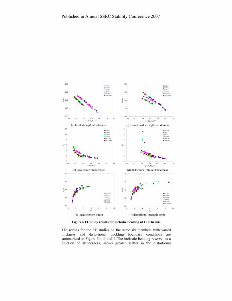
The results for the six members studied with varying thickness using the local buckling boundary conditions are summarized in Figure 6a,c,e. The members exhibited significant inelastic reserve, as shown in Figure 6a. Also shown in Figure 6a, the deeper sections developed slightly greater inelastic reserve at equivalent slenderness values. Figure 6c and e show how local slenderness is related to the strain demand (Cy) and how the strain demand is related to strength. Potential functional relationships are observed in both cases (Figure 6c and e) and are investigated further in the DESIGN METHODS section of this paper.
Table 2 Strain demands summary table Cymax-membrane/Cy Cymax-surface/Cy ave. st.dev. max ave. st.dev. max Local models 2.8 0.5 5.3 4.9 1.6 8.7 Distortional models 3.2 0.8 5.3 3.4 0.7 6.1
* Cy without any modifier is taken as the average of the flange membrane strain
The strain demand, Cy, was calculated as the average membrane strain over the flange. This most closely corresponds to the strains expected from elementary mechanics; however this does not adequately reflect the strain demands on the material itself. The peak (max) membrane strains are significantly higher, and the peak (max) surface strains, which include the local bending of the plate, are even higher still, as summarized in Table 2. Peak membrane strains are typically 3 times greater than the average Cy from elementary mechanics and peak surface strains are typically from 3.5 to 5 times greater than average Cy, with inelastic local buckling having the highest peak surface strains. Thus, for a Cy of 3, one would typically expect local Cy demands as high as 15, i.e. 15εy, even for well behaved inelastic local buckling collapse, and demands as high as 26εy are observed.
Published in Annual SSRC Stability Conference 2007
0.90
1.00
1.10
1.20
1.30
0.0 0.2 0.4 0.6 0.8 1.0 1.2λl = (My/Mcrl)
0.5
Mul
/My
85Z120-3
6C054-1
4C054-1
362C054
D85Z120-1
D362C054-4
0.90
1.00
1.10
1.20
1.30
0.0 0.2 0.4 0.6 0.8 1.0 1.2λd = (My/Mcrd)
0.5
Mud
/My
85Z120-3
6C054-1
4C054-1
362C054
D85Z120-1
D362C054-4
(a) local strength-slenderness (b) distortional strength-slenderness
0
2
4
6
8
10
12
0.0 0.2 0.4 0.6 0.8 1.0 1.2λl = (My/Mcrl)
0.5
Cy
85Z120-3
6C054-1
4C054-1
362C054
D85Z120-1
D362C054-4
0
2
4
6
8
10
12
0.0 0.2 0.4 0.6 0.8 1.0 1.2λd = (My/Mcrd)
0.5
Cy
85Z120-3
6C054-1
4C054-1
362C054
D85Z120-1
D362C054-4
(c) local strain-slenderness (d) distortional strain-slenderness
0.9
1.0
1.1
1.2
1.3
0 2 4 6 8 10 12Cy
Mul
/My
85Z120-3
6C054-1
4C054-1
362C054
D85Z120-1
D362C054-4
0.9
1.0
1.1
1.2
1.3
0 2 4 6 8 10 12Cy
Mud
/My
85Z120
6C054-1
4C054-1
362C054
D85Z120-1
D362C054-4
(e) local strength-strain (f) distortional strength-strain
Figure 6 FE study results for inelastic bending of CFS beams
The results for the FE studies on the same six members with varied thickness and distortional buckling boundary conditions are summarized in Figure 6b, d, and f. The inelastic bending reserve, as a function of slenderness, shows greater scatter in the distortional

Published in Annual SSRC Stability Conference 2007
buckling models (Figure 6b) than in the local buckling models (Figure 6a). For instance the 4C054-1 member (▲ symbol) may fail around 1.1My or 1.2My for essentially the same slenderness. This scatter in the observed peak bending capacity was determined to be a function of the sign of the imperfection and whether or not inelastic distortional collapse initiated with a flange moving outward or inward. The lower inelastic capacities are regarded as most relevant to design.
Figure 6d and f show how distortional slenderness is related to the strain demand (Cy) and how the strain demand is related to strength. Strain demands in the distortional models (Figure 6d) are greater than those in the local models (Figure 6c), and at an equivalent slenderness distortional inelastic strain demands are significantly higher than those in local inelastic buckling. The relationship between strain and peak moment is provided in Figure 6f and is similar to the local models.
DESIGN METHODS The available experimental data (Table 1) along with the FE studies are combined to develop a preliminary method for inclusion of inelastic bending reserve in a Direct Strength Method format.
Strain limit as a function of slenderness The normalized strain, Cy, that can be sustained in inelastic local or distortional buckling, as a function of cross-section slenderness is provided for the available test data (Table 1), and all members studied in the FE parametric study, in Figure 7. Based on these results the following approximate design relations were developed:
if λl< λly then 9.0
yyC ⎟⎟
⎠
⎞⎜⎜⎝
⎛
λ
λ=
l
ll where λly=0.776 & ll cry MM=λ (10)
if λd< λdy then 2
d
dyydC ⎟⎟
⎠
⎞⎜⎜⎝
⎛
λ
λ= where λdy=0.673 & crdyd MM=λ (11)
The expressions are only valid in the inelastic regime, and are considerably conservative (particularly for inelastic distortional buckling) when compared with available test data. The observation that high strains develop more “quickly” in inelastic distortional buckling as slenderness decreases is reflected in the selected coefficients.

Published in Annual SSRC Stability Conference 2007
0
2
4
6
8
10
12
0.0 0.2 0.4 0.6 0.8 1.0 1.2λl = (My/Mcrl)
0.5 or λd = (My/Mcrd)0.5
Cy
FE - Dist.
FE - Local
Test - Dist. controlled
Test - Local controlled
LD
Figure 7 Normalized strain demand as a function of slenderness
Strength as a function of strain As discussed previously, using Eq.’s 2, 4, and 8, through elementary mechanics, the moment, M, as a function of strain demand Cy may be determined. Thus, inelastic design for local and distortional buckling could proceed by predicting Cy from Eq.’s 10 and 11 and then leaving the engineer to calculate M. However, this requires an iterative solution, and ignores the strong relationship that exists between Cy and M.
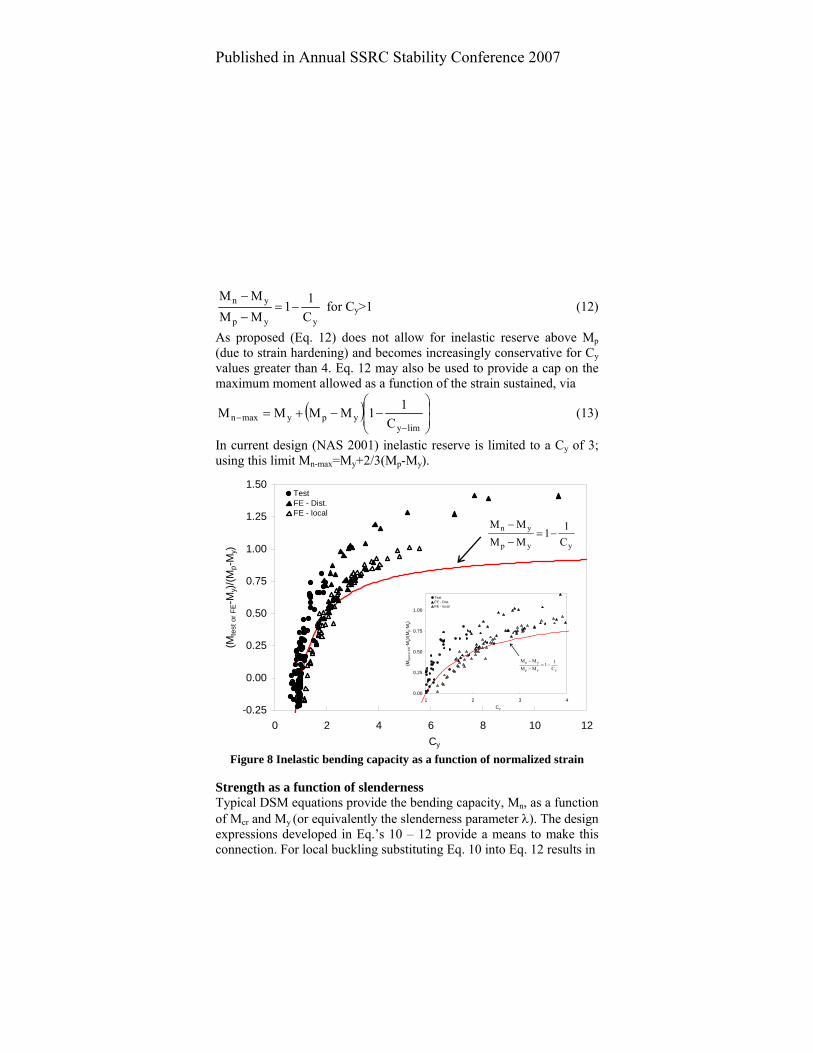
The average membrane strain (normalized to Cy) associated with the peak moment is provided in Figure 8 both for the available test data (Table 1), and all members studied in the FE parametric study. The test data and FE study data are tightly grouped, and the relationship between the inelastic local and distortional buckling peak moments is similar. Due to strain hardening, many of the numerical FE results exceed Mp (based on elastic-perfectly plastic material). A simple, conservative design relationship between peak bending strength in either local or distortional buckling is determined as follows:
1
2
3
4
5
0.0 0.2 0.4 0.6 0.8 1.0λl = (My/Mcrl)
0.5 or λd = (My/Mcrd)0.5
Cy
FE - Dist.
FE - Local
Test - Dist. controlled
Test - Local controlled
Published in Annual SSRC Stability Conference 2007
yyp
yn
C11
MMMM
−=−
− for Cy>1 (12)
As proposed (Eq. 12) does not allow for inelastic reserve above Mp (due to strain hardening) and becomes increasingly conservative for Cy values greater than 4. Eq. 12 may also be used to provide a cap on the maximum moment allowed as a function of the strain sustained, via
( ) ⎟⎟⎠
⎞⎜⎜⎝
⎛−−+=
−−
limyypymaxn C
11MMMM (13)
In current design (NAS 2001) inelastic reserve is limited to a Cy of 3; using this limit Mn-max=My+2/3(Mp-My).
-0.25
0.00
0.25
0.50
0.75
1.00
1.25
1.50
0 2 4 6 8 10 12Cy
(Mte
st o
r FE-
My)/
(Mp-
My)
TestFE - Dist.FE - local
yyp
yn
C11
MMMM
−=−
−
Figure 8 Inelastic bending capacity as a function of normalized strain
Strength as a function of slenderness Typical DSM equations provide the bending capacity, Mn, as a function of Mcr and My (or equivalently the slenderness parameter λ). The design expressions developed in Eq.’s 10 – 12 provide a means to make this connection. For local buckling substituting Eq. 10 into Eq. 12 results in
0.00
0.25
0.50
0.75
1.00
1 2 3 4Cy
(Mte
st o
r FE-
My)/
(Mp-
My)
TestFE - Dist.FE - local
yyp
yn
C11
MMMM
−=−
−

Published in Annual SSRC Stability Conference 2007
if λl<λly, ( )⎟⎟⎟
⎠
⎞
⎜⎜⎜
⎝
⎛
⎟⎟⎠
⎞⎜⎜⎝
⎛
λλ
−−+=9.0
yypyn 1MMMM
l
ll (14)
and for distortional buckling, substituting Eq. 11 into Eq. 12 results in
if λd<λdy, ( )⎟⎟⎟
⎠
⎞
⎜⎜⎜
⎝
⎛
⎟⎟⎠
⎞⎜⎜⎝
⎛
λλ
−−+=2
dy
dypynd 1MMMM (15)
For the available experimental data, the sections studied by FE, and Eq.’s 14 and 15, the peak moments in the inelastic regime as a function of local or distortional cross-section slenderness are provided in Figure 9. In addition, the application of maximum strain limits (Cy-lim) on the peak predicted moment via Eq. 13 are also illustrated in the figure.
-0.4
-0.2
0
0.2
0.4
0.6
0.8
1
0 0.2 0.4 0.6 0.8 1 1.2slenderness: λl=(My/Mcrl)
0.5 or λd=(My/Mcrd)0.5
(Mte
st-M
y)/(M
p-M
y)
Test - Local controlledTest - Dist. controlledFE - LocalFE - Distortional
Mp/My = 1.1 1.21.31.1
1.2 1.3
Cy=2 cutoff
Cy=3Cy=4
L
D
Figure 9 Strength as a function of slenderness for all data
Statistical comparison of the developed expressions (Eq.’s 14 and 15) with the available data is provided in Table 3. The prediction methods show good overall agreement and reasonably low standard deviation.

Published in Annual SSRC Stability Conference 2007
Table 3 Prediction statistics for inelastic bending capacity Section and Mtest/Mn Mtest/Mn for Mn>My
* Researcher ave. st.dev. n ave. st.dev. n Hats and Decks Acharya (1997) 1.11 0.08 12 1.03 2 Desmond (1977) 1.10 0.03 2 Hoglund (1980) 1.06 0.07 36 1.03 0.04 15 Papazian (1994) 1.17 0.15 8 1.01 2 C and Z ‘s Cohen (1987) 1.18 0.07 7 LaBoube and Yu (1978) 1.14 0.05 10 Rogers (1995) 1.08 0.05 17 1.09 0.05 12 Shan (1994) 1.12 0.09 6 1.16 0.01 3 Yu and Schafer (2003) 1.04 0.05 8 1.05 0.04 7 Yu and Schafer (2006) 1.00 0.03 4 1.05 All test data 1.11 0.08 110 1.03 0.05 42 FE Studies Local models 1.00 0.02 66 1.00 0.02 66 Distortional models 1.10 0.06 66 1.10 0.06 66 * these statistics are provided only when Eq. 14 and 15 are employed for prediction, i.e., when the predicted Mn is greater than My (or equivalently λl<λly or λd<λdy) The “crossing” of prediction Eq.’s 14 and 15 in Figure 9 appears awkward and unusual, but occurs for two reasons: the existing slenderness limit “anchor points” in DSM, and the observed strain demands in the two different inelastic buckling modes. If the “anchor points” where Mn=My, denoted as λd= λdy=0.673 for distortional buckling and λl= λly=0.776 for local buckling, are to be left alone (which is preferable) then it must be recognized that λdy and λly are in poor agreement with the observed data. For distortional buckling λdy appears too low, and for local buckling λly, too high. The second reason for the crossing of the prediction equations can be observed in Figure 7, the strain demands for inelastic distortional buckling develop much more quickly as slenderness is decreased than for inelastic local buckling. In the typical DSM prediction equations distortional buckling is always lower than local buckling (see Figure 2) reflecting a decreased post-buckling reserve in distortional buckling compared to

Published in Annual SSRC Stability Conference 2007
local buckling. The “crossing” in Figure 9 suggests that distortional buckling has greater inelastic reserve at a given slenderness, indeed this is observed in the modeling; however, that reserve comes at the cost of greatly increased strain demands. Thus, at a given slenderness inelastic distortional buckling requires much greater strain capacity in the material and section than inelastic local buckling; this is consistent with the reduced post-buckling capacity observed in more slender sections. Thus, the sensitivity of the inelastic distortional mode is manifested in higher strain demands, as opposed to reduced capacities.
DISCUSSION/FUTURE WORK The material model selected in the FE studies has a great deal of strain hardening and the impact of strain hardening needs to be quantified, as its influence on the solution (peak strength, peak strains, etc.) is far reaching. The geometric imperfections considered in the FE model deserve further study, including: sensitivity to inward vs. outward inelastic distortional buckling collapse mechanisms, and imperfection magnitude (which is currently normalized to material thickness). Lateral-torsional buckling (LTB) is avoided in the FE studies by virtue of the short length used in the models and full lateral bracing at the member ends. The extent to which LTB, and unbraced length, influences the solution, particularly for inelastic distortional buckling, deserves further study. Preliminary verifications of the FE model with test data showed good agreement with the tests and models in the literature, but a comprehensive verification is still needed.
Strain demands, Cy, for the test data were back-calculated via the elementary mechanics assumptions in this paper, including an elastic-perfectly plastic material. Detailed comparison of back-calculated strain demands from tests with FE predicted strain demands of the same tests are needed to further explore the impact of these assumptions. The design methods developed rely on the elastic slenderness, i.e., (My/Mcr)0.5, as was previously done for DSM. However, the elastic stress distribution is no longer valid in the inelastic range – and the validity of using an elastic parameter to correlate to inelastic strength needs further study.

Published in Annual SSRC Stability Conference 2007
CONCLUSIONS Inelastic bending reserve in CFS beams, where the moment capacity is greater than the moment at first yield, develops primarily from one of two distinct mechanisms: first yield in tension, or inelastic local or distortional buckling. Existing experiments demonstrate that inelastic bending reserve exists in common CFS beams. However, inelastic bending capacities observed in tests typically do not reach the full plastic moment. Existing design methods including inelastic bending have limited application, and no inelastic bending exists within the Direct Strength Method of design.
A nonlinear finite element model, motivated by previous testing on C and Z section beams that failed via inelastic local or distortional buckling, was developed. From the developed finite element model average strain demands in inelastic distortional bucking are shown to be much greater than in inelastic local buckling at an equivalent slenderness. Further, peak strain demands are shown to be far in excess of the average membrane strains that would be predicted via elementary mechanics. Sections undergoing inelastic buckling may locally have to endure strains as high as 8.7 times the average membrane strain of elementary mechanics; however 3 to 5 times the average membrane strain is more typical.
Using test data and the developed finite element models simple expressions for the strain demands in inelastic local and distortional buckling as a function of elastic cross-section slenderness are determined. A simple expression for the relationship between the strain demand and inelastic bending reserve is also established. Based on these two relationships preliminary Direct Strength Method design expressions for inelastic bending reserve in local and distortional buckling as a function of elastic section slenderness (Eq.’s 14 and 15) are established. The developed expressions agree well with available test data and the finite element studies performed herein. Significant future work exists on this topic, and will be completed by the first author as part of his dissertation work.

Published in Annual SSRC Stability Conference 2007
ACKNOWLEDGMENTS This material is based upon work supported by the National Science Foundation under Grant No. 0448707. Any opinions, findings, and conclusions or recommendations expressed in this material are those of the authors and do not necessarily reflect the views of the National Science Foundation.
REFERENCES ABAQUS (2006) ABAQUS/Standard User’s Manual, Version 6.5, ABAQUS,
Inc., Pawtucket, RI, www.abaqus.com Acharya, V.V., Schuster, R.M. (1998). “Bending Tests of Hat Section with
Multiple Longitudinal Stiffeners.” Proceedings of the Fourteenth International Specialty Conference on Cold-Formed Steel Structures, October 1998, St. Louis, Missouri, 77-92.
Bambach, M. R., Rasmussen, K. J. R. (2004). “Design Provisions for Sections Containing Unstiffened Elements with Stress Gradient.” ASCE, Journal of Structural Engineering. 130 (10) 1620–1628.
Camotim, D., Silvestre, N., Dinis, P.B., Bebiano, R., Basaglia, C. (2006). “Recent progress on the numerical analysis of thin-walled steel members and frames.” Proceedings of the International Symposium on Innovative Design of Steel Structures, 10 November 2006, Hong Kong, Ed. B. Young, 63-104.
Cohen, J. M. (1987). “Local Buckling Behavior of Plate Elements.” Department of Structural Engineering Report, Cornell University, Ithaca, New York.
Desmond, T.P. (1977). “The Behavior and Design of Thin-Walled Compression Elements with Longitudinal Stiffeners.” Ph.D. Thesis, Cornell University, Ithaca, New York.
Höglund, T. (1980). “Design of Trapezoidal Sheeting Provided with Stiffeners in the Flanges and Webs.” Swedish Council for Building Research, Stockholm, Sweden, D28:1980.
LaBoube, R.A., Yu, W., (1978). “Structural Behavior of Beam Webs Subjected to Bending Stress.” Civil Engineering Study Structural Series, 78-1, Department of Civil Engineering, University of Missouri-Rolla, Rolla, Missouri.
NAS (2001). North American Specification for the Design of Cold-Formed Steel Structural Members. American Iron and Steel Institute, Washington, D.C. (Also Canadian Standards Association CSA S136-01)
NAS (2004). Supplement 2004 to the North American Specification for the Design of Cold-Formed Steel Structural Members 2001 Edition: Appendix

Published in Annual SSRC Stability Conference 2007
1, Design of Cold-Formed Steel Structural Members Using Direct Strength Method. American Iron and Steel Institute, Washington, D.C.
Papazian, R.P., Schuster, R.M., Sommerstein, M. (1994). "Multiple Stiffened Deck Profiles." Proceedings of the Twelfth International Specialty Conference on Cold-Formed Steel Structures, October 1994, St. Louis, Missouri, 217-228.
Reck, H.P., Peköz,T.; Winter,G. (1975). “Inelastic strength of cold-formed steel beams.” ASCE, Journal of the Structural Division, 101 (11) 2193-2203.
Rogers, C.A. (1995). "Interaction Buckling of Flange, Edge Stiffener and Web of C-Sections in Bending." M.S. Thesis, University of Waterloo, Ontario, Canada.
Schafer, B.W. (2006). “Review: The Direct Strength Method of Cold-Formed Steel Member Design.” Proceedings of International Colloquium on Stability and Ductility of Steel Structures, Lisbon, Portugal, Ed. Camotim et al., Vol. 1, 49-66.
Schafer, B.W., Ádány, S. (2006). “Buckling analysis of cold-formed steel members using CUFSM: conventional and constrained finite strip methods.” Proceedings of the Eighteenth International Specialty Conference on Cold-Formed Steel Structures, October 2006, Orlando, Florida. 39-54.
Schafer, B.W., Peköz, T. (1998). “Computational Modeling of Cold-Formed Steel: Characterizing Geometric Imperfections and Residual Stresses.” Elsevier, Journal of Constructional Steel Research. 47 (3) 193-210.
Shan, M., R.A. LaBoube, W. Yu, (1994). “Behavior of Web Elements with Openings Subjected to Bending, Shear and the Combination of Bending and Shear.” Civil Engineering Study Structural Series, 94-2, Department of Civil Engineering, University of Missouri-Rolla, Rolla, Missouri.
Yener, M., Peköz, T. (1983). “Limit design in cold-formed steel.” ASCE, Journal of Structural Engineering, 109 (9) 2033-2047.
Yener, M., Peköz, T. (1983). “Partial Stress Redistribution in Cold-Formed Steel.” ASCE, Journal of Structural Engineering, 111 (6) 1169-1185.
Yu, C., Schafer, B.W. (2003). “Local Buckling Tests on Cold-Formed Steel Beams.” ASCE, Journal of Structural Engineering. 129 (12) 1596-1606.
Yu, C., Schafer, B.W. (2006). “Distortional buckling tests on cold-formed steel beams.” ASCE, Journal of Structural Engineering. 132 (4) 515-528.
Yu, C., Schafer, B.W. (2007). “Simulation of Cold-Formed Steel Beams in Local and Distortional Buckling with Application to the Direct Strength Method” Elsevier, Journal of Constructional Steel Research 63 (5) 581-590.