industrial maintenance - belt drives 2, model 46612-1 · pdf file · 2015-05-29job...
TRANSCRIPT

Industrial Maintenance
Belt Drives 2
Job Sheets - Courseware Sample 36963-F0

Order no.: 36963-30 First Edition Revision level: 05/2015
By the staff of Festo Didactic
© Festo Didactic Ltée/Ltd, Quebec, Canada 2005 Internet: www.festo-didactic.com e-mail: [email protected]
Printed in Canada All rights reserved ISBN 978-2-89289-800-2 (Printed version) Legal Deposit – Bibliothèque et Archives nationales du Québec, 2005 Legal Deposit – Library and Archives Canada, 2005
The purchaser shall receive a single right of use which is non-exclusive, non-time-limited and limited geographically to use at the purchaser's site/location as follows.
The purchaser shall be entitled to use the work to train his/her staff at the purchaser's site/location and shall also be entitled to use parts of the copyright material as the basis for the production of his/her own training documentation for the training of his/her staff at the purchaser's site/location with acknowledgement of source and to make copies for this purpose. In the case of schools/technical colleges, training centers, and universities, the right of use shall also include use by school and college students and trainees at the purchaser's site/location for teaching purposes.
The right of use shall in all cases exclude the right to publish the copyright material or to make this available for use on intranet, Internet and LMS platforms and databases such as Moodle, which allow access by a wide variety of users, including those outside of the purchaser's site/location.
Entitlement to other rights relating to reproductions, copies, adaptations, translations, microfilming and transfer to and storage and processing in electronic systems, no matter whether in whole or in part, shall require the prior consent of Festo Didactic GmbH & Co. KG.
Information in this document is subject to change without notice and does not represent a commitment on the part of Festo Didactic. The Festo materials described in this document are furnished under a license agreement or a nondisclosure agreement.
Festo Didactic recognizes product names as trademarks or registered trademarks of their respective holders.
All other trademarks are the property of their respective owners. Other trademarks and trade names may be used in this document to refer to either the entity claiming the marks and names or their products. Festo Didactic disclaims any proprietary interest in trademarks and trade names other than its own.
© Festo Didactic 36963-30 III
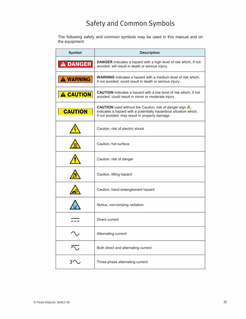
Safety and Common Symbols
The following safety and common symbols may be used in this manual and on the equipment:
Symbol Description
DANGER indicates a hazard with a high level of risk which, if not avoided, will result in death or serious injury.
WARNING indicates a hazard with a medium level of risk which, if not avoided, could result in death or serious injury.
CAUTION indicates a hazard with a low level of risk which, if not avoided, could result in minor or moderate injury.
CAUTION used without the Caution, risk of danger sign , indicates a hazard with a potentially hazardous situation which, if not avoided, may result in property damage.
Caution, risk of electric shock
Caution, hot surface
Caution, risk of danger
Caution, lifting hazard
Caution, hand entanglement hazard
Notice, non-ionizing radiation
Direct current
Alternating current
Both direct and alternating current
Three-phase alternating current
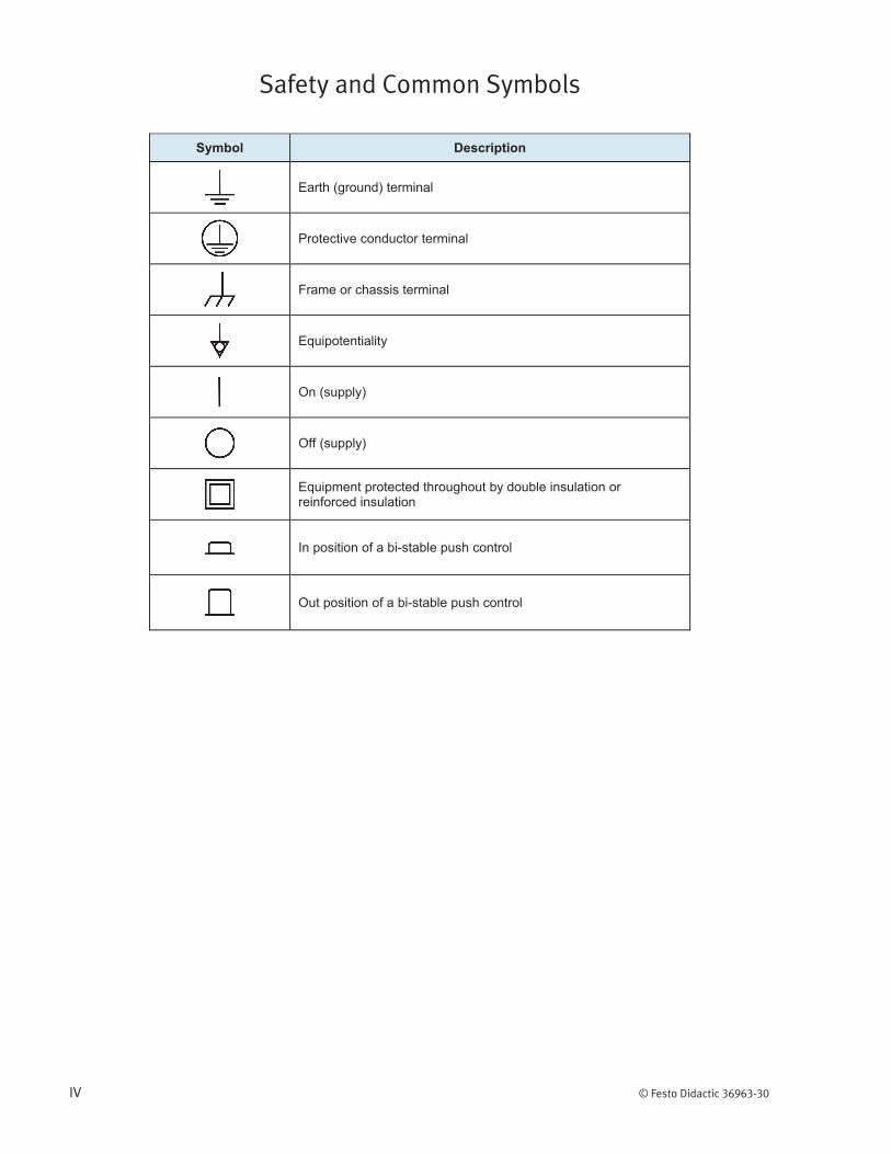
Safety and Common Symbols
IV © Festo Didactic 36963-30
Symbol Description
Earth (ground) terminal
Protective conductor terminal
Frame or chassis terminal
Equipotentiality
On (supply)
Off (supply)
Equipment protected throughout by double insulation or reinforced insulation
In position of a bi-stable push control
Out position of a bi-stable push control
© Festo Didactic 36963-30 V
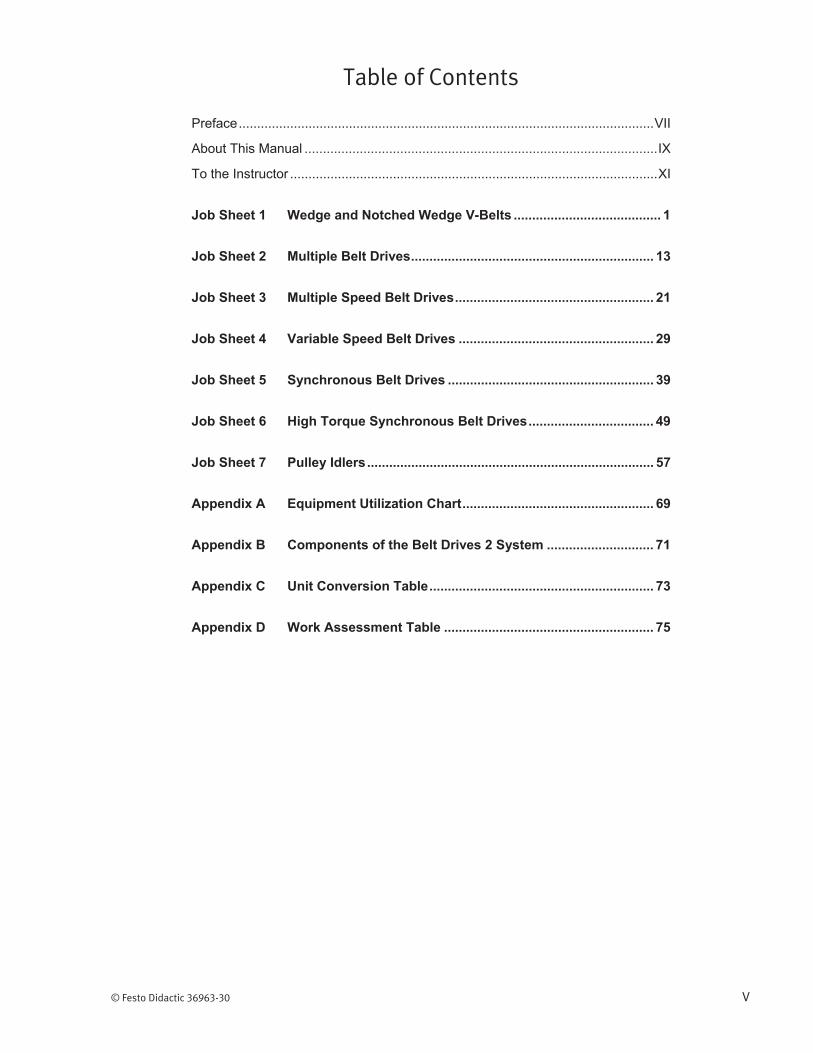
Table of Contents
Preface ................................................................................................................. VII
About This Manual ................................................................................................ IX
To the Instructor .................................................................................................... XI
Job Sheet 1 Wedge and Notched Wedge V-Belts ........................................ 1
Job Sheet 2 Multiple Belt Drives .................................................................. 13
Job Sheet 3 Multiple Speed Belt Drives ...................................................... 21
Job Sheet 4 Variable Speed Belt Drives ..................................................... 29
Job Sheet 5 Synchronous Belt Drives ........................................................ 39
Job Sheet 6 High Torque Synchronous Belt Drives .................................. 49
Job Sheet 7 Pulley Idlers .............................................................................. 57
Appendix A Equipment Utilization Chart .................................................... 69
Appendix B Components of the Belt Drives 2 System ............................. 71
Appendix C Unit Conversion Table ............................................................. 73
Appendix D Work Assessment Table ......................................................... 75


© Festo Didactic 36963-30 VII
Preface
The Mechanical Training System, Model 46101, is a modular program that covers the installation, use, maintenance, and troubleshooting of mechanical drive systems.
The curriculum is divided into five levels, and covers the following topics :
Introduction to mechanical drive systems
Belt drives 1 and 2
Chain drives 1 and 2
Gear drives 1 and 2
Lubrication
Couplings
Shaft alignment
Bearings
Ball Screws
Linear bearings
Gaskets and seals
Clutches
Brakes
Laser alignment
Vibration metering
This manual Belt Drives 2, is one of the four manuals supplied with the Mechanical Training System, level 2. The objective of this manual is to explain aspects of dvanced belt drives.
The other manuals supplied with the Mechanical Training System, level 2, are Chain Drives 2, Alignment and Couplings, and Lubrication.
We invite readers of this manual to send us their tips, feedback, and suggestions for improving the book.
Please send these to [email protected].
The authors and Festo Didactic look forward to your comments.

© Festo Didactic 36963-30 IX
About This Manual
The topics covered in this manual are presented in the form of Job Sheets. The Job Sheets include a description of the objectives, a list of equipment required, a list of safety procedures, and a list of steps required to attain the objectives.
The topics are usually introduced in an Information Sheet. However, to obtain detailed information about the covered topic, you should refer to your textbook or ask your instructor to guide your learning process.
Safety considerations
Safety symbols that may be used in this manual and on the equipment are listed in the Safety Symbols table at the beginning of the manual.
Safety procedures related to the tasks that you will be asked to perform are indicated in each exercise.
Make sure that you are wearing appropriate protective equipment when performing the tasks. You should never perform a task if you have any reason to think that a manipulation could be dangerous for you or your teammates.
Reference material
Refer to the manual titled Industrial Maintenance written by Michael E. Brumbach and Jeffrey A. Clade as reference textbook
Prerequisite
As a prerequisite to this manual, you should have read the manuals titled Introduction to Mechanical Drive Systems, p/n 36737-20, and Belt Drives 1, p/n 36891-20.
Systems of units
Units are expressed using the International System of Units (SI) followed by the units expressed in the U.S. customary system of units (between parentheses).
Most of the components in the Mechanical Training System are machined using the imperial system of units. For this reason the imperial system of units was preferred in the manual.
In the figures, however, the distances are also indicated in the SI system. These values are shown in parentheses.
The distances are estimates and may vary due to the play in the components.
Refer to the Unit Conversion Table in Appendix C if necessary.
About This Manual
X © Festo Didactic 36963-30
Appendices
The appendices included in this manual are:
Appendix A: Equipment Utilization Chart, shows in which Job Sheet the equipment is used
Appendix B: Components of the Belt Drives 2 System, shows the list of equipment supplied with the system.
Appendix C: Unit Conversion Table, shows the conversion factors to apply to convert Imperial units to SI units and vice versa.
© Festo Didactic 36963-30 XI
To the Instructor
You will find in this Instructor Guide all the elements included in the Student Manual together with the answers to all questions, results of measurements, graphs, explanations, suggestions, and, in some cases, instructions to help you guide the students through their learning process. All the information that applies to you is placed between markers and appears in red.
Accuracy of measurements
The numerical results of the hands-on exercises may differ from one student to another. For this reason, the results and answers given in this manual should be considered as a guide. Students who correctly performed the exercises should expect to demonstrate the principles involved and make observations and measurements similar to those given as answers.


Sample Extracted from
the Job Sheets Student and the Job Sheets Instructor

© Festo Didactic 36963-30 29
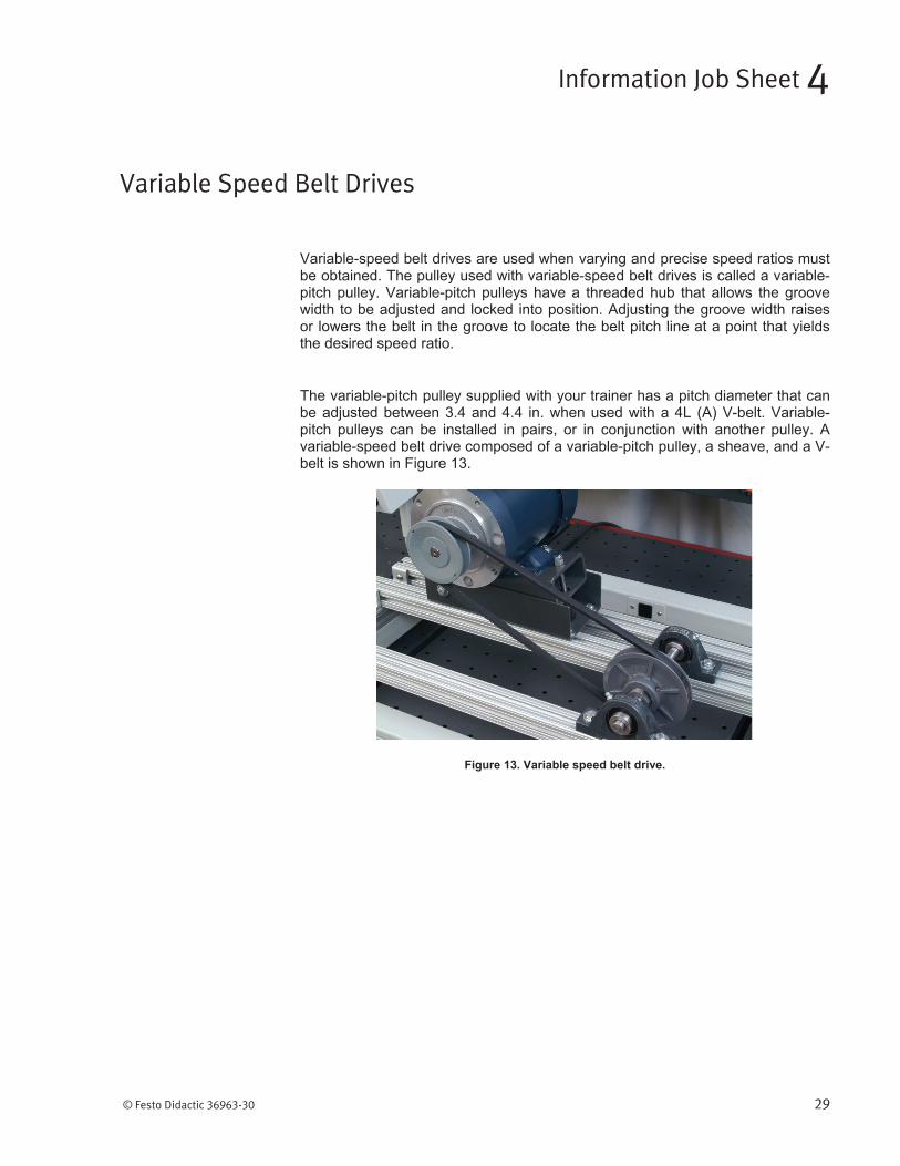
Variable-speed belt drives are used when varying and precise speed ratios must be obtained. The pulley used with variable-speed belt drives is called a variable-pitch pulley. Variable-pitch pulleys have a threaded hub that allows the groove width to be adjusted and locked into position. Adjusting the groove width raises or lowers the belt in the groove to locate the belt pitch line at a point that yields the desired speed ratio.
The variable-pitch pulley supplied with your trainer has a pitch diameter that can be adjusted between 3.4 and 4.4 in. when used with a 4L (A) V-belt. Variable-pitch pulleys can be installed in pairs, or in conjunction with another pulley. A variable-speed belt drive composed of a variable-pitch pulley, a sheave, and a V-belt is shown in Figure 13.
Figure 13. Variable speed belt drive.
Variable Speed Belt Drives
Information Job Sheet 4

© Festo Didactic 36963-30 31
In this job, you will install, align, and tension a variable-speed belt drive.
Universal Base Assembly, model 46603
Motor Package, model 46609
Couplings-Shafts Panel, model 46610
Pillow Block Bearings Panel, model 46611
Belt Drives 1, model 46612
Belt Drives 2, model 46612-10
Test and Measurement package, model 46630
Tool Box Component Package, model 46631
Before proceeding with this job, complete the following check list:
You are wearing safety glasses.
You are wearing safety shoes.
You are not wearing anything that might get caught such as a tie,
jewelry, or loose clothes.
If your hair is long, tie it out of the way.
The working area is clean and free of oil.
The floor is not wet.
Your sleeves are rolled up.
Lockout/Tagout procedure
1. Perform a lockout/tagout procedure as described in Job Sheet 1.
a The universal base should be set up from Job Sheet 1. Repeat Job Sheet 1 if necessary.
Variable Speed Belt Drives
Job Sheet 4
OBJECTIVE
EQUIPMENT REQUIRED
SAFETY PROCEDURES
PROCEDURE
Job Sheet 4 – Variable Speed Belt Drives
32 © Festo Didactic 36963-30
Variable pitch pulley and sheave installation
2. Install a key into the motor shaft keyseat.
a The edges of the keyseat are sharp.
3. Slide the 3-in. pitch diameter V-belt sheave on the motor shaft.
4. Tighten the sheave setscrew.
5. Install a key into the keyseat of the shaft supported by the pillow block bearings.
6. Slide the variable-pitch pulley on the shaft. Do not tighten the setscrews.
Job Sheet 4 – Variable Speed Belt Drives
© Festo Didactic 36963-30 33
Pitch diameter adjustment
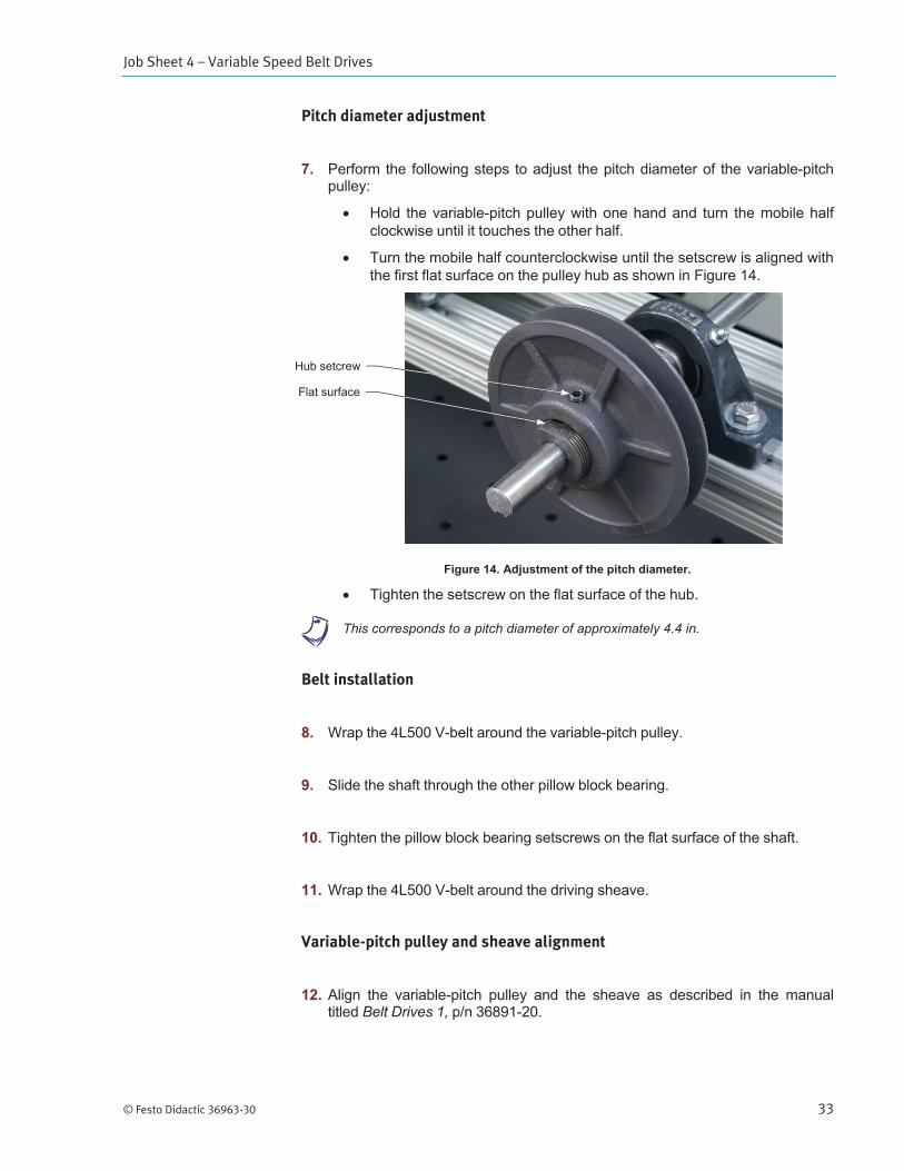
7. Perform the following steps to adjust the pitch diameter of the variable-pitch pulley:
Hold the variable-pitch pulley with one hand and turn the mobile half clockwise until it touches the other half.
Turn the mobile half counterclockwise until the setscrew is aligned with the first flat surface on the pulley hub as shown in Figure 14.
Figure 14. Adjustment of the pitch diameter.
Tighten the setscrew on the flat surface of the hub.
a This corresponds to a pitch diameter of approximately 4.4 in.
Belt installation
8. Wrap the 4L500 V-belt around the variable-pitch pulley.
9. Slide the shaft through the other pillow block bearing.
10. Tighten the pillow block bearing setscrews on the flat surface of the shaft.
11. Wrap the 4L500 V-belt around the driving sheave.
Variable-pitch pulley and sheave alignment
12. Align the variable-pitch pulley and the sheave as described in the manual titled Belt Drives 1, p/n 36891-20.
Hub setcrew
Flat surface
Job Sheet 4 – Variable Speed Belt Drives
34 © Festo Didactic 36963-30
13. Tighten the variable-pitch pulley setscrew on the shaft key.
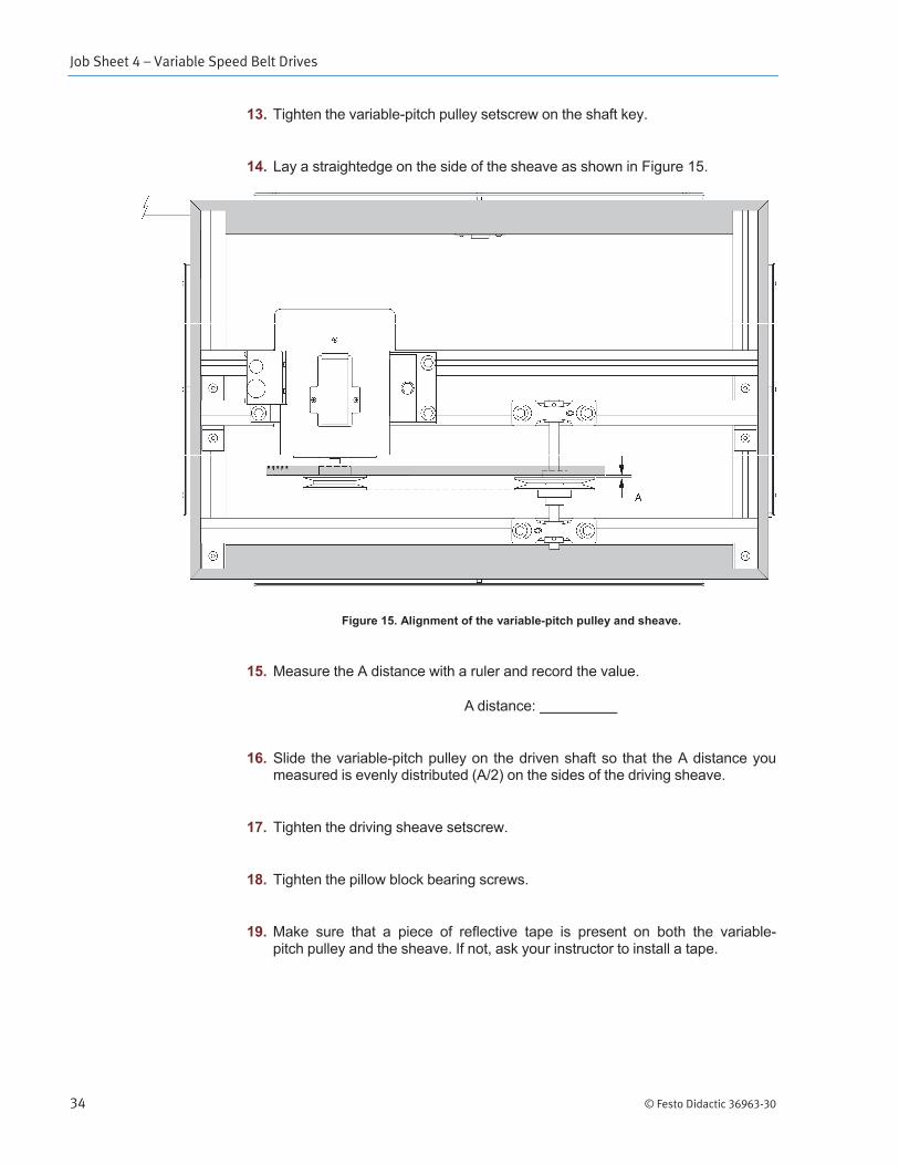
14. Lay a straightedge on the side of the sheave as shown in Figure 15.
Figure 15. Alignment of the variable-pitch pulley and sheave.
15. Measure the A distance with a ruler and record the value.
A distance:
16. Slide the variable-pitch pulley on the driven shaft so that the A distance you measured is evenly distributed (A/2) on the sides of the driving sheave.
17. Tighten the driving sheave setscrew.
18. Tighten the pillow block bearing screws.
19. Make sure that a piece of reflective tape is present on both the variable- pitch pulley and the sheave. If not, ask your instructor to install a tape.
Job Sheet 4 – Variable Speed Belt Drives
© Festo Didactic 36963-30 35
Tension adjustment
20. Adjust the tension of the belt to the required deflection force, as described in the manual titled Belt Drives 1, p/n 36891-20.
Start-up procedure
21. Perform a start-up procedure as described in Job Sheet 1.
System operation
22. Let the motor run for a few seconds.
23. Check to see whether the drive produces unusual vibrations. If this is the case, perform the following steps:
Stop the motor by pressing the Stop button on the Start/Stop push- button station.
Set the disconnecting switch to OFF.
Perform a lockout/tagout procedure.
Remove the safety panels.
Ensure that the deflection force on the belt is comprised in the range you determined previously. If not, readjust it.
Ensure that the alignment is correct. If not, realign the variable-pitch pulley and the sheave.
Perform a start-up procedure.
Determination of the speed ratio
24. Measure the speed of the driving sheave using the photo-reflective tachometer and record the value.
Speed (n1):
Speed (n1): approximately 1785 r/min
Job Sheet 4 – Variable Speed Belt Drives
36 © Festo Didactic 36963-30
25. Measure the speed of the variable-pitch pulley and record the value.
Speed (n2):
Speed (n2): approximately 1250 r/min
26. Stop the motor by pressing the Stop button on the Start/Stop push-button station.
27. Perform a lockout/tagout procedure.
28. Using the speed values, calculate the speed ratio (n1/n2).
Speed ratio (n1/n2):
Speed ratio: approximately 1.43
Modification of the speed ratio
29. Loosen the belt by turning the tension adjustment screw counterclockwise.
30. Untighten the setscrew of the mobile half of the variable-pitch pulley.
31. Turn the mobile half five turns in the counterclockwise direction.
32. Tighten the mobile half setscrew on the flat surface of the hub.
33. Repeat the installation procedure with the new pitch diameter.
34. Perform a start-up procedure as described in Job Sheet 1.
35. Measure the speed of the driving sheave using the photo reflective tachometer and record the value.
Speed (n1):
Speed (n1): approximately 1785 r/min
Job Sheet 4 – Variable Speed Belt Drives
© Festo Didactic 36963-30 37
36. Measure the speed of the variable-pitch pulley and record the value.
Speed (n2):
Speed (n2): approximately 1600 r/min
37. Stop the motor by pressing the Stop button on the Start/Stop push-button station.
38. Perform a lockout/tagout procedure as described in Job Sheet 1.
39. Using the speed values and the pitch diameter of the driving sheave, and the following formula, calculate the pitch diameter of the variable-pitch pulley.
Pitch diameter (D2):______
Pitch diameter (D2): approximately 3.35 in.
40. Ask your instructor to check your work.
Job Sheet 4 – Variable Speed Belt Drives
38 © Festo Didactic 36963-30
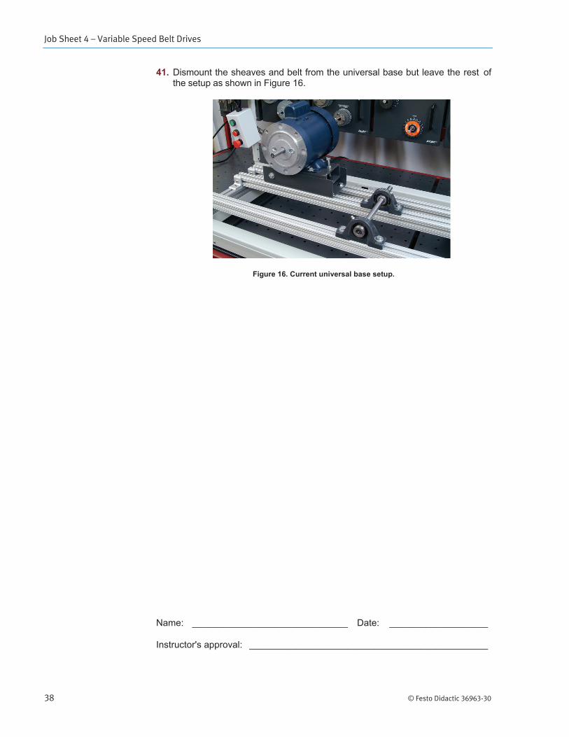
41. Dismount the sheaves and belt from the universal base but leave the rest of the setup as shown in Figure 16.
Figure 16. Current universal base setup.
Name: ______________________________ Date: ___________________
Instructor's approval: ______________________________________________
