industrial gaskets - markbimarkbi.ro/files/donit_ig_brosura_novo.pdf · industrial gaskets...
TRANSCRIPT
www.donit.eu
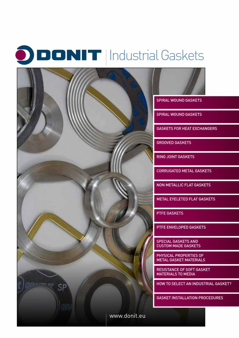
Industrial Gaskets
SPIRAL WOUND GASKETS
SPIRAL WOUND GASKETS
GASKETS FOR HEAT EXCHANGERS
GROOVED GASKETS
RING JOINT GASKETS
CORRUGATED METAL GASKETS
NON METALLIC FLAT GASKETS
METAL EYELETED FLAT GASKETS
PTFE GASKETS
PTFE ENVELOPED GASKETS
SPECIAL GASKETS AND CUSTOM MADE GASKETS
PHYSICAL PROPERTIES OF METAL GASKET MATERIALS
RESISTANCE OF SOFT GASKET MATERIALS TO MEDIA
HOW TO SELECT AN INDUSTRIAL GASKET?
GASKET INSTALLATION PROCEDURES

Industrial Gaskets
3
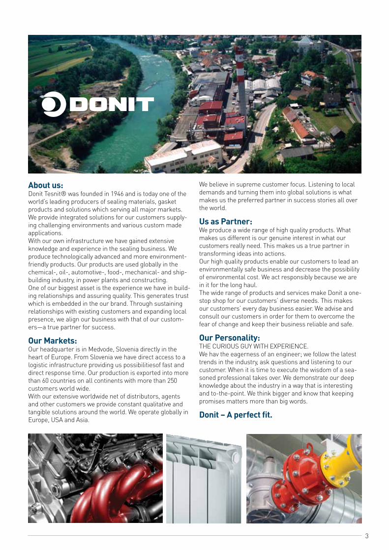
About us:Donit Tesnit® was founded in 1946 and is today one of the world’s leading producers of sealing materials, gasket products and solutions which serving all major markets. We provide integrated solutions for our customers supply-ing challenging environments and various custom made applications. With our own infrastructure we have gained extensive knowledge and experience in the sealing business. We produce technologically advanced and more environment-friendly products. Our products are used globally in the chemical-, oil-, automotive-, food-, mechanical- and ship-building industry, in power plants and constructing. One of our biggest asset is the experience we have in build-ing relationships and assuring quality. This generates trust which is embedded in the our brand. Through sustaining relationships with existing customers and expanding local presence, we align our business with that of our custom-ers—a true partner for success.
Our Markets: Our headquarter is in Medvode, Slovenia directly in the heart of Europe. From Slovenia we have direct access to a logistic infrastructure providing us possibilitiesof fast and direct response time. Our production is exported into more than 60 countries on all continents with more than 250 customers world wide. With our extensive worldwide net of distributors, agents and other customers we provide constant qualitative and tangible solutions around the world. We operate globally in Europe, USA and Asia.
We believe in supreme customer focus. Listening to local demands and turning them into global solutions is what makes us the preferred partner in success stories all over the world.
Us as Partner:We produce a wide range of high quality products. What makes us different is our genuine interest in what our customers really need. This makes us a true partner in transforming ideas into actions.Our high quality products enable our customers to lead an environmentally safe business and decrease the possibility of environmental cost. We act responsibly because we are in it for the long haul.The wide range of products and services make Donit a one-stop shop for our customers’ diverse needs. This makes our customers’ every day business easier. We advise and consult our customers in order for them to overcome the fear of change and keep their business reliable and safe.
Our Personality:THE CURIOUS GUY WITH EXPERIENCE. We hav the eagerness of an engineer; we follow the latest trends in the industry, ask questions and listening to our customer. When it is time to execute the wisdom of a sea-soned professional takes over. We demonstrate our deep knowledge about the industry in a way that is interesting and to-the-point. We think bigger and know that keeping promises matters more than big words.
Donit – A perfect fit.
4
SPIRAL WOUND GASKETSIndustrial Gaskets
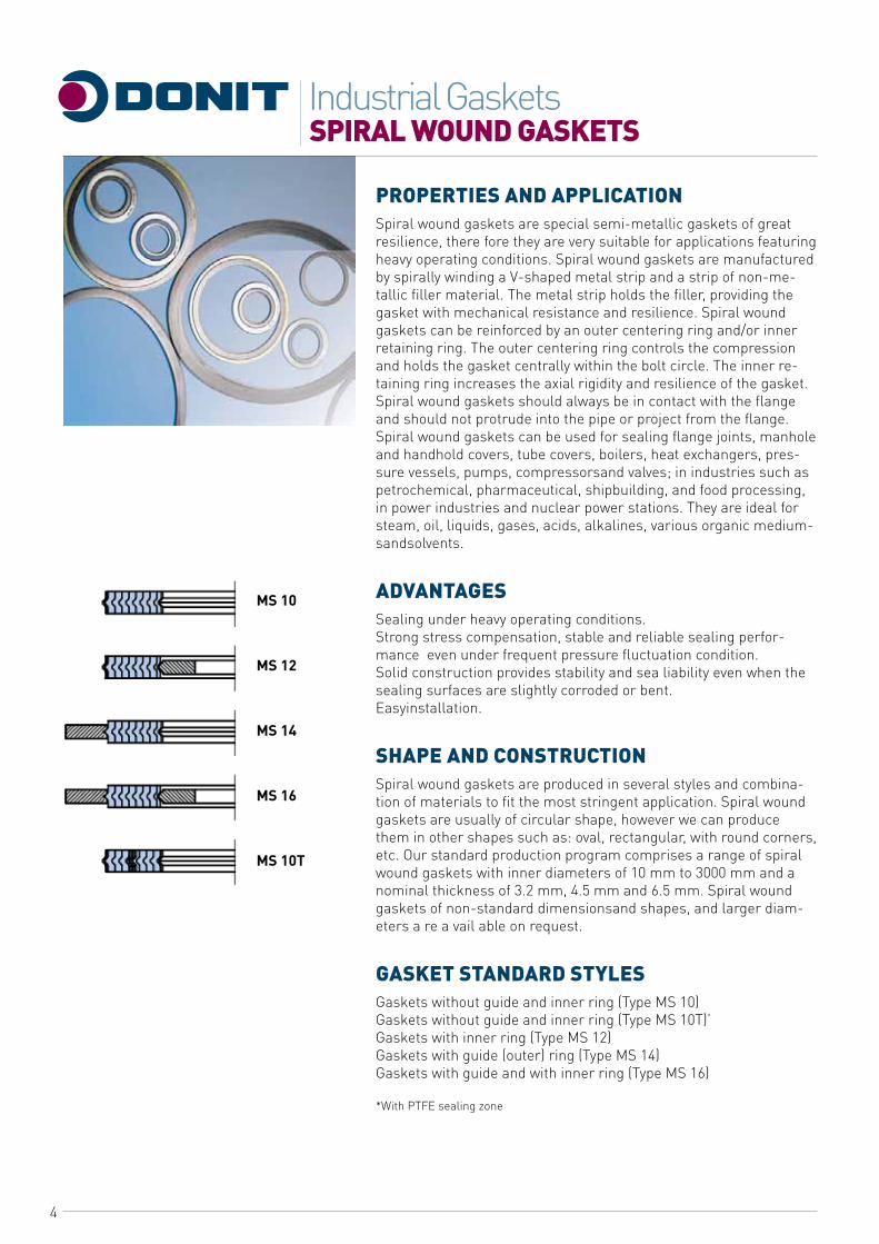
PROPERTIES AND APPLICATIONSpiral wound gaskets are special semi-metallic gaskets of great resilience, there fore they are very suitable for applications featuring heavy operating conditions. Spiral wound gaskets are manufactured by spirally winding a V-shaped metal strip and a strip of non-me-tallic filler material. The metal strip holds the filler, providing the gasket with mechanical resistance and resilience. Spiral wound gaskets can be reinforced by an outer centering ring and/or inner retaining ring. The outer centering ring controls the compression and holds the gasket centrally within the bolt circle. The inner re-taining ring increases the axial rigidity and resilience of the gasket. Spiral wound gaskets should always be in contact with the flange and should not protrude into the pipe or project from the flange. Spiral wound gaskets can be used for sealing flange joints, manhole and handhold covers, tube covers, boilers, heat exchangers, pres-sure vessels, pumps, compressorsand valves; in industries such as petrochemical, pharmaceutical, shipbuilding, and food processing, in power industries and nuclear power stations. They are ideal for steam, oil, liquids, gases, acids, alkalines, various organic medium-sandsolvents.
ADVANTAGESSealing under heavy operating conditions.Strong stress compensation, stable and reliable sealing perfor-mance even under frequent pressure fluctuation condition.Solid construction provides stability and sea liability even when the sealing surfaces are slightly corroded or bent.Easyinstallation.
SHAPE AND CONSTRUCTIONSpiral wound gaskets are produced in several styles and combina-tion of materials to fit the most stringent application. Spiral wound gaskets are usually of circular shape, however we can produce them in other shapes such as: oval, rectangular, with round corners, etc. Our standard production program comprises a range of spiral wound gaskets with inner diameters of 10 mm to 3000 mm and a nominal thickness of 3.2 mm, 4.5 mm and 6.5 mm. Spiral wound gaskets of non-standard dimensionsand shapes, and larger diam-eters a re a vail able on request.
GASKET STANDARD STyLESGaskets without guide and inner ring (Type MS 10)Gaskets without guide and inner ring (Type MS 10T)’Gaskets with inner ring (Type MS 12)Gaskets with guide (outer) ring (Type MS 14)Gaskets with guide and with inner ring (Type MS 16)
*With PTFE sealing zone
MS 10
MS 12
MS 14
MS 16
MS 10T
5
SPIRAL WOUND GASKETSIndustrial Gaskets
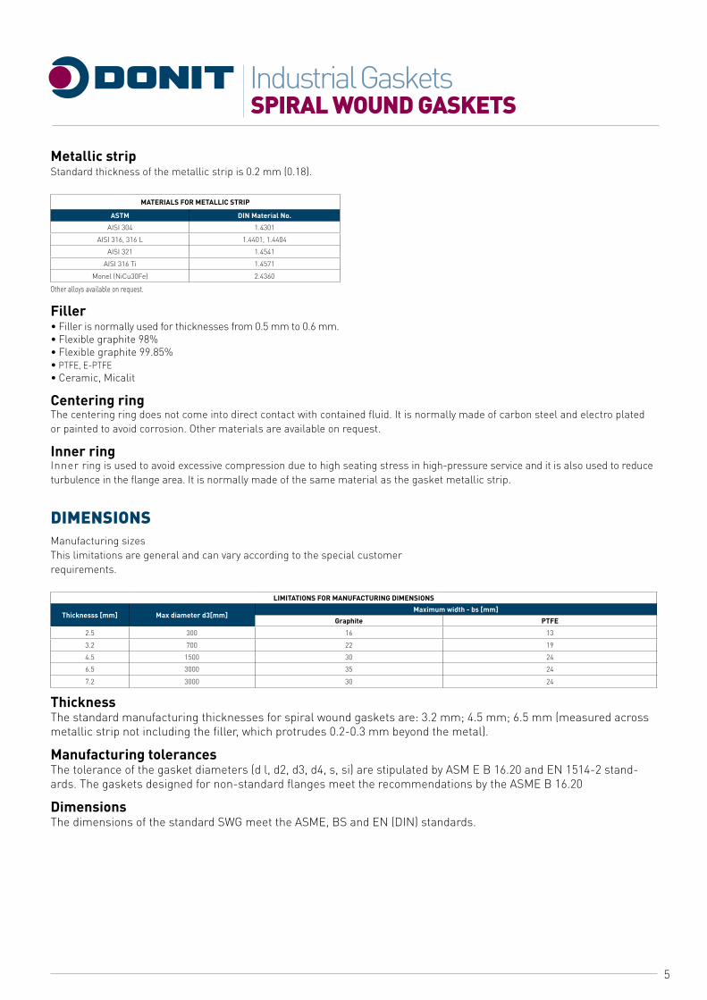
Metallic stripStandard thickness of the metallic strip is 0.2 mm (0.18).
MATERIALS FOR METALLIC STRIP
ASTM DIN Material No.
AISI 304 1.4301
AISI 316, 316 L 1.4401, 1.4404
AISI 321 1.4541
AISI 316 Ti 1.4571
Monel (NiCu30Fe) 2.4360
Other alloys available on request.
Filler• Filler is normally used for thicknesses from 0.5 mm to 0.6 mm.• Flexible graphite 98%• Flexible graphite 99.85%• PTFE, E-PTFE• Ceramic, Micalit
Centering ringThe centering ring does not come into direct contact with contained fluid. It is normally made of carbon steel and electro plated or painted to avoid corrosion. Other materials are available on request.
Inner ringInner ring is used to avoid excessive compression due to high seating stress in high-pressure service and it is also used to reduce turbulence in the flange area. It is normally made of the same material as the gasket metallic strip.
DIMENSIONSManufacturing sizesThis limitations are general and can vary according to the special customerrequirements.
LIMITATIONS FOR MANUFACTURING DIMENSIONS
Thicknesss [mm] Max diameter d3[mm]Maximum width - bs [mm]
Graphite PTFE
2.5 300 16 13
3.2 700 22 19
4.5 1500 30 24
6.5 3000 35 24
7.2 3000 30 24
ThicknessThe standard manufacturing thicknesses for spiral wound gaskets are: 3.2 mm; 4.5 mm; 6.5 mm (measured across metallic strip not including the filler, which protrudes 0.2-0.3 mm beyond the metal).
Manufacturing tolerancesThe tolerance of the gasket diameters (d l, d2, d3, d4, s, si) are stipulated by ASM E B 16.20 and EN 1514-2 stand-ards. The gaskets designed for non-standard flanges meet the recommendations by the ASME B 16.20
DimensionsThe dimensions of the standard SWG meet the ASME, BS and EN (DIN) standards.
6
SPIRAL WOUND GASKETSIndustrial Gaskets
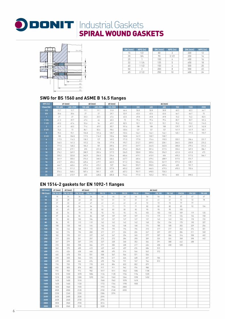
DN (mm) NPS (in) DN (mm) NPS (in) DN (mm) NPS (in)15 1/2 80 3 300 1220 3/4 90 3 1/2 350 1425 1 100 4 400 1632 1 1/4 125 5 450 1840 1 1/2 150 6 500 2050 2 200 8 550 2265 2 1/2 250 10 600 24
SWG for BS 1560 and ASME B 16.5 flangesNPS (in) d1 (mm) d2 (mm) d3 (mm) d4 (mm)
Class (lb) 150-400 600-2500 150-400 600-2500 150-2500 150 300 400 600 900 1500 2500
1/2 12.7 12.7 19.1 19.1 31.8 44.4 50.8 50.8 50.8 60.3 60.3 66.7
3/4 20.6 20.6 27 27 39.7 53.9 63.5 63.5 63.5 66.7 66.7 73
1 27 27 33.3 33.3 47.6 63.5 69.8 69.8 69.8 76.2 76.2 82.5
1 1/4 41.3 39.7 47.6 46 60.3 73 79.4 79.4 79.4 85.7 85.7 101.6
1 1/2 49.2 47.6 55.6 54 69.9 82.5 92.1 92.1 92.1 95.2 95.2 114.3
2 61.9 60.3 71.4 69.9 85.7 101.6 108 108 108 139.7 139.7 142.8
2 1/2 74.6 73 84.1 82.6 98.4 120.6 127 127 127 161.9 161.9 165.1
3 95.3 92.1 104.8 101.6 120.7 133.4 146.1 146.1 146.1 165.1 171.5 193.7
3 1/2 108 104.8 117.5 114.3 133.4 158.8 161.9 158.7 158.7
4 117.5 114.3 130.2 127 149.2 171.5 177.8 174.6 190.5 203.2 206.4 231.7
5 144.5 141.3 157.2 154 177.8 193.7 212.7 209.5 238.1 244.5 250.8 276.2
6 171.5 168.3 184.2 181 209.6 219.1 247.7 244.5 263.5 285.8 279.4 314.3
8 222.3 219.1 235 231.8 263.5 276.2 304.8 301.6 317.5 355.6 349.3 384.1
10 276.2 269.9 288.9 282.6 317.5 336.5 358.8 355.6 396.9 431.8 431.8 473
12 330.2 323.8 342.9 336.5 374.6 406.4 419.1 415.9 454 495.3 517.5 546.1
14 361.9 355.6 374.6 368.3 406.4 447.7 482.6 479.4 488.9 517.5 574.7
16 412.7 406.4 425.4 419.1 463.5 511.2 536.6 533.4 561.9 571.5 638.1
18 466.7 460.4 479.4 473.1 527 546.1 593.7 590.5 609.6 635 701.7
20 517.5 511.2 530.2 523.9 577.8 603.2 650.9 644.5 679.5 695.3 752.4
22 574.4 568.4 587.4 581.1 635 657.2 701.7 698.5 730.3
24 622.3 615.9 635 628.6 685.8 714.4 771.5 765.2 787.4 835 898.5
EN 1514-2 gaskets for EN 1092-1 flangesDN (mm) d1 (mm) d2 (mm) d3 (mm) d4 (mm)
PN Class PN 10-320 PN 10-320 PN 10-40 PN 64-320 PN 10 PN 16 PN 25 PN 40 PN64 PN 100 PN 160 PN250 PN 320 PN 400
10 18 24 36 36 46 46 46 46 56 56 56 67 67 67
15 22 28 40 40 51 51 51 51 61 61 61 72 72 78
20 27 33 47 47 61 61 61 61 72 72 72 77 77
25 34 40 54 54 71 71 71 71 82 82 82 83 92 104
32 43 49 65 65 82 82 82 82 90 90 90 100
40 48 54 70 70 92 92 92 92 103 103 103 109 119 135
50 57 66 84 84 107 107 107 107 113 119 119 124 134 150
65 73 82 102 104 127 127 127 127 137 143 143 153 170 192
80 86 95 115 119 142 142 142 142 148 154 154 170 190 207
100 108 120 140 144 162 162 168 168 174 180 180 202 229 256
125 134 146 168 172 192 192 194 194 210 217 217 242 274 301
150 162 174 196 200 217 217 224 224 247 257 257 284 311 348
175 183 195 221 227 247 247 254 265 277 287 284 316 358 402
200 213 225 251 257 272 272 284 290 309 324 324 358 398 442
250 267 279 307 315 327 328 340 352 364 391 388 442 488
300 318 330 358 366 377 383 400 417 424 458 458 538
350 363 375 405 413 437 443 457 474 486 512
400 414 426 458 466 488 495 514 546 543 572
450 460 478 526 551 558 567 564 571 534
500 518 530 566 574 593 617 624 628 657 704
600 618 630 666 674 695 734 731 747 764 813
700 718 730 770 778 810 804 833 852 879
800 818 830 874 882 917 911 942 974 988
900 910 930 974 982 1017 1011 1042 1084 1108
1000 1010 1030 1078 1086 1124 1128 1154 1194 1220
1200 1210 1230 1280 1290 1341 1342 1364 1398 1452
1400 1420 1450 1510 1548 1542 1578 1618
1600 1630 1660 1720 1772 1764 1798 1830
1800 1830 1860 1920 1972 1964 2000
2000 2020 2050 2120 2182 2168 2230
2200 2230 2260 2330 2384 2376
2400 2430 2480 2530 2594
2600 2630 2660 2730 2794
2800 2830 2860 2930 3014
3000 3030 3060 3130 3228
7
SPIRAL WOUND GASKETSIndustrial Gaskets
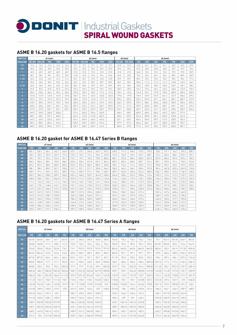
ASME B 16.20 gaskets for ASME B 16.5 flangesNPS (in) d1 (mm) d2 (mm) d3 (mm) d4 (mm)
Class (lb) 150-300 400-600 900 1500 2500 150-300 400-600 900 1500 2500 150-600 900-2500 150 300 400 600 900 1500 2500
1/2 14.2 14.2 14.2 14.2 14.2 19.1 19.1 19.1 19.1 19.1 31.8 31.8 47.8 54.1 54.1 54.1 63.5 63.5 69.9
3/4 20.6 20.6 20.6 20.6 20.6 25.4 25.4 25.4 25.4 25.4 39.6 39.6 57.2 66.8 66.8 66.8 69.9 69.9 76.2
1 26.9 26.9 26.9 26.9 26.9 31.8 31.8 31.8 31.8 31.8 47.8 47.8 66.8 73.2 73.2 73.2 79.5 79.5 85.9
1 1/4 38.1 38.1 38.1 33.3 33.3 47.8 47.8 39.6 39.6 39.6 60.5 60.5 76.2 82.6 82.6 82.6 88.9 88.9 104.9
1 1/2 44.5 44.5 44.5 41.4 41.4 54.1 54.1 47.8 47.8 47.8 69.9 69.9 85.9 95.3 95.3 95.3 98.6 98.6 117.6
2 55.6 55.6 55.6 52.3 52.3 69.9 69.9 58.7 58.7 58.7 85.9 85.9 104.9 111.3 111.3 111.3 143.0 143.0 146.1
2 1/2 66.5 66.5 66.5 63.5 63.5 82.6 82.6 69.9 69.9 69.9 98.6 98.6 124.0 130.3 130.3 130.3 165.1 165.1 168.4
3 81.0 81.0 81.0 81.0 81.0 101.6 101.6 95.3 92.2 92.2 120.7 120.7 136.7 149.4 149.4 149.4 168.4 174.8 196.9
4 106.4 106.4 106.4 106.4 106.4 127.0 120.7 120.7 117.6 117.6 149.4 149.4 174.8 181.1 177.8 193.8 206.5 209.6 235.0
5 131.8 131.8 131.8 131.8 131.8 155.7 147.6 147.6 143.0 143.0 177.8 177.8 196.9 215.9 212.9 241.3 247.7 254.0 279.4
6 157.2 157.2 157.2 157.2 157.2 182.6 174.8 174.8 171.5 171.5 209.6 209.6 222.3 251.0 247.7 266.7 289.1 282.7 317.5
8 215.9 209.6 196.9 196.9 196.9 233.4 225.6 222.3 215.9 215.9 263.7 257.3 279.4 308.1 304.8 320.8 358.9 352.6 387.4
10 268.2 260.4 246.1 246.1 246.1 287.3 274.6 276.4 266.7 270.0 317.5 311.2 339.9 362.0 358.9 400.1 435.1 435.1 476.3
12 317.5 317.5 292.1 292.1 292.1 339.9 327.2 323.9 323.9 317.5 374.7 368.3 409.7 422.4 419.1 457.2 498.6 520.7 549.4
14 349.3 349.3 320.8 320.8 371.6 362.0 356.6 362.0 406.4 400.1 450.9 485.9 482.6 492.3 520.7 577.9
16 400.1 400.1 374.7 368.3 422.4 412.8 412.8 406.7 463.6 457.2 514.4 539.8 536.7 565.2 574.8 641.4
18 449.3 449.3 425.5 425.5 474.7 469.9 463.6 463.6 527.1 520.7 549.4 596.9 593.9 612.9 638.3 704.9
20 500.1 500.1 482.6 476.3 525.5 520.7 520.7 514.4 577.9 571.5 606.6 654.1 647.7 682.8 698.5 755.7
24 603.3 603.3 590.6 577.9 628.7 628.7 628.7 616.0 685.8 679.5 717.6 774.7 768.4 790.7 838.2 901.7
ASME B 16.20 gasket for ASME B 16.47 Series B flangesNPS (in) d1 (mm) cl2 (mm) d3 (mm) d4 (mm)
Class (lb) 150 300 400 600 900 150 300 400 600 900 150 300 400 600 900 150 300 400 600 900
26 654.1 654.1 654.1 644.7 666.8 673.1 673.1 666.8 663.7 692.2 698.5 711.2 698.5 714.5 749.3 725.4 771.7 746.3 765.3 838.2
28 704.9 704.9 701.8 692.2 717.6 723.9 723.9 714.5 704.9 743.0 749.3 762.0 749.3 755.7 800.1 776.2 825.5 800.1 819.2 901.7
30 755.7 755.7 752.6 752.6 781.1 774.7 774.7 765.3 778.0 806.5 800.1 812.8 806.5 828.8 857.3 827.0 886.0 857.3 879.6 958.3
32 806.5 806.5 800.1 793.8 838.2 825.5 825.5 812.8 831.9 863.6 850.9 863.6 858.5 882.7 914.4 881.1 939.8 911.4 933.5 1016.0
34 857.3 857.3 850.9 850.9 895.4 876.3 876.3 866.9 889.0 920.8 908.1 914.4 911.4 939.8 971.6 935.0 993.9 962.2 997.0 1073.2
36 908.1 908.1 898.7 901.7 920.8 927.1 927.1 917.7 939.8 946.2 958.9 962.2 965.2 990.6 997.0 987.6 1047.8 1022.4 1047.8 1124.0
38 958.9 971.6 952.5 952.5 1009.7 974.6 1009.7 971.6 990.6 1035.1 1009.7 1047.8 1022.4 1041.4 1085.9 1044.7 1098.6 1073.2 1104.9 1200.2
40 1009.7 1003.3 1000.3 1009.7 1060.5 1022.4 1060.5 1025.7 1047.8 1098.6 1063.8 1098.6 1076.5 1098.6 1149.4 1095.5 1149.4 1127.3 1155.7 1251.0
42 1060.5 1054.1 1051.1 1066.8 1111.3 1079.5 1111.3 1076.5 1104.9 1149.4 1114.6 1149.4 1127.3 1155.7 1200.2 1146.3 1200.2 1178.1 1219.2 1301.8
44 1111.3 1124.0 1104.9 1111.3 1155.7 1124.0 1162.1 1130.3 1162.1 1206.5 1165.4 1200.2 1181.1 1212.9 1257.3 1197.1 1251.0 1231.9 1270.0 1368.6
46 1162.1 1178.1 1168.4 1162.1 1219.2 1181.1 1216.2 1193.8 1212.9 1270.0 1224.0 1254.3 1244.6 1263.7 1320.8 1255.7 1317.8 1289.1 1327.2 1435.1
48 1212.9 1231.9 1206.5 1219.2 1270.0 1231.9 1263.7 1244.6 1270.0 1320.8 1270.0 1311.4 1295.4 1320.8 1371.6 1306.6 1368.6 1346.2 1390.7 1485.9
50 1263.7 1267.0 1257.3 1270.0 1282.7 1317.8 1295.4 1320.8 1325.6 1355.9 1346.2 1371.6 1357.4 1419.4 1403.4 1447.8
52 1314.5 1317.8 1308.1 1320.8 1335.5 1368.6 1346.2 1371.6 1376.4 1406.7 1397.0 1422.4 1408.2 1470.2 1454.2 1498.6
54 1365.3 1365.3 1352.6 1378.0 1384.3 1403.4 1403.4 1428.8 1422.4 1454.2 1454.2 1479.6 1463.8 1530.4 1517.7 1555.8
56 1422.4 1428.8 1403.4 1428.8 1444.8 1479.6 1454.2 1479.6 1477.8 1524.0 1505.0 1530.4 1514.6 1593.8 1568.5 1612.9
58 1478.0 1484.4 1454.2 1473.2 1500.4 1535.2 1505.0 1536.7 1528.8 1573.3 1555.8 1587.5 1579.6 1655.8 1619.3 1663.7
60 1535.2 1557.3 1517.7 1530.4 1557.3 1589.0 1568.5 1593.9 1586.0 1630.4 1619.3 1644.7 1630.4 1706.6 1682.8 1733.6
ASME B 16.20 gaskets for ASME B 16.47 Series A flangesNPS (in) d1 (mm) d2 (mm) cB (mm) d4 (mm)
Class (lb) 150 300 400 600 900 150 300 400 600 900 150 300 400 600 900 150 300 400 600 900
26 654.05 654.05 660.4 647.7 666.75 673.1 685.8 685.8 685.8 685.8 704.85 736.6 736.6 736.6 736.6 774.7 835.15 831.85 866.9 882.65
28 704.85 704.85 711.2 698.5 711.2 723.9 736.6 736.6 736.6 736.6 755.65 787.4 787.4 787.4 787.4 831.85 898.65 892.3 914.4 946.15
30 755.65 755.65 755.65 755.65 774.7 774.7 793.75 793.75 793.75 793.75 806.45 844.55 844.55 844.55 844.55 882.65 952.5 946.15 971.55 1009.65
32 806.45 806.45 812.8 812.8 812.8 825.5 850.9 850.9 850.9 850.9 860.55 901.7 901.7 901.7 901.7 939.8 1006.6 1003.3 1022.4 1073.15
34 857.25 857.25 863.6 863.6 863.6 876.3 901.7 901.7 901.7 901.7 911.35 952.5 952.5 952.5 952.5 990.6 1057.4 1054.1 1073.2 1136.65
36 908.05 908.05 917.7 917.7 920.75 927.1 955.8 955.8 955.8 958.85 968.5 1006.6 1006.6 1006.6 1009.65 1047.75 1117.6 1117.6 1130.3 1200.15
38 958.85 952.5 952.5 952.5 1009.65 977.9 977.9 971.55 990.6 1035.05 1019.3 1016 1022.35 1041.4 1085.85 1111.25 1054.1 1073.15 1104.9 1200.15
40 1009.65 1003.3 1000.25 1009.65 1060.45 1028.7 1022.35 1025.65 1047.75 1098.55 1070.1 1070.1 1076.45 1098.55 1149.35 1162.05 1114.55 1127.25 1155.7 1250.95
42 1050.45 1054.1 1051.05 1066.8 1111.25 1079.5 1073.15 1076.45 1104.9 1149.35 1123.95 1120.9 1127.25 1155.7 1200.15 1219.2 1165.35 1178.05 1219.2 1301.75
44 1111.25 1104.9 1104.9 1111.25 1155.7 1130.3 1130.3 1130.3 1162.05 1206.5 1178.05 1181.1 1181.1 1212.85 1257.3 1276.35 1219.2 1231.9 1270 1368.55
46 1162.05 1152.65 1168.4 1162.05 1219.2 1181.1 1178.05 1193.8 1212.85 1270 1228.85 1228.85 1244.6 1263.65 1320.8 1327.15 1273.3 1289.05 1327.2 1435.1
48 1212.85 1209.8 1206.5 1219.2 1270 1231.9 1235.2 1244.6 1270 1320.8 1279.65 1286 1295.4 1320.8 1371.6 1384.3 1324.1 1346.2 1390.7 1485.9
50 1263.65 1244.6 1257.3 1270 1282.7 1295.4 1295.4 1320.8 1333.5 1346.2 1346.2 1371.6 1435.1 1377.95 1403.35 1447.8
52 1314.45 1320.8 1308.1 1320.8 1333.5 1346.2 1346.2 1371.6 1384.3 1397 1397 1422.4 1492.25 1428.75 1454.15 1498.6
54 1358.9 1352.55 1352.55 1377.95 1384.3 1403.35 1403.35 1428.75 1435.1 1454.15 1454.15 1479.55 1549.4 1492.25 1517.65 1555.8
56 1409.7 1403.35 1403.35 1428.75 1435.1 1454.15 1454.15 1479.55 1485.9 1504.95 1504.95 1530.35 1606.55 1543.05 1568.45 1612.9
58 1460.5 1447.8 1454.15 1473.2 1485.9 1511.3 1504.95 1536.7 1536.7 1562.1 1555.75 1587.5 1663.7 1593.85 1619.25 1663.7
60 1511.3 1524 1517.65 1530.35 1535.7 1562.1 1568.45 1593.85 1587.5 1612.9 1619.25 1644.65 1714.5 1644.65 1682.75 1733.6
8
SPIRAL WOUND GASKETSIndustrial Gaskets
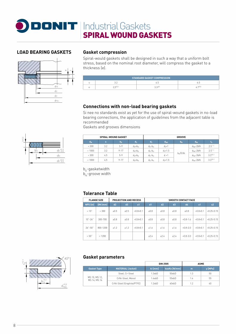
Gasket compressionSpiral-would gaskets shall be designed in such a way that a uniform bolt stress, based on the nominal root diameter, will compress the gasket to a thickness (e).
STANDARD GASKET COMPRESSION
s 3.2 4.5 6.5
e 2,5*0.1 3.3±01 4.7*01
Connections with non-load bearing gasketsSi nee no standards exist as yet for the use of spiral-wound gaskets in no-load bearing connections, the application of guidelines from the adjacent table is recommendedGaskets and grooves dimensions
SPIRAL-WOUND GASKET GROOVE
dM s bG d3 d2 dNO bN dNI tn
< 300 3.2 5-9 dG+bG dG-bG d3+1
bG/0.86
dN0-2bN 2.5^-1
< 1000 3.2 9-17 dG+bG dG-bG d3+1.5 dN0-2bN 2.5°-1
< 300 4.5 5-9 dG+bG dG-bG d +1 dN0-2bN 3.3*0-1
< 1000 4.5 9-17 dG+bG dG-bG d3+1.5 dN0-2bN 3.3*0-1
bG-gasketwidth bN-groove width
Tolerance TableFLANGE SIZE PROJECTION AND RECESS SMOOTH CONTACT FACE
NPS (in) DN (mm) d2 d3 s1 d1 d2 d3 d4 s1 s2
< 10” < 300 ±0.5 ±0.5 +0.8+0.1 ±0.8 ±0.8 ±0.8 ±0.8 +0.8+0.1 +0.25-0.15
10”-24” 300-700 ±0.8 ±0.8 +0.8+0.1 ±0.8 ±0.8 ±0.8 +0.8-1.6 +0.8+0.1 +0.25-0.15
26”-50” 800-1200 ±1.2 ±1.2 +0.8+0.1 ±1.6 ±1.6 ±1.6 +0.8-2.0 +0.8+0.1 +0.25-0.15
> 50” > 1200 ±2.4 ±2.4 ±2.4 +0.8-3.0 +0.8+0.1 +0.25-0.15
Gasket parametersDIN 2505 ASME
Gasket Type MATERIAL (Jacket) ki [mm] koxKo [N/mm] m y [MPa]
MS 10, MS 12, MS 14, MS 16
Steel, Cr-Steel 1.3xbD 50xbD 1.3 50
CrNi-Steel, Monel 1.4xbD 55xbD 1.4 55
CrNi-Steel (Graphite/PTFE) 1.2xbD 40xbD 1.2 40
LOAD BEARING GASKETS
9
SPIRAL WOUND GASKETSIndustrial Gaskets
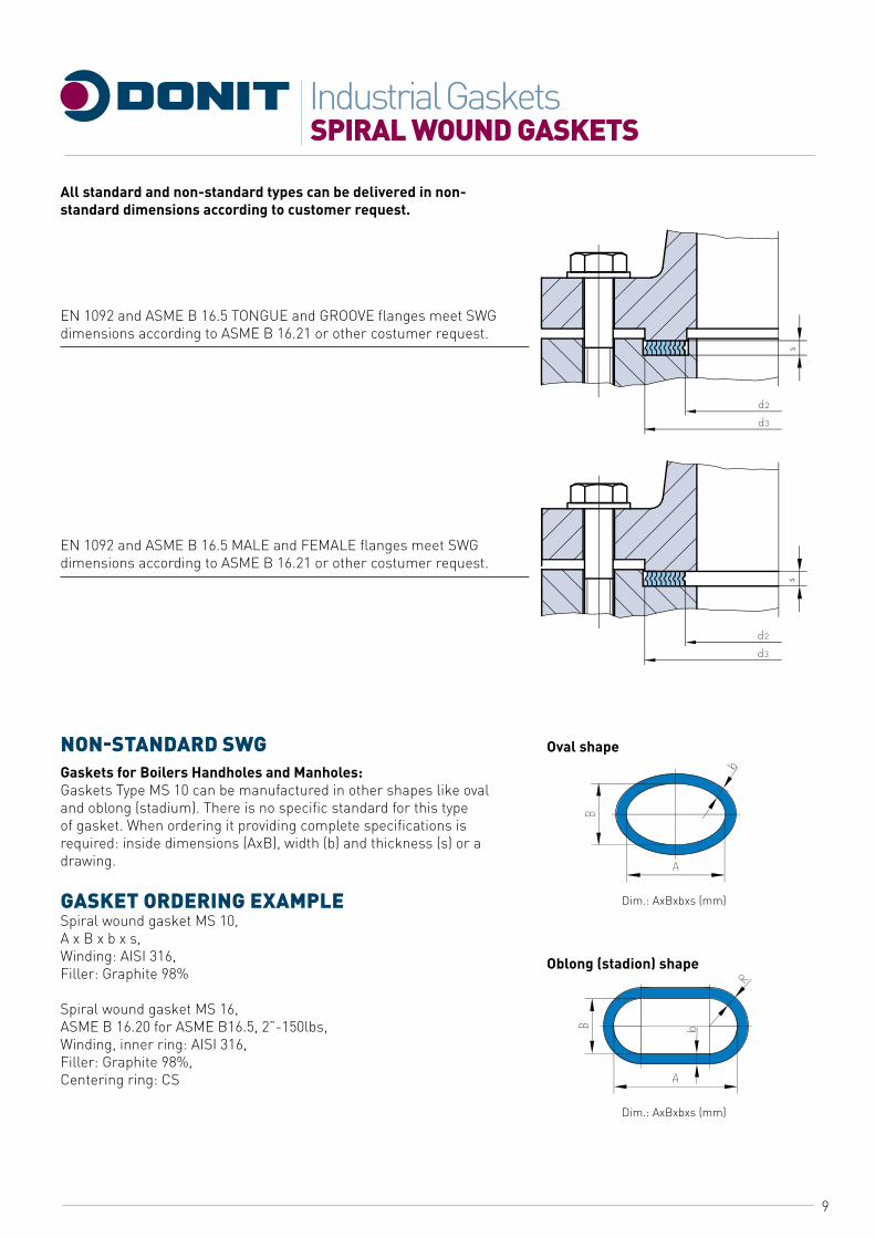
All standard and non-standard types can be delivered in non-standard dimensions according to customer request.
EN 1092 and ASME B 16.5 TONGUE and GROOVE flanges meet SWG dimensions according to ASME B 16.21 or other costumer request.
EN 1092 and ASME B 16.5 MALE and FEMALE flanges meet SWG dimensions according to ASME B 16.21 or other costumer request.
NON-STANDARD SWGGaskets for Boilers Handholes and Manholes:Gaskets Type MS 10 can be manufactured in other shapes like oval and oblong (stadium). There is no specific standard for this type of gasket. When ordering it providing complete specifications is required: inside dimensions (AxB), width (b) and thickness (s) or a drawing.
GASKET ORDERING EXAMPLESpiral wound gasket MS 10, A x B x b x s, Winding: AISI 316, Filler: Graphite 98%
Spiral wound gasket MS 16,ASME B 16.20 for ASME B16.5, 2”-150lbs,Winding, inner ring: AISI 316,Filler: Graphite 98%,Centering ring: CS
Oval shape
Oblong (stadion) shape
Dim.: AxBxbxs (mm)
Dim.: AxBxbxs (mm)
10
METAL - JACKETED GASKETSIndustrial Gaskets
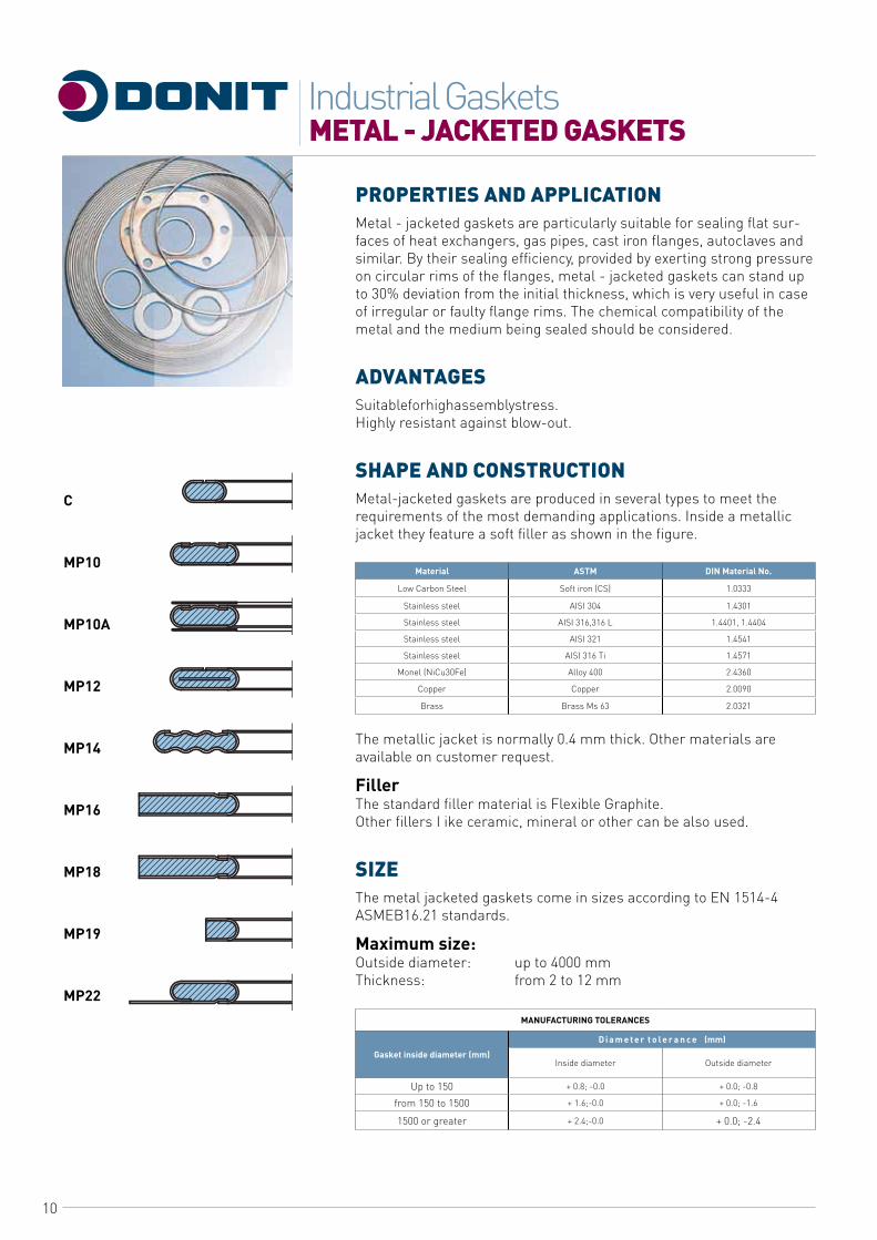
PROPERTIES AND APPLICATIONMetal - jacketed gaskets are particularly suitable for sealing flat sur-faces of heat exchangers, gas pipes, cast iron flanges, autoclaves and similar. By their sealing efficiency, provided by exerting strong pressure on circular rims of the flanges, metal - jacketed gaskets can stand up to 30% deviation from the initial thickness, which is very useful in case of irregular or faulty flange rims. The chemical compatibility of the metal and the medium being sealed should be considered.
ADVANTAGESSuitableforhighassemblystress.Highly resistant against blow-out.
SHAPE AND CONSTRUCTIONMetal-jacketed gaskets are produced in several types to meet the requirements of the most demanding applications. Inside a metallic jacket they feature a soft filler as shown in the figure.
Material ASTM DIN Material No.
Low Carbon Steel Soft iron (CS) 1.0333
Stainless steel AISI 304 1.4301
Stainless steel AISI 316,316 L 1.4401, 1.4404
Stainless steel AISI 321 1.4541
Stainless steel AISI 316 Ti 1.4571
Monel (NiCu30Fe) Alloy 400 2.4360
Copper Copper 2.0090
Brass Brass Ms 63 2.0321
The metallic jacket is normally 0.4 mm thick. Other materials are available on customer request.
FillerThe standard filler material is Flexible Graphite.Other fillers I ike ceramic, mineral or other can be also used.
SIZEThe metal jacketed gaskets come in sizes according to EN 1514-4 ASMEB16.21 standards.
Maximum size:Outside diameter: up to 4000 mmThickness: from 2 to 12 mm
MANUFACTURING TOLERANCES
Gasket inside diameter (mm)
D i a m e t e r t o l e r a n c e (mm)
Inside diameter Outside diameter
Up to 150 + 0.8; -0.0 + 0.0; -0.8
from 150 to 1500 + 1.6;-0.0 + 0.0; -1.6
1500 or greater + 2.4;-0.0 + 0.0; -2.4
C
MP10
MP10A
MP12
MP14
MP16
MP18
MP19
MP22
11
METAL - JACKETED GASKETSIndustrial Gaskets
DIN 2505 ASME
Gasket Type MATERIAL (Jacket) ki [mm] koxKD[N/mm] m y [MPa]
MP 10, MP 12, MP 16, MP 18, MP 19, MP 22
Cr-Ni steel 2.0XDD 100xbD 2.0 100
Soft iron 1 .8XDD 70xbD 1.8 70
Cu 1 .6XDD 60XDD 1.6 60
Ms 1 .6XDD 60xbD 1.6 60
STANDARDS FOR METAL JACKETED GASKETS USED WITH FLANGES
METAL JACKETED GASKETS - Standard Flange Standard
EN 1514-4 EN 1092
ASME B 16.20 ASME B 16.5
ASME B 16.20 ASME B 16.47
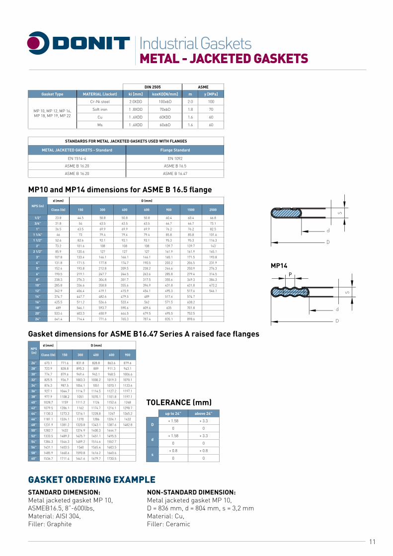
MP10 and MP14 dimensions for ASME B 16.5 flange
NPS (in)
d (mm) D (mm)
Class (lb) 150 300 400 600 900 1500 2500
1/2” 23.8 44.5 50.8 50.8 50.8 60.4 60.4 66.8
3/4” 31.8 54 63.5 63.5 63.5 66.7 66.7 73.1
1” 36.5 63.5 69.9 69.9 69.9 76.2 76.2 82.5
1 1/4” 46 73 79.4 79.4 79.4 85.8 85.8 101.6
1 1/2” 52.4 82.6 92.1 92.1 92.1 95.3 95.3 114.3
2” 73.2 101.6 108 108 108 139.7 139.7 143
2 1/2” 85.9 120.6 127 127 127 161.9 161.9 165.1
3” 107.8 133.4 146.1 146.1 146.1 165.1 171.5 193.8
4” 131.8 171.5 177.8 174.7 190.5 203.2 206.5 231.9
5” 152.4 193.8 212.8 209.5 238.2 244.6 250.9 276.3
6” 190.5 219.1 247.7 244.5 263.6 285.8 279.4 314.5
8” 238.3 276.3 304.8 301.7 317.5 355.6 349.3 384.3
10” 285.8 336.6 358.8 355.6 396.9 431.8 431.8 473.2
12” 342.9 406.4 419.1 415.9 454.1 495.3 517.6 546.1
14” 374.7 447.7 482.6 479.5 489 517.6 574.7
16” 425.5 511.2 536.6 533.4 562 571.5 638.2
18” 489 546.1 593.7 590.6 609.6 635 701.8
20” 533.4 603.3 650.9 644.5 679.5 695.5 752.5
24” 641.4 714.4 771.6 765.3 787.4 835.1 898.6
Gasket dimensions for ASME B16.47 Series A raised face flanges
NPS(in)
d (mm) D (mm)
Class (lb) 150 300 400 600 900
26” 673.1 771.6 831.8 828.8 863.6 879.6
28” 723.9 828.8 895.3 889 911.3 943.1
30” 774.7 879.6 949.4 943.1 968.5 1006.6
32” 825.5 936.7 1003.3 1000.2 1019.3 1070.1
34” 876.3 987.5 1054.1 1051 1070.1 1133.6
36” 927.1 1044.7 1114.7 1114.5 1127.2 1197.1
38” 977.9 1108.2 1051 1070.1 1101.8 1197.1
40” 1028.7 1159 1111.2 1124 1152.6 1248
42” 1079.5 1286.1 1162 1174.7 1216.1 1298.7
44” 1130.3 1273.3 1216.1 1228.8 1267 1365.2
46” 1181.1 1324.1 1270 1286 1324.1 1432
48” 1231.9 1381.2 1320.8 1343.1 1387.6 1482.8
50” 1282.7 1432 1374.9 1400.3 1444.7
52” 1333.5 1489.2 1425.7 1451.1 1495.5
54” 1384.3 1546.3 1489.2 1514.6 1552.7
56” 1431.1 1603.5 1540 1565.4 1603.5
58” 1485.9 1660.6 1590.8 1616.2 1660.6
60” 1536.7 1711.4 1641.6 1679.7 1730.5
GASKET ORDERING EXAMPLESTANDARD DIMENSION: NON-STANDARD DIMENSION:Metal jacketed gasket MP 10, Metal jacketed gasket MP 10, ASMEB16.5, 8”-600lbs, D = 836 mm, d = 804 mm, s = 3,2 mm Material: AISI 304, Material: Cu,Filler: Graphite Filler: Ceramic
TOLERANCE (mm)up to 24” above 24”
D+ 1.58 + 3.3
0 0
d+ 1.58 + 3.3
0 0
s+ 0.8 + 0.8
0 0
MP14
12
GASKETS FOR HEAT EXCHANGERSIndustrial Gaskets
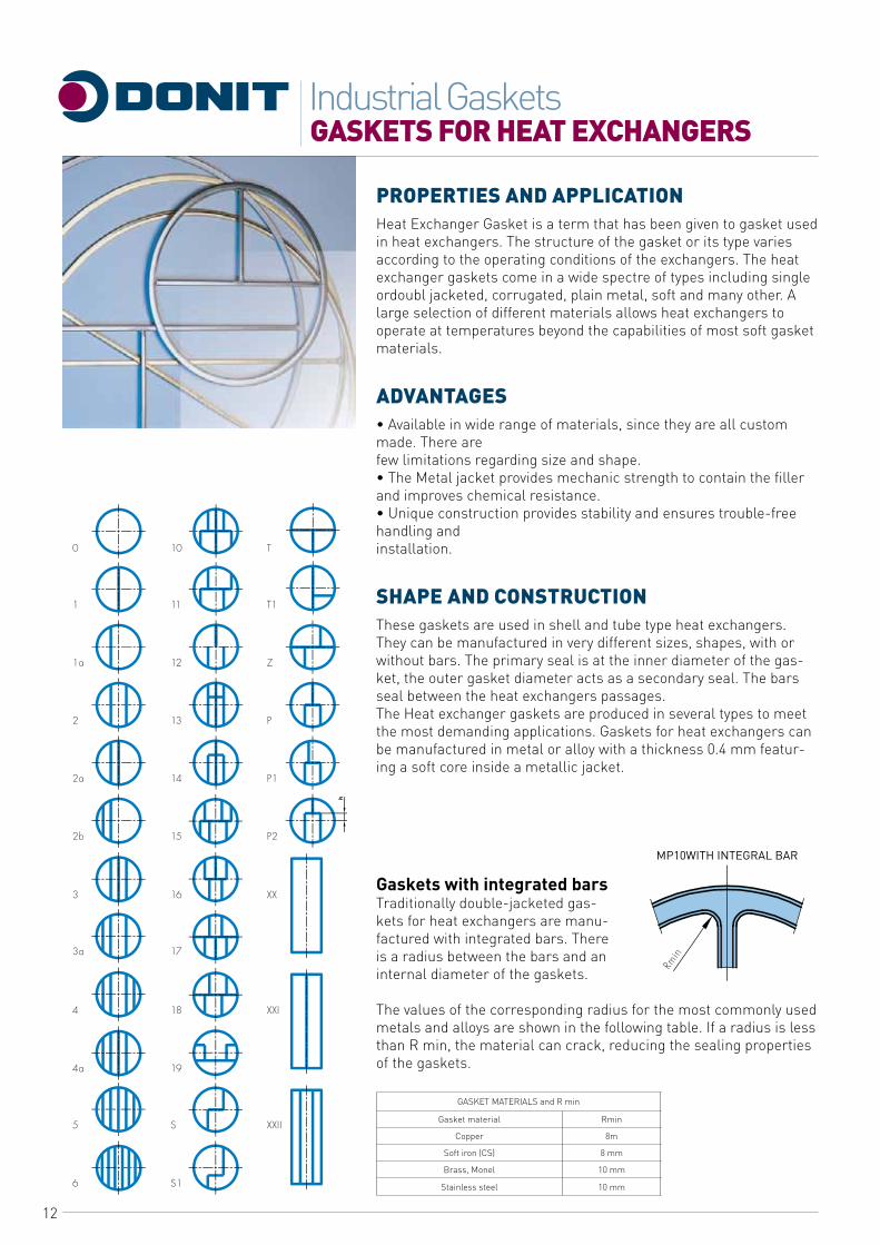
PROPERTIES AND APPLICATIONHeat Exchanger Gasket is a term that has been given to gasket used in heat exchangers. The structure of the gasket or its type varies according to the operating conditions of the exchangers. The heat exchanger gaskets come in a wide spectre of types including single ordoubl jacketed, corrugated, plain metal, soft and many other. A large selection of different materials allows heat exchangers to operate at temperatures beyond the capabilities of most soft gasket materials.
ADVANTAGES• Available in wide range of materials, since they are all custom made. There arefew limitations regarding size and shape.• The Metal jacket provides mechanic strength to contain the filler and improves chemical resistance.• Unique construction provides stability and ensures trouble-free handling andinstallation.
SHAPE AND CONSTRUCTIONThese gaskets are used in shell and tube type heat exchangers. They can be manufactured in very different sizes, shapes, with or without bars. The primary seal is at the inner diameter of the gas-ket, the outer gasket diameter acts as a secondary seal. The bars seal between the heat exchangers passages.The Heat exchanger gaskets are produced in several types to meet the most demanding applications. Gaskets for heat exchangers can be manufactured in metal or alloy with a thickness 0.4 mm featur-ing a soft core inside a metallic jacket.
Gaskets with integrated barsTraditionally double-jacketed gas-kets for heat exchangers are manu-factured with integrated bars. There is a radius between the bars and an internal diameter of the gaskets.
The values of the corresponding radius for the most commonly used metals and alloys are shown in the following table. If a radius is less than R min, the material can crack, reducing the sealing properties of the gaskets.
GASKET MATERIALS and R min
Gasket material Rmin
Copper 8m
Soft iron (CS) 8 mm
Brass, Monel 10 mm
Stainless steel 10 mm
MP10WITH INTEGRAL BAR
13
GASKETS FOR HEAT EXCHANGERSIndustrial Gaskets
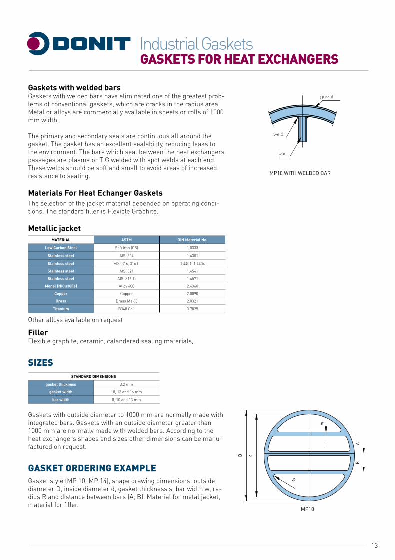
MP10 WITH WELDED BAR
MP10
Gaskets with welded barsGaskets with welded bars have eliminated one of the greatest prob-lems of conventional gaskets, which are cracks in the radius area. Metal or alloys are commercially available in sheets or rolls of 1000 mm width.
The primary and secondary seals are continuous all around the gasket. The gasket has an excellent sealability, reducing leaks to the environment. The bars which seal between the heat exchangers passages are plasma or TIG welded with spot welds at each end. These welds should be soft and small to avoid areas of increased resistance to seating.
Materials For Heat Echanger GasketsThe selection of the jacket material depended on operating condi-tions. The standard filler is Flexible Graphite.
Metallic jacketMATERIAL ASTM DIN Material No.
Low Carbon Steel Soft iron (CS) 1.0333
Stainless steel AISI 304 1.4301
Stainless steel AISI 316, 316 L 1.4401, 1.4404
Stainless steel AISI 321 1.4541
Stainless steel AISI 316 Ti 1.4571
Monel (NiCu30Fe) Alloy 400 2.4360
Copper Copper 2.0090
Brass Brass Ms 63 2.0321
Titanium B348 Gr.1 3.7025
Other alloys available on request
FillerFlexible graphite, ceramic, calandered sealing materials,
SIZESSTANDARD DIMENSIONS
gasket thickness 3.2 mm
gasket width 10, 13 and 16 mm
bar width 8, 10 and 13 mm
Gaskets with outside diameter to 1000 mm are normally made with integrated bars. Gaskets with an outside diameter greater than 1000 mm are normally made with welded bars. According to the heat exchangers shapes and sizes other dimensions can be manu-factured on request.
GASKET ORDERING EXAMPLEGasket style (MP 10, MP 14), shape drawing dimensions: outside diameter D, inside diameter d, gasket thickness s, bar width w, ra-dius R and distance between bars (A, B). Material for metal jacket, material for filler.

14
SPIRAL WOUND GASKETS FOR HEAT EXCHANGERSThe spiral wound gaskets of MS10, MS12, MS14 or MS16 type can be manufactured with one or more metal jacketed bars (profile MP10) in different shape shown in drawing. Metal-jacketed bars are welded and made of the same material as the spiral windings. The standard thicknesses are 3.2 mm, 4.5 mmy 6.5 mm and 7.2 mm.
MAX. DIMENSIONS
Thickness s [mm] Max. diameter d3 [mm]
3.2 750
4.5 1500
6.5 2200
7.2 2500
GASKET ORDERING EXAMPLESWG style,metal jacketed profile (MP10),material,shape drawing
GASKETS FOR HEAT EXCHANGERSIndustrial Gaskets
MS214
MS212
MS216

15
GROOVED GASKETSIndustrial Gaskets
M7A
M7B
M7C
M7D
M10
M10A
PROPERTIES AND APPLICATIONThe groved gasket are the preferred gaskets when improved per-formance at low seating stresses is required. It features excellent anti-blow-out properties. A tighter joint is provided with reliable solid metal to metal seal combined with a soft sealing face. Metal gaskets with grooved faces have proven to be very effective for seal-ing flange connections, and are particularly suitable for applica-tions where high temperatures, pressures and fluctuating condi-tions are encountered. Non-metal cover layers ensure that flanges are not damaged, even at extreme loads, and provide excellent sealing properties when supported by the grooved metallic gasket. The grooved gasket can be used as an alternative for applications associated with jacketed gaskets (for heat exchangers, vessels and reactors and various flanged connections).
ADVANTAGESCapable of sealing pressures exceeding 250 bar.Capable of withstanding temperatures up to 700°C.Particularly effective in maintaining performance under condition of fluctuating temperatures and pressures.Solid construction provides stability even for large diameters and ensures trouble-free handling and installation.Gaskets can be fitted to existing assemblies without modification.
SHAPE AND CONSTRUCTIONThe grooved gaskets are produced in several types to fit the most demanding applications.
METAL CORE
Material ASTM DIN Material No.
Stainless steel AISI 321 1.4541
Stainless steel AISI316TI 1.4571
SIZESUpon request the grooved gaskets can be manufactured in various shapes and sizes.

16
GROOVED GASKETSIndustrial Gaskets
EN 12560-6 Grooved Gaskets for ASME B16.5 flanges
NPS (in)d1 (mm) d3 (mm)
Class (lb) 150 300 400 600 900 1500 2500
1/2” 23.8 44.5 50.8 50.8 50.8 60.4 60.4 66.8
3/4” 31.8 54 63.5 63.5 63.5 66.7 66.7 73.1
1” 36.5 63.5 69.9 69.9 69.9 76.2 76.2 82.5
1 1/4” 46 73 79.4 79.4 79.4 85.8 85.8 101.6
1 1/2” 52.4 82.6 92.1 92.1 92.1 95.3 95.3 114.3
2” 73.2 101.6 108 108 108 139.7 139.7 143
2 1/2” 85.9 120.6 127 127 127 161.9 161.9 165.1
3” 107.8 133.4 146.1 146.1 146.1 165.1 171.5 193.8
4” 131.8 171.5 177.8 174.7 190.5 203.2 206.5 231.9
5” 152.4 193.8 212.8 209.5 238.2 244.6 250.9 276.3
6” 190.5 219.1 247.7 244.5 263.6 285.8 279.4 314.5
8” 238.3 276.3 304.8 301.7 317.5 355.6 349.3 384.3
10” 285.8 336.6 358.8 355.6 396.9 431.8 431.8 473.2
12” 342.9 406.4 419.1 415.9 454.1 495.3 517.6 546.1
14” 374.7 447.7 482.6 479.5 489 517.6 574.7
16” 425.5 511.2 536.6 533.4 562 571.5 638.2
18” 489 546.1 593.7 590.6 609.6 635 701.8
20” 533.4 603.3 650.9 644.5 679.5 695.5 752.524” 641.4 714.4 771.6 765.3 787.4 835.1 898.6
EN 1514-6 grooved gaskets for EN 1092-1 flanges
DN(mm)
d1 (mm) d2 (mm) d3(mm)
PN Class
PN 10-40
PN 63-160
PN 250-400
PN 10
PN 16
PN 25
PN 40
PN 63
PN 100
PN 160
PN 250
10 22 36 36 36 46 46 46 46 56 56 56 67
15 26 42 42 42 51 51 51 51 61 61 61 72
20 31 47 47 47 61 61 61 61
25 36 52 52 52 71 71 71 71 82 82 82 83
32 46 62 62 66 82 82 82 82
40 53 69 69 73 92 92 92 92 103 103 103 109
50 65 81 81 87 107 107 107 107 113 119 119 124
65 81 100 100 103 127 127 127 127 137 143 143 153
80 95 115 115 121 142 142 142 142 148 154 154 170
100 118 138 138 146 162 162 168 168 174 180 180 202
125 142 162 162 178 192 192 194 194 210 217 217 242
150 170 190 190 212 217 217 224 224 247 257 257 284
175 195 215 215 245 247 247 254 265 277 287 284 316
200 220 240 248 280 272 272 284 290 309 324 324 358
250 270 290 300 340 327 328 340 352 364 391 388 442
300 320 340 356 400 377 383 400 417 424 458 458
350 375 395 415 437 443 457 474 486 512
400 426 450 474 489 495 514 546 543 572
450 480 506 539 555 571
500 530 560 588 594 617 624 628 657 704
600 630 664 700 695 734 731 747 764 813
700 730 770 812 810 804 833 852 879 950
800 830 876 886 917 911 942 974 988
900 930 982 994 1017 1011 1042 1084 1108
1000 1040 1098 1110 1124 1128 1154 1194 1220
1200 1250 1320 1334 1341 1342 1364 1398 1452
GASKET ORDERING EXAMPLEGrooved gasket M7A,EN 1514-6, DN 80, PN 40,1.4541/Graphite
PROFILE s1 (mm)
standard 1.0
fine 0.5
FINE GROVE PROFILE
STANDARD GROVE PROFILE
M78
17
RING JOINT GASKETSIndustrial Gaskets
OVAL SECTION OCTAGONAL SECTION
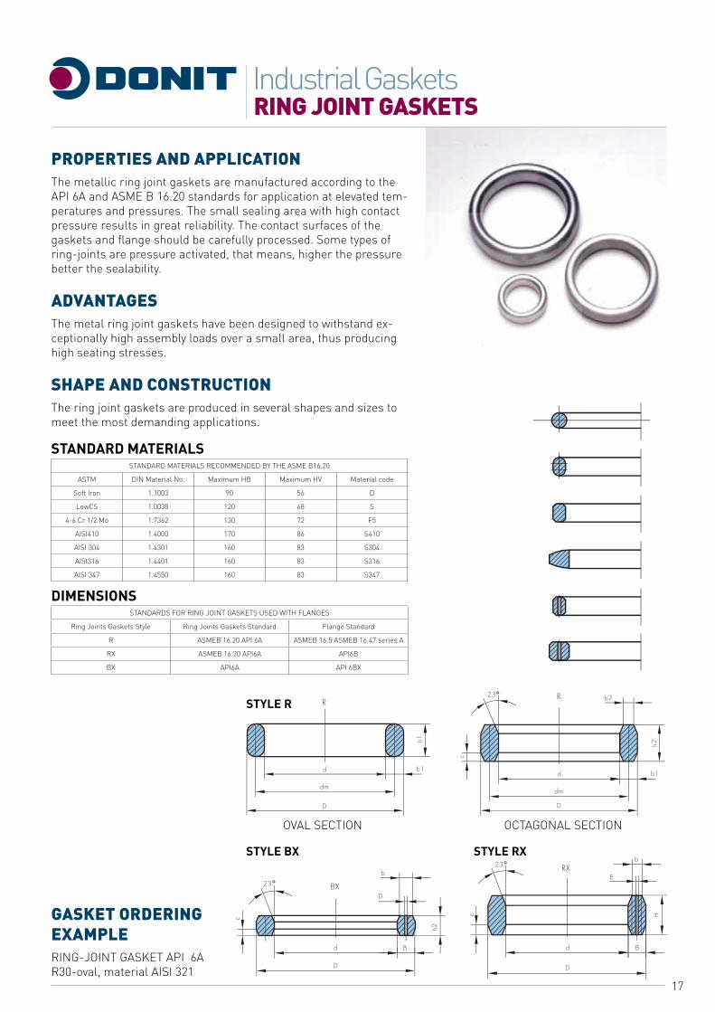
PROPERTIES AND APPLICATIONThe metallic ring joint gaskets are manufactured according to the API 6A and ASME B 16.20 standards for application at elevated tem-peratures and pressures. The small sealing area with high contact pressure results in great reliability. The contact surfaces of the gaskets and flange should be carefully processed. Some types of ring-joints are pressure activated, that means, higher the pressure better the sealability.
ADVANTAGESThe metal ring joint gaskets have been designed to withstand ex-ceptionally high assembly loads over a small area, thus producing high seating stresses.
SHAPE AND CONSTRUCTIONThe ring joint gaskets are produced in several shapes and sizes to meet the most demanding applications.
STANDARD MATERIALSSTANDARD MATERIALS RECOMMENDED BY THE ASME B16.20
ASTM DIN Material No. Maximum HB Maximum HV Material code
Soft Iron 1.1003 90 56 D
LowCS 1.0038 120 68 S
4-6 Cr 1/2 Mo 1.7362 130 72 F5
AISI410 1.4000 170 86 S410
AISI 304 1.4301 160 83 S304
AISI316 1.4401 160 83 S316
AISI 347 1.4550 160 83 S347
DIMENSIONSSTANDARDS FOR RING JOINT GASKETS USED WITH FLANGES
Ring Joints Gaskets Style Ring Joints Gaskets Standard Flange Standard
R ASMEB 16.20 API 6A ASMEB 16.5 ASMEB 16.47 series A
RX ASMEB 16.20 API6A API6B
BX API6A API 6BX
GASKET ORDERING EXAMPLERING-JOINT GASKET API 6A R30-oval, material AISI 321
STYLE R
STYLE BX STYLE RX
18
RING JOINT GASKETSIndustrial Gaskets
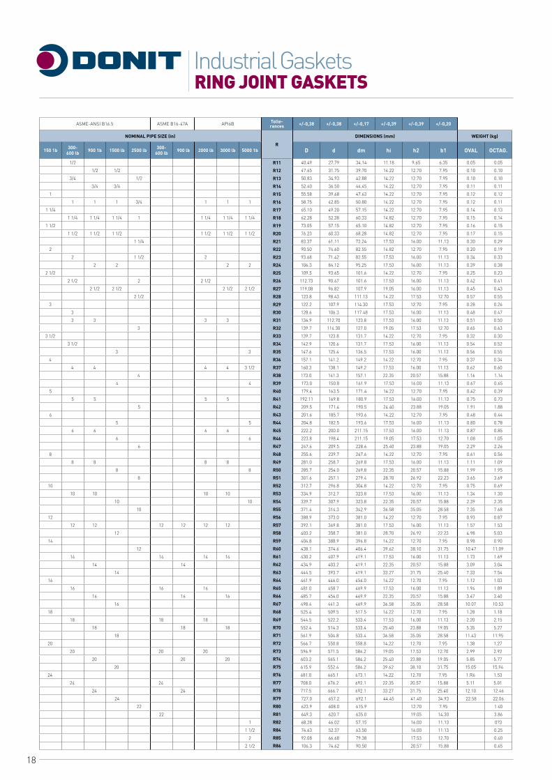
ASME-ANSI B16.5 ASME B16-47A API6B Tolle- rances +/-0,38 +/-0,38 +/-0,17 +/-0,39 +/-0,39 +/-0,20
NOMINAL PIPE SIZE (in)
R
DIMENSIONS (mm) WEIGHT (kg)
150 1b 300-600 lb 900 1b 1500 lb 2500 lb 300-
600 lb 900 lb 2000 lb 3000 lb 5000 1b D d dm hi h2 b1 OVAL OCTAG.
1/2 R11
R12
R13
R14
R15
R16
R17
R18
R19
R20
R21
R22
R23
R24
R25
R26
R27
R28
R29
R30
R31
R32
R33
R34
R35
R36
R37
R38
R39
R40
R41
R42
R43
R44
R45
R46
R47
R48
R49
R50
R51
R52
R53
R54
R55
R56
R57
R58
R59
R60
R61
R62
R63
R64
R65
R66
R67
R68
R69
R70
R71
R72
R73
R74
R75
R76
R77
R78
R79
R80
R81
R82
R84
R85
R86
40.49 27.79 34.14 11.18 9.65 6.35 0.05 0.05
1/2 1/2 47.65 31.75 39.70 14.22 12.70 7.95 0.10 0.10
3/4 1/2 50.83 34.93 42.88 14.22 12.70 7.95 0.10 0.10
3/4 3/4 52.40 36.50 44.45 14.22 12.70 7.95 0.11 0.11
1 55.58 39.68 47.63 14.22 12.70 7.95 0.12 0.12
1 1 1 3/4 1 1 1 58.75 42.85 50.80 14.22 12.70 7.95 0.12 0.11
1 1/4 65.10 49.20 57.15 14.22 12.70 7.95 0.14 0.13
1 1/4 1 1/4 1 1/4 1 1 1/4 1 1/4 1 1/4 62.28 52.38 60.33 14.82 12.70 7.95 0.15 0.14
1 1/2 73.05 57.15 65.10 14.82 12.70 7.95 0.16 0.15
1 1/2 1 1/2 1 1/2 1 1/2 1 1/2 1 1/2 76.23 60.33 68.28 14.82 12.70 7.95 0.17 0.15
1 1/4 83.37 61.11 72.24 17.53 16.00 11.13 0.30 0.29
2 90.50 74.60 82.55 14.82 12.70 7.95 0.20 0.19
2 1 1/2 2 93.68 71.42 82.55 17.53 16.00 11.13 0.34 0.33
2 2 2 2 106.3 84.12 95.25 17.53 16.00 11.13 0.39 0.38
2 1/2 109.5 93.65 101.6 14.22 12.70 7.95 0.25 0.23
2 1/2 2 2 1/2 112.73 90.47 101.6 17.53 16.00 11.13 0.42 0.41
2 1/2 2 1/2 2 1/2 2 1/2 119.08 96.82 107.9 19.05 16.00 11.13 0.45 0.43
2 1/2 123.8 98.43 111.13 14.22 17.53 12.70 0.57 0.55
3 122.2 107.9 114.30 17.53 12.70 7.95 0.28 0.26
3 128.6 106.3 117.48 17.53 16.00 11.13 0.48 0.47
3 3 3 3 134.9 112.70 123.8 17.53 16.00 11.13 0.51 0.50
3 139.7 114.30 127.0 19.05 17.53 12.70 0.65 0.63
3 1/2 139.7 123.8 131.7 14.22 12.70 7.95 0.32 0.30
3 1/2 142.9 120.6 131.7 17.53 16.00 11.13 0.54 0.52
3 3 147.6 125.4 136.5 17.53 16.00 11.13 0.56 0.55
4 157.1 141.2 149.2 14.22 12.70 7.95 0.37 0.34
4 4 4 4 3 1/2 160.3 138.1 149.2 17.53 16.00 11.13 0.62 0.60
4 173.0 141.3 157.1 22.35 20.57 15.88 1.16 1.14
4 4 173.0 150.8 161.9 17.53 16.00 11.13 0.67 0.65
5 179.4 163.5 171.4 14.22 12.70 7.95 0.42 0.39
5 5 5 5 192.11 169.8 180.9 17.53 16.00 11.13 0.75 0.73
5 209.5 171.4 190.5 24.40 23.88 19.05 1.91 1.88
6 201.6 185.7 193.6 14.22 12.70 7.95 0.48 0.44
5 5 204.8 182.5 193.6 17.53 16.00 11.13 0.80 0.78
6 6 6 6 222.2 200.0 211.15 17.53 16.00 11.13 0.87 0.85
6 6 223.8 198.4 211.15 19.05 17.53 12.70 1.08 1.05
6 247.6 209.5 228.6 25.40 23.88 19.05 2.29 2.26
8 255.6 239.7 247.6 14.22 12.70 7.95 0.61 0.56
8 8 8 8 281.0 258.7 269.8 17.53 16.00 11.13 1.11 1.09
8 8 285.7 254.0 269.8 22.35 20.57 15.88 1.99 1.95
8 301.6 257.1 279.4 28.70 26.92 22.23 3.65 3.69
10 312.7 296.8 304.8 14.22 12.70 7.95 0.75 0.69
10 10 10 10 334.9 312.7 323.8 17.53 16.00 11.13 1.34 1.30
10 10 339.7 307.9 323.8 22.35 20.57 15.88 2.39 2.35
10 371.4 314.3 342.9 36.58 35.05 28.58 7.35 7.68
12 388.9 373.0 381.0 14.22 12.70 7.95 0.93 0.87
12 12 12 12 12 12 392.1 369.8 381.0 17.53 16.00 11.13 1.57 1.53
12 403.2 358.7 381.0 28.70 26.92 22.23 4.98 5.03
14 404.8 388.9 396.8 14.22 12.70 7.95 0.98 0.90
12 438.1 374.6 406.4 39.62 38.10 31.75 10.47 11.09
14 14 14 14 430.2 407.9 419.1 17.53 16.00 11.13 1.73 1.69
14 14 434.9 403.2 419.1 22.35 20.57 15.88 3.09 3.04
14 444.5 393.7 419.1 33.27 31.75 25.40 7.33 7.54
16 461.9 446.0 454.0 14.22 12.70 7.95 1.12 1.03
16 16 16 481.0 458.7 469.9 17.53 16.00 11.13 1.94 1.89
16 16 16 485.7 454.0 469.9 22.35 20.57 15.88 3.47 3.40
16 498.4 441.3 469.9 36.58 35.05 28.58 10.07 10.53
18 525.4 509.5 517.5 14.22 12.70 7.95 1.28 1.18
18 18 18 544.5 522.2 533.4 17.53 16.00 11.13 2.20 2.15
18 18 18 552.4 514.3 533.4 25.40 23.88 19.05 5.35 5.27
18 561.9 504.8 533.4 36.58 35.05 28.58 11.43 11.95
20 566.7 550.8 558.8 14.22 12.70 7.95 1.38 1.27
20 20 20 596.9 571.5 584.2 19.05 17.53 12.70 2.99 2.92
20 20 20 603.2 565.1 584.2 25.40 23.88 19.05 5.85 5.77
20 615.9 552.4 584.2 39.62 38.10 31.75 15.05 15.94
24 681.0 665.1 673.1 14.22 12.70 7.95 1.R6 1.53
24 24 708.0 676.2 692.1 22.35 20.57 15.88 5.11 5.01
24 24 717.5 666.7 692.1 33.27 31.75 25.40 12.10 12.46
24 727.0 657.2 692.1 44.45 41.40 34.93 22.58 22.06
22 623.9 608.0 615.9 12.70 7.95 1 40
22 649.3 620.7 635.0 19.05 14.30 3.86
1 68.28 46.02 57.15 16.00 11.13 0?3
1 1/2 74.63 52.37 63.50 16.00 11.13 0.25
2 92.08 66.68 79.38 17.53 12.70 0.40
2 1/2 106.3 74.62 90.50 20.57 15.88 0.65
19
CORRUGATED METAL GASKETSIndustrial Gaskets
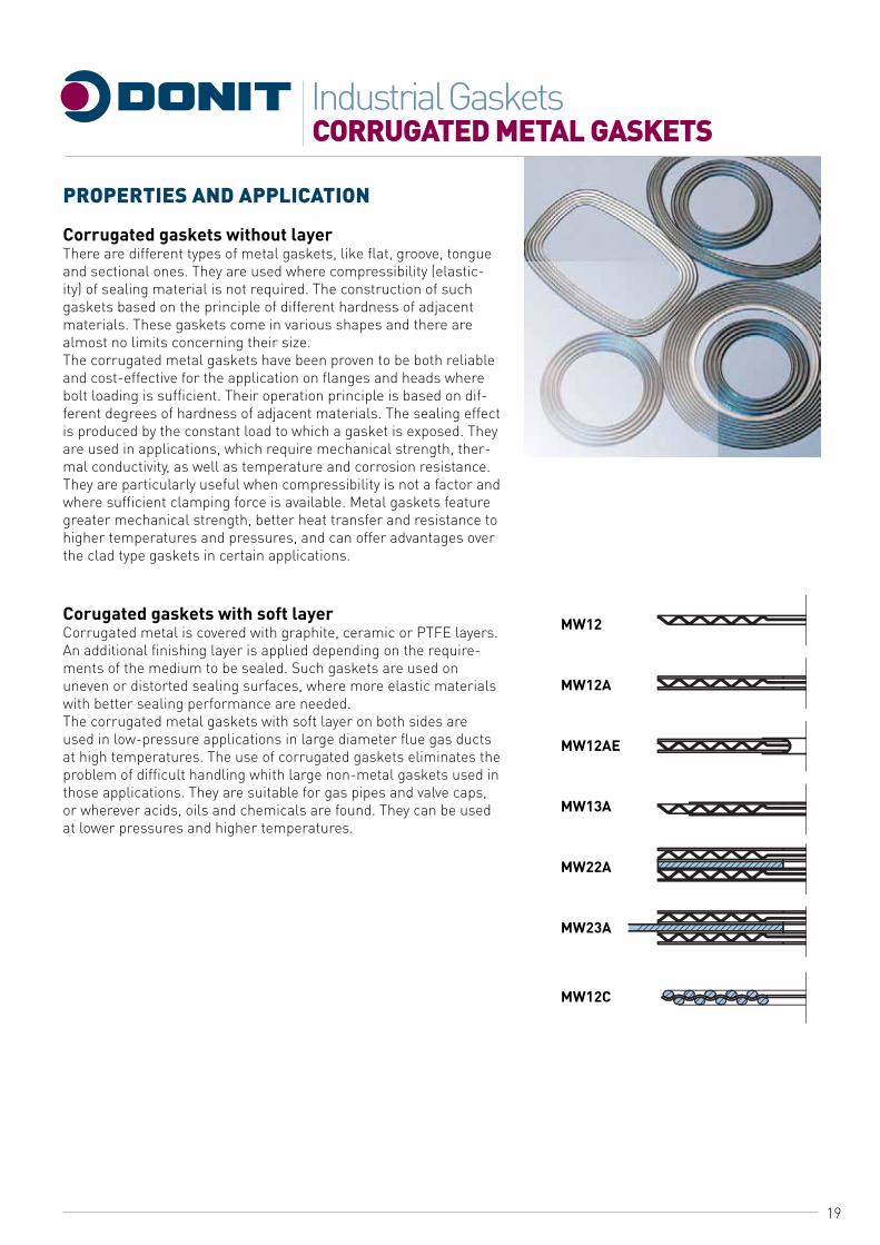
PROPERTIES AND APPLICATION
Corrugated gaskets without layerThere are different types of metal gaskets, like flat, groove, tongue and sectional ones. They are used where compressibility (elastic-ity) of sealing material is not required. The construction of such gaskets based on the principle of different hardness of adjacent materials. These gaskets come in various shapes and there are almost no limits concerning their size.The corrugated metal gaskets have been proven to be both reliable and cost-effective for the application on flanges and heads where bolt loading is sufficient. Their operation principle is based on dif-ferent degrees of hardness of adjacent materials. The sealing effect is produced by the constant load to which a gasket is exposed. They are used in applications, which require mechanical strength, ther-mal conductivity, as well as temperature and corrosion resistance. They are particularly useful when compressibility is not a factor and where sufficient clamping force is available. Metal gaskets feature greater mechanical strength, better heat transfer and resistance to higher temperatures and pressures, and can offer advantages over the clad type gaskets in certain applications.
Corugated gaskets with soft layerCorrugated metal is covered with graphite, ceramic or PTFE layers. An additional finishing layer is applied depending on the require-ments of the medium to be sealed. Such gaskets are used on uneven or distorted sealing surfaces, where more elastic materials with better sealing performance are needed.The corrugated metal gaskets with soft layer on both sides are used in low-pressure applications in large diameter flue gas ducts at high temperatures. The use of corrugated gaskets eliminates the problem of difficult handling whith large non-metal gaskets used in those applications. They are suitable for gas pipes and valve caps, or wherever acids, oils and chemicals are found. They can be used at lower pressures and higher temperatures.
MW12
MW12A
MW12AE
MW13A
MW22A
MW23A
MW12C
20
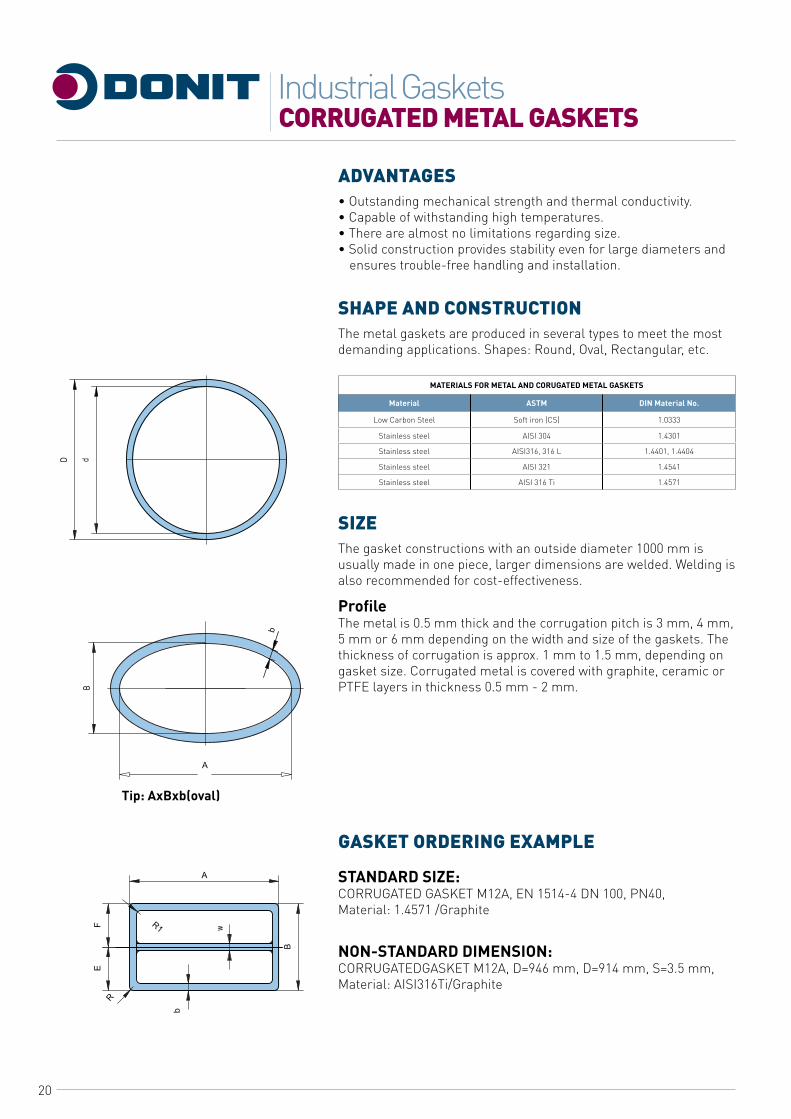
Tip: AxBxb(oval)
ADVANTAGES• Outstanding mechanical strength and thermal conductivity.• Capable of withstanding high temperatures.• There are almost no limitations regarding size.• Solid construction provides stability even for large diameters and
ensures trouble-free handling and installation.
SHAPE AND CONSTRUCTIONThe metal gaskets are produced in several types to meet the most demanding applications. Shapes: Round, Oval, Rectangular, etc.
MATERIALS FOR METAL AND CORUGATED METAL GASKETS
Material ASTM DIN Material No.
Low Carbon Steel Soft iron (CS) 1.0333
Stainless steel AISI 304 1.4301
Stainless steel AISI316, 316 L 1.4401, 1.4404
Stainless steel AISI 321 1.4541
Stainless steel AISI 316 Ti 1.4571
SIZEThe gasket constructions with an outside diameter 1000 mm is usually made in one piece, larger dimensions are welded. Welding is also recommended for cost-effectiveness.
ProfileThe metal is 0.5 mm thick and the corrugation pitch is 3 mm, 4 mm, 5 mm or 6 mm depending on the width and size of the gaskets. The thickness of corrugation is approx. 1 mm to 1.5 mm, depending on gasket size. Corrugated metal is covered with graphite, ceramic or PTFE layers in thickness 0.5 mm - 2 mm.
GASKET ORDERING EXAMPLE
STANDARD SIZE:CORRUGATED GASKET M12A, EN 1514-4 DN 100, PN40,Material: 1.4571 /Graphite
NON-STANDARD DIMENSION:CORRUGATEDGASKET M12A, D=946 mm, D=914 mm, S=3.5 mm, Material: AISI316Ti/Graphite
CORRUGATED METAL GASKETSIndustrial Gaskets

21
NON METALLIC FLAT GASKETSIndustrial Gaskets
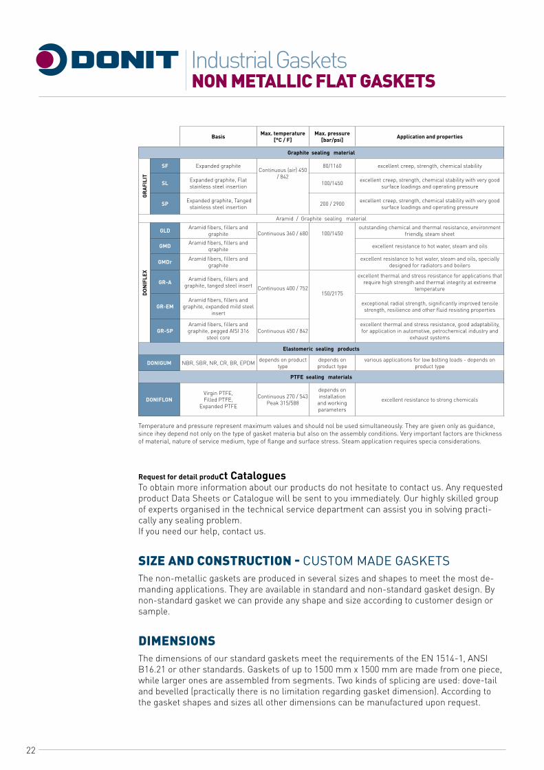
PROPERTIES AND APPLICATIONThe non-metallic or flat gaskets are the most typical ones from the family of flat static gaskets. They are used in a large number by various industries and in a variety of applications. Soft gaskets are made of non-asbestos (CSF), graphite, PTFE, mica, aramide/graphite and rubber sealing materials. Available are standard and nonstandard gasket design.
Gasket materials and applicationCopressed-
S. Line Basis Max.T[C7F°] Max. P[bar/psi] Application and properties
BA-202 Organic fibres, NBR • Peak• Continuous
180/356140/2 84 2/29 for ower oadings, good resistance to water, gases, oils, Fuels
BA-203 Aramid fibres, NBR • Peak• Continuous
250/482 200/392 2/29 for medium oading, good
resistance to water, gases, oils, fuels
BA-50 Aramid fibres, NBR • Peak• Continuous
2 80/536 220/428 2/29 good dynamic resistance for higher
loading, gas, food industry
BA-55 Syntetic fibres, NBR • Peak• Continuous
350/662 270/518 2/29 excellent thermal properties and good steam resistance, economical
quality for wide field of app ication
BA-U Aramid fibres, NBR • Peak• Continuous
350/662 250/482 2/29 genera use
BA-GL Glass fibres, NBR • Peak• Continuous
440/824 350/662 2/29 very good therma properties and excellent torque retention
BA-CF Carbon fibres, NBR • Peak• Continuous
400/752 300/572 2/29 resistance to steam and alkaline media, chemica and petrochemica
industry
BA-Auto Aramid fibres, SBR • Peak• Continuous
280/536 220/428 2/29 controlled swell properties in oil, automotive industry
BA-N Aramid fibres, CR • Peak• Continuous
350/662 270/518 2/29 resistance to refrigerant, genera use
BA-C Aramid fibres, CSM • Peak• Continuous
200/392 150/302 2/29 excellent resistance to acids anda ka ine media
BA-R Aramide fibres, NBR/SBR, wire reinforced
• Peak• Continuous
400/752 350/662 2/29 great strenght, for dynamic oadings, automotive and petrochemica
industry, shipyards
BA-R3 00 Inorganic fibres, NBR, special reinforced
• Peak• Continuous
550/1022 450/842
excellent dynamic and therma resistance, automotive and petrochemica industry, shipyards
BA-R302 Inorganic fibres, NBR, special reinforcement
• Peak• Continuous
650/1202 600/1112
extreme dynamic and therma resistance, automotive and petrochemica industry, shipyards
BA-U R200 Aramid fibres, NBR, Expanded metal • Continuous 75/143 2/29 improved strenght, for dynamic oadings, high pressure appications,
district heating, ship’s piping system
HighPerformance
LineBasis Max.T[C7F°] Max. P [bar/psi] Application and properties
BAU 2000 Aramid fibres, NBR • Peak• Continuous
400/752 280/536 2/29 environment friendly gasket materia with specially balanced sea ling,
thermal, chemical and mechanica properties allows universa use
BAGL 3000 Glass fibres, NBR • Peak• Continuous
440/8 24 350/662 2/29 environment friendly gasket material with excellent torque retention
and therma resistance
BACF 4000 Carbon fibres, NBR • Peak• Continuous
440/8 24 350/662 2/29 environment friendly gasket material with very good resistance to
strong alkaline media and steam
BAX 5000 Aramid fibres, NBR • Peak• Continuous
400/752 250/482 2/29 environment friendly gasket material with supreme mechanica
properties
BAM 6000 Biosoluble mineralfibres, NBR
• Peak• Continuous
440/8 24 350/662 2/29 environment friendly gasket materia with excellent resistance to
steam and ong-term steam sea ability
22
Basis Max. temperature [°C / F]
Max. pressure [bar/psi] Application and properties
Graphite sealing material
SF Expanded graphiteContinuous (air) 450
/ 842
80/1160 excellent creep, strength, chemical stability
SL Expanded graphite, Flat stainless steel insertion 100/1450 excellent creep, strength, chemical stability with very good
surface loadings and operating pressure
SP Expanded graphite, Tanged stainless steel insertion 200 / 2900 excellent creep, strength, chemical stability with very good
surface loadings and operating pressure
Aramid / Graphite sealing material
GLD Aramid fibers, fillers and graphite Continuous 360 / 680 100/1450
outstanding chemical and thermal resistance, environment friendly, steam sheet
GMD Aramid fibers, fillers and qraphite excellent resistance to hot water, steam and oils
GMDr Aramid fibers, fillers and graphite
excellent resistance to hot water, steam and oils, specially designed for radiators and boilers
GR-A Aramid fibers, fillers and graphite, tanged steel insert Continuous 400 / 752
150/2175
excellent thermal and stress resistance for applications thatrequire high strength and thermal integrity at extreeme
temperature
GR-EMAramid fibers, fillers and
graphite, expanded mild steelinsert
exceptional radial strength, significantly improved tensile strength, resilience and other fluid resisting properties
GR-SPAramid fibers, fillers andgraphite, pegged AISI 316
steel coreContinuous 450 / 842
excellent thermal and stress resistance, good adaptability,for application in automotive, petrochemical industry and
exhaust systems
Elastomeric sealing products
DONIGUM NBR, SBR, NR, CR, BR, EPDM depends on product type
depends on product type
various applications for low bolting loads - depends on product type
PTFE sealing materials
DONIFLONVirgin PTFE,Filled PTFE,
Expanded PTFE
Continuous 270 / 543Peak 315/588
depends on installationand working parameters
excellent resistance to strong chemicals
Temperature and pressure represent maximum values and should nol be used simultaneously. They are given only as guidance, since ihey depend not only on the type of gasket materia but also on the assembly conditions. Very important factors are thickness of material, nature of service medium, type of flange and surface stress. Steam application requires specia considerations.
Request for detail product CataloguesTo obtain more information about our products do not hesitate to contact us. Any requested product Data Sheets or Catalogue will be sent to you immediately. Our highly skilled group of experts organised in the technical service department can assist you in solving practi-cally any sealing problem.If you need our help, contact us.
SIZE AND CONSTRUCTION - cusToM MADE GAskETsThe non-metallic gaskets are produced in several sizes and shapes to meet the most de-manding applications. They are available in standard and non-standard gasket design. By non-standard gasket we can provide any shape and size according to customer design or sample.
DIMENSIONSThe dimensions of our standard gaskets meet the requirements of the EN 1514-1, ANSI B16.21 or other standards. Gaskets of up to 1500 mm x 1500 mm are made from one piece, while larger ones are assembled from segments. Two kinds of splicing are used: dove-tail and bevelled (practically there is no limitation regarding gasket dimension). According to the gasket shapes and sizes all other dimensions can be manufactured upon request.
GRAF
ILIT
DO
NIF
LEX
NON METALLIC FLAT GASKETSIndustrial Gaskets
23
NON METALLIC FLAT GASKETSIndustrial Gaskets
CUTTING CAPABILITIESWith our cutting technology, experience and knowledge we are able to cut almost any material. A wide range of cutting equipment provides competitive pricing and high quality regardless of the gasket size or quantity. A large range of presses, special cutting tools, CAM-CAD Water Jet, and also a skilled team for the swift production of small quantities are available. Custom-cut gas-kets according to the customers own drawing and specification, samples and templates. Cutter manufacture-cutting tools are made in-house as an integral part of the production unit. There is an extensive catalogue of cutters available.
Water Jet CuttingCAM-CAD Water Jet cutter is an excellent system for manufacturing a variety of a two-dimensional items both large and small in simple or complex shapes from a wide range of materials. Steel, rubber, aluminium are just a few of the materials that can be cut to the desired shape-drawn, programmed and stored on a CAD-system. The process will leave a smooth finish on steel with no heat affected zones and exceptional two-dimension accuracy.
STANDARDS FOR NON-METALLIC FLAT GASKETS
Gasket Standard Flange Standard
EN 1514-1 ASME B 16.21 (ASME B16.5) EN 1092-1,-2,-3,-4, EN 545, EN 598, EN 969
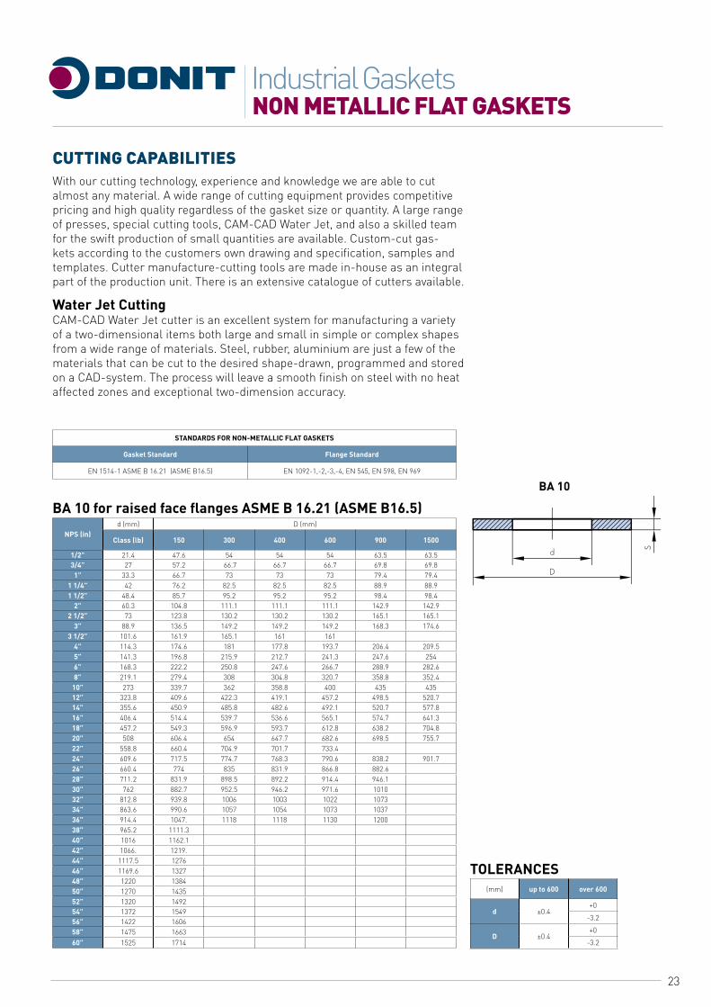
BA 10 for raised face flanges ASME B 16.21 (ASME B16.5)
NPS (in)d (mm) D (mm)
Class (lb) 150 300 400 600 900 1500
1/2” 21.4 47.6 54 54 54 63.5 63.53/4” 27 57.2 66.7 66.7 66.7 69.8 69.8
1” 33.3 66.7 73 73 73 79.4 79.41 1/4” 42 76.2 82.5 82.5 82.5 88.9 88.91 1/2” 48.4 85.7 95.2 95.2 95.2 98.4 98.4
2” 60.3 104.8 111.1 111.1 111.1 142.9 142.92 1/2” 73 123.8 130.2 130.2 130.2 165.1 165.1
3” 88.9 136.5 149.2 149.2 149.2 168.3 174.63 1/2” 101.6 161.9 165.1 161 161
4” 114.3 174.6 181 177.8 193.7 206.4 209.55” 141.3 196.8 215.9 212.7 241.3 247.6 2546” 168.3 222.2 250.8 247.6 266.7 288.9 282.68” 219.1 279.4 308 304.8 320.7 358.8 352.4
10” 273 339.7 362 358.8 400 435 43512” 323.8 409.6 422.3 419.1 457.2 498.5 520.714” 355.6 450.9 485.8 482.6 492.1 520.7 577.816” 406.4 514.4 539.7 536.6 565.1 574.7 641.318” 457.2 549.3 596.9 593.7 612.8 638.2 704.820” 508 606.4 654 647.7 682.6 698.5 755.722” 558.8 660.4 704.9 701.7 733.424” 609.6 717.5 774.7 768.3 790.6 838.2 901.726” 660.4 774 835 831.9 866.8 882.628” 711.2 831.9 898.5 892.2 914.4 946.130” 762 882.7 952.5 946.2 971.6 101032” 812.8 939.8 1006 1003 1022 107334” 863.6 990.6 1057 1054 1073 103736” 914.4 1047. 1118 1118 1130 120038” 965.2 1111.340” 1016 1162.142” 1066. 1219.44” 1117.5 127646” 1169.6 132748” 1220 138450” 1270 143552” 1320 149254” 1372 154956” 1422 160658” 1475 166360” 1525 1714
TOLERANCES(mm) up to 600 over 600
d ±0.4+0
-3.2
D ±0.4+0
-3.2
BA 10
24
NON METALLIC FLAT GASKETSIndustrial Gaskets
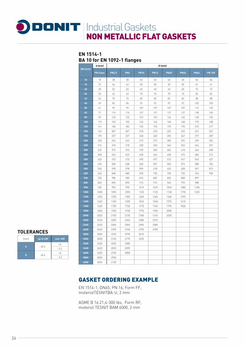
EN 1514-1 BA 10 for EN 1092-1 flanges
DN (mm)d (mm) D (mm)
PN Class PN2.5 PN6 PN10 PN16 PN25 PN40 PN64 PN 100
10 18 38 38 45 45 45 45 56 56
15 22 43 43 50 50 50 50 61 61
20 28 53 53 60 60 60 60 72 72
25 35 63 63 70 70 70 70 82 82
32 43 75 75 82 82 82 82 88 88
40 49 85 85 92 92 92 92 103 103
50 61 95 95 107 107 107 107 113 120
65 77 115 115 127 127 127 127 138 145
80 90 132 132 142 142 142 142 148 155
100 115 152 152 162 162 168 168 175 180
125 141 182 182 192 192 195 195 210 217
150 169 207 207 218 218 225 225 247 257
175 195 237 237 248 248 255 267 277 287
200 220 262 262 273 273 285 292 309 324
250 274 318 318 328 330 342 353 364 391
300 325 373 373 378 385 402 418 424 458
350 368 423 423 438 445 458 475 486 512
400 420 473 473 490 497 515 547 543 627
450 470 528 528 540 557 565 572 588 704
500 520 578 578 595 618 625 628 657 813
600 620 680 680 695 735 730 745 764 950
700 720 785 785 810 805 830 850 879
800 820 890 890 915 910 940 970 988
900 920 990 990 1015 1010 1040 1080 1108
1000 1020 1090 1090 1120 1125 1150 1190 1220
1200 1220 1290 1305 1340 1340 1360 1395
1400 1420 1490 1520 1545 1540 1575 1615
1600 1620 1700 1720 1770 1760 1795 1830
1800 1820 1900 1930 1970 1960 2000
2000 2020 2100 2135 2180 2165 2230
2200 2220 2305 2345 2380 2375
2400 2420 2505 2555 2590 2585
2600 2620 2705 2760 2790 2785
2800 2820 2920 2970 3010
3000 3020 3120 3170 3225
3200 3220 3320 3380
3400 3420 3520 3590
3600 3620 3730 3800
3800 3820 3930
4000 4020 4130
GASKET ORDERING EXAMPLEEN 1514-1, DN65, PN 16, Form FF, moteriolTESNITBA-U, 2 mm
ASME B 16.21,4-300 lbs, Form RF, moteriol TESNIT BAM 6000, 2 mm
TOLERANCES(mm) up to 600 over 600
d ±0.4+0
-3.2
D ±0.4+0
-3.2

25
METAL EyELETED FLAT GASKETSIndustrial Gaskets
PROPERTIES AND APPLICATIONThe metal eyeleted flat gaskets offer special protection against blowout for the sealing of critical or dangerous media. The sealing insert is usually made from TESNIT BA or Grafilit gasket mate-rial. The standard metal jacket is formed with an austenitic stain-less steel leaf with a thickness 0.15 mm - 0.2 mm U-shaped and pressed in such a way that it becomes a single body with a base seal. The good melleability grade of the austenitic stainless steel gives to the covering excellent mechanical properties and good resistance to erosion, while the well known resistance to heat and to corrosion ensures the long working life of the seal.
ADVANTAGES• Blow out protection.• Protection against chemical attack.• Improved sealability due to the local higher stress under eyelet.
SHAPE AND CONSTRUCTIONGaskets are available according to EN 1514-1, ASME B 16.21 and other Standard Forms. Custom made gaskets are available upon request.
SIZEThe only limitation of the eyeleted gasket is the size of the basic gasket material.Size limitations:From 20 mm to 400 mm one piece eyelet.From 400 mm upwards plasma welded eyelet.The standard production follows the sizes and norms byASME B16-21 and EN 1514-1.
GASKET ORDERING EXAMPLEEN 1514-1, DN65, PN 16, Form RF, material TESNIT BA-U, 2 mm, eyelet AISI 316
MP1
26
PTFE GASKETSIndustrial Gaskets
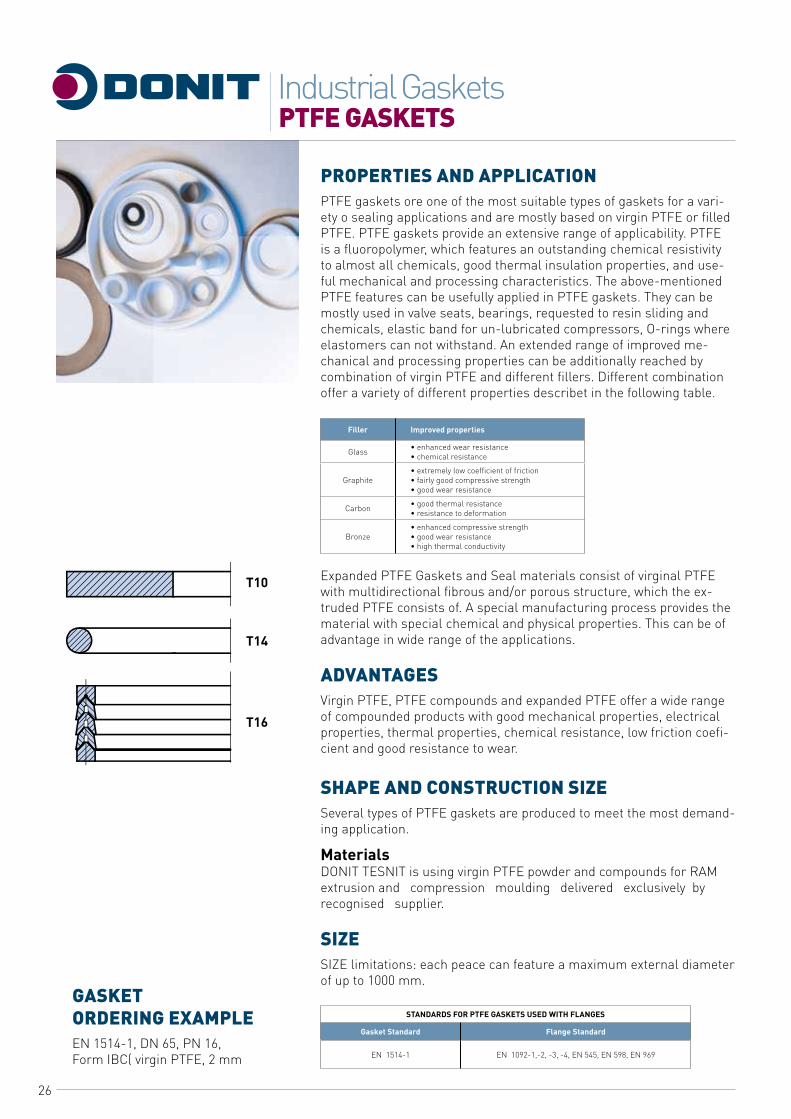
PROPERTIES AND APPLICATIONPTFE gaskets ore one of the most suitable types of gaskets for a vari-ety o sealing applications and are mostly based on virgin PTFE or filled PTFE. PTFE gaskets provide an extensive range of applicability. PTFE is a fluoropolymer, which features an outstanding chemical resistivity to almost all chemicals, good thermal insulation properties, and use-ful mechanical and processing characteristics. The above-mentioned PTFE features can be usefully applied in PTFE gaskets. They can be mostly used in valve seats, bearings, requested to resin sliding and chemicals, elastic band for un-lubricated compressors, O-rings where elastomers can not withstand. An extended range of improved me-chanical and processing properties can be additionally reached by combination of virgin PTFE and different fillers. Different combination offer a variety of different properties describet in the following table.
Filler Improved properties
Glass • enhanced wear resistance• chemical resistance
Graphite• extremely low coefficient of friction• fairly good compressive strength• good wear resistance
Carbon • good thermal resistance• resistance to deformation
Bronze• enhanced compressive strength• good wear resistance• high thermal conductivity
Expanded PTFE Gaskets and Seal materials consist of virginal PTFE with multidirectional fibrous and/or porous structure, which the ex-truded PTFE consists of. A special manufacturing process provides the material with special chemical and physical properties. This can be of advantage in wide range of the applications.
ADVANTAGESVirgin PTFE, PTFE compounds and expanded PTFE offer a wide range of compounded products with good mechanical properties, electrical properties, thermal properties, chemical resistance, low friction coefi-cient and good resistance to wear.
SHAPE AND CONSTRUCTION SIZESeveral types of PTFE gaskets are produced to meet the most demand-ing application.
MaterialsDONIT TESNIT is using virgin PTFE powder and compounds for RAM extrusion and compression moulding delivered exclusively by recognised supplier.
SIZESIZE limitations: each peace can feature a maximum external diameter of up to 1000 mm.
STANDARDS FOR PTFE GASKETS USED WITH FLANGES
Gasket Standard Flange Standard
EN 1514-1 EN 1092-1,-2, -3, -4, EN 545, EN 598, EN 969
T10
T14
T16
GASKET ORDERING EXAMPLEEN 1514-1, DN 65, PN 16, Form IBC( virgin PTFE, 2 mm
27
PTFE ENVELOPED GASKETSIndustrial Gaskets
TF02
TF04
TF05
TF06
TF08
TF10
TF12
TF13
TF14
TF16
TF20
TF21
TF22
TF24
TF30
TF31
TF32
TF34
TF40
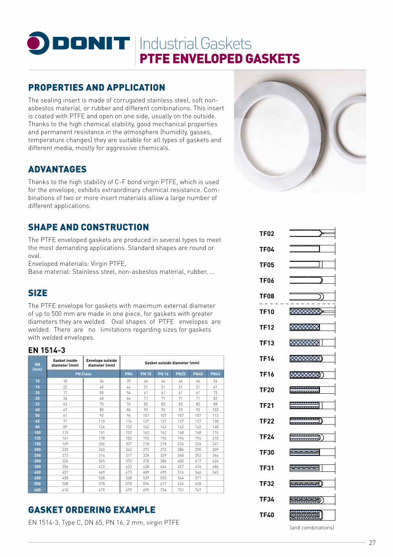
PROPERTIES AND APPLICATIONThe sealing insert is made of corrugated stainless steel, soft non-asbestos material, or rubber and different combinations. This insert is coated with PTFE and open on one side, usually on the outside. Thanks to the high chemical stability, good mechanical properties and permanent resistance in the atmosphere (humidity, gasses, temperature changes) they are suitable for all types of gaskets and different media, mostly for aggressive chemicals.
ADVANTAGESThanks to the high stability of C-F bond virgin PTFE, which is used for the envelope, exhibits extraordinary chemical resistance. Com-binations of two or more insert materials allow a large number of different applications.
SHAPE AND CONSTRUCTIONThe PTFE enveloped gaskets are produced in several types to meet the most demanding applications. Standard shapes are round or oval.Enveloped materials: Virgin PTFE,Base material: Stainless steel, non-asbestos material, rubber, ...
SIZEThe PTFE envelope for gaskets with maximum external diameter of up to 500 mm are made in one piece, for gaskets with greater diameters they are welded. Oval shapes of PTFE envelopes are welded. There are no limitations regarding sizes for gaskets with welded envelopes.
EN 1514-3
DN(mm)
Gasket inside diameter (mm)
Envelope outside diameter (mm) Gasket outside diameter (mm)
PN Class PN6 PN 10 PN 16 PN25 PN40 PN63
10 18 36 39 46 46 46 46 5615 22 40 44 51 51 51 51 6120 17 50 54 61 61 61 61 7225 34 60 64 71 71 71 71 8232 43 70 76 82 82 82 82 8840 49 80 86 92 92 92 92 10350 61 92 96 107 107 107 107 11365 77 110 116 127 127 127 127 13880 89 126 132 142 142 142 142 148
100 115 151 152 162 162 168 168 174125 141 178 182 192 192 194 194 210150 169 206 207 218 218 224 224 247200 220 260 262 273 273 284 290 309250 273 314 317 328 329 340 352 364300 324 365 373 378 384 400 417 424350 356 412 423 438 444 457 474 486400 407 469 473 489 495 514 546 543450 458 528 528 539 555 564 571500 508 578 578 594 617 624 628600 610 679 679 695 734 731 747
GASKET ORDERING EXAMPLEEN 1514-3, Type C, DN 65, PN 16, 2 mm, virgin PTFE
(and combinations)
28
SPECIAL GASKETS AND CUSTOM MADE GASKETSIndustrial Gaskets
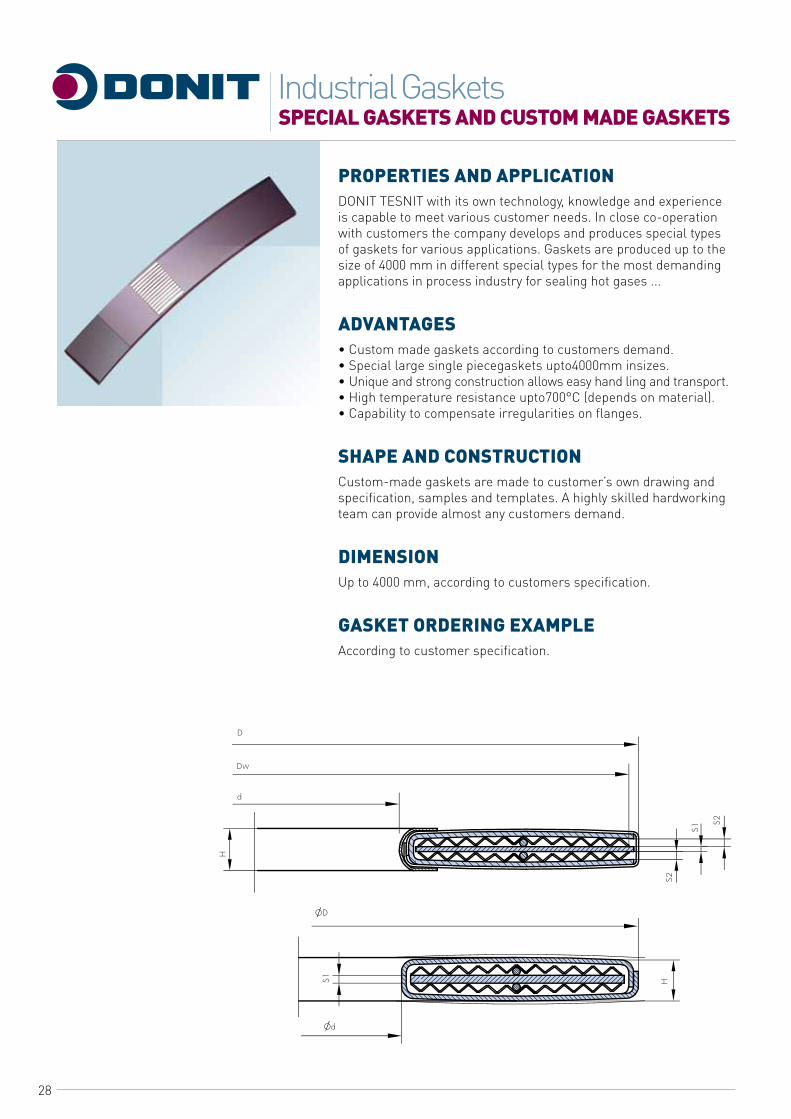
PROPERTIES AND APPLICATIONDONIT TESNIT with its own technology, knowledge and experience is capable to meet various customer needs. In close co-operation with customers the company develops and produces special types of gaskets for various applications. Gaskets are produced up to the size of 4000 mm in different special types for the most demanding applications in process industry for sealing hot gases ...
ADVANTAGES• Custom made gaskets according to customers demand.• Special large single piecegaskets upto4000mm insizes.• Unique and strong construction allows easy hand ling and transport.• High temperature resistance upto700°C (depends on material).• Capability to compensate irregularities on flanges.
SHAPE AND CONSTRUCTIONCustom-made gaskets are made to customer’s own drawing and specification, samples and templates. A highly skilled hardworking team can provide almost any customers demand.
DIMENSIONUp to 4000 mm, according to customers specification.
GASKET ORDERING EXAMPLEAccording to customer specification.
29
PHySICAL PROPERTIES OF METAL GASKET MATERIALSIndustrial Gaskets
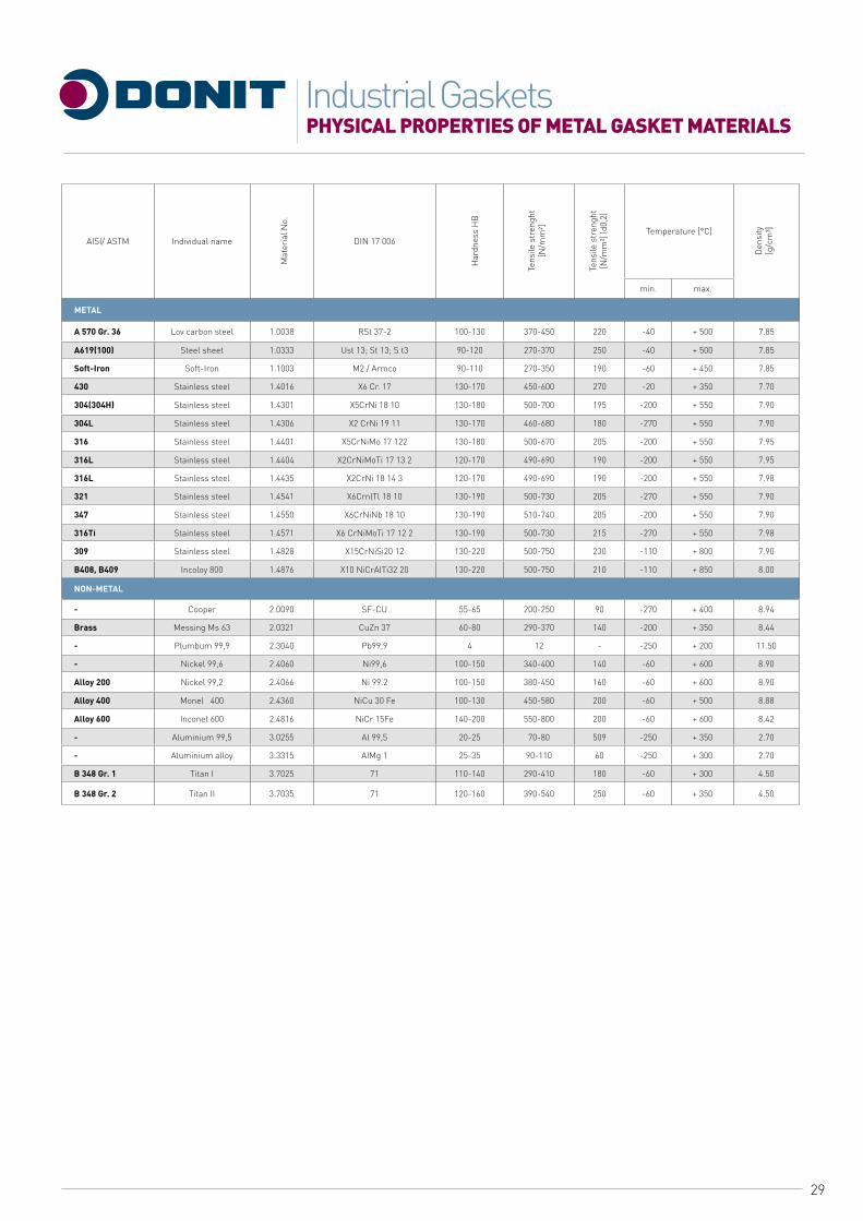
AISI/ ASTM Individual name DIN 17 006Temperature [°C]
min. max.
METAL
A 570 Gr. 36 Lov carbon steel 1.0038 RSt 37-2 100-130 370-450 220 -40 + 500 7.85
A619(100) Steel sheet 1.0333 Ust 13; St 13; S t3 90-120 270-370 250 -40 + 500 7.85
Soft-Iron Soft-Iron 1.1003 M2 / Armco 90-110 270-350 190 -60 + 450 7.85
430 Stainless steel 1.4016 X6 Cr. 17 130-170 450-600 270 -20 + 350 7.70
304(304H) Stainless steel 1.4301 X5CrNi 18 10 130-180 500-700 195 -200 + 550 7.90
304L Stainless steel 1.4306 X2 CrNi 19 11 130-170 460-680 180 -270 + 550 7.90
316 Stainless steel 1.4401 X5CrNiMo 17 122 130-180 500-670 205 -200 + 550 7.95
316L Stainless steel 1.4404 X2CrNiMoTi 17 13 2 120-170 490-690 190 -200 + 550 7.95
316L Stainless steel 1.4435 X2CrNi 18 14 3 120-170 490-690 190 -200 + 550 7.98
321 Stainless steel 1.4541 X6CrnlTl 18 10 130-190 500-730 205 -270 + 550 7.90
347 Stainless steel 1.4550 X6CrNiNb 18 10 130-190 510-740 205 -200 + 550 7.90
316Ti Stainless steel 1.4571 X6 CrNiMoTi 17 12 2 130-190 500-730 215 -270 + 550 7.98
309 Stainless steel 1.4828 X15CrNiSi20 12 130-220 500-750 230 -110 + 800 7.90
B408, B409 Incoloy 800 1.4876 X10 NiCrAITi32 20 130-220 500-750 210 -110 + 850 8.00
NON-METAL
- Cooper 2.0090 SF-CU 55-65 200-250 90 -270 + 400 8.94
Brass Messing Ms 63 2.0321 CuZn 37 60-80 290-370 140 -200 + 350 8.44
- Plumbum 99,9 2.3040 Pb99,9 4 12 - -250 + 200 11.50
- Nickel 99,6 2.4060 Ni99,6 100-150 340-400 140 -60 + 600 8.90
Alloy 200 Nickel 99,2 2.4066 Ni 99.2 100-150 380-450 160 -60 + 600 8.90
Alloy 400 Monel 400 2.4360 NiCu 30 Fe 100-130 450-580 200 -60 + 500 8.88
Alloy 600 Inconel 600 2.4816 NiCr 15Fe 140-200 550-800 200 -60 + 600 8.42
- Aluminium 99,5 3.0255 Al 99,5 20-25 70-80 509 -250 + 350 2.70
- Aluminium alloy 3.3315 AIMg 1 25-35 90-110 60 -250 + 300 2.70
B 348 Gr. 1 Titan I 3.7025 71 110-140 290-410 180 -60 + 300 4.50
B 348 Gr. 2 Titan II 3.7035 71 120-160 390-540 250 -60 + 350 4.50
Mat
eria
l No.
Har
dnes
s H
B
Tens
ile s
tren
ght
[N/m
m²]
Tens
ile s
tren
ght
[N/m
m²]
(d0,
2)
Den
sity
[g/c
m³]
30
PHySICAL PROPERTIES OF METAL GASKET MATERIALSIndustrial Gaskets
31
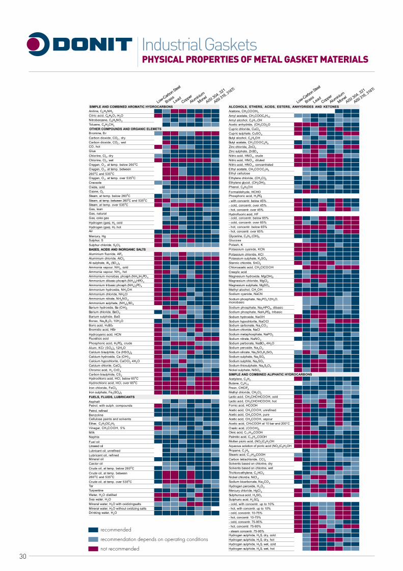
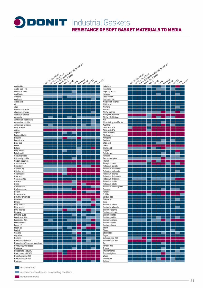
RESISTANCE OF SOFT GASKET MATERIALS TO MEDIAIndustrial Gaskets
32
HOW TO SELECT AN INDUSTRIAL GASKET?Industrial Gaskets
For any gasket application the choice of gasket material will depend on the operating conditions, mechanical features of the flanged assembly, the gasket characteristics and dimensions. In general, operating conditions determine the choice of jointing material, whereas the dimensional and mechanical features of the flange define the gasket type. The performance of any jointing material is influenced by the temperature, internal pressure, fluid, bolts (compressive stress), flange (type of flange, flange surface finish ...), cost-effectiveness and other special considerations. By us-ing special software like the Gasket Calculation software DON, we combined all gasket selection factors thus offering our customers an easy and safe gasket selection.
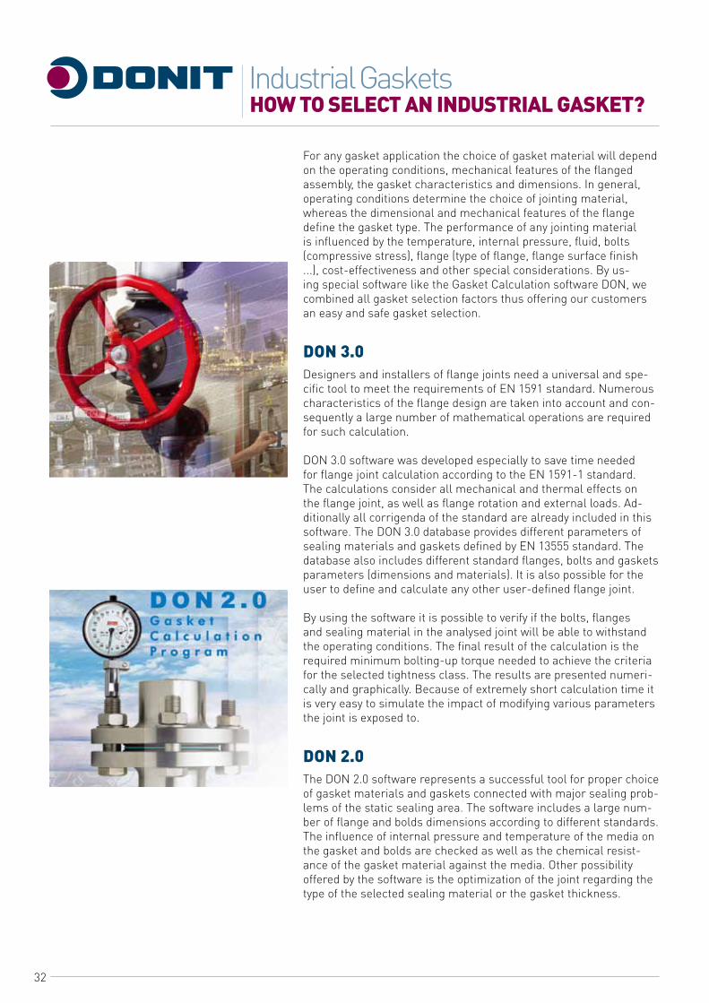
DON 3.0Designers and installers of flange joints need a universal and spe-cific tool to meet the requirements of EN 1591 standard. Numerous characteristics of the flange design are taken into account and con-sequently a large number of mathematical operations are required for such calculation.
DON 3.0 software was developed especially to save time needed for flange joint calculation according to the EN 1591-1 standard. The calculations consider all mechanical and thermal effects on the flange joint, as well as flange rotation and external loads. Ad-ditionally all corrigenda of the standard are already included in this software. The DON 3.0 database provides different parameters of sealing materials and gaskets defined by EN 13555 standard. The database also includes different standard flanges, bolts and gaskets parameters (dimensions and materials). It is also possible for the user to define and calculate any other user-defined flange joint.
By using the software it is possible to verify if the bolts, flanges and sealing material in the analysed joint will be able to withstand the operating conditions. The final result of the calculation is the required minimum bolting-up torque needed to achieve the criteria for the selected tightness class. The results are presented numeri-cally and graphically. Because of extremely short calculation time it is very easy to simulate the impact of modifying various parameters the joint is exposed to.
DON 2.0The DON 2.0 software represents a successful tool for proper choice of gasket materials and gaskets connected with major sealing prob-lems of the static sealing area. The software includes a large num-ber of flange and bolds dimensions according to different standards. The influence of internal pressure and temperature of the media on the gasket and bolds are checked as well as the chemical resist-ance of the gasket material against the media. Other possibility offered by the software is the optimization of the joint regarding the type of the selected sealing material or the gasket thickness.

33
GASKET INSTALLATION PROCEDURESIndustrial Gaskets
HOWTO INSTALL AND USE GASKETS IN THE FIELD?Successfully sealing o flanged connection depends upon many ele-ments of a well -designed flanged system working well together. Here is a summary, which should serve as a guideline for mainte-nance operators, engineers, and fitters in order to ensure success-ful gasket installation and assembly of bolted flange connections.
TOOLS REqUIREDSpecial tools are required for cleaning and tensioning the fasteners. In addition, always use standard safety equipment and follow good safety practice. Prepare the following equipment prior to installa-tion:• Calibrated torque wrench, hydraulicorothertensioner,• Wire brush,• Lubricant,• Helmetand safetygoggles,• Other plantspecified equipment.
1. Clean and examineRemove all particles and debris from seating surfaces, fasten-ers (bolds or studs), nuts, and washers. Use plant-specified dust control procedures. Examine fasteners (bolds or studs), nuts, and washers for defects such as burrs or cracks. Examine flange surfaces for warping, radial scores, heavy tool marks, or anything prohibiting proper gasket seating. Replace components if found to be defective.
2. Align flangesAlign flange faces and bolt holes without using excessive force. Report any misalignment.
3. Install gasketVerify if the gasket is of the specified size and material. Carefully in-sert gaskets between the flanges. Make sure the gasket is centred between the flanges. Do not use “jointing compounds”, graphite, grease or release agents on the gasket or seating surfaces. Bring flanges together, ensuring the gasket isn’t pinched ordamaged.
4. Lubricate load-bearing surfacesUse only specified or approved lubricants. Liberally apply Lubricant uniformly to all thread, nut, and washer load-bearing surfaces. Ensure Lubricant doesn’t contaminate either flange or gasket face.
34
GASKET INSTALLATION PROCEDURESIndustrial Gaskets
5. Install and tighten boltsAlways use proper tools: co lib rated torque wrench or other controlled tensioning device.Consult our Technical expert or use the Gasket calculation software DON for guidance on torque specification.Always torque nuts in a cross bolt-tightening pattern. Tighten the nuts in multiple steps:step-1 Tighten all nuts initially by hand. (Larger bolts may require a small handwrench.)step-2 Torque each nut to approximately 40% of full torque.step-3 Torque the nuts to approximately 70% of full torque.step-4 Torque each nut to full torque, again using the cross bolt tightening pattern. (Large-diameterflanges may require additional tightening passes.)step-5 Apply at least one final full torque to all nuts in a clock-wise direction until all torque is uniform. (Large diameter flanges may require additional tightening passes.)
6. RetighteningDo not retorque elastomer-based, asbestos free gaskets after they have been exposed to elevated temperatures unless other-wise specified. Retorque fasteners exposed to aggressive thermal cycling. All retorquing should be performed at ambient temperature and atmospheric pressure.
STORING GASKETSIndustrial gaskets consist of various materials, which are subjected to ageing, weathering, oxidation ... Ageing causes decreasing of the mechanical properties of gaskets. For this reason storage under the following conditions is recommended:• Ambient temperature of storage-move away from heaters• Dark storage room-move away from direct sunlight• Dry atmosphere• Avoid areas where electric discharge appears-ozone production• The gaskets must lie horizontally-avoid hanging on hooks or folding which could cause cracking
Avoid storing gaskets for more than two years.
CUSTOMERS SERVICE - TECHNICAL SUPPORTOur team is always available to our customers for any assistance, including advice they might need on the selection and use of our sealing products. This is provided by a special team of highly skilled experts making up the Technical Service deportment. By spreading the most comprehensive knowledge of our products, the Technical Service can help you to solve practically any sealing problem. If you need our help, do not hesitate to contact us.
35
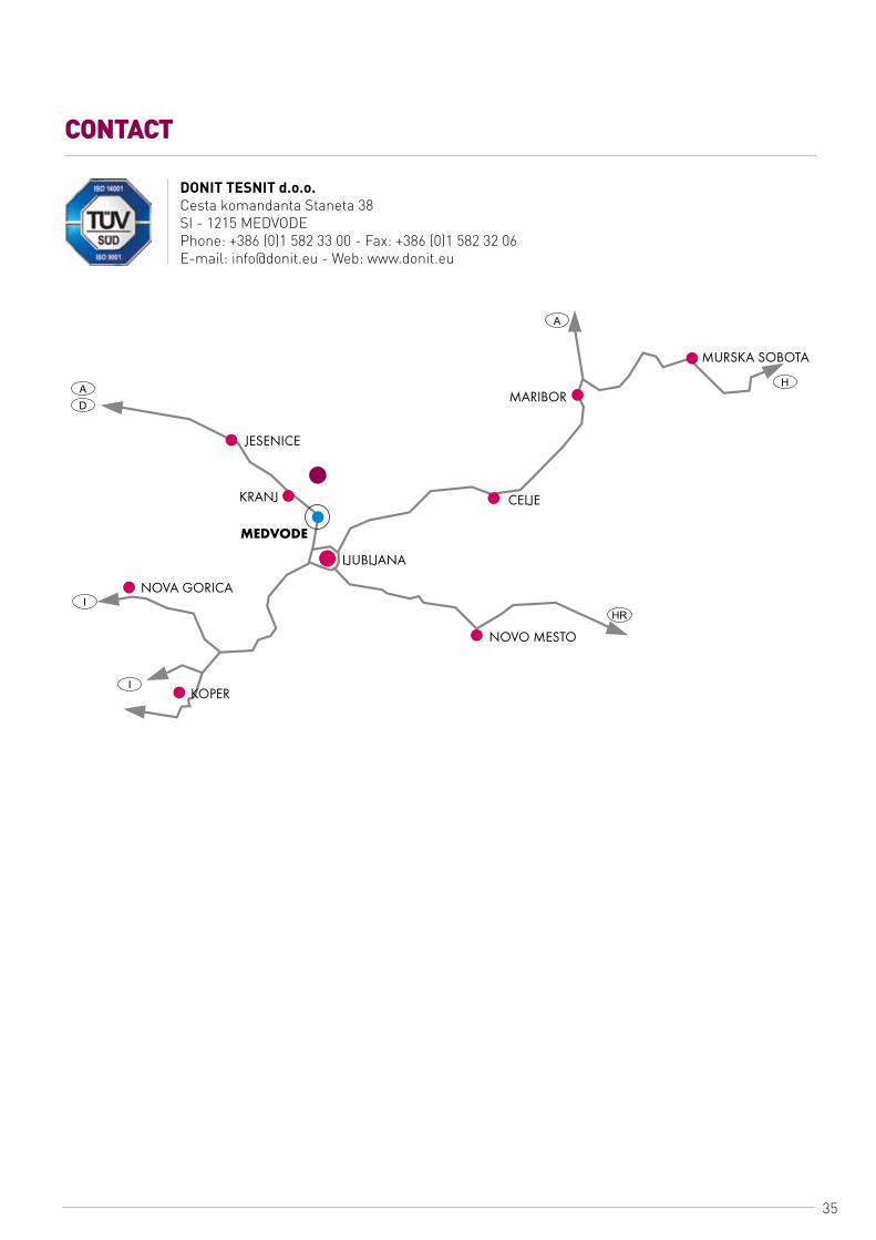
CONTACT
DONIT TESNIT d.o.o.Cesta komandanta Staneta 38SI - 1215 MEDVODEPhone: +386 (0)1 582 33 00 - Fax: +386 (0)1 582 32 06E-mail: [email protected] - Web: www.donit.eu

www.donit.eu