industrial brake products parts hydraulic brake systems brakes/pdf/hydraulic... · industrial brake...
TRANSCRIPT

Industrial Brake ProductsHydraulic Brake Systems
ReplacementParts

INDEX
HYDRAULIC BRAKES REPLACEMENT PARTS LIST
DESCRIPTION PAGE NO.
BRAKE ASSEMBLIES
§ 6x3, 8x3 Type H Brake 1§ 10x4 Type H Brake 2§ 14x6, 18x8 Type H Brake 3§ 6x3, 8x3TypeHM Brake 4§ 10x4 Type HM Brake 5§ 14x6, 18x8 Type HM Brake 6§ Pin Update Information 7-8
AUXILIARY COMPONENTS
§ Hydraulic Brake Actuator 9§ Fluid Reservoir Bleeder and Pushbutton 10§ Control Cylinder and Pedal 11§ 10, 14, and 18 HM Parking Cylinder 12§ HM Control Units 13§ Miscellaneous Fittings, Tubing, and Accessories 14
AIR COMPONENTS USED ON AIR-OVER-HYDRAULIC PANELS
§ Pressure Clusters 15§ Moisture Ejection Valve 16§ Air Treadle Valve 17-18§ Relay Emergency Valve 19-20§ Protection Valve 21§ Emergency Valve 22-23§ Air Compressor 24
AIR-OVER-HYDRAULIC PANELS
§ AH-ERC Panel J070970 - J070973 25§ AH-ERC Panel J070980 - J070987 26§ AH-HRC Panel J071020 - J071027 27§ AH-ARC Panel J089660 - J089667 28§ AHM-ERC Panel J100650 - J100661, J103650 - J103661 29§ AHM-HRC Panel J100330 - J100341, J103330 - J103341 30§ AHM-ARC Panel J104400 - J104411, J104424 - J104435 31
AIR-RELEASING CYLINDER 32DISC BRAKE POWER CLUSTERS 33-34
I
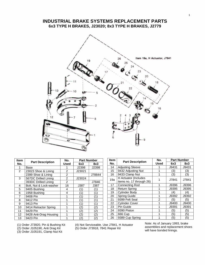
INDUSTRIAL BRAKE SYSTEMS REPLACEMENT PARTS6x3 TYPE H BRAKES, J23020; 8x3 TYPE H BRAKES, J2779
Part NumberItemNo. Part Description No.
Used 6x3 8x31 Base 1 J2398 J2398
23023 Shoe & Lining 2 J2302122399 Shoe & Lining 2 J78844567DC Drilled Lining 2 J230243393DC Drilled Lining 2 J7846
4 Bolt, Nut & Lock-washer 16 J387 J3875 9405 Bushing 4 (1) (1)6 1958 Bushing 4 (1) (1)7 9408 Pin 1 (1) (1)8 9412 Pin 1 (1) (1)9 9413 Pin 1 (1) (1)
10 9414 Retractor Spring 1 (2) (2)11 9429 Pin 1 (2) (2)12 9428 Anti-Drag Housing 1 (2) (2)13 9423 Pin 1 (2) (2)
Part NumberItemNo. Part Description No.
Used 6x3 8x314 Adjusting Sleeve 1 J9431 J943115 9432 Adjusting Nut 1 (3) (3)16 9433 Clamp Nut 1 (3) (3)
19a H Actuator (Includesitems no. 17 through 26) 1 J7841 J7841
17 Connecting Rod 1 J9396 J939618 Return Spring 1 J9395 J939519 Cylinder Body 1 (4) (4)20 Spring Guide 1 J9392 J939221 9399 Felt Seal 2 (5) (5)22 Cylinder Cover 1 J9400 J940023 Pin Guide 1 J9391 J939124 9390 Piston 1 (5) (5)25 666 Cup 1 (5) (5)26 9389 Cup Spring 1 (5) (5)
Note: As of January 1993, brakeassemblies and replacement shoeswill have bonded linings.
(1) Order J73920, Pin & Bushing Kit(2) Order J105190, Anti Drag Kit(3) Order J105191, Clamp Nut Kit
(4) Not Serviceable. Use J7841, H Actuator(5) Order J73918, 7841 Repair Kit
1

INDUSTRIAL BRAKE SYSTEMS REPLACEMENT PARTS10x4 TYPE H BRAKE, J2926
ItemNo. Part Description No.
Used Part No.
17 6114 Knuckle & Bushing 1 J1007118 Bushing 2 J694119 Shoe Arm 1 J268120 Shoe Centering Lock Kit 1 J8724922 Shoe Centering Spring 1 J812223 Shoe Centering Spring Arm 2 J812024 286DC Drilled Lining 2 J495425 Bolt, Nut & Lock-washer 16 J23326 6108 Shoe & Lining 2 J611027 Base 1 J268028 8280 Grease Fitting 7 (2)29 9/16-18 Nut 7 (2)30 9/16” Lock-washer 7 (2)
ItemNo. Part Description No.
Used Part No.
1 Return Spring 2 J81342 Shoe Arm 1 J26823 Actuating Cylinder 1 (1)4 6946 Pin 1 (2)5 6943 Pin 3 (2)6 6528 Friction Plug Spring 2 (3)7 6314 Friction Plug 4 (3)8 6942 Pin 4 (2)9 Eye Bolt Bushing 1 J694010 6939 Eye Bolt & Bushing 1 J1006911 6953 Pin 1 (2)12 Spring Hook 1 J694513 Spring Hook 1 J694414 1291 Lever & Bushing 1 J1007015 7/8-14 Clamp Nut 1 (4)16 8287 Adjusting Nut 1 (4)
(1) Order J7905 or J23437, Actuator, per Page 7(2) Order J105197, 10” Hinge Pin Kit(3) Order J105194, 10” Friction Plug Kit(4) Order J105192, 10” Clamp Nut Kit
Pin Update: In June of 1992 pindesign was changed for 10”, 14”& 18” brakes. When orderingnew shoes, also order new pin.See pages 7 and 8.
Note: As of January 1993,brake assemblies andreplacement shoes havebonded linings.
2

INDUSTRIAL BRAKE SYSTEMS REPLACEMENT PARTS14x6 TYPE H BRAKE; J2929, 18x8 TYPE H BRAKE, J2932
Part NumberItemNo. Part Description No.
Used 14x6 18x81 Shoe Arm 1 J2685 J29372 6873 Pin 1 (1) (2)3 Actuating Cylinder 1 (3) (3)4 Return Spring 1 J8135 J81355 6818 Pin 1 (1) (2)6 6528 Friction Plug Spring 2 (4) (5)
6689 Friction Plug 4 (4)76876 Friction Plug 4 (5)6816 Pin 4 (1)86874 Pin 4 (2)
9 Eye Bolt Bushing 1 J6694 J669410 9634 Eye Bolt & Bushing 1 J10068 J1006811 6696 Pin 1 (1) (2)12 Lever 1 J1768 J176813 1”-14 Clamp Nut 1 (6) (6)14 6817 Pin 2 (1) (2)
Part NumberItemNo. Part Description No.
Used 14x6 18x815 Bushing 2 J6693 J669316 5020 Knuckle & Bushing 1 J9637 J963717 9638 Adjusting Nut 1 (6) (6)18 Shoe Arm 1 J2684 J293620 Shoe Centering Lock Kit 1 J87249 J8724921 Shoe Centering Spring 1 J8126 J268622 Centering Spring Arm 2 J8124 J8128
287DC Drilled Lining 2 J123423288DC Drilled Lining 2 J1276
24 Bolt, Nut & Lock-washer 16/28 J363 J3631225 Shoe & Lining 2 J1235251799 Shoe & Lining 2 J1803
26 Base 1 J2683 J293527 Grease Fitting 7 (1) (2)28 Nut 7 (1) (2)29 Lock-washer 7 (1) (2)
(1) Order J105198, 14” Hinge Pin Kit(2) Order J105199, 18” Hinge Pin Kit(3) Order J7905 or J23437, Actuator, per Page 7
(4) Order J105195, 14” Friction Plug Kit(5) Order J105196, 18” Friction Plug Kit(6) Order J105193, 14” & 18” Clamp Nut Kit
Pin Update: In June of 1992 pindesign was changed for 10”, 14” &18” brakes. When ordering newshoes, also order new pin. Seepages 7 and 8.
Note: As of January 1993,brake assemblies andreplacement shoes havebonded linings.
3
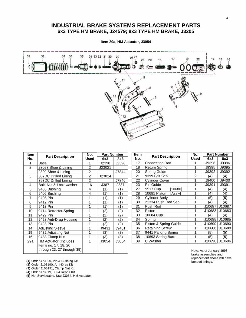
INDUSTRIAL BRAKE SYSTEMS REPLACEMENT PARTS6x3 TYPE HM BRAKE, J24579; 8x3 TYPE HM BRAKE, J3205
Item 29a, HM Actuator, J3054
Part NumberItemNo. Part Description No.
Used 6x3 8x317 Connecting Rod 1 J9396 J939618 Return Spring 1 J9395 J939520 Spring Guide 1 J9392 J939221 9399 Felt Seal 2 (4) (4)22 Cylinder Cover 1 J9400 J940023 Pin Guide 1 J9391 J939127 9517 Cup [10680] 1 (4) (4)28 10681 Piston [Ass’y] 1 (4) (4)29 Cylinder Body 1 (5) (5)30 21334 Push Rod Seal 1 (4) (4)31 Push Rod 1 J10687 J1068732 Piston 1 J10683 J1068333 10684 Cup 1 (4) (4)34 Spring 1 J10685 J1068535 Piston & Spring Guide 1 J10690 J1069036 Retaining Screw 1 J10688 J1068837 9441 Parking Spring 1 (5) (5)38 10693 Spring Barrel 1 (5) (5)39 C Washer 1 J10696 J10696
Part NumberItemNo. Part Description No.
Used 6x3 8x31 Base 1 J2398 J2398
23023 Shoe & Lining 2 J2302122399 Shoe & Lining 2 J7844567DC Drilled Lining 2 J230243393DC Drilled Lining 2 J7846
4 Bolt, Nut & Lock-washer 16 J387 J3875 9405 Bushing 4 (1) (1)6 9406 Bushing 4 (1) (1)7 9408 Pin 1 (1) (1)8 9412 Pin 1 (1) (1)9 9413 Pin 1 (1) (1)
10 9414 Retractor Spring 1 (2) (2)11 9429 Pin 1 (2) (2)12 9428 Anti-Drag Housing 1 (2) (2)13 9423 Pin 1 (2) (2)14 Adjusting Sleeve 1 J9431 J943115 9432 Adjusting Nut 1 (3) (3)16 9433 Clamp Nut 1 (3) (3)29a HM Actuator (Includes
items no. 17, 18, 20through 23, 27 through 39)
1 J3054 J3054
Note: As of January 1993,brake assemblies andreplacement shoes will havebonded linings.(1) Order J73920, Pin & Bushing Kit
(2) Order J105190, Anti-Drag Kit(3) Order J105191, Clamp Nut Kit(4) Order J73919, 3054 Repair Kit(5) Not Serviceable. Use J3054, HM Actuator
4

INDUSTRIAL BRAKE SYSTEMS REPLACEMENT PARTS10x4 TYPE HM BRAKE, J34780
(3) Order J105192, 10” Clamp Nut Kit(4) Standard hardware items. Obtain locally
ItemNo. Part Description No.
Used Part No.
1 Return Spring 2 J81342 Shoe Arm 1 J26823 Actuating Cylinder 1 J234374 6946 Pin 1 (1)5 6943 Pin 3 (1)6 6528 Friction Plug Spring 2 (2)7 6314 Friction Plug 4 (2)8 6942 Pin 4 (1)9 Eye Bolt Bushing 1 J6940
10 6939 Eye Bolt & Bushing 1 J1006911 6953 Pin 1 (1)12 Spring Hook 1 J694513 Spring Hook 1 J694414 2822 Lever & Bushing 1 J804015 7/8-14 Clamp Nut 1 (3)16 8287 Adjusting Nut 1 (3)17 6114 Knuckle & Bushing 1 J1007118 Bushing 2 J694119 Shoe Arm 1 J268120 Shoe Centering Lock Kit 1 J87249
ItemNo. Part Description No.
UsedPartNo.
22 Shoe Centering Spring 1 J812223 Shoe Centering Spring Arm 1 J812024 286DC DrilIed Lining 2 J495425 Bolt, Nut & Lock-washer 16 J23326 6108 Shoe & Lining 2 J611027 Base 1 J268028 8280 Grease Fitting 7 (1)29 9/16-18 Nut 7 (1)30 9/16 Lock-washer 7 (1)31 HM Park Release Cylinder 1 J7946332 Rod End Assembly 1 J799633 Pin 1 J967034 Bracket 1 J966535 1/2-20 x 1-3/8 Cap Screw 1 (4)36 1/2” Lock-washer 1 (4)37 1/2-20 Nut 1 (4)38 5/16-24x1-1/8 Cap Screw 2 (4)39 5/16” Lock-washer 2 (4)40 5/16” Nut 2 (4)41 5/16”-18x1 Allen Head Screw 1 (4)
(1) Order J105197, 10” Hinge Pin Kit(2) Order J105194, 10” Friction Plug Kit
Pin Update: In June of 1992pin design was changed for10”, 14” & 18” brakes. Whenordering new shoes, also ordernew pin. See pages 7 and 8.
Note: As of January1993, brake assembliesand replacement shoeshave bonded linings
5

INDUSTRIAL BRAKE SYSTEMS REPLACEMENT PARTS14x6 TYPE HM J34735; 18x8 TYPE HM J40065
(5) Order J105193, 14’ & 18’ Clamp Nut Kit(6) Order J73922, HM Link Kit(7) Standard hardware Items. Obtain locally.
Note: As of January1993, brake assembliesand replacement shoeshave bonded linings.
Part NumberItemNo. Part Description No.
Used 14x6 18x81 Shoe Arm 1 J2685 J29372 6873 Pin 1 (1) (2)3 Actuating Cylinder 1 J23437 J234374 Return Spring 1 J8135 J81355 6818 Pin 1 (1) (2)6 6528 Friction Plug Spring 2 (3) (4)
6689 Friction Plug 4 (3)76876 Friction Plug 4 (4)6816 Pin 4 (1)86874 Pin 4 (2)
9 Eye Bolt Bushing 1 J6694 J669410 9634 Eye Bolt & Bushing 1 J10068 J1006811 6696 Pin 1 (1) (2)12 Lever 1 J1768 J176813 1”-14 Clamp Nut 1 (5) (5)14 6817 Pin 2 (1) (2)15 Bushing 2 J6693 J669316 5020 Knuckle & Bushing 1 J9637 J963717 9638 Adjusting Nut 1 (5) (5)18 Shoe Arm 1 J2684 J293620 Shoe Centering Lock Kit 1 J87249 J8724921 Shoe Centering Spring 1 J8126 J268622 Centering Spring Arm 2 J8124 J8128
287DC Drilled Lining 1 J123423288DC Drilled Lining 1 J1276
Part NumberItemNo. Part Description No.
Used 14x6 18x824 Bolt, Nut & Lock-washer 16/28 J363 J36325 1225 Shoe & Lining 2 J1235
1799 Shoe & Lining 2 J180326 Base 1 J2683 J293527 Grease Fitting 7 (1) (2)28 Nut 7 (1) (2)29 Lock-washer 7 (1) (2)30 HM Park Release Cylinder 1 J79462 J7946431 Tubular Push Rod 1 J9668 J966832 8354 Pin 2 (6) (6)33 Yoke 1 J7268 J726834 9669 Tie Link 1 (6) (6)35 8352 Connecting Link 2 (6) (6)36 Pin 1 J9670 J967037 Bracket 1 J23434 J2343438 1/2”-20 x 1-3/8” Cap Screw 1 (2) (7)39 1/2” Lock-washer 1 (7) (7)40 1/2”-20 Nut 1 (7) (7)41 5/16”-24 x 1-1/8” Cap Screw 2 (7) (7)42 5/16” Lock-washer 2 (7) (7)43 5/16”-24 Nut 2 (7) (7)44 Spacer 7 (6) (6)45 5/16”-18x1 Allen Head Screw 1 (7) (7)
(1) Order J105196, 14” Hinge Pin Kit(2) Order J105199, 18” Hinge Pin kit(3) Order J105195, 14” Friction Plug Kit(4) Order J105196, 18” Friction Plug Kit
Pin Update: In June of 1992 pin designwas changed for 10W, 14” & 18” brakes.When ordering new shoes, also ordernew pin. See pages 7 and 8.
6

NEW PIN DESIGN FOR 10 X 4, 14 X 6, AND 18 X 8 H & HM BRAKES
The base pin, shoe pin, and arm pin designs for 10 x 4, 14 x 6, and 18 x 8 Type H and HM brakeassemblies have been improved. The following brake assemblies and pin kit numbers have beenaffected:
Size Type Brake No. Pin Kit No.(1) 10x4 H J2926 J105197, J73925, J73926
10x4 HM J34780 J105197, J73925, J73926(2) 14x6 H J2929 J105198, J73927, J73928, J73929
14x6 HM J34735 J105198, J73927, J73928, J7392918x8 H J2932 J105199, J73928, J73929, J7393018x8 HM J40065 J105199, J73928, J73929, J73930
When installing these pins on existing brakes (seven total per brake assembly), it will be necessary toenlarge the present holes to allow the new pins to mount in the appropriate base, top arm, shoe, andshoe arms. Pins are provided with snap rings.
NEW PIN CONSTRUCTION (TYPICAL)
(1) Also applies to J53958 and J107077 (10” H brakes with air release/spring set actuator).(2) Also applies to J53957 (14” H brakes with air release/spring set actuator).
* 1-1/4” for base pins 1” all other pins
BRAKE SIZE PIN DIA.10x4 3/4”14x6 1”*18x8 1” & 1-1/4”
7

NEW PIN DESIGN FOR 10X4, 14X6, AND 18X8 H & HM BRAKES
Please note items 5 and 8 on the illustration below as an example of pin locations.
We have initiated this new pin design in June 1992. New brakes will utilize this new design. The brakebase, top arm, shoe, and shoe arms will also be manufactured for this pin design. If a customerpurchases a replacement brake base, top arm, shoe, or shoe arm to repair an existing brakeassembly, he should also purchase a new pin kit. At that time, the brake assembly can be updated tothe new pin design.
If there are any questions, please contact your local representative or distributor, or consult thefactory.
8

INDUSTRIAL BRAKE SYSTEMS HYDRAULIC ACTUATING CYLINDERSJ7905, J8765, J23437
Three alternate hydraulic actuating cylinders areavailable J7905, 1-1/8” dia. or J23437, 7/8” dia.actuators fit all Gemco Industrial Brakes. J8765, 1-1/8”dia. “short stroke” actuators fit some other non-Gemcobrakes.
Identify assembly from nameplate band on sleeve orfrom dimensions below. These assemblies may besubstituted for some obsolete actuators, some ofwhich include clevis mounting at both ends. Checkmounting dimensions carefully.
ACTUATING CYLINDER ASSY. NO. J23437 J7905 J8765CYLINDER BODY CASTING NO. JFD23438 JFD7985 JFD7985INTERNAL CYLINDER DIA. 7/8” 1-1/8” 1-1/8”OUTSIDE SLEEVE DIA. (X) 1-3/8” 1-5/8” 1-5/8”CLEVIS WIDTH,(Y) 1-1/8” 1-3/8” 1-3/8”COMPRESSED LENGTH (Z) 9-13/16” 9-13/16” 8-1/8”MAX. WORKING STROKE 3” 3” 2-1/2”
REPLACEMENT PARTS LIST
Disassembled view of actuating cylinder.
ACTUATOR CYLINDER ASSY. NO. ITEM J23437 J7905 J87655-9, 11 Repair Kit, J73911 J73912 J739138 Cup (available 10 lot pack only) J23447 J9704 J970411 Boot (available 10 lot pack only) J2395 J2395 J239525 lot pack F17 Gasket J105376 J105376 J10537613 Bleeder Screw Adaptor J7346 J7346 J734614 Bleeder Screw P6446 F6446 F64465, 6, 7, 8 & 11 Seal Kit J98133 J98134 J98134
Replace complete assembly if items 1 or 10 are not serviceabie.
9

INDUSTRIAL BRAKE SYSTEMS REPLACEMENT PARTS(FRB) FLUID RESERVOIR / BLEEDER ASSEMBLY
Assembly No. Solenoid Voltage• Fluid Capacity 2 1/4 qts.
PSD-0180100 110/120 VAC 50/60 Hz • Fluid Type Wagner 21BPSD-O1 801 01 240 VDC • Max. Valve Pressure 1000 PSIPSD-O1 80102 Manual • Conduit Size 1/2”
COMPONENT PARTS LIST AND DIAGRAM
BPB Bleeder Pushbutton Operator
Part No. J10008
OIL TIGHT, surface mounted enclosure with onenormally open momentary contact.
Nameplate Legend.Hyd. Brk. Bleeder
4-MTG HolesFor 10-32 Screws
3/4-14 Conduit Entrance
CHART 12 PSD-0179900 VALVE AND SOLENOID ASSEMBLY - 120 VAC 12 PSD-0179901 VALVE AND SOLENOID ASSEMBLY - 240 VDC 18 9990266200 SCREW DRIVE “U” SIZE 4 X 3/16” LG 27 J010457999 NAMEPLATE FRB UNIT 16 9012038000 LOCKWASHER SPLIT 1/4” 25 9010302400 NUT HEX FIN JAM 1/4-28 24 9010000800 BOLT HEX HD 1/4-28 X 3” LG 23 J008483006 CLAMP REMOTE BLEEDER ASSEMBLY 12 PSD-01799** SEE CHART 1 11 PSD-0179800 RESERVOIR ASSY FRB UNIT 1
ITEM PART NO. DESCRIPTION QTY.
NOTE:PIPE SEALANT SWAK # MS-PTS-250 OR EQUIVALENT TOBE USED ON ALL THREAD JOINTS WHEN ASSEMBLING
10

INDUSTRIAL BRAKE SYSTEMS REPLACEMENT PARTSCONTROL CYLINDERS (J16320 - J17616 - J19907) AND PEDAL (J8219)
The control cylinders below replace equivalent assemblies, which areidentified by the nameplate on the top of the supply tank. SimilarJ17617, 2” diameter control cylinders as well as 2” diameter head &barrels and repair kits are no longer manufactured and must bereplaced by 1 3/4” diameter J17616 control cylinders. J17616 controlcylinders must also replace obsolete 1/4 J8142 and J9337 control
cylinders. However, new 1/2” mounting holes must be drilled to matchthe smaller assembly. Casting numbers are included in the part nametabulation to assist in identification. The head & barrel diameter can bedetermined without removal from control cylinder by measuringextension of “nose.”*
ItemNo. Part Description No.
Used Part No.
1 Filler Plug 1 (10)2 Filler Plug Gasket 1 (10)3 17615 Supply Tank 1
Control Cylinder Assy., less pedal 1 1 1/2” Diameter J16320 1 3/4” Diameter J17616 1 3/4” Diameter (Screened Breather J19907
3a
Replaces Items 28 & 29)4 Shaft 1 J176115 Lever 1 J71586 1/2” Lock-washer 1 (2)7 1/2-20 x 2” Cap Screw 1 (2)8 O Ring 19 Retainer Plate 110 Snap Ring 111 Felt Seal 112 Felt Retainer
J10799 Kit
1Head & Barrel Assy. (Items 14-19a, 27-30) 1 16308 1 1/2” Diameter J16307
13
6911 1 3/4” Diameter J691214 Valve & Seat 1 (4)15 Head & Barrel 116 Retainer Spring 1 (4)17 Piston Cup 1 (4)18 Piston 1 (4)19 Support Ring
J19039 KITor
J19040 KIT
1 (4)
*1.85” = 1 1/2” diameter. Use control cyl. J16320, head & barrel J16307 2.85” = 1 3/4” or 2” diameter. (1 3/4” has X cast on side).
Use control cyl. J17616, head & barrel J6912
18” pedals replace all old assemblies, including 21” and 24” pedals as well as 13 1/4”automotive and pendulum type pedals which are no longer available.
ItemNo. Part Description No.
Used Part No.
19a Piston Stop wire 120 Spring & Case Assy. 1 J1762621 Shaft Pin 122 Sleeve Arbor 123 Spring Case Gasket 1 (8)24 Case Washer 3 (8)25 #10 Lock-washer 3 (8)26 Stainless Allen Screw 3 (8)27 F17 Copper Gasket 5 J10537628 Bleeder Screw Adaptor 1 J734629 Bleeder Screw 1 F644631 1396 Head Gasket 1 (9)32 7/16” Lock-washer 4 (2)33 7/16”-14 x 1 1/4”Cap Screw 4 (2)34 Ped & Assy. 1 J821936 1/2”-20 x 2 1/4” Bolt 1 (2)37 1/2” Lock-washer 1 (2)38 1/2”-20 Nut 1 (2)
(2) Standard hardware items. Obtain locally(4) Use Either Kit J19039 for 1 1/2” Head and Barrel or Kit J19040
for 1 3/4” Head and Barrel (Items 14, 16-19)(8) Order Gasket Kit J73923(9) Included in Item 13, Head & Barrel Assy., or (4) or (5) Head &
Barrel Repair Kits(10) Order J105377 Filler Plug/Gasket Kit
11

INDUSTRIAL BRAKE SYSTEMS REPLACEMENT PARTSTYPE HM PARK RELEASE CYLINDERS
REPLACEMENT PARTS LISTItemNo. Name of Part 10”x4” 14”x6” 18”x8”
Complete Assembly J-79463 J-79462 J-7946421 Mounting Lug J-9681 J-9681 J-96888 Piston Rod Assembly J-23040 J-23041 J-2304134 Piston Rod Guide J-9662 Not Used Not Used35 “C” Washer J-9661 Not Used Not Used
The following parts are used in all the above ReIeasing Cylinder Assemblies:
ItemNo. Name of Part Number Used Part Number
1 Cylinder Body 1 J-147042 Bushing 1 J-96743 9691 Packing Felts 4 *4 Bushing 1 J-96725 10167 ”O” Ring 1 *6 10229 “O” Ring Retainer 1 *7 10231 Felt Washer 1 *9 1733 Gasket 1 *10 Piston Stop Sleeve 1 J-969711 9696 Cup Retainer 1 *12 9694 Cup 1 *13 Piston 1 J-969514 Shake proof Lock-washer 1 *15 14707 Piston Rod Nut 1 *16 Cylinder End 1 J-7946719 9680 Filter Retainer 1 *20 1823 Filter 1 *31 25 lot pack F17 Gasket 1 J-10537632 Bleeder Screw Adaptor 1 J-734633 Bleeder Screw 1 F-6446
* ORDER J73921 HM CYLINDER REPAIR KIT
Exploded view of type HM releasing cylinder after spring andclamp have been removed.
Spring Clamp Tool J-391 (Illustration shows brakesetting spring clamped in tool)
Expanding Drift Tool J-394
Pilot Tool J-392
12

INDUSTRIAL BRAKE SYSTEMS REPLACEMENT PARTSHM CONTROL UNIT, J107206
(Replaces J070930 and J107154)
The HM Control units traps pressure in the HM park releasecylinder circuit when solenoid is energized.
Brake fluid displaced by the control cylinder flows to port A.Beyond that point it divides, part flowing past port A to the servicebrake cylinder and part flowing past the check valve, port B and tothe HM park release brake cylinder. Normal maximum force on thebrake pedal will develop 400 psi to fully compress the parkingspring. If the solenoid is energized the check valve traps thispressure to keep the parking cylinder released even after the pedalforce is released and pressure in line A-A drops back to zero.Subsequent pedal force develops pressure at the service brakecylinder, while the parking brake cylinder remains released as longas the solenoid is energized.
The solenoid consists of 11 5V D.C. coil which is factoryconnected in series with a resistor for 230V DC operation. TheTSRM rectifier is series connected in theDC circuit to suppress any transient voltage surges. If the systemis operated at 11 5V AC, the coil must be re-connected. See wiringdiagrams on the door of thecontrol unit.
Whenever electric power is ON and the parking switch in thecab is CLOSED, the solenoid check valve holds pressure in theparking brake release cylinder. This pressure also operates thenormally open hydraulic pressure switch, which closes above 400psi, when the parking brake should be fully released. The closedpressure switch operates the green signal light in the cab and thedrive motor pilot relay.
If power to the system is disconnected the solenoid checkvalve will release the trapped pressure. The pressure switch willopen below 320 psi-turning the green light OFF and opening themotor pilot relay. The parking brake will reset below 320 psi.
For the HM brake system to function properly.1. The HM park release hydraulic circuit as well as the service
brake hydraulic circuit must be filled with brake fluid and be bledtree of air. The service brake circuit is bled by operating thebleeder, however the parking brake circuit must be bled manually.
2. The HM brake must be properly adjusted. Final brakeadjustment is necessary after the hydraulic circuit is operationaland the parking cylinder can be fully released. When properlyadjusted-one full stroke of the pedal is all that is needed to fully
release the parking brakes for normal service brake operation.3. There can be NO external or internal leaks in the hydraulic system.
Visible external leaks must be corrected.4. The power supply must be ON and there must be 230V or 115V DC
across + and - terminals at the terminal board. The solenoid must beconnected for the correct voltage. Check color code of lead wires carefully.Check operation of the TSRM rectifier.
If all of the above conditions have been checked and are normal, andthe park release cylinder will not stay released then the problem can onlybe a leaking solenoid check valve and/or a leaking HM park releasecylinder.
ITEMNO. PART DESCRIPTION NO.
USED PART NO.
1 N.O. Pressure Switch 1 J0246842 TSRM Rectifier Kit 1 J0710533 1/2 20 Union 3 J0490874 Swivel Fitting 2 F0031635 Solenoid Check Valve Assembly 1 J1071516 Solenoid Only 1 J1071487 Resistor 1 J107149+ Valve Stem with Seals 1 J107156* Conversion Kit 1 J107155
+ Value stem is located within Solenoid Check Valve Assembly.* Conversion Kit includes resistor, washers, fittings and hose
(hose from valve to H cylinder port, valve to HM cylinder port,valve to pressure switch).
NOTE: To modify existing J070930 or J107154 HM Control Unit toJ107206, order J107155 Kit and J107151 Solenoid ValveAssembly.
13
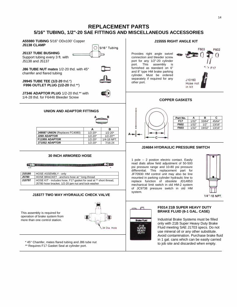
REPLACEMENT PARTS5/16" TUBING, 1/2"-20 SAE FITTINGS AND MISCELLANEOUS ACCESSORIES
J15555 RIGHT ANGLE KITA55980 TUBING 5/16” ODx100’ CopperJ5138 CLAMP
J5137 TUBE BUSHINGSupport tubing every 3 ft. withJ5138 and J5137
J86 TUBE NUT mates 1/2-20 thd. with 45°chamfer and flared tubing
J9945 TUBE TEE (1/2-20 thd.*) F996 OUTLET PLUG (1/2-20 thd.**)
J7346 ADAPTOR PLUG 1/2-20 thd.** with1/4-28 thd. for F6446 Bleeder Screw
COPPER GASKETS
UNION AND ADAPTOR FITTINGS
J24684 HYDRAULIC PRESSURE SWITCH
30 INCH ARMORED HOSE
J18377 TWO WAY HYDRAULIC CHECK VALVE
* 45° Chamfer, mates flared tubing and J86 tube nut** Requires F17 Gasket Seal at cylinder port.
A BJ49087 UNION (Replaces FC4080) 1/2-20* 1/2-20*J269 ADAPTOR 1/2-20* 1/2-20**F11955 ADAPTOR 1/2-20* 1/4-18 NPT.J71052 ADAPTOR 1/2-20* 7/16-24
J10160 HOSE ASSEMBLY - onlyJ5780 HOSE BRACKET - anchors hose at * long threadJ10797 HOSE KIT - includes hose, F17 gasket for seal at ** short thread,
J5780 hose bracket, 1/2-20 jam nut and lock-washer
This assembly is required foroperation of brake system frommore than one control station.
Part No. A B CF17 1/32” 33/64” 45/64"F602 1/32” 1/2” 13/16”F603 1/32” 19/32” 13/16”
F9314 21B SUPER HEAVY DUTYBRAKE FLUID (6-1 GAL. CASE)
Industrial Brake Systems must be filledonly with 21B Super Heavy Duty BrakeFluid meeting SAE J1703 specs. Do notuse mineral oil or any other substitute.Avoid contamination. Purchase brake fluidin 1 gal. cans which can be easily carriedto job site and discarded when empty.
14
Provides right angle swivelconnection and bleeder screwport for any 1/2”-20 cylinderport. This assembly isfurnished as standard on 6”and 8” type HM brake parkingcylinder. Must be orderedseparately if required for anyother port.
1 pole -- 2 postion electric contact. Easilyread dials allow field adjustment of 50-500psi pressure range and 10-80 psi pressuredifferential. This replacement part forJF70930 HM control unit may also be linemounted in parking cylinder hydraulic line toreplace function of obsolete JD14853mechanical limit switch in old HM-2 systemof JC9738 pressure switch in old HMsystem.
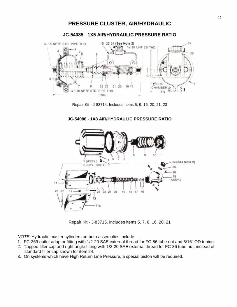
PRESSURE CLUSTER, AIR/HYDRAULIC
JC-54085 - 1X5 AIR/HYDRAULIC PRESSURE RATIO
Repair Kit - J-83714. Includes items 5, 9, 16, 20, 21, 23
JC-54086 - 1X8 AIR/HYDRAULIC PRESSURE RATIO
Repair Kit - J-83715. Includes items 5, 7, 8, 16, 20, 21
NOTE: Hydraulic master cylinders on both assemblies include:1. FC-269 outlet adaptor fitting with 1/2-20 SAE external thread for FC-86 tube nut and 5/16” OD tubing.2. Tapped filler cap and right angle fitting with 1/2-20 SAE external thread for FC-86 tube nut, instead of
standard filler cap shown for item 24.3. On systems which have High Return Line Pressure, a special piston will be required.
15

MOISTURE EJECTION VALVE J107084
This valve automatically keeps air reservoirs clean and dry. Each brake application causes a small volumeof air and any accumulated moisture from the air supply tank to fill the valve chamber. This is expelled toatmosphere when application pressure is released.
VALVE SERVICE
Periodically open the air supply tank drain cock. A relatively clean discharge of air indicates that the valve isfunctioning properly.
A constant air leakage from the exhaust port during application period indicates a defective seal.
To repair the valve, obtain repair kit J107085. Drain the system. To vent or drain system, pull cord attachedto valve. Completely disassemble the valve, inspect and clean the valve body. Reassemble the valve usingnew parts Items 2, 4, 5, & 6. Tighten nuts as shown. Change filter. Reinstall valve in unit.
PARTS DESCRIPTIONItem No. Description Quantity
1 Valve Body 12 “O” Ring 13 Cover 14 Piston Assembly 15 Retaining Ring 16 Screen 17 Screw 4
Repair Kit J107085 contains Items 2, 4, 5 & 6.
TYPICAL INSTALLATION OF VALVE ON A/H ERC PANEL
16
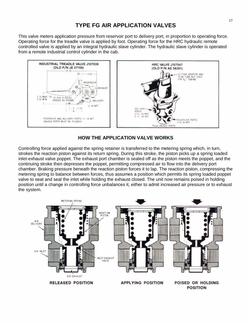
TYPE FG AIR APPLICATION VALVES
This valve meters application pressure from reservoir port to delivery port, in proportion to operating force.Operating force for the treadle valve is applied by foot. Operating force for the HRC hydraulic remotecontrolled valve is applied by an integral hydraulic slave cylinder. The hydraulic slave cylinder is operatedfrom a remote industrial control cylinder in the cab.
HOW THE APPLICATION VALVE WORKS
Controlling force applied against the spring retainer is transferred to the metering spring which, in turn,strokes the reaction piston against its return spring. During this stroke, the piston picks up a spring loadedinlet-exhaust valve poppet. The exhaust port chamber is sealed off as the piston meets the poppet, and thecontinuing stroke then depresses the poppet, permitting compressed air to flow into the delivery portchamber. Braking pressure beneath the reaction piston forces it to lap. The reaction piston, compressing themetering spring to balance between forces, thus assumes a position which permits its spring loaded poppetvalve to seat and seal the inlet while holding the exhaust closed. The unit now remains poised in holdingposition until a change in controlling force unbalances it, either to admit increased air pressure or to exhaustthe system.
17
TYPE FG AIR APPLICATION VALVES
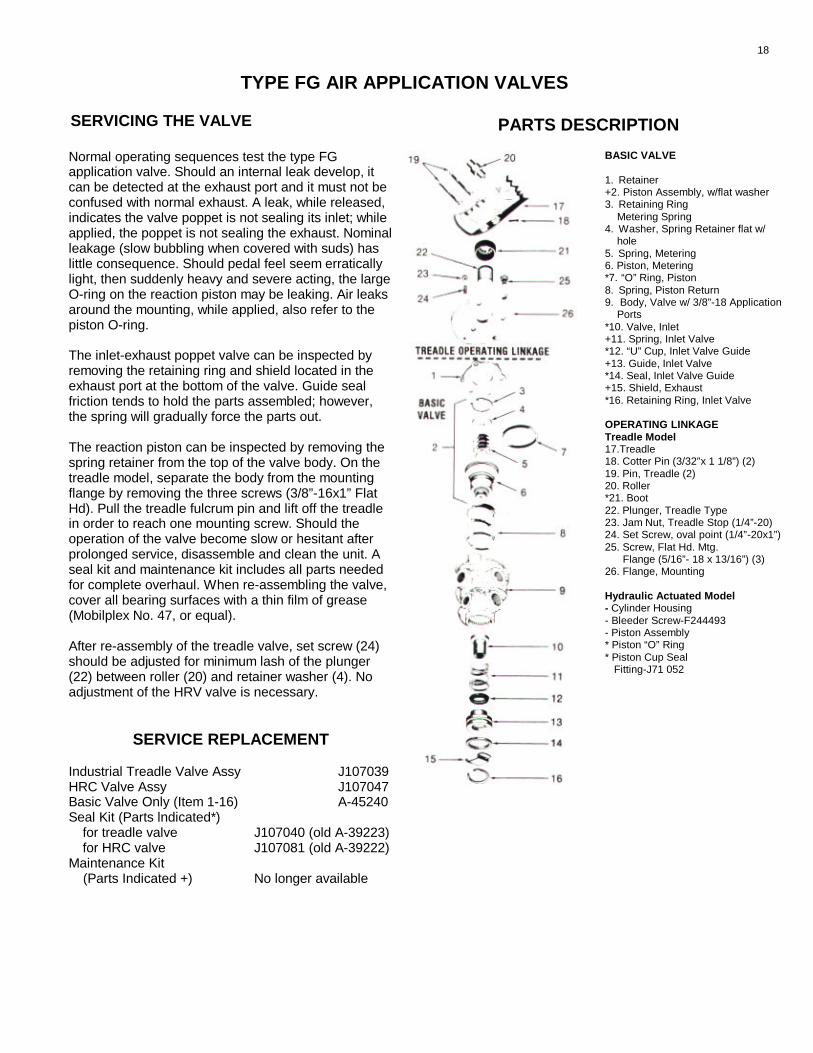
SERVICING THE VALVE PARTS DESCRIPTION
Normal operating sequences test the type FGapplication valve. Should an internal leak develop, itcan be detected at the exhaust port and it must not beconfused with normal exhaust. A leak, while released,indicates the valve poppet is not sealing its inlet; whileapplied, the poppet is not sealing the exhaust. Nominalleakage (slow bubbling when covered with suds) haslittle consequence. Should pedal feel seem erraticallylight, then suddenly heavy and severe acting, the largeO-ring on the reaction piston may be leaking. Air leaksaround the mounting, while applied, also refer to thepiston O-ring.
The inlet-exhaust poppet valve can be inspected byremoving the retaining ring and shield located in theexhaust port at the bottom of the valve. Guide sealfriction tends to hold the parts assembled; however,the spring will gradually force the parts out.
The reaction piston can be inspected by removing thespring retainer from the top of the valve body. On thetreadle model, separate the body from the mountingflange by removing the three screws (3/8”-16x1” FlatHd). Pull the treadle fulcrum pin and lift off the treadlein order to reach one mounting screw. Should theoperation of the valve become slow or hesitant afterprolonged service, disassemble and clean the unit. Aseal kit and maintenance kit includes all parts neededfor complete overhaul. When re-assembling the valve,cover all bearing surfaces with a thin film of grease(Mobilplex No. 47, or equal).
After re-assembly of the treadle valve, set screw (24)should be adjusted for minimum lash of the plunger(22) between roller (20) and retainer washer (4). Noadjustment of the HRV valve is necessary.
SERVICE REPLACEMENT
Industrial Treadle Valve Assy J107039HRC Valve Assy J107047Basic Valve Only (Item 1-16) A-45240Seal Kit (Parts lndicated*)
for treadle valve J107040 (old A-39223)for HRC valve J107081 (old A-39222)
Maintenance Kit(Parts Indicated +) No longer available
BASIC VALVE
1. Retainer+2. Piston Assembly, w/flat washer3. Retaining Ring
Metering Spring4. Washer, Spring Retainer flat w/
hole5. Spring, Metering6. Piston, Metering*7. “O” Ring, Piston8. Spring, Piston Return9. Body, Valve w/ 3/8”-18 Application
Ports*10. Valve, Inlet+11. Spring, Inlet Valve*12. “U” Cup, Inlet Valve Guide+13. Guide, Inlet Valve*14. Seal, Inlet Valve Guide+15. Shield, Exhaust*16. Retaining Ring, Inlet Valve
OPERATING LINKAGETreadle Model17.Treadle18. Cotter Pin (3/32”x 1 1/8”) (2)19. Pin, Treadle (2)20. Roller*21. Boot22. Plunger, Treadle Type23. Jam Nut, Treadle Stop (1/4”-20)24. Set Screw, oval point (1/4”-20x1”)25. Screw, Flat Hd. Mtg.
Flange (5/16”- 18 x 13/16”) (3)26. Flange, Mounting
Hydraulic Actuated Model- Cylinder Housing- Bleeder Screw-F244493- Piston Assembly* Piston “O” Ring* Piston Cup Seal
Fitting-J71 052
18

INDUSTRIAL BRAKE SYSTEMSEE BLEED DOWN TYPE RELAY EMERGENCY VALVE J 58860
This valve controls pressure to the service brake pressurecluster on type A/H, A/H-HRC, and A/H-ERC systems. Itapplies pressure from the right half of the horizontal reservoir.Whenever emergency port E is pressurized above 50 psi,reservoir port R pressure is poised for application to deliveryport D at whatever pressure is applied to service port S.Without pressure at the service port, no pressure is applied tothe delivery port.
Whenever emergency port pressure drops below 40 psi,pressure at the reservoir port is applied to the delivery port.Hence the valve applies pressure to the service brakepressure cluster in “emergencies” although a tiny “bleed downby-pass” bleeds delivery port pressure through the service port. After several hours the “emergency” brake pressure isfully released.
HOW THE VALVE WORKS
SYSTEM IDLE In the idle condition, emergency port pressure is off, reservoirport is open to delivery port. Service brake pressure cluster is applied ifreservoir pressure is available. The check valve has no function and is closedpermanently. With no emergency pressure, the emergency piston and valvecartridge is held in by spring force and the exhaust poppet closes service portwhile the inlet poppet opens a passage to the relay piston. Pressure on therelay piston forces it down against spring force, sealing the inlet-exhaustpoppet and opening reservoir port to delivery port. A bleed down by pass slowlyvents reservoir pressure to the service port to prevent service pressure clusterapplication for extended periods.
SYSTEM NORNAL When emergency port is pressurized, 65-80 psicompressor pressure forces the emergency piston and valve out against springforce, pulling the exhaust poppet open and the inlet poppet closed. With nopressure at the service port, the return spring forces the relay piston up,allowing relay inlet-exhaust poppet to seal reservoir port and open delivery portto exhaust port. Service pressure cluster is released.
SERVICE STOP When service port is pressurized pressure strokes the relaypiston against spring force. The piston picks up the relay inlet-exhaust poppetvalve, first closing the exhaust passage and then unseating the poppet to openreservoir port to delivery port. When the force on the relay piston balancesopposing spring forces, the piston is forced to lap, permitting the spring loadedrelay inlet-exhaust poppet to close while holding the exhaust passage sealed.The valve remains poised in this “hold” position, relaying delivery port pressureequal to service port pressure.
EMERGENCY STOP Reduction of emergency port pressure below 40 psitriggers the valve to apply reservoir pressure, as described in System Idledescription above.
VALVE PORTSE — Emerg. Air LineS — Service Air LineR — ReservoirD — Delivery Ports
19
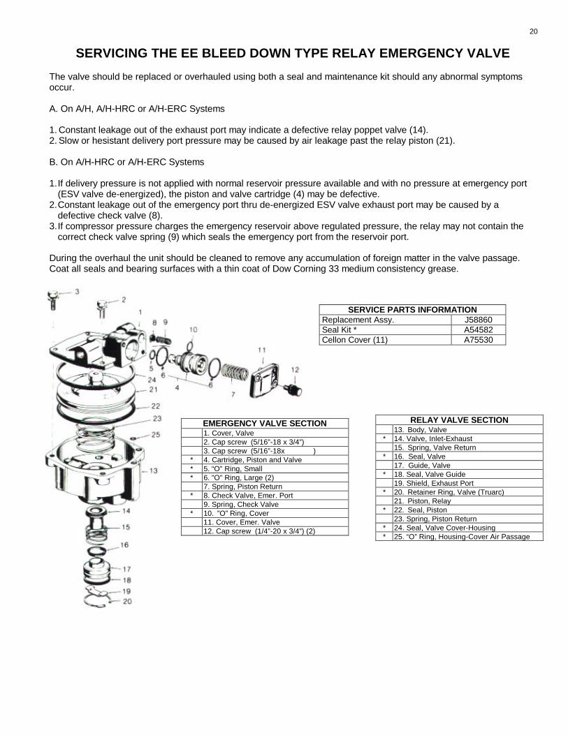
SERVICING THE EE BLEED DOWN TYPE RELAY EMERGENCY VALVE
The valve should be replaced or overhauled using both a seal and maintenance kit should any abnormal symptomsoccur.
A. On A/H, A/H-HRC or A/H-ERC Systems
1. Constant leakage out of the exhaust port may indicate a defective relay poppet valve (14).2. Slow or hesistant delivery port pressure may be caused by air leakage past the relay piston (21).
B. On A/H-HRC or A/H-ERC Systems
1.If delivery pressure is not applied with normal reservoir pressure available and with no pressure at emergency port(ESV valve de-energized), the piston and valve cartridge (4) may be defective.
2.Constant leakage out of the emergency port thru de-energized ESV valve exhaust port may be caused by adefective check valve (8).
3.If compressor pressure charges the emergency reservoir above regulated pressure, the relay may not contain thecorrect check valve spring (9) which seals the emergency port from the reservoir port.
During the overhaul the unit should be cleaned to remove any accumulation of foreign matter in the valve passage.Coat all seals and bearing surfaces with a thin coat of Dow Corning 33 medium consistency grease.
SERVICE PARTS INFORMATIONReplacement Assy. J58860Seal Kit * A54582Cellon Cover (11) A75530
EMERGENCY VALVE SECTION1. Cover, Valve2. Cap screw (5/16”-18 x 3/4”)3. Cap screw (5/16”-18x )
* 4. Cartridge, Piston and Valve* 5. “O” Ring, Small* 6. ”O” Ring, Large (2)
7. Spring, Piston Return* 8. Check Valve, Emer. Port
9. Spring, Check Valve* 10. ”O” Ring, Cover
11. Cover, Emer. Valve12. Cap screw (1/4”-20 x 3/4”) (2)
RELAY VALVE SECTION13. Body, Valve
* 14. Valve, Inlet-Exhaust15. Spring, Valve Return
* 16. Seal, Valve17. Guide, Valve
* 18. Seal, Valve Guide19. Shield, Exhaust Port
* 20. Retainer Ring, Valve (Truarc)21. Piston, Relay
* 22. Seal, Piston23. Spring, Piston Return
* 24. Seal, Valve Cover-Housing* 25. “O” Ring, Housing-Cover Air Passage
20

INDUSTRIAL BRAKE SYSTEMSREPLACEMENT PARTS PROTECTION VALVE A24912
The protection valve is a pilot operated check valve, used inconjunction with a timer valve, to coordinate application of parkingbrakes in type AHM-HRC and AHM-ERC system panels. Withnormal minimum 65 psi. pressure at control port B, service brakeports E to D and parking brake release ports A to C are open.When pressure at B drops to 40 psi., the valve closes port A to Cand exhausts C. When pressure at B drops to 30 psi., the valvecloses port E to D and exhausts D.
SERVICING THE VALVE
The valve must be replaced if it should fail to activate combination braking or should a consistent air leakdevelop at the exhaust port.
REPLACEMENT UNITS A24912
1. Valve Body2. Springtite Cap Screw (4 used) (10-24x7/8)3. Cap, Inlet4. Diaphragm5. Plunger Assy6. “O” Ring7. Spring8. Clip, Retainer9. Retainer, Spring10. Spring11. Valve Assy., Exhaust
12. Springtite Cap Screw (2 used) (1/4-20x3/4)13. Cap, Application14. Gasket15. Valve Assy., Inlet16. Spring17. Valve Guide18. “O” Ring19. “O” Ring20. Spring21. Valve and Seat Assy.
21

INDUSTRIAL BRAKE SYSTEMSEE RELAY EMERGENCY VALVE A71891
This valve controls pressure to the service brake pressure cluster on typeA/HM-HRC and A/HM-ERC systems supplied after September, 1978. Itapplies pressure from the right half of the horizontal reservoir. Wheneveremergency port is pressurized above 50 psi, reservoir port R is poised forapplication to delivery port D at whatever pressure is applied to serviceport S. Without pressure at the service port*, no pressure is applied to thedelivery port.
Whenever emergency port pressure drops below 40 psi, pressure at thereservoir port is applied tothe delivery port. Hence the valve applies pressure to the service brakepressure cluster in “emergencies”.
* Service port is not used on A/HM-HRC systems and must always be open to atmosphere.
HOW THE VALVE WORKS
SYSTEM IDLE In the idle condition, emergency port pressure is off, reservoirport is open to delivery port. Service brake pressure cluster is applied ifreservoir pressure is available. The check, valve has no function and isclosed permanently. With no emergency pressure, the emergency piston andvalve cartridge is held in by spring force and the exhaust poppet closesservice port while the inlet poppet opens a passage to the relay piston.Pressure on the relay piston forces it down against spring force, sealing theinlet-exhaust poppet and opening reservoir port to delivery port.
SYSTEM NORMAL When emergency port is pressurized, 65-80 psicompressor pressure forces the emergency piston and valve out againstspring force, pulling the exhaust poppet open and the inlet poppet closed.With no pressure at the service port, the return spring forces the relay pistonup, allowing relay inlet-exhaust poppet to seal reservoir port and opendelivery port to exhaust port. Service pressure cluster is released.
SERVICE STOP (AHM-ERC Systems only) When service port is pressurized,pressure strokes the relay piston against spring force. The piston picks up therelay inlet-exhaust poppet valve, first closing the exhaust passage and thenunseating the poppet to open reservoir port to delivery port. When the forceon the relay piston balances opposing spring forces, the piston is forced tolap, permitting the spring loaded relay inlet-exhaust poppet to close whileholding the exhaust passage sealed. The valve remains poised in this “hold”position, relaying delivery port pressure equal to service port pressure.
EMERGENCY STOP Reduction of emergency port pressure below 40 psitriggers the valve to apply reservoir pressure, as described in System Idledescription above.
VALVE PORTSE — Emerg. Air LineS — Service Air LineR — ReservoirD — Delivery Ports
22

SERVICING THE EE RELAY EMERGENCY VALVE
The valve should be replaced or overhauled using both a seal and maintenance kit should any abnormal symptomsoccur.
1.Constant leakage out of the exhaust port may indicate a defective relay poppet valve (14).
2.Slow or hesistant delivery port pressure may be caused by air leakage past the relay piston (21).
3.If delivery pressure is not applied with normal reservoir pressure available and with no pressure at emergencyport (ESV valve de-energized), the piston and valve cartridge (4) may be defective.
4.Constant leakage out of the emergency port thru de-energized ESV valve exhaust port may be caused by adefective check valve (8).
5.If compressor pressure charges the emergency reservoir above regulated pressure, the relay may not containthe correct check valve spring (9) which seals the emergency port from the reservoir port.
During the overhaul the unit should be cleaned to remove any accumulation of foreign matter in the valve passage.Coat all seals and bearing surfaces with a thin coat of Dow Corning 33 medium consistency grease.
SERVICE PARTS INFORMATIONReplacement Assy. A 71891Seal Kit * A 54582Cellon Cover (11) A 75530
EMERGENCY VALVE SECTION1. Cover, Valve2. Cap screw (5/16”-18 x 3/4”)3. Cap screw (5/16”-18 x 3/4 “)
* 4. Cartridge, Piston and Valve* 5. “O” Ring, Small* 6. ”O” Ring, Large (2)
7. Spring, Piston Return* 8. Check Valve, Emer. Port
9. Spring, Check Valve* 10. ”O” Ring, Cover
11. Cover, Emer. Valve12. Cap screw (1/4”-20 x 3/4”) (2)
RELAY VALVE SECTION13. Body, Valve
* 14. Valve, Inlet-Exhaust15. Spring, Valve Return
* 16. Seal, Valve17. Guide, Valve
* 18. Seal, Valve Guide19. Shield, Exhaust Port
* 20. Retainer Ring, Valve (Truarc)21. Piston, Relay
* 22. Seal, Piston23. Spring, Piston Return
* 24. Seal, Valve Cover-Housing
* 25. “O” Ring, Housing-Cover AirPassage
23

INDUSTRIAL BRAKE SYSTEMS REPLACEMENT PARTSAIR COMPRESSOR AND MOTOR ASSEMBLY
COMPRESSORASSY. NO. MOTOR HP MOTOR VOLTAGE MOTOR
PULLEY PDBELTLENGTH
J-70941 3/4 550v, 3 ph, 60 HZ 3.9” 51”J-70942* 3/4 460v, 3 ph, 60 HZ 3.9" 51”J-70943 3/4 230v, D.C. 3.9” 51”
*J-70942 Is Also Suitabte For Use On 380v, 3 ph, 50 HZ.
Compressor service parts should be ordered from local Quincy authorized Service Depot, indicating compressormodel, record of change and se rial number, from compressor nameplate. Principle Quincy parts references are asfollows:
Head, Crankcase, Cylinder, & Flywheel Assy. (Includes Items 2 & 3) 206L 1Hydraulic Unloader Valve Assembly 7970X 1Intake Valve Unloader Assembly 6547X 2Compressor Base 2044 1Belt (51”-B Section) 8138 1Belt Guard 5343x1 13.9” P.D. Motor Pulley (5/8” Bore - 3/16” Key Slot ) 6768-58 1Intake Filter (Oil Bath Type) 4509 1
24

INDUSTRIAL BRAKE SYSTEMSREPLACEMENT PARTS TYPE A/H-ERC CONTROL PANELS
8:1 Ratio A. C. Panel - J-70970 8:1 Ratio D. C. Panel - J-709725:1 Ratio A. C. Panel - J-70971 5:1 Ratio D. C. Panel - J-70973
Item Name of Part Part No.1. Pressure Switch J780612. Safety Valve A28
Gauge 1/4” Bottom Conn. J293493. 1/8” Back Conn. A2226
4. Moisture Ejection Valve J1070845. Drain Cock A20916. Pressure Regulator/Gauge A64132 / A22267. Relay Emergency Valve J588608. Dual Air Reservoir A499749. One Way Check Valve A26710. Pressure Cluster - 5:1 Ratio J5408510a. Pressure Cluster - 8:1 Ratio J5408611. Solenoid Valve (115V, 60HZ) J4019411a. Solenoid Valve (230V, D.C.) J40193
A.C. Panels D.C. PanelsSolenoid valve, coil (Honeywell) 71315SN2GV00N0C111P3 71315SN2GV00N0C111C8Control relay (Allen Bradley) 700F220A1 700DCF220Z25Motor starter (Allen Bradley) 100-A09ND3 100A12NZ253Starter overload coil (Allen Bradley) 193BSB60 193BSB60Control transformer (Osborne) U57313TFTransformer fuse (Buss No.) FRN 2 1/2
25
Replacement electrical parts should be ordered from themanufacturers’ local distributor. Electrical parts used on panelsare listed for reference only as follows:

TYPE A/H-ERC CONTROL PANELS
Item Name of Part Part No.1. Pressure Switch J780612. Gauge A - 1/4”Bottom Conn. J29349
B - 1/8” Back Conn. A22263. Pressure Regulator/Gauge A64132 / A22264. Pressure Cluster - 5:1 Ratio J540854a. Pressure Cluster - 8:1 Ratio J540865. Relay Emergency Valve J588606. Dual Air Reservoir A499747. Safety Valve A2288. Single Air Reservoir A357809. Moisture Ejection Valve (Now modified) J10708410. Solenoid Valve (115V, 60HZ) J4019410a. Solenoid Valve (230V, D.C.) J4019311. One Way Check Valve A267
Replacement electrical parts should be ordered from the manufacturer’s local distributor. Electrical parts used on panels are listed forreference only as follows:
A.C. Panels D.C. PanelsSolenoid valve, coil (Honeywell) 71315SN2GV00N0C111P3 71315SN2GV00N0C11108Control relay (Allen Bradley) 700F220A1 700DCF220Z25Motor starter (Allen Bradley) 100-A09ND3 100A12NZ253Starter overload coil (Allen Bradley) 193BSB60 193BSB60Control transformer (Osborne) U57313TFTransformer fuse (Buss No.) FRN 2 1/2
For Four Brake Systems8:1 Ratio A. C. Panel- J-709825:1 Ratio A. C. Panel - J-709838:1 Ratio D. C. Panel - J-709865:1 Ratio D. C. Panel - J-70987
For One or Two Brake Systems8:1 Ratio A. C. Panel - J-709805:1 Ratio A. C. Panel - J-709818:1 Ratio D. C. Panel - J-709845:1 Ratio D. C. Panel - J-70985
26

TYPE A/H-HRC CONTROL PANELS
For One or Two Brake Systems8:1 Ratio A. C. Panel - J-710205:1 Ratio A. C. Panel - J-710218:1 Ratio D. C. Panel - J-710245:1 Ratio D. C. Panel - J-71025
For Four Brake Systems8:1 Ratio A. C. Panel - J-710225:1 Ratio A. C. Panel - J-710238:1 Ratio D. C. Panel - J-710265:1 Ratio D. C. Panel - J-71027
Item Name of Part Part No.1. Pressure Switch J 80612. Gauge (A - 1/4” Bottom Conn., B - 1/8” Back Conn.) J 9349 / A22263. Dual Air Reservoir A499744. Bleeding Control Valve A887405. Pressure Cluster - 5:1 Ratio J540855a. Pressure Cluster - 8:1 Ratio J540866. Hydraulic Controlled Air Valve J1070477. Relay Emergency Valve J588608. Pressure Regulator A641329. Two-Way Air Check Valve A3292210. Safety Valve A22811. Single Air Reservoir A3578012. Moisture Ejection Valve (Now modified) J10708413. Solenoid Valve (115V, 60HZ) J4019413a. Solenoid Valve (230V, D.C.) J4019314. One Way Check Valve A267
Replacement electrical parts should be ordered from the manufacturer’s local distributor. Electrical parts used on panels are listed for reference onlyas follows:
A.C. Panels D.C. PanelsSolenoid valve, coil (Honeywell) 7131 5SN2GV00N0C111 P3 71315SN2GV00N0C11108Control relay (Allen Bradley) 700F220A1 700DCF220Z25Motor starter (Allen Bradley) 100-A09ND3 100A12NZ253Starter overload coil (Allen Bradley) 193BSB60 193BSB60Control transformer (Osborne) U57313TFTransformer fuse (Buss No.) FRN 2 1/2
27

INDUSTRIAL BRAKE SYSTEMSREPLACEMENT PARTS DATA TYPE AH-ARC CONTROL PANELS
For One or Two Brake Systems8:1 Ratio A. C. Panel - J-896605:1 Ratio A. C. Panel - J-896618:1 Ratio D. C. Panel - J-896645:1 Ratio D. C. Panel - J-89665
For Four Brake Systems8:1 Ratio A. C. Panel - J-896625:1 Ratio A. C. Panel - J-896638:1 Ratio D. C. Panel - J-896665:1 Ratio D. C. Panel - J-89667
Item Name of Part Part No.1. Pressure Switch J780612. Gauge J293493. Dual Air Reservoir A499744. NC Bleed Valve A887405. Pressure Cluster - 5:1 Ratio J540855a. Pressure Cluster - 8:1 Ratio J540866. Two-Way Air Check Valve A329227. Relay Emergency Valve J588608. One Way Check Valve A2679. Safety Valve A22810. Single Air Reservoir A3578011. Moisture Ejection Valve (Now modified) J10708412. Drain Valve A2091
Replacement electrical parts should be ordered from the manufacturer’s local distributor. Electrical parts used on panels are listed for referenceonly as follows:
A.C. Panels D.C. PanelsSolenoid valve, coil (Honeywell) 71315SN2GV00N0C111P3 71315SN2GV00N0C111C8Control relay (Allen Bradley) 700F220A1 700DCF220Z25Motor starter (Allen Bradley) 100-A09ND3 100A12NZ253Starter overload coil (Allen Bradley) 193BSB60 193BSB60Control transformer (Osborne) U57313TFTransformer fuse (Buss No.) FRN 2 1/2
28

INDUSTRIAL BRAKE SYSTEMSREPLACEMENT PARTS LIST TYPE A/HM-ERC CONTROL PANEL
J 100650 - 100661 are panel assemblies onlyJ 103650 - 103661 are panel assemblies in enclosure
Item Name of Part Part No.1. Pressure Switch J780612. QR Valve J1070433. Restrictor Valve J1071284. Check Valve A1005965. Service Brake Cluster - 5:1 Ratio J540855a. Service Brake Cluster - 8:1 Ratio J540866. Park Release Cluster J540867. Hydraulic Controlled Air Valve J1070478. Relay Emergency Valve A718919. Pressure Regulator A6413210. Dual Air Reservoir A4997411. Protection Valve A2491212. Two-Way Check Valve A3292213. Safety Valve A22814. Gauge (1/4" Bottom Connection) J2934915. Parking Bleed Valve A8874016. Moisture Valve (Now modified) J10708417. Single Reservoir A3578018. Emergency Brake Solenoid Valve DC J4019318a. Emergency Brake Solenoid Valve AC J4019419. One Way Check Valve A 26720. Drain Valve A 209121. Gauge (1/8” Back Connection) A 2226
Replacement electrical parts should be ordered from the manufacturer’s local distributor. Electrical parts used on panels are listed for reference onlyas follows:
A.C. Panels D.C. PanelsSolenoid valve, coil (Honeywell) 71315SN2GV00N0C111P3 71315SN2GV00N0C111C8Control relay (Allen Bradley) 700F220A1 700DCF220Z25Motor starter (Allen Bradley) 100-A09ND3 100A12NZ253Starter overload coil (Allen Bradley) 193B5B60 193BSB60Control transformer (Osborne) U57313TFTransformer fuse (Buss No.) FRN 2 1/2
ONE OR TWO BRAKE SYSTEMS8:1 Ratio A.C. - J 100630 or 1036505:]. Ratio A.C. - J 100651 or 1036518:1 Ratio D.C. - J 100656 or 1036365:1 Ratio D.C. - J 100637 or 103657
FOUR BRAKE SYSTEMS8:1 Ratio A.C. - J 100652 or 1036525:1 Ratio A.C. - J 100633 or 1036338:1 Ratio D.C. - J 100658 or 1036585:1 Ratio D.C. - J 100659 or 103659
FOUR BRAKE W/TWO BRAKE PARKING8:1 Ratio A.C. - J 100654 or 1036545:1 Ratio A.C. - J 100655 or 1036558:1 Ratio D.C. - J 100660 or 1036605:1 Ratio D.C. - J 100661 or 103661
29

INDUSTRIAL BRAKE SYSTEMSREPLACEMENT PARTS LIST TYPE A/HN-HRC CONTROL PANEL
Item Name of Part Part No.1. Pressure Switch J780612. OR Valve J1070433. Restrictor Valve J1071284. Check Valve A1005965. Service Brake Cluster - 5:1 Ratio J540855a. Service Brake Cluster - 8:1 Ratio J540866. Park Release Cluster J540867. Hydraulic Controlled Air Valve J1070478. Relay Emergency Valve A718919. Pressure Regulator A6413210. Dual Air Reservoir A4997411. Protection Valve A2491212. Two-Way Check Valve A3292213. Safety Valve A22814. Gauge J2934915. Parking Bleed Valve A8874016. Moisture Valve (Now modified) J10708417. Single Reservoir A3578018. Emergency Brake Solenoid Valve DC J4019318a. Emergency Brake Solenoid Valve AC J4019419. One Way Check Valve A26720. Drain Valve A2091
A.C. Panels D.C. PanelsSolenoid valve, coil (Honeywell) 71315SN2GV00N0C111P3 71315SN2GV00N0C111C8Control relay (Allen Bradley) 700F220A1 700DCF220Z25Motor starter (Allen Bradley) 100-A09ND3 100A12NZ253Starter overload coil (Allen Bradley) 193BSB60 193BSB60Control transformer (Osborne) U57313TFTransformer fuse (Buss No.) FRN 2 1/2
J 100330 - 100341 are panel assembliesJ 103330 - 103341 are panel assemblies in enclosure
ONE OR TWO BRAKE SYSTEMS8:1 Ratio A.C. - J 100330 or 1033305:1 Ratio A.C. - J 100331 or 1033318:1 Ratio D.C. - J 100336 or 1033365:1 Ratio D.C. - J 100337 or 103337
FOUR BRAKE SYSTEMS8:1 Ratio A.C. - J 100332 or 1033325:1 Ratio A.C. - J 100333 or 1033338:1 Ratio D.C. - J 103338 or 1033385:1 Ratio D.C. - J 100339 or 103339
FOUR BRAKE W/TWO BRAKE PARKING8:1 Ratio A.C.- J 100334 or 1033345:1 Ratio A.C. - J 100335 or 1033358:1 Ratio D.C. - J 100340 or 1033405:1 Ratio D.C. - J 100341 or 103341
Replacement electrical parts should be ordered from themanufacturer’s local distributor. Electrical parts used onpanels are listed for reference only as follows:
30

INDUSTRIAL BRAKE SYSTEMSREPLACEMENT PARTS LIST TYPE A/EM ARC CONTROL PANEL
J 104400 - 104411 are panel assemblies onlyJ 104424 - 104435 are panel assemblies in enclosure
Item Name of Part Part No.1. Pressure Switch J780612. QR Valve J1070433. Restrictor Valve J1071284. Check Valve A1005965. Service Brake Cluster - 5:1 Ratio J540855a. Service Brake Cluster - 8:1 Ratio J540866. Park Release Cluster J540867. Relay Valve A788808. Relay Emergency Valve A718919. Pressure Regulator A6413210. Dual Air Reservoir A4997411. Protection Valve A2491212. Two-Way Check Valve A3292213. Safety Valve A22814. Gauge J2934915. Parking Bleed Valve A8874016. Moisture Valve (Now modified) J10708417. Single Reservoir A3578018. Emergency Brake Solenoid Valve DC J4019318a. Emergency Brake Solenoid Valve AC J4019419, One Way Check Valve A26720. Drain Valve A2091
A.C. Panels D.C. PanelsSolenoid valve, coil (Honeywell) 71315SN2GV00N0C111P3 71315SN2GV00N0C111C8Control relay (Allen Bradley) 700F220A1 700DCF220Z25Motor starter (Allen Bradley) 100-A09ND3 100A12NZ253Starter overload coil (Allen Bradley) 193BSB60 193BSB60Control transformer (Osborne) U57313TFTransformer fuse (Buss No.) FRN 2 1/2
Replacement electrical parts should be ordered from themanufacturer’s local distributor. Electrical parts used onpanels are listed for reference only as follows:
ONE OR TWO BRAKE SYSTEMS8:1 Ratio A.C. - J 104400 or 1044245:1 Ratio A.C. - J 104401 or 1044258:1 Ratio D.C. - J 104406 or 1044305:1 Ratio D.C. - J 104407 or 104431
FOUR BRAKE SYSTEMS8:1 Ratio A.C. - J 104402 or 1044265:1 Ratio A.C. - J 104403 or 1044278:1 Ratio D.C. - J 104408 or 1044325:1 Ratio D.C. - J 104409 or 104433
FOUR BLAKE W/TWO BRAKE PARKING8:1 Ratio A.C. - J 104404 or 1044285:3 Ratio A.C. - J 104405 or 1044298:1 Ratio D.C. - J 104410 or 1044345:1 Ratio D.C. - J 104411 or 104435
31

REPLACEMENT PARTS10” & 14” AIR RELEASING CYLINDER
*Available in J-76346 Repair Kit. Numbers in (*) identify parts in repair kit. Parts not listed in “Part No.” tabulation are notseparately available.
ItemNo. Name of Part Part No.
1 Releasing CylinderFor 10x4 Brake J-23033For 14x6 Brake J-23034
2 Mounting Lug J-96813 Filter & Retainer (1823 & 9680)4 Cylinder (9677)5 Screw #10— 24 X 3/8”6 Lock-washer, Shakeproof #11107 Nut, 1/2”— 208 Lock-washer, Shakeproof #1124
10 Piston May., Items 11-13 (23036)11 J001846 Felt Ring *12 J1847 Piston *13 J107010 Cup *
ItemNo. Name of Part Part No.
22 Body Assy. (7988)23 O Ring, Rod Seal (17026) *24 O Ring, Cylinder Seal (9795) *25 2499 Body & Bushing (22528)26 Felt Washer (10231) *27 Rod Packing Felts (9691) *28 O Ring, Rod Seal (23043) *29 Piston Rod & Sleeve
10” J-2304014” J-23041
30 Piston Rod Guide J-9662(Used on 10x4 assy. only)
31 C Washer(Used on 10x4 assy. only) J-9661
32 Applying Spring (99317)33 Spring Clamp Tool J-391
32

AIR-OVER-HYDRAULIC DISC BRAKE POWER CLUSTERS
GENERAL DESCRIPTIONIn air-over hydraulic brake systems power clustersconvert moderate applied air pressure to the relativelyhigher pressure required for hydraulic braking.Compressed air entering the unit forces a largediameter air actuator to stroke a small diameterhydraulic brake master cylinder. Hydraulic pressure isdeveloped in direct proportion to the amount ofapplied air pressure.
DISC BRAKE POWER CLUSTERSThe conventional hydraulic brake master cylinder isunsuitable for systems with insufficient initial lowpressure displacement. Typical low initial dis-placement systems are hydraulic actuated disc brakesystems, hydraulic operated clutch control systems,and spring set hydraulic released brake systems.
A new non-bypass-ported master cylinder which wasdeveloped eliminates the need to add a sup-plementary displacement cylinder in low displacementsystems.
TYPE HD MASTER CYLINDER OPERATIONThe Type HD master cylinder is similar to the con-ventional hydraulic brake master cylinder except apush rod actuated secondary piston is added insidethe main piston. During an applying stroke, theactuator push rod moves the secondary piston toclose the hole in the center of the primary cup.Further movement of the push rod strokes the mainpiston in combination with the secondary piston todisplace fluid into the sealed system.
Upon release, both master cylinder pistons arereturned against a piston stop by the master cylinderreturn spring. The pistons and primary cup arereturned to the released position faster than thedisplaced fluid can return to the cylinder bore. Thepartial vacuum thus formed draws fluid from thereservoir thru the compensating check valve in thesecondary piston. Excess fluid from the superchargedsystem forces the secondary piston thru the centerhole in the primary cup to relieve residual pressurethru clearance between the secondary and mainpiston. A back-up washer is used between theprimary cup and the main piston face to preventextrusion of the primary cup into the clearancebetween the pistons and their bores.
HydraulicCylinderDiameter(Inches)
PowerClusterStroke
(Inches)
RequiredPorthole
Displ.(In3)
Net UsableDispI.(In3)
1.75 2.6 0 5.0
This washer increases the expected life of the primarycup in relatively high pressure disc brake systems.
PRESSURE RATIOPower clusters with 7 inch diameter air cylinder and1.75 inch diameter master cylinder develop 1500 psihydraulic pressure with approximately 100 psi appliedair pressure.A power cluster with 5 inch diameter air cylinderdevelops 800 psi hydraulic pressure with approximately100 psi air pressure.
33

DISC BRAKE POWER CLUSTERS DIMENSIONS
DIMENSIONSCYLINDER I.D.DISPLACEMENT(CU. IN.)
POWERCLUSTER
PARTNUMBER
AIR/HYDRAULICPRESSURE
RATIO PORTHOLE USABLE
POWERCLUSTERSTROKE HYD. AIR A B C D
J-98274 1 x 15 0 5.0 2.6” 1.75” 7” 15.70” 7.80” 6.03” 8.40”J-98275 1 x 8 0 5.0 2.6” 1.75” 5” 15.60” 6.50” 5.83” 7.40”
SERVICE IN FORMATION
POWERCLUSTER
PART NUMBER
A/HRATIO
MAINTENANCEKIT
J-98274 1 x15 A-75431J-98275 1 x 8 A-75422
The above units replace JF-71882 (1 x 8 ratio) and JF-71883(1 x 15 ratio) pressure clusters with external displacementcylinder, which are no longer manufactured. The new
assemblies function and mount identical to the oldassemblies and may be used as replacement.
CAUTION:These units are intended for use withSAE J1703 Automotive Brake Fluid only.
After extended service, the hydraulic and/or air seals in theunit may deteriorate, resulting in failure to develop hydraulicpressure proportional to application air pressure. The firstsymptom of trouble is usually increasing hydraulic pressurewhen the piston strokes the master cylinder but thengradual loss of pressure after piston reaches full stroke. Full2.6” movement of the stroke indicator of the unit in aproperly bled system is usually and indication of sealfailure.
These units can be serviced as follows:
1. Maintenance kits are available which include all airand hydraulic sub parts identified in the drawing atleft.
2. If both air and master cylinder is required, replacethe complete assembly.
F-Outlet Ports - Three 1/2”-20-2B thd. Two ports include F-996 Plugs and F-17 Gaskets. F-4481 Adaptor Fitting and F-17Gasket included with assembly for 1/4” female pipe thread connection at third outlet port.
A-75420 - Mounting Bracket Kit (illustrated on assembly above) is included for right or left hand field mounting.
34