industrial asset management strategies for the oil & gas
TRANSCRIPT
1
Industrial Asset Management strategies for the Oil & Gas sector
Dr. V. Kongezos *, Mr. E. Jellum *
* ABB, Norway, [email protected], [email protected]
Keywords: Asset, monitoring, management, strategies, oil &
gas.
Abstract
This paper discusses some key facts about the industrial asset
management and the technology behind it as well as asset
management strategies that ABB has deployed to some of the
biggest projects in the oil and gas industry: offshore and
onshore. These, amongst others, include the Ormen Lange
natural gas plant which supplies to the UK from Norway over
the 1,155km pipeline the longest subsea pipeline in the world
and the Goliat FPSO which is partly electrified by a 106km
subsea power cable, the longest most powerful cable ever
delivered for an offshore application.
1 Introduction
Asset management in the modern industrial era is the enabler
for optimised profits by exploiting assets to their maximum
potential. Industrial asset management takes into
consideration all the assets needed for production and
distribution of goods and services. Therefore it is not
concerned only with measurement of assets and resources but
also analysing data and quickly taking business decisions
based on information collected.
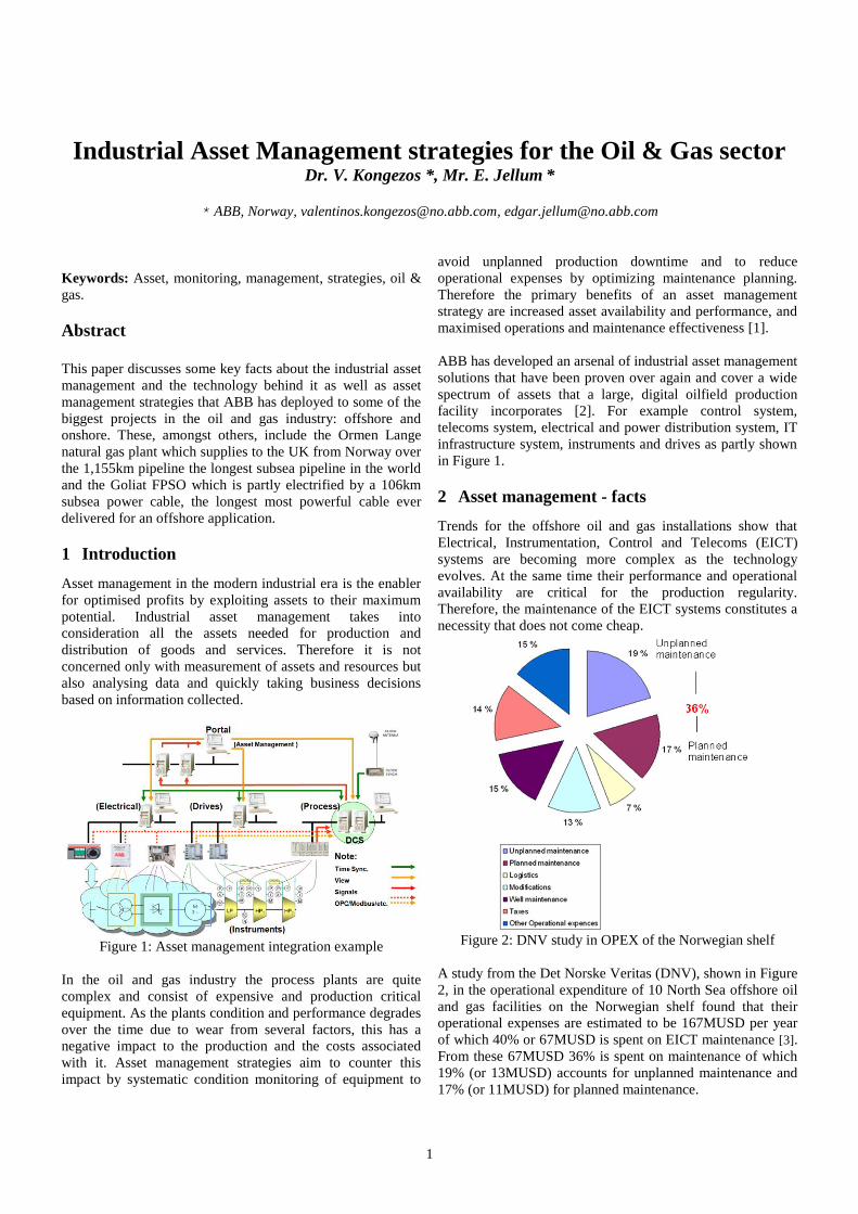
Figure 1: Asset management integration example
In the oil and gas industry the process plants are quite
complex and consist of expensive and production critical
equipment. As the plants condition and performance degrades
over the time due to wear from several factors, this has a
negative impact to the production and the costs associated
with it. Asset management strategies aim to counter this
impact by systematic condition monitoring of equipment to
avoid unplanned production downtime and to reduce
operational expenses by optimizing maintenance planning.
Therefore the primary benefits of an asset management
strategy are increased asset availability and performance, and
maximised operations and maintenance effectiveness [1].
ABB has developed an arsenal of industrial asset management
solutions that have been proven over again and cover a wide
spectrum of assets that a large, digital oilfield production
facility incorporates [2]. For example control system,
telecoms system, electrical and power distribution system, IT
infrastructure system, instruments and drives as partly shown
in Figure 1.
2 Asset management - facts
Trends for the offshore oil and gas installations show that
Electrical, Instrumentation, Control and Telecoms (EICT)
systems are becoming more complex as the technology
evolves. At the same time their performance and operational
availability are critical for the production regularity.
Therefore, the maintenance of the EICT systems constitutes a
necessity that does not come cheap.
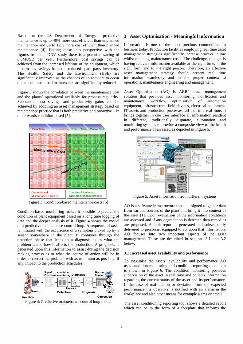
Figure 2: DNV study in OPEX of the Norwegian shelf
A study from the Det Norske Veritas (DNV), shown in Figure
2, in the operational expenditure of 10 North Sea offshore oil
and gas facilities on the Norwegian shelf found that their
operational expenses are estimated to be 167MUSD per year
of which 40% or 67MUSD is spent on EICT maintenance [3].
From these 67MUSD 36% is spent on maintenance of which
19% (or 13MUSD) accounts for unplanned maintenance and
17% (or 11MUSD) for planned maintenance.
2
Based on the US Department of Energy predictive
maintenance is up to 40% more cost efficient than unplanned
maintenance and up to 12% more cost efficient than planned
maintenance [4]. Putting these into perspective with the
figures from the DNV study there is a potential saving of
6.5MUSD per year. Furthermore, cost savings can be
achieved from the increased lifetime of the equipment, which
in turn has savings from the reduced spare parts inventory.
The Health, Safety and the Environment (HSE) are
significantly improved as the chances of an accident to occur
due to equipment bad maintenance are significantly reduced.
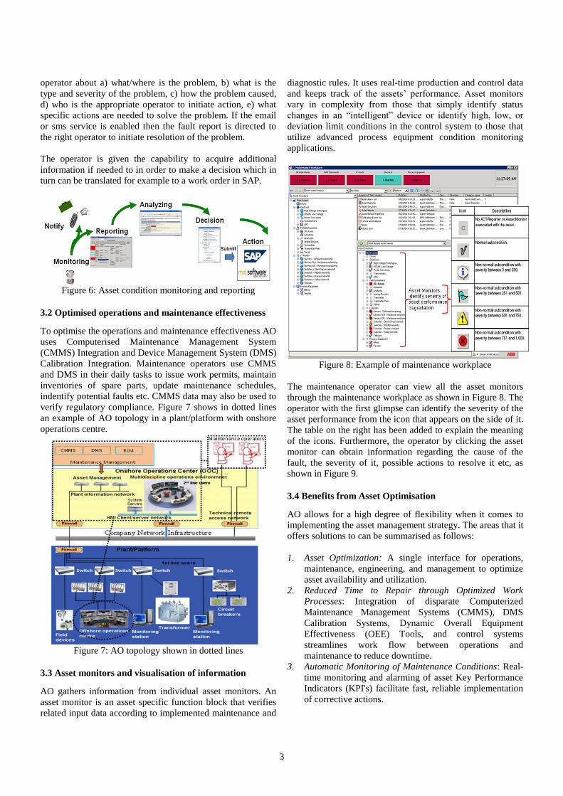
Figure 3 shows the correlation between the maintenance cost
and the plants’ operational availably for process regularity.
Substantial cost savings and productivity gains can be
achieved by adopting an asset management strategy based on
maintenance practice that is both predictive and proactive – in
other words condition-based [5].
Figure 3: Condition-based maintenance costs [6]
Condition-based monitoring makes it possible to predict the
condition of plant equipment based on a long time logging of
data and the deeper analysis of it. Figure 4 shows the model
of a predictive maintenance control loop. A sequence of tasks
is initiated with the occurrence of a symptom picked up by a
sensor somewhere in the plant. It continues through the
detection phase that leads to a diagnosis as to what the
problem is and how it affects the production. A prognosis is
generated upon this information to assist during the decision
making process as to what the course of action will be in
order to correct the problem with as minimum as possible, if
any, impact to the production schedules.
Figure 4: Predictive maintenance control loop model
3 Asset Optimisation - Meaningful information
Information is one of the most precious commodities in
business today. Production facilities employing real time asset
management strategies significantly increase process uptime
whilst reducing maintenance costs. The challenge, though, is
having relevant information available at the right time, in the
right form and to the right person. Therefore, an effective
asset management strategy should present real time
information seamlessly and in the proper context to
operations, maintenance engineering and management.
Asset Optimisation (AO) is ABB’s asset management
solution that provides asset monitoring, notification and
maintenance workflow optimisation of automation
equipment, infrastructure, field devices, electrical equipment,
IT assets and production processes, all that in a real-time. It
brings together in one user interface all information resident
in different, traditionally disparate, automation and
monitoring systems to provide a composite view of the health
and performance of an asset, as depicted in Figure 5.
Figure 5: Asset information from different systems
AO is a software infrastructure that is designed to gather data
from various sources of the plant and bring it into context of
the asset [1]. Upon evaluation of the information conditions
are assessed and if any degradation is detected then remedies
are proposed. A fault report is generated and subsequently
delivered to personnel equipped to act upon that information.
AO focuses into two important aspects of the asset
management. These are described in sections 3.1 and 3.2
below.
3.1 Increased asset availability and performance
To maximise the assets’ availability and performance AO
uses condition monitoring and condition reporting tools as it
is shown in Figure 6. The condition monitoring provides
supervision of the asset in real time and collects information
regarding the current status of the asset and its performance.
If the case of malfunction or deviation from the expected
performance the operators is notified with an alarm in the
workplace and also other means for example a sms or email.
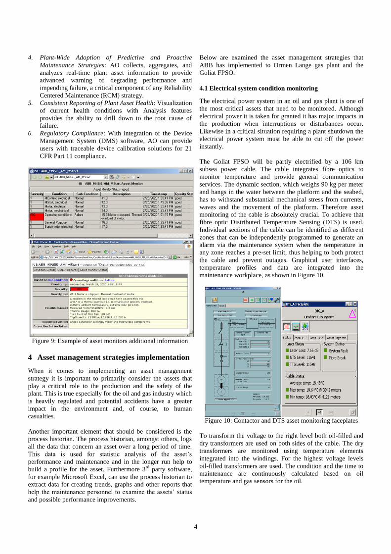
The asset conditioning reporting tool shows a detailed report
which can be in the form of a faceplate that informs the
3
operator about a) what/where is the problem, b) what is the
type and severity of the problem, c) how the problem caused,
d) who is the appropriate operator to initiate action, e) what
specific actions are needed to solve the problem. If the email
or sms service is enabled then the fault report is directed to
the right operator to initiate resolution of the problem.
The operator is given the capability to acquire additional
information if needed to in order to make a decision which in
turn can be translated for example to a work order in SAP.
Figure 6: Asset condition monitoring and reporting
3.2 Optimised operations and maintenance effectiveness
To optimise the operations and maintenance effectiveness AO
uses Computerised Maintenance Management System
(CMMS) Integration and Device Management System (DMS)
Calibration Integration. Maintenance operators use CMMS
and DMS in their daily tasks to issue work permits, maintain
inventories of spare parts, update maintenance schedules,
indentify potential faults etc. CMMS data may also be used to
verify regulatory compliance. Figure 7 shows in dotted lines
an example of AO topology in a plant/platform with onshore
operations centre.
Figure 7: AO topology shown in dotted lines
3.3 Asset monitors and visualisation of information
AO gathers information from individual asset monitors. An
asset monitor is an asset specific function block that verifies
related input data according to implemented maintenance and
diagnostic rules. It uses real-time production and control data
and keeps track of the assets’ performance. Asset monitors
vary in complexity from those that simply identify status
changes in an “intelligent” device or identify high, low, or
deviation limit conditions in the control system to those that
utilize advanced process equipment condition monitoring
applications.
Figure 8: Example of maintenance workplace
The maintenance operator can view all the asset monitors
through the maintenance workplace as shown in Figure 8. The
operator with the first glimpse can identify the severity of the
asset performance from the icon that appears on the side of it.
The table on the right has been added to explain the meaning
of the icons. Furthermore, the operator by clicking the asset
monitor can obtain information regarding the cause of the
fault, the severity of it, possible actions to resolve it etc, as
shown in Figure 9.
3.4 Benefits from Asset Optimisation
AO allows for a high degree of flexibility when it comes to
implementing the asset management strategy. The areas that it
offers solutions to can be summarised as follows:
1. Asset Optimization: A single interface for operations,
maintenance, engineering, and management to optimize
asset availability and utilization.
2. Reduced Time to Repair through Optimized Work
Processes: Integration of disparate Computerized
Maintenance Management Systems (CMMS), DMS
Calibration Systems, Dynamic Overall Equipment
Effectiveness (OEE) Tools, and control systems
streamlines work flow between operations and
maintenance to reduce downtime.
3. Automatic Monitoring of Maintenance Conditions: Real-
time monitoring and alarming of asset Key Performance
Indicators (KPI's) facilitate fast, reliable implementation
of corrective actions.
4
4. Plant-Wide Adoption of Predictive and Proactive
Maintenance Strategies: AO collects, aggregates, and
analyzes real-time plant asset information to provide
advanced warning of degrading performance and
impending failure, a critical component of any Reliability
Centered Maintenance (RCM) strategy.
5. Consistent Reporting of Plant Asset Health: Visualization
of current health conditions with Analysis features
provides the ability to drill down to the root cause of
failure.
6. Regulatory Compliance: With integration of the Device
Management System (DMS) software, AO can provide
users with traceable device calibration solutions for 21
CFR Part 11 compliance.
Figure 9: Example of asset monitors additional information
4 Asset management strategies implementation
When it comes to implementing an asset management
strategy it is important to primarily consider the assets that
play a critical role to the production and the safety of the
plant. This is true especially for the oil and gas industry which
is heavily regulated and potential accidents have a greater
impact in the environment and, of course, to human
casualties.
Another important element that should be considered is the
process historian. The process historian, amongst others, logs
all the data that concern an asset over a long period of time.
This data is used for statistic analysis of the asset’s
performance and maintenance and in the longer run help to
build a profile for the asset. Furthermore 3rd
party software,
for example Microsoft Excel, can use the process historian to
extract data for creating trends, graphs and other reports that
help the maintenance personnel to examine the assets’ status
and possible performance improvements.
Below are examined the asset management strategies that
ABB has implemented to Ormen Lange gas plant and the
Goliat FPSO.
4.1 Electrical system condition monitoring
The electrical power system in an oil and gas plant is one of
the most critical assets that need to be monitored. Although
electrical power it is taken for granted it has major impacts in
the production when interruptions or disturbances occur.
Likewise in a critical situation requiring a plant shutdown the
electrical power system must be able to cut off the power
instantly.
The Goliat FPSO will be partly electrified by a 106 km
subsea power cable. The cable integrates fibre optics to
monitor temperature and provide general communication
services. The dynamic section, which weighs 90 kg per meter
and hangs in the water between the platform and the seabed,
has to withstand substantial mechanical stress from currents,
waves and the movement of the platform. Therefore asset
monitoring of the cable is absolutely crucial. To achieve that
fibre optic Distributed Temperature Sensing (DTS) is used.
Individual sections of the cable can be identified as different
zones that can be independently programmed to generate an
alarm via the maintenance system when the temperature in
any zone reaches a pre-set limit, thus helping to both protect
the cable and prevent outages. Graphical user interfaces,
temperature profiles and data are integrated into the
maintenance workplace, as shown in Figure 10.
Figure 10: Contactor and DTS asset monitoring faceplates
To transform the voltage to the right level both oil-filled and
dry transformers are used on both sides of the cable. The dry
transformers are monitored using temperature elements
integrated into the windings. For the highest voltage levels
oil-filled transformers are used. The condition and the time to
maintenance are continuously calculated based on oil
temperature and gas sensors for the oil.
5
The electrical distribution system is essential for the safe
operation of the plant. Breakers and contactors must be able
to switch off the power during shutdowns. During normal
operation of the plant many of the electrical breakers and
contactors will stay constantly in either closed or open
position, and this makes condition monitoring a challenge.
For condition monitoring ABB has built “intelligence” into
the breakers and contactors, and the condition is calculated
based on the measuring temperatures, the number of
couplings and the current during switching. The electrical
resistance in screw joints on the busbar placed inside the
electrical distribution cabinets is monitored by measuring the
temperatures.
For the large electrical motors conventional vibration sensors
are installed both for protection and condition monitoring. In
addition the motor current is analysed to detect electrical and
mechanical problems. For the smaller electrical motors
wireless vibration sensors are installed for condition
monitoring.
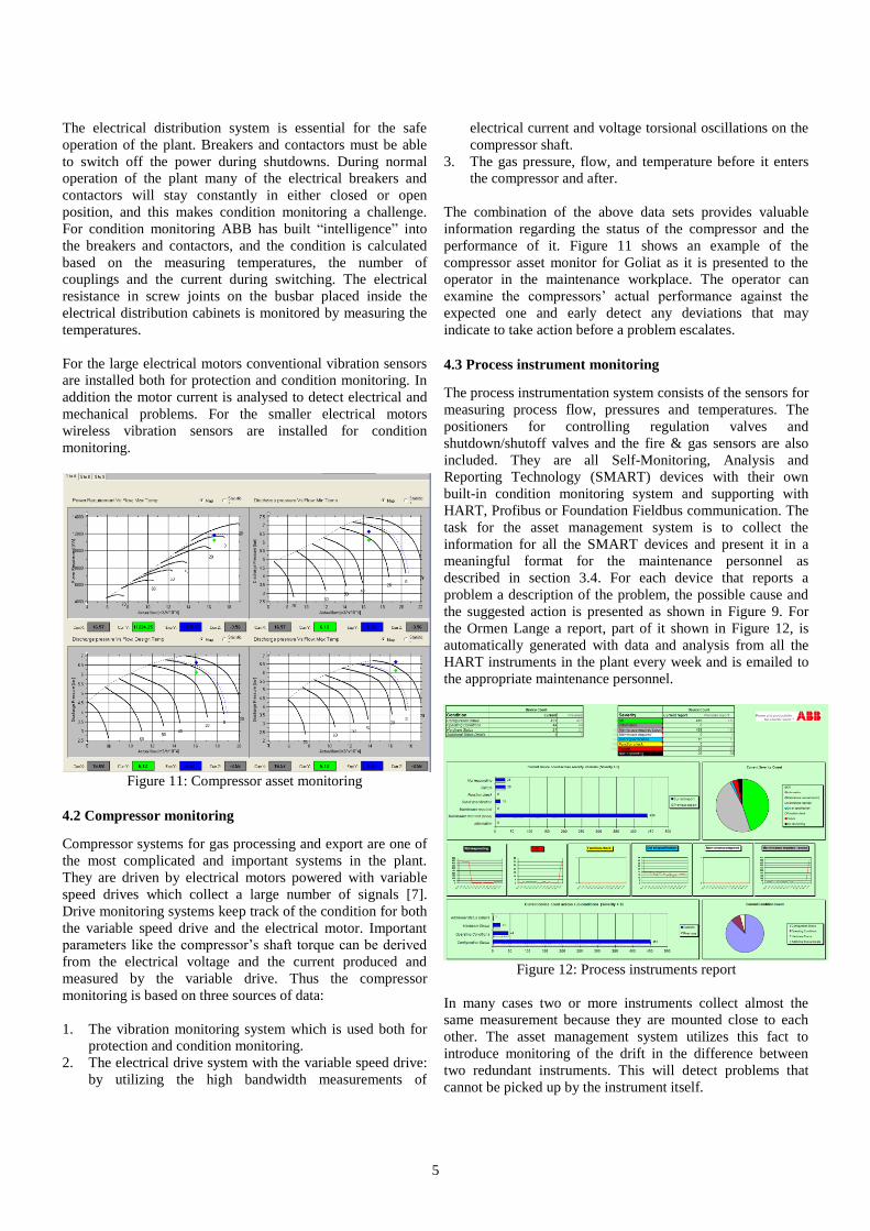
Figure 11: Compressor asset monitoring
4.2 Compressor monitoring
Compressor systems for gas processing and export are one of
the most complicated and important systems in the plant.
They are driven by electrical motors powered with variable
speed drives which collect a large number of signals [7].
Drive monitoring systems keep track of the condition for both
the variable speed drive and the electrical motor. Important
parameters like the compressor’s shaft torque can be derived
from the electrical voltage and the current produced and
measured by the variable drive. Thus the compressor
monitoring is based on three sources of data:
1. The vibration monitoring system which is used both for
protection and condition monitoring.
2. The electrical drive system with the variable speed drive:
by utilizing the high bandwidth measurements of
electrical current and voltage torsional oscillations on the
compressor shaft.
3. The gas pressure, flow, and temperature before it enters
the compressor and after.
The combination of the above data sets provides valuable
information regarding the status of the compressor and the
performance of it. Figure 11 shows an example of the
compressor asset monitor for Goliat as it is presented to the
operator in the maintenance workplace. The operator can
examine the compressors’ actual performance against the
expected one and early detect any deviations that may
indicate to take action before a problem escalates.
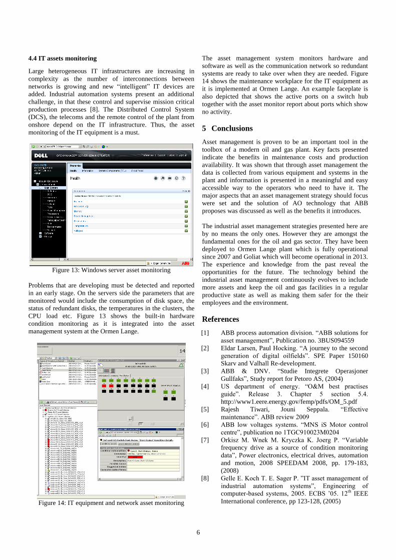
4.3 Process instrument monitoring
The process instrumentation system consists of the sensors for
measuring process flow, pressures and temperatures. The
positioners for controlling regulation valves and
shutdown/shutoff valves and the fire & gas sensors are also
included. They are all Self-Monitoring, Analysis and
Reporting Technology (SMART) devices with their own
built-in condition monitoring system and supporting with
HART, Profibus or Foundation Fieldbus communication. The
task for the asset management system is to collect the
information for all the SMART devices and present it in a
meaningful format for the maintenance personnel as
described in section 3.4. For each device that reports a
problem a description of the problem, the possible cause and
the suggested action is presented as shown in Figure 9. For
the Ormen Lange a report, part of it shown in Figure 12, is
automatically generated with data and analysis from all the
HART instruments in the plant every week and is emailed to
the appropriate maintenance personnel.
Figure 12: Process instruments report
In many cases two or more instruments collect almost the
same measurement because they are mounted close to each
other. The asset management system utilizes this fact to
introduce monitoring of the drift in the difference between
two redundant instruments. This will detect problems that
cannot be picked up by the instrument itself.
6
4.4 IT assets monitoring
Large heterogeneous IT infrastructures are increasing in
complexity as the number of interconnections between
networks is growing and new “intelligent” IT devices are
added. Industrial automation systems present an additional
challenge, in that these control and supervise mission critical
production processes [8]. The Distributed Control System
(DCS), the telecoms and the remote control of the plant from
onshore depend on the IT infrastructure. Thus, the asset
monitoring of the IT equipment is a must.
Figure 13: Windows server asset monitoring
Problems that are developing must be detected and reported
in an early stage. On the servers side the parameters that are
monitored would include the consumption of disk space, the
status of redundant disks, the temperatures in the clusters, the
CPU load etc. Figure 13 shows the built-in hardware
condition monitoring as it is integrated into the asset
management system at the Ormen Lange.
Figure 14: IT equipment and network asset monitoring
The asset management system monitors hardware and
software as well as the communication network so redundant
systems are ready to take over when they are needed. Figure
14 shows the maintenance workplace for the IT equipment as
it is implemented at Ormen Lange. An example faceplate is
also depicted that shows the active ports on a switch hub
together with the asset monitor report about ports which show
no activity.
5 Conclusions
Asset management is proven to be an important tool in the
toolbox of a modern oil and gas plant. Key facts presented
indicate the benefits in maintenance costs and production
availability. It was shown that through asset management the
data is collected from various equipment and systems in the
plant and information is presented in a meaningful and easy
accessible way to the operators who need to have it. The
major aspects that an asset management strategy should focus
were set and the solution of AO technology that ABB
proposes was discussed as well as the benefits it introduces.
The industrial asset management strategies presented here are
by no means the only ones. However they are amongst the
fundamental ones for the oil and gas sector. They have been
deployed to Ormen Lange plant which is fully operational
since 2007 and Goliat which will become operational in 2013.
The experience and knowledge from the past reveal the
opportunities for the future. The technology behind the
industrial asset management continuously evolves to include
more assets and keep the oil and gas facilities in a regular
productive state as well as making them safer for the their
employees and the environment.
References
[1] ABB process automation division. “ABB solutions for
asset management”, Publication no. 3BUS094559
[2] Eldar Larsen, Paul Hocking. “A journey to the second
generation of digital oilfields”. SPE Paper 150160
Skarv and Valhall Re-development.
[3] ABB & DNV. “Studie Integrete Operasjoner
Gullfaks”, Study report for Petoro AS, (2004)
[4] US department of energy. “O&M best practises
guide”. Release 3. Chapter 5 section 5.4.
http://www1.eere.energy.gov/femp/pdfs/OM_5.pdf
[5] Rajesh Tiwari, Jouni Seppala. “Effective
maintenance”. ABB review 2009
[6] ABB low voltages systems. “MNS iS Motor control
centre”, publication no 1TGC910023M0204
[7] Orkisz M. Wnek M. Kryczka K. Joerg P. “Variable
frequency drive as a source of condition monitoring
data”, Power electronics, electrical drives, automation
and motion, 2008 SPEEDAM 2008, pp. 179-183,
(2008)
[8] Gelle E. Koch T. E. Sager P. ”IT asset management of
industrial automation systems”, Engineering of
computer-based systems, 2005. ECBS ’05. 12th
IEEE
International conference, pp 123-128, (2005)