indexes—table of contents hd-01 design manual... · 301.7 contract documents ... topographic...
TRANSCRIPT
INDEXES—Table of Contents HD-01
300 SURVEYING 301 Operations 301.1 Introduction .............................................................................................. 09/16 301.2 Standards .................................................................................................. 09/16 301.3 GNSS Procedures and Techniques ........................................................... 09/16 301.4 Kentucky Single Zone................................................................................ 09/16 301.5 KYCORS ..................................................................................................... 09/16 301.6 Survey Reports ......................................................................................... 09/16 301.7 Contract Documents................................................................................. 09/16 301.8 QA/QC ....................................................................................................... 09/16 302 Survey Control 302.1 Survey Control .......................................................................................... 09/16 302.2 Field Control Reconnaissance................................................................... 09/16
302.3 Primary Control ...................................................................................... 09/16 302.4 Project Control ........................................................................................ 09/16 302.4.1 Project Control Monumentation ........................................... 09/16 302.4.2 Horizontal Project Control ..................................................... 09/16 302.4.3 Vertical Project Control .......................................................... 09/16
302.5 Supplemental Control ............................................................................. 09/16 302.5.1 Supplemental Control Monumentation ................................. 09/16 302.5.2 Aerial Mapping Control .......................................................... 09/16 302.5.2.1 Photogrammetric Panel Points ............................................ 09/16 302.5.2.2 LiDAR Ground Control Points (GCP) ..................................... 09/16 302.5.3 Mobile Terrestrial Laser Scanning (MLTS) Control ................ 09/16 302.5.4 Stationary Terrestrial Laser Scan (STLS) Control .................... 09/16 302.6 Deliverables ............................................................................................ 09/16 302.7 QA/QC ................................................................................................. 09/16
303 Data Collection 303.1 Overview ................................................................................................... 09/16
303.2 Survey Field Crew Responsibilities ......................................................... 09/16 303.3 Safety ................................................................................................. 09/16 303.4 Electronic Data Collectors ...................................................................... 09/16 303.4.1 Feature Coding ......................................................................... 09/16
303.5 Digital Terrain Modeling ......................................................................... 09/16 303.6 Topographic Features ............................................................................. 09/16 303.7 Existing Structures .................................................................................. 09/16 303.8 Property Line Features ........................................................................... 09/16
304 Utility Location 304.1 Overview ................................................................................................... 09/16
304.2 Procedures .............................................................................................. 09/16 304.3 Deliverables ....................................................................................... 09/16 304.4 QA/QC ..................................................................................................... 09/16
305 Preconstruction Activity on Private Property
INDEXES—Table of Contents HD-01
305.1 Property Entry .......................................................................................... 09/16 305.1.1 Surveyor Responsibility ........................................................... 09/16 305.1.2 Contact Procedures ................................................................ 09/16 305.1.3 Refusal of Entry ........................................................................ 09/16
305.2 Damages ................................................................................................. 09/16 305.2.1 Damages ≤ $1000 .................................................................... 09/16 305.2.2 Damages >$1000 ..................................................................... 09/16 305.2.3 Damage Assessment and Payment ......................................... 09/16 305.2.4 Damages by a Consultant ........................................................ 09/16
306 Other Survey Activities 306.1 Property Boundary Surveys ...................................................................... 09/16 306.2 General Order Surveys ............................................................................. 09/16 306.3 Cemetery .................................................................................................. 09/16 306.4 Drainage ................................................................................................... 09/16 306.5 Railroads ................................................................................................... 09/16 307 Right of Way Monumentation 307.1 Right of Way Location .............................................................................. 09/16 307.2 Standard Monumentation Types ............................................................. 09/16 307.2.1 Non-KYTC Routes ................................................................... 09/16
307.3 Right of Way Location ............................................................................. 09/16 307.3.1 Placement of Witness Posts ................................................... 09/16 307.3.2 Placement Exceptions ............................................................ 09/16 307.3.3 Permanent Monumentation .................................................. 09/16 307.4 Coordinate Control Sheets ..................................................................... 09/16
308 Aerial Mapping 308.1 Introduction .............................................................................................. 09/16 308.1.1 Definitions of Terms ............................................................... 09/16 308.2 Procedures ................................................................................................ 09/16 308.2.1 Photogrammetry .................................................................... 09/16 308.2.2 Digital Orthophotos ................................................................ 09/16 308.2.3 Aerial Light Detection and Ranging (LiDAR) ........................... 09/16
308.3 Deliverables ............................................................................................ 09/16 308.3.1 Digital Orthophotos ................................................................ 09/16 308.3.2 Aerial LiDAR ............................................................................ 09/16
308.3.2.1 Raw Point Cloud .................................................... 09/16 308.3.2.2 Classified Point Cloud ............................................ 09/16
309 Terrestrial Mapping 309.1 Introduction .............................................................................................. 09/16 309.2 Considerations for Use of MTLS ............................................................... 09/16
309.3 Consideration for Use of STLS ................................................................ 09/16 309.4 TLS Accuracy ........................................................................................... 09/16 309.5 Procedures .............................................................................................. 09/16 309.5.1 Calibration .............................................................................. 09/16 309.5.2 Data Collection ....................................................................... 09/16
INDEXES—Table of Contents HD-01
309.6 Lane Closures ............................................................................................ 09/16 309.7 Planning a MTLS Project ........................................................................... 09/16 309.7.1 Project Site Visit ..................................................................... 09/16 309.7.2 Data Collection ....................................................................... 09/16 309.8 Planning an STLS Project .......................................................................... 09/16 309.9 Deliverables .............................................................................................. 09/16 309.9.1 Point Cloud ............................................................................. 09/16 309.9.2 Classified Point Cloud ............................................................. 09/16 309.9.3 Metadata ................................................................................ 09/16 309.9.4 Imagery/Video ........................................................................ 09/16 309.9.5 Survey Report ......................................................................... 09/16 309.10 QA/QC ................................................................................................. 09/16 309.11 Accuracy ................................................................................................. 09/16
310 Acronyms and Terms

Highway Design Manual
Chapter
EXHIBITS
Subject
Table of Exhibits
300-01 Geospatial Positioning Accuracy Standards 300-02 Accuracy Standards 300-03 Standards & Specifications for Geodetic Control Networks 300-04 United States National Map Accuracy Standards 300-05 Example Quality Level “D” and “C” Plan Sheet 300-06 Example QL “A” Data Summary Sheet 300-07 Classification Schema 300-08 Control Monument Information Sheet

HD-301
09/16 Page 1 of 5
HIGHWAY DESIGN
Chapter
SURVEYING
Subject
Operations
HD-301.1 INTRODUCTION Surveying is used throughout the design process from initial topographic data collection, which identifies features that need to be accommodated by the project design, to construction staking to assist in properly building the highway project. In addition, other survey activities may be used by the project team to provide additional data, including, but not limited to, boundary surveys, environmental surveys, cemetery relocations, and hydrologic surveys. For additional references on survey-related items, see the Division of Highway Design Survey Coordination online at: http://transportation.ky.gov/Highway-Design/Pages/Survey-Coordination.aspx
HD-301.2 STANDARDS
Deliverables from KYTC consultants shall be MicroStation (DGN) files with all graphics submitted according to the current KYTC CADD standards referenced online at: http://transportation.ky.gov/CADD-Standards/Pages/default.aspx
LiDAR will be tested to meet the 95% Confidence Interval root-mean-square error (RMSE) for the type of data collected by either airborne, mobile mapping, or stationary scanners.
The default KYTC standard for design mapping is a scale of 1 inch = 50 feet with
2-foot contours. Other scales and intervals may be acceptable based on the request of the project manager and the design team.
Topographic survey data shall meet accuracies outlined in the “Standards of
Practice” as specified by the Commonwealth of Kentucky, State Board of Licensure for Professional Engineers and Land Surveyors Table of Specifications by Class: Classification of Surveys (201 KAR 18:150).

SURVEY
Operations HD-301
09/16 Page 2 of 5
Right of Way Monumentation shall be set with a horizontal closure of 1:15,000 relative to primary control. Right-of-Way Monumentation is further discussed in HD-307.
KYTC standards for survey accuracy are based on standards set by the Federal
Geographic Data Committee’s (FGDC) Geospatial Positioning Accuracy Standard (see Exhibit 300-01) and are referenced online at http://transportation.ky.gov/Highway-Design/Pages/Survey-Coordination.aspx
Positional Accuracy and Relative Closure Ratio Accuracy are two types of
accuracies that may be specified. Surveys conducted using Global Navigation Satellite System (GNSS) techniques use positional accuracy standards while conventional techniques use relative accuracy standards. See Exhibit 300-02 for more information.
All control shall meet specifications as prescribed in HD-302.
HD-301.3 GNSS PROCEDURES AND TECHNIQUES
Global Navigation Satellite System (GNSS) survey technology is evolving. The specifications described in HD-302 are not intended to discourage the development of new GNSS procedures and techniques. New procedures and techniques may be used with prior approval from the KYTC State Survey Coordinator.
GNSS equipment and software must be of survey grade and meet the accuracy specifications for the various survey activities discussed in this chapter. See HD-302 for GNSS survey control specifications.
Whenever feasible, GNSS survey methods shall be used for establishing
horizontal control. GNSS methods may be used to bring NAVD88 elevations to a project area provided 2nd Order accuracy (unless otherwise specified) can be achieved and conventional leveling techniques are used for densification.
HD-301.4 KENTUCKY SINGLE ZONE
The State Plane Coordinate system known as Kentucky Single Zone shall be used for the survey and development of all projects. The Kentucky Single Zone is defined as: Datum=NAD83/GRS80 Ellipsoid Central Meridian=85°45’ West Longitude Parallel of Grid Origin (Base Parallel) =36°20’ North Latitude
SURVEY
Operations HD-301
09/16 Page 3 of 5
Southern Standard Parallel=37°05’ North Latitude Northern Standard Parallel=38°40’ North Latitude False Northing=1,000,000 meters (3,280,833.333 feet*) False Easting=1,500,000 meters (4,921,250.000 feet*)
*The Kentucky Single Zone is to be used with the U.S. Survey linear foot of measure.
All design and construction mapping and surveying products will be delivered in Kentucky Single Zone State Plane coordinates (parameters defined in FIPS 1600, and units of U.S. Survey Feet), NAD83* geometric datum (most current adjustment), and NAVD88 vertical datum. The most current adjustment and geoid model available from the National Geodetic Survey (NGS) shall be used when approved by KYTC.
HD-301.5 KYCORS
KYTC has established a network of continuously operating fixed GNSS reference base stations commonly known as KYCORS. The network provides real-time, three-dimensional GNSS network corrections via the internet 24/7. Real time positional accuracy of +/-1cm horizontally and +/2cm vertically can be obtained when precision GNSS equipment is used following GNSS best practices. A map of the current KYCORS stations and their status can be viewed online at http://kycors.ky.gov/. Access to the network is free, but does require user registration. Where practical, use of the network is recommended when referencing highway projects.
HD-301.6 SURVEY REPORTS
All projects should use Kentucky single zone coordinates. It is unacceptable to use assumed coordinate systems. Project specific survey deliverables shall be listed in the project scope. The final Survey Report shall contain: Project name & identification: County, Route, Mile Post, E.A., or Project
Identification, etc. Survey date, limits, and purpose A scaled map (e.g. KML file) of the project area, showing all primary and
supplemental (horizontal and vertical) control monumentation established with appropriate designation
Datum realization, epoch, geoid model, and units Project datum factor, if used, that relates to the Kentucky State Plane

SURVEY
Operations HD-301
09/16 Page 4 of 5
Coordinates Dated signature and seal of the Kentucky Professional Land Surveyor in charge Number of intervisible monuments set and any supplemental physical feature
points (e.g. aerial target locations) Description of all primary and project control found, held, or established Validation points Closures of all traverses Unadjusted and adjusted information of traverses Adjustment report for control Dates of observations Time interval of each observation Number of times occupying each control point Personnel, equipment, and surveying methods used Any other pertinent information such as GNSS observation logs Problems encountered
Submit the report as a PDF document to the PDM. Document all pertinent information of all control on Control Monument Data Sheets available online at http://transportation.ky.gov/Highway-Design/Pages/Survey-Coordination.aspx and submit with the final control survey report. Unless otherwise described in the project scope, the survey report will not be accepted from any non-KYTC source unless signed, dated, and stamped by a Kentucky Professional Land Surveyor, certifying the accuracy of the report submitted and the accuracy of all control monuments set for the Department.
HD-301.7 CONTRACT DOCUMENTS
Survey deliverables must be submitted electronically and include, at a minimum: Property Entry Documentation Survey Report DTM Surfaces-Existing Boundary and Right of Way Deed Research Packet Related Plats and Exhibits ROW Field Monumentation ROW Monument Control Plan ROW Acquisition Plat
Note: All maps must be submitted as PDFs.
HD-301.8 QA/QC

SURVEY
Operations HD-301
09/16 Page 5 of 5
Quality of the survey data is integral to the quality of highway design and roadway construction. Each section of the survey chapters includes key items for quality review and checking. The survey party chief is responsible for daily quality assurance.
HD-302
09/16 Page 1 of 5
HIGHWAY DESIGN
Chapter
SURVEYING
Subject
Survey Control
HD-302.1 SURVEY CONTROL
Project control establishes a consistent network of accurate horizontal and vertical control for use in all subsequent project surveys – photogrammetric, mapping, planning, design, construction, and right of way. Projects will have the following types of control. Each has slightly different requirements as described in the appropriate section. Primary Control Project Control Supplemental Control
HD-302.2 FIELD CONTROL RECONNAISSANCE
The traditional geodetic reference system consists of horizontal and vertical control monuments, typically metal disks set in concrete pillars or on rods driven in the ground. Many of these monuments have been destroyed and the National Geodetic Survey (NGS) is not replacing or further maintaining physical markers. Physical, passive markers may continue to be recoverable and useable, but that is not guaranteed. The surveyor should make every effort to obtain information for any existing control in the project area. If any primary control exists from the NGS database or project control from previous Department of Highways projects, it is highly recommended that this control be used for further densification of the project. Recovered control monuments must be evaluated before being used as a basis for new control surveys.
HD-302.3 PRIMARY CONTROL
Primary control monuments, both horizontal and vertical, are monuments included in the NGS National Spatial Reference System (NSRS). NGS Continuously Operating Reference Station (CORS) and Kentucky Geodetic Reference Network
SURVEYING
Survey Control HD-302
09/16 Page 2 of 5
(KGRN) monuments are examples of this type of control. NGS monuments used as primary control must be of an equal or higher order than the survey being performed.
Recovered and destroyed NGS monuments shall be reported using the NGS GPS on Bench Mark Reporting available online at:
http://www.ngs.noaa.gov/GPSonBM/Report.shtml HD-302.4 PROJECT CONTROL
Project control monuments should last at least the lifetime of a project and have a positional network accuracy of 1cm, 95% confidence or better. Project control must have their locations determined with ties to primary control monuments.
HD-302.4.1 Project Control Monumentation
Project control monuments shall be set as described in the NGS Bench Mark Reset Procedures available online at the Survey Coordination Website under standards:
http://transportation.ky.gov/Highway-Design/Pages/Survey-Coordination.aspx The monuments shall have aluminum, brass, or bronze geodetic control disks inscribed with “KYTC Survey Monument,” an identifier, and the date the monument was set. A 48-inch minimum Carsonite witness post labeled “KYTC Survey Control” will witness each monument. The surveyor should locate the monuments to avoid destruction or disturbance during construction. Global Navigation Satellite System (GNSS) shall be the standard method of developing control. Control extended from GNSS shall be derived by post-processed networked static GNSS procedures as recommended by NGS. If control is not possible to be established by GNSS or is proposed to be established using conventional methods for unique circumstances, the KYTC State Survey Coordinator should be contacted for approval. The Control Monument Information Sheet, Exhibit 300-08, will be submitted with new of replacement survey monuments. The form can be located on the Division of Highway Design’s webpage for forms.
HD-302.4.2 Horizontal Project Control
Set monuments as required by project conditions, generally no more than 2640 feet apart and preferably intervisible with at least two other monuments.
SURVEYING
Survey Control HD-302
09/16 Page 3 of 5
Minimum spacing for monuments is 1000 feet when using GNSS methods or 500 feet when using conventional survey methods. If conventional methods must be used, horizontal surveys may be specified as Second Order Class I or Second Order Class II depending on the precision required (such as, bridge or tunnel control).
HD-302.4.3 Vertical Project Control
Set monuments as required by project conditions, generally no more than 1500 feet apart. When feasible, utilize horizontal project control monuments as vertical control monuments. The 1 centimeter equivalent for conventional vertical surveys is Second Order Class I. See Exhibit 300-03 for more information.
HD-302.5 SUPPLEMENTAL CONTROL
Supplemental control should have a 2 centimeter network accuracy, 95 percent confidence and tied to primary control monuments. Supplemental control points may be used for establishing photogrammetric control, Light Detection and Ranging (LiDAR) control, and right-of-way survey control unless specified otherwise.
HD-302.5.1 Supplemental Control Monumentation
Supplemental control monumentation may be pipe or rebar (18 inches in length), PK nails in pavement, chiseled crosses in concrete, or similar material. Plastic caps should be used for horizontal control and metal caps should be used for vertical control. “KYTC” shall be legible on all caps.
HD-302.5.2 Aerial Mapping Control
All control set for KYTC Aerial Mapping shall be tied to primary control and spaced as required by project conditions.
HD-302.5.2.1 Photogrammetric Panel Points
Control points utilized in photogrammetry are commonly referred to as “panel points” and are designated by an “x,” “v,” or open center cross with approximately 5 feet legs. The legs of the cross are made of cloth, plastic, or paint. The panels are usually white in order to contrast with the ground; however, on concrete pavements and extremely colored barren soils, it is best to use dark gray or black materials. Control points should be paneled in advance of flying to ensure visibility in the acquired photography.
HD-302.5.2.2 LiDAR Ground Control Points (GCP)
Aerial LiDAR differs from photogrammetry in that features are not visible in LiDAR
SURVEYING
Survey Control HD-302
09/16 Page 4 of 5
datasets as in photography. (For example, a manhole would not be a discernible feature in an aerial LiDAR dataset.) For that reason, control placed for Aerial LiDAR projects do not need to be paneled and can be placed after the LiDAR acquisition is complete, assuming ground conditions have not changed between LiDAR acquisition and control survey. GCP preference should be given to points associated to permanent, recoverable structures which may be used in future survey work. Examples include manholes, curbs, utility structures, etc.
HD-302.5.3 Mobile Terrestrial Laser Scanning (MTLS) Control Global Navigation Satellite System (GNSS) control stations used to control the post-processed kinematic adjustment of the MTLS data shall be placed at a maximum of 5-mile intervals. In no case should the processed baseline exceed 5 miles in length. Short baselines contribute to the best possible positional accuracy outcome. Dual redundant GNSS base stations are highly recommended to guard against the possibility of wasted effort and useless data from base station failure due to equipment, accident, or human error in station setup. Dual base stations also allow redundant post-processing and 10-mile baseline post-processing in case of a base station failure. Locate one base station near the beginning of the project and another near the end of the project. The horizontal accuracy standard of control stations shall be second order or better, and the vertical accuracy standard shall be third order or better as defined for project and supplemental control. Mobile Mapping control falls under the categories of “Transformation” or “Validation” control points. Transformation points serve as control for processing of the point clouds. Validation points are used to check the geospatial data adjustment to the transformation points and allow for QA/QC checks of the adjusted scan data. Both types of points should be placed throughout at even intervals. Transformation points should be placed before and after expected obstructions, such as bridges. For MTLS surveys, the scanned area shall have control on both sides of the roadway with transformation points at a maximum of 1500-foot roadway centerline stationing intervals and validation points at a maximum of 500-foot roadway centerline stationing intervals. MTLS surveys require local points to have surveyed local positional accuracies of Hz ≤ 15mm and Z ≤ 15mm or better. Differential digital leveling is the preferred method of establishing transformation and validation point elevations.
HD-302.5.4 Stationary Terrestrial Laser Scan (STLS) Control Total station targets reduce pointing error when placed at long distances. Laser scanning targets, however, are designed for a specific distance. Most laser scanners do not have telescopes to orient the instrument to a backsight. Vendor-
SURVEYING
Survey Control HD-302
09/16 Page 5 of 5
specific targets tuned for the laser scanner frequency are recommended. Best results are typically seen when the targeted control stations are evenly spaced horizontally throughout the scan. Variation in target elevations is desirable. Targets should be placed at the recommended optimal distance from the scanner and scanned at high-density as recommended by the STLS manufacturer. Hard surface topographic STLS surveys require control and validation point surveyed local positional accuracies of Hz ≤ 15mm and Z ≤ 15mm.
HD-302.6 DELIVERABLES
Files shall have non-proprietary format point data showing applied corrections. All point, elevation, and metadata data used to calibrate, process, and validate control points shall be submitted on portable media. A Surveyor’s Report is required (see HD-301.6).
HD-302.7 QA/QC
Quality of the control data is essential to the quality of the entire survey and, by extension, the entire project. Minimally, the following items should be verified and submitted: Correct coordinate system Correct elevation datum Project Datum Factor, if used Unedited raw files Rotation Translation Correction Factors Shown ties to existing Primary Control Labeled types of monuments
NOTE: Due to the evolving software and mapping techniques for LiDAR technology, the procedures listed in the previous pages may be altered with approval from the KYTC State Survey Coordinator.
HD-303
09/16 Page 1 of 4
HIGHWAY DESIGN
Chapter
SURVEYING
Subject
Data Collection
HD-303.1 OVERVIEW
The degree of precision of all surveys is determined by the final intended use of the data. Generally, when new surveys are being undertaken, a preliminary survey should be to the same order as that required for the final survey. In some situations, a preliminary survey for mapping or reconnaissance studies may be to a lesser order with approval of the KYTC State Survey Coordinator.
HD-303.2 SURVEY FIELD CREW RESPONSIBILITIES
For all KYTC projects, survey field crews are responsible for processing their data and delivering a design (.dgn) file, digital terrain model (.dtm) file, and geometry (.alg) file. KYTC field crews are responsible for final checking and the assurance of the accuracy of all survey products delivered to the design office. Consultants may follow their internal QA/QC procedures.
HD-303.3 SAFETY
Surveyors work in hazardous environments, such as rugged terrain or in the vicinity of high-speed traffic and construction equipment. Working in these conditions requires a constant awareness of the need for safety. When working in or near traffic, survey crew signing must be in place before survey work begins. Survey signing should comply with the recommendations in the most recent Manual on Uniform Traffic Control Devices (MUTCD) and will be coordinated with the district. Survey conditions should be suspended when uncontrollable hazards develop, and work may be resumed only when safe working conditions have been restored. Personnel must be particularly aware of avoiding the creation of hazards when working on private property.
HD-303.4 ELECTRONIC DATA COLLECTORS
The electronic data collectors (electronic field books) selected for use shall not allow the data to be deleted until it has been sent to a printer or a computer. If
SURVEYING
Data Collection HD-303
09/16 Page 2 of 4
an error is made in the field, the data collector retains both the error and the correction.
As standard procedure to ensure that a permanent record of the original fieldwork is available, any agent of the Cabinet using electronic data collectors should comply with the following practices:
Download the original data into a computer and copy (unedited) to a
permanent medium. Produce a hard-copy printout of the data before any editing takes place. Do any editing or subsequent changes to the data on copies of the original
data. Never alter the original data. In any subsequent submittals of project information, treat the permanent
medium and the hardcopy printout, cited before, as a traditional field book. Electronic data files submitted should be in the approved KYTC format. If it is
submitted in a text file, the following format shall be used: point number, Northing, Easting, elevation, feature code.
HD-303.4.1 Feature Coding
All survey and DTM information for KYTC projects shall utilize the KYTC feature codes list. The current feature codes list can be found online at the KYTC Highway Design web page under Survey Coordination:
http://transportation.ky.gov/Highway-Design/Pages/Survey-Coordination.aspx HD-303.5 DIGITAL TERRAIN MODELING
A Digital Terrain Model (DTM) is a three-dimensional representation of the surface of the earth. The accuracy of the DTM should reflect its intended use.
Cross-sections and profiles needed for plan development and documentation shall be derived from the DTMs. DTMs are created from breaklines and random points. Breaklines are linear features that locate “breaks” (changes) in the earth’s surface, such as changes in slope. Examples of breaklines are the crown of pavement, edge of pavement, edge of shoulder, flow line, top of curb, bottom of slope, top of slope, bottom of ditch, and top of ridge. Random points are used to define the surface between breaklines. These points are spot elevations at various or key locations. Random points are generally collected in a grid with a nominal spacing of 25 to 50 feet. Additional points may be added to define high and low spots in terrains as needed. This spacing can vary widely depending on the regularity of the surface being surveyed.
SURVEYING
Data Collection HD-303
09/16 Page 3 of 4
The surveyor shall be responsible for adequate breaklines and random points to ensure that the DTM accurately reflects the surface. Additional care shall be taken in the collection of breaklines in areas around bridges and other structures, streams, and other sensitive locations. At bridge abutments, wing walls, ends of pipes and culverts, curbs, retaining walls, and any other vertical-type situation, breaklines at both the top and bottom of the feature are necessary for the definition of the surface.
Take breakline data in a directional sequence and do not jump back and forth on the same breakline. The rodman should be knowledgeable of the data collection process and how the collected data influences the quality of the DTM. Thus, the rodman is key to the collection process.
The surveyor is responsible for the processing, final checking, and validating of the DTM.
HD-303.6 TOPOGRAPHIC FEATURES
Topography is defined as the graphic delineation of all natural and manmade features of an area. Collect all topographic feature data within the project area. Where appropriate, elevations should be collected. For overhead utilities, identify the ownership, pole number(s), and low wire elevation(s). Collect the major topographic features of the area such as buildings, septic systems, existing roads, drainage structures, and utilities. The types of construction and descriptions for all buildings and existing roadway surfaces shall be noted. In addition, collect any item that may influence project decisions.
HD-303.7 EXISTING STRUCTURES
Accurate depiction of existing structures is particularly important to the design process. Field information should completely define the structure and surrounding terrain. Additional information should be collected to describe the components of the structure (beam depths, pier heights, bridge seats, headwalls, abutments, wing walls, etc.). A written description of the structure should also be documented.
HD-303.8 PROPERTY LINE FEATURES
All property lines, easement lines, lease lines, and special agreement lines, as well as KYTC permits and agreements, etc., within the limits of the project (and in some instances in the general proximity) must be identified. All monuments and features that aid in the description of property lines should be located. Other information to be collected to help locate property lines may include deed

SURVEYING
Data Collection HD-303
09/16 Page 4 of 4
descriptions, PVA maps, plats, and subdivision plans. The names of all property owners are to be collected as recorded in the deed book, along with the deed book and page numbers and acreage or square footage.
HD-304
09/16 Page 1 of 3
HIGHWAY DESIGN
Chapter
SURVEYING
Subject
Utility Location
HD-304.1 OVERVIEW
The location of aboveground and underground utilities is a primary concern during project development. Complete and concise locations of existing utilities shall be obtained early in the design process. Utility company archives may not be sufficient to identify all utilities within the project corridor. The quality level that is utilized in the location of existing utilities should be based on the stage of development for a roadway project. During the corridor study to determine potential alternatives, the use of existing records or verbal information from utility companies typically will suffice. The quality level utilized in locating existing utilities should improve as alternatives are developed and their subsequent location refined. Location of utilities should include the horizontal position (and vertical position when appropriate) of the utility, the material of which it is composed, the size, and any other pertinent data concerning the facility. The following is a description of the differing quality levels of aboveground and underground utility location. Quality level “D” and “C” apply to aboveground. Quality level “B” and “A” apply to underground utility location, but use level “D” and “C” for initial location. The quality levels for utility location are as follows:
Quality Level D (QL D): Information derived solely from existing records or
verbal recollections
Quality Level C (QL C): Information obtained by surveying and plotting visible aboveground utility features and by using professional judgment in correlating this information to Quality Level D information
Quality Level B (QL B): Information obtained through the application of
appropriate surface geophysical methods to identify the existence and

SURVEYING
Data Collection HD-303
09/16 Page 2 of 3
approximate horizontal position of subsurface utilities
Note: Quality Level B data should be reproducible by surface geophysics at any point of the utility’s depiction. This information is surveyed to applicable tolerances and reduced onto plan documents.
Quality Level A (QL A): Information obtained by the actual exposure (or
verification of previously exposed and surveyed utilities) of subsurface utilities using (typically) minimally intrusive excavation equipment to determine their precise horizontal and vertical positions, as well as their other utility attributes
Note: This information is surveyed and reduced onto plan documents. Accuracy should be to applicable horizontal survey and mapping accuracy and should be within ± 0.05 foot vertical.
HD-304.2 PROCEDURES
Project Development Managers direct where Subsurface Utility Engineering (SUE) work is to be conducted. Locating existing utilities to a certain level should occur as early as the Pre-Design and/or Conceptual Design phase of a project whenever there are large concentrations of utilities or a major utility facility. At any stage of design, the utility companies should be an integral part of the design process and should be invited to key meetings to be advised of and consulted about impacts of the proposed roadway improvements to their facilities. Utility companies should also be invited to attend and provide input at public involvement meetings. The choice of alternatives for the proposed roadway should reflect this information in an effort to first avoid the utility conflict, secondarily minimize the effect, and thirdly mitigate the conflict. The project team shall determine the quality level (QL) of utility locations for the various stages of project development conceptual design. QL A will be done as needed, based on potential conflicts. To more adequately and expeditiously effect the location of utilities, the project team should specify in the advertisement for consultant services that the consultant will be required to locate utilities to the differing levels dictated by the project development stages. It may appear fiscally advantageous to place the brunt of relocation costs on private companies, while avoiding publicly owned utilities simply to avoid the direct cost of utility relocation by the Cabinet. The ultimate cost in time and money to the public should compel the designer to consider all the impacts of utility relocation whenever decisions are made regarding roadway location. All of the above quality level work shall be completed in accordance with Section
SURVEYING
Data Collection HD-303
09/16 Page 3 of 3
5: Utility Quality Level Attributes as documented in CI/ASCE 38-02, the Standard Guideline for the Collection and Depiction of Existing Subsurface Utility Data by the American Society of Civil Engineers.
HD-304.3 DELIVERABLES
The utilities must be identified and located on plan documents. All underground utilities depicted shall be QL B unless the particular utility is labeled “QL C” or “QL D” (Exhibit 300-05). QL A is applicable only where direct observations of the exposed utility are made.
A summary sheet will be included to document in the plans the QL A horizontal and vertical locations noted. The QL A data shall be documented by station, offset, northing, easting, and elevation (see sample in Exhibit 300-06). The Quality Level (and specific locations for QL A) should be chosen for each project and listed during scoping on the Features Checklist.
HD-304.4 QA/QC
Emphasis and care should be given in the following areas to establish complete and accurate location of underground utilities:
The urban highway construction project with high potential for anticipated
utility conflicts Projects with complex utility networks, either aged or of significantly high
potential for expensive utility relocations Limited, narrow, and congested existing rights of way
High-profile highway projects that have critical schedule.

HD-305
09/16 Page 1 of 3
HIGHWAY DESIGN
Chapter
SURVEYING
Subject
Preconstruction Activity on Private Property
HD-305.1 PROPERTY ENTRY
As with all field activities, ground survey crews should respect the rights of individual property owners and ask permission before entering their property. For more information, see HD-306 “Other Survey Activities.”
HD-305.1.1 Surveyor Responsibility The Cabinet’s intent is that all property owners be contacted and informed about any need to access their property. During the survey function, it is the surveyors’ responsibility to assure that property owners are advised of when, where, and why their property will be accessed. Property owners are more likely to grant permission for entry if they receive a complete explanation, a promise not to cause undue damage, and an assurance to repair damages caused by the activity.
HD-305.1.2 Contact Procedures The individual property owners are to be contacted before entry upon their property. Contact should be made face-to-face, via phone, or by certified mail. The Project Development Manager (PDM) is responsible for determining how and when this contact is made and who will make the contact for field surveys, sounding work, and other activities. The individual assigned this responsibility shall maintain a log of these contacts, which will be provided to the project manager. The log shall include names, addresses, and telephone numbers of persons contacted; dates contacted; and a synopsis of each discussion. Note: Consultants contracted by the department for engineering and related work must follow this same procedure.
HD-305.1.3 Refusal of Entry
If the property owner refuses permission for entry, the state has the right to enter private property for studies and related activities and may exercise its rights over refusal by the owner as allowed by KRS 416.560(4):
"(4) Prior to the filing of the petition to condemn, the condemnor or its employees or agents shall have the right to enter upon any
SURVEYING
Preconstruction Activity on Private Property HD-305
09/16 Page 2 of 3
land or improvement which it has the power to condemn in order to make studies, surveys, tests, soundings, and appraisals, provided that the owner of the land or the party in whose name the property is assessed has been notified ten (10) days prior to entry on the property. Any actual damages sustained by the owner of a property interest in the property entered upon by the condemnor shall be paid by the condemnor and shall be assessed by the court or the court may refer the matter to commissioners to ascertain and assess the damages sustained by the condemned, which award shall be subject to appeal."
When property owners refuse permission for entry upon their property, the PDM shall be responsible for initiating action. This action may include personal contact, contact with local officials for assistance, alternative methods of obtaining data, or other efforts as appropriate. Ultimately, the use of KRS 416.560(4) may be necessary to ensure timely completion of planned activities. A certified letter providing 10-day notice shall be given before entry upon private property to initiate this process. The PDM will be responsible for action. The date of entry should be included in the letter along with a commitment to exercise care while obtaining the necessary data.
HD-305.2 DAMAGES
Compensation will be afforded for substantiated damages. An incident report should be filed as soon as feasibly possible. Payment for damages generally occurs after the actual damage is determined and a value has been assigned.
HD-305.2.1 Damages ≤ $1000 The PDM shall initiate the process of compensation for damages. For amounts up to $1,000, the PDM shall submit appropriate documentation and a request for payment directly to the Division of Accounts.
HD-305.2.2 Damages > $1000
For amounts over $1,000, the PDM shall requests a damage assessment from the district right of way office which shall determine the value of the damage. The damage value and supporting documentation shall be submitted to the director of the Division of Highway Design for approval and endorsement to the Division of Accounts for payment.
In such instances, the PDM shall submit the following to the director of the Division of Highway Design: A memorandum explaining the necessity for entering the property and a
description of damage Documentation describing the property and location of the damage (include

SURVEYING
Preconstruction Activity on Private Property HD-305
09/16 Page 3 of 3
parcel number when applicable) Property owner’s name, address, and phone number A copy of the release agreement
HD-305.2.3 Damage Assessment and Payment
The district's right-of-way personnel will compute an assessment of losses and obtain necessary agreements and releases. The Location Engineer will be responsible for taking this request and preparing a letter of transmittal from the Director, Division of Highway Design, to the Director, Division of Accounts, requesting payment from design funds. The check should be forwarded to the PDM, who will present the check to the designated payee upon obtaining the property owner’s signature on the release agreement. This agreement, along with a copy of the check, is to be placed in the project file.
HD-305.2.4 Damages by Consultants
Consultants performing work for the department are encouraged to schedule and conduct their work in such a way as to avoid damages to private property. Unjustified damages caused by consultant personnel shall remain the responsibility of the consultant. In the event that time constraints placed upon the consultant do not allow for normal scheduling of work, unavoidable damages are compensated through the PDM in the manner described in HD-305.2.1 and HD-305.2.2. The consultant shall contact the PDM and obtain approval prior to initiating actions that will cause damage. Such damage must be minimized to the extent practicable and should generally be outlined in direct communication with the property owner before the damage.
HD-306
09/16 Page 1 of 3
HIGHWAY DESIGN
Chapter
SURVEYING
Subject
Other Survey Activities
HD-306.1 PROPERTY BOUNDARY SURVEYS
Occasionally, it becomes necessary to perform a property boundary survey. Boundary surveys are to be conducted in accordance with requirements defined by the Commonwealth of Kentucky, State Board of Licensure for Professional Engineers and Land Surveyors. Tie the boundary survey to the roadway centerline on active design projects; to the centerline or right-of-way line on existing highway; or, to the state-plane coordinate system, whichever is requested by the Project Development Manager (PDM). All boundary surveys are to be performed under the supervision of a Kentucky Professional Land Surveyor in accordance with Kentucky Board of Engineers and Surveyors (201 KAR 18:150). Consultant contracts are available to accomplish this work, if needed.
HD-306.2 GENERAL ORDER SURVEYS
Once the Primary and Supplemental Control has been established, a General Order Survey can be done. These types of surveys can be done to Third-Order Specifications. Applications for these surveys may be additional topographic points, staking points from a radial method, GIS surveys, and environmental surveys.
HD-306.3 CEMETERY
Cemetery relocation requires a boundary survey. Any gravesites within the right of way must be located in relation to the roadway centerline or boundary-survey base line. All gravesite locations and boundary surveys of cemeteries are to be performed under the supervision of a registered land surveyor. All survey work for these surveys shall meet or exceed the “minimum standards of practice” as specified by the Kentucky Board of Engineers and Surveyors (201 KAR 18:150).
SURVEYING
Other Survey Activities HD-306
09/16 Page 2 of 3
HD-306.4 DRAINAGE
Major drainage situations that impact roadway location require sufficient fieldwork for a hydraulic analysis. Methods and procedures to follow can be found in the Drainage Design Guidance Manual. Appropriate densification of terrain and topographic data is required for all bridges, box culverts, and structures 54 inches or greater in diameter (or equivalent). Additional fieldwork may be necessary for other drainage features. Complete details for the requirements for densification of data are contained in the Drainage Design Guidance Manual. The necessary drainage baselines, sections, and profiles (and flood plain cross sections when practical) should be extracted from the Digital Terrain Model (DTM). Densification and/or additional data are normally required. In order for hydraulic analysis to be completed, obtain all pertinent information on existing stream (such as, top of bank, bottom of bank, flow line, edge of water). This includes sufficient terrain data to accurately describe bridge and culvert ends. DTM data shall be taken at regular intervals (depending on the size and the uniformity of the stream) and at any point the water velocity changes. The type of material in the streambed shall be described, and it shall be noted if banks are subject to scour. When collecting field data for the hydraulic analysis, include a reach of two flood plain widths up and down stream. Obtain information about the flood plain from available mapping, such as Federal Emergency Management Agency (FEMA). High and normal water information shall be collected and recorded with a description of how these levels were determined (include event date, if possible). If the high-water level is a result of backwater, then the source should be identified.
HD-306.5 RAILROADS
Typically, the location and topography of a railroad can be obtained from project mapping. When the location of the rail is critical, densification and/or additional survey data may be needed. In order to index the railroad mapping to the project mapping, the distance to the nearest railroad milepost on each side of the highway centerline shall be measured and the information on the mileposts recorded. When the location of the rail is critical, the surveyor shall be responsible for adequate breaklines and random points to ensure that the DTM accurately

SURVEYING
Other Survey Activities HD-306
09/16 Page 3 of 3
reflects the railroad in the project area. When collecting additional data, locate all topography for 500 feet on each side of the highway centerline. For railroad detour plans, locate topography for a minimum of 1,500 feet on each side of the centerline. The topographic features include: Railroad switches Signal equipment Flashers Gates Pole lines (with number of wires) Switch-points Right-of-way limits Drainage features Size and type of all structures
Additionally, each rail of the tracks shall be located with the elevations taken at 50-foot intervals. If drainage is diverted toward railroad right of way, additional data may be needed through the affected area. All survey stakes within 15 feet of the centerline of the tracks shall be driven flush to the existing grade to avoid interference with railroad train traffic; guard stakes are not to be used within this area.
HD-307
09/16 Page 1 of 3
HIGHWAY DESIGN
Chapter
SURVEYING
Subject
Right of Way Monumentation
HD-307.1 RIGHT OF WAY LOCATION
The right-of-way boundaries for newly acquired right of way shall be established and monumented for all projects. The existing right of way boundaries are not required to be permanently monumented. The intent is to define new right-of-way boundaries on plans and in the field.
HD-307.2 STANDARD MONUMENTATION TYPES
Monumentation shall be placed in accordance with the Standard Drawings (RGX-005) and the Special Note for Right-of-Way Monuments.
Monumentation includes:
Type 1 and 1A – KYTC R/W disk (See standard drawing for application.) Type 2 – (witness) - KYTC W-R/W disk (See standard drawing for application.) Witness posts – 48-inch Carsonite post or 6-foot orange fiberglass post with
KYTC decal Temporary – 36-inch wood stakes Supplemental – 24-inch rebar with plastic or aluminum KYTC cap
HD-307.2.1 Non-KYTC Routes
Type 3 and 3A – no KYTC label, R/W disk (See standard drawing for application.)
Type 4 – (witness) – no KYTC label, W-R/W disk (See standard drawing for application.)
In instances where KYTC will be purchasing right of way for a Local Public Agency (LPA), the Project Development Manager (PDM) may decide that setting right of way monuments is not necessary. In these situations, or if there are extenuating circumstances, the PDM can request an exception from setting right of way monuments. Such requests must be submitted to the KYTC State Survey Coordinator.
SURVEYING
Right of Way Monumentation HD-307
09/16 Page 2 of 3
HD-307.3 RIGHT OF WAY LOCATION
Right-of-way monuments and witness monuments shall be flagged on the plan sheets with station and offset, and documented on the coordinate control sheets with northing, easting, station, and offset. Coordinate control sheets shall be included in the right-of-way and construction plans. All right-of-way monumentation (including witness monuments) shall be established from the monumented Primary control with an accuracy of 1:15,000 or better and shall be set under direct supervision of a Kentucky Licensed Professional Land Surveyor.
HD-307.3.1 Placement of Witness Posts
To aid others in the field location of the right-of-way or witness monuments, a 6-foot orange witness post may be used. The land surveyor in charge of monumentation is encouraged to place a witness post for the right-of-way monuments where practical and feasible. If possible, a minimum of three witness posts per project should be placed. A witness post is to be set within 1 foot of the monument location and shall be set on the property of the Transportation Cabinet. A witness post shall have a label indicating that the point is Kentucky Right of Way.
HD-307.3.2 Placement Exceptions Occasionally, several monuments may be in close proximity to one another (for example, when the right-of-way lines are making several short 90-degree turns) or may be in someone’s “front yard” that becomes unsightly to property owners. In such situations, it is recommended that only 36-inch wooden stakes be set within one foot of the monument. This gives the property owner notice of where the property line is.
HD-307.3.3 Permanent Monumentation Preferably, monumentation should be completed before construction. However, if there is a high probability that a right of way monument will be disturbed by construction, the PDM may choose to have the permanent monument(s) set after construction is complete. In this situation, the surveyor shall set a temporary 36 inch stake and a temporary ½ inch diameter (#4 or greater) steel rebar at the location until a permanent monument can be placed. Note: The stake and rebar are for temporary purposes only and will not, under any circumstances, be considered the final monumentation.
The project manager is still encouraged to request that right-of-way be staked during the right-of-way process, if deemed necessary to communicate right-of-way locations to property owners.
SURVEYING
Right of Way Monumentation HD-307
09/16 Page 3 of 3
HD-307.4 COORDINATE CONTROL SHEETS
The coordinate control sheets document the control information that facilitates the field survey process. Right-of-way monuments and witness monuments are documented on the coordinate control sheets with northing, easting, station, and offset. Coordinate control sheets shall be included in the right-of-way plans so that monumentation can be established during the project’s right-of-way phase.
Note: If a project has a project datum factor that relates the State Plane Coordinates and the project coordinates for the right of way, it shall be published on the coordinate control sheets.
HD-308
09/16 Page 1 of 6
HIGHWAY DESIGN
Chapter
SURVEYING
Subject
Aerial Mapping
HD-308.1 INTRODUCTION
As a result of statewide interagency coordinated efforts, aerial mapping methods are used most commonly for statewide data collection. Project Development Managers (PDMs) should check for available data before requesting new data. Base Resolution Aerial Light Detection and Ranging (LiDAR), Orthophotography, and Photogrammetry data is widely available for planning level accuracy. Higher Resolution Orthophotos, Aerial LiDAR, and Photogrammetry for design grade data may be available from KYTC or other state agencies or may be obtained through the inter-agency statewide aerial photography and LiDAR contract. Typically, aerial surveys are most cost effective for design projects over 2 miles in length. For shorter projects, conventional or Global Navigation Satellite System (GNSS) ground surveys are suggested as they are generally more cost effective. Ground surveys are usually necessary to supplement aerial surveys when locating underground or obscured items such as sizes of pipes and inverts for inlets. See HD-302 for methods on establishing ground control for aerial surveys. When requesting aerial mapping, the limits of work should be clearly specified for each project and include a buffer on all sides (typically 1000 feet). It is best to request project limits with wide buffers to allow for unforeseen design decisions nearby. Sending survey crews to pick up items later is expensive and can be avoided with reasonable buffers for data collection at the beginning and end limits, as well as corridor width.
HD-308.1.1 Definitions of Terms
Aerial Photography does not have a uniform scale. It is not possible to measure distances. It is not considered a map because it contains image displacements caused by the tilting of the camera and terrain relief (topography).
Aerial LiDAR is an optical remote sensing technology that measures properties
of scattered light to find range and/or other information of a distant target.
Digital Elevation Model (DEM) is a digital model or 3-D representation of a
SURVEYING
Aerial Mapping HD-308
09/16 Page 2 of 6
terrain’s surface created from terrain elevation data. KYTC uses DEMs for planning purposes.
Digital Surface Model (DSM) represents the earth’s surface and includes all
objects on it.
Digital Terrain Model (DTM) represents the bare ground surface without any objects such as plants or buildings. KYTC uses DTMs for design purposes.
Orthophoto is a uniform-scale photograph. It is a photographic map from
which measurements are possible. It can serve as a base map.
Orthorectified imagery is created using National Grid control points and a DTM. This means that the distortions inherent in a flat photograph of a three-dimensional object (the earth's surface) are more completely and accurately corrected. An orthorectified image is positionally more accurate, and geometric fidelity (shape) is retained in all terrain, including hilly areas.
Photogrammetry has been defined by the American Society for
Photogrammetry and Remote Sensing (ASPRS) as “the art, science, and technology of obtaining reliable information about physical objects and the environment through processes of recording, measuring and interpreting photographic images.”
HD-308.2 PROCEDURES
Requests for aerial surveys are submitted to the KYTC Survey Coordinator, however supplemental photography, mapping, etc. can be downloaded from statewide/regional files at http://kygeonet.ky.gov or designers can download project level photos, surveys, etc. from ProjectWise.
HD-308.2.1 Photogrammetry
Photogrammetry is a time and cost effective way to gather survey data on large projects. Photogrammetry begins with aerial photography that is either captured on film or captured by high resolution digital cameras. The film is then scanned on a special high resolution photogrammetric scanner into a digital file. Certified Photogrammetrists (CP) then identify the ground control targets in the files and use a special aerotriangulation (AT) software package, which uses a “least squares” adjustment. The software and experienced operator then fix problems and complete the AT process. AT is used for all design grade data. Orthophotos or planning grade images captured with digital cameras should use Exterior Orientations (EOs) for each mission from the GNSS data collected from: CORS stations, GNSS unit in the plane, and POS data from the Inertial Measuring

SURVEYING
Aerial Mapping HD-308
09/16 Page 3 of 6
Unit (IMU) in place of AT. AT may still be used to fix problems or for high accuracy projects; however, it is not a required process with good digital data. The post-processed digital file is then used to create a base map in as much detail as the scope of work requests.
All aerial photography and photogrammetry services are to comply with the conditions and specifications described in the Reference Guide Outline, Specifications for Aerial Surveys and Mapping by Photogrammetric Methods for Highways (Photogrammetry for Highways Committee 1968). They are also to comply with the U.S. Department of Transportation, Federal Highway Administration, and the terms and conditions of the contract agreement between the Department of Highways and the company furnishing the aerial and photogrammetric services.
HD-308.2.2 Digital Orthophotos
The intended use of Orthophotography includes design level mapping, especially when combining it with Geographic Information System (GIS) data. Orthophotos begin with the DTMs and other planimetric files created by photogrammetry and then are tied together geographically to make photo mosaics. The geographically rectified mosaics are then color balanced. Seams and artifacts are removed.
Some special considerations in collecting digital orthophotos are listed below:
Leaf Off Data Collection Minimal shadow and cloud conditions Interfering weather
HD-308.2.3 Aerial Light Detection and Ranging (LiDAR)
Aerial Light Detection and Ranging (LiDAR) data may be used for KYTC projects. LiDAR is best for fast and detailed collection of 3-D point clouds of the earth for the production of true orthophotos and DTMs. Higher Resolution LiDAR may be available by data mining the statewide LiDAR consultant contract. Base Resolution LiDAR is helpful in planning level documents. Traditional orthophoto generation does not use a digital surface model (DSM), and often suffers from obscured areas and indistinct edges. By improving the surface modeling, more accurate, true orthophotos can be produced. LiDAR is best used for increased accuracy on a project. The use of Aerial LiDAR and or Photogrammetry will still require limited field survey methods, especially for items not visible from the sky (i.e. manhole depth, underside of bridge, headwall pipe diameter, etc.) LiDAR data collection, processing, and delivery shall be consistent with the most
SURVEYING
Aerial Mapping HD-308
09/16 Page 4 of 6
recent version of the LAS file specification as defined by the American Society for Photogrammetry & Remote Sensing (ASPRS) and be in agreement with the specifications set forth by the Kentucky Division of Geographic Information (DGI). For a full list of applicable specifications refer to the KYTC Survey Coordination site at:
http://transportation.ky.gov/Highway-Design/Pages/Survey-Coordination.aspx HD-308.3 DELIVERABLES
Aerial mapping deliverables shall be produced in MicroStation and delivered as DGN files with all graphics being submitted in adherence to the current KYTC graphic standards. All mapping products will be delivered in Kentucky Single Zone State Plane coordinates and United States National Map Accuracy Standards (USNMAS). For the current listing of required geometric and vertical datums, adjustments, and geoids, refer to the KYTC Survey Coordination site link in HD-308.2.3. For more information on the USNMAS see Exhibit 300-04. The horizontal accuracy of the orthorectified imagery shall be better than 2-foot RMSEXY (1.41 foot RMSE - X or Y) in the case of 12-inch spatial resolution, and 1-foot RMSE (0.7 foot RMSE - X or Y) in the case of 6-inch spatial resolution. The plotted position of each control point shall lie to an accuracy of one one-hundredth (1/100) of an inch of its true position, as expressed by the State Plane coordinate for that point. Control point coordinates will be submitted as a dataset. See HD-302. The default KYTC standard for design mapping is a scale of 1 inch = 50 feet with 2-foot contours. Other scales and intervals may be acceptable based on the request of the project manager and the design team. A survey report, as described in HD-301.6, shall be prepared by the responsible party and submitted to the project manager. The consultant project manager shall submit a PDF copy of the survey report to the KYTC Survey Coordinator for review. Specific deliverables shall be specified by the project team as necessary to meet the individual scope of the project. General requirements for each deliverable are presented below.
HD-308.3.1 Digital Orthophotos
In addition to the processed imagery, deliverables for orthophotos may be included in the survey report and should include source imagery information such as the following:

SURVEYING
Aerial Mapping HD-308
09/16 Page 5 of 6
Calibration Reports Camera Station Control Airborne GPS IMU Data
Supplemental Ground Control (HD 302.5) Flight Diagram Photography and Supplemental Reports Digital Frames
HD-308.3.2 Aerial LiDAR
LiDAR Survey Reports shall contain the following information:
Survey Report detailing the collection of control and reference points used for calibration and QA/QC
Processing Report detailing calibration, classification, and product generation procedures including methodology used for breakline collection and hydro-flattening
QA/QC Reports detailing the analysis, accuracy assessment, and validation of: The point data (absolute, within swath, and between swath) The bare-earth surface (absolute) Other optional deliverables, as appropriate
Control and Calibration points: all control and reference points used to calibrate, control, process, and validate the LiDAR point data
LiDAR data may be requested with various levels of post processing, depending upon the specific project needs. Each of these deliverables is presented briefly below.
HD-308.3.2.1 Raw Point Cloud
Raw point cloud data are mass irregularly-spaced points with each containing 3D coordinates (x, y, and z). Raw point clouds can be used to determine surface elevations within a project.
HD-308.3.2.2 Classified Point Cloud
Classified point clouds are processed based on the intensity return of the laser pulse to classify the point as bare earth, vegetation, hard surface, etc. Classified point clouds are necessary to determine elevations in developing a digital elevation or digital terrain model as it allows the differentiation of earth from vegetative readings. A brief listing is shown in Table 308-1. A full listing of point cloud classifications is provided in Exhibit 300-07.

SURVEYING
Aerial Mapping HD-308
09/16 Page 6 of 6
Table 308-1: Point Cloud Code Description Code Description 0 Never classified 1 Unassigned 2 Ground 3 Low vegetation 4 Medium vegetation 5 High vegetation 6 Building 7 Noise 8 Model key 9 Water
All point cloud data shall be submitted in compliance with LAS file format requirements as defined by ASPRS. Refer to the KYTC State Survey Coordinator for identification of the current LAS file version in use.
A Surface Raster Digital Elevation Model (DEM) is a grid of z-values at regularly spaced intervals in x and y directions. DEMs may be used for a large variety of automated analyses, mathematical models, and 3D simulations and visualization. Breaklines are linear features that describe a change in the smoothness or continuity of a surface. Breaklines are typically used to define edges of hard surfaces, such as roadways, and may be placed from either orthophoto processing or field survey measurements. The project team may also request hydroflattening of LiDAR data to define the surface of lakes, streams, and rivers which may be undefined in DEMs and DTMs due to triangulation patterns when hydroflattening is not used. In the absence of hydroflattening, field survey data collection may be required to better define contours near water features.

HD-309
09/16 Page 1 of 8
HIGHWAY DESIGN
Chapter
SURVEYING
Subject
Terrestrial Mapping
HD-309.1 INTRODUCTION
Terrestrial Mapping includes the use of Mobile and Stationary Light Detection and Ranging (LiDAR) systems. LiDAR uses lasers to make measurements from a tripod or other stationary mount, a mobile surface vehicle, or an aircraft. The term LiDAR is sometimes used interchangeably with laser scanning, but is more often associated with the airborne method (performed from an airplane, helicopter, or other aircraft). Note: Terrestrial Laser Scanning (TLS) as discussed in this chapter does not pertain to airborne LiDAR or Airborne Laser Scanning (ALS). See HD-310 for further explanation of terms. Terrestrial LiDAR (a specialty survey) has the potential to acquire millions of survey points in a short time, especially in dangerous areas that are not conducive to traditional methods of data collection. Every detail of an overpass that is visible can be picked up from one short field trip with Stationary Scanning or Mobile Mapping without inverted survey rods (and the negative sign errors), requisite field sketches, or climbing on and around pilings or bents. While the scanning collects the data very quickly, the post-processing can be very difficult and time consuming. Note: Safety, higher levels of accuracy, and efficiency of data collection are compelling reasons to use terrestrial laser scanning for some projects. Mobile Mapping is also known as Mobile Terrestrial Laser Scanning (MTLS). Mobile Mapping is an emerging technology that uses laser scanner technology in combination with Global Navigation Satellite Systems (GNSS) and other sensors to produce accurate and precise geospatial data from a moving vehicle. MTLS platforms may include sport utility vehicles, pick-up trucks, hi-rail vehicles, boats, and other types of vehicles. Data collection on 20 miles of highway per day is achievable. Stationary Terrestrial Laser Scanning (STLS) is commonly referred to as Tripod
SURVEYING
Terrestrial Mapping HD-309
09/16 Page 2 of 8
Scanning. Stationary Scanning has many of the same advantages of Mobile Mapping, but is generally applied to smaller projects or spot improvements. Currently, there are many more providers of Stationary Scanning than Mobile Mapping. This is because Stationary Scanning has a broader range of applications outside of KYTC work than corridor Mobile Mapping.
HD-309.2 CONSIDERATIONS FOR USE OF MTLS
The following are a few factors to consider when determining if MTLS is appropriate for a particular project: Safety of in-lane survey crews for project area—MTLS reduces the exposure of
surveyors to traffic. (Traditional Survey methods are still required for the placement of transformation and validation points.)
Project time constraints—MTLS may be faster than traditional crews, if equipment is available.
Length/size of project—Less than 2 miles without an overpass may not be as
cost effective for MTLS. Long corridors, repairs of overpasses or critical cross slope areas are excellent candidates for MTLS. Shorter corridors with a high level of complexity are also excellent candidates for MTLS.
High Traffic volumes in project area—Crew has ability to survey during
congestion or at night with MTLS. (Photos are not included in nighttime data collection so some value is lost in this scenario), but the point cloud accuracy is unaltered in night time conditions.
Projects requiring high precision—These projects are excellent candidates for
MTLS surveys; however, traditional survey crews may be adequate.
Complexity of project—Corridors of nearly any length with a high level of complexity (such as a full ROW survey) are excellent candidates for MTLS due in part to the ability to extract additional data from an MTLS point cloud, which reduces the need for additional data gathering. This is highly beneficial in more remote project sites.
HD-309.3 CONSIDERATIONS FOR USE OF STLS
STLS is utilized in the same situations as MTLS, but is typically most efficient for smaller projects. The following are examples of where STLS may be preferred over MTLS for a particular project: Safety of in-lane or railroad right-of-way survey crews for critical spot
SURVEYING
Terrestrial Mapping HD-309
09/16 Page 3 of 8
improvement Bridge rehab projects and box culverts Project time constraints Pavement analysis scans Structures and bridge clearance surveys Architectural and historic preservation surveys Intersections or other small-site surveys
Note: STLS is faster than traditional survey, if equipment is available (It is more readily available than MTLS).
HD-309.4 TLS ACCURACY
Terrestrial Laser Scanning accuracy for KYTC is the same as other survey methods. For unique projects where higher accuracy is considered, contact the KYTC State Survey Coordinator for requirements. Survey field crews are necessary to set survey control points to adequately tie down both the vertical and horizontal values to a coordinate system with either technology (HD-302). Post-processing of LiDAR involves transformation of scan data using control points. Multiple checks for accuracy and precision should be performed. Post-processed LiDAR is utilized to generate the deliverables requested, such as 3D CADD files. All of the equipment used to collect scanning data shall meet American Society for Photogrammetry and Remote Sensing (ASPRS) and National Standard for Spatial Data Accuracy (NSSDA) standards.
HD-309.5 PROCEDURES
GNSS equipment used in conjunction with STLS and MTLS must correspond with the requirements stated in HD 301.3. TLS kinematic post-processing must comply with ASPRS and NSSDA standards. MTLS kinematic GNSS/IMU data must be post-processed in forward and reverse directions (from beginning-to-end and end-to-beginning).
HD-309.5.1 Calibration Sensor alignment (bore sighting) procedures shall be performed prior to scanning if the system has been disassembled for transport. Following scanning, collected data shall be adjusted to transportation points collected for the project.
SURVEYING
Terrestrial Mapping HD-309
09/16 Page 4 of 8
HD-309.5.2 Data Collection Monitoring various component operations during the scan session is an important step in the QA/QC process. The system operator should note when the system encountered the most difficulty and be prepared to take appropriate action in adverse circumstances. The scanning equipment shall be monitored throughout the data collection. If a fault is detected, additional scanning may be necessary to provide the accuracy of the project scope.
HD-309.6 LANE CLOSURES
Lane closure and time of day requirements shall be made at the district level and might change during the project. It is important to specify these details in the scope of services and contracts. Manual on Uniform Traffic Control Devices (MUTCD) standards for rolling or fixed lane closures will be followed when lane closures are deemed necessary due to expected high volumes of traffic; vehicles operating continuously or in close proximity to the collection vehicle, which results in breaks in scan coverage; or high volumes of tractor trailers on route causing satellite breaks. Traffic control for vehicular data collection should be consistent with MUTCD requirements.
HD-309.7 PLANNING A MTLS PROJECT
Before the scanning project commences, a mission planning session should be conducted to assure that manufacturer recommendations for satellite availability and Positional Dilution of Precision (PDOP) requirements can be met. During the data collection, there shall be a minimum of 5 satellites in view for the GNSS Control Stations and the GNSS unit in the MTLS system. Similarly, the maximum PDOP value during acquisition shall be 5.
HD-309.7.1 Project Site Visit A project area site visit shall be conducted to determine the best time to collect data so that excessive artifacts from surrounding traffic or other factors are minimized; identify obstructions that may cause GNSS signal loss; identify areas in the project that have poor satellite visibility; and develop a plan to minimize the effects of poor satellite visibility on the data (such as a network of transformation points and validation points). Planning for data collection shall also include the use of classification schema in Exhibit 300-07.
HD-309.7.2 Data Collection MTLS data shall be collected so that there is an overlap (more than one pass in the same direction on the project, overlapping passes in opposite directions, or both). Data collection shall have a minimum of 20 percent sidelap. Optimize station
SURVEYING
Terrestrial Mapping HD-309
09/16 Page 5 of 8
spacing to meet accuracies as described in HD-302.5.3
Data points collected using scanning are checked by various means, including comparing scan points to validation points, reviewing the digital terrain model, reviewing data terrain lines in profile, and comparing redundant measurements. Note: Redundant measurements with MTLS or STLS can only be accomplished by multiple scans that offer overlapping coverage.
HD-309.8 PLANNING AN STLS PROJECT
Before the STLS project commences, a project area site visit shall be conducted to determine the best time to collect data so that excessive artifacts from traffic or other factors are minimized, and to identify obstructions that may cause data voids or shadows. Check weather forecast for fog, rain, snow, smoke, or blowing dust. Additional stationary setups may be used to help reduce artifacts and obstructions from traffic and pedestrians. Areas of the project that will be difficult to scan should be identified and a plan developed to minimize the effect on the final data through additional set-ups or alternate methods of data collection. Safety should always be taken into consideration when selecting setup locations. STLS data collection shall have between 5 percent and 15 percent overlap. Optimize measurement distance to meet positional accuracies as described in HD-302.5.4.
HD-309.9 DELIVERABLES
The project team shall specify deliverables necessary to meet the individual scope of the project. General requirements for each deliverable are presented below.
HD-309.9.1 Point Cloud
The simplest form of the processed TLS data is a point cloud, which can be saved in an LAS format (v1.2 or later). If image overlay data is available, the post-processed point cloud may be delivered with an RGB value for each collected point. While a point cloud is the simplest deliverable form, it is also the largest and most difficult to manipulate. A typical TLS point cloud can include billions of individual XYZ positions, which most software cannot work with. All points collected shall be included in the final report, even though some points will not be used in the production of deliverables for various reasons.

SURVEYING
Terrestrial Mapping HD-309
09/16 Page 6 of 8
Point cloud data can be imported into various software packages. Further data manipulation, infusing other types of data, and the use of analytical tools with the imported point cloud create a variety of value-added products. It is anticipated that raw point clouds will rarely be requested by KYTC; rather, classified point clouds will be the more common deliverable.
HD-309.9.2 Classified Point Cloud A classified point cloud contains all TLS point data collected, but differs from a point cloud in that each point is assigned to a classification indicative of the type of feature reflecting the laser beam. If a classified point cloud is required, classification specifications should be noted with reference to Exhibit 300-07. Note: Not all classifications are required for all projects, and only classifications usable on a specific project should be requested.
HD-309.9.3 Metadata A geospatial metadata file specifying the units, datum adjustment, and geoid model of the point cloud should be provided with all scopes for this type of work.
HD-309.9.4 Imagery/Video
Video or image files should also be delivered, if available. If delivered, files must be in common (non-proprietary) format. Note: Imagery collected with a TLS sensor is from the perspective of the scanning equipment and does not include aerial photography.
HD-309.9.5 Survey Report
A survey report, as described in HD-301, shall be prepared by the responsible party and submitted to the project manager. The consultant project manager shall submit a PDF of the survey report to the KYTC Survey Coordinator for review.
The documentation of TLS projects must show clear data lineage from the published primary control to the final deliverables. The data path of the entire process must be defined, documented, accessible, and allow for identifying adjustment or modification. 3D data without a documented lineage is susceptible to imbedded mistakes and is difficult to adjust or modify to reflect changes in control. An additional concern is that a poorly documented data lineage would not be legally supportable.
The Terrestrial LiDAR Survey Narrative Report, completed by the person in charge of the survey, shall contain specific information required by each survey method, any appropriate supplemental information (including geospatial metadata files conforming to the current KYTC standard), and the following general information:
SURVEYING
Terrestrial Mapping HD-309
09/16 Page 7 of 8
Control lineage or pedigree Primary and project control held or established Local transformation points Validation points Adjustment report for control and validation points Base station observation logs (occupation data, obstruction diagram,
atmospheric conditions, etc.) Control for scanner registration and QC Local transformation points Validation points GNSS accuracy report (GNSS satellite visibility and PDOP IMU accuracy report) Trajectory reports Registration reports Results of target and cloud-to-cloud registration Results of finished products to validation points Geospatial metadata files conforming to current KYTC standards QA/QC reports
HD-309.10 QA/QC
The TLS data provider shall provide a Quality Management Plan (QMP) that includes descriptions of the proposed quality control and quality assurance plan. The QMP shall address the requirements set forth in HD308 as well as other project specific QA/QC measures. For an STLS survey, the QA/QC report shall list (at a minimum): Control survey reports STLS system reports Statistical comparison of point cloud data and transformation points Statistical comparison of adjusted point cloud data and validation points
For an MTLS survey, the QA/QC report shall list (at a minimum): Control survey reports MTLS system reports PDOP values during the survey Separation of forward and reverse solutions (difference between forward and
reverse post-processed roll, pitch, yaw, and XYZ positions solution) Forward and reverse refers to time: processing from beginning-to-end and end-to-beginning.
Areas of the project where data collected exceeded the maximum elapsed time or distance traveled of uncorrected IMU drift due to degraded, lost, or
SURVEYING
Terrestrial Mapping HD-309
09/16 Page 8 of 8
obstructed GNSS signal reception Comparison of elevation data from overlapping (sidelap) runs Comparison of points at the area of overlap (endlap) if more than one GNSS
base is used Statistical comparison of point cloud data and finished products to validation
points Statistical comparison of adjusted point cloud data and redundant validation
points
HD-309.11 ACCURACY
Accuracy has commonly been used in the industry to refer to the tested Root Mean Square Error in Z (RMSEZ) of the LiDAR data. Technically, this is improper usage. NSSDA accuracy is defined as the 95% confidence level equal to (RMSEZ*1.96) in a set of errors to be normally distributed. In keeping with common usage to reduce confusion, this specification’s use of the term accuracy is indicative of the RMSE value and will be annotated as such. KYTC will not accept deliverables that do not meet the defined project scope. If errors exist, it is incumbent on the consultant to re-collect or re-process the data without additional fee. Common issues include:
Smoothed Contours—There is either too much editing that detail is lost or not
enough smoothing to look right. It is suggested that this issue be discussed during scoping.
Point Cloud misunderstandings—Discuss expectations in scoping. Requesting a consultant to provide an unclassified point cloud as a cost savings
without an understanding of what to do with it or how to process it

HD-310
09/16 Page 1 of 3
HIGHWAY DESIGN
Chapter
SURVEYING
Subject
Acronyms and Terms
ACSM American Congress on Surveying and Mapping Artifacts Erroneous data points that do not correctly depict the scanned area.
Objects moving through the scanner’s field of view, temporary obstructions, highly reflective surfaces, and erroneous measurements at edges of objects (also known as “Edge Effects”) can cause artifacts. Erroneous depiction of features can be due to inadequate or uneven scan point density.
ASPRS American Society of Photogrammetry and Remote Sensing Data Voids Gaps in scan data caused by temporary obstructions or inadequate
scanner occupation positions. Overlapping scans and awareness of factors causing data shadows can help mitigate data voids. Some data voids are caused by temporary obstructions such as pedestrians and vehicles.
Decimation Reduction of the density of the point cloud. DEM Digital Elevation Model DMI Distance Measuring Instrument DTM Digital Terrain Model FGDC Federal Geographic Data Committee GNSS Global Navigation Satellite System refers to the constellations of satellites
providing signals from space transmitting positioning and timing data. The USA’s NAVSTAR Global Positioning System (GPS) and Russia’s Global ‘naya Navigatsionnaya Sputnikovaya Sistema (GLONASS) are examples of GNSS.
HDGM Highway Design Guidance Manual

SURVEYING
Acronyms and Terms HD-310
09/16 Page 2 of 3
Inertial Measurement Unit (IMU) A device that senses and quantifies motion by measuring the forces of
acceleration and changes in attitude in the pitch, roll, and yaw axes using accelerometers and gyroscopes.
Intensity A value indicating the amount of laser light energy reflected back to the
scanner. LiDAR Light Detection and Ranging Noise Erroneous measurement data resulting from random errors. NGS National Geodetic Survey NSSDA National Standard for Spatial Data Accuracy MTLS Mobile Terrestrial Laser Scanning, also known as Mobile Mapping PDOP Position Dilution of Precision Phantom Points See Artifacts. Point Cloud The 3D point data collected by a laser scanner from a single observation
session. A point cloud may be merged with other point clouds to form a larger composite point cloud. Data from within a point cloud may be used to produce traditional survey products, and point clouds may be specified as a deliverable.
Point Density The average distance between XYZ coordinates in a point cloud, typically
at a specified distance from the scanner. The point density specified by the client or selected by the contractor should be understood as the maximum value for the subject in question and should be dense enough to achieve extraction of detail at the scales specified for the project.
Registration The process of joining point clouds together or transforming them onto a
common coordinate system. Registration can be by use of a) known coordinates and orientations b) target transformation or c) surface matching algorithms.
Resolution The ability to detect small objects or object details in the point cloud. See:
Investigating Laser Scanner Accuracy, W. Boehler, M. Bordas Vicent, A. Marbs, i3mainz, Institute for Spatial Information and Surveying Technology, April 2004.
SURVEYING
Acronyms and Terms HD-310
09/16 Page 3 of 3
ROW Right of Way RTK Real Time Kinematic (GPS Survey) Scan The acquiring of point cloud data by a Lidar system. STLS Stationary Terrestrial Laser Scan, also known as Tripod Scanning Detail Scan A higher point density scan. Overview Scan A scan to gather general details of an area. Scan Density See Point Density. Scan Speed The rate at which individual points are measured and recorded. Time-of-flight Measurement Distance measurements based on the time between emitting a pulse of
light and the detecting the reflection of the pulse. TIN Triangulated Irregular Network TLS Terrestrial Laser Scan, including MTLS and STLS Trajectory report MTLS system and positional performance data from each scanning pass
produced by post-processing software. Reported parameters may include satellites in view, PDOP, GDOP, uncorrected IMU distance, uncorrected IMU duration, difference in positional solutions between forward and backward processing, and estimated positional accuracy.
Wave-form Processing Also called “echo digitization.” Scanner system that uses the pulsed time-
of-flight technology and internal real-time processing capabilities of multiple returns to identify multiple targets.
XYZI ASCII format showing X & Y coordinate, Z elevation and reflection Intensity
values from NSSDA. XYZIRGB ASCII format showing X & Y coordinate, Z elevation, reflection Intensity,
and Red, Green, Blue color values from NSSDA.
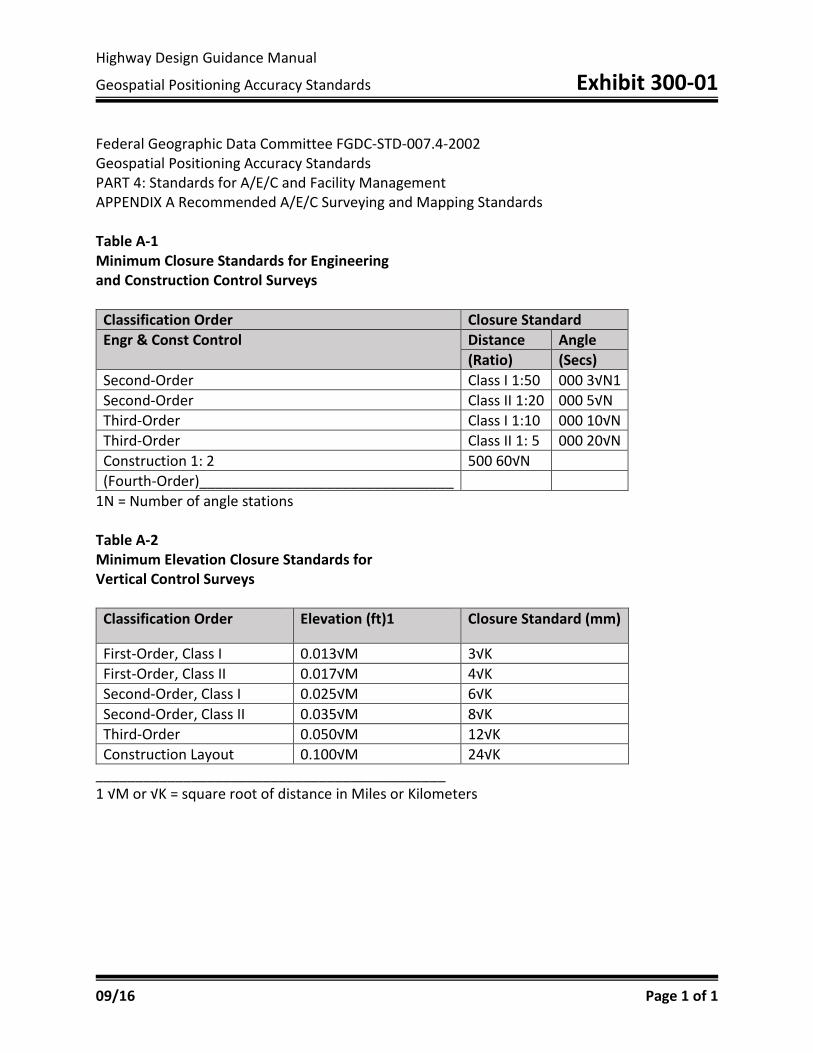
Highway Design Guidance Manual
Geospatial Positioning Accuracy Standards Exhibit 300-01
09/16 Page 1 of 1
Federal Geographic Data Committee FGDC-STD-007.4-2002 Geospatial Positioning Accuracy Standards PART 4: Standards for A/E/C and Facility Management APPENDIX A Recommended A/E/C Surveying and Mapping Standards Table A-1 Minimum Closure Standards for Engineering and Construction Control Surveys
Classification Order Closure Standard Engr & Const Control Distance Angle
(Ratio) (Secs) Second-Order Class I 1:50 000 3√N1 Second-Order Class II 1:20 000 5√N Third-Order Class I 1:10 000 10√N Third-Order Class II 1: 5 000 20√N Construction 1: 2 500 60√N (Fourth-Order)________________________________
1N = Number of angle stations Table A-2 Minimum Elevation Closure Standards for Vertical Control Surveys
Classification Order Elevation (ft)1 Closure Standard (mm)
First-Order, Class I 0.013√M 3√K First-Order, Class II 0.017√M 4√K Second-Order, Class I 0.025√M 6√K Second-Order, Class II 0.035√M 8√K Third-Order 0.050√M 12√K Construction Layout 0.100√M 24√K
____________________________________________ 1 √M or √K = square root of distance in Miles or Kilometers
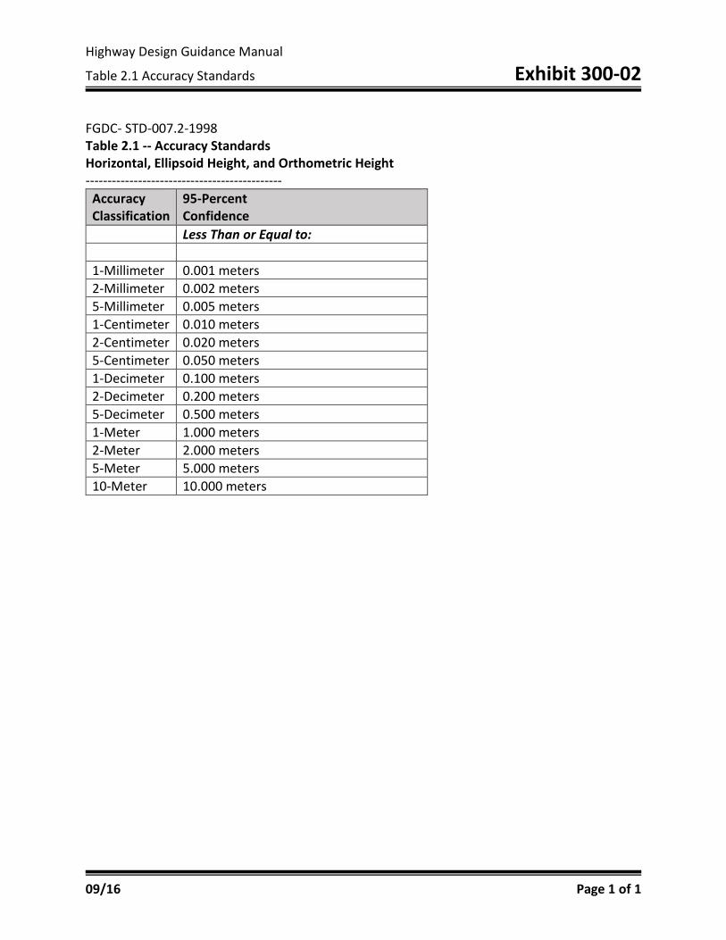
Highway Design Guidance Manual
Table 2.1 Accuracy Standards Exhibit 300-02
09/16 Page 1 of 1
FGDC- STD-007.2-1998 Table 2.1 -- Accuracy Standards Horizontal, Ellipsoid Height, and Orthometric Height ---------------------------------------------
Accuracy Classification
95-Percent Confidence
Less Than or Equal to: 1-Millimeter 0.001 meters 2-Millimeter 0.002 meters 5-Millimeter 0.005 meters 1-Centimeter 0.010 meters 2-Centimeter 0.020 meters 5-Centimeter 0.050 meters 1-Decimeter 0.100 meters 2-Decimeter 0.200 meters 5-Decimeter 0.500 meters 1-Meter 1.000 meters 2-Meter 2.000 meters 5-Meter 5.000 meters 10-Meter 10.000 meters

Highway Design Guidance Manual
Standards & Specifications for Geodetic Control Networks Exhibit 300-03
09/16 Page 1 of 1
Standards and Specifications for Geodetic Control Networks, Federal Geodetic Control Committee (1984)
When a vertical control point is classified with a particular order and class, NGS certifies that the orthometric elevation at that point bears a relation of specific accuracy to the elevations of all other points in the vertical control network. That relation is expressed as an elevation difference accuracy, b. An elevation difference accuracy is the relative elevation error between a pair of control points that is scaled by the square root of their horizontal separation traced along existing level routes.
Table 2.2 Elevation Accuracy Standards
Classifications Maximum elevation difference accuracy First-order, class I 0.5 First-order, classs II 0.7 Second-order, class I 1.0 Second-order, class II 1.3 Third-order 2.0
An elevation difference accuracy, b, is computed from a minimally constrained correctly weighted, least squares adjustment by
𝑏𝑏 = 𝑆𝑆/√𝑑𝑑
where
d = approximate horizontal distance in kilometers between control point positions traced along existing level routes.
S = propagated standard deviation of elevation difference in millimeters between survey control points obtained from the least squares adjustment. Note that the units of b are
(mm)/ √ (𝑘𝑘𝑘𝑘).
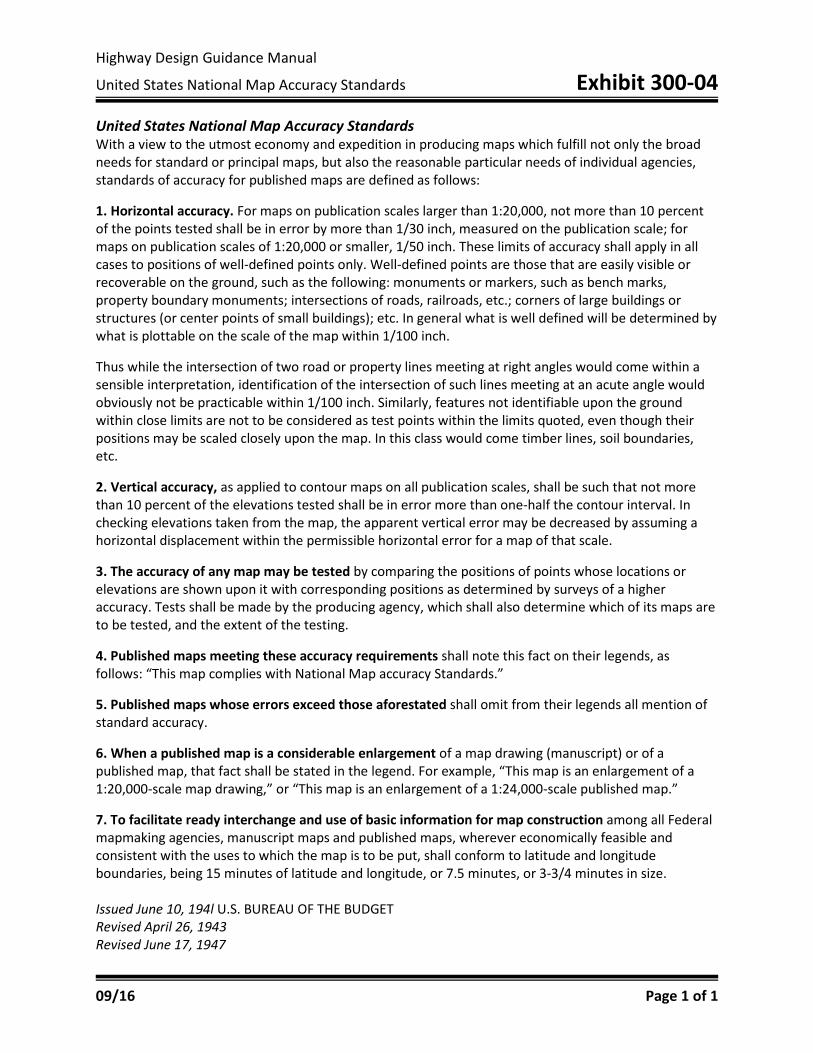
Highway Design Guidance Manual
United States National Map Accuracy Standards Exhibit 300-04
09/16 Page 1 of 1
United States National Map Accuracy Standards With a view to the utmost economy and expedition in producing maps which fulfill not only the broad needs for standard or principal maps, but also the reasonable particular needs of individual agencies, standards of accuracy for published maps are defined as follows: 1. Horizontal accuracy. For maps on publication scales larger than 1:20,000, not more than 10 percent of the points tested shall be in error by more than 1/30 inch, measured on the publication scale; for maps on publication scales of 1:20,000 or smaller, 1/50 inch. These limits of accuracy shall apply in all cases to positions of well-defined points only. Well-defined points are those that are easily visible or recoverable on the ground, such as the following: monuments or markers, such as bench marks, property boundary monuments; intersections of roads, railroads, etc.; corners of large buildings or structures (or center points of small buildings); etc. In general what is well defined will be determined by what is plottable on the scale of the map within 1/100 inch. Thus while the intersection of two road or property lines meeting at right angles would come within a sensible interpretation, identification of the intersection of such lines meeting at an acute angle would obviously not be practicable within 1/100 inch. Similarly, features not identifiable upon the ground within close limits are not to be considered as test points within the limits quoted, even though their positions may be scaled closely upon the map. In this class would come timber lines, soil boundaries, etc. 2. Vertical accuracy, as applied to contour maps on all publication scales, shall be such that not more than 10 percent of the elevations tested shall be in error more than one-half the contour interval. In checking elevations taken from the map, the apparent vertical error may be decreased by assuming a horizontal displacement within the permissible horizontal error for a map of that scale. 3. The accuracy of any map may be tested by comparing the positions of points whose locations or elevations are shown upon it with corresponding positions as determined by surveys of a higher accuracy. Tests shall be made by the producing agency, which shall also determine which of its maps are to be tested, and the extent of the testing. 4. Published maps meeting these accuracy requirements shall note this fact on their legends, as follows: “This map complies with National Map accuracy Standards.” 5. Published maps whose errors exceed those aforestated shall omit from their legends all mention of standard accuracy. 6. When a published map is a considerable enlargement of a map drawing (manuscript) or of a published map, that fact shall be stated in the legend. For example, “This map is an enlargement of a 1:20,000-scale map drawing,” or “This map is an enlargement of a 1:24,000-scale published map.” 7. To facilitate ready interchange and use of basic information for map construction among all Federal mapmaking agencies, manuscript maps and published maps, wherever economically feasible and consistent with the uses to which the map is to be put, shall conform to latitude and longitude boundaries, being 15 minutes of latitude and longitude, or 7.5 minutes, or 3-3/4 minutes in size. Issued June 10, 194l U.S. BUREAU OF THE BUDGET Revised April 26, 1943 Revised June 17, 1947
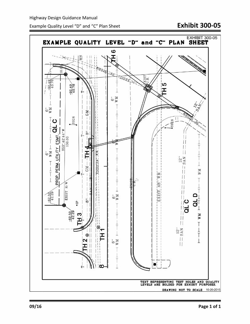
Highway Design Guidance Manual
Example Quality Level “D” and “C” Plan Sheet Exhibit 300-05
09/16 Page 1 of 1
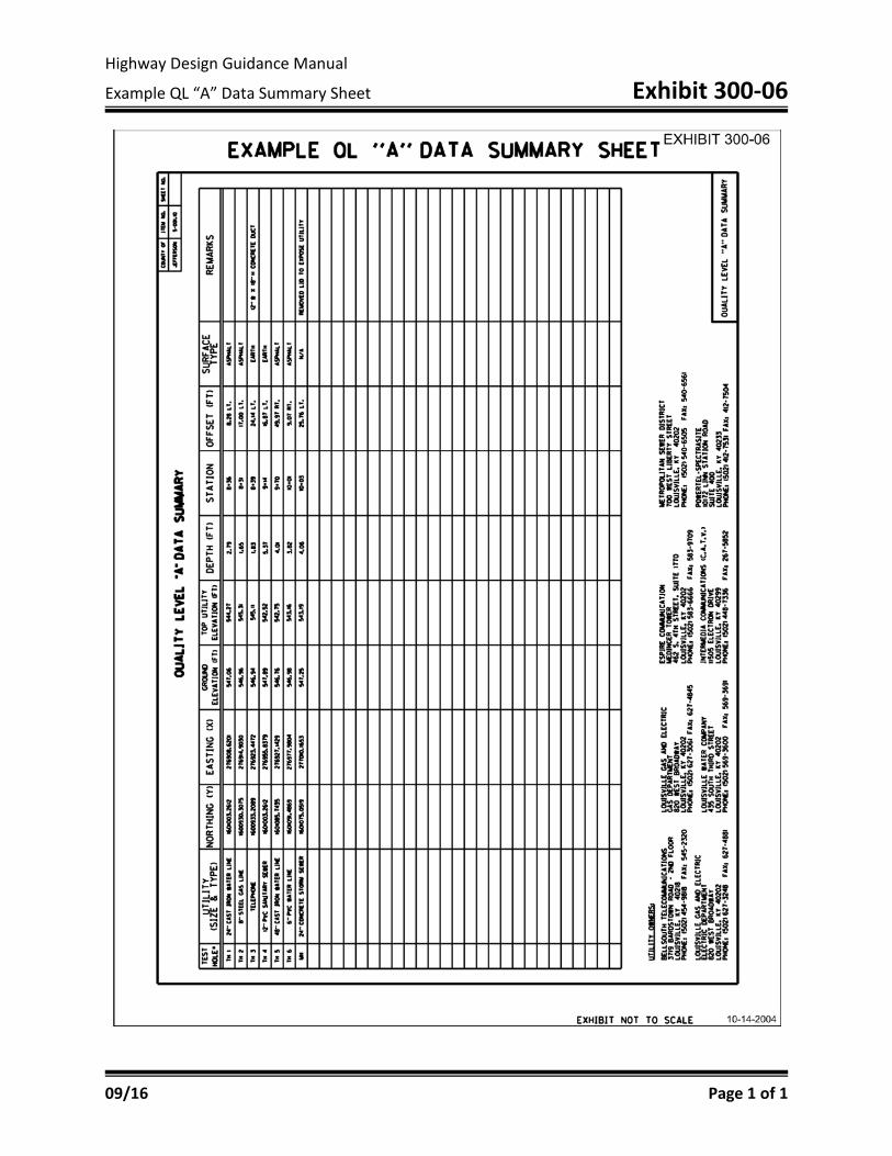
Highway Design Guidance Manual
Example QL “A” Data Summary Sheet Exhibit 300-06
09/16 Page 1 of 1
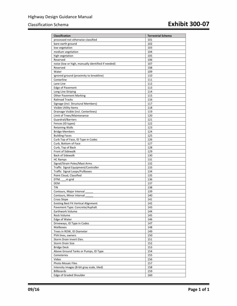
Highway Design Guidance Manual
Classification Schema Exhibit 300-07
09/16 Page 1 of 1
Classification Terrestrial Schema processed not otherwise classified 101 bare-earth ground 102 low vegetation 103 medium vegetation 104 high vegetation 105 Reserved 106 noise (low or high, manually identified if needed) 107 Reserved 108 Water 109 ignored ground (proximity to breakline) 110 Centerline 111 Lane Line 112 Edge of Pavement 113 Long Line Striping 114 Other Pavement Marking 115 Railroad Tracks 116 Signage (incl. Structural Members) 117 Visible Utility Items 118 Drainage Visible (incl. Centerlines) 119 Limit of Trees/Maintenance 120 Guardrail/Barriers 121 Fences (ID types) 122 Retaining Walls 123 Bridge Members 124 Building Faces 125 Curb Top of Face, ID Type in Codes 126 Curb, Bottom of Face 127 Curb, Top of Back 128 Front of Sidewalk 129 Back of Sidewalk 130 HC Ramps 131 Signal/Strain Poles/Mast Arms 132 Traffic Signal Equipment/Controller 133 Traffic Signal Loops/Pullboxes 134 Point Cloud, Classified 135 DTM, ___m grid 136 DEM 137 TIN 138 Contours, Major Interval _____ 139 Contours, Minor Interval _____ 140 Cross Slope 141 Existing Best Fit Vertical Alignment 142 Pavement Type: Concrete/Asphalt 143 Earthwork Volume 144 Rock Volume 145 Edge of Water 146 Driveways, ID Type in Codes 147 Mailboxes 148 Trees in ROW, ID Diameter 149 PVA lines, owners 150 Storm Drain Invert Elev. 151 Storm Drain Size 152 Bridge Deck 153 Above Ground Tanks or Pumps, ID Type 154 Cemeteries 155 Video 156 Photo Mosaic Files 157 Intensity images (8-bit gray scale, tiled) 158 Billboards 159 Edge of Graded Shoulder 160

Highway Design Guidance Manual
Control Monument Information Sheet Exhibit 300-08
09/16 Page 1 of 2

Highway Design Guidance Manual
Control Monument Information Sheet Exhibit 300-08
09/16 Page 2 of 2