incremental path-independent integrals in … path-independent integrals in inelastic and dynamic...
TRANSCRIPT
Engimwing Frachwe Mech,mlcs Vol. 20, No. 2, pp. 2OM44, 1984 001~7!%4/84 S3.00 + .oo Rinted in the U.S.A. ~ergamon hss Ltd.
INCREMENTAL PATH-INDEPENDENT INTEGRALS IN INELASTIC AND DYNAMIC
FRACTURE MECHANICS
S. N. ATLURIt and T. NISHIOKAt: Center for the Advancement of Computational Mechanics, School of Civil Engineering,
Georgia Institute of Technology, Atlanta, GA 30332, U.S.A.
and
M. NAKAGAKI Battelle Columbus Labs, Columbus, Ohio, U.S.A.
Ah&act-Certain incremental path-independent integrals, of relevance in the mechanics of fracture of elasticplastic materials described by a classical flow theory of plasticity, are presented. Both quasi-static as well as dynamic fracture situations are considered. The topics discussed include: (i) incremental path-independent integrals that characterize. the crack-tip fields in elastic-plastic materials; (ii) incremental integrals related to the incremental total potential energy difference; and (iii) the complementary or dual representations of these integrals. The use of these integrals is illustrated through some numerical examples. Comments are made on the utility of these integrals in postulating rational fracture criteria.
1. INTRODUCTION
THE MOST widely researched topic in the past decade or so, and the one that has made possible certain impressive advances in elastic-plastic fracture mechanics, has been the now well-known J integral introduced independently by Eshelby [l] and Rice[2]. It is also well known that J is in fact the component along the crack-line of a vector integral, and its significance is in the context of incipient self-similar growth of a crack in a (nonlinear) elastic material. In this case, J has the meaning of the rate of energy-release per unit of crack-extension. The path-independency of J can be established only ‘when the strain energy density (or stress working density) of the material is a single valued function of strain. In a deformation theory of plasticity, which is valid for radial monotonic loading but precludes unloading and which is mathematically equivalent to a nonlinear theory of elasticity, J still characterizes the crack-tip field and is still a path-independent integral. However, in this case, J does not have the meaning of an energy-release rate; it is simply the total potential-energy difference between two identical and identically (monotonically) loaded cracked bodies which differ in crack lengths by a differential amount. However, in a flow theory of plasticity, even under monotonic loading, the path-independence of J (as defined directly, using the total values of strain and stress and displacement, by Eshelby and Rice) cannot be established. Also, under arbitrary load histories which may include loading and unloading, J (as directly defined by Eshelby and Rice) is not only not path-independent, but also it does not have any physical meaning.
Significant advances have been made, however, in the problem of crack-growth initiation in monotonically loaded cracked structures. The principal contributions that made these possible may perhaps be identified as follows: (i) for stationary cracks in monotonically loaded bodies of a power-law hardening material, it has been shown by Hutchinson[3] and Rice and Rosengren[4] that the stresses and strains in the vicinity of the crack-tip under yielding conditions varying from small-scale to fully plastic are controlled by J; (ii) the work of Begley and Landes[5] and Rice et ul.[6] on the measurement of J from small laboratory test specimens; and (iii) simple procedures for estimation of J, by interpolating between fully plastic solutions and elastic solutions, based on the works of Bucci et uZ.[7j, Shih and Hutchinson[8,9] and Rice et al. [6].
On the other hand, a large amount of crack growth in a ductile material is necessarily
TRegents’ Professor of Mechanics, Georgia Institute of Technology. $Visiting Assistant Professor, Georgia Institute of Technology.
209

210 S. N. ATLURI et al.
accompanied by a significant non-proportional plastic deformation which invalidates the defor- mation theory of plasticity. Thus, the validity of J (as directly defined by Eshelby [l] and Rice[2]) is questionable under these circumstances. However, for limited amounts of crack growth, Hutchinson and Paris[lO] argue that the strain field undergoes a proportional increment due to an increment in applied loading and that J is still a controlling parameter. For such situations of J-controlled growth, Paris et al. [l l] introduced the concepts of a “tearing modulus” and “J-resistance curve” to analyze the stability of such growth. Using the above concepts, and the related concept of CTOA, engineering approaches to elastic-plastic fracture analyses were elaborated upon by Kumar et al. [12] and Kanninen et al. [13].
The mechanics of crack growth initiation in elastic-plastic materials subject to arbitrary load histories is not yet understood. Also situations, wherein substantial amounts (which are no longer within the limits[ IO] of J-controlled growth) of stable growth exist, are not fully understood. This state of affairs is due, in part, to the reason, as explained by Rice[l4] who (in 1968) stated, “We are . . . forced to employ a deformation plasticity formulation rather than the physically appropri- ate incremental formulation. This is a regrettable situation, but no success has been met in attempts to formulate similar general results for incremental plasticity”.
The main objective of this paper is to explore the subject of path-independent integrals in incremental (flow) theory if plasticity. Incremental path-independent integral parameters corre- sponding to an increment of externally imposed boundary traction and/or an increment of prescribed boundary displacement are considered. The features of these parameters, viz. (i) their path-independence; (ii) their measurability; (iii) their physical interpretation; and (iv) their role in characterizing the strength of the crack-tip fields are critically examined.
Recently one of the authors [ 151 has derived certain path-independent integrals, of relevance in the presence of cracks, in elastic and inelastic solids. The hypothesized material properties included: (i) finite and infinitesimal elasticity; (ii) rate independent incremental flow theory of plasticity; and (iii) rate-sensitive behaviour including elasto-viscoplasticity and creep. In each case, finite defor- mations are considered, along with the effects of body forces, material acceleration, and arbitrary traction/displacement conditions on the crack-face. The incremental or rate integral derived in [ 151, say AT, or (Fc) was used in the study of creep crack growth[l6, 171. However, even in elasticity (linear or nonlinear) (and thus in deformation theory of plasticity and monotonic loading), it has been found [ 181 that X(A T,) (wherein the summation extends over all loud increments from beginning to current state) is not equal to J.
However, in the present paper, which builds upon concepts earlier presented in [15], attention is focused on incremental parameters, which under assumptions of nonlinear elasticity (or deformation theory of plasticity and monotonic loading) and when integrated over the load path would be equal to J.
In Section 2 of the paper, we focus on an incremental parameter, denoted by AT,*, which: (i) is defined as a path-independent integral; (ii) is directly a measure of the crack-tip jields under a frow theory of plasticity; and (iii) is valid for arbitrary loading/unloading histories. However, under conditions of radial monotonic loading, when a deformation theory of plasticity (or effectively a nonlinear theory of elasticity) may be valid, EAT,* (with the summation being carried over the load path) is equal to J as directly defined by Eshelby and Rice.
In Section 3, we present a parameter, denoted by AT,, which: (i) is defined as a path-independent integral; (ii) is related to the incremental total potential energy difference between identical and identically loaded cracked bodies with slightly different crack lengths; (iii) is amenable to direct measurement on laboratory test specimens by measuring certain strain/displacement data at the external boundary of the specimen; (iv) is valid for arbitrary loading/unloading histories and consistent with the use of an incremental flow theory of plasticity; and (v) is such that it is equal to AT,* (the crack-tip parameter) plus another term involving a volume integral. Since this volume integral cannot, in general, be measured directly on a laboratory test specimen, one may use the now-well-known hybrid numerical-experimental method (or a “generation-type” calculation now so widely used in dynamic fracture mechanics [ 19,201) to evaluate (A Tf) from the directly measured (AT,). Once again, under conditions of radial monotonic loading when effectively a nonlinear elasticity theory is applicable, CAT, is equal to J as directly defined by Eshelby and Rice.
In both Sections 2 and 3, concepts of strain-energy and potential energy are used. In Section 4, we give complementary representations for (AT,*) and (AT,) using concepts of complementary
lmxementai pan-inde~ndent integrals in ineiastic and dynamic fracture mechanics 211
energy of the material and total complementary energy of the structure. These dual representations are useful in establishing bounds on (LIT;) and (AT,) that are evaluated from numerical (finite element!) solutions.
In Section 5, we elaborate on the relation between (AT,*) and (AT’) for an arbitrary increment of loading during either loa~ng/unloading.
In Section 6, we present the counterparts of the incremental path-inde~ndent integrals in elastic-plastic dynamic fracture, i.e. when material inertia is included in the considerations.
In Section 7, we briefly comment on possible finite deformation effects. In Section 8, several numerical results, which are mainly intended to illustrate the concepts introduced in Sections 2-6, tire included and discussed in detail.
Some of the contents of this paper have been presented by the authors at certain recent symposia[21-241. This paper, which is developed from elementary first principles for the most part, is at times too detailed in certain places. While this may be inconvenient for some readers, we hope that in the end this lengthy development would prove to be a very simple and readable account.
2. INCREMENTAL PATH-INDEPENDENT INTEGRALS RELATED TO CRACK-TIP FIELDS IN ELAS~C-PLAS~C ~A~~
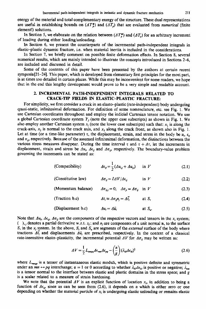
For simplicity, we first consider a crack in an elasto-plastic (rate-independent) body undergoing quasi-static, infinitesimal deformation. For definition of some nomenclature, etc. see Fig. 1. We use Cartesian coordinates throughout and employ the indicial Cartesian tensor notation. We use a global Cartesian coordinate system YJ (note the upper case subscripts) as shown in Fig. 1. We also employ another Cartesian system xi (note the lower case subscripts) such that: x1 is along the crack-axis, x2 is normal to the crack axis, and x3 along the crack front, as shown also in Fig. 1. Let at time (or a time-like parameter) z, the displacement, strain, and stress in the body be ui, ~~ and cii, respectively. Because of the assumed infinitesimal deformation, the distinctions between the various stress measures disappear. During the time interval z and z + AT, let the increments in displacement, strain and stress be Aui, AQ and Aav, respectively. The boundary-value problem governing the increments can be stated as:
(Compatibility)
(Constitutive law)
(Momentum balance)
(Traction b.c)
(Displacement b.c)
A~ii = f (AU, + AUj,i) in V (2.1)
Aa, = i?A V/Ace in V
Aged= 0; Asji= do, in V
Ati ~ A~iptj = A~ at S,
AU, = Aii, at S,.
(2.2)
(2.3)
(2.4)
(2.5)
Note that AUi, AQ, ACTS are the components of the respective vectors and tensors in the X, system; ( ),j denotes a partial derivative w.r.t. xj; and nj are components of a unit normal n, to the surface S, in the xi system. In the above, S, and S, are segments of the external surface of the body where tractions A< and displacements AUi are prescribed, respectively. In the context of a classical rate-insensitive elast~plasti~ty, the incremental potential A V for Arr@ may be written as:
A V = ; L,,,,,~A~:,A~~ - (&,Ac~,)~ (2.6)
where L,, is a tensor of instantaneous elastic moduli, which is positive definite and symmetric under an n?n ++pq in~r~hange; 01 = 1 or 0 according to whether &AQ, is positive or negative; & is a tensor normal to the interface between elastic and plastic domains in the stress space; and g is a scalar related to a measure of strain hardening.
We note that the potential AV is an explicit function of location xi, in addition to being a function of de, since as can be seen from (2.6), it depends on tl which is either zero or one depending on whether the material particle of xi is undergoing elastic unloading or remains elastic

212 S. N. ATLURI ef d.
%I t
Fig. 1. Nomenclature for a cracked body.
[01 = 0) or whether the particle is undergoing plastic loading [a = I]. Likewise, the parameter g depends on the level of strain hardening undergone by the material particle at xi.
For classical isotropically hardening materials, under the use of the well-known Huber-Mises-Hencky yield criterion, the constitutive law of (2.2) can be stated as:
(2.7)
where 1 and ,U are Lame Constants, 0,; = cq - (1/3)0,,6,; and the yield surface F is represented by:
F = [3J,(a;)] U2 - I$( FP) = 0
WP= s
CQA$. dr, and 1
J2(09 = -2 a&.
(2.8)
(2.9)
The strain-increments are postulated, as is common practice, to have the additive decomposition,
where the superscripts e and p represent “elastic” and “plastic” parts, respectively. The incremental stress-working density (per unit volume) between times r and r + AZ can be
written as:
AW=(~~+~A~~)d~~~*~A~,+AY (2.1 la)
=AW@+AWp (2.llb)
where
AW’=(~Y~+~A.~)AC~; AWp=(~v+;A~v)A~$. (2.12)
The component, along the crack-axis xi, of the path-independent vector integral defined in [15]

Incremental path-independent integrals in inelastic and dynamic fracture mechanics
can be written as:
213
(AT,), = R, + big s
[A Wnl - (ti + AtJAu,,] dS l-6
= Lim C-t0
[d Wn, - (ti + Ati)Aui,,] dS - s
a,,AevdV . >
(2.13) “r-V,
In the above, as per notation earlier explained, ( ),, implies a( )/ax,. A pictorial illustration of the pathst r, SC,. and r,, and volumes V, and V, is given in Fig. 1. The radius 6 is considered to be very small and shrunk to zero in the limiting process. Thus, the notation Lim will be omitted
hereafter, for convenience. In the event that the path r in (2.13) coincides with the external surface S of the body, it is understood that ti and At, in the contour integral will be considered as the prescribed tractions 6 and A<, respectively, on the external surface S, as well as the crack-surface
SC As noted in Ref. [15], the term R, in (2.13) is a “residue” which arises due to the dependence
of the incremental potential A V explicitly on location Xi within the volume (V-V,). Since A V is a quadratic in A+ we may write:
AV=;Aa,d$ 2 A %tE&A $ (2.14)
where E& is the elastic-plastic constitutive tensor as defined through (2.7). Note that:
EL!, = EL& (xm), g (-41
where a and g are plasticity parameters defined earlier. Now,
(2.15)
(2.16)
Hence,
Thus,
(2.17)
Thus,
aA -= 4 axI explicit
; A~,idq, - ;Ao,ds,,,,.
Using (2.19) in eqns (88) and (92) of Ref. [15], it is seen that:
R, = s [
dv. “r-V< 1
(2.19)
(2.20)
Note once again that R, is a quantity that vanishes if AV is a single valued function of strain AC, (and thus does not depend explicitly on xi) as in any material description mathematically equivalent to a nonlinear theory of elasticity.
TThroughout this paper, it should be understood that r is a far-field path that is fixed in space.

214 S. N. ATLURI ef al.
In view of (2.20) we may slightly modify the definition of the path-independent integral (A 7’,‘,), and rewrite (2.13) as:
(AT,), = I
[A Wn, - (ti + AtJAu,,,] dS (2.21a) r,
From the dependence of (AT,), on the crack-tip fields as seen from eqn (2.21a), it is seen that it is a measure of the severity of the stress/strain fields near the crack-tip.
It is worthwhile to comment on the nature of path-independence of (AT,), as in eqn (2.21a, b). First (AT,), is defined through an integral over r,. On the other hand, when (AT,), is evaluated over a far-field contour r, there is an additional volume (area) term. However, for instance suppose we consider a closed contour which does not envelope the crack-tip, say I’* as in Fig. 1. Let the volume enclosed by r* be v *. Then it is easy to verify that:
This is so, because we may use the divergence theorem in a volume which does not contain non-integrable singularities. Thus, the first term of (2.22) can be written as:
s [A Wnl - (h + AtJAu,,] dS = aAw
dV r* f[
~ ax, - (oV+ AoJAE,, 1 ~A~,+~At~E~~,,,df,+At,,do,-(o,+A~~)Ac,, dV 1
(2.23)
wherein (2.19) has been used. From (2.23) one can immediately verify the validity of (2.22). This feature of (AT,),, namely that it vanishes over a closed path r* (and the enclosed volume) not enclosing the crack-tip, is analogous to that of the well-known J integral.
For a deformation theory of plasticity, the well-known J integral (actually the component of a vector-integral along xi axis, denoted herein by J1) is defined as:
J1 = s
[ Wn, - tiui,,] dS (2.24a) r,
= I [ Wn, - tiui,l] dS (2.24b) r + Gr
Because of (2.24a), J,, in a deformation theory of plasticity, characterizes the crack-tip singular fields. The path-independence of J, in nonlinear elasticity, as embodied in eqn (2.24a, b), prevails due to the facts: (i) W is a single-valued function of the total strain; and (ii) the stress-state is in equilibrium.
One may formally take an increment of J1 of (2.24) as:
AJI = s
[A Wn, - (ti + Ati)AUi,, - AtiU,,] dS r,
= s
[A Wn, - (ti + Ati)Aql - At,+] dS r+s,,
(2.25a)
(2.25b)
where A W = (au + ~A+)AQ. Of course, under the assumption of the validity of deformation theory

Incremental pan-ind~nd~t integrals in inelastic and dynamic fracture mechanics
of plasticity or of nonlinear elasticity, A.& is path independent. This is so because:
In arriving at (2.26), the conditions that: (i) in nonlinear elasticity A W is not an explicit function of x, and (ii) oii and Au, satisfy the quasi-static equilibrium, are used. Now, in nonlinear elasticity,
Thus, eqn (2.26) is identically equal to zero. Thus, in nonlinear elasticity, AJ, is path independent. Further, the definition of AJ, as in (2.25a) makes it apparent that it is an “incremental” measure of crack-tip singular fields in nonlinear elasticity. Further, the definition of A./, as in (2.25b) [of course, equal to that in (2.25a) only in nonlinear elasticity] makes it possible to directly measure AJ, since it involves only far-field quantities; and, in a test specimen, Z can be taken to coincide with the external surface S of the test specimen.
Under incremental theory of plasticity, one may define a parameter (ATb)l to serve as an “incremental” measure of the strength of the crack-tip strain/stress fields, as:
(A Tfh = [A WRZ, - (ti + AtJAUi,l - AtiUi,,] dS (2.28)
where, it is now understood that A W = A We + A v = (au + $A~da&(d$ + A+. Further, we consider the above definition of (AT,*), as a measure of the crack-tip fields to be valid under either loading or unloading conditions at either the global level or near the crack-tip.
Now we derive an expression for (AT;), that involves integration on a far-field contour. To this end, let
(AT:), = s [A WPZ~ - (ti + AtJAUi,! - AfiU,,] dS + (Al:), r + .k
(2.29)
where (dl:), is to be determined such that the expressions for (AT;), as in (2.28) and (2.29) are identi~ly equal. Thus, we see that:
(AZf), = - s [A Wnl - (ti + AtJAU<,l - AtiUi,l] dS r+s,-r,
(2.30)
(2.31)
(2.32)
(2.33)

216 S. N. ATLURI et a/.
In going from (2.3 1) to (2.32), the quasi-static equilibrium conditions have been used; while in going from (2.32) to (2.33), eqn (2.19) has been used.
Thus, the path-independent expression for (AT,*), can be written as:
(AT;), = s [A Wn, - (ti + Ati)Aql - Atiz+] dS rr
(2.34a)
= s [A W’n, - (ti + Ati)AUi,l - At++] dS r + &r
(AT:), is now path independent in the sense demonstrated above, in that, when (2.34b) is evaluated over a closed contour f * (and the enclosed volume) not enclosing the crack-tip, it vanishes identically. Note that this path-independency of (AT:), is valid under either loading or unloading. Note also that there is nothing that precludes its validity in the case of growing cracks in elastic-plastic materials.
Now, comparing (2.21a) and (2.34a), it is seen that:
(AT;), = (AT,), - s
AtiUi,l dS* (2.35) r,
Also, in a computational evaluation of (AT;),, it is, in general, easier to use (2.34b) rather than (2.34a). (AT;), of (2.34) is clearly an incremental parameter that characterizes the crack-tip fields in either loading or unloading and it, or its sum over the load history, may be postulated as a material property. However, it appears to be difficult to directly measure (AT;), experimentally, because: (i) in general, it is extremely difficult to directly evaluate (2.34a) experimentally; (ii) even when F in (2.34b) is taken to be the external boundary of a specimen, it is still inconvenient to measure the term involving the volume.
With the motivation of finding an incremental parameter which: (i) is of relevance in elastic-plastic fracture; (ii) is defined as a path-independent integral; (iii) is valid in arbitrary loading/unloading histories; and (iv) is easily measurable in a laboratory test specimen, we now turn our attention to yet another parameter, denoted herein as (AT,).
3. INCREMENTAL PATH-INDEPENDENT INTEGRAL (d T’), RELATED TO INCREMENTAL TOTAL POTENTIAL
ENERGY DIFFERENCE:
Consider two cracked bodies, identical in geometry in every detail except that the crack in the second body is longer than that in the first by (da), as depicted in Figs. 2(a) and (b). We consider both the bodies to be subjected to identical load histories, which may involve arbitrary loading and unloading as shown in Figs. 3(a) and (b). The loading may be both of the “load-control” type on a portion S, of the external surface of the body (as in Fig. 3a), as well as of a “displacement control” type on a portion S, of the external surface of the body (as in Fig. 3b).
To begin with, we consider a monotonic loading of the first specimen along the path OA in Fig. 3 and a similar monotonic loading of the second specimen along path OA ’ to the same level of external loading [< on S, as in Fig. 3a and rji on S, as in Fig. 3b] as in the first specimen. It can be shown that at least during monotonic loading, even under a deformation theory of plasticity, the sum of the areas OAA’ in Figs. 3(a) and (b), respectively, is approximately equal to the J integral, evaluated as a contour integral in the jrst body, at the equilibrium state corresponding to the applied “loading”, c on S, and i& on S, respectively, on thefirst body. The celebrated success of the concepts of J-integral is due, in a good measure, to the demonstration by Begley and Landes[5] that, under monotonic loading, J can be experimentally measured through an evaluation of ‘the areas OAA ’ of Figs. 3(a) and (b), respectively. Of course, simple formulae, as well as experimental procedures, have later been developed to measure J from single-specimen test data.
With the above in mind, we seek a parameter that would be related to the incremental area between the load-deformation curves of cracked bodies, that are identical in every respect except

path-independent integrals in inelastic and fracture 217
(a)
iii (b)
S"
(c )
Fig. 2. Two identical cracked bodies differing in crack lengths by (da) are shown in Figs. 2(a) and (b); the concept of subtracting out singularities is illustrated in Fig. 2(c).
for crack-lengths differing by an amount (da) [as in Figs. 2a and b], both of which are subject to identical load histories (which may include loading/unloading) as in Fig. 3. Such an incremental area, both in loading and unloading, is illustrated by the shaded area (1234) in Fig. 3 (Fig. 3a for loading 6 on S, and Fig. 3b for “loading” of ~7~ on S,,). Let this incremental area? be denoted as AA. It is seen from Fig. 3, that for the presently considered case of “loading” with < on S, and iii on S,, we have:
AA =da
In the above, A( ) denotes an increment of the quantity ( ) due to an increment in loading. Note that the negative sign in the second term on the r.h.s. of (3.1) is due to the fact, as illustrated in Figs. 3(a) and (b),
while,
dui
d&?d >o (3.2a)
dti < 0
G lii6xed
(3.2b)
tA further discussion of this incremental area, and its relation to the concept of incremental potential energy, is given in Appendix I.

218 S. N. ATLURI et al.
(Ui I imposed
Fig. 3. Identical loading/unloading histories (both load control and displacement control types) for the two cracked bodies differing in crack lengths by (da).
and (AA) represents sum of the areas (1234) from S, as well as S,,. It is important to note that (3.1) is valid both during loading as well as unloading.
When equilibrium prevails in both the bodies under the actions of the external “loading” (6 + A0 on S, and (Ui + AziJ on S,,, the balance of energy in eacht body, individually, implies that:
and
1 a;Ac; + z Aa;A+
> f( =
S, r;duf+~A<A~~)dS+Jsu(t~AC~+~At~Ati~)dS (3.4)
where V is the total volume of the cracked body. Let S be the total surface of V, including the crack surface. Without loss of generality, we assume that S = S, + S,.
In (3.3.4), ( )’ and ( )’ refer to the quantity ( ) associated with the same material particle in bodies 1 and 2, respectively. Thus, from Figs. 2(a) and (b) it is seen that:
and
CT: = a&); uil = t&+); Aah = da&Q; . . . etc. (3.5)
rsi = aO{P2); u: = ui(P2); doi = Aab{P,); . . , etc. (3.6)
j’It is assumed, for the moment, that the crack-tips remain stationary in both the bodies. If, during the considered interval t and T + AT, the crack-extends in one or both the bodies, an incremental energy release term should be included on one or both the left-hand sides of (3.3) and (3.4), respectively. However, it may be noted that in the limit when crack growth Aa, in either body, tends to zero, this energy release, under elastic-plastic conditions, is xero[25,26].

Incremental path-independent integrals in inelastic and dynamic fracture mechanics 219
Note that while pz and P2 represent the same material particle in bodies 1 and 2, respectively (see Figs. 2a and b), the points p1 and Pz are located at the sume distance and orientation [i.e. r, 8 as in Figs. 2a and b] from the crack-tips in bodies 1 and 2, respectively. Thus, it is seen that:
(3.7)
since, the geometries and load-histories are identical in bodies 1 and 2 respectively. The nature of singularity, if any, in the stresses, as a function of (r, 0) is the same in the two bodies, except that the “strength” of the singularity may depend on the crack length a. Thus, (&r&la) has the same singular dependence, if any, on (r) as (BJ itself.
On the other hand, it is seen that:
a,&) - a&) = 2 da 1
since pz and p, are two neighboring particles in the same body, body 1. Thus, from (3.7) and (34, it is seen that:
With similar reasoning, one may also write:
A a,,(&) - A O&P,) = (a;2 a;;) da
Au,@‘,) - &W = (!$!! -!A$)&
AfdP,)-A&+)=($-z)da.
(3.9)
(3.10a)
(3.1Oc)
(3.10d)
(3.10e)
Suppose that we consider the same material particle, identified by pz and P2, respectively, at the traction prescribed boundaries S, of bodies 1 and 2. Since both the bodies are assumed to be subject to the same tractions, clearly ti(P2) - fi(pz) = 0 at S,. Since the unit normal nj is the same for two bodies of identical geometries with identical S,, it then follows that:
aa,, aa,, &2 - ax,
at S,.
For identical reasons, it also follows that, at the displacement prescribed boundary S,,
aui aui
aa - ax, at S,.
(3.11)
Likewise,
a.& _aAaij at s
aa ax, f (3.13)
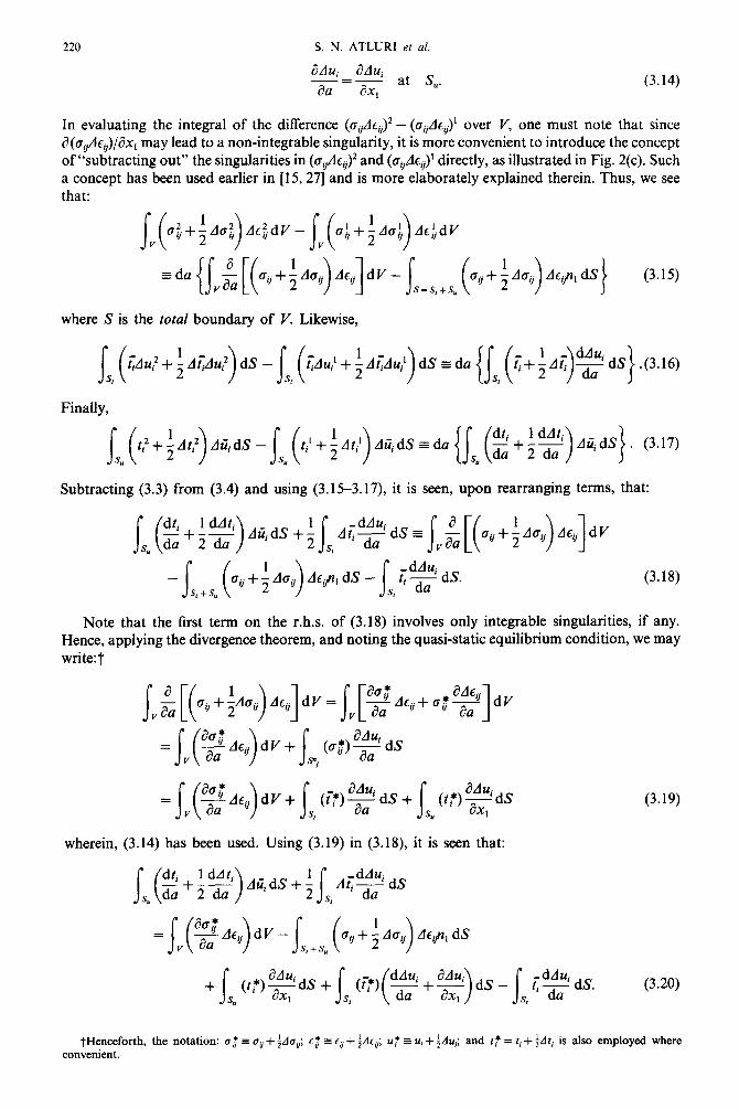
220 S. N. ATLURI er al.
adu, aAui at s -=- aa ax, U.
(3.14)
In evaluating the integral of the difference (agAqJ2 - (a,/dQ’ over V, one must note that since a(ovAcJ/&c, may lead to a non-integrable singularity, it is more convenient to introduce the concept of “subtracting out” the singularities in (aiiAcJ2 and (o,Ac,)’ directly, as illustrated in Fig. 2(c). Such a concept has been used earlier in [15,27] and is more elaborately explained therein. Thus, we see that:
where S is the total boundary of V. Likewise,
<Au’+;A@u’)dS - js, ( ~Au~+fA~Au,‘)dS~do{~~,(~+fAi$~dS).(3.16)
Finally,
S,(ti,~At:>A,,d,_S,(t~+~At:>,,d,~d,iS,(~+f~)AqdSj. (3.17)
Subtracting (3.3) from (3.4) and using (3.153.17), it is seen, upon rearranging terms, that:
(3.18)
Note that the first term on the r.h.s. of (3.18) involves only integrable singularities, if any. Hence, applying the divergence theorem, and noting the quasi-static equilibrium condition, we may write:i
(3.19)
wherein, (3.14) has been used. Using (3.19) in (3.18), it is seen that:
j-Henceforth, the notation: (r: = uq + $lu,; L$ s cII + fdc,; uf s ui + fdu,; and ft = f, + fdr, is also employed where convenient.

Incremental path-independent integrals in inelastic and dynamic fracture mechanics
Hence, it follows that:
221
We may also write, since dq/da = 0 at S,, that:
(3.22)
AR= f3.25)
In the case of monotonic loading, and when deformation theory of plasticity or nonlinear elasticity theory may be deemed to be valid, we see that:
(3.26)
(where, then W would be the “strain energy density”). Thus, for deformation theory of plasticity or nonlinear elasticity, (3.26) implies that dR = 0.
Thus, in monotonic loading of cracked structures as indicated by the curves OA and OA’ in Fig. 3, the ~~re~e~t~ area (1234) d&r&g the young cycle may be co~i~red to be given by the cmtour integral on the r.h.s. of (3.23). l%e conclusion that AR is identically zero is not in general valid in the case of unloading. In general, one may write, in the context of infinitesimal deformations,
Thus,
AR z ARe -I- ARP
= (3.29a)
(3.29b)

222 S. N. ATLURI et al.
In the case of classical elasto-plasticity, it may immediately be seen that, in general, AR’ = 0. Thus, in general, in elastoplasticity,
AR = A,,.% _ 2 AL?.
‘I aa aa ‘I
dV
’ (3.30)
Further, since A.c$ = 0 during unloading as indicated by paths AB and AB’, the relation for AR during elastic-unloading can be written as:
AR = s Ao..!% dV
V “iTa ’ (3.31)
Thus, we note in summary that: (i) AR in (3.25) is zero during monotonic loading when deformation theory may be valid; (ii) AR is given by (3.31) during elastic unloading of the entire structure and precluding the possibility of reverse plasticity; (iii) in any event, AR E ARP as given in (3.29b). The absolute magnitude of AR has been illustrated in a numerical example wherein AA and the contour integral on the r.h.s. of (3.24) are directly evaluated.
We now define an incremental parameter (AT,),, for both loading an unloading, for elasto-plastic cracked bodies, as:
Recall that S includes the crack-face also and is the external boundary of the cracked-body under consideration. We now define A T, as a path -independent integral for incremental elasto-plasticity. Thus, we set:
(AT,), = A Wn, - (ti + A tJ
s I aAui =
r + &r A Wn, - (ti + Ati) ax -
1
(3.33)
where r is any contour enclosing the crack-tip, and both r and SC, are shown in Fig. 1; and (AZ,), is to be determined such that eqn (3.33) is valid. From (3.33), since the volume between the external boundary S and the considered internal contour r does not contain any singularities, we see that:
(AZ,), = adu.
AWnI -(ti+ Ati)*- Ati dS 1 I 1 (3.34a)
(3.34b)
where V,. is the volume between the crack-tip and r (see Fig. 4). Equation (3.34b) follows from (3.34a) in much the same way that (2.33) followed from (2.31) as explained before. For the same reasons as also explained before, for nonlinear theory of elasticity or under conditions for validity of a deformation theory of plasticity, (AZ,), = 0. However, for arbitrary loading/unloading in an elastic-plastic material described by incremental theory of plasticity; (AZ,), # 0. Thus, eqn (3.33)

Incremental path-independent integrals in inelastic and dynamic fracture mechanics 223
-.-.- H10.061
I
DIMENSIONS IN (ml
Fig. 4. The compact tension specimen used in the analyses.
may be rewritten as:
(3.35)
It is apparent from (3.35) that when r is shrunk to r,, the value of ATp depends not only on a contour integral on r, but also on an integral over the volume (V - V,). Thus, even though A T, is a parameter that is measurable, it is not solely related to the strength of the crack-tip fields.
From (3.32) it is seen that ATp can be ex~~men~lly evaluated by measuring the incremental area AA between the load-displacement diagrams (for S, and S, as in Fig. 3) for two identical cracked specimens (with slightly different crack-lengths) or by directly measuring the traction/displacement data on the boundary of a single specimen. We comment further on this single specimen measurement method. First note that since
du. ddu.
id=O=-;i;;! at S,
and
d”_-o-dAti at s
da -da t
we may rewrite (3.1) as:
(3.36a)
(3.36b)
(3.37)
From (3.25), upon using divergence theorem, we may write:?
TNote that the direction cosines n, at S are not functions of a; hence, &t/&z 3 nj au,:/&

224 S. N. ATLURI et al.
Using (3.37) and (3.38) in (3.33) we have:t
(A Tp), =&AA)-AR= Js{ -[~+;~]d,+[$+f~]~z+dS (3.39)
From (3.38), (3.32) and (3.35), we state in summary:
AA-AR
= A Wn, - (ti - At,)
adu. = Awn,-(t,+dti)-&-Ati2
1 1
(3.40a)
(3.40b)
(3.4Oc)
(34Od)
(3.4w
The interpretations of (AT,) as in (3.40a), (3.4Ob) and (34Od) may make it amenable for experimental measurements. As noted, (AT,) is not solely a crack-tip field strength parameter. However, the relation between (d T,) and the parameter (AT;), which is described in Section 2 and which is directly a measure of crack-tip field strength, will be discussed shortly. Prior to discussing this relationship, we introduce, however, certain complementary representations for (AT,) and (AT;) in terms of complementary energy quantities, in Section 4.
It is also interesting to observe that even though at the beginning in eqns (3.3) and (3.4) the assumption of a stationary crack-tip was invoked, there is nothing in the definition of the path-independent integral (d T,> in eqns (3.40b-e) that precludes its validity in the case of growing cracks. The physical meaning of (AT,) in such a case is, however, somewhat obscure. However, even in the case of growing cracks, (AT,) can be measured experimentally, using (3.40b).
4. COMPLEMENTARY REPRESENTATIONS OF (d T;) AND (AT,)
Let us first consider monotonic loading of a finitely elastic body (or equivalently, one in which a deformation theory may be considered valid). Consider two identical bodies, with crack lengths differing by (da) and being subjected to identical (monotonic) loading histories. Let the bodies, each of total volume V and (total) external surface S, be subjected to external tractions < at S, and displacements I& at S, [S = S, + SJ. Then the total potential energy and complementary energy in each body can be written as:
tNote that in (3.39) and (3.40), (atJa~,) = t~,(a~~/,x~,).

Incremental path-ind~nd~t integrals in inelastic and dynamic fracture mechanics 225
r(a) =
s IV(@) dY -
s &i(d) dS (u = 1,2) (4.la)
V 4
@)=I -
s
W(d) dV + C II J z&i,/=) dS (or = 1,2) (4.16) V ‘x!
wherein the superscripts (1) and (2) denote the respective quantities in bodies 1 and 2, respectively. The “strain energy” stored in each body? at the final equilibrium state can be written as:
J V JJ u, Cd
W(@)dV= 6 du/@ dS + & 0 JJ ” ti’“’ dii, dS. (4.2)
S” 0
Hence, from (4.2) and (4.la), it follows that, at the final equilibrium state,
(4.3)
Similarly, at the final equilibrium state, the “complementary energy” in each body can be written as:
From (4. lb) and (4.4), it follows that at the final equilibrium state,
q@’ = -Js, jo’d<upts - f, j-“i’a’dtpu;dS + Jsutiit,ws.
From (4.3) and (49, it follows that, at the final equilibria state,
Hence, it follows that at the final equilibrium state,
dn da -.=e da da
and thus J has the complementary representation,f
J= -($)= -e)
as also noted in [271. From (4. lb) it then follows that:
(4.5)
(4.6)
(4.7)
(4.8)
For the moment it is assumed that the crack-tips remain stationary in both the bodies. SThis equation, as well as (4.8), apply at any point in the load history. That this J attains a critical value is the
well-known growth-initiation criterion.

226 S. N. ATLURI et al.
Using the arguments presented in Section 3, it is seen that:
,=l~d~-~~~,W~dS-s,li~(~-~)dS
=~~(~~~)dY-~~“~i~j~dS-~~~,W.dS+~~”~~j~dS.
However,
(4.9)
jvcvz dV = j)z,$u;dS + js,ryi~&S.
Since ao,/aa = &,/ax, at S,. Using (4.10) in (4.9), we find that:
J= s [
- Wp, + uinjz dS. S=S,+S” 1 1
For a path r* not enclosing the crack-tip,
J= S[ r*
- W~i+zqzj~]dI’=~P[ -z+$&]dY=O
when WC is a single valued function of bij It thus follows that:
J= -
S[ rr
Now we formally define:
AJ= - AWp, +nj(z+$$j)Aui+njf&%i]dS
-AWy,+nj(z+2)Aq+nj2q]dS rr
(4.10)
(4.11)
(4.12)
(4.13)
(4.14)
where
Jr+s,
A WC = e,Auti + f Actida, = c,Aa, + A V,. (4.15)
In elasto-plasticity, as before, we define an incremental parameter (AT;), to serve as a measure of the crack-tip field strength:
(AT;), = -AWy,+nj(~+~)Aui+nj~uidS].
As before, the far-field expression for (AT;), becomes:
(A T;h = s [ I- + Scr
-AWcn,fnj($+~)Aui+nj~ui]dS
+s,_, [Ao,(z+;%)- Af,(2+;%)]dY
In arriving at (4.17), use had been made of the relation,
adv, -aAv =- ax 1 explicit ax, explicit
= ; Ao~AQ~ - ; AcgAov,,
(4.16)
(4.17)
(4.18)
which can be derived in much the same way as (2.19).

Incremental path-independent integrals in inelastic and dynamic fracture mechanics 227
Now we derive a complements expression for the incremental area dA (either in loading or in unloading) as shown in Fig. 3. Once again, we have:
(4.19)
Now, when equilibrium prevails in each body, we have, from the balance? of energy,
s ilW!“dV=~~,df;(up’+f~~~))dS+~~” At. ,@,(; ; -) u. + -Au. dS for bodies, ot = 1,2. (4.20) V
From (4.20) it follows that:
f,dl;~+~~)dS+~~“~~~i~dS
s
BAW = ‘dV-
y aa s n,A WC dS -
s=s,+s, s
ddt. 2 zi, dS.
S, da
But,
s
ddt, _ -UidS =
s, da f(
aAcT. aty*&+$* dV
y aa )
-~~~($-$+,&dS =Jv(zAcv)dV
From (4.23) and (4.22), it follows that:
AlSO
-
(4.22)
(4.23)
(4.24)
afl; -- ax, >
nj dS
(4.25)
TAgain, for the moment, we assume the crack-tips to be stationary.
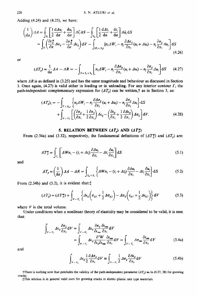
228 S. N. ATLURI ef ai.
Adding (4.24) and (4.25), we have:
(uj + hi) - nj 2 Au,] dS I
(4.26)
Or
(AT,)=-&4 -AR= - s i s=s,+s, (Ui + dui) - njz d~i dS (4.27)
1 1 where AR is as defined in (3.25) and has the same magnitude and behaviour as discussed in Section 3. Once again, (4.27) is valid either in loading or in unloading. For any interior contour I’, the path-inde~ndent complementary expression for (dT’) can be written,? as in Section 3, as:
(4.28)
5. RELATION BETWEEN @I’,) AND (0;)
From (2.34a) and (3.32), respectively, the fundamental definitions of (AT,*) and (d7”) are:
AT;= S[ a&4.
rr AWnI-(ti+AtJ ax I-,&.!% dS
1 ’ ax, 1 and
From (2.34b) and (5.2), it is evident that:$
(5.1)
(5.2)
(5.3)
where V is the total volume. Under conditions when a nonlinear theory of elasticity may be considered to be valid, it is seen
that:
I=: s AE.. a2w af”“,,= “-ax, s AQ at”dV
m ax, (54a) v- v, V- V,
and
s I ah. &..-2dV E
v- V‘ “2 ax, s v-v, (5.4b)
tThere is nothing now that precludes the validity of the path-independent parameter (dTP) as in (4.27, 28) for growing cracks.
fThis relation is in genera1 valid even for growing cracks in elastic-plastic rate type materials.
Incremental path-independent integrals in inelastic and dynamic fracture mechanics 229
In view of (5.4a, b), it is seen that under conditions of validity of a nonlinear theory of elasticity, we have from (5.3) that
(A Tp) = (A q> (5.5)
We now explore further the relation of (5.3) for Jrow theory of plasticity, which can account for both loading and unloading.
Also, from (3.1) and (3.32), we have:
For small deformation problems, we may use the decomposition,
Au,=Aui’+Au/‘; ui=ui’+u/‘. (5.7)
Thus,
1 -AA = (da)
= i (AA’ + AAP) (say) (5.8)
with obvious definitions for AA’ and AAP. Once again, we consider the two identical cracked bodies, with crack lengths differing by da, which are subject to identical load histories. In each body, the incremental elastic strain energy stored at equilibrium, assuming stationary crack-tips, may be written as:
s V
A~~a)dV=~~,(~+~A~)Au~)d~+~~“[t~)+ldt!”ldu;)d~ (a=1,2bodies) (5.9)
where
(5.10)
From (5.9) it follows that:
s aA W’ -dY-~~n,A~edS=~~,(~+~A~)~d~+~~“~+~~)Au:dS. (5.11)
v aa
It is seen that eqn (5.11) is entirely analogous to (3.18) except (3.18) refers to the case when both elastic as well as plastic parts of ui and Au, are considered. By carrying out the same algebra as in (3.19) to (3.23) we find that:
+ S[ Ao..&.i _ a(r,AEf. dV
V rl aa aa rl 1 (5.12)
However, the volume integral on the r.h.s. of (5.12) vanishes in the case of classical elasto-plasticity.

230 S. N. ATLURI ef al.
Furthermore, the remaining contour integral on the r.h.s. is path independent, i.e.
The above is true, since,
i?A W’ --(~,+AqJf$ ax,
Ag..s dV=O I ‘/ax, - 1
(5.13)
(5.14)
in the case of classical elasto-plasticity of homogeneous materials. Now, we may decompose AT,* such that
AT;=(ATf)‘+(AT;t)P= A W%, - (tl + Ati) -_&At.aU; dS adu: ax
1 1 ax, 1 adup
+ A WPn, - (ti + Ati) $- -At,% dS I 1 ax, 1 . (5.15)
From (5.6), (5.7), (5.13) and (5.15), it follows that:
AT,+AR =(ATf)‘+ k?% +$] A<dS -s, [;$ +;] Ati/‘dS} 2 da
(5.16)
where AR is given in (3.30). Equation (5.16), however, is, in general, valid only for stationary cracks up to the load level corresponding to growth initiation. As remarked earlier, (5.3) is, in general, valid for growing cracks.
6. INCREMENTAL, PATH-INDEPENDENT INTEGRALS IN DYNAMIC FRACTURE
For elastic problems, the authors[28,29] have recently derived a path-independent integral, which has the meaning of rate of energy release for dynamically propagating cracks, as
J; = f
[(W + K)n, - tiui,l] dS = [( W + K)n, - fiui,t] dS + [piiiUi,l - pti&] d V (6.1) rr s r + &r f vr - v,
where K is the kinetic energy density ( = $I&&), and (a) denotes the material derivative with respect to time. We may now define the incremental parameter (AT;) to serve as a measure of the incremental crack-tip fields in dynamic problems, as:
where
and
AT; = I
[(A W + AK)n, - (ti + AtJAui,l - Atit+] dS r,
(6.2)
(6.3a)
(6.3b) AK=p tii+fdrii Ati,. ( >

Incremental path-independent integrals in inelastic and dynamic fracture mechanics 231
The far-field expression for (dTf) can then be derived in the usual fashion, and the path- independent expression for AT: can then be written as:
AT; = I
[(A W + A@, - (tj + At,)Au,,, - dtpcu,,] dS r<
= s
[(A W + AK)n, - (ti + AtJAu,,, - At,z.+J dS r+s,
+ p (iii + LliiJAUi,, - p(tii + Arii)Ati,, + pAt&Ui,, - pAlii~i,* 1 dV. (6.4)
In deriving (6.4), we have used the linear momentum balance conditions, oiij = ptij and do,, = pdii,. Now, we derive the dynamic analogue of the (A Tb) parameter discussed in Section 3. Here, we
seek to measure “AA” as defined in (3.1). However, the “energy balance” equations? as in (3.3) and (3.4) are now replaced by:
s [A W(@ + AK’“‘] d V = V
~~,(i+fA~)Au!.‘ds+Ss(r”‘+fA~~‘)A~id~ [fora=1,2bodies]
(6.5) Thus, we obtain:
Thus, instead of (3.18), we have:
Following the same steps as in (3.W3.23), except using the “dynamic” momentum balance conditions as opposed to the “quasi-static” ones, we have:
where
& (AA) = s c dS S=S,+S,
(A W + AK)nl - (ti + Ati) $ - At.3 1 I ax, 1
+ S[ da,, a&; acr; dflU.
V ’ da - - aa At:, + p(ii, + A&) +
&lli~
- p(ti,+ AzQx +~A~i~-~A~i~ dV ‘I 0 & dA -AR = (AT,)
(6.8)
(6.9)
(6.10)
iAs in (j.3,4) we assume at this point that the crack-tips are stationary.

232 S. N. ATLURI et al.
and AR is the volume integral on the r.h.s. of eqn (6.8). Note that AR # 0 even in the case of elastic material behaviour, due to the presence of acceleration and velocity terms.
As before, the path-independent expression for ATp, involving any interior contour r, can be derived from (6.10) as:?
ACT,= (Aw+nK)n,-(ti+dri)~-A~-dU’ dS I lax, 1
Comparing (6.4) and (6.9, 10, 1 I), we have:
AT,=AT;fAQ
where
+ p(t& + Alii)Atii,, - p(Z& + AiiJA~i,l + PAZ&J - PAZ&~ 1 dV
and
-&AA=AT;+AQ+AR
where
. . . . ddu, 22, -p(~,+A~~)~+pAri,~-pAii,~ dV. 1 (6.14)
(6.11)
(6.12)
(6.13)
From (6.12, 13) it may be seen that even in elastodynamics, AT, # d T$ due to the acceleration and velocity terms in the volume integral in AQ. It can be shown that:
AQ+AR=--$ ddu.
n,(oii + AaJ -& + njAde
Further exploration of the dynamic case is deferred to a future publication.
7. EXTENSION TO FINITE DEFORMATIONS
The integrals (AT;) and (AT,) of Sections 2-6 can be easily extended to the case when defo~ations are considered to be finite, using essentially the concepts presented in Ref. [15]. Such finite deformation generalizations are not included here for the sake of brevity but can be found in [30].
8. SOME NUMERICAL RESULTS
We present here some numerical results, which are mainly intended to illustrate the concepts presented in the earlier sections and, as such, are not meant to be conclusive for the purposes of postulation of any fracture criteria.
We first consider the example of a stationary crack in a compact tension specimen which is subject to a history of loading/unloading/reloading. The geometry of the specimen is shown in Fig.
i(dT’) as defined in (6. IO, II) remains vaiid for a propagating crack as well.

Incremental path-independent integrals in inelastic and dynamic fracture mechanics 233
4. The material is considered to be A533B, with properties: Young’s modulus E = 199.95 GPa; Poisson’s ratio v = 0.3; yield stress r.ryS = 413 MPa. The uniaxial stress-strain relation, for small strains, is approximated by the Ramberg-Osgood relation,
E = (o/E) + (a/B,) (8.1)
with B, = 765.30 MPa; n = 10.08. A unit thickness of the specimen, under plane strain condition, is assumed in the analysis. A J2 flow theory of plasticity is used under the assumption of isotropic hardening. The specimen is assumed to be loaded under displacement-control.
Two types of finite element modeling are used as shown in Figs. 5(a) and (b), respectively. The details of these models are as follows: Type 1: (i) number of nodes: 221; (ii) number of elements: 70; (iii) around the crack-tip, eight four-noded elements are used with the displacement function
of the form, U(P, ?) = (1 -V%;(P) + (1/2)(rl - ~)(~CVXP) + (1/2)(tl + l)ti@), where f;(p) = a,+b,p(i= 1,2,3); O<p < 1; - 1 < q < 1, and where the local coordinates p (radial) and q (angular) are centered at the crack-tip. The second model has: (i) total nodes: 211; (ii) total elements: 60; (iii) eight six-noded collapsed (non-singular) elements are used around the crack-tip, while the remainder are the usual eight-noded isoparametric elements.
It is noted that in both the models the singular-fields near the crack-tip are not modeled (I priori in the elements near the crack-tip. It is also noted that in the first model the exact shape of the specimen is modeled, while in the second, the upper-half of the specimen is approximated by a rectangular shape (Fig. 5b).
First we present some results using the second finite element model (Fig. 5b). We consider two
PATH r.
(a) Type I
PATH I’,
Ii--- -.-. _____-.-. .-. ._ -. . _______-. .-.-.
!
r3 __- ._-._. -.- ._._. - -.-.
I
II ! _
I I I I I’2 1
F
I 1
.-.- _ _. . . .-.
I L I r II IM L ,,_I. 1 1
(b) Type 2
Fig. 5. Two types of finite element modeling of the compact tension specimen.
234 S. N. ATLURI et al.
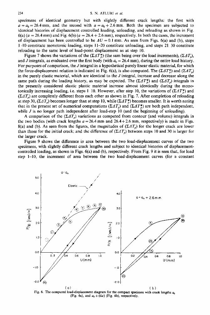
specimens of identical geometry but with slightly different crack lengths: the first with a = a, = 26.4 mm, and the second with a = a, + 2.6 mm. Both the specimen are subjected to identical histories of displacement controlled loading, unloading, and reloading as shown in Fig. 6(a) (a = 26.4 mm) and Fig. 6(b) (a = 26.4 + 2.6 mm), respectively. In both the cases, the increment of displacement has been controlled to be AU = 0.1 mm. As seen from Figs. 6(a) and (b), steps l-10 constitute monotonic loading, steps 1 l-20 constitute unloading, and steps 21-30 constitute reloading to the same level of load-point displacement as at step 10.
Figure 7 shows the variations of the (EAT,*) (the sum being over the load increments), (CAT,),
and Jintegrals, as evaluated over the first body (with a, = 26.4 mm), during the entire load history. For purposes of comparison, the Jintegral in a hypothetical purely linear elastic material, for which the force-displacement relation is indicated in Fig. 6(a), is also computed. The @AT,*) and @AT,)
in the purely elastic material, which are identical to the J integral, increase and decrease along the same path during the loading history, as may be expected. The (EAT,*) and @AT,) integrals in the presently considered elastic plastic material increase almost identically during the mono- tonically increasing loading, i.e. steps l-10. However, after step 10, the variations of @AT,*) and (CAT,) are completely different from each other as shown in Fig. 7. After completion of reloading at step 30, (Ed T,) becomes longer than at step 10, while (IZA Ta) becomes smaller. It is worth noting that in the present set of numerical computations (EAT,) and (XATf) are both path independent, while J is no longer path independent after load-step 10 (and the beginning of unloading).
A comparison of the (EAT,) variations as computed from contour (and volume) integrals in the two bodies (with crack lengths a = 26.4 mm and 26.4+ 2.6 mm, respectively) is made in Figs. 8(a) and (b). As seen from the figures, the magnitudes of (EAT,) for the longer crack are lower than those for the initial crack; and the difference of (EAT,) between steps 10 and 30 is larger for the larger crack.
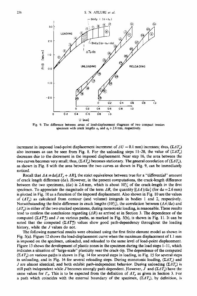
Figure 9 shows the difference in area between the two load-displacement curves of the two specimens, with slightly different crack lengths and subject to identical histories of displacement- controlled loading, as shown in Figs. 6(a) and (b), respectively. From Fig. 9 it is seen that, for load step l-10, the increment of area between the two load-displacement curves (for a constant
5.0
40
a=aO /’
/’
E’as+ic -Y /’ 4.0 t
I a=a,+2.6mm
(a) (b) Fig. 6. The computed load-displacement diagram for the compact specimen with crack lengths a,
(Fig. 6a), and a, + (da) (Fig. 6b), respectively.

Incremental pan-ind~de~t integrals in inelastic and dynamic fracture mechanics 235
0.2
ai
0.c
-0.1
-0.2
@
/
@ @
-------Elastic
IO U tmml
Elastoflastic
Elastic
Fig. 7. The variation of J, @I Tf) and @A $) during loadin~unloadingjroading of the compact tensIon specimen.
0 =u 0 Q =aO+ 2.6 mm 30
P”
0 0.2 0.4 0.6 0.8 1.0 0 Q2 0.4 0.6 0.6
U Emml U tmm3
Ia 1 (b)
Fig. 8. Computed (Ed Tp) during loading/unloading/reloading of a cumpact tension specimen with crack lengths a, pig. ga), and (4 + da) (Fig. 8b), respectively,
236 S. N. ATLURI et al.
i--Body I (o=a.,)
Body2(o=a,+da
U [mm1
Fig. 9. The difference between areas of load-displacement diagrams of two compact tension specimen with crack lengths a,, and a, + 2.6 mm, respectively.
increment in imposed load-point displacement increment of A U = 0.1 mm) increases; thus, @AT,) also increases as can be seen from Fig. 8. For the unloading steps 1 l-20, the value of (ZAT,) decreases due to the decrement in the imposed displacement. Near step 16, the area between the two curves becomes very small; thus, (XA T,) becomes stationary. The general correlation of (CA T,), as shown in Fig. 8 with the area between the two curves as shown in Fig. 9, can be immediately noticed.
Recall that AA =du[AT, + AR], the strict equivalence between true for a “differential” amount of crack length difference (da). However, in the present computations, the crack-length difference between the two specimens, (da) is 26mm, which is about 10% of the crack-length in the first specimen. To appreciate the magnitude of the term AR, the quantity [(AA)/da] (for da = 2.6 mm) is plotted in Fig. 10 as a function of the imposed displacement. Also shown in Fig. 10 are the values of (AT,) as calculated from contour (and volume) integrals in bodies 1 and 2, respectively. Notwithstanding the finite difference in crack lengths (lo%), the correlation between (AA/da) and (AT,) in either of the two cracked specimens, during monotonic loading, is reasonable. These results
tend to confirm the conclusions regarding (AR) as arrived at in Section 3. The dependence of the computed (CAT;) and J on various paths, as marked in Fig. 5(b), is shown in Fig. 11. It can be noted that the computed (EAT,*) values show good path-dependency throughout the loading history, while the J values do not.
The following numerical results were obtained using the first finite element model as shown in Fig. 5(a). Figure 12 shows the load-displacement curve when the maximum displacement of 1.1 mm is imposed on the specimen, unloaded, and reloaded to the same level of load-point displacement. Figure 13 shows the development of plastic zones in the specimen during the load steps l-l 1, which indicates a situation of “large-scale” plasticity near the crack-tip. The dependence of the computed (CAT,) on various paths is shown in Fig. 14 for several steps in loading, in Fig. 15 for several steps in unloading, and in Fig. 16 for several reloading steps. During monotonic loading, @AT,) and J are almost identical; and both exhibit path-independent behavior. During unloading (EAT,) is still path independent while J becomes strongly path dependent. However, J and @AT,) have the same values for f,. This is to be expected from the definition of ATp as given in Section 3. For a path which coincides with the external boundary of the specimen, @AT,), by definition, is

Incremental path-independent integrals in inelastic and dynamic fracture mechanics 237
n! 0 6
0
OQ a 0

238 S. N. ATLURI et af.
0 U~rrlmf
DISPLACEMENT
Fig. 12. Load-displacement diagram computed from the fmite element model shown in Fig. 5(b).
identical to (UJ). However, path r, coincides, for the most part, with the external surface except that it does not include the part marked “A” in Fig. 13. Thus, the expression for (LIT,) would involve not only a contour integral on r, but also a volume integral on “A”. However, the region A remains elastic throughout the load history. Hence, as can be seen from (3.35) and (3.341, the volume integral of (3.35) over the region A (which remains elastic) is zero. Thus, (ZdT,) on r4 would have the same value as on the extemd surface.
Fig. 13. Devekqment of plastic zones during various stages in loading.

Incremental path-independent integrals in inelastic and dynamic fracture mechanics
a
3
\ C
= 0
i
\ 4
m
a
a
\ 4
(D
a
a
\ a
\
a
(D 0
a
a
a
a
239

240 S. N. ATLURI et al.
PATH INDEPENDENCE (Relaadnq Steps)
0.3
a2
F 1
z 0.1 a
2 W
b-
0.c
- 0.1
0
-o- XAT, -_A- _ J step
,_-‘,, A-’ ,,’
A’
IO 20
PATH RADIUS r (mm)
30
Fig. 16. Path-dependence of computed J and (ZdT+,) during reloading.
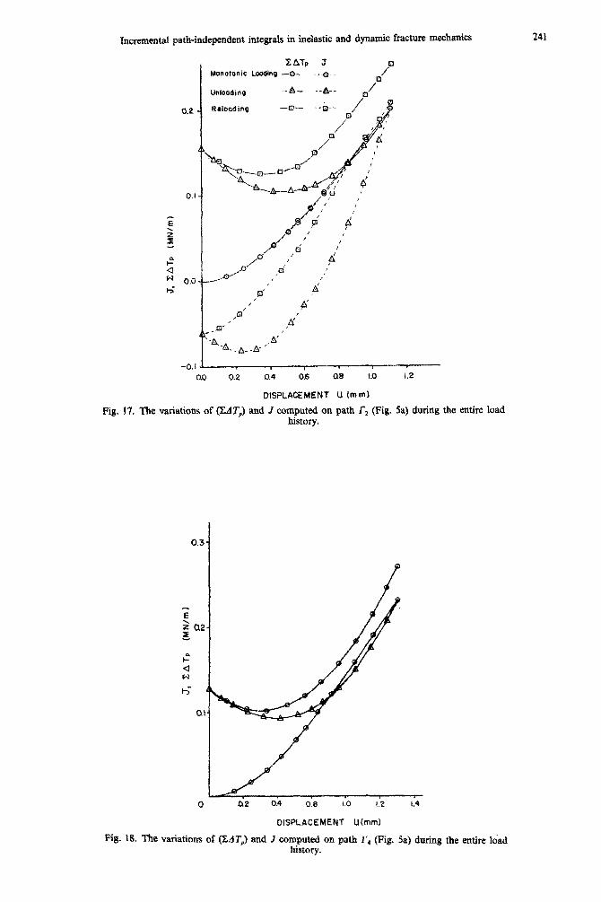
The variations of (Cl Tp) and J [actually computed as (Ed J)] on path r, (see Fig. 5a) during the entire loading history are shown in Fig. 17; while such variations on path r, (the external boundary) are shown in Fig. 18. From Fig. 18 it should be evident that (LIT,) = (Ll J) when evaluated only on the external boundary or any contour, between which and the external boundary the material remains purely elastic.
All the above results are primarily meant to be illustrative of the concepts presented in this paper. Postulation of fracture criteria based on these results, and their verification, are deferred to forthcoming reports.
CLOSURE The salient features of the present theoretical developments for incremental path-independent
integrals in elasto-plastic crack mechanics are as follows:
(i) The path-independent integral (d T,), reported earlier in Ref. [ 151 characterizes the crack-tip fields under either loading or unloading in a cracked elastic-plastic body when an incremental (flow) theory of plasticity is used. It is also valid in the case of growing cracks. However, even in the case of a monotonically loaded stationary crack, (&IT,) (the sum being on the load path) is not equal to the well-known J.
(ii) The path-independent integral (AT,*) of eqn (2.34) possesses all the features of (LIT,) described above. Further, it has the property that in the case of a stationary crack and monotonic loading, UT; is equal to J.
In~cntal path-~nd~nd~~t integrals in inelastic and dynamic fracture mechanics
XdiTp J Monotonic Loading -6. ___Q__ 7
Unloading _A.+_ __&.
0.0 0.2 0.4 0.6 06 I.0 1.2
DISPLACEMENT U mm)
Fig, 17. The variations of &IT,) and J computed on path f2 (Fig. 5a) during the entire load history.
DlsPLAc~~ENT U(mm)
Fig. 18. The variations of (Z&T,) and J computed on path r, (Fig. Sa) during the entire Ibad history.

242 S. N. ATLURI et af.
(iii) The equivalence of the difference (or incremental difference) between the areas under load-displacement diagrams, from S, and S, as in Fig. 3 for two identical cracked bodies differing in crack lengths by (da), and ZAT, or J (or AT,) is valid only in the case of monotonic loading of the cracked body with a stationary crack.
(iv) However, the contour (and volume) integral (AT,) as defined in (3.41) is valid under arbitrary loading and unloading as well as for growing cracks, when a flow theory of elasto- plasticity is used. It can be measured directly using, for instance, eqn (3.41b).
(v) Equations (4.17) and (4.28) give the dual or complementary representations for (AT,*) and (ATb). These representations are helpful in establishing bounds on the computed values of these integrals using approximate (finite element!) solutions.
(vi) The relation (5.3), between AT, and AT:, is valid for quasi-s~tically growing cracks and for loading or unloading. Since Air, is more easily measurable in a test specimen, eqn (5.3) is useful in a hybrid experimental-numerical study to determine the crack-tip parameter (AT;).
(vii) The quantity (AT,) evaluated on the external boundary of the body as in (3.4ld) is such that it is equal to AJ (formally the increment of J) evaluated also on the external boundary of the body.
(viii) Equations (6.2) and (6.11) define, respectively, the parameter AT: and AT, for dynamically propagating cracks in elastic plastic materials. Since AT, is more easily measurable in a test specimen, the relation between AT,* and AT, for a dynamically propagating crack, as given in (6.12) is useful in a hybrid experimental-numerical study to determine the crack-tip parameter
(A 1”:).
Ac&~owZedge~e~ts-me results herein were obtained during the course of investigations supported by the O&e of Naval Research, under contract NOOOM-78-C-0636 with Georgia Tech. The authors thank Dr. Y. Rajapakse of ONR for his continuous encouragement. The first author thanks Mr. F. W. Brust, a graduate student at Georgia Tech, who asked the questions that made him think. It is a pleasure to thank Ms. J. Webb for her patient assistance in preparing this typescript.
111
PI
Bl
t41
PI
I61
VI
@I
[91
[lOI
[lU
WI
1131
[I41
I151
f161
1171
REFERENCES J. D. Eshelby, The ~ntinuum theory of lattice defects. Solid State Physics, Vol. III, pp. 79-144. Academic Press, New York (1956). J. R. Rice, A path-independent integral and the approximate analysis of strain concentration by notches and cracks. J. Appl. Mech. 35, 376-386 (1968). J. W. Hutchinson, Singular behaviour at the end of a tensile crack in a hardening material. J. Mech. Phys. Soli&. 16(l), 1331 (1968). J. R. Rice and G. F. Rosengren, Plane strain deformation near a crack-tip in a power-law hardening material. J. Mech. Phys. Soliris 16(l), l-12 (1968). J. A. Begley and J. D. Landes, The J-integral as a fracture criterion in fracture toughness testing. Fracture To~h~ss, ASTM STP 514, l-39 (1972). J. R. Rice, P. C. Paris and J. G. Merkle, Some further results on J-integral analysis and estimates. Progress in Flaw Growth and Fracture Toughness Testing, ASTM STP 536, 231-245 (1973). R. J. Bucci, P. C. Paris, J. D. Landes and J. R. Rice, J-Integral estimation procedures, in Fracture Toughness, ASTM STP 514, 40-69 (1972). C. F. Shih and J. W. Hutchinson, Fully plastic solutions and large scale yielding estimates for plane stress crack problems. J. .&gag Mat. and Tech. 98(i),-289-295 (1976). C. F. Shih, J-Integral estimates for strain hardening materials in antiplane shear using fully plastic solutions. Mechanics of Crack Growth, ASTM STP 590, 3-22 (1976). J. W. Hutchinson and P. C. Paris, Stability analysis of J-controlled crack growth. Elastic-Plastic Fracture, ASTM STP 668, 37-64 (1979). P. C. Paris, H. Tada, A. Zahoor and H. Ernst, The theory of instability of the tearing mode of elastic-plastic crack growth. Elastic-Plastic Fracture, ASTIU STP 668, 5-36 (1979). V. Kumar, M. D. German and C. F. Shih, An Engineering Approach for Elastic-Plastic Fracture Analysis, EPRf NP-1931, Electric power Research Institute Report, July (1981). M. F. Kanninen et al., Development of a plastic fracture methodology, EPRI NP-1734, Project 601-1, Final Report, March (1981). J. R. Rice, Mathematical analysis in the mechanics of fracture. Fracture Vol. II (Mathematical Fundamentals) (Edited by H. Liebowitz), p. 213. Academic Press, New York (1968). S. N. Atluri, Path-independent integrals in finite elasticity, and inelasticity, with body forces, inertia, and arbitrary crack-face conditions. E?tgng Fracture Mech. 16(3), 341-364 (1982). R. B. Stonesifer and S. N. Atlmi, Gn a study of the (LIT), and C* integrals for fracture analysis under non-steady creep. Engns Fracture Meeh. la(S), 625-643 (1983). R. B. Stonesifer and S. N. Atluri, Moving singularity creep crack growth analyses with the (f& and C* integrals. Engng Fracture Mech. 16(a), 769-782 (1982).
[18] M. Nakagalci and S. N. Atluri, On a study of the use of the (f) integral in fracture analysis of solids with inelastic rate constitutive laws. J. Pressure Vessel Tech. 104(4), 331-337 (1982).
[19] A. S. Kobayashi, Hybrid experimental-numerical stress analysis. Murray Lecture, Society of Experimental Stress Analysis (1983). Also Report No. UWA/DME/TR-83/47, University of Washington, Seatth, Washington (1983).

Incremental path-independent integrals in inelastic and dynamic fracture mechanics 243
T. Nishioka and S. N. Atluri, Numerical analysis of dynamic crack propagation: generation and prediction studies. Engng. Fructure Mech. 16(3), 303-332 (1982). S. N. Atluri, Gn the (d T) integral in elasticplastic fracture, Paper presented at the Sessions of Pressure Vessels and Piping Division, ASME Winter Annual Meeting, Tucson, Arizona, Nov. (1982). M. Nakagaki and S. N. Athrri, Use of the (t) integral in elastic-plastic fracture. Presented at Workshop on Mechanics of Damage and Fracture, Stone Mountain, Georgia, Nov. 1982 (to appear in the Proceedings). T. Nishioka and S. N. Atluri, Studies of dynamic crack propagation using the (t) integral. Paper presented at Workshop on the Mechanics of Damage and Fracture, Stone Mountain, Georgia, Nov. 1982 (to appear in the Proceedings). S. N. Atluri and T. Nishioka, Path-independent integrals in dynamic fracture. Paper presented a Workshop on Dynamic Fracture, California Institute of Technology, Pasadena, 16-17 Feb. (1982) (to appear in the Proceedings). A. P. Kfouri and J. R. Rice, Elastic/plastic separation energy rate for crack advance in finite growth steps, in Fraciure, Vol. 1, pp. 43-59. ICF4, Waterloo, Canada (1977). M. Nakagaki, W. H. Chen and S. N. Atluri, A finite element analysis of stable crack growth-I. Elastic-Plastic Fracture, ASTM-STP 668. 195-213 (1979). H. D. Bui, Dual path independent integrals in the boundary-value problems of cracks. Engng Fracture Mech. 6, 287-296 (1974). T. Nishioka and S. N. Atluri, Path-independent integrals, energy release rates and general solutions of near-tip fields in mixed-mode dynamic fracture mechanics. Engng Fructure Mech. M(7), l-22 (1983). T. Nishioka and S. N. Atluri, Gn the computation of mixed-mode K-factors for a dynamically propagating crack, using path-independent integrals J;. Engng Fracture Mech. 20, 193-208 (1984). F. W. Brust, Ph.D. Thesis, Georgia Institute of Technology (under preparation). S. N. Atluri and H. Murakawa, Hybrid finite element models in nonlinear solid mechanics, in Finite Elements in Nonlinear Mechanics (Edited by P. G. Bergan ef al.), Vol. 1, pp. 341. Tapir Press, Norway (1977). S. N. Atluri, On some new general and complementary energy theorems for the rate problems of classical, finite strain elastoplasticity. J. Structural Mech. 8(l), 36-66 (1980).
WI
WI
[221
[231
[241
WI
WI
m
1281
[291
1;;;
[321
(Received 8 August 1983; received for publication 9 November 1983)
APPENDIX I Consider, for instance, the total potential energy (denoted by IJ) of a cracked elastic body subject to deadweight type
(conservative) loading:
lJ =~/‘(e,)dV-~s,i$idS
where V is the total volume, and S, is the portion of S where tractions are prescribed. We assume, for simplicity, that S = S, + S, and that non-zero displacements tij are prescribed on S,. At the final equilibrium state we have, for a stationary crack
Thus, at the final equilibrium state, we have from (1.1) and (1.2) that
From (1.1) and (1.4), we can find the rate of change of the equilibrium value of total potential energy of an elastic body with respect to crack length (denoted by dII/da) as:
wherein, both the cracked bodies, with crack lengths (a) and (a + da), respectively, have been assumed to be subject to the same “external” actions, 6 on S, and ~7~ on S,.
Since (dui/du) is zero on S, and ti=< on S,, we may write (1.5) as:
Since the body is elastic, and further, is assumed to be homogeneous, we may write
aw_awac, ac.. __,,A
aa a6, aa y da ’ 0.8)
In the absence of body forces, since oyJ- -0, we see that the first two terms on the extreme right-hand side of (1.7) vanish
244 S. N. ATLURI
in view of (1.8). Thus, in the end, we get the result:
~=-~r(Wr,-ri$)dS
“du. =- c c + d<dS + c
et al
(1.9a)
*dt, _ X dui dS.
Js. JO u- (1.9b)
Js, Jo aa Even though the integral in (L9a) is on the external boundary S, it is now well known that: (i) whenever W is a single valued function of eii; (ii) whenever the material is homogeneous; and (iii) whenever stress is in equilibrium, the integral in (1.9a) can be replaced by one over any internal contour r enclosing the crack-tip. Equation (L9b), on the other hand, has the clear meaning that it is the sum of: (a) the total area between the load-displacement curves of two identical elastic cracked bodies (with crack lengths differing by da) that are subject to identical < on S,; and (b) the total area between displacement-load curves of the said bodies that are subject to identical rir on S,
It is important to note that all the preceding discussion in this Appendix pertains to (linear or nonlinear) elastic bodies with stationary cracks, subject to conservative loads, such that a total potential at the jinal load state can be defined.
Suppose now we consider the case when incremental external loading (on both S, and SJ is superimposed on a current equilibrium state. Let the current displacement, strain and stress, in the current state say C,, as referred to the initial undeformed configuration, be ui, cii and eii, respectively. Let the incremental external loading be A< on S, and At& on S,. Let the corresponding incremental response of the cracked body be denoted by the quantities: Au,, 44 and Aul,, respectively. The state after the application of A< and At?, is denoted by C,,,, so that, formally, C,,, = C,+ AC.
The total potential energy n can be formally expanded in a “series” form (see [31] for a detailed explanation of the “total Lagrangean” approach) as:
where
II (C,.,, ,) = n (C,) + All + higher order terms (LlOa)
n(C,,=~~~(~Sdv-~~,~~i* (I.lOb)
J[
1 All= y ~,+k,+~Aa& dV- 1 s [&hi + A<Aui + A&J dS. (LlOc)
s,
It is seen that All of (LlOb) involves first as well as second order in terms of the incremental quantities Au,, A+,, A<, etc. Thus, the third and higher order quantities in the incremental quantities are left as “higher order terms” in @lOa).
It is important to note that in the classical variational theory [31,32], the incremental functional Al7 is used to obtain . . the eqtnhbrmm equation m C,, , from the condition that All is stationary. It is interesting to note that in such a variational theory[31,32], the incremental functional All is minimized w.r.t. the incremental displacements Au,. Thus, it is seen that in the sense of a variational theory, i.e. to recover the equilibrium equation in C,,,, one may omit the term
s A&, dS (1.11) s,
from Al7 of (I.lOb). In the discussion on conservation laws, which are inherently linked to variational principles, in Ref. [15], the term in (I.1 1) was omitted. However, this term will be retained in the present discussion concerning the “measurable” path-independent integral parameter related to the incremental area AA as defined in eqn (3.1).
At this point, two important observations must be made. In deriving All of (I.lOb) from (I.lOa), two important generalizations have been achieved: (a) Ail of (LlOb) is valid for an arbitrary material characterized by incremental constitutiue laws (either rate-sensitive or insensitive). Thus, Al7 is valid for an elastic-plastic material under either loading or unloading situations and (b) now, nonconservative loadings may be considered as well (thus Acneed not be co-directional with t3. It is well known that these generalizations offer the means of treating the boundary-value problems for incremental variables dug Act and AaU, through incremental variational principles.
Now, irrespective ofthe material behavior, the conservation of energy equation in each increment (loading or unloading) reads, for a stationary crack as:
Thus, at equilibrium condition in C,,,, we have, from eqns (LlOb) and (1.12),
All = - SL
~A<Aui+Ai&jdS+~sU(t,AtZ,+fAt,Azi,)dS. s,
(1.13)
Thus, it follows that
&An)= - S[ d
From (1.14) and (3.1), it is evident that
0 -$ AA = -$ (An).
(1.14)
(1.15)
It should be noted again that both (3.1) and (1.14) are valid for arbitrary incremental constitutive laws and either loading/unloading of cracked bodies with stationary cracks.