in situ chemical reduction using zero valent iron · pdf filein situ chemical reduction using...
TRANSCRIPT
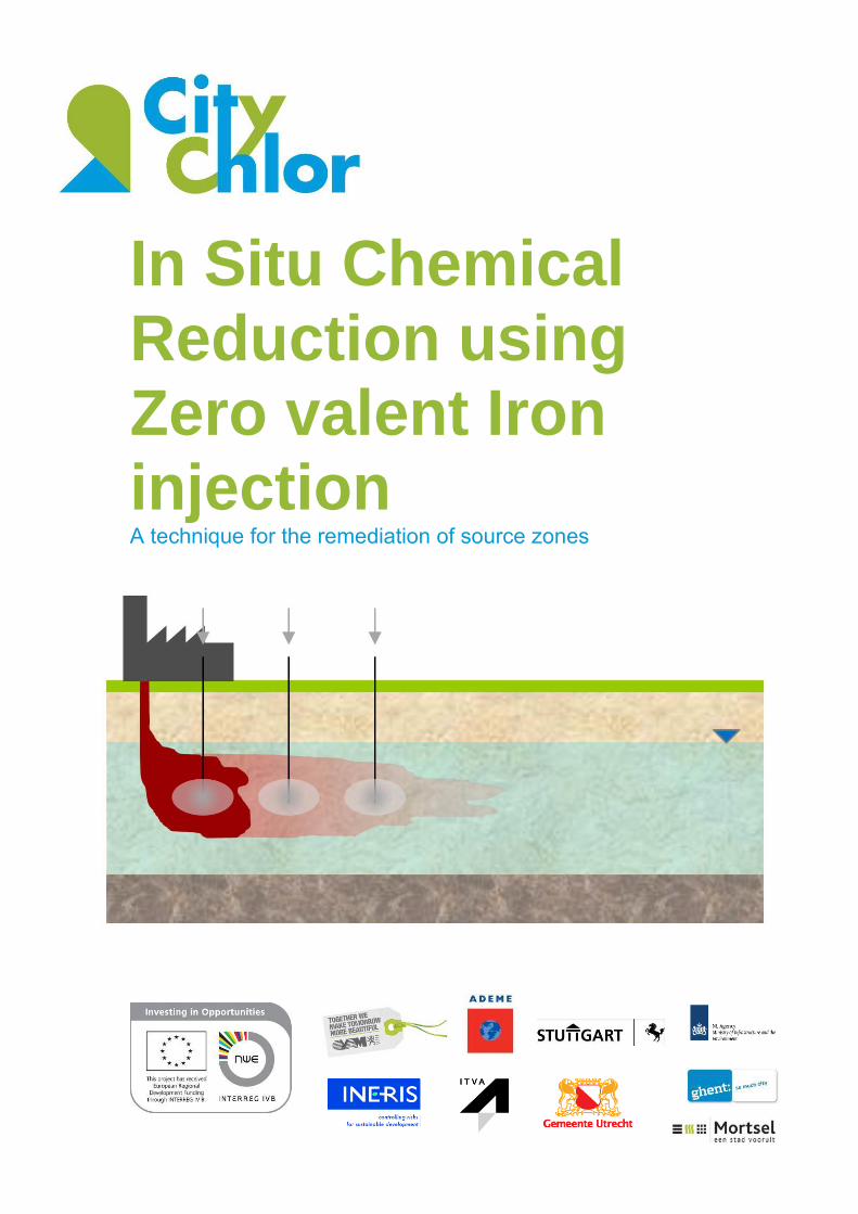
In Situ Chemical Reduction using Zero valent Iron injection A technique for the remediation of source zones
In Situ Chemical Reduction using Zero Valent Iron injection - A technique for the remediation of source zones 2
Summary
Zerovalent iron (ZVI) can be used for the remediation of soil and groundwater contamination with chlorinated solvents. ZVI has the ability to dehalogenate chlorinated compounds by chemical reduction and has been used since many years as a granular material in permeable reactive barriers for the treatment of contaminated groundwater. Due to the high specific surface area, nano- and micro- sized ZVI-particles (nZVI & mZVi) are more reactive than granular materials. Moreover, nZVI- and mZVI-particles can be readily injected into the soilmatrix, thus allowing for active treatment of source and plume areas, even at greater depth. Nowadays there are many different types of ZVI-materials available on the market. ZVI-particles can be differentiated based on size (nano (<1µm) or micro (> 1µm)) and on constitution: Catalysed bimetallic ZVI-particles consist of zerovalent iron/metal and a catalyst (Pt, Pd,..) thus generating more reactive materials which cause higher degradation rates. Supported ZVI-particles consist of ZVI-particles attached on a non-metallic carrier material which mostly serves to create higher stability and mobility of the ZVI suspension. Emulsified ZVI-particles (EZVI) are developed to directly treat the free phase of chlorinated solvents (DNAPL). The ZVI-particles are surrounded by a biodegradable oil-based hydrophobic membrane. Since the remediation with injectable ZVI-particles is based on direct contact between the ZVI-particle and the contaminant, the mobility and stability of the ZVI-particle in the soil is of crucial importance for the effectiveness of the remediation. Based on mathematical models and previous experiments, the mobility of non-modified nZVI-particles in the soil is limited to a few centimetres. The limited mobility is mainly due to aggregation of ZVI-particles (electromagnetic forces), ZVI-soil particle interactions and geochemical conditions. Mobility of ZVI-particles can be increased by Surface modifications of ZVI-particles to prevent aggregation; The implementation of high injection velocities; Mechanical modifications of the subsurface via fracturing (pneumatic or hydraulic) or dilatation (pressure pulse technology). A thorough preliminary study is necessary to check the feasibility of ZVI-particle injection (ISCR) for the treatment of chlorinated solvents. The preliminary study consists of the following phases: 1. Contaminated site characterisation (conceptual site model (CSM)) The contaminated soil volume and depth is essential to determine the required injection depths, distances and volumes. Information about the amounts of electron donors, contaminants and other electron acceptors (nitrate, sulphate, oxygen, Fe(II)/Fe(III) ) is essential to determine the needed amount of ZVI. Hydrogeological parameters such as hydraulic permeability, the average groundwater flow velocity and groundwater flow direction are needed to determine the radius of influence of the injections, the volumes that can be injected, the time period of injection, reflux of the injected solution and the number of injections (distance between injection points).
In Situ Chemical Reduction using Zero Valent Iron injection - A technique for the remediation of source zones 3
2. Lab tests Lab tests allow for the investigation of degradation kinetics (batch tests), stoichiometry (batch test with aquifer samples), potential to inject a ZVI-solution, mobility (column tests), stability of the ZVI-particle suspension (sedimentation tests) and overall feasibility of a ZVI application for a particular site. 3. Field test Since it is difficult to exactly simulate the conditions in the aquifer, it is recommended to conduct a field test. A field test can i.a. provide information about the injection method and the maximum injection pressure, flow rate and radius of influence. It also allows for the observation of possible rebound effects and the establishment of a reasonable remediation target. ZVI-particles can be injected via several injection methods. The chosen injection method is of great influence on the rate of influence of the injection. Each injection method has is own specific advantages and limitations and the choice is, amongst others, determined by the site specific conditions and available remediation budget. During injection it is important to avoid contact between the ZVI and oxidizing agents since these diminish the reactivity and, in addition, can cause safety hazards due to strong exothermic reactions. ZVI-particle injection is an expensive remediation technique since ZVI-particles (especially the nano-sized and/or modified ZVI-particles) are expensive and the radius of influence (because of limited mobility) is low. Based on literature and experience, ZVI-particle injection for the remediation of CVOC contaminated aquifers is best used in combination with an injection of substrate to enhance the natural degradation of CVOC’s in
order to achieve a (cost) effective remediation. The combined injection of ZVI and organic substrate will manipulate geochemical conditions in order to optimize both abiotic and biotic degradation of CVOC-contaminations by creating e.g. optimal ORP (oxidoreduction potential) and DO (dissolved oxygen) conditions in the subsoil.
In Situ Chemical Reduction using Zero Valent Iron injection - A technique for the remediation of source zones 4
Table of content
Summary ................................................................................................................................... 2
Table of content ......................................................................................................................... 4
1 Introduction ....................................................................................................................... 6
1.1 CityChlor and the integrated approach ...................................................................... 6
1.2 CityChlor and technical innovations .......................................................................... 6
2 Contents and structure...................................................................................................... 7
2.1 Content composition .................................................................................................. 7
2.2 Discussion of the technique ....................................................................................... 7
2.3 Structure of the study................................................................................................. 8
2.4 Glossary ..................................................................................................................... 9
2.5 List of abbreviations ................................................................................................. 11
3 Characteristics of nano- and micro-scale (bi)metallic particles ...................................... 12
3.1 Background .............................................................................................................. 12
3.2 Micro- and nano-scale zero-valent iron ................................................................... 12
3.2.1 Micro-scale zero-valent iron (mZVI) ................................................................... 12
3.2.2 Nano-scale zero-valent iron (nZVI) .................................................................... 12
3.2.3 Modified nZVI ..................................................................................................... 13
3.3 Production and availability of NZVI particles ........................................................... 15
3.3.1 Group 1: Production of nano-particles from individual atoms (bottom-up) ........ 15
3.3.2 Group 2: Production of nano-particles through the refinement of rougher materials (top-down) ....................................................................................................... 16
3.4 Commercially available nano-scale & micro-scale iron ........................................... 16
3.5 Reaction mechanisms ............................................................................................. 17
3.6 Transport and mobility of mZVI and nZVI particle ................................................... 21
3.6.1 Factors that influence the mobility of mZVI and nZVI particles ......................... 21
3.6.2 Surface modifications of MZVI and NZVI particles ............................................ 23
4 Known possibilities and limitations of ZVI particles ........................................................ 25
4.1 Known possibilities .................................................................................................. 25
4.2 Known limitations ..................................................................................................... 25
5 Practice: application of ZVI particles for the treatment of soil contamination ................. 27
5.1 Introduction .............................................................................................................. 27
5.2 Practical application ................................................................................................. 27
5.3 Preliminary study ..................................................................................................... 28
5.3.1 Introduction ........................................................................................................ 28
5.3.2 Characterisation of the site to be remediated .................................................... 28
In Situ Chemical Reduction using Zero Valent Iron injection - A technique for the remediation of source zones 5
5.3.3 Feasibility tests: laboratory tests and pilot tests ................................................ 29
5.4 Dosage calculation .................................................................................................. 32
5.5 Application methods ................................................................................................ 32
5.6 Monitoring of the remediation .................................................................................. 34
5.6.1 Monitoring during the injections ......................................................................... 34
5.6.2 Monitoring after the injection .............................................................................. 34
5.7 Evaluation diagram for use of iron injection ............................................................ 35
5.8 Stability/safety .......................................................................................................... 35
6 Cost ................................................................................................................................. 36
6.1 Cost of ZVI particles ................................................................................................ 36
6.2 Cost of preparing full-scale iron injection................................................................. 36
6.3 Cost of full-scale remediation iron injection ............................................................. 37
7 Results of market survey ................................................................................................ 39
8 Conclusions .................................................................................................................... 41
9 Bibliography .................................................................................................................... 42
10 Appendix ......................................................................................................................... 46
10.1 CityChlor Herk-de-Stad: Trial Test ISCR injection nZVI & mZVI ............................. 46
10.1.1 Introduction ........................................................................................................ 46
10.1.2 Conceptual model .............................................................................................. 46
10.1.3 Trial test ............................................................................................................. 49
10.1.4 Design and execution of iron injections ............................................................. 51
10.1.5 Results of the trial test ....................................................................................... 52
10.1.6 General Conclusion ........................................................................................... 53
10.1.7 Learned facts ..................................................................................................... 54
10.2 Case Rotterdam ....................................................................................................... 55
10.3 Questionnaire .......................................................................................................... 91
10.4 Evaluatieschema .....................................................................................................102
In Situ Chemical Reduction using Zero Valent Iron injection - A technique for the remediation of source zones 6
1 Introduction
1.1 CityChlor and the integrated approach
Space is scarce in Europe. Even in the subsurface it is getting busier. Large-scale soil and groundwater contamination with chlorinated solvents are often an obstruction for urban developments. The traditional way of dealing with polluted soil and groundwater does not work in all cases and is not economically and sustainable feasible. In urban environments multiple contaminations with chlorinated solvents are often mixed with each other and spread underneath buildings. This not only leads to technical problems for remediation, but also to liability and financial discussions and hence has an impact on society. An integrated approach and area-oriented approach is needed to tackle the problems. The CityChlor project has demonstrated that remediation and sustainable development can evolve on a parallel timescale. An integrated approach combines all aspects that are relevant to tackle the problems that pollution with VOC in urban environment causes. Depending on area, site and context different aspects together or parallel to each other can be used. Not only technical solutions are included, but also socio-economic aspects as urban development, communication, financial and legal aspects, time, space, environment and actors (active & passive) have to be handled. CityChlor did not remain at single case remediation, but looked at the area as a whole in a bigger context: the area-oriented approach. A technical approach that makes it possible to remediate, monitor and control multiple groundwater sources and plumes within a fixed area.
1.2 CityChlor and technical innovations
The managing of knowledge and technical innovations are one of the key to achieve a sustainable city development. A development project has to cope with loads of information coming from different disciplines in different (technical) languages and with different uncertainties. With chlorinated solvents, the knowledge about the pollution will always have a certain uncertainty that can have an impact on the course and the costs of the remediation. An efficient 'managing of knowledge' will try to decrease this degree of uncertainty. CityChlor therefore also worked on the technical aspects of characterization and remediation. The conventional techniques that are applied for investigation and remediation have their limitations dealing with chlorinated solvents. Promising innovative techniques exist, but do not easily find their way to current application. This barrier is often caused by lack of knowledge on different levels. Experts and contractors do not always have the means to invest in experiments with new techniques, authorities are reluctant to accept techniques of which the results may be uncertain and clients aren't eager to pay for experimental techniques. Dissemination of knowledge can break this deadlock. CityChlor therefore collected experiences from field application of innovative techniques and implemented itself a number of techniques in pilot projects. For the detailed outcomes, the reader is referred to the specific reports.
CityChlor - “new solutions for complex pollutions” http://www.citychlor.eu/
In Situ Chemical Reduction using Zero Valent Iron injection - A technique for the remediation of source zones 7
2 Contents and structure
The document before you contains a technical summary of the state of play with regard to the use of injections with zero-valent (nano or micro-scale) iron for treating ground and groundwater contamination with chlorinated solvents. Given the fact that practical experience within the (European) market with respect to this technique was rather limited when the document was written there was opted on elaborating a technical summary instead of a code of best practice. This document, however, not only contains a summary of the technological state of play, but will also enable the reader to evaluate the practicality of this technique and also provide a guideline for the actual usage thereof.
2.1 Content composition
The content of this document has been composed on the basis of
1. Experiences from the CityChlor pilot test in Herk-de-Stad 2. Literature study (see bibliography)
The literature study by Leen Bastiaens (VITO) ‘Injection of (bi)metallic nano-scale iron particles
into aquifers contaminated with chlorinated hydrocarbons, Phase 1’ was the basis for this
literature study.
Additional information was obtained from the following sources:
Background information gathered by OVAM, including, among others, articles from U.S. EPA
(with Superfund sites, among others), Aquarehab, Nanofrezes
Scientific articles from U.S. EPA
Scientific articles & proceedings from the 2010 Consoil conference
Scientific articles & proceedings from the 2006 & 2010 Batelle conferences
Information available via the Internet
3. Survey of soil remediation companies and suppliers (see chapter 7)
2.2 Discussion of the technique
Over the past few years a lot of research has been conducted on new or improved remediation techniques for the treatment of soil and groundwater contamination with volatile organic chlorine compounds (VOCl). As soil contaminated with VOCl is mostly present in urbanised areas and, due to the nature of the contaminants, is often not easily accessible for conventional remediation techniques, such as excavation, there is increasing demand for in situ remediation techniques capable of remediating this contamination in its different phases (dissolved, free phase), at a great depth and in an efficient and effective manner. Until the early 1990s pump & treat was the most common remediation technique for the treatment of groundwater contaminated with VOCl. As this technique in many cases is not effective (due to low solvability of VOCl) and sustainable, cause long-term costs and can even be very expensive and slow (the average pump & treat system in the US is active for 18 years (U.S. EPA, 2001)), this technology was in several cases
In Situ Chemical Reduction using Zero Valent Iron injection - A technique for the remediation of source zones 8
replaced with passive in situ remediation techniques, such as (bi)metallic permeable barriers (‘permeable
reactive barrier’: PRB). PRBs have been applied in the field for more than 10 years (Matheson & Tratnyek;
1994; Gillham, 1996; Gavaskar, 1997; O’Hannesin & Gillham, 1998; Bastiaens et al., 2002a, 2002b; Dries et
al., 2004). Due to the following limitations of permeable reactive barriers (Watlington, 2005):
Can only be used for treatment of the dissolved phase (~plume remediation), this means this is more or less a safety measure for the downstream aquifer
Less reactive for lightly chlorinated products (components with Cl content < trichloro ethene)
Can be applied down to a maximum depth of approx. 15 m bgl (this is a question of the construction technology you use)
Relatively high investment cost with a ‘replacement period’ which is hard to estimate (gradual
reduction of reactivity due to formation of iron hydroxide and iron carbonate deposition)
there is a growing interest in other in situ remediation techniques, such as:
Thermal treatment
In situ chemical oxidation (ISCO)
In situ chemical reduction (ISCR)
Surfactant co-solvent ‘flushing’
Stimulation of natural attenuation (ENA) This literature study focuses on in situ chemical reduction (ISCR) through the use of injectable micro- and nano-scale zero-valent (bi)metallic particles for the treatment of soil contamination with chlorinated hydrocarbons.
2.3 Structure of the study
1. Characteristics of nano- and micro-scale (bi)metallic particles
In this chapter an overview is given of the commercially available nano- and micro-scale (bi)metallic particles and their properties. 2. Known possibilities and limitations of iron injections
In this chapter an overview is given of the known applications of ZVI-particles and their limitations. 3. Practice: applicability of iron particles for the treatment of soil contamination with VOCl
In this chapter the practical aspects of this remediation technique will be looked at: 1. Set-up of laboratory and pilot tests 2. Application methods 3. Follow-up of the remediation
4. Cost of iron injection
In Situ Chemical Reduction using Zero Valent Iron injection - A technique for the remediation of source zones 9
This chapter gives an idea of the cost of iron particles and the cost of remediation per m³ of treated soil, based on the literature studied. 5. Results of market survey
This chapter explains the way of market survey with the results. 6. Conclusions
7. Cases
2.4 Glossary
Adsorption Process whereby a substance adheres via
physical-chemical forces to the surface of a solid.
Anionic Negatively charged particles (ion).
Soil The solid constituents of the earth, also including the groundwater and other components and organisms that form part of it or live therein.
Colloid A small particle (or collection of particles) that is larger than one molecule and has a diameter of between 1 and 1000 nm.
Desorption Process whereby adsorbed compounds are released in the water phase.
DNAPL Layer of organic (non-aqueous) liquids with a greater density than water.
Electron acceptor See oxidants.
Electron donor See reductants.
Electrostatic stabilisation Stabilisation of particles via use of electrorepulsion (or mutual repulsion from particles with the same electrical charge).
Emulsion An emulsion is a mixture of two immiscible liquids that, under normal circumstances, do not form a stable or homogenous mixture. To obtain an emulsion, a surfactant is required in order to create a stable mixture. An emulsion typically forms a colloidal mixture.
In Situ Chemical Reduction using Zero Valent Iron injection - A technique for the remediation of source zones 10
Geogenic Concentration that originates in geological formation and is thus natural in this formation.
Catalyst A substance that affects the reaction speed of a chemical reaction without being used up in the chemical reaction itself.
Non-saturated area Zone in de soil above the groundwater table.
Solubility A measure that expresses the maximum amount of a product that can be dissolved in water without forming precipitation or a LNAPL or DNAPL.
Oxidant Chemical substance with a high redox potential. The oxidant acts as an electron acceptor in the redox reaction. The valency state of the reductant decreases in the redox reaction.
Permeability A measure of the speed at which a fluid can pass through a permeable medium.
pH Acidity
PRB Permeable reactive barrier. Artificial barrier in the subsurface that is used as a management tool for groundwater pollution. The dissolved pollution is typically broken down in the barrier via oxidative or reductive reactions.
Reagent A chemical substance that reacts in a chemical reaction.
Redox potential Unit used to express the degree to which electrons are available for redox reactions.
Redox reaction Chemical reaction whereby electrons are transferred from the electron donor to the electron acceptor.
Reductant Chemical substance with a low redox potential. The reductant acts as an electron donor in the redox reaction. The valency state of the reductant increases in the redox reaction.
Steric stabilisation Stabilisation of particles via the adherence of molecules that, as a result of the volume that they take up, inhibit the advance and aggregation of the particles.
In Situ Chemical Reduction using Zero Valent Iron injection - A technique for the remediation of source zones 11
Saturated zone Zone in the soil which is filled with groundwater.
Zero-valent iron Iron with a valency state equal to zero.
2.5 List of abbreviations
BNP Bimetallic nano particle DCE Dichloroethene (cis or trans) DNAPL Dense non-aqueous phase liquid DO Dissolved oxygen DOC Dissolved organic carbon dm Dry matter Eh Redox potential (expressed in mV) EPA Environmental Protection Agency EZVI Emulsified zero-valent iron ISCO in-situ chemical oxidation ISCR In-situ chemical reduction m Metre (distance) m-bg Meter below ground level (depth) mg/l Milligrams per litre (concentration) mV Millivolt mZVI Micro-scale zero-valent iron nm nanometre nZVI Nano-scale zero-valent iron PCB Polychlorinated biphenyl PCE Perchloroethylene (or tetrachloroethene) pH Acidity PPT Pressure pulse technology PRB Permeable reactive barrier PVC Polyvinylchloride RNIP Reactive nano-scale iron product TCE Trichloroethene TOC Total organic carbon TNT Trinitrotoluene ZVI Zero-valent iron
In Situ Chemical Reduction using Zero Valent Iron injection - A technique for the remediation of source zones 12
3 Characteristics of nano- and micro-
scale (bi)metallic particles
3.1 Background
The use of zero-valent metals for environmental applications was first described in the literature in 1972 (Sweeny & Fischer, 1972). Years later, the observed disappearance of trichloroethene (TCE) in metal probes was a starting point for a more detailed study on the use of zero-valent metals (mainly Fe(0)) for the remediation of groundwater contaminated with VOCl. (Gillham & O’Hannesin, 1994; Gillham et al., 1998; Tratnyek et al., 2003). Granular (bi)metallic materials (> 50 μm), such as, for instance, granular zero-valent iron (ZVI), have been studied for years for the in situ removal of VOCl from groundwater in PRBs. (Bastiaans et al.) For a few years now there has been a special interest in finer (bi)metallic materials, such as micro-scale (Cantrell & Kaplan, 1997; Choe et al. 2000) and nano-scale (bi)metallic particles (Wang & Zhang, 1997; Ponder et al., 2000; Lien & Zhang, 1999, 2001; Li et al., 2003; Zhang, 2004). Due to their high specific surface, these materials are more reactive than granular materials, and due to their small particle size they can be used in more diverse applications. The high reactivity of these materials makes it possible to remove a wide range of pollutants from the groundwater (Reference ????). Moreover, it is possible to apply the material via injection at a great depth. Modified nano-scale zero-valent iron (nZVI), concretely emulsified nano-scale zero-valent iron (EZVI), even makes it possible, in theory, to treat free phase (DNAPL). The injection of nano-scale and micro-scale zero-valent iron (mZVI) constitutes the basis of a new generation of in situ remediation techniques for the treatment of soil contamination with VOCl.
3.2 Micro- and nano-scale zero-valent iron
Fine ZVI materials can be subdivided into different categories based on particle size. An additional subdivision can be made based on the composition of the particles (metallic, bimetallic), surface modifications and the solution medium or carrier material (supported, emulsion, …).
3.2.1 Micro-scale zero-valent iron (mZVI) Micro-scale (bi)metallic particles are, strictly speaking, particles with a diameter greater than 1µm.
3.2.2 Nano-scale zero-valent iron (nZVI) Nano-scale zero-valent iron particles are, strictly speaking, (bi)metallic particles with a diameter smaller than 100 nm. In certain cases, colloïdal particles (1-2μm) are also – incorrectly – included with nZVI. In this report, nZVI comprises both metallic and (bi)metallic nano-scale particles.
In Situ Chemical Reduction using Zero Valent Iron injection - A technique for the remediation of source zones 13
nZVI consists of a mixture of zero-valent iron and iron oxides. More concretely, the following two variants can be distinguished:
Pure nano-scale zero-valent iron (nZVI) nZVI particles mainly consist of zero-valent iron (80-90% wt%) and, depending on the producer, have the following specifications:
Particle diameter 20-200 nm
Specific surface area 20-58 m²/g
Reactive nano-scale iron product (RNIP) Reactive nano-scale iron product consists of a mixture of 50/50 wt% zero-valent iron and magnetite (Fe3O4), in which the magnetite forms the outer shell of the particle. In a study by Okinaka et al. (2004), the average particle size is approx. 70 nm and the average specific surface area 28.8 m²/g.
The larger specific surface area and the higher zero-valent iron content of nZVI are responsible for a higher degradation rate of VOCl (~dechlorination) than that observed for RNIP. However, the outer magnetite shell of RNIP slow down reaction with water (H2 formation), as a result of which the life of such particles is extended considerably (Liu et al., 2005). The limited stability and mobility (see paragraph §3.6 and §3.7) of pure nZVI provides the impetus for the development of modified nZVI.
3.2.3 Modified nZVI A. Catalysed bimetallic nano-scale particles Besides the aforementioned ‘classic’ particles, there is a growing offer of nano-scale bimetallic particles which, in addition to zero-valent iron or another metal, contain a second metallic material. Here, one metal (Fe, Zn, …) is mainly the electron donor, and the other (Pd, Pt, Ni …) the catalyst in the reaction. Such nano-scale bimetallic particles are also sometimes called catalysed nZVI particles. With catalysed nZVI particles much higher reaction rates can be obtained, with the disadvantage that the life of such particles is limited. Examples of such materials are:
Fe/Pd, Fe/Ag, Fe/Ni, Fe/Co, Fe/Cu, Zn/Pd (Zhang et al., 2003)
Ag/Pd, Au/Pd (Nutt et al, 2005)
Fe/Pd particles cause high reaction rates 1 in comparison with pure nZVI. In addition, Pd has a high selectivity for the C-Cl bond. However, research by Huang et al. (2009) shows that Ni is a cheaper alternative for the expensive Pd. Fe/Ni particles can achieve the complete degradation of perchloroethene (PCE) to ethane. Catalysed nZVI is mostly used in the US (40% of nZVI remediations), but has not yet been used in Europe (data for 2010). In Europe, the opinion is held that the possible advantages of catalysed nZVI particles do not
1 Pd and Ni are hydrogenation catalysts which play an important role in the transfer of H2. Moreover, Pd and Ni as transition metals have free
electron shells which make it possible to lower the activation energy via transition bonds with the p-electron pair or -bond of the chlorine atom
in chlorinated organic components (Huang et al., 2009).
In Situ Chemical Reduction using Zero Valent Iron injection - A technique for the remediation of source zones 14
compensate for the possible disadvantages (higher costs, short life and possible toxicity of the catalyst) (Müller, Nowack, 2010). B. ‘Supported’ nano-scale particles ‘Supported’ nano-scale particles are nZVI particles that are attached to a non-metallic carrier. Ponder et al. (2000) have conducted research on carbon nano-particles onto which nZVI particles were attached. The ‘pellets’ obtained have a diameter of 50 to 200 nm and are made anionic before they are introduced into the
soil. The anionic carrier material is supposed to impede the aggregation and sedimentation of the particles, as a result of which the injectability, the mobility and hence the spread of the particle are increased. ‘Supported’ nano-scale particles with a hydrophilic carrier consisting of polymers, e.g. poly(acrylic acid), have also been described (Ponder et al., 2001, Schrick et al., 2004).
C. Emulsified nZVI particles (EZVI) EZVI has been specifically developed for the treatment of free phases of chlorinated solvents (DNAPLs, Dense Non-Aqueous Phase Liquids) (Quinn et al., 2003). Plant oils and all kinds of surfactants can be used to prepare this emulsion. More specifically, this is a surfactant-stabilised biodegradable emulsion which forms drops with an oil-water membrane around the nZVI or mZVI particles in water drops. Emulsions typically have a diameter of approx. 40 µm and a specific gravity of approx. 1.1 kg/l (Quinn 2005, O’Hara 2004). As the
emulsion also behaves as a DNAPL, it will move through the soil in the same way as the DNAPL to be remediated, thus allowing for maximum contact. A graphic representation of this emulsion can be found in Figure 1.
Figure 1: Graphic representation of emulsified NZVI particles (left) & microscopic view of emulsified NZVI particles (right)
The following hypothetic reaction mechanism is proposed: DNAPL components diffuse from the oil layer to the enclosed water phase, where they react with the zero-valent iron. Generated degradation products diffuse with increasing concentrations from the enclosed water phase through the oil layer to the surrounding water. The oil membrane around the nZVI particles offers protection against premature oxidation by oxygen and other components (e.g. inorganic material, such as sulphate and nitrate). The reactivity of classic nZVI
In Situ Chemical Reduction using Zero Valent Iron injection - A technique for the remediation of source zones 15
particles and EZVI particles is comparable (Quinn et al., 2005). In the longer term, the oil phase can serve as an electron donor in the biological degradation of residual VOCl concentrations.
3.3 Production and availability of NZVI particles
Diverse methods for the production of NZVIs have been described in the literature and can be subdivided into 2 groups.
3.3.1 Group 1: Production of nano-particles from individual atoms (bottom-up)
Wang and Zhang (1997) synthesise nano-particles via chemical reduction of Fe3+ by sodium borohydride. More specifically, 0.2 M NaBH4 is added to FeCl3.2H2O (0.05 M), which results in nano-particles with a diameter between 1 nm and 100 nm, an average size of 50 ± 15 nm and a specific surface area of 10 – 50 m²/g. The method allows for large amounts to be produced, but it is expensive, up to 5,000 $ per kg (Vance et al., 2002).
It is also possible to heat iron pentacarbonyl to 200-250 °C. At this temperature, nZVI and carbon monoxide are produced. This method allows to obtain nano-particles with a diameter of 5 nm.
(bi)metallic materials are produced via reductive precipitation (Zhang et al., 2003). For instance, palladium-coated nano-scale iron particles can be obtained by bringing freshly made nano-scale iron particles into contact with palladium acetate (1 %W). As a result of reduction, a Pd layer will form on the iron material (Wang & Zhang, 1997). Other (bi)metallic materials can be obtained in a similar manner (Xu & Zhang, 2000).
With the micro-emulsion method nano-particles are produced via chemical reduction with sodium borohydride. However, these reactions take place in small aqueous environments in an oil phase, which allows for the production of nano-materials with a controlled size and shape (Li et al., 2003). The materials obtained have an average diameter smaller than 10 nm.
Nano-iron particles can also be produced through reduction of goethite by means of heat (up to 600 °C) and hydrogen gas. In this process, iron sulphate, sodium carbonate and sodium hydroxide are used as base materials to make goethite precursors. By dehydration of these goethite precursors, hematite precursors are then produced, which are further reduced with hydrogen gas to nano-iron (Uegami et al, 2003).
The ‘sol-gel’ method was mentioned by Li et al. (2003). A gel containing silicon tetraethoxide and a metal component, such as FeCl3, is heated. A glass-metal nano-composite is produced which contains ultra-fine iron particles. Aside from these methods there is also electrolysis (Fisher).
In Situ Chemical Reduction using Zero Valent Iron injection - A technique for the remediation of source zones 16
Toda RNIP is a crystalline nano-iron which is produced by a reduction of FeOOH in the gas phase. This reaction produces particles with an average size of 70 nm and a specific surface area of 29 m²/g. These specific nano-particles are coated with polyacrylic acid.
NANO IRON produces nZVI particles from nano-particles of ferrihydrite ((Fe3+)2O3•0.5H2O)
3.3.2 Group 2: Production of nano-particles through the refinement of rougher materials (top-down)
Vance and his co-authors (2002) use a ball mill system to refine a powder of an elemental metal (1-10 μm) to
a nano-material (100-400 nm). During this process a non-aqueous organic liquid and a dispersant are added. Via this method materials are produced in amounts up to 10 kg. The production of larger amounts would be possible (NAPASAN Project > 300 kg) .
3.4 Commercially available nano-scale & micro-scale iron
The number of producers of NZVI & MZVI and, concretely, those able to deliver large amounts, are currently still relatively limited.
1. NANO IRON (Czech Republic) Czech company specialised in the production of nZVI particles. The particles have an average size of 50 nm (between 20 and 100 nm), a specific surface area of 20-25 m²/g and a high zero-valent iron content of approx. 80/90 wt%. The cost depends on the amount and nature of the product and varies between 25 - 65 Euro/kg for the nZVI slurry (20% dm). The following products are commercially available:
nZVI powder (100 g, 1 & 5 kg)
NANOFER STAR: Surface-modified iron. Stable in normal atmospheric conditions
NANOFER 25P: Unmodified iron. Only stable in inert (nitrogen) atmosphere
nZVI slurry (10, 20 & 40 kg, 20% dm)
NANOFER 25S: slurry with organic and inorganic stabilisers
NANOFER 25: slurry with only inorganic stabilisers
2. TODA KOGYO CORP. (Japan) TODA KOGYO is a Japanese company specialised in the production of nano-scale RNIP particles (mainly iron oxides). The products are offered as a powder and as a slurry. The particles have an average size of 100 nm and a specific surface area of approx. 23 m²/g. The cost depends on the amount and varies between 25-33 Euro/kg (powder).
ANIP-10DS (Active Nanoscale Iron Particles): metallic
ANIP-20DS: metallic, finer material than ANIP-10DS, not commercially available;
3. Polyflon company (US, Florida)
In Situ Chemical Reduction using Zero Valent Iron injection - A technique for the remediation of source zones 17
Polyflon company produces nZVI particles. The particles have a size between 100-200 nm and a specific surface area between 37 and 58 m²/g. The cost is unknown.
PolyMetallixTM Particles
4. PARS Environmental inc. (US, NJ) PARS is an American environmental consultancy firm that has developed its own nZVI particles. Product specifications are unknown and it is also unclear whether the nZVI particles are available commercially.
NanoFeTM: nano-scale zero-valent iron particles
NanoFe PlusTM: a modified NanoFeTM with enclosure of a catalyst and an additive to boost the speed and efficiency of the remediation. (Varadhi et al., 2005a);
5. TOYO INK MFG. CO. LTD (Japan)
Toyo Ink is a company specialised in the production of ink, paint, colouring agents and hence colloidal dispersions, including dispersions of colloidal micro-scale iron (50% average diameter: 2080 nm).
6. Gotthart Maier Metallpulver GmbH
GMM produces metal powders with, among other things, micro-scale iron powder. mZVI particles from GMM were used for the pilot test in Herk-de-Stad. The product used has a size between 0-80 µm, a zero-valent iron content of approx. 90 wt% and contains traces of other metals. The material is available at a cost of 1.2 euro/kg
7. Lehigh University (US, Pennsylvania)
No permanent product, no commercial production 8. Golder 9. Aventus
3.5 Reaction mechanisms
Zero-valent iron is capable of reducing chlorinated compounds to harmless components, as shown in the general reaction formula below:
2 Fe0 + R-Cl + 3 H2O → 2 Fe2+ + R-H + 3 OH- + H2 + Cl-(R = Aryl group) The chlorinated compounds can be reduced as follows:
1. Reduction at the metal surface in the presence of a proton donor Fe0 + R-Cl + H+ → Fe2+ + R-H+ Cl- (1)
2. Continuation of reaction 1 by the further oxidation of Fe2+ to Fe3+
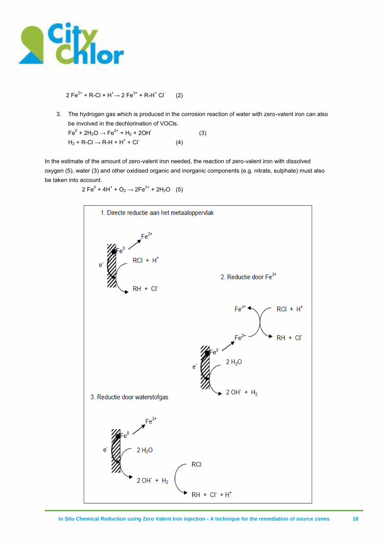
In Situ Chemical Reduction using Zero Valent Iron injection - A technique for the remediation of source zones 18
2 Fe2+ + R-Cl + H+→ 2 Fe3+ + R-H+ Cl- (2)
3. The hydrogen gas which is produced in the corrosion reaction of water with zero-valent iron can also
be involved in the dechlorination of VOCls. Fe0 + 2H2O → Fe2+ + H2 + 2OH- (3) H2 + R-Cl → R-H + H+ + Cl- (4)
In the estimate of the amount of zero-valent iron needed, the reaction of zero-valent iron with dissolved oxygen (5), water (3) and other oxidised organic and inorganic components (e.g. nitrate, sulphate) must also be taken into account.
2 Fe0 + 4H+ + O2 → 2Fe2+ + 2H2O (5)
In Situ Chemical Reduction using Zero Valent Iron injection - A technique for the remediation of source zones 19
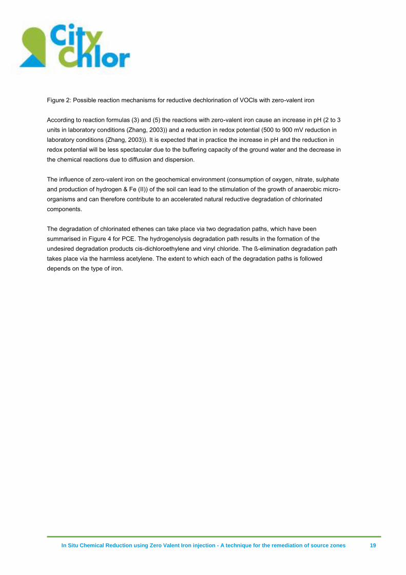
Figure 2: Possible reaction mechanisms for reductive dechlorination of VOCls with zero-valent iron According to reaction formulas (3) and (5) the reactions with zero-valent iron cause an increase in pH (2 to 3 units in laboratory conditions (Zhang, 2003)) and a reduction in redox potential (500 to 900 mV reduction in laboratory conditions (Zhang, 2003)). It is expected that in practice the increase in pH and the reduction in redox potential will be less spectacular due to the buffering capacity of the ground water and the decrease in the chemical reactions due to diffusion and dispersion. The influence of zero-valent iron on the geochemical environment (consumption of oxygen, nitrate, sulphate and production of hydrogen & Fe (II)) of the soil can lead to the stimulation of the growth of anaerobic micro-organisms and can therefore contribute to an accelerated natural reductive degradation of chlorinated components. The degradation of chlorinated ethenes can take place via two degradation paths, which have been summarised in Figure 4 for PCE. The hydrogenolysis degradation path results in the formation of the undesired degradation products cis-dichloroethylene and vinyl chloride. The ß-elimination degradation path takes place via the harmless acetylene. The extent to which each of the degradation paths is followed depends on the type of iron.
In Situ Chemical Reduction using Zero Valent Iron injection - A technique for the remediation of source zones 20
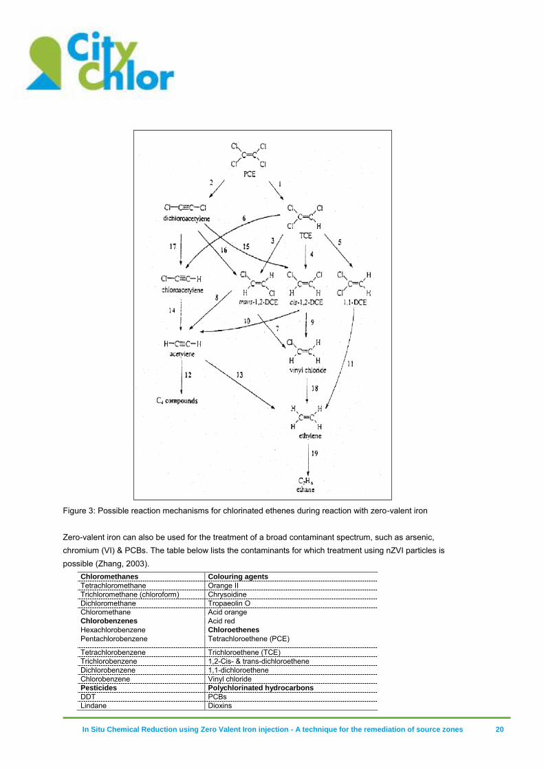
Figure 3: Possible reaction mechanisms for chlorinated ethenes during reaction with zero-valent iron Zero-valent iron can also be used for the treatment of a broad contaminant spectrum, such as arsenic, chromium (VI) & PCBs. The table below lists the contaminants for which treatment using nZVI particles is possible (Zhang, 2003).
Chloromethanes Colouring agents
Tetrachloromethane Orange II Trichloromethane (chloroform) Chrysoidine Dichloromethane Tropaeolin O Chloromethane Acid orange Chlorobenzenes Acid red Hexachlorobenzene Chloroethenes
Pentachlorobenzene Tetrachloroethene (PCE)
Tetrachlorobenzene Trichloroethene (TCE) Trichlorobenzene 1,2-Cis- & trans-dichloroethene Dichlorobenzene 1,1-dichloroethene Chlorobenzene Vinyl chloride Pesticides Polychlorinated hydrocarbons
DDT PCBs Lindane Dioxins
In Situ Chemical Reduction using Zero Valent Iron injection - A technique for the remediation of source zones 21
Trihalomethanes Pentachlorophenol Bromoform Other organic components
Dibromochloromethane N-nitrosodimethylamine Dichlorobromomethane TNT Heavy metals Inorganic components
Mercury Dichromate Nickel Arsenic Silver Perchlorate Cadmium Nitrate
Table 1: Components which are degradable with zero-valent iron
3.6 Transport and mobility of mZVI and nZVI particle
3.6.1 Factors that influence the mobility of mZVI and nZVI particles
As the remediation technique with zero-valent iron is based on direct contact between the surface of the ZVI particle and the dissolved contaminant, the mobility of the ZVI particles is of crucial importance for the effectiveness of the remediation. According to Lowry (2005), the transport of unmodified nZVI is limited to a maximum of a few metres. Experiments at the university of Stuttgart have even shown that the transport of unmodified iron is limited to a few cm. Based on arithmetic models, the mobility of nZVI particles is estimated to be limited, unless the following points are applied:
1. Adjustment of the nZVI particles by means of surface modifications, so that aggregation is prevented as much as possible
2. High injection speeds in comparison with the natural groundwater flow 3. Mechanical adjustments to the soil in the form of cracks (pneumatic & hydraulic fracturing)
and/or dilation of the soil particles (pressure pulse technology)
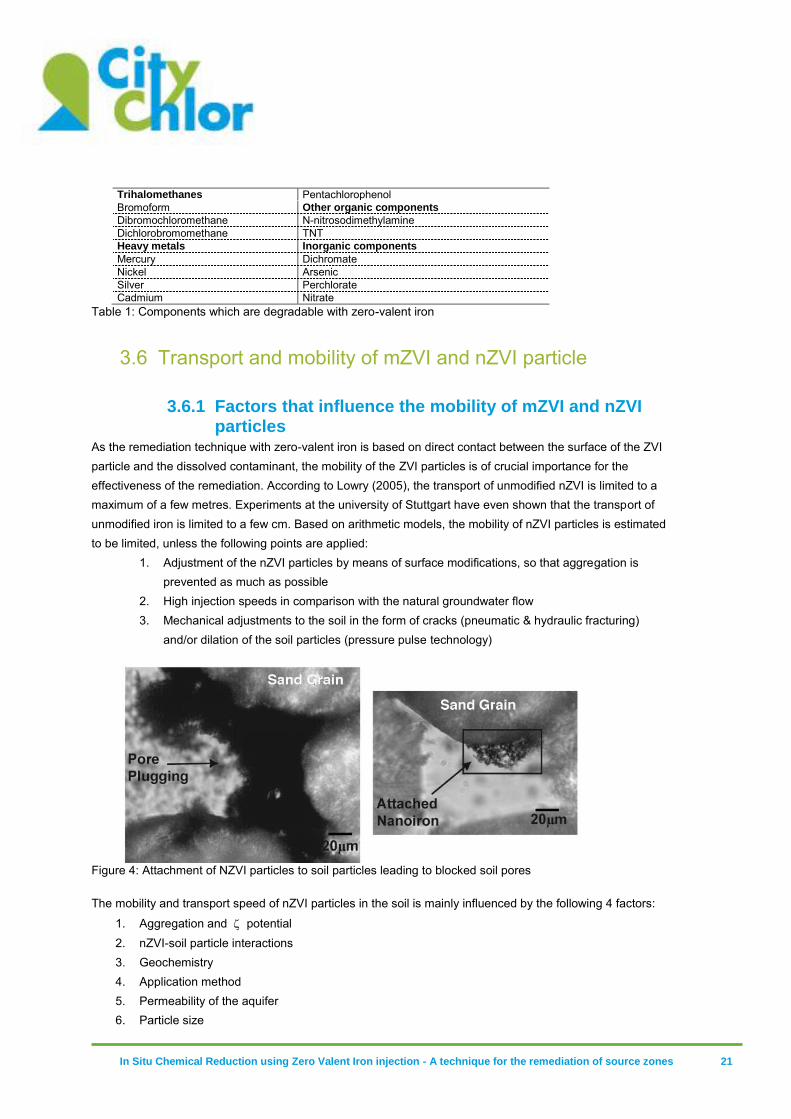
Figure 4: Attachment of NZVI particles to soil particles leading to blocked soil pores
The mobility and transport speed of nZVI particles in the soil is mainly influenced by the following 4 factors:
1. Aggregation and potential 2. nZVI-soil particle interactions 3. Geochemistry 4. Application method 5. Permeability of the aquifer 6. Particle size

In Situ Chemical Reduction using Zero Valent Iron injection - A technique for the remediation of source zones 22
1. Aggregation and potential
The aggregation of ZVI particles causes a reduced mobility and reactivity. The reduction in mobility is caused by the blockage of the soil pores (see Figure 4) and by the attachment to soil particles. The reduction in reactivity is the result of the reduction in the specific surface area and the blockage of reactive sites on the particle. The aggregation of ZVI particles is caused by the following processes:
Concentration of ZVI particles in solution: Recent research has shown that the particles are mobile at low concentrations (e.g. 30 mg/l) and that this does not depend on particle diameter distribution and magnetic forces (Phenrat et al., 2009b).
Magnetic forces: large particles with a higher Fe(0) content have a stronger magnetic field and will preferably aggregate with other ZVI particles. Small particles with a lower ZVI content are less susceptible to aggregation and hence more mobile. As the ZVI content is essential for the degradation potential of the particle, the increased mobility and the increased reaction speeds must be weighed up. (References ???)
potential2: The potential or electric potential of the nZVI particle depends on the way the particle is produced and will determine the extent to which the particle is drawn to other
particles, and hence the extent to which the particles will aggregate. When the potential
approaches 0 mV, there is a large chance of aggregation. Particles with a potential greater than +30 mV or smaller than -30 mV are considered stable. The following factors
have an influence on the potential: pH: A pH between 8.0 and 8.2 can result in a
potential of 0 mV and hence an aggregation of ZVI particles
The ionic strength of the solution: As the concentration of cations (e.g. Na+, Ca2+, Mg2+, K+)
increases, the potential will approach 0 mV. In laboratory tests usually de-ionised water is used, while the concentrations of mono- and divalent cations in pore water lie between 1-10 mM and 1-2 mM respectively.
The potential of classic ZVI particles is -30 ± 3 mV (Zhang and Elliott 2006; Saleh et al. 2008).
Research shows that modified ZVI particles with triblock copolymers have the highest potential (-50 ± 1.2 mV) and are therefore highly mobile in porous media. The high mobility is explained by the electrosteric stabilisation caused by the polymer.
2. ZVI particle-soil particle interaction
Aggregation and deposition of ZVI particles onto soil particles can lead to a blockage of the soil pores. The surface modification of ZVI particles (e.g. coating) can considerably increase mobility.
3. Geochemistry
2 The zeta potential or electrokinetic potential stands for the electric potential in the electric double layer around loaded particles. The zeta potential is determined by the difference in electric potential between the dispersion medium and the stationary liquid layer (‘slipping plane’) around the particle. The zeta potential is a measure for the electric repulsion between the particles and hence determines the stability of the dispersion. With a low zeta potential the attractive forces will be greater than the repulsive forces. As a result, the dispersion will not be stable and aggregation of the particles will occur.
In Situ Chemical Reduction using Zero Valent Iron injection - A technique for the remediation of source zones 23
As discussed in the previous paragraphs, the mobility and hence the transport of the ZVI particles is strongly influenced by the geochemical conditions of the aquifer (ionic strength, pH, Eh, DO). The addition of ZVI particles also has an influence on the geochemical conditions of the aquifer: → Dissolved oxygen (DO) is consumed quickly →Strongly reducing circumstances are created with redox potentials (Eh) below 0 mV →pH increases by more than 3 pH units have already been observed in the lab
The Eh and DO have a strong influence on the oxidation of ZVI particles and hence on the mobility of the particles (e.g. large quantities of oxygen will oxidise the ZVI particles faster, decreasing mobility).
4. Application method The transport, mixing and injection method must be aimed at preventing contact between the ZVI particles and oxygen or other oxidants as much as possible. The oxidation of the ZVI particles will lead to a reduced reactivity and mobility (Gavaskar et al. 2005; U.S. EPA 2008c). The radius of influence of the injection method can be improved by the following measures:
High injection speed in comparison with the natural groundwater flow
Creating a dilation and/or cracks in the soil structure via pulsed injection, increased injection pressure or ‘fracturing’ before injection (pneumatic and hydraulic fracturing)
Creating an artificially high hydraulic gradient (connected injection and extraction wells)
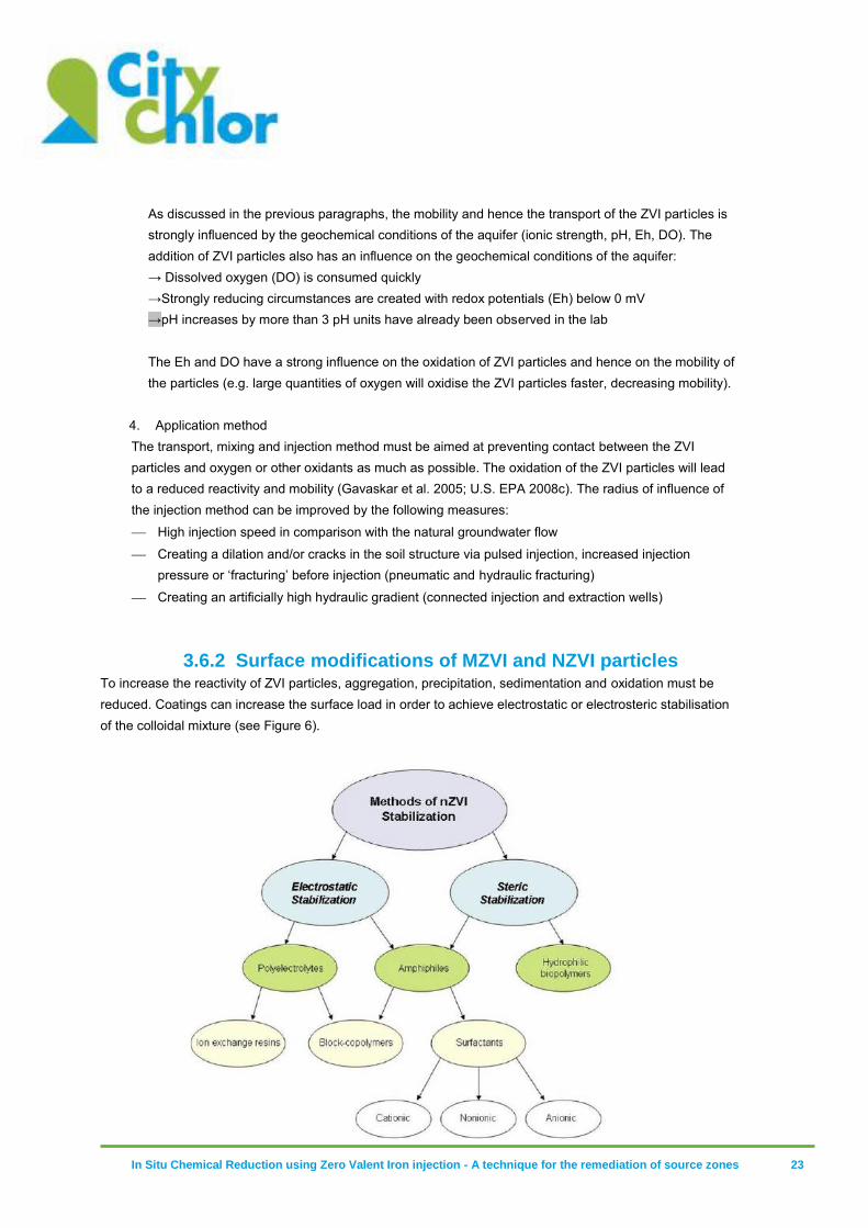
3.6.2 Surface modifications of MZVI and NZVI particles To increase the reactivity of ZVI particles, aggregation, precipitation, sedimentation and oxidation must be reduced. Coatings can increase the surface load in order to achieve electrostatic or electrosteric stabilisation of the colloidal mixture (see Figure 6).
In Situ Chemical Reduction using Zero Valent Iron injection - A technique for the remediation of source zones 24
Figure 5: Possible surface modifications (‘coatings’) to stabilise the NZVI particles
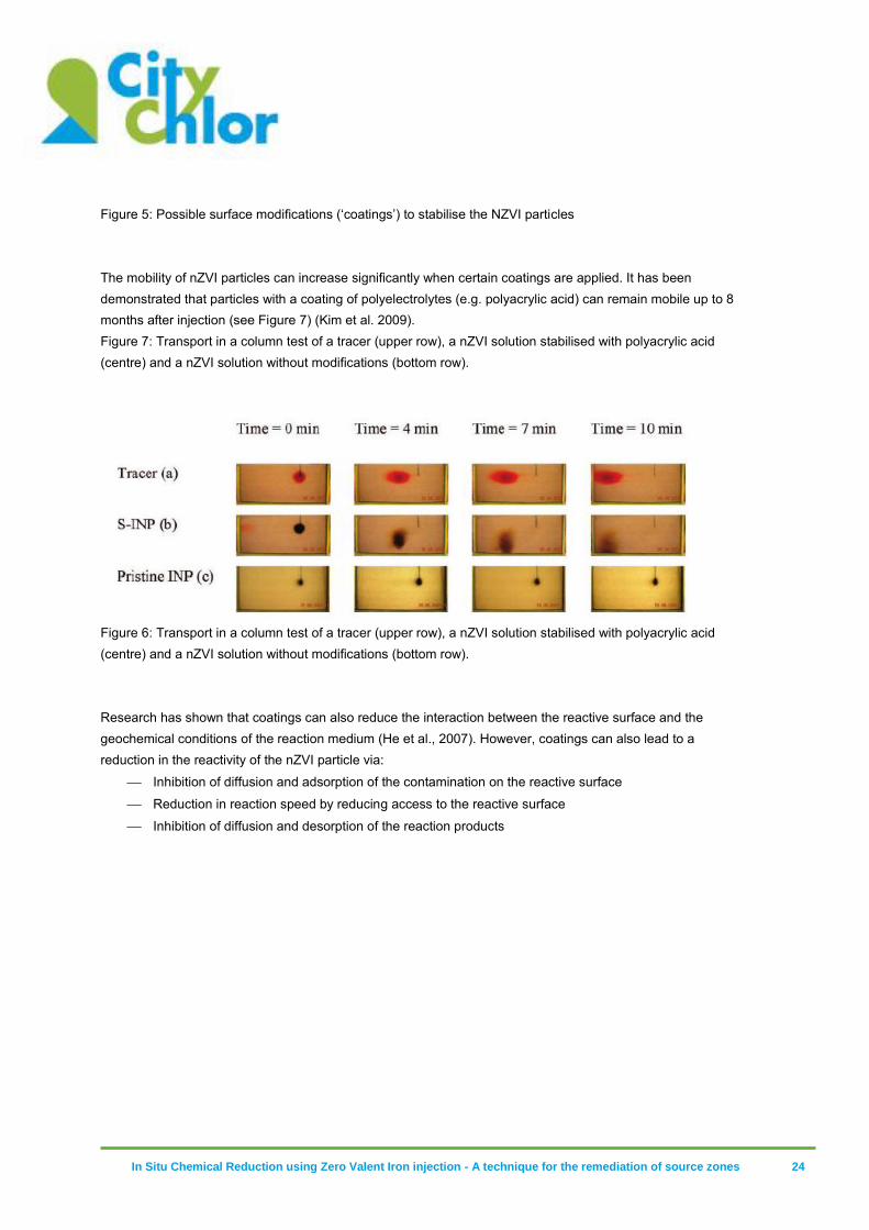
The mobility of nZVI particles can increase significantly when certain coatings are applied. It has been demonstrated that particles with a coating of polyelectrolytes (e.g. polyacrylic acid) can remain mobile up to 8 months after injection (see Figure 7) (Kim et al. 2009). Figure 7: Transport in a column test of a tracer (upper row), a nZVI solution stabilised with polyacrylic acid (centre) and a nZVI solution without modifications (bottom row).
Figure 6: Transport in a column test of a tracer (upper row), a nZVI solution stabilised with polyacrylic acid (centre) and a nZVI solution without modifications (bottom row). Research has shown that coatings can also reduce the interaction between the reactive surface and the geochemical conditions of the reaction medium (He et al., 2007). However, coatings can also lead to a reduction in the reactivity of the nZVI particle via:
Inhibition of diffusion and adsorption of the contamination on the reactive surface
Reduction in reaction speed by reducing access to the reactive surface
Inhibition of diffusion and desorption of the reaction products
In Situ Chemical Reduction using Zero Valent Iron injection - A technique for the remediation of source zones 25
4 Known possibilities and limitations
of ZVI particles
4.1 Known possibilities
ZVIs can be used in different ways for the remediation of groundwater/soil:
Given its greater reactivity and the broader range of pollutants which can be treated, micro-scale or nano-scale zero-valent iron can be used as a more efficient material in reactive barriers than the conventional iron particles for the remediation of contaminant plumes. The life of mZVI & nZVI remains a big unknown factor here;
Due to the injectability of nZVI & mZVI, in combination with the relative mobility, reactive zones can be created with zero-valent iron. This allows us to, in comparison with reactive barriers, work at greater depths in the subsoil. Even places that are not easy to access (e.g. underneath buildings) can be reached with ZVI if the mobility of the injected ZVI is great enough;
Until now, ZVIs were mainly studied and applied for the remediation of source zones and contaminant plumes with high pollutant concentrations. Emulsified nano-metallic particles (EZVI) were developed for the remediation of zones with free-phase chlorinated pollutants (DNAPLs);
ZVI particles can also be used for the ex situ treatment of groundwater in a pump-and-treat remediation. This can be done, for instance, in combination with active carbon, in which the groundwater treatment is not only based on sorption processes, but also on transformation processes (Köber et al., 2001);
The treatment of other above-ground waterways (tank waste) with ZVI was also found in the literature (Mallouk and Ponder, 2001).
4.2 Known limitations
Besides the many possibilities offered by ZVI, there are also a number of limitations involved in the use of these nano- and micro-scale particles.
Limited life of nZVI particles: nZVI particles have a larger specific surface area and are therefore more reactive than granular metallic materials (up to factor 3) Besides the reaction with the chlorinated hydrocarbons, nZVI particles – just like granular metallic materials – also react with water (anaerobic corrosion), but also with a higher reaction rate (Gillham, 2003). Based on anaerobic corrosion rate of zero-valent iron mentioned by Reardon (1995), Gillham (2003) made the following calculation:
Granular ZVI (size: 1 mm): estimated corrosion rate 0.2 to 0.6 mmoles/kg Fe0/day, estimated life is 130 years;
nZVI (size: 100 nm): 0.4 mmoles/kg Fe0/day, 150 more reactive than granular iron, estimated life 0.8 years;

In Situ Chemical Reduction using Zero Valent Iron injection - A technique for the remediation of source zones 26
Decreasing reactivity of (bi)metallic nZVI: It is known that (bi)metallic nano-scale and granular materials are sensitive to a decreasing reactivity which is explained by the deactivation of the catalyst (Muftikan et al; 1996; Gui et al., 2000). Reactivation via flushing of the (bi)metallic materials is possible, but not feasible in situ for ZVIs (Gillham, 2003);
Aggregate formation, sedimentation and adsorption: Aggregate formation and sedimentation of ZVI particles lead to a limited spread of ZVI in the subsoil (Schrik et al., 2004). As a result of aggregate formation the specific surface area will also decrease, resulting in a decrease of reactivity (Nurmi et al., 2005). A sufficiently high mobility of ZVIs during the injection is very important, and this is often an obstacle. Vance (2001) states that a thorough site-specific preliminary study is necessary in this respect. This comprises soil flushing (column test) to check whether a lot of colloidal and inorganic dissolved particles elute. This will determine whether the soil (in situ) must be flushed before the injection of NZVI or not. Via batch tests a colloidal suspension must be optimised in order to prevent aggregation of ZVI particles. Feasibility tests are also necessary to determine the exact mobility of the ZVI particles in the aquifer in order to be able to estimate the area of influence of the ZVI injection;
Homogeneous distribution in the aquifer: This was mentioned several times as the critical point of the ZVI technology. In case of a homogeneous distribution of ZVIs in the aquifer, not only aggregation, sedimentation and adsorption play a role, but also heterogeneities in the formations. For emulsified ZVIs difficulties were experienced as well to bring the ZVIs into contact with the DNAPLs (Quinn et al., 2005);
Cost of ZVIs: The cost of nano-iron is considerable. As the technology is recent, it is hard to estimate the costs. Taking into account that 10 kg of pollutants can be broken down with 100 kg of nano-iron, this technology could be competitive with the more conventional methods (RPM News, winter 2004);
In Situ Chemical Reduction using Zero Valent Iron injection - A technique for the remediation of source zones 27
5 Practice: application of ZVI
particles for the treatment of soil
contamination
5.1 Introduction
In the paragraphs below, a short overview is provided of the practical and technical aspects of the application of iron injections. In addition, a practical guide is offered for the remediation design.
5.2 Practical application
The U.S. EPA has made a list of 25 sites in the U.S. where nZVI particles are tested or used for the remediation of soil contamination with VOCl. Below, the data from this list have been summarised briefly.
In 60% of cases, nZVI is used for the treatment of the dissolved phase. The treatment of source zones requires a large quantity of reactive material, which is why the remediation is not always economically feasible
In 56% of cases, the remediation objectives are reached (= usually a clear decreasing trend in pollutant concentrations, leading to a significant reduction in pollutant loads)
Observed reduction in pollutant load between 1.5 & 100%, with an average of 70%
ZVI particles applied
nZVI: 40%
BNP: 32%
EZVI: 16%
Surface-modified nZVI: 8%
Other (only catalyst): 4%
Slurry composition: average 8 g Fe(0)/l with a range between 0.2 – 30 g Fe(0)/l
Application method
Gravitational infiltration on permanent filters: 23%
Injection on permanent filters: 13%
Direct push: 41%
Direct push with pneumatic fracturing: 18%
Direct push with pressure pulse technology: 4%
Observed effects on geochemistry:
Decrease in the redox potential to between -100 and -500 mV
Decrease in oxygen content
pH usually remains stable, slight decrease in some cases
Decrease in permeability of the soil is observed due to blockage of the pores
In Situ Chemical Reduction using Zero Valent Iron injection - A technique for the remediation of source zones 28
In some cases the natural reductive degradation was stimulated
5.3 Preliminary study
5.3.1 Introduction A thorough preliminary study is required in order to determine whether and in what way iron injection can be applied to remediate soil contamination with VOCl. In addition to a thorough prior knowledge of the site to be remediated (geohydrology, geochemistry, detailed contamination situation) it is also advisable to determine the following through lab tests:
Injectability (injection proportion, modified ZVI particles, need for stabilisers to prevent aggregation and sedimentation)
Mobility of the iron slurry and the radius of influence to be expected
Reactivity of the ZVI products (reaction rate, complete degradation possible, matrix demand, etc.) Finally, a field test is highly recommended in order to check the following:
Injection method (injection technique, injection pressure)
Absorption capacity of the soil (optimal injection volume)
Real radius of influence of the injection
Effects on the contamination and the geochemistry Based on the information above, it can be studied whether iron injection is feasible as a full-scale remediation technique and can therefore be considered Best Available Technique. The information above must allows to prepare a full-scale remediation (application method, number of injection points, injection distances, number of injection events, amount of product to be injected, results to be expected, cost estimate, etc.)
5.3.2 Characterisation of the site to be remediated For the preparation of the remediation design it is essential to carry out thorough characterisation of the site/area to be remediated. The following must be studied in depth:
Contamination situation in the area to be remediated
Spread of the soil contamination in the vertical and the horizontal plane → determination of the soil sections to be treated (= injection sections)
Presence of possible pure product (residually or as free phase) →determination of amount of ZVI to be injected and/or combination with other remediation techniques
Determination of geochemistry
Determination of the redox potential and pH → determine zero point so that effects of the iron injections can be monitored
Determination of the amount of electron acceptors present (oxidants): amount of dissolved oxygen, nitrate, sulphate, Fe(II) and Fe(total) at the different depths in and outside the area to be remediated →determination of the amount of ZVI to be injected
In Situ Chemical Reduction using Zero Valent Iron injection - A technique for the remediation of source zones 29
Determination of the amount of electron donors present (reductants): organic matter content, TOC, DOC, chemical oxygen demand → determination of quantity of ZVI to be injected
Geohydrological study
Detailed description of soil structure → estimate of distribution and radius of influence of ZVI injections, injection volume and duration of injections
Groundwater flow speed and direction → estimate of radius of influence, design of injection and monitoring geometry
5.3.3 Feasibility tests: laboratory tests and pilot tests
1. Laboratory tests The aim of laboratory tests is:
To look at the reaction kinetics and the formation of degradation products (complete degradation) study based on batch tests
To determine injectability and mobility research using column tests
To determine the stability of the iron slurry sedimentation tests
To determine the stoichiometry and the amount of reductant necessary per unit of soil volume batch test with several aquifer samples
Below, by way of an example, is a description of the laboratory tests which were used for the pilot test with iron injection in Herk-de-Stad (project in the framework of CityChlor):
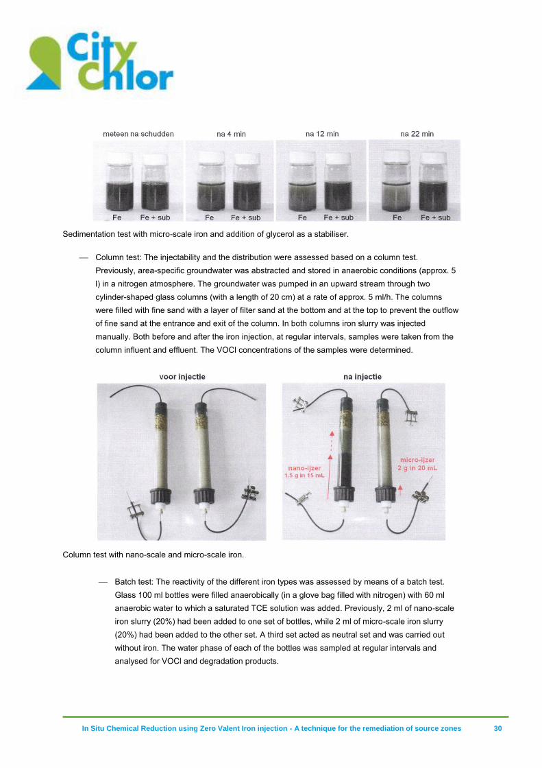
Sedimentation test: A sedimentation test was carried out to check whether the stability of the iron slurry can be improved by adding a substrate (~reduction of particle sedimentation speed). The test was carried out in glass 20 ml vials (vial 1: ZVI + water; vial 2: ZVI + 1:1 water/glycol mixture). The vials were shaken vigorously and subsequently the sediment was monitored visually after 4, 12 & 22 minutes.
In Situ Chemical Reduction using Zero Valent Iron injection - A technique for the remediation of source zones 30
Sedimentation test with micro-scale iron and addition of glycerol as a stabiliser.
Column test: The injectability and the distribution were assessed based on a column test.
Previously, area-specific groundwater was abstracted and stored in anaerobic conditions (approx. 5 l) in a nitrogen atmosphere. The groundwater was pumped in an upward stream through two cylinder-shaped glass columns (with a length of 20 cm) at a rate of approx. 5 ml/h. The columns were filled with fine sand with a layer of filter sand at the bottom and at the top to prevent the outflow of fine sand at the entrance and exit of the column. In both columns iron slurry was injected manually. Both before and after the iron injection, at regular intervals, samples were taken from the column influent and effluent. The VOCl concentrations of the samples were determined.
Column test with nano-scale and micro-scale iron.
Batch test: The reactivity of the different iron types was assessed by means of a batch test. Glass 100 ml bottles were filled anaerobically (in a glove bag filled with nitrogen) with 60 ml anaerobic water to which a saturated TCE solution was added. Previously, 2 ml of nano-scale iron slurry (20%) had been added to one set of bottles, while 2 ml of micro-scale iron slurry (20%) had been added to the other set. A third set acted as neutral set and was carried out without iron. The water phase of each of the bottles was sampled at regular intervals and analysed for VOCl and degradation products.
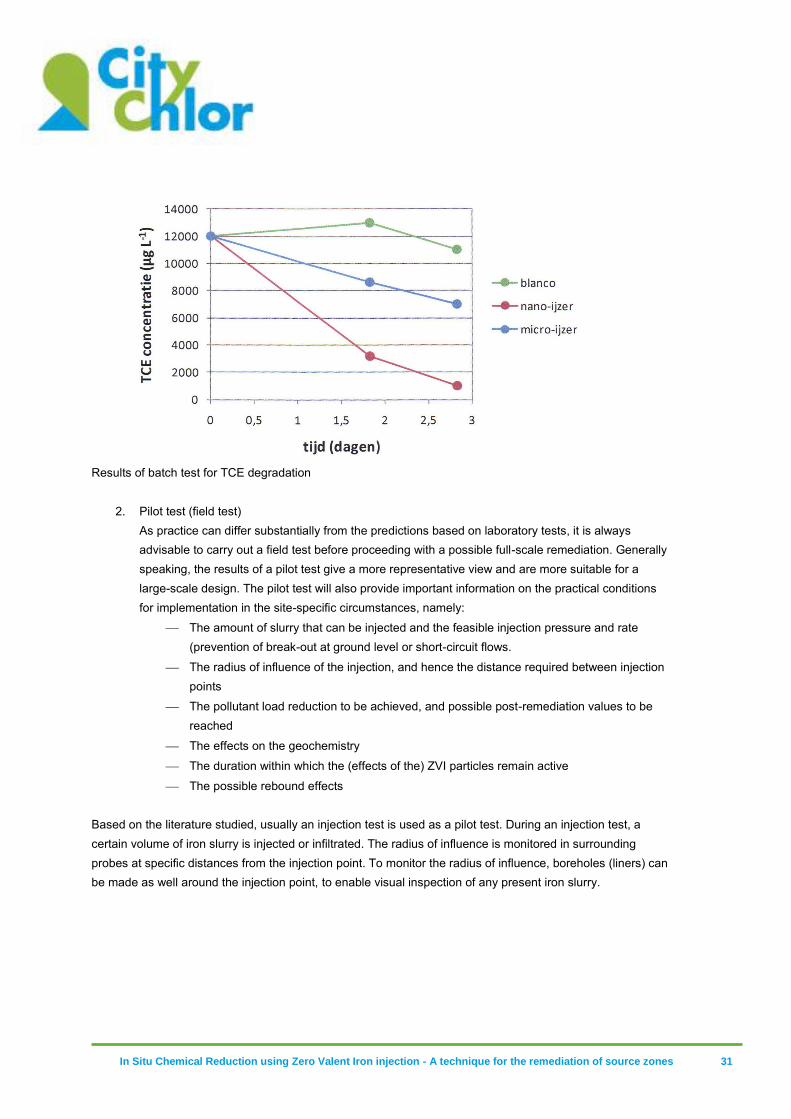
In Situ Chemical Reduction using Zero Valent Iron injection - A technique for the remediation of source zones 31
Results of batch test for TCE degradation
2. Pilot test (field test)
As practice can differ substantially from the predictions based on laboratory tests, it is always advisable to carry out a field test before proceeding with a possible full-scale remediation. Generally speaking, the results of a pilot test give a more representative view and are more suitable for a large-scale design. The pilot test will also provide important information on the practical conditions for implementation in the site-specific circumstances, namely:
The amount of slurry that can be injected and the feasible injection pressure and rate (prevention of break-out at ground level or short-circuit flows.
The radius of influence of the injection, and hence the distance required between injection points
The pollutant load reduction to be achieved, and possible post-remediation values to be reached
The effects on the geochemistry
The duration within which the (effects of the) ZVI particles remain active
The possible rebound effects
Based on the literature studied, usually an injection test is used as a pilot test. During an injection test, a certain volume of iron slurry is injected or infiltrated. The radius of influence is monitored in surrounding probes at specific distances from the injection point. To monitor the radius of influence, boreholes (liners) can be made as well around the injection point, to enable visual inspection of any present iron slurry.
In Situ Chemical Reduction using Zero Valent Iron injection - A technique for the remediation of source zones 32
5.4 Dosage calculation
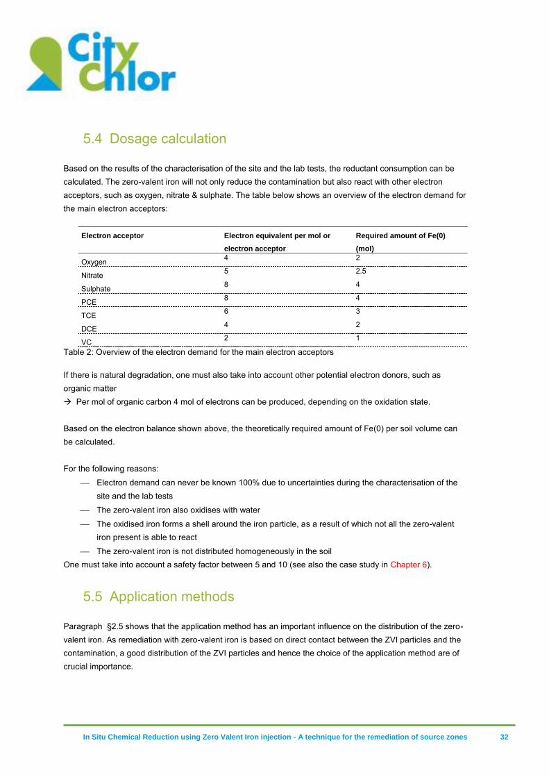
Based on the results of the characterisation of the site and the lab tests, the reductant consumption can be calculated. The zero-valent iron will not only reduce the contamination but also react with other electron acceptors, such as oxygen, nitrate & sulphate. The table below shows an overview of the electron demand for the main electron acceptors:
Electron acceptor Electron equivalent per mol or
electron acceptor
Required amount of Fe(0)
(mol)
Oxygen 4 2
Nitrate 5 2.5
Sulphate 8 4
PCE 8 4
TCE 6 3
DCE 4 2
VC 2 1
Table 2: Overview of the electron demand for the main electron acceptors
If there is natural degradation, one must also take into account other potential electron donors, such as organic matter Per mol of organic carbon 4 mol of electrons can be produced, depending on the oxidation state. Based on the electron balance shown above, the theoretically required amount of Fe(0) per soil volume can be calculated. For the following reasons:
Electron demand can never be known 100% due to uncertainties during the characterisation of the site and the lab tests
The zero-valent iron also oxidises with water
The oxidised iron forms a shell around the iron particle, as a result of which not all the zero-valent iron present is able to react
The zero-valent iron is not distributed homogeneously in the soil One must take into account a safety factor between 5 and 10 (see also the case study in Chapter 6).
5.5 Application methods
Paragraph §2.5 shows that the application method has an important influence on the distribution of the zero-valent iron. As remediation with zero-valent iron is based on direct contact between the ZVI particles and the contamination, a good distribution of the ZVI particles and hence the choice of the application method are of crucial importance.
In Situ Chemical Reduction using Zero Valent Iron injection - A technique for the remediation of source zones 33
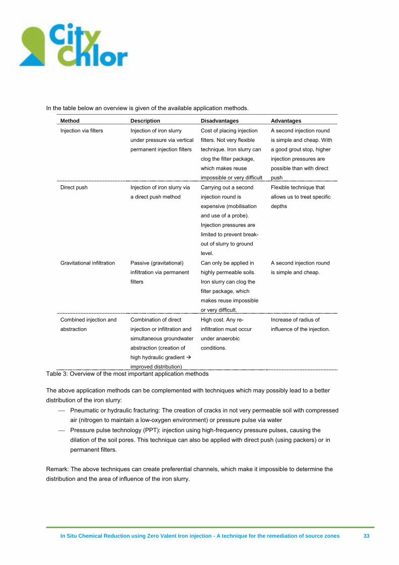
In the table below an overview is given of the available application methods.
Method Description Disadvantages Advantages
Injection via filters Injection of iron slurry
under pressure via vertical
permanent injection filters
Cost of placing injection
filters. Not very flexible
technique. Iron slurry can
clog the filter package,
which makes reuse
impossible or very difficult
A second injection round
is simple and cheap. With
a good grout stop, higher
injection pressures are
possible than with direct
push
Direct push Injection of iron slurry via
a direct push method
Carrying out a second
injection round is
expensive (mobilisation
and use of a probe).
Injection pressures are
limited to prevent break-
out of slurry to ground
level.
Flexible technique that
allows us to treat specific
depths
Gravitational infiltration Passive (gravitational)
infiltration via permanent
filters
Can only be applied in
highly permeable soils.
Iron slurry can clog the
filter package, which
makes reuse impossible
or very difficult.
A second injection round
is simple and cheap.
Combined injection and
abstraction
Combination of direct
injection or infiltration and
simultaneous groundwater
abstraction (creation of
high hydraulic gradient
improved distribution)
High cost. Any re-
infiltration must occur
under anaerobic
conditions.
Increase of radius of
influence of the injection.
Table 3: Overview of the most important application methods
The above application methods can be complemented with techniques which may possibly lead to a better distribution of the iron slurry:
Pneumatic or hydraulic fracturing: The creation of cracks in not very permeable soil with compressed air (nitrogen to maintain a low-oxygen environment) or pressure pulse via water
Pressure pulse technology (PPT): injection using high-frequency pressure pulses, causing the dilation of the soil pores. This technique can also be applied with direct push (using packers) or in permanent filters.
Remark: The above techniques can create preferential channels, which make it impossible to determine the distribution and the area of influence of the iron slurry.
In Situ Chemical Reduction using Zero Valent Iron injection - A technique for the remediation of source zones 34
The injection pressure in porous media is lower than 1-2 bar. The injection pressure must in no case exceed the matrix pressure3 if one wants to avoid vertical spread to the surface.
5.6 Monitoring of the remediation
5.6.1 Monitoring during the injections At least the following parameters must be monitored during the injections:
Injected volumes and concentrations of iron slurry per injection point and interval
Injection pressure (prevention of break-out to ground level)
5.6.2 Monitoring after the injection In order to determine the influence of the iron injections on the contamination situation, the following parameters must be measured:
VOCl
Degradation products ethene, ethane and methane
In order to determine the influence of the iron injections on the local geochemistry, the following parameters must be monitored:
Measurement of Fe(II) and Fe (total) contents. These measurements are important to determine the radius of influence of the zero-valent iron injection. The radius of influence can be deduced from significant increases in the Fe(II) and Fe(total) content before and after the injection and after oxidation of the zero-valent iron.
Measurement of local redox conditions:
Redox potential measurements
Oxygen content
Nitrate and sulphate The contents measured must be compared to those found before the injections. In order to determine the inflow of these parameters, a probe located upstream must also be sampled.
In order to study the spread of organic substrate that may have been added (e.g. stabiliser of the ZVI particles or emulsified iron), the DOC content (dissolved organic carbon) must be monitored in the surrounding probes. The evolution of the DOC content can also tell something about the presence or stimulation of natural degradation.
3 Matrix pressure or effective stress: σe = σs – P where σs is particle stress (σs = ρs x g x h) and P water pressure (P = ρw x g x h).
In Situ Chemical Reduction using Zero Valent Iron injection - A technique for the remediation of source zones 35
5.7 Evaluation diagram for use of iron injection
The decision framework for the application of iron injections has been added under appendix 3.
5.8 Stability/safety
ZVI particles, and especially nZVI particles, are not stable. In dry form, the powder ignites immediately when it enters into contact with air. Storage in dry form can only take place in an inert atmosphere. For this reason, nZVI is usually supplied as a slurry, but even so the product can only be stored for a limited amount of time, as it reacts with water. Contact between nZVI and important oxidants such as oxygen, sulphate, nitrate and water must be avoided. The life time also depends on the pH of the suspension and the particle type. A low pH causes an accelerated oxidation of the nZVI particles (Lowry, 2005). Open flame near the ZVI particles is strictly prohibited as nZVI particles can generate hydrogen (reaction with water). There is a warning about dangerous reactions when the product is mixed with oxidising agents (exothermic reaction) or acids (production of hydrogen). It is recommended to store the product in a cool place and prevent drying. ZVI particles are described as a product that is not hazardous to man or nature Protection of the skin (PVC-coated gloves, protective clothing), eyes (safety goggles) and airways (usually not necessary) is recommended. Any spilled product must be cleaned with a large amount of water as soon as possible.
All chemicals that are used for the purposes of ISCR must fulfil European Union REACH
(registration, evaluation, authorisation & restriction of chemicals) guidelines.
In Situ Chemical Reduction using Zero Valent Iron injection - A technique for the remediation of source zones 36
6 Cost
6.1 Cost of ZVI particles
The price of nZVI particles varies between 25 and 325 euro/kg Fe(0). This variation in price can be put down to the manufacture and also the type of nZVI (stabilised products, modified products, conservation). Micro-scale and granular Fe(0) are available for less than 1 euro/kg (see also paragraph §3.4, excluding costs for transport and handling).
6.2 Cost of preparing full-scale iron injection
The preparation for a full-scale remediation typically includes all the necessary lab tests, followed by a field test. On the basis of the experiences with the CityChlor pilot
4 in Herk-de-Stad, the costs of the
entire pilot can be divided up as follows (including consultancy costs, rounded up to significant figures, excluding VAT): Post Cost (kEuro, excl. VAT) Share (%)
1. Lab tests 10 20 2. Field test - Injections 22 44 - Cost of ZVI material 2 4 3. Monitoring and interpretation 16 32 Total 50 100%
Table 4: Division of costs – CityChlor pilot Herk-de-Stad
4 Voor meer details met betrekking tot deze pilootproef wordt verwezen naar het praktijkvoorbeeld onder bijlage 1.
In Situ Chemical Reduction using Zero Valent Iron injection - A technique for the remediation of source zones 37
The following costs were incurred during the pilot for ZVI materials: ZVI material Form Cost price ZVI
material Price of ZVI per m injection phase (Euro/m) (*)
Price of slurry per m injection phase (Euro/m)
Price of slurry ZVI/m³ soil (Euro/m³ soil)
nZVI: NANOFER 25 – Nano Iron
Slurry (20% dm)
25 Euro/kg slurry = 125 Euro/kg ZVI dm
62,5 62,5 120
mZVI: Gotthart Maier Metallpulver GmbH
Powder 1.2 Euro/kg ZVI dm
3 29(**) 260
(*) 50 l of slurry per metre were injected with 50 g mZVI/l and 10 g nZVI/l injected
(**) The mZVI was dissolved in a 40% v/v solution with glycerol. Glycerol costs approximately 1.3 euro/l.
(***) Based on the volume of soil that comes into direct contact with the injected solution (theoretical radius of influence of 0.28 m around each injection point.
Table 5: Costs of ZVI materials – CityChlor pilot Herk-de-Stad
6.3 Cost of full-scale remediation iron injection
1. General estimate of cost of remediation per m³ of treated soil On the basis of the full-scale remediation in Rotterdam (practical case Wegrosan hmvt, see appendix 1) and 5 practical cases5 that were found in the literature, which provided sufficient financial information, the remediation costs varies between (rounded to significant figures) 20 and 370 euro/m³ of treated soil6 (for remediation of polluted soil volumes ranging from 735 to 24,000 m³). The cost per volume of treated soil is inversely proportional to the scale of the project. 2. Summary of cost division for full-scale remediation On the basis of 3 practical examples from the literature and the practical example from Rotterdam (Wegrosan hmvt, see appendix 1) of full-scale remediations, for which there is sufficient financial information, the total price can be categorised (in order of significance) as follows:
5 Mueller, N. C. and Nowack, B. 2010. Nano zero valent iron - THE solution for water and soil remediation? Report of the ObservatoryNANO at www.observatorynano.eu. U.S. EPA. (2008) Nanotechnology for Site Remediation Fact Sheet. www.epa.gov http://cluin.org/542F08009. 6 Prijzen cases uit de literatuur zijn afkomstig van amerikaanse en europese studies uitgevoerd in de periode 2004 – 2010. De dollarprijzen werden omgerekend naar euro op basis van een wisselkoers van 1,3 dollar / euro. In de studies wordt de kostprijs meestal zeer summier vermeld, de opdeling van de kosten is eveneens niet voor elke studie dezelfde.
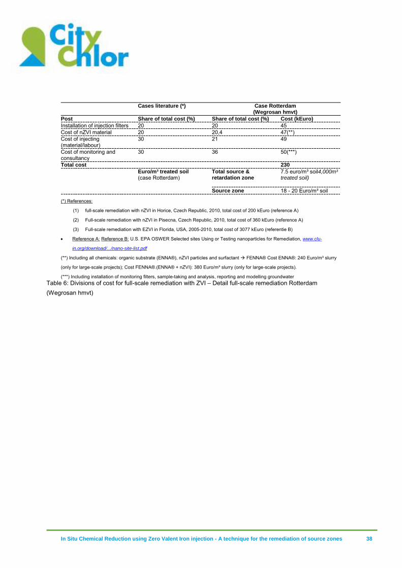
In Situ Chemical Reduction using Zero Valent Iron injection - A technique for the remediation of source zones 38
Cases literature (*) Case Rotterdam
(Wegrosan hmvt)
Post Share of total cost (%) Share of total cost (%) Cost (kEuro)
Installation of injection filters 20 20 45 Cost of nZVI material 20 20,4 47(**) Cost of injecting (material/labour)
30 21 49
Cost of monitoring and consultancy
30 36 50(***)
Total cost 230
Euro/m³ treated soil (case Rotterdam)
Total source & retardation zone
7.5 euro/m³ soil4,000m³ treated soil)
Source zone 18 - 20 Euro/m³ soil
(*) References:
(1) full-scale remediation with nZVI in Horice, Czech Republic, 2010, total cost of 200 kEuro (reference A)
(2) Full-scale remediation with nZVI in Pisecna, Czech Republic, 2010, total cost of 360 kEuro (reference A)
(3) Full-scale remediation with EZVI in Florida, USA, 2005-2010, total cost of 3077 kEuro (referentie B)
Reference A: Reference B: U.S. EPA OSWER Selected sites Using or Testing nanoparticles for Remediation, www.clu-
in.org/download/.../nano-site-list.pdf
(**) Including all chemicals: organic substrate (ENNA®), nZVI particles and surfactant FENNA® Cost ENNA®: 240 Euro/m³ slurry
(only for large-scale projects); Cost FENNA®.(ENNA® + nZVI): 380 Euro/m³ slurry (only for large-scale projects).
(***) Including installation of monitoring filters, sample-taking and analysis, reporting and modelling groundwater Table 6: Divisions of cost for full-scale remediation with ZVI – Detail full-scale remediation Rotterdam (Wegrosan hmvt)
In Situ Chemical Reduction using Zero Valent Iron injection - A technique for the remediation of source zones 39
7 Results of market survey
In order to supplement this study, a market survey was conducted to gauge experiences with ISCR according to the following parties: Soil remediation companies (cases and/or specific experiences with zero-valent iron):
European Remediation Technologies (ERT) DEC Ecoterres Groundwater technology In-Situ Techniques Mourik Verhoeve Milieu Wegrosan hmvt
Suppliers of zero-valent micro and nano-scale iron: FMC Technologies (EHC®, EHC-L®, Daramend®) Regenesis (CRS®)
The market survey was conducted on the basis of a questionnaire (see appendix 2) which initially gauged the experiences (# cases) of the soil remediation company/supplier with respect to the application of iron injections for the treatment of soil contamination with chlorinated components ((ISCR). The second part of the survey asked for further details about issues such as the pollution situation, soil texture, injection method, type of iron product (and supplier), cost and any points of particular attention. On the basis of the surveys returned, a number of contactors were selected for an in-depth interview. On the basis of this interview, a final decision was made regarding which practical cases would be added to the study at hand (see chapter 9). The following information was obtained on the basis of the surveys:
Soil remediation companies (cases and/or specific experiences with zero-valent iron): European Remediation Technologies (ERT) no experience with ISCR DEC Ecoterres no experience with ISCR Groundwater technology no response to survey In-Situ Techniques no experience with ISCR Mourik no experience with ISCR Verhoeve Milieu experience with ISCR (2 cases) Wegrosan hmvt experience with ISCR (5 cases)
Suppliers of zero-valent micro and nano-scale iron: FMC Technologies (EHC®, EHC-L®, Daramend®) experience with ISCR (1 case) Regenesis (CRS®) no info on ISCR practical examples
On the basis of the information supplied, in consultation with OVAM, a decision was made to interview Verhoeve Milieu and Wegrosan hmvt. The following cases were then discussed: Verhoeve Milieu
Case 1: CityChlor Herk-de-Stad, Belgium - Pilot: Chemical reduction using nZVI and mZVI
In Situ Chemical Reduction using Zero Valent Iron injection - A technique for the remediation of source zones 40
This case is fully elaborated and added under appendix 1. - Case 2: Project in Huizingen, Belgium – Pilot: Injection of nZVI dissolved in organic substrate PV1® for the treatment of soil contamination with trichloroethane Before the remediation of soil contamination with TCA, a number of injections were carried out with nZVI dissolved in the organic substrate PV1 (mixture of alcohols and sugars). Prior to the injections, no lab tests were carried out, the injection doses were set on the basis of the estimated contamination loading (see paragraph §4.4) with a safety factor of 10. The injections were carried out via a direct push in the form of a hexagonal template (centre-to-centre distance of injections = 4 m). After injection, a redox potential of -200 mV was recorded at the site. According to Verhoeve Milieu, the low redox potential can be put down to the injections of the substrate. Eighty days after injection, a reduction in the contamination loading of 80% was observed (1000 µg/l TCA (200 µg/l TCA). Assessment of iron injections by Verhoeve Milieu: ZVI is practical as a management tool in permeable reactive barriers. As a result of the limited spread of the ZVI particles, the use of iron injections as an active
remediation measure is not recommended.
Wegrosan hmvt Case 3: Rotterdam, the Netherlands – Full-scale remediation: Stimulation of anaerobic organic
decomposition and chemical reduction using EZVI. This case has been fully elaborated and added under appendix 1.

In Situ Chemical Reduction using Zero Valent Iron injection - A technique for the remediation of source zones 41
8 Conclusions
The remediation of soil contamination by means of iron injections is based on direct contact between the zero-valent iron and the contamination. Good injectability, stability and mobility of the iron particles are crucial for this. Based on our own practical experience (pilot CityChlor Herk-de-Stad) and the literature studied, these are the main bottlenecks of iron injection as a remediation technique. In comparison with other, more conventional remediation techniques, there is a high remediation cost involved in the use of iron injections, as this technique requires a very dense network of injection points and/or the application of advanced injection techniques in combination with expensive modified iron particles. The use of iron injection (with EZVI) for the treatment of areas with DNAPL is possible in theory, but is not considered cost-effective, as it requires a large amount of (expensive) zero-valent iron and a good contact between the DNAPL and the zero-valent iron cannot be guaranteed. Based on our own practical experience and the study at hand, iron injection as an independent remediation technique is less suitable for the remediation of soil contamination with VOCl. The use of iron injections, however, is deemed to be useful for creating suitable geochemical circumstances for the natural reductive breakdown of VOCI contamination (see also the practical examples under appendix 1). In other words, zero-valent iron can serve as an aid for stimulating natural decomposition: a combined injection of substrate and zero-valent iron (e.g. emulsified zero-valent iron) in (source) areas with unsuitable geochemical conditions or strongly increased (~toxic for biology) concentrations of contaminants.
On the basis of our own practical experiences (pilot CityChlor Herk-de-Stad) and the literature review, the increased efficiency of the remediation and the reduced remediation costs depend on the radius of influence of the injection. Additional research into expanding the radius of influence of iron injections is thus vital. Expanding the radius of influence can be achieved via 1. Improved injection techniques 2. Modified zero-valent iron A tried-and-tested and effective use of zero-valent iron (granular) involves PRB (permeable reactive barrier) for the treatment and management of the retardation zone.
In Situ Chemical Reduction using Zero Valent Iron injection - A technique for the remediation of source zones 42
9 Bibliography
Arnason, J.G., Harkness, M., Butler-Veytia, B. 2010. A magnetic susceptibility method for evaluating distribution of zero-valent iron in the subsurface. In: Abstracts seventh international conference on remediation of chlorinated and recalcitrant compounds (edited by Fields K.A. & Wickramanayake, G.B.), Monterey, California, USA, D-071 Bastiaens, L. Injectie van (bi)metallisch nanoschaal ijzerpartikels in met chloorkoolwaterstoffen verontreinigde aquifers, Fase 1: Literatuurstudie stand van techniek. Niet gepubliceerd rapport, VITO, Mol, 39p. Bastiaens, L., 2010. Official project periodic report 1 OR-1-DRAFT provided to advisory board. Niet gepubliceerd rapport, AQUAREHAB, 118p. Battelle. 2004. Demonstration of In Situ dehalogenation of DNAPL through injection of emulsified zero-valent iron at Launch Complex 34 in Cape Canaveral Air Force Station, Florida. Rapport EPA/540/R-07/006, U.S. EPA, 83p. Bozzini, C., Cleland, D., Lowder, R., Skeean, J., Fulkerson, M. 2010. Large-scale DNAPL remediation using ZVI-clay soil mixing at site 89 MCB Camp Lejeune. In: Abstracts seventh international conference on remediation of chlorinated and recalcitrant compounds (edited by Fields K.A. & Wickramanayake, G.B.), Monterey, California, USA, D-076 Bures, G.H., Skog, J.A., Swift, D., Rothermel, J., Starr, R., Moreno, J. 2010. Fracture-emplacement and 3-D mapping of a microiron/carbon amendment in TCE-impacted sedimentary bedrock. In: Abstracts seventh international conference on remediation of chlorinated and recalcitrant compounds (edited by Fields K.A. & Wickramanayake, G.B.), Monterey, California, USA, D-067 Chen, S., Markesic, S.J., Abrams, S.H. 2002. Injection of zero-valent iron into a bedrock formation for the reduction of TCE. In: Proceedings of the third international conference on remediation of chlorinated and recalcitrant compounds (edited by Fields K.A. & Wickramanayake, G.B.), Monterey, California, USA, Paper 2H-56 Chen, S., Smith, P.G., Hall, M. 2010. Innovative application of pneumatic fracturing and atomized injection application in high traffic urban environment. In: Abstracts seventh international conference on remediation of chlorinated and recalcitrant compounds (edited by Fields K.A. & Wickramanayake, G.B.), Monterey, California, USA, D-077 Clark, C.J., Rao, P.S.C., Annable, M.D. 2002. Iron treatment of chlorinated waste in cosolvent solutions. In: Proceedings of the third international conference on remediation of chlorinated and recalcitrant compounds (edited by Fields K.A. & Wickramanayake, G.B.), Monterey, California, USA, Paper 2C-28 De Boer, C., Braun, J., Klaas, N. 2010. Transport of zero-valent iron colloids in aquifers. In: ConSoil 2010, Salzburg, Oostenrijk, ThS_A13 Desseau, 2010. Essai pilote de la technologie barrière multi-réactive pour le côntrole du panache TCE à la Garnison Valcartier, Québec, Canada. Niet gepubliceerd eindrapport, Construction de défense Canada, ref. HQ06084-30665SC
Dowiak, M., Smith, G., D’Arcy, K., Dumdei, B., Imbrie, J. 2002. Monitoring of zero-valent iron injection pilot test for trichloroethene treatment. In: Proceedings of the third international conference on remediation of chlorinated and recalcitrant compounds (edited by Fields K.A. & Wickramanayake, G.B.), Monterey, California, USA, Paper 2A-19 Dries, J., Kemps, A., Trögl, J., Bastiaens, L., Diels, L., Agathos, S.N. 2002 Effect of humic acid on heavy metal removal by zero-valent iron. In: Proceedings of the third international conference on remediation of chlorinated and recalcitrant compounds (edited by Fields K.A. & Wickramanayake, G.B.), Monterey, California, USA, Paper 2A-15
In Situ Chemical Reduction using Zero Valent Iron injection - A technique for the remediation of source zones 43
Forman, K., Kito, M., Kayaci, H., Zimmerle, J., Rhoades, D., Silver, D. 2010. Chloroform and TCE reduction using pneumatically injected microscale zero-valent iron (ZVI). In: Abstracts seventh international conference on remediation of chlorinated and recalcitrant compounds (edited by Fields K.A. & Wickramanayake, G.B.), Monterey, California, USA, D-069 Geiger, C.L., Clause, C.A., Reinhart, D., Brooks, K., Clausen, C., Huntley, C., Filipek, L., Krug, T., O’Hara, S., Majors, D., Quinn, J. 2002. Reductive dehalogenation of DNAPL using emulsified zero-valent iron. In: Proceedings of the third international conference on remediation of chlorinated and recalcitrant compounds (edited by Fields K.A. & Wickramanayake, G.B.), Monterey, California, USA, Paper 2C-32 Goiti, E., Ocejo, M., Moragues, M., Cagigal, E. 2010 Preparation of biopolymers modified zero valent iron particles for in-situ soil applications. In: ConSoil 2010, Salzburg, Oostenrijk, ThS_A13 Golder Associés, 2009. Essaie pilote pour le contrôle du panache de TCE – BFC Valcartier technologie fer zéro-valent. Niet gepubliceerd rapport, ref. CDC HQ 060 84 Huang Y.Y., Liu, F., Li H.D. 2009. Degradation of tetrachloromethane and tetrachloroethene by Ni/Fe bimetallic nanoparticles. Journal of Physics: Conference series 188, 012014 Johnson, R. L., Nurmi, J. T., Johnson, R. O., Shi, Z., Tratnyek, P., Phenrat, T., Lowry, G. 2010. Injection of nano zero-valent iron for subsurface remediation: a controlled field-scale test of transport. In: Seventh international conference on remediation of chlorinated and recalcitrant compounds (edited by Fields K.A. & Wickramanayake, G.B.), Monterey, California, USA, D-063 Jou, C.J., Hsieh, S.C., Lee, C.L., Lin, C., Huang, H.W. 2010. Combining zero-valent iron nanoparticles with microwave energy to treat chlorobenzene. Journal of Taiwan institute of Chemical Engineers 41, 216-220 Karn, B., Kuiken, T., Otto, M. 2009. Nanotechnology and in situ remediation: A review of the benefits and potential risks. Environmental health perspectives 117 (12), 1823-1831 Keane, E. 2009. Fate, transport and toxicity of nanoscale zero-valent iron (nZVI) used during superfund remediation. U.S. Environmental protection agency, Washington, DC Kim, H.J., Phenrat, T., Tilton, R.D., Illangasekare, T., Lowry, G.V. 2010. Influence of nZVI dose and groundwater flow rate on PCE dechlorination in porous media. In: Abstracts seventh international conference on remediation of chlorinated and recalcitrant compounds (edited by Fields K.A. & Wickramanayake, G.B.), Monterey, California, USA, D-079 Kvapil, P., Cernik, M., Lacinova, L. 2010. Combined application of lactates and nZVI for remediation of chlorinated hydrocarbons. In: Abstracts seventh international conference on remediation of chlorinated and recalcitrant compounds (edited by Fields K.A. & Wickramanayake, G.B.), Monterey, California, USA, D-070 Lee, J.W., Kim, J.H., Cho, S.H., Jeon, J.R., Kim, E.J., Jung, J.L., Chang, Y.S. 2010. Field application of natural polyphenol-stabilized nanoscale iron particles for in-situ remediation of DNAPL contaminated groundwater. In: Abstracts seventh international conference on remediation of chlorinated and recalcitrant compounds (edited by Fields K.A. & Wickramanayake, G.B.), Monterey, California, USA, D-073 Li, Z., Willms, C., Zhang, P., Bowman, R.S. 2002. Rate and pathway change in PCE dechlorination by zero-valent iron in the presence of cationic surfactant. In: Proceedings of the third international conference on remediation of chlorinated and recalcitrant compounds (edited by Fields K.A. & Wickramanayake, G.B.), Monterey, California, USA, Paper 2C-35 Lowry, G.V., Phenrat, T., Kim, H.J., Cihan, A., Illangasekare, T. 2010. Modeling tool to design in situ nanoscale zero-valent iron (NZVI) emplacement strategies. In: Abstracts seventh international conference on remediation of chlorinated and recalcitrant compounds (edited by Fields K.A. & Wickramanayake, G.B.), Monterey, California, USA, D-078
In Situ Chemical Reduction using Zero Valent Iron injection - A technique for the remediation of source zones 44
Mace, C. 2006. Controlling groundwater VOCs. Pollution engineering Molin, J., Mueller, J., Moreno, J., Valkenburg, J., Duchene, M. 2010. Subsurface distribution of ZVI/EHC slurry – Validating radius of influence. In: Abstracts seventh international conference on remediation of chlorinated and recalcitrant compounds (edited by Fields K.A. & Wickramanayake, G.B.), Monterey, California, USA, D-068 Mowder, C., Hanlon, R., Divine, C., Valkenburg, J., Simmons, B., Northway, A. 2010. Injection of ZVI/Carbon for complete source zone treatment of PCE/TCE in fractured basalt. In: Abstracts seventh international conference on remediation of chlorinated and recalcitrant compounds (edited by Fields K.A. & Wickramanayake, G.B.), Monterey, California, USA, D-066 Mueller, N.C., Nowack, B. 2010. Nano-zero valent iron – THE solution for water and soil remediation? Report of the ObservatoryNANO. Available at www.observatorynano.eu. O’Hara, S., Krug, T., Watling, M., Quinn, J., Ruiz, N., Su, C., Puls, R. 2010. Field evaluation of the treatment of DNAPL using emulsified zero-valent iron. In: Abstracts seventh international conference on remediation of chlorinated and recalcitrant compounds (edited by Fields K.A. & Wickramanayake, G.B.), Monterey, California, USA, D-074 Oleniuk, A., Kocur, C., O’Carroll, D., Sleep, B., Xiong, Z., Bennett, P.J. 2010. Simulation of nZVI transport at a field site. In: Abstracts seventh international conference on remediation of chlorinated and recalcitrant compounds (edited by Fields K.A. & Wickramanayake, G.B.), Monterey, California, USA, D-072 Phenrat, T., Long, T.C., Lowry, G.V., Veronesi, B. 2008. Partial oxidation (aging) and surface modification decrease the toxicity of nano-sized zero valent iron. Environmental science and technology 43(1), 195-200 Schnell, D.L. 2010. Design, field application, and verification of pneumatically injected permeable reactive barriers. In: In: Abstracts seventh international conference on remediation of chlorinated and recalcitrant compounds (edited by Fields K.A. & Wickramanayake, G.B.), Monterey, California, USA, D-065 Svab, M., Dosoudil, P., Turkova, E., Svabova, M. 2010. Comparison of migration properties of various types of nanoscale zerovalent iron in porous media. In: ConSoil 2010, Salzburg, Oostenrijk, ThS_A13 Tosco, T., Sethi, R. 2010. Transport of iron micro and nanoparticles in saturated porous media. In: ConSoil 2010, Salzburg, Oostenrijk, ThS_A13 Van Nooten, T. 2007. Reactieve ijzerwanden. Niet gepubliceerde doctoraatsthesis, VITO, 142p. Truex, M., Vermeul, V., Oostrom, M., Macbeth, T. 2010, Field test of a shear thinning fluid to deliver ZVI particles to the subsurface. In: Abstracts seventh international conference on remediation of chlorinated and recalcitrant compounds (edited by Fields K.A. & Wickramanayake, G.B.), Monterey, California, USA, D-064 U.S. EPA Contaminated site clean-up information 2013. Selected sites using or testing nanoparticles for remediation, http://www.clu-in.org/download/remed/nano-site-list.pdf U.S. EPA. 2008. Nanotechnology for site remediation fact sheet. U.S. EPA, Washington, DC U.S. EPA. 2000. Engineered approaches to in situ bioremediation of chlorinated solvents: Fundamentals and field applications. U.S. EPA Office of solid waste and emergency response, Washington, DC Uyttebroek, M., Baillieul, H., Vermeire, N., Scholiers, R., Devleeschauwer, P., Gemoets, J., Bastiaens, L. 2010. In situ remediation of a chlorinated ethene contaminated source zone by injection of zero-valent iron: From lab to field scale. In: ConSoil 2010, Salzburg, Oostenrijk, ThS_A13 Wattlington, K. 2005. Emerging nanotechnologies for site remediation and wastewater treatment. U.S. EPA, Washington, DC

In Situ Chemical Reduction using Zero Valent Iron injection - A technique for the remediation of source zones 45
Zaluski, M.H., Logar, A., Petersen, S.W., Runchal, A.K. 2010. Transport and amassing of ZVI nano-sized particles in groundwater. In: Abstracts seventh international conference on remediation of chlorinated and recalcitrant compounds (edited by Fields K.A. & Wickramanayake, G.B.), Monterey, California, USA, D-075 Zhang, L., Fang, M. 2010. Nanomaterials in pollution trace detection and environmental improvement. Nanotoday 5, 128-142 Zhang, W.X. 2003. Nanoscale iron particles for environmental remediation: An overview. Journal of Nanoparticle Research 5, 323-332
In Situ Chemical Reduction using Zero Valent Iron injection - A technique for the remediation of source zones 46
10 Appendix
10.1 CityChlor Herk-de-Stad: Trial Test ISCR injection nZVI &
mZVI
10.1.1 Introduction On commission from OVAM, the temporary partnership Tauw België NV – Verhoeve Group Belgium conducted during the period June 2011 – January 2013 a trial test on ‘In-Situ Chemical Reduction’ (ISCR) of chlorinated solvents (VOCl). The trial test is part of the CityChlor project. More concretely, in the vicinity of a source zone contaminated with VOCl, located on the site of a former printing plant in Herk-de-Stad, soil injections were carried out with micro and nano-scale zero valent iron (MZVI & NZVI). The trial test was conducted in 4 stages: Stage 1: Eco-technical evaluation of the site interpretation of earlier investigation findings and
characteristics of the injection zone Stage 2: Design and performance of lab testing Stage 3: Injection of iron particles Stage 4: Monitoring geochemical and eco-technical parameters following injection
10.1.2 Conceptual model
10.1.2.1 Geo-hydrology Based on the performed characterisation core drillings, the soil composition strata may be summarized as follows: 0-5.9 m down from ground level: silty to clayish moderately coarse-grained sand 5.9-6.3 m down from ground level: presence of thin layer of peat (* not observed in all drillings) 6.3-7.8 m down from ground level: silty to clayish moderately coarse-grained sand 7.8-8 m down from ground level: sandy thin layer of peat (*not observed in all drillings) 8-14.5 m down from ground level: moderately coarse-grained sand >14.5 m down from ground level: clay The phreatic groundwater lies at ca. 3 m down from ground level The horizontal groundwater flow direction may, albeit not entirely uniformly, be considered to be north-westerly. On the basis of the current horizontal level reference, a very limited hydraulic gradient (ca. 0.2 %) is calculated. The following table shows the hydraulic conductivity per depth-trajectory:
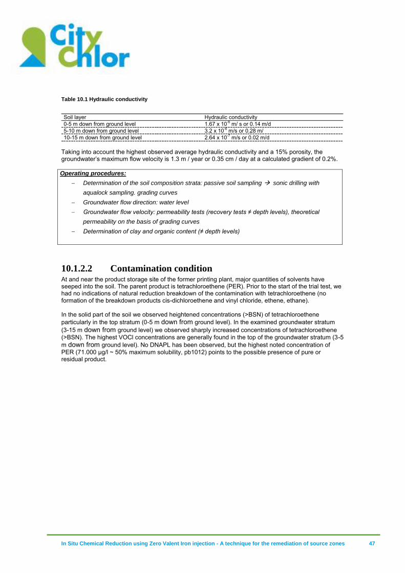
In Situ Chemical Reduction using Zero Valent Iron injection - A technique for the remediation of source zones 47
Table 10.1 Hydraulic conductivity
Soil layer Hydraulic conductivity 0-5 m down from ground level 1.67 x 10⁻⁶ m/ s or 0.14 m/d 5-10 m down from ground level 3.2 x 10⁻⁶ m/s or 0.28 m/ 10-15 m down from ground level 2.64 x 10⁻⁷ m/s or 0.02 m/d
Taking into account the highest observed average hydraulic conductivity and a 15% porosity, the groundwater’s maximum flow velocity is 1.3 m / year or 0.35 cm / day at a calculated gradient of 0.2%. Operating procedures:
Determination of the soil composition strata: passive soil sampling sonic drilling with
aqualock sampling. grading curves
Groundwater flow direction: water level
Groundwater flow velocity: permeability tests (recovery tests ≠ depth levels), theoretical
permeability on the basis of grading curves
Determination of clay and organic content (≠ depth levels)
10.1.2.2 Contamination condition At and near the product storage site of the former printing plant, major quantities of solvents have seeped into the soil. The parent product is tetrachloroethene (PER). Prior to the start of the trial test, we had no indications of natural reduction breakdown of the contamination with tetrachloroethene (no formation of the breakdown products cis-dichloroethene and vinyl chloride, ethene, ethane). In the solid part of the soil we observed heightened concentrations (>BSN) of tetrachloroethene particularly in the top stratum (0-5 m down from ground level). In the examined groundwater stratum (3-15 m down from ground level) we observed sharply increased concentrations of tetrachloroethene (>BSN). The highest VOCl concentrations are generally found in the top of the groundwater stratum (3-5 m down from ground level). No DNAPL has been observed, but the highest noted concentration of PER (71.000 µg/l ~ 50% maximum solubility, pb1012) points to the possible presence of pure or residual product.
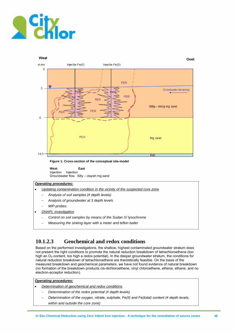
In Situ Chemical Reduction using Zero Valent Iron injection - A technique for the remediation of source zones 48
Figure 1: Cross-section of the conceptual site-model West East Injection Injection Groundwater flow Silty – clayish mg sand
Operating procedures:
Updating contamination condition in the vicinity of the suspected core zone
Analysis of soil samples (≠ depth levels)
Analysis of groundwater at 3 depth levels
MIP-probes
DNAPL investigation
Control on soil samples by means of the Sudan IV lysochrome
Measuring the sinking layer with a meter and teflon bailer
10.1.2.3 Geochemical and redox conditions Based on the performed investigations, the shallow, highest contaminated groundwater stratum does not present the right conditions to promote the natural reduction breakdown of tetrachloroethene (too high an O2-content, too high a redox potential). In the deeper groundwater stratum, the conditions for natural reduction breakdown of tetrachloroethene are theoretically feasible. On the basis of the measured breakdown and geochemical parameters, we have not found evidence of natural breakdown (no formation of the breakdown products cis-dichloroethene, vinyl chloroethene, ethene, ethane, and no electron-acceptor reduction). Operating procedures:
Determination of geochemical and redox conditions
Determination of the redox potential (≠ depth levels)
Determination of the oxygen, nitrate, sulphate, Fe(II) and Fe(total) content (≠ depth levels,
within and outside the core zone)
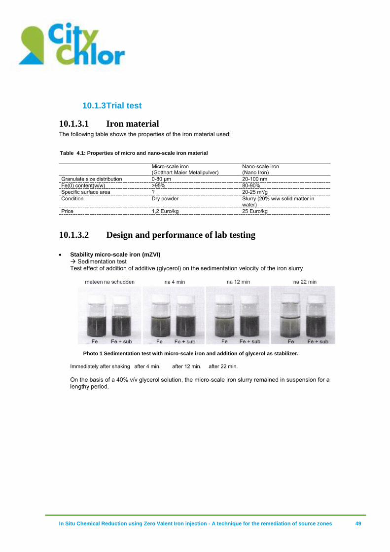
In Situ Chemical Reduction using Zero Valent Iron injection - A technique for the remediation of source zones 49
10.1.3 Trial test
10.1.3.1 Iron material The following table shows the properties of the iron material used:
Table 4.1: Properties of micro and nano-scale iron material
Micro-scale iron
(Gotthart Maier Metallpulver) Nano-scale iron (Nano Iron)
Granulate size distribution 0-80 µm 20-100 nm Fe(0) content(w/w) >95% 80-90% Specific surface area ? 20-25 m²/g Condition Dry powder Slurry (20% w/w solid matter in
water) Price 1,2 Euro/kg 25 Euro/kg
10.1.3.2 Design and performance of lab testing Stability micro-scale iron (mZVI)
Sedimentation test Test effect of addition of additive (glycerol) on the sedimentation velocity of the iron slurry
Photo 1 Sedimentation test with micro-scale iron and addition of glycerol as stabilizer.
Immediately after shaking after 4 min. after 12 min. after 22 min. On the basis of a 40% v/v glycerol solution, the micro-scale iron slurry remained in suspension for a lengthy period.
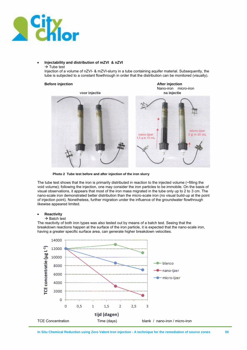
In Situ Chemical Reduction using Zero Valent Iron injection - A technique for the remediation of source zones 50
Injectability and distribution of mZVI & nZVI
Tube test Injection of a volume of nZVI- & mZVI-slurry in a tube containing aquifer material. Subsequently, the tube is subjected to a constant flowthrough in order that the distribution can be monitored (visually). Before injection After injection
Nano-iron micro-iron
Photo 2 Tube test before and after injection of the iron slurry
The tube test shows that the iron is primarily distributed in reaction to the injected volume (~filling the void volume); following the injection, one may consider the iron particles to be immobile. On the basis of visual observations, it appears that most of the iron mass migrated in the tube only up to 2 to 3 cm. The nano-scale iron demonstrated better distribution than the micro-scale iron (no visual build-up at the point of injection point). Nonetheless, further migration under the influence of the groundwater flowthrough likewise appeared limited.
Reactivity
Batch test The reactivity of both iron types was also tested out by means of a batch test. Seeing that the breakdown reactions happen at the surface of the iron particle, it is expected that the nano-scale iron, having a greater specific surface area, can generate higher breakdown velocities.
TCE Concentration Time (days) blank / nano-iron / micro-iron
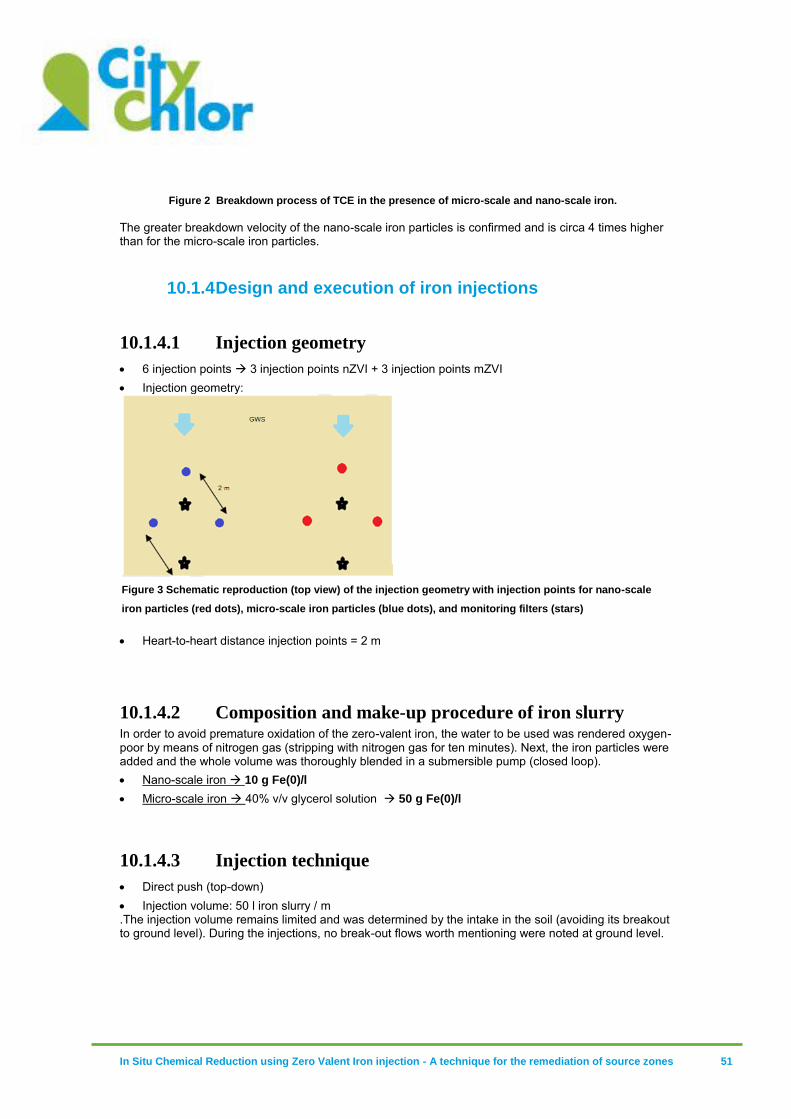
In Situ Chemical Reduction using Zero Valent Iron injection - A technique for the remediation of source zones 51
Figure 2 Breakdown process of TCE in the presence of micro-scale and nano-scale iron.
The greater breakdown velocity of the nano-scale iron particles is confirmed and is circa 4 times higher than for the micro-scale iron particles.
10.1.4 Design and execution of iron injections
10.1.4.1 Injection geometry
6 injection points 3 injection points nZVI + 3 injection points mZVI Injection geometry:
Figure 3 Schematic reproduction (top view) of the injection geometry with injection points for nano-scale
iron particles (red dots), micro-scale iron particles (blue dots), and monitoring filters (stars)
Heart-to-heart distance injection points = 2 m
10.1.4.2 Composition and make-up procedure of iron slurry In order to avoid premature oxidation of the zero-valent iron, the water to be used was rendered oxygen-poor by means of nitrogen gas (stripping with nitrogen gas for ten minutes). Next, the iron particles were added and the whole volume was thoroughly blended in a submersible pump (closed loop). Nano-scale iron 10 g Fe(0)/l Micro-scale iron 40% v/v glycerol solution 50 g Fe(0)/l
10.1.4.3 Injection technique
Direct push (top-down) Injection volume: 50 l iron slurry / m .The injection volume remains limited and was determined by the intake in the soil (avoiding its breakout to ground level). During the injections, no break-out flows worth mentioning were noted at ground level.
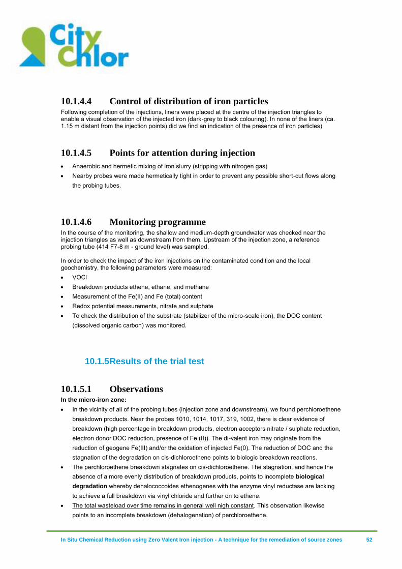
In Situ Chemical Reduction using Zero Valent Iron injection - A technique for the remediation of source zones 52
10.1.4.4 Control of distribution of iron particles Following completion of the injections, liners were placed at the centre of the injection triangles to enable a visual observation of the injected iron (dark-grey to black colouring). In none of the liners (ca. 1.15 m distant from the injection points) did we find an indication of the presence of iron particles)
10.1.4.5 Points for attention during injection
Anaerobic and hermetic mixing of iron slurry (stripping with nitrogen gas) Nearby probes were made hermetically tight in order to prevent any possible short-cut flows along
the probing tubes.
10.1.4.6 Monitoring programme In the course of the monitoring, the shallow and medium-depth groundwater was checked near the injection triangles as well as downstream from them. Upstream of the injection zone, a reference probing tube (414 F7-8 m - ground level) was sampled. In order to check the impact of the iron injections on the contaminated condition and the local geochemistry, the following parameters were measured: VOCl Breakdown products ethene, ethane, and methane Measurement of the Fe(II) and Fe (total) content Redox potential measurements, nitrate and sulphate To check the distribution of the substrate (stabilizer of the micro-scale iron), the DOC content
(dissolved organic carbon) was monitored.
10.1.5 Results of the trial test
10.1.5.1 Observations In the micro-iron zone:
In the vicinity of all of the probing tubes (injection zone and downstream), we found perchloroethene breakdown products. Near the probes 1010, 1014, 1017, 319, 1002, there is clear evidence of breakdown (high percentage in breakdown products, electron acceptors nitrate / sulphate reduction, electron donor DOC reduction, presence of Fe (II)). The di-valent iron may originate from the reduction of geogene Fe(III) and/or the oxidation of injected Fe(0). The reduction of DOC and the stagnation of the degradation on cis-dichloroethene points to biologic breakdown reactions.
The perchloroethene breakdown stagnates on cis-dichloroethene. The stagnation, and hence the absence of a more evenly distribution of breakdown products, points to incomplete biological
degradation whereby dehalococcoides ethenogenes with the enzyme vinyl reductase are lacking to achieve a full breakdown via vinyl chloride and further on to ethene.
The total wasteload over time remains in general well nigh constant. This observation likewise points to an incomplete breakdown (dehalogenation) of perchloroethene.
In Situ Chemical Reduction using Zero Valent Iron injection - A technique for the remediation of source zones 53
At the injection zone with zero-valent micro-iron, 10 months following injection there still remains a strong increased level of DOC content (vis-à-vis the reference), which indicates the presence of glycol as a carbon source (injected as stabilizer of the zero-valent micro-iron particles).
The redox potential Injection core mZVI: 4 – 15 mV (prior to injection) -40 to -231 mV (after injection) Downstream mZVI: -61 – 93 mV -46 - -135 mV
In the nano-iron zone:
In the vicinity of most of the probes, breakdown products of perchloroethene are observed. Near the probes 1013, 1020 and 1005, no significant breakdown is noted.
Likewise incomplete is the breakdown in the zone with nano-iron particles. The absence of a somewhat even distribution of vinyl chloride points to a biological instead of an abiotic breakdown under the influence of zero-valent iron.
The redox potential Injection core nZVI: -27 - -22 mV (prior to injection) -40 - -231 mV (after injection) Downstream nZVI: -72 – 24 mV 170 – 250 mV
10.1.6 General Conclusion Based on the results of the most recent monitoring, it is evident that the breakdown of perchloroethene has started near, and downstream from, both injection zones. The reduction of DOC (micro-iron) and the stagnation of the breakdown on cis-dichloroethene point to a natural reduction degradation rather than to an abiotic one under direct influence of the zero-valent iron. The natural breakdown is more evident in the zone where micro-iron was injected together with carbon source (glycol) than in the zone with nano-iron. In the nano-iron zone, interference may possibly have occurred. The stagnation of the breakdown on cis-dichloroethene points to the absence of the suitable microbial community to make a complete breakdown to ethene (via vinyl chloride) possible (likely the absence of the dehalococcoides ethenogenes genus that possesses the enzyme vinyl reductase). Bio-augmentation or the introduction of suitable microbial cultures can enable the total conversion from perchloroethene to ethene.
10.1.6.1 Evaluation of the cost price of the trial test The costs for the entire investigation may be broken down as follows (inclusive of consultancy fee, rounded up to significant digits, exclusive of VAT): Characterisation of the site and eco-technical investigation 20 kEuro Lab testing 10 kEuro Field testing
Injections (incl. preparations, mixing, ..) 22 kEuro Price mZVI & nZVI slurry 2 kEuro Monitoring 16 kEuro
Total (exclusive of additional investigations) 70 kEuro
The following expenditures were incurred for the ZVI-material: ZVI-material Form Purchase price
ZVI-material Cost ZVI per m injection trajectory (Euro/m) (*)
Cost slurry ZVI per m injection trajectory (Euro/m)
Cost slurry ZVI/m³ soil (***)
nZVI: NANOFER Slurry 25 Euro/kg slurry = 62,5 62,5 120
In Situ Chemical Reduction using Zero Valent Iron injection - A technique for the remediation of source zones 54
25 – Nano Iron (20% ds) 125 Euro/kg ZVI ds
mZVI: Gotthart Maier Metallpulver
Powder 1,2 Euro/kg ZVI ds 3 29(**) 260
(*)50 l of slurry per meter was injected with 50 g mZVI/l and 10 g nZVI/l injected. (**) The mZVI was dissolved in a 40% v/v solution with glycerol. Glycerol cost = ca. 1,3 euro/l. (***) Based on the volume of soil that comes in direct contact with the injected solution (theoretic impact radius of 0.28 m around each injection point.
10.1.7 Learned facts
Micro-scale iron appears to be readily injectable with addition of a stabilizer The addition of a relatively inexpensive substrate such as glycerol that counteracts the sedimentation of micro-scale iron makes it possible to inject micro-scale iron in the subsoil.
The impact radius of nano-scale and micro-scale iron remains limited (max. 15 cm)
The major limitation of zero-valent iron is that it is not, or barely, distributed together with the groundwater. The impact radius is, therefore, determined by the injection volume. This injection volume remains limited with the direct-push injection technique given that it is necessary to avoid breakout to the ground level and/or short-cut flows to nearby injection points /probing tubes.
In the vicinity of both injection zones (micro- and nano-scale iron), a reducing environment (low redox potential and oxygen concentrations) is observed, in combination with an increased content in PER breakdown products.
In both injection zones a sharp decline in redox potential is observed (sulphate reducing to methanogene conditions). Notable are the redox potentialities of < -250 mV that point to a direct effect of the zero-valent iron on the geochemistry. In both injection zones, we note an increase in breakdown products. Given the breakdown cascade, there is likely question of the presence of natural reduction breakdown. It is not entirely evident what part of the contamination is directly broken down by the zero-valent iron. Given the absence of natural breakdown reactions prior to the execution of the injections, the iron injections may be assumed to have caused the breakdown reactions by creating suitable geochemical conditions.
Downstream, a decrease in redox potential is observed only in the case of micro-scale iron At circa 2 m distance from the injection points, no effects in geochemical and breakdown reactions are observed with reference to the nano-scale iron. Hence, the impact of the injections remains very limited. The change in geochemistry and the presence of breakdown products downstream from the injection zone with micro-scale iron can be explained by stimulated natural breakdown under the influence of the added substrate (confirmed by the increased DOC contents downstream).
Cost price During the performed trial test, the following volumes/contents were injected: 50 l iron slurry/m with a content of g Nano Fe(0)/ l 62,5 euro/m7 50 l iron slurry/m with a content of 50 g Micro Fe(0)/ l 3 euro/m Taking into account the addition of substrate (40 % v/v glycerol to 1.4 euro/l), one calculates a cost price of 31 euro/m for the injection of micro Fe(0). When considering the added substrate, the injection of nano-scale iron is up to 2x more expensive than the micro-scale iron injection. Moreover, with the injection of nano-scale iron, 5x less Fe(0) was injected into the subsoil..
7 Price of the purchase and delivery of the iron product.

In Situ Chemical Reduction using Zero Valent Iron injection - A technique for the remediation of source zones 55
10.2 Case Rotterdam
Praktijkvoorbeeld Combinatie stimulatie anaërobe afbraak en chemische reductie
Locatie: Rotterdam (NL)
Rapportnummer: 257644 Casestudie NVZI Rotterdam.docm Datum rapportage: 28 maart 2013 HMVT B.V. WeGroSan/HMVT bvba Maxwellstraat 31 Vaartkant Rechts 27 Postbus 174 B-2960 Sint Lenaarts 6710 BD EDE T +32 (0)3 609 55 30 T +31 (0)318 62 46 24 F +32 (0)3 609 55 40 F +31 (0)318 62 49 13 www.wegrosan.be www.hmvt.nl
Opdrachtgever OVAM Stationsstraat 110 B-2800 Mechelen
Datum vrijgave Beschrijving revisie 0 Opgesteld door Gecontroleerd door
28-3-2013 definitief F.J. Pels J. van Rossum
WeGroSan/HMVT,257644 casestudie nvzi rotterdam versie mrt 2013.docm
Inhoud
1 Inleiding..............................................................................................1
2 Conceptueel model ................................................................................2 2.1 Geohydrologie ..............................................................................2 2.2 Verontreinigingsituatie ....................................................................2 2.3 Saneringstechniek ..........................................................................3 2.4 Labexperimenten ...........................................................................5
3 Uitvoering ...........................................................................................5 3.1 Stimulering afbraak onderzijde deklaag en watervoerend pakket ................6
3.1.1 Injectiefilters .....................................................................7 3.1.2 Aanmaken en injecteren ENNA ................................................7 3.1.3 Aanmaken en injecteren FENNA ...............................................9
3.2 Keuze injectietechniek .................................................................. 10
4 Resultaten ......................................................................................... 12
5 Leerpunten ........................................................................................ 13 Bijlagen bijlage 1 Toelichting ENNA (Enhanced Natural attenuation)
bijlage 2 Labexperimenten
HMVT, 257644 casestudie nvzi rotterdam versie mrt 2013.docm
1 Inleiding
De site van het praktijkvoorbeeld is gelegen in Rotterdam (NL). Op deze site hebben diverse industriële activiteiten plaatsgevonden vanaf 1902. Door met name ontvettings- en spuitwerkzaamheden is de bodem ernstig verontreinigd geraakt met gechloreerde solvents. In 2011 is de oude bebouwing gesloopt. De omgeving wordt herontwikkeld en krijgt een kantoren / woonbestemming. Hiervoor wordt de aangetroffen verontreiniging gesaneerd. Voor sanering worden de volgende technieken toegepast:
Ontgraving van de kernen van de verontreiniging, zover als technische goed uitvoerbaar en kosteneffectief;
Combinatie van chemische reductie en gestimuleerde afbraak in de kernen van de verontreiniging;
Gestimuleerde afbraak in de pluim (biobarriers).
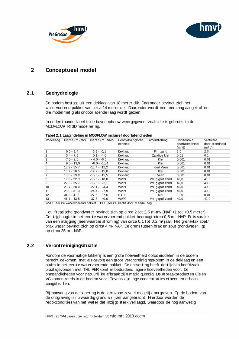
HMVT, 257644 casestudie nvzi rotterdam versie mrt 2013.docm
2 Conceptueel model
2.1 Geohydrologie
De bodem bestaat uit een deklaag van 18 meter dik. Daaronder bevindt zich het watervoerend pakket van circa 14 meter dik. Daaronder wordt een leemlaag aangetroffen die modelmatig als ondoorlatende laag wordt gezien. In onderstaande tabel is de bovenopbouw weergegeven, zoals die is gebruikt in de MODFLOW/ RT3D modellering. Tabel 2.1 Laagindeling in MODFLOW inclusief doorlatendheden Modellaag Diepte (m –mv) Diepte (m +NAP) Geohydrologische
eenheid Samenstelling Horizontale
doorlatendheid (m/d)
Verticale doorlatendheid (m/d)
1 0,0 – 3,4 3,5 - 0,1 Deklaag Fijn zand 2,0 2,0 2 3,4 – 7,5 0,1 – -4,0 Deklaag Zandige klei 0,01 0,1 3 7,5 – 9,5 - 4,0 - -6,0 Deklaag Klei 0,001 0,01 4 9,5 - 13,9 -6,0 – -10,4 Deklaag Klei 0,001 0,01 5 13,9 - 15,7 -10,4 - -12,2 Deklaag Klei/Veen 0,001 0,01 6 15,7 - 18,5 -12,2 - -15,0 Deklaag Klei 0,001 0,01 7 18,5 - 19,0 -15,0 – -15,5 Deklaag Veen 0,001 0,01 8 19,0 - 22,3 -15,5 - -18,8 WVP1 Matig grof zand 40,0 40,0 9 22,3 - 25,7 -18,8 - -22,1 WVP1 Matig grof zand 40,0 40,0 10 25,7 - 28,0 -22,1 – -24,4 WVP1 Matig grof zand 40,0 40,0 11 28,0 - 31,3 -24,4 – -27,9 WVP1 Matig grof zand 40,0 40,0 12 31,3 - 41,1 -27,8 - -37,6 SDL1 Klei 0,001 0,01 13 41,1 - 43,5 -37,6 - -40,0 WVP2 Matig grof zand 40,0 40,0 WVP1: eerste watervoerend pakket, SDL1: eerste slecht doorlatende laag Het freatische grondwater bevindt zich op circa 2 tot 2,5 m-mv (NAP +1 tot +0,5 meter). De stijghoogte in het eerste watervoerend pakket bedraagt circa 0,5 m – NAP. Er is sprake van een inzijging (neerwaartse stroming) van circa 0,1 tot 0,2 m/jaar. Het grensvlak zoet/ brak water bevindt zich op circa 4 m- NAP. De grens tussen brak en zout grondwater ligt op circa 35 m – NAP.
2.2 Verontreinigingsituatie
Rondom de voormalige lakkerij is een grote hoeveelheid oplosmiddelen in de bodem terecht gekomen, met als gevolg een grote verontreinigingskolom in de deklaag en een pluim in het eerste watervoerende pakket. De ontvetting heeft destijds in hoofdzaak plaatsgevonden met TRI. PER komt in beduidend lagere hoeveelheden voor. De omstandigheden voor natuurlijke afbraak zijn matig gunstig. De afbraakproducten Cis en VC komen reeds in de bodem voor. Tevens zijn lage concentraties etheen en ethaan aangetroffen. Bij aanvang van de sanering is de kernzone zoveel mogelijk ontgraven. Op de bodem van de ontgraving is nulwaardig granulair ijzer aangebracht. Hierdoor worden de redoxcondities van het water dat inzijgt sterk verlaagd, waardoor de nog aanwezig
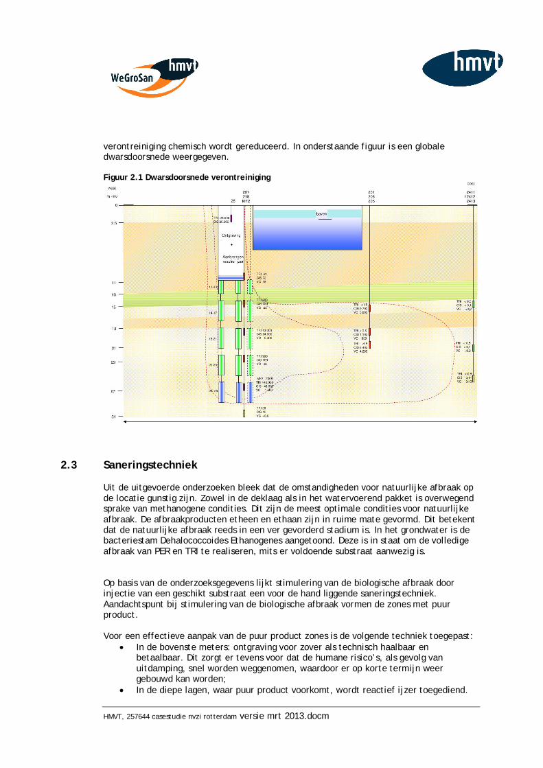
HMVT, 257644 casestudie nvzi rotterdam versie mrt 2013.docm
verontreiniging chemisch wordt gereduceerd. In onderstaande figuur is een globale dwarsdoorsnede weergegeven. Figuur 2.1 Dwarsdoorsnede verontreiniging
2.3 Saneringstechniek
Uit de uitgevoerde onderzoeken bleek dat de omstandigheden voor natuurlijke afbraak op de locatie gunstig zijn. Zowel in de deklaag als in het watervoerend pakket is overwegend sprake van methanogene condities. Dit zijn de meest optimale condities voor natuurlijke afbraak. De afbraakproducten etheen en ethaan zijn in ruime mate gevormd. Dit betekent dat de natuurlijke afbraak reeds in een ver gevorderd stadium is. In het grondwater is de bacteriestam Dehalococcoides Ethanogenes aangetoond. Deze is in staat om de volledige afbraak van PER en TRI te realiseren, mits er voldoende substraat aanwezig is. Op basis van de onderzoeksgegevens lijkt stimulering van de biologische afbraak door injectie van een geschikt substraat een voor de hand liggende saneringstechniek. Aandachtspunt bij stimulering van de biologische afbraak vormen de zones met puur product. Voor een effectieve aanpak van de puur product zones is de volgende techniek toegepast:
In de bovenste meters: ontgraving voor zover als technisch haalbaar en betaalbaar. Dit zorgt er tevens voor dat de humane risico’s, als gevolg van uitdamping, snel worden weggenomen, waardoor er op korte termijn weer gebouwd kan worden;
In de diepe lagen, waar puur product voorkomt, wordt reactief ijzer toegediend.
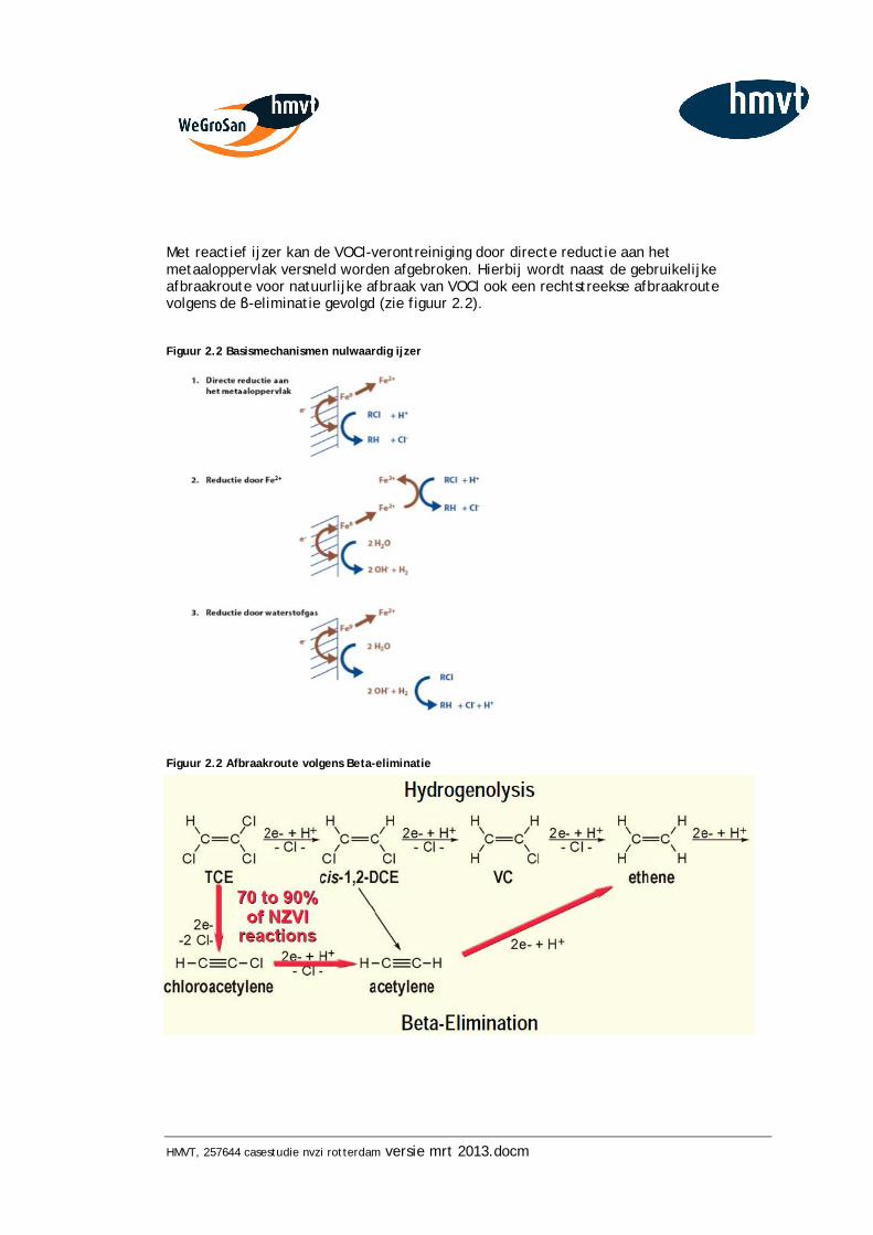
HMVT, 257644 casestudie nvzi rotterdam versie mrt 2013.docm
Met reactief ijzer kan de VOCl-verontreiniging door directe reductie aan het metaaloppervlak versneld worden afgebroken. Hierbij wordt naast de gebruikelijke afbraakroute voor natuurlijke afbraak van VOCl ook een rechtstreekse afbraakroute volgens de -eliminatie gevolgd (zie figuur 2.2). Figuur 2.2 Basismechanismen nulwaardig ijzer
Figuur 2.2 Afbraakroute volgens Beta-eliminatie
HMVT, 257644 casestudie nvzi rotterdam versie mrt 2013.docm
2.4 Labexperimenten
Voor aanvang van de werkzaamheden zijn labexperimenten uitgevoerd. Deze zijn opgenomen in bijlage 2. Hierbij is vooral de werking van het nulwaardig ijzer getest. Er is een forse afname van de verontreiniging waargenomen. Deels door omzetting door het ijzer-0. De massabalans was echter niet compleet sluitend, daarom wordt vermoed dat ook een deel van de verontreiniging is ‘verdwenen’ in het labexperiment door bijvoorbeeld absorptie aan de gebruikte materialen.
3 Uitvoering
In de deklaag (11 tot 18 m –mv) en het watervoerend pakket (18 tot 30 m –mv) is de afbraak gestimuleerd door injectie van een slow release substraat. Hierbij is gebruik gemaakt van het concept voor ENhanced Natural Attenuation (ENNA). HMVT heeft het ENNA-concept ontwikkeld om de afbraak van VOCl langdurig te bevorderen. Bij toepassing van ENNA wordt een duurzaam substraatmengsel in de bodem geïnjecteerd. Het hoofdbestanddeel van dit substraat bestaat uit plantaardige sojaolie. Het ENNA substraat wordt als suspensie (10% plantaardige sojaolie) ingebracht. Voor het aanmaken van ENNA wordt gebiedseigen water gebruikt. Dit heeft dezelfde geochemische eigenschappen en bevat de van nature aanwezige bacteriën. Er wordt een overmaat van het ENNA substraat (shock load) ingebracht, zodat de biologische afbraak gedurende een aantal jaren bevorderd kan worden. Het ENNA-substraat is op vijf niveaus geïnjecteerd via vaste injectiefilters.
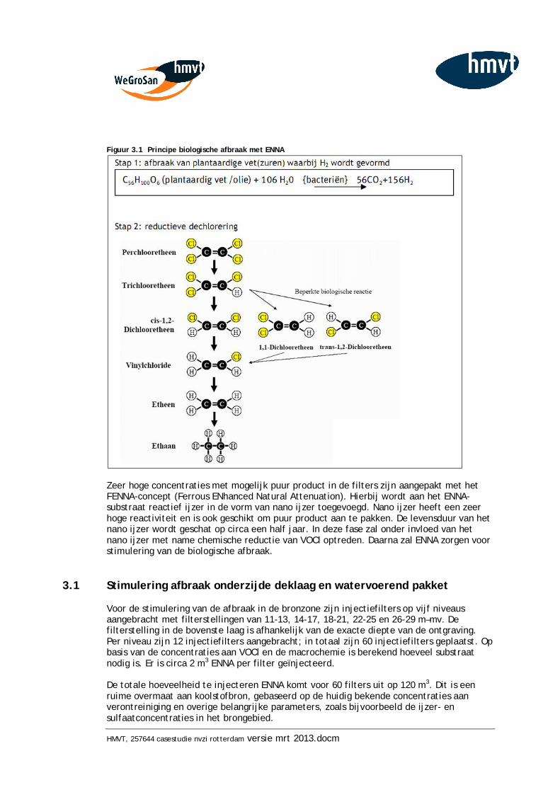
HMVT, 257644 casestudie nvzi rotterdam versie mrt 2013.docm
Figuur 3.1 Principe biologische afbraak met ENNA
Zeer hoge concentraties met mogelijk puur product in de filters zijn aangepakt met het FENNA-concept (Ferrous ENhanced Natural Attenuation). Hierbij wordt aan het ENNA-substraat reactief ijzer in de vorm van nano ijzer toegevoegd. Nano ijzer heeft een zeer hoge reactiviteit en is ook geschikt om puur product aan te pakken. De levensduur van het nano ijzer wordt geschat op circa een half jaar. In deze fase zal onder invloed van het nano ijzer met name chemische reductie van VOCl optreden. Daarna zal ENNA zorgen voor stimulering van de biologische afbraak.
3.1 Stimulering afbraak onderzijde deklaag en watervoerend pakket
Voor de stimulering van de afbraak in de bronzone zijn injectiefilters op vijf niveaus aangebracht met filterstellingen van 11-13, 14-17, 18-21, 22-25 en 26-29 m–mv. De filterstelling in de bovenste laag is afhankelijk van de exacte diepte van de ontgraving. Per niveau zijn 12 injectiefilters aangebracht; in totaal zijn 60 injectiefilters geplaatst. Op basis van de concentraties aan VOCl en de macrochemie is berekend hoeveel substraat nodig is. Er is circa 2 m3 ENNA per filter geïnjecteerd. De totale hoeveelheid te injecteren ENNA komt voor 60 filters uit op 120 m3. Dit is een ruime overmaat aan koolstofbron, gebaseerd op de huidig bekende concentraties aan verontreiniging en overige belangrijke parameters, zoals bijvoorbeeld de ijzer- en sulfaatconcentraties in het brongebied.
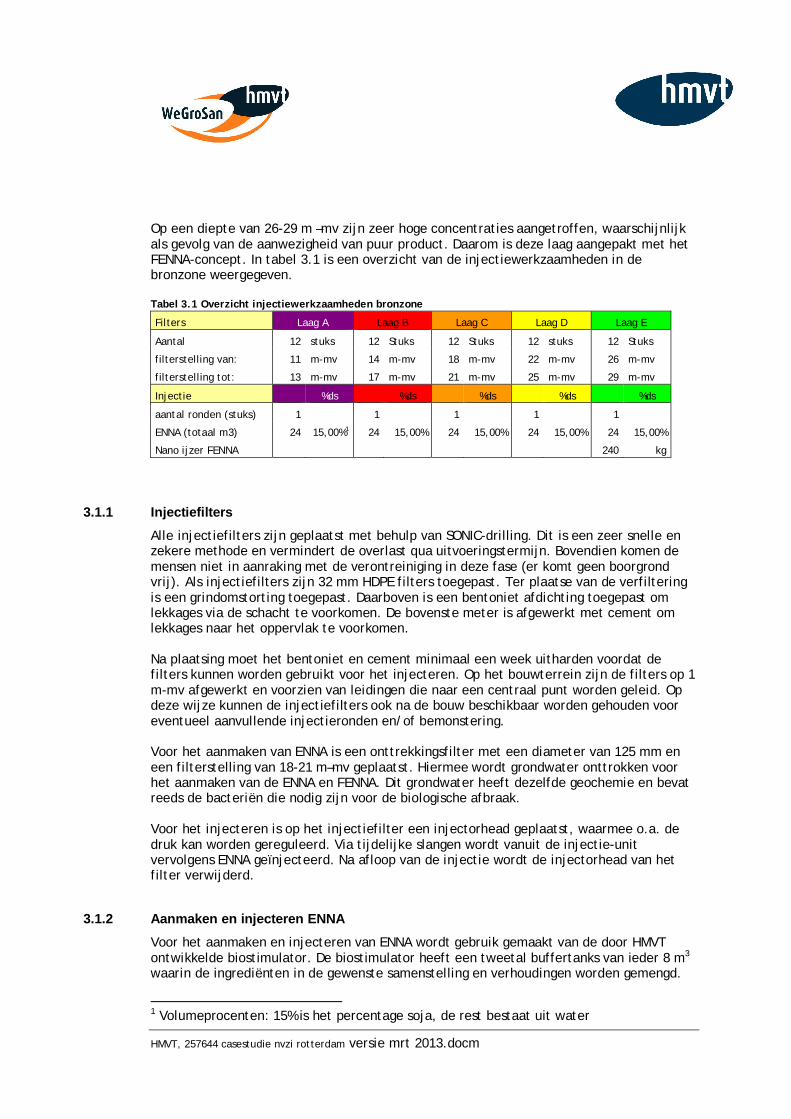
HMVT, 257644 casestudie nvzi rotterdam versie mrt 2013.docm
Op een diepte van 26-29 m –mv zijn zeer hoge concentraties aangetroffen, waarschijnlijk als gevolg van de aanwezigheid van puur product. Daarom is deze laag aangepakt met het FENNA-concept. In tabel 3.1 is een overzicht van de injectiewerkzaamheden in de bronzone weergegeven. Tabel 3.1 Overzicht injectiewerkzaamheden bronzone Filters Laag A Laag B Laag C Laag D Laag E
Aantal 12 stuks 12 Stuks 12 Stuks 12 stuks 12 Stuks
filterstelling van: 11 m-mv 14 m-mv 18 m-mv 22 m-mv 26 m-mv
filterstelling tot: 13 m-mv 17 m-mv 21 m-mv 25 m-mv 29 m-mv
Injectie %ds %ds %ds %ds %ds
aantal ronden (stuks) 1 1 1 1 1
ENNA (totaal m3) 24 15,00%1 24 15,00% 24 15,00% 24 15,00% 24 15,00%
Nano ijzer FENNA 240 kg
3.1.1 Injectiefilters Alle injectiefilters zijn geplaatst met behulp van SONIC-drilling. Dit is een zeer snelle en zekere methode en vermindert de overlast qua uitvoeringstermijn. Bovendien komen de mensen niet in aanraking met de verontreiniging in deze fase (er komt geen boorgrond vrij). Als injectiefilters zijn 32 mm HDPE filters toegepast. Ter plaatse van de verfiltering is een grindomstorting toegepast. Daarboven is een bentoniet afdichting toegepast om lekkages via de schacht te voorkomen. De bovenste meter is afgewerkt met cement om lekkages naar het oppervlak te voorkomen. Na plaatsing moet het bentoniet en cement minimaal een week uitharden voordat de filters kunnen worden gebruikt voor het injecteren. Op het bouwterrein zijn de filters op 1 m-mv afgewerkt en voorzien van leidingen die naar een centraal punt worden geleid. Op deze wijze kunnen de injectiefilters ook na de bouw beschikbaar worden gehouden voor eventueel aanvullende injectieronden en/of bemonstering. Voor het aanmaken van ENNA is een onttrekkingsfilter met een diameter van 125 mm en een filterstelling van 18-21 m–mv geplaatst. Hiermee wordt grondwater onttrokken voor het aanmaken van de ENNA en FENNA. Dit grondwater heeft dezelfde geochemie en bevat reeds de bacteriën die nodig zijn voor de biologische afbraak. Voor het injecteren is op het injectiefilter een injectorhead geplaatst, waarmee o.a. de druk kan worden gereguleerd. Via tijdelijke slangen wordt vanuit de injectie-unit vervolgens ENNA geïnjecteerd. Na afloop van de injectie wordt de injectorhead van het filter verwijderd.
3.1.2 Aanmaken en injecteren ENNA Voor het aanmaken en injecteren van ENNA wordt gebruik gemaakt van de door HMVT ontwikkelde biostimulator. De biostimulator heeft een tweetal buffertanks van ieder 8 m3 waarin de ingrediënten in de gewenste samenstelling en verhoudingen worden gemengd.
1 Volumeprocenten: 15% is het percentage soja, de rest bestaat uit water
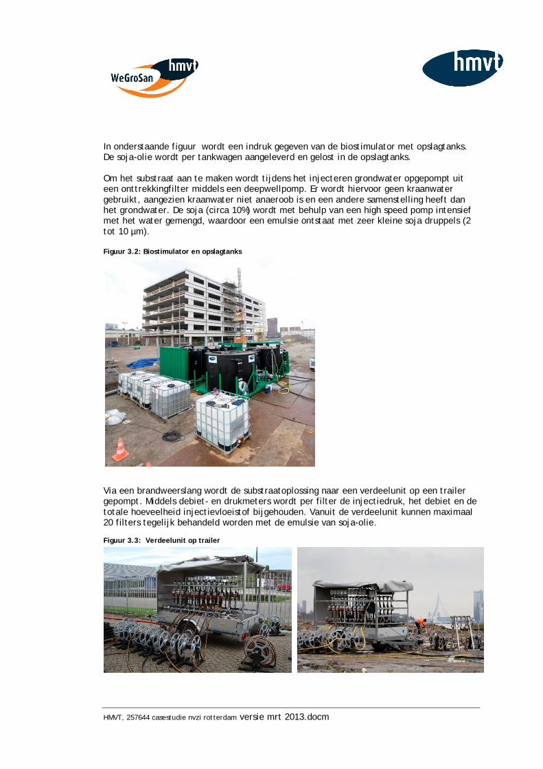
HMVT, 257644 casestudie nvzi rotterdam versie mrt 2013.docm
In onderstaande figuur wordt een indruk gegeven van de biostimulator met opslagtanks. De soja-olie wordt per tankwagen aangeleverd en gelost in de opslagtanks. Om het substraat aan te maken wordt tijdens het injecteren grondwater opgepompt uit een onttrekkingfilter middels een deepwellpomp. Er wordt hiervoor geen kraanwater gebruikt, aangezien kraanwater niet anaeroob is en een andere samenstelling heeft dan het grondwater. De soja (circa 10%) wordt met behulp van een high speed pomp intensief met het water gemengd, waardoor een emulsie ontstaat met zeer kleine soja druppels (2 tot 10 µm). Figuur 3.2: Biostimulator en opslagtanks
Via een brandweerslang wordt de substraatoplossing naar een verdeelunit op een trailer gepompt. Middels debiet- en drukmeters wordt per filter de injectiedruk, het debiet en de totale hoeveelheid injectievloeistof bijgehouden. Vanuit de verdeelunit kunnen maximaal 20 filters tegelijk behandeld worden met de emulsie van soja-olie. Figuur 3.3: Verdeelunit op trailer
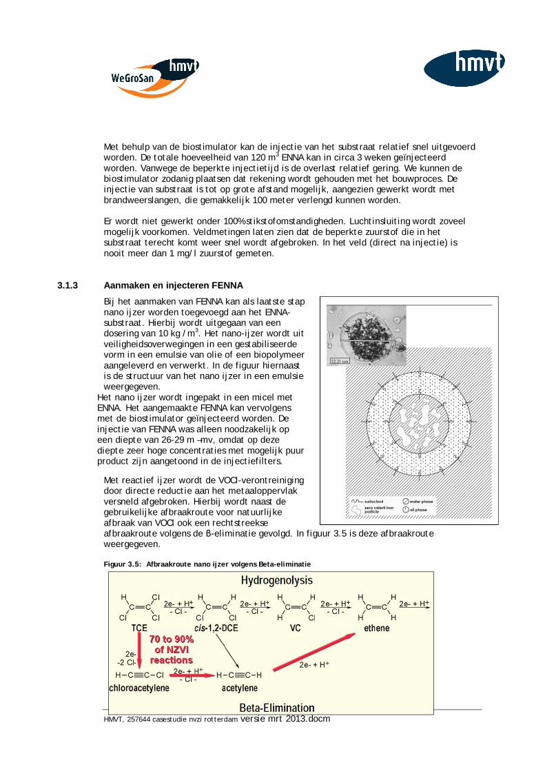
HMVT, 257644 casestudie nvzi rotterdam versie mrt 2013.docm
Met behulp van de biostimulator kan de injectie van het substraat relatief snel uitgevoerd worden. De totale hoeveelheid van 120 m3 ENNA kan in circa 3 weken geïnjecteerd worden. Vanwege de beperkte injectietijd is de overlast relatief gering. We kunnen de biostimulator zodanig plaatsen dat rekening wordt gehouden met het bouwproces. De injectie van substraat is tot op grote afstand mogelijk, aangezien gewerkt wordt met brandweerslangen, die gemakkelijk 100 meter verlengd kunnen worden. Er wordt niet gewerkt onder 100% stikstofomstandigheden. Luchtinsluiting wordt zoveel mogelijk voorkomen. Veldmetingen laten zien dat de beperkte zuurstof die in het substraat terecht komt weer snel wordt afgebroken. In het veld (direct na injectie) is nooit meer dan 1 mg/l zuurstof gemeten.
3.1.3 Aanmaken en injecteren FENNA Bij het aanmaken van FENNA kan als laatste stap nano ijzer worden toegevoegd aan het ENNA-substraat. Hierbij wordt uitgegaan van een dosering van 10 kg /m3. Het nano-ijzer wordt uit veiligheidsoverwegingen in een gestabiliseerde vorm in een emulsie van olie of een biopolymeer aangeleverd en verwerkt. In de figuur hiernaast is de structuur van het nano ijzer in een emulsie weergegeven.
Het nano ijzer wordt ingepakt in een micel met ENNA. Het aangemaakte FENNA kan vervolgens met de biostimulator geïnjecteerd worden. De injectie van FENNA was alleen noodzakelijk op een diepte van 26-29 m –mv, omdat op deze diepte zeer hoge concentraties met mogelijk puur product zijn aangetoond in de injectiefilters.
Met reactief ijzer wordt de VOCl-verontreiniging door directe reductie aan het metaaloppervlak versneld afgebroken. Hierbij wordt naast de gebruikelijke afbraakroute voor natuurlijke afbraak van VOCl ook een rechtstreekse afbraakroute volgens de -eliminatie gevolgd. In figuur 3.5 is deze afbraakroute weergegeven. Figuur 3.5: Afbraakroute nano ijzer volgens Beta-eliminatie
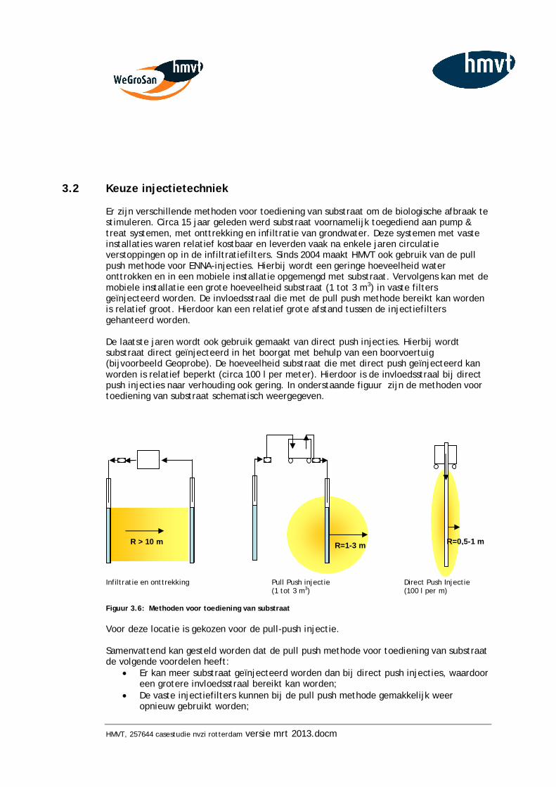
HMVT, 257644 casestudie nvzi rotterdam versie mrt 2013.docm
3.2 Keuze injectietechniek
Er zijn verschillende methoden voor toediening van substraat om de biologische afbraak te stimuleren. Circa 15 jaar geleden werd substraat voornamelijk toegediend aan pump & treat systemen, met onttrekking en infiltratie van grondwater. Deze systemen met vaste installaties waren relatief kostbaar en leverden vaak na enkele jaren circulatie verstoppingen op in de infiltratiefilters. Sinds 2004 maakt HMVT ook gebruik van de pull push methode voor ENNA-injecties. Hierbij wordt een geringe hoeveelheid water onttrokken en in een mobiele installatie opgemengd met substraat. Vervolgens kan met de mobiele installatie een grote hoeveelheid substraat (1 tot 3 m3) in vaste filters geïnjecteerd worden. De invloedsstraal die met de pull push methode bereikt kan worden is relatief groot. Hierdoor kan een relatief grote afstand tussen de injectiefilters gehanteerd worden. De laatste jaren wordt ook gebruik gemaakt van direct push injecties. Hierbij wordt substraat direct geïnjecteerd in het boorgat met behulp van een boorvoertuig (bijvoorbeeld Geoprobe). De hoeveelheid substraat die met direct push geïnjecteerd kan worden is relatief beperkt (circa 100 l per meter). Hierdoor is de invloedsstraal bij direct push injecties naar verhouding ook gering. In onderstaande figuur zijn de methoden voor toediening van substraat schematisch weergegeven.
Infiltratie en onttrekking Pull Push injectie Direct Push Injectie
(1 tot 3 m3) (100 l per m) Figuur 3.6: Methoden voor toediening van substraat Voor deze locatie is gekozen voor de pull-push injectie. Samenvattend kan gesteld worden dat de pull push methode voor toediening van substraat de volgende voordelen heeft:
Er kan meer substraat geïnjecteerd worden dan bij direct push injecties, waardoor een grotere invloedsstraal bereikt kan worden;
De vaste injectiefilters kunnen bij de pull push methode gemakkelijk weer opnieuw gebruikt worden;
R=0,5-1 m R=1-3 m R > 10 m
HMVT, 257644 casestudie nvzi rotterdam versie mrt 2013.docm
Er kunnen meerdere filters tegelijk behandeld worden, waardoor de injectie relatief snel uitgevoerd kan worden en de overlast beperkt is.
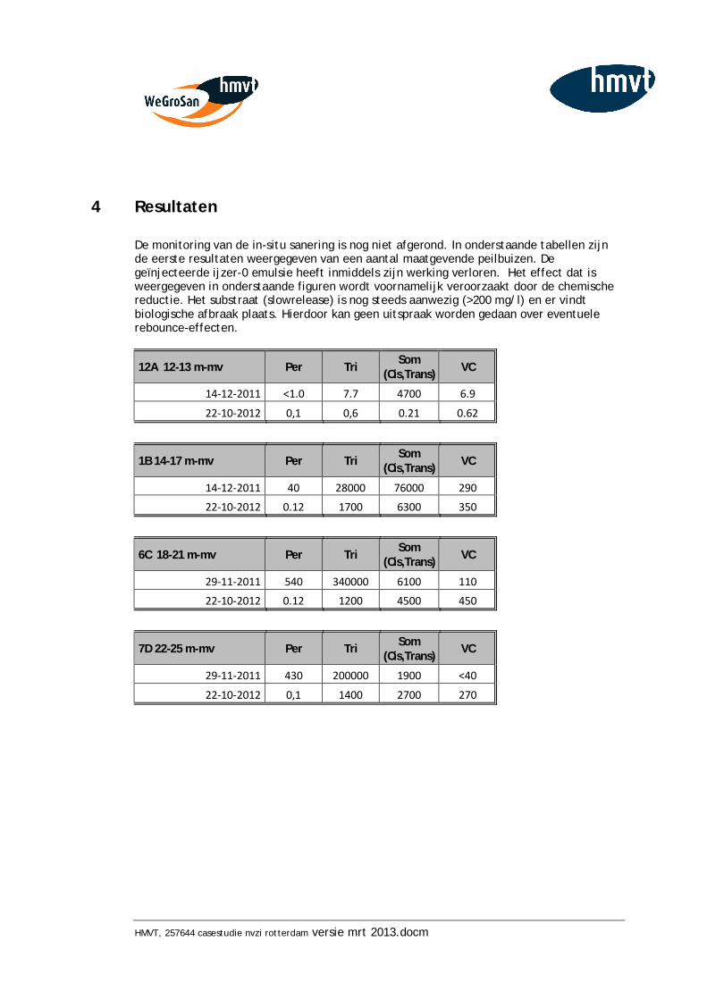
HMVT, 257644 casestudie nvzi rotterdam versie mrt 2013.docm
4 Resultaten
De monitoring van de in-situ sanering is nog niet afgerond. In onderstaande tabellen zijn de eerste resultaten weergegeven van een aantal maatgevende peilbuizen. De geïnjecteerde ijzer-0 emulsie heeft inmiddels zijn werking verloren. Het effect dat is weergegeven in onderstaande figuren wordt voornamelijk veroorzaakt door de chemische reductie. Het substraat (slowrelease) is nog steeds aanwezig (>200 mg/l) en er vindt biologische afbraak plaats. Hierdoor kan geen uitspraak worden gedaan over eventuele rebounce-effecten.
12A 12-13 m-mv Per Tri Som (Cis,Trans) VC
14-12-2011 <1.0 7.7 4700 6.9
22-10-2012 0,1 0,6 0.21 0.62
1B 14-17 m-mv Per Tri Som
(Cis,Trans) VC
14-12-2011 40 28000 76000 290
22-10-2012 0.12 1700 6300 350
6C 18-21 m-mv Per Tri Som
(Cis,Trans) VC
29-11-2011 540 340000 6100 110
22-10-2012 0.12 1200 4500 450
7D 22-25 m-mv Per Tri Som
(Cis,Trans) VC
29-11-2011 430 200000 1900 <40
22-10-2012 0,1 1400 2700 270
HMVT, 257644 casestudie nvzi rotterdam versie mrt 2013.docm
5 Leerpunten
Uit de uitgevoerde in-situ sanering en de resultaten tot dit moment kunnen de volgende leerpunten worden getrokken: Injectie in de winter De injectie is deels uitgevoerd in de winterperiode. Niet plezierig voor de medewerkers, maar ook enkele ingrediënten zoals de emulgator verliezen dan hun functie. Dit is op te lossen door dit verwarmd op te slaan, maar dit leidt tot extra kosten en handelingen. Het werk kan beter worden uitgevoerd wanneer de temperatuur minimaal +4 graden Celsius is. Effectiviteit ijzer-0 niet vast te stellen Door het toepassen van een combinatie van ijzer-0 en een koolstofbron (stimulatie van de biologische afbraak) is niet vast te stellen wat precies het effect van de chemische reductie is, en welk deel veroorzaakt wordt door de biologische afbraak. Beide processen volgen dezelfde afbraakroutes en dezelfde (tussen) afbraakproducten worden gevormd. Bij testen in het lab kan dit worden opgelost door in controlemonster te steriliseren. In het veld is hiervoor nog geen methode beschikbaar. Rebounce De biologische afbraak is nog actief. Er kan op dit moment nog niets worden gezegd over eventuele rebounce-effecten. Extreem lage redox niet waargenomen Door de leveranciers van ijzer-0 wordt een extreme lage Redox voorspeld (-600 mV). In het veld zien wij echter een Redox van -200 tot -350 mV. De (theoretisch) voorspelde extreem lage Redox van -500 mV tot -600 mV hebben wij niet gemeten. Vergelijking met ISCO Op diverse locaties hebben wij in-situ chemische oxidatie toegepast met Fentons Reagens, waarna we – na een sterke reductie – zijn overgestapt op gestimuleerde anaerobe afbraak. Om de omstandigheden vervolgens weer optimaal te krijgen voor anaerobe afbraak kost een zeer behoorlijke inspanning. Het gevormde zuurstof en de ingebrachte sulfaat (van de katalysator ijzersulfaat) moeten namelijk eerst worden omgezet, voordat de biologische afbraak van VOCl weer op gang komt. Dit kost meestal drie tot zes maanden. Bij een combinatie van chemische reductie met nulwaardig nano ijzer en gestimuleerde biologische afbraak doet dit probleem zich niet voor. Bij ISCO is het over het algemeen een behoorlijk mobilisatie-effect van de verontreiniging als gevolg van de gasvorming en de toegenomen temperatuur in de bodem. Door het mobilisatie effect bij ISCO kun je puur product goed meten, waardoor je goed kunt bijsturen. Dit voor de sanering (meestal) positieve mobilisatie-effect doet zich niet voor bij de combinatie van chemische reductie en biologische afbraak. Hierdoor is er een grotere kans dat puur product ‘gemist’ wordt, waardoor er een grotere kans bestaat op ‘rebounce’ na afronding van de sanering.
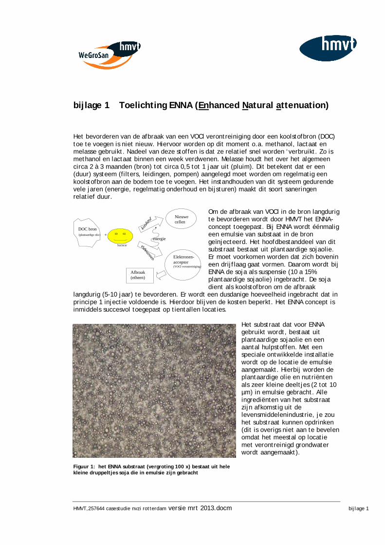
HMVT,257644 casestudie nvzi rotterdam versie mrt 2013.docm bijlage 1
+DOC bron{plantaardige olie}
kools
tof
elektronen
Nieuwe cellen
Elektronen-acceptor(VOCl verontreiniging)
energiebacterie
Afbraak(etheen)
bijlage 1 Toelichting ENNA (Enhanced Natural attenuation)
Het bevorderen van de afbraak van een VOCl verontreiniging door een koolstofbron (DOC) toe te voegen is niet nieuw. Hiervoor worden op dit moment o.a. methanol, lactaat en melasse gebruikt. Nadeel van deze stoffen is dat ze relatief snel worden ‘verbruikt. Zo is methanol en lactaat binnen een week verdwenen. Melasse houdt het over het algemeen circa 2 à 3 maanden (bron) tot circa 0,5 tot 1 jaar uit (pluim). Dit betekent dat er een (duur) systeem (filters, leidingen, pompen) aangelegd moet worden om regelmatig een koolstofbron aan de bodem toe te voegen. Het instandhouden van dit systeem gedurende vele jaren (energie, regelmatig onderhoud en bijsturen) maakt dit soort saneringen relatief duur.
Om de afbraak van VOCl in de bron langdurig te bevorderen wordt door HMVT het ENNA-concept toegepast. Bij ENNA wordt éénmalig een emulsie van substaat in de bron geïnjecteerd. Het hoofdbestanddeel van dit substraat bestaat uit plantaardige sojaolie. Er moet voorkomen worden dat zich bovenin een drijflaag gaat vormen. Daarom wordt bij ENNA de soja als suspensie (10 a 15% plantaardige sojaolie) ingebracht. De soja dient als koolstofbron om de afbraak
langdurig (5-10 jaar) te bevorderen. Er wordt een dusdanige hoeveelheid ingebracht dat in principe 1 injectie voldoende is. Hierdoor blijven de kosten beperkt. Het ENNA concept is inmiddels succesvol toegepast op tientallen locaties.
Het substraat dat voor ENNA gebruikt wordt, bestaat uit plantaardige sojaolie en een aantal hulpstoffen. Met een speciale ontwikkelde installatie wordt op de locatie de emulsie aangemaakt. Hierbij worden de plantaardige olie en nutriënten als zeer kleine deeltjes (2 tot 10 µm) in emulsie gebracht. Alle ingrediënten van het substraat zijn afkomstig uit de levensmiddelenindustrie, je zou het substraat kunnen opdrinken (dit is overigs niet aan te bevelen omdat het meestal op locatie met verontreinigd grondwater wordt aangemaakt).
Figuur 1: het ENNA substraat (vergroting 100 x) bestaat uit hele kleine druppeltjes soja die in emulsie zijn gebracht
HMVT,257644 casestudie nvzi rotterdam versie mrt 2013.docm bijlage 1
Ten opzicht van de veel gebruikte injecties met melasse of methanol/lactaat biedt ENNA de volgende voordelen:
er wordt een fijne emulsie gemaakt die nog het meeste op melk lijkt. Dit laat zich goed in de bodem injecteren tot grote diepte. De kleine deeltjes (2 tot 10 µm) verspreiden zich gemakkelijk tot in de bodemmatrix.
het substaat komt geleidelijk in de tijd beschikbaar voor de biologie; er wordt een enorme hoeveelheid DOC tegelijkertijd ingebracht: hierdoor is één
injectie in beginsel voldoende; ENNA is relatief goedkoop;
Om bovenstaande redenen is voor deze locatie gekozen voor ENNA in plaats van het injecteren van melasse.
HMVT,257644 casestudie nvzi rotterdam versie mrt 2013.docm bijlage 2
bijlage 2 Labexperimenten
Kolomtest nanoijzer Reductie VOCl verontreiniging Cofely Rotterdam
HMVT-nummer: 10841-rap-1 Datum rapportage: oktober 2011 Hannover Milieu- en Veiligheidstechniek B.V. Maxwellstraat 31 Postbus 174 6710 BD EDE T (0318) 62 46 24 F (0318) 62 49 13 www.hmvt.nl
Datum vrijgave Beschrijving revisie Opgesteld door Gecontroleerd door
Oktober 2011 10841-rap-01 G.A. van Sandwijk C.M. Soeter
HMVT, 10841-rap-01
INHOUDSOPGAVE
1. INLEIDING ............................................................................... 2
2. ALGEMEEN .............................................................................. 3 2.1 Locatiegegevens ............................................................................ 3 2.2 Theorie ....................................................................................... 4 2.3 Hypothese ................................................................................... 5 2.4 Doel van het onderzoek ................................................................... 5
3. LABORATORIUMTESTEN ............................................................... 6 3.1 Voorbereiding ............................................................................... 6 3.2 Testopstelling ............................................................................... 6
4. Resultaten .............................................................................. 8 4.1 Kolomexperiment, resultaten influent ................................................. 8 4.2 Kolomexperiment, resultaten effluent ................................................. 9 4.2 Glas experiment .......................................................................... 10
5. CONCLUSIES ............................................................................ 11
6. AANBEVELINGEN....................................................................... 12 BIJLAGE
1 Resultaten influent 2 Resultaten effluent
HMVT, 10841-rap-01
1. INLEIDING
Op een locatie van Cofely in Rotterdam is een omvangrijke grondwaterverontreiniging met TRI, CIS en VC aangetroffen. Er worden hoge concentraties aan TRI aangetoond. Het is zeer goed mogelijk dat de verontreiniging in de vorm van puur product aanwezig is. Als sanerende maatregel wordt overwogen om de grondwaterverontreiniging door middel van een scherm met injectiefilters te saneren. Er worden twee soorten schermen overwogen: 1 scherm met nanoijzer Bij het toepassen van een scherm met nanoijzer wordt een slurry van grondwater en nanoijzer geïnjecteerd. Door toepassing van nanoijzer kan een snelle chemische reductie van de verontreiniging met VOCl worden bewerkstelligd. 2 scherm met FENNA Een tweede variant van de schermaanpak is een gecombineerde chemische en biologische aanpak. Er wordt een emulsie van sojaolie en nanoijzer geïnjecteerd. Voor een goede onderbouwing van de te nemen sanerende maatregelen zijn door HMVT R&D kolomtesten uitgevoerd. Door middel van kolomtesten wordt de veldsituatie nagebootst en kan op basis van concentratiemetingen worden aangetoond met welke schermvariant het meest efficiënt de reductie van VOCl verontreiniging wordt behaald. Tevens wordt informatie verkregen over de juiste dosering toeslagstoffen.
HMVT, 10841-rap-01
2. ALGEMEEN
2.1 Locatiegegevens
Het bedrijfsterrein van Cofely ligt ingeklemd tussen de Willingestraat 2-10 en de Robbenoordse haven in Rotterdam. De aanwezige VOCl-verontreiniging heeft zich in het eerste watervoerend pakket verspreid tot aan de overzijde van de Robbenoordse haven. De verontreinigingssituatie van de VOCl-verontreiniging is in een dwarsprofiel in bijlage 3 weergegeven. Tot op een diepte van 27 m –mv zijn in 2008 zeer hoge gehalten aan VOCl aangetoond, die duiden op de aanwezigheid van mogelijk puur produkt. Op basis van saneringsgericht onderzoek (Tauw maart 2011) blijk dat de interventiewaardecontour tot aan Bijlstraat reikt. De VOCl-verontreiniging heeft zich tussen 2008 en 2011 aanzienlijk verspreid, aangezien in 2008 de interventiewaardecontour zich nog onder de Robbenoordse haven bevond. De verwachting is dat onder de Robbenoordsehaven nog hoge gehalten aan VOCl bevinden. In tabel 1 is de locale bodemopbouw weergegeven: Tabel 1 Locale bodemopbouw Diepte (m –mv) Geohydrologische
eenheid Samenstelling
0 – 3,5 Deklaag Zeer fijn tot matig fijn zand 3,5 – 13 Deklaag Sterk siltige klei met inschakeling van uiterst
fijne zandlaagjes 13 – 15 Deklaag Veen 15 – 17 Deklaag Fijn zand met kleilaagjes 17 – 18 Deklaag Sterk siltige klei 18 – 31 Eerste watervoerend
pakket Matig fijn tot grof zand
Uit onderzoek naar de afbraak (Bioclear, 2004) is bekend dat de omstandigheden voor natuurlijke afbraak op de locatie gunstig zijn. Zowel in de deklaag als in het watervoerend pakket is overwegend sprake van methanogene condities. Dit zijn de meest optimale condities voor natuurlijke afbraak. De afbraakprodukten etheen en ethaan zijn in ruime mate gevormd. Dit betekent dat de natuurlijke afbraak reeds in ver gevorderd stadium is. In het grondwater is de bacteriestam Dehalococcoides Ethanogenes aangetoond. Deze is in staat om de volledige afbraak van PER en TRI te realiseren, mits er voldoende substraat aanwezig is. Op basis van de onderzoeksgegevens lijkt stimulering van de biologische afbraak door injectie van een geschikt substraat een voor de hand liggende saneringstechniek. Aandachtspunt bij stimulering van de biologische afbraak vormen de zones met puur produkt.
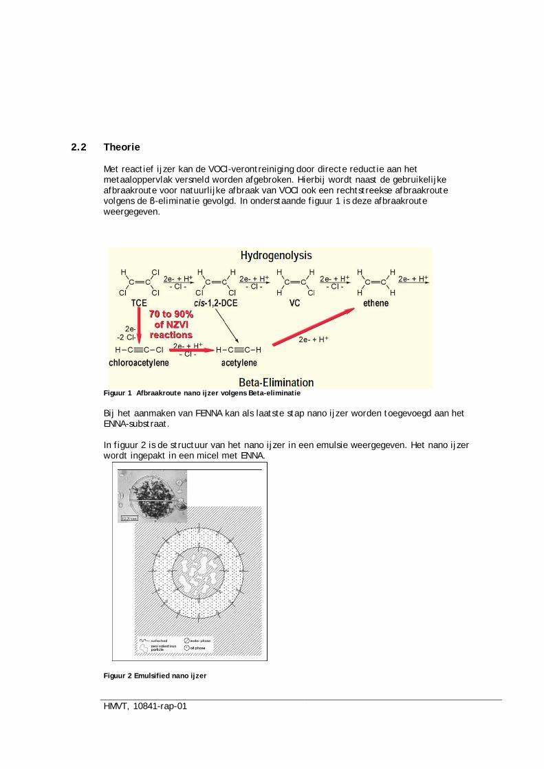
HMVT, 10841-rap-01
2.2 Theorie
Met reactief ijzer kan de VOCl-verontreiniging door directe reductie aan het metaaloppervlak versneld worden afgebroken. Hierbij wordt naast de gebruikelijke afbraakroute voor natuurlijke afbraak van VOCl ook een rechtstreekse afbraakroute volgens de -eliminatie gevolgd. In onderstaande figuur 1 is deze afbraakroute weergegeven.
Figuur 1 Afbraakroute nano ijzer volgens Beta-eliminatie Bij het aanmaken van FENNA kan als laatste stap nano ijzer worden toegevoegd aan het ENNA-substraat. In figuur 2 is de structuur van het nano ijzer in een emulsie weergegeven. Het nano ijzer wordt ingepakt in een micel met ENNA.
Figuur 2 Emulsified nano ijzer
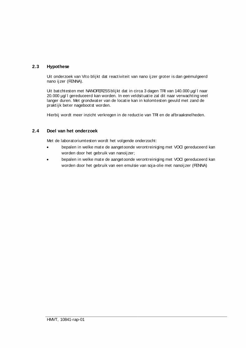
HMVT, 10841-rap-01
2.3 Hypothese
Uit onderzoek van Vito blijkt dat reactiviteit van nano ijzer groter is dan geëmulgeerd nano ijzer (FENNA). Uit batchtesten met NANOFER25S blijkt dat in circa 3 dagen TRI van 140.000 µg/l naar 20.000 µg/l gereduceerd kan worden. In een veldsituatie zal dit naar verwachting veel langer duren. Met grondwater van de locatie kan in kolomtesten gevuld met zand de praktijk beter nagebootst worden. Hierbij wordt meer inzicht verkregen in de reductie van TRI en de afbraaksnelheden.
2.4 Doel van het onderzoek
Met de laboratoriumtesten wordt het volgende onderzocht:
bepalen in welke mate de aangetoonde verontreiniging met VOCl gereduceerd kan worden door het gebruik van nanoijzer;
bepalen in welke mate de aangetoonde verontreiniging met VOCl gereduceerd kan worden door het gebruik van een emulsie van soja-olie met nanoijzer (FENNA)
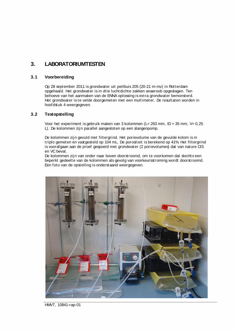
HMVT, 10841-rap-01
3. LABORATORIUMTESTEN
3.1 Voorbereiding
Op 28 september 2011 is grondwater uit peilbuis 205 (20-21 m-mv) in Rotterdam opgehaald. Het grondwater is in drie luchtdichte zakken anaeroob opgeslagen. Ten behoeve van het aanmaken van de ENNA oplossing is extra grondwater bemonsterd. Het grondwater is te velde doorgemeten met een multimeter. De resultaten worden in hoofdstuk 4 weergegeven.
3.2 Testopstelling
Voor het experiment is gebruik maken van 3 kolommen (L= 263 mm, ID = 35 mm, V= 0,25 L). De kolommen zijn parallel aangesloten op een slangenpomp. De kolommen zijn gevuld met filtergrind. Het porievolume van de gevulde kolom is in triplo gemeten en vastgesteld op 104 mL. De porositeit is berekend op 41%. Het filtergrind is voorafgaan aan de proef gespoeld met grondwater (2 porievolumes) dat van nature CIS en VC bevat. De kolommen zijn van onder naar boven doorstroomd, om te voorkomen dat slechts een beperkt gedeelte van de kolommen als gevolg van voorkeursstroming wordt doorstroomd. Een foto van de opstelling is onderstaand weergegeven.
HMVT, 10841-rap-01
Het debiet van de pomp is afgestemd op de porositeit en de grondwatersnelheid zoals weergegeven in de beschikbare rapportage. De grondwatersnelheid is vastgesteld op 28 m/j. Dit is gelijk aan ca. 76 cm/dag. Met een kolomhoogte van 263 mm is het debiet berekend op 305 ml/dag (2,9 porievolumes per dag). De pompinstellingen zijn voor bovenstaande grondwater/kolomsnelheid als volgt: 40 rpm Voorspanning slang op slangenpomp niveau “2” Slangdiameter op slangenpomp : 0,2 mm
De flexboy is met ‘luchtslang’ (PE) verbonden met de pomp. Het grondwater in de luchtdichte zakken is gespiked met TRI (99% zuiver) door het toevoegen van 0,9 mL TRI aan de luchtdichte zak. Hiertoe is aan een erlenmeyer gevuld met 200 mL grondwater 0,9 mL TRI toegevoegd terwijl dit grondwater werd geroerd. De inhoud van de erlenmeyer is met een regulier Eijkelkamp slangenpomp overgebracht naar de flexboy. De concentratie VOCl in het grondwater is daarna in het laboratorium vastgesteld. De resultaten worden in hoofdstuk 4 weergegeven. Er worden drie kolommen gebruikt: Kolom 1: Nano ijzer 3 g/l) Kolom 2: Geëmulgeerd nano ijzer (FENNA) 3 g/L Kolom 3: Blanco Het nanoijzer (1,5 gram aan 500 mL grondwater) is in een high-speed mixer opgelost in 500 mL grondwater. Middels een injectiespuit is 50 mL grondwater met nanoijzer toegevoegd aan de vooraf met grondwater gevulde verticaal opgestelde kolom 1. Dit volume (50 mL) komt overeen met 50% van het porievolume in de kolom. De ENNA oplossing is aangemaakt op met behulp van soja olie is een high speed mixer en een pomp met regelbaar toerental. Nadien is het nanoijzer (1,5 gram aan 500 mL ENN) in een high speed mixer aan de ENNA toegevoegd. Middels een injectiespuit is 50 mL FENNA toegevoegd aan de vooraf met grondwater gevulde verticaal opgestelde kolom 2. Dit is wederom ca. 50% van het porievolume. Aan kolom 3 is een conserveringsmiddel toegevoegd, waarmee alle biologische processen zijn stilgelegd. Als conservering is 0,1 gram natrium-azide toegediend aan in totaal 10 l grondwater. Kolom drie wordt gebruikt als blanco, waarmee de concentratieafnames als gevolg van proceseffecten in de kolom worden vastgesteld. Tijdens de kolomtesten zijn gedurende 4 weken wekelijks analyses en metingen voorzien.
Dag Analyses en metingen 0 VOCl, etheen, ethaan, methaan 2 VOCl + veldmetingen 7 VOCl + veldmetingen
14 VOCl, macrochemie, etheen 21 VOCl + veldmetingen 28 VOCl, macrochemie, etheen
HMVT, 10841-rap-01
4. Resultaten
4.1 Kolomexperiment, resultaten influent
In bijlage 1 zijn 3 grafieken weergegeven. De volgende datapunten zijn weergegeven: Eerste ‘datapunt’: berekende concentratie TRI, voor CIS en VC zijn de in het veld door
Tauw gemeten concentraties weergegeven Tweede datapunt: bemonstering uit influent flexboy op t=0, direct na het aanmaken
van de oplossing met TRI in de flexboy Derde datapunt: bemonstering influent flexboy na 6 dagen
De conclusie op basis van de gemeten concentraties in het influent zijn
In het influent worden te lage contcentraties aan TRI aangetoond in vergelijking tot de concentraties zoals berekend;
in het influent van alle 3 de experimenten wordt niet alle CIS en VC teruggemeten, de concentraties zouden op basis van de peilbuisgegevens hoger moeten zijn;
na het aanmaken van de oplossing neemt de concentratie aan TRI, CIS en VC in de influentflexboy niet of nauwelijks meer af (horizontale lijn tussen 2e en 3e datapunt);
Er is geen onderscheid waarneembaar in het concentratieniveau in het influent gedurende het experiment in flexboys met of zonder natriumazide, na 1 week spelen biologische afbraakprocessen (nog) geen rol.
HMVT, 10841-rap-01
4.2 Kolomexperiment, resultaten effluent
In bijlage 2 zijn 3 grafieken weergegeven. De volgende datapunten zijn weergegeven: Eerste ‘datapunt’: berekende concentratie TRI en voor CIS en VC de in het veld door
Tauw gemeten concentraties aan CIS en VC; Tweede datapunt: Bemonstering uit influent flexboy op t=0, direct na het aanmaken
van de oplossing met TRI in de flexboy; Derde datapunt: bemonstering effluent flexboy na 1 dag; Vierde datapunt: bemonstering effluent flexboy na 2 dagen.
De conclusie op basis van de gemeten concentraties in het effluent zijn De afname aan de gemeten concentraties aan TRI zijn niet te wijten reductie
processen in de kolom, ook bij de blanco wordt een sterke concentratieafname gemeten;
De afname aan de aangetoonde gehalten aan TRI in het influent en effluent is groter dan de concentratieafname aan CIS en VC, er gaat dus meer TRI verloren dan CIS en VC, dit komt mogelijk doordat de kolommen niet zijn voorgespoeld met grondwater met een hoge concentratie aan TRÌ
De vullingsgraad in de influentflexboy is 100% (V=10L), in de effluentflexboy is de vullingsgraad veel lager (ca. 200 mL in de effluentflexboy bij monstername), door het verschil in vullingsgraad is mogelijk meer diffusie/adsorptieoppervlak beschikbaar. Hierdoor wordt mogelijk in de effleuntflexboy een concentratieafname voor TRI/CIS/VC gemeten
Anderzijds is de afname aan de gemeten concentraties aan TRI mogelijk niet te wijten aan het gebruik van een flexboy, immers in de influent-flexboy zijn ‘stabiele concentraties’ aan TRI aangetoond;
Het is onduidelijk wat de concentratieafname aan TRI/CIS/VC veroorzaakt, mogelijk zijn de overig gebruikte materialen niet geschikt.
Aanbeveling: De te gebruiken materialen bij kolomexperimenten moeten nader worden onderzocht
HMVT, 10841-rap-01
4.3 Glas experiment
Doel van het glasexperiment is het onderzoeken van een oorzaak voor de lage aangetoonde concentraties aan TRI in het influent. Probleemstelling: de berekende TRI-concentratie op basis van de gebruikte hoeveelheden TRI en water komt niet overeen met de resultaten van het lab. Werkwijze: Aan 1 L demiwater is 0,1 mL resp 1,5 mL TRI toegevoegd in een glazen literfles. De flessen zijn geroerd, varieren van 1 uur tot 1 week. De flessen met 1,5 mL overschrijden in theroie de maxiimale oplosbaarheid van TRI in grondwater (1,4x10^6 ug/L). De analyses zijn aan twee laboratoria aangeboden ter verificatie van de analyseresultaten van Alcontrol. Resultaten: De resultaten zijn in onderstaande tabel weergegeven. Glaswerk ug/L ug/L C berekend 146.000 recovery 2.190.000 recovery Analyseresultaat Alcontrol na 1-3 uur op roerder 24000 16,4% 93000 4,2% na 1 week 83000 56,8% Analyseresultaat Analytico na 1-3 uur op roerder 34000 23,3% 120000 5,5% na 1 week 85000 58,2% Conclusie experiment met concentratie 146.000 ug/L:
1. Bij de oplossing met streefconcentratie 146000 ug/l wordt maximaal 58% van de TRI teruggemeten
2. De mengtijd heeft een positief effect op het terugmeten van TRI, langer mengen resulteert in een hoger teruggemeten concentratie aan TRI
3. Er is weinig verschil waarneembaar tussen de labs Alcontrol en analytico Conclusie experiment met concentratie 2.190.000 ug/L:
1. Bij het aanmaken van een oververzadigde oplossing wordt de maximale oplosbaarheid van TRI niet teruggemeten
Oplossingsrichting: het verdient de aanbeveling om sterk verontreinigd grondwater met TRI uit het brongebied in Rotterdam te gebruiken bij de experimenten. Hierdoor worden afwijkingen door meng-effecten voorkomen.
HMVT, 10841-rap-01
5. CONCLUSIES
Uit de kolomexperimenten blijkt dat er afname van TRI, CIS en VC optreedt in alle drie kolommen met 1 nano ijzer, 2 FENNA en 3 blanco. In de blanco kolom was deze afname van TRI, CIS en VC niet verwacht. Het vermoeden bestaat dat er een verlies van verontreiniging optreedt bij het transport van het water via de PE-slangen en de slangenpomp naar de kolommen. Mogelijk zijn de PE-slangen niet bestand tegen TRI. De influentconcentraties uit de flexboys zijn in de tijd relatief constant gebleven. Dit betekent naar verwachting dat er geen verlies van verontreiniging in de flexboys optreedt. Het verhogen van de concentratie TRI in het influent door toevoegen van TRI in het lab blijkt niet gemakkelijk. Uit de startconcentraties in de flexboys blijkt dat de concentraties aan TRI veel lager zijn dan de berekende 140.000 µg/l. Naar verwachting is de menging van TRI in de flexboys met 10 l water niet optimaal. Uit het glasexperiment met 1 l water is gebleken dat een mengtijd van tenminste een week is benodigd om de concentratie te verhogen tot circa 85.000 µg/l
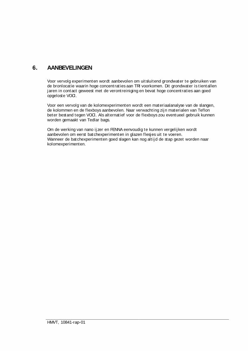
HMVT, 10841-rap-01
6. AANBEVELINGEN
Voor vervolg experimenten wordt aanbevolen om uitsluitend grondwater te gebruiken van de bronlocatie waarin hoge concentraties aan TRI voorkomen. Dit grondwater is tientallen jaren in contact geweest met de verontreiniging en bevat hoge concentraties aan goed opgeloste VOCl. Voor een vervolg van de kolomexperimenten wordt een materiaalanalyse van de slangen, de kolommen en de flexboys aanbevolen. Naar verwachting zijn materialen van Teflon beter bestand tegen VOCl. Als alternatief voor de flexboys zou eventueel gebruik kunnen worden gemaakt van Tedlar bags. Om de werking van nano ijzer en FENNA eenvoudig te kunnen vergelijken wordt aanbevolen om eerst batchexperimenten in glazen flesjes uit te voeren. Wanneer de batchexperimenten goed slagen kan nog altijd de stap gezet worden naar kolomexperimenten.
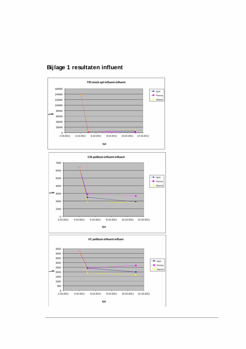
Bijlage 1 resultaten influent
0
20000
40000
60000
80000
100000
120000
140000
160000
2-10-2011 4-10-2011 6-10-2011 8-10-2011 10-10-2011 12-10-2011
ug/L
tijd
TRI stock opl-influent-influent
ijzer
Fenna
blanco
0
500
1000
1500
2000
2500
3000
3500
4000
4500
2-10-2011 4-10-2011 6-10-2011 8-10-2011 10-10-2011 12-10-2011
ug/l
tijd
VC peilbuis-influent-influen
ijzer
Fenna
blanco
0
1000
2000
3000
4000
5000
6000
7000
2-10-2011 4-10-2011 6-10-2011 8-10-2011 10-10-2011 12-10-2011
ug/L
tijd
CIS peilbuis-influent-influent
ijzer
Fenna
blanco
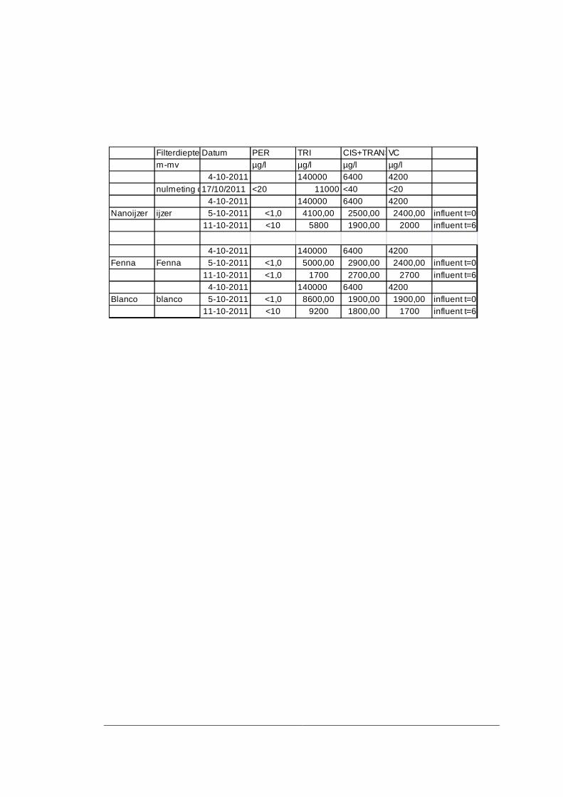
Filterdiepte Datum PER TRI CIS+TRANSVCm-mv µg/l µg/l µg/l µg/l
4-10-2011 140000 6400 4200nulmeting demi-oplossing17/10/2011 <20 11000 <40 <20
4-10-2011 140000 6400 4200Nanoijzer ijzer 5-10-2011 <1,0 4100,00 2500,00 2400,00 influent t=0
11-10-2011 <10 5800 1900,00 2000 influent t=6
4-10-2011 140000 6400 4200Fenna Fenna 5-10-2011 <1,0 5000,00 2900,00 2400,00 influent t=0
11-10-2011 <1,0 1700 2700,00 2700 influent t=64-10-2011 140000 6400 4200
Blanco blanco 5-10-2011 <1,0 8600,00 1900,00 1900,00 influent t=011-10-2011 <10 9200 1800,00 1700 influent t=6
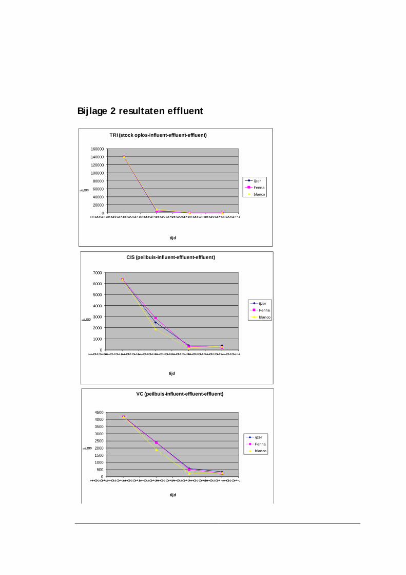
Bijlage 2 resultaten effluent
0
20000
40000
60000
80000
100000
120000
140000
160000
3-10-2011 4-10-2011 4-10-2011 5-10-2011 5-10-2011 6-10-2011 6-10-2011 7-10-2011 7-10-2011
ug/L
tijd
TRI (stock oplos-influent-effluent-effluent)
ijzer
Fenna
blanco
0
1000
2000
3000
4000
5000
6000
7000
3-10-2011 4-10-2011 4-10-2011 5-10-2011 5-10-2011 6-10-2011 6-10-2011 7-10-2011 7-10-2011
ug/L
tijd
CIS (peilbuis-influent-effluent-effluent)
ijzer
Fenna
blanco
0
500
1000
1500
2000
2500
3000
3500
4000
4500
3-10-2011 4-10-2011 4-10-2011 5-10-2011 5-10-2011 6-10-2011 6-10-2011 7-10-2011 7-10-2011
ug/L
tijd
VC (peilbuis-influent-effluent-effluent)
ijzer
Fenna
blanco
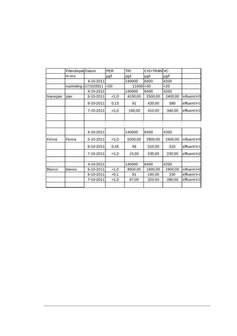
Filterdiepte Datum PER TRI CIS+TRANSVCm-mv µg/l µg/l µg/l µg/l
4-10-2011 140000 6400 4200nulmeting demi-oplossing17/10/2011 <20 11000 <40 <20
4-10-2011 140000 6400 4200Nanoijzer ijzer 5-10-2011 <1,0 4100,00 2500,00 2400,00 influent t=0
6-10-2011 0,13 91 420,00 580 effluent t=1
7-10-2011 <1,0 140,00 410,00 340,00 effluent t=2
4-10-2011 140000 6400 4200
Fenna Fenna 5-10-2011 <1,0 5000,00 2900,00 2400,00 influent t=0
6-10-2011 0,45 46 310,00 510 effluent t=1
7-10-2011 <1,0 15,00 230,00 230,00 effluent t=2
4-10-2011 140000 6400 4200Blanco blanco 5-10-2011 <1,0 8600,00 1900,00 1900,00 influent t=0
6-10-2011 <0,1 81 150,00 230 effluent t=17-10-2011 <1,0 87,00 320,00 280,00 effluent t=2

In Situ Chemical Reduction using Zero Valent Iron injection - A technique for the remediation of source zones 91
10.3 Questionnaire
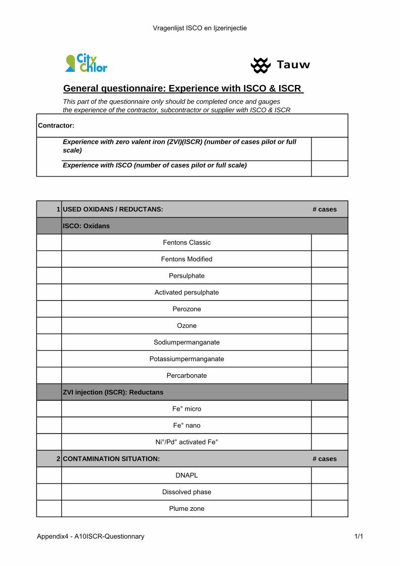
Vragenlijst ISCO en Ijzerinjectie
General questionnaire: Experience with ISCO & ISCR
This part of the questionnaire only should be completed once and gauges
the experience of the contractor, subcontractor or supplier with ISCO & ISCR
Experience with zero valent iron (ZVI)(ISCR) (number of cases pilot or full
scale)
Experience with ISCO (number of cases pilot or full scale)
1 USED OXIDANS / REDUCTANS: # cases
ISCO: Oxidans
Fentons Classic
Fentons Modified
Persulphate
Activated persulphate
Perozone
Ozone
Sodiumpermanganate
Potassiumpermanganate
Percarbonate
ZVI injection (ISCR): Reductans
Fe° micro
Fe° nano
Ni°/Pd° activated Fe°
2 CONTAMINATION SITUATION: # cases
DNAPL
Dissolved phase
Plume zone
Contractor:
Appendix4 - A10ISCR-Questionnary 1/1
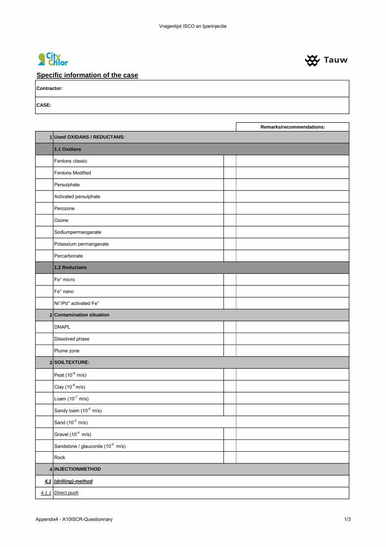
Vragenlijst ISCO en Ijzerinjectie
Remarks/recommendations:
1
1.1 Oxidans
Fentons classic
Fentons Modified
Persulphate
Activated persulphate
Perozone
Ozone
Sodiumpermanganate
Potassium permanganate
Percarbonate
Fe° micro
Fe° nano
Ni°/Pd° activated Fe°
2
DNAPL
Dissolved phase
Plume zone
3
Peat (10-8 m/s)
Clay (10-8 m/s)
Loam (10-7 m/s)
Sandy loam (10-6 m/s)
Sand (10-5 m/s)
Gravel (10-4 m/s)
Sandstone / glauconite (10-5 m/s)
Rock
4
4,1 (drilling)-method
4,1,1
INJECTIONMETHOD
Direct push
CASE:
Contractor:
Used OXIDANS / REDUCTANS:
SOILTEXTURE:
Contamination situation
1.2 Reductans
Specific information of the case
Appendix4 - A10ISCR-Questionnary 1/3

Vragenlijst ISCO en Ijzerinjectie
4,1,1,1 Geoprobe
4,1,1,2 Sonic
4,1,2
4,1,2,1 PEHD
4,1,2,2 RVS
4,1,3 Recirculationsystem
4,2
4,2,1 Aboveground
4,2,2 Underground
4,2,3 In case of above ground mixing: expected halftime of selfdecomposition of reactif agent/ maximal storage period before injection
4,2,4 In case a reductans is used: way of anaerobic mixing
4,2,5 Additives (emulgator, stabilisator)
4,2,6 Katalysator (eg.heat activated …)
4,3
4,3,1 Injection horizontal distance
4,3,1,1 < 3 m
4,3,1,2 3 m - 6 m
4,3,1,3 6 m - 10 m
4,3,1,4 > 10 m
4,3,2
4,3,2,1 injection points in line
4,3,2,2 injection points alternated
4,3,2,3 Injection points triangular
4,3,2,4 injection points hexagonal
4,3,2,5 Other geometry
4,4
4,4,1 meter per day (direct push)
4,4
4,4,1 Dilution factor of oxidans or reductans if applied as a slurry
4,4,2 Kg of slurry injected per m depth interval
5 LABTEST
5,1 Batchtest
5,2 Colomntest
6
6,1 Underground infrastructure
6,2 Underground piping and cabling (gas, electricity, sewer, water, ….)
6,3 Specific safety aspects
6,4 Used injection and drilling material (e.g. galvanised)
Mixing method
Fixed filters
Preferred layout of injection filters
POINTS OF ATTENTION
Injection geometry
Injection speed
Injection dosis
Appendix4 - A10ISCR-Questionnary 2/3
Vragenlijst ISCO en Ijzerinjectie
6,5 Monitoring of proces parameters
7
7,1 Suppliers of oxidans/reductans
8
8,1 Cost of oxidans/reductans per kg
General evaluation of the case by the contractor: Do you considere the case as successfull, less successfull or as a failure? Why? (max,
5 lines of comments)
COST
SUPPLIER(S)
Appendix4 - A10ISCR-Questionnary 3/3

Vragenlijst ISCO en Ijzerinjectie
Remarks/recommendations:
1
1.1 Oxidans
Fentons classic
Fentons Modified
Persulphate
Activated persulphate
Perozone
Ozone
Sodiumpermanganate
Potassium permanganate
Percarbonate
Fe° micro
Fe° nano
Ni°/Pd° activated Fe°
2
DNAPL
Dissolved phase
Plume zone
3
Peat (10-8 m/s)
Clay (10-8 m/s)
Loam (10-7 m/s)
Sandy loam (10-6 m/s)
Sand (10-5 m/s)
Gravel (10-4 m/s)
Sandstone / glauconite (10-5 m/s)
Rock
4
4,1 (drilling)-method
4,1,1
1.2 Reductans
Specific information of the case
INJECTIONMETHOD
Direct push
CASE:
Contractor:
Used OXIDANS / REDUCTANS:
SOILTEXTURE:
Contamination situation
Appendix4 - A10ISCR-Questionnary 1/3
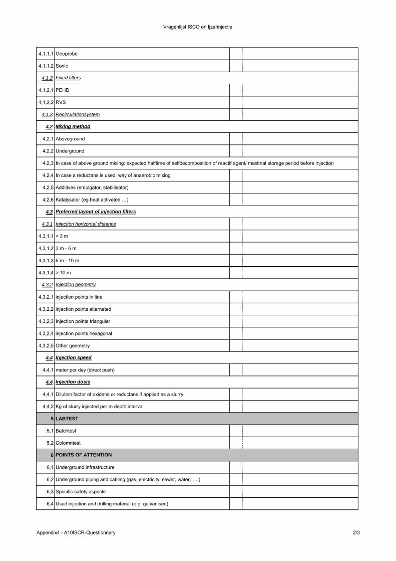
Vragenlijst ISCO en Ijzerinjectie
4,1,1,1 Geoprobe
4,1,1,2 Sonic
4,1,2
4,1,2,1 PEHD
4,1,2,2 RVS
4,1,3 Recirculationsystem
4,2
4,2,1 Aboveground
4,2,2 Underground
4,2,3 In case of above ground mixing: expected halftime of selfdecomposition of reactif agent/ maximal storage period before injection
4,2,4 In case a reductans is used: way of anaerobic mixing
4,2,5 Additives (emulgator, stabilisator)
4,2,6 Katalysator (eg.heat activated …)
4,3
4,3,1 Injection horizontal distance
4,3,1,1 < 3 m
4,3,1,2 3 m - 6 m
4,3,1,3 6 m - 10 m
4,3,1,4 > 10 m
4,3,2
4,3,2,1 injection points in line
4,3,2,2 injection points alternated
4,3,2,3 Injection points triangular
4,3,2,4 injection points hexagonal
4,3,2,5 Other geometry
4,4
4,4,1 meter per day (direct push)
4,4
4,4,1 Dilution factor of oxidans or reductans if applied as a slurry
4,4,2 Kg of slurry injected per m depth interval
5 LABTEST
5,1 Batchtest
5,2 Colomntest
6
6,1 Underground infrastructure
6,2 Underground piping and cabling (gas, electricity, sewer, water, ….)
6,3 Specific safety aspects
6,4 Used injection and drilling material (e.g. galvanised)
Preferred layout of injection filters
POINTS OF ATTENTION
Injection geometry
Injection speed
Injection dosis
Mixing method
Fixed filters
Appendix4 - A10ISCR-Questionnary 2/3

Vragenlijst ISCO en Ijzerinjectie
6,5 Monitoring of proces parameters
7
7,1 Suppliers of oxidans/reductans
8
8,1 Cost of oxidans/reductans per kg
General evaluation of the case by the contractor: Do you considere the case successfull, less successfull or a failure? Why? (max, 5
lines of comments)
COST
SUPPLIER(S)
Appendix4 - A10ISCR-Questionnary 3/3
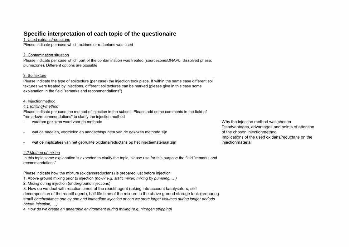
Specific interpretation of each topic of the questionaire1. Used oxidans/reductansPlease indicate per case which oxidans or reductans was used
2. Contamination situationPlease indicate per case which part of the contamination was treated (sourcezone/DNAPL, dissolved phase, plumezone). Different options are possible
3. SoiltexturePlease indicate the type of soiltexture (per case) the injection took place. If within the same case different soil textures were treated by injections, different soiltextures can be marked (please give in this case some explanation in the field "remarks and recommendations")
4. Injectionmethod4.1 (drilling)-method
Please indicate per case the method of injection in the subsoil. Please add some comments in the field of "remarks/recommendations" to clarify the injection method- waarom gekozen werd voor de methode Why the injection method was chosen
- wat de nadelen, voordelen en aandachtspunten van de gekozen methode zijnDisadvantages, advantages and points of attention of the chosen injectionmethod
- wat de implicaties van het gebruikte oxidans/reductans op het injectiemateriaal zijnImplications of the used oxidans/reductans on the injectionmaterial
4.2 Method of mixing
In this topic some explanation is expected to clarify the topic, please use for this purpose the field "remarks and recommendations"
Please indicate how the mixture (oxidans/reductans) is prepared just before injection1. Above ground mixing prior to injection (how? e.g. static mixer, mixing by pumping, …)
2. Mixing during injection (underground injections)3. How do we deal with reaction times of the reactif agent (taking into account katalysators, self decomposition of the reactif agent), half life time of the mixture in the above ground storage tank (preparing small batchvolumes one by one and immediate injection or can we store larger volumes during longer periods
before injection, …)
4. How do we create an anaerobic environment during mixing (e.g. nitrogen stripping)
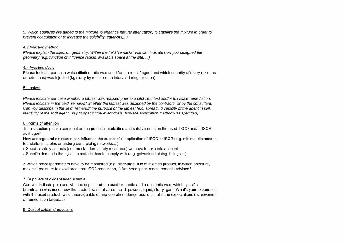
5. Which additives are added to the mixture to enhance natural attenuation, to stabilize the mixture in order to
prevent coagulation or to increase the solubility, catalysts,...)
4.3 Injection method
Please explain the injection geometry. Within the field "remarks" you can indicate how you designed the
geometry (e.g. function of influence radius, available space at the site, ...)
4.4 Injection dosis
Please indicate per case which dilution ratio was used for the reactif agent and which quantity of slurry (oxidans or reductans) was injected (kg slurry by meter depth interval during injection)
5. Labtest
Please indicate per case whether a labtest was realised prior to a pilot field test and/or full scale remediation.
Please indicate in the field "remarks" whether the labtest was designed by the contractor or by the consultant.
Can you describe in the field "remarks" the purpose of the labtest (e.g. spreading velocity of the agent in soil,
reactivity of the actif agent, way to specify the exact dosis, how the application method was specified)
6. Points of attention In this section please comment on the practical modalities and safety issues on the used ISCO and/or ISCR actif agentHow underground structures can influence the successfull application of ISCO or ISCR (e.g. minimal distance to foundations, cables or underground piping networks,...)1. Specific safety aspects (not the standard safety measures) we have to take into account2. Specific demands the injection material has to comply with (e.g. galvanised piping, fittings,...)
3.Which procesparameters have to be monitored (e.g. discharge, flux of injected product, injection pressure, maximal pressure to avoid breakthru, CO2-production,..) Are headspace measurements advised?
7. Suppliers of oxidantia/reductantiaCan you indicate per case who the supplier of the used oxidantia and reductantia was, which specific brandname was used, how the product was delivered (solid, powder, liquid, slurry, gas). What's your experience with the used product (was it manageable during operation, dangerous, dit it fulfill the expectations (achievement of remediation target,...)
8. Cost of oxidans/reductans
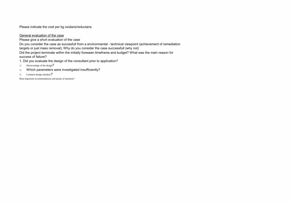
Please indicate the cost per kg oxidans/reductans
General evaluation of the casePlease give a short evaluation of the case Do you consider the case as succesfull from a environmental - technical viewpoint (achievement of remediation targets or just mass removal); Why do you consider the case successfull (why not)Did the project terminate within the initially foreseen timeframe and budget? What was the main reason for success of failure?1. Did you evaluate the design of the consultant prior to application?o Shortcomings of the design?o Which parameters were investigated insufficiently?o Common design mistakes?Most important recommendations and points of attention?

In Situ Chemical Reduction using Zero Valent Iron injection - A technique for the remediation of source zones 102
10.4 Evaluatieschema
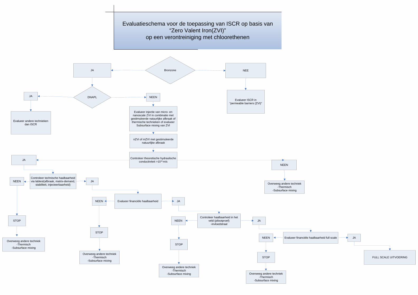
JA NEEBronzone
DNAPL
Evalueer andere technieken dan ISCR
Evalueer injectie van micro- en nanoscale ZVI in combinatie met
gestimuleerde natuurlijke afbraak of thermische technieken of evalueer
Subsurface mixing van ZVI
Evalueer ISCR in “permeable barriers (ZVI)”
Evaluatieschema voor de toepassing van ISCR op basis van “Zero Valent Iron(ZVI)”
op een verontreiniging met chloorethenen
nZVi of mZVI met gestimuleerde natuurlijke afbraak
Controleer theoretische hydraulische conductiviteit >10-6 m/sJA
NEEN
Controleer technische haalbaarheid via labtest(afbraak, matrix-demand,
stabiliteit, injecteerbaarheid)JANEEN
Evalueer financiële haalbaarheid
Controleer haalbaarheid in het veld (pilootproef)
-invloedstraal
Overweeg andere techniek-Thermisch
-Subsurface mixing
JA
JA
Evalueer financiële haalbaarheid full scale
FULL SCALE UITVOERING
NEEN
NEEN
NEEN JA
STOP
Overweeg andere techniek-Thermisch
-Subsurface mixing
Overweeg andere techniek-Thermisch
-Subsurface mixing
STOP
Overweeg andere techniek-Thermisch
-Subsurface mixing
STOP
Overweeg andere techniek-Thermisch
-Subsurface mixing
STOP
NEENJA
Document description
Title: In Situ Chemical Reduction using Zero Valent Iron injection - A technique for the
remediation of source zones
Deposit number: -
Number of Pages: 104
Editor: Veerle Labeeuw
Date of publication: April 12 2013
Contact: Machteld De Wit, OVAM
Key words: Zero Valent Iron injection ISCR In Situ Chemical Reduction
Translations:
Summary: Zerovalent iron (ZVI) can be used for the remediation of soil and groundwater
contamination with chlorinated solvents. ZVI has the ability to dehalogenate chlorinated
compounds by chemical reduction.