in nity looper - pigtronix · in nity looper user’s guide all contents c absara audio llc 2014
TRANSCRIPT
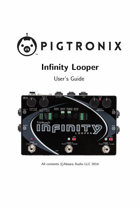
Infinity LooperUser’s Guide
All contents c©Absara Audio LLC 2014
Contents
Contents 1
1 Welcome to Infinity 5
2 Anatomy and Functions 72.1 Footswitches . . . . . . . . . . . . . . . . . . . . . . . 7
Loop 1 . . . . . . . . . . . . . . . . . . . . . . . . . . 7Loop 2 . . . . . . . . . . . . . . . . . . . . . . . . . . 7Stop . . . . . . . . . . . . . . . . . . . . . . . . . . . 8
2.2 Toggle Switches . . . . . . . . . . . . . . . . . . . . . 8Stop Mode . . . . . . . . . . . . . . . . . . . . . . . . 8
Arm, All . . . . . . . . . . . . . . . . . . . . . 8Full, Trail, Fade . . . . . . . . . . . . . . . . . 9
Input Split . . . . . . . . . . . . . . . . . . . . . . . . 9Series Loops . . . . . . . . . . . . . . . . . . . . . . . 10Sync Multi . . . . . . . . . . . . . . . . . . . . . . . . 10
2.3 Knobs . . . . . . . . . . . . . . . . . . . . . . . . . . 11Master Volume . . . . . . . . . . . . . . . . . . . . . 11Preset . . . . . . . . . . . . . . . . . . . . . . . . . . 12Loop Volume 1 . . . . . . . . . . . . . . . . . . . . . 12Loop Volume 2 . . . . . . . . . . . . . . . . . . . . . 12
2.4 Jacks . . . . . . . . . . . . . . . . . . . . . . . . . . . 13DC Power . . . . . . . . . . . . . . . . . . . . . . . . 13
1
CONTENTS 2
In 1 . . . . . . . . . . . . . . . . . . . . . . . . . . . . 13In 2 . . . . . . . . . . . . . . . . . . . . . . . . . . . . 13Out 1 . . . . . . . . . . . . . . . . . . . . . . . . . . 13Out 2 . . . . . . . . . . . . . . . . . . . . . . . . . . 14Aux Out . . . . . . . . . . . . . . . . . . . . . . . . . 14Undo . . . . . . . . . . . . . . . . . . . . . . . . . . . 14Expression . . . . . . . . . . . . . . . . . . . . . . . . 14MIDI In . . . . . . . . . . . . . . . . . . . . . . . . . 15USB . . . . . . . . . . . . . . . . . . . . . . . . . . . 15
2.5 LEDs . . . . . . . . . . . . . . . . . . . . . . . . . . . 16Loop LEDs . . . . . . . . . . . . . . . . . . . . . . . . 16Stop LED . . . . . . . . . . . . . . . . . . . . . . . . 16Clip LED . . . . . . . . . . . . . . . . . . . . . . . . . 16Multi-Segment Digit . . . . . . . . . . . . . . . . . . . 17Decimal Point . . . . . . . . . . . . . . . . . . . . . . 17
3 Infinity Rules 193.1 Arm . . . . . . . . . . . . . . . . . . . . . . . . . . . 193.2 Record . . . . . . . . . . . . . . . . . . . . . . . . . . 193.3 Jump Record . . . . . . . . . . . . . . . . . . . . . . . 203.4 Play . . . . . . . . . . . . . . . . . . . . . . . . . . . 203.5 Stop . . . . . . . . . . . . . . . . . . . . . . . . . . . 203.6 Erase . . . . . . . . . . . . . . . . . . . . . . . . . . . 213.7 Overdub . . . . . . . . . . . . . . . . . . . . . . . . . 213.8 Sync Multi . . . . . . . . . . . . . . . . . . . . . . . . 223.9 Series Loops . . . . . . . . . . . . . . . . . . . . . . . 223.10 Series & Fade Modes . . . . . . . . . . . . . . . . . . 23
Trails . . . . . . . . . . . . . . . . . . . . . . . . . . . 23Overdub . . . . . . . . . . . . . . . . . . . . . . . . . 23
3.11 Input Split . . . . . . . . . . . . . . . . . . . . . . . . 243.12 Presets . . . . . . . . . . . . . . . . . . . . . . . . . . 24
Loading . . . . . . . . . . . . . . . . . . . . . . . . . 24Saving . . . . . . . . . . . . . . . . . . . . . . . . . . 25Copying . . . . . . . . . . . . . . . . . . . . . . . . . 25Erasing . . . . . . . . . . . . . . . . . . . . . . . . . . 26
3.13 Loop Aging . . . . . . . . . . . . . . . . . . . . . . . 26
CONTENTS 3
3.14 Click Killer . . . . . . . . . . . . . . . . . . . . . . . . 273.15 Varispeed . . . . . . . . . . . . . . . . . . . . . . . . 283.16 Boot Options . . . . . . . . . . . . . . . . . . . . . . 30
Auto Zero Record . . . . . . . . . . . . . . . . . . . . 30Mono Mixdown . . . . . . . . . . . . . . . . . . . . . 31Stutter . . . . . . . . . . . . . . . . . . . . . . . . . . 31Reformat . . . . . . . . . . . . . . . . . . . . . . . . . 32
4 Remote Switch Functions 334.1 Reverse . . . . . . . . . . . . . . . . . . . . . . . . . . 334.2 Undo . . . . . . . . . . . . . . . . . . . . . . . . . . . 344.3 Redo . . . . . . . . . . . . . . . . . . . . . . . . . . . 344.4 Rec→Overdub→Play . . . . . . . . . . . . . . . . . . 354.5 Instant Erase . . . . . . . . . . . . . . . . . . . . . . . 354.6 Varispeed Remote Control Menu . . . . . . . . . . . . 35
5 Expression Pedal Functions 395.1 Loop Volume . . . . . . . . . . . . . . . . . . . . . . 395.2 Loop Aging . . . . . . . . . . . . . . . . . . . . . . . 395.3 Varispeed . . . . . . . . . . . . . . . . . . . . . . . . 405.4 Expression Pedal Assignment . . . . . . . . . . . . . . 40
6 MIDI 436.1 MIDI Sync . . . . . . . . . . . . . . . . . . . . . . . . 436.2 Time Signature . . . . . . . . . . . . . . . . . . . . . 446.3 Commands That Sync to MIDI Clock . . . . . . . . . 44
Record and Play . . . . . . . . . . . . . . . . . . . . . 44Stop . . . . . . . . . . . . . . . . . . . . . . . . . . . 44Start . . . . . . . . . . . . . . . . . . . . . . . . . . . 44Overdub . . . . . . . . . . . . . . . . . . . . . . . . . 45
6.4 Commands That Ignore MIDI Sync . . . . . . . . . . . 456.5 Full MIDI Mapping . . . . . . . . . . . . . . . . . . . 45
Cycle/Toggle . . . . . . . . . . . . . . . . . . . . . . . 46Mapped . . . . . . . . . . . . . . . . . . . . . . . . . 46Loop-Assignable . . . . . . . . . . . . . . . . . . . . . 46Switch . . . . . . . . . . . . . . . . . . . . . . . . . . 46

CONTENTS 4
MIDI Real-Time Messages . . . . . . . . . . . . . . . 47Varispeed MIDI Note Control . . . . . . . . . . . . . . 48
7 Infinity Looper Application 49
8 Firmware Updates 518.1 Automatic Update Using the Looper Application . . . 518.2 Manual Firmware Update . . . . . . . . . . . . . . . . 52
9 Minimum and Maximum Loop Times 53
10 Acknowledgements 55
11 Pigtronix Limited Warranty 57

1. Welcome to Infinity
Pigtronix designed this pedal to be easy to use, yet vastly powerful and deeply musical. Think of itas a foot-operated, digital version of a multi-track tape recorder. Eschewing the quantization anddelayed commands found in other looper pedals, the Pigtronix approach is to make all commandsinstantaneous. The incredible processing power available in this pedal allows any action to be executedwith approximately 1 millisecond of latency and high fidelity recording at 24 bits/48 kHz. It is a mirrorof musical reality... what you put in is what you get out.
All loop audio on the Infinity Looper is stored to an on-board memory card and can be accessed viathe USB port located on the front of the unit. With the easy-to-use computer application that comespre-installed on the Infinity Looper pedal, you’ll be able to offload audio from−and upload audioto−this pedal, via a PC or MAC computer.
Complementing the state-of-the-art digital platform of the Infinity Looper is a beautifully executedanalog input and output section that provides transparent pass-through audio as well as superiorheadroom and discreet transistor-based limiting circuitry to prevent digital distortion, even at extremesignal levels.
To put it succinctly, this looper sounds great! It will not ruin your tone like so many other looperpedals that have come before.
Of all the innovative features found in the Infinity Looper, perhaps the most notable is the Sync Multi-function, which allows Loop 2 to be a multiple length of Loop 1. This facilitates greater melodicand harmonic development and frees the musician from the limits of their initial loop length. Alongwith the inclusion of Series and Parallel loop operation, Auxiliary Output for loop audio, Input Splitcapacity for recording different instruments on separate loops, Reverse, Undo, Redo, Loop Aging andVarispeed, the Infinity Looper presets a near limitless set of possibilities for the creative musician.
The Infinity Looper was many years in the making and required a great deal of time and resourcesto accomplish its ambitious goals. It’s been an emotional and psychologically challenging adventurethat resulted in a product we are exceptionally proud to present to the world of musicians interestedin creating loop-based music.
This pedal is dedicated to the memory of the great Les Paul, inventor of multi-track recording.
−Dave Koltai 11/2012
5
2. Anatomy and Functions
2.1 Footswitches
Loop 1
This footswitch controls the looping actions for Loop 1.
Pressing the Loop 1 footswitch at any time will arm Loop 1, illumi-nating the corresponding red LED and indicating that Loop 1 is readyto receive Play, Stop, Overdub and Undo commands. Loop 1 is armedby default upon power up.
If there is no audio recorded on Loop 1, pressing the Loop 1 footswitchwill begin recording immediately. Once the loop is recording, pressingthe Loop 1 footswitch again will close the loop and begin playback.
During playback, pressing the Loop 1 footswitch will open an overdublayer on Loop 1. Once an overdub is recording, pressing the Loop 1footswitch again will close that overdub layer and continue playback.When a loop has been recorded but is stopped, pressing the Loop 1footswitch will resume playback from the beginning of the loop.
Loop 2
This footswitch controls the looping actions for Loop 2, and functionsthe same way as the Loop 1 footswitch (see above).
6

CHAPTER 2. ANATOMY AND FUNCTIONS 7
Stop
Quickly pressing the Stop footswitch will stop audio playback on oneor both loops, depending on the Arm/All setting (see below).
Holding down the Stop footswitch for at least two seconds will causeloop audio to be erased from one or both loops, depending on theArm/All setting.
2.2 Toggle Switches
Stop Mode
Quickly pressing the Stop Mode switch will toggle between Arm andAll modes.
Holding down the Stop Mode switch will toggle between Full, Trailand Fade modes.
Arm, All
In All mode, the Stop footswitch will stop playback on both loops.The All functionality also applies to the erase command. With ALLselected, holding down the Stop footswitch will erase both loops. TheAll functionality also applies to the Play command. Once the loopsare stopped, hitting either loop footswitch will resume playback onboth loops.
In Arm mode, the Stop footswitch will stop playback only on thearmed loop. The arm functionality also applies to the erase command.In Arm mode, holding down the Stop footswitch will erase only thearmed loop (to stop both loops in Arm mode, hit the Stop footswitch

CHAPTER 2. ANATOMY AND FUNCTIONS 8
twice within 1 second). The Arm functionality also applies to the Playcommand. When loops are stopped, pressing a loop footswitch willonly resume playback of the currently armed loop.
Some Remote Switch functions (page 33) also follow the Arm/Allsetting.
Many MIDI CC/Note messages contain values that also specify Armor All control. For more information please see the description of theMIDI implementation on page 43.
Full, Trail, Fade
In Full mode, audio will stop immediately when you push the Stopfootswitch.
In Trail mode, pressing the Stop footswitch will stop the loop audiowhen it reaches the end of the current loop cycle.
In Fade mode, pressing the Stop footswitch will steadily decrease theloop audio in volume until the end of the current loop cycle.
All three Stop modes obey the Arm/All setting.
In All mode, when audio has been recorded on both Loop 1 and Loop2, Trail and Fade modes will be applied to the length of Loop 2.
Input Split
When Input Split is off, both loops record stereo audio coming fromInputs 1 and 2.
When Input Split in on, Loop 1 gets audio from Input 1 only and Loop2 gets audio from Input 2 only.
CHAPTER 2. ANATOMY AND FUNCTIONS 9
For more options and details, see the Infinity Rules Input Split sectionon page 24.
Series Loops
When Series Loops is on, you are in Series mode. This means thatonly one of the two loops can play at any given time. This is handyfor verse/chorus-type song structures.
When Series Loops is off, you are in Parallel mode. This means thatLoop 1 and Loop 2 can play together at the same time.
Sync Multi
Holding the Sync Multi switch will toggle Sync Multi on or off.
Quickly pressing the Sync Multi switch once Sync Multi is on, cyclesthrough the sync multiplier factor.
When Sync Multi is off, none of the sync multi lights are lit. In thismode, the lengths of the two loops are unrelated and playback is notsynchronized.
When Sync Multi is on, the lengths of the two loops are synchronized.The length of Loop 2 will be a multiple of the length of Loop 1, asset by the multiplier factor indicated by the LED bar to the right ofthe sync multi switch.
Loop 1 sets the initial length. Once recording on Loop 2 is initiated,the Arm light will blink and it will wait to begin recording until the topof the next loop cycle. Loop 2 will automatically stop recording andbegin playback when the proper length multiple has been reached.

CHAPTER 2. ANATOMY AND FUNCTIONS 10
You can alter the synchronization at any time while recording, bymanually closing Loop 2 with the Loop 2 footswitch. This will causeLoop 2 to close at the end of the current loop cycle. The arm lightwill blink to indicate that Loop 2 is about to close. To cancel this op-eration, hit the Loop 2 footswitch again and it will continue recordinguntil the full multiplier factor has been reached.
Once Loop 2 is recorded, the Sync is locked to the multiplier youhave selected. It is possible to turn Sync on and off at this point, butyou must delete Loop 2 if you want to switch to a different multipliervalue.
Once Loop 2 is recorded, its length is fixed. However, turning Sync offafter that point allows you to start playback of Loop 2 at any time,not just at the start of Loop 1. Keeping Sync Multi on means thatLoop 2 will always replay from the start Loop 1.
During recording, whichever loop is armed will automatically closeonce you hit the maximum allowable length. Overall recording timefor Loop 1 is dependent on the multiplier value you’ve selected for thecurrent preset, the size of the memory card you have installed in yourInfinity Looper, and the number of preset slots you have assigned usingthe PC or MAC application. See the table on page 53 for maximumrecording times based on these factors.
2.3 Knobs
Master Volume
This knob functions as a stereo output control, determining the outputlevel of both loop audio and pass-through audio.
When turned fully clockwise, the Master Volume knob provides anoverall boost of approximately 3dB.

CHAPTER 2. ANATOMY AND FUNCTIONS 11
Setting it at around 3 o’clock gives you unity gain.
Preset
This is a rotary push button encoder that is used to select what looppreset is in use, and to store loop audio.
The Infinity Looper allows you to store and recall up to 50 presets,which consist of audio that you’ve either recorded on the Infinity, oraudio you’ve loaded onto the pedal from your computer using the app.Each preset includes a Loop 1, and a Loop 2 if you’ve recorded one.
For full instructions on how to Load, Save and Copy presets, pleasesee the Infinity Rules preset sections, page 24.
Loop Volume 1
Sets the Loop 1 output volume.
Loop Volume 2
Sets the Loop 2 output volume.
The Loop 1 and Loop 2 Volume knobs are calibrated so that 12 o’clockis unity gain for Loop audio. Turning either of the Loop Volume knobsabove 12 o’clock will result in Loop Audio that is actually louder thanthe input signal.
However, when recording Overdubs, the Infinity keeps track of theMaximum input level and will decrease the signal level of the Overduband previous recordings if the increased Loop Volume level would resultin distortion.
CHAPTER 2. ANATOMY AND FUNCTIONS 12
Loop volume can also be controlled via expression pedal (see Expres-sion Pedal Functions, page 39)
2.4 Jacks
DC Power
Use only the 18-Volt, 300mA, negative-tip power supply that camewith your Pigtronix Infinity Looper. Using the wrong power supply islikely to result in a damaged pedal.
In 1
Looper input 1. This is normally the input to use, unless you are usingboth inputs for stereo or two instruments.
In 2
Looper input 2. Use this input for the second input of a stereo signal,or a second instrument using Input Split. When nothing is connectedto Input 2, the signal from Input 1 is automatically passed to Input 2.
Out 1
Main pass-through/loop output, uses a standard (TS) 1/4 instrumentcable. Amp, mixer, or DI goes here.

CHAPTER 2. ANATOMY AND FUNCTIONS 13
Out 2
Second pass-through/loop output, for use when you’re using stereoinputs, or two instruments, or want to split your output signal (one toan amp, one to a recording unit, for example).
Aux Out
This output contains summed mono audio of all currently playingloops. This output is primarily intended for use as a loop only monitorsend to a drummer, bandmate or FOH mixer.
Undo
Connect a dual momentary remote switch here using a TRS (balanced1/4”) cable (not an instrument or speaker cable!) to enable Overdub,Undo, Redo, Reverse, and Varispeed.
We recommend the Infinity Remote: www.pigtronix.com/products/infinity-remote-switch.
For details on how to use the remote switch, please see Remote SwitchFunctions, page 33.
Expression
This is the TRS (balanced 1/4”) input for an expression pedal thatcan be used for three different purposes: audio level control of bothloops simultaneously, Loop Aging, or Varispeed.
CHAPTER 2. ANATOMY AND FUNCTIONS 14
For details on how to use the Expression Pedal, see Expression PedalFunctions, page 39.
MIDI In
This provides a connection for MIDI beat clock sync (slave), or a MIDIcontroller. Infinity Looper will sync to MIDI whenever a MIDI BeatClock signal is preset. The Infinity Looper can also be configured toobey MIDI Start, Stop and Song Select, as well as CC/Note controlover every feature (complete MIDI mapping). For more informationand instructions, go to page 43.
USB
This provides a connection to a PC or MAC computer for loading andoffloading loop audio, preset management, audio routing configurationand firmware updates. There are no drivers to install−just connect toyour computer and you’re good to go. For more information, go topage 49.
When the USB port is connected, the Infinity boots into USB modeand will not function as a looper until the USB is disconnected andthe pedal is rebooted. Save any loop data you wish to keep beforeplugging the Infinity in via USB.
CHAPTER 2. ANATOMY AND FUNCTIONS 15
2.5 LEDs
Loop LEDs
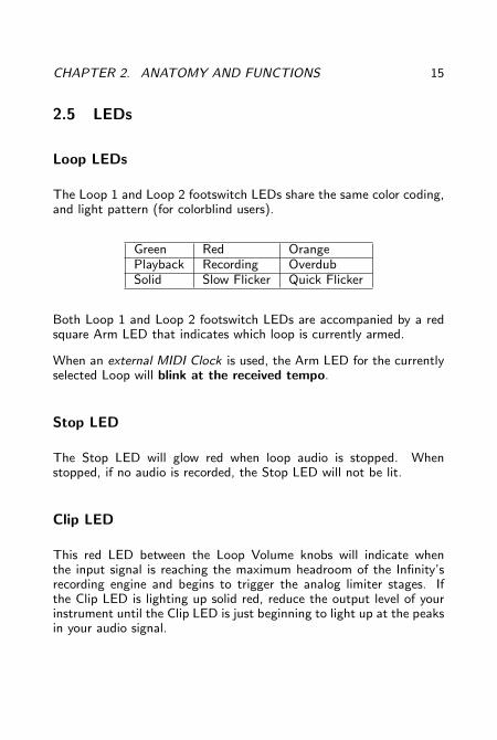
The Loop 1 and Loop 2 footswitch LEDs share the same color coding,and light pattern (for colorblind users).
Green Red OrangePlayback Recording OverdubSolid Slow Flicker Quick Flicker
Both Loop 1 and Loop 2 footswitch LEDs are accompanied by a redsquare Arm LED that indicates which loop is currently armed.
When an external MIDI Clock is used, the Arm LED for the currentlyselected Loop will blink at the received tempo.
Stop LED
The Stop LED will glow red when loop audio is stopped. Whenstopped, if no audio is recorded, the Stop LED will not be lit.
Clip LED
This red LED between the Loop Volume knobs will indicate whenthe input signal is reaching the maximum headroom of the Infinity’srecording engine and begins to trigger the analog limiter stages. Ifthe Clip LED is lighting up solid red, reduce the output level of yourinstrument until the Clip LED is just beginning to light up at the peaksin your audio signal.
CHAPTER 2. ANATOMY AND FUNCTIONS 16
Multi-Segment Digit
This numeric display tells the user which preset is currently selected(within the selected bank) and is also used to confirm firmware update“F”, and to indicate copy in progress “C” and USB active “U” states.
In Varispeed mode (see page 35) a “-” is displayed. It’s height repre-sents the speed of the sample rate.
Decimal Point
Located to the right of the digit, this LED lights up to indicate thataudio has been recorded to a preset bank. When changes have beenmade to a preset but not saved, the decimal point will blink. Oncethe changes have been saved, the decimal point will return to solid.
When a delayed command has been initiated, the relevant footswitch,Arm, and Stop LEDs will blink repeatedly to indicate a pending action,and will turn solid in color once the action is taken. At the end of theloop cycle of the currently armed loop, the stop, multi-segment digit,associated footswitch LED, and arm LEDs will all flash. The other(non-armed) loop’s associated LEDs (Footswitch and A) will flash atthe end of its loop cycle as well.

3. Infinity Rules
3.1 Arm
Arming a loop is achieved by pressing the footswitch that correspondsto the desired loop. The Arm light above the selected loop will glowred indicating its status as armed. A loop must be armed in orderto accept further commands. When the Infinity powers up initially,LOOP 1 is armed by default. Loop 2 cannot be armed until materialis recorded on Loop 1.
3.2 Record
Once a loop is armed, pressing the footswitch for that loop will be-gin recording. The corresponding loop LED will glow red to indicaterecording. You must record to Loop 1 first. You will be able to recordon Loop 2 once there is audio recorded on Loop 1.
Pressing a Loop footswitch after the loop has started recording willstop recording and immediately begin playback. The loop LED willglow green to indicate playback.
Pressing the Stop footswitch while a loop is recording will stop record-ing without immediate playback. You will need to press the appro-priate loop footswitch again to begin playback.
17
CHAPTER 3. INFINITY RULES 18
3.3 Jump Record
Pressing the Loop 2 footswitch while Loop 1 is recording will closeLoop 1 and begin recording on Loop 2.
In parallel mode, Loop 1 will immediately begin playback when Loop2 starts recording.
In series mode, Loop 1 will simply close and be ready for playback thenext time you hit the Loop 1 footswitch.
3.4 Play
When a loop has been recorded but is stopped, pressing that loop’sfootswitch will restart playback. The corresponding LED will glowgreen to indicate playback.
The Play function is tied to the Arm/All setting (see page 8).
3.5 Stop
Pressing stop will stop audio playback.
The Stop function is tied to the Arm/All setting (see page 8).
Double pressing the Stop footswitch within 1 second will override theArm/All and Trail/Fade settings and will stop all loop audio.
CHAPTER 3. INFINITY RULES 19
3.6 Erase
To erase a loop, press and hold down the Stop footswitch.
If a loop is stopped and armed, pressing the Undo remote switch willerase that loop.
When the erase command is triggered, the Stop LED, the current ArmLED and the Multi-Segment Digit will flash once to indicate audiohas just been erased.
The Erase function is tied to the Arm/All settings (see page 8).
3.7 Overdub
Overdub lets you add additional material to the original loop.
Pressing the Loop footswitch when a loop is playing back will startoverdubbing. The corresponding footswitch LED will glow orange toindicate Overdub.
Pressing the loop footswitch during an overdub will close that over-dub.
After closing an overdub you can choose to reopen it by pressing theloop footswitch − as long as the loop cycle hasn’t ended yet. At theend of the loop cycle, all audio recorded during that cycle is mergedand saved as a single overdub.
Pressing Stop in the middle of an overdub will cancel that overduband eliminate the dubbed audio.
For instructions on how to Undo and Redo overdubs, please see Re-mote Switch Functions, page 33.

CHAPTER 3. INFINITY RULES 20
3.8 Sync Multi
For basic Sync Multi functionality see the Sync Multi Section (page10)
Holding the Sync Multi switch will toggle Sync Multi on or off.
Quickly pressing the Sync Multi switch once Sync Multi is on, cyclesthrough the sync multiplier factor.
When Sync Multi is turned off, the lengths of Loop 1 and 2 are un-related and playback is unsynchronized. If Loop 2 is recorded whenSync Multi is off, it cannot be turned off until Loop 2 is erased.
The multiplier displayed on the LED bar to the right of the Sync Multiswitch determines the length of Loop 2 relative to Loop 1. At x1, thelengths of Loop 1 and Loop 2 are identical, and they begin and endat the same points. At x2, Loop 2 is double the length of Loop 2.Etc.
When Multi Sync is on and the Loop 2 footswitch has been pressed,recording on Loop 2 will automatically begin at the start of the nextLoop 1 cycle, and close after the selected number of cycles.
3.9 Series Loops
When Series is on, only one of the two loops can be played back atany given time.
When Series is on, enabling playback or recording on a loop will im-mediately stop playback of the previously selected loop, closing anyoverdub that was in progress.
In Series mode, when recording on Loop 1, pressing the Loop 2

CHAPTER 3. INFINITY RULES 21
footswitch will close Loop 1, and will simultaneously arm and beginrecording on Loop 2. Pressing the Loop 1 footswitch next will causeLoop 2 to close and will simultaneously arm and begin playback onLoop 1.
3.10 Series & Fade Modes
Trails
In Series mode, when Trails is selected, switching between loops atany time will cue the selected loop to begin playback automaticallyat the end of the current loop cycle.
Similarly, when Fade is selected, switching between loops at any timewill fade the currently playing loop from the time the button ispressed until the end of the current loop cycle and also cue the newlyselected loop to begin playback automatically at the end of the currentloop cycle.
Overdub
When recording an overdub, the overdub will not save until it is closedand a loop boundary has been passed. As a result, when Full is selectedin Series mode, switching loops right after recording an overdub willresult in the overdub not being present when you switch back to theother loop. However, Trails and Fade automatically close the recordingat the end of the loop cycle−this ensures that the Overdub you justrecorded gets saved. For this reason, it’s best to always use Seriesmode with the Trails or Fade setting. You can always accomplish aFull stop, by double pressing the Stop switch.
CHAPTER 3. INFINITY RULES 22
3.11 Input Split
The Input Split function is intended for isolating Loop 1 to audiochannel 1 and Loop 2 to audio channel 2. This is helpful if you wantto loop multiple instruments on isolated, yet synchronized loops.
When nothing is plugged into Input 2, then the audio from Input 1becomes the source for Input 2 (as well as Input 1) and the InputSplit function allows you to record separate loops for the left and rightoutput channels.
3.12 Presets
The Infinity Looper allows you to store and recall up to 50 presets,which consist of audio that you’ve either recorded by playing throughthe Infinity, or audio you’ve loaded onto the pedal from your computerusing the app. Each preset includes a Loop 1, as well as a Loop 2 ifyou’ve recorded a second loop.
The 50 presets are organized into five banks of 10.
Loading
To Load a preset, simply turn the Preset knob until you arrive at thedesired preset, then press the knob to select.
The Sync Multi Bar Graph indicates the currently selected bank−thetop (x1) corresponds to Bank 1 and the bottom (x6) corresponds toBank 5 and the Multi-Segment Digit displays the preset number withinthe chosen bank.

CHAPTER 3. INFINITY RULES 23
To cancel the load process at any time, hit the Stop footswitch, orsimply turn the preset knob to return to the currently loaded preset.
Saving
To Save a preset you have created, push and hold the preset knobfor 2 seconds, until the digit begins flashing. Turn the preset knob toselect the bank you want to save the loops in and then push down andhold the preset knob for 2 seconds to finalize the save. To cancel thesave process at any time, hit the Stop footswitch.
Preset 0 does not store any loops, it is the blank canvas. If you try tosave a loop to Preset 0, the digit will show you a “-” symbol, indicatingthat you should save this audio somewhere else by turning the encoderto select a different preset slot. Settings for Preset 0 can be changedusing the Pigtronix Infinity Application.
The decimal point will illuminate to indicate that audio is present ina Loop bank. When changes have been made but not saved, thedecimal point will blink. If you want to keep your changes, simplyfollow the save process explained above without changing the selectedbank. When the changes are saved, the decimal point will stay on.
Copying
To copy a preset from one bank to another simply initiate the saveprocess as explained above on a bank that already contains audio.
Being able to copy presets allows you to create different versions ofloops with the same starting point. It also facilitates the reorganizationof preset locations (you can move presets, for example, by copying apreset to the location you want to move it to, then deleting the originalpreset).

CHAPTER 3. INFINITY RULES 24
In certain instances while saving, the Infinity Looper may need toquickly copy data from one sector of the disk to another. When thishappens, the digit will show a flashing “C” while the copy is in process.
Erasing
To erase saved audio from a preset (for example, erasing one of theloops), the audio must first be erased by pressing and holding the Stopfootswitch. Then the modified loop must be saved using the processpreviously described.
3.13 Loop Aging
Press and hold Input Split for 2 seconds to enter the Loop Aging Menu.The digit will flash between “A” and “-” indicating that Loop Agingis currently turned off. Turn the rotary encoder to select the desiredLoop Aging value.
Digits (0−9) represent variable feedback decay. The lower the number,the faster the loop decays. For example a “0” means no feedback, soan overdub disappears after one playback cycle.
“-” shows that Loop Aging is turned off.
Press down on the encoder (or push Input Split again) to finalize thevalue you want and exit the Loop Aging menu.
Like everything else on the Infinity, Loop Aging happens in real time,so you can turn Loop Aging on and off (or adjust it with expressionpedal) as much as you want throughout the course of a single loopcycle.
CHAPTER 3. INFINITY RULES 25
To enable Expression Pedal control of the feedback value, select ”A”from the Expression Pedal Assignment Menu (page 40). For moreinformation on Expression Pedal Loop Aging control see ExpressionPedal Functions, 39.
You can enter the Loop Aging menu at any time, even during playback.
Loop Aging settings will be saved when you save your preset.
Loop Aging only takes place when you are in an Overdub state,and only applies to the armed loop. When you are in normal play-back, the loop does not decay.
Undo works as expected, allowing you to Undo or Redo any LoopAging that you let happen during an overdub, no matter how manytimes you let the loop cycle.
3.14 Click Killer
Within the Loop Aging menu (press and hold Input Split), an optionhas been added to enable or disable the loop boundary Click Killer. Ifit is on, the menu will show “C.” If it is off, the menu will show “c”.Click Killer defaults to “C.” Pressing the encoder while on this optionwill toggle the loop boundary Click Killer status. The loop boundaryClick Killer is a super quick crossfade between the beginning and end ofa loop. For musicians who want to construct sustained droning loopswith overdubs that cross the loop boundary, turning the Click Killeroff will result in seamless loops. For more rhythmic and song-basedperformances, we recommend leaving the Click Killer on.
CHAPTER 3. INFINITY RULES 26
3.15 Varispeed
Varispeed allows you to change the pitch (and speed) of your loopedaudio by altering the recording and playback sample rate. This changecan be made in real time using an expression pedal, remote switch,or MIDI. Further details are provided in the Remote Switch section(page 33), Expression Pedal Functions (page 39) and MIDI section(page 43).
Push and hold down the Reverse switch to allow user control ofVarispeed.
The sample rate can be set anywhere between 48 kHz to 12 kHz. Asthe sample rate is increased or decreased, both the pitch and lengthof the recorded audio changes. The sample rate is a global parameterand affects both loops simultaneously.
Playback Sample RateRecordingSampleRate
12 kHz 24 kHz 48 kHz
48 kHz 2 Octaves Down 1 Octave Down Same Pitch(Default) Quarter Speed Half Speed Same Speed24 kHz 1 Octaves Down 1 Same Pitch 1 Octave Up
Half Speed Same Speed Double Speed12 kHz Same Pitch 1 Octave Up 2 Octaves Up
Same Speed Double Speed Quadruple Speed
During Recording or Playback, you can use the Varispeed RemoteControl Menu, the Expression pedal, MIDI commands, or MIDI Clockto adjust the sample rate as desired.
The current sample rate is saved at the same time that your currentloop is saved. Sample-rate changes cannot be undone or redone using

CHAPTER 3. INFINITY RULES 27
standard Undo or Redo functionality however, you can snap to anydesired sample rate using the remote switch. In ARM mode, pressingboth Remote Switches at the same time will snap the sample-rateto the sample-rate used to record the currently armed Loop. In ALLmode it will always snap to the sample-rate used to record Loop 1.This behavior will save whether the recording sample-rate was setusing the Remote Switch or the Expression Pedal and set the Infinity’sstate accordingly. Caution: By default, loop audio that is recordedat 48 kHz can only get longer and lower in pitch. To enable sped-up, shorter, and pitched-up loops, this initial recording rate must belowered before recording audio.
There are many ways to change the sample rate on the Infinity. Someof them are best thought of as sample rate changes, while others arebest thought of as pitch changes. All of them change both the pitchand length of recorded material. See the table on the next page for alisting of how pitch changes relate to loop length.
When using Varispeed, the expression pedal provides control over thecomplete range of sample rates. It is mapped to control the samplerate using Expression Mapping (page 39) or while in the VarispeedRemote Control Menu.
For more precise changes, the Remote Switch can change the samplerate by a pre-defined musical interval. By default, Reverse halves thesample rate (octave down) and Undo doubles it (octave up). The pitchchange controlled by the Reverse and Undo switches can be customset (on a preset-specific basis) to other intervals, using the InfinityApplication (for example, up 4 semitones and down 4 semitones).
For more information, see the Varispeed Remote Control Menu in theRemote Switches section on page 33.
Complete MIDI mapping allows you to change pitch by sending MIDINotes, and also tracks changes in the MIDI Beat Clock’s tempo. Fora complete understanding of these controls, see the MIDI Section onpage 48.

CHAPTER 3. INFINITY RULES 28
# of Semi-tones
Interval Up Speed(%)
Down Speed(%)
1 Minor Second .94 1.072 Major Second 0.89 1.133 Minor Third 0.83 1.24 Major Third 0.8 1.255 Perfect Fourth 0.75 1.336 Diminished Fifth 0.70 1.427 Perfect Fifth 0.67 1.508 Minor Sixth 0.63 1.69 Major Sixth 0.60 1.6710 Minor Seventh 0.56 1.8011 Major Seventh 0.53 1.8812 Perfect Octave 0.50 2.00
3.16 Boot Options
Each of the footswitches can be pressed during power up to enableand disable a specialty global setting on the Infinity Looper. Thesesettings are sticky and will remain set even after removing power fromthe Infinity.
Auto Zero Record
Hold Loop 1 during boot to toggle Auto Zero Record.
With Auto Zero Record off (Loop 1 LED is off during boot), theMIDI downbeat is reset on the first received note or MIDI start, thesample-rate of empty loops is automatically set to 48 kHz.
With Auto Zero Record on (Loop 1 LED is lit red during boot), theMIDI counter is reset on the initial record of Loop 1, the sample-rate

CHAPTER 3. INFINITY RULES 29
of empty loops is automatically set to 24 kHz.
This is essential if you are creating live loops using any type of taptempo MIDI clock source. The default 24 kHz sample-rate allows forthe MIDI source to speed up and slow down without loosing sync.
Mono Mixdown
Hold Loop 2 during boot to toggle Mono Mixdown.
With Mono Mixdown off (Loop 2 LED is off during boot), the InfinityLooper outputs in stereo (Default).
With Mono Mixdown on (Loop 2 LED is lit red during boot), bothinput channels run into a single output. Both Outputs 1 and 2 willreceive the mono mix of all recorded material.
Stutter
Hold Stop during boot to toggle Stutter.
Stutter replaces the functionality of the Reverse button on the RemoteSwitch (see page 33).
With Stutter off (Stop LED is off during boot), the Reverse buttonon the Remote Switch functions as expected.
With Stutter on (Stop LED is on during boot), pressing the Reversebutton on the Remote Switch causes the armed loop to be playedfrom its start point immediately.

CHAPTER 3. INFINITY RULES 30
Reformat
Hold the Series Loops switch during boot to reformat the microSDCard to 50 Presets.
Caution: This erase all saved presets and recorded loop audio!
4. Remote Switch Functions
We recommend that you use the Infinity Remote (www.pigtronix.com/products/infinity-remote-switch) as your remote switch.
Plug your remote switch into the Undo jack.
4.1 Reverse
Reverse is triggered by shorting the ring to the sleeve of the Undojack. This is accomplished by connecting any two-button, momentaryfootswitch (such as the Pigtronix Infinity Remote) to the Undo jackwith a TRS cable.
Pressing the Reverse button triggers reverse playback at the begin-ning of the next loop cycle according to the Arm/All setting (seepage 8. Pressing Reverse while recording will instantly trigger reverseplayback once the Loop footswitch is pressed.
Pressing Reverse while playing a reversed Loop, will revert it to itsnormal play direction after the next loop cycle.
Once you are in reverse playback, you can use the Undo switch toflip flop between forwards and reverse versions of the same layerinstantly.
Hitting Reverse and then Undo before the end of the loop cycle willcancel the requested Reverse.
31

CHAPTER 4. REMOTE SWITCH FUNCTIONS 32
4.2 Undo
To undo overdubs, a dual momentary remote switch is required. Thisshould be connected to the Undo jack using a TRS (balanced 1/4”)cable.
When an overdub is being recorded (Loop LED is orange), pressing theUndo switch will cause the Infinity to permanently erase that over-dub at the end of the current loop cycle. Any material from previousoverdubs that have already been merged with the initial recording willnot be undone.
When an overdub is playing back (Loop LED is green), pressing theUndo switch will remove that overdub instantly, and the overdub isretained for Redo if desired.
You can only undo your most recent overdub; once you open and thenclose a new overdub, the previous overdub layer will be merged withthe base layer at the end of the current loop cycle and can no longerbe undone.
4.3 Redo
Once an overdub has been closed and then undone, it can be putback instantly by pressing the Undo remote switch once again. Youcan Undo and Redo an overdub as many times as desired.
CHAPTER 4. REMOTE SWITCH FUNCTIONS 33
4.4 Rec→Overdub→Play
In response to numerous customer requests, we have implemented afeature that allows you to go directly from recording the base layer,straight into overdub mode. This feature is particularly good if youhave sounds (delays, reverbs etc) that will trail across the Loop’sboundary; using it will prevent clicks and pops.
Once you have started the base layer recording, simply press the Undoswitch to close your initial loop and go straight into playback withoverdub active. Press the appropriate Loop footswitch as you nor-mally would to close the overdub when desired and begin regular play-back.
4.5 Instant Erase
When one or both loops are stopped, hitting Undo will trigger aninstant erase of the currently armed loop. This lets you simply leavethe unit in All mode and retain the option to clear individual loops bypressing the Undo switch after the desired loop has been stopped.
4.6 Varispeed Remote Control Menu
For basic Varispeed functionality, see page 28.
To access the Varispeed Remote Control Menu, press and hold theReverse switch for 2 seconds. While in this menu a “−” is displayedon the Multi-Segment Display. This menu remaps the functionalityof the Reverse and Undo switches to control the pitch of recordedmaterial. To exit this menu, press and hold the Reverse switch for 2seconds.
CHAPTER 4. REMOTE SWITCH FUNCTIONS 34
A short press of Reverse decreases the pitch and increases thelength of both loops by the interval selected using the Infinity Ap-plication.
A short press of Undo increases the pitch and decreases the lengthof both loops by the musical interval selected using the Infinity Appli-cation.
Pressing and holding undo or pressing both Reverse and Undo resetsthe sample rate to the initial recording sample rate.
The default Interval selection is one octave, enabling Reverse andUndo to double-speed and half-speed recorded audio respectively.
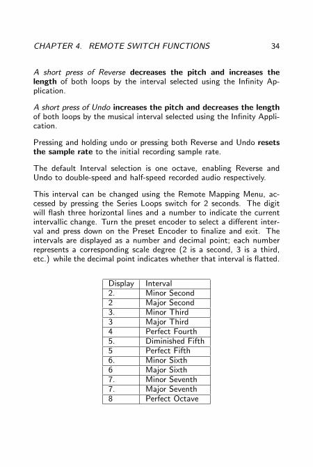
This interval can be changed using the Remote Mapping Menu, ac-cessed by pressing the Series Loops switch for 2 seconds. The digitwill flash three horizontal lines and a number to indicate the currentintervallic change. Turn the preset encoder to select a different inter-val and press down on the Preset Encoder to finalize and exit. Theintervals are displayed as a number and decimal point; each numberrepresents a corresponding scale degree (2 is a second, 3 is a third,etc.) while the decimal point indicates whether that interval is flatted.
Display Interval2. Minor Second2 Major Second3. Minor Third3 Major Third4 Perfect Fourth5. Diminished Fifth5 Perfect Fifth6. Minor Sixth6 Major Sixth7. Minor Seventh7. Major Seventh8 Perfect Octave

CHAPTER 4. REMOTE SWITCH FUNCTIONS 35
The Remote Mapping Menu only sets the Interval while in the VarispeedRemote Control Menu, if you leave the Varispeed Remote ControlMenu the Remote Mapping Menu sets the Expression Pedal assign-ment as described on page 39.
Caution: Press-and-hold functionality on the Reverse and Undo switchesin this menu prevents actions taking place immediately when pressed.While in the Varispeed Remote Control Menu, short press actions areexecuted when the Reverse and Undo switches are released.

5. Expression Pedal Functions
An industry standard low-impedance TRS expression pedal can beconnected to the Infinity using a TRS (tip-ring-sleeve) cable, to controlany one of the following (but only one at a time): Loop Volume, LoopAging, or Varispeed.
Moving the expression pedal towards the heel will turn the loop audiodown (for both loops) from the level set by the individual loop volumeknobs.
5.1 Loop Volume
This is the default function of the Expression pedal while not in theVarispeed Remote Control Menu.This mapping controls the audio out-put level of both loops simultaneously.
Moving the expression pedal towards the heel will turn the loop audiodown (for both loops) from the level set by the individual loop volumeknobs.
5.2 Loop Aging
For basic Loop Aging functionality see page 26.
This is a non-default function of the Expression pedal. When usingexpression pedal feedback control, toe maps to “no feedback decay”and the numbers go down from 9 to 0 as you move towards the heel.
36

CHAPTER 5. EXPRESSION PEDAL FUNCTIONS 37
You can use a simple momentary switch (connected via TRS) in placeof an expression pedal to get an instant Loop Replace function out ofthe “A” mode, since hitting the switch is like going to “0.”
5.3 Varispeed
This is the default function of the Expression pedal while in theVarispeed Remote Control Menu. This mapping controls the Varispeedsample rate. Moving the expression pedal towards the heel will de-crease the sample rate, decreasing pitch and increasing loop length.When the Expression Pedal is moved it takes control of the samplerate and will remain in control until the Pitch Up or Down functionsof the Varispeed Remote Control Menu are used. Once the PitchUp or Down functions have been used the Expression Pedal must first“Catch Up” the the Remote Switch setting before it begins controllingthe sample-rate again.
5.4 Expression Pedal Assignment
When shipped from the factory or Reformatted (as described on page32), the Expression Pedal is assigned to control Loop Volume ex-cept while in the Varispeed Remote Control Menu when it controlsVarispeed.
The Expression Pedal can be assigned using the Application or usingthe Remote Mapping Menu.
The Remote Mapping Menu is accessed by pressing the Series Loopsswitch for 2 seconds. The digit will flash “P” and the current Ex-pression pedal assignment (either “U”, “A”, or “≡” for Loop Volume,Loop Aging, or Varispeed respectively). Move the encoder to selectthe desired Expression pedal mapping and press the Preset Encoder

CHAPTER 5. EXPRESSION PEDAL FUNCTIONS 38
to finalize and exit. The selection from the Remote Mapping Menuapplies globally, both in and out of Varispeed Remote Control Menu.
The Remote Mapping Menu only sets the Expression Pedal assign-ment when NOT in the Varispeed Remote Control Menu. If theVarispeed Remote Control Menu is entered while in the Remote Map-ping Menu, the Remote Mapping Menu will set the Interval Changeof the Varispeed Remote Control Menu as described on page 35.
Using the Application the Expression Pedal can be assigned to controlseparate parameters while inside the Varispeed Remote Control menuand while outside the Varispeed Remote Control Menu.
6. MIDI
6.1 MIDI Sync
MIDI Sync is the normal default MIDI mode of the Infinity−it’s alwayson.
When a MIDI Beat Clock is present, the Infinity Looper will synchro-nize its actions to the MIDI beat clock, acting as a slave device.
Once a loop has been recorded with a MIDI Beat Clock, the Infinitywill constantly readjust the loop length to stay synchronized. Thisactive MIDI synchronization prevents drift, and guarantees that allsynchronized actions happen on time at the start of MIDI measures.
This active MIDI synchronization is designed to work with regular MIDIclock signals that don’t change tempo or time signature. If the MIDIclock signal does change tempo, the Infinity will react and adjust thesample rate gradually.
The MIDI actions of the Infinity are quantized to the measure whenMIDI is running, by default in 4/4 time. Any action that is meant toobey MIDI clock will be applied at the beginning of the next measure(not necessarily the end of the loop cycle). So it’s best to cue theMIDI command within the bar/measure before you want it to occur,not right on the downbeat.
If a MIDI clock signal is present during recording and then stoppedor disconnected, the Infinity will continue playback using its recordedlength. Actions will continue to be quantized to an internal, approxi-mate MIDI clock. However, this internal MIDI clock may drift or differfrom the external MIDI clock that was disabled.
39

CHAPTER 6. MIDI 40
6.2 Time Signature
The Time signature can be changed, on a preset-by-preset basis, usingthe Infinity Application. For quantization to the beat rather than tothe measure, set the measure to a single note (eg. 1/2, 1/4, 1/8,1/16).
6.3 Commands That Sync to MIDI Clock
With MIDI Sync active, some commands initiated using the Infinity’sfootswitches will be automatically quantized to the beginning of thenext MIDI Measure.
Record and Play
Appropriate action is executed at the start of the next measure afterthe switch has been pressed.
Stop
The Stop footswitch closes loops and stops loop audio at the start ofthe next measure after the switch has been pressed.
Start
Starts loop audio at the start of the next measure after the switchhas been pressed. Switching between loops in Series mode will trigger

CHAPTER 6. MIDI 41
which loop is playing back at the start of the next measure after theswitch has been pressed.
Overdub
Closes a base recording at the start of the next measure after theswitch has been pressed then begins recording an Overdub.
6.4 Commands That Ignore MIDI Sync
Erase, Overdub, Global stop (via double tap), and all mode changesvia the tactile switches, potentiometers or encoder are not quantizedto MIDI beat clock.
6.5 Full MIDI Mapping
To select a MIDI channel, press and hold the Stop Mode switch asthe Infinity Looper turns on. The Looper will learn the MIDI channelof the next MIDI signal it receives, and only respond to MIDI signalsthat come from that channel.
We’ve seen how you can control tempo and pitch change by synchingto an external MIDI beat clock; MIDI can also be used to controlmany specific functions of the Infinity via a properly configured MIDIcontroller.
Like MIDI Sync, MIDI mapping is always enabled, so that MIDI footcontrollers, Ableton, and other devices or software can control param-eters of the Infinity Looper.
CHAPTER 6. MIDI 42
A Full MIDI Map is provided on page 47. The behavior of individualcommands (CC: control change) is broken down into 4 types of control:
Cycle/Toggle
Any value of these MIDI CC/Note messages toggles or cycles throughthe available options, changing to the next selection.
Mapped
The value (0-127) of these MIDI CC/Note messages sets the value ofthe parameter.
Loop-Assignable
Specific values of these MIDI CC/Note messages triggers the actionfor Loop 1 Only (0), Loop 2 Only (1), the currently Armed Loop Only(2), or Both Loops (3).
Switch
The value of these MIDI CC/Note messages determines whether themessage acts like a switch press or delivers a specific type (short orlong) of switch press.
A value of 0 is not pressed, a value of 127 is pressed. For MIDIcontrollers that send 127 when pressed and 0 otherwise, this type ofcommand lets the MIDI footswitch act like the buttons (hold for 2seconds for a long press, or less for a short press).
CHAPTER 6. MIDI 43
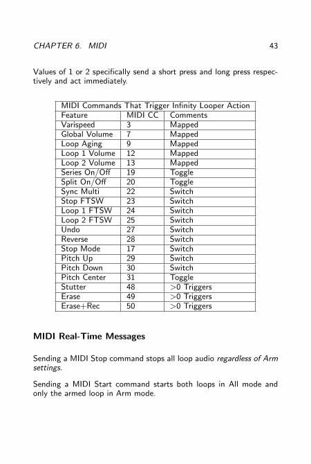
Values of 1 or 2 specifically send a short press and long press respec-tively and act immediately.
MIDI Commands That Trigger Infinity Looper ActionFeature MIDI CC CommentsVarispeed 3 MappedGlobal Volume 7 MappedLoop Aging 9 MappedLoop 1 Volume 12 MappedLoop 2 Volume 13 MappedSeries On/Off 19 ToggleSplit On/Off 20 ToggleSync Multi 22 SwitchStop FTSW 23 SwitchLoop 1 FTSW 24 SwitchLoop 2 FTSW 25 SwitchUndo 27 SwitchReverse 28 SwitchStop Mode 17 SwitchPitch Up 29 SwitchPitch Down 30 SwitchPitch Center 31 ToggleStutter 48 >0 TriggersErase 49 >0 TriggersErase+Rec 50 >0 Triggers
MIDI Real-Time Messages
Sending a MIDI Stop command stops all loop audio regardless of Armsettings.
Sending a MIDI Start command starts both loops in All mode andonly the armed loop in Arm mode.
CHAPTER 6. MIDI 44
Sending a MIDI Song Select command will change preset banks, inorder to move between different loops during performance. Allow upto 4 seconds for song select changes to take effect.
Varispeed MIDI Note Control
For precise changes of sample rate for the purposes of a pitch change,the Infinity accepts MIDI Note Control.
MIDI Notes C5 to C7 change the sample rate between 12 and 48 khz.The looper starts at 48 kHz, so if you want to raise the pitch of asample, lower the sample rate before recording.
MIDI Notes C2 to C4 change the sample rate between 12 and 48 kHz,and Stutter the loop (see page 31). So playing these notes will changethe pitch and replay the loop, which creates a “mellotron-like” sound.Like above, the looper starts at 48 kHz, so if you want to raise thepitch of a sample, lower the sample rate before recording.
Please see the tables on pages 28 and 30 for pitch and length changeinformation and the table on page 47 for the complete MIDI Mapping.

7. Infinity Looper Application
The Infinity Looper Application comes pre-installed on your InfinityLooper pedal. To run the application, plug in your Looper via USBand open the appropriate folder (PC or MAC) from the on-board driveand then click on the LooperApp.exe file. If using Windows 7, pleaseright-click and choose “Run As Administrator”
To update the Infinity Looper application on your Infinity Looper,download the updated version at the following URL: www.Pigtronix.com/SPLapplication and replace the appropriate folder on the Infin-ity Looper with the new version of the application.
45

8. Firmware Updates
8.1 Automatic Update Using the LooperApplication
In order to launch the Infinity Looper Application, you must plug thelooper into a PC using the supplied USB-A to microUSB cable. TheInfinity is not a bus powered device and must be plugged into thewall using the supplied adapter in order to run the Infinity LooperApplication.
Once the Infinity has been connected to a computer, it will appear asa USB mass storage device.
Open the drive that appears and double click on the appropriate (MACor PC) folder then double click the Space Pig icon to launch the InfinityLooper Application.
Make sure your computer has an active internet connection.
Choose the firmware update option from the Tools menu within theInfinity Looper Application. Choose the “automatic” option.
Close the Infinity Looper Application.
Power down the Infinity Looper (eject first on MAC) and then discon-nect the USB cable from the Infinity Looper.
While holding down the Input Split switch, reconnect the power sup-ply. The digit will display an “F” to indicate the firmware updateprocess has been initiated. When finished, the Infinity will re-bootautomatically and your firmware will be updated.
46
CHAPTER 8. FIRMWARE UPDATES 47
If you followed the above instructions correctly and the “F” does notappear, then the firmware you are trying to install is the same as whatis currently running on your device.
8.2 Manual Firmware Update
To update your Infinity Looper with the latest firmware, power upthe Infinity Looper and plug it into a PC with the supplied USB-A tomicroUSB cable. The Infinity is not a bus powered device and mustbe plugged into the wall using the supplied adapter in order to connectvia USB. Once the Infinity has been connected to a computer, it willappear as a USB mass storage device.
Download the latest Firmware update (fwupdate.dat) from the follow-ing URL: www.pigtronix.com/SPLfirmware
Open the drive that appears and double click on the LOOPERFWdirectory. Copy the fwupdate.dat file into the LOOPERFW directory,replacing the current file of the same name. Power down the InfinityLooper (eject first on MAC) and then disconnect the USB cable fromthe Infinity Looper.
While holding down the Input Split switch, reconnect the power supplyto the Infinity Looper, the digit will display an “F” to indicate thefirmware update process has been initiated. When finished, the Infinitywill re-boot automatically and your firmware will be updated.
If the “F” does not appear, then the firmware you are trying to installis the same as what is currently running on your device.
9. Minimum and Maximum Loop Times
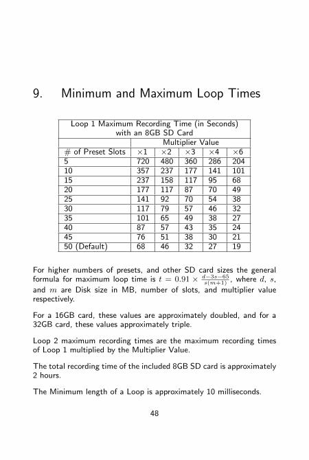
Loop 1 Maximum Recording Time (in Seconds)with an 8GB SD Card
Multiplier Value# of Preset Slots ×1 ×2 ×3 ×4 ×65 720 480 360 286 20410 357 237 177 141 10115 237 158 117 95 6820 177 117 87 70 4925 141 92 70 54 3830 117 79 57 46 3235 101 65 49 38 2740 87 57 43 35 2445 76 51 38 30 2150 (Default) 68 46 32 27 19
For higher numbers of presets, and other SD card sizes the generalformula for maximum loop time is t = 0.91 × d−3s−65
s(m+1), where d, s,
and m are Disk size in MB, number of slots, and multiplier valuerespectively.
For a 16GB card, these values are approximately doubled, and for a32GB card, these values approximately triple.
Loop 2 maximum recording times are the maximum recording timesof Loop 1 multiplied by the Multiplier Value.
The total recording time of the included 8GB SD card is approximately2 hours.
The Minimum length of a Loop is approximately 10 milliseconds.
48
10. Acknowledgements
Years of work went into creating the Infinity Looper pedal. We wouldlike to thank the following people for their help along the way:
Ray Heasman, Howard Davis, Ben Artes, Steve Turnidge, Lisa Rickmers,Megan Leary, the Bethke and Koltai families, Jer Coons, Aaron Reed,Dan Pavone, Kevin Griffin, Sean Fitzsimons, Brett Perdie and B-Dawg.
Ray Heasman, Ben Artes, Howard Mick Davis, Jer Coons, SteveTurnidge and David Koltai designed the Pigtronix Infinity Looper dur-ing 2010−2012 in Port Jefferson, NY and Seattle, WA.
It is inevitable that there will be software updates to the InfinityLooper over time that will expand the pedal’s functionality. Pleaserun the firmware update function on the included application or sim-ply check the Infinity Looper product page on the Pigtronix website fordownloadable firmware updates. We hope you enjoy your new InfinityLooper pedal! As always, we welcome your input, and value customerfeedback. Since this device is firmware updatable, we may be ableto implement changes that address concerns or new features you mayhave in mind.
Contact us at (631) 331-PIGS (7447) or email [email protected].
Please check our website, www.pigtronix.com for the latest informa-tion on new Pigtronix gear.
Dave Koltai & Brian Bethke
Pigtronix
49
11. Pigtronix Limited Warranty
Your Pigtronix effect pedal comes with a 1-year limited warranty onparts and workmanship. During the warranty period we will repairor replace, at our option, defective parts or pedals free of charge,and return them to the owner. Warranty service does not includedamaged, modified, or misused pedals and such pedals will be subjectto a standard repair charge.
What you must do: First, contact us directly via email and describethe problem to us. If the problem cannot be resolved we will have yousend the pedal directly to us for servicing.
How to contact us for warranty service:
Email: [email protected]
Phone: 631-331-PIGS (7447)
Warranty Limitations: This warranty does not cover defects resultingfrom improper or unreasonable use, accident, unauthorized tamperingor modifications.
To validate your 1-year, limited warranty, please register your InfinityLooper, within 30 days of purchase, on the web at:
www.pigtronix.com/warranty
50