improving laser cutting quality for two-dimensional ...yly1/pdfs2/paul jmse 2d.pdfnew york n, y...
TRANSCRIPT

P. Di Pietro* School of Mechanical and
Manufacturing Engineering, The University of New South Wales,
Sydney, NSW, Australia
Y. Lawrence Yao Department of Mechanical Engineering,
Columbia University, New York, NY 10027
Improving Laser Cutting Quality for Two-Dimensional Contoured Paths Quality improvements in laser cutting of mild steel have been achieved by a newly developed model-based optimization strategy and its application to one-dimensional cut has been reported early. The specific aims of this paper are to assure quality of cut when cornering and generating small diameter holes. Such routines encompass a large proportion of all features processed on laser cutting systems, and therefore their successful production is significant. Currently, extensive trial-and-error based experimentation is needed in order to improve quality for these routines. Thus model-based optimization has the benefit of reducing this time-exhaustive step whilst leading to an optimal solution. Nonlinear power adaptation profiles are generated via the optimization strategy in order to stabilize cutting front temperatures. Uniform temperatures produce better quality by reducing (i) kerf widening effects, (ii) heat-affected zone extents, and (Hi) workpiece self-burning effects. Experimental results are presented, and it is demonstrated that such process manipulation can produce significant quality improvements. In addition, predicted heat-affected zones correlate closely to those actually obtained. The process manipulation is successfully implemented in an industrial laser cutting system under laboratory condition.
Introduction Today, laser cutting of highly complex and intricate work-
pieces is a reality. Of concern though, is the effect of part geometry on the quality achievable. Such part programs typically contain many pre-cut sections and boundaries, and because of the obvious size of such workpieces, heat accumulation is often severe. This can result in poor cutting quality in the form of widespread burning, increased dross, increased surface roughness, increased heat-affected zone, and kerf widening being common amongst other problems. The appearance of even one of these anomalies can render the complete job useless.
Currently, extensive trial-and-error based experimentation is needed in order to obtain acceptable windows of operation for laser cutting of complex and intricate geometry. A modeling technique aimed at improving cutting quality without extensive trial-and-error has been reported (Di Pietro and Yao, 1995a). The application of a model-based optimization technique to one-dimensional cut has been reported (Di Pietro and Yao, 1995b). It is the aim of this paper to investigate the issues associated with applying this model-based optimization techniques to two-dimensional contoured paths, such as, cornering, and small diameter hole making.
The background related to such two-dimensional cuts is first reviewed. The model-based optimization technique is briefly explained in the context of two-dimensional application, while the model itself is summarized in Appendix for self-containment purpose. The numeric issues arising from the two-dimensional applications are then stated. Experimental setup and preparatory work follows. Experimental results are presented as comparison with the numerical results from the model, along with detailed discussion. Finally, concluding remarks are made.
Background Laser Corner Cutting. Simple observation of laser-cut
corners show that in most cases, corner tip melt-off is com-
* Currently with Di Pietro & Sons Engineering, Fairy Meadow, NSW, Australia Contributed by the Manufacturing Engineering Division for publication in the
JOURNAL OF MANUFACTURING SCIENCE AND ENGINEERING. Manuscript received
Sept. 1996; revised April 1997. Associate Technical Editor: K. Rajurkar.
mon. This is due to the increased time the laser beam is in this area due to the deceleration of one axis, and then acceleration of the other to perform the desired task with adequate positional control. Many systems now allow the adaptation of laser power when cornering to compensate for the reduced cutting speeds associated there (Leece, 1984; Delle Piane, 1985; VanderWert, 1985; Steen and Li, 1988; and Powell, 1993). This was possible through advances made in controller design. Such adaptation ensures that the rate of energy input into the interaction zone and the rate of melt ejection from the kerf is kept somewhat balanced. This technique can be used either under continuous wave (CW) or pulsed mode operation.
The determination of this power-feed ratio currently relies on extensive experimentation. One method of achieving this control feature is by varying the pulse frequency and/or pulse length proportionally to the feedrate (Moriyasu et al„ 1986; Schuocker and Steen, 1986; Borgstrom, 1988; and Schwarzen-bach and Hunziker, 1988). Such duty cycle modulation produces very accurate control of the laser output by altering the percentage of beam 'on-time' to suit the feedrate.
If the system can respond quickly to power commands from the controller, then the input current to the laser can be manipulated for an effective power-feed strategy. Another approach is termed channel switching (Hertzel, 1987), whereby various power levels can be accessed via control functions in the part program generated. Multi-channel capabilities are therefore required so that each channel can be preset with a different power level. It is suggested that the controller needs to be able to effectively switch channels without significant delay in order to assure that no irregularities appear on the cut edge.
Small Diameter Laser Hole Cutting. When laser cutting large diameter holes, some cooling of the workpiece can occur before the beam circles back to its starting position. But when small diameter holes are processed, the time taken for the beam to perform the task is greatly reduced and thus no heat accumulation relief is possible. In order to obtain sharp edges on curved trajectories, pulsed mode operation is commonly employed. The problem with this is that heat-affected zones are almost doubled in extent compared to using continuous wave power (Geiger et
590 / Vol. 120, AUGUST 1998 Transactions of the ASME Copyright © 1998 by ASME
Downloaded From: http://manufacturingscience.asmedigitalcollection.asme.org/ on 01/08/2014 Terms of Use: http://asme.org/terms

al., 1988). This is explained by the more gradual temperature gradients experienced when pulsing the laser beam. Heat-affected zones are often areas where part failure can occur due to their transformed microstructures, which invariably have different post-processed mechanical properties. Minimizing the extent of heat-affected zones are therefore critical, especially when the material properties of a part are carefully considered for its intended design function, as is often the case. Therefore in many cases it is appropriate to laser cut holes using continuous wave energy deposition, above and beyond its benefit of pure simplicity of operation.
Laser cutting of curved trajectories has been studied previously (Sheng and Cai, 1994). It was clearly shown that circular laser cutting produces three effects in quality over simple straight-line cutting. The kerf width is typically larger, a center-line shift of the inner kerf wall towards the center of rotation is evident, and the inner kerf wall taper is larger than that of the outer wall. These changes in the kerf's characteristics are more pronounced obviously at smaller curvature ratio's (i.e. CR = radius of cutting path:focused beam radius) because the heat accumulation between the rotation center and the inner kerf wall becomes extreme.
Model-Based Optimization
A complete description of the modeling has been presented elsewhere by the authors, Di Pietro and Yao (1995a) and a summary thereof is included in the Appendix for self-containment purpose. Additionally, model-based optimization for one-dimensional laser cutting when encroaching upon a boundary has been studied previously in order to assure cut quality right up to pre-cut sections and boundaries (Di Pietro et al., 1995b). Results showed that process manipulation recommended by the model-based optimization can lead to significant quality improvements. The work is therefore extended in this paper to examine the geometric cases of two-dimensional, such as, cornering and small diameter hole cutting. A brief summary of model-based optimization is given below.
Industry (Moriyasu et al., 1986) and research groups realized early on that adaptive control of laser parameters was a real possibility with conventional CNC (computer numeric control) systems. By adapting parameters such as laser power levels, switching between continuous wave (CW) and pulsed mode, and effecting cutting speed changes, vast quality improvements were obtainable. Such techniques are trial-and-error based, and therefore are time consuming, whereby the optimal set of parameters may still not be reached. It was recognized by Bier-mann and Geiger (1991) that simulation of the laser process under the effects of the motion system can lead to improved results for laser processing.
An optimization strategy is therefore proposed in which it forces the cutting front temperature to remain steady anywhere on a two-dimensional path. The problem of maintaining steady-state cutting front temperature results in a nonlinear power profile, as the inter-relationships between laser parameters are complicated by the mobility exhibited by the cutting front. Uniform cutting front temperatures affect quality in various ways. They produce better quality by reducing (i) kerf widening effects, (ii) heat-affected zones, and (iii) wide spread self-burning. At the very least, uniform cutting front temperatures reduce the variability in progressive cut quality.
The strategy developed is iterative by nature (see Fig. 1). The model proceeds forward in time by the accumulation of the timestep At of integration. By monitoring the status of the front temperature at every instance, a steady state value can be established, \Tj+1 - Tj\ < AT, where 7}denotes cutting front temperature and j current time. The cutting front temperature can be disturbed subsequently by a speed change of the motion system (as in the case of cornering, cutting holes, or general contouring). It may also be disturbed by a change in the work-
£
AP = ITf i + 1 -T(J lxk
1 """"^ ^ " * > ^ . FALSE T(J+1>Tf) Z>~—*"
J TRUE
PJ=PJ-AP
pj = pi + AP pj = pi + AP
I Optimisation Modulej
Fig. 1 Power optimization strategy for cutting front temperature stabilization
piece heat accumulation (due to the presence of the kerf, such as, near the completion of cutting a small diameter hole, which frustrate heat conduction).
As the change in temperature exceeds the previously set limit AT, a course of action is required in the form of a power rise or reduction of size AP - | Tj+1 - Tj \ k. A conditional test is then given: if Tj+1 > Tj, then P{m = P{nc - AP where Pinc is incident beam power. Otherwise, P-mc = P'inc + AP. From which, an updated cutting front temperature Tj+' is determined. If it falls within the set allowable temperature tolerance Tj ± AT, the model proceeds forward to the next user-specified beam position whereby the procedure repeats. If it still falls outside of the tolerance, the constant k is typically doubled (It was arbitrarily chosen at the beginning). If it is found that the constant k over-affected the new Tj+l, it will be reduced to its three fourth. The process repeats until the tolerance is satisfied. The assumption that the required power change is proportional to the temperature difference is reasonable because the step size chosen is small.
Numerical Issues In order to consider both laser corner cutting and circular
hole cutting, the model developed was defined in the x-y cartesian plane. This poses no conflicts when generating corners, but because of the nature of circular motion, models are best described in terms of cylindrical coordinates for hole cutting. Under a cartesian-defined strategy, typically cut curves can be represented by a segmented, circle approximation adequately so long as the path radius does not become too small
Journal of Manufacturing Science and Engineering AUGUST 1998, Vol. 120 / 591
Downloaded From: http://manufacturingscience.asmedigitalcollection.asme.org/ on 01/08/2014 Terms of Use: http://asme.org/terms
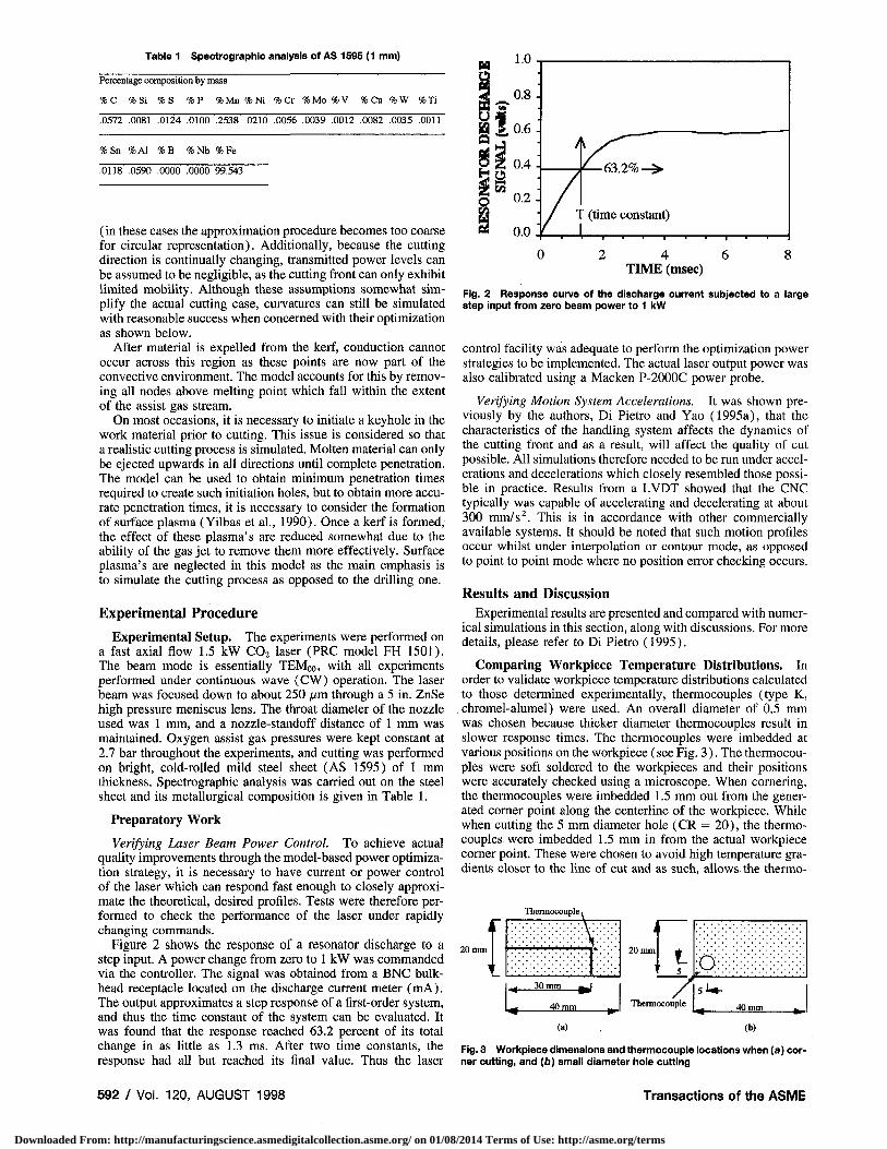
Table 1 Spectrographic analysis of AS 1595 (1 mm)
Percentage composition by mass
%C %Si %S %P %Mn %Ni % Cr %Mo %V % Cu %W %Ti
.0572 .0081 .0124 .0100 .2538 .0210 .0056 .0039 .0012 .0082 .0035 .0011
%Sn %A1 %B ;Nb %Fe
.0118 .0590 .0000 .0000 99.543
(in these cases the approximation procedure becomes too coarse for circular representation). Additionally, because the cutting direction is continually changing, transmitted power levels can be assumed to be negligible, as the cutting front can only exhibit limited mobility. Although these assumptions somewhat simplify the actual cutting case, curvatures can still be simulated with reasonable success when concerned with their optimization as shown below.
After material is expelled from the kerf, conduction cannot occur across this region as these points are now part of the convective environment. The model accounts for this by removing all nodes above melting point which fall within the extent of the assist gas stream.
On most occasions, it is necessary to initiate a keyhole in the work material prior to cutting. This issue is considered so that a realistic cutting process is simulated. Molten material can only be ejected upwards in all directions until complete penetration. The model can be used to obtain minimum penetration times required to create such initiation holes, but to obtain more accurate penetration times, it is necessary to consider the formation of surface plasma (Yilbas et a l , 1990). Once a kerf is formed, the effect of these plasma's are reduced somewhat due to the ability of the gas jet to remove them more effectively. Surface plasma's are neglected in this model as the main emphasis is to simulate the cutting process as opposed to the drilling one.
Experimental Procedure Experimental Setup. The experiments were performed on
a fast axial flow 1.5 kW C0 2 laser (PRC model FH 1501). The beam mode is essentially TEMoo, with all experiments performed under continuous wave (CW) operation. The laser beam was focused down to about 250 /xm through a 5 in. ZnSe high pressure meniscus lens. The throat diameter of the nozzle used was 1 mm, and a nozzle-standoff distance of 1 mm was maintained. Oxygen assist gas pressures were kept constant at 2.7 bar throughout the experiments, and cutting was performed on bright, cold-rolled mild steel sheet (AS 1595) of 1 mm thickness. Spectrographic analysis was carried out on the steel sheet and its metallurgical composition is given in Table 1.
Preparatory Work
Verifying Laser Beam Power Control. To achieve actual quality improvements through the model-based power optimization strategy, it is necessary to have current or power control of the laser which can respond fast enough to closely approximate the theoretical, desired profiles. Tests were therefore performed to check the performance of the laser under rapidly changing commands.
Figure 2 shows the response of a resonator discharge to a step input. A power change from zero to 1 kW was commanded via the controller. The signal was obtained from a BNC bulkhead receptacle located on the discharge current meter (mA). The output approximates a step response of a first-order system, and thus the time constant of the system can be evaluated. It was found that the response reached 63.2 percent of its total change in as little as 1.3 ms. After two time constants, the response had all but reached its final value. Thus the laser
H 1.0
4 0.8 *M w
0.6
it 04
o o 0.2 CO
3 0.0
0 2 4 6 8 TIME (msec)
Fig. 2 Response curve of the discharge current subjected to a large step Input from zero beam power to 1 kW
control facility was adequate to perform the optimization power strategies to be implemented. The actual laser output power was also calibrated using a Macken P-2000C power probe.
Verifying Motion System Accelerations. It was shown previously by the authors, Di Pietro and Yao (1995a), that the characteristics of the handling system affects the dynamics of the cutting front and as a result, will affect the quality of cut possible. All simulations therefore needed to be run under accelerations and decelerations which closely resembled those possible in practice. Results from a LVDT showed that the CNC typically was capable of accelerating and decelerating at about 300 mm/s2. This is in accordance with other commercially available systems. It should be noted that such motion profiles occur whilst under interpolation or contour mode, as opposed to point to point mode where no position error checking occurs.
Results and Discussion
Experimental results are presented and compared with numerical simulations in this section, along with discussions. For more details, please refer to Di Pietro (1995).
Comparing Workpiece Temperature Distributions. In order to validate workpiece temperature distributions calculated to those determined experimentally, thermocouples (type K, chromel-alumel) were used. An overall diameter of 0.5 mm was chosen because thicker diameter thermocouples result in slower response times. The thermocouples were imbedded at various positions on the workpiece (see Fig. 3). The thermocouples were soft soldered to the workpieces and their positions were accurately checked using a microscope. When cornering, the thermocouples were imbedded 1.5 mm out from the generated corner point along the centerline of the workpiece. While when cutting the 5 mm diameter hole (CR = 20), the thermocouples were imbedded 1.5 mm in from the actual workpiece corner point. These were chosen to avoid high temperature gradients closer to the line of cut and as such, allows the thermo-
20 mm
Thermocouple
£ 20 mm
40 mm
5
~7 O:
Thermocouple 40 mm
(a) (b)
Fig. 3 Workpiece dimensions and thermocouple locations when (a) corner cutting, and (b) small diameter hole cutting
592 / Vol. 120, AUGUST 1998 Transactions of the ASME
Downloaded From: http://manufacturingscience.asmedigitalcollection.asme.org/ on 01/08/2014 Terms of Use: http://asme.org/terms

1000
800
600
400
200 800 W, 10 mm/s 800 W, 20 mm/s 800 W, 30 mm/s
427. I K 600 K 700 K
0.84 2.51 4.18 0.44 1.33 2.21 0.32 0.95 1.58
(a) TIME (s) (b) TIME (s) (c) TIME (s)
Fig. 4 Typical cornering temperature measurements (obtained by thermocouples) as compared to simulation results
couples to respond adequately. In addition, validation becomes difficult at very close positions to the line of cut because small shifts in thermocouple locations results in large variations. This is due to the large temperature gradients experienced around the interaction zone. The thermocouple positions were accurately checked using a microscope and data collection was triggered via an electrical relay in the controller which actuates the beam shutter mechanism. The thermocouples were calibrated using an accurate industrial oven (NABER kiln with a microprocessor based temperature program controller—Model PS—962C). A reasonably linear relationship was observed between temperature and signal output, but actual data was used for signal analysis instead of a curve-fitting algorithm.
Figure 4 shows typical results obtained from model execution as compared to experimentally determined thermocouple values for laser corner cutting. Various cutting conditions are examined. It is clear from the plots that severe transience is common. Such high temperature yields about the corner point result in tip melt-off which degrades the overall quality of the finished product. Thermocouple detachment from the workpiece did occur because of the significant bulk heating experienced at this location. This explains why the temperature plots are incomplete for the very final stage of cutting. Nevertheless, numerical temperature histories are favorably compared. Note that in the laser hole cutting cases, the effect of the exothermic reaction when blast drilling the initiation hole is clearly visible at the thermocouple location (see Fig. 5) . This is shown by the temperature rises and then leveling-off back down to their expected values early on in the generated cut (approximately 0.2 s). In all cases for both cornering and hole cutting, temperatures continually rise because of the large heat accumulation present in the work-pieces.
200
0.69 1.39 2.C
(a) TIME (s)
0.36 0.73 1.09
(b) TIME (s)
0.25 0.51 0.76
(c) TIME (s)
Fig. 5 Typical hole cutting temperature measurements (obtained by thermocouples) as compared to simulation results
(a) - 1 0 |
600 K > 2 0 0 0 K 367.5 K
300 K
(b)
20
- 10
J - 0
10 20
(mm)
30 40
Fig. 6 Progressive numerical temperature contour plots at (a) 3.075 : and (6) 4.125 s (laser power: 800 W, cutting speed: 10 mm/s)
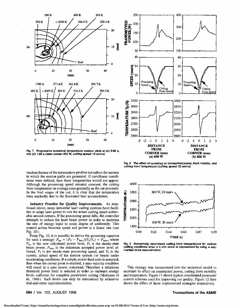
Figure 6 shows typical progressive temperature contours determined from the numerical model when cornering. It is clear that heat diffusion in the workpiece is frustrated by the directional change of the kerf and results in a more complex isothermal description. Because of the higher temperatures experienced in the vicinity of the corner point when generating male corners, they are much more susceptible to tip melt-off when compared to their female counterparts. This feature is generally true under all laser corner cutting conditions.
Figure 7 similarly shows typical numerically determined temperature distribution histories for small curvature hole cutting. In the final stages of cutting, it is evident that bulk heating is severe due to heat diffusion being frustrated in the circle's core by the inner kerf wall of the cut.
Transient Effects. Figure 8 shows typical simulation results when a corner is part-programmed. It is clear that the transmitted power increases to the corners because of the deceleration of one axis to zero. After the corners, greater beam coupling results because of the acceleration of the other axis to reach the target speed of 30 mm/s. Also note the dynamics of the cutting front, where there is an apparent speed lag behind the processing velocity. The net effect of these two contributions are shown by the complex temperature profiles generated. The contour change involved in processing such routines (viz., the positional relationship of existing boundaries to the kerf' s altered directional path), impacts on the transmitted power, front velocity and temperature in that they do not stabilize to their pre-corner, steady-state values but to other levels.
Figure 9 shows typical simulation results when the 5 mm hole is approximated. The unusual peaks and valleys are not a
Journal of Manufacturing Science and Engineering AUGUST 1998, Vol. 120 / 593
Downloaded From: http://manufacturingscience.asmedigitalcollection.asme.org/ on 01/08/2014 Terms of Use: http://asme.org/terms
950 K 400K 295 K 250- 4 0 0 !
550 K
(a)
900
(b)
20 (mm)
Fig. 7 Progressive numerical temperature contour plots at (a) 0.85 s, and (b) 1.85 s (laser power: 800 W, cutting speed: 10 mm/s)
random feature of the temperature profiles but reflect the manner in which the motion paths are generated. If curvilinear coordinates were defined, then these irregularities would not appear. Although the processing speed remains constant, the cutting front temperature on average rises gradually as the cut proceeds. In the final stages of the cut, it is clear that the temperature rises markedly due to the frustrated heat accumulation.
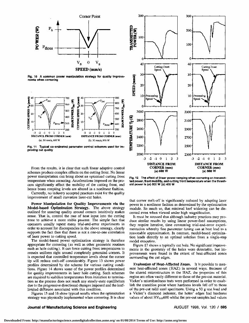
Industry Practice for Quality Improvements. As mentioned above, many industrial laser cutting systems have facilities to adapt laser power to suit the actual cutting speed achievable around corners. If the processing speed falls, the controller attempts to reduce the laser beam power in order to maintain the rate of energy input to some degree of uniformity. This control action between speed and power is a linear one (see Fig. 10).
From Fig. 10, it is possible to derive the governing equation for such a strategy: Pmc = (Ps - Ptbres)(Vb/Vs) + PthKs> where Pinc is the new calculated power level, Ps is the steady-state beam power, Plhres is the minimum accepted power level allowed, Vs is the steady-state processing speed, and Vb is the current, actual speed of the motion system (or beam) under accelerating conditions. If a simple power-feed ratio is assumed, then when the corner point is reached, a zero velocity condition will result in a zero power command. Therefore a minimum threshold power limit is selected in order to maintain energy levels sufficient for complete penetration cutting (Moriyasu et al., 1986). Such levels can only be determined by extensive trial-and-error experimentation.
2 - 1 0 1 2 3 DISTANCE
FROM CORNER (mm)
(a) 600 W
- 2 - 1 0 1 2 3 DISTANCE
FROM CORNER (mm)
(b) 800 W
Fig. 8 The effect of cornering on transmitted power, front mobility, and cutting front temperature (cutting speed: 30 mm/s)
4000
1500 600 W, 20 mm/s
0.00 0.22 0.44 0.65
TIME (s)
— i —
0.87 1.09
Fig. 9 Numerically determined cutting front temperatures for various cutting conditions when a 5 mm circle is represented by using a segmented circle approximation
This strategy was incorporated into the numerical model to ascertain its affect on transmitted power, cutting front mobility and temperature. Figure 11 shows typical coordinated parameter control schemes used for improving cut quality. Figure 12 then shows the effect of these implemented strategies respectively.
594 / Vol. 120, AUGUST 1998 Transactions of the ASME
Downloaded From: http://manufacturingscience.asmedigitalcollection.asme.org/ on 01/08/2014 Terms of Use: http://asme.org/terms
Corner Point
E
ft *thres IW~ Vs 0 Vs
SPEED (mm/s)
Fig. 10 A common power manipulation strategy for quality Improvements when cornering
700 S-40
1 j j-30
500 g s 5 gj 20 400 g s 300 3 1 10
200 " 0 - 3 - 2 - 1 0 1 2 3
DISTANCE FROM CORNER (mm) (a). 30 mm/s. 600 W
- 3 - 2 - 1 0 1 2 3 DISTANCE FROM CORNER (mm)
(b). 30 mm/s, 800 W
Fig. 11 Typical co-ordinated parameter control schemes used for improving cut quality
From the results, it is clear that such linear adaptive control schemes produce complex effects on the cutting front. No linear power manipulation can bring about an optimized cutting front temperature when cornering. Accelerations imposed on the process significantly affect the mobility of the cutting front, and hence beam coupling levels are altered in a nonlinear fashion.
Currently, no industry accepted practices exist for the quality improvement of small curvature laser-cut holes.
Power Manipulation for Quality Improvements via the Model-based Optimization Strategy. The above strategy outlined for assuring quality around corners intuitively makes sense. That is, control the rate of heat input into the cutting zone to achieve a more stable process. The simple fact that operators usually repeat many trial-and-error experiments in order to account for discrepancies in the above strategy, clearly supports the fact then that there is not a one-to-one correlation of laser power to cutting speed.
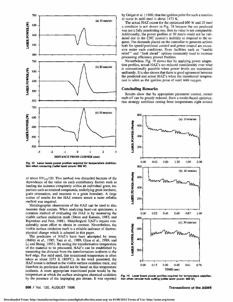
The model-based power optimization strategy is therefore appropriate for cornering (as well as other geometric routines such as hole cutting). It can force cutting front temperatures to remain uniform right around completely generated corners. It is expected that controlled temperature levels about the corner tip will reduce melt-off considerably. Figure 13 shows power profiles determined by the scheme for various cutting conditions. Figure 14 shows some of the power profiles determined for quality improvements in laser hole cutting. Such schemes are required to stabilize temperatures from initiation to termination as the process does not reach any steady-state equilibrium due to the progressive directional changes imposed and the kerf-limited diffusion associated with this condition.
Figures 15 and 16 show typical results when the optimization strategy was physically implemented when cornering. It is clear
2000 2300 •*
- 3 - 2 - 1 0 1 2 3 DISTANCE FROM
CORNER (mm) (a) 600 W
- 3 - 2 - 1 0 1 2 3 DISTANCE FROM
CORNER (mm) (a) 800 W
Fig. ted old
12 The effect of linear power ramping when cornering on transmit-power, front mobility, and cutting front temperature when the thresh-power is (a) 300 W (b) 400 W
that corner melt-off is significantly reduced by adapting laser power in a nonlinear fashion as determined by the optimization module. So much so, that minimal kerf widening can be discerned even when viewed under high magnification.
It must be stressed that although industry practices may produce similar results by using linear power-feed assumptions, they require iterative, time consuming trial-and-error experimentation whereby fine parameter tuning can at best lead to a reasonable approximation. In contrast, model-based optimization leads directly to an optimal solution from a single-step model execution.
Figure 17 shows a typically cut hole. No significant improvements in the geometry of the holes were detectable, but improvements were found in the extent of heat-affected zones surrounding the cut edges.
Evaluation of Heat-Affected Zones. It is possible to measure heat-affected zones (HAZ) in several ways. Because of the altered microstructure in the HAZ, the properties of this region are often vastly different to those of the pre-cut material. Vicker's microhardness tests were performed in order to establish the transition point where hardness levels fell off to those of the pre-cut mild steel specimens. Using a 50 g test load and a Vicker's diamond indentor, the holes' edges had hardness values of about HV0.056OO whilst the pre-cut samples had values
Journal of Manufacturing Science and Engineering AUGUST 1998, Vol. 120 / 595
Downloaded From: http://manufacturingscience.asmedigitalcollection.asme.org/ on 01/08/2014 Terms of Use: http://asme.org/terms
- 3 - 2 - 1 0 1 2 3 DISTANCE FROM CORNER (mm)
Fig. 13 Laser beam power profiles required for temperature stabilization when cornering (initial laser power: 600 W)
of about HV0.05I2O. This method was discarded because of the dependence of the value on such contributory factors such as landing the indentor completely within an individual grain, impurities such as retained compounds, underlying grain hardness, grain orientation, and nearness to a grain boundary. A large scatter of results for the HAZ extents meant a more reliable method was required.
Metallographic observation of the HAZ can be used to also measure their extents. When analyzing laser-cut specimens, a common method of evaluating the HAZ is by measuring the visible surface oxidation mark (Steen and Kamalu, 1983; and Rajendran and Pate, 1988). Metallurgical HAZ's require considerably more effort to obtain in contrast. Nevertheless, the visible surface oxidation mark is a reliable indicator of thermo-physical change which is adopted in this paper.
The prediction of HAZ's have been attempted by many (Bibby et al., 1985; Tarn et al., 1989; Glass et al., 1989; and Li and Sheng, 1995). By noting the transformation temperature of the material to be processed, HAZ's can be established by measuring the distance from the transformation isotherm to the kerf edge. For mild steel, this transitional temperature is often taken as about 1073 K (800°C). In the work presented, the HAZ extent is defined as the visible surface oxidation mark, and therefore its prediction should not be based on this temperature isotherm. A more appropriate transitional point would be the temperature at which the surface undergoes chemical oxidation by the presence of the impinging gas stream. It was reported
by Geiger et al. (1988) that the ignition point for such a reaction to occur in mild steel is about 1473 K.
The actual HAZ extent for the optimized 600 W and 20 mm/ s condition is not shown in Fig. 18 because the cut produced was not a fully penetrating one, thus its value is not comparable. Additionally, the power profiles at 30 mm/s could not be validated due to the CNC system's inability to respond to the request. The demands placed on the controller to generate actions both for speed/positional control and power control are excessive under such conditions. Even facilities such as "enable relief" and "look ahead" options commonly used to increase processing efficiency proved fruitless.
Nevertheless, Fig. 18 shows that by applying power adaptation profiles, actual HAZ's are reduced considerably over what is conventionally possible when power levels are maintained uniformly. It is also shown that there is good agreement between the predicted and actual HAZ's when the transitional temperature is taken as the ignition point of steel with oxygen.
Concluding Remarks Results show that by appropriate parameter control, corner
melt-off can be greatly reduced. Such a model-based optimization strategy stabilizes cutting front temperatures right around
800
0.00 0.42 0.83 1.25 1.66 2.08 800,
1.09
(c). 30 mm/sec
600-rtA^A^VVVwv/T/\AA^A^1.
400. f* KVWNA/- y^ .
200-
0- • 1 • 1 • 1 • r~—'
0.00 0.15 030 0.45 TIME (sec)
0.61 0.76
Fig. 14 Laser beam power profiles required for temperature stabilization when circular hole cutting (initial laser power: 800 W)
596 / Vol. 120, AUGUST 1998 Transactions of the ASME
Downloaded From: http://manufacturingscience.asmedigitalcollection.asme.org/ on 01/08/2014 Terms of Use: http://asme.org/terms

250|im
H
(a). Laser cutting without power optimization (a). Laser cutting without power optimization
250um
H 250|*m
H
(b). Laser cutting with power optimization
Fig. 15 SEM micrographs comparing obtainable quality with and without laser power adaption (laser power: 600 W, cutting speed: 20 mm/s)
(b). Laser cutting with power optimization
Fig. 16 SEM micrographs comparing obtainable quality with and without laser power adaption (laser power: 800 W, cutting speed: 30 mm/s)
corners, where ordinarily tip temperatures rise markedly due to the accelerations imposed on the process. Visual examination of the laser cuts show that kerf widening is almost completely eliminated. This strongly suggests that the energy balance at the interaction zone is kept at an equilibrium. Quality improvements are also possible when cutting small diameter holes through the reduction in HAZ extents. The lack of an adequate heat sink means that excessive over-heating is common and can lead to extensive HAZ's if power adaptation is not considered. These optimization profiles are required from initiation to termination as cutting directions continually change, meaning that cutting front temperatures never have the opportunity to stabilize to steady-state levels. Apart from significant quality improvements possible through this strategy, model-based optimization eliminates current industry practice trial-and-error experimentation, leads directly to an optimal solution, and can effectively predict heat-affected zones.
The implementation of the model-based optimization scheme in industry is readily feasible. As seen, the optimization is done off-line so that it does not impose stringent requirements on realtime computational power. As described in section Preparatory Work and seen from Fig. 2, the industrial laser system used in our experiments has a time constant slightly over 1 ms for a
step input of laser power command. This is adequately fast for most applications. It should be pointed out that this time constant was obtained when the laser system operated under closed-
Fig. 17 SEM micrograph of a typically cut hole (laser power: 800 W, cutting speed: 10 mm/s)
Journal of Manufacturing Science and Engineering AUGUST 1998, Vol. 120 / 597
Downloaded From: http://manufacturingscience.asmedigitalcollection.asme.org/ on 01/08/2014 Terms of Use: http://asme.org/terms

A ACTUAL A PREDICTED
IT 20 mm/s (power adaption)
20 mm/s (normal)
10 mm/s (power adaption)
10 mm/s (normal)
Fig. 18 Comparisons of actual heat-affected zones with and without power adaption and numerically determined values
loop control. When the system operated under open-loop control, a much shorter time constant was recorded.
References Bibby, M. J„ et al., 1985, "A Model for Predicting the Fusion and Heat-affected
Zone Sizes of deep Penetration Welds," Canadian Metallurgical Quarterly, Vol. 24, No. 1, pp. 101-105.
Biermann, S., and Geiger, M., 1991, "Integration of Diagnostics in High Power Laser Systems for Optimization of Laser Material Processing," Modeling and Simulation of Laser Systems II, SPIE Vol. 1415, pp. 330-341.
Borgstrom, R. N., 1988, "Tool Center Point Speed of Industrial Robots and Cutting Machines for Adaptive Control of Laser Power,'' Laser Materials Processing, Proc. of ICALEO, California, pp. 130-139.
Delle Piane, A., 1985, "A Laser Robot for Cutting and Trimming Deeply Stamped Metal Sheets," Proc. of 2nd Int. Conf. on Lasers in Manufacturing, Birmingham, UK, pp. 219-224.
Di Pietro, P., 1995, "Characterising, predicting and Optimising Laser Cutting Quality," Ph.D. dissertation, University of New South Wales, Australia.
Di Pietro et al., 1995b, "Model-Based Quality Optimization for Laser Cutting Under Transient Conditions," Proc. of ASME IMECE (WAM), MED-Vol. 2-1, San Francisco, pp. 12-17 Nov., 29-53.
Di Pietro, P., and Yao, Y. L., 1995a, "A Numerical Investigation into Cutting Front Mobility in C0 2 Laser Cutting," Int. J. Mack Tools Manufact., Vol. 35, No. 5, pp. 673-688.
Di Pietro, P., and Yao, Y. L., 1995c, "A New Technique to Characterize and Predict Laser Cut Striations," Int. J. Mach. Tools Manufact., Vol. 35, No. 7, pp. 903-1002.
Geiger, M., et al., 1988, "Laser Cutting of Steel Sheets," Laser Assisted Processing, SPIE Vol: 1022, pp. 20-33.
Glass, J. M., et al., 1989, "Heat Transfer in Metallic Glasses During Laser Cutting," Heat Transfer in Manufacturing and Materials Processing, Trans. ASME, HTD-113, pp. 31-38.
Hertzel, G. T., 1987, "Precision C0 2 Laser Cutting of Small Parts," Lasers in Motion for Industrial Applications, SPIE Vol. 744, California, pp. 96-100.
Leece, J., 1984, "An Analysis of Machine Tool Systems Suitable for Laser Profiling," Laser Welding, Cutting and Surface Treatment, The Welding Institute, Cambridge, UK, pp. 13-17.
Li, K., and Sheng, P., 1995, "Computational Model for Laser Cutting of Thin Steel Plates," Proc. of ASME IMECE (WAM) Symp. on Material Removal and Surface Modification issues in Machining Processes, Vol. MED 2-1, San Francisco, 12-17 Nov., 3-14.
Moriyasu, M., et al., 1986, "Adaptive Control for High-Speed and High-Quality Laser Cutting," Proc. of ICALEO, pp. 129-136.
Powell, J., et al., 1992, "The Role of Oxygen Purity in Laser Cutting of Mild Steel," Proc, ICALEO, FL, pp. 1-10.
Rajendran, N., and Pate, M. B„ 1988, "Real-Time Laser Materials Processing Control: A Feasibility Study," Laser Materials Processing, Proc. of ICALEO, CA, pp. 119-129.
Schuocker, D„ 1988, "Heat Conduction and Mass Transfer in Laser Cutting," Laser Technologies in Industry, SPIE Vol. 952, pp. 592-599.
Schuocker, D., and Steen, W„ 1986, "Advanced Concepts in Laser Material Processing in Europe," Manufacturing Applications of Lasers, SPIE Vol. 621, pp. 17-22.
Schwarzenbach, A. P., and Hunziker, U. W„ 1988, "Recent Progress in Laser-cutting," Laser Materials Processing, Proc. of ICALEO, CA, pp. 303-312.
Sheng, P., and Cai, L., 1994, "Model-Based Path Planning for Laser Cutting of Curved Trajectories," Int. J. Machine Tools and Manufacture, draft copy.
Steen, W. M., and Kamalu, J. N., 1983, Laser Materials Processing, M. Bass, ed., North-Holland Publishing Co., The Netherlands, pp. 15-111.
Steen, W. M., and Li, L., 1988, "Some Viewpoints on Laser Automation and Processing Quality Control," Laser Technologies in Industry, SPIE Vol. 952, pp. 544-551.
Tam, S. C , et al., 1989, "Computer Simulation of Temperature Fields in Mechanized Plasma-arc Welding," /. Mech. Working Tech., Vol. 19, pp. 23-33.
VanderWert, T. L., 1985, "Systems Considerations for Multiaxis C0 2 Laser Material Processing," Laser Welding, Machining and Materials Processing, Proc. of ICALEO, San Francisco, pp. 101-106.
White, F. M., 1988, Heat and Mass Transfer, Addison-Wesley, Reading, MA, pp. 332-336.
Yilbas, B. S„ et al., 1990, "Study Into the Measurement and Prediction of Penetration Time During C0 2 Laser Cutting Process," /. Engng Manufact., Part B, Vol. 204, pp. 105-113.
A P P E N D I X A brief summary of the mathematical formulation is given
below (Di Pietro and Yao, 1995a for more details). In order to focus on the development of optimization, constant thermo-physical properties and two-dimensional transient heat conduction are simply assumed, while boundary conditions which allow convection and radiation to occur to the surroundings are considered. This results the following equation:
K_ d2T d2T
Ox2 + By2 ^-(hf+hn + 2hr) + -^-^~(M) pc„oz pcv at
where K is thermal conductivity, p density, cv heat capacity, h„ natural or free convective heat transfer coefficient, hr radiative heat transfer coefficient, and q heat generation. The forced convective heat transfer coefficient is
hf = Nu„ Kid (A2)
where d is duct diameter and the Nusselt number determined using Dittus-Boelter formula (White, 1988) as
Nil, = 0.027 Re?8 P r °» ( M m / M J° (A3)
where Re is Reynolds number and Pr Prandtl number, fim and \xw mixed-mean and wall coefficients of viscosity. Although the free convection contribution hn is relatively small, it too is included for the sake of completeness,
In Eq. (A l ) , the radiative heat transfer coefficient hr is given as
hr = eab(Tb + r . ) ( 7 l + Tl) (A4)
where e is emissivity, ab Stefan-Boltzmann constant, Tb boundary temperature, and T„ ambient temperature. Because of the higher-order relationship in Eq. (A4), radiation becomes dominant at high temperatures, as in the case of laser cutting, and radiation is considered both on the upper and lower surfaces. Heat transfer to the substrate is neglected. The material removal process is in fact a rather complex interaction of the gas jet on the free surface of the melt, where shear stresses act on the cutting front and a boundary layer exists. It is assumed in our model that any area in the molten state is expelled out of the kerf immediately, by the force of the gas jet.
The C0 2 laser source is assumed to be of Gaussian TEMQO mode. Its radial intensity distribution can then be given as I(r) = 1(0) exp(-4r2ld2), where 1(0) is the peak intensity, r is the radial distance from the beam center, and d equals 2V2<r, where ar is the standard deviation of the Guassian distribution of the laser beam intensity. Since we consider depolarized or circularly polarized laser beams as is the case with coordinated
598 / Vol. 120, AUGUST 1998 Transactions of the ASME
Downloaded From: http://manufacturingscience.asmedigitalcollection.asme.org/ on 01/08/2014 Terms of Use: http://asme.org/terms

motion laser cutting systems, The radial absorbed beam power is given as:
P » ( r ) = A i / ( r ) = ( l - r / ) / ( r ) (A5)
where Ab is absorptivity and rf is reflectivity. The energy produced by the exothermic reaction is generally of the same order of magnitude as the absorbed laser beam power (Powell et a l , 1992). Assuming a pure oxygen supply for the assist gas, the following reaction occurs within the cutting kerf: Fe + 0.5O2
= FeO and AH = -257.58 kJ/mol, where AH is the energy released during the reaction and the ignition point is about 1470 K (Geiger et al., 1988).
If the mass removal rate of the melt out of the kerf is known or can be calculated, then the following relationship can be used to determine the energy obtained by reaction.
\ amu J
where m is melt removal rate, amu = 1 mole FeO = 71.847 g/mol and ratio is the percentage of FeO:Fe ejected from the kerf. Because the material within the kerf is melted and then expelled out, it is necessary to consider latent heat effects.
fmel, = mLf (A7)
where latent heat of fusion Lf — 275 kJ/kg. It has been assumed
previously that the material removal rate can be given approximately by the following equation (Schuocker, 1988):
m = pbDVb (A8)
where b is kerf width, D workpiece thickness and Vb velocity of laser beam. This is only true though when it is assumed that the processing speed equals the front speed as in steady state cutting. In reality though, the front speed Vf is the factor affecting the mass removal rate and not the cutting speed. The mass removal rate is therefore more appropriately given as:
m = pbDVf (A9)
where Vf, whose numerical calculation has been presented by Di Pietro and Yao (1995a), physically represents the solid-liquid interface speed, as all the molten material is assumed to be ejected out of the bottom of the kerf immediately. If the beam speed is too high, then melting and evaporation will cease. In this case, no melt ejection is possible and Eqs. (A8) and (A9) are inappropriate. This condition is continually checked throughout program execution and simulation ceases if it is violated. Because kerf width fluctuations are generally small for high quality cutting, it is assumed that they are negligible and that the width is approximately of the same extent as that of the laser spot diameter. Such fluctuations have been considered elsewhere (Di Pietro and Yao, 1995c).
Journal of Manufacturing Science and Engineering AUGUST 1998, Vol. 120 / 599
Downloaded From: http://manufacturingscience.asmedigitalcollection.asme.org/ on 01/08/2014 Terms of Use: http://asme.org/terms