important that you familiarize yourself with all - nissan · important that you familiarize...
TRANSCRIPT
Welcome to the growing family of new NISSANowners. This vehicle is delivered to you withconfidence. It was produced using the latesttechniques and strict quality control.
This manual was prepared to help you under-stand the operation and maintenance of yourvehicle so that you may enjoy many miles(kilometers) of driving pleasure. Please readthrough this manual before operating yourvehicle.
A separate Warranty Information Bookletcontains the warranties covering yourvehicle (whose terms have control overthis Owner’s Manual or any other docu-ment or representation regarding warrantycoverage). The “NISSAN GT-R Service andMaintenance Guide” explains detailsabout maintaining and servicing your ve-hicle.
Additionally, a separate Customer Care/Lemon Law Booklet (U.S. only) will explainhow to resolve any concerns you may havewith your vehicle, as well as clarify yourrights under your state’s lemon law.
In addition to factory installed options, yourvehicle may also be equipped with additionalaccessories installed by NISSAN or your GT-Rcertified NISSAN dealer prior to delivery. It is
important that you familiarize yourself with alldisclosures, warnings, cautions and instructionsconcerning proper use of such accessories priorto operating the vehicle and/or accessory. See aGT-R certified NISSAN dealer for details con-cerning the particular accessories with whichyour vehicle is equipped.
Your GT-R certified NISSAN dealer knowsyour vehicle best. When you require anyservice or have any questions, they will beglad to assist you with the extensiveresources available to them.
READ FIRST— THEN DRIVE SAFELY
Before driving your vehicle, please read thisOwner’s Manual carefully. This will ensurefamiliarity with controls and maintenance re-quirements, assisting you in the safe operationof your vehicle.
WARNING
IMPORTANT SAFETY INFORMATIONREMINDERS FOR SAFETY!
Follow these important driving rules tohelp ensure a safe and comfortable tripfor you and your passengers!
. NEVER drive under the influence of
alcohol or drugs.
. ALWAYS observe posted speed lim-its and never drive too fast forconditions.
. ALWAYS give your full attention todriving and avoid using vehiclefeatures or taking other actions thatcould distract you.
. ALWAYS use your seat belts andappropriate child restraint systems.Pre-teen children should be seatedin the rear seat.
. ALWAYS provide information aboutthe proper use of vehicle safetyfeatures to all occupants of thevehicle.
. ALWAYS review this Owner’s Man-ual for important safety information.
MODIFICATION OF YOUR VEHICLE
This vehicle should not be modified. Mod-ification could affect its performance,safety or durability, and may even violategovernmental regulations. See the 2015NISSAN GT-R Warranty Information Book-let for details including applicable exclu-sions.
FOREWORD
WHEN READING THE MANUAL
This manual includes information for allfeatures and equipment available on thismodel. Features and equipment in yourvehicle may vary depending on model, trimlevel, options selected, order, date ofproduction, region or availability. There-fore, you may find information aboutfeatures or equipment that are not in-cluded or installed on your vehicle.
All information, specifications and illustrations inthis manual are those in effect at the time ofprinting. NISSAN reserves the right to changespecifications, performance, design or compo-nent suppliers without notice and withoutobligation. From time to time, NISSAN mayupdate or revise this manual to provide ownerswith the most accurate information currentlyavailable. Please carefully read and retain withthis manual all revision updates sent to you byNISSAN to ensure you have access to accurateand up-to-date information regarding your ve-hicle. Current versions of vehicle Owner’sManuals and any updates can also be found inthe Owner section of the NISSAN website athttps://owners.nissanusa.com/nowners/naviga-tion/manualsGuide. If you have questions con-cerning any information in your Owner’s Manual,contact NISSAN Consumer Affairs. See the
NISSAN CUSTOMER CARE PROGRAM pagein this Owner’s Manual for contact information.
IMPORTANT INFORMATION ABOUTTHIS MANUAL
You will see various symbols in this manual. Theyare used in the following ways:
WARNING
This is used to indicate a hazard thatcould cause death or serious personalinjury. To avoid or reduce the risk,follow the information and instructionsexactly.
CAUTION
This is used to indicate a hazard thatcould cause minor or moderate perso-nal injury. To avoid or reduce the risk,follow the information and instructionscarefully.
NOTICE
This is used to indicate a hazard thatcould cause damage to property or yourvehicle. To avoid or reduce the risk,follow the information and instructions.
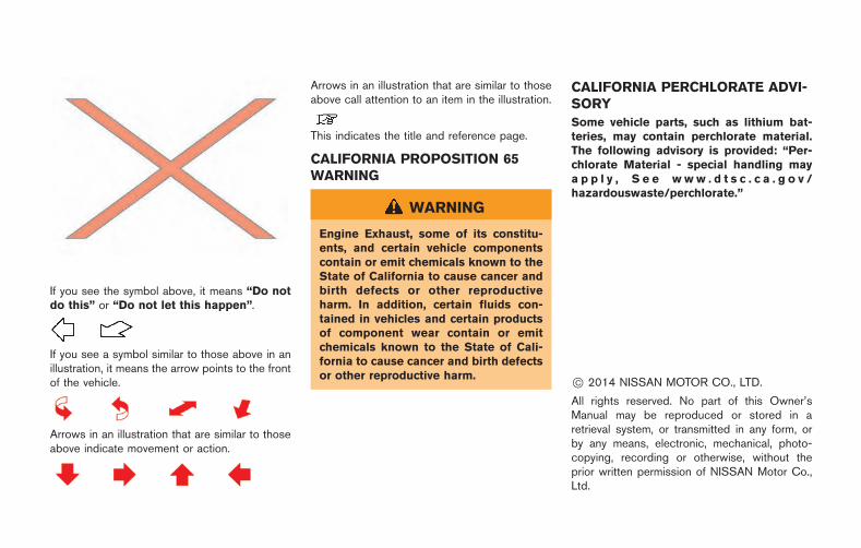
If you see the symbol above, it means “Do notdo this” or “Do not let this happen”.
If you see a symbol similar to those above in anillustration, it means the arrow points to the frontof the vehicle.
Arrows in an illustration that are similar to thoseabove indicate movement or action.
Arrows in an illustration that are similar to thoseabove call attention to an item in the illustration.
This indicates the title and reference page.
CALIFORNIA PROPOSITION 65WARNING
WARNING
Engine Exhaust, some of its constitu-ents, and certain vehicle componentscontain or emit chemicals known to theState of California to cause cancer andbirth defects or other reproductiveharm. In addition, certain fluids con-tained in vehicles and certain productsof component wear contain or emitchemicals known to the State of Cali-fornia to cause cancer and birth defectsor other reproductive harm.
CALIFORNIA PERCHLORATE ADVI-SORY
Some vehicle parts, such as lithium bat-teries, may contain perchlorate material.The following advisory is provided: “Per-chlorate Material - special handling maya p p l y , S e e w w w . d t s c . c a . g o v /hazardouswaste/perchlorate.”
*C 2014 NISSAN MOTOR CO., LTD.
All rights reserved. No part of this Owner’sManual may be reproduced or stored in aretrieval system, or transmitted in any form, orby any means, electronic, mechanical, photo-copying, recording or otherwise, without theprior written permission of NISSAN Motor Co.,Ltd.
NISSAN CUSTOMER CARE PROGRAM
NISSAN CARES ...
Both NISSAN and your GT-R certified NISSAN dealer are dedicated to serving all your automotive needs. Your satisfaction with your vehicle and yourGT-R certified NISSAN dealer are our primary concerns. Your GT-R certified NISSAN dealer is always available to assist you with all your automobile salesand service needs.
However, if there is something that your GT-Rcertified NISSAN dealer cannot assist you withor you would like to provide NISSAN directlywith comments or questions, please contact theNISSAN Consumer Affairs Department usingour toll-free number:
For U.S. customers1-866-668-1GTR(1-866-668-1487)
For Canadian customers1-800-387-0122
The Consumer Affairs Department will ask forthe following information:
. Your name, address, and telephone number
. Vehicle identification number (attached tothe top of the instrument panel on thedriver’s side)
. Date of purchase
. Current odometer reading
. Your NISSAN dealer’s name
. Your comments or questions
OR
You can write to NISSAN with the information onthe left at:
For U.S. customersNISSAN North America, Inc.Consumer Affairs DepartmentP.O. Box 685003Franklin, TN 37068-5003or via e-mail at:[email protected]
For Canadian customersNISSAN Canada Inc.5290 Orbitor DriveMississauga, Ontario L4W 4Z5or via e-mail at:[email protected]
If you prefer, visit us at:
www.nissanusa.com (for U.S. customers) orwww.nissan.ca (for Canadian customers)
We appreciate your interest in NISSAN andthank you for buying a quality NISSAN vehicle.

GT-R Overview GTR
Illustrated table of contents 0
Safety — Seats, seat belts and supplemental restraint system
Instruments and controls
Pre-driving checks and adjustments
Display screen, heater, air conditioner and audio systems
Starting and driving
In case of emergency
Appearance and care
Maintenance and do-it-yourself
Technical and consumer information
1
2
3
4
5
6
7
8
9
Table ofContents
Index 10

GT-R Overview
GT-R specific information ............................................... GTR-3Warranty information .................................................. GTR-3Maintenance information ........................................... GTR-3
GT-R special specification parts ................................... GTR-3Engine oil ....................................................................... GTR-3Transmission oil ........................................................... GTR-4Differential oil (front and rear) .................................. GTR-4Brake fluid ..................................................................... GTR-4
GT-R special precautions ............................................... GTR-5Tires and road wheels ............................................... GTR-5Brake pad and disc rotor .......................................... GTR-5Exhaust muffler and trunk carpet ............................ GTR-6Titanium muffler and trunk carpet(if so equipped) ........................................................... GTR-6Dry carbon fiber parts (if so equipped) ................ GTR-7Matte paint (if so equipped) .................................... GTR-8
GT-R performance optimization services .................... GTR-8Wheel alignment inspection and adjustment(if necessary) (including tirepressure adjustment) ................................................. GTR-8Transmission settings ................................................. GTR-9
Break-in schedule ............................................................. GTR-9Wheel alignment ....................................................... GTR-10
Precautions before driving ........................................... GTR-10Vehicle Dynamic Control (VDC) OFF mode .... GTR-10Summer tires ............................................................ GTR-11All-season tires ........................................................ GTR-11Avoiding body damage .......................................... GTR-11Fuel ............................................................................. GTR-12Body repair ............................................................... GTR-12Driving after replacing tires .................................. GTR-12
Additional maintenance items ..................................... GTR-12Precautions on performance driving .................. GTR-13Inspection and adjustments before driving ...... GTR-14Inspection and adjustments after driving .......... GTR-18
GT-R specific vehicle characteristics ........................ GTR-23Refueling precautions ............................................ GTR-23Gasoline smell ......................................................... GTR-23Outside temperature display indicateshigher temperature ................................................. GTR-23Idle speed is not steady ........................................ GTR-23Engine speed is restricted .................................... GTR-23Engine output ........................................................... GTR-23Uneven wear of tires .............................................. GTR-24Noises are heard while driving ............................ GTR-24Brake system information ...................................... GTR-26
Change of surface color of titanium muffler(if so equipped) ......................................................... GTR-26Sound heard around titanium muffler(if so equipped) ......................................................... GTR-27
Dry carbon fiber parts (if so equipped) ............ GTR-27Dual clutch transmission .............................................. GTR-27
Transmission operation characteristics ............. GTR-28

The GT-R is NISSAN’s first supercar categoryvehicle. The GT-R is equipped with specialsystems. These systems are different than thoseused on conventional vehicles to allow for thehigh performance driving characteristics of thisvehicle. Your vehicle should be maintained by aGT-R certified NISSAN dealer. Special skills,knowledge and equipment are necessary toproperly maintain your GT-R.
WARRANTY INFORMATION
Please read this Owner’s Manual carefully,together with your Warranty Information Bookletwhich describes a number of express limitations,exclusions and ways to void your warranty forfailing to follow the instructions contained in thisOwner’s Manual, including, but not limited to:
. Failure to use proper parts, fuel and fluids,
. Driving with the VDC off,
. Racing,
. Any competitive driving of any sort whatso-ever,
. Use on a track or driving on any airstrip,
. Modifications, including adding/replacing,reprogramming, attempting to reprogram,altering, disconnecting any computer, con-trol unit or electronic modules,
. Deleting any or all stored information in anycomputer, control unit or electronic moduleincluding VSDR,
. Failure to have required GT-R PerformanceOptimization Services performed.
In addition, see your tire warranty for specificlimitations or exclusions for operating summertires below 48F ( 208C).
MAINTENANCE INFORMATION
. Special skills, knowledge and equipment arenecessary to properly inspect and adjust theGT-R engine, transmission, suspension andbrakes to maintain performance. A GT-Rcertified NISSAN dealer has the GT-Rcertified technical staff and the specialequipment to properly maintain your GT-R.
. NISSAN recommends maintenance itemsthat require the replacement of parts, engineoil, oil filters and air filters should beperformed by a GT-R certified NISSANdealer. Make sure the specified fluids andparts are used when the maintenance isperformed. NISSAN also recommends thereplacement of parts such as brakes shouldbe performed by a GT-R certified NISSANdealer.
NOTICE
Only use the following specified fluidsand parts in the GT-R to avoid possiblevehicle damage.
ENGINE OIL
Mobil 1 (0W-40) (100% synthetic oil)
Mobil 1 (0W-40) (100% synthetic) is the factoryfill oil. The VR38 engine with its plasma-sprayedbores was developed using this oil. NISSANcannot ensure proper engine operation anddurability if other synthetic oil is used. If Mobil1 (0W-40) is not available, Mobil 1 (10W-40)(100% synthetic) may be used; however, someperformance loss may be noticed.
Furthermore, replacement of the engine oil withMOTUL NISMO COMPETITION OIL type2193E(5W40) is recommended for the frequenthigh performance driving opportunities.
NISSAN cannot ensure proper engine operationand durability if other synthetic oil is used.
The use of additives, chemical materials orabrasive compounds is prohibited.
The use of additives, chemical materials, abra-sive compounds or other high performance
GT-R Overview GTR-3
GT-R SPECIFIC INFORMATIONGT-R SPECIAL SPECIFICATIONPARTS
GTR-4 GT-R Overview
engine oils may cause internal engine damage.
Engine oil maintenance
. When the vehicle is delivered, the engine oillevel is 0.39 in (10 mm) below the H mark onthe engine oil dipstick for optimum highperformance driving. The engine oil can befilled up to the H mark if not engaging inperformance driving.
. Because of the high performance character-istics of the GT-R engine, more frequent oillevel inspections are necessary. Check theoil level every 1,800 miles (3,000 km) andadjust as necessary. Also, change theengine oil based on the driving conditions.For the information regarding oil replace-ment intervals, refer to the 2015 NISSANGT-R Service and Maintenance Guide.
. Some amount of oil is consumed by yourengine under normal operating conditions,and oil consumption by itself does notnecessarily indicate any malfunction. If yourrate of oil consumption increases suddenlyor without explanation, NISSAN recom-mends that you have your vehicle inspectedby a GT-R certified NISSAN dealer.
. For information about the oil replacementintervals for performance driving, refer to theinterval for replacing oil after high perfor-
mance driving. ( “Additional mainte-nance items” page GTR-12)
Make sure to replace the oil filter when theengine oil is changed.
TRANSMISSION OIL
Genuine NISSAN Transmission Oil R35Special (100% synthetic oil)
The GT-R uses a multiple-disc dual wet clutchtransmission. The specially developed transmis-sion oil maximizes the friction characteristics ofthe clutch and the lubrication of the gearbearings.
The use of additives is prohibited.
The use of additives or other transmission oilmay cause internal transmission or clutchdamage.
DIFFERENTIAL OIL (front and rear)
Differential Oil R35 COMPETITION type2189E
Use only the Differential Oil R35 COMPETITIONtype 2189E that can keep the oil temperaturelow in order to protect all parts of the differentialand maximize the performance of the LimitedSlip Differential (LSD).
The use of additives is prohibited.
Using additives or any other than the specified
differential oil may cause the oil temperature toincrease and the final drive to be damaged. Alsoit may cause vibration and adversely the vehiclehandling characteristics.
BRAKE FLUID
Genuine NISSAN Brake Fluid R35 SpecialII
Genuine NISSAN Brake Fluid R35 Special II isthe factory fill brake fluid. The Vehicle DynamicControl (VDC) unit and other related parts werespecially designed for this brake fluid. NISSANcannot ensure proper operation of the vehicle ifother brake fluid is used.
TIRES AND ROAD WHEELS
Tires
The GT-R uses specially designed run-flat tiresand matching road wheels. Use of thesespecially developed tires and wheels providesthe greatest potential for maximum performance.
. Using non-genuine GT-R tires may causepowertrain system damage if the vehicle isdriven in a flat tire situation, even if run-flattires are used. This may also prevent thevehicle from being stopped safely.
. Using non-genuine GT-R tires may alsocause tire failure due to excessive heatbuildup caused by tire distortion whiledriving.
. Using non-genuine GT-R tires may affect theoperation of the VDC system.
Tire replacement:
. When tire replacement is required, replacingtires as a set of four with new tires isrecommended. However, if a tire is punctu-red or damaged, it may be possible toreplace only the damaged tire. Determiningwhether one tire or a complete set of tiresshould be replaced is based on a number offactors including tire wear and condition.
Contact your GT-R certified NISSAN dealer.They can recommend if an individual tire or acomplete set should be replaced.
. The GT-R uses specially designed run-flattires which have a rigid side wall. Specialequipment and procedures are requiredwhen replacing these tires. NISSAN recom-mends that tire replacement be performed ata GT-R certified NISSAN dealer.
. Specific tire changing equipment must beused to remove the GT-R tires from thewheel and to install the GT-R tires onto thewheel. It is only possible to reuse the tireswhen they have no cracks and/or deforma-tions on the bead portion of the tire. If theincorrect equipment is used to remove theGT-R tires from the wheel and to install theGT-R tires onto the wheel, cracks anddeformation may occur on the bead portionof the tires meaning that the tires cannot bereused. Contact a GT-R certified NISSANdealer if the tires need to be removed fromthe wheels.
. When reusing tires, contact a GT-R certifiedNISSAN dealer.
Road wheels
Using non-genuine GT-R wheels may cause thefollowing:
. vehicle vibration
. the tire coming loose from the wheel duringa flat tire
. reduced wheel lug nut tightness
BRAKE PAD AND DISC ROTOR
This vehicle is equipped with cross-drilledfloating rotors and radial-mounted six-pistonmonoblock calipers. This helps to achieveexcellent stopping performance and fade-resis-tance.
Using non-genuine GT-R brake pads or rotorscan affect vehicle braking performance and theoperation of the ABS and VDC system.
Replacement of brake pads and discrotors
NISSAN generally recommends to replace allfour sets of brake pads and disc rotors at thesame time to maintain maximum brake perfor-mance.
However, replacing only the brake pads may beallowed in some cases (four wheels or only frontwheels depending on the conditions). A GT-R
GT-R Overview GTR-5
GT-R SPECIAL PRECAUTIONS
GTR-6 GT-R Overview
certified technician must inspect the vehicle anddetermine that only the brake pads need to bereplaced. In this case, replacing all brake padsand disc rotors as a set is not necessary.
Note that the replacement of brake pads and thedisc rotors as a set on all four wheels should beperformed when a GT-R certified techniciandetermines that this is the correct repair.
If the inside of the disc rotors are cold during thewinter and the surface becomes hot due to aheavy force being applied repeatedly to thebrakes, cracks may occur near the coolant holeon the surface of the disc rotor. Cracks may alsooccur due to a heavy force being repeatedlyapplied to the brakes during high performancedriving. In these cases it may be necessary toreplace the disc rotors or brake pads dependingon the condition of the crack. Contact a GT-Rcertified NISSAN dealer for replacement.
EXHAUST MUFFLER AND TRUNKCARPET
The GT-R exhaust system is designed to providethe maximum vehicle performance and toprotect the vehicle from high exhaust gastemperatures.
If non-genuine GT-R exhaust system parts areused it is possible that the muffler or otherexhaust system parts will deform and cause
damage to the underbody. Non-genuine GT-Rexhaust system parts can also affect vehicleperformance and possibly lead to turbocharger,engine or power train related parts includingtransmission, damage.
Also, do not remove the trunk carpet from thevehicle for any reason. The carpet insulates thevehicle interior from the heat of the muffler andfrom the noise of the transmission.
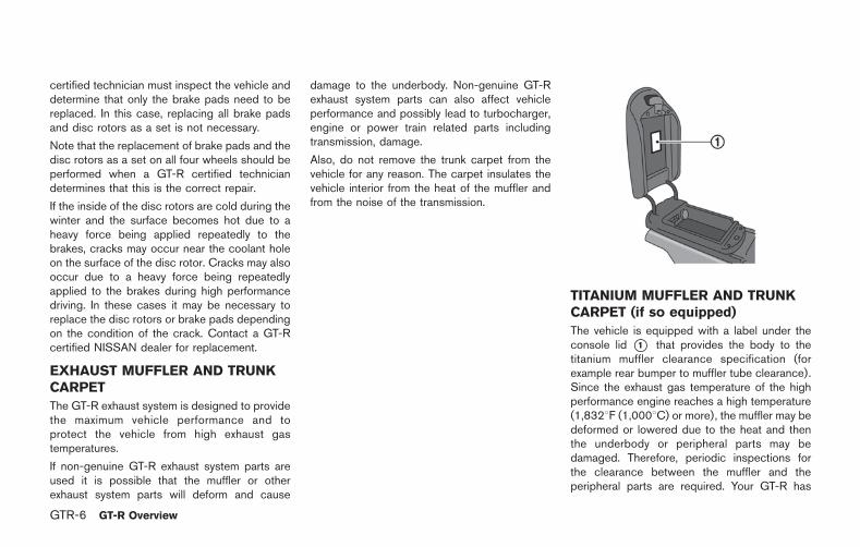
TITANIUM MUFFLER AND TRUNKCARPET (if so equipped)
The vehicle is equipped with a label under theconsole lid *1 that provides the body to thetitanium muffler clearance specification (forexample rear bumper to muffler tube clearance).Since the exhaust gas temperature of the highperformance engine reaches a high temperature(1,8328F (1,0008C) or more), the muffler may bedeformed or lowered due to the heat and thenthe underbody or peripheral parts may bedamaged. Therefore, periodic inspections forthe clearance between the muffler and theperipheral parts are required. Your GT-R has
been tested on a test circuit to ensure thesuspension components “settle” prior to ship-ping. Following this circuit test the odometerreading at the time of vehicle shipment is aslisted. Please note a small amount of additionalmileage may have been added in the subse-quent onward transportation. In addition yourGT-R has been inspected and tested by thefactory test personnel. The titanium mufflerspecifications are provided on a label underthe console lid should the muffler need to beadjusted. Please do not remove the label fromthe console lid. See a GT-R certified NISSANdealer for detailed information.
If a non-genuine titanium muffler is used, themuffler may become deformed and damage theunderbody due to the high performance enginereaching high exhaust gas temperatures(1,8328F (1,0008C) or more). The highest-classtitanium alloy is used for genuine parts to ensurethe resistance strength and creeping character-istics against high exhaust gas temperature. Inaddition, further cooling effects are secured byadopting additional cooling fins and by applyingpartial plate thickness reduction. Since genuinetitanium mufflers are made of titanium alloy, thesurface color will change depending on thedriving conditions, which is not unusual. Prior toshipping from factory, all vehicles receive
balance aligning for engine, transmission, andclutch, as well as quench driving of brake padsand rotors. As a result, the muffler surface colormay differ depending on the vehicle.
Never remove the trunk carpet from the vehiclefor any reason. The carpet insulates the vehicleinterior from the heat of the muffler and from thenoise of the transmission.
Never Allow Oil or Grease to Adhere to theTitanium Muffler.
If the muffler is heated when oil or grease adhereto the muffler surface, the color of this area willbe different from that of the surrounding area. Toremove the oil or grease, check that the surfacetemperature of the muffler has cooled, wash thearea with a neutral detergent, wipe it with abrake cleaner-sprayed clean shop cloth andgently tap it with a dry shop cloth to dry. Becareful not to allow the brake cleaner to splatteron rubber parts, bumper, etc.
DRY CARBON FIBER PARTS (if soequipped)
Because of the characteristics of the material,the dry carbon fiber parts may turn yellow due toexposure to ultraviolet rays. The surfaces of drycarbon fiber parts are coated with a specialultraviolet protection paint. To maintain theappearance of these parts, it is important totake proper care of them.
NOTICE
. Do not use compound agents onclear-coated dry carbon fiber parts(such as the NISMO model’s bum-per, side sill protector, rear spoiler,etc.).
. Do not use any chemical agents(wax, coating agent, compoundagent, etc.) on matte-painted drycarbon fiber parts (such as the reardiffuser, a rear spoiler that is ofspecifications other than NISMO,etc.).
. When dry carbon fiber parts becomedirty, prepare a dilute cleaning solu-tion by mixing one capful of milddetergent in a bucket of water, and
GT-R Overview GTR-7
GTR-8 GT-R Overview
use that mixture to clean the parts.
NOTE:
The surfaces of the dry carbon fiber partsare lightly coated like a race car so thatyou can feel the proper texture of realcarbon, which may feel rough. This isnormal.
MATTE PAINT (if so equipped)
If your vehicle is equipped with matte paint,special care is necessary to clean your vehicle tomaintain the appearance of the matte paint.( “Matte paint care” page 7-2)
In addition to the regular maintenance recom-mended by NISSAN, the GT-R requires thefollowing special inspections:
. Wheel alignment inspection and adjustment(if necessary) (including tire pressure ad-justment)
. Transmission settings
These inspections are required at the followingintervals:
. 1,000 miles
. 12 months
. 24 months
. 36 months
NOTE:
. These inspections will be performedfree of charge for labor at a GT-Rcertified NISSAN dealer only. Inspec-tions thereafter are recommendedevery 12 months or 12,000 miles(whichever comes first) at the custo-mer’s expense. See the 2015 NISSANGT-R Warranty Information Booklet fordetails.
. Repairs and adjustments involvingparts replacement, etc. determined tobe necessary as a result of these
inspections are performed at the cus-tomer’s expense.
. See the 2015 NISSAN GT-R WarrantyInformation Booklet for significant lim-itations, exclusions and possible void-ing of your warranty resulting fromfailure to have these necessary inspec-tions, repairs and/or adjustments per-formed.
. See the 2015 NISSAN GT-R Service andMaintenance Guide for a detailed ex-planation of the GT-R PerformanceOptimization Services.
WHEEL ALIGNMENT INSPECTIONAND ADJUSTMENT (if necessary)(including tire pressure adjustment)
This vehicle is equipped with a high perfor-mance suspension. The vehicle’s wheel align-ment needs to be measured and adjusted (ifnecessary) by a GT-R certified NISSAN dealeras necessary as the vehicle is driven and thesuspension parts break-in.
The wheel alignment can be adjusted by a GT-Rcertified NISSAN dealer in accordance withspecifications for city driving to high perfor-mance driving.
The tires on the GT-R may have different wear
GT-R PERFORMANCEOPTIMIZATION SERVICES
rates and wear patterns in comparison toconventional passenger vehicles. Contact aGT-R certified NISSAN dealer to confirm thatthe alignment is within specifications.
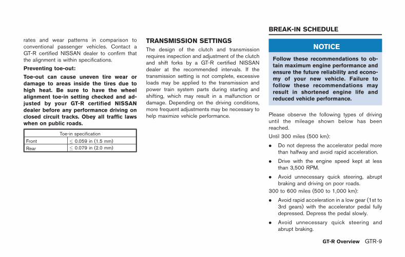
Preventing toe-out:
Toe-out can cause uneven tire wear ordamage to areas inside the tires due tohigh heat. Be sure to have the wheelalignment toe-in setting checked and ad-justed by your GT-R certified NISSANdealer before any performance driving onclosed circuit tracks. Obey all traffic lawswhen on public roads.
Toe-in specification
Front � 0.059 in (1.5 mm)
Rear � 0.079 in (2.0 mm)
TRANSMISSION SETTINGS
The design of the clutch and transmissionrequires inspection and adjustment of the clutchand shift forks by a GT-R certified NISSANdealer at the recommended intervals. If thetransmission setting is not complete, excessiveloads may be applied to the transmission andpower train system parts during starting andshifting, which may result in a malfunction ordamage. Depending on the driving conditions,more frequent adjustments may be necessary tohelp maximize vehicle performance.
NOTICE
Follow these recommendations to ob-tain maximum engine performance andensure the future reliability and econo-my of your new vehicle. Failure tofollow these recommendations mayresult in shortened engine life andreduced vehicle performance.
Please observe the following types of drivinguntil the mileage shown below has beenreached.
Until 300 miles (500 km):
. Do not depress the accelerator pedal morethan halfway and avoid rapid acceleration.
. Drive with the engine speed kept at lessthan 3,500 RPM.
. Avoid unnecessary quick steering, abruptbraking and driving on poor roads.
300 to 600 miles (500 to 1,000 km):
. Avoid rapid acceleration in a low gear (1st to3rd gears) with the accelerator pedal fullydepressed. Depress the pedal slowly.
. Avoid unnecessary quick steering andabrupt braking.
GT-R Overview GTR-9
BREAK-IN SCHEDULE
GTR-10 GT-R Overview
. Drive with the suspension setup switch inthe COMF mode to allow more suspensionstroke.
600 to 1,200 miles (1,000 to 2,000 km):
. Drive with the engine speed kept relativelyhigh with the shift lever in the &M position.Shifting is recommended between 1st and4th gears.
. Avoid unnecessary quick steering andabrupt braking.
. Drive with the suspension setup switch inthe COMF mode to allow more suspensionstroke.
Even though the mileage reaches over 1,200miles (2,000 km), the clutch may take longer toproperly engage if the vehicle is mainly driven intown at a low speed. NISSAN recommendsbreaking in the clutch at a GT-R certifiedNISSAN dealer. Always perform the transmis-sion setting after breaking in the clutch. If thetransmission setting is not complete, excessiveloads may be applied to the transmission andpower train system parts during starting andshifting, which may result in a malfunction ordamage.
WHEEL ALIGNMENT
Do not adjust the wheel alignment until themileage reaches 1,000 miles (1,600 km). Untilthen, the suspension may not engage enoughand the height may be higher.
However, make sure to adjust the alignmentafter 1,000 miles (1,600 km).
The wheel alignment can be adjusted by a GT-Rcertified NISSAN dealer in accordance withspecifications for city driving to high perfor-mance driving.
The tires on the GT-R may have different wearrates and wear patterns in comparison toconventional passenger vehicles. Contact aGT-R certified NISSAN dealer to confirm thatthe alignment is within specifications.
VEHICLE DYNAMIC CONTROL (VDC)OFF MODE
Always make sure the VDC is ON before drivingthe vehicle by checking that the VDC OFFindicator lights on the meter and the VDC set-upswitch are not illuminated. The GT-R is a highperformance vehicle and the VDC must be on/activated to provide proper powertrain operationand intended drivability.
WARNING
. The VDC OFF mode should ONLY beused briefly to help free the vehicleif stuck in snow or mud by tempora-rily stopping operation of the VDCto maintain wheel torque.
. Driving the GT-R with the VDC offmay lead to handling issues relatedto steering maneuvers, acceleration,or deceleration. Moreover, drivingwith the VDC off can result in aninoperative vehicle by causing ser-ious damage to the powertrain,including damage to the TransaxleAssembly including Transfer, Clutch,Gears, Transaxle case and all of itscomponents and other drivetrain
PRECAUTIONS BEFORE DRIVING
component(s) by overheating or ex-cessive force.
. Damage to the powertrain or anydrivetrain component(s) that occurswhen there is a record in the VehicleStatus Data Recorder (VSDR) thatthe vehicle was driven with VDC offduring the period when the damagewas incurred is excluded from war-ranty coverage.
See your 2015 Warranty Information Booklet forimportant related information and warrantycoverage exclusions. See also section 2( “Transmission warning light” page 2-30)and section 5 ( “Vehicle Dynamic Control(VDC) system” page 5-50) of this Owner’sManual, “Transmission Clutch TemperatureHigh” and “Vehicle Dynamic Control (VDC)System” for important additional related informa-tion.
SUMMER TIRES
The GT-R summer tires are made from aspecially formulated rubber to maximize thevehicle’s performance capabilities. Performanceof summer tires is substantially reduced whentemperatures are less than 328F (08C) so youmust drive carefully. NISSAN recommends theuse of winter or all-season tires on all fourwheels if you plan to operate your vehicle insnowy or icy conditions when temperatures areless than 328F (08C).
WARNING
Never use summer tires when thetemperature is below 48F ( 208C) toprevent permanent tread deformationwhich may cause tire damage or tirefailure. This may cause a loss of vehiclecontrol which can result in seriouspersonal injury or death.
ALL-SEASON TIRES
Do not exceed the speed rating of the tire that isinstalled on the vehicle.
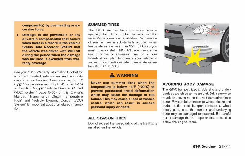
AVOIDING BODY DAMAGE
The GT-R bumper, fascia, side sills and under-carriage are close to the ground. Drive slowly onrough or uneven roads to avoid damaging theseparts. Pay careful attention to wheel blocks andcurbs. If the front bumper contacts a wheelblock, curb, etc., the bumper and underlyingparts may be damaged or cracked. Be carefulnot to damage the front spoiler that is installedbelow the engine room.
GT-R Overview GTR-11
GTR-12 GT-R Overview
FUEL
NISSAN recommends using fuels that containno alcohol. However, fuels containing up to 10%alcohol may be used, if necessary. Do not use E-15 or E-85 in your vehicle. ( “Fuel informa-tion” page 9-4)
NOTICE
To avoid serious engine damage due toincreased cylinder temperatures, do notuse fuels that contain more alcoholthan indicated in “Gasoline con-taining oxygenates” page 9-4. Also, donot use fuel additives, fuel stabilizers orfuel deicers that contain alcohol.
BODY REPAIR
The body of the GT-R has been manufacturedon special fixtures utilizing a hybrid structurewith aluminum die cast parts for the frame work.Special skills, information and equipment arerequired to correctly repair the body. Contact aGT-R certified NISSAN dealer if the vehicle isdamaged, such as in a collision, and they willrecommend an appropriate body shop.
Only certified body shops using CELETTEadvanced collision repair equipment are ap-
proved by NISSAN for repairing structural bodydamage. Contact a GT-R certified NISSANdealer or NISSAN Consumer Affairs for areferral or list of certified body shops.
DRIVING AFTER REPLACING TIRES
Avoid the driving conditions listed under “Addi-tional maintenance items” in this section for 48hours after tires are installed on the wheels( “Additional maintenance items” pageGTR-12). The tire may slip on the wheel if thevehicle is driven in these conditions before 48hours have passed. If the tire slips on the wheel,the wheel/tire assembly will be out of balanceand will require rebalancing.
The information and specifications in thissection apply only when engaging inperformance driving.
The following information applies only if youengage in performance driving such as drivingyour GT-R for extended periods under thefollowing conditions.
. Higher-RPM (approaching redline) opera-tion
. Frequent high pedal force braking frommoderate and higher speeds
. Frequent throttle activation
. Fast revving throughout the RPM range
In such cases, the following additional main-tenance guidelines apply.
However, you should also carefully readyour 2015 NISSAN GT-R Warranty Informa-tion Booklet for important informationconcerning warranty coverage, limitationsand exclusions.
We recommend that all GT-R maintenance beperformed at a GT-R certified NISSAN dealer.NISSAN will only pay for GT-R PerformanceOptimization Services performed at a GT-Rcertified NISSAN dealer.
ADDITIONAL MAINTENANCE ITEMS
PRECAUTIONS ON PERFORMANCEDRIVING
The information and specifications in thissection apply only when engaging inperformance driving.
Checking the temperature of thecoolant and oils on the multi func-tion display
When the temperatures of the engine coolantand oil, and the oil pressure exceed the normalrange, the color of the meter on the multifunction display changes to red to warn thedriver. When engaging in high performancedriving, switch the display to the function meterto display the temperature of the engine coolantand oil, and the oil pressure. When the color ofthe meter display changes to red, perform cooldown driving. When the values of the tempera-ture and pressure return to the normal range, thecolor of the meter display will turn back to white.
Warning temperature:
. Engine coolant temperature is 2308F(1108C) or higher:If the engine coolant temperature increasesabove 2308F (1108C), the color of the meterdisplay on the multi function display changesto red to warn of a possible overheat
condition and engine output is reduced.
. Engine oil temperature is 2758F (1358C) orhigher:
If the engine oil temperature is higher than2758F (1358C), the meter display changesto red, maximum engine speed is automati-cally limited to 4,000 rpm, and the transmis-sion automatically changes from the &Mposition to the &A position.
. Transmission oil temperature is 2848F(1408C) or higher:
If the transmission oil temperature increasesto over 2848F (1408C), the color of themeter display changes to red. However, thevehicle can continue to be driven until thetemperature reaches 2958F (1468C). If theoil temperature exceeds 2848F (1408C)while driving (the color of the meter dis-played in red), change both the transmissionoil and the differential oil after drivingbecause these fluids have deterioratedbecause of the heat.
Cool down
The information and specifications in thissection apply only when engaging inperformance driving.
Cool down the vehicle to help extend the life of
the vehicle if coolant temperatures are extremelyhigh. Drive the vehicle at 37 to 50 MPH (60 to80 km/h), in 5th or 6th gear for 2 to 3 miles (3 to5 km) and then stop the engine.
Refueling precautions
WARNING
Do not attempt to top off the fuel tankafter the fuel pump nozzle shuts offautomatically. Continued refueling maycause fuel overflow, resulting in fuelspray and possibly a fire. The fuel tankis full at the first automatic shutoff.
To maximize vehicle performance, the fuel tank islocated as low as possible to lower the vehiclecenter of gravity. The tank is also divided intotwo parts. This fuel tank design causes higherpressures inside the tank than other vehicles sofuel spillage is possible by trying to top off thefuel tank after automatic shutoff.
The fuel tank pressure is higher when the vehicleis hot, especially if the tank is more than half full.If the cap is opened when the vehicle is hot, itmay cause fuel spray and there may be a hissingnoise. Open the cap slowly, releasing thepressure from the tank gradually. Also, if the
GT-R Overview GTR-13
GTR-14 GT-R Overview
vehicle is refueled when the vehicle is hot, thefuel pump may automatically shut off before thetank is full. This does not indicate that there is amalfunction. Refuel slowly or refuel after thevehicle has cooled.
INSPECTION AND ADJUSTMENTSBEFORE DRIVING
The information and specifications in thissection apply only when engaging inperformance driving.
Fluids
. Check the engine, transmission, differentialand under vehicle surfaces for oil andcoolant leaks.
. Check the fluid levels and adjust as neces-sary using the specified fluid as describedunder the conditions listed in this section.( “Recommended fluids and mainte-nance interval” page GTR-19 ) If you donot drive under the conditions listed, refer tothe 2015 NISSAN Service and MaintenanceGuide.
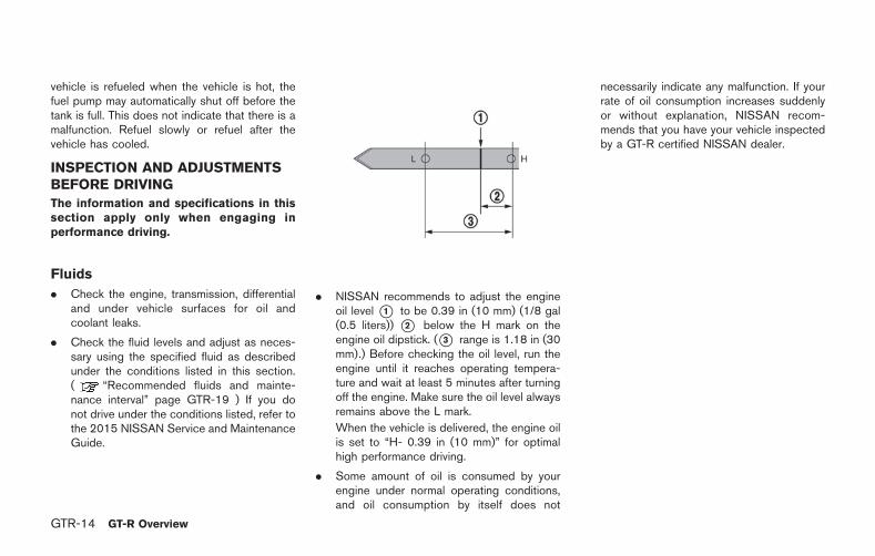
. NISSAN recommends to adjust the engineoil level *1 to be 0.39 in (10 mm) (1/8 gal(0.5 liters)) *2 below the H mark on theengine oil dipstick. (*3 range is 1.18 in (30mm).) Before checking the oil level, run theengine until it reaches operating tempera-ture and wait at least 5 minutes after turningoff the engine. Make sure the oil level alwaysremains above the L mark.
When the vehicle is delivered, the engine oilis set to “H- 0.39 in (10 mm)” for optimalhigh performance driving.
. Some amount of oil is consumed by yourengine under normal operating conditions,and oil consumption by itself does not
necessarily indicate any malfunction. If yourrate of oil consumption increases suddenlyor without explanation, NISSAN recom-mends that you have your vehicle inspectedby a GT-R certified NISSAN dealer.
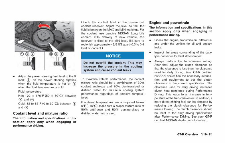
. Adjust the power steering fluid level to the Rmark *5 on the power steering dipstickwhen the fluid temperature is hot or *6when the fluid temperature is cold.
Fluid temperature:
Hot: 122 to 1768F (50 to 808C): between*1 and *5Cold: 32 to 868F (0 to 308C): between *3and *6
Coolant level and mixture ratio
The information and specifications in thissection apply only when engaging inperformance driving.
Check the coolant level in the pressurizedcoolant reservoir. Adjust the level so that thefluid is between the MAX and MIN markings. Forthe coolant, use genuine NISSAN Long Lifecoolant. (On delivery of new vehicle, thereservoir is filled to the MIN level. Be sure toreplenish approximately 3/8 US quart (0.3 to 0.4liter) of coolant.)
NOTICE
Do not overfill the coolant. This mayincrease the pressure in the coolingsystem and cause coolant leaks.
To maximize vehicle performance, the coolantmixture ratio should be a combination of 30%coolant antifreeze and 70% demineralized ordistilled water for maximum cooling systemperformance regardless of ambient tempera-tures.
If ambient temperatures are anticipated below58F ( 158C), make sure a proper mixture ratio of50% antifreeze and 50% demineralized ordistilled water mix is used.
Engine and powertrain
The information and specifications in thissection apply only when engaging inperformance driving.
. Check the engine, transmission, differentialand under the vehicle for oil and coolantleaks.
. Inspect the areas surrounding of the cata-lytic converter for heat deterioration.
. Always perform the transmission setting.After that, adjust the clutch clearance sothat the clearance is less than the clearanceused for daily driving. Your GT-R certifiedNISSAN dealer has the necessary informa-tion and equipment to set the clutchclearance to the correct specification. Theclearance used for daily driving increasesclutch heat generated during PerformanceDriving. This leads to an increase in tem-perature of the transmission oil. In addition, amore direct shifting feel can be obtained byreducing the clutch clearance for Perfor-mance Driving. The clutch clearance shouldbe reset to the daily driving specificationafter Performance Driving. See your GT-Rcertified NISSAN dealer for information.
GT-R Overview GTR-15
GTR-16 GT-R Overview
NOTICE
Failure to have the clutch properlyadjusted before performance drivingmay cause the transmission oil tem-perature to increase which may causetransmission damage.
. Inspect and confirm the clearance betweenthe exhaust finisher and rear bumper is morethan 0.24 in (6 mm) (up/down) and morethan 0.20 in (5 mm) (left/right).
. Inspect the dust boot of the drive shaftuniversal joint for cracks or damage.
Suspension and wheel alignment
The information and specifications in thissection apply only when engaging inperformance driving.
. Check the steering and suspension systemand other links for loose and/or damagedparts.
. Measure and adjust the wheel alignment.( “Wheel alignment” page GTR-10)Contact a GT-R certified NISSAN dealer toadjust the wheel alignment to the recom-mended setting for high performance driv-ing.
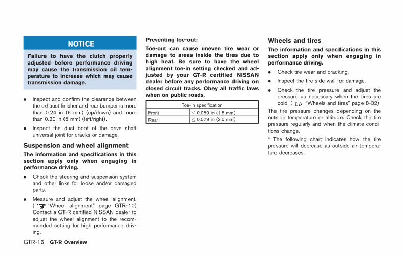
Preventing toe-out:
Toe-out can cause uneven tire wear ordamage to areas inside the tires due tohigh heat. Be sure to have the wheelalignment toe-in setting checked and ad-justed by your GT-R certified NISSANdealer before any performance driving onclosed circuit tracks. Obey all traffic lawswhen on public roads.
Toe-in specification
Front � 0.059 in (1.5 mm)
Rear � 0.079 in (2.0 mm)
Wheels and tires
The information and specifications in thissection apply only when engaging inperformance driving.
. Check tire wear and cracking.
. Inspect the tire side wall for damage.
. Check the tire pressure and adjust thepressure as necessary when the tires arecold. ( “Wheels and tires” page 8-32)
The tire pressure changes depending on theoutside temperature or altitude. Check the tirepressure regularly and when the climate condi-tions change.
* The following chart indicates how the tirepressure will decrease as outside air tempera-ture decreases.
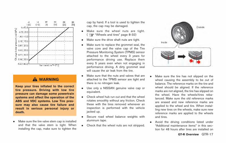
WARNING
Keep your tires inflated to the correcttire pressure. Driving with low tirepressure can damage some powertrainsystems and affect the operation of theABS and VDC systems. Low Tire pres-sure may also cause tire failure andresult in serious personal injury ordeath.
. Make sure the tire valve stem cap is installedand that the valve stem is tight. Wheninstalling the cap, make sure to tighten the
cap by hand. If a tool is used to tighten thecap, the cap may be damaged.
. Make sure the wheel nuts are tight.( “Wheels and tires” page 8-32)
. Make sure the drive shaft nuts are tight.
. Make sure to replace the grommet seal, thevalve core and the valve cap of the TirePressure Monitoring System (TPMS) sensorattached to the wheel every 3 years forperformance driving use. Replace themevery 5 years even when not engaging inperformance driving. A dirty grommet sealwill cause the air leak from the tire.
. Make sure that the nuts and valves that areattached to the TPMS sensor are tight andthere is no nitrogen leak.
. Use only a NISSAN genuine valve cap orequivalent.
. Check wheel hub run out and that the wheelrotates smoothly without any friction. Checkthese with the tires removed whenever aninspection is performed with the vehiclejacked up.
. Secure road wheel balance weights withaluminum tape.
. Check that the wheel nuts are not stripped.
. Make sure the tire has not slipped on thewheel causing the assembly to be out ofbalance. The reference marks on the tire andwheel should be aligned. If the referencemarks are not aligned, the tire has slipped onthe wheel. Have the wheels/tires reba-lanced. Make sure the old reference marksare erased and new reference marks areapplied to the wheel and tire. When instal-ling new tires on the wheels, make sure newreference marks are applied to the wheelsand tires.
. Avoid the driving conditions listed under“Additional maintenance items” in this sec-tion for 48 hours after tires are installed on
GT-R Overview GTR-17
GTR-18 GT-R Overview
the wheels. The tire may slip on the wheel ifthe vehicle is driven in these conditionsbefore 48 hours have passed. If the tire slipson the wheel, the wheel/tire assembly will beout of balance and will require rebalancing.
Brakes
The information and specifications in thissection apply only when engaging inperformance driving.
. Check for the heat deterioration of thebrakes and parts around the brakes.
. It is recommended that you remove air fromthe brake system after any of the following:
— When engaging in high performancedriving for the first time after purchasinga new vehicle.
— After replacing the brake fluid.
— When engaging in high performancedriving for a sustained period of time. Itis recommended that bleeding the brakebe performed when the brake calipersare hot (about 2128F (1008C)).
Brake pad break-in procedure:
NISSAN recommends that a special brake padbreak-in procedure be performed before enga-ging in performance driving. Contact a GT-Rcertified NISSAN dealer for details.
INSPECTION AND ADJUSTMENTSAFTER DRIVING
The information and specifications in thissection apply only when engaging inperformance driving.
NOTICE
At the completion of performance driv-ing, all fluid and other adjustmentsshould be returned to the normal fluidspecifications as shown in the “Main-tenance and do-it-yourself” section ofthis manual.
Fluids
The information and specifications in thissection apply only when engaging inperformance driving.
. Check the engine, transmission, differentialand under the vehicle for oil and coolantleaks.
. Check the fluid levels and adjust as neces-sary using the specified fluid as describedunder the conditions listed in this section.( “Recommended fluids and mainte-nance interval” page GTR-19) If you do not
drive under the conditions listed, refer to the2015 NISSAN Service and MaintenanceGuide.
. When changing fluids, be sure to use thespecified fluids as described in this Owner’smanual. ( “Capacities and recom-mended fluids/lubricants” page 9-2)
Recommended fluids and maintenance interval
The information and specifications in this section apply only when engaging in performance driving.
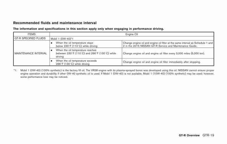
ITEMS Engine Oil
GT-R SPECIFIED FLUIDS Mobil 1 (0W-40)*1
MAINTENANCE INTERVAL
. When the oil temperature staysbelow 2308F (1108C) while driving
Change engine oil and engine oil filter at the same interval as Schedule 1 and2 in the 2015 NISSAN GT-R Service and Maintenance Guide.
. When the oil temperature reachesbetween 2308F (1108C) and 2668F (1308C) whiledriving
Change engine oil and engine oil filter every 3,000 miles (5,000 km).
. When the oil temperature exceeds2668F (1308C) while driving
Change engine oil and engine oil filter immediately after stopping.
*1: Mobil 1 (0W-40) (100% synthetic) is the factory fill oil. The VR38 engine with its plasma-sprayed bores was developed using this oil. NISSAN cannot ensure properengine operation and durability if other 0W-40 synthetic oil is used. If Mobil 1 (0W-40) is not available, Mobil 1 (10W-40) (100% synthetic) may be used; however,some performance loss may be noticed.
GT-R Overview GTR-19
GTR-20 GT-R Overview
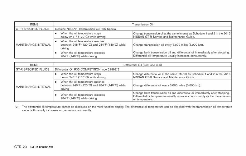
ITEMS Transmission Oil
GT-R SPECIFIED FLUIDS Genuine NISSAN Transmission Oil R35 Special
MAINTENANCE INTERVAL
. When the oil temperature staysbelow 2488F (1208C) while driving
Change transmission oil at the same interval as Schedule 1 and 2 in the 2015NISSAN GT-R Service and Maintenance Guide.
. When the oil temperature reachesbetween 2488F (1208C) and 2848F (1408C) whiledriving
Change transmission oil every 3,000 miles (5,000 km).
. When the oil temperature exceeds2848F (1408C) while driving
Change both transmission oil and differential oil immediately after stopping.Differential oil temperature usually increases concurrently.
ITEMS Differential Oil (front and rear)
GT-R SPECIFIED FLUIDS Differential Oil R35 COMPETITION type 2189E*2
MAINTENANCE INTERVAL
. When the oil temperature staysbelow 2488F (1208C) while driving
Change differential oil at the same interval as Schedule 1 and 2 in the 2015NISSAN GT-R Service and Maintenance Guide .
. When the oil temperature reachesbetween 2488F (1208C) and 2848F (1408C) whiledriving
Change differential oil every 3,000 miles (5,000 km).
. When the oil temperature exceeds2848F (1408C) while driving
Change both transmission oil and differential oil immediately after stopping.Differential oil temperature usually increases concurrently as the transmissionoil temperature.
*2: The differential oil temperature cannot be displayed on the multi function display. The differential oil temperature can be checked with the transmission oil temperaturesince both usually increases or decrease concurrently.
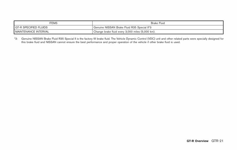
ITEMS Brake Fluid
GT-R SPECIFIED FLUIDS Genuine NISSAN Brake Fluid R35 Special II*3
MAINTENANCE INTERVAL Change brake fluid every 3,000 miles (5,000 km).
*3: Genuine NISSAN Brake Fluid R35 Special II is the factory fill brake fluid. The Vehicle Dynamic Control (VDC) unit and other related parts were specially designed forthis brake fluid and NISSAN cannot ensure the best performance and proper operation of the vehicle if other brake fluid is used.
GT-R Overview GTR-21
GTR-22 GT-R Overview
Suspension and wheel alignment
. Check the steering and suspension systemand other links for loose and/or damagedparts.
. Measure and adjust the wheel alignment.Contact a GT-R certified NISSAN dealer toadjust the wheel alignment to the recom-mended setting for normal driving.
Wheels and tires
. Check tire wear and cracking.
. Inspect the tire side wall for damage.
. Check the tire pressure and adjust thepressure as necessary when the tires arecold. ( “Wheels and tires” page GTR-16) If you do not drive under the conditionslisted in this section, see “Wheels andtires” page 8-32.
. Check that the wheel nuts are not stripped.Check if there is no deformation on thecontact surface of the wheel nuts.
. Make sure the wheel nuts are tight.( “Wheels and tires” page 8-32)
. Make sure the drive shaft nuts are tight.
. Check wheel hub run out and that the wheelrotates smoothly without any friction. Checkthese with the tires removed whenever an
inspection is performed with the vehiclejacked up.
. Make sure the tire has not slipped on thewheel causing the assembly to be out ofbalance. The reference marks on the tire andwheel should be aligned. If the referencemarks are not aligned, the tire has slipped onthe wheel. Have the wheels/tires reba-lanced. Make sure the old reference marksare erased and new reference marks areapplied to the wheel and tire. When instal-ling new tires on the wheels, make sure newreference marks are applied to the wheelsand tires. ( “Wheels and tires” pageGTR-16)
. Make sure that the TPMS sensor installationnuts and the sensor valve are tight and thereis no nitrogen leak.
Brakes
. Check for the heat deterioration of thebrakes and parts around the brakes.
. Check the condition of the brake pads anddisc rotors and replace them as necessary.
Engine and powertrain
. Check the engine, transmission, differentialand under the vehicle for oil and coolant
leaks.
. Inspect the area surrounding the catalyticconverter for heat deterioration.
. Inspect and confirm the clearance betweenthe exhaust finisher and rear bumper is morethan 0.24 in (6 mm) (up/down) and morethan 0.20 in (5 mm) (left/right).
. The clutch clearance and shift fork positionmay need to be adjusted.
. Inspect the dust boot of the drive shaftuniversal joint for cracks or damage.
. Check that there is no abnormal noise,vibrations or warning lights illuminated whenmaking tight turns at slow speed (for tightcorner braking phenomenon).
REFUELING PRECAUTIONS
WARNING
Do not attempt to top off the fuel tankafter the fuel pump nozzle shuts offautomatically. Continued refueling maycause fuel overflow, resulting in fuelspray and possibly a fire. The fuel tankis full at the first automatic shutoff.
To maximize vehicle performance, the fuel tank islocated as low as possible to lower the vehiclecenter of gravity. The tank is also divided intotwo parts. This fuel tank design causes higherpressures inside the tank than other vehicles sofuel spillage is possible by trying to top off thefuel tank after automatic shutoff.
The fuel tank pressure is higher when the vehicleis hot, especially if the tank is more than half full.If the cap is opened when the vehicle is hot, itmay cause fuel spray and there may be a hissingnoise. Open the cap slowly, releasing thepressure from the tank gradually. Also, if thevehicle is refueled when the vehicle is hot, thefuel pump may automatically shut off before thetank is full. This does not indicate that there is amalfunction. Refuel slowly or refuel after the
vehicle has cooled.
GASOLINE SMELL
The fuel temperature is higher when the vehicleis hot. This may cause a gasoline smell from thevehicle. This does not indicate that there is amalfunction. The smell will go away when thefuel temperature has cooled.
OUTSIDE TEMPERATURE DISPLAYINDICATES HIGHER TEMPERATURE
Heat from the engine compartment, radiator andintercoolers can affect the outside temperaturedisplay. The outside temperature display mayindicate a higher than actual temperature whiledriving or stopped. This is normal.
IDLE SPEED IS NOT STEADY
The idle speed may not be steady when theengine compartment is extremely hot. This isnormal. The engine speed will be steady whenthe engine cools down.
In this case, the Malfunction Indicator Light (MIL)may come on. After a few driving trips, the MILshould turn off. If the light remains on after a fewdriving trips, have the vehicle inspected by aGT-R certified NISSAN dealer.
ENGINE SPEED IS RESTRICTED
To help protect the engine, the maximum enginespeed is automatically controlled in the followingconditions:
. Revving the engine with the shift lever in the
&P or &N position: The maximum enginespeed is 5,000 RPM
. Revving the engine when the engine oil is ata low (below 328F (08C)) or extremely high(over 2758F (1358C)) temperature: Themaximum engine speed is 4,000 RPM (The
&M position will automatically change to the
&A position.)
ENGINE OUTPUT
High altitude
To protect the engine, engine output is con-trolled so that it does not increase at altitudes3,281 ft (1,000 m) or higher.
Engine output according to thecoolant temperature
The engine output is controlled at a low levelwhen the engine coolant temperature is lowerthan approximately 1588F (708C) or higher than2308F (1108C). This is not a malfunction.
If the temperature is lower than approximately
GT-R Overview GTR-23
GT-R SPECIFIC VEHICLECHARACTERISTICS
GTR-24 GT-R Overview
1588F (708C), drive the vehicle until it reachesnormal operating temperature. If the temperatureis higher than 2308F (1108C), perform cool-down driving procedure. ( “Cool down”page GTR-13) When the temperature of theengine coolant is between 1588F (708C) and2308F (1108C), the engine output returns tonormal.
UNEVEN WEAR OF TIRES
The GT-R is equipped with high performance,low profile, run-flat tires that are optimized forperformance and handling. The life of these tireswill be less than those of tires installed on atypical vehicle, and you are likely to experienceuneven tire wear and tire noise regardless of thetype of tire used.
NOISES ARE HEARD WHILE DRIV-ING
. The GT-R brake pads use material thatprovides a high amount of braking powereven in high temperatures. This material cancause an intermittent screeching noise justbefore the vehicle comes to a stop when thebrakes are gently applied. The noise de-creases as the brake pads wear. However,the additional brake pad break-in or repla-cing the cross spring may decrease the
noise. Contact a GT-R certified NISSANdealer.
. A screeching noise may be heard when thebrake pedal is depressed:
— When driving the vehicle for the first timein the morning,
— After leaving the vehicle parked forextended periods of time, or
— When the vehicle is damp following rainshowers or washing the vehicle.
These sounds are normal. The noise iscaused when the brake pads absorb moist-ure, and the noise stops after the brake isapplied several times.
. A screeching noise may also be heard whenthe brake pedal is depressed:
— When repeatedly applying gentle brak-ing, especially on a curve at a low speed,or
— When the brake rotors have circularscores with the brake temperature high.
WARNING
Follow the instructions below whenparking the vehicle to help prevent thebrake rotor and brake pads from rust-ing together. Failure to follow the
instructions could cause the rotor andpads to rust together. If the rotor andpads rust together, there may be apopping noise and some vibrationwhen the vehicle is driven, a wheelmay not roll correctly, or the brake padscould be damaged. If the pads aredamaged, this may reduce the effec-tiveness of the brake system whichcould cause a collision, serious perso-nal injury or death.
. The GT-R uses brake pad materials thathave high metallic content. The brake padmaterial helps maintain braking performancein a wide range of weather and drivingconditions.
For the first 3,000-6,000 miles (5,000-10,000 km) of the vehicle’s service life,and for the first 3,000-6,000 miles (5,000-10,000 km) after a brake replacement, thebrake pad to brake rotor clearance is verysmall. When parking, apply the parkingbrake and move the shift lever to the &Pposition. Idle the engine for more than 20seconds without depressing the brakepedal. This allows the brake pads to moveaway from the rotor so the pad does notcontact the rotor.
Additionally, the brakes must be dry beforeparking the vehicle after driving on wet roadsor after washing the vehicle. If the roads arewet, lightly apply the brakes for a shortdistance before parking the vehicle to drythe brakes. After washing the vehicle, dry thebrakes by driving on a dry road for a fewmiles and apply the brakes normally basedon traffic and road conditions.
The metallic brake pads and brake disc rotormay rust together when the brakes are notapplied:
— If the vehicle is not idled for 20 secondswithout the brakes applied, or if thebrakes are applied when the vehicle isshut off, the rotor and pads can rusttogether, even when the brake pads aredry.
— If the brakes are wet when the vehicle isparked and the parking brake is appliedfor a long time.
— The hill start assist system can apply thebrakes even if the brake pedal is notdepressed. The brake pads and rotorscan rust together if the parking proce-dure previously described is not fol-lowed.
Contact a GT-R certified NISSAN dealer ifthe brake pads and brake rotor have rusted
together.
NOTICE
To help reduce the possibility of therotors and brake pads rusting:
Have the brake pads and/or rotorsquenched when the brake pads arereplaced. For detailed informationabout quenching, contact a GT-R certi-fied NISSAN dealer.
After quenching the brake pads and/orrotors, apply a brake of 0.5G to stop thevehicle 6-7 times at least once a weekin a safe location. G-force can bechecked on the multi function display.Refer to the separate Multi FunctionDisplay Owner’s Manual.
. To maintain steady braking performance inboth extremely high and low temperatures,the gap between the brake pad and caliperis larger than normal and large-size brakepads are used. When driving over a bump, alight rattling sound may be heard from thebrake pad. This does not indicate that thereis a malfunction.
. When the brake disc rotor undergoesthermal expansion, a ticking noise may beheard from the engaging portion of thewheel and the brake disc rotor. This doesnot indicate that there is a malfunction. Thenoise will reduce when the temperaturedecreases.
. In addition to noise resulting from uneventire wear discussed in the previous section,the GT-R tires are more rigid than a typicalpassenger car tire and are made from aspecially formulated rubber to maximize thevehicle’s performance capabilities. Thesecharacteristics cause the GT-R tires to havemore road noise than a typical passengercar tire. This road noise is normal.
. Due to the performance capabilities andrequirements of the GT-R, the sequential 6-speed dual clutch transmission is unlike atypical automatic transmission. You will likelyhear mechanical sounds from the transmis-sion, particularly at slow speeds and at idle.This condition is normal.
GT-R Overview GTR-25
GTR-26 GT-R Overview
BRAKE SYSTEM INFORMATION
Cracks on brake pad
The friction material of the GT-R disc brake padis bonded to the pad backing plate morestrongly than conventional brake pads to with-stand the high brake temperatures. The frictionmaterial and backing plate expand due to heat atdifferent rates. Some cracks may be on thesurface of the friction material due to thedifferences in expansion rates and the strongbond between the friction material and backingplate. The cracks do not indicate the brake padsneed to be replaced. However, depending onthe condition of the cracks, the pads may needto be replaced. Contact a GT-R certifiedNISSAN dealer.
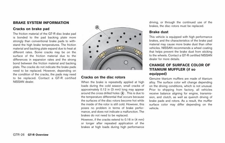
Cracks on the disc rotors
When the brake is repeatedly applied at highloads during the cold season, small cracks ofapproximately 0.12 in (3 mm) long may appeararound the cross drilled holes*A . This is due tothe temperature differential that occurs becausethe surfaces of the disc rotors become hot whilethe inside of the rotor is still cold. However, thisposes no problem in terms of brake perfor-mance, and does not indicate a malfunction. Thebrakes do not need to be replaced.
However, if the cracks extend to 0.16 in (4 mm)or longer after repeated application of thebrakes at high loads during high performance
driving, or through the continued use of thebrakes, the disc rotors must be replaced.
Brake dust
This vehicle is equipped with high performancebrakes, and the characteristics of the brake padmaterial may cause more brake dust than othervehicles. NISSAN recommends a wheel coatingthat helps prevent the brake dust from stickingto the wheels. Contact a GT-R certified NISSANdealer for more details.
CHANGE OF SURFACE COLOR OFTITANIUM MUFFLER (if soequipped)
Genuine titanium mufflers are made of titaniumalloy. The surface color will change dependingon the driving conditions, which is not unusual.Prior to shipping from factory, all vehiclesreceive balance aligning for engine, transmis-sion, and clutch, as well as quench driving ofbrake pads and rotors. As a result, the mufflersurface color may differ depending on thevehicle.
SOUND HEARD AROUND TITANIUMMUFFLER (if so equipped)
When stopping the engine (rapid cooling), youmay hear a metal-rubbing sound or unusualticking sound because of the differential thermalexpansion between the inner and outer pipes ofthe muffler. This is not a malfunction. The soundwill decrease when the temperature lowers.
DRY CARBON FIBER PARTS (if soequipped)
Roughness or uneven surfaces of drycarbon fiber parts and fiber twists
The surfaces of the dry carbon fiber parts arelightly coated like a race car so that you can feelthe proper texture of real carbon, which may feelrough. This is normal.
The GT-R dual clutch transmission is a newly-developed system that uses an electronicallycontrolled multiple-disc wet clutch attached tothe highly efficient manual transmission. Thistransmission has two driving modes.
. &A position (Automatic gearshift):
allows automatic shifting of the manualtransmission.
. &M position (Manual gearshift):
allows quick shifting of the manual transmis-sion.
NOTE:
When starting or driving on a steep uphillgrade, shift to the &M position and operatethe paddle shifter to shift down to 1st gearsimilar to a manual transmission vehicle.
The GT-R dual clutch transmission was devel-oped specifically to maximize vehicle perfor-mance and driving enjoyment. The GT-Rtransmission components were designed usingdifferent engineering standards than typicalpassenger car transmissions. Because of this,the GT-R has different operating characteristics,and various rattle noises may be heard duringsome driving conditions because of the follow-ing items:
. Gear clearances
. Ultralight flywheel
. Dry sump lubrication
These noises do not indicate that there is amalfunction.
GT-R Overview GTR-27
DUAL CLUTCH TRANSMISSION
GTR-28 GT-R Overview
TRANSMISSION OPERATION CHARACTERISTICS
Mechanism Operation characteristics
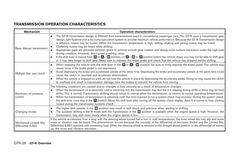
Base Manual transmission
. The GT-R transmission design is different from transmissions used in conventional passenger cars. The GT-R uses a transmission geardesign, light flywheel and a dry sump lubrication system to provide maximum vehicle performance. Because the GT-R Transmission designis different, noises may be louder. When the transmission temperature is high, rattling, shaking and jarring noises may be heard.
. Clattering noises may be heard while shifting.
. Appropriate gaps are provided between gears to achieve smooth gear rotation and steady tooth surface lubrication under the high-loaddriving condition. However, this causes a rattling noise.
. If the shift lever is moved from&R to&A &M position, or&A &M to&R position before the vehicle stops, you may not be able to shift gearor it may take longer to shift gear. Make sure to depress the brake pedal and check that the vehicle has stopped before shifting.
Multiple disc wet clutch
. When stopping the vehicle with the shift lever in the &R or &A &M position, be sure to firmly depress the brake pedal. The vehicle mayslowly move if the brake pedal is not depressed.
. Avoid depressing the brake and accelerator pedals at the same time. Depressing the brake and accelerator pedals at the same time couldcause the clutch to overheat and accelerate deterioration.
. When the vehicle is stopped on a hill, do not hold the vehicle in place by depressing the accelerator pedal. Doing so may cause the clutchto overheat and result in transmission damage. Use the brakes to prevent the vehicle from moving.
Electronic oil pressurecontrol
The following conditions are caused due to changes in fluid viscosity as a result of temperature changes.. When the transmission oil is extremely cold or extremely hot, the transmission may feel like it is slipping during shifts or there may be hard
shifts. This is normal. Transmission shifting should return to normal when the transmission oil returns to normal operating temperatures.. When the transmission oil temperature is extremely cold, the time required to run a system check may increase. During the system check,
the shift lever must stay in the&P position. Move the shift lever after turning off the system check display. Also, it is normal to hear clickingnoises during the transmission systems check.
Changing modes. The higher shift speeds in the &M position may result in shift shock and jerkiness when starting or shifting.. The quickest shifting in the R mode with the transmission in the &M position is available when the engine speed is high. However, the
transmission may shift more slowly when the engine speed is low.
Mechanical Limited SlipDifferential (LSD)
If the vehicle accelerates from a stop with the steering wheel turned half a turn in cold temperatures, the inner wheel tire may slip and somenoise or vibration may be heard. This phenomenon occurs because the viscosity of the differential oil becomes thicker and the Limited SlipDifferential (LSD) operates with increasing load. When the steering wheel is returned to the straight ahead position or the differential oil warmsup, the noise and vibration decrease.
Mechanism Operation characteristics
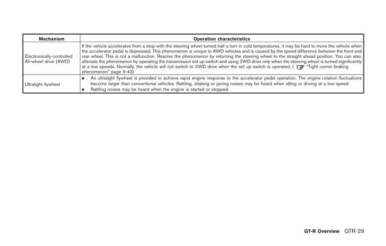
Electronically-controlledAll-wheel drive (AWD)
If the vehicle accelerates from a stop with the steering wheel turned half a turn in cold temperatures, it may be hard to move the vehicle whenthe accelerator pedal is depressed. This phenomenon is unique to AWD vehicles and is caused by the speed difference between the front andrear wheel. This is not a malfunction. Resolve the phenomenon by returning the steering wheel to the straight ahead position. You can alsoalleviate the phenomenon by operating the transmission set up switch and using 2WD drive only when the steering wheel is turned significantlyat a low speeds. Normally, the vehicle will not switch to 2WD drive when the set up switch is operated. ( “Tight corner brakingphenomenon” page 5-43)
Ultralight flywheel
. An ultralight flywheel is provided to achieve rapid engine response to the accelerator pedal operation. The engine rotation fluctuationsbecome larger than conventional vehicles. Rattling, shaking or jarring noises may be heard when idling or driving at a low speed.
. Rattling noises may be heard when the engine is started or stopped.
GT-R Overview GTR-29

GTR-30 GT-R Overview
MEMO
0 Illustrated table of contents
Seats, seat belts and Supplemental RestraintSystem (SRS) ........................................................................... 0-2
Front ...................................................................................... 0-2Rear ....................................................................................... 0-3
Exterior ........................................................................................ 0-4Front ...................................................................................... 0-4Rear ....................................................................................... 0-6
Passenger compartment ........................................................ 0-7Cockpit ....................................................................................... 0-8Instrument panel ...................................................................... 0-9Meters and gauges .............................................................. 0-10Engine compartment ........................................................... 0-11Warning and indicator lights ............................................. 0-12
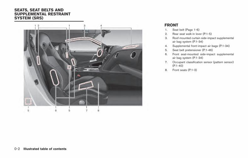
0-2 Illustrated table of contents
FRONT1. Seat belt (Page 1-6)
2. Rear seat walk-in lever (P.1-5)
3. Roof-mounted curtain side-impact supplementalair bag system (P.1-34)
4. Supplemental front-impact air bags (P.1-34)
5. Seat belt pretensioner (P.1-46)
6. Front seat-mounted side-impact supplementalair bag system (P.1-34)
7. Occupant classification sensor (pattern sensor)(P.1-40)
8. Front seats (P.1-3)
SEATS, SEAT BELTS ANDSUPPLEMENTAL RESTRAINTSYSTEM (SRS)

REAR1. Rear seats
— Child restraint installation (P.1-15)
2. Child restraint anchor points (for top tether strapchild restraint) (P.1-19)
3. LATCH (Lower Anchors and Tethers for CHil-dren) system (P.1-17, P.1-26, P.1-30)
Illustrated table of contents 0-3
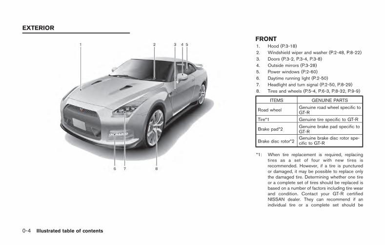
0-4 Illustrated table of contents
FRONT1. Hood (P.3-18)
2. Windshield wiper and washer (P.2-48, P.8-22)
3. Doors (P.3-2, P.3-4, P.3-8)
4. Outside mirrors (P.3-28)
5. Power windows (P.2-60)
6. Daytime running light (P.2-50)
7. Headlight and turn signal (P.2-50, P.8-29)
8. Tires and wheels (P.5-4, P.6-3, P.8-32, P.9-9)
ITEMS GENUINE PARTS
Road wheelGenuine road wheel specific toGT-R
Tire*1 Genuine tire specific to GT-R
Brake pad*2Genuine brake pad specific toGT-R
Brake disc rotor*2Genuine brake disc rotor spe-cific to GT-R
*1: When tire replacement is required, replacingtires as a set of four with new tires isrecommended. However, if a tire is puncturedor damaged, it may be possible to replace onlythe damaged tire. Determining whether one tireor a complete set of tires should be replaced isbased on a number of factors including tire wearand condition. Contact your GT-R certifiedNISSAN dealer. They can recommend if anindividual tire or a complete set should be
EXTERIOR
replaced.
*2: “Replacement of brake pads and discrotors” page GTR-5
Genuine NISSAN Brake Fluid R35 Special II isthe factory fill brake fluid. The Vehicle DynamicControl (VDC) unit and other related parts werespecially designed for this brake fluid. NISSANcannot ensure proper operation of the vehicle ifother brake fluid is used.
Illustrated table of contents 0-5
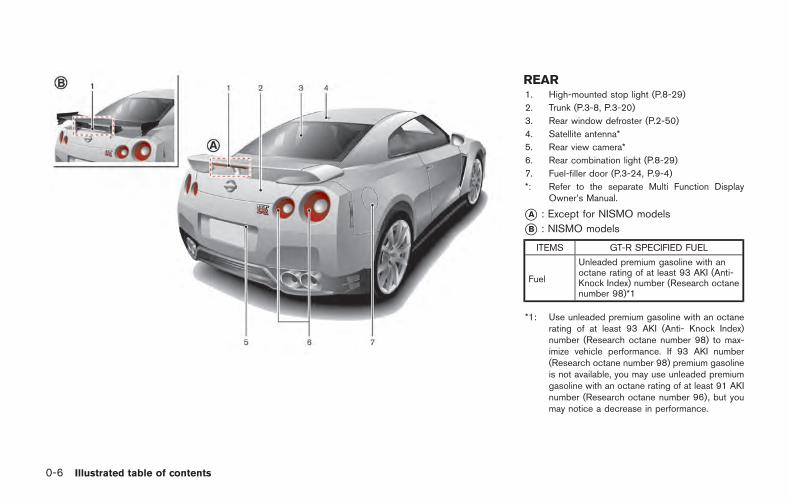
0-6 Illustrated table of contents
REAR1. High-mounted stop light (P.8-29)
2. Trunk (P.3-8, P.3-20)
3. Rear window defroster (P.2-50)
4. Satellite antenna*
5. Rear view camera*
6. Rear combination light (P.8-29)
7. Fuel-filler door (P.3-24, P.9-4)
*: Refer to the separate Multi Function DisplayOwner’s Manual.
*A : Except for NISMO models
*B : NISMO models
ITEMS GT-R SPECIFIED FUEL
Fuel
Unleaded premium gasoline with anoctane rating of at least 93 AKI (Anti-Knock Index) number (Research octanenumber 98)*1
*1: Use unleaded premium gasoline with an octanerating of at least 93 AKI (Anti- Knock Index)number (Research octane number 98) to max-imize vehicle performance. If 93 AKI number(Research octane number 98) premium gasolineis not available, you may use unleaded premiumgasoline with an octane rating of at least 91 AKInumber (Research octane number 96), but youmay notice a decrease in performance.
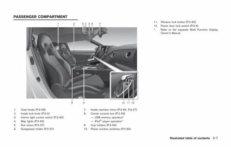
1. Coat hooks (P.2-59)
2. Inside lock knob (P.3-5)
3. Interior light control switch (P.2-62)
4. Map lights (P.2-62)
5. Sun visors (P.3-27)
6. Sunglasses holder (P.2-57)
7. Inside rearview mirror (P.2-64, P.3-27)
8. Center console box (P.2-59)
— USB memory operation*
— iPod player operation*
9. Cup holders (P.2-56)
10. Power window switches (P.2-60)
11. Window lock button (P.2-60)
12. Power door lock switch (P.3-5)
*: Refer to the separate Multi Function DisplayOwner’s Manual.
Illustrated table of contents 0-7
PASSENGER COMPARTMENT
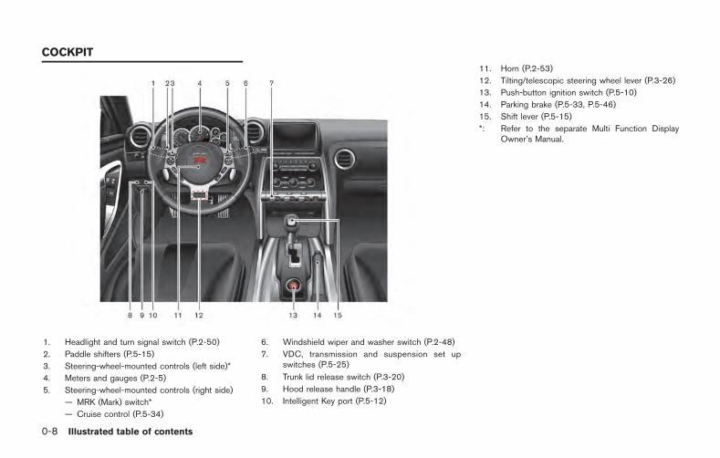
0-8 Illustrated table of contents
1. Headlight and turn signal switch (P.2-50)
2. Paddle shifters (P.5-15)
3. Steering-wheel-mounted controls (left side)*
4. Meters and gauges (P.2-5)
5. Steering-wheel-mounted controls (right side)
— MRK (Mark) switch*
— Cruise control (P.5-34)
6. Windshield wiper and washer switch (P.2-48)
7. VDC, transmission and suspension set upswitches (P.5-25)
8. Trunk lid release switch (P.3-20)
9. Hood release handle (P.3-18)
10. Intelligent Key port (P.5-12)
11. Horn (P.2-53)
12. Tilting/telescopic steering wheel lever (P.3-26)
13. Push-button ignition switch (P.5-10)
14. Parking brake (P.5-33, P.5-46)
15. Shift lever (P.5-15)
*: Refer to the separate Multi Function DisplayOwner’s Manual.
COCKPIT
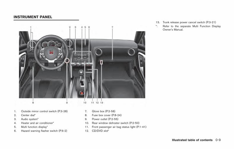
1. Outside mirror control switch (P.3-28)
2. Center dial*
3. Audio system*
4. Heater and air conditioner*
5. Multi function display*
6. Hazard warning flasher switch (P.6-2)
7. Glove box (P.2-58)
8. Fuse box cover (P.8-24)
9. Power outlet (P.2-55)
10. Rear window defroster switch (P.2-50)
11. Front passenger air bag status light (P.1-41)
12. CD/DVD slot*
13. Trunk release power cancel switch (P.3-21)
*: Refer to the separate Multi Function DisplayOwner’s Manual.
Illustrated table of contents 0-9
INSTRUMENT PANEL
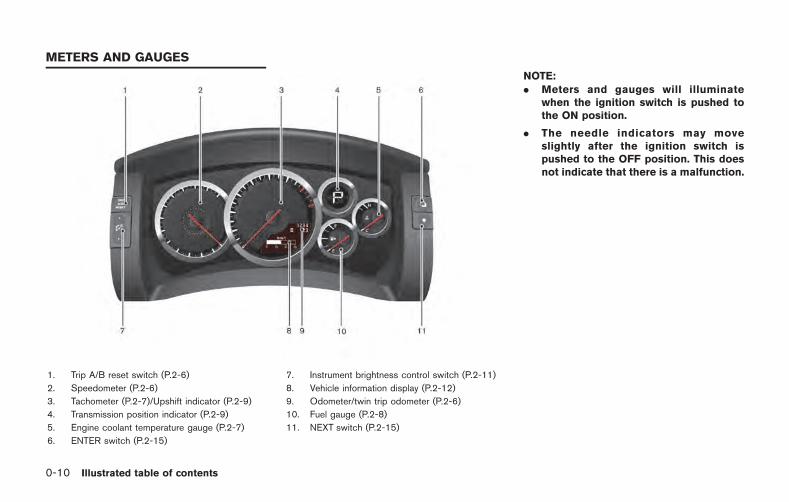
0-10 Illustrated table of contents
1. Trip A/B reset switch (P.2-6)
2. Speedometer (P.2-6)
3. Tachometer (P.2-7)/Upshift indicator (P.2-9)
4. Transmission position indicator (P.2-9)
5. Engine coolant temperature gauge (P.2-7)
6. ENTER switch (P.2-15)
7. Instrument brightness control switch (P.2-11)
8. Vehicle information display (P.2-12)
9. Odometer/twin trip odometer (P.2-6)
10. Fuel gauge (P.2-8)
11. NEXT switch (P.2-15)
NOTE:. Meters and gauges will illuminate
when the ignition switch is pushed tothe ON position.
. The needle indicators may moveslightly after the ignition switch ispushed to the OFF position. This doesnot indicate that there is a malfunction.
METERS AND GAUGES
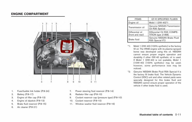
1. Fuse/fusible link holder (P.8-24)
2. Battery (P.8-17)
3. Engine oil filler cap (P.8-13)
4. Engine oil dipstick (P.8-13)
5. Brake fluid reservoir (P.8-15)
6. Air cleaner (P.8-21)
7. Power steering fluid reservoir (P.8-14)
8. Radiator filler cap (P.8-10)
9. Coolant reservoir cap (pressure type) (P.8-10)
10. Coolant reservoir (P.8-10)
11. Window washer fluid reservoir (P.8-16)
ITEMS GT-R SPECIFIED FLUIDS
Engine oil Mobil 1 (0W-40)*1
Transmission oilGenuine NISSAN TransmissionOil R35 Special
Differential oil(front and rear)
Differential Oil R35 COMPE-TITION type 2189E
Brake fluidGenuine NISSAN Brake FluidR35 Special II*2
*1: Mobil 1 (0W-40) (100% synthetic) is the factoryfill oil. The VR38 engine with its plasma-sprayedbores was developed using this oil. NISSANcannot ensure proper engine operation anddurability if other 0W-40 synthetic oil is used.If Mobil 1 (0W-40) is not available, Mobil 1(10W-40) (100% synthetic) may be used;however, some performance loss may benoticed.
*2: Genuine NISSAN Brake Fluid R35 Special II isthe factory fill brake fluid. The Vehicle DynamicControl (VDC) unit and other related parts werespecially designed for this brake fluid andNISSAN cannot ensure proper operation of thevehicle if other brake fluid is used.
Illustrated table of contents 0-11
ENGINE COMPARTMENT
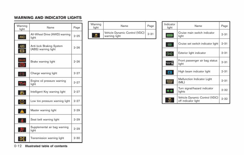
0-12 Illustrated table of contents
Warninglight
Name Page
All-Wheel Drive (AWD) warninglight
2-25
Anti-lock Braking System(ABS) warning light
2-26
Brake warning light 2-26
Charge warning light 2-27
Engine oil pressure warninglight
2-27
Intelligent Key warning light 2-27
Low tire pressure warning light 2-27
Master warning light 2-29
Seat belt warning light 2-29
Supplemental air bag warninglight
2-29
Transmission warning light 2-30
Warninglight
Name Page
Vehicle Dynamic Control (VDC)warning light
2-31
Indicatorlight
Name Page
Cruise main switch indicatorlight
2-31
Cruise set switch indicator light 2-31
Exterior light indicator 2-31
Front passenger air bag statuslight
2-31
High beam indicator light 2-31
Malfunction Indicator Light(MIL)
2-31
Turn signal/hazard indicatorlights
2-32
Vehicle Dynamic Control (VDC)off indicator light
2-32
WARNING AND INDICATOR LIGHTS
1 Safety — Seats, seat belts and supple-mental restraint system
Seats ........................................................................................... 1-2Front seats ........................................................................... 1-3
Head restraints/headrests ...................................................... 1-5Seat belts ................................................................................... 1-6
Precautions on seat belt usage ...................................... 1-6Pregnant women ................................................................ 1-9Injured persons ................................................................... 1-9Three-point type seat belt with retractor ..................... 1-9Seat belt extenders ......................................................... 1-12Seat belt maintenance ................................................... 1-13
Child safety ............................................................................. 1-13Infants ................................................................................. 1-14Small children ................................................................... 1-14Larger children ................................................................. 1-14
Child restraints ....................................................................... 1-15Precautions on child restraints .................................... 1-15Lower Anchors and Tethers for CHildrenSystem (LATCH) ............................................................. 1-17Rear-facing child restraint installationusing LATCH .................................................................... 1-19
Rear-facing child restraint installation using theseat belts ......................................................................... 1-21Forward-facing child restraint installationusing LATCH .................................................................. 1-24Forward-facing child restraint installation using theseat belts ......................................................................... 1-27Booster seats ................................................................. 1-31
Supplemental restraint system .......................................... 1-34Precautions on supplemental restraint system ...... 1-34NISSAN Advanced Air Bag System(front seats) .................................................................... 1-40Front seat-mounted side-impact supplementalair bag and roof-mounted curtain side-impactsupplemental air bag systems ................................... 1-45Seat belts with pretensioners (front seats) ............ 1-46Supplemental air bag warning labels ...................... 1-47Supplemental air bag warning light ......................... 1-47Repair and replacement procedure ......................... 1-48
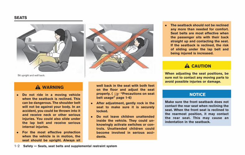
1-2 Safety — Seats, seat belts and supplemental restraint system
WARNING
. Do not ride in a moving vehiclewhen the seatback is reclined. Thiscan be dangerous. The shoulder beltwill not be against your body. In anaccident, you could be thrown into itand receive neck or other seriousinjuries. You could also slide underthe lap belt and receive seriousinternal injuries.
. For the most effective protectionwhen the vehicle is in motion, theseat should be upright. Always sit
well back in the seat with both feeton the floor and adjust the seatproperly. ( “Precautions on seatbelt usage” page 1-6)
. After adjustment, gently rock in theseat to make sure it is securelylocked.
. Do not leave children unattendedinside the vehicle. They could un-knowingly activate switches or con-trols. Unattended children couldbecome involved in serious acci-dents.
. The seatback should not be reclinedany more than needed for comfort.Seat belts are most effective whenthe passenger sits with their backstraight up and contacting the seat.If the seatback is reclined, the riskof sliding under the lap belt andbeing injured is increased.
CAUTION
When adjusting the seat positions, besure not to contact any moving parts toavoid possible injuries or damage.
NOTICE
Make sure the front seatback does notcontact the rear seat when reclining theseat. When the front seat is reclined tothe rearmost position, it may contactthe rear seat. This may cause anindentation in the seatback.
SEATS
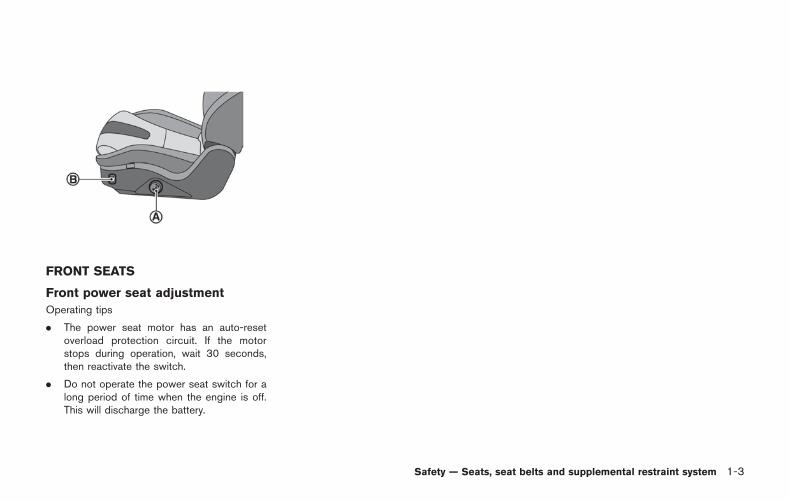
FRONT SEATS
Front power seat adjustment
Operating tips
. The power seat motor has an auto-resetoverload protection circuit. If the motorstops during operation, wait 30 seconds,then reactivate the switch.
. Do not operate the power seat switch for along period of time when the engine is off.This will discharge the battery.
Safety — Seats, seat belts and supplemental restraint system 1-3
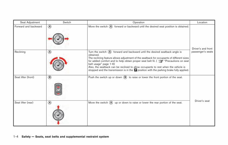
1-4 Safety — Seats, seat belts and supplemental restraint system
Seat Adjustment Switch Operation Location
Forward and backward *A Move the switch*A forward or backward until the desired seat position is obtained.
Driver’s and frontpassenger’s seatsReclining *A Turn the switch *A forward and backward until the desired seatback angle is
obtained.The reclining feature allows adjustment of the seatback for occupants of different sizesfor added comfort and to help obtain proper seat belt fit. ( “Precautions on seatbelt usage” page 1-6)Also, the seatback can be reclined to allow occupants to rest when the vehicle isstopped and the transmission is in the&P position with the parking brake fully applied.
Seat lifter (front) *B Push the switch up or down *B to raise or lower the front portion of the seat.
Driver’s seatSeat lifter (rear) *A Move the switch *A up or down to raise or lower the rear portion of the seat.
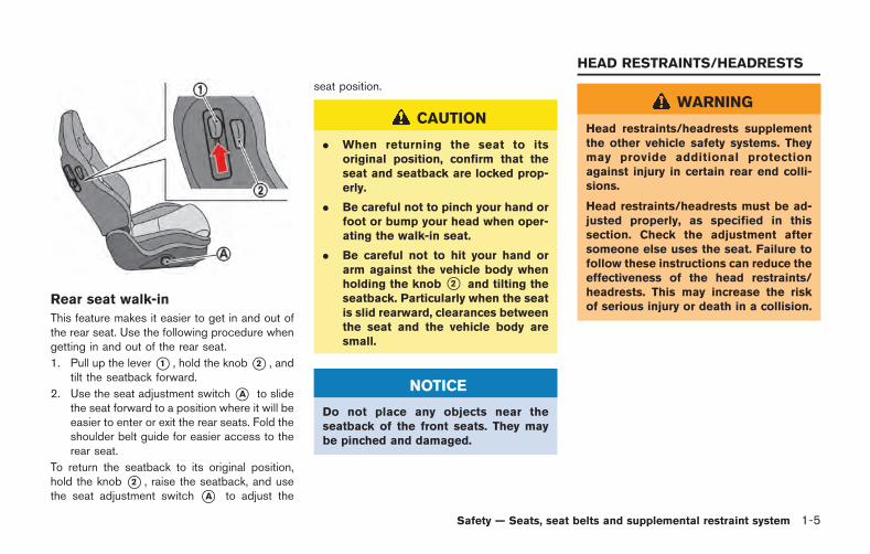
Rear seat walk-in
This feature makes it easier to get in and out ofthe rear seat. Use the following procedure whengetting in and out of the rear seat.
1. Pull up the lever*1 , hold the knob*2 , andtilt the seatback forward.
2. Use the seat adjustment switch*A to slidethe seat forward to a position where it will beeasier to enter or exit the rear seats. Fold theshoulder belt guide for easier access to therear seat.
To return the seatback to its original position,hold the knob *2 , raise the seatback, and usethe seat adjustment switch *A to adjust the
seat position.
CAUTION
. When returning the seat to itsoriginal position, confirm that theseat and seatback are locked prop-erly.
. Be careful not to pinch your hand orfoot or bump your head when oper-ating the walk-in seat.
. Be careful not to hit your hand orarm against the vehicle body whenholding the knob *2 and tilting theseatback. Particularly when the seatis slid rearward, clearances betweenthe seat and the vehicle body aresmall.
NOTICE
Do not place any objects near theseatback of the front seats. They maybe pinched and damaged.
WARNING
Head restraints/headrests supplementthe other vehicle safety systems. Theymay provide additional protectionagainst injury in certain rear end colli-sions.
Head restraints/headrests must be ad-justed properly, as specified in thissection. Check the adjustment aftersomeone else uses the seat. Failure tofollow these instructions can reduce theeffectiveness of the head restraints/headrests. This may increase the riskof serious injury or death in a collision.
Safety — Seats, seat belts and supplemental restraint system 1-5
HEAD RESTRAINTS/HEADRESTS
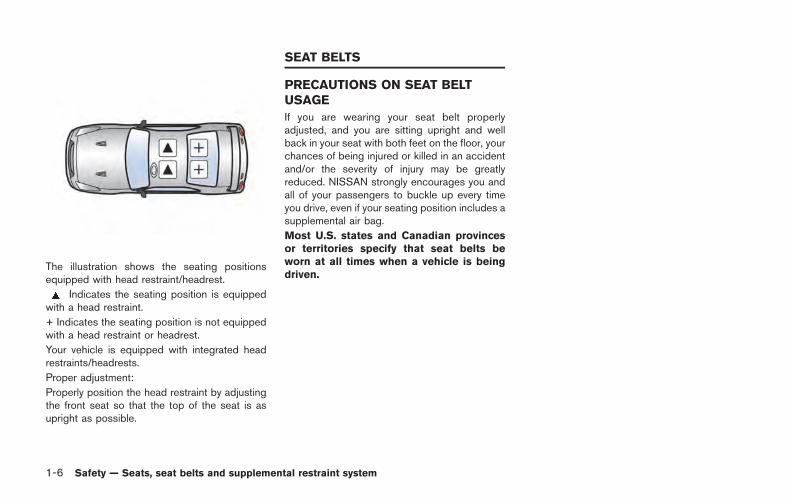
1-6 Safety — Seats, seat belts and supplemental restraint system
The illustration shows the seating positionsequipped with head restraint/headrest.
Indicates the seating position is equippedwith a head restraint.
+ Indicates the seating position is not equippedwith a head restraint or headrest.
Your vehicle is equipped with integrated headrestraints/headrests.
Proper adjustment:
Properly position the head restraint by adjustingthe front seat so that the top of the seat is asupright as possible.
PRECAUTIONS ON SEAT BELTUSAGE
If you are wearing your seat belt properlyadjusted, and you are sitting upright and wellback in your seat with both feet on the floor, yourchances of being injured or killed in an accidentand/or the severity of injury may be greatlyreduced. NISSAN strongly encourages you andall of your passengers to buckle up every timeyou drive, even if your seating position includes asupplemental air bag.
Most U.S. states and Canadian provincesor territories specify that seat belts beworn at all times when a vehicle is beingdriven.
SEAT BELTS
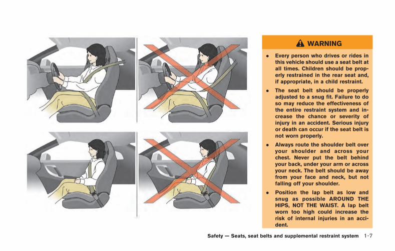
WARNING
. Every person who drives or rides inthis vehicle should use a seat belt atall times. Children should be prop-erly restrained in the rear seat and,if appropriate, in a child restraint.
. The seat belt should be properlyadjusted to a snug fit. Failure to doso may reduce the effectiveness ofthe entire restraint system and in-crease the chance or severity ofinjury in an accident. Serious injuryor death can occur if the seat belt isnot worn properly.
. Always route the shoulder belt overyour shoulder and across yourchest. Never put the belt behindyour back, under your arm or acrossyour neck. The belt should be awayfrom your face and neck, but notfalling off your shoulder.
. Position the lap belt as low andsnug as possible AROUND THEHIPS, NOT THE WAIST. A lap beltworn too high could increase therisk of internal injuries in an acci-dent.
Safety — Seats, seat belts and supplemental restraint system 1-7
1-8 Safety — Seats, seat belts and supplemental restraint system
. Be sure the seat belt tongue issecurely fastened to the properbuckle.
. Do not wear the seat belt inside outor twisted. Doing so may reduce itseffectiveness.
. Do not allow more than one personto use the same seat belt.
. Never carry more people in thevehicle than there are seat belts.
. If the seat belt warning light glowscontinuously while the ignition isturned ON with all doors closed andall seat belts fastened, it may in-dicate a malfunction in the system.Have the system checked by a GT-Rcertified NISSAN dealer.
. No changes should be made to theseat belt system. For example, donot modify the seat belt, add mate-rial, or install devices that maychange the seat belt routing ortension. Doing so may affect theoperation of the seat belt system.Modifying or tampering with theseat belt system may result inserious personal injury.
. Once a seat belt pretensioner hasactivated, it cannot be reused andmust be replaced together with theretractor. See a GT-R certifiedNISSAN dealer.
. Removal and installation of thepretensioner system componentsshould be done by a GT-R certifiedNISSAN dealer.
. All seat belt assemblies, includingretractors and attaching hardware,should be inspected after any colli-sion by a GT-R certified NISSANdealer. NISSAN recommends thatall seat belt assemblies in useduring a collision be replaced un-less the collision was minor and thebelts show no damage and continueto operate properly. Seat belt as-semblies not in use during a colli-sion should also be inspected andreplaced if either damage or impro-per operation is noted.
. All child restraints and attachinghardware should be inspected afterany collision. Always follow therestraint manufacturer’s inspectioninstructions and replacement re-
commendations. The child restraintsshould be replaced if they aredamaged.
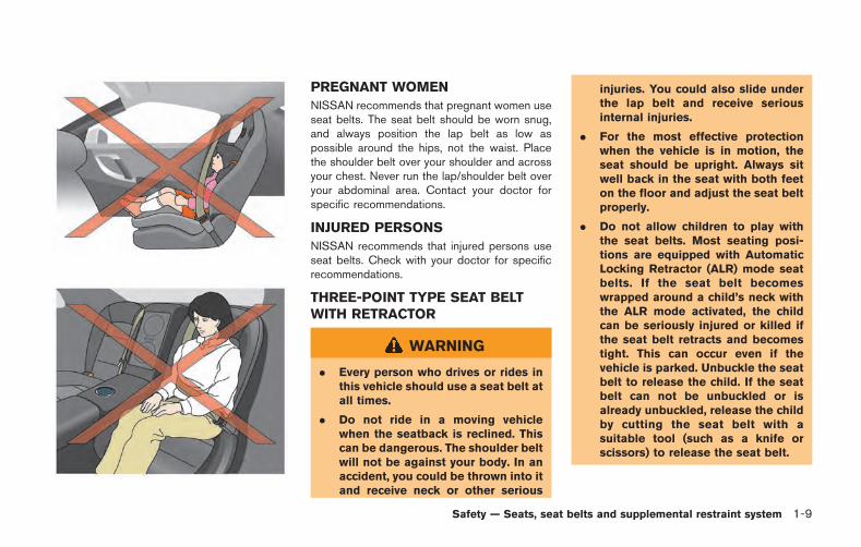
PREGNANT WOMEN
NISSAN recommends that pregnant women useseat belts. The seat belt should be worn snug,and always position the lap belt as low aspossible around the hips, not the waist. Placethe shoulder belt over your shoulder and acrossyour chest. Never run the lap/shoulder belt overyour abdominal area. Contact your doctor forspecific recommendations.
INJURED PERSONS
NISSAN recommends that injured persons useseat belts. Check with your doctor for specificrecommendations.
THREE-POINT TYPE SEAT BELTWITH RETRACTOR
WARNING
. Every person who drives or rides inthis vehicle should use a seat belt atall times.
. Do not ride in a moving vehiclewhen the seatback is reclined. Thiscan be dangerous. The shoulder beltwill not be against your body. In anaccident, you could be thrown into itand receive neck or other serious
injuries. You could also slide underthe lap belt and receive seriousinternal injuries.
. For the most effective protectionwhen the vehicle is in motion, theseat should be upright. Always sitwell back in the seat with both feeton the floor and adjust the seat beltproperly.
. Do not allow children to play withthe seat belts. Most seating posi-tions are equipped with AutomaticLocking Retractor (ALR) mode seatbelts. If the seat belt becomeswrapped around a child’s neck withthe ALR mode activated, the childcan be seriously injured or killed ifthe seat belt retracts and becomestight. This can occur even if thevehicle is parked. Unbuckle the seatbelt to release the child. If the seatbelt can not be unbuckled or isalready unbuckled, release the childby cutting the seat belt with asuitable tool (such as a knife orscissors) to release the seat belt.
Safety — Seats, seat belts and supplemental restraint system 1-9
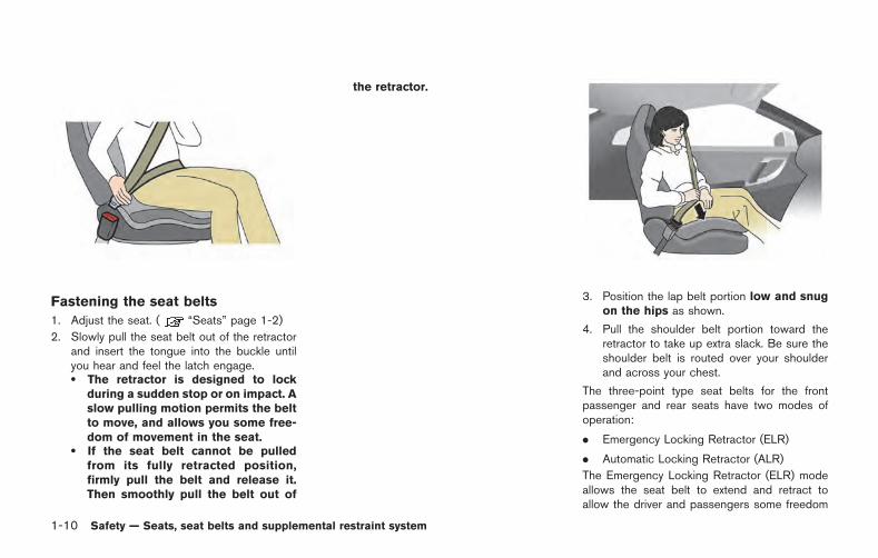
1-10 Safety — Seats, seat belts and supplemental restraint system
Fastening the seat belts
1. Adjust the seat. ( “Seats” page 1-2)
2. Slowly pull the seat belt out of the retractorand insert the tongue into the buckle untilyou hear and feel the latch engage.. The retractor is designed to lock
during a sudden stop or on impact. Aslow pulling motion permits the beltto move, and allows you some free-dom of movement in the seat.
. If the seat belt cannot be pulledfrom its fully retracted position,firmly pull the belt and release it.Then smoothly pull the belt out of
the retractor.
3. Position the lap belt portion low and snugon the hips as shown.
4. Pull the shoulder belt portion toward theretractor to take up extra slack. Be sure theshoulder belt is routed over your shoulderand across your chest.
The three-point type seat belts for the frontpassenger and rear seats have two modes ofoperation:
. Emergency Locking Retractor (ELR)
. Automatic Locking Retractor (ALR)
The Emergency Locking Retractor (ELR) modeallows the seat belt to extend and retract toallow the driver and passengers some freedom
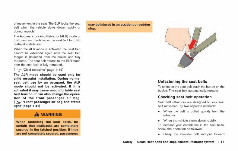
of movement in the seat. The ELR locks the seatbelt when the vehicle slows down rapidly orduring impacts.
The Automatic Locking Retractor (ALR) mode orchild restraint mode locks the seat belt for childrestraint installation.
When the ALR mode is activated the seat beltcannot be extended again until the seat belttongue is detached from the buckle and fullyretracted. The seat belt returns to the ELR modeafter the seat belt is fully retracted.
( “Child restraints” page 1-15)
The ALR mode should be used only forchild restraint installation. During normalseat belt use by an occupant, the ALRmode should not be activated. If it isactivated it may cause uncomfortable seatbelt tension. It can also change the opera-tion of the front passenger air bag.( “Front passenger air bag and statuslight” page 1-41)
WARNING
When fastening the seat belts, becertain that seatbacks are completelysecured in the latched position. If theyare not completely secured, passengers
may be injured in an accident or suddenstop.
Unfastening the seat belts
To unfasten the seat belt, push the button on thebuckle. The seat belt automatically retracts.
Checking seat belt operation
Seat belt retractors are designed to lock seatbelt movement by two separate methods:
. When the belt is pulled quickly from theretractor.
. When the vehicle slows down rapidly.
To increase your confidence in the seat belts,check the operation as follows:
. Grasp the shoulder belt and pull forward
Safety — Seats, seat belts and supplemental restraint system 1-11
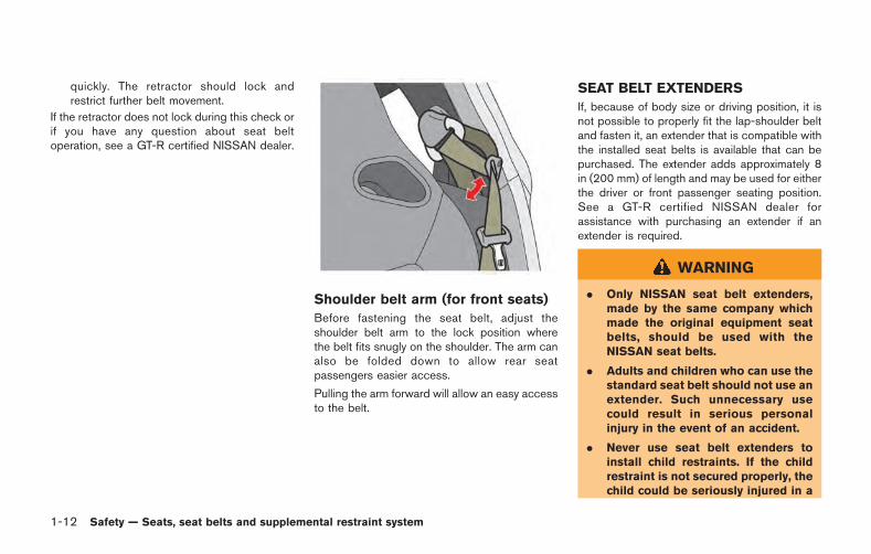
1-12 Safety — Seats, seat belts and supplemental restraint system
quickly. The retractor should lock andrestrict further belt movement.
If the retractor does not lock during this check orif you have any question about seat beltoperation, see a GT-R certified NISSAN dealer.
Shoulder belt arm (for front seats)
Before fastening the seat belt, adjust theshoulder belt arm to the lock position wherethe belt fits snugly on the shoulder. The arm canalso be folded down to allow rear seatpassengers easier access.
Pulling the arm forward will allow an easy accessto the belt.
SEAT BELT EXTENDERS
If, because of body size or driving position, it isnot possible to properly fit the lap-shoulder beltand fasten it, an extender that is compatible withthe installed seat belts is available that can bepurchased. The extender adds approximately 8in (200 mm) of length and may be used for eitherthe driver or front passenger seating position.See a GT-R certified NISSAN dealer forassistance with purchasing an extender if anextender is required.
WARNING
. Only NISSAN seat belt extenders,made by the same company whichmade the original equipment seatbelts, should be used with theNISSAN seat belts.
. Adults and children who can use thestandard seat belt should not use anextender. Such unnecessary usecould result in serious personalinjury in the event of an accident.
. Never use seat belt extenders toinstall child restraints. If the childrestraint is not secured properly, thechild could be seriously injured in a

collision or a sudden stop.
SEAT BELT MAINTENANCE
. To clean the seat belt webbing, apply amild soap solution or any solution recom-mended for cleaning upholstery or carpets.Then, wipe with a cloth and allow the seatbelts to dry in the shade. Do not allow theseat belts to retract until they are completelydry.
. If dirt builds up in the shoulder beltguide of the seat belt anchors, the seatbelts may retract slowly. Wipe the shoulderbelt guide with a clean, dry cloth.
. Periodically check to see that the seatbelt and the metal components such asbuckles, tongues, retractors, flexible wiresand anchors work properly. If loose parts,deterioration, cuts or other damage on thewebbing is found, the entire seat beltassembly should be replaced.
WARNING
Do not allow children to play with theseat belts. Most seating positions areequipped with Automatic Locking Re-tractor (ALR) mode seat belts. If theseat belt becomes wrapped around achild’s neck with the ALR mode acti-vated, the child can be seriously injuredor killed if the seat belt retracts andbecomes tight. This can occur even ifthe vehicle is parked. Unbuckle the seatbelt to release the child. If the seat beltcan not be unbuckled or is alreadyunbuckled, release the child by cuttingthe seat belt with a suitable tool (suchas a knife or scissors) to release theseat belt.
Children need adults to help protect them.They need to be properly restrained.
In addition to the general information in thismanual, child safety information is available frommany other sources, including doctors, teachers,government traffic safety offices, and communityorganizations. Every child is different, so be sureto learn the best way to transport your child.
There are three basic types of child restraint
systems:
. Rear-facing child restraint
. Forward-facing child restraint
. Booster seat
The proper restraint depends on the child’s size.Generally, infants (up to about 1 year and lessthan 20 lb (9 kg)) should be placed in rear-facing child restraints. Forward-facing childrestraints are available for children who outgrowrear-facing child restraints and are at least 1year old. Booster seats are used to help positiona vehicle lap/shoulder belt on a child who can nolonger use a forward-facing child restraint.
WARNING
Infants and children need special pro-tection. The vehicle’s seat belts may notfit them properly. The shoulder belt maycome too close to the face or neck. Thelap belt may not fit over their small hipbones. In an accident, an improperlyfitting seat belt could cause serious orfatal injury. Always use appropriatechild restraints.
All U.S. states and Canadian provinces orterritories require the use of approved child
Safety — Seats, seat belts and supplemental restraint system 1-13
CHILD SAFETY
1-14 Safety — Seats, seat belts and supplemental restraint system
restraints for infants and small children.( “Child restraints” page 1-15)
A child restraint may be secured in the vehicleby using either the LATCH (Lower Anchor andTethers for CHildren) system or with the vehicleseat belt. ( “Child restraints” page 1-15)
NISSAN recommends that all pre-teensand children be restrained in the rear seat.According to accident statistics, childrenare safer when properly restrained in therear seat than in the front seat.
This is especially important because yourvehicle has a supplemental restraint sys-tem (air bag system) for the front passen-ger. ( “Supplemental restraint system”page 1-34)
INFANTS
Infants up to at least one year old should beplaced in a rear-facing child restraint. NISSANrecommends that infants be placed in childrestraints that comply with Federal MotorVehicle Safety Standards or Canadian MotorVehicle Safety Standards. You should choose achild restraint which fits your vehicle and alwaysfollow the manufacturer’s instructions for instal-lation and use.
SMALL CHILDREN
Children that are over 1 year old and weigh atleast 20 lb (9 kg) should remain in a rear-facingchild restraint as long as possible up to theheight or weight limit of the child restraint.Children who outgrow the height or weight limitof the rear-facing child restraint and are at least1 year old should be secured in a forward-facingchild restraint with a harness. Refer to themanufacturer’s instructions for minimum andmaximum weight and height recommendations.NISSAN recommends that small children beplaced in child restraints that comply withFederal Motor Vehicle Safety Standards orCanadian Motor Vehicle Safety Standards. Youshould choose a child restraint that fits yourvehicle and always follow the manufacturer’sinstructions for installation and use.
LARGER CHILDREN
Children should remain in a forward-facing childrestraint with a harness until they reach themaximum height or weight limit allowed by thechild restraint manufacturer.
Once a child outgrows the height or weight limitof the harness-equipped forward-facing childrestraint, NISSAN recommends that the child beplaced in a commercially available booster seatto obtain proper seat belt fit. For a seat belt to fit
properly, the booster seat should raise the childso that the shoulder belt is properly positionedacross the chest and the top, middle portion ofthe shoulder. The shoulder belt should not crossthe neck or face and should not fall off theshoulder. The lap belt should lie snugly acrossthe lower hips or upper thighs, not the abdomen.
A booster seat can only be used in seatingpositions that have a three-point type seat belt.The booster seat should fit the vehicle seat andhave a label certifying that it complies withFederal Motor Vehicle Safety Standards orCanadian Motor Vehicle Safety Standards.Once the child has grown so the shoulder beltis no longer on or near the face and neck, andthe lap belt can be positioned properly acrossthe lower hips or upper thighs, use the seat beltwithout the booster seat.
WARNING
Never let a child stand or kneel on anyseat and do not allow a child in thecargo areas while the vehicle is moving.The child could be seriously injured orkilled in an accident or sudden stop.
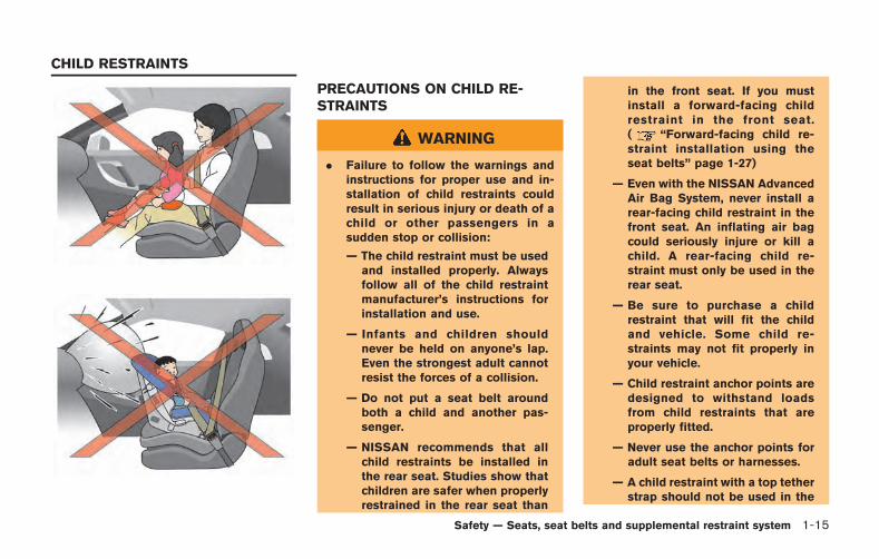
PRECAUTIONS ON CHILD RE-STRAINTS
WARNING
. Failure to follow the warnings andinstructions for proper use and in-stallation of child restraints couldresult in serious injury or death of achild or other passengers in asudden stop or collision:
— The child restraint must be usedand installed properly. Alwaysfollow all of the child restraintmanufacturer’s instructions forinstallation and use.
— Infants and children shouldnever be held on anyone’s lap.Even the strongest adult cannotresist the forces of a collision.
— Do not put a seat belt aroundboth a child and another pas-senger.
— NISSAN recommends that allchild restraints be installed inthe rear seat. Studies show thatchildren are safer when properlyrestrained in the rear seat than
in the front seat. If you mustinstall a forward-facing childrestraint in the front seat.( “Forward-facing child re-straint installation using theseat belts” page 1-27)
— Even with the NISSAN AdvancedAir Bag System, never install arear-facing child restraint in thefront seat. An inflating air bagcould seriously injure or kill achild. A rear-facing child re-straint must only be used in therear seat.
— Be sure to purchase a childrestraint that will fit the childand vehicle. Some child re-straints may not fit properly inyour vehicle.
— Child restraint anchor points aredesigned to withstand loadsfrom child restraints that areproperly fitted.
— Never use the anchor points foradult seat belts or harnesses.
— A child restraint with a top tetherstrap should not be used in the
Safety — Seats, seat belts and supplemental restraint system 1-15
CHILD RESTRAINTS
1-16 Safety — Seats, seat belts and supplemental restraint system
front passenger seat.
— Keep seatbacks as upright aspossible after fitting the childrestraint.
— Infants and children should al-ways be placed in an appropri-ate child restraint while in thevehicle.
. When the child restraint is not inuse, keep it secured with the LATCHsystem or a seat belt. In a suddenstop or collision, loose objects caninjure occupants or damage thevehicle.
CAUTION
A child restraint in a closed vehicle canbecome very hot. Check the seatingsurface and buckles before placing achild in the child restraint.
This vehicle is equipped with a universal childrestraint anchor system, referred to as theLATCH (Lower Anchors and Tethers for CHil-dren) system. Some child restraints include rigidor webbing-mounted attachments that can be
connected to these anchors. (See “LowerAnchors and Tethers for CHildren System(LATCH)” page 1-17.)
If you do not have a LATCH compatible childrestraint, the vehicle seat belts can be used.
Several manufacturers offer child restraints forinfants and small children of various sizes. Whenselecting any child restraint, keep the followingpoints in mind:
. Choose only a restraint with a label certifyingthat it complies with Federal Motor VehicleSafety Standard 213 or Canadian MotorVehicle Safety Standard 213.
. Check the child restraint in your vehicle tobe sure it is compatible with the vehicle’sseat and seat belt system.
. If the child restraint is compatible with yourvehicle, place your child in the child restraintand check the various adjustments to besure the child restraint is compatible withyour child. Choose a child restraint that isdesigned for your child’s height and weight.Always follow all recommended procedures.
. If the combined weight of the child and childrestraint is less than 65 lbs (29.5 kg), youmay use either the LATCH anchors or theseat belt to install the child restraint (notboth at the same time).
. If the combined weight of the child and childrestraint is greater than 65 lbs (29.5 kg), usethe vehicle’s seat belt (not the loweranchors) to install the child restraint.
. Be sure to follow the child restraint manu-facturer’s instructions for installation.
All U.S. states and Canadian provinces orterritories require that infants and smallchildren be restrained in an approved childrestraint at all times while the vehicle isbeing operated. Canadian law requires thetop tether strap on forward-facing childrestraints be secured to the designatedanchor point on the vehicle.
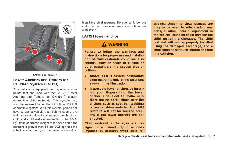
LATCH label location
Lower Anchors and Tethers forCHildren System (LATCH)
Your vehicle is equipped with special anchorpoints that are used with the LATCH (LowerAnchors and Tethers for CHildren) systemcompatible child restraints. This system mayalso be referred to as the ISOFIX or ISOFIXcompatible system. With this system, you do nothave to use a vehicle seat belt to secure thechild restraint unless the combined weight of thechild and child restraint exceeds 65 lbs (29.5kg). If the combined weight of the child and childrestraint is greater than 65 lbs (29.5 kg), use thevehicle’s seat belt (not the lower anchors) to
install the child restraint. Be sure to follow thechild restraint manufacturer’s instructions forinstallation.
LATCH lower anchor
WARNING
Failure to follow the warnings andinstructions for proper use and installa-tion of child restraints could result inserious injury or death of a child orother passengers in a sudden stop orcollision:
. Attach LATCH system compatiblechild restraints only at the locationsshown in the illustration.
. Inspect the lower anchors by insert-ing your fingers into the loweranchor area. Feel to make surethere are no obstructions over theanchors such as seat belt webbingor seat cushion material. The childrestraint will not be secured prop-erly if the lower anchors are ob-structed.
Child restraint anchorages are de-signed to withstand only those loadsimposed by correctly fitted child re-
straints. Under no circumstances arethey to be used to attach adult seatbelts, or other items or equipment tothe vehicle. Doing so could damage thechild restraint anchorages. The childrestraint will not be properly installedusing the damaged anchorage, and achild could be seriously injured or killedin a collision.
Safety — Seats, seat belts and supplemental restraint system 1-17
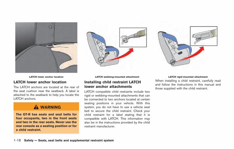
1-18 Safety — Seats, seat belts and supplemental restraint system
LATCH lower anchor location
LATCH lower anchor location
The LATCH anchors are located at the rear ofthe seat cushion near the seatback. A label isattached to the seatback to help you locate theLATCH anchors.
WARNING
The GT-R has seats and seat belts forfour occupants, two in the front seatsand two in the rear seats. Never use therear console as a seating position or fora child restraint.
LATCH webbing-mounted attachment
Installing child restraint LATCHlower anchor attachments
LATCH compatible child restraints include tworigid or webbing-mounted attachments that canbe connected to two anchors located at certainseating positions in your vehicle. With thissystem, you do not have to use a vehicle seatbelt to secure the child restraint. Check yourchild restraint for a label stating that it iscompatible with LATCH. This information mayalso be in the instructions provided by the childrestraint manufacturer.
LATCH rigid-mounted attachment
When installing a child restraint, carefully readand follow the instructions in this manual andthose supplied with the child restraint.
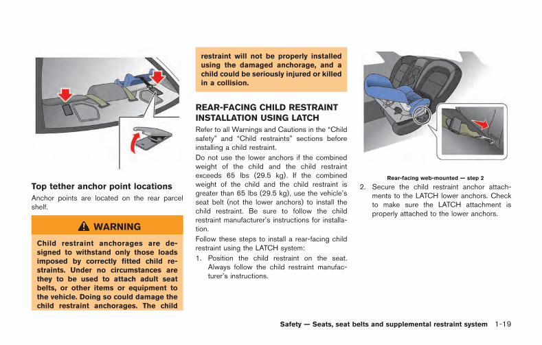
Top tether anchor point locations
Anchor points are located on the rear parcelshelf.
WARNING
Child restraint anchorages are de-signed to withstand only those loadsimposed by correctly fitted child re-straints. Under no circumstances arethey to be used to attach adult seatbelts, or other items or equipment tothe vehicle. Doing so could damage thechild restraint anchorages. The child
restraint will not be properly installedusing the damaged anchorage, and achild could be seriously injured or killedin a collision.
REAR-FACING CHILD RESTRAINTINSTALLATION USING LATCH
Refer to all Warnings and Cautions in the “Childsafety” and “Child restraints” sections beforeinstalling a child restraint.
Do not use the lower anchors if the combinedweight of the child and the child restraintexceeds 65 lbs (29.5 kg). If the combinedweight of the child and the child restraint isgreater than 65 lbs (29.5 kg), use the vehicle’sseat belt (not the lower anchors) to install thechild restraint. Be sure to follow the childrestraint manufacturer’s instructions for installa-tion.
Follow these steps to install a rear-facing childrestraint using the LATCH system:
1. Position the child restraint on the seat.Always follow the child restraint manufac-turer’s instructions.
Rear-facing web-mounted — step 2
2. Secure the child restraint anchor attach-ments to the LATCH lower anchors. Checkto make sure the LATCH attachment isproperly attached to the lower anchors.
Safety — Seats, seat belts and supplemental restraint system 1-19
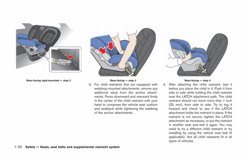
1-20 Safety — Seats, seat belts and supplemental restraint system
Rear-facing rigid-mounted — step 2 Rear-facing — step 3
3. For child restraints that are equipped withwebbing-mounted attachments, remove anyadditional slack from the anchor attach-ments. Press downward and rearward firmlyin the center of the child restraint with yourhand to compress the vehicle seat cushionand seatback while tightening the webbingof the anchor attachments.
Rear-facing — step 4
4. After attaching the child restraint, test itbefore you place the child in it. Push it fromside to side while holding the child restraintnear the LATCH attachment path. The childrestraint should not move more than 1 inch(25 mm), from side to side. Try to tug itforward and check to see if the LATCHattachment holds the restraint in place. If therestraint is not secure, tighten the LATCHattachment as necessary, or put the restraintin another seat and test it again. You mayneed to try a different child restraint or tryinstalling by using the vehicle seat belt (ifapplicable). Not all child restraints fit in alltypes of vehicles.
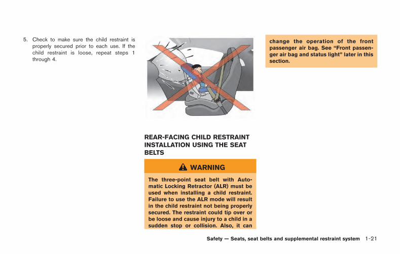
5. Check to make sure the child restraint isproperly secured prior to each use. If thechild restraint is loose, repeat steps 1through 4.
REAR-FACING CHILD RESTRAINTINSTALLATION USING THE SEATBELTS
WARNING
The three-point seat belt with Auto-matic Locking Retractor (ALR) must beused when installing a child restraint.Failure to use the ALR mode will resultin the child restraint not being properlysecured. The restraint could tip over orbe loose and cause injury to a child in asudden stop or collision. Also, it can
change the operation of the frontpassenger air bag. See “Front passen-ger air bag and status light” later in thissection.
Safety — Seats, seat belts and supplemental restraint system 1-21
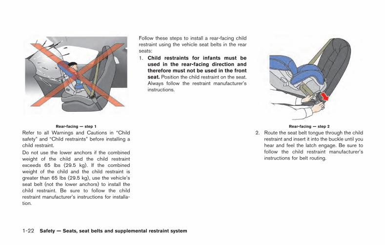
1-22 Safety — Seats, seat belts and supplemental restraint system
Rear-facing — step 1
Refer to all Warnings and Cautions in “Childsafety” and “Child restraints” before installing achild restraint.
Do not use the lower anchors if the combinedweight of the child and the child restraintexceeds 65 lbs (29.5 kg). If the combinedweight of the child and the child restraint isgreater than 65 lbs (29.5 kg), use the vehicle’sseat belt (not the lower anchors) to install thechild restraint. Be sure to follow the childrestraint manufacturer’s instructions for installa-tion.
Follow these steps to install a rear-facing childrestraint using the vehicle seat belts in the rearseats:
1. Child restraints for infants must beused in the rear-facing direction andtherefore must not be used in the frontseat. Position the child restraint on the seat.Always follow the restraint manufacturer’sinstructions.
Rear-facing — step 2
2. Route the seat belt tongue through the childrestraint and insert it into the buckle until youhear and feel the latch engage. Be sure tofollow the child restraint manufacturer’sinstructions for belt routing.
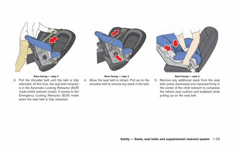
Rear-facing — step 3
3. Pull the shoulder belt until the belt is fullyextended. At this time, the seat belt retractoris in the Automatic Locking Retractor (ALR)mode (child restraint mode). It reverts to theEmergency Locking Retractor (ELR) modewhen the seat belt is fully retracted.
Rear-facing — step 4
4. Allow the seat belt to retract. Pull up on theshoulder belt to remove any slack in the belt.
Rear-facing — step 5
5. Remove any additional slack from the seatbelt; press downward and rearward firmly inthe center of the child restraint to compressthe vehicle seat cushion and seatback whilepulling up on the seat belt.
Safety — Seats, seat belts and supplemental restraint system 1-23
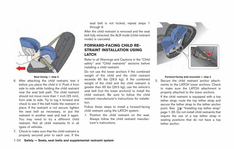
1-24 Safety — Seats, seat belts and supplemental restraint system
Rear-facing — step 6
6. After attaching the child restraint, test itbefore you place the child in it. Push it fromside to side while holding the child restraintnear the seat belt path. The child restraintshould not move more than 1 inch (25 mm),from side to side. Try to tug it forward andcheck to see if the belt holds the restraint inplace. If the restraint is not secure, tightenthe seat belt as necessary, or put therestraint in another seat and test it again.You may need to try a different childrestraint. Not all child restraints fit in alltypes of vehicles.
7. Check to make sure that the child restraint isproperly secured prior to each use. If the
seat belt is not locked, repeat steps 1through 6.
After the child restraint is removed and the seatbelt fully retracted, the ALR mode (child restraintmode) is canceled.
FORWARD-FACING CHILD RE-STRAINT INSTALLATION USINGLATCH
Refer to all Warnings and Cautions in the “Childsafety” and “Child restraints” sections beforeinstalling a child restraint.
Do not use the lower anchors if the combinedweight of the child and the child restraintexceeds 65 lbs (29.5 kg). If the combinedweight of the child and the child restraint isgreater than 65 lbs (29.5 kg), use the vehicle’sseat belt (not the lower anchors) to install thechild restraint. Be sure to follow the childrestraint manufacturer’s instructions for installa-tion.
Follow these steps to install a forward-facingchild restraint using the LATCH system:
1. Position the child restraint on the seat.Always follow the child restraint manufac-turer’s instructions.
Forward-facing web-mounted — step 2
2. Secure the child restraint anchor attach-ments to the LATCH lower anchors. Checkto make sure the LATCH attachment isproperly attached to the lower anchors.
If the child restraint is equipped with a toptether strap, route the top tether strap andsecure the tether strap to the tether anchorpoint. See “Installing top tether strap”page 1-26. Do not install child restraints thatrequire the use of a top tether strap inseating positions that do not have a toptether anchor.
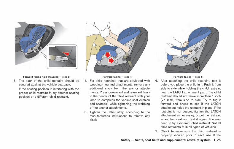
Forward-facing rigid-mounted — step 2
3. The back of the child restraint should besecured against the vehicle seatback.
If the seating position is interfering with theproper child restraint fit, try another seatingposition or a different child restraint.
Forward-facing — step 4
4. For child restraints that are equipped withwebbing-mounted attachments, remove anyadditional slack from the anchor attach-ments. Press downward and rearward firmlyin the center of the child restraint with yourknee to compress the vehicle seat cushionand seatback while tightening the webbingof the anchor attachments.
5. Tighten the tether strap according to themanufacturer’s instructions to remove anyslack.
Forward-facing — step 6
6. After attaching the child restraint, test itbefore you place the child in it. Push it fromside to side while holding the child restraintnear the LATCH attachment path. The childrestraint should not move more than 1 inch(25 mm), from side to side. Try to tug itforward and check to see if the LATCHattachment holds the restraint in place. If therestraint is not secure, tighten the LATCHattachment as necessary, or put the restraintin another seat and test it again. You mayneed to try a different child restraint. Not allchild restraints fit in all types of vehicles.
7. Check to make sure the child restraint isproperly secured prior to each use. If the
Safety — Seats, seat belts and supplemental restraint system 1-25
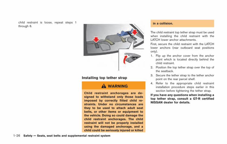
1-26 Safety — Seats, seat belts and supplemental restraint system
child restraint is loose, repeat steps 1through 6.
Installing top tether strap
WARNING
Child restraint anchorages are de-signed to withstand only those loadsimposed by correctly fitted child re-straints. Under no circumstances arethey to be used to attach adult seatbelts, or other items or equipment tothe vehicle. Doing so could damage thechild restraint anchorages. The childrestraint will not be properly installedusing the damaged anchorage, and achild could be seriously injured or killed
in a collision.
The child restraint top tether strap must be usedwhen installing the child restraint with theLATCH lower anchor attachments.
First, secure the child restraint with the LATCHlower anchors (rear outboard seat positionsonly).
1. Flip up the anchor cover from the anchorpoint which is located directly behind thechild restraint.
2. Position the top tether strap over the top ofthe seatback.
3. Secure the tether strap to the tether anchorpoint on the rear parcel shelf.
4. Refer to the appropriate child restraintinstallation procedure steps earlier in thissection before tightening the tether strap.
If you have any questions when installing atop tether strap, consult a GT-R certifiedNISSAN dealer for details.
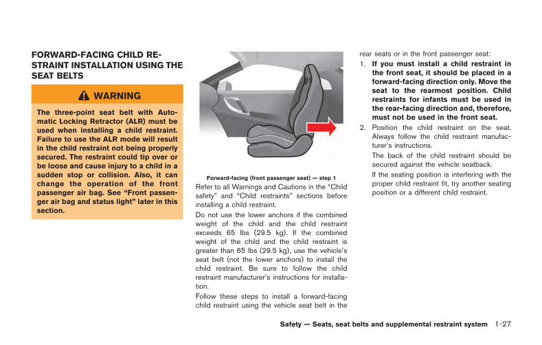
FORWARD-FACING CHILD RE-STRAINT INSTALLATION USING THESEAT BELTS
WARNING
The three-point seat belt with Auto-matic Locking Retractor (ALR) must beused when installing a child restraint.Failure to use the ALR mode will resultin the child restraint not being properlysecured. The restraint could tip over orbe loose and cause injury to a child in asudden stop or collision. Also, it canchange the operation of the frontpassenger air bag. See “Front passen-ger air bag and status light” later in thissection.
Forward-facing (front passenger seat) — step 1
Refer to all Warnings and Cautions in the “Childsafety” and “Child restraints” sections beforeinstalling a child restraint.
Do not use the lower anchors if the combinedweight of the child and the child restraintexceeds 65 lbs (29.5 kg). If the combinedweight of the child and the child restraint isgreater than 65 lbs (29.5 kg), use the vehicle’sseat belt (not the lower anchors) to install thechild restraint. Be sure to follow the childrestraint manufacturer’s instructions for installa-tion.
Follow these steps to install a forward-facingchild restraint using the vehicle seat belt in the
rear seats or in the front passenger seat:
1. If you must install a child restraint inthe front seat, it should be placed in aforward-facing direction only. Move theseat to the rearmost position. Childrestraints for infants must be used inthe rear-facing direction and, therefore,must not be used in the front seat.
2. Position the child restraint on the seat.Always follow the child restraint manufac-turer’s instructions.
The back of the child restraint should besecured against the vehicle seatback.
If the seating position is interfering with theproper child restraint fit, try another seatingposition or a different child restraint.
Safety — Seats, seat belts and supplemental restraint system 1-27
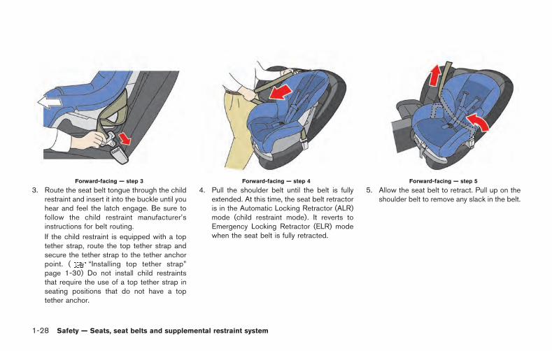
1-28 Safety — Seats, seat belts and supplemental restraint system
Forward-facing — step 3
3. Route the seat belt tongue through the childrestraint and insert it into the buckle until youhear and feel the latch engage. Be sure tofollow the child restraint manufacturer’sinstructions for belt routing.
If the child restraint is equipped with a toptether strap, route the top tether strap andsecure the tether strap to the tether anchorpoint. ( “Installing top tether strap”page 1-30) Do not install child restraintsthat require the use of a top tether strap inseating positions that do not have a toptether anchor.
Forward-facing — step 4
4. Pull the shoulder belt until the belt is fullyextended. At this time, the seat belt retractoris in the Automatic Locking Retractor (ALR)mode (child restraint mode). It reverts toEmergency Locking Retractor (ELR) modewhen the seat belt is fully retracted.
Forward-facing — step 5
5. Allow the seat belt to retract. Pull up on theshoulder belt to remove any slack in the belt.
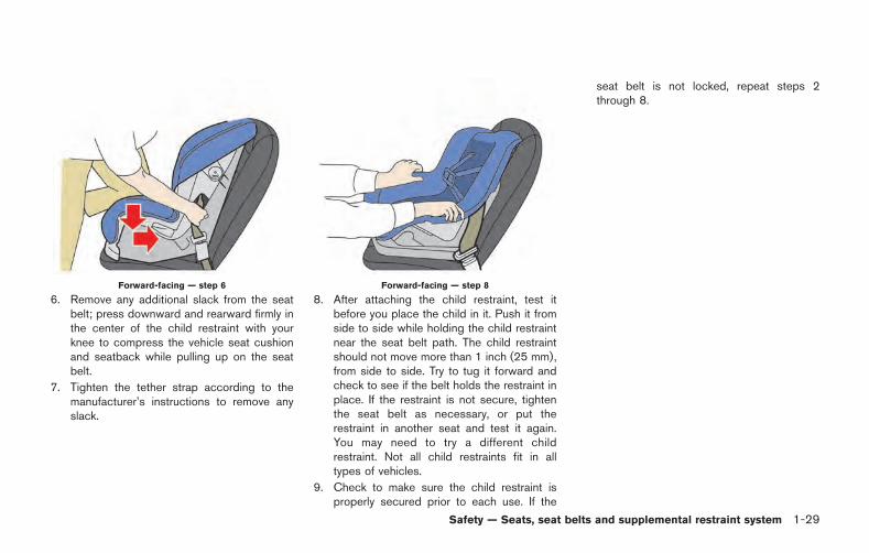
Forward-facing — step 6
6. Remove any additional slack from the seatbelt; press downward and rearward firmly inthe center of the child restraint with yourknee to compress the vehicle seat cushionand seatback while pulling up on the seatbelt.
7. Tighten the tether strap according to themanufacturer’s instructions to remove anyslack.
Forward-facing — step 8
8. After attaching the child restraint, test itbefore you place the child in it. Push it fromside to side while holding the child restraintnear the seat belt path. The child restraintshould not move more than 1 inch (25 mm),from side to side. Try to tug it forward andcheck to see if the belt holds the restraint inplace. If the restraint is not secure, tightenthe seat belt as necessary, or put therestraint in another seat and test it again.You may need to try a different childrestraint. Not all child restraints fit in alltypes of vehicles.
9. Check to make sure the child restraint isproperly secured prior to each use. If the
seat belt is not locked, repeat steps 2through 8.
Safety — Seats, seat belts and supplemental restraint system 1-29
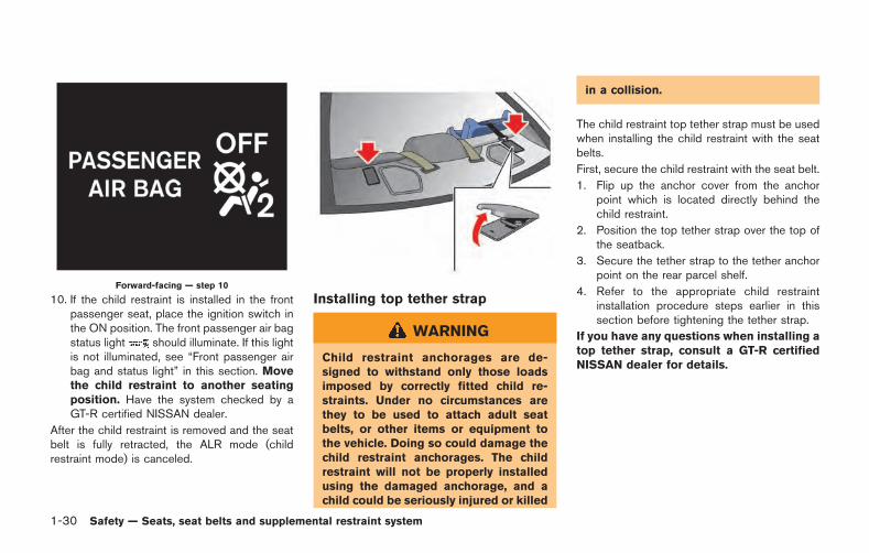
1-30 Safety — Seats, seat belts and supplemental restraint system
Forward-facing — step 10
10. If the child restraint is installed in the frontpassenger seat, place the ignition switch inthe ON position. The front passenger air bagstatus light should illuminate. If this lightis not illuminated, see “Front passenger airbag and status light” in this section. Movethe child restraint to another seatingposition. Have the system checked by aGT-R certified NISSAN dealer.
After the child restraint is removed and the seatbelt is fully retracted, the ALR mode (childrestraint mode) is canceled.
Installing top tether strap
WARNING
Child restraint anchorages are de-signed to withstand only those loadsimposed by correctly fitted child re-straints. Under no circumstances arethey to be used to attach adult seatbelts, or other items or equipment tothe vehicle. Doing so could damage thechild restraint anchorages. The childrestraint will not be properly installedusing the damaged anchorage, and achild could be seriously injured or killed
in a collision.
The child restraint top tether strap must be usedwhen installing the child restraint with the seatbelts.
First, secure the child restraint with the seat belt.
1. Flip up the anchor cover from the anchorpoint which is located directly behind thechild restraint.
2. Position the top tether strap over the top ofthe seatback.
3. Secure the tether strap to the tether anchorpoint on the rear parcel shelf.
4. Refer to the appropriate child restraintinstallation procedure steps earlier in thissection before tightening the tether strap.
If you have any questions when installing atop tether strap, consult a GT-R certifiedNISSAN dealer for details.
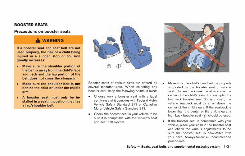
BOOSTER SEATS
Precautions on booster seats
WARNING
If a booster seat and seat belt are notused properly, the risk of a child beinginjured in a sudden stop or collisiongreatly increases:
. Make sure the shoulder portion ofthe belt is away from the child’s faceand neck and the lap portion of thebelt does not cross the stomach.
. Make sure the shoulder belt is notbehind the child or under the child’sarm.
. A booster seat must only be in-stalled in a seating position that hasa lap/shoulder belt.
Booster seats of various sizes are offered byseveral manufacturers. When selecting anybooster seat, keep the following points in mind:
. Choose only a booster seat with a labelcertifying that it complies with Federal MotorVehicle Safety Standard 213 or CanadianMotor Vehicle Safety Standard 213.
. Check the booster seat in your vehicle to besure it is compatible with the vehicle’s seatand seat belt system.
. Make sure the child’s head will be properlysupported by the booster seat or vehicleseat. The seatback must be at or above thecenter of the child’s ears. For example, if alow back booster seat *1 is chosen, thevehicle seatback must be at or above thecenter of the child’s ears. If the seatback islower than the center of the child’s ears, ahigh back booster seat*2 should be used.
. If the booster seat is compatible with yourvehicle, place your child in the booster seatand check the various adjustments to besure the booster seat is compatible withyour child. Always follow all recommendedprocedures.
Safety — Seats, seat belts and supplemental restraint system 1-31
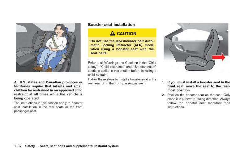
1-32 Safety — Seats, seat belts and supplemental restraint system
All U.S. states and Canadian provinces orterritories require that infants and smallchildren be restrained in an approved childrestraint at all times while the vehicle isbeing operated.
The instructions in this section apply to boosterseat installation in the rear seats or the frontpassenger seat.
Booster seat installation
CAUTION
Do not use the lap/shoulder belt Auto-matic Locking Retractor (ALR) modewhen using a booster seat with theseat belts.
Refer to all Warnings and Cautions in the “Childsafety”, “Child restraints” and “Booster seats”sections earlier in this section before installing achild restraint.
Follow these steps to install a booster seat in therear seat or in the front passenger seat: 1. If you must install a booster seat in the
front seat, move the seat to the rear-most position.
2. Position the booster seat on the seat. Onlyplace it in a forward-facing direction. Alwaysfollow the booster seat manufacturer’sinstructions.
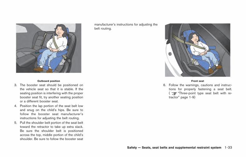
Outboard position
3. The booster seat should be positioned onthe vehicle seat so that it is stable. If theseating position is interfering with the properbooster seat fit, try another seating positionor a different booster seat.
4. Position the lap portion of the seat belt lowand snug on the child’s hips. Be sure tofollow the booster seat manufacturer’sinstructions for adjusting the belt routing.
5. Pull the shoulder belt portion of the seat belttoward the retractor to take up extra slack.Be sure the shoulder belt is positionedacross the top, middle portion of the child’sshoulder. Be sure to follow the booster seat
manufacturer’s instructions for adjusting thebelt routing.
Front seat
6. Follow the warnings, cautions and instruc-tions for properly fastening a seat belt.( “Three-point type seat belt with re-tractor” page 1-9)
Safety — Seats, seat belts and supplemental restraint system 1-33
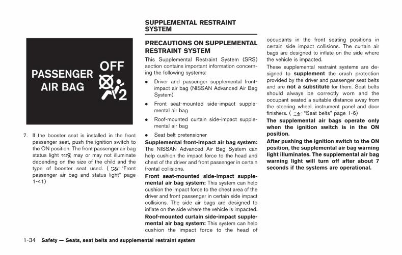
1-34 Safety — Seats, seat belts and supplemental restraint system
7. If the booster seat is installed in the frontpassenger seat, push the ignition switch tothe ON position. The front passenger air bagstatus light may or may not illuminatedepending on the size of the child and thetype of booster seat used. ( “Frontpassenger air bag and status light” page1-41)
PRECAUTIONS ON SUPPLEMENTALRESTRAINT SYSTEM
This Supplemental Restraint System (SRS)section contains important information concern-ing the following systems:
. Driver and passenger supplemental front-impact air bag (NISSAN Advanced Air BagSystem)
. Front seat-mounted side-impact supple-mental air bag
. Roof-mounted curtain side-impact supple-mental air bag
. Seat belt pretensioner
Supplemental front-impact air bag system:The NISSAN Advanced Air Bag System canhelp cushion the impact force to the head andchest of the driver and front passenger in certainfrontal collisions.
Front seat-mounted side-impact supple-mental air bag system: This system can helpcushion the impact force to the chest area of thedriver and front passenger in certain side impactcollisions. The side air bags are designed toinflate on the side where the vehicle is impacted.
Roof-mounted curtain side-impact supple-mental air bag system: This system can helpcushion the impact force to the head of
occupants in the front seating positions incertain side impact collisions. The curtain airbags are designed to inflate on the side wherethe vehicle is impacted.
These supplemental restraint systems are de-signed to supplement the crash protectionprovided by the driver and passenger seat beltsand are not a substitute for them. Seat beltsshould always be correctly worn and theoccupant seated a suitable distance away fromthe steering wheel, instrument panel and doorfinishers. ( “Seat belts” page 1-6)
The supplemental air bags operate onlywhen the ignition switch is in the ONposition.
After pushing the ignition switch to the ONposition, the supplemental air bag warninglight illuminates. The supplemental air bagwarning light will turn off after about 7seconds if the systems are operational.
SUPPLEMENTAL RESTRAINTSYSTEM
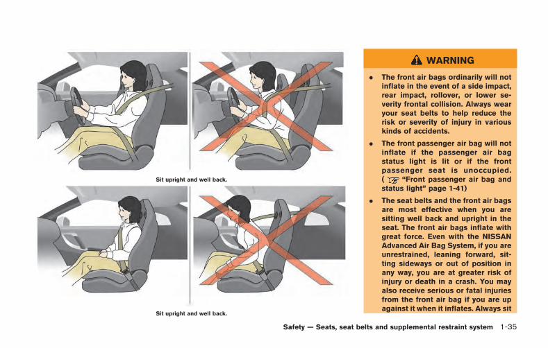
Sit upright and well back.
Sit upright and well back.
WARNING
. The front air bags ordinarily will notinflate in the event of a side impact,rear impact, rollover, or lower se-verity frontal collision. Always wearyour seat belts to help reduce therisk or severity of injury in variouskinds of accidents.
. The front passenger air bag will notinflate if the passenger air bagstatus light is lit or if the frontpassenger seat is unoccupied.( “Front passenger air bag andstatus light” page 1-41)
. The seat belts and the front air bagsare most effective when you aresitting well back and upright in theseat. The front air bags inflate withgreat force. Even with the NISSANAdvanced Air Bag System, if you areunrestrained, leaning forward, sit-ting sideways or out of position inany way, you are at greater risk ofinjury or death in a crash. You mayalso receive serious or fatal injuriesfrom the front air bag if you are upagainst it when it inflates. Always sit
Safety — Seats, seat belts and supplemental restraint system 1-35
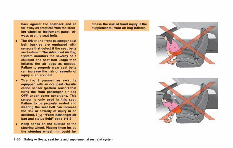
1-36 Safety — Seats, seat belts and supplemental restraint system
back against the seatback and asfar-away as practical from the steer-ing wheel or instrument panel. Al-ways use the seat belts.
. The driver and front passenger seatbelt buckles are equipped withsensors that detect if the seat beltsare fastened. The Advanced Air BagSystem monitors the severity of acollision and seat belt usage theninflates the air bags as needed.Failure to properly wear seat beltscan increase the risk or severity ofinjury in an accident.
. The front passenger seat isequipped with an occupant classifi-cation sensor (pattern sensor) thatturns the front passenger air bagOFF under some conditions. Thissensor is only used in this seat.Failure to be properly seated andwearing the seat belt can increasethe risk or severity of injury in anaccident. ( “Front passenger airbag and status light” page 1-41)
. Keep hands on the outside of thesteering wheel. Placing them insidethe steering wheel rim could in-
crease the risk of hand injury if thesupplemental front air bag inflates.
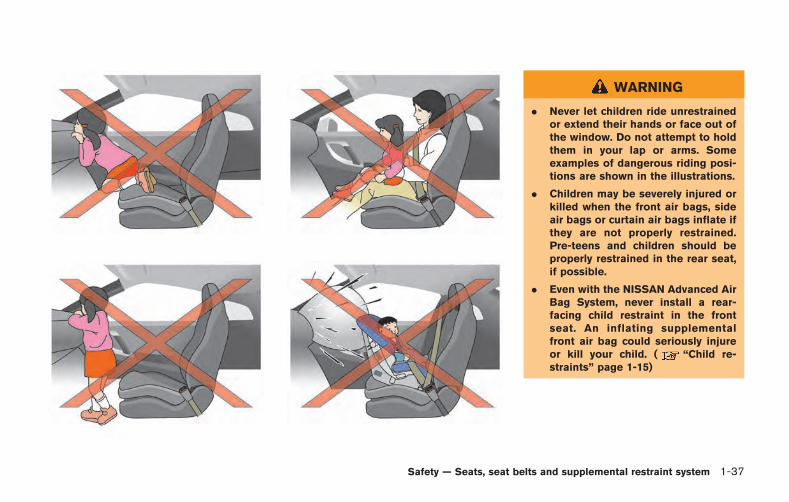
WARNING
. Never let children ride unrestrainedor extend their hands or face out ofthe window. Do not attempt to holdthem in your lap or arms. Someexamples of dangerous riding posi-tions are shown in the illustrations.
. Children may be severely injured orkilled when the front air bags, sideair bags or curtain air bags inflate ifthey are not properly restrained.Pre-teens and children should beproperly restrained in the rear seat,if possible.
. Even with the NISSAN Advanced AirBag System, never install a rear-facing child restraint in the frontseat. An inflating supplementalfront air bag could seriously injureor kill your child. ( “Child re-straints” page 1-15)
Safety — Seats, seat belts and supplemental restraint system 1-37

1-38 Safety — Seats, seat belts and supplemental restraint system
Do not lean against doors or windows. Do not lean against doors or windows.
WARNING
Front seat-mounted side-impact sup-plemental air bag and roof-mountedcurtain side-impact supplemental airbag :
. The side air bags and curtain airbags ordinarily will not inflate in theevent of a frontal impact, rear im-pact, rollover or lower severity sidecollision. Always wear your seatbelts to help reduce the risk orseverity of injury in various kindsof accidents.
. The seat belts, side air bags andcurtain air bags are most effectivewhen you are sitting well back andupright in the seat. The side air bagsand curtain air bags inflate withgreat force. Do not allow anyone toplace their hand, leg or face near theside air bag on the side of theseatback of the front seat or nearthe side roof rails. Do not allowanyone sitting in the front seat toextend their hand out of the windowor lean against the door. Someexamples of dangerous riding posi-
tions are shown in the previousillustrations.
. When sitting in the rear seat, do nothold onto the seatback of the frontseat. If the supplemental side airbag inflates, you may be seriouslyinjured. Be especially careful withchildren, who should always beproperly restrained. Some examplesof dangerous riding positions areshown in the illustrations.
. Do not use seat covers on the frontseatbacks. They may interfere withside air bag inflation.
Safety — Seats, seat belts and supplemental restraint system 1-39
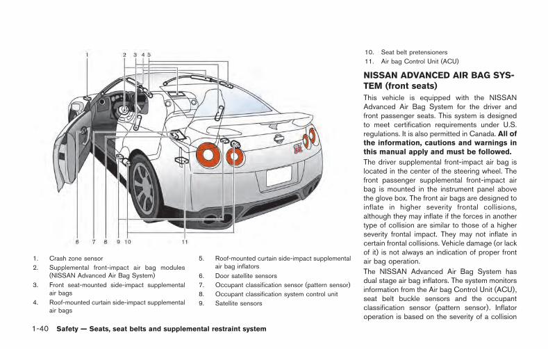
1-40 Safety — Seats, seat belts and supplemental restraint system
1. Crash zone sensor
2. Supplemental front-impact air bag modules(NISSAN Advanced Air Bag System)
3. Front seat-mounted side-impact supplementalair bags
4. Roof-mounted curtain side-impact supplementalair bags
5. Roof-mounted curtain side-impact supplementalair bag inflators
6. Door satellite sensors
7. Occupant classification sensor (pattern sensor)
8. Occupant classification system control unit
9. Satellite sensors
10. Seat belt pretensioners
11. Air bag Control Unit (ACU)
NISSAN ADVANCED AIR BAG SYS-TEM (front seats)
This vehicle is equipped with the NISSANAdvanced Air Bag System for the driver andfront passenger seats. This system is designedto meet certification requirements under U.S.regulations. It is also permitted in Canada. All ofthe information, cautions and warnings inthis manual apply and must be followed.
The driver supplemental front-impact air bag islocated in the center of the steering wheel. Thefront passenger supplemental front-impact airbag is mounted in the instrument panel abovethe glove box. The front air bags are designed toinflate in higher severity frontal collisions,although they may inflate if the forces in anothertype of collision are similar to those of a higherseverity frontal impact. They may not inflate incertain frontal collisions. Vehicle damage (or lackof it) is not always an indication of proper frontair bag operation.
The NISSAN Advanced Air Bag System hasdual stage air bag inflators. The system monitorsinformation from the Air bag Control Unit (ACU),seat belt buckle sensors and the occupantclassification sensor (pattern sensor). Inflatoroperation is based on the severity of a collision
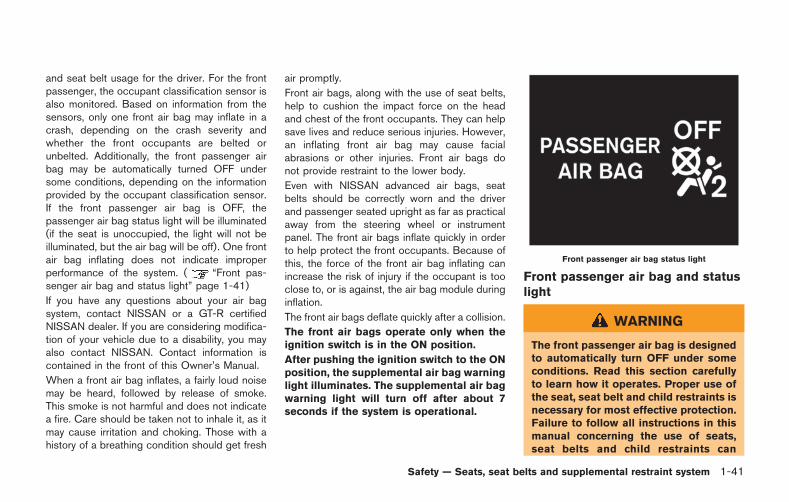
and seat belt usage for the driver. For the frontpassenger, the occupant classification sensor isalso monitored. Based on information from thesensors, only one front air bag may inflate in acrash, depending on the crash severity andwhether the front occupants are belted orunbelted. Additionally, the front passenger airbag may be automatically turned OFF undersome conditions, depending on the informationprovided by the occupant classification sensor.If the front passenger air bag is OFF, thepassenger air bag status light will be illuminated(if the seat is unoccupied, the light will not beilluminated, but the air bag will be off). One frontair bag inflating does not indicate improperperformance of the system. ( “Front pas-senger air bag and status light” page 1-41)
If you have any questions about your air bagsystem, contact NISSAN or a GT-R certifiedNISSAN dealer. If you are considering modifica-tion of your vehicle due to a disability, you mayalso contact NISSAN. Contact information iscontained in the front of this Owner’s Manual.
When a front air bag inflates, a fairly loud noisemay be heard, followed by release of smoke.This smoke is not harmful and does not indicatea fire. Care should be taken not to inhale it, as itmay cause irritation and choking. Those with ahistory of a breathing condition should get fresh
air promptly.
Front air bags, along with the use of seat belts,help to cushion the impact force on the headand chest of the front occupants. They can helpsave lives and reduce serious injuries. However,an inflating front air bag may cause facialabrasions or other injuries. Front air bags donot provide restraint to the lower body.
Even with NISSAN advanced air bags, seatbelts should be correctly worn and the driverand passenger seated upright as far as practicalaway from the steering wheel or instrumentpanel. The front air bags inflate quickly in orderto help protect the front occupants. Because ofthis, the force of the front air bag inflating canincrease the risk of injury if the occupant is tooclose to, or is against, the air bag module duringinflation.
The front air bags deflate quickly after a collision.
The front air bags operate only when theignition switch is in the ON position.
After pushing the ignition switch to the ONposition, the supplemental air bag warninglight illuminates. The supplemental air bagwarning light will turn off after about 7seconds if the system is operational.
Front passenger air bag status light
Front passenger air bag and statuslight
WARNING
The front passenger air bag is designedto automatically turn OFF under someconditions. Read this section carefullyto learn how it operates. Proper use ofthe seat, seat belt and child restraints isnecessary for most effective protection.Failure to follow all instructions in thismanual concerning the use of seats,seat belts and child restraints can
Safety — Seats, seat belts and supplemental restraint system 1-41
1-42 Safety — Seats, seat belts and supplemental restraint system
increase the risk or severity of injury inan accident.
Status light:
The front passenger air bag status light islocated on the center instrument panel. After theignition switch is placed in the ON position, thefront passenger air bag status light on theinstrument panel illuminates for about 7 secondsand then turns off or illuminates depending onthe front passenger seat occupied status. Thelight operates as follows:
. Unoccupied passenger seat: The lightis OFF and the front passenger air bag isOFF and will not inflate in a crash.
. Passenger seat occupied by a small adult,child or child restraint as outlined in thissection: The light illuminates to indicatethat the front passenger air bag is OFF andwill not inflate in a crash.
. Occupied passenger seat and the passen-ger meets the conditions outlined in thissection: The light is OFF to indicate thatthe front passenger air bag is operational.
Front passenger air bag:
The front passenger air bag is designed toautomatically turn OFF when the vehicle isoperated under some conditions as describedbelow as permitted by U.S. regulations. If thefront passenger air bag is OFF, it will not inflatein a crash. The driver air bag and other air bagsin your vehicle are not part of this system.
The purpose of the regulation is to help reducethe risk of injury or death from an inflating air bagto certain front passenger seat occupants, suchas children, by requiring the air bag to beautomatically turned OFF.
The occupant classification sensor (patternsensor) is in the front passenger seat cushionand is designed to detect an occupant andobjects on the seat. For example, if a child is inthe front passenger seat, the Advanced Air BagSystem is designed to turn the passenger airbag OFF in accordance with the regulations.Also, if a child restraint of the type specified inthe regulations is on the seat, the occupantclassification sensor can detect it and cause theair bag to turn OFF.
Front passenger seat adult occupants who areproperly seated and using the seat belt asoutlined in this manual should not cause thepassenger air bag to be automatically turnedOFF. For small adults it may be turned OFF,
however, if the occupant does not sit in the seatproperly (for example, by not sitting upright, bysitting on an edge of the seat, or by otherwisebeing out of position), this could cause thesensor to turn the air bag OFF. Always be sureto be seated and wearing the seat belt properlyfor the most effective protection by the seat beltand supplemental air bag.
NISSAN recommends that pre-teens and chil-dren be properly restrained in a rear seat.NISSAN also recommends that appropriatechild restraints and booster seats be properlyinstalled in a rear seat. If this is not possible, theoccupant classification sensor is designed tooperate as described above to turn the frontpassenger air bag OFF for specified childrestraints. Failing to properly secure childrestraints and to use the Automatic LockingRetractor (ALR) mode (child restraint mode)may allow the restraint to tip or move in anaccident or sudden stop. This can also result inthe passenger air bag inflating in a crash insteadof being OFF. ( “Child restraints” page 1-15)
If the front passenger seat is not occupied, thepassenger air bag is designed not to inflate in acrash. However, heavy objects placed on theseat could result in air bag inflation, because ofthe object being detected by the occupant
classification sensor. Other conditions couldalso result in air bag inflation, such as if a child isstanding on the seat, or if two children are on theseat, contrary to the instructions in this manual.Always be sure that you and all vehicleoccupants are seated and restrained properly.
Using the passenger air bag status light, you canmonitor when the front passenger air bag isautomatically turned OFF with the seat occu-pied. The light will not illuminate when the frontpassenger seat is unoccupied.
If an adult occupant is in the seat but thepassenger air bag status light is illuminated(indicating that the air bag is OFF), it could bethat the person is a small adult, or is not sittingon the seat properly.
If a child restraint must be used in the front seat,the passenger air bag status light may or maynot be illuminated, depending on the size of thechild and the type of child restraint being used. Ifthe passenger air bag status light is notilluminated (indicating that the air bag mightinflate in a crash), it could be that the childrestraint or seat belt is not being used properly.Make sure that the child restraint is installedproperly, the seat belt is used properly and theoccupant is positioned properly. If the passen-ger air bag status light is still not illuminated,reposition the occupant or child restraint in a
rear seat.
If the passenger air bag status light will notilluminate even though you believe that the childrestraint, the seat belts and the occupant areproperly positioned, the system may be sensingan unoccupied seat (in which case the air bag isOFF). Your GT-R certified NISSAN dealer cancheck that the system is OFF by using a specialtool. However, until you have confirmed withyour dealer that your air bag is working properly,reposition the occupant or child restraint in arear seat.
The NISSAN Advanced Air Bag System andpassenger air bag status light will take a fewseconds to register a change in the passengerseat status. However, if the seat becomesunoccupied, the air bag status light will remainoff.
If a malfunction occurs in the front passenger airbag system, the supplemental air bag warninglight , located in the meter and gauges areawill blink. Have the system checked by a GT-Rcertified NISSAN dealer.
Other supplemental front air bagprecautions
WARNING
. Do not place any objects on thesteering wheel pad or on the instru-ment panel. Also, do not place anyobjects between any occupant andthe steering wheel or instrumentpanel. Such objects may becomedangerous projectiles and causeinjury if the front air bag inflates.
. Do not place objects with sharpedges on the seat. Also, do notplace heavy objects on the seat thatwill leave permanent impressions inthe seat. Such objects can damagethe seat or occupant classificationsensor (pattern sensor). This canaffect the operation of the air bagsystem and result in serious perso-nal injury.
. Do not use water or acidic cleaners(hot steam cleaners) on the seat.This can damage the seat or occu-pant classification sensor. This canalso affect the operation of the air
Safety — Seats, seat belts and supplemental restraint system 1-43
1-44 Safety — Seats, seat belts and supplemental restraint system
bag system and result in seriouspersonal injury.
. Immediately after inflation, severalfront air bag system componentswill be hot. Do not touch them; youmay severely burn yourself.
. No unauthorized changes should bemade to any components or wiringof the supplemental air bag system.This is to prevent accidental infla-tion of the supplemental air bag ordamage to the supplemental air bagsystem.
. Do not make unauthorized changesto your vehicle’s electrical system,suspension system or front endstructure. This could affect properoperation of the front air bag sys-tem.
. Tampering with the supplementalair bag system may result in seriouspersonal injury. Tampering includeschanges to the steering wheel andthe instrument panel assembly byplacing material over the steeringwheel pad and above the instrumentpanel or by installing additional trimmaterial around the air bag system.
. Modifying or tampering with thefront passenger seat may result inserious personal injury. For exam-ple, do not change the front seats byplacing material on the seat cushionor by installing additional trim ma-terial, such as seat covers, on theseat that is not specifically designedto assure proper air bag operation.Additionally, do not stow any ob-jects under the front passenger seator the seat cushion and seatback.Such objects may interfere with theproper operation of the occupantclassification sensor.
. No unauthorized changes should bemade to any components or wiringof the seat belt system. This mayaffect the front air bag system.Tampering with the seat belt systemmay result in serious personal in-jury.
. Work on and around the front airbag system should be done by aGT-R certified NISSAN dealer. In-stallation of electrical equipmentshould also be done by a GT-Rcertified NISSAN dealer. The Sup-plemental Restraint System (SRS)
wiring harnesses* should not bemodified or disconnected. Un-authorized electrical test equipmentand probing devices should not beused on the air bag system.
. A cracked windshield should bereplaced immediately by a qualifiedrepair facility. A cracked windshieldcould affect the function of thesupplemental air bag system.
* The SRS wiring harness connectors areyellow and orange for easy identification.
When selling your vehicle, we request that youinform the buyer about the front air bag systemand guide the buyer to the appropriate sectionsin this Owner’s Manual.
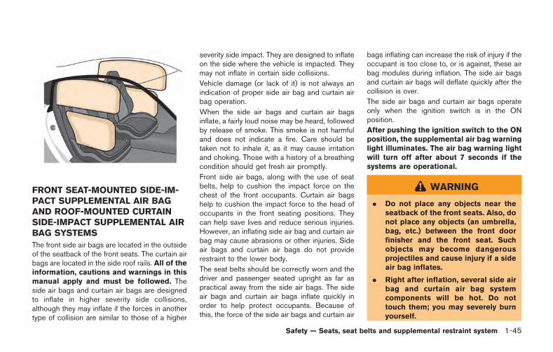
FRONT SEAT-MOUNTED SIDE-IM-PACT SUPPLEMENTAL AIR BAGAND ROOF-MOUNTED CURTAINSIDE-IMPACT SUPPLEMENTAL AIRBAG SYSTEMS
The front side air bags are located in the outsideof the seatback of the front seats. The curtain airbags are located in the side roof rails. All of theinformation, cautions and warnings in thismanual apply and must be followed. Theside air bags and curtain air bags are designedto inflate in higher severity side collisions,although they may inflate if the forces in anothertype of collision are similar to those of a higher
severity side impact. They are designed to inflateon the side where the vehicle is impacted. Theymay not inflate in certain side collisions.
Vehicle damage (or lack of it) is not always anindication of proper side air bag and curtain airbag operation.
When the side air bags and curtain air bagsinflate, a fairly loud noise may be heard, followedby release of smoke. This smoke is not harmfuland does not indicate a fire. Care should betaken not to inhale it, as it may cause irritationand choking. Those with a history of a breathingcondition should get fresh air promptly.
Front side air bags, along with the use of seatbelts, help to cushion the impact force on thechest of the front occupants. Curtain air bagshelp to cushion the impact force to the head ofoccupants in the front seating positions. Theycan help save lives and reduce serious injuries.However, an inflating side air bag and curtain airbag may cause abrasions or other injuries. Sideair bags and curtain air bags do not providerestraint to the lower body.
The seat belts should be correctly worn and thedriver and passenger seated upright as far aspractical away from the side air bags. The sideair bags and curtain air bags inflate quickly inorder to help protect occupants. Because ofthis, the force of the side air bags and curtain air
bags inflating can increase the risk of injury if theoccupant is too close to, or is against, these airbag modules during inflation. The side air bagsand curtain air bags will deflate quickly after thecollision is over.
The side air bags and curtain air bags operateonly when the ignition switch is in the ONposition.
After pushing the ignition switch to the ONposition, the supplemental air bag warninglight illuminates. The air bag warning lightwill turn off after about 7 seconds if thesystems are operational.
WARNING
. Do not place any objects near theseatback of the front seats. Also, donot place any objects (an umbrella,bag, etc.) between the front doorfinisher and the front seat. Suchobjects may become dangerousprojectiles and cause injury if a sideair bag inflates.
. Right after inflation, several side airbag and curtain air bag systemcomponents will be hot. Do nottouch them; you may severely burnyourself.
Safety — Seats, seat belts and supplemental restraint system 1-45
1-46 Safety — Seats, seat belts and supplemental restraint system
. No unauthorized changes should bemade to any components or wiringof the side air bags and curtain airbags. This is to prevent damage toor accidental inflation of the side airbag and curtain air bag systems.
. Do not make unauthorized changesto your vehicle’s electrical system,suspension system or side panel.This could affect proper operationof the side air bag and curtain airbag systems.
. Tampering with the side air bagsystem may result in serious perso-nal injury. For example, do notchange the front seat by placingmaterial near the seatback or byinstalling additional trim material,such as seat covers, around the sideair bags.
. Work around and on the side air bagand curtain air bag systems shouldbe done by a GT-R certified NISSANdealer. Installation of electricalequipment should also be done bya GT-R certified NISSAN dealer. TheSRS wiring harnesses* should notbe modified or disconnected. Un-
authorized electrical test equipmentand probing devices should not beused on the side air bag and curtainair bag systems.
* The SRS wiring harness connectors areyellow and orange for easy identification.
When selling your vehicle, we request that youinform the buyer about the side air bag andcurtain air bag systems and guide the buyer tothe appropriate sections in this Owner’s Manual.
SEAT BELTS WITH PRETEN-SIONERS (front seats)
WARNING
. The pretensioners cannot be reusedafter activation. They must be re-placed together with the retractorand buckle as a unit.
. If the vehicle becomes involved in acollision but the pretensioner is notactivated, be sure to have the pre-tensioner system checked and, ifnecessary, replaced by a GT-R certi-fied NISSAN dealer.
. No unauthorized changes should bemade to any components or wiringof the pretensioners. This is toprevent damage to or accidentalactivation of the pretensioners.Tampering with the pretensionersystem may result in serious perso-nal injury.
. Work around and on the preten-sioners should be done by a GT-Rcertified NISSAN dealer. Installationof electrical equipment should alsobe done by a GT-R certified NISSANdealer. Unauthorized electrical testequipment and probing devicesshould not be used on the preten-sioners.
. If you need to dispose of a preten-sioner or scrap the vehicle, contact aGT-R certified NISSAN dealer. Incor-rect disposal procedures couldcause personal injury.
The pretensioner system may activate with thesupplemental air bag system in certain types ofcollisions. Working with the seat belt retractor, ithelps tighten the seat belt when the vehiclebecomes involved in certain types of collisions,
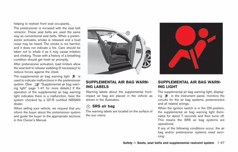
helping to restrain front seat occupants.
The pretensioner is encased with the seat beltretractor. These seat belts are used the sameway as conventional seat belts. When a preten-sioner activates, smoke is released and a loudnoise may be heard. The smoke is not harmful,and it does not indicate a fire. Care should betaken not to inhale it as it may cause irritationand choking. Those with a history of a breathingcondition should get fresh air promptly.
After pretensioner activation, load limiters allowthe seat belt to release webbing (if necessary) toreduce forces against the chest.
The supplemental air bag warning light isused to indicate malfunctions in the pretensionersystem. (See “Supplemental air bag warn-ing light” page 1-47 for more details.) If theoperation of the supplemental air bag warninglight indicates there is a malfunction, have thesystem checked by a GT-R certified NISSANdealer.
When selling your vehicle, we request that youinform the buyer about the pretensioner systemand guide the buyer to the appropriate sectionsin this Owner’s Manual.
SUPPLEMENTAL AIR BAG WARN-ING LABELS
Warning labels about the supplemental front-impact air bag are placed in the vehicle asshown in the illustration.
*1 SRS air bag
The warning labels are located on the surface ofthe sun visors.
SUPPLEMENTAL AIR BAG WARN-ING LIGHT
The supplemental air bag warning light, display-ing in the instrument panel, monitors thecircuits for the air bag systems, pretensionersand all related wirings.
When the ignition switch is in the ON position,the supplemental air bag warning light illumi-nates for about 7 seconds and then turns off.This means the SRS air bag systems areoperational.
If any of the following conditions occur, the airbag and/or pretensioner systems need servi-cing:
Safety — Seats, seat belts and supplemental restraint system 1-47
1-48 Safety — Seats, seat belts and supplemental restraint system
. The supplemental air bag warning lightremains on after approximately 7 seconds.
. The supplemental air bag warning lightflashes intermittently.
. The supplemental air bag warning light doesnot come on at all.
Under these conditions, the air bag and/orpretensioner systems may not operate properly.They must be checked and repaired. Take yourvehicle to the nearest GT-R certified NISSANdealer.
WARNING
If the supplemental air bag warninglight is on, it could mean that the frontair bag, side air bag, curtain air bagand/or pretensioners will not operate inan accident. To help avoid injury toyourself or others, have your vehiclechecked by a dealer as soon as possi-ble.
REPAIR AND REPLACEMENT PRO-CEDURE
The front air bags, side air bags, curtain air bagsand pretensioners are designed to activate on aone-time-only basis. As a reminder, unless it isdamaged, the supplemental air bag warning lightwill remain illuminated after inflation has oc-curred. Repair and replacement of these sys-tems should be done only by a GT-R certifiedNISSAN dealer.
When maintenance work is required on thevehicle, the front air bags, side air bags, curtainair bags, pretensioners and related parts shouldbe pointed out to the person conducting themaintenance. The ignition switch should alwaysbe in the LOCK position when working underthe hood or inside the vehicle.
WARNING
. Once a front air bag, side air bag, orcurtain air bag has inflated, the airbag module will not function againand must be replaced. Additionally,the activated pretensioners mustalso be replaced. The air bag mod-ule and pretensioners should bereplaced by a GT-R certified NISSANdealer. The air bag module and
pretensioners cannot be repaired.
. The front air bag, side air bag,curtain air bag and the pretensionershould be inspected by a GT-Rcertified NISSAN dealer if there isany damage to the front end or sideportion of the vehicle.
. If you need to dispose of a supple-mental air bag or a pretensioner orscrap the vehicle, contact a GT-Rcertified NISSAN dealer. Incorrectdisposal procedures could causepersonal injury.
2 Instruments and controls
Cockpit ....................................................................................... 2-3Instrument panel ....................................................................... 2-4Meters and gauges .................................................................. 2-5
Speedometer ....................................................................... 2-6Odometer/twin trip odometer ......................................... 2-6Tachometer .......................................................................... 2-7Engine coolant temperature gauge ............................... 2-7Fuel gauge ........................................................................... 2-8Transmission position indicator ...................................... 2-9Upshift indicator ................................................................. 2-9Instrument brightness control ...................................... 2-11
Vehicle information display ................................................. 2-12Engine oil level display ................................................... 2-12Transmission system check display ............................ 2-14
Drive computer ...................................................................... 2-15Current fuel consumption ............................................. 2-15Vehicle speed ................................................................... 2-16Cruise control ................................................................... 2-16Average fuel consumption and speed ....................... 2-16Elapsed time and trip odometer .................................. 2-17Distance to empty ........................................................... 2-17Outside air temperature ................................................ 2-18Setting (drive computer) ............................................... 2-19Warning (drive computer) ............................................. 2-23
Warning/indicator lights and audible reminders .......... 2-25Checking bulbs ............................................................. 2-25Warning lights ................................................................ 2-25Indicator lights ............................................................... 2-31Audible reminders ......................................................... 2-32
Warning display .................................................................... 2-33Engine oil low pressure warning ............................... 2-34Engine system warning ............................................... 2-34Shift lever position warning ........................................ 2-35Reverse warning ............................................................ 2-35Transmission system warning .................................... 2-35Transmission oil high temperature warning ............ 2-36Transmission clutch high temperature warning ..... 2-36Parking brake release warning .................................. 2-36Low brake fluid warning .............................................. 2-37Anti-lock Braking System (ABS) warning .............. 2-37Vehicle Dynamic Control (VDC)system warning .............................................................. 2-37AWD clutch high temperature warning ................... 2-38Front/rear tire size discrepancy warning ................. 2-38AWD system warning .................................................. 2-39Low tire pressure warning .......................................... 2-39Run-flat tire warning ..................................................... 2-39Tire Pressure Monitoring System(TPMS) warning ............................................................ 2-40
Cruise control system warning .................................... 2-40Low fuel warning ............................................................. 2-40Door/trunk open warning .............................................. 2-41Headlight system warning ............................................. 2-41Low washer fluid warning ............................................. 2-42No key warning ................................................................ 2-42
Operation displays ................................................................ 2-43Engine start operation indicator .................................. 2-43Shift “P” warning ............................................................. 2-43“PUSH” warning .............................................................. 2-44Steering lock release malfunction indicator ............. 2-44Intelligent Key insertion indicator ................................ 2-44Intelligent Key removal indicator .................................. 2-45Intelligent Key battery discharge indicator ................ 2-45
Security systems ................................................................... 2-45Vehicle security system ................................................. 2-45NISSAN Vehicle Immobilizer System ......................... 2-47
Windshield wiper and washer switch .............................. 2-48Using the wipers ............................................................. 2-49Using the washer ............................................................ 2-49
Rear window defroster switch ........................................... 2-50Headlight and turn signal switch ...................................... 2-50
Headlight switch .............................................................. 2-50Horn .......................................................................................... 2-53
Heated seats (if so equipped) .......................................... 2-54Turning on the heaters ................................................. 2-54Turning off the heaters ................................................. 2-54
Power outlets ........................................................................ 2-55Storage ................................................................................... 2-56
Cup holders .................................................................... 2-56Sunglasses holder ........................................................ 2-57Door pocket .................................................................... 2-58Glove box ........................................................................ 2-58Console box ................................................................... 2-59Coat hooks ..................................................................... 2-59
Windows ................................................................................ 2-60Power windows ............................................................. 2-60
Interior lights .......................................................................... 2-62Map lights ....................................................................... 2-62Interior light control switch ......................................... 2-62
Vanity mirror lights ................................................................ 2-63HomeLink Universal Transceiver .................................... 2-64
Programming HomeLink ............................................ 2-64Programming HomeLink for Canadian customersand gate openers .......................................................... 2-66Operating the HomeLink universal transceiver ... 2-66Programming troubleshooting .................................... 2-66Clearing the programmed information ..................... 2-67Reprogramming a single HomeLink button ......... 2-67If your vehicle is stolen ................................................ 2-67
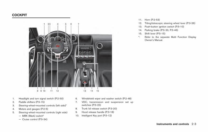
1. Headlight and turn signal switch (P.2-50)
2. Paddle shifters (P.5-15)
3. Steering-wheel-mounted controls (left side)*
4. Meters and gauges (P.2-5)
5. Steering-wheel-mounted controls (right side)
— MRK (Mark) switch*
— Cruise control (P.5-34)
6. Windshield wiper and washer switch (P.2-48)
7. VDC, transmission and suspension set upswitches (P.5-25)
8. Trunk lid release switch (P.3-20)
9. Hood release handle (P.3-18)
10. Intelligent Key port (P.5-12)
11. Horn (P.2-53)
12. Tilting/telescopic steering wheel lever (P.3-26)
13. Push-button ignition switch (P.5-10)
14. Parking brake (P.5-33, P.5-46)
15. Shift lever (P.5-15)
*: Refer to the separate Multi Function DisplayOwner’s Manual.
Instruments and controls 2-3
COCKPIT
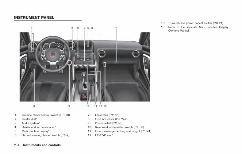
2-4 Instruments and controls
1. Outside mirror control switch (P.3-28)
2. Center dial*
3. Audio system*
4. Heater and air conditioner*
5. Multi function display*
6. Hazard warning flasher switch (P.6-2)
7. Glove box (P.2-58)
8. Fuse box cover (P.8-24)
9. Power outlet (P.2-55)
10. Rear window defroster switch (P.2-50)
11. Front passenger air bag status light (P.1-41)
12. CD/DVD slot*
13. Trunk release power cancel switch (P.3-21)
*: Refer to the separate Multi Function DisplayOwner’s Manual.
INSTRUMENT PANEL
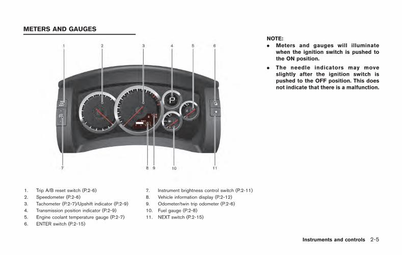
1. Trip A/B reset switch (P.2-6)
2. Speedometer (P.2-6)
3. Tachometer (P.2-7)/Upshift indicator (P.2-9)
4. Transmission position indicator (P.2-9)
5. Engine coolant temperature gauge (P.2-7)
6. ENTER switch (P.2-15)
7. Instrument brightness control switch (P.2-11)
8. Vehicle information display (P.2-12)
9. Odometer/twin trip odometer (P.2-6)
10. Fuel gauge (P.2-8)
11. NEXT switch (P.2-15)
NOTE:. Meters and gauges will illuminate
when the ignition switch is pushed tothe ON position.
. The needle indicators may moveslightly after the ignition switch ispushed to the OFF position. This doesnot indicate that there is a malfunction.
Instruments and controls 2-5
METERS AND GAUGES
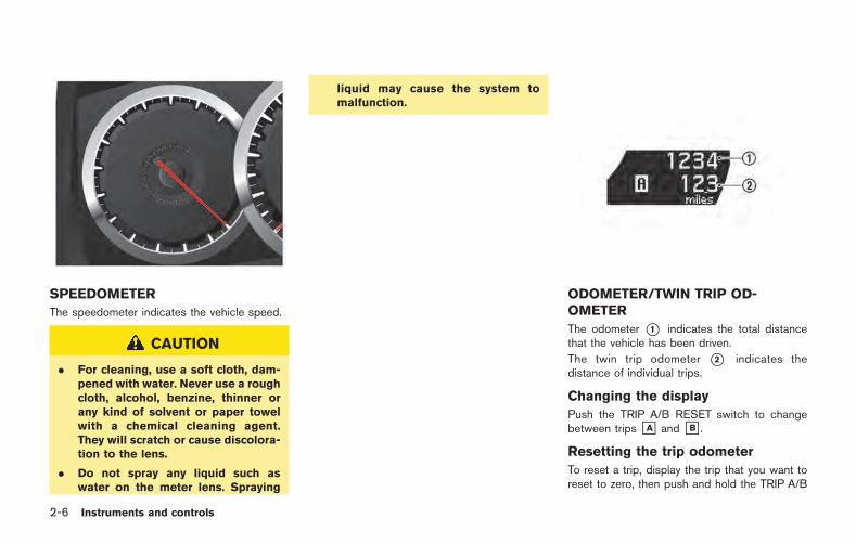
2-6 Instruments and controls
SPEEDOMETER
The speedometer indicates the vehicle speed.
CAUTION
. For cleaning, use a soft cloth, dam-pened with water. Never use a roughcloth, alcohol, benzine, thinner orany kind of solvent or paper towelwith a chemical cleaning agent.They will scratch or cause discolora-tion to the lens.
. Do not spray any liquid such aswater on the meter lens. Spraying
liquid may cause the system tomalfunction.
ODOMETER/TWIN TRIP OD-OMETER
The odometer *1 indicates the total distancethat the vehicle has been driven.
The twin trip odometer *2 indicates thedistance of individual trips.
Changing the display
Push the TRIP A/B RESET switch to changebetween trips &A and &B .
Resetting the trip odometer
To reset a trip, display the trip that you want toreset to zero, then push and hold the TRIP A/B
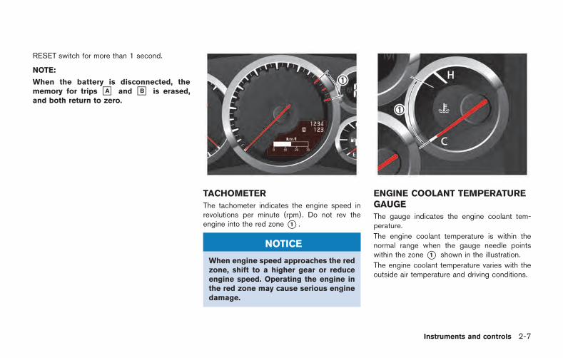
RESET switch for more than 1 second.
NOTE:
When the battery is disconnected, thememory for trips &A and &B is erased,and both return to zero.
TACHOMETER
The tachometer indicates the engine speed inrevolutions per minute (rpm). Do not rev theengine into the red zone *1 .
NOTICE
When engine speed approaches the redzone, shift to a higher gear or reduceengine speed. Operating the engine inthe red zone may cause serious enginedamage.
ENGINE COOLANT TEMPERATUREGAUGE
The gauge indicates the engine coolant tem-perature.
The engine coolant temperature is within thenormal range when the gauge needle pointswithin the zone *1 shown in the illustration.
The engine coolant temperature varies with theoutside air temperature and driving conditions.
Instruments and controls 2-7
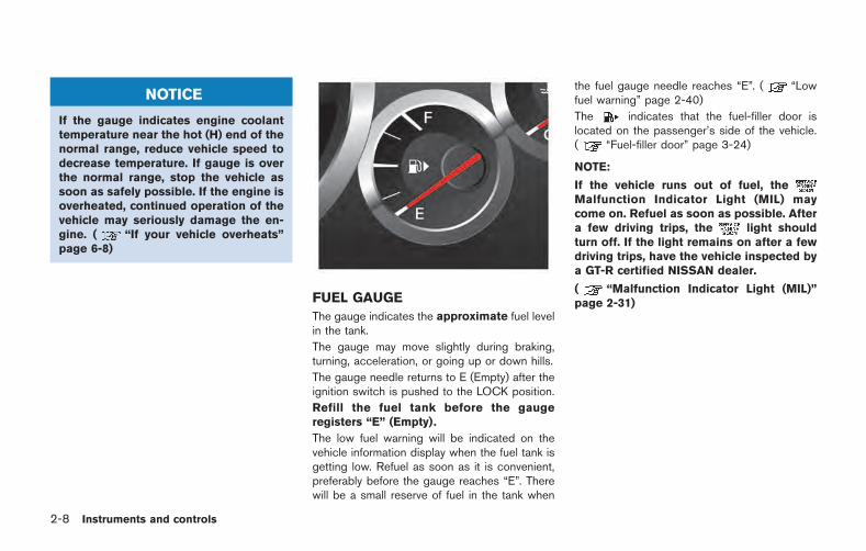
2-8 Instruments and controls
NOTICE
If the gauge indicates engine coolanttemperature near the hot (H) end of thenormal range, reduce vehicle speed todecrease temperature. If gauge is overthe normal range, stop the vehicle assoon as safely possible. If the engine isoverheated, continued operation of thevehicle may seriously damage the en-gine. ( “If your vehicle overheats”page 6-8)
FUEL GAUGE
The gauge indicates the approximate fuel levelin the tank.
The gauge may move slightly during braking,turning, acceleration, or going up or down hills.
The gauge needle returns to E (Empty) after theignition switch is pushed to the LOCK position.
Refill the fuel tank before the gaugeregisters “E” (Empty).
The low fuel warning will be indicated on thevehicle information display when the fuel tank isgetting low. Refuel as soon as it is convenient,preferably before the gauge reaches “E”. Therewill be a small reserve of fuel in the tank when
the fuel gauge needle reaches “E”. ( “Lowfuel warning” page 2-40)
The indicates that the fuel-filler door islocated on the passenger’s side of the vehicle.( “Fuel-filler door” page 3-24)
NOTE:
If the vehicle runs out of fuel, theMalfunction Indicator Light (MIL) maycome on. Refuel as soon as possible. Aftera few driving trips, the light shouldturn off. If the light remains on after a fewdriving trips, have the vehicle inspected bya GT-R certified NISSAN dealer.
( “Malfunction Indicator Light (MIL)”page 2-31)
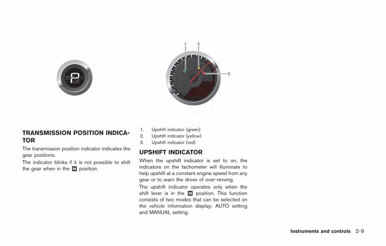
TRANSMISSION POSITION INDICA-TOR
The transmission position indicator indicates thegear positions.
The indicator blinks if it is not possible to shiftthe gear when in the &M position.
1. Upshift indicator (green)
2. Upshift indicator (yellow)
3. Upshift indicator (red)
UPSHIFT INDICATOR
When the upshift indicator is set to on, theindicators on the tachometer will illuminate tohelp upshift at a constant engine speed from anygear or to warn the driver of over-revving.
The upshift indicator operates only when theshift lever is in the &M position. This functionconsists of two modes that can be selected onthe vehicle information display: AUTO settingand MANUAL setting.
Instruments and controls 2-9
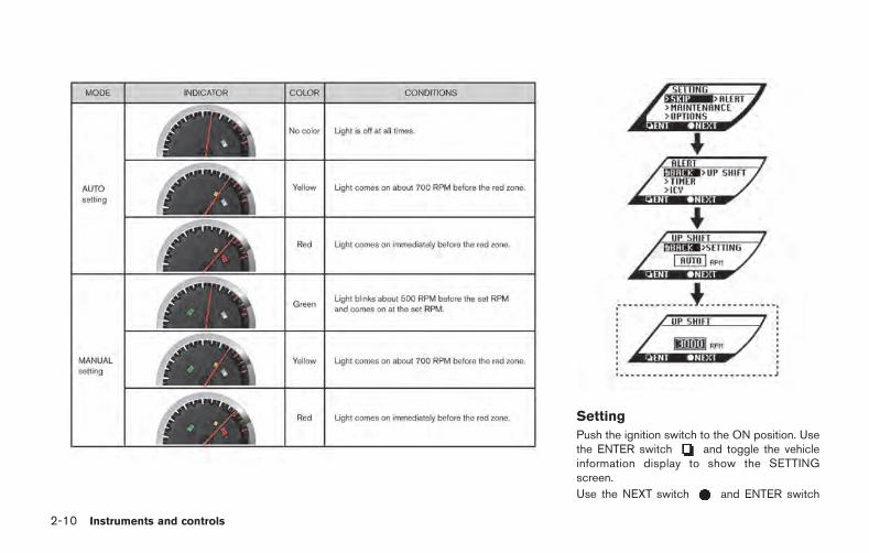
2-10 Instruments and controls
Setting
Push the ignition switch to the ON position. Usethe ENTER switch and toggle the vehicleinformation display to show the SETTINGscreen.
Use the NEXT switch and ENTER switch
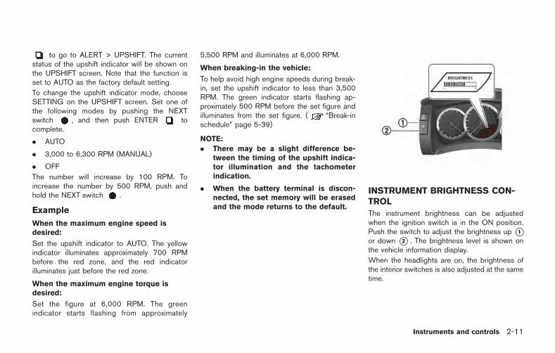
to go to ALERT > UPSHIFT. The currentstatus of the upshift indicator will be shown onthe UPSHIFT screen. Note that the function isset to AUTO as the factory default setting.
To change the upshift indicator mode, chooseSETTING on the UPSHIFT screen. Set one ofthe following modes by pushing the NEXTswitch , and then push ENTER tocomplete.
. AUTO
. 3,000 to 6,300 RPM (MANUAL)
. OFF
The number will increase by 100 RPM. Toincrease the number by 500 RPM, push andhold the NEXT switch .
Example
When the maximum engine speed isdesired:
Set the upshift indicator to AUTO. The yellowindicator illuminates approximately 700 RPMbefore the red zone, and the red indicatorilluminates just before the red zone.
When the maximum engine torque isdesired:
Set the figure at 6,000 RPM. The greenindicator starts flashing from approximately
5,500 RPM and illuminates at 6,000 RPM.
When breaking-in the vehicle:
To help avoid high engine speeds during break-in, set the upshift indicator to less than 3,500RPM. The green indicator starts flashing ap-proximately 500 RPM before the set figure andilluminates from the set figure. ( “Break-inschedule” page 5-39)
NOTE:
. There may be a slight difference be-tween the timing of the upshift indica-tor illumination and the tachometerindication.
. When the battery terminal is discon-nected, the set memory will be erasedand the mode returns to the default.
INSTRUMENT BRIGHTNESS CON-TROL
The instrument brightness can be adjustedwhen the ignition switch is in the ON position.Push the switch to adjust the brightness up *1or down *2 . The brightness level is shown onthe vehicle information display.
When the headlights are on, the brightness ofthe interior switches is also adjusted at the sametime.
Instruments and controls 2-11
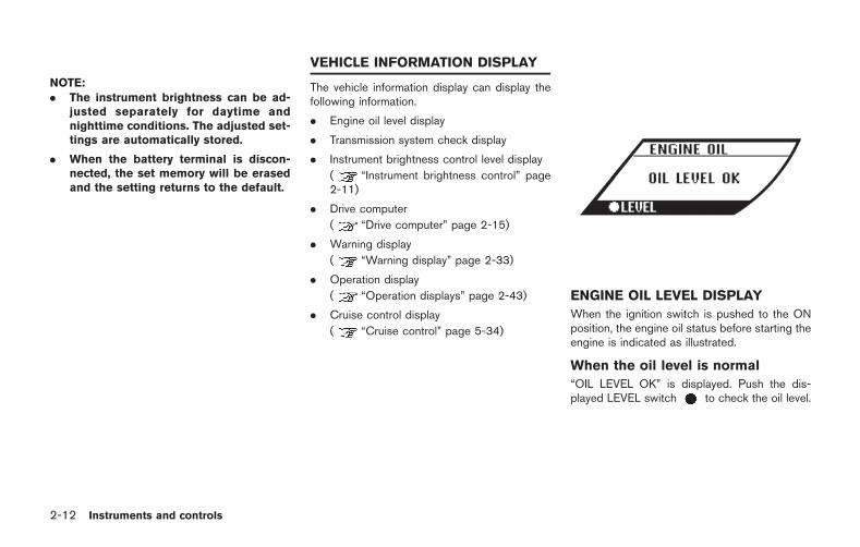
2-12 Instruments and controls
NOTE:. The instrument brightness can be ad-
justed separately for daytime andnighttime conditions. The adjusted set-tings are automatically stored.
. When the battery terminal is discon-nected, the set memory will be erasedand the setting returns to the default.
The vehicle information display can display thefollowing information.
. Engine oil level display
. Transmission system check display
. Instrument brightness control level display
( “Instrument brightness control” page2-11)
. Drive computer
( “Drive computer” page 2-15)
. Warning display
( “Warning display” page 2-33)
. Operation display
( “Operation displays” page 2-43)
. Cruise control display
( “Cruise control” page 5-34)
ENGINE OIL LEVEL DISPLAY
When the ignition switch is pushed to the ONposition, the engine oil status before starting theengine is indicated as illustrated.
When the oil level is normal
“OIL LEVEL OK” is displayed. Push the dis-played LEVEL switch to check the oil level.
VEHICLE INFORMATION DISPLAY
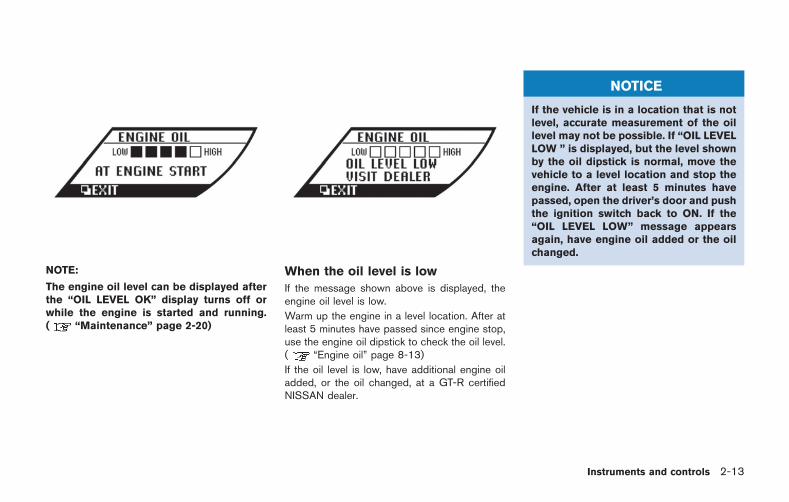
NOTE:
The engine oil level can be displayed afterthe “OIL LEVEL OK” display turns off orwhile the engine is started and running.( “Maintenance” page 2-20)
When the oil level is low
If the message shown above is displayed, theengine oil level is low.
Warm up the engine in a level location. After atleast 5 minutes have passed since engine stop,use the engine oil dipstick to check the oil level.( “Engine oil” page 8-13)
If the oil level is low, have additional engine oiladded, or the oil changed, at a GT-R certifiedNISSAN dealer.
NOTICE
If the vehicle is in a location that is notlevel, accurate measurement of the oillevel may not be possible. If “OIL LEVELLOW ” is displayed, but the level shownby the oil dipstick is normal, move thevehicle to a level location and stop theengine. After at least 5 minutes havepassed, open the driver’s door and pushthe ignition switch back to ON. If the“OIL LEVEL LOW” message appearsagain, have engine oil added or the oilchanged.
Instruments and controls 2-13
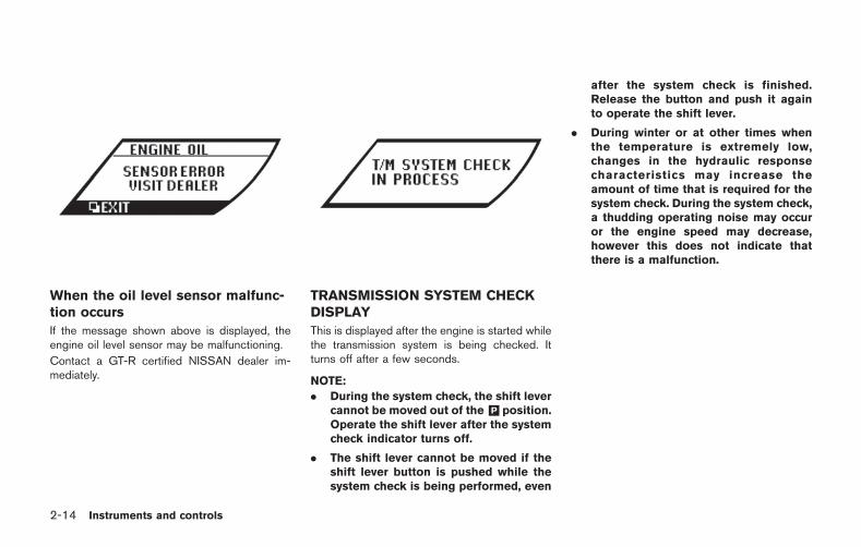
2-14 Instruments and controls
When the oil level sensor malfunc-tion occurs
If the message shown above is displayed, theengine oil level sensor may be malfunctioning.
Contact a GT-R certified NISSAN dealer im-mediately.
TRANSMISSION SYSTEM CHECKDISPLAY
This is displayed after the engine is started whilethe transmission system is being checked. Itturns off after a few seconds.
NOTE:
. During the system check, the shift levercannot be moved out of the&P position.Operate the shift lever after the systemcheck indicator turns off.
. The shift lever cannot be moved if theshift lever button is pushed while thesystem check is being performed, even
after the system check is finished.Release the button and push it againto operate the shift lever.
. During winter or at other times whenthe temperature is extremely low,changes in the hydraulic responsecharacteristics may increase theamount of time that is required for thesystem check. During the system check,a thudding operating noise may occuror the engine speed may decrease,however this does not indicate thatthere is a malfunction.
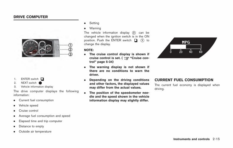
1. ENTER switch
2. NEXT switch
3. Vehicle information display
The drive computer displays the followinginformation:
. Current fuel consumption
. Vehicle speed
. Cruise control
. Average fuel consumption and speed
. Elapsed time and trip computer
. Distance to empty
. Outside air temperature
. Setting
. Warning
The vehicle information display *3 can bechanged when the ignition switch is in the ONposition. Push the ENTER switch *1 tochange the display.
NOTE:
. The cruise control display is shown ifcruise control is set. ( “Cruise con-trol” page 5-34)
. The warning display is not shown ifthere are no conditions to warn thedriver.
. Depending on the driving conditionsand other factors, the displayed valuesmay differ from the actual values.
. The position of the speedometer nee-dle and the speed shown in the vehicleinformation display may slightly differ.
CURRENT FUEL CONSUMPTION
The current fuel economy is displayed whendriving.
Instruments and controls 2-15
DRIVE COMPUTER
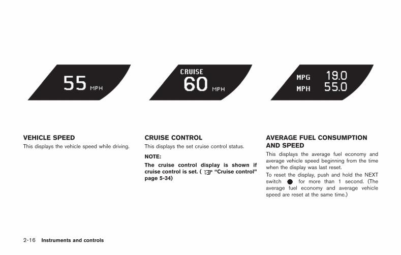
2-16 Instruments and controls
VEHICLE SPEED
This displays the vehicle speed while driving.
CRUISE CONTROL
This displays the set cruise control status.
NOTE:
The cruise control display is shown ifcruise control is set. ( “Cruise control”page 5-34)
AVERAGE FUEL CONSUMPTIONAND SPEED
This displays the average fuel economy andaverage vehicle speed beginning from the timewhen the display was last reset.
To reset the display, push and hold the NEXTswitch for more than 1 second. (Theaverage fuel economy and average vehiclespeed are reset at the same time.)
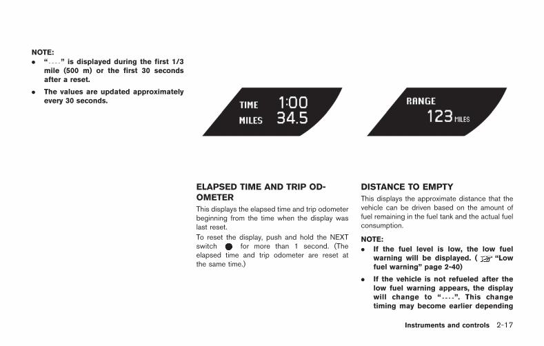
NOTE:. “ ” is displayed during the first 1/3
mile (500 m) or the first 30 secondsafter a reset.
. The values are updated approximatelyevery 30 seconds.
ELAPSED TIME AND TRIP OD-OMETER
This displays the elapsed time and trip odometerbeginning from the time when the display waslast reset.
To reset the display, push and hold the NEXTswitch for more than 1 second. (Theelapsed time and trip odometer are reset atthe same time.)
DISTANCE TO EMPTY
This displays the approximate distance that thevehicle can be driven based on the amount offuel remaining in the fuel tank and the actual fuelconsumption.
NOTE:
. If the fuel level is low, the low fuelwarning will be displayed. ( “Lowfuel warning” page 2-40)
. If the vehicle is not refueled after thelow fuel warning appears, the displaywill change to “ ”. This changetiming may become earlier depending
Instruments and controls 2-17
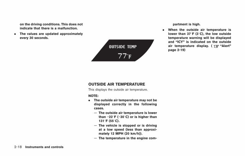
2-18 Instruments and controls
on the driving conditions. This does notindicate that there is a malfunction.
. The values are updated approximatelyevery 30 seconds.
OUTSIDE AIR TEMPERATURE
This displays the outside air temperature.
NOTE:
. The outside air temperature may not bedisplayed correctly in the followingcases.
— The outside air temperature is lowerthan 228F ( 308C) or is higher than1318F (558C).
— The vehicle is stopped or is drivingat a low speed (less than approxi-mately 12 MPH (20 km/h)).
— The temperature in the engine com-
partment is high.
. When the outside air temperature islower than 378F (38C), the low outsidetemperature warning will be displayedand “ICY” is indicated on the outsideair temperature display. ( “Alert”page 2-19)
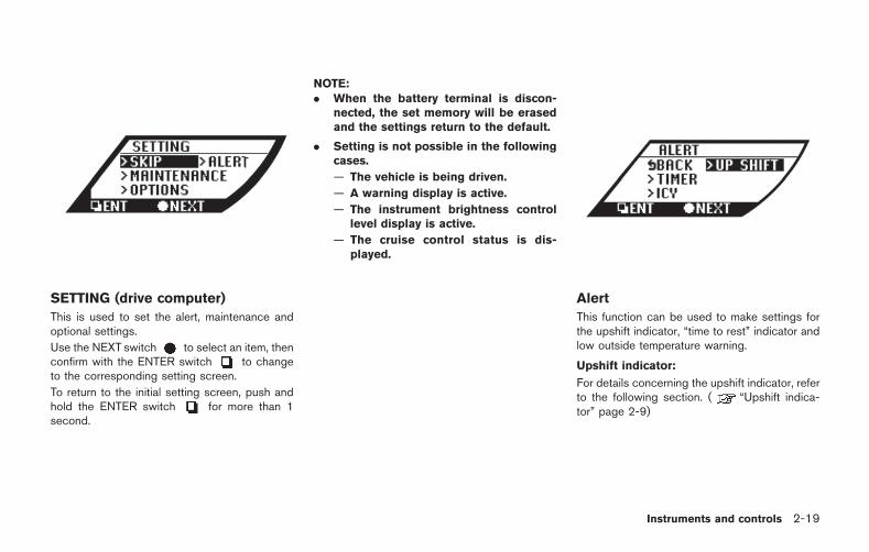
SETTING (drive computer)
This is used to set the alert, maintenance andoptional settings.
Use the NEXT switch to select an item, thenconfirm with the ENTER switch to changeto the corresponding setting screen.
To return to the initial setting screen, push andhold the ENTER switch for more than 1second.
NOTE:. When the battery terminal is discon-
nected, the set memory will be erasedand the settings return to the default.
. Setting is not possible in the followingcases.
— The vehicle is being driven.
— A warning display is active.
— The instrument brightness controllevel display is active.
— The cruise control status is dis-played.
Alert
This function can be used to make settings forthe upshift indicator, “time to rest” indicator andlow outside temperature warning.
Upshift indicator:
For details concerning the upshift indicator, referto the following section. ( “Upshift indica-tor” page 2-9)
Instruments and controls 2-19
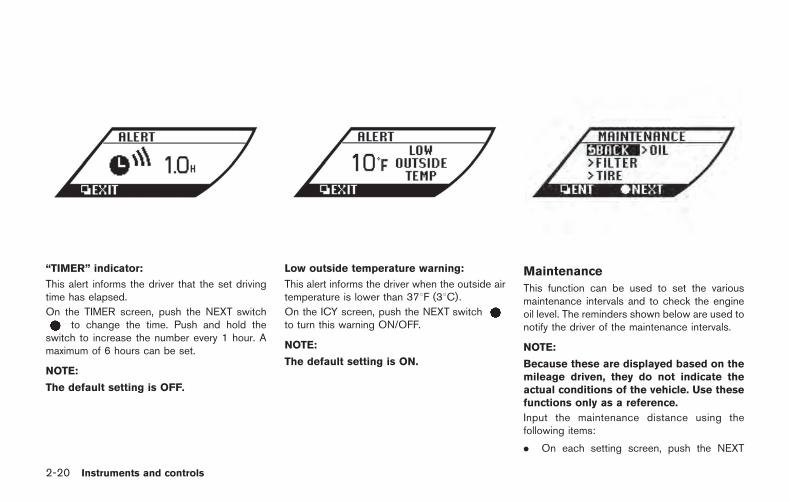
2-20 Instruments and controls
“TIMER” indicator:
This alert informs the driver that the set drivingtime has elapsed.
On the TIMER screen, push the NEXT switchto change the time. Push and hold the
switch to increase the number every 1 hour. Amaximum of 6 hours can be set.
NOTE:
The default setting is OFF.
Low outside temperature warning:
This alert informs the driver when the outside airtemperature is lower than 378F (38C).
On the ICY screen, push the NEXT switchto turn this warning ON/OFF.
NOTE:
The default setting is ON.
Maintenance
This function can be used to set the variousmaintenance intervals and to check the engineoil level. The reminders shown below are used tonotify the driver of the maintenance intervals.
NOTE:
Because these are displayed based on themileage driven, they do not indicate theactual conditions of the vehicle. Use thesefunctions only as a reference.
Input the maintenance distance using thefollowing items:
. On each setting screen, push the NEXT
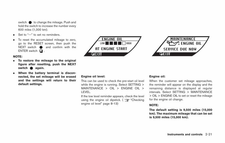
switch to change the mileage. Push andhold the switch to increase the number every600 miles (1,000 km).
. Set to “—” to set no reminders.
. To reset the accumulated mileage to zero,go to the RESET screen, then push theNEXT switch and confirm with theENTER switch .
NOTE:
. To restore the mileage to the originalfigure after resetting, push the NEXTswitch again.
. When the battery terminal is discon-nected, the set mileage will be erasedand the settings will return to theirdefault settings.
Engine oil level:
This can be used to check the pre-start oil levelwhile the engine is running. Select SETTING >MAINTENANCE > OIL > ENGINE OIL >LEVEL.
If the low level reminder appears, check the levelusing the engine oil dipstick. ( “Checkingengine oil level” page 8-13)
Engine oil:
When the customer set mileage approaches,the reminder will appear on the display and theremaining distance is displayed at regularintervals. Select SETTING > MAINTENANCE> OIL > ENGINE OIL to set or reset the mileagefor the engine oil change.
NOTE:
The default setting is 9,500 miles (15,000km). The maximum mileage that can be setis 9,500 miles (15,000 km).
Instruments and controls 2-21
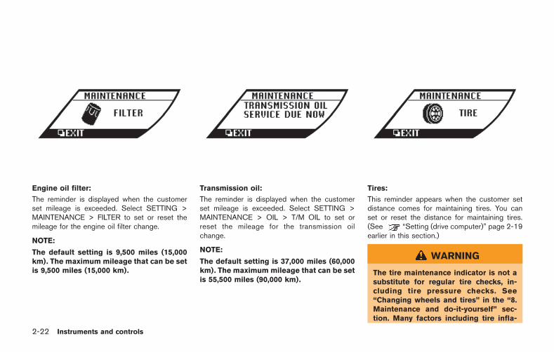
2-22 Instruments and controls
Engine oil filter:
The reminder is displayed when the customerset mileage is exceeded. Select SETTING >MAINTENANCE > FILTER to set or reset themileage for the engine oil filter change.
NOTE:
The default setting is 9,500 miles (15,000km). The maximum mileage that can be setis 9,500 miles (15,000 km).
Transmission oil:
The reminder is displayed when the customerset mileage is exceeded. Select SETTING >MAINTENANCE > OIL > T/M OIL to set orreset the mileage for the transmission oilchange.
NOTE:
The default setting is 37,000 miles (60,000km). The maximum mileage that can be setis 55,500 miles (90,000 km).
Tires:
This reminder appears when the customer setdistance comes for maintaining tires. You canset or reset the distance for maintaining tires.(See “Setting (drive computer)” page 2-19earlier in this section.)
WARNING
The tire maintenance indicator is not asubstitute for regular tire checks, in-cluding tire pressure checks. See“Changing wheels and tires” in the “8.Maintenance and do-it-yourself” sec-tion. Many factors including tire infla-
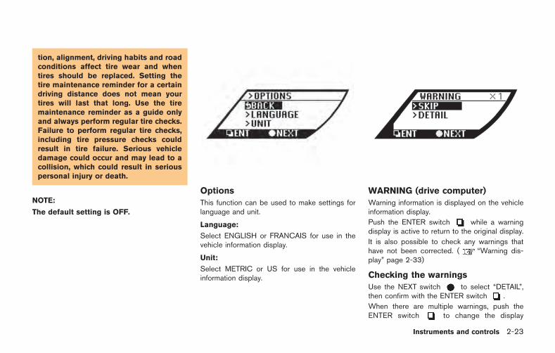
tion, alignment, driving habits and roadconditions affect tire wear and whentires should be replaced. Setting thetire maintenance reminder for a certaindriving distance does not mean yourtires will last that long. Use the tiremaintenance reminder as a guide onlyand always perform regular tire checks.Failure to perform regular tire checks,including tire pressure checks couldresult in tire failure. Serious vehicledamage could occur and may lead to acollision, which could result in seriouspersonal injury or death.
NOTE:
The default setting is OFF.
Options
This function can be used to make settings forlanguage and unit.
Language:
Select ENGLISH or FRANCAIS for use in thevehicle information display.
Unit:
Select METRIC or US for use in the vehicleinformation display.
WARNING (drive computer)
Warning information is displayed on the vehicleinformation display.
Push the ENTER switch while a warningdisplay is active to return to the original display.
It is also possible to check any warnings thathave not been corrected. ( “Warning dis-play” page 2-33)
Checking the warnings
Use the NEXT switch to select “DETAIL”,then confirm with the ENTER switch .
When there are multiple warnings, push theENTER switch to change the display
Instruments and controls 2-23
2-24 Instruments and controls
among them.
To return to the initial warning, push and hold theENTER switch for more than 1 second.
NOTE:
If there are no warnings to display, only“SKIP” can be selected.
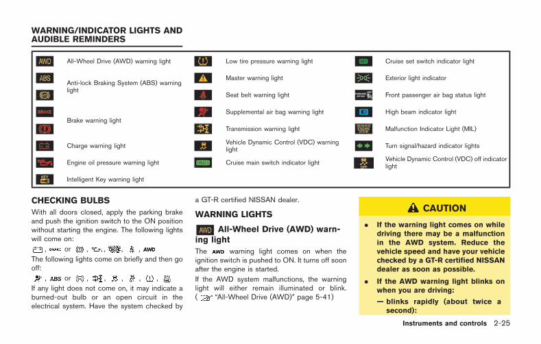
All-Wheel Drive (AWD) warning light Low tire pressure warning light Cruise set switch indicator light
Anti-lock Braking System (ABS) warninglight
Master warning light Exterior light indicator
Seat belt warning light Front passenger air bag status light
Brake warning lightSupplemental air bag warning light High beam indicator light
Transmission warning light Malfunction Indicator Light (MIL)
Charge warning lightVehicle Dynamic Control (VDC) warninglight
Turn signal/hazard indicator lights
Engine oil pressure warning light Cruise main switch indicator lightVehicle Dynamic Control (VDC) off indicatorlight
Intelligent Key warning light
CHECKING BULBS
With all doors closed, apply the parking brakeand push the ignition switch to the ON positionwithout starting the engine. The following lightswill come on:
, or , , , ,
The following lights come on briefly and then gooff:
, or , , , , ,
If any light does not come on, it may indicate aburned-out bulb or an open circuit in theelectrical system. Have the system checked by
a GT-R certified NISSAN dealer.
WARNING LIGHTS
All-Wheel Drive (AWD) warn-ing light
The warning light comes on when theignition switch is pushed to ON. It turns off soonafter the engine is started.
If the AWD system malfunctions, the warninglight will either remain illuminated or blink.( “All-Wheel Drive (AWD)” page 5-41)
CAUTION
. If the warning light comes on whiledriving there may be a malfunctionin the AWD system. Reduce thevehicle speed and have your vehiclechecked by a GT-R certified NISSANdealer as soon as possible.
. If the AWD warning light blinks onwhen you are driving:
— blinks rapidly (about twice asecond):
Instruments and controls 2-25
WARNING/INDICATOR LIGHTS ANDAUDIBLE REMINDERS
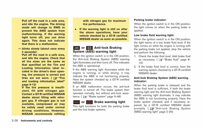
2-26 Instruments and controls
Pull off the road in a safe area,and idle the engine. The drivingmode will change to RWD toprevent the AWD system frommalfunctioning. If the warninglight turns off, you can driveagain. This does not indicatethat there is a malfunction.
— blinks slowly (about once every2 seconds):Pull off the road in a safe area,and idle the engine. Check thatall tire sizes are the same asthat specified on the Tire andLoading Information label lo-cated in the driver’s door open-ing, tire pressure is correct andtires are not worn. ( “Tireand loading information label”page 9-13)If the tire pressure is insuffi-cient, fill with nitrogen gas.Contact a GT-R certified NISSANdealer about filling with nitro-gen gas. If nitrogen gas is notavailable, compressed air maybe safely used under normaldriving conditions. However,NISSAN recommends refilling
with nitrogen gas for maximumtire performance.
. If the warning light is still on afterthe above operations, have yourvehicle checked by a GT-R certifiedNISSAN dealer as soon as possible.
or Anti-lock BrakingSystem (ABS) warning light
When the ignition switch is in the ON position,the Anti-lock Braking System (ABS) warninglight illuminates and then turns off. This indicatesthe ABS is operational.
If the ABS warning light illuminates while theengine is running, or while driving, it mayindicate the ABS is not functioning properly.Have the system checked by a GT-R certifiedNISSAN dealer.
If an ABS malfunction occurs, the anti-lockfunction is turned off. The brake system thenoperates normally, but without anti-lock assis-tance. ( “Brake system” page 5-48)
or Brake warning light
This light functions for both the parking brakeand the foot brake systems.
Parking brake indicator:
When the ignition switch is in the ON position,the light comes on when the parking brake isapplied.
Low brake fluid warning light:
When the ignition switch is in the ON position,the light warns of a low brake fluid level. If thelight comes on while the engine is running withthe parking brake not applied, stop the vehicleand perform the following:
1. Check the brake fluid level. Add brake fluidas necessary. ( “Brake fluid” page 8-15)
2. If the brake fluid level is correct, have thewarning system checked by a GT-R certifiedNISSAN dealer.
Anti-lock Braking System (ABS) warningindicator:
When the parking brake is released and thebrake fluid level is sufficient, if both the brakewarning light and the Anti-lock Braking System(ABS) warning light illuminate, it may indicatethe ABS is not functioning properly. Have thebrake system checked, and if necessary re-paired, by a GT-R certified NISSAN dealerpromptly. ( “Anti-lock Braking System(ABS) warning light” page 2-26)

WARNING
. Your brake system may not beworking properly if the warning lightis on. Driving could be dangerous. Ifyou judge it to be safe, drive care-fully to the nearest service stationfor repairs. Otherwise, have yourvehicle towed because driving itcould be dangerous.
. Pressing the brake pedal with theengine stopped and/or low brakefluid level may increase your stop-ping distance and braking will re-quire greater pedal effort as well aspedal travel.
. If the brake fluid level is below theminimum or MIN mark on the brakefluid reservoir, do not drive until thebrake system has been checked at aGT-R certified NISSAN dealer.
Charge warning light
If the light comes on while the engine is running,it may indicate the charging system is notfunctioning properly. Turn the engine off andcheck the alternator belt. If the belt is loose,
broken, missing or if the light remains on, see aGT-R certified NISSAN dealer immediately.
NOTICE
Do not continue driving if the alternatorbelt is loose, broken or missing.
Engine oil pressure warninglight
This light warns of low engine oil pressure. If thelight flickers or comes on during normal driving,pull off the road in a safe area, stop the engineimmediately and call a GT-R certified NISSANdealer.
The engine oil pressure warning light isnot designed to indicate a low oil level.Check the vehicle information display oruse the dipstick to check the oil level.( “Engine oil level display” page 2-12)( “Checking engine oil level” page 8-13)
NOTICE
Running the engine with the engine oilpressure warning light on could causeserious damage to the engine almostimmediately. Turn off the engine as
soon as it is safe to do so.
Intelligent Key warning light
After the ignition switch is pushed to the ONposition, this light comes on for about 2 secondsand then turns off.
This light warns of a malfunction with theelectrical steering lock system or the IntelligentKey system.
If the light comes on while the engine isstopped, it may be impossible to free thesteering lock or to start the engine. If the lightcomes on while the engine is running, you candrive the vehicle. However in these cases,contact a GT-R certified NISSAN dealer forrepair as soon as possible.
Low tire pressure warning light
Your vehicle is equipped with a Tire PressureMonitoring System (TPMS) that monitors the tirepressure of all tires.
The low tire pressure warning light warns of lowtire pressure and flat tire, or indicates that theTPMS is not functioning properly.
After the ignition switch is pushed to the ONposition, the warning light illuminates for about 1second and turns off.
Instruments and controls 2-27
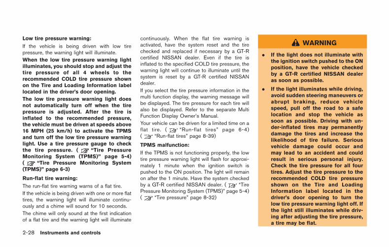
2-28 Instruments and controls
Low tire pressure warning:
If the vehicle is being driven with low tirepressure, the warning light will illuminate.
When the low tire pressure warning lightilluminates, you should stop and adjust thetire pressure of all 4 wheels to therecommended COLD tire pressure shownon the Tire and Loading Information labellocated in the driver’s door opening.
The low tire pressure warning light doesnot automatically turn off when the tirepressure is adjusted. After the tire isinflated to the recommended pressure,the vehicle must be driven at speeds above16 MPH (25 km/h) to activate the TPMSand turn off the low tire pressure warninglight. Use a tire pressure gauge to checkthe tire pressure. ( “Tire PressureMonitoring System (TPMS)” page 5-4)( “Tire Pressure Monitoring System(TPMS)” page 6-3)
Run-flat tire warning:
The run-flat tire warning warns of a flat tire.
If the vehicle is being driven with one or more flattires, the warning light will illuminate continu-ously and a chime will sound for 10 seconds.
The chime will only sound at the first indicationof a flat tire and the warning light will illuminate
continuously. When the flat tire warning isactivated, have the system reset and the tirechecked and replaced if necessary by a GT-Rcertified NISSAN dealer. Even if the tire isinflated to the specified COLD tire pressure, thewarning light will continue to illuminate until thesystem is reset by a GT-R certified NISSANdealer.
If you select the tire pressure information in themulti function display, the warning message willbe displayed. The tire pressure for each tire willalso be displayed. Refer to the separate MultiFunction Display Owner’s Manual.
Your vehicle can be driven for a limited time on aflat tire. ( “Run-flat tires” page 6-4)( “Run-flat tires” page 8-39)
TPMS malfunction:
If the TPMS is not functioning properly, the lowtire pressure warning light will flash for approxi-mately 1 minute when the ignition switch ispushed to the ON position. The light will remainon after the 1 minute. Have the system checkedby a GT-R certified NISSAN dealer. ( “TirePressure Monitoring System (TPMS)” page 5-4)( “Tire pressure” page 8-32)
WARNING
. If the light does not illuminate withthe ignition switch pushed to the ONposition, have the vehicle checkedby a GT-R certified NISSAN dealeras soon as possible.
. If the light illuminates while driving,avoid sudden steering maneuvers orabrupt braking, reduce vehiclespeed, pull off the road to a safelocation and stop the vehicle assoon as possible. Driving with un-der-inflated tires may permanentlydamage the tires and increase thelikelihood of tire failure. Seriousvehicle damage could occur andmay lead to an accident and couldresult in serious personal injury.Check the tire pressure for all fourtires. Adjust the tire pressure to therecommended COLD tire pressureshown on the Tire and LoadingInformation label located in thedriver’s door opening to turn thelow tire pressure warning light off. Ifthe light still illuminates while driv-ing after adjusting the tire pressure,a tire may be flat.
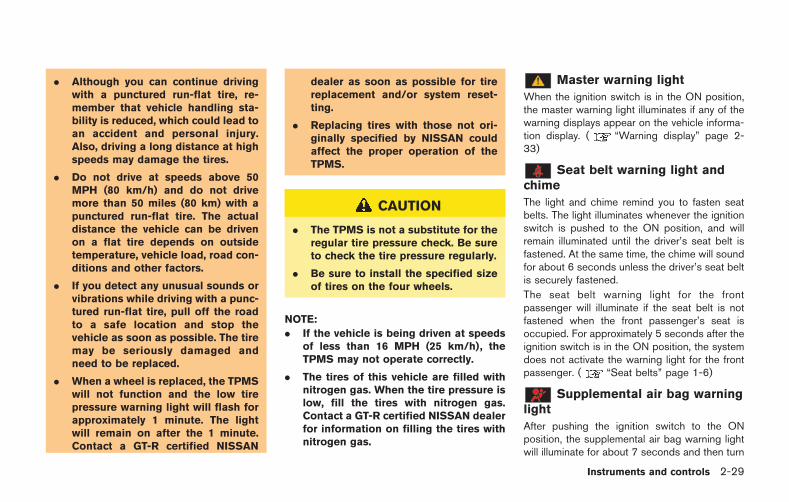
. Although you can continue drivingwith a punctured run-flat tire, re-member that vehicle handling sta-bility is reduced, which could lead toan accident and personal injury.Also, driving a long distance at highspeeds may damage the tires.
. Do not drive at speeds above 50MPH (80 km/h) and do not drivemore than 50 miles (80 km) with apunctured run-flat tire. The actualdistance the vehicle can be drivenon a flat tire depends on outsidetemperature, vehicle load, road con-ditions and other factors.
. If you detect any unusual sounds orvibrations while driving with a punc-tured run-flat tire, pull off the roadto a safe location and stop thevehicle as soon as possible. The tiremay be seriously damaged andneed to be replaced.
. When a wheel is replaced, the TPMSwill not function and the low tirepressure warning light will flash forapproximately 1 minute. The lightwill remain on after the 1 minute.Contact a GT-R certified NISSAN
dealer as soon as possible for tirereplacement and/or system reset-ting.
. Replacing tires with those not ori-ginally specified by NISSAN couldaffect the proper operation of theTPMS.
CAUTION
. The TPMS is not a substitute for theregular tire pressure check. Be sureto check the tire pressure regularly.
. Be sure to install the specified sizeof tires on the four wheels.
NOTE:
. If the vehicle is being driven at speedsof less than 16 MPH (25 km/h), theTPMS may not operate correctly.
. The tires of this vehicle are filled withnitrogen gas. When the tire pressure islow, fill the tires with nitrogen gas.Contact a GT-R certified NISSAN dealerfor information on filling the tires withnitrogen gas.
Master warning light
When the ignition switch is in the ON position,the master warning light illuminates if any of thewarning displays appear on the vehicle informa-tion display. ( “Warning display” page 2-33)
Seat belt warning light andchime
The light and chime remind you to fasten seatbelts. The light illuminates whenever the ignitionswitch is pushed to the ON position, and willremain illuminated until the driver’s seat belt isfastened. At the same time, the chime will soundfor about 6 seconds unless the driver’s seat beltis securely fastened.
The seat belt warning light for the frontpassenger will illuminate if the seat belt is notfastened when the front passenger’s seat isoccupied. For approximately 5 seconds after theignition switch is in the ON position, the systemdoes not activate the warning light for the frontpassenger. ( “Seat belts” page 1-6)
Supplemental air bag warninglight
After pushing the ignition switch to the ONposition, the supplemental air bag warning lightwill illuminate for about 7 seconds and then turn
Instruments and controls 2-29
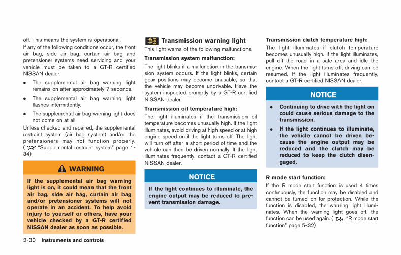
2-30 Instruments and controls
off. This means the system is operational.
If any of the following conditions occur, the frontair bag, side air bag, curtain air bag andpretensioner systems need servicing and yourvehicle must be taken to a GT-R certifiedNISSAN dealer.
. The supplemental air bag warning lightremains on after approximately 7 seconds.
. The supplemental air bag warning lightflashes intermittently.
. The supplemental air bag warning light doesnot come on at all.
Unless checked and repaired, the supplementalrestraint system (air bag system) and/or thepretensioners may not function properly.( “Supplemental restraint system” page 1-34)
WARNING
If the supplemental air bag warninglight is on, it could mean that the frontair bag, side air bag, curtain air bagand/or pretensioner systems will notoperate in an accident. To help avoidinjury to yourself or others, have yourvehicle checked by a GT-R certifiedNISSAN dealer as soon as possible.
Transmission warning light
This light warns of the following malfunctions.
Transmission system malfunction:
The light blinks if a malfunction in the transmis-sion system occurs. If the light blinks, certaingear positions may become unusable, so thatthe vehicle may become undrivable. Have thesystem inspected promptly by a GT-R certifiedNISSAN dealer.
Transmission oil temperature high:
The light illuminates if the transmission oiltemperature becomes unusually high. If the lightilluminates, avoid driving at high speed or at highengine speed until the light turns off. The lightwill turn off after a short period of time and thevehicle can then be driven normally. If the lightilluminates frequently, contact a GT-R certifiedNISSAN dealer.
NOTICE
If the light continues to illuminate, theengine output may be reduced to pre-vent transmission damage.
Transmission clutch temperature high:
The light illuminates if clutch temperaturebecomes unusually high. If the light illuminates,pull off the road in a safe area and idle theengine. When the light turns off, driving can beresumed. If the light illuminates frequently,contact a GT-R certified NISSAN dealer.
NOTICE
. Continuing to drive with the light oncould cause serious damage to thetransmission.
. If the light continues to illuminate,the vehicle cannot be driven be-cause the engine output may bereduced and the clutch may bereduced to keep the clutch disen-gaged.
R mode start function:
If the R mode start function is used 4 timescontinuously, the function may be disabled andcannot be turned on for protection. While thefunction is disabled, the warning light illumi-nates. When the warning light goes off, thefunction can be used again. ( “R mode startfunction” page 5-32)
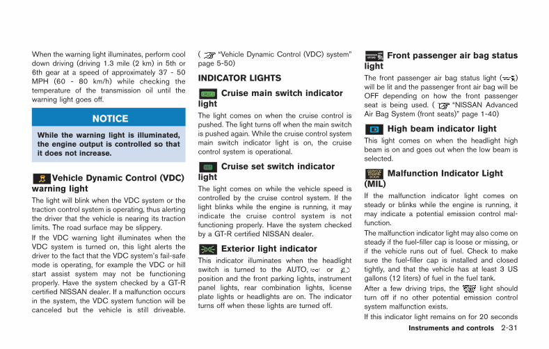
When the warning light illuminates, perform cooldown driving (driving 1.3 mile (2 km) in 5th or6th gear at a speed of approximately 37 - 50MPH (60 - 80 km/h) while checking thetemperature of the transmission oil until thewarning light goes off.
NOTICE
While the warning light is illuminated,the engine output is controlled so thatit does not increase.
Vehicle Dynamic Control (VDC)warning light
The light will blink when the VDC system or thetraction control system is operating, thus alertingthe driver that the vehicle is nearing its tractionlimits. The road surface may be slippery.
If the VDC warning light illuminates when theVDC system is turned on, this light alerts thedriver to the fact that the VDC system’s fail-safemode is operating, for example the VDC or hillstart assist system may not be functioningproperly. Have the system checked by a GT-Rcertified NISSAN dealer. If a malfunction occursin the system, the VDC system function will becanceled but the vehicle is still driveable.
( “Vehicle Dynamic Control (VDC) system”page 5-50)
INDICATOR LIGHTS
Cruise main switch indicatorlight
The light comes on when the cruise control ispushed. The light turns off when the main switchis pushed again. While the cruise control systemmain switch indicator light is on, the cruisecontrol system is operational.
Cruise set switch indicatorlight
The light comes on while the vehicle speed iscontrolled by the cruise control system. If thelight blinks while the engine is running, it mayindicate the cruise control system is notfunctioning properly. Have the system checkedby a GT-R certified NISSAN dealer.
Exterior light indicator
This indicator illuminates when the headlightswitch is turned to the AUTO, orposition and the front parking lights, instrumentpanel lights, rear combination lights, licenseplate lights or headlights are on. The indicatorturns off when these lights are turned off.
Front passenger air bag statuslight
The front passenger air bag status light ( )will be lit and the passenger front air bag will beOFF depending on how the front passengerseat is being used. ( “NISSAN AdvancedAir Bag System (front seats)” page 1-40)
High beam indicator light
This light comes on when the headlight highbeam is on and goes out when the low beam isselected.
Malfunction Indicator Light(MIL)
If the malfunction indicator light comes onsteady or blinks while the engine is running, itmay indicate a potential emission control mal-function.
The malfunction indicator light may also come onsteady if the fuel-filler cap is loose or missing, orif the vehicle runs out of fuel. Check to makesure the fuel-filler cap is installed and closedtightly, and that the vehicle has at least 3 USgallons (12 liters) of fuel in the fuel tank.
After a few driving trips, the light shouldturn off if no other potential emission controlsystem malfunction exists.
If this indicator light remains on for 20 seconds
Instruments and controls 2-31
2-32 Instruments and controls
and then blinks for 10 seconds when the engineis not running, it indicates that the vehicle is notready for an emission control system inspection/maintenance test. ( “Readiness for Inspec-tion/Maintenance (I/M) test (US only)” page 9-20)
Operation:
The malfunction indicator light will come on inone of two ways:
. Malfunction indicator light on steady — Anemission control system malfunction hasbeen detected. Check the fuel-filler cap. Ifthe fuel-filler cap is loose or missing, tightenor install the cap and continue to drive thevehicle. The light should turn off after afew driving trips. If the light does notturn off after a few driving trips, have thevehicle inspected by a GT-R certifiedNISSAN dealer. You do not need to haveyour vehicle towed to the dealer.
. Malfunction indicator light blinking — Anengine misfire has been detected which maydamage the emission control system.
To reduce or avoid emission control systemdamage:
1) Do not drive at speeds above 45 MPH(72 km/h).
2) Avoid hard acceleration or deceleration.
3) Avoid steep uphill grades.
4) If possible, reduce the amount of cargobeing hauled or towed.
The malfunction indicator light may stopblinking and remain on.
Have the vehicle inspected by a GT-Rcertified NISSAN dealer. You do not needto have your vehicle towed to the dealer.
NOTICE
Continued vehicle operation withouthaving the emission control systemchecked and repaired as necessarycould lead to poor driveability, reducedfuel economy, and possible damage tothe emission control system.
Turn signal/hazard indicatorlights
The light flashes when the turn signal switchlever or hazard switch is turned on.
Vehicle Dynamic Control (VDC)off indicator light
The light comes on when the Vehicle DynamicControl (VDC) set up switch is pushed to OFF
for more than 1 second. ( “VDC, transmis-sion and suspension setup switches” page 5-25)
This indicates that the vehicle dynamic controlsystem and traction control system are notoperating. ( “Vehicle Dynamic Control(VDC) system” page 5-50)
AUDIBLE REMINDERS
Key reminder chime
A chime will sound if the driver side door isopened while the ignition switch is pushed tothe ACC position or pushed to the OFF orLOCK position with the Intelligent Key left in theIntelligent Key port. Make sure the ignitionswitch is pushed to the OFF position, and takethe Intelligent Key with you when leaving thevehicle.
Light reminder chime
A chime will sound when the driver side door isopened with the light switch in the orposition and the ignition switch in the ACC, OFFor LOCK position.
Turn the light switch off when you leave thevehicle.
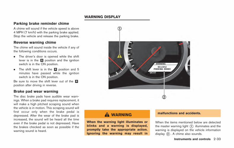
Parking brake reminder chime
A chime will sound if the vehicle speed is above4 MPH (7 km/h) with the parking brake applied.Stop the vehicle and release the parking brake.
Reverse warning chime
The chime will sound inside the vehicle if any ofthe following conditions occurs.
. The driver’s door is opened while the shiftlever is in the &R position and the ignitionswitch is in the ON position.
. The shift lever is in the &R position and 5minutes have passed while the ignitionswitch is in the ON position.
Be sure to move the shift lever out of the &Rposition after driving in reverse.
Brake pad wear warning
The disc brake pads have audible wear warn-ings. When a brake pad requires replacement, itwill make a high pitched scraping sound whenthe vehicle is in motion. This scraping sound willfirst occur only when the brake pedal isdepressed. After the wear of the brake pad isincreased, the sound will be heard all the timeeven if the brake pedal is not depressed. Havethe brakes checked as soon as possible if thewarning sound is heard.
WARNING
When the warning light illuminates orblinks and a warning is displayed,promptly take the appropriate action.Ignoring the warning may result in
malfunctions and accidents.
When the items mentioned below are detectedthe master warning light *1 illuminates and thewarning is displayed on the vehicle informationdisplay *2 . A chime also sounds.
Instruments and controls 2-33
WARNING DISPLAY
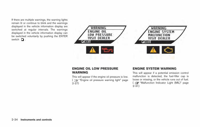
2-34 Instruments and controls
If there are multiple warnings, the warning lightsremain lit or continue to blink and the warningsdisplayed in the vehicle information display areswitched at regular intervals. The warningsdisplayed in the vehicle information display canbe switched voluntarily by pushing the ENTERswitch .
ENGINE OIL LOW PRESSUREWARNING
This will appear if the engine oil pressure is low.( “Engine oil pressure warning light” page2-27)
ENGINE SYSTEM WARNING
This will appear if a potential emission controlmalfunction is detected, the fuel-filler cap isloose or missing, or the vehicle runs out of fuel.( “Malfunction Indicator Light (MIL)” page2-31)
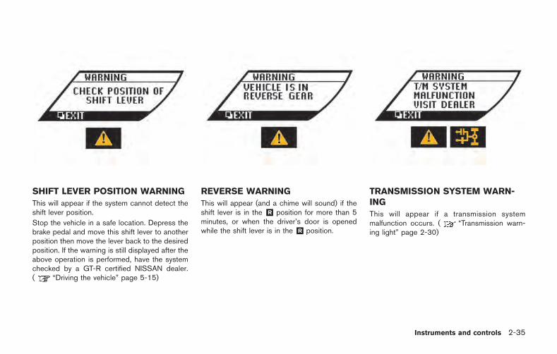
SHIFT LEVER POSITION WARNING
This will appear if the system cannot detect theshift lever position.
Stop the vehicle in a safe location. Depress thebrake pedal and move this shift lever to anotherposition then move the lever back to the desiredposition. If the warning is still displayed after theabove operation is performed, have the systemchecked by a GT-R certified NISSAN dealer.( “Driving the vehicle” page 5-15)
REVERSE WARNING
This will appear (and a chime will sound) if theshift lever is in the &R position for more than 5minutes, or when the driver’s door is openedwhile the shift lever is in the &R position.
TRANSMISSION SYSTEM WARN-ING
This will appear if a transmission systemmalfunction occurs. ( “Transmission warn-ing light” page 2-30)
Instruments and controls 2-35
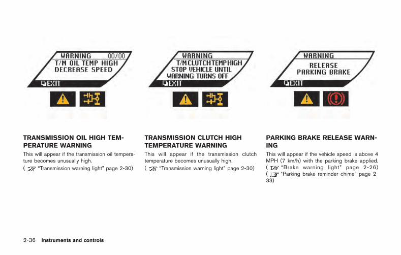
2-36 Instruments and controls
TRANSMISSION OIL HIGH TEM-PERATURE WARNING
This will appear if the transmission oil tempera-ture becomes unusually high.
( “Transmission warning light” page 2-30)
TRANSMISSION CLUTCH HIGHTEMPERATURE WARNING
This will appear if the transmission clutchtemperature becomes unusually high.
( “Transmission warning light” page 2-30)
PARKING BRAKE RELEASE WARN-ING
This will appear if the vehicle speed is above 4MPH (7 km/h) with the parking brake applied.( “Brake warning light” page 2-26)( “Parking brake reminder chime” page 2-33)
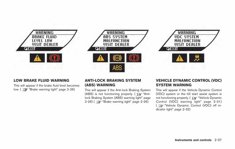
LOW BRAKE FLUID WARNING
This will appear if the brake fluid level becomeslow. ( “Brake warning light” page 2-26)
ANTI-LOCK BRAKING SYSTEM(ABS) WARNING
This will appear if the Anti-lock Braking System(ABS) is not functioning properly. ( “Anti-lock Braking System (ABS) warning light” page2-26) ( “Brake warning light” page 2-26)
VEHICLE DYNAMIC CONTROL (VDC)SYSTEM WARNING
This will appear if the Vehicle Dynamic Control(VDC) system or the hill start assist system isnot functioning properly. ( “Vehicle DynamicControl (VDC) warning light” page 2-31)( “Vehicle Dynamic Control (VDC) off in-dicator light” page 2-32)
Instruments and controls 2-37
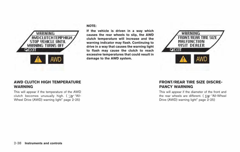
2-38 Instruments and controls
AWD CLUTCH HIGH TEMPERATUREWARNING
This will appear if the temperature of the AWDclutch becomes unusually high. ( “All-Wheel Drive (AWD) warning light” page 2-25)
NOTE:
If the vehicle is driven in a way whichcauses the rear wheels to slip, the AWDclutch temperature will increase and thewarning indicator may flash. Continuing todrive in a way that causes the warning lightto flash may cause the clutch to reachexcessive temperatures that could result indamage to the AWD system.
FRONT/REAR TIRE SIZE DISCRE-PANCY WARNING
This will appear if the diameter of the front andthe rear wheels are different. ( “All-WheelDrive (AWD) warning light” page 2-25)
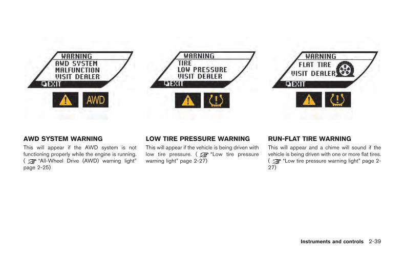
AWD SYSTEM WARNING
This will appear if the AWD system is notfunctioning properly while the engine is running.( “All-Wheel Drive (AWD) warning light”page 2-25)
LOW TIRE PRESSURE WARNING
This will appear if the vehicle is being driven withlow tire pressure. ( “Low tire pressurewarning light” page 2-27)
RUN-FLAT TIRE WARNING
This will appear and a chime will sound if thevehicle is being driven with one or more flat tires.( “Low tire pressure warning light” page 2-27)
Instruments and controls 2-39
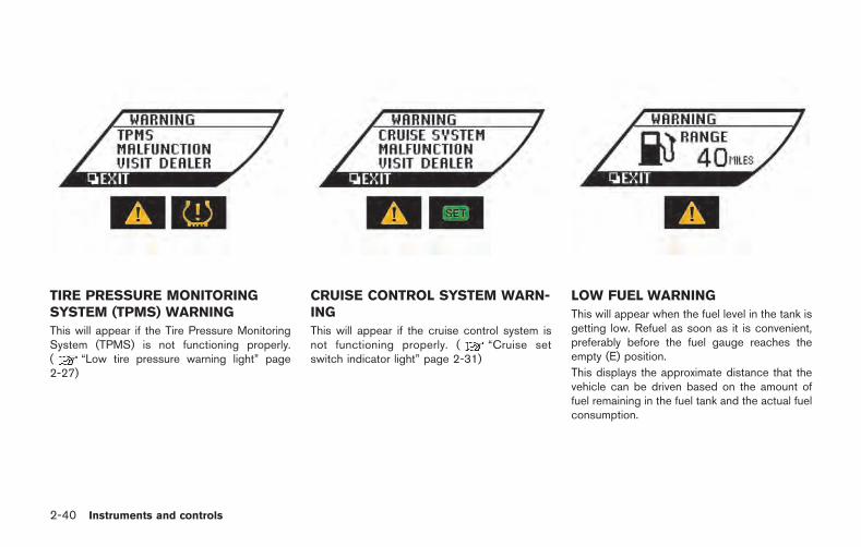
2-40 Instruments and controls
TIRE PRESSURE MONITORINGSYSTEM (TPMS) WARNING
This will appear if the Tire Pressure MonitoringSystem (TPMS) is not functioning properly.( “Low tire pressure warning light” page2-27)
CRUISE CONTROL SYSTEM WARN-ING
This will appear if the cruise control system isnot functioning properly. ( “Cruise setswitch indicator light” page 2-31)
LOW FUEL WARNING
This will appear when the fuel level in the tank isgetting low. Refuel as soon as it is convenient,preferably before the fuel gauge reaches theempty (E) position.
This displays the approximate distance that thevehicle can be driven based on the amount offuel remaining in the fuel tank and the actual fuelconsumption.
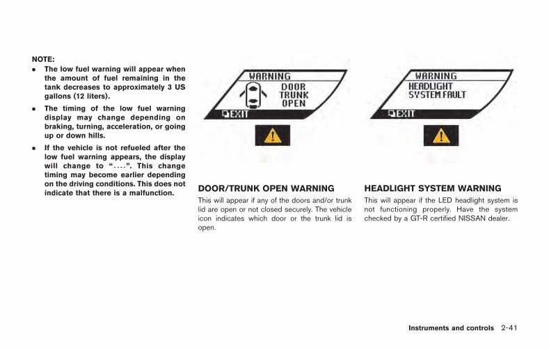
NOTE:
. The low fuel warning will appear whenthe amount of fuel remaining in thetank decreases to approximately 3 USgallons (12 liters).
. The timing of the low fuel warningdisplay may change depending onbraking, turning, acceleration, or goingup or down hills.
. If the vehicle is not refueled after thelow fuel warning appears, the displaywill change to “ ”. This changetiming may become earlier dependingon the driving conditions. This does notindicate that there is a malfunction.
DOOR/TRUNK OPEN WARNING
This will appear if any of the doors and/or trunklid are open or not closed securely. The vehicleicon indicates which door or the trunk lid isopen.
HEADLIGHT SYSTEM WARNING
This will appear if the LED headlight system isnot functioning properly. Have the systemchecked by a GT-R certified NISSAN dealer.
Instruments and controls 2-41
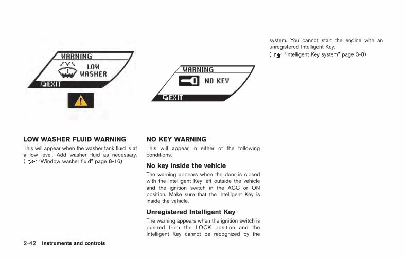
2-42 Instruments and controls
LOW WASHER FLUID WARNING
This will appear when the washer tank fluid is ata low level. Add washer fluid as necessary.( “Window washer fluid” page 8-16)
NO KEY WARNING
This will appear in either of the followingconditions.
No key inside the vehicle
The warning appears when the door is closedwith the Intelligent Key left outside the vehicleand the ignition switch in the ACC or ONposition. Make sure that the Intelligent Key isinside the vehicle.
Unregistered Intelligent Key
The warning appears when the ignition switch ispushed from the LOCK position and theIntelligent Key cannot be recognized by the
system. You cannot start the engine with anunregistered Intelligent Key.
( “Intelligent Key system” page 3-8)
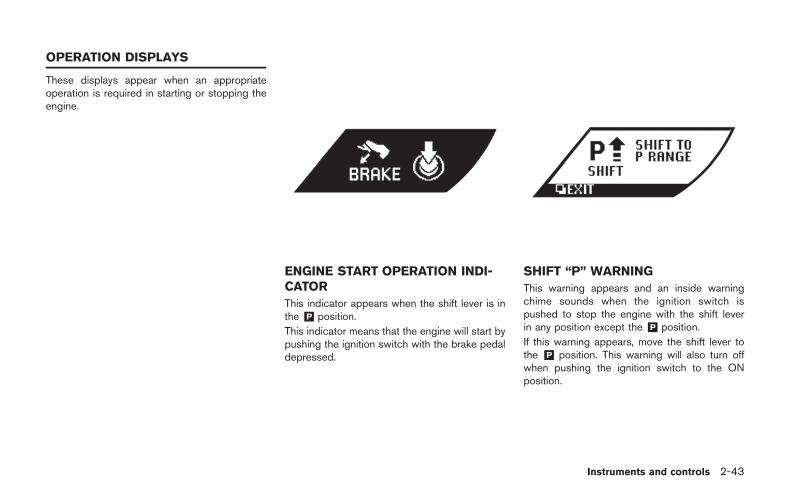
These displays appear when an appropriateoperation is required in starting or stopping theengine.
ENGINE START OPERATION INDI-CATOR
This indicator appears when the shift lever is inthe &P position.
This indicator means that the engine will start bypushing the ignition switch with the brake pedaldepressed.
SHIFT “P” WARNING
This warning appears and an inside warningchime sounds when the ignition switch ispushed to stop the engine with the shift leverin any position except the &P position.
If this warning appears, move the shift lever tothe &P position. This warning will also turn offwhen pushing the ignition switch to the ONposition.
Instruments and controls 2-43
OPERATION DISPLAYS
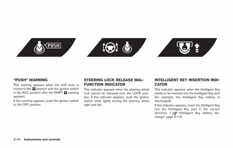
2-44 Instruments and controls
“PUSH” WARNING
This warning appears when the shift lever ismoved to the&P position with the ignition switchin the ACC position after the SHIFT &P warningappears.
If this warning appears, push the ignition switchto the OFF position.
STEERING LOCK RELEASE MAL-FUNCTION INDICATOR
This indicator appears when the steering wheellock cannot be released from the LOCK posi-tion. If this indicator appears, push the ignitionswitch while lightly turning the steering wheelright and left.
INTELLIGENT KEY INSERTION INDI-CATOR
This indicator appears when the Intelligent Keyneeds to be inserted into the Intelligent Key port(for example, the Intelligent Key battery isdischarged).
If this indicator appears, insert the Intelligent Keyinto the Intelligent Key port in the correctdirection. ( “Intelligent Key battery dis-charge” page 5-12)
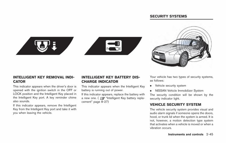
INTELLIGENT KEY REMOVAL INDI-CATOR
This indicator appears when the driver’s door isopened with the ignition switch in the OFF orLOCK position and the Intelligent Key placed inthe Intelligent Key port. A key reminder chimealso sounds.
If this indicator appears, remove the IntelligentKey from the Intelligent Key port and take it withyou when leaving the vehicle.
INTELLIGENT KEY BATTERY DIS-CHARGE INDICATOR
This indicator appears when the Intelligent Keybattery is running out of power.
If this indicator appears, replace the battery witha new one. ( “Intelligent Key battery repla-cement” page 8-27)
Your vehicle has two types of security systems,as follows:
. Vehicle security system
. NISSAN Vehicle Immobilizer System
The security condition will be shown by thesecurity indicator light.
VEHICLE SECURITY SYSTEM
The vehicle security system provides visual andaudio alarm signals if someone opens the doors,hood, or trunk lid when the system is armed. It isnot, however, a motion detection type systemthat activates when a vehicle is moved or when avibration occurs.
Instruments and controls 2-45
SECURITY SYSTEMS
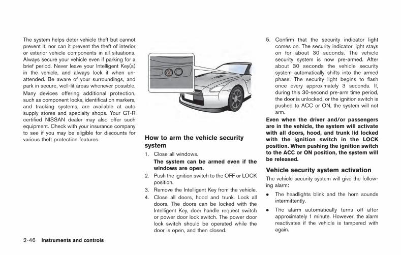
2-46 Instruments and controls
The system helps deter vehicle theft but cannotprevent it, nor can it prevent the theft of interioror exterior vehicle components in all situations.Always secure your vehicle even if parking for abrief period. Never leave your Intelligent Key(s)in the vehicle, and always lock it when un-attended. Be aware of your surroundings, andpark in secure, well-lit areas whenever possible.
Many devices offering additional protection,such as component locks, identification markers,and tracking systems, are available at autosupply stores and specialty shops. Your GT-Rcertified NISSAN dealer may also offer suchequipment. Check with your insurance companyto see if you may be eligible for discounts forvarious theft protection features. How to arm the vehicle security
system
1. Close all windows.
The system can be armed even if thewindows are open.
2. Push the ignition switch to the OFF or LOCKposition.
3. Remove the Intelligent Key from the vehicle.
4. Close all doors, hood and trunk. Lock alldoors. The doors can be locked with theIntelligent Key, door handle request switchor power door lock switch. The power doorlock switch should be operated while thedoor is open, and then closed.
5. Confirm that the security indicator lightcomes on. The security indicator light stayson for about 30 seconds. The vehiclesecurity system is now pre-armed. Afterabout 30 seconds the vehicle securitysystem automatically shifts into the armedphase. The security light begins to flashonce every approximately 3 seconds. If,during this 30-second pre-arm time period,the door is unlocked, or the ignition switch ispushed to ACC or ON, the system will notarm.
Even when the driver and/or passengersare in the vehicle, the system will activatewith all doors, hood, and trunk lid lockedwith the ignition switch in the LOCKposition. When pushing the ignition switchto the ACC or ON position, the system willbe released.
Vehicle security system activation
The vehicle security system will give the follow-ing alarm:
. The headlights blink and the horn soundsintermittently.
. The alarm automatically turns off afterapproximately 1 minute. However, the alarmreactivates if the vehicle is tampered withagain.
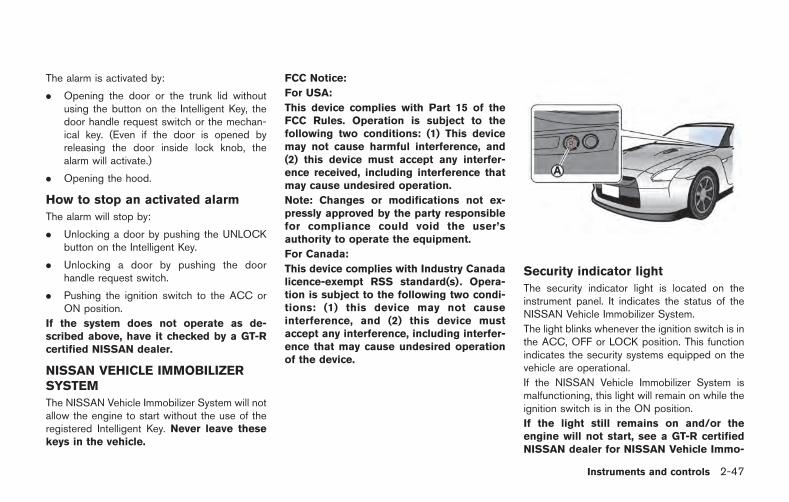
The alarm is activated by:
. Opening the door or the trunk lid withoutusing the button on the Intelligent Key, thedoor handle request switch or the mechan-ical key. (Even if the door is opened byreleasing the door inside lock knob, thealarm will activate.)
. Opening the hood.
How to stop an activated alarm
The alarm will stop by:
. Unlocking a door by pushing the UNLOCKbutton on the Intelligent Key.
. Unlocking a door by pushing the doorhandle request switch.
. Pushing the ignition switch to the ACC orON position.
If the system does not operate as de-scribed above, have it checked by a GT-Rcertified NISSAN dealer.
NISSAN VEHICLE IMMOBILIZERSYSTEM
The NISSAN Vehicle Immobilizer System will notallow the engine to start without the use of theregistered Intelligent Key. Never leave thesekeys in the vehicle.
FCC Notice:
For USA:
This device complies with Part 15 of theFCC Rules. Operation is subject to thefollowing two conditions: (1) This devicemay not cause harmful interference, and(2) this device must accept any interfer-ence received, including interference thatmay cause undesired operation.
Note: Changes or modifications not ex-pressly approved by the party responsiblefor compliance could void the user’sauthority to operate the equipment.
For Canada:
This device complies with Industry Canadalicence-exempt RSS standard(s). Opera-tion is subject to the following two condi-tions: (1) this device may not causeinterference, and (2) this device mustaccept any interference, including interfer-ence that may cause undesired operationof the device.
Security indicator light
The security indicator light is located on theinstrument panel. It indicates the status of theNISSAN Vehicle Immobilizer System.
The light blinks whenever the ignition switch is inthe ACC, OFF or LOCK position. This functionindicates the security systems equipped on thevehicle are operational.
If the NISSAN Vehicle Immobilizer System ismalfunctioning, this light will remain on while theignition switch is in the ON position.
If the light still remains on and/or theengine will not start, see a GT-R certifiedNISSAN dealer for NISSAN Vehicle Immo-
Instruments and controls 2-47
2-48 Instruments and controls
bilizer System service as soon as possible.Please bring all Intelligent Keys that youhave when visiting a GT-R certifiedNISSAN dealer for service.
WARNING
In freezing temperatures the washersolution may freeze on the windshieldand obscure your vision which may leadto an accident. Warm windshield withthe defroster before you wash thewindshield.
NOTICE
. Do not operate the washer continu-ously for more than 30 seconds.
. Do not operate the washer if thereservoir tank is empty.
. Do not fill the window washerreservoir tank with washer fluidconcentrates at full strength. Somemethyl alcohol based washer fluidconcentrates may permanently stainthe grille if spilled while filling thewindow washer reservoir tank.
. Pre-mix washer fluid concentrateswith water to the manufacturer’srecommended levels before pouringthe fluid into the window washerreservoir tank. Do not use the
window washer reservoir tank tomix the washer fluid concentrateand water.
The windshield wiper and washer operateswhen the ignition switch is in the ON position.
WINDSHIELD WIPER AND WASHERSWITCH
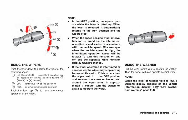
USING THE WIPERS
Push the lever down to operate the wiper at thefollowing speed:*1 INT (Intermittent) — intermittent operation can
be adjusted by turning the knob toward *A(Slower) or *B (Faster).
*2 Low — continuous low speed operation
*3 High — continuous high speed operation
Push the lever up *4 to have one sweepoperation of the wiper.
NOTE:. In the MIST position, the wipers oper-
ate while the lever is lifted up. Whenthe lever is released, it automaticallyreturns to the OFF position and thewipers stop.
. When the speed sensing wiper intervalfunction is turned on, the intermittentoperation speed varies in accordancewith the vehicle speed. (For example,when the vehicle speed is high, theintermittent operation speed will befaster.) To turn this function on andoff, see the separate Multi FunctionDisplay Owner’s Manual.
. If the wiper operation is interrupted bysnow or ice, the wiper may stop movingto protect its motor. If this occurs, turnthe wiper switch to the OFF positionand remove the snow or ice on andaround the wiper arms. In approxi-mately 1 minute, turn the switch onagain to operate the wiper.
USING THE WASHER
Pull the lever toward you to operate the washer.Then the wiper will also operate several times.
NOTE:
When the level of washer fluid is low, awarning display appears on the vehicleinformation display. ( “Low washerfluid warning” page 2-42)
Instruments and controls 2-49
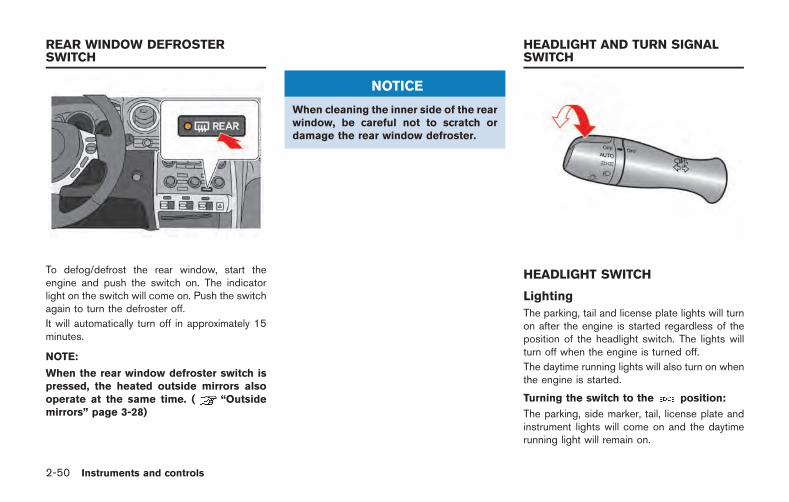
2-50 Instruments and controls
To defog/defrost the rear window, start theengine and push the switch on. The indicatorlight on the switch will come on. Push the switchagain to turn the defroster off.
It will automatically turn off in approximately 15minutes.
NOTE:
When the rear window defroster switch ispressed, the heated outside mirrors alsooperate at the same time. ( “Outsidemirrors” page 3-28)
NOTICE
When cleaning the inner side of the rearwindow, be careful not to scratch ordamage the rear window defroster.
HEADLIGHT SWITCH
Lighting
The parking, tail and license plate lights will turnon after the engine is started regardless of theposition of the headlight switch. The lights willturn off when the engine is turned off.
The daytime running lights will also turn on whenthe engine is started.
Turning the switch to the position:
The parking, side marker, tail, license plate andinstrument lights will come on and the daytimerunning light will remain on.
REAR WINDOW DEFROSTERSWITCH
HEADLIGHT AND TURN SIGNALSWITCH
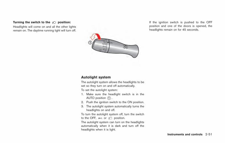
Turning the switch to the position:
Headlights will come on and all the other lightsremain on. The daytime running light will turn off.
Autolight system
The autolight system allows the headlights to beset so they turn on and off automatically.
To set the autolight system:
1. Make sure the headlight switch is in theAUTO position *1 .
2. Push the ignition switch to the ON position.
3. The autolight system automatically turns theheadlights on and off.
To turn the autolight system off, turn the switchto the OFF, or position.
The autolight system can turn on the headlightsautomatically when it is dark and turn off theheadlights when it is light.
If the ignition switch is pushed to the OFFposition and one of the doors is opened, theheadlights remain on for 45 seconds.
Instruments and controls 2-51
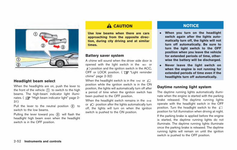
2-52 Instruments and controls
Headlight beam select
When the headlights are on, push the lever tothe front of the vehicle*1 to switch to the highbeams. The high-beam indicator light illumi-nates. ( “High beam indicator light” page 2-31)
Pull the lever to the neutral position *2 toswitch to the low beams.
Pulling the lever toward you *3 will flash theheadlight high beam even when the headlightswitch is in the OFF position.
CAUTION
Use low beams when there are carsapproaching from the opposite direc-tion, during city driving and at similartimes.
Battery saver system
A chime will sound when the driver side door isopened with the light switch in the or
position and the ignition switch in the ACC,OFF or LOCK position. ( “Light reminderchime” page 2-32)
When the headlight switch is in the orposition while the ignition switch is in the ONposition, the lights will automatically turn off aftera period of time when the ignition switch hasbeen pushed to the OFF position.
When the headlight switch remains in theor position after the lights automatically turnoff, the lights will turn on when the ignitionswitch is pushed to the ON position.
NOTICE
. When you turn on the headlightswitch again after the lights auto-matically turn off, the lights will notturn off automatically. Be sure toturn the light switch to the OFFposition when you leave the vehiclefor extended periods of time, other-wise the battery will be discharged.
. Never leave the light switch onwhen the engine is not running forextended periods of time even if theheadlights turn off automatically.
Daytime running light system
The daytime running lights automatically illumi-nate when the engine is started with the parkingbrake released. The daytime running lightsoperate with the headlight switch in the OFFposition. Turn the headlight switch to theposition for full illumination when driving at night.
If the parking brake is applied before the engineis started, the daytime running lights do notilluminate. The daytime running lights illuminateonce the parking brake is released. The daytimerunning lights will remain on until the ignitionswitch is pushed to the OFF position.
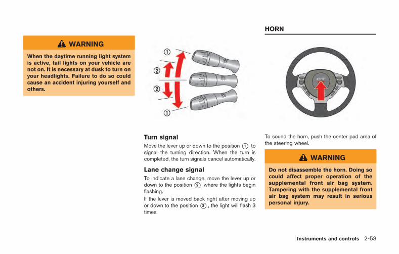
WARNING
When the daytime running light systemis active, tail lights on your vehicle arenot on. It is necessary at dusk to turn onyour headlights. Failure to do so couldcause an accident injuring yourself andothers.
Turn signal
Move the lever up or down to the position*1 tosignal the turning direction. When the turn iscompleted, the turn signals cancel automatically.
Lane change signal
To indicate a lane change, move the lever up ordown to the position *2 where the lights beginflashing.
If the lever is moved back right after moving upor down to the position*2 , the light will flash 3times.
To sound the horn, push the center pad area ofthe steering wheel.
WARNING
Do not disassemble the horn. Doing socould affect proper operation of thesupplemental front air bag system.Tampering with the supplemental frontair bag system may result in seriouspersonal injury.
Instruments and controls 2-53
HORN
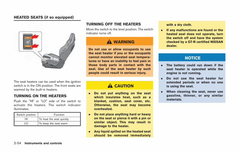
2-54 Instruments and controls
The seat heaters can be used when the ignitionswitch is in the ON position. The front seats arewarmed by the built-in heaters.
TURNING ON THE HEATERS
Push the "HI" or "LO" side of the switch toactivate the heaters. The switch indicatorilluminates.
Switch position Function
HI To heat the seat quickly
LO To keep the seat warm
TURNING OFF THE HEATERS
Move the switch to the level position. The switchindicator turns off.
WARNING
Do not use or allow occupants to usethe seat heater if you or the occupantscannot monitor elevated seat tempera-tures or have an inability to feel pain inthose body parts in contact with theseat. Use of the seat heater by suchpeople could result in serious injury.
CAUTION
. Do not put anything on the seatwhich insulates heat, such as ablanket, cushion, seat cover, etc.Otherwise, the seat may becomeoverheated.
. Do not place anything hard or heavyon the seat or pierce it with a pin orsimilar object. This may result indamage to the heater.
. Any liquid spilled on the heated seatshould be removed immediately
with a dry cloth.
. If any malfunctions are found or theheated seat does not operate, turnthe switch off and have the systemchecked by a GT-R certified NISSANdealer.
NOTICE
. The battery could run down if theseat heater is operated while theengine is not running.
. Do not use the seat heater forextended periods or when no oneis using the seat.
. When cleaning the seat, never usegasoline, thinner, or any similarmaterials.
HEATED SEATS (if so equipped)
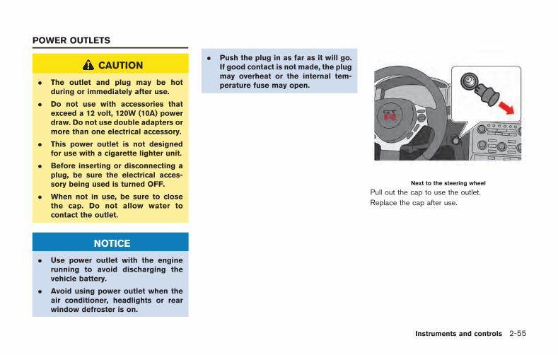
CAUTION
. The outlet and plug may be hotduring or immediately after use.
. Do not use with accessories thatexceed a 12 volt, 120W (10A) powerdraw. Do not use double adapters ormore than one electrical accessory.
. This power outlet is not designedfor use with a cigarette lighter unit.
. Before inserting or disconnecting aplug, be sure the electrical acces-sory being used is turned OFF.
. When not in use, be sure to closethe cap. Do not allow water tocontact the outlet.
NOTICE
. Use power outlet with the enginerunning to avoid discharging thevehicle battery.
. Avoid using power outlet when theair conditioner, headlights or rearwindow defroster is on.
. Push the plug in as far as it will go.If good contact is not made, the plugmay overheat or the internal tem-perature fuse may open.
Next to the steering wheel
Pull out the cap to use the outlet.
Replace the cap after use.
Instruments and controls 2-55
POWER OUTLETS
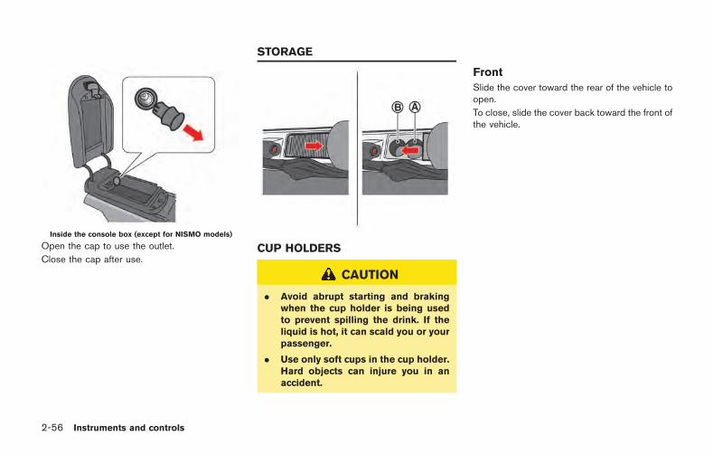
2-56 Instruments and controls
Inside the console box (except for NISMO models)
Open the cap to use the outlet.
Close the cap after use.CUP HOLDERS
CAUTION
. Avoid abrupt starting and brakingwhen the cup holder is being usedto prevent spilling the drink. If theliquid is hot, it can scald you or yourpassenger.
. Use only soft cups in the cup holder.Hard objects can injure you in anaccident.
Front
Slide the cover toward the rear of the vehicle toopen.
To close, slide the cover back toward the front ofthe vehicle.
STORAGE
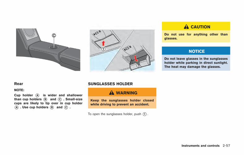
Rear
NOTE:
Cup holder *A is wider and shallowerthan cup holders *B and *C . Small-sizecups are likely to tip over in cup holder
*A . Use cup holders *B and *C .
SUNGLASSES HOLDER
WARNING
Keep the sunglasses holder closedwhile driving to prevent an accident.
To open the sunglasses holder, push *1 .
CAUTION
Do not use for anything other thanglasses.
NOTICE
Do not leave glasses in the sunglassesholder while parking in direct sunlight.The heat may damage the glasses.
Instruments and controls 2-57
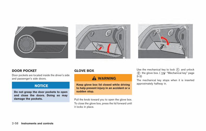
2-58 Instruments and controls
DOOR POCKET
Door pockets are located inside the driver’s sideand passenger’s side doors.
NOTICE
Do not grasp the door pockets to openand close the doors. Doing so maydamage the pockets.
GLOVE BOX
WARNING
Keep glove box lid closed while drivingto help prevent injury in an accident or asudden stop.
Pull the knob toward you to open the glove box.
To close the glove box, press the lid forward untilit locks in place.
Use the mechanical key to lock *1 and unlock*2 the glove box. ( “Mechanical key” page3-3)
The mechanical key stops when it is insertedapproximately halfway in.
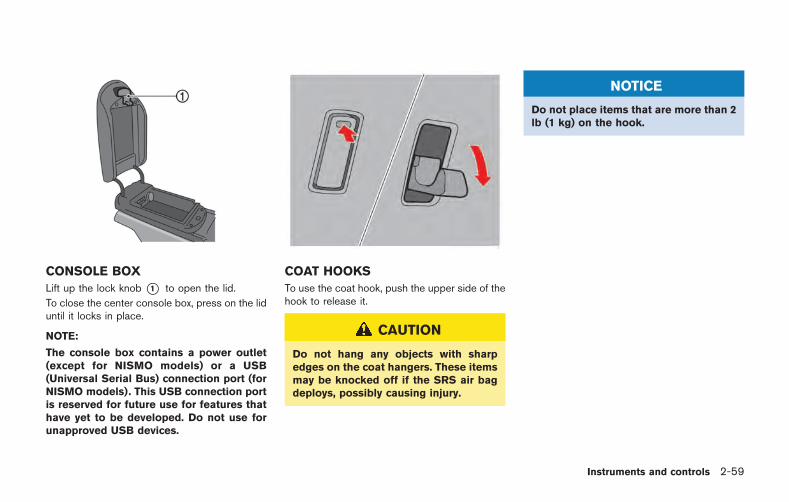
CONSOLE BOX
Lift up the lock knob *1 to open the lid.
To close the center console box, press on the liduntil it locks in place.
NOTE:
The console box contains a power outlet(except for NISMO models) or a USB(Universal Serial Bus) connection port (forNISMO models). This USB connection portis reserved for future use for features thathave yet to be developed. Do not use forunapproved USB devices.
COAT HOOKS
To use the coat hook, push the upper side of thehook to release it.
CAUTION
Do not hang any objects with sharpedges on the coat hangers. These itemsmay be knocked off if the SRS air bagdeploys, possibly causing injury.
NOTICE
Do not place items that are more than 2lb (1 kg) on the hook.
Instruments and controls 2-59
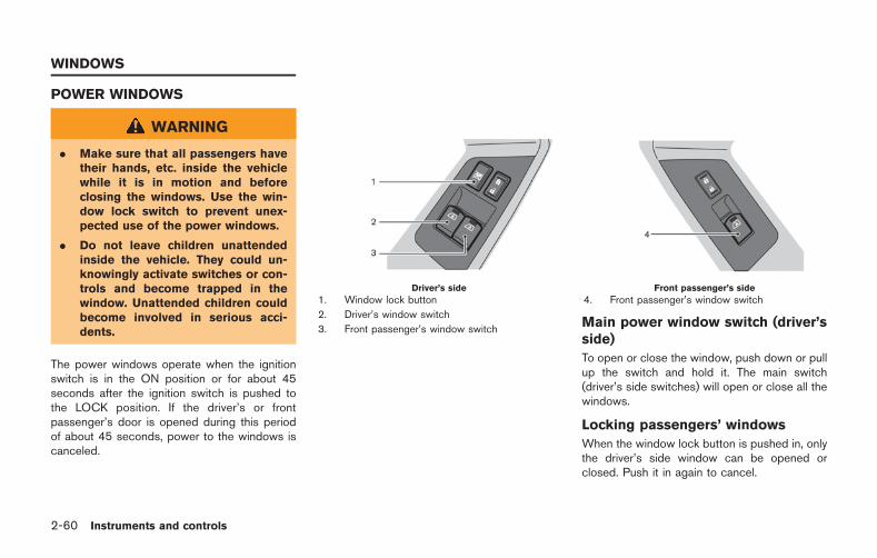
2-60 Instruments and controls
POWER WINDOWS
WARNING
. Make sure that all passengers havetheir hands, etc. inside the vehiclewhile it is in motion and beforeclosing the windows. Use the win-dow lock switch to prevent unex-pected use of the power windows.
. Do not leave children unattendedinside the vehicle. They could un-knowingly activate switches or con-trols and become trapped in thewindow. Unattended children couldbecome involved in serious acci-dents.
The power windows operate when the ignitionswitch is in the ON position or for about 45seconds after the ignition switch is pushed tothe LOCK position. If the driver’s or frontpassenger’s door is opened during this periodof about 45 seconds, power to the windows iscanceled.
Driver’s side
1. Window lock button
2. Driver’s window switch
3. Front passenger’s window switch
Front passenger’s side
4. Front passenger’s window switch
Main power window switch (driver’sside)
To open or close the window, push down or pullup the switch and hold it. The main switch(driver’s side switches) will open or close all thewindows.
Locking passengers’ windows
When the window lock button is pushed in, onlythe driver’s side window can be opened orclosed. Push it in again to cancel.
WINDOWS
Passenger’s side power windowswitch
The passenger side switch will open or closeonly the corresponding window. To open closethe window, push down or pull up the switchand hold it.
Automatic operation
To fully open or close the window, completelypush down or pull up the switch and release it; itdoes not need to be held. The window willautomatically open or close all the way. To stopthe window, just push or lift the switch in theopposite direction.
A light push or pull on the switch will cause thewindow to open or close until the switch isreleased.
Auto reverse function
If the control unit detects something caught inthe window as it is closing, the window will beimmediately lowered.
The auto reverse function can be activated whenthe window is closed by automatic operationwhen the ignition switch is in the ON position orfor 45 seconds after the ignition switch ispushed to the OFF position.
Depending on the environment or driving con-ditions, the auto reverse function may be
activated if an impact or load similar to some-thing being caught in the window occurs.
WARNING
There are some small distances imme-diately before the closed position whichcannot be detected. Make sure that allpassengers have their hands, etc., in-side the vehicle before closing thewindow.
Automatic adjusting function
CAUTION
When the battery cable is removed fromthe battery terminal, do not close eitherof the front doors. The automatic win-dow adjusting function will not workand the side roof panel may be da-maged.
The power window has an automatic adjustingfunction. When the door is being opened, thewindow is automatically lowered slightly to avoidcontact between the window and the side roofpanel. When the door is closed, the window is
automatically raised slightly.
While the automatic adjusting function does notwork, the window will be controlled as follows:
. When the door is opened, the windowlowers for approximately 2 seconds.
. While the door is open, the window cannotbe raised.
If the windows do not close auto-matically
If the power window automatic function (closingonly) does not operate properly, perform thefollowing procedure to initialize the powerwindow system.
1. Push the ignition switch to the ON position.
2. Close the door.
3. Open the window completely by operatingthe power window switch.
4. Pull the power window switch and hold it toclose the driver side window, and then holdthe switch more than 3 seconds after thewindow is closed completely.
5. Release the power window switch. Operatethe window by the automatic function toconfirm the initialization is complete.
6. Perform steps 2 through 5 above for thepassenger side window by operating eitherdriver’s or passenger’s side switch.
Instruments and controls 2-61
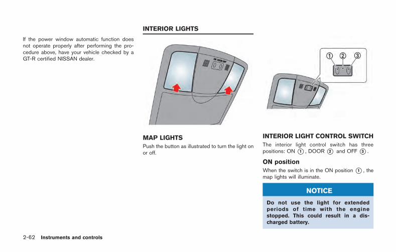
2-62 Instruments and controls
If the power window automatic function doesnot operate properly after performing the pro-cedure above, have your vehicle checked by aGT-R certified NISSAN dealer.
MAP LIGHTS
Push the button as illustrated to turn the light onor off.
INTERIOR LIGHT CONTROL SWITCH
The interior light control switch has threepositions: ON *1 , DOOR *2 and OFF *3 .
ON position
When the switch is in the ON position *1 , themap lights will illuminate.
NOTICE
Do not use the light for extendedperiods of time with the enginestopped. This could result in a dis-charged battery.
INTERIOR LIGHTS
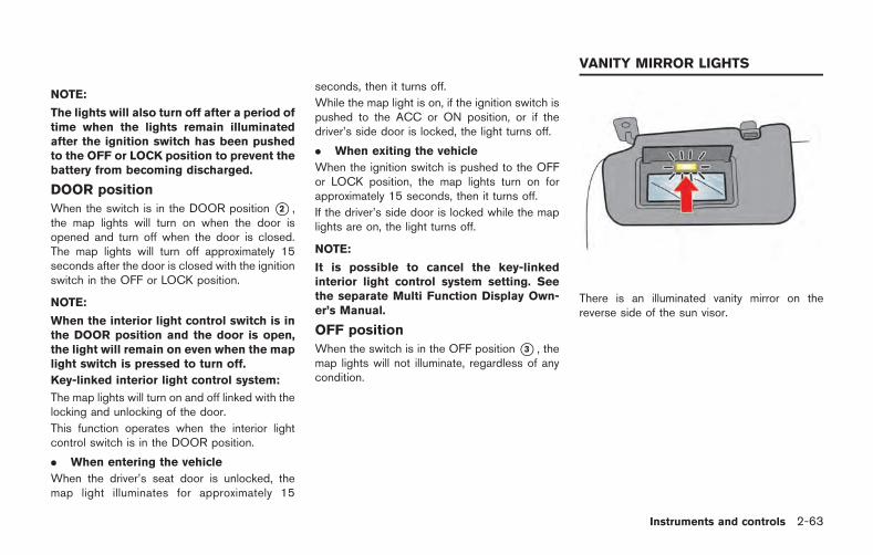
NOTE:
The lights will also turn off after a period oftime when the lights remain illuminatedafter the ignition switch has been pushedto the OFF or LOCK position to prevent thebattery from becoming discharged.
DOOR position
When the switch is in the DOOR position *2 ,the map lights will turn on when the door isopened and turn off when the door is closed.The map lights will turn off approximately 15seconds after the door is closed with the ignitionswitch in the OFF or LOCK position.
NOTE:
When the interior light control switch is inthe DOOR position and the door is open,the light will remain on even when the maplight switch is pressed to turn off.
Key-linked interior light control system:
The map lights will turn on and off linked with thelocking and unlocking of the door.
This function operates when the interior lightcontrol switch is in the DOOR position.
. When entering the vehicle
When the driver’s seat door is unlocked, themap light illuminates for approximately 15
seconds, then it turns off.
While the map light is on, if the ignition switch ispushed to the ACC or ON position, or if thedriver’s side door is locked, the light turns off.
. When exiting the vehicle
When the ignition switch is pushed to the OFFor LOCK position, the map lights turn on forapproximately 15 seconds, then it turns off.
If the driver’s side door is locked while the maplights are on, the light turns off.
NOTE:
It is possible to cancel the key-linkedinterior light control system setting. Seethe separate Multi Function Display Own-er’s Manual.
OFF position
When the switch is in the OFF position*3 , themap lights will not illuminate, regardless of anycondition.
There is an illuminated vanity mirror on thereverse side of the sun visor.
Instruments and controls 2-63
VANITY MIRROR LIGHTS
2-64 Instruments and controls
The HomeLink Universal Transceiver provides aconvenient way to consolidate the functions ofup to three individual hand-held transmitters intoone built-in device.
HomeLink Universal Transceiver:
. Will operate most Radio Frequency (RF)devices such as garage doors, gates, homeand office lighting, entry door locks andsecurity systems.
. Is powered by your vehicle’s battery. Noseparate batteries are required. If thevehicle’s battery is discharged or is dis-connected, HomeLink will retain all pro-gramming.
When the HomeLink Universal Transcei-ver is programmed, retain the originaltransmitter for future programming proce-dures (Example: new vehicle purchases).Upon sale of the vehicle, the programmedHomeLink Universal Transceiver buttonsshould be erased for security purposes.For additional information, refer to
“Programming HomeLink ” page 2-64.
WARNING
. Do not use the HomeLink UniversalTransceiver with any garage dooropener that lacks safety stop andreverse features as required byfederal safety standards. (Thesestandards became effective foropener models manufactured afterApril 1, 1982.) A garage door openerwhich cannot detect an object in thepath of a closing garage door andthen automatically stop and reverse,does not meet current federal safetystandards. Using a garage dooropener without these features in-creases the risk of serious injury ordeath.
. During the programming procedureyour garage door or security gatewill open and close (if the transmit-ter is within range). Make sure thatpeople or objects are clear of thegarage door, gate, etc. that you areprogramming.
. Your vehicle’s engine should beturned off while programming theHomeLink Universal Transceiver.
Do not breathe exhaust gases; theycontain colorless and odorless car-bon monoxide. Carbon monoxide isdangerous. It can cause uncon-sciousness or death.
PROGRAMMING HomeLink
If you have any questions or are having difficultyprogramming your HomeLink buttons, refer tothe HomeLink web site at: www.homelink.comor call 1-800-355-3515.
NOTE:
It is also recommended that a new batterybe placed in the hand-held transmitter ofthe device being programmed toHomeLink for quicker programming andaccurate transmission of the radio-fre-quency.
1. Position the end of your hand-held transmit-ter 1-3 in (26-76 mm) away from theHomeLink surface, keeping the HomeLinkindicator light *1 in view.
HomeLink UNIVERSALTRANSCEIVER
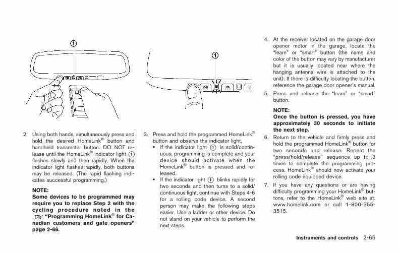
2. Using both hands, simultaneously press andhold the desired HomeLink button andhandheld transmitter button. DO NOT re-lease until the HomeLink indicator light *1flashes slowly and then rapidly. When theindicator light flashes rapidly, both buttonsmay be released. (The rapid flashing indi-cates successful programming.)
NOTE:Some devices to be programmed mayrequire you to replace Step 2 with thecycling procedure noted in the
“Programming HomeLink for Ca-nadian customers and gate openers”page 2-66.
3. Press and hold the programmed HomeLinkbutton and observe the indicator light.. If the indicator light *1 is solid/contin-
uous, programming is complete and yourdevice should activate when theHomeLink button is pressed and re-leased.
. If the indicator light *1 blinks rapidly fortwo seconds and then turns to a solid/continuous light, continue with Steps 4-6for a rolling code device. A secondperson may make the following stepseasier. Use a ladder or other device. Donot stand on your vehicle to perform thenext steps.
4. At the receiver located on the garage dooropener motor in the garage, locate the“learn” or “smart” button (the name andcolor of the button may vary by manufacturerbut it is usually located near where thehanging antenna wire is attached to theunit). If there is difficulty locating the button,reference the garage door opener’s manual.
5. Press and release the “learn” or “smart”button.
NOTE:Once the button is pressed, you haveapproximately 30 seconds to initiatethe next step.
6. Return to the vehicle and firmly press andhold the programmed HomeLink button fortwo seconds and release. Repeat the“press/hold/release” sequence up to 3times to complete the programming pro-cess. HomeLink should now activate yourrolling code equipped device.
7. If you have any questions or are havingdifficulty programming your HomeLink but-tons, refer to the HomeLink web site at:www.homelink.com or call 1-800-355-3515.
Instruments and controls 2-65
2-66 Instruments and controls
PROGRAMMING HomeLink FORCANADIAN CUSTOMERS AND GATEOPENERS
Canadian radio-frequency laws require trans-mitter signals to “time-out” (or quit) after severalseconds of transmission – which may not belong enough for HomeLink to pick up the signalduring programming. Similar to this Canadianlaw, some U.S. gate operators are designed to“time-out” in the same manner.
If you live in Canada or you are having difficultiesprogramming a gate operator or garage dooropener by using the “Programming HomeLink ”procedures, replace “Programming HomeLink ”Step 2 with the following:
NOTE:
When programming a garage door opener,etc., unplug the device during the “cycling”process to prevent possible damage to thegarage door opener components.
Step 2: Using both hands, simultaneously pressand hold the desired HomeLink button and thehand-held transmitter button. During program-ming, your hand-held transmitter may automati-cally stop transmitting. Continue to press andhold the desired HomeLink button while youpress and re-press (“cycle”) your hand-heldtransmitter every two seconds until the fre-
quency signal has been learned. The HomeLinkindicator light will flash slowly and then rapidlyafter several seconds upon successful program-ming. DO NOT release until the HomeLinkindicator light flashes slowly and then rapidly.When the indicator light flashes rapidly, bothbuttons may be released. The rapid flashingindicates successful programming.
Proceed with “Programming HomeLink ” step 3to complete.
Remember to plug the device back in whenprogramming is completed.
OPERATING THE HomeLink UNI-VERSAL TRANSCEIVER
The HomeLink Universal Transceiver, after it isprogrammed, can be used to activate theprogrammed device. To operate, simply pressand release the appropriate programmedHomeLink Universal Transceiver button. Theamber indicator light will illuminate while thesignal is being transmitted.
For convenience, the hand-held transmitter ofthe device may also be used at any time.
PROGRAMMING TROUBLESHOOT-ING
If the HomeLink does not quickly learn thehand-held transmitter information:
. replace the hand-held transmitter batterieswith new batteries.
. position the hand-held transmitter with itsbattery area facing away from theHomeLink surface.
. press and hold both the HomeLink andhand-held transmitter buttons without inter-ruption.
. position the hand-held transmitter 1-3 in(26-76 mm) away from the HomeLinksurface. Hold the transmitter in that positionfor up to 15 seconds. If HomeLink is notprogrammed within that time, try holding thetransmitter in another position - keeping theindicator light in view at all times.
If you have any questions or are having difficultyprogramming your HomeLink buttons, refer tothe HomeLink web site at: www.homelink.comor 1-800-355-3515.

CLEARING THE PROGRAMMED IN-FORMATION
The following procedure clears the programmedinformation from both buttons. Individual buttonscannot be cleared. However, individual buttonsc a n b e r e p r o g r a m m e d , s e e
“Reprogramming a single HomeLink but-ton” page 2-67.
To clear all programming
1. Press and hold the two outer HomeLinkbuttons until the indicator light begins toflash in approximately 10 seconds. Do nothold for longer than 20 seconds.
2. Release both buttons.
HomeLink is now in the programming modeand can be programmed at any time beginningwith “Programming HomeLink ” - Step 1.
REPROGRAMMING A SINGLEHomeLink BUTTON
To reprogram a HomeLink Universal Transcei-ver button, complete the following.
1. Press and hold the desired HomeLinkbutton. Do not release the button.
2. The indicator light will begin to flash after 20seconds. Without releasing the HomeLinkbutton, proceed with “Programming
HomeLink ” - Step 1.
For questions or comments, contact HomeLinkat: www.homelink.com or 1-800-355-3515.
The HomeLink Universal Transceiver buttonhas now been reprogrammed. The new devicecan be activated by pushing the HomeLinkbutton that was just programmed. This proce-dure will not affect any other programmedHomeLink buttons.
IF YOUR VEHICLE IS STOLEN
If your vehicle is stolen, you should change thecodes of any non-rolling code device that hasbeen programmed into HomeLink . Consult theOwner’s Manual of each device or call themanufacturer or retailer of those devices foradditional information.
When your vehicle is recovered, you willneed to reprogram the HomeLink Univer-sal Transceiver with your new transmitterinformation.
FCC Notice:
For USA:
This device complies with Part 15 of theFCC Rules. Operation is subject to thefollowing two conditions: (1) This devicemay not cause harmful interference, and(2) this device must accept any interfer-
ence received, including interference thatmay cause undesired operation.
NOTE:
Changes or modifications not expresslyapproved by the party responsible forcompliance could void the user’s authorityto operate the equipment.
For Canada:
This device complies with Industry Canadalicence-exempt RSS standard(s). Opera-tion is subject to the following two condi-tions: (1) this device may not causeinterference, and (2) this device mustaccept any interference, including interfer-ence that may cause undesired operationof the device.
Instruments and controls 2-67

2-68 Instruments and controls
MEMO
3 Pre-driving checks and adjustments
Keys ............................................................................................. 3-2Intelligent Key ...................................................................... 3-2
Doors ........................................................................................... 3-4Locking with inside lock knob ........................................ 3-5Locking with power door lock switch ........................... 3-5Automatic door lock system ............................................ 3-5Locking with mechanical key ........................................... 3-6Opening the doors ............................................................ 3-7
Intelligent Key system ............................................................. 3-8Intelligent Key functions .................................................... 3-9Remote keyless entry functions ................................... 3-12Setting hazard indicator and horn mode .................. 3-13Warning signals ............................................................... 3-16Troubleshooting guide ................................................... 3-17
Hood ......................................................................................... 3-18Opening the hood ........................................................... 3-18Closing the hood ............................................................. 3-19
Trunk ........................................................................................ 3-20Trunk open request switch ......................................... 3-20Trunk lid release switch ............................................... 3-20Trunk release power cancel switch .......................... 3-21Opening and closing the trunk .................................. 3-22Emergency trunk lid release ....................................... 3-22
Fuel-filler door ....................................................................... 3-24Opening the fuel filler door ........................................ 3-25Closing the fuel-filler door .......................................... 3-25
Steering wheel ...................................................................... 3-26Tilt/telescopic steering column .................................. 3-26
Sun visors ............................................................................... 3-27Mirrors ..................................................................................... 3-27
Inside mirror .................................................................... 3-27Outside mirrors .............................................................. 3-28Vanity mirror .................................................................... 3-29
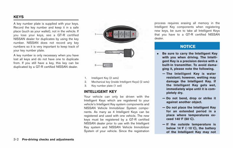
3-2 Pre-driving checks and adjustments
A key number plate is supplied with your keys.Record the key number and keep it in a safeplace (such as your wallet), not in the vehicle. Ifyou lose your keys, see a GT-R certifiedNISSAN dealer for duplicates by using the keynumber. NISSAN does not record any keynumbers so it is very important to keep track ofyour key number plate.
A key number is only necessary when you havelost all keys and do not have one to duplicatefrom. If you still have a key, this key can beduplicated by a GT-R certified NISSAN dealer.
1. Intelligent Key (2 sets)
2. Mechanical key (inside Intelligent Keys) (2 sets)
3. Key number plate (1 set)
INTELLIGENT KEY
Your vehicle can only be driven with theIntelligent Keys which are registered to yourvehicle’s Intelligent Key system components andNISSAN Vehicle Immobilizer System compo-nents. As many as 4 Intelligent Keys can beregistered and used with one vehicle. The newkeys must be registered by a GT-R certifiedNISSAN dealer prior to use with the IntelligentKey system and NISSAN Vehicle ImmobilizerSystem of your vehicle. Since the registration
process requires erasing all memory in theIntelligent Key components when registeringnew keys, be sure to take all Intelligent Keysthat you have to a GT-R certified NISSANdealer.
NOTICE
. Be sure to carry the Intelligent Keywith you when driving. The Intelli-gent Key is a precision device with abuilt-in transmitter. To avoid dama-ging it, please note the following.
— The Intelligent Key is waterresistant; however, wetting maydamage the Intelligent Key. Ifthe Intelligent Key gets wet,immediately wipe until it is com-pletely dry.
— Do not bend, drop or strike itagainst another object.
— Do not place the Intelligent Keyfor an extended period in aplace where temperatures ex-ceed 1408F (608C).
— If the outside temperature isbelow 148F ( 108C), the batteryof the Intelligent Key may not
KEYS
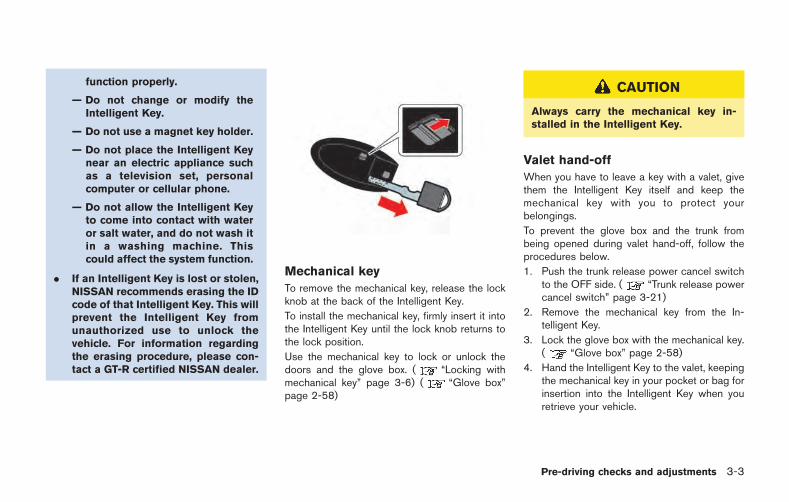
function properly.
— Do not change or modify theIntelligent Key.
— Do not use a magnet key holder.
— Do not place the Intelligent Keynear an electric appliance suchas a television set, personalcomputer or cellular phone.
— Do not allow the Intelligent Keyto come into contact with wateror salt water, and do not wash itin a washing machine. Thiscould affect the system function.
. If an Intelligent Key is lost or stolen,NISSAN recommends erasing the IDcode of that Intelligent Key. This willprevent the Intelligent Key fromunauthorized use to unlock thevehicle. For information regardingthe erasing procedure, please con-tact a GT-R certified NISSAN dealer.
Mechanical key
To remove the mechanical key, release the lockknob at the back of the Intelligent Key.
To install the mechanical key, firmly insert it intothe Intelligent Key until the lock knob returns tothe lock position.
Use the mechanical key to lock or unlock thedoors and the glove box. ( “Locking withmechanical key” page 3-6) ( “Glove box”page 2-58)
CAUTION
Always carry the mechanical key in-stalled in the Intelligent Key.
Valet hand-off
When you have to leave a key with a valet, givethem the Intelligent Key itself and keep themechanical key with you to protect yourbelongings.
To prevent the glove box and the trunk frombeing opened during valet hand-off, follow theprocedures below.
1. Push the trunk release power cancel switchto the OFF side. ( “Trunk release powercancel switch” page 3-21)
2. Remove the mechanical key from the In-telligent Key.
3. Lock the glove box with the mechanical key.( “Glove box” page 2-58)
4. Hand the Intelligent Key to the valet, keepingthe mechanical key in your pocket or bag forinsertion into the Intelligent Key when youretrieve your vehicle.
Pre-driving checks and adjustments 3-3
3-4 Pre-driving checks and adjustments
WARNING
. Always have the doors locked whiledriving. Along with the use of seatbelts, this provides greater safety inthe event of an accident by helpingto prevent persons from beingthrown from the vehicle. This alsohelps keep children and others fromunintentionally opening the doors,and will help keep out intruders.
. Before opening any door, alwayslook for and avoid oncoming traffic.
. Do not leave children unattendedinside the vehicle. They could un-knowingly activate switches or con-trols. Unattended children couldbecome involved in serious acci-dents.
CAUTION
To prevent theft or accidents, be sure tostop the engine and lock the doorsbefore stepping away from the vehicle.
NOTICE
When the battery cable is removed fromthe battery terminal, do not close eitherof the front doors. The automatic win-dow adjusting function will not work,and the side roof panel may be da-maged. ( “Automatic adjustingfunction” page 2-61)
NOTE:
. The doors of this vehicle are somewhatharder to close than those of anordinary vehicle (especially when thevehicle is new). This is because thestiffness of the rubber has been in-creased to improve the airtightness ofthe vehicle interior during situationssuch as higher speed driving. This doesnot indicate that there is a malfunction.
. When the driver’s door is locked orunlocked, the fuel-filler door is auto-matically locked or unlocked at thesame time.
When the door is being opened, the window isautomatically lowered slightly to avoid contactbetween the window and the side roof panel.When the door is closed, the window is
automatically raised slightly. ( “Automaticadjusting function” page 2-61)
DOORS
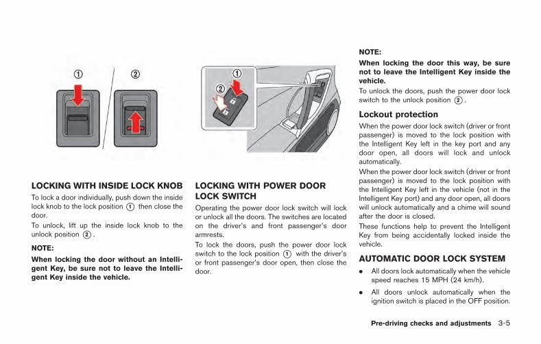
LOCKING WITH INSIDE LOCK KNOB
To lock a door individually, push down the insidelock knob to the lock position*1 then close thedoor.
To unlock, lift up the inside lock knob to theunlock position *2 .
NOTE:
When locking the door without an Intelli-gent Key, be sure not to leave the Intelli-gent Key inside the vehicle.
LOCKING WITH POWER DOORLOCK SWITCH
Operating the power door lock switch will lockor unlock all the doors. The switches are locatedon the driver’s and front passenger’s doorarmrests.
To lock the doors, push the power door lockswitch to the lock position *1 with the driver’sor front passenger’s door open, then close thedoor.
NOTE:
When locking the door this way, be surenot to leave the Intelligent Key inside thevehicle.
To unlock the doors, push the power door lockswitch to the unlock position *2 .
Lockout protection
When the power door lock switch (driver or frontpassenger) is moved to the lock position withthe Intelligent Key left in the key port and anydoor open, all doors will lock and unlockautomatically.
When the power door lock switch (driver or frontpassenger) is moved to the lock position withthe Intelligent Key left in the vehicle (not in theIntelligent Key port) and any door open, all doorswill unlock automatically and a chime will soundafter the door is closed.
These functions help to prevent the IntelligentKey from being accidentally locked inside thevehicle.
AUTOMATIC DOOR LOCK SYSTEM
. All doors lock automatically when the vehiclespeed reaches 15 MPH (24 km/h).
. All doors unlock automatically when theignition switch is placed in the OFF position.
Pre-driving checks and adjustments 3-5
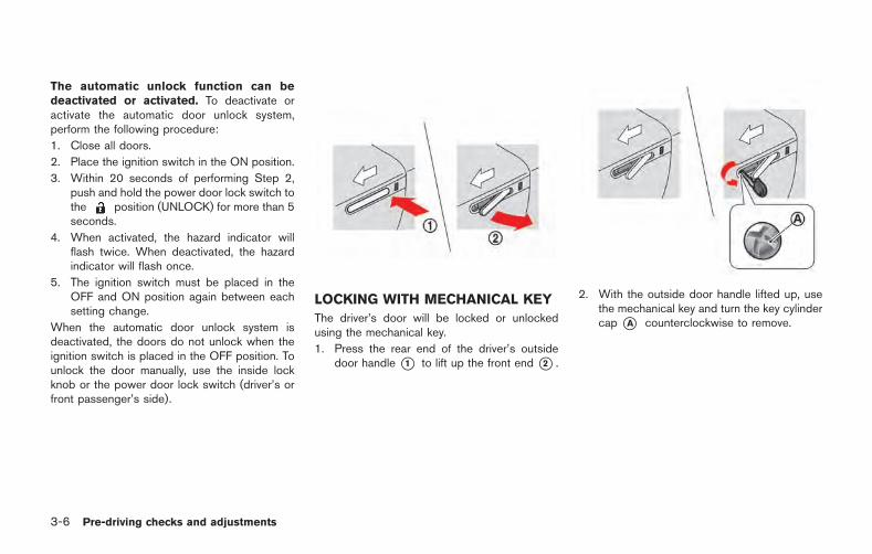
3-6 Pre-driving checks and adjustments
The automatic unlock function can bedeactivated or activated. To deactivate oractivate the automatic door unlock system,perform the following procedure:
1. Close all doors.
2. Place the ignition switch in the ON position.
3. Within 20 seconds of performing Step 2,push and hold the power door lock switch tothe position (UNLOCK) for more than 5seconds.
4. When activated, the hazard indicator willflash twice. When deactivated, the hazardindicator will flash once.
5. The ignition switch must be placed in theOFF and ON position again between eachsetting change.
When the automatic door unlock system isdeactivated, the doors do not unlock when theignition switch is placed in the OFF position. Tounlock the door manually, use the inside lockknob or the power door lock switch (driver’s orfront passenger’s side).
LOCKING WITH MECHANICAL KEY
The driver’s door will be locked or unlockedusing the mechanical key.
1. Press the rear end of the driver’s outsidedoor handle *1 to lift up the front end *2 .
2. With the outside door handle lifted up, usethe mechanical key and turn the key cylindercap *A counterclockwise to remove.
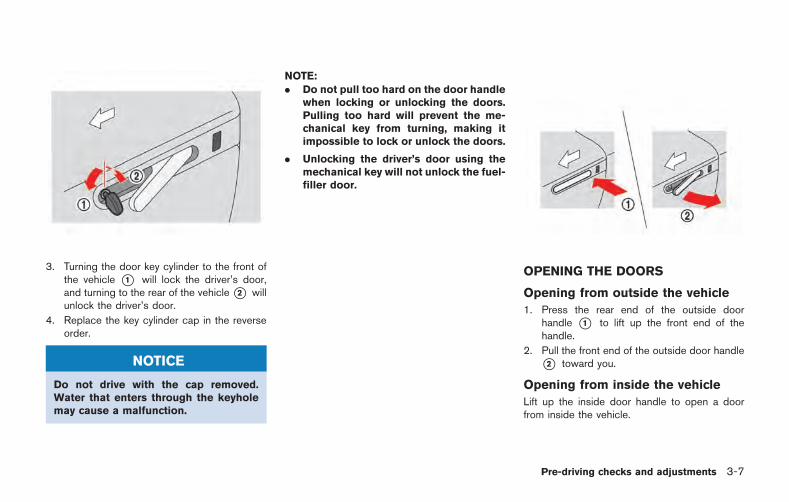
3. Turning the door key cylinder to the front ofthe vehicle *1 will lock the driver’s door,and turning to the rear of the vehicle*2 willunlock the driver’s door.
4. Replace the key cylinder cap in the reverseorder.
NOTICE
Do not drive with the cap removed.Water that enters through the keyholemay cause a malfunction.
NOTE:. Do not pull too hard on the door handle
when locking or unlocking the doors.Pulling too hard will prevent the me-chanical key from turning, making itimpossible to lock or unlock the doors.
. Unlocking the driver’s door using themechanical key will not unlock the fuel-filler door.
OPENING THE DOORS
Opening from outside the vehicle
1. Press the rear end of the outside doorhandle *1 to lift up the front end of thehandle.
2. Pull the front end of the outside door handle*2 toward you.
Opening from inside the vehicle
Lift up the inside door handle to open a doorfrom inside the vehicle.
Pre-driving checks and adjustments 3-7
3-8 Pre-driving checks and adjustments
NOTICE
Do not grasp the door pockets to openand close the doors. Doing so maydamage the pockets.
WARNING
. Radio waves could adversely affectelectric medical equipment. Thosewho use a pacemaker should con-tact the electric medical equipmentmanufacturer for the possible influ-ences before use.
. The Intelligent Key transmits radiowaves when the buttons arepushed. The Federal AviationAgency (FAA) advises the radiowaves may affect aircraft navigationand communication systems. Do notoperate the Intelligent Key while onan airplane. Make sure the buttonsare not operated unintentionallywhen the unit is stored for a flight.
The Intelligent Key system can operate all thedoor locks using the remote controller functionor pushing the request switch on the vehiclewithout taking the key out from a pocket orpurse. The operating environment and/or condi-tions may affect the Intelligent Key systemoperation.
Be sure to read the following before using theIntelligent Key system.
CAUTION
. Be sure to carry the Intelligent Keywith you when operating the vehi-cle.
. Never leave the Intelligent Key inthe vehicle when you leave thevehicle.
. The Intelligent Key is always communicatingwith the vehicle as it receives radio waves.The Intelligent Key system transmits weakradio waves. Environmental conditions mayinterfere with the operation of the IntelligentKey system under the following operatingconditions. In such cases, correct theoperating conditions before using the In-telligent Key function or use the mechanicalkey.
— When operating near a location wherestrong radio waves are transmitted, suchas a TV tower, power station and broad-casting station.
— When in possession of wireless equip-ment, such as a cellular telephone,transceiver, and CB radio.
— When the Intelligent Key is in contactwith or covered by metallic materials.
INTELLIGENT KEY SYSTEM
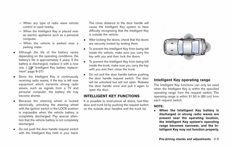
— When any type of radio wave remotecontrol is used nearby.
— When the Intelligent Key is placed nearan electric appliance such as a personalcomputer.
— When the vehicle is parked near aparking meter.
. Although the life of the battery variesdepending on the operating conditions, thebattery’s life is approximately 2 years. If thebattery is discharged, replace it with a newone. ( “Intelligent Key battery replace-ment” page 8-27)
. Since the Intelligent Key is continuouslyreceiving radio waves, if the key is left nearequipment which transmits strong radiowaves, such as signals from a TV andpersonal computer, the battery life maybecome shorter.
. Because the steering wheel is lockedelectrically, unlocking the steering wheelwith the ignition switch in the LOCK positionis impossible when the vehicle battery iscompletely discharged. Pay special atten-tion that the vehicle battery is not completelydischarged.
. Do not push the door handle request switchwith the Intelligent Key held in your hand.
The close distance to the door handle willcause the Intelligent Key system to havedifficulty recognizing that the Intelligent Keyis outside the vehicle.
. After locking the doors, check that the doorsare securely locked by testing them.
. To prevent the Intelligent Key from being leftinside the vehicle, make sure you carry thekey with you and then lock the doors.
. To prevent the Intelligent Key from being leftinside the trunk, make sure you carry the keywith you and then close the trunk.
. Do not pull the door handle before pushingthe door handle request switch. The doorwill be unlocked but will not open. Releasethe door handle once and pull it again toopen the door.
INTELLIGENT KEY FUNCTIONS
It is possible to lock/unlock all doors, fuel-fillerdoor and trunk lid by pushing the request switchon the outside door handles and the trunk lid.
Intelligent Key operating range
The Intelligent Key functions can only be usedwhen the Intelligent Key is within the specifiedoperating range from the request switch. Theoperating range is within 31.50 in (80 cm) fromeach request switch.
NOTE:
. When the Intelligent Key battery isdischarged or strong radio waves arepresent near the operating location,the Intelligent Key system’s operatingrange becomes narrower, and the In-telligent Key may not function properly.
Pre-driving checks and adjustments 3-9
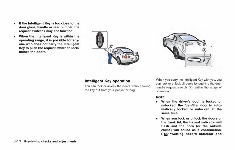
3-10 Pre-driving checks and adjustments
. If the Intelligent Key is too close to thedoor glass, handle or rear bumper, therequest switches may not function.
. When the Intelligent Key is within theoperating range, it is possible for any-one who does not carry the IntelligentKey to push the request switch to lock/unlock the doors.
Intelligent Key operation
You can lock or unlock the doors without takingthe key out from your pocket or bag.
When you carry the Intelligent Key with you, youcan lock or unlock all doors by pushing the doorhandle request switch *A within the range ofoperation.
NOTE:
. When the driver’s door is locked orunlocked, the fuel-filler door is auto-matically locked or unlocked at thesame time.
. When you lock or unlock the doors orthe trunk lid, the hazard indicator willflash and the horn (or the outsidechime) will sound as a confirmation.( “Setting hazard indicator and
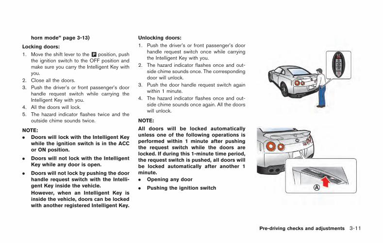
horn mode” page 3-13)
Locking doors:
1. Move the shift lever to the &P position, pushthe ignition switch to the OFF position andmake sure you carry the Intelligent Key withyou.
2. Close all the doors.
3. Push the driver’s or front passenger’s doorhandle request switch while carrying theIntelligent Key with you.
4. All the doors will lock.
5. The hazard indicator flashes twice and theoutside chime sounds twice.
NOTE:
. Doors will lock with the Intelligent Keywhile the ignition switch is in the ACCor ON position.
. Doors will not lock with the IntelligentKey while any door is open.
. Doors will not lock by pushing the doorhandle request switch with the Intelli-gent Key inside the vehicle.
However, when an Intelligent Key isinside the vehicle, doors can be lockedwith another registered Intelligent Key.
Unlocking doors:
1. Push the driver’s or front passenger’s doorhandle request switch once while carryingthe Intelligent Key with you.
2. The hazard indicator flashes once and out-side chime sounds once. The correspondingdoor will unlock.
3. Push the door handle request switch againwithin 1 minute.
4. The hazard indicator flashes once and out-side chime sounds once again. All the doorswill unlock.
NOTE:
All doors will be locked automaticallyunless one of the following operations isperformed within 1 minute after pushingthe request switch while the doors arelocked. If during this 1-minute time period,the request switch is pushed, all doors willbe locked automatically after another 1minute.
. Opening any door
. Pushing the ignition switch
Pre-driving checks and adjustments 3-11
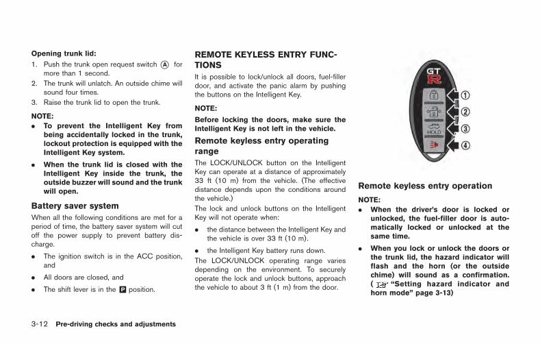
3-12 Pre-driving checks and adjustments
Opening trunk lid:
1. Push the trunk open request switch *A formore than 1 second.
2. The trunk will unlatch. An outside chime willsound four times.
3. Raise the trunk lid to open the trunk.
NOTE:
. To prevent the Intelligent Key frombeing accidentally locked in the trunk,lockout protection is equipped with theIntelligent Key system.
. When the trunk lid is closed with theIntelligent Key inside the trunk, theoutside buzzer will sound and the trunkwill open.
Battery saver system
When all the following conditions are met for aperiod of time, the battery saver system will cutoff the power supply to prevent battery dis-charge.
. The ignition switch is in the ACC position,and
. All doors are closed, and
. The shift lever is in the &P position.
REMOTE KEYLESS ENTRY FUNC-TIONS
It is possible to lock/unlock all doors, fuel-fillerdoor, and activate the panic alarm by pushingthe buttons on the Intelligent Key.
NOTE:
Before locking the doors, make sure theIntelligent Key is not left in the vehicle.
Remote keyless entry operatingrange
The LOCK/UNLOCK button on the IntelligentKey can operate at a distance of approximately33 ft (10 m) from the vehicle. (The effectivedistance depends upon the conditions aroundthe vehicle.)
The lock and unlock buttons on the IntelligentKey will not operate when:
. the distance between the Intelligent Key andthe vehicle is over 33 ft (10 m).
. the Intelligent Key battery runs down.
The LOCK/UNLOCK operating range variesdepending on the environment. To securelyoperate the lock and unlock buttons, approachthe vehicle to about 3 ft (1 m) from the door.
Remote keyless entry operation
NOTE:
. When the driver’s door is locked orunlocked, the fuel-filler door is auto-matically locked or unlocked at thesame time.
. When you lock or unlock the doors orthe trunk lid, the hazard indicator willflash and the horn (or the outsidechime) will sound as a confirmation.( “Setting hazard indicator andhorn mode” page 3-13)
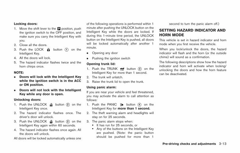
Locking doors:
1. Move the shift lever to the &P position, pushthe ignition switch to the OFF position, andmake sure you carry the Intelligent Key withyou.
2. Close all the doors.
3. Push the LOCK button *1 on theIntelligent Key.
4. All the doors will lock.
5. The hazard indicator flashes twice and thehorn chirps once.
NOTE:
. Doors will lock with the Intelligent Keywhile the ignition switch is in the ACCor ON position.
. Doors will not lock with the IntelligentKey while any door is open.
Unlocking doors:
1. Push the UNLOCK button *2 on theIntelligent Key once.
2. The hazard indicator flashes once. Thedriver’s door will unlock.
3. Push the UNLOCK button *2 on theIntelligent Key again within 60 seconds.
4. The hazard indicator flashes once again. Allthe doors will unlock.
All doors will be locked automatically unless one
of the following operations is performed within 1minute after pushing the UNLOCK button on theIntelligent Key while the doors are locked. Ifduring this 1-minute time period, the UNLOCKbutton on the Intelligent Key is pushed, all doorswill be locked automatically after another 1minute.
. Opening any door
. Pushing the ignition switch
Opening trunk lid:
1. Push the TRUNK button *3 on theIntelligent Key for more than 1 second.
2. The trunk will unlatch.
3. Raise the trunk lid to open the trunk.
Using panic alarm:
If you are near your vehicle and feel threatened,you may activate the alarm to call attention asfollows:
1. Push the PANIC button *4 on theIntelligent Key for more than 1 second.
2. The theft warning alarm and headlights willstay on for 25 seconds.
3. The panic alarm stops when:. It has run for 25 seconds, or. Any of the buttons on the Intelligent Key
are pushed. (Note: the panic buttonshould be pushed for more than 1
second to turn the panic alarm off.)
SETTING HAZARD INDICATOR ANDHORN MODE
This vehicle is set in hazard indicator and hornmode when you first receive the vehicle.
When you lock/unlock the doors, the hazardindicator will flash and the horn (or the outsidechime) will sound as a confirmation.
The following descriptions show how the hazardindicator and horn will activate when locking/unlocking the doors and how the horn featurecan be deactivated.
Pre-driving checks and adjustments 3-13
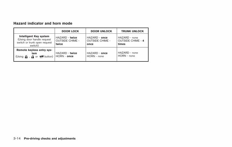
3-14 Pre-driving checks and adjustments
Hazard indicator and horn mode
DOOR LOCK DOOR UNLOCK TRUNK UNLOCK
Intelligent Key system(Using door handle requestswitch or trunk open request
switch)
HAZARD - twiceOUTSIDE CHIME -twice
HAZARD - onceOUTSIDE CHIME -once
HAZARD - noneOUTSIDE CHIME - 4times
Remote keyless entry sys-tem
(Using , or button)HAZARD - twiceHORN - once
HAZARD - onceHORN - none
HAZARD - noneHORN - none
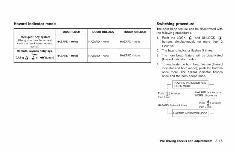
Hazard indicator mode
DOOR LOCK DOOR UNLOCK TRUNK UNLOCK
Intelligent Key system(Using door handle requestswitch or trunk open request
switch)
HAZARD - twice HAZARD - none HAZARD - none
Remote keyless entry sys-tem
(Using , or button)HAZARD - twice HAZARD - none HAZARD - none
Switching procedure
The horn beep feature can be deactivated withthe following procedures.
1. Push the LOCK and UNLOCKbuttons simultaneously for more than 2seconds.
2. The hazard indicator flashes 3 times.
3. The horn beep feature will be deactivated(Hazard indicator mode).
4. To reactivate the horn beep feature (Hazardindicator and horn mode), push the buttonsonce more. The hazard indicator flashesonce and the horn beeps once.
Pre-driving checks and adjustments 3-15
3-16 Pre-driving checks and adjustments
WARNING SIGNALS
To help prevent the vehicle from movingunexpectedly due to an erroneous operation ofthe Intelligent Key listed on the following chart orto help prevent the vehicle from being stolen, achime or beep sounds inside and outside thevehicle and a warning displays in the vehicleinformation display. ( “Warning display”page 2-33) ( “Operation displays” page2-43)
When a chime or beep sounds or a warningdisplays, be sure to check the vehicle and theIntelligent Key.
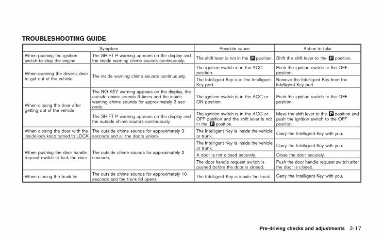
TROUBLESHOOTING GUIDE
Symptom Possible cause Action to take
When pushing the ignitionswitch to stop the engine
The SHIFT P warning appears on the display andthe inside warning chime sounds continuously.
The shift lever is not in the &P position. Shift the shift lever to the &P position.
When opening the driver’s doorto get out of the vehicle
The inside warning chime sounds continuously.
The ignition switch is in the ACCposition.
Push the ignition switch to the OFFposition.
The Intelligent Key is in the IntelligentKey port.
Remove the Intelligent Key from theIntelligent Key port.
When closing the door aftergetting out of the vehicle
The NO KEY warning appears on the display, theoutside chime sounds 3 times and the insidewarning chime sounds for approximately 3 sec-onds.
The ignition switch is in the ACC orON position.
Push the ignition switch to the OFFposition.
The SHIFT P warning appears on the display andthe outside chime sounds continuously.
The ignition switch is in the ACC orOFF position and the shift lever is notin the &P position.
Move the shift lever to the&P position andpush the ignition switch to the OFFposition.
When closing the door with theinside lock knob turned to LOCK
The outside chime sounds for approximately 3seconds and all the doors unlock.
The Intelligent Key is inside the vehicleor trunk.
Carry the Intelligent Key with you.
When pushing the door handlerequest switch to lock the door
The outside chime sounds for approximately 2seconds.
The Intelligent Key is inside the vehicleor trunk.
Carry the Intelligent Key with you.
A door is not closed securely. Close the door securely.
The door handle request switch ispushed before the door is closed.
Push the door handle request switch afterthe door is closed.
When closing the trunk lidThe outside chime sounds for approximately 10seconds and the trunk lid opens.
The Intelligent Key is inside the trunk. Carry the Intelligent Key with you.
Pre-driving checks and adjustments 3-17

3-18 Pre-driving checks and adjustments
OPENING THE HOOD
1. Pull the hood lock release handle *1located below the instrument panel. Thehood will then spring up slightly.
2. Pull the lever *2 at the front of the hoodwith your fingertips and raise the hood.
3. Grasp the insulated part of the stay*3 andrelease it from the hook, then securely insertit into the hood hole *4 .
WARNING
If you see steam or smoke coming fromthe engine compartment, do not openthe hood. Doing so could cause injury.
HOOD
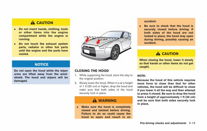
CAUTION
. Do not insert hands, clothing, toolsor other items into the enginecompartment while the engine isrunning.
. Do not touch the exhaust systemparts, radiator or other hot partsuntil the engine and the parts havecooled.
NOTICE
Do not open the hood while the wiperarms are lifted away from the wind-shield. The hood and wipers will bedamaged.
CLOSING THE HOOD
1. While supporting the hood, store the stay tothe original position.
2. Slowly lower the hood. When it is at a heightof 1 ft (30 cm) or higher, drop the hood andmake sure that both sides of the hoodsecurely lock in place.
WARNING
. Make sure the hood is completelyclosed and latched before driving.Failure to do so could cause thehood to open and result in an
accident.
. Be sure to check that the hood issecurely closed before driving. Ifboth sides of the hood are notlocked in place, the hood may openduring driving, possibly causing anaccident.
CAUTION
When closing the hood, lower it slowlyso that hands or other items do not getcaught.
NOTE:
Because the hood of this vehicle requiresmore force to close than that for othervehicles, the hood will be difficult to closeif you lower it all the way and then attemptto press it closed. Be sure to drop the hoodfrom a height of approximately 1 ft (30 cm)and be sure that both sides securely lockin place.
Pre-driving checks and adjustments 3-19
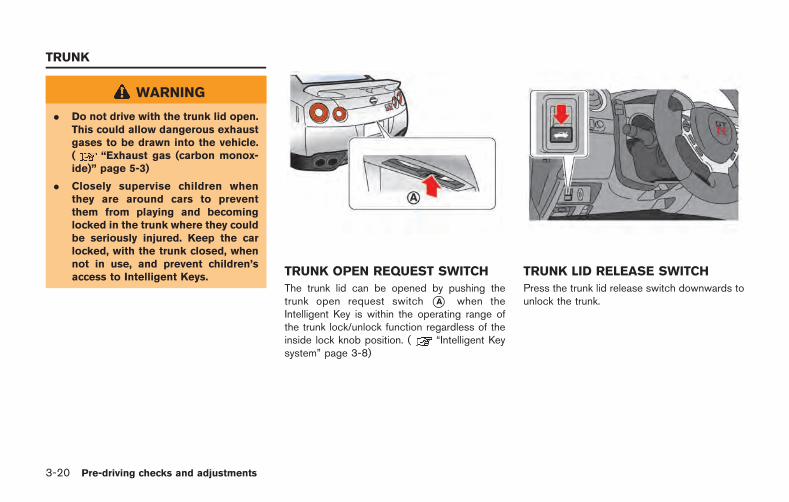
3-20 Pre-driving checks and adjustments
WARNING
. Do not drive with the trunk lid open.This could allow dangerous exhaustgases to be drawn into the vehicle.( “Exhaust gas (carbon monox-ide)” page 5-3)
. Closely supervise children whenthey are around cars to preventthem from playing and becominglocked in the trunk where they couldbe seriously injured. Keep the carlocked, with the trunk closed, whennot in use, and prevent children’saccess to Intelligent Keys. TRUNK OPEN REQUEST SWITCH
The trunk lid can be opened by pushing thetrunk open request switch *A when theIntelligent Key is within the operating range ofthe trunk lock/unlock function regardless of theinside lock knob position. ( “Intelligent Keysystem” page 3-8)
TRUNK LID RELEASE SWITCH
Press the trunk lid release switch downwards tounlock the trunk.
TRUNK
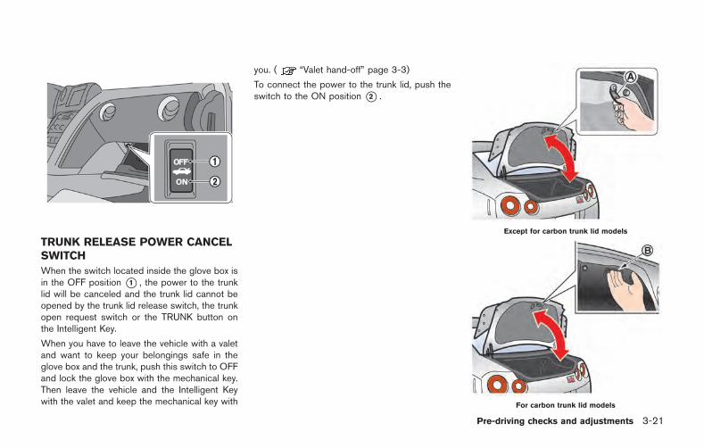
TRUNK RELEASE POWER CANCELSWITCH
When the switch located inside the glove box isin the OFF position *1 , the power to the trunklid will be canceled and the trunk lid cannot beopened by the trunk lid release switch, the trunkopen request switch or the TRUNK button onthe Intelligent Key.
When you have to leave the vehicle with a valetand want to keep your belongings safe in theglove box and the trunk, push this switch to OFFand lock the glove box with the mechanical key.Then leave the vehicle and the Intelligent Keywith the valet and keep the mechanical key with
you. ( “Valet hand-off” page 3-3)
To connect the power to the trunk lid, push theswitch to the ON position *2 .
Except for carbon trunk lid models
For carbon trunk lid models
Pre-driving checks and adjustments 3-21
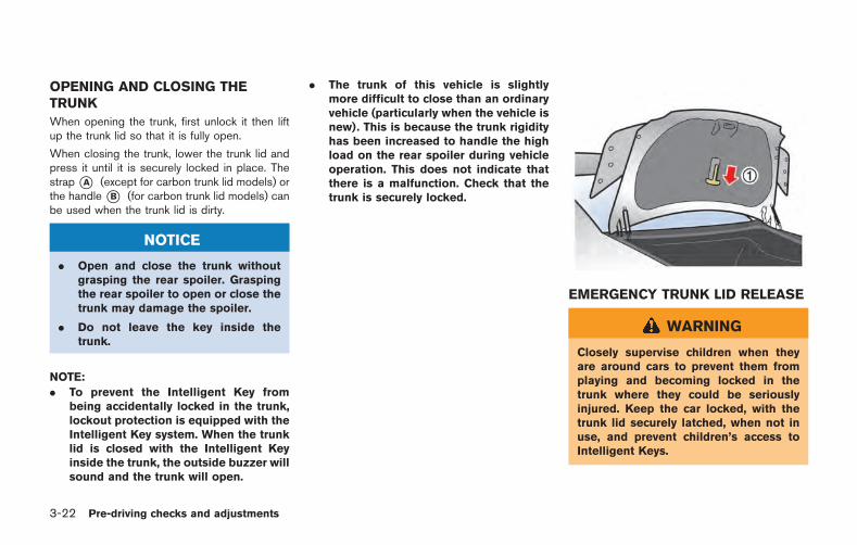
3-22 Pre-driving checks and adjustments
OPENING AND CLOSING THETRUNK
When opening the trunk, first unlock it then liftup the trunk lid so that it is fully open.
When closing the trunk, lower the trunk lid andpress it until it is securely locked in place. Thestrap*A (except for carbon trunk lid models) orthe handle*B (for carbon trunk lid models) canbe used when the trunk lid is dirty.
NOTICE
. Open and close the trunk withoutgrasping the rear spoiler. Graspingthe rear spoiler to open or close thetrunk may damage the spoiler.
. Do not leave the key inside thetrunk.
NOTE:
. To prevent the Intelligent Key frombeing accidentally locked in the trunk,lockout protection is equipped with theIntelligent Key system. When the trunklid is closed with the Intelligent Keyinside the trunk, the outside buzzer willsound and the trunk will open.
. The trunk of this vehicle is slightlymore difficult to close than an ordinaryvehicle (particularly when the vehicle isnew). This is because the trunk rigidityhas been increased to handle the highload on the rear spoiler during vehicleoperation. This does not indicate thatthere is a malfunction. Check that thetrunk is securely locked.
EMERGENCY TRUNK LID RELEASE
WARNING
Closely supervise children when theyare around cars to prevent them fromplaying and becoming locked in thetrunk where they could be seriouslyinjured. Keep the car locked, with thetrunk lid securely latched, when not inuse, and prevent children’s access toIntelligent Keys.
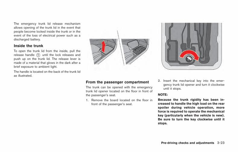
The emergency trunk lid release mechanismallows opening of the trunk lid in the event thatpeople become locked inside the trunk or in theevent of the loss of electrical power such as adischarged battery.
Inside the trunk
To open the trunk lid from the inside, pull therelease handle *1 until the lock releases andpush up on the trunk lid. The release lever ismade of a material that glows in the dark after abrief exposure to ambient light.
The handle is located on the back of the trunk lidas illustrated.
From the passenger compartment
The trunk can be opened with the emergencytrunk lid opener located on the floor in front ofthe passenger’s seat.
1. Remove the board located on the floor infront of the passenger’s seat.
2. Insert the mechanical key into the emer-gency trunk lid opener and turn it clockwiseuntil it stops.
NOTE:
Because the trunk rigidity has been in-creased to handle the high load on the rearspoiler during vehicle operation, moreforce is required to operate the mechanicalkey (particularly when the vehicle is new).Be sure to turn the key clockwise until itstops.
Pre-driving checks and adjustments 3-23
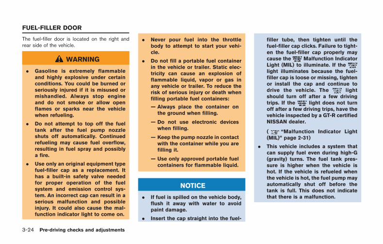
3-24 Pre-driving checks and adjustments
The fuel-filler door is located on the right andrear side of the vehicle.
WARNING
. Gasoline is extremely flammableand highly explosive under certainconditions. You could be burned orseriously injured if it is misused ormishandled. Always stop engineand do not smoke or allow openflames or sparks near the vehiclewhen refueling.
. Do not attempt to top off the fueltank after the fuel pump nozzleshuts off automatically. Continuedrefueling may cause fuel overflow,resulting in fuel spray and possiblya fire.
. Use only an original equipment typefuel-filler cap as a replacement. Ithas a built-in safety valve neededfor proper operation of the fuelsystem and emission control sys-tem. An incorrect cap can result in aserious malfunction and possibleinjury. It could also cause the mal-function indicator light to come on.
. Never pour fuel into the throttlebody to attempt to start your vehi-cle.
. Do not fill a portable fuel containerin the vehicle or trailer. Static elec-tricity can cause an explosion offlammable liquid, vapor or gas inany vehicle or trailer. To reduce therisk of serious injury or death whenfilling portable fuel containers:
— Always place the container onthe ground when filling.
— Do not use electronic deviceswhen filling.
— Keep the pump nozzle in contactwith the container while you arefilling it.
— Use only approved portable fuelcontainers for flammable liquid.
NOTICE
. If fuel is spilled on the vehicle body,flush it away with water to avoidpaint damage.
. Insert the cap straight into the fuel-
filler tube, then tighten until thefuel-filler cap clicks. Failure to tight-en the fuel-filler cap properly maycause the Malfunction IndicatorLight (MIL) to illuminate. If thelight illuminates because the fuel-filler cap is loose or missing, tightenor install the cap and continue todrive the vehicle. The lightshould turn off after a few drivingtrips. If the light does not turnoff after a few driving trips, have thevehicle inspected by a GT-R certifiedNISSAN dealer.
( “Malfunction Indicator Light(MIL)” page 2-31)
. This vehicle includes a system thatcan supply fuel even during high-G(gravity) turns. The fuel tank pres-sure is higher when the vehicle ishot. If the vehicle is refueled whenthe vehicle is hot, the fuel pump mayautomatically shut off before thetank is full. This does not indicatethat there is a malfunction.
FUEL-FILLER DOOR
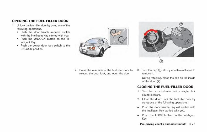
OPENING THE FUEL FILLER DOOR
1. Unlock the fuel-filler door by using one of thefollowing operations.. Push the door handle request switch
with the Intelligent Key carried with you.. Push the UNLOCK button on the In-
telligent Key.. Push the power door lock switch to the
UNLOCK position.
2. Press the rear side of the fuel-filler door torelease the door lock, and open the door.
3. Turn the cap*1 slowly counterclockwise toremove it.
During refueling, place the cap on the insideof the door *2 .
CLOSING THE FUEL-FILLER DOOR
1. Turn the cap clockwise until a single clicksound is heard.
2. Close the door. Lock the fuel-filler door byusing one of the following operations.
. Push the door handle request switch withthe Intelligent Key carried with you.
. Push the LOCK button on the IntelligentKey.
Pre-driving checks and adjustments 3-25
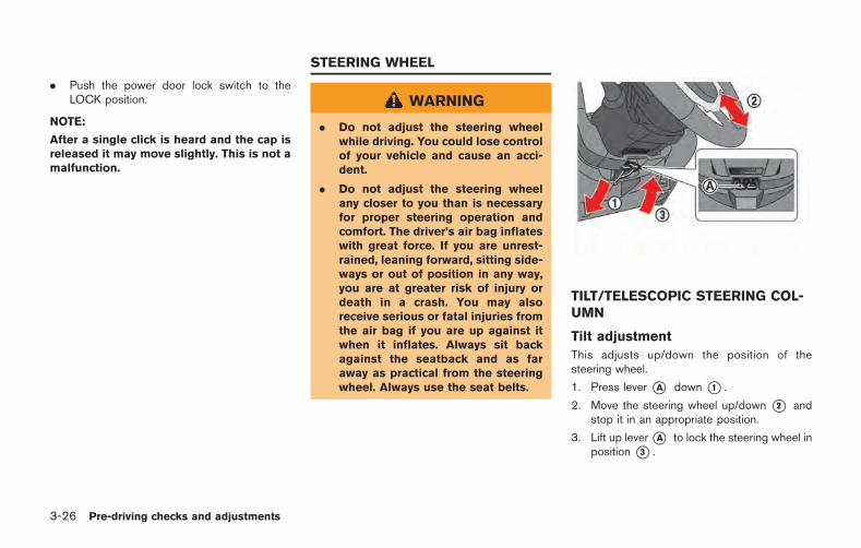
3-26 Pre-driving checks and adjustments
. Push the power door lock switch to theLOCK position.
NOTE:
After a single click is heard and the cap isreleased it may move slightly. This is not amalfunction.
WARNING
. Do not adjust the steering wheelwhile driving. You could lose controlof your vehicle and cause an acci-dent.
. Do not adjust the steering wheelany closer to you than is necessaryfor proper steering operation andcomfort. The driver’s air bag inflateswith great force. If you are unrest-rained, leaning forward, sitting side-ways or out of position in any way,you are at greater risk of injury ordeath in a crash. You may alsoreceive serious or fatal injuries fromthe air bag if you are up against itwhen it inflates. Always sit backagainst the seatback and as faraway as practical from the steeringwheel. Always use the seat belts.
TILT/TELESCOPIC STEERING COL-UMN
Tilt adjustment
This adjusts up/down the position of thesteering wheel.
1. Press lever *A down *1 .
2. Move the steering wheel up/down *2 andstop it in an appropriate position.
3. Lift up lever*A to lock the steering wheel inposition *3 .
STEERING WHEEL
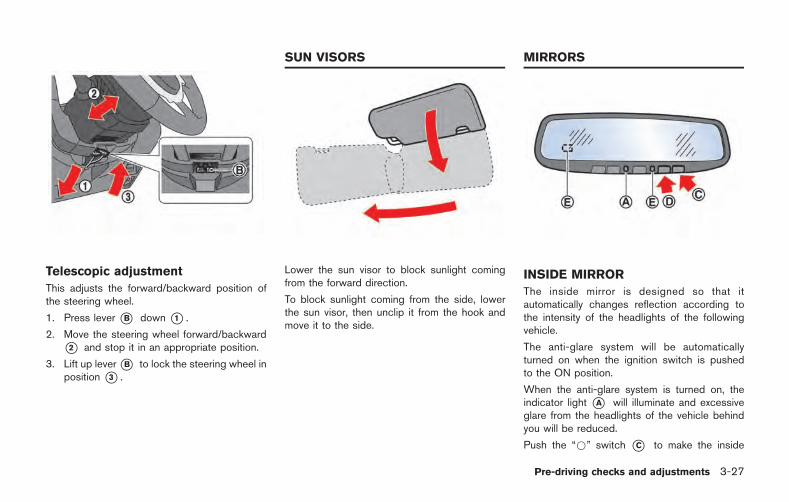
Telescopic adjustment
This adjusts the forward/backward position ofthe steering wheel.
1. Press lever *B down *1 .
2. Move the steering wheel forward/backward*2 and stop it in an appropriate position.
3. Lift up lever*B to lock the steering wheel inposition *3 .
Lower the sun visor to block sunlight comingfrom the forward direction.
To block sunlight coming from the side, lowerthe sun visor, then unclip it from the hook andmove it to the side.
INSIDE MIRROR
The inside mirror is designed so that itautomatically changes reflection according tothe intensity of the headlights of the followingvehicle.
The anti-glare system will be automaticallyturned on when the ignition switch is pushedto the ON position.
When the anti-glare system is turned on, theindicator light *A will illuminate and excessiveglare from the headlights of the vehicle behindyou will be reduced.
Push the “*” switch *C to make the inside
Pre-driving checks and adjustments 3-27
SUN VISORS MIRRORS
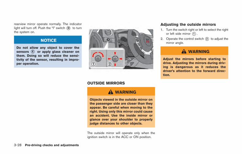
3-28 Pre-driving checks and adjustments
rearview mirror operate normally. The indicatorlight will turn off. Push the “I” switch*D to turnthe system on.
NOTICE
Do not allow any object to cover thesensors *E or apply glass cleaner onthem. Doing so will reduce the sensi-tivity of the sensor, resulting in impro-per operation.
OUTSIDE MIRRORS
WARNING
Objects viewed in the outside mirror onthe passenger side are closer than theyappear. Be careful when moving to theright. Using only this mirror could causean accident. Use the inside mirror orglance over your shoulder to properlyjudge distances to other objects.
The outside mirror will operate only when theignition switch is in the ACC or ON position.
Adjusting the outside mirrors
1. Turn the switch right or left to select the rightor left side mirror *1 .
2. Operate the control switch*2 to adjust themirror angle.
WARNING
Adjust the mirrors before starting todrive. Adjusting the mirrors during driv-ing is dangerous as it reduces thedriver’s attention to the forward direc-tion.
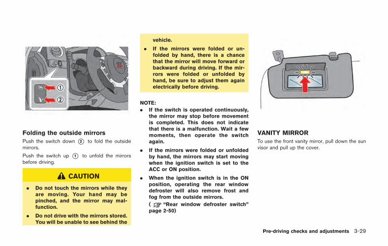
Folding the outside mirrors
Push the switch down *2 to fold the outsidemirrors.
Push the switch up *1 to unfold the mirrorsbefore driving.
CAUTION
. Do not touch the mirrors while theyare moving. Your hand may bepinched, and the mirror may mal-function.
. Do not drive with the mirrors stored.You will be unable to see behind the
vehicle.
. If the mirrors were folded or un-folded by hand, there is a chancethat the mirror will move forward orbackward during driving. If the mir-rors were folded or unfolded byhand, be sure to adjust them againelectrically before driving.
NOTE:
. If the switch is operated continuously,the mirror may stop before movementis completed. This does not indicatethat there is a malfunction. Wait a fewmoments, then operate the switchagain.
. If the mirrors were folded or unfoldedby hand, the mirrors may start movingwhen the ignition switch is set to theACC or ON position.
. When the ignition switch is in the ONposition, operating the rear windowdefroster will also remove frost andfog from the outside mirrors.
( “Rear window defroster switch”page 2-50)
VANITY MIRROR
To use the front vanity mirror, pull down the sunvisor and pull up the cover.
Pre-driving checks and adjustments 3-29

3-30 Pre-driving checks and adjustments
MEMO
4 Display screen, heater, air conditionerand audio systems
Multi Function Display Owner’s Manual ............................. 4-2
4 Display screen, heater, air conditionerand audio systems
Multi Function Display Owner’s Manual ............................. 4-2
4-2 Display screen, heater, air conditioner and audio systems
Refer to the separate Multi Function DisplayOwner’s Manual that includes the followinginformation.
. Multi function display system
. Navigation
. Audio system
. Bluetooth hands-free phone system
. Heater and air conditioner
. Viewing information
. Other settings
. Voice recognition
. Monitor system
. Multi function meter
. General system information
MULTI FUNCTION DISPLAYOWNER’S MANUAL
5 Starting and driving
Precautions when starting and driving ............................... 5-3Exhaust gas (carbon monoxide) ..................................... 5-3Three-way catalyst ............................................................. 5-3Tire Pressure Monitoring System (TPMS) ................... 5-4Avoiding collision and rollover ........................................ 5-7Off-road recovery ............................................................... 5-7Rapid air pressure loss ..................................................... 5-8Drinking alcohol/drugs and driving ................................ 5-9All-Wheel Drive (AWD) driving safety precautions .... 5-9
Push-button ignition switch ................................................ 5-10Operating range for engine start ................................ 5-10Ignition switch operation ............................................... 5-10Ignition switch positions ................................................ 5-11Emergency engine shut off ........................................... 5-11Intelligent Key battery discharge ................................. 5-12
Before starting the engine .................................................. 5-13Starting the engine ............................................................... 5-13Driving the vehicle ................................................................ 5-15
Dual clutch transmission ............................................... 5-15Driving tips ........................................................................ 5-21
VDC, transmission and suspension setup switches .... 5-25How to switch the modes ............................................ 5-25Features of each mode .................................................. 5-27
Turbocharger system ........................................................... 5-31R mode start function ......................................................... 5-32
How to use R mode start function ........................... 5-33Parking brake ......................................................................... 5-33Cruise control ........................................................................ 5-34
Precautions on cruise control .................................... 5-35Steering-wheel-mounted controls ............................ 5-35Indicators and display .................................................. 5-36Cruise control operations ........................................... 5-36
Hill Start Assist ..................................................................... 5-38Break-in schedule ................................................................ 5-39
Wheel alignment ........................................................... 5-39Fuel Efficient Driving Tips .................................................. 5-40Increasing fuel economy ..................................................... 5-41All-Wheel Drive (AWD) ...................................................... 5-41
AWD warning light ....................................................... 5-41Tight corner braking phenomenon ........................... 5-43Tires .................................................................................. 5-44AWD system characteristics ...................................... 5-44
Limited Slip Differential (LSD) .......................................... 5-45Parking/parking on hills ....................................................... 5-46Power steering ...................................................................... 5-47
Brake system .......................................................................... 5-48Braking precautions ........................................................ 5-48Parking brake break-in ................................................... 5-48
Brake assist ............................................................................ 5-49Anti-lock Braking System (ABS) ................................ 5-49
Vehicle Dynamic Control (VDC) system ......................... 5-50Cold weather driving ............................................................ 5-52
Freeing a frozen door lock ............................................ 5-52
Anti-freeze ....................................................................... 5-52Battery .............................................................................. 5-52Draining of coolant water ............................................ 5-52Tire equipment ............................................................... 5-53Special winter equipment ........................................... 5-53Driving on snow or ice ................................................ 5-53Engine block heater (if so equipped) ...................... 5-54
Active noise control (if so equipped) .............................. 5-54
WARNING
. Do not leave children or adults whowould normally require the supportof others alone in your vehicle. Petsshould not be left alone either. Theycould accidentally injure themselvesor others through inadvertent op-eration of the vehicle. Also, on hot,sunny days, temperatures in aclosed vehicle could quickly becomehigh enough to cause severe orpossibly fatal injuries to people oranimals.
. Closely supervise children whenthey are around cars to preventthem from playing and becominglocked in the trunk where they couldbe seriously injured. Keep the carlocked, with the rear seatback andtrunk lid securely latched when notin use, and prevent children’s accessto car keys.
EXHAUST GAS (carbon monoxide)
WARNING
. Do not breathe exhaust gases; theycontain colorless and odorless car-bon monoxide. Carbon monoxide isdangerous. It can cause uncon-sciousness or death.
. If you suspect that exhaust fumesare entering the vehicle, drive withall windows fully open, and have thevehicle inspected immediately.
. Do not run the engine in closedspaces such as a garage.
. Do not park the vehicle with theengine running for any extendedlength of time.
. Keep the trunk lid closed whiledriving, otherwise exhaust gasescould be drawn into the passengercompartment. If you must drive withthe trunk lid open, follow theseprecautions:
a. Open all the windows.
b. Set the air recirculation tooff and the fan control to high to
circulate the air.
. The exhaust system and bodyshould be inspected by a qualifiedmechanic whenever:
— The vehicle is raised for service.
— You suspect that exhaust fumesare entering into the passengercompartment.
— You notice a change in thesound of the exhaust system.
— You have had an accident invol-ving damage to the exhaustsystem, underbody, or rear ofthe vehicle.
THREE-WAY CATALYST
The three-way catalyst is an emission controldevice installed in the exhaust system. Exhaustgases in the three-way catalyst are burned athigh temperatures to help reduce pollutants.
Starting and driving 5-3
PRECAUTIONS WHEN STARTINGAND DRIVING
5-4 Starting and driving
WARNING
. The exhaust gas and the exhaustsystem are very hot. Keep people,animals or flammable materialsaway from the exhaust system com-ponents.
. Do not stop or park the vehicle overflammable materials such as drygrass, waste paper or rags. Theymay ignite and cause a fire.
NOTICE
. Do not use leaded gasoline. Depos-its from leaded gasoline seriouslyreduce the three-way catalyst’s abil-ity to help reduce exhaust pollu-tants.
. Keep your engine tuned up. Mal-functions in the ignition, fuel injec-tion, or electrical systems can causeoverrich fuel flow into the three-waycatalyst, causing it to overheat. Donot keep driving if the engine mis-fires, or if noticeable loss of perfor-mance or other unusual operating
conditions are detected. Have thevehicle inspected promptly by aGT-R certified NISSAN dealer.
. Avoid driving with an extremely lowfuel level. Running out of fuel couldcause the engine to misfire, dama-ging the three-way catalyst.
. Do not race the engine while warm-ing it up.
. Do not push or tow your vehicle tostart the engine.
TIRE PRESSURE MONITORINGSYSTEM (TPMS)
Each tire should be checked monthly when coldand inflated to the inflation pressure recom-mended by the vehicle manufacturer on thevehicle placard or tire inflation pressure label. (Ifyour vehicle has tires of a different size than thesize indicated on the vehicle placard or tireinflation pressure label, you should determinethe proper tire inflation pressure for those tires.)
As an added safety feature, your vehicle hasbeen equipped with a Tire Pressure MonitoringSystem (TPMS) that illuminates a low tirepressure telltale when one or more of your tiresis significantly under-inflated. Accordingly, when
the low tire pressure telltale illuminates, youshould stop and check your tires as soon aspossible, and inflate them to the proper pres-sure. Driving on a significantly under-inflated tirecauses the tire to overheat and can lead to tirefailure. Under-inflation also reduces fuel effi-ciency and tire tread life, and may affect thevehicle’s handling and stopping ability.
If the vehicle is being driven with one or more flattires, the low tire pressure warning light willilluminate continuously and a chime will soundfor 10 seconds. The chime will only sound at thefirst indication of a flat tire, and the warning lightwill illuminate continuously. When the flat tirewarning is activated, have the system reset andthe tire checked and replaced if necessary by aGT-R certified NISSAN dealer. Even if the tire isinflated to the specified COLD tire pressure, thewarning light will continue to illuminate until thesystem is reset by a GT-R certified NISSANdealer. Your vehicle can be driven for a limitedtime on a flat tire. ( “Run-flat tires” page 8-39)
Please note that the TPMS is not a substitute forproper tire maintenance, and it is the driver’sresponsibility to maintain correct tire pressure,even if under-inflation has not reached the levelto trigger illumination of the TPMS low tirepressure telltale.
Your vehicle has also been equipped with aTPMS malfunction indicator to indicate when thesystem is not operating properly. The TPMSmalfunction indicator is combined with the lowtire pressure telltale. When the system detects amalfunction, the telltale will flash for approxi-mately one minute and then remain continuouslyilluminated. This sequence will continue uponsubsequent vehicle start-ups as long as themalfunction exists. When the malfunction indi-cator is illuminated, the system may not be ableto detect or signal low tire pressure as intended.TPMS malfunctions may occur for a variety ofreasons, including the installation of replace-ment or alternate tires or wheels on the vehiclethat prevent the TPMS from functioning properly.Always check the TPMS malfunction telltaleafter replacing one or more tires or wheels onyour vehicle to ensure that the replacement oralternate tires and wheels allow the TPMS tocontinue to function properly.
Additional information
. The TPMS will activate only when thevehicle is driven at speeds above 16 MPH(25 km/h). Also, this system may not detecta sudden drop in tire pressure (for example aflat tire while driving).
. The low tire pressure warning light does notautomatically turn off when the tire pressureis adjusted. After the tire is inflated to therecommended pressure, the vehicle must bedriven at speeds above 16 MPH (25 km/h)to activate the TPMS and turn off the low tirepressure warning light. Use a tire pressuregauge to check the tire pressure.
. The “TIRE LOW PRESSURE - VISIT DEAL-ER” warning appears in the vehicle informa-tion display when the low tire pressurewarning light is illuminated and low tirepressure is detected. The “TIRE LOWPRESSURE - VISIT DEALER” warning turnsoff when the low tire pressure warning lightturns off.
The “TIRE LOW PRESSURE - VISIT DEAL-ER” warning appears each time the ignitionswitch is placed in the “ON” position as longas the low tire pressure warning lightremains illuminated.
The “TIRE LOW PRESSURE - VISIT DEAL-
ER” warning does not appear if the low tirepressure warning light illuminates to indicatea TPMS malfunction.
. The “FLAT TIRE - VISIT DEALER” warningappears in the vehicle information displaywhen the low tire pressure warning light isilluminated and one or more flat tires aredetected.
. Tire pressure rises and falls depending onthe heat caused by the vehicle’s operationand the outside temperature. Low outsidetemperature can lower the temperature ofthe air inside the tire which can cause alower tire inflation pressure. Altitude canalso affect tire pressure. These may causethe low tire pressure warning light toilluminate. If the warning light illuminates,check the tire pressure for all four tires.
. GT-R vehicles are delivered from the factorywith nitrogen-filled tires. For best perfor-mance, NISSAN recommends that GT-Rowners maintain their vehicles by usingnitrogen for tire inflation. Because nitrogenis more stable than compressed air, it is lessprone to pressure fluctuation resulting fromtemperature variations. If nitrogen is notavailable, compressed air may be safelyused under normal driving conditions. How-ever, NISSAN recommends refilling with
Starting and driving 5-5
5-6 Starting and driving
Nitrogen for maximum tire performance.
. The Tire and Loading Information label (alsoreferred to as the vehicle placard or tireinflation pressure label) is located in thedriver’s door opening.
. You can also check the pressure of all tireson the multi function display. Refer to theseparate Multi Function Display Owner’sManual.
. The tire pressure sensor should be resetanytime the wheels or tires are removed orreplaced.
. If the tire is removed in order to replace thetire pressure sensor battery, it may not bepossible to reuse the removed tire from thewheel. To replace the tire pressure sensorbattery, contact a GT-R certified NISSANdealer.
WARNING
. If the low tire pressure warning lightilluminates while driving, avoid sud-den steering maneuvers or abruptbraking, reduce vehicle speed, pulloff the road to a safe location andstop the vehicle as soon as possi-ble. Driving with under-inflated tires
may permanently damage the tiresand increase the likelihood of tirefailure. Serious vehicle damagecould occur and may lead to anaccident and could result in seriouspersonal injury. Check the tire pres-sure for all four tires. Adjust the tirepressure to the recommended COLDtire pressure shown on the Tire andLoading Information label to turnthe low tire pressure warning lightoff. If the light still illuminates whiledriving after adjusting the tire pres-sure, a tire may be flat.
. Although you can continue drivingwith a punctured run-flat tire, re-member that vehicle handling sta-bility is reduced, which could lead toan accident and personal injury.Also, driving a long distance at highspeeds may damage the tires.
. Do not drive at speeds above 50MPH (80 km/h) and do not drivemore than 50 miles (80 km) with apunctured run-flat tire. The actualdistance the vehicle can be drivenon a flat tire depends on outsidetemperature, vehicle load, road con-ditions and other factors.
. When a wheel is replaced, the TPMSwill not function and the low tirepressure warning light will flash forapproximately 1 minute. The lightwill remain on after 1 minute. Con-tact your GT-R certified NISSANdealer as soon as possible for tirereplacement and/or system reset-ting.
. Replacing tires with those not ori-ginally specified by NISSAN couldaffect the proper operation of theTPMS.
. Do not inject any tire liquid oraerosol tire sealant into the tires,as this may cause a malfunction ofthe tire pressure sensors.
NOTICE
. The TPMSmay not function properlywhen the wheels are equipped withtire chains or the wheels are buriedin snow.
. The TPMSmay not function properlyif the TPMS sensor is not reset andwhen wheels/tires from another
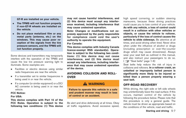
GT-R are installed on your vehicle.
. The TPMS will not function properlyif non-GT-R wheels are installed onthe vehicle.
. Do not place metalized film or anymetal parts (antenna, etc.) on thewindows. This may cause poor re-ception of the signals from the tirepressure sensors, and the TPMS willnot function properly.
Some devices and transmitters may temporarilyinterfere with the operation of the TPMS andcause the low tire pressure warning light toilluminate. Some examples are:
. Facilities or electric devices using similarradio frequencies are near the vehicle.
. If a transmitter set to similar frequencies isbeing used in or near the vehicle.
. If a computer (or similar equipment) or a DC/AC converter is being used in or near thevehicle.
FCC Notice:
For USA:
This device complies with Part 15 of theFCC Rules. Operation is subject to thefollowing two conditions: (1) This device
may not cause harmful interference, and(2) this device must accept any interfer-ence received, including interference thatmay cause undesired operation.
Note: Changes or modifications not ex-pressly approved by the party responsiblefor compliance could void the user’sauthority to operate the equipment.
For Canada:
This device complies with Industry Canadalicence-exempt RSS standard(s). Opera-tion is subject to the following two condi-tions: (1) this device may not causeinterference, and (2) this device mustaccept any interference, including interfer-ence that may cause undesired operationof the device.
AVOIDING COLLISION AND ROLL-OVER
WARNING
Failure to operate this vehicle in a safeand prudent manner may result in lossof control or an accident.
Be alert and drive defensively at all times. Obeyall traffic regulations. Avoid excessive speed,
high speed cornering, or sudden steeringmaneuvers, because these driving practicescould cause you to lose control of your vehicle.As with any vehicle, a loss of control couldresult in a collision with other vehicles orobjects, or cause the vehicle to rollover,particularly if the loss of control causes thevehicle to slide sideways. Be attentive at alltimes, and avoid driving when tired. Never drivewhen under the influence of alcohol or drugs(including prescription or over-the-counterdrugs which may cause drowsiness). Alwayswear your seat belt as outlined in this manual,and also instruct your passengers to do so.( “Seat belts” page 1-6)
Seat belts help reduce the risk of injury incollisions and rollovers. In a rollover crash, anunbelted or improperly belted person issignificantly more likely to be injured orkilled than a person properly wearing aseat belt.
OFF-ROAD RECOVERY
While driving, the right side or left side wheelsmay unintentionally leave the road surface. If thisoccurs, maintain control of the vehicle byfollowing the procedure below. Please note thatthis procedure is only a general guide. Thevehicle must be driven as appropriate based onthe conditions of the vehicle, road and traffic.
Starting and driving 5-7
5-8 Starting and driving
1. Remain calm and do not overreact.
2. Do not apply the brakes.
3. Maintain a firm grip on the steering wheelwith both hands and try to hold a straightcourse.
4. When appropriate, slowly release the accel-erator pedal to gradually slow the vehicle.
5. If there is nothing in the way, steer thevehicle to follow the road while the vehiclespeed is reduced. Do not attempt to drivethe vehicle back onto the road surface untilvehicle speed is reduced.
6. When it is safe to do so, gradually turn thesteering wheel until both tires return to theroad surface. When all tires are on the roadsurface, steer the vehicle to stay in theappropriate driving lane.. If you decide that it is not safe to return
the vehicle to the road surface based onvehicle, road or traffic conditions, gradu-ally slow the vehicle to a stop in a safeplace off the road.
RAPID AIR PRESSURE LOSS
Rapid air pressure loss or a “blow-out” canoccur if the tire is punctured or is damaged dueto hitting a curb or pothole. Rapid air pressureloss can also be caused by driving on under-inflated tires.
Rapid air pressure loss can affect the handlingand stability of the vehicle, especially at highwayspeeds.
Help prevent rapid air pressure loss by main-taining the correct air pressure and visuallyinspect the tires for wear and damage.( “Wheels and tires” page 8-32)
If a tire rapidly loses air pressure or “blows-out”while driving maintain control of the vehicle byfollowing the procedure below. Please note thatthis procedure is only a general guide. Thevehicle must be driven as appropriate based onthe conditions of the vehicle, road and traffic.
WARNING
The following actions can increase thechance of losing control of the vehicle ifthere is a sudden loss of tire airpressure. Losing control of the vehiclemay cause a collision and result inpersonal injury.
. The vehicle generally moves or pullsin the direction of the flat tire.
. Do not rapidly apply the brakes.
. Do not rapidly release the accelera-tor pedal.
. Do not rapidly turn the steeringwheel.
1. Remain calm and do not overreact.
2. Maintain a firm grip on the steering wheelwith both hands and try to hold a straightcourse.
3. When appropriate, slowly release the accel-erator pedal to gradually slow the vehicle.
4. Gradually steer the vehicle to a safe locationoff the road and away from traffic if possible.
5. Lightly apply the brake pedal to graduallystop the vehicle.
6. Turn on the hazard warning flashers andcontact a roadside emergency service tochange the tire.
DRINKING ALCOHOL/DRUGS ANDDRIVING
WARNING
Never drive under the influence ofalcohol or drugs. Alcohol in the blood-stream reduces coordination, delaysreaction time and impairs judgement.Driving after drinking alcohol increasesthe likelihood of being involved in anaccident injuring yourself and others.Additionally, if you are injured in anaccident, alcohol can increase the se-verity of the injury.
NISSAN is committed to safe driving. However,you must choose not to drive under the influenceof alcohol. Every year thousands of people areinjured or killed in alcohol-related accidents.Although the local laws vary on what isconsidered to be legally intoxicated, the fact isthat alcohol affects all people differently andmost people underestimate the effects ofalcohol.
Remember, drinking and driving don’t mix! Andthat is true for drugs, too (over-the-counter,prescription, and illegal drugs). Don’t drive ifyour ability to operate your vehicle is impaired by
alcohol, drugs, or some other physical condition.
ALL-WHEEL DRIVE (AWD) DRIVINGSAFETY PRECAUTIONS
WARNING
. Do not drive beyond the perfor-mance capability of the tires, evenwith AWD engaged. Acceleratingquickly, sharp steering maneuversor sudden braking may cause lossof control.
. Always use the specified tires on allfour wheels. Install tire chains onthe rear wheels when driving onslippery roads and drive carefully.
. This vehicle is not designed foroffroad (rough road) use. Do notdrive on sandy or muddy roads thattires may get stuck in.
. Do not attempt to raise two wheelsoff the ground and shift the trans-mission to any &A &M or &R positionwith the engine running. Doing somay result in drivetrain damage orunexpected vehicle movementwhich could result in serious vehicledamage or personal injury.
. Do not attempt to test an AWDequipped vehicle on a 2-wheel dy-namometer, (such as the dynam-ometers used by some states foremissions testing), or similar equip-ment even if the other two wheelsare raised off the ground. Make sureyou inform test facility personnelthat your vehicle is equipped withAWD before it is placed on adynamometer. Using the wrong testequipment may result in drivetraindamage or unexpected vehiclemovement which could result inserious vehicle damage or personalinjury.
. When a wheel is off the ground dueto an unlevel surface, do not spinthe wheel excessively.
Starting and driving 5-9
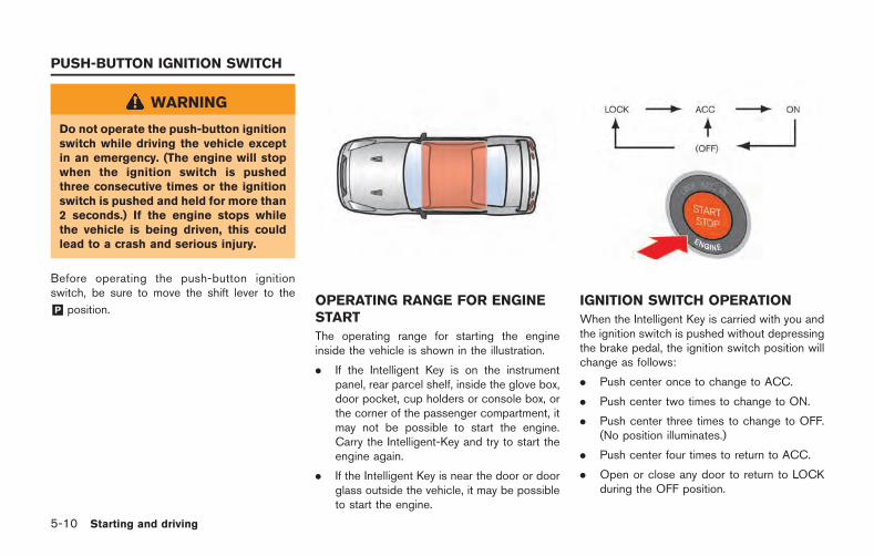
5-10 Starting and driving
WARNING
Do not operate the push-button ignitionswitch while driving the vehicle exceptin an emergency. (The engine will stopwhen the ignition switch is pushedthree consecutive times or the ignitionswitch is pushed and held for more than2 seconds.) If the engine stops whilethe vehicle is being driven, this couldlead to a crash and serious injury.
Before operating the push-button ignitionswitch, be sure to move the shift lever to the
&P position.OPERATING RANGE FOR ENGINESTART
The operating range for starting the engineinside the vehicle is shown in the illustration.
. If the Intelligent Key is on the instrumentpanel, rear parcel shelf, inside the glove box,door pocket, cup holders or console box, orthe corner of the passenger compartment, itmay not be possible to start the engine.Carry the Intelligent-Key and try to start theengine again.
. If the Intelligent Key is near the door or doorglass outside the vehicle, it may be possibleto start the engine.
IGNITION SWITCH OPERATION
When the Intelligent Key is carried with you andthe ignition switch is pushed without depressingthe brake pedal, the ignition switch position willchange as follows:
. Push center once to change to ACC.
. Push center two times to change to ON.
. Push center three times to change to OFF.(No position illuminates.)
. Push center four times to return to ACC.
. Open or close any door to return to LOCKduring the OFF position.
PUSH-BUTTON IGNITION SWITCH
IGNITION SWITCH POSITIONS
LOCK (Normal parking position)
The ignition switch can only be locked in thisposition.
The ignition switch will be unlocked when it ispushed to the ACC position while carrying theIntelligent Key or with the Intelligent Key insertedin the port.
ACC (Accessories)
This position activates electrical accessoriessuch as the radio, when the engine is notrunning.
ON (Normal operating position)
This position turns on the ignition system andelectrical accessories.
OFF
The engine can be turned off without locking thesteering wheel.
The ignition lock is designed so that the ignitionswitch cannot be switched to the LOCK positionuntil the shift lever is moved to the &P position.
NOTE:. If the steering lock release malfunction
indicator appears on the vehicle infor-mation display when the ignitionswitch is pressed, press the ignitionswitch again while gently turning thesteer ing wheel lef t and r ight .( “Steering lock release malfunc-tion indicator” page 2-44)
. If the shift &P warning appears on thevehicle information display when theignition switch is pushed, the shift leveris in any position except the &P posi-tion. Move the shift lever to the &Pposition. ( “Shift “P” warning”page 2-43)
. If the Intelligent Key battery dischargeindicator appears on the vehicle infor-mation display, the Intelligent Keybattery is discharged and the ignitionswitch will not operate. Insert theIntelligent Key into the key port toope r a t e t h e i gn i t i o n sw i t c h .( “Intelligent Key battery dischargeindicator” page 2-45)
. When all of the following conditionsare met for 60 minutes, the batterysaver system will cut off the powersupply to prevent battery discharge.
— The ignition switch is in the ACCposition, and
— All doors are closed, and
— The shift lever is in the &P position.
. Do not leave the vehicle with theignition switch in the ACC or ONposition when the engine is not run-ning for an extended period of time.This can discharge the battery.
EMERGENCY ENGINE SHUT OFF
To shut off the engine in an emergency situationwhile driving, perform the following procedure:
. Rapidly push the push-button ignition switch3 consecutive times in less than 1.5seconds, or
. Push and hold the push button ignitionswitch for more than 2 seconds.
Starting and driving 5-11
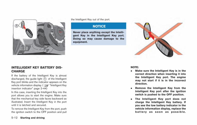
5-12 Starting and driving
INTELLIGENT KEY BATTERY DIS-CHARGE
If the battery of the Intelligent Key is almostdischarged, the guide light *1 of the IntelligentKey port blinks and the indicator appears on thevehicle information display. ( “Intelligent Keyinsertion indicator” page 2-44)
In this case, inserting the Intelligent Key into theport allows you to start the engine. Make surethat the mechanical key side faces backward asillustrated. Insert the Intelligent Key in the portuntil it is latched and secured.
To remove the Intelligent Key from the port, pushthe ignition switch to the OFF position and pull
the Intelligent Key out of the port.
NOTICE
Never place anything except the Intelli-gent Key in the Intelligent Key port.Doing so may cause damage to theequipment.
NOTE:
. Make sure the Intelligent Key is in thecorrect direction when inserting it intothe Intelligent Key port. The enginemay not start if it is in the incorrectdirection.
. Remove the Intelligent Key from theIntelligent Key port after the ignitionswitch is pushed to the OFF position.
. The Intelligent Key port does notcharge the Intelligent Key battery. Ifyou see the low battery indicator in thevehicle information display, replace thebat te r y as soon as poss ib le .
( “Intelligent Key battery replace-ment” page 8-27)
. Make sure the area around the vehicle isclear.
. Check fluid levels such as engine oil, cool-ant, brake fluid and window washer fluid asfrequently as possible, or at least wheneveryou refuel.
. Check that all windows and lights are clean.
. Visually inspect tires for their appearanceand condition. Also check tires for properinflation.
. Lock all doors.
. Position seat.
. Adjust inside and outside mirrors.
. Fasten seat belts and ask all passengers todo likewise.
. Check the operation of warning lights whenthe ignition switch is pushed to the ONposition. ( “Warning/indicator lightsand audible reminders” page 2-25)
NOTE:
. This vehicle includes spark plugs thatare designed for maximum perfor-mance. If the start time becomes long-er, the plugs may be fouled, making theengine difficult to start. If this occurs,start the engine using the proceduredescribed in this section.
. A click sound may be heard when thebrake pedal is depressed and released.This is normal.
. A low rattling operating sound mayoccur when the engine is started orstopped. This is because of the trans-mission gear design, light flywheel anddry sump lubrication system used inthis transmission. This does not indi-cate that there is a malfunction. Thissound is likely to occur in particular ifthe engine is stopped when the tem-perature of the transmission oil is high.
Starting and driving 5-13
BEFORE STARTING THE ENGINE STARTING THE ENGINE
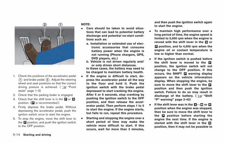
5-14 Starting and driving
1. Check the positions of the accelerator pedal*1 and brake pedal*2 . Adjust the steeringwheel and seat positions so that the correctdriving posture is achieved. ( “Frontseats” page 1-3)
2. Check that the parking brake is engaged.
3. Check that the shift lever is in the &P or &Nposition. (&P is recommended.)
4. Firmly depress the brake pedal. Withoutdepressing the accelerator pedal, push theignition switch once to start the engine.
5. To stop the engine, move the shift lever tothe &P position, and push the ignition switchto the OFF position.
NOTE:
. Care should be taken to avoid situa-tions that can lead to potential batterydischarge and potential no-start condi-tions such as:
a. Installation or extended use of elec-tronic accessories that consumebattery power when the engine isnot running (Phone chargers, GPS,DVD players, etc.)
b. Vehicle is not driven regularly and/or only driven short distances.
In these cases, the battery may need tobe charged to maintain battery health.
. If the engine is difficult to start, de-press the accelerator pedal all the wayto the floor and hold it. Push theignition switch with the brake pedaldepressed to start cranking the engine.After 5 or 6 seconds, stop cranking bypushing the ignition switch to the OFFposition, and then release the accel-erator pedal. Then perform steps 1 to 5to start the engine. If the engine starts,but fails to run, repeat this procedure.
. Starting and stopping the engine over ashort period of time may make thevehicle more difficult to start. If thisoccurs, wait for more than 3 minutes,
and then push the ignition switch againto start the engine.
. To maintain high performance over along period of time, the engine speed islimited to 5,000 rpm when the engine isrevved with the shift lever in the &N or
&P position, and to 4,000 rpm when theengine oil or coolant temperature islow or higher than normal.
. If the ignition switch is pushed beforethe shift lever is moved to the &Pposition, the ignition switch will notchange to the OFF position. If thisoccurs, the SHIFT &P warning displayappears on the vehicle informationdisplay. When stopping the engine, besure to move the shift lever to the &Pposition and then push the ignitionswitch. Failure to do so may result indischarge of the battery. ( “Shift“P” warning” page 2-43)
. If the shift lever was in the&A &M or&Rposition when the engine was stopped,then be sure to move the shift lever tothe &P position before starting theengine the next time. If the engine isstarted with the shift lever in the &Nposition, then it may not be possible to
drive the vehicle even when the shiftlever is moved to the &A &M or &Rposition. If this occurs, the SHIFT &Pwarning appears on the vehicle infor-mation display. ( “Shift “P” warn-ing” page 2-43)
CAUTION
If the engine was stopped soon whenthe engine is hot, the cooling fan mayoperate for approximately 2 minutesafter the engine was stopped to coolthe components in the engine compart-ment. When the cooling fan is operat-ing, be sure that hands or other itemsdo not get caught in it.
DUAL CLUTCH TRANSMISSION
The GT-R dual clutch transmission is a newly-developed system that uses an electronicallycontrolled multiple-disc wet clutch attached tothe highly efficient manual transmission. Thistransmission has two driving modes.
. &A position (Automatic gearshift):
allows automatic shifting of the manualtransmission.
. &M position (Manual gearshift):
allows quick shifting of the manual transmis-sion.
NOTE:
When starting or driving on a steep uphillgrade, shift to the &M position and operatethe paddle shifter to shift down to 1st gearsimilar to a manual transmission vehicle.
The GT-R dual clutch transmission was devel-oped specifically to maximize vehicle perfor-mance and driving enjoyment. The GT-Rtransmission components were designed usingdifferent engineering standards than typicalpassenger car transmissions. Because of this,the GT-R has different operating characteristics,and various rattle noises may be heard duringsome driving conditions because of the follow-ing items:
. Gear clearances
. Ultralight flywheel
. Dry sump lubrication
These noises do not indicate that there is amalfunction.
WARNING
. Do not depress the acceleratorpedal while shifting from the &P or
&N position to the &R or &A &Mposition. Always depress the brakepedal until shifting is completed.Failure to do so could cause lossof control and an accident.
. Cold engine idle speed is high, souse caution when shifting into aforward or reverse gear before theengine has warmed up.
. Never shift to the &P or &R positionwhile the vehicle is moving forward.Never shift to the &P or &A &Mposition while the vehicle is movingrearward. Doing so could cause lossof control and an accident.
. The shift lever contains a powerfulmagnet. Do not place electronic
Starting and driving 5-15
DRIVING THE VEHICLE
5-16 Starting and driving
medical devices or other electronicproducts that are susceptible tomagnetic force close to the shiftlever.
. Do not downshift abruptly on slip-pery roads. This may cause a loss ofcontrol.
. If the shift lever is moved from &R to
&A &M position, or &A &M to &Rposition before the vehicle stops,you may not be able to shift gear orit may take longer to shift gear.Make sure to depress the brakepedal and check that the vehiclehas stopped before shifting.
CAUTION
. Because the vehicle includes a dualclutch transmission that automati-cally controls the clutch and shiftingoperation of the manual transmis-sion, whenever the shift lever is in aposition other then &P or &N , thevehicle will begin to move slowly, inthe same way as when the clutch ina manual transmission vehicle is
partially engaged. Keep the brakepedal firmly depressed when thevehicle is stopped. In some circum-stances the vehicle may not startmoving on its own, however thisdoes not indicate that there is amalfunction.
NOTICE
. When the vehicle is stopped on ahill, do not hold the vehicle in placeby depressing the accelerator pedal.Doing so may cause the clutch tooverheat and result in transmissiondamage. Use the brakes to preventthe vehicle from moving.
. The GT-R dual clutch transmission isprovided with a dry sump lubricationsystem that improves efficiency andensures reliability under high g-force conditions. When oil viscosityis high at low temperatures, it takeslonger for all components to besufficiently lubricated. Thus, whenthe transmission temperature is low(approximately 104 8F (408C), do notaccelerate rapidly or run the engine
faster than 4,000 rpm.
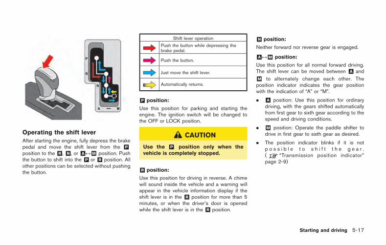
Operating the shift lever
After starting the engine, fully depress the brakepedal and move the shift lever from the &Pposition to the &R , &N , or &A &M position. Pushthe button to shift into the &P or &R position. Allother positions can be selected without pushingthe button.
Shift lever operation
Push the button while depressing thebrake pedal.
Push the button.
Just move the shift lever.
Automatically returns.
&P position:
Use this position for parking and starting theengine. The ignition switch will be changed tothe OFF or LOCK position.
CAUTION
Use the &P position only when thevehicle is completely stopped.
&R position:
Use this position for driving in reverse. A chimewill sound inside the vehicle and a warning willappear in the vehicle information display if theshift lever is in the &R position for more than 5minutes, or when the driver’s door is openedwhile the shift lever is in the &R position.
&N position:
Neither forward nor reverse gear is engaged.
&A &M position:
Use this position for all normal forward driving.The shift lever can be moved between &A and
&M to alternately change each other. Theposition indicator indicates the gear positionwith the indication of “A” or “M”.
. &A position: Use this position for ordinarydriving, with the gears shifted automaticallyfrom first gear to sixth gear according to thespeed and driving conditions.
. &M position: Operate the paddle shifter todrive in first gear to sixth gear as desired.
. The position indicator blinks if it is notp o s s i b l e t o s h i f t t h e g e a r .( “Transmission position indicator”page 2-9)
Starting and driving 5-17
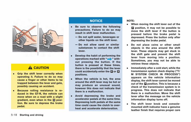
5-18 Starting and driving
CAUTION
. Grip the shift lever correctly whenoperating it. Failure to do so maycause a finger or other items to betrapped between the lever and gate,possibly causing an accident.
. Because rolling resistance is re-duced in the GT-R, the vehicle canmove when on a road with a slightgradient, even when in the &N posi-tion. Be sure to depress the brakepedal.
NOTICE
. Be sure to observe the followingprecautions. Failure to do so mayresult in shift lever malfunction.
— Do not spill water, beverages orother liquids on the shift lever.
— Do not allow sand or similarsubstances to contact the shiftlever.
. Develop the habit of performing theoperations marked with “ ” with-out pressing the button. If thebutton is pressed at these times,there is the possibility that the levercould accidentally enter the&P or&Rpositions.
. When the vehicle is hot, the areaaround the shift lever may be hot ormay produce an unusual sound,however this does not indicate thatthere is a malfunction.
. Avoid depressing the brake andaccelerator pedals at the same time.Depressing both pedals at the sametime could cause the clutch to over-heat and accelerate deterioration.
NOTE:
. When moving the shift lever out of the
&P position, it may not be possible tomove the shift lever if the button ispressed before the brake pedal isdepressed. Press the button only afterdepressing the brake pedal.
. Do not place coins or other smallobjects in the area around the shiftlever. These objects may get stuck inthe shift gate and prevent the shiftlever from moving into a position.Sometimes, you may not be able toretrieve these objects.
. Immediately after a cold start, while thetransmission system check display (“T/M SYSTEM CHECK IN PROCESS”)appears on the vehicle informationdisplay, the shift lever cannot be movedout of the&P position. This is because acheck of the transmission system is inprogress. This does not indicate thatthere is a malfunction. Move the shiftlever after the message on the vehicleinformation display turns off.
. The shift lever knob and console-mounted shift indicator have a genuineleather finish that requires proper care
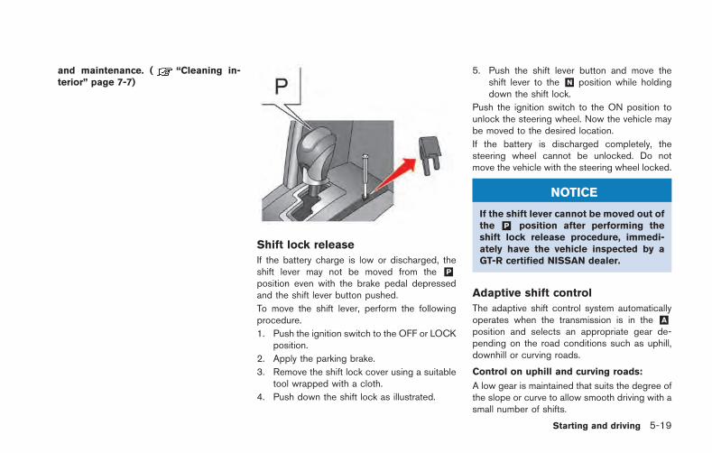
and maintenance. ( “Cleaning in-terior” page 7-7)
Shift lock release
If the battery charge is low or discharged, theshift lever may not be moved from the &Pposition even with the brake pedal depressedand the shift lever button pushed.
To move the shift lever, perform the followingprocedure.
1. Push the ignition switch to the OFF or LOCKposition.
2. Apply the parking brake.
3. Remove the shift lock cover using a suitabletool wrapped with a cloth.
4. Push down the shift lock as illustrated.
5. Push the shift lever button and move theshift lever to the &N position while holdingdown the shift lock.
Push the ignition switch to the ON position tounlock the steering wheel. Now the vehicle maybe moved to the desired location.
If the battery is discharged completely, thesteering wheel cannot be unlocked. Do notmove the vehicle with the steering wheel locked.
NOTICE
If the shift lever cannot be moved out ofthe &P position after performing theshift lock release procedure, immedi-ately have the vehicle inspected by aGT-R certified NISSAN dealer.
Adaptive shift control
The adaptive shift control system automaticallyoperates when the transmission is in the &Aposition and selects an appropriate gear de-pending on the road conditions such as uphill,downhill or curving roads.
Control on uphill and curving roads:
A low gear is maintained that suits the degree ofthe slope or curve to allow smooth driving with asmall number of shifts.
Starting and driving 5-19
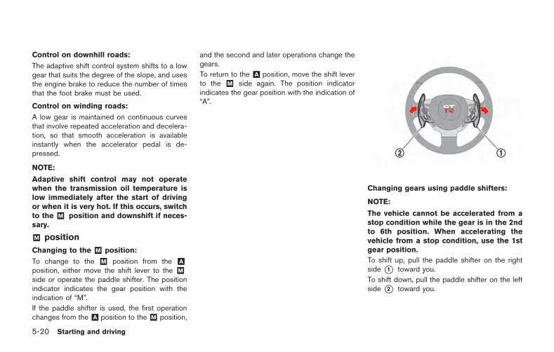
5-20 Starting and driving
Control on downhill roads:
The adaptive shift control system shifts to a lowgear that suits the degree of the slope, and usesthe engine brake to reduce the number of timesthat the foot brake must be used.
Control on winding roads:
A low gear is maintained on continuous curvesthat involve repeated acceleration and decelera-tion, so that smooth acceleration is availableinstantly when the accelerator pedal is de-pressed.
NOTE:
Adaptive shift control may not operatewhen the transmission oil temperature islow immediately after the start of drivingor when it is very hot. If this occurs, switchto the &M position and downshift if neces-sary.
&M position
Changing to the &M position:
To change to the &M position from the &Aposition, either move the shift lever to the &Mside or operate the paddle shifter. The positionindicator indicates the gear position with theindication of “M”.
If the paddle shifter is used, the first operationchanges from the &A position to the &M position,
and the second and later operations change thegears.
To return to the &A position, move the shift leverto the &M side again. The position indicatorindicates the gear position with the indication of“A”.
Changing gears using paddle shifters:
NOTE:
The vehicle cannot be accelerated from astop condition while the gear is in the 2ndto 6th position. When accelerating thevehicle from a stop condition, use the 1stgear position.
To shift up, pull the paddle shifter on the rightside *1 toward you.
To shift down, pull the paddle shifter on the leftside *2 toward you.
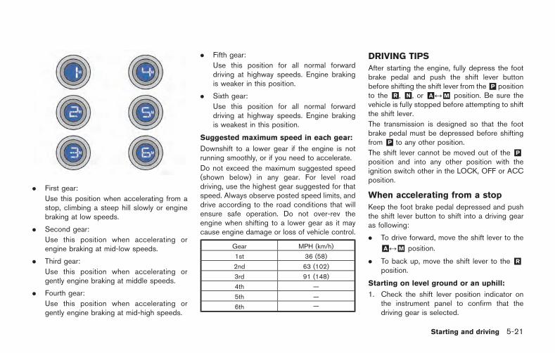
. First gear:
Use this position when accelerating from astop, climbing a steep hill slowly or enginebraking at low speeds.
. Second gear:
Use this position when accelerating orengine braking at mid-low speeds.
. Third gear:
Use this position when accelerating orgently engine braking at middle speeds.
. Fourth gear:
Use this position when accelerating orgently engine braking at mid-high speeds.
. Fifth gear:
Use this position for all normal forwarddriving at highway speeds. Engine brakingis weaker in this position.
. Sixth gear:
Use this position for all normal forwarddriving at highway speeds. Engine brakingis weakest in this position.
Suggested maximum speed in each gear:
Downshift to a lower gear if the engine is notrunning smoothly, or if you need to accelerate.
Do not exceed the maximum suggested speed(shown below) in any gear. For level roaddriving, use the highest gear suggested for thatspeed. Always observe posted speed limits, anddrive according to the road conditions that willensure safe operation. Do not over-rev theengine when shifting to a lower gear as it maycause engine damage or loss of vehicle control.
Gear MPH (km/h)
1st 36 (58)
2nd 63 (102)
3rd 91 (148)
4th —
5th —
6th —
DRIVING TIPS
After starting the engine, fully depress the footbrake pedal and push the shift lever buttonbefore shifting the shift lever from the&P positionto the &R , &N , or &A &M position. Be sure thevehicle is fully stopped before attempting to shiftthe shift lever.
The transmission is designed so that the footbrake pedal must be depressed before shiftingfrom &P to any other position.
The shift lever cannot be moved out of the &Pposition and into any other position with theignition switch other in the LOCK, OFF or ACCposition.
When accelerating from a stop
Keep the foot brake pedal depressed and pushthe shift lever button to shift into a driving gearas following:
. To drive forward, move the shift lever to the
&A &M position.
. To back up, move the shift lever to the &Rposition.
Starting on level ground or an uphill:
1. Check the shift lever position indicator onthe instrument panel to confirm that thedriving gear is selected.
Starting and driving 5-21
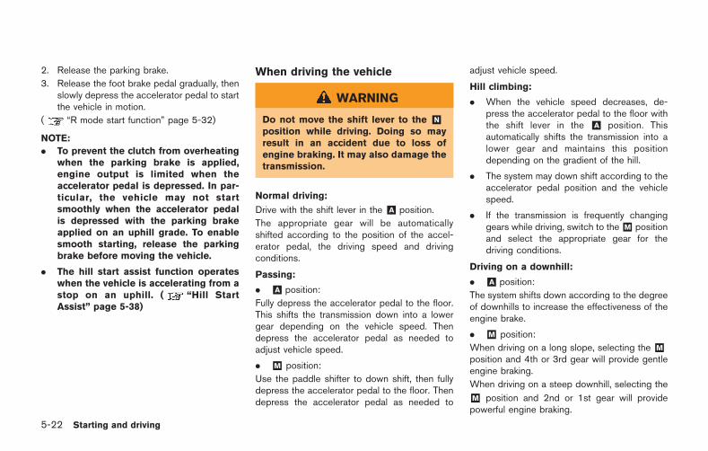
5-22 Starting and driving
2. Release the parking brake.
3. Release the foot brake pedal gradually, thenslowly depress the accelerator pedal to startthe vehicle in motion.
( “R mode start function” page 5-32)
NOTE:
. To prevent the clutch from overheatingwhen the parking brake is applied,engine output is limited when theaccelerator pedal is depressed. In par-ticular, the vehicle may not startsmoothly when the accelerator pedalis depressed with the parking brakeapplied on an uphill grade. To enablesmooth starting, release the parkingbrake before moving the vehicle.
. The hill start assist function operateswhen the vehicle is accelerating from astop on an uphill. ( “Hill StartAssist” page 5-38)
When driving the vehicle
WARNING
Do not move the shift lever to the &Nposition while driving. Doing so mayresult in an accident due to loss ofengine braking. It may also damage thetransmission.
Normal driving:
Drive with the shift lever in the &A position.
The appropriate gear will be automaticallyshifted according to the position of the accel-erator pedal, the driving speed and drivingconditions.
Passing:
. &A position:
Fully depress the accelerator pedal to the floor.This shifts the transmission down into a lowergear depending on the vehicle speed. Thendepress the accelerator pedal as needed toadjust vehicle speed.
. &M position:
Use the paddle shifter to down shift, then fullydepress the accelerator pedal to the floor. Thendepress the accelerator pedal as needed to
adjust vehicle speed.
Hill climbing:
. When the vehicle speed decreases, de-press the accelerator pedal to the floor withthe shift lever in the &A position. Thisautomatically shifts the transmission into alower gear and maintains this positiondepending on the gradient of the hill.
. The system may down shift according to theaccelerator pedal position and the vehiclespeed.
. If the transmission is frequently changinggears while driving, switch to the&M positionand select the appropriate gear for thedriving conditions.
Driving on a downhill:
. &A position:
The system shifts down according to the degreeof downhills to increase the effectiveness of theengine brake.
. &M position:
When driving on a long slope, selecting the &Mposition and 4th or 3rd gear will provide gentleengine braking.
When driving on a steep downhill, selecting the
&M position and 2nd or 1st gear will providepowerful engine braking.
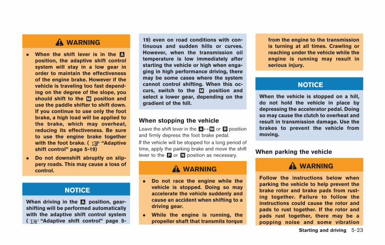
WARNING
. When the shift lever is in the &Aposition, the adaptive shift controlsystem will stay in a low gear inorder to maintain the effectivenessof the engine brake. However if thevehicle is traveling too fast depend-ing on the degree of the slope, youshould shift to the &M position anduse the paddle shifter to shift down.If you continue to use only the footbrake, a high load will be applied tothe brake, which may overheat,reducing its effectiveness. Be sureto use the engine brake togetherwith the foot brake. ( “Adaptiveshift control” page 5-19)
. Do not downshift abruptly on slip-pery roads. This may cause a loss ofcontrol.
NOTICE
When driving in the &A position, gear-shifting will be performed automaticallywith the adaptive shift control system( “Adaptive shift control” page 5-
19) even on road conditions with con-tinuous and sudden hills or curves.However, when the transmission oiltemperature is low immediately afterstarting the vehicle or high when enga-ging in high performance driving, theremay be some cases where the systemcannot control shifting. When this oc-curs, switch to the &M position andselect a lower gear, depending on thegradient of the hill.
When stopping the vehicle
Leave the shift lever in the&A &M or&R positionand firmly depress the foot brake pedal.
If the vehicle will be stopped for a long period oftime, apply the parking brake and move the shiftlever to the &P or &N position as necessary.
WARNING
. Do not race the engine while thevehicle is stopped. Doing so mayaccelerate the vehicle suddenly andcause an accident when shifting to adriving gear.
. While the engine is running, thepropeller shaft that transmits torque
from the engine to the transmissionis turning at all times. Crawling orreaching under the vehicle while theengine is running may result inserious injury.
NOTICE
When the vehicle is stopped on a hill,do not hold the vehicle in place bydepressing the accelerator pedal. Doingso may cause the clutch to overheat andresult in transmission damage. Use thebrakes to prevent the vehicle frommoving.
When parking the vehicle
WARNING
Follow the instructions below whenparking the vehicle to help prevent thebrake rotor and brake pads from rust-ing together. Failure to follow theinstructions could cause the rotor andpads to rust together. If the rotor andpads rust together, there may be apopping noise and some vibration
Starting and driving 5-23
5-24 Starting and driving
when the vehicle is driven, a wheel maynot roll correctly, or the brake padscould be damaged. If the pads aredamaged, this may reduce the effec-tiveness of the brake system whichcould cause a collision, serious perso-nal injury or death.
The GT-R uses brake pad materials that havehigh metallic content. The brake pad materialhelps maintain braking performance in a widerange of weather and driving conditions.
For the first 3,000 miles (5,000 km) of thevehicle’s service life, and for the first 3,000 miles(5,000km) after a brake replacement, the brakepad to brake rotor clearance is very small. Whenparking, apply the parking brake and move theshift lever to the &P position. Idle the engine formore than 20 seconds without depressing thebrake pedal. This allows the brake pads to moveaway from the rotor so the pad does not contactthe rotor.
Additionally, the brakes must be dry beforeparking the vehicle after driving on wet roads orafter washing the vehicle. If the roads are wet,lightly apply the brakes for a short distancebefore parking the vehicle to dry the brakes.After washing the vehicle, dry the brakes bydriving on a dry road for a few miles and apply
the brakes normally based on traffic and roadconditions.
The metallic brake pads and brake disc rotormay rust together when the brakes are notapplied:
. If the vehicle is not idled for 20 secondswithout the brakes applied, or if the brakesare applied when the vehicle is shut off, therotor and pads can rust together, even whenthe brake pads are dry.
. If the brakes are wet when the vehicle isparked and the parking brake is applied for along time.
Contact a GT-R certified NISSAN dealer if thebrake pads and brake rotor have rustedtogether.
1. Bring the vehicle to a complete stop.
2. With the foot brake pedal depressed, applythe parking brake.
3. Move the shift lever to the &P position.
4. Check the shift lever position indicator onthe instrument panel to confirm that the &Pposition is selected.
5. Push the ignition switch to stop the engine.
WARNING
Before exiting the vehicle, be sure tomove the shift lever to the &P positionand stop the engine. If the engine isrunning and the shift lever is not in the
&P position, the vehicle may start mov-ing due to partial engagement of theclutch or to the effects of gravity on aslope, or the vehicle may suddenlyaccelerate due to accidental operationof the accelerator pedal, possibly caus-ing an accident.
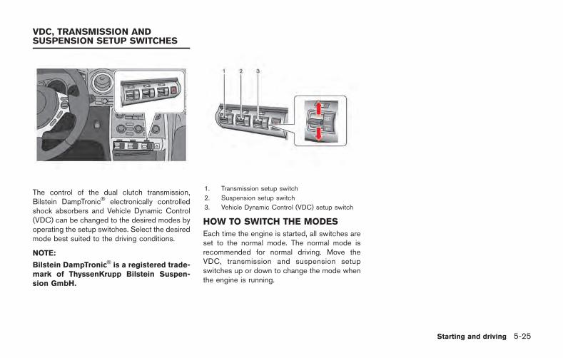
The control of the dual clutch transmission,Bilstein DampTronic electronically controlledshock absorbers and Vehicle Dynamic Control(VDC) can be changed to the desired modes byoperating the setup switches. Select the desiredmode best suited to the driving conditions.
NOTE:
Bilstein DampTronic is a registered trade-mark of ThyssenKrupp Bilstein Suspen-sion GmbH.
1. Transmission setup switch
2. Suspension setup switch
3. Vehicle Dynamic Control (VDC) setup switch
HOW TO SWITCH THE MODES
Each time the engine is started, all switches areset to the normal mode. The normal mode isrecommended for normal driving. Move theVDC, transmission and suspension setupswitches up or down to change the mode whenthe engine is running.
Starting and driving 5-25
VDC, TRANSMISSION ANDSUSPENSION SETUP SWITCHES
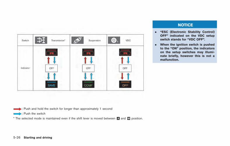
5-26 Starting and driving
: Push and hold the switch for longer than approximately 1 second
: Push the switch
* The selected mode is maintained even if the shift lever is moved between &A and &M position.
NOTICE
. “ESC (Electronic Stability Control)OFF” indicated on the VDC setupswitch stands for “VDC OFF”.
. When the ignition switch is pushedto the “ON” position, the indicatorson the setup switches may illumi-nate briefly, however this is not amalfunction.
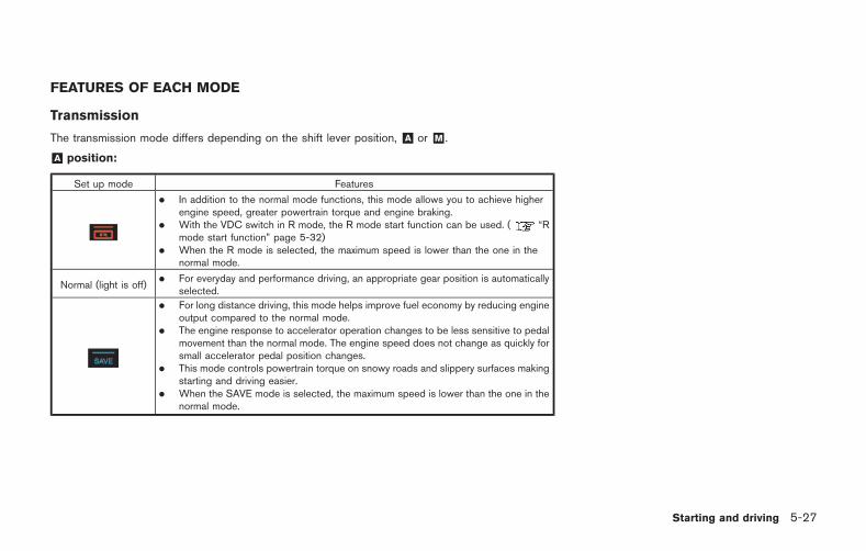
FEATURES OF EACH MODE
Transmission
The transmission mode differs depending on the shift lever position, &A or &M .
&A position:
Set up mode Features
. In addition to the normal mode functions, this mode allows you to achieve higherengine speed, greater powertrain torque and engine braking.
. With the VDC switch in R mode, the R mode start function can be used. ( “Rmode start function” page 5-32)
. When the R mode is selected, the maximum speed is lower than the one in thenormal mode.
Normal (light is off). For everyday and performance driving, an appropriate gear position is automatically
selected.
. For long distance driving, this mode helps improve fuel economy by reducing engineoutput compared to the normal mode.
. The engine response to accelerator operation changes to be less sensitive to pedalmovement than the normal mode. The engine speed does not change as quickly forsmall accelerator pedal position changes.
. This mode controls powertrain torque on snowy roads and slippery surfaces makingstarting and driving easier.
. When the SAVE mode is selected, the maximum speed is lower than the one in thenormal mode.
Starting and driving 5-27
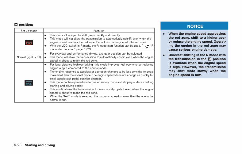
5-28 Starting and driving
&M position:
Set up mode Features
. This mode allows you to shift gears quickly and directly.
. This mode will not allow the transmission to automatically upshift even when theengine speed reaches the red zone. Do not rev the engine into the red zone.
. With the VDC switch in R mode, the R mode start function can be used. ( “Rmode start function” page 5-32)
Normal (light is off). For everyday and performance driving, any gear position can be selected.. This mode will allow the transmission to automatically upshift even when the engine
speed is about to reach the red zone.
. For long distance highway driving, this mode improves fuel economy by reducingengine output compared to the normal mode.
. The engine response to accelerator operation changes to be less sensitive to pedalmovement than the normal mode. The engine speed does not change as quickly forsmall accelerator pedal position changes.
. This mode controls powertrain torque on snowy roads and slippery surfaces makingstarting and driving easier.
. This mode allows the transmission to automatically upshift even when the enginespeed is about to reach the red zone.
. When the SAVE mode is selected, the maximum speed is lower than the one in thenormal mode.
NOTICE
. When the engine speed approachesthe red zone, shift to a higher gearor reduce the engine speed. Operat-ing the engine in the red zone maycause serious engine damage.
. Quickest shifting in the R mode withthe transmission in the &M positionis available when the engine speedis high. However, the transmissionmay shift more slowly when theengine speed is low.
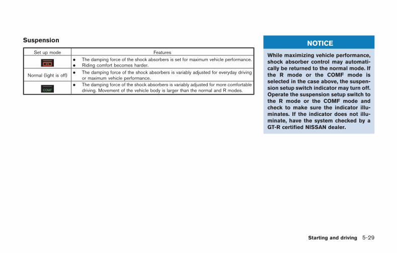
Suspension
Set up mode Features
. The damping force of the shock absorbers is set for maximum vehicle performance.
. Riding comfort becomes harder.
Normal (light is off). The damping force of the shock absorbers is variably adjusted for everyday driving
or maximum vehicle performance.
. The damping force of the shock absorbers is variably adjusted for more comfortabledriving. Movement of the vehicle body is larger than the normal and R modes.
NOTICE
While maximizing vehicle performance,shock absorber control may automati-cally be returned to the normal mode. Ifthe R mode or the COMF mode isselected in the case above, the suspen-sion setup switch indicator may turn off.Operate the suspension setup switch tothe R mode or the COMF mode andcheck to make sure the indicator illu-minates. If the indicator does not illu-minate, have the system checked by aGT-R certified NISSAN dealer.
Starting and driving 5-29
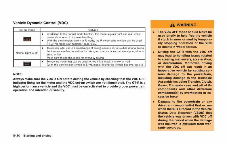
5-30 Starting and driving
Vehicle Dynamic Control (VDC)
Set up mode Features
. In addition to the normal mode function, this mode adjusts front and rear wheelpower distribution to improve handling.
. With the transmission switch in R mode, the R mode start function can be used.( “R mode start function” page 5-32)
Normal (light is off)
. This mode is for use in a broad range of driving conditions, for routine driving duringfair to rainy weather, as well as for driving on road surfaces that are slippery due tosnow or ice.Make sure to use this mode for everyday driving.
. Temporary mode that can be used to free if it is stuck in snow or mud(With the transmission switch in SAVE mode, freeing the vehicle become easier.)
NOTE:
Always make sure the VDC is ON before driving the vehicle by checking that the VDC OFFindicator lights on the meter and the VDC set-up switch are not illuminated. The GT-R is ahigh performance vehicle and the VDC must be on/activated to provide proper powertrainoperation and intended drivability.
WARNING
. The VDC OFF mode should ONLY beused briefly to help free the vehicleif stuck in snow or mud by tempora-rily stopping operation of the VDCto maintain wheel torque.
. Driving the GT-R with the VDC offmay lead to handling issues relatedto steering maneuvers, acceleration,or deceleration. Moreover, drivingwith the VDC off can result in aninoperative vehicle by causing ser-ious damage to the powertrain,including damage to the TransaxleAssembly including Transfer, Clutch,Gears, Transaxle case and all of itscomponents and other drivetraincomponent(s) by overheating or ex-cessive force.
. Damage to the powertrain or anydrivetrain component(s) that occurswhen there is a record in the VehicleStatus Data Recorder (VSDR) thatthe vehicle was driven with VDC offduring the period when the damagewas incurred is excluded from war-ranty coverage.
See your 2015 Warranty Information Booklet forimportant related information and warrantycoverage exclusions. See also section 2( “Transmission warning light” page 2-30)and section 5 ( “Vehicle Dynamic Control(VDC) system” page 5-50) of this Owner’sManual, “Transmission Clutch TemperatureHigh” and “Vehicle Dynamic Control (VDC)System” for important additional related informa-tion.
The turbocharger system uses engine oil forlubrication and cooling of its rotating compo-nents. The turbocharger turbine turns at extre-mely high speeds and it can get very hot. It isessential to maintain a supply of oil flowingthrough the turbocharger system. Therefore, asudden interruption of oil supply may cause amalfunction in the turbocharger.
To ensure prolonged life and performance of theturbocharger, it is essential to perform thefollowing maintenance procedure:
. Change your engine oil according to therecommended intervals shown in the sepa-rate Service and Maintenance Guide. Useonly the recommended engine oil.
. If the engine had been operating at highengine speed for an extended period of time,let it idle for a few minutes prior to shut-down.
. Do not accelerate your engine to highengine speed immediately after start.
NOTICE
. This vehicle includes spark plugsthat are designed for high perfor-mance. For this reason, if the engineis repeatedly started and stopped
over a short time, the spark plugsmay become fouled, making theengine difficult to start. To preventdiminished starting performance,avoid starting and stopping theengine repeatedly during a shortperiod of time.
NOTE:
. When the vehicle is delivered, theengine oil level is 0.39 in (10 mm)below the H mark on the engine oildipstick for optimum high performancedriving. The engine oil can be filled upto the H mark if not engaging inperformance driving.
. Because of the high performance char-acteristics of the GT-R engine, morefrequent oil level inspections are ne-cessary. Check the oil level every 1,800miles (3,000km) and adjust as neces-sary. Also, change the engine oil basedon the driving conditions. For theinformation regarding oil replacementintervals, refer to the 2015 NISSANGT-R Service and Maintenance Guide.
. Some amount of oil is consumed byyour engine under normal operating
Starting and driving 5-31
TURBOCHARGER SYSTEM
5-32 Starting and driving
conditions, and oil consumption byitself does not necessarily indicateany malfunction. If your rate of oilconsumption increases suddenly orwithout explanation, NISSAN recom-mends that you have your vehicleinspected by a GT-R certified NISSANdealer.
This function enables the driver to start accel-eration from a stop by selecting R mode with theVDC and transmission setup switch. The engineoutput will be maintained at approximately 4,000rpm. When using the R mode or the R modestart function, always use proper seating posi-tion and follow the safety instructions in Section1 of this manual.
WARNING
. Failure to follow the warnings andinstruction for the use of this fea-ture may cause a loss of vehiclecontrol or a collision which may leadto serious personal injury or death:
. Make sure to drive carefully withinlegal limits.
. Only use this function when you canguarantee that it is safe to do so,based on the surrounding trafficconditions.
. Do not use this function on slipperyor wet roads. This may cause loss ofvehicle control and could result inan accident.
. The R mode start function has beendeveloped not only for controlling
the engine, transmission and VDCsystem, but also the settings of thesuspension and tires. Therefore, anymodification of the vehicle maydisrupt the vehicle’s balance. Thiswill not only reduce the optimumperformance of the vehicle but mayalso cause damage to powertraincomponents, including the trans-mission.
NOTICE
. When the temperature of the enginecoolant and transmission oil is highor low, the function cannot be used.The temperature range in which theR mode start function can be used:
— Engine coolant: 1408F - 2128F(608C - 1008C)
— Transmission oil: 1408F - 2668F(608C - 1308C)
. If the R mode start function is used4 times consecutively, the functionmay be disabled and cannot beturned on to protect the vehiclesystem. While the function is dis-
R MODE START FUNCTION
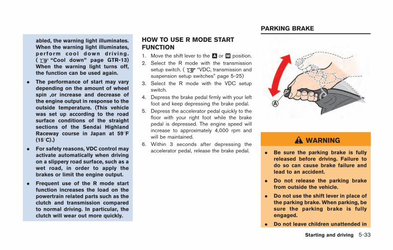
abled, the warning light illuminates.When the warning light illuminates,per form cool down dr iv ing .( “Cool down” page GTR-13)When the warning light turns off,the function can be used again.
. The performance of start may varydepending on the amount of wheelspin ,or increase and decrease ofthe engine output in response to theoutside temperature. (This vehiclewas set up according to the roadsurface conditions of the straightsections of the Sendai HighlandRaceway course in Japan at 598F(158C).)
. For safety reasons, VDC control mayactivate automatically when drivingon a slippery road surface, such as awet road, in order to apply thebrakes or limit the engine output.
. Frequent use of the R mode startfunction increases the load on thepowertrain related parts such as theclutch and transmission comparedto normal driving. In particular, theclutch will wear out more quickly.
HOW TO USE R MODE STARTFUNCTION
1. Move the shift lever to the &A or &M position.
2. Select the R mode with the transmissionsetup switch. ( “VDC, transmission andsuspension setup switches” page 5-25)
3. Select the R mode with the VDC setupswitch.
4. Depress the brake pedal firmly with your leftfoot and keep depressing the brake pedal.
5. Depress the accelerator pedal quickly to thefloor with your right foot while the brakepedal is depressed. The engine speed willincrease to approximately 4,000 rpm andwill be maintained.
6. Within 3 seconds after depressing theaccelerator pedal, release the brake pedal.
WARNING
. Be sure the parking brake is fullyreleased before driving. Failure todo so can cause brake failure andlead to an accident.
. Do not release the parking brakefrom outside the vehicle.
. Do not use the shift lever in place ofthe parking brake. When parking, besure the parking brake is fullyengaged.
. Do not leave children unattended in
Starting and driving 5-33
PARKING BRAKE
5-34 Starting and driving
a vehicle. They could release theparking brake and cause an acci-dent.
To apply: Pull the parking brake lever up.
To release:
1. Firmly apply the foot brake.
2. While pulling up on the parking brake leverslightly, push the button *A and lower thelever completely.
3. Before driving, be sure the brake warninglight goes out.
The cruise control allows driving at speedsabove 25 MPH (40 km/h) without keeping yourfoot on the accelerator pedal.
WARNING
Do not use the cruise control whendriving under the following conditions.Doing so could cause a loss of vehiclecontrol and result in an accident.
. When it is not possible to keep thevehicle at a set speed.
. In heavy traffic or in traffic thatvaries in speed.
. On winding or hilly roads.
. On slippery roads (rain, snow, ice,etc.).
. In very windy areas.
NOTE:
. When the SAVE mode is selected withthe transmission setup switch, theacceleration and deceleration can becontrolled smoothly. When the SAVEmode is selected, the maximum settingspeed is lower than the one in thenormal mode. When the vehicle ap-
proaches a gentle uphill, there may bea slight delay as the vehicle returns tothe preset speed. However, the vehiclewill gradually accelerate and return tothe preset speed.
CRUISE CONTROL
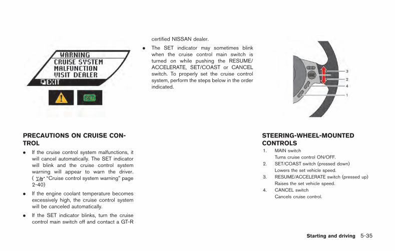
PRECAUTIONS ON CRUISE CON-TROL
. If the cruise control system malfunctions, itwill cancel automatically. The SET indicatorwill blink and the cruise control systemwarning will appear to warn the driver.( “Cruise control system warning” page2-40)
. If the engine coolant temperature becomesexcessively high, the cruise control systemwill be canceled automatically.
. If the SET indicator blinks, turn the cruisecontrol main switch off and contact a GT-R
certified NISSAN dealer.
. The SET indicator may sometimes blinkwhen the cruise control main switch isturned on while pushing the RESUME/ACCELERATE, SET/COAST or CANCELswitch. To properly set the cruise controlsystem, perform the steps below in the orderindicated.
STEERING-WHEEL-MOUNTEDCONTROLS1. MAIN switch
Turns cruise control ON/OFF.
2. SET/COAST switch (pressed down)
Lowers the set vehicle speed.
3. RESUME/ACCELERATE switch (pressed up)
Raises the set vehicle speed.
4. CANCEL switch
Cancels cruise control.
Starting and driving 5-35
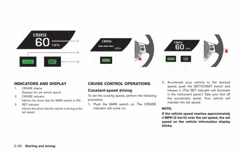
5-36 Starting and driving
INDICATORS AND DISPLAY1. CRUISE display
Displays the set vehicle speed.
2. CRUISE indicator
Informs the driver that the MAIN switch is ON.
3. SET indicator
Informs the driver that the vehicle is driving at theset speed.
CRUISE CONTROL OPERATIONS
Constant-speed driving
To set the cruising speed, perform the followingprocedure.
1. Push the MAIN switch on. The CRUISEindicator will come on.
2. Accelerate your vehicle to the desiredspeed, push the SET/COAST switch andrelease it. (The SET indicator will illuminatein the instrument panel.) Take your foot offthe accelerator pedal. Your vehicle willmaintain the set speed.
NOTE:
If the vehicle speed reaches approximately3 MPH (5 km/h) over the set speed, the setspeed on the vehicle information displayblinks.
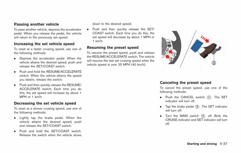
Passing another vehicle
To pass another vehicle, depress the acceleratorpedal. When you release the pedal, the vehiclewill return to the previously set speed.
Increasing the set vehicle speed
To reset at a faster cruising speed, use one ofthe following methods:
. Depress the accelerator pedal. When thevehicle attains the desired speed, push andrelease the SET/COAST switch.
. Push and hold the RESUME/ACCELERATEswitch. When the vehicle attains the speedyou desire, release the switch.
. Push and then quickly release the RESUME/ACCELERATE switch. Each time you dothis, the set speed will increase by about 1MPH or 1 km/h.
Decreasing the set vehicle speed
To reset at a slower cruising speed, use one ofthe following methods:
. Lightly tap the brake pedal. When thevehicle attains the desired speed, pushand release the SET/COAST switch.
. Push and hold the SET/COAST switch.Release the switch when the vehicle slows
down to the desired speed.
. Push and then quickly release the SET/COAST switch. Each time you do this, theset speed will decrease by about 1 MPH or1 km/h.
Resuming the preset speed
To resume the preset speed, push and releasethe RESUME/ACCELERATE switch. The vehiclewill resume the last set cruising speed when thevehicle speed is over 25 MPH (40 km/h).
Canceling the preset speed
To cancel the preset speed, use one of thefollowing methods:
. Push the CANCEL switch *1 . The SETindicator will turn off.
. Tap the brake pedal *3 . The SET indicatorwill turn off.
. Turn the MAIN switch *2 off. Both theCRUISE indicator and SET indicator will turnoff.
Starting and driving 5-37
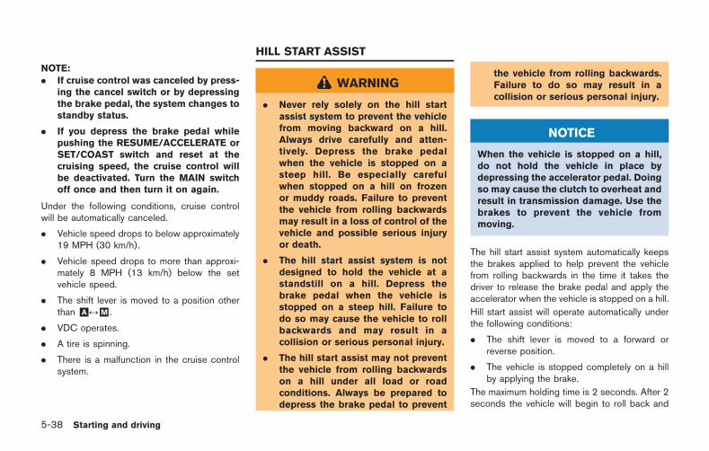
5-38 Starting and driving
NOTE:. If cruise control was canceled by press-
ing the cancel switch or by depressingthe brake pedal, the system changes tostandby status.
. If you depress the brake pedal whilepushing the RESUME/ACCELERATE orSET/COAST switch and reset at thecruising speed, the cruise control willbe deactivated. Turn the MAIN switchoff once and then turn it on again.
Under the following conditions, cruise controlwill be automatically canceled.
. Vehicle speed drops to below approximately19 MPH (30 km/h).
. Vehicle speed drops to more than approxi-mately 8 MPH (13 km/h) below the setvehicle speed.
. The shift lever is moved to a position otherthan &A &M .
. VDC operates.
. A tire is spinning.
. There is a malfunction in the cruise controlsystem.
WARNING
. Never rely solely on the hill startassist system to prevent the vehiclefrom moving backward on a hill.Always drive carefully and atten-tively. Depress the brake pedalwhen the vehicle is stopped on asteep hill. Be especially carefulwhen stopped on a hill on frozenor muddy roads. Failure to preventthe vehicle from rolling backwardsmay result in a loss of control of thevehicle and possible serious injuryor death.
. The hill start assist system is notdesigned to hold the vehicle at astandstill on a hill. Depress thebrake pedal when the vehicle isstopped on a steep hill. Failure todo so may cause the vehicle to rollbackwards and may result in acollision or serious personal injury.
. The hill start assist may not preventthe vehicle from rolling backwardson a hill under all load or roadconditions. Always be prepared todepress the brake pedal to prevent
the vehicle from rolling backwards.Failure to do so may result in acollision or serious personal injury.
NOTICE
When the vehicle is stopped on a hill,do not hold the vehicle in place bydepressing the accelerator pedal. Doingso may cause the clutch to overheat andresult in transmission damage. Use thebrakes to prevent the vehicle frommoving.
The hill start assist system automatically keepsthe brakes applied to help prevent the vehiclefrom rolling backwards in the time it takes thedriver to release the brake pedal and apply theaccelerator when the vehicle is stopped on a hill.
Hill start assist will operate automatically underthe following conditions:
. The shift lever is moved to a forward orreverse position.
. The vehicle is stopped completely on a hillby applying the brake.
The maximum holding time is 2 seconds. After 2seconds the vehicle will begin to roll back and
HILL START ASSIST
hill start assist will stop operating completely.
Hill start assist will not operate when the shiftlever is moved to the &N or &P position or on aflat and level road.
NOTE:
This system does not function when theVehicle Dynamic Control VDC) systemwarning appears on the vehicle informa-tion display located in the tachometer.( “Vehicle Dynamic Control (VDC) sys-tem warning” page 2-37)
NOTICE
Follow these recommendations to ob-tain maximum engine performance andensure the future reliability and econo-my of your new vehicle. Failure tofollow these recommendations mayresult in shortened engine life andreduced vehicle performance.
Please observe the following types of drivinguntil the mileage shown below has beenreached.
Until 300 miles (500 km):
. Do not depress the accelerator pedal morethan halfway and avoid rapid acceleration.
. Drive with the engine speed kept at lessthan 3,500 RPM.
. Avoid unnecessary quick steering, abruptbraking and driving on poor roads.
300 to 600 miles (500 to 1,000 km)
. Avoid rapid acceleration in a low gear (1st to3rd gears) with the accelerator pedal fullydepressed. Depress the pedal slowly.
. Avoid unnecessary quick steering andabrupt braking.
. Drive with the suspension setup switch inthe COMF mode to allow more suspensionstroke.
600 to 1,200 miles (1,000 to 2,000 km)
. Drive with the engine speed kept relativelyhigh with the shift lever in the &M position.Shifting is recommended between 1st and4th gears.
. Avoid unnecessary quick steering andabrupt braking.
. Drive with the suspension setup switch inthe COMF mode to allow more suspensionstroke.
Even though the mileage reaches over 1,200miles (2,000 km), the clutch may take longer toproperly engage if the vehicle is mainly driven intown at a low speed. NISSAN recommendsbreaking in the clutch at a GT-R certifiedNISSAN dealer.
WHEEL ALIGNMENT
Do not adjust the wheel alignment until themileage reaches 1,000 miles (1,600 km). Untilthen, the suspension may not engage enoughand the height may be higher.
However, make sure to adjust the alignmentafter 1,000 miles (1,600 km).
The wheel alignment can be adjusted by a GT-R
Starting and driving 5-39
BREAK-IN SCHEDULE
5-40 Starting and driving
certified NISSAN dealer in accordance withspecifications for city driving to high perfor-mance driving.
The tires on the GT-R may have different wearrates and wear patterns in comparison toconventional passenger vehicles. Contact aGT-R certified NISSAN dealer to confirm thatthe alignment is within specifications.
Follow these easy-to-use Fuel Efficient DrivingTips to help you achieve the most fuel economyfrom your vehicle.
1. Use smooth accelerator and brake pedalapplication.. Avoid rapid starts and stops.. Use smooth, gentle accelerator and
brake application whenever possible.. Maintain constant speed while commut-
ing and coast whenever possible.
2. Maintain constant speed.. Look ahead to try and anticipate and
minimize stops.. Synchronizing your speed with traffic
lights allows you to reduce your numberof stops.
. Maintaining a steady speed can minimizered light stops and improve fuel effi-ciency.
3. Use air conditioning (A/C) at higher vehiclespeeds.. Below 40 MPH (64 km/h), it is more
efficient to open windows to cool thevehicle due to reduced engine load.
. Above 40 MPH (64 km/h), it is moreefficient to use A/C to cool the vehicledue to increased aerodynamic drag.
. Recirculating the cool air in the cabinwhen the A/C is on reduces cooling load.
4. Drive at economical speeds and distances.. Observing the speed limit and not
exceeding 60 MPH (97 km/h) (wherelegally allowed) can improve fuel effi-ciency due to reduced aerodynamicdrag.
. Maintaining a safe following distancebehind other vehicles reduces unneces-sary braking.
. Safely monitoring traffic to anticipatechanges in speed permits reduced brak-ing and smooth acceleration changes.
. Select a gear range suitable to roadconditions.
5. Use cruise control.. Using cruise control during highway
driving helps maintain a steady speed.. Cruise control is particularly effective in
providing fuel savings when driving onflat terrains.
6. Plan for the shortest route.. Utilize a map or navigation system to
determine the best route to save time.
FUEL EFFICIENT DRIVING TIPS
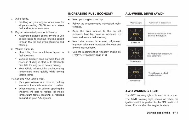
7. Avoid idling.. Shutting off your engine when safe for
stops exceeding 30-60 seconds savesfuel and reduces emissions.
8. Buy an automated pass for toll roads.. Automated passes permit drivers to use
special lanes to maintain cruising speedthrough the toll and avoid stopping andstarting.
9. Winter warm up.. Limit idling time to minimize impact to
fuel economy.. Vehicles typically need no more than 30
seconds of idling at start-up to effectivelycirculate the engine oil before driving.
. Your vehicle will reach its ideal operatingtemperature more quickly while drivingversus idling.
10. Keeping your vehicle cool.. Park your vehicle in a covered parking
area or in the shade whenever possible.. When entering a hot vehicle, opening the
windows will help to reduce the insidetemperature faster, resulting in reduceddemand on your A/C system.
. Keep your engine tuned up.
. Follow the recommended scheduled main-tenance.
. Keep the tires inflated to the correctpressure. Low tire pressure increases tirewear and lowers fuel economy.
. Keep the wheels in correct alignment.Improper alignment increases tire wear andlowers fuel economy.
. Use the recommended viscosity engine oil.( “Oil viscosity” page 9-6)
AWD WARNING LIGHT
The AWD warning light is located in the meter.
The AWD warning light comes on when theignition switch is pushed to the ON position. Itturns off soon after the engine is started.
Starting and driving 5-41
INCREASING FUEL ECONOMY ALL-WHEEL DRIVE (AWD)
5-42 Starting and driving
If any malfunction occurs in the AWD systemwhile the engine is running, the warning light willcome on.
The warning light may blink rapidly (about twiceper second) while trying to free a stuck vehicledue to high AWD clutch temperature. Thedriving mode may change to two-wheel drive.If the warning light blinks rapidly during opera-tion, stop the vehicle with the engine idling in asafe place immediately. Then if the light goes offafter a while, you can continue driving.
A large difference between the diameters offront and rear wheels will make the warning lightblink slowly (about once per two seconds). Pulloff the road in a safe area, and idle the engine.Check that all tire sizes are the same, tirepressure is correct and tires are not worn andwinter tires are not installed on the front or rearwheels only.
If the warning light is blinking after the aboveoperation, have your vehicle checked by a GT-Rcertified NISSAN dealer as soon as possible.
If non-genuine GT-R tires are used, the warninglight may illuminate. ( “GT-R special pre-cautions” page GTR-5)
WARNING
. Do not attempt to raise two wheelsoff the ground and shift the trans-mission to any drive or reverseposition with the engine running.Doing so may result in drivetraindamage or unexpected vehiclemovement which could result inserious vehicle damage or personalinjury.
. Do not attempt to test an AWDequipped vehicle on a 2-wheel dy-namometer (such as the dynam-ometers used by some states foremissions testing) or similar equip-ment even if the other two wheelsare raised off the ground. Make surethat you inform the test facilitypersonnel that your vehicle isequipped with AWD before it isplaced on a dynamometer. Usingthe wrong test equipment may re-sult in drivetrain damage or unex-pected vehicle movement whichcould result in serious vehicle da-mage or personal injury.
NOTICE
. If the warning light comes on whiledriving there may be a malfunctionin the AWD system. Reduce thevehicle speed and have your vehiclechecked by a GT-R certified NISSANdealer as soon as possible.
. If the warning light remains on afterthe above operation, have yourvehicle checked by a GT-R certifiedNISSAN dealer as soon as possible.
. The powertrain may be damaged ifyou continue driving with the warn-ing light blinking.
. Do not spin the rear wheels whiledriving. Spinning the rear wheelsmay increase the temperatures ofthe AWD clutch system and damagethe system. Adjust the acceleratorpedal position to stop wheel spin.
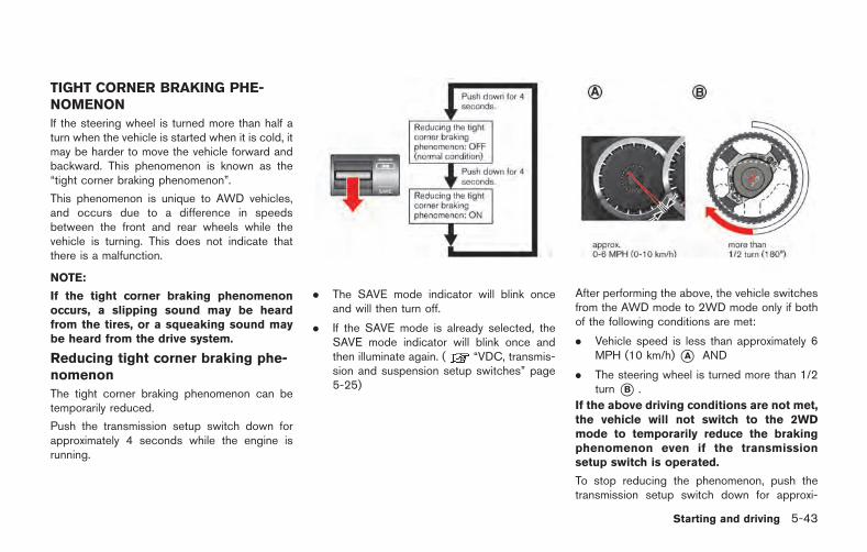
TIGHT CORNER BRAKING PHE-NOMENON
If the steering wheel is turned more than half aturn when the vehicle is started when it is cold, itmay be harder to move the vehicle forward andbackward. This phenomenon is known as the“tight corner braking phenomenon”.
This phenomenon is unique to AWD vehicles,and occurs due to a difference in speedsbetween the front and rear wheels while thevehicle is turning. This does not indicate thatthere is a malfunction.
NOTE:
If the tight corner braking phenomenonoccurs, a slipping sound may be heardfrom the tires, or a squeaking sound maybe heard from the drive system.
Reducing tight corner braking phe-nomenon
The tight corner braking phenomenon can betemporarily reduced.
Push the transmission setup switch down forapproximately 4 seconds while the engine isrunning.
. The SAVE mode indicator will blink onceand will then turn off.
. If the SAVE mode is already selected, theSAVE mode indicator will blink once andthen illuminate again. ( “VDC, transmis-sion and suspension setup switches” page5-25)
After performing the above, the vehicle switchesfrom the AWD mode to 2WD mode only if bothof the following conditions are met:
. Vehicle speed is less than approximately 6MPH (10 km/h) *A AND
. The steering wheel is turned more than 1/2turn *B .
If the above driving conditions are not met,the vehicle will not switch to the 2WDmode to temporarily reduce the brakingphenomenon even if the transmissionsetup switch is operated.
To stop reducing the phenomenon, push thetransmission setup switch down for approxi-
Starting and driving 5-43
5-44 Starting and driving
mately 4 seconds again. The driving mode willswitch to the normal AWD mode.
Reduction of the tight corner braking phenom-enon will be cancelled when:
. the R mode is selected with the transmissionsetup switch
. the SAVE mode is selected with thetransmission setup switch and the OFFmode is selected with the VDC setup switch
. the ignition switch is pushed to the "OFF"position
. the R mode start function is used
WARNING
Do not reduce the tight corner brakingphenomenon when driving on a roadsurface that is slippery or covered insnow, because the driving mode willswitch to 2WD. This may cause tireslipping and may cause a loss of controland result in a collision, personal injuryor death.
TIRES
This vehicle is equipped with special tires. Whenchanging the tires, install the designated specialtires. Replacing tires as a set of four with newones is recommended. However, if a tire ispunctured or damaged, it may be possible toreplace only the damaged tire. Determiningwhether one tire or a complete set of tiresshould be replaced is based on a number offactors including tire wear and condition. Con-tact your GT-R certified NISSAN dealer. Theycan recommend if an individual tire or acomplete set should be replaced.
NOTICE
If tires other than the designated tires,tires with large differences in wear ortires of different sizes are installed, theAWD performance will be degraded andthe drive mechanism may be damaged.
AWD SYSTEM CHARACTERISTICS
The AWD system automatically distributes theoptimal torque to the front and rear wheels. Thisprovides both the superior turning performanceof a rear wheel drive vehicle and the traction of aAWD vehicle.
Electronic control continuously distributes tor-que to the front and rear wheels in the rangefrom 0:100 (rear-wheel drive mode) to 50:50(all-wheel drive mode) to match the drivingconditions and road conditions. This allows theengine output (torque) to be effectively trans-mitted to the road surface.
The rear final drive of this vehicle is equippedwith a 1.5-way mechanical Limited Slip Differ-ential (LSD).
WARNING
Sudden operation of the acceleratorpedal can result in fishtailing or side-slip, possibly causing an accident. Useparticular caution when driving in rainyweather or on slippery roads.
NOTICE
Use the designated differential gear oil.If any oil other than the designated oilis used, the LSD may not operatecorrectly, and noise and vibration mayoccur, possibly resulting in a malfunc-tion.
NOTE:
. If the vehicle accelerates from a stopwith the steering wheel turned in coldtemperatures, the inner wheel tire mayslip and some noise or vibration maybe heard. This phenomenon is uniqueto vehicles equipped with the LSD. This
does not indicate that there is a mal-function.
. The LSD controls the speed differencebetween the left and right wheels, andoptimally allocates torque to thewheels.
. The 1.5-way mechanical LSD in the rearfinal drive of this vehicle is character-ized by its asymmetrical LSD effectswhen the accelerator pedal is ON andwhen it is OFF. This allows the appro-priate amount of torque for the drivingenvironment to be transmitted to theroad surface.
Starting and driving 5-45
LIMITED SLIP DIFFERENTIAL (LSD)
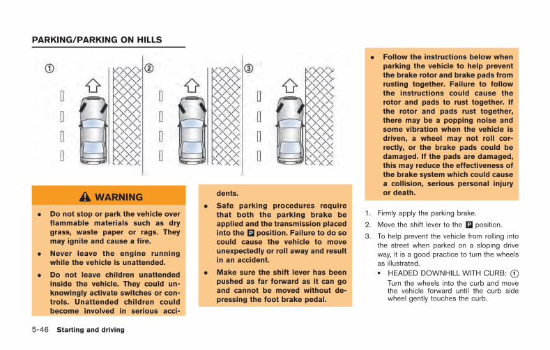
5-46 Starting and driving
WARNING
. Do not stop or park the vehicle overflammable materials such as drygrass, waste paper or rags. Theymay ignite and cause a fire.
. Never leave the engine runningwhile the vehicle is unattended.
. Do not leave children unattendedinside the vehicle. They could un-knowingly activate switches or con-trols. Unattended children couldbecome involved in serious acci-
dents.
. Safe parking procedures requirethat both the parking brake beapplied and the transmission placedinto the &P position. Failure to do socould cause the vehicle to moveunexpectedly or roll away and resultin an accident.
. Make sure the shift lever has beenpushed as far forward as it can goand cannot be moved without de-pressing the foot brake pedal.
. Follow the instructions below whenparking the vehicle to help preventthe brake rotor and brake pads fromrusting together. Failure to followthe instructions could cause therotor and pads to rust together. Ifthe rotor and pads rust together,there may be a popping noise andsome vibration when the vehicle isdriven, a wheel may not roll cor-rectly, or the brake pads could bedamaged. If the pads are damaged,this may reduce the effectiveness ofthe brake system which could causea collision, serious personal injuryor death.
1. Firmly apply the parking brake.
2. Move the shift lever to the &P position.
3. To help prevent the vehicle from rolling intothe street when parked on a sloping driveway, it is a good practice to turn the wheelsas illustrated.. HEADED DOWNHILL WITH CURB: *1
Turn the wheels into the curb and movethe vehicle forward until the curb sidewheel gently touches the curb.
PARKING/PARKING ON HILLS
. HEADED UPHILL WITH CURB: *2Turn the wheels away from the curb andmove the vehicle back until the curb sidewheel gently touches the curb.
. HEADED UPHILL OR DOWNHILL, NOCURB: *3Turn the wheels toward the side of theroad so the vehicle will move away fromthe center of the road if it moves.
4. Push the ignition switch to the LOCKposition.
The GT-R uses brake pad materials that havehigh metallic content. The brake pad materialhelps maintain braking performance in a widerange of weather and driving conditions.
For the first 3,000 - 6,000 miles (5,000 -10,000 km) of the vehicle’s service life, and forthe first 3,000 - 6,000 miles (5,000 - 10,000km) after a brake replacement, the brake pad tobrake rotor clearance is very small. Whenparking, apply the parking brake and move theshift lever to the &P position. Idle the engine formore than 20 seconds without depressing thebrake pedal. This allows the brake pads to moveaway from the rotor so the pad does not contactthe rotor.
Additionally, the brakes must be dry beforeparking the vehicle after driving on wet roads orafter washing the vehicle. If the roads are wet,
lightly apply the brakes for a short distancebefore parking the vehicle to dry the brakes.After washing the vehicle, dry the brakes bydriving on a dry road for a few miles and applythe brakes normally based on traffic and roadconditions.
The metallic brake pads and brake disc rotormay rust together when the brakes are notapplied:
. If the vehicle is not idled for 20 secondswithout the brakes applied, or if the brakesare applied when the vehicle is shut off, therotor and pads can rust together, even whenthe brake pads are dry.
. If the brakes are wet when the vehicle isparked and the parking brake is applied for along time.
Contact a GT-R certified NISSAN dealer if thebrake pads and brake rotor have rustedtogether.
WARNING
If the engine is not running or is turnedoff while driving, the power assist forthe steering will not work. Steering willbe harder to operate.
The power assisted steering uses a hydraulicpump, driven by the engine, to assist steering.
If the engine stops or the drive belt breaks, youwill still have control of the vehicle. However,much greater steering effort is needed, espe-cially in sharp turns and at low speeds.
Starting and driving 5-47
POWER STEERING
5-48 Starting and driving
BRAKING PRECAUTIONS
The brake system has two separate hydrauliccircuits. If one circuit malfunctions, you will stillhave braking at two wheels.
You may feel a small click and hear a soundwhen the brake pedal is fully depressed slowly.This is not a malfunction and indicates that thebrake assist mechanism is operating properly.
Vacuum assisted brakes
The brake booster aids braking by using enginevacuum. If the engine stops, you can stop thevehicle by depressing the brake pedal. However,greater foot pressure on the brake pedal will berequired to stop the vehicle and the stoppingdistance will be longer.
Wet brakes
When the vehicle is washed or driven throughwater, the brakes may get wet. As a result, yourbraking distance will be longer and the vehiclemay pull to one side during braking.
To dry brakes, drive the vehicle at a safe speedwhile lightly tapping the brake pedal to heat-upthe brakes. Do this until the brakes return tonormal. Avoid driving the vehicle at high speedsuntil the brakes function correctly.
Using the brakes
Avoid resting your foot on the brake pedal whiledriving. This will cause overheating of thebrakes, wearing out the brake and pads fasterand reduce gas mileage.
To help reduce brake wear and to prevent thebrakes from overheating, reduce speed anddownshift to a lower gear before going down aslope or long grade. Overheated brakes mayreduce braking performance and could result inloss of vehicle control.
WARNING
. While driving on a slippery surface,be careful when braking, accelerat-ing or downshifting. Abrupt brakingor accelerating could cause thewheels to skid and result in anaccident.
. If the engine is not running or isturned off while driving, the powerassist for the brakes will not work.Braking will be harder.
PARKING BRAKE BREAK-IN
Break in the parking brake shoes whenever thestopping effect of the parking brake is weakenedor whenever the parking brake shoes and/ordrums/rotors are replaced, in order to assure thebest braking performance.
This procedure is described in the vehicleservice manual and can be performed by aGT-R certified NISSAN dealer.
BRAKE SYSTEM
ANTI-LOCK BRAKING SYSTEM(ABS)
WARNING
. The Anti-lock Braking System (ABS)is a sophisticated device, but itcannot prevent accidents resultingfrom careless or dangerous drivingtechniques. It can help maintainvehicle control during braking onslippery surfaces. Remember thatstopping distances on slippery sur-faces will be longer than on normalsurfaces even with ABS. Stoppingdistances may also be longer onrough, gravel or snow coveredroads, or if you are using tire chains.Always maintain a safe distancefrom the vehicle in front of you.Ultimately, the driver is responsiblefor safety.
. Tire type and condition may alsoaffect braking effectiveness. Whenreplacing tires, install the specifiedsize of tires on all four wheels.
The Anti-lock Braking System (ABS) controlsthe brakes so the wheels do not lock during hardbraking or when braking on slippery surfaces.The system detects the rotation speed at eachwheel and varies the brake fluid pressure toprevent each wheel from locking and sliding. Bypreventing each wheel from locking, the systemhelps the driver maintain steering control andhelps to minimize swerving and spinning onslippery surfaces.
Using the system
Depress the brake pedal and hold it down.Depress the brake pedal with firm steadypressure, but do not pump the brakes. TheABS will operate to prevent the wheels fromlocking up. Steer the vehicle to avoid obstacles.
WARNING
Do not pump the brake pedal. Doing somay result in increased stopping dis-tances.
Self-test feature
The ABS includes electronic sensors, electricpumps, hydraulic solenoids and a computer. Thecomputer has a built-in diagnostic feature thattests the system each time you start the engine
and move the vehicle at a low speed in forwardor reverse. When the self-test occurs, you mayhear a “clunk” noise and/or feel a pulsation in thebrake pedal. This does not indicate that there isa malfunction. If the computer senses a mal-function, it switches the ABS off and illuminatesthe ABS warning light on the instrument panel.The brake system then operates normally, butwithout anti-lock assistance.
If the ABS warning light illuminates during theself-test or while driving, have the vehiclechecked by a GT-R certified NISSAN dealer.
Normal operation
The ABS operates at speeds above 3 to 6 MPH(5 to 10 km/h). The speed varies according toroad conditions.
When the ABS senses that one or more wheelsare close to locking up, the actuator rapidlyapplies and releases hydraulic pressure. Thisaction is similar to pumping the brakes veryquickly. You may feel a pulsation in the brakepedal and hear a noise from under the hood orfeel a vibration from the actuator when it isoperating. This is normal and indicates that theABS is operating properly. However, the pulsa-tion may indicate that road conditions arehazardous and extra care is required whiledriving.
Starting and driving 5-49
BRAKE ASSIST
5-50 Starting and driving
The Vehicle Dynamic Control (VDC) systemuses various sensors to monitor driver inputsand vehicle motion. Under certain driving con-ditions, the VDC system helps to perform thefollowing functions.
. Controls brake pressure to reduce wheelslip on one slipping drive wheel so power istransferred to a non slipping drive wheel onthe same axle.
. Controls brake pressure and engine outputto reduce drive wheel slip based on vehiclespeed (traction control function).
. Controls brake pressure at individual wheelsand engine output to help the driver maintaincontrol of the vehicle in the followingconditions:
— understeer (vehicle tends to not followthe steered path despite increasedsteering input)
— oversteer (vehicle tends to spin due tocertain road or driving conditions).
The VDC system can help the driver to maintaincontrol of the vehicle, but it cannot prevent lossof vehicle control in all driving situations.
When the VDC system operates, the VDCwarning light in the instrument panel flashesso note the following:
. The road may be slippery or the system maydetermine some action is required to helpkeep the vehicle on the steered path.
. You may feel a pulsation in the brake pedaland hear a noise or vibration from under thehood. This is normal and indicates that theVDC system is working properly.
. Adjust your speed and driving to the roadconditions.
. The VDC mode can be changed using theVDC setup switch. ( “VDC, transmis-sion and suspension setup switches” page5-25)
( “Vehicle Dynamic Control (VDC) warninglight” page 2-31, “Vehicle Dynamic Con-trol (VDC) off indicator light” page 2-32)
If a malfunction occurs in the system, the VDCwarning light illuminates in the instrumentpanel. The VDC system automatically turns off.
The VDC setup switch is used to turn off theVDC system. The VDC off indicatorilluminates to indicate the VDC system is off.
When the VDC setup switch is used to turn offthe system, the VDC system still operates toprevent one drive wheel from slipping bytransferring power to a non slipping drive wheel.The VDC warning light flashes if thisoccurs. All other VDC functions are off and the
VDC warning light will not flash. The VDCsystem is automatically reset to on when theignition switch is placed in the off position thenback to the on position.
( “Vehicle Dynamic Control (VDC) warninglight” page 2-31, “Vehicle Dynamic Con-trol (VDC) off indicator light” page 2-32)
The computer has a built-in diagnostic featurethat tests the system each time you start theengine and move the vehicle forward or inreverse at a slow speed. When the self-testoccurs, you may hear a “clunk” noise and/or feela pulsation in the brake pedal. This is normal andis not an indication of a malfunction.
WARNING
. The VDC system is designed to helpthe driver maintain stability butdoes not prevent accidents due toabrupt steering operation at highspeeds or by careless or dangerousdriving techniques. Reduce vehiclespeed and be especially carefulwhen driving and cornering on slip-pery surfaces and always drive care-fully.
. Do not modify the vehicle’s suspen-sion. If suspension parts such as
VEHICLE DYNAMIC CONTROL (VDC)SYSTEM
shock absorbers, struts, springs,stabilizer bars, bushings andwheels are not NISSAN approvedor are extremely deteriorated, theVDC system may not operate prop-erly. This could adversely affectvehicle handling performance, andthe VDC warning light mayilluminate.
. If brake related parts such as brakepads, rotors and calipers are notstandard equipment or are extre-mely deteriorated, the VDC systemmay not operate properly and theVDC warning light may illumi-nate.
. If engine control related parts arenot standard equipment or are ex-tremely deteriorated, the VDC warn-ing light may illuminate.
. When driving on extremely inclinedsurfaces such as higher bankedcorners, the VDC system may notoperate properly and the VDC warn-ing light may illuminate. Do notdrive on these types of roads.
. When driving on an unstable sur-face such as a turntable, ferry,
elevator or ramp, the VDC warninglight may illuminate. This is nota malfunction. Restart the engineafter driving onto a stable surface.
. If wheels or tires other than thethose recommended are used, theVDC system may not operate prop-erly and the VDC warning lightmay illuminate.
. The VDC system is not a substitutefor winter tires or tire chains on asnow covered road.
NOTE:
. Always make sure the VDC is ONbefore driving the vehicle by checkingthat the VDC OFF indicator lights onthe meter and the VDC set-up switchare not illuminated.
The GT-R is a high performance vehicleand the VDC must be on/activated toprovide proper powertrain operationand intended drivability.
WARNING
. The VDC OFF mode should ONLY beused briefly to help free the vehicleif stuck in snow or mud by tempora-rily stopping operation of the VDCto maintain wheel torque.
. Driving the GT-R with the VDC offmay lead to handling issues relatedto steering maneuvers, acceleration,or deceleration. Moreover, drivingwith the VDC off can result in aninoperative vehicle by causing ser-ious damage to the powertrain,including damage to the TransaxleAssembly including Transfer, Clutch,Gears, Transaxle case and all of itscomponents and other drivetraincomponent(s) by overheating or ex-cessive force.
. Damage to the powertrain or anydrivetrain component(s) that occurswhen there is a record in the VehicleStatus Data Recorder (VSDR) thatthe vehicle was driven with VDC offduring the period when the damagewas incurred is excluded from war-ranty coverage.
Starting and driving 5-51
5-52 Starting and driving
See your 2015 Warranty Information Booklet forimportant related information and warrantycoverage exclusions. See also section 2( “Transmission warning light” page 2-30)and section 5 ( “Vehicle Dynamic Control(VDC) system” page 5-50) of this Owner’sManual, “Transmission Clutch TemperatureHigh” and “Vehicle Dynamic Control (VDC)System” for important additional related informa-tion.
. Except for the emergency cases above,any issues related to driving stability(e.g., steering maneuvers and maneu-vers during acceleration and decelera-tion) and any damages to drivetraincomponents (e.g., transfer, clutch, asort of gear, transaxle case) will notbe covered by warranty if there is arecord in the Vehicle Status DataRecorder (VSDR) that the vehicle wasdriven with VDC off.
. When attempting to free the vehiclefrom mud or fresh snow, the VDC willdetect the tire slipping, and the enginespeed may not increase even when theaccelerator pedal is depressed. To raisethe engine speed, use the VDC set upswitch to turn the VDC system OFF andselect SAVE mode with the transmis-
sion switch. ( “VDC, transmissionand suspension setup switches” page5-25)
. When the VDC system is turned OFF,all VDC functions (including tractioncontrol), except for the ABS functions,are deactivated.
FREEING A FROZEN DOOR LOCK
To prevent a door lock from freezing, applydeicer through the key hole. If the lock becomesfrozen, heat the key before inserting it into thekey hole or use the Intelligent Key system.
ANTI-FREEZE
In the winter when it is anticipated that theoutside temperature will drop below 328F (08C),check antifreeze to assure proper winter protec-tion. ( “Engine cooling system” page 8-10)
BATTERY
If the battery is not fully charged duringextremely cold weather conditions, the batteryfluid may freeze and damage the battery. Tomaintain maximum efficiency, the battery shouldbe checked regularly. ( “Battery” page 8-17)
DRAINING OF COOLANT WATER
If the vehicle is to be left outside withoutantifreeze, drain the cooling system, includingthe engine block. Refill before operating thevehicle. For details, contact a GT-R certifiedNISSAN dealer.
COLD WEATHER DRIVING
TIRE EQUIPMENT
The GT-R summer tires are made from aspecially formulated rubber to maximize thevehicle’s performance capabilities. Performanceof summer tires is substantially reduced whentemperatures are less than 328F (08C) so youmust drive carefully. NISSAN recommends theuse of winter or all-season tires on all fourwheels if you plan to operate your vehicle insnowy or icy conditions when temperatures areless than 328F (08C).
WARNING
Never use summer tires when thetemperature is below 48F ( 208C) toprevent permanent tread deformationwhich may cause tire damage or tirefailure. This may cause a loss of vehiclecontrol which can result in seriouspersonal injury or death.
Tire chains may be used. ( “Tire chains”page 8-40)
If you install tires, they must also be the specifiedsize, brand, construction and tread pattern on allfour wheels.
SPECIAL WINTER EQUIPMENT
It is recommended that the following items becarried in the vehicle during winter:
. A scraper and stiff-bristled brush to removeice and snow from the windows and wiperblades.
. A sturdy, flat board to be placed under thejack to give it firm support.
. A shovel to dig the vehicle out of snowdrifts.
. Extra window washer fluid to refill thereservoir tank.
DRIVING ON SNOW OR ICE
WARNING
. Wet ice (328F, 08C and freezing rain),very cold snow or ice can be slickand very hard to drive on. Thevehicle will have much less tractionor “grip” under these conditions. Tryto avoid driving on wet ice until theroad is salted or sanded.
. Whatever the condition, drive withcaution. Accelerate and slow downwith care. If accelerating or down-shifting too fast, the drive wheelswill lose even more traction.
. Allow more stopping distance underthese conditions. Braking should bestarted sooner than on dry pave-ment.
. Allow greater following distanceson slippery roads.
. Watch for slippery spots (glare ice).These may appear on an otherwiseclear road in shaded areas. If apatch of ice is seen ahead, brakebefore reaching it. Try not to brakewhile on the ice, and avoid anysudden steering maneuvers.
. Do not use the cruise control onslippery roads.
. Snow can trap dangerous exhaustgases under your vehicle. Keepsnow clear of the exhaust pipe andfrom around your vehicle.
NOTE:
When driving on snow, select the SAVEmode with the setup switch. By selectingthe SAVE mode, the engine output iscontrolled appropriately for snow or slip-pery road surfaces. This enables the vehi-cle to start or accelerate smoothly.
Starting and driving 5-53
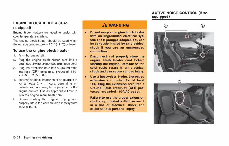
5-54 Starting and driving
ENGINE BLOCK HEATER (if soequipped)
Engine block heaters are used to assist withcold temperature starting.
The engine block heater should be used whenthe outside temperature is 208F ( 78C) or lower.
To use the engine block heater
1. Turn the engine off.
2. Plug the engine block heater cord into agrounded 3-wire, 3-pronged extension cord.
3. Plug the extension cord into a Ground FaultInterrupt (GFI) protected, grounded 110-volt AC (VAC) outlet.
4. The engine block heater must be plugged infor at least 2 - 4 hours, depending onoutside temperatures, to properly warm theengine coolant. Use an appropriate timer toturn the engine block heater on.
5. Before starting the engine, unplug andproperly store the cord to keep it away frommoving parts.
WARNING
. Do not use your engine block heaterwith an ungrounded electrical sys-tem or a 2-pronged adapter. You canbe seriously injured by an electricalshock if you use an ungroundedconnection.
. Disconnect and properly store theengine block heater cord beforestarting the engine. Damage to thecord could result in an electricalshock and can cause serious injury.
. Use a heavy-duty 3-wire, 3-prongedextension cord rated for at least10A. Plug the extension cord into aGround Fault Interrupt (GFI) pro-tected, grounded 110-VAC outlet.
Failure to use the proper extensioncord or a grounded outlet can resultin a fire or electrical shock andcause serious personal injury.
ACTIVE NOISE CONTROL (if soequipped)
This system uses the front and rear microphones*1 to detect engine booming noise. The systemthen automatically generates a noise cancellingsound through the speakers *2 and woofer*3to reduce engine booming noise.
The front and rear microphones *1 are locatedinside of the roof.
The front speakers are located on the doors andthe woofer is located in between the rear seats.
NOTE:
To operate the active noise control prop-erly:
. Do not cover the speakers or woofer.
. Do not cover the microphones.
. Do not change or modify speakers includingthe woofer and any audio related parts suchas the amplifier.
. Do not make any modification includingsound deadening or modifications aroundthe microphones, speakers or woofer.
Starting and driving 5-55

5-56 Starting and driving
MEMO
6 In case of emergency
Hazard warning flasher switch ............................................. 6-2Roadside assistance program .............................................. 6-2Emergency engine shut off .................................................... 6-3Flat tire ........................................................................................ 6-3
Tire Pressure Monitoring System (TPMS) ................... 6-3Run-flat tires ........................................................................ 6-4
Jump starting ............................................................................ 6-5Push starting ............................................................................. 6-7If your vehicle overheats ........................................................ 6-8Towing your vehicle ................................................................ 6-9
Towing recommended by NISSAN ............................. 6-9Vehicle recovery (freeing a stuck vehicle) .............. 6-10
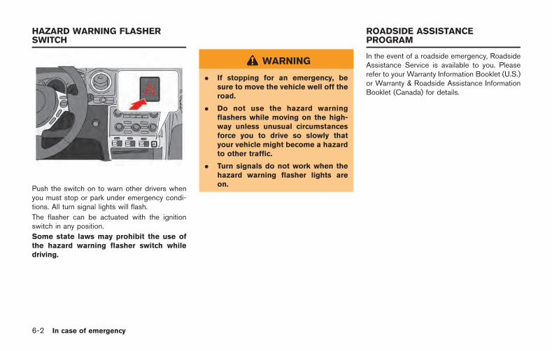
6-2 In case of emergency
Push the switch on to warn other drivers whenyou must stop or park under emergency condi-tions. All turn signal lights will flash.
The flasher can be actuated with the ignitionswitch in any position.
Some state laws may prohibit the use ofthe hazard warning flasher switch whiledriving.
WARNING
. If stopping for an emergency, besure to move the vehicle well off theroad.
. Do not use the hazard warningflashers while moving on the high-way unless unusual circumstancesforce you to drive so slowly thatyour vehicle might become a hazardto other traffic.
. Turn signals do not work when thehazard warning flasher lights areon.
In the event of a roadside emergency, RoadsideAssistance Service is available to you. Pleaserefer to your Warranty Information Booklet (U.S.)or Warranty & Roadside Assistance InformationBooklet (Canada) for details.
HAZARD WARNING FLASHERSWITCH
ROADSIDE ASSISTANCEPROGRAM
To shut off the engine in an emergency situationwhile driving, perform the following procedure:
. Rapidly push the push-button ignition switch3 consecutive times in less than 1.5seconds, or
. Push and hold the push-button ignitionswitch for more than 2 seconds.
TIRE PRESSURE MONITORINGSYSTEM (TPMS)
This vehicle is equipped with the Tire PressureMonitoring System (TPMS). It monitors tirepressure of all tires. When the low tire pressurewarning light is lit, one or more of your tires issignificantly under-inflated. If the vehicle is beingdriven with low tire pressure, the TPMS willactivate and warn you of it by the low tirepressure warning light (in the instrument panel)or the warning message (on the display). Thissystem will activate only when the vehicle isdriven at speeds above 16 MPH (25 km/h).( “Low tire pressure warning light” page 2-27) ( “Tire Pressure Monitoring System(TPMS)” page 5-4)
WARNING
. If the low tire pressure warning lightilluminates while driving, avoid sud-den steering maneuvers or abruptbraking, reduce vehicle speed, pulloff the road to a safe location andstop the vehicle as soon as possi-ble. Driving with under-inflated tiresmay permanently damage the tiresand increase the likelihood of tirefailure. Serious vehicle damage
could occur and may lead to anaccident and could result in seriouspersonal injury. Check the tire pres-sure for all four tires. Adjust the tirepressure to the recommended COLDtire pressure shown on the Tire andLoading Information label to turnthe low tire pressure warning lightoff. If the light still illuminates whiledriving after adjusting the tire pres-sure, a tire may be flat.
. When a wheel is replaced, the TPMSwill not function and the low tirepressure warning light will flash forapproximately 1 minute. The lightwill remain on after 1 minute. Con-tact a GT-R certified NISSAN dealeras soon as possible for tire replace-ment and/or system resetting.
. Replacing tires with those not ori-ginally specified by NISSAN couldaffect the proper operation of theTPMS.
. Do not inject any tire liquid oraerosol tire sealant into the tires,as this may cause a malfunction ofthe tire pressure sensors.
In case of emergency 6-3
EMERGENCY ENGINE SHUT OFF FLAT TIRE
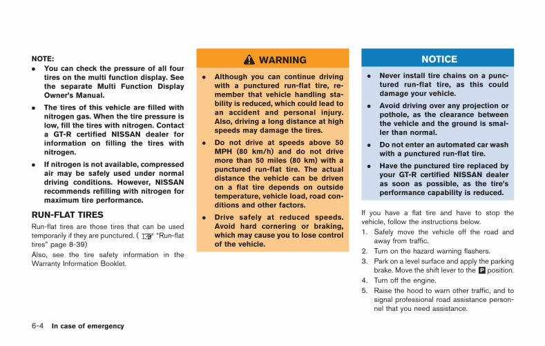
6-4 In case of emergency
NOTE:
. You can check the pressure of all fourtires on the multi function display. Seethe separate Multi Function DisplayOwner’s Manual.
. The tires of this vehicle are filled withnitrogen gas. When the tire pressure islow, fill the tires with nitrogen. Contacta GT-R certified NISSAN dealer forinformation on filling the tires withnitrogen.
. If nitrogen is not available, compressedair may be safely used under normaldriving conditions. However, NISSANrecommends refilling with nitrogen formaximum tire performance.
RUN-FLAT TIRES
Run-flat tires are those tires that can be usedtemporarily if they are punctured. ( “Run-flattires” page 8-39)
Also, see the tire safety information in theWarranty Information Booklet.
WARNING
. Although you can continue drivingwith a punctured run-flat tire, re-member that vehicle handling sta-bility is reduced, which could lead toan accident and personal injury.Also, driving a long distance at highspeeds may damage the tires.
. Do not drive at speeds above 50MPH (80 km/h) and do not drivemore than 50 miles (80 km) with apunctured run-flat tire. The actualdistance the vehicle can be drivenon a flat tire depends on outsidetemperature, vehicle load, road con-ditions and other factors.
. Drive safely at reduced speeds.Avoid hard cornering or braking,which may cause you to lose controlof the vehicle.
NOTICE
. Never install tire chains on a punc-tured run-flat tire, as this coulddamage your vehicle.
. Avoid driving over any projection orpothole, as the clearance betweenthe vehicle and the ground is smal-ler than normal.
. Do not enter an automated car washwith a punctured run-flat tire.
. Have the punctured tire replaced byyour GT-R certified NISSAN dealeras soon as possible, as the tire’sperformance capability is reduced.
If you have a flat tire and have to stop thevehicle, follow the instructions below.
1. Safely move the vehicle off the road andaway from traffic.
2. Turn on the hazard warning flashers.
3. Park on a level surface and apply the parkingbrake. Move the shift lever to the&P position.
4. Turn off the engine.
5. Raise the hood to warn other traffic, and tosignal professional road assistance person-nel that you need assistance.
6. Have all passengers get out of the vehicleand stand in a safe place, away from trafficand clear of the vehicle.
For the tire removing procedure, see thefollowing section. ( “Jacking vehicle andremoving wheels” page 8-43)
The following circumstances indicate that thebattery is discharged.
. The starter motor does not turn or it turnsweakly and the engine does not start.
. The vehicle lights are much dimmer thanusual.
. The sound of the horn is weak. The hornmakes no sound.
NOTICE
When the battery is discharged, do notclose either of the front doors. Theautomatic window adjusting functionwill not work, and the side roof panelmay be damaged.
To start your engine with a booster battery, theinstructions and precautions below must befollowed.
For the battery maintenance information, see thefollowing section. ( “Battery” page 8-17)
WARNING
. If done incorrectly, jump startingcan lead to a battery explosion,resulting in severe injury or death.It could also damage your vehicle.
. Explosive hydrogen gas is alwayspresent in the vicinity of the battery.Keep all sparks and flames awayfrom the battery.
. Do not allow battery fluid to comeinto contact with eyes, skin, clothingor painted surfaces. Battery fluid isa corrosive sulphuric acid solutionwhich can cause severe burns. If thefluid should come into contact withanything, immediately flush the con-tacted area with water.
. Keep the battery out of the reach ofchildren.
. The booster battery must be rated at12 volts. Use of an improperly ratedbattery can damage your vehicle.
. Whenever working on or near abattery, always wear suitable eyeprotectors (for example, goggles orindustrial safety spectacles) and
In case of emergency 6-5
JUMP STARTING
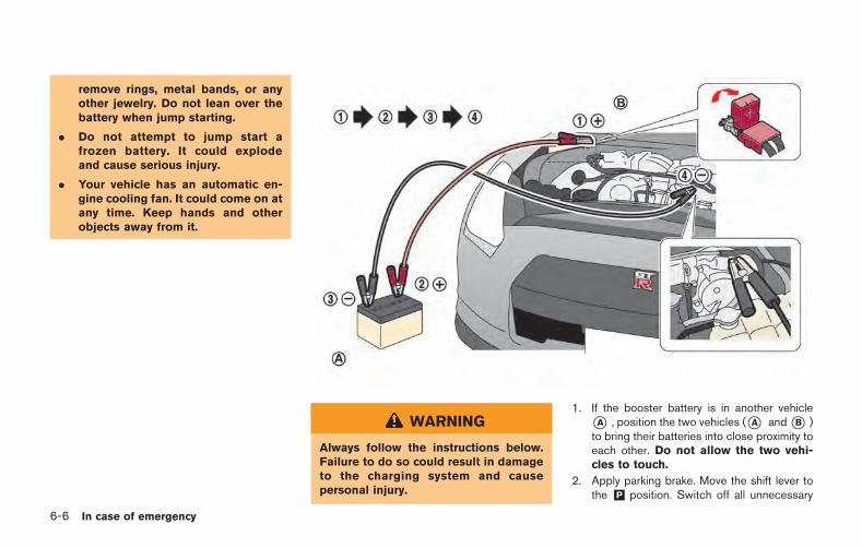
6-6 In case of emergency
remove rings, metal bands, or anyother jewelry. Do not lean over thebattery when jump starting.
. Do not attempt to jump start afrozen battery. It could explodeand cause serious injury.
. Your vehicle has an automatic en-gine cooling fan. It could come on atany time. Keep hands and otherobjects away from it.
WARNING
Always follow the instructions below.Failure to do so could result in damageto the charging system and causepersonal injury.
1. If the booster battery is in another vehicle*A , position the two vehicles (*A and*B )to bring their batteries into close proximity toeach other. Do not allow the two vehi-cles to touch.
2. Apply parking brake. Move the shift lever tothe &P position. Switch off all unnecessary
electrical systems (light, heater, air condi-tioner, etc.).
3. Remove the battery cover. Cover the batterywith a firmly wrung out moist cloth to reduceexplosion hazard.
4. Connect jumper cables in the sequence asillustrated (*1 ? *2 ? *3 ? *4 ).
If the battery is disconnected or dis-charged, the steering wheel will lockand cannot be turned. Supply powerusing jumper cables before pushingthe ignition switch and disengagingthe steering lock.
CAUTION
. Always connect positive (+) to posi-tive (+) and negative ( ) to bodyground (as illustrated), not to thebattery.
. Make sure that the jumper cablesdo not touch moving parts in theengine compartment and thatclamps do not contact any othermetal.
5. Start the engine of the booster vehicle *Aand let it run for a few minutes.
6. Keep the engine speed of the boostervehicle *A at about 2,000 rpm, and startthe engine of the vehicle being jump started*B .
NOTE:Do not keep the starter motor engagedfor more than 10 seconds. If the enginedoes not start right away, push theignition switch to the OFF position andwait 10 seconds before trying again.
7. After starting your engine, carefully discon-nect the negative cable and then the positivecable (*4 ? *3 ? *2 ? *1 ).
8. Be sure to dispose of the cloth used tocover the vent holes as it may be contami-nated with corrosive acid.
9. Put the battery cover on.
NOTE:
If the clamp clip is difficult to connect tothe battery terminal, remove the cowl topcover to make it easier. ( “Removingthe cowl top cover” page 8-9)
Do not attempt to start the engine by pushing.
NOTICE
Your NISSAN cannot be push-started ortow-started. Attempting to do so maycause transmission damage.
In case of emergency 6-7
PUSH STARTING
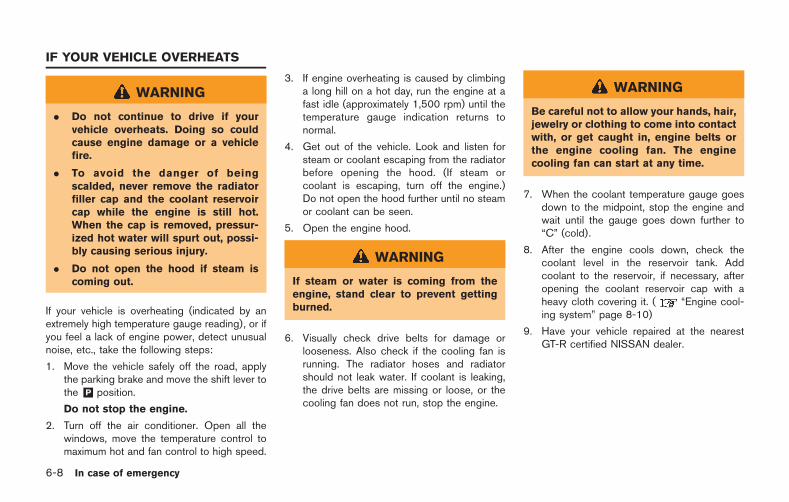
6-8 In case of emergency
WARNING
. Do not continue to drive if yourvehicle overheats. Doing so couldcause engine damage or a vehiclefire.
. To avoid the danger of beingscalded, never remove the radiatorfiller cap and the coolant reservoircap while the engine is still hot.When the cap is removed, pressur-ized hot water will spurt out, possi-bly causing serious injury.
. Do not open the hood if steam iscoming out.
If your vehicle is overheating (indicated by anextremely high temperature gauge reading), or ifyou feel a lack of engine power, detect unusualnoise, etc., take the following steps:
1. Move the vehicle safely off the road, applythe parking brake and move the shift lever tothe &P position.
Do not stop the engine.
2. Turn off the air conditioner. Open all thewindows, move the temperature control tomaximum hot and fan control to high speed.
3. If engine overheating is caused by climbinga long hill on a hot day, run the engine at afast idle (approximately 1,500 rpm) until thetemperature gauge indication returns tonormal.
4. Get out of the vehicle. Look and listen forsteam or coolant escaping from the radiatorbefore opening the hood. (If steam orcoolant is escaping, turn off the engine.)Do not open the hood further until no steamor coolant can be seen.
5. Open the engine hood.
WARNING
If steam or water is coming from theengine, stand clear to prevent gettingburned.
6. Visually check drive belts for damage orlooseness. Also check if the cooling fan isrunning. The radiator hoses and radiatorshould not leak water. If coolant is leaking,the drive belts are missing or loose, or thecooling fan does not run, stop the engine.
WARNING
Be careful not to allow your hands, hair,jewelry or clothing to come into contactwith, or get caught in, engine belts orthe engine cooling fan. The enginecooling fan can start at any time.
7. When the coolant temperature gauge goesdown to the midpoint, stop the engine andwait until the gauge goes down further to“C” (cold).
8. After the engine cools down, check thecoolant level in the reservoir tank. Addcoolant to the reservoir, if necessary, afteropening the coolant reservoir cap with aheavy cloth covering it. ( “Engine cool-ing system” page 8-10)
9. Have your vehicle repaired at the nearestGT-R certified NISSAN dealer.
IF YOUR VEHICLE OVERHEATS
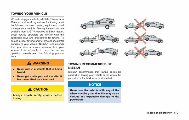
When towing your vehicle, all State (Provincial inCanada) and local regulations for towing mustbe followed. Incorrect towing equipment coulddamage your vehicle. Towing instructions areavailable from a GT-R certified NISSAN dealer.Local service operators are familiar with theapplicable laws and procedures for towing. Toassure proper towing and to prevent accidentaldamage to your vehicle, NISSAN recommendsthat you have a service operator tow yourvehicle. It is advisable to have the serviceoperator carefully read the following precau-tions.
WARNING
. Never ride in a vehicle that is beingtowed.
. Never get under your vehicle after ithas been lifted by a tow truck.
CAUTION
Always attach safety chains beforetowing.
TOWING RECOMMENDED BYNISSAN
NISSAN recommends that towing dollies beused when towing your vehicle or the vehicle beplaced on a flat bed truck as illustrated.
NOTICE
Never tow the vehicle with any of thewheels on the ground as this may causeserious and expensive damage to thepowertrain.
In case of emergency 6-9
TOWING YOUR VEHICLE
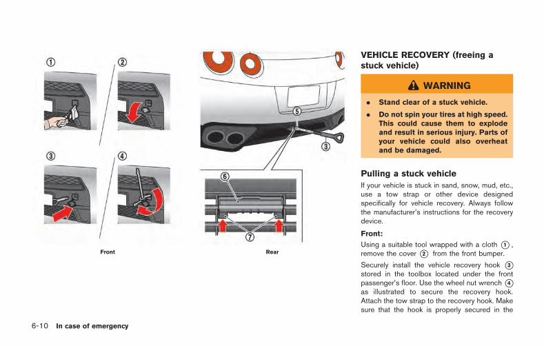
6-10 In case of emergency
Front Rear
VEHICLE RECOVERY (freeing astuck vehicle)
WARNING
. Stand clear of a stuck vehicle.
. Do not spin your tires at high speed.This could cause them to explodeand result in serious injury. Parts ofyour vehicle could also overheatand be damaged.
Pulling a stuck vehicle
If your vehicle is stuck in sand, snow, mud, etc.,use a tow strap or other device designedspecifically for vehicle recovery. Always followthe manufacturer’s instructions for the recoverydevice.
Front:
Using a suitable tool wrapped with a cloth *1 ,remove the cover *2 from the front bumper.
Securely install the vehicle recovery hook *3stored in the toolbox located under the frontpassenger’s floor. Use the wheel nut wrench*4as illustrated to secure the recovery hook.Attach the tow strap to the recovery hook. Makesure that the hook is properly secured in the
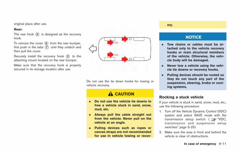
original place after use.
Rear:
The rear hook *5 is designed as the recoveryhook.
To remove the cover *6 from the rear bumper,first push in the tabs *7 until they unlatch andthen pull the cover.
Securely install the recovery hook *3 to theattaching mount located on the rear bumper.
Make sure that the recovery hook is properlysecured in its storage location after use.
Do not use the tie down hooks for towing orvehicle recovery.
CAUTION
. Do not use the vehicle tie downs tofree a vehicle stuck in sand, snow,mud, etc.
. Always pull the cable straight outfrom the vehicle. Never pull on thevehicle at an angle.
. Pulling devices such as ropes orcanvas straps are not recommendedfor use in vehicle towing or recov-
ery.
NOTICE
. Tow chains or cables must be at-tached only to the vehicle recoveryhooks or main structural membersof the vehicle. Otherwise, the vehi-cle body will be damaged.
. Never tow a vehicle using the vehi-cle tie downs or recovery hooks.
. Pulling devices should be routed sothey do not touch any part of thesuspension, steering, brake or cool-ing systems.
Rocking a stuck vehicle
If your vehicle is stuck in sand, snow, mud, etc.,use the following procedure:
1. Turn off the Vehicle Dynamic Control (VDC)system and select SAVE mode with thetransmission setup switch. ( “VDC,transmission and suspension setupswitches” page 5-25)
2. Make sure the area in front and behind thevehicle is clear of obstructions.
In case of emergency 6-11
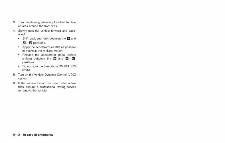
6-12 In case of emergency
3. Turn the steering wheel right and left to clearan area around the front tires.
4. Slowly rock the vehicle forward and back-ward.. Shift back and forth between the &R and
&A &M positions.. Apply the accelerator as little as possible
to maintain the rocking motion.. Release the accelerator pedal before
shifting between the &R and &A &Mpositions.
. Do not spin the tires above 35 MPH (55km/h).
5. Turn on the Vehicle Dynamic Control (VDC)system.
6. If the vehicle cannot be freed after a fewtries, contact a professional towing serviceto remove the vehicle.
7 Appearance and care
Cleaning exterior ...................................................................... 7-2Matte paint care (if so equipped) .................................. 7-2Washing ................................................................................ 7-3Waxing .................................................................................. 7-4Removing spots .................................................................. 7-4Underbody ............................................................................ 7-5Glass ..................................................................................... 7-5Wheels .................................................................................. 7-5Chrome parts ...................................................................... 7-5Outside door handles ....................................................... 7-6Tire dressing ........................................................................ 7-6
Dry carbon fiber parts (if so equipped) ..................... 7-6Cleaning interior ...................................................................... 7-7
Air fresheners .................................................................... 7-7Floor mats .......................................................................... 7-8Seat belts ........................................................................... 7-8
Corrosion protection ............................................................... 7-9Most common factors contributing tovehicle corrosion .............................................................. 7-9Environmental factors influence the rateof corrosion ....................................................................... 7-9To protect your vehicle from corrosion ................... 7-10
7-2 Appearance and care
In order to maintain the appearance of yourvehicle, it is important to take proper care of it.
To protect the paint surfaces, wash your vehicleas soon as you can:
. after a rainfall to prevent possible damagefrom acid rain
. after driving on coastal roads
. when contaminants such as soot, birddroppings, tree sap, metal particles or bugsget on the paint surface
. when dust or mud builds up on the surface
Whenever possible, store or park your vehicleinside a garage or in a covered area.
When it is necessary to park outside, park in ashady area or protect the vehicle with a bodycover.
Be careful not to scratch the paint surfacewhen putting on or removing the bodycover.
MATTE PAINT CARE (if so equipped)
If your vehicle is equipped with matte paint,special care is necessary to clean your vehicle tomaintain the appearance of the matte paint.
CAUTION
Failure to follow the proper matte paintcare instructions can permanently af-fect the appearance of the paint. Im-proper care can result in shiny spots,rub marks or other damage. This da-mage can only be repaired at a bodyshop trained in matte paint repair.Damage resulting from improper mattepaint care is not covered under NIS-SAN’s new vehicle limited warranty.
. Do not use an automatic car wash.
. Do not rub the paint.
. Only use cleaners and soaps thatare specifically formulated for mattepaint.
. Do not use terry cloth towels towash or dry the vehicle.
. Do not rub repeatedly with anycleaning material to minimize therisk of burnishing a shiny spot.
. Hand wash with a wet microfibercloth, dry with clean damp chamois,and use light pressure with a micro-fiber towel. Minimize the pressureyou use.
. Test all cleaning products on ahidden part of the vehicle (such asunder the rocker sills) to makecertain they do not affect the ap-pearance of the matte paint.
. Pre-rinse the vehicle before wash-ing to remove coarse dirt that canscratch the paint.
. Do not wash using a pressurewasher.
. Spot treat heavy dirt accumulationwith a cleaner made for matte paint.
. Do not use solvent based tar andbug remover products to clean thevehicle.
. Do not use waxes and sealers, eventhose specifically formulated formatte paint. These products mayaffect the appearance (add shine)of the matte paint.
CLEANING EXTERIOR
Washing
Hand wash the vehicle for best results. Park thevehicle in a cool, shaded area, out of directsunlight. Read these procedures and gather thenecessary equipment and supplies beforewashing the vehicle.
Equipment/Supplies:
. Vehicle soap specifically made for mattepaint
. Microfiber cloth
. Chamois cloth, for drying
. Two buckets with grit guards or dirt separa-tors (available at many automotive supply ordetaining supply sources).
1. Clean the wheels.. Use a product specifically formulated to
clean wheels.. Do not get any wheel cleaner on the
paint. Immediately wash and rinse thepaint if any wheel clear contacts thepaint.
. Do not use the same cleaning materialsto clean the wheels and paint.
2. Fill the buckets.. Fill one bucket (with dirt separator grid at
the bottom) with vehicle soap specificallymade for matte paint and water. Follow
the soap manufacturer’s instructions.. Fill the second bucket with clean water
for rinsing the wash cloth.. Always rinse the wash cloth in the clean
water before putting the wash cloth intothe cleaning solution.
3. Inspect the car for areas with heavy soilingor spots and, if necessary, treat these areasfirst, before washing the entire vehicle.
4. Remove large pieces of dirt by spraying thevehicle with a hose.
5. Soak the wash cloth in the soap solution andwash the vehicle lightly. Work in smallsections from the bottom of the vehicle tothe top.. Wash a section then rinse the soapy
section of the vehicle completely beforestarting another section.
. Keep the clean sections of the vehiclewet as the remaining sections are com-pleted.
6. Use a clean damp chamois to dry the vehiclebefore it air dries. If the undried surfacesstart to air dry, redampen those areas.. Do not allow surface to air dry. Air drying
allows water spots to form.
WASHING
Wash dirt off the vehicle with a wet sponge andplenty of water. Clean the vehicle thoroughlyusing a mild soap, a special vehicle soap orgeneral purpose dishwashing liquid mixed withclean, lukewarm (never hot) water.
NOTICE
. Do not use an automatic car wash.The rear spoiler may be damaged.
. Do not use car washes that use acidin the detergent. Some car washes,especially brushless ones, use someacid for cleaning. The acid may reactwith some plastic vehicle compo-nents, causing them to crack. Thiscould affect their appearance, andalso could cause them not to func-tion properly. Always check withyour car wash to confirm that acidis not used.
. Do not wash the vehicle with stronghousehold soap, strong chemicaldetergents, gasoline or solvents.
. Do not wash the vehicle in directsunlight or while the vehicle body ishot, as the surface may become
Appearance and care 7-3
7-4 Appearance and care
water-spotted.
. Avoid using tight-napped or roughcloths, such as washing mitts. Caremust be taken when removingcaked-on dirt or other foreign sub-stances so the paint surface is notscratched or damaged.
Rinse the vehicle thoroughly with plenty of cleanwater.
Inside flanges, seams and folds on the doors,hatches and hood are particularly vulnerable tothe effects of road salt. Therefore, these areasmust be regularly cleaned. Take care that thedrain holes in the lower edge of the door areopen. Spray water under the body and in thewheel wells to loosen the dirt and wash awayroad salt.
Avoid leaving water spots on the paint surfaceby using a damp chamois to dry the vehicle.
WAXING
Regular waxing protects the paint surface andhelps retain new vehicle appearance. Polishingis recommended to remove built-up wax residueand to avoid a weathered appearance beforereapplying wax.
A GT-R certified NISSAN dealer can assist youin choosing the proper product.
. Wax your vehicle only after a thoroughwashing. Follow the instructions suppliedwith the wax.
. Do not use a wax containing any abrasives,cutting compounds or cleaners that maydamage the vehicle finish.
Machine compound or aggressive polishing on abase coat/clear coat paint finish may dull thefinish or leave swirl marks.
WARNING
Do not use wax on the glass, rubber orplastic parts around the glass or door.This may prevent the window operationor cause poor visibility and the waxcannot be coated uniformly.
NOTICE
. Do not use compound agents onclear-coated dry carbon fiber parts(such as the NISMO model’s bum-per, side sill protector, rear spoiler,etc.).
. Do not use any chemical agents(wax, coating agent, compoundagent, etc.) on matte-painted drycarbon fiber parts (such as the reardiffuser, a rear spoiler that is ofspecifications other than NISMO,etc.).
REMOVING SPOTS
Remove tar and oil spots, industrial dust,insects, and tree sap as quickly as possiblefrom the paint surface to avoid lasting damageor staining. Special cleaning products areavailable at a GT-R certified NISSAN dealer orany automotive accessory stores.
UNDERBODY
In areas where road salt is used in winter, theunderbody must be cleaned regularly. This willprevent dirt and salt from building up andcausing the acceleration of corrosion on theunderbody and suspension. Before the winterperiod and again in the spring, the undersealmust be checked and, if necessary, re-treated.
GLASS
Use glass cleaner to remove smoke and dustfilm from the glass surfaces. It is normal for glassto become coated with a film after the vehicle isparked in the hot sun. Glass cleaner and a softcloth will easily remove this film.
NOTICE
When cleaning the inside of the win-dows, do not use sharp-edged tools,abrasive cleaners or chlorine-baseddisinfectant cleaners. They could da-mage the electrical conductors, radioantenna elements or rear windowdefroster elements.
WHEELS
Wash the wheels when washing the vehicle tomaintain their appearance.
. Clean the inner side of the wheels when thewheel is changed or the underside of thevehicle is washed.
. Inspect wheel rims regularly for dents orcorrosion. Such damage may cause loss ofpressure or poor seal at the tire bead.
. NISSAN recommends that the road wheelsbe waxed to protect against road salt inareas where it is used during winter.
CAUTION
Do not use abrasive cleaners whenwashing the wheels.
Aluminum alloy wheels
Wash regularly with a sponge dampened in amild soap solution, especially during wintermonths in areas where road salt is used. Saltcould discolor the wheels if not removed.
The dark chrome coat wheel is specially coatedto a distinctive color. It may discolor to blackdepending on storage conditions. If only onewheel is changed, it may be different color with
other wheels. If the wheel is changed, consultwith a GT-R certified NISSAN dealer.
NOTICE
Follow the directions below to avoidstaining or discoloring the wheels:
. Do not use a cleaner that usesstrong acid or alkali contents toclean the wheels.
. Do not apply wheel cleaners to thewheels when they are hot. Thewheel temperature should be thesame as ambient temperature.
. Rinse the wheel to completely re-move the cleaner within 15 minutesafter the cleaner is applied.
CHROME PARTS
Clean chrome parts regularly with a non-abrasive chrome polish to maintain the finish.
Appearance and care 7-5
7-6 Appearance and care
OUTSIDE DOOR HANDLES
After driving on a road where salt is used inwinter, immediately wash and clean the outsidedoor handles that are provided with a specialcoating. This will keep the beautiful finish longer.
TIRE DRESSING
NISSAN does not recommend the use of tiredressings. Tire manufacturers apply a coating tothe tires to help reduce discoloration of therubber. If a tire dressing is applied to the tires, itmay react with the coating and form a com-pound. This compound may come off the tirewhile driving and stain the vehicle paint.
If you choose to use a tire dressing, take thefollowing precautions:
. Use a water-based tire dressing. The coat-ing on the tire dissolves more easily with anoil-based tire dressing.
. Apply a light coat of tire dressing to helpprevent it from entering the tire tread/grooves (where it would be difficult toremove).
. Wipe off excess tire dressing using a drytowel. Make sure the tire dressing iscompletely removed from the tire tread/grooves.
. Allow the tire dressing to dry as recom-mended by tire dressing manufacturer.
DRY CARBON FIBER PARTS (if soequipped)
Because of the characteristics of the material,the dry carbon fiber parts may turn yellow due toexposure to ultraviolet rays. The surfaces of drycarbon fiber parts are coated with a specialultraviolet protection paint. To maintain theappearance of these parts, it is important totake proper care of them.
NOTICE
. Do not use compound agents onclear-coated dry carbon fiber parts(such as the NISMO model’s bum-per, side sill protector, rear spoiler,etc.).
. Do not use any chemical agents(wax, coating agent, compoundagent, etc.) on matte-painted drycarbon fiber parts (such as the reardiffuser, a rear spoiler that is ofspecifications other than NISMO,etc.).
. When dry carbon fiber parts becomedirty, prepare a dilute cleaning solu-
tion by mixing one capful of milddetergent in a bucket of water, anduse that mixture to clean the parts.
NOTE:
The surfaces of the dry carbon fiber partsare lightly coated like a race car so thatyou can feel the proper texture of realcarbon, which may feel rough. This isnormal.
Occasionally remove loose dust from the interiortrim, plastic parts and seats using a vacuumcleaner or soft bristled brush. Wipe the vinyl andleather surfaces with a clean, soft cloth dam-pened in mild soap solution, then wipe cleanwith a dry soft cloth.
Regular care and cleaning is required in order tomaintain the appearance of the leather.
Before using any fabric protector, read themanufacturer’s recommendations. Some fabricprotectors contain chemicals that may stain orbleach the seat material.
Use a cloth dampened only with water, to cleanthe meter and gauge lens.
WARNING
Do not use water or acidic cleaners (hotsteam cleaners) on the seat. This candamage the seat or occupant classifica-tion sensor. This can also affect theoperation of the air bag system andresult in serious personal injury.
CAUTION
. Never use benzine, thinner, or anysimilar material.
. For cleaning, use a soft cloth, dam-pened with water. Never use a roughcloth, alcohol, benzine, thinner orany kind of solvent or paper towelwith a chemical cleaning agent.They will scratch or cause discolora-tion to the lens.
. Do not spray any liquid such aswater on the meter lens. Sprayingliquid may cause the system tomalfunction.
NOTICE
. Small dirt particles can be abrasiveand damaging to the leather sur-faces and should be removedpromptly. Do not use saddle soap,car waxes, polishes, oils, cleaningfluids, solvents, detergents or am-monia-based cleaners as they maydamage the leather’s natural finish.
. Never use fabric protectors unlessrecommended by the manufacturer.
. Do not use glass or plastic cleaneron meter or gauge lens covers. Itmay damage the lens cover.
AIR FRESHENERS
Most air fresheners use a solvent that couldaffect the vehicle interior. If an air freshener isused, take the following precautions:
. Hanging-type air fresheners can causepermanent discoloration when they contactvehicle interior surfaces. Place the airfreshener in a location that allows it to hangfree and not contact an interior surface.
. Liquid-type air fresheners typically clip onthe vents. These products can causeimmediate damage and discoloration whenspilled on interior surfaces.
Carefully read and follow the manufacturer’sinstructions before using air fresheners.
Appearance and care 7-7
CLEANING INTERIOR
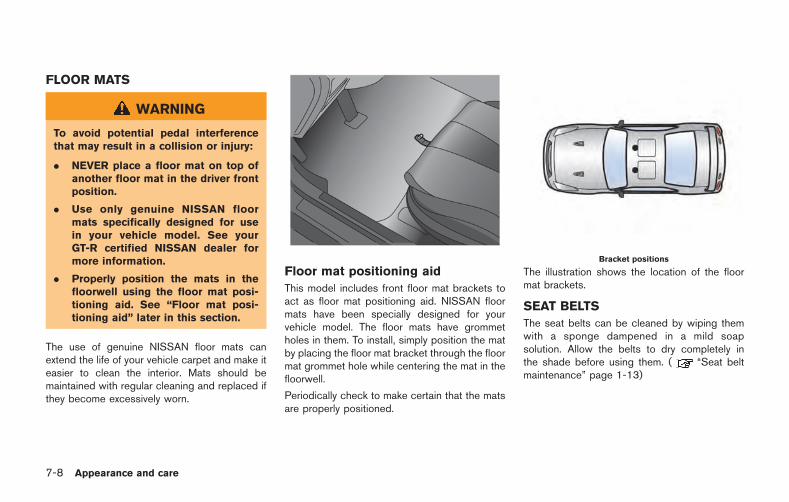
7-8 Appearance and care
FLOOR MATS
WARNING
To avoid potential pedal interferencethat may result in a collision or injury:
. NEVER place a floor mat on top ofanother floor mat in the driver frontposition.
. Use only genuine NISSAN floormats specifically designed for usein your vehicle model. See yourGT-R certified NISSAN dealer formore information.
. Properly position the mats in thefloorwell using the floor mat posi-tioning aid. See “Floor mat posi-tioning aid” later in this section.
The use of genuine NISSAN floor mats canextend the life of your vehicle carpet and make iteasier to clean the interior. Mats should bemaintained with regular cleaning and replaced ifthey become excessively worn.
Floor mat positioning aid
This model includes front floor mat brackets toact as floor mat positioning aid. NISSAN floormats have been specially designed for yourvehicle model. The floor mats have grommetholes in them. To install, simply position the matby placing the floor mat bracket through the floormat grommet hole while centering the mat in thefloorwell.
Periodically check to make certain that the matsare properly positioned.
Bracket positions
The illustration shows the location of the floormat brackets.
SEAT BELTS
The seat belts can be cleaned by wiping themwith a sponge dampened in a mild soapsolution. Allow the belts to dry completely inthe shade before using them. ( “Seat beltmaintenance” page 1-13)
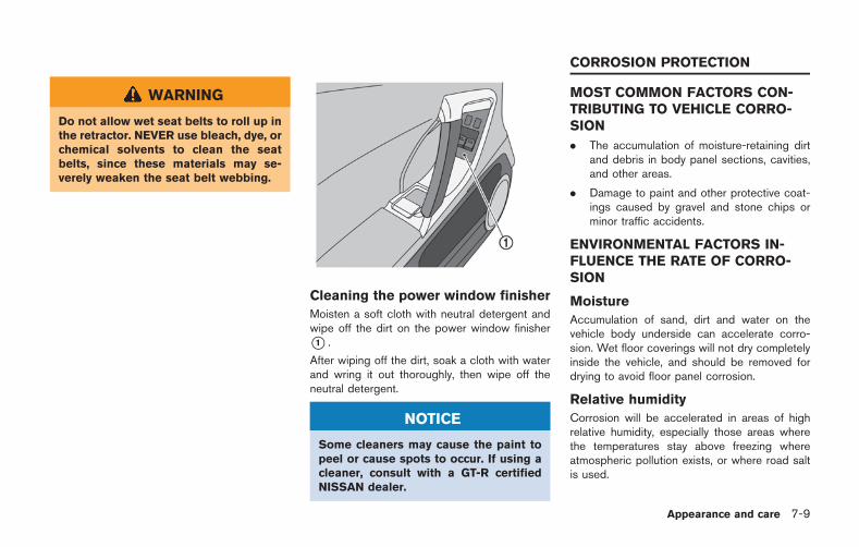
WARNING
Do not allow wet seat belts to roll up inthe retractor. NEVER use bleach, dye, orchemical solvents to clean the seatbelts, since these materials may se-verely weaken the seat belt webbing.
Cleaning the power window finisher
Moisten a soft cloth with neutral detergent andwipe off the dirt on the power window finisher*1 .
After wiping off the dirt, soak a cloth with waterand wring it out thoroughly, then wipe off theneutral detergent.
NOTICE
Some cleaners may cause the paint topeel or cause spots to occur. If using acleaner, consult with a GT-R certifiedNISSAN dealer.
MOST COMMON FACTORS CON-TRIBUTING TO VEHICLE CORRO-SION
. The accumulation of moisture-retaining dirtand debris in body panel sections, cavities,and other areas.
. Damage to paint and other protective coat-ings caused by gravel and stone chips orminor traffic accidents.
ENVIRONMENTAL FACTORS IN-FLUENCE THE RATE OF CORRO-SION
Moisture
Accumulation of sand, dirt and water on thevehicle body underside can accelerate corro-sion. Wet floor coverings will not dry completelyinside the vehicle, and should be removed fordrying to avoid floor panel corrosion.
Relative humidity
Corrosion will be accelerated in areas of highrelative humidity, especially those areas wherethe temperatures stay above freezing whereatmospheric pollution exists, or where road saltis used.
Appearance and care 7-9
CORROSION PROTECTION
7-10 Appearance and care
Temperature
A temperature increase will accelerate the rateof corrosion to those parts which are not wellventilated.
Air pollution
Industrial pollution, the presence of salt in the airin coastal areas, or heavy road salt use willaccelerate the corrosion process. Road salt willalso accelerate the disintegration of paintsurfaces.
TO PROTECT YOUR VEHICLE FROMCORROSION
. Wash and wax your vehicle often to keep thevehicle clean.
. Always check for minor damage to the paintand repair it as soon as possible.
. Keep drain holes at the bottom of the doorsopen to avoid water accumulation.
. Check the underbody for accumulation ofsand, dirt or salt. If present, wash with wateras soon as possible.
CAUTION
. NEVER remove dirt, sand or otherdebris from the passenger compart-ment by washing it out with a hose.Remove dirt with a vacuum cleaner.
. Never allow water or other liquids tocome in contact with electroniccomponents inside the vehicle asthis may damage them.
Chemicals used for road surface deicing areextremely corrosive. They accelerate corrosionand deterioration of underbody componentssuch as the exhaust system, fuel and brakelines, brake cables, floor pan and fenders.
In winter, the underbody must be cleanedperiodically.
For additional protection against rust andcorrosion, which may be required in some areas,consult a GT-R certified NISSAN dealer.
8 Maintenance and do-it-yourself
Maintenance requirement ....................................................... 8-3Scheduled maintenance ................................................... 8-3General maintenance ........................................................ 8-3Where to go for service ................................................... 8-3
General maintenance .............................................................. 8-4Explanation of maintenance items ................................. 8-4
Maintenance precautions ....................................................... 8-6Engine compartment check locations ................................. 8-8
Removing the cowl top cover ......................................... 8-9Engine cooling system ......................................................... 8-10
Checking engine coolant level ..................................... 8-11Changing engine coolant .............................................. 8-12
Engine oil ................................................................................ 8-13Checking engine oil level .............................................. 8-13Changing engine oil and filter ...................................... 8-14
Transmission oil ..................................................................... 8-14Power steering fluid .............................................................. 8-14Brake fluid ............................................................................... 8-15Window washer fluid ........................................................... 8-16Battery ...................................................................................... 8-17
Precautions ....................................................................... 8-17Fluid level check .............................................................. 8-18Jump starting .................................................................... 8-19
Drive belts .............................................................................. 8-19Spark plugs ............................................................................ 8-20
Replacing spark plugs ................................................. 8-20Air cleaner .............................................................................. 8-21Windshield wiper blades .................................................... 8-22
Cleaning .......................................................................... 8-22Replacing the wiper blades ....................................... 8-22
Brakes ..................................................................................... 8-23Self-adjusting brakes ................................................... 8-23Brake pad wear warning ............................................. 8-23High performance brake system ............................... 8-23Replacing the brake pads ........................................... 8-24
Fuses ....................................................................................... 8-24Engine compartment .................................................... 8-24Passenger compartment ............................................. 8-25
Intelligent Key battery replacement .................................. 8-27Lights ....................................................................................... 8-29
Headlights ....................................................................... 8-30Exterior and interior lights ........................................... 8-30
Wheels and tires .................................................................. 8-32Tire pressure .................................................................. 8-32Tire and loading information label ............................ 8-35Checking the tire pressure ......................................... 8-36
Tire labeling ...................................................................... 8-37Types of tires .................................................................... 8-38Tire chains ......................................................................... 8-40
Changing wheels and tires ......................................... 8-41Jacking vehicle and removing wheels ...................... 8-43
Some day-to-day and regular maintenance isessential to maintain your vehicle good mechan-ical condition, as well as its emission and engineperformance.
It is the owner’s responsibility to make sure thatthe scheduled maintenance, as well as generalmaintenance, is performed.
As the vehicle owner, you are the only one whocan ensure that your vehicle receives the propermaintenance care. You are a vital link in themaintenance chain.
SCHEDULED MAINTENANCE
For your convenience, both required and op-tional scheduled maintenance items are de-scribed and listed in your NISSAN Service andMaintenance Guide. You must refer to that guideto ensure that necessary maintenance is per-formed on your vehicle at regular intervals.
GENERAL MAINTENANCE
General maintenance includes those itemswhich should be checked during normal day-to-day operation. They are essential for propervehicle operation. It is your responsibility toperform these procedures regularly as pre-scribed.
Performing general maintenance checks re-quires minimal mechanical skill and only a few
general automotive tools.
These checks or inspections can be done byyourself, a qualified technician or, if you prefer, aGT-R certified NISSAN dealer.
WHERE TO GO FOR SERVICE
GT-R certified NISSAN dealers are required tohave additional training and equipment and arethe only NISSAN dealers authorized to performwarranty work on key vehicle performancesystems such as engine, transmission, suspen-sion and brakes.
If maintenance service is required or your vehicleappears to malfunction, have the systemschecked and serviced by a GT-R certifiedNISSAN dealer.
NISSAN technicians are well-trained specialistsand are kept up to date with the latest serviceinformation through technical bulletins, servicetips, and in-dealer information systems. They arecompletely qualified to work on NISSAN vehi-cles before work begins.
You can be confident that a GT-R certifiedNISSAN dealer’s service department performsthe best job to meet the maintenance require-ments on your vehicle.
To find a GT-R certified NISSAN dealer nearyou, call 1-866-668-1GTR in the US or 1-800-
387-0122 in Canada, or go to www. gtrnissan.com/.
Maintenance and do-it-yourself 8-3
MAINTENANCE REQUIREMENT
8-4 Maintenance and do-it-yourself
During the normal day-to-day operation of thevehicle, general maintenance should be per-formed regularly as prescribed in this section. Ifyou detect any unusual sounds, vibrations orsmell, be sure to check for the cause or have aGT-R certified NISSAN dealer do it promptly. Inaddition, you should notify a GT-R certifiedNISSAN dealer if you think that repairs arerequired. ( “Maintenance precautions”page 8-6)
EXPLANATION OF MAINTENANCEITEMS
Additional information on the followingitems with “*” is found later in this section.
Outside the vehicle
The maintenance items listed here should beperformed from time to time, unless otherwisespecified.
Doors and engine hood: Check that all doorsand the engine hood, operate properly. Alsoensure that all latches lock securely. Lubricatehinges, latches, latch pins, rollers and links ifnecessary. Make sure that the secondary latchkeeps the hood from opening when the primarylatch is released.
When driving in areas using road salt or othercorrosive materials, check lubrication frequently.
Lights*: Clean the headlights on a regular basis.Make sure that the headlights, stop lights, taillights, turn signal lights, and other lights are alloperating properly and installed securely. Alsocheck headlight aim.
Road wheel nuts (lug nuts)*: When checkingthe tires, make sure no wheel nuts are missing,and check for any loose wheel nuts. Tighten ifnecessary.
Tire rotation*: Tires cannot be rotated becauseyour vehicle is equipped with different sized tiresin the front and rear.
Tires*: Check the pressure with a gauge oftenand always prior to long distance trips. Ifnecessary, adjust the pressure in all tires to thepressure specified. Check carefully for damage,cuts or excessive wear.
NOTE:
. You can check the pressure of all fourtires on the multi function display. Seethe separate Multi Function DisplayOwner’s Manual.
. The tires of this vehicle are filled withnitrogen gas. When the tire pressure islow, fill the tires with nitrogen. Contacta GT-R certified NISSAN dealer forinformation on filling the tires withnitrogen.
. If nitrogen is not available, compressedair may be safely used under normaldriving conditions. However, NISSANrecommends refilling with nitrogen formaximum tire performance.
Tire Pressure Monitoring System (TPMS)transmitter components: Replace grommetseal of transmitter in TPMS, when replacingeach tire by reaching the wear limit.
Tire, wheel alignment and balance: If thevehicle should pull to either side while driving ona straight and level road, or if you detect unevenor abnormal tire wear, there may be a need forwheel alignment.
If the steering wheel or seat vibrates at normalhighway speeds, wheel balancing may beneeded.
For additional information regarding tires, referto “Important Tire Safety Information” (US) or“Tire Safety Information” (Canada) in the War-ranty Information Booklet.
Windshield: Clean the windshield on a regularbasis. Check the windshield at least every sixmonths for cracks or other damage. Have adamaged windshield repaired by a qualifiedrepair facility.
Windshield wiper blades*: Check for cracksor wear if they do not wipe properly.
GENERAL MAINTENANCE
Inside the vehicle
The maintenance items listed here should bechecked on a regular basis, such as whenperforming scheduled maintenance, cleaningthe vehicle, etc.
Accelerator pedal: Check the pedal forsmooth operation and make sure the pedaldoes not catch or require uneven effort. Keepthe floor mat away from the pedal.
Transmission &P mechanism: On a fairlysteep hill, check that your vehicle is heldsecurely with the shift lever in the &P positionwithout applying any brakes.
Brake pedal: Check the pedal for smoothoperation. If the brake pedal suddenly goesdown further than normal, the pedal feelsspongy or the vehicle seems to take longer tostop, see a GT-R certified NISSAN dealerimmediately. Keep the floor mat away from thepedal.
Brakes: Check that the brakes do not pull thevehicle to one side when applied.
Parking brake: Check the parking brakeoperation regularly. The vehicle should besecurely held on a fairly steep hill with only theparking brake applied. If the parking brake needsto be adjusted, see a GT-R certified NISSANdealer.
Seat belts: Check that all parts of the seat beltsystem (for example, buckles, anchors, adjusterand retractors) operate properly and smoothly,and are installed securely. Check the beltwebbing for cuts, fraying, wear or damage.
Seats: Check seat position controls such asseat adjusters, seatback recliner, etc. to ensurethey operate smoothly and that all latches locksecurely in every position.
Steering wheel: Check for changes in thesteering conditions, such as excessive free play,hard steering or strange noises.
Warning lights and chimes: Make sure thatall warning lights and chimes are operatingproperly.
Windshield defroster: Check that the aircomes out of the defroster outlets properly andin sufficient quantity when operating the heateror air conditioner.
Windshield wiper and washer*: Check thatthe wipers and washer operate properly and thatthe wipers do not streak.
Under the hood and vehicle
The maintenance items listed here should bechecked periodically (for example, each time youcheck the engine oil or refuel).
Battery*: Check the fluid level in each cell. Itshould be between the MAX and MIN lines.Vehicles operated in high temperatures or undersevere condition require frequent checks of thebattery fluid level.
NOTE:
Care should be taken to avoid situationsthat can lead to potential battery dischargeand potential no-start conditions such as:1. Installation or extended use of electro-
nic accessories that consume batterypower when the engine is not running(Phone chargers, GPS, DVD players,etc.)
2. Vehicle is not driven regularly and/oronly driven short distances.
In these cases, the battery may need to becharged to maintain battery health.
Brake fluid level*: Make sure that the brakefluid level is between the MAX and MIN lines onthe reservoir.
Engine coolant level*: Check the coolant levelwhen the engine is cold.
Engine drive belts*: Make sure that no belt isfrayed, worn, cracked or oily.
Engine oil level*: Check the level after parkingthe vehicle on a level spot and turning off the
Maintenance and do-it-yourself 8-5
8-6 Maintenance and do-it-yourself
engine. Wait at least 5 minutes for the oil todrain back into the oil pan before checking theoil.
Exhaust system: Make sure there are no loosesupports, cracks or holes. If the sound of theexhaust seems unusual or there is a smell ofexhaust fumes in the engine compartment,immediately have the exhaust system inspectedby a GT-R cert i f ied NISSAN dealer .( “Exhaust gas (carbon monoxide)” page5-3)
Fluid leaks: Check under the vehicle for fuel,oil, water or other fluid leaks after the vehicle hasbeen parked for a while. Water dripping from theair conditioner after use is normal. If you shouldnotice any leaks or if gasoline fumes are evident,check for the cause and have it correctedimmediately.
Power steering fluid level* and lines: Checkthe level when the fluid is cold, with the engineoff. Check the lines for proper attachment, leaks,cracks, etc.
Radiator and hoses: Check the front of theradiator and clean off any dirt, insects, leaves,etc., that may have accumulated. Make sure thehoses have no cracks, deformation, rot or looseconnections.
Underbody: The underbody is frequently ex-posed to corrosive substances such as thoseused on icy roads or to control dust. It is veryimportant to remove these substances, other-wise rust will form on the floor pan, frame, fuellines and around the exhaust system. At the endof winter, the underbody should be thoroughlyflushed with plain water, being careful to cleanthose areas where mud and dirt may accumu-late. ( “Underbody” page 7-5)
Windshield washer fluid*: Check that there isadequate fluid in the reservoir.
When performing any inspection or mainte-nance work on your vehicle, always take careto prevent serious accidental injury to yourself ordamage to the vehicle. The following are generalprecautions which should be closely observed.
WARNING
. Park the vehicle on a level surface,apply the parking brake securelyand block the wheels to preventthe vehicle from moving. Move theshift lever to the &P position.
. Be sure the ignition switch is in theOFF or LOCK position when per-forming any parts replacement orrepairs.
. If you must work with the enginerunning, keep your hands, clothing,hair and tools away from movingfans, belts and any other movingparts.
. It is advisable to secure or removeany loose clothing and remove anyjewelry, such as rings, watches, etc.before working on your vehicle.
. Always wear eye protection when-ever you work on your vehicle.
MAINTENANCE PRECAUTIONS
. If you must run the engine in anenclosed space such as a garage, besure there is proper ventilation forexhaust gases to escape.
. Never get under the vehicle while itis supported only by a jack. If it isnecessary to work under the vehicle,support it with safety stands.
. Keep smoking materials, flame andsparks away from fuel tank and thebattery.
. Your vehicle is equipped with anautomatic engine cooling fan. It maycome on at any time without warn-ing, even if the ignition key is in theOFF position and the engine is notrunning. To avoid injury, alwaysdisconnect the negative batterycable before working near the fan.
. The fuel filter or fuel lines should beserviced by a GT-R certified NISSANdealer because the fuel lines areunder high pressure even when theengine is off.
CAUTION
. Do not work under the hood whilethe engine is hot. Turn the engineoff and wait until it cools down.
. Avoid direct contact with used en-gine oil and coolant. Improperlydisposed engine oil, coolant, and/or other vehicle fluids can damagethe environment. Always conform tolocal regulations for disposal ofvehicle fluid.
NOTICE
. Never connect or disconnect thebattery or any transistorized com-ponent while the ignition switch isin the ON position.
. Never leave the engine or transmis-sion related component harnessesdisconnected while the ignitionswitch is in the ON position.
This “8. Maintenance and do-it-yourself” sectiongives instructions regarding only those itemswhich are relatively easy for an owner to perform.
A genuine NISSAN Service Manual is alsoavailable. ( “Owner’s Manual/Service Man-ual order information” page 9-22)
You should be aware that incomplete orimproper servicing may result in operatingdifficulties or excessive emissions. If in doubtabout any servicing, we recommend that itbe done by a GT-R certified NISSAN dealer.
Maintenance and do-it-yourself 8-7
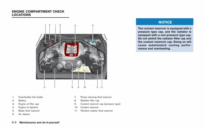
8-8 Maintenance and do-it-yourself
1. Fuse/fusible link holder
2. Battery
3. Engine oil filler cap
4. Engine oil dipstick
5. Brake fluid reservoir
6. Air cleaner
7. Power steering fluid reservoir
8. Radiator filler cap
9. Coolant reservoir cap (pressure type)
10. Coolant reservoir
11. Window washer fluid reservoir
NOTICE
The coolant reservoir is equipped with apressure type cap, and the radiator isequipped with a non-pressure type cap.Do not switch the radiator filler cap andthe coolant reservoir cap. Doing so willcause substandard cooling perfor-mance and overheating.
ENGINE COMPARTMENT CHECKLOCATIONS
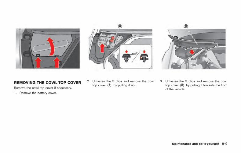
REMOVING THE COWL TOP COVER
Remove the cowl top cover if necessary.
1. Remove the battery cover.
2. Unfasten the 5 clips and remove the cowltop cover *A by pulling it up.
3. Unfasten the 3 clips and remove the cowltop cover *B by pulling it towards the frontof the vehicle.
Maintenance and do-it-yourself 8-9
8-10 Maintenance and do-it-yourself
The engine cooling system is filled at the factorywith a pre-diluted mixture of 50% GenuineNISSAN Long Life Antifreeze/Coolant (blue) and50% water to provide year-round anti-freezeand coolant protection. The anti-freeze solutioncontains rust and corrosion inhibitors. Additionalengine cooling system additives are not neces-sary.
WARNING
. Never remove the radiator or cool-ant reservoir cap when the engine ishot. Wait until the engine andradiator cool down. Serious burnscould be caused by high pressurefluid escaping from the radiator.( “If your vehicle overheats”page 6-8)
. The radiator is equipped with apressure type radiator cap. To pre-vent engine damage, use only agenuine NISSAN radiator cap.
CAUTION
. Never use any cooling system ad-ditives such as radiator sealer. Ad-ditives may clog the cooling systemand cause damage to the engine,transmission and/or cooling sys-tem.
. When adding or replacing coolant,be sure to use only GenuineNISSAN Long Life Antifreeze/Cool-ant (blue) or equivalent. GenuineNISSAN Long Life Antifreeze/Cool-ant (blue) is pre-diluted to provideantifreeze protection to 348F( 378C). If additional freeze protec-tion is needed due to weather whereyou operate your vehicle, add Gen-uine NISSAN Long Life Antifreeze/Coolant (blue) concentrate follow-ing the directions on the container.If an equivalent coolant other thanGenuine NISSAN Long Life Anti-freeze/ Coolant (blue) is used, fol-low the coolant manufacture’sinstructions to maintain minimumantifreeze protection to 348F( 378C). The use of other types ofcoolant solutions other than Genu-
ine NISSAN Long Life Antifreeze/Coolant (blue) or equivalent maydamage the engine cooling system.
. The life expectancy of the factory-fillcoolant is 24,000 miles (38,400 km)or 2 years. Mixing any other type ofcoolant other than Genuine NISSANLong Life Antifreeze/Coolant (blue),including Genuine NISSAN LongLife Antifreeze/Coolant (green), orthe use of nondistilled water willreduce the life expectancy of thefactory-fill coolant. Refer to theGT-R Service and MaintenanceGuide for more details.
ENGINE COOLING SYSTEM
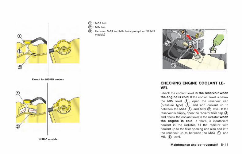
Except for NISMO models
NISMO models
*1 : MAX line
*2 : MIN line
*3 : Between MAX and MIN lines (except for NISMOmodels)
CHECKING ENGINE COOLANT LE-VEL
Check the coolant level in the reservoir whenthe engine is cold. If the coolant level is belowthe MIN level *2 , open the reservoir cap(pressure type) *B and add coolant up tobetween the MAX *1 and MIN *2 level. If thereservoir is empty, open the radiator filler cap*Aand check the coolant level in the radiator whenthe engine is cold. If there is insufficientcoolant in the radiator, fill the radiator withcoolant up to the filler opening and also add it tothe reservoir up to between the MAX *1 andMIN *2 level.
Maintenance and do-it-yourself 8-11
8-12 Maintenance and do-it-yourself
This vehicle contains Genuine NISSAN LongLife Antifreeze/Coolant (blue). The life expec-tancy of the factory-fill coolant is 24,000 miles(38,400 km) or 2 years. Mixing any other type ofcoolant or the use of non-distilled water willreduce the life expectancy of the factory-fillcoolant. Refer to the GT-R Service and Main-tenance Guide for more details.
If the cooling system frequently requirescoolant, have it checked by a GT-R certifiedNISSAN dealer.
Check that the level of coolant is between MAXand MIN on the pressurized radiator reservoir. Ifthe level is below the midpoint, the amount ofcoolant circulating may be insufficient for max-imum vehicle performance, possibly causingengine overheating or other trouble.
For the coolant level and mixture ratio whenengaging in performance driv ing, see
“Coolant level and mixture ratio” pageGTR-15.
Except for NISMO models:
If it is difficult to determine the midpoint betweenMAX and MIN, remove the coolant reservoir capand look inside through the opening to checkthat the coolant level is above the divider *3between the top half and bottom half of thepressurized coolant reservoir.
NOTICE
. The coolant reservoir is equippedwith a pressure type cap, and theradiator is equipped with a non-pressure type cap. Do not switchthe radiator filler cap and the cool-ant reservoir cap. Doing so willcause substandard cooling perfor-mance and overheating.
. If you have added only water as thecoolant in an emergency, change itto a coolant mixture ratio specifiedas soon as possible.
CHANGING ENGINE COOLANT
If major cooling system repairs are required,contact a GT-R certified NISSAN dealer. Theservice procedures can be found in the appro-priate NISSAN Service Manual.
Improper servicing can result in reducedheater performance and engine overheat-ing.
WARNING
. To avoid the danger of beingscalded, never change the coolantwhen the engine is hot.
. Never remove the radiator filler capand the coolant reservoir cap whenthe engine is hot. Serious burnscould be caused by high pressurefluid escaping from the radiator andreservoir.
. Avoid direct skin contact with usedcoolant. If skin contact is made,wash thoroughly with soap or handcleaner as soon as possible.
. Keep coolant out of reach of chil-dren and pets.
Engine coolant must be disposed of properly.Check your local regulations.

CHECKING ENGINE OIL LEVEL
1. Park the vehicle on a level surface and applythe parking brake.
2. Run the engine until it reaches operatingtemperature.
3. Turn off the engine. Wait at least 5minutes for the oil to drain back intothe oil pan before checking the oil.
4. Remove the dipstick and wipe it clean.Reinsert it all the way.
5. Remove the dipstick again and check the oillevel. It should be within the range*1 . If theoil level is below*2 , remove the oil filler cap
and pour recommended oil through theopening. Do not overfill *3 .
6. Recheck oil level with the dipstick.
NOTE:
. It is normal to add some oil between oilmaintenance intervals or during thebreak-in period, depending on theseverity of operating conditions. Moreengine oil is consumed by frequentacceleration/deceleration especiallywhen the engine rpm is high. If yourrate of oil consumption increases sud-denly or without explanation, NISSANrecommends that you have your vehicleinspected by a GT-R certified NISSANdealer.
. When the vehicle is delivered, theengine oil is set to 0.39 in (10 mm)below the H mark for optimal highperformance driving. The engine oil canbe filled up to the H mark if perfor-mance driving is not engaged.
NOTICE
. Mobil 1 (0W-40) (100% synthetic) isthe factory fill oil. The VR38 enginewith its plasma-sprayed bores wasdeveloped using this oil. NISSANcannot ensure proper engine opera-tion and durability if other 0W-40synthetic oil is used. If Mobil 1 (0W-40) is not available, Mobil 1 (10W-40) (100% synthetic) may be used;however, some performance lossmay be noticed.
. Oil level should be checked regu-larly. Operating the engine with aninsufficient amount of oil can da-mage the engine. See the 2015NISSAN GT-R Warranty InformationBooklet for details including applic-able exclusions.
Maintenance and do-it-yourself 8-13
ENGINE OIL
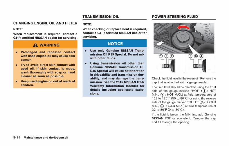
8-14 Maintenance and do-it-yourself
CHANGING ENGINE OIL AND FILTER
NOTE:
When replacement is required, contact aGT-R certified NISSAN dealer for servicing.
WARNING
. Prolonged and repeated contactwith used engine oil may cause skincancer.
. Try to avoid direct skin contact withused oil. If skin contact is made,wash thoroughly with soap or handcleaner as soon as possible.
. Keep used engine oil out of reach ofchildren.
NOTE:
When checking or replacement is required,contact a GT-R certified NISSAN dealer forservicing.
NOTICE
. Use only Genuine NISSAN Trans-mission Oil R35 Special. Do not mixwith other fluids.
. Using transmission oil other thanGenuine NISSAN Transmission OilR35 Special will cause deteriorationin driveability and transmission dur-ability, and may damage the trans-mission. See the 2015 NISSAN GT-RWarranty Information Booklet fordetails including applicable exclu-sions.
Check the fluid level in the reservoir. Remove thecap that is attached with a gauge inside.
The fluid level should be checked using the frontside of the gauge marked “HOT” (*1 : HOTMIN., *2 : HOT MAX.) at fluid temperatures of122 to 1768F (50 to 808C) or using the reverseside of the gauge marked “COLD” (*3 : COLDMIN.,*4 : COLD MAX.) at fluid temperatures of32 to 868F (0 to 308C).
If the fluid is below the MIN line, add GenuineNISSAN PSF or equivalent. Remove the capand fill through the opening.
TRANSMISSION OIL POWER STEERING FLUID
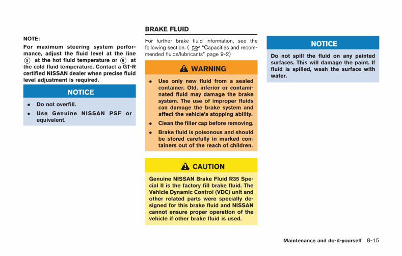
NOTE:
For maximum steering system perfor-mance, adjust the fluid level at the line
*5 at the hot fluid temperature or *6 atthe cold fluid temperature. Contact a GT-Rcertified NISSAN dealer when precise fluidlevel adjustment is required.
NOTICE
. Do not overfill.
. Use Genuine NISSAN PSF orequivalent.
For further brake fluid information, see thefollowing section. ( “Capacities and recom-mended fluids/lubricants” page 9-2)
WARNING
. Use only new fluid from a sealedcontainer. Old, inferior or contami-nated fluid may damage the brakesystem. The use of improper fluidscan damage the brake system andaffect the vehicle’s stopping ability.
. Clean the filler cap before removing.
. Brake fluid is poisonous and shouldbe stored carefully in marked con-tainers out of the reach of children.
CAUTION
Genuine NISSAN Brake Fluid R35 Spe-cial II is the factory fill brake fluid. TheVehicle Dynamic Control (VDC) unit andother related parts were specially de-signed for this brake fluid and NISSANcannot ensure proper operation of thevehicle if other brake fluid is used.
NOTICE
Do not spill the fluid on any paintedsurfaces. This will damage the paint. Iffluid is spilled, wash the surface withwater.
Maintenance and do-it-yourself 8-15
BRAKE FLUID
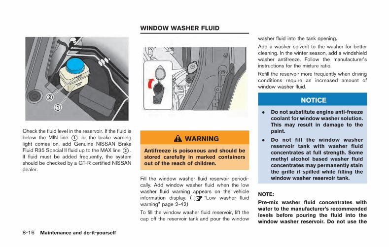
8-16 Maintenance and do-it-yourself
Check the fluid level in the reservoir. If the fluid isbelow the MIN line *1 or the brake warninglight comes on, add Genuine NISSAN BrakeFluid R35 Special II fluid up to the MAX line*2 .If fluid must be added frequently, the systemshould be checked by a GT-R certified NISSANdealer.
WARNING
Antifreeze is poisonous and should bestored carefully in marked containersout of the reach of children.
Fill the window washer fluid reservoir periodi-cally. Add window washer fluid when the lowwasher fluid warning appears on the vehicleinformation display. ( “Low washer fluidwarning” page 2-42)
To fill the window washer fluid reservoir, lift thecap off the reservoir tank and pour the window
washer fluid into the tank opening.
Add a washer solvent to the washer for bettercleaning. In the winter season, add a windshieldwasher antifreeze. Follow the manufacturer’sinstructions for the mixture ratio.
Refill the reservoir more frequently when drivingconditions require an increased amount ofwindow washer fluid.
NOTICE
. Do not substitute engine anti-freezecoolant for window washer solution.This may result in damage to thepaint.
. Do not fill the window washerreservoir tank with washer fluidconcentrates at full strength. Somemethyl alcohol based washer fluidconcentrates may permanently stainthe grille if spilled while filling thewindow washer reservoir tank.
NOTE:
Pre-mix washer fluid concentrates withwater to the manufacturer’s recommendedlevels before pouring the fluid into thewindow washer reservoir. Do not use the
WINDOW WASHER FLUID
window washer reservoir to mix thewasher fluid concentrate and water.
. Keep the battery surface clean and dry.Clean the battery with a solution of bakingsoda and water.
. Make certain the terminal connections areclean and securely tightened.
. If the vehicle is not to be used for 30 days orlonger, disconnect the negative ( ) batteryterminal cable to prevent discharging it.
NOTE:
Care should be taken to avoid situationsthat can lead to potential battery dischargeand potential no-start conditions such as:1. Installation or extended use of electro-
nic accessories that consume batterypower when the engine is not running(Phone chargers, GPS, DVD players,etc.)
2. Vehicle is not driven regularly and/oronly driven short distances.
In these cases, the battery may need to becharged to maintain battery health.
PRECAUTIONS
NOTICE
When the battery cable is removed fromthe battery terminal, do not close eitherof the front doors. The automatic win-dow adjusting function will not work,and the side roof panel may be da-maged.
To disconnect the negative ( ) battery terminal,perform the procedure in the following order.Otherwise, the window and the side roof panelmay contact and be damaged.
1. Close the windows.
2. Open the hood.
3. Close and lock all the doors.
4. Disconnect the negative ( ) battery terminal.
5. Securely close the hood.
To connect the negative ( ) battery terminal,perform the procedure in the following order.Otherwise, the window and the side roof panelmay contact and be damaged.
1. Unlock and open the driver side door. Donot close the door.
2. Open the hood.
Maintenance and do-it-yourself 8-17
BATTERY
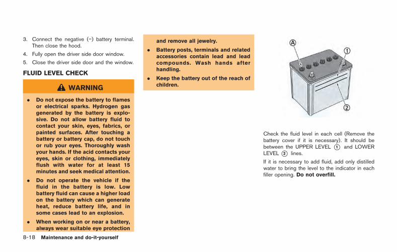
8-18 Maintenance and do-it-yourself
3. Connect the negative ( ) battery terminal.Then close the hood.
4. Fully open the driver side door window.
5. Close the driver side door and the window.
FLUID LEVEL CHECK
WARNING
. Do not expose the battery to flamesor electrical sparks. Hydrogen gasgenerated by the battery is explo-sive. Do not allow battery fluid tocontact your skin, eyes, fabrics, orpainted surfaces. After touching abattery or battery cap, do not touchor rub your eyes. Thoroughly washyour hands. If the acid contacts youreyes, skin or clothing, immediatelyflush with water for at least 15minutes and seek medical attention.
. Do not operate the vehicle if thefluid in the battery is low. Lowbattery fluid can cause a higher loadon the battery which can generateheat, reduce battery life, and insome cases lead to an explosion.
. When working on or near a battery,always wear suitable eye protection
and remove all jewelry.
. Battery posts, terminals and relatedaccessories contain lead and leadcompounds. Wash hands afterhandling.
. Keep the battery out of the reach ofchildren.
Check the fluid level in each cell (Remove thebattery cover if it is necessary). It should bebetween the UPPER LEVEL *1 and LOWERLEVEL *2 lines.
If it is necessary to add fluid, add only distilledwater to bring the level to the indicator in eachfiller opening. Do not overfill.
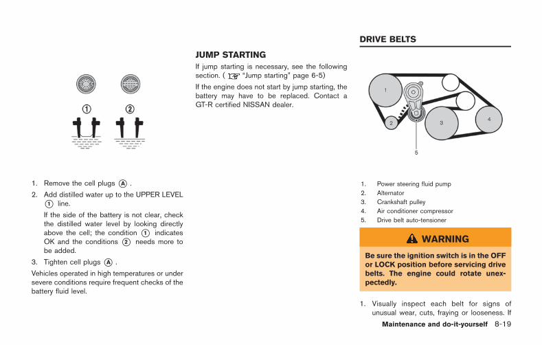
1. Remove the cell plugs *A .
2. Add distilled water up to the UPPER LEVEL*1 line.
If the side of the battery is not clear, checkthe distilled water level by looking directlyabove the cell; the condition *1 indicatesOK and the conditions *2 needs more tobe added.
3. Tighten cell plugs *A .
Vehicles operated in high temperatures or undersevere conditions require frequent checks of thebattery fluid level.
JUMP STARTING
If jump starting is necessary, see the followingsection. ( “Jump starting” page 6-5)
If the engine does not start by jump starting, thebattery may have to be replaced. Contact aGT-R certified NISSAN dealer.
1. Power steering fluid pump
2. Alternator
3. Crankshaft pulley
4. Air conditioner compressor
5. Drive belt auto-tensioner
WARNING
Be sure the ignition switch is in the OFFor LOCK position before servicing drivebelts. The engine could rotate unex-pectedly.
1. Visually inspect each belt for signs ofunusual wear, cuts, fraying or looseness. If
Maintenance and do-it-yourself 8-19
DRIVE BELTS
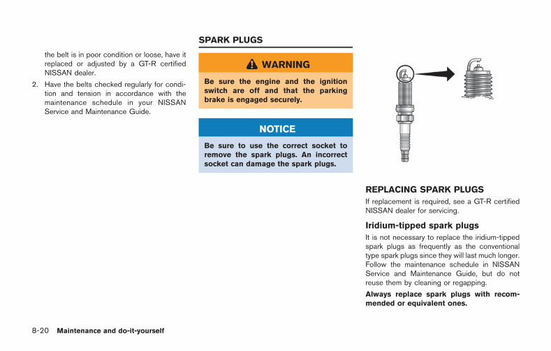
8-20 Maintenance and do-it-yourself
the belt is in poor condition or loose, have itreplaced or adjusted by a GT-R certifiedNISSAN dealer.
2. Have the belts checked regularly for condi-tion and tension in accordance with themaintenance schedule in your NISSANService and Maintenance Guide.
WARNING
Be sure the engine and the ignitionswitch are off and that the parkingbrake is engaged securely.
NOTICE
Be sure to use the correct socket toremove the spark plugs. An incorrectsocket can damage the spark plugs.
REPLACING SPARK PLUGS
If replacement is required, see a GT-R certifiedNISSAN dealer for servicing.
Iridium-tipped spark plugs
It is not necessary to replace the iridium-tippedspark plugs as frequently as the conventionaltype spark plugs since they will last much longer.Follow the maintenance schedule in NISSANService and Maintenance Guide, but do notreuse them by cleaning or regapping.
Always replace spark plugs with recom-mended or equivalent ones.
SPARK PLUGS
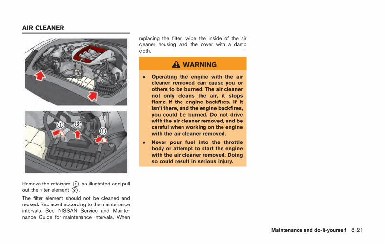
Remove the retainers *1 as illustrated and pullout the filter element *2 .
The filter element should not be cleaned andreused. Replace it according to the maintenanceintervals. See NISSAN Service and Mainte-nance Guide for maintenance intervals. When
replacing the filter, wipe the inside of the aircleaner housing and the cover with a dampcloth.
WARNING
. Operating the engine with the aircleaner removed can cause you orothers to be burned. The air cleanernot only cleans the air, it stopsflame if the engine backfires. If itisn’t there, and the engine backfires,you could be burned. Do not drivewith the air cleaner removed, and becareful when working on the enginewith the air cleaner removed.
. Never pour fuel into the throttlebody or attempt to start the enginewith the air cleaner removed. Doingso could result in serious injury.
Maintenance and do-it-yourself 8-21
AIR CLEANER
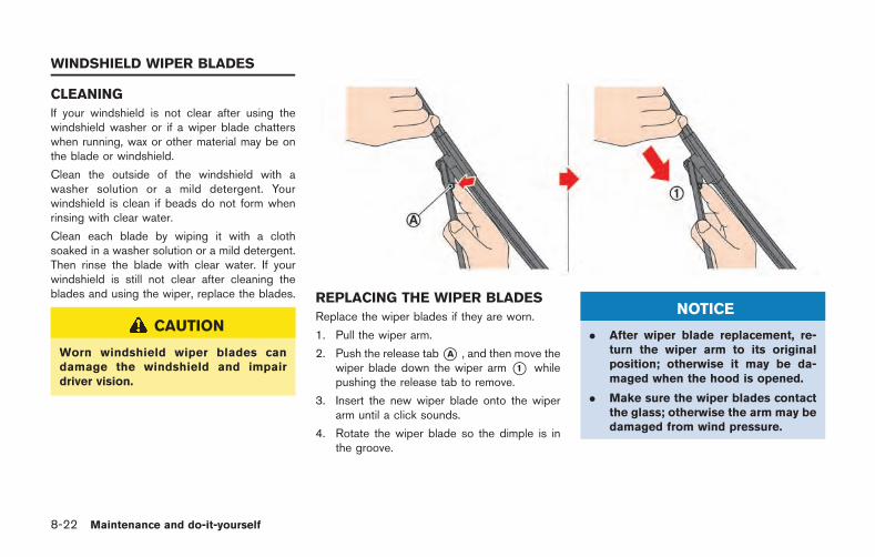
8-22 Maintenance and do-it-yourself
CLEANING
If your windshield is not clear after using thewindshield washer or if a wiper blade chatterswhen running, wax or other material may be onthe blade or windshield.
Clean the outside of the windshield with awasher solution or a mild detergent. Yourwindshield is clean if beads do not form whenrinsing with clear water.
Clean each blade by wiping it with a clothsoaked in a washer solution or a mild detergent.Then rinse the blade with clear water. If yourwindshield is still not clear after cleaning theblades and using the wiper, replace the blades.
CAUTION
Worn windshield wiper blades candamage the windshield and impairdriver vision.
REPLACING THE WIPER BLADES
Replace the wiper blades if they are worn.
1. Pull the wiper arm.
2. Push the release tab*A , and then move thewiper blade down the wiper arm *1 whilepushing the release tab to remove.
3. Insert the new wiper blade onto the wiperarm until a click sounds.
4. Rotate the wiper blade so the dimple is inthe groove.
NOTICE
. After wiper blade replacement, re-turn the wiper arm to its originalposition; otherwise it may be da-maged when the hood is opened.
. Make sure the wiper blades contactthe glass; otherwise the arm may bedamaged from wind pressure.
WINDSHIELD WIPER BLADES
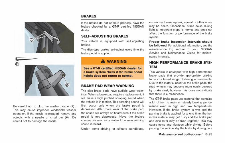
Be careful not to clog the washer nozzle *A .This may cause improper windshield washeroperation. If the nozzle is clogged, remove anyobjects with a needle or small pin *B . Becareful not to damage the nozzle.
If the brakes do not operate properly, have thebrakes checked by a GT-R certified NISSANdealer.
SELF-ADJUSTING BRAKES
Your vehicle is equipped with self-adjustingbrakes.
The disc-type brakes self-adjust every time thebrake pedal is applied.
WARNING
See a GT-R certified NISSAN dealer fora brake system check if the brake pedalheight does not return to normal.
BRAKE PAD WEAR WARNING
The disc brake pads have audible wear warn-ings. When a brake pad requires replacement, itwill make a high pitched scraping sound whenthe vehicle is in motion. This scraping sound willfirst occur only when the brake pedal isdepressed. After more wear of the brake pad,the sound will always be heard even if the brakepedal is not depressed. Have the brakeschecked as soon as possible if the wear warningsound is heard.
Under some driving or climate conditions,
occasional brake squeak, squeal or other noisemay be heard. Occasional brake noise duringlight to moderate stops is normal and does notaffect the function or performance of the brakesystem.
Proper brake inspection intervals shouldbe followed. For additional information, see themaintenance log section of your NISSANService and Maintenance Guide for mainte-nance intervals.
HIGH PERFORMANCE BRAKE SYS-TEM
This vehicle is equipped with high performancebrake pads that provide appropriate brakingforce in a broad range of driving environments.Due to the material used for the brake pads, theroad wheels may become more easily coveredby brake dust, however this does not indicatethat there is a malfunction.
The GT-R brake pads use material that containsa lot of iron to maintain steady braking perfor-mance even in high and low temperatures.However, if the brake system is wet and theparking brake is applied for a long time, the ironin this material may get rusty and the brake padand disc rotor may be fixed together. This maycause noise and vibration while driving. Beforeparking the vehicle, dry the brake by driving on a
Maintenance and do-it-yourself 8-23
BRAKES
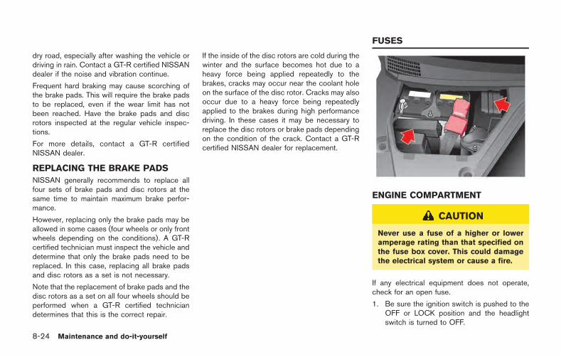
8-24 Maintenance and do-it-yourself
dry road, especially after washing the vehicle ordriving in rain. Contact a GT-R certified NISSANdealer if the noise and vibration continue.
Frequent hard braking may cause scorching ofthe brake pads. This will require the brake padsto be replaced, even if the wear limit has notbeen reached. Have the brake pads and discrotors inspected at the regular vehicle inspec-tions.
For more details, contact a GT-R certifiedNISSAN dealer.
REPLACING THE BRAKE PADS
NISSAN generally recommends to replace allfour sets of brake pads and disc rotors at thesame time to maintain maximum brake perfor-mance.
However, replacing only the brake pads may beallowed in some cases (four wheels or only frontwheels depending on the conditions). A GT-Rcertified technician must inspect the vehicle anddetermine that only the brake pads need to bereplaced. In this case, replacing all brake padsand disc rotors as a set is not necessary.
Note that the replacement of brake pads and thedisc rotors as a set on all four wheels should beperformed when a GT-R certified techniciandetermines that this is the correct repair.
If the inside of the disc rotors are cold during thewinter and the surface becomes hot due to aheavy force being applied repeatedly to thebrakes, cracks may occur near the coolant holeon the surface of the disc rotor. Cracks may alsooccur due to a heavy force being repeatedlyapplied to the brakes during high performancedriving. In these cases it may be necessary toreplace the disc rotors or brake pads dependingon the condition of the crack. Contact a GT-Rcertified NISSAN dealer for replacement.
ENGINE COMPARTMENT
CAUTION
Never use a fuse of a higher or loweramperage rating than that specified onthe fuse box cover. This could damagethe electrical system or cause a fire.
If any electrical equipment does not operate,check for an open fuse.
1. Be sure the ignition switch is pushed to theOFF or LOCK position and the headlightswitch is turned to OFF.
FUSES
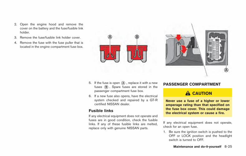
2. Open the engine hood and remove thecover on the battery and the fuse/fusible linkholder.
3. Remove the fuse/fusible link holder cover.
4. Remove the fuse with the fuse puller that islocated in the engine compartment fuse box.
5. If the fuse is open*A , replace it with a newfuses *B . Spare fuses are stored in thepassenger compartment fuse box.
6. If a new fuse also opens, have the electricalsystem checked and repaired by a GT-Rcertified NISSAN dealer.
Fusible links
If any electrical equipment does not operate andfuses are in good condition, check the fusiblelinks. If any of these fusible links are melted,replace only with genuine NISSAN parts.
PASSENGER COMPARTMENT
CAUTION
Never use a fuse of a higher or loweramperage rating than that specified onthe fuse box cover. This could damagethe electrical system or cause a fire.
If any electrical equipment does not operate,check for an open fuse.
1. Be sure the ignition switch is pushed to theOFF or LOCK position and the headlightswitch is turned to OFF.
Maintenance and do-it-yourself 8-25
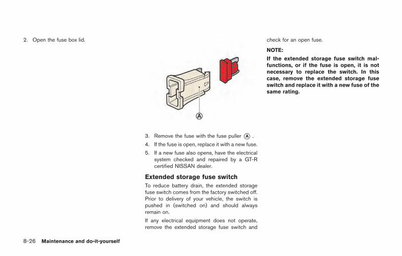
8-26 Maintenance and do-it-yourself
2. Open the fuse box lid.
3. Remove the fuse with the fuse puller *A .
4. If the fuse is open, replace it with a new fuse.
5. If a new fuse also opens, have the electricalsystem checked and repaired by a GT-Rcertified NISSAN dealer.
Extended storage fuse switch
To reduce battery drain, the extended storagefuse switch comes from the factory switched off.Prior to delivery of your vehicle, the switch ispushed in (switched on) and should alwaysremain on.
If any electrical equipment does not operate,remove the extended storage fuse switch and
check for an open fuse.
NOTE:
If the extended storage fuse switch mal-functions, or if the fuse is open, it is notnecessary to replace the switch. In thiscase, remove the extended storage fuseswitch and replace it with a new fuse of thesame rating.
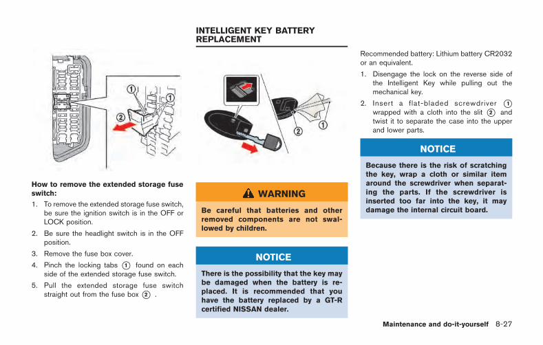
How to remove the extended storage fuseswitch:
1. To remove the extended storage fuse switch,be sure the ignition switch is in the OFF orLOCK position.
2. Be sure the headlight switch is in the OFFposition.
3. Remove the fuse box cover.
4. Pinch the locking tabs *1 found on eachside of the extended storage fuse switch.
5. Pull the extended storage fuse switchstraight out from the fuse box *2 .
WARNING
Be careful that batteries and otherremoved components are not swal-lowed by children.
NOTICE
There is the possibility that the key maybe damaged when the battery is re-placed. It is recommended that youhave the battery replaced by a GT-Rcertified NISSAN dealer.
Recommended battery: Lithium battery CR2032or an equivalent.
1. Disengage the lock on the reverse side ofthe Intelligent Key while pulling out themechanical key.
2. Insert a flat-bladed screwdriver *1wrapped with a cloth into the slit *2 andtwist it to separate the case into the upperand lower parts.
NOTICE
Because there is the risk of scratchingthe key, wrap a cloth or similar itemaround the screwdriver when separat-ing the parts. If the screwdriver isinserted too far into the key, it maydamage the internal circuit board.
Maintenance and do-it-yourself 8-27
INTELLIGENT KEY BATTERYREPLACEMENT
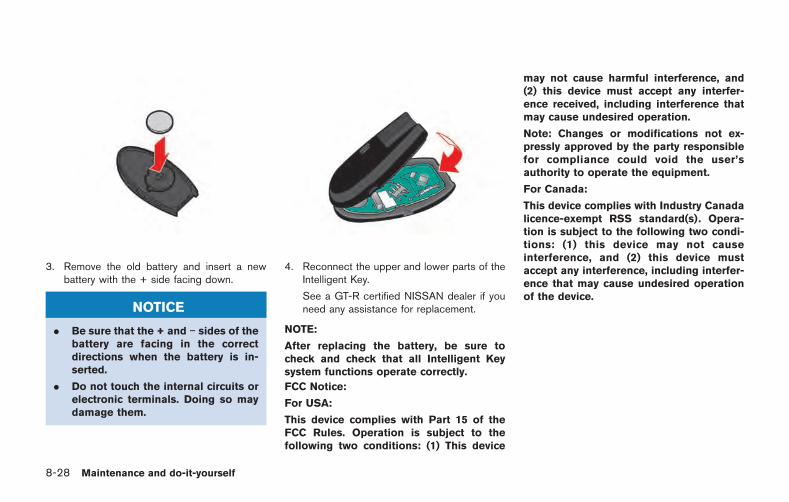
8-28 Maintenance and do-it-yourself
3. Remove the old battery and insert a newbattery with the + side facing down.
NOTICE
. Be sure that the + and sides of thebattery are facing in the correctdirections when the battery is in-serted.
. Do not touch the internal circuits orelectronic terminals. Doing so maydamage them.
4. Reconnect the upper and lower parts of theIntelligent Key.
See a GT-R certified NISSAN dealer if youneed any assistance for replacement.
NOTE:
After replacing the battery, be sure tocheck and check that all Intelligent Keysystem functions operate correctly.
FCC Notice:
For USA:
This device complies with Part 15 of theFCC Rules. Operation is subject to thefollowing two conditions: (1) This device
may not cause harmful interference, and(2) this device must accept any interfer-ence received, including interference thatmay cause undesired operation.
Note: Changes or modifications not ex-pressly approved by the party responsiblefor compliance could void the user’sauthority to operate the equipment.
For Canada:
This device complies with Industry Canadalicence-exempt RSS standard(s). Opera-tion is subject to the following two condi-tions: (1) this device may not causeinterference, and (2) this device mustaccept any interference, including interfer-ence that may cause undesired operationof the device.
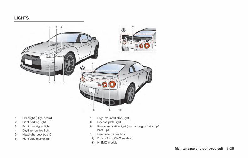
1. Headlight (High beam)
2. Front parking light
3. Front turn signal light
4. Daytime running light
5. Headlight (Low beam)
6. Front side marker light
7. High-mounted stop light
8. License plate light
9. Rear combination light (rear turn signal/tail/stop/back-up)
10. Rear side marker light
*A : Except for NISMO models
*B : NISMO models
Maintenance and do-it-yourself 8-29
LIGHTS
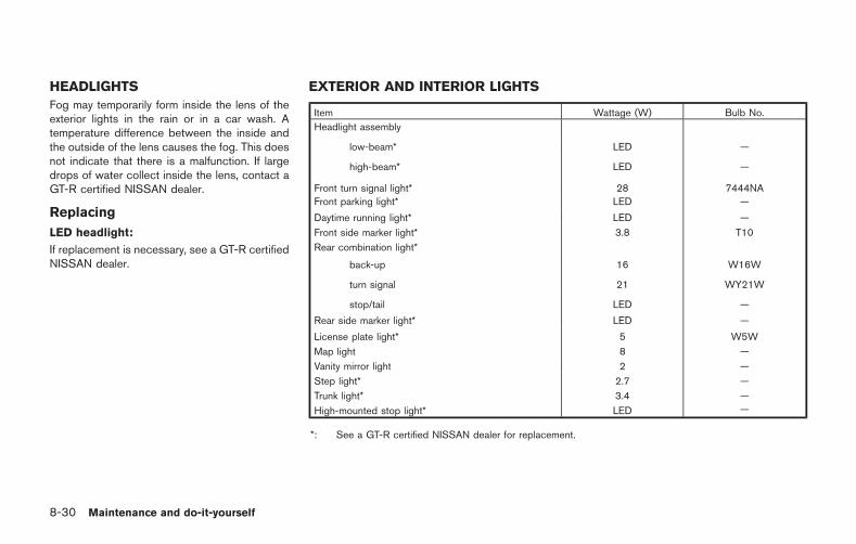
8-30 Maintenance and do-it-yourself
HEADLIGHTS
Fog may temporarily form inside the lens of theexterior lights in the rain or in a car wash. Atemperature difference between the inside andthe outside of the lens causes the fog. This doesnot indicate that there is a malfunction. If largedrops of water collect inside the lens, contact aGT-R certified NISSAN dealer.
Replacing
LED headlight:
If replacement is necessary, see a GT-R certifiedNISSAN dealer.
EXTERIOR AND INTERIOR LIGHTS
Item Wattage (W) Bulb No.
Headlight assembly
low-beam* LED —
high-beam* LED —
Front turn signal light* 28 7444NAFront parking light* LED —
Daytime running light* LED —
Front side marker light* 3.8 T10
Rear combination light*
back-up 16 W16W
turn signal 21 WY21W
stop/tail LED —
Rear side marker light* LED —
License plate light* 5 W5W
Map light 8 —
Vanity mirror light 2 —
Step light* 2.7 —
Trunk light* 3.4 —
High-mounted stop light* LED —
*: See a GT-R certified NISSAN dealer for replacement.
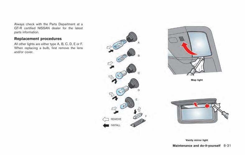
Always check with the Parts Department at aGT-R certified NISSAN dealer for the latestparts information.
Replacement procedures
All other lights are either type A, B, C, D, E or F.When replacing a bulb, first remove the lensand/or cover.
Map light
Vanity mirror light
Maintenance and do-it-yourself 8-31
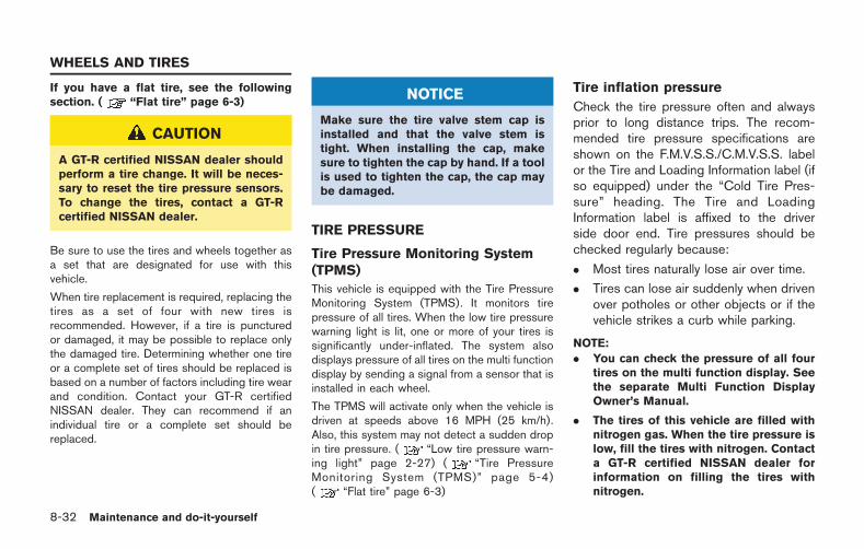
8-32 Maintenance and do-it-yourself
If you have a flat tire, see the followingsection. ( “Flat tire” page 6-3)
CAUTION
A GT-R certified NISSAN dealer shouldperform a tire change. It will be neces-sary to reset the tire pressure sensors.To change the tires, contact a GT-Rcertified NISSAN dealer.
Be sure to use the tires and wheels together asa set that are designated for use with thisvehicle.
When tire replacement is required, replacing thetires as a set of four with new tires isrecommended. However, if a tire is puncturedor damaged, it may be possible to replace onlythe damaged tire. Determining whether one tireor a complete set of tires should be replaced isbased on a number of factors including tire wearand condition. Contact your GT-R certifiedNISSAN dealer. They can recommend if anindividual tire or a complete set should bereplaced.
NOTICE
Make sure the tire valve stem cap isinstalled and that the valve stem istight. When installing the cap, makesure to tighten the cap by hand. If a toolis used to tighten the cap, the cap maybe damaged.
TIRE PRESSURE
Tire Pressure Monitoring System(TPMS)
This vehicle is equipped with the Tire PressureMonitoring System (TPMS). It monitors tirepressure of all tires. When the low tire pressurewarning light is lit, one or more of your tires issignificantly under-inflated. The system alsodisplays pressure of all tires on the multi functiondisplay by sending a signal from a sensor that isinstalled in each wheel.
The TPMS will activate only when the vehicle isdriven at speeds above 16 MPH (25 km/h).Also, this system may not detect a sudden dropin tire pressure. ( “Low tire pressure warn-ing light” page 2-27) ( “Tire PressureMonitoring System (TPMS)” page 5-4)( “Flat tire” page 6-3)
Tire inflation pressure
Check the tire pressure often and alwaysprior to long distance trips. The recom-mended tire pressure specifications areshown on the F.M.V.S.S./C.M.V.S.S. labelor the Tire and Loading Information label (ifso equipped) under the “Cold Tire Pres-sure” heading. The Tire and LoadingInformation label is affixed to the driverside door end. Tire pressures should bechecked regularly because:
. Most tires naturally lose air over time.
. Tires can lose air suddenly when drivenover potholes or other objects or if thevehicle strikes a curb while parking.
NOTE:
. You can check the pressure of all fourtires on the multi function display. Seethe separate Multi Function DisplayOwner’s Manual.
. The tires of this vehicle are filled withnitrogen gas. When the tire pressure islow, fill the tires with nitrogen. Contacta GT-R certified NISSAN dealer forinformation on filling the tires withnitrogen.
WHEELS AND TIRES
. If nitrogen is not available, compressedair may be safely used under normaldriving conditions. However, NISSANrecommends refilling with nitrogen formaximum tire performance.
The tire pressures should be checkedwhen the tires are cold. The tires areconsidered COLD after the vehicle hasbeen parked for 3 or more hours, or drivenless than 1 mile (1.6 km) at moderatespeeds.
Incorrect tire pressure, including un-der inflation, may adversely affect tirelife and vehicle handling.
WARNING
. Improperly inflated tires can failsuddenly and cause an accident.
. The Gross Vehicle Weight rating(GVWR) is located on the F.M.V.S.S./C.M.V.S.S. certification la-bel. The vehicle weight capacityis indicated on the Tire andLoading Information label (if soequipped). Do not load your
vehicle beyond this capacity.Overloading your vehicle mayresult in reduced tire life, unsafeoperating conditions due to pre-mature tire failure, or unfavor-able handling characteristicsand could also lead to a seriousaccident. Loading beyond thespecified capacity may also re-sult in failure of other vehiclecomponents.
. Before taking a long trip, orwhenever you heavily load yourvehicle, use a tire pressuregauge to ensure that the tirepressures are at the specifiedlevel.
. For additional information re-garding tires, refer to “ImportantTire Safety Information” (US) or“Tire Safety Information” (Cana-da) in the Warranty InformationBooklet.
NOTE:. Use only genuine GT-R tires and road
wheels.
The GT-R uses specially designed run-flat tires and matching road wheels.Use of these specially developed tiresand wheels provides the greatest po-tential for maximum performance.— Genuine GT-R tires and road wheels
help achieve maximum corneringand braking performance.
— Genuine GT-R tires and road wheelshelp achieve maximum tire durabil-ity during acceleration.
— Genuine GT-R tires and road wheelshelp achieve maximum handlingcapability during performance driv-ing.
— Genuine GT-R tires and road wheelshelp provide road holding in theevent of decreasing tire pressureand punctures.
— Genuine GT-R tires and road wheelshelp prevent the decrease ofstraight-running stability caused byuneven tire wear due to high rigiditywheels and wide tires.
. The GT-R uses specially designed run-flat tires which feature an extremely
Maintenance and do-it-yourself 8-33
8-34 Maintenance and do-it-yourself
rigid side wall. Special techniques andequipment are therefore required whenreplacing these tires. NISSAN recom-mends that tire replacement be per-formed at a GT-R certified NISSANdealer.
. Specific tire changing equipment mustbe used to remove the GT-R tires fromthe wheel and to install the GT-R tiresonto the wheel. It is only possible toreuse the tires when they have nocracks and/or deformations on thebead portion of the tire. If the incorrectequipment is used to remove the GT-Rtires from the wheel and to install theGT-R tires onto the wheel, cracks anddeformation may occur on the beadportion of the tires meaning that thetires cannot be reused. Contact a GT-Rcertified NISSAN dealer if the tiresneed to be removed from the wheels.
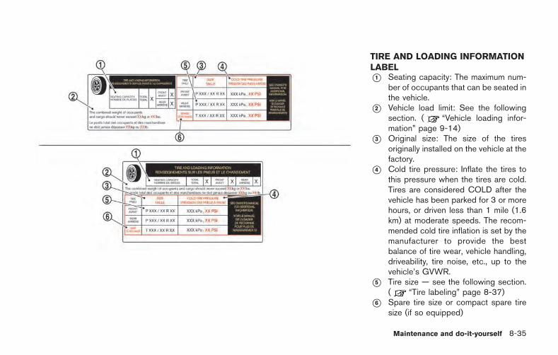
TIRE AND LOADING INFORMATIONLABEL*1 Seating capacity: The maximum num-
ber of occupants that can be seated inthe vehicle.
*2 Vehicle load limit: See the followingsection. ( “Vehicle loading infor-mation” page 9-14)
*3 Original size: The size of the tiresoriginally installed on the vehicle at thefactory.
*4 Cold tire pressure: Inflate the tires tothis pressure when the tires are cold.Tires are considered COLD after thevehicle has been parked for 3 or morehours, or driven less than 1 mile (1.6km) at moderate speeds. The recom-mended cold tire inflation is set by themanufacturer to provide the bestbalance of tire wear, vehicle handling,driveability, tire noise, etc., up to thevehicle’s GVWR.
*5 Tire size — see the following section.( “Tire labeling” page 8-37)
*6 Spare tire size or compact spare tiresize (if so equipped)
Maintenance and do-it-yourself 8-35
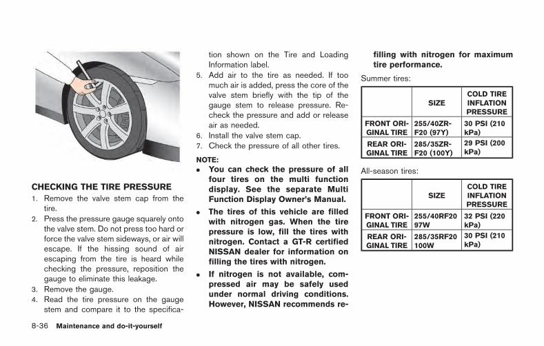
8-36 Maintenance and do-it-yourself
CHECKING THE TIRE PRESSURE
1. Remove the valve stem cap from thetire.
2. Press the pressure gauge squarely ontothe valve stem. Do not press too hard orforce the valve stem sideways, or air willescape. If the hissing sound of airescaping from the tire is heard whilechecking the pressure, reposition thegauge to eliminate this leakage.
3. Remove the gauge.4. Read the tire pressure on the gauge
stem and compare it to the specifica-
tion shown on the Tire and LoadingInformation label.
5. Add air to the tire as needed. If toomuch air is added, press the core of thevalve stem briefly with the tip of thegauge stem to release pressure. Re-check the pressure and add or releaseair as needed.
6. Install the valve stem cap.7. Check the pressure of all other tires.
NOTE:
. You can check the pressure of allfour tires on the multi functiondisplay. See the separate MultiFunction Display Owner’s Manual.
. The tires of this vehicle are filledwith nitrogen gas. When the tirepressure is low, fill the tires withnitrogen. Contact a GT-R certifiedNISSAN dealer for information onfilling the tires with nitrogen.
. If nitrogen is not available, com-pressed air may be safely usedunder normal driving conditions.However, NISSAN recommends re-
filling with nitrogen for maximumtire performance.
Summer tires:
SIZECOLD TIREINFLATIONPRESSURE
FRONT ORI-GINAL TIRE
255/40ZR-F20 (97Y)
30 PSI (210kPa)
REAR ORI-GINAL TIRE
285/35ZR-F20 (100Y)
29 PSI (200kPa)
All-season tires:
SIZECOLD TIREINFLATIONPRESSURE
FRONT ORI-GINAL TIRE
255/40RF2097W
32 PSI (220kPa)
REAR ORI-GINAL TIRE
285/35RF20100W
30 PSI (210kPa)
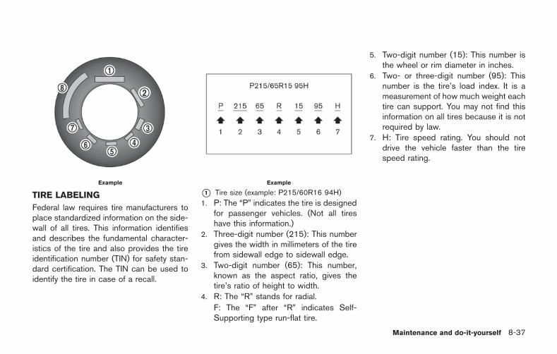
Example
TIRE LABELING
Federal law requires tire manufacturers toplace standardized information on the side-wall of all tires. This information identifiesand describes the fundamental character-istics of the tire and also provides the tireidentification number (TIN) for safety stan-dard certification. The TIN can be used toidentify the tire in case of a recall.
Example
*1 Tire size (example: P215/60R16 94H)
1. P: The “P” indicates the tire is designedfor passenger vehicles. (Not all tireshave this information.)
2. Three-digit number (215): This numbergives the width in millimeters of the tirefrom sidewall edge to sidewall edge.
3. Two-digit number (65): This number,known as the aspect ratio, gives thetire’s ratio of height to width.
4. R: The “R” stands for radial.
F: The “F” after “R” indicates Self-Supporting type run-flat tire.
5. Two-digit number (15): This number isthe wheel or rim diameter in inches.
6. Two- or three-digit number (95): Thisnumber is the tire’s load index. It is ameasurement of how much weight eachtire can support. You may not find thisinformation on all tires because it is notrequired by law.
7. H: Tire speed rating. You should notdrive the vehicle faster than the tirespeed rating.
Maintenance and do-it-yourself 8-37
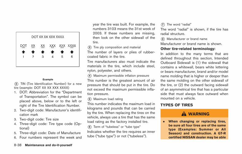
8-38 Maintenance and do-it-yourself
Example
*2 TIN (Tire Identification Number) for a newtire (example: DOT XX XX XXX XXXX)
1. DOT: Abbreviation for the “Departmentof Transportation”. The symbol can beplaced above, below or to the left orright of the Tire Identification Number.
2. Two-digit code: Manufacturer’s identifi-cation mark
3. Two-digit code: Tire size4. Three-digit code: Tire type code (Op-
tional)5. Three-digit code: Date of Manufacture6. Four numbers represent the week and
year the tire was built. For example, thenumbers 3103 means the 31st week of2003. If these numbers are missing,then look on the other sidewall of thetire.
*3 Tire ply composition and material
The number of layers or plies of rubber-coated fabric in the tire.
Tire manufacturers also must indicate thematerials in the tire, which include steel,nylon, polyester, and others.
*4 Maximum permissible inflation pressure
This number is the greatest amount of airpressure that should be put in the tire. Donot exceed the maximum permissible infla-tion pressure.
*5 Maximum load rating
This number indicates the maximum load inkilograms and pounds that can be carriedby the tire. When replacing the tires on thevehicle, always use a tire that has the sameload rating as the factory installed tire.
*6 Term of “tubeless” or “tube type”
Indicates whether the tire requires an innertube (“tube type”) or not (“tubeless”).
*7 The word “radial”
The word “radial” is shown, if the tire hasradial structure.
*8 Manufacturer or brand name
Manufacturer or brand name is shown.
Other tire-related terminology:
In addition to the many terms that aredefined throughout this section, IntendedOutboard Sidewall is (1) the sidewall thatcontains a whitewall, bears white letteringor bears manufacturer, brand and/or modelname molding that is higher or deeper thanthe same molding on the other sidewall ofthe tire, or (2) the outward facing sidewallof an asymmetrical tire that has a particularside that must always face outward whenmounted on a vehicle.
TYPES OF TIRES
WARNING
. When changing or replacing tires,be sure all four tires are of the sametype (Examples: Summer or AllSeason) and construction. A GT-Rcertified NISSAN dealer may be able
to help you with information abouttire type, size, speed rating andavailability.
. Replacing tires with those not ori-ginally specified by NISSAN couldaffect the proper operation of theTPMS.
. For additional information regard-ing tires, refer to “Important TireSafety Information” (US) or “TireSafety Information” (Canada) in theWarranty Information Booklet.
All-season tires
NISSAN specifies all-season tires on somemodels to provide good performance for useall year around, including snowy and icy roadconditions. All-season tires are identified by ALLSEASON on the tire sidewall.
Summer tires
The GT-R summer tires are made from aspecially formulated rubber to maximize thevehicle’s performance capabilities. Performanceof summer tires is substantially reduced whentemperatures are less than 328F (08C) so youmust drive carefully. NISSAN recommends theuse of winter or all-season tires on all four
wheels if you plan to operate your vehicle insnowy or icy conditions when temperatures areless than 328F (08C).
WARNING
Never use summer tires when thetemperature is below 48F ( 208C) toprevent permanent tread deformationwhich may cause tire damage or tirefailure. This may cause a loss of vehiclecontrol which can result in seriouspersonal injury or death.
Run-flat tires
Your vehicle is equipped with run-flat tires. Youcan continue driving to a safe location even ifthey are punctured. Always use run-flat tires ofthe specified size on all four wheels. Mixing tiresizes or construction may reduce vehicle hand-ling stability. If necessary, contact a GT-Rcertified NISSAN dealer for assistance.
Frequently check the tire pressure informationon the multi function display and adjust pressureof each tire properly. See the separate MultiFunction Display Owner’s Manual.
It can be difficult to tell if a run-flat tire is under-inflated or flat. Check the tire pressures as
described earlier in this section. If the tirebecomes under-inflated while driving, the lowtire pressure warning light will come on. If thetire becomes flat while driving, the low tirepressure warning light and the run-flat tirewarning display will come on.
Low tire pressure:
If the vehicle is being driven with low tirepressure, the low tire pressure warning light willilluminate and the low tire pressure warning willappear in the vehicle information display.
Flat tire:
If the vehicle is being driven with one or more flattires, the low tire pressure warning light willilluminate continuously and a chime will soundfor 10 seconds. The run-flat tire warning alsoappears in the vehicle information display.
The chime will only sound at the first indicationof a flat tire and the run-flat tire warning displaywill illuminate continuously. When the flat tirewarning is activated, have the system reset andthe tire checked and replaced if necessary by aGT-R certified NISSAN dealer. Even if the tire isinflated to the specified COLD tire pressure, thewarning light will continue to illuminate until thesystem is reset by a GT-R certified NISSANdealer.
If the low tire pressure and the run-flat tire
Maintenance and do-it-yourself 8-39

8-40 Maintenance and do-it-yourself
warning appears on the vehicle informationdisplay:
. Do not exceed 50 MPH (80 km/h).
. Increase your following distance to allow forincreased stopping distances.
. Avoid sudden maneuvers, hard corneringand hard braking.
WARNING
. Although you can continue drivingwith a punctured run-flat tire, re-member that vehicle handling sta-bility is reduced, which could lead toan accident and personal injury.Also, driving a long distance at highspeeds may damage the tire.
. Do not drive at speeds above 50MPH (80 km/h) and do not drivemore than 50 miles (80 km) with apunctured run-flat tire. The actualdistance the vehicle can be drivenon a flat tire depends on outsidetemperature, vehicle load, road con-ditions and other factors.
. Drive safely at reduced speeds.Avoid hard cornering or braking,which may cause you to lose control
of the vehicle.
NOTICE
. Never install tire chains on a punc-tured run-flat tire, as this coulddamage your vehicle.
. Avoid driving over any projection orpothole, as the clearance betweenthe vehicle and the ground is smal-ler than normal.
. Do not enter an automated car washwith a punctured run-flat tire.
. Have the punctured tire replaced bya GT-R certified NISSAN dealer assoon as possible, as the tire’sperformance capability is reduced.
Tires for All-Wheel Drive (AWD)
If excessive tire wear is found, it is recom-mended that all four tires be replaced with tiresof the specified size, brand, construction andtread pattern. The tire pressure and wheelalignment should also be checked and cor-rected as necessary. Contact a GT-R certifiedNISSAN dealer.
TIRE CHAINS
Use of tire chains may be prohibited accordingto location. Check the local laws before instal-ling tire chains. When installing tire chains, makesure they are of proper size for the tires on yourvehicle and are installed according to the chainmanufacturer instructions. Use only SAE classS chains. Class “S” chains are used on vehicleswith restricted tire to vehicle clearance. Vehiclesthat can use Class “S” chains are designed tomeet the SAE standard minimum clearancesbetween the tire and the closest vehiclesuspension or body component required toaccommodate the use of a winter traction device(tire chains or cables). The minimum clearancesare determined using the factory equipped tiresize. Other types may damage your vehicle. Usechain tensioners when recommended by the tirechain manufacturer to ensure a tight fit. Looseend links of the tire chain must be secured orremoved to prevent the possibility of whippingaction damage to the fenders or undercarriage.If possible, avoid fully loading your vehicle whenusing tire chains. In addition, drive at a reducedspeed. Otherwise, your vehicle may be da-maged and/or vehicle handling and performancemay be adversely affected.
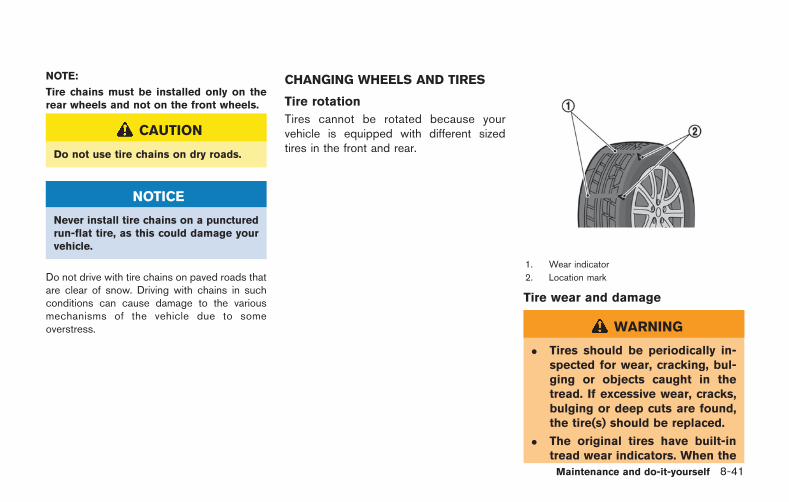
NOTE:
Tire chains must be installed only on therear wheels and not on the front wheels.
CAUTION
Do not use tire chains on dry roads.
NOTICE
Never install tire chains on a puncturedrun-flat tire, as this could damage yourvehicle.
Do not drive with tire chains on paved roads thatare clear of snow. Driving with chains in suchconditions can cause damage to the variousmechanisms of the vehicle due to someoverstress.
CHANGING WHEELS AND TIRES
Tire rotation
Tires cannot be rotated because yourvehicle is equipped with different sizedtires in the front and rear.
1. Wear indicator
2. Location mark
Tire wear and damage
WARNING
. Tires should be periodically in-spected for wear, cracking, bul-ging or objects caught in thetread. If excessive wear, cracks,bulging or deep cuts are found,the tire(s) should be replaced.
. The original tires have built-intread wear indicators. When the
Maintenance and do-it-yourself 8-41
8-42 Maintenance and do-it-yourself
wear indicators are visible, thetire(s) should be replaced.
. Tires degrade with age and use.Have tires, over 6 years oldchecked by a qualified techni-cian because some tire damagemay not be obvious. Replace thetires as necessary to prevent tirefailure and possible personalinjury.
. For additional information re-garding tires, refer to “ImportantTire Safety Information” (US) or“Tire Safety Information” (Cana-da) in the Warranty InformationBooklet.
Replacing wheels and tires
When tire replacement is required, replacingtires as a set of four with new tires isrecommended. However, if a tire is puncturedor damaged, it may be possible to replace onlythe damaged tire. Determining whether one tireor a complete set of tires should be replaced isbased on a number of factors including tire wearand condition. Contact your GT-R certified
NISSAN dealer. They can recommend if anindividual tire or a complete set should bereplaced.
When replacing a tire, use the specified size,speed rating and load carrying capacity asoriginally equipped. ( “Wheels and tires”page 9-9)
NOTICE
. When you replace the GT-R tires, itis recommended that you replace allthe tires at the same time.
. The GT-R uses specially designedrun-flat tires which feature an ex-tremely rigid side wall. Special tech-niques and equipment are thereforerequired when replacing these tires.NISSAN recommends that tire re-placement be performed at a GT-Rcertified NISSAN dealer.
. When tires are reinstalled afterbeing uninstalled from the wheels,use equipment such as a leverlessautomatic tire changer. It is onlypossible to reuse the tires whenthey have no cracks and/or defor-mations on the bead portion. How-ever, if you use a lever-type tire
changer, cracks and deformationmay occur on the bead portion ofthe tires meaning that the tirescannot be reused.
. Make sure the tire valve stem cap isinstalled and that the valve stem istight. When installing the cap, makesure to tighten the cap by hand. If atool is used to tighten the cap, thecap may be damaged.
WARNING
. The use of tires other than thosespecified or the mixed use of tires ofdifferent brands, construction (bias,bias-belted, radial or run-flat), ortread patterns can adversely affectthe ride, braking, VDC system, hand-ling, ground clearance, body-to-tireclearance, tire chain clearance,speedometer calibration, headlightaim and bumper height. Some ofthese effects may lead to accidentsand could result in serious personalinjury.
. If the wheels are changed for anyreason, always replace with wheels
which have the same off-set dimen-sion. Wheels of a different off-setcould cause premature tire wear,degrade vehicle handling character-istics, affect the VDC system and/orcause interference with the brakediscs. Such interference can lead todecreased braking efficiency and/orearly brake pad wear. ( “Wheelsand tires” page 9-9)
. When a wheel is replaced, tirepressure will not be indicated, theTPMS will not function and the lowtire pressure warning light will flashfor approximately 1 minute andremain on after the 1 minute. Con-tact a GT-R certified NISSAN dealeras soon as possible for tire replace-ment and/or system resetting.
. Replacing tires with those not ori-ginally specified by NISSAN couldaffect the proper operation of theTPMS.
. Do not install a damaged or de-formed wheel or tire even if it hasbeen repaired. Such wheels or tirescould have structural damage andcould fail without warning.
. Never use retread tires.
. For additional information regard-ing tires, refer to “Important TireSafety Information” (US) or “TireSafety Information” (Canada) in theWarranty Information Booklet.
. Always use tires of the specifiedtype, size, brand, construction (bias,bias-belted, radial or run-flat), andtread pattern on all four wheels.Failure to do so may result in acircumference difference betweentires on the front and rear axleswhich will cause excessive tire wearand may damage the transmission,transfer case and differential gears.
Wheel balance
Unbalanced wheels may affect vehicle handlingand tire life. Even with regular use, wheels canget out of balance. Therefore, they should bebalanced as required.
Wheel balance service should be performedwith the wheels off the vehicle. Spin balancingthe rear wheels on the vehicle could lead tomechanical damage.
For additional information regarding tires, refer
to “Important Tire Safety Information” (US) or“Tire Safety Information” (Canada) in the War-ranty Information Booklet.
Care of wheels
( “Cleaning exterior” page 7-2)
JACKING VEHICLE AND REMOVINGWHEELS
WARNING
. Make sure the parking brake issecurely applied and the transmis-sion is shifted into the &P position.
. Never change tires when the vehicleis on a slope, ice or slippery areas.This is hazardous.
. Never change tires if oncomingtraffic is close to your vehicle. Waitfor professional road assistance.
Maintenance and do-it-yourself 8-43
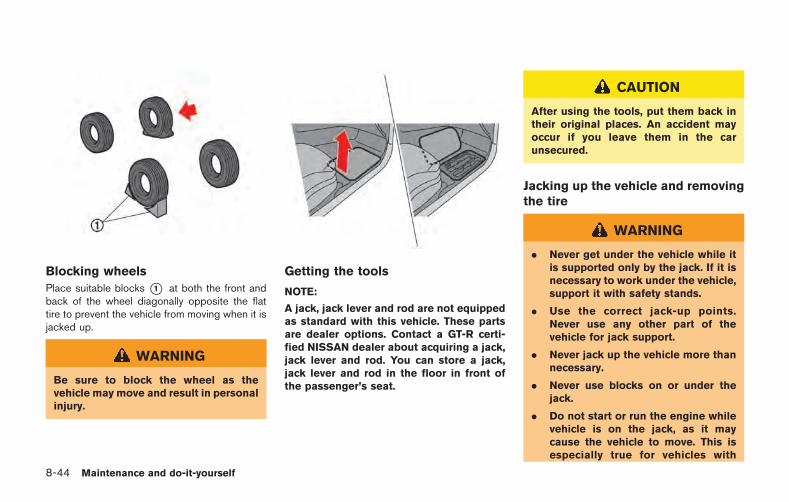
8-44 Maintenance and do-it-yourself
Blocking wheels
Place suitable blocks *1 at both the front andback of the wheel diagonally opposite the flattire to prevent the vehicle from moving when it isjacked up.
WARNING
Be sure to block the wheel as thevehicle may move and result in personalinjury.
Getting the tools
NOTE:
A jack, jack lever and rod are not equippedas standard with this vehicle. These partsare dealer options. Contact a GT-R certi-fied NISSAN dealer about acquiring a jack,jack lever and rod. You can store a jack,jack lever and rod in the floor in front ofthe passenger’s seat.
CAUTION
After using the tools, put them back intheir original places. An accident mayoccur if you leave them in the carunsecured.
Jacking up the vehicle and removingthe tire
WARNING
. Never get under the vehicle while itis supported only by the jack. If it isnecessary to work under the vehicle,support it with safety stands.
. Use the correct jack-up points.Never use any other part of thevehicle for jack support.
. Never jack up the vehicle more thannecessary.
. Never use blocks on or under thejack.
. Do not start or run the engine whilevehicle is on the jack, as it maycause the vehicle to move. This isespecially true for vehicles with
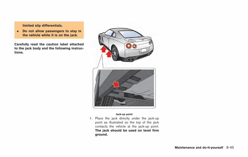
limited slip differentials.
. Do not allow passengers to stay inthe vehicle while it is on the jack.
Carefully read the caution label attachedto the jack body and the following instruc-tions.
Jack-up point
1. Place the jack directly under the jack-uppoint as illustrated so the top of the jackcontacts the vehicle at the jack-up point.The jack should be used on level firmground.
Maintenance and do-it-yourself 8-45
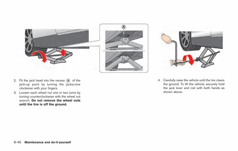
8-46 Maintenance and do-it-yourself
2. Fit the jack head into the recess *A of thejack-up point by turning the jackscrewclockwise with your fingers.
3. Loosen each wheel nut one or two turns byturning counterclockwise with the wheel nutwrench. Do not remove the wheel nutsuntil the tire is off the ground.
4. Carefully raise the vehicle until the tire clearsthe ground. To lift the vehicle, securely holdthe jack lever and rod with both hands asshown above.
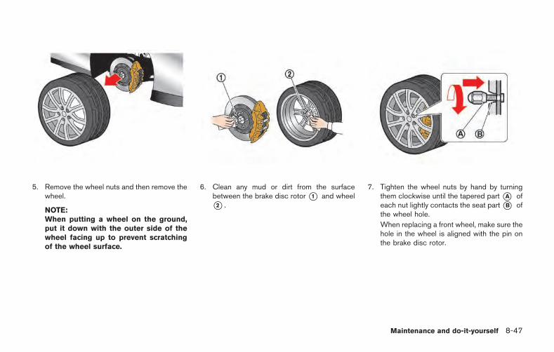
5. Remove the wheel nuts and then remove thewheel.
NOTE:When putting a wheel on the ground,put it down with the outer side of thewheel facing up to prevent scratchingof the wheel surface.
6. Clean any mud or dirt from the surfacebetween the brake disc rotor*1 and wheel*2 .
7. Tighten the wheel nuts by hand by turningthem clockwise until the tapered part*A ofeach nut lightly contacts the seat part*B ofthe wheel hole.
When replacing a front wheel, make sure thehole in the wheel is aligned with the pin onthe brake disc rotor.
Maintenance and do-it-yourself 8-47
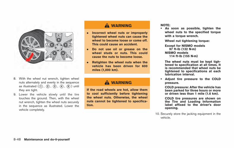
8-48 Maintenance and do-it-yourself
8. With the wheel nut wrench, tighten wheelnuts alternately and evenly in the sequenceas illustrated (*1 , *2 , *3 , *4 , *5 ) untilthey are tight.
9. Lower the vehicle slowly until the tiretouches the ground. Then, with the wheelnut wrench, tighten the wheel nuts securelyin the sequence as illustrated. Lower thevehicle completely.
WARNING
. Incorrect wheel nuts or improperlytightened wheel nuts can cause thewheel to become loose or come off.This could cause an accident.
. Do not use oil or grease on thewheel studs or nuts. This couldcause the nuts to become loose.
. Retighten the wheel nuts when thevehicle has been driven for 600miles (1,000 km).
WARNING
If the road wheels are hot, allow themto cool sufficiently before tighteningthe wheel nuts. Otherwise, the wheelnuts cannot be tightened to specifica-tion.
NOTE:. As soon as possible, tighten the
wheel nuts to the specified torquewith a torque wrench.
Wheel nut tightening torque:
Except for NISMO models97 ft-lb (132 N·m)
NISMO models114 ft-lb (155 N·m)
The wheel nuts must be kept tigh-tened to specification at all times. Itis recommended that wheel nuts betightened to specifications at eachlubrication interval.
. Adjust tire pressure to the COLDpressure.
COLD pressure: After the vehicle hasbeen parked for three hours or moreor driven less than 1 mile (1.6 km).
COLD tire pressures are shown onthe Tire and Loading Informationlabel affixed to the driver’s dooropening.
10. Securely store the jacking equipment in thevehicle.
MEMO
Maintenance and do-it-yourself 8-49

8-50 Maintenance and do-it-yourself
MEMO
9 Technical and consumer information
Capacities and recommended fluids/lubricants ............... 9-2Fuel information .................................................................. 9-4Engine oil and oil filter recommendation ...................... 9-6Air conditioning system refrigerant andlubricant recommendations .............................................. 9-7
Specifications ............................................................................ 9-8Engine ................................................................................... 9-8Wheels and tires ................................................................ 9-9Dimensions ....................................................................... 9-10
When traveling or registering your vehicle inanother country ...................................................................... 9-11Vehicle identification ............................................................. 9-11
Vehicle Identification Number (VIN) plate ................. 9-11Vehicle identification number (chassis number) ..... 9-11Engine serial number ...................................................... 9-12F.M.V.S.S./C.M.V.S.S. certification label ................... 9-12Emission control information label .............................. 9-12Tire and loading information label ............................... 9-13Air conditioner specification label ............................... 9-13
Installing front license plate ................................................ 9-13
Vehicle loading information ................................................ 9-14Terms ................................................................................ 9-14Vehicle load capacity ................................................... 9-15Loading tips .................................................................... 9-16Measurement of weights ............................................. 9-16
Towing a trailer ...................................................................... 9-17Flat towing .............................................................................. 9-17Uniform tire quality grading ................................................ 9-17
Treadwear ....................................................................... 9-17Traction AA, A, B and C ............................................. 9-18Temperature A, B and C ............................................. 9-18
Emission control system warranty .................................... 9-18Reporting safety defects .................................................... 9-19Readiness for Inspection/Maintenance (I/M) test(US only) ................................................................................ 9-20Event Data Recorders (EDR) ............................................ 9-20Vehicle status data recorder (VSDR) ............................. 9-21
Handling of data ............................................................ 9-21Owner’s Manual/Service Manual order information .... 9-22
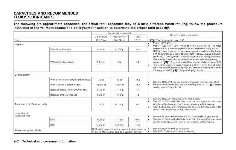
9-2 Technical and consumer information
The following are approximate capacities. The actual refill capacities may be a little different. When refilling, follow the procedureinstructed in the “8. Maintenance and do-it-yourself” section to determine the proper refill capacity.
Capacity (Approximate)Recommended specifications
US measure Imp measure Liter
Fuel 19-1/2 gal 16-1/4 gal 73.8 ( “Fuel information” page 9-4)
Engine oil. Mobil 1 (0W-40). Mobil 1 (0W-40) (100% synthetic) is the factory fill oil. The VR38
engine with its plasma-sprayed bores was developed using this oil.NISSAN cannot ensure proper engine operation and durability if other0W-40 synthetic oil is used. If Mobil 1 (0W-40) is not available, Mobil 1(10W-40) (100% synthetic) may be used; however, some performanceloss may be noticed. For additional information, see the followingsection. ( “Engine oil and oil filter recommendation” page 9-6)
. The recommended oil capacity level is 0.39 in (10mm) (0.5 L) belowthe H mark on the engine oil dipstick. For additional information, see thefollowing section. ( “Engine oil” page 8-13)
With oil filter change 5-1/4 qt 4-3/8 qt 5.0
Without oil filter change 4-3/4 qt 4 qt 4.5
Cooling system
. Genuine NISSAN Long Life Antifreeze/Coolant (blue) or equivalent
. For additional information, see the following section. ( “Enginecooling system” page 8-10)
With reservoir (except for NISMO models) 12 qt 10 qt 11.3
With reservoir (NISMO models) 12-3/8 qt 10-1/4 qt 11.7
Reservoir (except for NISMO models) 1-1/2 qt 1-1/4 qt 1.4
Reservoir (NISMO models) 1-7/8 qt 1-5/8 qt 1.8
Transmission oil (Drain and refill) 10 qt 8-1/4 qt 9.4
. Genuine NISSAN Transmission Oil R35 Special
. The use of fluids and lubricants other than the specified may causevehicle malfunctions and result in non-warranty vehicle repairs.
. All of the fluid cannot be removed when servicing the transmission. Theactual refill amount may be less than shown.
Differential oil(Drain and refill) . Genuine NISSAN Differential Oil R35 COMPETITION type 2189E
. The use of fluids and lubricants other than the specified may causevehicle malfunctions and result in non-warranty vehicle repairs.
Front 1-3/8 pt 1-1/8 pt 0.65
Rear 2-7/8 pt 2-3/8 pt 1.35
Power steering fluid (PSF)Refill to the proper oil level according to the instructionsin the “8. Maintenance and do-it-yourself” section.
. Genuine NISSAN PSF or equivalent
. DEXRONTM VI type ATF may also be used.
CAPACITIES AND RECOMMENDEDFLUIDS/LUBRICANTS
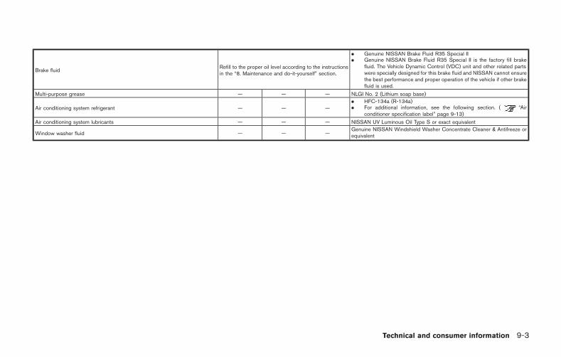
Brake fluidRefill to the proper oil level according to the instructionsin the “8. Maintenance and do-it-yourself” section.
. Genuine NISSAN Brake Fluid R35 Special II
. Genuine NISSAN Brake Fluid R35 Special II is the factory fill brakefluid. The Vehicle Dynamic Control (VDC) unit and other related partswere specially designed for this brake fluid and NISSAN cannot ensurethe best performance and proper operation of the vehicle if other brakefluid is used.
Multi-purpose grease — — — NLGI No. 2 (Lithium soap base)
Air conditioning system refrigerant — — —. HFC-134a (R-134a). For additional information, see the following section. ( “Air
conditioner specification label” page 9-13)
Air conditioning system lubricants — — — NISSAN UV Luminous Oil Type S or exact equivalent
Window washer fluid — — —Genuine NISSAN Windshield Washer Concentrate Cleaner & Antifreeze orequivalent
Technical and consumer information 9-3
9-4 Technical and consumer information
FUEL INFORMATION
VR38 engine
Use unleaded premium gasoline with an octanerating of at least 93 AKI (Anti-Knock Index)number (Research octane number 98) to max-imize vehicle performance.
If the premium gasoline specified above is notavailable, you may use unleaded premium gaso-line with an octane rating of at least 91 AKInumber (Research octane number 96), but youmay notice a decrease in performance.
Do not use gasoline with an octane rating lowerthan 91 AKI (Research octane number 96).
NOTICE
. Using a fuel other than that speci-fied could adversely affect the emis-sion control system, and may alsoaffect warranty coverage.
. Under no circumstances should aleaded gasoline be used, becausethis will damage the three-way cat-alyst.
. Do not use E-15 or E-85 fuel in yourvehicle. Your vehicle is not designedto run on E-15 or E-85 fuel. Using E-
15 or E-85 fuel in a vehicle notspecifically designed for E-15 or E-85 fuel can adversely affect theemission control devices and sys-tems of the vehicle. Damage causedby such fuel is not covered by theNISSAN new vehicle limited war-ranty.
. U.S. government regulations requireethanol dispensing pumps to beidentified by a small, square, orangeand black label with the commonabbreviation or the appropriate per-centage for that region.
. NISSAN recommends using fuelsthat contain no alcohol. However,fuels containing up to 10% alcoholmay be used, if necessary. To avoidserious engine damage due to in-creased cylinder temperatures, donot use fuels that contain morealcohol than indicated in this sec-tion. Also, do not use fuel additives,fuel stabilizers or fuel deicers thatcontain alcohol.
Gasoline specifications
NISSAN recommends using gasoline that meetsthe World-Wide Fuel Charter (WWFC) speci-fications where it is available. Many of theautomobile manufacturers developed this spe-cification to improve emission system andvehicle performance. Ask your service stationmanager if the gasoline meets the World-WideFuel Charter (WWFC) specifications.
Reformulated gasoline
Some fuel suppliers are now producing refor-mulated gasolines. These gasolines are speciallydesigned to reduce vehicle emissions. NISSANsupports efforts towards cleaner air and sug-gests that you use reformulated gasoline whenavailable.
Gasoline containing oxygenates
Some fuel suppliers sell gasoline containingoxygenates such as ethanol, MTBE and metha-nol with or without advertising their presence.NISSAN does not recommend the use of fuelsof which the oxygenate content and the fuelcompatibility for your NISSAN cannot be readilydetermined. If in doubt, ask your service stationmanager.
If you use oxygenate-blend gasoline, please takethe following precautions as the usage of such

fuels may cause vehicle performance problemsand/or fuel system damage.
. The fuel should be unleaded and havean octane rating no lower than thatrecommended for unleaded gasoline.
. If an oxygenate-blend, excepting amethanol blend, is used, it shouldcontain no more than 10% oxygenate.(MTBE may, however, be added up to15%.)
. E-15 fuel contains more than 10%oxygenate. E-15 fuel will adverselyaffect the emission control devicesand systems of the vehicle and shouldnot be used. Damage caused by suchfuel is not covered under the NISSANnew vehicle limited warranty.
. If a methanol blend is used, it shouldcontain no more than 5% methanol(methyl alcohol and wood alcohol). Itshould also contain a suitable amountof appropriate cosolvents and corro-sion inhibitors. If not properly formu-lated with the appropriate cosolventsand corrosion inhibitors, such metha-nol blends may cause fuel systemdamage and/or vehicle performancemalfunctions. At this time, sufficient
data is not available to ensure that allmethanol blends are suitable for use inNISSAN vehicles.
If any undesirable driveability problems such asengine stalling or hard hot starting are experi-enced after using oxygenate-blend fuels, im-mediately change to a non-oxygenate fuel or afuel with a low blend of MTBE.
NOTICE
Take care not to spill gasoline duringrefueling. Gasoline containing oxyge-nates can cause paint damage.
E-15 fuel
E-15 fuel is a mixture of approximately 15% fuelethanol and 85% unleaded gasoline. E-15 canonly be used in vehicles designed to run on E-15 fuel. Do not use E-15 in your vehicle. U.S.government regulations require fuel ethanoldispensing pumps to be identified with small,square, orange and black label with the commonabbreviation or the appropriate percentage forthat region.
E-85 fuel
E-85 fuel is a mixture of approximately 85% fuelethanol and 15% unleaded gasoline. E-85 canonly be used in a Flexible Fuel Vehicle (FFV). Donot use E-85 fuel in your vehicle. U.S. govern-ment regulations require fuel ethanol dispensingpumps to be identified by a small, square,orange and black label with the commonabbreviation or the appropriate percentage forthat region.
Aftermarket fuel additives
NOTICE
NISSAN does not recommend the useof any aftermarket fuel additives (Ex-ample: fuel injector cleaner, intakevalve deposit removers, etc.) which aresold commercially. Many of these ad-ditives intended for gum, varnish ordeposit removal may contain activesolvent or similar ingredients that canbe harmful to the fuel system andengine.
Technical and consumer information 9-5
9-6 Technical and consumer information
Octane rating tips
Using unleaded gasoline with an octanerating lower than recommended above cancause persistent, heavy spark knock.(Spark knock is a metallic rapping noise.)If severe, this can lead to engine damage.If you detect a persistent heavy sparkknock even when using gasoline of thestated octane rating, or if you hear steadyspark knock while holding a steady speedon level roads, have a GT-R certifiedNISSAN dealer correct the condition. Fail-ure to correct the condition is misuse ofthe vehicle, for which NISSAN is notresponsible.
Incorrect ignition timing will result in knocking,after-run or overheating. This in turn may causeexcessive fuel consumption or damage to theengine. If any of the above symptoms areencountered, have your vehicle checked at aGT-R certified NISSAN dealer or other compe-tent service facility.
However, now and then you may noticelight spark knock for a short time whileaccelerating or driving up hills. This is nocause for concern, because you get thegreatest fuel benefit when there is lightspark knock for a short time under heavyengine load.
ENGINE OIL AND OIL FILTER RE-COMMENDATION
Selecting the correct oil
It is essential to choose the correct grade,quality, and viscosity engine oil to ensuresatisfactory engine life and performance.( “Capacities and recommended fluids/lu-bricants” page 9-2)
Mobil 1 (0W-40) (100% synthetic) is the factoryfill oil. The VR38 engine with its plasma-sprayedbores was developed using this oil. NISSANcannot ensure proper engine operation anddurability if other 0W-40 synthetic oil is used.If Mobil 1 (0W-40) is not available, Mobil 1(10W-40) (100% synthetic) may be used;however, some performance loss may benoticed.
NOTICE
Using an engine oil other than thatspecified could adversely affect theengine. See the 2015 NISSAN GT-RWarranty Information Booklet for de-tails and exclusions.
Oil additives
NISSAN does not recommend the use of oiladditives. The use of an oil additive is notnecessary when the proper oil type is used andmaintenance intervals are followed.
Oil which may contain foreign matter or hasbeen previously used should not be used.
Oil viscosity
The engine oil viscosity or thickness changeswith temperature. Because of this, it is importantthat the engine oil viscosity be selected basedon the temperatures at which the vehicle will beoperated before the next oil change. Choosingan oil viscosity other than that recommendedcould cause serious engine damage.
Selecting the correct oil filter
Your new vehicle is equipped with a high-qualitygenuine NISSAN oil filter. NISSAN recommendsto use the genuine NISSAN oil filter for thereason described in change intervals.
Change intervals
The oil and oil filter change intervals for yourengine are based on the use of the specifiedquality oils and filters. Oil and filter other than thespecified quality, or oil and filter change intervalslonger than recommended could reduce engine
life. Damage to engines caused by impropermaintenance or use of incorrect oil and filterquality and/or viscosity is not covered by theNISSAN new vehicle limited warranties.
Your engine was filled with a high quality engineoil when it was built. You do not have to changethe oil before the first recommended changeinterval. Oil and filter change intervals dependupon how you use your vehicle. Operation underthe following conditions may require morefrequent oil and filter changes.
. repeated short distance driving at coldoutside temperatures
. driving in dusty conditions
. extensive idling
. stop and go “rush hour” traffic
Refer to the “NISSAN Service and MaintenanceGuide” for the maintenance schedule.
AIR CONDITIONING SYSTEM RE-FRIGERANT AND LUBRICANT RE-COMMENDATIONS
The air conditioning system in yourNISSAN vehicle must be charged with therefrigerant HFC-134a (R-134a) and thelubricant, NISSAN UV Luminous Oil TypeS or the exact equivalents.
NOTICE
The use of any other refrigerant orlubricant will cause severe damage tothe air conditioning system and willrequire the replacement of all air con-ditioner system components.
The refrigerant HFC-134a (R-134a) in yourNISSAN vehicle will not harm the earth’s ozonelayer. Although this refrigerant does not affectthe earth’s atmosphere, certain governmentalregulations require the recovery and recycling ofany refrigerant during automotive air condition-ing system service. Your GT-R certified NISSANdealer has the trained technicians and equip-ment needed to recover and recycle your airconditioning system refrigerant.
Contact a GT-R certified NISSAN dealer whenservicing your air conditioning system.
Technical and consumer information 9-7
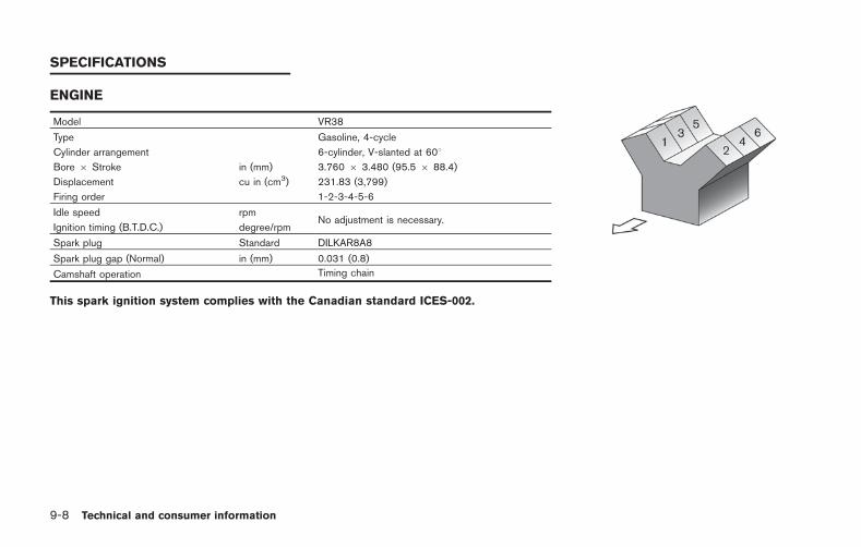
9-8 Technical and consumer information
ENGINE
Model VR38
Type Gasoline, 4-cycle
Cylinder arrangement 6-cylinder, V-slanted at 608Bore 6 Stroke in (mm) 3.760 6 3.480 (95.5 6 88.4)
Displacement cu in (cm3) 231.83 (3,799)
Firing order 1-2-3-4-5-6
Idle speed rpmNo adjustment is necessary.
Ignition timing (B.T.D.C.) degree/rpm
Spark plug Standard DILKAR8A8
Spark plug gap (Normal) in (mm) 0.031 (0.8)
Camshaft operation Timing chain
This spark ignition system complies with the Canadian standard ICES-002.
SPECIFICATIONS
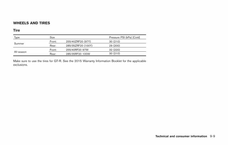
WHEELS AND TIRES
Tire
Type Size Pressure PSI (kPa) [Cold]
SummerFront: 255/40ZRF20 (97Y) 30 (210)
Rear: 285/35ZRF20 (100Y) 29 (200)
All-seasonFront: 255/40RF20 97W 32 (220)
Rear: 285/35RF20 100W 30 (210)
Make sure to use the tires for GT-R. See the 2015 Warranty Information Booklet for the applicableexclusions.
Technical and consumer information 9-9
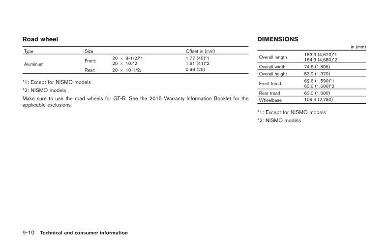
9-10 Technical and consumer information
Road wheel
Type Size Offset in (mm)
AluminumFront:
20 6 9-1/2J*120 6 10J*2
1.77 (45)*11.61 (41)*2
Rear: 20 6 10-1/2J 0.98 (25)
*1: Except for NISMO models
*2: NISMO models
Make sure to use the road wheels for GT-R. See the 2015 Warranty Information Booklet for theapplicable exclusions.
DIMENSIONSin (mm)
Overall length183.9 (4,670)*1184.3 (4,680)*2
Overall width 74.6 (1,895)
Overall height 53.9 (1,370)
Front tread62.6 (1,590)*163.0 (1,600)*2
Rear tread 63.0 (1,600)
Wheelbase 109.4 (2,780)
*1: Except for NISMO models
*2: NISMO models
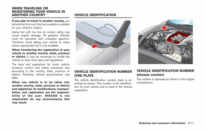
If you plan to travel in another country, youshould first find out if the fuel available is suitablefor your vehicle’s engine.
Using fuel with too low an octane rating maycause engine damage. All gasoline vehiclesmust be operated with unleaded gasoline.Therefore, avoid taking your vehicle to areaswhere appropriate fuel is not available.
When transferring the registration of yourvehicle to another country, state, provinceor district, it may be necessary to modify thevehicle to meet local laws and regulations.
The laws and regulations for motor vehicleemission control and safety standards varyaccording to the country, state, province ordistrict; therefore, vehicle specifications maydiffer.
When any vehicle is to be taken intoanother country, state, province or districtand registered, its modifications, transpor-tation, and registration are the responsi-bility of the user. NISSAN is notresponsible for any inconvenience thatmay result.
VEHICLE IDENTIFICATION NUMBER(VIN) PLATE
The vehicle identification number plate is at-tached as shown. This number is the identifica-tion for your vehicle and is used in the vehicleregistration.
VEHICLE IDENTIFICATION NUMBER(chassis number)
The number is stamped as shown in the enginecompartment.
Technical and consumer information 9-11
WHEN TRAVELING ORREGISTERING YOUR VEHICLE INANOTHER COUNTRY VEHICLE IDENTIFICATION
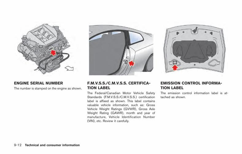
9-12 Technical and consumer information
ENGINE SERIAL NUMBER
The number is stamped on the engine as shown.
F.M.V.S.S./C.M.V.S.S. CERTIFICA-TION LABEL
The Federal/Canadian Motor Vehicle SafetyStandards (F.M.V.S.S./C.M.V.S.S.) certificationlabel is affixed as shown. This label containsvaluable vehicle information, such as: GrossVehicle Weight Ratings (GVWR), Gross AxleWeight Rating (GAWR), month and year ofmanufacture, Vehicle Identification Number(VIN), etc. Review it carefully.
EMISSION CONTROL INFORMA-TION LABEL
The emission control information label is at-tached as shown.
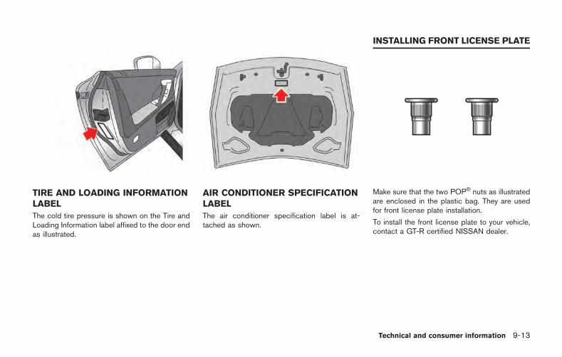
TIRE AND LOADING INFORMATIONLABEL
The cold tire pressure is shown on the Tire andLoading Information label affixed to the door endas illustrated.
AIR CONDITIONER SPECIFICATIONLABEL
The air conditioner specification label is at-tached as shown.
Make sure that the two POP nuts as illustratedare enclosed in the plastic bag. They are usedfor front license plate installation.
To install the front license plate to your vehicle,contact a GT-R certified NISSAN dealer.
Technical and consumer information 9-13
INSTALLING FRONT LICENSE PLATE
9-14 Technical and consumer information
WARNING
. It is extremely dangerous to ridein a cargo area inside the vehi-cle. In a collision, people ridingin these areas are more likely tobe seriously injured or killed.
. Do not allow people to ride inany area of vehicle that is notequipped with seats and seatbelts.
. Be sure everyone in your vehicleis in a seat and using a seat beltproperly.
TERMS
It is important to familiarize yourself with thefollowing terms before loading your vehicle:
. Curb Weight (actual weight of yourvehicle) - vehicle weight including:standard and optional equipment, fluidsor emergency tools. This weight doesnot include passengers and cargo.
. GVW (Gross Vehicle Weight) - curbweight plus the combined weight ofpassengers and cargo.
. GVWR (Gross Vehicle Weight Rating)- maximum total combined weight of theunloaded vehicle, passengers, luggage,hitch, trailer tongue load and any otheroptional equipment. This information islocated on the F.M.V.S.S./C.M.V.S.S.label.
. GAWR (Gross Axle Weight Rating) -maximum weight (load) limit specifiedfor the front or rear axle. This informa-tion is located on the F.M.V.S.S./C.M.V.S.S. label.
. GCWR (Gross Combined Weight Rat-ing) - The maximum total weight ratingof the vehicle, passengers, cargo, andtrailer.
. Vehicle Capacity Weight, Load limit,Total load capacity - maximum totalweight limit specified of the load(passengers and cargo) for the vehicle.This is the maximum combined weightof occupants and cargo that can beloaded into the vehicle. If the vehicle is
used to tow a trailer, the trailer tongueweight must be included as part of thecargo load. This information is locatedon the Tire and Loading Informationlabel.
. Cargo capacity - permissible weight ofcargo, the weight of total occupantsweight subtracted from the load limit.
VEHICLE LOADING INFORMATION

VEHICLE LOAD CAPACITY
Do not exceed the load limit of your vehicleshown as “The combined weight of occu-pants and cargo” on the Tire and LoadingInformation label. Do not exceed thenumber of occupants shown as “SeatingCapacity” on the Tire and Loading Informa-tion label.
To get “the combined weight of occupantsand cargo”, add the weight of all occu-pants, then add the total luggage weight.Examples are shown in the illustration.
Steps for determining correct loadlimit
1. Locate the statement “The combinedweight of occupants and cargo shouldnever exceed XXX kg or XXX lbs” onyour vehicle’s placard.
2. Determine the combined weight of thedriver and passengers that will be ridingin your vehicle.
3. Subtract the combined weight of thedriver and passengers from XXX kg orXXX lbs.
4. The resulting figure equals the availableamount of cargo and luggage loadcapacity. For example, if the XXXamount equals 1400 lbs. and there willbe five 150 lb. passengers in yourvehicle, the amount of available cargoand luggage load capacity is 650 lbs.(1400 750 (5 x 150) = 650 lbs) or640 340 (5 x 70) = 300 kg.)
5. Determine the combined weight ofluggage and cargo being loaded onthe vehicle. That weight may not safelyexceed the available cargo and luggageload capacity calculated in Step 4.
6. If your vehicle will be towing a trailer,load from your trailer will be transferredto your vehicle. Consult this manual todetermine how this reduces the avail-able cargo and luggage load capacityof your vehicle.
Before driving a loaded vehicle, confirmthat you do not exceed the Gross VehicleWeight Rating (GVWR) or the Gross AxleWeight Rating (GAWR) for your vehicle.( “Measurement of weights” page 9-16)
Technical and consumer information 9-15
9-16 Technical and consumer information
Also check tires for proper inflation pres-sures. See the Tire and Loading Informationlabel.
LOADING TIPS
. The GVW must not exceed GVWR orGAWR as specified on the F.M.V.S.S./C.M.V.S.S. certification label.
. Do not load the front and rear axle tothe GAWR. Doing so will exceed theGVWR.
WARNING
. Properly secure all cargo to helpprevent it from sliding or shift-ing. Do not place cargo higherthan the seatbacks. In a suddenstop or collision, unsecured car-go could cause personal injury.
. Do not load your vehicle anyheavier than the GVWR or themaximum front and rearGAWRs. If you do, parts of yourvehicle can break, tire damagecould occur, or it can change theway your vehicle handles. This
could result in loss of controland cause personal injury.
. Overloading could not onlyshorten the life of your vehicleand the tires, but also could leadto hazardous vehicle handlingand long braking distance. Thismay cause a premature tiremalfunction, which could resultin a serious accident and perso-nal injury. Repairs due to over-loading the vehicle are notcovered by the vehicle’s war-ranty. (See the 2015 NISSANGT-R Warranty InformationBooklet.)
MEASUREMENT OF WEIGHTS
Secure loose items to prevent weight shiftsthat could affect the balance of yourvehicle. When the vehicle is loaded, driveto a scale and weigh the front and the rearwheels separately to determine axle loads.Individual axle loads should not exceedeither of the gross axle weight ratings
(GAWR). The total of the axle loads shouldnot exceed the gross vehicle weight rating(GVWR). These ratings are given on thevehicle certification label. If weight ratingsare exceeded, move or remove items tobring all weights below the ratings.

Do not tow a trailer with your vehicle. Towing your vehicle with all four wheels on theground is sometimes called flat towing. Thismethod is sometimes used when towing avehicle behind a recreational vehicle, such as amotor home.
DO NOT tow the GT-R with all four wheels onthe ground (flat towing). Doing so WILLDAMAGE internal transmission parts. Tow theGT-R with all four wheels off the ground.( “Towing your vehicle” page 6-9)
DOT (Department Of Transportation) QualityGrades: All passenger car tires must conform tofederal safety requirements in addition to thesegrades.
Quality grades can be found where applicableon the tire sidewall between tread shoulder andmaximum section width. For example:
Treadwear 200 Traction AA Temperature A
TREADWEAR
The treadwear grade is a comparative ratingbased on the wear rate of the tire when testedunder controlled conditions on a specifiedgovernment test course. For example, a tiregraded 150 would wear one and one-half (11/2) times as well on the government course asa tire graded 100. The relative performance oftires depends upon actual conditions of theiruse, however, and may depart significantly fromthe norm due to variations in driving habits,service practices and differences in road char-acteristics and climate.
Technical and consumer information 9-17
TOWING A TRAILER FLAT TOWING UNIFORM TIRE QUALITY GRADING
9-18 Technical and consumer information
TRACTION AA, A, B AND C
The traction grades, from highest to lowest, areAA, A, B and C. Those grades represent thetire’s ability to stop on wet pavement asmeasured under controlled conditions on spe-cified government test surfaces of asphalt andconcrete. A tire marked C may have poortraction performance.
WARNING
The traction grade assigned to this tireis based on straight-ahead brakingtraction tests, and does not includeacceleration, cornering, hydroplaning,or peak traction characteristics.
TEMPERATURE A, B AND C
The temperature grades A (the highest), B, andC, representing the tire’s resistance to thegeneration of heat and its ability to dissipateheat when tested under controlled conditions ona specified indoor laboratory test wheel. Sus-tained high temperature can cause the materialof the tire to degenerate and reduce tire life, andexcessive temperature can lead to sudden tirefailure. The grade C corresponds to a level ofperformance which all passenger car tires must
meet under the Federal Motor Vehicle SafetyStandard No. 109. Grades B and A representhigher levels of performance on the laboratorytest wheel than the minimum required by law.
WARNING
The temperature grade for this tire isestablished for a tire that is properlyinflated and not overloaded. Excessivespeed, under-inflation, or excessiveloading, either separately or in combi-nation, can cause heat build-up andpossible tire failure.
Your NISSAN is covered by specific emissionwarranties:
For the United States, see the 2015 NISSANGT-R Warranty Information Booklet.
For Canada, see the Warranty and RoadsideAssistance Information Booklet.
If you did not receive a Warranty InformationBooklet (Warranty and Roadside AssistanceInformation (Canada only)), or it has becomelost, you may obtain a replacement by writing to:
. NISSAN Division
NISSAN North America, Inc.
Consumer Affairs Department
P.O. Box 685003
Franklin, TN 37068-5003
. NISSAN Canada Inc.
5290 Orbitor Drive
Mississauga, Ontario,
L4W 4Z5
EMISSION CONTROL SYSTEMWARRANTY
For USA
If you believe that your vehicle has a defectwhich could cause a crash or could causeinjury or death, you should immediatelyinform the National Highway Traffic SafetyAdministration (NHTSA) in addition tonotifying NISSAN.
If NHTSA receives similar complaints, itmay open an investigation, and if it findsthat a safety defect exists in a group ofvehicles, it may order a recall and remedycampaign. However, NHTSA cannot be-come involved in individual problems be-tween you, your dealer, or NISSAN.
To contact NHTSA, you may call theVehicle Safety Hotline toll-free at 1-888-327-4236 (TTY: 1-800-424-9153); go tohttp://www.safercar.gov; or write to: Ad-ministrator, NHTSA, 400 Seventh Street,SW., Washington, D.C. 20590. You canalso obtain other information about motorvehicle safety from http://www.safercar.gov.
You may notify NISSAN by contacting ourConsumer Affairs Department, toll-free, at
1-866-668-1GTR (1-866-668-1487).
For Canada
If you believe that your vehicle has a defectwhich could cause a crash or could causeinjury or death, you should immediatelyinform Transport Canada in addition tonotifying NISSAN.
If Transport Canada receives complaints, itmay open an investigation, and if it findsthat a safety defect exists in a group ofvehicles, it may request that NISSANconduct a recall campaign. However,Transport Canada cannot become involvedin individual problems between you, yourdealer, or NISSAN.
You may contact Transport Canada’s De-fect Investigations and Recalls Division tollfree at 1-800-333-0510. You may alsoreport safety defects online at: https://wwwapps . tc .gc .ca/Saf-Sec-Sur/7/PCDB-BDPP/Index.aspx.
Additional information concerning motorvehicle safety may be obtained from Trans-port Canada’s Road Safety InformationCentre at 1-800-333-0371 or online at
www.tc.gc.ca/roadsafety (English speak-ers) or www.tc.gc.ca/securiteroutiere(French speakers).
To notify NISSAN of any safety concernsplease contact our Consumer InformationCentre toll free at 1-800-387-0122.
Technical and consumer information 9-19
REPORTING SAFETY DEFECTS
9-20 Technical and consumer information
A vehicle equipped with All-Wheel Drive (AWD)should never be tested using a two wheeldynamometer (such as the dynamometers usedby some states for emissions testing), or similarequipment. Make sure you inform test facilitypersonnel that your vehicle is equipped withAWD before it is placed on a dynamometer.Using the wrong test equipment may result intransmission damage or unexpected vehiclemovement which could result in serious vehicledamage or personal injury.
Due to legal requirements in some states/ areas,your vehicle may be required to be in what iscalled the “ready condition” for an Inspection/Maintenance (I/M) test of the emission controlsystem.
The vehicle is set to the “ready condition” whenit is driven through certain driving patterns.Usually, the “ready condition” can be obtainedby ordinary usage of the vehicle.
If a powertrain system component is repaired orthe battery is disconnected, the vehicle may bereset to a “not ready condition”. Before takingthe I/M test, check the vehicle’s inspection/maintenance test readiness condition. Push theignition switch to the ON position withoutstarting the engine. If the Malfunction IndicatorLight (MIL) comes on steady for 20 seconds andthen blinks for 10 seconds, the I/M test
condition is “not ready”. If the MIL does notblink after 20 seconds, the I/M test condition is“ready”.
Contact a GT-R certified NISSAN dealer to set“ready condition” or to prepare the vehicle fortesting.
This vehicle is equipped with an Event DataRecorder (EDR). The main purpose of an EDR isto record, in certain crash or near crash-likesituations, such as an air bag deployment orhitting a road obstacle, data that will assist inunderstanding how a vehicle’s systems per-formed. The EDR is designed to record datarelated to vehicle dynamics and safety systemsfor a short period of time, typically 30 secondsor less. The EDR in this vehicle is designed torecord such data as:
. How various systems in your vehicle wereoperating;
. Whether or not the driver and passengersafety belts were buckled/fastened;
. How far (if at all) the driver was depressingthe accelerator and/or brake pedal; and,
. How fast the vehicle was traveling.
. Sounds are not recorded.
These data can help provide a better under-standing of the circumstances in which crashesand injuries occur. NOTE: EDR data arerecorded by your vehicle only if a nontrivialcrash situation occurs; no data are recorded bythe EDR under normal driving conditions and nopersonal data (e.g. name, gender, age and crashlocation) are recorded. However, other parties,such as law enforcement, could combine the
READINESS FOR INSPECTION/MAINTENANCE (I/M) TEST (US only) EVENT DATA RECORDERS (EDR)
EDR data with the type of personally identifyingdata routinely acquired during a crash investiga-tion.
To read data recorded by an EDR, specialequipment is required and access to the vehicleor the EDR is needed. In addition to the vehiclemanufacturer and NISSAN dealer, other parties,such as law enforcement, that have the specialequipment, can read the information if they haveaccess to the vehicle or the EDR. EDR data willonly be accessed with the consent of the vehicleowner or lessee or as otherwise required orpermitted by law.
The Vehicle Status Data Recorder (VSDR) isdifferent from the Event Data Recorder de-scribed in “Event Data Recorder” in this section.The VSDR is not a crash-activated device, but itrecords and accumulates vehicle data whiledriving.
Examples are:
. Vehicle operating information such as thewheel speeds of the front and rear wheels
. Engine control information such as theengine speed and boost pressure
The VSDR always records and stores vehicleoperating data between periodic inspections,which can assist and be used for servicing,diagnosing and performing warranty repairs.
The VSDR does not record sounds, conversa-tions or images.
To read data recorded by the VSDR, specialequipment is required and access to the vehicleor the VSDR is needed.
HANDLING OF DATA
NISSAN and third parties affiliated with NISSANcan acquire and use the data recorded by theVSDR in order to confirm the part replacementhistory to improve the quality of NISSANvehicles.
With the exception of the following cases,
neither NISSAN nor third parties affiliated withNISSAN, shall disclose or offer the acquireddata to other non-affiliated third parties.
. With the agreement of the vehicle owner
. When legally required to, such as whenordered by a court of law, etc.
. When offering processed data so thatneither the vehicle owner nor the vehicle isidentified, to research centers for statisticalanalysis, etc.
Technical and consumer information 9-21
VEHICLE STATUS DATA RECORDER(VSDR)
9-22 Technical and consumer information
Genuine NISSAN Service Manuals for thismodel year and prior can be purchased. Agenuine NISSAN Service Manual is the bestsource of service and repair information for yourvehicle. This manual is the same one used by thefactory-trained technicians working at NISSANdealerships. Genuine NISSAN Owner’s Man-uals can also be purchased.
For USA:
For current pricing and availability of genuineNISSAN Service Manuals,
1-800-450-9491
www.nissan-techinfo.com
For current pricing and availability of genuineNISSAN Owner’s Manuals, contact:
1-800-247-5321
For Canada:
To purchase a copy of a genuine NISSANService Manual or Owner’s Manual for thismodel year and prior, please contact a GT-Rcertified NISSAN dealer. For the phone numberand location of a GT-R certified NISSAN dealerin your area call the NISSAN Information Centerat 1-800-387-0122 and a bilingual NISSANrepresentative will assist you.
OWNER’S MANUAL/SERVICEMANUAL ORDER INFORMATION
10 IndexA
Active noise control.................................................... 5-54Additional maintenance items............................ GTR-12Air cleaner..................................................................... 8-21Air conditioner
Air conditioner specification label.................... 9-13Air conditioning system refrigerant andlubricant recommendations......................................... 9-7Air fresheners................................................................. 7-7All-season tires...................................................... GTR-11All-Wheel Drive............................................................ 5-41All-Wheel Drive driving safety precautions............ 5-9Anti-freeze..................................................................... 5-52Anti-lock Braking System.......................................... 5-49Anti-lock Braking System warning.......................... 2-37Audible reminders....................................................... 2-32Automatic
Automatic door lock system................................. 3-5Average fuel consumption and speed................... 2-16Avoiding body damage........................................ GTR-11Avoiding collision and rollover................................... 5-7AWD clutch high temperature warning................. 2-38AWD system characteristics.................................... 5-44AWD system warning................................................ 2-39AWD warning light ..................................................... 5-41
B
Battery................................................................ 5-52, 8-17Intelligent Key battery discharge...................... 5-12Intelligent Key battery discharge indicator..... 2-45
Intelligent Key battery replacement ................. 8-27Before starting the engine........................................ 5-13Body repair............................................................. GTR-12Booster seats............................................................... 1-31Brake
Brake assist........................................................... 5-49Brake fluid............................................... GTR-4, 8-15Brake pad wear warning.................................... 8-23Brake system......................................................... 5-48Brakes..................................................................... 8-23High performance brake system...................... 8-23Low brake fluid warning..................................... 2-37Parking brake........................................................ 5-33Parking brake break-in........................................ 5-48Parking brake release warning ......................... 2-36Replacing the brake pads.................................. 8-24Self-adjusting brakes.......................................... 8-23
Brake dust............................................................... GTR-26Brake pad................................................................ GTR-15Brake pad and disc rotor...................................... GTR-5Brake pad break-in procedure........................... GTR-15Brake system information.................................... GTR-26Brakes.................................................... GTR-18, GTR-22Braking precautions.................................................... 5-48Break-in schedule........................................ GTR-9, 5-39
C
Capacities and recommended fluids/lubricants.... 9-2Changing
Changing engine coolant................................... 8-12
Changing engine oil and filter........................... 8-14Changing wheels and tires................................ 8-41
CheckingChecking bulbs..................................................... 2-25Checking engine coolant level.......................... 8-11Checking engine oil level................................... 8-13Checking the tire pressure................................ 8-36
Child restraints............................................................. 1-15Child safety................................................................... 1-13Chrome parts................................................................. 7-5Cleaning ........................................................................ 8-22Cleaning exterior ........................................................... 7-2Cleaning interior............................................................ 7-7Closing the fuel-filler door........................................ 3-25Closing the hood......................................................... 3-19Coat hooks................................................................... 2-59Cockpit ............................................................................ 2-3Cold weather driving.................................................. 5-52Console box ................................................................. 2-59Cool down.............................................................. GTR-13Coolant
Changing engine coolant................................... 8-12Checking engine coolant level.......................... 8-11Draining of coolant water................................... 5-52Engine coolant temperature gauge.................... 2-7
Coolant level and mixture ratio.......................... GTR-15Corrosion protection.................................................... 7-9Cracks on brake pad........................................... GTR-26Cracks on the disc rotors................................... GTR-26Cruise control................................................... 2-16, 5-34Cruise control operations.......................................... 5-36
10-2
Cruise control system warning................................ 2-40Cup holders.................................................................. 2-56Current fuel consumption ......................................... 2-15
D
Differential oil............................................................ GTR-4Dimensions................................................................... 9-10Distance to empty....................................................... 2-17Door pocket.................................................................. 2-58Door/trunk open warning.......................................... 2-41Doors................................................................................ 3-4Draining of coolant water.......................................... 5-52Drinking alcohol/drugs and driving........................... 5-9Drive belts..................................................................... 8-19Drive computer............................................................ 2-15Driving
All-Wheel Drive driving safety precautions...... 5-9Cold weather driving........................................... 5-52Drinking alcohol/drugs and driving..................... 5-9Driving on snow or ice........................................ 5-53Driving the vehicle................................................ 5-15Driving tips............................................................. 5-21Precautions when starting and driving.............. 5-3
Driving after replacing tires ................................ GTR-12Dry carbon fiber parts................. GTR-7, GTR-27, 7-6Dual clutch transmission......................... GTR-27, 5-15
E
Elapsed time and trip odometer.............................. 2-17Emergency engine shut off.............................. 5-11, 6-3
Emergency trunk lid release..................................... 3-22Emission control information label.......................... 9-12Emission control system warranty........................... 9-18Engine.............................................................................. 9-8
Before starting the engine................................. 5-13Changing engine coolant................................... 8-12Changing engine oil and filter........................... 8-14Checking engine coolant level.......................... 8-11Checking engine oil level................................... 8-13Emergency engine shut off....................... 5-11, 6-3Engine block heater............................................. 5-54Engine compartment........................................... 8-24Engine compartment check locations................ 8-8Engine coolant temperature gauge.................... 2-7Engine cooling system........................................ 8-10Engine oil................................................. GTR-3, 8-13Engine oil and oil filter recommendation........... 9-6Engine oil level display........................................ 2-12Engine oil low pressure warning...................... 2-34Engine serial number........................................... 9-12Engine start operation indicator....................... 2-43Engine system warning....................................... 2-34Operating range for engine start ..................... 5-10Starting the engine.............................................. 5-13
Engine and powertrain....................... GTR-15, GTR-22Engine oil maintenance.......................................... GTR-4Engine output......................................................... GTR-23Engine output according to thecoolant temperature.............................................. GTR-23Engine speed is restricted.................................. GTR-23
Environmental factors influence the rateof corrosion..................................................................... 7-9Event Data Recorders................................................ 9-20Exhaust gas.................................................................... 5-3Exhaust muffler and trunk carpet........................ GTR-6Explanation of maintenance items............................ 8-4Extended storage fuse switch ................................. 8-26Exterior and interior lights......................................... 8-30
F
F.M.V.S.S./C.M.V.S.S. certification label ............... 9-12Features of each mode.............................................. 5-27Flat tire............................................................................. 6-3Flat towing.................................................................... 9-17Floor mats....................................................................... 7-8Fluid
Brake fluid............................................... GTR-4, 8-15Fluid level check................................................... 8-18Low brake fluid warning..................................... 2-37Low washer fluid warning.................................. 2-42Power steering fluid............................................. 8-14Window washer fluid.......................................... 8-16
Fluids...................................................... GTR-14, GTR-18Forward-facing child restraint installationusing LATCH................................................................ 1-24Forward-facing child restraint installation usingthe seat belts ............................................................... 1-27Freeing a frozen door lock........................................ 5-52
Front seat-mounted side-impact supplementalair bag and roof-mounted curtain side-impactsupplemental air bag systems................................. 1-45Front seats...................................................................... 1-3Front/rear tire size discrepancy warning............... 2-38Fuel........................................................................... GTR-12
Average fuel consumption and speed............ 2-16Capacities andrecommended fluids/lubricants............................ 9-2Closing the fuel-filler door................................. 3-25Current fuel consumption .................................. 2-15Fuel gauge................................................................ 2-8Fuel information....................................................... 9-4Fuel-filler door....................................................... 3-24Increasing fuel economy..................................... 5-41Low fuel warning.................................................. 2-40Opening the fuel filler door ............................... 3-25
Fuel Efficient Driving Tips......................................... 5-40Fuses.............................................................................. 8-24
G
Garage door openerHomeLink Universal Transceiver.................... 2-64
Gasoline smell ....................................................... GTR-23Gauge
Engine coolant temperature gauge.................... 2-7Fuel gauge................................................................ 2-8Meters and gauges................................................. 2-5
General maintenance.......................................... 8-3, 8-4Glass................................................................................ 7-5
Glove box...................................................................... 2-58GT-R performance optimization services.......... GTR-8GT-R special precautions..................................... GTR-5GT-R special specification parts......................... GTR-3GT-R specific information..................................... GTR-3GT-R specific vehicle characteristics .............. GTR-23
H
Handling of data.......................................................... 9-21Hazard warning flasher switch................................... 6-2Head restraints/headrests........................................... 1-5Headlight
Headlight and turn signal switch..................... 2-50Headlight switch................................................... 2-50Headlights.............................................................. 8-30
Heated seats................................................................ 2-54High altitude........................................................... GTR-23High performance brake system............................. 8-23Hill Start Assist............................................................ 5-38HomeLink Universal Transceiver........................... 2-64Hood............................................................................... 3-18Horn................................................................................ 2-53How to switch the modes ........................................ 5-25How to use R mode start function......................... 5-33
I
Idle speed is not steady...................................... GTR-23If your vehicle overheats.............................................. 6-8Ignition switch operation........................................... 5-10Ignition switch positions............................................ 5-11
Increasing fuel economy............................................ 5-41Indicator lights.............................................................. 2-31Indicators and display................................................ 5-36Infants............................................................................. 1-14Injured persons.............................................................. 1-9Inside mirror.................................................................. 3-27Inspection and adjustments after driving........ GTR-18Inspection and adjustments before driving .... GTR-14Installing front license plate...................................... 9-13Installing top tether strap.............................. 1-26, 1-30Instrument brightness control .................................. 2-11Instrument panel............................................................ 2-4Intelligent Key................................................................. 3-2Intelligent Key battery discharge............................. 5-12Intelligent Key battery discharge indicator............ 2-45Intelligent Key battery replacement ........................ 8-27Intelligent Key functions............................................... 3-9Intelligent Key insertion indicator............................ 2-44Intelligent Key removal indicator.............................. 2-45Intelligent Key system.................................................. 3-8Interior light control switch....................................... 2-62Interior lights................................................................. 2-62
J
Jacking vehicle and removing wheels.................... 8-43Jump starting....................................................... 6-5, 8-19
K
KeyIntelligent Key........................................................... 3-2
10-3
10-4
Intelligent Key battery discharge...................... 5-12Intelligent Key battery discharge indicator..... 2-45Intelligent Key battery replacement ................. 8-27Intelligent Key functions......................................... 3-9Intelligent Key insertion indicator..................... 2-44Intelligent Key removal indicator....................... 2-45Intelligent Key system............................................ 3-8Keys............................................................................ 3-2Locking with mechanical key................................ 3-6No key warning..................................................... 2-42Remote keyless entry functions........................ 3-12
L
Larger children............................................................. 1-14Light
AWD warning light .............................................. 5-41Exterior and interior lights.................................. 8-30Headlight and turn signal switch..................... 2-50Headlight switch................................................... 2-50Headlights.............................................................. 8-30Indicator lights....................................................... 2-31Interior light control switch................................ 2-62Interior lights.......................................................... 2-62Lights....................................................................... 8-29Map lights .............................................................. 2-62Supplemental air bag warning light................. 1-47Vanity mirror lights ............................................... 2-63Warning lights....................................................... 2-25Warning/indicator lights andaudible reminders................................................. 2-25
Limited Slip Differential.............................................. 5-45Loading tips.................................................................. 9-16Lock
Anti-lock Braking System................................... 5-49Anti-lock Braking System warning................... 2-37Automatic door lock system................................. 3-5Freeing a frozen door lock................................. 5-52Locking with inside lock knob............................. 3-5Locking with mechanical key................................ 3-6Locking with power door lock switch................ 3-5Steering lock release malfunction indicator.... 2-44
Low brake fluid warning............................................ 2-37Low fuel warning......................................................... 2-40Low tire pressure warning........................................ 2-39Low washer fluid warning......................................... 2-42Lower anchors and tethers for children system.... 1-17
M
MaintenanceExplanation of maintenance items...................... 8-4General maintenance.................................... 8-3, 8-4Maintenance information................................. GTR-3Maintenance precautions...................................... 8-6Maintenance requirement...................................... 8-3Readiness forInspection/Maintenance test............................. 9-20Scheduled maintenance........................................ 8-3Seat belt maintenance........................................ 1-13
Map lights ..................................................................... 2-62Matte paint care............................................................ 7-2
Measurement of weights........................................... 9-16Meters and gauges....................................................... 2-5Mirror
Inside mirror........................................................... 3-27Mirrors..................................................................... 3-27Outside mirrors..................................................... 3-28Vanity mirror........................................................... 3-29Vanity mirror lights ............................................... 2-63
Most common factors contributing tovehicle corrosion........................................................... 7-9Multi Function Display Owner’s Manual.................. 4-2
N
NISSAN Advanced Air Bag System...................... 1-40NISSAN Vehicle Immobilizer System..................... 2-47No key warning............................................................ 2-42Noises are heard while driving.......................... GTR-24
O
Odometer/twin trip odometer.................................... 2-6Off-road recovery.......................................................... 5-7Oil
Changing engine oil and filter........................... 8-14Checking engine oil level................................... 8-13Differential oil...................................................... GTR-4Engine oil................................................. GTR-3, 8-13Engine oil and oil filter recommendation........... 9-6Engine oil level display........................................ 2-12Engine oil low pressure warning...................... 2-34Transmission oil ..................................... GTR-4, 8-14
Transmission oil high temperature warning.... 2-36Opening and closing the trunk................................ 3-22Opening the doors ....................................................... 3-7Opening the fuel filler door ...................................... 3-25Opening the hood....................................................... 3-18Operating range for engine start ............................ 5-10Operation displays...................................................... 2-43Outside air temperature ............................................ 2-18Outside door handles.................................................. 7-6Outside mirrors............................................................ 3-28Outside temperature display indicateshigher temperature................................................ GTR-23Overheat
If your vehicle overheats........................................ 6-8Owner’s Manual/Service Manualorder information......................................................... 9-22
P
ParkingParking brake........................................................ 5-33Parking brake break-in........................................ 5-48Parking brake release warning ......................... 2-36Parking/parking on hills...................................... 5-46
Passenger compartment ........................................... 8-25Power
Locking with power door lock switch................ 3-5Power outlets........................................................ 2-55Power steering...................................................... 5-47Power steering fluid............................................. 8-14Power windows.................................................... 2-60
Trunk release power cancel switch................. 3-21Precautions................................................................... 8-17
All-Wheel Drive driving safety precautions...... 5-9Braking precautions............................................. 5-48Maintenance precautions...................................... 8-6Precautions on child restraints......................... 1-15Precautions on cruise control........................... 5-35Precautions on seat belt usage........................... 1-6Precautions on supplementalrestraint system..................................................... 1-34Precautions when starting and driving.............. 5-3
Precautions before driving.................................. GTR-10Precautions on performance driving................ GTR-13Pregnant women........................................................... 1-9Push starting.................................................................. 6-7“PUSH” warning.......................................................... 2-44Push-button ignition switch...................................... 5-10
R
R mode start function................................................ 5-32Rapid air pressure loss................................................ 5-8Readiness for Inspection/Maintenance test......... 9-20Rear window defroster switch................................. 2-50Rear-facing child restraint installationusing LATCH................................................................ 1-19Rear-facing child restraint installation using theseat belts....................................................................... 1-21Recommended fluids andmaintenance interval............................................. GTR-19Reducing tight corner braking phenomenon ....... 5-43
Refueling precautions.......................................... GTR-13Remote keyless entry functions............................... 3-12Removing spots............................................................. 7-4Removing the cowl top cover.................................... 8-9Repair and replacement procedure........................ 1-48Replacement of brake pads and disc rotors.... GTR-5Replacing spark plugs............................................... 8-20Replacing the brake pads......................................... 8-24Replacing the wiper blades...................................... 8-22Reporting safety defects .......................................... 9-19Reverse warning.......................................................... 2-35Roadside assistance program................................... 6-2Run-flat tire warning................................................... 2-39Run-flat tires................................................................... 6-4
S
SafetyAll-Wheel Drive driving safety precautions...... 5-9Child safety............................................................ 1-13Reporting safety defects ................................... 9-19
Safety — Seats, seat belts and supplementalrestraint system.............................................................. 1-1Scheduled maintenance.............................................. 8-3Seat
Booster seats........................................................ 1-31Forward-facing child restraint installationusing the seat belts............................................. 1-27
10-5
10-6
Front seat-mounted side-impact supplementalair bag and roof-mounted curtain side-impactsupplemental air bag systems.......................... 1-45Front seats................................................................ 1-3Heated seats......................................................... 2-54NISSAN Advanced Air Bag System............... 1-40Precautions on seat belt usage........................... 1-6Rear-facing child restraint installation usingthe seat belts ........................................................ 1-21Seat belt extenders.............................................. 1-12Seat belt maintenance........................................ 1-13Seat belts......................................................... 1-6, 7-8Seat belts with pretensioners........................... 1-46Seats.......................................................................... 1-2Three-point type seat belt with retractor.......... 1-9
Seat beltForward-facing child restraint installationusing the seat belts............................................. 1-27Precautions on seat belt usage........................... 1-6Rear-facing child restraint installation usingthe seat belts ........................................................ 1-21Seat belt extenders.............................................. 1-12Seat belt maintenance........................................ 1-13Seat belts......................................................... 1-6, 7-8Seat belts with pretensioners........................... 1-46Three-point type seat belt with retractor.......... 1-9
Security systems......................................................... 2-45Self-adjusting brakes................................................. 8-23Setting (drive computer) ........................................... 2-19Setting hazard indicator and horn mode .............. 3-13Shift lever position warning...................................... 2-35
Shift “P” warning......................................................... 2-43Small children............................................................... 1-14Spark plugs.................................................................. 8-20Special winter equipment......................................... 5-53Specifications................................................................. 9-8Speedometer.................................................................. 2-6Starting
Before starting the engine................................. 5-13Jump starting................................................ 6-5, 8-19Precautions when starting and driving.............. 5-3Push starting............................................................ 6-7Starting the engine.............................................. 5-13
SteeringPower steering...................................................... 5-47Power steering fluid............................................. 8-14Steering lock release malfunction indicator.... 2-44Steering wheel...................................................... 3-26Steering-wheel-mounted controls ................... 5-35Tilt/telescopic steering column......................... 3-26
Storage.......................................................................... 2-56Summer tires.......................................................... GTR-11Sun visors..................................................................... 3-27Sunglasses holder...................................................... 2-57Supplemental air bag warning labels..................... 1-47Supplemental air bag warning light........................ 1-47Supplemental restraint system................................. 1-34Suspension and wheel alignment.... GTR-16, GTR-22Switch
Hazard warning flasher switch............................. 6-2Headlight and turn signal switch..................... 2-50Headlight switch................................................... 2-50
How to switch the modes ................................. 5-25Ignition switch operation.................................... 5-10Ignition switch positions..................................... 5-11Interior light control switch................................ 2-62Locking with power door lock switch................ 3-5Push-button ignition switch............................... 5-10Rear window defroster switch.......................... 2-50Trunk lid release switch...................................... 3-20Trunk open request switch................................ 3-20Trunk release power cancel switch................. 3-21VDC, transmission and suspensionsetup switches...................................................... 5-25Windshield wiper and washer switch............. 2-48
T
Tachometer..................................................................... 2-7Temperature A, B and C........................................... 9-18Terms.............................................................................. 9-14Three-point type seat belt with retractor................ 1-9Three-way catalyst........................................................ 5-3Tight corner braking phenomenon.......................... 5-43Tilt/telescopic steering column................................ 3-26Tire
Changing wheels and tires................................ 8-41Checking the tire pressure................................ 8-36Flat tire....................................................................... 6-3Front/rear tire size discrepancy warning........ 2-38Low tire pressure warning................................. 2-39Run-flat tire warning............................................ 2-39Run-flat tires............................................................. 6-4
Tire and loading information label......... 8-35, 9-13Tire chains.............................................................. 8-40Tire dressing............................................................. 7-6Tire equipment...................................................... 5-53Tire labeling........................................................... 8-37Tire pressure ......................................................... 8-32Tire Pressure Monitoring System............... 5-4, 6-3Tire Pressure Monitoring System warning..... 2-40Tires......................................................................... 5-44Types of tires......................................................... 8-38Uniform tire quality grading............................... 9-17Wheels and tires......................................... 8-32, 9-9
Tires and road wheels........................................... GTR-5Titanium muffler ....................................................... GTR-6
Change of surface color oftitanium muffler................................................ GTR-26Sound heard around titanium muffler ....... GTR-27
To protect your vehicle from corrosion.................. 7-10Towing
Flat towing............................................................. 9-17Towing a trailer ..................................................... 9-17Towing recommended by NISSAN.................... 6-9Towing your vehicle................................................ 6-9
Traction AA, A, B and C........................................... 9-18Transceiver
HomeLink Universal Transceiver.................... 2-64Transmission
Dual clutch transmission.................................... 5-15Transmission clutch hightemperature warning............................................ 2-36Transmission oil ..................................... GTR-4, 8-14
Transmission oil high temperature warning.... 2-36Transmission position indicator ........................... 2-9Transmission system check display................. 2-14Transmission system warning ........................... 2-35VDC, transmission and suspensionsetup switches...................................................... 5-25
Transmission operation characteristics............ GTR-28Transmission settings............................................. GTR-9Treadwear...................................................................... 9-17Troubleshooting guide ............................................... 3-17Trunk............................................................................... 3-20Trunk lid release switch............................................. 3-20Trunk open request switch....................................... 3-20Trunk release power cancel switch........................ 3-21Turbocharger system.................................................. 5-31Turning off the heaters............................................... 2-54Turning on the heaters............................................... 2-54Types of tires................................................................ 8-38
U
Underbody....................................................................... 7-5Uneven wear of tires............................................ GTR-24Uniform tire quality grading...................................... 9-17Upshift indicator ............................................................ 2-9Using the washer........................................................ 2-49Using the wipers......................................................... 2-49
V
Vanity mirror.................................................................. 3-29Vanity mirror lights ...................................................... 2-63
VDC, transmission and suspensionsetup switches............................................................. 5-25Vehicle Dynamic Control (VDC) OFF mode.... GTR-10Vehicle Dynamic Control (VDC) warning light.... 2-31Vehicle Dynamic Control system............................ 5-50Vehicle Dynamic Control system warning............ 2-37Vehicle identification................................................... 9-11
Vehicle identification number............................ 9-11Vehicle Identification Number plate................. 9-11
Vehicle information display........................................ 2-12Vehicle load capacity.................................................. 9-15Vehicle loading information....................................... 9-14Vehicle recovery........................................................... 6-10Vehicle security system............................................. 2-45Vehicle speed............................................................... 2-16Vehicle status data recorder.................................... 9-21
W
WarningAnti-lock Braking System warning................... 2-37AWD clutch high temperature warning.......... 2-38AWD system warning......................................... 2-39AWD warning light .............................................. 5-41Brake pad wear warning.................................... 8-23Cruise control system warning......................... 2-40Door/trunk open warning................................... 2-41Engine oil low pressure warning...................... 2-34Engine system warning....................................... 2-34Front/rear tire size discrepancy warning........ 2-38Hazard warning flasher switch............................. 6-2
10-7
10-8
Low brake fluid warning..................................... 2-37Low fuel warning.................................................. 2-40Low tire pressure warning................................. 2-39Low washer fluid warning.................................. 2-42No key warning..................................................... 2-42Parking brake release warning ......................... 2-36“PUSH” warning................................................... 2-44Reverse warning................................................... 2-35Run-flat tire warning............................................ 2-39Shift lever position warning............................... 2-35Shift “P” warning.................................................. 2-43Supplemental air bag warning labels.............. 1-47Supplemental air bag warning light................. 1-47Tire Pressure Monitoring System warning..... 2-40Transmission clutch hightemperature warning............................................ 2-36Transmission oil high temperature warning.... 2-36Transmission system warning ........................... 2-35Vehicle Dynamic Control system warning..... 2-37Warning (drive computer).................................. 2-23Warning display.................................................... 2-33Warning lights....................................................... 2-25Warning signals.................................................... 3-16Warning/indicator lights andaudible reminders................................................. 2-25
Warranty information.............................................. GTR-3Washing........................................................................... 7-3Waxing............................................................................. 7-4Wheel alignment ....................................... GTR-10, 5-39
Wheel alignment inspection and adjustment (if ne-cessary) (including tirepressure adjustment) ............................................. GTR-8Wheels............................................................................. 7-5Wheels and tires............ GTR-16, GTR-22, 8-32, 9-9When traveling or registering your vehicle inanother country............................................................ 9-11Where to go for service.............................................. 8-3Window washer fluid................................................. 8-16Windows....................................................................... 2-60Windshield wiper and washer switch.................... 2-48Windshield wiper blades........................................... 8-22Wiper
Replacing the wiper blades............................... 8-22Using the wipers.................................................. 2-49Windshield wiper and washer switch............. 2-48Windshield wiper blades.................................... 8-22

MEMO
10-9
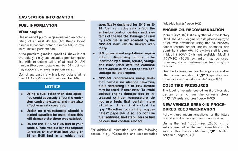
FUEL INFORMATION
VR38 engine
Use unleaded premium gasoline with an octanerating of at least 93 AKI (Anti-Knock Index)number (Research octane number 98) to max-imize vehicle performance.
If the premium gasoline specified above is notavailable, you may use unleaded premium gaso-line with an octane rating of at least 91 AKInumber (Research octane number 96), but youmay notice a decrease in performance.
Do not use gasoline with a lower octane ratingthan 91 AKI (Research octane number 96).
NOTICE
. Using a fuel other than that speci-fied could adversely affect the emis-sion control systems, and may alsoaffect warranty coverage.
. Under no circumstances should aleaded gasoline be used, since thiswill damage the three way catalyst.
. Do not use E-15 or E-85 fuel in yourvehicle. Your vehicle is not designedto run on E-15 or E-85 fuel. Using E-15 or E-85 fuel in a vehicle not
specifically designed for E-15 or E-85 fuel can adversely affect theemission control devices and sys-tems of the vehicle. Damage causedby such fuel is not covered by theNISSAN new vehicle limited war-ranty.
. U.S. government regulations requireethanol dispensing pumps to beidentified by a small, square, orangeand black label with the commonabbreviation or the appropriate per-centage for that region.
. NISSAN recommends using fuelsthat contain no alcohol. However,fuels containing up to 10% alcoholmay be used, if necessary. To avoidserious engine damage due to in-creased cylinder temperature, donot use fuels that contain morea l c o ho l t h a n i n d i c a t e d i n
“Gasoline containing oxyge-nates” page 9-4. Also, do not usefuel additives, fuel stabilizers or fueldeicers that contain alcohol.
For additional information, see the followingsection. ( “Capacities and recommended
fluids/lubricants” page 9-2)
ENGINE OIL RECOMMENDATION
Mobil 1 (0W-40) (100% synthetic) is the factoryfill oil. The VR38 engine with its plasma-sprayedbores was developed using this oil. NISSANcannot ensure proper engine operation anddurability if other 0W-40 synthetic oil is used.If Mobil 1 (0W-40) is not available, Mobil 1(10W-40) (100% synthetic) may be used;however, some performance loss may benoticed.
See the following section for engine oil and oilfilter recommendation. ( “Capacities andrecommended fluids/lubricants” page 9-2)
COLD TIRE PRESSURES
The label is typically located on the driver sidecenter pi l lar or on the driver’s door.( “Wheels and tires” page 8-32)
NEW VEHICLE BREAK-IN PROCE-DURES RECOMMENDATION
Follow these recommendations for the futurereliability and economy of your new vehicle.
During the first 1,200 miles (2,000 km) ofvehicle use, follow the recommendations out-lined in this Owner’s Manual. ( “Break-inschedule” page 5-39)
GAS STATION INFORMATION