implementing itil change management - autenticação · implementing itil change management ... in...
TRANSCRIPT

Implementing ITIL Change Management
Filipe Crespo Martins
Dissertacao para obtencao do Grau de Mestre emEngenharia Informatica e de Computadores
Juri
Presidente: Professor Doutor Antonio Manuel Ferreira Rito da Silva
Orientador: Professor Doutor Miguel Leitao Bignolas Mira da Silva
Vogal: Professora Maria do Rosario Bernardo
Novembro 2010

Acknowledgements
First and foremost, I would like to thank to my supervisor, Prof. Miguel Mira da Silva for all his
guidance, support and availability during the last year.
Then, I would like to thank to all my colleagues for their support especially Diogo Nesbitt for all
his good advices, help and support in understanding the application he developed and that I used
in my work.
I would also like to thank to the two organizations that made possible for me to develop my work
in their facilities and specially to Hugo Sousa, Nuno Henriques and Paulo Oliveira for all the infor-
mation they provided me to develop my work.
To all my friends a great thank you for all your support and helping me in the worst moments.
Finally, I would like to thank to my family, especially my mother for her continuous support not
only during this year but also during all the course.
Lisboa, November 5, 2010
Filipe Martins
Resumo
Hoje em dia, a tecnologia tem um forte impacto na nossa sociedade. As praticas actuais nas
empresas seriam impossıveis nos dias de hoje sem IT. O ITIL e uma framework que foi criada com
o objectivo de reduzir os custos e de melhor gerir o IT. Contudo, implementar ITIL nao se tem
verificado uma tarefa facil sendo comum grande parte das implementacoes nao terem sucesso. Para
alem disso, toda a documentacao sobre ITIL explica em detalhe todos os processos mas nao explica
como e que os mesmos devem ser implementados. Neste documento propusemos implementar o
processo ITIL Change Management assim como construir uma CMDB e um prototipo para suportar
esse mesmo processo, usando as melhores praticas de implementacao de sistemas de informacao
tentando evitar os erros mais comuns nesta area. Usando o metodo Action Research, esta proposta
foi avaliada numa organizacao publica que ja seguia outros processos ITIL impementados tais como
Gestao de Incidentes e Gestao de Configuracoes. Concluımos que se tornou muito difıcil obter
todas as informacoes necessarias para construir a CMDB. Ja a implementacao do processo Change
Management foi um sucesso, com o auxılio de um prototipo desenvolvido e posteriormente colocado
em producao.

Abstract
Today’s technology has had a huge impact on business and society. Current business practices
would be impossible without IT. ITIL is a framework that was created with the goal of reducing
costs and to better manage IT service delivery. However, implementing ITIL is not easy and it is
common that ITIL implementations end in failure. Further more, ITIL documentation explains all
the processes but it doesn’t tell us how that implementation should be made. In this document we
proposed to build a Configuration Management Database and how to implement an ITIL Change
Management process, including the development of a prototype to support the process, using the
best practices of implementing information systems, avoiding the most common mistakes in this
area. Using the Action Research method, this proposal was evaluated in a public organization
which already followed other processes, namely ITIL Incident Management and ITIL Configuration
Management. We concluded that it became very difficult to obtain all the information necessary
to build the Configuration Management database. However, we could accomplish this step and
implement a Change Management process including a prototype which was then put in production
and used.

Palavras Chave
Keywords
Palavras Chave
ITIL
Implementacao ITIL
CMDB
Gestao de Alteracoes
Keywords
ITIL
ITIL Implementation
Configuration Management Database
Change Management

Table of Contents
1 Introduction 1
1.1 ITIL . . . . . . . . . . . . . . . . . . . . . . . . . . . . . . . . . . . . . . . . . . . . . 1
1.2 Change Management . . . . . . . . . . . . . . . . . . . . . . . . . . . . . . . . . . . . 3
1.3 Problem . . . . . . . . . . . . . . . . . . . . . . . . . . . . . . . . . . . . . . . . . . . 5
1.4 Research Method . . . . . . . . . . . . . . . . . . . . . . . . . . . . . . . . . . . . . . 7
2 Related Work 10
2.1 The Configuration Management Database . . . . . . . . . . . . . . . . . . . . . . . . 10
2.2 The Change Management Process . . . . . . . . . . . . . . . . . . . . . . . . . . . . 11
2.3 Information Systems Implementation . . . . . . . . . . . . . . . . . . . . . . . . . . . 17
3 Proposal 21
4 First Research Cycle 23
4.1 Diagnosing . . . . . . . . . . . . . . . . . . . . . . . . . . . . . . . . . . . . . . . . . 23
4.2 Action Planning . . . . . . . . . . . . . . . . . . . . . . . . . . . . . . . . . . . . . . 24
4.3 Action Taking . . . . . . . . . . . . . . . . . . . . . . . . . . . . . . . . . . . . . . . . 26
4.4 Evaluating . . . . . . . . . . . . . . . . . . . . . . . . . . . . . . . . . . . . . . . . . . 28
4.5 Learning . . . . . . . . . . . . . . . . . . . . . . . . . . . . . . . . . . . . . . . . . . . 29
5 Second Research Cycle 30
5.1 Diagnosing . . . . . . . . . . . . . . . . . . . . . . . . . . . . . . . . . . . . . . . . . 30
5.2 Action Planning . . . . . . . . . . . . . . . . . . . . . . . . . . . . . . . . . . . . . . 31
5.2.1 Defining the New Structure of the Data . . . . . . . . . . . . . . . . . . . . . 31
i
5.2.2 Defining the Change Management Process . . . . . . . . . . . . . . . . . . . . 33
5.3 Action Taking . . . . . . . . . . . . . . . . . . . . . . . . . . . . . . . . . . . . . . . . 35
5.3.1 Getting the Data . . . . . . . . . . . . . . . . . . . . . . . . . . . . . . . . . . 35
5.3.2 Importing the Data to the CMDB . . . . . . . . . . . . . . . . . . . . . . . . 36
5.3.3 The Change Management Prototype . . . . . . . . . . . . . . . . . . . . . . . 36
5.4 Evaluating . . . . . . . . . . . . . . . . . . . . . . . . . . . . . . . . . . . . . . . . . . 46
5.4.1 Building the CMDB . . . . . . . . . . . . . . . . . . . . . . . . . . . . . . . . 47
5.4.2 Developing and Deploying the Change Management Prototype . . . . . . . . 47
5.5 Learning . . . . . . . . . . . . . . . . . . . . . . . . . . . . . . . . . . . . . . . . . . . 48
6 Conclusion 49
6.1 Future Work . . . . . . . . . . . . . . . . . . . . . . . . . . . . . . . . . . . . . . . . 50
References 51
A Work System Method Example 53
B Proposed Change Management Process 54
C Listings for the CMDB 55
D List of Registered Changes 58
ii

List of Figures
1.1 The Configuration Management Database . . . . . . . . . . . . . . . . . . . . . . . . 4
1.2 Percentage of succeeded, challenged and failed IT projects according to The CHAOS
Reports . . . . . . . . . . . . . . . . . . . . . . . . . . . . . . . . . . . . . . . . . . . 5
1.3 The Action Research Cycle . . . . . . . . . . . . . . . . . . . . . . . . . . . . . . . . 8
2.1 Change Management and other ITIL Processes (van Bon, 2007) . . . . . . . . . . . . 12
2.2 High level overview of the change management process (Addy, 2007) . . . . . . . . . 13
2.3 Change Management activities (Arjen de Jong, 2008) . . . . . . . . . . . . . . . . . . 13
2.4 Lifecycle of hardware CI proposal (Mattila, 2008) . . . . . . . . . . . . . . . . . . . . 15
2.5 Proposed states of change (Ward et al., 2007) . . . . . . . . . . . . . . . . . . . . . . 16
2.6 The Work System FrameworkTM (Alter, 2006) . . . . . . . . . . . . . . . . . . . . . 18
3.1 IT Department Organizational Chart . . . . . . . . . . . . . . . . . . . . . . . . . . . 22
4.1 CMDB Data Model in the first organization . . . . . . . . . . . . . . . . . . . . . . . 25
4.2 Incident States and Transitions . . . . . . . . . . . . . . . . . . . . . . . . . . . . . . 25
4.3 Definition of resolution times according to urgency and impact of the incident . . . . 26
5.1 Initial structure of the CMDB . . . . . . . . . . . . . . . . . . . . . . . . . . . . . . . 32
5.2 The new defined structure of the CMDB . . . . . . . . . . . . . . . . . . . . . . . . . 32
5.3 Proposed Change Management Process . . . . . . . . . . . . . . . . . . . . . . . . . 33
5.4 Change States Diagram . . . . . . . . . . . . . . . . . . . . . . . . . . . . . . . . . . 34
5.5 The Outsystems Platform . . . . . . . . . . . . . . . . . . . . . . . . . . . . . . . . . 36
5.6 References from the Configuration Management Application . . . . . . . . . . . . . . 37
5.7 The Prototype’s Datamodel . . . . . . . . . . . . . . . . . . . . . . . . . . . . . . . . 38
iii

5.8 Create new RFC screen . . . . . . . . . . . . . . . . . . . . . . . . . . . . . . . . . . 39
5.9 Set changes in CI screen . . . . . . . . . . . . . . . . . . . . . . . . . . . . . . . . . . 40
5.10 Home screen . . . . . . . . . . . . . . . . . . . . . . . . . . . . . . . . . . . . . . . . 41
5.11 Review RFC screen . . . . . . . . . . . . . . . . . . . . . . . . . . . . . . . . . . . . . 42
5.12 Build Change screen . . . . . . . . . . . . . . . . . . . . . . . . . . . . . . . . . . . . 43
5.13 Definition of Priorities screen . . . . . . . . . . . . . . . . . . . . . . . . . . . . . . . 44
5.14 Definition of Categories screen . . . . . . . . . . . . . . . . . . . . . . . . . . . . . . 44
5.15 CI log screen (CMDB application) . . . . . . . . . . . . . . . . . . . . . . . . . . . . 45
B.1 Proposed Change Management Process . . . . . . . . . . . . . . . . . . . . . . . . . 54
iv
List of Tables
1.1 Components of ITIL v3 and its main processes . . . . . . . . . . . . . . . . . . . . . 2
2.1 KPIs for ITIL processes Change Management and Release Management (Spremic
et al., 2008) . . . . . . . . . . . . . . . . . . . . . . . . . . . . . . . . . . . . . . . . . 16
4.1 List of types and subtypes of CMDB’s items . . . . . . . . . . . . . . . . . . . . . . . 24
A.1 WSM snapshot example: Implementing a software package in a large company . . . 53
v
List of Abbreviations
AR Action Research
CAB Change Advisory Board
Ci Configuration Item
CM Change Management
CMDB Configuration Management Database
CMS Configuration Management System
ECAB Emergency Change Advisory Board
IT Information Technology
ITIL Information Technology Infrastructure Library
ITSM Information Technology Service Management
KPI Key Performance Indicator
RFC Request For Change
vi
Chapter 1
Introduction
Today’s technology has had a huge impact on business and society. Current business practices would
be impossible without IT. A seemingly endless stream of innovations brings images of boundless
opportunity and change (Alter, 2006).
1.1 ITIL
In response to the serious economic downturn in the late 1980s, the Central Computer and Telecom-
munications Agency (CCTA) in the United Kingdom developed the IT Infrastructure Library (ITIL)
framework to reduce costs and to better manage IT service delivery. The ITIL framework is now
administrated by the Office of Government Commerce1 (OGC) and its best-practice processes are
supported by the British Standards Institutes BS 15000 Standard for IT Service Management (Cater-
Steel et al., 2006).
Since 1989 the ITIL concepts, policies and guidelines progressed through its stages of maturity. In
May 2007, the version 3 of ITIL, known as ITIL v3, was published. It comprised 26 processes and
functions, assimilated under 5 volumes, arranged around the concept of service lifecycle structure.
Apart from limiting itself into improved concepts of the framework and standards and emphasizing
the service delivery model, the ITIL v3 also popularized the concepts of IT Service Lifecycle with a
strong focus on the IT strategy and its business outcomes. In other words, ITIL v3 further elevated
the status of IT department from a service provider to that of a strategic partner.
ITIL v3 Core is a set of five books, consisting of: Service Strategy, Service Design, Service Tran-
sition, Service Operation and Continual Service Improvement. Each one provides guidance for an
integrated approach. Furthermore, ITIL complementary guidance is a set of publications which are
related to a specific industry, type of organization, technology architectures and operating models
(Sharon Taylor, 2006). A more detailed description of each book is found in Table 1.1.
IT Service Management is a subset of the Services Science discipline that focuses on IT operations
1http://www.ogc.gov.uk/
1

Table 1.1: Components of ITIL v3 and its main processes
Component Processes
Service StrategyService Portfolio ManagementDemand ManagementIT Financial Management
Service Design
Service Level ManagementAvailability ManagementCapacity ManagementIT Service Continuity ManagementInformation Security ManagementSupplier ManagementService Catalog Management
Service Transition
Service Asset and Configuration ManagementValidation and TestingRelease and Deployment ManagementChange ManagementKnowledge Management
Service Operation
Event ManagementIncident ManagementProblem ManagementRequest FulfillmentAccess Management
Continual Service ImprovementService Level ManagementService Measurement and ReportingContinual Service Improvement
delivery and support (Galup et al., 2007) and, in spite of being often associated with ITIL (OGC,
2000) it also has an international standard, ISO 2000.
In this trend towards embracing principles of organizational IT Service Management, the IT Infras-
tructure Library has, of all approaches, gained the biggest popularity and can, at least in Europe,
now indeed be called a de-facto standard (Brenner, 2006).
Why is ITIL important to the organization? ITIL itself tells us a number of benefits, or added value
for business, of having this process implemented. Such benefits can be (OGC, 2007):
• Implementing changes that can meet the customers’ agreed service requirements while opti-
mizing costs
• Reducing failed changes and therefore service disruption, defects and re-work
• Tracking changes through the service lifecycle and to the assets of its customers
• Liaising with the business change process to identify opportunities for business improvement
Further more, in 2005 a study revealed that both customer satisfaction and operational performance
improve as the activities in the ITIL framework increases (J.H. Botha, 2005). Increased use of the
ITIL framework is therefore likely to result in improvements to customer satisfaction and operational
performance.
2
1.2 Change Management
Change Management is not responsible for identifying components affected by Change or updating
Change records (the domain of Configuration Management), nor is it responsible for the release of
new changed components (the domain of Release Management) (OGC, 2001).
The change management process must:
• use standardized methods and procedures
• record all changes in the CMDB
• take account of risks for the business
ITIL Change Management recommendations emphasize on the activity of assessing and evaluating
the change requests or change orders. During change assessment, some generic questions, popularly
known as 7 Rs of change management, play critical role in judging its potential impact on service
assets and configurations (OGC, 2007). These Rs are described below:
1. Raised - who raised the changes?
2. Reason - what is the reason for the change?
3. Return - what is the return required from the change?
4. Risk - what are the change’s risks?
5. Resources - what resources does it require?
6. Responsible - who are responsible for build, testing and implementation?
7. Relationship - which relationships exist between this and other changes?
Change Management is one of the ITIL processes and in the current version of this framework, it is
integrated in the Service Transition volume (see Table 1.1). According to this framework, “Change
is the process of moving from one defined state to another”.
The ITIL Change Management, in simple words, covers the management methods of IT change
control encompassing the change orders or change requests for the Configuration Items2 (CIs).
CIs are the items that are present in the Configuration Management Database, commonly known
as CMDB. CIs typically include IT Services, hardware, software, buildings, people and formal
documentation such as Process documentation and Service Level Agreements (OGC, 2007).
Change Management is responsible for managing Change processes involving (OGC, 2001):
• Hardware
2http://itilchangemanagement.blogspot.com/2009/10/itil-change-management.html, last accessed onDec 2009
3
• Communications equipment and software
• System Software
• ’Live’ applications software
• All documentation and procedures associated with the running, support and maintenance of
live systems.
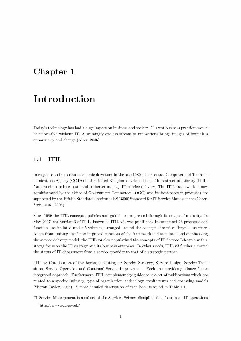
CMDB is something that underlies all the processes, it is where the usual asset management data
resides, but the CMDB also holds the sources on information on the resources used by each service
and their dependencies. A common example of a CMDB is shown in Figure 1.1. When a Change
needs to be executed, the CMDB will show which components are attached to the altered compo-
nent or service so that any consequences and problems associated to the change are always known
(Greiner, 2007). Further more, this repository is widely used in many organizations (Steinberg,
2005)(Atherton, 2007).
Figure 1.1: The Configuration Management Database
The primary objective of Change Management is to enable beneficial changes to be made with
minimal disruption to IT services. Change Management ensures that changes are deployed in a
controlled way, i.e. they are evaluated, prioritized, planned, tested, implemented and documented
(Arjen de Jong, 2008).
Changes arise as a result of problems, but many Changes can come from proactively seeking business
benefits such as reducing costs or improving services.
Changes are also made for proactive or reactive reasons. Examples of proactive reasons are cost
reduction and service improvement. Examples of reactive reasons for change are solving service
disruptions and adapting the service to a changing environment.
4

The goal of the Change Management process is to ensure that standardised methods and procedures
are used for efficient and prompt handling of all Changes, in order to minimise the impact of Change-
related Incidents upon service quality, and consequently to improve the day-to-day operations of
the organization (OGC, 2001).
1.3 Problem
One of the main challenges posed by information systems is ensuring they can deliver genuine
business benefits. There is a very high failure rate among information systems projects because
organizations have incorrectly assessed their business value or because firms have failed to manage
the organizational change surrounding the introduction of new technology (Laudon, 2007).
The CHAOS Report (The Standish Group, 1995) also refers that only 16% of IT projects are
successful (finished on-time and on-budget). However, since 1994 this value has not suffered almost
any variation, as it is illustrated in Figure 1.2.
Figure 1.2: Percentage of succeeded, challenged and failed IT projects according to The CHAOSReports
ITIL is a methodology to improve delivery service efficiently and effectively, with high quality,
based on the best practices of service. Every year more organizations desire implementing ITIL.
However a considerable percentage of them fail and some organizations collapse trying it. Some
of the most common mistakes made by organizations when implementing ITIL are (The Standish
Group, 1995)(Sharifi et al., 2008):
• Lack of management commitment
• Spend too much time on complicated process diagrams
• Not creating work instructions
5

• Not assigning process owners
• Concentrating too much on performance
• Being too ambitious
• Failing to maintain momentum
• Allowing departmental demarcation
• Ignoring constant reviewing of the ITIL
• Memorizing self ITIL books
Besides these factors, another ones can also be referred like the organizational resistance to change
or even the fact that ITIL books only explain what to do to implement its processes but it does not
explain how that same implementation should be done.
Another research (Pereira, 2010) where a maturity model for ITIL implementations was developed
and was tested in seven different portuguese organizations, proved that those same organizations
had a maturity level of one. The fact that these organizations were only at the first level of maturity
is also a good reason to believe that ITIL implementations are not easy.
There are studies that conclude that a majority of organizations give priority to implement some ITIL
processes (Cater-Steel & Toleman, 2007a) but there is even less research about the implementation
of these processes. Despite this sweeping adoption by industry, most academic institutions appear
to be reluctant to include ITIL in their IT curriculum (Cater-Steel & Toleman, 2007b), what helps
to explain a little why there is not much published in implementing ITIL.
Many organizations are already implementing ITIL. Most part of them resume ITIL to just Incident
Management and Configuration Management. These points represent a huge problem regarding
first, the CMDB and then the business itself. Many organizations that use a CMDB today don’t
have Change Management implemented. The most direct consequence is that the CMDB used in
Configuration and Incident Management, can become out of date very quickly, caused by any change
in any Configuration Item (Ci). Some common examples are the installation of new software or even
software updates in the workstations. Further more, these changes can occur several times a week or
even several times a day. It becomes obvious that a CMDB that is not up to date, does not have any
interest to the organization. Worse than that, working with a CMDB which is not up to date, thus
inconsistent, can lead to wrong and bad decisions. As ITIL says, the Change Management process
depends on the accuracy of the configuration data to ensure the full impact of making Changes is
known (OGC, 2000).
So, the fact that many organizations don’t know how to implement Information Systems projects,
namely ITIL, is a problem that this thesis proposes to solve.
6

1.4 Research Method
In order to evaluate the work and goals proposed on section 1.3, it was chosen a methodology called
Action Research.
Action Research is about investigating change. Cunningham (1993) suggests that action research
is “a continuous process of research and learning in the researcher’s long-term relationship with
a problem”. He further suggests that the action researcher must be prepared to experience the
research problems its context evolves within the problem. The intention of action research is to
institute a process of change and then to draw conclusions from this process. More specifically,
action research involves the collection of data about an organization in order to identify problems
and their identifying causes (Michael E. Withman, 2004).
The ideal domain of the action research method is characterized by a social setting where (Baskerville,
1999):
1. The researcher is actively involved, with expected benefit for both researcher and organization.
2. The knowledge obtained can be immediately applied, there is not the sense of the detached
observer, but that of an active participant wishing To utilize any new knowledge based on an
explicit, clear conceptual framework.
3. The research is a (typically cyclical) process linking theory and practice.
In Action Research, the researcher wants to try out a theory with practitioners in real situations, gain
feedback from this experience, modify the theory as a result of this feedback, and try it again. Each
iteration of the action research process adds to the theory in this case a framework for information
systems development so it is more likely to be appropriate for a variety of situations (Avison et al.,
1999).
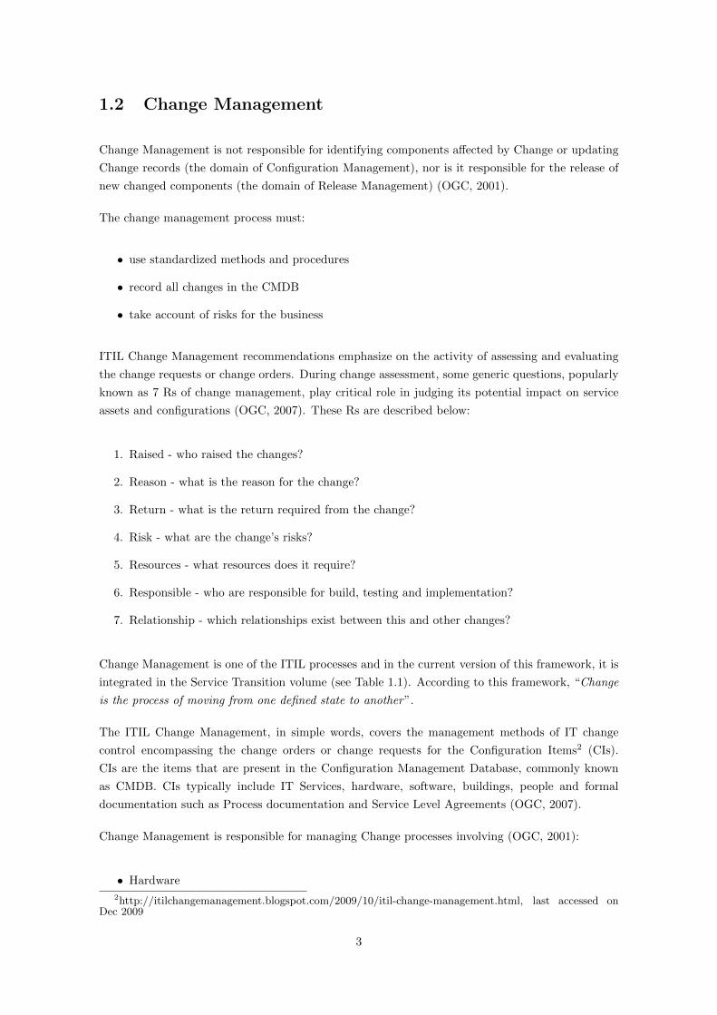
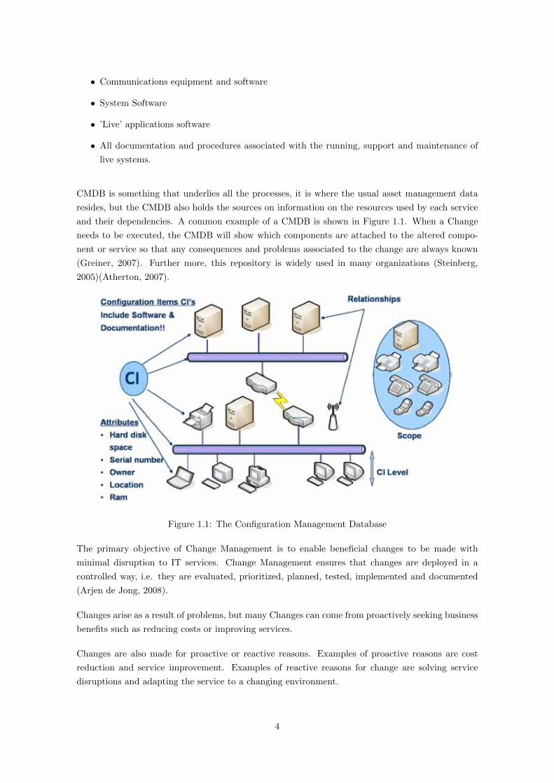
The Action Research cycle is composed of five steps (Baskerville, 1999) which are (also illustrated
on Figure 1.3):
Diagnosing
Diagnosing corresponds to the identification of the primary problems that are the underlying causes
of the organizations desire for change. Normally, diagnosing is made through self-interpretation
of the organizational problem. This diagnosis will develop certain theoretical assumptions (i.e., a
working hypothesis) about the nature of the organization and its problem domain.
Action Planning
In this phase, researchers and practitioners collaborate in planning the actions to solve the problem
identified earlier. This planning is guided by the theoretical framework, which indicates both some
7
Figure 1.3: The Action Research Cycle
desired future state for the organization, and the changes that would achieve such a state. The plan
also establishes the target for change and the approach to change.
Action Taking
In this third phase, the actions decided in the last one (Action Planning), are implemented. Similarly
to Action Planning, both researchers and practitioners work together in this implementation. For
example, the intervention might be directive, in which the research “directs” the change, or non-
directive, in which the change is sought indirectly. Intervention tactics can also be adopted, such as
recruiting intelligent laypersons as change catalysts and pacemakers. The process can draw its steps
from social psychology, e.g., engagement, unfreezing, learning and re-framing (Baskerville, 1999).
Evaluating
Following Action Taking, comes evaluation. This is the phase where is decided if the problem was
successfully solved within the actions taken before. If those actions were unsuccessful, a change
to the working framework or even to the hypothesis formulated at the begin of the cycle may be
required or necessary.
Specifying Learning
This is the last step of the Action Research Cycle. In spite of being the last one, the learning
should be done during all the other four steps. Taking the fact that this methodology has a strong
8

practical component, this learning comes natural and is made during all the process. This last phase
has many advantages as not only because it is possible to learn about a problem a try to solve it
better in a future cycle but also because the organization itself learns more about its nature and
environment.
9

Chapter 2
Related Work
In this section, we present various concepts related to ITIL implementation, including CMDB and
Change Management implementation, as well as some work that has already been done in this area.
Unfortunately, there is still a lot to investigate as currently the information available is not as much
as we would like (see page 17).
2.1 The Configuration Management Database
A Configuration Management Database (CMDB) is a repository of information related to all the
components managed by IT. Although repositories similar to CMDBs have been used by IT depart-
ments for many years, the term CMDB stems from ITIL. In the ITIL context, a CMDB represents
the authorized configuration of the significant components of the IT environment. A CMDB helps
an organization understand the relationships between these components and track their configura-
tions. The CMDB is a fundamental component of the ITIL framework’s Configuration Management
process. As it has been previously referred, a common example of a CMDB can be viewd in Figure
1.1.
The CMDB records are called Configuration Items (CI). A Configuration Item is any component
of an information technology infrastructure that is under the control of configuration management.
Configuration Items can be individually managed and versioned, and they are usually treated as
self contained units for the purposes of identification and change control. The CMDB should also
include all relationships between its Configuration Items.
All Configuration Items are uniquely identified by names, version numbers, and other attributes. The
lowest level CI is usually the smallest unit that will be changed independently of other components.
CIs vary in complexity, size, and type. They can range from an entire service which may consist of
hardware, software, and documentation to a single program module or a minor hardware component.
The benefits of having a good Configuration Management CMDB are many. As ITIL says, some of
these benefits are (OGC, 2000):
10

• CIs affected by a scheduled (authorised) Change
• All Requests for Change (RFCs) relating to one particular CI
• CIs purchased from a particular supplier within a specific period
• CI history
• Equipment and software at a given location, for example to assist in an audit
• CIs that are scheduled to be upgraded, replaced or decommissioned
• Changes and Problem records associated with a CI
2.2 The Change Management Process
Changes should be managed to optimize risk exposure, minimize the severity of any impact and
disruption or to be successful at the first attempt (of any change). Such an approach will deliver
direct benefit to the bottom line for the business by delivering early realization of benefits (or
removal risk), with a saving of money and time (OGC, 2007).
While the benefits of applying IT Service Management practices vary depending on the organiza-
tion’s needs, some typical benefits include (OGC, 2009):
• Improved quality service provision
• Cost justifiable service quality
• Services that meet business, customer and user demands
• Integrated centralized processes
• Everyone knows their role and knows their responsibilities in service provision
• Learning from previous experience
• Demonstrable performance indicators.
The activities involved in ITIL Change Management process are shown in Figure 2.3.
It is also important to consider the range of stakeholders who can benefit from improved ITSM
practices. These stakeholders can come from (OGC, 2009):
• Senior management
• Business unit managers
• Customers
• End-users
11

• IT staff
• Suppliers.
A study (Thomas Mendel, 2004) states that, on average, the information network causes 15% of
all problems resulting in downtime at $1 billion-plus companies. However, only 2% are caused by
actual networking hardware failures: The other 13% are due to different issues like human errors,
unmanaged changes, misconfigurations, routing failures, and problems with networking software.
ITIL Service Support volume states that Change Management ensures that standardized methods
and procedures are used for efficient and prompt handling of all changes, in order to minimize the
impact of change-related incidents upon service quality, and consequently to improve the day-to-day
operations of the organization (OGC, 2000). This way, Figure 2.1 shows the interfaces of Change
Management process with other ITIL processes.
Figure 2.1: Change Management and other ITIL Processes (van Bon, 2007)
Furthermore, changes to any components that are under the control of projects are subject to project
Change Management Procedures, not under general Change Management procedures. The Change
Management team will, however, be expected to liaise closely with project managers to ensure
smooth implementation and consistency within the changing management environments. It is the
Change Management process that produces approval for any proposed Change. While Change Man-
agement makes the process happen, the decision authority is the Change Advisory Board (CAB),
which is made up for the most part of people from other functions within the organization (OGC,
2000).
Change Management Activities
Figure 2.3 shows the activities involved in ITIL Change Management Process.
12
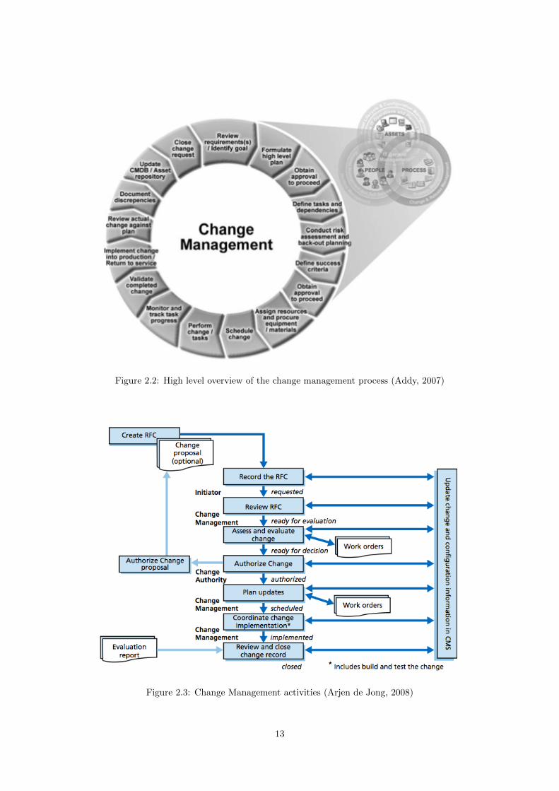
Figure 2.2: High level overview of the change management process (Addy, 2007)
Figure 2.3: Change Management activities (Arjen de Jong, 2008)
13

There is a research that proposes an interesting approach to the Change Management activities.
The author states that it is based on ITIL with some specific modifications according to the business
needs of the respective organization in the case study (Mattila, 2008). A summary of this process
follows:
1. Request for Change (RFC) - change originator requests for a change by using a web form in
the intranet or by sending e-mail to the Service Desk. Change initiator can be anyone. RFC
ticket is created.
2. Change Coordinator reviews the RFC
3. Change Coordinator evaluates the RFC, classifies it, and categorizes it based on the impact
and urgency. Change Coordinator does the initial planning of the change implementation by
describing the change and by assessing the change necessity and feasibility.
4. The change request is approved for implementation either by the Change coordinator or the
Change Advisory Board (CAB). Need for CAB approval depends on the change impact for
the business, the scope of the investment, the amount of resources needed for implementation,
and the amount of risk related to the change implementation.
5. Change Coordinator plans the change implementation by defining the tasks needed to com-
plete the implementation, the work effort, resources, schedule budget and acceptance criteria.
Change implementer plans the change implantation from technical viewpoint by defining tech-
nical solution, test and back out plans.
6. The change is implemented according to the implementation plan and Build and Test and
Release to production Methods
7. Build and Test is the change preparation process where impact of the change is verified and
also what will be done and how. It also includes testing if feasible. Release to Production
is the process of taking changes to production. It also involves defining if the change can be
considered successful or not and deciding if implementation of back-out plan is needed.
8. The change implementation success and impact are reviewed in cooperation with the Change
Originator. The RFC ticket and related information is updated, and the change ticket closed.
Change Advisory Board
According to ITIL, the Change Advisory Board (CAB) is a group that provides expert advice to
the Change Manager. It involves representatives from various IT and business areas as well as other
involved stakeholders including external suppliers. It is chaired by the Change Manager. There is
also a subgroup of CAB called Emergency CAB which task is to provide expert advice for emergency
change decisions (OGC, 2009).
A research asserts that too few people in the CAB make it easier to meet, but may exclude some of
the essential stakeholders of a particular change1 (Dorst, n.d.). In order to avoid this problem, the
1http://www.lucidit.com.au/files/How to change Change.pdf,s last accessed in December 2009
14

author proposes the creation of several area CABs. This has the benefit that it becomes easier to
accommodate existing decisions and communication forums. The logical separation between areas
made it easier to appoint the correct people in these roles, both from a management (authority) and
an acceptance perspective. In order to overcome the silo-structure that was created (albeit business
rather than technology focussed), they defined a new role, the Change Controller which is someone
who specifically (horizontally, across all CABs) would review, authorize, coordinate and control the
changes from a technical or technological perspective.
Configuration Item Lifecyle
ITIL suggests only some examples of the status of an RFC as logged, assessed, rejected, accepted
and sleeping. Mattila also proposes a Lifecycle in his thesis (Mattila, 2008) which is illustrated in
Figure 2.4.
Figure 2.4: Lifecycle of hardware CI proposal (Mattila, 2008)
Other author still suggests other stages, as is shown in Figure 2.5 (Ward et al., 2007). He also
introduces the concept of protected stages. In these stages, any change made do the Configuration
Item required that an RFC has to be associated with them. This validation capability recognizes
explicitly that there are life-cycle states in which a greater degree of control is required over the way
in which they can be modified.
Change States
In spite of the fact that ITIL already defines different change states as standard, minor, major and
significant, other authors propose slightly modifications to this idea.
For example, (Mattila, 2008) proposes three states instead of the four referred in the last paragraph:
Normal, Major and Emergency Change.
15
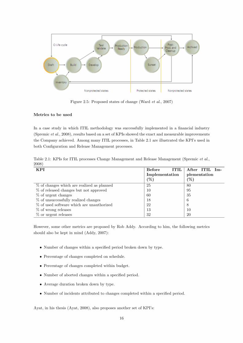
Figure 2.5: Proposed states of change (Ward et al., 2007)
Metrics to be used
In a case study in which ITIL methodology was successfully implemented in a financial industry
(Spremic et al., 2008), results based on a set of KPIs showed the exact and measurable improvements
the Company achieved. Among many ITIL processes, in Table 2.1 are illustrated the KPI’s used in
both Configuration and Release Management processes.
Table 2.1: KPIs for ITIL processes Change Management and Release Management (Spremic et al.,2008)
KPI Before ITILImplementation(%)
After ITIL Im-plementation(%)
% of changes which are realized as planned 25 80% of released changes but not approved 10 95% of urgent changes 60 35% of unsuccessfully realized changes 18 6% of used software which are unauthorized 22 8% of wrong releases 13 10% or urgent releases 32 20
However, some other metrics are proposed by Rob Addy. According to him, the following metrics
should also be kept in mind (Addy, 2007):
• Number of changes within a specified period broken down by type.
• Percentage of changes completed on schedule.
• Percentage of changes completed within budget.
• Number of aborted changes within a specified period.
• Average duration broken down by type.
• Number of incidents attributed to changes completed within a specified period.
Ayat, in his thesis (Ayat, 2008), also proposes another set of KPI’s:
16
• Number of changes completed per time per unit
• Number of rejected changes
• Number of incidents resulting from changes
• Number of back out related to changes
• Cost of the implemented changes
Unfortunately, a large array of authors state that there is little or no published research that concerns
ITSM. There is a world of knowledge, secretly contained in Consulting Firms and Organizations,
but that knowledge is contained there, in exclusivity, and is not based on worldwide scientific
construction. There is some research related to areas like automatic scheduling of IT Changes, but
none concerning the actual way to implement and do IT Change Management. There are studies
that conclude that a majority of organizations give priority to implement Change Management
(Cater-Steel & Toleman, 2007a) but there is even less research about the implementation of this
process.
Despite this sweeping adoption by industry, most academic institutions appear to be reluctant
to include ITIL in their IT curriculum (Cater-Steel & Toleman, 2007b), what helps to explain a
little why there is not much published in implementing ITIL, or specifically implementing Change
Management.
So, actually it is not known how to implement ITIL Change Management in any context of an
organization.
2.3 Information Systems Implementation
In order to better understand information systems implementation, a framework called The Work
System Method (WSM) (Alter, 2006) was analysed.
Work System Method
This framework (see Figure 2.6) was designed to help business professionals understand systems in
their organizations. It is especially valuable early in a system-related project when people identify
the problem, think about alternative courses of action, and decide how to proceed. Unlike some
other methods that require specific steps performed in a specific order, the work system method is
designed to be quite flexible. It provides usable guidelines and analysis concepts while at the same
time permitting the analysis to occur in whatever order and at whatever level of detail is appropriate
for the task at hand.
So, the WSM is organized around a typical problem solving processes of defining a problem, gathering
and analysing relevant data, identifying alternatives, and selecting a preferred alternative (Alter,
2006).
17

Figure 2.6: The Work System FrameworkTM (Alter, 2006)
WSM is divided into three major steps that apply general problem solving to typical systems in
organizations:
1. SP - Identify the System and the Problem: Identify the work system that has the problems
or opportunities that launched the analysis. The size and scope of the work system depends
on the purpose of the analysis.
2. AP - Analyse the system and identify Possibilities: Understand current issues and find pos-
sibilities for improving the work system.
3. RJ - Recommend and Justify changes: Specify proposed changes and sanity-check the recom-
mendation.
To use this framework, the first and surely the most important phase is the first one, in which the
work system itself is defined. It is a very important phase as if a system is defined too wide and
contains many activities or processes, it becomes easy to loose the focus on the small problems that
shouldn’t be ignored as unnecessary topics will expand time and effort required for the analysis. On
the other hand, if a system is defined too strict or limited, we may not be able to detect external
problems that are avoiding the well functioning of the activity in analysis in spite of being possible
to view an entire organization as a single work system. Due to the points referred before in this
paragraph, is is better to see that same organization as a combination of many smaller work systems.
Having said this, how is a Work System and its scope defined? Since this work’s scope is englobed
on a Information Systems thesis, it is important to have in mind that the definition of a system
work scope cannot be only thought in terms of technology. Using other words, the work defines
the system, not the technology that is used to do the work. An example of a definition of a work
system, is illustrated on Table A.1.
18

As shown on Table A.1, six main topics were defined: Customers, Products & Services, Work
Practices, Participants, Information and Technologies. To understand a little bit more about what
is each topic, a small description is made below:
• Customers - people who receive direct benefit from products and services the work system
produces. They can be external customers who receive the organization’s products and/or
services or internal customers who are employees or contractors working inside the organiza-
tion.
• Products & Services - they are the combination of physical things, information, and services
that the Work System produces. This may include physical products, information products,
services, intangibles such as enjoyment and peace of mind, and social products such as ar-
rangements, agreements, and organizations.
• Work Practices - these include everything that happens within the Work System. The term
processes and activities is used instead of the term business process because many work systems
do not contain highly structured business processes defined. However, business process is but
one of a number of different perspectives for analyzing the activities within a work system.
Other perspectives with their own valuable concepts and terminology include decision-making,
communication, coordination, control, and information processing.
• Participants - these are the people who perform the work. Some may use computers and IT
extensively, whereas others may use little or no technology. When analyzing a work system
the deeper role of work system participant is more important than the more limited role of
technology user.
• Information - includes codified and non-codified information used and created as participants
perform their work which may or may not be computerized. Data not related to the work
system is not directly relevant, making the distinction between data and information secondary
when describing or analyzing a work system. Knowledge can be viewed as a special case of
information.
• Technologies include tools (such as cell phones, projectors, spreadsheet software, and auto-
mobiles) and techniques (such as management by objectives, optimization, and remote track-
ing) that Work System participants use while doing their work.
After defining the work system, the next phase is to analyse it. This way, we can evaluate it and
decide wether and how to improve it.
IT Processes Performance
Nowadays, IT Departments can no longer be an isolated silo in the organization. They must be
completely aligned with business in order not only to support it, but also to improve it. Still,
business is not static, and it needs to be adapted as a response to market needs or to exploit a
business opportunity that has arised. As business is not static, IT Services can’t be static either.
This is another important motivation for IT Departments to continuously improve their processes
19
(Peynot, 2006). But once again, it is hard to define a roadmap for improvement as ITIL does not
provide a set of tools to do so and as very often CIOs arent able to see the true links between IT
and Business (Gaughan, 2008).
Even when CIOs know how to effectively analyze their IT processes performance and know which
changes need to be introduced, in many situations, it is not easy to implement them. In fact, the
amount of changes can be extremely high and according to Laudon’s framework (Laudon, 2007)
they can be organized as following:
Organizational changes
• New organizational structure for the department
• New skills demanded for the employees
• New activities and processes
• Different way to perform old activities
• New perspectives of how IT supports and enables Business
Managing changes
• New metrics and indicators to analyze
• New SLAs
• Higher expectations for this department and his services
Technological changes
• New software
• New hardware
20

Chapter 3
Proposal
Building a new Information System is one kind of planned organizational change. The inroduction
of a new information systems involves much more than new hardware and software. it also includes
changes in jobs, skills, management and organization. When we design a new Information System,
we are redesigning the organization. Systems builders must understand how a systems will affect
specific business processes and the organization as a whole.
An Information System implementation can be composed of three main components (Laudon, 2007).
These components are People, Organization and Technology.
Being ITIL an Information System implementation, it can also be composed by these three compo-
nents. As it has been already said in section X, there are few Information Systems projects that are
finished on-time and on-budget.
Having said this, we propose an implementation of a new Information System taking in mind that
it is crucial to avoid the problems that usually make this projects to fail, such as:
• Lack of management commitment
• Spend too much time on complicated process diagrams
• Not creating work instructions
• Not assigning process owners
• Concentrating too much on performance
• Being too ambitious
• Failing to maintain momentum
• Allowing departmental demarcation
• Ignoring constant reviewing of the ITIL
• Memorizing self ITIL books
21

In the specific context of this thesis, we implemented the ITIL Change Management process in a
public organization. This implementation consisted in two phases. The first phase of this work
consisted in constructing a new and up to date CMDB so that it could bring added value to the
organization. Only with this phase completed, the Change Management process implementation
could advance.
This implementation was integrated in a wider ITIL implementation project where other processes
such as Configuration Management or Incident Management were underway or almost completely
implemented. However, no Change Management process was defined. Besides this, the CMDB that
existed was not up to date which made it unuseful. All its contents were more than one year old
and since that time that nobody maintained it. The only information that was kept to date, was
the inventory of the workstations of everybody and even this list, in which were made changes every
day in order to keep it actual, had many inconsistencies. This list was only maintained by the
service-desk responsible (see figure 3.1)
Figure 3.1: IT Department Organizational Chart
To implement the Change Management process in the organization, an application was developed
using the agile programming framework Scrum in the Outsystems platform. With this solution,
the time spent is minimal, the development sprints are very short and there is constant feedback
between the users and the development team.
22
Chapter 4
First Research Cycle
The first of a set of two Action Research cycles concluded in this work, consisted in Importing a
Configuration Management Database in a private organization which main business is to provide
IT Outsourcing services.
In this project, the goal was to implement ITIL processes Incident Management and Configuration
Management in the Organization mentioned before. At the moment, there were no processes defined
and the idea was to create a centralized support center where they could manage all IT infrastructure
of their clients, which had IT technicians in outsourcing contacts. The implementation of the Change
Management process was also planned, but it was cancelled later. The causes for this cancelation
are unknown.
In the future it was pretended to put all the technicians, that were in each client, in the newly
created support center and do the work from there. Of course they would need to go to their clients
if the situation required that.
The idea was to have these processes working for six different organizations (six clients of the
organization).
4.1 Diagnosing
Before starting the project, a kick-off meeting was arranged. In that meeting, the problem (all
the service-desk activities did not follow a defined process) and all its consequences were discussed.
It was also decided mainly the specific organizations we would do the project. Some points were
discussed in detail, such as deciding what would be the CIs and their types or subtypes, which turned
to be the items illustrated on Table 4.1. A detailed diagram of these items and their relations can
be viewed on Figure 4.1.
23

Table 4.1: List of types and subtypes of CMDB’s itemsCMDB items
Type Subtype
WorkstationDesktopLaptop
ServerPhysicalVirtual
DatabaseSQLOracle
ApplicationClientWeb
RouterRouterSwitch
External DeviceLocal PrinterNetwork PrinterScanner
4.2 Action Planning
By taking advantage of some other projects (MSc and Phd thesis) in implementing this ITIL process
and using it to our benefit, it was decided to use an application already developed using the Outsys-
tems technology. This application is already being successfully used in another public organization
for almost two years in order to manage incidents according to the ITIL framework.
It was also discussed in a following-up meeting the states of any incident, during its lifecycle. It was
decided that any incident should have one of possible nine states. These states and the transitions
between them, are illustrated in Figure 4.2. A small description of each states is also made below:
• Not Assigned - The Incident has not been assigned to anyone
• Assigned - The Incident is assigned to a technician.
• Validation of Information - It is verified if all the information needed to solve the incident
is available.
• Pending from Client - Waiting for the client to give more detailed information about the
incident.
• Scheduled - The incident is scheduled to be solved.
• External Entity - The incident resolution was assigned to an external entity.
• In Resolution - Incident is being solved.
• Solved - Incident is solved.
• Closed - After the client confirmation that the incident is solved, it is closed.
• Cancelled - Incident is cancelled.
Another topic that was decided was the impact, urgency and time of resolution of a problem. That
decision is illustrated on Figure 4.3 where:
24

Figure 4.1: CMDB Data Model in the first organization
Figure 4.2: Incident States and Transitions
25

• Critical means 2 hours
• High means 4 hours
• Medium means 8 hours
• Low means 24 hours
• Planning - very low priority thus no time is assigned
Figure 4.3: Definition of resolution times according to urgency and impact of the incident
4.3 Action Taking
Putting this to work was not a big problem at all. All the points previously defined (the ones
described in the last section) had to be configured in the Incident Management application which,
once more, was already developed.
All this parameters were easy to set as the application has many configuration areas which allow to
easily add or remove certain configuration data. Further more, it was used some former knowledge
as we had information of these configuration data in a public organization where this process was
already implemented.
Technicians
First of all the names and logins of the technicians, as well as other relevant data as their e-mails
and phone contacts, had to be introduced in the system.
Two new teams were newly built. The service-desk team and the system administrator team. The
service-desk team was the first line of support. It was their role to solve all the problems. If the
service-desk could not solve the problem or incident, it was passed to a second line of support, the
system administrator team.
The role of this second line of support was to solve any problems that the first line couldn’t solve,
either by not having permissions or because they simply didn’t have the required knowledge. This
team usually would resolve more technical and specific problems as for example upgrading a server
or backing up some databases.
26

A third line of support was not defined as it was considered that this type of support would be given
by external entities, usually the manufacturers which had already maintenance contracts with the
organizations involved.
States and Transitions
The states previously defined, as illustrated in figure 4.2 had also to be introduced in the application.
Then each transition between the states was also configured. This allowed the application to follow
the states of the incidents exactly as it was defined earlier.
Impacts, Urgencies and Priorities
As previously defined in a meeting, the impacts, urgencies and its respective priorities, which were
used to prioritize each incident, had also to be introduced in the application.
Four different Impacts and Urgencies were loaded. Then, the priorities were already defined for each
combination of those same Impacts and Urgencies, as it is illustrated in Figure 4.3. The maximum
times of resolution of the incidents according to its priorities were already set.
Incident Categories
The categories of the incidents also had to be defined. When creating an incident, the application
forces the user to categorize it. The categorization is made after the technician has chosen what
was the CI related with the new incident.
There were three top pre-defined categories by the application: Failure, Service Request and As-
sistance Inquiry. My role here was to configure all the categories under each of these top three
categories. They also had to be defined by CI Types and Subtypes (see those types in Table 4.1).
Using the knowledge from an older ITIL implementation process, these categories were defined:
• Failure
– Permission issues
– Outlook
– Office
– Operating System
– Workstation doesn’t boot
– Hardware
– Drivers
– Disks
– Network
27

– Communication Devices
– Total Failure
– Application
– Other failures
• Service Request
– Keyboard
– Mouse
– New software installation
– General Service Request
• Assistance Inquiry
– General Inquiry
Building the CMDB
Having completed the first step, the loading of the CIs to the CMDB began.
Lists of all items were requested to each organization. The idea was to load all the CIs as soon as
the lists were received. However, such requests turned out to be very difficult and long, as it is going
to be described in the next section.
Using the Application
The technicians and the system administrators, which would be the new users of this application,
had already worked with it in other organization. Thus, no training was required as they already
had the necessary knowledge do work with it.
This way, the beginning of the use of the application was natural and had no difficulties at all.
4.4 Evaluating
Considering all the six organizations together, the following items were imported to the newly
created CMDB:
• 292 Workstations
• 224 Staff
• 88 Printers or Scanners
• 57 Servers
28

• 22 Applications
• 11 Routers
• 116 Databases
4.5 Learning
After finishing this cycle, some conclusions can be taken.
First of all, some lists took a long time to receive. Then, we realised that all the lists came incomplete
or with serious errors. The errors were very different, but mostly because the lists were incomplete
or had many contradictions. The most common of these errors were (among others):
• Incomplete list of the existing workstations and servers
• List of users was incomplete and/or out of date
• It was not known what workstations were being used by what users
• It isn’t known which users use some applications
• It isn’t known what items are connected to the routers
• It isn’t known what computers use certain network printers
• It isn’t known what databases belong to what servers
In order to be possible to do the loading, we had to detect the errors and ask for a new list. This
happened with all of the six organizations involved. While in the smaller ones (I am considering
smaller the ones with less IT assets) it was more easy to correct what was wrong, in the bigger ones
it revealed to be a bit more complex and long task. In spite of having more errors to correct, I also
realized that in these ones, the quality of the lists was worse than in the smaller ones. Due to this
fact we can say that the information about what the organizations have, become more accurate as
less assets they have.
After asking for some more corrections of the lists until have accurate ones, we began the loading of
the items to the CMDB. Fortunately this step was quick and we can affirm that six organizations
had their CMDB loaded and used in the Incident Management process.
Throughout the entire process we can conclude that, as predicted, organizations don’t know what
their assets are. Specifically in IT, which is the context of this project, no one knows how many
workstations exist or who uses them, how many servers exist or the list of web applications, for
example. These were real problems that had to be faced and solved in order to accomplish our
initial goal, to successfully create an accurate Configuration Management Database.
The following step would be to start building an application to support a new Change Management
process but, due to unexplained reasons, the project was cancelled by the organization which made
impossible to accomplish all the initial goals.
29
Chapter 5
Second Research Cycle
The second Action Research Cycle took part in a second public organization.
This public organization has suffered some strong organizational changes in the last two years as
it became responsible for managing not only its own headquarters but also all casinos and hotel
schools from Portugal. The same happens to IT.
The goal in this second organization, which already followed some ITIL processes namely ITIL
Incident Management and ITIL Configuration Management, was to implement ITIL Change Man-
agement.
5.1 Diagnosing
Regarding its ITIL usage, they have been using an ITIL Incident Management application for almost
two years. A Configuration Management application was already implemented and available but it
was ignored by all as its rarely modified information data (the CI data and its relations) was out of
date.
Especially this last point made the implementation of ITIL Change Management the next logical
step. This way, the data of all IT assets would be kept up to date and this would bring many
advantages to the Organization. These advantages were already described in the first chapters of
this document.
At the beginning, there was no process defined for managing changes. Besides this, even the lists
of assets were highly incoherent. All the data they used, was based on many Excel files. Almost
everyone had its own Excel file and made changes on it not sharing them with anyone. No one
could be sure on who had the right list of anything. The closest I verified for a process of managing
changes, was the service-desk manager to update daily a list of the headquarters’ workstations and
the users of each of these workstations.
30
5.2 Action Planning
Before implementing Change Management itself, a Configuration Management Database with all
its up to date information had to be imported as Change Management logically makes no sense
without a CMDB.
Like it was said before, an application was already functioning but all the data was out of date. So,
the first step was to clean it before getting and introducing the new information. To clean it was
relatively simple as it only required minor changes in the application itself once the items could not
be deleted forever because there were many incidents that were related to one or more CIs. This
way, the items were only deactivated maintaining all the data from the incident reports that existed
at the time.
5.2.1 Defining the New Structure of the Data
The base structure, already defined in the existing Configuration Management application, allowed
the division of each Configuration Item by one of the following CI Types (this is the name the
application uses to name these types): Staff; Software; Hardware; Server; Workstation; Router;
External Device; Racks; Communication Device; Database; Application.
These CI Types are static and pre-defined by the application. However, for each of these CI Types,
it is possible to define subtypes, designated by the application as Meta CIs.
Having said this, the structure of the data that was in place at the beggining had a quite complex
model, as it is shown in Figure 5.1. The Meta CIs are represented in Figure 5.1 inside the bubbles
while the correspondent CI Types are represented outside those same bubbles.
As it was learned in the first organization, the more complex the structure we define, the longer it
takes to obtain the information we want in a consistent mode. So, a new and more simple structure
based on the former one was defined. The criteria used to choose which items would be imported
was simply to choose the items that were more used by the service-desk technicians and system
administrators in their daily tasks.
The structure of the new CMDB was defined as it is illustrated in Figure 5.2. In this figure, CI
Types and its related Meta CIs are represented in the same way as in the previous figure.
In Figure 5.2 there are some sections marked in blue, namely Databases and Applications. The
fact that these points are marked in a different way, was used to distinguish these ones from the
other ones. The difference was that there was no available information about these ones. While
some listings of the other assets were already available there was zero information about these ones.
However, the fact that some of the listings were already available, did not help too much as they
were all inconsistent and out of date. Once more, regarding to servers and databases, no list had
ever been done.
31
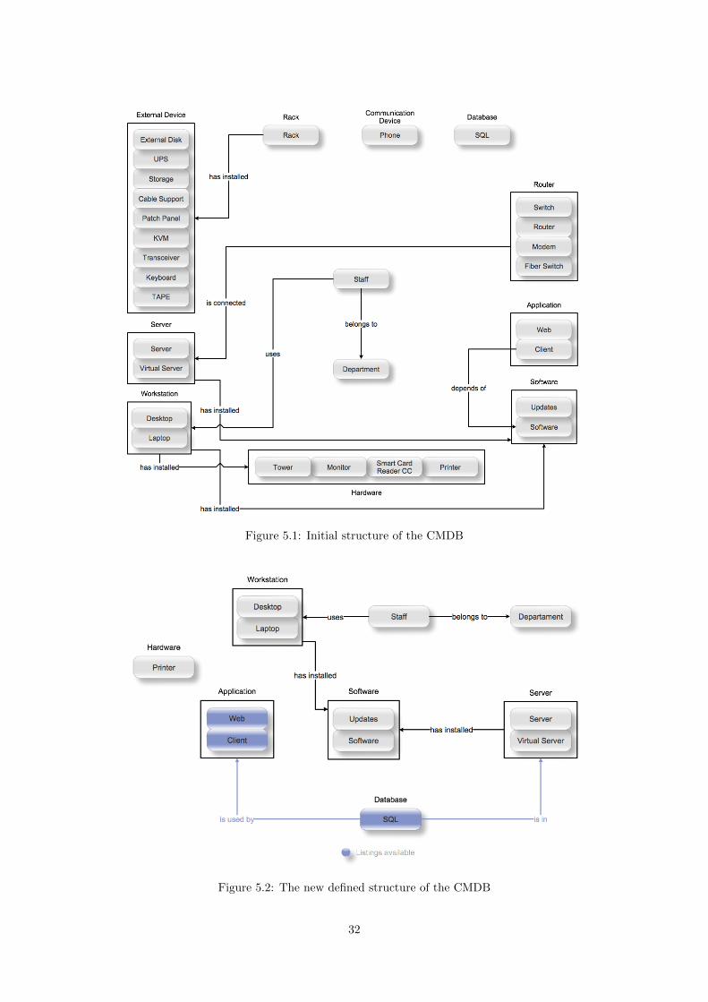
Figure 5.1: Initial structure of the CMDB
Figure 5.2: The new defined structure of the CMDB
32

5.2.2 Defining the Change Management Process
The design of the proposed Change Management Process, had some points taken in mind. First
of all, it is based in the process defined by ITIL (see Figure 2.3). Then, the goal was to define a
simple process based on the one described in ITIL, not forgetting its main phases like requesting,
authorization, scheduling, implementation and roll-back if anything goes wrong.
In Figure 5.3 it is illustrated the proposed process in this thesis that was later implemented in the
application. The same figure in a higher resolution is available in appendix B.
Figure 5.3: Proposed Change Management Process
As it can be seen, these process always begins creating a new RFC. In this step, it is chosen the
CI in which the change is pretended to be made and all the related information such as the change
requester, the category of the Request For Change and any additional details that describe the
change and that will be useful for the Change Coordinator or CAB decide if the change will be
accepted.
Depending on the category of the change, it can be standard or not. If it is, the change is automati-
cally approved and the change can immediately be built. Otherwise, the request goes to the change
coordinator awaiting feedback (Evaluate action in Figure 5.3). Here, if the Change Coordinator has
all the privileges to approve or reject the change, he approves or rejects it. Otherwise, he passes the
RFC to the CAB, a higher change authority which is capable of deciding if some changes can be
built. Normally, these are changes which may represent higher risk to the business as they can cause
33

unwanted damage to it. For example, a change that requires some downtime from a crucial server
to the business can be considered a type of change that requires the feedback from a CAB. However,
the definition of the changes that required CAB review must be defined in each organization by
that same organization. This way, it is guaranteed that all these classifications are aligned to the
business itself.
After the approval phase, the RFC can be approved or rejected.
If it is rejected there are two options. The first one is that the RFC is simply closed. The second one
allows the creation of a new RFC based on the first one. This normally happens when the first one
did not have the required information for the Change Coordinator or the CAB to take a decision.
In this case, the change agent receives the feedback from the Change Coordinator or the CAB and
can provide the missing information in the new RFC. This corresponds to the decision Propose New
RFC in Figure 5.3.
If the RFC is approved, the Change Agent can Build the Change (Build Change). The RFC then
passes to a testing phase where it will be tested if the Change was successful and did not cause
any unexpected behaviour, either on the related CI or on any other one. For example, if a change
is made in an application, is it necessary to check if the application continues to function without
any problem and that all the workstations that use that application also do not experience any
unexpected behaviour.
As ITIL defines, the Change Requester can be anyone. Then there are the roles of Change Agent
that is responsible to build, test and close changes. Change Coordinator and CAB (Change Ad-
visory Board) roles are assigned to the ones that inside the organization have the privileges or
responsibilities to take decisions on Changes that may represent high risk or impact to the business.
Following this definition, different states for a RFC were also defined. These states and transitions
are illustrated in Figure 5.4.
Figure 5.4: Change States Diagram
Below, a description of each state represented in Figure 5.4 is made:
• Open - This is the first state. When the user is creating the RFC, the RFC is in this state.
34
• Pending Approval - After creating the RFC, the RFC passes to this state where it is pending
an approval, either from a Change Coordinator or from a CAB. If the change is considered a
standard change, the RFC automatically passes from this state to Approved or to Rejected.
• Rejected - This is the state of the RFC when it was previously rejected either by a Change
Coordinator or a CAB.
• Approved - In this state, the RFC was previously approved either by a Change Coordinator
or a CAB.
• Testing - After building the change, the RFC remains in Testing. As explained earlier, this
is the phase where it is checked that the change was successful.
• Closed - This is the last state of a RFC. A RFC can reach this state after being rejected
or after having passed the testing phase. In this phase it is considered that the process was
concluded and that the change was sucessful (if it was previously built).
5.3 Action Taking
In this section it will be described all the phases that followed the planning one, described in the
previous section.
5.3.1 Getting the Data
Having defined the new structure, the next step consisted in requiring the data to the ones responsible
for it. While the list of workstations, staff and phones was requested to the service-desk people,
other items such as servers, databases and their relations were asked to the system administrators
team.
A structured spreadsheet was provided to them where they could fill in the data and all the infor-
mation that was needed. They were asked to provide:
• List of Workstations, their serial numbers, models and location
• Relationship between Staff and Workstations
• List of Servers and Clusters
• List of Databases
• Relationship between Databases, Servers and Clusters
• List of phones and its relationships with Staff
• List of Routers
• List of Racks and its relationships with the Servers
35

A list of the the Staff was not needed as the application automatically obtains it once a day with a
direct integration to the organization’s Active Directory.
In spite of having simplified the initial structure of the CMDB in order to be easier to understand
and obtain the information, this phase revealed to be the most difficult, long (it took more than 3
months) and complicated phase.
5.3.2 Importing the Data to the CMDB
Once the data was obtained in a consistent mode, the importation began. Using the potentials of
Outsystems technology, which makes it very simple to read data from Excel (.xls) files, this phase
did not take long and in two days, all the information was loaded to the new CMDB.
5.3.3 The Change Management Prototype
Having concluded the previous phase, the building of the prototype to support the Change Man-
agement Process began.
Technology
The technology chosen to build the prototype was the Outsystems Platform which is a technology
that provides rapid and agile development of web based business applications.
Figure 5.5: The Outsystems Platform
It’s made of four major components, as illustrated in Figure 5.5:
• The Platform Server - a collection of services that complement standard .Net or Java
application server installations and it is where the web application is stored and run. This
component is composed by the four components Application Management, Environment Op-
eration, Application Server and 1-Click Publishing illustrated in Figure 5.5.
36
• Service Studio - a visual modelling tool used by development and maintenance teams to
assemble and change web business applications.
• Integration Studio - a windows tool that works in tandem with Microsoft Studio or Eclipse.
It is used by developers to extend the built-in Platform Services with extra functionality.
• Service Center - a browser-based administration console that controls and manages the agile
platform.
The reasons that led to the choice of this solution were first of all, the ease and the rapid development
of applications that it provides. Then, the implementation of both Incident and Configuration
Management processes had already been done using this technology, which would facilitate the
integration of the existing ones to the new Change Management process.
Integration
One of the advantages of using the Outsystems platform and having already the Configuration
Management application developed with this technology is the integration between applications.
Once the Change Management process is highly dependent on a Configuration Management Database,
it became necessary to integrate the new Change Management prototype with the existing Config-
uration Management one, using this way the items of the CMDB.
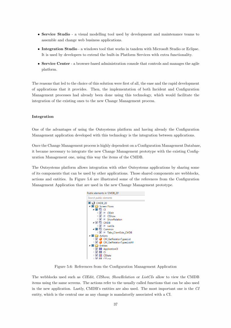
The Outsystems platform allows integration with other Outsystems applications by sharing some
of its components that can be used by other applications. Those shared components are webblocks,
actions and entities. In Figure 5.6 are illustrated some of the references from the Configuration
Management Application that are used in the new Change Management prototype.
Figure 5.6: References from the Configuration Management Application
The webblocks used such as CIEdit, CIShow, ShowRelation or ListCIs allow to view the CMDB
items using the same screens. The actions refer to the usually called functions that can be also used
in the new application. Lastly, CMDB’s entities are also used. The most important one is the CI
entity, which is the central one as any change is mandatorily associated with a CI.
37

Data Model
In Figure 5.7 it is shown the defined datamodel of the new prototype.
Figure 5.7: The Prototype’s Datamodel
Below, a small description of each one of the entities shown in figure 5.7 is made:
• RFC - This is the central entity. As it can be seen, all data from a created Request For
Change like the Change Requester, the CI where the change is intended to be made or all the
RFC history is stored here.
• RFCState - The states of a Request For Change are defined in this entity. The states defined,
are the ones previously described in section 5.2.2.
• RFC Logs - In this entity, each log is considered to be a change to a attribute of a CI. The list
of all changes related to an RFC are a set of many RFC Logs records (one for each attribute
changed) related to one only RFC.
• ChangeLogRelations - Similar to the last one, but instead of registering the changes of the
attributes, it registers the changes in relations between CIs.
• Categories - Here, the different categories of a Request For Change are defined and also if a
Category represents a standard change or not.
• Priority - Here, it is defined the priorities for a RFC. These priorities are defined, according
to ITIL, as a result of a matching between an Impact and an Urgency.
• ChangeLog - A set of logs of all changes to a CI. This entity is used to show the history of
changes to the attributes of a CI in the CMDB application.
38

• CM RelationCis - Similar to the last one, but regarding only changes in relations between
CIs.
• Ci - This entity represents a single CI. It had been already defined when the Configuration
Management application was built and it belongs to that application. It is represented in this
schema as it is a vital entity to the prototype as it is strongly related to the new ones.
Create New RFC
Creating a new RFC (Request For Change) is composed of two screens.
Figure 5.8: Create new RFC screen
The first one, as is illustrated in Figure 5.8 is composed by the following fields:
• Change Requester - The name of who requests the change. This can be anyone.
• Date - The date and time of the request. By default, the date and time are the current ones.
• Description - A description of the change to be requested.
• Backout Plan - A description of what needs to be done if anything goes wrong with the
change.
• Change Agent - The name of the technician responsible for this Request For Change. It will
be who, after approval, builds the change.
• Impact and Urgency - Here, it is chosen the Impact and Urgency of the change to be
proposed. The choice can be made using a set of pre-defined values.
39
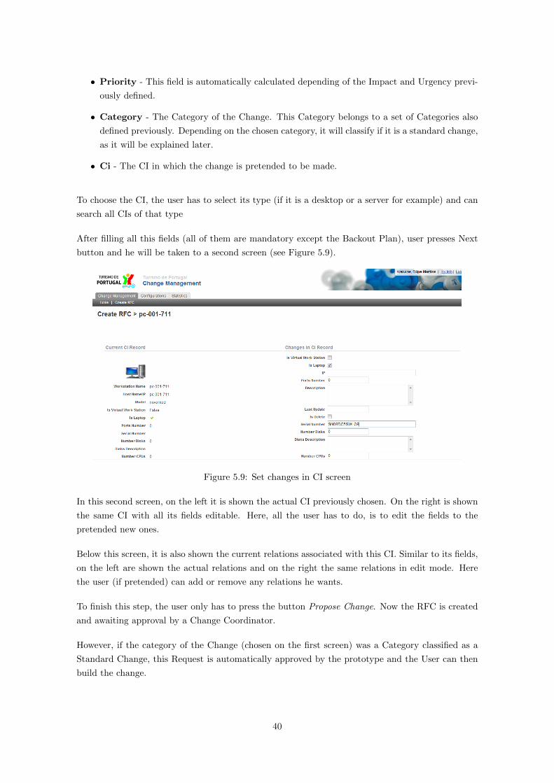
• Priority - This field is automatically calculated depending of the Impact and Urgency previ-
ously defined.
• Category - The Category of the Change. This Category belongs to a set of Categories also
defined previously. Depending on the chosen category, it will classify if it is a standard change,
as it will be explained later.
• Ci - The CI in which the change is pretended to be made.
To choose the CI, the user has to select its type (if it is a desktop or a server for example) and can
search all CIs of that type
After filling all this fields (all of them are mandatory except the Backout Plan), user presses Next
button and he will be taken to a second screen (see Figure 5.9).
Figure 5.9: Set changes in CI screen
In this second screen, on the left it is shown the actual CI previously chosen. On the right is shown
the same CI with all its fields editable. Here, all the user has to do, is to edit the fields to the
pretended new ones.
Below this screen, it is also shown the current relations associated with this CI. Similar to its fields,
on the left are shown the actual relations and on the right the same relations in edit mode. Here
the user (if pretended) can add or remove any relations he wants.
To finish this step, the user only has to press the button Propose Change. Now the RFC is created
and awaiting approval by a Change Coordinator.
However, if the category of the Change (chosen on the first screen) was a Category classified as a
Standard Change, this Request is automatically approved by the prototype and the User can then
build the change.
40
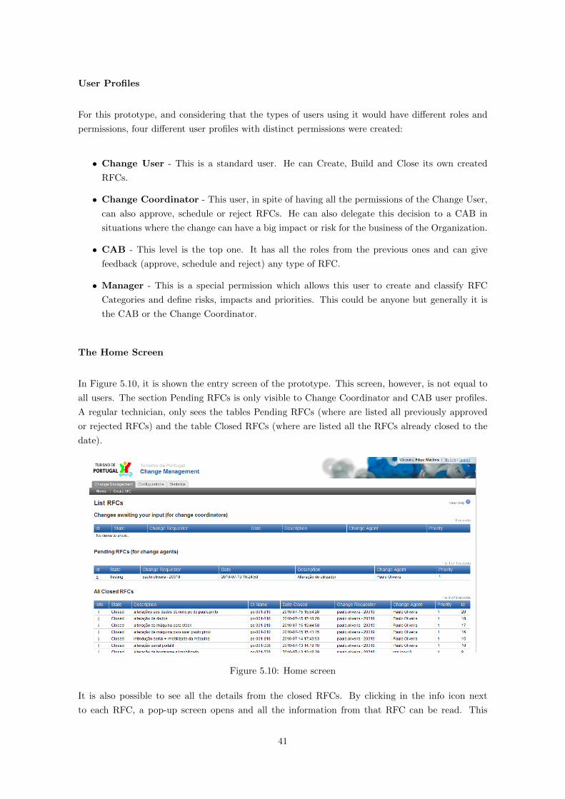
User Profiles
For this prototype, and considering that the types of users using it would have different roles and
permissions, four different user profiles with distinct permissions were created:
• Change User - This is a standard user. He can Create, Build and Close its own created
RFCs.
• Change Coordinator - This user, in spite of having all the permissions of the Change User,
can also approve, schedule or reject RFCs. He can also delegate this decision to a CAB in
situations where the change can have a big impact or risk for the business of the Organization.
• CAB - This level is the top one. It has all the roles from the previous ones and can give
feedback (approve, schedule and reject) any type of RFC.
• Manager - This is a special permission which allows this user to create and classify RFC
Categories and define risks, impacts and priorities. This could be anyone but generally it is
the CAB or the Change Coordinator.
The Home Screen
In Figure 5.10, it is shown the entry screen of the prototype. This screen, however, is not equal to
all users. The section Pending RFCs is only visible to Change Coordinator and CAB user profiles.
A regular technician, only sees the tables Pending RFCs (where are listed all previously approved
or rejected RFCs) and the table Closed RFCs (where are listed all the RFCs already closed to the
date).
Figure 5.10: Home screen
It is also possible to see all the details from the closed RFCs. By clicking in the info icon next
to each RFC, a pop-up screen opens and all the information from that RFC can be read. This
41
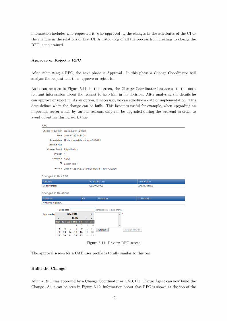
information includes who requested it, who approved it, the changes in the attributes of the CI or
the changes in the relations of that CI. A history log of all the process from creating to closing the
RFC is maintained.
Approve or Reject a RFC
After submitting a RFC, the next phase is Approval. In this phase a Change Coordinator will
analyse the request and then approve or reject it.
As it can be seen in Figure 5.11, in this screen, the Change Coordinator has access to the most
relevant information about the request to help him in his decision. After analysing the details he
can approve or reject it. As an option, if necessary, he can schedule a date of implementation. This
date defines when the change can be built. This becomes useful for example, when upgrading an
important server which by various reasons, only can be upgraded during the weekend in order to
avoid downtime during work time.
Figure 5.11: Review RFC screen
The approval screen for a CAB user profile is totally similar to this one.
Build the Change
After a RFC was approved by a Change Coordinator or CAB, the Change Agent can now build the
Change. As it can be seen in Figure 5.12, information about that RFC is shown at the top of the
42
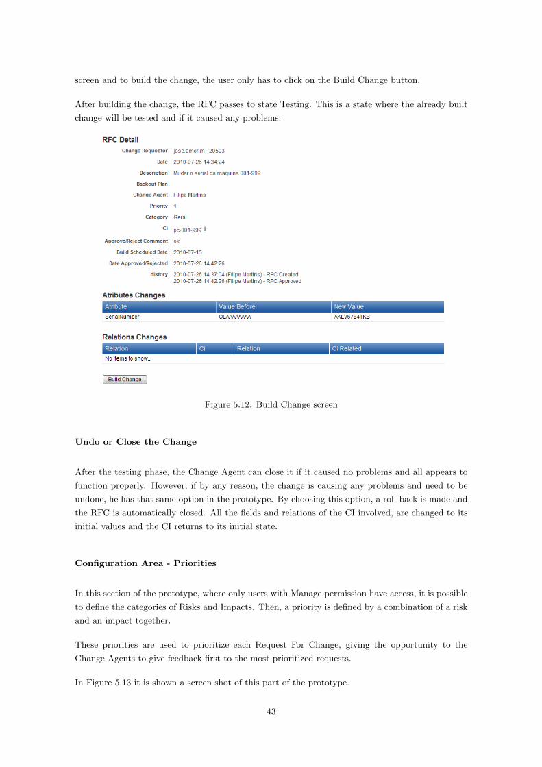
screen and to build the change, the user only has to click on the Build Change button.
After building the change, the RFC passes to state Testing. This is a state where the already built
change will be tested and if it caused any problems.
Figure 5.12: Build Change screen
Undo or Close the Change
After the testing phase, the Change Agent can close it if it caused no problems and all appears to
function properly. However, if by any reason, the change is causing any problems and need to be
undone, he has that same option in the prototype. By choosing this option, a roll-back is made and
the RFC is automatically closed. All the fields and relations of the CI involved, are changed to its
initial values and the CI returns to its initial state.
Configuration Area - Priorities
In this section of the prototype, where only users with Manage permission have access, it is possible
to define the categories of Risks and Impacts. Then, a priority is defined by a combination of a risk
and an impact together.
These priorities are used to prioritize each Request For Change, giving the opportunity to the
Change Agents to give feedback first to the most prioritized requests.
In Figure 5.13 it is shown a screen shot of this part of the prototype.
43

Figure 5.13: Definition of Priorities screen
To the date, only a single Priority labeled default was defined. The main reason for this was that
the most important in this phase was to get the users comfortable using the prototype while these
definitions can be made in the future with a minimal effort through this screen.
Configuration Area - Categories
This section, which have the same access permission restrictions as the Priorities section, allows the
users to create RFCs categories. Each category is defined by a name and an additional attribute
which defines it as a standard or non-standard change.
This was the way found to differentiate standard changes. As ITIL defines them, standard changes
are automatically approved and don’t need any extra feedback from a Change Coordinator or from
a CAB member.
As in the previous described section, for the same reasons, one single category was defined in this
phase. But it becomes very easy in the future to create another different categories when needed.
Figure 5.14: Definition of Categories screen
Change Management Dashboard
In order to help the IT staff to check in a easy way if the prototype is being used to record the
changes, a dahsboard with some useful data was developed.
44

At the moment, and considering the usage of the prototype the following metrics were introduced
in the dashboard:
• Number of RFCs per state in a defined period of time - It is presented the number of RFCs in
each state (Pending Approval, Approved, Rejected, Testing and Closed) in a period defined
by the user (e.g. last week)
• Number of RFCs per state at the moment - It is possible to know at each moment how many
RFCs are pending approval or are in testing phase, for example
• Number of closed RFCs per day, during the last 5 days
• Number of rejected RFCs in the last 5 days
CI Log in the CMDB
In the Configuration Management application, when viewing a single CI, it was also developed a
new screen where a user can view all the history from that CI. By other words, it is possible to view
each change in any attribute or relation of a single CI, as well as all the details from each change
like the RFC associated, the responsible for it, the datetime it was made or who approved it for
example.
In Figure 5.15 it is shown a sample from this screen.
Figure 5.15: CI log screen (CMDB application)
45
Change Management Prototype Functionalities
To summarize, the developed prototype allows a change to be requested and built and allows that
all this process follows the main phases as defined in ITIL like requesting, evaluating, approving and
testing. To undo the change and put the CI to its initial state is also possible.
Besides from this, the prototype offers the following functionalities:
• Creating a Request For Change associated with a CI, a Change Requester, a Category and a
Priority.
• When a Change Coordinator reviews the RFC, he has access to all the information the Change
Requester provided. He also can view the current associated CI information before making a
decision on the RFC.
• Scheduling the build of the change is also possible just by defining a date. Then, the prototype
automatically blocks any intention of building the change if the scheduled date is ahead of the
current date.
• A change is built (and the CI attributes automatically modified in the CMDB) easily by press-
ing a single button. This is only possible when the Request For Change has been previously
approved by a Change Coordinator or a CAB.
• After the change is built, is passes to a Testing phase. In this phase, if anything went wrong,
there is the possibility to execute a roll back and change the CI to its initial state.
• A complete list of all changes is recorded.
• A complete list of all changes in a CI is recorded and it is possible to consult all its history
and every RFC related to its change. It is also possible to know all the information of that
RFC such as the change requester or the change agent, who approved it, in which date the
change was built, etc.
• Is is possible in a simple way to define new RFC Categories as well as new Priorities using a
restricted access area of the prototype.
• A dashboard is available with some useful metrics to the users.
• Various user profiles are available such as Change Agent, Change Coordinator, CAB and
Manage. Each profile allows the use of specified functionalities.
5.4 Evaluating
Having completed the last phase from the cycle, fortunately we can say that all the initial goals
were accomplished.
46
5.4.1 Building the CMDB
This was the most difficult phase of all the work. After requesting to the right staff for the lists of
all the assets, they took too long to give them to me. Further more, all the problems described in
section 4.5 (page 29) referring to the first organization were once more repeated.
Only after three or four requests of the lists to each person (in fact I made about eight more requests
as I had to make them to two different persons) I could get an acceptable and coherent list. In fact,
it was not 100% coherent, but some inconsistencies that existed were easily corrected. All this
process of requesting, analysing, typing the errors, having to make new requests and waiting for
their responses took about three months, which was the main reason for the whole project to take
so long.
The following items were imported to the new CMDB:
• 443 Workstations (desktops and laptops)
• 135 Servers
• 137 Databases
• 382 Communication Devices
• 39 Network Printers
• 65 Applications
• 21 Switches
• All the relations between the previous items, already described in section 5.3.1.
Before importing definitely the new CMDB, I was still asked to include all the assets not only from
the headquarters but also from all the other schools and casinos that this organization is responsible
for. After some tries, I had to give up and focus on my initial idea - only the headquarters. They
simply couldn’t provide me with accurate information. Many workstations, for example, had been
already destroyed. The usernames were completely out of date and many of them didn’t even exist.
The problems verified were basically the ones referred previously.
At least, I could load a set of items to the CMDB. It’s true that the CMDB only contains the assets
from its headquarters, maintaining all the other ones from schools and casinos out of the CMDB.
However, considering that some months ago, they had no (useful) CMDB, it is a good achievement
to have one now and, besides this, it is being refreshed daily and it is up to date.
5.4.2 Developing and Deploying the Change Management Prototype
In contrast to constructing the CMDB, this phase was easier as in fact my work wasn’t dependent
on any other. This allowed me to work without delays.
47

When the development of the prototype ended, some tests with the users were made. This led to
some minor corrections, mainly functional errors that were detected with them and that were not
detected in development time.
The most interested user in the Change Management Prototype (the service-desk responsible) has
been the one who has been using it mostly. Now, he registers any changes in the CIs (mainly
workstations) directly in the prototype, and consequently in the CMDB. It is a major improvement
instead of registering the changes in a spreadsheet that only he had access.
About 15 days after the deployment of the prototype, turning it accessible to everyone, there are (at
the time of the writing of this document) 17 changes in a closed state, being all of them successful.
5.5 Learning
Reaching the final phase of this Action Research Cycle, some conclusions can be made.
Considering the first part, in which a new CMDB was built, there were many difficulties in all the
process. Beginning with the lists of all the assets, it became very clear that organizations don’t
know what they have. This was the second organization where I realized that the problems in this
area were very similar.
Another point is that even the department doesn’t know with some accuracy what are the items
that it is responsible for. Referring to the context of this thesis, the IT department doesn’t have
the information about what are the assets they should manage. For example, it is impossible to ask
and expect for an accurate list of either workstations, users, servers or databases. Further more,
this point is a need for the organization for logical reasons. First, it is always a good management
practice to know what we have to manage. Then, in spite of this fact, even the IT director asks
regularly for lists of this type to the technicians.
Having imported the Configuration Management Database successfully, allowed to the service-desk
team to associate the new Incidents (from the Incident Management process) to associate with
accuracy the incidents with the respective CI (all the new up to date CIs were loaded into the
CMDB and its relations, including relations with Staff).
Then, the Change Management prototype is very useful tool to help keeping the CMDB up to date.
As referred earlier, a CMDB which is not up to date logically has no interest and this was exactly
what was happening at the beginning of this thesis. Then, all changes from now become logged
and it is possible to view all details from all changes in the future, which can be useful to the
organization.
48

Chapter 6
Conclusion
This thesis main goal was to implement a Change Management process in an organization which
already followed other ITIL processes namely ITIL Incident Management and ITIL Configuration
Management.
Change Management is not responsible for identifying components affected by Change or updating
Change records (the domain of Configuration Management), nor is it responsible for the release
of new changed components (the domain of Release Management) (OGC, 2001). However, having
a CMDB is vital and as the organization didn’t provide an accurate one, the work also involved
importing a new one.
One of the most important phases of importing a new Configuration Management Database was to
ask and obtain list of the IT assets. In the two organizations where this was done, many difficulties
were faced. However, the difficulties in those two different organizations were basically the same. It
revealed to be of an extremely high difficulty to obtain the list of the IT assets and the relationships
between them. Even after asking for the lists some more times, it was almost impossible to get
accurate information. The problems and inconsistencies were always the same: wrong lists and
inconsistencies in those same lists (they contaions both lists of the assets and relationships between
them). It also happened to asking for a list of workstations and no one could provide even a small
one.
In order to solve this problem, a simpler structure (with less assets) was defined and after some
effort, good lists were obtained and finally the construction of a new Configuration Management
Database became possible.
All these facts show that the organizations do not know what they have (at least the IT department),
as many literature in the area argues. Having this in mind it becomes clear that IT Management
could be a lot better and ITIL is a good guidance to turn the IT Management more efficient.
The second part of this work, involved the implementation of the Change Management process.
This implementation was made with the aid of a built application to support it.
A critical point that causes many IT implementations to fail is the resistence to change by the users
49

to the new processes. Particularly in this work, making the users to use the new application was
not so difficult as expected. After some testing with the users, they began using the application
with minimal effort. This can be explained by two important factors. The first one, is that the
new application was strongly integrated with the Configuration Management application which they
already knew and have been using for approximately two years. The second and probably the most
important one was that the Change Management and the CMDB application was something that
the IT department had already understood that was very important and useful to them.
Having this application working and people using them allows the organization to know what they
have and other many advantages as it was described in the first section of this document. Among
all the advantages, perhaps the most important one is that it allows the organization to maintain
an up to date CMDB and this way knowing at each time, what assets do they have which brings
value not only to the IT department but also to the whole organization.
6.1 Future Work
In spite of having imported CIs to a Configuration Management Database and created and deployed
an application to support the Change Management process, there is still some work to be done.
Regarding the CMDB, it is still necessary to obtain accurate lists of all the assets that do not belong
to the headquarters building and introduce the in the CMDB application. Then, other assets that
were not considered in this phase can be added too in order to get, in the future a good and very
complete Configuration Management Database.
About the Change Management application, some change Categories can and should be created.
As said before, only one exists at the moment and it is non-standard (needs always an approval).
Some meetings should be arranged and after analysing the types and number of changes, define
different categories and to each one of them, if they are standard. Despite allowing to have different
categories, this can be useful in the future as it can allow specific reports to be created.
It is also necessary to define a CAB in the organization. In spite of having defined roles for a CAB
in the application, no one was nominated as one, so this is a point that can be decided in the future.
Having this process to work well is also a good starting point to implement other ITIL processes
like Release Management or Problem Management.
50
References
1995. The CHAOS Report. Tech. rept. The Standish Group International, Inc.
Addy, Rob. 2007. Effective IT Service Management - To ITIL and Beyond! Springer.
Alter, Steven. 2006. The Work System Method. Work System Press.
Arjen de Jong, Axel Kolthof, Mike Pieper Ruby Tjassing Annelies van der Veen Tieneke Verheijen.2008. ITIL V3 Foundation Exam - The Study Guide. 1st edn. Van Haren Publishing.
Atherton, Martin. 2007. Deploying CMDB Technology Pragmatism and realism will deliver thebenefits. Tech. rept. Freeform Dynamics Ltd.
Avison, David E., Lau, Francis, Myers, Michael D., & Nielsen, Peter Axel. 1999. Action Research.Commun. ACM, 42(1), 94–97.
Ayat, Masarat. 2008. Implementing ITIL Service Support in the Infrastructure and Service Unit ofCICT, UTM. M.Phil. thesis, Faculty of Computer Science and Information System, UniversitiTeknologi Malaysia.
Baskerville, Richard L. 1999. Investigating Information Systems with Action Research. Commun.AIS, 2, 4.
Brenner, M. 2006 (April). Classifying ITIL Processes; A Taxonomy under Tool Support Aspects.Pages 19–28 of: Business-Driven IT Management, 2006. BDIM ’06. The First IEEE/IFIPInternational Workshop on.
Cater-Steel, Aileen, & Toleman. 2007a. ITIL Adoption in Australia: 2 years of itSMFA Surveys andCase Studies. In: itSMF Australia 10th National Conference and Expo, Melbourne.
Cater-Steel, Aileen, & Toleman, Mark. 2007b. The Role of Universities in IT Service ManagementEducation. In: 11th Pacific Asia Conference on Information Systems.
Cater-Steel, Aileen, Toleman, Mark, & Tan, Wui-Gee. 2006. Transforming IT Service Management- The ITIL Impact. In: ACIS 17th Australasian Conference on Information Systems: Thought,Leadership in IS.
Dorst, Simon. How to Change Change. Whitepaper, last accessed in 14th December 2009.
Galup, Stuart, Quan, Jim J., Dattero, Ronald, & Conger, Sue. 2007. Information TechnologyService Management: An Emerging Area for Academic Research and Pedagogical Development.Pages 46–52 of: SIGMIS CPR ’07: Proceedings of the 2007 ACM SIGMIS CPR conference onComputer personnel research. New York, NY, USA: ACM.
Gaughan, Dennis. 2008. Notes From the Field: CMDB Projects Stall Because of Missing BusinessFocus. AMR Research.
Greiner, Lynn. 2007. ITIL: The International Repository of IT Wisdom. netWorker, 11(4), 9–11.
51
J.H. Botha, Dr B.C. Potgieter, Dr C. Lew. 2005. Evidence That Use of The ITIL Framework isEffective. 18th Annual Conference of the National Advisory Committee on Computing Qualifi-cations, Tauranga, NZ.
Laudon, Jane P. 2007. Management Information Systems: Managing the Digital Firm. 10 edn.Prentice Hall.
Mattila, Antti. 2008. Best Practices for Network Infrastructure Management - a Case Study ofInformation Technology Infrastructure Library (ITIL). M.Phil. thesis, Helsinki University ofTechnology.
Michael E. Withman, Amy B. Woszczynski. 2004. The Handbook of Information Systems Research.Idea Group Publishing.
OGC. 2000. Service Support (IT Infrastructure Library). The Stationary Office.
OGC. 2001. Best Practice for Service Support, Managing IT Services. The Stationary Office.
OGC. 2007. ITIL Service Transition. The Stationary Office.
OGC. 2009. How to Develop, Implement and Enforce ITIL V3 Best Practices. The Art of Service.
Pereira, Ruben. 2010. A Maturity Model for Implementing ITIL v3. M.Phil. thesis, InstitutoSuperior Tecnico, Universidade Tecnica de Lisboa.
Peynot, Richard. 2006. Firms Must Take ITIL Beyond IT Operational Goals - Service ProvidersCan Help With Change Management Issues. Forester.
Sharifi, Mohammad, Ayat, Masarat, Rahman, Azizah A., & Sahibudin, Shamsul. 2008. LessonsLearned in ITIL Implementation Failure. 1(Aug), 1–4.
Sharon Taylor, M. Iqbal, M. Nieves. 2006. ITIL Service Strategy. The Stationary Office.
Spremic, M., Zmirak, Z., & Kraljevic, K. 2008 (June). IT and Business Process PerformanceManagement: Case Study of ITIL Implementation in Finance Service Industry. Pages 243–250of: 30th International Conference on Information Technology Interfaces.
Steinberg, Randy A. 2005. Implementing ITIL. Trafford Publishing.
Thomas Mendel, Bernt Ostergaard, Niek van Veen. 2004 (Aug). A Big Step Toward AutomatingNetwork Management. Forrester.
van Bon, Jan. 2007. Foundations of IT Service Management based on ITIL V3. Zaltbommel: VanHaren Publishing.
Ward, C., Aggarwal, V., Buco, M., Olsson, E., & Weinberger, S. 2007. Integrated change andconfiguration management. IBM Syst. J., 46(3), 459–478.
52
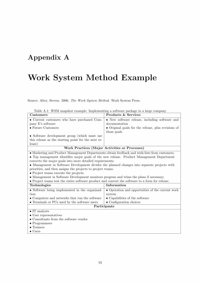
Appendix A
Work System Method Example
Source: Alter, Steven. 2006. The Work System Method. Work System Press.
Table A.1: WSM snapshot example: Implementing a software package in a large companyCustomers Products & Services
• Current customers who have purchased Com-pany E’s software
• New software release, including software anddocumentation
• Future Customers • Original goals for the release, plus revisions ofthose goals
• Software development group (which must usethis release as the starting point for the next re-lease)
Work Practices (Major Activities or Processes)
• Marketing and Product Management Departments obtain feedback and wish-lists from customers.• Top management identifies major goals of the new release. Product Management Departmentconverts the major goals into more detailed requirements.• Management in Software Development divides the planned changes into separate projects withpriorities, and then assigns the projects to project teams.• Project teams execute the projects.• Management in Software Development monitors progress and trims the plans if necessary.• Project teams test the entire software product and convert the software to a form for release.Technologies Information
• Software being implemented in the organizad-tion
• Operation and opportnities of the current worksystem
• Computers and networks that run the software • Capabilities of the software• Terminals or PCs used by the software users • Configuration choices
Participants
• IT analysts• User representatives• Consultants from the software vendor• Programmers• Trainers• Users
53
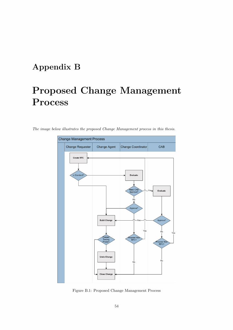
Appendix B
Proposed Change ManagementProcess
The image below illustrates the proposed Change Management process in this thesis.
Figure B.1: Proposed Change Management Process
54

Appendix C
Listings for the CMDB
This appendix contains only 3 from a total of 26 pages that correspond to the listings of the IT assetsof the second organization. These listings do not include Workstations, Databases, CommunicationDevices, Databases, Applications Switches nor all the Servers.
Printers
ID Impressora IP Modelo prod no model Local2 PisoCNPNC17032 10.4.22.165 MFP-001-001 CB415A HP LaserJet M3035xs MFP Sede TdP Piso 0JPBT8B6GBR 10.4.22.109 MFP-001-002 Q3939A HP Color LaserJet CM6040f MFP Sede TdP Piso 0CNPNB16549 10.4.22.115 MFP-001-011 CB415A HP LaserJet M3035xs MFP Sede TdP Piso 1CNPNC16896 10.4.22.116 MFP-001-012 CB415A HP LaserJet M3035xs MFP Sede TdP Piso 1CNPNB23384 10.4.22.118 MFP-001-013 CB415A HP LaserJet M3035xs MFP Sede TdP Piso 1JPBT8DHGBB 10.4.22.21 MFP-001-014 Q3939A HP Color LaserJet CM6040f MFP Sede TdP Piso 1JPBT8DHGBN 10.4.22.86 MFP-001-015 Q3939A HP Color LaserJet CM6040f MFP Sede TdP Piso 1CNPNB16551 10.4.22.123 MFP-001-021 CB415A HP LaserJet M3035xs MFP Sede TdP Piso 2JPBT8B5GG1 10.4.22.124 MFP-001-022 Q3939A HP Color LaserJet CM6040f MFP Sede TdP Piso 2CNPNC17852 10.4.22.126 MFP-001-031 CB415A HP LaserJet M3035xs MFP Sede TdP Piso 3JPBT914GBJ 10.4.22.127 MFP-001-032 Q3939A HP Color LaserJet CM6040f MFP Sede TdP Piso 3JPBT8BGGGK 10.4.22.128 MFP-001-041 Q3939A HP Color LaserJet CM6040f MFP Sede TdP Piso 4CNPNC17818 10.4.22.130 MFP-001-051 CB415A HP LaserJet M3035xs MFP Sede TdP Piso 5JPBT8B6GBT 10.4.22.131 MFP-001-052 Q3939A HP Color LaserJet CM6040f MFP Sede TdP Piso 5CNPNC17016 10.4.22.134 MFP-001-061 CB415A HP LaserJet M3035xs MFP Sede TdP Piso 6JPBT8BGGGN 10.4.22.135 MFP-001-062 Q3939A HP Color LaserJet CM6040f MFP Sede TdP Piso 6CNPNC16657 10.4.22.138 MFP-001-071 CB415A HP LaserJet M3035xs MFP Sede TdP Piso 7JPBT8B6GBD 10.4.22.139 MFP-001-072 Q3939A HP Color LaserJet CM6040f MFP Sede TdP Piso 7CNPNB16663 10.4.22.140 MFP-001-081 CB415A HP LaserJet M3035xs MFP Sede TdP Piso 8JPBT8BJGFF 10.4.22.141 MFP-001-082 Q3939A HP Color LaserJet CM6040f MFP Sede TdP Piso 8CNPNB16106 10.4.22.146 MFP-001-091 CB415A HP LaserJet M3035xs MFP Sede TdP Piso 9JPBT8BJGFJ 10.4.22.145 MFP-001-092 Q3939A HP Color LaserJet CM6040f MFP Sede TdP Piso 9CNS1R23845 10.4.22.79 PRT-001-011 Q7815A HP LaserJet P3005dn Sede TdP Piso 1CNS2P09742 10.4.22.112 PRT-001-012 Q7815A HP LaserJet P3005dn Sede TdP Piso 1CNS2P09737 10.4.22.113 PRT-001-013 Q7815A HP LaserJet P3005dn Sede TdP Piso 1CNS2N09562 10.4.22.114 PRT-001-014 Q7815A HP LaserJet P3005dn Sede TdP Piso 1CNS2N10427 10.4.22.121 PRT-001-021 Q7815A HP LaserJet P3005dn Sede TdP Piso 2CNS2N09563 10.4.22.122 PRT-001-022 Q7815A HP LaserJet P3005dn Sede TdP Piso 2CNS1R23835 10.4.22.125 PRT-001-031 Q7815A HP LaserJet P3005dn Sede TdP Piso 3CNS1R23838 10.4.22.132 PRT-001-061 Q7815A HP LaserJet P3005dn Sede TdP Piso 6CNS1R23833 10.4.22.133 PRT-001-062 Q7815A HP LaserJet P3005dn Sede TdP Piso 6CNS1R23534 10.4.22.136 PRT-001-071 Q7815A HP LaserJet P3005dn Sede TdP Piso 7CNS2P10107 10.4.22.137 PRT-001-072 Q7815A HP LaserJet P3005dn Sede TdP Piso 7CNS2N10442 10.4.22.111 PRT-001-081 Q7815A HP LaserJet P3005dn Sede TdP Piso 8CNS2P09740 10.4.22.169 PRT-001-082 Q7815A HP LaserJet P3005dn Sede TdP Piso 8
55
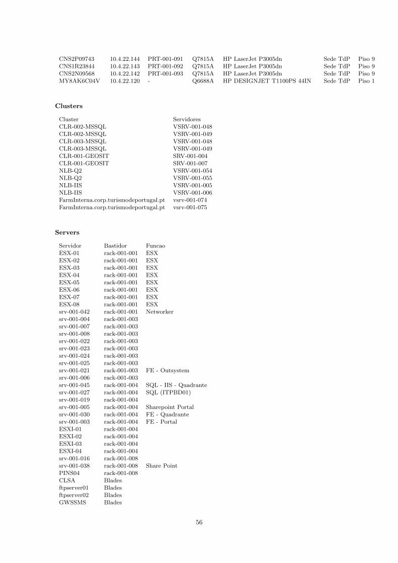
CNS2P09743 10.4.22.144 PRT-001-091 Q7815A HP LaserJet P3005dn Sede TdP Piso 9CNS1R23844 10.4.22.143 PRT-001-092 Q7815A HP LaserJet P3005dn Sede TdP Piso 9CNS2N09568 10.4.22.142 PRT-001-093 Q7815A HP LaserJet P3005dn Sede TdP Piso 9MY8AK6C04V 10.4.22.120 - Q6688A HP DESIGNJET T1100PS 44IN Sede TdP Piso 1
Clusters
Cluster ServidoresCLR-002-MSSQL VSRV-001-048CLR-002-MSSQL VSRV-001-049CLR-003-MSSQL VSRV-001-048CLR-003-MSSQL VSRV-001-049CLR-001-GEOSIT SRV-001-004CLR-001-GEOSIT SRV-001-007NLB-Q2 VSRV-001-054NLB-Q2 VSRV-001-055NLB-IIS VSRV-001-005NLB-IIS VSRV-001-006FarmInterna.corp.turismodeportugal.pt vsrv-001-074FarmInterna.corp.turismodeportugal.pt vsrv-001-075
Servers
Servidor Bastidor FuncaoESX-01 rack-001-001 ESXESX-02 rack-001-001 ESXESX-03 rack-001-001 ESXESX-04 rack-001-001 ESXESX-05 rack-001-001 ESXESX-06 rack-001-001 ESXESX-07 rack-001-001 ESXESX-08 rack-001-001 ESXsrv-001-042 rack-001-001 Networkersrv-001-004 rack-001-003srv-001-007 rack-001-003srv-001-008 rack-001-003srv-001-022 rack-001-003srv-001-023 rack-001-003srv-001-024 rack-001-003srv-001-025 rack-001-003srv-001-021 rack-001-003 FE - Outsystemsrv-001-006 rack-001-003srv-001-045 rack-001-004 SQL - IIS - Quadrantesrv-001-027 rack-001-004 SQL (ITPBD01)srv-001-019 rack-001-004srv-001-005 rack-001-004 Sharepoint Portalsrv-001-030 rack-001-004 FE - Quadrantesrv-001-003 rack-001-004 FE - PortalESXI-01 rack-001-004ESXI-02 rack-001-004ESXI-03 rack-001-004ESXI-04 rack-001-004srv-001-016 rack-001-008srv-001-038 rack-001-008 Share PointPINS04 rack-001-008CLSA Bladesftpserver01 Bladesftpserver02 BladesGWSSMS Blades
56
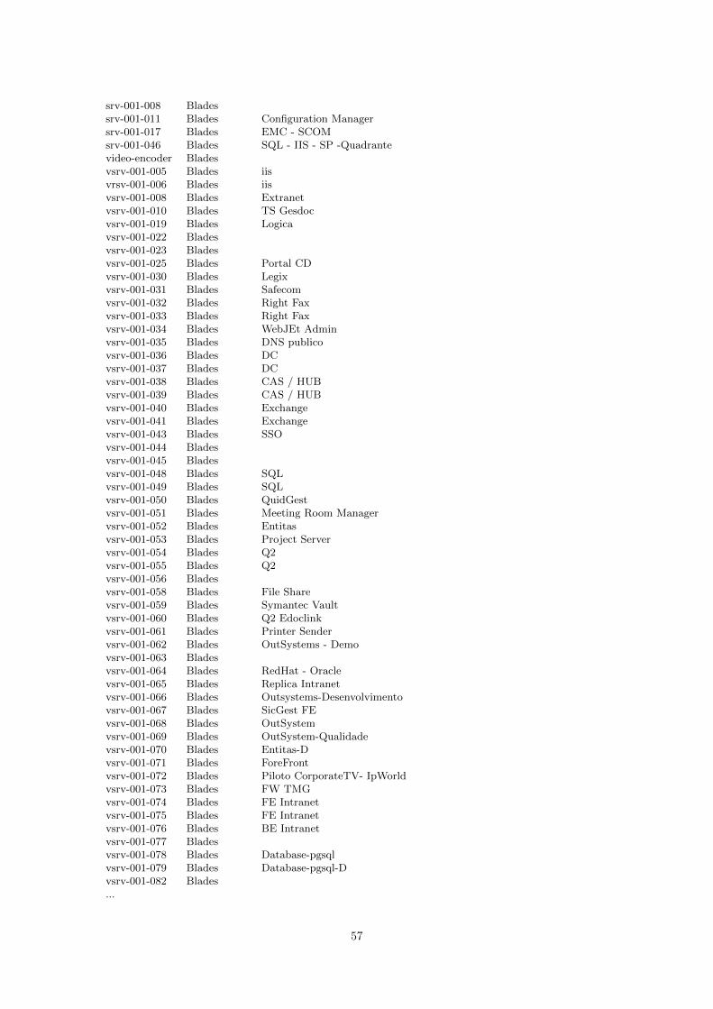
srv-001-008 Bladessrv-001-011 Blades Configuration Managersrv-001-017 Blades EMC - SCOMsrv-001-046 Blades SQL - IIS - SP -Quadrantevideo-encoder Bladesvsrv-001-005 Blades iisvrsv-001-006 Blades iisvsrv-001-008 Blades Extranetvsrv-001-010 Blades TS Gesdocvsrv-001-019 Blades Logicavsrv-001-022 Bladesvsrv-001-023 Bladesvsrv-001-025 Blades Portal CDvsrv-001-030 Blades Legixvsrv-001-031 Blades Safecomvsrv-001-032 Blades Right Faxvsrv-001-033 Blades Right Faxvsrv-001-034 Blades WebJEt Adminvsrv-001-035 Blades DNS publicovsrv-001-036 Blades DCvsrv-001-037 Blades DCvsrv-001-038 Blades CAS / HUBvsrv-001-039 Blades CAS / HUBvsrv-001-040 Blades Exchangevsrv-001-041 Blades Exchangevsrv-001-043 Blades SSOvsrv-001-044 Bladesvsrv-001-045 Bladesvsrv-001-048 Blades SQLvsrv-001-049 Blades SQLvsrv-001-050 Blades QuidGestvsrv-001-051 Blades Meeting Room Managervsrv-001-052 Blades Entitasvsrv-001-053 Blades Project Servervsrv-001-054 Blades Q2vsrv-001-055 Blades Q2vsrv-001-056 Bladesvsrv-001-058 Blades File Sharevsrv-001-059 Blades Symantec Vaultvsrv-001-060 Blades Q2 Edoclinkvsrv-001-061 Blades Printer Sendervsrv-001-062 Blades OutSystems - Demovsrv-001-063 Bladesvsrv-001-064 Blades RedHat - Oraclevsrv-001-065 Blades Replica Intranetvsrv-001-066 Blades Outsystems-Desenvolvimentovsrv-001-067 Blades SicGest FEvsrv-001-068 Blades OutSystemvsrv-001-069 Blades OutSystem-Qualidadevsrv-001-070 Blades Entitas-Dvsrv-001-071 Blades ForeFrontvsrv-001-072 Blades Piloto CorporateTV- IpWorldvsrv-001-073 Blades FW TMGvsrv-001-074 Blades FE Intranetvsrv-001-075 Blades FE Intranetvsrv-001-076 Blades BE Intranetvsrv-001-077 Bladesvsrv-001-078 Blades Database-pgsqlvsrv-001-079 Blades Database-pgsql-Dvsrv-001-082 Blades...
57

Appendix D
List of Registered Changes
This appendix contains only 7 from a total of 17 changes registered in the newly created ChangeManagement prototype.
Change Requester paulo.oliveira - 20319Date Created 2010-07-13 10:08:41Description alteracao de hostnameChange Agent Paulo OliveiraCi pc-001-896ChangesHostname pc-001-166 −→ pc-001-896
Change Requester paulo.oliveira - 20319Date Created 2010-07-13 10:23:47Description alteracao do hostnameChange Agent Paulo OliveiraCi pc-001-194ChangesHostname pc-001-059 −→ pc-001-194
Change Requester paulo.oliveira - 20319Date Created 2010-07-13 10:46:25Description Alteracao de hostname e imobilizadoChange Agent vpn.inov10Ci pc-001-338ChangesIsLaptop False −→ TrueHostname pc-001-829 −→ pc-001-338Imobilizado 42609 −→ 42590
Change Requester paulo.oliveira - 20319Date Created 2010-07-13 14:16:16Description alteracao serial porttilChange Agent Paulo OliveiraCi pc-001-338ChangesSerialNumber X8108796H −→ X8107255H
Change Requester paulo.oliveira - 20319
58

Date Created 2010-07-14 17:49:27Description introducao serial + imobilizado da mquinaChange Agent Paulo OliveiraCi pc-001-818ChangesIsLaptop False −→ TrueSerialNumber n.a. −→ X8108767HImobilizado n.a. −→ 42599
Change Requester paulo.oliveira - 20319Date Created 2010-07-15 15:40:47Description alteracao de maquina para user paulo.pintoChange Agent Paulo OliveiraCi pc-001-810
Relation Removed pc-001-810 ←→ STOCKRelation Added pc-001-810 ←→ paulo.pinto
Change Requester paulo.oliveira - 20319Date Created 2010-07-15 15:47:48Description alteracao de dadosChange Agent Paulo OliveiraCi pc-001-818ChangesPiso Piso 11 −→ Piso 4Departamento GABINETE FINANCEIRO −→ TECNOLOGIASRelation Added STOCK ←→ pc-001-818
59