implementation of ds-cdma transmitter and receiver · pdf fileimplementation of ds-cdma...
TRANSCRIPT

Implementation of DS-CDMA Transmitter and
Receiver in VHDL for FPGA
Vaibhav K Kakade
Department of Electronics and Communication Engineering
M.M.E.C, Belgaum, Karnataka, India
Abstract- Code division multiple access (CDMA) uses spread spectrum technology where each user is assigned a unique
code and allows multiple users to be multiplexed over the same physical channel. The spread spectrum is used in the
commercial applications such as mobile handsets, internet, and satellite applications.
Keywords – SSMA, DDS, DS-CDMA, PN code.
I. INTRODUCTION
Over the past five to ten years, communication systems have been developing rapidly in wireless and cellular
network arena [6]. As a user demand grows, conventional communication systems such as TDMA and FDMA are
becoming inadequate for some application in today’s communication requirements. A new system called CDMA is
proposed to replace the above mentioned systems. The idea of this system is to transmit signals simultaneously
through a linear band limited channel without inter channel or inter symbol interference [2]. This new system
utilizes the spread spectrum technique where the message signal can occupy both time and frequency domains
simultaneously, thus the system capacity is significantly increased. To design multi channel transmission must
concentrate on reducing cross talk between adjacent channels. One of the most promising cellular standard is IS-95
A [7].
Today widely used data communication scheme is spread spectrum communications. It has many features
that make it suitable for secure, multiple accesses and many other properties that are needed in a communication
system. Spread spectrum is a means of transmission in which the signal occupies a bandwidth in excess of the
minimum necessary to send the information. The band spread is accomplished by means of a code, which is
independent of the data and synchronized reception with the code at the receiver is used for dispreading and
subsequently data recovery [6]. The purpose of coding is to transform an information signal so that it looks more
like noise. The spreading or dilution of energy in spread spectrum systems over a wide bandwidth results in several
possible advantages, short range interferences- free overlays on their emissions and resistance to interference, from
other emissions and detestability. The low spectral density needed for spread spectrum communication systems as
well as ability of some of these systems [6]. In the recent years the CDMA on FPGA platform has attracted attention
of academic research and industry. The field Programmable Gate Arrays (FPGA’s) is specifically broadband
designed to meet the needs of high volume, cost sensitive consumer electronic applications. The FPGA family offers
densities ranging from 100,000 to 1.6 million system gates. Because of this exceptionally low cost, FPGAs are
ideally suited to a wide range of consumer electronics applications, including access, home networking and digital
television equipment [1].
II. MULTIPLE ACCESS TECHNIQUES
Multiple access is a technique where many subscribers or local stations can share the use of a
communication channel at the same time or nearly so despite the fact originate from widely different locations. A
channel can be thought of as merely a portion of the limited radio resource, which is temporarily allocated for a
specific purpose, such as someone’s phone call. A multiple access method is a definition of how the radio spectrum
is divided into channels and how the channels are allocated to the many users of the system. Since there are multiple
International Journal of Latest Trends in Engineering and Technology (IJLTET)
Special Issue - IDEAS-2013 158 ISSN: 2278-621X

users transmitting over the same channel, a method must be established so that individual users will not disrupt one
another.
There are three basic schemes
1. Frequency Division Multiple Access (FDMA)
2. Time Division Multiple Access (TDMA)
3. Spread Spectrum Multiple Access (SSMA)
• Frequency Hopped Multiple Access (FHMA)
• Code Division Multiple Access (CDMA)
1.1. Frequency Division Multiple Access (FDMA)
Each user is allocated a unique frequency band or channel. These channels are assigned on demand to users
who request service. In Frequency Division Duplexing, the channel has two frequencies – forward channel &
reverse channel. During the period of the call, no other user can share the same frequency band. If the FDMA
channel is not in use, then it sits idle and cannot be used by other users to increase or share capacity. Receiver only
has to know the frequency to tune in to.
Figure 1: FDMA channel allocation
1.2. Time Division Multiple Access (TDMA)
TDMA allows access to entire frequency bandwidth but for a limited amount of time. All senders use same
frequency in at different time. If two transmissions overlaps, known as co-channel interference. Precise clock
synchronization required.
Figure 2: TDMA time slot allocation
1.3. Spread Spectrum Multiple Access(SSMA)
Spread spectrum multiple access (SSMA) uses signals which have a transmission bandwidth that is several
orders of magnitude greater than the minimum required RF bandwidth. A pseudo-noise (PN) sequence converts a
narrowband Signal to a wideband noise-like signal before transmission. SSMA also provides immunity to multipath
interference and robust multiple access capability. SSMA is not very bandwidth efficient when used by a single user.
However, since many users can share the same spread spectrum bandwidth without interfering with one another.
Spread spectrum systems become bandwidth efficient in a multiple user environment. It is exactly this situation that
is of interest to wireless system designers. There are two main types of spread spectrum multiple access techniques;
International Journal of Latest Trends in Engineering and Technology (IJLTET)
Special Issue - IDEAS-2013 159 ISSN: 2278-621X
frequency hopped multiple access (FH) and direct sequence multiple access (DS). Direct sequence multiple access
is also called code division multiple access (CDMA).
There are three types of spread spectrum techniques by which the bandwidth of the signal can be spread. They are
• Frequency hopping(FH): The signal is rapidly switched between different frequencies within the hopping
bandwidth pseudo-randomly, and the receiver knows before hand where to find the signal at any given
time.
• Time hopping (TH): The signal is transmitted in short bursts pseudo-randomly, and the receiver knows
before hand when to expect the burst.
• Direct sequence(DS): The digital data is directly coded at a much higher frequency. The code is generated
pseudo-randomly, the receiver knows how to generate the same code, and correlates the received signal
with that code to extract the data.
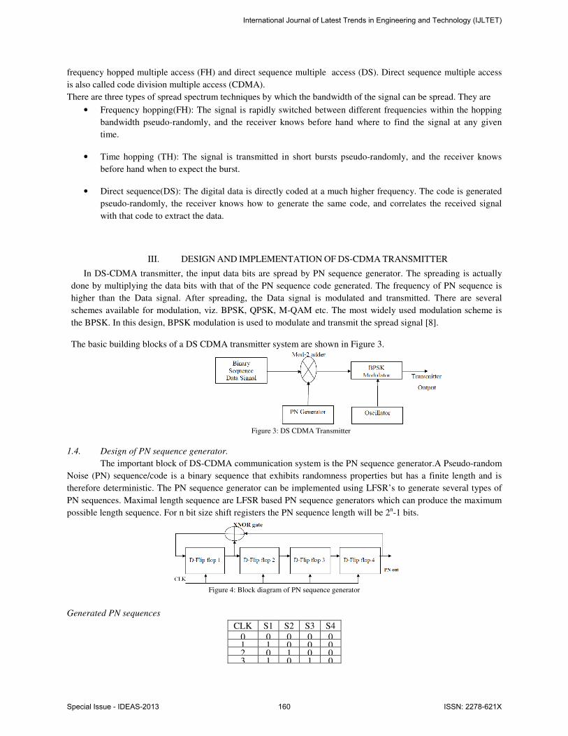
III. DESIGN AND IMPLEMENTATION OF DS-CDMA TRANSMITTER
In DS-CDMA transmitter, the input data bits are spread by PN sequence generator. The spreading is actually
done by multiplying the data bits with that of the PN sequence code generated. The frequency of PN sequence is
higher than the Data signal. After spreading, the Data signal is modulated and transmitted. There are several
schemes available for modulation, viz. BPSK, QPSK, M-QAM etc. The most widely used modulation scheme is
the BPSK. In this design, BPSK modulation is used to modulate and transmit the spread signal [8].
The basic building blocks of a DS CDMA transmitter system are shown in Figure 3.
Figure 3: DS CDMA Transmitter
1.4. Design of PN sequence generator.
The important block of DS-CDMA communication system is the PN sequence generator.A Pseudo-random
Noise (PN) sequence/code is a binary sequence that exhibits randomness properties but has a finite length and is
therefore deterministic. The PN sequence generator can be implemented using LFSR’s to generate several types of
PN sequences. Maximal length sequence are LFSR based PN sequence generators which can produce the maximum
possible length sequence. For n bit size shift registers the PN sequence length will be 2n-1 bits.
Figure 4: Block diagram of PN sequence generator
Generated PN sequences
CLK S1 S2 S3 S4
0 0 0 0 0 1 1 0 0 0 2 0 1 0 0 3 1 0 1 0
International Journal of Latest Trends in Engineering and Technology (IJLTET)
Special Issue - IDEAS-2013 160 ISSN: 2278-621X

4 0 1 0 1 5 0 0 1 0 6 1 0 0 1 7 1 1 0 0 8 1 1 0 0 9 0 1 1 0
10 1 0 1 1 11 1 1 0 1 12 1 1 1 0 13 0 1 1 1 14 0 0 1 1 15 0 0 0 1 16 0 0 0 0
Table 2: Generated PN sequences
A. D
esign of Spreader device:
Spreader device used at the transmitter side, consists of XOR gate which performs XOR operation between
data input and locally generated PN sequences.
B. D
esign of BPSK modulator
Modulation is the process of changing some characteristics of a carrier wave in proportion to the signal to be
transmitted. A general equation for a sine wave is:
e(t)=EC Sin(2πfct + Q) (1)
Where e(t) is instantaneous amplitude of the sine wave as a function of time.
EC = Peak amplitude of the sine wave.
fc =Frequency of the sine wave in hertz.
t= Time in seconds.
Q= Phase in radians.
Equation one suggests that there are only 3 ways; the sine wave can be changed:
• The amplitude
Ec.
• The frequency Cf .
• The phase Q .
It is also possible to change more than one of these quantities simultaneously. In digital communications, it is
common practice to change both the amplitude and the phase angle to obtain higher data rates. It should be noted
that once a carrier is modulated, it becomes a complete waveform containing more than one frequency components
and therefore would require an appropriate channel that can carry all frequency components of this complex
modulated signal. The signal occupies a BW and the channel must have sufficient BW.
BPSK uses one of the digital modulation techniques, i.e.., Phase Shift Keying (PSK). In this phase of the
carrier varies according to binary inputs keeping amplitude and frequency constant. Carrier signal modulates
according to spreaded binary data as shown below
A sin (2πfLOt) for a binary 1
S (t) = -A sin (2πfLOt) for a binary 0
A “0” represent a 0 degree reference phase and “1” represents a carrier shift of 180°.
C. D
esign of Local Oscillator
International Journal of Latest Trends in Engineering and Technology (IJLTET)
Special Issue - IDEAS-2013 161 ISSN: 2278-621X

The DDS is used for generating waveforms by LUT tables, where the samples of a harmonic function are
stored. Samples may be stored either in the distributed memory or in the block memory in FPGA structure[8]..
Figure 5. DDS synthesizer block diagram
Direct digital synthesizer is a technique to produce desired output with full digital control. Entity is DDFS,
Components used in this block are phase accumulator and COS look up table (LUT_ COS).Inputs given to this
entity phase increment word, Rst and Clk.
The phase accumulator consists of a 6-bit frequency register, which stores a digital phase
increment word followed by a 6-bit full adder and a phase register. The digital input phase increment “000001”
word is held in the phase increment register. The rising edge of each clock pulse phase increment word “000001”
added to the data previously held in the phase register. Initial data in the phase register. Initial data in the phase
register is “000000”, represents zero degrees. Rising edge of first clock pulse “000001” added to”000000”. Then
resultant data in phase register is “000001” represents the (5.60). At the next clock pulse “000001” adder to
“000001”. The phase increment word represents a phase angle step that is added to previous value at each
rising edge of clock to produce linearly increasing digital value. Final value of phase accumulator is 111111 (3600).
Again in next clock pulse phase accumulator output is initialized to 000000.The number held in the Accumulator is
used to address a LUT held in ROM which converts phase information to a series of discrete digitized samples of
the amplitude of a cosine wave Frequency of the carrier generated is f c= f clk /64 = f ck /26.
IV. DESIGN AND IMPLEMENTATION OF DS-CDMA RECEIVER.
In DS-CDMA receiver, the input to the system is the BPSK modulated signal. This signal would have been
affected by noise and other interference in the communication channel. The DS-SS CDMA receiver should be
designed carefully to reproduce the data signal with least error [8].
The BPSK modulated input signal is multiplied by the locally generated carrier wave by the oscillator. The
multiplied signal is then passed through the low pass filter to get low frequency components only. A decision device
is used to approximate the signal to binary sequence. This binary sequence is the spread sequence of the data signal.
The most sensitive part of the DS-SS receiver is the synchronization of the locally generated PN sequence and the
sequence obtained from the decision device . Even a single bit mismatch may lead to noise instead of the data signal.
Suitable technique is used to achieve synchronization and multiply the local PN sequence code with that of the
received PN code. The Data signal is obtained after the multiplication process.
In this design, since transmitter and receiver uses common clock on the same FPGA board, the delay in the receiver
is considered and modeled appropriately. No specific synchronization technique is used.
Figure 6: DS-CDMA Receiver
The multiplied output will have higher frequency components and channel noise as well. The high frequency
components are eliminated using a suitable Low Pass Filter. The filtered low frequency component will have
distortion in the signal. Hence a suitable ‘Decision Device’ is used to smoothen to binary sequence.
International Journal of Latest Trends in Engineering and Technology (IJLTET)
Special Issue - IDEAS-2013 162 ISSN: 2278-621X

V. SIMULATION RESULTS OF ALL MODULES.
A. Simulation waveform for PN generator
The generated Pseudo random Noise sequences (PN) is Pn_out= 101001101110000. The Same code will repeat
after every 15 clock cycles.
B. Simulation result for spreader device.
The below waveforms is obtained after spreading the message input. The XOR gate is used to spread the
message input. The generated PN sequences and message inputs are given to XOR gate and the resulted output is
spreader version of input message.
I have taken message input as 000101110110101 and PN sequence as 101001101110000. The Spreader device’s
output bits are obtained as 101100011000101.
C. Simulation result of local oscillator generator.
International Journal of Latest Trends in Engineering and Technology (IJLTET)
Special Issue - IDEAS-2013 163 ISSN: 2278-621X

D. Simulation result for BPSK modulator.
The BPSK modulator output is obtained as shown below. In the BPSK modulator, phase of the carrier is
changed according to spreaded binary data bits, keeping amplitude and frequency constant. If spreader bit is 1 then
sine wave is obtained else if spreader bit is 0 then phase shifted version of sine wave is obtained.
E. Simulation waveform for BPSK demodulator.
The BPSK demodulator output is obtained as shown below. In this demodulator receives BPSK signal and
compares this signal with local oscillator that is used at transmitter. After comparison if both received and carrier are
in phase then it will be coded as 1 else, if both signals are out of phase then it will be coded as 0.
F. Comparison of transmitted and received data bit streams.
The comparison can be done between transmitted bits and received data bit streams as shown below. The
comparison is done after receiving the entire transmitted signal so that received signal is demodulated completely. In
the below figure yellow marker indicates the completion of demodulation. So at this instant comparison is done and
obtained error free transmission and reception of message.
International Journal of Latest Trends in Engineering and Technology (IJLTET)
Special Issue - IDEAS-2013 164 ISSN: 2278-621X
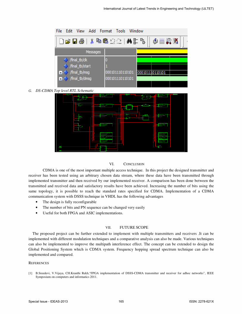
G. DS-CDMA Top level RTL Schematic
VI. CONCLUSION
CDMA is one of the most important multiple access technique. In this project the designed transmitter and
receiver has been tested using an arbitrary chosen data stream, where these data have been transmitted through
implemented transmitter and then received by our implemented receiver. A comparison has been done between the
transmitted and received data and satisfactory results have been achieved. Increasing the number of bits using the
same topology, it is possible to reach the standard rates specified for CDMA. Implementation of a CDMA
communication system with DSSS technique in VHDL has the following advantages
• The design is fully reconfigurable
• The number of bits and PN sequence can be changed very easily
• Useful for both FPGA and ASIC implementations.
VII. FUTURE SCOPE
The proposed project can be further extended to implement with multiple transmitters and receivers .It can be
implemented with different modulation techniques and a comparative analysis can also be made. Various techniques
can also be implemented to improve the multipath interference effect. The concept can be extended to design the
Global Positioning System which is CDMA system. Frequency hopping spread spectrum technique can also be
implemented and compared.
REFERENCES
[1] B.Sreedevi, V.Vijaya, CH.Kranthi Rekh,“FPGA implementation of DSSS-CDMA transmitter and receiver for adhoc networks”, IEEE
Symposium on computers and informatics 2011.
International Journal of Latest Trends in Engineering and Technology (IJLTET)
Special Issue - IDEAS-2013 165 ISSN: 2278-621X

[2] M.K. Simon, D.Divsalar and D.Raphaehi “Improved parallel interference cancellation for CDMA”, IEEE Trans.Commun..vol. 46 Feb
1998.
[3] Gold,R., “Optimal Binary Sequences for Spread Spectrum Multiplexing”, IEEE Trans. Infor. Theory, Oct.,1967.
[4] R.Sarojini, Ch.Rambabu “Design & Implementation of DSSS-CDMA transmitter and Receiver for reconfigurable Links using FPGA”,
International Journal of Recent Technology and Engineering (IJRTE). ISSN: 2277-3878, Vol-1, Issue-3, August 2012.
[5] Bramha Swaroop Tripathi and Monika Kapoor“Review on DSSS-CDMA transmitter and receiver for ad hoc network using VHDL
implementation”, International Journal of Advances in Engineering & Technology,(IJAET) Jan. 2013
[6] Sanjay kumar Jaiswal, Kumkum verma, Dheeraj Jain, “Design of DS-CDMA transceiver using BPSK Modulation and Demodulation”,
World Applied Science Journal 16: 09-04-2012 ISSN 1818-4952.
[7] John G. Proakis and Masoud Salehi. “Communications Systems Engineering”, 2nd edition Prentice Hall, Inc. Englewood Cliffs, New Jersey
1994, page 729-768.
[8] V.A.Chandrasetty, “VLSI Design: A practical Guide for FPGA and ASIC Implementation”, Springer Briefs in Electrical and computer
Engineering, DOI 10.1007/978-1-4614-1120-8_2.page 17-25.
[9] Jouko Vankka “Direct Digital Synthesizers: Theory, Design and Applications”, November 2000 ISBN 951-22-5232-5 SSN 1455-8440 page
23-26.
[10] Timothy Ellis “The Implementation of a CDMA System on an FPGA-based Software Radio”, University of Natal, December 2000, page
16-19.
[11] Kamil Sh. Zigangirov “Theory of code division multiple access communication”, John Wiley and Sons, INC., publication ISBN: 0-471-
45712-4, page 4-22.
[12] Simon Haykin ,“Digital Communication”, John Wiley and sons, Inc. Publication ISBN 978-81-265-0824-2, 1988 page 445-467.
[13] William C.Y.Lee,”Mobile Cellular Telecommunications Systems”, McGraw-Hill International Editions, 1997.
[14] www.wikipedia.com
[15] www.maxim-ic.com/appnotes
International Journal of Latest Trends in Engineering and Technology (IJLTET)
Special Issue - IDEAS-2013 166 ISSN: 2278-621X