implant remover kit
DESCRIPTION
User Guide 151209TRANSCRIPT
Rev.2 08/2015-E
Neo FR KitUser Guide
Rev.2 08/2015
NB-FRK-IFU-001
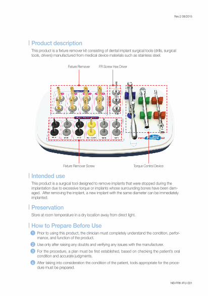
Fixture Remover
Fixture Remover Screw
FR Screw Hex Driver
Torque Control Device
This product is a fi xture remover kit consisting of dental implant surgical tools (drills, surgical tools, drivers) manufactured from medical device materials such as stainless steel.
Product description
This product is a surgical tool designed to remove implants that were stopped during the implantation due to excessive torque or implants whose surrounding bones have been dam-aged. After removing the implant, a new implant with the same diameter can be immediately implanted.
Intended use
Store at room temperature in a dry location away from direct light.Preservation
1
2
3
4
Prior to using this product, the clinician must completely understand the condition, perfor-mance, and function of the product. Use only after raising any doubts and verifying any issues with the manufacturer. For the procedure, a plan must be fi rst established, based on checking the patient’s oral condition and accurate judgments. After taking into consideration the condition of the patient, tools appropriate for the proce-dure must be prepared.
How to Prepare Before Use
Rev.2 08/2015
NB-FRK-IFU-001
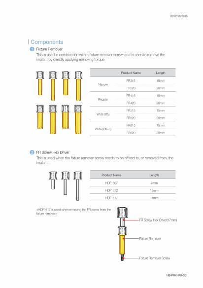
Product Name Length
NarrowFR315 15mm
FR320 20mm
RegularFR415 15mm
FR420 20mm
Wide (Ø5)FR515 15mm
FR520 20mm
Wide (Ø6~8)FR615 15mm
FR620 20mm
Product Name Length
HDF1607 7mm
HDF1612 12mm
HDF1617 17mm
FR Screw Hex Driver(17mm)
Fixture Remover
Fixture Remover Screw
<HDF1617 is used when removing the FR screw from the fi xture remover>
This is used in combination with a fi xture remover screw, and is used to remove the implant by directly applying removing torque
Fixture Remover1
This is used when the fi xture remover screw needs to be affi xed to, or removed from, the implant.
FR Screw Hex Driver2
Components
Rev.2 08/2015
NB-FRK-IFU-001
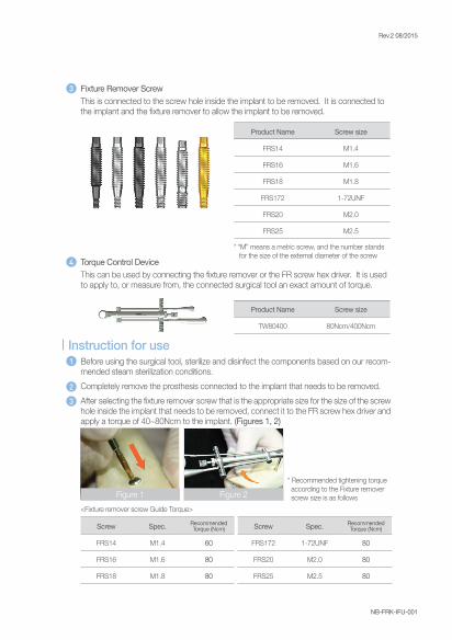
Product Name Screw size
FRS14 M1.4
FRS16 M1.6
FRS18 M1.8
FRS172 1-72UNF
FRS20 M2.0
FRS25 M2.5
Product Name Screw size
TW80400 80Ncm/400Ncm
* “M” means a metric screw, and the number stands for the size of the external diameter of the screw
* Recommended tightening torque according to the Fixture remover screw size is as followsFigure 1
<Fixture remover screw Guide Torque>
Screw Spec.
FRS14 M1.4 60
FRS16 M1.6 80
FRS18 M1.8 80
Recommended Torque (Ncm) Screw Spec.
FRS172 1-72UNF 80
FRS20 M2.0 80
FRS25 M2.5 80
Recommended Torque (Ncm)
This is connected to the screw hole inside the implant to be removed. It is connected to the implant and the fi xture remover to allow the implant to be removed.
Fixture Remover Screw3
This can be used by connecting the fi xture remover or the FR screw hex driver. It is used to apply to, or measure from, the connected surgical tool an exact amount of torque.
Torque Control Device4
1
2
3
Before using the surgical tool, sterilize and disinfect the components based on our recom-mended steam sterilization conditions. Completely remove the prosthesis connected to the implant that needs to be removed. After selecting the fi xture remover screw that is the appropriate size for the size of the screw hole inside the implant that needs to be removed, connect it to the FR screw hex driver and apply a torque of 40~80Ncm to the implant. (Figures 1, 2)
Instruction for use
Figure 2
Rev.2 08/2015
NB-FRK-IFU-001
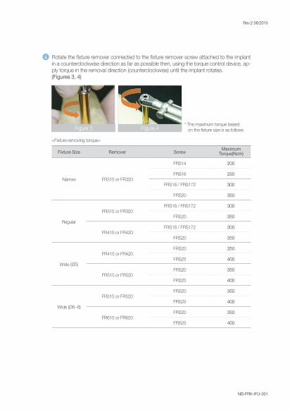
<Fixture removing torque>
Fixture Size Remover Screw
Narrow FR315 or FR320
FRS14 200
FRS16 250
FRS18 / FRS172 300
FRS20 350
Regular
FR315 or FR320FRS18 / FRS172 300
FRS20 350
FR415 or FR420FRS18 / FRS172 300
FRS20 350
Wide (Ø5)
FR415 or FR420FRS20 350
FRS25 400
FR515 or FR520FRS20 350
FRS25 400
Wide (Ø6~8)
FR515 or FR520FRS20 350
FRS25 400
FR615 or FR620FRS20 350
FRS25 400
Maximum Torque(Ncm)
4 Rotate the fi xture remover connected to the fi xture remover screw attached to the implant in a counterclockwise direction as far as possible then, using the torque control device, ap-ply torque in the removal direction (counterclockwise) until the implant rotates.(Figures 3, 4)
Figure 3 Figure 4* The maximum torque based on the fi xture size is as follows
Rev.2 08/2015
NB-FRK-IFU-001
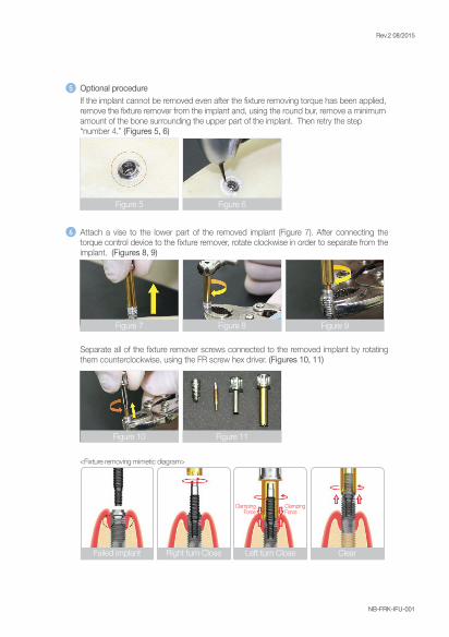
Separate all of the fi xture remover screws connected to the removed implant by rotating them counterclockwise, using the FR screw hex driver. (Figures 10, 11)
<Fixture removing mimetic diagram>
Failed implant Right turn Close Clear
ClampingForce
ClampingForce
Left turn Close
If the implant cannot be removed even after the fi xture removing torque has been applied, remove the fi xture remover from the implant and, using the round bur, remove a minimum amount of the bone surrounding the upper part of the implant. Then retry the step “number 4.” (Figures 5, 6)
Optional procedure5
6 Attach a vise to the lower part of the removed implant (Figure 7). After connecting the torque control device to the fi xture remover, rotate clockwise in order to separate from the implant. (Figures 8, 9)
Figure 5 Figure 6
Figure 7
Figure 10 Figure 11
Figure 8 Figure 9
Rev.2 08/2015
NB-FRK-IFU-001
1
2
3
4
5
6
7
8
The product must be used only after the user becomes completely familiar with the proper methods of use. When selecting the size of the fixture remover screw, the precise size of the screw hole inside the implant that needs to be removed must be verified. If not, incomplete fixation of the fixture remover screw to the implant may cause the screw to become damaged or fractured before the implant can be removed (If a fixture remover screw is used that is too small for the size of the screw hole inside the implant, connection can be forced. Accordingly, when the proper size is unknown, start from the largest size fixture remover screw and go down until the proper size fixture remover screw to connect is selected.)When selecting the size of the fixture remover, it is recommended that a size bigger than the diameter of the upper part of the implant be selected. If a smaller size is used, it may not be able to properly receive the removing torque, making it difficult to remove the implant. When affixing the fixture remover screw, it must be affixed using the recommended amount of torque. If not, the fixture remover screw may fracture, bend, or it may simply rotate between the implant and the fixture remover. A fixture remover screw and fixture remover must be used one time only as the fixture remover screw and fixture remover may bend or fracture if reused. Accordingly, reuse is prohibited.When the maximum removing torque is exceeded in the course of using the fixture remover, there is a risk that the surgical tool will be damaged, or the implant will be shattered or bone fractured. Accordingly, caution should be taken not to exceed the maximum removing torque. If 60 Ncm or a higher amount of torque is applied when removing the implant, the implant must be removed with adequate irrigation in order to prevent any overheating. When using the torque control device together with surgical tools, if torque is applied before they are completely connected, the product performance may be reduced or the product may be damaged. Accordingly, use only after they are properly connected. (Such as a fixture remover, or FR Screw hex driver)
Precaution for use
1
2
Because the product is a non-sterilized medical device, select either a pre-vacuum or a gravity autoclave. (Plastic products must not be sterilized at or above 170°C (338°F)Before sterilization, the inner wrapper must be removed from the tray. Assembled compo-nents must be separated in order to improve the efficiency of sterilization.
How to Sterilize
Rev.2 08/2015
NB-FRK-IFU-001
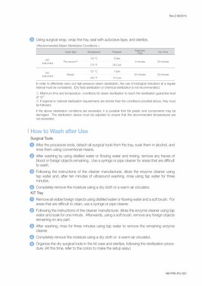
In order to effectively carry out high-pressure steam sterilization, the use of biological indicators at a regular interval must be considered. (Dry heat sterilization or chemical sterilization is not recommended.)① Minimum time and temperature conditions for steam sterilization to reach the sterilization guarantee level of 10-6
② If regional or national sterilization requirements are stricter than the conditions provided above, they must be followed. If the above sterilization conditions are exceeded, it is possible that the plastic and components may be damaged. The sterilization device must be adjusted to ensure that the recommended temperatures are not exceeded.
Cycle Type Temperature Pressure Dry Time
KIT,Instrument Pre-vacuum¹²
132 ℃ 2 bars3 minutes 30 minutes
270 °F 28.5 psi
KIT,Instrument Gravity¹
121 ℃ 1 bars40 minutes 30 minutes
250 °F 14.5 psi
ExposureTime
<Recommended Steam Sterilization Conditions >
3 Using surgical wrap, wrap the tray, seal with autoclave tape, and sterilize.
Surgical Tools 1
2
3
4
After the procedure ends, detach all surgical tools from the tray, soak them in alcohol, and rinse them using conventional means. After washing by using distilled water or flowing water and rinsing, remove any traces of blood or foreign objects remaining. Use a syringe or pipe cleaner for areas that are difficult to wash. Following the instructions of the cleaner manufacturer, dilute the enzyme cleaner using tap water and, after ten minutes of ultrasound washing, rinse using tap water for three minutes. Completely remove the moisture using a dry cloth or a warm-air circulator.
KIT Tray1
2
3
4
5
Remove all visible foreign objects using distilled water or flowing water and a soft brush. For areas that are difficult to clean, use a syringe or pipe cleaner. Following the instructions of the cleaner manufacturer, dilute the enzyme cleaner using tap water and soak for one minute. Afterwards, using a soft brush, remove any foreign objects remaining on any part. After washing, rinse for three minutes using tap water to remove the remaining enzyme cleaner. Completely remove the moisture using a dry cloth or a warm-air circulator. Organize the dry surgical tools in the kit case and sterilize, following the sterilization proce-dure. (At this time, refer to the colors to make the setup easy.)
How to Wash after Use
Rev.2 08/2015
NB-FRK-IFU-001
1
2
3
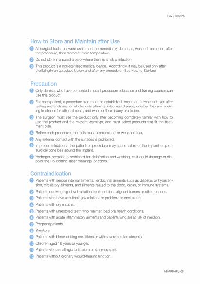
All surgical tools that were used must be immediately detached, washed, and dried, after the procedure, then stored at room temperature. Do not store in a soiled area or where there is a risk of infection. This product is a non-sterilized medical device. Accordingly, it may be used only aftersterilizing in an autoclave before and after any procedure. (See How to Sterilize)
1
2
3
4
5
6
7
8
10
9
11
12
Patients with serious internal ailments: endocrinal ailments such as diabetes or hyperten-sion, circulatory ailments, and ailments related to the blood, organ, or immune systems.Patients receiving high-level radiation treatment for malignant tumors or other reasons. Patients who have unsuitable jaw relations or problematic occlusions. Patients with dry mouths.Patients with unrestored teeth who maintain bad oral health conditions. Patients with acute inflammatory ailments and patients who are at risk of infection. Pregnant patients. Smokers. Patients with blood clotting conditions or with severe cardiac ailments. Children aged 16 years or younger. Patients who are allergic to titanium or stainless steel.Patients without ordinary wound-healing function.
How to Store and Maintain after Use
1
2
3
4
5
6
7
Only dentists who have completed implant procedure education and training courses can use this product.For each patient, a procedure plan must be established, based on a treatment plan after testing and analyzing for whole-body ailments, infectious disease, whether they are receiv-ing treatment for other ailments, and whether there is any oral lesion.The surgeon must use the product only after becoming completely familiar with how to use the product and the relevant warnings, and must select products that fit the treat-ment plan. Before each procedure, the tools must be examined for wear and tear. Any external contact with the surfaces is prohibited. Improper selection of the patient or procedure may cause failure of the implant or post-surgical bone loss around the implant. Hydrogen peroxide is prohibited for disinfection and washing, as it could damage or dis-color the TIN coating, laser markings, or colors.
Precaution
Contraindication
Rev.2 08/2015
NB-FRK-IFU-001
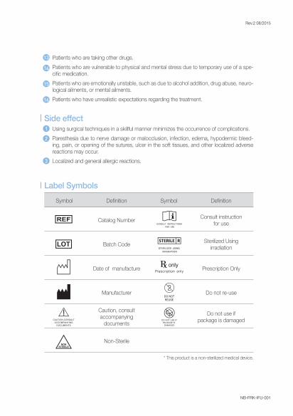
* This product is a non-sterilized medical device.
Symbol Definition Symbol Definition
Catalog Number Consult instructionfor use
Batch Code Sterilized Usingirradiation
Date of manufacture Prescription Only
Manufacturer Do not re-use
Caution, consultaccompanying
documents
Do not use ifpackage is damaged
Non-Sterile
13
14
15
16
Patients who are taking other drugs. Patients who are vulnerable to physical and mental stress due to temporary use of a spe-cific medication.Patients who are emotionally unstable, such as due to alcohol addition, drug abuse, neuro-logical ailments, or mental ailments.Patients who have unrealistic expectations regarding the treatment.
1
2
3
Using surgical techniques in a skillful manner minimizes the occurrence of complications. Paresthesia due to nerve damage or malocclusion, infection, edema, hypodermic bleed-ing, pain, or opening of the sutures, ulcer in the soft tissues, and other localized adverse reactions may occur. Localized and general allergic reactions.
Side effect
Label Symbols
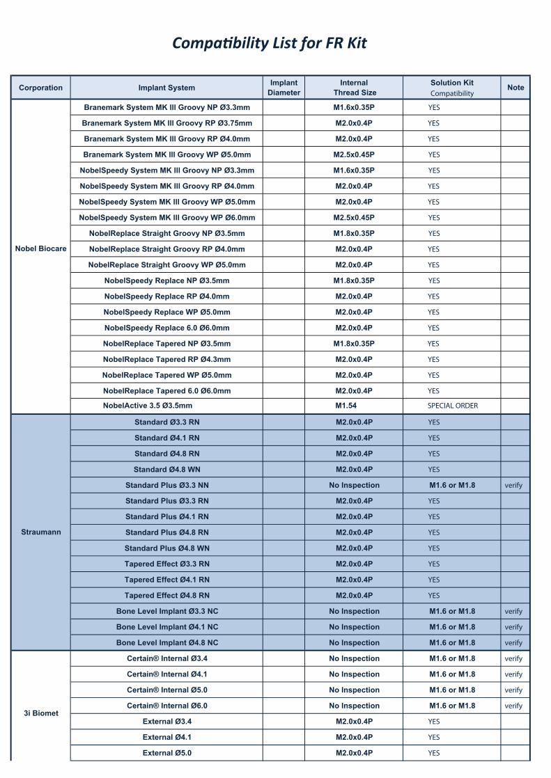
Corporation Implant System ImplantDiameter
Internal Thread Size
Solution KitCompatibility
Note
Branemark System MK lll Groovy NP Ø3.3mm M1.6x0.35P YES
Branemark System MK lll Groovy RP Ø3.75mm M2.0x0.4P YES
Branemark System MK lll Groovy RP Ø4.0mm M2.0x0.4P YES
Branemark System MK lll Groovy WP Ø5.0mm M2.5x0.45P YES
NobelSpeedy System MK lll Groovy NP Ø3.3mm M1.6x0.35P YES
NobelSpeedy System MK lll Groovy RP Ø4.0mm M2.0x0.4P YES
NobelSpeedy System MK lll Groovy WP Ø5.0mm M2.0x0.4P YES
NobelSpeedy System MK lll Groovy WP Ø6.0mm M2.5x0.45P YES
NobelReplace Straight Groovy NP Ø3.5mm M1.8x0.35P YES
NobelReplace Straight Groovy RP Ø4.0mm M2.0x0.4P YES
NobelReplace Straight Groovy WP Ø5.0mm M2.0x0.4P YES
NobelSpeedy Replace NP Ø3.5mm M1.8x0.35P YES
NobelSpeedy Replace RP Ø4.0mm M2.0x0.4P YES
NobelSpeedy Replace WP Ø5.0mm M2.0x0.4P YES
NobelSpeedy Replace 6.0 Ø6.0mm M2.0x0.4P YES
NobelReplace Tapered NP Ø3.5mm M1.8x0.35P YES
NobelReplace Tapered RP Ø4.3mm M2.0x0.4P YES
NobelReplace Tapered WP Ø5.0mm M2.0x0.4P YES
NobelReplace Tapered 6.0 Ø6.0mm M2.0x0.4P YES
Standard Ø3.3 RN M2.0x0.4P YES
Standard Ø4.1 RN M2.0x0.4P YES
Standard Ø4.8 RN M2.0x0.4P YES
Standard Ø4.8 WN M2.0x0.4P YES
Standard Plus Ø3.3 NN No Inspection M1.6 or M1.8 verify
Standard Plus Ø3.3 RN M2.0x0.4P YES
Standard Plus Ø4.1 RN M2.0x0.4P YES
Standard Plus Ø4.8 RN M2.0x0.4P YES
Standard Plus Ø4.8 WN M2.0x0.4P YES
Tapered Effect Ø3.3 RN M2.0x0.4P YES
Tapered Effect Ø4.1 RN M2.0x0.4P YES
Tapered Effect Ø4.8 RN M2.0x0.4P YES
Bone Level Implant Ø3.3 NC No Inspection M1.6 or M1.8 verify
Bone Level Implant Ø4.1 NC No Inspection M1.6 or M1.8 verify
Bone Level Implant Ø4.8 NC No Inspection M1.6 or M1.8 verify
Certain® Internal Ø3.4 No Inspection M1.6 or M1.8 verify
Certain® Internal Ø4.1 No Inspection M1.6 or M1.8 verify
Certain® Internal Ø5.0 No Inspection M1.6 or M1.8 verify
Certain® Internal Ø6.0 No Inspection M1.6 or M1.8 verify
External Ø3.4 M2.0x0.4P YES
External Ø4.1 M2.0x0.4P YES
External Ø5.0 M2.0x0.4P YES
Nobel Biocare
Compatibility List for FR Kit2010.12.03
Straumann
3i Biomet
NobelActive 3.5 Ø3.5mm M1.54 SPECIAL ORDER
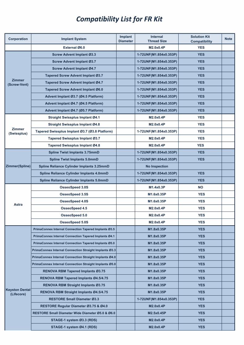
Corporation Implant System ImplantDiameter
Internal Thread Size
Solution KitCompatibility
Note
Compatibility List for FR Kit2010.12.03
External Ø6.0 M2.0x0.4P YES
Screw Advent Implant Ø3.3 1-72UNF(M1.854x0.353P) YES
Screw Advent Implant Ø3.7 1-72UNF(M1.854x0.353P) YES
Screw Advent Implant Ø4.7 1-72UNF(M1.854x0.353P) YES
Tapered Screw Advent Implant Ø3.7 1-72UNF(M1.854x0.353P) YES
Tapered Screw Advent Implant Ø4.7 1-72UNF(M1.854x0.353P) YES
Tapered Screw Advent Implant Ø6.0 1-72UNF(M1.854x0.353P) YES
Advent Implant Ø3.7 (Ø4.5 Platform) 1-72UNF(M1.854x0.353P) YES
Advent Implant Ø4.7 (Ø4.5 Platform) 1-72UNF(M1.854x0.353P) YES
Advent Implant Ø4.7 (Ø5.7 Platform) 1-72UNF(M1.854x0.353P) YES
Straight Swissplus Implant Ø4.1 M2.0x0.4P YES
Straight Swissplus Implant Ø4.8 M2.0x0.4P YES
Tapered Swissplus Implant Ø3.7 (Ø3.8 Platform) 1-72UNF(M1.854x0.353P) YES
Tapered Swissplus Implant Ø3.7 M2.0x0.4P YES
Tapered Swissplus Implant Ø4.8 M2.0x0.4P YES
Spline Twist Implants 3.75mmD 1-72UNF(M1.854x0.353P) YES
Spline Twist Implants 5.0mmD 1-72UNF(M1.854x0.353P) YES
Spline Reliance Cylinder Implants 3.25mmD No Inspection
Spline Reliance Cylinder Implants 4.0mmD 1-72UNF(M1.854x0.353P) YES
Spline Reliance Cylinder Implants 5.0mmD 1-72UNF(M1.854x0.353P) YES
OsseoSpeed 3.0S M1.4x0.3P NO
OsseoSpeed 3.5S M1.6x0.35P YES
OsseoSpeed 4.0S M1.6x0.35P YES
OsseoSpeed 4.5 M2.0x0.4P YES
OsseoSpeed 5.0 M2.0x0.4P YES
OsseoSpeed 5.0S M2.0x0.4P YES
PrimaConnex Internal Connection Tapered Implants Ø3.5 M1.8x0.35P YES
PrimaConnex Internal Connection Tapered Implants Ø4.1 M1.8x0.35P YES
PrimaConnex Internal Connection Tapered Implants Ø5.0 M1.8x0.35P YES
PrimaConnex Internal Connection Straight Implants Ø3.3 M1.8x0.35P YES
PrimaConnex Internal Connection Straight Implants Ø4.0 M1.8x0.35P YES
PrimaConnex Internal Connection Straight Implants Ø5.0 M1.8x0.35P YES
RENOVA RBM Tapered Implants Ø3.75 M1.8x0.35P YES
RENOVA RBM Tapered Implants Ø4.5/4.75 M1.8x0.35P YES
RENOVA RBM Straight Implants Ø3.75 M1.8x0.35P YES
RENOVA RBM Straight Implants Ø4.5/4.75 M1.8x0.35P YES
RESTORE Small Diameter Ø3.3 1-72UNF(M1.854x0.353P) YES
RESTORE Regular Diameter Ø3.75 & Ø4.0 M2.0x0.4P YES
RESTORE Small Diameter Wide Diameter Ø5.0 & Ø6.0 M2.5x0.45P YES
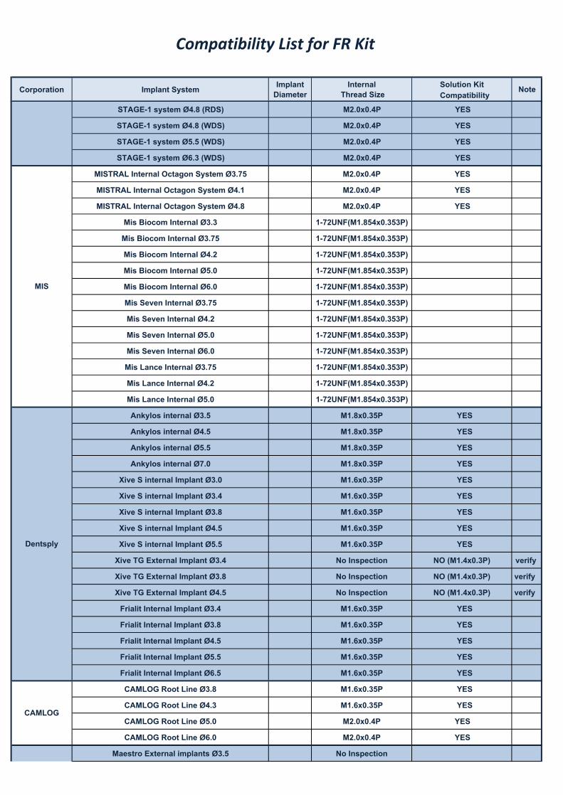
STAGE-1 system Ø3.3 (RDS) M2.0x0.4P YES
STAGE-1 system Ø4.1 (RDS) M2.0x0.4P YES
Zimmer(Screw-Vent)
Zimmer(Swissplus)
Zimmer(Spline)
Astra
Keyston Dental(Lifecore)
3i Biomet
Corporation Implant System ImplantDiameter
Internal Thread Size
Solution KitCompatibility
Note
Compatibility List for FR Kit2010.12.03
STAGE-1 system Ø4.8 (RDS) M2.0x0.4P YES
STAGE-1 system Ø4.8 (WDS) M2.0x0.4P YES
STAGE-1 system Ø5.5 (WDS) M2.0x0.4P YES
STAGE-1 system Ø6.3 (WDS) M2.0x0.4P YES
MISTRAL Internal Octagon System Ø3.75 M2.0x0.4P YES
MISTRAL Internal Octagon System Ø4.1 M2.0x0.4P YES
MISTRAL Internal Octagon System Ø4.8 M2.0x0.4P YES
Mis Biocom Internal Ø3.3 1-72UNF(M1.854x0.353P)
Mis Biocom Internal Ø3.75 1-72UNF(M1.854x0.353P)
Mis Biocom Internal Ø4.2 1-72UNF(M1.854x0.353P)
Mis Biocom Internal Ø5.0 1-72UNF(M1.854x0.353P)
Mis Biocom Internal Ø6.0 1-72UNF(M1.854x0.353P)
Mis Seven Internal Ø3.75 1-72UNF(M1.854x0.353P)
Mis Seven Internal Ø4.2 1-72UNF(M1.854x0.353P)
Mis Seven Internal Ø5.0 1-72UNF(M1.854x0.353P)
Mis Seven Internal Ø6.0 1-72UNF(M1.854x0.353P)
Mis Lance Internal Ø3.75 1-72UNF(M1.854x0.353P)
Mis Lance Internal Ø4.2 1-72UNF(M1.854x0.353P)
Mis Lance Internal Ø5.0 1-72UNF(M1.854x0.353P)
Ankylos internal Ø3.5 M1.8x0.35P YES
Ankylos internal Ø4.5 M1.8x0.35P YES
Ankylos internal Ø5.5 M1.8x0.35P YES
Ankylos internal Ø7.0 M1.8x0.35P YES
Xive S internal Implant Ø3.0 M1.6x0.35P YES
Xive S internal Implant Ø3.4 M1.6x0.35P YES
Xive S internal Implant Ø3.8 M1.6x0.35P YES
Xive S internal Implant Ø4.5 M1.6x0.35P YES
Xive S internal Implant Ø5.5 M1.6x0.35P YES
Xive TG External Implant Ø3.4 No Inspection NO (M1.4x0.3P) verify
Xive TG External Implant Ø3.8 No Inspection NO (M1.4x0.3P) verify
Xive TG External Implant Ø4.5 No Inspection NO (M1.4x0.3P) verify
Frialit Internal Implant Ø3.4 M1.6x0.35P YES
Frialit Internal Implant Ø3.8 M1.6x0.35P YES
Frialit Internal Implant Ø4.5 M1.6x0.35P YES
Frialit Internal Implant Ø5.5 M1.6x0.35P YES
Frialit Internal Implant Ø6.5 M1.6x0.35P YES
CAMLOG Root Line Ø3.8 M1.6x0.35P YES
CAMLOG Root Line Ø4.3 M1.6x0.35P YES
CAMLOG Root Line Ø5.0 M2.0x0.4P YES
CAMLOG Root Line Ø6.0 M2.0x0.4P YES
Maestro External implants Ø3.5 No Inspection
CAMLOG
Biohorizons
MIS
Dentsply
Keyston Dental(Lifecore)
Corporation Implant System ImplantDiameter
Internal Thread Size
Solution KitCompatibility
Note
Compatibility List for FR Kit2010.12.03
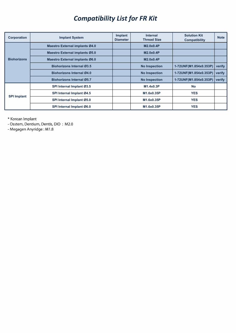
Maestro External implants Ø4.0 M2.0x0.4P
Maestro External implants Ø5.0 M2.0x0.4P
Maestro External implants Ø6.0 M2.0x0.4P
Biohorizons Internal Ø3.5 No Inspection 1-72UNF(M1.854x0.353P) verify
Biohorizons Internal Ø4.0 No Inspection 1-72UNF(M1.854x0.353P) verify
Biohorizons Internal Ø5.7 No Inspection 1-72UNF(M1.854x0.353P) verify
SPI Internal Implant Ø3.5 M1.4x0.3P No
SPI Internal Implant Ø4.5 M1.6x0.35P YES
SPI Internal Implant Ø5.0 M1.6x0.35P YES
SPI Internal Implant Ø6.0 M1.6x0.35P YES
Biohorizons
SPI Implant


Manufacturer /Distributor : Neobiotech Co., Ltd. www.neobiotech.co.kr104, 24 / 102, 103, 104-1, 104-2, 105, 106, 205, 212, 312, 509, 510, 511, 10F36 Digital-ro 27-Gil, Guro-Gu, Seoul, Korea Tel. +82 2 582 2885 Fax. +82 2 582 2883