if you want to experience honest, dependable, responsive ... · if you want to experience honest,...
TRANSCRIPT

If you want to experiencehonest, dependable, responsive,service-oriented wastewater treatment specialists, you want Jet - A company founded on innovation and anchored by service
Commercial Product CatalogVolume Two
Wastewater Treatment Solutions2
About Jet
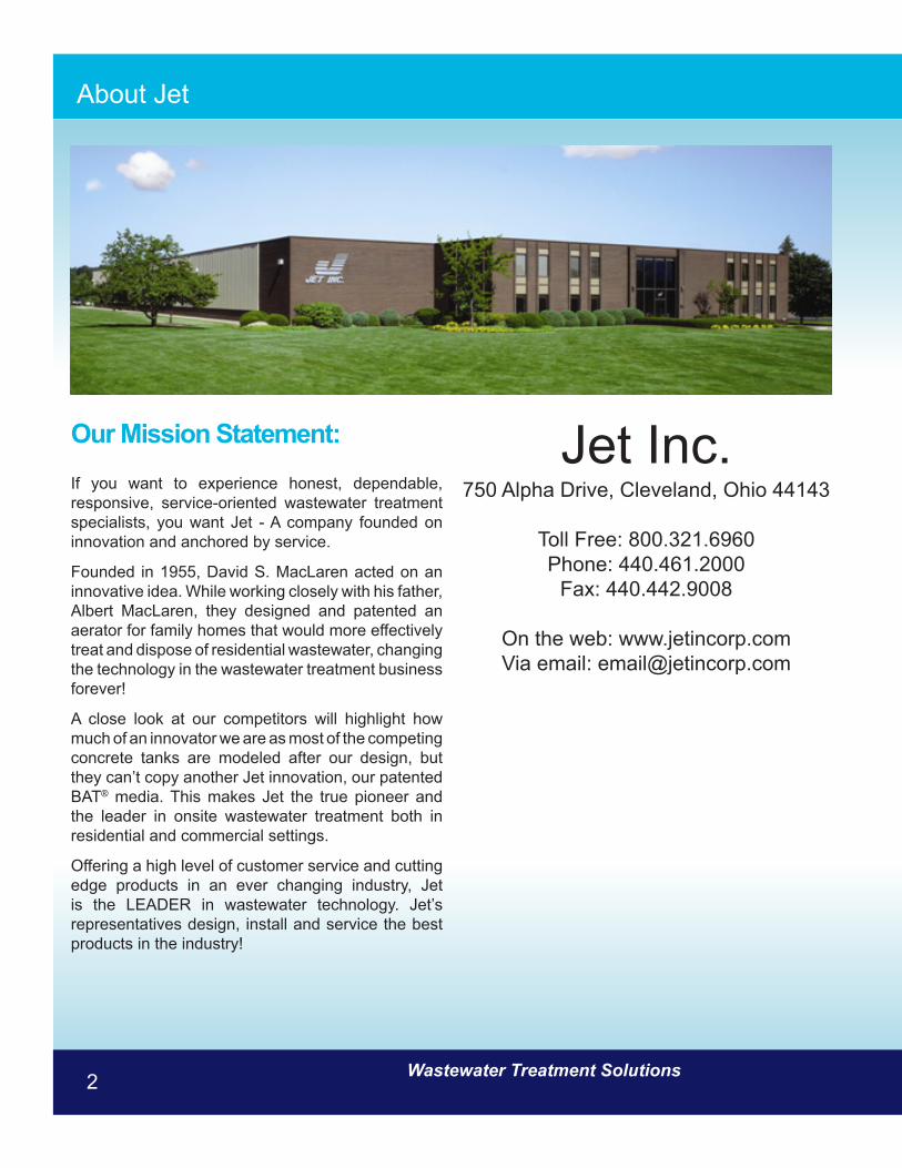
Our Mission Statement:
If you want to experience honest, dependable, responsive, service-oriented wastewater treatment specialists, you want Jet - A company founded on innovation and anchored by service.
Founded in 1955, David S. MacLaren acted on an innovative idea. While working closely with his father, Albert MacLaren, they designed and patented an aerator for family homes that would more effectively treat and dispose of residential wastewater, changing the technology in the wastewater treatment business forever!
A close look at our competitors will highlight how much of an innovator we are as most of the competing concrete tanks are modeled after our design, but they can’t copy another Jet innovation, our patented BAT® media. This makes Jet the true pioneer and the leader in onsite wastewater treatment both in residential and commercial settings.
Offering a high level of customer service and cutting edge products in an ever changing industry, Jet is the LEADER in wastewater technology. Jet’s representatives design, install and service the best products in the industry!
Jet Inc.750 Alpha Drive, Cleveland, Ohio 44143
Toll Free: 800.321.6960Phone: 440.461.2000
Fax: 440.442.9008
On the web: www.jetincorp.comVia email: [email protected]

www.jetincorp.com 1-800-321-6960 3
Table of Contents
Title PagesAbout Jet - Our Mission 2Table of Contents 3Order Form 4Commercial Systems - How they work 5AIR-SEAL Diffusers® 7 Commercial Control Panels 9Equipment Housing 10Housing Components - Motors 11Housing Components - Blowers 12Drive Components - Belts 13Drive Components - Bushings 13Drive Components - Sheaves 14Pressure Relief Valves 14Air Filters, Filter/Silencers and Silencers 15Electrical Components 16Piping 17Comminutors 18Bar Screens 19Weirs 20Grating and Hardware 21Polylok Effluent Filters 22 - 25Commercial Disinfection Systems and Replacement Parts 26 - 29 JET-CHLOR® 30CHLOR-AWAY® 31BIO JET-7® 323G UV Disinfection Lamp 33 - 34Geoflow Drip Line 35 - 37Geoflow Headworks 38
Title Pages Geoflow Vortex Filters 39Geoflow Air Vent & Box 41 Pressure Gauge, Ball Valves and Lockslip Fittings 42Controllers 43K-Rain Indexing Valves 44K-Rain Sprinkler Heads 45K-Rain Pro Plus Sprinkler Heads 46Polylok Distribution Box 47Polylok Risers & Covers 48Red Jacket Subermersible Pumps 49 - 52Polylok Seals & Mandrels 53Polylok Boots Seals and Concrete Inserts 54Polylok Plastic Wheel Chairs 55Jet Home and Commercial Molds 56Notes 57Custom Commercial Plants 58Sludge Judge 59
Wastewater Treatment Solutions4
Buyer Name: _________________________________
Phone: ______________________________________
Fax: ________________________________________
Best Time to call: ______________________________
Title: ________________________________________
Print Name: __________________________________
Authorized Signature: __________________________
Company Name: _______________________________
Address: ______________________________________
City, State ZIP: __________________________________
Company Name: ________________________________
Address: ______________________________________
City, State & ZIP: _______________________________
Jet Inc., 750 Alpha Drive, Cleveland, Oh 44143Toll Free: (800) 321-6960 (440) 461-2000Fax: (440) 442-9008www.jetincorp.com [email protected]
Credit Card (please circle price)
Card Holder’s Name:
______________________________________Card Number:
______________________________________Expiration Date: ______ / _______
Ship To:
Sold To (required):
Bill to Account - Use PO# __________________
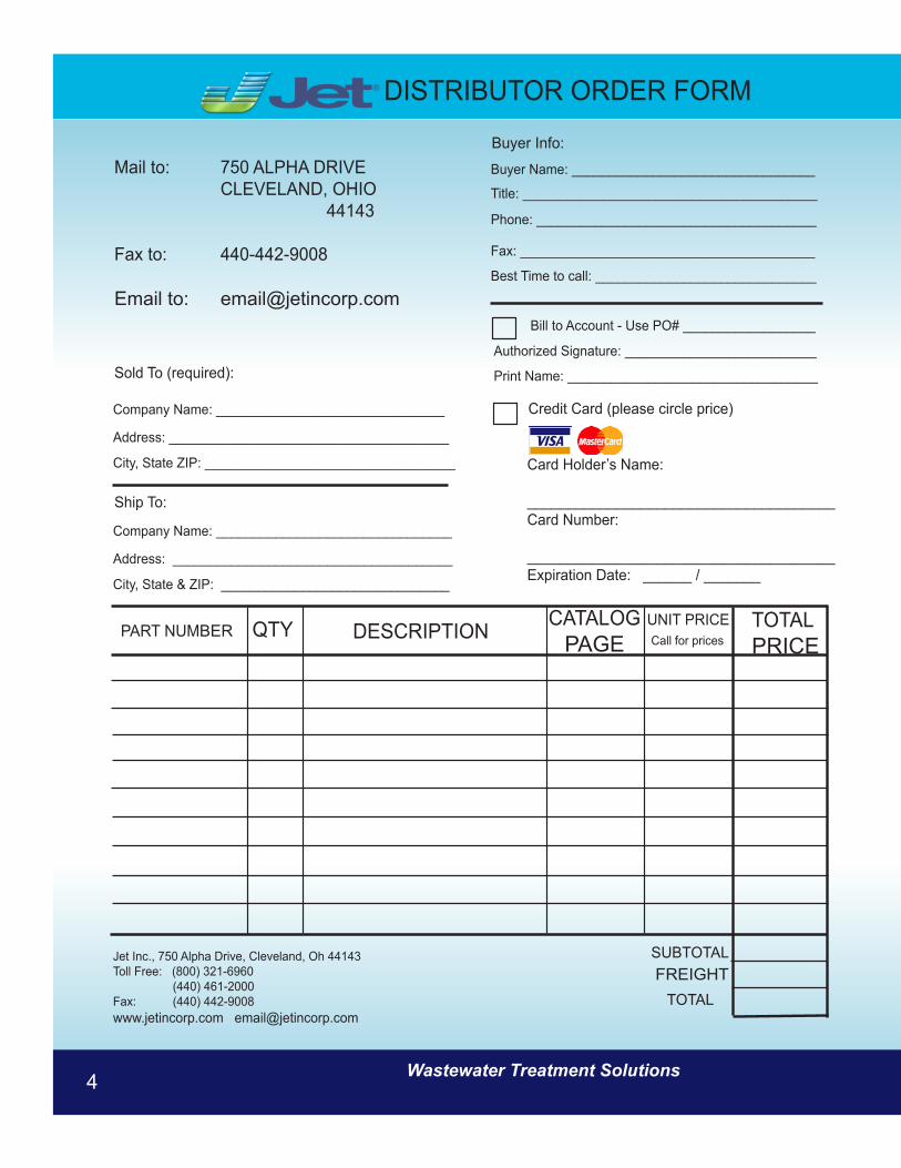
Buyer Info:Mail to: 750 ALPHA DRIVE CLEVELAND, OHIO 44143
Fax to: 440-442-9008
Email to: [email protected]
PART NUMBER DESCRIPTIONQTY TOTALPRICE
CATALOGPAGE
SUBTOTAL
TOTALFREIGHT
UNIT PRICECall for prices
DISTRIBUTOR ORDER FORM®

www.jetincorp.com 1-800-321-6960 5
Why Buy A Jet?• Jet has been thriving and innovating since 1955.
We are the leader in onsite wastewater technology.• Jet offers assistance with design, engineering and
construction.• Jet offers 24/7 technical support, plant start up and operator
training. • Jet’s modular design offers the ability to do phase
construction to grow with project demands.• Jet’s plants are great for new commercial developments.• Jet’s plants make it possible for motels, shopping centers,
factories, and service stations to be constructed along highways away from city sewer lines.
• Jet’s plants are time-tested and custom designed to treat wastewater through the extended aeration process.
• Jet’s plants are made of corrosion-free, reinforced concrete for durability.
• Jet’s plants are configured to meet your specific site requirements.
• Jet’s plants are designed to use our patented Jet AIR-SEAL Diffuser® which saves time & money.
• Jet’s plants range in size from 1,500 – 100,000 gpd. (gallons per day)
• Jet’s plants are Better for Precasting, Better for Installation, Better for Service…..Simply Better!
Total Pollution Control for Any Facility Built Beyond Sewer Lines
Jet’s Package Wastewater Treatment Plants have made it possible for motels, shopping centers and service stations to be constructed along interstate highways far from any town. With a Jet Package Plant: Subdivisions can be developed miles beyond sewer lines; factories can be erected in rural areas; and people can live and work in isolated areas in places throughout the world including the world’s deserts, deep valleys and mountain ranges. Ours are time-tested and custom designed plants that treat wastewater through the performance-proven aerobic digestion process that enables microscopic living organisms to transform wastewater into a clear, odorless liquid.
DELIVERING DEPENDABLE AND QUALITY ONSITE COMMERCIAL WASTEWATER TREATMENT SINCE 1955• Corrosion-free, reinforced concrete tank for durability• Great for new property development• Modular in construction supporting a broad range of plant
sizes and phased developments• Configured to meet your specific site requirements• Capable of processing 1,500 - 100,000 gpd (gallons per day)• Designed to leverage our patented Jet AIR-SEAL Diffuser
®
which saves time and money• Uses the time-tested and proven Extended Aeration Process• Supported by 24/7 technical assistance: Plant Start-up and
Operator Training Available• Backed by over 50 years in the business of designing
wastewater treatment systems
Commercial Systems
A small Jet Commercial Plant
Wastewater Treatment Solutions6
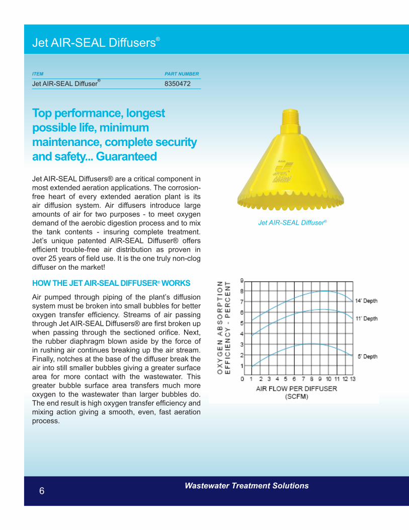
Top performance, longest possible life, minimum maintenance, complete security and safety... Guaranteed
Jet AIR-SEAL Diffusers® are a critical component in most extended aeration applications. The corrosion-free heart of every extended aeration plant is its air diffusion system. Air diffusers introduce large amounts of air for two purposes - to meet oxygen demand of the aerobic digestion process and to mix the tank contents - insuring complete treatment. Jet’s unique patented AIR-SEAL Diffuser® offers efficient trouble-free air distribution as proven in over 25 years of field use. It is the one truly non-clog diffuser on the market!
HOW THE JET AIR-SEAL DIFFUSER® WORKSAir pumped through piping of the plant’s diffusion system must be broken into small bubbles for better oxygen transfer efficiency. Streams of air passing through Jet AIR-SEAL Diffusers® are first broken up when passing through the sectioned orifice. Next, the rubber diaphragm blown aside by the force of in rushing air continues breaking up the air stream. Finally, notches at the base of the diffuser break the air into still smaller bubbles giving a greater surface area for more contact with the wastewater. This greater bubble surface area transfers much more oxygen to the wastewater than larger bubbles do. The end result is high oxygen transfer efficiency and mixing action giving a smooth, even, fast aeration process.
ITEM PART NUMBER
Jet AIR-SEAL Diffuser® 8350472
Jet AIR-SEAL Diffuser®
Jet AIR-SEAL Diffusers®

www.jetincorp.com 1-800-321-6960 7
Jet AIR-SEAL Diffusers®
The Only Non-Clog Diffuser You Can Buy
The heart of every extended aeration wastewater treatment facility is its air diffusion system. The diffuser introduces the large amounts of oxygen required to meet the demands of the aerobic digestion process. It also mixes that oxygen with activated sludge in the tank to provide complete treatment. But not all diffusers are the same.
Some are merely pipe pieces with holes drilled to release air. Others use spring-loaded valves. Some are simple porous structures. No matter what they are made from or how they release oxygen into the plant, they all diffuse air upward - and that’s why they all quickly clog up. During off-cycle periods when air is not being circulated, solids in the aeration chamber settle to the bottom to clog the diffuser opening. The result: air flow is reduced or completely stopped, and the plant must be shut down so the diffusion system can be cleaned.
Now consider Jet’s AIR-SEAL Diffuser:® Its exclusive cone-shaped design causes settling solids to slide down the sloped sides and away from an opening that faces down, not up. When the blower shuts down, the opening is immediately and securely sealed with a rubber diaphragm. A bubble of air is trapped there to prevent any liquids or floating solids from coming into any contact with the diffuser opening. Clogging is made impossible.
No Clogging! No Maintenance! Owners save money because they save labor and replacement parts, and the plant continues to operate at peak efficiency. They can be used on new plants or as replacement parts on existing plants. Jet’s AIR-SEAL Diffuser® is simple in design and effective in operation. It is the one truly non-clog diffuser on the market!
Jet AIR-SEAL Diffuser®

Wastewater Treatment Solutions8
Commercial Control Panels
The Command Center
Every Jet Commercial Wastewater Treatment Plant is supplied with a pre-wired electrical control panel that can monitor motor and blower operations, flow, chlorination, spray, pumps and other auxiliary equipment. Whether you would like our traditional panel (pictured to the right) or our new PLC-based version, they all contain proven components that are simple to maintain, operate, and troubleshoot.
All Jet Commercial Plant electrical equipment is monitored here, at the control panel. That equipment is pre-wired at the Jet factory to our exacting quality standards. All switches and controls are clearly identified, and a wiring diagram is furnished with each panel. Before shipment of any control panel, Jet fully tests all mechanical and electrical equipment in order to ensure that all components operate properly.
An optional 24-hour time clock permits automatic cycling of the motor(s) and blower(s).
This clock is preset at the Jet factory to operate the motor(s), blower(s) and foam control for 15 minutes of each half hour. Motors and blowers can be run manually with the toggle switch that is included.
In our 2000 Series plants, the motor, blowers and control panel itself are protected inside a Jet weatherproof, fiberglass equipment housing. Jet 3000 Series plants, a separate weatherproof sheet metal enclosure with an equivalent NEMA 3R rating houses all electrical controls. This enclosure is protected by long-lasting weather resistant paint. Both 2000 and 3000 Series enclosures are secured with master-keyed padlocks.
Traditional Jet Commercial Control Panel(A PLC-based version is available)
CONTROL PANEL OPTIONS:• 24-Hour Time Clock • Flow Recorder • Test Switch • 7-Day Time Clock • 115 V Receptacle • Foam Control/Spray Option • Chlorinator Option • Comminutor Option • Spare Switch • Automatic Alternation
Special Order only, call for quote

www.jetincorp.com 1-800-321-6960 9
Equipment Housing
ITEM PART NUMBER
Equipment Housing & Base without mounting holes 8007015Equipment Housing & Base with holes for 22 & 33 URAI Blowers 8007023Equipment Housing & Base with holes for 45 & 56 URAI Blowers 8007049Cover of Equipment Housing 8000028
Wastewater Treatment Solutions10
Housing Components - Motors
ITEM PART NUMBER
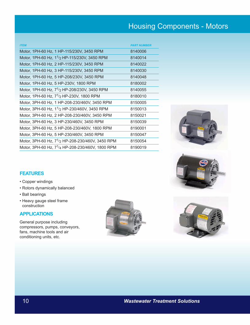
Motor, 1PH-60 Hz, 1 HP-115/230V, 3450 RPM 8140006Motor, 1PH-60 Hz, 11/2 HP-115/230V, 3450 RPM 8140014Motor, 1PH-60 Hz, 2 HP-115/230V, 3450 RPM 8140022Motor, 1PH-60 Hz, 3 HP-115/230V, 3450 RPM 8140030Motor, 1PH-60 Hz, 5 HP-208/230V, 3450 RPM 8140048Motor, 1PH-60 Hz, 5 HP-230V, 1800 RPM 8180002Motor, 1PH-60 Hz, 71/2 HP-208/230V, 3450 RPM 8140055Motor, 1PH-60 Hz, 71/2 HP-230V, 1800 RPM 8180010Motor, 3PH-60 Hz, 1 HP-208-230/460V, 3450 RPM 8150005Motor, 3PH-60 Hz, 11/2 HP-230/460V, 3450 RPM 8150013Motor, 3PH-60 Hz, 2 HP-208-230/460V, 3450 RPM 8150021Motor, 3PH-60 Hz, 3 HP-230/460V, 3450 RPM 8150039Motor, 3PH-60 Hz, 5 HP-208-230/460V, 1800 RPM 8190001Motor, 3PH-60 Hz, 5 HP-230/460V, 3450 RPM 8150047Motor, 3PH-60 Hz, 71/2 HP-208-230/460V, 3450 RPM 8150054Motor, 3PH-60 Hz, 71/4 HP-208-230/460V, 1800 RPM 8190019
FEATURES• Copper windings • Rotors dynamically balanced • Ball bearings • Heavy gauge steel frame
construction
APPLICATIONSGeneral purpose including compressors, pumps, conveyors, fans, machine tools and air conditioning units, etc.

www.jetincorp.com 1-800-321-6960 11
Housing Components - Blowers
ITEM PART NUMBER
Blower, URAI 22 8050098Blower, URAI 33 8050106Blower, URAI 45 8050114Blower, URAI 56 8050122
Universal RAI® blowers are heavy-duty rotary blowers designed with detachable rugged steel mounting feet that permit easy, in-field adaptability to vertical or horizontal installation requirements. Because of the detachable mounting feet, these units can be easily adapted to any of four drive shaft positions: right, left, bottom, or top. The compact, sturdy design is engineered for continuous service when operated in accordance with speed and pressure ratings.
The basic model consists of a cast iron casing, carburized and ground alloy steel spur timing gears secured to steel shafts with a taper mounting and locknut, and cast iron involute impellers. Oversized antifriction bearings are used, with a cylindrical rollerbearing at the drive shaft to withstand V-belt pull. The Universal RAI® features splash oil lube on the gear end and grease lube on the drive end. ROOTS’ exclusive “figure-eight” gearbox design improves oil distribution to maximize gear and bearing life. After testing, the unit is sprayed with a protective paint.
Available accessories include driver, relief valve, inlet and discharge silencers, inlet filter, check valve, extended base, V-belt or flexible coupling and drive guards.
OPERATING PRINCIPLE Two figure-eight lobe impellers mounted on parallel shafts rotate in opposite directions. As each impeller passes the blower inlet, it traps a definite volume of air and carries it around the case to the blower outlet, where the air is discharged. With constant speed operation, the displaced volume is essentially the same regardless of pressure or temperature. Timing gears control the impellers relative positions and maintain small but definite clearances.
This allows operation without lubrication requirements inside the unit casing.

Wastewater Treatment Solutions12
Drive Components - Belts
ITEM PART NUMBER
Belt - 3V300 8070443Belt - 3V315 8070450Belt - 3V335 8070468Belt - 3V355 8070500Belt - 3V375 8070435Belt - 3V400 8070377Belt - 3V450 8070476Belt - 3V475 8070427Belt - 3V500 8070419Belt - 3V530 8070484Belt - 3V560 8070401Belt - 3V600 8070492
Drive Components - Bushings .ITEM PART NUMBER
Bushing, SH, .625 8070203Bushing, SDS, 1.125 8070211Bushing, SH, .875 8070229Bushing, SH, 1.125 8070237Bushing, SH, .6562 8070245Bushing, SH, .5875 8070252Bushing, JA, .625 8070260Bushing, SDS, .875 8070278Bushing, SOS, .9687 8070286Bushing, SM, .750 8070294Bushing, SOS, .750 8070302Bushing, SK, .9687 8070310Bushing, SK, .1.25 8070328Bushing, SH, 1.375 8070336Bushing, SOS, .7812 8070344Bushing, SDS, .6562 8070351Bushing, JA, .875 8070369
FEATURES & BENEFITS • Reverse Mounting possible • 3/4” taper per foot is a self locking taper • Interchangeable with competitive QD bushings
APPLICATIONS • Fans & Blowers • Ventilation Units • Agricultural blower units • Pumps • Conveyors • Mixers
FEATURES & BENEFITS • Ground form sidewalls reduces vibration and increases
belt and bearing life. • Raw edge sidewalls provide a uniform, anti-slip surface
with greater flexibility. • Wider notch spacing increases rigidity and stability
while also reducing the stress on the cord line. • Fabric Top and Bottom also increases rigidity and
stability of the belt. • “CODE 1” one-match belt system assures that all the
belts in the drive carries an equal amount of the load.
APPLICATIONS • Fans & Blowers • Ventilation Units • Agricultural blower units • Pumps • Conveyors • Mixers
Bushing
Belt

www.jetincorp.com 1-800-321-6960 13
Drive Components - Sheaves
ITEM PART NUMBER
Sheave, 1 groove, JA, 2.65 8070047Sheave, 1 groove, JA, 2.80 8070062Sheave, 1 groove, JA, 3.15 8070005Sheave, 1 groove, JA, 3.35 8070013Sheave, 1 groove, SOS, 10.6 8070096Sheave, 1 groove, SOS, 8.0 8070138Sheave, 1 groove, SM, 3.65 8070120Sheave, 1 groove, SH, 4.12 8070070Sheave, 1 groove, SH, 4.75 8070104Sheave, 1 groove, SM, 5.30 8070179Sheave, 1 groove, SM, 5.6 8070021Sheave, 1 groove, SM, 6.0 8070039Sheave, 1 groove, SM, 6.90 8070054Sheave, 2 groove, SH, 6.50 8070187Sheave, 2 groove, SH, 3.65 8070146Sheave, 2 groove, SH, 4.12 8070088Sheave, 2 groove, SM, 5.00 8069999Sheave, 2 groove, SM, 6.00 8070112Sheave, 2 groove, 5K, 10.6 8070153Sheave, 2 groove, 5K, 14.00 8070161
Pressure Relief ValvesITEM PART NUMBER
Pressure Relief Valve, 1 inch 8080012Pressure Relief Valve, 11/2 inch 8080020Pressure Relief Valve Weight - 1 pound for 1 inch valve 8080046Pressure Relief Valve Weight - 1/2 pound for 11/2 inch valve 8080053Pressure Relief Valve Weight - 1/2 pound for 1 inch valve 8080038
The pressure relief valve is a type of valve used to control or limit the pressure in a system which can build up by a process upset, instrument or equipment failure, by allowing the pressurized fluid to flow from an auxiliary passage out of the pressure vessel. The relief valve is designed or set to open at a predetermined pressure to protect pressure vessels and other equipment from being subjected to pressures that exceed their design limits.
Sheave
Pressure Relief Valve
www.jetincorp.com 1-800-321-6960 13
Wastewater Treatment Solutions14
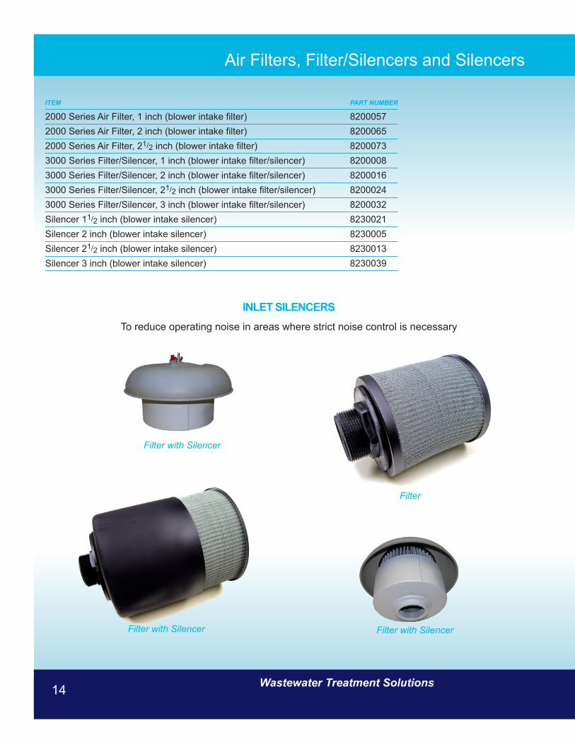
Air Filters, Filter/Silencers and Silencers
ITEM PART NUMBER
2000 Series Air Filter, 1 inch (blower intake filter) 82000572000 Series Air Filter, 2 inch (blower intake filter) 82000652000 Series Air Filter, 21/2 inch (blower intake filter) 82000733000 Series Filter/Silencer, 1 inch (blower intake filter/silencer) 82000083000 Series Filter/Silencer, 2 inch (blower intake filter/silencer) 82000163000 Series Filter/Silencer, 21/2 inch (blower intake filter/silencer) 82000243000 Series Filter/Silencer, 3 inch (blower intake filter/silencer) 8200032Silencer 11/2 inch (blower intake silencer) 8230021Silencer 2 inch (blower intake silencer) 8230005Silencer 21/2 inch (blower intake silencer) 8230013Silencer 3 inch (blower intake silencer) 8230039
INLET SILENCERS
To reduce operating noise in areas where strict noise control is necessary
Filter
Filter with SilencerFilter with Silencer
Filter with Silencer

www.jetincorp.com 1-800-321-6960 15
Electrical Components
ITEM PART NUMBER
Alternator (with wiring for 2000 or 3000 Series Panel) 8297012Alternator (without wiring) 8210478115 Volt Receptacle with transformer for 2000 Series 8457020115 Volt Receptacle with transformer for 3000 Series 8457012Time Clock, 115/230 V - 1Phase - 60 Hz - 24 hour - 7 days 8300063
ALTERNATOR• Solid-state Reliability • Heavy-duty Contact Rating • Optional Load 1-Load 2 Toggle • UL Recognized; CSA Certified • Indicator lights
TIME CLOCKEnables plants to run different time cycles on specified days of the week.
115-VOLT RECEPTACLETo permit use of small power tools, trouble lights, etc., during maintenance of plant. Outlet is fused at 6 amps and a transformer is provided thereby eliminating a separate 115-volt line.
www.jetincorp.com 1-800-321-6960 15

Wastewater Treatment Solutions16
Piping ITEM PART NUMBER
Diaphragm. Diffuser 8350522Diffuser Bushing, PVC 1/2 ” x 1/2 ” 8350530Foam Control Nozzles 8430134Foam Control Nozzle Bushing, PVC Reducer 1/2 ” x 11/4 ” 8430126Check Valve, 11/4” (for air header) 8100091Check Valve, 2” (for air header) 8100216Check Valve, 21/2” (for air header) 8100125Check Valve, 3” (for air header) 8100133Gas Cock Valve, 11/4” (for diffuser drop bar) 8350456Gate Valve, 2” (for sludge holding) 8350860Gate Valve, 3” (for sludge return) 8350308Stop Valve, 3/4 ” (for skimmer, sludge lift and diffuser air) 8350019Skimmer Intake Clamp 8350100Skimmer Intake Pipe 8350092
CHECK VALVECheck valves are two-port valves, meaning they have two openings in the body, one for fluid to enter and the other for fluid to exit.
Gas Cock Valve
Skimmer Intake Clamp
Skimmer Intake Pipe
Diffuser BushingFoam Control Nozzle Bushing
GATE VALVE
Located in each sludge return line to facilitate backwashing procedure on 10,000 gpd plants or larger. Gate valves are constructed of bronze with non-rising stems.
Stop Valve
Foam Control Nozzles
FOAM CONTROL SYSTEM
Pumps clarified liquid from settling chamber through non-clog spray nozzles into Jet aeration chamber to control foaming. Spray pump is a 1/4 HP submersible pump. System includes a wash-water outlet to permit hosing down plant, as well as other routine maintenance.
www.jetincorp.com 1-800-321-6960 17
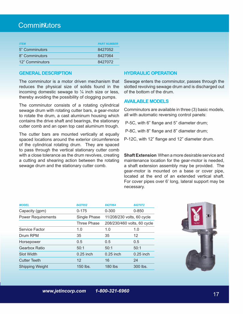
Comminutors
ITEM PART NUMBER
5” Comminutors 84270528” Comminutors 842706412” Comminutors 8427072
GENERAL DESCRIPTION The comminutor is a motor driven mechanism that reduces the physical size of solids found in the incoming domestic sewage to ¼ inch size or less, thereby avoiding the possibility of clogging pumps.
The comminutor consists of a rotating cylindrical sewage drum with rotating cutter bars, a gear-motor to rotate the drum, a cast aluminum housing which contains the drive shaft and bearings, the stationary cutter comb and an open top cast aluminum trough.
The cutter bars are mounted vertically at equally spaced locations around the exterior circumference of the cylindrical rotating drum. They are spaced to pass through the vertical stationary cutter comb with a close tolerance as the drum revolves, creating a cutting and shearing action between the rotating sewage drum and the stationary cutter comb.
HYDRAULIC OPERATION Sewage enters the comminutor, passes through the slotted revolving sewage drum and is discharged out of the bottom of the drum.
AVAILABLE MODELS Comminutors are available in three (3) basic models, all with automatic reversing control panels:
P-5C, with 6” flange and 5” diameter drum;
P-8C, with 8” flange and 8” diameter drum;
P-12C, with 12” flange and 12” diameter drum.
Shaft Extension When a more desirable service and maintenance location for the gear-motor is needed, a shaft extension assembly may be provided. The gear-motor is mounted on a base or cover pipe, located at the end of an extended vertical shaft. For cover pipes over 6’ long, lateral support may be necessary.
MODEL 8427052 8427064 8427072
Capacity (gpm) 0-175 0-300 0-850Power Requirements Single Phase 11/208/230 volts, 60 cycle Three Phase 208/230/460 volts, 60 cycleService Factor 1.0 1.0 1.0Drum RPM 35 35 12Horsepower 0.5 0.5 0.5Gearbox Ratio 50:1 50:1 50:1Slot Width 0.25 inch 0.25 inch 0.25 inchCutter Teeth 12 16 24Shipping Weight 150 lbs. 180 lbs 300 lbs.
www.jetincorp.com 1-800-321-6960 17
17

Wastewater Treatment Solutions18
Bar Screens
ITEM PART NUMBER
Fixed Bar Screen Only 8417024Fixed Bar Screen with chamber cover 8417016Removable Bar Screen Basket with support frame 8477010
REMOVABLE BASKET SCREEN Designed to mount at inlet to plant with mounting frame supplied. Catches all solids which will not fit through a 1” square opening. Easily removable for emptying and cleaning. Can only be used on plants 4,000 gpd or larger.
FIXED BAR SCREEN Has 1” bar spacing with a built-in overflow in case bar screen becomes plugged. Designed for installation in a Jet Comminutor Casting, but can be modified for other installations.
www.jetincorp.com 1-800-321-6960 19
ITEM PART NUMBER
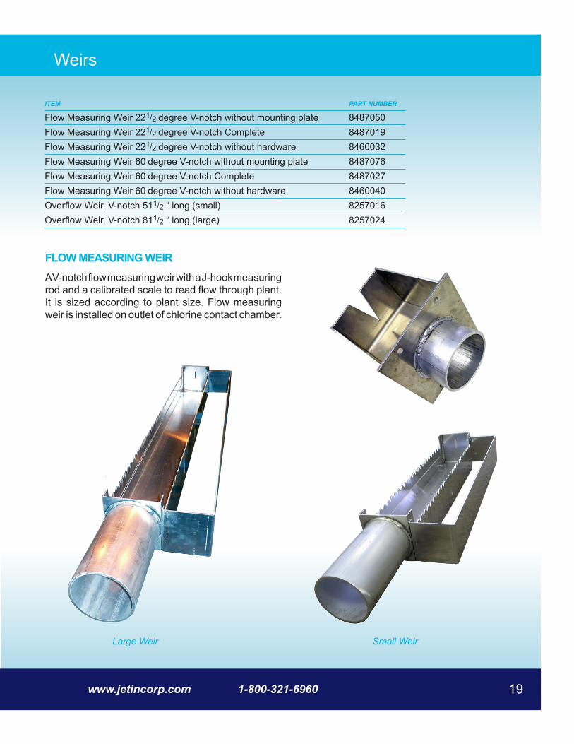
Flow Measuring Weir 221/2 degree V-notch without mounting plate 8487050Flow Measuring Weir 221/2 degree V-notch Complete 8487019Flow Measuring Weir 221/2 degree V-notch without hardware 8460032Flow Measuring Weir 60 degree V-notch without mounting plate 8487076Flow Measuring Weir 60 degree V-notch Complete 8487027Flow Measuring Weir 60 degree V-notch without hardware 8460040Overflow Weir, V-notch 511/2 “ long (small) 8257016Overflow Weir, V-notch 811/2 “ long (large) 8257024
FLOW MEASURING WEIR A V-notch flow measuring weir with a J-hook measuring rod and a calibrated scale to read flow through plant. It is sized according to plant size. Flow measuring weir is installed on outlet of chlorine contact chamber.
Weirs
Large Weir Small Weir
Wastewater Treatment Solutions20
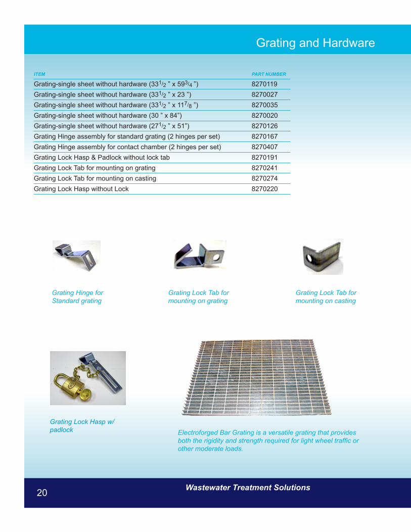
Grating and Hardware
ITEM PART NUMBER
Grating-single sheet without hardware (331/2 ” x 593/4 ”) 8270119Grating-single sheet without hardware (331/2 ” x 23 ”) 8270027Grating-single sheet without hardware (331/2 ” x 117/8 ”) 8270035Grating-single sheet without hardware (30 ” x 84”) 8270020Grating-single sheet without hardware (271/2 ” x 51”) 8270126Grating Hinge assembly for standard grating (2 hinges per set) 8270167Grating Hinge assembly for contact chamber (2 hinges per set) 8270407Grating Lock Hasp & Padlock without lock tab 8270191Grating Lock Tab for mounting on grating 8270241Grating Lock Tab for mounting on casting 8270274Grating Lock Hasp without Lock 8270220
Electroforged Bar Grating is a versatile grating that provides both the rigidity and strength required for light wheel traffic or other moderate loads.
Grating Hinge for Standard grating
Grating Lock Tab for mounting on grating
Grating Lock Tab for mounting on casting
Grating Lock Hasp w/padlock
www.jetincorp.com 1-800-321-6960 21
Polylok Effluent Filters
ITEM PART NUMBER
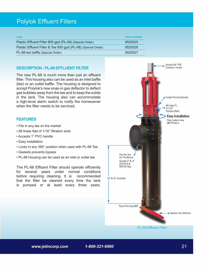
Plastic Effluent Filter 800 gpd (PL-68) (Special Order) 9520025Plastic Effluent Filter & Tee 800 gpd (PL-68) (Special Order) 9520026PL-68 tee baffle (Special Order) 9520027
DESCRIPTION - PL-68 EFFLUENT FILTERThe new PL-68 is much more than just an effluent filter. This housing also can be used as an inlet baffle (tee) or an outlet baffle. The housing is designed to accept Polylok’s new snap-in gas deflector to deflect gas bubbles away from the tee and to keep the solids in the tank. The housing also can accommodate a high-level alarm switch to notify the homeowner when the filter needs to be serviced.
FEATURES• Fits in any tee on the market • 68 linear feet of 1/16” filtration slots • Accepts 1” PVC handle • Easy installation • Locks in any 360° position when used with PL-68 Tee • Gaskets prevents bypass • PL-68 Housing can be used as an inlet or outlet tee
The PL-68 Effluent Filter should operate efficiently for several years under normal conditions before requiring cleaning. It is recommended that the filter be cleaned every time the tank is pumped or at least every three years.
PL-68 Effluent Filter
Wastewater Treatment Solutions22
ITEM PART NUMBER
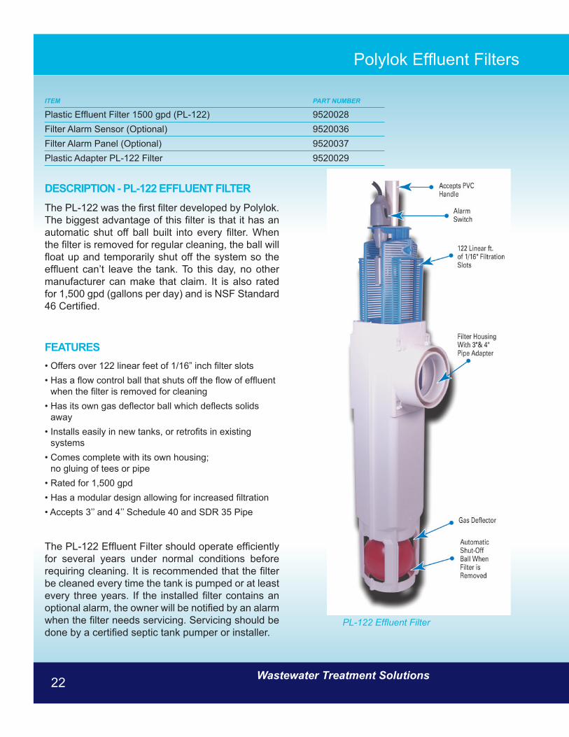
Plastic Effluent Filter 1500 gpd (PL-122) 9520028Filter Alarm Sensor (Optional) 9520036Filter Alarm Panel (Optional) 9520037Plastic Adapter PL-122 Filter 9520029
DESCRIPTION - PL-122 EFFLUENT FILTERThe PL-122 was the first filter developed by Polylok. The biggest advantage of this filter is that it has an automatic shut off ball built into every filter. When the filter is removed for regular cleaning, the ball will float up and temporarily shut off the system so the effluent can’t leave the tank. To this day, no other manufacturer can make that claim. It is also rated for 1,500 gpd (gallons per day) and is NSF Standard 46 Certified.
FEATURES• Offers over 122 linear feet of 1/16” inch filter slots • Has a flow control ball that shuts off the flow of effluent
when the filter is removed for cleaning • Has its own gas deflector ball which deflects solids
away • Installs easily in new tanks, or retrofits in existing
systems • Comes complete with its own housing;
no gluing of tees or pipe • Rated for 1,500 gpd • Has a modular design allowing for increased filtration • Accepts 3’’ and 4’’ Schedule 40 and SDR 35 Pipe
The PL-122 Effluent Filter should operate efficiently for several years under normal conditions before requiring cleaning. It is recommended that the filter be cleaned every time the tank is pumped or at least every three years. If the installed filter contains an optional alarm, the owner will be notified by an alarm when the filter needs servicing. Servicing should be done by a certified septic tank pumper or installer.
Polylok Effluent Filters
PL-122 Effluent Filter

www.jetincorp.com 1-800-321-6960 23
DESCRIPTION - PL-525 EFFLUENT FILTERPolylok, Inc. is pleased to add its new commercial filter to its existing line of quality effluent filters. The PL-525 is rated for over 10,000 gpd (gallons per day) making it one of the largest commercial filters in its class. It has 525 linear feet of 1/16” filtration slots. Like the Polylok PL-122, the new Polylok PL-525 has an automatic shut off ball installed with every filter. When the filter is removed for cleaning, the ball will float up and temporarily shut off the system so the effluent won’t leave the tank. No other filter on the market can make that claim!
FEATURES• Rated for 10,000 gpd (gallons per day) • 525 linear feet of 1/16” filtration • Accepts 4’’ and 6’’ Schedule 40 pipe • Built in Gas Deflector • Alarm accessibility • Accepts PVC extension handle• Automatic shut-off ball when filter is removed
The PL-525 Effluent Filter should operate efficiently for several years under normal conditions before requiring cleaning. It is recommended that the filter be cleaned every time the tank is pumped or at least every three years. If the installed filter contains an optional alarm, the owner will be notified by an alarm when the filter needs servicing. Servicing should be done by a certified septic tank pumper or installer.
ITEM PART NUMBER
Plastic Effluent Filter 1500 gpd (PL-122) 9520028Filter Alarm Sensor (Optional) 9520036Filter Alarm Panel (Optional) 9520037Plastic Adapter PL-122 Filter 9520029
Polylok Effluent Filters
PL-525 Effluent Filter
Wastewater Treatment Solutions24
ITEM PART NUMBER
Plastic Effluent Filter 1500 gpd (PL-122) 9520028Filter Alarm Sensor (Optional) 9520036Filter Alarm Panel (Optional) 9520037Plastic Adapter PL-122 Filter 9520029
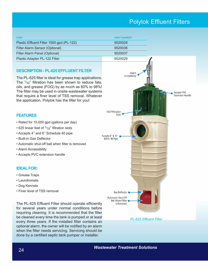
DESCRIPTION - PL-625 EFFLUENT FILTERThe PL-625 filter is ideal for grease trap applications. The 1/32” filtration has been shown to reduce fats, oils, and grease (FOG) by as much as 60% to 98%! The filter may be used in onsite wastewater systems that require a finer level of TSS removal. Whatever the application, Polylok has the filter for you!
FEATURES• Rated for 10,000 gpd (gallons per day)
• 625 linear feet of 1/32” filtration slots • Accepts 4’’ and 6’’ Schedule 40 pipe • Built-in Gas Deflector • Automatic shut-off ball when filter is removed • Alarm Accessibility • Accepts PVC extension handle
IDEAL FOR: • Grease Traps • Laundromats • Dog Kennels • Finer level of TSS removal
The PL-625 Effluent Filter should operate efficiently for several years under normal conditions before requiring cleaning. It is recommended that the filter be cleaned every time the tank is pumped or at least every three years. If the installed filter contains an optional alarm, the owner will be notified by an alarm when the filter needs servicing. Servicing should be done by a certified septic tank pumper or installer.
Polylok Effluent Filters
PL-625 Effluent Filter

www.jetincorp.com 1-800-321-6960 25
Commercial Disinfection Systems
The Commercial Tablet Feeders are self-contained, chlorine dispensing systems designed specifically for the disinfection of effluent from commercial wastewater treatment facilities. Three models are available for chlorination of flows up to 100,000 gallons per day. Easily installed directly in the ground on the discharge line or on the inlet of a chlorine contact chamber, these tablet feeders use no electricity and have no moving parts. Chlorine dosage is automatically adjusted in proportion to the flow. On the larger two models the weir plates are calibrated in both Metric and English and enable the user to tell the flow rate at a glance.
A complete “Installation and Operation” manual containing detailed instruction is supplied with each Commercial Tablet Feeder. This comprehensive manual contains step by step instructions for easy set up, operation and maintenance.
ADVANTAGES OF OWNING A COMMERCIAL TABLET FEEDER:• LOW INITIAL COST - No need for complicated and expensive pumps, mixing tanks, control
devices, electrical wiring or piping. The feeder is a simple, non-mechanical, gravity operated device.
• LOW OPERATING COST - Uses no electrical power. Labor costs reduced because there is no need for pre-mixing, pumps or control devices to maintain, adjust, repair or replace.
• WARRANTY - Each Jet Tablet Feeder carries a 10 year limited warranty against defective materials and workmaship.
• EFFICIENT - Chemical dosage is automatically varied in proportion to the flow. Higher flows expose more tablets to the effluent and correspondingly fewer tablets are exposed during periods of low flow.
• AUTOMATIC (OPERATES UNATTENDED) - The tablet feeders’ unique design insures automatic mixing and chemical transfer 24 hours a day after initial adjustments have been made. It can go long periods of time between restocking.
• YEARS AND YEARS OF REPAIR FREE LIFE - The tablet feeders’ simple, non-mechanical design has no moving parts to wear. Constructed of tough corrosion-proof plastics. Feed tubes and caps will not melt in the sun because they are protected by an enclosure with ultra-violet inhibitors.
• SEPARATE ENCLOSURES NOT REQUIRED - The self-contained and totally enclosed tablet feeder does not require a separate manhole, service box or casing when it is buried. Unique design prevents dirt and water from entering and makes the tubes easy to remove. For deep installations, optional risers are available which extend the tablet feeder to grade.
• LONG LASTING TABLETS - Efficient, slow dissolving chemical tablets do not “wick” and contain no dangerous gases, liquids or powders.
HOW IT WORKS:
As the treated wastewater flows through the tablet feeder, it contacts the chlorine tablets which gradually dissolve and slowly release an even and controlled amount of active chlorine into the wastewater. If the flow rate increases, the liquid level in the tablet feeder rises and more tablets are immersed. If the flow rate decreases, the liquid level drops and exposes correspondingly fewer tablets to the effluent.
The rate of chlorination and the chlorine residual can be adjusted and after adjustment they remain constant and in proportion to the flow. If needed, adjustments can be made by varying the number of tablet feed tubes which are filled.
www.jetincorp.com 1-800-321-6960 25

Wastewater Treatment Solutions26
Model 110 & 120 Chlorinator/Dechlorinator
MODEL 110 CHLORINATOR/DECHLORINATOR: This durable and reliable commercial chlorinator is capable of disinfecting flows up to 50,000 gpd and up to 100,000 gpd when installed in parallel. The maximum flow rate on the Model 110 is 80 gpm (gallons per minute) and 160 gpm when installed in parallel. This unit has a 6 5/8” diameter inlet.
MODEL 120 CHLORINATOR/DECHLORINATOR:This durable and reliable commercial chlorinator is capable of disinfection flows up to 50,000 gpd and up to 100,000 gpd when installed in parallel. The maximum flow rate on the model 120 is 80 gpm and 160 gpm when installed in parallel. Inlet diameter is variable up to 10”.
Both models come equipped with the following:
FEATURES• MOUNTING - each comes equipped with an easy
mounting base for easy installation in a chlorine contact chamber
• MATERIALS - each is constructed with high density polyethylene, which is chemical and ultraviolet resistant
• FEED TUBES - each model contains 4-22 5/8” PVC tubes with a 3” inside diameter and caps. Each tube can hold 27 tablets
• OUTLET WEIR PLATES - three outlet weir plates ranging from 1” to 3” are included to regulate effluent level. Each plate is calibrated with Metric and English to enable the user to visually determine the flow rate
• INLET BAFFLE - Controls the direction and velocity of flow within the tablet feeder
• LIMITED WARRANTY - Every tablet feeder carries a 10-year limited warranty against defective material and workmanship
ITEM PART NUMBER
Model 110 Chlorinator/Dechlorinator 110Model 120 Chlorinator/Dechlorinator 120

www.jetincorp.com 1-800-321-6960 27
Model 108 Chlorinator/Dechlorinator
MODEL 108 CHLORINATOR/DECHLORINATOR Capable of disinfecting flows up to 10,000 gpd, a 4 1/2” diameter inlet; lockable; optional risers are available. The maximum flow rate is 35 gpm (gallons per minute).
FEATURES• MOUNTING - Equipped with a mounting base for
easy installation in a chlorine contact chamber. For installation on discharge lines, a 4 1/2” inside diameter inlet and outlet are provided.
• MATERIALS - Each are constructed with high density polyethylene, which is chemical and ultraviolet resistant.
• FEED TUBES - 2 removable PVC tubes, 28” long and 3” inside diameter, with caps. Each tube holds 34 tablets. *It is not recommended filling the tubes to the top.
• OUTLET WEIR PLATE - A permanently affixed, outlet weir plate is included to regulate effluent level.
• INLET BAFFLE - An inlet baffle plate to control the direction and velocity of flow within the tablet feeder is supplied.
• RISERS (OPTIONAL) - For expanding tablet feeder to grade on deep installations.
• LOCKABLE COVER - Can be locked to prevent unauthorized access.
• LIMITED WARRANTY - Every tablet feeder carries a 10-year limited warranty against defective material and workmanship.
ITEM PART NUMBER
Model 108 Chlorinator/Dechlorinator 108
Wastewater Treatment Solutions28
ITEM PART NUMBER
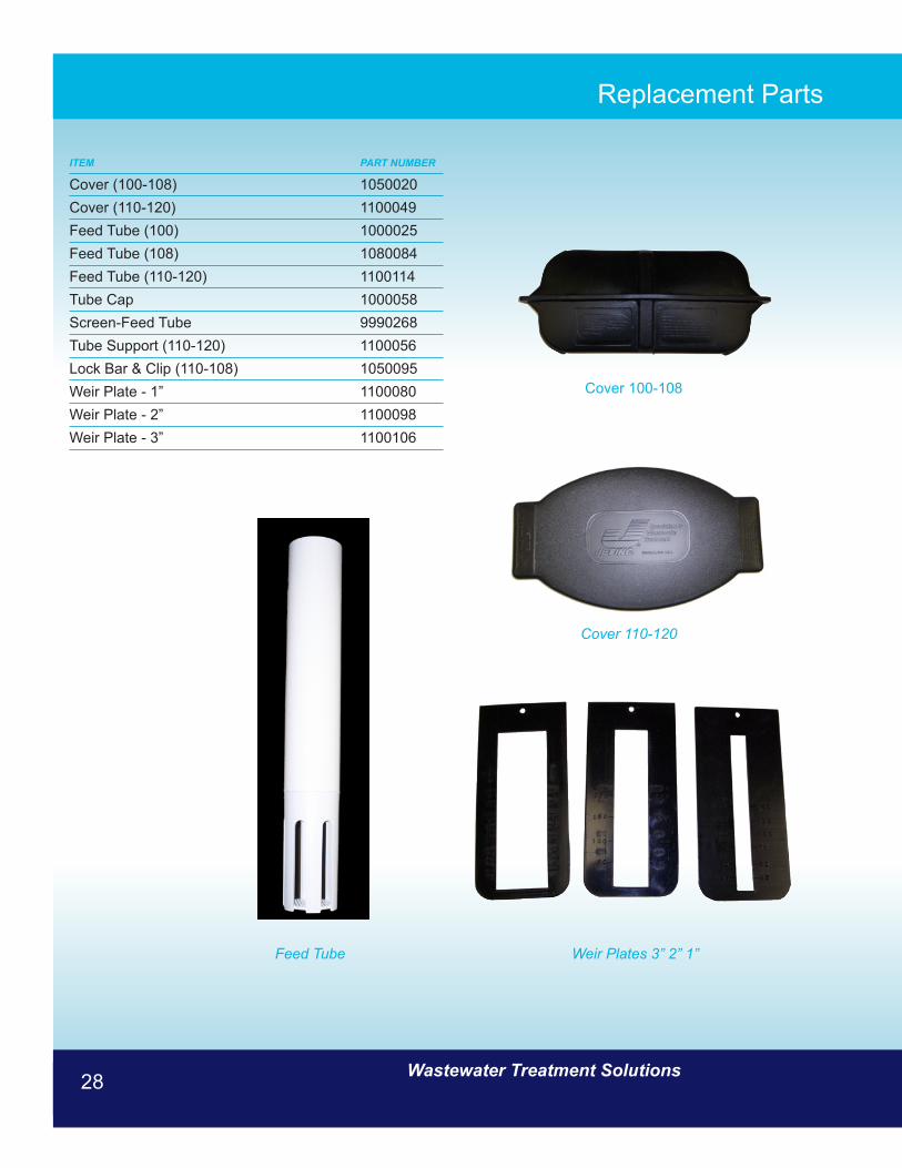
Cover (100-108) 1050020Cover (110-120) 1100049Feed Tube (100) 1000025Feed Tube (108) 1080084Feed Tube (110-120) 1100114Tube Cap 1000058Screen-Feed Tube 9990268Tube Support (110-120) 1100056Lock Bar & Clip (110-108) 1050095Weir Plate - 1” 1100080Weir Plate - 2” 1100098Weir Plate - 3” 1100106
Replacement Parts
Feed Tube Weir Plates 3” 2” 1”
Cover 100-108
Cover 110-120
www.jetincorp.com 1-800-321-6960 29
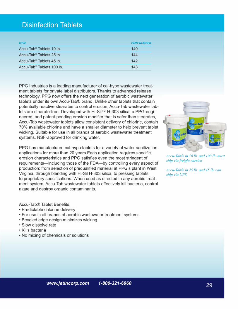
PPG Industries is a leading manufacturer of cal-hypo wastewater treat-ment tablets for private label distributors. Thanks to advanced release technology, PPG now offers the next generation of aerobic wastewater tablets under its own Accu-Tab® brand. Unlike other tablets that contain potentially reactive stearates to control erosion, Accu-Tab wastewater tab-lets are stearate-free. Developed with Hi-Sil™ H-303 silica, a PPG-engi-neered, and patent-pending erosion modifier that is safer than stearates, Accu-Tab wastewater tablets allow consistent delivery of chlorine, contain 70% available chlorine and have a smaller diameter to help prevent tablet wicking. Suitable for use in all brands of aerobic wastewater treatment systems. NSF-approved for drinking water.
PPG has manufactured cal-hypo tablets for a variety of water sanitization applications for more than 20 years.Each application requires specific erosion characteristics and PPG satisfies even the most stringent ofrequirements—including those of the FDA—by controlling every aspect of production: from selection of prequalified material at PPG’s plant in West Virginia, through blending with Hi-Sil H-303 silica, to pressing tabletsto proprietary specifications. When used as directed in any aerobic treat-ment system, Accu-Tab wastewater tablets effectively kill bacteria, control algae and destroy organic contaminants.
Accu-Tab® Tablet Benefits:• Predictable chlorine delivery• For use in all brands of aerobic wastewater treatment systems• Beveled edge design minimizes wicking• Slow dissolve rate• Kills bacteria• No mixing of chemicals or solutions
Disinfection Tablets
ITEM PART NUMBER
Accu-Tab® Tablets 10 lb. 140Accu-Tab® Tablets 25 lb. 144Accu-Tab® Tablets 45 lb. 142Accu-Tab® Tablets 100 lb. 143
Accu-Tab® in 10 lb. and 100 lb. must ship via freight carrier.
Accu-Tab® in 25 lb. and 45 lb. can ship via UPS.
29www.jetincorp.com 1-800-321-6960

Wastewater Treatment Solutions30
CHLOR-AWAY®
Laboratory-tested and proven, the CHLOR-AWAY® Dechlorination System uses a compact, lightweight Jet Tablet Feeder and long lasting sodium sulfite tablets to remove chlorine in proportion to the flow of treated wastewater.
It is the most practical chlorine removal system available today. Use your CHLOR-AWAY® System to dechlorinate wastewater, cooling tower blow down, boiler water and process water when chlorine or oxidizers are undesirable. In addition to unsurpassed efficiency and effectiveness, the Jet CHLOR-AWAY® System provides all these benefits:
• The Strongest Sodium Sulfite Blend Available - Jet’s specially formulated tablets provide the strongest blend of sodium sulfite available in tablet form.
• The Longest Lasting Tablets Available - Efficient, slow dissolving chlorine removal tablets help meet National Pollution Disposal Elimination System (NPDES) permit requirements.
• CHLOR-AWAY® Tablets Fit Other Feeders - Jet’s 2 5/8” diameter tablets are designed for Jet Tablet Feeders, but can also be used in other tablet feeders.
• Safe - There are no dangerous gases, liquids or powders to handle or store.
• Every CHLOR-AWAY® System is backed by over 50 years of wastewater treatment experience. We’ve invested all of this knowledge into the innovation, development, performance testing and manufacturing of the best dechlorination system available today - CHLOR-AWAY®.
Jet’s specially formulated CHLOR-AWAY® Tablets provide unsurpassed dechlorination convenience, efficiency and dependability.
ITEM PART NUMBER
CHLOR-AWAY® 25 lb. 171CHLOR-AWAY® 45 lb. 170
www.jetincorp.com 1-800-321-6960 31
A New Powerful Wastewater Treatment Weapon
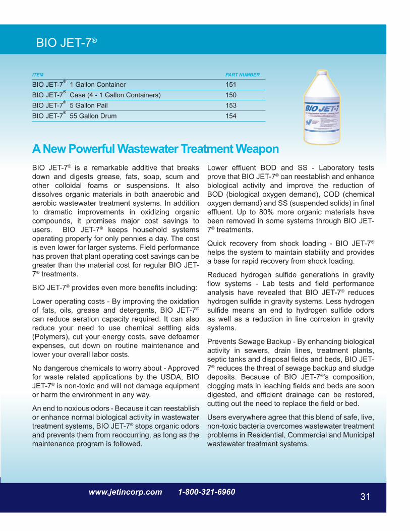
BIO JET-7®
BIO JET-7® is a remarkable additive that breaks down and digests grease, fats, soap, scum and other colloidal foams or suspensions. It also dissolves organic materials in both anaerobic and aerobic wastewater treatment systems. In addition to dramatic improvements in oxidizing organic compounds, it promises major cost savings to users. BIO JET-7® keeps household systems operating properly for only pennies a day. The cost is even lower for larger systems. Field performance has proven that plant operating cost savings can be greater than the material cost for regular BIO JET-7® treatments.
BIO JET-7® provides even more benefits including:
Lower operating costs - By improving the oxidation of fats, oils, grease and detergents, BIO JET-7® can reduce aeration capacity required. It can also reduce your need to use chemical settling aids (Polymers), cut your energy costs, save defoamer expenses, cut down on routine maintenance and lower your overall labor costs.
No dangerous chemicals to worry about - Approved for waste related applications by the USDA, BIO JET-7® is non-toxic and will not damage equipment or harm the environment in any way.
An end to noxious odors - Because it can reestablish or enhance normal biological activity in wastewater treatment systems, BIO JET-7® stops organic odors and prevents them from reoccurring, as long as the maintenance program is followed.
Lower effluent BOD and SS - Laboratory tests prove that BIO JET-7® can reestablish and enhance biological activity and improve the reduction of BOD (biological oxygen demand), COD (chemical oxygen demand) and SS (suspended solids) in final effluent. Up to 80% more organic materials have been removed in some systems through BIO JET-7® treatments.
Quick recovery from shock loading - BIO JET-7® helps the system to maintain stability and provides a base for rapid recovery from shock loading.
Reduced hydrogen sulfide generations in gravity flow systems - Lab tests and field performance analysis have revealed that BIO JET-7® reduces hydrogen sulfide in gravity systems. Less hydrogen sulfide means an end to hydrogen sulfide odors as well as a reduction in line corrosion in gravity systems.
Prevents Sewage Backup - By enhancing biological activity in sewers, drain lines, treatment plants, septic tanks and disposal fields and beds, BIO JET-7® reduces the threat of sewage backup and sludge deposits. Because of BIO JET-7®’s composition, clogging mats in leaching fields and beds are soon digested, and efficient drainage can be restored, cutting out the need to replace the field or bed.
Users everywhere agree that this blend of safe, live, non-toxic bacteria overcomes wastewater treatment problems in Residential, Commercial and Municipal wastewater treatment systems.
ITEM PART NUMBER
BIO JET-7® 1 Gallon Container 151BIO JET-7® Case (4 - 1 Gallon Containers) 150BIO JET-7® 5 Gallon Pail 153BIO JET-7® 55 Gallon Drum 154
www.jetincorp.com 1-800-321-6960 31

Wastewater Treatment Solutions32
UV disinfection lamp
The Ultraviolet Disinfection Unit (patent pending) was specifically designed for disinfecting the effluent from small aerobic treatment plants. It is able to reduce fecal coliform bacteria levels well below the most stringent US treatment standards, even when the upstream treatment plant is operating in a mild upset condition.
Most small aerobic treatment plants are installed so that their discharge piping is below grade. The Ultraviolet Disinfection chamber directly couples to the Jet plant 4’’ discharge pipe and is permanently installed below grade.
The ultraviolet light source for disinfection is mounted in a sub-assembly that can be inserted or removed through the top of the riser pipe for periodic servicing. The light source is mounted in the center of an anodized aluminum frame that divides the disinfection chamber in half. The Kapton® film seals against the inner surface of the disinfection chamber to prevent flow bypass.
When fully inserted, the disinfection sub-assembly is properly located near the top of the disinfection chamber. It causes the wastewater entering one side of the unit to flow vertically downward, make a 180° turn, and then flow vertically upward and out the other side of the unit. This well-defined flow path is designed to give the proper fluid exposure time. The ultraviolet light source is surrounded by a clear fused quartz tube to control lamp surface temperature. When the disinfection chamber is filled with water, the ultraviolet light source can operate continuously, whether or not water is flowing. Continuous operation within a lamp surface temperature range of 105-120° F provides optimum ultraviolet light output and long lamp life.
A fiber optic probe conveys visible light from the ultraviolet light source located underground to an electrical junction box mounted on the outside surface of the riser pipe above grade, allowing
lamp operating status to be confirmed visually without the necessity for removing the disinfection sub-assembly. The disinfection sub-assembly is watertight throughout its length, which extends approximately one foot above grade. This protects the electrical connections against a fluid backup which could cause the wastewater effluent level to rise to the maximum height of the upstream treatment plant.
The UV system operates on 115V AC power and consumes less than 25 watts. The power lead wires attach to a terminal strip inside the junction box. A green LED indicates that the ultraviolet light source is operating.
The Jet UV Disinfection Lamp

www.jetincorp.com 1-800-321-6960 33
UV disinfection lamp
SPECIFICATIONS:Maximum flow through the unit is rated at 3 gallons per minute (gpm), or 4,320 gallons per day (gpd), with the following effluent conditions:
Suspended Solids < 30 mg/liter5-day BOD < 30 mg/liter
Under the above conditions, the fecal coliform reduction by the Jet unit exceeds 3-logs, or 99.9%, at the end of the UV lamp life (one year of continuous operation).
Fecal coliform counts in the home aerobic treatment effluent typically range from 800-20,000 per 100ml. The Ultraviolet Disinfection Unit is well designed to disinfect the effluent from home units. There are no adverse effects from over exposing the effluent to germicidal ultraviolet light, because UV disinfection does not form by-products, in contrast to chlorination and other chemical disinfection methods.
UV disinfection lamp assembly
ITEM PART NUMBER
UV disinfection lamp 952UV replacement bulb 9521001

Wastewater Treatment Solutions34
Geoflow Drip Line
WASTEFLOW PC 1/2 GPH SPECIFICATIONThe dripline consists of nominal sized one-half inch linear low density polyethylene tubing, with turbulent flow, drip emitters bonded to the inside wall. The drip emitter flow passage is 0.032” x 0.045” square. The tubing has an outside diameter (O.D.) of approximately .64 inches and an inside diameter (I.D.) of approximately .55 inches. The tubing consists of three layers; the inside layer is a bactericide protection, the middle layer is black and the outside layer is purple striped for easy identification. The dripline has emitters regularly spaced 24” (or 18” or 12” or 6”) apart. The pressure compensating emitters are molded from virgin polyethylene resin with a silicone rubber diaphragm. The pressure compensating emitters have nominal discharge rates of 0.53 gallons per hour. The emitters are impregnated with Treflan® to inhibit root intrusion for a minimum period of ten years and are guaranteed by the manufacturer to inhibit root intrusion for this period. 0.53 gph WASTEFLOW.
HEAD LOSS CHARTPRESSURE HEAD WFPC WFPC WFPC
16-2-24 16-2-18 16-2-1210 psi 23.10 ft. — — —15 psi 34.65 ft. 321 ft. 260 ft. 174 ft.20 psi 46.20 ft. 423 ft. 330 ft. 228 ft.25 psi 57.75 ft. 478 ft. 377 ft. 260 ft.30 psi 69.30 ft. 535 ft. 415 ft. 288 ft.35 psi 80.85 ft. 576 ft. 448 ft. 313 ft.40 psi 92.40 ft. 613 ft. 475 ft. 330 ft.45 psi 103.95 ft. 651 ft. 501 ft. 354 ft.50 psi 115.50 ft. 675 ft. 523 ft. 363 ft.55 psi 127.50 ft. 700 ft. 544 ft. 377 ft.60 psi 138.60 ft. 727 ft. 563 ft. 403 ft.Kd = 2.070
Maximum Length of Run vs. PressureAllows a minimum of 10 psi in the line*Recommended operating pressure is 10 - 45 psi
DRIP LINE 16 MM - 500 FT. COILS - 1/2 GPH ITEM PART NUMBER
With 24” spacing 9500001With 18” spacing (Special Order) 9500002With 12” spacing (Special Order) 9500003With 6” spacing (Special Order) 9500004
DRIP LINE INSTALLATION
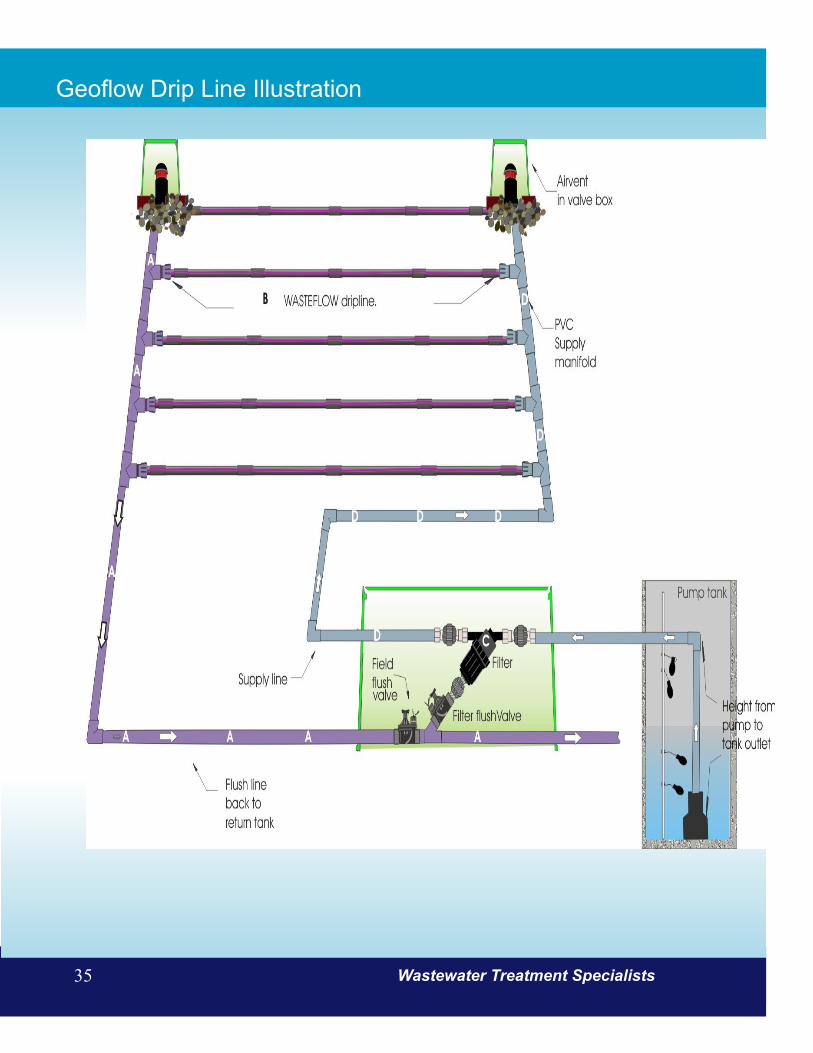
www.jetincorp.com 1-800-321-6960 35
Geoflow Drip Line Illustration
Wastewater Treatment Specialists35

Wastewater Treatment Solutions36
Geoflow Drip Line
WASTEFLOW PC 1 GPH SPECIFICATIONThe dripline consists of nominal sized one-half inch linear low density polyethylene tubing, with turbulent flow, drip emitters bonded to the inside wall. The drip emitter flow passage is 0.032” x 0.045” square. The tubing has an outside diameter (O.D.) of approximately .64 inches and an inside diameter (I.D.) of approximately .55 inches. The tubing consists of three layers; the inside layer is a bactericide protection, the middle layer is black and the outside layer is purple striped for easy identification. The dripline has emitters regularly spaced 24” (or 18” or 12” or 6”) apart. The pressure compensating emitters are molded from virgin polyethylene resin with a silicone rubber diaphragm. The pressure compensating emitters have nominal discharge rates of 1.02 gallons per hour. The emitters are impregnated with Treflan® to inhibit root intrusion for a minimum period of ten years and are guaranteed by the manufacturer to inhibit root intrusion for this period.
HEAD LOSS CHARTPRESSURE HEAD WFPC WFPC WFPC
16-4-24 16-4-18 16-4-1210 psi 23.10 ft. — — —15 psi 34.65 ft. 211 ft. 172 ft. 115 ft.20 psi 46.20 ft. 265 ft. 210 ft. 146 ft.25 psi 57.75 ft. 315 ft. 242 ft. 171 ft.30 psi 69.30 ft. 335 ft. 266 ft. 180 ft.35 psi 80.85 ft. 379 ft. 287 ft. 199 ft.40 psi 92.40 ft. 385 ft. 305 ft. 211 ft.45 psi 103.95 ft. 429 ft. 321 ft. 222 ft.50 psi* 115.50 ft. 431 ft. 334 ft. 232 ft.55 psi* 127.05 ft. 449 ft. 347 ft. 240 ft.60 psi* 138.60 ft. 465 ft. 360 ft. 249 ft.Kd = 2.070
Maximum Length of Run vs. PressureAllows a minimum of 10 psi in the line*Recommended operating pressure is 10 - 45 psi
DRIP LINE 16 MM - 500 FT. COILS - 1GPH ITEM PART NUM-BER
With 24” spacing 9500005With 18” spacing (Special Order) 9500006With 12” spacing (Special Order) 9500007With 6” spacing (Special Order) 9500008
DRIP LINE ROLL

www.jetincorp.com 1-800-321-6960 37
Geoflow Headworks
ITEM PART NUMBER
HEADWORKS STANDARD - 3/4” FILTERManual flush valves 9500009Auto flush valves 9500010
HEADWORKS STANDARD - 1” FILTERManual flush valves 9500011Auto flush valves 9500012
HEADWORKS STANDARD - 3/4” FILTER GUTS ONLY *Manual flush valves 9500013Auto flush valves 9500014
HEADWORKS STANDARD - 1” FILTER GUTS ONLY *Manual flush valves 9500015Auto flush valves 9500016Jumbo valve box with no guts 95000176” riser for Standard headworks 9500018
DESCRIPTIONEach headworks box includes the following:
• Vortex filter• Filter flush valve• Field flush valve• Pressure gauge• Headwork air vent• Headwork box
Note: Air vents, dripline, and fittings are required to complete the Geoflow disposal system. Pressure regulators are recom-mended.
MODEL MIN. FLOW MAX. FLOW
.75” Auto/Man 4 gpm 11 gpm1.0” Auto/Man 10 gpm 28 gpm
OPERATIONField and filter flushing can be done manually or automatically.
MANUAL HEADWORKSBoth valves should be cracked open slightly at all times to allow a constant flush. Make sure pressure at the Headworks gauge is at least 3 psi, and if not, close the valves slightly to increase pressure. The valves need to be fully open for a complete system flush twice a year.
AUTOMATIC HEADWORKSBoth valves are activated electrically. Jet recommends using a GEO controller to activate your flush cycles in the Automatic Headworks.
* Note: “Guts Only” does not include an enclosure
Typical Headworks Diagram

Wastewater Treatment Solutions38
Geoflow Vortex Filters
OPERATION:The filters are placed between the pump and dripfield to screen out any debris.
Body - The two-piece threaded housing with O-ring seal is molded from high heat ABS and chemical resistant glass reinforced plastic.
Screen - Constructed of sintered stainless steel. Sintering is a process in which three pieces of stainless steel mesh are transformed into one; a perforated plate, 30m then 150 mesh. Screen collars molded from vinyl for long life and durability.
Spin Plate and drain - Directional spin plate is molded of PVC or fiberglass.
Vortex Spin Action - Incoming water is forced through a directional nozzle plate onto the inside of the stainless steel screen. A centrifugal motion starts inside the screen chamber, throwing organic and inorganic particles outward against the screen. Gravity moves the debris down the screen wall to the 3/4” flush outlet at the base of the Vortex Filter.
To stay clean, two criteria must be met:
• Flow into the filter must be within the specified range to produce a 5 to 8 psi pressure differential across the filter.
• The filter flush valve must be partially to fully open allowing debris to flush away.
ITEM PART NUMBER
Vortex Filter 3/4” MPT Filter, 150 mesh, 4-11 gpm 9500019Vortex Filter 1” MPT Filter (long body) 150 Mesh, 7-28 gpm 9500020Screen Replacement 3/4” 9500021Screen Replacement 1” 9500022Spinplate Replacement 3/4” 9500023Spinplate Replacement 1” 9500024
Vortex Filter Vortex Filter Assembly

www.jetincorp.com 1-800-321-6960 39
Geoflow Vortex Filters
9500019 - 3/4” FILTERThe Y filter body is molded from glass reinforced engineering grade black plastic with a 3/4 inch male pipe thread (MIPT) inlet and outlet. The two piece body is capable of being serviced by untwisting and includes an O-ring seal. An additional 3/4 inch MIPT outlet is available for periodic flushing. The 150 mesh filter screen is all stainless steel, providing a 23.4 square inch filtration area.
WIDTH HEIGHT SIZE OF JET PART ITEM SIZE FLOW MAX. thread to with flush FLUSH AREA OF NUMBER NUMBERS (MIPT) (GPM) PRESSURE thread port PORT FILTRATION
9500019 AP4E-75 3/4” 04 - 11 80 psi 6.0” 12.0” 3/4” MPT 23.4 inches9500020 AP4E 1F long 1.0” 07 - 28 80 psi 6.5” 13.0” 3/4” MPT 28.4 inches
9500020 - 1” LONG FILTERThe Y filter body is molded from glass reinforced engineering grade black plastic with a 1 inch male pipe thread (MIPT) inlet and outlet. The two piece body is capable of being serviced by untwisting and includes an O-ring seal. An additional 1 inch MIPT outlet is available for periodic flushing. The 150 mesh filter screen is all stainless steel, providing a 28.4 square inch filtration area. The screen collar is molded from vinyl.
9500019 - 3/4” Filter Flow Rate Chart 9500020 - 1” Filter Flow Rate Chart
Wastewater Treatment Solutions39

Wastewater Treatment Solutions40
Geoflow Air Vent & Box
DESCRIPTIONAir Vacuum Breakers are installed at the high points of the WASTEFLOW dripfield to keep soil from being sucked into the drip emitters due to back siphoning or back pressure. This is an absolute necessity with underground drip systems. They are also used for proper draining of the supply and return manifolds in freezing conditions. Use one on the high end of the supply manifold and one at the high point of the flush manifold and any other high points in the system.
• Instant and continuous vacuum relief • Non-continuous air relief • Readily accessible pressure test point • Durable, weather resistant• Seals tight at 5 psi • Easy to install• Removable dirt cover• Maximum flow of 50 gpm
AIR VACUUM SPECIFICATIONThe air vacuum relief valve provides instant and continuous vacuum relief and non-continuous air relief. Both the body and the removable dirt cover are constructed of molded plastic. The body and the dirt cover are connected with a 3/4 inch hose thread. The ball is constructed of low density plastic and the internal seat is constructed of vinyl. The air vacuum relief valve seals at 5 psi. The inlet size is a 1 inch male pipe thread.
ITEM PART NUMBER
Air Vent 1” NPT + shrader (seals from 5-110 psi) 9500025Box, air vent 6” 9500026
Valve inline fits 1/2” dripline (not pictured) 9500027
Removable dirt capPressure Test Probe Seal
3/4” hose threadFlex vinyl seal
Air relief chamber
Low density ball
Ball retainer
1” MTPS
Air Vacuum Breaker
Air Vacuum Breaker Box
Air Vacuum Breaker Diagram

www.jetincorp.com 1-800-321-6960 41
Pressure Gauge
Ball Valves
ITEM PART NUMBER
Pressure Gauge -1/4” NPT lower mount 9500028
ITEM PART NUMBER
True Union Ball Valve PVC/Viton - 1/2” 9500029
True Union Ball Valve PVC/Viton - 3/4” 9500030True Union Ball Valve PVC/Viton - 1” 9500031
True Union Ball Valve PVC/Viton - 1 1/4” 9500032
True Union Ball Valve PVC/Viton - 1 1/2” 9500033True Union Ball Valve PVC/Viton - 2” 9500034True Union Ball Valve PVC/Viton - 3” 9500035
Geoflow Lockslip Fitting
ITEM PART NUMBER
Adapter. 1/2” SLIP x 1/2” Wasteflow dripline 9500041
Adapter. 3/4” MPT x 1/2” Wasteflow dripline 9500042
Tee. Fits 1/2” Wasteflow dripline 9500043
Elbow. Fits 1/2” Wasteflow dripline 9500044
Coupling. Fits 1/2” Wasteflow dripline 9500045
Tee
Elbow
Liquid Filled Pressure gauge

Wastewater Treatment Solutions42
Controllers
ITEM PART NUMBER
Controller, Drip Line 115V 1-Zone Auto, 1 pump 1970001Controller, Drip Line 115V 1-Zone Manual, 1 pump 1970002
These controllers are the brain in the system, utilizing a programmable logic controller (PLC) to activate the pumps cycles, zone valves and flush valves when needed. All Geo controllers have the following built-in log functions:
• Elapsed time meter (ETM)• Pump events• Peak timer events• High level alarm events• Power failure events
Geoflow drip line control panel
GEO1 MANUAL CONTROLLERS
The Primary Timer (float 2 activated) controls the pump dose cycle during normal operating conditions. During high flow conditions the pump dosing cycles will be controlled by the Peak Timer (float 3 activated). The Peak Timer off is typically set to trigger more frequent flow than the Primary Timer off setting. Pump dosing cycles are controlled by the timers when the H-O-A switch is in the auto position. Under normal conditions the Primary Timer (float 2) will control the pump(s). During high flow conditions, the Peak Timer (float 3) will control the pump(s). The Peak Timer will cycle the pump more frequently than the Primary Timer (field adjustable). The pump will dose for the same amount of time as it does when operated by the Primary Timer but the time in between doses, or the Peak timer “off time”, will be 75% of that of the Primary Timer “off time”. Factory settings (field adjustable) are 1 hr. 55 minutes off and 5 minutes on for Primary Timer and Peak Timer is set to 1 hr. 25 minutes off (1 hr. 55 minutes x 75%) and 5 minutes on. Consequently peak doses are more frequent than normal.
Hydraulically activated zone valve(s) will index each time the PLC calls for a dose. Each time the pump is called for another zone is dosed. The controller does not dose all zones sequentially as “one” dose and ignores the fact that there are multiple zones for the purpose of dosing. For example if the Primary Timer is programmed to be off for 1 hour, on for 5 minutes and there are four zones, each zone will get 6 doses - five minutes in length - in a 24-hour period. The controller will dose a single zone every hour and will not dose all zones every hour.
GEO1 AUTOMATIC CONTROLLERS
The Primary Timer (float 2 activated) controls the pump dose cycle during normal operating conditions. During high flow conditions the pump dosing cycles will be controlled by the Peak Timer (float 3 activated). This allows one pump to be taken out of service for maintenance without affecting the operation of the system. The Vortex Filter flush valve will open for 15 seconds (field adjustable) at the end of the pump cycle to allow the filter to self-flush. When the vortex filter flush is complete, the filter flush valve will close and the system drain function will begin. Pump dosing cycles are controlled by the timers when the H-O-A switch is in the auto position. Under normal conditions the Primary Timer (float 2) will control the pump. During high flow conditions, the Peak Timer (float 3) will control the pump. The Peak Timer will cycle the pump more frequently than the Primary Timer. The pump will dose for the same amount of time as it does when operated by the Primary Timer but the time in between doses, or the Peak Timer “off time”, will be 75% that of the Primary Timer “off time”. Factory settings (field adjustable) are 1 hour 55 minutes off and 5 minutes on for Primary Timer and Peak Timer is set to 1 hour 25 minutes off (1 hour 55 minutes x 75%) and 5 minutes on. Zone valve(s) will open when the PLC calls for a dose or flush. After the pump is deactivated the electrically activated solenoid flush valve will remain open for five minutes (field adjustable) to allow for drainage of the supply line and return line. If hydraulically activated index valve is used, be sure to drain the supply line in freezing climates.

www.jetincorp.com 1-800-321-6960 43
K-Rain Indexing Valves
ITEM PART NUMBER
Indexing Valve, 4 Outlet Indexing - No Cam (4400) 9500046Indexing Valve, 4 Outlet Indexing - Cammed for 2 zones 9500047Indexing Valve, 4 Outlet Indexing - Cammed for 3 zones 9500048Indexing Valve, 4 Outlet Indexing - Cammed for 4 zones 9500049Replacement Cam 2 zone, 4 outlet 9500050Replacement Cam 3 zone, 4 outlet 9500051Replacement Cam 4 zone, 4 outlet 9500052Indexing Valve, 6 Outlet Indexing - Cammed for 5 zones 9500053Indexing Valve, 6 Outlet Indexing - Cammed for 6 zones 9500054
ITEM PART NUMBER
Indexing Valve, Premium Four Outlet Indexing - Cammed for 2 zone operation 9500055Indexing Valve, Premium Four Outlet Indexing - Cammed for 3 zone operation 9500056Indexing Valve, Premium Four Outlet Indexing - Cammed for 4 zone operation 9500057Indexing Valve, Premium Six Outlet Indexing - Cammed for 5 zone operation 9500058Indexing Valve, Premium Six Outlet Indexing - Cammed for 6 zone operation 9500059
Standrad Indexing Valve Premium Indexing Valve
The standard indexing valve offers a reliable and economical way to automate multiple zoned systems. The simplicity of design and a minimum of moving parts ensures ease of maintenance and a long life.
FEATURES• ABS Polymer Construction - High strength, non-
corrosive body for long life• Operates at 10 GPM at pressures of 25 - 75 PSI
The premium indexing valve offers exceptional reliability and durability even under the dirtiest water conditions. With a metal die-cast body, the premium indexing valves are capable of high pressure applications and are recommended for use on pump fed systems.
FEATURES• Metal Die-Cast Body - Durable, long lasting • Operates at 15 GPM at pressures of 25 - 150 PSI• Built in vacuum breaker releases any vacuum between
the valve and pump at shutdown
HOW IT WORKSIndexing valves are an economical and reliable method for creating automated dosing of multiple zones. With one input and multiple outputs, each time the pressure is applied and removed the valve indexes to the next zone. This approach reduces control panel costs and complexity.
Sample Installation
Wastewater Treatment Solutions43

Wastewater Treatment Solutions44
K-Rain RCW Sprinkler Heads
ITEM PART NUMBER
Sprinkler Head RCW 3” pop-up (Special Order) 9510001Sprinkler Head RCW 4” pop-up (Special Order) 9510002Sprinkler Head RCW 6” pop-up (Special Order) 9510003Sprinkler Head RCW 12” pop-up (Special Order) 9510004Nozzle (pattern for RCW Sprinkler Heads) (Special Order) 9510005
FEATURES AND BENEFITS
• Available in 3”, 4”, 6” and 12” Models – Provides flexibility in systems design.
• Stainless Steel Retraction Spring – Provides reli-able retraction of the riser in all soil conditions.
• Ratchet Riser – Allows for easy pattern alignment by turning the riser.
• Heavy Duty Wiper Seal – Ensures leak free, full pop-up operation even under low-pressure situa-tions.
• Purple Cap for Reclaimed Water use – Highly vis-ible for identification of reclaimed water systems reducing liability.
• Time Proven Patented Reversing Mechanism - As-sures continuous reverse and return...over a 20 year history.
• Ratcheting Riser – Allows for easy adjustment of your left starting position with a simple turn of the riser.
• K-Spray pop-ups are ideal for watering smaller areas, ground cover and shrubs areas.
PLEASE NOTE: These sprinkler heads come with standard 360 degree nozzles. Special patterns are available on a special order basis.
K-Spray RCW family
www.jetincorp.com 1-800-321-6960 45
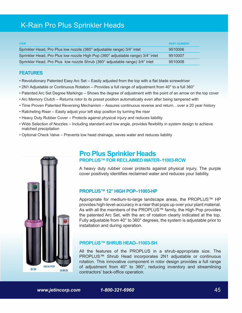
K-Rain Pro Plus Sprinkler Heads
FEATURES• Revolutionary Patented Easy Arc Set – Easily adjusted from the top with a flat blade screwdriver• 2N1 Adjustable or Continuous Rotation – Provides a full range of adjustment from 40° to a full 360°• Patented Arc Set Degree Markings – Shows the degree of adjustment with the point of an arrow on the top cover• Arc Memory Clutch – Returns rotor to its preset position automatically even after being tampered with• Time Proven Patented Reversing Mechanism – Assures continuous reverse and return…over a 20 year history• Ratcheting Riser – Easily adjust your left stop position by turning the riser• Heavy Duty Rubber Cover – Protects against physical injury and reduces liability• Wide Selection of Nozzles – Including standard and low angle, provides flexibility in system design to achieve
matched precipitation• Optional Check Valve – Prevents low head drainage, saves water and reduces liability
ITEM PART NUMBER
Sprinkler Head, Pro Plus low nozzle (360° adjustable range) 3/4” inlet 9510006Sprinkler Head, Pro Plus low nozzle High Pop (360° adjustable range) 3/4” inlet 9510007Sprinkler Head, Pro Plus low nozzle Shrub (360° adjustable range) 3/4” inlet 9510008
PROPLUS™ FOR RECLAIMED WATER–11003-RCWA heavy duty rubber cover protects against physical injury. The purple cover positively identifies reclaimed water and reduces your liability.
PROPLUS™ 12” HIGH POP–11003-HPAppropriate for medium-to-large landscape areas, the PROPLUS™ HP provides high-level-accuracy in a riser that pops up over your plant material. As with all the members of the PROPLUS™ family, the High Pop provides the patented Arc Set, with the arc of rotation clearly indicated at the top. Fully adjustable from 40° to 360° degrees, the system is adjustable prior to installation and during operation.
PROPLUS™ SHRUB HEAD–11003-SHAll the features of the PROPLUS in a shrub-appropriate size. The PROPLUS™ Shrub Head incorporates 2N1 adjustable or continuous rotation. This innovative component in rotor design provides a full range of adjustment from 40° to 360°, reducing inventory and streamlining contractors’ back-office operation.
Pro Plus Sprinkler Heads
Wastewater Treatment Solutions46
Polylok Distribution Box
ITEM PART NUMBER
Plastic Distribution Box - 12” 9520032Plastic Distribution Box - 20” 9520033
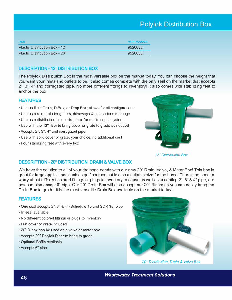
DESCRIPTION - 12’’ DISTRIBUTION BOXThe Polylok Distribution Box is the most versatile box on the market today. You can choose the height that you want your inlets and outlets to be. It also comes complete with the only seal on the market that accepts 2”, 3”, 4” and corrugated pipe. No more different fittings to inventory! It also comes with stabilizing feet to anchor the box.
FEATURES• Use as Rain Drain, D-Box, or Drop Box; allows for all configurations • Use as a rain drain for gutters, driveways & sub surface drainage • Use as a distribution box or drop box for onsite septic systems • Use with the 12’’ riser to bring cover or grate to grade as needed • Accepts 2’’, 3’’, 4’’ and corrugated pipe • Use with solid cover or grate, your choice, no additional cost • Four stabilizing feet with every box
DESCRIPTION - 20’’ DISTRIBUTION, DRAIN & VALVE BOXWe have the solution to all of your drainage needs with our new 20” Drain, Valve, & Meter Box! This box is great for large applications such as golf courses but is also a suitable size for the home. There’s no need to worry about different colored fittings or plugs to inventory because as well as accepting 2”, 3” & 4” pipe, our box can also accept 6” pipe. Our 20” Drain Box will also accept our 20” Risers so you can easily bring the Drain Box to grade. It is the most versatile Drain Box available on the market today!
FEATURES• One seal accepts 2”, 3” & 4” (Schedule 40 and SDR 35) pipe • 6” seal available • No different colored fittings or plugs to inventory • Flat cover or grate included • 20” D-box can be used as a valve or meter box • Accepts 20” Polylok Riser to bring to grade • Optional Baffle available • Accepts 6” pipe
12’’ Distribution Box
20’’ Distribution, Drain & Valve Box

www.jetincorp.com 1-800-321-6960 47
Polylok Risers & Covers
Plastic GratePlastic Cover
FEATURES• Watertight and airtight • Allows tank to be easily vacuum or water tested • Highest UV-Ray Protection on the market today • Easy to bring access to grade • Made of High Density Polyethylene which won’t
shatter like some Polypropylene risers • Structural ribs inside prevent frost from adhering to
the riser in frost prone areas
ITEM PART NUMBER
Plastic Riser 12 inch x 6 inch 9520013Plastic Cover or Grate 12 inch 9520014Plastic Riser 6 inch x 20 inch 9520015Plastic Riser 12 inch x 20 inch 9520016Plastic Cover 20 inch 9520017Plastic Cover or Grates 20 inch flat 9520018Plastic Adapter Rings 9520019Plastic Riser 24 inch x 6 inch 9520020Plastic Riser 24 inch x 12 inch 9520021Plastic Cover 24 inch 9520022Heavy Duty Plastic Cover 24 inch 9520023Stainless steel screws 9520024
Riser 6 x 20 with coverHD Cover
Adapter Rings 12 inch riser
12 x 6 riser
24 inch riser

Wastewater Treatment Solutions48
Red Jacket Submersible Pumps
ITEM PART NUMBER
Economy Submersible Effluent Pump -1/2 HP 953001
APPLICATIONMound systems, effluent dosing, low pressure pipe, heavy duty sump or dewatering systems
REP5 PUMP• Max. Capacity: 70 GPM• Max. Head: 37’ TDH• 1/2 HP, 115 and 230 V
MATERIALS OF CONSTRUCTIONCast iron, thermoplastic and stainless steel
FEATURES• Continuous duty, oil-filled, single phase motors• Built-in venting - no need to drill vent hole in pipe• Handles 1/2” solids for use as a sump or effluent pump• Carbon, ceramic, BUNA mechanical seal• Quick Disconnect 20’ power cord• Discharge: 1-1/2” NPT
15.4
12.0
.6
3.1
11⁄ 2" NPTDISCHARGE
Model REP5 Submersible Effluent Pump
www.jetincorp.com 1-800-321-6960 49
Red Jacket Submersible Pumps
ITEM PART NUMBER
Submersible Effluent Pump - 1/2 HP 953002
METERS FEET
130
0 10 20 30 40 50 60 70 80 90 100 110 120 GPM
0
0
10
10
0
20
30
20 m3/hr
5
40
20
15
10
80
70
60
50
40
CAPACITY
160
90
100
110
120
35
30
25
130 140 150
353025155
5 FT
5 GPM
TOTAL DYNAMIC HEAD
SERIES: 2EPDISCHARGE: 2”SOLIDS: 3/4"RPM: 1750, 35002EP20
2EP15
2EP10
2EP07
2EP05
2EP03
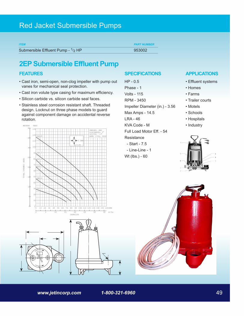
FEATURES• Cast iron, semi-open, non-clog impeller with pump out
vanes for mechanical seal protection.• Cast iron volute type casing for maximum efficiency.• Silicon carbide vs. silicon carbide seal faces.• Stainless steel corrosion resistant shaft. Threaded
design. Locknut on three phase models to guard against component damage on accidental reverse rotation.
APPLICATIONS• Effluent systems• Homes • Farms • Trailer courts • Motels • Schools • Hospitals • Industry
SPECIFICATIONSHP - 0.5Phase - 1Volts - 115RPM - 3450Impeller Diameter (in.) - 3.56Max Amps - 14.5LRA - 46KVA Code - MFull Load Motor Eff. - 54Resistance - Start - 7.5 - Line-Line - 1Wt (lbs.) - 60
2EP Submersible Effluent Pump
Wastewater Treatment Solutions50
Red Jacket Submersible Pumps
ITEM PART NUMBER
Utility Pump - 1/2 HP 953003
TOTAL HEAD IN FEET
200
150
100
50
0
CAPACITY IN GPM0 5 10 15 20 25
6 STAGE10 GPM
5 STAGE18 GPM
3.75"
3.75"
L.O
.A.
MOTOR
W.E.
11⁄ 4” NPT DISCHARGE
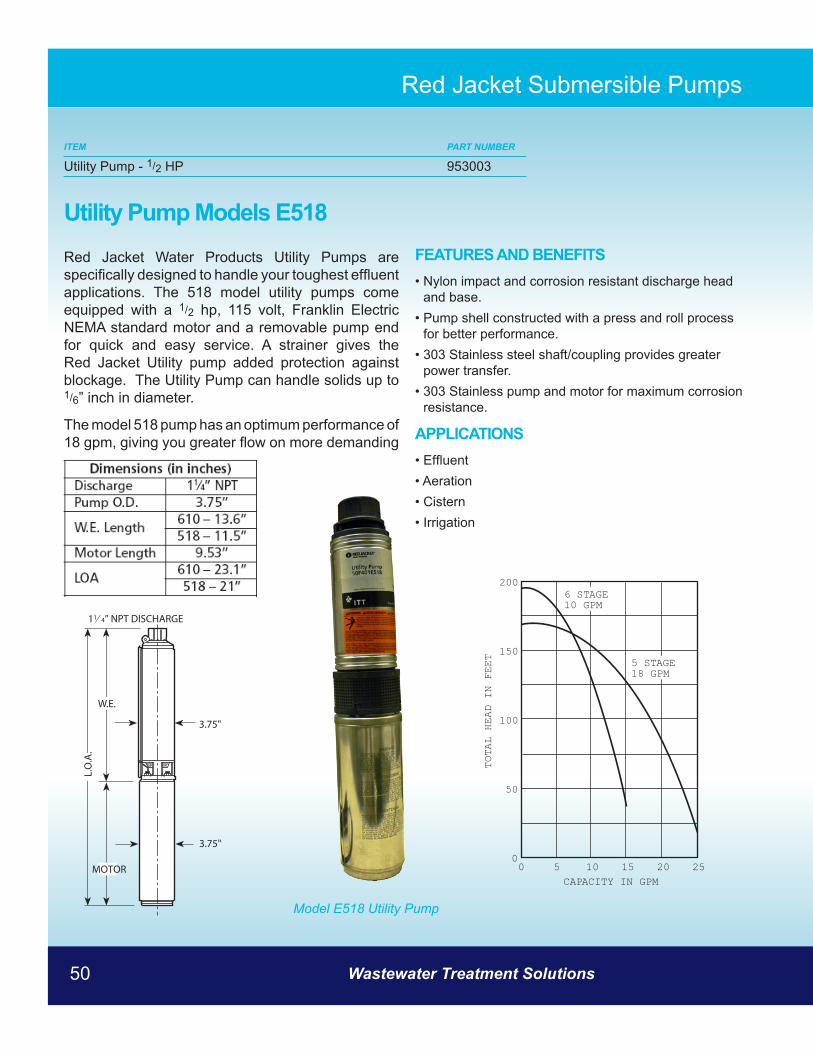
Utility Pump Models E518
Red Jacket Water Products Utility Pumps are specifically designed to handle your toughest effluent applications. The 518 model utility pumps come equipped with a 1/2 hp, 115 volt, Franklin Electric NEMA standard motor and a removable pump end for quick and easy service. A strainer gives the Red Jacket Utility pump added protection against blockage. The Utility Pump can handle solids up to 1/6” inch in diameter.
The model 518 pump has an optimum performance of 18 gpm, giving you greater flow on more demanding jobs.
Model E518 Utility Pump
FEATURES AND BENEFITS• Nylon impact and corrosion resistant discharge head
and base.• Pump shell constructed with a press and roll process
for better performance. • 303 Stainless steel shaft/coupling provides greater
power transfer. • 303 Stainless pump and motor for maximum corrosion
resistance.
APPLICATIONS• Effluent• Aeration • Cistern • Irrigation
Wastewater Treatment Solutions50

www.jetincorp.com 1-800-321-6960 51
Red Jacket Submersible Pumps
ITEM PART NUMBER
Submersible Sewage Pump - 1/2 HP 953004
Submersible Sewage Pump
FEATURES AND BENEFITS• Impeller: Cast iron, enclosed, non-clog, dynamically
balanced with pump out vanes for mechanical seal protection
• Casing: Cast iron flanged volute type for maximum efficiency. Designed for easy installation on A10-20 slide rail
• Mechanical Seal: Silicon Carbide vs. Silicon Carbide sealing faces for superior abrasive resistance, stainless steel metal parts, BUNA-N elastomers
• Shaft: Corrosion resistant, 300 series stainless steel. Threaded design. Locknut on all models to guard against component damage on accidental reverse rotation
• Fasteners: 300 series stainless steel• Capable of running dry without damage to components• Designed for continuous operation, when fully
submerged 2WS BHF Sewage Pump
www.jetincorp.com 1-800-321-6960 51

Wastewater Treatment Solutions52
Polylok Seals & Mandrels
ITEM PART NUMBER
Poly Seal I Low Pressure 9520001Poly Seal II High Pressure 9520002Mandrels (for Seal I & II) 9520003Mandrels (Boot Seals Poly IV High Pressure) 9520006
DESCRIPTION - POLY SEAL II HIGH PRESSUREUse the Poly II for the Inlet & Outlet pipes on septic tanks, aerobic systems, or anywhere you need water tightness. This new hybrid seal will mount to our existing mandrel that bolts directly to the septic tank form just like the original.
The Poly II will meet the Vacuum & Hydrostatic pressure requirements of A.S.T.M. spec. C-923 for 2”, 3” & 4” Schedule 40. It will allow you the water tightness that is now required and the flexibility of choosing what size pipe you want.
• Accepts 2’’, 3’’ and 4’’ Schedule 40 and corrugated pipes • Prevents infiltration and exfiltration • No grouting for secure pipe connection • Fits tank walls 2.5’’- 6’’
DESCRIPTION - POLY SEAL I LOW PRESSUREEliminate grouting around the pipe. This design promotes quick and easy conversion to any existing form. Low pressure pipe seals can be used in any low pressure application. It’s time to upgrade your product with the Polylok Pipe Seal...your customers will be glad you did.
• Accommodates 2’’, 3’’, 4’’, Schedule 40 & corrugated pipes • Watertight • No grouting
DESCRIPTION - MANDRELSThe mandrels are made from a polypropylene composite which allows the mandrels to maintain their shape even during the most demanding applications. Each time you cast a Polylok Seal into your tank, you can be assured you will get a watertight connection. The mandrels will accommodate 2.5”- 6” wall thickness.
Poly Seal I Low Pressure
Poly Seal II High Pressure
Mandrels
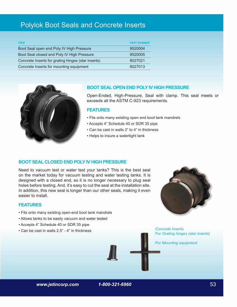
www.jetincorp.com 1-800-321-6960 53
Polylok Boot Seals and Concrete Inserts
BOOT SEAL CLOSED END POLY IV HIGH PRESSURE Need to vacuum test or water test your tanks? This is the best seal on the market today for vacuum testing and water testing tanks. It is designed with a closed end, so it is no longer necessary to plug seal holes before testing. And, it’s easy to cut the seal at the installation site. In addition, this new seal is longer than our other seals, making it even easier to install.
FEATURES• Fits onto many existing open-end boot tank mandrels• Allows tanks to be easily vacuum and water tested• Accepts 4” Schedule 40 or SDR 35 pipe• Can be cast in walls 2.5” - 4” in thickness
BOOT SEAL OPEN END POLY IV HIGH PRESSUREOpen-Ended, High-Pressure, Seal with clamp. This seal meets or exceeds all the ASTM C-923 requirements.
FEATURES• Fits onto many existing open end boot tank mandrels • Accepts 4” Schedule 40 or SDR 35 pipe • Can be cast in walls 2” to 4” in thickness • Helps to insure a watertight tank
ITEM PART NUMBER
Boot Seal open end Poly IV High Pressure 9520004Boot Seal closed end Poly IV High Pressure 9520005Concrete Inserts for grating hinges (star inserts) 8027021Concrete Inserts for mounting equipment 8027013
Concrete InsertsFor Grating hinges (star inserts)
For Mounting equipment

Wastewater Treatment Solutions54
Polylok Plastic Wheel Chairs
ITEM PART NUMBER
Plastic Wheel Chairs 7/8 inch 9520007Plastic Wheel Chairs 1 inch 9520008Plastic Wheel Chairs 1 inch HD 9520009Plastic Wheel Chairs 1.5 inch 9520010Plastic Wheel Chairs 2 inch 9520011Plastic Wheel Chairs 3 inch 9520012
WHEEL CHAIRSPolylok chairs can handle any load! Be confident knowing that your rebar will stay where you place it. The strongest 7/8’’, 1’’, 1½”, 2’’ and 3’’ cover chairs for all concrete work including: precast, utility vaults, slabs, barriers, foundation work and bridges. Use one of our Polylok ratchet style chairs instead of three of the competitors.
FEATURES• Wheel Chairs available in 7/8’’, 1’’, 11/2”, 2’’ & 3’’ cover • 1’’ for wire mesh to # 4 bar • 7/8’’ Cover wire mesh to #3 bar • Patented locking latch • Extra heavy duty 11/2”, 2’’ and 3’’ cover. Guaranteed to
accept 600 lbs. • Eliminates at least 33% spacer costs due to superior
strength • Wide web for additional strength
WHEEL CHAIR 1 INCH HDPolylok’s patented wheel chair design has been copied but never matched. They offer the only wheel chair that locks in place and accommodates more than 1 size rebar. Precasters can use these wheel chairs in both horizontal and vertical applications. Polylok is pleased to introduce their new 1” wheel chair that can now accept up to #6 bar.
FEATURES• 1” LC for #3 - #6 bar • Eliminates at least 33% spacer costs due to superior strength • Wide web for additional strength

www.jetincorp.com 1-800-321-6960 55
Jet Home and Commercial Molds
ITEM PART NUMBER
Jet Home Plant One Piece Mold 6910000Aerator Mounting Casting Mold 6900526Extension Riser Mold 6900518Cover Casting Mold 6900500Jet Commercial Mold 8900672Grating Pans - Setting 8900094Grating Pans - Large Aeration 8900029Grating Pans - Small Aeration 8900011Tounge and Groove Pan 8900326Small Hopper Mold 8900664Large Hopper Mold 8900680
Home Plant Mold
55www.jetincorp.com 1-800-321-6960

Wastewater Treatment Solutions56
Jet Home and Commercial Molds

www.jetincorp.com 1-800-321-6960 57
Custom Commercial Plants
ITEM PART NUMBER
Custom Commercial Plants JCP/000000000
CUSTOM 23,000 GPD COMMERCIAL PLANT
CUSTOM 40,000 GPD COMMERCIAL PLANT

Wastewater Treatment Solutions58
ITEM PART NUMBER
Sludge Judge 9990116
Sludge Judge
The Nasco Sludge Judge® is designed to take accurate readings of settled solids, 5% or less, in a variety of liquids, to any depth. It is ideal for sewage treatment plants, chemical plants, and food processing facilities - anywhere that accurate sample levels of settled solids in noncaustic materials are needed. The unit holds approximately 3 oz. per foot, 89 ml per 0.31 m. The Sludge Judge® comes in 5 ft., 1.53 m sections of 3/4”, 1.90 cm plastic pipe with screw-type connectors.
The top section includes a nylon rope for raising and lowering the sampler. Individual sections can be combined as required to achieve the length needed. Do not use in liquids over 165° F, 74° C. Sludge Judge® is not autoclavable.
A convenient cotton canvas carrying case that holds four sections, cleaning brush, cleaning rod, and cotton strips are available.
TO USE:1. Slowly lower the Sludge Judge® to the bottom of
the tank.
A. The float valve opens (see picture A) allowing materials to flow in. When the bottom has been reached and the pipe has filled to the surface level, tug slightly on the rope as the unit is raised.
B. This sets the check valve (see picture B), trapping the mixture inside.
2. When the unit has been raised clear of the liquid, the amount of solids in the sample can be read using the 1 ft., 0.31m increments marked on the pipe sections.
3. To release the material in the unit, touch the pin extending from the bottom section against a hard surface. This opens the check valve to drain the sample.
15-ft., 4.60 mContains three sections.

www.jetincorp.com 1-800-321-6960 59
Notes:

Wastewater Treatment Solutions60
750 Alpha DriveCleveland, OH 44143
T 800.321.6960P 440.461.2000F 440.442.9008
www.jetincorp.com
MMXII
R