ieee transactions on biomedical circuits and systems, vol...
TRANSCRIPT

IEEE TRANSACTIONS ON BIOMEDICAL CIRCUITS AND SYSTEMS, VOL. 7, NO. 5, OCTOBER 2013 601
Massively-Parallel Neuromonitoring andNeurostimulation Rodent Headset WithNanotextured Flexible Microelectrodes
Arezu Bagheri, Student Member, IEEE, S. R. I. Gabran, Member, IEEE, Muhammad Tariqus Salam, Member, IEEE,Jose Luis Perez Velazquez, Raafat R. Mansour, Fellow, IEEE, M. M. A. Salama, Fellow, IEEE, and
Roman Genov, Senior Member, IEEE
Abstract—We present a compact wireless headset for simulta-neous multi-site neuromonitoring and neurostimulation in the ro-dent brain. The system comprises flexible-shaft microelectrodes,neural amplifiers, neurostimulators, a digital time-division mul-tiplexer (TDM), a micro-controller and a ZigBee wireless trans-ceiver. The system is built by parallelizing up to four 0.35CMOS integrated circuits (each having 256 neural amplifiers and64 neurostimulators) to provide a total maximum of 1024 neuralamplifiers and 256 neurostimulators. Each bipolar neural ampli-fier features 54 dB–72 dB adjustable gain, 1 Hz–5 kHz adjustablebandwidth with an input-referred noise of 7.99 and dissi-pates 12.9 . Each current-mode bipolar neurostimulator gen-erates programmable arbitrary-waveform biphasic current in therange of 20–250 and dissipates 2.6 in the stand-by mode.Reconfigurability is provided by stacking a set of dedicated mini-PCBs that share a common signaling bus within as small as
volume. The system features flexible polyimide-based microelectrode array design that is not brittle and increasespad packing density. Pad nanotexturing by electrodeposition re-duces the electrode-tissue interface impedance from an average of2 to 30 at 100 Hz. The rodent headset and the microelec-trode array have been experimentally validated in vivo in freelymoving rats for two months. We demonstrate 92.8 percent seizurerate reduction by responsive neurostimulation in an acute epilepsyrat model.
Index Terms—Brain, extracellular recording, flexible microelec-trode array, hippocampus, multichannel neural recording, multi-channel neural stimulation, rodent headset.
I. INTRODUCTION
S IMULTANEOUS monitoring of electrical neural activityat many locations in the brain provides electrographic
data with high spatial resolution. This enables investigation
Manuscript received March 22, 2013; revised June 14, 2013; accepted July07, 2013. Date of publication October 17, 2013; date of current version October24, 2013. This work was supported by the Natural Sciences and EngineeringResearch Council of Canada, the Ontario Brain Institute, and the Canadian Mi-croelectronics Corporation (CMC). The authors also thank these organizationsfor their technical support and Y. Adamchik for animal care and handling. Thispaper was recommended by Associate Editor T.-P. Jung.A. Bagheri, M. T. Salam, and R. Genov are with the Department of Elec-
trical and Computer Engineering, University of Toronto, Toronto, ON M5S3G4, Canada (e-mail: [email protected]).S. R. I. Gabran, R. R. Mansour, andM.M. A. Salama are with the Department
of Electrical and Computer Engineering, University of Waterloo, Waterloo, ONN2L 3G1, Canada.J. L. Perez Velazquez is with the Brain and Behaviour Centre, Division of
Neurology, University of Toronto, Toronto, ON M5G 1X8, Canada.Color versions of one or more of the figures in this paper are available online
at http://ieeexplore.ieee.org.Digital Object Identifier 10.1109/TBCAS.2013.2281772
of the behavior of a large population of neurons and compre-hensive neural activity assessment required for developingstate-of-the-art neural prostheses, such as for treatment ofmedically refractory epilepsy [1]. Simultaneous electricalcurrent stimulation localized at many sites in the brain allowsfor fine-tuned neurostimulation therapies optimized for a givenneural disorder and custom-tailored to each specific patient,potentially increasing their efficacy. Combining both neuralmonitoring and neural stimulation in a single implantable de-vice enables responsive neural stimulation, where stimulationis triggered by detected neural events, a promising paradigm inmodern neuro-rehabilitation.A steady increase in the number of monitored sites in the
brain has been observed, approximately doubling every sevenyears [2]. Expanding the number of recording and stimulationsites introduces several challenges including noise, power con-sumption and form factor of electronic neural interfacing cir-cuits as well as impedance and fragility of microelectrodes.Multichannel commercial neural recording and stimulation
systems for humans do not interface with many recording orstimulation sites (e.g., currently up to eight for responsive neu-rostimulation for treatment of medically refractory epilepsy).Animal models of neurological disorders, particularly rodentmodels, are widely accepted as low-cost vehicles for developingstate-of-the-art neural prostheses. Commercial neural recordingand stimulation products for implantation in rodents currentlyoffer up to 32 channels [3]. In academia, Neurochip-2 at Uni-versity ofWashington has been very successful but weighs 145 gand has only three recording and three stimulation channels[4]. HermesD at Stanford University has 32 recording chan-nels but no neurostimulation channels [5]. A number of otherstate-of-the-art headset designs have been reported [6], [7], buteither have a limited number of channels, or lack neurostimula-tion, or have a large form factor.Several microelectrode designs, mostly silicon-based, have
been developed for multi-site neural recording and stimulation[8]–[10]. Silicon electrodes can cause post-operative trauma anddamage to brain tissue due to their rigid structure. Silicon elec-trodes are brittle and would release debris in the brain uponmechanical failure and fracture. Additionally, the high packingdensity requirement necessitates reducing contact size, whichincreases its impedance, thus degrades the recording signal-to-noise ratio and the maximum stimulation current for a givensupply voltage.
1932-4545 © 2013 IEEE

602 IEEE TRANSACTIONS ON BIOMEDICAL CIRCUITS AND SYSTEMS, VOL. 7, NO. 5, OCTOBER 2013
Fig. 1. System-level block diagram.
Massively-parallel integrated neural interfaces have a poten-tial to improve our understanding of neurological disorders suchas intractable epilepsy, and meliorate therapy development. In-tractable epilepsy (also known as uncontrolled or refractory)is a seizure disorder in which patient seizures cannot be con-trolled with medication. Several therapeutic devices for treatingintractable epilepsy have been introduced to replace conven-tional therapies which have low efficacy. Currently, vagus nervestimulator (VNS) is the only medical device approved by FDA(Food and Drug Administration) for the treatment of intractableepilepsy patients in the US [11], [12]. However, the efficacy ofthis arbitrary (open-loop) stimulation device is limited to 3 per-cent for seizure freedom (i.e., observing no seizures for a periodof 12 months) [13] and 30–40 percent for responder rate (i.e.,showing more than 50 percent reduction in seizure frequency)[11], [12], [14]. Recently, Neuropace Inc. (Mountain View, CA)introduced the RNS (responsive neurostimulator) system thattriggers electrical stimulation upon electrographic seizure onsetdetection [15]. This cranially implanted neurostimulator is de-signed to detect seizure activity in the brain and to deliver pre-defined electrical stimulation to suppress seizures. Preliminaryresults of this electrical stimulation therapy are acceptable, how-ever, many patients do not respond well to this treatment, andthis is hypothesized to be in part due to low recording and stim-ulation electrode count [16], [17].In this paper, we present a compact wireless rodent headset
with a maximum channel count of 1024 for simultaneousneural recording, and 256 for simultaneous neural stimulation.It is interfaced with flexible-shaft microelectrode arrays withtissue contact surface modified by nanotexturing to reduce itsimpedance on average by a factor of over 60. The system tar-gets simultaneous large-scale neural monitoring, spatially-richneural stimulation and closed-loop neurostimulation for studiesof intractable epilepsy treatment in rodent seizure models. Theblock diagram of the system is shown in Fig. 1.
II. METHODS AND MATERIALS
The head-mounted system is comprised of two components:an electronic headset and a flexible microelectrode array.
A. Rodent Headset
The rodent headset consists of 2 core and 3 optional modulesin the form of stacked miniature printed circuit boards (PCBs)
Fig. 2. Wireless headset. (a) Assembled stack. (b) Individual boards.
as shown in Fig. 2. Each module provides circuits for a distinctfunction, as described next. Using some of the modules is op-tional as the system is functional without them in a wired con-figuration with back-end bench-top equipment.1) Neural Amplifiers and Stimulators (Core1) Module: A
neuro-interface integrated circuit (chip) was designed and in-troduced in [18] to provide 256 recording and 64 stimulationchannels. The chip is wire-bonded onto a 22 mm 30 mm PCBmodule and is protected by epoxy. Four of these modules can bestacked to provide 1024 simultaneous recording channels and256 stimulation channels. In this prototype only 64 channelswere wirebonded for experimental testing. This module alsofeatures a small low-power FPGA to provide clocks and con-trol signals to the chip and perform data processing.The amplifier in each recording channel has a programmable
mid-band gain from 54 dB to 72 dB, programmable bandwidthof 1 Hz to 5 kHz with 7.99 input-referred noise. Eachrecording channel consumes 12.9 and occupies 0.02[18]. Microelectrodes are connected to the amplifier in a bipolarfashion through four Omnetics connector ports. The low-powerFPGA performs time-domain multiplexing of these channels.The bipolar stimulators feature charge-balanced symmetric
biphasic stimulation which provides control over the charge de-livered to the tissue. The delivered charge per phase is limitedaccording to safe electrical stimulation model [19]. The stimu-lation current ranges from 20 to 250 and each stimulatorconsumes 2.6 quiescent power and occupies 0.03 .Each stimulation channel can be individually addressed and thestimulation parameters are set by the on-board FPGA. A groupof selected stimulation channels provide simultaneous stimula-tion without multiplexing.2) Biasing (Core2) Module: The bias voltages and currents
required by the neural recording and stimulation chip are gen-erated by a set of DACs.3) Power Supply (Optional) Module: The power supply
module provides multiple regulated source voltages fordifferent circuits of the system. Power is provided to thismodule from a small battery. The power supply board hasprogrammable power-down mode for efficient power use andlonger battery life. The system remains in the power downmode until certain amount of data is stored in the microcon-troller for wireless transmission.4) ADC (Optional) Module: The analog recorded data is fed
to the ADC module to digitize the data.

BAGHERI et al.: MASSIVELY-PARALLEL NEUROMONITORING AND NEUROSTIMULATION RODENT HEADSET 603
Fig. 3. Flexible microelectrode array example. (a) Photograph and dimensions.(b) Fabrication process (not to scale).
5) Wireless Tx/Rx and Microprocessor (Optional) Module:The digital data packets received from the ADC module can betransmitted through a ZigBee wireless connection. Commandscan also be received wireless through the same interface. A TImicrocontroller can be used in a closed-loop configuration. Thewireless interface is included to facilitate debugging the neu-rostimulator in the closed-loop configuration.This system is powered by a Lithium-sulfur dioxide battery
(not shown), weighs 12 g (with the battery), and can operate for10 hours continuously. The optional modules described in items3 to 5 above were designed and fabricated by Canadian Micro-electronics Corporation (CMC), in a joint research project.
B. Flexible Microelectrode Array
The microelectrodes provide a 2-D array of neural interfacingsites capable of both recording and stimulation through large-area pads. The electrode architecture was developed to maxi-mize channel packing for a given set of electrode dimensionswithout increasing the shaft width.1) Electrode Mechanical Design: During insertion and op-
eration, the electrode is subjected to axial and shear loading andis susceptible to mechanical failure. Buckling failure is causedby axial loading if the insertion force exceeds the critical loadof the electrode structure and will prevent tissue penetration.Moreover, the electrode is loaded with stresses during operationgenerated by vascular pulsatility, and these can cause fracturein the case of a brittle electrode structure. In order to addressthese issues, the microelectrode array is implemented on a flex-ible polyimide substrate. A finite element model was created toanalyze the electrode mechanical performance. The microelec-trode dimensions and geometry are designed to provide the re-quired mechanical stability during tissue penetration to avoidbuckling failure. The flexible structure allows the microelec-trode to conform to the surrounding tissue and flex in responseto the exerted shear forces without failure. Themicroelectrode isdesigned with tapered tips and its small footprint reduces tissuetrauma and improves biocompatibility.2) Electrode Layout: The developed architecture was em-
ployed to create a multi-shaft microelectrode array. Each shaftis 3 mm long and has a width of 130 . It accommodates six
pads with pad spacing of 90 , as de-picted in Fig. 3(a). The design is scalable and can provide more
Fig. 4. Scanning electron microscope (SEM) images. (a) Smooth-surface mi-croelectrode (SME). (b) Nanotextured microelectrode (NME). (c) Commercialmicroelectrode (CME). (d) Commercial microwire (CMW).
interface channels by increasing the number of shafts and lay-ering multiple substrates onto each other. This has been exper-imentally validated. Each channel has an interconnect pad tocouple the electrode to circuits using FFC/FPC connectors andcables (Molex 501616-2575). A custom printed circuit board isdesigned to provide standard pin header connection to the elec-trode channels to facilitate mating to other circuits.3) Fabrication Process: Polyimide is a biocompatible
polymer and was chosen as the structural layer due to itsmechanical properties. The electrode is implemented on poly-imide film, as shown in Fig. 3(b). The film, which is 125thick, is cleaned in acetone and isopropanol alcohol baths, andthen dehydrated on a hotplate. The metallization layers aremade of gold. Chrome is used to improve adhesion betweengold and polyimide, as shown in Fig. 3(b). Metal films aredeposited using e-beam evaporation and DC sputtering forchrome (30 nm) and gold (500 nm) respectively. Metallizationlayers are patterned using photolithography and wet etching.Then polyimide passivation layer is spin coated and cured ina furnace according to the standard polyimide process recipe.Via holes are created in the passivation layer using aluminummask and plasma etching, then the top metallization layeris deposited and patterned to create the exposed pads with araised profile. Finally, the aluminum mask is wet etched andthe electrode is diced and released using laser micromachining[20]. The fabrication process is illustrated in Fig. 3(b).4) Electrode Pad Surface Modification: The surface
impedance of the resulting microelectrode pads shown inFig. 4(a) is approximately 2 at 100 Hz. In order to reducethe pad impedance, a pad surface modification technique wasdeveloped using low-current pulsed electroplating process toincrease the pad surface roughness. Electroplating is performed

604 IEEE TRANSACTIONS ON BIOMEDICAL CIRCUITS AND SYSTEMS, VOL. 7, NO. 5, OCTOBER 2013
Fig. 5. Microelectrode implantation procedure in the rat brain. (a) Craniotomywindows created in the skull. (b) Customized flexible microelectrode array withits connector. (c) Microelectrode array and microcannula after the implantation.(d) Surgical site covered with dental cement.
using pure gold plating process (Technic Mini Plating Plant 3),in which a 30 mA current was applied in bursts of 20 secondsfor 2 minutes. The resulting nanotextured electrodes (NME)exhibit rough surface, shown in Fig. 4(b), and an improvedaverage impedance of approximately 30 at 100 Hz. Sec-tion III compares the performance of these microelectrodeswith a commercial microelectrode (CME) and a commercialmicrowire (CMW) shown in Fig. 4(c) and (d), respectively.
C. Seizure Suppression by Closed-Loop Stimulation
Closed-loop stimulation studies were conducted at the Neu-roscience & Mental Health Research Institute at the Hospitalfor Sick Children (Toronto, Canada) with an approval from itsethics committee.1) Microelectrode Array Implantation Procedure: Six male
Dawley rats (weight: 150–500 g) underwent craniotomy withgeneral anaesthesia (using isoflurane and oxygen) as shown inFig. 5(a). The animal hair was shaved and skin was pre-treatedwith atropine, lactate ringer USP and lidocaine. A small slit wascreated in the skin overlying the head to expose the skull. Fourholes were drilled on the skull to place four anchor screws (withdiameter of 1.25 mm) on top of the cerebellum, as shown inFig. 5(a).Craniotomy windows were drilled out on both sides. The
flexible microelectrode array, shown in Fig. 5(b), was im-planted in the somatosensory area in the right hippocampus,using a stereotaxic micro manipulator apparatus with steadyforceps arms (Stoelting Co., Germany). On the other side,in the left hippocampus, a microwire with a microcannula(Plastics-1 Inc., Roanoke, VA, USA) was implanted similarly.Finally, the entire surgical site surface, skull, anchor screws,microelectrodes and microwires were covered and sealed withdental cement. The tip of the microcannular drug injection site,
Fig. 6. Measured impedance of the presented and commercial electrodes.
the recording connector and the reference were left exposed asshown in Fig. 5(c) and (d).After the implantation, each animal was under post-opera-
tive care for three consecutive days. After a 10-day post-oper-ative recovery period, the freely-moving animals were placedin cages to perform intracranial EEG recording, monitored byvideo cameras. Intracranial EEG signals were monitored usingthe presented headset and the animal behaviors were recordedsimultaneously by two video cameras.2) Chronic Basal Activity Recording: Basal EEG signals and
animal behaviors were monitored for 4 hours each day, 2 hoursin daytime (12–2 p.m.) and 2 hours at night (12–2 a.m.) for aperiod of one week.3) Epileptic Seizure Induction Method: Focal seizures were
induced by intracerebral injection of 4-aminopyridine (4-AP).300 nmol of 4-AP was diluted in 2 of sterile 0.9 percentsaline and was sonicated for two minutes to have uniform sus-pension and adequate concentration of the drug. Each rat wasanesthetized with isoflurane and 8 of 4-AP solution was in-jected through the microcannula into its hippocampus. After theinjection, each rat was connected to the system for recordingspontaneous recurrent electrographic seizures and was moni-tored by video cameras for clinically associated behaviors for4 hours. The seizure behaviors were carefully monitored andnoted according to the Racine scale [21].4) Seizure Onset Detection: The epileptic seizure detection
method was previously introduced by the authors in [22], [23].It has been demonstrated that the phase locking valuebetween two or more EEG signals is a good precursor of ictalevents and thus can be used to detect a seizure onset [24], [25].
is proportional to the fluctuations in the phase differenceof two channels and is calculated as ,where is the phase difference between the two selectedchannels. This seizure onset detection method was converted toa script in Matlab and used in a remote computer. It can also beimplemented on the FPGA in the first core PCB module (Sec-tion II-A-1) for in-situ seizure onset detection.5) Closed-Loop Stimulation Method: All seizure-induced
animals were divided into two groups: (1) non-treatment groupand (2) treatment group. In the non-treatment group (three rats),seizures were monitored, labeled and the seizure frequency perhour was determined. In the treatment group (three rats), theimplanted microelectrode array was connected externally to the

BAGHERI et al.: MASSIVELY-PARALLEL NEUROMONITORING AND NEUROSTIMULATION RODENT HEADSET 605
Fig. 7. Measured electrode noise spectral densities of the presented and commercial electrodes.
headset and the recorded EEG signals were sent to a computerto be analyzed by the seizure onset detection algorithm inMatlab every two seconds. The detector triggers the neurostim-ulators in the headset to send a burst of electrical stimulationcurrent in response to a seizure onset detection.
III. EXPERIMENTAL RESULTS
The system has been used in comparing the performance ofseveral electrodes including smooth-surface microelectrodes(SME), nanotextured microelectrodes (NME), commercialthin film microelectrodes (CME) and commercial microwires(CMW). Fig. 4(a)–(d) present the scanning electron microscope(SEM) images of these electrodes, respectively. The close-upviews in Fig. 4 illustrate the surface condition of the metalpads. The NME exhibits the most roughened surface with thedesired nano-scale structures clearly seen and yields the lowestimpedance, as detailed next.
A. Microelectrodes Characterization
The electrode-tissue interface impedance of the presented andthe commercial electrodes were measured using standard two-electrode electrochemical cell with 0.9 percent saline solution.The impedance magnitude versus frequency plots for the elec-trodes, obtained by impedance spectroscopy (Solatron SI 1260Impedance/Gain-Phase Analyzer), are shown in Fig. 6. The pre-sented rough surface nanotextured microelectrode (NME) ex-hibits significantly lower impedance in the 10 Hz to 100 kHzfrequency band due to the increased effective surface area.Electrode-electrolyte noise was measured using a large (2 cm2 cm) platinum reference plate in a standard physiological
saline solution. Fig. 7 illustrates electrode-electrolyte noise den-sities of the presented and commercial electrodes. The NME hasthe lowest noise density due to its lower impedance.
B. In Vivo Neural Signal Recording Performance
The recording performance of the four electrode types wasevaluated in acute EEG signal recording using the rodentheadset. The headset was also tested chronically in vivo infreely moving rats.1) Acute Recording: One Dawley rat underwent a cran-
iotomy with general anaesthesia. Through the craniotomywindows, four types of microelectrodes (Fig. 4) were im-planted in the somatosensory area. Bipolar intracranial EEGrecording was performed using the headset. The recordedsignals have been analyzed in several frequency bands (delta0.1–4 Hz, theta 4–7 Hz, alpha 8–13 Hz, beta 13–30 Hz, and
Fig. 8. Field potential power recorded from somatosensory area using thepresented and commercial electrodes.
Fig. 9. Intracranial EEG signal from rat hippocampus recorded in vivo from 12channels using the presented flexible microelectrode array and headset.
gamma 30–100 Hz). The mean field potential power in eachband was measured in order to evaluate the recording quality,as shown in Fig. 8. Fig. 8 illustrates that CME and SME exhibithigher low-frequency noise whereas the low-frequency noiseis suppressed when using NME and CMW. Fig. 8 also demon-strates that at high frequencies, NME exhibits lower thermalnoise than that of CMW. Thus NME yields the best overallsignal fidelity.2) Chronic Recording: A dual-shaft flexible microelectrode
array with 12 channels was implanted in the right hippocampusof a rat, as described in Section II-C-1. Two weeks after the im-plantation, field potentials were sampled at 1 kHz and band-passfiltered from 0.5Hz to 500Hz. Fig. 9 illustrates intracranial EEGrecordings (3 weeks after the implantation) using the presentedheadset. The long-term recordings are stable without a signifi-cant decrement in signal quality for up to 9 weeks after implan-tation.
606 IEEE TRANSACTIONS ON BIOMEDICAL CIRCUITS AND SYSTEMS, VOL. 7, NO. 5, OCTOBER 2013
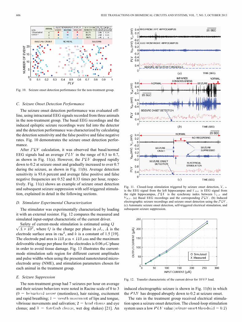
Fig. 10. Seizure onset detection performance for the non-treatment group.
C. Seizure Onset Detection Performance
The seizure onset detection performance was evaluated off-line, using intracranial EEG signals recorded from three animalsin the non-treatment group. The basal EEG recordings and theinduced epileptic seizure recordings were fed into the detectorand the detection performance was characterized by calculatingthe detection sensitivity and the false positive and false negativerates. Fig. 10 demonstrates the seizure onset detection perfor-mance.After calculation, it was observed that basal/normal
EEG signals had an average in the range of 0.3 to 0.7,as shown in Fig. 11(a). However, the dropped rapidlydown to 0.2 at seizure onset and gradually increased to over 0.7during the seizure, as shown in Fig. 11(b). Average detectionsensitivity is 93.6 percent and average false positive and falsenegative frequencies are 0.52 and 0.33 times per hour, respec-tively. Fig. 11(c) shows an example of seizure onset detectionand subsequent seizure suppression with self-triggered stimula-tion, explained in detail in the following sections.
D. Stimulator Experimental Characterization
The stimulator was experimentally characterized by loadingit with an external resistor. Fig. 12 compares the measured andsimulated input-output characteristic of the current driver.Safety of current-mode stimulation is estimated using
, where is the charge per phase in , is theelectrode surface area in , and is a constant of 1.5 [19].The electrode pad area is and the maximumdeliverable charge per phase for the electrodes is 0.06 /phasein order to avoid tissue damage. Fig. 13 illustrates the current-mode stimulation safe region for different current amplitudesand pulse widths when using the presented nanotextured micro-electrode array (NME), and stimulation parameters chosen foreach animal in the treatment group.
E. Seizure Suppression
The non-treatment group had 7 seizures per hour on averageand their seizure behaviors were noted in Racine scale of 0 to 3( (motionless), hair raising, excitementand rapid breathing; of lips and tongue,vibrissae movements and salivation; and eyeclonus; and , wet dog shakes) [21]. An
Fig. 11. Closed-loop stimulation triggered by seizure onset detection,is the EEG signal from the left hippocampus and is EEG signal fromthe right hippocampus, is the synchrony index between and
. (a) Basal EEG recordings and the corresponding . (b) Inducedelectrographic seizure recordings and seizure onset detection using the .(c) Automatic seizure onset detection, self-triggered electrical stimulation, andsubsequent seizure suppression.
Fig. 12. Transfer characteristic of the current driver for 10 load.
induced electrographic seizure is shown in Fig. 11(b) in whichthe has dropped abruptly down to 0.2 at seizure onset.The rats in the treatment group received electrical stimula-
tion upon a seizure onset detection. The closed-loop stimulationsystem uses a low value

BAGHERI et al.: MASSIVELY-PARALLEL NEUROMONITORING AND NEUROSTIMULATION RODENT HEADSET 607
Fig. 13. Stimulation safe region for different current amplitudes and pulsewidths when using the presented nanotextured microelectrode array (NME),and stimulation parameters chosen for each animal in the treatment group(3 rats).
TABLE IEFFICACY OF THE SYSTEM IN SEIZURE SUPPRESSION
for triggering a 5 Hz 220 monophasic stimulation currentfor 5 seconds in the hippocampus. Fig. 11(c) demonstrates theseizure onset detection, responsive electrical stimulation andseizure abortion. In this experiment, recording was temporarilydisabled during stimulation in order to avoid stimulation arti-fact [26]. Late seizure detection (false negative) was observed0.17 times per hour and false detections happened 0.4 timesper hour. After the closed-loop stimulation, seizure frequencyin treatment group dropped down to 0.17 times per hour onaverage (92.8 percent seizure rate reduction). The efficacy ofthe system in seizure onset detection and seizure rate reductionin the non-treatment group and treatment group rats is demon-strated in Table I.
F. Comparative Analysis
Table II compares the neuromonitoring and neurostimulationintegrated circuit presented here to other reported designs. Thissystem has the highest recording channels density at the costof moderate power dissipation. The presented stimulator has amoderate number of channels and dissipates the least power.A comparative analysis of the existing animal headsets is
given in Table III. The presented headset prototype currentlyhas 64 channels wirebonded for recording and 32 channels forstimulation. The number of channels can be scaled up to 1024recording and 256 stimulation channels by full wirebonding onfour stacked time-multiplexed neural amplifiers and stimulatorsmodules. The other reported headsets have no or few stimula-tion channels. This work has the highest number of recordingplus stimulation channels while dissipating least power.
TABLE IICOMPARATIVE ANALYSIS OF NEUROMONITORING AND
NEUROSTIMULATION ICS
This prototype was designed for self-triggered closed-loopstimulation for treatment of epilepsy. Therefore, it includesZigBee wireless transmission for a limited number of channelsfor optional remote neuromonitoring. The initial stage of thetreatment includes recording EEG signals from all the channelswith wired connection to delineate epileptogenic zone. In thenext stage, stimulation is self-triggered upon seizure onsetdetection (Section II-C-5), while the wireless EEG record-ings from a few channels can be monitored on a computer.Table III also shows that all the other headsets use commercialmicroelectrodes, but in this work custom-made smooth-surfaceand nanotextured microelectrode arrays were used in orderto record good quality chronic EEG signals and stimulate onmultiple channels. This design has a moderate size and weightand an adult rat (200 g) can readily carry the headset, whichweighs approximately 6 percent of its body weight.
IV. CONCLUSION
A compact wireless rodent headset with a flexible micro-electrode array have been demonstrated in neuromonitoringand neurostimulation in freely moving animals. The number ofchannels in the headset scales up to 1024 and 256, for neuralrecording and stimulation, respectively. Electrodepositionsurface modification increases the effective surface area ofthe electrode contacts, yielding lower input impedance andimproved interfacial capacitance. This translates into over60 times reduction in the impedance at 100 Hz and four timesless noise density compared to smooth-surface and commercialelectrodes. Stimulation current is triggered once a seizureonset is detected in EEG recordings, using real-time digitalsignal processing in a remote computer or the on-board FPGAof the headset. The system features, including high-channelcount in a small form factor, capability to both record andstimulate, flexible microelectrode arrays which enable highquality chronic recording and stimulation, and self-triggeredclosed-loop stimulation, shown to reduce seizure rate by92.8 percent, differentiate this work and enable various novelresponsive neurostimulation therapy experiments on freelymoving animals.

608 IEEE TRANSACTIONS ON BIOMEDICAL CIRCUITS AND SYSTEMS, VOL. 7, NO. 5, OCTOBER 2013
TABLE IIICOMPARATIVE ANALYSIS OF NEURAL STIMULATION AND RECORDING HEADSETS
REFERENCES
[1] M. Fifer, S. Acharya, H. Benz, M. Mollazadeh, N. Crone, and N.Thakor, “Toward electrocorticographic control of a dexterous upperlimb prosthesis: Building brain-machine interfaces,” IEEE Pulse, vol.3, no. 1, pp. 38–42, Jan. 2012.
[2] I. H. Stevenson and K. P. Kording, “How advances in neural recordingaffect data analysis,”Nature Neurosci., vol. 14, pp. 139–142, Jan. 2011.
[3] Ripple: Grapevine Nano, Accessed Jun. 1, 2012 [Online]. Avail-able: https://www.rppl.com/products/grapevine-front-ends/item/133-grapevine-nano
[4] S. Zanos, A. G. Richardson, L. Shupe, F. P. Miles, and E. E. Fetz,“The neurochip-2: An autonomous head-fixed computer for recordingand stimulating in freely behaving monkeys,” IEEE Trans. Neural Syst.Rehabil. Eng., vol. 19, no. 4, pp. 427–435, 2011.
[5] H. Miranda, V. Gilja, C. Chestek, K. Shenoy, and T. Meng, “Hermesd:A high-rate long-range wireless transmission system for simultaneousmultichannel neural recording applications,” IEEE Trans. Biomed. Cir-cuits Syst., vol. 4, no. 3, pp. 181–191, Jun. 2010.
[6] R. Harrison, R. Kier, C. Chestek, V. Gilja, P. Nuyujukian, S. Ryu, B.Greger, F. Solzbacher, and K. Shenoy, “Wireless neural recording withsingle low-power integrated circuit,” IEEETrans. Neural Syst. Rehabil.Eng., vol. 17, no. 4, pp. 322–329, Aug. 2009.
[7] C. P. Young, S. F. Liang, D. W. Chang, Y. C. Liao, F. Z. Shaw, andC. H. Hsieh, “A portable wireless online closed-loop seizure controllerin freely moving rats,” IEEE Trans. Instrum. Meas., vol. 60, no. 2, pp.513–521, Feb. 2011.
[8] J. Csicsvari, D. A. Henze, B. Jamieson, K. D. Harris, A. Sirota, P.Barthó, K. D. Wise, and G. Buzsáki, “Massively parallel recording ofunit and local field potentials with silicon-based electrodes,” J. Neuro-phys., vol. 90, no. 2, pp. 1314–23, Aug. 2003.
[9] R. Vetter, R. Miriani, B. Casey, K. Kong, J. Hetke, and D. Kipke, “De-velopment of a microscale implantable neural interface (mini) probesystem,” in Proc. 27th Annu. IEEE Int. Conf. Engineering in Medicineand Biology Soc., Jan. 2005, pp. 7341–7344.
[10] R. H. Olsson and K. D. Wise, “A three-dimensional neural recordingmicrosystem with implantable data compression circuitry,” IEEE J.Solid-State Circuits, vol. 40, no. 12, pp. 2796–2804, Dec. 2005.
[11] T. J. Reese, “Vagus nerve stimulation: A proven therapy for treatmentof epilepsy strives to improve efficacy and expand applications,” inProc. IEEE Engineering in Medicine and Biology Conf., 2009, pp.4631–4634.
[12] N. Sethi, D. Labar, L. Ponticello, J. Torgovnick, P. Sethi, and E. Arsura,“Treatment of medically refractory epilepsy: A review of vagus nervestimulator,” Internet J. Neurol., vol. 9, no. 1, 2008.
[13] M. B. Westover, J. Cormier, M. T. Bianchi, M. Shafi, R. Kilbride, A.J. Cole, and S. S. Cash, “Revising the “Rule of Three” for inferringseizure freedom,” Epilepsia, vol. 53, no. 2, pp. 368–376, Feb. 2012.
[14] F. Rychlicki, N. Zamponi, R. Trignani, R. A. Ricciuti, M. Iacoangeli,and M. Scerrati, “Vagus nerve stimulation: Clinical experience indrug-resistant pediatric epileptic patients,” Seizure, vol. 15, no. 7, pp.483–490, 2006.
[15] F. T. Sun, R. E. Wharen, and M. J. Morrell, “Responsive cortical stim-ulation for the treatment of epilepsy,” Neurotherapeut., vol. 5, no. 1,pp. 68–74, 2013.
[16] T. L. Skarpaas and M. J. Morrell, “Intracranial stimulation therapy forepilepsy,” Neurotherapeut., vol. 6, no. 2, pp. 238–43, Apr. 2009.
[17] R. S. Joseph, K. N. Fountas, A. M. Murro, D. Y. Park, P. D. Jenkins,M. Morrell, R. Esteller, and D. Greene, “Closed-loop stimulation inthe control of focal epilepsy of insular origin,” Stereotactic Function.Neurosurg., vol. 88, no. 5, pp. 281–287, 2009.
[18] R. Shulyzki, K. Abdelhalim, A. Bagheri, C. Florez, P. Carlen, and R.Genov, “256-site active neural probe and 64-channel responsive cor-tical stimulator,” in Proc. IEEE Custom Integrated Circuits Conf., Sep.2011.
[19] R. V. Shannon, “A model of safe levels for electrical stimulation,”IEEE Trans. Biomed. Eng., vol. 39, no. 2, pp. 424–426, Feb. 1992.
[20] S. Gabran, R. Mansour, and M. Salama, “Maskless pattern transferusing 355 nm laser,” Opt. Lasers Eng., vol. 50, no. 5, pp. 710–716,2012.
[21] R. J. Racine, “Modification of seizure activity by electrical stimulation:Ii. Motor seizure,” Electroencephalogr. Clin. Neurophys., vol. 32, pp.281–294, 1972.
[22] J. L. Perez Velazquez, L. G. Dominguez, V. Nenadovic, and R. A.Wennberg, “Experimental observation of increased fluctuations in anorder parameter before epochs of extended brain synchronization,” J.Biol. Phys., vol. 37, pp. 141–152, 2011.
[23] K. Abdelhalim, V. Smolyakov, and R. Genov, “A phase-synchroniza-tion epileptic seizure detector vlsi architecture,” IEEE Trans. Biomed.Circuits Syst., vol. 5, no. 5, pp. 430–438, 2011.
[24] T. I. Netoff and S. J. Schiff, “Decreased neuronal synchronizationduring experimental seizures,” J. Neurosci., vol. 22, no. 16, pp.7297–7307, Aug. 2002.
[25] D. Gupta and C. J. James, “Narrowband vs. broadband phase synchro-nization analysis applied to independent components of ictal and in-terictal EEG,” in Proc. 29th Annu. Int. Conf. IEEE Engineering inMedicine and Biology Soc., Aug. 2007, pp. 3864–3867.
[26] E. Brown, J. Ross, R. Blum, Y. Nam, B. Wheeler, and S. DeWeerth,“Stimulus-artifact elimination in a multi-electrode system,” IEEETrans. Biomed. Circuits Syst., vol. 2, no. 1, pp. 10–21, Mar. 2008.
[27] F. Heer, S. Hafizovic, W. Franks, A. Blau, C. Ziegler, and A. Hierle-mann, “CMOS microelectrode array for bidirectional interaction withneuronal networks,” IEEE J. Solid-State Circuits, vol. 41, no. 7, pp.1620–1629, Jul. 2006.
[28] M. Azin, D. J. Guggenmos, S. Barbay, R. J. Nudo, and P. Mohseni, “Abattery-powered activity-dependent intracortical microstimulation ICfor brain-machine-brain interface,” IEEE J. Solid-State Circuits, vol.46, no. 4, pp. 731–745, Apr. 2011.
[29] J. Lee, H. Rhew, D. R. Kipke, and M. P. Flynn, “A 64 channel pro-grammable closed-loop neurostimulator with 8 channel neural ampli-fier and logarithmic ADC,” IEEE J. Solid-State Circuits, vol. 45, no. 9,pp. 1935–1945, Sep. 2010.
[30] E. A. Brown, J. D. Ross, R. A. Blum, Y. Nam, B. C. Wheeler, and S. P.DeWeerth, “Stimulus-artifact elimination in a multi-electrode system,”IEEE Trans. Biomed. Circuits Syst., vol. 2, no. 1, pp. 10–21, Mar. 2008.

BAGHERI et al.: MASSIVELY-PARALLEL NEUROMONITORING AND NEUROSTIMULATION RODENT HEADSET 609
[31] T. A. Szuts, V. Fadeyev, S. Kachiguine, A. Sher, M. V. Grivich, M.Agrochao, W. Hottowy, P. Dabrowski, E. V. Lubenov, A. G. Siapas,N. Uchida, A. M. Litke, and M. Meister, “A wireless multi-channelneural amplifier for freely moving animals,” Nature Neurosci., vol. 14,no. 2, pp. 263–269, 2011.
[32] M. Yin, D. A. Borton, J. Aceros, W. R. Patterson, and A. V. Nurmikko,“A 100-channel hermetically sealed implantable device for wirelessneurosensing applications,” in Proc. IEEE Int. Symp. Circuits and Sys-tems, May 2012, pp. 2629–2632.
Arezu Bagheri (S’11) received the B.A.Sc. degreein electrical and computer engineering from the Uni-versity of Tehran, Tehran, Iran, in 2009.Currently, she is working toward the M.A.Sc.
degree in electrical and computer engineering atthe University of Toronto, Toronto, ON, Candada.She was a Research Assistant at the IntelligentSensory Microsystem Laboratory at the Universityof Toronto and her thesis focuses on DC-coupleddigitally-assisted neural recording amplifiers. Herresearch interests include analog and mixed-signal
integrated circuit design for biomedical applications.Ms. Bagheri was the recipient of the Ontario Graduate Scholarship in 2011.
S. R. I. Gabran (M’98) received the B.Sc. degree inelectrical engineering from Cairo University, Cairo,Egypt, in 2002, and the M.A.Sc. and Ph.D. degreesin electrical engineering from the University of Wa-terloo, Waterloo, ON, Canada, in 2006 and 2012, re-spectively.Currently, he is CTO and Director at Novela Inc.
and a Researcher with the CIRFE Lab, Universityof Waterloo. His interests include micro-fabrication,neuro-engineering, intra-cortical implants, andBioMEMS.
Muhammad Tariqus Salam (M’09) received theB.A.Sc. degree in electrical and electronics engi-neering from the Islamic University of Technology,Gazipur, Bangladesh, the M.A.Sc degree in elec-trical and computer engineering from ConcordiaUniversity, Montréal, QC, Canada, and the Ph.D.degree in electrical engineering from PolytechniqueMontréal, Montréal, QC, Canada, in 2003, 2007, and2012, respectively.Currently, he is a Postdoctoral Fellow at the Uni-
versity of Toronto, Toronto, QC, Canada, where heworks in the Intelligent Sensory Microsystems Laboratory, Neurosciences andMental Health Institute of Hospital for Sick Children Hospital, and the Neuro-science division of Toronto Western Hospital. His specific research interests arein the areas of biosensing, detection and stimulation microsystems, implantablebiomedical microdevices for continuous health monitoring, cognitive brain re-search, mental disease diagnosis, treatment, and rehabilitations.
Jose Luis Perez Velazquez was born in Zaragoza,Spain. He received the “Licenciado” degree inchemistry (biochemistry, Universities of Zaragozaand Complutense of Madrid) and the Ph.D. degreefrom the Department of Molecular in Physiology andBiophysics at Baylor College of Medicine, Houston,TX, USA, in 1992, homologated to Doctorate inChemistry by the Spanish Ministry of Culture in1997.Currently, he is an Associate Scientist in the Neu-
roscience and Mental Programme and the Brain andBehaviour Center at the Hospital For Sick Children, Toronto, ON, Canada, andAssociate Professor at the University of Toronto, Toronto, ON, Canada.
Raafat R.Mansour (S’84–M’86–SM’90–F’01) wasborn in Cairo, Egypt, onMarch 31, 1955. He receivedthe B.Sc. (with honors) and M.Sc. degrees in elec-trical engineering from Ain Shams University, Cairo,Egypt, in 1977 and 1981, respectively, and the Ph.D.degree in electrical engineering from the Universityof Waterloo, Waterloo, ON, Canada, in 1986.In 1981, he was a Research Fellow with the Labo-
ratoire de Electromagnetisme, Institut National Poly-technique, Grenoble, France. From 1983 to 1986, hewas a Research and Teaching Assistant with the De-
partment of Electrical Engineering, University of Waterloo. In 1986, he joinedCOM DEV Ltd., Cambridge, ON, Canada, where he held several technical andmanagement positions with the Corporate Research and Development Depart-ment, becoming a Scientist in 1998. Since January 2000, he has been a Pro-fessor with the Electrical and Computer Engineering Department, University ofWaterloo, where he was a Natural Sciences and Engineering Research Councilof Canada (NSERC) Industrial Research Chair from 2001 to 2010. He currentlyholds a Canada Research Chair. He is the Founding Director of the Centre for In-tegrated RF Engineering. He has authored or coauthored numerous publicationsin the areas of filters and multiplexers, high-temperature superconductivity, andmicroelectromechanical systems (MEMS). He coauthored Microwave Filtersfor Communication Systems (Wiley, 2007). He holds several patents related tothe areas of dielectric resonator filters, superconductivity and MEMS devices.His current research interests include MEMS technology and miniature tunableRF filters for wireless and satellite applications.Dr. Mansour is a Fellow of the Engineering Institute of Canada (EIC) and the
Canadian Academy of Engineering (CAE).
M. M. A. Salama (F’02) received the B.Sc. andM.Sc. degrees in electrical engineering from CairoUniversity, Cairo, Egypt, in 1971 and 1973, respec-tively, and the Ph.D. degree in electrical engineeringfrom the University of Waterloo, Waterloo, ON,Canada, in 1977.Currently, he is a Professor in the Department of
Electrical and Computer Engineering, Universityof Waterloo. His interests include the operationand control of distribution systems, power-qualitymonitoring and mitigation, asset management, and
electromagnetics. He has consulted widely with government agencies and theelectrical industry.Dr. Salama is a registered Professional Engineer in the Province of Ontario.
Roman Genov (S’96–M’02–SM’11) receivedthe B.S. degree in electrical engineering from theRochester Institute of Technology, NY, USA, in1996, and the M.S.E. and Ph.D. degrees in electricaland computer engineering from The Johns HopkinsUniversity, Baltimore, MD, USA, in 1998 and 2002,respectively.He held engineering positions at Atmel Corpora-
tion, Columbia, MD, USA, in 1995 and Xerox Cor-poration, Rochester, NY, USA, in 1996. Hewas a Vis-iting Researcher in the Laboratory of Intelligent Sys-
tems at the Swiss Federal Institute of Technology (EPFL), Lausanne, Switzer-land, in 1998 and in the Center for Biological and Computational Learning atMassachusetts Institute of Technology, Cambridge, MA, USA, in 1999. Cur-rently, he is an Associate Professor in the Department of Electrical and Com-puter Engineering at the University of Toronto, Toronto, ON, Canada. His re-search interests are primarily in the area of implantable, wearable, and dispos-able biomedical electronics. This includes analog and digital VLSI circuits, sys-tems and algorithms for electrical, chemical and photonic sensory informationacquisition and energy-efficient signal processing with various medical appli-cations such as brain-silicon interfaces and DNA microarrays.Dr. Genov is a co-recipient of the Best Paper Award of the IEEE Biomedical
Circuits and Systems Conference, Best Student Paper Award of the IEEEInternational Symposium on Circuits and Systems, Best Paper Award at theIEEE Circuits and Systems Society Sensory Systems Technical Committee,Brian L. Barge Award for Excellence in Microsystems Integration, MEMSCAPMicrosystems Design Award, DALSA Corporation Award for Excellencein Microsystems Innovation, and Canadian Institutes of Health ResearchNext Generation Award. He was a Technical Program Co-Chair at the IEEEBiomedical Circuits and Systems Conference. He was an Associate Editor ofIEEE TRANSACTIONS ON CIRCUITS AND SYSTEMS-II: EXPRESS BRIEFS andIEEE SIGNAL PROCESSING LETTERS. Currently, he is an Associate Editor ofIEEE TRANSACTIONS ON BIOMEDICAL CIRCUITS AND SYSTEMS and serves onthe Imagers, MEMS, Medical, and Displays Subcommittee of the InternationalSolid-State Circuits Conference.