ieee beyond the classroom seminar - letourneau … · ieee beyond the classroom seminar:...
TRANSCRIPT

IEEE Beyond the Classroom Seminar:
Introduction to Logical Troubleshooting

Format of this Presentation
Very fast.
Lots of information & examples.
Will not teach how to use test
equipment. That‟s what labs are for.
For a copy of this presentation, see
www.letu.edu/engineeringtips and look
for “IEEE Beyond the Classroom”.
Contents of this Presentation
1. Common sense questions to ask before
troubleshooting
2. US Navy Six-Step Troubleshooting Method
3. Some real-world troubleshooting examples
4. General troubleshooting tips

Common Sense Questions to Ask Prior to Troubleshooting
What seems to be the problem?
Exactly what occurred to cause this errant behavior if it is a new problem?
What‟s the history of this equipment?
Did it ever function properly? (yes for technicians repairing existing equipment / usually no for engineers doing initial prototype testing)
Are there other working units to compare (“known good units”)?
What documentation is available?
What testing has already been done by others?
Six-Step Troubleshooting (technique used by the US Navy)
1. Symptom recognition
2. Symptom elaboration
3. Listing of probable faulty functions
4. Localizing the faulty function
5. Localizing trouble to the circuit
6. Failure analysis
Know what is normal behavior (or expected normal behavior) for the equipment. Check documentation or ask for advice if not certain.
Recognize the abnormal behavior.
Step #1: Symptom recognition
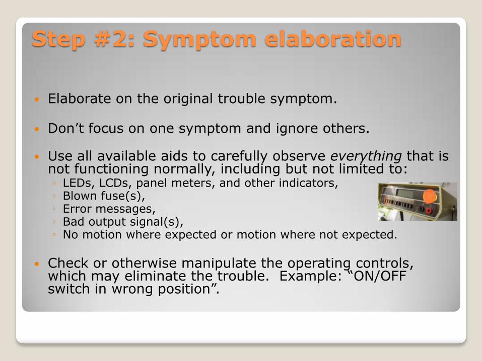
Elaborate on the original trouble symptom.
Don‟t focus on one symptom and ignore others.
Use all available aids to carefully observe everything that is not functioning normally, including but not limited to:◦ LEDs, LCDs, panel meters, and other indicators,◦ Blown fuse(s),◦ Error messages,◦ Bad output signal(s),◦ No motion where expected or motion where not expected.
Check or otherwise manipulate the operating controls, which may eliminate the trouble. Example: “ON/OFF switch in wrong position”.
Step #2: Symptom elaboration
Formulate a number of logical choices as to the cause and likely location (functional section) of the trouble.
Make these logical choices based upon knowledge of the equipment operation, full identification of the trouble symptom(s), and information in the technical manuals and data sheets.
Especially consider the overall functional description, block diagram, and/or complete schematic diagram when identifying possible faulty functional sections.
Step #3: Listing probable faulty functions
Step #4: Localizing the faulty functions
Test the suspected bad functional sections in the quickest order (“git „er done!”).
Consider: Most likely faulty functional area, Ease of testing the functional area, Suggestions in technical manual servicing
block diagrams, if available.
Use as reference: Technical manual, Known good device for comparison, Engineering educated guess.
After isolation of faulty functional section, may need to narrow down further to which circuit or group of circuits within the functional section is at fault.
Service manuals may provide additional test information, if available.
Step #5: Localizing trouble to the circuit
Need to find the cause of the malfunction, not the result. This may prevent reoccurrence.
After finding the trouble (faulty component, misalignment, environmental factor, etc), but prior to performing corrective action), ask “What caused this failure?”◦ Review procedures followed up to this point.◦ Look for the root cause of the failure.◦ Determine exactly why the fault had this effect on the equipment.
Example: Someone may replace numerous fuses before realizing the fault is not a batch of bad fuses, but a main power wiring short in the equipment!
Step #6: Failure analysis
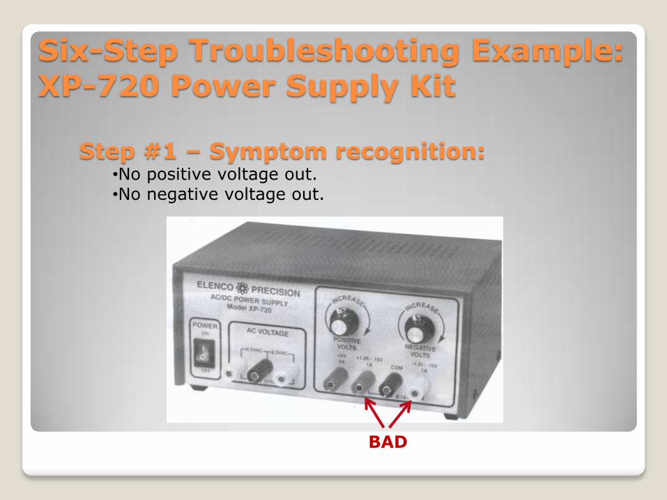
Six-Step Troubleshooting Example: XP-720 Power Supply Kit
Step #1 – Symptom recognition:•No positive voltage out.•No negative voltage out.
BAD
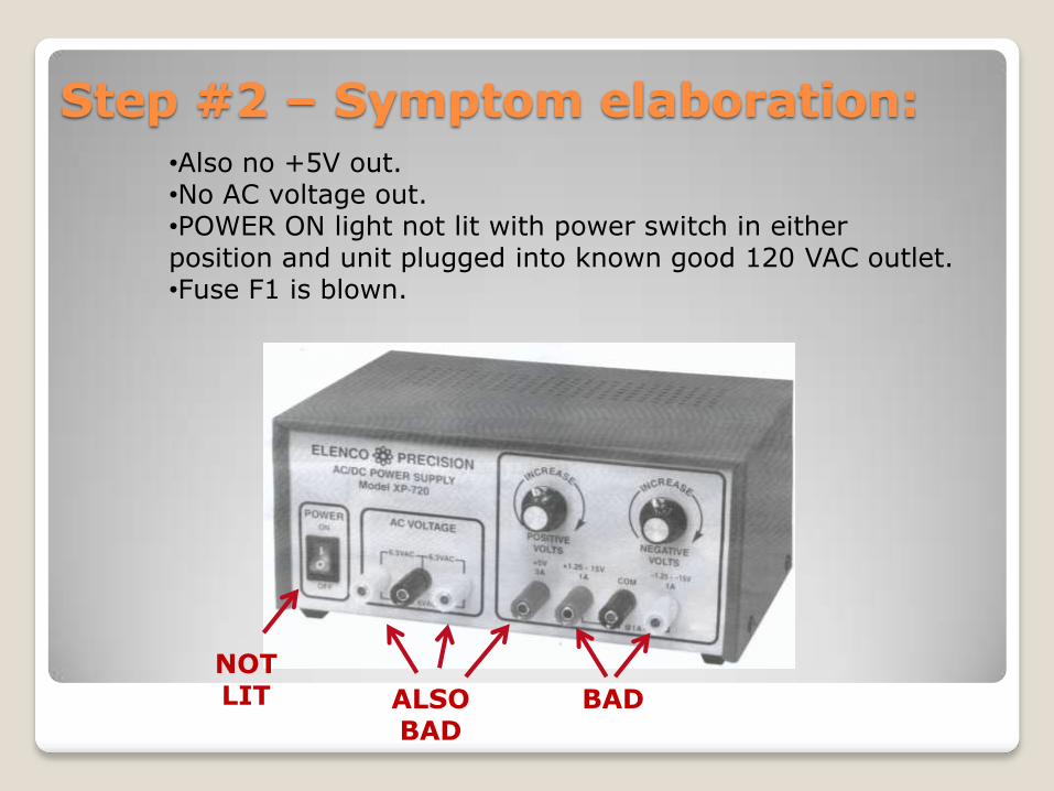
Step #2 – Symptom elaboration:•Also no +5V out.•No AC voltage out.•POWER ON light not lit with power switch in either position and unit plugged into known good 120 VAC outlet.•Fuse F1 is blown.
BADALSOBAD
NOTLIT
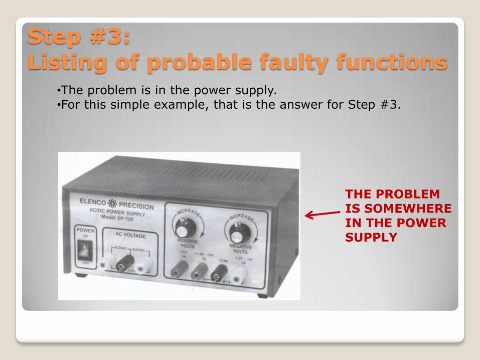
Step #3: Listing of probable faulty functions
•The problem is in the power supply.•For this simple example, that is the answer for Step #3.
THE PROBLEM IS SOMEWHERE IN THE POWER SUPPLY
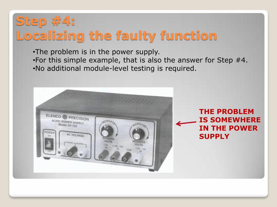
Step #4:Localizing the faulty function
•The problem is in the power supply.•For this simple example, that is also the answer for Step #4.•No additional module-level testing is required.
THE PROBLEM IS SOMEWHERE IN THE POWER SUPPLY
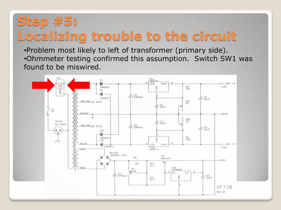
Step #5:Localizing trouble to the circuit
•Problem most likely to left of transformer (primary side).•Ohmmeter testing confirmed this assumption. Switch SW1 was found to be miswired.
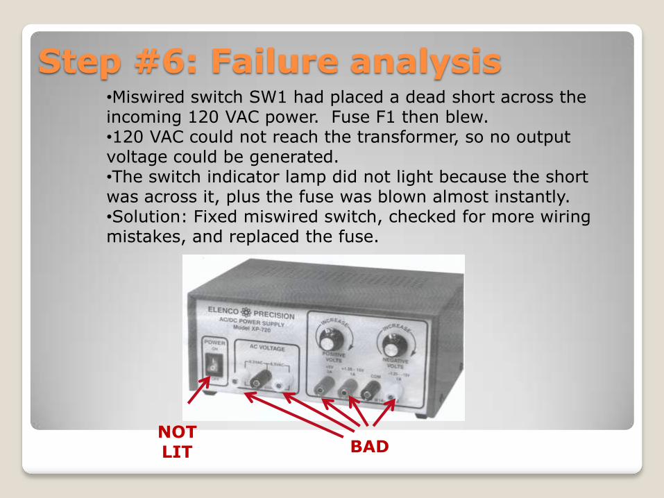
Step #6: Failure analysis•Miswired switch SW1 had placed a dead short across the incoming 120 VAC power. Fuse F1 then blew. •120 VAC could not reach the transformer, so no output voltage could be generated.•The switch indicator lamp did not light because the short was across it, plus the fuse was blown almost instantly.•Solution: Fixed miswired switch, checked for more wiring mistakes, and replaced the fuse.
BADNOTLIT
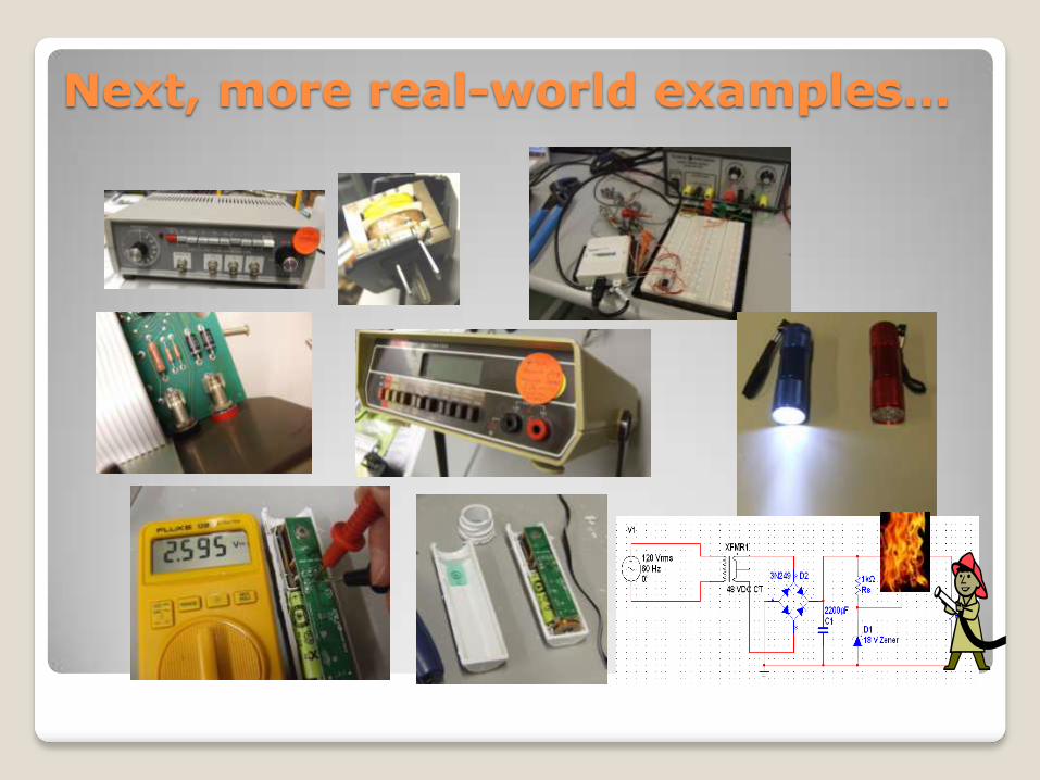
Next, more real-world examples…
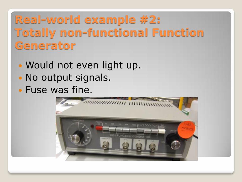
Real-world example #2:Totally non-functional Function Generator
Would not even light up.
No output signals.
Fuse was fine.
Real-world example #2:Totally non-functional Function Generator
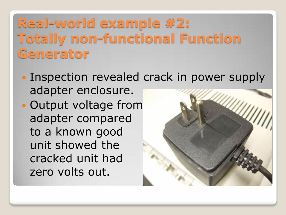
Inspection revealed crack in power supply adapter enclosure.
Output voltage from adapter compared to a known good unit showed the cracked unit hadzero volts out.
Real-world example #2:Totally non-functional Function Generator
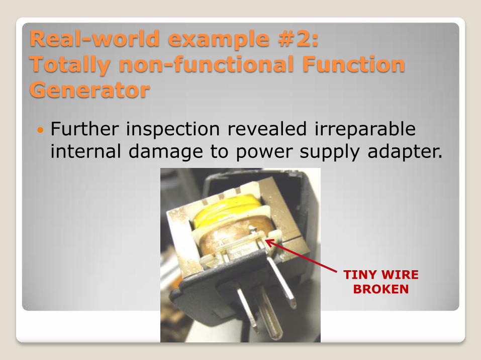
Further inspection revealed irreparable internal damage to power supply adapter.
TINY WIRE BROKEN

Real-world example #2:Totally non-functional Function Generator
Ideal solution: Replace power supply.
Problem: This unit no longer available.
Backup solution: Put function generator back on shelf for use with one of the good power supply adapters.

Real-world example #3:Bad Load Cell Data Acquisition System
Problem: NI-DAQ & LabVIEW showed constant +12 VDC out from this system, but should have been 0-12 VDC proportional to load.
LOAD CELL
OP AMP
PC RUNNING NI LABVIEW
NI-DAQ(DATA
ACQUISITION UNIT)
0-300 LB FORCE
Real-world example #3:Bad Load Cell Data Acquisition System
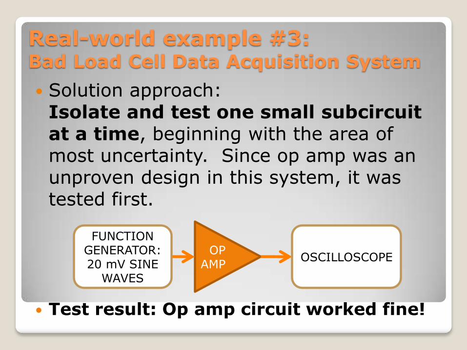
Solution approach: Isolate and test one small subcircuitat a time, beginning with the area of most uncertainty. Since op amp was an unproven design in this system, it was tested first.
Test result: Op amp circuit worked fine!
OP AMP
FUNCTION GENERATOR:20 mV SINE
WAVES
OSCILLOSCOPE

Real-world example #3:Bad Load Cell Data Acquisition System
Next, replaced function generator with actual load cell.
Result: Op amp circuit output was bad –constant +12 VDC regardless of load cell force input.
LOAD CELL
OP AMP
0-300 LB FORCE
OSCILLOSCOPE
Real-world example #3:Bad Load Cell Data Acquisition System
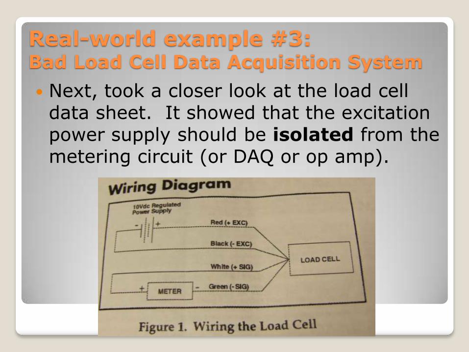
Next, took a closer look at the load cell data sheet. It showed that the excitation power supply should be isolated from the metering circuit (or DAQ or op amp).
Real-world example #3:Bad Load Cell Data Acquisition System
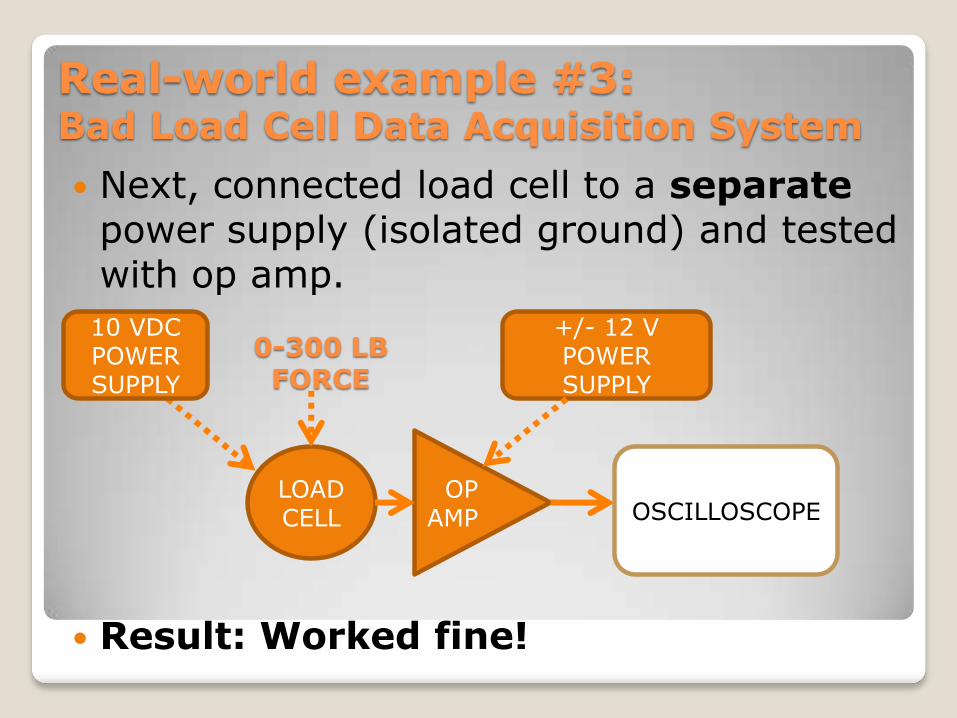
Next, connected load cell to a separatepower supply (isolated ground) and tested with op amp.
Result: Worked fine!
LOAD CELL
OP AMP
0-300 LB FORCE
+/- 12 V POWER SUPPLY
OSCILLOSCOPE
10 VDC POWER SUPPLY

Real-world example #3:Bad Load Cell Data Acquisition System
Finally, reconnected NI-DAQ and LabVIEW PC.
Everything then worked as expected!
LOAD CELL
OP AMP
PC RUNNING NI LABVIEW
NI-DAQ(DATA
ACQUISITION UNIT)
0-300 LB FORCE
10 VDC POWER SUPPLY
+/- 12 V POWER SUPPLY

Lessons learned:◦ If a system does not work, test each subcircuitthoroughly.
◦ It is better to test each subcircuit or module before building an entire system, and then integrate them into the whole.
◦ Read, understand, and trust the manufacturer‟s data sheets.
Real-world example #3:Bad Load Cell Data Acquisition System
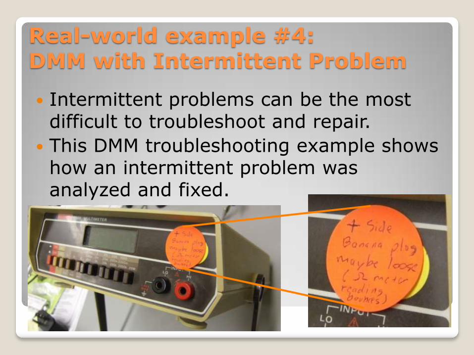
Intermittent problems can be the most difficult to troubleshoot and repair.
This DMM troubleshooting example shows how an intermittent problem was analyzed and fixed.
Real-world example #4:DMM with Intermittent Problem
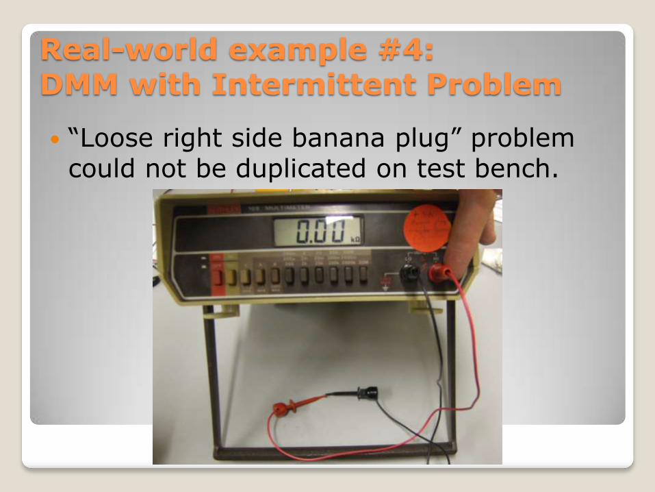
“Loose right side banana plug” problem could not be duplicated on test bench.
Real-world example #4:DMM with Intermittent Problem
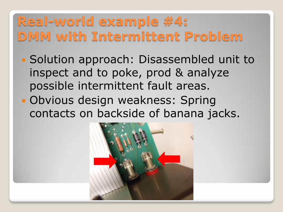
Solution approach: Disassembled unit to inspect and to poke, prod & analyze possible intermittent fault areas.
Obvious design weakness: Spring contacts on backside of banana jacks.
Real-world example #4:DMM with Intermittent Problem
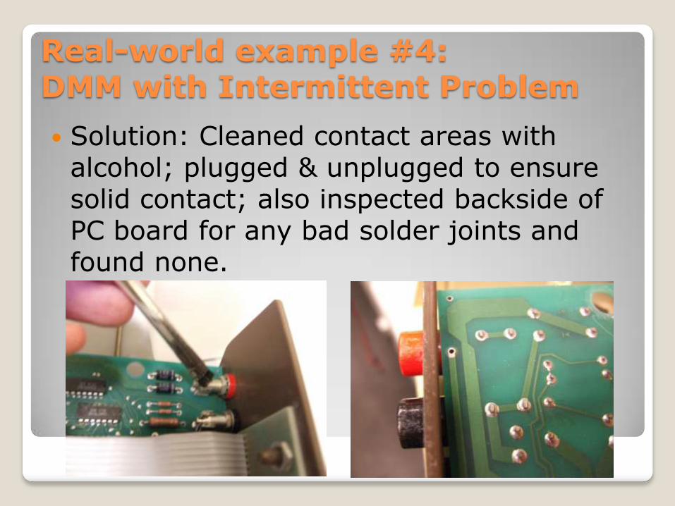
Solution: Cleaned contact areas with alcohol; plugged & unplugged to ensure solid contact; also inspected backside of PC board for any bad solder joints and found none.
Real-world example #4:DMM with Intermittent Problem

Side note on bad solder joints
Realize that bad solder joints are a common cause of intermittent problems in electronics equipment. For example, this photo shows a different project with very bad solder joints that were causing intermittent problems.
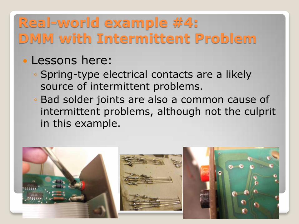
Lessons here: ◦ Spring-type electrical contacts are a likely source of intermittent problems.
◦ Bad solder joints are also a common cause of intermittent problems, although not the culprit in this example.
Real-world example #4:DMM with Intermittent Problem
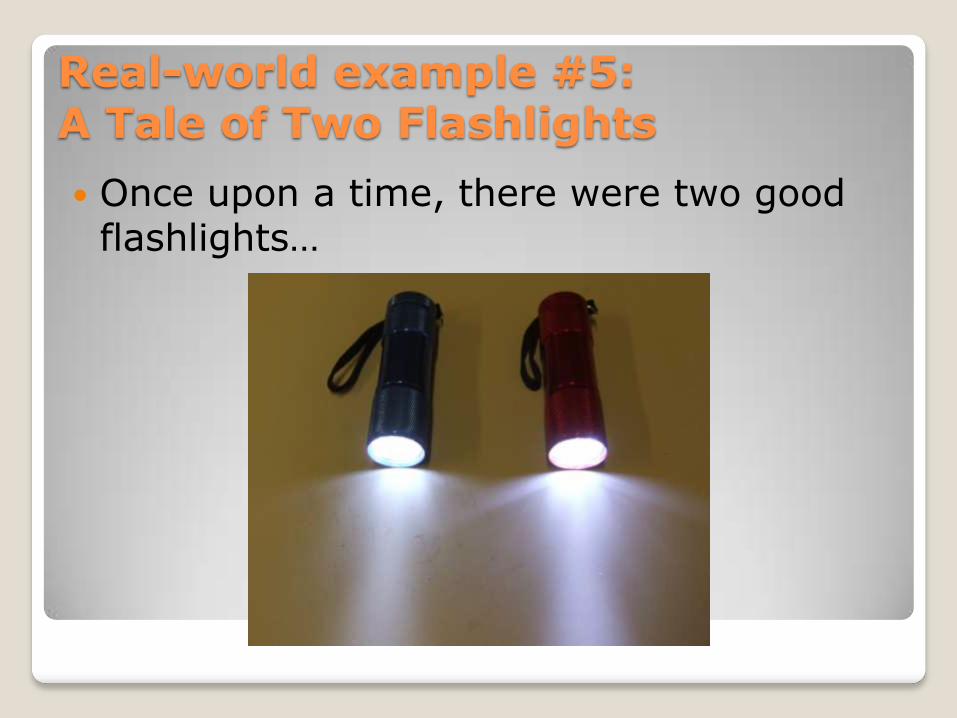
Once upon a time, there were two good flashlights…
Real-world example #5:A Tale of Two Flashlights
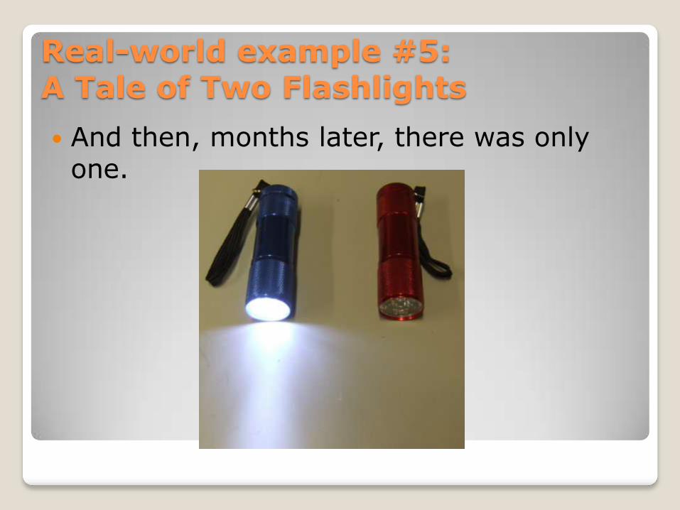
And then, months later, there was only one.
Real-world example #5:A Tale of Two Flashlights
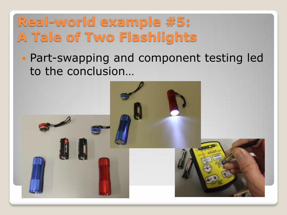
Part-swapping and component testing led to the conclusion…
Real-world example #5:A Tale of Two Flashlights
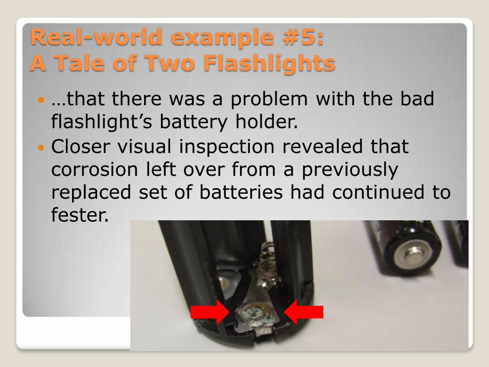
…that there was a problem with the bad flashlight‟s battery holder.
Closer visual inspection revealed that corrosion left over from a previously replaced set of batteries had continued to fester.
Real-world example #5:A Tale of Two Flashlights
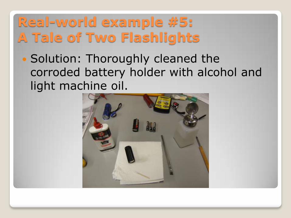
Solution: Thoroughly cleaned the corroded battery holder with alcohol and light machine oil.
Real-world example #5:A Tale of Two Flashlights
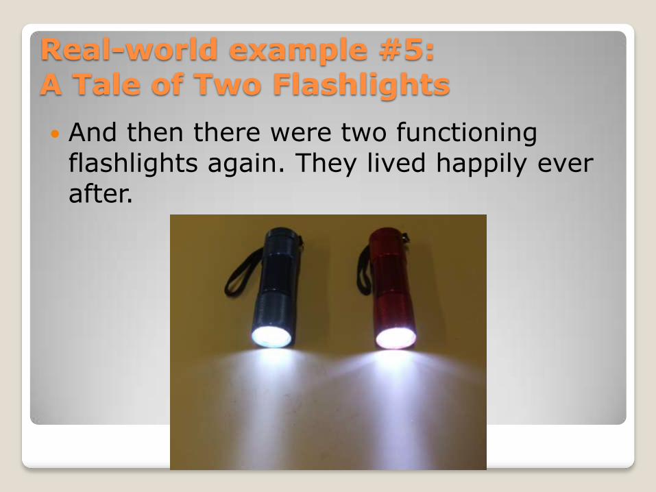
And then there were two functioning flashlights again. They lived happily ever after.
Real-world example #5:A Tale of Two Flashlights

Lessons learned:◦ Part-swapping with a known good unit can save time and effort.
◦ Careful visual inspection at the start of troubleshooting can also save time.
Real-world example #5:A Tale of Two Flashlights
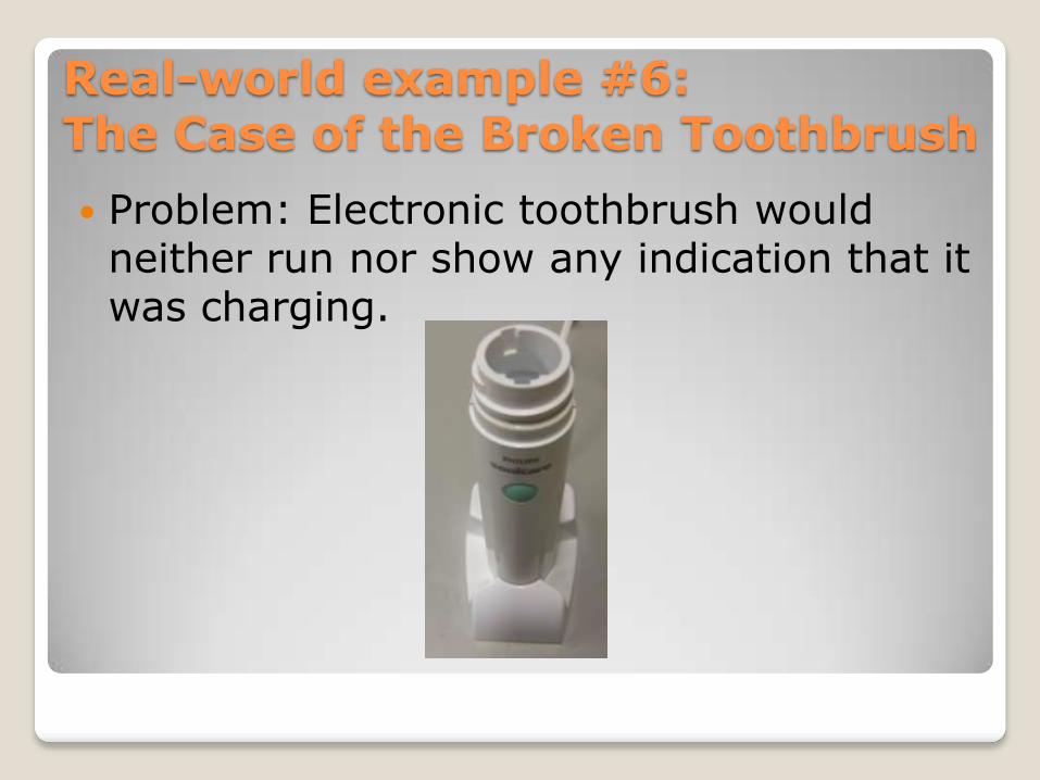
Problem: Electronic toothbrush would neither run nor show any indication that it was charging.
Real-world example #6:The Case of the Broken Toothbrush
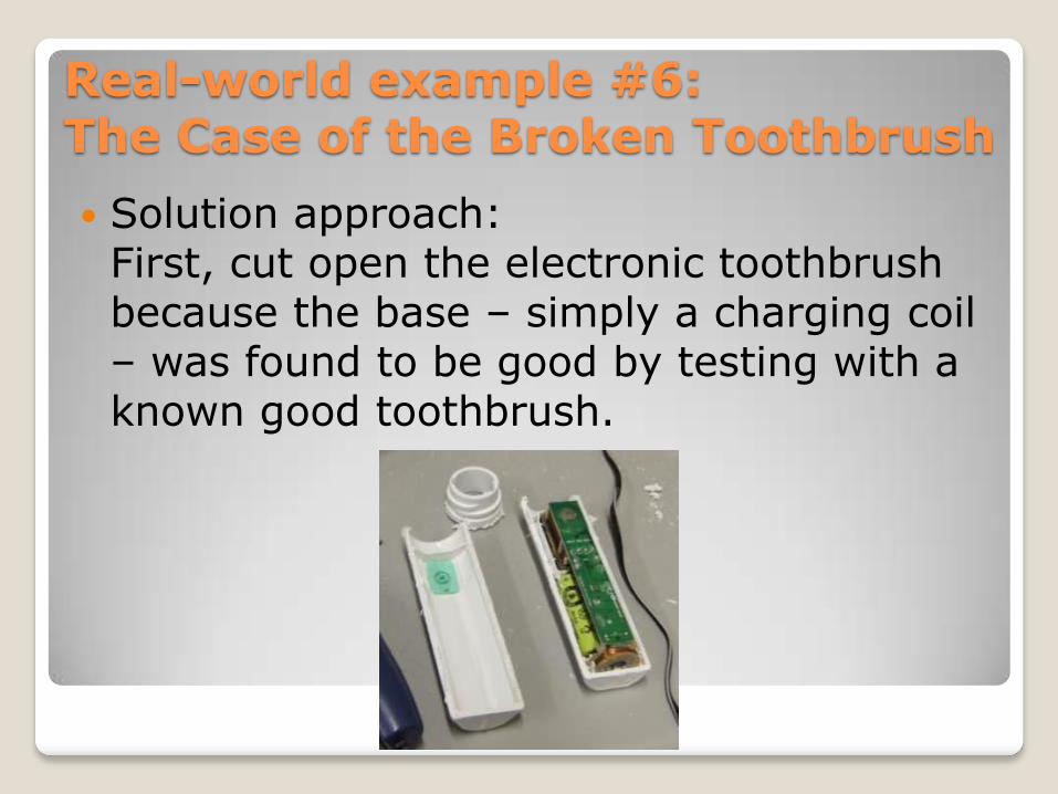
Solution approach: First, cut open the electronic toothbrush because the base – simply a charging coil – was found to be good by testing with a known good toothbrush.
Real-world example #6:The Case of the Broken Toothbrush
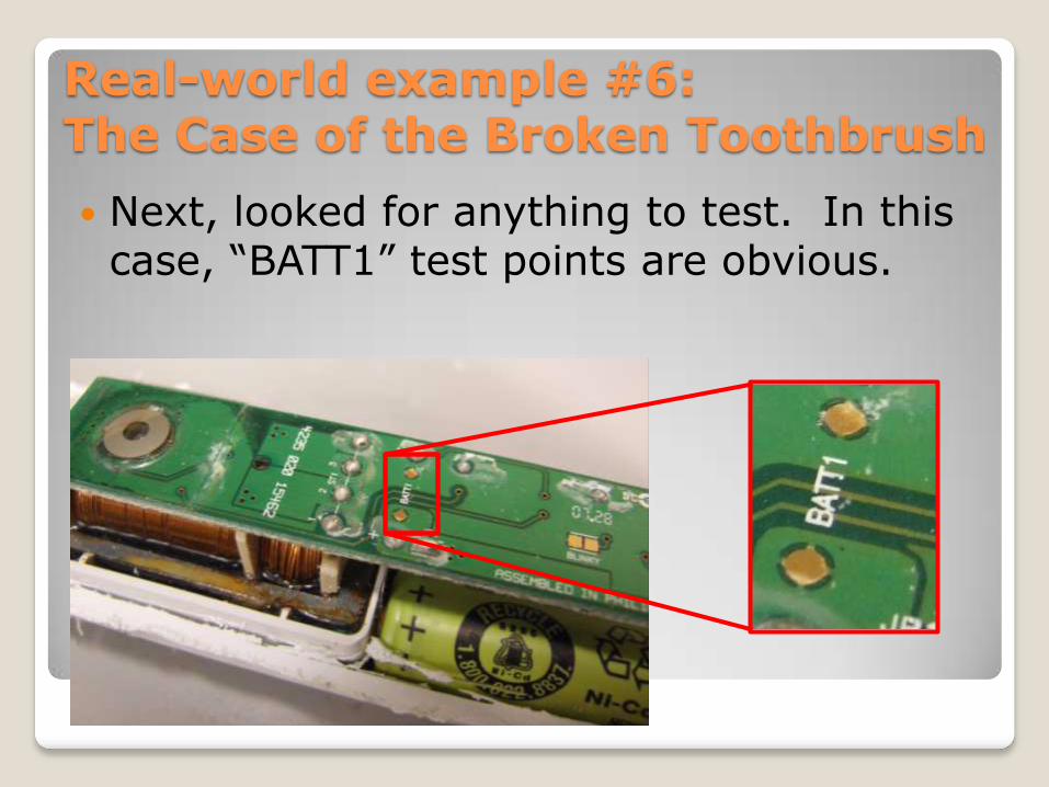
Next, looked for anything to test. In this case, “BATT1” test points are obvious.
Real-world example #6:The Case of the Broken Toothbrush
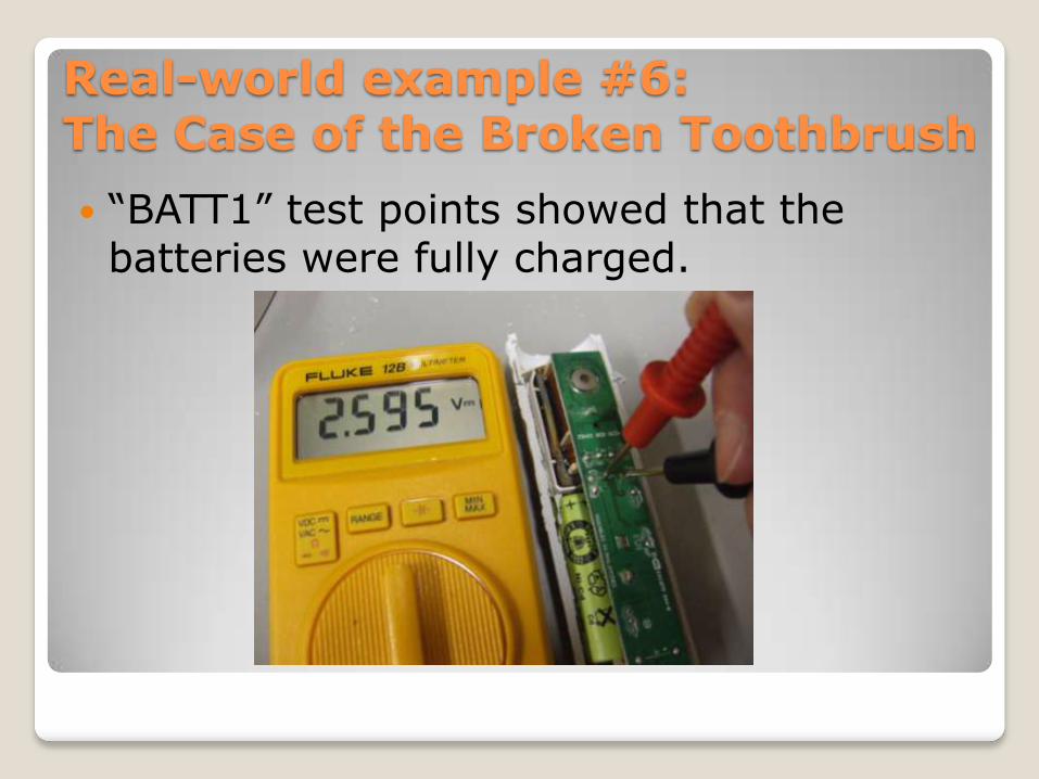
“BATT1” test points showed that the batteries were fully charged.
Real-world example #6:The Case of the Broken Toothbrush
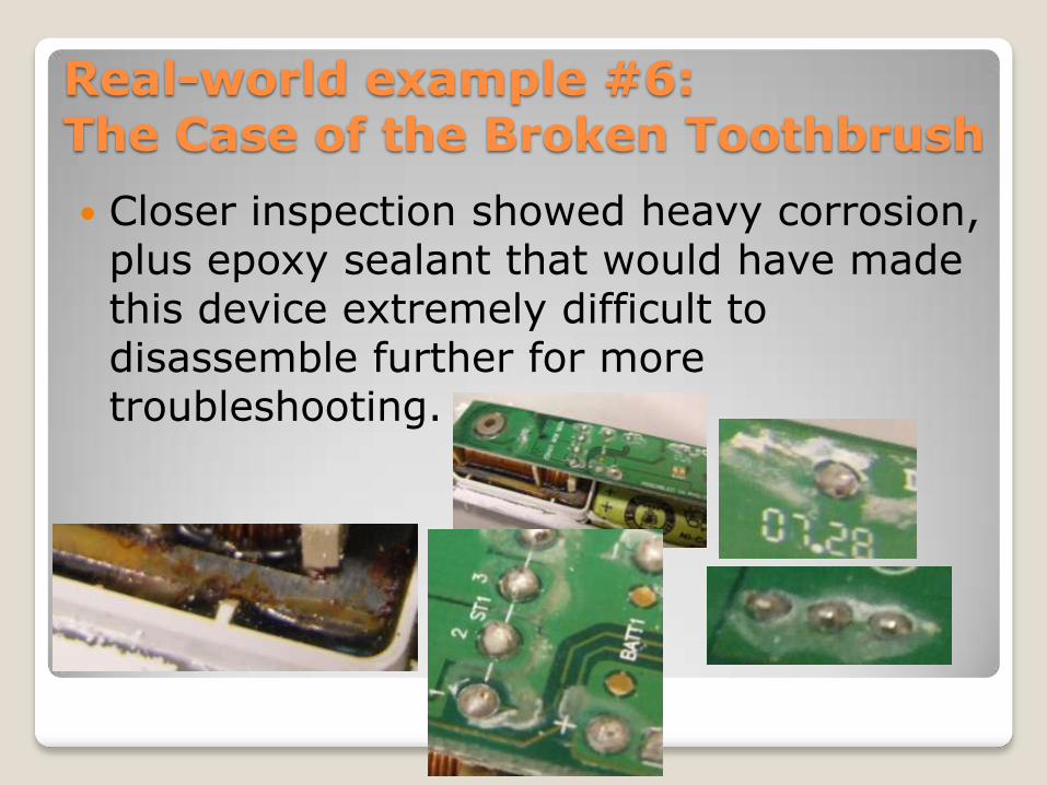
Closer inspection showed heavy corrosion, plus epoxy sealant that would have made this device extremely difficult to disassemble further for more troubleshooting.
Real-world example #6:The Case of the Broken Toothbrush

Final decision: Quick cost-benefit analysis showed this repair to potentially cost more in parts and labor than the device was worth. Gave it up.
Real-world example #6:The Case of the Broken Toothbrush
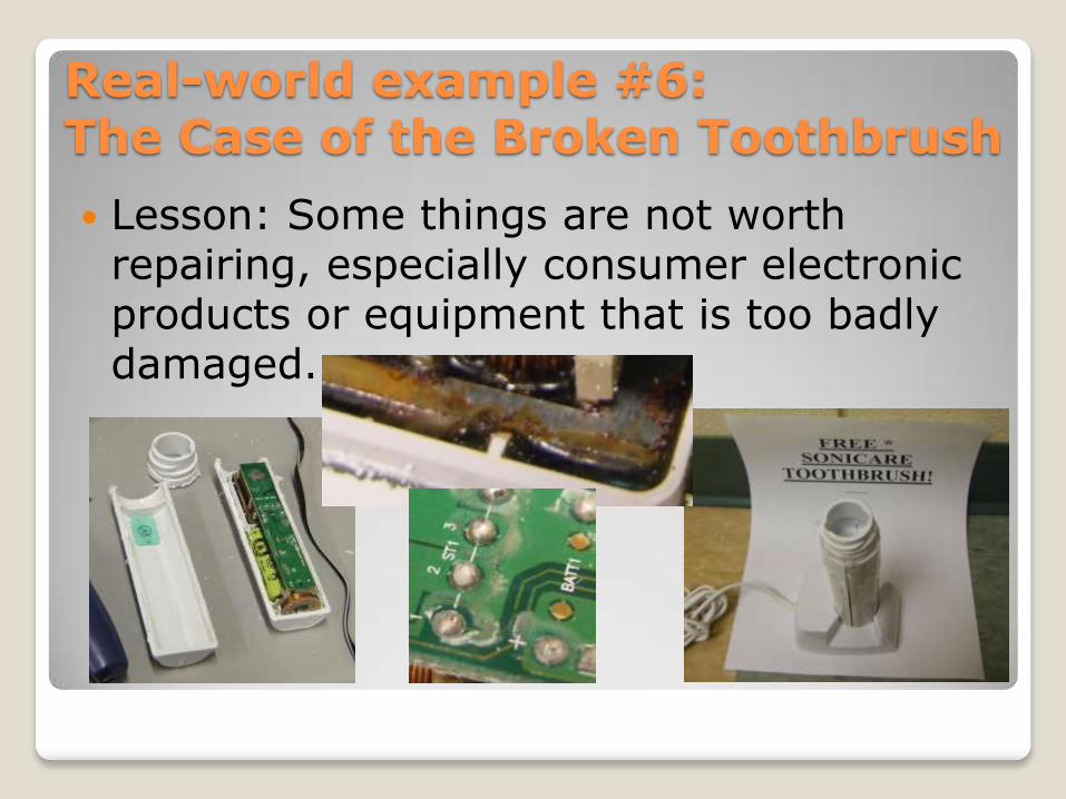
Lesson: Some things are not worth repairing, especially consumer electronic products or equipment that is too badly damaged.
Real-world example #6:The Case of the Broken Toothbrush
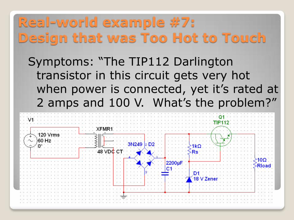
Symptoms: “The TIP112 Darlington transistor in this circuit gets very hot when power is connected, yet it‟s rated at 2 amps and 100 V. What‟s the problem?”
Real-world example #7:Design that was Too Hot to Touch
Circuit analysis:
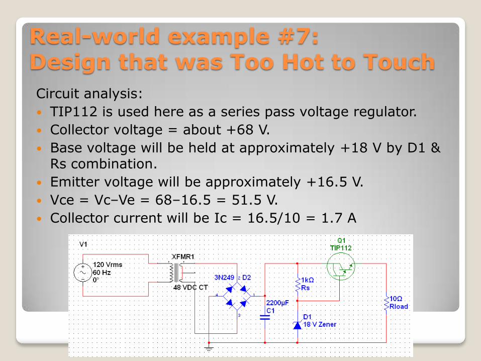
TIP112 is used here as a series pass voltage regulator.
Collector voltage = about +68 V.
Base voltage will be held at approximately +18 V by D1 & Rs combination.
Emitter voltage will be approximately +16.5 V.
Vce = Vc–Ve = 68–16.5 = 51.5 V.
Collector current will be Ic = 16.5/10 = 1.7 A
Real-world example #7:Design that was Too Hot to Touch
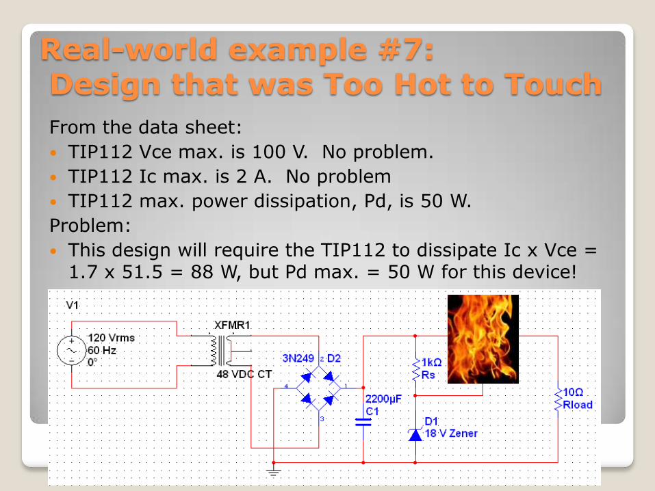
From the data sheet:
TIP112 Vce max. is 100 V. No problem.
TIP112 Ic max. is 2 A. No problem
TIP112 max. power dissipation, Pd, is 50 W.
Problem:
This design will require the TIP112 to dissipate Ic x Vce = 1.7 x 51.5 = 88 W, but Pd max. = 50 W for this device!
Real-world example #7:Design that was Too Hot to Touch
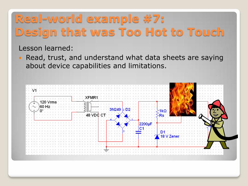
Lesson learned:
Read, trust, and understand what data sheets are saying about device capabilities and limitations.
Real-world example #7:Design that was Too Hot to Touch
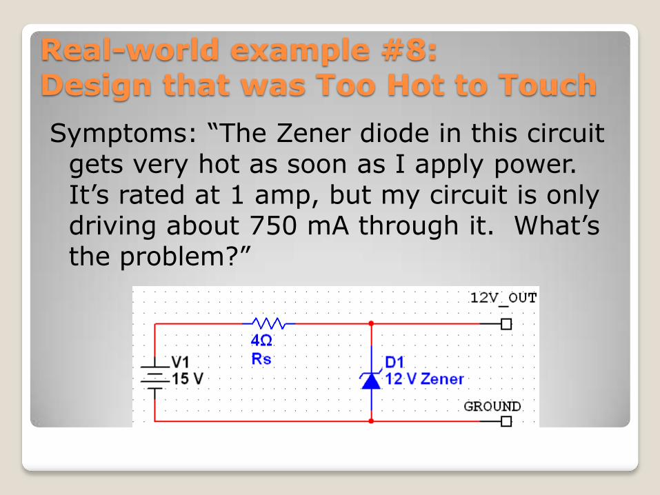
Symptoms: “The Zener diode in this circuit gets very hot as soon as I apply power. It‟s rated at 1 amp, but my circuit is only driving about 750 mA through it. What‟s the problem?”
Real-world example #8:Design that was Too Hot to Touch
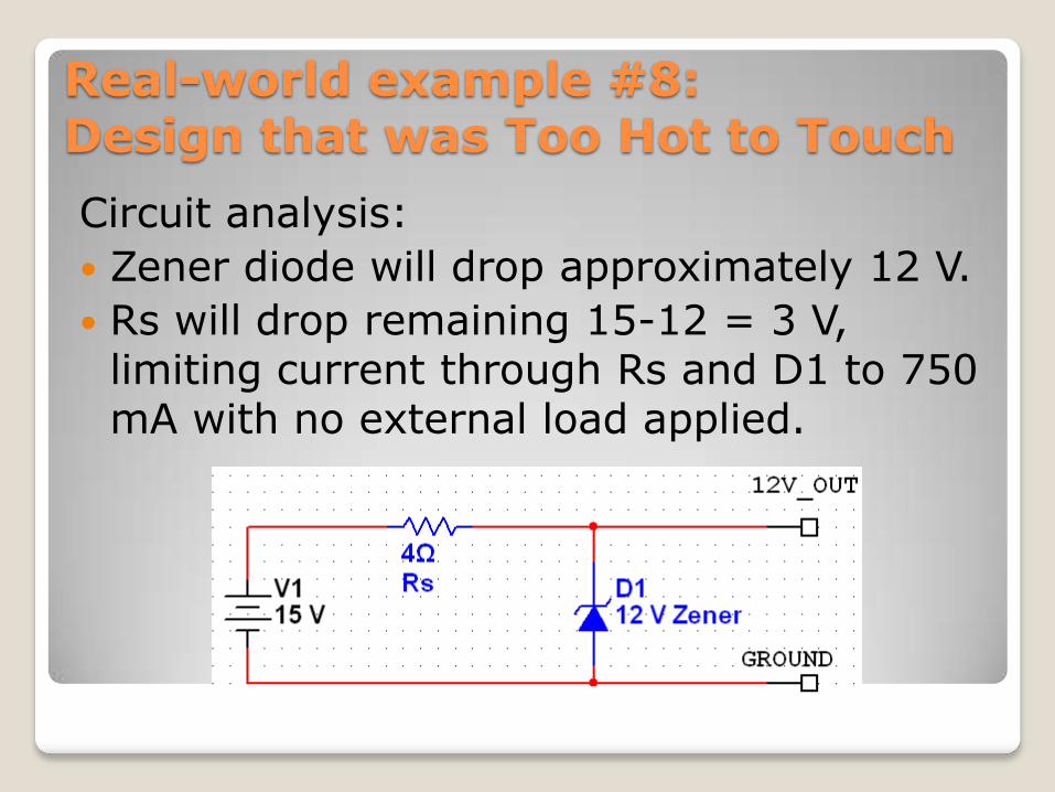
Circuit analysis:
Zener diode will drop approximately 12 V.
Rs will drop remaining 15-12 = 3 V, limiting current through Rs and D1 to 750 mA with no external load applied.
Real-world example #8:Design that was Too Hot to Touch
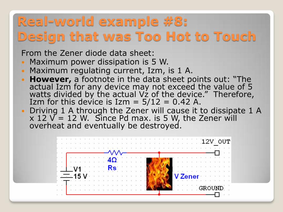
From the Zener diode data sheet: Maximum power dissipation is 5 W. Maximum regulating current, Izm, is 1 A. However, a footnote in the data sheet points out: “The
actual Izm for any device may not exceed the value of 5 watts divided by the actual Vz of the device.” Therefore, Izm for this device is Izm = 5/12 = 0.42 A.
Driving 1 A through the Zener will cause it to dissipate 1 A x 12 V = 12 W. Since Pd max. is 5 W, the Zener will overheat and eventually be destroyed.
Real-world example #8:Design that was Too Hot to Touch
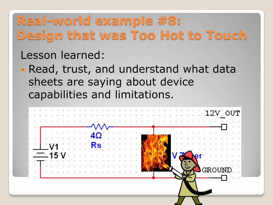
Lesson learned:
Read, trust, and understand what data sheets are saying about device capabilities and limitations.
Real-world example #8:Design that was Too Hot to Touch
In closing, Some General Troubleshooting Tips
Pay attention to all trouble symptoms in a faulty device or equipment.
Careful visual inspection is always a good idea.
Look for discolored or damaged components.
Look for bad solder joints or loose connections.
Make logical troubleshooting decisions based on facts. Don‟t just jump around the circuits randomly looking at signals and replacing components.
Compare the operation and signals of known good devices when available.
Read and trust any documentation on the equipment or components. Trust it at least 99%, anyway.
Track down intermittent problems by shaking, wiggling, and prodding components (the shaking & wiggling may not help with troubleshooting, but it will relieve personal frustration).
Intermittent problems may sometimes be temperature-related. Consider gently using a heat gun or cool spray to try to smoke out thermal instabilities.
When breadboarding, many problems are caused by miswiring or shorted bare wire component leads. Look for those types of problems on breadboards.

For a copy of this presentation,
go to
www.letu.edu/engineeringtips
and look for “IEEE Beyond the
Classroom”.

Questions?