idg-655 dual-axis gyro product specification · idg-655 dual-axis gyroscope product specification...
TRANSCRIPT
InvenSense Inc. 1197 Borregas Ave, Sunnyvale, CA 94089 U.S.A. Tel: +1 (408) 988-7339 Fax: +1 (408) 988-8104
Website: www.invensense.com
PS-IDG-0655-00-01 Release Date: 06/10/10
IDG-655 Dual-Axis Gyro Product Specification
A printed copy of this document is NOT UNDER REVISION CONTROL
unless it is dated and stamped in red ink as, “REVISION CONTROLLED COPY.”
Performance characteristics shown in this document are estimates only and do not constitute a warranty or guarantee of product performance. InvenSense does not support any applications in connection with weapon systems. Since InvenSense’s products are not designed for use in life-support and commercial aviation applications they shall not be used in such products. In devices or systems whereby malfunction of these products can be expected to result in personal injury and casualties, InvenSense customers using or selling these products do so at their own risk and agree to keep InvenSense harmless from any consequences. InvenSense reserves the right to make changes to this product, including its circuits and software, in order to improve its design and/or performance, without prior notice.
InvenSense makes no warranties, neither expressed nor implied, regarding the information and specifications contained in this document. InvenSense assumes no responsibility for any claims or damages arising from information contained in this document, or from the use of products and services detailed therein. This includes, but is not limited to, claims or damages based on the infringement of patents, copyrights, mask work and/or other intellectual property rights.
InvenSense’s integrated circuits, software and designs are protected by intellectual property laws in USA and abroad. This product may in whole or in part be subject to intellectual property rights protection. Please contact InvenSense for any additional information.
Copyright © 2009, InvenSense, Inc.
IDG-655 Dual-Axis Gyroscope Product Specification
PS-IDG-0655-00-01 Release Date: 06/10/10
CONFIDENTIAL & PROPRIETARY 2 of 25
TABLE OF CONTENTS 1. REVISION HISTORY ............................................................................................................................. 4
2. PURPOSE ............................................................................................................................................. 5
3. PRODUCT OVERVIEW ......................................................................................................................... 5
4. FEATURES ........................................................................................................................................... 5
5. FUNCTIONAL BLOCK DIAGRAM ......................................................................................................... 6
6. FUNCTIONAL DESCRIPTION ............................................................................................................... 6
6.1 OVERVIEW .................................................................................................................................... 6
6.2 RATE SENSORS ............................................................................................................................. 6
6.3 OSCILLATOR CIRCUIT ..................................................................................................................... 6
6.4 AMPLITUDE CONTROL .................................................................................................................... 7
6.5 CORIOLIS SENSE ........................................................................................................................... 7
6.6 DEMODULATOR.............................................................................................................................. 7
6.7 LOW-PASS FILTER ......................................................................................................................... 7
6.8 AUTO ZERO SWITCH ...................................................................................................................... 7
6.9 CHARGE PUMP .............................................................................................................................. 7
6.10 MEMORY TRIM............................................................................................................................... 7
6.11 SCALE FACTOR ............................................................................................................................. 7
7. SPECIFICATION ................................................................................................................................... 8
7.1 SPECIFIED PARAMETERS ................................................................................................................ 8
7.2 RECOMMENDED OPERATING CONDITIONS ........................................................................................ 9
7.3 ABSOLUTE MAXIMUM RATINGS ........................................................................................................ 9
7.4 REFERENCE CIRCUIT ................................................................................................................... 10
7.4.1 BILL OF MATERIAL FOR EXTERNAL COMPONENTS ............................................................................ 10
8. APPLICATION INFORMATION ........................................................................................................... 11
8.1 PIN OUT AND SIGNAL DESCRIPTION ............................................................................................... 11
8.2 DESIGN CONSIDERATIONS ............................................................................................................ 12
8.2.1 POWER SUPPLY REJECTION RATIO ................................................................................................ 12
8.2.2 POWER SUPPLY FILTERING ........................................................................................................... 12
8.2.3 AMPLITUDE CONTROL .................................................................................................................. 12
8.2.4 INTERNAL LOW-PASS FILTER ........................................................................................................ 12
8.2.5 CHARGE PUMP ............................................................................................................................ 13
8.2.6 ACOUSTIC NOISE SENSITIVITY ....................................................................................................... 13
8.2.7 ELECTROSTATIC DISCHARGE SENSITIVITY ...................................................................................... 13
8.2.8 AUTO ZERO OVERVIEW ................................................................................................................ 13
IDG-655 Dual-Axis Gyroscope Product Specification
PS-IDG-0655-00-01 Release Date: 06/10/10
CONFIDENTIAL & PROPRIETARY 3 of 25
9. ASSEMBLY ......................................................................................................................................... 14
9.1 ORIENTATION .............................................................................................................................. 14
9.2 PACKAGE DIMENSIONS ................................................................................................................. 15
9.3 PACKAGE MARKING SPECIFICATION ............................................................................................... 16
9.4 TAPE & REEL SPECIFICATION ........................................................................................................ 16
9.4.1 LABEL ......................................................................................................................................... 18
9.4.2 PACKING ..................................................................................................................................... 18
9.5 PCB PAD LAYOUT DIMENSIONS .................................................................................................... 19
9.6 TRACE ROUTING .......................................................................................................................... 19
9.7 SOLDERING EXPOSED DIE PAD ..................................................................................................... 19
9.8 COMPONENT PLACEMENT ............................................................................................................. 19
9.9 PCB MOUNTING AND CROSS-AXIS SENSITIVITY .............................................................................. 19
9.10 AGC NODES ............................................................................................................................... 20
9.11 MEMS HANDLING INSTRUCTIONS .................................................................................................. 20
9.12 GYROSCOPE SURFACE MOUNT GUIDELINES ................................................................................... 20
9.13 REFLOW SPECIFICATION ............................................................................................................... 21
9.14 STORAGE SPECIFICATIONS AND RE-BAKE ...................................................................................... 22
10. RELIABILITY ....................................................................................................................................... 23
10.1 QUALIFICATION TEST POLICY ........................................................................................................ 23
10.2 QUALIFICATION TEST PLAN ........................................................................................................... 23
11. ENVIRONMENTAL COMPLIANCE ..................................................................................................... 25
IDG-655 Dual-Axis Gyroscope Product Specification
PS-IDG-0655-00-01 Release Date: 06/10/10
CONFIDENTIAL & PROPRIETARY 4 of 25
1. Revision History
Revision Date Revision Description
06/10/08 01 Initial Release
IDG-655 Dual-Axis Gyroscope Product Specification
PS-IDG-0655-00-01 Release Date: 06/10/10
CONFIDENTIAL & PROPRIETARY 5 of 25
2. Purpose The purpose of this document is to provide a detailed product description and design-related information regarding the IDG-655 dual-axis gyroscope.
3. Product Overview The IDG-655 is a state-of-the-art dual-axis gyroscope designed specifically for complex motion sensing in 3D-input devices and gaming controllers. The IDG-655 gyroscope utilizes state-of-the-art MEMS fabrication with wafer-scale integration technology. This technology combines completed MEMS wafers and completed CMOS electronic wafers together using a patented and proprietary wafer-scale bonding process that simultaneously provides electrical connections and hermetically sealed enclosures. This unique and novel fabrication technique is the key enabling technology that allows for the design and manufacture of high performance, multi-axis, integrated MEMS gyroscopes in a very small and economical package. Integration at the wafer-level minimizes parasitic capacitances, allowing for improved signal-to-noise over a discrete solution. With the addition of the new patented Auto Zero feature for minimizing bias drift over temperature, the IDG-655 offers unparalleled gyroscope performance in 3D-input and gaming applications.
4. Features By integrating the control electronics with the sensor elements at the wafer level, the IDG-655 gyroscope supports a rich feature set including:
a) Integrated X- and Y-axis gyro on a single chip b) Factory calibrated scale factor c) Integrated low-pass filter d) Auto Zero function e) High vibration rejection over wide frequency range f) High cross-axis isolation by design g) 3V single-supply operation h) RoHS and Green Compliant
IDG-655 Dual-Axis Gyroscope Product Specification
PS-IDG-0655-00-01 Release Date: 06/10/10
CONFIDENTIAL & PROPRIETARY 6 of 25
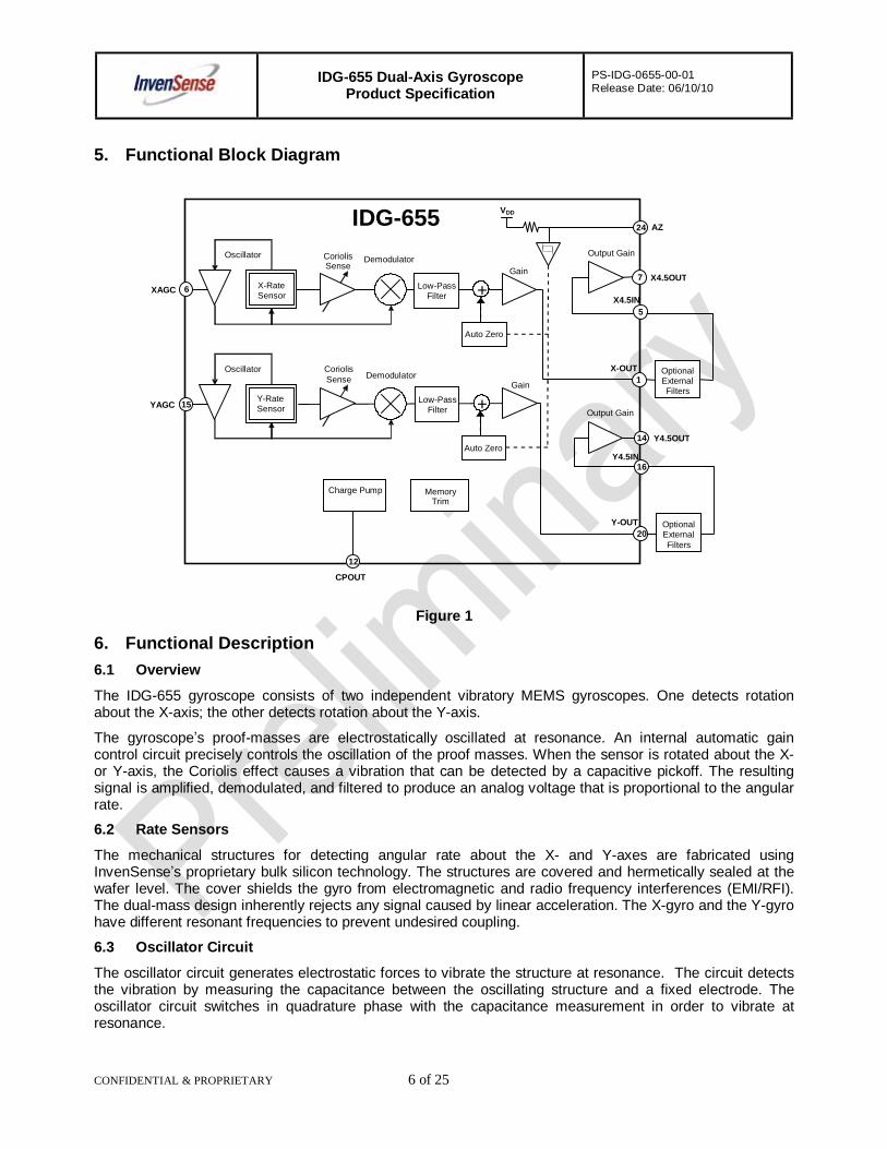
5. Functional Block Diagram
Figure 1
6. Functional Description 6.1 Overview
The IDG-655 gyroscope consists of two independent vibratory MEMS gyroscopes. One detects rotation about the X-axis; the other detects rotation about the Y-axis.
The gyroscope’s proof-masses are electrostatically oscillated at resonance. An internal automatic gain control circuit precisely controls the oscillation of the proof masses. When the sensor is rotated about the X- or Y-axis, the Coriolis effect causes a vibration that can be detected by a capacitive pickoff. The resulting signal is amplified, demodulated, and filtered to produce an analog voltage that is proportional to the angular rate.
6.2 Rate Sensors
The mechanical structures for detecting angular rate about the X- and Y-axes are fabricated using InvenSense’s proprietary bulk silicon technology. The structures are covered and hermetically sealed at the wafer level. The cover shields the gyro from electromagnetic and radio frequency interferences (EMI/RFI). The dual-mass design inherently rejects any signal caused by linear acceleration. The X-gyro and the Y-gyro have different resonant frequencies to prevent undesired coupling.
6.3 Oscillator Circuit
The oscillator circuit generates electrostatic forces to vibrate the structure at resonance. The circuit detects the vibration by measuring the capacitance between the oscillating structure and a fixed electrode. The oscillator circuit switches in quadrature phase with the capacitance measurement in order to vibrate at resonance.
XAGC 6
YAGC 15
AZ 24
X4.5OUT 7
14
20
16
IDG-655
MemoryTrim
Demodulator Oscillator
Demodulator Oscillator Coriolis Sense
Output Gain
Output Gain
Y-Rate Sensor
X-Rate Sensor
1
VDD
Coriolis Sense
Y4.5OUT
Charge Pump
Regulator
CPOUT
12
5
Y-OUT
Y4.5IN
X4.5IN
X-OUT
Gain
Low-Pass Filter +
Gain
Low-Pass Filter +
Auto Zero
Auto Zero
Optional External Filters
Optional External Filters
IDG-655 Dual-Axis Gyroscope Product Specification
PS-IDG-0655-00-01 Release Date: 06/10/10
CONFIDENTIAL & PROPRIETARY 7 of 25
6.4 Amplitude Control
The scale factor of the gyroscope depends on the amplitude of the mechanical motion and the trim setting of the internal programmable gain stages. The oscillation circuit precisely controls the amplitude to maintain constant sensitivity over the temperature range.
6.5 Coriolis Sense
Rotating the sensor about the X- or Y-axis results in a Coriolis force on the corresponding X- or Y-rate sensor. The Coriolis force causes the mechanical structure to vibrate in-plane. The resulting vibration is detected by measuring the capacitance change between the mechanical structure and fixed electrodes. This signal is converted to a voltage waveform by means of low-noise charge integrating amplifier and amplification stages.
6.6 Demodulator
The output of the Coriolis sense is an amplitude modulated waveform. The amplitude corresponds to the rotation rate, and the carrier frequency is the mechanical drive frequency. The synchronous demodulator converts the Coriolis sense waveform to the low-frequency, angular rate signal.
6.7 Low-Pass Filter
After the demodulation stage, there is a low-pass filter. This filter attenuates noise and high frequency artifacts before final amplification.
6.8 Auto Zero Switch
The Auto Zero function is used to reduce DC offset caused by bias drift. The implementation of this function will vary by application requirement. Pin 24 (AZ) is used to set the Auto Zero function, resetting the bias to 1.35V.
6.9 Charge Pump
The on-chip charge pump generates the voltage required to oscillate the mechanical structure.
6.10 Memory Trim
The on-chip memory is used to select the gyro’s sensitivity, calibrate the sensitivity, null DC offsets and select the low-pass filter option
6.11 Scale Factor
The Rate-Out of the gyro is not ratiometric to the supply voltage. The scale factor is calibrated at the factory and is nominally independent of supply voltage.
IDG-655 Dual-Axis Gyroscope Product Specification
PS-IDG-0655-00-01 Release Date: 06/10/10
CONFIDENTIAL & PROPRIETARY 8 of 25
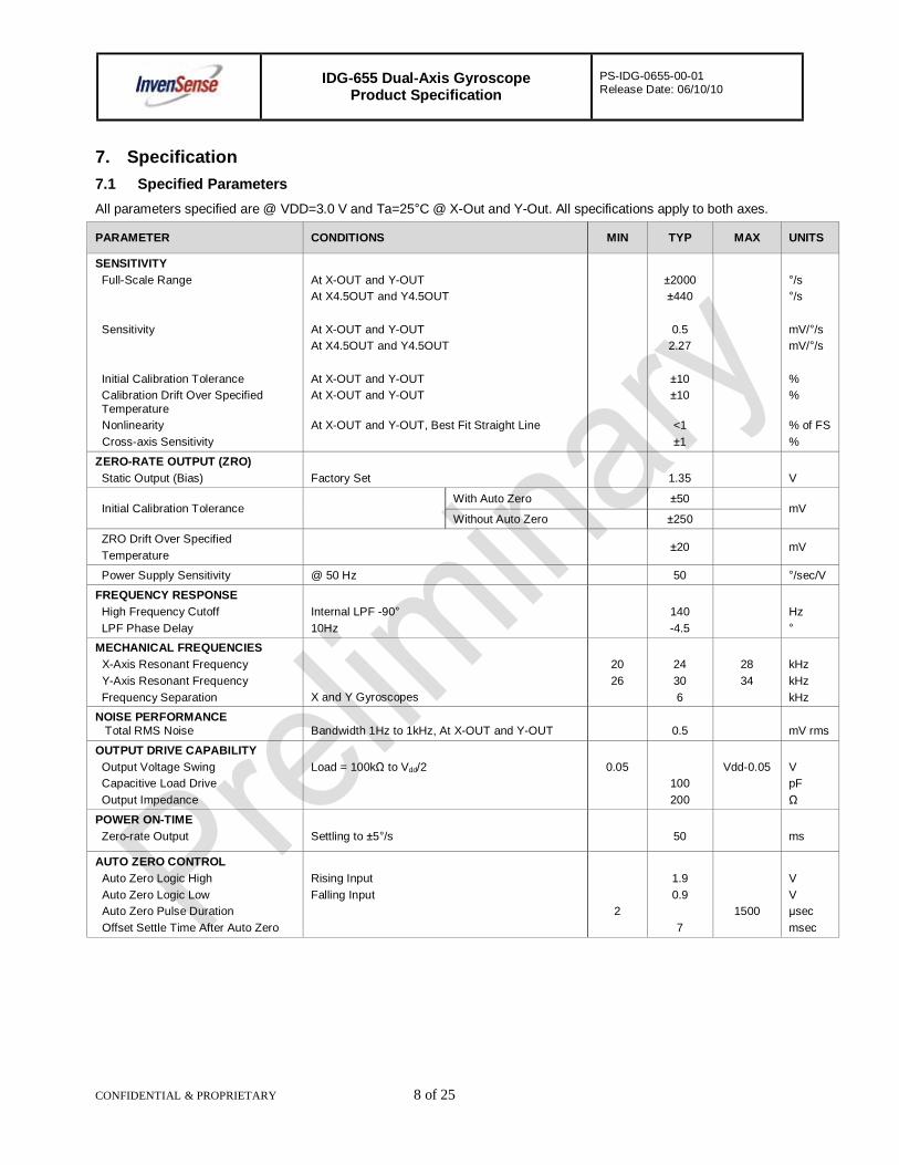
7. Specification 7.1 Specified Parameters All parameters specified are @ VDD=3.0 V and Ta=25°C @ X-Out and Y-Out. All specifications apply to both axes.
PARAMETER CONDITIONS MIN TYP MAX UNITS
SENSITIVITY Full-Scale Range
Sensitivity
Initial Calibration Tolerance Calibration Drift Over Specified Temperature
Nonlinearity Cross-axis Sensitivity
At X-OUT and Y-OUT At X4.5OUT and Y4.5OUT At X-OUT and Y-OUT At X4.5OUT and Y4.5OUT At X-OUT and Y-OUT At X-OUT and Y-OUT At X-OUT and Y-OUT, Best Fit Straight Line
±2000 ±440
0.5
2.27
±10 ±10
<1 ±1
°/s °/s mV/°/s mV/°/s % % % of FS %
ZERO-RATE OUTPUT (ZRO) Static Output (Bias)
Factory Set
1.35
V
Initial Calibration Tolerance With Auto Zero ±50
mV Without Auto Zero ±250
ZRO Drift Over Specified Temperature
±20 mV
Power Supply Sensitivity @ 50 Hz 50 °/sec/V
FREQUENCY RESPONSE High Frequency Cutoff LPF Phase Delay
Internal LPF -90° 10Hz
140 -4.5
Hz °
MECHANICAL FREQUENCIES X-Axis Resonant Frequency Y-Axis Resonant Frequency Frequency Separation X and Y Gyroscopes
20 26
24 30 6
28 34
kHz kHz kHz
NOISE PERFORMANCE Total RMS Noise
Bandwidth 1Hz to 1kHz, At X-OUT and Y-OUT
0.5
mV rms
OUTPUT DRIVE CAPABILITY Output Voltage Swing Capacitive Load Drive Output Impedance
Load = 100kΩ to Vdd/2
0.05
100 200
Vdd-0.05
V pF Ω
POWER ON-TIME Zero-rate Output
Settling to ±5°/s
50
ms
AUTO ZERO CONTROL Auto Zero Logic High Auto Zero Logic Low Auto Zero Pulse Duration Offset Settle Time After Auto Zero
Rising Input Falling Input
2
1.9 0.9
7
1500
V V µsec msec

IDG-655 Dual-Axis Gyroscope Product Specification
PS-IDG-0655-00-01 Release Date: 06/10/10
CONFIDENTIAL & PROPRIETARY 9 of 25
PARAMETER CONDITIONS MIN TYP MAX UNITS
POWER SUPPLY (VDD) Operating Voltage Range
Quiescent Supply Current Supply Current Change Over Specified Temperature
2.7
3.0 6.5 ±2
3.3
V mA mA
TEMPERATURE SENSOR Sensitivity Offset
Output Impedance
Range -20 to +85°C
4
1.25 12
mV/°C V kΩ
TEMPERATURE RANGE Specified Temperature Range
-20
+85
°C
7.2 Recommended Operating Conditions
Parameter Min Typ Max Unit Power Supply Voltage (VDD) 2.7 3.0 3.3 V Power Supply Voltage (VDD) Rise Time (10% - 90%)
20 ms
7.3 Absolute Maximum Ratings
Stress above those listed as “Absolute Maximum Ratings” may cause permanent damage to the device. This is a stress rating only and functional operation of the device under these conditions is not implied. Exposure to the absolute maximum rating conditions for extended periods may affect device reliability.
Parameter Rating Supply Voltage -0.3V to +3.6V Acceleration (Any Axis, unpowered) 10,000g for 0.3ms Operating Temperature Range -40 to +105°C Storage Temperature Range -40 to +125°C

IDG-655 Dual-Axis Gyroscope Product Specification
PS-IDG-0655-00-01 Release Date: 06/10/10
CONFIDENTIAL & PROPRIETARY 10 of 25
7.4 Reference Circuit
Figure 2
7.4.1 Bill of Material for External Components
Component Specification
Low Pass Filter Capacitors 0.1uF ±20% / 10V
AGC Capacitors 0.22uF ±10% / 10V
VDD Bypass Capacitor 0.1uF ±20% / 10V
Charge Pump Capacitor 0.1uF ±20% / 25V
LDO Input Filter Capacitor 1.0uF / Ratings Dependent upon Supply Voltage
LDO Input Filter Resistor 2.2 Ohm ±1%
Low Pass Filter Resistors 750 Ohm ±1%
1.0µF 19
9
0.22µF
XAGC 6
0.22µF
YAGC 15
AZ 24
X4.5OUT 7
14
20
16 2.2Ω
750Ω
0.1µF
IDG-655
0.1µF
Memory Trim
Demodulator Oscillator
Demodulator Oscillator Coriolis Sense
Output Gain
Output Gain
Y-Rate Sensor
X-Rate Sensor
VDD
1
VDD
Coriolis Sense
Y4.5OUT
Charge Pump
Regulator
GND CPOUT27 26 2
0.1µF/25V
12
300kΩ
750Ω
0.1µF
5
Supply
LDO VDD Y-OUT
Y4.5IN
X4.5IN
X-OUT
28
Gain
Low-Pass Filter +
Gain
Low-Pass Filter +
Auto Zero
Auto Zero 4.5X
4.5X
IDG-655 Dual-Axis Gyroscope Product Specification
PS-IDG-0655-00-01 Release Date: 06/10/10
CONFIDENTIAL & PROPRIETARY 11 of 25
Y
+
+ X
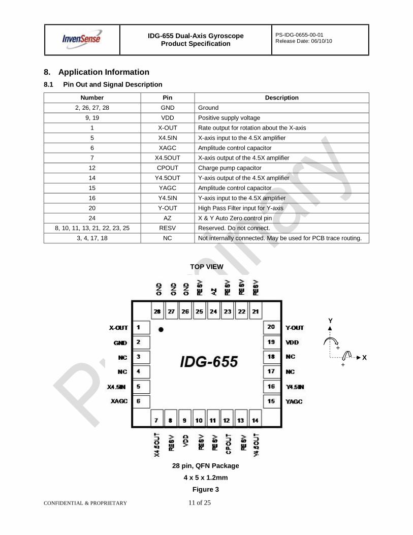
8. Application Information 8.1 Pin Out and Signal Description
Number Pin Description 2, 26, 27, 28 GND Ground
9, 19 VDD Positive supply voltage 1 X-OUT Rate output for rotation about the X-axis 5 X4.5IN X-axis input to the 4.5X amplifier 6 XAGC Amplitude control capacitor 7 X4.5OUT X-axis output of the 4.5X amplifier
12 CPOUT Charge pump capacitor 14 Y4.5OUT Y-axis output of the 4.5X amplifier 15 YAGC Amplitude control capacitor 16 Y4.5IN Y-axis input to the 4.5X amplifier 20 Y-OUT High Pass Filter input for Y-axis 24 AZ X & Y Auto Zero control pin
8, 10, 11, 13, 21, 22, 23, 25 RESV Reserved. Do not connect. 3, 4, 17, 18 NC Not internally connected. May be used for PCB trace routing.
TOP VIEW
28 pin, QFN Package
4 x 5 x 1.2mm
Figure 3
IDG-655 Dual-Axis Gyroscope Product Specification
PS-IDG-0655-00-01 Release Date: 06/10/10
CONFIDENTIAL & PROPRIETARY 12 of 25
8.2 Design Considerations
8.2.1 Power Supply Rejection Ratio
The gyro is most susceptible to power supply noise (ripple) at frequencies less than 100Hz. At less than 100Hz, the PSRR is determined by the overall internal gain of the gyroscope. Above 100Hz, the PSRR is determined by the characteristics of the on-chip low-pass filter. Above 1 kHz, the PSRR is relatively constant except for two narrow frequency ranges corresponding to the resonant frequencies of the X and Y gyroscopes.
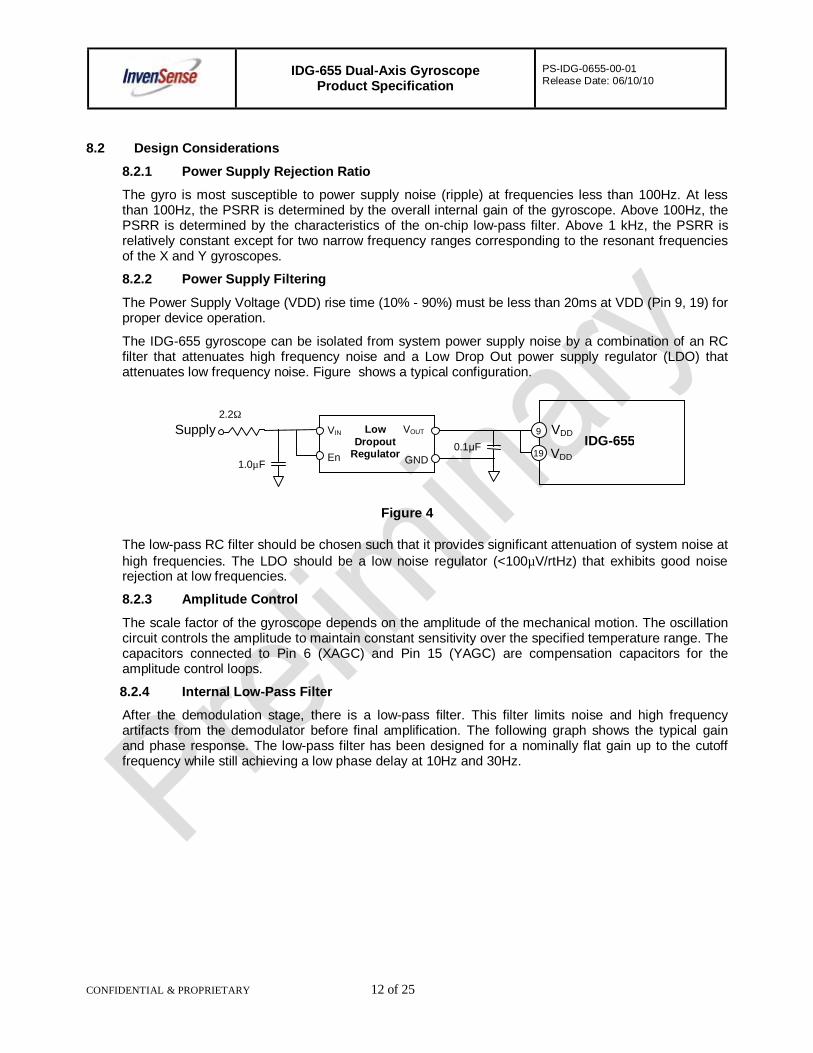
8.2.2 Power Supply Filtering
The Power Supply Voltage (VDD) rise time (10% - 90%) must be less than 20ms at VDD (Pin 9, 19) for proper device operation.
The IDG-655 gyroscope can be isolated from system power supply noise by a combination of an RC filter that attenuates high frequency noise and a Low Drop Out power supply regulator (LDO) that attenuates low frequency noise. Figure shows a typical configuration.
Figure 4
The low-pass RC filter should be chosen such that it provides significant attenuation of system noise at high frequencies. The LDO should be a low noise regulator (<100µV/rtHz) that exhibits good noise rejection at low frequencies.
8.2.3 Amplitude Control
The scale factor of the gyroscope depends on the amplitude of the mechanical motion. The oscillation circuit controls the amplitude to maintain constant sensitivity over the specified temperature range. The capacitors connected to Pin 6 (XAGC) and Pin 15 (YAGC) are compensation capacitors for the amplitude control loops.
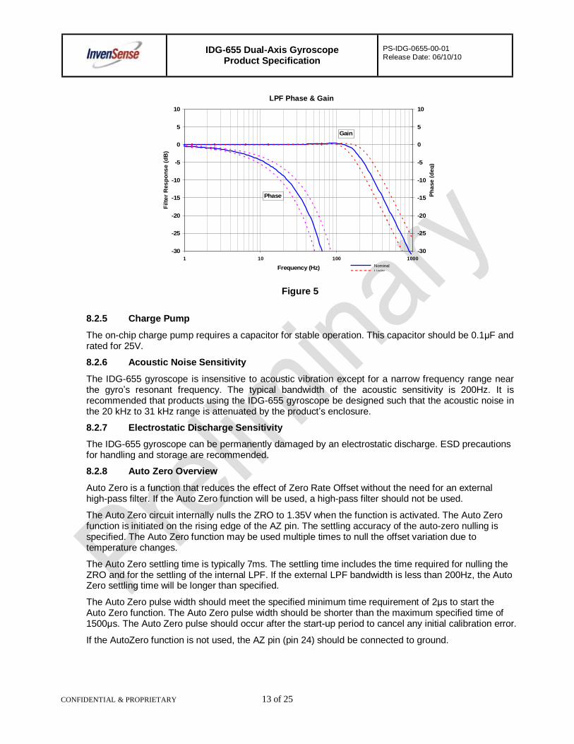
8.2.4 Internal Low-Pass Filter
After the demodulation stage, there is a low-pass filter. This filter limits noise and high frequency artifacts from the demodulator before final amplification. The following graph shows the typical gain and phase response. The low-pass filter has been designed for a nominally flat gain up to the cutoff frequency while still achieving a low phase delay at 10Hz and 30Hz.
IDG-655 19
Supply
1.0µF
2.2Ω
0.1µF VDD
VDD
VIN
En GND
VOUT 9 Low Dropout
Regulator
IDG-655 Dual-Axis Gyroscope Product Specification
PS-IDG-0655-00-01 Release Date: 06/10/10
CONFIDENTIAL & PROPRIETARY 13 of 25
Figure 5
8.2.5 Charge Pump
The on-chip charge pump requires a capacitor for stable operation. This capacitor should be 0.1µF and rated for 25V.
8.2.6 Acoustic Noise Sensitivity
The IDG-655 gyroscope is insensitive to acoustic vibration except for a narrow frequency range near the gyro’s resonant frequency. The typical bandwidth of the acoustic sensitivity is 200Hz. It is recommended that products using the IDG-655 gyroscope be designed such that the acoustic noise in the 20 kHz to 31 kHz range is attenuated by the product’s enclosure.
8.2.7 Electrostatic Discharge Sensitivity
The IDG-655 gyroscope can be permanently damaged by an electrostatic discharge. ESD precautions for handling and storage are recommended.
8.2.8 Auto Zero Overview
Auto Zero is a function that reduces the effect of Zero Rate Offset without the need for an external high-pass filter. If the Auto Zero function will be used, a high-pass filter should not be used.
The Auto Zero circuit internally nulls the ZRO to 1.35V when the function is activated. The Auto Zero function is initiated on the rising edge of the AZ pin. The settling accuracy of the auto-zero nulling is specified. The Auto Zero function may be used multiple times to null the offset variation due to temperature changes.
The Auto Zero settling time is typically 7ms. The settling time includes the time required for nulling the ZRO and for the settling of the internal LPF. If the external LPF bandwidth is less than 200Hz, the Auto Zero settling time will be longer than specified.
The Auto Zero pulse width should meet the specified minimum time requirement of 2µs to start the Auto Zero function. The Auto Zero pulse width should be shorter than the maximum specified time of 1500µs. The Auto Zero pulse should occur after the start-up period to cancel any initial calibration error.
If the AutoZero function is not used, the AZ pin (pin 24) should be connected to ground.
-30
-25
-20
-15
-10
-5
0
5
10
1 10 100 1000
Frequency (Hz)
Filte
r Res
pons
e (d
B)
-30
-25
-20
-15
-10
-5
0
5
10
Phas
e (d
eg)
Phase
Gain
NominalLimits
LPF Phase & Gain

IDG-655 Dual-Axis Gyroscope Product Specification
PS-IDG-0655-00-01 Release Date: 06/10/10
CONFIDENTIAL & PROPRIETARY 14 of 25
9. Assembly 9.1 Orientation
The diagram below shows the orientation of the axes of sensitivity and the polarity of rotation.
Figure 6
IDG-655
+Y
+X
IDG-655 Dual-Axis Gyroscope Product Specification
PS-IDG-0655-00-01 Release Date: 06/10/10
CONFIDENTIAL & PROPRIETARY 15 of 25
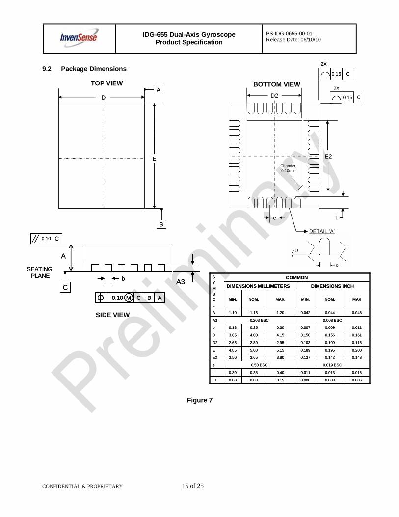
9.2 Package Dimensions
Figure 7
D
E
A
B
D
E
A
Be
0.15 C
2X
0.15 C
2X
L
E2
D2 0.15 C
2X
Chamfer,0.10mm
DETAIL ‘A’
A
Cb A3
C0.10
0.10 CM B A
SEATINGPLANE
A
Cb A3
C0.10
0.10 CM B A0.10 CM B A
SEATINGPLANE
0.0060.0030.0000.150.080.00L1
MAXNOM.MIN.MAX.NOM.MIN.
DIMENSIONS INCHDIMENSIONS MILLIMETERS
0.0150.0130.0110.400.350.30L
0.019 BSC0.50 BSCe
0.1480.1420.1373.803.653.50E2
0.2000.1950.1895.155.004.85E
0.1150.1090.1032.952.802.65D2
0.1610.1560.1504.154.003.85D
0.0110.0090.0070.300.250.18b
0.008 BSC0.203 BSCA3
0.0460.0440.0421.201.151.10A
COMMONSYMBOL
SIDE VIEW
TOP VIEW BOTTOM VIEW
IDG-655 Dual-Axis Gyroscope Product Specification
PS-IDG-0655-00-01 Release Date: 06/10/10
CONFIDENTIAL & PROPRIETARY 16 of 25
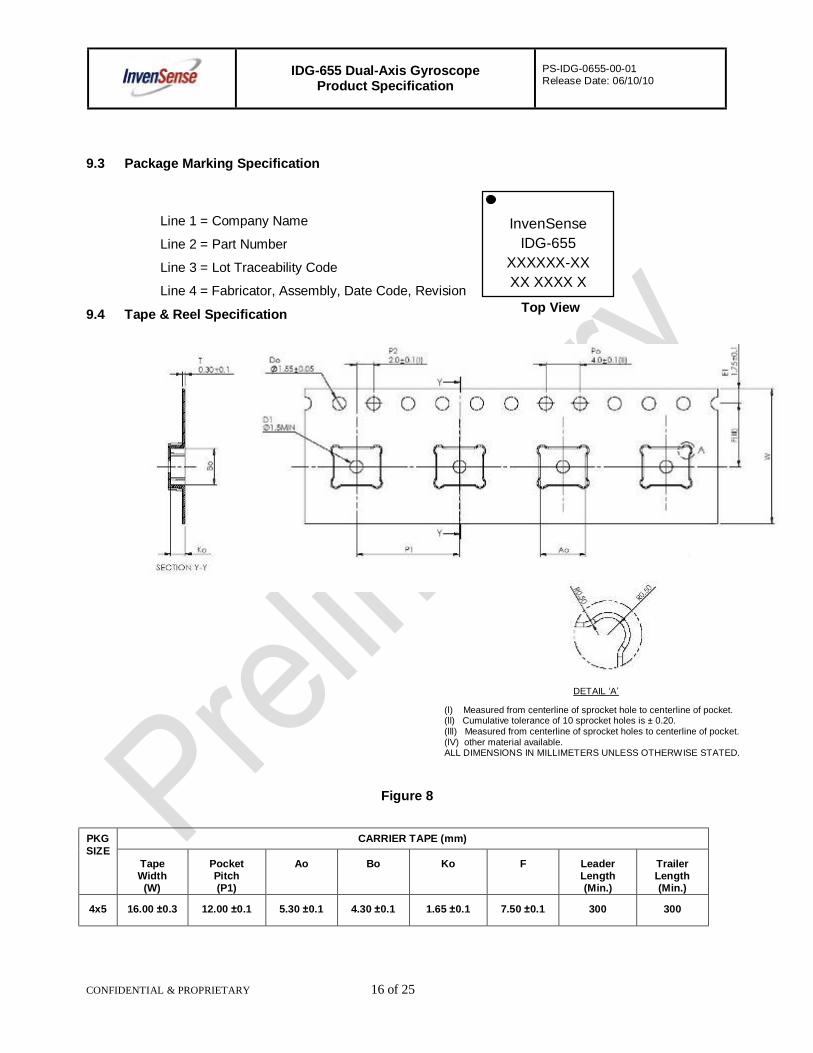
9.3 Package Marking Specification
9.4 Tape & Reel Specification
Figure 8
PKG SIZE
CARRIER TAPE (mm)
Tape Width
(W)
Pocket Pitch (P1)
Ao Bo Ko F Leader Length (Min.)
Trailer Length (Min.)
4x5 16.00 ±0.3 12.00 ±0.1 5.30 ±0.1 4.30 ±0.1 1.65 ±0.1 7.50 ±0.1 300 300
DETAIL ‘A’
(l) Measured from centerline of sprocket hole to centerline of pocket. (ll) Cumulative tolerance of 10 sprocket holes is ± 0.20. (lll) Measured from centerline of sprocket holes to centerline of pocket. (lV) other material available. ALL DIMENSIONS IN MILLIMETERS UNLESS OTHERWISE STATED.
Line 1 = Company Name
Line 2 = Part Number
Line 3 = Lot Traceability Code
Line 4 = Fabricator, Assembly, Date Code, Revision Top View
InvenSense
IDG-655 XXXXXX-XX XX XXXX X
IDG-655 Dual-Axis Gyroscope Product Specification
PS-IDG-0655-00-01 Release Date: 06/10/10
CONFIDENTIAL & PROPRIETARY 17 of 25
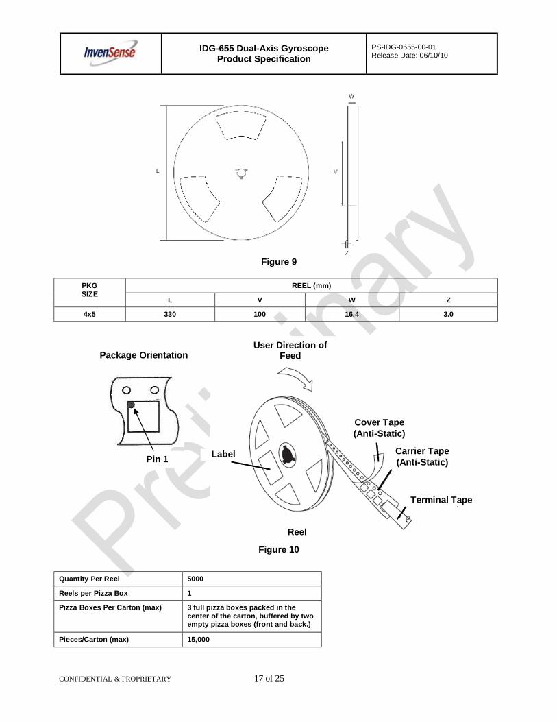
Figure 9
PKG SIZE
REEL (mm)
L V W Z
4x5 330 100 16.4 3.0
Figure 10
Quantity Per Reel 5000
Reels per Pizza Box 1
Pizza Boxes Per Carton (max) 3 full pizza boxes packed in the center of the carton, buffered by two empty pizza boxes (front and back.)
Pieces/Carton (max) 15,000
Package Orientation
Pin 1
User Direction of Feed
Cover Tape (Anti-Static)
Carrier Tape (Anti-Static)
Label
Reel
Terminal Tape
IDG-655 Dual-Axis Gyroscope Product Specification
PS-IDG-0655-00-01 Release Date: 06/10/10
CONFIDENTIAL & PROPRIETARY 18 of 25
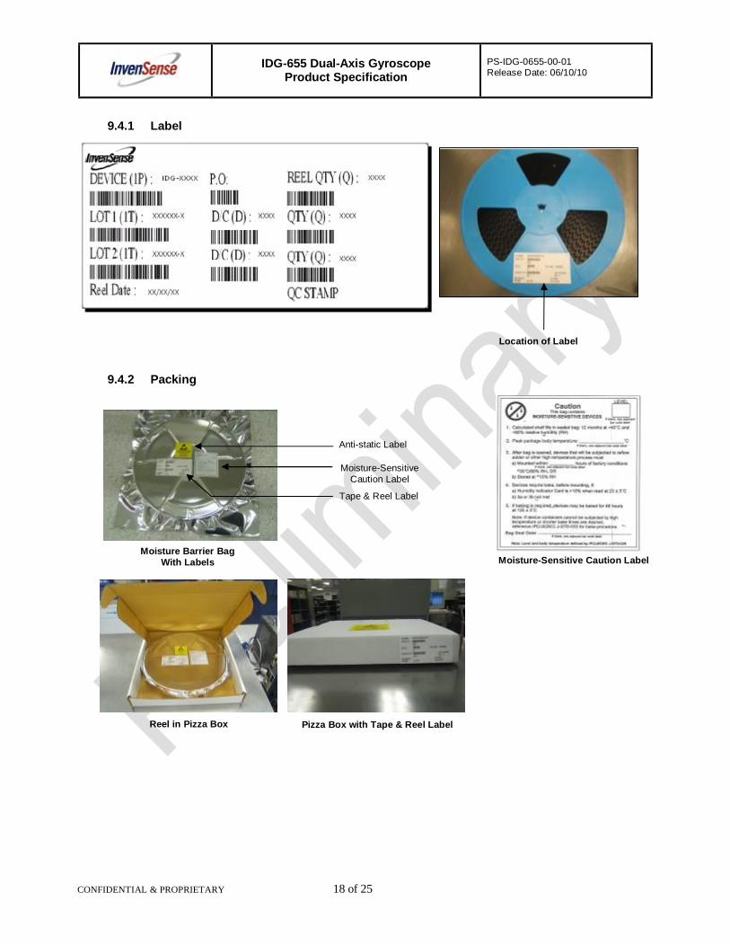
9.4.1 Label
9.4.2 Packing
Location of Label
Moisture Barrier Bag With Labels
Anti-static Label
Moisture-Sensitive Caution Label
Tape & Reel Label
Reel in Pizza Box Pizza Box with Tape & Reel Label
Moisture-Sensitive Caution Label
IDG-655 Dual-Axis Gyroscope Product Specification
PS-IDG-0655-00-01 Release Date: 06/10/10
CONFIDENTIAL & PROPRIETARY 19 of 25
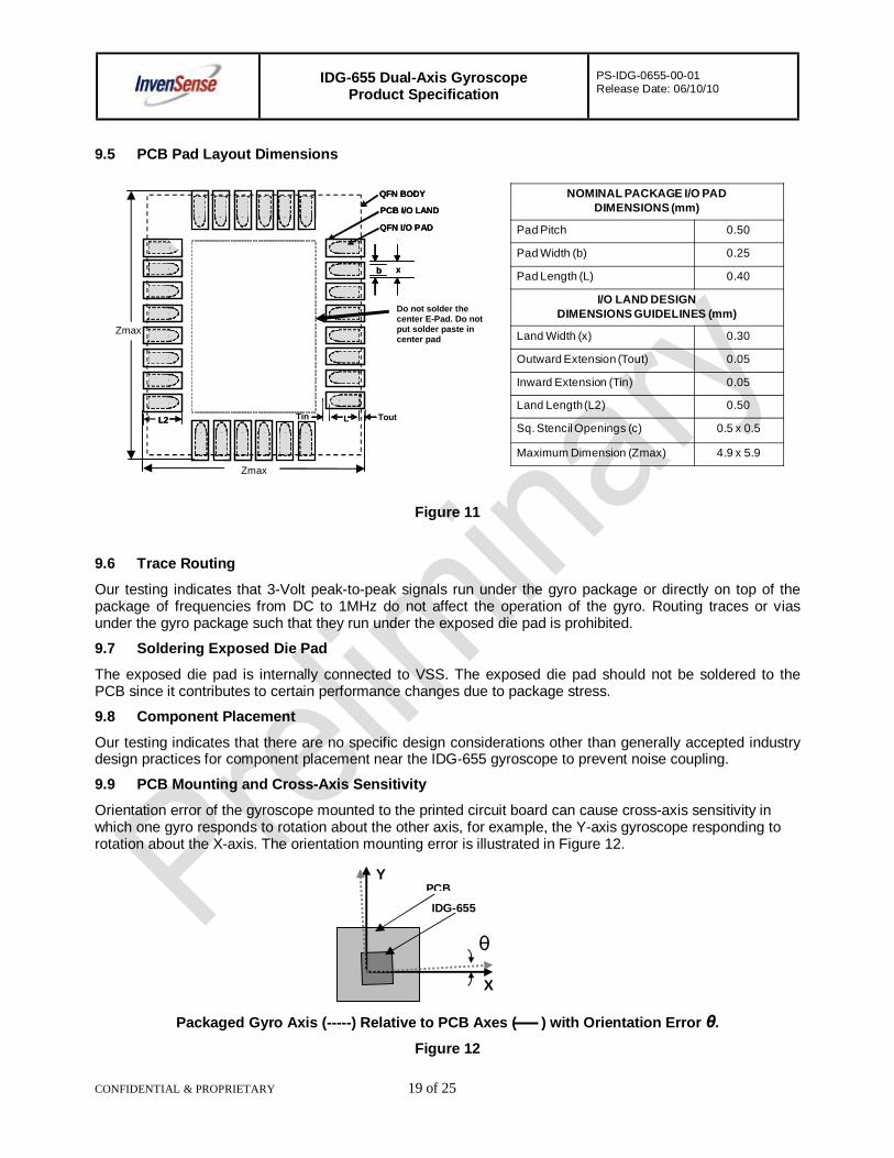
9.5 PCB Pad Layout Dimensions
Figure 11
9.6 Trace Routing
Our testing indicates that 3-Volt peak-to-peak signals run under the gyro package or directly on top of the package of frequencies from DC to 1MHz do not affect the operation of the gyro. Routing traces or vias under the gyro package such that they run under the exposed die pad is prohibited.
9.7 Soldering Exposed Die Pad
The exposed die pad is internally connected to VSS. The exposed die pad should not be soldered to the PCB since it contributes to certain performance changes due to package stress.
9.8 Component Placement
Our testing indicates that there are no specific design considerations other than generally accepted industry design practices for component placement near the IDG-655 gyroscope to prevent noise coupling.
9.9 PCB Mounting and Cross-Axis Sensitivity
Orientation error of the gyroscope mounted to the printed circuit board can cause cross-axis sensitivity in which one gyro responds to rotation about the other axis, for example, the Y-axis gyroscope responding to rotation about the X-axis. The orientation mounting error is illustrated in Figure 12.
Packaged Gyro Axis (-----) Relative to PCB Axes ( ) with Orientation Error θ.
Figure 12
X
Y
θ
IDG-655 PCB
NOMINAL PACKAGE I/O PADDIMENSIONS (mm)
Pad Pitch 0.50
Pad Width (b) 0.25
Pad Length (L) 0.40
I/O LAND DESIGNDIMENSIONS GUIDELINES (mm)
Land Width (x) 0.30
Outward Extension (Tout) 0.05
Inward Extension (Tin) 0.05
Land Length(L2) 0.50
Sq. Stencil Openings (c) 0.5 x 0.5
Maximum Dimension (Zmax) 4.9 x 5.9
b x
QFN BODY
PCB I/O LAND
QFN I/O PAD
L2
b x
Tin Tout
QFN BODY
PCB I/O LAND
QFN I/O PAD
L2
Do not solder the center E-Pad. Do not put solder paste in center pad Zmax
Zmax
L
IDG-655 Dual-Axis Gyroscope Product Specification
PS-IDG-0655-00-01 Release Date: 06/10/10
CONFIDENTIAL & PROPRIETARY 20 of 25
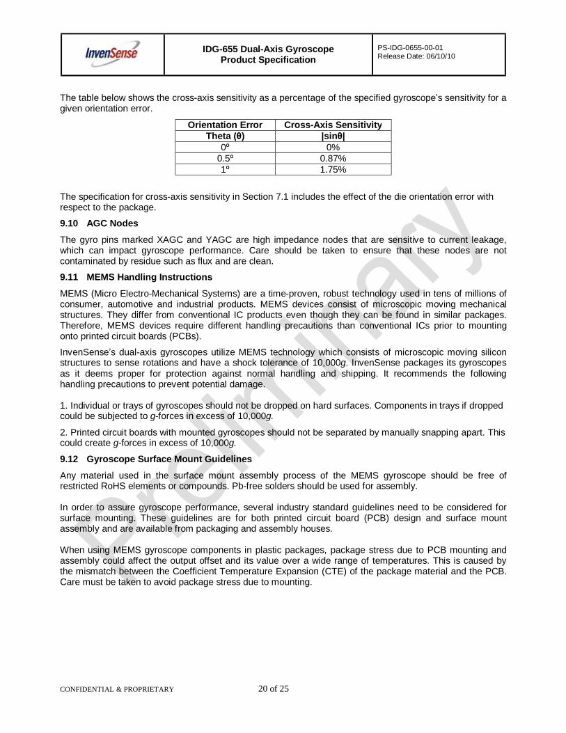
The table below shows the cross-axis sensitivity as a percentage of the specified gyroscope’s sensitivity for a given orientation error.
Orientation Error Cross-Axis Sensitivity Theta (θ) |sinθ|
0º 0% 0.5º 0.87% 1º 1.75%
The specification for cross-axis sensitivity in Section 7.1 includes the effect of the die orientation error with respect to the package.
9.10 AGC Nodes
The gyro pins marked XAGC and YAGC are high impedance nodes that are sensitive to current leakage, which can impact gyroscope performance. Care should be taken to ensure that these nodes are not contaminated by residue such as flux and are clean.
9.11 MEMS Handling Instructions
MEMS (Micro Electro-Mechanical Systems) are a time-proven, robust technology used in tens of millions of consumer, automotive and industrial products. MEMS devices consist of microscopic moving mechanical structures. They differ from conventional IC products even though they can be found in similar packages. Therefore, MEMS devices require different handling precautions than conventional ICs prior to mounting onto printed circuit boards (PCBs).
InvenSense’s dual-axis gyroscopes utilize MEMS technology which consists of microscopic moving silicon structures to sense rotations and have a shock tolerance of 10,000g. InvenSense packages its gyroscopes as it deems proper for protection against normal handling and shipping. It recommends the following handling precautions to prevent potential damage. 1. Individual or trays of gyroscopes should not be dropped on hard surfaces. Components in trays if dropped could be subjected to g-forces in excess of 10,000g.
2. Printed circuit boards with mounted gyroscopes should not be separated by manually snapping apart. This could create g-forces in excess of 10,000g.
9.12 Gyroscope Surface Mount Guidelines
Any material used in the surface mount assembly process of the MEMS gyroscope should be free of restricted RoHS elements or compounds. Pb-free solders should be used for assembly.
In order to assure gyroscope performance, several industry standard guidelines need to be considered for surface mounting. These guidelines are for both printed circuit board (PCB) design and surface mount assembly and are available from packaging and assembly houses.
When using MEMS gyroscope components in plastic packages, package stress due to PCB mounting and assembly could affect the output offset and its value over a wide range of temperatures. This is caused by the mismatch between the Coefficient Temperature Expansion (CTE) of the package material and the PCB. Care must be taken to avoid package stress due to mounting.
IDG-655 Dual-Axis Gyroscope Product Specification
PS-IDG-0655-00-01 Release Date: 06/10/10
CONFIDENTIAL & PROPRIETARY 21 of 25
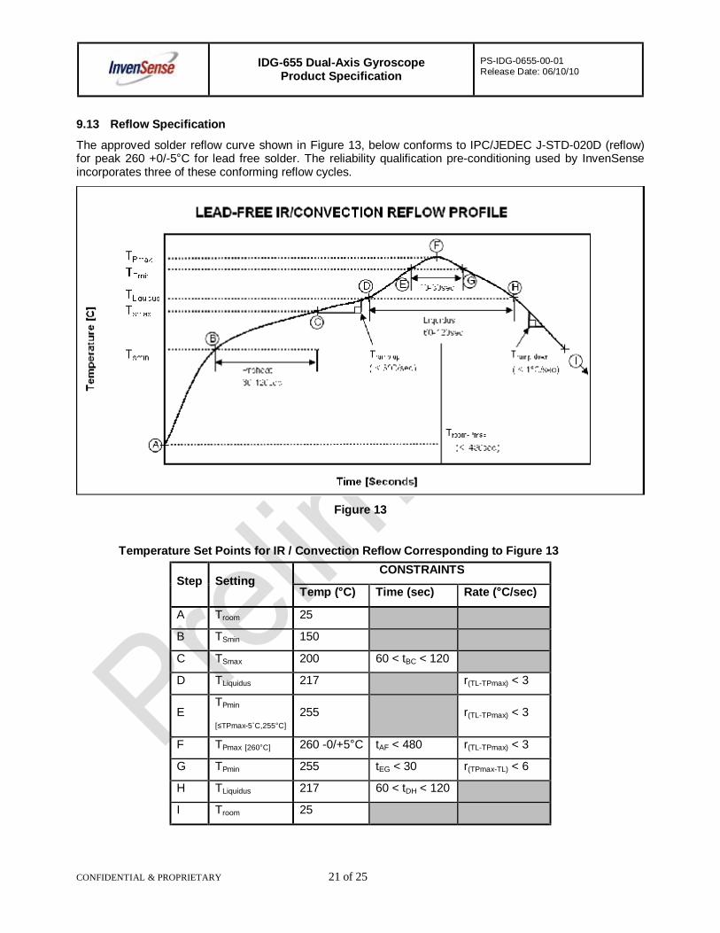
9.13 Reflow Specification
The approved solder reflow curve shown in Figure 13, below conforms to IPC/JEDEC J-STD-020D (reflow) for peak 260 +0/-5°C for lead free solder. The reliability qualification pre-conditioning used by InvenSense incorporates three of these conforming reflow cycles.
Figure 13
Temperature Set Points for IR / Convection Reflow Corresponding to Figure 13
Step Setting CONSTRAINTS
Temp (°C) Time (sec) Rate (°C/sec) A Troom 25
B TSmin 150
C TSmax 200 60 < tBC < 120
D TLiquidus 217 r(TL-TPmax) < 3
E TPmin
[≤TPmax-5˚C,255°C] 255 r(TL-TPmax) < 3
F TPmax [260°C] 260 -0/+5°C tAF < 480 r(TL-TPmax) < 3 G TPmin 255 tEG < 30 r(TPmax-TL) < 6 H TLiquidus 217 60 < tDH < 120
I Troom 25
IDG-655 Dual-Axis Gyroscope Product Specification
PS-IDG-0655-00-01 Release Date: 06/10/10
CONFIDENTIAL & PROPRIETARY 22 of 25
All temperatures refer to the topside of the QFN package, as measured on the package body surface. The temperatures described in the table (above) are the maximum temperatures specified for the supplier to use to qualify the package for reliability. These represent the maximum tolerable ratings for the package. Solder manufacturers have developed solder formulations that will assure excellent results at lower temperatures. Use the solder manufacturer’s recommendations for recommended temperatures. In all cases, the solder manufacturer’s recommendations should not exceed the constraints used in the package qualification. In general, production solder reflow processes used by the customer should use lower temperatures, reduced exposure times to high temperatures, and lower ramp-up and ramp-down rates for optimum results.
9.14 Storage Specifications and Re-Bake The storage specification of the IDG-655 gyroscope conforms to IPC/JEDEC J-STD-020D.01 MSL-3, for storage shelf life before reflow and production use. The parts are packaged using tape-and-reel packaging (see Section 9.4). The tape and reel, along with a Humidity Indicator Card (HIC) and a desiccant package are vacuum sealed in moisture proof bags labeled with MSL-3 and ESD warning labels (see Section 9.4.2).
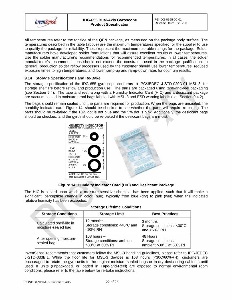
The bags should remain sealed until the parts are required for production. When the bags are unsealed, the humidity indicator card, Figure 14, should be checked to see whether the parts will require re-baking. The parts should be re-baked if the 10% dot is not blue and the 5% dot is pink. Additionally, the desiccant bags should be checked, and the gyros should be re-baked if the desiccant bags are moist.
Figure 14: Humidity Indicator Card (HIC) and Desiccant Package
The HIC is a card upon which a moisture-sensitive chemical has been applied, such that it will make a significant, perceptible change in color (hue), typically from blue (dry) to pink (wet) when the indicated relative humidity has been exceeded.
Storage Lifetime Conditions
Storage Conditions Storage Limit Best Practices
Calculated shelf-life in moisture-sealed bag
12 months – Storage conditions: <40°C and <90% RH
3 months Storage conditions: <30°C and <60% RH
After opening moisture-sealed bag
168 hours – Storage conditions: ambient ≤30°C at 60% RH
48 Hours Storage conditions: ambient ≤30°C at 60% RH
InvenSense recommends that customers follow the MSL-3 handling guidelines, please refer to IPC/JEDEC J-STD-033B.1. While the floor life for MSL-3 devices is 168 hours (<30C/60%RH), customers are encouraged to retain the gyro units in the original moisture-sealed bags or in dry desiccating cabinets until used. If units (unpackaged, or loaded in Tape-and-Reel) are exposed to normal environmental room conditions, please refer to the table below for re-bake instructions.
IDG-655 Dual-Axis Gyroscope Product Specification
PS-IDG-0655-00-01 Release Date: 06/10/10
CONFIDENTIAL & PROPRIETARY 23 of 25
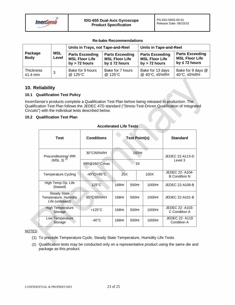
Re-bake Recommendations
Package Body
MSL Level
Units in Trays, not Tape-and-Reel Units in Tape-and-Reel
Parts Exceeding MSL Floor Life by > 72 hours
Parts Exceeding MSL Floor Life by ≤ 72 hours
Parts Exceeding MSL Floor Life by > 72 hours
Parts Exceeding MSL Floor Life by ≤ 72 hours
Thickness ≤1.4 mm 3 Bake for 9 hours
@ 125°C Bake for 7 hours @ 125°C
Bake for 13 days @ 40°C, ≤5%RH
Bake for 9 days @ 40°C, ≤5%RH
10. Reliability 10.1 Qualification Test Policy
InvenSense’s products complete a Qualification Test Plan before being released to production. The Qualification Test Plan follows the JEDEC 47D standard (“Stress-Test-Driven Qualification of Integrated Circuits”) with the individual tests described below.
10.2 Qualification Test Plan
Accelerated Life Tests
Test Conditions Test Point(s) Standard
Preconditioning/ IRR (MSL 3) (1)
30°C/60%RH 192Hr JEDEC 22-A113-D
Level 3 IRR@260°C max 3X
Temperature Cycling -40°C/+85°C 25X 100X JEDEC 22- A104-B Condition N
High Temp Op. Life (biased) 125°C 168Hr 500Hr 1000Hr JEDEC 22-A108-B
Steady State Temperature, Humidity
Life (unbiased) 85°C/85%RH 168Hr 500Hr 1000Hr JEDEC 22-A101-B
High Temperature Storage +125°C 168Hr 500Hr 1000Hr JEDEC 22- A103-
C Condition A
Low Temperature Storage -40°C 168Hr 500Hr 1000Hr JEDEC 22- A119
Condition A
NOTES:
(1) To precede Temperature Cycle, Steady State Temperature, Humidity Life Tests
(2) Qualification tests may be conducted only on a representative product using the same die and package as this product.
IDG-655 Dual-Axis Gyroscope Product Specification
PS-IDG-0655-00-01 Release Date: 06/10/10
CONFIDENTIAL & PROPRIETARY 24 of 25
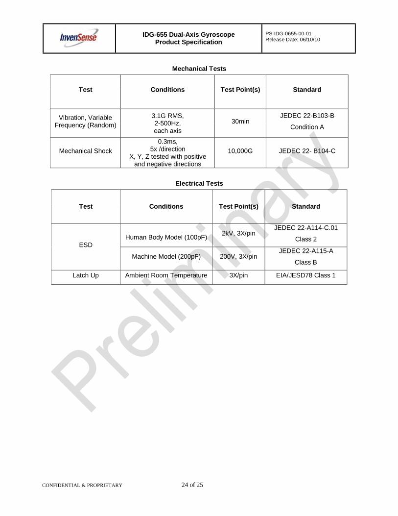
Mechanical Tests
Test Conditions Test Point(s) Standard
Vibration, Variable Frequency (Random)
3.1G RMS, 2-500Hz, each axis
30min JEDEC 22-B103-B
Condition A
Mechanical Shock 0.3ms,
5x /direction X, Y, Z tested with positive
and negative directions
10,000G JEDEC 22- B104-C
Electrical Tests
Test Conditions Test Point(s) Standard
ESD Human Body Model (100pF) 2kV, 3X/pin
JEDEC 22-A114-C.01
Class 2
Machine Model (200pF) 200V, 3X/pin JEDEC 22-A115-A
Class B
Latch Up Ambient Room Temperature 3X/pin EIA/JESD78 Class 1
IDG-655 Dual-Axis Gyroscope Product Specification
PS-IDG-0655-00-01 Release Date: 06/10/10
CONFIDENTIAL & PROPRIETARY 25 of 25
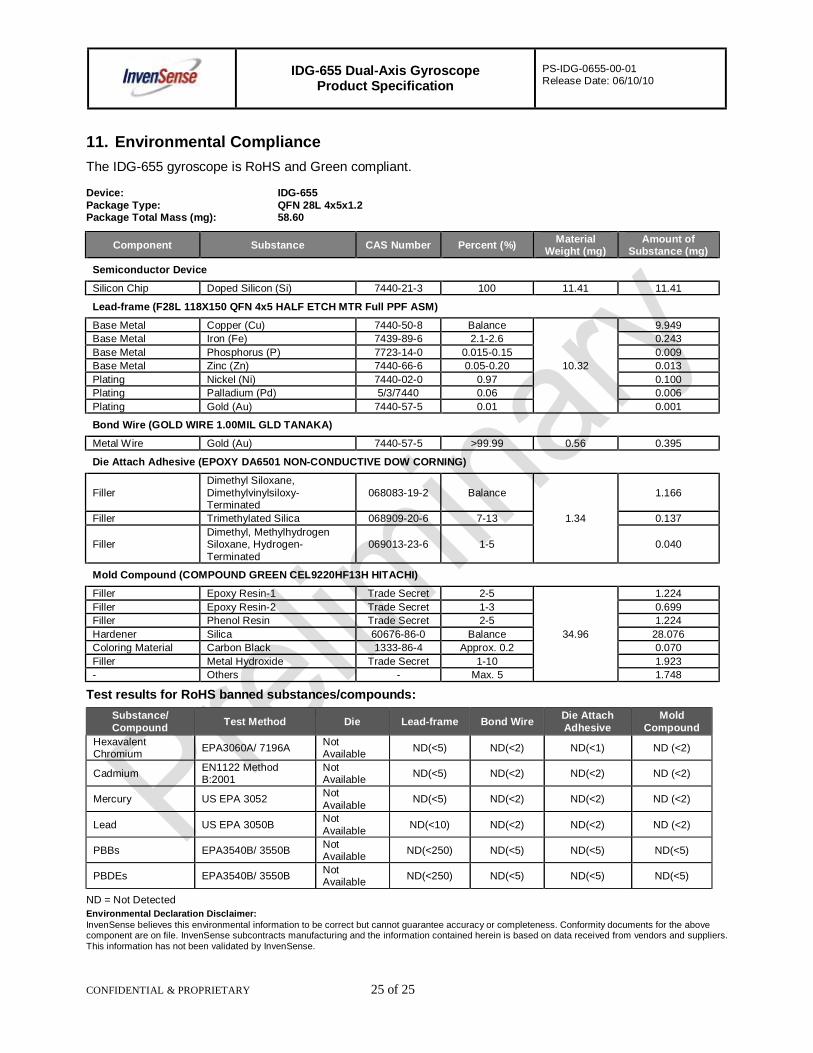
11. Environmental Compliance The IDG-655 gyroscope is RoHS and Green compliant. Device: IDG-655 Package Type: QFN 28L 4x5x1.2 Package Total Mass (mg): 58.60
Component Substance CAS Number Percent (%) Material Weight (mg)
Amount of Substance (mg)
Semiconductor Device
Silicon Chip Doped Silicon (Si) 7440-21-3 100 11.41 11.41
Lead-frame (F28L 118X150 QFN 4x5 HALF ETCH MTR Full PPF ASM)
Base Metal Copper (Cu) 7440-50-8 Balance 9.949 Base Metal Iron (Fe) 7439-89-6 2.1-2.6 0.243 Base Metal Phosphorus (P) 7723-14-0 0.015-0.15 0.009 Base Metal Zinc (Zn) 7440-66-6 0.05-0.20 10.32 0.013 Plating Nickel (Ni) 7440-02-0 0.97 0.100 Plating Palladium (Pd) 5/3/7440 0.06 0.006 Plating Gold (Au) 7440-57-5 0.01 0.001
Bond Wire (GOLD WIRE 1.00MIL GLD TANAKA)
Metal Wire Gold (Au) 7440-57-5 >99.99 0.56 0.395
Die Attach Adhesive (EPOXY DA6501 NON-CONDUCTIVE DOW CORNING)
Filler Dimethyl Siloxane, Dimethylvinylsiloxy-Terminated
068083-19-2 Balance 1.166
Filler Trimethylated Silica 068909-20-6 7-13 1.34 0.137
Filler Dimethyl, Methylhydrogen Siloxane, Hydrogen-Terminated
069013-23-6 1-5 0.040
Mold Compound (COMPOUND GREEN CEL9220HF13H HITACHI)
Filler Epoxy Resin-1 Trade Secret 2-5 1.224 Filler Epoxy Resin-2 Trade Secret 1-3 0.699 Filler Phenol Resin Trade Secret 2-5 1.224 Hardener Silica 60676-86-0 Balance 34.96 28.076 Coloring Material Carbon Black 1333-86-4 Approx. 0.2 0.070 Filler Metal Hydroxide Trade Secret 1-10 1.923 - Others - Max. 5 1.748
Test results for RoHS banned substances/compounds: Substance/ Compound Test Method Die Lead-frame Bond Wire Die Attach
Adhesive Mold
Compound Hexavalent Chromium EPA3060A/ 7196A Not
Available ND(<5) ND(<2) ND(<1) ND (<2)
Cadmium EN1122 Method B:2001
Not Available ND(<5) ND(<2) ND(<2) ND (<2)
Mercury US EPA 3052 Not Available ND(<5) ND(<2) ND(<2) ND (<2)
Lead US EPA 3050B Not Available ND(<10) ND(<2) ND(<2) ND (<2)
PBBs EPA3540B/ 3550B Not Available ND(<250) ND(<5) ND(<5) ND(<5)
PBDEs EPA3540B/ 3550B Not Available ND(<250) ND(<5) ND(<5) ND(<5)
ND = Not Detected Environmental Declaration Disclaimer: InvenSense believes this environmental information to be correct but cannot guarantee accuracy or completeness. Conformity documents for the above component are on file. InvenSense subcontracts manufacturing and the information contained herein is based on data received from vendors and suppliers. This information has not been validated by InvenSense.