ics 97.040.20 q82 gb - europatrade.ec.europa.eu/doclib/docs/2007/february/tradoc_133282.en.pdf ·...
TRANSCRIPT

ICS 97.040.20 Q82
GB National Standard of the People’s Republic of China
GB 16410 – xxxx Replacing GB 16410-1996
_______________________________________________________________
Domestic gas cooking appliances
(Version Submitted for Approval)
Promulgated on 2006- - Enforced on 2006- -
____________________________________________________________________

The General Administration of Quality Supervision, Inspection and Quarantine of the People’s Republic of China Promulgated
by The Standardisation Administration of the People’s Republic of China (SAC)

GB 16410-XXXX
Contents Foreword ………………………………………….……………………………… III 1 Scope …………………………………………………………………………. 1 2 Normative references ………………………………………………………… 1 3 Terms and definitions ………………………………………………………… 2 4 Classification of products …………………………………………………… 3 4.1 Types of cooking appliances ………………………………………………. 3 4.2 Numbering methods for cooking appliance models …………………….… 3 5 Requirements …………………………………………………………………. 4 5.1 Basic design parameters ……………………………………………………. 4 5.2 Performance ……………………………………………………….……….. 4 5.2.1 Air-tightness ……………………………………………………………… 4 5.2.2 Heat input ………………………………………………………………… 4 5.2.3 Operating mode of burning ……………………………………………… 4 5.2.4 Temperature rise …………………………………………………………. 5 5.2.5 Heat impact resistance …………………………………………………… 5 5.2.6 Gravitational impact resistance …………………………………….……. 6 5.2.7 Safety devices ……………………………………………………….……. 6 5.2.8 Electric ignition device ………………………………………………….. 6 5.2.9 Utilisation performance ……………………………………………….… 6 5.2.10 Electrical performance …………………………………………….…… 6 5.2.11 Durability performance ………………………………………………… 7 5.2.12 Vibration resistance performance ……………………………………… 7 5.2.13 Falling resistance performance ………………………………………… 7 5.2.14 Pressure-bearing performance of package ……………………….…….. 8 5.3 Structure …………………………………………………….……….…….. 8 5.3.1 General structure ………………………………………………………… 8 5.3.2 Structure of stove ………………………………………………………... 9 5.3.3 Structure of barbecue ……………………………………………………. 9 5.3.4 Structure of oven ………………………………………………………… 9 5.3.5 Structure of rice cooker ………………………………………………… 10 5.3.6 Special structural requirements for cooking appliances using AC power … 10 5.3.7 Structure of parts ………………………………………………….…… 14 5.4 Materials …………………………………………………………………. 14 5.4.1 General requirements for materials ………………..…………………… 14 5.4.2 Sealing materials …………………………………………….………… 15

GB 16410-XXXX
5.4.3 Thermo materials ……………………………………………….…….. 15 5.4.4 Electricity-conducting materials …………………………………….… 15 5.4.5 Gas conduit and conduit of permanent pilot igniter …………………… 15 5.4.6 Cock valve ………………………………………………………….….. 15 5.4.7 Nozzle …………………………………………………………………. 15 5.4.8 Nozzle stand ……………………………………………………………. 15 5.4.9 Air conditioner ………………….………………………………….….. 15 5.4.10 Burner ……………………………………………………………….…. 15 5.4.11 Pot support ………………………………………………………….… 15 5.4.12 Fluid plate …………………………………………………………….. 15 5.4.13 Inner walls, baking pan and baking rack of oven, and radiation plate
of barbecue ……………………………………………………………. 16 5.4.14 Glass of oven door ……………………………………………………. 16 5.4.15 Toughened glass panel ………………………………………………… 16 5.4.16 Other non-metallic panels ………………………………………..….… 16 5.4.17 Stove legs ……………………………………………………………… 16 5.4.18 Pot of rice cooker ……………………………………………………… 16 5.4.19 Packaging materials and packaging waste …………………………...… 16 5.4.20 Flame detector of protective extinguishing device ………….………… 16 5.5 Appearance ……………………………………………………………….. 16 6 Test methods ……………………………………………………………….. 16 6.1 Test room status ………….………………………………………………. 16 6.2 Gas for use in test ………………………………………………………… 16 6.3 Major instruments for use in test ………………………………………… 17 6.4 Test equipment ………………………………………………………….. 17 6.5 Test status of cooking appliances ………………………………………… 17 6.6 Air-tightness test ………………………………………………………….. 17 6.7 Heat input test ……………………………………………….…………… 19 6.8 Test of operating mode of burning ………………………………..……… 20 6.9 Temperature rise test ……………………………………………………… 22 6.10 Test of heat impact resistance …………………………………………… 25 6.11 Test of gravitational impact resistance ………………………..………… 25 6.12 Test of safety device …………………………………………………….. 25 6.13 Test of electrical ignition device ………………………………………….. 25 6.14 Utilisation performance test ……………………………………….…… 26 6.15 Electrical performance test …………………………………….……….. 28

GB 16410-XXXX
6.16 Durability performance test …………………………………….………. 31 6.17 Vibration test …………………………………………………….……… 32 6.18 Falling test ……………………………………………………………… 32 6.19 Structure test ……………………………………………………………. 32 6.20 Heat resistance performance test of parts ………………………………. 32 6.21 Test of materials ………………………………………………………… 33 7 Test rules…………………………………………………………..……….. 34 7.1 Ex-factory inspection ……………………………………………………. 34 7.2 Type inspection ………………………………………………………….. 34 7.3 Judgement principles for the inspection of an individual cooking appliance … 34 8 Marking, packaging, transportation, storage ………………………………… 34 8.1 Marking ………………………………………………………………….. 35 8.2 Packaging ……………………………………………………………...…… 35 8.3 Transportation ……………………………………………………………. 36 8.4 Storage …………………………………………………………………… 36 Appendix A (Information Appendix) Gradation requirements in terms of nitrogen oxide [Nox (α=1)] content in the fumes released by domestic gas cooking
appliances …………………………………………………………. 46

GB 16410-XXXX
Foreword This Standard has mandatory clauses. In the Standard, all the parts of the following in bold typeface are mandatory clauses: subsections 5.2.1; 5.2.2a and c; 5.2.5c; 5.2.6b; 5.2.7.1b; 5.2.7.3; 5.2.10.2; 5.3.1.4; 5.3.1.5; 5.3.1.10d and f; 5.3.1.12; 5.3.1.14; 5.3.2.6; 5.3.6; 5.3.7.5a; 5.4.2.2; 5.4.2.3; 5.4.10.1; 5.4.16.1; all clauses of 8.1.1 apart from f; 8.1.2; 8.2.1; 8.2.4c, d and h; and Tables 2, 3, 4, 5, 6, 7 and 8. The remaining clauses are recommended clauses. The following contents of this version of the Standard are based on the related international and foreign standards: The standard conditions, maximum normal temperature rise, performance of the burner in relation to resistance to overheating and test methods are based on EN 30-1-1: 1998 “Domestic gas cooking appliances – Part 1-1: Safety – General.” The valve closing time of the protective extinguishing device is based on EN 30-1-1: 1998 “Domestic gas cooking appliances – Part 1-1: Safety – General” and JIS S 2103-1996 “Gas-burning cooking appliances for domestic use.” The utilisation performance requirements of the oven and test methods are based on JIS S 2103-1996 “Gas-burning cooking appliances for domestic use” and JIS S 2093-1996 “Test methods for gas-burning appliances for domestic use.” The equation for calculating the CO concentration percentage in dry fumes is based on JIS S 2103-1996 “Gas-burning cooking appliances for domestic use.” Comparing the Standard with GB16410-1996 “Domestic gas appliances,” the major changes are as follows: – This version of the Standard has mandatory clauses whereas the whole text of the
1996 version of the Standard was mandatory; – The scope of application has been increased to include gas-electric combined
stoves; – In the Terms and Definitions section, 2 terms have been deleted, 5 terms revised,
and 16 terms added; – The standard temperature has been adjusted from 0oC in the 1996 version to
15oC; – In the 1996 version, the required heat input from the main fire of stoves with two

GB 16410-XXXX
burners or more was a minimum of 2.91 kW. But in this Standard, it has been adjusted that there should be one main fire in stoves with two burners or more as well as in gas-electric combined stoves, and its converted actual heat input is: ≥ 3.5 kW for ordinary types of cooking appliances; ≥ 3.0 kW for infrared ray cooking appliances.
– The requirements for use in airy conditions have been deleted; – It is specified that each burner of the stove should be equipped with a protective
extinguishing device; – The special structural requirements for cooking appliances which use AC power
have been increased; – The quality requirements in terms of the materials for cooking appliances have
been revised as the performance requirements of materials; – The clauses regarding packaging materials and packaging waste have been
increased; – The equation for calculating the actual heat input has been added to; – The equation for calculating the converted actual heat input has been revised; – The equation for calculating the percentage of CO concentration in dry fumes has
been revised; – Regarding the conditions of the test room, the room temperature of 20±15oC has
been changed to 20±5oC; – Falling and stacking requirements and test methods have been increased. Appendix A of the Standard is an information appendix. The transition period of the Standard after its promulgation is 9 months. This Standard was proposed by the General Administration of Quality Supervision, Inspection and Quarantine and the Standardisation Administration of the People’s Republic of China. The Standard is held by the China Association for Standardisation and the China Metal Products Association. Drafting units of the Standard: Zhongshan Vantage Gas Appliances Corporation, Quanguo Daily Metals Standardisation Centre, Jiangsu Provincial Supervision and Testing Centre for Product Quality, Zhejiang Dandy Kitchenware Co. Ltd., China Quality Supervision and Test Centre for Gas Appliances, China Product Quality Supervision and Test Centre for Gas Appliances (Foshan), China Supervision and Testing Centre for Quality of Daily Metal Products, Haier Group Gas Stove Research Unit, Foshan City Midea Electric Kitchen Appliances Manufacturing Co. Ltd., Guangdong Macro Gas Appliances Co. Ltd., Jiangsu Guangmang Light Tool Co. Ltd.,

GB 16410-XXXX
Zhejiang Puti Electrical Appliances Co. Ltd., Hangzhou Laoban Industries Group Co. Ltd., Shanxi Tianzhou High Technology Co. Ltd. and Guangdong Chant (Group) Co. Ltd. Main drafters of the Standard: Yi Hongbin, Yao Kenong, Wang Fengling, Gao Dekang, Liu Tong, Bi Zhitao, Weng Wuyun, Cai Weiming, Chou Minggui, Zhou Shideng, Du Renyao, Wu Weiliang, Fu Liang and Xiong Wei. The previous versions of the Standard, which are replaced by this Standard on its promulgation, are: – CJ 4-1983; – GB 16410-1996.

GB 16410-XXXX
Domestic gas cooking appliances
1 Scope The Standard specifies the terms and definitions, classification, requirements, test methods, inspection rules, marking, packaging, transportation and storage of domestic gas cooking appliances. The Standard is applicable to domestic cooking appliances which use town gas and domestic gas-electric combined stoves which use town gas and electrical energy, including:
a) Gas stoves with a nominal heat input at their single burners of ≤ 5.23 kW; b) Gas ovens and gas barbecues with a nominal heat input of ≤ 5.82 kW; c) Freestanding gas cookers and independent hotplates and grills with a nominal heat input meeting the requirements of a) and b); d) Gas-powered rice cookers with a maximum volume for rice softening in the closed rice cooker of ≤ 4 l each time and a nominal heat input of ≤ 4.19 kW; e) Gas-electric combined stove with a nominal heat input meeting the requirements of a), b) and d), and a total nominal input power of ≤ 5.00 kW.
For domestic gas cooking appliances which use gas types other than those covered by GB/T 13611 “Classification of town gas”, please refer to the Standard. The Standard does not apply to gas cooking appliances used in road and other types of transport vehicles. 2 Normative references The clauses in the following documents become clauses of this standard after being referenced. For all dated reference documents, subsequent amendments (excluding corrections) and revised versions do not apply to this standard; however, any parties that come to an agreement in accordance with the Standard are encouraged to study whether the latest versions of these documents are applicable. Where the references are not dated, their latest versions are applicable to the Standard. GB 4208 Degrees of protection provided by enclosures (IP code) GB 4706.1 Safety of household and similar electrical appliances –
General requirements GB 4706.22 Safety of household and similar electrical appliances –

GB 16410-XXXX
Specific requirements for stationary cooking ranges, hobs, ovens and similar appliances
GB 5013.4 Rubber insulated cables with rated voltages up to and including 450/750V – Part 4: Cords and flexible cables
GB 5023.3 Polyvinyl chloride insulated cables with rated voltages up to and including 450/750V – Part 3: Non-sheathed cables for fixed wiring
GB 13028 Technical requirements for isolating transformers and safety isolating transformers
GB/T 191-2000 Packaging, storage and transportation illustration signs GB/T 1019-1989 General requirements for packing of household electrical
appliances GB/T 1690-1992 Methods for testing the resistance of vulcanised rubber to
liquids GB/T 1740-1979 Methods of testing the resistance of paint films to heat and
humidity GB/T 1765-1979 Method of producing paint films for testing heat and humidity
resistance, salt-fog resistance and accelerated weathering GB/T 1771-1991 Paints and varnishes — Determination of resistance to neutral
salt spray GB/T 2828.1-2003 Sampling procedures for attribute inspection – Part 1:
Sampling schemes indexed by acceptance quality limit (AQL) for lot-by-lot inspection
GB/T 2903-1998 Copper-copper nickel (Constantan) thermocouple wires GB/T 3768-1996 Acoustics – Determination of sound power levels of noise
sources using sound pressure – Survey method using an enveloping measurement surface over a reflecting plane
GB/T 3772-1998 Platinum 10 – Rhodium/Platinum thermocouple wires GB/T 4857.3-1992 Packaging – Complete, filled transport packages – Stacking
tests using static load GB/T 7306.1-2000 Pipe threads with a 55-degree thread angle where
pressure-tight joints are made on the threads – Part 1: Parallel internal and tapered external threads
GB/T 7306.2-2000 Pipe threads with a 55-degree thread angle where pressure-tight joints are made on the threads – Part 2: Tapered internal and external threads
GB/T 7307-2001 Pipe threads with a 55-degree thread angle where pressure-tight joints are not made on the threads
GB 16410-XXXX
GB/T 13611-1992 Classification of town gas GB/T 16411-1996 Universal test methods for gas burning appliances for
domestic use QB/T 3826-1999 Corrosion-resistant testing method for metal deposits and
conversion coatings for light industrial products – Neutral salt spray (NSS) test
QB/T 3832-1999 Evaluation of the results of corrosion tests on metal deposits for light industrial products
CJ/T 3085-1999 Town gas terms 3 Terms and definitions The terms established in GB 4706.1-1998, GB 4706.22-2002 and CJ/T 3085-1999 as well as the following terms are applicable to this Standard. Remarks: The terms for cooking appliances which use AC power correspond to the terms for
appliances established in GB 4706.1-1998. For example, cooking appliances correspond to
appliances, Category I cooking appliances correspond to Category I appliances, Category II
cooking appliances correspond to Category II appliances, Category III cooking appliances
correspond to Category III appliances, electrothermal cooking appliances correspond to
electrothermal appliances, electrical cooking appliances correspond to electrical appliances,
and combined-type cooking appliances correspond to combined-type appliances.
3.1 Gas cooking appliances A general term for appliances that cook using a gas burner. They are simply referred to as “cooking appliances” hereinafter. They include gas stoves, gas ovens, gas barbecues, freestanding gas cookers, independent hotplates and grills, gas rice cookers, and gas-electric combined stoves. 3.2 Gas stove Gas-burning appliances that use an attached support to hold the cooking utensil and use fire to heat the cooking utensil directly. Simply referred to as “stove” hereinafter. 3.3 Built-in gas stove A gas stove built into the cooking work surface. Simply referred to as “built-in stove” hereinafter.

GB 16410-XXXX
3.4 Gas-electric combined stove A two-function stove which is a combination of a gas stove and an electric stove (including electromagnetic stoves), and which can independently or simultaneously use gas and electrical energy for heating. 3.5 Gas oven A gas-burning device which can semi-directly or directly heat food placed in an enclosed space (heating chamber) with a fixed capacity by using convective heat and radiation heat. Simply referred to as “oven” hereinafter. 3.6 Gas barbecue An open-topped gas burning tool which directly grills the food by fire. Simply referred to as “barbecue” hereinafter. 3.7 Freestanding gas cooker A gas-burning device which is a combination of an oven and a stove. Simply referred to as “freestanding cooker” hereinafter. 3.8 Independent hotplate and grill A gas-burning device which is a combination of a barbecue and a stove. Simply referred to as “hotplate and grill” hereinafter. 3.9 Standard conditions The dry gas conditions in which the specified temperature is 15oC and the absolute pressure is 101.3 kPa. 3.10 Net Wobbe number A proportion of the low heat value of gas to the square root of its relative density. 3.11 Nominal heat input

GB 16410-XXXX
The designated value of the heat input of a stove as determined by the manufacturer when the stove is using the reference gas under the nominal gas supply pressure and in the standard conditions. 3.12 Actual heat input The product of the low heat value of gas for use in testing and the actual gas flow during the test. 3.13 Converted actual heat input The product of the designated low heat value of gas and the calculated value of the actual gas flow converted to standard status. 3.14 Gas supply pressure The relative static pressure at the gas intake of the stove while the stove is in operation. 3.15 Nominal gas supply pressure The specified gas supply pressure value designated by the manufacturer according to the gas category, the actual pressure of the pipe network and the standard requirements. 3.16 Limit gas The standard gas equipped according to the permitted gas fluctuation range. 3.17 Burner A device that can make gas burn stably. 3.18 Main burner A burner for cooking or heating water when the stove is working.

GB 16410-XXXX
3.19 Permanent pilot igniter A small burner that uses flame to ignite the permanent ignition burner or the main burner. 3.20 Permanent ignition burner A small burner that uses flame to ignite the main burner when the stove is not extinguished during the working period and is set to ready status (continuously burning pilot light). 3.21 Oven temperature controller An automatic control device that guarantees that the preset temperature inside the oven remains constant and stable. 4 Classification of products 4.1 Types of cooking appliances 4.1.1 Depending on the gas type used, cooking appliances can be classified as: artificial gas cooking appliances, natural gas cooking appliances and liquefied petroleum gas (LPG) cooking appliances. 4.1.2 According to the number of burners, cooking appliances can be classified as: single-burner stoves, two-burner stoves and multiple-burner stoves. 4.1.3 According to their functions, cooking appliances can be classified as: stoves, freestanding cookers, independent hotplates and grills, ovens, barbecues, rice cookers and gas-electric combined stoves. 4.1.4 According to their structure types, cooking appliances can be classified as: table-top type, built-in type, floor type, assembled type and other types. 4.1.5 According to their heating methods, cooking appliances can be classified as: direct method, semi-direct method and indirect method. 4.2 Numbering method for cooking appliance models

GB 16410-XXXX
4.2.1 According to the different functions, the codes for different types of gas cooking appliances use Latin capital letters as follows: – JZ stands for gas stove; – JKZ stands for freestanding cooker; – JHZ stands for independent hotplate and grill; – JH stands for barbecue; – JK stands for oven; – JF stands for rice cooker. 4.2.2 The type code for gas-electric combined stoves is composed of the type code for gas cooking appliances and the code for cooking appliances using electrical power for heating, and is indicated by Latin capital letters, as follows:
D cooking appliances that use electrical power for heating type code of gas cooking appliances specified according to Subsection 4.2.1

GB 16410-XXXX
4.2.3 The model number of a cooking appliance is composed of the type code of the cooking appliance, the type code of the gas and the code given by the enterprise, indicated as follows:
- code given by the enterprise: product characteristic number or design
serial number (indicated by Latin letters and/or Arabic numbers). type code of gas:
Y – liquefied petroleum gas T – natural gas R – artificial gas type code of cooking appliance specified according to Subsections 4.2.1 and 4.2.2.
For example: JZD R - code numbered by the enterprise artificial gas gas-electric combined stove 5 Requirements 5.1 Basic design parameters 5.1.1 For the nominal gas supply pressure at the front of cooking appliances please refer to Table 1. 5.1.2 The power source of cooking appliances which use AC power is: single-phase nominal voltage ≤ 250V. 5.1.3 When using cooking appliances in mountainous regions, the effects of the elevation on the actual heat input should be considered. Table 1 Nominal gas supply pressure at the front of cooking appliances Unit: Pa
Types of Gas Code Nominal gas supply pressure
at the front of cooking appliances Artificial Gas 5R, 6R, 7R 1,000
4T, 6T 1,000 Natural Gas 10T, 12T, 13T 2,000
Liquefied Petroleum Gas 19Y, 20Y, 22Y 2,800 Remarks: For special gas sources, if the nominal gas supply pressure identified

GB 16410-XXXX
locally is different from this table, please use the nominal gas supply pressure identified locally.
5.2 Performance 5.2.1 Air-tightness The air-tightness of cooking appliances should meet the following requirements:
a) From the gas intake to the gas valve at a pressure of 4.2 kPa, the leakage must be ≤ 0.07 l/h; b) When the automatic control valve is at a pressure of 4.2 kPa, the leakage must be ≤ 0.55 l/h; c) When using 0-1 gas to ignite the burner, there must be no gas leakage between the gas intake and the flame outlet of the burner.
Please refer to the test methods in Subsection 6.6. 5.2.2 Heat input The heat input of cooking appliances should meet the following requirements:
a) The error between the actual heat input of each burner and the nominal heat input should be within the range of 10%; b) The proportion of the total converted actual heat input to the sum of the converted actual heat input of single burners should be ≥ 85%; c) For gas stoves and gas-electric combined stoves with two or more burners, there should be a main fire, with an actual heat input of: ≥ 3.5 kW for ordinary stoves; ≥ 3.0 kW for infrared ray stoves.
Please refer to the test methods in Subsection 6.7. 5.2.3 Operating mode of burning The operating mode for burning in cooking appliances should satisfy the requirements of Table 2. Please refer to the test methods in Subsection 6.8.
Table 2 Operating mode of burning Item Requirements
Flame transmission Catch fire in 4 s, no backdraft

GB 16410-XXXX
Flame-out No flame-out Extinguishing No extinguishing Evenness of flame Even flame Tempering No tempering Burning noise ≤ 65 dB(A) Extinguishing noise ≤ 85 dB(A) CO concentration in dry fumes (α = 1) ≤ 0.05 (0-2 gas) Black smoke No black smoke Contact yellow flame The electrode should not often
contact yellow flame. Burning stability of permanent ignition burner No flame-out, no tempering Burning stability when using an extra-large pot No flame-out, no tempering When the oven door is open or closed: – Burning stability of main burner – Burning stability of permanent ignition
burner
No flame-out, no tempering No flame-out, no tempering
When the temperature controller of the oven is in operation: – Burning stability – Flame transmission
No flame-out, no tempering Ignited easily, no backdraft
Remarks: For the gradation and methods for testing nitrogen oxide content in the burning fumes of cooking appliances, please refer to Appendix A.
5.2.4 Temperature increase The temperature increase should not exceed the values specified in Table 3. Please refer to the test methods in Subsection 6.9.
Table 3 Maximum normal temperature increase
Parts Temperature increase (K)
Areas with which hands come into contact while operating: – Metallic materials and coated metallic materials – Non-metallic materials
35 45
Shell of dry batteries 20 Hose joint 20 Outer shell of valve 50

GB 16410-XXXX
Outer shell of igniter 50 Outer shell of gas pressure adjustor 35 Lateral side of cooking appliances, wooden wall at the back, and wooden table-top surface under the cooking appliances: – When using lower-limit pot – When using extra-large pot
100 100
Environmental space or switch surround, temperature control and temperature limiter: – With a T-sign – Without a T-sign
T-25 30
Internal wiring and external wiring, including the rubber or PVC surface of the flexible power cord: – With a T-sign – Without a T-sign
T-25 50
Surface of flexible cord protective case for additional insulation
20
Outer surface of capacitor 25 Coil: — Grade A insulation — Grade E insulation — Grade B insulation — Grade F insulation — Grade H insulation
75 90 95 115 140
5.2.5 Heat impact resistance a) No crack shall be found on the door glass after receiving a heat impact; b) No crack shall be found on toughened glass after receiving a heat impact;
c) If other non-metallic panels are broken after receiving a heat impact, fragments may not be scattered.
5.2.6 Gravitational impact resistance
a) No crack shall be found on the toughened glass of the stove surface after receiving a gravitational impact; b) If other non-metallic panels are broken after receiving a gravitational impact, fragments may not be scattered.
Please refer to the test methods in Subsection 6.11. 5.2.7 Safety devices

GB 16410-XXXX
5.2.7.1 Protective extinguishing device The protective extinguishing device of cooking appliances must meet the following requirements: a) Valve opening time ≤ 15 s; b) Valve closing time ≤ 60 s. Please refer to the test methods in Subsection 6.12. 5.2.7.2 Temperature control devices of rice cookers The valve closing temperature of temperature control devices in rice cookers should be the boiling point at the testing place +0.5-4.5oC. Please refer to the test methods in Subsection 6.12. 5.2.7.3 Overheat control devices for the gas temperature The highest permissible temperature of the gas is ≤ 300oC. Please refer to the test methods in Subsection 6.12. 5.2.8 Electric ignition device Ignition must occur on at least 8 out of 10 attempts, and ignition failure may not occur twice consecutively. No backdraft may occur. Please refer to the test methods in Subsection 6.13. 5.2.9 Utilisation performance The utilisation performance of cooking appliances should satisfy the requirements of Table 4. Please refer to the test methods in Subsection 6.14.

GB 16410-XXXX
Table 4 Requirements in terms of utilisation performance Utilisation Performance Requirements
The heat efficiency of gas stoves and gas stove
burners in combined stoves:
– Table-top type cooking appliances
– Built-in type cooking appliances
≥ 55%
≥ 50%
Baking performance of barbecues and barbecue units in
combined stoves.
No large burnt area may be found on
food surfaces, and food may not be
half-cooked.
Ovens and oven units in cooking appliances:
– Baking performance
– Temperature difference between each point inside
the oven and the geometric centre of the oven
– The time for the geometric centre of the oven to
reach 200oC
– Highest temperature inside the oven
– Precision of temperature controller
– Precision of temperature indicator
No large burnt area may be found on
food surfaces.
≤ 20oC
≤ 20 min
≥ 230oC
Within the range of ± 25oC
Within the range of ± 25oC
Rice cookers and the rice cooking units in combined
stoves
– Rice softening performance in closed rice cookers
– Heat-preservation performance of rice cookers
with thermal burners
– Heat-preservation performance of rice cookers
employing electronic heat-preservation
– Heat efficiency
Rice may not be half-cooked.
The temperature at the centre of the
cooked rice may not be lower than 80oC,
and no signs of burning may be found.
The temperature at the centre of the
cooked rice must be within the range of
(71±6)oC. No obvious strange odour or
brown colour may be found.
≥ 55%
5.2.10 Electrical performance 5.2.10.1 For cooking appliances which use AC power, their electrical performance should satisfy the requirements of Table 5. Please refer to the test methods in Subsection 6.15.1. 5.2.10.2 For cooking appliances which use DC power, when the voltage of DC

GB 16410-XXXX
power is abnormal, the following requirements must be met: – When the voltage is at 70% of the nominal voltage, the safety protection function should be normal and the utilisation may not be obstructed; – When the voltage is at 0, the cooking appliances should be in safety protection mode or normal utilisation mode. Please refer to the test methods in Subsection 6.15.2. 5.2.11 Durability performance The durability performance of cooking appliances should satisfy the requirements of Table 6. Please refer to the test methods in Subsection 6.16. 5.2.12 Vibration resistance performance After the packaging of a cooking appliance has undergone horizontal and vertical vibration at a frequency of 10 Hz and amplitude of 5 mm for 30 minutes respectively, the air-tightness should meet the requirements of Subsection 5.2.1, the electrical performance should meet the requirements of Subsection 5.2.10.1, and the utilisation should not be obstructed. Please refer to the test methods in Subsection 6.17. 5.2.13 Falling resistance performance After the packaging of a cooking appliance has undergone a falling test in accordance with the methods specified in Appendix A of GB/T 1019-1989, the air-tightness should meet the requirements of Subsection 5.2.1. For cooking appliances which use AC power, their electrical strength, current leakage and ground resistance should satisfy the requirements of Table 5.
Table 5 Requirements in terms of Electrical Performance Item Performance Requirements
Anti-shock
protection
The anti-shock protection performance must meet the following requirements:
– The test requires that the electric parts should not be easily touchable;
– Only the basically insulated parts which are separated from the electric
parts and the parts of the Category II structure are used. The test pin should
not touch the electric parts;
– For parts which may occasionally be touched by a fork or any other type of

GB 16410-XXXX
sharp object during normal use, a long test pin should not touch the electric parts.
The current leakage of cooking appliances should meet the following
requirements:
–– For Category I electrical cooking appliances, it should not exceed 3.5
mA;
–– For Category I electrothermal cooking appliances, it should not exceed 1
mA or 1 mA/kW, whichever is the greater value, but the maximum value
should be ≤ 10 mA;
–– For Category II cooking appliances, it should not exceed 0.25 mA;
–– For Category III cooking appliances, it should not exceed 0.5 mA;
–– For electromagnetic stoves, it should not exceed the product of 0.7 mA
(peak value) and the working frequency in the unit of kHz or 70 mA (peak
value), whichever is the smaller value.
Current
leakage and
electrical
strength at
room
temperature
Electrical Strength
No flashover or puncture should appear during a voltage test on the insulated
cooking appliance at a frequency of 50 Hz or 60 Hz on the basis of sine waves
for 1 minute.
For the voltage for use in the test and the place where it should be applied,
please refer to Table 23.
Current
leakage and
electrical
strength at
working
temperature
At the working temperature, the current leakage of cooking appliances should
meet the following requirements:
– For Category I electric cooking appliances, it should not exceed 3.5 mA;
– For Category I electrothermal cooking appliances, it should not exceed 1
mA or 1 mA/kW, whichever is the greater value, but the maximum value
should be ≤ 10 mA;
– For Category II cooking appliances, it should not exceed 0.25 mA;
– For Category III cooking appliances, it should not exceed 0.5 mA;
– For electromagnetic stoves, it should not exceed the product of 0.7 mA
(peak value) and the working frequency in the unit of kHz or 70 mA (peak
value), whichever is the smaller value.

GB 16410-XXXX
Electrical strength at the working temperature
No flashover or puncture should appear during a voltage test on the insulated
cooking appliance at a frequency of 50 Hz or 60 Hz on the basis of sine waves
for 1 minute.
The test voltage is as follows:
– For basic insulation at safe and extremely low voltages during normal
utilisation: 500 V;
– For other basic insulation: 1,000 V;
– For additional insulation: 2,750 V;
– For reinforced insulation: 3,750 V.
Ground
resistance
There should be low resistance at the connection between the ground terminal
or ground contact point and the ground metallic part. The ground resistance
should not exceed 0.1 Ω.
Humidity
resistance
The humidity resistance of a cooking appliance must meet the following
requirements:
a) After the cooking appliance has undergone a water pouring test and
received an electrical strength test immediately afterwards, it should not be
punctured.
b) After the cooking appliance has undergone humidity treatment and
received an electrical strength test immediately afterwards, it should not be
punctured.
Nominal
input power
The nominal input power error of a cooking appliance should satisfy the
following requirements:
a) For all cooking appliances, when the input power is ≤ 25W, the error
should be < +20%.
b) For electrothermal stoves and the combined-type stoves:
– When the input power is > 25-200W, the error should be within the
range of ± 10%.
– When the input power is > 200W, then – 10% < error < + 5% or 20 W
(select the greater value).
c) For electric cooking appliances:
– When the input power is > 25-300W, the error should be < +20%.
– When the input power is > 300W, the error should be < + 15% or 60 W
(select the greater value).
Table 6 Requirements in terms of durability performance
Name of Device Requirements in terms of Durability Performance Gas cork valve Having functioned 15,000 times, air-tightness is at the right level and

GB 16410-XXXX
utilisation is not obstructed.
Protective
extinguishing device
Having functioned 6,000 times, air-tightness, valve opening time and
valve closing time are at the right level and utilisation is not
obstructed.
Electromagnetic
valve
Having functioned 30,000 times, air-tightness is at the right level and
utilisation is not affected.
Temperature control
of oven
The durability of the oven’s temperature control should satisfy the
following requirements:
a) Having functioned in the same way as the electromagnetic valve
30,000 times, the temperature inside the oven is at the right level and
utilisation is not affected.
b) Methods of direct action on the valve:
– After carrying out the bypass action 1,000 times, the
air-tightness and temperature inside the oven are at the right level and
utilisation is not affected.
– After carrying out the non-bypass action 6,000 times, the
air-tightness and temperature inside the oven are at the right level and
utilisation is not affected.
Temperature control
of rice cooker
Having functioned 1,000 times, air-tightness is at the right level and
the rice softening performance in the closed rice cooker remains
unchanged.
Mechanical timer Having functioned 2,000 times, air-tightness is at the right level,
utilisation is not affected and the scope of the timer has not changed
more than ± 10%.
Electric ignition device Having functioned 15,000 times, the ignition performance is at the right
level and utilisation is not affected.
Oven door Having functioned 500 times, utilisation is not affected.
5.2.14 Pressure-bearing performance of package After the packaging of a cooking appliance has undergone a pressure stacking test according to the methods set out in Appendix A of GB/T 1019-1989, the difference between the current height of the packaging and the height before the test should be less than 1 cm/m. Please refer to the test methods specified in GB/T 4857.3-1992. 5.3 Structure 5.3.1 General structure

GB 16410-XXXX
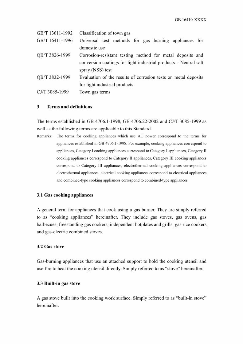
5.3.1.1 The parts of a cooking appliance should be safe and durable. Under normal operation, no deformation that leads to a breakage affecting utilisation may occur. 5.3.1.2 In the process of normal utilisation, the cooking appliance should have a sufficient level of stability, and no sliding or inclination may be caused. 5.3.1.3 When the overall structure is tilted up to 15o in any direction, the parts may not fall over. Please refer to the test methods in Subsection 6.19.2. 5.3.1.4 The burner of a cooking appliance should be equipped with no less than 2 independent gas valves. Please refer to Figure 20. 5.3.1.5 If a malfunction is found in the electric ignition device, its safety should not be affected. After the protective extinguishing device functions, it can only be re-used when it is restored manually. 5.3.1.6 The burning status of the burner should be easily observable. 5.3.1.7 The ends of parts that may be touched by hand during use and cleaning should be smooth. 5.3.1.8 For attaching the parts of cooking appliances, standard tightening and fixing objects should be used, and the connection should be strong, reliable and easy to inspect and repair. 5.3.1.9 The tools usually used for the cleaning, inspection and repair of parts should be easy to install and dismantle. 5.3.1.10 The gas conduit should meet the following requirements: a) The gas conduit (including the gas conduit of the permanent pilot igniter) should be in a position in which it cannot overheat and corrode; b) The internal diameter of the gas conduit of the permanent pilot igniter should not be less than 2 mm; c) When the gas conduit is connected by means of welding, a flange or threading, its structure should be able to guarantee its air-tightness performance; d) The connecting joints of the pipes of cooking appliances should use pipe threading which meets the requirements of GB/T 7306.1, GB/T 7306.2 and GB/T 7307. The connecting joints of the hoses of cooking appliances should use the two structures shown in Figure 1 (Φ 9.5 mm or Φ 13 mm); e) The suggested approach to gas piping is to adopt a connection system using hard pipes (or metallic hoses). When non-metallic hoses are used for connection, the gas conduit shall not be loosened and no gas leakage shall occur during the installation and dismantling of the hoses. Hoses and hose joints should be in positions which can be observed, inspected and repaired easily. f) For connections between hoses and hose joints, safe tightening and fixing measures should be used. 5.3.1.11 The structure and packaging of cooking appliances should be able to bear

GB 16410-XXXX
stacking, vibration and falling during storage and transportation. 5.3.1.12 Each burner in all types of cooking appliances should be equipped with a protective extinguishing device. 5.3.1.13 When the control structure is used normally, parts subject to an excessive temperature increase should not be readily touchable by the hands of the operator. 5.3.1.14 Asbestos should not be applied to the structure of cooking appliances. 5.3.2 Structure of stoves 5.3.2.1 The distance between the burner centres of the two-burner and multiple-turner stoves shall be determined according to the size and shape of the pot. 5.3.2.2 In two-burner and multiple-burner stoves, at least one burner and its support must be useable by sharp-bottomed pots, which should be able to sit on the stove stably under normal operation, and utilisation should not be obstructed. 5.3.2.3 The pot support should meet the following requirements: a) When different types of pots are used, the pot support should be strong and firm. At least one of the burners should be able to hold a pan with a diameter of 100 mm. When using the moveable pot support, it can be adjusted and changed easily. When using the sharp-bottomed pot, normal burning should not be affected. b) Please refer to the test methods in Subsection 6.19.3.1. 5.3.2.4 The fluid collection pan should have a sufficient capacity for holding any fluid spilled while cooking. 5.3.2.5 When the stove top undergoes the loading test, the deflection in all parts of the stove top should be ≤ 5 mm. Please refer to the test methods in Subsection 6.19.3.1. 5.3.2.6 When non-metallic materials are used for the panels, and when a panel is broken, the following requirements should be met: a) Fragments may not be scattered; b) The cooking pot may not tilt. 5.3.2.7 Built-in stoves should also meet the following requirements: a) The bottom panel of the stove should be easy to clean (using the normal tool); b) The bottom panel of the stove should be made of anti-corrosive materials or anti-corrosion measures must be applied to it; c) A closed structure is suggested for use at the joint between the built-in position and the kitchen work surface; d) An anti-spill structure is suggested for use for parts such as the burner ring, fluid collection pan, etc, so that any spilled fluid cannot flow to the bottom panel; e) There should be an air intake to help ignition. The installation and structure

GB 16410-XXXX
of the air intake should not affect the burning performance; f) The stove top should be made of materials which are resistant to high temperatures and deflection. The heat-deformation deflection at any position should be ≤ 5 mm. 5.3.3 Structure of barbecues 5.3.3.1 It must be possible to put in and take out the baking pan and baking rack easily, and they should not fall out by themselves. 5.3.3.2 When a container is placed above the exhaust of the barbecue, the fume exhaust must not be affected. If no container should be placed there, this should be clearly indicated in writing in a visible place. 5.3.3.3 It must be possible to open and close the door of the barbecue flexibly and reliably. 5.3.4 Structure of ovens 5.3.4.1 During the loading test, the oven door should be stable. No deformation or damage affecting utilisation may occur. Please refer to the test methods in Subsection 6.19.3.2. 5.3.4.2 Ovens with no ignition device equipped may have their flame hole and ignition structure exposed only when the oven door is open. 5.3.4.3 It must be possible to open and close the oven door flexibly, and its seal must perform well. 5.3.4.4 During ordinary use, there should be no bending of the internal wall of the oven affecting the mechanisms. 5.3.4.5 It must be possible to put in and take out the baking pan, baking rack, etc, of the oven easily, and they should not fall out by themselves. 5.3.4.6 Baking pans for use in the oven should not be caused to bend by the object being baked, and should not allow the object being baked to leak out during utilisation. 5.3.4.7 The capacity of baking pans for use in the oven should be large enough to hold any spilled fluid. 5.3.4.8 It must be easy to clean the flame holes of burners inside the oven, and the fire should not be easily extinguished by any spilled fluid. 5.3.4.9 The temperature indicator of the oven should show the actual temperature inside the oven, and should be sensitive and reliable. 5.3.4.10 The temperature control of the oven should be sensitive and reliable, and

GB 16410-XXXX
should indicate temperature values or temperature codes equivalent to 150oC, 200oC and above 250oC. 5.3.4.11 The oven should be made of heat-resistant materials which do not contaminate food. The heat-resistant materials of the oven should be even and consistent, and should not cause disassociation and falling. 5.3.4.12 When 2/3 of the baking pan is being pulled out of the oven, sliding may not be caused. For the ovens with locking devices, the pan should be locked at the locking point. 5.3.4.13 The exhaust of the oven should be positioned at the back of the oven body. 5.3.4.14 For ovens equipped with a hot air fan, when the oven door is open, the fan should stop running. It is essential that no danger be caused when the object being baked is put in and taken out. The circulator should be equipped with a protective frame and a protective net. 5.3.4.15 The lighting facilities inside the oven should be equipped with a protective cover. 5.3.5 Structure of rice cookers 5.3.5.1 Boiling water shall not be spilled onto the automatic extinguishing device. The automatic extinguishing device must not be caused to overheat. 5.3.5.2 On the wall of the inner pot, there should be a graduated water level for easy reference when pouring water. 5.3.6 Special structural requirements for cooking appliances that use AC power: 5.3.6.1 Cooking appliances that use AC power should be Category I stoves, Category II stoves or Category III stoves. 5.3.6.2 Category I stoves shall have safe grounding measures, and the ground resistance should meet the requirements of Table 5. 5.3.6.3 It must be possible to reliably support the electrothermal components inside the cooking appliances. Even if the electrothermal components break, the electrothermal lead shall not contact with the metallic parts. 5.3.6.4 The electrothermal components should not be designed to be components subject to visible scorching. 5.3.6.5 The outer shell of cooking appliances should be designed as a structure which can only be opened using a tool. There should be sufficient protection of any electric parts which could be accidentally touched. 5.3.6.6 The moving parts of cooking appliances should be placed or covered in consideration of the utilisation and operation of the cooking appliances, so as to offer sufficient protection from harm for people under normal use conditions.

GB 16410-XXXX
5.3.6.7 The protective shell, protective cover and similar parts should not be dismantlable, and must have sufficient mechanical strength. 5.3.6.8 Under normal use conditions, it must not be possible for the electrical insulation of the structure of cooking appliances to be affected by condensation or by any fluid leaked onto the cold surface. The protection grade should not be lower than IP3. Tests should be carried out according to the requirements specified in Subsection 13.2.3 of GB 4208-1993. 5.3.6.9 When the safe and extremely low voltage used by cooking appliances is taken from the electricity network, it should go through a safe isolating transformer. The insulation of the safe isolating transformer should meet the requirements in terms of double insulation or reinforced insulation. The techniques of safe isolating transformers should meet the requirements of GB 13028. 5.3.6.10 The structure of cooking appliances should not allow parts such as insulation, internal wiring, airing parts, commutators and sliding rings to be exposed to oil, grease or similar substances. However if the decision is made to allow the structure to be exposed to substances like oil or grease, the structural elements should have a sufficiently high level of insulation performance that does not contradict the Standard. 5.3.6.11 In the event of any accidental automatic re-connection to the restoration circuit breaker and the overcurrent protection device, no danger may be caused. 5.3.6.12 If the restoration button is not on the restoration control, and if accidental restoration could cause danger, then it should be made impossible for accidental restoration to occur, or protection should be added. 5.3.6.13 Parts which cannot be dismantled and which provide necessary protection against water shock or contact with moving parts should be fixed reliably, and should bear the level of mechanical stress that occurs during normal utilisation. 5.3.6.14 For objects which indicate open or closed positions, or the handle of similar components, controls and similar objects, if they may cause danger by being in the wrong positions, it should be impossible to set them to the wrong positions. 5.3.6.15 Any direct contact with electrical parts and heat insulation can be effectively prevented, unless these materials never corrode, never absorb humidity and can never be burned. 5.3.6.16 Wood, cotton, silk, ordinary paper and similar fibres or humidity-absorbent materials should not be used for insulation unless they have been macerated.

GB 16410-XXXX
5.3.6.17 The structure of cooking appliances should make it impossible for any suspended electrothermal lead to come into contact with any easily touchable metallic parts. 5.3.6.18 Between parts connected by protective impedance, double insulation or reinforced insulation should be used for separation purposes. 5.3.6.19 The creepage distance and electrical gap on the additional insulation and the reinforced insulation should not be decreased, due to wearing, below the value specified in Table 8. If any wire, screw, nut, gasket, spring or similar parts are loosened or fall from their original position, the creepage distance and electrical gap on the additional insulation and the reinforced insulation should not decrease to 50% of the value specified in Table 8. 5.3.6.20 The design or protection of the additional insulation and the strengthened insulation should be such that the creepage distance or electrical gap cannot be decreased below the value specified in Table 8 due to the deposition of dust or dirt caused by the friction of parts inside the cooking appliances. 5.3.6.21 Any electricity-conducting liquid with which it is easy to come into contact including under normal use conditions should not have any direct contact with the electrical parts. In Category II structures, this kind of liquid should not have any direct contact with the basic insulation or the reinforced insulation. It should pass the visual inspection, and its conformity should be checked. 5.3.6.22 The operation controls, handles, control rods, and the shafts of similar parts should not be electrified, unless the parts above them have been removed. Shaft shall not be easily touchable. 5.3.6.23 Even if the insulation of the handles, control rods and knobs being held or controlled is ineffective under normal utilisation, it should not be electric. If these handles, control rods or knobs are made of metal, and their shafts or fixed devices may be electric when the insulation is ineffective, then they should be covered by insulated materials, or additional insulation should be applied to separate the easily touchable parts from their shaft rods or fixed devices. 5.3.6.24 The electric capacitor should not be connected to the point between two corresponding contact terminals of a circuit breaker. 5.3.6.25 The protective impedance should be composed of at least two independent components. It should be impossible for any obvious change to occur in the impedance of these components within the life span of the cooking appliances. 5.3.6.26 Internal wiring

GB 16410-XXXX
a) The wireway should be smooth and have no sharp corners or edges. The wiring protection should not make them contact with any burrs which could cause damage to insulation, fins for cooling, or similar sharp edges. The metallic hose of the feed-through insulation wire inside should have a flat, smooth surface or be attached with a bush. It should be able to effectively prevent wiring from coming into contact with moving parts; b) The string of insulated beads on electric metallic wire and similar porcelain insulation should be fixed or supported, so as to keep its position unchanged. It should not be placed on sharp edges or sharp angular corners. If the string of insulated beads is inside a soft metallic conduit, it should be placed inside an insulated case, unless the conduit cannot be moved under normal use conditions; c) Any naked internal wiring should be rigid and fixed, so as to make it impossible for the creepage distance and electrical gap to decrease to below the value specified in Table 8 during normal use conditions; d) The insulation of the internal wiring should be able to bear the electrical stress that could occur during normal use. The electrical performance of its insulation should meet the requirements specified in GB 5023.3 or GB 5013.4; e) When the casing pipe is used as additional insulation for internal wiring, reliable methods should be used to keep it fixed in position; f) When applying 2N pulling force on the internal wiring, parts at a temperature higher than 100oC (except wire which can resist high temperatures) and any moving parts should not be touched; g) When the internal wiring runs through a metallic hole, the metal surface should be smooth or equipped with a casing pipe; h) When the connector assembly is connected with the internal wiring, it should not fall off when 5N force is applied at the joint; i) The yellow-green combined lead should only be applied to the ground lead. It should be connected to the point between the ground terminal of cooking appliances and the ground contact point of the plug; j) Stranded wire points with bearing contact pressure should not be welded together using lead-silicon welding, unless the structure of the clamping device is such that it can preclude any danger of poor contact caused by the cold flow of the welding agent; k) Aluminium wire should not be used for internal wiring. 5.3.6.27 Power connections and external flexible cords 5.3.6.27.1 The cooking appliances should use plug-attached flexible power cords to connect the power. 5.3.6.27.2 Flexible power cords should go through a Y shape and be connected to

GB 16410-XXXX
the cooking appliances. 5.3.6.27.3 A connecting method should be adopted for the power cable of cooking appliances with the manufacturer, its maintenance department or similarly qualified staff to carry out replacements. Suitable warnings should be given in the operating manual. Users should not carry out maintenance work or change the power cable by themselves. 5.3.6.27.4 The plug should not be equipped with more than one soft flexible cord. The flexible power cord of ordinary hard-rubber protective cases should not be lighter than the YZ or YZW types given in Table 4 of GB 5013.4-1997 (Wire No. 53 of IEC 245). 5.3.6.27.5 The lead of the flexible power cord should have a claimed cross-section area as specified in Table 7.
Table 7 Minimum cross-section area of lead Nominal Current A of Cooking
Appliances Claimed Cross-Section Area mm2
< 6 > 6-10 > 10-16 > 16-25 > 25-32 > 32-40 > 40-63
0.75 1
1.5 2.5 4 6 10
5.3.6.27.6 When the flexible cord is partially moulded to the outer shell, the insulation of the flexible power cord should not be damaged. 5.3.6.27.7 The fixing devices of flexible cords should be placed in a position where they cannot be touched without the aid of a tool, or their structures cannot be equipped with flexible cords without the aid of a tool. 5.3.6.27.8 The insulated lead of the flexible power cord should again be isolated away from the basically insulated and easily touchable metallic parts. The insulation can be provided by using the protective case of the flexible power cord or other methods. 5.3.6.27.9 The flexible power cords should meet the requirements of GB 5023.3 or GB 5013.4. 5.3.6.27.10 Flexible power cords used by Category I cooking appliances should be equipped with a yellow/green-fused ground wire. 5.3.6.27.11 At the place where the lead of the flexible power cord bears the contact pressure, no ply reinforcement should be conducted through “lead

GB 16410-XXXX
silicon”, unless the structure of the clamping device is such that it can preclude any danger of poor contact caused by the cold flow of the welding agent. 5.3.6.27.12 The flexible power cords should not come into contact with any sharp ends or sharp edges of the cooking appliances. The flexible cord inlet should be attached with a bush, or its structure should be such that it can let the protective case of the flexible power cord pass through without any danger of it being damaged. The flexible cord inlet should: –– have a shape which can prevent the flexible power cord from being damaged; –– be impossible to dismantle. At the flexible cord inlet, the insulation between the lead of the flexible power cord and the outer shell of the cooking appliance should be composed of an insulation layer of lead and at least two independent insulation layers additionally added. If the outer shell of the flexible cord inlet should be made of insulated materials, only one independent insulation layer is required. 5.3.6.27.13 Cooking appliances with flexible power cords should be equipped with a fixing device for the flexible cords, so that the lead is not subjected to tension and torque at the joint inside the cooking appliance, and so that the insulation of the lead is protected from wear. It should not be possible to push the flexible cord into the cooking appliance, or to reach a level at which the flexible cord or the parts inside the cooking appliance can be damaged. Its conformity can be inspected through visual inspections and manual tests, and the following tests should be carried out. When the flexible cord receives a pulling force of 100N and 0.35 Nm torque, a mark should be made at the point 20 mm from the fixing device of the flexible cord, or at another suitable spot. After that, the same force should be used to pull the flexible cord 25 times. The pulling force should be applied in the most disadvantageous direction for 1 second each time, but sudden force should not be applied. During the test, the flexible cord should not be damaged. After the test, the vertical displacement of the flexible cord should not exceed 2 mm, and the displacement of the lead inside the contact terminal should not exceed 1 mm. At the joint, no obvious tension may exist. The creepage distance and the electrical gap should not decrease below the value specified in Table 8. 5.3.6.28 Creepage distance, electrical gap and feed-through insulation distance 5.3.6.28.1 The creepage distance and the electrical gap should not be below the

GB 16410-XXXX
value specified in Table 8. 5.3.6.28.2 The electrical gap between the wiring terminal and the easily touchable metallic parts should be measured in conditions in which the screw and nut are loosened as far as possible. The electrical gap should not be below 50% of the value specified in Table 8.
Table 8 Minimum creepage distance and electrical gap
Working Voltage
≤ 130 V
Working Voltage
> 130 V - 250 V
Working Voltage
≥ 250 V - 480 V Distance
Creepage
Distance
Electri-
cal Gap
Creepage
Distance
Electri-
cal Gap
Creepage
Distance
Electri-
cal Gap
Between the electric parts of different
potentials a:
- if deposited by anti-dirt objects b
- if not deposited by anti-dirt objects
- if enamel-insulated wires
- if protected by deposition from anti-dirt
objects or humidity:
Resistance (including its connection line)
of positive temperature coefficient
(PTC)b
1.0
2.0
1.5
1.0
1.0
1.5
1.5
1.0
2.0
3.0
2.0
1.0
2.0
2.5
2.0
1.0
2.0
4.0
3.0
-
2.0
3.0
3.0
-
Between the electric parts and other
metallic parts crossing over the basic
insulation:
- if deposited by anti-dirt objects b
composed of porcelain, pure mica
and similar materials
composed of other materials
- if not deposited by anti-dirt objects
- if the electric parts are enamel-
insulated wires
- at the end of pipe-shaped armoured
electrothermal components.
1.0
1.5
2.0
1.5
1.0
1.0
1.0
1.5
1.5
1.0
2.5 c
3.0
4.0
2.0
1.0 e
2.5 c
2.5 c
3.0
2.0
1.0 d
-
-
-
-
-
-
-
-
-
-
Between the electric parts and other
metallic parts crossing over the
strengthened insulation:
- if the electric parts are enamel-
insulated wires
6.0
6.0
6.0
6.0
-
-

GB 16410-XXXX
- towards other electric parts 8.0 8.0 8.0 8.0 - -
Between metallic parts separated by
additional insulation 4.0 4.0 4.0 4.0 - -
Between electric parts inside the groove
of the panel with cooking appliances
installed and the fixed support surface
6.0 6.0 6.0 6.0 - -
a The electrical gap specified here is inapplicable to the air gap between the contact points of the automatic
control, micro-gap-structured switch and similar devices, and also inapplicable to the air gap between the
mobile-phase parts in those devices with its electrical gaps alternated with the movements at the contact points.
b Normally, only if the inside of a cooking appliance does not create dust by itself, it shall not be
considered that a cooking appliance with a reasonable anti-dust outer shell shall require anti-dirt treatments on
the inside, and it does not have to be closed completely.
c If the part is rigid and is positioned by moulding, or if it is impossible for its structure to make the
distance decrease due to deformation or movement of the part, then the value can be decreased to 2.6 mm.
d If it is protected by deposited anti-dirt treatments.
e If crossing over porcelain, pure mica and the similar materials which are protected by deposited anti-dirt
treatments.
5.3.6.28.3 The distance of the narrow hole or opening on the outer parts of the feed-through insulation materials should be measured up to the metallic foil which can be contacted easily and has surface contact. Use the test pin shown in Figure 13 to push the metallic foil into the ridge and a similar position, but do not press it into the opening. a) If necessary, during measurement, apply force to a random point on the naked lead other than the electrothermal component, to a random point on the non-insulated metallic capillary of the temperature control or a similar device, and to the outer surface of the metallic shell, so as to decrease the creepage distance and electrical gap. b) This force is applied by the test pin shown in Figure 13, and its value is as follows: – The force on the naked lead, the non-insulated capillary of the temperature control, the electric conductive hose, the metallic foil inside the cooking appliances and similar parts is 2 N; – The force on the outer shell is 30 N. 5.3.6.28.4 For working voltages smaller than or equal to 250 V, the feed-through insulation distance between metallic parts, if separated by additional insulation, should not be below 1.0 mm; and if separated by strengthened insulation, it should not be below 2.0 mm. 5.3.6.29 Heat resistance: external parts composed of non-metallic materials,

GB 16410-XXXX
whose deterioration may lead to the cooking appliances’ failure to meet the requirements of the Standard, parts made of insulated materials used for supporting (including connection) the electric parts, and parts made from thermoplastic materials providing additional insulation or strengthened insulation should be effectively resistant to heat. 5.3.6.30 Power leakage tracking resistance: insulated materials which may create a tracking path when something crosses over them should be sufficiently resistant to tracking. At this point, the harshness of the working conditions should be considered. 5.3.6.31 Components Under reasonable application conditions, the parts and electronic components of each type of electrical appliance should meet the related national standards. 5.3.6.31.1 Wiring terminal The connection terminal of the power wire of cooking appliances can be connected to the external lead by means of welding, fusion welding, crimp connection and similar connection methods. a) The wiring terminals of flexible power cords should be suitable for their utilisation purposes. Wiring terminals clamped by screw and screw-free wiring terminals should not be used for the connection of flat double-core tinsel cord, unless the end of the tinsel cord is equipped with a device which is suitable for use together with the screw wiring terminal; b) Without the help of a tool, the wiring terminal should not be easily touchable, even if the electric parts above it cannot be reached; c) Ground terminal: – Easily touchable metallic parts of Category I cooking appliances should be permanently and reliably connected to a ground terminal inside the cooking appliances. The ground terminal should not be connected to the neutral wiring terminal; – The clamping device of the ground terminal should be strong enough to prevent any accidental loosening; – When designing the length of lead between the wiring terminal of power wire or the fixing device of a flexible cord and the wiring terminal, it should be considered that if the flexible cord slides out from the fixing device of the flexible cord, the mobile-phase lead should be tightened before the ground lead. 5.3.6.31.2 Screw a) The solidifying device and the failed electrical connection, which may harm the extent of conformity with the Standard, should be able to bear the mechanical stress apparent during normal utilisation;

GB 16410-XXXX
b) The structure of the electrical connection should be such that it can ensure that contact pressure is never transmitted through insulated materials which can contract or deform easily, unless the metallic parts have sufficient resilient force to compensate for any possible contraction or deformation of insulated materials; c) Wide-distance screws (metallic plates) should not be applied to the connection of mobile-phase parts, unless they tightly compress those parts by way of direct mutual contacts; d) Tapping screws cannot be applied to the electrical connections of mobile-phase parts, unless they can form a kind of mechanical screw thread of a completely standard shape. If this kind of screw can be operated by users or the installing person, they should still not be used unless their thread is formed by compression; e) It must not hinder the connection if it is in normal use conditions only. There should be at least 2 screws at each joint, then the tapping screw and the wide-distance screws can be applied for ground continuity purposes; f) If the screws and nuts for mechanical connection between different parts of the cooking appliances also carry out electrical connection or provide ground continuity, they should be reliably fixed and prevented from loosening. 5.3.7 Structure of parts 5.3.7.1 The valve should meet the following requirements: a) The opening and closing of the valves and knobs of cooking appliances at room temperature or the highest temperature should be very flexible; b) At the points where the knobs open and close, there should be obvious signs and directions. There should be range-restriction and self-locking devices (the main switch body, if exposed, should not be attached to any self-locking device); c) After the heat resistance performance test, the air-tightness should meet the requirements of Subsection 5.2.1, and utilisation should not be hindered. Please refer to the test methods in Subsection 6.20.1. 5.3.7.2 The nozzle should meet the following requirements: a) It can be easily dismantled and installed using general tools; b) It should be at a position which cannot easily be blocked by dust and foreign particles from outside, or it should be a nozzle which cannot easily be blocked and can be cleaned during utilisation. 5.3.7.3 The burner should meet the following requirements: a) The points and other joints welded by riveting shall have no defect that affects

GB 16410-XXXX
utilisation; b) The processing of flame holes should be precise. There should be no defect or deformation that affects burning; c) Cast objects shall have no defect that affects their appearance and utilisation; d) For burners composed of more than two heads, the interpositions between them should be accurate; e) The interpositions between the nozzle, electric ignition device, safety device and other related parts should be accurate. In the process of utilisation, there should be no movement or falling; f) Flame shall not cause unrelated portions to overheat or become damaged; g) It must be possible to clean, install and dismantle the burner easily. 5.3.7.4 The draft regulator should meet the following requirements: a) The air volume can be adjusted easily. Its position must not be able to slide by itself after adjustment; b) Any draft regulators without adjustment knobs or handles should be installed in a position in which they can be operated easily. 5.3.7.5 The protective extinguishing device should meet the following requirements: a) When the burner cannot be ignited or is accidentally extinguished, or the flame detector is ineffective, the gas channel of the burner can be closed; b) In normal utilisation, the relative positions of the flame adjustor and the burner should remain unchanged. 5.3.7.6 The electric ignition device should meet the following requirements: a) The position of the electrode in relation to the ignition hole as well as the gap between electrodes must be appropriate, and should be fixed; b) Effective insulation measures should be taken for the electric portions of the high-voltage parts; c) For any other high-voltage parts which can easily be touched by hand, effective insulation should be installed. d) When dry batteries are used as a power source, it must be possible to replace the dry batteries easily; e) After the heat resistance performance test, the ignition performance should meet the requirements of Subsection 5.2.8. Please refer to the test methods in Subsection 6.20.2. 5.4 Materials 5.4.1 General requirements for materials 5.4.1.1 They should be able to bear the normal use temperature.

GB 16410-XXXX
5.4.1.2 The metallic parts (except the corrosion-resistant materials) should be electroplated, spray painted, porcelain enamelled, or undergo other suitable anti-corrosion surface treatment. 5.4.1.3 Parts with direct contact with food and possible contact with food should be made of materials which do not have a harmful chemical reaction with the human body, or materials which have undergone appropriate surface treatment. It must not be possible for any harmful substance to be created. 5.4.1.4 The materials should meet the related standards. After materials have been tested, they should meet the following requirements: a) Heat resistance performance: they should meet the requirements specified in Subsection 5.2.5; b) Corrosion resistance performance: no corrosion should be found on the surface. No bubbles, collapsing or rust may be found on the cast layer and the paint film; c) Gas resistance performance: they should meet the requirements of Subsection 5.4.2; d) Steel ball impact resistance performance of porcelain enamel: no collapse of the porcelain enamel may be found; e) Flame-retarding performance of thermo and heat insulation materials: they should not be burned or the must be extinguishable by natural means within 1 minute; f) Impact resistance performance: they should meet the requirements specified in Subsection 5.2.6; g) Oil resistance performance: they should not be deformed, and shall not affect utilisation. 5.4.2 Sealing materials 5.4.2.1 Sealing materials that have come into contact with gas and the lubricant for the use of the cock valve should be adaptable to the characteristics of the gas used. 5.4.2.2 After the gas resistance performance test, the quality and mass change of the washer, spacer, etc for sealing the insulation should not be less than 20%, and no softening and fragility may appear which would affect utilisation. For rubber products, after the n-pentane test, their leakage should be less than 0.005 g/h. Please refer to the test methods in Subsections 6.21.4.1 and 6.21.4.2. 5.4.2.3 After the gas resistance performance test, the quality and mass change of the lubricant for the cock valve should be less than 10% at 20oC, and should be less than 25% at 4oC. After the test, the air-tightness should be at the right level. Please refer to the test methods in Subsections 6.21.4.3. 5.4.3 Thermo materials

GB 16410-XXXX
There must be no corrosion on the contact surface, and no bad smell shall be created during utilisation. 5.4.4 Electricity-conducting materials Electricity-conducting materials should be copper, copper alloy or materials with equivalent electrical performance, heat stability performance and mechanical stability performance. For places where elasticity is required and other necessary part materials, such restrictions do not apply when no danger has occurred. 5.4.5 Gas conduit and conduit of permanent pilot igniter The gas conduit should be made of materials with a temperature resistance above 350oC. The conduit of the permanent pilot igniter should be made of materials with a temperature resistance above 500oC. 5.4.6 Cock valve It should be made of materials with a temperature resistance above 350oC. 5.4.7 Nozzle It should be made of materials with a temperature resistance above 500oC. 5.4.8 Nozzle stand It should be made of materials with a temperature resistance above 350oC. 5.4.9 Air conditioner (Ventilation door) It should be made of materials with a temperature resistance above 500oC. 5.4.10 Burner 5.4.10.1 The flame hole point of the burner should be made of materials with a temperature resistance above 700oC. Please refer to the test methods in Subsection 6.20.4. 5.4.10.2 All the parts of the burner of cooking appliances from the gas outlet of the nozzle to the flame hole of the burner should be made of materials which have undergone a tempering test for 15 minutes according to the burner overheat resistance test methods, and the burner must not have any deformation affecting its performance. Please refer to the test methods in Subsection 6.20.3. 5.4.10.3 The thickness and surface treatment should meet the following requirements: a) The wall thickness of the cast products shall not be less than 3 mm, and shall not

GB 16410-XXXX
have defects such as obvious cast air holes; b) The wall thickness of die-cast products shall not be less than 1.5 mm, and shall not have any defect affecting utilisation; c) The wall thickness of stainless steel products should not be less than 0.3 mm; d) The wall thickness of products made of hot-dipped aluminium-plating steel materials should not be less than 0.3 mm; e) For ordinary steel-made products, the wall thickness of the steel materials should not be less than 0.5 mm, and anti-corrosion treatment should be carried out on the surface. When carrying out surface treatment using porcelain enamel, the steel ball impact test should be carried out, and the porcelain enamel should not be collapse; f) The wall thickness of products made of copper and copper alloy material should not be less than 1 mm. 5.4.11 Pot support It should be made of materials with a temperature resistance above 700oC. 5.4.12 Fluid plate It should be made of materials with a temperature resistance above 500oC. 5.4.13 Inner walls, baking pan and baking rack of oven, and radiation plate of
barbecue It should be made of materials with a temperature resistance above 500oC. During utilisation, there should be no creation of gas harmful to the human body caused by heat decomposition. 5.4.14 Glass of oven door After the heat impact resistance test, no breaking shall appear. 5.4.15 Toughened glass panel 5.4.15.1 After the heat impact resistance test, no breaking shall appear on the panel. 5.4.15.2 After the gravitational impact resistance test, no breaking shall appear. 5.4.16 Other non-metallic panels 5.4.16.1 In case of breaking during utilisation, the fragments shall not scatter. 5.4.16.2 Other performance points should meet the related standards. 5.4.17 Stove legs 5.4.17.1 It is suggested that the point in contact with the kitchen work surface is

GB 16410-XXXX
made of rubber or other materials which cannot slide. 5.4.17.2 Having undergone the oil resistance test, rubber products or other non-metallic products in contact with the kitchen work surface should not affect utilisation. 5.4.17.3 The hardness HS (Shore A) of rubber products in contact with the kitchen work surface should reach 50-90. 5.4.18 Pot of rice cookers This should be made of materials with a temperature resistance above 500oC. 5.4.19 Packaging materials and packaging waste The packaging materials and packaging waste should meet the following requirements: a) The toxic metal and other harmful substance content inside the packaging materials should be restricted. One point should be noted: whether these materials will create radiation or harmful ingredients when they are burned, or whether they will release harmful substances when they are buried; b) All the materials should be available for recycling and reuse to a high extent; c) Try to reduce the proportion of non-degradable materials used in the packaging materials as a whole; d) All the materials can be recycled and disposed of easily. 5.4.20 Flame detector of protective extinguish device It should be made of materials with a temperature resistance above 700oC, and an oxidised layer shall not be caused in a high-temperature environment. 5.5 Appearance 5.5.1 The appearance should be attractive, simple, and have well-coordinated colours. There should be no defect affecting the appearance. 5.5.2 The panel of cooking appliances should bend no more than 5 mm. 6 Test methods 6.1 Test room status 6.1.1 The room temperature should be 20±5oC. In each test, the fluctuation of the

GB 16410-XXXX
room temperature should be less than 5oC. Determination method of room temperature: 1 metre from the front side, left side and right side of the cooking appliances, fix the temperature sensing part of the thermometer at a height equivalent to the upper end of the cooking appliances, then test the temperature of the above 3 points and take the average. 6.1.2 The ventilation and air flow should be good. The carbon oxide content in the indoor air should be less than 0.02%, and the carbon dioxide content in the indoor air should be less than 0.2%. The air flow speed at 1 metre around the tested cooking appliance should be ≤ 0.3 m/s. 6.1.3 Power source conditions: the fluctuation scope of the voltage of AC power for use in the test room should be within the range of ± 2%. 6.2 Gas for use in the test 6.2.1 The code of the gas for use in the test should be according to the specifications of GB/T 13611. Please refer to Table 9. The scope of the change of the net Wobbe number in the gas during the testing procedures should be within the range of ± 2%. When the cooking appliances stop operating, the static pressure should be less than or equal to 1.25 times the gas supply pressure.
Table 9 Gas for use in test
Code Gas for Use in Test 0 Reference gas 1 Yellow flame limit gas 2 Tempering limit gas 3 Flame-out limit gas
6.2.2 The gas supply pressure for use in the test is shown in Table 10.
Table 10 Gas Supply Pressure
Code Liquefied Petroleum Gas
Natural Gas Artificial Gas
1 (maximum test pressure) 3300 3000 1500 1500
2 (nominal gas supply pressure) 2800 2000 1000 1000
3 (minimum test pressure) 2000 1000 500 500
6.2.3 When using gases other than those specified in GB/T 13611, the gas for use in testing the cooking appliances should be the gas which was used as the basis during

GB 16410-XXXX
the design of the product. For the scope of fluctuation, please refer to the related specifications in GB/T 13611. 6.2.4 The code for the condition of gases for use in tests is: code of test gas – code of supply pressure of gas for use in tests. For example:
0-2 indicating: reference gas – nominal gas supply pressure
6.3 Main instruments for use in the test The main instruments for use in tests are indicated in Table 11. 6.4 Test equipment The test equipment is shown in Table 12. 6.5 Test status of cooking appliances Cooking appliances should be tested according to the specified installation and utilisation status. Apart from the concrete specifications in each independent performance test, they should meet the following basic requirements: a) For the air volume required for burning of the burner, use 0-2 gas and adjust it so that the flame is at its best level. Then fix the ventilation door. When carrying out various performance tests, the ventilation door cannot be adjusted; b) The selected aluminium pot (lower-limit pot) should be attached to the stove and the heating water volume should be set as specified in Table 17. When the water volume is too little during the test, water should be poured in gradually; c) During the test, the moveable pot support should be adjusted to the point which is most disadvantageous to the test; d) For barbecues with fluid collection pan, water should be poured into the fluid collection pan. When the water volume is too little during the test, water should be pour in gradually; e) During tests on ovens, place a baking pan in the middle of the oven; f) During tests on rice cookers, the water should be poured in based on the maximum volume of the cooked rice. When the water level is lower than 1/2 of the water volume during the test, water should be poured in gradually. 6.6 Air-tightness test The air-tightness test on the gas channel is indicated in Table 13
Table 11 Main instruments for use in tests

GB 16410-XXXX
Specifications Purposes
(Test Items) Names of Instruments
Scope Precision or Minimum
Graduation
Measurement of room
temperature and gas temperature Thermometer 0oC-50oC
Gas temperature 0.5oC;Room temperature 1oC
Measurement of humidity Humidometer 10%RH-98%RH ±5%RH
Measurement of atmospheric
pressure Barometer 81 kPa-107 kPa 0.1 kPa
Measurement of gas pressure U-shape pressure gauge or
manometer 0 Pa-5000 Pa 10 Pa
Measurement of time Second meter ----- 0.1 s
Measurement of gas flow Gas flow meter ----- 0.1 l
Measurement of relative density
of gas
Relative density meter of
gas ----- ±2%
Measurement of air-tightness Gas leakage meter ----- -----
Measurement of noise Sound level meter 40 dB-120 dB 1 dB
Measurement of gas ingredients
Chromatographic
instrument or absorption gas
analyser
----- -----
Measurement of heat value of
gas Calorie meter ----- -----
Measurement of carbon
monoxide
Carbon monoxide
measurement instrument 0-0.2% 0.001%
Measurement of carbon dioxide Carbon dioxide
measurement instrument 0-15% 0.01%
Measurement of oxygen content Oxygen measurement
instrument 0-21% 0.01%
Water temperature Thermometer 0oC-100oC 0.2
Measurement of surface
temperature
Thermoelectric
thermometer, thermocouple0oC-300oC 2
Table of AC power voltage ----- Precision: Grade 1.0Measurement of voltage
Table of DC power voltage ----- Precision: Grade 1.0
Measurement of ground
resistance Ground resistance tester ----- -----
Measurement of current leakage Current meter, voltage
meter, current leakage tester----- -----
Measurement of power
consumption Power table ----- -----

GB 16410-XXXX
Measurement of temperature
rise of coils DC low resistance tester ----- -----
Measurement of mass and
quality Weighing apparatus 0 kg-15 kg 10 g
Table 12 Test equipment
Types and Specifications Purposes of
Test Items Names of Test Equipment
Types Remarks
Preparation of gas for use in
test Gas supply device -----
Wobbe number ± 2%
Measurement of heat input Measurement device of gas
consumption
-----
Air-tightness test of gas
channel
Testing device of
air-tightness
-----
Testing device of durability
of gas valve
-----
Testing device of durability
of ignition, control devices
-----
Testing device of durability
of protective extinguishing
device
----- Durability test
Testing device of durability
of electromagnetic valve
-----
Heat resistance test of
structural parts
Temperature constancy
device
Temperature
constancy device
Room temperature ~ 750oC
Vibration test Testing device of vibration
Vibration test
stand
Vibration frequency 10 Hz,full vibration amplitude 5 mm
Up and down, left and right
Electrical strength test Testing device of electrical
strength
----- -----
Structural test of electric parts Finger probe Test pin ----- -----
Testing device of power cut ----- 0.05 s -180 s Power abnormality test
Other testing device ----- -----
Table 13 Air-tightness test of gas channel
Test Items Test Conditions, Test Statuses, Test Methods
From gas intake to gas
valve
Let the tested gas valve be set to closed status, and the rest of the valves at open
status, and then carry out inspection one by one (the correlated valves are treated

GB 16410-XXXX
as the same valve for inspection). Connect the leakage detector to the gas intake.
Transfer 4.2 kPa air into it and inspect its leakage.
Automatic control
valve
Close the automatic control valve, and open the rest of the valves. Connect the
leakage detector to the gas intake. Transfer 4.2 kPa air into it and inspect its
leakage.
From gas intake to
flame hole of burner
Test condition: Use 0-1 gas.
Test status: Ignite all the burners.
Test method: Use soap solution, leakage detection liquid or the burner for fire
testing to inspect whether there is leakage from the gas intake to
each position in front of the flame hole of burner
6.7 Heat input test The heat input test is indicated in Table 14.
Table 14 Heat input test
Test Items Test Conditions, Test Statuses, Test Methods
Actual heat
input
Test condition: Use 0-2 gas.
Test status: Connect the barometer and gas flow meter to the cooking appliances
according to Figure 8. Before igniting the cooking appliances, the gas
channel in front of the cooking appliances should be at the maximum gas
flow volume.
Test methods:
–– For cooking appliances using AC power, set the voltage of the power to the
nominal voltage;
–– When testing the heat input of a single burner, only the single burner is ignited,
and then inspection is carried out one by one. When testing the total heat input of
cooking appliances, all the burners should be ignited at the same time for inspection;
–– After the single burner or all the burners are ignited, use the gas flow meter to
measure the gas flow volume within 15-20 minutes. The indicator on the gas flow
meter should run for at least a complete circle, and the time of measurement should not
be less than 1 minute. Repeat the measurement at least twice, and the error of readings
should be less than 2%. Take the average of the two gas flows;
Calculate the actual heat input by using equation (1).
1 273 Pamb + Pm - S Φactual = ------ × V × Q1 × -------------× ------------------ ……….. (1)
3.6 273 + tg 101.3 In the equation:
Φ actual –– actual heat input, kW;
Q1 –– 0oC, low heat value of the tested gas under the status of 101.3 kPa, MJ/m3;

GB 16410-XXXX
V –– actual gas flow volume, m3/h;
tg –– gas temperature inside the gas flow meter, oC;
Pamb –– atmospheric pressure during the test, kPa;
Pm –– actual relative static pressure of gas inside the gas flow meter, kPa;
S –– saturated vapour pressure when the temperature is tg, kPa (when using the
dry-type flow meter for measurement, the S value should be multiplied by the
relative humidity of the tested gas for modification).
Converted
actual heat input
Calculate the converted actual heat input by using equation (2).
1 273 √da 101.3 + Ps Pamb + Pm
Φ = ----- × ------- × Q1 × Q1 × ------ × --------------- × -------------- ×
3.6 288 √dmg 101.3 Pamb + Pg
√ 288 Pamb + Pm - ( 1 – 0.622 / da ) × S
------------ × ----------------------------------------- …………………………… (2)
√273 + tg 101.3 + Ps
(The parts in blue have to be square rooted.)
Φ –– converted actual heat input, kW;
Q1 –– 0oC, low heat value of the intended gas under the status of 101.3 kPa, MJ/m3;
V –– actual gas flow volume, m3/h;
da –– relative density of dry tested gas under standard status;
dmg –– relative density of dry designated gas under standard status;
Pamb –– atmospheric pressure during the test, kPa;
Ps –– nominal gas supply pressure used in design; kPa;
Pm –– actual relative static pressure of gas inside the gas flow meter, kPa;
Pg –– actual relative static pressure of gas at the front of the cooking appliances, kPa;
tg –– actual gas temperature inside the gas flow meter, oC;
S –– saturated vapour pressure when the temperature is tg, kPa (when using the
dry-type flow meter for measurement, the S value should be multiplied by the relative
humidity of the tested gas for modification);
0.622 –– relative density of ideal gas of vapour.
Precision of
nominal heat
input
Calculate the precision of nominal heat input by using equation (3).
Converted actual heat input – Nominal heat input
Precision of nominal heat input (%) = -------------------------------------------------------- × 100 … (3)
Nominal heat input
Proportion of
the total
converted actual
Calculate the proportion of the total converted actual heat input to the sum of the
converted actual heat input of single burners by using equation (4).
Total converted actual heat input

GB 16410-XXXX
heat input to the
sum of the
converted actual
heat input of
single burners
b = ------------------------------------------ × 100 ……………………………………………. (4)
∑Φi
In the equation:
b –– Proportion of the total converted actual heat input to the sum of the converted
actual heat input of single burners, %;
Φi –– Converted actual heat input of single burners
6.8 Test of operating mode of burning 6.8.1 Test conditions of operating mode of burning The test conditions of the operating mode of burning are shown in Table 15.
Table 15 Test conditions of operating mode of burning Gas Adjustment Ways
Test Items Gas Volume
Adjustment Way a)
Gas Volume
Switch Way a)
Test
Voltagea)
(%)
Test Gas
Flame transmission Large All 110 0-2
Flame-out Large Large 90 and 110 3-1
Extinguishing Large, Small All 90 and 110 0-1, 0-3
Evenness of flame Large, Small All 100 0-2
Tempering Large, Small All 90 and 110 2-3
Burning noise Large Large 100 0-1
Extinguishing noise Large Large 90 and 110 0-2
Carbon oxide Large Large 100 0-2
Contact yellow flame Large Large 90 1-1
Black smoke Large Large 90 1-1
Extinguishing Large Large 100 0-1, 0-3 Burning stability of
permanent ignition
burner Tempering Large Large 100 2-3
Burning stability when using a
super-large pot Large All 90 and 110 1-1
Main burner Large, Small Large 90 and 110 0-3 Burning stability when
the oven door is closed. Permanent
ignition burner Small Small 90 and 110 0-2

GB 16410-XXXX
Permanent
ignition burner Large, Small Large 90 and 110 0-3
Burning stability and
flame transmission
when the temperature
controller of oven is
working.
Burner Large, Small Large 90 and 110 0-3
a) When adjusting the gas knob or taking out the rod, the gas volume can be adjusted. “Large”
refers to the gas volume at maximum status. “Small” refers to the gas volume at minimum status.
If the minimum status is not known. If the minimum status is not known, one-third of the maximum
gas flow volume is regarded as being at the minimum status.
b) When adjusting the gas knob, the adjustment way of the number of burners can be changed.
Among them, “large” refers to the ignition of all the burners, “small” refers to the ignition of the
minimum number of burners, and “all” refers to the ignition of the burners one by one.
c) For the cooking appliances using AC power, when the voltage change has effects on the
performance, a test should be carried out according to the voltage conditions specified in the table.
6.8.2 Test methods of operating mode of burning The test methods of the operating mode of burning are indicated in Table 16.
Table 16 Test methods of operating mode of burning
Test Items Test Statuses, Test Methods
Flame transmission
Test status: For the cooking appliances with gas volume adjustor, test is carried out
only at the “Maximum” status.
Test method: After a flame hole of the main burner is ignited at cold status, record
the time taken for the flame to be transmitted to all the flame holes and check by
visual inspection whether there is any backdraft.
Flame-out
Test method: After the main burner has been ignited at cold status for 15 seconds,
if above 1/3 of the flame hole is found to be subject to flame-out on visual
inspection, it is judged as flame-out.
Extinguishing Test method: After the main burner has been ignited for 15 seconds, check by
visual inspection whether each flame hole has flame.
Evenness of flame Test method: After the main burner has been ignited for 20 minutes, check by
visual inspection whether the flame is clear and even.
Tempering Test method: After the main burner has been ignited for 20 minutes, check by
visual inspection whether the flame is tempering.
Burning noise
Test method:
–– After all the burners have been ignited for 15 minutes, carry out the test on
the 3 points specified in Figure 2.
–– Use a noise level meter and press A to calculate the weight. Use speed
monitoring to carry out the measurement. The noise of the environment itself

GB 16410-XXXX
should be lower than 40 dB, or above 10dB lower than the actual noise; otherwise,
make corrections according to Table 2 in GB/T 3768-1996.
Extinguishing
noise
Test method:
–– After the cooking appliance has operated for 15 minutes, close the gas valve
rapidly. Carry out the test on the 3 points specified in Figure 2.
–– Use a noise level meter and press A to measure the weight. Use speed
monitoring to carry out the measurement. The noise of the environment itself
should be lower than 40 dB, or above 10dB lower than the actual noise; otherwise,
make corrections according to Table 2 in GB/T 3768-1996;
–– Add 5dB to the measured maximum noise to form the extinguishing noise.
CO concentration
in dry fumes (α =
1, V%)
Test status: Based on the specifications of Subsection 6.5.
Test method:
–– For the shape of the fume sampler and its installation position, please refer to
Figure 3;
–– Measure the CO2t concentration in the indoor air (at dry status);
–– After the cooking appliance has been ignited for 15 minutes, use the fume
sample to take a sample. Measure the COa content and CO2a content in the dry
fumes;
–– Calculate the CO concentration in dry fumes by using equation (5).
CO2 max
CO = COa × ------------------ ……………………………………….. (5)
CO2a – CO2t
In the equation:
CO –– carbon monoxide concentration in dry fumes, α = 1, V%
COa –– measured carbon monoxide concentration in dry fume sample, V%
CO2t –– measured carbon dioxide concentration in indoor air (at dry fume
status), V%
CO2a –– measured carbon dioxide concentration in dry fume sample, V%
CO2 max –– carbon dioxide concentration (calculated value) in the theoretical dry
fume sample, V%
Black smoke Test method: Ignite the main burner from cold status until the flame is stable.
Place a clean pot or a glossy metallic plate on the cooking appliance, and check
whether there is black smoke by visual inspection. After the cooking appliance has
been ignited for 20 minutes, repeat once.
Contact yellow
flame
Test method: Within 15 minutes since the main burner is ignited from cold status,
check whether there is a yellow flame by visual inspection. If there is a yellow
flame, do the test within any random 1 minute. The electrode should continuously

GB 16410-XXXX
contact the yellow flame for more than 30 seconds.
Burning stability
of permanent
ignition burner
Test method:
–– For cooking appliances with permanent ignition burners, after the permanent
ignition burner has been ignited for 15 minutes, check by visual inspection if there is
any extinguishing and tempering occurring to the permanent ignition burner.
–– Open the gas valve to the maximum, and ignite the main burner continuously.
When the main burner is being ignited and extinguished, check whether there is any
extinguishing and tempering occurring to the permanent ignition burner.
Burning stability
when using an
extra-large pot
Test status: Use a pot which is 4 cm larger in diameter than the pot for use in the
test (lower limit pot) as specified in Table 17.
Test method: Ignite the burners of the cooking appliances one by one, and let the
gas valves all open. Check by visual inspection if there is any black smoke and if
the burning is stable.
Burning stability of main burner:
Test method: Ignite the main burners of the permanent ignition burners (constantly
burning pilot light) and oven, and adjust the gas volume to keep the temperature at
the centre of the oven at (150 ± 10)oC. Use the ordinary operation speed to open
and close the oven door 5 times, and check by visual inspection if the burning is
stable.
Burning stability
when the oven
door is closed. Burning stability of permanent ignition burner:
Test method: Ignite the permanent ignition burner only. After the burning
has been stable or 5 minutes later, use the ordinary operation speed to open and
close the oven door 5 times, and check by visual inspection if the burning is stable.
Burning stability of the burner of constantly-lit oven when the temperature
controller is not working:
Test method: Preset the temperature controller at 200oC. After the
permanent pilot igniter and the burner of the oven are ignited, check by visual
inspection if there is any extinguishing and tempering occurring to the burner of the
oven when the temperature control is at the working status.
Burning stability
and flame
transmission when
the temperature
control of the oven
is working.
Test method: Preset the temperature controller at 200oC. After the
permanent pilot igniter and the burner of the oven are ignited, check by visual
inspection if the flame transmission is normal, and if there is any backdraft when the
temperature controller is at working status.
Remarks: Under the condition that the fume sample is guaranteed to be even, for all gas cooking
appliances other than gas stoves, the fume sampling device can be determined according to
the concrete situation.
Table 17 Pot and heating water volume in the test of cooking appliances

GB 16410-XXXX
Size of Aluminium Pot mm Actual Heat Input
kW Diameter of PotWall thickness
of Pot
Diameter of
Rounded CornerHeight
Heating Water
Volume
<1.10 140 0.55 ± 0.1 90 0.5
1.10 160 0.55 ± 0.1 100 0.8
1.40 180 0.6 ± 0.1 110 1.0
1.72 200 0.65 ± 0.1 125 1.5
2.08 220 0.65 ± 0.1 140 2
2.48 240 0.7 ± 0.1 150 2.5
2.91 260 0.7 ± 0.1 160 3
3.36 280 0.8 ± 0.1 175 4
3.86 300 0.8 ± 0.1 190 5
4.40 320 0.9 ± 0.1 200 6
4.95 340 0.9 ± 0.1 210 7
5.56 360 1.0 ± 0.1
16
225 8
6.9 Temperature rise test The temperature rise test is shown in Table 18.
Table 18 Temperature rise test
Test Items Test Conditions, Test Statuses, Test Methods
General
temperature
rise
Test Conditions: –– Use 0-1 gas; –– The environmental temperature is 20oC ± 5oC; ––Cooking appliances using AC power are supplied with power according to the nominal voltage. Test Statuses: –– The test of gas stoves is based on the test status specified in Subsection 6.5; –– For ovens with temperature controllers, the temperature controller should be adjusted to the indicated position of the highest temperature; –– For ovens without temperature controllers, the gas volume should be adjusted. The temperature at the centre of the oven should be kept at 230oC ± 10oC. If it cannot reach 230oC, the gas valve should be adjusted to the maximum utilisation status; –– The rice cooker should have water poured in at the water level for the

GB 16410-XXXX
maximum cooked rice volume; –– Pots for use in the test of electric stove heads should be selected according to Figure 6, and water should be poured in to 2/3 of the depth of pot; –– Pots for use in the test of electromagnetic stove heads should be selected according to Figure 7, and water should be poured in to 2/3 of the depth of pot; –– The combined cooking appliances are set at the test statuses according to their respective functions. All the burners (including the electrothermal stove head) should be utilised at the same time. But the stove burner with a barbecue uses the stove at the test status; –– Cooking appliances with other functions (e.g. gas stoves also serving as barbecues, rice cookers also serving as gas stoves, etc) are tested at their respective functional statuses; –– The device for measuring the temperature rise is shown in Figure 4; –– For the distance between cooking appliances and the temperature-test plate, please refer to Figure 5. Test Methods: –– Ignite all the burners; –– Open the valve of the gas stove, barbecue and rice cooker to the maximum. Open the valve of the burner of the oven to the specified position; –– All the heat generating units work according to normal utilisation conditions; –– After the temperature rise to the temperature testing position has been constant (the longest temperature rise time should not exceed 1 hour), use a thermoelectric thermometer or thermocouple (pre-buried in the wooden plate) to measure and record the temperature rise at the following places:
• the place where hands have to contact during operation; • outer shell of dry batteries; • hose joint; • outer shell of valve; • outer shell of igniter; • outer shell of gas pressure adjuster;
• environmental space or surrounding object of switch, temperature controller and temperature limiter;
• internal wiring and external wiring, including the rubber or PVC insulated surface of flexible power cords;
• surface of flexible cord protective case for additional insulation • outer surface of capacitor
• lateral side of cooking appliances, wooden wall at the back, and wooden table-top surface under the cooking appliances
Temperature
rise when
using an
extra-large
pot
Test Conditions: –– Use 0-1 gas; –– The environmental temperature is 20oC ± 5oC; Test Statuses: –– Place on the gas stove stand a pot which is 4 cm larger in diameter than the pot for use in the test (lower limit pot) as specified in Table 17. When a pot of above 36 cm is used, a bucket can be the replacement; –– No ignition on the barbecue and oven;

GB 16410-XXXX
–– The electric stove is not turned on; –– The device for measuring the temperature rise is shown in Figure 4; –– For the distance between cooking appliances and the temperature-test plate, please refer to Figure 5. Test Methods: –– Ignite all the gas stove heads; –– Open the valve of the gas stove burner to the maximum; –– After the temperature rise at the temperature testing position has been constant (the longest temperature rise time should not exceed 1 hour), use a thermoelectric thermometer or thermocouple (pre-buried in the wooden plate) to measure and record the temperature rise at the lateral side of cooking appliances, wooden wall at the back, and wooden table-top surface under the cooking appliances.
Temperature
rise of coils
Test Conditions: –– Use 0-1 gas; –– The environmental temperature is 20oC ± 5oC; Test Statuses: –– The pot for use in the test of electric stove heads should be selected according to Figure 6, and water should be poured in to 2/3 of the depth of pot; –– The pot for use in the test of electromagnetic stove head should be selected according to Figure 7, and water should be poured in to 2/3 of the depth of pot; –– Under normal working conditions, the electrothermal cooking appliances work at 1.15 times the nominal input power; –– Under normal working conditions, the electric cooking appliances supply power at the most disadvantageous voltage between 0.94 times and 1.06 times of the nominal voltage; –– For cooking appliances for which air volume can be adjusted, the air volume should be adjusted to the minimum. Test Methods: Ignite all the burners, turn on the electric stove, and keep it boiling. The test starts after the cooking appliance has conducted burning for 15 minutes. During the test, the temperature rise should be continuously monitored. Measure it by using the resistance method, and calculate the temperature rise of coils by using equation (6). R2 – R1
t = ------------- (K + t1) – (t2 - t1) ………………………………………………. (6) R1 In the equation
t –– temperature rise of coils R1 –– resistance at the beginning of the test, Ω; R2 –– resistance at the end of the test, Ω;
K –– equivalent to 234.5 for copper wires; equivalent to 225 for aluminium wires; t1 –– room temperature at the beginning of the test, oC; t2 –– room temperature at the end of the test, oC.
6.10 Test of heat impact resistance The test of heat impact resistance is shown in Table 19.

GB 16410-XXXX
Table 19 Test of heat impact resistance Test Items Test Conditions, Test Statuses, Test Methods
Glass of oven
door
Immediately after the general temperature rise test (the temperature inside the
oven is 230oC ± 10oC) is done and under the original test statuses, pour 5 ml and
10 ml of cold water at 5oC onto the centre of the glass for 2 times. After the
temperature of glass returns to the normal condition, check whether there is any
crack left on the glass.
Stove top made
of toughened
glass
At the status of normal temperature, pour 500 g of the melted metallic silicon
(232oC) on the geometric centre of the glass stove top. Twenty seconds later,
pour 500 ml of cold water at 20oC ± 5oC on the geometric centre of the stove top.
Having repeated the procedure 5 times, check whether there is any crack left on
the glass.
6.11 Test of gravitational impact resistance Under the condition of normal temperature, prepare a round, smooth-surfaced steel cake with a weight of 1800 g, diameter Φ of 120 mm, and the round corner at the bottom at R10 mm. It is made to fall down freely from 200 mm above the geometric centre of the stove top at the installation status. Repeat the procedure 10 times. 6.12 Test of safety device The safety device test is indicated in Table 20.
Table 20 Test of safety device Test Item Test Conditions, Test Statuses, Test Methods
Protective
extinguishing
device
Valve opening time:
–– Test condition: Use 0-3 gas.
–– Test status: At the status of normal utilisation.
–– Test method: Calculate the time as from the operation of ignition to the
time the extinguishing protection device is situated at a valve opening status.
Valve closing time:
–– Test condition: Use 0-1 gas.
–– Test status: Normal utilisation status
–– Test method: After the main burner has been ignited for 15 minutes, carry
out compulsory extinguishing immediately. Record the time from extinguishing to
the time the protective extinguishing device is turned off.
Temperature
control device
of rice cooker
Test condition: Use 0-2 gas.
Test status: At the status of maximum rice volume.
Test method: According to Figure 12, insert the mercury thermometer to the area
of within 50mm in diameter at the centre of the bottom of the inner pot. Let the
thermometer keep on contacting with the bottom of the inner pot. Within 5
seconds after the control component cut off the main burner, take the reading shown

GB 16410-XXXX
on the thermometer, and at the same time turn off the thermo burner. Then, pour
in about 50 ml of hot water at 80oC ~ 90oC. About 10 minutes later, carry out the
test for the second time, and repeat the test 3 times. Take the average of the 3
readings of the thermometer as the valve closing temperature of the temperature
control device.
Oil temperature
overheat control
device
Test condition: Use 0-2 gas.
Test status: Select the pot for use in test according to Table 17. Pour in the salad
oil at the depth of 10mm. Ignite the burner. Measure the highest temperature of
oil as the control device is functioning. For cooking appliances with temperature
adjustor, set it at the highest temperature to carry out the test.
Test method:
6.13 Test of electric ignition device 6.13.1 Test condition: Use 0-1 gas, 0-3 gas. 6.13.2 Test statuses: –– The igniter using dry batteries should be adjusted to 70% of the nominal voltage of the power voltage; –– The igniter using AC power should be adjusted to 90% of the nominal voltage of the power voltage. 6.13.3 Test methods: –– Carry out preparatory ignition several times in advance. –– The ignition of each time should be carried out when the burner is close to the room temperature. –– According to the different igniters, the operation methods of ignition and the speed of ignition shall be different. They are specified as follows:
• For single-shot type piezoelectric igniters, the operation once is regarded as one time. The speed of each time should be controlled at 0.5 second ~ 1 second.
• For rotary igniter, the rotation once is regarded as one time. The speed of each time should be controlled at 0.5 second ~ 1 second.
• For the continuous power-generating type or the heating-fuse type igniter using AC power or DC power, staying at the ignition position for 2 seconds is regarded as one time.
–– Repeat the ignition 10 times. Inspect the number of times of catching fire and check whether there is the backdraft. 6.14 Utilisation performance test
The utilisation performance test is shown in Table 21. Table 21 Utilisation performance test
Test Items Test Conditions, Test Statuses, Test Methods

GB 16410-XXXX
Heat efficiency Test condition: Use 0-2 gas.
Test status:
–– Connect with the stove for use in test according to the methods indicated in
Figure 8. Use the stirrer for processing according to Figure 9, or use other
device which can stir even the water temperature.
–– Use equation (1) to calculate the actual heat input. Select the use of the
upper-limit pot and lower-limit pot as well as the heating water volume according
to Table 17.
Test method:
–– Ignite the burner. Adjust the gas supply pressure to the nominal value.
–– After the burning is stable, place the pot on the stove. The initial water
temperature should be 5oC plus room temperature, and the final water temperature
should be 30oC plus the initial water temperature. When the water temperature
is at 5oC before the initial temperature, start stirring the water. When the initial
temperature is reached, start measuring the gas consumption. When the
temperature is 25 K higher than the initial temperature, start the stirring again.
When the temperature is 30 K higher than the initial temperature, turn off the gas
and continue stirring. The highest temperature reached is regarded as the final
temperature. Calculate the actual heat efficiency by using equation (7).
M × C × (t2 – t1) 273 + tg 101.3
ηactual = ---------------------- × ------------ × ----------------- × 100 …………..… (7)
Vconsumption × Q1 273 Pamb + Pm – s
In the equation:
ηactual –– actual heat efficiency, %.
M –– heating water volume, kg.
C –– specific heat of water, C = 4.19 × 10⁻³ MJ/kg. .oC
t1 –– initial temperature of water, oC.
t2 –– final temperature of water, oC.
Vconsumption –– actual gas consumption volume, m3.
Q1 –– actual low heat value of tested gas at the status of 0oC, 101.3 kPa, MJ/kg3.
Pm –– actual relative static pressure of gas inside the gas flow meter, kPa.
Pamb –– atmospheric pressure during the test, kPa.
tg –– temperature of gas inside the gas flow meter during the test, oC.
s –– saturated vapour pressure when the temperature is tg, kPa (when using the
dry-type flow meter for measurement, the s value should be multiplied by the
relative humidity of the tested gas for modification).
Carry out the test more than twice under the same condition. When the
difference of the heat efficiency of the 2 consecutive times is below 5%, take the

GB 16410-XXXX
average as the actual heat efficiency; otherwise, re-test should be carried out until
the requirement is met.
Having finished the test of the actual heat efficiency of the upper-limit pot and
the lower-limit pot, calculate the heat efficiency of stove head by using equation
(8).
qdown - 5.47 η = ηactual, down + ---------------- × (ηactual, up - ηactual, down) …….. (8) qdown – qup
In the equation:
η –– heat efficiency, %.
ηactual, down –– actual heat efficiency when using the lower-limit pot, %.
ηactual, up –– actual heat efficiency when using the upper-limit pot, %.
qdown –– heat strength at the bottom of pot when using the lower-limit
pot in the test, W/cm2.
qup –– heat strength at the bottom of pot when using the upper-limit pot in the test,
W/cm2.
Remarks: heat strength at the bottom of pot = actual heat input (W) /
area of the pot for use in test in the front projection side
(cm2)
Baking
performance of
barbecue
Test condition: Use 0-2 gas.
Test status: At the status of normal utilisation.
Test method: After the burner has been ignited for preheating for 3 minutes, put
the raw fish fillet, meat, and so on, in the barbecue according to the specifications
of the operation manual. Check by visual inspection whether there is a large
area of burnt sign on the food surface and whether the food is half-cooked.
Baking
performance of
oven
Test condition: Use 0-2 gas.
Test status: At the status of normal utilisation.
Test method: After the burner has been ignited for preheating for 3 minutes, put
the raw fish fillet, meat, and so on, in the barbecue according to the specifications
of the operation manual. Check by visual inspection whether there is a large
area of burnt sign on the food surface.
Temperature
distribution of
oven
Test condition: Use 0-2 gas.
Test method: Place the temperature-test plate on the baking pan and put it into
the oven according to Figure 10. The centre of the temperature-test plate should
be at the place around the central part inside the oven. Ignite the burner, and
keep the temperature at the centre of the temperature-test plate at 180oC ± 10oC.
One hour later, measure the temperature at the central temperature-test point and
other 6 temperature-test points. Calculate the difference between the
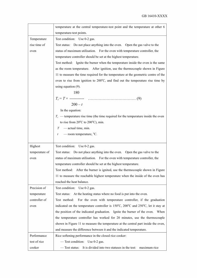
GB 16410-XXXX
temperature at the central temperature-test point and the temperature at other 6
temperature-test points.
Temperature
rise time of
oven
Test condition: Use 0-2 gas.
Test status: Do not place anything into the oven. Open the gas valve to the
status of maximum utilisation. For the oven with temperature controller, the
temperature controller should be set at the highest temperature.
Test method: Ignite the burner when the temperature inside the oven is the same
as the room temperature. After ignition, use the thermocouple shown in Figure
11 to measure the time required for the temperature at the geometric centre of the
oven to rise from ignition to 200oC, and find out the temperature rise time by
using equation (9).
180 Tc = T × ----------- ……………………………… (9) 200 – t
In the equation:
Tc –– temperature rise time (the time required for the temperature inside the oven
to rise from 20oC to 200oC), min.
T –– actual time, min.
t –– room temperature, oC.
Highest
temperature of
oven
Test condition: Use 0-2 gas.
Test status: Do not place anything into the oven. Open the gas valve to the
status of maximum utilisation. For the oven with temperature controller, the
temperature controller should be set at the highest temperature.
Test method: After the burner is ignited, use the thermocouple shown in Figure
11 to measure the reachable highest temperature when the inside of the oven has
reached the heat balance.
Precision of
temperature
controller of
oven
Test condition: Use 0-2 gas.
Test status: At the heating status where no food is put into the oven.
Test method: For the oven with temperature controller, if the graduation
indicated on the temperature controller is 150oC, 200oC and 250oC, let it stay at
the position of the indicated graduation. Ignite the burner of the oven. When
the temperature controller has worked for 20 minutes, use the thermocouple
shown in Figure 11 to measure the temperature at the central part inside the oven,
and measure the difference between it and the indicated temperature.
Performance
test of rice
cooker
Rice softening performance in the closed rice cooker:
–– Test condition: Use 0-2 gas.
–– Test status: It is divided into two statuses in the test: maximum rice

GB 16410-XXXX
volume and minimum rice volume.
–– Test method:
• Before the test, the rice for use in test should be immersed in water for a
period of time. The test can be carried out according to the specified
conditions of the operation manual of the product.
• Cook the rice according to the methods specified in the operation
manual. In the 15th minute after automatic extinguishing, inspect the
quality of the cooked rice.
• Turn off the main burner, and let the rice pot preserve heat
automatically. During the heat preservation period, inspect the quality
of the cooked rice.
Heat preservation performance:
–– Rice pot with a thermo burner:
• Test condition: Use 0-2 gas.
• Test status: Use the maximum rice volume for test.
• Test method: After the main burner is extinguished, let the heat
preserved for 1 hour at the airless status. Then measure the
temperature at the central part of the cooked rice and inspect the quality
of the cooked rice.
–– Electronic thermo rice cooker:
• Test condition: Use 0-2 gas.
• Test status: Use the maximum rice volume in the test.
• Test method: In the 15th minute after the extinguishing of the main
burner, connect the thermo power. Let the heat be preserved for 12
hours without air flow. Then measure the temperature of the cooked
rice and inspect the condition of the cooked rice. The points for
temperature measurement are shown in Figure 12. Take the average
of the various points.
Heat efficiency:
–– Test condition: Use 0-2 gas.
–– Test status:
• Connect with the rice pot for use in the test according to the methods
shown in Figure 8.
• The water volume for use in test is two times of the maximum rice
volume.
–– Test method: Use the same test method as the heat efficiency of gas
stove.
6.15 Electrical performance test

GB 16410-XXXX
6.15.1 The electrical performance test of the cooking appliances using AC power is shown in Table 22.
Table 22 Electrical performance test Test Item Test Conditions, Test Statuses, Test Methods
Anti-shock
protection
Test statuses: At all the statuses in times of working according to the normal
utilisation of cooking appliances, and at the status that the burner ring or handle
and other dismantlable parts can be even dismantled.
Test methods:
–– Apply unobvious force onto the finger probe specified in Figure 15.
Except the inclined placing of the cooking appliances which are utilised on the
ground and their mass exceed 40 kg, the cooking appliances are situated at every
possible status. The finger probe goes through the opening and stretch to any
permitted depth. After it is inserted to the front, middle and back of any single
position, turn or incline the finger probe. If the finger probe cannot enter the
opening, use a straight-typed joint-free finger probe to apply force to 20N. If
this finger probe can enter the opening, use the original finger probe with joint to
repeat the test.
When carrying out the test, connect an indicating light with the place between
the testing instrument and the dangerous parts inside the shell, and supply safe
power of extremely low voltage at 40 V ~ 50 V. If the surface of the dangerous
electric parts is found to have a layer of paint film or oxidised layer or protection
of the similar method, then cover it by a layer of golden foil during the test. A
test is carried out again together with the connected electric parts during normal
working.
–– Apply unobvious force onto the test pin shown in Figure 13a) to go
through each opening of the Category II cooking appliances or the Category II
structured cooking appliances.
–– For the corresponding places being possibly touchable occasionally by fork
or sharp-like object under normal utilisation, apply unobvious force onto the long
test pin shown in Figure 13b) to go through each opening.
If the touchable parts are found to have the following circumstances, they are
not regarded as electric:
–– The part is supplied with safe power of extremely low voltage.
• For AC power, its peak value of voltage is ≤ 42.4 V.
• For DC power, its voltage is ≤ 42.4 V.
–– Through protective impedance, the part is separated from the electric parts.
The current between the part and power source under the circumstances with
protective impedance: For DC, it should be ≤ 2 mA; for AC, its peak value

GB 16410-XXXX
should be ≤ 0.7 mA. Besides,
• For the peak voltage being greater than 42.4 V and small than or equal
to 450 V, its power capacity should be ≤ 0.1 µF.
• For the peak voltage being greater than 450 V and small than or equal
to 15 kV, its electric discharge should be ≤ 45 µC.
Inspect its conformity through the measurement of power supply from the
nominal voltage.
Independently carry out measurement of the voltage and the current between
the various correlated parts and each electrode of power source. Measure the
power discharge immediately after the power is cut.
If the test circuit contains a resistance with its value being 2000Ω ± 100Ω, and
the measured discharge volume in times of ignition is ≤ 45 µC, then the easily
touchable part of its ignition circuit is regarded as not electric.
Current leakage
and electrical
strength at
working
temperature
Current Leakage
Test conditions: The work of cooking appliances continuously extends to the
corresponding time of the most disadvantageous conditions during normal
utilisation. The electrothermal cooking appliances work by using 1.15 times the
nominal input power. The electric cooking appliances and the combined
cooking appliances are supplied by the power being 1.06 times of the nominal
voltage.
Test status:
–– Before the test is carried out, protective impedance should be cut off from
the electric parts.
–– Carry out the measurement by using the device formulated by the circuit as
described in Figure 14d). The measurement is done between any one electrode
and the metal-foiled easily touchable metallic part. The connected metal foil is ≤
20 cm × 10 cm. It contacts with the easily touchable surface of the insulated
materials.
–– During the test, the cooking appliances should keep insulated from the
ground. The ground wire of the flexible power cord should be cut off from the
ground terminal inside the cooking appliances.
–– Place a selected test pot according Figure 6 / Figure 7 in the electric stove
cooking region, and heat the water at 2/3 of the depth of pot. Keep the water
boiling and at maintain its water level.
Test methods:
–– If it is a single-phase Category II appliance, use the circuit diagram shown
in Figure 14c).
–– If it is a single-phase non-Category II appliance, use the circuit diagram

GB 16410-XXXX
shown in Figure 14a).
–– For electromagnetic stove head, use the circuit diagram shown in Figure
14b).
Electrical Strength
Test conditions: According to the different structures and utilisation statuses, the
following voltage tests are adopted respectively. Connect and test the circuit
diagram according to Figure 19.
Test status: After the current leakage test, carry out the test without any
protective impedance.
Test methods:
–– The insulation has to immediately receive the sine-wave-based voltage at
the frequency 50 Hz for 1 minute. It is applied to the place between the electric
parts and the easily touchable parts.
For the Category II structure with metallic objects between the electric parts and
the easily touchable parts, the voltage application has to cross over the basic
insulation and additional insulation respectively.
–– At the beginning of the test, the applied voltage should not exceed half of
the specified voltage. Then it is rapidly raised to full value.
Current leakage
and electrical
strength at room
temperature
Test conditions:
–– Before the test, protective impedance should be cut off from the electric
parts.
Test status:
–– The test is carried out with power disconnected.
Test methods:
–– The application of the test AC voltage is shown in Item 1 and Item 3
specified in Table 23. Metallic foil ≤ 20 cm × 10 cm. If necessary it should be
moved so as to make all parts of the surface are tested.
–– Test voltage: For single-phase cooking appliances, it is 1.06 times the
nominal voltage.
–– Within 5 seconds after application of the test voltage, measure the current
leakage.
Electrical Strength:
After the current leakage test, carry out electrical strength test immediately.
Test methods:
–– The test voltage and the place of application are shown in Table 23.
–– The easily touchable parts made of insulated materials should be covered
by metallic foil.
–– For cooking appliances with nominal voltage ≤ 130 V, reduce 1,250 V to

GB 16410-XXXX
1,000 V.
–– At the beginning of the test, the applied voltage should not exceed half of
the specified voltage. Then it is rapidly raised to full value.
Nominal input
power error
Test conditions: Adjust the input voltage to be nominal working voltage. In
the whole testing process, the input voltage should be kept at the fluctuation range
of ± 2%.
Test status: The cooking appliance is situated at a stable working status.
Test methods: Use the Table of Power to measure the power of the cooking
appliance at working status.
Humidity
resistance
Water Leakage Test:
Test status:
–– Place the cooking appliance horizontally.
Test methods:
–– Let a pot equivalent to electric stove head and gas stove head filled with
salt water containing about 1% of NaCl, and place the pot at the centre of the
cooking region. Use 0.5 l of the solution to stably pour into the pot for 15
seconds so as to remove the residue fluid let on the surface of the cooking
appliance. Then electrical strength test is carried out at the cooking appliance.
–– For the cooking appliances with switch and temperature control, pour 0.2 l
of the solution on the electric stove head and let it flow over the switch or the
controller. After that, place a container on the stove head and press down to the
moveable parts.
–– For the cooking appliances with a vent on the surface, let 0.2 l of the
solution go through a funnel from 200mm above the vent and run to the vent at
the most disadvantageous situation (the diameter of the funnel outlet is 8 mm).
Humidity Treatment:
Test condition: The test can only be carried out after the cooking appliance has
received the above test and then has been placed in a test room at a common
atmospheric environment for 24 hours.
Test status: The cooking appliance is placed in a humid box at a relative
humidity of (93 ± 2)% for 48 hours. Keep the air at any one temperature within
the range of 20oC ~ 30oC, and keep the temperature change within the range of ±
1oC. Before placing it into the humid box, let the sample reach this temperature.
Test methods:
–– After this treatment is done, the cooking appliance should be inside the
original humid box, or in a room that can make the sample reach the specified
temperature. After that, carry out electrical strength test immediately

GB 16410-XXXX
Table 23 Test Voltage
Test Voltage, V
Position of Application Category III
Appliance and
Category III
Structure
Category II
Appliance
and Category
II Structure
Other
Appliances
1 Between the electric part and the easily touchable part:
–– where only basic insulated isolation is adopted.
–– where strengthened insulated isolation is adopted.
500
––
––
3,750
1,250
3,750
2 For the double-insulated parts, it is between the metallic
parts, which only adopt basic insulation to isolate from the
electric parts, and:
–– the electric parts.
–– the easily touchable parts.
––
––
1,250
2,500
1,250
2,500
3 If the measured distance between the electric parts and
the metallic outer shell with insulated lining or the metallic
cover, and going through the lining, is less than the
corresponding gap specified in Subsection 29.1, then it is
between the metallic outer shell with insulated lining or the
metallic cover and the metallic foil with contacts with the
surface layer inside the lining.
–– 2,500 1,250
4 If the insulation is accidentally failed and its shaft is
electric, then it is between the metallic foil touchable with
the handle, knob, grip and the similar parts, and their
shafts.
–– 2,500 2,500
(1,250)
5 Under the circumstances that the flexible cord is placed
inside the inlet bush of the insulated material, flexible cord
protection device, flexible cord fixing device and the
similar parts, it is between the easily touchable parts and
the flexible power cord wrapped by metallic foil.
–– 2,500 1,250
6 If a resonant voltage U is caused between a joint at the
airing or the capacitor and the wiring terminal of any one
external lead, then it is between this joint and:
–– the easily touchable parts.
–– the metallic parts which only adopt basic insulation to
isolate from the electric parts.
––
––
2U + 1,000
2U+ 1,000
1) The value in the brackets is applicable to Category 0 cooking appliances.
2) The outer surface of the flexible cord protection device has no metallic foil wrapped.

GB 16410-XXXX
3) The moment applied to the camping screw of the flexible cord fixing device is 2/3 of the moment
specified in Table 12 of GB 4706.1-1998.
4) For the test between the airing-capacitor joint and the easily touchable parts or the metallic parts,
it is carried out only when the insulation of that place has received resonant voltage under normal
working conditions. During the test, disconnect other parts and shut down the capacitor.
6.15.2 DC power abnormality test 6.15.2.1 Test condition: Use 0-2 gas. 6.15.2.2 Test status: 15 minutes after the cooking appliance is ignited. 6.15.2.3 Test methods:
–– Slowly reduce the DC power from the nominal voltage to 70% of the nominal value. Test if the cooking appliance can keep on working normally, and if the extinguishing protection function of the cooking appliance is normal. –– Slowly reduce the DC power from the nominal voltage to 0 V, and resume it to the nominal voltage. Test if the cooking appliance is situated at the specified status. 6.16 Durability performance test 6.16.1 Gas cork valve 6.16.1.1 Test condition: Use the air with the same pressure as the nominal gas supply pressure. 6.16.1.2 Test status: The appliance and the cooking appliance are situated at a separating status, or the appliance is installed on the cooking appliance. 6.16.1.3 Test method: After the test has been carried out 15,000 times at an operation speed of (5~20) times/min., carry out air-tightness and operation performance tests. 6.16.2 Electric ignition device 6.16.2.1 Test condition: Use the air with the same pressure as the nominal gas supply pressure, or use 0-2 gas. 6.16.2.2 Test status: The appliance and the cooking appliance are situated at a separating status, or the appliance is installed on the cooking appliance. 6.16.2.3 Test method: After the test has been carried out 15,000 times at an operation speed of (5~20) times/min., carry out ignition performance test. 6.16.3 Extinguishing protection device 6.16.3.1 Test condition: Use 0-2 gas. 6.16.3.2 Test status: The appliance and the cooking appliance are situated at a separating status, or the appliance is installed on the cooking appliance. 6.16.3.3 Test method: Ignite the burner. Let the flame detector of the extinguishing protection device contact with the flame for 1 minute. After that, turn off the power and extinguish the burner. The flame detector stays away from the

GB 16410-XXXX
flame for no less than 1 minute. This kind of operation is regarded as one time. After the test has been carried out for 6,000 times, carry out air-tightness test as well as the performance test of the extinguishing protection device. 6.16.4 Electromagnetic valve 6.16.4.1 Test condition: Use the air with the same pressure as the nominal gas supply pressure. 6.16.4.2 Test status: The appliance and the cooking appliance are situated at a separating status, or the appliance is installed on the cooking appliance. 6.16.4.3 Test method: Repeat the opening and closing acts at a speed of (10~30) times/min. After the test has been carried out for 30,000 times, carry out the open-and-close functional and air-tightness tests. 6.16.5 Mechanical timer 6.16.5.1 Test condition: Use the air with the same pressure as the nominal gas supply pressure. 6.16.5.2 Test status: The appliance and the cooking appliance are situated at a separating status, or the appliance is installed on the cooking appliance. 6.16.5.3 Test method: Turn the knob of the main shaft to the minimum preset time, but cannot be less than 1 minute. The time of connection is regarded as the starting point of time, and the time of disconnection is regarded as the final point of time. This kind of operation is regarded as one time. After the test has been carried out 2,000 times: –– carry out air-tightness test; –– turn the main shaft to the full-range angle within 2 seconds. The time of connection is regarded as the starting point of time, and the time of disconnection is regarded as the final point of time. Measure the full-range preset time for 3 times, and take the arithmetic average. The average is compared with the full-range preset time before the durability test, and the change rate is calculated. 6.16.6 Temperature controller of oven Use the controller to control the temperature at the central part of the oven at the status of 200oC. Alternately blow hot air and cold air onto the temperature sensing place of the temperature controller (heat sensor). The air blowing for 1 minute is regarded as one time. The number of times for the test to be carried out is based on the specifications in Table 6. Carry out the temperature control precision, temperature indication precision and air-tightness tests of the temperature controller. 6.16.7 Temperature controller of rice cooker Let the rice cooker simmer. Let the temperature controller function repeatedly at a certain interval. Assuredly cut the gas supply of the main burner. After the test has been carried out 2,000 times, carry out air-tightness test and rice softening test in

GB 16410-XXXX
the closed rice cooker. 6.16.8 Oven door After the door and the linked mechanism have been repeatedly operated for 500 times at a speed of (5~20) times/min., inspect whether the oven door and the linked mechanism have been damaged or malfunctioned. 6.17 Vibration test Tie the cooking appliance according to the transportation requirements, and place it horizontally on the vibration machine. Let the machine vibrate at the frequency 10 Hz, full amplitude 5 mm, in up-and-down direction and in left-and-right direction for 30 minutes respectively. After that, carry out the air-tightness, electrical performance and utilisation function tests of the gas channel. 6.18 Falling test Let the sides 3, 2, 5, 4, 6 of the test piece face downwards one by one by using the methods given by Appendix in GB/T 1019-1989. For the packed object at a mass below 25 kg, the height of the fall is 600 mm. For the packed object at a mass of 25kg ~ 50kg, the height of the fall is 450 mm. The release is done under the condition that the initial speed is 0. Each side has to fall once. For those products which cannot be put upside down, they should carry out falling test, with the bottom facing downwards, for 6 times continuously. After that, carry out the air-tightness and electrical performance tests of the gas passage (its electrical strength, current leakage and ground resistance should meet the requirements of Table 5). 6.19 Structure test 6.19.1 General test According to the requirements of Subsection 5.3, make visual inspection and carry out the test. 6.19.2 Inclined and turn-over test Place the cooking appliance horizontally on the test table. Let it inclined gradually until it forms an included angle of 15o with the water level. Check visually whether it is turned over, and if there is any movement and falling of the fire-catching parts. 6.19.3 Loading test 6.19.3.1 Loading test of stove top and pot support Place the cooking appliance horizontally on a firm and solid surface. Apply 98.1 N static load to the central part of the pot support for 5 minutes. Inspect the bending of any part of the stove top, and whether the pot support is deformed and damaged. 6.19.3.2 Loading test of oven door Place the oven horizontally on a firm and solid plane, and open the oven door.

GB 16410-XXXX
For the table-top type oven, apply a static load of 39.2 N to the central part of the door. For the built-in stove, apply a static load of 147 N to the central part of the door. Maintain both actions for 5 minutes. Inspect whether it is turned over and whether there is any deformation and damage affecting the utilisation.
Remarks:
1 The so-called “without any deformation and damage affecting the utilisation” refers that
after loading is added, the bending at the front edge of the door (referring to the difference between the
position of door being at full-open status and the sunk position after loading is added to the door)
should not be below 15 mm, and the mechanism shall not be damaged.
2 Method of applying the load: The fluid collection pan, which is attached to the oven and is
for use in oven, can be placed at the central part of the oven door. Place a round heavy load at a
diameter 260 m on the central part of the fluid collection pan.
6.20 Heat resistance performance test of parts 6.20.1 Heat resistance performance test cork valve and other valves Put the valve into the temperature constancy box. Adjust the temperature to 90oC for 24 hours, and then take it out. Let it cool down to room temperature naturally. Carry out the air-tightness test according to Subsection 6.6. 6.20.2 Heat resistance performance test of electric ignition device Put the electric ignition device into the temperature constancy box. Adjust the temperature to 90oC for 24 hours, and then take it out. Let it cool down to room temperature naturally. Carry out the test according to Subsection 6.13. 6.20.3 Overheat resistance performance test of burner
According to Table 17, select an upper-limit pot based on the actual heat input. Pour in proper water volume into the pot. Use tempering limit gas. Ignite the burner under the nominal gas supply pressure, and use tempering artificially. If tempering is unavailable, gas can be ignited at the nozzle, so as to make it burn inside the nozzle or burner. If this kind of burning cannot be maintained, it can be realized by the ways of reducing the pressure or appropriately decreasing the flow volume. But the gas supply pressure cannot be lowered to a pressure which is lower than the tempering test. Maintain tempering burning for 15 minutes, and test whether the burner has any deformation affecting its performance. 6.20.4 Test methods and judging principles by using the materials with temperature resistance greater than 700oC at the flame hole of burner: Take out the parts of the units that can be dismantled easily that form the flame hole of the burner. Measure the size of the flame hole part, calculate the area of the flame hole, and place it in a temperature constancy box at an adjusted temperature of 700oC. Take it out 2 hours later, and let it cool down to room temperature naturally. Measure the size of the flame hole part, calculate the area of the flame hole, and test

GB 16410-XXXX
the area alteration rate of the front and rear flame holes which should be within the range of ± 10%. If exceeding the range, it is regarded as failed. 6.21 Test of materials 6.21.1 General tests According to the requirements of Subsection 5.4, make visual inspection and carry out the test. 6.21.2 Heat resistance performance test Put the test sample into the heating stove. Let the temperature rise slowly to the temperature specified in Subsection 5.4, and keep it at the temperature for 1 hour. Visually inspect whether the materials have any change affecting the utilisation 6.21.3 Corrosion resistance performance test 6.21.3.1 Salt fog test of electroplated objects Put the electroplated sample in the specified sprayed fog of salt water. At the temperature of 35oC ± 2oC, spray a fog of salt solution at a concentration of 5%. The pressure of the fogged air is (70 ~ 100) kPa, and the time is (24 ~ 72) hours. Take out the test sample, and inspect the extent of corrosion. The test methods are executed according to QB/T 3826-1999, and the mass assessment is executed according to QB/T 3821-1999. 6.21.3.2 Salt fog resistance test of paint coated test sample Prepare the test sample according to the specifications in GB/T 1765-1979, and then carry out salt water spray test. The test methods are executed according to the related specifications in GB/T 1771-1991, and the extent of corrosion is assessed according to the specifications of GB/T 1740-1979. 6.21.4 Gas resistance performance test 6.21.4.1 Test method of film
Let the 3 test samples, with their mass measured in advance, be immersed in the liquid of liquefied petroleum gas at (5 ~ 25)oC for 72 hours. Take them out and place them in the air for 24 hours. Test their mass and quality change according to the methods given in GB/T 1690-1992. For films for use in artificial gas, carry out the test by using the solution specified in GB/T 1690-1992. 6.21.4.2 Test methods of gas sealing spacer, washer Except the implementation of the test indicated in Subsection 6.21.4.1, the following test also has to be carried out. First of all, put the three test samples, with the thickness 2 mm, outer diameter 19 mm and inner diameter 18 mm, into the devices shown in Figure 16 respectively. Each device is filled with 0.5 g of n-pentane. Compress the test samples to 80% of their original thickness, and then weigh the devices. Put them in the temperature constancy tank at 23oC ± 2oC for 24 hours. After that, weigh them again, and indicate the average leakage of n-pentane

GB 16410-XXXX
from the 3 test samples per hour. 6.21.4.3 Test methods of grease sealing materials Apply 1 gram of sealing materials on an aluminium plate. Place it in the greenhouse for 24 hours, and then put it in the test equipment shown in Figure 17. Turn on the knobs A and B. Use n-butane to exhaust the air inside, and then turn off knob B. Keep the gas pressure inside the U-tube at 5.0 kPa. It is placed under the conditions of 20oC ± 1oC and 4oC ± 1oC for 1 hour respectively. After that, calculate the change rate of the sealing materials. 6.21.5 Steel ball impact resistance performance test of porcelain Place the porcelain enamel treated test sample on a wooden plate of the corresponding size. Let a steel ball at a diameter 30 mm fall freely from the height of 300 m and the impact onto the test sample. The porcelain enamel should not fall from the test sample. 6.21.6 Inflaming retarding performance test of thermo and heat insulation materials At the place with materials evenly spread, put a test sample at the length (150 ± 1) mm and thickness (13 ± 1) mm on the device shown in Figure 18. After it is burned by fire for 1 minute, take away the fire. Check visually whether the test sample is burned. When burning happens to the test sample, measure the time from burning to extinguishing by itself. 6.21.7 Oil resistance performance test Immerse the rubber-made stove leg test sample in the edible oil (e.g. bean oil) at the temperature 20oC ± 15oC for 24 hours. After that, inspect visually whether there is any deformation obviously affecting the utilisation 7 Test rules Cooking appliances should carry out inspection and type inspection before they are delivered from the factory. 7.1 Ex-factory inspection 7.1.1 Before delivery from the factory, the cooking appliances should carry out the following inspection one by one: a) Air-tightness performance of gas piping system;
b) Operation flexibility performance of each part; c) Ignition performance and burning stability performance; d) Ground resistance (applicable to Category I cooking appliances); e) Appearance; f) Name plate; g) Current leakage (applicable to the cooking appliances using AC power); h) Electrical strength (applicable to the cooking appliances using AC power).

GB 16410-XXXX
Remarks: The cooking appliances stored in the warehouse for more than 2 years should be
re-inspected according to this Subsection.
7.1.2 Sampling test 7.1.2.1 During the batch inspection of products before acceptance, carry out the sampling test. The sampling methods are specified in GB/T 2828.1-2003. 7.1.2.2 Sampling plan
a) The sampling plan is specified in GB/T 2828.1. The acceptable quality level (AQL) is 4.0. The inspection level taken is S = 1. Implement the sampling plan according to the normal inspection for one time;
b) When the sampling test of a product is failed, the products of the batch are judged as non-conforming. This batch of products should be re-inspected one by one, and then receive sample test again.
7.1.2.3 In addition to the specified contents of Subsection 7.1.1, the sampling test should also include heat input, carbon oxide content in fume, heat efficiency. 7.1.3 After the products have passed the inspection, certificates of conformity are issued before delivery out of the factory. 7.2 Type inspection 7.2.1 Inspection should be carried out according to all the contents of the Standard. 7.2.2 In case of any one of the following circumstances, type inspection should be carried out:
a) Assessment of the trial manufacturing finalizing of new products or old products to be produced in another factory;
b) After official production, the structure, materials and workmanship may have greater change which may affect the performance of products;
c) After official production, an output accumulated regularly or to a certain volume should carry out inspection periodically;
d) After the production of certain products has been stopped for 1 year, the production is resumed;
e) There is a greater difference between the ex-factory inspection results and the type inspection of the last time;
f) The General Administration of Quality Supervision, Inspection and Quarantine of the People’s Republic of China makes a request of type inspection. 7.2.3 Sampling method: Take 3 samples each time. 2 of them receive the test and 1 is the reserved sample 7.2.4 When all the items of type inspection have met the requirements of the Standard, the type inspection is judged to be passed. If there are any non-conforming items, they should be improved. Do the re-inspection until all the items are passed. Then the type inspection can be judged as passed.

GB 16410-XXXX
7.3 Judgment principles for the inspection of single cooking appliance 7.3.1 Classification of clauses The text in blocked characters are the mandatory clauses, and the rest of them are the recommendatory clauses. 7.3.2 Judgment methods 7.3.2.1 After a single machine sample has been tested, if there are more than 1 (including 1) mandatory clause not conforming to the regulations, the machine sample is regarded as non-conforming. 7.3.2.2 After a single machine sample has been tested, if there is 1 or several recommendatory clause not conforming to the regulations, the non-conformance contents of the machine sample should be stated in the test report. 8 Marking, package, transportation, storage 8.1 Marking 8.1.1 Each cooking appliance should be installed with a name plate at the suitable place. The marking contents should include:
a) Name and model number; b) Kind of gas to be used or applicable regions; c) Nominal gas supply pressure; d) Nominal heat input: e) Name of manufacturer; f) Year, month of manufacturing or code; g) Nominal voltage (applicable to the cooking appliances using AC
power, V); h) Nominal input power (applicable to the cooking appliances using AC
power, kW/W); i) Nominal frequency (applicable to the cooking appliances using AC
power, Hz) j) Sign of Category II structure (only indicated on the Category II
cooking appliances). 8.1.2 Besides the marking of the name plate, the following marking should also be made:
a) The wiring terminal for connection with the electric wire fence should contain the following markings:
–– The wiring terminal especially for the connection with the neutral wire should be marked with the letter N;
–– The protective ground terminal should be marked with the sign: Remarks: All these specifications show that the sign should not be placed on screw,
dismantlable washer or any other parts which can be dismantled during the connection of lead.

GB 16410-XXXX
b) Unless being obviously unnecessary, the marking or placement position of the switch which may cause danger during work should clearly state that the part it controls is which part of the cooking appliance;
Remarks: The marking way, no matter being placed anywhere, used for this purpose should
be so clearly explained that they are comprehended by anybody without language proficiency or
without the knowledge of the National Standard. c) The different fire volumes of switch on the cooking appliances and
the different fire volumes of controller on the cooking appliances should be indicated by numbers, letters or other visual way;
d) During the period of installation or normal utilisation, the controller intending for adjustment should be indicated with the adjustment direction;
e) If the compliance with the Standard is determined by an available changing act of the thermal fused object or the fuse, then its name plate or other indications for identifying the fuse should be clearly shown on the visible position when the cooking appliance is required to be dismantled for changing the fuse;
Remarks: 1 Marking on the fuse: The marking is acceptable only if its marking is still
clear after the fuse is functioned.
2 The marking required in the Standard should be clear, readable and durable.
After a person uses a hand to hold a water-damped cloth to wipe the marking for 15 seconds, and uses a
fuel-damped cloth to wipe the marking for 15 seconds, the marking should be still clear and readable.
It is not so easy for the marking plate to be dismantled or for the edge to be rolled up. f) If the stove head surface is made of glass, porcelain or the similar
fragile materials, and the heat-generation component is installed on the abovementioned materials or above them, or the main part of the outer shell of the electric parts of the cooking appliance is made of the abovementioned materials, then the following warning should be stated in the Operation Manual and on the cooking appliance:
Warning –– If cracks are found on the surface, turn off the cooking appliance to any possible avoid electric shock. 8.2 Package 8.2.1 Outside the package carton should be indicated with the product name, model number, kind of gas to be used or applicable regions 8.2.2 The package should be safe, firm, beautiful. The package carton should be indicated with the ex-factory date and name of factory, the words like “fragile product, upwards, avoid rain, turnover prohibited, fork truck restricted, stack weight limit,” and so on. The pattern of characters or illustration should meet the specifications of GB/T 191-2000. 8.2.3 Inside the package carton, there should be a list of product accessories,

GB 16410-XXXX
certificate of conformity, maintenance guarantee certificate, as well as installation and operation manual. 8.2.4 When delivered out of the factory, each cooking appliance should be attached with the installation and operation manual. An installation and operation manual should include the following contents: a) Description on the size of appearance and installation;
b) Operation and adjustment methods of ignition and extinguishing; c) Safety notes (relating to gas, ventilation, fire prevention, prevention of
human burn, keep away from children, and so on); d) If the flexible power cord is damages, it should be replaced by the
manufacturer or its maintenance department or the similar professional staff in order to avoid danger;
e) Notes for cleaning and maintenance; f) Address of factory and the contact affairs; g) Size of hole opening in the installation requirements and the fixing method
(built-in cooking appliances); h) The kitchen cabinets for installing the built-in stove should have the
hole opened at the size that meets the ventilation requirements and connecting with the atmosphere; otherwise, explosion will be caused by the deposited gas leakage;
i) Handbook of environmental effects for user; j) All the messages on the name plate (when the marking is invisible after the
built-in stove is installed) should be clearly indicated in the manual; k) The cooking appliance will generate heat during the utilisation period.
Avoid contacting with the heat generating unit. The metallic objects, such as knife, fork, ladle and cover, should not be placed on the stove top because they may be heat generating. 8.2.4 The package materials should meet the requirements of Subsection 5.4.19 of the Standard. 8.3 Transportation 8.3.1 In the process of transportation, prevent drastic vibration, compression, rain and corrosion of chemical products. 8.3.2 During the transportation, rolling and throwing are prohibited 8.4 Storage 8.4.1 The finished products have to be stored in a warehouse with dry ventilation and without corrosive gas around. 8.4.2 The cooking appliances should be stored according to the classification of models. The stacking of products should not be too high. Prevent compression and
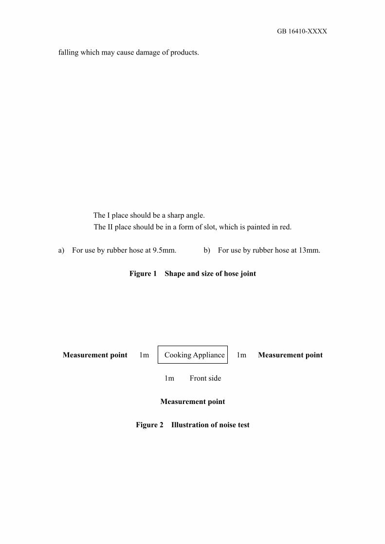
GB 16410-XXXX
falling which may cause damage of products.
The I place should be a sharp angle. The II place should be in a form of slot, which is painted in red.
a) For use by rubber hose at 9.5mm. b) For use by rubber hose at 13mm.
Figure 1 Shape and size of hose joint
Measurement point 1m Cooking Appliance 1m Measurement point
1m Front side
Measurement point
Figure 2 Illustration of noise test

GB 16410-XXXX
48 - Φ1 Apply evenly along the circumference
Φ12x1 Red copper pipe Aluminium pot for test D is diameter of pot in the test
Shape and size of fume sampler of gas stove Fume sampling place of gas stove
Remarks: The barbecue, oven and rice cooker should use the sampler which is respectively suitable for their exhaust shape, to take samples.
Figure 3 Ringed fume sampler and the sampling position
Wooden wall
(lateral side) Wooden wall (lateral side)
about 1mm Surface Thermocouple about 30mm Wooden table (bottom) a) The materials of wooden wall and wooden table should be the 5-6-layered
plywood. The wooden table should be painted on the surface. The wooden wall surface should be painted with non-shiny paint;
b) The size of wooden wall and wooden table should be a little bit larger than the cooking appliance;
c) Try to bury more thermocouples (thermal resistance), and make them form a net shape;
d) Thermocouples (thermal resistance) should be buried at the depth of 1mm of the wooden wall and wooden table;
e) The thermocouples (thermal resistance) should refer to GB/T 3772-1998 and GB/T 2903-1998.
Figure 4 Testing device for temperature rise on the surface of wooden wall and wooden table

GB 16410-XXXX
a. Disconnection at heating place (stove) b. Disconnection at heating place (oven) c. Rice cooker
Figure 5 Distance between cooking appliance and temperature-test plate
Diameter of cooking region a b c 100 110 140 8 145 145 140 8 180 180 140 9 220 220 120 10 300 300 100 10
Figure 6 Stove for use in the test of electric stove head

GB 16410-XXXX
Thickness at the bottom and lateral wall 1.5 – 2.5 Maximum limit of concavity
The pot is made of carbon steel (the maximum carbon content is 0.18%), without a handle and a protruding cylinder. The diameter of the flat bottom region is at least the diameter of the cooking region. The maximum concavity (C) is 0.006d. d is the diameter of the plane region at the bottom. The bottom is not convex.
Figure 7 Stove for use in the test of electromagnetic stove
Gas Pressure adjustment valve 3-Way tube 1- valve
2- damped gas flow meter
3- thermometer
4- barometer
5- cooking appliance
6- aluminium pot
7- precise thermometer
8- stirrer Gas pressure test pipe Remarks:
a The precise thermometer should be placed at the central
position at 1/2 of water depth.
b The stirrer should be placed at the position without contact
with the mercury ball of thermometer
c The measurement point of gas pressure in front of the cooking
appliance should be at the 3-way tube position shown in the
figure. The distance from the vent should not be greater
than 100mm.
D = (1~1,1)d
D –– inner diameter
of 3-way tube
d –– inner diameter
of gas pipe
Length = 5D + 5D
Figure 8 Testing device of heat input and heat efficiency

GB 16410-XXXX
1 – stirrer 2 – nut 3 – handle
Remarks:
a) D is the diameter of aluminium pot in mm; H is the height of aluminium pot in mm.
b) Materials of parts: The stirring plate is made of 1mm-thick aluminium plate. The
handle is made of Φ galvanized steel.
Figure 9 Stirrer
Baking plate Glass-fibre thermo plate
Temperature testing point (7 points) Remarks:
a) The gap between two overlapped glass-fibre thermo plates is sealed by sealing tape;
b) The surface of the glass-fibre thermo plates are painted in black.
Figure 10 Temperature-test plate for testing temperature distribution of oven

GB 16410-XXXX
Plate 0.5 – 0.6 / Copper Hard fibre welding
Ø 1.5 – 2.0 Insulation Cased thermoelectric pot
Pipe Ø 3 × 0.5 / Copper
The tip of thermoelectric pot is generally matching with the centre and is being fixed.
Figure 11 Thermocouple for testing the temperature of oven
Inner pot Cooked Rice Central part of inner pot
Figure 12 Test of temperature control device of rice cooker
Insulated material Metal Metal Insulated material a Short test pin b Long test pin
Figure 13 Test pins

GB 16410-XXXX
Easily touchable place Not easily touchable place Basic insulation
a) Circuit plan of current leakage measurement Additional insulation of the single-phase connected non-Category Strengthened insulation II appliance at working temperature Measurement
end
b) Circuit plan of current leakage measurement of electromagnetic stove head
c) Circuit plan of current leakage measurement of the single-phase connected Category II appliance at working temperature
d) Circuit plan of current leakage measurement device
Figure 14 Circuit plan of current leakage measurement

GB 16410-XXXX
Surface of cylinder Joint All-edge angular rounding Thrust surface
Insulated material Protective plate Handle
Cross-section A-A Cross-section B-B
Materials: Metal, except those specified additionally.
Length is in the unit of mm.
For the size without common error specified, its tolerance is:
For angle: 0
-10’
For length size: For ≤ 25mm, 0
-0.05
For > 25mm, ± 0.2
Two combined points should be allowed to be on the same plane.
Have movement in the same direction 90o +10o
0
Figure 15 Finger probe

GB 16410-XXXX
10 equal portions of pressing cap
Test sample
Metallic spacer
Vertical reference line
Internal capacity 5.5cm3
Figure 16 Testing device of gas resistance of washer and spacer Water bath Adjuster Vase 3-Way tube Voltage meter Cork Aluminium U-shape Sealing Thermometer
plate tube
Temperature constancy tank 20oC ± 1oC or 4oC ± 1oC
Figure 17 Testing device of grease resistant gas
Size of metallic net: 76 mm × 215 mm
Wire diameter: Φ0.7 mm
Hole diameter: Φ4.2mm
Support Burner Metallic net Test sample Support
Remarks:
a The test room should be airless, and the metallic
net should be horizontal;
b Liquefied petroleum gas burner should be used.
For the burner, please refer to Appendix F in GB 4706.1.
The distance between the flame hole and the metallic net
should be 13 mm;
c Bending position for test sample to be close to the
metallic net
Figure 18

GB 16410-XXXX
High-voltage transformer Isolated transformer N 3- Phase power source
Figure 19 Circuit plan of electrical strength test under working temperature
Valve A Valve B Main burner Valve C Main burner C Gas Gas Valve A Valve B Main burner B
Remarks: The functions of Valves A and B are
independent with each other.
Remarks: The functions of Valves A and C are
independent with each other. The
functions of Valves A and B are also
independent with each other.
Figure 20 Illustration of gas channel

GB 16410-XXXX
Appendix A (Informative Appendix)
Gradation requirements of nitrogen oxide [Nox (α=1)] content in the burning fume of domestic gas cooking appliances
A1 Gradation requirements of nitrogen oxide [Nox (α=1)] content in the burning fume
of domestic gas cooking appliances (please refer to Table A1) Table A1 Gradation of nitrogen oxide emission
Limited Concentration of Nox (α=1) (ppm) Gradation of Nox (α=1)
Emission Natural Gas, Artificial Gas Liquefied Petroleum Gas 1 150 180 2 120 150 3 90 110 4 60 70 5 40 50
A2 Instruments for use in test It is suggested that the instruments for use in test are the chemical luminescent typed, electrochemical typed or infrared-ray fume analyzing instruments. Range: 0~0.05%; minimum graduation: 0.001%. A3 Test condition: Use 0-2 gas. A4 Test status: Based on the status given in Subsection 6.5 of the Standard. A5 Test method A5.1 After the cooking appliance has worked for 15 minutes, use a fume sampler to take sample. From the fume sample taken, measure the nitrogen oxide content in fume. The nitrogen oxide content in fume being taken should be ≤ 14%. A5.2 The fume sampler should be prepared according to Figure 3. The material should be stainless steel. The sampling tube should be made of teflon or other materials which do not absorb nitrogen oxide. A5.3 The position of the fume sampler should be based on Figure 3. A5.4 The calculation of nitrogen oxide content in fume should be based on equation (A1) (during the fume analysis, the nitrogen oxide content in the indoor air should also be measured): NO’x – NO”x – (O2‘ / 20.9) NOx(a=1) = ----------------------------------- …………………………………….. (A1) 1 - (O2‘ / 20.9) In the equation: NOx(a=1) –– surplus air coefficient α = 1, nitrogen oxide content in dry fume, V%; NO’x –– nitrogen oxide content in fume sample, V%;

GB 16410-XXXX
NO”x –– nitrogen oxide content in indoor air, V%; O2‘ –– oxide content in fume sample, V%. A5 Evaluation of grades Compare the calculated Nox (α=1) value with the value in Table A1, and determine the grade of the nitrogen oxide emission of the product.
__________________________________