ics-5000 ion chromatography system operator's...
TRANSCRIPT
Dionex ICS-5000 Ion Chromatography System Operator's Manual
Document No. 065342Revision 06
December 2011

© 2011 Thermo Fisher Scientific. All rights reserved.
AES, Atlas, Chromeleon, IonPac, OnGuard, and SRS are registered trademarks of Thermo Fisher Scientific, Inc. in the United States.
Adobe, Acrobat, and Adobe Reader are registered trademarks of Adobe Systems, Incorporated in the United States and other countries. Windows is a registered trademark of Microsoft Corporation in the United states and other countries.
The following are registered trademarks in the United States and possibly other countries: Kel-F is a registered trademark of 3M Company, Inc. KIMWIPES is a registered trademark of Kimberly-Clark Corporation. PharMed and Tygon are registered trademarks of Saint-Gobain Performance Plastics. Ultrajet is a registered trademark of ITW Chemtronics.
PEEK is a trademark of Victrex PLC. TitanHP is a trademark of Rheodyne L.L.C.
All other trademarks are the property of Thermo Fisher Scientific and its subsidiaries.
Thermo Fisher Scientific Inc. provides this document to its customers with a product purchase to use in the product operation. This document is copyright protected and any reproduction of the whole or any part of this document is strictly prohibited, except with the written authorization of Thermo Fisher Scientific Inc.
The contents of this document are subject to change without notice. All technical information in this document is for reference purposes only. System configurations and specifications in this document supersede all previous information received by the purchaser.
Thermo Fisher Scientific Inc. makes no representations that this document is complete, accurate or error-free and assumes no responsibility and will not be liable for any errors, omissions, damage or loss that might result from any use of this document, even if the information in the document is followed properly.
For research use only. Not for use in diagnostic procedures.
Revision history: Revision 01 released May 2010
Revision 02 released June 2010 Revision 03 released February 2011
Revision 04 released June 2011 Revision 05 released September 2011
Revision 06 released December 2011
Doc. 065342-06 12/11 i
1 • Introduction
1.1 Thermo Scientific Dionex ICS-5000 System Overview . . . . . . . . . . . 1
1.1.1 Dionex ICS-5000 System Components . . . . . . . . . . . . . . . . . 2
1.1.2 Dionex ICS-5000 System Control . . . . . . . . . . . . . . . . . . . . 11
1.2 Dionex ICS-5000 System Documentation . . . . . . . . . . . . . . . . . . . . . 14
1.3 The Dionex ICS-5000 System Operator’s Manual . . . . . . . . . . . . . . 15
1.4 Safety and Regulatory Information . . . . . . . . . . . . . . . . . . . . . . . . . . 16
1.4.1 Safety Messages and Notes . . . . . . . . . . . . . . . . . . . . . . . . . . 16
1.4.2 Safety Symbols . . . . . . . . . . . . . . . . . . . . . . . . . . . . . . . . . . . 18
1.4.3 Declaration of Conformity . . . . . . . . . . . . . . . . . . . . . . . . . . 19
1.5 Deionized Water Requirements for IC . . . . . . . . . . . . . . . . . . . . . . . . 20
2 • Description
DP/SP Description . . . . . . . . . . . . . . . . . . . . . . . . . . . . . . . . . . . . . . . . . 21
2.1 DP/SP Front Features . . . . . . . . . . . . . . . . . . . . . . . . . . . . . . . . . . . . . 21
2.2 DP/SP Interior Components . . . . . . . . . . . . . . . . . . . . . . . . . . . . . . . . 23
2.2.1 Pump Heads . . . . . . . . . . . . . . . . . . . . . . . . . . . . . . . . . . . . . 24
2.2.2 Pressure Transducer . . . . . . . . . . . . . . . . . . . . . . . . . . . . . . . 25
2.2.3 Proportioning Valves (Gradient pump only) . . . . . . . . . . . . 25
2.2.4 Vacuum Degassing Module . . . . . . . . . . . . . . . . . . . . . . . . . 25
2.2.5 Piston Seal Wash System . . . . . . . . . . . . . . . . . . . . . . . . . . . 26
Contents
Dionex ICS-5000 Operator’s Manual
ii Doc. 065342-06 12/11
2.2.6 Static Mixer (Analytical IC only) . . . . . . . . . . . . . . . . . . . . . 27
2.2.7 Pulse Damper (Capillary IC only) . . . . . . . . . . . . . . . . . . . . 27
2.3 DP/SP Flow Schematics . . . . . . . . . . . . . . . . . . . . . . . . . . . . . . . . . . . 28
2.3.1 Isocratic Pump Flow Schematic . . . . . . . . . . . . . . . . . . . . . . 28
2.3.2 Gradient Pump Flow Schematic . . . . . . . . . . . . . . . . . . . . . . 29
2.4 DP/SP Rear Panel . . . . . . . . . . . . . . . . . . . . . . . . . . . . . . . . . . . . . . . . 30
2.5 Eluent Reservoirs . . . . . . . . . . . . . . . . . . . . . . . . . . . . . . . . . . . . . . . . 34
2.5.1 EO (Optional) . . . . . . . . . . . . . . . . . . . . . . . . . . . . . . . . . . . . 34
2.5.2 Pressurizing Eluent Reservoirs . . . . . . . . . . . . . . . . . . . . . . . 34
2.5.3 Filtering Eluent . . . . . . . . . . . . . . . . . . . . . . . . . . . . . . . . . . . 36
EG Description . . . . . . . . . . . . . . . . . . . . . . . . . . . . . . . . . . . . . . . . . . . . 37
2.6 EG Front Features . . . . . . . . . . . . . . . . . . . . . . . . . . . . . . . . . . . . . . . 37
2.7 EG Interior Components . . . . . . . . . . . . . . . . . . . . . . . . . . . . . . . . . . 38
2.8 EG Rear Panel . . . . . . . . . . . . . . . . . . . . . . . . . . . . . . . . . . . . . . . . . . 45
2.9 EG Flow Schematics . . . . . . . . . . . . . . . . . . . . . . . . . . . . . . . . . . . . . 47
DC Description . . . . . . . . . . . . . . . . . . . . . . . . . . . . . . . . . . . . . . . . . . . . 51
2.10 DC Front Features . . . . . . . . . . . . . . . . . . . . . . . . . . . . . . . . . . . . . . . 51
2.11 DC Interior Components . . . . . . . . . . . . . . . . . . . . . . . . . . . . . . . . . . 53
2.11.1 DC Interior Components for Capillary IC . . . . . . . . . . . . . . 54
2.11.2 IC Cube for Capillary IC . . . . . . . . . . . . . . . . . . . . . . . . . . . . 55
2.11.3 DC Interior Components for Analytical IC . . . . . . . . . . . . . 61
2.12 DC Temperature Control Zones . . . . . . . . . . . . . . . . . . . . . . . . . . . . . 63
2.13 High-Pressure Valves . . . . . . . . . . . . . . . . . . . . . . . . . . . . . . . . . . . . . 65
2.13.1 4-Port Valve . . . . . . . . . . . . . . . . . . . . . . . . . . . . . . . . . . . . . 66
Contents
Doc. 065342-06 12/11 iii
2.13.2 6-Port Valve . . . . . . . . . . . . . . . . . . . . . . . . . . . . . . . . . . . . . 67
2.13.3 10-Port Valve . . . . . . . . . . . . . . . . . . . . . . . . . . . . . . . . . . . . 68
2.14 CD Conductivity Detector . . . . . . . . . . . . . . . . . . . . . . . . . . . . . . . . . 69
2.14.1 Heated Conductivity Cell . . . . . . . . . . . . . . . . . . . . . . . . . . . 69
2.14.2 Suppressor . . . . . . . . . . . . . . . . . . . . . . . . . . . . . . . . . . . . . . . 71
2.14.3 System Flow Schematics for Conductivity Detection . . . . . 72
2.15 ED Electrochemical Detector . . . . . . . . . . . . . . . . . . . . . . . . . . . . . . . 75
2.15.1 Electrochemical Detector Cell . . . . . . . . . . . . . . . . . . . . . . . 75
2.15.2 Combination pH–Ag/AgCl Reference Electrode . . . . . . . . . 77
2.15.3 Palladium Hydrogen (PdH) Reference Electrode . . . . . . . . . 79
2.16 DC Rear Panel . . . . . . . . . . . . . . . . . . . . . . . . . . . . . . . . . . . . . . . . . . 80
2.17 I/O Option . . . . . . . . . . . . . . . . . . . . . . . . . . . . . . . . . . . . . . . . . . . . . 83
2.17.1 I/O Option Connections . . . . . . . . . . . . . . . . . . . . . . . . . . . . 84
2.17.2 Analog Outputs . . . . . . . . . . . . . . . . . . . . . . . . . . . . . . . . . . . 85
2.17.3 Power, Relay, and TTL Outputs . . . . . . . . . . . . . . . . . . . . . . 87
2.17.4 TTL Inputs . . . . . . . . . . . . . . . . . . . . . . . . . . . . . . . . . . . . . . 89
2.18 Automation Manager . . . . . . . . . . . . . . . . . . . . . . . . . . . . . . . . . . . . . 94
2.18.1 AM High-Pressure Switching Valves . . . . . . . . . . . . . . . . . . 96
2.18.2 AM Low-Pressure Valves . . . . . . . . . . . . . . . . . . . . . . . . . . . 97
2.18.3 AM High- and Low-Pressure Valve Control . . . . . . . . . . . . 98
2.18.4 RCH-1 Reaction Coil Heater . . . . . . . . . . . . . . . . . . . . . . . 101
2.19 Electrochemical Detection Modes . . . . . . . . . . . . . . . . . . . . . . . . . . 102
2.19.1 DC Amperometric Detection . . . . . . . . . . . . . . . . . . . . . . . 102
2.19.2 Integrated and Pulsed Amperometric Detection . . . . . . . . 103
2.19.3 Cyclic Voltammetry . . . . . . . . . . . . . . . . . . . . . . . . . . . . . . 105
Dionex ICS-5000 Operator’s Manual
iv Doc. 065342-06 12/11
2.19.4 Waveforms . . . . . . . . . . . . . . . . . . . . . . . . . . . . . . . . . . . . . 105
2.19.5 Storing and Reprocessing Amperometry Data . . . . . . . . . . 109
TC Description . . . . . . . . . . . . . . . . . . . . . . . . . . . . . . . . . . . . . . . . . . . 115
2.20 TC Front Features . . . . . . . . . . . . . . . . . . . . . . . . . . . . . . . . . . . . . . 115
2.21 TC Interior Components . . . . . . . . . . . . . . . . . . . . . . . . . . . . . . . . . 117
2.22 TC Rear Panel . . . . . . . . . . . . . . . . . . . . . . . . . . . . . . . . . . . . . . . . . 119
2.23 Injection Valves . . . . . . . . . . . . . . . . . . . . . . . . . . . . . . . . . . . . . . . . 122
2.23.1 Injection Valve Operation . . . . . . . . . . . . . . . . . . . . . . . . . . 122
2.23.2 Injection Valve Plumbing . . . . . . . . . . . . . . . . . . . . . . . . . . 124
2.24 Column Identification (ID) System . . . . . . . . . . . . . . . . . . . . . . . . . 125
2.25 Gas and Humidity Sensors . . . . . . . . . . . . . . . . . . . . . . . . . . . . . . . . 126
2.26 TC Theory of Operation . . . . . . . . . . . . . . . . . . . . . . . . . . . . . . . . . . 127
2.26.1 Predictive Performance . . . . . . . . . . . . . . . . . . . . . . . . . . . . 128
3 • Configurations
3.1 Overview . . . . . . . . . . . . . . . . . . . . . . . . . . . . . . . . . . . . . . . . . . . . . 129
4 • Startup
4.1 Operating Precautions . . . . . . . . . . . . . . . . . . . . . . . . . . . . . . . . . . . 141
4.1.1 EG Operating Precautions . . . . . . . . . . . . . . . . . . . . . . . . . . 141
4.1.2 ED Cell Operating Precautions . . . . . . . . . . . . . . . . . . . . . . 143
4.2 System Startup Checklist . . . . . . . . . . . . . . . . . . . . . . . . . . . . . . . . . 146
4.3 Preparing Samples . . . . . . . . . . . . . . . . . . . . . . . . . . . . . . . . . . . . . . 147
4.3.1 Collecting and Storing Samples . . . . . . . . . . . . . . . . . . . . . 147
Contents
Doc. 065342-06 12/11 v
4.3.2 Pretreating Samples . . . . . . . . . . . . . . . . . . . . . . . . . . . . . . 147
4.3.3 Diluting Samples . . . . . . . . . . . . . . . . . . . . . . . . . . . . . . . . . 148
4.3.4 Filling the Autosampler Vials and Loading the Sample Tray . . . . . . . . . . . . . . . . . . . . . . . . . . . . . . . . . . . . . . . . . . . 149
4.4 Starting Chromeleon 7 . . . . . . . . . . . . . . . . . . . . . . . . . . . . . . . . . . . 149
4.4.1 Starting the Chromeleon 7 Instrument Controller Service . 149
4.4.2 Starting the Chromeleon 7 Client . . . . . . . . . . . . . . . . . . . . 149
4.5 Starting Chromeleon 6.8 . . . . . . . . . . . . . . . . . . . . . . . . . . . . . . . . . 150
4.5.1 Starting the Chromeleon 6.8 Server . . . . . . . . . . . . . . . . . . 150
4.5.2 Starting the Chromeleon 6.8 Client . . . . . . . . . . . . . . . . . . 151
DP/SP Startup . . . . . . . . . . . . . . . . . . . . . . . . . . . . . . . . . . . . . . . . . . . . 153
4.6 Setting Up the Eluent Reservoirs . . . . . . . . . . . . . . . . . . . . . . . . . . . 153
4.7 Setting Up the Piston Seal Wash System . . . . . . . . . . . . . . . . . . . . . 154
4.8 Starting the Pump . . . . . . . . . . . . . . . . . . . . . . . . . . . . . . . . . . . . . . . 157
EG Startup . . . . . . . . . . . . . . . . . . . . . . . . . . . . . . . . . . . . . . . . . . . . . . . 161
4.9 Entering the Eluent Concentration . . . . . . . . . . . . . . . . . . . . . . . . . . 161
4.10 Selecting an Eluent Concentration . . . . . . . . . . . . . . . . . . . . . . . . . . 162
DC Startup . . . . . . . . . . . . . . . . . . . . . . . . . . . . . . . . . . . . . . . . . . . . . . . 165
4.11 Starting the DC . . . . . . . . . . . . . . . . . . . . . . . . . . . . . . . . . . . . . . . . . 165
4.12 Equilibrating the System and Verifying Operational Readiness . . . 166
TC Startup . . . . . . . . . . . . . . . . . . . . . . . . . . . . . . . . . . . . . . . . . . . . . . . . 169
4.13 Starting the TC . . . . . . . . . . . . . . . . . . . . . . . . . . . . . . . . . . . . . . . . . 169
4.14 Equilibrating the System and Verifying Operational Readiness . . . 170
Dionex ICS-5000 Operator’s Manual
vi Doc. 065342-06 12/11
5 • Operation
5.1 Controlling Modules Directly . . . . . . . . . . . . . . . . . . . . . . . . . . . . . 171
5.2 Analyzing Samples . . . . . . . . . . . . . . . . . . . . . . . . . . . . . . . . . . . . . 172
5.2.1 Creating a New Sequence in Chromeleon 7 . . . . . . . . . . . . 173
5.2.2 Creating a New Sequence in Chromeleon 6.8 . . . . . . . . . . 174
5.2.3 Starting a Sequence . . . . . . . . . . . . . . . . . . . . . . . . . . . . . . . 176
5.3 Loading Samples Into the Sample Loop or Concentrator . . . . . . . . 178
5.3.1 Loading Samples with an Autosampler . . . . . . . . . . . . . . . 178
5.3.2 Loading Samples with a Syringe . . . . . . . . . . . . . . . . . . . . 178
5.3.3 Loading Samples with a Vacuum Syringe (Pull Method) . 179
5.4 Autosampler Commands for Loading and Injecting Samples . . . . . 180
6 • Shutdown
DP/SP Shutdown . . . . . . . . . . . . . . . . . . . . . . . . . . . . . . . . . . . . . . . . . 183
EG Shutdown. . . . . . . . . . . . . . . . . . . . . . . . . . . . . . . . . . . . . . . . . . . . . 185
6.1 Short-term Shutdown . . . . . . . . . . . . . . . . . . . . . . . . . . . . . . . . . . . . 185
6.2 Long-term Shutdown . . . . . . . . . . . . . . . . . . . . . . . . . . . . . . . . . . . . 185
DC Shutdown. . . . . . . . . . . . . . . . . . . . . . . . . . . . . . . . . . . . . . . . . . . . . 187
6.3 Consumables Storage . . . . . . . . . . . . . . . . . . . . . . . . . . . . . . . . . . . . 187
6.4 ED Cell Storage . . . . . . . . . . . . . . . . . . . . . . . . . . . . . . . . . . . . . . . . 187
6.4.1 Short-term Storage of the ED Cell . . . . . . . . . . . . . . . . . . . 187
6.4.2 Long-term Storage of the pH-Ag/AgCl Reference Electrode . . . . . . . . . . . . . . . . . . . . . . . . . . . . . . . . . . . . . . . 187
Contents
Doc. 065342-06 12/11 vii
TC Shutdown . . . . . . . . . . . . . . . . . . . . . . . . . . . . . . . . . . . . . . . . . . . . . 189
6.5 Consumables Storage . . . . . . . . . . . . . . . . . . . . . . . . . . . . . . . . . . . . 189
6.6 Short-term Shutdown . . . . . . . . . . . . . . . . . . . . . . . . . . . . . . . . . . . . 189
6.7 Long-term Shutdown . . . . . . . . . . . . . . . . . . . . . . . . . . . . . . . . . . . . 189
7 • Maintenance
7.1 System Maintenance Checklists . . . . . . . . . . . . . . . . . . . . . . . . . . . . 191
7.1.1 Daily Maintenance . . . . . . . . . . . . . . . . . . . . . . . . . . . . . . . 191
7.1.2 Weekly Maintenance . . . . . . . . . . . . . . . . . . . . . . . . . . . . . 191
7.1.3 Periodic Maintenance . . . . . . . . . . . . . . . . . . . . . . . . . . . . . 192
7.1.4 Annual Maintenance . . . . . . . . . . . . . . . . . . . . . . . . . . . . . . 192
DP/SP Routine Maintenance . . . . . . . . . . . . . . . . . . . . . . . . . . . . . . 195
7.2 DP/SP Daily Maintenance . . . . . . . . . . . . . . . . . . . . . . . . . . . . . . . . 195
7.3 DP/SP Weekly Maintenance . . . . . . . . . . . . . . . . . . . . . . . . . . . . . . 195
7.4 DP/SP Periodic Maintenance . . . . . . . . . . . . . . . . . . . . . . . . . . . . . . 196
7.5 DP/SP Annual Maintenance . . . . . . . . . . . . . . . . . . . . . . . . . . . . . . . 196
EG Routine Maintenance . . . . . . . . . . . . . . . . . . . . . . . . . . . . . . . . . 197
7.6 EG Daily Maintenance . . . . . . . . . . . . . . . . . . . . . . . . . . . . . . . . . . . 197
7.7 EG Weekly Maintenance . . . . . . . . . . . . . . . . . . . . . . . . . . . . . . . . . 197
7.8 EG Annual Maintenance . . . . . . . . . . . . . . . . . . . . . . . . . . . . . . . . . 197
DC Routine Maintenance . . . . . . . . . . . . . . . . . . . . . . . . . . . . . . . . . 199
7.9 DC Daily Maintenance . . . . . . . . . . . . . . . . . . . . . . . . . . . . . . . . . . . 199
7.10 DC Weekly Maintenance . . . . . . . . . . . . . . . . . . . . . . . . . . . . . . . . . 199
Dionex ICS-5000 Operator’s Manual
viii Doc. 065342-06 12/11
7.11 DC Periodic Maintenance . . . . . . . . . . . . . . . . . . . . . . . . . . . . . . . . 199
7.12 DC Annual Maintenance . . . . . . . . . . . . . . . . . . . . . . . . . . . . . . . . . 200
TC Routine Maintenance . . . . . . . . . . . . . . . . . . . . . . . . . . . . . . . . . 201
7.13 TC Daily Maintenance . . . . . . . . . . . . . . . . . . . . . . . . . . . . . . . . . . . 201
7.14 TC Weekly Maintenance . . . . . . . . . . . . . . . . . . . . . . . . . . . . . . . . . 201
7.15 TC Periodic Maintenance . . . . . . . . . . . . . . . . . . . . . . . . . . . . . . . . . 201
7.16 TC Annual Maintenance . . . . . . . . . . . . . . . . . . . . . . . . . . . . . . . . . 202
8 • Troubleshooting
8.1 Audit Trail Error Messages . . . . . . . . . . . . . . . . . . . . . . . . . . . . . . . 203
8.1.1 DP/SP Error Messages . . . . . . . . . . . . . . . . . . . . . . . . . . . . 204
8.1.2 EG Error Messages . . . . . . . . . . . . . . . . . . . . . . . . . . . . . . . 205
8.1.3 DC Error Messages . . . . . . . . . . . . . . . . . . . . . . . . . . . . . . . 207
8.1.4 TC Error Messages . . . . . . . . . . . . . . . . . . . . . . . . . . . . . . . 209
8.2 Noisy Baseline . . . . . . . . . . . . . . . . . . . . . . . . . . . . . . . . . . . . . . . . . 214
8.3 Poor Retention Time Reproducibility . . . . . . . . . . . . . . . . . . . . . . . 218
8.4 Peak Retention Times Are Too Early . . . . . . . . . . . . . . . . . . . . . . . 220
8.5 Peak Retention Times Are Too Late . . . . . . . . . . . . . . . . . . . . . . . . 220
8.6 No Peaks . . . . . . . . . . . . . . . . . . . . . . . . . . . . . . . . . . . . . . . . . . . . . 220
8.7 Tailing Peaks . . . . . . . . . . . . . . . . . . . . . . . . . . . . . . . . . . . . . . . . . . 222
8.8 Low System Backpressure . . . . . . . . . . . . . . . . . . . . . . . . . . . . . . . . 223
8.9 High System Backpressure . . . . . . . . . . . . . . . . . . . . . . . . . . . . . . . 223
8.10 Low Detector Output . . . . . . . . . . . . . . . . . . . . . . . . . . . . . . . . . . . . 224
8.11 High Background . . . . . . . . . . . . . . . . . . . . . . . . . . . . . . . . . . . . . . . 225
Contents
Doc. 065342-06 12/11 ix
DP/SP Troubleshooting . . . . . . . . . . . . . . . . . . . . . . . . . . . . . . . . . . 227
8.12 Troubleshooting DP/SP Error Messages . . . . . . . . . . . . . . . . . . . . . 227
8.13 DP/SP Does Not Start . . . . . . . . . . . . . . . . . . . . . . . . . . . . . . . . . . . 235
8.14 DP/SP Stops . . . . . . . . . . . . . . . . . . . . . . . . . . . . . . . . . . . . . . . . . . . 236
8.15 DP/SP Liquid Leaks/Leak Alarm . . . . . . . . . . . . . . . . . . . . . . . . . . 237
8.16 Vacuum Degassing Module Low Vacuum . . . . . . . . . . . . . . . . . . . 238
8.17 Vacuum Degassing Module Does Not Run . . . . . . . . . . . . . . . . . . . 238
8.18 DP/SP Digital I/O Port Inoperative . . . . . . . . . . . . . . . . . . . . . . . . . 239
EG Troubleshooting . . . . . . . . . . . . . . . . . . . . . . . . . . . . . . . . . . . . . . 241
8.19 Troubleshooting EG Error Messages . . . . . . . . . . . . . . . . . . . . . . . . 241
8.20 EG ALARM LED Is Lighted . . . . . . . . . . . . . . . . . . . . . . . . . . . . . . 253
8.21 EG POWER LED Fails to Light . . . . . . . . . . . . . . . . . . . . . . . . . . . 254
8.22 Liquid Leaks in the EG . . . . . . . . . . . . . . . . . . . . . . . . . . . . . . . . . . 254
8.23 No Flow . . . . . . . . . . . . . . . . . . . . . . . . . . . . . . . . . . . . . . . . . . . . . . 255
8.24 EG Stops Operation . . . . . . . . . . . . . . . . . . . . . . . . . . . . . . . . . . . . . 256
DC Troubleshooting . . . . . . . . . . . . . . . . . . . . . . . . . . . . . . . . . . . . . 259
8.25 Troubleshooting DC Error Messages . . . . . . . . . . . . . . . . . . . . . . . . 259
8.26 Liquid Leaks from DC Components . . . . . . . . . . . . . . . . . . . . . . . . 270
8.27 VALVE Button Not Working . . . . . . . . . . . . . . . . . . . . . . . . . . . . . 271
8.28 ED Cell Troubleshooting . . . . . . . . . . . . . . . . . . . . . . . . . . . . . . . . . 271
8.28.1 ED Cell pH Readout Always 7.0 . . . . . . . . . . . . . . . . . . . . 271
8.28.2 Cannot Set ED Cell pH Readout to 7.0 . . . . . . . . . . . . . . . . 272
8.28.3 Shift in ED Cell pH Readout . . . . . . . . . . . . . . . . . . . . . . . 272
8.28.4 No ED Cell pH Readout or Intermittent Readout . . . . . . . . 273
Dionex ICS-5000 Operator’s Manual
x Doc. 065342-06 12/11
8.28.5 Leak in pH-Ag/AgCl Reference Electrode Compartment . 274
8.28.6 Shift in Ag/AgCl Reference Potential . . . . . . . . . . . . . . . . . 274
TC Troubleshooting . . . . . . . . . . . . . . . . . . . . . . . . . . . . . . . . . . . . . . 275
8.29 Troubleshooting TC Error Messages . . . . . . . . . . . . . . . . . . . . . . . . 275
8.30 TC ALARM LED Is Lighted . . . . . . . . . . . . . . . . . . . . . . . . . . . . . . 299
8.31 Liquid Leaks from TC Components . . . . . . . . . . . . . . . . . . . . . . . . 300
8.32 TC Temperature Does Not Increase . . . . . . . . . . . . . . . . . . . . . . . . . 301
8.33 TC Temperature Stabilizer Not Operating Properly . . . . . . . . . . . . 301
9 • Service
9.1 Connecting Capillary Tubing . . . . . . . . . . . . . . . . . . . . . . . . . . . . . . 303
9.2 Tightening Guidelines for High-Pressure Fittings . . . . . . . . . . . . . . 305
DP/SP Service . . . . . . . . . . . . . . . . . . . . . . . . . . . . . . . . . . . . . . . . . . . . 306
9.3 Replacing Tubing and Fittings . . . . . . . . . . . . . . . . . . . . . . . . . . . . . 306
9.4 Cleaning Eluent Reservoirs . . . . . . . . . . . . . . . . . . . . . . . . . . . . . . . 308
9.5 Priming the DP/SP . . . . . . . . . . . . . . . . . . . . . . . . . . . . . . . . . . . . . . 308
9.5.1 Priming with the PUMP PRIME Button . . . . . . . . . . . . . . . 309
9.5.2 Priming from the Chromeleon Panel . . . . . . . . . . . . . . . . . 310
9.6 Replacing the Check Valves . . . . . . . . . . . . . . . . . . . . . . . . . . . . . . 312
9.6.1 Removing the Check Valves . . . . . . . . . . . . . . . . . . . . . . . . 313
9.6.2 Installing the New Check Valves . . . . . . . . . . . . . . . . . . . . 314
9.7 Replacing Piston Seals . . . . . . . . . . . . . . . . . . . . . . . . . . . . . . . . . . . 316
9.7.1 Removing the Pump Head and Piston . . . . . . . . . . . . . . . . 317
9.7.2 Cleaning the Piston . . . . . . . . . . . . . . . . . . . . . . . . . . . . . . . 320
Contents
Doc. 065342-06 12/11 xi
9.7.3 Removing the Main Piston Seal . . . . . . . . . . . . . . . . . . . . . 320
9.7.4 Removing the Piston Seal Wash Seal . . . . . . . . . . . . . . . . . 321
9.7.5 Installing the Piston Seals and O-Ring . . . . . . . . . . . . . . . . 321
9.7.6 Reinstalling the Piston and Pump Head . . . . . . . . . . . . . . . 323
9.8 Replacing the Piston . . . . . . . . . . . . . . . . . . . . . . . . . . . . . . . . . . . . . 323
9.8.1 Removing the Pump Head and Piston . . . . . . . . . . . . . . . . 324
9.8.2 Reinstalling the New Piston . . . . . . . . . . . . . . . . . . . . . . . . 325
9.8.3 Reinstalling the Pump Head . . . . . . . . . . . . . . . . . . . . . . . . 325
9.9 Replacing the Piston Seal Wash Tubing . . . . . . . . . . . . . . . . . . . . . 326
9.10 Replacing the DP/SP Priming Valve Knob Seal . . . . . . . . . . . . . . . 329
9.11 Changing the DP/SP Main Power Fuses . . . . . . . . . . . . . . . . . . . . . 330
EG Service . . . . . . . . . . . . . . . . . . . . . . . . . . . . . . . . . . . . . . . . . . . . . . . 333
9.12 Replacing Tubing and Fittings . . . . . . . . . . . . . . . . . . . . . . . . . . . . . 333
9.12.1 Tubing and Fittings for Capillary IC EG Channels . . . . . . 333
9.12.2 Tubing and Fittings for Analytical IC EG Channels . . . . . 335
9.13 Isolating a Restriction in the Liquid Lines . . . . . . . . . . . . . . . . . . . . 336
9.14 Replacing the EGC . . . . . . . . . . . . . . . . . . . . . . . . . . . . . . . . . . . . . . 336
9.14.1 Removing the Old EGC . . . . . . . . . . . . . . . . . . . . . . . . . . . 337
9.14.2 Disposing of the Old EGC . . . . . . . . . . . . . . . . . . . . . . . . . 339
9.14.3 Storing an Old EGC . . . . . . . . . . . . . . . . . . . . . . . . . . . . . . 339
9.14.4 Installing and Conditioning a New Capillary EGC . . . . . . 340
9.14.5 Installing and Conditioning a New Analytical EGC . . . . . . 345
9.15 Replacing the CR-TC . . . . . . . . . . . . . . . . . . . . . . . . . . . . . . . . . . . . 349
9.15.1 Removing the Old CR-TC . . . . . . . . . . . . . . . . . . . . . . . . . 350
Dionex ICS-5000 Operator’s Manual
xii Doc. 065342-06 12/11
9.15.2 Installing and Flushing the New CR-TC . . . . . . . . . . . . . . 350
9.15.3 Completing the New CR-TC Plumbing . . . . . . . . . . . . . . . 353
9.16 Replacing the RFIC Eluent Degasser . . . . . . . . . . . . . . . . . . . . . . . . 355
9.17 Installing a Backpressure Coil . . . . . . . . . . . . . . . . . . . . . . . . . . . . . 355
9.18 Changing the EG Main Power Fuses . . . . . . . . . . . . . . . . . . . . . . . . 357
DC Service . . . . . . . . . . . . . . . . . . . . . . . . . . . . . . . . . . . . . . . . . . . . . . . 359
9.19 Replacing Tubing and Fittings . . . . . . . . . . . . . . . . . . . . . . . . . . . . . 359
9.19.1 Tubing and Fittings for Capillary IC Systems . . . . . . . . . . 359
9.19.2 Tubing and Fittings for Analytical IC Systems . . . . . . . . . 362
9.20 Connecting a Sample Loading Port to the Injection Valve . . . . . . . 363
9.21 Replacing the Leak Sensor . . . . . . . . . . . . . . . . . . . . . . . . . . . . . . . . 364
9.22 Rebuilding a High-Pressure (Injection) Valve . . . . . . . . . . . . . . . . . 366
9.23 Replacing a High-Pressure (Injection) Valve Pod . . . . . . . . . . . . . . 367
9.24 Installing or Replacing an I/O Option Board . . . . . . . . . . . . . . . . . . 369
9.25 Changing the DC Main Power Fuses . . . . . . . . . . . . . . . . . . . . . . . . 371
9.26 IC Cube Service Procedures . . . . . . . . . . . . . . . . . . . . . . . . . . . . . . 372
9.26.1 Replacing an IC Cube Cartridge . . . . . . . . . . . . . . . . . . . . . 372
9.26.2 Replacing Capillary Columns . . . . . . . . . . . . . . . . . . . . . . . 374
9.27 CD Service Procedures . . . . . . . . . . . . . . . . . . . . . . . . . . . . . . . . . . 379
9.27.1 Calibrating the CD Cell . . . . . . . . . . . . . . . . . . . . . . . . . . . 379
9.27.2 Replacing an Analytical Suppressor . . . . . . . . . . . . . . . . . . 381
9.27.3 Replacing a CD . . . . . . . . . . . . . . . . . . . . . . . . . . . . . . . . . . 382
9.27.4 Removing Trapped Air from the Conductivity Cell . . . . . . 383
9.28 ED Service Procedures . . . . . . . . . . . . . . . . . . . . . . . . . . . . . . . . . . . 385
Contents
Doc. 065342-06 12/11 xiii
9.28.1 Disconnecting the ED Cell . . . . . . . . . . . . . . . . . . . . . . . . . 385
9.28.2 Replacing an ED Cell Disposable Working Electrode Gasket . . . . . . . . . . . . . . . . . . . . . . . . . . . . . . . . . . . . . . . . . 386
9.28.3 Replacing an ED Cell Conventional Working Electrode Gasket . . . . . . . . . . . . . . . . . . . . . . . . . . . . . . . . . . . . . . . . . 386
9.28.4 Polishing an ED Cell Conventional Working Electrode . . . 389
9.28.5 Replacing a pH-Ag/AgCl Reference Electrode . . . . . . . . . 392
9.28.6 Calibrating the pH-Ag/AgCl Reference Electrode . . . . . . . 394
9.28.7 Replacing the pH-Ag/AgCl Reference Electrode O-Ring . 399
9.28.8 Replacing a PdH Reference Electrode . . . . . . . . . . . . . . . . 400
9.28.9 Replacing an ED Detector . . . . . . . . . . . . . . . . . . . . . . . . . 404
TC Service. . . . . . . . . . . . . . . . . . . . . . . . . . . . . . . . . . . . . . . . . . . . . . . . 407
9.29 Replacing Tubing and Fittings . . . . . . . . . . . . . . . . . . . . . . . . . . . . . 407
9.30 Setting Up the Column ID System . . . . . . . . . . . . . . . . . . . . . . . . . . 408
9.31 Rebuilding an Injection Valve . . . . . . . . . . . . . . . . . . . . . . . . . . . . . 410
9.32 Replacing an Injection Valve Pod . . . . . . . . . . . . . . . . . . . . . . . . . . 411
9.33 Changing the Main Power Fuses . . . . . . . . . . . . . . . . . . . . . . . . . . . 413
A • Specifications
DP/SP Specifications . . . . . . . . . . . . . . . . . . . . . . . . . . . . . . . . . . . . . 415
EG Specifications . . . . . . . . . . . . . . . . . . . . . . . . . . . . . . . . . . . . . . . . 419
DC Specifications . . . . . . . . . . . . . . . . . . . . . . . . . . . . . . . . . . . . . . . . 423
TC Specifications. . . . . . . . . . . . . . . . . . . . . . . . . . . . . . . . . . . . . . . . . 433
Dionex ICS-5000 Operator’s Manual
xiv Doc. 065342-06 12/11
B • Reordering Information
DP/SP Reordering Information . . . . . . . . . . . . . . . . . . . . . . . . . . . 435
EG Reordering Information . . . . . . . . . . . . . . . . . . . . . . . . . . . . . . . 439
DC Reordering Information . . . . . . . . . . . . . . . . . . . . . . . . . . . . . . . 441
TC Reordering Information . . . . . . . . . . . . . . . . . . . . . . . . . . . . . . . 445
Doc. 065342-06 12/11 1
1 • Introduction
1.1 Thermo Scientific Dionex ICS-5000 System Overview
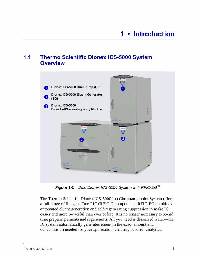
The Thermo Scientific Dionex ICS-5000 Ion Chromatography System offers a full range of Reagent-Free™ IC (RFIC™) components. RFIC-EG combines automated eluent generation and self-regenerating suppression to make IC easier and more powerful than ever before. It is no longer necessary to spend time preparing eluents and regenerants. All you need is deionized water—the IC system automatically generates eluent in the exact amount and concentration needed for your application, ensuring superior analytical
Figure 1-1. Dual Dionex ICS-5000 System with RFIC-EG™
Dionex ICS-5000 Detector/Chromatography Module
Dionex ICS-5000 Dual Pump (DP)
Dionex ICS-5000 Eluent Generator (EG)
1
2
3
1
2
3
Dionex ICS-5000 Operator’s Manual
2 Doc. 065342-06 12/11
results. In combination with capillary columns at flow rates of 0.010 mL/min, the Dionex ICS-5000 system can be used for long periods of continuous operation and minimal eluent consumption.
The dual-analysis capabilities (both simultaneous and sequential) of the Dionex ICS-5000 system let you maximize efficiency and throughput and minimize downtime. The modular system design lets you quickly configure and customize hardware.
The single-channel Dionex ICS-5000 can be configured to run either capillary IC applications or microbore or standard bore IC applications.
• Capillary IC applications use 0.4 mm diameter columns with flow rates typically from 0.005 to 0.02 mL/min.
• Microbore IC applications use 2 mm diameter columns and with flow rates typically from 0.2 to 0.5 mL/min.
• Standard bore IC applications use 4 mm diameter columns with flow rates typically from 1.0 to 2.0 mL/min.
A dual Dionex ICS-5000 system can be configured with any combination of the above application types (for example, one capillary IC channel and one microbore IC channel, or two capillary IC channels, or one microbore IC channel and one standard bore IC channel).
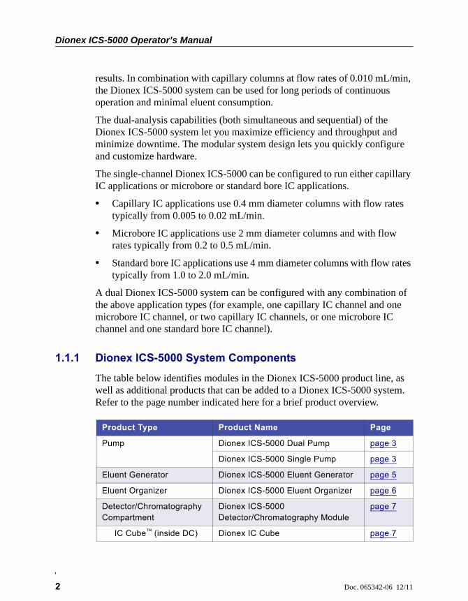
1.1.1 Dionex ICS-5000 System Components
The table below identifies modules in the Dionex ICS-5000 product line, as well as additional products that can be added to a Dionex ICS-5000 system. Refer to the page number indicated here for a brief product overview.
Product Type Product Name Page
Pump Dionex ICS-5000 Dual Pump page 3
Dionex ICS-5000 Single Pump page 3
Eluent Generator Dionex ICS-5000 Eluent Generator page 5
Eluent Organizer Dionex ICS-5000 Eluent Organizer page 6
Detector/Chromatography Compartment
Dionex ICS-5000 Detector/Chromatography Module
page 7
IC Cube™ (inside DC) Dionex IC Cube page 7
1 • Introduction
Doc. 065342-06 12/11 3
Dionex ICS-5000 Dual Pump (DP) and Dionex ICS-5000 Single Pump (SP)
Each Dionex ICS-5000 pump can be configured for either capillary IC applications or analytical (standard bore and microbore) IC applications. Capillary IC pumps are always isocratic (they deliver one eluent). Analytical IC pumps can be either isocratic or low pressure proportioned gradient. Gradient pumps deliver gradient mixtures of up to four eluent components. The eluent composition selected for a gradient pump can be delivered as isocratic, isocratic proportioned, linear ramp, step, curved, or any combination of these.
The SP contains one of the following pump types:
• Isocratic capillary IC pump
• Isocratic analytical IC pump
• Gradient analytical IC pump
The DP contains two pumps in any combination of the three types listed above (for example, two isocratic capillary IC pumps, or two isocratic analytical IC pumps, or one isocratic capillary IC pump and one gradient analytical IC pump).
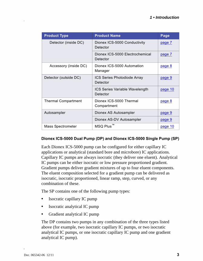
Detector (inside DC) Dionex ICS-5000 Conductivity Detector
page 7
Dionex ICS-5000 Electrochemical Detector
page 7
Accessory (inside DC) Dionex ICS-5000 Automation Manager
page 8
Detector (outside DC) ICS Series Photodiode Array Detector
page 9
ICS Series Variable Wavelength Detector
page 10
Thermal Compartment Dionex ICS-5000 Thermal Compartment
page 8
Autosampler Dionex AS Autosampler page 9
Dionex AS-DV Autosampler page 9
Mass Spectrometer MSQ Plus™ page 10
Product Type Product Name Page

Dionex ICS-5000 Operator’s Manual
4 Doc. 065342-06 12/11
The second pump in the DP can be operated as a second-channel chromatography pump, an auxiliary dependent pump, or an auxiliary independent pump.
Capillary IC pumps operate at flow rates ranging from 0.001 to 3.0 mL/min and operating pressures up to 41 MPa (6000 psi) (without RFIC) and up to 35 MPa (5000 psi) (with RFIC).
IMPORTANT
Capillary IC pumps shipped before February 17, 2011 were rated for lower operating pressures than the pumps currently being shipped. The older pumps can be operated at pressures up to 35 MPa (5000 psi) (without RFIC) and up to 21 MPa (3000 psi) (with RFIC). Before operating at pressures above these limits, verify that you have the appropriate pump.
• HPC is stamped on the secondary pump heads of the older (lower pressure rated) capillary IC pumps.
• HPC-2 is stamped on the secondary pump heads of the newer (higher pressure rated) capillary IC pumps.
A Capillary Pump High-Pressure Upgrade Kit (P/N 075994) is available for converting a lower pressure rated capillary IC pump to a higher pressure rated pump. The kit includes the HPC-2 secondary pump head and high-pressure pump seals.
NOTE A high-pressure EG degas (capillary) cartridge (P/N 074459) is also required when operating a capillary RFIC system at pressures up to 35 MPa (5000 psi). For details, see page 5.
Capillary IC
1 • Introduction
Doc. 065342-06 12/11 5
Analytical IC pumps operate at flow rates ranging from 0.00 to 10.0 mL/min and operating pressures up to 35 MPa (5000 psi) without RFIC and up to 21 MPa (3000 psi) with RFIC. Both microbore and standard bore IC applications are supported.
Dionex ICS-5000 Eluent Generator (EG)
The EG generates high purity acid or base eluents online from deionized water. The EG can be configured for single- or dual-channel operation. Each channel includes:
• A high precision programmable current source (power supply)
For each channel, the following options must be ordered separately for installation inside the EG.
• A disposable eluent generator cartridge (EGC). Each cartridge contains an electrolyte concentrate solution, appropriate for the eluent being generated.
• A Continuously Regenerated Trap Column (CR-TC) to remove any extraneous contaminants from the deionized water source. The CR-TC is electrolytically-regenerated, which allows it to operate for extended periods without chemical regeneration.
• A high-pressure gas removal device that removes electrolysis gases created during eluent generation
Two versions of EGC and CR-TC are available: one for capillary IC systems and one for analytical IC systems.
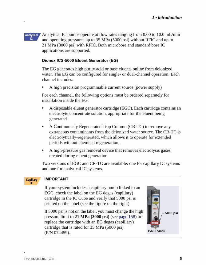
IMPORTANT
If your system includes a capillary pump linked to an EGC, check the label on the EG degas (capillary) cartridge in the IC Cube and verify that 5000 psi is printed on the label (see the figure on the right).
If 5000 psi is not on the label, you must change the high pressure limit to 21 MPa (3000 psi) (see page 158) or replace the cartridge with an EG degas (capillary) cartridge that is rated for 35 MPa (5000 psi) (P/N 074459).
Capillary IC
5000 psi
P/N 074459
Dionex ICS-5000 Operator’s Manual
6 Doc. 065342-06 12/11
Reagent-Free IC with Eluent Regeneration (RFIC-ER™)
RFIC-ER is available as an option for Dionex ICS-5000 systems without an EG. Eluent regeneration uses the suppressor to reconstitute the starting eluent, allowing use of a single 4-liter bottle of eluent for up to four weeks. Because the system is a closed loop, it can run continuously, eliminating the need for recalibration or re-equilibration during the 28 days of non-stop operation. RFIC-ER uses carbonate, carbonate/bicarbonate, or MSA eluents for isocratic separations on standard bore columns.
Dionex ICS-5000 Eluent Organizer (EO)
The EO holds eluent reservoirs in a liner that contains spills and leaks. Up to two EOs can be installed on top of the DC. Each EO accommodates up to four 1-liter or 2-liter reservoirs or up to two 4-liter reservoirs. The EO is typically ordered configured with four 2-liter reservoirs (P/N 072058).
All eluent reservoirs available for use with the DP/SP can be pressurized. If you plan to pressurize the eluent reservoirs, the optional EO Regulator Accessory and Stand (P/N 074423) is required.
The Regulator Accessory includes a pressure regulator and gauge assembly with four outputs (for connections to four eluent reservoirs), as well as the tubing and connection fitting required. If more reservoirs are required, order a second regulator (P/N 074422).
Reagent-Free IC with Electrolytic Sample Preparation (RFIC-ESP™)
RFIC-ESP systems enable a range of automated sample preparation techniques which use proprietary electrolytic devices to provide reduced cost and higher value analyses.
RFIC-ESP devices and techniques can be used for removing cations from an anion sample before analysis by using a Dionex CR-TC device, or neutralizing a strongly acidic or basic solution—25% phosphoric acid or sodium hydroxide solutions, for example—with an AutoNeutralization™ device. An Electrolytic Water Purifier is available which provides water of extremely high purity (backgrounds below sub ng/L levels are possible) for use in trace-level analytical work where use of a concentrator column is necessary.
1 • Introduction
Doc. 065342-06 12/11 7
Dionex ICS-5000 Detector/Chromatography Module (DC)
The DC provides a temperature-controlled environment for Dionex ICS-5000 chromatography components. The DC can accommodate components for two channels, plumbed either serially or in parallel.
The following components may be installed in the DC:
• Conductivity detectors
• Electrochemical detectors
• Injection valves
• Switching valves
• Guard and separator columns
• Suppressors
• Dionex IC Cubes or Dionex ICS-5000 Automation Manager
Dionex ICS-5000 Conductivity Detector (CD)
The CD is a modular detector with an integrated cell. The CD has a signal range up to 15,000 S and supports high background, nonsuppressed applications. The CD is installed in the upper compartment of the DC. For a dual-system, two CDs can be installed.
Dionex ICS-5000 Electrochemical Detector (ED)
The ED is a modular detector and a modular cell. The ED supports multiple waveforms, multiple integration times, and post-analysis data manipulation. With Chromeleon 6.8, the ED is also capable of providing 3D amperometry data. The ED cell can be configured with gold, silver, platinum, carbon, or glassy carbon working electrodes. The ED is installed in the upper compartment of the DC. For a dual-system, two EDs can be installed.
Dionex IC Cube (IC Cube)
The IC Cube houses components for running capillary IC applications. Each IC Cube includes an injection valve, a column heater, and removable cartridges containing capillary IC components. Cartridges for the following components are available: carbonate removal device (CRD), suppressor, guard and separator columns, and EG degasser. The IC Cube is installed in the
Capillary IC
Dionex ICS-5000 Operator’s Manual
8 Doc. 065342-06 12/11
upper compartment of the DC. For a dual-system, two IC Cubes can be installed.
Dionex ICS-5000 Automation Manager (AM)
The AM consists of a component mounting panel on a base tray. The AM provides mounting sites for sample preparation and post-column application components: high-pressure (switching) valves, low-pressure (solenoid) valves, reaction coils, etc. The AM is installed in the upper compartment of the DC, above the detector.
Dionex ICS-5000 Thermal Compartment (TC)
The TC provides a temperature-controlled environment for Dionex ICS-5000 chromatography components. The TC is intended for applications that do not require conductivity or electrochemical detection.
The TC is available in four configurations:
• With one 2-position, 6-port high-pressure injection valve
• With two 2-position, 6-port high-pressure injection valves
• With one 2-position, 6-port high-pressure injection valve and one 2-position, 10-port high-pressure injection valve
• With no injection valves
An optional temperature stabilizer (standard bore, P/N 064548; microbore, P/N 064650) can be installed inside the TC, if necessary. The temperature stabilizer brings the eluent to the column temperature before it enters the column.
Dionex AS-AP Autosampler (AS-AP)
The AS-AP provides high-performance, automated sample processing for ion chromatography applications. Key features of the AS-AP include:
• Excellent reproducibility with RSDs less than 0.3% for full-loop injections
• All-PEEK™ flow paths, compatible with aqueous and reversed-phase eluents, safe from metal contamination
1 • Introduction
Doc. 065342-06 12/11 9
• Carousel and moving-needle design to guarantee reliable sampling from a variety of vial sizes and well plates
• 10 mL polystyrene sample vials with wide openings for large-volume injections and trace analysis
• High sample capacity, from 81 (10 mL vials) to 1152 (three 384-position well plates)
• Sample preparation function to automate sample and standard preparations, saving time and labor
Optional features of the AS-AP include sample tray temperature control, simultaneous injections, sequential injections, sample preparation, or fraction collection and reinjection, and 6-port or 10-port valves.
Dionex AS-DV Autosampler
The AS-DV is a basic autosampler that is capable of delivering between 0.1 and 5.0 mL of sample (in 0.1 mL increments) to the sample loop or concentrator column in an ion chromatography system.
The Dionex ICS-5000 holds 50 vials (either 0.5 mL or 5.0 mL, or a combination of the two sizes). Vials can be sampled in any order and multiple samples can be taken from each vial. The Dionex AS-DV remembers the vial size and volume delivered for each vial position, allowing multiple samples to be taken from a vial non-sequentially.
Dionex AS Autosampler (AS)
The AS is a powerful, full-featured autosampler that precisely delivers from 1.0 to 100 µL (in 0.1 µL increments) or 100 to 8000 µL (in 1 µL increments) of sample to an injection valve. In addition to the normal mode, the autosampler can operate in several other modes, including concentrate, simultaneous, and sequential injections.
Dionex ICS Series Photodiode Array Detector (PDA)
The PDA optical detector is capable of measuring the absorbance spectrum from 190 to 800 nm. A deuterium lamp optimizes the UV range (190 to 380 nm) and a tungsten lamp optimizes the visible range (380 to 800 nm).
The PDA enables you to collect up to five single wavelengths (2D chromatograms) without being required to collect 3D data. Collecting
Dionex ICS-5000 Operator’s Manual
10 Doc. 065342-06 12/11
chromatograms at individual wavelengths instead of from spectra offers two advantages: it eliminates the need to perform extractions for chromatograms that do not require spectral data and it conserves disk space.
Dionex ICS Series Variable Wavelength Detector (VWD)
The VWD is a dual-beam, variable wavelength photometer with one measurement and one internal reference beam. Spectral capability from 190 to 900 nm is provided by two light sources: a deuterium lamp for ultraviolet detection and a tungsten lamp for visible wavelength operation. The four-channel detector measures at up to four wavelengths simultaneously. The VWD contains a built-in holmium oxide filter for wavelength verification. To suppress higher-order radiation, two optical filters can be inserted (automatically) into the light path.
MSQ Plus Mass Spectrometer
The MSQ Plus is an advanced analytical instrument that includes an MS detector, vacuum pumps, and data system. When integrated with an IC system, the MSQ Plus provides the separation capability of an IC and the detection capability of a single-quadrupole MS detector. This provides a strong starting point for sample analysis by offering a quick and clear mass identification for chromatographic peaks.
The MS detector contains an atmospheric pressure ionization (API) source, advanced high efficiency transmission ion optics of a square quadrupole RF lens and dual RF generators, a mass analyzer, and an ion detection system. An optional cone wash pump is available for improved performance when dealing with dirty matrices.
The MS detector is equipped with FastLock™ probes for two complementary ionization techniques: atmospheric pressure chemical ionization (APCI) and electrospray ionization (ESI).
During a scan, ions of selected mass-to-charge ratios are sequentially transmitted through a quadrupole mass filter analyzer. The MS detector can perform both full-range scans and selected ion monitoring (SIM) scans.
1 • Introduction
Doc. 065342-06 12/11 11
1.1.2 Dionex ICS-5000 System Control
The Dionex ICS-5000 system is controlled by a PC configured with Thermo Scientific Dionex Chromeleon™ 7 Chromatography Data System (release 7.0 SR1 or later) or Thermo Scientific Dionex Chromeleon 6.8 Chromatography Data System (release 6.8 SR9a or later). Chromeleon 7 and Chromeleon 6.8 provide complete instrument control, data acquisition, and data management.
Optionally, the Dionex ICS-5000 system can be controlled by a PC configured with Chromeleon Xpress. Chromeleon Xpress provides real-time control and monitoring of Dionex chromatography instruments, but does not include data management capabilities.
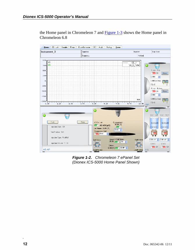
In Chromeleon 7, an ePanel Set provides centralized system control. You can use the ePanel Set to view system status information and issue commands for controlling each module. In Chromeleon 6.8, these functions are available on a panel tabset. In both the ePanel Set and the panel tabset, a convenient Home panel shows the overall system status and provides basic module control functions. Individual tabs provide quick access to additional functions for each module and detailed status and diagnostics functions. Figure 1-2 shows
Dionex ICS-5000 Operator’s Manual
12 Doc. 065342-06 12/11
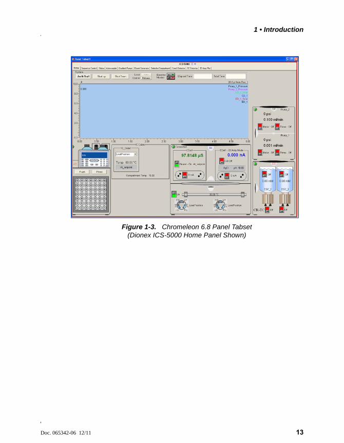
the Home panel in Chromeleon 7 and Figure 1-3 shows the Home panel in Chromeleon 6.8
Figure 1-2. Chromeleon 7 ePanel Set (Dionex ICS-5000 Home Panel Shown)
1 • Introduction
Doc. 065342-06 12/11 13
Figure 1-3. Chromeleon 6.8 Panel Tabset (Dionex ICS-5000 Home Panel Shown)
Dionex ICS-5000 Operator’s Manual
14 Doc. 065342-06 12/11
1.2 Dionex ICS-5000 System Documentation
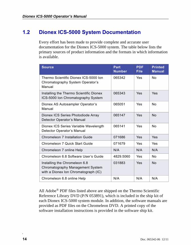
Every effort has been made to provide complete and accurate user documentation for the Dionex ICS-5000 system. The table below lists the primary sources of product information and the formats in which information is available.
All Adobe® PDF files listed above are shipped on the Thermo Scientific Reference Library DVD (P/N 053891), which is included in the ship kit of each Dionex ICS-5000 system module. In addition, the software manuals are provided as PDF files on the Chromeleon DVD. A printed copy of the software installation instructions is provided in the software ship kit.
Source Part Number
PDF File
Printed Manual
Thermo Scientific Dionex ICS-5000 Ion Chromatography System Operator’s Manual
065342 Yes No
Installing the Thermo Scientific Dionex ICS-5000 Ion Chromatography System
065343 Yes Yes
Dionex AS Autosampler Operator’s Manual
065051 Yes No
Dionex ICS Series Photodiode Array Detector Operator’s Manual
065147 Yes No
Dionex ICS Series Variable Wavelength Detector Operator’s Manual
065141 Yes No
Chromeleon 7 Installation Guide 071686 Yes Yes
Chromeleon 7 Quick Start Guide 071679 Yes Yes
Chromeleon 7 online Help N/A N/A N/A
Chromeleon 6.8 Software User’s Guide 4829.5060 Yes No
Installing the Chromeleon 6.8 Chromatography Management System with a Dionex Ion Chromatograph (IC)
031883 Yes No
Chromeleon 6.8 online Help N/A N/A N/A
1 • Introduction
Doc. 065342-06 12/11 15
Consumables documentation: For complete information about columns, suppressors, eluent generator cartridges, etc., refer to the appropriate product manual. These manuals are provided on the Reference Library DVD.
1.3 The Dionex ICS-5000 System Operator’s Manual
The electronic version (i.e., PDF file) of the Dionex ICS-5000 system operator’s manual contains numerous links that you can click to go to other locations within the manual. These links include:
• Table of contents entries
• Index entries
• Cross-references (underlined in blue) to sections, figures, tables, etc.
If you are not familiar with how to navigate PDF files, refer to the Help system for Adobe® Acrobat® or Adobe Reader® for assistance.
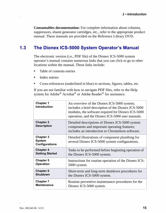
Chapter 1 Introduction
An overview of the Dionex ICS-5000 system; includes a brief description of the Dionex ICS-5000 modules, the software required for Dionex ICS-5000 operation, and the Dionex ICS-5000 user manuals.
Chapter 2 Description
Detailed descriptions of Dionex ICS-5000 system components and important operating features; includes an introduction to Chromeleon software.
Chapter 3System Configurations
Detailed illustrations of component plumbing for several Dionex ICS-5000 system configurations.
Chapter 4Getting Started
Tasks to be performed before beginning operation of the Dionex ICS-5000 system.
Chapter 5Operation
Instructions for routine operation of the Dionex ICS-5000 system.
Chapter 6Shutdown
Short-term and long-term shutdown procedures for the Dionex ICS-5000 system.
Chapter 7 Maintenance
Routine preventive maintenance procedures for the Dionex ICS-5000 system.
Dionex ICS-5000 Operator’s Manual
16 Doc. 065342-06 12/11
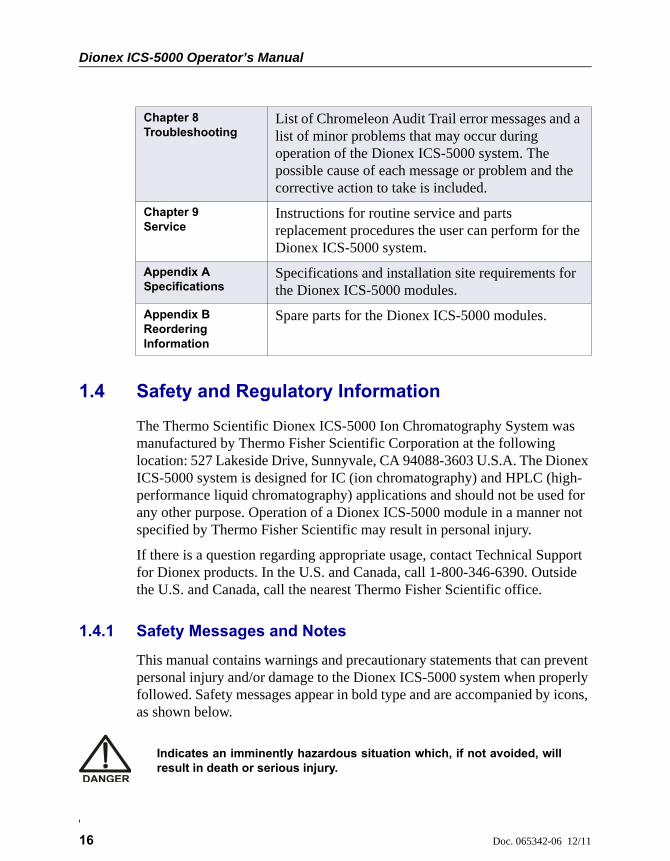
1.4 Safety and Regulatory Information
The Thermo Scientific Dionex ICS-5000 Ion Chromatography System was manufactured by Thermo Fisher Scientific Corporation at the following location: 527 Lakeside Drive, Sunnyvale, CA 94088-3603 U.S.A. The Dionex ICS-5000 system is designed for IC (ion chromatography) and HPLC (high-performance liquid chromatography) applications and should not be used for any other purpose. Operation of a Dionex ICS-5000 module in a manner not specified by Thermo Fisher Scientific may result in personal injury.
If there is a question regarding appropriate usage, contact Technical Support for Dionex products. In the U.S. and Canada, call 1-800-346-6390. Outside the U.S. and Canada, call the nearest Thermo Fisher Scientific office.
1.4.1 Safety Messages and Notes
This manual contains warnings and precautionary statements that can prevent personal injury and/or damage to the Dionex ICS-5000 system when properly followed. Safety messages appear in bold type and are accompanied by icons, as shown below.
Chapter 8Troubleshooting
List of Chromeleon Audit Trail error messages and a list of minor problems that may occur during operation of the Dionex ICS-5000 system. The possible cause of each message or problem and the corrective action to take is included.
Chapter 9Service
Instructions for routine service and parts replacement procedures the user can perform for the Dionex ICS-5000 system.
Appendix A Specifications
Specifications and installation site requirements for the Dionex ICS-5000 modules.
Appendix B Reordering Information
Spare parts for the Dionex ICS-5000 modules.
Indicates an imminently hazardous situation which, if not avoided, willresult in death or serious injury.
1 • Introduction
Doc. 065342-06 12/11 17
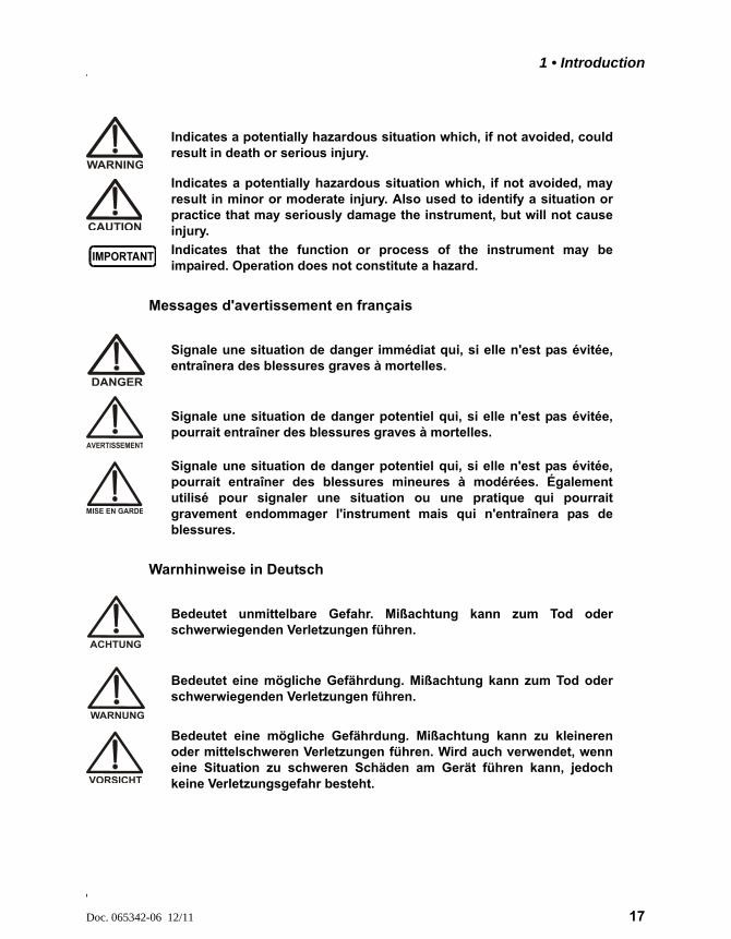
Messages d'avertissement en français
Warnhinweise in Deutsch
Indicates a potentially hazardous situation which, if not avoided, couldresult in death or serious injury.
Indicates a potentially hazardous situation which, if not avoided, mayresult in minor or moderate injury. Also used to identify a situation orpractice that may seriously damage the instrument, but will not causeinjury.
Indicates that the function or process of the instrument may beimpaired. Operation does not constitute a hazard.
Signale une situation de danger immédiat qui, si elle n'est pas évitée,entraînera des blessures graves à mortelles.
Signale une situation de danger potentiel qui, si elle n'est pas évitée,pourrait entraîner des blessures graves à mortelles.
Signale une situation de danger potentiel qui, si elle n'est pas évitée,pourrait entraîner des blessures mineures à modérées. Égalementutilisé pour signaler une situation ou une pratique qui pourraitgravement endommager l'instrument mais qui n'entraînera pas deblessures.
Bedeutet unmittelbare Gefahr. Mißachtung kann zum Tod oderschwerwiegenden Verletzungen führen.
Bedeutet eine mögliche Gefährdung. Mißachtung kann zum Tod oderschwerwiegenden Verletzungen führen.
Bedeutet eine mögliche Gefährdung. Mißachtung kann zu kleinerenoder mittelschweren Verletzungen führen. Wird auch verwendet, wenneine Situation zu schweren Schäden am Gerät führen kann, jedochkeine Verletzungsgefahr besteht.
Dionex ICS-5000 Operator’s Manual
18 Doc. 065342-06 12/11
Notes
Informational messages also appear throughout this manual. These are labeled NOTE and are in bold type:
NOTE NOTES call attention to certain information. They alert you to an unexpected result of an action, suggest how to optimize instrument performance, etc.
Sections preceded with the Capillary IC flag indicate that the information in the section applies to capillary IC systems only.
Sections preceded with the Analytical IC flag indicate that the information in the section applies to analytical IC systems only.
If a section is not flagged, the information in the section applies to both capillary IC and analytical IC systems.
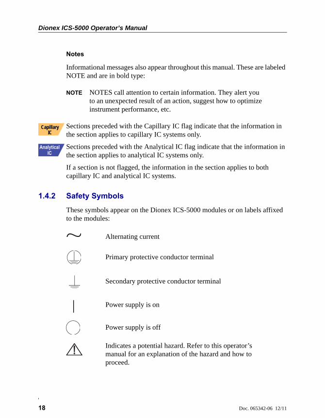
1.4.2 Safety Symbols
These symbols appear on the Dionex ICS-5000 modules or on labels affixed to the modules:
Capillary IC
Alternating current
Primary protective conductor terminal
Secondary protective conductor terminal
Power supply is on
Power supply is off
Indicates a potential hazard. Refer to this operator’s manual for an explanation of the hazard and how to proceed.
1 • Introduction
Doc. 065342-06 12/11 19
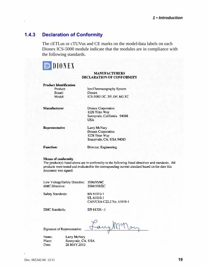
1.4.3 Declaration of Conformity
The cETLus or cTUVus and CE marks on the model/data labels on each Dionex ICS-5000 module indicate that the modules are in compliance with the following standards.
Dionex ICS-5000 Operator’s Manual
20 Doc. 065342-06 12/11
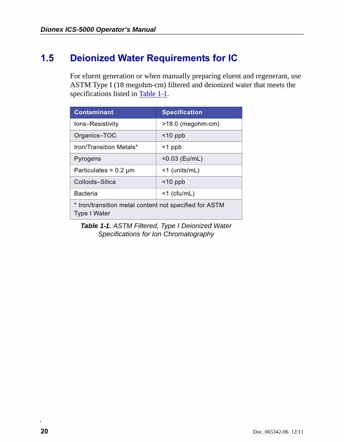
1.5 Deionized Water Requirements for IC
For eluent generation or when manually preparing eluent and regenerant, use ASTM Type I (18 megohm-cm) filtered and deionized water that meets the specifications listed in Table 1-1.
Contaminant Specification
Ions–Resistivity >18.0 (megohm-cm)
Organics–TOC <10 ppb
Iron/Transition Metals* <1 ppb
Pyrogens <0.03 (Eu/mL)
Particulates > 0.2 µm <1 (units/mL)
Colloids–Silica <10 ppb
Bacteria <1 (cfu/mL)
* Iron/transition metal content not specified for ASTM Type I Water
Table 1-1. ASTM Filtered, Type I Deionized Water Specifications for Ion Chromatography
Doc. 065342-06 12/11 21
2 • Description
DP/SP Description
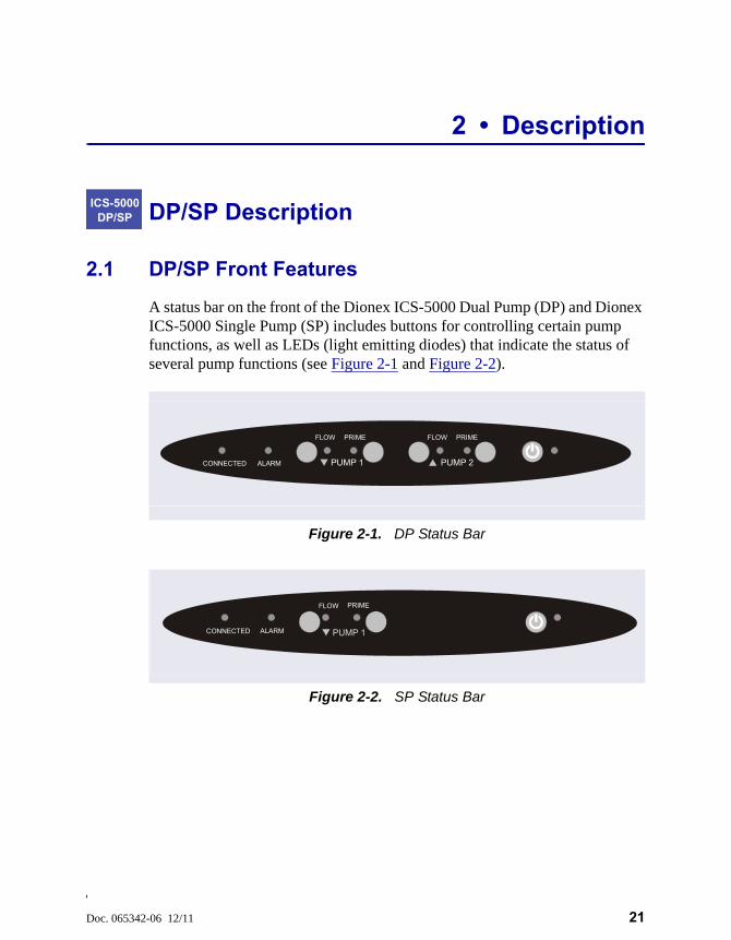
2.1 DP/SP Front Features
A status bar on the front of the Dionex ICS-5000 Dual Pump (DP) and Dionex ICS-5000 Single Pump (SP) includes buttons for controlling certain pump functions, as well as LEDs (light emitting diodes) that indicate the status of several pump functions (see Figure 2-1 and Figure 2-2).
ICS-5000 DP/SP
Figure 2-1. DP Status Bar
Figure 2-2. SP Status Bar
ALARM PUMP 1 PUMP 2CONNECTED
FLOW PRIMEFLOW PRIME
ALARMCONNECTED PUMP 1
FLOW PRIME
Dionex ICS-5000 Operator’s Manual
22 Doc. 065342-06 12/11
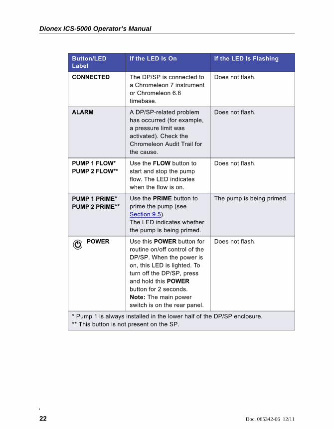
Button/LED Label
If the LED Is On If the LED Is Flashing
CONNECTED The DP/SP is connected to a Chromeleon 7 instrument or Chromeleon 6.8 timebase.
Does not flash.
ALARM A DP/SP-related problem has occurred (for example, a pressure limit was activated). Check the Chromeleon Audit Trail for the cause.
Does not flash.
PUMP 1 FLOW*PUMP 2 FLOW**
Use the FLOW button to start and stop the pump flow. The LED indicates when the flow is on.
Does not flash.
PUMP 1 PRIME*PUMP 2 PRIME**
Use the PRIME button to prime the pump (see Section 9.5).The LED indicates whether the pump is being primed.
The pump is being primed.
POWER Use this POWER button for routine on/off control of the DP/SP. When the power is on, this LED is lighted. To turn off the DP/SP, press and hold this POWER button for 2 seconds.Note: The main power switch is on the rear panel.
Does not flash.
* Pump 1 is always installed in the lower half of the DP/SP enclosure.** This button is not present on the SP.
2 • Description
Doc. 065342-06 12/11 23
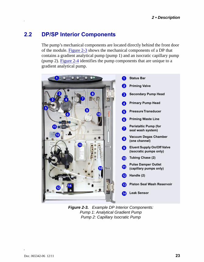
2.2 DP/SP Interior Components
The pump’s mechanical components are located directly behind the front door of the module. Figure 2-3 shows the mechanical components of a DP that contains a gradient analytical pump (pump 1) and an isocratic capillary pump (pump 2). Figure 2-4 identifies the pump components that are unique to a gradient analytical pump.
Figure 2-3. Example DP Interior Components: Pump 1: Analytical Gradient Pump Pump 2: Capillary Isocratic Pump
Status Bar
Priming Valve
Vacuum Degas Chamber (one channel)
Piston Seal Wash Reservoir
Eluent Supply On/Off Valve (isocratic pumps only)
Tubing Chase (2)
Primary Pump Head
Secondary Pump Head
Handle (2)
Peristaltic Pump (for seal wash system)
1
3
2
4
7
8
9
910
12
13
1
3
2
4 7
8
9
12
11
14
Leak Sensor14
Priming Waste Line6
Pulse Damper Outlet (capillary pumps only)11
Pressure Transducer 5
56 910
13
12
910
Dionex ICS-5000 Operator’s Manual
24 Doc. 065342-06 12/11
NOTE For easier access to pump components when performing ser-vice procedures, the pump panel can be pulled forward to the front of the pump compartment. First, make sure that the five red Phillips screws are removed from the component panel. Then, use the handles to pull the panel forward. The upper and lower component panels slide forward together.
2.2.1 Pump Heads
The DP/SP is a low-pulsation, serial dual-piston pump with electronic compressibility compensation. Two pump heads—a primary head and a secondary head—are connected in series. Eluent passes through both pump heads in succession.
The primary pump head delivers eluent at the selected flow rate, while simultaneously filling the secondary pump head. The latter serves as a reservoir and delivers eluent while the primary head carries out the refill stroke.
The characteristic feature of the patented isokinetic pre-compression phase is the programmed overlapping of the delivery strokes of the two pump heads. When delivering compressible liquids without controlled pre-compression,
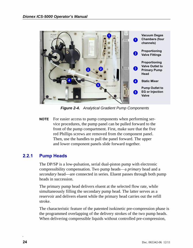
Figure 2-4. Analytical Gradient Pump Components
Proportioning Valve Fittings
Vacuum Degas Chambers (four channels)
1
4
2
1
2 3
Static Mixer4
Proportioning Valve Outlet to Primary Pump Head
Pump Outlet to EG or Injection Valve
5
3
5
2 • Description
Doc. 065342-06 12/11 25
the pulsation increases as the operating pressure increases, because part of the delivery stroke is required to compress eluent in the pump head.
During the pre-compression phase, pulsation is minimized. A patented secondary control system (automatic compressibility compensation) ensures highly constant eluent delivery. The flow rate remains constant in relation to the pressure.
2.2.2 Pressure Transducer
The secondary pump head contains a built-in pressure transducer to measure the system pressure. The DP/SP instrument control firmware installed in the pump precisely controls the pump motor speed to ensure flow rate accuracy and to maintain constant flow and constant pressure.
2.2.3 Proportioning Valves (Gradient pump only)
In the gradient pump, which is available for analytical IC applications only, eluent flows from the eluent reservoirs, through the vacuum degas chambers, and into a four-way proportioning valve assembly (see Figure 2-4). Programmed percentages of each eluent are proportioned by the four valves.
2.2.4 Vacuum Degassing Module
The DP/SP vacuum degassing module provides continuous, online eluent degassing. Eluent quality significantly affects DP/SP performance, and vacuum degassing eluents is one way to ensure high eluent quality.
Degassing helps prevent bubbles (caused by eluent outgassing) from forming in the eluent proportioning valves (gradient pump only), pump heads, and detector cell. Degassing eluents is especially important when combining aqueous and nonaqueous components (for example, water and acetonitrile).
The vacuum degassing module is either single-channel (in an isocratic pump) or quad-channel (in a gradient pump). The module consists of:
• A degas chamber (with degassing membranes) with internal capacity of 670 L per channel
• A dual-stage diaphragm vacuum pump
• An on-board vacuum sensor

Dionex ICS-5000 Operator’s Manual
26 Doc. 065342-06 12/11
• The electronics required to operate the vacuum pump
• Tubing, fittings, and other accessories
The vacuum degassing module is automatically activated when the DP/SP power is turned on. Allow about 10 minutes for the module to equilibrate.
NOTE Make sure the run time is long enough to ensure that the vac-uum degassing module delivers the optimal degassing perfor-mance.
Manual Control of the Vacuum Degassing Module
The vacuum degassing module normally remains on continuously. To turn it off (for example, to investigate a leak), follow these steps:
1. Open the Chromeleon 7 ePanel Set or the Chromeleon 6.8 panel tabset.
2. Press the F8 key to open the Commands dialog box.
3. Select the pump name.
4. Select the Degasser property and select Off.
5. For Chromeleon 6.8, click Execute.
6. To turn on the degasser again, select On.
2.2.5 Piston Seal Wash System
The piston seal wash system consists of a peristaltic pump, a reservoir containing wash solution, and the connecting tubing. The wash solution is usually ASTM Type I (18 megohm-cm) filtered and deionized water that meets the specifications listed in Section 1.5.
When seal washing is activated, the back of the main piston seal is rinsed with wash solution; this prolongs seal lifetime by preventing eluent crystallization on the piston surfaces.
Notes About the DP Piston Seal Wash System
The piston seal wash system is designed for use with only one of the two pumps in a DP module. When the DP is shipped from Thermo Fisher Scientific, the seal wash system is connected to pump 1 (the bottom pump). If
2 • Description
Doc. 065342-06 12/11 27
necessary, connect the seal wash system to pump 2 (the top pump), instead. For instructions on how to replumb the system, refer to Section 4.7.
NOTE For users who need to operate a piston seal wash system for both pumps in the DP, Thermo Fisher Scientific offers an External Seal Wash Kit (P/N 063518) or a second seal wash system (P/N 068661).
2.2.6 Static Mixer (Analytical IC only)
For an analytical pump, a GM-3 or GM-4 static mixer is installed after the secondary pump head (see Figure 2-3). In the gradient pump, the mixer helps to ensure that proportioned eluents are mixed thoroughly. In the isocratic pump, the mixer is optional, but can function as a pulse damper.
The DP/SP gradient delay volume is 600 L when a GM-3 is installed and 380 L when a GM-4 is installed. The gradient delay volume (or dwell volume) is the volume of liquid in the system between the point where the gradient is formed and the point where it enters the column. This includes the mixer, transfer tubing, and swept volume in the injector or autosampler.
2.2.7 Pulse Damper (Capillary IC only)
For a capillary pump, flow output from the pressure transducer continues to the pulse damper, which smooths minor pressure variations. From there, flow is directed to the injection valve and then to the remainder of the chromatography system.
Capillary IC
Dionex ICS-5000 Operator’s Manual
28 Doc. 065342-06 12/11
2.3 DP/SP Flow Schematics
2.3.1 Isocratic Pump Flow Schematic
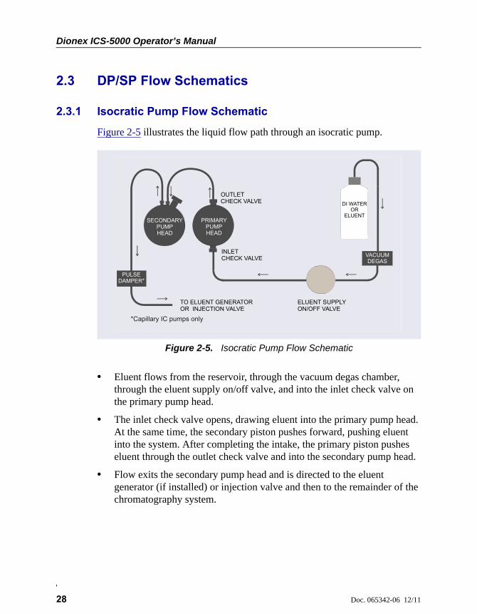
Figure 2-5 illustrates the liquid flow path through an isocratic pump.
• Eluent flows from the reservoir, through the vacuum degas chamber, through the eluent supply on/off valve, and into the inlet check valve on the primary pump head.
• The inlet check valve opens, drawing eluent into the primary pump head. At the same time, the secondary piston pushes forward, pushing eluent into the system. After completing the intake, the primary piston pushes eluent through the outlet check valve and into the secondary pump head.
• Flow exits the secondary pump head and is directed to the eluent generator (if installed) or injection valve and then to the remainder of the chromatography system.
Figure 2-5. Isocratic Pump Flow Schematic
INLETCHECK VALVE
OUTLETCHECK VALVE
ELUENT SUPPLYON/OFF VALVE
TO ELUENT GENERATOROR INJECTION VALVE
VACUUMDEGAS
DI WATEROR
ELUENTSECONDARY
PUMPHEAD
PRIMARYPUMPHEAD
PULSE DAMPER*
*Capillary IC pumps only
2 • Description
Doc. 065342-06 12/11 29
2.3.2 Gradient Pump Flow Schematic
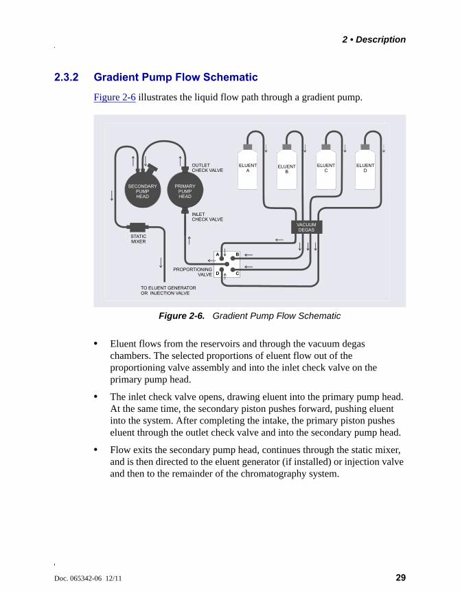
Figure 2-6 illustrates the liquid flow path through a gradient pump.
• Eluent flows from the reservoirs and through the vacuum degas chambers. The selected proportions of eluent flow out of the proportioning valve assembly and into the inlet check valve on the primary pump head.
• The inlet check valve opens, drawing eluent into the primary pump head. At the same time, the secondary piston pushes forward, pushing eluent into the system. After completing the intake, the primary piston pushes eluent through the outlet check valve and into the secondary pump head.
• Flow exits the secondary pump head, continues through the static mixer, and is then directed to the eluent generator (if installed) or injection valve and then to the remainder of the chromatography system.
Figure 2-6. Gradient Pump Flow Schematic
TO ELUENT GENERATOROR INJECTION VALVE
ELUENT A
ELUENT B
ELUENT C
ELUENT D
VACUUMDEGAS
INLETCHECK VALVE
PROPORTIONINGVALVE
OUTLETCHECK VALVE
STATICMIXER
A B
CD
SECONDARYPUMPHEAD
PRIMARYPUMPHEAD
Dionex ICS-5000 Operator’s Manual
30 Doc. 065342-06 12/11
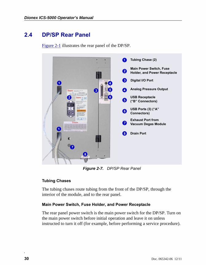
2.4 DP/SP Rear Panel
Figure 2-1 illustrates the rear panel of the DP/SP.
Tubing Chases
The tubing chases route tubing from the front of the DP/SP, through the interior of the module, and to the rear panel.
Main Power Switch, Fuse Holder, and Power Receptacle
The rear panel power switch is the main power switch for the DP/SP. Turn on the main power switch before initial operation and leave it on unless instructed to turn it off (for example, before performing a service procedure).
Figure 2-7. DP/SP Rear Panel
1
2
3
5
6
7
8
4
Tubing Chase (2)
USB Receptacle (“B” Connectors)
Main Power Switch, Fuse Holder, and Power Receptacle
Drain Port
USB Ports (3) (“A” Connectors)
Digital I/O Port
Analog Pressure Output
Exhaust Port from Vacuum Degas Module
1
1
2
3
4
5
6
7
8
2 • Description
Doc. 065342-06 12/11 31
NOTE For routine on/off control, use the POWER button on the front of the DP/SP (see Figure 2-1 and Figure 2-2). To turn off the pump, press and hold the POWER button for 2 seconds.
The fuse cartridge contains two 2-amp IEC 60127-2 slow-blow fuses (P/N 954773). For instructions on how to change the fuses, see Section 9.11.
The power cord plugs into the IEC 320 three-prong receptacle.
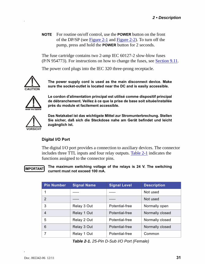
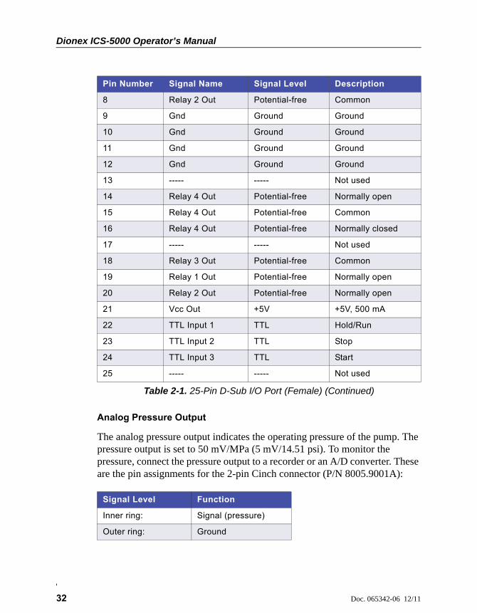
Digital I/O Port
The digital I/O port provides a connection to auxiliary devices. The connector includes three TTL inputs and four relay outputs. Table 2-1 indicates the functions assigned to the connector pins.
The power supply cord is used as the main disconnect device. Makesure the socket-outlet is located near the DC and is easily accessible.
Le cordon d'alimentation principal est utilisé comme dispositif principalde débranchement. Veillez à ce que la prise de base soit située/installéeprès du module et facilement accessible.
Das Netzkabel ist das wichtigste Mittel zur Stromunterbrechung. StellenSie sicher, daß sich die Steckdose nahe am Gerät befindet und leichtzugänglich ist.
The maximum switching voltage of the relays is 24 V. The switchingcurrent must not exceed 100 mA.
Pin Number Signal Name Signal Level Description
1 ----- ----- Not used
2 ----- ----- Not used
3 Relay 3 Out Potential-free Normally open
4 Relay 1 Out Potential-free Normally closed
5 Relay 2 Out Potential-free Normally closed
6 Relay 3 Out Potential-free Normally closed
7 Relay 1 Out Potential-free Common
Table 2-1. 25-Pin D-Sub I/O Port (Female)
Dionex ICS-5000 Operator’s Manual
32 Doc. 065342-06 12/11
Analog Pressure Output
The analog pressure output indicates the operating pressure of the pump. The pressure output is set to 50 mV/MPa (5 mV/14.51 psi). To monitor the pressure, connect the pressure output to a recorder or an A/D converter. These are the pin assignments for the 2-pin Cinch connector (P/N 8005.9001A):
8 Relay 2 Out Potential-free Common
9 Gnd Ground Ground
10 Gnd Ground Ground
11 Gnd Ground Ground
12 Gnd Ground Ground
13 ----- ----- Not used
14 Relay 4 Out Potential-free Normally open
15 Relay 4 Out Potential-free Common
16 Relay 4 Out Potential-free Normally closed
17 ----- ----- Not used
18 Relay 3 Out Potential-free Common
19 Relay 1 Out Potential-free Normally open
20 Relay 2 Out Potential-free Normally open
21 Vcc Out +5V +5V, 500 mA
22 TTL Input 1 TTL Hold/Run
23 TTL Input 2 TTL Stop
24 TTL Input 3 TTL Start
25 ----- ----- Not used
Signal Level Function
Inner ring: Signal (pressure)
Outer ring: Ground
Pin Number Signal Name Signal Level Description
Table 2-1. 25-Pin D-Sub I/O Port (Female) (Continued)
2 • Description
Doc. 065342-06 12/11 33
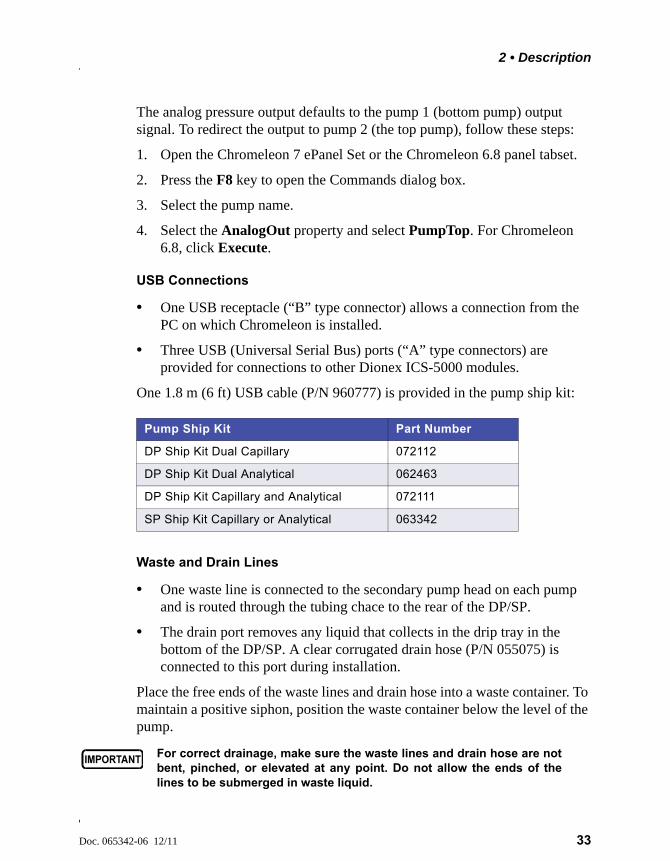
The analog pressure output defaults to the pump 1 (bottom pump) output signal. To redirect the output to pump 2 (the top pump), follow these steps:
1. Open the Chromeleon 7 ePanel Set or the Chromeleon 6.8 panel tabset.
2. Press the F8 key to open the Commands dialog box.
3. Select the pump name.
4. Select the AnalogOut property and select PumpTop. For Chromeleon 6.8, click Execute.
USB Connections
• One USB receptacle (“B” type connector) allows a connection from the PC on which Chromeleon is installed.
• Three USB (Universal Serial Bus) ports (“A” type connectors) are provided for connections to other Dionex ICS-5000 modules.
One 1.8 m (6 ft) USB cable (P/N 960777) is provided in the pump ship kit:
Waste and Drain Lines
• One waste line is connected to the secondary pump head on each pump and is routed through the tubing chace to the rear of the DP/SP.
• The drain port removes any liquid that collects in the drip tray in the bottom of the DP/SP. A clear corrugated drain hose (P/N 055075) is connected to this port during installation.
Place the free ends of the waste lines and drain hose into a waste container. To maintain a positive siphon, position the waste container below the level of the pump.
Pump Ship Kit Part Number
DP Ship Kit Dual Capillary 072112
DP Ship Kit Dual Analytical 062463
DP Ship Kit Capillary and Analytical 072111
SP Ship Kit Capillary or Analytical 063342
For correct drainage, make sure the waste lines and drain hose are notbent, pinched, or elevated at any point. Do not allow the ends of thelines to be submerged in waste liquid.
Dionex ICS-5000 Operator’s Manual
34 Doc. 065342-06 12/11
2.5 Eluent Reservoirs
The following reservoirs are available for use with the DP/SP:
• 1-liter plastic reservoir (P/N 063291)
• 2-liter plastic reservoir (P/N 062510)
• 4-liter plastic reservoir (P/N 063292)
2.5.1 EO (Optional)
The Dionex ICS-5000 Eluent Organizer (EO) holds eluent reservoirs in a liner that contains spills and leaks. Up to two EOs can be installed on top of the DC. Each EO accommodates up to four 1-liter or 2-liter reservoirs or up to two 4-liter reservoirs. The EO is typically ordered configured with four 2-liter reservoirs (P/N 072058).
2.5.2 Pressurizing Eluent Reservoirs
All eluent reservoirs available for use with the DP/SP can be pressurized. Although the DP/SP does not require pressurized reservoirs, Thermo Fisher Scientific recommends pressurizing reservoirs with helium or nitrogen under the following circumstances:
• When using eluents that are sensitive to contamination.
Do not use the plastic reservoirs for offline vacuum degassing ofeluents. The reservoirs were not designed for this purpose.
N'utilisez pas le réservoir en plastique pour le dégazage à vide horsligne d'éluants. Le réservoir n'a pas été conçu à cette fin.
Verwenden Sie keine Plastikbehälter zum Offline Vakkum-Entgasen vonEluenten. Die Behälter sind dafür nicht ausgelegt.

2 • Description
Doc. 065342-06 12/11 35
• When combining aqueous and nonaqueous components (for example, water and acetonitrile). Pressurizable reservoirs allow eluents to be stored under a specific atmosphere.
If you plan to pressurize the eluent reservoirs, an optional regulator kit is required. The kit is available in two versions:
• When the DC is installed as the topmost module in the system, the EO Regulator Kit (P/N 074422) is required. The kit includes a pressure regulator and gauge assembly with four outputs (for connections to four eluent reservoirs), as well as the tubing and connection fitting required.
• When the TC, VWD, or PDA is installed as the topmost module in the system, the TC/VWD/PDA Regulator Bracket Kit (P/N 074424) is required. The kit includes the EO Regulator Kit described above, as well as a right-angle regulator bracket and mounting hardware. After attaching the bracket to the TC or detector, you will mount the gas regulator assembly on the bracket.
If more reservoirs are required, order a second regulator (P/N 074423).
For instructions on installing the regulator kits, refer to Thermo Scientific Dionex ICS-5000 Ion Chromatography System Installation Instructions (Document No. 065343). The manual is included on the Thermo Scientific Reference Library DVD (P/N 053891).
Never pressurize eluent reservoirs above 0.07 MPa (10 psi).Pressurizing reservoirs above this limit can cause the reservoir toexplode.
Ne mettez jamais les réservoirs d'éluants sous une pression supérieureà 0,07 MPa (10 psi).
Setzen Sie den Eluentbehälter auf keinen Fall einem Druck über0,07 MPa aus.

Dionex ICS-5000 Operator’s Manual
36 Doc. 065342-06 12/11
2.5.3 Filtering Eluent
• Install an end-line filter (P/N 045987) on the end of each reservoir’s eluent line. End-line filters are provided in the pump ship kit.
• A Dionex High-Pressure Inline Filter (P/N 044105) can be used to remove particulates down to 0.45 micron from eluent. Connect the inline filter between the pump outlet and the eluent inlet port on the injection valve. For details, see the instructions provided with the inline filter.
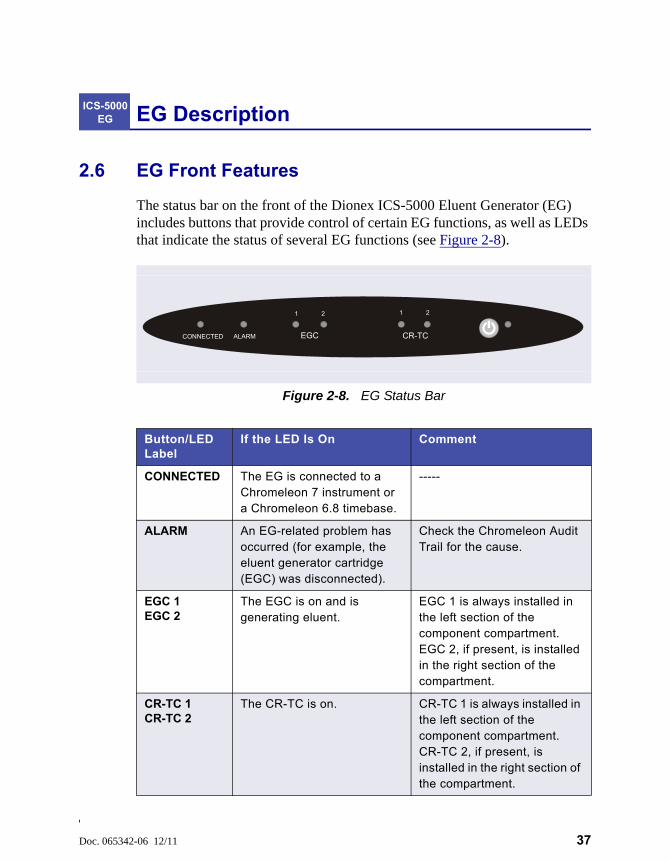
Doc. 065342-06 12/11 37
EG Description
2.6 EG Front Features
The status bar on the front of the Dionex ICS-5000 Eluent Generator (EG) includes buttons that provide control of certain EG functions, as well as LEDs that indicate the status of several EG functions (see Figure 2-8).
ICS-5000 EG
Figure 2-8. EG Status Bar
Button/LED Label
If the LED Is On Comment
CONNECTED The EG is connected to a Chromeleon 7 instrument or a Chromeleon 6.8 timebase.
-----
ALARM An EG-related problem has occurred (for example, the eluent generator cartridge (EGC) was disconnected).
Check the Chromeleon Audit Trail for the cause.
EGC 1EGC 2
The EGC is on and is generating eluent.
EGC 1 is always installed in the left section of the component compartment. EGC 2, if present, is installed in the right section of the compartment.
CR-TC 1CR-TC 2
The CR-TC is on. CR-TC 1 is always installed in the left section of the component compartment. CR-TC 2, if present, is installed in the right section of the compartment.
ALARM EGC CR-TC
1 2
CONNECTED
1 2
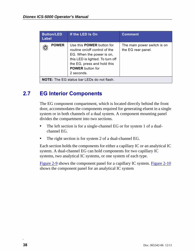
Dionex ICS-5000 Operator’s Manual
38 Doc. 065342-06 12/11
2.7 EG Interior Components
The EG component compartment, which is located directly behind the front door, accommodates the components required for generating eluent in a single system or in both channels of a dual system. A component mounting panel divides the compartment into two sections.
• The left section is for a single-channel EG or for system 1 of a dual-channel EG.
• The right section is for system 2 of a dual-channel EG.
Each section holds the components for either a capillary IC or an analytical IC system. A dual-channel EG can hold components for two capillary IC systems, two analytical IC systems, or one system of each type.
Figure 2-9 shows the component panel for a capillary IC system. Figure 2-10 shows the component panel for an analytical IC system
POWER Use this POWER button for routine on/off control of the EG. When the power is on, this LED is lighted. To turn off the EG, press and hold this POWER button for 2 seconds.
The main power switch is on the EG rear panel.
NOTE: The EG status bar LEDs do not flash.
Button/LED Label
If the LED Is On Comment
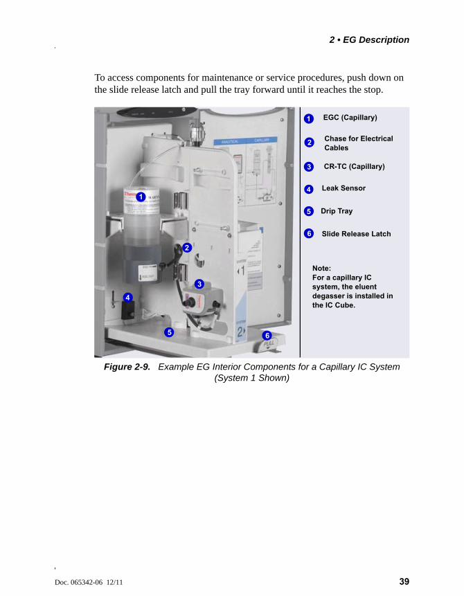
2 • EG Description
Doc. 065342-06 12/11 39
To access components for maintenance or service procedures, push down on the slide release latch and pull the tray forward until it reaches the stop.
Figure 2-9. Example EG Interior Components for a Capillary IC System (System 1 Shown)
CR-TC (Capillary)
Leak Sensor
EGC (Capillary)
Slide Release Latch
1
3
4
5
6
4
2
1
3
5
Note: For a capillary IC system, the eluent degasser is installed in the IC Cube.
Drip Tray
6
Chase for Electrical Cables
2
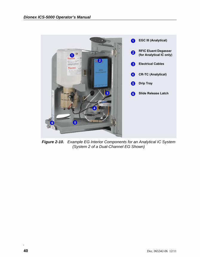
Dionex ICS-5000 Operator’s Manual
40 Doc. 065342-06 12/11
Figure 2-10. Example EG Interior Components for an Analytical IC System (System 2 of a Dual-Channel EG Shown)
EGC III (Analytical)
CR-TC (Analytical)
RFIC Eluent Degasser (for Analytical IC only)
Drip Tray
Electrical Cables
Slide Release Latch
1
2
3
4
5
5
4
1
2
3
6
6
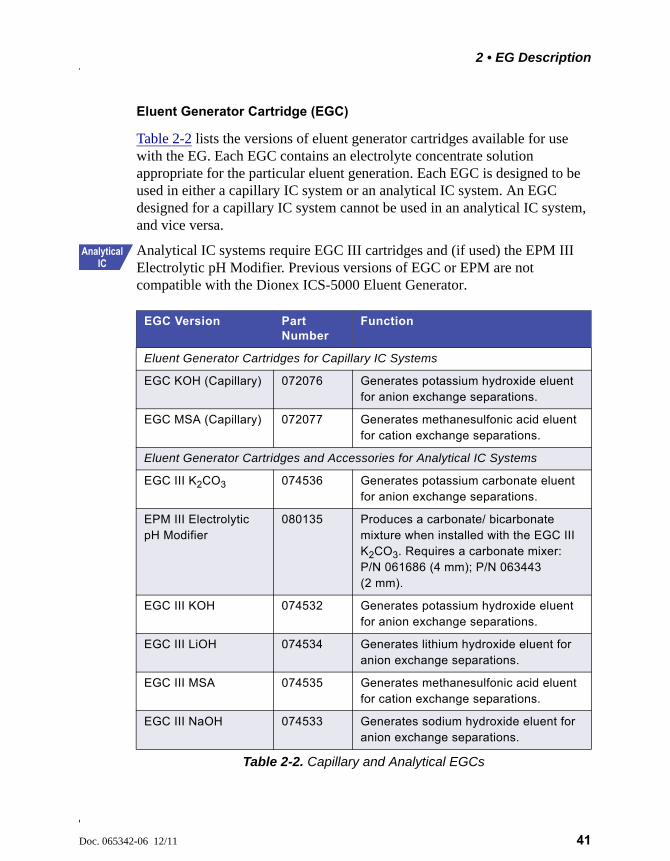
2 • EG Description
Doc. 065342-06 12/11 41
Eluent Generator Cartridge (EGC)
Table 2-2 lists the versions of eluent generator cartridges available for use with the EG. Each EGC contains an electrolyte concentrate solution appropriate for the particular eluent generation. Each EGC is designed to be used in either a capillary IC system or an analytical IC system. An EGC designed for a capillary IC system cannot be used in an analytical IC system, and vice versa.
Analytical IC systems require EGC III cartridges and (if used) the EPM III Electrolytic pH Modifier. Previous versions of EGC or EPM are not compatible with the Dionex ICS-5000 Eluent Generator.
EGC Version Part Number
Function
Eluent Generator Cartridges for Capillary IC Systems
EGC KOH (Capillary) 072076 Generates potassium hydroxide eluent for anion exchange separations.
EGC MSA (Capillary) 072077 Generates methanesulfonic acid eluent for cation exchange separations.
Eluent Generator Cartridges and Accessories for Analytical IC Systems
EGC III K2CO3 074536 Generates potassium carbonate eluent for anion exchange separations.
EPM III Electrolytic pH Modifier
080135 Produces a carbonate/ bicarbonate mixture when installed with the EGC III K2CO3. Requires a carbonate mixer: P/N 061686 (4 mm); P/N 063443 (2 mm).
EGC III KOH 074532 Generates potassium hydroxide eluent for anion exchange separations.
EGC III LiOH 074534 Generates lithium hydroxide eluent for anion exchange separations.
EGC III MSA 074535 Generates methanesulfonic acid eluent for cation exchange separations.
EGC III NaOH 074533 Generates sodium hydroxide eluent for anion exchange separations.
Table 2-2. Capillary and Analytical EGCs
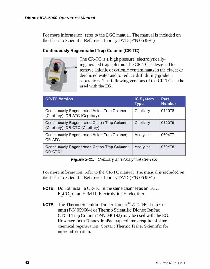
Dionex ICS-5000 Operator’s Manual
42 Doc. 065342-06 12/11
For more information, refer to the EGC manual. The manual is included on the Thermo Scientific Reference Library DVD (P/N 053891).
Continuously Regenerated Trap Column (CR-TC)
The CR-TC is a high pressure, electrolytically-regenerated trap column. The CR-TC is designed to remove anionic or cationic contaminants in the eluent or deionized water and to reduce drift during gradient separations. The following versions of the CR-TC can be used with the EG:
For more information, refer to the CR-TC manual. The manual is included on the Thermo Scientific Reference Library DVD (P/N 053891).
NOTE Do not install a CR-TC in the same channel as an EGC K2CO3 or an EPM III Electrolytic pH Modifier.
NOTE The Thermo Scientific Dionex IonPac™ ATC-HC Trap Col-umn (P/N 059604) or Thermo Scientific Dionex IonPac CTC-1 Trap Column (P/N 040192) may be used with the EG. However, both Dionex IonPac trap columns require off-line chemical regeneration. Contact Thermo Fisher Scientific for more information.
CR-TC Version IC System Type
Part Number
Continuously Regenerated Anion Trap Column (Capillary); CR-ATC (Capillary)
Capillary 072078
Continuously Regenerated Cation Trap Column (Capillary); CR-CTC (Capillary)
Capillary 072079
Continuously Regenerated Anion Trap Column; CR-ATC
Analytical 060477
Continuously Regenerated Cation Trap Column; CR-CTC II
Analytical 060478
Figure 2-11. Capillary and Analytical CR-TCs

2 • EG Description
Doc. 065342-06 12/11 43
RFIC Eluent Degasser
For analytical IC systems, an RFIC Eluent Degasser (P/N 062137) is installed on the EG component mounting panel. The degasser contains a tubing assembly that purges the electrolysis gas from the freshly-generated eluent before it is directed to the separator column.
For capillary IC systems, the degasser is installed in the IC Cube (see Section 2.11.2).
Backpressure Coil (Optional)
For analytical IC systems, the EGC requires at least 14 MPa (2000 psi) of system backpressure for removal of electrolysis gas from the eluent produced by the cartridge. A system backpressure of 16 MPa (2300 psi) is ideal.
If necessary, increase the system backpressure by installing a backpressure coil between the injection valve and the EGC OUTLET port. For details, refer to Section 9.17.
EPM III Electrolytic pH Modifier and Carbonate Mixer
The EGC III K2CO3 can be used with an EPM III Electrolytic pH Modifier (P/N 080135) and a carbonate mixer (P/N 061686, 4 mm; P/N 063443, 2 mm) to produce a carbonate/bicarbonate mixture for use with anion exchange separations on carbonate-based Dionex IonPac columns.
After the cartridge generates potassium carbonate eluent, the EPM adjusts the eluent concentration to produce the carbonate/bicarbonate mixture. The carbonate mixer provides mixing necessary to produce a homogenous solution of electrolytically-generated K2CO3 and KHCO3 eluent.
For more information about these products, refer to the EGC manual. EGC manuals are included on the Thermo Scientific Reference Library DVD (P/N 053891).
Leak Sensor
If liquid collects in the drip tray in the bottom of the EG, a leak sensor reports the leak to Chromeleon, and an error message is displayed in the Audit Trail. In addition, the Alarm LED on the EG front panel lights.
Capillary IC
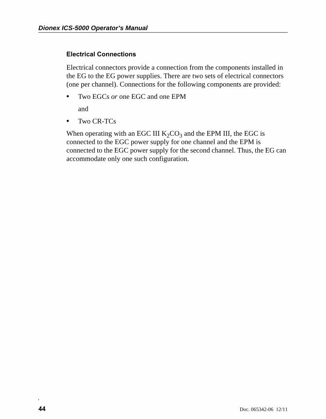
Dionex ICS-5000 Operator’s Manual
44 Doc. 065342-06 12/11
Electrical Connections
Electrical connectors provide a connection from the components installed in the EG to the EG power supplies. There are two sets of electrical connectors (one per channel). Connections for the following components are provided:
• Two EGCs or one EGC and one EPM
and
• Two CR-TCs
When operating with an EGC III K2CO3 and the EPM III, the EGC is connected to the EGC power supply for one channel and the EPM is connected to the EGC power supply for the second channel. Thus, the EG can accommodate only one such configuration.
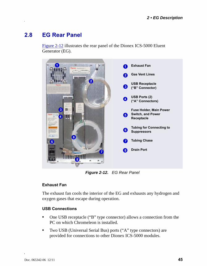
2 • EG Description
Doc. 065342-06 12/11 45
2.8 EG Rear Panel
Figure 2-12 illustrates the rear panel of the Dionex ICS-5000 Eluent Generator (EG).
Exhaust Fan
The exhaust fan cools the interior of the EG and exhausts any hydrogen and oxygen gases that escape during operation.
USB Connections
• One USB receptacle (“B” type connector) allows a connection from the PC on which Chromeleon is installed.
• Two USB (Universal Serial Bus) ports (“A” type connectors) are provided for connections to other Dionex ICS-5000 modules.
Figure 2-12. EG Rear Panel
Exhaust Fan
Gas Vent Lines
Fuse Holder, Main Power Switch, and Power Receptacle
Drain Port
USB Receptacle (“B” Connector)
USB Ports (2) (“A” Connectors)
Tubing for Connecting to Suppressors
Tubing Chase
1
2
3
4
5
7
6
8
1
2
3
4
5
7
6
8
Dionex ICS-5000 Operator’s Manual
46 Doc. 065342-06 12/11
One 1.8 m (6 ft) USB cable (P/N 960777) is provided in the EG Ship Kit (P/N 072047).
Fuse Holder, Main Power Switch, and Power Receptacle
The fuse cartridge contains two 2-amp slow-blow fuses (P/N 954773). For instructions on how to change the fuses, see Section 9.18.
The rear panel power switch is the main power switch for the EG. Turn on the main power switch before initial operation and leave it on unless instructed to turn it off (for example, before performing a service procedure).
NOTE For routine on/off control, use the POWER button on the front of the EG (see Figure 2-8). To turn off the EG, press and hold the POWER button for 2 seconds.
The power cord plugs into the IEC 320 three-prong receptacle.
Tubing Chase
The tubing chase routes tubing from the front of the EG, through the interior of the module, and to the rear panel.
Suppressor, Vent, and Drain Lines
• The lines exiting the tubing chase (white tubing) are for connecting the REGEN IN port on the RFIC Eluent Degasser or EPM III Electrolytic pH Modifier to the REGEN OUT port on the suppressor.
• The gas vent line (clear tubing) discharges the electrolysis gas (H2 or O2) that is vented from the electrolyte reservoir of the EGC.
The power supply cord is used as the main disconnect device. Makesure the socket-outlet is located near the EG and is easily accessible.
Le cordon d'alimentation principal est utilisé comme dispositif principalde débranchement. Veillez à ce que la prise de base soit située/installéeprès du module et facilement accessible.
Das Netzkabel ist das wichtigste Mittel zur Stromunterbrechung. StellenSie sicher, daß sich die Steckdose nahe am Gerät befindet und leichtzugänglich ist.
2 • EG Description
Doc. 065342-06 12/11 47
• The drain port removes any liquid that collects in the drip tray in the bottom of the EG. A clear corrugated drain hose (P/N 055075) is connected to this port during installation.
Place the free ends of the vent lines and drain hose into a waste container. To maintain a positive siphon, position the waste container below the level of the EG.
2.9 EG Flow Schematics
Liquid flows through the EG components in the following order:
• The pump delivers deionized water to the EGC. Direct current is applied to the EGC to produce eluent.
• The electrolytically-generated eluent flows to the CR-TC (which traps ionic contaminants) and then into the degasser.
• After exiting the degasser, the eluent flows through the backpressure coil (if installed), through the injection valve to the separator column, and finally to the detector cell.
• The detector cell effluent is directed through the suppressor regenerant chamber, to the degasser regenerant tubing, through the CR-TC regenerant chamber, and finally to waste.
The flow paths for a capillary IC and an analytical IC system are the same. However, in a capillary IC system, a degasser cartridge is located in the IC Cube inside the DC. In an analytical IC system, the degasser is located inside the EG.
Figure 2-13 illustrates the liquid flow path through an EG configured for a capillary IC system.
Figure 2-14 illustrates the liquid flow path through an EG configured for an analytical IC system.
For correct drainage, make sure the vent lines and drain hose are notbent, pinched, or elevated at any point. Do not allow the ends of thelines to be submerged in waste liquid.
Capillary IC
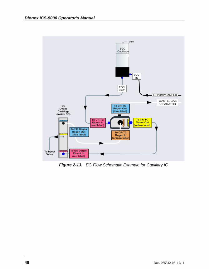
Dionex ICS-5000 Operator’s Manual
48 Doc. 065342-06 12/11
Figure 2-13. EG Flow Schematic Example for Capillary IC
EGC OUT
TO PUMP/DAMPER
EGC IN
To CR-TC Regen Out(blue label)
To CR-TC Eluent In
(red label) EL
UE
NT
OU
T
RE
GE
NIN
To EG Degas Regen Out(blue label)
To CR-TC Regen In
(orange label)
Vent
WASTE, GAS SEPARATOR
To CR-TC Eluent Out
(yellow label)
To EG Degas Eluent In(red label)
EGDegas
Cartridge(inside DC)
ELUENT IN
REGEN
OUT
ELUENT
OUT
To Inject Valve
EGC(Capillary)

2 • EG Description
Doc. 065342-06 12/11 49
NOTE Refer to the EGC-CO3 Mixer manual for a flow schematic showing the components required to generate a carbon-ate/bicarbonate mixture. The manual is included on the Thermo Scientific Reference Library DVD (P/N 053891).
Figure 2-14. EG Flow Schematic Example for Analytical IC
Eluent Out
EGC VENT
To Waste
EGC IN
EGC OUT
EGC
Inlet Outlet
TO INJ VALVE - P
TO PUMP
WASTE, GAS SEPARATOR
CouplerTO SRS/AES REGEN OUT
Eluent In
CR-TC
Coupler
EL
UE
NT
OU
T
RE
GE
NIN
TO CR -TC REGEN OUT (blue label)
To CR-TC Eluent In
(red label)
To CR-TC Eluent Out
(yellow label)
To CR-TC Regen In
(orange label)
RFIC Eluent
Degasser
Regen Out
Regen In

Dionex ICS-5000 Operator’s Manual
50 Doc. 065342-06 12/11
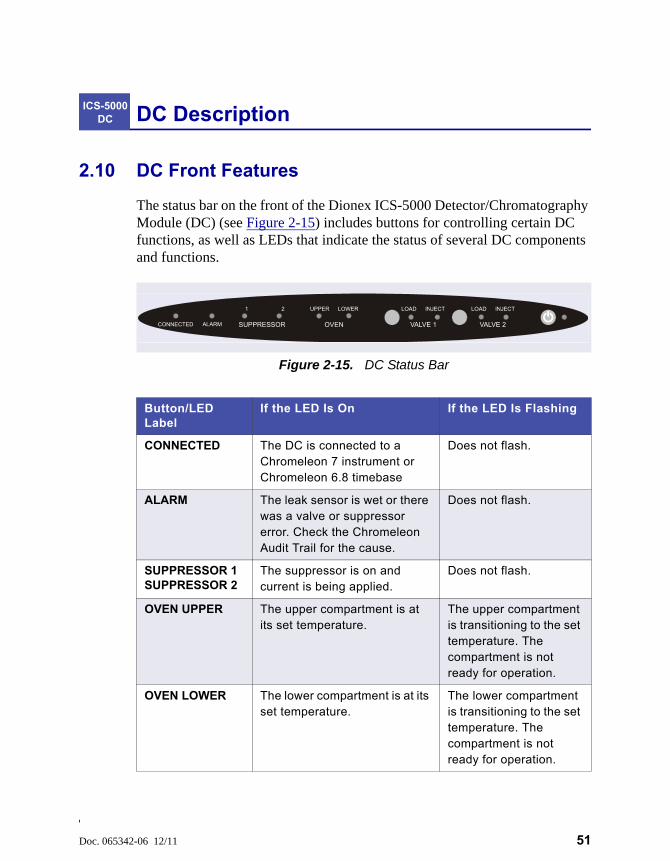
Doc. 065342-06 12/11 51
DC Description
2.10 DC Front Features
The status bar on the front of the Dionex ICS-5000 Detector/Chromatography Module (DC) (see Figure 2-15) includes buttons for controlling certain DC functions, as well as LEDs that indicate the status of several DC components and functions.
ICS-5000 DC
Figure 2-15. DC Status Bar
Button/LED Label
If the LED Is On If the LED Is Flashing
CONNECTED The DC is connected to a Chromeleon 7 instrument or Chromeleon 6.8 timebase
Does not flash.
ALARM The leak sensor is wet or there was a valve or suppressor error. Check the Chromeleon Audit Trail for the cause.
Does not flash.
SUPPRESSOR 1SUPPRESSOR 2
The suppressor is on and current is being applied.
Does not flash.
OVEN UPPER The upper compartment is at its set temperature.
The upper compartment is transitioning to the set temperature. The compartment is not ready for operation.
OVEN LOWER The lower compartment is at its set temperature.
The lower compartment is transitioning to the set temperature. The compartment is not ready for operation.
CONNECTED ALARM SUPPRESSOR OVEN VALVE 1 VALVE 2
1 2 UPPER LOWER LOAD INJECT LOAD INJECT
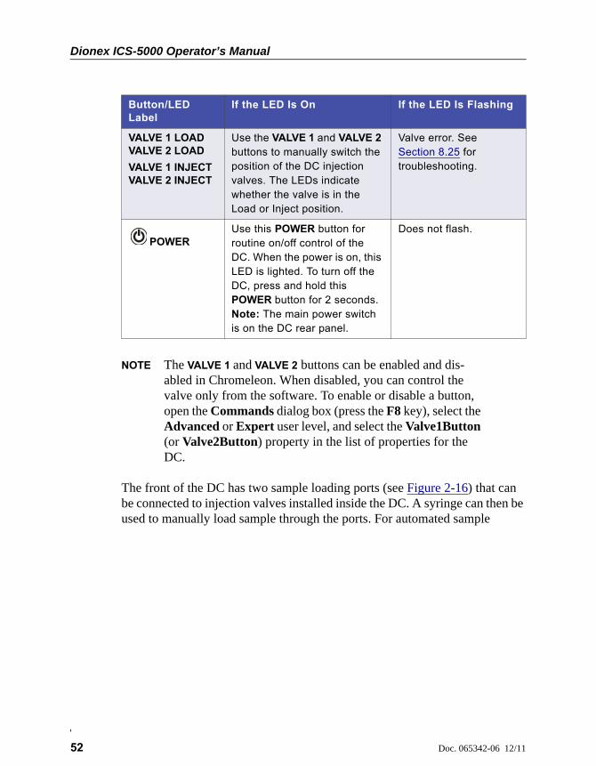
Dionex ICS-5000 Operator’s Manual
52 Doc. 065342-06 12/11
NOTE The VALVE 1 and VALVE 2 buttons can be enabled and dis-abled in Chromeleon. When disabled, you can control the valve only from the software. To enable or disable a button, open the Commands dialog box (press the F8 key), select the Advanced or Expert user level, and select the Valve1Button (or Valve2Button) property in the list of properties for the DC.
The front of the DC has two sample loading ports (see Figure 2-16) that can be connected to injection valves installed inside the DC. A syringe can then be used to manually load sample through the ports. For automated sample
VALVE 1 LOADVALVE 2 LOAD
VALVE 1 INJECTVALVE 2 INJECT
Use the VALVE 1 and VALVE 2 buttons to manually switch the position of the DC injection valves. The LEDs indicate whether the valve is in the Load or Inject position.
Valve error. See Section 8.25 for troubleshooting.
POWERUse this POWER button for routine on/off control of the DC. When the power is on, this LED is lighted. To turn off the DC, press and hold this POWER button for 2 seconds.Note: The main power switch is on the DC rear panel.
Does not flash.
Button/LED Label
If the LED Is On If the LED Is Flashing
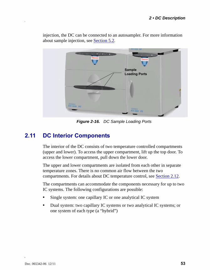
2 • DC Description
Doc. 065342-06 12/11 53
injection, the DC can be connected to an autosampler. For more information about sample injection, see Section 5.2.
2.11 DC Interior Components
The interior of the DC consists of two temperature controlled compartments (upper and lower). To access the upper compartment, lift up the top door. To access the lower compartment, pull down the lower door.
The upper and lower compartments are isolated from each other in separate temperature zones. There is no common air flow between the two compartments. For details about DC temperature control, see Section 2.12.
The compartments can accommodate the components necessary for up to two IC systems. The following configurations are possible:
• Single system: one capillary IC or one analytical IC system
• Dual system: two capillary IC systems or two analytical IC systems; or one system of each type (a “hybrid”)
Figure 2-16. DC Sample Loading Ports
Sample Loading Ports
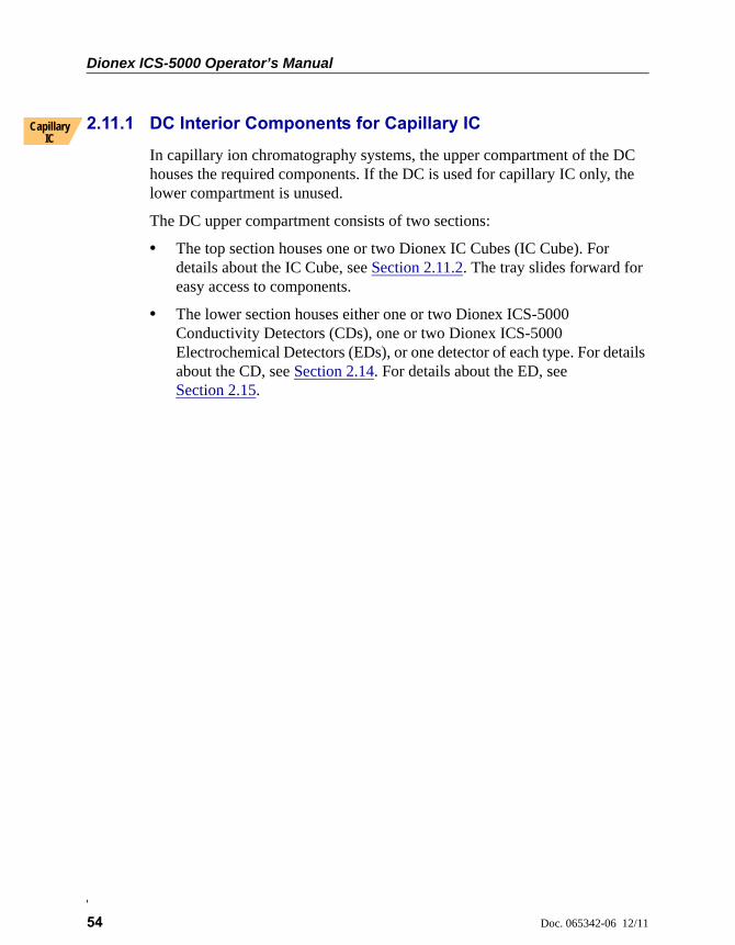
Dionex ICS-5000 Operator’s Manual
54 Doc. 065342-06 12/11
2.11.1 DC Interior Components for Capillary IC
In capillary ion chromatography systems, the upper compartment of the DC houses the required components. If the DC is used for capillary IC only, the lower compartment is unused.
The DC upper compartment consists of two sections:
• The top section houses one or two Dionex IC Cubes (IC Cube). For details about the IC Cube, see Section 2.11.2. The tray slides forward for easy access to components.
• The lower section houses either one or two Dionex ICS-5000 Conductivity Detectors (CDs), one or two Dionex ICS-5000 Electrochemical Detectors (EDs), or one detector of each type. For details about the CD, see Section 2.14. For details about the ED, see Section 2.15.
Capillary IC
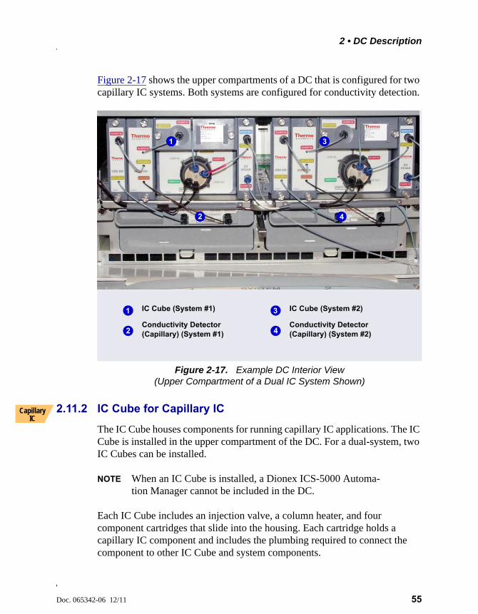
2 • DC Description
Doc. 065342-06 12/11 55
Figure 2-17 shows the upper compartments of a DC that is configured for two capillary IC systems. Both systems are configured for conductivity detection.
2.11.2 IC Cube for Capillary IC
The IC Cube houses components for running capillary IC applications. The IC Cube is installed in the upper compartment of the DC. For a dual-system, two IC Cubes can be installed.
NOTE When an IC Cube is installed, a Dionex ICS-5000 Automa-tion Manager cannot be included in the DC.
Each IC Cube includes an injection valve, a column heater, and four component cartridges that slide into the housing. Each cartridge holds a capillary IC component and includes the plumbing required to connect the component to other IC Cube and system components.
Figure 2-17. Example DC Interior View(Upper Compartment of a Dual IC System Shown)
IC Cube (System #1)
Conductivity Detector (Capillary) (System #1)
1
2
1
2
3
4
IC Cube (System #2)
Conductivity Detector (Capillary) (System #2)
3
4
Capillary IC
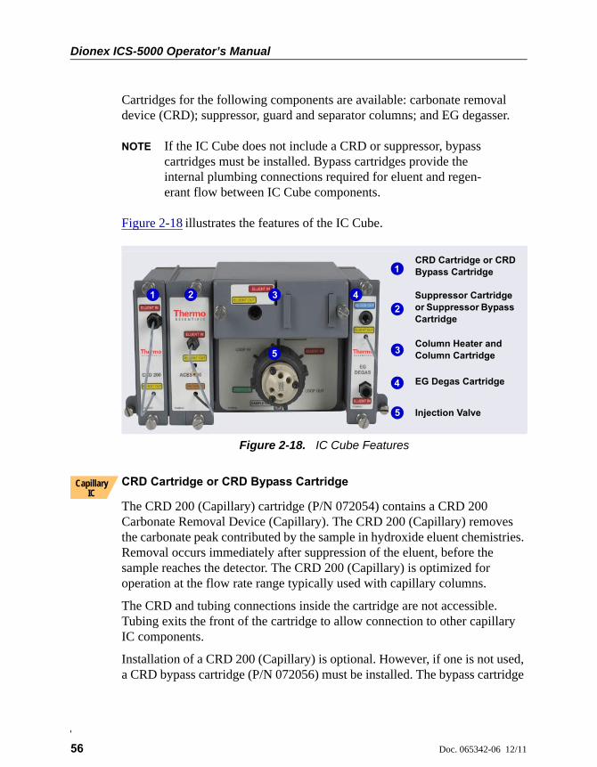
Dionex ICS-5000 Operator’s Manual
56 Doc. 065342-06 12/11
Cartridges for the following components are available: carbonate removal device (CRD); suppressor, guard and separator columns; and EG degasser.
NOTE If the IC Cube does not include a CRD or suppressor, bypass cartridges must be installed. Bypass cartridges provide the internal plumbing connections required for eluent and regen-erant flow between IC Cube components.
Figure 2-18 illustrates the features of the IC Cube.
CRD Cartridge or CRD Bypass Cartridge
The CRD 200 (Capillary) cartridge (P/N 072054) contains a CRD 200 Carbonate Removal Device (Capillary). The CRD 200 (Capillary) removes the carbonate peak contributed by the sample in hydroxide eluent chemistries. Removal occurs immediately after suppression of the eluent, before the sample reaches the detector. The CRD 200 (Capillary) is optimized for operation at the flow rate range typically used with capillary columns.
The CRD and tubing connections inside the cartridge are not accessible. Tubing exits the front of the cartridge to allow connection to other capillary IC components.
Installation of a CRD 200 (Capillary) is optional. However, if one is not used, a CRD bypass cartridge (P/N 072056) must be installed. The bypass cartridge
Figure 2-18. IC Cube Features
EG Degas Cartridge
CRD Cartridge or CRD Bypass Cartridge
Suppressor Cartridge or Suppressor Bypass Cartridge
Column Heater and Column Cartridge
Injection Valve
1
2
3
4
5
1 2 3 4
5
Capillary IC
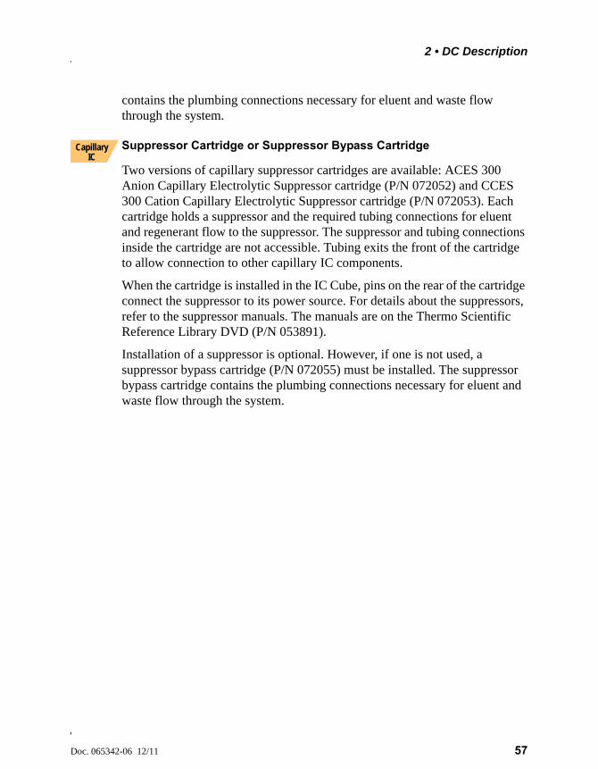
2 • DC Description
Doc. 065342-06 12/11 57
contains the plumbing connections necessary for eluent and waste flow through the system.
Suppressor Cartridge or Suppressor Bypass Cartridge
Two versions of capillary suppressor cartridges are available: ACES 300 Anion Capillary Electrolytic Suppressor cartridge (P/N 072052) and CCES 300 Cation Capillary Electrolytic Suppressor cartridge (P/N 072053). Each cartridge holds a suppressor and the required tubing connections for eluent and regenerant flow to the suppressor. The suppressor and tubing connections inside the cartridge are not accessible. Tubing exits the front of the cartridge to allow connection to other capillary IC components.
When the cartridge is installed in the IC Cube, pins on the rear of the cartridge connect the suppressor to its power source. For details about the suppressors, refer to the suppressor manuals. The manuals are on the Thermo Scientific Reference Library DVD (P/N 053891).
Installation of a suppressor is optional. However, if one is not used, a suppressor bypass cartridge (P/N 072055) must be installed. The suppressor bypass cartridge contains the plumbing connections necessary for eluent and waste flow through the system.
Capillary IC
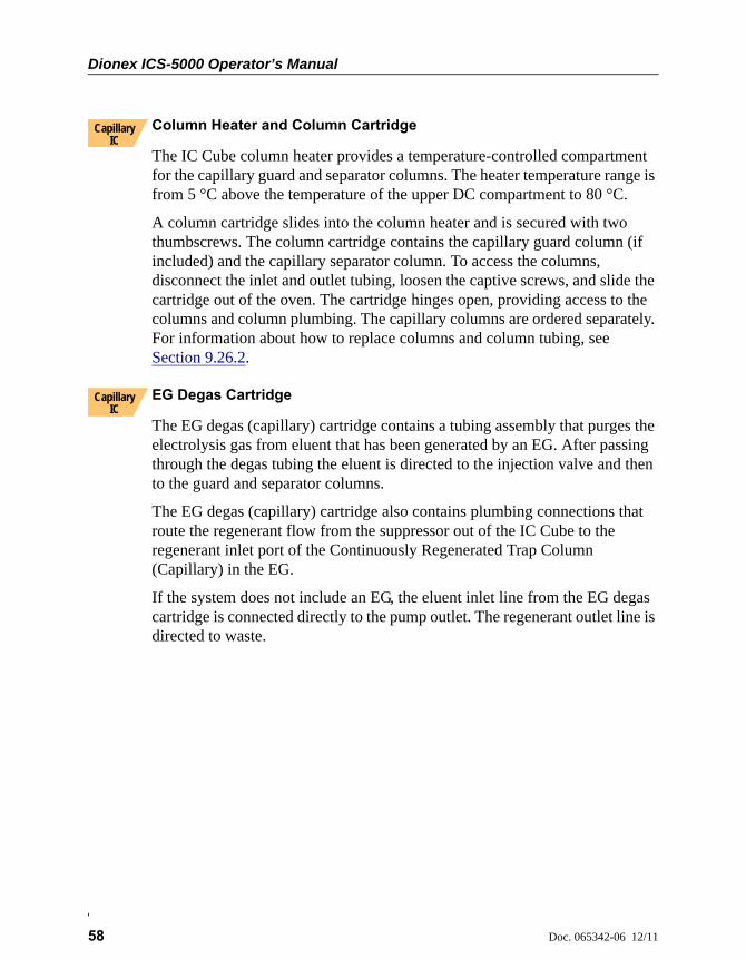
Dionex ICS-5000 Operator’s Manual
58 Doc. 065342-06 12/11
Column Heater and Column Cartridge
The IC Cube column heater provides a temperature-controlled compartment for the capillary guard and separator columns. The heater temperature range is from 5 °C above the temperature of the upper DC compartment to 80 °C.
A column cartridge slides into the column heater and is secured with two thumbscrews. The column cartridge contains the capillary guard column (if included) and the capillary separator column. To access the columns, disconnect the inlet and outlet tubing, loosen the captive screws, and slide the cartridge out of the oven. The cartridge hinges open, providing access to the columns and column plumbing. The capillary columns are ordered separately. For information about how to replace columns and column tubing, see Section 9.26.2.
EG Degas Cartridge
The EG degas (capillary) cartridge contains a tubing assembly that purges the electrolysis gas from eluent that has been generated by an EG. After passing through the degas tubing the eluent is directed to the injection valve and then to the guard and separator columns.
The EG degas (capillary) cartridge also contains plumbing connections that route the regenerant flow from the suppressor out of the IC Cube to the regenerant inlet port of the Continuously Regenerated Trap Column (Capillary) in the EG.
If the system does not include an EG, the eluent inlet line from the EG degas cartridge is connected directly to the pump outlet. The regenerant outlet line is directed to waste.
Capillary IC
Capillary IC
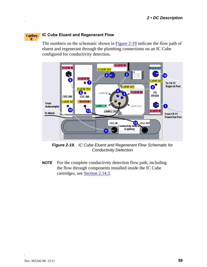
2 • DC Description
Doc. 065342-06 12/11 59
IC Cube Eluent and Regenerant Flow
The numbers on the schematic shown in Figure 2-19 indicate the flow path of eluent and regenerant through the plumbing connections on an IC Cube configured for conductivity detection.
NOTE For the complete conductivity detection flow path, including the flow through components installed inside the IC Cube cartridges, see Section 2.14.3.
Figure 2-19. IC Cube Eluent and Regenerant Flow Schematic for Conductivity Detection
Capillary IC
From CR-TC Eluent Out Port
To CR-TCRegen In Port
CRD 200
EGDEGAS
From Autosampler
To Waste
ELUENT IN
ELUENT IN
ELUENT OUT
ELUENT OUT
REGEN IN
CES 300
ELUENT IN
ELUENT OUT
ELUENT IN
REGEN OUT
ELUENT OUT
SAMPLE IN
SAMPLE OUT
ELUENT IN
ELUENT OUT
Conductivity Detector(Capillary)
CELL IN CELL OUT
1
2
3
56
4
7
8
9
10
9
11
12
13
14
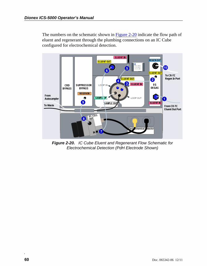
Dionex ICS-5000 Operator’s Manual
60 Doc. 065342-06 12/11
The numbers on the schematic shown in Figure 2-20 indicate the flow path of eluent and regenerant through the plumbing connections on an IC Cube configured for electrochemical detection.
Figure 2-20. IC Cube Eluent and Regenerant Flow Schematic for Electrochemical Detection (PdH Electrode Shown)
CRD BYPASS
EGDEGAS
REGEN IN
SUPPRESSORBYPASS
ELUENT IN
ELUENT OUT
ELUENT IN
REGEN OUT
ELUENT OUT
SAMPLE IN
SAMPLE OUT
ELUENT IN
ELUENT OUT
IN
OUTEC CELL
From Autosampler
To Waste From CR-TC Eluent Out Port
To CR-TCRegen In Port
1
23
56
4
7
8
99
10
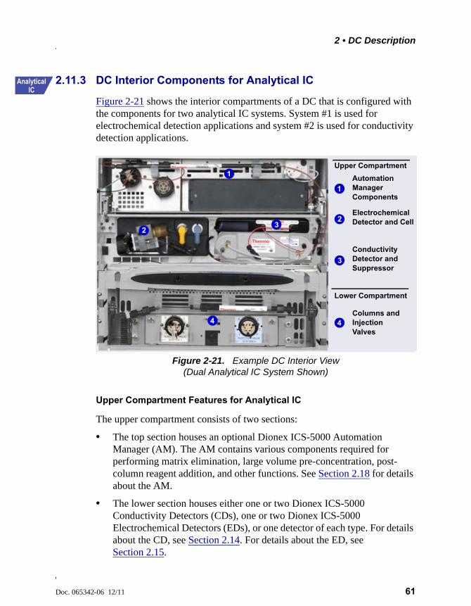
2 • DC Description
Doc. 065342-06 12/11 61
2.11.3 DC Interior Components for Analytical IC
Figure 2-21 shows the interior compartments of a DC that is configured with the components for two analytical IC systems. System #1 is used for electrochemical detection applications and system #2 is used for conductivity detection applications.
Upper Compartment Features for Analytical IC
The upper compartment consists of two sections:
• The top section houses an optional Dionex ICS-5000 Automation Manager (AM). The AM contains various components required for performing matrix elimination, large volume pre-concentration, post-column reagent addition, and other functions. See Section 2.18 for details about the AM.
• The lower section houses either one or two Dionex ICS-5000 Conductivity Detectors (CDs), one or two Dionex ICS-5000 Electrochemical Detectors (EDs), or one detector of each type. For details about the CD, see Section 2.14. For details about the ED, see Section 2.15.
Figure 2-21. Example DC Interior View(Dual Analytical IC System Shown)
Automation Manager Components
Columns and Injection Valves
Electrochemical Detector and Cell
Conductivity Detector and Suppressor
Upper Compartment
Lower Compartment
1
2
3
4
1
23
4
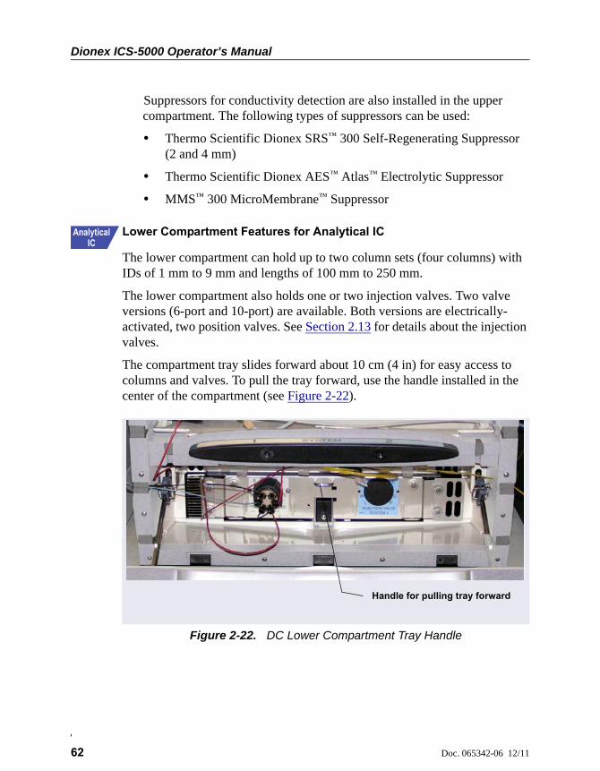
Dionex ICS-5000 Operator’s Manual
62 Doc. 065342-06 12/11
Suppressors for conductivity detection are also installed in the upper compartment. The following types of suppressors can be used:
• Thermo Scientific Dionex SRS™ 300 Self-Regenerating Suppressor (2 and 4 mm)
• Thermo Scientific Dionex AES™ Atlas™ Electrolytic Suppressor
• MMS™ 300 MicroMembrane™ Suppressor
Lower Compartment Features for Analytical IC
The lower compartment can hold up to two column sets (four columns) with IDs of 1 mm to 9 mm and lengths of 100 mm to 250 mm.
The lower compartment also holds one or two injection valves. Two valve versions (6-port and 10-port) are available. Both versions are electrically-activated, two position valves. See Section 2.13 for details about the injection valves.
The compartment tray slides forward about 10 cm (4 in) for easy access to columns and valves. To pull the tray forward, use the handle installed in the center of the compartment (see Figure 2-22).
Figure 2-22. DC Lower Compartment Tray Handle
Handle for pulling tray forward
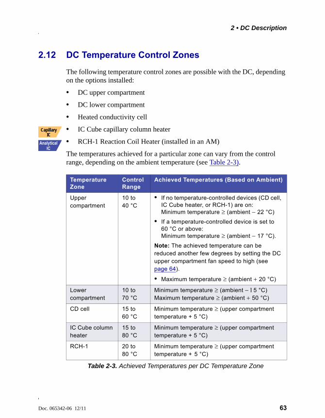
2 • DC Description
Doc. 065342-06 12/11 63
2.12 DC Temperature Control Zones
The following temperature control zones are possible with the DC, depending on the options installed:
• DC upper compartment
• DC lower compartment
• Heated conductivity cell
• IC Cube capillary column heater
• RCH-1 Reaction Coil Heater (installed in an AM)
The temperatures achieved for a particular zone can vary from the control range, depending on the ambient temperature (see Table 2-3).
Temperature Zone
Control Range
Achieved Temperatures (Based on Ambient)
Upper compartment
10 to 40 °C
• If no temperature-controlled devices (CD cell, IC Cube heater, or RCH-1) are on: Minimum temperature (ambient 22 °C)
• If a temperature-controlled device is set to 60 °C or above: Minimum temperature (ambient 17 °C).
Note: The achieved temperature can be reduced another few degrees by setting the DC upper compartment fan speed to high (see page 64).
• Maximum temperature (ambient 20 °C)
Lower compartment
10 to 70 °C
Minimum temperature (ambient 5 °C)Maximum temperature (ambient 50 °C)
CD cell 15 to 60 °C
Minimum temperature (upper compartment temperature + 5 °C)
IC Cube column heater
15 to 80 °C
Minimum temperature (upper compartment temperature + 5 °C)
RCH-1 20 to 80 °C
Minimum temperature (upper compartment temperature + 5 °C)
Table 2-3. Achieved Temperatures per DC Temperature Zone
Capillary IC
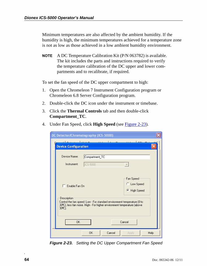
Dionex ICS-5000 Operator’s Manual
64 Doc. 065342-06 12/11
Minimum temperatures are also affected by the ambient humidity. If the humidity is high, the minimum temperatures achieved for a temperature zone is not as low as those achieved in a low ambient humidity environment.
NOTE A DC Temperature Calibration Kit (P/N 063782) is available. The kit includes the parts and instructions required to verify the temperature calibration of the DC upper and lower com-partments and to recalibrate, if required.
To set the fan speed of the DC upper compartment to high:
1. Open the Chromeleon 7 Instrument Configuration program or Chromeleon 6.8 Server Configuration program.
2. Double-click the DC icon under the instrument or timebase.
3. Click the Thermal Controls tab and then double-click Compartment_TC.
4. Under Fan Speed, click High Speed (see Figure 2-23).
Figure 2-23. Setting the DC Upper Compartment Fan Speed
2 • DC Description
Doc. 065342-06 12/11 65
2.13 High-Pressure Valves
Up to four high-pressure valves can be installed in the DC. The following valve models are available: 4-port (P/N 074525), 6-port (P/N 061961), and 10-port (P/N 061962).
In a capillary IC system, one 4-port high-pressure valve is installed on each IC Cube. This valve is used for sample injection. Optionally, the 6-port valve can be installed instead of the 4-port valve. In addition to the injection valve, one or two high-pressure valves can be installed in the lower compartment. These valves can be used for applications requiring auxiliary valves.
In an analytical IC system, one 6-port high-pressure valve is installed in the lower compartment for each system configured in the DC.This valve is used for sample injection. Optionally, one or two high-pressure valves can be installed on an AM (see Section 2.18). These valves can be used for applications requiring auxiliary valves.
Each valve has two operating positions. When configured as an injection valve, liquid flows through either the Load or Inject path, depending on the valve position. In the Load position, sample is loaded into the sample loop. In the Inject position, sample is swept to the column for analysis.
When configured as an auxiliary valve, the flow path through system components in each valve position depends on the component configuration.
Capillary IC
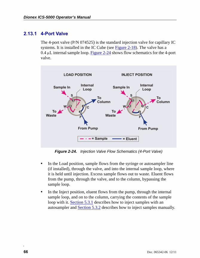
Dionex ICS-5000 Operator’s Manual
66 Doc. 065342-06 12/11
2.13.1 4-Port Valve
The 4-port valve (P/N 074525) is the standard injection valve for capillary IC systems. It is installed in the IC Cube (see Figure 2-18). The valve has a 0.4 L internal sample loop. Figure 2-24 shows flow schematics for the 4-port valve.
• In the Load position, sample flows from the syringe or autosampler line (if installed), through the valve, and into the internal sample loop, where it is held until injection. Excess sample flows out to waste. Eluent flows from the pump, through the valve, and to the column, bypassing the sample loop.
• In the Inject position, eluent flows from the pump, through the internal sample loop, and on to the column, carrying the contents of the sample loop with it. Section 5.3.1 describes how to inject samples with an autosampler and Section 5.3.2 describes how to inject samples manually.
Figure 2-24. Injection Valve Flow Schematics (4-Port Valve)
LOAD POSITION INJECT POSITION
= Sample = Eluent
To Waste
Sample In
To Column
From Pump
S
W 6
5
2
3
InternalLoop
To Waste
Sample In
To Column
From Pump
S
W 6
5
2
3
InternalLoop
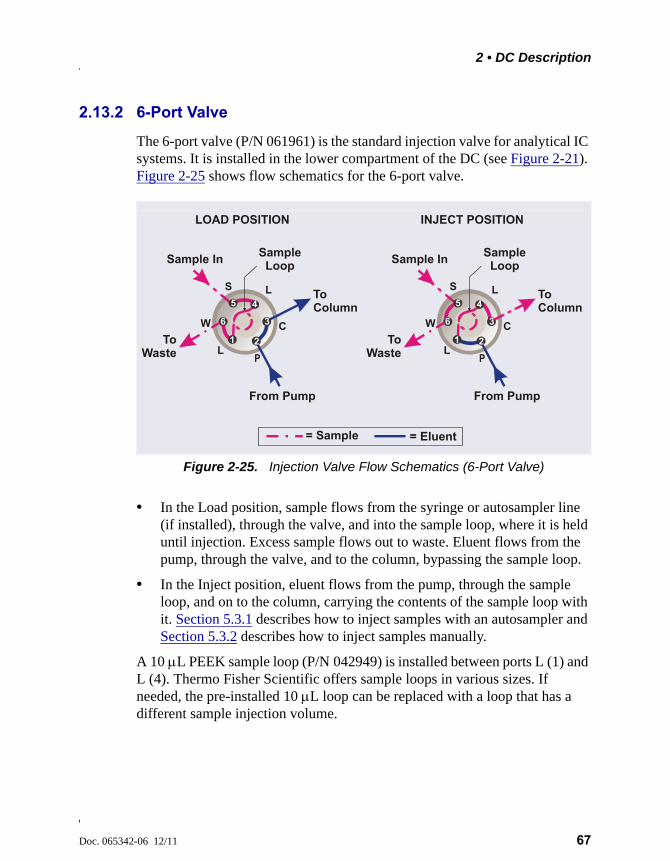
2 • DC Description
Doc. 065342-06 12/11 67
2.13.2 6-Port Valve
The 6-port valve (P/N 061961) is the standard injection valve for analytical IC systems. It is installed in the lower compartment of the DC (see Figure 2-21). Figure 2-25 shows flow schematics for the 6-port valve.
• In the Load position, sample flows from the syringe or autosampler line (if installed), through the valve, and into the sample loop, where it is held until injection. Excess sample flows out to waste. Eluent flows from the pump, through the valve, and to the column, bypassing the sample loop.
• In the Inject position, eluent flows from the pump, through the sample loop, and on to the column, carrying the contents of the sample loop with it. Section 5.3.1 describes how to inject samples with an autosampler and Section 5.3.2 describes how to inject samples manually.
A 10 L PEEK sample loop (P/N 042949) is installed between ports L (1) and L (4). Thermo Fisher Scientific offers sample loops in various sizes. If needed, the pre-installed 10 L loop can be replaced with a loop that has a different sample injection volume.
Figure 2-25. Injection Valve Flow Schematics (6-Port Valve)
LOAD POSITION INJECT POSITION
= Sample = Eluent
To Waste
Sample In
To Column
From Pump
S
W 6
5
2
3
Sample Loop
1
4
To Waste
Sample In
To Column
From Pump
S
W 6
5
2
3
Sample Loop
1
4
L
L
L
L
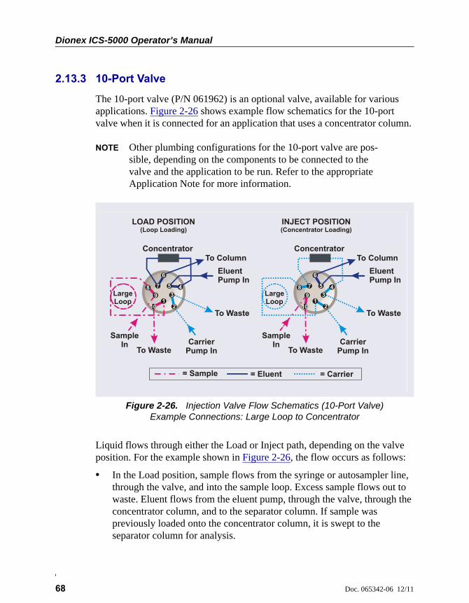
Dionex ICS-5000 Operator’s Manual
68 Doc. 065342-06 12/11
2.13.3 10-Port Valve
The 10-port valve (P/N 061962) is an optional valve, available for various applications. Figure 2-26 shows example flow schematics for the 10-port valve when it is connected for an application that uses a concentrator column.
NOTE Other plumbing configurations for the 10-port valve are pos-sible, depending on the components to be connected to the valve and the application to be run. Refer to the appropriate Application Note for more information.
Liquid flows through either the Load or Inject path, depending on the valve position. For the example shown in Figure 2-26, the flow occurs as follows:
• In the Load position, sample flows from the syringe or autosampler line, through the valve, and into the sample loop. Excess sample flows out to waste. Eluent flows from the eluent pump, through the valve, through the concentrator column, and to the separator column. If sample was previously loaded onto the concentrator column, it is swept to the separator column for analysis.
Figure 2-26. Injection Valve Flow Schematics (10-Port Valve)Example Connections: Large Loop to Concentrator
5
LOAD POSITION(Loop Loading)
To Waste
Eluent Pump In
To Column
Sample In
To Waste
Concentrator
LargeLoop
Carrier Pump In
INJECT POSITION(Concentrator Loading)
4
= Carrier= Sample = Eluent
3
210
89
6
7
1
To Waste
Eluent Pump In
To Column
Sample In
To Waste
Concentrator
LargeLoop
Carrier Pump In
21
3
10
89
6
7 45
2 • DC Description
Doc. 065342-06 12/11 69
• In the Inject position, carrier liquid flows through the sample loop and on to the concentrator column, carrying the contents of the sample loop with it. Excess flows out to waste. Eluent flows from the pump, through the valve, and to the separator column, bypassing the concentrator column.
2.14 CD Conductivity Detector
Each Dionex ICS-5000 Conductivity Detector (CD) consists of a heated conductivity cell and the electronics required for collecting the conductivity data and sending it to the computer and the analog output (if installed). The CD is installed in the upper compartment of the DC (see Figure 2-21).
Two versions of CD are available:
• A capillary CD (P/N 072041), for use in systems running capillary flow rates
• An analytical CD (P/N 061716), for use in systems running analytical (standard bore or microbore) flow rates
The features and functions of the two CD versions are the same. However, because the cell volumes of the two are different, the versions are not interchangeable. The CD version must match the system type (capillary IC or analytical IC). If the CD version and system type are mismatched, chromatograms will be affected (for example, broad peaks or lowered sensitivity).
2.14.1 Heated Conductivity Cell
The flow-through conductivity cell measures the electrical conductance of analyte ions as they pass through the cell. Two passivated 316 stainless steel electrodes are permanently sealed into the PEEK cell body. The cell design provides efficient sweep-out, low volume (<1 L), and low dispersion. Temperature control and compensation help ensure good peak reproducibility and baseline stability.
Temperature Control
Temperature directly affects the conductivity of a solution. For example, laboratory heating and air conditioning systems can cause a regular slow
Dionex ICS-5000 Operator’s Manual
70 Doc. 065342-06 12/11
cycling in the baseline. This, in turn, can affect the reproducibility of an analysis. The higher the conductivity, the more pronounced the effect.
To reduce the effect of temperature variation, the DC provides temperature control of both the DC compartment and the cell. A heater inside the cell regulates the cell temperature. The cell heater temperature range is from a low of 5 °C above the temperature of the upper DC compartment to a high of 60 °C.
Temperature Compensation
Built-in temperature compensation helps minimize changes in the baseline or in peak heights if the operating temperature is different from the temperature at which the cell was calibrated. The default temperature compensation is 1.7% per °C. This can be reset to between 0% and 3.0% per °C, depending on the eluent. If you notice that the baseline shifts up when the temperature increases, the compensation factor is too low and should be reset to a higher value.
To change the temperature compensation factor:
1. Open the Chromeleon 7 ePanel Set or the Chromeleon 6.8 panel tabset.
2. Press the F8 key to open the Commands dialog box.
3. Select the conductivity detector.
4. Select the Temperature_Compensation property and enter the value.
5. For Chromeleon 6.8, click Execute.
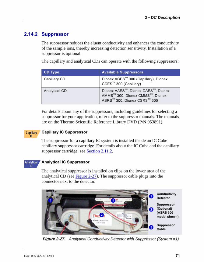
2 • DC Description
Doc. 065342-06 12/11 71
2.14.2 Suppressor
The suppressor reduces the eluent conductivity and enhances the conductivity of the sample ions, thereby increasing detection sensitivity. Installation of a suppressor is optional.
The capillary and analytical CDs can operate with the following suppressors:
For details about any of the suppressors, including guidelines for selecting a suppressor for your application, refer to the suppressor manuals. The manuals are on the Thermo Scientific Reference Library DVD (P/N 053891).
Capillary IC Suppressor
The suppressor for a capillary IC system is installed inside an IC Cube capillary suppressor cartridge. For details about the IC Cube and the capillary suppressor cartridge, see Section 2.11.2.
Analytical IC Suppressor
The analytical suppressor is installed on clips on the lower area of the analytical CD (see Figure 2-27). The suppressor cable plugs into the connector next to the detector.
CD Type Available Suppressors
Capillary CD Dionex ACES™ 300 (Capillary), Dionex CCES™ 300 (Capillary)
Analytical CD Dionex AAES™, Dionex CAES™, Dionex AMMS™ 300, Dionex CMMS™, Dionex ASRS™ 300, Dionex CSRS™ 300
Figure 2-27. Analytical Conductivity Detector with Suppressor (System #1)
Capillary IC
Suppressor (Optional) (ASRS 300 model shown)
Conductivity Detector1
2
3
1
2
3
Suppressor Cable
Dionex ICS-5000 Operator’s Manual
72 Doc. 065342-06 12/11
NOTE It is also possible to control an analytical suppressor with a Dionex ICS-5000 Electrochemical Detector (ED). Tabs for installing the suppressor are provided on the front of the DC (next to the ED). The cable connection is the same as for the CD.
NOTE To prevent accumulation of oxygen or hydrogen gases, con-nect a gas separator waste tube (P/N 045460) to the suppres-sor waste line during installation For details, refer to Thermo Scientific Dionex ICS-5000 Ion Chromatography System Installation Instructions (Document No. 065343).
2.14.3 System Flow Schematics for Conductivity Detection
Figure 2-28 illustrates the flow path through a DC for a conductivity detection application using suppression in recycle mode. For information about other suppression modes, refer to the suppressor manuals. The manuals are on the Thermo Scientific Reference Library DVD (P/N 053891).
NOTE The basic flow path is the same for both capillary IC and ana-lytical IC systems. However, in capillary IC systems, connec-tions to components installed inside IC Cube cartridges (columns, suppressor, and CRD) are not visible.

2 • DC Description
Doc. 065342-06 12/11 73
• Eluent from the pump flows into the injection valve .
• After sample is loaded into the sample loop and the injection valve is toggled to the Inject position, eluent passes through the loop.
• The eluent/sample mixture is pumped first through a temperature stabilizer (analytical IC only), through the guard and separator columns , and then through the suppressor .
• From the suppressor, the mixture flows through a CRD (if installed) to the cell , where the analytes are detected. A digital signal is sent to Chromeleon.
• Finally, the mixture flows out of the cell and is recycled back into the suppressor , where it is used as the water source for the regenerant
Figure 2-28. DC Flow Schematic for Conductivity Detection (Suppression in Recycle Mode)
ELUENT IN
TEMPSTABILIZER
CELLCOND
SUPPRESSOR
PUMP or ELUENT
GENERATOR
GUARD
SEPARATOR COLUMN
VALVE
1 2
3
45
6
WASTE
SAMPLE
L P
C
LS
W
CRDREGENOUT
(Inject Position)
For anion suppression only (optional).
For analytical IC only
= Eluent Flow
= Regenerant Flow
12
3
5
6
7
8
910 9
4
1 2
3
4 5
6
7
8
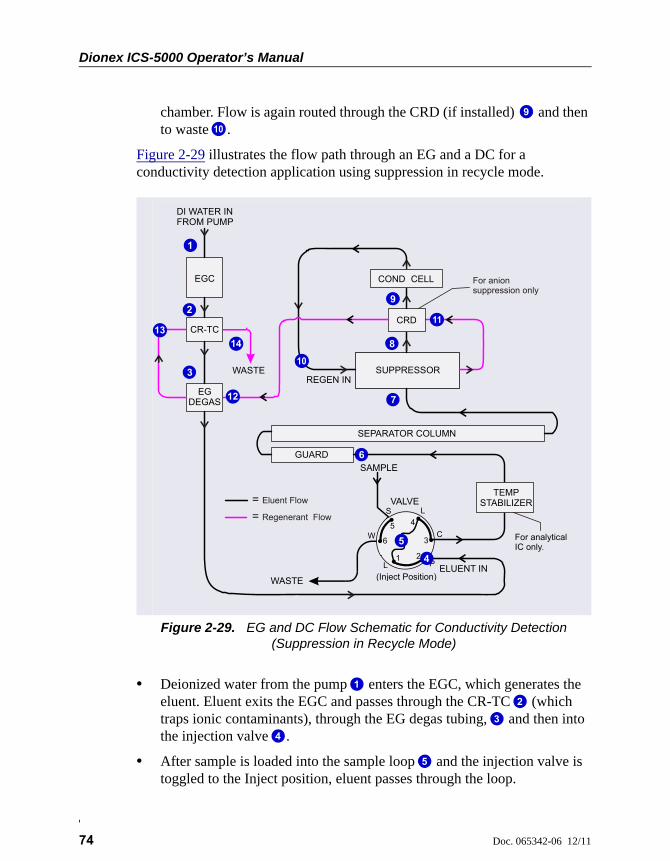
Dionex ICS-5000 Operator’s Manual
74 Doc. 065342-06 12/11
chamber. Flow is again routed through the CRD (if installed) and then to waste .
Figure 2-29 illustrates the flow path through an EG and a DC for a conductivity detection application using suppression in recycle mode.
• Deionized water from the pump enters the EGC, which generates the eluent. Eluent exits the EGC and passes through the CR-TC (which traps ionic contaminants), through the EG degas tubing, and then into the injection valve .
• After sample is loaded into the sample loop and the injection valve is toggled to the Inject position, eluent passes through the loop.
Figure 2-29. EG and DC Flow Schematic for Conductivity Detection (Suppression in Recycle Mode)
9
10
12
3
4
5
6
7
8
9
ELUENT IN
CELLCOND
SUPPRESSOR
GUARD
SEPARATOR COLUMN
VALVE
1 2
3
45
6
WASTE
SAMPLE
L P
C
LS
W
CRD
(Inject Position)
For anion suppression only
CR-TC
EGC
EG DEGAS
TEMPSTABILIZER
WASTE
DI WATER INFROM PUMP
For analytical IC only.
REGEN IN
= Eluent Flow
= Regenerant Flow
1
2
3
5
6
7
8
9
10
11
12
9
4
1314
1
2
3
4
5
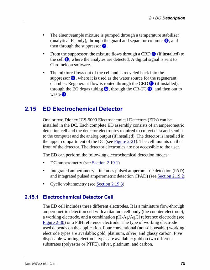
2 • DC Description
Doc. 065342-06 12/11 75
• The eluent/sample mixture is pumped through a temperature stabilizer (analytical IC only), through the guard and separator columns , and then through the suppressor .
• From the suppressor, the mixture flows through a CRD (if installed) to the cell , where the analytes are detected. A digital signal is sent to Chromeleon software.
• The mixture flows out of the cell and is recycled back into the suppressor , where it is used as the water source for the regenerant chamber. Regenerant flow is routed through the CRD (if installed), through the EG degas tubing , through the CR-TC , and then out to waste .
2.15 ED Electrochemical Detector
One or two Dionex ICS-5000 Electrochemical Detectors (EDs) can be installed in the DC. Each complete ED assembly consists of an amperometric detection cell and the detector electronics required to collect data and send it to the computer and the analog output (if installed). The detector is installed in the upper compartment of the DC (see Figure 2-21). The cell mounts on the front of the detector. The detector electronics are not accessible to the user.
The ED can perform the following electrochemical detection modes:
• DC amperometry (see Section 2.19.1)
• Integrated amperometry—includes pulsed amperometric detection (PAD) and integrated pulsed amperometric detection (IPAD) (see Section 2.19.2)
• Cyclic voltammetry (see Section 2.19.3)
2.15.1 Electrochemical Detector Cell
The ED cell includes three different electrodes. It is a miniature flow-through amperometric detection cell with a titanium cell body (the counter electrode), a working electrode, and a combination pH-Ag/AgCl reference electrode (see Figure 2-30) or a PdH reference electrode. The type of working electrode used depends on the application. Four conventional (non-disposable) working electrode types are available: gold, platinum, silver, and glassy carbon. Five disposable working electrode types are available: gold on two different substrates (polyester or PTFE), silver, platinum, and carbon.
6
7
8
9
10
11
12 13
14
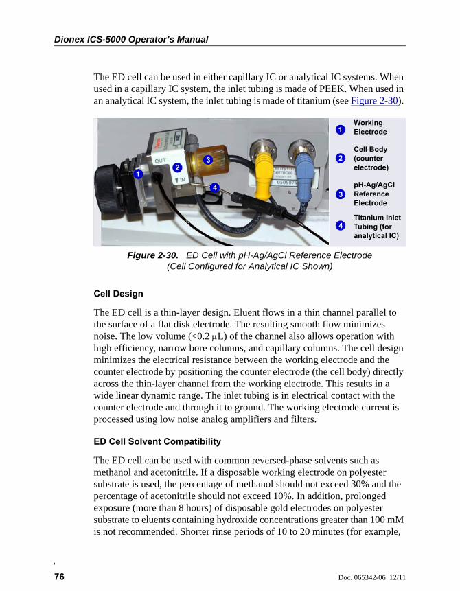
Dionex ICS-5000 Operator’s Manual
76 Doc. 065342-06 12/11
The ED cell can be used in either capillary IC or analytical IC systems. When used in a capillary IC system, the inlet tubing is made of PEEK. When used in an analytical IC system, the inlet tubing is made of titanium (see Figure 2-30).
Cell Design
The ED cell is a thin-layer design. Eluent flows in a thin channel parallel to the surface of a flat disk electrode. The resulting smooth flow minimizes noise. The low volume (<0.2 L) of the channel also allows operation with high efficiency, narrow bore columns, and capillary columns. The cell design minimizes the electrical resistance between the working electrode and the counter electrode by positioning the counter electrode (the cell body) directly across the thin-layer channel from the working electrode. This results in a wide linear dynamic range. The inlet tubing is in electrical contact with the counter electrode and through it to ground. The working electrode current is processed using low noise analog amplifiers and filters.
ED Cell Solvent Compatibility
The ED cell can be used with common reversed-phase solvents such as methanol and acetonitrile. If a disposable working electrode on polyester substrate is used, the percentage of methanol should not exceed 30% and the percentage of acetonitrile should not exceed 10%. In addition, prolonged exposure (more than 8 hours) of disposable gold electrodes on polyester substrate to eluents containing hydroxide concentrations greater than 100 mM is not recommended. Shorter rinse periods of 10 to 20 minutes (for example,
Figure 2-30. ED Cell with pH-Ag/AgCl Reference Electrode (Cell Configured for Analytical IC Shown)
Working Electrode
Cell Body (counter electrode)
pH-Ag/AgCl Reference Electrode
1
23
12
34
4Titanium Inlet Tubing (for analytical IC)
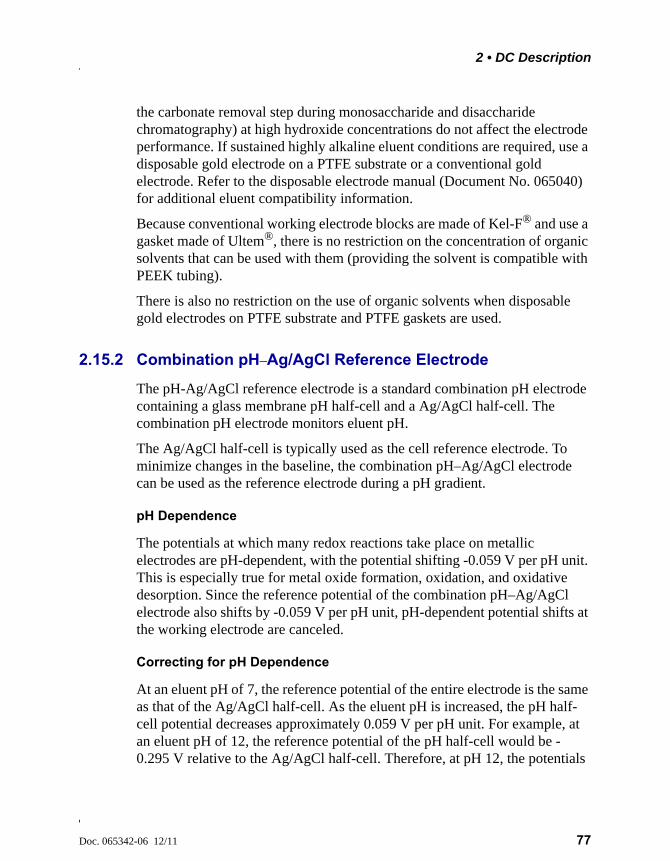
2 • DC Description
Doc. 065342-06 12/11 77
the carbonate removal step during monosaccharide and disaccharide chromatography) at high hydroxide concentrations do not affect the electrode performance. If sustained highly alkaline eluent conditions are required, use a disposable gold electrode on a PTFE substrate or a conventional gold electrode. Refer to the disposable electrode manual (Document No. 065040) for additional eluent compatibility information.
Because conventional working electrode blocks are made of Kel-F® and use a gasket made of Ultem®, there is no restriction on the concentration of organic solvents that can be used with them (providing the solvent is compatible with PEEK tubing).
There is also no restriction on the use of organic solvents when disposable gold electrodes on PTFE substrate and PTFE gaskets are used.
2.15.2 Combination pH–Ag/AgCl Reference Electrode
The pH-Ag/AgCl reference electrode is a standard combination pH electrode containing a glass membrane pH half-cell and a Ag/AgCl half-cell. The combination pH electrode monitors eluent pH.
The Ag/AgCl half-cell is typically used as the cell reference electrode. To minimize changes in the baseline, the combination pH–Ag/AgCl electrode can be used as the reference electrode during a pH gradient.
pH Dependence
The potentials at which many redox reactions take place on metallic electrodes are pH-dependent, with the potential shifting -0.059 V per pH unit. This is especially true for metal oxide formation, oxidation, and oxidative desorption. Since the reference potential of the combination pH–Ag/AgCl electrode also shifts by -0.059 V per pH unit, pH-dependent potential shifts at the working electrode are canceled.
Correcting for pH Dependence
At an eluent pH of 7, the reference potential of the entire electrode is the same as that of the Ag/AgCl half-cell. As the eluent pH is increased, the pH half-cell potential decreases approximately 0.059 V per pH unit. For example, at an eluent pH of 12, the reference potential of the pH half-cell would be -0.295 V relative to the Ag/AgCl half-cell. Therefore, at pH 12, the potentials

Dionex ICS-5000 Operator’s Manual
78 Doc. 065342-06 12/11
applied to the working electrode must be raised approximately 0.3 V when switching from the “Ag” reference to the “pH” reference.
In acidic eluents, the reference potential of the pH half-cell is positive with respect to the Ag/AgCl half-cell, and all applied potentials must be decreased by 0.059 V per pH unit when switching from the “Ag” reference to the “pH” reference.
Monitoring the ED Cell pH Readout
Monitoring the pH readout of a solution with a known composition lets you detect any reference potential shift that may occur over time. This allows you to determine when the pH-Ag/AgCl reference electrode needs regenerating or replacing, thus improving the reproducibility of your analyses. For instructions on how to monitor the pH readout, see Section 4.1.2.
NOTE Monitor the pH when the pH-Ag/AgCl reference electrode is used in the Ag mode as well as in the pH mode.
Do not allow the pH-Ag/AgCl reference electrode to dry out. Make sure that eluent is being pumped continuously through the cell at a low flow rate (for example, 0.05 mL/min). If the cell will not be used for a short time (less than 2 days), disconnect the tubing from the inlet and outlet fittings and install fitting plugs. For longer shutdowns, remove the elec-trode from the cell and store it in its storage cap filled with saturated KCl solution. See Section 6.4 for detailed storage instructions.
2 • DC Description
Doc. 065342-06 12/11 79
2.15.3 Palladium Hydrogen (PdH) Reference Electrode
The PdH reference electrode consists of palladium and platinum electrodes immersed in an aqueous solution. With a potential applied between the two electrodes, palladium is connected as a cathode and platinum as an anode. As a consequence of the applied potential, hydrogen gas is generated at the palladium electrode and oxygen gas at the platinum electrode. Whereas the oxygen gas is swept out of the cell in the liquid stream, a portion of the hydrogen gas is taken up by palladium metal. An equilibrium develops between molecular hydrogen in the liquid phase and the adsorbed hydrogen in palladium. The palladium hydrogen electrode becomes a reference electrode with a half reaction of:
H+ + e- = ½ H2
Where the hydrogen is supplied by the following process:
Pd + ½ H2 Pd-Hads Pd-Habs
The PdH reference electrode is thus similar to the standard hydrogen electrode, which is based on the same half reaction between the hydronium ions and molecular hydrogen. However, there are also some differences. For example, palladium is not as good a catalyst for the electrode half reaction as platinum. As a consequence, under identical conditions, the reference potential of the palladium hydrogen electrode differs from that of the standard hydrogen electrode by a constant potential. In addition, because hydronium ions are involved in the reference half reaction, the potential of the PdH electrode is pH dependent.
Waveforms for PdH Reference Electrodes in Chromeleon
When you create or edit an instrument method in Chromeleon 7 or a program in Chromeleon 6.8, you can select a waveform created for use with the PdH reference electrode. To use a waveform that was created for a pH-Ag/AgCl electrode, select the waveform and then manually correct the potential values in the Waveform Editor. The formula for correction is provided in the Waveform Editor.
No pH Readout with the PdH Reference Mode
If the PdH electrode were connected to another reference electrode (for example, a Ag/AgCl electrode), the PdH electrode could serve as a pH indicator electrode. However, when the PdH electrode functions as a
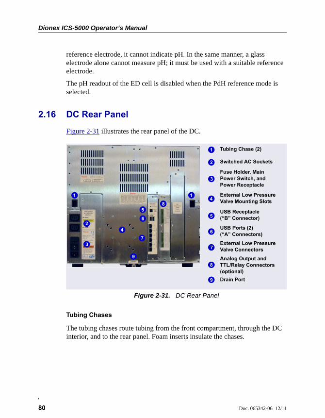
Dionex ICS-5000 Operator’s Manual
80 Doc. 065342-06 12/11
reference electrode, it cannot indicate pH. In the same manner, a glass electrode alone cannot measure pH; it must be used with a suitable reference electrode.
The pH readout of the ED cell is disabled when the PdH reference mode is selected.
2.16 DC Rear Panel
Figure 2-31 illustrates the rear panel of the DC.
Tubing Chases
The tubing chases route tubing from the front compartment, through the DC interior, and to the rear panel. Foam inserts insulate the chases.
Figure 2-31. DC Rear Panel
Tubing Chase (2)
Analog Output and TTL/Relay Connectors (optional)
USB Receptacle (“B” Connector)
External Low Pressure Valve Connectors
Switched AC Sockets
Fuse Holder, Main Power Switch, and Power Receptacle
USB Ports (2)(“A” Connectors)
Drain Port
External Low Pressure Valve Mounting Slots
1
2
3
5
6
7
9
98
41 1
2
3
4
5
6
7
8
99
2 • DC Description
Doc. 065342-06 12/11 81
Switched AC Sockets
The two AC receptacles can be used to control the power to external devices. Use Chromeleon to switch the power on and off. TTL inputs can also be used to control the AC sockets (see Section 2.17.4).
Fuse Holder, Main Power Switch, and Power Receptacle
The fuse holder contains two 10-amp slow-blow fuses (P/N 954772). For instructions on how to change the fuses, see Section 9.22.
The rear panel power switch is the main power switch for the DC. Turn on the main power switch before initial operation and leave the switch on unless instructed to turn it off (for example, before performing a service procedure).
NOTE For routine on/off control, use the POWER button on the front of the DC (see Figure 2-16). To turn off the DC, press and hold the POWER button for 2 seconds.
The power cord plugs into the IEC 320 three-prong receptacle.
USB Connections
The USB (Universal Serial Bus) receptacle (“B” type connector) allows connection to the PC on which Chromeleon software is installed.
The two USB ports (“A” type connectors) allows connection to other USB devices in the system (for example, the pump and eluent generator).
A 1.8 m (6 ft) USB cable (P/N 960777) is included in the DC Ship Kit (P/N 072011).
The power supply cord is used as the main disconnect device. Makesure the socket-outlet is located near the DC and is easily accessible.
Le cordon d'alimentation principal est utilisé comme dispositif principalde débranchement. Veillez à ce que la prise de base soit située/installéeprès du module et facilement accessible.
Das Netzkabel ist das wichtigste Mittel zur Stromunterbrechung. StellenSie sicher, daß sich die Steckdose nahe am Gerät befindet und leichtzugänglich ist.
Dionex ICS-5000 Operator’s Manual
82 Doc. 065342-06 12/11
External Low Pressure Valve Outputs
Six outputs allow connection to externally-installed low-pressure (solenoid) valves. Low-pressure valves can be used for on/off control of liquid flow (for example, to turn flow on and off from a reagent reservoir). You control the outputs with Chromeleon.
Two low-pressure valves can be installed on a regulator stand and four valves can be installed on the rear of the DC.
Analog Output, TTL, and Relay Connectors (Optional)
If the I/O option (P/N 062201) is installed, the following connections are provided:
• Two analog outputs (one for each detector)
• One +5V power output
• Two relay outputs
• Two TTL outputs
• Eight programmable TTL inputs
See Section 2.17 for details about the I/O option.
Drain Port
The drain port removes any liquid that collects in the drip tray in the bottom of the DC. A clear corrugated drain hose (P/N 055075) is connected to this port during installation. Place the drain hose into a waste container. To maintain a positive siphon, position the waste container below the level of the DC.
For correct drainage, make sure the drain hose is not bent, pinched, orelevated at any point. Do not allow the end of the hose to be submergedin waste liquid.
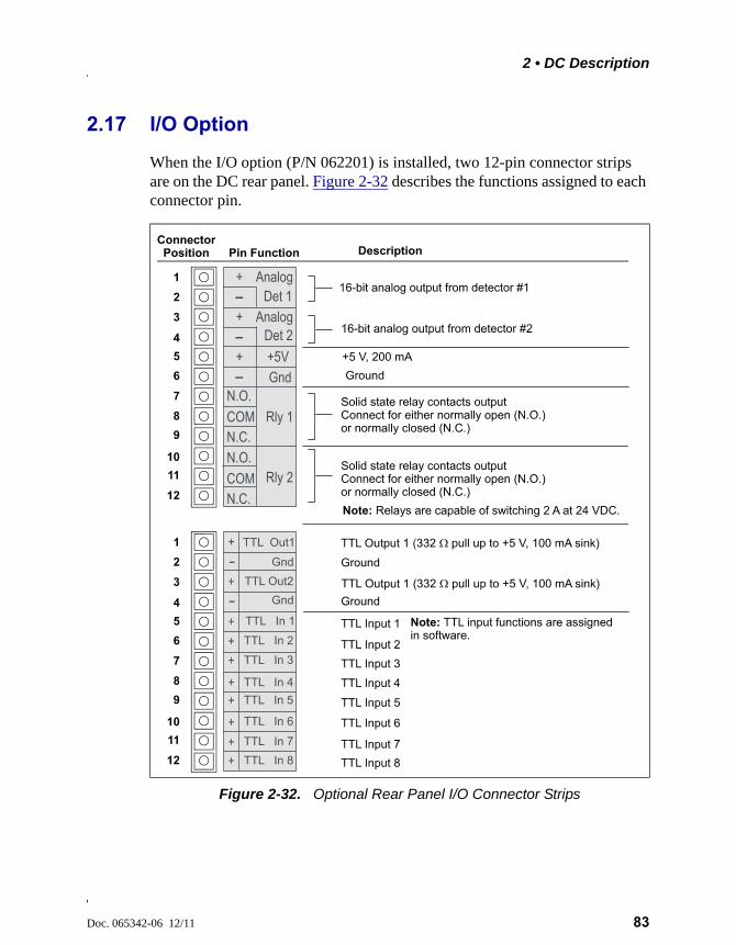
2 • DC Description
Doc. 065342-06 12/11 83
2.17 I/O Option
When the I/O option (P/N 062201) is installed, two 12-pin connector strips are on the DC rear panel. Figure 2-32 describes the functions assigned to each connector pin.
Figure 2-32. Optional Rear Panel I/O Connector Strips
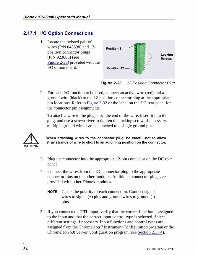
Dionex ICS-5000 Operator’s Manual
84 Doc. 065342-06 12/11
2.17.1 I/O Option Connections
1. Locate the twisted pair of wires (P/N 043598) and 12-position connector plugs (P/N 923686) (see Figure 2-33) provided with the I/O option board.
Figure 2-33. 12-Position Connector Plug
2. For each I/O function to be used, connect an active wire (red) and a ground wire (black) to the 12-position connector plug at the appropriate pin locations. Refer to Figure 2-32 or the label on the DC rear panel for the connector pin assignments.
To attach a wire to the plug, strip the end of the wire, insert it into the plug, and use a screwdriver to tighten the locking screw. If necessary, multiple ground wires can be attached to a single ground pin.
3. Plug the connector into the appropriate 12-pin connector on the DC rear panel.
4. Connect the wires from the DC connector plug to the appropriate connector pins on the other modules. Additional connector plugs are provided with other Dionex modules.
NOTE Check the polarity of each connection. Connect signal wires to signal (+) pins and ground wires to ground (-) pins.
5. If you connected a TTL input, verify that the correct function is assigned to the input and that the correct input control type is selected. Select different settings if necessary. Input functions and control types are assigned from the Chromeleon 7 Instrument Configuration program or the Chromeleon 6.8 Server Configuration program (see Section 2.17.4).
Position 1
Position 12
Locking Screws
When attaching wires to the connector plug, be careful not to allowstray strands of wire to short to an adjoining position on the connector.

2 • DC Description
Doc. 065342-06 12/11 85
2.17.2 Analog Outputs
When the I/O option is installed, two analog outputs (one for each detector) are installed on the DC rear panel (see Figure 2-31). The analog outputs supply a voltage signal proportional to the current measured by the detector cell. The outputs can be connected to an analog-to-digital (A/D) converter such as an integrator or other recording device. Refer to Section 2.17.1 and the documentation for the device for connection instructions.
Several settings are available that allow you to configure the analog output signal for your detector and connected device. Table 2-4 describes the settings. You select the preferred settings on the detector panel on the Chromeleon 7 ePanel Set (see Figure 2-34) or Chromeleon 6.8 panel tabset.
Analog Output Setting
Values Description
Full-scale voltage 0.01, 0.10, or 1.00 V Sets the voltage output of a full-scale detector response. The voltage to use depends on the recording device to which the analog output is connected. For example, if the analog output is connected to a device that accepts input voltages up to 1 V, select a full-scale voltage output of 1 V.
Range Conductivity: 0.01 to 15,000 SDC Amperometry: 50 pA to 300 A Integrated Amperometry:50 pC to 200 C
Sets the full-scale detector response value. The range to use depends on the detector readings expected for the application. For example, selecting a range of 20 micro Siemens (S) will limit you to viewing conductivity readings of 20 S or less.
Table 2-4. Analog Output Configuration Settings
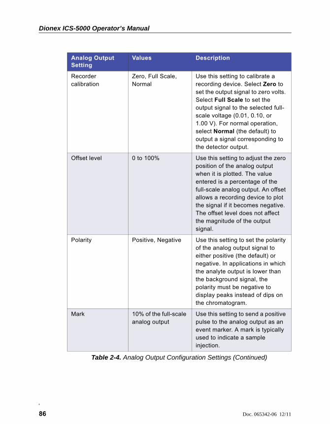
Dionex ICS-5000 Operator’s Manual
86 Doc. 065342-06 12/11
Recorder calibration
Zero, Full Scale, Normal
Use this setting to calibrate a recording device. Select Zero to set the output signal to zero volts. Select Full Scale to set the output signal to the selected full-scale voltage (0.01, 0.10, or 1.00 V). For normal operation, select Normal (the default) to output a signal corresponding to the detector output.
Offset level 0 to 100% Use this setting to adjust the zero position of the analog output when it is plotted. The value entered is a percentage of the full-scale analog output. An offset allows a recording device to plot the signal if it becomes negative. The offset level does not affect the magnitude of the output signal.
Polarity Positive, Negative Use this setting to set the polarity of the analog output signal to either positive (the default) or negative. In applications in which the analyte output is lower than the background signal, the polarity must be negative to display peaks instead of dips on the chromatogram.
Mark 10% of the full-scale analog output
Use this setting to send a positive pulse to the analog output as an event marker. A mark is typically used to indicate a sample injection.
Analog Output Setting
Values Description
Table 2-4. Analog Output Configuration Settings (Continued)
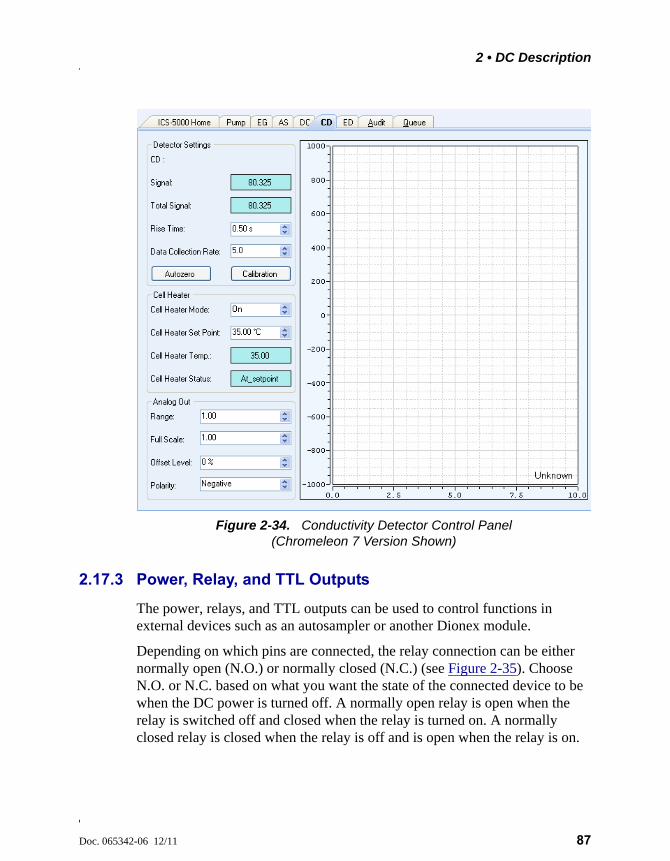
2 • DC Description
Doc. 065342-06 12/11 87
2.17.3 Power, Relay, and TTL Outputs
The power, relays, and TTL outputs can be used to control functions in external devices such as an autosampler or another Dionex module.
Depending on which pins are connected, the relay connection can be either normally open (N.O.) or normally closed (N.C.) (see Figure 2-35). Choose N.O. or N.C. based on what you want the state of the connected device to be when the DC power is turned off. A normally open relay is open when the relay is switched off and closed when the relay is turned on. A normally closed relay is closed when the relay is off and is open when the relay is on.
Figure 2-34. Conductivity Detector Control Panel (Chromeleon 7 Version Shown)

Dionex ICS-5000 Operator’s Manual
88 Doc. 065342-06 12/11
The relays can be programmed to switch any low-voltage device. Switched current must be no more than 2 A at 24 VDC. Refer to Section 2.17.1 and the documentation for the external device for connection instructions.
Figure 2-35. Relay Output Configuration
RELAY OUTPUT CONFIGURATION
The relays are capable of switching 2 A at 24 VDC.
For a normally open connection, connect a COM pin and an N.O. pin.
For a normally closed connection, connect a COM pin and an N.C. pin.
NOTES
N.O.
COM
N.C.
Rear Panel Pins
Relay Output(on DC Electronics)
Non-Energized Relay
N.O.
COM
N.C.Energized Relay
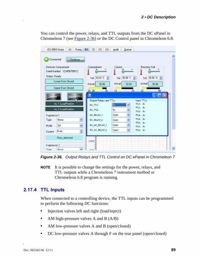
2 • DC Description
Doc. 065342-06 12/11 89
You can control the power, relays, and TTL outputs from the DC ePanel in Chromeleon 7 (see Figure 2-36) or the DC Control panel in Chromeleon 6.8.
NOTE It is possible to change the settings for the power, relays, and TTL outputs while a Chromeleon 7 instrument method or Chromeleon 6.8 program is running.
2.17.4 TTL Inputs
When connected to a controlling device, the TTL inputs can be programmed to perform the following DC functions:
• Injection valves left and right (load/inject)
• AM high-pressure valves A and B (A/B)
• AM low-pressure valves A and B (open/closed)
• DC low-pressure valves A through F on the rear panel (open/closed)
Figure 2-36. Output Relays and TTL Control on DC ePanel in Chromeleon 7
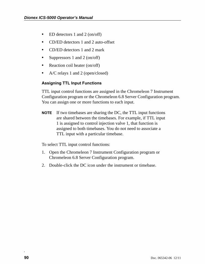
Dionex ICS-5000 Operator’s Manual
90 Doc. 065342-06 12/11
• ED detectors 1 and 2 (on/off)
• CD/ED detectors 1 and 2 auto-offset
• CD/ED detectors 1 and 2 mark
• Suppressors 1 and 2 (on/off)
• Reaction coil heater (on/off)
• A/C relays 1 and 2 (open/closed)
Assigning TTL Input Functions
TTL input control functions are assigned in the Chromeleon 7 Instrument Configuration program or the Chromeleon 6.8 Server Configuration program. You can assign one or more functions to each input.
NOTE If two timebases are sharing the DC, the TTL input functions are shared between the timebases. For example, if TTL input 1 is assigned to control injection valve 1, that function is assigned to both timebases. You do not need to associate a TTL input with a particular timebase.
To select TTL input control functions:
1. Open the Chromeleon 7 Instrument Configuration program or Chromeleon 6.8 Server Configuration program.
2. Double-click the DC icon under the instrument or timebase.
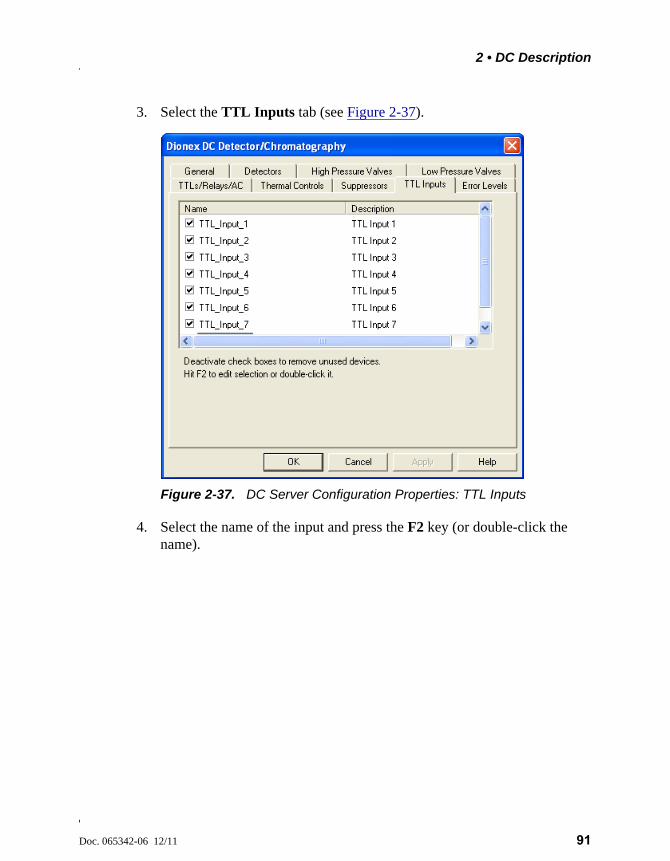
2 • DC Description
Doc. 065342-06 12/11 91
3. Select the TTL Inputs tab (see Figure 2-37).
4. Select the name of the input and press the F2 key (or double-click the name).
Figure 2-37. DC Server Configuration Properties: TTL Inputs
Dionex ICS-5000 Operator’s Manual
92 Doc. 065342-06 12/11
The Device Configuration dialog box for the selected input appears.
5. In the Control Functions list, select the check box of one or more functions to be controlled by this input. When connected to a controlling device, the device can send a signal to the input to trigger the selected functions.
6. By default, several functions are selected. Scroll down the list and disable all unwanted functions.
TTL Input Control Types
The DC TTL inputs respond to four types of signals to accommodate different controlling devices. The default control type, Normal Edge, is compatible with the output signals provided by Dionex modules.
If the device connected to the DC does not send a normal edge signal, select the appropriate control type. Refer to the documentation provided with the
Figure 2-38. Assign TTL Input Control Functions

2 • DC Description
Doc. 065342-06 12/11 93
controlling device and the information below to determine the correct type. Select the input control type in the Device Configuration dialog box for each TTL input (see Figure 2-38).
• Normal Edge: In normal edge operation, the negative (falling) edge of a signal turns on the function.
The action of the positive (rising) edge depends on the function: For on/off or other functions that have two options, the rising edge turns off the function. However, for functions with only one option, the rising edge has no effect.
For example, for the injection valve position, the falling edge switches the valve to Load and the rising edge switches the valve to Inject. Similarly, for the detector start/stop, the falling edge starts the detector and the rising edge stops it. For the detector mark and offset functions, the falling edge turns on the function and the rising edge has no effect.
• Inverted Edge: The inverted edge mode works identically to the normal edge mode except that the positive and negative edges are reversed in function.
• Normal Pulse: In normal pulse operation, the negative (falling) edge of the TTL signal is the active edge and the positive (rising) edge is ignored.
A pulse width of 50 ms or more is guaranteed to be detected. A pulse width of 4 ms or less is guaranteed to be ignored. The action for pulse widths that are greater than 4 ms and less than 50 ms is undefined.
• Inverted Pulse: The inverted pulse mode operates identically to the normal pulse mode except that the positive and negative edges are reversed in function.
Action On
Action Off or No Effect
+5 V
+0 V
TTL NORMAL
EDGE
Action On
Action Off or No Effect
+5 V
+0 V
TTL INVERTED
EDGE
Action On Action Off
+5 V
+0 V
TTL NORMAL
PULSE
Action On Action Off
+5 V
+0 V
TTL INVERTED
PULSE
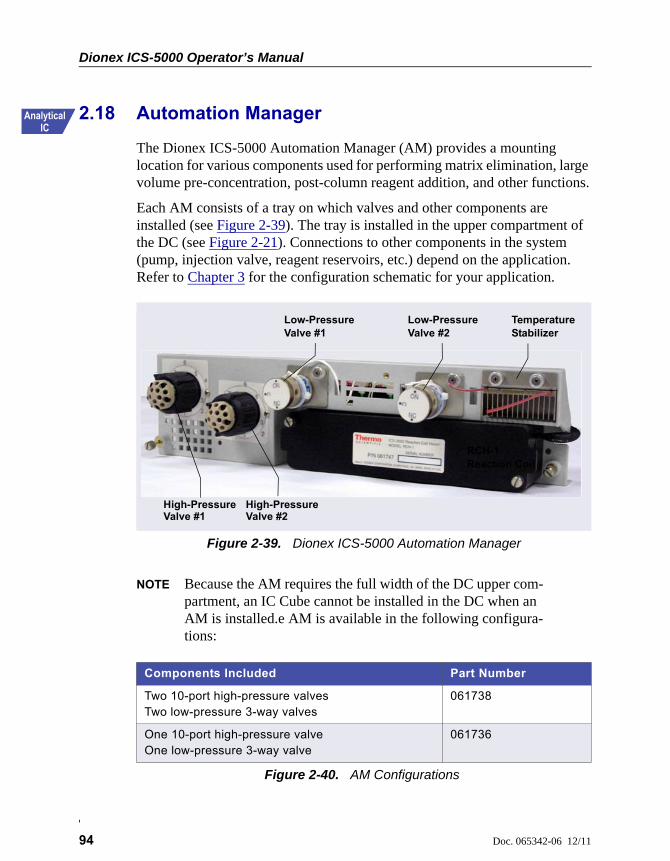
Dionex ICS-5000 Operator’s Manual
94 Doc. 065342-06 12/11
2.18 Automation Manager
The Dionex ICS-5000 Automation Manager (AM) provides a mounting location for various components used for performing matrix elimination, large volume pre-concentration, post-column reagent addition, and other functions.
Each AM consists of a tray on which valves and other components are installed (see Figure 2-39). The tray is installed in the upper compartment of the DC (see Figure 2-21). Connections to other components in the system (pump, injection valve, reagent reservoirs, etc.) depend on the application. Refer to Chapter 3 for the configuration schematic for your application.
NOTE Because the AM requires the full width of the DC upper com-partment, an IC Cube cannot be installed in the DC when an AM is installed.e AM is available in the following configura-tions:
Figure 2-39. Dionex ICS-5000 Automation Manager
Components Included Part Number
Two 10-port high-pressure valvesTwo low-pressure 3-way valves
061738
One 10-port high-pressure valve One low-pressure 3-way valve
061736
Figure 2-40. AM Configurations
RCH-1 Reaction Coil
Low-Pressure Valve #1
Low-Pressure Valve #2
Temperature Stabilizer
High-Pressure Valve #1
High-Pressure Valve #2
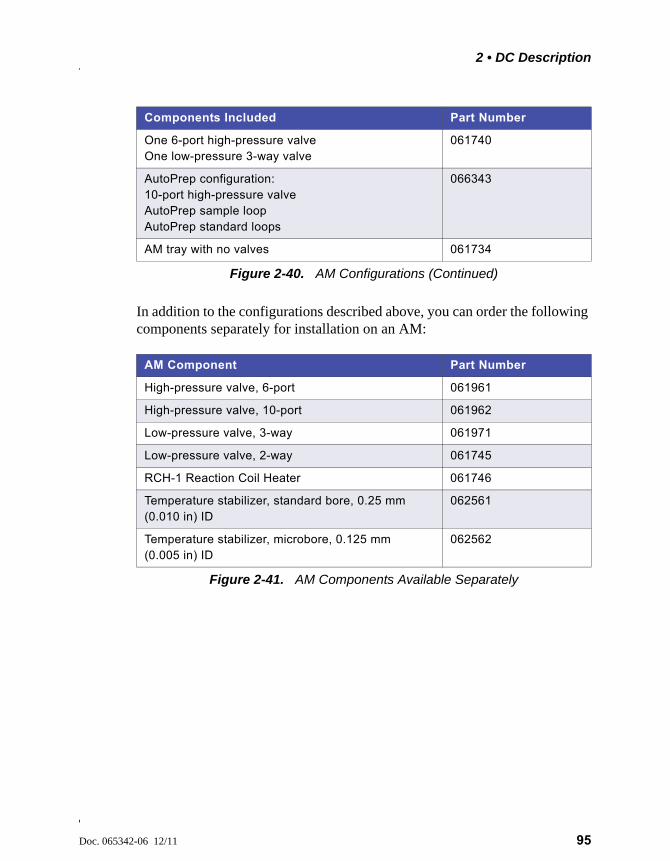
2 • DC Description
Doc. 065342-06 12/11 95
In addition to the configurations described above, you can order the following components separately for installation on an AM:
One 6-port high-pressure valveOne low-pressure 3-way valve
061740
AutoPrep configuration:10-port high-pressure valve AutoPrep sample loopAutoPrep standard loops
066343
AM tray with no valves 061734
AM Component Part Number
High-pressure valve, 6-port 061961
High-pressure valve, 10-port 061962
Low-pressure valve, 3-way 061971
Low-pressure valve, 2-way 061745
RCH-1 Reaction Coil Heater 061746
Temperature stabilizer, standard bore, 0.25 mm (0.010 in) ID
062561
Temperature stabilizer, microbore, 0.125 mm (0.005 in) ID
062562
Figure 2-41. AM Components Available Separately
Components Included Part Number
Figure 2-40. AM Configurations (Continued)
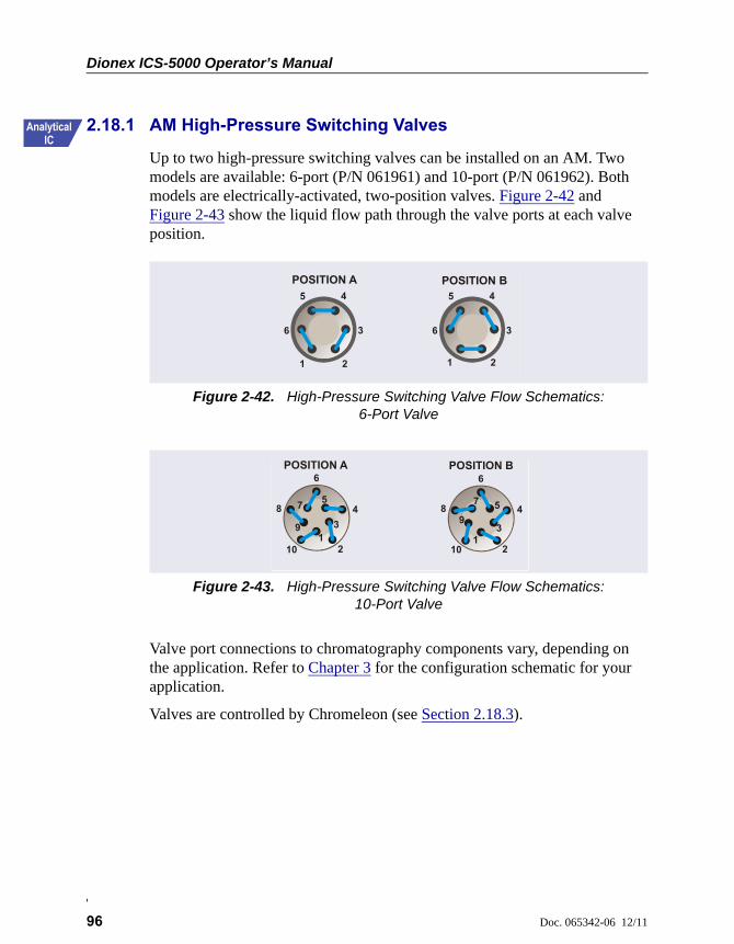
Dionex ICS-5000 Operator’s Manual
96 Doc. 065342-06 12/11
2.18.1 AM High-Pressure Switching Valves
Up to two high-pressure switching valves can be installed on an AM. Two models are available: 6-port (P/N 061961) and 10-port (P/N 061962). Both models are electrically-activated, two-position valves. Figure 2-42 and Figure 2-43 show the liquid flow path through the valve ports at each valve position.
Valve port connections to chromatography components vary, depending on the application. Refer to Chapter 3 for the configuration schematic for your application.
Valves are controlled by Chromeleon (see Section 2.18.3).
Figure 2-42. High-Pressure Switching Valve Flow Schematics: 6-Port Valve
Figure 2-43. High-Pressure Switching Valve Flow Schematics: 10-Port Valve
POSITION A POSITION B4
1
5
6
2
3
4
1
5
6
2
3
POSITION A POSITION B
13
57
9
2
4
6
8
101
3
57
9
6
2
48
10
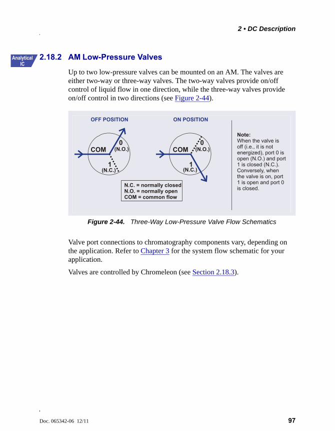
2 • DC Description
Doc. 065342-06 12/11 97
2.18.2 AM Low-Pressure Valves
Up to two low-pressure valves can be mounted on an AM. The valves are either two-way or three-way valves. The two-way valves provide on/off control of liquid flow in one direction, while the three-way valves provide on/off control in two directions (see Figure 2-44).
Valve port connections to chromatography components vary, depending on the application. Refer to Chapter 3 for the system flow schematic for your application.
Valves are controlled by Chromeleon (see Section 2.18.3).
Figure 2-44. Three-Way Low-Pressure Valve Flow Schematics
COM0
1
(N.O.)
(N.C.)
OFF POSITION
COM0
1
(N.O.)
(N.C.)
ON POSITION
N.C. = normally closedN.O. = normally openCOM = common flow
Note: When the valve is off (i.e., it is not energized), port 0 is open (N.O.) and port 1 is closed (N.C.). Conversely,
port 1 is open and port 0 is closed.
when the valve is on,
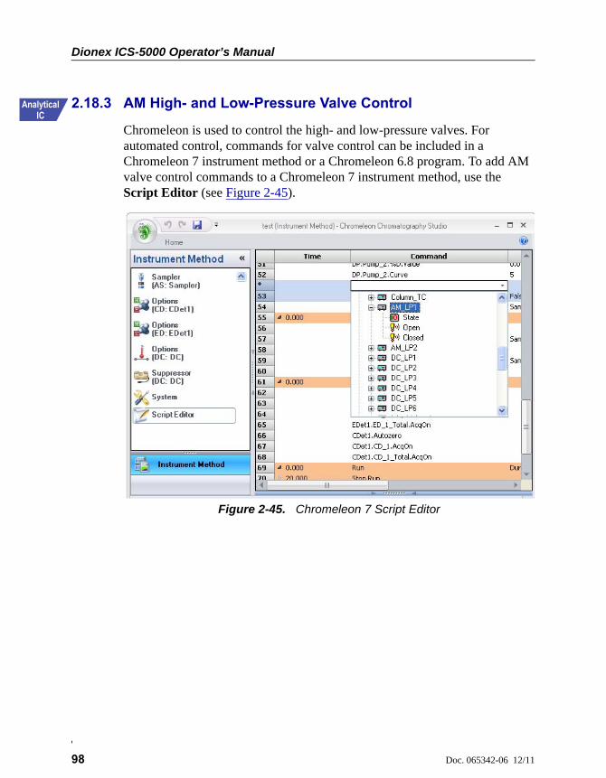
Dionex ICS-5000 Operator’s Manual
98 Doc. 065342-06 12/11
2.18.3 AM High- and Low-Pressure Valve Control
Chromeleon is used to control the high- and low-pressure valves. For automated control, commands for valve control can be included in a Chromeleon 7 instrument method or a Chromeleon 6.8 program. To add AM valve control commands to a Chromeleon 7 instrument method, use the Script Editor (see Figure 2-45).
Figure 2-45. Chromeleon 7 Script Editor
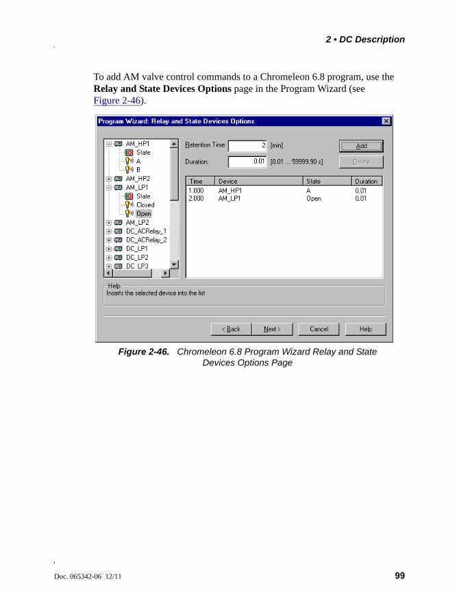
2 • DC Description
Doc. 065342-06 12/11 99
To add AM valve control commands to a Chromeleon 6.8 program, use the Relay and State Devices Options page in the Program Wizard (see Figure 2-46).
Figure 2-46. Chromeleon 6.8 Program Wizard Relay and State Devices Options Page
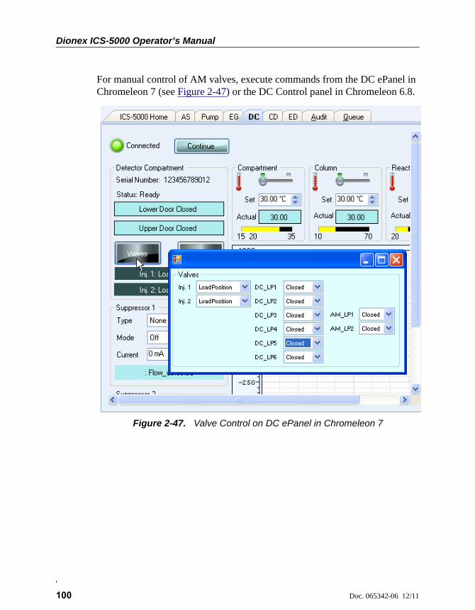
Dionex ICS-5000 Operator’s Manual
100 Doc. 065342-06 12/11
For manual control of AM valves, execute commands from the DC ePanel in Chromeleon 7 (see Figure 2-47) or the DC Control panel in Chromeleon 6.8.
Figure 2-47. Valve Control on DC ePanel in Chromeleon 7

2 • DC Description
Doc. 065342-06 12/11 101
2.18.4 RCH-1 Reaction Coil Heater
The RCH-1 Reaction Coil Heater (P/N 061746) can hold up to two reaction coils. The heater has an operating temperature range of from 5 °C above the temperature of the upper compartment up to 80 °C.
For automated control of the heater, commands can be included in a Chromeleon 7 instrument method (see Figure 2-48) or Chromeleon 6.8 program.
For direct control of the heater, use the controls on the DC ePanel in Chromeleon 7 or the Control panel in Chromeleon 6.8.
Figure 2-48. Instrument Wizard DC Options Page in Chromeleon 7
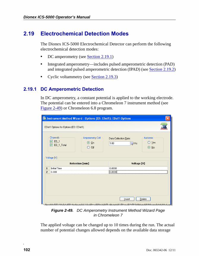
Dionex ICS-5000 Operator’s Manual
102 Doc. 065342-06 12/11
2.19 Electrochemical Detection Modes
The Dionex ICS-5000 Electrochemical Detector can perform the following electrochemical detection modes:
• DC amperometry (see Section 2.19.1)
• Integrated amperometry—includes pulsed amperometric detection (PAD) and integrated pulsed amperometric detection (IPAD) (see Section 2.19.2)
• Cyclic voltammetry (see Section 2.19.3)
2.19.1 DC Amperometric Detection
In DC amperometry, a constant potential is applied to the working electrode. The potential can be entered into a Chromeleon 7 instrument method (see Figure 2-49) or Chromeleon 6.8 program.
The applied voltage can be changed up to 10 times during the run. The actual number of potential changes allowed depends on the available data storage
Figure 2-49. DC Amperometry Instrument Method Wizard Page in Chromeleon 7
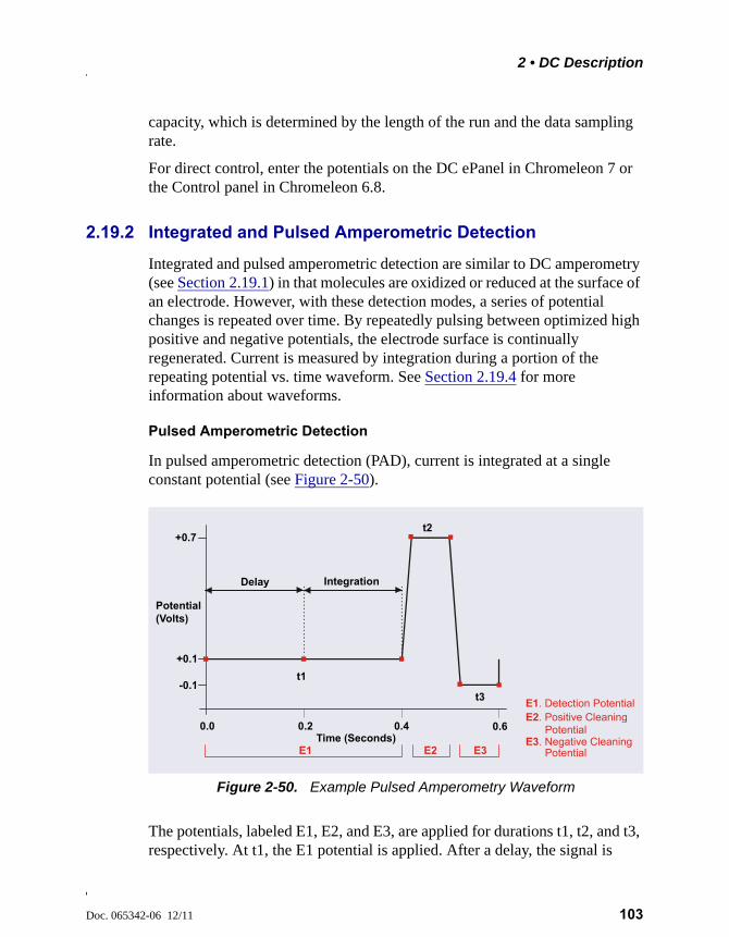
2 • DC Description
Doc. 065342-06 12/11 103
capacity, which is determined by the length of the run and the data sampling rate.
For direct control, enter the potentials on the DC ePanel in Chromeleon 7 or the Control panel in Chromeleon 6.8.
2.19.2 Integrated and Pulsed Amperometric Detection
Integrated and pulsed amperometric detection are similar to DC amperometry (see Section 2.19.1) in that molecules are oxidized or reduced at the surface of an electrode. However, with these detection modes, a series of potential changes is repeated over time. By repeatedly pulsing between optimized high positive and negative potentials, the electrode surface is continually regenerated. Current is measured by integration during a portion of the repeating potential vs. time waveform. See Section 2.19.4 for more information about waveforms.
Pulsed Amperometric Detection
In pulsed amperometric detection (PAD), current is integrated at a single constant potential (see Figure 2-50).
The potentials, labeled E1, E2, and E3, are applied for durations t1, t2, and t3, respectively. At t1, the E1 potential is applied. After a delay, the signal is
Figure 2-50. Example Pulsed Amperometry Waveform
Integration
Potential(Volts)
Time (Seconds)0.2 0.40.0 0.6
+0.1
+0.7
t1
t2
t3
Delay
-0.1
E1 E2 E3E3. Negative Cleaning
E2. Positive Cleaning E1. Detection Potential
Potential
Potential
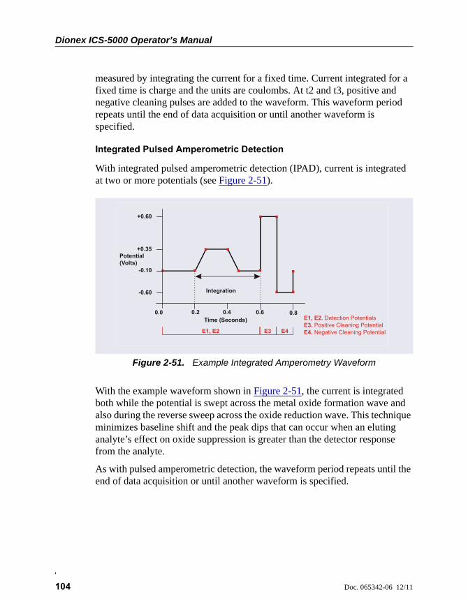
Dionex ICS-5000 Operator’s Manual
104 Doc. 065342-06 12/11
measured by integrating the current for a fixed time. Current integrated for a fixed time is charge and the units are coulombs. At t2 and t3, positive and negative cleaning pulses are added to the waveform. This waveform period repeats until the end of data acquisition or until another waveform is specified.
Integrated Pulsed Amperometric Detection
With integrated pulsed amperometric detection (IPAD), current is integrated at two or more potentials (see Figure 2-51).
With the example waveform shown in Figure 2-51, the current is integrated both while the potential is swept across the metal oxide formation wave and also during the reverse sweep across the oxide reduction wave. This technique minimizes baseline shift and the peak dips that can occur when an eluting analyte’s effect on oxide suppression is greater than the detector response from the analyte.
As with pulsed amperometric detection, the waveform period repeats until the end of data acquisition or until another waveform is specified.
Figure 2-51. Example Integrated Amperometry Waveform
Integration
Potential(Volts)
Time (Seconds)0.2 0 4 0.6 0.80.0
+0.35
-0.60
.
-0.10
+0.60
E3. Positive Cleaning PotentialE4. Negative Cleaning PotentialE1, E2 E3 E4
E1, E2. Detection Potentials
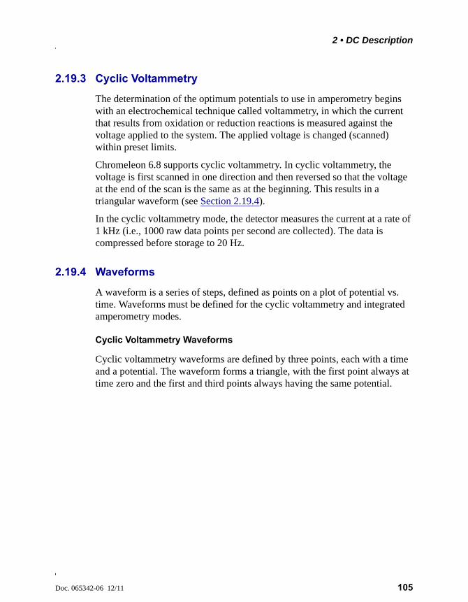
2 • DC Description
Doc. 065342-06 12/11 105
2.19.3 Cyclic Voltammetry
The determination of the optimum potentials to use in amperometry begins with an electrochemical technique called voltammetry, in which the current that results from oxidation or reduction reactions is measured against the voltage applied to the system. The applied voltage is changed (scanned) within preset limits.
Chromeleon 6.8 supports cyclic voltammetry. In cyclic voltammetry, the voltage is first scanned in one direction and then reversed so that the voltage at the end of the scan is the same as at the beginning. This results in a triangular waveform (see Section 2.19.4).
In the cyclic voltammetry mode, the detector measures the current at a rate of 1 kHz (i.e., 1000 raw data points per second are collected). The data is compressed before storage to 20 Hz.
2.19.4 Waveforms
A waveform is a series of steps, defined as points on a plot of potential vs. time. Waveforms must be defined for the cyclic voltammetry and integrated amperometry modes.
Cyclic Voltammetry Waveforms
Cyclic voltammetry waveforms are defined by three points, each with a time and a potential. The waveform forms a triangle, with the first point always at time zero and the first and third points always having the same potential.
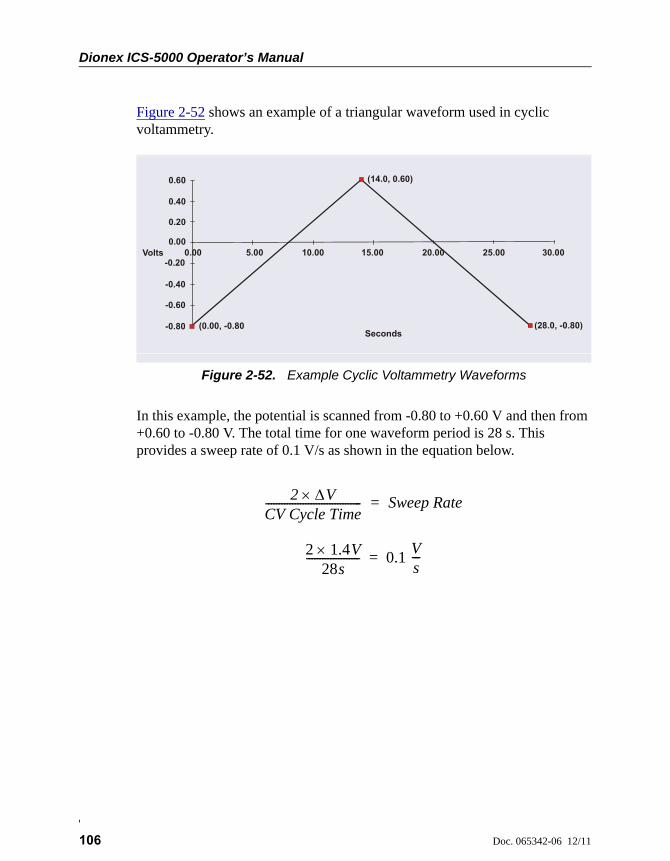
Dionex ICS-5000 Operator’s Manual
106 Doc. 065342-06 12/11
Figure 2-52 shows an example of a triangular waveform used in cyclic voltammetry.
In this example, the potential is scanned from -0.80 to +0.60 V and then from +0.60 to -0.80 V. The total time for one waveform period is 28 s. This provides a sweep rate of 0.1 V/s as shown in the equation below.
Figure 2-52. Example Cyclic Voltammetry Waveforms
Seconds
0.60
Volts
0.40
0.20
-0.20
-0.40
-0.60
-0.80
0.00 5.00 10.00 15.00 20.00 25.00 30.00
(28.0, -0.80)
(14.0, 0.60)
(0.00, -0.80
0.00
2 VCV Cycle Time------------------------------------ Sweep Rate=
2 1.4 V28s
-------------------- 0.1 Vs---=
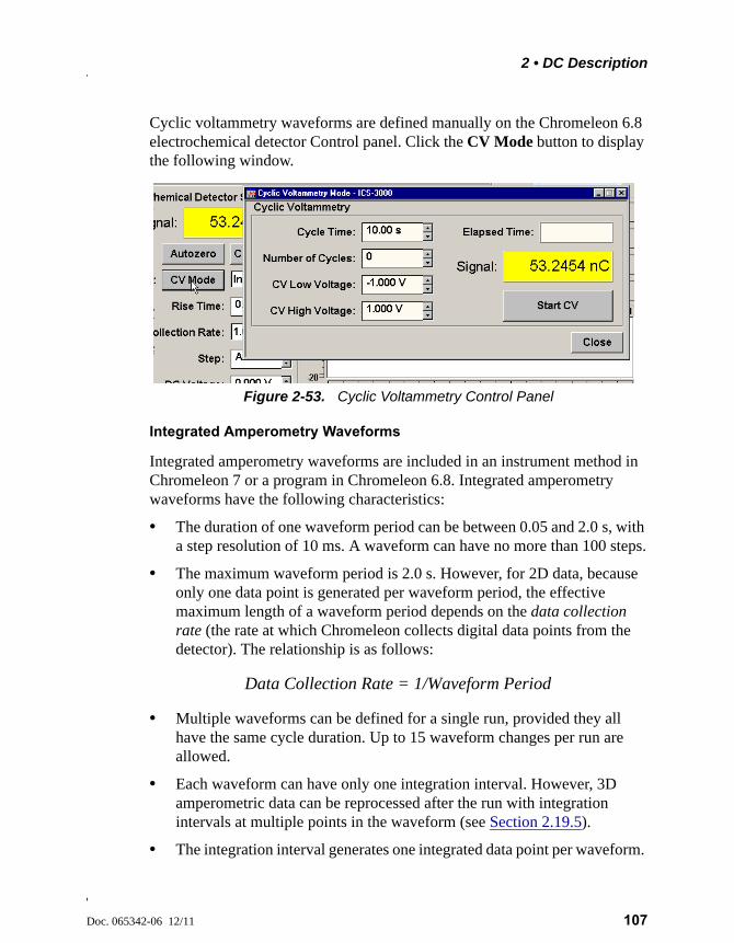
2 • DC Description
Doc. 065342-06 12/11 107
Cyclic voltammetry waveforms are defined manually on the Chromeleon 6.8 electrochemical detector Control panel. Click the CV Mode button to display the following window.
Integrated Amperometry Waveforms
Integrated amperometry waveforms are included in an instrument method in Chromeleon 7 or a program in Chromeleon 6.8. Integrated amperometry waveforms have the following characteristics:
• The duration of one waveform period can be between 0.05 and 2.0 s, with a step resolution of 10 ms. A waveform can have no more than 100 steps.
• The maximum waveform period is 2.0 s. However, for 2D data, because only one data point is generated per waveform period, the effective maximum length of a waveform period depends on the data collection rate (the rate at which Chromeleon collects digital data points from the detector). The relationship is as follows:
• Multiple waveforms can be defined for a single run, provided they all have the same cycle duration. Up to 15 waveform changes per run are allowed.
• Each waveform can have only one integration interval. However, 3D amperometric data can be reprocessed after the run with integration intervals at multiple points in the waveform (see Section 2.19.5).
• The integration interval generates one integrated data point per waveform.
Figure 2-53. Cyclic Voltammetry Control Panel
Data Collection Rate = 1/Waveform Period
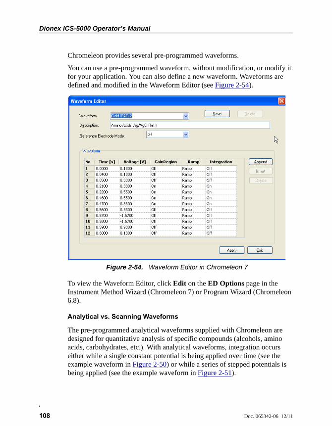
Dionex ICS-5000 Operator’s Manual
108 Doc. 065342-06 12/11
Chromeleon provides several pre-programmed waveforms.
You can use a pre-programmed waveform, without modification, or modify it for your application. You can also define a new waveform. Waveforms are defined and modified in the Waveform Editor (see Figure 2-54).
To view the Waveform Editor, click Edit on the ED Options page in the Instrument Method Wizard (Chromeleon 7) or Program Wizard (Chromeleon 6.8).
Analytical vs. Scanning Waveforms
The pre-programmed analytical waveforms supplied with Chromeleon are designed for quantitative analysis of specific compounds (alcohols, amino acids, carbohydrates, etc.). With analytical waveforms, integration occurs either while a single constant potential is being applied over time (see the example waveform in Figure 2-50) or while a series of stepped potentials is being applied (see the example waveform in Figure 2-51).
Figure 2-54. Waveform Editor in Chromeleon 7
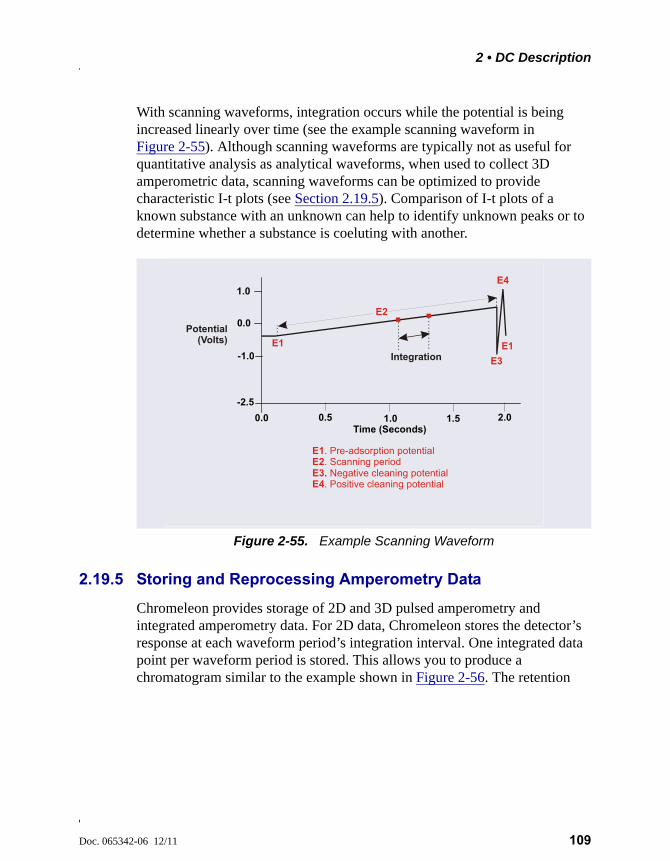
2 • DC Description
Doc. 065342-06 12/11 109
With scanning waveforms, integration occurs while the potential is being increased linearly over time (see the example scanning waveform in Figure 2-55). Although scanning waveforms are typically not as useful for quantitative analysis as analytical waveforms, when used to collect 3D amperometric data, scanning waveforms can be optimized to provide characteristic I-t plots (see Section 2.19.5). Comparison of I-t plots of a known substance with an unknown can help to identify unknown peaks or to determine whether a substance is coeluting with another.
2.19.5 Storing and Reprocessing Amperometry Data
Chromeleon provides storage of 2D and 3D pulsed amperometry and integrated amperometry data. For 2D data, Chromeleon stores the detector’s response at each waveform period’s integration interval. One integrated data point per waveform period is stored. This allows you to produce a chromatogram similar to the example shown in Figure 2-56. The retention
Figure 2-55. Example Scanning Waveform
1.0
-2.5
-1.0
1.0 2.00.5 1.5
0.0
0.0Time (Seconds)
E3. E4
Negative cleaning potential. Positive cleaning potential
E1E2
. Pre-adsorption potential
. Scanning period
Potential (Volts)
IntegrationE1
E2
E3
E4
E1
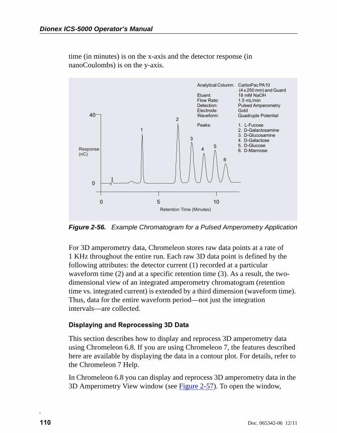
Dionex ICS-5000 Operator’s Manual
110 Doc. 065342-06 12/11
time (in minutes) is on the x-axis and the detector response (in nanoCoulombs) is on the y-axis.
For 3D amperometry data, Chromeleon stores raw data points at a rate of 1 KHz throughout the entire run. Each raw 3D data point is defined by the following attributes: the detector current (1) recorded at a particular waveform time (2) and at a specific retention time (3). As a result, the two-dimensional view of an integrated amperometry chromatogram (retention time vs. integrated current) is extended by a third dimension (waveform time). Thus, data for the entire waveform period—not just the integration intervals—are collected.
Displaying and Reprocessing 3D Data
This section describes how to display and reprocess 3D amperometry data using Chromeleon 6.8. If you are using Chromeleon 7, the features described here are available by displaying the data in a contour plot. For details, refer to the Chromeleon 7 Help.
In Chromeleon 6.8 you can display and reprocess 3D amperometry data in the 3D Amperometry View window (see Figure 2-57). To open the window,
Figure 2-56. Example Chromatogram for a Pulsed Amperometry Application
0
1
2
3
45
6
Minutes
0 5 10
40
Analytical Column: CarboPac PA10 and GuardEluent: 18 mM NaOHFlow Rate: 1.5 mL/minDetection: Pulsed AmperometryElectrode: Gold Waveform: Quadruple Potential
(4 x 250 mm)
Peaks: 1. L-Fucose2. D-Galactosamine3. D-Glucosamine4. D-Galactose5. D-Glucose6. D-Mannose
Retention Time (Minutes)
Response(nC)
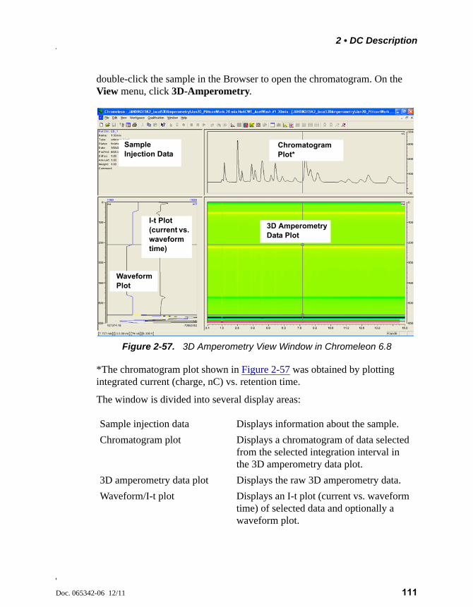
2 • DC Description
Doc. 065342-06 12/11 111
double-click the sample in the Browser to open the chromatogram. On the View menu, click 3D-Amperometry.
*The chromatogram plot shown in Figure 2-57 was obtained by plotting integrated current (charge, nC) vs. retention time.
The window is divided into several display areas:
Figure 2-57. 3D Amperometry View Window in Chromeleon 6.8
Sample injection data Displays information about the sample.
Chromatogram plot Displays a chromatogram of data selected from the selected integration interval in the 3D amperometry data plot.
3D amperometry data plot Displays the raw 3D amperometry data.
Waveform/I-t plot Displays an I-t plot (current vs. waveform time) of selected data and optionally a waveform plot.
I-t Plot (current vs. waveform time)
Chromatogram Plot*
Sample Injection Data
Waveform Plot
3D Amperometry Data Plot

Dionex ICS-5000 Operator’s Manual
112 Doc. 065342-06 12/11
In Chromeleon 6.8, the raw 3D amperometry data plot can be viewed as either an Iso or a 3D (wireframe) plot. For both plot types, colors are used to represent the ranges of response values.
The Iso view is the default view for the 3D raw data. This is a top down view of the data (imagine you are looking down on the data from above the plot) (see Figure 2-58). The x-axis is the retention time (min) and the y-axis is the waveform period (ms). The z-axis, which is represented by different colors in the plot, is the response (nA).
NOTE The 3D data shown in Figures 2-58 and 2-59 were collected using an analytical waveform (see “Analytical vs. Scanning Waveforms” on page 108).
To switch to the 3D plot view, right-click on the Iso plot, select Decoration and click the Iso/3D Plot tab. The 3D view projects the response values in the third dimension, which allows you to see the height of responses as well as the colors representing different magnitudes of detection signal along the z-axis
Figure 2-58. 3D Amperometry Data in Chromeleon 6.8: Iso View
retention time (min)
wav
efo
rm t
ime
(ms)
resp
onse
(nA
)
y
x
z
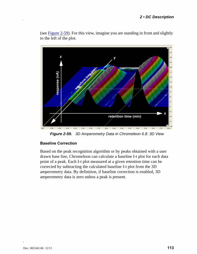
2 • DC Description
Doc. 065342-06 12/11 113
(see Figure 2-59). For this view, imagine you are standing in front and slightly to the left of the plot.
Baseline Correction
Based on the peak recognition algorithm or by peaks obtained with a user drawn base line, Chromeleon can calculate a baseline I-t plot for each data point of a peak. Each I-t plot measured at a given retention time can be corrected by subtracting the calculated baseline I-t plot from the 3D amperometry data. By definition, if baseline correction is enabled, 3D amperometry data is zero unless a peak is present.
Figure 2-59. 3D Amperometry Data in Chromeleon 6.8: 3D View
retention time (min)
wavef
orm ti
me
(ms)
res
po
ns
e (n
A)
z y
x

Dionex ICS-5000 Operator’s Manual
114 Doc. 065342-06 12/11
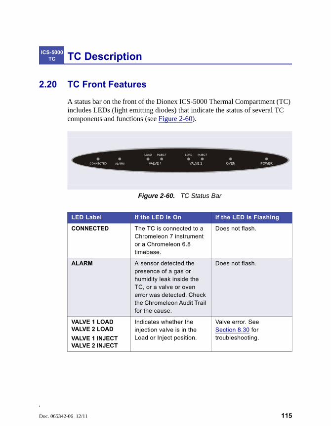
Doc. 065342-06 12/11 115
TC Description
2.20 TC Front Features
A status bar on the front of the Dionex ICS-5000 Thermal Compartment (TC) includes LEDs (light emitting diodes) that indicate the status of several TC components and functions (see Figure 2-60).
ICS-5000 TC
Figure 2-60. TC Status Bar
LED Label If the LED Is On If the LED Is Flashing
CONNECTED The TC is connected to a Chromeleon 7 instrument or a Chromeleon 6.8 timebase.
Does not flash.
ALARM A sensor detected the presence of a gas or humidity leak inside the TC, or a valve or oven error was detected. Check the Chromeleon Audit Trail for the cause.
Does not flash.
VALVE 1 LOADVALVE 2 LOAD
VALVE 1 INJECTVALVE 2 INJECT
Indicates whether the injection valve is in the Load or Inject position.
Valve error. See Section 8.30 for troubleshooting.
CONNECTED ALARM VALVE 1 VALVE 2 POWEROVEN
LOAD INJECT LOAD INJECT
Dionex ICS-5000 Operator’s Manual
116 Doc. 065342-06 12/11
NOTE The main power switch is on the TC rear panel (see Figure 2-62).
OVEN The TC is at its set temperature.
The TC is transitioning to the set temperature. The TC is not ready for operation.If the LED is flashing and the ALARM LED is lighted, an oven error has been detected. See Section 8.30 for troubleshooting.
POWER When the power is on, this LED is lighted.Use the POWER button on the front of the TC for routine on/off control. To turn on the TC, press the POWER button. To turn off the TC, press and hold the POWER button for 2 seconds.
Does not flash.
LED Label If the LED Is On If the LED Is Flashing

2 • TC Description
Doc. 065342-06 12/11 117
2.21 TC Interior Components
Figure 2-61 illustrates the interior of the TC. The components installed in your TC may vary, depending on your application.
Injection Valves
The TC can hold one or two electrically-actuated, high-pressure injection valves. Two valve models are available:
• A 2-position, 6-port Rheodyne TitanHP™ injection valve
• A 2-position, 10-port Rheodyne TitanHP™ injection valve
See Section 2.23 for details about the injection valves.
Column Brackets
The column brackets are installed in the TC at the factory. The TC can hold up to three columns with an inner diameter of 1 to 9 mm and a maximum length of 30 cm (11.8 in). Columns are attached to the brackets with special column clips (P/N 064786; set of six clips).
Figure 2-61. TC Interior View (Dual System Configuration Shown)
Separator Column
Column Brackets
Temperature Stabilizer
Slots for Column ID Chip Cards (A, B, C, and D)
Guard Column
Injection Valves
3
5
6
4
1
1
2
2
3
45
6

Dionex ICS-5000 Operator’s Manual
118 Doc. 065342-06 12/11
Temperature Stabilizers (Optional)
Installation of a temperature stabilizer (standard bore, P/N 064548; microbore, P/N 064650) ensures that (a) the temperature of the stationary phase remains constant over the total column length and (b) the column and the eluent have the same temperature during the analysis.
When these conditions are met, the analytical separation is performed at the nominal temperature. This minimizes fronting and tailing of peaks, as well as retention time variations.
Column ID Chip Card Slots
The TC column ID (identification) system lets you store column-specific information on a memory card and read the information at any time. Up to four column ID chip cards can be installed at the same time. The TC is shipped with two column ID chip cards (P/N 5710.1500). An optional Column ID Kit (P/N 066353) containing five chip cards is available.
See Section 2.24 for details about the column ID system.

2 • TC Description
Doc. 065342-06 12/11 119
2.22 TC Rear Panel
Figure 2-62 illustrates the rear panel of the TC.
Main Power Switch, Fuse Holder, and Power Receptacle
The rear panel power switch is the main power switch for the TC. Turn on the main power switch before initial operation, and leave the switch on unless instructed to turn it off (for example, before performing a service procedure).
NOTE For routine on/off control of the TC, use the POWER button on the front of the module. To turn off the TC, press and hold the POWER button for 2 seconds.
The fuse holder contains two 2-amp fuses (P/N 954776). For instructions on how to change the fuses, see Section 9.33.
The power cord plugs into the IEC 320 three-prong receptacle.
Figure 2-62. TC Rear Panel
USB Receptacle (“B” Connector)
Main Power Switch, Fuse Holder, and Power Receptacle
Digital I/O Connectors (2)
Drain Port
4
1
2 31
2 3 4
The power supply cord is used as the main disconnect device. Makesure the socket-outlet is located near the TC and is easily accessible.
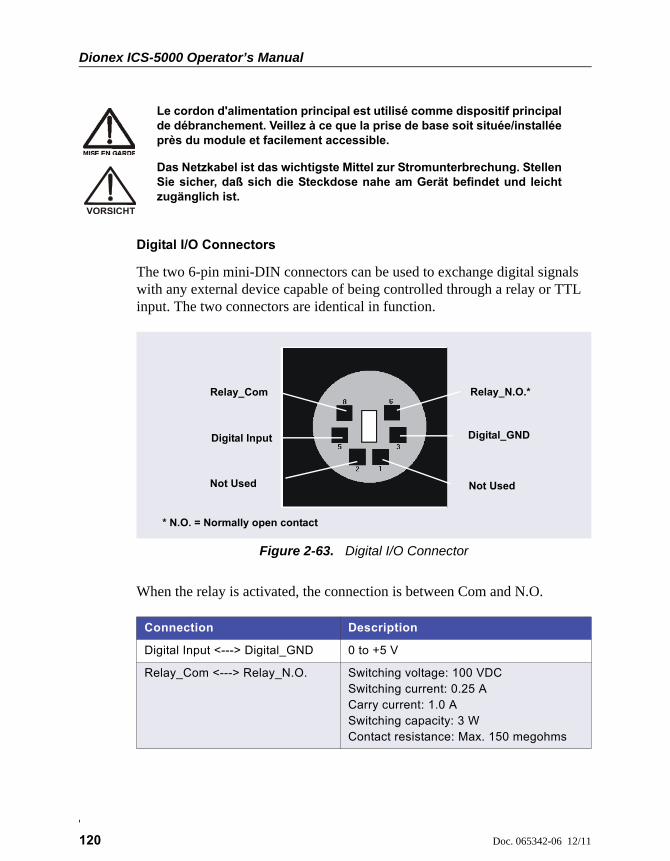
Dionex ICS-5000 Operator’s Manual
120 Doc. 065342-06 12/11
Digital I/O Connectors
The two 6-pin mini-DIN connectors can be used to exchange digital signals with any external device capable of being controlled through a relay or TTL input. The two connectors are identical in function.
When the relay is activated, the connection is between Com and N.O.
Le cordon d'alimentation principal est utilisé comme dispositif principalde débranchement. Veillez à ce que la prise de base soit située/installéeprès du module et facilement accessible.
Das Netzkabel ist das wichtigste Mittel zur Stromunterbrechung. StellenSie sicher, daß sich die Steckdose nahe am Gerät befindet und leichtzugänglich ist.
Figure 2-63. Digital I/O Connector
Connection Description
Digital Input <---> Digital_GND 0 to +5 V
Relay_Com <---> Relay_N.O. Switching voltage: 100 VDCSwitching current: 0.25 ACarry current: 1.0 ASwitching capacity: 3 WContact resistance: Max. 150 megohms
Relay_Com Relay_N.O.*
Not Used
Digital Input
Not Used
Digital_GND
* N.O. = Normally open contact
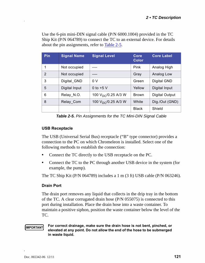
2 • TC Description
Doc. 065342-06 12/11 121
Use the 6-pin mini-DIN signal cable (P/N 6000.1004) provided in the TC Ship Kit (P/N 064789) to connect the TC to an external device. For details about the pin assignments, refer to Table 2-5.
USB Receptacle
The USB (Universal Serial Bus) receptacle (“B” type connector) provides a connection to the PC on which Chromeleon is installed. Select one of the following methods to establish the connection:
• Connect the TC directly to the USB receptacle on the PC.
• Connect the TC to the PC through another USB device in the system (for example, the pump).
The TC Ship Kit (P/N 064789) includes a 1 m (3 ft) USB cable (P/N 063246).
Drain Port
The drain port removes any liquid that collects in the drip tray in the bottom of the TC. A clear corrugated drain hose (P/N 055075) is connected to this port during installation. Place the drain hose into a waste container. To maintain a positive siphon, position the waste container below the level of the TC.
Pin Signal Name Signal Level Core Color
Core Label
1 Not occupied ---- Pink Analog High
2 Not occupied ---- Gray Analog Low
3 Digital_GND 0 V Green Digital GND
5 Digital Input 0 to +5 V Yellow Digital Input
6 Relay_N.O. 100 VDC/0.25 A/3 W Brown Digital Output
8 Relay_Com 100 VDC/0.25 A/3 W White Dig./Out (GND)
Black Shield
Table 2-5. Pin Assignments for the TC Mini-DIN Signal Cable
For correct drainage, make sure the drain hose is not bent, pinched, orelevated at any point. Do not allow the end of the hose to be submergedin waste liquid.

Dionex ICS-5000 Operator’s Manual
122 Doc. 065342-06 12/11
2.23 Injection Valves
The TC is available in the following configurations:
2.23.1 Injection Valve Operation
The 6-port injection valve has two operating positions: Load and Inject. Liquid flows through either the Load or Inject path, depending on the valve position.
Figure 2-64 shows flow schematics for the 6-port valve.
• In the Load position, sample is loaded into the sample loop, where it is held until injection. Eluent flows from the pump, through the valve, and to the column, bypassing the sample loop. Sample flows from the syringe
TC Description Part Number
TC with no injection valves 074108
TC with one 2-position, 6-port high-pressure injection valve 074109
TC with two 2-position, 6-port high-pressure injection valves 074112
TC with one 2-position, 6-port high-pressure injection valve and one 2-position, 10-port high-pressure injection valve(The 6-port valve is installed on the left side of the module.)
074113
Figure 2-64. TC Injection Valve Flow Schematics (6-Port Valve)
L (4)
S (5)S (5)
W (6)W (6)
To WasteTo WasteSample InSample In
To ColumnTo ColumnFrom PumpFrom Pump
LOAD POSITION INJECT POSITION
= Sample = Eluent
L (4)
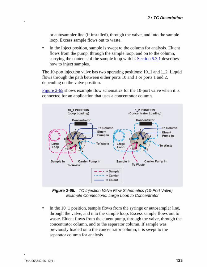
2 • TC Description
Doc. 065342-06 12/11 123
or autosampler line (if installed), through the valve, and into the sample loop. Excess sample flows out to waste.
• In the Inject position, sample is swept to the column for analysis. Eluent flows from the pump, through the sample loop, and on to the column, carrying the contents of the sample loop with it. Section 5.3.1 describes how to inject samples.
The 10-port injection valve has two operating positions: 10_1 and 1_2. Liquid flows through the path between either ports 10 and 1 or ports 1 and 2, depending on the valve position.
Figure 2-65 shows example flow schematics for the 10-port valve when it is connected for an application that uses a concentrator column.
• In the 10_1 position, sample flows from the syringe or autosampler line, through the valve, and into the sample loop. Excess sample flows out to waste. Eluent flows from the eluent pump, through the valve, through the concentrator column, and to the separator column. If sample was previously loaded onto the concentrator column, it is swept to the separator column for analysis.
Figure 2-65. TC Injection Valve Flow Schematics (10-Port Valve)Example Connections: Large Loop to Concentrator
1
3
57
9
10_1 POSITION(Loop Loading)
To Waste
Eluent Pump In
To Column
Sample In
To Waste
Concentrator
LargeLoop
Carrier Pump In
1_2 POSITION(Concentrator Loading)
To Waste
Eluent Pump In
To Column
Sample In
To Waste
Concentrator
Carrier Pump In
= Sample
= Carrier
= Eluent
LargeLoop
2
4
6
8
10 13
57
9
2
4
6
8
10
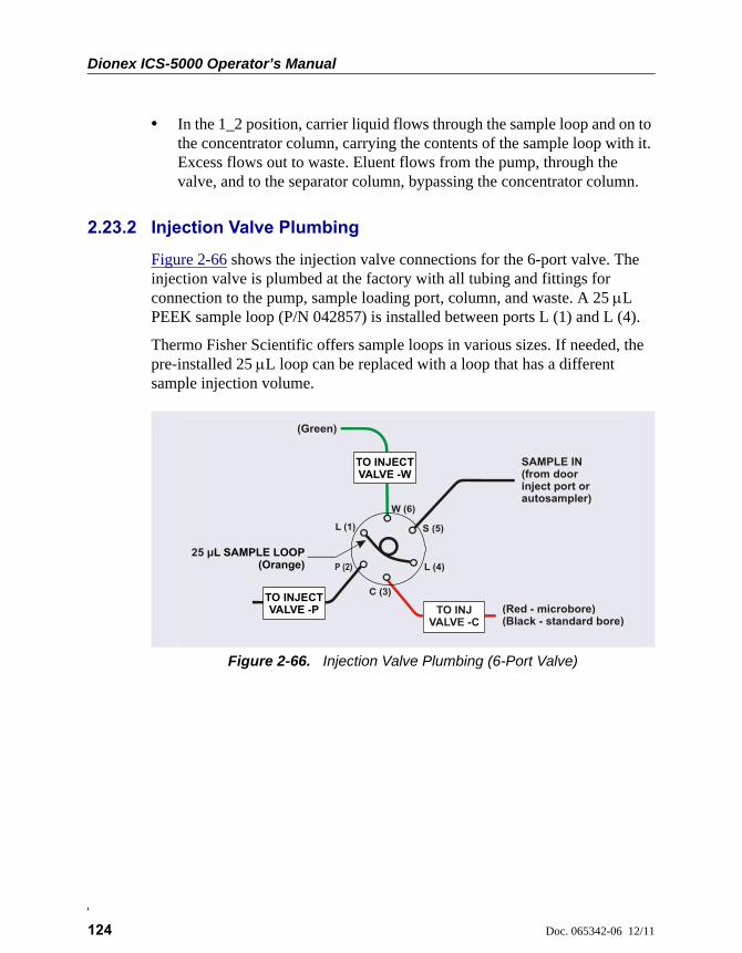
Dionex ICS-5000 Operator’s Manual
124 Doc. 065342-06 12/11
• In the 1_2 position, carrier liquid flows through the sample loop and on to the concentrator column, carrying the contents of the sample loop with it. Excess flows out to waste. Eluent flows from the pump, through the valve, and to the separator column, bypassing the concentrator column.
2.23.2 Injection Valve Plumbing
Figure 2-66 shows the injection valve connections for the 6-port valve. The injection valve is plumbed at the factory with all tubing and fittings for connection to the pump, sample loading port, column, and waste. A 25 L PEEK sample loop (P/N 042857) is installed between ports L (1) and L (4).
Thermo Fisher Scientific offers sample loops in various sizes. If needed, the pre-installed 25 L loop can be replaced with a loop that has a different sample injection volume.
Figure 2-66. Injection Valve Plumbing (6-Port Valve)
SAMPLE IN(from door inject port or autosampler)
(Green)
(Red - microbore)(Black - standard bore)
TO INJECT VALVE -P
TO INJECT VALVE -W
TO INJ VALVE -C
25 μL SAMPLE LOOP(Orange) L (4)
S (5)
W (6)
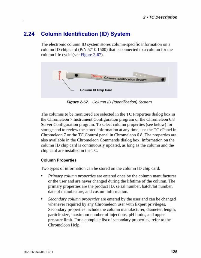
2 • TC Description
Doc. 065342-06 12/11 125
2.24 Column Identification (ID) System
The electronic column ID system stores column-specific information on a column ID chip card (P/N 5710.1500) that is connected to a column for the column life cycle (see Figure 2-67).
The columns to be monitored are selected in the TC Properties dialog box in the Chromeleon 7 Instrument Configuration program or the Chromeleon 6.8 Server Configuration program. To select column properties (see below) for storage and to review the stored information at any time, use the TC ePanel in Chromeleon 7 or the TC Control panel in Chromeleon 6.8. The properties are also available in the Chromeleon Commands dialog box. Information on the column ID chip card is continuously updated, as long as the column and the chip card are installed in the TC.
Column Properties
Two types of information can be stored on the column ID chip card:
• Primary column properties are entered once by the column manufacturer or the user and are never changed during the lifetime of the column. The primary properties are the product ID, serial number, batch/lot number, date of manufacture, and custom information.
• Secondary column properties are entered by the user and can be changed whenever required by any Chromeleon user with Expert privileges. Secondary properties include the column manufacturer, diameter, length, particle size, maximum number of injections, pH limits, and upper pressure limit. For a complete list of secondary properties, refer to the Chromeleon Help.
Figure 2-67. Column ID (Identification) System
Column ID Chip Card
Dionex ICS-5000 Operator’s Manual
126 Doc. 065342-06 12/11
2.25 Gas and Humidity Sensors
The TC contains two sensors to detect any gas or humidity that may accumulate inside the TC. When a certain concentration of gas or humidity is reached (while the door is closed), the following events occur:
• The corresponding sensor is activated.
• The ALARM LED on the front of the TC lights (red), and remains red as long as the sensor is exposed to gases or humidity.
• The error is logged in the Chromeleon Audit Trail.
• A beep sounds.
What to do when an alarm occurs:
1. Find and eliminate the leak.
2. If you are using Chromeleon 7: Open the Commands dialog box (press the F8 key). Select the TC and click the Commands tab. Click the ClearAlarmLED button.
3. If you are using Chromeleon 6.8: On the TC Control panel, click the Clear Alarm button.
4. Ventilate the interior of the TC thoroughly before closing the door and resuming operation.
Adjusting the Sensor Sensitivity
Follow these steps to change the sensitivity setting of the gas or humidity sensor, or to turn off a sensor:
1. Open the Chromeleon 7 ePanel Set or the Chromeleon 6.8 panel tabset.
2. Press the F8 key to open the Commands dialog box.
3. Select the TC.
4. If you are using Chromeleon 7: Click the Parameters tab page for the TC, click the GasLeakSensor or HumidityLeakSensor parameter. Select the new sensitivity setting (or select Off to disable the sensor).
5. If you are using Chromeleon 6.8, click the plus sign beside TC to display the items underneath. Under TC_Temp, select the GasLeakSensor or
2 • TC Description
Doc. 065342-06 12/11 127
HumidityLeakSensor parameter. Select the new sensitivity setting (or select Off to disable the sensor) and click Execute.
2.26 TC Theory of Operation
The fundamental requirement for a thermal compartment intended for chromatography applications is the ability to maintain the preset temperature as precisely as possible. The TC contains advanced electronic circuitry that maintains the selected temperature with a precision of ±0.1 °C.
The TC can be heated from 5 to 85 °C in 0.1 °C increments. An increase in temperature from 20 to 50 °C (or a decrease from 50 to 20 °C) is typically realized in less than 20 minutes. Columns can be warmed up to 85 °C. If the ambient temperature changes during the analysis, increased heating or cooling ensures that the column temperature remains constant.
The thermo-optimized design of the TC reduces the time required to equilibrate the temperature between the column and the eluent. Peltier elements in the TC heat up and cool down the columns. They also help to bring the air and all of the installed components (including the injection valves) to the selected temperature.
If necessary, a temperature stabilizer (standard bore, P/N 064548; microbore, P/N 064650) can be installed in the TC. Installation of a temperature stabilizer ensures that:
• The stationary phase temperature remains constant over the total column length.
• The column and the eluent have the same temperature during the analysis.
Under these conditions, the separation is performed at the nominal temperature. This minimizes fronting and tailing of peaks, as well as retention time variations.
Operating IC columns at temperatures above 70 °C (158 °F) may affectcolumn performance. Before selecting the TC temperature, refer to thecolumn manual for the recommended operating conditions. Columnmanuals are provided on the Thermo Scientific Reference Library DVD(P/N 053891).
Dionex ICS-5000 Operator’s Manual
128 Doc. 065342-06 12/11
The temperature achieved may vary from the control range, depending on the ambient temperature (see the table below).
For example, if the ambient air temperature in the lab is 30 °C and you set the temperature to 5 °C, the actual temperature achieved will be about 12 °C.
2.26.1 Predictive Performance
The Predictive Performance feature of the TC provides various functions for estimating the lifetime of replaceable parts and for planning and recording service and qualification procedures.
A partial list of the TC Predictive Performance functions is provided below. Refer to the Chromeleon Help for details.
• Monitoring of the total cooling and heating workload performed by the compartment and the total operating hours since initial operation
• Monitoring of the injection valve usage
• Reminders for service and qualification periods, including display of warning messages when limits are approaching or overdue
Predictive Performance commands and parameters are available in the Chromeleon Commands dialog box.
Control Range Achieved Temperatures (Based on Ambient)
5 to 85 °C Minimum temperature 18 °C below ambientMaximum temperature 70 °C above ambient
Do not touch any metal parts inside the TC while it is heating up or afterit reaches the set point temperature. Wait for the compartment to cooldown before servicing any parts.
Ne touchez à aucune des pièces métalliques à l'intérieur du TC pendantqu'il chauffe ou après qu'il ait atteint la température de consigne.Attendez que le compartiment soit refroidi avant de réparer les pièces.
Berühren Sie im TC keine metallischen Teile, während diesesaufgeheizt wird oder nachdem die Solltemperatur erreicht ist. WartenSie, bis die Kammer abgekühlt ist, ehe Sie Wartungsarbeitendurchführen.
Doc. 065342-06 12/11 129
3 • Configurations
3.1 Overview
This chapter provides example component and plumbing drawings for the following Dionex ICS-5000 system configurations:
Dionex ICS-5000 IC System Configuration See
Capillary IC: Dual RFIC-EG System (CD/CD) page 130
Capillary IC: Dual RFIC-EG System (CD/ED) page 131
Hybrid System: Dual RFIC-EG System (CD Analytical/CD Capillary)
page 132
Analytical IC: Single System without EG (CD) page 133
Analytical IC: Single RFIC-EG System (CD) page 134
Analytical IC: Dual RFIC-EG System (CD/CD) page 135
Analytical IC: Dual RFIC-EG System (CD/ED) page 136
Analytical IC: Single RFIC-EG System with Matrix Elimination Using a DP and a 6-Port Valve
page 137
Analytical IC: Single RFIC-EG System with Matrix Elimination Using an SP and a 10-Port Valve
page 138
Analytical IC: Single RFIC-EG System with Post-Column Reagent Addition (Bromate)
page 139
Analytical IC: Single RFIC-EG System with ED and VP (for Carbohydrate Analysis)
page 140
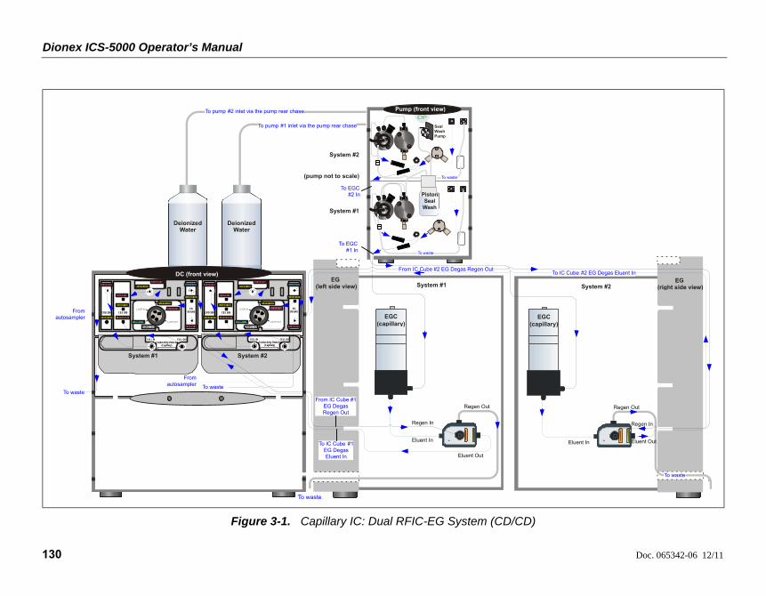
Dionex ICS-5000 Operator’s Manual
130 Doc. 065342-06 12/11
Figure 3-1. Capillary IC: Dual RFIC-EG System (CD/CD)
Pump (front view)To pump #2 inlet via the pump rear chase
DeionizedWater
To pump #1 inlet via the pump rear chase
DeionizedWater
DC (front view)EG
(right side view)EG
(left side view)
To waste
System #1 System #2
System #1
System #2
Eluent In
Eluent Out
Regen In
Regen Out
EGC (capillary)
(pump not to scale)
CRD 200
EGDEGAS
ELUENT IN
ELUENT IN
ELUENT OUT
ELUENT OUT
REGEN IN
CES 300
ELUENT IN
ELUENT OUT
ELUENT IN
REGEN OUT
ELUENT OUT
SAMPLE IN
SAMPLE OUT
ELUENT IN
ELUENT OUT
Conductivity Detector(Capillary)
CELL IN CELL OUT
CRD 200
EGDEGAS
ELUENT IN
ELUENT IN
ELUENT OUT
ELUENT OUT
REGEN IN
CES 300
ELUENT IN
ELUENT OUT
ELUENT IN
REGEN OUT
ELUENT OUT
SAMPLE IN
SAMPLE OUT
ELUENT IN
ELUENT OUT
Conductivity Detector(Capillary)
CELL IN CELL OUT
From IC Cube #1 EG Degas Regen Out
To IC Cube #1 EG Degas Eluent In
Piston Seal
Wash
Seal WashPump
To EGC #1 In
To waste
Eluent In Eluent Out
Regen In
Regen Out
To IC Cube #2 EG Degas Eluent In
EGC (capillary)
From IC Cube #2 EG Degas Regen Out
From autosampler
To waste
From autosampler To waste
System #1 System #2
To EGC #2 In
To waste
To waste
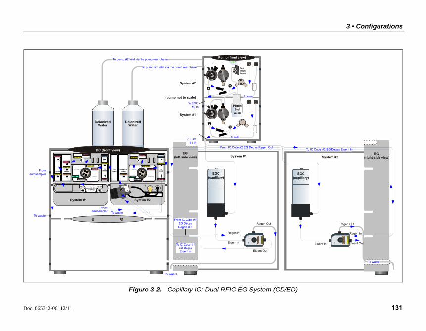
3 • Configurations
Doc. 065342-06 12/11 131
Figure 3-2. Capillary IC: Dual RFIC-EG System (CD/ED)
Pump (front view)
Piston Seal
Wash
Seal WashPump
To waste
To waste
To pump #2 inlet via the pump rear chase
DeionizedWater
To pump #1 inlet via the pump rear chase
DeionizedWater
DC (front view)
CRD BYPASS
EGDEGAS
REGEN IN
SUPPRESSORBYPASS
ELUENT IN
ELUENT OUT
ELUENT IN
REGEN OUT
ELUENT OUT
SAMPLE IN
SAMPLE OUT
ELUENT IN
ELUENT OUT
IN
OUTEC CELL
EG (right side view)
EG (left side view)
To waste
System #1 System #2
System #1
System #2
Eluent In
Eluent Out
Regen In
Regen Out
EGC (capillary)
(pump not to scale)
CRD 200
EGDEGAS
ELUENT IN
ELUENT IN
ELUENT OUT
ELUENT OUT
REGEN IN
CES 300
ELUENT IN
ELUENT OUT
ELUENT IN
REGEN OUT
ELUENT OUT
SAMPLE IN
SAMPLE OUT
ELUENT IN
ELUENT OUT
Conductivity Detector(Capillary)
CELL IN CELL OUT
From IC Cube #1 EG Degas Regen Out
To IC Cube #1 EG Degas Eluent In
To EGC #1 In
To EGC #2 In
To waste
Eluent In Eluent Out
Regen In
Regen Out
To IC Cube #2 EG Degas Eluent In
EGC (capillary)
From IC Cube #2 EG Degas Regen Out
From autosampler
To waste
From autosampler To waste
System #1 System #2
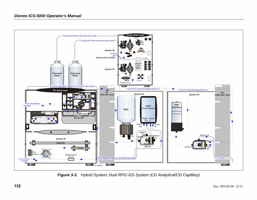
Dionex ICS-5000 Operator’s Manual
132 Doc. 065342-06 12/11
Figure 3-3. Hybrid System: Dual RFIC-EG System (CD Analytical/CD Capillary)
Pump (front view)To pump #2 inlet via the pump rear chase
DeionizedWater
To pump #1 inlet via the pump rear chase
DeionizedWater
DC (front view)EG
(right side view)EG
(left side view) System #1 System #2
System #1
System #2
(pump not to scale)
CRD 200
EGDEGAS
ELUENT IN
ELUENT IN
ELUENT OUT
ELUENT OUT
REGEN IN
CES 300
ELUENT IN
ELUENT OUT
ELUENT IN
REGEN OUT
ELUENT OUT
SAMPLE IN
SAMPLE OUT
ELUENT IN
ELUENT OUT
Conductivity Detector(Capillary)
CELL IN CELL OUT
Piston Seal
Wash
Seal WashPump
Eluent In Eluent Out
Regen In
Regen Out
EGC (capillary)
From autosamplerTo waste
System #1
System #2
To EGC #2 In
Separator
Temp. Stabilizer
(1)
L
L
S
W
P
C
(2)
(3)
(4)(5)
(6)
To waste
Guard
From autosampler
Eluent In Regen In
Regen Out Eluent Out
Cell In Cell Out
Backpressure Device
From the suppressor Regen Out via the DC rear chase
EL
UE
NT
OU
T
RE
GE
NIN
CR-TC
Eluent Out
Eluent In
Regen Out
Regen In
Eluent In
Eluent Out
Regen In
Regen Out
EGC
In Out
To waste
To the degasser Regen In via the EG rear chase
A B
CD
A
B
C
D
Mixer To waste
To EGC #1 In
To waste
To waste
From the IC Cube EG Degas Regen OutTo the IC Cube EG Degas Eluent In
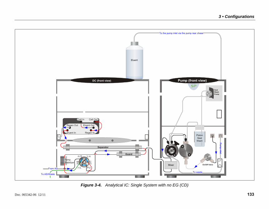
3 • Configurations
Doc. 065342-06 12/11 133
Figure 3-4. Analytical IC: Single System with no EG (CD)
To the pump inlet via the pump rear chase
DC (front view)
Eluent In Regen In
Regen Out Eluent Out
Cell In Cell Out
Separator
Temp. Stabilizer
(1)
L
L
S
W
P
C
(2)
(3)
(4)(5)
(6)
To AS/Waste
Guard
From AS
Pump (front view)
Pum
p inlet
On/Off Valve
Seal WashPump
To waste
Piston SealWash
Mixer
Eluent
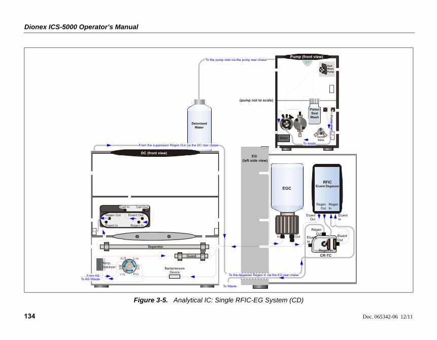
Dionex ICS-5000 Operator’s Manual
134 Doc. 065342-06 12/11
Figure 3-5. Analytical IC: Single RFIC-EG System (CD)
Pump (front view)To the pump inlet via the pump rear chase
EG (left side view)
DC (front view)
To Waste
EL
UE
NT
OU
T
RE
GE
NIN
From the suppressor Regen Out via the DC rear chase
Pum
pinlet
On/Off Valve
Seal WashPump
To waste
Eluent In Regen In
Regen Out Eluent Out
Cell In Cell Out
Separator
Temp. Stabilizer
(1)
L
L
S
W
P
C
(2)
(3)
(4)(5)
(6)
To AS /Waste
Guard
From AS
Mixer
Backpressure Device
Piston Seal
Wash
(pump not to scale)
To the degasser Regen In via the EG rear chase
CR-TC
Eluent Out
Eluent In
Regen Out
Regen In
Eluent In
Eluent Out
Regen In
Regen Out
Deionized Water
EGC
In Out
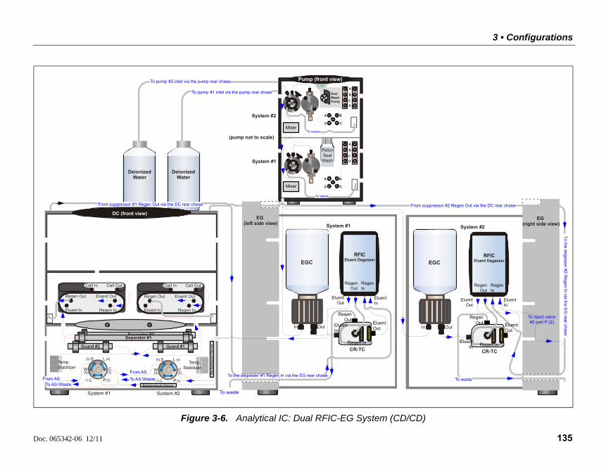
3 • Configurations
Doc. 065342-06 12/11 135
Figure 3-6. Analytical IC: Dual RFIC-EG System (CD/CD)
Pump (front view)To pump #2 inlet via the pump rear chase
To pump #1 inlet via the pump rear chase
EG (right side view)
EG (left side view)
To waste
System #1 System #2
DeionizedWater
DeionizedWater
System #1
System #2
To waste
DC (front view)
(1)
L
L
S
W
P
C
(2)
(3)
(4)(5)
(6)
(1)
L
L
S
W
P
C
(2)
(3)
(4)(5)
(6)
System #1 System #2
From suppressor #2 Regen Out via the DC rear chase
To
thedega
sser#2
Rege
nIn
viathe
EG
rearchase
From suppressor #1 Regen Out via the DC rear chase
A B
CD
A
B
C
D
A B
CD
A
B
C
D
To waste
To waste
Seal WashPump
Temp. Stabilizer
To AS /Waste
Separator #2Separator #1
Guard #2
Eluent In Regen In
Regen Out Eluent Out
Cell In Cell Out
Eluent In Regen In
Regen Out Eluent Out
Cell In Cell Out
Temp. Stabilizer
Eluent Out
Eluent Out
Mixer
Mixer
To AS /WasteFrom AS
Guard #1
From AS
Backpressure Device
Ba
ckp
ress
ure
Dev
ice
Piston SealWash
(pump not to scale)
To the degasser #1 Regen In via the EG rear chase
EL
UE
NT
OU
T
RE
GE
NIN
Eluent In
CR-TC
Eluent Out
Eluent In
Regen Out
Regen In
EL
UE
NT
OU
T
RE
GE
NIN
CR-TC
Eluent Out
Eluent In
Regen Out
Regen In
Regen In
Regen Out
Regen In
Regen Out
To inject valve #2 port P (2)
Eluent In
EGC
In Out
EGC
In Out
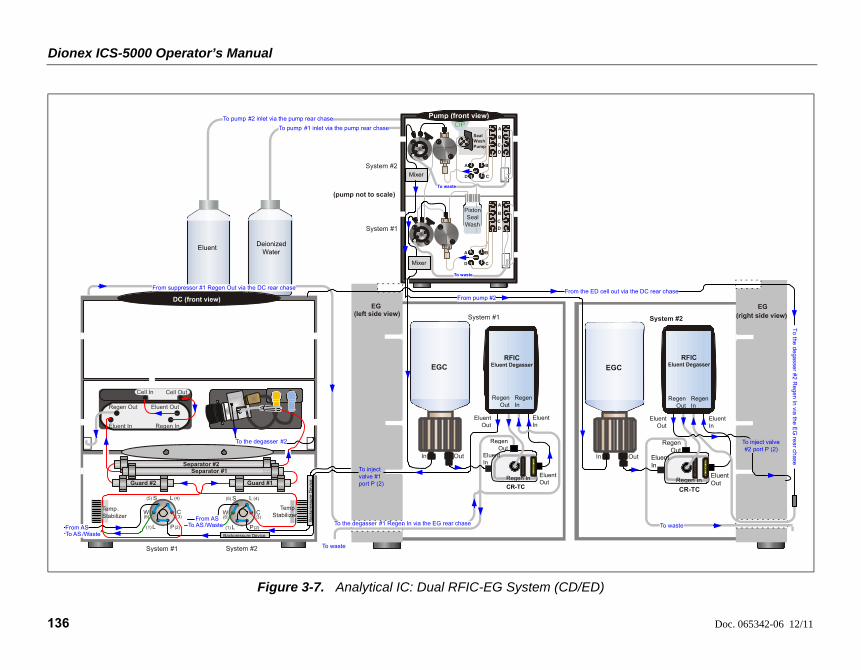
Dionex ICS-5000 Operator’s Manual
136 Doc. 065342-06 12/11
Figure 3-7. Analytical IC: Dual RFIC-EG System (CD/ED)
To pump #2 inlet via the pump rear chase
To pump #1 inlet via the pump rear chase
Pump (front view)
EG (left side view)
To waste
System #1
System #1
System #2
DC (front view)
(1)
L
L
S
W
P
C
(2)
(3)
(4)(5)
(6)
(1)
L
L
S
W
P
C
(2)
(3)
(4)(5)
(6)
From AS
From suppressor #1 Regen Out via the DC rear chase
A B
CD
A
B
C
D
A B
CD
A
B
C
D
To waste
Mixing Chamber
To waste
Mixing Chamber
Seal WashPump
Eluent In Regen In
Regen Out Eluent Out
Cell In Cell Out
System #1 System #2
To inject valve #1 port P (2)
Temp. Stabilizer
To AS /Waste
From ASTo AS /Waste
Temp. Stabilizer
Separator #2Separator #1
Guard #2 Guard #1
Deionized Water
Mixer
Mixer
Backpressure Device
Eluent
Piston Seal
Wash
(pump not to scale)
To the degasser #1 Regen In via the EG rear chase
EGC
In Out
Eluent Out
CR-TC
EL
UE
NT
OU
T
RE
GE
NIN
Regen Out
Eluent In
Regen In
Eluent In
Eluent Out
Regen In
Regen Out
Ba
ckp
ress
ure
Dev
ice
EG (right side view)System #2
To waste
Eluent Out
EL
UE
NT
OU
T
RE
GE
NIN
CR-TC
Eluent Out
Eluent In
Regen Out
Regen In
Eluent In
EGC
In Out
From pump #2From the ED cell out via the DC rear chase
To
thed
ega
sser#
2R
ege
nIn
viathe
EG
rea
rch
ase
Regen In
Regen Out
To inject valve #2 port P (2)
To the degasser #2

3 • Configurations
Doc. 065342-06 12/11 137
Figure 3-8. Analytical IC: Single RFIC-EG System with Matrix Elimination Using a DP and a 6-Port Valve
To pump #2 inlet via the pump rear chase
To pump #1 inlet (A) via the pump rear chase
DeionizedWater
DeionizedWater
Pump (front view)
Pu
mp
inle
t
On/Off Valve
A B
CD
A
B
C
D
To waste
To waste
Seal WashPump
Mixer
Mixer
EG (left side view)
DC (front view)
To Waste
From the suppressor Regen Out via the DC rear chase
Eluent In Regen In
Regen Out Eluent Out
Cell In Cell Out
Separator
Temp. Stabilizer
(1)
L
L
S
W
P
C
(2)
(3)
(4)(5)
(6)
To AS /Waste
Guard
Large Loop
(carrier)
Pump #1
Pump #2
To
AS
/Waste To inject valve sample port
1 2
3
45
6
From
AS
Backpressure Device
Piston SealWash
(pump not to scale)
To the degasser Regen In via the EG rear chase
CR-TC
EL
UE
NT
OU
T
RE
GE
NIN
EGC
In Out
Eluent In
Eluent Out
Regen In
Regen Out
Regen Out
Eluent Out
Eluent In
Regen In
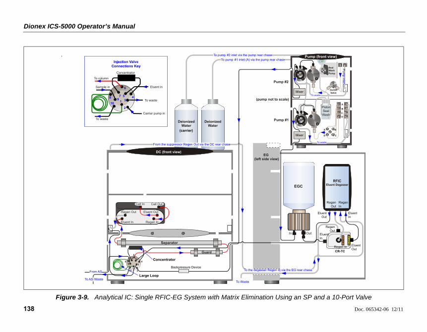
Dionex ICS-5000 Operator’s Manual
138 Doc. 065342-06 12/11
Figure 3-9. Analytical IC: Single RFIC-EG System with Matrix Elimination Using an SP and a 10-Port Valve
To pump #2 inlet via the pump rear chase
To pump #1 inlet (A) via the pump rear chase
DeionizedWater
DeionizedWater
(carrier)
EG (left side view)
To Waste
DC (front view)
Concentrator
Large Loop
From the suppressor Regen Out via the DC rear chase
10 2
4
6
8
1
3
57
9
From AS
To AS /Waste
Guard
Eluent In Regen In
Regen Out Eluent Out
Cell In Cell Out
Separator
Injection Valve Connections Key
3
Carrier pump in
To waste
2
1
To waste
10
8
Concentrator
7 4
Sample in
95
Eluent in6
To column
Pump (front view)
Pu
mp
inle
t
On/Off Valve
A B
CD
A
B
C
D
To waste
To waste
Seal WashPump
Mixer
Mixer
Pump #1
Pump #2
Backpressure Device
Piston SealWash
(pump not to scale)
To the degasser Regen In via the EG rear chase
CR-TC
EL
UE
NT
OU
T
RE
GE
NIN
Eluent In
Eluent Out
Regen In
Regen Out
EGC
In Out
Eluent In
Eluent Out
Regen In
Regen Out
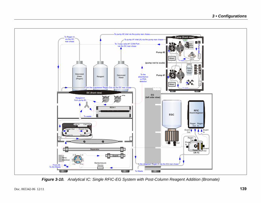
3 • Configurations
Doc. 065342-06 12/11 139
Figure 3-10. Analytical IC: Single RFIC-EG System with Post-Column Reagent Addition (Bromate)
To pump #2 inlet via the pump rear chase
To Regen In via the DC rear chase
To pump #1 inlet (A) via the pump rear chase
EG (left side view)
To Waste
DC (front view)
N.C.CO N.O.
RCH-1
Reagent in from pump #2
M
plug
To waste
N.C.
COMN.O.
Temp. Stabilizer
(1)
L
L
S
W
P
C
(2)
(3)
(4)(5)
(6)
To AS /WasteFrom AS
Eluent In Regen In
Regen Out Eluent Out
Cell In Cell Out
Separator
Guard
Deionized Water
(Regen)Reagent
Deionized Water
Pump (front view)
Pum
pinlet
On/Off Valve
A B
CD
A
B
C
D
To waste
To waste
Seal WashPump
Mixer
Pump #1
Pump #2
Mixer
To 3-way valve #1 COM Port via the DC rear chase
From the suppressor Regen Out via the DC rear chase
Backpressure Device
Piston SealWash
(pump not to scale)
To the degasser Regen In via the EG rear chase
CR-TC
EL
UE
NT
OU
T
RE
GE
NIN
Eluent In
Eluent Out
Regen In
Regen Out
Regen Out
Eluent Out
Eluent In
Regen In
EGC
In Out
To the absorbance
or PDA detector
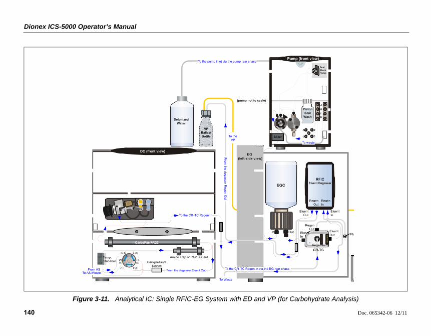
Dionex ICS-5000 Operator’s Manual
140 Doc. 065342-06 12/11
Figure 3-11. Analytical IC: Single RFIC-EG System with ED and VP (for Carbohydrate Analysis)
Pump (front view)To the pump inlet via the pump rear chase
EG (left side view)
DC (front view)
To Waste
EL
UE
NT
OU
T
RE
GE
NIN
Seal WashPump
To waste
Temp. Stabilizer
(1)
L
L
S
W
P
C
(2)
(3)
(4)(5)
(6)
To AS /WasteFrom the degasser Eluent OutFrom AS
Mixer
Backpressure Device
Piston Seal
Wash
(pump not to scale)
To the CR-TC Regen In via the EG rear chase
CR-TC
Eluent Out
Eluent In
Regen Out
Regen In
Eluent In
Eluent Out
EGC
In Out
A B
CD
A
B
C
DDeionized
Water
Regen In
Regen Out
CarboPac PA20
Amino Trap or PA20 Guard
To the VP
From
the
de
gasse
rR
ege
nO
ut
VPBallastBottle
Plu
To the CR-TC Regen In

Doc. 065342-06 12/11 141
4 • Startup
This section is an overview of the steps required to start up the Dionex ICS-5000 system components and prepare the system to run samples. The operating parameters (flow rate, compartment temperature, suppressor current, etc.) depend on the application you plan to run. Refer to the column manual, as well as the schematics in Chapter 3 of this manual, for the required operating parameters.
NOTE Before beginning operation, be sure to perform any special startup procedures required for the columns, suppressors, etc. Startup procedures are described in the quick start guides and manuals provided on the Thermo Scientific Reference Library DVD (P/N 053891).
4.1 Operating Precautions
4.1.1 EG Operating Precautions
In an analytical IC system, the EGC requires at least 14 MPa (2000 psi) of system backpressure. This ensures optimal removal of electrolysis gas from the eluent produced by the cartridge.
During system equilibration, monitor the Current Pressure reading on the Pump panel in Chromeleon; the pressure should remain between 14 and 21 MPa (2000 and 3000 psi). If necessary, increase the system backpressure by installing a backpressure coil between the injection valve and the ELUENT
OUT port on the EGC. For instructions, refer to Section 9.17.
The recommended maximum operating pressure for the EG in ananalytical IC system is 21 MPa (3000 psi). Excessive backpressure mayrupture the tubing inside the RFIC Eluent Degasser.
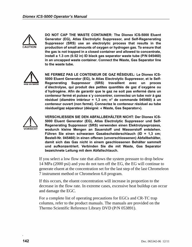
Dionex ICS-5000 Operator’s Manual
142 Doc. 065342-06 12/11
If you select a low flow rate that allows the system pressure to drop below 14 MPa (2000 psi) and you do not turn off the EG, the EG will continue to generate eluent at the concentration set for the last step of the last Chromeleon 7 instrument method or Chromeleon 6.8 program.
If this occurs, the eluent concentration will increase in proportion to the decrease in the flow rate. In extreme cases, excessive heat buildup can occur and damage the EGC.
For a complete list of operating precautions for EGCs and CR-TC trap columns, refer to the product manuals. The manuals are provided on the Thermo Scientific Reference Library DVD (P/N 053891).
DO NOT CAP THE WASTE CONTAINER: The Dionex ICS-5000 EluentGenerator (EG), Atlas Electrolytic Suppressor, and Self-RegeneratingSuppressor (SRS) use an electrolytic process that results in theproduction of small amounts of oxygen or hydrogen gas. To ensure thatthe gas is not trapped in a closed container and allowed to concentrate,install a 1.3 cm (0.52 in) ID black gas separator waste tube (P/N 045460)in an uncapped waste container. Connect the Waste, Gas Separator lineto the waste tube.
NE FERMEZ PAS LE CONTENEUR DE GAZ RÉSIDUEL: Le Dionex ICS-5000 Eluent Generator (EG), le Atlas Electrolytic Suppressor, et le Self-Regenerating Suppressor (SRS) travaillent avec un procesd´électrolyse, qui produit des petites quantités de gaz d´oxygène oud´hydrogène. Afin de garantir que le gaz ne soit pas enfermé dans unconteneur fermé et puisse s´y concentrer, connectez un tube noir à gazrésiduel (diamètre intérieur = 1,3 cm; n° de commande 045460) à unconteneur ouvert (non fermé). Connectez le conteneur résiduel au tuberésiduel/gaz séparateur (désigné: « Waste, Gas Separator»).
VERSCHLIESSEN SIE DEN ABFALLBEHÄLTER NICHT: Der Dionex ICS-5000 Eluent Generator (EG), Atlas Electrolytic Suppressor und Self-Regenerating Suppressor (SRS) verwenden einen Elektrolyseprozess,wodurch kleine Mengen an Sauerstoff und Wasserstoff entstehen.Führen Sie einen schwarzen Gasabscheiderschlauch (ID = 1,3 cm;Bestell-Nr. 045460) in einen offenen (unverschlossenen) Abfallbehälter,damit sich das Gas nicht in einem geschlossenen Behälter sammeltund aufkonzentriert. Verbinden Sie die mit Waste, Gas Separatorbezeichnete Leitung mit dem Abfallschlauch.
4 • Startup
Doc. 065342-06 12/11 143
4.1.2 ED Cell Operating Precautions
To maintain good reproducibility of detection results:
• Prepare all eluents with ASTM Type I (18 megohm-cm) filtered and deionized water that meets the specifications listed in Section 1.5.
• Avoid contamination of the cell with incompatible eluents.
• Never apply potential to the electrode unless a stream of eluent or water is flowing through the cell.
• Do not allow a pH-Ag/AgCl reference electrode to dry out. Make sure that eluent is pumped continuously through the cell. If the cell will not be used for a short time (less than 2 days), disconnect the tubing from the inlet and outlet fittings and all fitting plugs. For longer shutdowns, see Section 6.4.
• Be careful to keep the polished surface of the ED cell body clean and dry when not in use. The gold, spring-loaded (pogo) contact must also remain clean and dry. If a salt bridge forms, it can cause an electrical short between the working electrode contact and the cell body.
• If the conventional (nondisposable) working electrode becomes discolored or if you notice a degradation in performance (baseline noise, tailing peaks, etc.), polish the electrode as instructed in Section 9.28.4.
• Over the lifetime of the conventional working electrode, the surface may gradually become pitted or receded. Receded electrodes can be repaired by sanding with 600 grit sandpaper. Continue sanding until the metal surface is again flush with the Kel-F electrode block surface. Then, polish the electrode (see Section 9.28.4).
• To help determine when the pH-Ag/AgCl reference electrode needs regenerating or replacing, monitor the pH value displayed on the detector panel in Chromeleon (see page 144).
• To have an alarm displayed in the Audit Trail if the pH exceeds certain values, set pH limits in Chromeleon (see page 145).
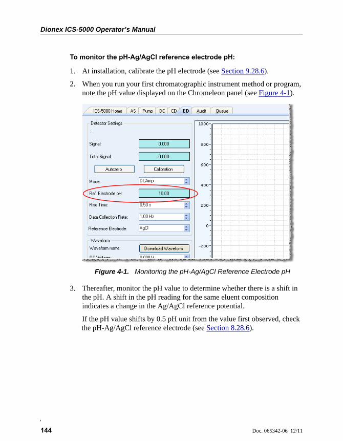
Dionex ICS-5000 Operator’s Manual
144 Doc. 065342-06 12/11
To monitor the pH-Ag/AgCl reference electrode pH:
1. At installation, calibrate the pH electrode (see Section 9.28.6).
2. When you run your first chromatographic instrument method or program, note the pH value displayed on the Chromeleon panel (see Figure 4-1).
3. Thereafter, monitor the pH value to determine whether there is a shift in the pH. A shift in the pH reading for the same eluent composition indicates a change in the Ag/AgCl reference potential.
If the pH value shifts by 0.5 pH unit from the value first observed, check the pH-Ag/AgCl reference electrode (see Section 8.28.6).
Figure 4-1. Monitoring the pH-Ag/AgCl Reference Electrode pH

4 • Startup
Doc. 065342-06 12/11 145
To set ED cell pH limits:
You can set upper and lower pH limits in the Chromeleon 7 Instrument Method Wizard (see Figure 4-2) or Chromeleon 6.8 Program Wizard. The Audit Trail displays an alarm if the limits are exceeded.
NOTE To disable the alarm, set the upper limit to 14 and the lower limit to 0.
Figure 4-2. Setting pH Limits in Chromeleon 7
Dionex ICS-5000 Operator’s Manual
146 Doc. 065342-06 12/11
4.2 System Startup Checklist
Prepare the samples (see page 147)
Fill the autosampler vials and load the sample tray (see page 149)
Start Chromeleon (see page 149)
Set up the eluent reservoirs (see page 153)
Set up the piston seal wash system (see page 154)
Start the pump (see page 157)
Set the pressure limits (see page 158)
If an EG is installed, start the EG and set the eluent concentration (see page 161)
Start the DC (see page 165) or TC (see page 169)
Equilibrate the system and verify operational readiness (DC: see page 166; TC: see page 170)
NOTE You can use the Smart Startup feature in Chromeleon to auto-mate system startup and equilibration. Refer to the Chrome-leon Help for details.
4 • Startup
Doc. 065342-06 12/11 147
4.3 Preparing Samples
This section provides basic information about collecting, storing, and preparing samples for analysis.
NOTE Sample preparation can be performed while the system is equilibrating.
4.3.1 Collecting and Storing Samples
Collect samples in high density polyethylene, polystyrene, or polycarbonate containers that have been thoroughly cleaned with ASTM Type I (18 megohm-cm) filtered and deionized water that meets the specifications listed in Section 1.5. Do not clean containers with strong acids or detergents because these can leave traces of ions on the container walls. The ions may interfere with the analysis.
If samples will not be analyzed on the day they are collected, filter them through clean 0.45 micron filters immediately after collection; otherwise, bacteria in the samples may cause the ionic concentrations to change over time. Refrigerating the samples at 4C (39 F) will reduce, but not eliminate, bacterial growth.
Analyze samples containing nitrite or sulfite as soon as possible. Nitrite oxidizes to nitrate, and sulfite to sulfate, thus increasing the measured concentrations of these ions in the sample. In general, samples that do not contain nitrite or sulfite can be refrigerated for at least one week with no significant change in anion concentration.
4.3.2 Pretreating Samples
Analyze rainwater, drinking water, and air particulate leach solutions directly with no sample preparation (other than filtering and if required, diluting).
Filter groundwater and wastewater samples through 0.45 micron filters before injection, unless samples were filtered after collection.
A Low-Volume High-Pressure Inline Filter (P/N 074505) is available for removing particulates down to 0.45 micron from samples. Connect the inline filter between the autosampler outlet and the sample inlet port on the injection valve. For details, see the instructions provided with the inline filter.
Dionex ICS-5000 Operator’s Manual
148 Doc. 065342-06 12/11
Before injection, pretreat samples that may contain high concentrations of interfering substances by putting them through Thermo Scientific Dionex OnGuard™ cartridges. Refer to the installation and troubleshooting guide for the Dionex OnGuard cartridge for instructions. The guide is located on the Thermo Scientific Reference Library DVD (P/N 053891).
4.3.3 Diluting Samples
Because the concentrations of ionic species in different samples can vary widely from sample to sample, no single dilution factor can be recommended for all samples of one type. In some cases (for example, many water samples), concentrations are so low that dilution is not necessary.
To dilute the sample, use eluent or ASTM Type I (18 megohm-cm) filtered and deionized water that meets the specifications listed in Section 1.5. When using carbonate eluents, diluting with eluent minimizes the effect of the water dip at the beginning of the chromatogram. If you dilute the sample with eluent, also use eluent from the same lot to prepare the calibration standards. This is most important for fluoride and chloride, which elute near the water dip.
To improve the accuracy of early eluting peak determinations, such as fluoride, at concentrations below 50 ppb, dilute samples in eluent or spike the samples with concentrated eluent to minimize the water dip. For example, spike a 100 mL sample with 1.0 mL of a 100 X eluent concentrate.
4 • Startup
Doc. 065342-06 12/11 149
4.3.4 Filling the Autosampler Vials and Loading the Sample Tray
Follow the instructions in the autosampler manual to fill the vials or well plates and load them into the sample tray or carousel. The autosampler manuals are included on the Thermo Scientific Reference Library DVD (P/N 053891).
4.4 Starting Chromeleon 7
4.4.1 Starting the Chromeleon 7 Instrument Controller Service
To start the Chromeleon 7 Instrument Controller Service, right-click the Chromeleon tray icon (which is crossed out in red) and click Start Chromeleon Instrument Controller. The icon changes to gold to indicate that the Instrument Controller Service is starting. When the Instrument Controller Service is running (idle), the icon changes to gray .
If the Chromeleon Tray Icon is not on the taskbar, click Start > All Programs > Chromeleon 7 > Services Manager to open the Services Manager and click Start Instrument Controller.
4.4.2 Starting the Chromeleon 7 Client
1. To start the Chromeleon 7 client, click Start > All Programs > Chromeleon 7 > Chromeleon 7.
2. To display the Chromeleon 7 ePanel Set, click the Instruments category bar on the Console. Click your instrument in the Navigation Pane. Chromeleon 7 connects to the instrument and displays the ePanel Set (see Figure 4-3). The ePanel Set opens to the Home panel by default. This panel displays basic status information for each instrument in the system.

Dionex ICS-5000 Operator’s Manual
150 Doc. 065342-06 12/11
In addition, a limited number of device functions can be controlled directly from this panel. You can also access the Audit Trail from here
4.5 Starting Chromeleon 6.8
4.5.1 Starting the Chromeleon 6.8 Server
To start the Chromeleon 6.8 Server, right-click the Chromeleon Server Monitor icon (which is crossed out in red) on the Windows taskbar and click Start Server. The icon changes to gold to indicate that the Chromeleon Server is starting. When the Chromeleon Server is running (idle), the icon changes to gray .
If the Server Monitor icon is not on the Windows taskbar, click Start > All Programs > Chromeleon > Server Monitor to open the Server Monitor and click Start.
Figure 4-3. Example Chromeleon 7 ePanel Set
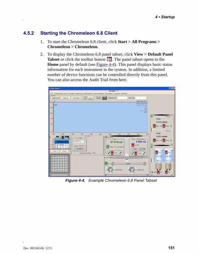
4 • Startup
Doc. 065342-06 12/11 151
4.5.2 Starting the Chromeleon 6.8 Client
1. To start the Chromeleon 6.8 client, click Start > All Programs > Chromeleon > Chromeleon.
2. To display the Chromeleon 6.8 panel tabset, click View > Default Panel Tabset or click the toolbar button . The panel tabset opens to the Home panel by default (see Figure 4-4). This panel displays basic status information for each instrument in the system. In addition, a limited number of device functions can be controlled directly from this panel. You can also access the Audit Trail from here.
Figure 4-4. Example Chromeleon 6.8 Panel Tabset

Dionex ICS-5000 Operator’s Manual
152 Doc. 065342-06 12/11

Doc. 065342-06 12/11 153
DP/SP Startup
4.6 Setting Up the Eluent Reservoirs
1. Rinse the eluent reservoirs with ASTM Type I (18 megohm-cm) filtered and deionized water.
NOTE Always use ASTM Type I (18 megohm-cm) filtered and deionized water that meets the specifications listed in Section 1.5 to prepare eluent and regenerant or to rinse eluent reservoirs.
2. If an EG is not installed, prepare the eluent for the application. For instructions, refer to the manual for the column. Column manuals are provided on the Thermo Scientific Reference Library DVD (P/N 053891).
3. Fill the reservoirs with prepared eluent or deionized water (if an EG is installed).
4. Locate the end-line filters (P/N 045987) provided in the pump ship kit:
Before installation, thoroughly rinse the end-line filter with ASTM Type I (18 megohm-cm) filtered and deionized water to remove any loose particles.
5. Install an end-line filter on the end of each reservoir’s eluent line.
6. Install the reservoir caps, making sure the end of each line extends to the bottom of the reservoir, and that each filter is submerged in liquid. This prevents air from being drawn through the eluent lines. Hand-tighten the caps.
ICS-5000 DP/SP
Pump Ship Kit Part Number
DP Ship Kit Dual Capillary 072112
DP Ship Kit Dual Analytical 062463
DP Ship Kit Capillary and Analytical 072111
SP Ship Kit Capillary or Analytical 063342

Dionex ICS-5000 Operator’s Manual
154 Doc. 065342-06 12/11
NOTE A High-Pressure Inline Filter (P/N 044105) can be used to remove particulates down to 0.45 micron from eluent. Connect the inline filter between the pump out-let and the eluent inlet port on the injection valve. For details, see the instructions provided with the inline filter.
4.7 Setting Up the Piston Seal Wash System
Replumbing the Seal Wash System (DP only) (Optional)
The standard piston seal wash system is designed for use with only one of the two pumps in a DP module. When the DP is shipped from Thermo Fisher Scientific, the seal wash system is connected to pump 1 (the bottom pump). If you want to connect the seal wash system to pump 2 (the top pump), follow the instructions in this section.
NOTE For users who need to operate a piston seal wash system for both pumps in the DP, Thermo Fisher Scientific offers an External Seal Wash Kit (P/N 063518) or a second seal wash system (P/N 068661).
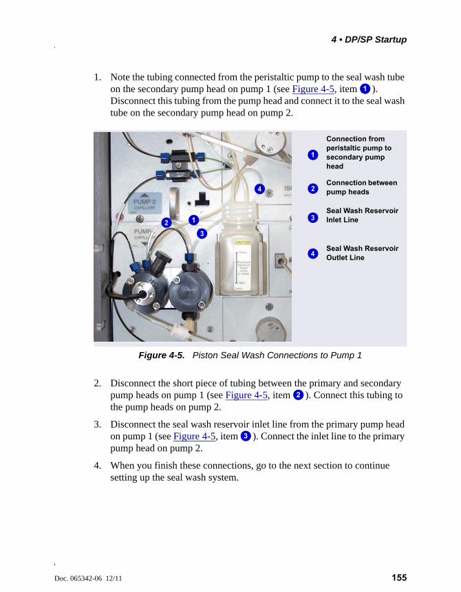
4 • DP/SP Startup
Doc. 065342-06 12/11 155
1. Note the tubing connected from the peristaltic pump to the seal wash tube on the secondary pump head on pump 1 (see Figure 4-5, item ). Disconnect this tubing from the pump head and connect it to the seal wash tube on the secondary pump head on pump 2.
2. Disconnect the short piece of tubing between the primary and secondary pump heads on pump 1 (see Figure 4-5, item ). Connect this tubing to the pump heads on pump 2.
3. Disconnect the seal wash reservoir inlet line from the primary pump head on pump 1 (see Figure 4-5, item ). Connect the inlet line to the primary pump head on pump 2.
4. When you finish these connections, go to the next section to continue setting up the seal wash system.
Figure 4-5. Piston Seal Wash Connections to Pump 1
1
Seal Wash Reservoir Inlet Line
Connection from peristaltic pump to secondary pump head
Seal Wash Reservoir Outlet Line
Connection between pump heads
1
2
3
4
1
3
2
4
2
3
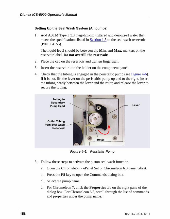
Dionex ICS-5000 Operator’s Manual
156 Doc. 065342-06 12/11
Setting Up the Seal Wash System (All pumps)
1. Add ASTM Type I (18 megohm-cm) filtered and deionized water that meets the specifications listed in Section 1.5 to the seal wash reservoir (P/N 064155).
The liquid level should be between the Min. and Max. markers on the reservoir label. Do not overfill the reservoir.
2. Place the cap on the reservoir and tighten fingertight.
3. Insert the reservoir into the holder on the component panel.
4. Check that the tubing is engaged in the peristaltic pump (see Figure 4-6). If it is not, lift the lever on the peristaltic pump up and to the right, insert the tubing neatly between the lever and the rotor, and release the lever to secure the tubing.
5. Follow these steps to activate the piston seal wash function:
a. Open the Chromeleon 7 ePanel Set or Chromeleon 6.8 panel tabset.
b. Press the F8 key to open the Commands dialog box.
c. Select the pump name.
d. For Chromeleon 7, click the Properties tab on the right pane of the dialog box. For Chromeleon 6.8, scroll through the list of commands and properties under the pump name.
Figure 4-6. Peristaltic Pump
Rotor
Lever
Outlet Tubingfrom Seal Wash
Reservoir
Tubing toSecondary
Pump Head
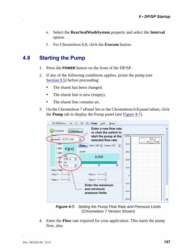
4 • DP/SP Startup
Doc. 065342-06 12/11 157
e. Select the RearSealWashSystem property and select the Interval option.
f. For Chromeleon 6.8, click the Execute button.
4.8 Starting the Pump
1. Press the POWER button on the front of the DP/SP.
2. If any of the following conditions applies, prime the pump (see Section 9.5) before proceeding:
• The eluent has been changed.
• The eluent line is new (empty).
• The eluent line contains air.
3. On the Chromeleon 7 ePanel Set or the Chromeleon 6.8 panel tabset, click the Pump tab to display the Pump panel (see Figure 4-7).
4. Enter the Flow rate required for your application. This starts the pump flow, also.
Figure 4-7. Setting the Pump Flow Rate and Pressure Limits (Chromeleon 7 Version Shown)
Enter a new flow rate or click the switch to start the pump at the selected flow rate.
Enter the maximum and minimum pressure limits.
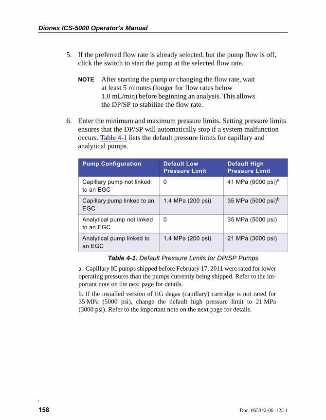
Dionex ICS-5000 Operator’s Manual
158 Doc. 065342-06 12/11
5. If the preferred flow rate is already selected, but the pump flow is off, click the switch to start the pump at the selected flow rate.
NOTE After starting the pump or changing the flow rate, wait at least 5 minutes (longer for flow rates below 1.0 mL/min) before beginning an analysis. This allows the DP/SP to stabilize the flow rate.
6. Enter the minimum and maximum pressure limits. Setting pressure limits ensures that the DP/SP will automatically stop if a system malfunction occurs. Table 4-1 lists the default pressure limits for capillary and analytical pumps.
Pump Configuration Default Low Pressure Limit
Default High Pressure Limit
Capillary pump not linked to an EGC
0 41 MPa (6000 psi)a
a. Capillary IC pumps shipped before February 17, 2011 were rated for loweroperating pressures than the pumps currently being shipped. Refer to the im-portant note on the next page for details.
Capillary pump linked to an EGC
1.4 MPa (200 psi) 35 MPa (5000 psi)b
b. If the installed version of EG degas (capillary) cartridge is not rated for35 MPa (5000 psi), change the default high pressure limit to 21 MPa(3000 psi). Refer to the important note on the next page for details.
Analytical pump not linked to an EGC
0 35 MPa (5000 psi)
Analytical pump linked to an EGC
1.4 MPa (200 psi) 21 MPa (3000 psi)
Table 4-1. Default Pressure Limits for DP/SP Pumps

4 • DP/SP Startup
Doc. 065342-06 12/11 159
IMPORTANT
Capillary IC pumps shipped before February 17, 2011 were rated for lower operating pressures than the pumps currently being shipped. The older pumps can be operated at pressures up to 35 MPa (5000 psi) (without RFIC) and up to 21 MPa (3000 psi) (with RFIC). Before operating at pressures above these limits, verify that you have the appropriate pump.
• HPC is stamped on the secondary pump heads of the older (lower pressure rated) capillary IC pumps.
• HPC-2 is stamped on the secondary pump heads of the newer (higher pressure rated) capillary IC pumps.
A Capillary Pump High Pressure Upgrade Kit (P/N 075994) is available for converting a lower pressure rated capillary IC pump to a higher pressure rated pump.
IMPORTANT
If your system includes a capillary pump linked to an EGC, check the label on the EG degas (capillary) cartridge in the IC Cube and verify that 5000 psi is printed on the label (see the figure on the right).
If 5000 psi is not on the label, you must change the high pressure limit to 21 MPa (3000 psi) or replace the cartridge with an EG degas (capillary) cartridge that is rated for 35 MPa (5000 psi) (P/N 074459).
Capillary IC
5000 psi
P/N 074459

Dionex ICS-5000 Operator’s Manual
160 Doc. 065342-06 12/11
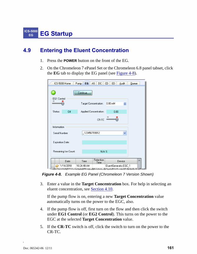
Doc. 065342-06 12/11 161
EG Startup
4.9 Entering the Eluent Concentration
1. Press the POWER button on the front of the EG.
2. On the Chromeleon 7 ePanel Set or the Chromeleon 6.8 panel tabset, click the EG tab to display the EG panel (see Figure 4-8).
3. Enter a value in the Target Concentration box. For help in selecting an eluent concentration, see Section 4.10.
If the pump flow is on, entering a new Target Concentration value automatically turns on the power to the EGC, also.
4. If the pump flow is off, first turn on the flow and then click the switch under EG1 Control (or EG2 Control). This turns on the power to the EGC at the selected Target Concentration value.
5. If the CR-TC switch is off, click the switch to turn on the power to the CR-TC.
ICS-5000 EG
Figure 4-8. Example EG Panel (Chromeleon 7 Version Shown)
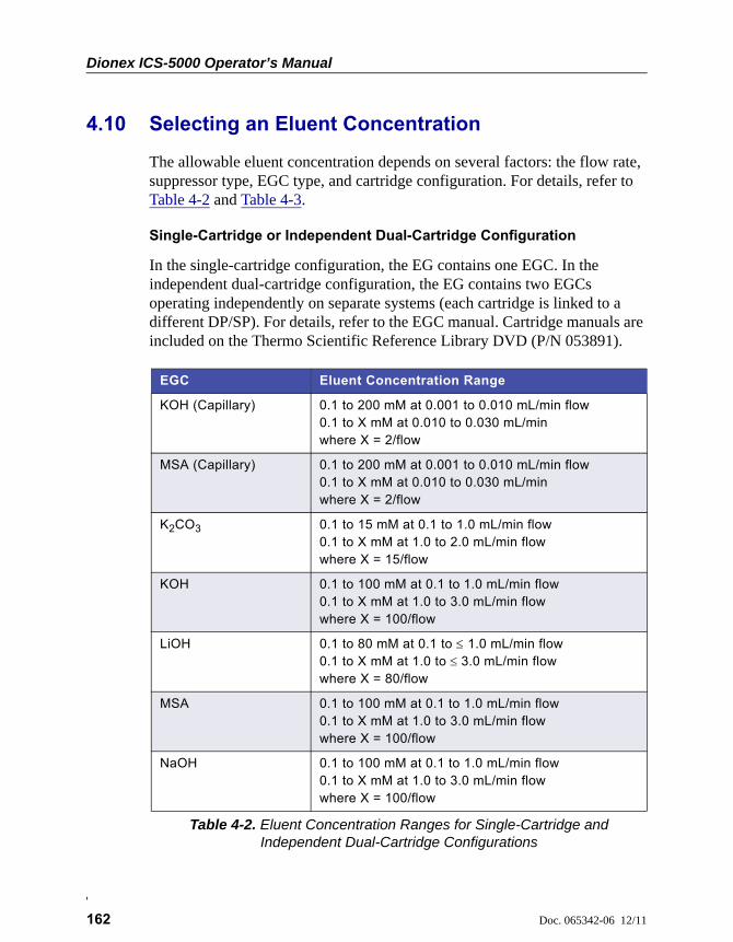
Dionex ICS-5000 Operator’s Manual
162 Doc. 065342-06 12/11
4.10 Selecting an Eluent Concentration
The allowable eluent concentration depends on several factors: the flow rate, suppressor type, EGC type, and cartridge configuration. For details, refer to Table 4-2 and Table 4-3.
Single-Cartridge or Independent Dual-Cartridge Configuration
In the single-cartridge configuration, the EG contains one EGC. In the independent dual-cartridge configuration, the EG contains two EGCs operating independently on separate systems (each cartridge is linked to a different DP/SP). For details, refer to the EGC manual. Cartridge manuals are included on the Thermo Scientific Reference Library DVD (P/N 053891).
EGC Eluent Concentration Range
KOH (Capillary) 0.1 to 200 mM at 0.001 to 0.010 mL/min flow0.1 to X mM at 0.010 to 0.030 mL/minwhere X = 2/flow
MSA (Capillary) 0.1 to 200 mM at 0.001 to 0.010 mL/min flow0.1 to X mM at 0.010 to 0.030 mL/minwhere X = 2/flow
K2CO3 0.1 to 15 mM at 0.1 to 1.0 mL/min flow0.1 to X mM at 1.0 to 2.0 mL/min flowwhere X = 15/flow
KOH 0.1 to 100 mM at 0.1 to1.0 mL/min flow0.1 to X mM at 1.0 to 3.0 mL/min flowwhere X = 100/flow
LiOH 0.1 to 80 mM at 0.1 to 1.0 mL/min flow0.1 to X mM at 1.0 to 3.0 mL/min flowwhere X = 80/flow
MSA 0.1 to 100 mM at 0.1 to 1.0 mL/min flow0.1 to X mM at 1.0 to 3.0 mL/min flowwhere X = 100/flow
NaOH 0.1 to 100 mM at 0.1 to 1.0 mL/min flow0.1 to X mM at 1.0 to 3.0 mL/min flowwhere X = 100/flow
Table 4-2. Eluent Concentration Ranges for Single-Cartridge and Independent Dual-Cartridge Configurations

4 • EG Startup
Doc. 065342-06 12/11 163
Linked Dual-Cartridge Configuration
In the linked dual-cartridge configuration, the EG contains two EGCs, linked to a single pump. Note that the allowable eluent concentration for a linked cartridge is less than when the cartridge is defined as independent. For details, refer to the EGC manual. EGC manuals are included on the Thermo Scientific Reference Library DVD (P/N 053891).
EGCs Eluent Concentration Range Comment
K2CO3/EPM Electrolytic pH Modifier
0.1 to 15 mM at 0.1 to 1.0 ml/min flow0.1 to X mM at 1.0 to 2.0 ml/min flowwhere X = 15/flow
The total of the eluent concentrations from both cartridges (K2CO3 and EPM) must not exceed the specified range. The EPM concentration must not exceed 10 mM. See the notes below for additional information.
KOH/KOHKOH/MSAKOH/NaOHMSA/MSAMSA/NaOHNaOH/NaOH
0.1 to 50 mM at 0.1 to1.0 mL/min flow0.1 to X mM at 1.0 to3.0 mL/min flowwhere X = 50/flow
The eluent concentration range for each cartridge is 50% of the range for an independent cartridge
LiOH/LiOH 0.1 to 40 mM at 0.1 to1.0 mL/min flow0.1 to X mM at 1.0 to3.0 mL/min flowwhere X = 40/flow
The eluent concentration range for each cartridge is 50% of the range for an single-independent cartridge.
KOH (Capillary)/MSA (Capillary)
0.1 to 100 mM at 0.001 to 0.01 mL/min0.1 to X mM at 0.01 to 0.1mL/minwhere X = 1/flow
The eluent concentration range for each cartridge is 50% of the range for an independent cartridge.
Table 4-3. Eluent Concentration Ranges for Linked Dual-Cartridge Configurations

Dionex ICS-5000 Operator’s Manual
164 Doc. 065342-06 12/11
Notes for Generating Carbonate/Bicarbonate Eluent
If an EGC III K2CO3 and an EPM III Electrolytic pH Modifier are installed (EGC_1 and EGC_2, respectively):
1. Set EGC_1 Target Concentration to the concentration of K2CO3 required for your application
2. Set EGC_2 Target Concentration to the concentration of KHCO3 required.
The K2CO3 cartridge generates the total of the two target concentrations and the EPM modifies the total to achieve the K2CO3/KHCO3 eluent mixture that you require.
For example:
For a 3.50 mM K2CO3/1.00 mM KHCO3 eluent, set EGC_1 to 3.50 mM and EGC_2 to 1.00 mM.
The K2CO3 cartridge generates 4.50 mM K2CO3 (indicated in the Applied Concentration field for the K2CO3 EGC). The EPM modifies the 4.50 mM K2CO3 eluent to achieve the required 3.50 mM K2CO3/1.00 mM KHCO3 mixture.
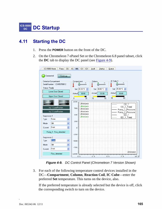
Doc. 065342-06 12/11 165
DC Startup
4.11 Starting the DC
1. Press the POWER button on the front of the DC.
2. On the Chromeleon 7 ePanel Set or the Chromeleon 6.8 panel tabset, click the DC tab to display the DC panel (see Figure 4-9).
3. For each of the following temperature control devices installed in the DC—Compartment, Column, Reaction Coil, IC Cube—enter the preferred Set temperature. This turns on the device, also.
If the preferred temperature is already selected but the device is off, click the corresponding switch to turn on the device.
ICS-5000 DC
Figure 4-9. DC Control Panel (Chromeleon 7 Version Shown)
Dionex ICS-5000 Operator’s Manual
166 Doc. 065342-06 12/11
4. If a suppressor is installed: Under Suppressor 1 (or Suppressor 2), select the suppressor Type, set the Mode to On, and enter the Current required for your application.
5. If a CD is installed: Click the CD tab to open the CD panel.
6. Under Cell Heater, set the Cell Heater Mode to On and enter the Cell Heater Set Point.
4.12 Equilibrating the System and Verifying Operational Readiness
NOTE You can also use the Smart Startup feature in Chromeleon to automate system startup and equilibration. Refer to the Chromeleon Help for details.
1. On the Chromeleon 7 ePanel Set or Chromeleon 6.8 panel tabset, verify that each device listed below (if installed in your system) is turned on and the selected setting for the device (flow rate, eluent concentration, temperature, and so on) is correct for your application:
• Pump
• EGC
• CR-TC
• EPM
• Suppressor
• Temperature control devices (DC compartment, DC column compartment, IC Cube, CD cell heater, reaction coil heater)
2. Click Monitor Background on the toolbar above the Chromeleon 7 ePanel Set or on the Home panel of the Chromeleon 6.8 panel tabset. Chromeleon begins plotting the detector signal and pump pressure readings.
3. View the detector signal and monitor the background. Refer to the column manual for the appropriate background for your application. The column manuals are included on the Thermo Scientific Reference Library DVD (P/N 053891).
4 • DC Startup
Doc. 065342-06 12/11 167
4. Offset the detector background and zero the reading by clicking the Autozero button.
5. Verify that the detector baseline is at the expected reading for your application and is stable. See Section 8.11 for troubleshooting information if the reading is too high. See Section 8.2 for troubleshooting information if the baseline is drifting or is excessively “noisy” (there are large fluctuations in readings).
6. Monitor the DP/SP pressure and make sure it is at the expected reading for the installed column and it is stable.
7. Verify that all installed temperature control devices are at their set points and are stable.
The system is now ready for operation.
Because capillary IC systems use low flow rates and consume very little eluent, you can leave a capillary IC system on at all times, allowing it to remain equilibrated and always ready to run the next sample.
Capillary IC

Dionex ICS-5000 Operator’s Manual
168 Doc. 065342-06 12/11
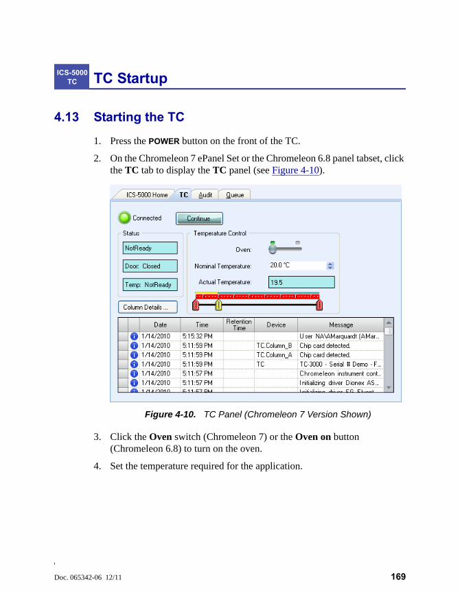
Doc. 065342-06 12/11 169
TC Startup
4.13 Starting the TC
1. Press the POWER button on the front of the TC.
2. On the Chromeleon 7 ePanel Set or the Chromeleon 6.8 panel tabset, click the TC tab to display the TC panel (see Figure 4-10).
3. Click the Oven switch (Chromeleon 7) or the Oven on button (Chromeleon 6.8) to turn on the oven.
4. Set the temperature required for the application.
ICS-5000 TC
Figure 4-10. TC Panel (Chromeleon 7 Version Shown)
Dionex ICS-5000 Operator’s Manual
170 Doc. 065342-06 12/11
4.14 Equilibrating the System and Verifying Operational Readiness
NOTE You can also use the Smart Startup feature in Chromeleon to automate system startup and equilibration. Refer to the Chromeleon Help for details.
1. On the Chromeleon 7 ePanel Set or Chromeleon 6.8 panel tabset, verify that the TC temperature is at its set point and is stable.
2. Monitor the pump pressure; make sure it is at the expected reading for the installed column and is stable.
3. Verify that the detector baseline is at the expected reading for your application and is stable.
The system is now ready for operation.
Doc. 065342-06 12/11 171
5 • Operation
5.1 Controlling Modules Directly
When the Thermo Scientific Dionex ICS-5000 Ion Chromatography System is not running automated analyses, you can directly control the system modules by issuing commands from the ePanel Set in Chromeleon 7 or the panel tabset in Chromeleon 6.8. For example, you can turn on the pump flow, set the eluent concentration, or set the compartment temperature.
To display the Chromeleon 7 ePanel Set:
1. On the Console, click the Instruments category bar.
2. In the Navigation Pane, click the instrument that you want to control. Chromeleon 7 connects to the instrument and displays the ePanel Set.
To display the Chromeleon 6.8 panel tabset:
1. Click View > Default Panel Tabset or click the toolbar button .
2. Select the Chromeleon server and click OK.
3. If more than one timebase is configured on the server, Chromeleon 6.8 displays a panel tabset for each timebase. Click the Expand Timebase View button for the timebase that you want to control.
To issue direct control commands to a module:
1. On the ePanel Set or panel tabset, click the tab for the module.
2. Use the controls (buttons, sliders, etc.) on the panel to issue commands.
3. If the function that you want to perform is not available from the panel, press the F8 key to open the Commands dialog box. You can access all commands available for the system from this dialog box.
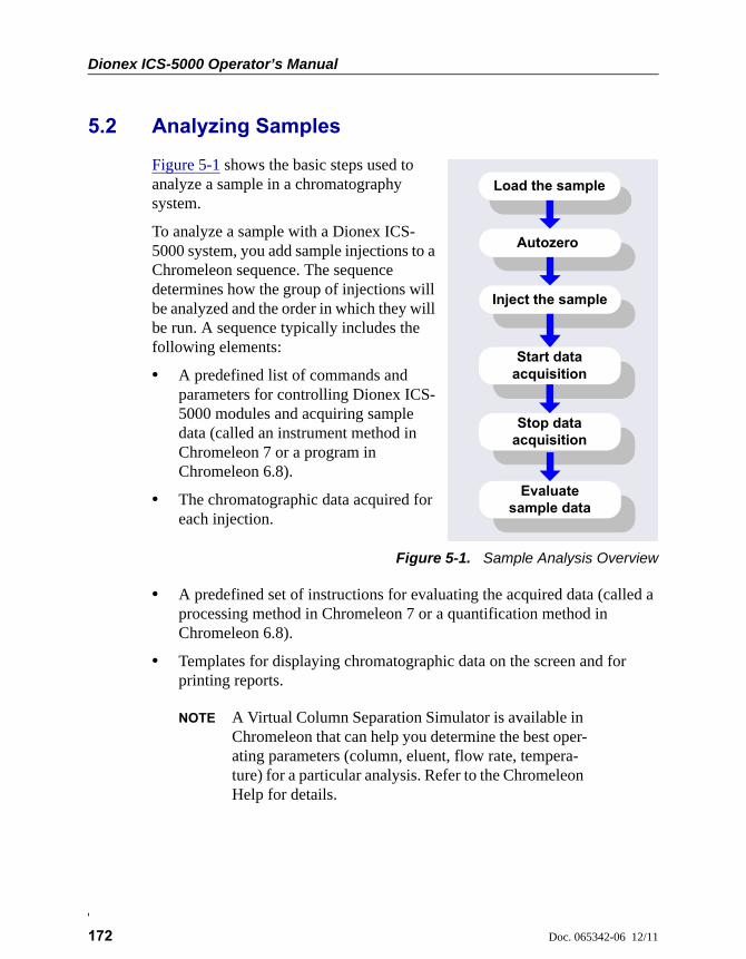
Dionex ICS-5000 Operator’s Manual
172 Doc. 065342-06 12/11
5.2 Analyzing Samples
Figure 5-1 shows the basic steps used to analyze a sample in a chromatography system.
To analyze a sample with a Dionex ICS-5000 system, you add sample injections to a Chromeleon sequence. The sequence determines how the group of injections will be analyzed and the order in which they will be run. A sequence typically includes the following elements:
• A predefined list of commands and parameters for controlling Dionex ICS-5000 modules and acquiring sample data (called an instrument method in Chromeleon 7 or a program in Chromeleon 6.8).
• The chromatographic data acquired for each injection.
Figure 5-1. Sample Analysis Overview
• A predefined set of instructions for evaluating the acquired data (called a processing method in Chromeleon 7 or a quantification method in Chromeleon 6.8).
• Templates for displaying chromatographic data on the screen and for printing reports.
NOTE A Virtual Column Separation Simulator is available in Chromeleon that can help you determine the best oper-ating parameters (column, eluent, flow rate, tempera-ture) for a particular analysis. Refer to the Chromeleon Help for details.
Inject the sample
Autozero
Stop dataacquisition
Start dataacquisition
Load the sample
Evaluate sample data
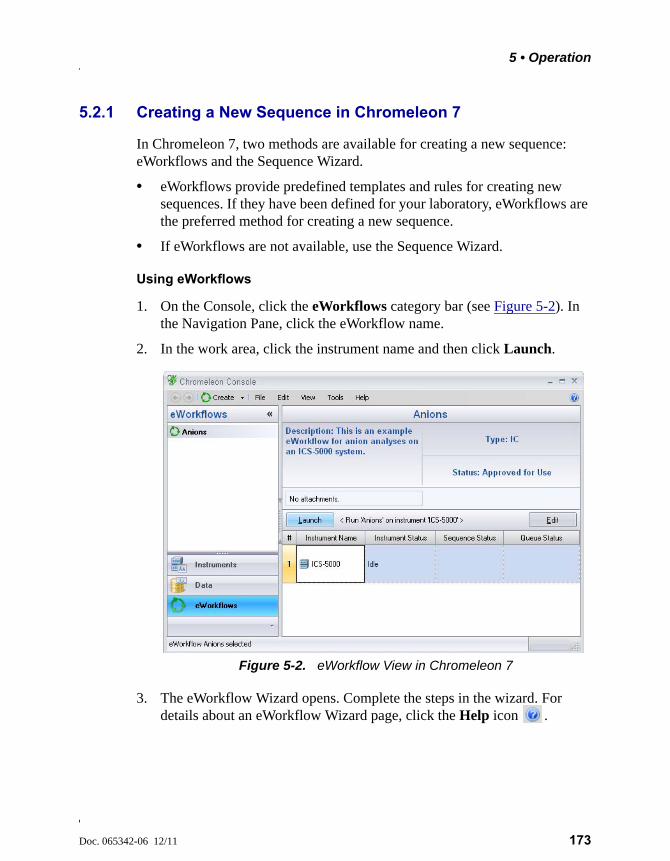
5 • Operation
Doc. 065342-06 12/11 173
5.2.1 Creating a New Sequence in Chromeleon 7
In Chromeleon 7, two methods are available for creating a new sequence: eWorkflows and the Sequence Wizard.
• eWorkflows provide predefined templates and rules for creating new sequences. If they have been defined for your laboratory, eWorkflows are the preferred method for creating a new sequence.
• If eWorkflows are not available, use the Sequence Wizard.
Using eWorkflows
1. On the Console, click the eWorkflows category bar (see Figure 5-2). In the Navigation Pane, click the eWorkflow name.
2. In the work area, click the instrument name and then click Launch.
3. The eWorkflow Wizard opens. Complete the steps in the wizard. For details about an eWorkflow Wizard page, click the Help icon .
Figure 5-2. eWorkflow View in Chromeleon 7
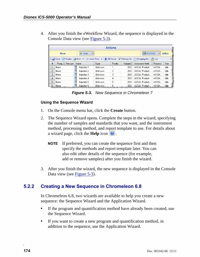
Dionex ICS-5000 Operator’s Manual
174 Doc. 065342-06 12/11
4. After you finish the eWorkflow Wizard, the sequence is displayed in the Console Data view (see Figure 5-3).
Using the Sequence Wizard
1. On the Console menu bar, click the Create button.
2. The Sequence Wizard opens. Complete the steps in the wizard, specifying the number of samples and standards that you want, and the instrument method, processing method, and report template to use. For details about a wizard page, click the Help icon .
NOTE If preferred, you can create the sequence first and then specify the methods and report template later. You can also edit other details of the sequence (for example, add or remove samples) after you finish the wizard.
3. After you finish the wizard, the new sequence is displayed in the Console Data view (see Figure 5-3).
5.2.2 Creating a New Sequence in Chromeleon 6.8
In Chromeleon 6.8, two wizards are available to help you create a new sequence: the Sequence Wizard and the Application Wizard.
• If the program and quantification method have already been created, use the Sequence Wizard.
• If you want to create a new program and quantification method, in addition to the sequence, use the Application Wizard.
Figure 5-3. New Sequence in Chromeleon 7
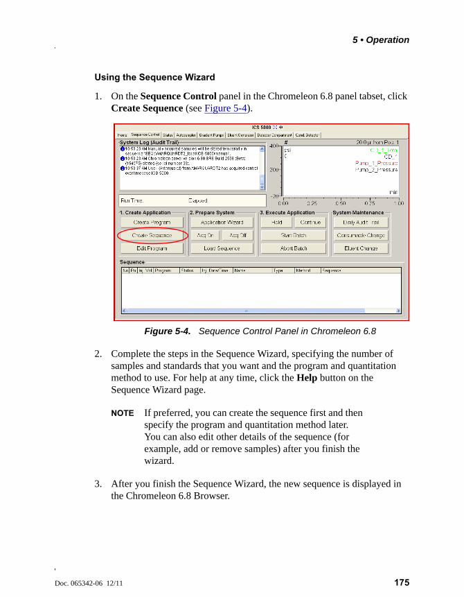
5 • Operation
Doc. 065342-06 12/11 175
Using the Sequence Wizard
1. On the Sequence Control panel in the Chromeleon 6.8 panel tabset, click Create Sequence (see Figure 5-4).
2. Complete the steps in the Sequence Wizard, specifying the number of samples and standards that you want and the program and quantitation method to use. For help at any time, click the Help button on the Sequence Wizard page.
NOTE If preferred, you can create the sequence first and then specify the program and quantitation method later. You can also edit other details of the sequence (for example, add or remove samples) after you finish the wizard.
3. After you finish the Sequence Wizard, the new sequence is displayed in the Chromeleon 6.8 Browser.
Figure 5-4. Sequence Control Panel in Chromeleon 6.8
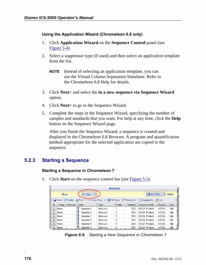
Dionex ICS-5000 Operator’s Manual
176 Doc. 065342-06 12/11
Using the Application Wizard (Chromeleon 6.8 only)
1. Click Application Wizard on the Sequence Control panel (see Figure 5-4).
2. Select a suppressor type (if used) and then select an application template from the list.
NOTE Instead of selecting an application template, you can use the Virtual Column Separation Simulator. Refer to the Chromeleon 6.8 Help for details.
3. Click Next> and select the in a new sequence via Sequence Wizard option.
4. Click Next> to go to the Sequence Wizard.
5. Complete the steps in the Sequence Wizard, specifying the number of samples and standards that you want. For help at any time, click the Help button on the Sequence Wizard page.
After you finish the Sequence Wizard, a sequence is created and displayed in the Chromeleon 6.8 Browser. A program and quantification method appropriate for the selected application are copied to the sequence.
5.2.3 Starting a Sequence
Starting a Sequence in Chromeleon 7
1. Click Start on the sequence control bar (see Figure 5-5).
Figure 5-5. Starting a New Sequence in Chromeleon 7
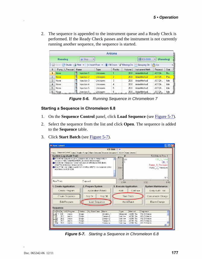
5 • Operation
Doc. 065342-06 12/11 177
2. The sequence is appended to the instrument queue and a Ready Check is performed. If the Ready Check passes and the instrument is not currently running another sequence, the sequence is started.
Starting a Sequence in Chromeleon 6.8
1. On the Sequence Control panel, click Load Sequence (see Figure 5-7).
2. Select the sequence from the list and click Open. The sequence is added to the Sequence table.
3. Click Start Batch (see Figure 5-7).
Figure 5-6. Running Sequence in Chromeleon 7
Figure 5-7. Starting a Sequence in Chromeleon 6.8
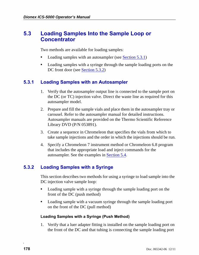
Dionex ICS-5000 Operator’s Manual
178 Doc. 065342-06 12/11
5.3 Loading Samples Into the Sample Loop or Concentrator
Two methods are available for loading samples:
• Loading samples with an autosampler (see Section 5.3.1)
• Loading samples with a syringe through the sample loading ports on the DC front door (see Section 5.3.2)
5.3.1 Loading Samples with an Autosampler
1. Verify that the autosampler output line is connected to the sample port on the DC (or TC) injection valve. Direct the waste line as required for this autosampler model.
2. Prepare and fill the sample vials and place them in the autosampler tray or carousel. Refer to the autosampler manual for detailed instructions. Autosampler manuals are provided on the Thermo Scientific Reference Library DVD (P/N 053891).
3. Create a sequence in Chromeleon that specifies the vials from which to take sample injections and the order in which the injections should be run.
4. Specify a Chromeleon 7 instrument method or Chromeleon 6.8 program that includes the appropriate load and inject commands for the autosampler. See the examples in Section 5.4.
5.3.2 Loading Samples with a Syringe
This section describes two methods for using a syringe to load sample into the DC injection valve sample loop:
• Loading sample with a syringe through the sample loading port on the front of the DC (push method)
• Loading sample with a vacuum syringe through the sample loading port on the front of the DC (pull method)
Loading Samples with a Syringe (Push Method)
1. Verify that a luer adapter fitting is installed on the sample loading port on the front of the DC and that tubing is connecting the sample loading port
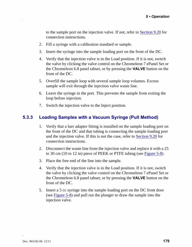
5 • Operation
Doc. 065342-06 12/11 179
to the sample port on the injection valve. If not, refer to Section 9.20 for connection instructions.
2. Fill a syringe with a calibration standard or sample.
3. Insert the syringe into the sample loading port on the front of the DC.
4. Verify that the injection valve is in the Load position. If it is not, switch the valve by clicking the valve control on the Chromeleon 7 ePanel Set or the Chromeleon 6.8 panel tabset, or by pressing the VALVE button on the front of the DC.
5. Overfill the sample loop with several sample loop volumes. Excess sample will exit through the injection valve waste line.
6. Leave the syringe in the port. This prevents the sample from exiting the loop before injection.
7. Switch the injection valve to the Inject position.
5.3.3 Loading Samples with a Vacuum Syringe (Pull Method)
1. Verify that a luer adapter fitting is installed on the sample loading port on the front of the DC and that tubing is connecting the sample loading port and the injection valve. If this is not the case, refer to Section 9.20 for connection instructions.
2. Disconnect the waste line from the injection valve and replace it with a 25 to 30 cm (10 to 12 in) piece of PEEK or PTFE tubing (see Figure 5-8).
3. Place the free end of the line into the sample.
4. Verify that the injection valve is in the Load position. If it is not, switch the valve by clicking the valve control on the Chromeleon 7 ePanel Set or the Chromeleon 6.8 panel tabset, or by pressing the VALVE button on the front of the DC.
5. Insert a 5 cc syringe into the sample loading port on the DC front door (see Figure 5-8) and pull out the plunger to draw the sample into the injection valve.
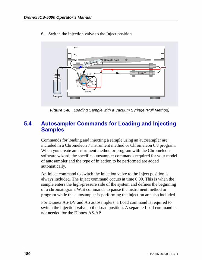
Dionex ICS-5000 Operator’s Manual
180 Doc. 065342-06 12/11
6. Switch the injection valve to the Inject position.
5.4 Autosampler Commands for Loading and Injecting Samples
Commands for loading and injecting a sample using an autosampler are included in a Chromeleon 7 instrument method or Chromeleon 6.8 program. When you create an instrument method or program with the Chromeleon software wizard, the specific autosampler commands required for your model of autosampler and the type of injection to be performed are added automatically.
An Inject command to switch the injection valve to the Inject position is always included. The Inject command occurs at time 0.00. This is when the sample enters the high-pressure side of the system and defines the beginning of a chromatogram. Wait commands to pause the instrument method or program while the autosampler is performing the injection are also included.
For Dionex AS-DV and AS autosamplers, a Load command is required to switch the injection valve to the Load position. A separate Load command is not needed for the Dionex AS-AP.
Figure 5-8. Loading Sample with a Vacuum Syringe (Pull Method)
(1)
L
L
S
W
P
C
(2)
(3)
(4)(5)
(6)
Sample
Valve
Sample Port
Guard
Syringe
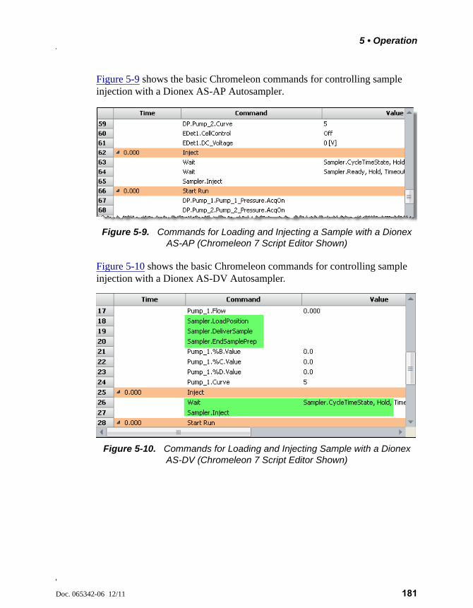
5 • Operation
Doc. 065342-06 12/11 181
Figure 5-9 shows the basic Chromeleon commands for controlling sample injection with a Dionex AS-AP Autosampler.
Figure 5-10 shows the basic Chromeleon commands for controlling sample injection with a Dionex AS-DV Autosampler.
Figure 5-9. Commands for Loading and Injecting a Sample with a Dionex AS-AP (Chromeleon 7 Script Editor Shown)
Figure 5-10. Commands for Loading and Injecting Sample with a Dionex AS-DV (Chromeleon 7 Script Editor Shown)
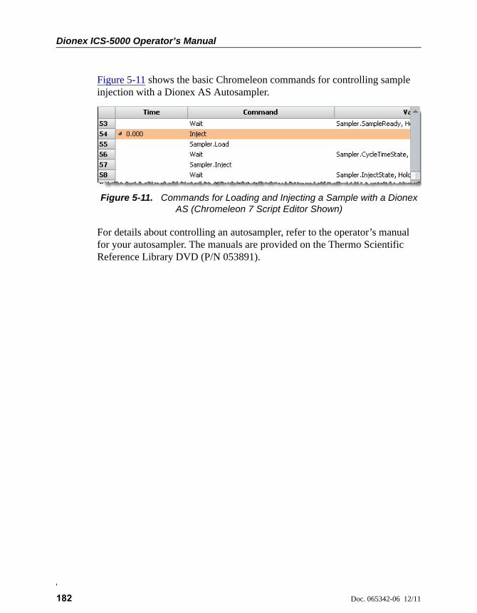
Dionex ICS-5000 Operator’s Manual
182 Doc. 065342-06 12/11
Figure 5-11 shows the basic Chromeleon commands for controlling sample injection with a Dionex AS Autosampler.
For details about controlling an autosampler, refer to the operator’s manual for your autosampler. The manuals are provided on the Thermo Scientific Reference Library DVD (P/N 053891).
Figure 5-11. Commands for Loading and Injecting a Sample with a Dionex AS (Chromeleon 7 Script Editor Shown)

Doc. 065342-06 12/11 183
6 • Shutdown
DP/SP Shutdown
If the Dionex ICS-5000 Dual Pump (DP) or Dionex ICS-5000 Single Pump (SP) will not be operated for a period of one week or more, follow the instructions below:
• Fill the pump with methanol (or a similar alcohol, such as 2-propanol or ethanol). If the eluents in the pump are not miscible with water, replace the eluents step-by-step.
• Fill the seal wash reservoir with wash solution (see Section 2.2.5).
• Rinse out buffers. This will reduce the time required for column equilibration when you resume operation.
• Disconnect the tubing from the peristaltic pump on the component panel: lift the lever up and to the right, remove the tubing, and release the lever (see Figure 6-1).
Before shipping the pump:
• Empty the seal wash reservoir.
• Disconnect the tubing from the peristaltic pump on the component panel: press the lever to the right, remove the tubing, and release the lever (see Figure 6-1).
ICS-5000 DP/SP
Figure 6-1. Peristaltic Pump for Seal Wash System
Rotor
Lever
Tubing

Dionex ICS-5000 Operator’s Manual
184 Doc. 065342-06 12/11
Doc. 065342-06 12/11 185
EG Shutdown
6.1 Short-term Shutdown
If the shutdown is for 3 months or less, follow the instructions below.
To prepare the EG for the shutdown:
1. Turn off the EG, including all consumables installed in the EG (the CR-TC, suppressor, etc.).
2. Verify that the current to the EGC and the suppressor is off.
3. Store the EGC in the EG during the shutdown.
To restart the EG:
1. Select the parameters for the analysis on the Chromeleon 7 ePanel Set or the Chromeleon 6.8 panel tabset. For EG startup information, see Section 4.9.
2. In an analytical IC system, if the EG has been shut down for more than 3 to 4 days, hydrate the suppressor as instructed in the product manual. Suppressor manuals are included on the Thermo Scientific Reference Library DVD (P/N 053891).
3. Let the system equilibrate before collecting data.
6.2 Long-term Shutdown
If the shutdown is for 3 months or more, follow the instructions below.
To prepare the EG for the shutdown:
1. Turn off the EG, including all consumables installed in the EG (the CR-TC, suppressor, etc.).
ICS-5000 EG
Supplying power to the EGC when there is no eluent flow can severelydamage the cartridge.

Dionex ICS-5000 Operator’s Manual
186 Doc. 065342-06 12/11
2. Verify that the current to the EGC and the suppressor is off.
3. If you plan to store the EGC in the EG, no further action is required.
If you plan to store the cartridge outside the EG (for example, in the original shipping container), follow the instructions in Section 9.14.1, to remove the EGC from the EG, and the instructions in Section 9.14.3, to store the EGC.
To restart the EG:
1. Select the parameters for the analysis on the Chromeleon 7 ePanel Set or the Chromeleon 6.8 panel tabset. For EG startup information, see Section 4.9.
2. Condition the EGC. For instructions, see “Conditioning the Capillary EGC” on page 343 or “Conditioning the Analytical EGC” on page 348.
3. Hydrate the CR-TC (see “Installing and Flushing the New CR-TC” on page 350).
4. Hydrate the suppressor as instructed in the product manual. Suppressor manuals are included on the Thermo Scientific Reference Library DVD (P/N 053891).
5. Let the system equilibrate before collecting data.
Before shipping the EG:
1. Follow the instructions in Section 9.14.1, to remove the EGC from the EG.
2. Plug all fittings. Tighten the vent fitting (capillary EGC) or cap the vent port (analytical EGC). This will prevent the evaporation of water in the electrolyte reservoir.
Supplying power to the EGC when there is no eluent flow can severelydamage the cartridge.
Make sure the EGC packaging conforms to hazardous materialshipping requirements. Refer to the Material Safety Data Sheet (MSDS)shipped with the EGC for the chemical description.
Doc. 065342-06 12/11 187
DC Shutdown
6.3 Consumables Storage
The columns, suppressors, and other consumable items used with a Dionex ICS-5000 system have various short- and long-term storage requirements. Refer to the manuals for the individual products for instructions. These manuals are provided on the Thermo Scientific Reference Library DVD (P/N 053891).
6.4 ED Cell Storage
6.4.1 Short-term Storage of the ED Cell
If the cell will not be used for a short period of time (less than 2 days), disconnect the tubing from the inlet and outlet fittings and all fitting plugs.
NOTE If the pH-Ag/AgCl reference electrode remains in the cell but eluent is not being pumped through the cell, the pH-Ag/AgCl reference electrode frit may partially dry out. If this occurs, regenerate the electrode by soaking it in a solution containing 1 M KCl and 1 M HCl.
6.4.2 Long-term Storage of the pH-Ag/AgCl Reference Electrode
If the cell will not be used for 2 days or more, remove the pH-Ag/AgCl reference electrode and store it in a solution of saturated KCl, as instructed in the procedure below.
1. Prepare a saturated solution of KCl in ASTM filtered, Type I (18 megohm-cm) deionized water that meets the specifications listed in Section 1.5.
2. Locate the cap in which the electrode was shipped and fill it two-thirds full with the prepared KCl solution.
3. Remove the pH-Ag/AgCl reference electrode from the cell.
4. Insert the electrode into the cap and screw on the cap (see Figure 6-2).
ICS-5000 DC
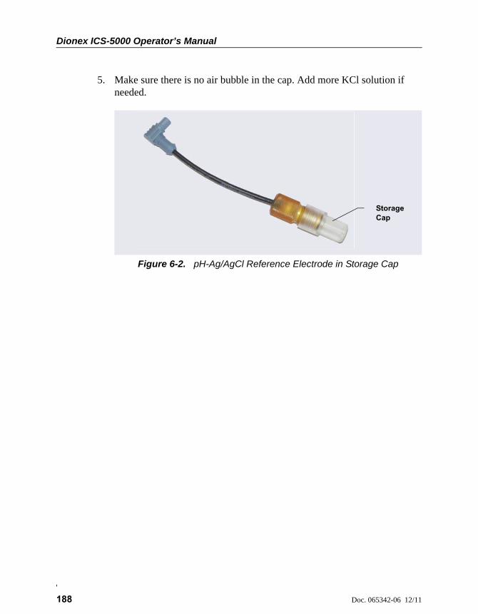
Dionex ICS-5000 Operator’s Manual
188 Doc. 065342-06 12/11
5. Make sure there is no air bubble in the cap. Add more KCl solution if needed.
Figure 6-2. pH-Ag/AgCl Reference Electrode in Storage Cap
Storage Cap
Doc. 065342-06 12/11 189
TC Shutdown
6.5 Consumables Storage
The columns and other consumable items used with a Dionex ICS-5000 system have various short- and long-term storage requirements. Refer to the manuals for the individual products for instructions. These manuals are provided on the Thermo Scientific Reference Library DVD (P/N 053891).
6.6 Short-term Shutdown
Before a TC shutdown of less than one week, no special procedure is required.
6.7 Long-term Shutdown
Before interrupting TC operation for more than one week or before shipping the TC, rinse the fluid connections with deionized water.
ICS-5000 TC

Dionex ICS-5000 Operator’s Manual
190 Doc. 065342-06 12/11
Doc. 065342-06 12/11 191
7 • Maintenance
This section describes routine maintenance procedures for the Dionex ICS-5000 system that users may perform. All other maintenance procedures must be performed by Thermo Fisher Scientific personnel.
For information about maintenance procedures for the EGC, CR-TC trap column, or suppressor, refer to the appropriate product manual. These manuals are included on the Thermo Scientific Reference Library DVD (P/N 053891).
7.1 System Maintenance Checklists
7.1.1 Daily Maintenance
Check for leaks.
Wipe up liquid spills.
Check eluent reservoirs for microbial growth; clean reservoirs and replace eluent as needed.
Check eluent reservoir levels and refill as needed.
Check waste containers and empty as needed.
For detailed daily maintenance instructions for each module, see:
7.1.2 Weekly Maintenance
Check end-line filters on eluent lines. When end-line filters are new, they are pure white. Replace filters if they become discolored, if bacterial
DP/SP page 195
EG page 197
DC page 199
TC page 201

Dionex ICS-5000 Operator’s Manual
192 Doc. 065342-06 12/11
buildup is evident, or if eluent flow is blocked. See Section 4.6 for instructions.
Check for plugged or blocked tubing connections.
Check eluent reservoir levels and refill as needed.
Check waste containers and empty as needed.
For detailed weekly maintenance instructions for each module, see:
7.1.3 Periodic Maintenance
Clean eluent reservoirs (when making fresh eluent or as needed) (see Section 9.4).
(Optional) Have Thermo Fisher Scientific perform the performance qualification (PQ) procedure for IC systems.
For detailed periodic maintenance instructions for each module, see:
NOTE There are no periodic maintenance instructions for the EG.
7.1.4 Annual Maintenance
Thermo Fisher Scientific recommends performing preventive maintenance on each module annually. Preventive Maintenance Kits contain all the required parts for these procedures. The following kits are available:
DP/SP Preventive Maintenance Kits
• ICS-5000 Analytical Pump Preventive Maintenance Kit (P/N 075038)
DP/SP page 195
EG page 197
DC page 199
TC page 201
Capillary IC
Capillary IC
DP/SP page 196
DC page 199
TC page 201
7 • Maintenance
Doc. 065342-06 12/11 193
• ICS-5000 Capillary Pump Preventive Maintenance Kit (P/N 075039)
DC/TC Preventive Maintenance Kits
• 0.4 L Internal Loop High-Pressure Valve Preventive Maintenance Kit (P/N 075040)
• 6-Port High-Pressure Valve Preventive Maintenance Kit (P/N 075041)
• 10-Port High-Pressure Valve Preventive Maintenance Kit (P/N 075042)
NOTE There is no Preventive Maintenance Kit for the EG.

Dionex ICS-5000 Operator’s Manual
194 Doc. 065342-06 12/11
Doc. 065342-06 12/11 195
DP/SP Routine Maintenance
This section describes routine maintenance procedures that users may perform for the Dionex ICS-5000 Dual Pump (DP) or Dionex ICS-5000 Single Pump (SP). All other maintenance procedures must be performed by Thermo Fisher Scientific personnel.
7.2 DP/SP Daily Maintenance
• Check for leaks at the following locations: the eluent proportioning valves (gradient pump only), vacuum degas chambers, and eluent reservoirs. Tighten or replace any leaking fittings.
• Wipe up liquid spills and rinse dried reagents off pump components with deionized water. Dry the leak sensor thoroughly; if the sensor is not dry, it will remain activated and continue to report a leak to the Audit Trail.
• Check the liquid level in the seal wash reservoir. The liquid level should remain between the Min. and Max. markers on the reservoir label.
• Check eluent reservoirs for microbial growth; clean reservoirs and replace eluent as needed. Rinse each eluent reservoir thoroughly (inside and out) with ASTM filtered, Type I (18 megohm-cm) deionized water that meets the specifications listed in Section 1.5. Dry with clean, particulate-free air. If a reservoir still appears dirty, or if there is a slimy film on the interior, clean the reservoir as instructed in Section 9.4.
• Check the liquid level in each eluent reservoir and refill as required.
7.3 DP/SP Weekly Maintenance
• The end-line filters (P/N 045987) on the eluent lines may need to be replaced weekly, depending on water quality and eluent conditions. For example, replace the filters weekly when using an EGC to generate carbonate/bicarbonate eluent.
When the end-line filters are new, they are pure white. Replace the filters whenever they become discolored, if bacterial buildup is evident, or if eluent flow is blocked.
ICS-5000 DP/SP
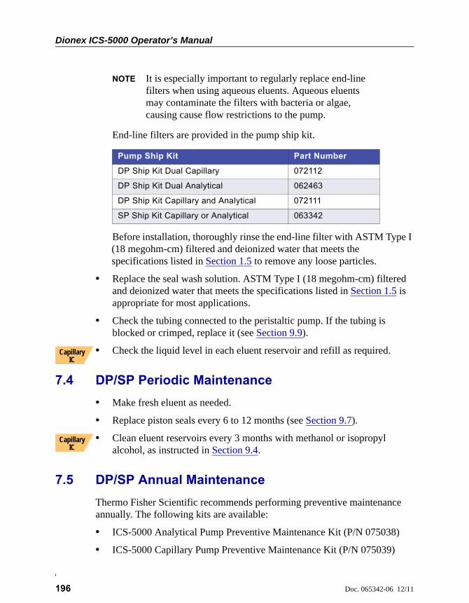
Dionex ICS-5000 Operator’s Manual
196 Doc. 065342-06 12/11
NOTE It is especially important to regularly replace end-line filters when using aqueous eluents. Aqueous eluents may contaminate the filters with bacteria or algae, causing cause flow restrictions to the pump.
End-line filters are provided in the pump ship kit.
Before installation, thoroughly rinse the end-line filter with ASTM Type I (18 megohm-cm) filtered and deionized water that meets the specifications listed in Section 1.5 to remove any loose particles.
• Replace the seal wash solution. ASTM Type I (18 megohm-cm) filtered and deionized water that meets the specifications listed in Section 1.5 is appropriate for most applications.
• Check the tubing connected to the peristaltic pump. If the tubing is blocked or crimped, replace it (see Section 9.9).
• Check the liquid level in each eluent reservoir and refill as required.
7.4 DP/SP Periodic Maintenance
• Make fresh eluent as needed.
• Replace piston seals every 6 to 12 months (see Section 9.7).
• Clean eluent reservoirs every 3 months with methanol or isopropyl alcohol, as instructed in Section 9.4.
7.5 DP/SP Annual Maintenance
Thermo Fisher Scientific recommends performing preventive maintenance annually. The following kits are available:
• ICS-5000 Analytical Pump Preventive Maintenance Kit (P/N 075038)
• ICS-5000 Capillary Pump Preventive Maintenance Kit (P/N 075039)
Pump Ship Kit Part Number
DP Ship Kit Dual Capillary 072112
DP Ship Kit Dual Analytical 062463
DP Ship Kit Capillary and Analytical 072111
SP Ship Kit Capillary or Analytical 063342
Capillary IC
Capillary IC
Doc. 065342-06 12/11 197
EG Routine Maintenance
This section describes routine maintenance procedures for the Dionex ICS-5000 Eluent Generator (EG) that users may perform. All other maintenance procedures must be performed by Thermo Fisher Scientific personnel.
For information about maintenance procedures for the EGC, CR-TC trap column, or suppressor, refer to the appropriate product manual. These manuals are included on the Thermo Scientific Reference Library DVD (P/N 053891).
7.6 EG Daily Maintenance
• Locate and repair leaks inside the EG (see Section 9.13) and wipe up liquid. Rinse dried eluents off components with deionized water.
• Rinse the EG drip tray with deionized water (to prevent formation of salt crystals) and dry the drip tray thoroughly. Rinse and dry the leak sensor, also; if the sensor is not dry, it will remain activated and continue to report a leak to the Audit Trail.
• Check the waste container and empty as needed.
7.7 EG Weekly Maintenance
• Check all lines for crimping. Move (or reroute) pinched lines and replace damaged lines (see Section 9.12). For help in isolating the cause of a tubing restriction, see Section 9.13.
• Monitor the system backpressure. A gradual increase in backpressure can indicate clogging of the EGC inlet frit from particulates in the eluent water.
7.8 EG Annual Maintenance
• Check the expiration date and remaining lifetime of the EGC on the EG ePanel in Chromeleon 7 or the Control panel in Chromeleon 6.8.
ICS-5000 EG

Dionex ICS-5000 Operator’s Manual
198 Doc. 065342-06 12/11
Doc. 065342-06 12/11 199
DC Routine Maintenance
This section describes routine maintenance procedures for the Dionex ICS-5000 Detector/Chromatography Module (DC) that users may perform. All other maintenance procedures must be performed by Thermo Fisher Scientific personnel.
7.9 DC Daily Maintenance
• Check the DC components for leaks or spills. Wipe up spills. Isolate and repair leaks (see Section 8.26). Rinse off any dried eluent with ASTM filtered, Type I (18 megohm-cm) deionized water that meets the specifications listed in Section 1.5.
• Check the waste container and empty as needed.
NOTE If you are using an electrochemical detector, also see the spe-cial maintenance considerations that are described in Section 4.1.2.
7.10 DC Weekly Maintenance
• Check liquid lines for crimping or discoloration. Relocate any pinched lines. Replace damaged lines.
• Check for excess condensation inside the DC. Condensation may build up when the DC is operated in a highly humid environment and the majority of the applications are run at cold temperatures. To remove condensation, run the DC at its maximum temperature for at least 48 hours.
7.11 DC Periodic Maintenance
• Inspect the door seal for signs of damage. A defective seal impairs the performance of the instrument. If the seal is defective, contact Technical Support for Dionex products.
ICS-5000 DC
Dionex ICS-5000 Operator’s Manual
200 Doc. 065342-06 12/11
7.12 DC Annual Maintenance
Thermo Fisher Scientific recommends performing preventive maintenance annually. The following kits are available:
• 0.4 L Internal Loop High-Pressure Valve Preventive Maintenance Kit (P/N 075040)
• 6-Port High-Pressure Valve Preventive Maintenance Kit (P/N 075041)
• 10-Port High-Pressure Valve Preventive Maintenance Kit (P/N 075042)
Doc. 065342-06 12/11 201
TC Routine Maintenance
This section describes routine maintenance procedures for the Dionex ICS-5000 Thermal Compartment (TC) that users may perform. All other maintenance procedures must be performed by Thermo Fisher Scientific personnel.
7.13 TC Daily Maintenance
• Check the TC components for leaks or spills. Wipe up spills. Isolate and repair leaks (see Section 8.31). Rinse off any dried eluent with ASTM filtered, Type I (18 megohm-cm) deionized water that meets the specifications listed in Section 1.5.
• Check the liquid level in the waste container and empty as needed.
7.14 TC Weekly Maintenance
• Check liquid lines for crimping or discoloration. Relocate any pinched lines. Replace damaged lines.
7.15 TC Periodic Maintenance
• Clean the interior of the TC, using a lint-free cloth. Use paper to absorb any liquid inside the module. The cleaner the module, the more effective the sensors are at detecting excessive gas or humidity.
ICS-5000 TC
Neutralize acidic and caustic wastes before disposal. Dispose of allwastes in accordance with local regulations.
Neutralisez les déchets acides ou caustiques avant de les jeter. Jetezles déchets aux règlements locaux.
Neutralisieren Sie säurehaltige und ätzende Abfälle vor ihrerEntsorgung. Entsorgen Sie alle Abfälle entsprechend den lokalenBestimmungen.
Dionex ICS-5000 Operator’s Manual
202 Doc. 065342-06 12/11
• Check for excess condensation inside the TC. Condensation may build up when the TC is operated in a highly humid environment and the majority of applications are run at cold temperatures. To remove condensation, run the TC at its maximum temperature for at least 72 hours.
• Inspect the door seal for signs of damage. A defective seal impairs the performance of the instrument. If the seal is defective, contact Technical Support for Dionex products.
7.16 TC Annual Maintenance
• Thermo Fisher Scientific recommends performing preventive maintenance annually. The following kits are available:
• 6-Port High-Pressure Valve Preventive Maintenance Kit (P/N 075041)
• 10-Port High-Pressure Valve Preventive Maintenance Kit (P/N 075042)
Some IC columns should not be operated at temperatures above 70 °C(158 °F). Remove all columns from the TC before beginning themaintenance procedure above.
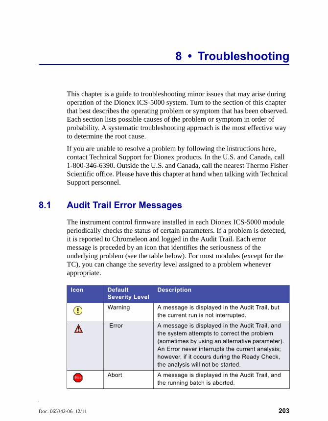
Doc. 065342-06 12/11 203
8 • Troubleshooting
This chapter is a guide to troubleshooting minor issues that may arise during operation of the Dionex ICS-5000 system. Turn to the section of this chapter that best describes the operating problem or symptom that has been observed. Each section lists possible causes of the problem or symptom in order of probability. A systematic troubleshooting approach is the most effective way to determine the root cause.
If you are unable to resolve a problem by following the instructions here, contact Technical Support for Dionex products. In the U.S. and Canada, call 1-800-346-6390. Outside the U.S. and Canada, call the nearest Thermo Fisher Scientific office. Please have this chapter at hand when talking with Technical Support personnel.
8.1 Audit Trail Error Messages
The instrument control firmware installed in each Dionex ICS-5000 module periodically checks the status of certain parameters. If a problem is detected, it is reported to Chromeleon and logged in the Audit Trail. Each error message is preceded by an icon that identifies the seriousness of the underlying problem (see the table below). For most modules (except for the TC), you can change the severity level assigned to a problem whenever appropriate.
Icon Default Severity Level
Description
Warning A message is displayed in the Audit Trail, but the current run is not interrupted.
Error A message is displayed in the Audit Trail, and the system attempts to correct the problem (sometimes by using an alternative parameter). An Error never interrupts the current analysis; however, if it occurs during the Ready Check, the analysis will not be started.
Abort A message is displayed in the Audit Trail, and the running batch is aborted.
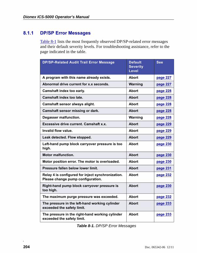
Dionex ICS-5000 Operator’s Manual
204 Doc. 065342-06 12/11
8.1.1 DP/SP Error Messages
Table 8-1 lists the most frequently observed DP/SP-related error messages and their default severity levels. For troubleshooting assistance, refer to the page indicated in the table.
DP/SP-Related Audit Trail Error Message Default Severity Level
See
A program with this name already exists. Abort page 227
Abnormal drive current for x.x seconds. Warning page 227
Camshaft index too early. Abort page 228
Camshaft index too late. Abort page 228
Camshaft sensor always alight. Abort page 228
Camshaft sensor missing or dark. Abort page 228
Degasser malfunction. Warning page 228
Excessive drive current. Camshaft x.x. Abort page 229
Invalid flow value. Abort page 229
Leak detected. Flow stopped. Abort page 229
Left-hand pump block carryover pressure is too high.
Abort page 230
Motor malfunction. Abort page 230
Motor position error. The motor is overloaded. Abort page 230
Pressure fallen below lower limit. Abort page 231
Relay 4 is configured for inject synchronization. Please change pump configuration.
Abort page 232
Right-hand pump block carryover pressure is too high.
Abort page 230
The maximum purge pressure was exceeded. Abort page 232
The pressure in the left-hand working cylinder exceeded the safety limit.
Abort page 233
The pressure in the right-hand working cylinder exceeded the safety limit.
Abort page 233
Table 8-1. DP/SP Error Messages
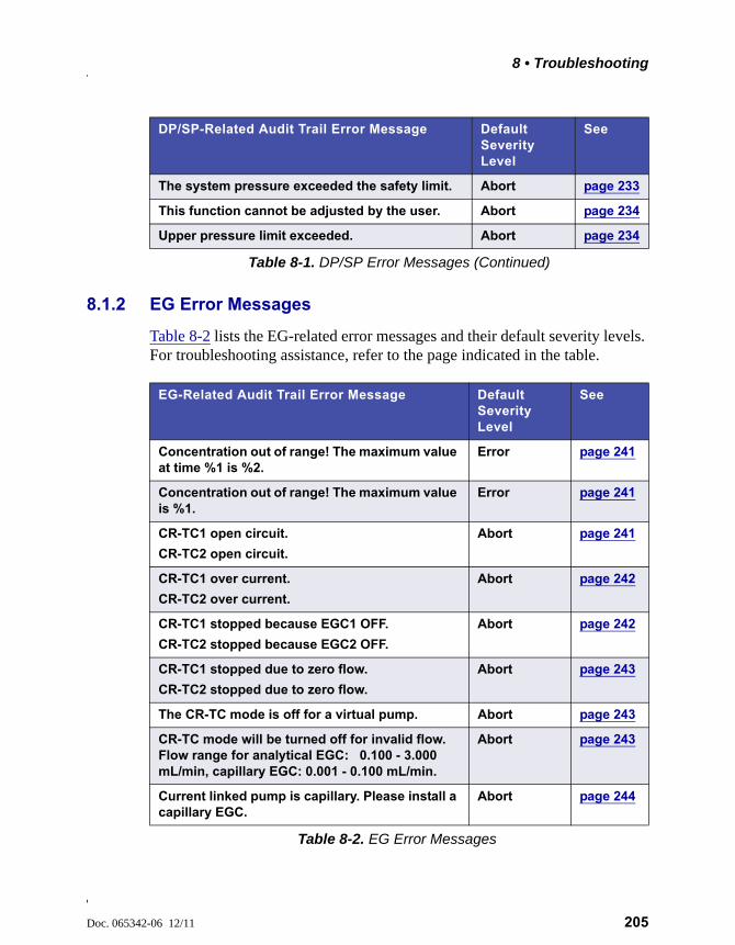
8 • Troubleshooting
Doc. 065342-06 12/11 205
8.1.2 EG Error Messages
Table 8-2 lists the EG-related error messages and their default severity levels. For troubleshooting assistance, refer to the page indicated in the table.
The system pressure exceeded the safety limit. Abort page 233
This function cannot be adjusted by the user. Abort page 234
Upper pressure limit exceeded. Abort page 234
DP/SP-Related Audit Trail Error Message Default Severity Level
See
Table 8-1. DP/SP Error Messages (Continued)
EG-Related Audit Trail Error Message Default Severity Level
See
Concentration out of range! The maximum value at time %1 is %2.
Error page 241
Concentration out of range! The maximum value is %1.
Error page 241
CR-TC1 open circuit.
CR-TC2 open circuit.
Abort page 241
CR-TC1 over current.
CR-TC2 over current.
Abort page 242
CR-TC1 stopped because EGC1 OFF.
CR-TC2 stopped because EGC2 OFF.
Abort page 242
CR-TC1 stopped due to zero flow.
CR-TC2 stopped due to zero flow.
Abort page 243
The CR-TC mode is off for a virtual pump. Abort page 243
CR-TC mode will be turned off for invalid flow. Flow range for analytical EGC: 0.100 - 3.000 mL/min, capillary EGC: 0.001 - 0.100 mL/min.
Abort page 243
Current linked pump is capillary. Please install a capillary EGC.
Abort page 244
Table 8-2. EG Error Messages
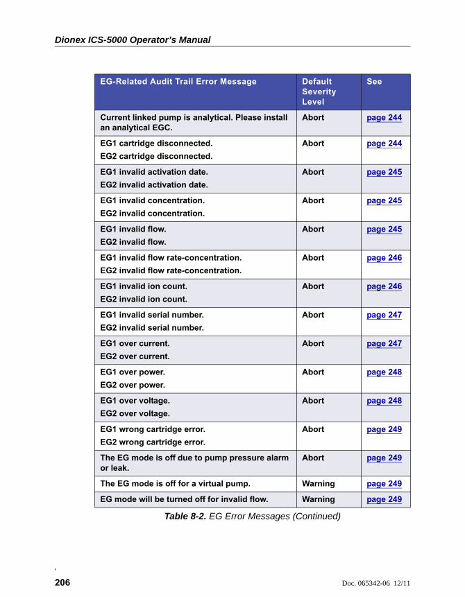
Dionex ICS-5000 Operator’s Manual
206 Doc. 065342-06 12/11
Current linked pump is analytical. Please install an analytical EGC.
Abort page 244
EG1 cartridge disconnected.
EG2 cartridge disconnected.
Abort page 244
EG1 invalid activation date.
EG2 invalid activation date.
Abort page 245
EG1 invalid concentration.
EG2 invalid concentration.
Abort page 245
EG1 invalid flow.
EG2 invalid flow.
Abort page 245
EG1 invalid flow rate-concentration.
EG2 invalid flow rate-concentration.
Abort page 246
EG1 invalid ion count.
EG2 invalid ion count.
Abort page 246
EG1 invalid serial number.
EG2 invalid serial number.
Abort page 247
EG1 over current.
EG2 over current.
Abort page 247
EG1 over power.
EG2 over power.
Abort page 248
EG1 over voltage.
EG2 over voltage.
Abort page 248
EG1 wrong cartridge error.
EG2 wrong cartridge error.
Abort page 249
The EG mode is off due to pump pressure alarm or leak.
Abort page 249
The EG mode is off for a virtual pump. Warning page 249
EG mode will be turned off for invalid flow. Warning page 249
EG-Related Audit Trail Error Message Default Severity Level
See
Table 8-2. EG Error Messages (Continued)

8 • Troubleshooting
Doc. 065342-06 12/11 207
8.1.3 DC Error Messages
Table 8-3 lists the DC-related error messages and their default severity levels. For troubleshooting assistance, refer to the page indicated in the table.
EG mode will be turned off for invalid flow. Flow range for analytical EGC: 0.100 - 3.000 mL/min, capillary EGC: 0.001 - 0.100 mL/min.
Abort page 250
EGC-1 is not linked to a compatible pump.
EGC-2 is not linked to a compatible pump.
Warning page 250
EGC cannot be used due to invalid ion count. Abort (can’t be changed)
page 251
EGC is either not installed or invalid cartridge number. Please install a capillary EGC.
Abort page 251
EGC is either not installed or invalid cartridge number. Please install an analytical EGC.
Abort page 251
EGC is either not installed or invalid cartridge number. Please install an EGC.
Abort page 252
Leak sensor wet. Warning page 252
pH modifier must be used with a different type of cartridge.
Error page 252
Pump is disconnected. The EG mode is off. Warning page 253
EG-Related Audit Trail Error Message Default Severity Level
See
Table 8-2. EG Error Messages (Continued)
DC-Related Audit Trail Error Message Default Severity Level
See
CD cell option disconnected. Abort page 259
CD cell over safe temperature. Abort page 260
Column temperature open circuit. Abort page 260
Column over safe temperature. Abort page 260
Column temperature calibration error. Warning page 261
Table 8-3. DC Error Messages

Dionex ICS-5000 Operator’s Manual
208 Doc. 065342-06 12/11
Compartment temperature open circuit. Abort page 261
Compartment over safe temperature. Abort page 261
Compartment temperature calibration error. Warning page 261
ED cell current exceeds limits error. Warning page 261
ED cell option disconnected. Abort page 262
ED cell working electrode disconnected. Abort page 263
ED pH offset calibration failed. Warning page 263
ED pH slope calibration failed. Warning page 264
ED reference electrode disconnected. Warning page 264
High pressure valve 1 error.
High pressure valve 2 error.
High pressure valve 3 error.
High pressure valve 4 error.
Abort page 265
IC Cube 1 heater over safe temperature.
IC Cube 2 heater over safe temperature.
Error page 266
Lower door opened. Warning page 267
Lower leak sensor wet. Warning page 267
Reaction coil open circuit. Abort page 267
Reaction coil over safe temperature. Abort page 268
Suppressor over-current. Abort page 268
Suppressor over-power. Abort page 268
Suppressor over-voltage. Abort page 269
Suppressor stopped for flow rate. Warning page 269
Upper door opened. Warning page 269
DC-Related Audit Trail Error Message Default Severity Level
See
Table 8-3. DC Error Messages (Continued)

8 • Troubleshooting
Doc. 065342-06 12/11 209
8.1.4 TC Error Messages
Table 8-4 lists the TC-related error messages and their default severity levels. For troubleshooting assistance, refer to the page indicated in the table.
TC-Related Audit Trail Error Message Default Severity Level
See
AcqOff without previous AcqOn. Error page 275
Acquisition is still on at program end. Error page 275
All samples scheduled for run on timebases x need to specify the same value for property (nominal) Temperature.
Error page 275
All samples scheduled for run on timebases x need to specify the same value for property TempCtrl.
Error page 275
All samples scheduled for run on timebases x need to specify the same value for property y.
Error page 276
Can't execute “Disconnect” command during data acquisition.
Warning page 276
Can't execute “Standby” command during data acquisition.
Warning page 276
Can't find download image TC3000.HEX. Abort page 276
Can't start acquisition at negative retention times.
Error page 277
Can't start acquisition: The server configuration does not fulfill the license conditions.
Abort page 277
Can’t start TC firmware. A firmware download may be necessary.
Abort page 277
Can't use device “x” as a source of the column pressure. Please check the property “SystemPressure” for a valid device name. The device must have the “Pressure” property available.
Error page 278
Table 8-4. TC Error Messages
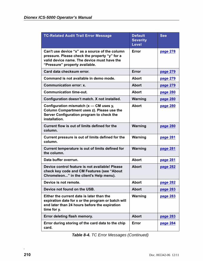
Dionex ICS-5000 Operator’s Manual
210 Doc. 065342-06 12/11
Can't use device “x” as a source of the column pressure. Please check the property “y” for a valid device name. The device must have the “Pressure” property available.
Error page 278
Card data checksum error. Error page 279
Command is not available in demo mode. Abort page 279
Communication error: x. Abort page 279
Communication time-out. Abort page 280
Configuration doesn’t match. X not installed. Warning page 280
Configuration mismatch (x — CM uses y, Column Compartment uses z). Please use the Server Configuration program to check the installation.
Abort page 280
Current flow is out of limits defined for the column.
Warning page 280
Current pressure is out of limits defined for the column.
Warning page 281
Current temperature is out of limits defined for the column.
Warning page 281
Data buffer overrun. Abort page 281
Device control feature is not available! Please check key code and CM Features (see “About Chromeleon...” in the client's Help menu).
Abort page 282
Device is not remote. Abort page 282
Device not found on the USB. Abort page 283
Either the current date is later than the expiration date for x or the program or batch will end later than 24 hours before the expiration time for y.
Warning page 283
Error deleting flash memory. Abort page 283
Error during storing of the card data to the chip card.
Error page 284
TC-Related Audit Trail Error Message Default Severity Level
See
Table 8-4. TC Error Messages (Continued)
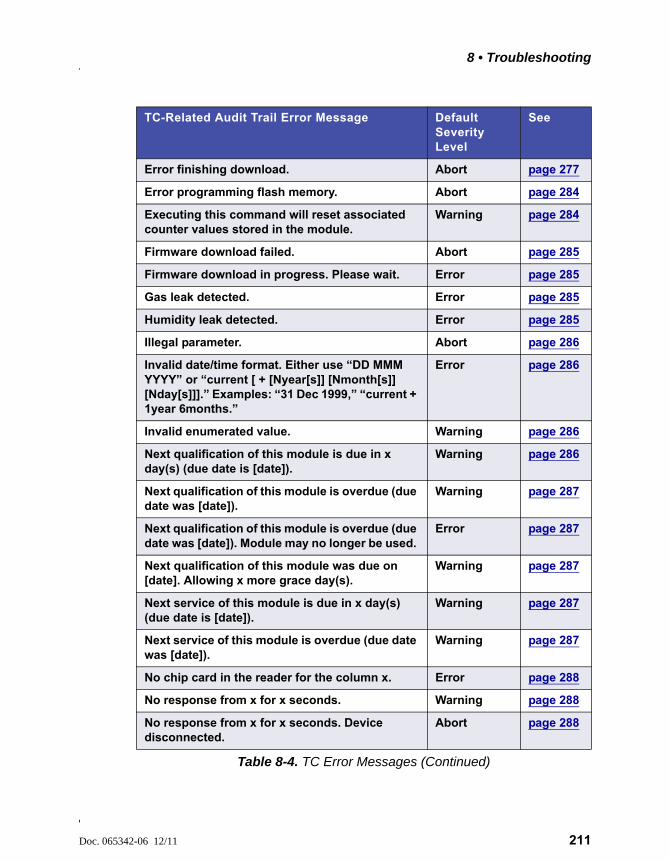
8 • Troubleshooting
Doc. 065342-06 12/11 211
Error finishing download. Abort page 277
Error programming flash memory. Abort page 284
Executing this command will reset associated counter values stored in the module.
Warning page 284
Firmware download failed. Abort page 285
Firmware download in progress. Please wait. Error page 285
Gas leak detected. Error page 285
Humidity leak detected. Error page 285
Illegal parameter. Abort page 286
Invalid date/time format. Either use “DD MMM YYYY” or “current [ + [Nyear[s]] [Nmonth[s]] [Nday[s]]].” Examples: “31 Dec 1999,” “current + 1year 6months.”
Error page 286
Invalid enumerated value. Warning page 286
Next qualification of this module is due in x day(s) (due date is [date]).
Warning page 286
Next qualification of this module is overdue (due date was [date]).
Warning page 287
Next qualification of this module is overdue (due date was [date]). Module may no longer be used.
Error page 287
Next qualification of this module was due on [date]. Allowing x more grace day(s).
Warning page 287
Next service of this module is due in x day(s) (due date is [date]).
Warning page 287
Next service of this module is overdue (due date was [date]).
Warning page 287
No chip card in the reader for the column x. Error page 288
No response from x for x seconds. Warning page 288
No response from x for x seconds. Device disconnected.
Abort page 288
TC-Related Audit Trail Error Message Default Severity Level
See
Table 8-4. TC Error Messages (Continued)
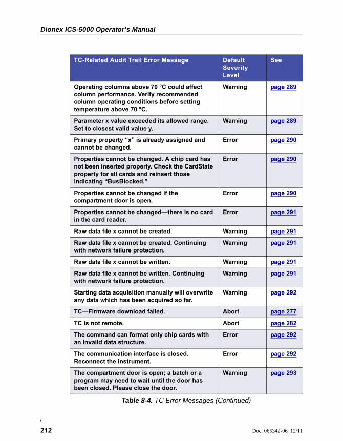
Dionex ICS-5000 Operator’s Manual
212 Doc. 065342-06 12/11
Operating columns above 70 °C could affect column performance. Verify recommended column operating conditions before setting temperature above 70 °C.
Warning page 289
Parameter x value exceeded its allowed range. Set to closest valid value y.
Warning page 289
Primary property “x” is already assigned and cannot be changed.
Error page 290
Properties cannot be changed. A chip card has not been inserted properly. Check the CardState property for all cards and reinsert those indicating “BusBlocked.”
Error page 290
Properties cannot be changed if the compartment door is open.
Error page 290
Properties cannot be changed—there is no card in the card reader.
Error page 291
Raw data file x cannot be created. Warning page 291
Raw data file x cannot be created. Continuing with network failure protection.
Warning page 291
Raw data file x cannot be written. Warning page 291
Raw data file x cannot be written. Continuing with network failure protection.
Warning page 291
Starting data acquisition manually will overwrite any data which has been acquired so far.
Warning page 292
TC—Firmware download failed. Abort page 277
TC is not remote. Abort page 282
The command can format only chip cards with an invalid data structure.
Error page 292
The communication interface is closed. Reconnect the instrument.
Error page 292
The compartment door is open; a batch or a program may need to wait until the door has been closed. Please close the door.
Warning page 293
TC-Related Audit Trail Error Message Default Severity Level
See
Table 8-4. TC Error Messages (Continued)
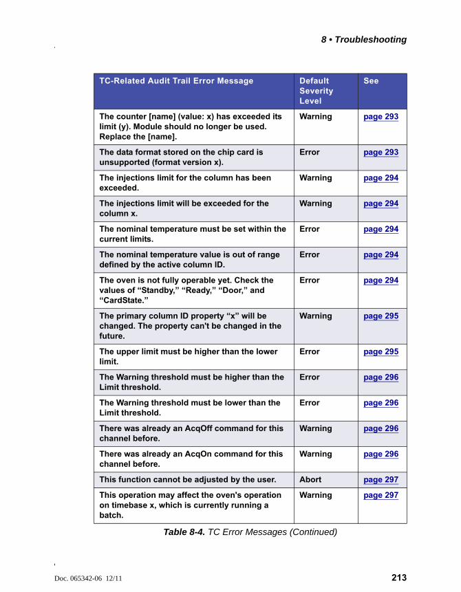
8 • Troubleshooting
Doc. 065342-06 12/11 213
The counter [name] (value: x) has exceeded its limit (y). Module should no longer be used. Replace the [name].
Warning page 293
The data format stored on the chip card is unsupported (format version x).
Error page 293
The injections limit for the column has been exceeded.
Warning page 294
The injections limit will be exceeded for the column x.
Warning page 294
The nominal temperature must be set within the current limits.
Error page 294
The nominal temperature value is out of range defined by the active column ID.
Error page 294
The oven is not fully operable yet. Check the values of “Standby,” “Ready,” “Door,” and “CardState.”
Error page 294
The primary column ID property “x” will be changed. The property can't be changed in the future.
Warning page 295
The upper limit must be higher than the lower limit.
Error page 295
The Warning threshold must be higher than the Limit threshold.
Error page 296
The Warning threshold must be lower than the Limit threshold.
Error page 296
There was already an AcqOff command for this channel before.
Warning page 296
There was already an AcqOn command for this channel before.
Warning page 296
This function cannot be adjusted by the user. Abort page 297
This operation may affect the oven's operation on timebase x, which is currently running a batch.
Warning page 297
TC-Related Audit Trail Error Message Default Severity Level
See
Table 8-4. TC Error Messages (Continued)
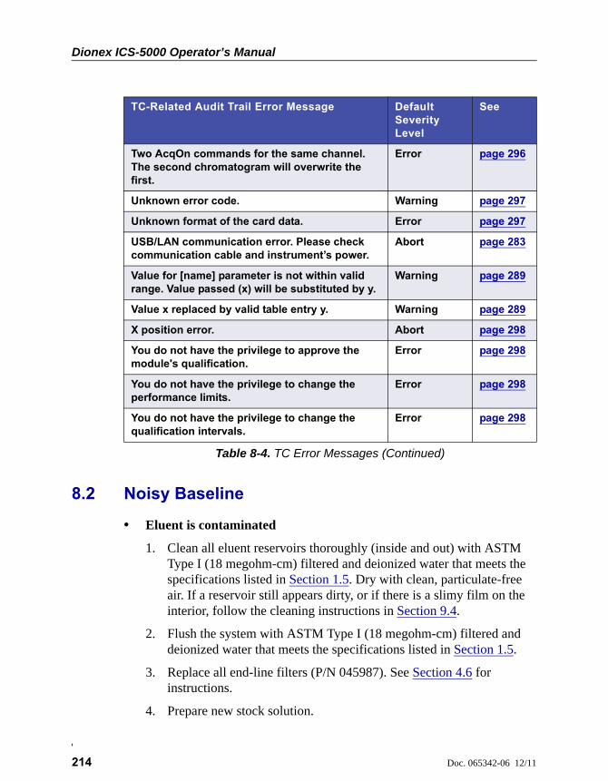
Dionex ICS-5000 Operator’s Manual
214 Doc. 065342-06 12/11
8.2 Noisy Baseline
• Eluent is contaminated
1. Clean all eluent reservoirs thoroughly (inside and out) with ASTM Type I (18 megohm-cm) filtered and deionized water that meets the specifications listed in Section 1.5. Dry with clean, particulate-free air. If a reservoir still appears dirty, or if there is a slimy film on the interior, follow the cleaning instructions in Section 9.4.
2. Flush the system with ASTM Type I (18 megohm-cm) filtered and deionized water that meets the specifications listed in Section 1.5.
3. Replace all end-line filters (P/N 045987). See Section 4.6 for instructions.
4. Prepare new stock solution.
Two AcqOn commands for the same channel. The second chromatogram will overwrite the first.
Error page 296
Unknown error code. Warning page 297
Unknown format of the card data. Error page 297
USB/LAN communication error. Please check communication cable and instrument’s power.
Abort page 283
Value for [name] parameter is not within valid range. Value passed (x) will be substituted by y.
Warning page 289
Value x replaced by valid table entry y. Warning page 289
X position error. Abort page 298
You do not have the privilege to approve the module's qualification.
Error page 298
You do not have the privilege to change the performance limits.
Error page 298
You do not have the privilege to change the qualification intervals.
Error page 298
TC-Related Audit Trail Error Message Default Severity Level
See
Table 8-4. TC Error Messages (Continued)
8 • Troubleshooting
Doc. 065342-06 12/11 215
5. Prepare fresh eluent. To ensure eluent purity, prepare all eluents with spectro-grade eluents, reagent-grade chemicals, and ASTM Type I (18 megohm-cm) filtered and deionized water that meets the specifications listed in Section 1.5.
• DP/SP not properly primed
Prime the pump (see Section 9.5).
• Piston seal is damaged
If the piston seal is damaged, it allows liquid leaks. Leaks are usually visible, and thus easily detected. If necessary, replace the piston seal (see Section 9.7).
• Inadequate system or cell backpressure
Add backpressure tubing to the cell outlet (see Section 9.27.4) or to the pump (if no column is installed).
• (Analytical EG only) System backpressure is below 14 MPa (2000 psi)
The optimal system backpressure is 16 MPa (2300 psi) in an analytical IC system with an EG installed,. Low system backpressure may cause high baseline noise as the eluent concentration increases in the gradient. To correct this, install a backpressure coil in the EG after the RFIC Eluent Degasser (see Section 9.17).
• Flow system leak ahead of cell
Check all fittings and liquid lines for leaks. Tighten or, if necessary, replace all liquid line connections (see Section 9.19).
• Rapid changes in ambient temperature
Make sure the column is installed in a thermostatically controlled compartment and the compartment door is closed.
• Insufficient system equilibration following changes to operating parameters; especially apparent when operating at high sensitivities
Allow a longer system equilibration time (up to 2 hours) before starting operation.
Dionex ICS-5000 Operator’s Manual
216 Doc. 065342-06 12/11
Noisy Baseline: CD Only
• Incorrect suppressor operating conditions
Refer to the suppressor manual for troubleshooting information. Suppressor manuals are included on the Thermo Scientific Reference Library DVD (P/N 053891).
• Cell above or below temperature
Contact Technical Support for Dionex products for assistance.
• Detector electronics not functioning correctly
Run the detector dummy cell diagnostics from the Wellness panel (see Section 9.27).
• Inappropriate suppressor operating conditions
Refer to the suppressor manual for the correct operating conditions. Suppressor manuals are included on the Thermo Scientific Reference Library DVD (P/N 053891).
• Temperature compensation setting not optimized
Optimize the selected setting (see Section 2.14).
• Trapped gases in cell
Release any trapped gases in the cell by loosening the lines to and from the cell and then retightening them. Also loosen and retighten the fittings to and from the suppressor eluent ports.
• Inadequate system backpressure
In an analytical IC system, add backpressure tubing to the cell outlet (see Section 9.27.4).
Noisy Baseline: ED Only
• (DC Amperometry and Integrated Amperometry modes) Air bubbles trapped inside cell
While wearing gloves and eye protection and with the pump running and all plumbing connected, generate a slight temporary backpressure by putting your finger over the end of the cell outlet tubing for 2 to
8 • Troubleshooting
Doc. 065342-06 12/11 217
3 seconds. Repeat two or three times. If the baseline does not improve, check the other causes of baseline instability described in this section.
NOTE To prevent air from becoming trapped in the cell in the future, increase the backpressure on the cell by connecting backpres-sure tubing to the cell outlet. The backpressure limit for the ED cell is 690 kPa (100 psi). Do not exceed this limit.
• (DC Amperometry and Integrated Amperometry modes) Frequent, random spikes in the baseline
The pH-Ag/AgCl reference electrode diaphragm is plugged. First, try regenerating the pH-Ag/AgCl reference electrode frit by soaking the electrode in a solution of 1 M KCl plus 1 M HCl. If this does not eliminate the spiking, replace the electrode (P/N 061879).
• (DC Amperometry and Integrated Amperometry modes) Regular baseline oscillation on high-sensitivity ranges
Reconnect the short length of titanium tubing to the cell inlet (see Figure 2-30).
• (DC Amperometry and Integrated Amperometry modes) Dirty or pitted conventional (nondisposable) working electrode
Polish the working electrode (see Section 9.28.4). If you are using a disposable electrode, replace it.
• (Integrated Amperometry mode) Regular baseline oscillations
1. Check the pump pressure plot to verify that the pump is working properly.
2. Air bubbles may be trapped inside the cell. While wearing gloves and eye protection, generate a slight temporary backpressure by putting your finger over the end of the cell outlet tubing for 2 to 3 seconds.
Do not block the end of the cell outlet tubing for longer than therecommended 2 to 3 seconds. Doing so creates high backpressure,which can break the pH-Ag/AgCl reference electrode glass membrane.
Dionex ICS-5000 Operator’s Manual
218 Doc. 065342-06 12/11
Repeat two or three times. If the baseline does not improve, check the other causes of baseline instability described in this section.
NOTE To prevent air from becoming trapped in the cell in the future, increase the backpressure on the cell by con-necting backpressure tubing to the cell outlet. The backpressure limit for the ED cell is 690 kPa (100 psi). Do not exceed this limit.
3. The water used to prepare the eluent may contain trace contaminants. Remake the eluent, using ASTM Type I (18 megohm-cm) filtered and deionized water that meets the specifications listed in Section 1.5.
8.3 Poor Retention Time Reproducibility
• Liquid leaks
1. Check for leaks from the piston seals. Replace the piston seal on any head with a leak (see Section 9.7).
2. Check for leaks throughout the remainder of the system, including the check valves, injection valve, and columns. Tighten or replace fittings as needed.
• DP/SP not primed
Prime the pump (see Section 9.5).
• Liquid lines incompletely flushed after an eluent change
Attach a 10 cc syringe (P/N 054578) to the waste port on the priming valve. Open the priming valve (turn the knob one-half turn counterclockwise). Draw at least 20 mL of the new eluent through the liquid lines before operation.
• Inoperative eluent proportioning valve (gradient pump only)
The proportioning valve assembly should be replaced. Contact Technical Support for Dionex products for assistance.
Do not block the end of the cell outlet tubing for longer than therecommended 2 to 3 seconds. Doing so creates high backpressure,which can break the pH-Ag/AgCl reference electrode glass membrane.
8 • Troubleshooting
Doc. 065342-06 12/11 219
• Inoperative check valves
Replace the check valve cartridges (see Section 9.6).
• Insufficient mixing (gradient pump only)
The static mixer may be dirty or contaminated. Flush with IPA (isopropyl alcohol). If this does not eliminate the problem, install a new mixer (GM-3, P/N 042126; GM-4, P/N 049135).
• Eluent is contaminated
1. Clean all eluent reservoirs thoroughly (inside and out) with ASTM Type I (18 megohm-cm) filtered and deionized water that meets the specifications listed in Section 1.5. Dry with clean, particulate-free air. If a reservoir still appears dirty, or if there is a slimy film on the interior, follow the cleaning instructions in Section 9.4.
2. Flush the system with ASTM Type I (18 megohm-cm) filtered and deionized water that meets the specifications listed in Section 1.5.
3. Replace all end-line filters (P/N 045987). See Section 4.6 for instructions.
4. Prepare new stock solution.
5. Prepare fresh eluent. To ensure eluent purity, prepare all eluents with electrochemical-grade chemicals, and ASTM Type I (18 megohm-cm) filtered and deionized water that meets the specifications listed in Section 1.5.
• Problem unrelated to the pump
1. The eluent concentration may be wrong, or the eluent may have been prepared with impure chemicals/eluents or water. To ensure eluent purity, prepare all eluents with spectro-grade eluents, reagent-grade chemicals, and ASTM Type I (or better) filtered and deionized water that meets the specifications listed in Section 1.5.
2. The column may be the source of the problem. Refer to the column manual for troubleshooting assistance. Column manuals are provided on the Thermo Scientific Reference Library DVD (P/N 053891).
3. The injection valve may be the source of the problem. Rebuild the injection valve (see Section 9.22).
Dionex ICS-5000 Operator’s Manual
220 Doc. 065342-06 12/11
8.4 Peak Retention Times Are Too Early
• Eluent concentration setting is too high
The correct eluent concentration setting depends on several factors (the flow rate, EGC type, etc.). Refer to Section 4.9 for a list of valid concentration ranges for the cartridges, and then edit the program as required.
• DP/SP flow rate is too low
Increase the DP/SP flow rate.
• Inoperative eluent proportioning valve (gradient pump only)
The proportioning valve assembly should be replaced. Contact Technical Support for Dionex products for assistance.
8.5 Peak Retention Times Are Too Late
• Eluent concentration setting is too low
The correct eluent concentration setting depends on several factors (the flow rate, EGC type, etc.). Refer to Section 4.9 for a list of valid concentration ranges for the cartridges, and then edit the program as required.
• DP/SP flow rate is too high
Decrease the DP/SP flow rate.
• Inoperative eluent proportioning valve (gradient pump only)
The proportioning valve assembly should be replaced. Contact Technical Support for Dionex products for assistance.
8.6 No Peaks
• EG power is not turned on
1. Check that the POWER button on the front of the EG is turned on.
2. Check that the EG main power switch (on the rear panel) is turned on.
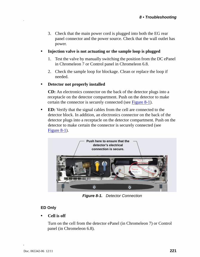
8 • Troubleshooting
Doc. 065342-06 12/11 221
3. Check that the main power cord is plugged into both the EG rear panel connector and the power source. Check that the wall outlet has power.
• Injection valve is not actuating or the sample loop is plugged
1. Test the valve by manually switching the position from the DC ePanel in Chromeleon 7 or Control panel in Chromeleon 6.8.
2. Check the sample loop for blockage. Clean or replace the loop if needed.
• Detector not properly installed
CD: An electronics connector on the back of the detector plugs into a receptacle on the detector compartment. Push on the detector to make certain the connector is securely connected (see Figure 8-1).
• ED: Verify that the signal cables from the cell are connected to the detector block. In addition, an electronics connector on the back of the detector plugs into a receptacle on the detector compartment. Push on the detector to make certain the connector is securely connected (see Figure 8-1).
ED Only
• Cell is off
Turn on the cell from the detector ePanel (in Chromeleon 7) or Control panel (in Chromeleon 6.8).
Figure 8-1. Detector Connection
Push here to ensure that the detector’s electrical
connection is secure.

Dionex ICS-5000 Operator’s Manual
222 Doc. 065342-06 12/11
8.7 Tailing Peaks
• Excess tubing void volumes
Check tubing connections for void volumes.
• (CD) Long tubing lengths connecting
Minimize all tubing lengths between the injection valve and the detector.
• (DC Amperometry and Integrated Amperometry modes) Dirty or pitted conventional (nondisposable) working electrode
Clean the working electrode with water and dry with pressurized air or nitrogen.
Polish the working electrode (see Section 9.28.4). If you are using a disposable electrode, replace it.
• Capillary tubing fittings incorrectly installed
Incorrectly installed fittings on capillary tubing can increase void volumes, causing chromatograms with tailing peaks (see Figure 8-2).
To correctly install fittings on capillary tubing, follow the instructions in Section 9.1.
Figure 8-2. Tailing Peaks Caused by Incorrectly Installed Capillary Tubing Fittings
Capillary IC
8 • Troubleshooting
Doc. 065342-06 12/11 223
8.8 Low System Backpressure
• Loose fitting
Make sure there are no liquid leaks in the flow system. Check tubing connections throughout the system (including the check valves, injection valves, and columns) and tighten or replace fittings as needed.
• RFIC Eluent Degasser tubing is ruptured
If flow from the EG waste line is normal but there is no flow through the columns, the tubing assembly inside the RFIC Eluent Degasser has ruptured. Replace the degasser (see Section 9.16).
• Internal EGC leak (from membrane barrier)
Leakage from the membrane barrier may trip the DP/SP low pressure limit and shut down the pump. If all other causes of the low system pressure have been eliminated, replace the EGC (see Section 9.14).
NOTE The EG leak sensor cannot immediately detect leakage from the membrane barrier because these leaks exit the EG through the vent line.
8.9 High System Backpressure
• Restriction in the system plumbing
1. Begin pumping eluent through the system (including the columns) at the flow rate normally used.
2. Work backward through the system, beginning at the flow cell exit. One at a time, loosen each fitting and observe the pressure. The connection at which the pressure drops abnormally indicates the point of restriction. If the EGC is the source of the high backpressure, replace the outlet frit as instructed in the EGC manual. The manual is on the Thermo Scientific Reference Library DVD (P/N 053891).
3. If the restriction has caused such high pressure that the system cannot be operated, you must work forward through the system, adding parts one at a time until an abnormal pressure increase (and hence, the restriction) is found.
Dionex ICS-5000 Operator’s Manual
224 Doc. 065342-06 12/11
• TC temperature stabilizer is blocked
Rinse the temperature stabilizer and the temperature stabilizer inlet line, using an appropriate solvent. If necessary, replace the temperature stabilizer (standard bore, P/N 064548; microbore, P/N 064650).
8.10 Low Detector Output
• Insufficient sample injected
Increase the injection size or concentration.
ED Only
• Working electrode fouled
1. If a disposable working electrode is being used, replace the electrode.
2. For conventional (nondisposable) electrodes, clean the working electrode with ASTM Type I (18 megohm-cm) filtered and deionized water that meets the specifications listed in Section 1.5. Dry with pressurized air or nitrogen. If the electrode is pitted, polish the electrode (see Section 9.28.4).
3. Check the value of the reference potential shift (see “Using a Digital Voltmeter to Determine Reference Potential Shift” on page 274). If the value fluctuates by more than 30 mV, electrode passivation may occur because potentials that are too high are being applied. Recalibrate the pH-Ag/AgCl reference electrode (see Section 9.28.6). If the problem persists, replace the pH-Ag/AgCl reference electrode (see Section 9.28.5).
Analog Output Option
• Analog output range set too high
Select a more sensitive analog output range.
8 • Troubleshooting
Doc. 065342-06 12/11 225
8.11 High Background
• CR-TC is contaminated
Clean the trap column as instructed in the CR-TC manual. The manual is included on the Thermo Scientific Reference Library DVD (P/N 053891).
• Wrong eluent
Check that you are using the correct eluent for your application. For ED detectors, verify that the pH readout is correct for your eluent.
• Background signal not offset from detector signal
Before injecting sample, allow the background signal to equilibrate, and then press Autozero on the detector ePanel in Chromeleon 7 or Control panel in Chromeleon 6.8.
CD Only
• Background not suppressed by suppressor
Verify that the suppressor is turned on and the current is set to the correct value. Refer to the suppressor manual for additional troubleshooting guidance. Suppressor manuals are included on the Thermo Scientific Reference Library DVD (P/N 053891).
• Regenerant fails to suppress background
Use a higher regenerant flow rate. Refer to the suppressor manual for the suggested regenerant flow rate for your application.
ED Only
• (Integrated Amperometry mode) Excessive number or length of integration intervals and/or incorrect potential for the integration
Verify that the length and potential of the integration interval is correct (refer to the column manual for the settings required for your application). Column manuals are included on the Thermo Scientific Reference Library DVD (P/N 053891).
Dionex ICS-5000 Operator’s Manual
226 Doc. 065342-06 12/11
• (DC Amperometry and Integrated Amperometry modes) Amperometric detection cell working electrode shorted to counter electrode
Clean the working electrode with water and dry with pressurized air or nitrogen.
Remove any precipitate on the counter electrode by cleaning the spot directly opposite the working electrode with a lint-free tissue.
• (DC Amperometry and Integrated Amperometry modes)—Leak between gasket and electrode, or between gasket and cell body
Remove any precipitate with water and a lint-free tissue and then install a new gasket (see Section 9.28.3).
Turn the yoke knob (see Figure 9-53) a full 360 degrees to completely engage the knob.
Doc. 065342-06 12/11 227
DP/SP Troubleshooting
8.12 Troubleshooting DP/SP Error Messages
If any of the following alarm conditions occurs, a message is displayed in the Chromeleon Audit Trail.
A program with this name already exists.
This error occurs if you attempt to save a modified Chromeleon 7 instrument method or Chromeleon 6.8 program under the name of an existing instrument method or program.
To troubleshoot:
Enter a new name for the modified instrument method or program or select Save to save your changes under the existing instrument method or program name.
Abnormal drive current for x.x seconds.
If this error occurs, the tubing between the pump heads may be blocked or the fitting may be overtightened.
To troubleshoot:
Inspect the tubing for blockage or crimping and replace if needed (see Section 9.3). Be careful to not overtighten fittings. If the message appears again, contact Technical Support for Dionex products for assistance.
ICS-5000 DP/SP
Dionex ICS-5000 Operator’s Manual
228 Doc. 065342-06 12/11
Camshaft index too early.
-or-
Camshaft index too late.
This error is caused by an internal error in the pump drive mechanism.
To troubleshoot:
Turn off the DP/SP power for 30 seconds and then turn it on again. If the error message appears again, contact Technical Support for Dionex products for assistance.
Camshaft sensor always alight.
-or-
Camshaft sensor missing or dark.
This error is caused by an internal error in the pump drive mechanism.
To troubleshoot:
Turn off the DP/SP power for 30 seconds and then turn it on again. If the error message appears again, contact Technical Support for Dionex products for assistance.
Degasser malfunction.
The vacuum degassing module monitors the vacuum system continuously. If a problem is detected, this error occurs.
To troubleshoot:
1. Check all tubing connections to the vacuum degassing module for leakage; tighten loose fitting connections. Be careful not to overtighten fittings.
2. Turn off the DP/SP power for 30 seconds and then restart the pump.
3. If the message appears again, the vacuum degassing module should be replaced. Contact Technical Support for Dionex products for assistance.
8 • DP/SP Troubleshooting
Doc. 065342-06 12/11 229
Excessive drive current. Camshaft x.x.
This error occurs if the drive current is above the allowed value. When this message appears, the DP/SP stops running.
To troubleshoot:
One or more tubing connections may be plugged, blocked, or crimped. Check all tubing connections and replace as needed (see Section 9.3). Be careful not to overtighten fittings.
Invalid flow value.
This error occurs if you enter an invalid value for the DP/SP flow rate in Chromeleon.
To troubleshoot:
Select a flow rate within the DP/SP flow rate range. For the flow rate range for each type of DP/SP, refer to Section 1.5.
Leak detected.
This error occurs if the DP/SP leak sensor detects a liquid leak inside the enclosure. When this error occurs, the pump stops running.
To troubleshoot:
To find and eliminate the source of the leak, see Section 8.15.
Dionex ICS-5000 Operator’s Manual
230 Doc. 065342-06 12/11
Left-hand pump block carryover pressure is too high.
-or-
Right-hand pump block carryover pressure is too high.
This error occurs if the pressure in the primary pump head exceeds the maximum allowed. (“Right-hand” refers to the bottom pump; “left-hand” refers to the top pump in a dual-pump module.)
To troubleshoot:
1. Make sure that the tubing between the pump heads and the tubing leading to the priming/outlet block is not plugged or blocked. Replace tubing connections as needed (see Section 9.3). Be careful not to overtighten fittings.
2. Inspect the outlet check valve for blockage. Replace the check valve cartridge if needed (see Section 9.6).
Motor malfunction.
This error occurs if an internal error in the pump drive mechanism occurs.
To troubleshoot:
Turn off the DP/SP power for 30 seconds, and then turn on the power again. If the error message appears again, contact Technical Support for Dionex products for assistance.
Motor position error. The motor is overloaded.
This error occurs if the pump motor is overloaded.
To troubleshoot:
1. One or more tubing connections may be plugged or blocked. Check all tubing connections and replace as needed (see Section 9.3). Be careful not to overtighten fittings.
2. If the “Upper pressure limit exceeded message” is also displayed, refer to page 234 for additional troubleshooting steps.
8 • DP/SP Troubleshooting
Doc. 065342-06 12/11 231
Pressure fallen below lower limit.
This error occurs if the DP/SP pressure falls below the low pressure limit specified in Chromeleon.
To troubleshoot:
1. The eluent supply may be depleted. Check the Eluent Level Display on the Chromeleon 7 ePanel Set or Chromeleon 6.8 panel tabset to verify that eluent is present in the selected channel. If the eluent reservoir is empty, refill it (or select a channel that does have eluent). Prime the pump before resuming operation (see Section 9.5).
2. Check all eluent lines for air bubbles. If air is trapped in a line, replace the end-line filter (P/N 045987). See Section 4.6 for instructions. Verify that the end of each filter extends to the bottom of the reservoir and is submerged in eluent. Prime the pump (see Section 9.5).
3. Eluents may be insufficiently degassed. Check the vacuum degassing module.
4. Check all tubing connections for leaks; tighten loose fitting connections. Be careful not to overtighten fittings.
5. Make sure the priming valve is closed (see Figure 2-3). To close the valve, turn the knob clockwise until closed. Tighten no more than fingertight.
6. A check valve may be defective. Replace the check valve cartridges (see Section 9.6) and then prime the pump (see Section 9.5).
Do not use any tools to tighten the priming valve! Overtightening maydestroy the cap seal. Open or close the priming valve only when thesystem pressure is down.
Dionex ICS-5000 Operator’s Manual
232 Doc. 065342-06 12/11
Relay 4 is configured for inject synchronization. Please change pump configuration.
This error occurs if you attempt to use relay 4 as a standard relay in a Chromeleon 7 instrument method or Chromeleon 6.8 program, but the relay has been set to synchronize the gradient with the autosampler sample injection.
To troubleshoot:
Define the relay as a standard relay or specify a different relay for use in the program.
The maximum purge pressure was exceeded.
If the DP/SP pressure exceeds 5 MPa (725 psi) during priming, this error occurs and the priming process is aborted.
To troubleshoot:
1. Verify that the priming valve is open. (To open the valve, turn the knob one-half turn counterclockwise.)
2. Check fittings for overtightening. Check tubing for crimping and replace it as necessary (see Section 9.3). Be careful not to overtighten fittings.
8 • DP/SP Troubleshooting
Doc. 065342-06 12/11 233
The pressure in the left-hand working cylinder exceeded the safety limit.
-or-
The pressure in the right-hand working cylinder exceeded the safety limit.
-or-
The system pressure exceeded the safety limit.
This error may be caused by a blockage in the system or by a problem with the column. (“Right-hand” refers to the bottom pump; “left-hand” refers to the top pump in a dual-pump module.)
To troubleshoot:
1. Check all tubing connections for signs of blockage; replace as needed (see Section 9.3). Be careful not to overtighten fittings.
2. To determine the source of the high backpressure, isolate segments of the flow path:
a. Remove the pump outlet tubing at the injection valve.
b. Press the POWER button on the front of the DP/SP to turn on the pump.
c. On the Chromeleon 7 ePanel Set or Chromeleon 6.8 panel tabset, set the Flow rate to 0.01 mL/min for a capillary IC system or 1.0 mL/min for an analytical IC system and record the backpressure.
d. Disconnect all components after the injection valve.
e. One at a time, reconnect each component of the flow path. If reconnecting a component causes an abnormal increase in backpressure, replace the component. Replace as many components as necessary to resume operation at the standard operating backpressure.
3. As columns age, their backpressure increases. It may be necessary to compensate for this by increasing the high pressure limit. If the column is the source of the high backpressure, clean the column. (Refer to the column manual provided on the Thermo Scientific Reference Library DVD (P/N 053891) for instructions.) If this does not eliminate the problem, replace the column.
Dionex ICS-5000 Operator’s Manual
234 Doc. 065342-06 12/11
4. Observe a run to see whether the high pressure limit is triggered when injection occurs; if it is, the injection valve may be the source of the blockage (i.e., the rotor seal or stator may need to be replaced). Contact Technical Support for Dionex products for assistance.
This function cannot be adjusted by the user.
This error occurs if you attempt to change a parameter that users are not allowed to adjust.
To troubleshoot:
Only Thermo Fisher Scientific Service Representatives can change this parameter.
Upper pressure limit exceeded.
This error occurs if the upper pressure limit specified in the program is exceeded. The running batch is aborted (default) and this message appears.
To troubleshoot:
1. Inspect the tubing for blockage or crimping; replace as needed (see Section 9.3). Be careful not to overtighten fittings.
2. To determine the source of the high backpressure, isolate segments of the flow path:
a. Remove the pump outlet tubing at the injection valve.
b. Press the POWER button on the front of the DP/SP to turn on the pump.
c. On the Chromeleon 7 ePanel Set or Chromeleon 6.8 panel tabset, set the Flow rate to 0.01 mL/min for a capillary IC system or 1.0 mL/min for an analytical IC system and record the backpressure.
d. Disconnect all components after the injection valve.
e. One at a time, reconnect each component of the flow path. If reconnecting a component causes an abnormal increase in backpressure, replace the component. Replace as many components
8 • DP/SP Troubleshooting
Doc. 065342-06 12/11 235
as necessary to resume operation at the standard operating backpressure.
3. As columns age, their backpressure increases. It may be necessary to compensate for this by increasing the high pressure limit. If the column is the source of the high backpressure, clean the column. (Refer to the column manual provided on the Thermo Scientific Reference Library DVD (P/N 053891) for instructions.) If this does not eliminate the problem, replace the column.
4. Observe a run to see whether the high pressure limit is triggered when injection occurs; if it is, the injection valve may be the source of the blockage (i.e., the rotor seal or stator may need to be replaced). Contact Technical Support for Dionex products for assistance.
8.13 DP/SP Does Not Start
• Power is off
Check that the main power switch on the DP/SP rear panel is turned on.
Press the POWER button on the front of the DP/SP to turn on the pump.
• Flow rate is set to zero
Select a Flow rate on the Chromeleon 7 ePanel Set or Chromeleon 6.8 panel tabset.
• While being primed, pump starts briefly and an alarm sounds
If the high pressure limit was tripped:
1. Check that the priming valve on the secondary pump head is opened (see Figure 2-3). To open the valve, turn the knob one-half turn counterclockwise.
2. Check fittings for overtightening. Check tubing for crimping and replace it as necessary (see Section 9.3). Be careful not to overtighten fittings.
Dionex ICS-5000 Operator’s Manual
236 Doc. 065342-06 12/11
If the low pressure limit was tripped:
1. Verify that the Minimum Pressure setting is set to the correct value.
2. Make sure there are no liquid leaks in the flow system. To find and eliminate the source of a leak, see Section 8.15.
If an Audit Trail error message is displayed, refer to the troubleshooting steps listed for the particular message.
8.14 DP/SP Stops
• Instrument method or program (or other remote input) instructed the pump to stop
If no error message is displayed in the Audit Trail, the DP/SP was probably instructed to stop by the Chromeleon 7 instrument method, the Chromeleon 6.8 program, or other remote signal source. If you do not want the pump to stop, take the appropriate preventive action (edit the instrument method, the program, or the settings of the other remote signal source).
• Low pressure limit was tripped
Refer to the troubleshooting steps for the Audit Trail message “Pressure fallen below lower limit.” on page 231.
• High pressure limit was tripped
Refer to the troubleshooting steps for the Audit Trail message “The system pressure exceeded the safety limit.” on page 233.
• Electrical connections incorrectly installed
The electrical cables may not be properly installed. Contact Technical Support for Dionex products for assistance.
NOTE The Thermo Scientific Dionex ICS-5000 Ion Chroma-tography System electronics components cannot be serviced by the user.
8 • DP/SP Troubleshooting
Doc. 065342-06 12/11 237
8.15 DP/SP Liquid Leaks/Leak Alarm
NOTE After eliminating the source of a leak, always dry the leak sensor thoroughly. If the leak sensor is not dry, it will remain activated and will continue to report a leak to the Audit Trail.
• Defective piston seal
Check the pump heads for leaks. If there is any leakage, tighten the fitting connections just enough to stop the leak. Dry the components. If the pump head continues to leak, replace the piston seal (see Section 9.7).
• Leaking check valve
If the leaking check valve is securely tightened but allows leaks despite this, the valve is defective. Replace both check valve cartridges (see Section 9.6).
If the leaking check valve is loose, follow these steps to tighten it:
1. Turn off the pump.
2. Loosen the check valve enough to allow it to turn freely.
3. Tighten the check valve fingertight, and then tighten it one-quarter turn with a 1/2-inch wrench.
4. If the check valve continues to leak, tighten it an additional one-quarter turn with the 1/2-inch wrench.
5. If the check valve continues to leak, it is defective. Replace both check valve cartridges (see Section 9.6).
• Eluent proportioning valve leaks (gradient pump only)
Tighten loose fittings. If there are no loose fittings, the proportioning valve assembly should be replaced. Contact Technical Support for Dionex products for assistance.
Dionex ICS-5000 Operator’s Manual
238 Doc. 065342-06 12/11
• Priming valve knob leaks
If leaks occur when the priming valve knob is open, close the knob completely and then open it one-half to three-quarters turn. If this does not stop the leakage, replace the seal in the priming valve knob (see Section 9.10).
If leaks occurs when the priming valve knob is closed, either the pump head or the knob is damaged and should be replaced. Contact Technical Support for Dionex products for assistance.
• Excessive system backpressure
If system backpressure is substantially higher than the normal operating backpressure for the currently configured system (including the column), tubing may be plugged or overtightened. Refer to the troubleshooting steps for the Audit Trail message “The system pressure exceeded the safety limit.” on page 233.
8.16 Vacuum Degassing Module Low Vacuum
• Leak in the vacuum degassing module
Check all tubing connections for leakage; tighten loose fitting connections.
8.17 Vacuum Degassing Module Does Not Run
• Electrical connections incorrectly installed
There may be a problem with the connections from the vacuum degassing module to the CPU board. Contact Technical Support for Dionex products for assistance.
NOTE The Thermo Scientific Dionex ICS-5000 Ion Chroma-tography System electronics components cannot be serviced by the user.
8 • DP/SP Troubleshooting
Doc. 065342-06 12/11 239
8.18 DP/SP Digital I/O Port Inoperative
• TTL input-related error
1. The TTL input mode must match the signal type output by the device connected to the pump. Check the user’s manual for the device to verify that the correct signal type is selected.
2. A programming error occurred in the device sending the signal. Refer to the user’s manual for the device for troubleshooting assistance.
• TTL/Relay output-related error
1. A programming error occurred in the device sending the signal. Refer to the user’s manual for the device for troubleshooting assistance.
2. The device being triggered may require a TTL, not a relay. Connect the device to a pump TTL output.

Dionex ICS-5000 Operator’s Manual
240 Doc. 065342-06 12/11
Doc. 065342-06 12/11 241
EG Troubleshooting
8.19 Troubleshooting EG Error Messages
If any of the following alarm conditions occurs, a message is displayed in the Chromeleon Audit Trail.
Concentration out of range! The maximum value is %1.
-or-
Concentration out of range! The maximum value at time %1 is %2.
The allowable eluent concentration depends on the flow rate and the EGC type. This message appears if the selected eluent concentration is out-of-range for the flow rate. The time indicated in the message refers to the time specified in the Chromeleon 7 instrument method or Chromeleon 6.8 program.
To troubleshoot:
Check the information in Section 4.10 to verify that the selected concentration is within the accepted range for the cartridge type and flow rate. Adjust the flow rate or concentration as needed.
CR-TC1 open circuit.
-or-
CR-TC2 open circuit.
To troubleshoot:
1. Check that the CR-TC is correctly plugged into the EG. Push the CR-TC electrical cable firmly into the CR-TC 1 (or CR-TC 2) bulkhead connector. Twist the ring on the cable connector fingertight to secure it.
2. If the error persists, the CR-TC may be faulty. Replace the CR-TC (see Section 9.15).
ICS-5000 EG
Dionex ICS-5000 Operator’s Manual
242 Doc. 065342-06 12/11
CR-TC1 over current.
-or-
CR-TC2 over current.
This error occurs when the current applied to the CR-TC exceeds the maximum current allowed. (The CR-TC current is automatically turned off to prevent damage to the CR-TC.) This error may also occur if liquid flow to the CR-TC is interrupted.
To troubleshoot:
1. Check the CR-TC cable connection to the electrical bulkhead (see Figure 2-10).
2. Refer to Section 8.23 to determine why liquid flow stopped.
3. If the error message appears again, contact Technical Support for Dionex products for assistance. The CR-TC control electronics may have malfunctioned.
NOTE The Thermo Scientific Dionex ICS-5000 Ion Chromatogra-phy System electronics components cannot be serviced by the user.
CR-TC1 stopped because EGC1 OFF.
-or-
CR-TC2 stopped because EGC1 OFF.
This error occurs if you attempt to turn on the CR-TC when the EGC is turned off. The CR-TC current is automatically turned off to prevent damage to the CR-TC.
To troubleshoot:
Verify that the pump flow and the EGC are on before turning on the CR-TC.
8 • EG Troubleshooting
Doc. 065342-06 12/11 243
CR-TC1 stopped due to zero flow.
-or-
CR-TC2 stopped due to zero flow.
This error occurs if you turn off the pump flow while the EGC current (and CR-TC) are on. The CR-TC current is automatically turned off to prevent damage to the CR-TC.
To troubleshoot:
If the pump stopped unexpectedly, follow the troubleshooting steps in Section 8.23.
The CR-TC mode is off for a virtual pump.
This error occurs when a “live” EG is linked to a virtual pump and you try to turn on the CR-TC. The mode is automatically turned off to ensure that the EG does not operate when there is no flow.
CR-TC mode will be turned off for invalid flow. Flow range for analytical EGC: 0.100 – 3.000 mL/min, capillary EGC: 0.001 – 0.100 mL/min.
This error occurs when the flow to the CR-TC is out of range or there is no pumped linked to the EGC.
To troubleshoot:
1. Set the flow rate to a value within the allowed range. Refer to Appendix A for flow rate specifications.
2. Check the EGC configuration properties in the Chromeleon 7 Instrument Controller Service or the Chromeleon 6.8 Server Configuration program to verify that the pump and EGC are linked.
Dionex ICS-5000 Operator’s Manual
244 Doc. 065342-06 12/11
Current linked pump is capillary. Please install a capillary EGC.
-or-
Current linked pump is analytical. Please install an analytical EGC.
This error occurs if the type of pump linked to the EGC does not match the EGC type. A capillary EGC can only be used with a capillary pump and an analytical EGC can only be used with an analytical pump.
To troubleshoot:
1. Install the correct type of EGC for the pump type.
2. For a hybrid system (a dual system with both an analytical and a capillary pump), check the EGC configuration properties in the Chromeleon 7 Instrument Controller Service or the Chromeleon 6.8 Server Configuration program to verify that the correct pump is linked to the EGC.
EG1 cartridge disconnected.
-or-
EG2 cartridge disconnected.
This error occurs if Chromeleon sends a command to set an EG parameter when the EGC is disconnected.
To troubleshoot:
1. Make sure the EGC cable is securely plugged into the EG (see Figure 2-10) and the locking ring is tightened.
2. If the error message appears again, contact Technical Support for Dionex products for assistance. The EGC control electronics may have malfunctioned.
NOTE The Thermo Scientific Dionex ICS-5000 Ion Chromatogra-phy System electronics components cannot be serviced by the user.
8 • EG Troubleshooting
Doc. 065342-06 12/11 245
EG1 invalid activation date.
-or-
EG2 invalid activation date.
This error occurs if the activation date for the EGC is not a valid date. This may indicate a problem with the memory chip in the EGC.
To troubleshoot:
1. Make sure the EGC cable is securely plugged into the EG (see Figure 2-10) and the locking ring is tightened.
2. If the error message appears again, contact Technical Support for Dionex products for assistance.
EG1 invalid concentration.
-or-
EG2 invalid concentration.
This error occurs if the eluent concentration is outside the range allowed by the EG. This may indicate corrupted memory or a problem in the EG instrument control firmware.
To troubleshoot:
Contact Technical Support for Dionex products for assistance.
NOTE The Thermo Scientific Dionex ICS-5000 Ion Chromatogra-phy System electronics components and instrument control firmware cannot be serviced by the user.
Dionex ICS-5000 Operator’s Manual
246 Doc. 065342-06 12/11
EG1 invalid flow.
-or-
EG2 invalid flow.
This error occurs if the flow rate is set to a value the EG does not support.
To troubleshoot:
Set the flow rate to a value within the allowed range. Refer to Appendix A for flow rate specifications.
EG1 invalid flow rate-concentration.
-or-
EG2 invalid flow rate-concentration.
This error occurs if the selected concentration is too high for the current flow rate.
To troubleshoot:
Set the flow rate to a value within the allowed range. The allowable eluent concentration for a particular application depends on several factors: the flow rate, suppressor type, EGC type, and cartridge configuration. For details, refer to Section 4.9.
EG1 invalid ion count.
-or-
EG2 invalid ion count.
This error occurs if the ion count reported by the EGC is invalid. This may indicate a problem with the memory chip in the EGC.
To troubleshoot:
1. Make sure the EGC cable is securely plugged into the EG (see Figure 2-10) and the locking ring is tightened.
2. If the error message appears again, contact Technical Support for Dionex products for assistance.

8 • EG Troubleshooting
Doc. 065342-06 12/11 247
EG1 invalid serial number.
-or-
EG2 invalid serial number.
This error occurs if the serial number reported by the EGC is invalid. This may indicate a problem with the memory chip in the EGC.
To troubleshoot:
1. Make sure the EGC cable is securely plugged into the EG (see Figure 2-10) and the locking ring is tightened.
2. If the error message appears again, contact Technical Support for Dionex products for assistance.
EG1 over current.
-or-
EG2 over current.
This error occurs when the current applied to the EGC exceeds the maximum current allowed. (The EGC current is automatically turned off to prevent damage to the cartridge.) This error may also occur if the liquid flow to the cartridge is interrupted.
To troubleshoot:
1. Make sure the EGC cable is securely plugged into the EG (see Figure 2-10) and the locking ring is tightened.
2. Refer to Section 8.23 to determine why there is no flow.
3. If the error message appears again, contact Technical Support for Dionex products for assistance. The cartridge control electronics may have malfunctioned.
NOTE The Thermo Scientific Dionex ICS-5000 Ion Chromatogra-phy System electronics components cannot be serviced by the user.
Dionex ICS-5000 Operator’s Manual
248 Doc. 065342-06 12/11
EG1 over power.
-or-
EG2 over power.
This error occurs when, in order to maintain the selected current, the power supply is required to supply a higher voltage than the EGC can support.
To troubleshoot:
Replace the EGC (see Section 9.14).
EG1 over voltage.
-or-
EG2 over voltage.
This error occurs when the current applied to the EGC exceeds the maximum current allowed. (The EGC current is automatically turned off to prevent damage to the cartridge.) This error may also occur if the liquid flow to the cartridge is interrupted.
To troubleshoot:
1. Refer to Section 8.23 to determine why there is no flow.
2. If the error message appears again, contact Technical Support for Dionex products for assistance. The EGC control electronics may have malfunctioned.
NOTE The Thermo Scientific Dionex ICS-5000 Ion Chromatogra-phy System electronics components cannot be serviced by the user.
8 • EG Troubleshooting
Doc. 065342-06 12/11 249
EG1 wrong cartridge error.
-or-
EG2 wrong cartridge error.
This error occurs when an EGC is plugged into the EG that is not one of the supported types.
To troubleshoot:
Refer to Table 2-2 for a list of the supported EGC types for capillary and analytical IC systems.
The EG mode is off due to pump pressure alarm or leak.
This error occurs if the pump flow is turned off because of a pump pressure alarm or leak. The EG is automatically turned off to prevent damage to the EG.
To troubleshoot:
Check the troubleshooting information for the pump in Section 8.14 and Section 8.15.
The EG mode is off for a virtual pump.
This error occurs when a “live” EG is linked to a virtual pump and you try to turn on the EGC. To prevent damage to the EGC, the mode is automatically turned off to ensure that the EG does not operate when there is no flow.
EG mode will be turned off for invalid flow.
This error occurs when the flow to the EG is out of range or there is no pumped linked to the EG.
To troubleshoot:
1. Set the flow rate to a value within the allowed range. Refer to Appendix A for flow rate specifications.
Dionex ICS-5000 Operator’s Manual
250 Doc. 065342-06 12/11
2. Check the EGC configuration properties in the Chromeleon 7 Instrument Controller Service or the Chromeleon 6.8 Server Configuration program to verify that the pump and EGC are linked.
EG mode will be turned off for invalid flow. Flow range for analytical EGC: 0.100 – 3.000 mL/min, capillary EGC: 0.001 – 0.100 mL/min.
This error occurs when the flow to the EGC is out of range or there is no pumped linked to the EGC.
To troubleshoot:
1. Set the flow rate to a value within the allowed range. Refer to Appendix A for flow rate specifications.
2. Check the EGC configuration properties in the Chromeleon 7 Instrument Controller Service or the Chromeleon 6.8 Server Configuration program to verify that the pump and EGC are linked.
EGC-1 is not linked to a compatible pump.
-or-
EGC-2 is not linked to a compatible pump.
This error occurs if the type of pump linked to the EGC does not match the EGC type. A capillary EGC can only be used with a capillary pump and an analytical EGC can only be used with an analytical pump.
To troubleshoot:
1. Install the correct type of EGC for the pump type.
2. For a hybrid system (a dual system with both an analytical and a capillary pump), check the EGC configuration properties in the Chromeleon 7 Instrument Controller Service or the Chromeleon 6.8 Server Configuration program to verify that the correct pump is linked to the EGC.
8 • EG Troubleshooting
Doc. 065342-06 12/11 251
EGC cannot be used due to invalid ion count.
This error occurs if the ion count reported by the EGC is invalid. This may indicate a problem with the memory chip in the EGC.
To troubleshoot:
1. Make sure the EGC cable is securely plugged into the EG (see Figure 2-10) and the locking ring is tightened.
2. If the error message appears again, contact Technical Support for Dionex products for assistance.
EGC is either not installed or invalid cartridge number. Please install a capillary EGC.
This error occurs if no EGC cartridge is connected to the EG or an analytical EGC is connected to a capillary IC system.
To troubleshoot:
1. Verify that a capillary EGC is installed.
2. Verify that the EGC cable is securely plugged into the EG (see Figure 2-10) and the locking ring is tightened.
EGC is either not installed or invalid cartridge number. Please install an analytical EGC.
This error occurs if no EGC cartridge is connected to the EG or a capillary EGC is connected to an analytical IC system.
To troubleshoot:
1. Verify that an analytical EGC is installed.
2. Verify that the EGC cable is securely plugged into the EG (see Figure 2-10) and the locking ring is tightened.
Dionex ICS-5000 Operator’s Manual
252 Doc. 065342-06 12/11
EGC is either not installed or invalid cartridge number. Please install an EGC.
This error occurs if no EGC cartridge is connected to the EG or the cartridge serial number is not valid for the type of IC system.
To troubleshoot:
1. Verify that an EGC of the correct type (capillary or analytical) is installed.
2. Verify that the EGC cable is securely plugged into the EG (see Figure 2-10) and the locking ring is tightened.
Leak sensor wet.
This error occurs when liquid accumulates in the drip tray in the bottom of the EG.
To troubleshoot:
1. Locate the source of the leak by visually inspecting the tubing, fittings, and components in the EG.
2. Tighten fittings (or replace tubing and fittings) as required (see Section 9.12). Refer to Section 8.22 for detailed troubleshooting of various types of leaks.
3. After fixing the leak, dry the drip tray and leak sensor thoroughly to prevent the leak sensor from triggering additional error messages.
pH modifier must be used with a different type of cartridge.
This error occurs if you attempt to configure an EPM III Electrolytic pH Modifier with an incompatible type of EGC.
To troubleshoot:
Verify that the EPM III is paired with an EGC III K2CO3. The EPM III cannot be used with any other cartridge type.
8 • EG Troubleshooting
Doc. 065342-06 12/11 253
Pump is disconnected. The EG mode and CR-TC modes are turned off.
This error occurs if the pump linked to the EG is disconnected from Chromeleon. To prevent damage to the EGC and CR-TC, the modes are automatically turned off to ensure that the EG does not operate when there is no flow.
8.20 EG ALARM LED Is Lighted
• Leaking fitting
Locate the source of the leak. Tighten or replace liquid line connections as needed (see Section 9.12).
• Blocked or improperly installed waste line
Check the EG waste lines to be sure they are not crimped or otherwise blocked. Make sure the lines are not elevated at any point after they exit the EG.
• EGC leaks
Replace the EGC (see Section 9.14).
• RFIC Eluent Degasser leaks
Replace the RFIC Eluent Degasser (see Section 9.16).
• EGC electrical connection is open
1. Tug gently on the EGC electrical cable; the locking connector should hold the cable in place (see Figure 2-10).
2. If the electrical cable is fully seated but the problem persists, the cartridge is defective and must be replaced (see Section 9.14).
• EGC input electrical connection has shorted out
Replace the EGC (see Section 9.14).
Dionex ICS-5000 Operator’s Manual
254 Doc. 065342-06 12/11
• Electrical error
The EG current and/or voltage may have become unstable. Contact Technical Support for Dionex products for assistance.
NOTE The Thermo Scientific Dionex ICS-5000 Ion Chroma-tography System electronics components cannot be serviced by the user.
8.21 EG POWER LED Fails to Light
• No power
Check that the POWER button on the front of the EG is turned on.
Check that the EG main power switch (on the rear panel) is turned on.
Check that the main power cord is plugged into both the EG rear panel connector and the power source. Check that the wall outlet has power.
If the POWER LED still fails to light, contact Technical Support for Dionex products for assistance.
8.22 Liquid Leaks in the EG
• Leaking fitting
Locate the source of the leak. Tighten or replace liquid line connections as needed (see Section 9.12).
• Blocked or improperly installed waste line
Check the EG waste lines to be sure they are not crimped or otherwise blocked. Make sure the lines are not elevated at any point after they exit the EG.
• EGC leaks
Replace the EGC (see Section 9.14).
• (Analytical IC only) RFIC Eluent Degasser leaks
Replace the analytical IC system RFIC Eluent Degasser (see Section 9.16).
8 • EG Troubleshooting
Doc. 065342-06 12/11 255
8.23 No Flow
• DP/SP power is off
Turning off the DP/SP automatically turns off the EG and the suppressor. Current to the CR-TC is automatically turned on and off when the EG power is turned on and off.
Check that the power to the DP/SP is turned on. Prime the pump (see Section 9.5) and resume operation.
• DP/SP pressure limit tripped
Verify that the Current Pressure reading on the Chromeleon 7 ePanel Set or the Chromeleon 6.8 panel tabset is between the high and low limits displayed on the panel. For details, see Section 4.8.
NOTE The analytical EGC requires at least 14 MPa (2000 psi) of backpressure for optimal removal of electrolysis gas from the eluent produced by the car-tridge. A system backpressure of 16 MPa (2300 psi) is ideal.
• (Analytical IC only) RFIC Eluent Degasser tubing is ruptured
If flow from the EG waste line is normal but there is no flow through the columns, the tubing assembly inside the analytical IC system RFIC Eluent Degasser has ruptured. Replace the degasser (see Section 9.16).
Dionex ICS-5000 Operator’s Manual
256 Doc. 065342-06 12/11
8.24 EG Stops Operation
• DP/SP power is off
Turning off the DP/SP automatically turns off the EG and the suppressor. Current to the CR-TC is automatically turned on and off when the EG power is turned on and off.
Check that the power to the DP/SP is turned on. Prime the pump (see Section 9.5) and resume operation.
• DP/SP pressure limit tripped
Verify that the Current Pressure reading on the Chromeleon 7 ePanel Set or the Chromeleon 6.8 panel tabset is between the high and low limits displayed on the panel. For details, see Section 4.8.
NOTE The analytical EGC requires at least 14 MPa (2000 psi) of backpressure for optimal removal of electrolysis gas from the eluent produced by the cartridge. A system backpressure of 16 MPa (2300 psi) is ideal.
• DP/SP flow rate is too low or too high
For a capillary IC system, select a flow rate between 0.001 and 0.100 mL/min. For an analytical IC system, select a flow rate between 0.100 and 3.000 mL/min.
• Electrical error detected (ALARM LED is lighted)
To prevent damage to the EGCs, the DP/SP automatically turns off electrical power to the cartridge when excessive current or voltage is detected. Contact Technical Support for Dionex products for assistance.
NOTE The Thermo Scientific Dionex ICS-5000 Ion Chroma-tography System electronics components cannot be serviced by the user.
• EGC is expended
Replace the cartridge (see Section 9.14).
• No communication with Chromeleon
1. Check that the POWER button on the front of the EG is turned on.
8 • EG Troubleshooting
Doc. 065342-06 12/11 257
2. Check that the EG main power switch (on the rear panel) is turned on.
3. Check that the main power cord is plugged into both the EG rear panel connector and the power source. Check that the wall outlet has power.
4. Check the USB connections. The EG should be connected to the DP/SP (or other Dionex ICS-5000 module) via a USB cable (P/N 960777). In addition, one module in the system must be connected to the PC on which Chromeleon is installed.
5. Check that the EG is configured in Chromeleon and is assigned to an instrument (Chromeleon 7) or timebase (Chromeleon 6.8).

Dionex ICS-5000 Operator’s Manual
258 Doc. 065342-06 12/11
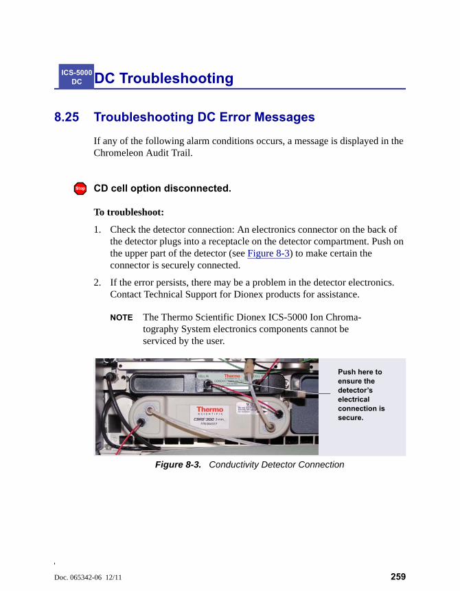
Doc. 065342-06 12/11 259
DC Troubleshooting
8.25 Troubleshooting DC Error Messages
If any of the following alarm conditions occurs, a message is displayed in the Chromeleon Audit Trail.
CD cell option disconnected.
To troubleshoot:
1. Check the detector connection: An electronics connector on the back of the detector plugs into a receptacle on the detector compartment. Push on the upper part of the detector (see Figure 8-3) to make certain the connector is securely connected.
2. If the error persists, there may be a problem in the detector electronics. Contact Technical Support for Dionex products for assistance.
NOTE The Thermo Scientific Dionex ICS-5000 Ion Chroma-tography System electronics components cannot be serviced by the user.
ICS-5000 DC
Figure 8-3. Conductivity Detector Connection
Push here to ensure the detector’s electrical connection is secure.
Dionex ICS-5000 Operator’s Manual
260 Doc. 065342-06 12/11
CD cell over safe temperature.
This error occurs when the temperature of the conductivity detector is higher than the maximum allowed. This error may occur if the Thermo Scientific Dionex ICS-5000 Ion Chromatography System is operating in an environment in which the temperature is greater than 40 °C (104 °F).
To troubleshoot:
1. Refer to Appendix A for environmental specifications.
2. Verify that the compartment setpoint is at least 5 °C less than the CD cell setpoint.
3. Check the suppressor current setting. Running the suppressor at a higher current than is recommended for the application can cause heat-up of the CD cell.
Column temperature open circuit.
This error may indicate a problem in the detector electronics. Contact Technical Support for Dionex products for assistance.
Column over safe temperature.
This error occurs when the temperature of the column compartment exceeds the maximum allowed. This error may occur if the Thermo Scientific Dionex ICS-5000 Ion Chromatography System is operating in an environment in which the temperature is greater than 40 °C (104 °F).
To troubleshoot:
Refer to Appendix A for environmental specifications.
8 • DC Troubleshooting
Doc. 065342-06 12/11 261
Column temperature calibration error.
To troubleshoot:
Repeat the calibration procedure. Follow the instructions provided in the DC Temperature Calibration Kit (P/N 063782). If the error appears again, contact Technical Support for Dionex products for assistance.
Compartment temperature open circuit.
This error may indicate a problem in the detector electronics. Contact Technical Support for Dionex products for assistance.
Compartment over safe temperature.
This error occurs when the temperature of the DC lower compartment is higher than the maximum allowed. This error may occur if the Thermo Scientific Dionex ICS-5000 Ion Chromatography System is operating in an environment in which the temperature is greater than 40 °C (104 °F).
To troubleshoot:
Refer to Appendix A for environmental specifications.
Compartment temperature calibration error.
To troubleshoot:
Repeat the calibration procedure, following the instructions provided in the DC Temperature Calibration Kit (P/N 063782). If the error appears again, contact Technical Support for Dionex products for assistance.
ED cell current exceeds limits error.
This error can have multiple causes (for example, a cell potential that is too high for a given salt concentration, a cell potential that is too high because the reference mode is incorrect, injection of excessive amounts of electroactive
Dionex ICS-5000 Operator’s Manual
262 Doc. 065342-06 12/11
analytes, a damaged or incorrectly installed cell gasket, or an electrical short between two of the three electrodes).
To troubleshoot:
1. Turn off the cell voltage. Excessive currents can change or even damage the working electrode.
2. Turn off the pump flow.
3. Disassemble the cell (see Section 9.28.3) and check for evidence of liquid and salt bridges that can cause shorts. Rinse the cell surface and dry it with a clean, lint-free towel. Replace the cell gasket.
4. Verify that the correct electrode material, waveform potentials, and reference mode are selected for the application being run.
5. Restart the flow and select DC amperometry mode. Apply cell potential in steps increasing toward the detection potential (the potential of the integration period in integrated amperometric detection). If the current becomes excessive again, try a new working electrode or another cell, if available.
ED cell option disconnected.
This error indicates that the electrochemical detector is unplugged.
To troubleshoot:
1. Check the detector connections: Verify that the signal cable from the cell is connected to the appropriate connector on the detector block (see Figure 8-4). Also, push firmly on the detector to ensure the electronics

8 • DC Troubleshooting
Doc. 065342-06 12/11 263
connector on the back of the detector is securely connected to the receptacle on the detector compartment.
2. If the error appears again, contact Technical Support for Dionex products for assistance. The detector electronics may have malfunctioned.
NOTE The Thermo Scientific Dionex ICS-5000 Ion Chroma-tography System electronics components cannot be serviced by the user.
ED cell working electrode disconnected.
This error occurs when the cable on the working electrode is disconnected from the cell electronics.
To troubleshoot:
Check the cable connection: Verify that the signal cable from the working electrode is connected to the detector block (see Figure 8-4).
ED pH offset calibration failed.
This error occurs when the pH reading differs by more than 1.0 pH unit from 7.0, which is the value specified for offset calibration. This can be caused by too large a change in the Ag/AgCl reference potential or by a damaged glass membrane in the pH sensing part of the reference electrode
To troubleshoot:
Figure 8-4. Electrochemical Detector Connection (Analytical Cell Shown)
Push here to ensure the detector’s electrical connection is secure.
ED Cell Cable
Dionex ICS-5000 Operator’s Manual
264 Doc. 065342-06 12/11
1. Check the buffer selection.
2. Verify that the electrode is properly immersed in the calibration buffer.
3. Repeat the calibration procedure (see Section 9.28.6). If the error recurs, repeat the calibration at least one more time.
4. If the error recurs after repeating the calibration at least two times, replace the Ag/AgCl reference electrode (see Section 9.28.5).
ED pH slope calibration failed.
This error occurs when the pH sensing glass membrane of the Ag/AgCl reference electrode is broken or otherwise affected, causing the calibration slope to deviate by more than ±10% from the theoretical slope of 59 mV/pH unit at 25 C.
To troubleshoot:
1. Make sure the calibration temperature is as close as possible to 25 C.
2. Verify that the correct buffer is being used and that the electrode is properly immersed in the calibration buffer.
3. Repeat the calibration procedure (see Section 9.28.6). If the error recurs, repeat the calibration at least one more time.
4. If the error recurs after repeating the calibration at least two times, replace the Ag/AgCl reference electrode (see Section 9.28.5).
ED reference electrode disconnected.
To troubleshoot:
Check the cable connection: Verify that the signal cable from the working electrode is connected to the detector block (see Figure 8-4).
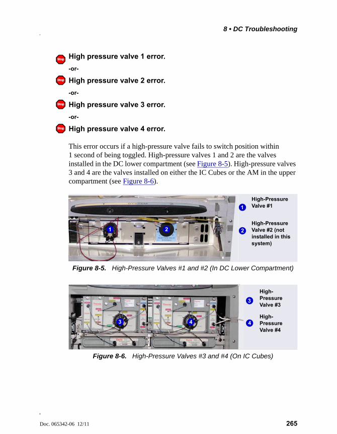
8 • DC Troubleshooting
Doc. 065342-06 12/11 265
High pressure valve 1 error.
-or-
High pressure valve 2 error.
-or-
High pressure valve 3 error.
-or-
High pressure valve 4 error.
This error occurs if a high-pressure valve fails to switch position within 1 second of being toggled. High-pressure valves 1 and 2 are the valves installed in the DC lower compartment (see Figure 8-5). High-pressure valves 3 and 4 are the valves installed on either the IC Cubes or the AM in the upper compartment (see Figure 8-6).
Figure 8-5. High-Pressure Valves #1 and #2 (In DC Lower Compartment)
Figure 8-6. High-Pressure Valves #3 and #4 (On IC Cubes)
High-Pressure Valve #1
High-Pressure Valve #2 (not installed in this system)
1
21 2
High-Pressure Valve #3
High-Pressure Valve #4
3
43 4
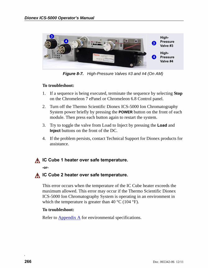
Dionex ICS-5000 Operator’s Manual
266 Doc. 065342-06 12/11
To troubleshoot:
1. If a sequence is being executed, terminate the sequence by selecting Stop on the Chromeleon 7 ePanel or Chromeleon 6.8 Control panel.
2. Turn off the Thermo Scientific Dionex ICS-5000 Ion Chromatography System power briefly by pressing the POWER button on the front of each module. Then press each button again to restart the system.
3. Try to toggle the valve from Load to Inject by pressing the Load and Inject buttons on the front of the DC.
4. If the problem persists, contact Technical Support for Dionex products for assistance.
IC Cube 1 heater over safe temperature.
-or-
IC Cube 2 heater over safe temperature.
This error occurs when the temperature of the IC Cube heater exceeds the maximum allowed. This error may occur if the Thermo Scientific Dionex ICS-5000 Ion Chromatography System is operating in an environment in which the temperature is greater than 40 °C (104 °F).
To troubleshoot:
Refer to Appendix A for environmental specifications.
Figure 8-7. High-Pressure Valves #3 and #4 (On AM)
High-Pressure Valve #3
High-Pressure Valve #4
3
4
3
4
8 • DC Troubleshooting
Doc. 065342-06 12/11 267
Lower door opened.
This message occurs when the door to the lower compartment is opened during a run.
To troubleshoot:
1. Verify that the door is fully closed.
2. Check for—and remove—any obstruction.
3. If the door is fully closed and the error persists, contact Technical Support for Dionex products for assistance.
Lower leak sensor wet.
The leak sensor is installed in the drip tray at the bottom of the column compartment (see Figure 9-33). If liquid accumulates in the tray, the sensor signals the problem and this error message appears.
To troubleshoot:
1. Locate the source of the leak by visually inspecting the tubing, fittings, and components.
2. Tighten fittings or replace tubing and fittings as required. Refer to Section 8.26 for detailed troubleshooting of various types of leaks.
3. After fixing the leak, dry the drip tray thoroughly to prevent the leak sensor from triggering additional error messages.
Reaction coil open circuit.
This error occurs when the reaction coil heater is unplugged from the DC.
To troubleshoot:
1. Check that the reaction coil heater is correctly plugged into the component panel.
2. If the error persists, the heater may be faulty. Replace the heater (P/N 061746).
Dionex ICS-5000 Operator’s Manual
268 Doc. 065342-06 12/11
Reaction coil over safe temperature.
This error occurs when the temperature of the DC upper compartment is higher than the maximum allowed. This error may occur if the Thermo Scientific Dionex ICS-5000 Ion Chromatography System is operating in an environment in which the temperature is greater than 40 °C (104 °F).
To troubleshoot:
Refer to Appendix A for environmental specifications.
Suppressor over-current.
This error may be caused by a depleted or dirty suppressor or by a malfunction in the suppressor controller electronics.
To troubleshoot:
1. Follow the instructions in the suppressor manual to regenerate the suppressor. Suppressor manuals are included on the Thermo Scientific Reference Library DVD (P/N 053891).
2. Follow the instructions in the suppressor manual to clean the suppressor.
3. If you suspect a malfunction in the suppressor controller, contact Technical Support for Dionex products for assistance.
NOTE The Thermo Scientific Dionex ICS-5000 Ion Chromatogra-phy System electronics components cannot be serviced by the user.
Suppressor over-power.
This error appears when, in order to maintain the selected current, the Thermo Scientific Dionex ICS-5000 Ion Chromatography System is required to apply a higher voltage than the suppressor can support.
To troubleshoot:
1. Reduce the flow rate.
8 • DC Troubleshooting
Doc. 065342-06 12/11 269
2. Rehydrate the suppressor. Refer to the suppressor manual for instructions. Suppressor manuals are included on the Thermo Scientific Reference Library DVD (P/N 053891).
3. If the error persists, replace the suppressor (see Section 9.27.2).
Suppressor over-voltage.
This error appears if you turn on the suppressor and the system cannot establish a connection with the suppressor.
To troubleshoot:
1. Check the suppressor cable connection.
2. If the error persists, replace the suppressor (see Section 9.27.2).
Suppressor stopped for flow rate.
This message occurs if the pump flow stops while the suppressor is on. The suppressor is automatically turned off to prevent damage to the suppressor.
To troubleshoot:
If the pump stopped unexpectedly, see Section 8.14 for pump troubleshooting information.
Upper door opened.
This message occurs when the door to the upper compartment is opened during a run.
To troubleshoot:
1. Verify that the door is fully closed.
2. Check for—and remove—any obstruction.
3. If the door is fully closed and the error persists, contact Technical Support for Dionex products for assistance.
Dionex ICS-5000 Operator’s Manual
270 Doc. 065342-06 12/11
8.26 Liquid Leaks from DC Components
• Leaking fitting
Locate the source of the leak. Tighten or, if necessary, replace the liquid line connection (see Section 9.19).
• Broken liquid line
Replace the line and fittings with the same length and internal diameter tubing (see Section 9.19).
• Blocked or improperly installed line
Make sure the lines are not crimped or otherwise blocked. Also, if the blocked line is a waste line, make sure it is not elevated at any point after it exits the DC. If a line is blocked, replace it (see Section 9.19).
• Leaking injection valve
1. Make sure the liquid line connections to the transducer are tight. Replace any damaged fittings (see Section 9.19).
2. If the leak is from behind the valve stator, the rotor seal may be scratched. Rebuild the injection valve (see Section 9.22).
• Leaking cell
1. Check the waste lines for blockage; trapped particles can plug the lines and cause a restriction and/or leak. If necessary, clear the waste lines by reversing the direction of flow.
2. Make sure the plumbing downstream from the cell is clear; a blockage may overpressurize the cell and cause it to leak. If the problem continues, Contact Technical Support for Dionex products for assistance.
Leaking suppressor
Refer to the suppressor manual for troubleshooting procedures. Suppressor manuals are included on the Thermo Scientific Reference Library DVD (P/N 053891).
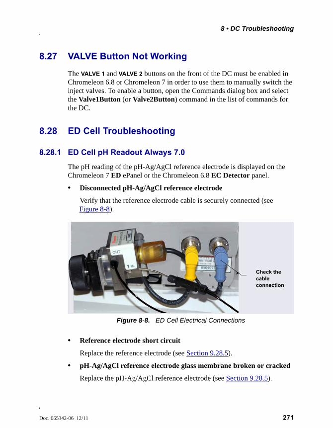
8 • DC Troubleshooting
Doc. 065342-06 12/11 271
8.27 VALVE Button Not Working
The VALVE 1 and VALVE 2 buttons on the front of the DC must be enabled in Chromeleon 6.8 or Chromeleon 7 in order to use them to manually switch the inject valves. To enable a button, open the Commands dialog box and select the Valve1Button (or Valve2Button) command in the list of commands for the DC.
8.28 ED Cell Troubleshooting
8.28.1 ED Cell pH Readout Always 7.0
The pH reading of the pH-Ag/AgCl reference electrode is displayed on the Chromeleon 7 ED ePanel or the Chromeleon 6.8 EC Detector panel.
• Disconnected pH-Ag/AgCl reference electrode
Verify that the reference electrode cable is securely connected (see Figure 8-8).
• Reference electrode short circuit
Replace the reference electrode (see Section 9.28.5).
• pH-Ag/AgCl reference electrode glass membrane broken or cracked
Replace the pH-Ag/AgCl reference electrode (see Section 9.28.5).
Figure 8-8. ED Cell Electrical Connections
Check the cable connection
Dionex ICS-5000 Operator’s Manual
272 Doc. 065342-06 12/11
8.28.2 Cannot Set ED Cell pH Readout to 7.0
The pH reading of the pH-Ag/AgCl reference electrode is displayed on the ED ePanel in Chromeleon 7 or the EC Detector Control panel in Chromeleon 6.8.
• Inaccurate calibration buffer
Use a pH meter to check the pH of the buffer.
• Dry pH-Ag/AgCl reference electrode
1. Soak the pH-Ag/AgCl reference electrode in a solution containing 1 M KCl and 1 M HCl long enough to restore the electrode potential to within 30 mV when compared to an unexposed Ag/AgCl reference electrode. To test the pH-Ag/AgCl reference electrode potential, see “Using a Digital Voltmeter to Determine Reference Potential Shift” on page 274.
2. Replace the pH-Ag/AgCl reference electrode (see Section 9.28.5).
To prevent a pH-Ag/AgCl reference electrode from drying out, make sure that eluent is being pumped continuously through the cell. If the cell will not be used for a short time (less than 2 days), disconnect the tubing from the inlet and outlet fittings and all fitting plugs. For longer shutdowns, remove the electrode from the cell and store it in its storage bottle filled with saturated KCl solution. See Section 4.1.2 for detailed instructions.
8.28.3 Shift in ED Cell pH Readout
The pH readout is considered to have shifted if it is 0.5 pH units or more different from the value observed when the pH-Ag/AgCl reference electrode was new.
• Faulty pH-Ag/AgCl reference electrode
1. Check the electrode by following the instructions in Section 8.28.6.
2. Regenerate the electrode by soaking in a solution containing 1 M KCl and 1 M HCl long enough to restore the electrode potential to within 30 mV when compared to an unexposed Ag/AgCl reference electrode. To test the pH-Ag/AgCl reference electrode potential, see “Using a Digital Voltmeter to Determine Reference Potential Shift” on page 274.
8 • DC Troubleshooting
Doc. 065342-06 12/11 273
3. If soaking does not fix the problem, replace the electrode (see Section 9.28.5).
8.28.4 No ED Cell pH Readout or Intermittent Readout
The pH reading is displayed on the ED ePanel in Chromeleon 7 or the EC Detector Control panel in Chromeleon 6.8.
• PdH reference electrode selected
Select the AgCl reference electrode mode on the ED ePanel in Chromeleon 7 or the EC Detector Control panel in Chromeleon 6.8, or in the Chromeleon 7 instrument method or the Chromeleon 6.8 program.
• Disconnected reference electrode
Verify that the reference electrode cable is securely connected (see Figure 8-8).
• Uncalibrated pH-Ag/AgCl reference electrode
Calibrate the pH-Ag/AgCl reference electrode (see Section 9.28.6).
• Dry pH-Ag/AgCl reference electrode
1. Soak the pH-Ag/AgCl reference electrode in a solution containing 1 M KCl and 1 M HCl long enough to restore the electrode potential to <30 mV when compared to an unexposed Ag/AgCl reference electrode. To test the electrode potential, see “Using a Digital Voltmeter to Determine Reference Potential Shift” on page 274.
2. If soaking the pH-Ag/AgCl reference electrode does not fix the problem, replace the electrode (see Section 9.28.5).
To prevent a pH-Ag/AgCl reference electrode from drying out, make sure that eluent is being pumped continuously through the cell. If the cell will not be used for a short time (less than 2 days), disconnect the tubing from the inlet and outlet fittings and all fitting plugs. For longer shutdowns, remove the electrode from the cell and store it in its storage bottle filled with saturated KCl solution. See Section 4.1.2 for detailed instructions.
• Contaminated pH-Ag/AgCl reference electrode
Replace the pH-Ag/AgCl reference electrode (see Section 9.28.5).
Dionex ICS-5000 Operator’s Manual
274 Doc. 065342-06 12/11
8.28.5 Leak in pH-Ag/AgCl Reference Electrode Compartment
• Defective pH-Ag/AgCl reference electrode O-ring
Replace the pH-Ag/AgCl reference electrode O-ring (see Section 9.28.7).
8.28.6 Shift in Ag/AgCl Reference Potential
• Faulty pH-Ag/AgCl reference electrode
A shift in reference potential causes a shift in the effective potential applied to the working electrode. For example, when using an electrode with a shift of 50 mV, an applied potential of 0.1 V, is equivalent to an applied potential of 0.15 V for a new pH-Ag/AgCl reference electrode with no shift.
Following the steps below, measure the pH-Ag/AgCl reference electrode potential shift by comparing it to the potential shift of an unexposed electrode. A spare pH-Ag/AgCl reference electrode (P/N 061879) stored in 3 M KCl can be kept on hand for this purpose.
Using a Digital Voltmeter to Determine Reference Potential Shift
1. For each pH-Ag/AgCl reference electrode (the unexposed electrode and the electrode being tested), use a straightened paper clip or short piece of wire of a suitable diameter to connect the voltmeter’s voltage inputs to pin 1 on the reference electrode’s cable connector.
To identify the cable connector pins, refer to Product Information Update for the Electrochemical Detector (PIU_ED_1). The document is included on the Thermo Scientific Reference Library DVD (P/N 053891).
2. Immerse both electrodes in a solution of 0.1 M KCl.
3. Read the potential difference (in mV) between the unexposed electrode and the electrode being tested. If it is greater than 30 mV, try regenerating the electrode by soaking it in a solution containing 1 M KCl and 1 M HCl. If this does not reduce the potential shift, replace the electrode (see Section 9.28.7).
Doc. 065342-06 12/11 275
TC Troubleshooting
8.29 Troubleshooting TC Error Messages
If any of the following alarm conditions occurs, a message is displayed in the Chromeleon Audit Trail.
AcqOff without previous AcqOn.
This error occurs if the Chromeleon 7 instrument method or Chromeleon 6.8 program contains an AcqOff command, but no AcqOn command.
To troubleshoot:
Every program should include one AcqOn command. Enter the AcqOn command after the first injection.
Acquisition is still on at program end.
This error occurs if a Chromeleon 7 instrument method or Chromeleon 6.8 program does not include a command that ends data acquisition.
To troubleshoot:
The AcqOn command must be paired with an AcqOff command. Enter the AcqOff command at the appropriate point in the program.
All samples scheduled for run on timebases x need to specify the same value for property (nominal) Temperature.
-or-
All samples scheduled for run on timebases x need to specify the same value for property TempCtrl.
-or-
ICS-5000 TC
Dionex ICS-5000 Operator’s Manual
276 Doc. 065342-06 12/11
All samples scheduled for run on timebases x need to specify the same value for property y.
When a TC is shared by two timebases, the same values must be selected for certain parameters. If the Chromeleon Ready Check detects a discrepancy, this error occurs and batch processing cannot be started.
To troubleshoot:
Find and eliminate any discrepancies in the parameter settings. For example, all samples must turn on TempCtrl or all samples must turn off TempCtrl.
Can't execute “Disconnect” command during data acquisition.
-or-
Can't execute “Standby” command during data acquisition.
Selecting the Disconnect or Standby command during data acquisition will stop data transmission and cause data acquisition to stall. If you attempt to issue one of these commands during data acquisition, this error occurs.
To troubleshoot:
Wait until data acquisition is completed before attempting to issue either of these commands.
Can't find download image TC3000.HEX.
TC3000.HEX is the version of the TC instrument control firmware file that should be available in the \Bin directory of your Chromeleon installation. This error occurs if the file is missing.
To troubleshoot:
Select Tools > Instrument Qualification (Chromeleon 7) or Qualification > Chromeleon 6.8 IQ (Chromeleon 6.8) to run the Chromeleon IQ and diagnose the problem. When you eliminate the source of the error, rerun the Setup program.
8 • TC Troubleshooting
Doc. 065342-06 12/11 277
Can't start acquisition at negative retention times.
This error occurs if you attempt to execute the AcqOn command while retention times are negative.
To troubleshoot:
Wait until the retention time value is positive.
Can’t start acquisition: The server configuration does not fulfill the license conditions.
Operation of the TC requires the appropriate version of Chromeleon plus a Timebase Class 1 license. This error occurs if you attempt to start data acquisition when these requirements are not met.
To troubleshoot:
Contact your local Dionex products representative at Thermo Fisher Scientific to obtain the appropriate software version and/license.
Can’t start TC firmware. A firmware download may be necessary.
-or-
Error finishing download.
-or-
TC—Firmware download failed.
If the TC firmware cannot be started after a firmware download or if Chromeleon is unable to successfully download firmware to the TC, the appropriate message (shown above) is displayed.
To troubleshoot:
1. Press the POWER button on the front of the TC to turn off the power; after 30 seconds, press the button again to turn on the power.
2. Download new firmware to the TC as follows:
a. Insert the CD containing the new firmware version into the CD drive.
Dionex ICS-5000 Operator’s Manual
278 Doc. 065342-06 12/11
b. Start the Chromeleon 7 Instrument Configuration Manager or the Chromeleon 6.8 Server Configuration program.
c. In the instrument or timebase, right-click the TC for which you want to update the firmware and select Properties on the context menu.
d. On the General tab page in the Properties dialog box, click Firmware Download to display a file open dialog box.
e. Select the file (the extension is .fmw) containing the new firmware version and click Open to begin the download. Audit Trail messages will inform you of the status of the download.
3. If the error occurs again, contact Technical Support for Dionex products for assistance. The firmware cannot be serviced by the user.
Can't use device “x” as a source of the column pressure. Please check the property “SystemPressure” for a valid device name. The device must have the “Pressure” property available.
-or-
Can't use device “x” as a source of the column pressure. Please check the property “y” for a valid device name. The device must have the “Pressure” property available.
This error occurs if the device selected to monitor the system pressure is ineligible to do so.
To troubleshoot:
1. Open the Chromeleon 7 ePanel Set or the Chromeleon 6.8 panel tabset.
2. Press the F8 key to open the Commands dialog box.
3. Under TC, select the column name, and select the SystemPressure command.
4. Enter the name of the pump currently delivering flow for this column.
5. For Chromeleon 6.8, click Execute.
8 • TC Troubleshooting
Doc. 065342-06 12/11 279
Card data checksum error.
This error indicates that the column ID chip card memory is corrupted.
To troubleshoot:
Replace the column ID chip card (see Section 9.30).
Command is not available in demo mode.
This error occurs if you attempt to issue a command that is not available when the TC is in demo (or simulation) mode.
To troubleshoot:
If a TC is present and connected, disable the demo mode:
1. Start the Chromeleon 7 Instrument Configuration Manager or the Chromeleon 6.8 Server Configuration program.
2. In the instrument or timebase, right-click the TC and select Properties.
3. On the General tab page, clear the Simulation Mode or Demo Mode check box.
4. If the TC does not appear in the Module address box, click Browse and select the TC. Click OK.
Communication error: x.
This error occurs if there is a communication failure between the TC and the PC on which Chromeleon is installed.
To troubleshoot:
1. Check the USB connections.
2. Check the connection from the TC to the power supply.
3. If you cannot identify the cause of the error, contact Technical Support for Dionex products for assistance.

Dionex ICS-5000 Operator’s Manual
280 Doc. 065342-06 12/11
Communication time-out.
This error occurs if a TC firmware command is not executed within the time allotted for its completion.
To troubleshoot:
1. Check the USB connections.
2. Check the connection from the TC to the power supply.
3. If you cannot identify the cause of the error, contact Technical Support for Dionex products for assistance.
Configuration doesn’t match. X not installed.
-or-
Configuration mismatch (x - CM uses y, Column Compartment uses z). Please use the Server Configuration program to check the installation.
This error occurs if there is a discrepancy between the TC properties and the actual configuration.
To troubleshoot:
1. Start the Chromeleon 7 Instrument Configuration Manager or the Chromeleon 6.8 Server Configuration program.
2. In the instrument or timebase, right-click the TC and select Properties.
3. Correct any discrepancies in the Properties dialog box.
Current flow is out of limits defined for the column.
This error occurs if the current flow rate exceeds the value specified by the Column_x.FlowRate_UpperLimit command.
To troubleshoot:
Select a valid flow rate.
8 • TC Troubleshooting
Doc. 065342-06 12/11 281
Current pressure is out of limits defined for the column.
This error occurs if the current pressure reading is outside the range specified by the Column_x.Pressure_UpperLimit and Column_x.Pressure_ LowerLimit commands.
To troubleshoot:
• Find and eliminate any liquid leaks or blockages in tubing connections (see Section 8.31). Adjust the flow rate accordingly.
Current temperature is out of limits defined for the column.
This error occurs if the current temperature reading is outside the range specified by the Column_x.Temp_UpperLimit and Column_x.Temp_ LowerLimit commands.
To troubleshoot:
Select a valid temperature setting.
Data buffer overrun.
This error occurs in Chromeleon 6.8 if the system cannot write incoming data to disk fast enough.
To troubleshoot:
Increase the buffer size:
1. Start the Chromeleon 7 Instrument Configuration Manager or the Chromeleon 6.8 Server Configuration program.
2. Right-click the computer name and select Properties on the menu.
3. Click the Advanced tab and enter a new value (in seconds) in the Buffer field. Click OK.
4. If the error occurs again, contact Technical Support for Dionex products for assistance.

Dionex ICS-5000 Operator’s Manual
282 Doc. 065342-06 12/11
Device control feature is not available! Please check key code and CM Features (see “About Chromeleon...” on the client's Help menu).
This error occurs if you attempt to select or define a feature that is not available for your TC.
To troubleshoot:
Select Help > About Chromeleon... to open the About Chromeleon screen.
• For Chromeleon 7, click Details to view all license features you purchased (devices controlled, number of timebases, and other software options).
• For Chromeleon 6.8, the license features you purchased are listed on the About Chromeleon screen and labeled On.
If necessary, upgrade your software by acquiring the corresponding licenses. Contact your local Dionex products representative at Thermo Fisher Scientific for assistance.
Device is not remote.
-or-
TC is not remote.
If you try to issue certain commands (for example, Column_x and InjectValve_x commands) when the TC is not under Chromeleon control, the appropriate message (shown above) is displayed.
To troubleshoot:
Select the Connect command to connect the TC to the Chromeleon server. Check the Audit Trail for messages indicating whether the module was successfully connected.
8 • TC Troubleshooting
Doc. 065342-06 12/11 283
Device not found on the USB.
-or-
USB/LAN communication error. Please check communication cable and instrument’s power.
This error occurs if there is a problem with the connection between the TC and the Chromeleon server or with the power supply.
To troubleshoot:
1. Check the USB connections.
2. Check the connection from the TC to the power supply.
3. If you cannot identify the cause of the error, contact Technical Support for Dionex products for assistance.
Either the current date is later than the expiration date for x or the program or batch will end later than 24 hours before the expiration time for x.
Chromeleon compares the current date with the column expiration date during injection or before beginning batch processing. This error occurs if the expiration date has already passed or if batch processing is scheduled to start less than 24 hours before the expiration date.
To troubleshoot:
Replace the column.
Error deleting flash memory.
This error occurs if, during a firmware download, the existing firmware cannot be erased from memory.
To troubleshoot:
Flash memory cannot be serviced by the user. Contact Technical Support for Dionex products for assistance.
Dionex ICS-5000 Operator’s Manual
284 Doc. 065342-06 12/11
Error during storing of the card data to the chip card.
This error occurs if the column ID chip card is installed incorrectly, or is defective.
To troubleshoot:
When the chip card is properly installed, the Dionex logo on the card faces up and the LED on the memory slot is green. If this error occurs when the chip card is properly installed, it indicates that the card is defective and should be replaced (for instructions, refer to Section 9.30).
Error programming flash memory.
This error occurs if, during a firmware download, the new firmware cannot be programmed into memory.
To troubleshoot:
Flash memory cannot be serviced by the user. Contact Technical Support for Dionex products for assistance.
Executing this command will reset associated counter values stored in the module.
This error occurs when you select a command (RotorSealChanged, for example) that updates information stored in the TC. To prevent information from being inadvertently changed, Chromeleon requests confirmation before executing the command.
To troubleshoot:
If you want to execute this command, click Execute; otherwise, click Cancel.
8 • TC Troubleshooting
Doc. 065342-06 12/11 285
Firmware download in progress. Please wait.
This error occurs if you attempt to issue a command while firmware is being downloaded to the TC.
To troubleshoot:
Wait until the firmware download is complete. Audit Trail messages will inform you of the status of the download.
Gas leak detected.
This error occurs if the gas sensor detects an increased concentration of gas inside the TC.
To troubleshoot:
1. Find and eliminate the leak.
2. If you are using Chromeleon 7: Open the Commands dialog box (press the F8 key). Select the TC and click the Commands tab. Click the ClearAlarmLED button.
3. If you are using Chromeleon 6.8: On the TC Control panel, click the Clear Alarm button.
4. Ventilate the interior of the TC thoroughly before closing the door and resuming operation.
Humidity leak detected.
This error occurs if the humidity sensor detects an increased concentration of humidity inside the TC.
To troubleshoot:
1. Find and eliminate the leak.
2. If you are using Chromeleon 7: Open the Commands dialog box (press the F8 key). Select the TC and click the Commands tab. Click the ClearAlarmLED button.
Dionex ICS-5000 Operator’s Manual
286 Doc. 065342-06 12/11
3. If you are using Chromeleon 6.8: On the TC Control panel, click the Clear Alarm button.
4. Ventilate the interior of the TC thoroughly before closing the door and resuming operation.
Illegal parameter.
This error occurs if you enter a parameter that is not valid for the TC.
To troubleshoot:
Select a valid parameter.
Invalid date/time format. Either use “DD MMM YYYY” or “current [ + [Nyear[s]] [Nmonth[s]] [Nday[s]]].” Examples: “31 Dec 1999,” “current + 1 year 6 months.”
This error occurs if you enter the date associated with an event in an invalid format.
To troubleshoot:
Enter the date in the format specified in the message.
Invalid enumerated value.
This error occurs if you attempt to enter an invalid value for a property, rather than selecting a value from the drop-down list box in the Commands dialog box.
To troubleshoot:
Select a valid option from the drop-down list box available for this property.
Next qualification of this module is due in x day(s) (due date is [date]).
-or-
8 • TC Troubleshooting
Doc. 065342-06 12/11 287
Next qualification of this module is overdue (due date was [date]).
-or-
Next qualification of this module was due on [date]. Allowing x more grace day(s).
-or-
Next qualification of this module is overdue (due date was [date]). Module may no longer be used.
Chromeleon monitors the date on which qualification was last performed and displays an appropriate message (shown above) at the following times: when the due date for the next qualification is approaching; when the due date is overdue, but the TC can still be used; and when the due date is overdue and the TC can no longer be used.
The Qualification.WarningPeriod property determines the number of days before the due date that the warning is first displayed. The Qualification.GracePeriod property determines for how many days after the due date you can continue using the TC without performing the qualification.
To troubleshoot:
Contact Technical Support for Dionex products to schedule an Operational Qualification and Performance Qualification.
Next service of this module is due in x day(s) (due date is [date]).
-or-
Next service of this module is overdue (due date was [date]).
Chromeleon monitors the date on which service was last performed and display an appropriate message (shown above) at the following times: when the due date for the next service is approaching and when the due date is overdue. The Service.WarningPeriod property determines the number of days before the due date that the warning is first displayed.
To troubleshoot:
Contact Technical Support for Dionex products for information about performing annual preventive maintenance.

Dionex ICS-5000 Operator’s Manual
288 Doc. 065342-06 12/11
No chip card in the reader for the column x.
This error occurs if a column ID chip card is not installed for the column identified in the message.
To troubleshoot:
Install a column ID chip card for the column (see Section 9.30). Or, if you do not want to store information about this column, follow the steps below to disable this option.
1. In the Chromeleon 7 Instrument Configuration Manager or the Chromeleon 6.8 Server Configuration program, right-click the TC and select Properties on the context menu.
2. Select the Components tab in the Properties dialog box. Clear the check mark beside the column name and click OK.
No response from x for x seconds.
-or-
No response from x for x seconds. Device disconnected.
This error occurs if there is a communication failure between the TC and the PC on which Chromeleon is installed.
To troubleshoot:
1. Check the USB connections.
2. Check the connection from the TC to the power supply.
3. If you cannot identify the cause of the error, contact Technical Support for Dionex products for assistance.

8 • TC Troubleshooting
Doc. 065342-06 12/11 289
Operating columns above 70 °C could affect column performance. Verify recommended column operating conditions before setting temperature above 70 °C.
This error occurs if you select a TC temperature setting above 70 °C (158 °F).
To troubleshoot:
Refer to the column manual for the recommended operating conditions. Column manuals are provided on the Thermo Scientific Reference Library DVD (P/N 053891).
Parameter x value exceeded its allowed range. Set to closest valid value x.
-or-
Value for [name] parameter is not within valid range. Value passed (x) will be substituted by y.
-or-
Value x replaced by valid table entry y.
If you select a value outside the allowable range for certain parameters, Chromeleon ignores the setting, replaces it with the closest valid setting, and this error occurs.
To troubleshoot:
No immediate action is required. In future, specify a valid setting for the parameter.
Dionex ICS-5000 Operator’s Manual
290 Doc. 065342-06 12/11
Primary property “x” is already assigned and cannot be changed.
This error occurs if you attempt to change one of the primary column properties (batch or lot number, date of manufacture, etc.) used for column identification.
To troubleshoot:
Once a primary column property has been assigned, it cannot be changed. As an alternative, consider changing a secondary column property. For a list of primary and secondary properties, refer to the Chromeleon Help.
Properties cannot be changed. A chip card has not been inserted properly. Check the CardState property for all cards and reinsert those indicating “BusBlocked.”
This error occurs if you attempt to change column ID properties when at least one column ID chip card is inserted incorrectly.
To troubleshoot:
1. Open the Chromeleon 7 ePanel Set or the Chromeleon 6.8 panel tabset.
2. Press the F8 key to open the Commands dialog box.
3. Under TC, select the column name and select the CardState property. If the status is BusBlocked, remove the card from the card slot and reinsert it.
When the card is properly installed, the Dionex logo on the card faces up and the LED on the memory slot is green.
Properties cannot be changed if the compartment door is open.
This error occurs if you attempt to change column ID properties when the TC door is open (or is not fully closed).
To troubleshoot:
1. Verify that the door is fully closed.
2. If the door is not fully closed, check for—and remove—any obstruction.
8 • TC Troubleshooting
Doc. 065342-06 12/11 291
3. If the door is fully closed but the error persists, contact Technical Support for Dionex products for assistance.
Properties cannot be changed—there is no card in the card reader.
This error occurs if you attempt to change column ID properties for a column for which no chip card is installed.
To troubleshoot:
Insert a column ID chip card into the appropriate slot (see Section 9.30).
Raw data file x cannot be created.
-or-
Raw data file x cannot be created. Continuing with network failure protection.
-or-
Raw data file x cannot be written.
-or-
Raw data file x cannot be written. Continuing with network failure protection.
If a network failure prevents Chromeleon from creating or writing to a raw data file, the corresponding error occurs.
To troubleshoot:
Wait until batch processing is complete; then, reboot the PC and restart the Chromeleon server.
Dionex ICS-5000 Operator’s Manual
292 Doc. 065342-06 12/11
Starting data acquisition manually will overwrite any data which has been acquired so far.
This error occurs if you attempt to start data acquisition manually while a batch is already running.
To troubleshoot:
To retain the data already acquired, cancel manual data acquisition; otherwise, go ahead and start data acquisition.
The command can format only chip cards with an invalid data structure.
This error occurs if you select the FormatChipCard command for a column ID chip card that is not defective.
To troubleshoot:
Cancel the command. Do not attempt to reinitialize a chip card unless it contains invalid or corrupted data.
The communication interface is closed. Reconnect the instrument.
This error occurs if there is a communication failure between the TC and the PC on which Chromeleon is installed.
To troubleshoot:
1. Check the USB connections.
2. Check the connection from the TC to the power supply.
3. If you cannot identify the cause of the error, contact Technical Support for Dionex products for assistance.
8 • TC Troubleshooting
Doc. 065342-06 12/11 293
The compartment door is open; a batch or a program may need to wait until the door has been closed. Please close the door.
This error occurs if you attempt to operate the TC when the door is open (or not fully closed).
To troubleshoot:
1. Verify that the door is fully closed.
2. If the door is not fully closed, check for—and remove—any obstruction.
3. If the door is fully closed but the error persists, contact Technical Support for Dionex products for assistance.
The counter [name] (value: x) has exceeded its limit (y). Module should no longer be used. Replace the [name].
This error occurs if the number of hours a TC part has been in use exceeds the lifetime set by the OperationTime.Limit property.
To troubleshoot:
Replace the part identified in the message before resuming operation.
The data format stored on the chip card is unsupported (format version x).
This error occurs if the column ID chip card data is inadvertently saved in an invalid format.
To troubleshoot:
1. To reinitialize the chip card, open the Chromeleon 7 ePanel Set or the Chromeleon 6.8 panel tabset.
2. Press the F8 key to open the Commands dialog box.
3. Under TC, select the column name and select the FormatChipCard command.
4. For Chromeleon 6.8, click Execute.
Dionex ICS-5000 Operator’s Manual
294 Doc. 065342-06 12/11
The injections limit for the column has been exceeded.
-or-
The injections limit will be exceeded for the column x.
Chromeleon monitors the number of injections done with each column and display an appropriate message (shown above) at the following times: when the injections limit is about to be exceeded or has been exceeded.
To troubleshoot:
Replace the column.
The nominal temperature must be set within the current limits.
This error occurs if the selected TC temperature setting is outside the range specified by the Temperature.LowerLimit and Temperature.UpperLimit commands.
To troubleshoot:
Select a valid temperature setting.
The nominal temperature value is out of range defined by the active column ID.
This error occurs if the selected TC temperature setting is outside the range specified by the Column_x.Temp_LowerLimit and Column_x.Temp_ UpperLimit commands.
To troubleshoot:
Select a valid temperature setting.
The oven is not fully operable yet. Check the values of “Standby,” “Ready,” “Door,” and “CardState.”
Each time the TC power is turned on, the firmware runs a series of self-diagnostics in which the status of the main components is checked. This error occurs if a component is not ready for operation.
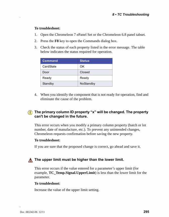
8 • TC Troubleshooting
Doc. 065342-06 12/11 295
To troubleshoot:
1. Open the Chromeleon 7 ePanel Set or the Chromeleon 6.8 panel tabset.
2. Press the F8 key to open the Commands dialog box.
3. Check the status of each property listed in the error message. The table below indicates the status required for operation.
4. When you identify the component that is not ready for operation, find and eliminate the cause of the problem.
The primary column ID property “x” will be changed. The property can't be changed in the future.
This error occurs when you modify a primary column property (batch or lot number, date of manufacture, etc.). To prevent any unintended changes, Chromeleon requests confirmation before saving the new property.
To troubleshoot:
If you are sure that the proposed change is correct, go ahead and save it.
The upper limit must be higher than the lower limit.
This error occurs if the value entered for a parameter’s upper limit (for example, TC_Temp.Signal.UpperLimit) is less than the lower limit for the parameter.
To troubleshoot:
Increase the value of the upper limit setting.
Command Status
CardState OK
Door Closed
Ready Ready
Standby NoStandby

Dionex ICS-5000 Operator’s Manual
296 Doc. 065342-06 12/11
The Warning threshold must be higher than the Limit threshold.
This error occurs if the Warning value selected for a Predictive Performance command (for example, LeftRotorSealSwitches) is lower than the Limit value. Chromeleon issues a warning message in the Audit Trail when the Warning value is reached and an error message when the Limit value is reached.
To troubleshoot:
Select a Warning value that is higher than the Limit value.
The Warning threshold must be lower than the Limit threshold.
This error occurs if the Warning value selected for a parameter is higher than the Limit value. Chromeleon issues a warning message in the Audit Trail when the Warning value is reached and an error message when the Limit value is reached.
To troubleshoot:
Select a Warning value that is lower than the Limit value.
There was already an AcqOff command for this channel before.
-or-
There was already an AcqOn command for this channel before.
-or-
Two AcqOn commands for the same channel. The second chromatogram will overwrite the first.
A Chromeleon 7 instrument method or Chromeleon 6.8 program can include no more than one command to start or terminate data acquisition for a channel; if multiple commands are present, the appropriate message (shown above) appears.
To troubleshoot:
Remove the duplicate commands from the instrument method or program.

8 • TC Troubleshooting
Doc. 065342-06 12/11 297
This function cannot be adjusted by the user.
This error occurs if you attempt to change the setting for a read-only parameter.
To troubleshoot:
Do not attempt to reset read-only parameters.
This operation may affect the oven's operation on timebase x, which is currently running a batch.
If batch processing is in progress when you attempt to change a property (such as Temperature or TempCtrl) that affects the entire TC, this error occurs.
To troubleshoot:
To avoid disrupting operation, cancel the command.
Unknown error code.
This error occurs if Chromeleon does not recognize the error code sent by the TC firmware.
To troubleshoot:
The firmware cannot be serviced by the user. Contact Technical Support for Dionex products for assistance.
Unknown format of the card data.
This error occurs if Chromeleon does not recognize the format of data stored on the column ID chip card.
To troubleshoot:
1. Open the Chromeleon 7 ePanel Set or the Chromeleon 6.8 panel tabset.
2. Press the F8 key to open the Commands dialog box.
Dionex ICS-5000 Operator’s Manual
298 Doc. 065342-06 12/11
3. Under TC, select the column name and select the FormatChipCard command.
4. For Chromeleon 6.8, click Execute.
5. If the error occurs again, insert a new column ID chip card (see Section 9.30).
X position error.
This error occurs if a TC injection valve fails to switch position within the time allotted.
To troubleshoot:
1. If a sequence is being executed, terminate the sequence by clicking Abort Batch on the Sequence Control panel.
2. Press the POWER button on the front of the TC to turn off the power; after 30 seconds, press the button again to turn on the power.
3. Try to toggle the injection valve from Load to Inject by clicking the Load and Inject buttons on the TC ePanel or Control panel.
4. If the error occurs again, contact Technical Support for Dionex products for assistance.
You do not have the privilege to approve the module's qualification.
-or-
You do not have the privilege to change the performance limits.
-or-
You do not have the privilege to change the qualification intervals.
In controlled environments, users are not allowed to perform certain operations unless they have been granted the appropriate privileges. If you attempt to do so, the appropriate message (shown above) is displayed.
8 • TC Troubleshooting
Doc. 065342-06 12/11 299
To troubleshoot:
The Chromeleon 6.8 administrator assigns various privileges to individual users or to user groups. Contact the administrator if you need one or more of the above privileges assigned to you.
8.30 TC ALARM LED Is Lighted
If the ALARM LED lights (red), check the Chromeleon Audit Trail for the cause.
• Gas leak inside the TC
1. Find and eliminate the leak.
2. If you are using Chromeleon 7: Open the Commands dialog box (press the F8 key). Select the TC and click the Commands tab. Click the ClearAlarmLED button.
3. If you are using Chromeleon 6.8: On the TC Control panel, click the Clear Alarm button.
4. Ventilate the interior of the TC thoroughly before closing the door and resuming operation.
• Humidity leak inside the TC
1. Find and eliminate the leak.
2. If you are using Chromeleon 7: Open the Commands dialog box (press the F8 key). Select the TC and click the Commands tab. Click the ClearAlarmLED button.
3. If you are using Chromeleon 6.8: On the TC Control panel, click the Clear Alarm button.
4. Ventilate the interior of the TC thoroughly before closing the door and resuming operation.
• Failure of a mechanical component
If a VALVE LED is flashing, a mechanical component in the TC injection valve has failed. Replace the injection valve “pod” (see Section 9.32).
If you are using Chromeleon 7: Open the Commands dialog box (press the F8 key). Select the TC and click the Commands tab. Click the
Dionex ICS-5000 Operator’s Manual
300 Doc. 065342-06 12/11
ClearAlarmLED button. If you are using Chromeleon 6.8: On the TC Control panel, click the Clear Alarm button.
If the OVEN LED is flashing, a mechanical component in the TC has failed. These parts are not user-serviceable. Contact Technical Support for Dionex products for assistance.
8.31 Liquid Leaks from TC Components
• Leaking fitting
Locate the source of the leak. Tighten or, if necessary, replace the liquid line connection (see Section 9.29).
• Broken liquid line
Replace the line with tubing of the same length and internal diameter (see Section 9.29).
• Blocked or improperly installed line
Make sure the lines are not crimped or otherwise blocked. Also, make sure the waste line is not elevated at any point after it exits the TC. If a line is blocked, replace it (see Section 9.29).
• Leaking injection valve
1. Make sure the liquid line connections to the valve are tight. Replace any damaged fittings (see Section 9.29).
2. Liquid leaks from behind the valve stator may indicate a scratched rotor seal. Rebuild the injection valve (see Section 9.31).
• Leaking temperature stabilizer
1. Tighten the fittings on the temperature stabilizer inlet and outlet.
2. If tightening the fittings does not eliminate the leak, excessive system backpressure may be the source of the problem. Follow the troubleshooting steps in Section 8.9 to reduce the backpressure.
8 • TC Troubleshooting
Doc. 065342-06 12/11 301
8.32 TC Temperature Does Not Increase
If the temperature fails to increase as expected, although the temperature set point has not been reached, follow the troubleshooting steps below.
• Front door not closed
Verify that the TC door is fully closed. If it is, check the door seal for signs of damage. If the seal is damaged, contact Technical Support for Dionex products for assistance.
• Column tubing connections incorrectly oriented
Column tubing connections that are incorrectly oriented can open a small path for ambient air into the TC. Check that the tubing connections are at a 90-degree angle in relation to the door seal.
• Ventilation slots on TC are obstructed
Make sure the ventilation slots are not obstructed in any way. Allow at least 6 cm (2.4 in) behind the TC for ventilation.
• Ambient temperature is too high
Reduce the ambient temperature (for example, ventilate the lab in which the TC is installed).
8.33 TC Temperature Stabilizer Not Operating Properly
• Temperature stabilizer installed incorrectly
Remove the temperature stabilizer and install it correctly. Make sure there is good thermal contact between the temperature stabilizer and the thermal element. For detailed instructions, refer to Thermo Scientific Dionex ICS-5000 Ion Chromatography System Installation Instructions (Document No. 065343).
• TC calibration is incorrect
The TC cannot be calibrated by the user. Contact Technical Support for Dionex products for assistance.
• Defective temperature stabilizer
Replace the temperature stabilizer (standard bore, P/N 064548; microbore, P/N 064650).

Dionex ICS-5000 Operator’s Manual
302 Doc. 065342-06 12/11
Doc. 065342-06 12/11 303
9 • Service
This chapter describes Thermo Scientific Dionex ICS-5000 Ion Chromatography System service and repair procedures that users may perform. All procedures not included here, including electronics-related repair procedures, must be performed by Thermo Fisher Scientific personnel. For assistance, contact Technical Support for Dionex products. In the U.S. and Canada, call 1-800-346-6390. Outside the U.S. and Canada, call the nearest Thermo Fisher Scientific office.
Before replacing any part, refer to the troubleshooting information in Chapter 8 to correctly identify the cause of the problem.
9.1 Connecting Capillary Tubing
When connecting precision cut 0.062 mm (0.0025 in) ID blue PEEK tubing (capillary tubing) to a port, make sure the ferrule and fitting bolt are at least 2 mm (0.1 in) from the end of the tubing before you insert the tubing into the port. Do not position the ferrule and fitting bolt flush with the end of the tubing.
Substituting non-Dionex/Thermo Fisher Scientific parts may impair amodule’s performance, thereby voiding the product warranty. Refer tothe warranty statement in the Dionex Terms and Conditions for moreinformation.
Capillary IC
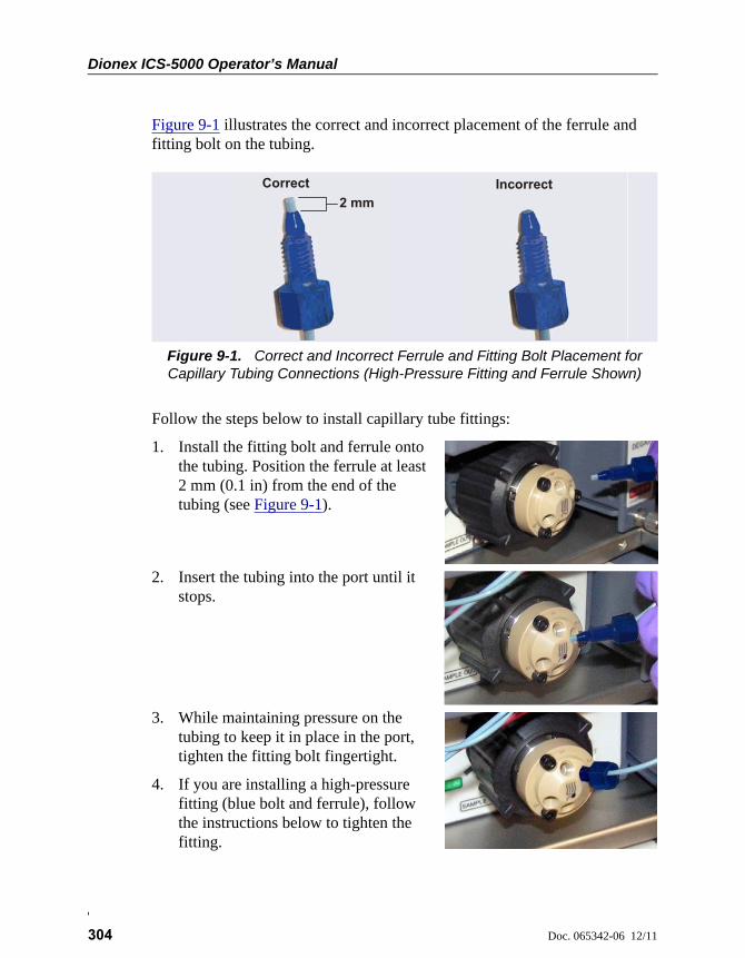
Dionex ICS-5000 Operator’s Manual
304 Doc. 065342-06 12/11
Figure 9-1 illustrates the correct and incorrect placement of the ferrule and fitting bolt on the tubing.
Follow the steps below to install capillary tube fittings:
1. Install the fitting bolt and ferrule onto the tubing. Position the ferrule at least 2 mm (0.1 in) from the end of the tubing (see Figure 9-1).
2. Insert the tubing into the port until it stops.
3. While maintaining pressure on the tubing to keep it in place in the port, tighten the fitting bolt fingertight.
4. If you are installing a high-pressure fitting (blue bolt and ferrule), follow the instructions below to tighten the fitting.
Figure 9-1. Correct and Incorrect Ferrule and Fitting Bolt Placement for Capillary Tubing Connections (High-Pressure Fitting and Ferrule Shown)
Correct
2 mmIncorrect

Doc. 065342-06 12/11 305
9.2 Tightening Guidelines for High-Pressure Fittings
Follow these guidelines when tightening a high-pressure fitting bolt (P/N 074449) and high-pressure ferrule (P/N 074373):
1. First, use your fingers to tighten the fitting bolt as tight as you can. Then, use a wrench to tighten the fitting an additional 3/4 turn (270 degrees).
2. If leaks occur, replace the fitting bolt, ferrule, and tubing.
Capillary IC
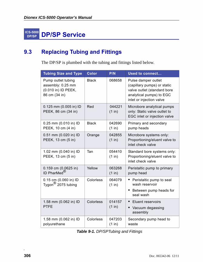
Dionex ICS-5000 Operator’s Manual
306 Doc. 065342-06 12/11
DP/SP Service
9.3 Replacing Tubing and Fittings
The DP/SP is plumbed with the tubing and fittings listed below.
ICS-5000 DP/SP
Tubing Size and Type Color P/N Used to connect…
Pump outlet tubing assembly: 0.25 mm (0.010 in) ID PEEK, 86 cm (34 in)
Black 068658 Pulse damper outlet (capillary pumps) or static valve outlet (standard bore analytical pumps) to EGC inlet or injection valve
0.125 mm (0.005 in) ID PEEK, 86 cm (34 in)
Red 044221 (1 in)
Microbore analytical pumps only: Static valve outlet to EGC inlet or injection valve
0.25 mm (0.010 in) ID PEEK, 10 cm (4 in)
Black 042690 (1 in)
Primary and secondary pump heads
0.51 mm (0.020 in) ID PEEK, 13 cm (5 in)
Orange 042855 (1 in)
Microbore systems only: Proportioning/eluent valve to inlet check valve
1.02 mm (0.040 in) ID PEEK, 13 cm (5 in)
Tan 054410 (1 in)
Standard bore systems only: Proportioning/eluent valve to inlet check valve
0.159 cm (0.0625 in) ID PharMed®
Yellow 063268 (1 in)
Peristaltic pump to primary pump head
0.15 cm (0.060 in) ID Tygon® 2075 tubing
Colorless 064079 (1 in)
• Peristaltic pump to seal wash reservoir
• Between pump heads for seal wash
1.58 mm (0.062 in) ID PTFE
Colorless 014157 (1 in)
• Eluent reservoirs
• Vacuum degassing assembly
1.58 mm (0.062 in) ID polyurethane
Colorless 047203 (1 in)
Secondary pump head to waste
Table 9-1. DP/SPTubing and Fittings

9 • DP/SP Service
Doc. 065342-06 12/11 307
Notes
• For tightening requirements for the 10-32 fitting bolt (P/N 043275) and ferrule (P/N 043276), refer to Installation of Dionex Liquid Line Fittings (Document No. 031432). The manual is on the Thermo Scientific Reference Library DVD (P/N 053891).
• For tightening requirements for the high-pressure fitting bolt (P/N 074449) and ferrule (P/N 074373), see Section 9.2.
• Use a tubing cutter to cut tubing to the required length. Make sure the cut is at a right angle to the length of the tubing and there are no nicks or burrs on the end. A tubing cutter (P/N 049584) is included in the DC Ship Kit (P/N 072011). Refer to the instructions provided with the cutter.
10 mm (0.39 in) ID polyethylene
Colorless 055075 Drip tray drain hose
1/16 in fitting bolt1/16 in ferrule
TanTan
052230062511
Inlet check valve fitting
1/8 in fitting bolt1/8 in ferrule
TanYellow
052267048949
Eluent reservoir fittings
High-pressure 10-32 fitting bolt
Blue 074449 Capillary pumps only: Pulse damper to EGC or injection valve
High-pressure 10-32 ferrule, double-cone
Blue 074373 Use with high-pressure fitting bolts
10-32 fitting bolt10-32 ferrule, double-cone
BlackTan
043275043276
All other tubing fittings
Tubing Size and Type Color P/N Used to connect…
Table 9-1. DP/SPTubing and Fittings (Continued)
Dionex ICS-5000 Operator’s Manual
308 Doc. 065342-06 12/11
9.4 Cleaning Eluent Reservoirs
Before preparing new eluent, all eluent reservoirs should be rinsed thoroughly (inside and out) with ASTM Type I (18 megohm-cm) filtered and deionized water that meets the specifications listed in Section 1.5. If a reservoir still appears dirty, or has a slimy film on the inside, clean it as instructed below.
Clean reservoirs in a capillary IC system every 3 months, as instructed below.
1. Dispose of any remaining chemicals according to municipal regulations.
2. Rinse the reservoir (inside and out) with ASTM Type I (18 megohm-cm) filtered and deionized water.
3. Rinse the inside of the reservoir with isopropyl alcohol or methanol.
4. If algae or bacteria have left a slimy film on the reservoir, use an algicide or disinfectant (dilute hydrogen peroxide, etc.).
5. Rinse cleaning chemicals out of the reservoir with ASTM Type I (18 megohm-cm) filtered and deionized water.
6. Dry the reservoir with clean, particulate-free air.
9.5 Priming the DP/SP
The pump should be primed if the eluent has been changed, the eluent line is new (empty), or the eluent line contains air. This section describes two methods for priming the pump:
• To prime the pump with the PUMP PRIME button, see Section 9.5.1.
• To prime the pump from the Pump panel in Chromeleon, see Section 9.5.2.
Although a 10 cc syringe (P/N 054578) can be used with either priming procedure, using a syringe only if eluent lines are 100% empty or if the pump is dry is recommended.
Capillary IC
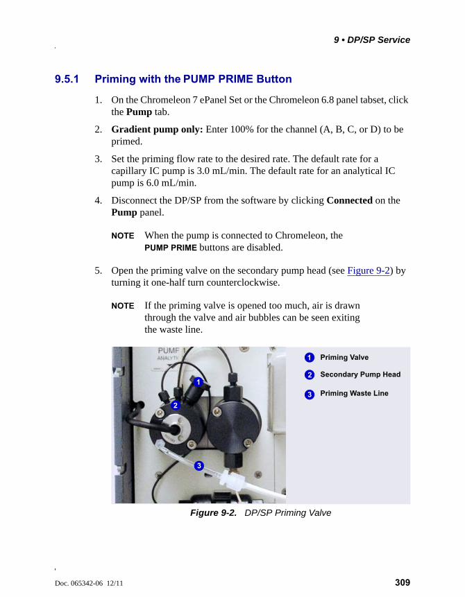
9 • DP/SP Service
Doc. 065342-06 12/11 309
9.5.1 Priming with the PUMP PRIME Button
1. On the Chromeleon 7 ePanel Set or the Chromeleon 6.8 panel tabset, click the Pump tab.
2. Gradient pump only: Enter 100% for the channel (A, B, C, or D) to be primed.
3. Set the priming flow rate to the desired rate. The default rate for a capillary IC pump is 3.0 mL/min. The default rate for an analytical IC pump is 6.0 mL/min.
4. Disconnect the DP/SP from the software by clicking Connected on the Pump panel.
NOTE When the pump is connected to Chromeleon, the PUMP PRIME buttons are disabled.
5. Open the priming valve on the secondary pump head (see Figure 9-2) by turning it one-half turn counterclockwise.
NOTE If the priming valve is opened too much, air is drawn through the valve and air bubbles can be seen exiting the waste line.
Figure 9-2. DP/SP Priming Valve
Priming Valve
Priming Waste Line
1
3
2
2
3
1Secondary Pump Head
Dionex ICS-5000 Operator’s Manual
310 Doc. 065342-06 12/11
6. Press PUMP PRIME 1 (or PUMP PRIME 2) on the front of the DP/SP. The pump will begin pumping at the priming flow rate selected on the Chromeleon panel.
7. Prime the pump until all air is purged and no air bubbles can be seen exiting the waste line.
8. Gradient pump only: To prime additional eluent lines, select another eluent channel and repeat the priming procedure.
9. After priming all eluent lines, press PUMP PRIME 1 (or PUMP PRIME 2) to stop priming and return to the flow rate last selected.
10. Close the priming valve by turning it clockwise. Do not overtighten the priming valve.
11. Reconnect the pump to the software by clicking Connected on the Pump panel.
9.5.2 Priming from the Chromeleon Panel
1. Open the priming valve on the secondary pump head (see Figure 9-2) by turning it one-half turn counterclockwise.
NOTE If the priming valve is opened too much, air is drawn through the valve and air bubbles can be seen exiting the waste line.
2. On the Chromeleon 7 ePanel Set or the Chromeleon 6.8 panel tabset, click the Pump tab.
3. Gradient pump only: Enter 100% for the channel (A, B, C, or D) to be primed.
4. Set the priming flow rate to the desired rate. The default rate for a capillary IC pump is 3.0 mL/min. The default rate for an analytical IC pump is 6.0 mL/min.
5. Click the Prime button on the Pump panel. A warning message asks you to verify that the purge (priming) valve is open. Click Execute despite warnings (Chromeleon 7) or OK (Chromeleon 6.8). Priming starts.
Do not use any tools to tighten the priming valve! Overtightening maydestroy the cap seal. Open or close the priming valve only when thesystem pressure is down.
9 • DP/SP Service
Doc. 065342-06 12/11 311
6. Prime the pump until all air is purged and no air bubbles can be seen exiting the waste line. Click the Prime button to stop priming.
NOTE Priming will stop automatically after the number of seconds specified in the Duration box have elapsed. You can set the duration to a preferred value.
7. Gradient pump only: To prime additional eluent lines, select another eluent channel and repeat the priming procedure.
8. Close the priming valve by turning it clockwise. Do not overtighten the priming valve.
9. Enter the flow rate required for your application.
10. Gradient pump only: Enter the required proportions of eluents A, B, C, and D on the Pump panel.
11. Turn on the pump flow.
NOTE After starting the pump, wait at least 5 minutes (longer for flow rates below 1.0 mL/min) before beginning an analysis. This allows the DP/SP to stabilize the flow rate.
Do not use any tools to tighten the priming valve! Overtightening maydestroy the cap seal. Open or close the priming valve only when thesystem pressure is down.
Dionex ICS-5000 Operator’s Manual
312 Doc. 065342-06 12/11
9.6 Replacing the Check Valves
A dirty check valve causes erratic flow rates and pressures; in addition, it may cause the pump to lose prime and/or be difficult to reprime. If a check valve leaks or is dirty, it should be replaced.
Capillary IC pumps and analytical IC pumps use different check valves. Verify that you have the correct check valve assembly for your pump type (see Table 9-2).
Before beginning, locate the 1/2-inch wrench (P/N 062336) in your pump ship kit:
Additional items:
• Cleanroom gloves (lint-free, particle-free, and oil-free)
• 0.2 micron filtered, Class 10, isopropyl alcohol (IPA)
• 0.2 micron filtered, canned air duster (ITW Chemtronics Ultrajet® or equivalent)
Pump Type Check Valve Assembly Part Number
Capillary IC Inlet 044541
Outlet 044540
Analytical IC Inlet 045722
Outlet 045721
Table 9-2. DP/SP Check Valve Assemblies
Pump Ship Kit Part Number
DP Ship Kit Dual Capillary 072112
DP Ship Kit Dual Analytical 062463
DP Ship Kit Capillary and Analytical 072111
SP Ship Kit Capillary or Analytical 063342
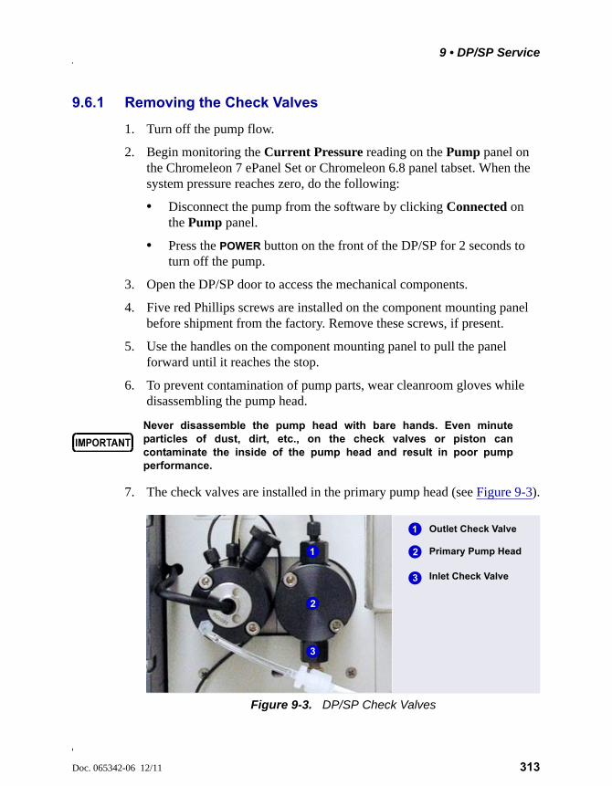
9 • DP/SP Service
Doc. 065342-06 12/11 313
9.6.1 Removing the Check Valves
1. Turn off the pump flow.
2. Begin monitoring the Current Pressure reading on the Pump panel on the Chromeleon 7 ePanel Set or Chromeleon 6.8 panel tabset. When the system pressure reaches zero, do the following:
• Disconnect the pump from the software by clicking Connected on the Pump panel.
• Press the POWER button on the front of the DP/SP for 2 seconds to turn off the pump.
3. Open the DP/SP door to access the mechanical components.
4. Five red Phillips screws are installed on the component mounting panel before shipment from the factory. Remove these screws, if present.
5. Use the handles on the component mounting panel to pull the panel forward until it reaches the stop.
6. To prevent contamination of pump parts, wear cleanroom gloves while disassembling the pump head.
7. The check valves are installed in the primary pump head (see Figure 9-3).
Never disassemble the pump head with bare hands. Even minuteparticles of dust, dirt, etc., on the check valves or piston cancontaminate the inside of the pump head and result in poor pumpperformance.
Figure 9-3. DP/SP Check Valves
Outlet Check Valve
Inlet Check Valve
1
3
2 Primary Pump Head1
3
2
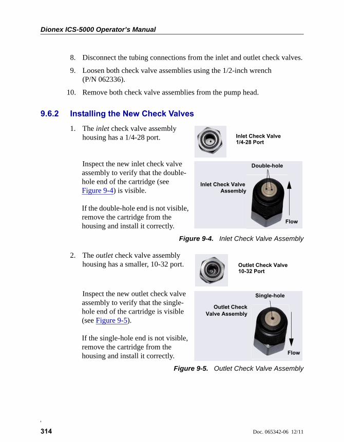
Dionex ICS-5000 Operator’s Manual
314 Doc. 065342-06 12/11
8. Disconnect the tubing connections from the inlet and outlet check valves.
9. Loosen both check valve assemblies using the 1/2-inch wrench (P/N 062336).
10. Remove both check valve assemblies from the pump head.
9.6.2 Installing the New Check Valves
1. The inlet check valve assembly housing has a 1/4-28 port.
Inspect the new inlet check valve assembly to verify that the double-hole end of the cartridge (see Figure 9-4) is visible.
If the double-hole end is not visible, remove the cartridge from the housing and install it correctly.
Figure 9-4. Inlet Check Valve Assembly
2. The outlet check valve assembly housing has a smaller, 10-32 port.
Inspect the new outlet check valve assembly to verify that the single-hole end of the cartridge is visible (see Figure 9-5).
If the single-hole end is not visible, remove the cartridge from the housing and install it correctly.
Figure 9-5. Outlet Check Valve Assembly
Inlet Check Valve1/4-28 Port
Double-hole
Flow
Inlet Check Valve
Assembly
Outlet Check Valve10-32 Port
Single-hole
Flow
Outlet CheckValve Assembly
9 • DP/SP Service
Doc. 065342-06 12/11 315
NOTE The pump cannot operate properly unless the car-tridges are installed in their respective housings in the correct orientation. Liquid enters through the check valve in the large single hole and exits through the small double holes.
3. Before installing the inlet and outlet check valves, rinse the bottom of the check valve ports in the pump head with isopropyl alcohol and blow them clean using a 0.2 micron filtered, canned air duster. Inspect the bottom of each port for any particulate matter. If necessary, rinse and dry again until they are clean.
4. Install the inlet check valve assembly on the bottom of the primary pump head. Install the outlet check valve assembly on the top of the pump head.
5. Tighten the check valves fingertight, and then use the 1/2-inch wrench to tighten an additional one-quarter to one-half turn.
6. Push the component mounting panel back into the enclosure. Close the DP/SP door.
7. Press the POWER button on the front of the DP/SP to turn on the pump.
8. Reconnect the pump to the software by clicking Connected on the Pump panel.
Overtightening may damage the pump head and check valve housingand crush the check valve seats.
Dionex ICS-5000 Operator’s Manual
316 Doc. 065342-06 12/11
9.7 Replacing Piston Seals
A defective piston seal allows leakage past the piston. This may cause unstable flow rates and baseline noise; in addition, it may make it difficult to prime the pump.
The piston seal replacement procedure consists of:
• Removing the pump head and piston (Section 9.7.1)
• Cleaning the piston (Section 9.7.2)
• Removing the main piston seal (Section 9.7.3)
• Removing the piston seal wash seal (Section 9.7.4)
• Installing new seals (Section 9.7.5)
• Reinstalling the piston and pump head (Section 9.7.6)
NOTE Capillary IC pumps and analytical IC pumps use different main piston seals and piston seal wash seals. Before continu-ing, verify that you have the correct seal for your pump type. Part numbers are shown on Figure 9-6 and Figure 9-7.
Before beginning, locate the following items in your pump ship kit:
• 3.0 mm hex key (P/N 062338)
• 10-32 fitting plugs (P/N 042772)
• 10 cc syringe (P/N 054578)
• Seal insertion tool (P/N 063675)
Pump Ship Kit Part Number
DP Ship Kit Dual Capillary 072112
DP Ship Kit Dual Analytical 062463
DP Ship Kit Capillary and Analytical 072111
SP Ship Kit Capillary or Analytical 063342
9 • DP/SP Service
Doc. 065342-06 12/11 317
Additional items:
• Cleanroom gloves (lint-free, particle-free, and oil-free)
• Small beaker
• ASTM Type I (18 megohm-cm) filtered and deionized water that meets the specifications listed in Section 1.5
• Methanol (optional)
• 0.2 micron filtered, Class 10, isopropyl alcohol (IPA)
• Lint-free paper towels (KIMWIPES® or equivalent)
• Large flat-blade screwdriver
• 0.2 micron filtered, canned air duster (ITW Chemtronics Ultrajet or equivalent)
9.7.1 Removing the Pump Head and Piston
1. Turn off the pump flow.
2. Begin monitoring the Current Pressure reading on the Pump panel on the Chromeleon 7 ePanel Set or Chromeleon 6.8 panel tabset. When the system pressure reaches zero, do the following:
• Disconnect the pump from the software by clicking Connected on the Pump panel.
• Press the POWER button on the front of the DP/SP for 2 seconds to turn off the pump.
3. Open the DP/SP door to access the mechanical components.
4. Five red Phillips screws are installed on the component mounting panel before shipment from the factory. Remove these screws, if present.
5. Use the handles on the component mounting panel to pull the panel forward until it reaches the stop.
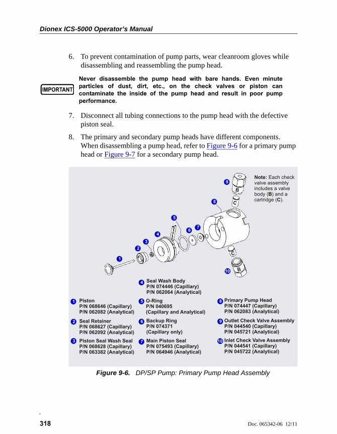
Dionex ICS-5000 Operator’s Manual
318 Doc. 065342-06 12/11
6. To prevent contamination of pump parts, wear cleanroom gloves while disassembling and reassembling the pump head.
7. Disconnect all tubing connections to the pump head with the defective piston seal.
8. The primary and secondary pump heads have different components. When disassembling a pump head, refer to Figure 9-6 for a primary pump head or Figure 9-7 for a secondary pump head.
Never disassemble the pump head with bare hands. Even minuteparticles of dust, dirt, etc., on the check valves or piston cancontaminate the inside of the pump head and result in poor pumpperformance.
Figure 9-6. DP/SP Pump: Primary Pump Head Assembly
Inlet Check Valve Assembly P/N 044541 (Capillary)P/N 045722 (Analytical)
Outlet Check Valve Assembly P/N 044540 (Capillary)P/N 045721 (Analytical)
PistonP/N 068646 (Capillary)P/N 062082 (Analytical)
Piston Seal Wash SealP/N 068628 (Capillary)P/N 063382 (Analytical)
Seal Wash BodyP/N 074446 (Capillary)P/N 062064 (Analytical)
Seal RetainerP/N 068627 (Capillary)P/N 062092 (Analytical)
Main Piston SealP/N 075493 (Capillary)P/N 064946 (Analytical)
Primary Pump HeadP/N 074447 (Capillary)P/N 062083 (Analytical)
Backup RingP/N 074371(Capillary only)
1
1
2
3
4
5
67
8
9
10
2
3
4
5
6
7
8
9
10
Note:
BC
Each check valve assembly includes a valve body ( ) and a cartridge ( ).
B
C
B
C
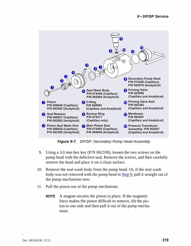
9 • DP/SP Service
Doc. 065342-06 12/11 319
9. Using a 3.0 mm hex key (P/N 062338), loosen the two screws on the pump head with the defective seal. Remove the screws, and then carefully remove the head and place it on a clean surface.
10. Remove the seal wash body from the pump head. Or, if the seal wash body was not removed with the pump head in Step 9, pull it straight out of the pump mechanism now.
11. Pull the piston out of the pump mechanism.
NOTE A magnet secures the piston in place. If the magnetic force makes the piston difficult to remove, tilt the pis-ton to one side and then pull it out of the pump mecha-nism.
Figure 9-7. DP/SP: Secondary Pump Head Assembly
PistonP/N 068646 (Capillary)P/N 062082 (Analytical)
Piston Seal Wash SealP/N 068628 (Capillary)P/N 063382 (Analytical)
Seal Wash BodyP/N 074446 (Capillary)P/N 062064 (Analytical)
Seal RetainerP/N 068627 (Capillary)P/N 062092 (Analytical)
Main Piston SealP/N 075493 (Capillary)P/N 064946 (Analytical)
Secondary Pump HeadP/N 074240 (Capillary)P/N 062079 (Analytical)
Priming Valve SealP/N 063382 (Capillary and Analytical)
Priming ValveP/N 063968 (Capillary and Analytical)
Pressure Transducer Assembly; P/N 062057 (Capillary and Analytical)
MembraneP/N 062081 (Capillary and Analytical)
Backup RingP/N 074371(Capillary only)
1
1
2
3
4
56
7
8
9
1011
12
2
3
4
5
6
7
8
9
10
11
12
Dionex ICS-5000 Operator’s Manual
320 Doc. 065342-06 12/11
9.7.2 Cleaning the Piston
1. Place the piston in a beaker containing either ASTM Type I (18 megohm-cm) filtered and deionized water or methanol. Sonicate for several minutes.
2. After cleaning, rinse the piston thoroughly with ASTM Type I (18 megohm-cm) filtered and deionized water. Dry it with a lint-free paper towel.
3. Inspect the piston for signs of damage. If the piston is scratched or scored, replace it (see Section 9.8).
9.7.3 Removing the Main Piston Seal
1. If this is the primary pump head, insert a 10-32 fitting plug (P/N 042772) into the 10-32 outlet hole of the check valve nut.
2. If this is the secondary pump head, insert a 10-32 fitting plug (P/N 042772) into both the 10-32 inlet and outlet holes.
3. Using a 10 cc syringe (P/N 054578), inject a few drops of ASTM Type I (18 megohm-cm) filtered and deionized water through the main piston seal and into the piston cavity in the pump head.
4. Reinsert the piston approximately 3 mm (0.125 in) into the piston seal and press gently. The seal should pop out of the head and onto the piston.
5. If the piston seal was not removed in Step 4, follow these steps:
a. Verify that the 10-32 fitting plugs in the inlet and outlet holes are tightened enough to prevent any leaks from the pump head.
b. Fill the piston cavity with water and check for bubbles.
c. If there are no bubbles, repeat Step 4.
Even minute scratches or particles of dust, dirt, etc. on the checkvalves or piston can contaminate the inside of the pump head andresult in poor pump performance.
Do not use a sharp tool (such as tweezers) to remove the piston seal.This will scratch the inside of the pump housing; these scratches willprevent a proper seal and cause leakage.
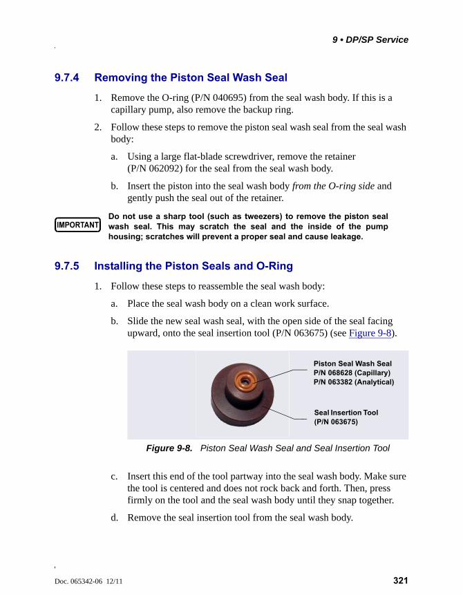
9 • DP/SP Service
Doc. 065342-06 12/11 321
9.7.4 Removing the Piston Seal Wash Seal
1. Remove the O-ring (P/N 040695) from the seal wash body. If this is a capillary pump, also remove the backup ring.
2. Follow these steps to remove the piston seal wash seal from the seal wash body:
a. Using a large flat-blade screwdriver, remove the retainer (P/N 062092) for the seal from the seal wash body.
b. Insert the piston into the seal wash body from the O-ring side and gently push the seal out of the retainer.
9.7.5 Installing the Piston Seals and O-Ring
1. Follow these steps to reassemble the seal wash body:
a. Place the seal wash body on a clean work surface.
b. Slide the new seal wash seal, with the open side of the seal facing upward, onto the seal insertion tool (P/N 063675) (see Figure 9-8).
c. Insert this end of the tool partway into the seal wash body. Make sure the tool is centered and does not rock back and forth. Then, press firmly on the tool and the seal wash body until they snap together.
d. Remove the seal insertion tool from the seal wash body.
Do not use a sharp tool (such as tweezers) to remove the piston sealwash seal. This may scratch the seal and the inside of the pumphousing; scratches will prevent a proper seal and cause leakage.
Figure 9-8. Piston Seal Wash Seal and Seal Insertion Tool
Seal Insertion Tool (P/N 063675)
Piston Seal Wash Seal P/N 068628 (Capillary)P/N 063382 (Analytical)
Dionex ICS-5000 Operator’s Manual
322 Doc. 065342-06 12/11
e. The seal wash seal is now partially installed. To complete the seal installation, place the retainer in the seal wash body and use the large flat-blade screwdriver to tighten the retainer.
f. Place the new O-ring (P/N 040695) on the seal wash body.
NOTE When replacing a piston seal, always replace the O-ring, also. This will prevent leaks.
g. If this is a capillary IC pump, place the new backup ring (P/N 074371) on the seal wash body.
2. Rinse the new main piston seal (P/N 075493, for capillary pump; P/N 064946, for analytical pump) with isopropyl alcohol (IPA) or dip it into a container of IPA. (The seal is easier to install when it is moist.)
3. Insert the piston through the seal wash assembly, and then through the new main piston seal.
4. Make sure the piston seal is centered.
5. Place the front of the pump head, flat side down, on a clean work surface.
Make sure the open side of the piston seal faces away from the retainer for the seal wash seal.
6. Using IPA, rinse inside the pump head cavity where the seal will be installed. Blow inside the cavity to dry it using the 0.2 micron filtered, canned air duster. Inspect the cavity for any particulate matter. If necessary, rinse and dry again, until the cavity is clean. Fill the cavity with ASTM Type I (18 megohm-cm) filtered and deionized water.
7. Place the components on the pump head and gently press the housing until the piston seal snaps into place.
When pressing the seal in place, ensure that the piston is free to move out, to relieve the pressure in the pump head during seal installation.
8. Remove the 10-32 fitting plugs from the pump head.
If the piston seal is not centered, applying pressure to it in Step 7 willdamage the seal and make it unusable.
Do not use a sharp tool (such as tweezers) to install the piston seal.This will scratch the seal and the inside of the pump housing; thesescratches will prevent a proper seal and cause leakage.
9 • DP/SP Service
Doc. 065342-06 12/11 323
9.7.6 Reinstalling the Piston and Pump Head
1. Slide the piston partway into the pump head; approximately 6 mm (1/4 in) of the sapphire part of the piston should extend from the head.
2. Place the pump head back on the pump.
3. Reinstall the screws in the pump head. Using the 3.0 mm hex key (P/N 062338), tighten the screws just until they come into contact with the pump head. Then, tighten the screws another one-quarter to one-half turn, one-eighth of a turn at a time.
4. Reconnect all tubing connections to the pump head. Tighten connections fingertight, and then tighten an additional one-quarter turn only.
5. Push the component mounting panel back into the enclosure. Close the DP/SP door.
6. Press the POWER button on the front of the DP/SP to turn on the pump.
7. Reconnect the pump to the software by clicking Connected on the Pump panel.
8. Turn on the pump flow.
9.8 Replacing the Piston
If a new piston seal leaks (assuming that the pump head is tight), it indicates that the piston is dirty, scratched, or broken, and should be replaced.
The piston replacement procedure consists of:
• Removing the pump head and the old piston (see Section 9.8.1)
• Reinstalling a new piston (see Section 9.8.2)
• Reinstalling the pump head (see Section 9.8.3)
NOTE Capillary IC pumps and analytical IC pumps use different pistons. Before continuing, verify that you have the correct piston for your pump type: P/N 068646 (for capillary), P/N 062082 (for analytical).
Dionex ICS-5000 Operator’s Manual
324 Doc. 065342-06 12/11
Before beginning, locate the 3.0 mm hex key (P/N 062338) in your pump ship kit:
Additional items:
• Cleanroom gloves (lint-free, particle-free, and oil-free)
• ASTM Type I (18 megohm-cm) filtered and deionized water that meets the specifications listed in Section 1.5
9.8.1 Removing the Pump Head and Piston
When disassembling and reassembling the pump head, refer to Figure 9-6 (primary pump head) or Figure 9-7 (secondary pump head).
1. Turn off the pump flow.
2. Begin monitoring the Current Pressure reading on the Pump panel on the Chromeleon 7 ePanel Set or Chromeleon 6.8 panel tabset. When the system pressure reaches zero, do the following:
• Disconnect the pump from the software by clicking Connected on the Pump panel.
• Press the POWER button on the front of the DP/SP for 2 seconds to turn off the pump.
3. Open the DP/SP door to access the mechanical components.
4. Five red Phillips screws are installed on the component mounting panel before shipment from the factory. Remove these screws, if present.
5. Use the handles on the component mounting panel to pull the panel forward until it reaches the stop.
Pump Ship Kit Part Number
DP Ship Kit Dual Capillary 072112
DP Ship Kit Dual Analytical 062463
DP Ship Kit Capillary and Analytical 072111
SP Ship Kit Capillary or Analytical 063342
9 • DP/SP Service
Doc. 065342-06 12/11 325
6. To prevent contamination of pump parts, wear cleanroom gloves while disassembling the pump head.
7. Disconnect all tubing connections to the pump head with the damaged piston.
8. Using a 3.0 mm hex key (P/N 062338), loosen the Allen screws on the pump head with the damaged piston. Remove the Allen screws, and then carefully remove the head and place it on a clean surface.
9. If the piston was not removed with the pump head in Step 8, remove the piston now by pulling it straight out of the pump mechanism.
NOTE A magnet secures the piston in place. If the magnetic force makes the piston difficult to remove, tilt the pis-ton to one side and then pull it out of the pump mecha-nism.
10. If the piston is broken, be sure to remove all broken pieces. If necessary, flush the pump head with ASTM Type I (18 megohm-cm) filtered and deionized water.
9.8.2 Reinstalling the New Piston
Slide the new piston (P/N 068646, for capillary; P/N 062082, for analytical) partway into the pump head; approximately 6 mm (1/4 in) of the sapphire part of the piston should extend from the head.
9.8.3 Reinstalling the Pump Head
1. Place the pump head back on the pump.
2. Reinstall the screws in the pump head. Using the 3.0 mm hex key (P/N 062338), tighten the screws just until they come into contact with the pump head. Then, tighten the screws another one-quarter to one-half turn, one-eighth of a turn at a time.
Never disassemble the pump head with bare hands. Even minuteparticles of dust, dirt, etc., on the check valves or piston cancontaminate the inside of the pump head and result in poor pumpperformance.
Dionex ICS-5000 Operator’s Manual
326 Doc. 065342-06 12/11
3. Reconnect all tubing connections to the pump head. Tighten connections fingertight, and then tighten an additional one-quarter turn only.
4. Push the component mounting panel back into the enclosure, using the handle in the center of the panel. Close the DP/SP door.
5. Press the POWER button on the front of the DP/SP to turn on the pump.
6. Reconnect the pump to the software by clicking Connected on the Pump panel.
7. Turn on the pump flow.
9.9 Replacing the Piston Seal Wash Tubing
Check the piston seal wash tubing weekly for crimping or blockage and replace as needed.
1. Turn off the pump flow.
2. Five red Phillips screws are installed on the component mounting panel before shipment from the factory. Remove these screws, if present.
3. Open the DP/SP door and then use the handles on the component mounting panel to pull the panel forward until it reaches the stop.
4. Remove the old tubing from the peristaltic pump (see Figure 9-9) as follows:
a. Lift the lever up and to the right and hold it in that position with one hand.
b. With your other hand, pull the PharMed tubing away from the rotor and out of the lower notch on the left side of the mounting plate.
c. Release the lever.
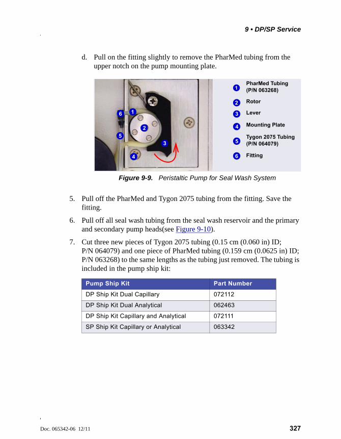
9 • DP/SP Service
Doc. 065342-06 12/11 327
d. Pull on the fitting slightly to remove the PharMed tubing from the upper notch on the pump mounting plate.
5. Pull off the PharMed and Tygon 2075 tubing from the fitting. Save the fitting.
6. Pull off all seal wash tubing from the seal wash reservoir and the primary and secondary pump heads(see Figure 9-10).
7. Cut three new pieces of Tygon 2075 tubing (0.15 cm (0.060 in) ID; P/N 064079) and one piece of PharMed tubing (0.159 cm (0.0625 in) ID; P/N 063268) to the same lengths as the tubing just removed. The tubing is included in the pump ship kit:
Figure 9-9. Peristaltic Pump for Seal Wash System
Pump Ship Kit Part Number
DP Ship Kit Dual Capillary 072112
DP Ship Kit Dual Analytical 062463
DP Ship Kit Capillary and Analytical 072111
SP Ship Kit Capillary or Analytical 063342
Rotor
Lever
PharMed Tubing (P/N 063268)
Fitting
Tygon 2075 Tubing(P/N 064079)
Mounting Plate
2
4
1
6
5
1
4
3
2
6
5
3
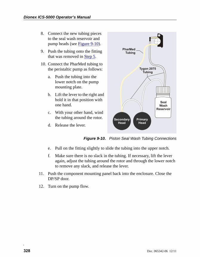
Dionex ICS-5000 Operator’s Manual
328 Doc. 065342-06 12/11
8. Connect the new tubing pieces to the seal wash reservoir and pump heads (see Figure 9-10).
9. Push the tubing onto the fitting that was removed in Step 5.
10. Connect the PharMed tubing to the peristaltic pump as follows:
a. Push the tubing into the lower notch on the pump mounting plate.
b. Lift the lever to the right and hold it in that position with one hand.
c. With your other hand, wind the tubing around the rotor.
d. Release the lever.
Figure 9-10. Piston Seal Wash Tubing Connections
e. Pull on the fitting slightly to slide the tubing into the upper notch.
f. Make sure there is no slack in the tubing. If necessary, lift the lever again, adjust the tubing around the rotor and through the lower notch to remove any slack, and release the lever.
11. Push the component mounting panel back into the enclosure. Close the DP/SP door.
12. Turn on the pump flow.
PharMedTubing
Tygon 2075 Tubing
Secondary Head
PrimaryHead
SealWash
Reservoir
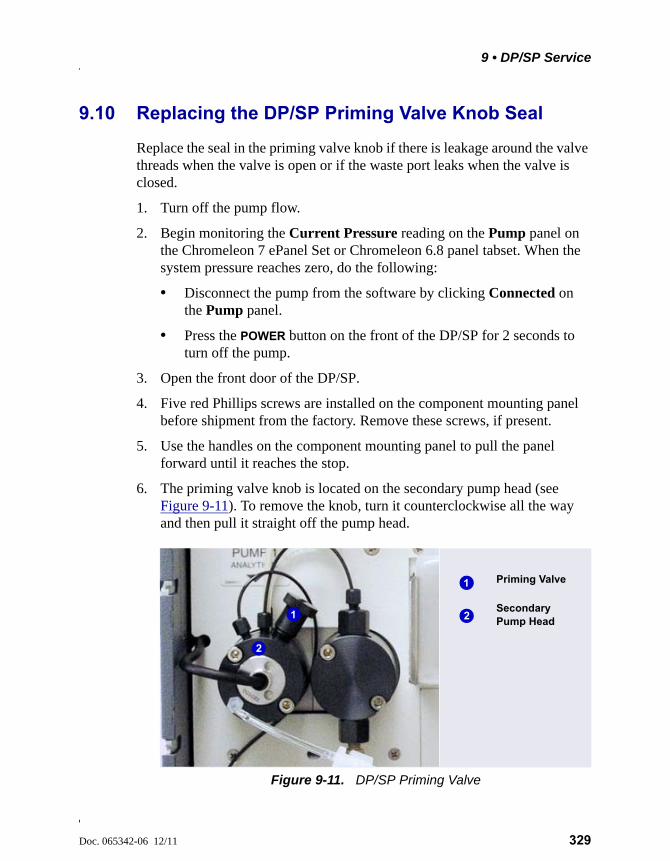
9 • DP/SP Service
Doc. 065342-06 12/11 329
9.10 Replacing the DP/SP Priming Valve Knob Seal
Replace the seal in the priming valve knob if there is leakage around the valve threads when the valve is open or if the waste port leaks when the valve is closed.
1. Turn off the pump flow.
2. Begin monitoring the Current Pressure reading on the Pump panel on the Chromeleon 7 ePanel Set or Chromeleon 6.8 panel tabset. When the system pressure reaches zero, do the following:
• Disconnect the pump from the software by clicking Connected on the Pump panel.
• Press the POWER button on the front of the DP/SP for 2 seconds to turn off the pump.
3. Open the front door of the DP/SP.
4. Five red Phillips screws are installed on the component mounting panel before shipment from the factory. Remove these screws, if present.
5. Use the handles on the component mounting panel to pull the panel forward until it reaches the stop.
6. The priming valve knob is located on the secondary pump head (see Figure 9-11). To remove the knob, turn it counterclockwise all the way and then pull it straight off the pump head.
Figure 9-11. DP/SP Priming Valve
Secondary Pump Head
Priming Valve1
21
2
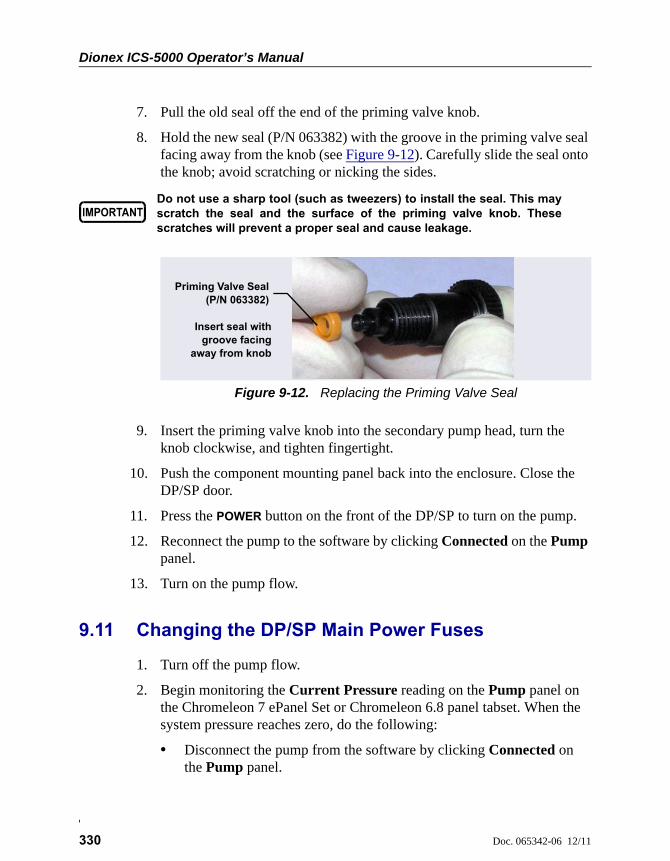
Dionex ICS-5000 Operator’s Manual
330 Doc. 065342-06 12/11
7. Pull the old seal off the end of the priming valve knob.
8. Hold the new seal (P/N 063382) with the groove in the priming valve seal facing away from the knob (see Figure 9-12). Carefully slide the seal onto the knob; avoid scratching or nicking the sides.
9. Insert the priming valve knob into the secondary pump head, turn the knob clockwise, and tighten fingertight.
10. Push the component mounting panel back into the enclosure. Close the DP/SP door.
11. Press the POWER button on the front of the DP/SP to turn on the pump.
12. Reconnect the pump to the software by clicking Connected on the Pump panel.
13. Turn on the pump flow.
9.11 Changing the DP/SP Main Power Fuses
1. Turn off the pump flow.
2. Begin monitoring the Current Pressure reading on the Pump panel on the Chromeleon 7 ePanel Set or Chromeleon 6.8 panel tabset. When the system pressure reaches zero, do the following:
• Disconnect the pump from the software by clicking Connected on the Pump panel.
Do not use a sharp tool (such as tweezers) to install the seal. This mayscratch the seal and the surface of the priming valve knob. Thesescratches will prevent a proper seal and cause leakage.
Figure 9-12. Replacing the Priming Valve Seal
Priming Valve Seal(P/N 063382)
Insert seal withgroove facing
away from knob
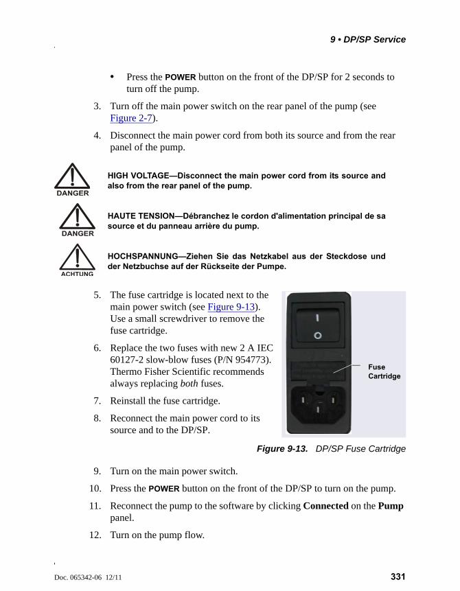
9 • DP/SP Service
Doc. 065342-06 12/11 331
• Press the POWER button on the front of the DP/SP for 2 seconds to turn off the pump.
3. Turn off the main power switch on the rear panel of the pump (see Figure 2-7).
4. Disconnect the main power cord from both its source and from the rear panel of the pump.
5. The fuse cartridge is located next to the main power switch (see Figure 9-13). Use a small screwdriver to remove the fuse cartridge.
6. Replace the two fuses with new 2 A IEC 60127-2 slow-blow fuses (P/N 954773). Thermo Fisher Scientific recommends always replacing both fuses.
7. Reinstall the fuse cartridge.
8. Reconnect the main power cord to its source and to the DP/SP.
Figure 9-13. DP/SP Fuse Cartridge
9. Turn on the main power switch.
10. Press the POWER button on the front of the DP/SP to turn on the pump.
11. Reconnect the pump to the software by clicking Connected on the Pump panel.
12. Turn on the pump flow.
HIGH VOLTAGE—Disconnect the main power cord from its source andalso from the rear panel of the pump.
HAUTE TENSION—Débranchez le cordon d'alimentation principal de sasource et du panneau arrière du pump.
HOCHSPANNUNG—Ziehen Sie das Netzkabel aus der Steckdose undder Netzbuchse auf der Rückseite der Pumpe.
Fuse Cartridge

Dionex ICS-5000 Operator’s Manual
332 Doc. 065342-06 12/11
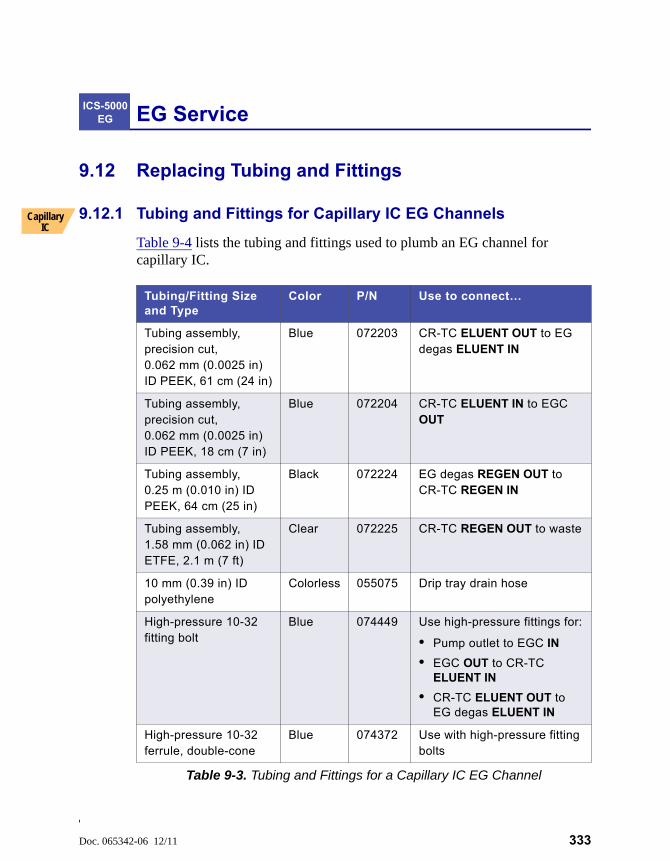
Doc. 065342-06 12/11 333
EG Service
9.12 Replacing Tubing and Fittings
9.12.1 Tubing and Fittings for Capillary IC EG Channels
Table 9-4 lists the tubing and fittings used to plumb an EG channel for capillary IC.
ICS-5000 EG
Capillary IC
Tubing/Fitting Size and Type
Color P/N Use to connect…
Tubing assembly, precision cut, 0.062 mm (0.0025 in) ID PEEK, 61 cm (24 in)
Blue 072203 CR-TC ELUENT OUT to EG degas ELUENT IN
Tubing assembly, precision cut, 0.062 mm (0.0025 in) ID PEEK, 18 cm (7 in)
Blue 072204 CR-TC ELUENT IN to EGC OUT
Tubing assembly, 0.25 m (0.010 in) ID PEEK, 64 cm (25 in)
Black 072224 EG degas REGEN OUT to CR-TC REGEN IN
Tubing assembly, 1.58 mm (0.062 in) ID ETFE, 2.1 m (7 ft)
Clear 072225 CR-TC REGEN OUT to waste
10 mm (0.39 in) ID polyethylene
Colorless 055075 Drip tray drain hose
High-pressure 10-32 fitting bolt
Blue 074449 Use high-pressure fittings for:
• Pump outlet to EGC IN
• EGC OUT to CR-TC ELUENT IN
• CR-TC ELUENT OUT to EG degas ELUENT IN
High-pressure 10-32 ferrule, double-cone
Blue 074372 Use with high-pressure fitting bolts
Table 9-3. Tubing and Fittings for a Capillary IC EG Channel
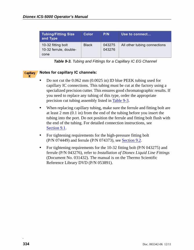
Dionex ICS-5000 Operator’s Manual
334 Doc. 065342-06 12/11
Notes for capillary IC channels:
• Do not cut the 0.062 mm (0.0025 in) ID blue PEEK tubing used for capillary IC connections. This tubing must be cut at the factory using a specialized precision cutter. This ensures good chromatographic results. If you need to replace any tubing of this type, order the appropriate precision cut tubing assembly listed in Table 9-3.
• When replacing capillary tubing, make sure the ferrule and fitting bolt are at least 2 mm (0.1 in) from the end of the tubing before you insert the tubing into the port. Do not position the ferrule and fitting bolt flush with the end of the tubing. For detailed connection instructions, see Section 9.1.
• For tightening requirements for the high-pressure fitting bolt (P/N 074449) and ferrule (P/N 074373), see Section 9.2.
• For tightening requirements for the 10-32 fitting bolt (P/N 043275) and ferrule (P/N 043276), refer to Installation of Dionex Liquid Line Fittings (Document No. 031432). The manual is on the Thermo Scientific Reference Library DVD (P/N 053891).
10-32 fitting bolt10-32 ferrule, double-cone
Black 043275043276
All other tubing connections
Tubing/Fitting Size and Type
Color P/N Use to connect…
Table 9-3. Tubing and Fittings for a Capillary IC EG Channel
Capillary IC

9 • EG Service
Doc. 065342-06 12/11 335
9.12.2 Tubing and Fittings for Analytical IC EG Channels
Table 9-4 lists the tubing and fittings used to plumb an EG channel for analytical IC.
Notes for analytical IC channels:
• For ferrule fitting tightening requirements, refer to Installation of Dionex Liquid Line Fittings (Document No. 031432). The manual is on the Thermo Scientific Reference Library DVD (P/N 053891).
• For an analytical IC channel, use a tubing cutter to cut tubing to the required length. Make sure the cut is at a right angle to the length of the tubing and there are no nicks or burrs on the end. A tubing cutter (P/N 049584) is included in the DC Ship Kit (P/N 072011). Refer to the instructions provided with the cutter.
Tubing/Fitting Size and Type
Color P/N Used to connect…
0.25 mm (0.010 in) ID PEEK tubing
Black 042690 (1 in)
• EGC to pump
• EGC to CR-TC
• RFIC Eluent Degasser to injection valve
• RFIC Eluent Degasser to eluent reservoir
1.6 mm (0.062 in) ID PTFE tubing
Colorless 014157 (1 in)
• RFIC Eluent Degasser REGEN IN to CR-TC
• RFIC Eluent Degasser REGEN OUT to waste
1.58 mm (0.062 in) ID polyurethane tubing
Colorless 047203 EGC gas vent line
10 mm (0.39 in) ID polyethylene tubing
Colorless 055075 Drip tray drain hose
1/8 in fitting bolt1/8 in ferrule
TanYellow
052267048949
The suppressor REGEN OUT port and the eluent reservoirs
10-32 fitting bolt10-32 ferrule, double-cone
BlackTan
043275043276
All other tubing connections
Table 9-4. Tubing and Fittings for an Analytical IC EG Channel
Dionex ICS-5000 Operator’s Manual
336 Doc. 065342-06 12/11
9.13 Isolating a Restriction in the Liquid Lines
A restriction in the liquid plumbing will cause excessive system backpressure.
1. Begin pumping eluent through the system (including the columns) at the flow rate normally used.
2. Work backward through the system, beginning at the flow cell exit. One at a time, loosen each fitting and observe the pressure. The connection at which the pressure drops abnormally indicates the point of restriction. If the EGC is the source of the high backpressure, replace the outlet frit as instructed in the EGC manual. The manual is included on the Thermo Scientific Reference Library DVD (P/N 053891).
3. If the restriction has caused such high pressure that the system cannot be operated, you must work forward through the system, adding parts one at a time, until an abnormal pressure increase (and hence, the restriction) is found.
9.14 Replacing the EGC
Replace the EGC when the cartridge is expended or when it leaks. Refer to Table 2-2 for a list of the EGC models that can be used with the Dionex ICS-5000 Eluent Generator.
Analytical IC systems require EGC III cartridges. Previous versions of EGC are not compatible with the Dionex ICS-5000 Eluent Generator.
The EGC replacement procedure consists of:
• Removing the old EGC (see Section 9.14.1)
• Disposing of the old EGC (see Section 9.14.2)
• Installing and conditioning a new capillary EGC (see Section 9.14.4)
–or–
• Installing and conditioning a new analytical EGC (see Section 9.14.5)
The EGC contains one of the following: a corrosive base (KOH, LiOH, orNaOH), a corrosive acid (MSA), or a concentrated K2CO3 solution. Wear
protective eyewear and gloves when handling the cartridge.
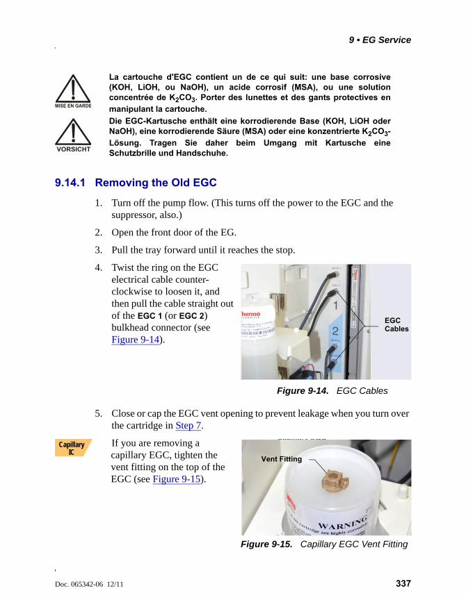
9 • EG Service
Doc. 065342-06 12/11 337
9.14.1 Removing the Old EGC
1. Turn off the pump flow. (This turns off the power to the EGC and the suppressor, also.)
2. Open the front door of the EG.
3. Pull the tray forward until it reaches the stop.
4. Twist the ring on the EGC electrical cable counter-clockwise to loosen it, and then pull the cable straight out of the EGC 1 (or EGC 2) bulkhead connector (see Figure 9-14).
Figure 9-14. EGC Cables
5. Close or cap the EGC vent opening to prevent leakage when you turn over the cartridge in Step 7.
If you are removing a capillary EGC, tighten the vent fitting on the top of the EGC (see Figure 9-15).
Figure 9-15. Capillary EGC Vent Fitting
La cartouche d'EGC contient un de ce qui suit: une base corrosive(KOH, LiOH, ou NaOH), un acide corrosif (MSA), ou une solutionconcentrée de K2CO3. Porter des lunettes et des gants protectives en
manipulant la cartouche.
Die EGC-Kartusche enthält eine korrodierende Base (KOH, LiOH oderNaOH), eine korrodierende Säure (MSA) oder eine konzentrierte K2CO3-
Lösung. Tragen Sie daher beim Umgang mit Kartusche eineSchutzbrille und Handschuhe.
EGCCables
Capillary EGCVent Fitting
Vent Fitting
Capillary IC
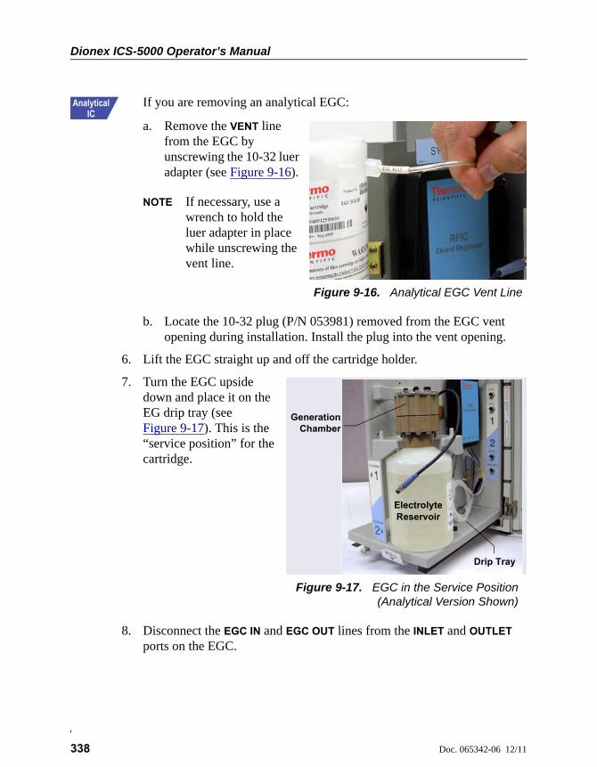
Dionex ICS-5000 Operator’s Manual
338 Doc. 065342-06 12/11
If you are removing an analytical EGC:
a. Remove the VENT line from the EGC by unscrewing the 10-32 luer adapter (see Figure 9-16).
NOTE If necessary, use a wrench to hold the luer adapter in place while unscrewing the vent line.
Figure 9-16. Analytical EGC Vent Line
b. Locate the 10-32 plug (P/N 053981) removed from the EGC vent opening during installation. Install the plug into the vent opening.
6. Lift the EGC straight up and off the cartridge holder.
7. Turn the EGC upside down and place it on the EG drip tray (see Figure 9-17). This is the “service position” for the cartridge.
Figure 9-17. EGC in the Service Position(Analytical Version Shown)
8. Disconnect the EGC IN and EGC OUT lines from the INLET and OUTLET ports on the EGC.
EGCVent Line
LuerAdapter
Electrolyte
Drip Tray
Chamber
Reservoir
Generation
9 • EG Service
Doc. 065342-06 12/11 339
9.14.2 Disposing of the Old EGC
If the EGC is expended, follow these steps to dispose of it:
1. Hold the cartridge with the eluent generation chamber on top. Unscrew the eluent generation chamber from the electrolyte reservoir and pour the remaining electrolyte solution into an appropriate hazardous waste container.
NOTE Refer to the Material Safety Data Sheet (MSDS) shipped with the EGC for the chemical description.
2. Rinse the electrolyte reservoir and membranes three times with ASTM Type I (18 megohm-cm) filtered and deionized water that meets the specifications listed in Section 1.5. Rinsing should render the reservoir and membranes nonhazardous; however, check your local, state, and federal regulatory agency regulations for proper disposal.
9.14.3 Storing an Old EGC
If the EGC is not expended, follow these steps to prepare the cartridge for storage:
1. Plug all fittings. Tighten the vent fitting (capillary EGC) or cap the vent port (analytical EGC). This will prevent the evaporation of water in the electrolyte reservoir.
2. Store the cartridge in an upright position (with the electrolyte reservoir at top) at 4 to 40°C (39 to 104°F) until its next use. The original shipping container is ideal for storage. Before resuming operation, condition the cartridge. For instructions, see Section 9.14.4 (for a capillary EGC) or Section 9.14.5 (for an analytical EGC).
If you are replacing a capillary EGC, go on to Section 9.14.4.
If you are replacing an analytical EGC, go on to Section 9.14.5.
Capillary IC
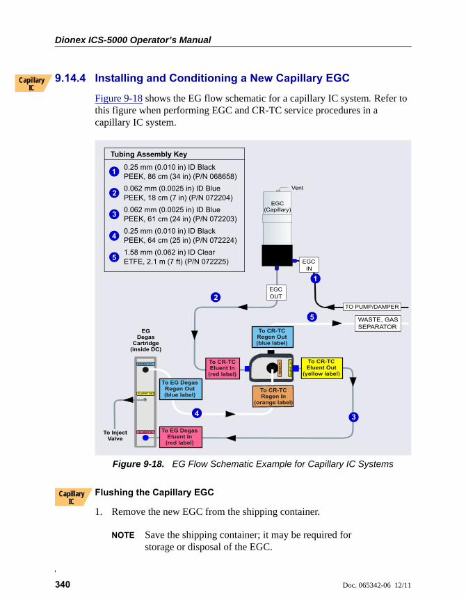
Dionex ICS-5000 Operator’s Manual
340 Doc. 065342-06 12/11
9.14.4 Installing and Conditioning a New Capillary EGC
Figure 9-18 shows the EG flow schematic for a capillary IC system. Refer to this figure when performing EGC and CR-TC service procedures in a capillary IC system.
Flushing the Capillary EGC
1. Remove the new EGC from the shipping container.
NOTE Save the shipping container; it may be required for storage or disposal of the EGC.
Capillary IC
Figure 9-18. EG Flow Schematic Example for Capillary IC Systems
EGC OUT
TO PUMP/DAMPER
EGC IN
To CR-TC Regen Out(blue label)
To CR-TC Eluent In
(red label) EL
UE
NT
OU
T
RE
GE
NIN
To EG Degas Regen Out(blue label)
To CR-TC Regen In
(orange label)
Vent
WASTE, GAS SEPARATOR
To CR-TC Eluent Out
(yellow label)
To EG Degas Eluent In(red label)
EGDegas
Cartridge(inside DC)
ELUENT IN
REGEN
OUT
ELUENT
OUT
To Inject Valve
EGC(Capillary)
Tubing Assembly Key
0.25 mm (0.010 in) ID Black PEEK, 86 cm (34 in) (P/N 068658)
0.062 mm (0.0025 in) ID Blue PEEK, 18 cm (7 in) (P/N 072204)
0.062 mm (0.0025 in) ID Blue PEEK, 61 cm (24 in) (P/N 072203)
0.25 mm (0.010 in) ID Black PEEK, 64 cm (25 in) (P/N 072224)
1.58 mm (0.062 in) ID Clear ETFE, 2.1 m (7 ft) (P/N 072225)
1
3
2
4
5
1
2
34
5
Capillary IC
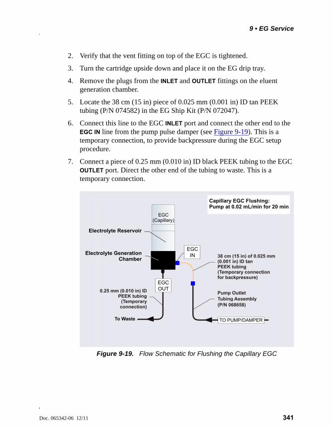
9 • EG Service
Doc. 065342-06 12/11 341
2. Verify that the vent fitting on top of the EGC is tightened.
3. Turn the cartridge upside down and place it on the EG drip tray.
4. Remove the plugs from the INLET and OUTLET fittings on the eluent generation chamber.
5. Locate the 38 cm (15 in) piece of 0.025 mm (0.001 in) ID tan PEEK tubing (P/N 074582) in the EG Ship Kit (P/N 072047).
6. Connect this line to the EGC INLET port and connect the other end to the EGC IN line from the pump pulse damper (see Figure 9-19). This is a temporary connection, to provide backpressure during the EGC setup procedure.
7. Connect a piece of 0.25 mm (0.010 in) ID black PEEK tubing to the EGC OUTLET port. Direct the other end of the tubing to waste. This is a temporary connection.
Figure 9-19. Flow Schematic for Flushing the Capillary EGC
To Waste
Pump Outlet Tubing Assembly (P/N 068658)
0.25 mm (0.010 in) PEEK tubing
(Temporary connection)
ID
EGC(Capillary)
EGC OUT
EGC IN 38 cm (15 in) of 0.025 mm
(0.001 in) ID tan PEEK tubing (Temporary connectionfor backpressure)
TO PUMP/DAMPER
Capillary EGC Flushing:Pump at 0.02 mL/min for 20 min
Electrolyte Reservoir
Electrolyte GenerationChamber
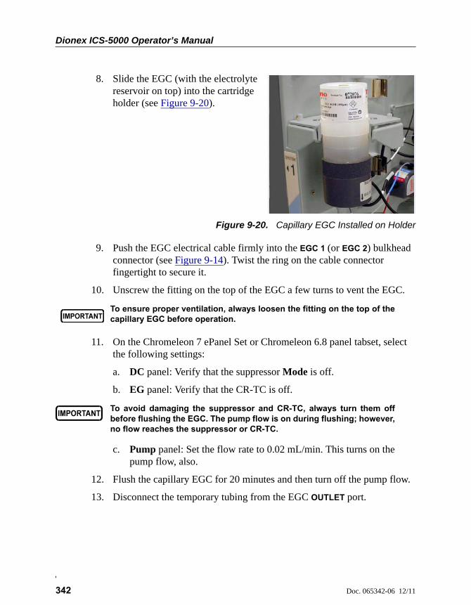
Dionex ICS-5000 Operator’s Manual
342 Doc. 065342-06 12/11
8. Slide the EGC (with the electrolyte reservoir on top) into the cartridge holder (see Figure 9-20).
Figure 9-20. Capillary EGC Installed on Holder
9. Push the EGC electrical cable firmly into the EGC 1 (or EGC 2) bulkhead connector (see Figure 9-14). Twist the ring on the cable connector fingertight to secure it.
10. Unscrew the fitting on the top of the EGC a few turns to vent the EGC.
11. On the Chromeleon 7 ePanel Set or Chromeleon 6.8 panel tabset, select the following settings:
a. DC panel: Verify that the suppressor Mode is off.
b. EG panel: Verify that the CR-TC is off.
c. Pump panel: Set the flow rate to 0.02 mL/min. This turns on the pump flow, also.
12. Flush the capillary EGC for 20 minutes and then turn off the pump flow.
13. Disconnect the temporary tubing from the EGC OUTLET port.
To ensure proper ventilation, always loosen the fitting on the top of thecapillary EGC before operation.
To avoid damaging the suppressor and CR-TC, always turn them offbefore flushing the EGC. The pump flow is on during flushing; however,no flow reaches the suppressor or CR-TC.

9 • EG Service
Doc. 065342-06 12/11 343
Conditioning the Capillary EGC
1. Use a high-pressure (blue) fitting bolt and ferrule to connect the EGC OUT line from the ELUENT IN port of the CR-TC to the EGC OUTLET port (see Figure 9-21).
2. Disconnect the lines from the ELUENT OUT and REGEN IN port of the CR-TC.
3. Connect a piece of 0.25 mm (0.010 in) ID PEEK tubing between the ports. This is a temporary connection.
4. Verify that the suppressor Mode is off.
Figure 9-21. Flow Schematic for Conditioning the Capillary EGC
Capillary IC
EGC OUT
0.25 mm (0.010 in)
(Temporaryconnection)
IDPEEK Tubing
To CR-TC Eluent Out
(yellow label)
To CR-TC Regen Out(blue label)
To CR-TC Eluent In(red label)
To CR-TC Regen In
(orange label)
EL
UE
NT
OU
T
RE
GE
NIN
EGC(Capillary)
EGC IN
TO PUMP/DAMPER
ELUENT IN
0.062 mm (0.0025 in) ID PEEK Tubing
Assembly (P/N 072204)
1.58 mm (0.062 in) ID Tefzel Tubing Assembly (P/N 072225)
Capillary EGC Conditioning:
EGC concentration at 50 mMPump at 0.02 mL/min for 15 min
Dionex ICS-5000 Operator’s Manual
344 Doc. 065342-06 12/11
5. Set the pump flow rate to 0.02 mL/min.
6. Set the EGC concentration to 50 mM and turn on the EGC and CR-TC power.
7. Condition the EGC for 15 minutes.
8. Turn off the EGC and CR-TC power.
9. Turn off the pump flow.
10. Remove the backpressure tubing from the EGC IN line.
11. Use a high-pressure (blue) fitting to connect the EGC IN line to the EGC INLET port.
12. Disconnect the temporary tubing from the ELUENT OUT and REGEN IN ports of the CR-TC.
13. Reconnect the lines to the ELUENT OUT and REGEN IN ports of the CR-TC that were disconnected in Step 2.
To avoid damaging the suppressor, always turn it off beforeconditioning the EGC. The pump flow is on during conditioning;however, no flow reaches the suppressor.
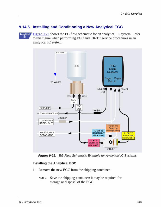
9 • EG Service
Doc. 065342-06 12/11 345
9.14.5 Installing and Conditioning a New Analytical EGC
Figure 9-22 shows the EG flow schematic for an analytical IC system. Refer to this figure when performing EGC and CR-TC service procedures in an analytical IC system.
Installing the Analytical EGC
1. Remove the new EGC from the shipping container.
NOTE Save the shipping container; it may be required for storage or disposal of the EGC.
Figure 9-22. EG Flow Schematic Example for Analytical IC Systems
Eluent Out
EGC VENT
To Waste
EGC IN
EGC OUT
EGC
Inlet Outlet
TO INJ VALVE - P
TO PUMP
WASTE, GAS SEPARATOR
CouplerTO SRS/AES REGEN OUT
Eluent In
CR-TC
Coupler
EL
UE
NT
OU
T
RE
GE
N IN
TO CR -TC REGEN OUT (blue label)
To CR-TC Eluent In(red label)
To CR-TC Eluent Out
(yellow label)
To CR-TC Regen In
(orange label)
RFIC Eluent
Degasser
Regen Out
Regen In
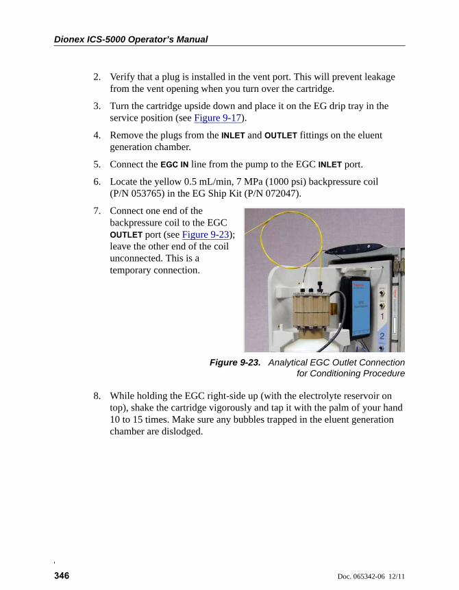
Dionex ICS-5000 Operator’s Manual
346 Doc. 065342-06 12/11
2. Verify that a plug is installed in the vent port. This will prevent leakage from the vent opening when you turn over the cartridge.
3. Turn the cartridge upside down and place it on the EG drip tray in the service position (see Figure 9-17).
4. Remove the plugs from the INLET and OUTLET fittings on the eluent generation chamber.
5. Connect the EGC IN line from the pump to the EGC INLET port.
6. Locate the yellow 0.5 mL/min, 7 MPa (1000 psi) backpressure coil (P/N 053765) in the EG Ship Kit (P/N 072047).
7. Connect one end of the backpressure coil to the EGC OUTLET port (see Figure 9-23); leave the other end of the coil unconnected. This is a temporary connection.
Figure 9-23. Analytical EGC Outlet Connectionfor Conditioning Procedure
8. While holding the EGC right-side up (with the electrolyte reservoir on top), shake the cartridge vigorously and tap it with the palm of your hand 10 to 15 times. Make sure any bubbles trapped in the eluent generation chamber are dislodged.
Backpressure
EGC
PortOutlet
Coil

9 • EG Service
Doc. 065342-06 12/11 347
9. Slide the EGC (with the electrolyte reservoir on top) into the holder in the EG (see Figure 9-24).
Figure 9-24. Analytical EGC Installed on Holder
10. Push the EGC electrical cable firmly into the EGC 1 (or EGC 2) bulkhead connector (see Figure 9-14). Twist the ring on the cable connector fingertight to secure it.
11. Remove the 10-32 plug from the EGC vent opening. Install a 10-32 luer adapter in the vent opening.
12. Connect the luer adapter and VENT line removed from the old cartridge to the vent opening in the new cartridge (see Figure 9-16).
13. Place the 10-32 plug removed from the vent opening in a safe place for storage. The 10-32 plug is required for shipping or storing the cartridge.
To ensure proper ventilation, always connect the vent line to theanalytical EGC before operation.
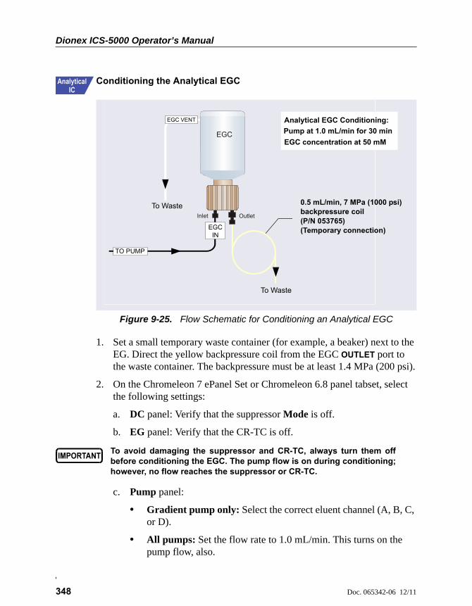
Dionex ICS-5000 Operator’s Manual
348 Doc. 065342-06 12/11
Conditioning the Analytical EGC
1. Set a small temporary waste container (for example, a beaker) next to the EG. Direct the yellow backpressure coil from the EGC OUTLET port to the waste container. The backpressure must be at least 1.4 MPa (200 psi).
2. On the Chromeleon 7 ePanel Set or Chromeleon 6.8 panel tabset, select the following settings:
a. DC panel: Verify that the suppressor Mode is off.
b. EG panel: Verify that the CR-TC is off.
c. Pump panel:
• Gradient pump only: Select the correct eluent channel (A, B, C, or D).
• All pumps: Set the flow rate to 1.0 mL/min. This turns on the pump flow, also.
Figure 9-25. Flow Schematic for Conditioning an Analytical EGC
EGC VENT
To Waste
EGC IN
EGC
Inlet Outlet
TO PUMP
To Waste
Analytical EGC Conditioning:
EGC concentration at 50 mM
Pump at 1.0 mL/min for 30 min
0.5 mL/min, 7 MPa (1000 psi) backpressure coil (P/N 053765) (Temporary connection)
To avoid damaging the suppressor and CR-TC, always turn them offbefore conditioning the EGC. The pump flow is on during conditioning;however, no flow reaches the suppressor or CR-TC.
9 • EG Service
Doc. 065342-06 12/11 349
d. EG panel: Enter 50 mM in the Target Concentration field. This turns on the power to the EGC, also.
e. Condition the analytical EGC for 30 minutes.
3. Turn off the EGC and CR-TC power.
4. Turn off the pump flow.
Completing the Analytical EGC Installation
1. Twist the ring on the EGC electrical cable counterclockwise to loosen it, and then pull the cable straight out of the EGC 1 (or EGC 2) bulkhead connector.
2. Remove the backpressure tubing from the waste container and remove the waste container.
3. Replace the 10-32 plug in the EGC vent opening.
4. Lift the EGC out of the holder, turn it upside down, and place it on the drip tray in the service position (see Figure 9-17).
5. Disconnect the backpressure coil from the EGC OUTLET port.
6. Connect the EGC OUT line to the OUTLET port.
7. Turn the EGC right-side up, and check for bubbles in the eluent generation chamber. If necessary, shake and tap the cartridge to remove bubbles.
8. Install the EGC in the holder. Remove the 10-32 plug from the vent opening and reinstall the luer adapter and vent line.
9. Reconnect the EGC electrical cable.
9.15 Replacing the CR-TC
The CR-TC replacement procedure consists of:
• Removing the old CR-TC (see Section 9.14.1)
• Installing and hydrating the new CR-TC (see Section 9.15.2)
• Completing the plumbing for the new CR-TC (see Section 9.15.3)
Dionex ICS-5000 Operator’s Manual
350 Doc. 065342-06 12/11
Refer to Figure 9-18 for a flow schematic of the EG and CR-TC for capillary IC and to Figure 9-22 for analytical IC.
9.15.1 Removing the Old CR-TC
1. Turn off the pump flow. (This turns off the power to the EGC and the suppressor, also.)
2. Open the front door of the EG.
3. Push down on the slide release latch and pull the tray forward until it reaches the stop.
4. Pull the CR-TC off the ball studs on the component mounting panel.
5. Disconnect the liquid lines from the four ports on the CR-TC.
6. Twist the ring on the CR-TC electrical cable counterclockwise to loosen it, and then pull the cable straight out of the CR-TC 1 (or CR-TC 2) bulkhead connector.
7. Remove the CR-TC from the EG.
9.15.2 Installing and Flushing the New CR-TC
1. Remove the plugs from the ports on the new CR-TC.
2. If you are installing a CR-TC in a capillary IC system:
a. Connect a piece of 0.25 mm (0.010 in) ID PEEK tubing between the
ELUENT OUT and REGEN IN ports of the CR-TC (see Figure 9-26). This is a temporary connection.
b. Locate the 38 cm (15 in) piece of 0.025 mm (0.001 in) ID tan PEEK tubing (P/N 074582) in the EG Ship Kit (P/N 072047).
c. Connect this line to the EGC INLET port and connect the other end to the EGC IN line from the pump pulse damper (see Figure 9-19). This is a temporary connection, to provide backpressure.
Capillary IC
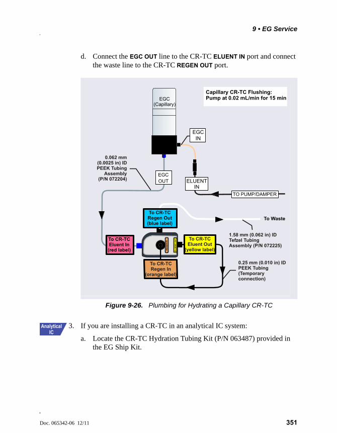
9 • EG Service
Doc. 065342-06 12/11 351
d. Connect the EGC OUT line to the CR-TC ELUENT IN port and connect the waste line to the CR-TC REGEN OUT port.
3. If you are installing a CR-TC in an analytical IC system:
a. Locate the CR-TC Hydration Tubing Kit (P/N 063487) provided in the EG Ship Kit.
Figure 9-26. Plumbing for Hydrating a Capillary CR-TC
EGC OUT
0.25 mm (0.010 in)
(Temporaryconnection)
IDPEEK Tubing
To CR-TC Eluent Out
(yellow label)
To CR-TC Regen Out(blue label)
To CR-TC Eluent In(red label)
To CR-TC Regen In
(orange label)
EL
UE
NT
OU
T
RE
GE
NIN
EGC(Capillary)
EGC IN
TO PUMP/DAMPER
ELUENT IN
0.062 mm (0.0025 in) ID PEEK Tubing
Assembly (P/N 072204)
1.58 mm (0.062 in) ID Tefzel Tubing Assembly (P/N 072225)
Capillary CR-TC Flushing: Pump at 0.02 mL/min for 15 min
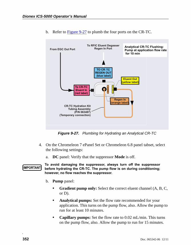
Dionex ICS-5000 Operator’s Manual
352 Doc. 065342-06 12/11
b. Refer to Figure 9-27 to plumb the four ports on the CR-TC.
4. On the Chromeleon 7 ePanel Set or Chromeleon 6.8 panel tabset, select the following settings:
a. DC panel: Verify that the suppressor Mode is off.
b. Pump panel:
• Gradient pump only: Select the correct eluent channel (A, B, C, or D).
• Analytical pumps: Set the flow rate recommended for your application. This turns on the pump flow, also. Allow the pump to run for at least 10 minutes.
• Capillary pumps: Set the flow rate to 0.02 mL/min. This turns on the pump flow, also. Allow the pump to run for 15 minutes.
Figure 9-27. Plumbing for Hydrating an Analytical CR-TC
From EGC Out Port
CR-TC Hydration KitTubing Assembly
(P/N 063487)(Temporary connection)
To RFIC Eluent DegasserRegen In Port
EL
UE
NT
OU
T
RE
GE
NIN
TO CR -TC REGEN OUT (blue label)
To CR-TC Eluent In(red label)
Eluent Out(yellow label)
Regen In(orange label)
Analytical CR-TC Flushing: Pump at application flow rate for 10 min
To avoid damaging the suppressor, always turn off the suppressorbefore hydrating the CR-TC. The pump flow is on during conditioning;however, no flow reaches the suppressor.
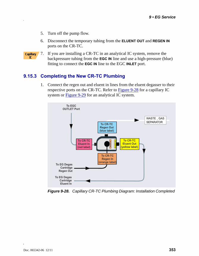
9 • EG Service
Doc. 065342-06 12/11 353
5. Turn off the pump flow.
6. Disconnect the temporary tubing from the ELUENT OUT and REGEN IN
ports on the CR-TC.
7. If you are installing a CR-TC in an analytical IC system, remove the backpressure tubing from the EGC IN line and use a high-pressure (blue) fitting to connect the EGC IN line to the EGC INLET port.
9.15.3 Completing the New CR-TC Plumbing
1. Connect the regen out and eluent in lines from the eluent degasser to their respective ports on the CR-TC. Refer to Figure 9-28 for a capillary IC system or Figure 9-29 for an analytical IC system.
Capillary IC
Figure 9-28. Capillary CR-TC Plumbing Diagram: Installation Completed
To CR-TC Regen Out(blue label)
To CR-TC Eluent In
(red label) EL
UE
NT
OU
T
RE
GE
N IN
To EG Degas Cartridge
Regen Out
To CR-TC Regen In
(orange label)
WASTE , GAS SEPARATOR
To CR-TC Eluent Out
(yellow label)
To EG Degas Cartridge Eluent In
To OUTLET Port
EGC

Dionex ICS-5000 Operator’s Manual
354 Doc. 065342-06 12/11
2. Check that no liquid lines are caught under the CR-TC. Align the two mounting holes on the CR-TC back plate with the ball studs on the mounting plate, and then push the CR-TC firmly onto the mounting ball studs. The CR-TC clicks into place when properly installed.
3. Push the CR-TC electrical cable firmly into the CR-TC 1 (or CR-TC 2) bulkhead connector. Twist the ring on the cable connector fingertight to secure it.
4. Push the tray into the module until it locks into place. Close the EG door.
Figure 9-29. Analytical CR-TC Plumbing Diagram: Installation Completed
To RFIC Eluent Degasser
REGEN OUT Port
To RFIC EluentDegasser ELUENT IN Port
To Gas Separator Waste Tube
ToOUTLET Port
EGC
WASTE , GAS SEPARATOR
TO CR -TC REGEN OUT (blue label)
CR-TC
To CR-TC Eluent In(red label)
To CR-TC Eluent Out
(yellow label)
EL
UE
NT
OU
T
RE
GE
NIN
To CR-TC Regen In
(orange label)
9 • EG Service
Doc. 065342-06 12/11 355
9.16 Replacing the RFIC Eluent Degasser
1. Turn off the pump flow.
2. Open the front door of the EG.
3. Push down on the slide release latch and pull the tray forward until it reaches the stop.
4. Grasp the degasser by the sides and pull it straight off the ball studs that secure it to the component mounting panel. Dispose of the degasser.
5. Disconnect the four lines connected to the RFIC Eluent Degasser fittings (ELUENT OUT, REGEN OUT, REGEN IN, and ELUENT IN).
6. Connect the four lines that were disconnected in Step 5 to the new RFIC Eluent Degasser (P/N 062137).
7. Align the two mounting holes on the back plate of the new RFIC Eluent Degasser with the ball studs on the component mounting panel. Push the degasser firmly onto the mounting ball studs. The degasser clicks into place when properly installed.
8. Push the tray into the module until it locks into place. Close the EG door.
9.17 Installing a Backpressure Coil
In an analytical IC system, the EGC requires at least 14 MPa (2000 psi) of system backpressure; this ensures optimal removal of electrolysis gas from the eluent produced by the cartridge.
During system equilibration, monitor the pressure and verify that it is between 14 and 21 MPa (2000 and 3000 psi). A system backpressure of 16 MPa (2300 psi) is optimal.
If the backpressure is too low, install a backpressure coil (see Table 9-5) between the injection valve and the OUTLET port on the EGC. Connect one end of the backpressure coil to Port P (2) on the injection valve; connect the other end to the TO INJ VALVE IN - P line.
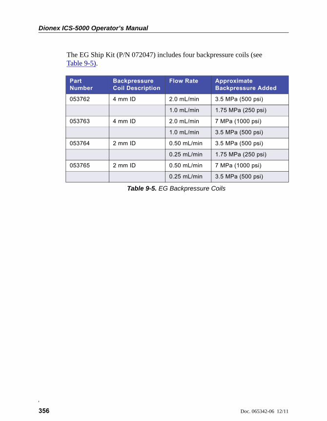
Dionex ICS-5000 Operator’s Manual
356 Doc. 065342-06 12/11
The EG Ship Kit (P/N 072047) includes four backpressure coils (see Table 9-5).
Part Number
Backpressure Coil Description
Flow Rate Approximate Backpressure Added
053762 4 mm ID 2.0 mL/min 3.5 MPa (500 psi)
1.0 mL/min 1.75 MPa (250 psi)
053763 4 mm ID 2.0 mL/min 7 MPa (1000 psi)
1.0 mL/min 3.5 MPa (500 psi)
053764 2 mm ID 0.50 mL/min 3.5 MPa (500 psi)
0.25 mL/min 1.75 MPa (250 psi)
053765 2 mm ID 0.50 mL/min 7 MPa (1000 psi)
0.25 mL/min 3.5 MPa (500 psi)
Table 9-5. EG Backpressure Coils

9 • EG Service
Doc. 065342-06 12/11 357
9.18 Changing the EG Main Power Fuses
1. Press the POWER button on the front of the EG for 2 seconds to turn off the power.
2. Turn off the main power switch on the EG rear panel (see Figure 2-12).
3. Disconnect the main power cord from both its source and from the EG rear panel.
.
4. The fuse drawer is located above the main power switch (see Figure 9-30). A small tab locks the fuse drawer in place. Using a small screwdriver, press the tab in and then up to release the fuse drawer.
5. Pull the fuse drawer out of the rear panel and remove the old fuses.
6. Replace the two fuses with new 2 A IEC 60127-2 slow-blow fuses (P/N 954773). Thermo Fisher Scientific recommends always replacing both fuses.
Figure 9-30. EG Fuse Drawer
7. Insert the fuse drawer into the rear panel and press until the drawer snaps into place.
8. Reconnect the main power cord and turn on the power.
HIGH VOLTAGE—Disconnect the main power cord from its source andalso from the rear panel of the EG.
HAUTE TENSION—Débranchez le cordon d'alimentation principal de sasource et du panneau arrière du EG.
HOCHSPANNUNG—Ziehen Sie das Netzkabel aus der Steckdose undder Netzbuchse auf der Rückseite des EG.
Fuse Drawer
Tab

Dionex ICS-5000 Operator’s Manual
358 Doc. 065342-06 12/11
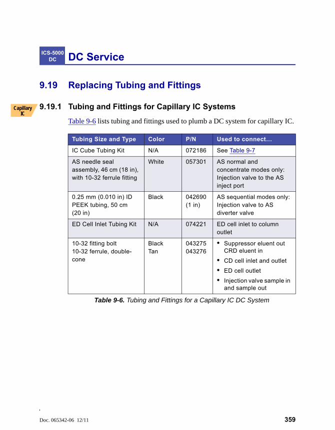
Doc. 065342-06 12/11 359
DC Service
9.19 Replacing Tubing and Fittings
9.19.1 Tubing and Fittings for Capillary IC Systems
Table 9-6 lists tubing and fittings used to plumb a DC system for capillary IC.
ICS-5000 DC
Capillary IC
Tubing Size and Type Color P/N Used to connect…
IC Cube Tubing Kit N/A 072186 See Table 9-7
AS needle seal assembly, 46 cm (18 in), with 10-32 ferrule fitting
White 057301 AS normal and concentrate modes only: Injection valve to the AS inject port
0.25 mm (0.010 in) ID PEEK tubing, 50 cm (20 in)
Black 042690 (1 in)
AS sequential modes only: Injection valve to AS diverter valve
ED Cell Inlet Tubing Kit N/A 074221 ED cell inlet to column outlet
10-32 fitting bolt10-32 ferrule, double-cone
BlackTan
043275043276
• Suppressor eluent out CRD eluent in
• CD cell inlet and outlet
• ED cell outlet
• Injection valve sample in and sample out
Table 9-6. Tubing and Fittings for a Capillary IC DC System
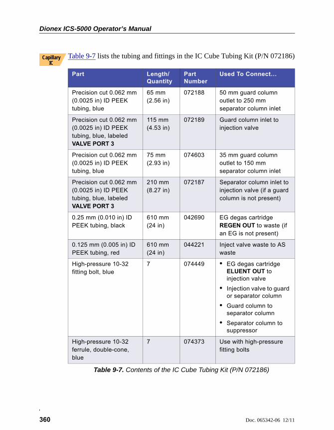
Dionex ICS-5000 Operator’s Manual
360 Doc. 065342-06 12/11
Table 9-7 lists the tubing and fittings in the IC Cube Tubing Kit (P/N 072186)
Part Length/Quantity
Part Number
Used To Connect…
Precision cut 0.062 mm (0.0025 in) ID PEEK tubing, blue
65 mm (2.56 in)
072188 50 mm guard column outlet to 250 mm separator column inlet
Precision cut 0.062 mm (0.0025 in) ID PEEK tubing, blue, labeled VALVE PORT 3
115 mm (4.53 in)
072189 Guard column inlet to injection valve
Precision cut 0.062 mm (0.0025 in) ID PEEK tubing, blue
75 mm (2.93 in)
074603 35 mm guard column outlet to 150 mm separator column inlet
Precision cut 0.062 mm (0.0025 in) ID PEEK tubing, blue, labeled VALVE PORT 3
210 mm (8.27 in)
072187 Separator column inlet to injection valve (if a guard column is not present)
0.25 mm (0.010 in) ID PEEK tubing, black
610 mm (24 in)
042690 EG degas cartridge REGEN OUT to waste (if an EG is not present)
0.125 mm (0.005 in) ID PEEK tubing, red
610 mm (24 in)
044221 Inject valve waste to AS waste
High-pressure 10-32 fitting bolt, blue
7 074449 • EG degas cartridge ELUENT OUT to injection valve
• Injection valve to guard or separator column
• Guard column to separator column
• Separator column to suppressor
High-pressure 10-32 ferrule, double-cone, blue
7 074373 Use with high-pressure fitting bolts
Table 9-7. Contents of the IC Cube Tubing Kit (P/N 072186)
Capillary IC
9 • DC Service
Doc. 065342-06 12/11 361
Notes for Capillary IC systems:
• The 0.062 mm (0.0025 in) ID blue PEEK tubing (capillary tubing) used for IC Cube connections is cut at the factory using a specialized precision cutter. If you need to replace any of this type of tubing, order an IC Cube Tubing Kit (P/N 072186) or the individual tubing listed in Table 9-7.
• When replacing capillary tubing, make sure the ferrule and fitting bolt are at least 2 mm (0.1 in) from the end of the tubing before you insert the tubing into the port. Do not position the ferrule and fitting bolt flush with the end of the tubing. For detailed connection instructions, see Section 9.1
• Except for capillary tubing, you can use a tubing cutter to cut tubing to the required length. Make sure the cut is at a right angle to the length of the tubing and there are no nicks or burrs on the end. A tubing cutter (P/N 049584) is included in the DC Ship Kit (P/N 072011). Refer to the instructions provided with the cutter.
• For tightening requirements for the high-pressure fitting bolt (P/N 074449) and ferrule (P/N 074373), see Section 9.2.
• For tightening requirements for the 10-32 fitting bolt (P/N 043275) and ferrule (P/N 043276), refer to Installation of Dionex Liquid Line Fittings (Document No. 031432). The manual is on the Thermo Scientific Reference Library DVD (P/N 053891).
Capillary IC
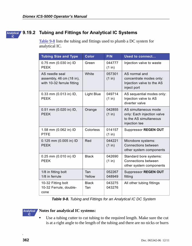
Dionex ICS-5000 Operator’s Manual
362 Doc. 065342-06 12/11
9.19.2 Tubing and Fittings for Analytical IC Systems
Table 9-8 lists the tubing and fittings used to plumb a DC system for analytical IC.
Notes for analytical IC systems:
• Use a tubing cutter to cut tubing to the required length. Make sure the cut is at a right angle to the length of the tubing and there are no nicks or burrs
Tubing Size and Type Color P/N Used to connect…
0.75 mm (0.030 in) ID PEEK
Green 044777 (1 in)
Injection valve to waste
AS needle seal assembly, 46 cm (18 in), with 10-32 ferrule fitting
White 057301 (1 in)
AS normal and concentrate modes only: Injection valve to the AS inject port
0.33 mm (0.013 in) ID, PEEK
Light Blue 049714 (1 in)
AS sequential modes only: Injection valve to AS diverter valve
0.51 mm (0.020 in) ID, PEEK
Orange 042855(1 in)
AS simultaneous mode only: Each injection valve to the AS simultaneous injection tee
1.58 mm (0.062 in) ID PTFE
Colorless 014157 (1 in)
Suppressor REGEN OUT
0.125 mm (0.005 in) ID PEEK
Red 044221(1 in)
Microbore systems: Connections between other system components
0.25 mm (0.010 in) ID PEEK
Black 042690(1 in)
Standard bore systems: Connections between other system components
1/8 in fitting bolt1/8 in ferrule
TanYellow
052267048949
Suppressor REGEN OUT fitting
10-32 Fitting bolt10-32 Ferrule, double-cone
BlackTan
043275043276
All other tubing fittings
Table 9-8. Tubing and Fittings for an Analytical IC DC System
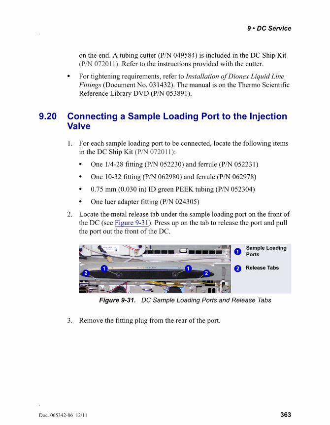
9 • DC Service
Doc. 065342-06 12/11 363
on the end. A tubing cutter (P/N 049584) is included in the DC Ship Kit (P/N 072011). Refer to the instructions provided with the cutter.
• For tightening requirements, refer to Installation of Dionex Liquid Line Fittings (Document No. 031432). The manual is on the Thermo Scientific Reference Library DVD (P/N 053891).
9.20 Connecting a Sample Loading Port to the Injection Valve
1. For each sample loading port to be connected, locate the following items in the DC Ship Kit (P/N 072011):
• One 1/4-28 fitting (P/N 052230) and ferrule (P/N 052231)
• One 10-32 fitting (P/N 062980) and ferrule (P/N 062978)
• 0.75 mm (0.030 in) ID green PEEK tubing (P/N 052304)
• One luer adapter fitting (P/N 024305)
2. Locate the metal release tab under the sample loading port on the front of the DC (see Figure 9-31). Press up on the tab to release the port and pull the port out the front of the DC.
3. Remove the fitting plug from the rear of the port.
Figure 9-31. DC Sample Loading Ports and Release Tabs
1
2
Sample Loading Ports
Release Tabs1 122
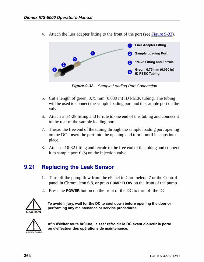
Dionex ICS-5000 Operator’s Manual
364 Doc. 065342-06 12/11
4. Attach the luer adapter fitting to the front of the port (see Figure 9-32).
5. Cut a length of green, 0.75 mm (0.030 in) ID PEEK tubing. The tubing will be used to connect the sample loading port and the sample port on the valve.
6. Attach a 1/4-28 fitting and ferrule to one end of this tubing and connect it to the rear of the sample loading port.
7. Thread the free end of the tubing through the sample loading port opening on the DC. Insert the port into the opening and turn it until it snaps into place.
8. Attach a 10-32 fitting and ferrule to the free end of the tubing and connect it to sample port S (5) on the injection valve.
9.21 Replacing the Leak Sensor
1. Turn off the pump flow from the ePanel in Chromeleon 7 or the Control panel in Chromeleon 6.8, or press PUMP FLOW on the front of the pump.
2. Press the POWER button on the front of the DC to turn off the DC.
Figure 9-32. Sample Loading Port Connection
1
2 Sample Loading Port
1/4-28 Fitting and Ferrule
1
33
2
Green, 0.75 mm (0.030 in) ID PEEK Tubing4
Luer Adapter Fitting
4
To avoid injury, wait for the DC to cool down before opening the door orperforming any maintenance or service procedures.
Afin d'éviter toute brûlure, laisser refroidir le DC avant d'ouvrir la porteou d'effectuer des opérations de maintenance.
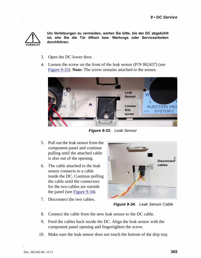
9 • DC Service
Doc. 065342-06 12/11 365
3. Open the DC lower door.
4. Loosen the screw on the front of the leak sensor (P/N 062437) (see Figure 9-33). Note: The screw remains attached to the sensor.
5. Pull out the leak sensor from the component panel and continue pulling until the attached cable is also out of the opening.
6. The cable attached to the leak sensor connects to a cable inside the DC. Continue pulling the cable until the connectors for the two cables are outside the panel (see Figure 9-34).
7. Disconnect the two cables.Figure 9-34. Leak Sensor Cable
8. Connect the cable from the new leak sensor to the DC cable.
9. Feed the cables back inside the DC. Align the leak sensor with the component panel opening and fingertighten the screw.
10. Make sure the leak sensor does not touch the bottom of the drip tray.
Um Verletzungen zu vermeiden, warten Sie bitte, bis der DC abgekühltist, ehe Sie die Tür öffnen bzw. Wartungs oder Servicearbeitendurchführen.
Figure 9-33. Leak Sensor
Loosen this screw
Leak Sensor
Disconnect cables
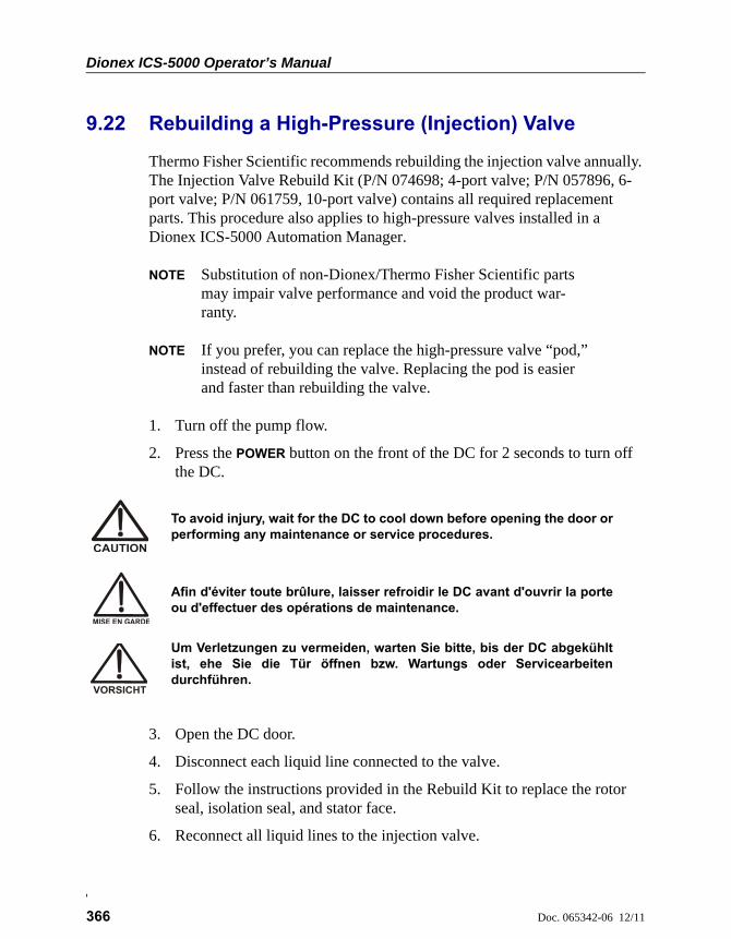
Dionex ICS-5000 Operator’s Manual
366 Doc. 065342-06 12/11
9.22 Rebuilding a High-Pressure (Injection) Valve
Thermo Fisher Scientific recommends rebuilding the injection valve annually. The Injection Valve Rebuild Kit (P/N 074698; 4-port valve; P/N 057896, 6-port valve; P/N 061759, 10-port valve) contains all required replacement parts. This procedure also applies to high-pressure valves installed in a Dionex ICS-5000 Automation Manager.
NOTE Substitution of non-Dionex/Thermo Fisher Scientific parts may impair valve performance and void the product war-ranty.
NOTE If you prefer, you can replace the high-pressure valve “pod,” instead of rebuilding the valve. Replacing the pod is easier and faster than rebuilding the valve.
1. Turn off the pump flow.
2. Press the POWER button on the front of the DC for 2 seconds to turn off the DC.
3. Open the DC door.
4. Disconnect each liquid line connected to the valve.
5. Follow the instructions provided in the Rebuild Kit to replace the rotor seal, isolation seal, and stator face.
6. Reconnect all liquid lines to the injection valve.
To avoid injury, wait for the DC to cool down before opening the door orperforming any maintenance or service procedures.
Afin d'éviter toute brûlure, laisser refroidir le DC avant d'ouvrir la porteou d'effectuer des opérations de maintenance.
Um Verletzungen zu vermeiden, warten Sie bitte, bis der DC abgekühltist, ehe Sie die Tür öffnen bzw. Wartungs oder Servicearbeitendurchführen.
9 • DC Service
Doc. 065342-06 12/11 367
7. Turn on the power to the DC.
8. Turn on the pump flow. Check for leaks from the valve. Tighten fittings as required. For tightening requirements, refer to Installation of Dionex Liquid Line Fittings (Document No. 031432). The manual is on the Thermo Scientific Reference Library DVD (P/N 053891).
9. Close the door.
9.23 Replacing a High-Pressure (Injection) Valve Pod
This procedure describes how to replace the mechanical parts (the “pod”) of a high-pressure valve (P/N 074699, 4-port; P/N 061947, 6-port; P/N 061948, 10-port).
NOTE If the valve electronics require service, contact Thermo Fisher Scientific. Electronics-related repair procedures must be performed by Thermo Fisher Sci-entific personnel.
NOTE Substitution of non-Dionex/Thermo Fisher Scientific parts may impair valve performance and void the product warranty.
1. Turn off the pump flow.
2. Press the POWER button on the front of the DC for 2 seconds to turn off the DC.
3. Open the DC door.
To avoid injury, wait for the DC to cool down before opening the door orperforming any maintenance or service procedures.
Afin d'éviter toute brûlure, laisser refroidir le DC avant d'ouvrir la porteou d'effectuer des opérations de maintenance.
Um Verletzungen zu vermeiden, warten Sie bitte, bis der DC abgekühltist, ehe Sie die Tür öffnen bzw. Wartungs oder Servicearbeitendurchführen.

Dionex ICS-5000 Operator’s Manual
368 Doc. 065342-06 12/11
4. Disconnect each liquid line connected to the valve.
5. Unscrew the locking ring on the outside of the valve (see Figure 9-35) and remove the ring.
6. Grasp the front of the valve pod and pull out firmly to remove it from the DC or AM.
7. Align the slots in the new pod with the runner in the valve holder on the DC or AM (see Figure 9-36). Valve pods are keyed to fit only one way (one slot is narrower than the other). Verify that the slots are aligned with their matching runners.
Figure 9-35. Unscrew the Locking Ring (Valve in IC Cube Shown)
Locking Ring
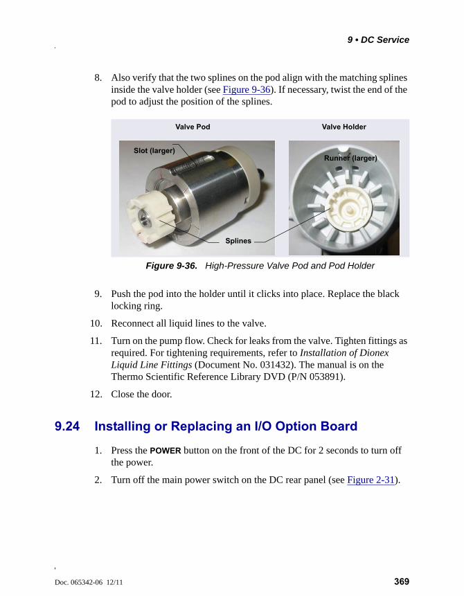
9 • DC Service
Doc. 065342-06 12/11 369
8. Also verify that the two splines on the pod align with the matching splines inside the valve holder (see Figure 9-36). If necessary, twist the end of the pod to adjust the position of the splines.
9. Push the pod into the holder until it clicks into place. Replace the black locking ring.
10. Reconnect all liquid lines to the valve.
11. Turn on the pump flow. Check for leaks from the valve. Tighten fittings as required. For tightening requirements, refer to Installation of Dionex Liquid Line Fittings (Document No. 031432). The manual is on the Thermo Scientific Reference Library DVD (P/N 053891).
12. Close the door.
9.24 Installing or Replacing an I/O Option Board
1. Press the POWER button on the front of the DC for 2 seconds to turn off the power.
2. Turn off the main power switch on the DC rear panel (see Figure 2-31).
Figure 9-36. High-Pressure Valve Pod and Pod Holder
Slot (larger)
Splines
Runner (larger)
Valve Pod Valve Holder
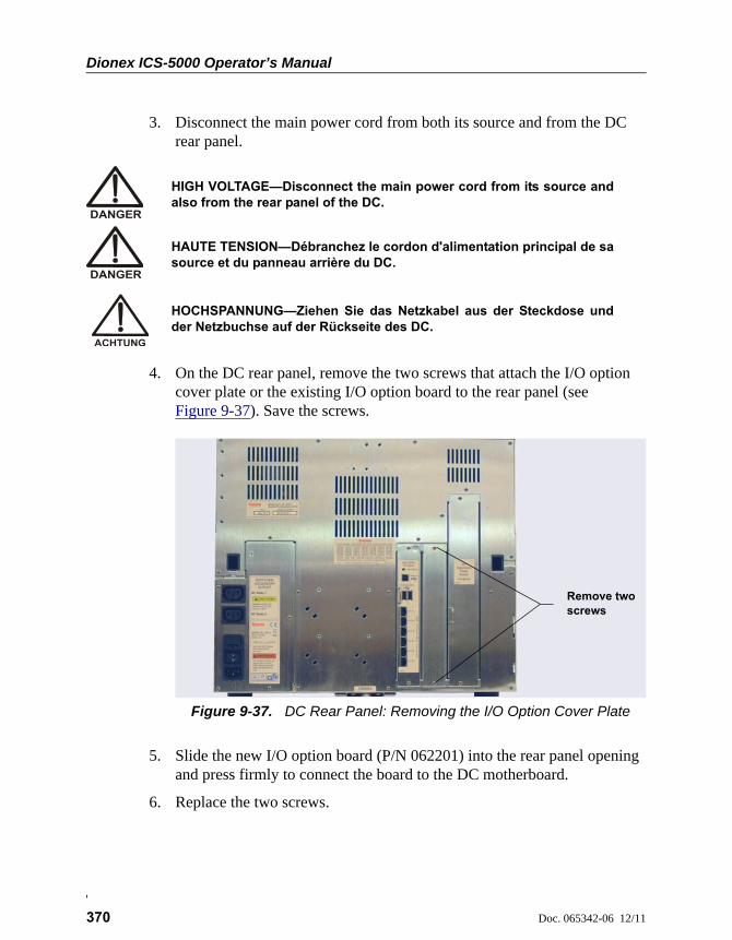
Dionex ICS-5000 Operator’s Manual
370 Doc. 065342-06 12/11
3. Disconnect the main power cord from both its source and from the DC rear panel.
4. On the DC rear panel, remove the two screws that attach the I/O option cover plate or the existing I/O option board to the rear panel (see Figure 9-37). Save the screws.
5. Slide the new I/O option board (P/N 062201) into the rear panel opening and press firmly to connect the board to the DC motherboard.
6. Replace the two screws.
HIGH VOLTAGE—Disconnect the main power cord from its source andalso from the rear panel of the DC.
HAUTE TENSION—Débranchez le cordon d'alimentation principal de sasource et du panneau arrière du DC.
HOCHSPANNUNG—Ziehen Sie das Netzkabel aus der Steckdose undder Netzbuchse auf der Rückseite des DC.
Figure 9-37. DC Rear Panel: Removing the I/O Option Cover Plate
Remove twoscrews
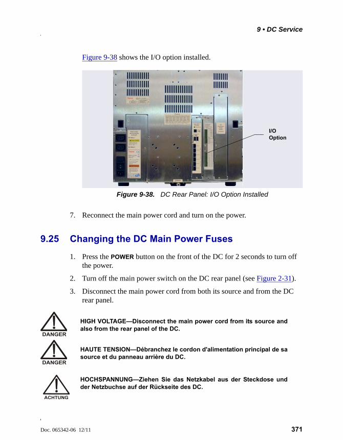
9 • DC Service
Doc. 065342-06 12/11 371
Figure 9-38 shows the I/O option installed.
7. Reconnect the main power cord and turn on the power.
9.25 Changing the DC Main Power Fuses
1. Press the POWER button on the front of the DC for 2 seconds to turn off the power.
2. Turn off the main power switch on the DC rear panel (see Figure 2-31).
3. Disconnect the main power cord from both its source and from the DC rear panel.
Figure 9-38. DC Rear Panel: I/O Option Installed
I/O Option
HIGH VOLTAGE—Disconnect the main power cord from its source andalso from the rear panel of the DC.
HAUTE TENSION—Débranchez le cordon d'alimentation principal de sasource et du panneau arrière du DC.
HOCHSPANNUNG—Ziehen Sie das Netzkabel aus der Steckdose undder Netzbuchse auf der Rückseite des DC.
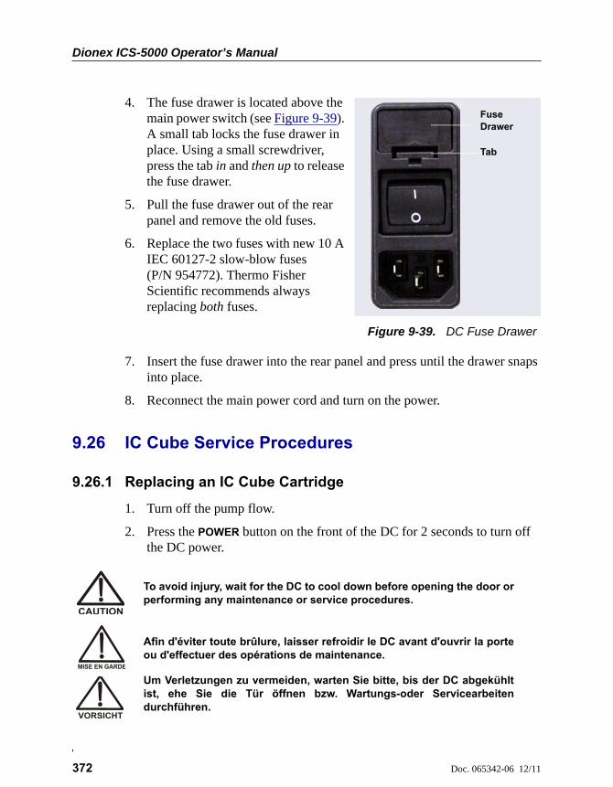
Dionex ICS-5000 Operator’s Manual
372 Doc. 065342-06 12/11
4. The fuse drawer is located above the main power switch (see Figure 9-39). A small tab locks the fuse drawer in place. Using a small screwdriver, press the tab in and then up to release the fuse drawer.
5. Pull the fuse drawer out of the rear panel and remove the old fuses.
6. Replace the two fuses with new 10 A IEC 60127-2 slow-blow fuses (P/N 954772). Thermo Fisher Scientific recommends always replacing both fuses.
Figure 9-39. DC Fuse Drawer
7. Insert the fuse drawer into the rear panel and press until the drawer snaps into place.
8. Reconnect the main power cord and turn on the power.
9.26 IC Cube Service Procedures
9.26.1 Replacing an IC Cube Cartridge
1. Turn off the pump flow.
2. Press the POWER button on the front of the DC for 2 seconds to turn off the DC power.
Fuse Drawer
Tab
To avoid injury, wait for the DC to cool down before opening the door orperforming any maintenance or service procedures.
Afin d'éviter toute brûlure, laisser refroidir le DC avant d'ouvrir la porteou d'effectuer des opérations de maintenance.
Um Verletzungen zu vermeiden, warten Sie bitte, bis der DC abgekühltist, ehe Sie die Tür öffnen bzw. Wartungs-oder Servicearbeitendurchführen.
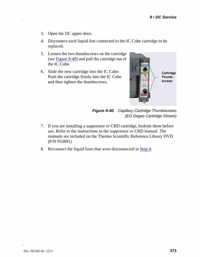
9 • DC Service
Doc. 065342-06 12/11 373
3. Open the DC upper door.
4. Disconnect each liquid line connected to the IC Cube cartridge to be replaced.
5. Loosen the two thumbscrews on the cartridge (see Figure 9-40) and pull the cartridge out of the IC Cube.
6. Slide the new cartridge into the IC Cube. Push the cartridge firmly into the IC Cube and then tighten the thumbscrews.
Figure 9-40. Capillary Cartridge Thumbscrews(EG Degas Cartridge Shown)
7. If you are installing a suppressor or CRD cartridge, hydrate them before use. Refer to the instructions in the suppressor or CRD manual. The manuals are included on the Thermo Scientific Reference Library DVD (P/N 053891)
8. Reconnect the liquid lines that were disconnected in Step 4.
Cartridge Thumb-screws
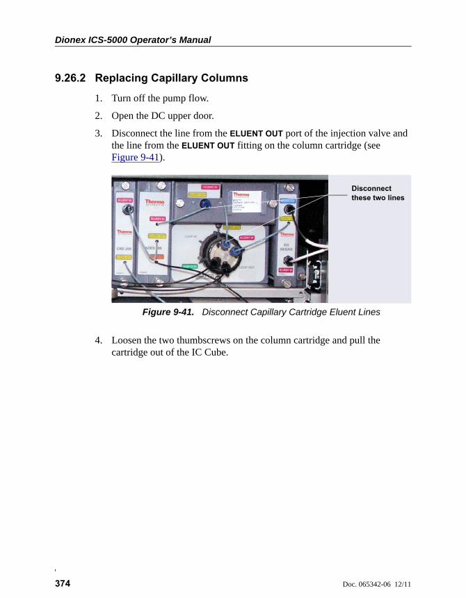
Dionex ICS-5000 Operator’s Manual
374 Doc. 065342-06 12/11
9.26.2 Replacing Capillary Columns
1. Turn off the pump flow.
2. Open the DC upper door.
3. Disconnect the line from the ELUENT OUT port of the injection valve and the line from the ELUENT OUT fitting on the column cartridge (see Figure 9-41).
4. Loosen the two thumbscrews on the column cartridge and pull the cartridge out of the IC Cube.
Figure 9-41. Disconnect Capillary Cartridge Eluent Lines
Disconnect these two lines
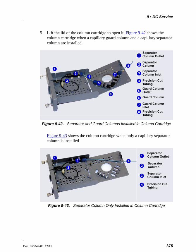
9 • DC Service
Doc. 065342-06 12/11 375
5. Lift the lid of the column cartridge to open it. Figure 9-42 shows the column cartridge when a capillary guard column and a capillary separator column are installed.
Figure 9-43 shows the column cartridge when only a capillary separator column is installed
Figure 9-42. Separator and Guard Columns Installed in Column Cartridge
Figure 9-43. Separator Column Only Installed in Column Cartridge
Separator
Guard Column
Guard Column
Separator
Precision Cut
Precision Cut
Column Outlet
Column Inlet
Inlet
1
34
6
7
8
5
1
3
4
7
8Separator Column 2
2
Guard ColumnOutlet5
6
Tubing
Tubing
Separator
Separator
Precision Cut
Column Outlet
Column Inlet
1
3
4
4
13
Separator Column2
2
Tubing
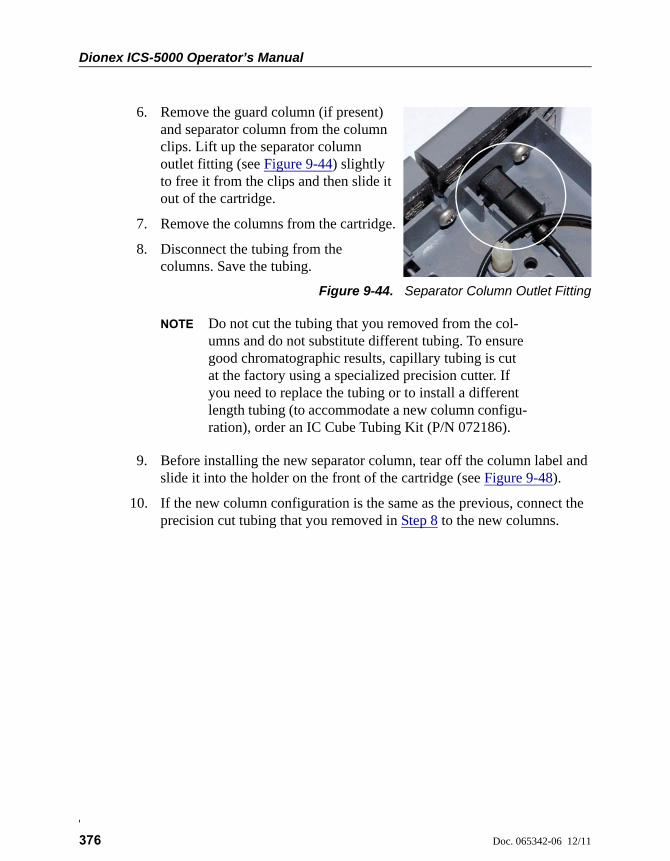
Dionex ICS-5000 Operator’s Manual
376 Doc. 065342-06 12/11
6. Remove the guard column (if present) and separator column from the column clips. Lift up the separator column outlet fitting (see Figure 9-44) slightly to free it from the clips and then slide it out of the cartridge.
7. Remove the columns from the cartridge.
8. Disconnect the tubing from the columns. Save the tubing.
Figure 9-44. Separator Column Outlet Fitting
NOTE Do not cut the tubing that you removed from the col-umns and do not substitute different tubing. To ensure good chromatographic results, capillary tubing is cut at the factory using a specialized precision cutter. If you need to replace the tubing or to install a different length tubing (to accommodate a new column configu-ration), order an IC Cube Tubing Kit (P/N 072186).
9. Before installing the new separator column, tear off the column label and slide it into the holder on the front of the cartridge (see Figure 9-48).
10. If the new column configuration is the same as the previous, connect the precision cut tubing that you removed in Step 8 to the new columns.
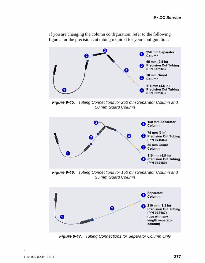
9 • DC Service
Doc. 065342-06 12/11 377
If you are changing the column configuration, refer to the following figures for the precision cut tubing required for your configuration:
Figure 9-45. Tubing Connections for 250 mm Separator Column and 50 mm Guard Column
Figure 9-46. Tubing Connections for 150 mm Separator Column and 35 mm Guard Column
Figure 9-47. Tubing Connections for Separator Column Only
250 mm Separator
50 mm Guard
1
3
1
3
2 65 mm (2.5 in)
2
Column
Precision Cut Tubing
Column 115 mm (4.5 in)
4 Precision Cut Tubing
4
(P/N 072189)
(P/N 072188)
150 mm Separator
35 mm Guard
1
3
1
3
2
75 mm (3 in)
2
Column
Precision Cut Tubing
Column 115 mm (4.5 in)
4 Precision Cut Tubing
4
(P/N 072189)
(P/N 074603)
Separator 1
1
2
210 mm (8.3 in) 2
Column
Precision Cut Tubing
(use with any length separatorcolumn)
(P/N 072187)
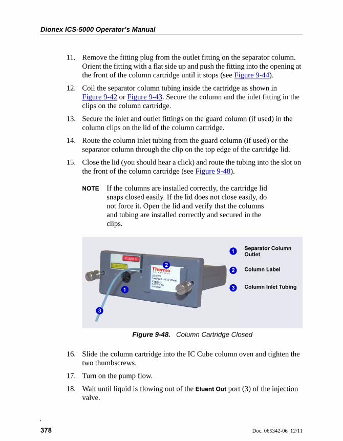
Dionex ICS-5000 Operator’s Manual
378 Doc. 065342-06 12/11
11. Remove the fitting plug from the outlet fitting on the separator column. Orient the fitting with a flat side up and push the fitting into the opening at the front of the column cartridge until it stops (see Figure 9-44).
12. Coil the separator column tubing inside the cartridge as shown in Figure 9-42 or Figure 9-43. Secure the column and the inlet fitting in the clips on the column cartridge.
13. Secure the inlet and outlet fittings on the guard column (if used) in the column clips on the lid of the column cartridge.
14. Route the column inlet tubing from the guard column (if used) or the separator column through the clip on the top edge of the cartridge lid.
15. Close the lid (you should hear a click) and route the tubing into the slot on the front of the column cartridge (see Figure 9-48).
NOTE If the columns are installed correctly, the cartridge lid snaps closed easily. If the lid does not close easily, do not force it. Open the lid and verify that the columns and tubing are installed correctly and secured in the clips.
16. Slide the column cartridge into the IC Cube column oven and tighten the two thumbscrews.
17. Turn on the pump flow.
18. Wait until liquid is flowing out of the Eluent Out port (3) of the injection valve.
Figure 9-48. Column Cartridge Closed
Separator Column Outlet
Column Inlet Tubing
1
31
3
2 Column Label 2
9 • DC Service
Doc. 065342-06 12/11 379
19. Connect the tubing from the Eluent In port of the column cartridge to the Eluent Out port (3) of the injection valve.
20. Wait until liquid is flowing out of the Eluent Out port of the column cartridge.
21. Reconnect the line to the Eluent Out fitting on the column cartridge that was disconnected in Step 3 (see Figure 9-41).
22. Close the DC upper door.
9.27 CD Service Procedures
9.27.1 Calibrating the CD Cell
NOTE Do not use this procedure to calibrate a new cell. New cells are calibrated at the factory.
1. On the Chromeleon 7 ePanel Set, click the CD tab. On the Chromeleon 6.8 panel tabset, click the CD tab.
Items Needed Description
1.0 mM KCl solution Prepare by dissolving 0.07456 g of reagent-grade KCl in 1 liter of 18 megohm-cm DI water.
Backpressure tubing to provide at least 7 MPa (1000 psi)
Use 0.25 mm (0.010 in) ID black PEEK tubing (P/N 042690).
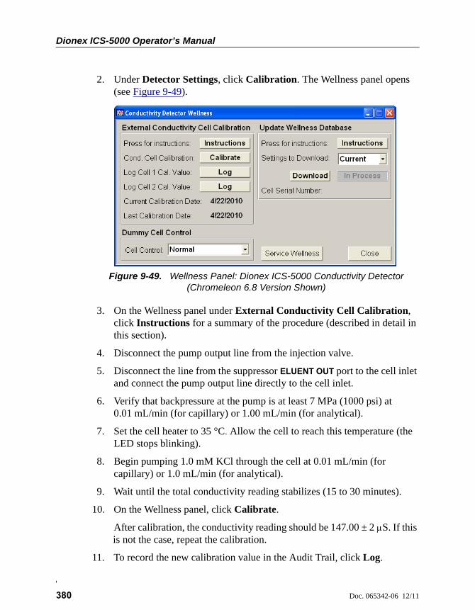
Dionex ICS-5000 Operator’s Manual
380 Doc. 065342-06 12/11
2. Under Detector Settings, click Calibration. The Wellness panel opens (see Figure 9-49).
3. On the Wellness panel under External Conductivity Cell Calibration, click Instructions for a summary of the procedure (described in detail in this section).
4. Disconnect the pump output line from the injection valve.
5. Disconnect the line from the suppressor ELUENT OUT port to the cell inlet and connect the pump output line directly to the cell inlet.
6. Verify that backpressure at the pump is at least 7 MPa (1000 psi) at 0.01 mL/min (for capillary) or 1.00 mL/min (for analytical).
7. Set the cell heater to 35 °C. Allow the cell to reach this temperature (the LED stops blinking).
8. Begin pumping 1.0 mM KCl through the cell at 0.01 mL/min (for capillary) or 1.0 mL/min (for analytical).
9. Wait until the total conductivity reading stabilizes (15 to 30 minutes).
10. On the Wellness panel, click Calibrate.
After calibration, the conductivity reading should be 147.00 ± 2 S. If this is not the case, repeat the calibration.
11. To record the new calibration value in the Audit Trail, click Log.
Figure 9-49. Wellness Panel: Dionex ICS-5000 Conductivity Detector (Chromeleon 6.8 Version Shown)
9 • DC Service
Doc. 065342-06 12/11 381
12. Flush the KCl solution from the system by pumping ASTM Type I (18 megohm-cm) filtered and deionized water through the cell. When the conductivity drops to less than 1 S/cm, stop the pump.
13. Reconnect the pump to the injection valve and reconnect the line from the suppressor to the cell inlet.
9.27.2 Replacing an Analytical Suppressor
Refer to the suppressor manual for guidance about when to replace a suppressor and for instructions on preparing a new suppressor before initial use. Suppressor manuals are included on the Thermo Scientific Reference Library DVD (P/N 053891).
1. Stop the pump flow.
2. Press the POWER button on the front of the DC for 2 seconds to turn off the DC.
3. Open the DC upper door.
4. Disconnect the four liquid lines from the suppressor (see Figure 9-50).
To avoid injury, wait for the DC to cool down before opening the door orperforming any maintenance or service procedures.
Afin d'éviter toute brûlure, laisser refroidir le DC avant d'ouvrir la porteou d'effectuer des opérations de maintenance.
Um Verletzungen zu vermeiden, warten Sie bitte, bis der DC abgekühltist, ehe Sie die Tür öffnen bzw. Wartungs oder Servicearbeitendurchführen.
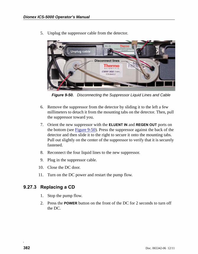
Dionex ICS-5000 Operator’s Manual
382 Doc. 065342-06 12/11
5. Unplug the suppressor cable from the detector.
6. Remove the suppressor from the detector by sliding it to the left a few millimeters to detach it from the mounting tabs on the detector. Then, pull the suppressor toward you.
7. Orient the new suppressor with the ELUENT IN and REGEN OUT ports on the bottom (see Figure 9-50). Press the suppressor against the back of the detector and then slide it to the right to secure it onto the mounting tabs. Pull out slightly on the center of the suppressor to verify that it is securely fastened.
8. Reconnect the four liquid lines to the new suppressor.
9. Plug in the suppressor cable.
10. Close the DC door.
11. Turn on the DC power and restart the pump flow.
9.27.3 Replacing a CD
1. Stop the pump flow.
2. Press the POWER button on the front of the DC for 2 seconds to turn off the DC.
Figure 9-50. Disconnecting the Suppressor Liquid Lines and Cable
Disconnect lines
Unplug cable
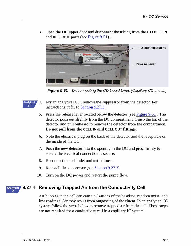
9 • DC Service
Doc. 065342-06 12/11 383
3. Open the DC upper door and disconnect the tubing from the CD CELL IN and CELL OUT ports (see Figure 9-51).
4. For an analytical CD, remove the suppressor from the detector. For instructions, refer to Section 9.27.2.
5. Press the release lever located below the detector (see Figure 9-51). The detector pops out slightly from the DC compartment. Grasp the top of the detector and pull outward to remove the detector from the compartment. Do not pull from the CELL IN and CELL OUT fittings.
6. Note the electrical plug on the back of the detector and the receptacle on the inside of the DC.
7. Push the new detector into the opening in the DC and press firmly to ensure the electrical connection is secure.
8. Reconnect the cell inlet and outlet lines.
9. Reinstall the suppressor (see Section 9.27.2).
10. Turn on the DC power and restart the pump flow.
9.27.4 Removing Trapped Air from the Conductivity Cell
Air bubbles in the cell can cause pulsations of the baseline, random noise, and low readings. Air may result from outgassing of the eluent. In an analytical IC system follow the steps below to remove trapped air from the cell. These steps are not required for a conductivity cell in a capillary IC system.
Figure 9-51. Disconnecting the CD Liquid Lines (Capillary CD shown)
Disconnect tubing
Release Lever
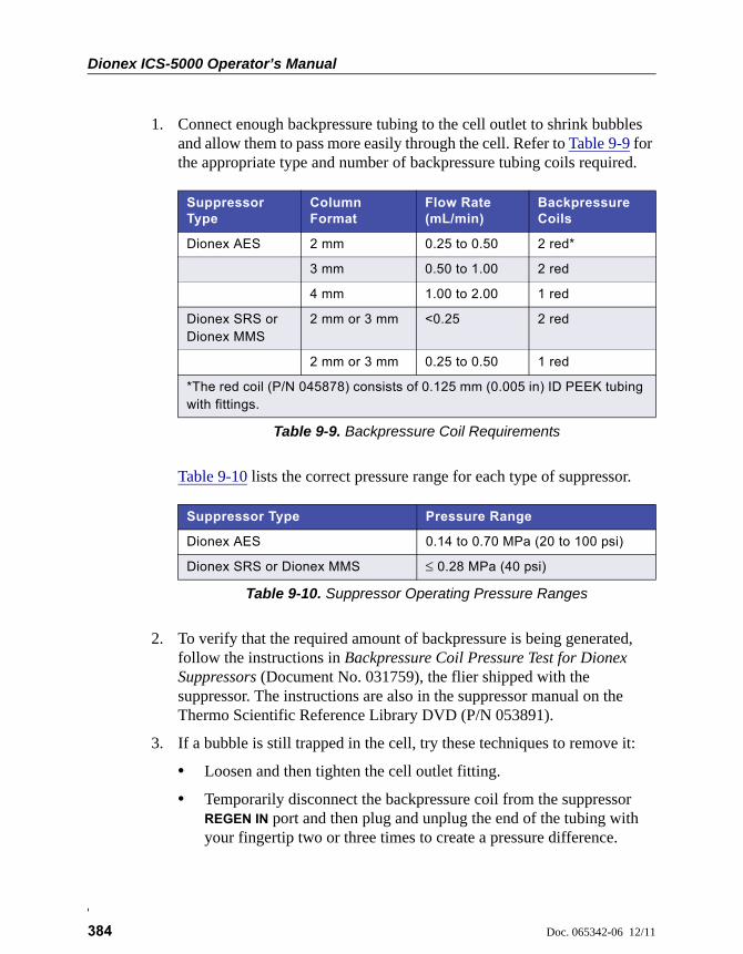
Dionex ICS-5000 Operator’s Manual
384 Doc. 065342-06 12/11
1. Connect enough backpressure tubing to the cell outlet to shrink bubbles and allow them to pass more easily through the cell. Refer to Table 9-9 for the appropriate type and number of backpressure tubing coils required.
Table 9-10 lists the correct pressure range for each type of suppressor.
2. To verify that the required amount of backpressure is being generated, follow the instructions in Backpressure Coil Pressure Test for Dionex Suppressors (Document No. 031759), the flier shipped with the suppressor. The instructions are also in the suppressor manual on the Thermo Scientific Reference Library DVD (P/N 053891).
3. If a bubble is still trapped in the cell, try these techniques to remove it:
• Loosen and then tighten the cell outlet fitting.
• Temporarily disconnect the backpressure coil from the suppressor REGEN IN port and then plug and unplug the end of the tubing with your fingertip two or three times to create a pressure difference.
Suppressor Type
Column Format
Flow Rate (mL/min)
Backpressure Coils
Dionex AES 2 mm 0.25 to 0.50 2 red*
3 mm 0.50 to 1.00 2 red
4 mm 1.00 to 2.00 1 red
Dionex SRS or Dionex MMS
2 mm or 3 mm <0.25 2 red
2 mm or 3 mm 0.25 to 0.50 1 red
*The red coil (P/N 045878) consists of 0.125 mm (0.005 in) ID PEEK tubing with fittings.
Table 9-9. Backpressure Coil Requirements
Suppressor Type Pressure Range
Dionex AES 0.14 to 0.70 MPa (20 to 100 psi)
Dionex SRS or Dionex MMS 0.28 MPa (40 psi)
Table 9-10. Suppressor Operating Pressure Ranges
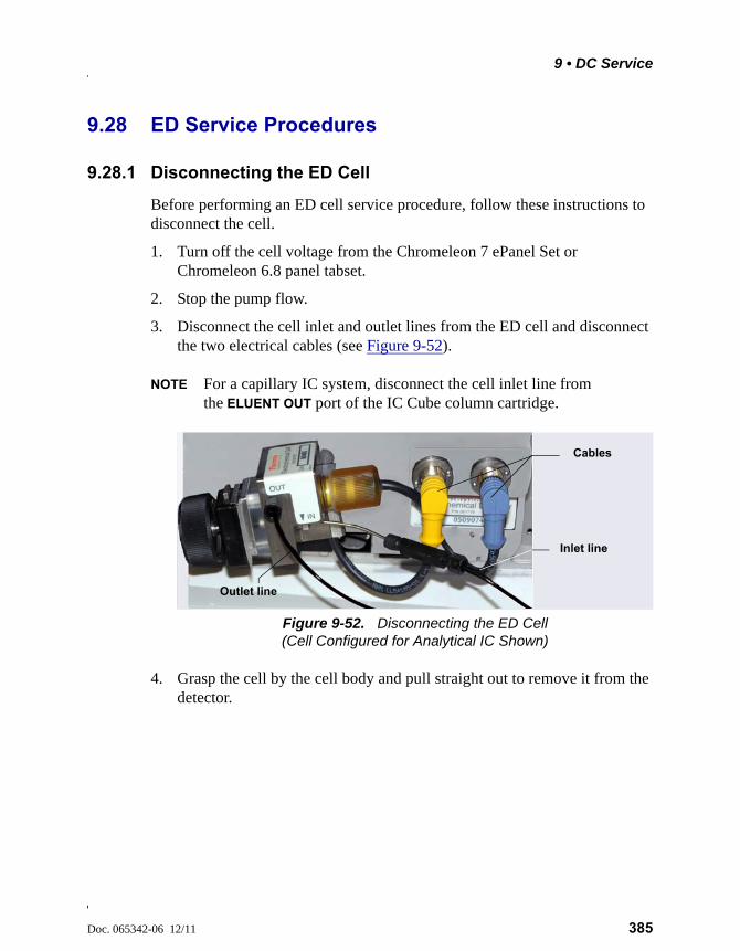
9 • DC Service
Doc. 065342-06 12/11 385
9.28 ED Service Procedures
9.28.1 Disconnecting the ED Cell
Before performing an ED cell service procedure, follow these instructions to disconnect the cell.
1. Turn off the cell voltage from the Chromeleon 7 ePanel Set or Chromeleon 6.8 panel tabset.
2. Stop the pump flow.
3. Disconnect the cell inlet and outlet lines from the ED cell and disconnect the two electrical cables (see Figure 9-52).
NOTE For a capillary IC system, disconnect the cell inlet line from the ELUENT OUT port of the IC Cube column cartridge.
4. Grasp the cell by the cell body and pull straight out to remove it from the detector.
Figure 9-52. Disconnecting the ED Cell (Cell Configured for Analytical IC Shown)
Cables
Outlet line
Inlet line
Dionex ICS-5000 Operator’s Manual
386 Doc. 065342-06 12/11
9.28.2 Replacing an ED Cell Disposable Working Electrode Gasket
For installation instructions for disposable working electrodes, refer to the installation guide shipped with the electrodes (see below) or to Product Manual for Disposable Electrodes (Document No. 065040), which is included on the Thermo Scientific Reference Library DVD (P/N 053891).
• Disposable Silver Electrode Installation Guide for ED (Document No. 065137)
• Disposable Platinum Electrode Installation Guide for ED (Document No. 065139)
• Disposable Gold Electrode Installation Guide (Document No. 065191)
9.28.3 Replacing an ED Cell Conventional Working Electrode Gasket
When to Replace the Gasket
Replace the gasket if there is a leak between the gasket and electrode, or between the gasket and cell body.
Items Needed
• ED cell gasket for conventional working electrodes (P/N 045972)
• Gloves
• Blunt-end tweezers
When you install a disposable electrode, make sure that you installthe correct gasket for your system.
• For a capillary system, use a 0.001-in PTFE gasket (P/N 072117, Pkg. of 2).
• For an analytical system with a gold, silver, or platinum disposable electrode, use a 0.002-in PTFE gasket (P/N 069141, Pkg. of 4).
• For an analytical system with a carbon disposable electrode, use a 0.001-in Ultem gasket (P/N 069339).
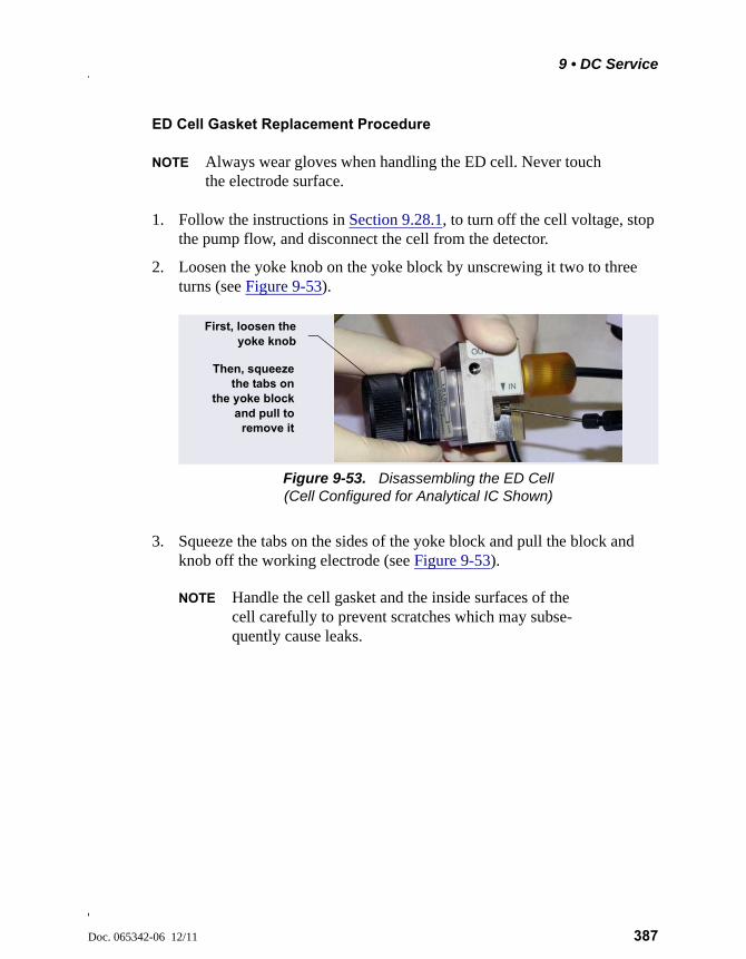
9 • DC Service
Doc. 065342-06 12/11 387
ED Cell Gasket Replacement Procedure
NOTE Always wear gloves when handling the ED cell. Never touch the electrode surface.
1. Follow the instructions in Section 9.28.1, to turn off the cell voltage, stop the pump flow, and disconnect the cell from the detector.
2. Loosen the yoke knob on the yoke block by unscrewing it two to three turns (see Figure 9-53).
3. Squeeze the tabs on the sides of the yoke block and pull the block and knob off the working electrode (see Figure 9-53).
NOTE Handle the cell gasket and the inside surfaces of the cell carefully to prevent scratches which may subse-quently cause leaks.
Figure 9-53. Disassembling the ED Cell (Cell Configured for Analytical IC Shown)
Then, squeezethe tabs on
the yoke blockand pull to
remove it
First, loosen theyoke knob
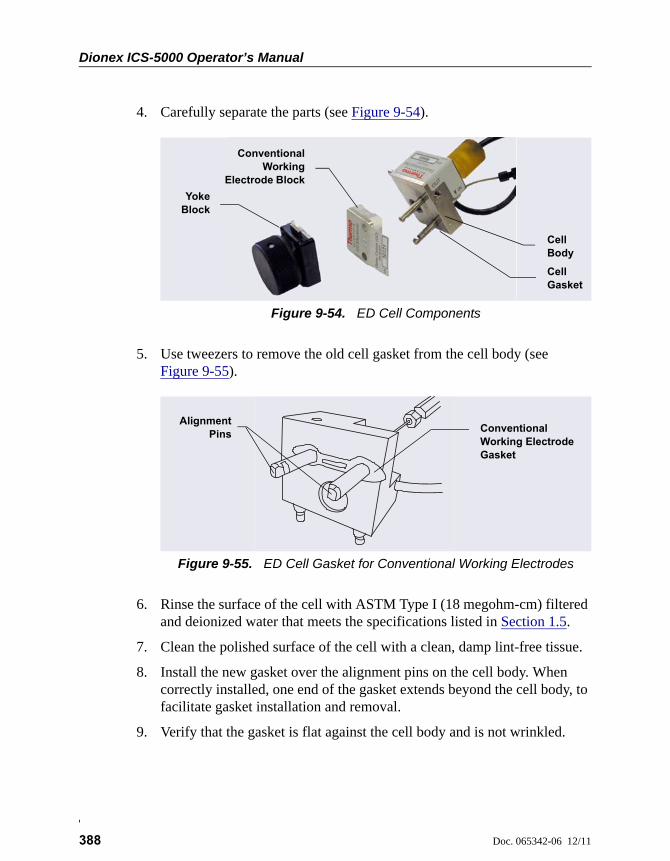
Dionex ICS-5000 Operator’s Manual
388 Doc. 065342-06 12/11
4. Carefully separate the parts (see Figure 9-54).
5. Use tweezers to remove the old cell gasket from the cell body (see Figure 9-55).
6. Rinse the surface of the cell with ASTM Type I (18 megohm-cm) filtered and deionized water that meets the specifications listed in Section 1.5.
7. Clean the polished surface of the cell with a clean, damp lint-free tissue.
8. Install the new gasket over the alignment pins on the cell body. When correctly installed, one end of the gasket extends beyond the cell body, to facilitate gasket installation and removal.
9. Verify that the gasket is flat against the cell body and is not wrinkled.
Figure 9-54. ED Cell Components
Figure 9-55. ED Cell Gasket for Conventional Working Electrodes
ConventionalWorking
Electrode Block
Cell Body
Cell Gasket
YokeBlock
AlignmentPins Conventional
Working Electrode Gasket

9 • DC Service
Doc. 065342-06 12/11 389
10. Reinstall the working electrode block and the yoke knob and block. Fingertighten the yoke knob by turning it a full 360 degrees.
NOTE It is not possible to overtighten the yoke knob. Once the knob clicks into place, it does not tighten any fur-ther. The yoke knob ensures constant pressure is applied to the cell.
11. Orient the cell assembly with the yoke knob on the left and push the cell onto its mounting location in the DC compartment.
12. Reconnect the cell’s inlet and outlet lines.
13. Reconnect the electrical cables.
14. Start the pump flow.
15. Wait until the pump pressure has stabilized (30 to 60 seconds) and then turn on the cell voltage.
9.28.4 Polishing an ED Cell Conventional Working Electrode
These instructions are for conventional (nondisposable) working electrodes only. Do not polish disposable electrodes.
When to Polish the Working Electrode
• Do not polish new conventional working electrodes before installation.
• After an electrode has been used for a period of time, a layer of contamination may build up. When this occurs, the electrode must be polished.
• After the working electrode is polished and installed, background signal and analyte sensitivity require several hours to stabilize. Once stabilized, do not polish the electrode unless you observe a loss of signal or severe electrode recession.
Items Needed
• Polishing kit (P/N 036313) shipped with the electrode. The kit contains polishing pads (P/N 036321), a bottle of fine polishing compound (P/N 036318), and a bottle of coarse polishing compound (P/N 036319).
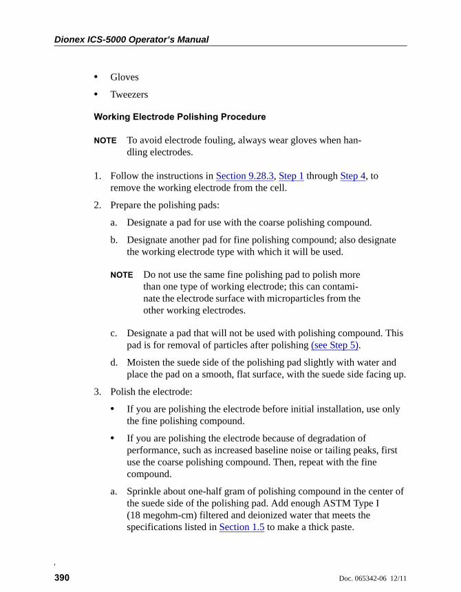
Dionex ICS-5000 Operator’s Manual
390 Doc. 065342-06 12/11
• Gloves
• Tweezers
Working Electrode Polishing Procedure
NOTE To avoid electrode fouling, always wear gloves when han-dling electrodes.
1. Follow the instructions in Section 9.28.3, Step 1 through Step 4, to remove the working electrode from the cell.
2. Prepare the polishing pads:
a. Designate a pad for use with the coarse polishing compound.
b. Designate another pad for fine polishing compound; also designate the working electrode type with which it will be used.
NOTE Do not use the same fine polishing pad to polish more than one type of working electrode; this can contami-nate the electrode surface with microparticles from the other working electrodes.
c. Designate a pad that will not be used with polishing compound. This pad is for removal of particles after polishing (see Step 5).
d. Moisten the suede side of the polishing pad slightly with water and place the pad on a smooth, flat surface, with the suede side facing up.
3. Polish the electrode:
• If you are polishing the electrode before initial installation, use only the fine polishing compound.
• If you are polishing the electrode because of degradation of performance, such as increased baseline noise or tailing peaks, first use the coarse polishing compound. Then, repeat with the fine compound.
a. Sprinkle about one-half gram of polishing compound in the center of the suede side of the polishing pad. Add enough ASTM Type I (18 megohm-cm) filtered and deionized water that meets the specifications listed in Section 1.5 to make a thick paste.
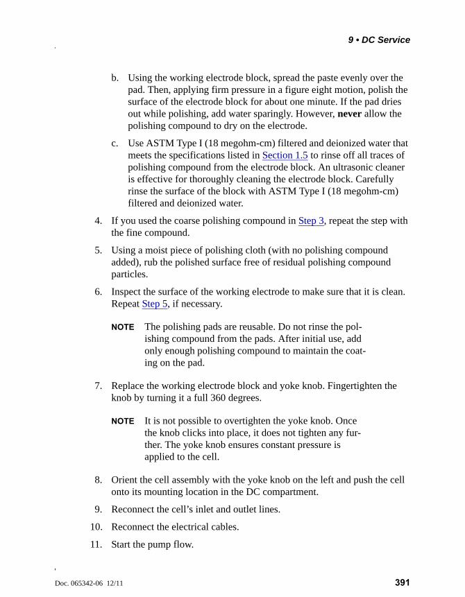
9 • DC Service
Doc. 065342-06 12/11 391
b. Using the working electrode block, spread the paste evenly over the pad. Then, applying firm pressure in a figure eight motion, polish the surface of the electrode block for about one minute. If the pad dries out while polishing, add water sparingly. However, never allow the polishing compound to dry on the electrode.
c. Use ASTM Type I (18 megohm-cm) filtered and deionized water that meets the specifications listed in Section 1.5 to rinse off all traces of polishing compound from the electrode block. An ultrasonic cleaner is effective for thoroughly cleaning the electrode block. Carefully rinse the surface of the block with ASTM Type I (18 megohm-cm) filtered and deionized water.
4. If you used the coarse polishing compound in Step 3, repeat the step with the fine compound.
5. Using a moist piece of polishing cloth (with no polishing compound added), rub the polished surface free of residual polishing compound particles.
6. Inspect the surface of the working electrode to make sure that it is clean. Repeat Step 5, if necessary.
NOTE The polishing pads are reusable. Do not rinse the pol-ishing compound from the pads. After initial use, add only enough polishing compound to maintain the coat-ing on the pad.
7. Replace the working electrode block and yoke knob. Fingertighten the knob by turning it a full 360 degrees.
NOTE It is not possible to overtighten the yoke knob. Once the knob clicks into place, it does not tighten any fur-ther. The yoke knob ensures constant pressure is applied to the cell.
8. Orient the cell assembly with the yoke knob on the left and push the cell onto its mounting location in the DC compartment.
9. Reconnect the cell’s inlet and outlet lines.
10. Reconnect the electrical cables.
11. Start the pump flow.

Dionex ICS-5000 Operator’s Manual
392 Doc. 065342-06 12/11
12. Wait until the pump pressure has stabilized (30 to 60 seconds) and then turn on the cell voltage.
13. Reapply the electrode potential. The baseline will drift for more than 1 hour as the cell re-equilibrates. Peak area values may require up to 12 hours to stabilize.
9.28.5 Replacing a pH-Ag/AgCl Reference Electrode
When to Replace a pH-Ag/AgCl Reference Electrode
Replace the pH-Ag/AgCl reference electrode if performance problems occur that are not corrected by regenerating the electrode. Performance problems can include no pH readouts, a shift in Ag/AgCl reference potential or incorrect readouts, baseline spikes, or a decreased response even with a freshly polished working electrode. The pH-Ag/AgCl reference electrode typically lasts from 3 months to 1 year, depending on use.
NOTE To regenerate a pH-Ag/AgCl reference electrode, soak it in a solution of 1 M KCl and 1 M HCl.
Items Needed
• pH-Ag/AgCl reference electrode (P/N 061879)
pH-Ag/AgCl Reference Electrode Replacement Procedure
1. Follow the instructions in Section 9.28.1 to turn off the cell voltage, stop the pump flow, and disconnect the cell from the detector.

9 • DC Service
Doc. 065342-06 12/11 393
2. Unscrew the pH-Ag/AgCl reference electrode and remove it from the cell body (see Figure 9-56).
3. Unscrew the storage cap from the new pH-Ag/AgCl reference electrode (see Figure 9-57). Save the cap.
4. Rinse the new electrode thoroughly in ASTM Type I (18 megohm-cm) filtered and deionized water that meets the specifications listed in Section 1.5 to remove any precipitated salt.
5. Calibrate the pH-Ag/AgCl reference electrode (see Section 9.28.6).
Figure 9-56. Removing the pH-Ag/AgCl Reference Electrode (Cell Configured for Analytical IC Shown)
Unscrew the pH-Ag/AgCl reference electrode
Always store the electrode in the storage cap filled with saturated KClsolution when the cell is not in use. This prevents the pH-Ag/AgClreference electrode membrane from drying out and damaging theelectrode. See Section 6.4 for storage instructions.
Figure 9-57. pH-Ag/AgCl Reference Electrode in Storage Cap
Save the storage cap
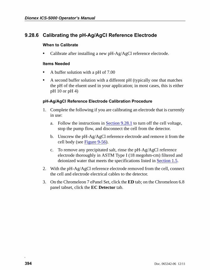
Dionex ICS-5000 Operator’s Manual
394 Doc. 065342-06 12/11
9.28.6 Calibrating the pH-Ag/AgCl Reference Electrode
When to Calibrate
• Calibrate after installing a new pH-Ag/AgCl reference electrode.
Items Needed
• A buffer solution with a pH of 7.00
• A second buffer solution with a different pH (typically one that matches the pH of the eluent used in your application; in most cases, this is either pH 10 or pH 4)
pH-Ag/AgCl Reference Electrode Calibration Procedure
1. Complete the following if you are calibrating an electrode that is currently in use:
a. Follow the instructions in Section 9.28.1 to turn off the cell voltage, stop the pump flow, and disconnect the cell from the detector.
b. Unscrew the pH-Ag/AgCl reference electrode and remove it from the cell body (see Figure 9-56).
c. To remove any precipitated salt, rinse the pH-Ag/AgCl reference electrode thoroughly in ASTM Type I (18 megohm-cm) filtered and deionized water that meets the specifications listed in Section 1.5.
2. With the pH-Ag/AgCl reference electrode removed from the cell, connect the cell and electrode electrical cables to the detector.
3. On the Chromeleon 7 ePanel Set, click the ED tab; on the Chromeleon 6.8 panel tabset, click the EC Detector tab.
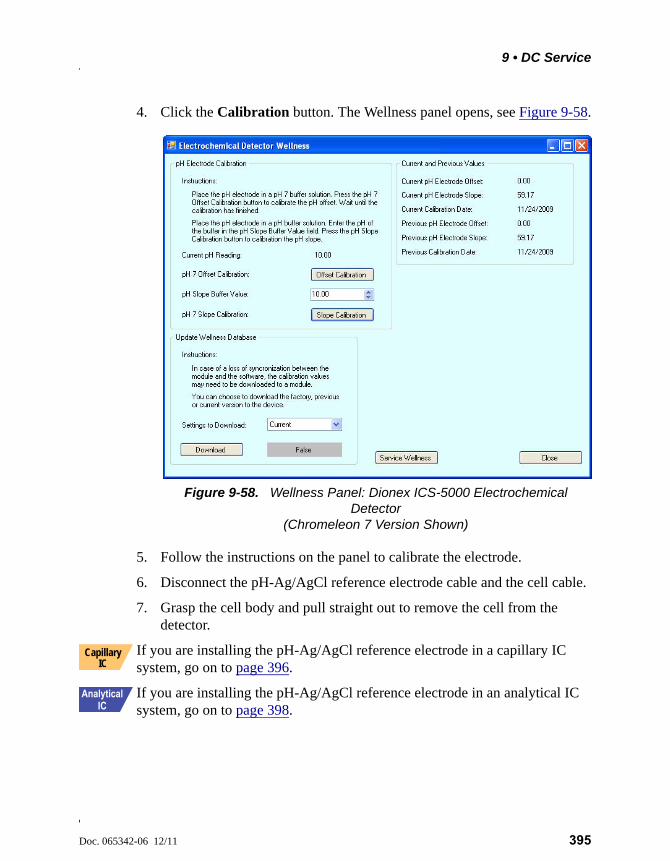
9 • DC Service
Doc. 065342-06 12/11 395
4. Click the Calibration button. The Wellness panel opens, see Figure 9-58.
5. Follow the instructions on the panel to calibrate the electrode.
6. Disconnect the pH-Ag/AgCl reference electrode cable and the cell cable.
7. Grasp the cell body and pull straight out to remove the cell from the detector.
If you are installing the pH-Ag/AgCl reference electrode in a capillary IC system, go on to page 396.
If you are installing the pH-Ag/AgCl reference electrode in an analytical IC system, go on to page 398.
Figure 9-58. Wellness Panel: Dionex ICS-5000 Electrochemical Detector
(Chromeleon 7 Version Shown)
Capillary IC
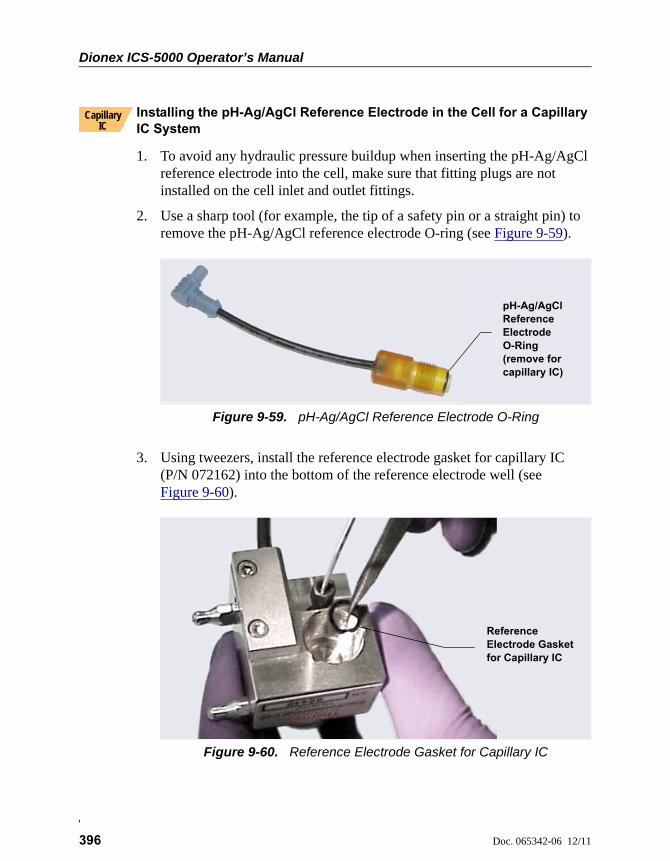
Dionex ICS-5000 Operator’s Manual
396 Doc. 065342-06 12/11
Installing the pH-Ag/AgCl Reference Electrode in the Cell for a Capillary IC System
1. To avoid any hydraulic pressure buildup when inserting the pH-Ag/AgCl reference electrode into the cell, make sure that fitting plugs are not installed on the cell inlet and outlet fittings.
2. Use a sharp tool (for example, the tip of a safety pin or a straight pin) to remove the pH-Ag/AgCl reference electrode O-ring (see Figure 9-59).
3. Using tweezers, install the reference electrode gasket for capillary IC (P/N 072162) into the bottom of the reference electrode well (see Figure 9-60).
Figure 9-59. pH-Ag/AgCl Reference Electrode O-Ring
Figure 9-60. Reference Electrode Gasket for Capillary IC
Capillary IC
pH-Ag/AgCl Reference Electrode O-Ring (remove for capillary IC)
Reference Electrode Gasket for Capillary IC
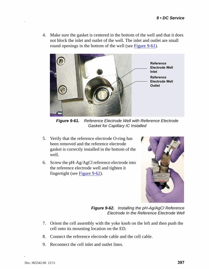
9 • DC Service
Doc. 065342-06 12/11 397
4. Make sure the gasket is centered in the bottom of the well and that it does not block the inlet and outlet of the well. The inlet and outlet are small round openings in the bottom of the well (see Figure 9-61).
5. Verify that the reference electrode O-ring has been removed and the reference electrode gasket is correctly installed in the bottom of the well.
6. Screw the pH-Ag/AgCl reference electrode into the reference electrode well and tighten it fingertight (see Figure 9-62).
Figure 9-62. Installing the pH-Ag/AgCl ReferenceElectrode In the Reference Electrode Well
7. Orient the cell assembly with the yoke knob on the left and then push the cell onto its mounting location on the ED.
8. Connect the reference electrode cable and the cell cable.
9. Reconnect the cell inlet and outlet lines.
Figure 9-61. Reference Electrode Well with Reference Electrode Gasket for Capillary IC Installed
Reference Electrode Well Inlet
Reference Electrode Well Outlet
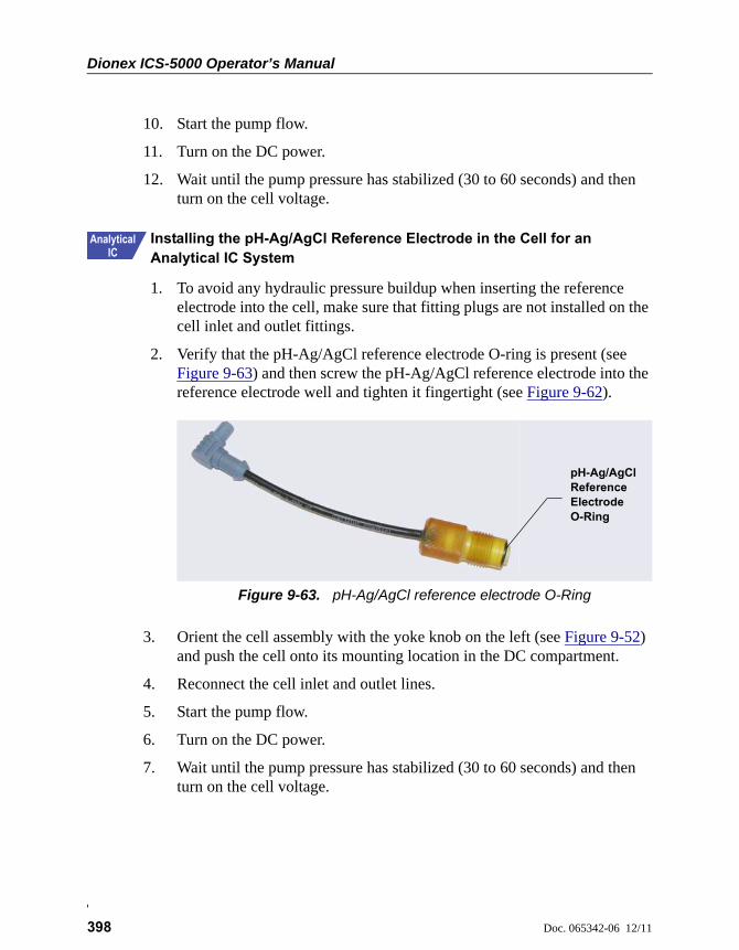
Dionex ICS-5000 Operator’s Manual
398 Doc. 065342-06 12/11
10. Start the pump flow.
11. Turn on the DC power.
12. Wait until the pump pressure has stabilized (30 to 60 seconds) and then turn on the cell voltage.
Installing the pH-Ag/AgCl Reference Electrode in the Cell for an Analytical IC System
1. To avoid any hydraulic pressure buildup when inserting the reference electrode into the cell, make sure that fitting plugs are not installed on the cell inlet and outlet fittings.
2. Verify that the pH-Ag/AgCl reference electrode O-ring is present (see Figure 9-63) and then screw the pH-Ag/AgCl reference electrode into the reference electrode well and tighten it fingertight (see Figure 9-62).
3. Orient the cell assembly with the yoke knob on the left (see Figure 9-52) and push the cell onto its mounting location in the DC compartment.
4. Reconnect the cell inlet and outlet lines.
5. Start the pump flow.
6. Turn on the DC power.
7. Wait until the pump pressure has stabilized (30 to 60 seconds) and then turn on the cell voltage.
Figure 9-63. pH-Ag/AgCl reference electrode O-Ring
pH-Ag/AgCl Reference Electrode O-Ring
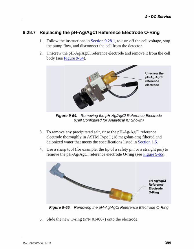
9 • DC Service
Doc. 065342-06 12/11 399
9.28.7 Replacing the pH-Ag/AgCl Reference Electrode O-Ring
1. Follow the instructions in Section 9.28.1, to turn off the cell voltage, stop the pump flow, and disconnect the cell from the detector.
2. Unscrew the pH-Ag/AgCl reference electrode and remove it from the cell body (see Figure 9-64).
3. To remove any precipitated salt, rinse the pH-Ag/AgCl reference electrode thoroughly in ASTM Type I (18 megohm-cm) filtered and deionized water that meets the specifications listed in Section 1.5.
4. Use a sharp tool (for example, the tip of a safety pin or a straight pin) to remove the pH-Ag/AgCl reference electrode O-ring (see Figure 9-65).
5. Slide the new O-ring (P/N 014067) onto the electrode.
Figure 9-64. Removing the pH-Ag/AgCl Reference Electrode (Cell Configured for Analytical IC Shown)
Figure 9-65. Removing the pH-Ag/AgCl Reference Electrode O-Ring
Unscrew the pH-Ag/AgCl reference electrode
pH-Ag/AgCl Reference Electrode O-Ring
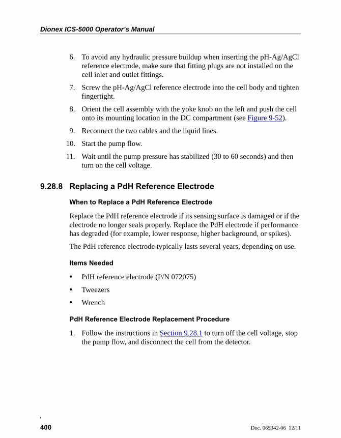
Dionex ICS-5000 Operator’s Manual
400 Doc. 065342-06 12/11
6. To avoid any hydraulic pressure buildup when inserting the pH-Ag/AgCl reference electrode, make sure that fitting plugs are not installed on the cell inlet and outlet fittings.
7. Screw the pH-Ag/AgCl reference electrode into the cell body and tighten fingertight.
8. Orient the cell assembly with the yoke knob on the left and push the cell onto its mounting location in the DC compartment (see Figure 9-52).
9. Reconnect the two cables and the liquid lines.
10. Start the pump flow.
11. Wait until the pump pressure has stabilized (30 to 60 seconds) and then turn on the cell voltage.
9.28.8 Replacing a PdH Reference Electrode
When to Replace a PdH Reference Electrode
Replace the PdH reference electrode if its sensing surface is damaged or if the electrode no longer seals properly. Replace the PdH electrode if performance has degraded (for example, lower response, higher background, or spikes).
The PdH reference electrode typically lasts several years, depending on use.
Items Needed
• PdH reference electrode (P/N 072075)
• Tweezers
• Wrench
PdH Reference Electrode Replacement Procedure
1. Follow the instructions in Section 9.28.1 to turn off the cell voltage, stop the pump flow, and disconnect the cell from the detector.
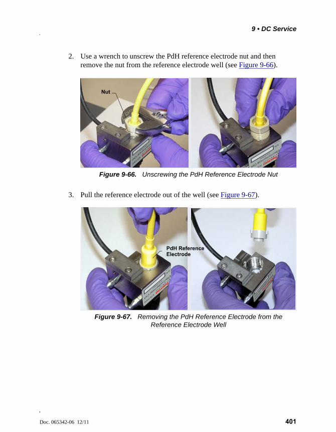
9 • DC Service
Doc. 065342-06 12/11 401
2. Use a wrench to unscrew the PdH reference electrode nut and then remove the nut from the reference electrode well (see Figure 9-66).
3. Pull the reference electrode out of the well (see Figure 9-67).
Figure 9-66. Unscrewing the PdH Reference Electrode Nut
Figure 9-67. Removing the PdH Reference Electrode from the Reference Electrode Well
Nut
PdH Reference Electrode
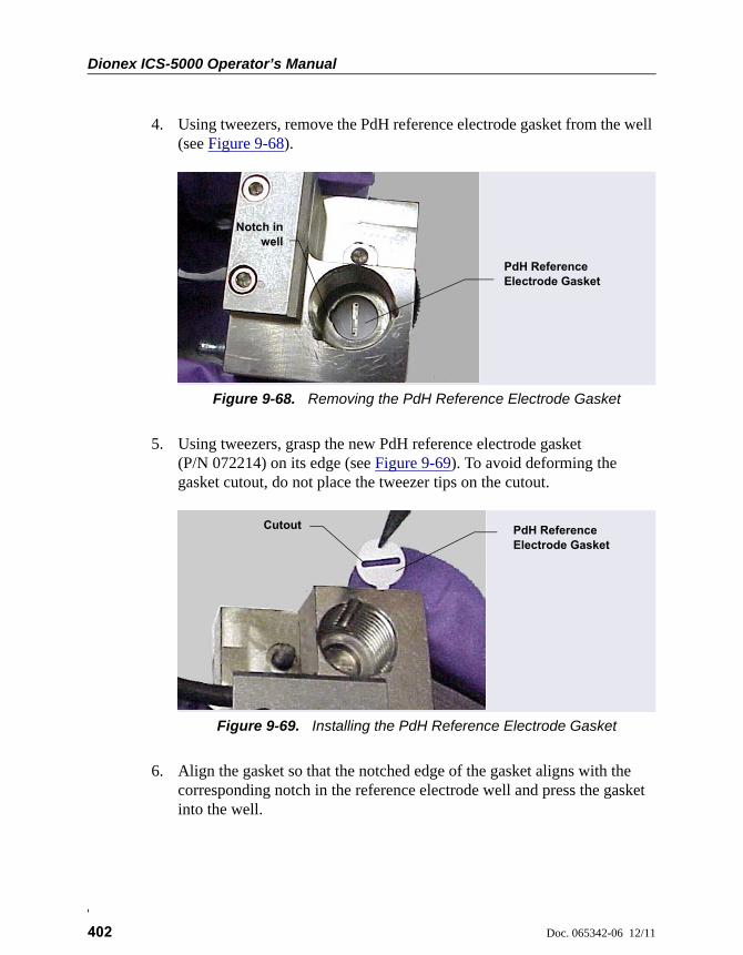
Dionex ICS-5000 Operator’s Manual
402 Doc. 065342-06 12/11
4. Using tweezers, remove the PdH reference electrode gasket from the well (see Figure 9-68).
5. Using tweezers, grasp the new PdH reference electrode gasket (P/N 072214) on its edge (see Figure 9-69). To avoid deforming the gasket cutout, do not place the tweezer tips on the cutout.
6. Align the gasket so that the notched edge of the gasket aligns with the corresponding notch in the reference electrode well and press the gasket into the well.
Figure 9-68. Removing the PdH Reference Electrode Gasket
Figure 9-69. Installing the PdH Reference Electrode Gasket
PdH Reference Electrode Gasket
Notch inwell
PdH Reference Electrode Gasket
Cutout
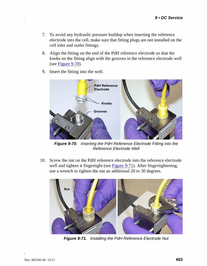
9 • DC Service
Doc. 065342-06 12/11 403
7. To avoid any hydraulic pressure buildup when inserting the reference electrode into the cell, make sure that fitting plugs are not installed on the cell inlet and outlet fittings.
8. Align the fitting on the end of the PdH reference electrode so that the knobs on the fitting align with the grooves in the reference electrode well (see Figure 9-70).
9. Insert the fitting into the well.
10. Screw the nut on the PdH reference electrode into the reference electrode well and tighten it fingertight (see Figure 9-71). After fingertightening, use a wrench to tighten the nut an additional 20 to 30 degrees.
Figure 9-70. Inserting the PdH Reference Electrode Fitting into the Reference Electrode Well
PdH Reference Electrode
Knobs
Grooves
Figure 9-71. Installing the PdH Reference Electrode Nut
Nut
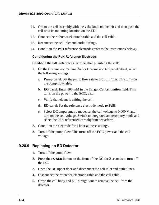
Dionex ICS-5000 Operator’s Manual
404 Doc. 065342-06 12/11
11. Orient the cell assembly with the yoke knob on the left and then push the cell onto its mounting location on the ED.
12. Connect the reference electrode cable and the cell cable.
13. Reconnect the cell inlet and outlet fittings.
14. Condition the PdH reference electrode (refer to the instructions below).
Conditioning the PdH Reference Electrode
Condition the PdH reference electrode after plumbing the cell:
1. On the Chromeleon 7ePanel Set or Chromeleon 6.8 panel tabset, select the following settings:
a. Pump panel: Set the pump flow rate to 0.01 mL/min. This turns on the pump flow, also.
b. EG panel: Enter 100 mM in the Target Concentration field. This turns on the power to the EGC, also.
c. Verify that eluent is exiting the cell.
d. ED panel: Set the reference electrode mode to PdH.
e. Select DC amperometry mode, set the cell voltage to 0.000 V, and turn on the cell voltage. Switch to integrated amperometry mode and select the PdH-referenced carbohydrate waveform.
2. Condition the electrode for 1 hour at these settings.
3. Turn off the pump flow. This turns off the EGC power and the cell voltage.
9.28.9 Replacing an ED Detector
1. Turn off the pump flow.
2. Press the POWER button on the front of the DC for 2 seconds to turn off the DC.
3. Open the DC upper door and disconnect the cell inlet and outlet lines.
4. Disconnect the reference electrode cable and the cell cable.
5. Grasp the cell body and pull straight out to remove the cell from the detector.
9 • DC Service
Doc. 065342-06 12/11 405
6. Press the release lever located below the detector. The detector pops out slightly from the DC compartment. Grasp the detector and pull outward to remove the detector from the compartment.
7. Note the electrical plug on the back of the detector and the receptacle on the inside of the DC.
8. Push the new detector into the opening in the DC and press firmly to ensure the electrical connection is secure.
9. Reinstall the cell and reconnect the cell inlet and outlet lines and the cables.
NOTE If you are installing an ED detector in a system that previ-ously was set up for conductivity detection, remove the sup-pressor cartridge from the IC Cube and replace it with a suppressor bypass cartridge (P/N 072055). For IC Cube car-tridge installation instructions, see Section 9.26.1.

Dionex ICS-5000 Operator’s Manual
406 Doc. 065342-06 12/11
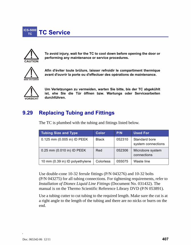
Doc. 065342-06 12/11 407
TC Service
9.29 Replacing Tubing and Fittings
The TC is plumbed with the tubing and fittings listed below.
Use double-cone 10-32 ferrule fittings (P/N 043276) and 10-32 bolts (P/N 043275) for all tubing connections. For tightening requirements, refer to Installation of Dionex Liquid Line Fittings (Document No. 031432). The manual is on the Thermo Scientific Reference Library DVD (P/N 053891).
Use a tubing cutter to cut tubing to the required length. Make sure the cut is at a right angle to the length of the tubing and there are no nicks or burrs on the end.
ICS-5000 TC
To avoid injury, wait for the TC to cool down before opening the door orperforming any maintenance or service procedures.
Afin d'éviter toute brûlure, laisser refroidir le compartiment thermiqueavant d'ouvrir la porte ou d'effectuer des opérations de maintenance.
Um Verletzungen zu vermeiden, warten Sie bitte, bis der TC abgekühltist, ehe Sie die Tür öffnen bzw. Wartungs oder Servicearbeitendurchführen.
Tubing Size and Type Color P/N Used For
0.125 mm (0.005 in) ID PEEK Black 052310 Standard bore system connections
0.25 mm (0.010 in) ID PEEK Red 052306 Microbore system connections
10 mm (0.39 in) ID polyethylene Colorless 055075 Waste line
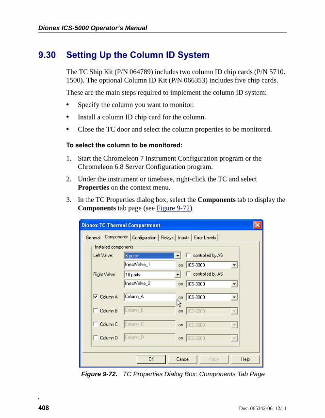
Dionex ICS-5000 Operator’s Manual
408 Doc. 065342-06 12/11
9.30 Setting Up the Column ID System
The TC Ship Kit (P/N 064789) includes two column ID chip cards (P/N 5710. 1500). The optional Column ID Kit (P/N 066353) includes five chip cards.
These are the main steps required to implement the column ID system:
• Specify the column you want to monitor.
• Install a column ID chip card for the column.
• Close the TC door and select the column properties to be monitored.
To select the column to be monitored:
1. Start the Chromeleon 7 Instrument Configuration program or the Chromeleon 6.8 Server Configuration program.
2. Under the instrument or timebase, right-click the TC and select Properties on the context menu.
3. In the TC Properties dialog box, select the Components tab to display the Components tab page (see Figure 9-72).
Figure 9-72. TC Properties Dialog Box: Components Tab Page
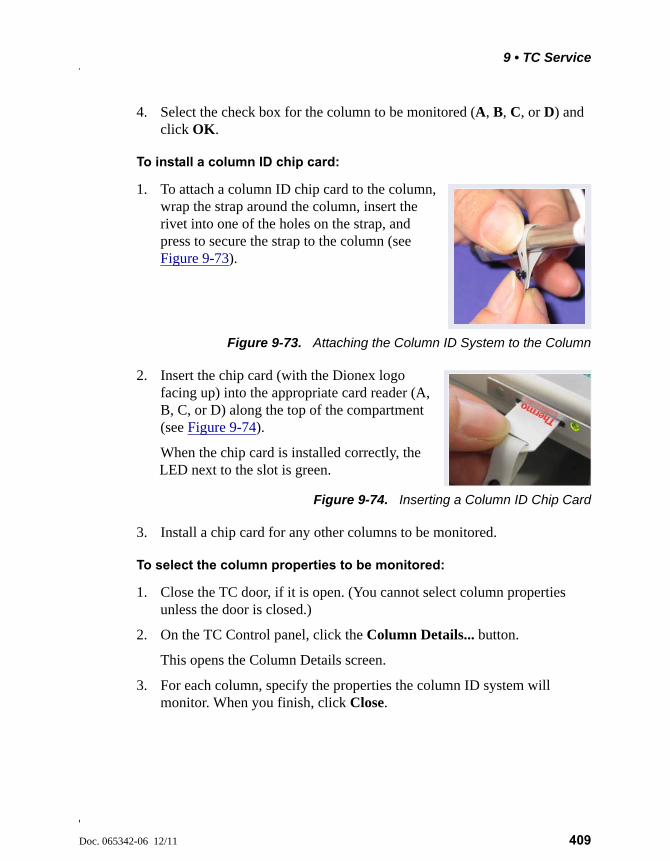
9 • TC Service
Doc. 065342-06 12/11 409
4. Select the check box for the column to be monitored (A, B, C, or D) and click OK.
To install a column ID chip card:
1. To attach a column ID chip card to the column, wrap the strap around the column, insert the rivet into one of the holes on the strap, and press to secure the strap to the column (see Figure 9-73).
Figure 9-73. Attaching the Column ID System to the Column
2. Insert the chip card (with the Dionex logo facing up) into the appropriate card reader (A, B, C, or D) along the top of the compartment (see Figure 9-74).
When the chip card is installed correctly, the LED next to the slot is green.
Figure 9-74. Inserting a Column ID Chip Card
3. Install a chip card for any other columns to be monitored.
To select the column properties to be monitored:
1. Close the TC door, if it is open. (You cannot select column properties unless the door is closed.)
2. On the TC Control panel, click the Column Details... button.
This opens the Column Details screen.
3. For each column, specify the properties the column ID system will monitor. When you finish, click Close.
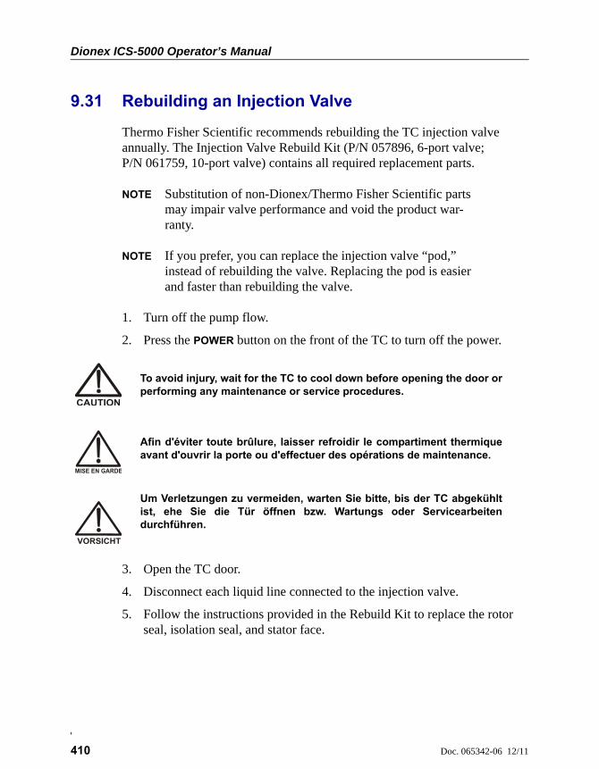
Dionex ICS-5000 Operator’s Manual
410 Doc. 065342-06 12/11
9.31 Rebuilding an Injection Valve
Thermo Fisher Scientific recommends rebuilding the TC injection valve annually. The Injection Valve Rebuild Kit (P/N 057896, 6-port valve; P/N 061759, 10-port valve) contains all required replacement parts.
NOTE Substitution of non-Dionex/Thermo Fisher Scientific parts may impair valve performance and void the product war-ranty.
NOTE If you prefer, you can replace the injection valve “pod,” instead of rebuilding the valve. Replacing the pod is easier and faster than rebuilding the valve.
1. Turn off the pump flow.
2. Press the POWER button on the front of the TC to turn off the power.
3. Open the TC door.
4. Disconnect each liquid line connected to the injection valve.
5. Follow the instructions provided in the Rebuild Kit to replace the rotor seal, isolation seal, and stator face.
To avoid injury, wait for the TC to cool down before opening the door orperforming any maintenance or service procedures.
Afin d'éviter toute brûlure, laisser refroidir le compartiment thermiqueavant d'ouvrir la porte ou d'effectuer des opérations de maintenance.
Um Verletzungen zu vermeiden, warten Sie bitte, bis der TC abgekühltist, ehe Sie die Tür öffnen bzw. Wartungs oder Servicearbeitendurchführen.
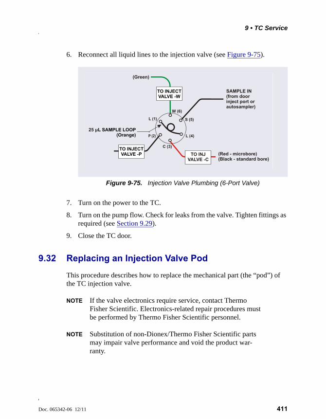
9 • TC Service
Doc. 065342-06 12/11 411
6. Reconnect all liquid lines to the injection valve (see Figure 9-75).
7. Turn on the power to the TC.
8. Turn on the pump flow. Check for leaks from the valve. Tighten fittings as required (see Section 9.29).
9. Close the TC door.
9.32 Replacing an Injection Valve Pod
This procedure describes how to replace the mechanical part (the “pod”) of the TC injection valve.
NOTE If the valve electronics require service, contact Thermo Fisher Scientific. Electronics-related repair procedures must be performed by Thermo Fisher Scientific personnel.
NOTE Substitution of non-Dionex/Thermo Fisher Scientific parts may impair valve performance and void the product war-ranty.
Figure 9-75. Injection Valve Plumbing (6-Port Valve)
SAMPLE IN(from door inject port or autosampler)
(Green)
(Red - microbore)(Black - standard bore)
TO INJECT VALVE -P
TO INJECT VALVE -W
TO INJ VALVE -C
25 μL SAMPLE LOOP(Orange) L (4)
S (5)
W (6)
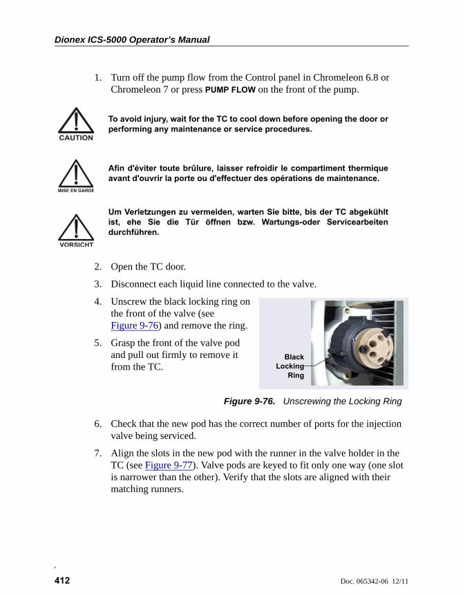
Dionex ICS-5000 Operator’s Manual
412 Doc. 065342-06 12/11
1. Turn off the pump flow from the Control panel in Chromeleon 6.8 or Chromeleon 7 or press PUMP FLOW on the front of the pump.
2. Open the TC door.
3. Disconnect each liquid line connected to the valve.
4. Unscrew the black locking ring on the front of the valve (see Figure 9-76) and remove the ring.
5. Grasp the front of the valve pod and pull out firmly to remove it from the TC.
Figure 9-76. Unscrewing the Locking Ring
6. Check that the new pod has the correct number of ports for the injection valve being serviced.
7. Align the slots in the new pod with the runner in the valve holder in the TC (see Figure 9-77). Valve pods are keyed to fit only one way (one slot is narrower than the other). Verify that the slots are aligned with their matching runners.
To avoid injury, wait for the TC to cool down before opening the door orperforming any maintenance or service procedures.
Afin d'éviter toute brûlure, laisser refroidir le compartiment thermiqueavant d'ouvrir la porte ou d'effectuer des opérations de maintenance.
Um Verletzungen zu vermeiden, warten Sie bitte, bis der TC abgekühltist, ehe Sie die Tür öffnen bzw. Wartungs-oder Servicearbeitendurchführen.
BlackLocking
Ring
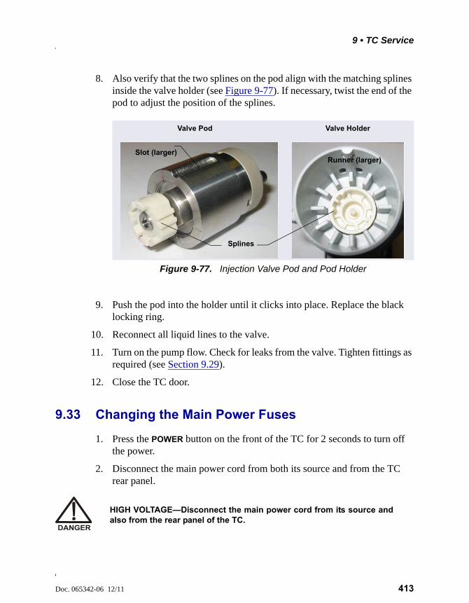
9 • TC Service
Doc. 065342-06 12/11 413
8. Also verify that the two splines on the pod align with the matching splines inside the valve holder (see Figure 9-77). If necessary, twist the end of the pod to adjust the position of the splines.
9. Push the pod into the holder until it clicks into place. Replace the black locking ring.
10. Reconnect all liquid lines to the valve.
11. Turn on the pump flow. Check for leaks from the valve. Tighten fittings as required (see Section 9.29).
12. Close the TC door.
9.33 Changing the Main Power Fuses
1. Press the POWER button on the front of the TC for 2 seconds to turn off the power.
2. Disconnect the main power cord from both its source and from the TC rear panel.
Figure 9-77. Injection Valve Pod and Pod Holder
Slot (larger)
Splines
Runner (larger)
Valve Pod Valve Holder
HIGH VOLTAGE—Disconnect the main power cord from its source andalso from the rear panel of the TC.
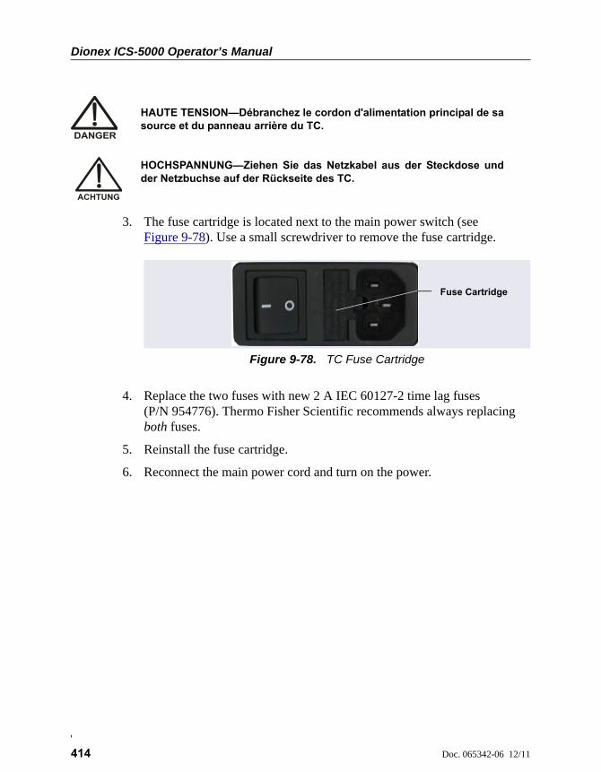
Dionex ICS-5000 Operator’s Manual
414 Doc. 065342-06 12/11
3. The fuse cartridge is located next to the main power switch (see Figure 9-78). Use a small screwdriver to remove the fuse cartridge.
4. Replace the two fuses with new 2 A IEC 60127-2 time lag fuses (P/N 954776). Thermo Fisher Scientific recommends always replacing both fuses.
5. Reinstall the fuse cartridge.
6. Reconnect the main power cord and turn on the power.
HAUTE TENSION—Débranchez le cordon d'alimentation principal de sasource et du panneau arrière du TC.
HOCHSPANNUNG—Ziehen Sie das Netzkabel aus der Steckdose undder Netzbuchse auf der Rückseite des TC.
Figure 9-78. TC Fuse Cartridge
Fuse Cartridge

Doc. 065342-06 12/11 415
A • Specifications
DP/SP Specifications
ICS-5000 SP Single Pump and DP Dual Pump Specifications
Type Dual-piston (in series), microprocessor controlled, constant stroke, variable speed, patented Isokinetic Eluent Precompression
Construction Chemically inert, metal-free PEEK pump heads and flow path; compatible with aqueous eluents from pH 0–14 and reversed-phase solvents
Pressure Range 0–35 MPa (0–5000 psi) (Analytical)0–41 MPa (0–6000 psi) (Capillary)
Flow Rate Range • 0.000–10.000 mL/min with settable flow increments at 0.001 mL/min (Analytical)
• 0.001–3.000 mL/min with settable flow increments at 0.0001 mL/min (Capillary)
Flow Rate Precision <0.1% (Analytical)
Flow Rate Accuracy <0.1% (Analytical) at 14 MPa (2000 psi)
Pressure Ripple < 1.0% (Analytical) at 1.0 mL/min typical < 0.2% (with damper) at 10 μL/min at 14 MPa (2000 psi)
Pressure None required
Vacuum Degasser Integrated, optional 1 channel for isocratic pump or 4 channel for quaternary pump
Piston Seal Wash Standard, automatic operation
Gradient Formation Quaternary low pressure (Analytical only) or electrolytic eluent generation at high pressure (Analytical and Capillary)
RFIC-EG Gradients 0.1–100 mM (Analytical) 0.1–200 mM (Capillary)
ICS-5000 DP/SP
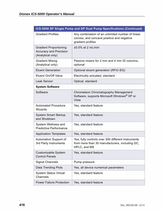
Dionex ICS-5000 Operator’s Manual
416 Doc. 065342-06 12/11
Gradient Profiles Any combination of an unlimited number of linear, convex, and concave positive and negative gradient profiles
Gradient Proportioning Accuracy and Precision(Analytical only)
±0.5% at 2 mL/min
Gradient Mixing(Analytical only)
Passive mixers for 2 mm and 4 mm ID columns, optional
Eluent Generation Optional eluent generation (RFIC-EG)
Eluent On/Off Valve Electrically actuated, standard
Leak Sensor Optical, standard
System Software
Software Chromeleon Chromatography Management Software, supports Microsoft Windows® XP or Vista
Automated Procedure Wizards
Yes, standard feature
System Smart Startup and Shutdown
Yes, standard feature
System Wellness and Predictive Performance
Yes, standard feature
Application Templates Yes, standard feature
Automation Support of 3rd Party Instruments
Yes, fully controls over 300 different instruments from more than 30 manufacturers, including GC, HPLC, and MS
Customizable System Control Panels
Yes, standard feature
Signal Channels Pump pressure
Data Trending Plots Yes, all device numerical parameters
System Status Virtual Channels
Yes, standard feature
Power Failure Protection Yes, standard feature
ICS-5000 SP Single Pump and DP Dual Pump Specifications (Continued)
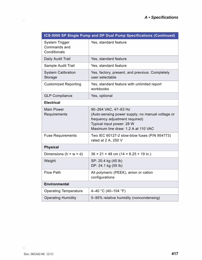
A • Specifications
Doc. 065342-06 12/11 417
System Trigger Commands and Conditionals
Yes, standard feature
Daily Audit Trail Yes, standard feature
Sample Audit Trail Yes, standard feature
System Calibration Storage
Yes, factory, present, and previous. Completely user selectable
Customized Reporting Yes, standard feature with unlimited report workbooks
GLP Compliance Yes, optional
Electrical
Main Power Requirements
90–264 VAC, 47–63 Hz(Auto-sensing power supply; no manual voltage or frequency adjustment required)Typical input power: 28 WMaximum line draw: 1.2 A at 110 VAC
Fuse Requirements Two IEC 60127-2 slow-blow fuses (P/N 954773) rated at 2 A, 250 V
Physical
Dimensions (h × w × d) 36 × 21 × 48 cm (14 × 8.25 × 19 in.)
Weight SP: 20.4 kg (45 lb)DP: 24.1 kg (55 lb)
Flow Path All polymeric (PEEK), anion or cation configurations
Environmental
Operating Temperature 4–40 °C (40–104 °F)
Operating Humidity 5–95% relative humidity (noncondensing)
ICS-5000 SP Single Pump and DP Dual Pump Specifications (Continued)

Dionex ICS-5000 Operator’s Manual
418 Doc. 065342-06 12/11
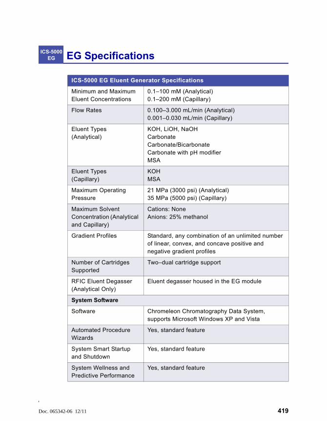
Doc. 065342-06 12/11 419
EG Specifications
ICS-5000 EG Eluent Generator Specifications
Minimum and Maximum Eluent Concentrations
0.1–100 mM (Analytical)0.1–200 mM (Capillary)
Flow Rates 0.100–3.000 mL/min (Analytical)0.001–0.030 mL/min (Capillary)
Eluent Types(Analytical)
KOH, LiOH, NaOHCarbonateCarbonate/BicarbonateCarbonate with pH modifierMSA
Eluent Types(Capillary)
KOHMSA
Maximum Operating Pressure
21 MPa (3000 psi) (Analytical)35 MPa (5000 psi) (Capillary)
Maximum Solvent Concentration (Analytical and Capillary)
Cations: NoneAnions: 25% methanol
Gradient Profiles Standard, any combination of an unlimited number of linear, convex, and concave positive and negative gradient profiles
Number of Cartridges Supported
Two–dual cartridge support
RFIC Eluent Degasser (Analytical Only)
Eluent degasser housed in the EG module
System Software
Software Chromeleon Chromatography Data System, supports Microsoft Windows XP and Vista
Automated Procedure Wizards
Yes, standard feature
System Smart Startup and Shutdown
Yes, standard feature
System Wellness and Predictive Performance
Yes, standard feature
ICS-5000 EG
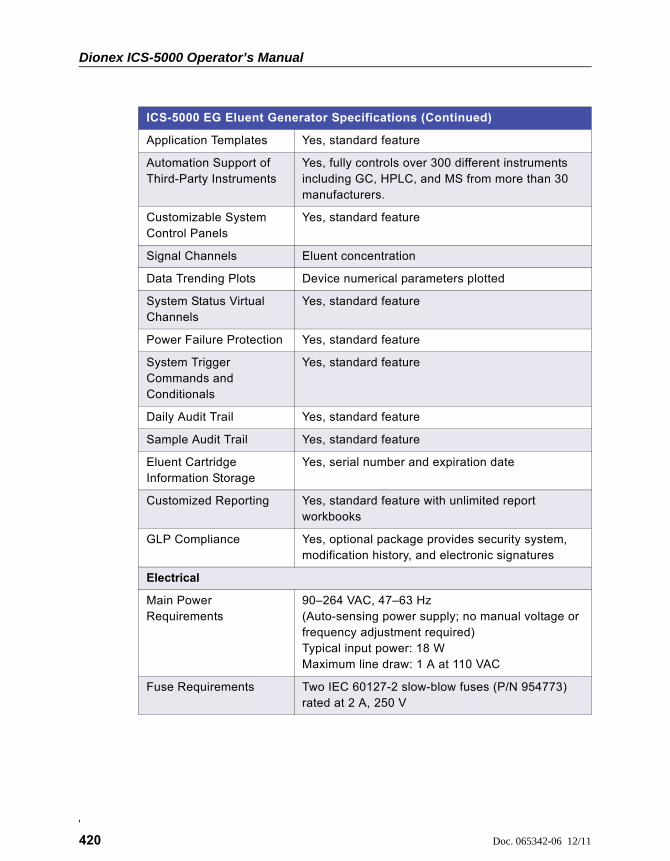
Dionex ICS-5000 Operator’s Manual
420 Doc. 065342-06 12/11
Application Templates Yes, standard feature
Automation Support of Third-Party Instruments
Yes, fully controls over 300 different instruments including GC, HPLC, and MS from more than 30 manufacturers.
Customizable System Control Panels
Yes, standard feature
Signal Channels Eluent concentration
Data Trending Plots Device numerical parameters plotted
System Status Virtual Channels
Yes, standard feature
Power Failure Protection Yes, standard feature
System Trigger Commands and Conditionals
Yes, standard feature
Daily Audit Trail Yes, standard feature
Sample Audit Trail Yes, standard feature
Eluent Cartridge Information Storage
Yes, serial number and expiration date
Customized Reporting Yes, standard feature with unlimited report workbooks
GLP Compliance Yes, optional package provides security system, modification history, and electronic signatures
Electrical
Main Power Requirements
90–264 VAC, 47–63 Hz(Auto-sensing power supply; no manual voltage or frequency adjustment required)Typical input power: 18 WMaximum line draw: 1 A at 110 VAC
Fuse Requirements Two IEC 60127-2 slow-blow fuses (P/N 954773) rated at 2 A, 250 V
ICS-5000 EG Eluent Generator Specifications (Continued)
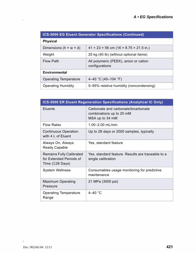
A • EG Specifications
Doc. 065342-06 12/11 421
Physical
Dimensions (h × w × d) 41 × 23 × 56 cm (16 × 8.75 × 21.5 in.)
Weight 25 kg (40 lb) (without optional items)
Flow Path All polymeric (PEEK), anion or cation configurations
Environmental
Operating Temperature 4–40 °C (40–104 °F)
Operating Humidity 5–95% relative humidity (noncondensing)
ICS-5000 EG Eluent Generator Specifications (Continued)
ICS-5000 ER Eluent Regeneration Specifications (Analytical IC Only)
Eluents Carbonate and carbonate/bicarbonate combinations up to 20 mMMSA up to 34 mM
Flow Rates 1.00–2.00 mL/min
Continuous Operation with 4 L of Eluent
Up to 28 days or 2000 samples, typically
Always On, Always Ready Capable
Yes, standard feature
Remains Fully Calibrated for Extended Periods of Time (28 Days)
Yes, standard feature. Results are traceable to a single calibration
System Wellness Consumables usage monitoring for predictive maintenance
Maximum Operating Pressure
21 MPa (3000 psi)
Operating Temperature Range
4–40 °C

Dionex ICS-5000 Operator’s Manual
422 Doc. 065342-06 12/11
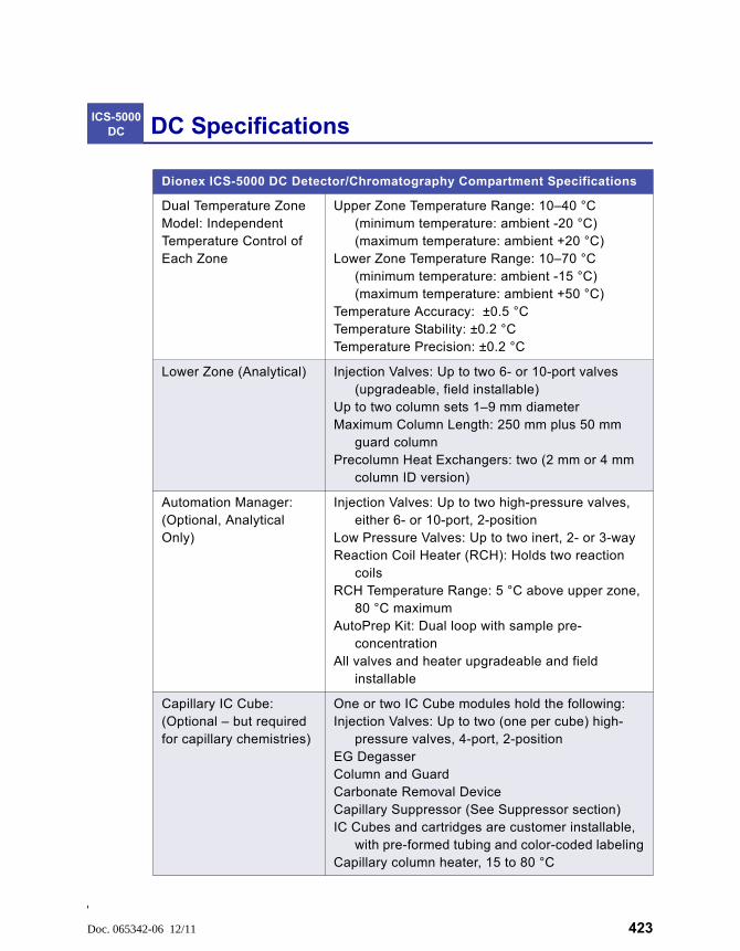
Doc. 065342-06 12/11 423
DC Specifications
Dionex ICS-5000 DC Detector/Chromatography Compartment Specifications
Dual Temperature Zone Model: Independent Temperature Control of Each Zone
Upper Zone Temperature Range: 10–40 °C(minimum temperature: ambient -20 °C)(maximum temperature: ambient +20 °C)
Lower Zone Temperature Range: 10–70 °C(minimum temperature: ambient -15 °C)(maximum temperature: ambient +50 °C)
Temperature Accuracy: ±0.5 °CTemperature Stability: ±0.2 °CTemperature Precision: ±0.2 °C
Lower Zone (Analytical) Injection Valves: Up to two 6- or 10-port valves (upgradeable, field installable)
Up to two column sets 1–9 mm diameterMaximum Column Length: 250 mm plus 50 mm
guard columnPrecolumn Heat Exchangers: two (2 mm or 4 mm
column ID version)
Automation Manager: (Optional, Analytical Only)
Injection Valves: Up to two high-pressure valves, either 6- or 10-port, 2-position
Low Pressure Valves: Up to two inert, 2- or 3-wayReaction Coil Heater (RCH): Holds two reaction
coilsRCH Temperature Range: 5 °C above upper zone,
80 °C maximum AutoPrep Kit: Dual loop with sample pre-
concentration All valves and heater upgradeable and field
installable
Capillary IC Cube: (Optional – but required for capillary chemistries)
One or two IC Cube modules hold the following:Injection Valves: Up to two (one per cube) high-
pressure valves, 4-port, 2-positionEG Degasser Column and Guard Carbonate Removal DeviceCapillary Suppressor (See Suppressor section)IC Cubes and cartridges are customer installable,
with pre-formed tubing and color-coded labelingCapillary column heater, 15 to 80 °C
ICS-5000 DC
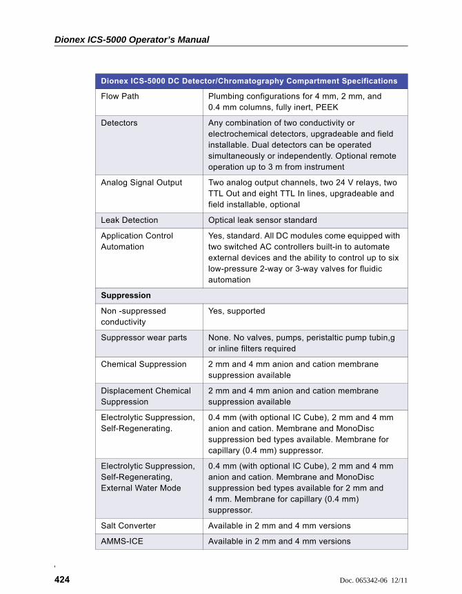
Dionex ICS-5000 Operator’s Manual
424 Doc. 065342-06 12/11
Flow Path Plumbing configurations for 4 mm, 2 mm, and 0.4 mm columns, fully inert, PEEK
Detectors Any combination of two conductivity or electrochemical detectors, upgradeable and field installable. Dual detectors can be operated simultaneously or independently. Optional remote operation up to 3 m from instrument
Analog Signal Output Two analog output channels, two 24 V relays, two TTL Out and eight TTL In lines, upgradeable and field installable, optional
Leak Detection Optical leak sensor standard
Application Control Automation
Yes, standard. All DC modules come equipped with two switched AC controllers built-in to automate external devices and the ability to control up to six low-pressure 2-way or 3-way valves for fluidic automation
Suppression
Non -suppressed conductivity
Yes, supported
Suppressor wear parts None. No valves, pumps, peristaltic pump tubin,g or inline filters required
Chemical Suppression 2 mm and 4 mm anion and cation membrane suppression available
Displacement Chemical Suppression
2 mm and 4 mm anion and cation membrane suppression available
Electrolytic Suppression, Self-Regenerating.
0.4 mm (with optional IC Cube), 2 mm and 4 mm anion and cation. Membrane and MonoDisc suppression bed types available. Membrane for capillary (0.4 mm) suppressor.
Electrolytic Suppression, Self-Regenerating, External Water Mode
0.4 mm (with optional IC Cube), 2 mm and 4 mm anion and cation. Membrane and MonoDisc suppression bed types available for 2 mm and 4 mm. Membrane for capillary (0.4 mm) suppressor.
Salt Converter Available in 2 mm and 4 mm versions
AMMS-ICE Available in 2 mm and 4 mm versions
Dionex ICS-5000 DC Detector/Chromatography Compartment Specifications
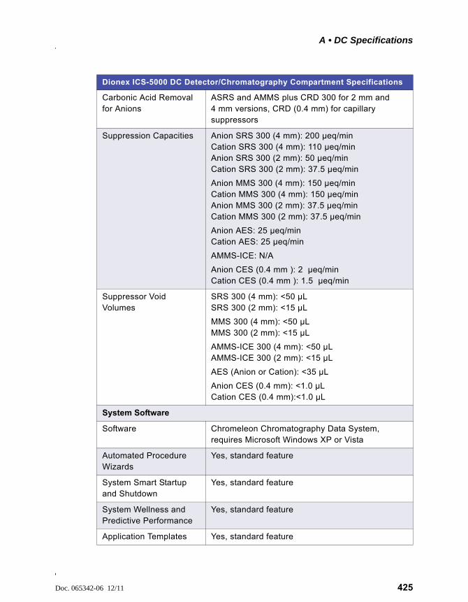
A • DC Specifications
Doc. 065342-06 12/11 425
Carbonic Acid Removal for Anions
ASRS and AMMS plus CRD 300 for 2 mm and 4 mm versions, CRD (0.4 mm) for capillary suppressors
Suppression Capacities Anion SRS 300 (4 mm): 200 μeq/minCation SRS 300 (4 mm): 110 μeq/minAnion SRS 300 (2 mm): 50 μeq/minCation SRS 300 (2 mm): 37.5 μeq/min
Anion MMS 300 (4 mm): 150 μeq/minCation MMS 300 (4 mm): 150 μeq/minAnion MMS 300 (2 mm): 37.5 μeq/minCation MMS 300 (2 mm): 37.5 μeq/min
Anion AES: 25 μeq/minCation AES: 25 μeq/min
AMMS-ICE: N/A
Anion CES (0.4 mm ): 2 μeq/minCation CES (0.4 mm ): 1.5 μeq/min
Suppressor Void Volumes
SRS 300 (4 mm): <50 μLSRS 300 (2 mm): <15 μL
MMS 300 (4 mm): <50 μLMMS 300 (2 mm): <15 μL
AMMS-ICE 300 (4 mm): <50 μLAMMS-ICE 300 (2 mm): <15 μL
AES (Anion or Cation): <35 μL
Anion CES (0.4 mm): <1.0 μLCation CES (0.4 mm):<1.0 μL
System Software
Software Chromeleon Chromatography Data System, requires Microsoft Windows XP or Vista
Automated Procedure Wizards
Yes, standard feature
System Smart Startup and Shutdown
Yes, standard feature
System Wellness and Predictive Performance
Yes, standard feature
Application Templates Yes, standard feature
Dionex ICS-5000 DC Detector/Chromatography Compartment Specifications
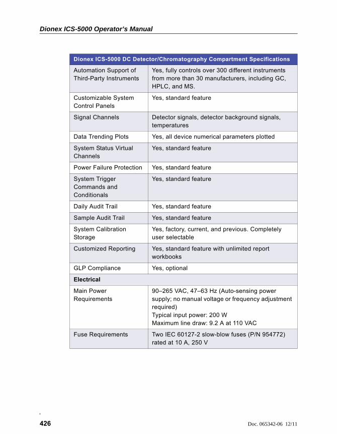
Dionex ICS-5000 Operator’s Manual
426 Doc. 065342-06 12/11
Automation Support of Third-Party Instruments
Yes, fully controls over 300 different instruments from more than 30 manufacturers, including GC, HPLC, and MS.
Customizable System Control Panels
Yes, standard feature
Signal Channels Detector signals, detector background signals, temperatures
Data Trending Plots Yes, all device numerical parameters plotted
System Status Virtual Channels
Yes, standard feature
Power Failure Protection Yes, standard feature
System Trigger Commands and Conditionals
Yes, standard feature
Daily Audit Trail Yes, standard feature
Sample Audit Trail Yes, standard feature
System Calibration Storage
Yes, factory, current, and previous. Completely user selectable
Customized Reporting Yes, standard feature with unlimited report workbooks
GLP Compliance Yes, optional
Electrical
Main Power Requirements
90–265 VAC, 47–63 Hz (Auto-sensing power supply; no manual voltage or frequency adjustment required)Typical input power: 200 WMaximum line draw: 9.2 A at 110 VAC
Fuse Requirements Two IEC 60127-2 slow-blow fuses (P/N 954772) rated at 10 A, 250 V
Dionex ICS-5000 DC Detector/Chromatography Compartment Specifications

A • DC Specifications
Doc. 065342-06 12/11 427
Physical Specifications
Dimensions (h × w × d):
44.5 × 42 × 57 cm (17.5 × 16.5 × 22.5 in)
Weight 38 kg (84 lb)
Flow Path All polymeric (PEEK), anion or cation configurations
Environmental
Operating Temperature 4–40 °C (40–104 °F)
Operating Humidity 5– 95% relative humidity (noncondensing)
Dionex ICS-5000 DC Detector/Chromatography Compartment Specifications
Dionex ICS-5000 Conductivity Detector Specifications
Electronics Type Microprocessor controlled digital signal processing, autoranging
Cell Drive 8 kHz square wave
Linearity 1%
Resolution 0.00238 nS/cm
Output Range Digital Signal Range: 0–15,000 µS/cm, Analog Signal Range: 0–15,000 µS/cm
Noise, Wet <0.2 nS at 23 µS/cm background<0.1 nS at 1 µS/cm background
Filter Rise times 0 to 10 s, programmable
Sampling Rate 1 to 100 Hz, user settable or automatic
Cell Temperature 5 °C above DC upper zone temperature to 60 °C maximum. User settable, working range is identical to settable range.
Cell Temperature Stability
<0.001 °C
Cell Temperature Compensation
Default 1.7% per °C; programmable from 0–3% per °C
Flow Cell Maximum Pressure
10 MPa (1500 psi)
Flow Cell Volume 0.7 µL (Analytical), 0.02 µL (Capillary)
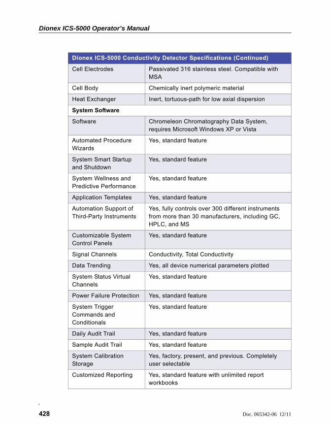
Dionex ICS-5000 Operator’s Manual
428 Doc. 065342-06 12/11
Cell Electrodes Passivated 316 stainless steel. Compatible with MSA
Cell Body Chemically inert polymeric material
Heat Exchanger Inert, tortuous-path for low axial dispersion
System Software
Software Chromeleon Chromatography Data System, requires Microsoft Windows XP or Vista
Automated Procedure Wizards
Yes, standard feature
System Smart Startup and Shutdown
Yes, standard feature
System Wellness and Predictive Performance
Yes, standard feature
Application Templates Yes, standard feature
Automation Support of Third-Party Instruments
Yes, fully controls over 300 different instruments from more than 30 manufacturers, including GC, HPLC, and MS
Customizable System Control Panels
Yes, standard feature
Signal Channels Conductivity, Total Conductivity
Data Trending Yes, all device numerical parameters plotted
System Status Virtual Channels
Yes, standard feature
Power Failure Protection Yes, standard feature
System Trigger Commands and Conditionals
Yes, standard feature
Daily Audit Trail Yes, standard feature
Sample Audit Trail Yes, standard feature
System Calibration Storage
Yes, factory, present, and previous. Completely user selectable
Customized Reporting Yes, standard feature with unlimited report workbooks
Dionex ICS-5000 Conductivity Detector Specifications (Continued)
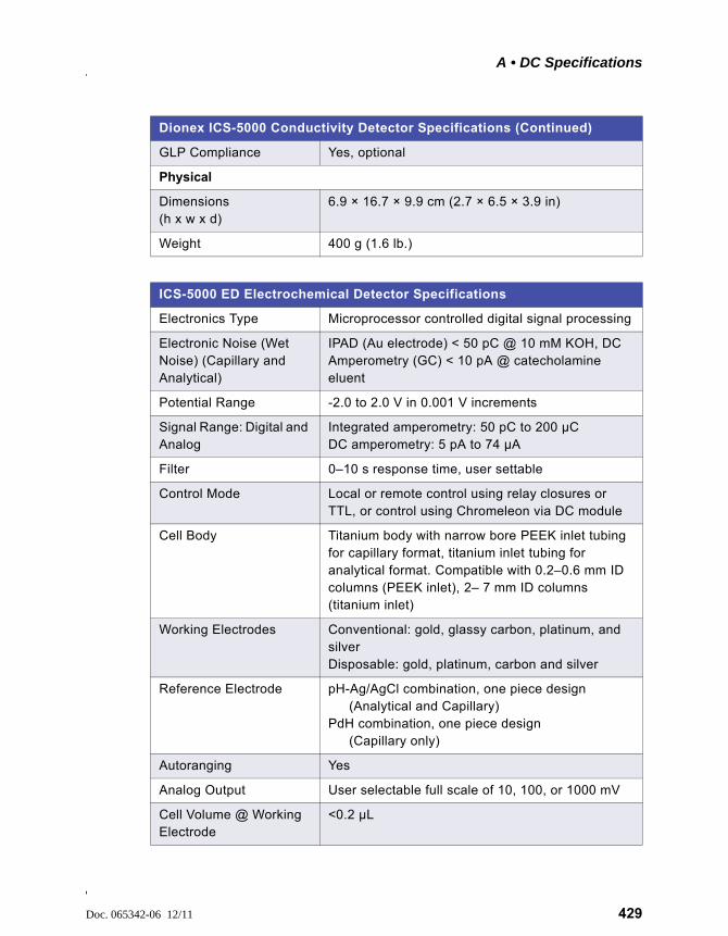
A • DC Specifications
Doc. 065342-06 12/11 429
GLP Compliance Yes, optional
Physical
Dimensions (h x w x d)
6.9 × 16.7 × 9.9 cm (2.7 × 6.5 × 3.9 in)
Weight 400 g (1.6 lb.)
ICS-5000 ED Electrochemical Detector Specifications
Electronics Type Microprocessor controlled digital signal processing
Electronic Noise (Wet Noise) (Capillary and Analytical)
IPAD (Au electrode) < 50 pC @ 10 mM KOH, DC Amperometry (GC) < 10 pA @ catecholamine eluent
Potential Range -2.0 to 2.0 V in 0.001 V increments
Signal Range: Digital and Analog
Integrated amperometry: 50 pC to 200 µC DC amperometry: 5 pA to 74 µA
Filter 0–10 s response time, user settable
Control Mode Local or remote control using relay closures or TTL, or control using Chromeleon via DC module
Cell Body Titanium body with narrow bore PEEK inlet tubing for capillary format, titanium inlet tubing for analytical format. Compatible with 0.2–0.6 mm ID columns (PEEK inlet), 2– 7 mm ID columns (titanium inlet)
Working Electrodes Conventional: gold, glassy carbon, platinum, and silverDisposable: gold, platinum, carbon and silver
Reference Electrode pH-Ag/AgCl combination, one piece design (Analytical and Capillary)
PdH combination, one piece design (Capillary only)
Autoranging Yes
Analog Output User selectable full scale of 10, 100, or 1000 mV
Cell Volume @ Working Electrode
<0.2 µL
Dionex ICS-5000 Conductivity Detector Specifications (Continued)
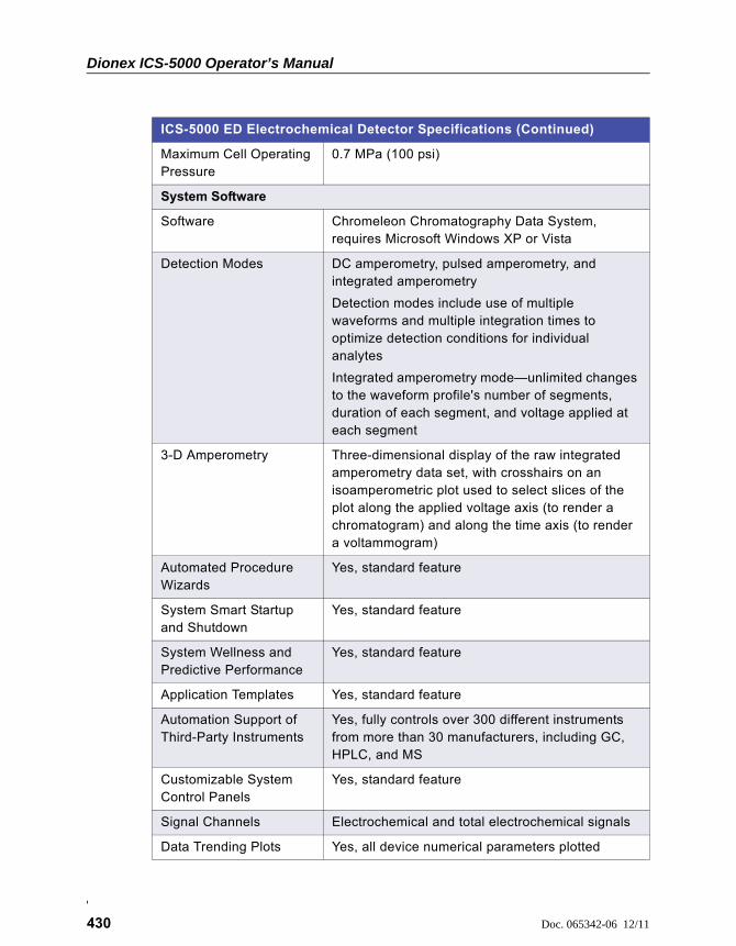
Dionex ICS-5000 Operator’s Manual
430 Doc. 065342-06 12/11
Maximum Cell Operating Pressure
0.7 MPa (100 psi)
System Software
Software Chromeleon Chromatography Data System, requires Microsoft Windows XP or Vista
Detection Modes DC amperometry, pulsed amperometry, and integrated amperometry
Detection modes include use of multiple waveforms and multiple integration times to optimize detection conditions for individual analytes
Integrated amperometry mode—unlimited changes to the waveform profile's number of segments, duration of each segment, and voltage applied at each segment
3-D Amperometry Three-dimensional display of the raw integrated amperometry data set, with crosshairs on an isoamperometric plot used to select slices of the plot along the applied voltage axis (to render a chromatogram) and along the time axis (to render a voltammogram)
Automated Procedure Wizards
Yes, standard feature
System Smart Startup and Shutdown
Yes, standard feature
System Wellness and Predictive Performance
Yes, standard feature
Application Templates Yes, standard feature
Automation Support of Third-Party Instruments
Yes, fully controls over 300 different instruments from more than 30 manufacturers, including GC, HPLC, and MS
Customizable System Control Panels
Yes, standard feature
Signal Channels Electrochemical and total electrochemical signals
Data Trending Plots Yes, all device numerical parameters plotted
ICS-5000 ED Electrochemical Detector Specifications (Continued)

A • DC Specifications
Doc. 065342-06 12/11 431
System Status Virtual Channels
Yes, standard feature
Power Failure Protection Yes, standard feature
System Trigger Commands and Conditionals
Yes, standard feature
Daily Audit Trail Yes, standard feature
Sample Audit Trail Yes, standard feature
System Calibration Storage
Yes, factory, present, and previous. Completely user selectable
Customized Reporting Yes, standard feature with unlimited report workbooks
GLP Compliance Yes, optional
Physical
Dimensions (h x w x d)
6.9 × 16.7 × 9.9 cm (2.7 × 6.5 × 3.9 in)
Weight 400 g (1.6 lb.)
ICS-5000 ED Electrochemical Detector Specifications (Continued)

Dionex ICS-5000 Operator’s Manual
432 Doc. 065342-06 12/11
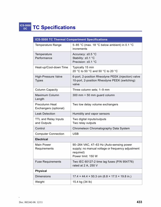
Doc. 065342-06 12/11 433
TC Specifications
ICS-5000 TC Thermal Compartment Specifications
Temperature Range 5–85 °C (max. 18 °C below ambient) in 0.1 °C increments
Temperature Performance
Accuracy: ±0.5 °C Stability: ±0.1 °CPrecision: ±0.1 °C
Heat-up/Cool-down Time Typically 15 min 20 °C to 50 °C and 50 °C to 20 °C
High-Pressure Valve Types
6-port, 2-position Rheodyne PEEK (injection) valve10-port, 2-position Rheodyne PEEK (switching) valve
Column Capacity Three column sets; 1–9 mm
Maximum Column Length
300 mm + 50 mm guard column
Precolumn Heat Exchangers (optional)
Two low delay volume exchangers
Leak Detection Humidity and vapor sensors
TTL and Relay Inputs and Outputs
Two digital inputs/outputsTwo relay outputs
Control Chromeleon Chromatography Data System
Computer Connection USB
Electrical
Main Power Requirements
90–264 VAC, 47–63 Hz (Auto-sensing power supply; no manual voltage or frequency adjustment required)Power limit: 150 W
Fuse Requirements Two IEC 60127-2 time lag fuses (P/N 954776) rated at 2 A, 250 V
Physical
Dimensions 17.4 × 44.4 × 50.3 cm (6.8 × 17.5 × 19.8 in.)
Weight 15.4 kg (34 lb)
ICS-5000 DC
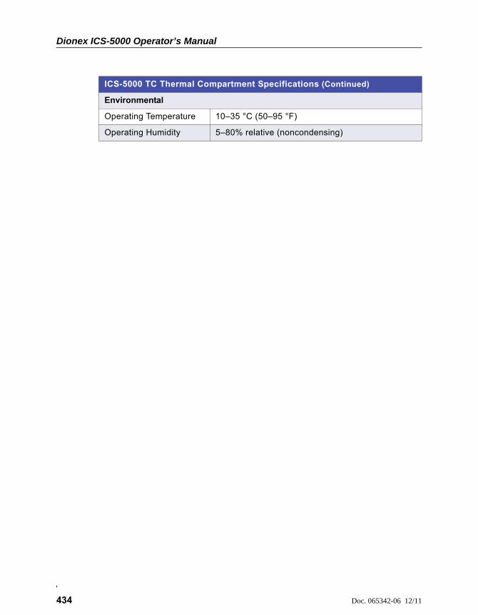
Dionex ICS-5000 Operator’s Manual
434 Doc. 065342-06 12/11
Environmental
Operating Temperature 10–35 °C (50–95 °F)
Operating Humidity 5–80% relative (noncondensing)
ICS-5000 TC Thermal Compartment Specifications (Continued)
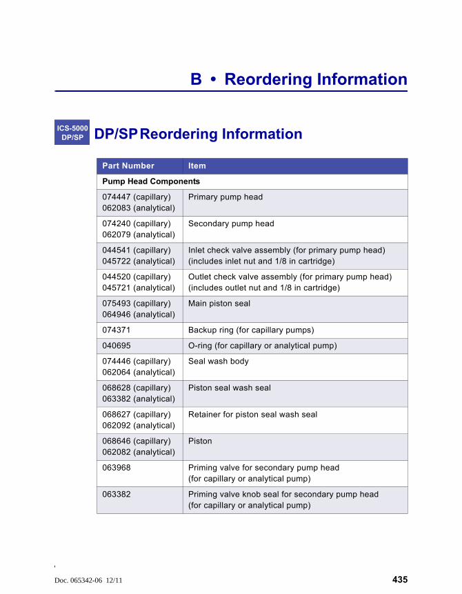
Doc. 065342-06 12/11 435
B • Reordering Information
DP/SP Reordering Information
Part Number Item
Pump Head Components
074447 (capillary)062083 (analytical)
Primary pump head
074240 (capillary)062079 (analytical)
Secondary pump head
044541 (capillary)045722 (analytical)
Inlet check valve assembly (for primary pump head)(includes inlet nut and 1/8 in cartridge)
044520 (capillary)045721 (analytical)
Outlet check valve assembly (for primary pump head)(includes outlet nut and 1/8 in cartridge)
075493 (capillary)064946 (analytical)
Main piston seal
074371 Backup ring (for capillary pumps)
040695 O-ring (for capillary or analytical pump)
074446 (capillary)062064 (analytical)
Seal wash body
068628 (capillary)063382 (analytical)
Piston seal wash seal
068627 (capillary)062092 (analytical)
Retainer for piston seal wash seal
068646 (capillary)062082 (analytical)
Piston
063968 Priming valve for secondary pump head (for capillary or analytical pump)
063382 Priming valve knob seal for secondary pump head (for capillary or analytical pump)
ICS-5000 DP/SP
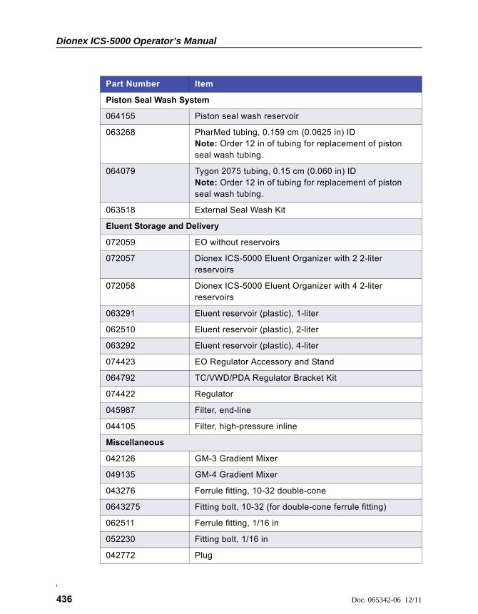
Dionex ICS-5000 Operator’s Manual
436 Doc. 065342-06 12/11
Piston Seal Wash System
064155 Piston seal wash reservoir
063268 PharMed tubing, 0.159 cm (0.0625 in) IDNote: Order 12 in of tubing for replacement of piston seal wash tubing.
064079 Tygon 2075 tubing, 0.15 cm (0.060 in) IDNote: Order 12 in of tubing for replacement of piston seal wash tubing.
063518 External Seal Wash Kit
Eluent Storage and Delivery
072059 EO without reservoirs
072057 Dionex ICS-5000 Eluent Organizer with 2 2-liter reservoirs
072058 Dionex ICS-5000 Eluent Organizer with 4 2-liter reservoirs
063291 Eluent reservoir (plastic), 1-liter
062510 Eluent reservoir (plastic), 2-liter
063292 Eluent reservoir (plastic), 4-liter
074423 EO Regulator Accessory and Stand
064792 TC/VWD/PDA Regulator Bracket Kit
074422 Regulator
045987 Filter, end-line
044105 Filter, high-pressure inline
Miscellaneous
042126 GM-3 Gradient Mixer
049135 GM-4 Gradient Mixer
043276 Ferrule fitting, 10-32 double-cone
0643275 Fitting bolt, 10-32 (for double-cone ferrule fitting)
062511 Ferrule fitting, 1/16 in
052230 Fitting bolt, 1/16 in
042772 Plug
Part Number Item
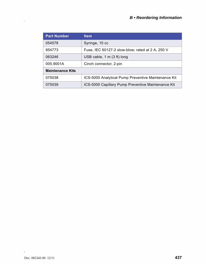
B • Reordering Information
Doc. 065342-06 12/11 437
054578 Syringe, 10 cc
954773 Fuse, IEC 60127-2 slow-blow; rated at 2 A, 250 V
063246 USB cable, 1 m (3 ft) long
005.9001A Cinch connector, 2-pin
Maintenance Kits
075038 ICS-5000 Analytical Pump Preventive Maintenance Kit
075039 ICS-5000 Capillary Pump Preventive Maintenance Kit
Part Number Item

Dionex ICS-5000 Operator’s Manual
438 Doc. 065342-06 12/11
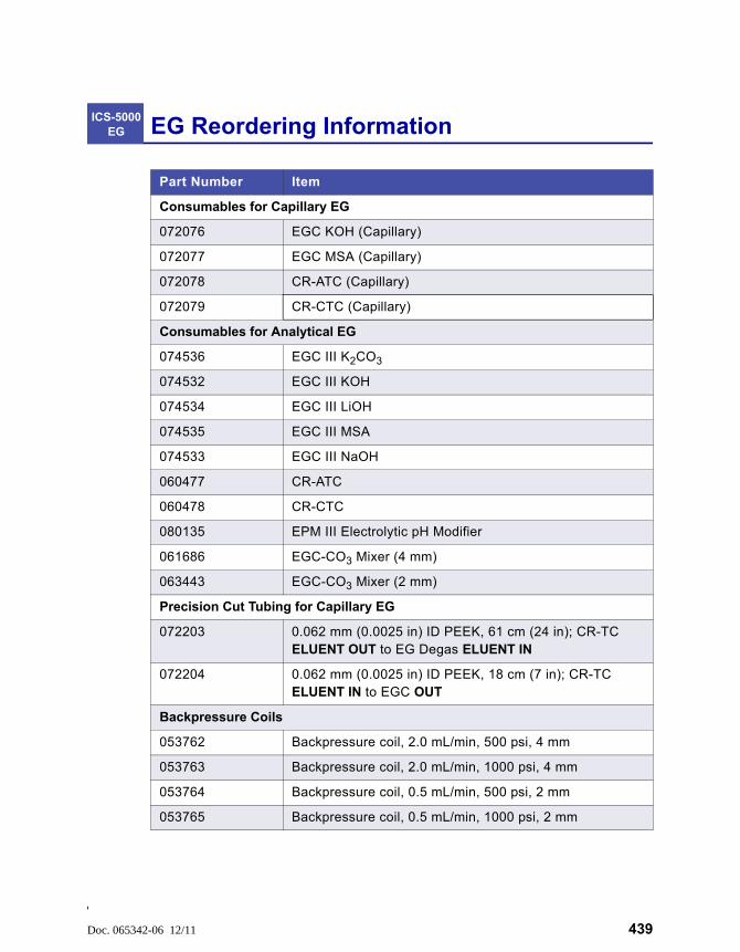
Doc. 065342-06 12/11 439
EG Reordering Information
Part Number Item
Consumables for Capillary EG
072076 EGC KOH (Capillary)
072077 EGC MSA (Capillary)
072078 CR-ATC (Capillary)
072079 CR-CTC (Capillary)
Consumables for Analytical EG
074536 EGC III K2CO3
074532 EGC III KOH
074534 EGC III LiOH
074535 EGC III MSA
074533 EGC III NaOH
060477 CR-ATC
060478 CR-CTC
080135 EPM III Electrolytic pH Modifier
061686 EGC-CO3 Mixer (4 mm)
063443 EGC-CO3 Mixer (2 mm)
Precision Cut Tubing for Capillary EG
072203 0.062 mm (0.0025 in) ID PEEK, 61 cm (24 in); CR-TC ELUENT OUT to EG Degas ELUENT IN
072204 0.062 mm (0.0025 in) ID PEEK, 18 cm (7 in); CR-TC ELUENT IN to EGC OUT
Backpressure Coils
053762 Backpressure coil, 2.0 mL/min, 500 psi, 4 mm
053763 Backpressure coil, 2.0 mL/min, 1000 psi, 4 mm
053764 Backpressure coil, 0.5 mL/min, 500 psi, 2 mm
053765 Backpressure coil, 0.5 mL/min, 1000 psi, 2 mm
ICS-5000 EG
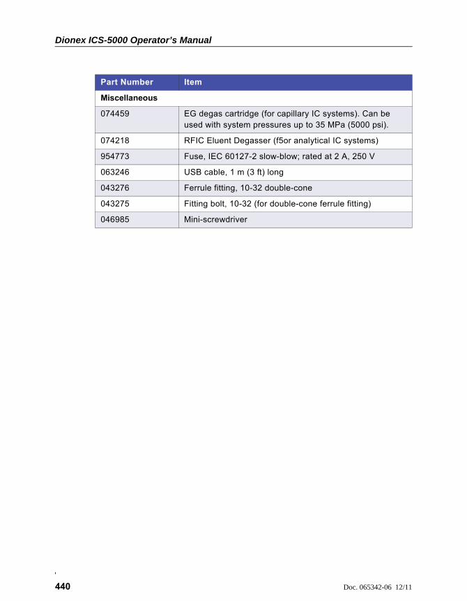
Dionex ICS-5000 Operator’s Manual
440 Doc. 065342-06 12/11
Miscellaneous
074459 EG degas cartridge (for capillary IC systems). Can be used with system pressures up to 35 MPa (5000 psi).
074218 RFIC Eluent Degasser (f5or analytical IC systems)
954773 Fuse, IEC 60127-2 slow-blow; rated at 2 A, 250 V
063246 USB cable, 1 m (3 ft) long
043276 Ferrule fitting, 10-32 double-cone
043275 Fitting bolt, 10-32 (for double-cone ferrule fitting)
046985 Mini-screwdriver
Part Number Item
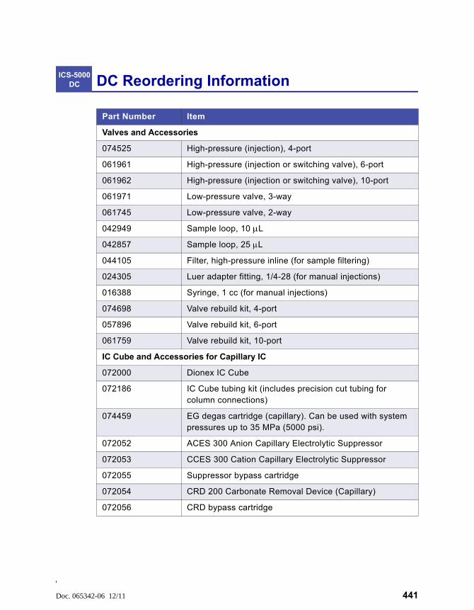
Doc. 065342-06 12/11 441
DC Reordering Information
Part Number Item
Valves and Accessories
074525 High-pressure (injection), 4-port
061961 High-pressure (injection or switching valve), 6-port
061962 High-pressure (injection or switching valve), 10-port
061971 Low-pressure valve, 3-way
061745 Low-pressure valve, 2-way
042949 Sample loop, 10 L
042857 Sample loop, 25 L
044105 Filter, high-pressure inline (for sample filtering)
024305 Luer adapter fitting, 1/4-28 (for manual injections)
016388 Syringe, 1 cc (for manual injections)
074698 Valve rebuild kit, 4-port
057896 Valve rebuild kit, 6-port
061759 Valve rebuild kit, 10-port
IC Cube and Accessories for Capillary IC
072000 Dionex IC Cube
072186 IC Cube tubing kit (includes precision cut tubing for column connections)
074459 EG degas cartridge (capillary). Can be used with system pressures up to 35 MPa (5000 psi).
072052 ACES 300 Anion Capillary Electrolytic Suppressor
072053 CCES 300 Cation Capillary Electrolytic Suppressor
072055 Suppressor bypass cartridge
072054 CRD 200 Carbonate Removal Device (Capillary)
072056 CRD bypass cartridge
ICS-5000 DC
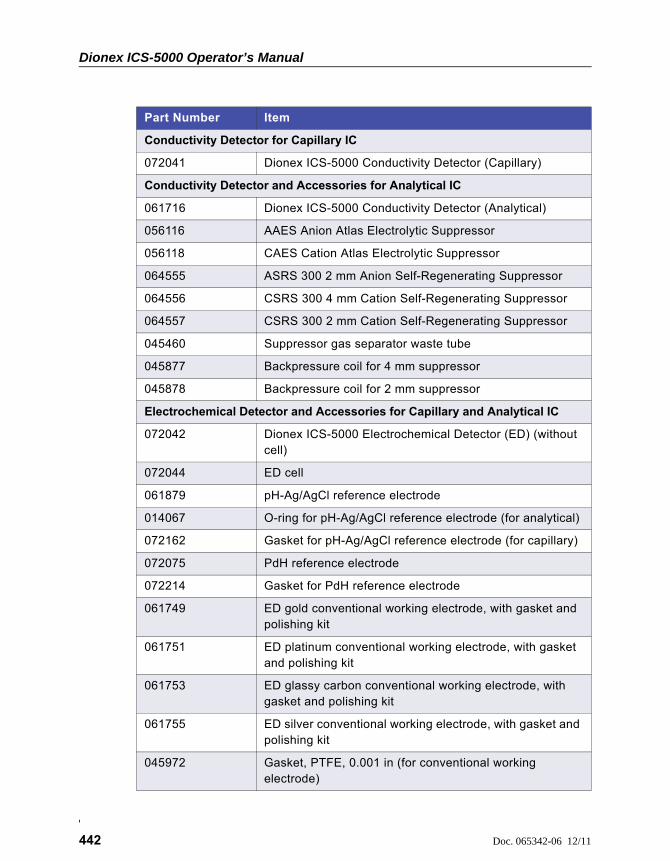
Dionex ICS-5000 Operator’s Manual
442 Doc. 065342-06 12/11
Conductivity Detector for Capillary IC
072041 Dionex ICS-5000 Conductivity Detector (Capillary)
Conductivity Detector and Accessories for Analytical IC
061716 Dionex ICS-5000 Conductivity Detector (Analytical)
056116 AAES Anion Atlas Electrolytic Suppressor
056118 CAES Cation Atlas Electrolytic Suppressor
064555 ASRS 300 2 mm Anion Self-Regenerating Suppressor
064556 CSRS 300 4 mm Cation Self-Regenerating Suppressor
064557 CSRS 300 2 mm Cation Self-Regenerating Suppressor
045460 Suppressor gas separator waste tube
045877 Backpressure coil for 4 mm suppressor
045878 Backpressure coil for 2 mm suppressor
Electrochemical Detector and Accessories for Capillary and Analytical IC
072042 Dionex ICS-5000 Electrochemical Detector (ED) (without cell)
072044 ED cell
061879 pH-Ag/AgCl reference electrode
014067 O-ring for pH-Ag/AgCl reference electrode (for analytical)
072162 Gasket for pH-Ag/AgCl reference electrode (for capillary)
072075 PdH reference electrode
072214 Gasket for PdH reference electrode
061749 ED gold conventional working electrode, with gasket and polishing kit
061751 ED platinum conventional working electrode, with gasket and polishing kit
061753 ED glassy carbon conventional working electrode, with gasket and polishing kit
061755 ED silver conventional working electrode, with gasket and polishing kit
045972 Gasket, PTFE, 0.001 in (for conventional working electrode)
Part Number Item
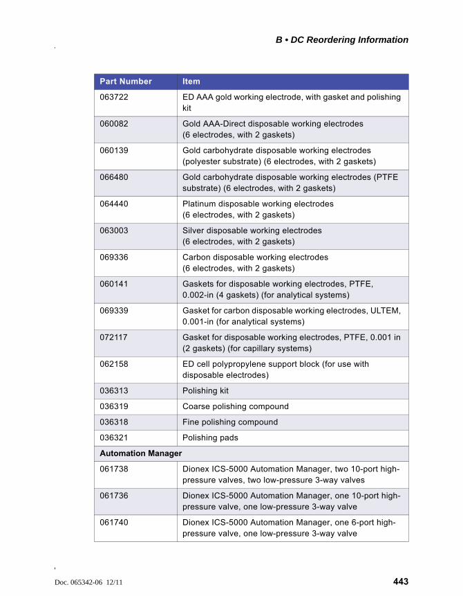
B • DC Reordering Information
Doc. 065342-06 12/11 443
063722 ED AAA gold working electrode, with gasket and polishing kit
060082 Gold AAA-Direct disposable working electrodes (6 electrodes, with 2 gaskets)
060139 Gold carbohydrate disposable working electrodes (polyester substrate) (6 electrodes, with 2 gaskets)
066480 Gold carbohydrate disposable working electrodes (PTFE substrate) (6 electrodes, with 2 gaskets)
064440 Platinum disposable working electrodes (6 electrodes, with 2 gaskets)
063003 Silver disposable working electrodes (6 electrodes, with 2 gaskets)
069336 Carbon disposable working electrodes (6 electrodes, with 2 gaskets)
060141 Gaskets for disposable working electrodes, PTFE, 0.002-in (4 gaskets) (for analytical systems)
069339 Gasket for carbon disposable working electrodes, ULTEM, 0.001-in (for analytical systems)
072117 Gasket for disposable working electrodes, PTFE, 0.001 in (2 gaskets) (for capillary systems)
062158 ED cell polypropylene support block (for use with disposable electrodes)
036313 Polishing kit
036319 Coarse polishing compound
036318 Fine polishing compound
036321 Polishing pads
Automation Manager
061738 Dionex ICS-5000 Automation Manager, two 10-port high-pressure valves, two low-pressure 3-way valves
061736 Dionex ICS-5000 Automation Manager, one 10-port high-pressure valve, one low-pressure 3-way valve
061740 Dionex ICS-5000 Automation Manager, one 6-port high-pressure valve, one low-pressure 3-way valve
Part Number Item
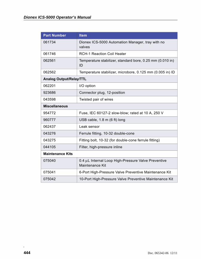
Dionex ICS-5000 Operator’s Manual
444 Doc. 065342-06 12/11
061734 Dionex ICS-5000 Automation Manager, tray with no valves
061746 RCH-1 Reaction Coil Heater
062561 Temperature stabilizer, standard bore, 0.25 mm (0.010 in) ID
062562 Temperature stabilizer, microbore, 0.125 mm (0.005 in) ID
Analog Output/Relay/TTL
062201 I/O option
923686 Connector plug, 12-position
043598 Twisted pair of wires
Miscellaneous
954772 Fuse, IEC 60127-2 slow-blow; rated at 10 A, 250 V
960777 USB cable, 1.8 m (6 ft) long
062437 Leak sensor
043276 Ferrule fitting, 10-32 double-cone
043275 Fitting bolt, 10-32 (for double-cone ferrule fitting)
044105 Filter, high-pressure inline
Maintenance Kits
075040 0.4 L Internal Loop High-Pressure Valve Preventive Maintenance Kit
075041 6-Port High-Pressure Valve Preventive Maintenance Kit
075042 10-Port High-Pressure Valve Preventive Maintenance Kit
Part Number Item
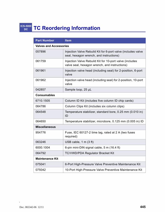
Doc. 065342-06 12/11 445
TC Reordering Information
Part Number Item
Valves and Accessories
057896 Injection Valve Rebuild Kit for 6-port valve (includes valve seal, hexagon wrench, and instructions)
061759 Injection Valve Rebuild Kit for 10-port valve (includes valve seal, hexagon wrench, and instructions)
061961 Injection valve head (including seal) for 2-position, 6-port valve
061962 Injection valve head (including seal) for 2-position, 10-port valve
042857 Sample loop, 25 µL
Consumables
6710.1505 Column ID Kit (includes five column ID chip cards)
064786 Column Clips Kit (includes six column clips)
064548 Temperature stabilizer, standard bore, 0.25 mm (0.010 in) ID
064650 Temperature stabilizer, microbore, 0.125 mm (0.005 in) ID
Miscellaneous
954776 Fuse, IEC 60127-2 time lag, rated at 2 A (two fuses required)
063246 USB cable, 1 m (3 ft)
6000.1004 6-pin mini-DIN signal cable, 5 m (16.4 ft)
064792 TC/VWD/PDA Regulator Bracket Kit
Maintenance Kit
075041 6-Port High-Pressure Valve Preventive Maintenance Kit
075042 10-Port High-Pressure Valve Preventive Maintenance Kit
ICS-5000 DC

Dionex ICS-5000 Operator’s Manual
446 Doc. 065342-06 12/11

Doc. 065342-06 12/11 Index-1
Symbols% Offset (analog out), 86+5V output (DC), 83, 87
Numerics10-port valve
AM, 96DC, 65 – 67TC, 123See also High-pressure valves
2D dataIntegrated amperometry, 107, 109Pulsed amperometry, 109
3D amperometry data, 111 – 1133D plot description, 112 – 113Chromatogram, 111Definition, 110Displayed in Chromeleon, 110Isoamperometric plot description, 112I-t plot, 111
3-way low-pressure valvesSee Low-pressure valves
4-port valve, 666-port valve
DC, 65, 96TC, 122, 124See also High-pressure valves, Injection
valves
AAAES, 71AC sockets (DC), 81ACES 300, 57ACES 300 (Capillary), 71Acetonitrile, 76
Ag/AgCl half-cell, 77Air bubbles (conductivity cell), 383Air particulate samples, 147Air pressure requirements, 146, 154Alarm conditions
See Error messagesAlarm LED (DC), 51Alarm LED (DP/SP), 22Alarm LED (EG), 256
LED is lighted, 253Troubleshooting, 253
Alarm LED (TC), 115Amperometry cell
Cell design, 76Cell gasket replacement, 386Description, 75Electrodes, 75Maintenance, 143Monitoring the pH readout, 78Operating precautions, 143pH cannot be set to 7.0, 272pH limits, 145Polishing the working electrode, 389Reordering, 442Solvent compatibility, 76Storage, 187Troubleshooting, 271
Amperometry detectionSee Cyclic voltammetrySee DC amperometrySee Integrated amperometrySee Pulsed amperometry
Analog output, 85Connection instructions, 84Connectors, 82 – 83Description, 85Full-scale, 86Mark, 86
Index
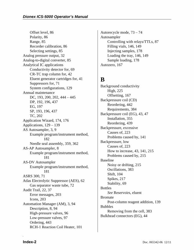
Dionex ICS-5000 Operator’s Manual
Index-2 Doc. 065342-06 12/11
Offset level, 86Polarity, 86Range, 85Recorder calibration, 86Selecting settings, 85
Analog pressure output, 32Analog-to-digital converter, 85Analytical IC applications
Conductivity detector for, 69CR-TC trap column for, 42Eluent generator cartridges for, 41Suppressors for, 71System configurations, 129
Annual maintenanceDC, 193, 200, 202, 444 – 445DP, 192, 196, 437EG, 197SP, 193, 196, 437TC, 202
Application Wizard, 174, 176Applications, 129 – 139AS Autosampler, 3, 9
Example program/instrument method, 182
Needle seal assembly, 359, 362AS-AP Autosampler, 8
Example program/instrument method, 181
AS-DV AutosamplerExample program/instrument method,
181ASRS 300, 71Atlas Electrolytic Suppressor (AES), 62
Gas separator waste tube, 72Audit Trail, 22, 37
Error messages, 203Icons, 203
Automation Manager (AM), 3, 94Description, 8, 94High-pressure valves, 96Low-pressure valves, 97Ordering, 443RCH-1 Reaction Coil Heater, 101
Autorecycle mode, 73 – 74Autosampler
Controlling with relays/TTLs, 87Filling vials, 146, 149Injecting samples, 178Loading the tray, 146, 149Sample loading, 178
Autozero, 167
BBackground conductivity
High, 225Offsetting, 167
Backpressure coil (CD)Reordering, 442Requirements, 384
Backpressure coil (EG), 43, 47Installation, 355Reordering, 439
Backpressure, excessiveCauses of, 223Problems caused by, 141
Backpressure, lowCauses of, 223How to increase, 43, 141, 215Problems caused by, 215
BaselineNoisy or drifting, 215Oscillations, 383Shift, 104Spikes, 217Stability, 69
BottlesSee Reservoirs, eluent
BromatePost-column reagent addition, 139
BubblesRemoving from the cell, 383
Bulkhead connectors (EG), 44
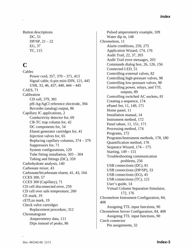
Index
Doc. 065342-06 12/11 Index-3
Button descriptionsDC, 51DP/SP, 21 – 22EG, 37TC, 115
CCables
Power cord, 357, 370 – 371, 413Signal cable, 6-pin mini-DIN, 121, 445USB, 33, 46, 437, 440, 444 – 445
CAES, 71Calibration
CD cell, 379, 381pH-Ag/AgCl reference electrode, 394Recorder (analog) output, 86
Capillary IC applications, 2Conductivity detector for, 69CR-TC trap column for, 42DC components for, 54Eluent generator cartridges for, 41Injection valves for, 65Replacing capillary columns, 374 – 379Suppressors for, 71System configurations, 129Tube fitting installation, 303 – 304Tubing and fittings (DC), 359
Carbohydrate analysis, 140Carbonate mixer, 43Carbonate/bicarbonate eluent, 41, 43, 164CCES 300, 57CCES 300 (Capillary), 71CD cell disconnected error, 259CD cell over safe temperature, 260CE mark, 19cETLus mark, 19Check valve cartridges
Replacement procedure, 312Chromatogram
Amperometry data, 111Dips instead of peaks, 86
Pulsed amperometry example, 109Water dip in, 148
Chromeleon, 11Alarm conditions, 259, 275Application Wizard, 174, 176Audit Trail, 22, 37, 203Audit Trail error messages, 203Commands dialog box, 26, 126, 156Connected LED, 51Controlling external valves, 82Controlling high-pressure valves, 98Controlling low-pressure valves, 98Controlling power, relays, and TTL
outputs, 89Controlling switched AC sockets, 81Creating a sequence, 174ePanel Set, 11, 149, 171Home panel, 11Installation manual, 14Instrument method, 172Panel tabset, 11, 151, 171Processing method, 174Programs, 172Programs/Instrument methods, 178, 180Quantification method, 176Sequence Wizard, 174 – 175Starting, 149 – 151Troubleshooting communication
problems, 256USB connections (DC), 81USB connections (DP/SP), 33USB connections (EG), 45USB connections (TC), 121User’s guide, 14Virtual Column Separation Simulator,
172, 176Chromeleon Instrument Configuration, 84, 408
Assigning TTL input functions, 90Chromeleon Server Configuration, 84, 408
Assigning TTL input functions, 90Cinch connector
Pin assignments, 32
Dionex ICS-5000 Operator’s Manual
Index-4 Doc. 065342-06 12/11
CMMS, 71Column clips
Reordering, 445Column ID chip card, 118, 125
Reordering, 445Slots for installation, 118
Column ID system, 125Chip card readers, 118Installing a chip card, 409Selecting a column, 408Selecting column properties, 409
Column open circuit, 260Column over safe temperature, 260, 266Column properties
Primary, 125, 290, 295Secondary, 125Selecting for column ID system, 409
ColumnsSizes available, 62
CommandsAS Autosampler control, 182AS-AP Autosampler control, 181AS-DV Autosampler control, 181Creating a program, 172
Commands dialog box, 26, 126, 156Compartment open circuit, 261Compartment over safe temperature, 261Concentrator column, 68, 123Condensation, 199Conductivity Detector (CD), 3, 7
Air bubble removal, 383Analytical IC system version, 69Capillary IC system version, 69Cell calibration, 379Cell description, 69Cell temperature control, 69Description, 69Effect of temperature on conductivity, 69Leaking, 270Replacement procedure, 382Specifications, 427Temperature compensation, 70
Configuration drawings, 129 – 139
Connected LED (DC)LED is lighted, 51
Connected LED (DP/SP)LED is lighted, 22
Connected LED (EG)LED is lighted, 37, 115
Connected LED (TC)LED is lighted, 115
Counter electrode, 75 – 76CRD bypass cartridge (for IC Cube), 56CRD cartridge (for IC Cube), 56CR-TC trap column, 5, 42
Contamination, 225Hydration procedure, 351Replacement procedure, 349 – 354
CSRS 300, 71Cyclic voltammetry, 105
Data collection rate, 105Example, 106Sweep rate, 106Triangle waveform, 106Waveforms, 105, 107
DDaily maintenance
DC, 199DP/SP, 195EG, 197TC, 201
DataDisplaying 3D amperometry data, 110Reprocessing amperometry data, 109
Data collection rateCyclic voltammetry, 105Electrochemical detector, 110Integrated amperometry, 107
Data compressionCyclic voltammetry, 105
DC amperometry, 102Entering the potential, 102
DC Temperature Calibration Kit, 64

Index
Doc. 065342-06 12/11 Index-5
Declaration of Conformity, 19Degassing eluents, 25Deionized water requirements, 20Detector
See Conductivity Detector (CD)See Electrochemical Detector (ED)
Detector outputLow, 224
Detector/Chromatography Module (DC), 2, 7Alarm LED is lighted, 51Automation Manager (AM), 94Electrochemical Detector (ED), 75Flow schematics, 73 – 74Front description, 51I/O option, 83Maintenance, 199Rebuilding the injection valve, 366Service procedures, 359Spare parts, 441Specifications, 423System configuration, 129Temperature control, 63
Disposable working electrodes, 75Reordering, 443
Drain portTC, 121
Drifting baseline, 215Dual Pump (DP), 2 – 3
Analog pressure output, 32Digital I/O port, 31Fuse replacement, 330Fuses, 31Maintenance, annual, 196Maintenance, daily, 195Maintenance, periodic, 196Maintenance, weekly, 195Operating humidity, 417Operating temperature, 417Piston replacement procedure, 323Piston seal replacement procedure, 316 –
321, 323 – 324Piston seal wash tubing replacement
procedure, 326
Pressure limit tripped, 223, 255 – 256Pressure limits for EG, 158Priming procedures, 308 – 311Priming valve knob seal replacement, 329Product warranty, 303Pulse damper (for capillary pump), 27Selecting pressure limits, 158Shutdown procedure, 183Spare parts, 435Specifications, 415Start-up procedures, 153Static mixer, 27Status bar buttons and LEDs, 21System configurations, 129, 137USB connections, 33Waste lines, 33
Dual system configuration, 132, 135 – 136
EEC cell
See Amperometry cellED cell
See Amperometry cellED cell disconnected error, 261 – 264EGC
See Eluent generator cartridgesElectrochemical detection
DC amperometry, 102Integrated amperometry, 103Pulsed amperometry, 103
Electrochemical Detector (ED), 3, 7, 75, 4293D data, 111 – 113Amperometric cell description, 75Data storage, 109Description, 61, 75Detection modes, 75, 102Palladium hydrogen (PdH) reference
electrode, 79pH-Ag/AgCl reference electrode, 77Reordering information, 442Replacement procedure, 404
Dionex ICS-5000 Operator’s Manual
Index-6 Doc. 065342-06 12/11
Shutdown procedure, 187Working electrodes, 75See also Amperometry cell
Electrodes, 76Reference, 75Working, 75
Electrolysis gasesPurging from eluent, 43, 58, 141Venting from system, 46
Eluemt generator cartridges, 5Eluent concentration, 161 – 163Eluent generation
Electrolysis gases, 43, 58Eluent Generator (EG), 2, 5
Alarm LED is lighted, 253, 256Analytical IC systems, 40Backpressure, 43Backpressure coil, 215Capillary IC system, 39Component description, 38, 41 – 43Degas cartridge (for IC Cube), 58Electrical connections (consumables), 44Eluent concentration ranges, 161 – 163Eluent generator cartridges, 5Fuse cartridge, 46Fuses, 46Gas vent line, 46Leak sensor, 43, 252Liquid flow path, 47 – 49Liquid leaks, 253 – 254Main power switch, 46Maintenance, 197Operating precautions, 141Power LED does not light, 254Pump pressure limits, 256Rear panel description, 45 – 46Selecting the eluent concentration, 161Shutdown procedures, 185Spare parts, 439Specifications, 419Status bar buttons and LEDs, 37System configuration, 129USB connections, 45
Waste lines, 46 – 47Eluent generator cartridges, 41
Backpressure requirement, 43, 141 – 142, 255 – 256
Conditioning procedure, 186Electrical connections, 44Frit, outlet, 223, 336Leaks, 223, 253 – 254Replacement procedure, 336 – 349Selecting the eluent concentration, 161Start-up procedures, 186Storage, long-term, 186Storage, short-term, 185
Eluent Organizer (EO), 2, 6, 34Eluent proportioning valves, 25Eluent reservoirs
See Reservoirs, eluentEluent, filtering, 36Eluents
Aqueous, 196Degassing, 25Filtering, 153Flushing lines after eluent change, 218Monitoring pH, 77Outgassing, 383
End-line filterSee Filter, end-line
EO Regulator Kit, 35ePanel Set, 11, 149, 171EPM III Electrolytic pH Modifier, 41, 43 –44, 252
Equilibration, 166, 170Error messages
Audit Trail description, 203DC summary, 207DP/SP summary, 204EG summary, 205TC summary, 209
Error messages (DC), 259 – 269CD cell disconnected, 259CD cell over safe temperature, 260Column open circuit, 260Column over safe temperature, 260, 266
Index
Doc. 065342-06 12/11 Index-7
Compartment open circuit, 261Compartment over safe temperature, 261ED cell disconnected, 261 – 264High-pressure valve error, 265Lower leak sensor wet, 267Reaction coil open circuit, 267Reaction coil over safe temperature, 268Suppressor over current, 268Suppressor over power, 268Suppressor over voltage, 269Upper leak sensor wet, 269
Error messages (DP/SP), 227 – 234Abnormal drive current, 227Camshaft index too early, 228Camshaft index too late, 228Camshaft sensor always alight, 228Degasser malfunction, 228Excessive drive current, 229Function cannot be adjusted by user, 234Invalid flow value, 229Leak detected, 229Maximum purge pressure exceeded, 232Motor malfunction, 230Motor position error, 230Pressure fallen below lower limit, 231Pressure in working cylinder exceeded
safety limit, 233Program with this name already exists,
227Pump block carryover pressure too high,
230Relay 4 configured for inject
synchronization, 232System pressure exceeded safety limit,
233Upper pressure limit exceeded, 234
Error messages (EG), 241 – 253CR-TC mode is off for a virtual pump.,
243CR-TC over current, 242CR-TC stopped due to zero flow, 243EG cartridge disconnected, 244EG invalid concentration, 245
EG invalid flow, 246EG invalid flow rate-concentration, 246EG over current, 247EG over power, 248EG over voltage, 248 – 249Leak sensor wet, 252
Error messages (TC)AcqOff with previous AcqOn, 275Acquisition still on at program end, 275All samples must specify same value, 275Can’t execute Disconnect command, 276Can’t execute Standby command, 276Can’t find TC3000.HEX image, 276Can’t start acquisition, 277Can’t start TC firmware, 277Can’t use device x, 278Card data checksum error, 279Command unavailable in demo mode,
279Communication error, 279Communication interface is closed, 292Communication time-out, 280Compartment door is open, 293Configuration doesn’t match, 280Configuration mismatch, 280Counter x exceeded its limit, 293Current flow out of limits, 280Current pressure out of limits, 281Current temperature out of limits, 281Data buffer overrun, 281Data format on chip card unsupported,
293Device control feature not available, 282Device is not remote, 282Device not found on USB, 283Either the current date is . . ., 283Error deleting flash memory, 283Error during storing of card data, 284Error finishing download, 277Error programming flash memory, 284Executing this command will reset . . .,
284Firmware download in progress, 285
Dionex ICS-5000 Operator’s Manual
Index-8 Doc. 065342-06 12/11
Gas leak detected, 285Humidity leak detected, 285Illegal parameter, 286Injections limit has been exceeded, 294Injections limit will be exceeded, 294Invalid date/time format, 286Invalid enumerated value, 286Next qualification is due, 286Next qualification is overdue, 287Next qualification was due on . . ., 287Next service is due in . . ., 287Next service is overdue, 287No chip card in reader, 288No response from x, 288Nominal temperature must be set . . ., 294Nominal temperature value out of range,
294Operating columns above . . ., 289Oven not fully operable, 294Parameter x value exceeded . . ., 289Primary column ID property . . ., 295Primary property x already assigned, 290Properties cannot be changed, 290 – 291Raw data file x cannot be created, 291Raw data file x cannot be written, 291Starting data acquisition manually . . .,
292TC firmware download failed, 277TC is not remote, 282The command can format . . ., 292There was already an AcqOff . . ., 296There was already an AcqOn . . ., 296This function cannot be adjusted, 297This operation may affect . . ., 297Two AcqOn commands for channel, 296Unknown error code, 297Unknown format of card data, 297Upper limit must be higher . . ., 295USB/LAN communication error, 283Value for parameter is not within . . ., 289Value x replaced by . . ., 289Warning threshold must be higher . . .,
296
Warning threshold must be lower . . ., 296X position error, 298You do not have the privilege . . ., 298
eWorkflows, 173External low-pressure valves (DC), 82External Seal Wash Kit, 27, 154, 436
FFilter, end-line
Bacterial contamination, 196InstallationMaintenance, 195
Filter, inline, 36Fittings (DC)
Replacing, 359Requirements, 359
Fittings (DP/SP)Replacing, 306Requirements, 306
Fittings (EG)Replacing, 333Requirements, 333
Fittings (TC)Replacing, 407Requirements, 407
Flow restrictions, 196Front description (DC)
Buttons and LEDs, 51Front description (DP/SP)
Buttons and LEDs, 21 – 22Front description (EG)
Buttons and LEDs, 37Front description (TC)
LEDs, 115Full-scale analog output, 86
Response range, 85Voltage output ranges, 85
Fuses (DC), 81Replacement procedure, 371
Fuses (DP/SP), 30Replacement procedure, 330
Index
Doc. 065342-06 12/11 Index-9
Fuses (EG), 46Replacement procedure, 357
Fuses (TC), 119Replacement procedure, 413
GGas leak in TC, 115, 126, 285Gas sensor, 126, 285Gas separator waste tube, 72
Installation, 142Reordering, 442
Gas vent line (EG), 46Glassy carbon electrodes, 75GM-3 Gradient Mixer, 27, 219, 436GM-4 Gradient Mixer, 27, 219, 436Gold electrodes, 75Gradient proportioning valves, 25
HHalf-cells, 77Heater
Conductivity cell, 69Reaction coil, 101
High pressure limitLimit is tripped, 233 – 234Selecting, 158
High-pressure fittings, 305High-pressure inline filter, 36High-pressure valve error, 265High-pressure valves (AM)
Controlling, 98Flow schematics, 96Installed in AM, 94Rebuilding, 366Reordering, 441Replacing, 367
High-pressure valves (DC), 6510-port valve, 684-port valve, 666-port valve, 67
For analytical IC system, 65For capillary IC system, 65
High-pressure valves (TC), 117, 122Reordering, 445
Humidity leak in TC, 115, 126, 285Humidity sensor, 126, 285Hybrid system configuration, 129, 132
II/O option (DC), 82 – 83, 444
+5V output, 83Analog outputs, 83Connections, 84Power output, 87Relay outputs, 83TTL inputs and outputs, 83
IC Cube, 55Cartridge replacement procedure, 372 –
373Column cartridge, 58Column heater, 58CRD bypass cartridge, 56CRD cartridge, 56EG degas cartridge, 58Flow schematic for conductivity
detection, 59Flow schematic for electrochemical
detection, 60Suppressor bypass cartridge, 57Suppressor cartridge, 57Tubing and fittings, 360
ICS-5000 Automation Manager (AM)See Automation Manager (AM)
ICS-5000 Conductivity Detector (CD)See Conductivity Detector (CD)
ICS-5000 Detector/Chromatography ModuleSee Detector/Chromatography Module
(DC)ICS-5000 Dual Pump (DP)
See Dual Pump (DP)ICS-5000 Electrochemical Detector (ED)
Dionex ICS-5000 Operator’s Manual
Index-10 Doc. 065342-06 12/11
See Electrochemical Detector (ED)ICS-5000 Eluent Generator (EG)
See Eluent Generator (EG)ICS-5000 Eluent Organizer (EO)
See Eluent Organizer (EO)ICS-5000 IC System
Overview, 1 – 2, 11Software control, 11User manuals, 14 – 15
ICS-5000 Single Pump (SP)See Single Pump (SP)
ICS-5000 Thermal Compartment (TC)See Thermal Compartment (TC)
Injecting samples, 180Injection ports
Loading with a syringe, 179Injection valves (DC), 65
Flow schematics (10-port valve), 68Flow schematics (4-port valve), 66Flow schematics (6-port valve), 67Leaking, 270Operation, 65 – 68Rebuilding, 366Reordering, 441Replacing mechanical parts (Pod), 367Types available, 62
Injection valves (TC), 122Flow schematics (10-port valve), 123Flow schematics (6-port valve), 122Leaking, 300Operation, 122 – 123Plumbing (6-port valve), 124Rebuilding, 366, 410Replacing mechanical parts (pod), 411Types available, 117
Inline filter, 36Instrument method (Chromeleon), 172Integrated amperometry, 103
3D data, 109Data storage, 109Integration interval, 104, 107Waveform characteristics, 107Waveform example, 104
Interior components (DC), 53Analytical IC components, 61Conductivity Detector (CD), 54, 61Electrochemical Detector (ED), 54, 61IC Cube, 55Lower compartment description, 62Suppressor types, 62Upper compartment description (for
analytical IC), 61Upper compartment description (for
capillary IC), 54Inverted edge TTL input control (DC), 93Inverted pulse TTL input control (DC), 93IonPac ATC-HC Trap Column, 42IonPac CTC-1 Trap Column, 42IPAD
See Integrated amperometryI-t plot, 111
LLeak sensor (EG), 43, 252Leak sensors (DC)
Lower leak sensor wet alarm, 267Replacement, 364Upper leak sensor wet alarm, 269
Leak sensors (TC)Gas, 126, 285Humidity, 126, 285
LeaksConductivity cell, 270DC, 270EG, 43, 252Gas, 115, 126, 285, 299Humidity, 115, 126, 285, 299Injection valve (DC), 270Injection valve (TC), 300Reference electrode, 274Suppressor, 270Temperature stabilizer (TC), 300
LED descriptions (DC), 51, 115LED descriptions (DP/SP), 21 – 22
Index
Doc. 065342-06 12/11 Index-11
LED descriptions (EG), 37LED descriptions (TC), 115Lithium hydroxide eluent, 41Loading samples, 178
With a syringe, 178With a vacuum syringe, 179With an autosampler, 178
Loading the autosampler tray, 146, 149Low detector output, 224Low pressure limit
Selecting, 158Lower compartment (DC)
Description, 62Lower oven LED, 51Low-pressure valves, 82
Controlling, 98External valve outputs (DC), 82Flow schematic, 97Installed in AM, 94Reordering, 441
Luer adapter fittingReordering, 441
MMain power receptacle
DC, 81DP/SP, 30EG, 46TC, 119
Main power switchDC, 81DP/SP, 30EG, 46TC, 119
Maintenance, annualDC, 200DP, 196EG, 197SP, 196TC, 202
Maintenance, daily
DC, 199, 201DP/SP, 195EG, 197TC, 201
Maintenance, periodicDP/SP, 196TC, 201
Maintenance, weeklyDC, 199DP/SP, 195EG, 197TC, 201
Manuals for ICS-5000 system, 14 – 15Mark (analog output), 86Matrix elimination, 61, 94
System configuration, 137 – 138Methanesulfonic acid eluent, 41Methanol, 76Microbore IC applications, 2MicroMembrane Suppressor (MMS), 62, 71
See also SuppressorMixer, static, 27Mobile phases
See EluentsModuleware, 203MSQ Plus Mass Spectrometer, 3, 10
NNeedle seal assembly (AS), 359, 362Nitrite in samples, 147Noisy baseline, 215Normal edge TTL input control (DC), 93Normal pulse TTL input control (DC), 93
OOffset percentage (analog out), 86Offsetting background conductivity, 167Open circuit, 267Operating temperature
DP/SP, 417

Dionex ICS-5000 Operator’s Manual
Index-12 Doc. 065342-06 12/11
OperationAnalyzing samples, 172Creating a sequence, 173 – 174Direct control of modules, 171Filling vials, 146, 149Loading samples, 178Overview, 172Sample preparation, 147Starting a sequence, 176 – 177
Organic solvent, 77Oven (TC), 116
See also Temperature control (TC)Oven LED (TC)
LED is flashing, 116, 300LED is lighted, 116
Oven LEDs (DC)LED is flashing, 51LED is lighted, 51
PPAD
See Pulsed amperometryPalladium hydrogen (PdH) reference electrode, 79
Replacement procedure, 400Panel tabset, 11
Home panel, 11, 149, 151How to display, 157, 165, 169, 255 – 256
ParametersChromeleon commands, 172
Peak heightReproducibility, 69
PeaksFronting, 118Reversed, 86Tailing, 118, 222
Periodic maintenanceDC, 199DP/SP, 196TC, 201
pH gradient, 77
pH half-cell, 77pH limits, 145pH modifier, 43pH reading
Adjusting potentials for, 77Always 7.0, 271Cannot be set to 7.0, 272Effect on potentials, 77Monitoring, 78Nonexistent, 273
pH-Ag/AgCl reference electrode, 75, 77Long-term storage, 187O-ring replacement procedure, 399Replacement procedure, 392See also Reference electrode
Photodiode Array Detector, 3, 9Regulator Bracket Kit, 35
Piston seal wash solution, 26, 183Piston seal wash system, 26, 154
Activation, 26Dual pump seal wash option, 27, 154, 436Replumbing the DP connections, 154Setup, 156
Piston sealsReplacement procedure, 316
PistonsReplacement procedure, 323
Platinum working electrodes, 75Plot, I-t, 111Plumbing
Replacing DC tubing and fittings, 359Replacing DP/SP tubing and fittings, 306Replacing EG tubing and fittings, 333Replacing TC tubing and fittings, 407
Plumbing configuration drawings, 129 – 139Polarity
Analog output, 86Polishing kit (ED)
Reordering, 443Polishing working electrodes, 389Post-column reagent addition, 61, 94, 139Potassium carbonate eluent, 41, 43Potassium hydroxide eluent, 41
Index
Doc. 065342-06 12/11 Index-13
Potential shifting, 77, 274Power cord, 357, 370 – 371, 413Power LED (DC), 52Power LED (DP/SP), 22Power LED (EG), 38Power LED (TC), 116Power output (DC)
I/O option, 82 – 83, 87Power receptacle
DC, 81DP/SP, 30EG, 46TC, 119
Power switch (rear panel)DC, 81DP/SP, 30EG, 46TC, 119
Pre-concentration, 61, 94Predictive Performance, 128Pressure limit settings, 158Pressure limits tripped, 223Pressure transducer, 25Pressurizable eluent reservoirs
Installation, 35Priming procedures (DP/SP), 308 – 309
From the Control panel, 310Priming with a syringe, 310 – 311Priming with the Prime button, 310 – 311With the Prime button, 310
Priming valveLeakage from knob, 238Seal knob replacement procedure, 329
ProblemsSee Troubleshooting
Processing samples, 172Product warranty, voiding, 303Program Wizard
Waveforms, 108Programs (Chromeleon)
Autosampler control, 178, 180Creating programs, 172
Proportioning valves, 25
Leaks, 237Malfunction, 218, 220
Pulse damper (for capillary pump), 27Pulsed amperometry, 103
3D data, 109Chromatogram example, 110Data storage, 109Integration interval, 103Waveform example, 103See also Integrated amperometry
PumpSee Dual Pump (DP), Single Pump (SP)
QQuantification method, 176
RRaw data, 110RCH-1 Reaction Coil Heater, 101
Controlling, 101Installed in AM, 94Open circuit error, 267Over safe temperature, 268Reordering, 444
Reagent-Free IC (RFIC), 1System configurations, 129 – 140
Rear panel (DC), 82AC sockets, 81Analog outputs, 82Description, 80Fuses, 81I/O option, 82, 444Power switch, 81TTL and relay connectors, 82USB connections, 81
Rear panel (DP/SP)Analog pressure output, 32Digital I/O port, 31Fuses, 31Power receptacle, 31
Dionex ICS-5000 Operator’s Manual
Index-14 Doc. 065342-06 12/11
Power switch, 30USB connections, 33Waste lines, 33
Rear panel (EG), 45Exhaust fan, 45Fuse cartridge, 46Gas vent line, 46 – 47Power switch, 46USB connections, 45Waste lines, 46 – 47
Rear panel (TC)Description, 119Digital I/O connectors, 120Fuses, 119Power switch, 119USB connections, 121Waste line, 121
Rear-seal washSee Piston seal wash system
RecorderAnalog output setting, 86Calibrating, 86
Recycle mode, 73Redox reactions, 77Reference electrode, 75
Contaminated, 272Faulty, 274Leaking, 274Preventing from drying out, 78Reordering information, 442Shutdown procedure, 187
Reference potential shift, 78, 274Regulator Bracket Kit, TC/VWD/PDA, 35Regulator Kit, EO, 35Relay connectors (DC), 82 – 84
Configuring, 87Relay outputs (DC), 82
Controlling, 89Reordering information
DC, 441DP/SP, 435EG, 439TC, 445
Reprocessing amperometry data, 109Reproducibility
Affected by amperometry cell pH, 78Affected by temperature changes, 70
Reproducibility is poor, 218Reservoirs, eluent, 34
Cleaning, 214, 219, 308Installation in EO, 6, 34 – 35Pressurizing, 34
Retention timeTroubleshooting, 220Variations, 118
Reversed-phase solvents, 76RFIC Eluent Degasser, 43, 47
Leaks, 253 – 254Pressure requirements, 141Replacement procedure, 355Tubing rupture, 141, 223, 255
RFIC-ER, 6RFIC-ESP, 6Running samples, 172
See also Sample processing
SSafety icons, 35Safety messages, 16, 35Salt crystals, preventing, 197Sample analysis overview, 172Sample loading
With a syringe, 179With an autosampler, 178
Sample loop (DC)Injecting, 66 – 67, 69Loading, 68, 178 – 179Reordering, 441
Sample loop (TC)Injecting, 123Injection valve connections, 124Loading, 122 – 123Reordering, 445
Sample processing, 172
Index
Doc. 065342-06 12/11 Index-15
Sample trayLoading, 146, 149See Tray
SamplesCollecting and storing, 147Diluting, 148Filtering, 147Loading, 178 – 179Pretreating, 147
See also High-pressure valves, Injection valvesSelf-Regenerating Suppressor (SRS), 47, 62
Gas separator waste tube, 72Hydrating, 185 – 186Start-up procedure, 185 – 186See also Suppressor
Sensor, gas, 115, 126, 285Sensor, humidity, 115, 126, 285Sequence Wizard, 173 – 176Service procedures (DC)
Amperometry cell gasket replacement, 386
Capillary column replacement, 374CD cell air removal, 383CD cell calibration, 379Conductivity detector replacement, 382Electrochemical detector replacement,
404Fuse replacement, 371IC Cube cartridge replacement, 372Injection valve Pod replacement, 367Injection valve rebuilding, 366, 410Leak sensor replacement, 364PdH reference electrode replacement, 400pH-Ag/AgCl reference electrode O-ring
replacement, 399pH-Ag/AgCl reference electrode
replacement, 392Replacing capillary columns, 375 – 379Suppressor replacement, 381Tubing and fittings replacement, 359Working electrode polishing, 389
Service procedures (DP/SP)
Check valve cartridge replacement, 312Eluent reservoir cleaning, 308Fuse replacement, 330Piston replacement, 323Piston seal replacement, 316 – 321, 323 –
324Piston seal wash tubing replacement, 326Priming, 310 – 311Priming valve knob seal replacement, 329
Service procedures (EG)CR-TC replacement, 349 – 354Eluent generator cartridge replacement,
336 – 349Fuse replacement, 357
Service procedures (TC)Column ID system setup, 408 – 409Fuse replacement, 413Injection valve pod replacement, 411Injection valve rebuilding, 410Tubing and fittings replacement, 407
Shift in reference potential, 274Ship Kit (DC), 81Ship Kit (DP/SP, 33Ship Kit (EG), 46Ship Kit (TC), 121Shutdown
DC, 187DP/SP, 183EG, 185TC, 189
Silver electrodes, 75Single Pump (SP), 2 – 3
Analog pressure output, 32Digital I/O port, 31Fuse replacement procedure, 330Fuses, 31Maintenance, annual, 196Maintenance, daily, 195Maintenance, periodic, 196Maintenance, weekly, 195Operating humidity, 417Operating temperature, 417Piston replacement procedure, 323
Dionex ICS-5000 Operator’s Manual
Index-16 Doc. 065342-06 12/11
Piston seal replacement procedure, 316 –321, 323 – 324
Piston seal wash tubing replacement procedure, 326
Pressure limit tripped, 223, 255 – 256Pressure limits for EG, 158Priming procedures, 308 – 311Priming valve knob seal replacement
procedure, 329Product warranty, 303Pulse damper (for capillary pump), 27Selecting pressure limits, 158Shutdown procedure, 183Spare parts, 435Specifications, 415Start-up procedures, 153Static mixer, 27Status bar buttons and LEDs, 21System configurations, 129, 138USB connections, 33Waste lines, 33
Sodium hydroxide eluent, 41Solvent compatibility (ED), 76Spare parts
DC, 441DP/SP, 435EG, 439TC, 445
SpecificationsConductivity Detector (CD), 427DC, 423DP/SP, 415EG, 419Electrochemical Detector (ED), 429TC, 433
Standard bore IC applications, 2Start-up procedures
DC, 165DP/SP, 153EG, 161Equilibrate the system, 166, 170Offsetting the background, 167TC, 169
Static mixer, 219See also GM-3 Gradient Mixer
Status bar (DC), 51LEDs described, 51, 115
Status bar (DP/SP)LEDs described, 22
Status bar (EG)LEDs described, 38
Status bar (TC)LEDs described, 115
Sulfite in samples, 147Suppressor
Description, 71For analytical IC system, 71For capillary IC system, 71Leaking, 270Reordering, 442Replacement procedure, 381Types supported, 62
Suppressor alarmsSuppressor over current, 268Suppressor over power, 268Suppressor over voltage, 269
Suppressor bypass cartridge (for IC Cube), 57Suppressor cartridge (for IC Cube), 57Suppressor LEDs (DC)
LED is lighted, 51Switched AC sockets (DC), 81Syringe
Reordering, 441Syringe injection, 178
Vacuum, 179System configuration drawings, 129 – 139
Analytical IC RFIC-EG dual CD and ED system, 136
Analytical IC RFIC-EG dual CD system, 135
Analytical IC RFIC-EG single system, 134
Analytical IC system (non-RFIC), 133Analytical RFIC-EG with post-column
reagent addition, 139 – 140
Index
Doc. 065342-06 12/11 Index-17
Capillary IC RFIC-EG dual CD and EG system, 131
Capillary IC RFIC-EG dual CD system, 130
Hybrid RFIC-EG dual CD analytical and CD capillary system, 132
Matrix elimination, 137 – 138System Wellness, 128
TTC/VWD/PDA Regulator Bracket Kit, 35Temperature calibration (DC), 64Temperature control (CD), 69
Minimizing the effect of variations, 70Temperature compensation, 70
Temperature control (DC), 63Cell heater, 70
Temperature control (TC), 118, 127Temperature stabilizer (TC), 8, 118
Liquid leaks, 300Operating problem, 301
Thermal Compartment (TC), 3, 8Alarm LED is lighted, 115Digital I/O connectors, 120Front description, 115Maintenance, 201 – 202Moduleware update, 278Oven LED is flashing, 116Oven LED is lighted, 116Rebuilding the injection valve, 410Regulator Bracket Kit, 35Replacing the injection valve pod, 411Service procedures, 407Shutdown procedure, 189Signal cable, 121, 445Specifications, 433Theory of operation, 127
Trace analyses, 9Trap column, 5Tray, autosampler
Loading, 146, 149
Triangle waveform, 106Troubleshooting (DC)
Alarm conditions (DC), 259Amperometry cell, 271Error messages (DC), 259Liquid leaks (DC), 270pH readout always at 7.0, 271pH readout cannot be set to 7.0, 272pH readout nonexistent, 273Reference electrode leaks, 274Reference potential shifts, 274VALVE button not working, 271
Troubleshooting (DP/SP)Chromatographic reproducibility, 218Digital I/O port not operating, 239Leak alarm, 237Liquid leaks, 237Pump does not start, 235Pump stops unexpectedly, 236Vacuum degassing module low vacuum,
238Troubleshooting (EG)
Alarm LED is lighted, 253EG stops operation, 256Error messages, 241Leaking fittings, 253Liquid leaks, 254No flow, 255Power LED does not light, 254
Troubleshooting (system-wide), 203High background, 225Low detector output, 224Noisy baseline, 215Retention times too early, 220Retention times too late, 220Tailing peaks, 222
Troubleshooting (TC)Alarm conditions (TC), 275Alarm LED is lighted, 299Liquid leaks, 300Temperature does not increase, 301Temperature stabilizer not operating, 301
Dionex ICS-5000 Operator’s Manual
Index-18 Doc. 065342-06 12/11
TTL and relay connectors (DC), 82 – 83Installation instructions, 84
TTL inputs (DC), 82Control types, 92Functions available, 89
TTL outputs (DC), 82Controlling, 87
TTL/Relay controlDC Control panel, 87DC relay output configuration, 87Operating failure, 239
TubingReplacing (DC), 359Replacing (DP/SP), 306Replacing (EG), 333Replacing (TC), 407
UUpper compartment (DC)
Description, 61Upper oven LED, 51USB cables
DC, 81DP/SP, 33EG, 46Reordering (DC), 444Reordering (DP/SP), 437Reordering (EG), 440Reordering (TC), 445TC, 121
USB connectionsDC, 81DP/SP, 33EG, 257TC, 121
VVacuum degassing module, 25
Daily maintenance, 195On/off control, 26
Vacuum is low, 238VALVE buttons (DC), 52
Enabling/disabling, 52Troubleshooting, 271
Valve LEDs (DC)LED is flashing, 52LED is lighted, 52
Valve LEDs (TC)LED is flashing, 115, 299LED is lighted, 115
ValvesSee High-pressure valves, Injection
valves, Low-pressure valvesVariable Wavelength Detector, 3, 10
Regulator Bracket Kit, 35Vials, 146, 149
Filling, 146, 149Virtual Column Separation Simulator, 172, 176Voltammetry, 105
See also Cyclic voltammetryVP Vacuum Pump, 140
WWaste container (EG)
Preventing gas buildup, 142Waste disposal, 201Waste lines (CD)
Gas separator waste tube, 72Waste lines (DC), 82
Blocked, 270Waste lines (DP/SP), 33Waste lines (EG), 46 – 47
Blocked or incorrectly installed, 253 –254
Waste lines (TC)Blocked, 300
Water dip, 148Water samples, 147Waveform Editor, 108
Index
Doc. 065342-06 12/11 Index-19
Waveforms, 105Cyclic voltammetry, 105Defining, 108Integrated amperometry, 107Integrated amperometry example, 104Maximum length, 107Pre-programmed, 108Pulsed amperometry example, 103
Weekly maintenanceDC, 199DP/SP, 195EG, 197TC, 201
Wellness, 128Wireframe plot, 112Working electrodes, 75
Maintenance, 143Materials, 75Polishing, 389
ZZero position (analog out), 86

Dionex ICS-5000 Operator’s Manual
Index-20 Doc. 065342-06 12/11