ice actions on sloping-sided structures · ice actions on sloping-sided structures sveinung...
TRANSCRIPT
Ice Actions on Sloping-Sided Structures
Sveinung Løset1,2,3
1Professor, Norwegian University of Science and Technology, Trondheim2Adjunct professor, University Centre in Svalbard, Longyearbyen
3Professor honoris causa, St. Petersburg State Polytechnical University, St. Petersburg

Failure modes
ICE ACTIONS
Interaction geometryIce features Ice properties Design philosophy
Crystallography
Rubble
Temperature
Salinity
Porosity
Surface tension
Limit stress
Ridge
Rafted
Level
Limit momentum
Limit force
Single
Multileg
Out- of-plane shape
Water depth
Waterline shape
Creep
Bending
Buckling
Splitting
Crushing
SpallingDimensions
Concentration
Velocity
Strength
Adhesion
Compressive
Flexure
Tensile
Shearing
Material
Roughness
Iceberg
Friction
Splitting

Sloping structuresSloping structures
FaceFace ofof structurestructure: plane, : plane, conecone or or facetfacet -- slopeslope angle angle αα
The slope changes the failure mode The slope changes the failure mode --> the ice loads are > the ice loads are less than on vertical ones (less than on vertical ones (σσf f < σσcc)
Influence of ice strength, ice thickness, slope and friction Influence of ice strength, ice thickness, slope and friction on the ice loadon the ice load
The slope affects the characteristic breaking frequencies The slope affects the characteristic breaking frequencies and thus reduces potential resonance problemsand thus reduces potential resonance problems
TheThe advantageadvantage ofof slopingsloping structuresstructures maymay be be reducedreduced by:by:–– rubblerubble accumulationaccumulation at at thethe structurestructure–– highhigh velocityvelocity ofof thethe advancingadvancing iceice sheetsheet

Downward breaking cone
Windmill foundation, Denmark

Upward breaking cone
Confederation Bridge, Canada
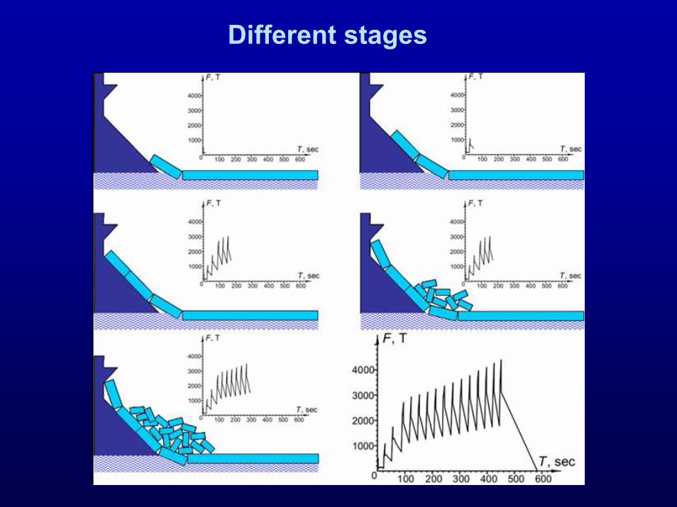
Different stages

Upward/downward breaking
Same treatment? (Weight Buoyancy)Effects on vertical load and overturning moment

Load prediction models
Ice loads induced by horizontal and vertical componentsIce loads induced by horizontal and vertical components
Limited by: Limited by: –– bending strength, shear stress capacity and thickness of icebending strength, shear stress capacity and thickness of ice–– friction and sloping of the structurefriction and sloping of the structure
Models:Models:–– Croasdale (1980), 2D beam theoryCroasdale (1980), 2D beam theory–– Ralston (1977), 3D plate theoryRalston (1977), 3D plate theory–– FEM simulations (FEM simulations (MMäääättttäänennen et al.)et al.)–– + several other models, see Chao (1992)+ several other models, see Chao (1992)

Forces on structure
α
μNcos α
μNsin αμN
Ncos α
Nsin α
sin cos
cos sinx
y
H F N N
V F N N
α μ α
α μ α
= = +
= = −∑∑
x
y
N

Simple 2D theoryCroasdale (1980)Croasdale (1980)
sin coscos sin
sin coscos sin
H N NV N N
H V V
α μ αα μ α
α μ α ξα μ α
= += −
⎛ ⎞+= = ⋅⎜ ⎟−⎝ ⎠
2D beam on elastic foundation
Note: Only valid for wide structures

Beam
II = second moment of area= second moment of areab b = beam width, = beam width, hh = ice thickness= ice thickness
2
/ 2 32
/ 2
,
:12
u u o o
zA
h
zh
M yIM Mh hI I
I I y dA
bhRectangular cross section I y bdy
σ
σ σ
−
=
= = −
= =
= =
∫
∫
y
x
hu
ho
σo
σu

Simple 2D theorySimple 2D theorycontinuecontinue
Vertical load Vertical load VV limited by the bending strength of icelimited by the bending strength of iceIce sheet assumed as a beam on elastic foundationIce sheet assumed as a beam on elastic foundationStrength limited by the bending moment as:Strength limited by the bending moment as:
,max 3 2
6/ 2/12f
M Mhbh bh
σ = =

Simple 2D theorycontinue
The maximum bending moment capacity for a semiThe maximum bending moment capacity for a semi--infinite beam oninfinite beam onelastic foundation (elastic foundation (HetenyiHetenyi, 1946):, 1946):
where where 1/1/ββ is characteristic length defined byis characteristic length defined by
sin( / 4)exp( / 4)
VM πβ π
=
1/ 4
4KEI
β ⎛ ⎞= ⎜ ⎟⎝ ⎠
3
'( /12)
w
w
K gb foundation constantdensity of water
g acceleration due to gravityE Young s modulusI second moment of area of the cross section bh
ρρ====
=

Simple 2D theorycontinue
By combining the previous equations, the limits of theBy combining the previous equations, the limits of thevertical and horizontal loads read:vertical and horizontal loads read:
1/ 45
1/ 45
0.68
hence
sin cos0.68cos sin
wf
wf
ghV WE
ghH WE
ρσ
ρ α μ ασα μ α
⎛ ⎞= ⎜ ⎟
⎝ ⎠
⎛ ⎞ += ⎜ ⎟ −⎝ ⎠
wherewhereWW = = bb is beam width (breath along the water line on the sloping face)is beam width (breath along the water line on the sloping face)

Simple 2D theorycontinue
Force needed to push ice blocks up the slope:Force needed to push ice blocks up the slope:
i
(sin cos )sin
wheredensity of iceheigth reached by the ice on the slope
iZP hW g
Z
ρ α μ αα
ρ
= +
==
( ) ( )1/ 4 25
1/5
sin cos( sin ) coscos sin
substituting for and
sin cos sin cossin cos0.68cos sin cos sin tan
simplified
wf i
wf
H V P P
V P
ghH W W Zh gE
ghH WE
α μ αα αα μ α
α μ α α μ αρ α μ ασ ρα μ α α μ α α
ρσ
⎛ ⎞+= + +⎜ ⎟−⎝ ⎠
⎛ ⎞+ +⎛ ⎞ ⎛ ⎞+= ⋅ + ⋅ +⎜ ⎟⎜ ⎟ ⎜ ⎟ ⎜ ⎟− −⎝ ⎠⎝ ⎠ ⎝ ⎠
⎛ ⎞= ⋅ ⎜ ⎟
⎝ ⎠
4
1 2iC W Zh g Cρ⋅ + ⋅ ⋅

Simple 2D theorycontinuecontinue
Constants C1 and C2 predicted vs α and μ

Simple 2D theorycontinue
1/ 45
1 2/ wf i
ghH W C Zh g CE
ρσ ρ⎛ ⎞
= ⋅ + ⋅⎜ ⎟⎝ ⎠
Breaking force Ride-up force
(1)

Example 1: Effects of thickness
Eq. (1), conical structureParameters:
Ride-up force dominates for h > 1 mForceAverage failure pressure almost independent of h
for h = 1-3 m,
45 , 0.30.7 , 5
1 / 144 /3 / 462 /
f MPa Z m
h m H W kN mh m H W kN m
α μσ= == =
= → == → =
h∝p
0.15p MPa≈

Example 2: Effects of αα and and μμ
Eq. (1), conical structureParameters:
Friction effects significant for slopes steeper than 45Friction effects significant for slopes steeper than 45˚̊Steeper angles Steeper angles →→ more crushing more crushing →→ higher loadshigher loadsImportant to maintain smooth surfaces for sloping Important to maintain smooth surfaces for sloping structures to minimize ice loadsstructures to minimize ice loads
0.7 , 5 , 1
45 , 0.1, 0.5 : / 95 / , 235 /55 , 0.1, 0.5 : / 125 / , 430 /
f MPa E GPa h m
H W kN m kN mH W kN m kN m
σ
α μ
α μ
= = =
= = =
= = =

Effects of ice strength
Affects the breaking partAffects the breaking part
Wide structures:Wide structures:–– rideride--up part > breaking part (2D situation)up part > breaking part (2D situation)
Narrow structures:Narrow structures:–– 3D effects, ice strength important3D effects, ice strength important
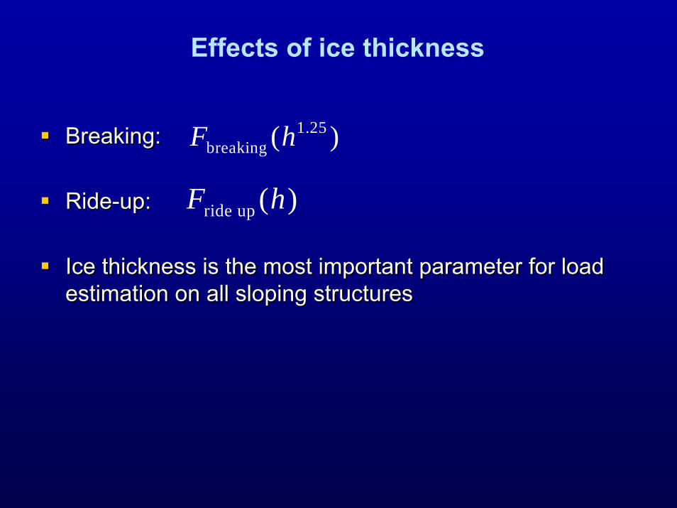
Effects of ice thickness
Breaking:Breaking:
RideRide--up:up:
Ice thickness is the most important parameter for load Ice thickness is the most important parameter for load estimation on all sloping structures estimation on all sloping structures
1.25breaking ( )F h
ride up ( )F h

Effects of velocity – upward cone
1 0.5 /1 0.5( 0.5) 0.5 /
if V m sV if V m s
η<⎧
= ⎨ + − >⎩
Influence of velocity only if V > 0.5 m/s (F0.5 is
the load at 0.5 m/s)
0.5/VF Fη =

2D vs 3D model
Wide structures:Wide structures:–– 2D assumption valid2D assumption valid–– simple 2D beam on simple 2D beam on
elastic foundation may elastic foundation may be assumedbe assumed
Narrow structures:Narrow structures:–– 3D effects will dominate3D effects will dominate–– failure zone wider than failure zone wider than
structurestructure–– plate theory more valid plate theory more valid
than beam theorythan beam theory

3D modelRalston (1977)Ralston (1977)
3D plate model based on plastic limit analysis (ice as a3D plate model based on plastic limit analysis (ice as aductile material)ductile material)
2 2 24 1 2 3
2 21 2
( )
( )f w w T
w T
H A A h A ghD A gh D D
V B H B gh D D
σ ρ ρ
ρ
⎡ ⎤= + + −⎣ ⎦= + −
DT - top diameter
D – waterline diameter
A, B coefficients

Adfreeze on sloping structuresCroasdale (1980)
Fadfr. - horizontal ice load due to adfreezing (MN)h - ice thickness (m)q - adfreeze bond strength (0.3-1 MPa)W - width of struture (m)
adfreeze tanhqWF πα
=

Kulluk Full-scale - Kulluk
Beaufort Sea

Resistance of a ship
Friction, Buoyancy
Breaking
Inertia ForceHydrodynamic ForceOpen Water Resistance
Res
ista
nce
Speed

IceIce barriersbarriers –– CaspianCaspian SeaSea

IceIce barriersbarriers –– CaspianCaspian SeaSea