i ,f tdr.63. 14 · 1 development of mechanical fittings ... hydromechanical design section mr. john...
TRANSCRIPT
I ,f TDR.63. 14
1 DEVELOPMENT OF MECHANICAL FITTINGS
j ,,w *• PHASE I.
L.;
C:_I r. -•
TECHNICAL DOCUMENTARY REPORT NO. RTD-TDR-63-14February 1963
!
Air Force Flight Test CenterRocket Propulsion Laboratories
rI lllm.. Edwards Air Force Base, California
I • ! Prolect No. 6753, Task No. 675304
I
I (Prepared under Contract No. AF 04(611)-8176 by
E. C. Rodabaugh, J. W. Adam, B. Goobich, andT. M. Trainer, Battelle Memorial Institute, Columbus,Ohio)
!IIh
FOREWORD
This report summarizes the research activities performed under USAF ContractNo. 04(611)-8176, from April 1, 1962, to November 30, 1962. The research was per-formed by Battelle Memorial Institute under the auspices of the Rocket Propulsion
- Laboratories, Air Force Systems Command, Edwards Air Force Base, withLt. P. Olekszyk serving as contract monitor. The principal investigators wereJ. W. Adam, J. C. Gerdeen, and B. Goobich, Research Engineers; E. C. Rodabaugh,Senior Research Engineer; W. A. Spraker, Staff Mechanical Engineer; andT. M. Trainer, Group Director.Ii
II[IIII[[I

DISTRIBUTION LIST
Mr. Ralph Middleton Mr. Glen HowellLockheed Aircraft Corp. Space Technology Laboratory2555 N. Hollywood Way Radiation and Compton BoulevardBurbank, California Los Angeles, California
Mr. J. B. Smith Mr. Sherwin Lewis, Propulsion EngineerSystems and Controls Aerospace Corp.Aerojet General Los Angeles, CaliforniaSacramento, California
Mr. Richard WeinerMr. Marvir. G. Luebben Development EngineerDept. 64-62 Jet Propulsion LaboratoryLockheed Missiles and Space Co. 4800 Oak Grove DriveSunnyvale, California Pasadena, California
Mr. Adrien Aitkin Mr. C. M. Richards, Design EngineerStanford Research Institute Astronautics DivisionMenlo Park, California General Dynamics Corp.SSan DigCalifornia
Mr. John C. Bloom, Test Group EngineerHydromechanical Design Section Mr. John F. MayerDouglas Aircraft Co., Inc. Department 596, Group 121Long Beach, California Rocketdyne Division
North American AviationMr. L. Anr!:ews, Supervisor 6633 Canoga ParkSpace Propulsion Group Canoga Park, CaliforniaDouglas Aircraft Co., Inc.Santa Monica, California Mr. Frank Brock
Resistoflex Corp.Mr. W. E. Currie Roseland, New Jersey"The Parker Appliance Co.17325 Euclid Avenue Mr. Paul Bauer, Project EngineerCleveland 12, Ohio Mechanics Research Division
Armour Research FoundationMr. Bruce Pauly 10 West 35th StreetThe Weatherhead Company Chicago 16, IllinoisCleveland, Ohio
Mr. M. H. Weisman, Research SpecialistMr. E. Floreen, Sr., Project Engineer Metallic Materials LaboratoryMarman Division Los Angeles Division
* Aeroquip Corp. North American Aviation, Inc.11214 Exposition Boulevard International AirportLos Angeles 64, California Los Angeles 9, California
II Mr. Jasper McKee, ChiefMechanical TestingFlexonics Co.Bartlett, Illinois
ABSTRACT
The purpose of this program is to develop a family of improved lightweight me-
chanical fittings for service with rockets' fluid systems under stringent environmentaland operating conditions. Phase I was to define and investigate the parameters signifi-cantly affecting the fitting classes and to initiate preliminary fitting designs. The workconsisted of (1) a review of the design and use of present fittings for missiles, (2) areview of candidate materials for the required operating conditions, (3) the establish-ment of recommended classifications for improved fittings, and (4) the development ofpreliminary design concepts for the proposed classifications. Three major conclusionswere drawn from Phase I: (1) the reconnectable union should be either threaded orflanged, (Z) the connection between the tube and the fitting should be a permanent jointmade independent of the seal mechanism or the reconnectable union, and (3) three seal-ing methods show promise of being developed for the improved fittings.
The following recommendations were made for future work: (1) the brazed orwelded joining method developed by North American Aviation should be adapted forjoining tubing to fittings and components, (2) high-energy-rate tube-to-fitting joiningmethods should be investigated as an eventual improvement of the welded or brazedI methods, (3) the best of the three promising seals should be selected and developed,and (4) the preliminary fitting-to-fitting de signs initiated during Phase I should be de-tailed and evaluated. Recommendations (3) and (4) are recommended for inclusion in
ii Phase II.
[PUBLICATION REVIEW
TiThis technical documentary report has been reviewed and is approved.
I iii
TABLE OF CONTENTS
Page
INTRODUCTION ...................... .............. ...... 1
SCOPE AND OBJECTIVES OF PHASE I ........... .... ......... 1
REPORT ORGANIZATION ............... ................. .... 2
DETERMINATION OF FITTING CLASSES ............. .............. 5
General Service Requirements ............ . .. ................ 5Materials Selection ................ ... . ................... 5
Materials Considered ................ .. ............... 6Low-Density Materials ......... .. .. .............. 6300 Series Stainless Steels ......... . .. . . ........... 6400 Series Stainless Steels ......... ... .. ........... 6High-Strength Tool Steels ......... ... ............. 6Maraging Steels ................ .. ............... 6Nickel- and Cobalt-Base Metals ....... . .. ........... 6Age-Hardenable Stainless Steels ....... ... ........... 6Refractory Metals ........... . ... . ............... 9
Materials Selected .............. . ... . ................ 9Mechanical Properties ................ ................. 9
Yield Strength-to-Density Ratio ............ .......... . 9Creep ................. . ... .................. 10Notch Sensitivity ............. . .. . .............. 10
Fluid Compatibility .............. . .. .................. 13Conclusions ................... ................... 13
Assembly Torque ................... ................... 19Recommended Fitting Classes ............. ................ 19References ................. . .. .. ..................... 22
FITTING-TO-FITTING CONNECTION .............. ............... 23
Design Parameters .................... ................. .. 24Structural Loads . .. .............. . 24
Hoop Stresses From Internal Pressure. ........ ....... . 24Pressure End Load ................ .............. . 24Bending Moments ............... ... ........... . . 26External Axial and Torsional Loads ....... ....... . 29
Seal-Seating Load ................. .............. . . 29Design Loads ...................... ............... . . 32Preload ...................... ................ ... 35Temperature Effects ............... ............. . . 39
Creep or Relaxation ........... ............... 39Thermal Gradients ............ ................ 39Modulus of Elasticity ........... ............... 40
iv
[j TABLE OF CONTENTS
(Continued)
TBsPage
Threaded Versus Bolted Fittings.................................41II Fatigue ................. . .. ................... 43Seal Interaction ................ ................ 43Tube-to-Fitting Interaction .......... . .............. 44
Designs Considered ............... ................... 44Ring Clamps ................ ................ ... 44Snap Clamps ................ .................... 46Differential Threads ............ . .. ........... .. 46Ball and Socket .................................. 46Conclusions ...................... 47
Design Procedure for Threaded Fittings ................... ..... ., 47Class Ia 1-In. Threaded Fitting ....... . . ............ 49
Class III 1/8-In. Threaded Fitting. ............. 57Additional Design Considerations ........ ........... 57
Accuracy of Preloading ........ .............. 57
Torque Relaxation ........... ............... 57Overtightening Factor .......... ............... 57Plastic Deformations .......... ............... 57
Design Procedure for Bolted Fittings ....... .............. 58
Class Ia 1-In. Bolted Fitting .......... . ............. 58Classes III and IV 1-In. Bolted Fitting ..... . ......... 64
Data on Ren4 41 for Creep Design .... ........... 64Application of Creep Design Procedure .......... 67
Class Ib 3-In. Bolted Fitting and Larger Bolted Fittings in General. 69
Additional Design Considerations .......... ............. 72Accuracy of Preloading ............ .............. 72Torque Relaxation .............. ................ 72Overtightening Factor ............................ 72Plastic Deformations ............ . .............. 72
Selection and Spacing of Bolts ......... . . ......... 72Alternative Types of Bolted Fittings .... ......... 73
Application of Computers for Optimization of Design ... ......... 74References ........................................... 77
TUBE-TO-FITTING DESIGN ............. ................... 79
Design Parameters ................................... 79Reliability .................................... 79
Weight .................. ...................... 79Assembly ................ .................... 79
Material ................ .................. . 80
Candidate Joining Methods .......... ............... 80Brazing and Welding ................................. 80
Choice of Materials ............. . ................ 81Source of Heat ................ ................. 81Joint Fit-Up .................. ............. . .. 81
Filler Material .............. . . . ................ 81
Cleanliness ................ .. .................. 81Conclusions ................ .. .................. 81
v
TABLE OF CONTENTS(Continued)
Page
High-Energy-Rate Welding ............. ... ................. 82Chemical Explosives ................. ................. 82Explosive Welding Variables .......... ............... 84Characteristics of Explosively Welded Joint ..... . ........ 91Conclusions ................. .................... 92
References ..................... ................ ...... 92
SEAL DESIGN ..................... ....................... 95
Design Parameters ...... .......... ................... . 95Leakage Analysis ... .............. .................. 95Seating Loads .......... ...... .................... o 97Plastic Flow ............ . ... ................... 99Temperature Effects ......... ... ................. 99Pressure Energization ............ . ................ ... 100Conclusions ................. .................... 101
Pressurized Metallic O-Rings .......... ............... .. 101Present Theory ................ ................... 101New Design Principle .... ............ ................. 102Conclusions ................. .................... 105
High-Energy-Rate Formed Seal ............ ............... 105Experiments Performed.....................................106Description of Results .... ......... ............ .... 106Possible Externally, Explosively Formed Seal. ............... 106Conclusions ........................... ............ 110
Mechanical Toggle Seal ............. . ......... . o . o. ... ISeating Action ................... .................. 11lForce Magnification ... ............ ................ o.112Preload Torque ................ ................... .112Axial Backoff ......... ........ ................. .113Conclusions ................. .................... o.115
References. .......... .. ................... 115
SUMMARY OF RECOMMENDATIONS .............. .............. 117
INFORMATION REVIEW AND BIBLIOGRAPHY ......... ............. 118
Information Review. . .. ........ .............. .. .. 118Technical Interviews ............. .. ............... o 118Technical Literature .. . . . ................. o119
Bibliography o................. ...................... .119
APPENDIX I
CALCULATION METHODS FOR STRESSES AND DISPLACEMENTS. ....... 129
vi
I.
TABLE OF CONTENTS(Continued)t
Page
9 APPENDIX II
DISCUSSION OF DESIGN FOR CREEP OR RELAXATION ... ......... 141
APPENDIX III
I SELECTION OF THREAD PROFILES FOR FITTINGS ... .......... 147
APPENDIX IV
TORQUE RELAXATION TESTS ON FLARED AND FLARELESS FITTINGS. 153
APPENDIX V
LEAKAGE FLOW ANALYSIS ............ .................. 161
LIST OF FIGURES
Figure
I Design Elements of a Total Fitting ...... ............ 2
2 Yield Strength-Density Ratio Over Service Temperature Range . 7
3 Tube Weight Vs. Temperature ...... ............. 11
4 Tube Weight Vs. Time .......... ................ 12
5 Notched (Kt = 6. 3)/Unnotched Tensile Ratio Vs. Temperature(Transverse) .............. ................... 14
1 6 Useful Temperature Ranges of Fluids .... ........... 15
7 Weight Comparison of Threaded Fitting Classes ..... ....... 20
8 Types of Flanges Considered for Recommended Flange Design 21
Procedure . . . . . . . . . . . . . . . . . .
9 Typical Loads Imposed on Fittings .......... ........... 24
10 Pressure End Load Acting on Fittings as a Function of Tube Diameter
and Design Pressure ............... ................. 25
11 Comparison of Bending-Moment Allowance for Small Fittings . . . 28
12 Bending-Moment-Limited Comparison for Large Fittings, DesignPressure at 1500 Psi ........... ................ 30
I vii
LIST OF FIGURES
(Continued)
Figuure Page
13 Proposed Design Bending Moments for Fittings .... ....... . 31
14 Equivalent Bending End Load as a Function of Tube Diameter andDesign Pressure ...................... 33
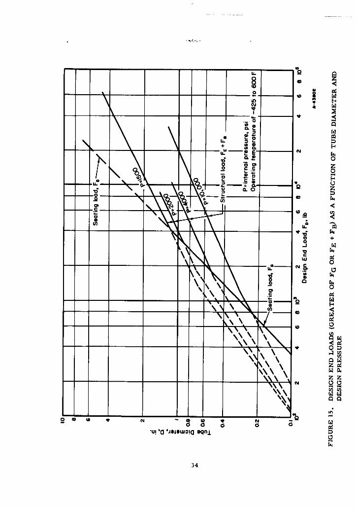
15 Design End Loads (Greater of FG or FE + FB) as a Function of TubeDiameter and Design Pressure ......... ... ............. 34
16 Model of Simplified Preload Theory ....... ........... 36
17 Graphical Illustration of Simplified Preload Theory . ...... 37
18 Preliminary Estimate of Preload Torque for Threaded Fittings . 42
19 Fitting-to-Fitting Designs Considered ...... ........... 45
20 Proposed 1-In. Class Ia Threaded Fitting, 2000 Psi at -100 to 600 F,AM-355 .................. .................... 48
21 Basic Preload Diagram for I-In. Class Ia Threaded Fitting. . . . 51
22 Preload Diagram for Proof Pressure at 70 F ... ........ .. 52
23 Preload Diagram for Steady State at 70 F .... .......... .... 53
24 Preload Diagram for Minus Temperature Gradient ......... 54
25 Preload Diagram for Plus Temperature Gradient .. .. ..... 55
26 Proposed 1/8-In. Class lila Threaded Fitting, 10,000 Psi at -425 to600 F, Rene41 ............. .................. . 56
27 1-In. Class Ia Bolted Fitting, 2000 Psi at -100 to 600 F, AM-355. * 59
Z8 Preload Diagram for Proof Pressure at 70 F for 1-In. Class IaBolted Fitting ...... .......... .................. 61
29 Preload Diagram for Steady State at 70 F .... .......... 62
30 1-In. Bolted Fitting, Approximately Class 11I '0,000 Psi up to650 F) and Class IV (4,000 Psi at 1500 F, 30-Minute Life) .... 65
31 Creep Rate of Rene 41 Bar at 1500 F ....... ........... 66
32 Pressure-Service Life Ratings of the Bolted Fitting Shown inFigure 30 ................. ...................... 70
33 3-In. Class Ib Bolted Fitting, 1500 Psi at -100 to +200 F, AM-355 . 71
34 Alternative Types of Bolted Fittings ........ ........... 74
35 Illustration of Independent Dimensional Variables in a BoltedFitting ................... .................... 75
36 Typical Time-Pressure Profiles for Low and High Explosives . . . 85
37 Line Charge Detonating in Water ........ ............. 86
viii

t LIST OF FIGURES(Continued)
Figure Page
38 Explosive Welding of Flat Plates ........ ............. 87
"V39 Effect of Charge Size and Standoff Distance on Peak Pressure . • 88
40 Effect of Transfer Medium and Standoff Distance on Peak Pressure 90
41 Explosive-Welding Arrangements ....... ............ 93
42 Model of Typical Leakage Path ........... ........... 96
43 Axial and Radial Sealing Cavities ....... ............ 100
44 Pressure Forces Acting on Various Types of Metallic O-Rings. 102
45 Internally Pressurized O-Ring ..... ... ............. 103
46 Pressure-Temperature-Yield Stress Relationship for O-Ring Seal. 104
47 Configuration for Internal-Charge Seal Experiment ...... 107
48 Configuration for External-Charge Seal Experiment 1....... 07
49 Area B of Figure 47 ............ ................. 108
50 Area C of Figure 47 ............ ................. 108
51 External- Explosive Seal. .... ..... ................ 109
52 Poisson's Effect on Seal Ring ........................... 109
53 External Explosive Seal ................ ............... 110
54 Seating Action of Mechanical Toggle Seal .... .......... Ill
55 Force Comparison Between Toggle Seal and Flat Metal Washer 113
56 Force-Deflection Curve for Toggle Seal ..... .......... 114
57 Dimensions of an Outwardly Projecting Flange Attached to aCylindrical Shell .............. .................. 131
58 Values of T, U, Y, and Z When v = 0.3 ..... .......... 133
59 Values of F and V for an Integral Flange .... .......... 133
60 Values of Stress-Correction Factor .......... 133
ix
LIST OF FIGURES(Continued)
Figure Pg
61 Inwardly Projecting Flanged Cylinder Nomenclature .. ...... 134
62 Method of Establishing Value of E1. . . . . . . . . . . . 143
63 Illustration of Nonuniform Load Distribution in a Nut Tightenedon a Bolt .................. .................... 147
64 Slot Assumed for Laminar-Flow Analysis .... .......... 161
65 Flow at Section dx of Slot ............. .............. 162
LIST OF TABLES
Table
1 General Service Requirements ....... ..... ............. 5
2 Summary of Fluid-Compatibility Data ...... ........... 16
3 Recommended Fitting Classes ........ .............. 19
4 Design Loads for 3/8-In. Fitting ........ ............. 35
5 Change in Effective Preload as Function of Temperature ..... .. 41
6 Division of Fittings into Threaded and Bolted, Based on a MaximumTorque of 2000 In-Lb ............. ............... 43
7 Service Conditions for Design of I-In. Class Ia Threaded Fitting . . 49
8 Design Properties of AM-355 ............. .............. 50
9 Design Properties of Reng 41 .......... .............. 67
10 Characteristics of High and Low Explosives ... ......... 83
11 Characteristics of High Explosives ...... ............ 83
12 Properties of Explosives ........... ............... 83
13 Torque Used in Assembly of Test Fittings on Tubing ........ .. 154
14 Average Uncoupling Torque as Per Cent of Installed Torque . . . 155
15 Torque Relaxation as Indicated by Degrees of Nut Rotation Requiredto Restore Original Torque, Source (B) ..... .......... 157
16 Results of Tests From Source (C) ....... ............ 158
17 Yield Strength as Function of Temperature for Type 304Stainless Steel ................ ................... 159
x
_L
j DEVELOPMENT OF MECHANICAL FITTINGS
INTRODUCTION
The purposes of this program are (1) to design, develop, and fabricate a family oflightweight mechanical fittings for service with rockets' fluid systems under stringentenvironmental and operational conditions and (2) to provide and prepare specificationsand drawings and test requirements for the fittings in such a manner that military speci-fications and standards may be published.
The fittings currently in general use in the fluid systems of rocket-propulsionvehicles were developed primarily for use in the aircraft industry. Because of thesevere missile environments and the use of new and exotic fluids, which have posedproblems of vibration, temperature, and chemical activity never before encountered,standard aircraft tube fittings in common use by Governmental agencies have been sub-ject to failure. This program is an attempt to develop new and fresh fitting-designconcepts to optimize weight, misalignment capability, and leakage characteristics con-sistent with high operational reliability. No one connector design can satisfy the re-quirements of the complete range of temperatures, pressures, and fluids encounteredin advanced missile systems. Therefore a basic requirement of this program is toidentify and develop families and classes of fittings. It is also required that the designsto be considered should be new and unique where applicable and not restricted to modi-fications of present aircraft designs. This goal is to be attained through:
(1) Use of new and unique concepts of mechanical fitting design
(2) New methods of joining tubing and fittings
(3) Optimum combinations of materials
(4) Effective use of manufacturing techniques.
SCOPE AND OBJECTIVES OF PHASE I
Phase I was to consist of an investigation of parameters such that classes andtypes of fittings could be chosen and preliminary designs could be initiated. The in-vestigation was to begin with a literature survey of present technology and a materials
* review for determination of the most suitable materials.
Investigations were to be made of (a) satisfactory methods of joining tubing andfittings, (b) forces required to tighten and seal, (c) effects of thread form on torque"relaxation, (d) effect of thread lubricant on sealing, thread galling, and torque relaxa-"tion, (e) the use of computer techniques to evaluate design criteria, and (f) methods toalleviate or eliminate the chances of human error in the assembly of fittings.
I[
The preliminary design of proposed connectors was to begin concurrently or onconclusion of these investigations. A stress analysis was to be made of each type offitting. Optimum operational service ranges were to be determined showing crossoverpoints between threaded and flanged fittings. Maximum strength under operational con-ditions vs. minimum weight was to serve as a major criterion.
REPORT ORGANIZATION
The preparation of this report on Phase I constituted a considerable problem be-cause of the large quantity of informaticn that was assembled and created and becauseof the interrelation of many of the design areas. The format finally selected is anarrangement of subjects such that the reader can best understand the proposed conceptsand the reasons for these concepts.
The first part, "Determination of Fitting Classes", outlines the requirementswhich determined the selection of candidate fitting materials, details the reasons forselecting the three recommended materials, and describes how the characteristics ofthe three selected fitting materials combined with certain operational and handling re-quirements define the recommended fitting classes. The fitting classifications affectmany of the subsequent design decisions.
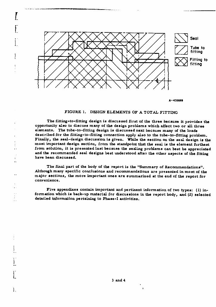
The next three parts discuss in detail the major results of Phase I - that is, thedesign thinking on improved mechanical fittings. Early in Phase I it was concluded thata reconnectable mechanical fitting could be made to seal helium satisfactorily only ifthe seal were not a part of the tubing, as is the case with the present flared and flarelessfittings. The reasons for this conclusion are given elsewhere in the report. As a resultof this decision, the fitting design was divided into three elements. While these ele-ments were not entirely independent of each other, their aspects were sufficiently uniquethat during much of Phase I they were considered to be separate design problems. Thethree elements, as shown in Figure 1, are:
"* The fitting-to-fitting connection, a reconnectable union in the fitting whichprovides the necessary structural integrity
e The tube-to-fitting connection, a permanent transition connection betweenthe fitting and the piping.
"* The seal, a metallic disposable seal independent of the structural connec-tions except for the seal seating surface.
The design thinking is presented in this report in terms of these individual ele-ments for two reasons: (1) they provide excellent means of discussing the many designaspects of the fitting in a systematic manner and (Z) the conclusions and recommenda-tions concerning each element are different and more easily formulated when consideredindependently.
2
SealI.
T ube to17 fitting
Z Y Fitting tofitting
A-43889
FIGURE 1. DESIGN ELEMENTS OF A TOTAL FITTING
The fitting-to-fitting design is discussed first of the three because it provides theopportunity also to discuss many of the design problems which affect two or all threeelements. The tube-to-fitting design is discussed next because many of the loadsdescribed for the fitting-to-fitting connection apply also to the tube-to-fitting problem.Finally, the seal-design discussion is given. While the section on the seal design is themost important design section, from the standpoint that the seal is the element furthestfrom solution, it is presented last because the sealing problems can best be appreciatedand the recommended seal designs best understood after the other aspects of the fittinghave been discussed.
The final part of the body of the report is the "Summary of Recommendations".Although many specific conclusions and recommendations are presented in most of themajor sections, the more important ones are summarized at the end of the report forconvenience.
Five appendixes contain important and pertinent information of two types: (1) in-formation which is back-up material for discussions in the report body, and (2) selecteddetailed information pertaining to Phase-I activities.
3 and 4
1.,

I.IIIIIIIII DETERMINATION OF FITTING CLASSES
General Service RequirementsTMaterials Selection
Assembly Torque
Recommended Fitting Classes
References
I
[~
DETERMINATION OF FITTING GLASSES
To achieve minimum weight in a missile piping system, each fitting and com-ponent should be designed on the basis of the exact operating requirements for thatparticular component. Even if these requirements were known at every point in thesystem, such a procedure would be impractical because of the excessive expenditureof time and money. Fortunately, if the smaller fittings are designed within certainranges of selected parameters, the production and logistics problems are reduced con-
"-, siderably, and the weight penalty is small. The most significant parameters consideredin determining the recommended fitting classes were (1) general service requirements,(2) materials selection, and (3) assembly torque.
General Service Requirements
The general service requirements applicable to missiles' and rockets' fluid sys-tems are shown in Table 1. It was agreed between Rocket Propulsion Laboratories andBattelle that the problems of developing a satisfactory fitting for up to 1500 F weresufficiently difficult that the upper design temperature at least for Phase I would belimited to 1500 F.
TABLE 1. GENERAL SERVICE REQUIREMENTS
Pre s sure Range, Temperature Range, Dimensional Range,Service psi F inches
Propellant 0 to 1500 -425 to 200 1 to 16
Pneumatic 0 to 2000 -425 to 200 1/8 to 10 to 10,000 -425 to 6000 to 4000 -425 to 1500
Hot Gas 0 to 1500 1000 to 3000 1 to 3
As presented in the table, the breakdown by fluids established natural "families"of fittings. However, within each family further classification was necessary. Thiswas especially true for propellant and hot-gas systems where operating pressures maybe much less than the maximum values stipulated.
Materials Selection
The selection of the fitting materials was determined largely by the mechanicalJ properties of the materials and by the compatibility of the materials with the fluid
media. In a few cases other considerations, such as machinability, governed. Sinceit would be impractical to review all of the candidate materials in detail, the char-
j acteristics of the classes of materials that were considered are discussed in generalterms. The selected materials are subsequently described in some detail.
1* 5
Materials Considered
General groupings of candidate materials and the major characteristics of thegroups are discussed below.
Low-Density Materials. The low-density materials include the aluminum, mag-nesium, and titanium alloys. Even though the aluminum and magnesium alloys have avery low density, the low strengths and their tendency to lose strength drastically astemperature is increased above about 300 F, make them undesirable. Compatibilitywith missile propellants is also a severe limitation.
Titanium, which has good mechanical properties up to about 600 F, is generallynot acceptable for service with oxidizers.
300 Series Stainless Steels. The 300 series stainless steels are easy to machineand fabricate, and are almost universally compatible with the fluids considered. How-ever, because of their relatively low yield strength-to-density ratio it is not possible todesign a lightweight fitting which can satisfy the operational limits specified in Table 1.Strength can be increased to some degree by cold working, but this increase is marginalwhen the final strength is compared with that of the age-hardenable stainless steels andother alloys discussed below. At temperature conditions exceeding 1000 F, the 300series alloys are too sensitive to creep to be practical for this application.
400 Series Stainless Steels. The 400 series stainless steels have a good combina-tion of physical properties over the temperature range of interest. They are easilyfabricated, and are available in production quantities. However, the heat treatmentrequired includes an oil or water quench, or at least a rapid cool, from temperaturesof 1760 to 1850 F. This procedure causes distortions in the fitting that could be detri-mental to the sealing surface.
High-Strength Tool Steels. The high-strength tool steels of the H-11 type, such asPotomac M, are difficult to weld and have poor corrosion resistance. Hence, they arenot considered candidate materials.
Maraging Steels. The 18Ni-Co-Mo maraging steels possess extremely highstrengths. However, these steels are still under development. Most work to date hasemphasized ambient applications, and no compatability data are available. Also, be-cause they are new, their availability is limited. For these reasons, they have notbeen considered further.
Nickel- and Cobalt-Base Metals. This category includes materials such asHaynes 25, Inconal IXII, and Rlen6 41, all of which are considered possible choices.Of this group, Rena 41 has the best combination of properties over the temperaturerange of interest.
Age-Hardenable Stainless Steels. The precipitation-hardenable stainless steelsinclude 17-7PH, PH 15-7 Mo, AM-350, 17-4PH, AM-355, and A-286. Of these,17-7PH, PH 15-7 Mo, and AM-350 are not available as bar stock or plate and hencecannot be considered. 17-4PH, AM-355, and A-286 are available as plate and bar stock.
6
16 _ _ _ _
15 - _ _ _ _ _ _ _ __ _ _ _ _ _ _ _ _ _ _ _
14 - Yield Strength-Den
143-
12 -1 \5 A V A 2 .5 S n__ _ __ _ _ _
6-
ra41-4PU*a
C05 -. ~ - --
o - - PtomaclvA-28- NRe,-
2
-400 -200 0 200 400 600 800 1000 1Temperature, F
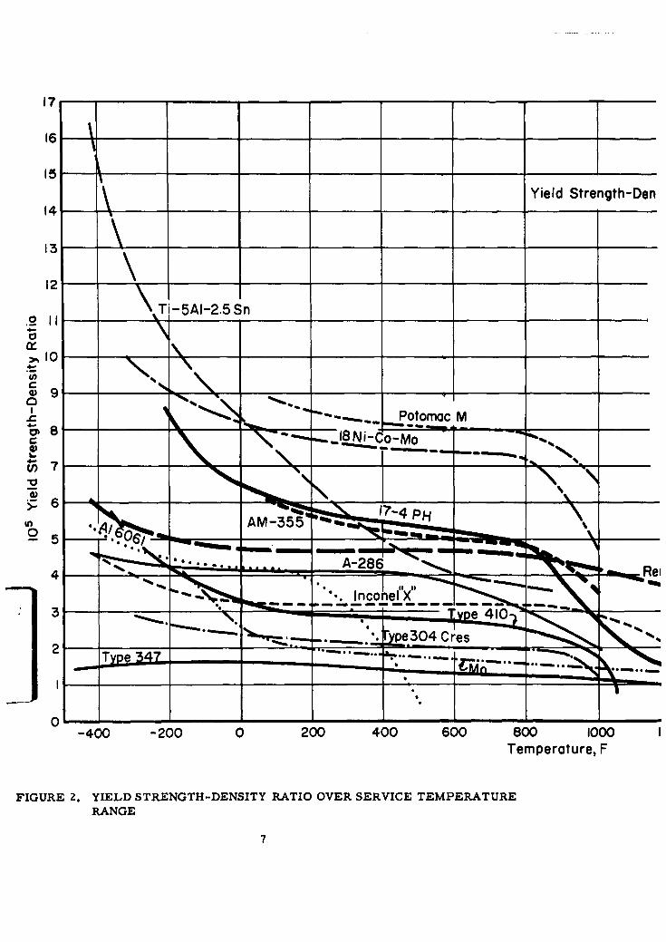
FIGURE 2. YIELD STRENGTH-DENSITY RATIO OVER SERVICE TEMPERATURERANGE
7
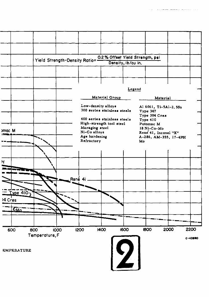
R o2 % Offset Yield Strength, psiYield Strength-Density Ratio= Density, lb/cu in.'
Legend
Material Group Material
Low-density alloys Al 6061, Ti-5AI-2. 5Sn300 series stainless steels Type 347
Type 304 Cres400 series stainless steels Type 410High-strength tool steel Potomac MMaraging steel 18 Ni-Co-Mo
)mOc M Ni-Co alloys Rene'41, Inconel "X"Age hardening A-286, AM-355, 17-4PH
-. . -~Refractory Mo
•',.- "-- Rene 4.1
e~ 410
)4 Cres " __
600 800 1000 1200 1400 1600 1800 2000 2200
Temperature, F C-4--90
EMPERATURE[2481
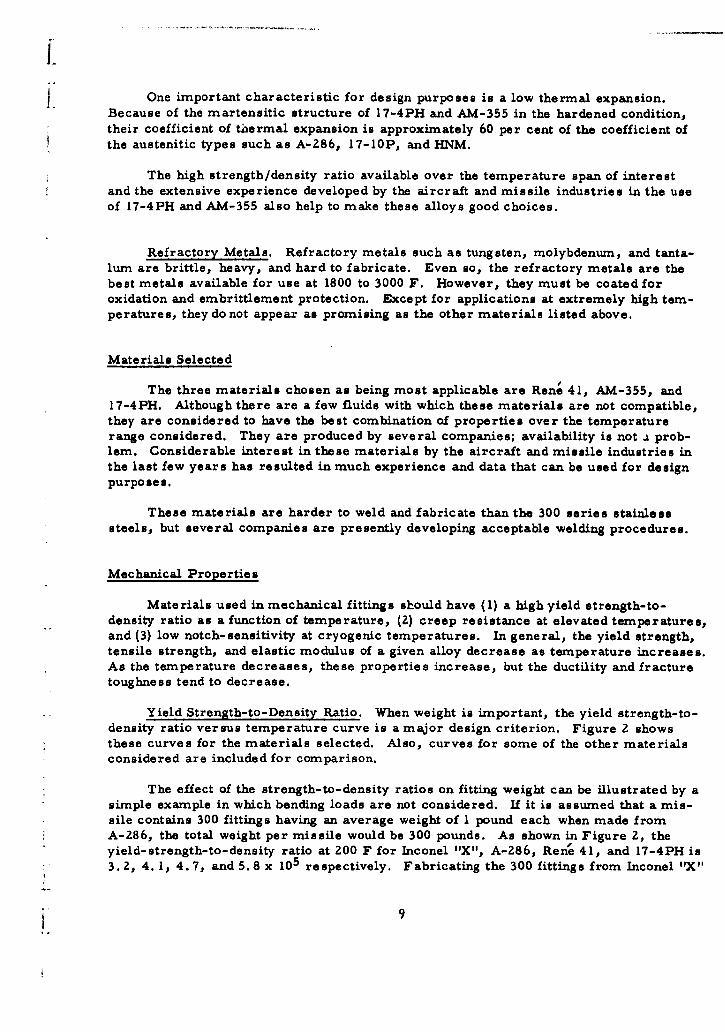
One important characteristic for design purposes is a low thermal expansion.Because of the martensitic structure of 17-4PH and AM-355 in the hardened condition,their coefficient of tiiermal expansion is approximately 60 per cent of the coefficient ofthe austenitic types such as A-286, 17-10P, and HNM.
The high strength/density ratio available over the temperature span of interestand the extensive experience developed by the aircraft and missile industries in the useof 17-4PH and AM-355 also help to make these alloys good choices.
Refractory Metals. Refractory metals such as tungsten, molybdenum, and tanta-lum are brittle, heavy, and hard to fabricate. Even so, the refractory metals are thebest metals available for use at 1800 to 3000 F. However, they must be coated foroxidation and embrittlement protection. Except for applications at extremely high tem-peratures, they do not appear as promising as the other materials listed above.
Materials Selected
The three materials chosen as being most applicable are Rene 41, AM-355, and17-4PH. Although there are a few fluids with which these materials are not compatible,they are considered to have the best combination of properties over the temperaturerange considered. They are produced by several companies; availability is not .a prob-lem. Considerable interest in these materials by the aircraft and missile industries inthe last few years has resulted in much experience and data that can be used for designpurposes.
These materials are harder to weld and fabricate than the 300 series stainlesssteels, but several companies are presently developing acceptable welding procedures.
Mechanical Properties
Materials used in mechanical fittings should have (1) a high yield strength-to-density ratio as a function of temperature, (2) creep resistance at elevated temperatures,and (3) low notch-sensitivity at cryogenic temperatures. In general, the yield strength,tensile strength, and elastic modulus of a given alloy decrease as temperature increases.As the temperature decreases, these properties increase, but the ductility and fracturetoughness tend to decrease.
Yield Strength-to-Density Ratio. When weight is important, the yield strength-to-density ratio versus temperature curve is a major design criterion. Figure 2 showsthese curves for the materials selected. Also, curves for some of the other materialsconsidered are included for comparison.
The effect of the strength-to-density ratios on fitting weight can be illustrated by asimple example in which bending loads are not considered. If it is assumed that a mis-sile contains 300 fittings having an average weight of 1 pound each when made fromA-286, the total weight per missile would be 300 pounds. As shown in Figure 2, theyield-strength-to-density ratio at ZOO F for Inconel "X", A-286, Rent 41, and 17-4PH is3. 2, 4. 1, 4.7, and 5.8 x 10⁵ respectively. Fabricating the 300 fittings from Inconel "X"
would increase the total weight to 383 pounds. When fabricated from Rene 41 and 17-4 PHthe total weight would decrease to 262 and 212 pounds respectively. The total fittingweight therefore could be reduced by more than 29 per cent if 17-4PH were used insteadof A-286. At high temperatures, above 800 F, the comparison of yield strength-to-density ratio is also important even though the strength of materials decreases markedlyas temperature increases, because the change is different for each metal.
Creep. Although the creep rate of metals is generally disregarded at temperaturesless than 800 F, it increases rapidly as temperatures exceed 800 F. For most materialsthere is some temperature at which the creep resistance or stress-to-rupture strengthbecomes less than the tensile yield strength, and hence the creep resistance rather thanthe yield strength must be used as the design basis.
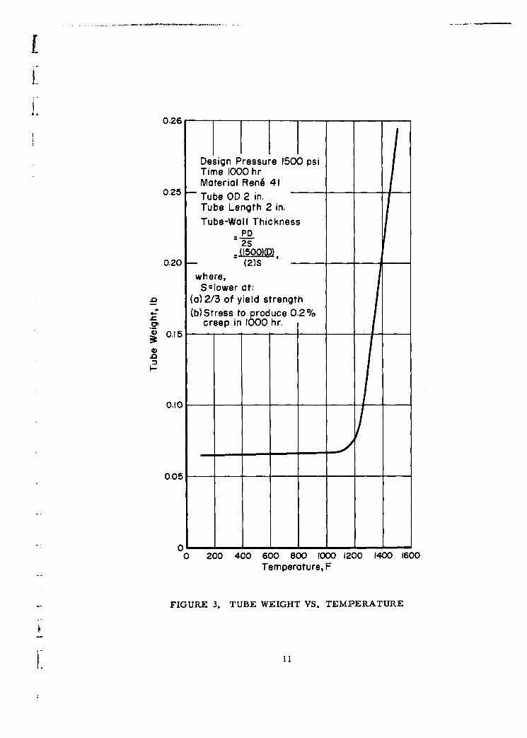
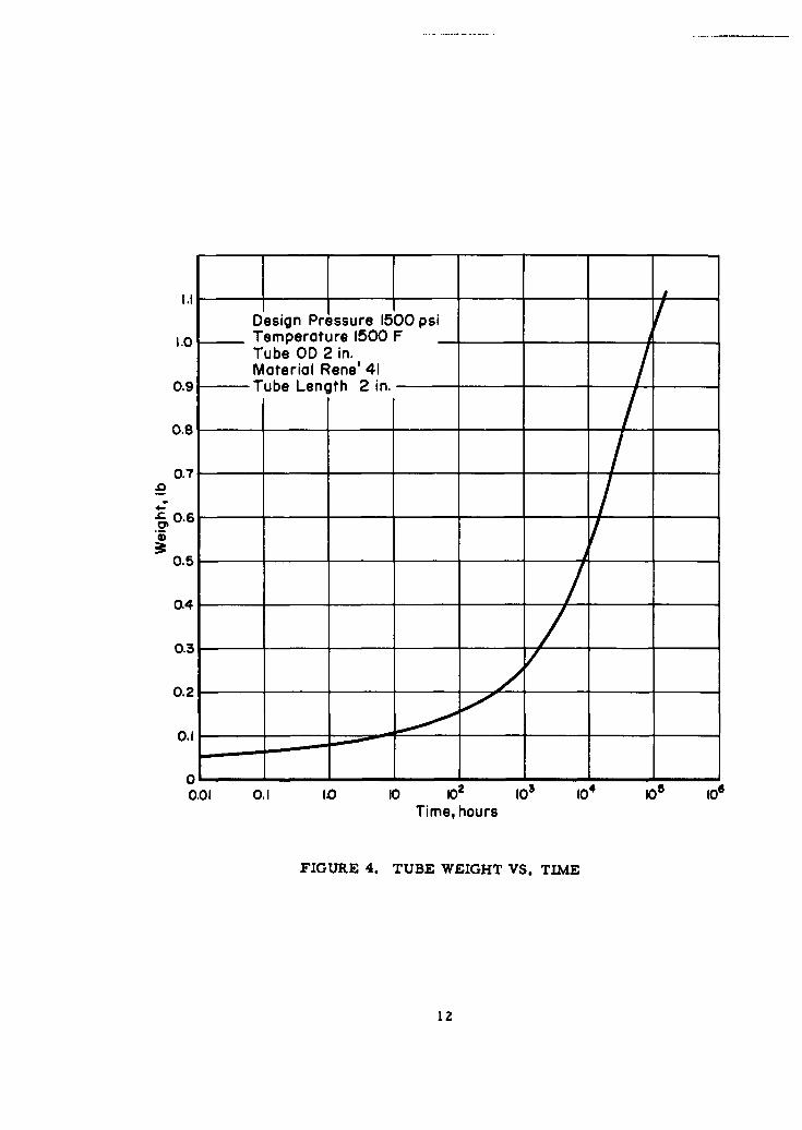
Because the factors governing tubing design in a fluid system also are majorfactors governing the design of a fitting for that system, the time and temperaturedependency of the fitting weight can be illustrated by considering the time and tempera-ture dependency of the tubing. The curve in Figure 3, tube weight versus temperature,is based on a 2-inch length of 2-inch outside-diameter tube of Rene 41 for a pressure of1500 psi and a life of 1000 hours. The creep strength for Rene 41 becomes the con-trolling strength factor at about 1100 F, as evidenced by the change in slope. The curvein Figure 4 represents tube weight versus time for a 2-inch length of 2-inch outsidediameter tubing of Rena 41 for a pressure of 1500 psi and a temperature of 1500 F.From these curves it is apparent that either a decrease in temperature or a decreasein service-life requirement would result in a significant weight saving. Thus, it isimportant that the expected service temperature and desired life be known to achievean optimum design.
Creep and stress-to-rupture data at elevated temperatures are commonly avail-able for all of the materials listed in the preceding section. The two best materials areRene 41 and Inconel IIX". AM-355 and 17-4PH are likely to become embrittled whenkept at temperatures above 700 F and hence should be restricted to 600 F service formissile fittings.
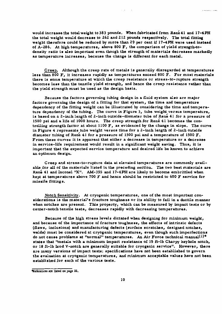
Notch Sensitivity. At cryogenic temperatures, one of the most important con-siderations is the material's fracture toughness or its ability to fail in a ductile mannerwhen notches are present. This property, which can be measured by impact tests or bycenter-notch tensile tests, decreases rapidly with decreasing temperatures.
Because of the high stress levels dictated when designing for minimum weight,and because of the importance of fracture toughness, the effects of intrinsic defects(flaws, inclusions) and manufacturing defects (surface scratches, designed notches,welds) must be considered at cryogenic temperatures, even though such imperfectionsdo not cause problems at "normal" temperatures. An Air Force technical manual(,)*states that "metals with a minimum impact resistance of 15 ft-lb Charpy keyhole notch,or 18 ft-lb Isod V-notch are generally suitable for cryogenic service". However, thereare many versions of impact tests; specifications have not been established to governthe evaluation at cryogenic temperatures, and minimum acceptable values have not beenestablished for each of the various tests.
References are listed on page 22.
10
11I-
0.26
Design Pressure 1500 psiTime 1000 hrMaterial Rene 41
0.25 Tube OD 2 in.Tube Length 2 in.
Tube-Wall ThicknessPD2S
=-(1500)(D)0.20 (2)S
where,S=lower at:
_n (a)2/3 of yield strength(b)Stress to produce 0.2%
creep in 1000 hr.S0.15
0.10I- 0.1- -
0.05
0 -
0 200 400 600 800 1000 1200 1400 1600Temperature, F
FIGURE 3. TUBE WEIGHT VS. TEMPERATURE
L 1I
Design Pressure 1500 psi1.0 Temperature 1500 F
Tube OD 2 in.Material Rene' 41
0.9 Tube Length 2 in.
0.8
0.7
0.6
0.5
0.4
0.3
0.2
0.1
0 - - -
0.01 0.1 ID I0 10 100 104 10Time, hours
FIGURE 4. TUBE WEIGHT VS. TIME
12
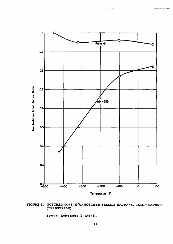
The notched/unnotched tensile ratio-vs. -temperature curves given in Figure 5
show a sharp decrease in the notched/unnotched ratio below -100 F for AM-355 as com-
pared to an almost constant value for Rene 41. The tendency for the notched-unnotchedtensile ratio to drop rapidly as temperatures are decreased is typical for martensiticmaterials. It appears on the basis of available data that this is true of 17-4PH as well.
On the basis of this curve, and because there is a lack of definitive data specifying
minimum acceptable values, the lower service temperature for AM-355 and for the
comparable material 17-4PH has been set at -100 F.
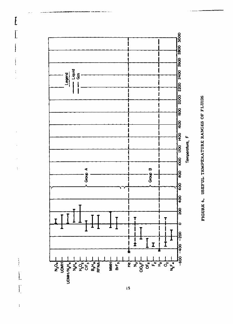
Fluid Compatibility
The fluids considered in this program and their useful temperature ranges are
shown in Figure 6. As shown by Figure 6, the fluids could be divided into two groups on
the basis of minimum service temperature. It was noted that the lower temperature ex-
treme for Group A was approximately equal to the lower design-temperature (-100 F)limit for AM-355 and 17-4PH.
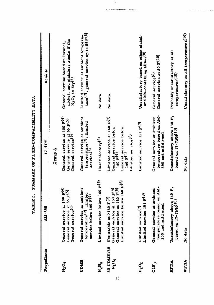
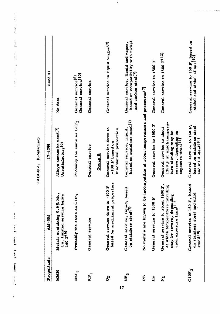
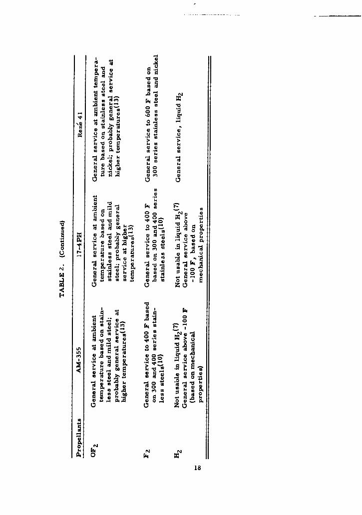
A summary of the compatibility data found for the compatibility of AM-355,17-4PH, and Rene 41 with the fluids is given in Table 2. Compatibility data for these
three materials with propellants are generally scarce and are nonexistent for some
combinations. Also, many of the available data are contradictory. Therefore, esti-mates of the compatibility with some fluids have been extrapolated on the basis of data
for other materials with similar chemical compositions. The following conclusions can
be made on the basis of the data in Table 2:
(1) AM-355 is acceptable for general service with the majority of fluids.
(2) 17-4PH is acceptable for general service with the majority of fluids.
It is unsatisfactory for use with hydrazine and NMH at all temperatures.
(3) Rene 41 is acceptable for general service with the exception that no
data were found for hydrazine, 50 UDMH/50 hydrazine mixtures, andMMH. It is unsatisfactory for use with hydrogen peroxide.
Other data collected during the program indicate that the 18-8 type stainless steels
are possible materials of construction for use with UDMH, UDMH/hydrazine mixtures,MMH, and hydrogen peroxide, as are many of the aluminum alloys.
Conclusions
Three materials were selected for minimum-weight fittings. Rene 41 can be used
for the entire temperature range, -423 to +1500 F, whereas AM-355 and 17-4PH are
restricted to the limits of -100 and 600 F. Within the narrower range, use of AM-355
or 17-4PH would result in a lighter fitting than would use of Rene 41. Also, both AM-355
and 17-4PH are more readily available and cost less than Rene 41. Although Type 347
stainless steel is widely used in this limited temperature range, a comparison of the
yield strength-to-density ratio of Type 347 with that of AM-355 or 17-4PH (Figure 2)
shows that a weight penalty might result if it were used. It is recognized that Type 347
is more readily available, is more easily machined, and has excellent compatibility.
However minimum weight is considered to be a more critical selection criterion when
designing for missile applications. Therefore, when considering the choice of materials
three temperature service ranges are identifiable and three materials appear to be the
best choice for these temperature ranges:
13
1.0
•Ren 41
0.9
0.8
• 0.7
0.6
0.2'500 -400 -300 -200 -100 0 100
Temperature, F
FIGURE 5. NOTCHED (Kt=6.3)/UNNOTCHED TENSILE RATIO VS. TEMPERATURE(TRANSVERSE)
Source: References (2) and (3).
14
I I
I I'
" I II I_
-iiI I
I I
I I "I g N •
" "I I "C .,.
I I__•I ,I________,, I i__.
.,;.
________II_
14
4) 44
0 u
4)) ca 4
4 0w 0
to
44 V),g .4)~4 S -
4) 4 Z * 00 4)
.Ln o~ ..
r4) ~ 10 0 Wol 4)
t:00
%04 0
A4 ý4 r
o ~ 4 144 Z 4)4 -4 n)) ** 4~W
o 000 0 -4 0. ". .4),*, -,4 *.4 ,4*4 .,44 -2 02 2 04
k ~ ~ $44a N4 k k ;4
4) -4)
j. 4-b k k ~ .k
00 20 4%0&
'4 0 0 )04 n c
N 0n' N
0-CD
4)4
cn~~ 0 0 00 a. 0 4
0 -0
P4 0 Z NP4 0 a
.4 tZ 1 0r 10 +;, th1t
0 0
4j "-4a 4 .
ID 0000
P4 14 k 4
0 $4%44 '0- 4 2 4 P4
"..' ".4 ~.4 'o 0* .
-,I) 44b 4) o~4 4)
4)& 4) o) 404' o)4)
4) A
$4. 4a 40a-. 04 a. 4 .448
0 o o -
to 04 14) P4 uf 4 ý 04)~~ ~ (4 8.0~4 .
P4)04)
01'0 ~ 44 0 4 8 'o ~~ i .0404 ~
0Os~4 0 0 (
8.40 4 S 4. . 0 4 4)in 0> 0 4a 00a4 (44
4;)
4) 0
- .0 1'~~-004 04. 44 0A 1-
4&. 0 44 ) n
UU k a j 00t
44)
14)o
& I0 m P0
0 -4
17
Z4~
-41-
4) 4)~4 4
4-44
~4J0) PO
00
4J.
4-b-
a t~ to ., 1> r 14)~0U 4, A)44
0 0 ZO u
00 (d toz m t
0
4)*)~ 4* 44
.0z 0
0. In
po .0 4) 44'4) 0
fn~4 .0v4
0 0 ZAO 4
k~ 44 N N0
to 0 ~0 k 0 4 18
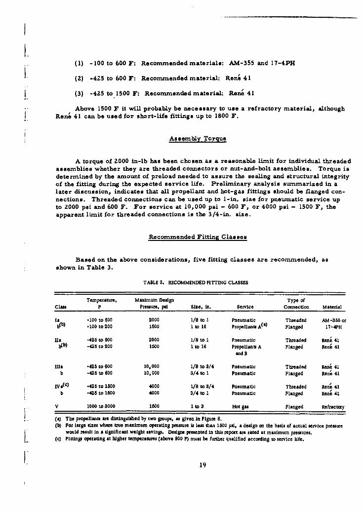
(1) -100 to 600 F: Recommended materials: AM-355 and 17-4PH
(2) -425 to 600 F: Recommended material: Rene 41
(3) -425 to 1500 F: Recommended material: Rem' 41
Above 1500 F it will probably be necessary to use a refractory material, althoughRene 41 can be used for short-life fittings up to 1800 F.
Assembly Torque
A torque of 2000 in-lb has been chosen as a reasonable limit for individual threadedassemblies whether they are threaded connectors or nut-and-bolt assemblies. Torque isdetermined by the amount of preload needed to assure the sealing and structural integrityof the fitting during the expected service life. Preliminary analysis summarized in alater discussion, indicates that all propellant and hot-gas fittings should be flanged con-nections. Threaded connections can be used up to 1-in. size for pneumatic service upto 2000 psi and 600 F. For service at 10,000 psi - 600 F, or 4000 psi - 1500 F, theapparent limit for threaded connections is the 3/4-in. size.
Recommended Fitting Classes
Based on the above considerations, five fitting classes are recommended, asshown in Table 3.
TABLE 3. RECOMMENDED FITTING CLASSES
Temperature. Maximum Design Type ofClass F Pressure. psi Size, in. Service Connection Material
la -100 to 600 2000 1/8 to I Pneumatic Threaded AM -355 orb(b) -100 to 200 1500 1 to 16 Propellants A(a) Flanged 17-4PH
Ha -425 to 600 2000 1/8 to 1 Pneumatic Threaded Rene 41b(b) -428 to 200 1800 1 to 16 Propellants A Flanged Rene 41
and B
lila -425 to 600 10,000 1/8 to 3/4 Pneumatic Threaded Rene 41b -425 to 600 10,000 3/4 to 1 Pneumatic Flanged Rena 41
IVa(c) -425 to 1500 4000 1/8 to 3/4 Pneumatic Threaded Rene 41b -428 to 1500 4000 3/4 to 1 Pneumatic Flanged Rena 41
V 1000 to 3000 1800 1 to 3 Hot gas Flanged Refractory
(a) The propellants are distinguished by two groups, as given in Figure 6.(b) For large sizes where true maximum operating pressure is less than 1500 psi, a design on the basis of actual service pressure
would result in a significant weight savings. Designs presented in this report are rated at maximum pressures.S(c) Fittings operating at higher temperatures (above 800 F) must be further qualified according to service life.
19
0.011Class T a-b - -(Ren1 41)
o.010
Class oaClass 1!'• (AM-355)
0.009(Rent 41)
Class Mrr,(Rent 41)
0.00/
0.007
0.006
Q005
0.004
0.003
0.002Note: Weight comparisons
are based on the weightof tubing equal in
0__001 length to 1.5x diameter
0 - -- _
a 4 T 2 0 4 T
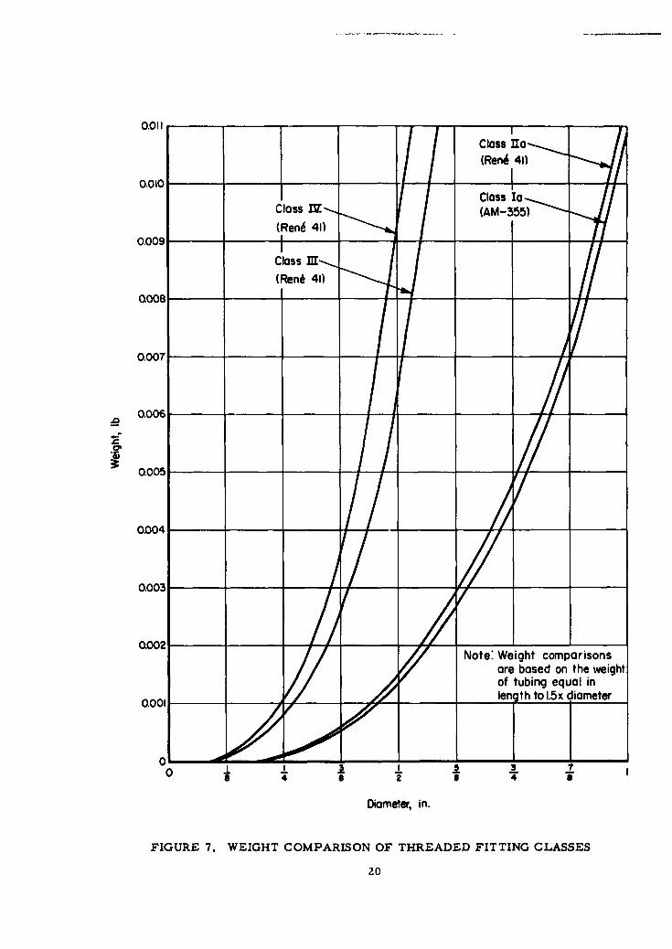
Diameter, in.
FIGURE 7. WEIGHT COMPARISON OF THREADED FITTING CLASSES
20
Class I is distinguished from Class II by the lower temperature limit, whichallows for use of AM-355 or 17-4PH alloys. The high-pressure and high-temperaturefittings are separated into Classes Ill and IV, on the basis of maximum service tempera-ture. The Class IV fittings must be designed for a specified service life because ofcreep. Weight comparisons based on equivalent tube lengths (Figure 7) show that a
1/2-in. Class IV fitting may be 46.5 per cent heavier than a 1/2-in. Class lil fitting.
A 1-in. Class lia fitting may be 4. 7 per cent heavier than a 1-in. Class la fitting. How-ever, the total weight increase per fitting may amount to less than 0. 0 1 pound. There-fore, a class simplification is possible if these additional weights are not considered to
be a severe penalty.
Classes iI and IV are subdivided because of the 2000 in-lb torque limitation. Itdoes not appear possible to overcome this limiting factor since the torque requirementfor the 3/4 to 1-in. range is beyond a reasonable expectation of a man's capability withreasonable wrench lengths.
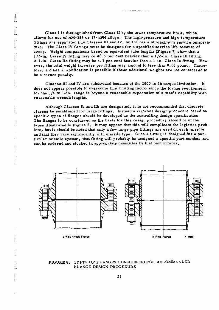
Although Classes Ib and lib are designated, it is not recommended that discreteclasses be established for large fittings. Instead a rigorous design procedure based onspecific types of flanges should be developed as the controlling design specification.The flanges to be considered as the basis for this design procedure should be of thetypes illustrated in Figure 8. It may appear that this will complicate the logistics prob-lem, but it should be noted that only a few large pipe fittings are used on each missile
and that they vary significantly with missile type. Once a fitting is designed for a par-
ticular missile system, that fitting will probably be assigned a specific part number andcan be ordered and stocked in appropriate quantities by that part number.
a Weld-Neck Flange b. Ring Flange A-.4434
FIGURE 8. TYPES OF FLANGES CONSIDERED FOR RECOMMENDEDFLANGE DESIGN PROCEDURE
21

References
(1) "Integrated Pressure Systems and Components (Portable and Installed)", Air ForceTechnical Manual T.O. 00-25-223 (February 1, 1962).
(2) Churchill, J. L., and Watson, J. F., "Properties of R-41 Sheet, A Vacuum-Melted, Nickel Based Alloy", Rept MGR-164, Convair Astronautics Division ofGeneral Dynamics Corporation (June 19, 1960).
(3) Christian, J. L., "Physical and Mechanical Properties of Pressure VesselMaterials for Application in a Cryogenic Environment", ASD-TDR-62-258(March 1962).
(4) Liberto, Ralph R., "Storable Propellant Data for the Titan II Program", BellAerospace Systems Company, Contract No. AF 04(694)-72 (March 1962).
(5) Liberto, Ralph R., "Storable Propellant Data for the Titan II Program", BellAerospace Systems Company, Report No. AFBMD-TR-61-55, Contract No.AF 04(647)-846 (July, 1961).
(6) Headquarters Office Instruction Data Sheets, HOI 74-30-1 through HOI 74-30-13,6593 Test Group Development, Edwards Air Force Base, California.
(7) Liquid Propellants Manual. Liquid Propellants Information Agency, ContractNORD 7386.
(8) "Compatibility of Materials With Demazine", Food Machinery and ChemicalCorp., Inorganic Research and Development Department.
(9) Bloom, Ralph, Weeks, Loren E., and Raleigh, Charles W., "Materials forConstruction of Equipment .n Use with Hydrogen Peroxide", Becco ChemicalDivision, Food Machinery and Chemical Corp. (1959).
(10) Boyd, W. K., and White, E. L., "Compatibility of Rocket Propellants WithMaterials of Construction", Defense Metals Information Center, MemorandumNo. 65 (September 15, 1960).
(11) Private communication from Herbert J. Wagner and Carl Lund, Battelle MemorialInstitute.
(12) Baughman, R. A., "Gas Atmosphere Effects on 32367 Metals", General ElectricCompany Interim Progress Report No. 3R59AGT 137, Contract AF 33 (616)-5667(February 15, 1959).
(13) "Oxygen Difluoride (OF 2 )", Product Data Sheet, Product Development Department,General Chemical Division, Allied Chemical Corporation (November, 1962).
22

i.
II
FITTING-TO-FITTING CONNECTION
Design Parameters
Designs Considered
Design Procedure for Threaded Fittings
Design Procedure for Bolted Fittings
Application of Computer to Optimization of Design
References
I
I.
FITTING- TO-FITTING CONNECTIONi.During the course of Phase I, many methods of assembling a mechanical con-
nection in a pressurized piping system were studied. Evaluation of these concepts,however, made it apparent that none could compete in simplicity, ruggedness, andreliability with the conventional attachments consisting of either threaded nuts matedwith threaded stub ends, in small sizes, or bolted-flanged connections in larger sizes.A comparatively large amount of experience with such structures is available, as arethe results of substantial analytical and experimental research on threads, bolts, nuts,and flanges. These data are extremely helpful in establishing reliable designs in a re-latively short time. In addition, designs based on these configurations can benefit fromimprovements which may be made in the future on such critical, basic mechanicalelements.
While the fitting-to-fitting connection designs are conventional in the sense thatthreaded or bolted-flanged connections are basic configurations, the proposed designscontain a number of unique features in which light weight, ruggedness, and reliabilityare achieved by use of high-strength materials and suitable design procedures. To aidin the establishment of fitting classes, preliminary designs of five representative fittingshave been prepared. Three of these correspond to the recommended classes (seeTable 4), whereas the other two are pre-ented for illustrative purposes only. Thesefive designs are:
(1) 1-in. threaded fitting, maximum pressure 2000 psi, temperaturerange -100 to 600 F (Class Ia)
(2) 1/8-in. threaded fitting, maximum pressure 10,000 psi, temperaturerange -425 to 600 F (Class lia)
(3) 1-in. flanged fitting, maximum pressure 2000 psi, temperaturerange -100 to 600 F (for comparison with Class Ia)
(4) 1-in. flanged fitting, maximum pressure 10, 000 psi, temperaturerange -100 to 600 F and 4,000 psi at 1500 F
(5) 3-in. flanged fitting, maximum pressure 1500 psi, temperaturerange -100 to 200 F (Class Ib).
In the following discussion the significant design ?arameters involved in designinga mechanical connection are first presented in general terms. Graphs and equationsare given to indicate the approximate magnitude and significance of the effect of eachparameter on the final design. Subsequently, the basic features of each selected designare described. Load and temperature factors, previously discussed in general terms,are applied to the specific fitting designs to illustrate the design procedure. The dis-cussion is presented in four sections:
* Design Parameters
- Designs Considered
L 0 Design Procedure for Threaded Fittings
0 Design Procedure for Bolted Fittings
0 Application of Computer to Optimization of Design
23
Design Parameters
The general discussion of design parameters presented below enumerates andexplains the effects on the structural components of the fitting-to-fitting connection ofsuch factors as structural loads, seal seating loads, preload, temperature, and fatigue.Also, the interactions between the seal, the tube-to-fitting joint, and the fitting-to-fitting structure are briefly discussed.
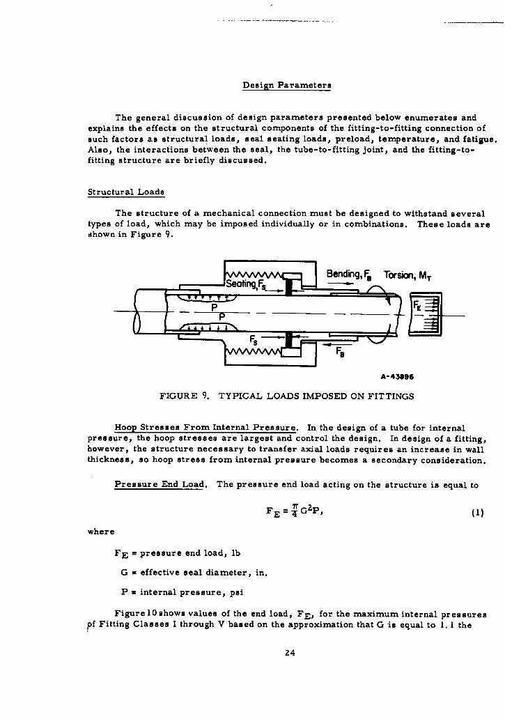
Structural Loads
The structure of a mechanical connection must be designed to withstand severaltypes of load, which may be imposed individually or in combinations. These loads areshown in Figure 9.
Bending, FE Torsion, MTSe Fting ,,F s M
ii
A-43896
FIGURE 9. TYPICAL LOADS IMPOSED ON FITTINGS
Hoop Stresses From Internal Pressure. In the design of a tube for internalpressure, the hoop stresses are largest and control the design. In design of a fitting,however, the structure necessary to transfer axial loads requires an increase in wallthickness, so hoop stress from internal pressure becomes a secondary consideration.
Pressure End Load. The pressure end load acting on the structure is equal to
FE = •G 2 P, (1)
where
FE = pressure end load, lb
G = effective seal diameter, in.
P = internal pressure, psi
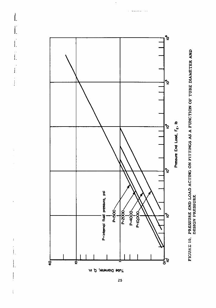
Figure 10 shows values of the end load, FE, for the maximum internal pressurespf Fitting Classes I through V based on the approximation that G is equal to 1. 1 the
24
I.0
1.1
2
LLrz
E-4
CL 0
0
0 -
a.a
00
252
tubing diameter. For the larger sizes, this load becomes very high: 360,000 lb for a
16-in. fitting withstanding 1500-psi internal fluid pressure.
In some systems, the pressure end load may be absorbed primarily by anchors
or clamps rather than transmitted through the fitting. In such systems, it may be
possible to use lighter fittings. However, for general use fittings must be designed to
withstand the total pressure end-load.
Bending Moments. A bending moment, M, producing bending loads, FB, may be
present because of tubing misalignment, thermal expansion or contraction of the tubing
system, vibrations, displacements of anchors, or acceleration forces. Bending mo-
ments imposed on a fitting in a tubing system cannot be determined in advance, since
these moments depend upon the specific tubing system, its operating conditions and the
location of the fitting in the system. However, some limits, even if arbitrary, must be
established to make design possible. For the fitting designs presented in this report the
design limits are based on (1) the strength of the tube in the system and (2) the strength
of equipment (compressors, pumps, pressure vessels, etc.) to which the tubing system
is attached.
The maximum bending moment that can be applied to a fitting through the attachedtubing is given by the equation
M = SZ, (2)
where
S = limiting stress of tube material, psi
Z = section modulus of tube cross section, in. 3
Since both S and Z in Equation (2) depend on the material used for the tubing and itswall thickness, the bending moment, M, can be established only after the tube is se-lected. In the following, a procedure for establishing the design moment is shown foran assumed tube material and related wall thickness. Analogous bending moments forother tubing can readily be established by the same procedure.
It is assumed for illustrations of the procedure that the tube will be made ofAM-350 stainless steel. This material is being used to some extent in missiles and,because of its high yield strength, a lightweight tube would be possible. The pertinentproperties of AM-350 are:
Yield Strength at 70 F(14)*, psi 150,000
Fatigue Strength at 70 F( 1 ;), psi
105 cycles 95,000106 cycles 85,000107 cycles 84,000
On the basis of the yield strength, S in Equation (2) could be as high as 150, 000 psi.However, considering the requirement that the fitting, and therefore the tubing must bedesigned to withstand 200,000 cycles of reversed bending,** it is apparent that the fatiguestrength rather than the yield strength will control.ONumbers in parenthesis denote references listed on page 77."Paragraph III 2 g (page 5) Exhibit A "Technical Requirements, Development of Mechanical Fittings". Contract AF
No. 04(611)-8176. March 13, 1962.26
The fatigue strength of AM-350 for 200,000 cycles is about 90,000 psi. This, ofcourse, is based on a smooth-specimen fatigue tests. In tubing systems there will bepoints of stress intensification at clamps and at curved tube sections. The stress-intensification factors may be of the order of two or larger. Accordingly, a fatigue
stress limit of 50,000 psi has been used in computing the bending moment limit fromEquation (2).
To compute the design bending moment by Equation (2), it is also necessary todetermine the tube wall thickness, since the section modulus of the tube depends uponits thickness. Tube thickness can be computed with the following equation (based onhoop stresses):
t D PD >.005, (3)
2Sh 200,000
where
t = tube-wall thickness, in.
P = internal pressure, psi
D = tube diameter, in.
Sh = design stress, taken as two-thirds of the yieldstrength of AM-350 at 70 F
The thickness computed from Equation (3) can be very small, e. g., . 001 in. for1/8-in. tubing at 1500 psi. It is improbable that such very thin-walled tubing will beused. Accordingly, a minimum thickness of 0. 005 in. has been used as the lower limitfor tube thickness, t, in cases when Equation (3) gives values smaller than this limit.
For thin-walled tubing, the section modulus can be closely approximated by
z 702t (4)4
By substituting the value S = 50, 000 and the expressions t PD and Z = 72Dt in
Equation (2), the bending moment can be determined as
M = 0. 197 PD 3
t >. 005 (5)
When t = 0. 005, the bending moment is
M = 197D 2 . (6)
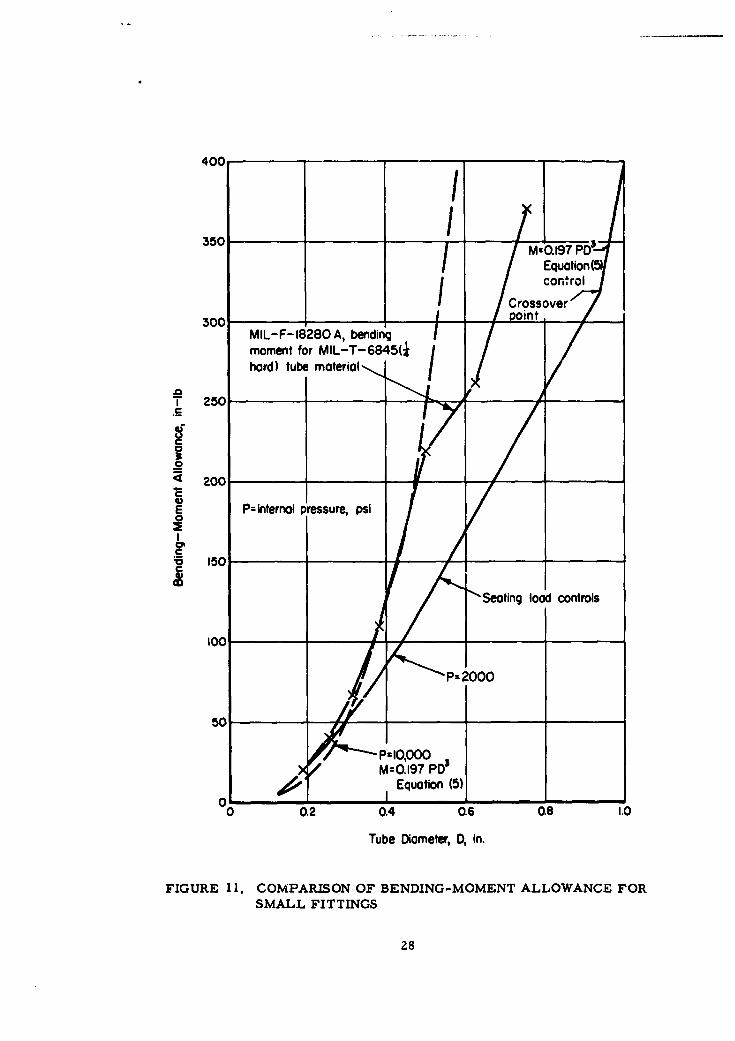
In smaller fittings for lower pressures the design will be controlled by the seal-seating load (discussed in the next section); hence, there will be a substantially largerbending-moment allowance than indicated directly by Equations (5) and (6). The approxi-mate bending-moment allowance for small fittings is shown on Figure 11, along withbending-moment requirements implied by MIL-F- 18280A, Par. 4.3.3.3.3 forcomparison.
27
400 - _/
350 I / M-o.17PD'/ / E~tion(513
Equation(5control_______ _______I / Crossoverpo /ist r;,ov,.
300 ____ itMIL-F-18280 A, bendingmoment for MIL-T-6845( Ihard) tube moterial- /I.
.2
S20
200
a•6 150 -IC
at d intrnltresuelps
50
001/M=0.197 POs0SeatingEquotion l5) 1
0 0.2 0.4 0.6 0.8 1.0
Tube Diameter, D, in.
FIGURE 11. COMPARISON OF BENDING-MOMENT ALLOWANCE FORSMALL FITTINGS
28
While Equations (5) and (6) provide a reasonable design basis for small fittings,the bending moments calculated may be unnecessarily high for large fittings. The limi-tations on bending moments which can be applied to equipment to which the tubing isattached are not known; however, some indication of the limits may be obtained fromthe bending moments permitted on the piping connections to steam turbines( 1 7 ), asshown on Figure 12. It is apparent that, even for equipment as heavily constructed aspower-plant steam turbines, the bending-moment allowance is substantially less thanthat given by Equation (5).
Another general indication of typical bending moments on flanged joints given byRossheim and Markl( 1 8 ) is
M = 60 (D + 3)3 in-lb. (7)
Equation (7) was originally developed as part of a review of a large number of stresscalculations on piping systems. It may be considered as a typical bending moment thatmay occur in piping systems in power plants, chemical process plants, and oil re-fineries. Equation (7) is also plotted on Figure 12.
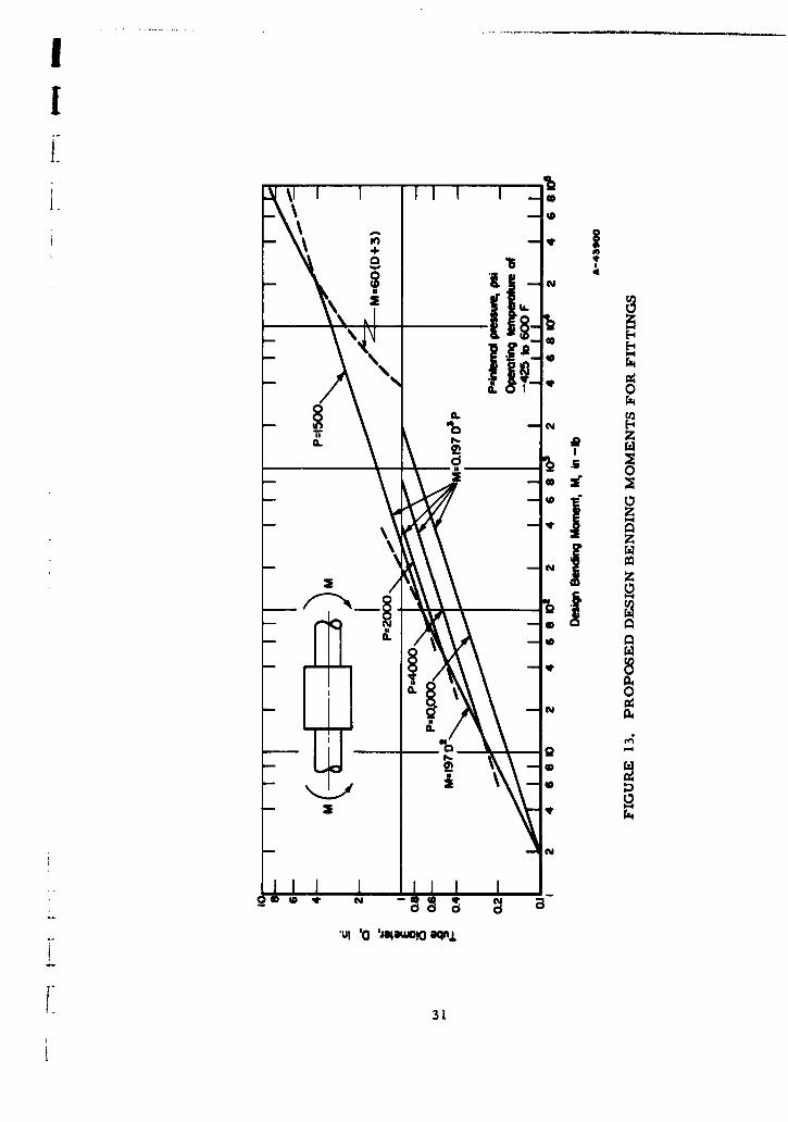
Design bending moments obtained from the larger of the moments from Equa-tions (5) and (6), but not exceeding the moment obtained from Equation (7), are shownon Figure 13. These are the moments proposed for use in designing the fitting-to-fitting structure.
External Axial and Torsional Loads. External axial and torsional loads arisefrom the same causes as do bending loads. External axial loads are usually minor andcan be discounted. Torsional loads are basically limited to three-dimensional tubingsystems and may be a problem if sufficiently large to cause rotation of one part of thejoint with respect to the other. Rotation could cause leakage, in either threaded orbolted fittings, because the seal is disturbed. It could also cause back-off and preloadrelaxation in a threaded joint. A torsional resistance of the fitting equal to that whichcan be safely imposed on the fitting by the attached tube is suggested as a design basis.
Seal-Seating Load
Quite independent of the structural load, the fitting structure must also be de-signed to withstand those loads required to produce intimate mating between the fitting' sseal-contact faces and the seal. The factors involved are discussed on pages 97 through99. For the purpose of fitting-to-fitting design, it has been assumed that an initialseating load of 1000 lb per linear in. of gasket length is required. The seal-seatingload, FG, is given by the equation
FG = 1000 7C (lb), (8)
where G = effective seal diameter. For preliminary evaluation, G may be taken as1. 1 D, where D is the tube size, giving
FG = 3460 D (lb). (9)
29
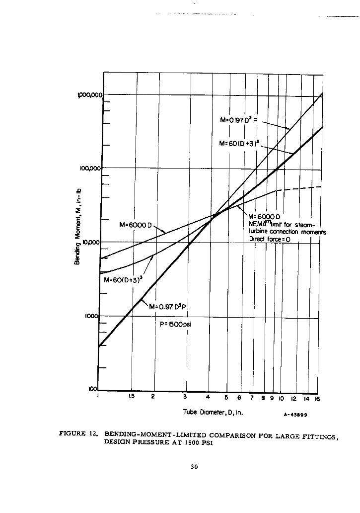
M= .197 D3 P
000Co, ooeo o
" M = 600 D ,• fr steomM NEWClimit
turbine connection moments01 ____ Direct force= 0
M=60(D+3)3
0M= 0.197 D3p
_• P = 1500 psi
11.5 2 3 4 ,5 6 7 8 9 10 12 14 16
Tube Diameter, D, in. A-43899
FIGURE 12. BENDING-MOMENT -LIMITED COMPARISON FOR LARGE FITTINGS,DESIGN PRESSURE AT 1500 PSI
30
060
+js
_ 9 Y
cN
z 0Y
40 C0
.ul 'a lsa~wOQ eqnj
1~ 31
Design Loads
The structural load applied by internal pressure is an axially symmetric load withrespect to the fitting structure, since the fitting structure, in the design concepts pro-posed, is itself symmetric about the longitudinal axis of the tube. Although an analysisof axially symmetric structures similar to the configurations used in the fittings isquite complex, theoretical methods are available which make possible a fairly preciseengineering design of axially symmetric loads such as that produced by internal pressure.
The structural load applied by bending, however, is not symmetrical. In thefollowing, a pressure, PB, equivalent to the bending moment, will be derived. Theequivalent pressure, PB, can then be handled in the same way as the actual pressvre,P, i. e., by using theoretical methods for axially symmetric loads.
When a bending load is imposed on the fitting through the piping, a maximumtensile stress will exist at one point on the circumference. A diametrically opposedmaximum compressive stress will arise simultaneously. However compressive failureis not likely to occur since the cumulative sum of the tensile stresses due to bending andthe pressure end load is greater. In any case, the minimum strength of the fitting isequal to or greater than the maximum strength of the tubing under conditions where
compressive failure might occur. The maximum tensile stress will be given by theequation
B .M (10)
where
SB = maximum bending stress in tube, psi
M = design bending load, in-lb (From Figure 12)
Z = section modulus of tube, in3 .
While this tensile stress exists at only one point on the circumference, it can beconservatively assumed that the fitting may be designed as if SB, the maximum bendingstress, existed uniformly all around the tube circumference. With this assumption, itis possible to express the bending load as an equivalent internal pressure, PB, which isgiven by the equation
4 SBtPB= ()
where
1B = equivalent internal pressure, psi, from design moment, M.
SB = maximum bending stress in tube, psi
t = tube-wall thickness, in.
D = outside diameter of tube, in.
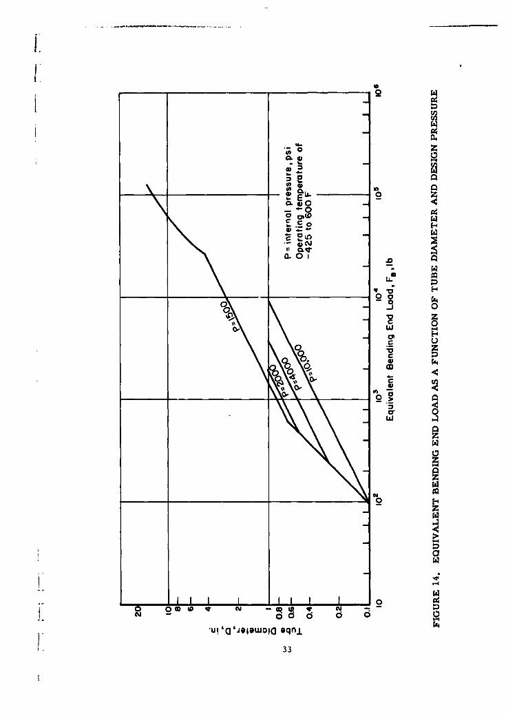
If it is assumed that a tubing material such as AM-350 precipitation-hardening
stainless steel with a design stress of Sh = 100,000 psi is used, the required tube-wallthickness can be determined by Equation (3). The equivalent axial load, FB, in termsof PB is
F- P I G 2 " (12)FB~ B4
Figure 14 shows FB as a function of size and pressure.
32
jb.
06 04
__________ 004) La0
-~0
rz 0
Laa
10-0 0 o( YtCYw -
-ui. ~ ~ ~ I( U~wo~ q
033
+- 'A CO
0 uu
0.
Sto
++
-4-i
00
0)) 0
0Y0
OD CC ]d 6 6
a joowoioqn.
34w
II
The total structural load the fitting must carry is at least equal to the sum of thepressure end load and the pressure equivalent of the bending loads. However, the total
structural load may not be the controlling design load since the load required to seat thegasket may be greater. The load required to seat the gasket given by Equation (9) andthe total structural load are plotted in Figure 15. Figure 15 shows approximately thecrossover point where either seating load or structural loads control the design. Asan example, for a 3/8-in. fitting (D = 0. 375), the seating and structural loads fordifferent internal pressures are given in Table 4. The design load for each pressure is
TABLE 4. DESIGN LOADS FOR 3/8-IN. FITTING
(-425 to 600 F Operating Temperature)
Design Seating StructuralPressure, Load, Load,
psi lb lb
1,500 1,300 6002,000 1,300 7504,000 1,300 1,000
10,000 1,300 2,100
underlined. For the 3/8-in. fitting the seating load is greater for design pressures of1500, 2000, or 4000 psi, and only for a design pressure of 10,000 psi is the structuralload the controlling factor.
Preload
Mechanical connections in a piping system are usually tightened so that an axialpreload force in excess of the design structural load is created. In flanged connections,determination and control of the preload is accomplished more easily than in threadedconnection. In threaded fittings the need for attaining a desired or required preload isoften neglected although the principles involved apply as well to threaded connections asto flanged connections.
In service the action of the imposed axial loads is to "pull" the mating parts of thefitting apart. Any degree of separation generally will lead to early failure. Thereforein order to counteract this action it is necessary to prestress the flange members of thefitting in compression an amount greater than the expected strain relaxation caused bythe tensile axial loads. Of course, preloading causes an initial tensile stress in thebolts or threaded nuts. This tensile stress may increase when the service loads areapplied, and a balance must be achieved between a preload which is sufficient to preventflange separation and a preload so large as to cause eventual tensile stress failure of thebolt or threaded nut. The factors that must be considered in determining the requiredpreload are: (1) the spring constants of the compression and tension members, (2) theminimum compressive load on the flange members needed to prevent leakage, (3) themaximum allowable stress in the tensile members, (4) the magnitude of the structuralloads, and (5) the effects of the thermal gradients.
The problem of a preloaded joint is statically indeterminate; hence, it must besolved on the basis of displacements of the structure. Calculations of displacementsbecome quite complex where stretching and bending of structural parts, changes iamoment arms, and radial effects of internal pressure are involved. A basic
35
understanding of the problem, however, can be obtained by disregarding the effects of
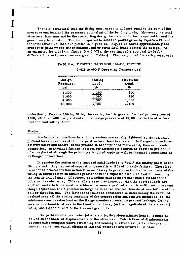
moment-arm changes and the radial components of internal pressure. The followingdiscussion is therefore limited to a simple case analogous to that shown in Figure 16,where only tensile and compressive displacements are considered.
In threaded fittings, the nut is the tension member, analogous to the bolt in Fig-
ure 16. The stub ends and seal are the compression members analogous to the ringsand seal of Figure 16. In flanged fittings, the bolts are analogous to the bolt and theflanges and seal are analogous to the rings and seal of Figure 16.
ts Ls=
2 G
Ring FealFF
A-43903
FIGURE 16. MODEL OF SIMPLIFIED PRELOAD THEORY
When the nut on the bolt is tightened, there will be an increase in bolt length and
a decrease in the length of the rings and seal, given by
FLBFLR FLG6B = _ , 6R = --LR , 5G = - ,
EBAB ERAR EGAG
where subscripts B, R, and G refer to the bolt, rings, and seal, respectively, and
F, initial bolt axial force, lb E = modulus of elasticity, psi
L = free axial length, in. A = cross-sectional area, in. 2
When a load Fs is applied (as from the attached tube in the actual fitting), the force
in the bolt in Figure 16 changes to FZ and
FZLB , LR 6LGRB EBAB R2 = W2 - Fs) ERAR= EGR--
The change in length of the bolt must remain equal to the combined changes in
lengths of the rings and gasket:
6B? - 6B = (6 R + 6G) - (6Rz + 6G2) (13)
or
(F 2 - FI) -B =(Fl - F2 + Fs) • LR + EGAG (14)
36
____ __L_ LGD n LB RB and yR + y - RG as the spring constants (in. Ilb), and
EBA B RA_ R G AG
collecting terms in Equation (14),
F2(RB + RG) = Fl (RB + RG) + FsRG, (15)
orFs
Fl = FZ- (16)RB1+--
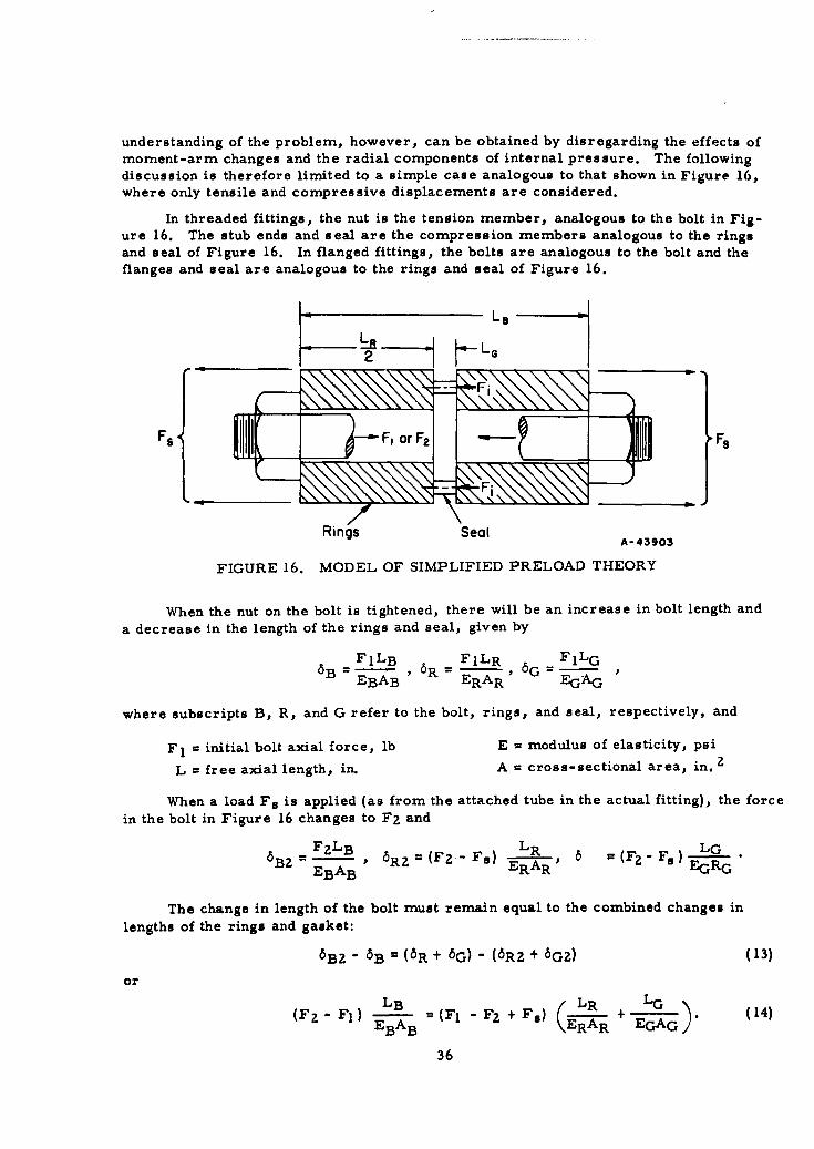
RGIf F., the maximum allowable load, and RB and RG, the spring constants, can be deter-mined or closely approximated, the analytical determination of Fl the preload is re-latively simple by means of Equation (16). However, this simple case, if changed intoa graphical representation, can be handled more easily when thermal effects are sub-sequently introduced. In a later discussion of the proposed fitting-to-fitting connections,the graphical presentation has been used extensively.
Fgt F ._ _I s
Fi-
*RSF I 4 F
0- A_+--.-Axial Displacement, 8 A-43904
FIGURE 17. GRAPHICAL ILLUSTRATION OF SIMPLIFIED PRELOAD THEORY
The graphical representation of the basic relationships is shown in Figuri 17. Aline is drawn from the origin with a slope 4 = R A second line, with slope 2F0-u RG,
is drawn to intersect the first line at F = Fl. The force applied, Fs, is drawn betweenthe two intersecting lines as shown in the figure. As can be seen in the construction,
X_ X X(RB + RG)F2 a Fl + Y. Since =RB and PG and Y + Z = = Fs:
Sz RBRGFsRBRGX
.X = F G, and with Y = XRB + RG RB
37
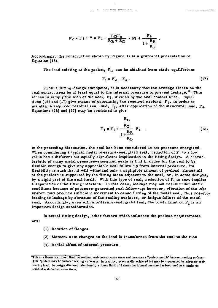
Fz =FI + Y =FI+ RGFs =F1 + FsRB +RG 1+RBRB
Accordingly, the construction shown by Figure 17 is a graphical presentation ofEquation (16).
The load existing at the gasket, Fi, can be obtained from static equilibrium:
Fi = F2 - Fs . (17)
From a fitting-design standpoint, it is necessary that the average stress on theseal contact area be at least equal to the internal pressure to prevent leakage. * Thisstress is simply the load at the seal, Fi, divided by the seal contact area. Equa-tions (16) and (17) give means of calculating the required preload, Fl, in order tomaintain a required residual seal load, Fi, after application of the structural load, Fs.Equations (16) and (17) may be combined to give
RB
F 1 = Fi + R Fs (18)1+RB1+-
RG
In the preceding discussion, the seal has been considered as not pressure energized.When considering a typical metal pressure-energized seal, reduction of Fi to a lowvalue has a different but equally significant implication in the fitting design. A charac-teristic of many metal pressure-energized seals is that in order for the seal to beflexible enough to give any appreciable seal follow-up from internal pressure, itsflexibility is such that it will withstand only a negligible amount of preload; almost allof the preload is supported by the fitting faces adjacent to the seal, or, in some designs,by a rigid part of the seal itself. With this type of seal, reduction of Fi to zero impliesa separation of the fitting interface. In this case, leakage may not result under staticconditions because of pressure-generated seal follow-up; however, vibration of the tubesystem may produce sufficient movement to cause flexing of the metal seal, thus possiblyleading to leakage by abrasion of the sealing surfaces, or fatigue failure of the metalseal. Accordingly, even with a pressure-energized seal, the lower limit on Fi is animportant design consideration.
In actual fitting design, other factors which influence the preload requirementsare:
(1) Rotation of flanges
(2) Moment-arm changes as the load is transferred from the seal to the tube
(3) Radial effect of internal pressure.
OThis is a theoretical lower limit on residual seal-contact-area streu and presumes a "perfect match" between sealing surfaces.This "perfect match" between sealing surfaces is, in practice, never really achieved but may be approached by adequate seal-seating load. In designs discussed later herein, a lower limit of 3 times the internal pressure has been used as a minimumresidual seal-contact-area stress.
38
An equation for calculating F 2 , including these factors, isF 2 = F1 + aP, (19)
where
P = internal pressure, psi- [F -ZqF(hT - hG) 2 - ZqFB 2(hD - hT) qr
Equation (19) and the definition of a. are taken from Wesatrom and Bergh( 1 9 ) and
Rodabaugh( 2 0 ). Symbols used are defined in Appendix I. The definition of a is directlyapplicable to a flanged fitting in which the flanges are identical. It may readily beadapted to a flanged fitting in which the two flanges are not identical. It may also beadapted to design of threaded fittings.
Equation (19), of course, reduces to Equation (16) when only tensile and com-
pressive deformations are considered. Equation (17) can be used with Equation (19) todetermine the relationship between F 1 , F., and Fi.
Temperature Effects
In the preceding sections only design loads essentially at ambient temperaturewere discussed. When the effects of temperature change are considered, the design
problem becomes more complex.
Creep or Relaxation. At high temperatures, the strain in a metal part under
stress cannot be considered as independent of time. In a mechanical connection, wherecreep produces a reduction in preload and in turn a reduction in stress, the problembecomes one of relaxation with variable stress.
An accurate theoretical method for calculating the performance of a threaded or
flanged fitting under creep or relaxation conditions has not been developed insofar asthe authors are aware. The problem is very complex because of the variable stressfield in the structure, nonlinear relationships that are a result of elastic-plastic de-
formations, and the introduction of time as an additional parameter.
In view of the necessity for design under creep or relaxation conditions, an
approximate theoretical design procedure has been established, as shown and discussedin Appendix II. This design method has the virtue of relative simplicity and is believedto be conservative.
Thermal Gradients. If a cold fluid, like liquid oxygen, is suddenly introduced into
a piping system, the temperatures of metal parts in direct contact with the fluid willdecrease rapidly. The temperatures of those parts not in direct contact, such as the
nut of a threaded fitting or the bolts of a bolted fitting, change less rapidly because of
the air-film resistance between parts. Accordingly, there is a period during whichthe average temperature of the interior parts of the fitting is lower than the average
39
temperature of the exterior parts. During this time effective preload decreases becauseof the relative thermal expansion of the fitting nut or bolts.
When a hot fluid is introduced into a piping system the internal parts may becomehotter than the external parts. This increases the preload, since a relative thermalcontraction of the nut or bolts occurs. However, there is also the possibility of yieldingof some member of the fitting, and if temperature equality were later re-established,the preload might be partially or completely removed, with consequent leakage.
The temperature difference is a function of the fluid properties and flow velocity,as well as the properties of the fitting and its material; hence, a numerical value forthis temperature difference can be calculated only for each specific case. To facilitatefitting design, the following limits have been set for the permissible temperaturegradients:
Maximum DesignService Temperature, Temperature Difference*
F F
-100 to 600 50-425 to 1500 200
A relatively thin-wall tube will change in temperature more rapidly than will themore massive fitting parts. Therefore, the tube will exert either a radially inward oroutward force on the flanges or stub ends, depending on whether cooling or heating isoccurring. In either case a consequent tendency for parts to rotate relative to each otherwill be a design factor. Although this factor has not been evaluated in the preliminarydesign, it should be considered when final designs are established.
A nonsymrnetrical temperature condition exists when some types of hot or coldfluids are introduced into a horizontal pipeline. The colder liquid tends to flow alongthe bottom half of the tube while the relatively warm vapor is near the top. Thisheterogeneous flow pattern causes "bowing" of the pipeline, with resulting high bendingmoments transmitted to the mechanical fitting. This condition is specific to a givenpiping system and when it is present its effect should be considered by the designer as abeinding moment which should be held within the bending-moment limits establishedpr eviously.
Modulus of Elasticity. When the temperature of a fitting changes, there is acorresponding change in the modulus of elasticity and in the effective preload, Fl, to anew value, (FO)T. For AM-355 and Rene' 41 in the temperature range under consider-ation, this effect is shown in Table 5.
With decreasing temperatures, the structure must retain a sufficient strengthmargin to prevent overstress by the consequent load increase. For the two materialsconsidered, the yield strength increases more rapidly than does the modulus of elastic-ity and, therefore, the change in preload is not a design problem. However, for in-creasing temperatures, the structure must be endowed with extra preload to maintainan adequate residual load at temperature. As an example, for AM-355 for service at600 F, this requires about I 1 per cent extra preload.*If in actual service the design limits are exceeded, use of a thermal shield is suggested. This could be simply a cylindricalsleeve at the bore of the fitting which provides a stagnant space between it and the fitting bore to retard heat transfer from thefluid to the fitting.
40
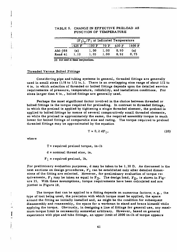
TABLE 5. CHANGE IN EFFECTIVE PRELOAD ASFUNCTION OF TEMPERATURE
(F1)T/F1 at Indicated Temperature
__ -4Z5 F -100 F 70 F 600 F 1500 F
AM-355 (a) 1.00 1.00 0.90 (a)Rene 41 1.10 1.03 1.00 0.92 0.75
(a) Not used at these temperatures.
Threaded Versus Bolted Fittings
Considering pipe and tubing systems in general, threaded fittings are generallyused in small sizes (1/8 to 1/2 in. ). There is an overlapping size range of about 1/2 to4 in. in which selection of threaded or bolted fittings depends upon the detailed servicerequirements of pressure, temperature, reliability, and installation conditions. Forsizes larger than 4 in., bolted fittings are generally used.
Perhaps the most significant factor involved in the choice between threaded orbolted fittings is the torque required for preloading. In contrast to threaded fittings,in which the preload is applied by tightening a single threaded element, the preload isapplied to bolted fittings by means of several comparatively small threaded elements,so while the preload is approximately the same, the required assembly torque is much
lower for bolted fittings of comparable size and rating. The torque required to preloadthreaded fittings may be approximated by the equation
T = 0.2 dF 1 , (20)Y
where
T = required preload torque, in-lb
d = nominal thread size, in.
F 1 = required preload, lb.
For preliminary evaluation purposes, d may be taken to be 1. 30 D. As discussed in thenext sections on design procedures, Fl can be established only after detailed dimen-sions of the fitting are selected. However, for preliminary evaluation of torque re-
quirements, F 1 may be taken as equal to FD. The design load, FD, is shown in Fig-ure 15. With these assumptions, torque requirements have been calculated and areplotted in Figure 18.
The torque that can be applied to a fitting depends on numerous factors; e. g., thetype of tool being used, the precision with which torque must be applied, the spacearound the fitting as initially installed and, as might be the condition for subsequentdisassembly and reassembly, the space for a workman to stand and brace himself whileapplying the torque. Obviously, in designing a line of fittings for general use, any maxi-mum torque limit is necessarily somewhat arbitrary. However, based on generalexperience with pipe and tube fittings, an upper limit of 2000 in-lb of torque appears
41
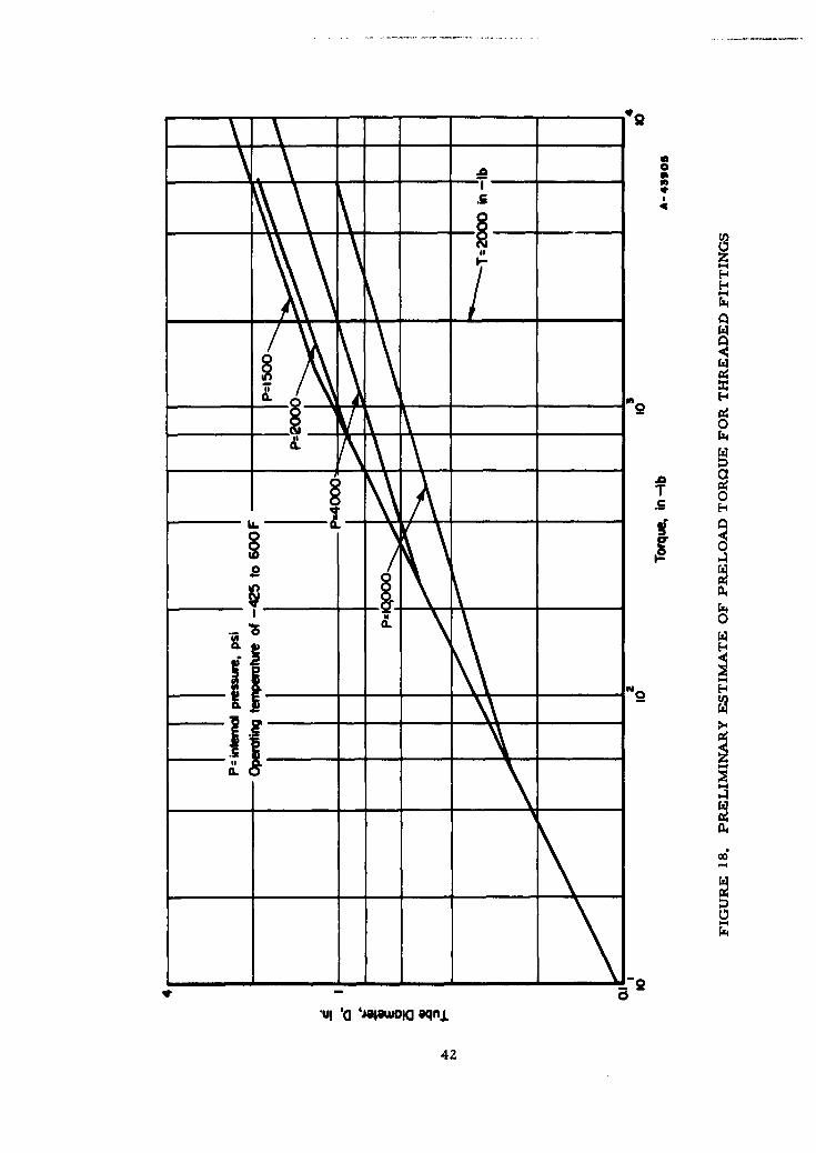
*24
a
P4
00
a..
42z
reasonable. This torque limit, when transferred to Figure 18, subdivides the fittingsinto threaded and bolted as shown in Table 6.
TABLE 6. DIVISION OF FITTINGS INTO THREADED AND BOLTED,BASED ON A MAXIMUM TORQUE OF 2000 IN-LB
(-425 to 600 F Operating Temperature)
Design Threaded-Fitting Bolted-FittingPressure, Sizes, Sizes,
psi in. in.
1,500 1/8 through 1-1/4 1-1/2 and larger2,000 1/8 through 1 (a)
(4, 000)(b) 1/8 through I (a)10,000 1/8 through 1/16 3/4 through I
(a) Larger sizes are not included in these pressure classes.(b) The design pressure of 4000 psi is shown for information only. Fittings for 4000 psi and 30-
minute life at 1500 F will probably be similar to the 10,000 psi-fittings at 600 F.
A more detailed analysis, in which actual fitting geometry is established, willshift this division, but Table 6 may be taken as a preliminary indication of the divisionbetween threaded and flanged fittings based on torque requirements. Table 3 showsslightly smaller-size divisions between threaded and bolted fittings in Classes I and IIthan shown in Table 6, reflecting an anticipation that preloads (F 1 ) will be somewhathigher than design loads (FD).
Fatigue
In general, tube or pipe fittings are subject to fatigue damage due to cyclic bending(vibration) of the piping system. When the fitting is properly preloaded, the cyclicstress in the fitting-to-fitting structure will be low and fatigue failure of the fitting-to-fitting is not anticipated. Fatigue failure, with cyclic bending of the attached pipe, ismore likely to occur at the tube-to-fitting juncture. With the details shown later herein,and assuming an adequate brazed or welded tube-to-fitting joint, fatigue failure willoccur first in the tube at the end of the hub socket. The stress-intensification factorat this juncture, however, will be fairly low if the socket wall thickness is not too large;i. e., the change in crosssection is not too great. The stress-intensification factors canbe further reduced by tapering the end of the socket.
Seal Interaction
For detail design of the fitting-to-fitting connection, presented in the next twoSsections, it was assumed that the seal considered of a flat metal ring gasket 0. 010 in.
43
thick, with appropriate diameters and width. It is expected that one or more ef the sealtypes suggested for further investigation will reduce the requirements for the fittingstructure, particularly in the realm of temperature gradients.
Tube-to-Fitting Interaction
Insofar as fitting-to-fitting design is concerned, the tube-to-fitting connectionshould be such that it does not distort the fitting structure, particularly the seatingsurface for the seal. Distortions produced at the tube-to-fitting connection can be pre-vented from distorting the sensitive parts of the fitting structure, such as threads inthreaded fittings or seal-seating surfaces in both threaded and flanged fittings, by usinga sufficiently long, relatively thin hub on the fitting stub ends (threaded fittings) or onflanges (flanged fittings). The designs shown later in Figures 20, 26, 27, 30, and 33have fairly long hubs; depending upon details of the tube-to-fitting joining process, itmay be possible to decrease the hub length. However, if the tube-to-fitting joiningprocess produces severe distortions particularly of an axially nonsymmetric type, itmay be necessary to increase the hub lengths.
Designs Considered
During the early stages of Phase I many possible methods of securing the fitting-to-fitting connection were considered. These ranged from exotic concepts like "Chinesefinger grips" to the simple and everyday nut and bolt. Four methods which were con-sidered worthy of consideration were (1) ring clamps, (Z) snap or overcenter clamps,(3) differential threads, and (4) ball-and-socket joints.
Ring Clamps
Ring clamps were devised in an attempt to duplicate a flanged connection withoutusing a great number of bolts. Generally the ring clamp is made of two mating flangeswith tapered outer surfaces. A split hoop whose inside surfaces are tapered at the sameangle as the flanges is fitted over the mating flanges. Small projections with bolt holesare provided where the two halves of the hoop are mated. Generally only two bolts areused. When these bolts are tightened a clamping force normal to the tapered faces isimposed. The axial component of the clamping force is the only force available forsealing and preloading. A typical ring clamp is shown in Figure 19a. This type ofclamp is used extensively for many commercial applications and has been used in missilesystems. Three major considerations ruled out this type of flange for an improvedfitting.
(1) It is difficult to attain the required preload and it in also difficult tocontrol initial preload within the limits necessary for the proposedservice conditions.
(2) The weight of a fitting of this type would far exceed that of standard-type flanges for high-pressure applications.
(3) It is exceedingly difficult to secure this type of joint when the tubingis misaligned.
44
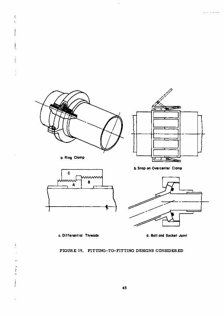
a. Ring Clamp
b. Snap on Overcenter Clamp
c. Differential Threads d. Boll and Socket Joint
FIGURE 19. FITTING-TO-FITTING DESIGNS CONSIDERED
45
Snap Clamps
Snap clamps, or overcenter clamps, like those in Figure l9b, would be placedcircumferentially around the tube and would act like a circle of bolts. However, unlikebolts, snap clamps once closed cannot be further tightened unless a take-up screw isprovided. Such a clamp would be complex in construction and would be less reliablethan a simple bolt-and-nut arrangement. Snap clamps cannot compensate for misalign-ment, cannot be readily preloaded, and are subject to early fatigue failure due to workingof the parts.
Differential Threads
The coupling shown in Figure 19c is a typical application of a differential thread.Because the threads on parts A and B have a different pitch, each will travel a differentlinear distance relative to coupling C as the coupling is rotated. An arrangement of thistype can produce high preload forces but it is difficult to assemble, it is heavy, and it issusceptible to thread seizure.
Ball and Socket
A ball-and-socket-type joint (Figure 19d) is probably the most widely acceptedmeans of joining two misaligned tubes. Because this type of joint can be made rugged,a design which can operate reliably is possible. However, in order to accommodatethe seal in any angular position within the range of misalignment specified, it is probablethat the seal would have to be placed at the ball-and-socket interface. Probably the bestapproach would be to machine a seal-retaining cavity in the ball and to make the socketsufficiently large that it could overlap the seal in any given position. A joint of this typeis nc essarily large and heavy because of the oversized socket and the oversized nut.This type of joint should not be used unless it is absolutely essential that the fitting com-pensate for misalignment. Although initial misalignment can be overcome with the ball-and-socket joint, bending moments due to vibration will still exist during operation.This type of joint is more likely to fail due to these bending moments.
Threaded and Bolted Flange Connections
Threaded and bolted flange connections have been used so universally that too oftenthey are taken for granted. Many times when structural failures occur in threaded orbolted fittings it is concluded too rapidly that the failure can be ascribed to the methodof connection. Rather, the failure is more probably the result of "insufficient" design;i. e., the fitting was not designed to take full advantage of the interacting physicalphenomena inherent in the design. Battelle's choice of threaded and bolted flange con-nections as the best means at present of securing the fitting-to-fitting connection isbased on the following:
(1) Preloading of the connection, which is considered essential forsuccessful operation of the system, is easily attained.
(2) The effects of transient thermal gradients can be overcome byjudicious choice of the spring constants RB and RG* in conjunctionwith the preload phenomena.
*See pages 35 through 39.
46
(3) Although assembly of the connection requires care, the technique isdefinitely within the capabilities of the average mechanic and thecompleted joint can be easily reassembled many times.
(4) In terms of load capability, the connection is probably lighter thanother comparable designs.
(5) The reliability of threaded and bolted connections has been demon-"strated conclusively.
It is recognized that such considerations as torque relaxation and preload controlby means of torque-wrench readings are two disadvantages inherent in these connections,especially with threaded fittings. However, because of the vast amount of experimentalwork already accomplished in these areas it is possible to adequately overcome theambiguity these factors introduce into the design process.
Conclusions
The four designs shown in Figure 19 represent only a fraction of the number ofconcepts considered. They do represent, however, the better designs possible. Ringclamps and overcenter clamps are simple and easy to assemble. They probably can beused successfully for light duty operation. Differential thread devices appear to be toounreliable for missile applications. A review of all possible means conceived of securingthe fitting-to-fitting connection revealed that none can compete with the threaded orbolted flange connections when the factors of simplicity, ruggedness, reliability, andweight are considered in combination.
Design Procedure for Threaded Fittings
Two preliminary designs of minimum-weight threaded fittings are presented inFigures 20 and 26. The first (Figure 20) is a Class Ia fitting designed for a 1-in. -
diameter tubing system which operates at a maximum internal pressure of 2000 psibetween -100 and 600 F. The second (Figure 26) is a Class IIIa fitting designed for a1/8-in. -diameter tubing system which operates at a maximum internal pressure of10,000 psi between -425 and 600 F.
Figures 20 and 26 show the basic structure of the fitting when used to connect onetube to another tube. In many applications the threaded stub end will be integral withor welded to a piece of equipment such as a compressor, pump, pressure vessel,manifold, elbow, or tee. In such applications, the attached equipment is expected tohold the fitting while the nut is being tightened, or, in the case of elbows or tees, therewill be a place on the elbow or tee body which can be held by a wrench. When usedsimply as a connector, a wrench flat or suitable reinforced knurled sections must beprovided on the threaded stub end.
47
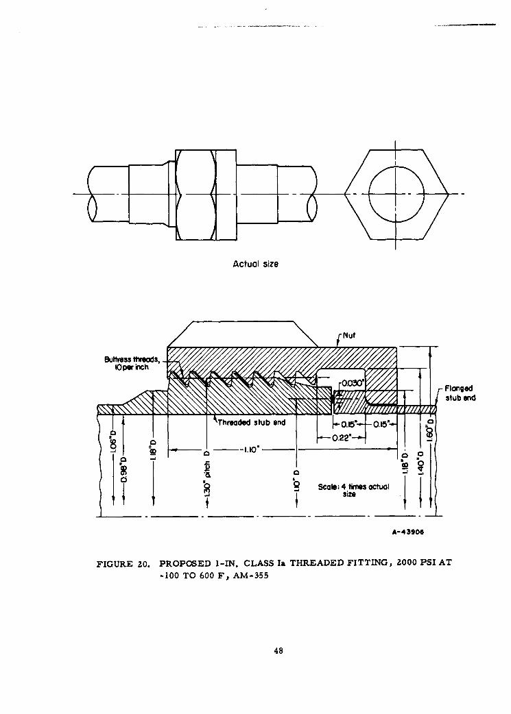
Actual size
I Z stub end
size
A-43906
FIGURE 20. PROPOSED I-IN. CLASS Ia THREADED FITTING, 2000 PSI AT
-100 TO 600 F, AM-355
48
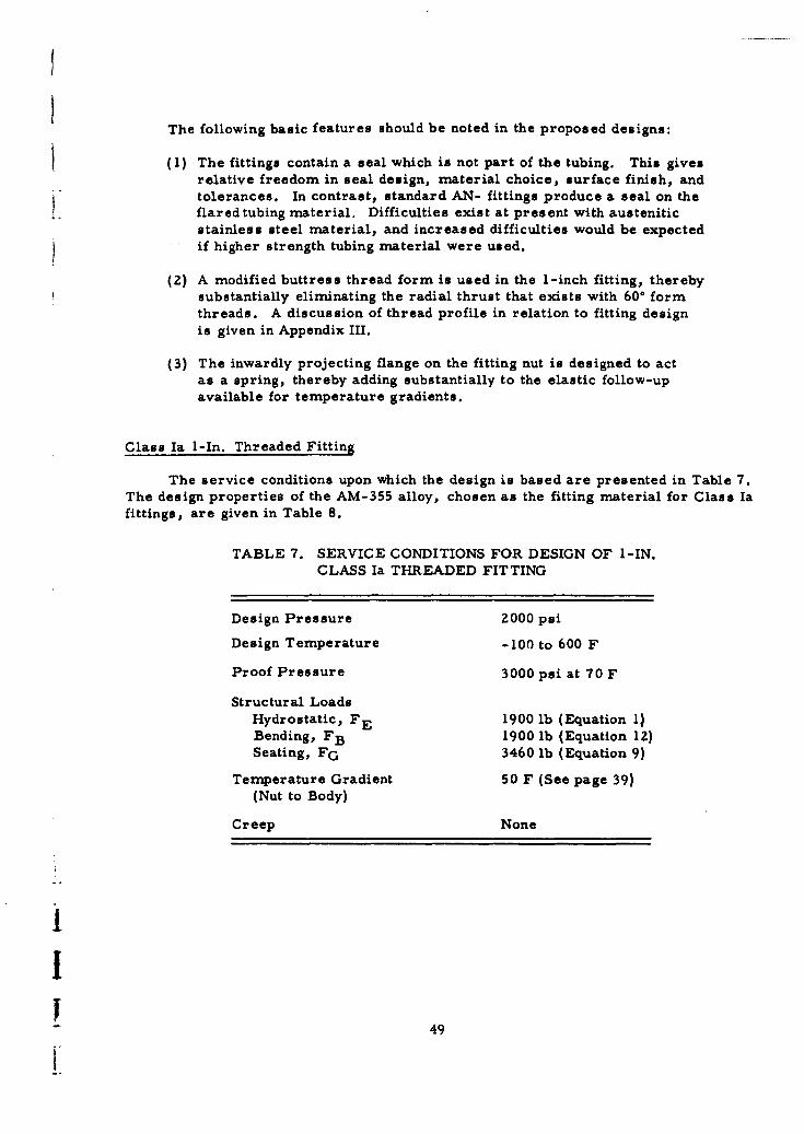
The following basic features should be noted in the proposed designs:
(1) The fittings contain a seal which is not part of the tubing. This givesrelative freedom in seal design, material choice, surface finish, andtolerances. In contrast, standard AN- fittings produce a seal on theflared tubing material. Difficulties exist at present with austeniticstainless steel material, and increased difficulties would be expectedif higher strength tubing material were used.
(2) A modified buttress thread form is used in the 1-inch fitting, therebysubstantially eliminating the radial thrust that exists with 60° formthreads. A discussion of thread profile in relation to fitting designis given in Appendix III.
(3) The inwardly projecting flange on the fitting nut is designed to actas a spring, thereby adding substantially to the elastic follow-upavailable for temperature gradients.
Class Ia I-In. Threaded Fitting
The service conditions upon which the design is based are presented in Table 7.The design properties of the AM-355 alloy, chosen as the fitting material for Class Iafittings, are given in Table 8.
TABLE 7. SERVICE CONDITIONS FOR DESIGN OF I-IN.CLASS Ia THREADED FITTING
Design Pressure 2000 psi
Design Temperature -100 to 600 F
Proof Pressure 3000 psi at 70 F
Structural Loads
Hydrostatic, FE 1900 lb (Equation 1)Bending, FB 1900 lb (Equation 12)Seating, FG 3460 lb (Equation 9)
Temperature Gradient 50 F (See page 39)(Nut to Body)
Creep None
i
- 49
TABLE 8. DESIGN PROPERTIES OF AM-355
Yield Modulus of ThermalStress, Elasticity, Coefficient of
Temperature, F 1000 psi 107 psi Expansion, in. /in. /F
-100 170 370 165 3 7 x 10⁻⁶
600 127 2.7
After the basic design requirements and the general geometrical shape have beenestablished, the detailed dimensions can be determined by an iterati-e procedure. Anestimate of dimensions is first made and the strength and displacement characteristicsare calculated. If these characteristics are not satisfactory, a second set of dimensions,based on the first approximation, is selected and the process repeated until a fitting ofsatisfactory design is obtained. The final calculations on the basis of the dimensionsshown in Figure 20 are summarized in a series of four steps:
(1) Determine the stresses for a basic imposed load, hydrostatic plusbending, of 3800 lb.
(2) Determine the displacements on the basis of a unit load.
(3) Establish preload requirements.
(4) Select from the above calculations the controlling preload conditionand recalculate the corresponding stresses.
As an aid in understanding how the various load conditions, evaluated in Step (3),influence the establishment of the necessary preload at room temperature, a series ofpreload diagrams are included. These diagrams, Figures 21 through 25, are all drawnto the same scale and if superimposed would result in a complete preload diagram whichcompares directly the maximum and minimum operating limits.
(1) Detefine the safeses for a basic Imposed load, hydrostatic plus bending, of 3800 lb.
Shear stress at thread pitch diameter, Sa = 2300 psi
Nut flange and hub maximum stress, Sb = *60,500 psi
Stub end maximum stress, Sc - 73,600 psi.
(2) Detaene the displacements on the basis of a unit loads.
Spring constant, RB = 2.47 x 10⁻⁷, composed of:
Tensile strain in the hub on the nut, (6) = 4.01 x 10⁻⁸a
Rotation of flange on nut, (G) b= 2. 06 x 10-7
*Stress and displacement calculation methods are shown in Appendix I. Because of the length of the detailed calculations, they
are not shown.
50
Spring constant, RG = 5. 483 x 10-8, composed of:Compression of flange stub end, (1 = 1.37 x 10⁻⁸
k cCompression of threaded stub end, () = 3.78 x 10⁻⁸
d
Compression of seal, (•) = 6) xe
Displacement characteristics are shown in Figure 21. The spring con-stant of the tension member, RB, is drawn with a positive slope from theorigin. The spring constant of the compression members, RG, is drawn witha negative slope and intersects RB at the required preload. This intersectionpoint is determined in the next series of calculations. Also shown in Fig-ure 21 is Fi, the minimum compressive load needed to maintain the seal.
jF.
F-
O~sp~ac~f- £44M)
FIGURE 21. BASIC PRELOAD DIAGRAM FOR I-IN. CLASS Ia THREADED FITTINGS
(3) Establish preload requirments.
Five design conditions are to be considered:
(a) Proof pressure of 1.5 times design pressure at 70 F(b) Steady (temperature) state at design pressure and 70 F(c) Minus* thermal gradient of 50 F(d) Plus thermal gradient of 50 F(e) Steady (temperature) state at design pressure and 600 F
"The maximum preload required for those five design conditions isdetermined. This preload is then used in combinati'on with the thermalgradient producing the highest load to determine the maximum stress condition.
*A "minus" temperature gradient is defined as a design condition in which the inner portions of the fitting are colder than the
"outer portions of the fttting.
51
Proof Pressure at 70 F
The design bending load and 1. 5 times the hydrostatic load are imposed.The total structural load is then(1900x 1.5)+ 1900 = 4750 lb. A preload F 1 of4500 lb is calculated by Equation (18) as required to maintain a residual sealload Fi of 600 lb after the proof pressure and design bending moment areapplied. With a seal contact area (see Figure 20) of ir x 1. 06 x 0.030 w0. 100 sq in., the residual seal stress is 6000 psi, which is three times thedesign pressure and therefore in accordance with the suggested minimumresidual seal stress.
Graphically, the total structural load of 4750 lb is measured verticallyfrom the intersection of RG and Fi in Figure 22. From the top of this line,RB is drawn and the origin is established where RB intersects the abscissa.The preload is 4500 lb and the maximum load on the nut is 5350 lb.
65350 lbFmox
5 45001b
4750 lb
2- R
4 8 12 16 20
Displacement, IO)4 in.A-44369
FIGURE 22. PRELOAD DIAGRAM FOR PROOF PRESSURE AT 70 F
Steady State at 70 F
At 70 F, only a preload of 3700 lb is required to maintain the residualseal load, F , of 600 lb when a structural load of 3800 lb is applied. Themaximum load on the nut is 4400 lb. These relationships are shown in
Figure 23.
52
" 5 n,
FMAX 4400 lb
0 F1x
o 2 R
Fi -600 lb
4 8 12 16
Displacement, 10-4 in.
A-44364
FIGURE 23. PRELOAD DIAGRAM FOR STEADY STATE AT 70 F
Minus Temperature Gradient
When a cold fluid is introduced and the average temperature of the nut
is 50 F (design limit) higher than the average temperature of the stub ends,the relative expansion of the nut is:
AT = 50 x 0.7 x 7 x 10-6= 2.45 x 10- 4 in.
When a minus temperature gradient giving a differential expansion of
AT occurs, the preload required to maintain a given residual seal load Fi isgiven by:
# 6 B + 6G + ATF1 6B + 6G F 1 , (21)
where
Fl = preload required with differential expansion, AT
F 1 = preload required without differential expansion
6.B 6G = displacements corresponding to preload Fl
53
when
FI = 3700 lb (steady state at 70 F), the corresponding
6B + 6 G = (RB + RG) 3700 = 11. 15 x I0-4 inches, and
F 13.60 x 3700 = 4510 lb.
11. 15
The effect of the minus temperature gradient is to displace RG to the left
as shown in Figure 24 because of the relative contraction of the compression
members. When the structural load of 3800 lb is measured vertically fromthe intersection of RG and Fi, the maximum load on the nut is less than the re-
quired room-temperature preload. The preload at room temperature neededto maintain the seal is 4510 ib, which is slightly greater than the previouspreload at proof pressure.
s Displacement, ATCold tfluidAF50F
8 4
R, R. R2
Fi 600 Ib
4 a 12 16 20
Displacement, 10-4 in.A-44365
FIGURE 24. PRELOAD DIAGRAM FOR MINUS TEMPERATURE GRADIENT
Plus Temperature Gradient
When a hot fluid is introduced and the average temperature of the nut is50 F lower than the average temperature of the stub ends, AT is again2. 45 x 10-4 in. However, in this case, the preload is proportionately in-
creased. On the basis of a preload of 4510 lb required to handle cold fluids,
the total load now carried by the fitting nut becomes, by Equation (16):
F = (4510 x AM.0•)+ 3800 = 6030 lb.2413.6054
54
the As shown in Figure 25, RG is displaced to the right due to expansion of
the compression members. The room temperature preload of 4510 lb estab-
lished in the previous case for a minus temperature gradient is still valid.
The structural load of 3800 lb represented by a vertical line is measured be-
tween RB and RG. The actual residual seal load Fi is approximately 2150 lband the maximum load on the nut is 6030 lb.
6030 lb Displacement, ATFmax Hot fluid, &F= +50F
4510 lb
_
451 11b
XF,
- 4 0
0 Fi0 2|
02 -R R
Fi 600 lb
00 4 8 12 16 20
Displacement, I0-6 in.A 4456
FIGURE Z5. PRELOAD DIAGRAM FOR PLUS TEMPERATURE GRADIENT
Steady State at 600 F
At a uniform temperature of 600 F, the modulus of elasticity of the
fitting material will decrease to 90 per cent of its room-temperature value.This loss reduces the effective preload from 4510 to 4060 lb. After appli-
cation of the structural load of 3800 ib, the residual seal load is 950 lb, whichis well above the design minimum of 600 lb.
(4) Select from the above calculluions the controlling preload condlition and recalculate the correspondingstress.
An initial preload of 4510 lb is necessary to provide sufficient residualgasket load when a thermal transient in which the nut temperature is 50 F
higher than the stub-end temperature is present. This preload is sufficientfor proof-pressure conditions and for steady-state conditions at 600 F. The
highest stress conditions will occur when the nut is 50 F colder than the stubends (plus temperature gradient). The stresses during this transient thermalstate will be:
55
Actual size
Clue SA IS 8 fit .. ,
FIGURE 26. PROPOSED I/8-IN. CLASS IIIa THREADED FITTING, 10,000 PSI AT-425 TO 600 F, RENE 41
56
I
70 F 600 FMax Stress in Nut, psi 96,000 86,200Max Stress in Flanged Stub End(a), psi 87,500 73,600
(a) The stresses in the flanged stub end arise directly from the structural loads. Atpreload conditions, before application of structural loads, the bending stress inthe flanged stub end is essentially zero, since the seal and point of load appU-cation from the nut are opposite each other. The maximum stress occurs at theproof-test conditions at 70 F.
The yield strength of AM-355 is 165,000 and 127,000 psi at 70 F and 600 F,respectively, and therefore a factor of safety of at least 1.47 is evident.
Class III 1/8-In. Threaded Fitting
The detail design procedure for the 1/8-in. threaded fitting shown in Figure 26 isanalogous to that of the 1-in. threaded fitting described above, with one important ex-ception. In the 1/8-in, size, the seal-seating load is 628 lb because of the need to plasti-cally yield the seal material. The structural load, even at 10,000-psi design pressure,is only 666 lb. Accordingly, there is little or no advantage to be gained in designing foroperating pressures less than 10,000 psi.
Additional Design Considerations
Accuracy of Preloading. In the calculations presented above, it was assumed thatthe desired preload could be accurately applied. In practice, accurate preloading maybe difficult. If a torque wrench is used, a preloading accuracy of about * 25 per centis the best to be expected.
Torque Relaxation. Experience with flared and flareless threaded fittings indicatesthat part of the initial torque applied to the fitting is lost with passage of time. It is notknown if the axial load also decreases, but presumably it does. At elevated tempera-tures this relaxation is intensified. Although use of high-precision buttress threadswill probably reduce thread relaxation, some relaxation may still exist, especially at
elevated temperatures. Additional preloading may be required, therefore, to com-pensate for thread relaxation. Available test data on torque relaxation and a discussionthereof are given in Appendix IV.
Overtightening Factor. Unless installation procedures are carefully controlled,threaded fittings may be overtightened. This leads to higher stresses in the fitting andthe possibility of yielding. To prevent yielding, a substantial margin must be availablein the threaded fitting for overtightening allowance. For example, MIL-F-5509A,"Fittings; Fluid Connections", requires that steel fittings be able to withstand a torqueequal to 1-1/3 times the required torque. The I-in. threaded connection is designed toprovide at least this overtightening margin. (The factor of safety is 1. 47.)
57
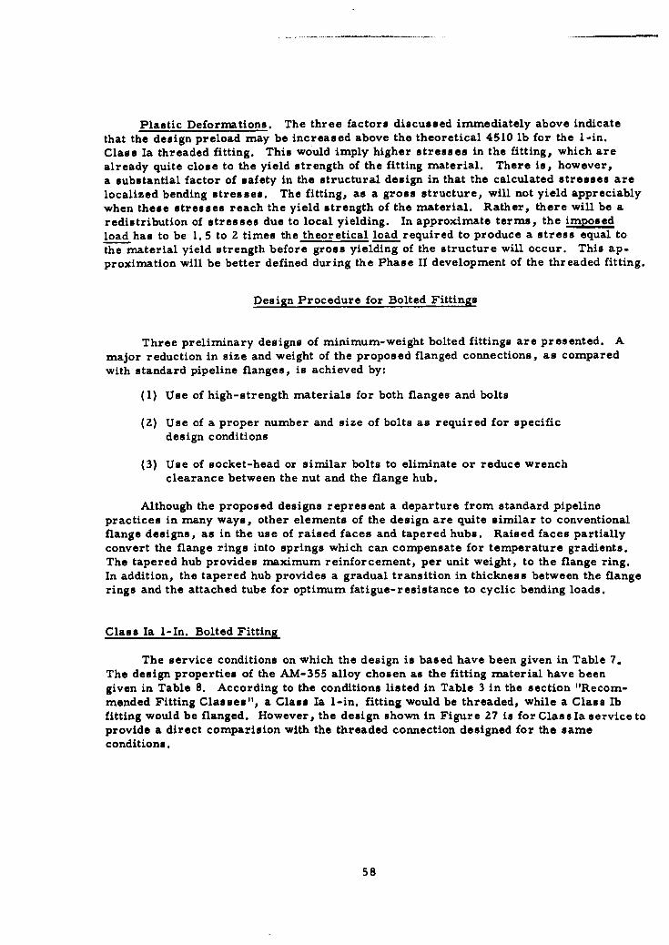
Plastic Deformations. The three factors discussed immediately above indicate
that the design preload may be increased above the theoretical 4510 lb for the 1-in.
Class Ia threaded fitting. This would imply higher stresses in the fitting, which arealready quite close to the yield strength of the fitting material. There is, however,a substantial factor of safety in the structural design in that the calculated stresses are
localized bending stresses. The fitting, as a gross structure, will not yield appreciablywhen these stresses reach the yield strength of the material. Rather, there will be a
redistribution of stresses due to local yielding. In approximate terms, the imposed
load has to be 1. 5 to 2 times the theoretical load required to produce a stress equal to
the material yield strength before gross yielding of the structure will occur. This ap-proximation will be better defined during the Phase II development of the threaded fitting.
Design Procedure for Bolted Fittings
Three preliminary designs of minimum-weight bolted fittings are presented. A
major reduction in size and weight of the proposed flanged connections, as comparedwith standard pipeline flanges, is achieved by:
(1) Use of high-strength materials for both flanges and bolts
(2) Use of a proper number and size of bolts as required for specificdesign conditions
(3) Use of socket-head or similar bolts to eliminate or reduce wrench
clearance between the nut and the flange hub.
Although the proposed designs represent a departure from standard pipeline
practices in many ways, other elements of the design are quite similar to conventionalflange designs, as in the use of raised faces and tapered hubs. Raised faces partially
convert the flange rings into springs which can compensate for temperature gradients.The tapered hub provides maximum reinforcement, per unit weight, to the flange ring.In addition, the tapered hub provides a gradual transition in thickness between the flangerings and the attached tube for optimum fatigue-resistance to cyclic bending loads.
Class Ia I-In. Bolted Fitting
The service conditions on which the design is based have been given in Table 7.The design properties of the AM-355 alloy chosen as the fitting material have been
given in Table 8. According to the conditions listed in Table 3 in the section "Recom-mended Fitting Classes", a Class Ia 1-in. fitting would be threaded, while a Class Ibfitting would be flanged. However, the design shown in Figure 27 is for Class Ia service toprovide a direct comparision with the threaded connection designed for the sameconditions.
58
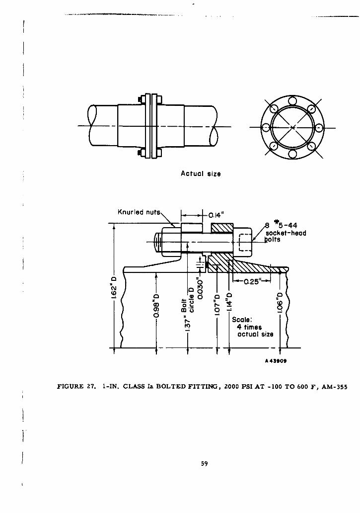
Actual size
Knurled nuts J 0.14*' 4
socket-headIlts
Cs c•' 0 Q C3o
0)0-
I- Scale:
S~4 timesS~actual size
A 43909
FIGURE 27. 1-IN. CLASS Ia BOLTED FITTING, 2000 PSI AT -100 TO 600 F, AM-355
59
Essentially the step-by-step analytical and graphical procedure used in analyzingthe Class Ia 1-inch bolted fitting is the same as the step-by-step procedure presented forthe Class Ia 1-inch threaded fitting. An iterative procedure is used to establish the de-tailed dimensions. The final series of calculations on the basis of the dimensions shownin Figure 26 are summarized in a series of four steps:
(1) Determine the stresses for a basic load, hydrostatic plus bending,of 3800 lb.
(2) Determine the displacements on the basis of unit load.
(3) Establish preload requirements.
(4) Select from the above calculations the controlling preload conditionand recalculate the corresponding stresses.
The preload diagrams presented in conjunction with these calculations do not depictthe effect of thermal gradients since subsequent analysis indicates that the required pre-load is not determined under thermal load conditions.
(1) Determine the stresses for a basic load, hydrostatic plus bending, of 3600 lb.
Tensile stress in bolts, Sb = 66,700 psi
Maximum stress in flanges, Sf = 73,000 psi
(2) Determine the displacements on the basis of unit load*.
Spring constant, RB = 7.775 x 10⁻⁷, composed of:
Tensile displacement of bolts (L) = 2.335 x I0-7a
Rotation of flanges, (4-) = 5.44 x 10-7.F b
Spring Constant, RG = 3. 213 x 10-8, composed of:
Compression of flanges, c6) = 2. 88 x 10-8
Compression of seal, (6 . x -9\F/d
The spring constants listed above describe the behavior of the flangedconnection as the bolts are tightened and the preload is applied. Subsequentapplication of structural loads in an axial direction causes the bolt load to in-crease slightly. Since changes in moment arms are small when the axialload is transferred from the seal to the flange hub, the effect of this changecan be neglected. The radial effect of internal pressure, however, is s•gni-ficant and must be included in the analysis. The decrease in initial bolt loaddue to the radial effects of internal pressure is
AF= q = 0. 174P (22)**Q
$Stes and displacement calculation methods are shown In Appendix I."This expression follows from Equation (19). In particular the last term in the definition'of a.
60
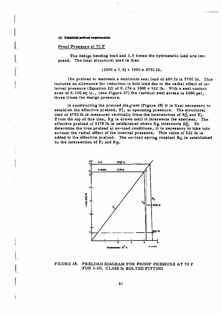
(3) Establih preload requirements.
Proof Pressure at 70 F
The design bending load and 1. 5 times the hydrostatic load are im-posed. The total structural load is then
(1900 x 1.5) + 1900 = 4750 lb.
The preload to maintain a minimum seal load of 600 lb is 5700 lb. Thisincludes an allowance for reduction in bolt load due to the radial effect of in-ternal pressure (Equation 22) of 0. 174 x 3000 = 522 lb. With a seal contactarea of 0. 100 sq in., (see Figure 27) the residual seal stress is 6000 psi,three times the design pressure.
In constructing the preload diagram (Figure 28) it is first necessary toestablish the effective preload, Fe, at operating pressure. The structuralload of 4750 lb is measured vertically from the intersection of RG and Fi.From the top of this line, RB is drawn until it intersects the abscissa. Theeffective preload of 5178 lb is established where RB intersects R6. Todetermine the true preload at no-load conditions, it is necessary to take intoaccount the radial effect of the internal pressure. This value of 522 lb isadded to the effective preload. The no-load spring constant RG is establishedby the intersection of Fi and RB.
6 - 57W01b
P-00 51 78 1b
5'
4
RS 47W0 1b
2
I 2 3 4 5
FIGURE 28. PRELOAD DIAGRAM FOR PROOF PRESSURE AT 70 FFOR 1-IN. CLASS Ia BOLTED FITTING
61
Steady State at 70 F
At 70 F, a preload of 4590 lb is required to provide the residual sealload of 600 lb after application of a structural load of 3800 lb, including theradial effect of the application of 2000-psi internal pressure, reduces the pre-load by 0. 174 x 2000 = 350 lb.
The preload diagram is constructed in the same manner as the preloaddiagram for proof-pressure conditions. This diagram is shown in Figure 29and is used to evaluate the effects of thermal gradients on the preload.
2F1 /
a 3 3
Dispocmsw , inO k. A-443o
FIGURE 29. PRELOAD DIAGRAM FOR STEADY STATE AT 70 F
Minus Thermal Gradient
When the cold fluid is introduced and the average temperature of thebolts is 50 F (design limit) higher than the average temperature of the flanges,the relative expansion of the bolts is:
AT = 50 x 0.4 x 7 x 10-6 = 1.40 x 10⁻⁴ in.
When a minus temperature gradient giving a differential expansion of
AT occurs, the preload required to maintain a given residual seal load Fi,is given by
6B + 6 G + AT 2qrrhG
6B + 6G Fl +
I
where
F preload required with differential expansion, AT
Fl = preload required with no differential expansion and
without the radial effect of internal-pressure term
6 B, 6 G = displacements corresponding to Fl.
Since F 1 = 4590 - 350 = 4240 lb (steady state at 70 F), and the cor-
responding 6 B + 6C; (RB + RG) 4240 = 34.2 x 10⁻⁴ in.,
F1 35.6-x 4240+0.174 x 2000=4760 lb1 34. 2
Plus Thermal Gradient
When hot fluid is introduced and the average temperature of the bolts is
50 F lower than the average temperature of the flanges, AT is again 1. 40 x10-4 in. In this case, the preload is proportionately increased. When a pre-
load of 5700 lb for the proof test has been applied, the maximum load carriedby flanges and bolts becomes
(5700 4 (3800 . (0. 174 x 2000) = 5670 lb
Steady State at 600 F
At a uniform temperature of 600 F, the modulus of elasticity of thematerial will decrease to 90 per cent of its room-temperature value. Theeffective preload is reduced to 5700 x 0.90 = 5130 lb. Because the radial
effect of internal pressure will further decrease the effective preload by350 lb, the residual preload is 4780 lb. The residual seal load, after appli-
cation of structural loads, is 1140 lb, which is more than ample to meet the
minimum design criterion of 600 lb (6000 psi seal-contact-area stress).
(4) Select from the above calculations the controlinag preload condition and recalculate the correspondingstresses.
A preload of 5700 lb is necessary for proof-pressure conditions and is
ample to handle thermal transients of +50 F and also steady-state conditionsat 600 F. With an initial preload of 5700 lb, the maximum stresses occurwhen the full design pressure and bending moment are applied, while the
temperature difference is such that the bolts are 50 F colder than the flanges.
The maximum stresses are:
70 F 600oFTensile stress in bolts, psi 99,600 89,600Bending stress in flanges, psi 109,000 98,000
63
The yield strength of AM-355 is 165,000 psi at 70 F and 127,000 psi at600 F. Therefore, the design provides a minimum safety factor of 1.30.
An important consideration in the design of a bolted connection is the
question of bolt selection and spacing. There are no analytical means ofdetermining optimum choices. However, there are some empirical guides
which on the basis of past experience can be used to closely approximate asatisfactory design. These guides are discussed on pages 72 and 73.
Classes III and IV 1-In. Bolted Fitting
The bolted fitting shown in Figure 30 generally illustrates the dimensions of a 1-in.bolted fitting suitable for 10,000 psi at temperatures up to 600 F when made of AM-355(Class Ill pressure and maximum temperature), and at the same time, when made ofRene 41 is suitable for 4000 psi for 30 minutes at 1500 F (Class IV) with about 100 Fmaximum thermal gradient. These designs were made to help establish the classesshown in Table 3. While design conditions do not correspond exactly to Table 3, theyare sufficiently close to illustrate the design procedure and resulting dimensionalproportions.
Design of the bolted fitting shown in Figure 30 for 10,000 psi at -100 to 600 Ffollows the same procedure as discussed for the 1-in. bolted fitting for 2000 psi at -100to 600 F. Establishing ratings for this bolted fitting at 1500 F, however, illustrates thedesign procedure for fittings where creep or relaxation occurs, and this aspect will bediscussed in the following.
The design procedure at temperatures where creep or relaxation is a dominantfactor is discussed in Appendix II. The procedure is essentially one of establishingpressure-time ratings at a specified temperature for a given fitting; i. e. , a fitting withall dimensions established and made of a specified material. In this discussion, the"given fitting" is shown in Figure 30.
Data on Reni 41 for Creep Design. As noted previously, Rene 41 was selected asthe recommended material for high-temperature design. The design analysis uses creepdata from Figure 3. 042 of Reference (15), "Master Curves for Creep and Creep Rupturefor Sheet and Bar". Specifically, the data for bar stock, heat treated at .150 F for2 hours, air cooled and aged at 1650 F for 4 hours, were used. These data are given inthe form of stress versus the Larson-Miller parameter (T+460) (20 +logl 0 t), for the0. 2 per cent creep condition. With the assumption that de/dt is independent of time, thedata can be converted to a graph of de/dt versus stress at 1500 F, as shown in Figure 31.
The relationship between creep rate and stress in the creep-stress range of10,000 to 60,000 psi can be conservatively approximated by the equation
- = 1. 3 x 10"26S4. 82 (24)
dt
where
Lp = strain, in. /in.
t = time, hr
S = stress, psi.64
Actual size
I ____________________________________________03 3_________
Knre 0 0.0694 ims
actual size0 08
FIGURE 30. I-IN. BOLTED FITTING, APPROXIMATELY CLASS 111 (10,000 PSI UP TOL 650 F) AND CLASS IV (4,000 PSI AT 1500 F, 30-MINUTE LIFE)
1 65
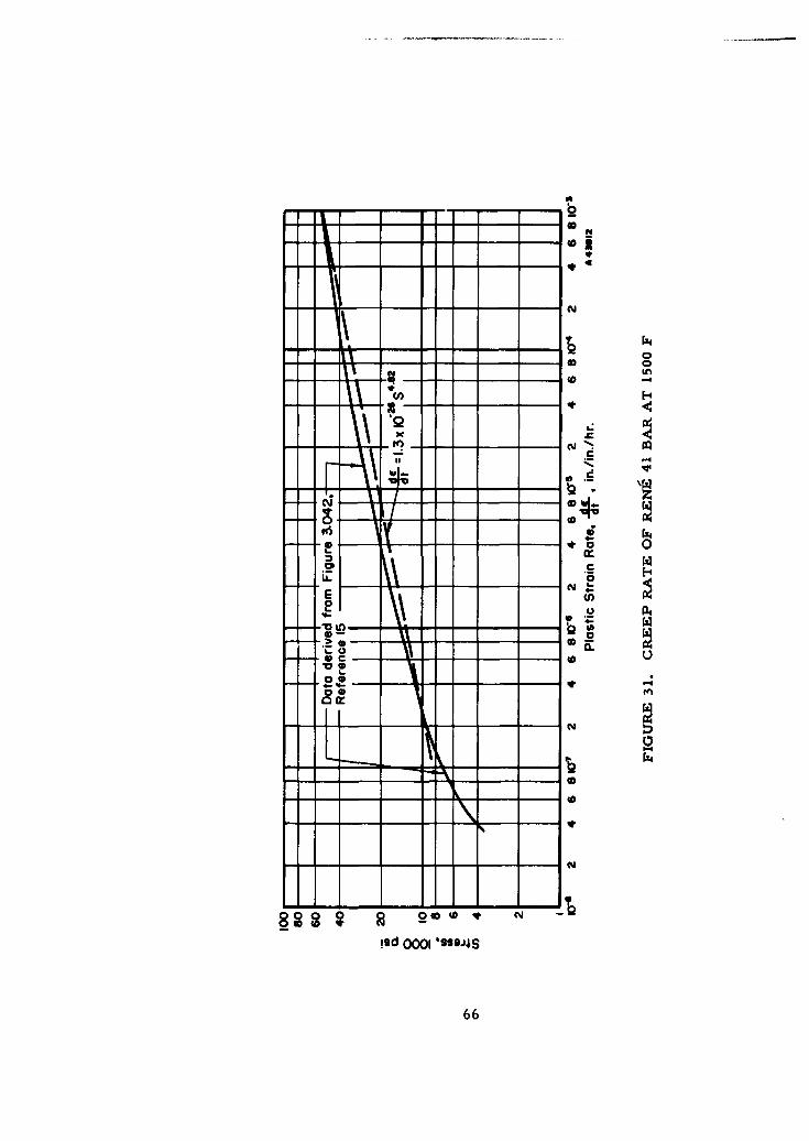
-- 403
8008 20 c!9 00 lu9*466*
Equation (24), plotted in Figure 31, is of the form - = cSn, which forms the basis forthe development in Appendix II. Additional data on Reng 41 needed for the analysis ispresented in Table 9.
II TABLE 9. DESIGN PROPERTIES OF RENE 41
70OF 1500 F
Yield Strength(a), psi 120,000 97,000Modulus of Elasticity, psi 3. 2 x 10⁷ (Er) 2. 4 x 10⁷ (ET)Coefficient of Thermal Expansion, per F 6. 8 x l1-6 8. 5 x 10⁻⁶
Pseudo-Modulue(b), El, psi, Approximately 1. 6 x 10⁷
at So = 60,000 psiand 1500 F
(a) From Reference (21).(b) From Reference (22).
Application of Creep Design Procedure. The creep design procedure establishedin Appendix I will be applied to the bolted flanged joint with the dimensions shown inFigure 30. The procedure is characterized by the following steps: (1) determinemaximum preload at room temperature,(2) determine effective preload at 1500 F, steadystate,(3) compute a time-versus-residual-bolt-stress curve, and (4) consolidate maximumoperating pressure corresponding to the residual bolt stresses for both steady state andtransient thermal conditions.
Because maximum service life is obtained with the application of maximum initialpreload, the bolts are considered to be initially tightened to their yield strength of120, 000 psi. The flanged-joint shown in Figure 30 has eight 1/4-28 bolts, each bolthaving a cross-sectional area at the root of the threads of 0. 0326 square inch. The totalcross sectional area of the bolts of the flanged joint shown in Figure 30 is therefore8 x 0. 0326 or 0. 261 square inch. The total bolt load corresponding to 120,000-psi boltstress is then 120,000 x 0. 261 = 31,400 lb. By using the stress-calculation methodsshown in Appendix I, it can be shown that a total bolt load of 31,400 lb, applied to theflanged-joint shown in Figure 30, produces a controlling stress in the flanges of 116,500psi. Since this stress is almost equal to the bolt stress of 120,000 psi, it will be as-sumed that the initial stress in both the bolts and the flanges is 120,000 psi. This as-sumption permits the use of Equation (81) of Appendix II to calculate service life, t,rather than the more complex Equation (82). In the following, the decrease in bolt stressas a function of time will be determined; it should be kept in mind that this decrease inbolt stress is due to creep of all parts of the joint, not the bolts alone.
As the temperature is increased from ambient to 1500 F, the initial preload is re-duced by a factor EI/Er, where El is the pseudo-modulus of elasticity at 1500 F (derivedas indicated in Appendix 11), and Er is the modulus of elasticity at room temperature.
Gross yielding does not occur, since the yield strength decreases at a lesser rate thandoes the modulus of elasticity.
The values of the constants in Equation (81) for Rene 41 at 1500 F are: C1 = 1. 3 x1026, n = 4. 82, and ET = 2. 4 x 10⁷. The bolt preload at 1500 F is one-half the initialpreload of 120,000 psi; that is, So is 60,000 psi. By substitution of these values,
Equation (81) becomesS~67
- St 3.82
t 600 (25)(1. 19 x 10'1 8 )(St) 3 . 82
where St = residual stress in the bolts after t hours of service life.
The effective residual bolt load at any time is simply St multiplied by the bolt areaof the flanged-joint shown in Figure 30:
F = ABSt = 0.261 St (26)
Arbitrary values may be assigned to St and the corresponding time required for thestress to relax from 60,000 psi to the chosen value can be calculated from Equation (25).
The corresponding residual bolt load given by Equation (26) can also be calculated foreach assigned valus of St. The structural loads carried by the connection, with thiseffective residual bolt load, can then be computed by the method outlined earlier, wheretemperature effects did not involve creep.
As an example, assume that St is assigned a value of 40,000 psi. From Equa-tion (25), t is found to be 1. 74 hours; i.e. , it will take 1. 74 hours for the bolt stress to
decrease from 60,000 psi to 40,000 psi. From Equation (26), with St = 40,000, theresidual bolt load at the end of 1. 74 hours is 10,430 lb.
The residual bolt load of 10,430 lb at the end of 1. 74 hours may now be consideredas if it were an initial applied bolt load F 1 . By using the method discussed earlier in
designs in which creep was not a factor, a design pressure P corresponding to an initialload F, can be obtained. For the bolted fitting shown in Figure 30, the significant fac-tors may be expressed by the equation
RBF-FS RG 2qhG
Fl = i +RG R + P(27)1i + RB1+- Q
RG
where
F 1 = 10,430 lb (in this particular example).
Fi = seal load which, in the design procedures, is required to besuch that the seal stress is not less than 3 times the pressure.
On this particular bolted fitting, the seal area (See Figure 30)is 0. 281 sq in. , hence, a minimum value of Fi is 0. 281 x3 x P = 0. 783 P.
RB and RG = spring constants of the bolted fitting discussed in the section"Preload".
Fe = structural load. This load is the sum of the hydrostatic endload, which is proportional to the pressure, and an external
bending-moment load*, which, while not necessarily pro-portional to the pressure, is considered as such in this
evaluation.
* The bending-moment design limits at high (over 600 F) temperatures should be further investigated before final designs areestablished.
68
ZqhG = displacement characteristic of the bolted fitting giving bolt-load
Q decrease due to the radial effect of internal pressure [See lastterm in definition of a under Equation (19). ]
When the displacement characteristics are evaluated for the bolted fitting shown inFigure 30, and taking F. as 1. 9 P (its value in the temperature range -425 to 600 F),L and using the design limit Fi = 0. 783 P, Equation (27) becomes
F1 = 0.783 P + 1.585 P + 0.206 P . (28)
For F 1 = 10,430 lb, Equation (28) gives P = 4050 psi. This means that the maximum
design pressure for the bolted fitting shown in Figure 30, operating at 1500 F for1. 7 hours, is 4050 psi. A series of such calculations has been made for different valuesof St; the results are shown graphically in Figure 32.
The above analysis assumed that there were no temperature gradients in the
flanged joint which, in general, probably is not a correct assumption. A criticalcondition occurs when the bolt load relaxes to 10,430 lb near the end of the servicelife along with a temperature fluctuation at that time which causes the flanges to be
200 F (design limit) cooler than the bolts. Under these conditions there will be arelative bolt expansion of:
AT = 200 x 0.86 x. 5 x 10-6 = 1.46 x 10⁻³ in.
The residual bolt load, F , is further reduced by this thermal gradient from 10,430 lbto 4900 lb; the corresponding design pressure, PI, must therefore be limited to 1900 psi.
Figure 25 shows P 1 plotted against service life, Pl being the maximum design pressurewhere the design procedure includes a 200 F thermal gradient.
Class lb 3-In. Bolted Fitting andLarger Bolted Fittings in General
The general configuration of a 3-in. bolted fitting for service with internal pressureup to 1500 psi, temperature from -100 F to +200 F is shown in Figure 33. The materialused is AM-355. The detailed design procedure is analogous to that discussed for the
1-in. Class Ia bolted fitting.
The comparison of the structural loads with the seating loads for the 3-in. fittingillustrates a general consideration in the design of larger bolted fittings. The basic
structural load for the 3-in. Class Ib bolted fitting is 29,000 lb, whereas the seating
load needed to yield the seal material is only 10,400 lb. The structural load is propor-tional to the pressure; hence, by designing for a lower pressure the weight of the fittingwould be substantially reduced. In contrast, for a I-in. Class Ia fitting, the structural
load is 3800 lb, the seating load is 3460 lb; hence, there is little to be gained by designingfor a pressure lower than 1500 psi.
L- In many piping systems in a missile, particularly in sizes over 3 in. , the actual
operating pressure may be only a fraction of the design pressure of 1500 psi specified
Sfor Class Ib and Class lIb fittings. In these large sizes, the structural load rather thanthe seal-seating load controls the design. Since the structural load is, in large part,
69
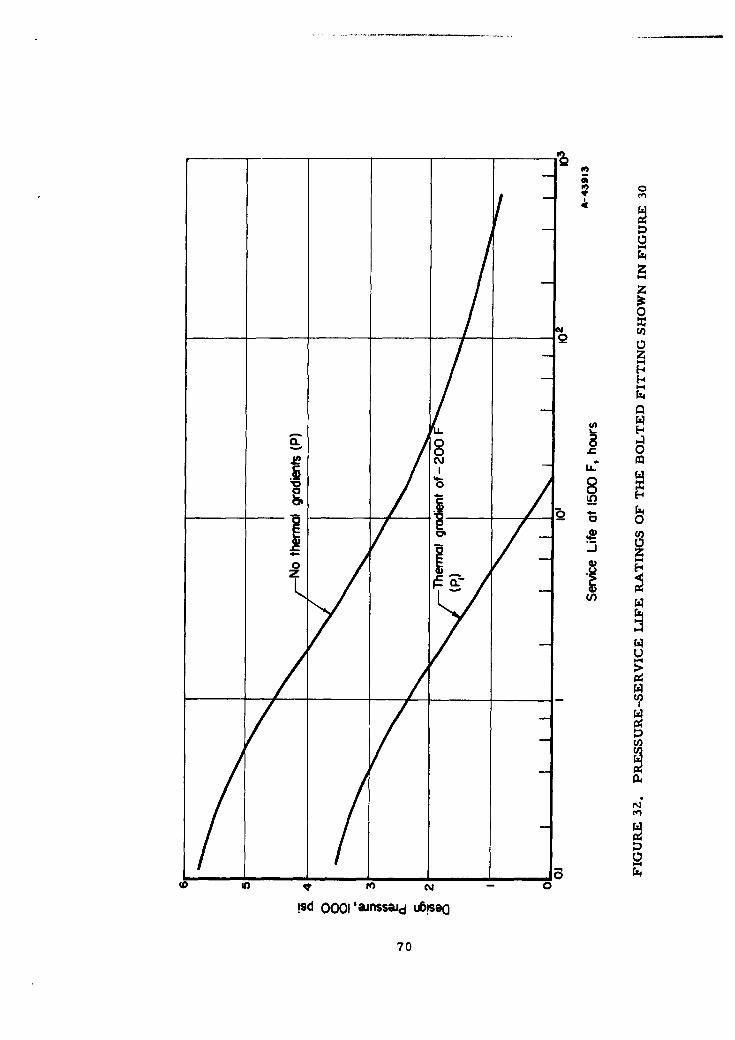
0
U)
LL
00
Is 001aissi0 0s(i 70
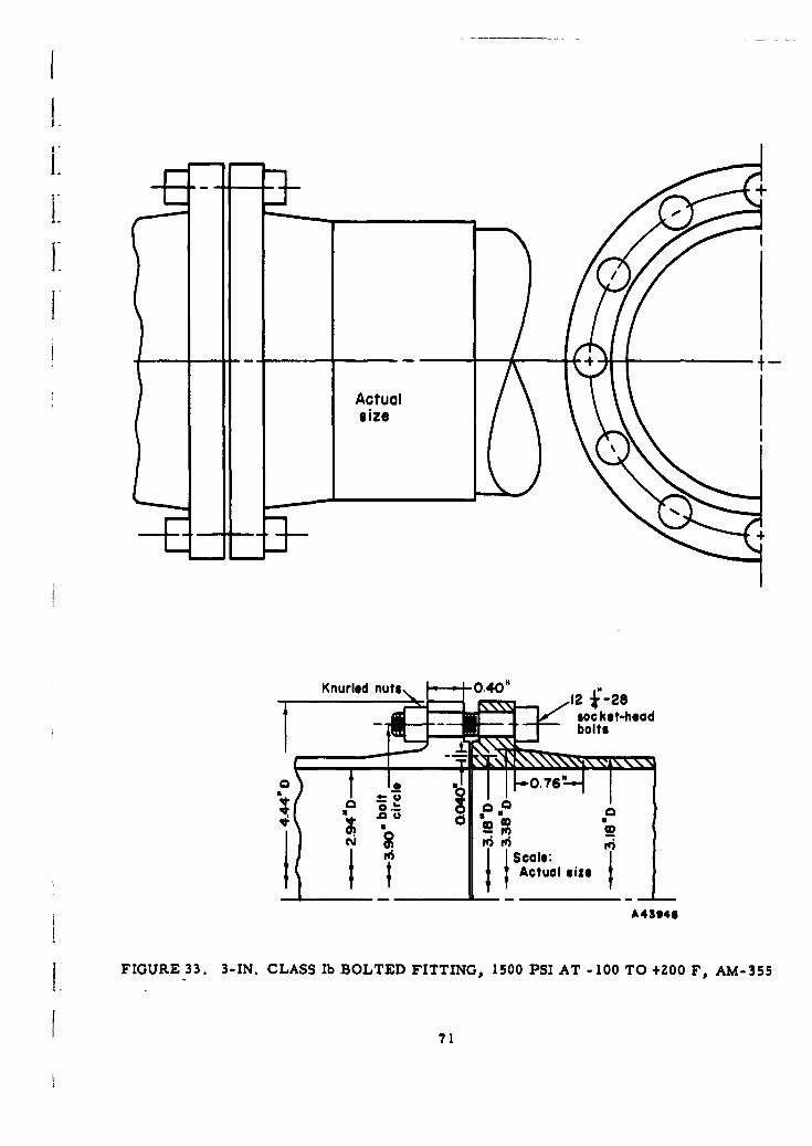
siz
Knurled nuts., 0 .4 0 " 2J2
FIGURE 33. 3-IN. ad5CL AS lb B O L T D F T TIN , 1 00 SI A T - 0k O +Z OFe- 5
71cbot
proportional to the design pressure, a large weight penalty will be imposed by designing
for 1500 psi when a lower operating pressure is to be used. As an example of the weightpenalty involved, a 16-in. fitting for 1500 psi might weigh about 200 ib, whereas a 16 -in.fitting designed for 150 psi might weigh only about 30 lb.
In view of the relatively small number of large size fittings required in missiles,
and in view of large weight penalties for overdesign in such large fittings, it does notappear reasonable to establish arbitrary detailed dimensional standards for such fittings.Instead, it would seem more desirable to establish a standardized design procedure, bywhich means larger fittings could be readily designed for a specific application.
Additional Design Considerations
Accuracy of Preloading. As in the case of threaded fittings, accuracy of preload-ing may be limited to *25 per cent if torque wrenches are used in tightening bolts. With
a multiplicity of bolts, the probability of achieving a prescribed preload is better thanfor a threaded fitting in which a single nut is tightened.
Torque Relaxation. While the problem of axial-load relaxation exists in boltedfittings, such behavior is usually ascribed to creep of nonmetallic gaskets rather thanto local deformations of the bolt threads. In the process of assembling a bolted fitting,it is good practice to tighten the bolts in steps, using a symmetrical tightening sequence.
In this process, each bolt is tightened not once but several times so that short-time yieldeffects are taken up in the assembly process. In addition, where service conditions arecritical, it is good practice to retighten the bolts some 24 hours after initial tightening
or, better yet, to retighten the bolts after a short period under service conditions.
Overtightening Factor. As discussed under threaded fittings, some allowance isnecessary to prevent damage due to inadvertent overtightening. The 1-in. Class Iabolted fitting has about a 30 per cent margin for flanges and 42 per cent margin for bolts.
Plastic Deformations. In the case of bolted fittings, maximum calculated stressesin the flanges are localized bending stresses and, hence, the design contains a reserve
against gross yielding. On the other hand, the bolts are loaded essentially in tension,and accordingly this margin does not exist. From this standpoint, allowable stresses forbolts should be somewhat more conservatively based than allowable stresses for flanges.
Selection and Spacing of Bolts. For minimum-weight design, it is desirable tolocate the bolts rather close to the flange hub, since this decreases the moment on the
flange ring by decreasing the moment lever arm. Use of standard hex-head bolts witheither regular or heavy hex nuts requires excessive clearance, particularly if additionalspace is required for use of a box wrench. Standard socket-head cap screws require a
minimum of radial clearance and appear generally acceptable for bolted fittings usingsmall (about 1/4 in. or smaller) bolts. In larger sizes, socket-head cap screws do nothave adequate bearing surface, and bolts such as those given in NAS-624, "High StrengthAir Frame Bolts"( 2 3 " are suitable.
72
I hThe minimum spacing between bolts is controlled by necessary bolt-head clear-ances and by the "rule-of-thumb" that the ligament between bolt holes should be at leastequal to the bolt diameter. The maximum spacing between bolts must be limited to pre-vent excessive bowing of the flanges between bolt holes, with consequent nonuniform sealloading. The maximum spacing is a function of flange thickness, bolt size, and sealcharacteristics, along with other factors. Several practical rules for maximum boltspacing have been proposed; some of these are discussed by Lake and Boyd( 2 4 ). Atheoretical approach is given by Roberts( 2 5 ), considering the flange as a beam on anelastic foundation consisting of the seal. This theoretical approach, however, is notapplicable to a flange with an integral hub. A review of these developments resulted inthe following equation for establishing maximum bolt spacing for bolted fittings withmetal seals:
Cmax = 2(d + t) , (29)I where
Cmax = maximum spacing between bolts, in.
d = bolt diameter, in.
t = flange thickness, in.
Equation (21) was used in designing the flanged joints shown in Figure 27 and 30.
Alternative Types of Bolted Fittings. The raised-face, welding-neck type ofr • bolted fitting is, of course, only one of several commonly used types of flanges. A
flanged joint with a full-face gasket, as illustrated in Figure 34a, is often used. Ithas the advantage that both initial bolt loads and structural loads produce less stressthan on a raised-face flange. The disadvantages are that the full-face flange has lesstolerance against thermal gradients, and there is a much greater tendency for the stresson the gasket to be concentrated at the bolt holes and on the part of the gasket outside ofthe bolt holes. For this reason, bolted fittings using full-face gaskets generally requirehigher bolt loads than do comparable fittings using raised faces (gasket entirely insidethe bolt holes). In commercial pipeline practice, flanges with full-face gaskets arewidely used for mild service conditions (e. g. , water or gas distribution lines at or nearatmospheric temperature) but are seldom used for severe service conditions involvingeither high or low (cryogenic) temperatures or high pressures (above 300 psi).
Use of weld-neck flanges, in which the flange is permanently attached to the tube,may involve problems in aligning bolt holes. The use of a loose-ring flange, as il-lustrated in Figure 34b, will alleviate this problem. The loose-ring type of flange may,under some conditions, have a further advantage in that greater freedom of choice isavailable in selecting the flange-ring material since it need not be weldable or brazableto the tube material and it need not be compatible with the fluid. Disadvantages are(1) in general, the loose-ring type flange will be somewhat heavier than the welding-neck-type flange, since it lacks the reinforcement of the integral hub, and (2) the joint is moresusceptible to bending-fatigue failure at the juncture of the cylindrical shell with the lap;this disadvantage can be at least partially overcome by inicreasing the stub-end thicknessover that of the mating tube wall, as indicated in Figure 34a.
The flange-ring cross section, except at the bolt holes, consists of a solid metalrectangle. Several other possible cross sections were investigated to see if significantweight reduction could be achieved. Cross sections investigated were (1) coned (Bellvillewasher shape), (2) tapered, (3) composite (surface of one material, core of a lighter
73
Gasket Loose rings
- III
(a) Flanged Joint With Full- (b) Loose-Ring-TypeFace Gasket Flanged Joint
A43947
FIGURE 34. ALTERNATIVE TYPES OF BOLTED FITTINGS
material), (4) honeycomb construction, and (5) boxed or internally ribbed construction.The conclusion from the preliminary studies of these alternative ring cross sectionswas that while minor reduction in weight can be achieved by their use, the resultantdisadvantages of increase in costs of design and manufacturing, limitations of temper-ature range and gradients, and problems of bolt-load distribution are such as to exceedthe advantage of a minor weight reduction.
Application of Computers for Optimization of Design
In discussing designs of threaded and bolted fittings the design method was brieflydescribed as the process of selecting a set of dimensions and then checking if thesedimensions were satisfactory; if not, a second set of dimensions were selected and thecomputations repeated. This was repeated as often as necessary to obtain a "satisfac-tory" design, but not necessarily an "optimum" design. To be of "optimum" design, afitting for use in missiles must meet two requirements:
(1) The fitting must have the required degree of reliability for thespecified service conditions.
(2) Of the infinite number of fitting designs meeting requirement (1),the optimum fitting must be of minimum weight.
74
I.
Since digital computers can do no more than that which can be done on a desk cal-culator, the advantage of a computer lies entirely in its speed and accuracy. It is there-fore pertinent to consider the design time required for fittings in the absence of a high-speed digital computer and the appropriate computer program. For a specific example,assume that the designer is to establish the dimensions for a bolted fitting of the typeshown in Figure 35. He will be furnished the required design parameters:
(1) Maximum and minimum operating temperature and pressure
(2) Matching tube diameter, wall thickness, and material
(3) Thermal gradients
(4) External loadings (bending, axial, and torsional)
(5) Contained fluid or fluids.
A Diem
h
A43949
FIGURE 35. ILLUSTRATION OF INDEPENDENT DIMENSIONAL VARIABLESIN A BOLTED FITTING
From the above the designer may select suitable materials for flanges, bolts, andseal, based on suitability for the operating temperatures, compatibility with the fluids,and possibly from the standpoint of weldability or brazability to the matching tube.Having selected materials, the designer may now choose suitable allowable stresses forthe flanges and bolts. The next step requires the selection of seven more-or-less in-h dependent variables; i. e., on Figure 35 the dimensions t, gI, go, h, 1, A, and db.
75
Having selected these dimensions, the designer may proceed with the following calcula-tions, with a rough estimate of the time required (using a desk calculator or slide rule)shown for each calculation:
Stress calculations 1 1murDisplacement calculations 2 hoursPreload calculations 2 hoursCreep design calculations 3 hours
Upon completion of from about 5 to 8 hours' work (depending on whether creep is in-volved), the designer will know whether the dimensions he has selected will provide asatisfactory fitting, as indicated by the maximum calculated stresses being less than thepre-established allowable stresses or, in the case of creep design, that the calculatedservice life is adequate. If the fitting meets the design criteria (and after some exper-ience, most designers can readily select dimensions so that the criteria are met) thequestion arises: Is the fitting of minimum weight? That is, is there some other com-bination of the variables t, gl, go, h, 1, A, and db which would also meet the designcriteria and would be of less weight? Unfortunately, there are no established analyticalrelationships between the seven independent variables, the design parameters, and thefitting weight. In order to answer the question, it is necessary to vary each of the sevenvariables while holding the other six constant. Even for a very limited investigation ofthe variable ranges, it is apparent that hundreds of calculations are involved, each ofwhich requires some 5 to 8 hours of design time. (For example, if only two steps areused for each variable, the total calculations number 128. )
The value of the digital computer at this stage is obvious, since the computationtime involved could be reduced from hundreds or thousands of hours to a few hours. (Areduction factor by use of high-speed digital computers of I to 100 is readily obtainable.)
Several degrees of sophistication in a computer program could be used. At oneextreme, a program which appears technically feasible would entail feeding into thecomputer only the design parameters of tube size, design pressure and temperature,external loads, thermal gradients, and material properties, the program being suchthat the computer would automatically perform a series of iterations with various stepvalues of the independent variables, compute and compare weights, and eventually printout the values of the independent dimensional variables which give a fitting of minimumweight and its weight. While technically feasible, preparation of such a program is aformidable undertaking.
On the other hand, a much simpler program could be developed in which the designparameters and independent dimensional variables would be fed into the computer. Thecomputer would then compute and print out the stresses and weight for the particular setof variables fed into the computer. Independent dimensional variables could then be step-varied by the designer, each step reintroduced into the computer and successive stepsvaried as indicated by the results of previous computations. This type of programwould be expected to give general indications of the relationships between the independentdimensional variables, the design parameters, and the fitting weight, in addition tospecific optimization of a given fitting design. In the present state of the art, thesimpler program approach appears to be more practical.
76

Although the design of a bolted fitting was used as an illustration in explaining theuse of a computer, threaded fittings are not excluded from this consideration. However,it must be recognized that design of a threaded fitting by a computer is more difficult
and the results will probably be less reliable in the absence of experimental verification.This is true because such variables as thread friction, torque relaxation, and preloadcontrol enter into the design process, and their varying behavior is not known as ac-curately for a threaded connection.
References
(14) "Strength of Aircraft Elements", Military Handbook 5 (March, 1961).
(15) "Air Weapons Materials Application Handbook, Metals and Alloys", ARDCTR 59-66 (December, 1959).
(16) "Fittings, Flareless, Fluid Connection", Military Specification MIL-F-1280A(A56) (April 24, 1956).
(17) "Mechanical-Drive Steam Turbines", National Electrical Manufacturers Association(NEMA) Standards Publication No. SM20-1958 (revised November, 1959).
(18) Rossheim, D. B. , and Markl, A. R. C. , "The Significance of and Suggested Limitsfor the Stress in Pipe Lines Due to the Combined Effects of Pressure and Expan-sion", ASME Trans. (July, 1940).
(19) Wesstrom, D. B. , and Bergh, S. E. , "Effect of Internal Pressure on Stresses and
Strains in Bolted-Flanged Connections ", ASME Trans. (July, 1951).
(20) Rodabaugh, E. C. , Discussion of Reference (1ch, ASME Trans. (July, 1951).
(21) Engineering Data Bulletin VM-107, Rene 41 (May, 1958), Metallurgical ProductsDept. , General Electric Co. , Detroit 32, Michigan.
(22) "Effect of Creep-Exposure on Mechanical Properties of Rene 41", University ofMichigan, ASD TR 61-73 (August, 1961).
(23) National Standards Association Standard NAS-624, "High Strength Air Frame Bolts".
(24) Lake, G. F. , and Boyd, G. , "Design of Bolted, Flanged Joints of PressureVessels", Proc. Institute of Mechanical Engineers (1957).
(25) Roberts, Irving, "Gaskets and Bolted Joints", ASME Journal of Applied Mechanics(1950).
77

Ii
TUBE-TO-FITTING DESIGN
Design Parameters
Brazing and Welding
High-Energy-Rate Welding
References
1iI.
TUBE-TO-FITTING DESIGN
The tube-to-fitting connection must satisfy two major requirements: it must con-tain the fluid with no leakage, and it must maintain structural integrity throughout the
design life of the system. The structural loads which the tube-to-fitting connection mustwithstand are similar to many loads discussed in the section on fitting-to-fitting connec-
"tions and hence will not be discussed here in detail. The other design parameters willbe described.
Design Parameters
Reliability
Reliability of the tube-to-fitting connection is of such prime importance that themethod chosen by which this connection is made must assure repeatable joint integritywithin close limits. Ideally, reproducibility as established by statistical evaluationshould be adequate to preclude preliminary tests. However, some provision for visualinspection is desirable to guarantee that all parts are assembled in their correct posi-tion.
Weight
A permanent connection would be the most reliable type of joint and would result in
a mechanical fitting of least weight. This is especially true when the effects of theconnection on the tubing wall thickness are considered. Because the tubing may consti-tute as much as 90 per cent of the total system weight, it is essential that its wall thick-ness be kept as low as possible. If the tube-to-fitting connection is not a permanentconnection, as is the case with the flareless fitting, additional tubing strength must
be provided at the point of connection because of the stresses caused by the clamping ofthe tubing wall. Practically speaking, this can be done only by increasing the wall
•- - thickness, with a resulting over-all weight increase.
Assembly
The tube-to-fitting connection must be simple to enhance its reliability and it must"also be easily assembled. The method of making the connection must therefore berelatively independent of tubing tolerances, surface finishes, surface cleanliness, andoperator skill. If this is not possible, a suitable technique or piece of equipment mustbe developed which will satisfactorily reduce these to minor considerations.
Misalignment of the tubing within the system must be compensated for. The pro-gram objectives were to provide a fitting which would tolerate 4" included angle mis-alignment for fitting sizes up to and including 4 in.; l-l/2" for size up to and including6 in.; and 1/20 for sizes up to and including 16 in. An axial misalignment capability
1/4 in. from center line was desired for all fitting sizes greater than 1 in.
79
One approach was to use a ball-and-socket joint at the fitting-to-fitting connection.Any such joint conceived, however, was excessively heavy. Within the fitting structurethe tube-to-fitting connection is the only other choice for misalignment compensation.The misalignment of the tubes to be joined might be measured and compensated for in theprocess of joining the tube to the fitting. Because the system will probably be fabricatedfrom a high-strength heat-treated material, not easily deformed or modified, it is possi-ble that misalignment can best be compensated for by means of adjustable tubingsupports. In any case the tube-to-fitting connection must be designed to withstand theseimposed loads.
Material
Recent advances in metallurgy have provided alloys with very good strength-to-density ratios. In the future, even better materials probably will be available. Theassembly method, therefore, should be such that new materials can be used with a mini-mum of development work. Furthermore, the assembly method should not cause degra-dation of the mechanical properties of the tube or fitting materials. Many of the neweralloys, including the three selected for the improved fittings, attain their high strength-to-density ratios because of heat treatment. This strength advantage is minimized whenexcessive temperatures are applied to local areas. The thickness and hence the weightof the fitting must then be increased in proportion to the reduction in material strength.
Candidate Joining Methods
Two kinds of joints were considered, namely, "hot" and "cold". Hot joints arethose which require an external source of heat, e. g., soldering, brazing, and the manytypes of welding. Cold joints are those which require only mechanical energy, e.g.swaging, roll bonding, friction welding, and high-energy welding.
Of the many types of joints considered, three are recommended for the tube-to-fitting connection: brazed, hot welded, and explosive welded. However, unlike thefitting-to-fitting connection, a configuration for the tube-to-fitting connection cannot bederived readily by analytical methods within the present state of the art. Experimenta-tion is necessary to define the critical parameters. Therefore in the following discus-sion instead of presenting preliminary designs, the recommended methods for makingthe tube-to-fitting connection will be described and the effect of these methods on thefinal configuration will be discussed.
Brazing and Welding
Considerable work has been done by North American Aviation* on welded andbrazed joints for tubing for aerospace applications. The results of this work have beenreviewed in detail and have been found to be directly applicable to the problem of makinga satisfactory tube-to-fitting connection for improved missile mechanical fittings.Many of the NAA procedures are illustrated in a paper by G. R. Barton, et al. , (26)**
and a full description will soon appear in an official report. The possible application ofthese concepts to a mechanical fitting is discussed below.
* AF Contract No. 04 (611) -8177.
w Numbers in parentheses refer to references on page 92.
80
Choice of Materials
Materials that are compatible with the welding and brazing operations must bechosen. North American Aviation has reported that the materials recommended byBattelle for mechanical fittings have been successfully brazed and welded by NAA aspart of their joint development effort. Therefore, no difficulties should arise because ofthe materials selected.
Source of Heat
Heat sources selected by NAA include a modification of the standard inductionheating system for the brazed joint and the tungsten, inert-gas (TIG) process for the
fusion-welded joint. Although other heat sources may be used, the ones chosen offer theadvantages of being clean, neat, versatile, and, most important, easily controlled.Very close control is necessary when heat-treated materials such as AM-350 are used,to prevent the heat-affected zone from extending outside the fitting envelope.
Joint Fit-U!
Because OD tolerances of purchased tubing are too liberal, the tubing must besized before joining to insure correct braze capillary action and proper weld penetration
and heat transfer, and to insure the proper fit of the tube and fitting to withstand externalbending loads. Typically, total diametrical tolerances of 0. 002 to 0. 005 in. arerequired.
Filler Material
In the NAA brazed joint, illustrated in the Barton paper( 2 6 ), brazing alloy reser-
voirs are provided to obtain optimum capillary flow during brazing. The brazing alloymust be selected for structural strength, service temperature, and corrosion resistanceto the contained fluid. Nominally, its eutectic temperature should be at least 300 to500 F above the expected service temperature(? 7 ). Fluid compatibility is unimportant in
fusion welding because there is no alien filler material present(26 ).
Cleanliness
To insure highly reliable joints, whether brazed or welded, all components must
be specially cleaned. It is also necessary to purge with a specially prepared inert gasbefore, during, and after the application of heat because of the detrimental effect of sur-face oxides.
Conclusions
In spite of some apparent drawbacks associated with North American Aviation'shot-joining techniques, the probability of successfully satisfying the stringent require-
ments of joint integrity are much better for the immediate present with these methodsthan with other methods or concepts suggested or studied. The need for sizing the tube
81
for joint fit-up will necessitate a quality-control program. Special handling and assem-bling procedures are also serious limitations. However, it is believed that such limita-tions can be sufficiently overcome to make the brazed or welded joint a practical tube-to-fitting connection. Furthermore, extensive field experience and experimentation shouldlead to further refinements and simplifications.
High-Energy-Rate Welding
High-energy-rate welding is a process which utilizes high pressures for extremelyshort periods of time to obtain a metallurgical union between two metallic parts. High-energy-rate welding differs from high-energy-rate forming only in the magnitudes andtime-variant characteristics of the applied forces.
Two basic energy sources presently being utilized for high-energy-rate formingare (1) the electrical energy stored in a bank of high-voltage capacitors, and (2) chemi-cal explosives. No data have been found on the use of capacitor discharge for weldingmetal, although the operation is theoretically possible. On the other hand, considerablework has been done by several companies on the use of chemical explosives to welddifferent metal shapes. Much of this work appears pertinent to the problem of makingsatisfactory tube-to-fitting connections.
Chemical Explosives
Chemical explosives are classified into two general categories: low explosives andhigh explosives. Low explosives, such as smokeless powder and black powder, have aburning rate or deflagration velocity ranging from a few inches to a few feet per secondand can produce pressures in the order of 30,000 to 300,000 psi, depending on thedegree of confinement. High explosives, such as TNT, PETN, and dynamite have adetonation velocity in the order of 6000 to 28,000 ft/sec and can produce pressures up toabout 4-million psi. Low explosives are normally used in enclosed systems where thecontainment helps increase the impulse imparted to the workpiece. High explosives arenormally fired as bare charges in open s stems because the peak pressure is relativelyindependent of the degree of confinement(2 8 ). Some characteristics of high explosivesare given in Tables 10, 11, and 12. From Table 11 the total energy available from 1 lbof PETN is approximately 1. 74-million ft-lb (4. 35 x 105 x 4). With a typical conversiontime of 2 A sec, this is equivalent to approximately 1. 57-billion hp.
The total impulse imparted to the workpiece is represented by
•tf
I = Stf Pdt, (30)
where
I = impulse, lb-sec/in. 2P = pressure, psit = time, sec.
82
TABLE 10. CHARACTERISTICS OF HIGH AND LOW EXPLOSIVES (29)
Property High Explosives Low Explosives
Method of initiation Primary high explosives-- Ignitionignition, spark, flame,or impact
Secondary high explosives--detonator, or detonatorand booster combination
Conversion time Microseconds Milliseconds
Conversion rate 6,000 to 28,000 ft/sec A few inchesto a few feet
per second
Pressures Up to about 4,000,000 psi Up to about40,000 psi
TABLE 11. CHARACTERISTICS OF HIGH EXPLOSIVES( 2 9 )
Detonation Velocity, MaximumSpecific 1- 1/4-In. Diameter, Energy(a), Pressure(b),
Explosive Gravity ft/sec 105 ft-lb/lb 106 psi
RDX (cyclotrimethylene 1.7 27,500 4.25 3.4trinitramine)
PETN .(pentaerythritol 1. 6 26,500 4.35 3.2tetranitrate)
Pentolite (50 PETN/50 TNT) 1.6 25,000 3.17 2.8TNT (trinitrotoluene) 1. 6 23,000 2.62 2.4
(a) Based on ballistic-mortar comparisons. Total energy would be four times these figures.(b) At 1-1/4-in, diameter. Based primarily on the calculations by the methods of Cook. By Taylor's methods, this pressure will
be 10 to 20 per cent lower.
TABLE 12. PROPERTIES OF EXPLOSIVES( 2 8 )
Detonation DetonationSpecific Temperature, Pressure,
Explosive Gravity C 106 psi
RDX 1. 6 5450 375PETN 1.6 5400 330Tetryl 1.6 4400 290
Picric acid 1. 6 3900 265TNT 1. 6 3900 225
83
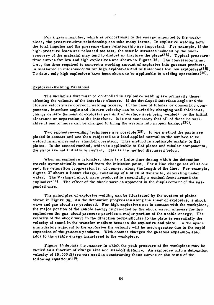
For a given impulse, which is proportional to the energy imparted to the work-piece, the pressure-time relationship can take many forms. In explosive welding boththe total impulse and the pressure-time relationship are important. For example, if thehigh-pressure loads are released too fast, the tensile stresses induced by the over-recovery of the material may tend to distort or fracture the piece(28). Typical pressure-time curves for low and high explosives are shown in Figure 36. The conversion time,i. e. , the time required to convert a working amount of explosive into gaseous products,is measured in microseconds for high explosives and milliseconds for low explosives(28).To date, only high explosives have been shown to be applicable to welding operations( 3 0).
Explosive-Welding Variables
The variables that must be controlled in explosive welding are primarily thoseaffecting the velocity of the interface closure. If the developed interface angle and theclosure velocity are correct, welding occurs. In the case of tubular or concentric com-ponents, interface angle and closure velocity can be varied by changing wall thickness,charge density (amount of explosive per unit of surface area being welded), or the initialclearance or separation at the interface. It is not necessary that all of these be vari-ables if one or more can be changed to bring the system into proper balance( 3 0 ).
Two explosive-welding techniques are possible(Z8). In one method the parts areplaced in contact and are then subjected to a load applied normal to the surface to bewelded in an underwater standoff operation. This method is applicable mainly to flatplates. In the second method, which is applicable to flat plates and tubular components,the parts are not initially in contact. This is the method discussed below.
When an explosive detonates, there is a finite time during which the detonationtravels symmetrically outward from the initiation point. For a line charge set off at oneend, the detonation progression is, of course, along the length of the line. For example,Figure 37 shows a linear charge, consisting of a stick of dynamite, detonating underwater. The V-shaped shock wave produced is essentially a conical front around theexplosive( 3 1). The effect of the shock wave is apparent in the displacement of the sus-pended wire.
The principles of explosive welding can be illustrated by the system of platesshown in Figure 38. As the detonation progresses along the sheet of explosive, a shockwave and gas cloud are produced. For high explosives not in contact with the workpiece,the major portion of the usable energy is provided by the shock wave, whereas for lowexplosives the gas-cloud pressure provides a major portion of the usable energy. Thevelocity of the shock wave in the direction perpendicular to the plate is essentially thevelocity of sound in the transfer medium between the explosive and plate. In the spaceimmediately adjacent to the explosive the velocity will be much greater due to the rapidexpansion of the gaseous products. With contact charges the gaseous expansion alsoadds to the usable energy transfered to the workpiece.
Figure 39 depicts the manner in which the peak pressure at the workpiece may bevaried as a function of charge size and standoff distance. An explosive with a detonationvelocity of 25,000 ft/sec was used in constructing these curves on the basis of thefollowing equations( 2 9 ):
84
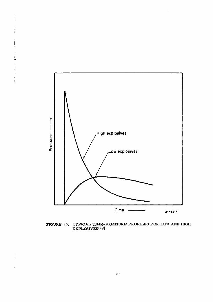
It
,High explosives
0" Low explosives
Time A-43917
FIGURE 36. TYPICAL TIME-PRESSURE PROFILES FOR LOW AND HIGHEXPLOSIVES(Z9)
85
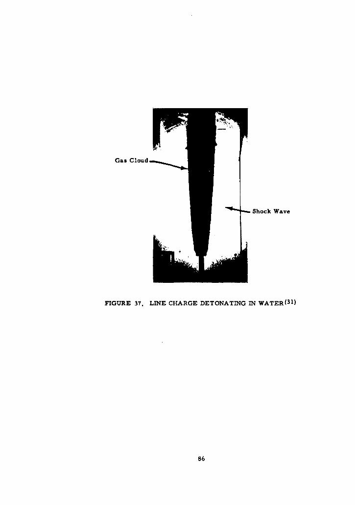
Gas Cloud
Shock Wave
FIGURE 37. LINE CHARGE DETONATING IN WATER( 3 1 )
86
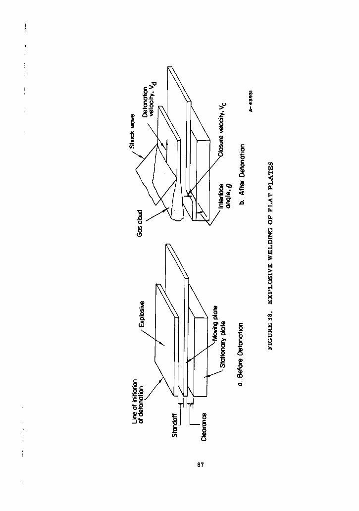
.0
::ýv 0
0-4
04
.9
P
87
50,000
Underwater explosions,Vd=25,000 ft/sec
40,000-
S30,000-
(h0)
0)0)CL -
20,000-
A0,000' 8
0 5 10Distance, ft
FIGURE 39. EFFECT OF CHARGE SIZE AND STANDOFF DISTANCE ONPEAK PRESSURE( 2 9 )
88
P d K1 (31)i• and
(w/15-fvd, (32)
S where
P = peak pressure, psiW = weight of explosive, lbR = distance from explosive, ftK 1 = constant which varies with the explosiveS= constant which is generally equal to 1. 15Vd = detonation velocity of explosive, ft/sec
It is not necessary to perform the welding operation in water. However, theconstants in Equations (31) and (32) must be modified where air is the transfer medium.The peak pressure with air as the transfer medium will be approximately 30 per cent ofthe peak pressure with water as the transfer medium.
Figure 40 shows the effect of the transfer medium and the standoff distance on thepeak pressure at the workpiece. If a charge were detonated at the end of a tube, thepeak pressure would diminish along the length of the tube as shown. Therefore, a pieceof equipment 3 ft from an explosive charge equal to 4 lb of TNT would be subjected to apressure of only 500 psi in air.
The shock wave, as it progresses (Figure 38b), imparts an impulse load to theplate. The velocity of closure, Vc, is much smaller than the velocity of detonation, Vd,and hence the plate, as it deforms, forms the interface angle, e, between the stationaryplate and the moving plate.
The developed interface angle, 9, will depend on the relative magnitudes of Vc andVd and the initial clearance between the two plates. As the initial clearance between theplates is increased, e becomes larger. For a given type of explosive, the detonation ofvelocity, Vd, is a constant. The closure velocity, Vc, which is a function of the totalenergy delivered to the upper plate, can be varied over a wide range by changing thecharge density, the upper plate thickness, and the charge standoff distance. The closurevelocity also depends on the density and dynamic yield strength of the upper-plate mate-rial. Variations in the charge density and standoff distance change the peak pressure andhence also change the total amount of energy delivered to the workpiece.
The total energy delivered to the workpiece is expended in three ways. Part of theenergy is used to overcome the material inertia, part causes deformation of the upperplate, and the remainder causes the plate to accelerate. The final closure velocity is afunction of the acceleration of the plate. Any parametric change that affects the percent-age of total energy left for acceleration of the plate will also cause a change in theclosure velocity. Hence, an increase in plate thickness, material density, or dynamicyield strength will diminish the closure velocity.
89
60o,00
50,000
40,000
"a _4 lb TNT
b- 30,0000L
a)a..
20,000 Wa t er r___
I10,000
0 I 2 3 4 5
Distance, f t
FIGURE 40. Eý"FECT OF TRANSFER MEDIUM AND STANDOFF DISTANCE ONPEAK PRESSURE(g9 )
90
In much of the past work on explosive welding, the interface between the two plateshas been evacuated. However, it has been shown that evacuation is not necessary to
obtain welding. The principal advantage to be gained from evacuation is the reducedcompound formation when dissimilar materials are being welded. However, even in
* cases in which dissimilar metals are Joined, the small amount of compound formation1. usually has little effect on the strength and integrity of the joint.
* Experience has shown that the explosive welding process is not sensitive to surfacecleanliness or roughness. Degreasing and wire brushing are usually the most stringentsurface preparations necessary. Welds have been obtained even without the wire brush-ing, and it has been reported that degreasing is unnecessary( 3 1, 32). A series of
experimental runs at Battelle on the explosive welding of Zircaloy-2 tubing to Type 410stainless steel tubing indicated that changes in the surface finish in the range of 300 pJin.rms to 1500 pin. rms had no effect on the accomplishment of a weld( 3 3 ). A Type 304stainless steel sleeve with a 100-pin. rms finish was successfully welded to the inside ofa Type 304 stainless steel ring with a surface finish of 30 Ain. rms.
Characteristics of Explosively Welded Joint
Among the principal advantages of explosive techniques are the absence of heat-affected zones, the absence of excessive compound formation in cases in which thewelded elements are dissimilar metals, the lack of effect on the mechanical characteris-tics of most materials, the ability to treat large areas and geometries which present
difficulties with other processes, and the relatively small and simple equipmentrequired(2 9 , 30).
Mechanical fittings which utilize a replaceable seal are particularly susceptible to
the effects of heat applied near the seal surface because of the tendency for the seal sur-
face to warp under nonuniform heating. A rule of thumb states that a fusion weld should
be a distance of 2 */-i from the sealing surface, where D is the tube diameter and t is
the tube-wall thickness. The temperature necessary to fusion weld or braze may also
affect the strength of the material, as previously discussed. An explosive weld, because
of the low amount of heat generated, and because of the symmetrical nature of the
forming process, would minimize the warping problem.
When dissimilar metals are fusion welded the relatively large melted zone causes
considerable compound formation. Again, because there is no melted zone with explo-
sive welding, this problem is minimized.
Figure 41 shows four possible arrangements of tube, fitting, and explosive.Figure 41a shows the working explosive charge in contact with the inside of the tube.The working charge is set off by means of the detonating cap attached to an explosiveleader, which is tented so that the detonation progression of the working explosive is
symmetrical with the tube axis. Figure 41b shows a line charge placed on the axis ofthe tube. A modification of Figures 41a and 41b in shown in Figure 41c, in which theworking explosive is wrapped on a mandrel centered in the tube. Variations in mandrel
diameter would vary the charge standoff distance. With a given total explosive charge,the peak pressure at the tube would be a maximum in Figure 41a, and a minimum inFigure 41b. Any pressure between the maximum and minimum could be obtained bymeans of the configuration in Figure 41c. An externally placed explosive charge is
shown in Figure 41d. Again, a tenting arrangement is provided to obtain the proper
detonation progression.
91
In each of the configurations in Figure 41 it would be possible to make the explo-sive into a package that could be inserted and set off by semiskilled personnel. The onlyother equipment needed for all fittings would be a battery detonator no larger than alunch pail and a length of wire to lead from the detonator to the detonating cap. Forsome fittings, depending on the tube wall thickness, the size of explosive charge, and theconfiguration, it might be necessary to provide internal or external backup dies to pre-vent excessive deformation of the tube and/or fitting.
Because of the possibility of developing a "package" for a particular size fitting,an explosively welded joint should be extremely reliable.
Conclusions
Although adaptation of the North American brazed or welded joint appears to be thebest method of achieving a reliable tube-to-fitting connection in the next year or two, itis believed that an explosively welded joint might be a significant improvement for intro-duction at a later date. For this reason it is recommended that further research bepursued to determine the general problems of explosively welding AM-355, 17-4PH, andRene'41, which are the materials selected for use in improved fittings. It is difficult toestimate the proper size range that future development should be concerned with becauseeconomic and logistic considerations are as important as the safety of the operation andthe technical feasibility. At Battelle, a 3 -in. -diameter Zircaloy tube with a wall thick-ness of 0. 045 in. was successfully welded to a stainless steel header with a 45-gramcharge of PETN. This appears to be a reasonable estimate of the conditions that mightbe encountered in making a 3-inch welded tube-to-fitting connection, and this size ofcharge probably represents the maximum that could be readily handled.
References
(26) Barton, G. R., et al., "Tubular Joining by Induction Brazing and Fusion WeldingMethods", SAE Aerospace Manufacturing Forum, The Ambassador Hotel, LosAngeles, California, October 8, 1962.
(27) Personal communications with Robert M. Evans of Metals Joining Division,Battelle Memorial Institute.
(28) Pearson, John, "The Explosive Working of Metals", Navord Report 7033 (1960).(29) Simons, Charles C., "Explosive Metalworking", DMIC Memorandum 71,
OTS PB 161221 (November 3, 1960).(30) Personal communication with Ronald J. Carlson and Charles C. Simons of the
Department of Metallurgy and Physics, Battelle Memorial Institute.(31) Douglass, John J., "Forming Practices With High Explosives", Du Pont Technical
Bulletin (May 26, 1960).(32) Yernow, Dr. Louis, "Explosive Welding", Paper presented at New Bonding Methods
Symposium of Annual ASM Metals Show, New York, New York, October 30, 1962.(33) Paprocki, Stan J., Porembka, Stanley W. , et al., "Joining Zircaloy-Stainless
Steel and SAP Alloys by Friction, Rolling, and Explosive Techniques", reportBMI-1594 to the AEC (September 4, 1962).
92
Workingexplosive Exploslve W
Explosive leader,
DetoatnowgCOP
Tube
Fitting
0. C.
FIGURE 41. EXPLOSIVE-WELDING ARRANGEMENTS
93
xplaS16
Workin
Exloiv 2okn xlsv

L
SEAL DESIGN
Design Parameters
Pressurized Metallic O-Rings
High-Energy.Rate Formed Seal
Mechanical Toggle Seal
References
SEAL DESIGN
The seal poses the most difficult design problem of the fitting. The requiredservice-temperature ranges preclude the use of a nonmetallic seal except for Class Ifittings, and experience with metal seals has not resulted in clearly defined understand-
ing or agreement among designers on the sealing mechanism of metal seals. Unfortu-nately, analytical studies do not appear to provide the necessary information, and lab-oratory studies have not been conclusive because of the predisposition of the evaluatorsor because of the small sample sizes tested. The failure data from the field have beensufficiently limited that field experience has not contributed significantly to a solution ofthe sealing problem.
The studies and evaluations performed in Phase I have resulted in the selection ofthree types of seals which offer sufficient potential to be considered for Phase 11:
0 Pressurized O-ring
* High-energy- rate formed
* Mechanical toggle
The first is conceptual, and its feasibility is yet untested. Considerable experi-mental evidence exists to support the basic mechanism of the second, but a promisingconfiguration has yet to be conceived. The third is available in commercial fittings, butthe configurations have not met with wide acceptance. The seal-design parameters arefirst discussed and then the recommended seals are described.
Design Parameters
An understanding of the problems involved in attaining a helium-tight seal is de-pendent on the analysis of certain factors known to affect leakage when the seal is initiallyestablished as well as after the seal is established. These factors include (1) the geom-etry of the leakage path and the nature of the leakage flow, (2) the magnitude of the seat-ing loads needed to produce an initial seal, (3) the plastic flow of the seal material,(4) the interaction of sealing members, and (5) the effects of temperature. Also in thissection, a brief discussion is given of the design thinking in relation to pressure-energized seals.
Leakage Analysis
The flow of a viscous fluid through the seal interface can be analyzed on the basis
of laminar flow if the mean free path of the fluid's molecules is less than the height of thesmallest passage along the leak path. If the mean free path is the same order of magni-tude as the passage height, molecular flow results, and a correction for slip flow alongthe wall must be applied to the laminar-flow analysis. A more detailed analysis ispresented in Appendix V. In general, the flow may be considered laminar if
< 1.0 , (33)h
l 95
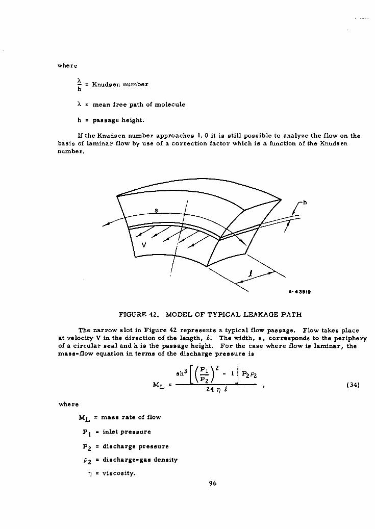
where
x- = Knudsen numberh
X = mean free path of molecule
h = passage height.
If the Knudsen number approaches 1. 0 it is still possible to analyze the flow on thebasis of laminar flow by use of a correction factor which is a function of the Knudsennumber.
h
A-43919
FIGURE 42. MODEL OF TYPICAL LEAKAGE PATH
The narrow slot in Figure 42 represents a typical flow passage. Flow takes placeat velocity V in the direction of the length, 1. The width, s, corresponds to the peripheryof a circular seal and h is the passage height. For the case where flow is laminar, themass-flow equation in terms of the discharge pressure is
ML-sh3[(E±) - P? P2pML P24• (34)
where
ML = mass rate of flow
P 1 = inlet pressure
P 2 f discharge pressure
P 2 = discharge-gas density
n= viscosity.
96
For molecular flow, the mass-flow equation is16sh 2 (PI - P?)PavuX
Mm - 97r T)RT ) aS.(35)
or more simply,
Mm = 6.8 ML . (36)
When the flow is neither laminar nor molecular, i. e. , for Knudsen's number close
to 1. 0, the flow equation of state is defined as
MT = ML + EMm (37)
where E is a constant found experimentally to be approximately 0. 9 for single gases and0. 66 for gaseous mixtures( 3 4 ). The total flow, by substitution of Equation (36) and thevalue of 0.9 for E, is
MT = ML(I + 6.1-) (38)h
This expression holds when the mean free path is evaluated at the average pressure inthe passage.
The above expressions indicate the important effect the length and height of theleakage path have on flow rate. For both the laminar and molecular flow conditions, therate of flow is inversely proportional to passage length. Therefore, one conclusion isthat the seal passage should be of considerable length. However, increasing the lengthof the seal passage is a severe handicap from the viewpoint of seating loads and minimumassembly torque.
The effect of the second parameter, height, makes it obvious that the degree ofsurface conformity is extremely critical. In the case of laminar flow, mass rate of flowis dependent on the cube of the passage height, whereas in molecular flow it is dependenton the square of the passage height.
Because of the random variations in surface profile, the best measure of requiredaverage passage height for seals capable of sealing jases would be in microinches orangstroms, where one angstrom equals 3. 937 x 10"A in. Extrapolation of leakage-ratecharts( 3 5 ) indicates that a passage height ranging between 0. 25 and 25 A is required toseal helium gas at 10, 000 psi, with a leakage rate no greater than 7. 7 x 10⁻⁷ atm-cc/sec.This is the maximum allowable leakage as defined for the project.
Seating Loads
A basic problem in designing a metal-to-metal fluid seal is the determination of the
"seating load", i. e. , the load required to produce intimate contact between the sealing
surfaces initially. The problem is essentially the same whether the seal is pressureenergized or not and is independent of operating pressures or external loads.
*Numbers in parenthesis denote references listed on page 115.
97
Below are some of the factors that must be considered in determining seating loads:
(1) Seal Design. The seal width largely determines the magnitude of theseating load, since seating load is a function of sealing area.
(2) Metal Properties. The hardness, compressive yield strength, andstrain-hardening characteristics of the seal material will determinethe unit stress necessary to effect a seal.
(3) Surface Properties. The surface finish determines the total amountof yielding necessary to close all leak passages. Gross distortionsuch as waviness and warping is ordinarily a minor problem but canbecome serious when processes which cause distortion, such aswelding, brazing, and swaging, are used to effect the tube-to-fittingconnection.
(4) Contained Fluid. The viscosity, density, surface tension, and stateof the contained fluid determine the maximum size of leak path whichcan be tolerated.
(5) Pressure. The pressure, which affects the rate of flow through apassage, also determines the maximum size of leak path acceptable.
(6) Allowable Leakage Rate. Obviously, as the allowable leakage rate islowered, higher seating loads may be required to reduce the size ofthe leak paths.
A widely used set of gasket seating-stress constants are those given in the ASMECode for Unfired Pressure Vessels.
Seating Stress(a),Material psi
Soft aluminum 4,400Soft copper or brass 6,500Iron or soft steel 9,000Monel or 4 to 6 per cent chromium 10,900Stainless steels 13,000
(a) Gaskets not over 1/2 in. wide.
These gasket constants are based on experience and rather limited test data and arejustified( 3 6 ) principally on the observation that flanged joints when designed on the basisof these constants almost always work satisfactorily.
In addition, it should be noted that the gasket stresses are interrelated with acomparatively low bolt design stress so that, in actual installations, considerably higherstresses can be and probably generally are applied.
A gasket stress of 30,000 psi is suggested for stainless steel flared fittings forsealing helium. (37) This is roughly double the ASME Code value. However, the Codevalue is possibly based on experience with liquids and gases for which low leakage rates
98
fwere not objectionable. It might be noted that flared fittings, usually satisfactory withliquids, have seating stresses as follows:
Nominal Seating Stress,Size psi
3 37,0004 36,0005 33,0006 37,0008 26,000
10 25,00012 18,40016 15,700
On the basis of the literature, the larger sizes of flared fittings, 8 and up,apparently are especially troublesome when attempting to seal helium.
The preceding discussion was concerned with seating stresses for flat metalgaskets. The axial load can be reduced by using a very narrow gasket until, as a limit,a line contact is obtained, at least initially. The question arises as to what seating loadis required for line-contact gaskets. For stainless ste,.1 O-rings used for sealing helium,an average seating load of 1000 lb/lineal in. is suggested. (38) One design method forflanges with lens-ring gaskets is based on about 3000 lb/lineal in. Some approximatecalculations on probable loadings on pipe unions also give seating loads in this generalrange.
Plastic Flow
The previous discussion of seating loads was based on gross effects and on datagathered from experience. Another approach to the problem is a consideration of micro-scopic effects at the seal interface. Because plastic deformation of the surface asper-ities is considered essential to achieve the surface conformity required to seal helium,an analysis of seating loads can be based on the phenomena of contact resistance andplastic flow of metals. Although the phenomenon of local plastic deformation of surfaceasperities has been investigated extensively, neither an exact nor consistent determina-tion of the phenomenon is available. It has been shown, however, that the seating forceapplied should be greater than that obtained by merely multiplying the yield stress of thematerial by the surface contact area. Exactly how much greater this force should be isnot known; estimates range up to 3 times greater.
Temperature Effects
Two temperature effects of particular importance are the steady-state effect at thetemperature extremes and the transient effect during temperature changes. Dimensionalchanges due to temperature occur axially, radially, or both, depending on the configura-tion of the seal. Typical configurations are shown in Figure 43. Seals may containvariations or even combinations of these basic seal configurations.
99
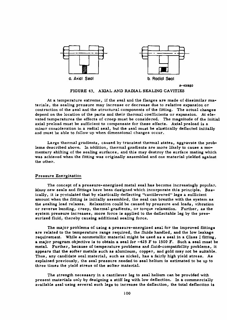
a. Axial Seal b. Radial Seal
A- 43920
FIGURE 43. AXIAL AND RADIAL SEALING CAVITIES
At a temperature extreme, if the seal and the flanges are made of dissimilar ma-terials, the sealing pressure may increase or decrease due to relative expansion or
contraction of the seal and the structural components of the fitting. The actual changesdepend on the location of the parts and their thermal coefficients or expansion. At ele-
vated temperatures the effects of creep must be considered. The magnitude of the initialaxial preload must be sufficient to compensate for these effects. Axial preload is a
minor consideration in a radial seal, but the seal must be elastically deflected initiallyand must be able to follow up when dimensional changes occur.
Large thermal gradients, caused by transient thermal states, aggravate the prob-lems described above. In addition, thermal gradients are more likely to cause a mo-
mentary shifting of the sealing surfaces, and this may destroy the surface mating which
was achieved when the fitting was originally assembled and one material yielded against
the other.
Pressure Energization
The concept of a pressure-energized metal seal has become increasingly popular.
Many new seals and fittings have been designed which incorporate this principle. Bas-ically, it is postulated that by elastically deflecting "cantilevered" legs a sufficientamount when the fitting is initially assembled, the seal can breathe with the system asthe sealing load relaxes. Relaxation could be caused by pressure end loads, vibrationor reverse bending, creep, thermal gradients, or torque relaxation. Further, as thesystem pressure increases, more force is applied to the deflectable leg by the pres-surized fluid, thereby causing additional sealing force.
The major problems of using a pressure-energized seal for the improved fittingsare related to the temperature range required, the fluids handled, and the low leakagerequirement. While a nonmetallic material might be used as a seal in a Class I fitting,a major program objective is to obtain a seal for -425 F to 1500 F. Such a seal must bemetal. Further, because of temperature problems and fluid-compatibility problems, itappears that the softer metals such as aluminum, copper, and gold may not be suitable.Thus, any candidate seal material, such as nickel, has a fairly high yield stress. Asexplained previously, the seal pressure needed to seal helium is estimated to be up tothree times the yield stress of the softer material.
The strength necessary in a cantilever leg to seal helium can be provided withpresent materials only by designing a stiff leg with low deflection. In a commerciallyavailable seal using several such legs to increase the deflection, the total deflection is
100
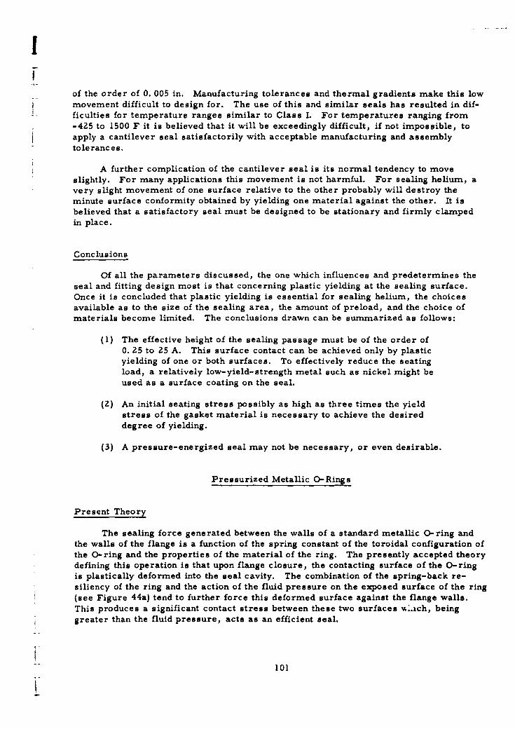
!
of the order of 0. 005 in. Manufacturing tolerances and thermal gradients make this lowmovement difficult to design for. The use of this and similar seals has resulted in dif-ficulties for temperature ranges similar to Class I. For temperatures ranging from-425 to 1500 F it is believed that it will be exceedingly difficult, if not impossible, to
apply a cantilever seal satisfactorily with acceptable manufacturing and assemblytolerances.
A further complication of the cantilever seal is its normal tendency to moveslightly. For many applications this movement is not harmful. For sealing helium, avery slight movement of one surface relative to the other probably will destroy theminute surface conformity obtained by yielding one material against the other. It isbelieved that a satisfactory seal must be designed to be stationary and firmly clampedin place.
Conclusions
Of all the parameters discussed, the one which influences and predetermines theseal and fitting design most is that concerning plastic yielding at the sealing surface.Once it is concluded that plastic yielding is essential for sealing helium, the choicesavailable as to the size of the sealing area, the amount of preload, and the choice ofmaterials become limited. The conclusions drawn can be summarized as follows:
(1) The effective height of the sealing passage must be of the order of0. 25 to 25 A. This surface contact can be achieved only by plasticyielding of one or both surfaces. To effectively reduce the seatingload, a relatively low-yield-strength metal such as nickel might be
used as a surface coating on the seal.
(2) An initial seating stress possibly as high as three times the yieldstress of the gasket material is necessary to achieve the desireddegree of yielding.
(3) A pressure-energized seal may not be necessary, or even desirable.
Pressurized Metallic O-Rings
Present Theory
The sealing force generated between the walls of a standard metallic O-ring andthe walls of the flange is a function of the spring constant of the toroidal configuration ofthe O-ring and the properties of the material of the ring. The presently accepted theorydefining this operation is that upon flange closure, the contacting surface of the O-ringis plastically deformed into the seal cavity. The combination of the spring-back re-siliency of the ring and the action of the fluid pressure on the exposed surface of the ring
(see Figure 44a) tend to further force this deformed surface against the flange walls.This produces a significant contact stress between these two surfaces %..ich, beinggreater than the fluid pressure, acts as an efficient seal.
101
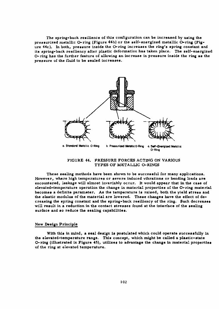
The spring-back resilience of this configuration can be increased by using thepressurized metallic O-ring (Figure 44b) or the self-energized metallic O-ring (Fig-ure 44c). In both, pressure inside the O-ring increases the ring's spring constant andits spring-back resiliency after plastic deformation has taken place. The self-energized0-ring has the further feature of allowing an increase in pressure inside the ring as thepressure of the fluid to be sealed increases.
a. Standard Metallic O-Ring b. Pressurized Metallic0-Ring c. Self-Energized MetallicO-Ring
FIGURE 44. PRESSURE FORCES ACTING ON VARIOUSTYPES OF METALLIC O-RINGS
These sealing methods have been shown to be successful for many applications.However, where high temperatures or severe induced vibrations or bending loads areencountered, leakage will almost invariably occur. It would appear that in the case ofelevated-temperature operation the change in material properties of the 0-ring materialbecomes a definite parameter. As the temperature is raised, both the yield stress andthe elastic modulus of the material are lowered. These changes have the effect of de-creasing the spring constant and the spring-back resiliency of the ring. Such decreaseswill result in a reduction in the contact stresses found at the interface of the sealingsurface and so reduce the sealing capabilities.
New Design Principle
With this in mind, a seal design is postulated which could operate successfully inthe elevated-temperature range. This concept, which might be called a plastic-stateO-ring (illustrated in Figure 45), utilizes to advantage the change in material propertiesof the ring at elevated temperature.
102
I
, Thin-walled 0- ring
.- Interface pressure, Pf
-- High pressure gas
A -42465
FIGURE 45. INTERNALLY PRESSURIZED O-RING
When assembled, the O-ring is fitted into a cavity which supports the torus in all
directions. In order to compensate for tolerances it may be advisable to make the cavity
and the torus dissimilar in cross section. When the flanges are assembled and the tight-
ening preload is applied, the torus will be deformed to conform to the cavity geometry,
and metal-to-metal contact will be obtained. Included inside the O-ring torus is a gas-emitting crystal or a low-energy pyrotechnic. The gas-producing reaction would be
initiated after the fitting is completely assembled and torqued.
Since the gas in the ring is completely sealed in a fixed volume, the change in pres-sure of this gas would be a simple function of the operating temperature of the fitting (see
Equation 40); a rise in temperature would induce a rise in pressure.
The material of the 0-ring should be so chosen that when the operating temperature
of the fitting is increased, its elastic-stress capability is drastically decreased. If the
O-ring material and the type and volume of gas in the O-ring are carefully selected, a
point somewhere below the normal operating temperature of the fitting will be reached
where the O-ring is in a fully plastic state. This can be clearly seen if we consider the
O-ring - flange configuration as a cylindrical pressure vessel with an infinite outside
diameter and an inside diameter equal to that of the O-ring. In this consideration, of
course, the curvature of the ring as well as the large but finite thickness of the flange
wall as compared with the 0-ring inside diameter are neglected. However, for a close
approximation this assumption serves adequately. The point at which the inner fibers of
the wall become plastic will be reached when the internal pressure equals 0. 577 0 y (yield
stress at any given temperature of the material as determined from a simple uniaxial
"tensile test). This criterion is derived from the maximum-distortion- energy-criterion
of failure for material, sometimes called the Hencky-von Mises criterion.
"Noting that the wall of the O-ring is very thin, we can further assume that the tube
will be fully plastic when the pressure is slightly greater than 0. 577 T Y
103
The action is qualitatively illustrated in Figure 46.
Elastic zone Plastic zone
Temperature, F
FIGURE 46. PRESSURE- TEMPERATURE- YIELD STRESS RELATIONSHIPFOR 0- RING SEAL
The internal pressure, P, is defined as
P =p ZRT , (39)
where
p = gas density
Z = compressibility factor
R = universal gas constant
T = absolute temperature.
Assuming that the internal volume is essentially unchanged and discounting the com-pressibility factor,
P. = C T-, (40)P 2 T2
where C includes the p, Z, and R terms. Therefore the internal pressure increaseslinearly with the change in temperature ratio.
In this situation the high internal pressure is contained in a fully plastic O-ringwhich is in turn fully contained by the walls of the seal cavity of the flange. As long as athere is no separation of the flange faces the tube cannot blow out, since there is no placefor the tube material to go. In fact, as long as the flange faces stay in contact the
104
!
internal pressure in the ring could still be raised significantly (as would occur with a
"further increase in temperature).
The advantages of this concept are: (I), that in the fully plastic state the O-ring
material, under the action of the high internal pressure, will flow into the small surfacediscontinuities of the seal-cavity walls, thereby forming a seal that should be effectivein stopping even molecular leakages, and (2) with the advent of the relaxation of theflange prestress, which is encountered at elevated temperatures, the high contact stressrequired to maintain this close interface fit is achieved by the action of the internal pres-sure. A serious disadvantage would be encountered if this type of seal were to be ex-posed to conditions where the temperature variation would be cyclic, resulting in acondition where the O-ring would vary between the plastic and the elastic state. Such acondition could adversely affect the physical properties of the ring material, resultingin a low-cycle fatigue phenomenom and early ring failure.
Conclusions
As presently conceived, the O-ring would not become plastic until some elevated
temperature was reached. The primary reason for this requirement is to prevent rup-ture at room temperature and to permit safe handling at assembly and disassembly of thepressurized O-ring. Therefore, the seal could be primarily of use for high tempera-
tures and might be considered only in the role of a secondary seal. In the plastic zonethere would be no significant time lag, as the seal breathes with the strain fluctuationsand essentially a steady state condition would exist. Probably the most advantageousapplication would be in sealing hot gases for Class V fittings where temperatures rangefrom 1000 to 3000 F. Development of an O-ring seal that could operate in this tempera-
ture range will require utilization of metals with very high melting points. Tantalumseems to be a possible choice. In the lower temperature range, 600 to 1500 F, nickelor copper could be used.
Aside from the temperature ranges, one other limitation must be emphasized. Aspreviously indicated, when the 0-ring is in the plastic zone the flange separation must be
kept below a few thousandths of an inch to prevent rupture or blowout.
High-Energy-Rate Formed Seal
Considerable experimental evidence has been developed concerning the conformityof one metallic surface with another when caused by high-energy rate forming. As dis-cussed in the section "Tube-to-Fitting Design", explosive energy has been used to ac-hieve a good mechanical bond, equivalent to a weld, between several kinds of metalseither flat or tubular in configuration. On the basis of an analysis of this work, it wasbelieved that the surface conformity needed to seal helium could be easily provided byhigh- energy- rate forming.
Two basic configurations were envisoned as a means of applying explosive energyto the formation of a seal in a fitting. The first was an internal formed seal in which theexpanding explosive force would be used to seal a sleeve against the inside of the fittingparts. This configuration would make the best use of the available energy, but a problem
existed in the contamination of the fluid system by the explosive. The second configuration
"105
was an externally formed seal which would collapse radially or seal against the flangefaces. Because it was difficult to postulate the energy needed to achieve adequateconformity for the possible configurations, preliminary laboratory experiments were
made to obtain a general idea of the effect of different amounts of explosive on basicseal shapes.
Experiments Performed
Seal formation by means of an internal explosive charge was investigated with theconfiguration shown in Figure 47. The ferrules, representing the stub-end portion ofthe fitting attached to the tubing, were separated by a spacer ring which would be usedto facilitate disassembly. The seal ring was expanded by means of an explosive chargeto form a seal between the ferrules. The mandrel diameter upon which the explosivecharge was mounted was changed in successive experiments to provide variations in thestandoff distance.
Use of an external explosive for formation of the seal was investigated by means ofthe configuration shown in Figure 48. The explosive was contained in a groove machinedon the outside diameter of the seal ring. The walls between the flanges and explosivewere approximately 0. 010 in. thick, and it was hoped that these walls would be sealedagainst the flanges.
Description of Results
For the internal explosive charge, five experiments were made with various sizemandrels. The mandrel size determined both the total charge and the standoff distance.In all cases the seal ring was displaced slightly in the direction of the detonation progres-sion, that is, from right to left as shown in Figure 47. Figure 49 is a photomicrographof Area B in Figure 47, polished and etched. Excellent conformity was achieved betweenthe seal ring and the spacer ring and ferrule. Figure 50 is a photomicrograph of Area Cpolished but not etched.
Eight experiments were made with the external explosive-charge configuration.The original attempt was to form a seal at,PointA in Figure 51. However the best bondoccurred at Point B. Evaluation will show that this is a reasonable result, since Poisson'seffect is most pronounced at Point B when the seal ring is under a high external load,as shown in Figure 52. The thin seal flanges shrouding the explosive were too flexibleand probably sprang back after the explosive pressure was dissipated.
However, when the force, w, is high, as in the case of an explosive charge, theactual strain, eZ, is much greater than the elastic strain and a considerable seating loadis applied from the seal to the flange face.
Possible Externally, Explosively Formed Seal
The design concept shown in Figure 53, although preliminary in nature, illustratesthe basic premises on which an external high-energy seal might be based.
106
!
-- Ferrules
A
Explosive
Mandrel noting
SSeal ring
Spacer ring
FIGURE 47. CONFIGURATION FOR INTERNAL-CHARGE SEAL EXPERIMENT
Detonating cap
Prmacor leader
Explosive
SSeal ring
Flanges
8-453M
FIGURE 48. CONFIGURATION FOR EXTERNAL-CHARGE SEAL EXPERIMENT
107
Seal ring • L.
.• . ... . ......"...........
"- Spacer ring
looX Etched RM22186
FIGURE 49. AREA B OF FIGURE 47
Seal ring
Interface ---o-..-.. Interface
S- Spacer ring
1000 X Unetched RM22256
FIGURE 50. AREA C OF FIGURE 47
108
1.
FBA
FIGURE 51. EXTERNAL-EXPLOSIVE SEAL
"---7 I
FIGURE 52. POISSONIS EFFECT ON SEAL RING
109
A
A-43926FIGURE 53. EXTERNAL EXPLOSIVE SEAL
A major consideration is the blowout effect of the internal pressure. The seal
ring must be thick enough to withstand the developed hoop stress. Also, the initial
strain on the seal interface must be sufficiently greater than the pressure-induced hoop
expansion to maintain sufficient surface contact. The primary seal is developed at
Point A because of the combined effects of initial preload, Poisson's ratio, and over-
center tin canning. A secondary seal can be developed along Surface B. This secondary
seal is highly desirable to reduce the force of the fluid acting on the seal and tending toblow it out. The overhanging lips at A also add structural support to the seal ring to
prevent blowout.
Initially the seal ring is clamped between the flanges, which bottom out as in Fig-
ure 53. The ring can be made to bow under this clamping force to compensate for manu-
facturing tolerances and discrepancies. In the example illustrated a contact explosive
charge, Point 2, is used.
The assembly preload is predicated on the eventual structural load requirements,
since the effective seating load will result from the high-energy discharge. The seal
ring is deformed by the high-energy discharge and is pushed over center. The insertion
of a transfer buffer at Point 2 may be necesary. A support die might have to be assem-
bled onto the fitting to prevent stretch and expansion of critical sections and subsequent
distortions and strain relaxations.
Other energy sources such as capacitor discharge or magnetic pulse might be usedas a means of applying more than one sealing impulse. With this arrangement, a leaking
seal could be tightened without disassembling the fitting.
Conclusions
It would be possible to use an internal explosive charge to form a seal if a method
could be found to initiate the detonation without the need for lead wires. An exceptionally
intimate bond is possible along the seal-retainer interface when a reasonable amount of
explosive is used. Moreover, the problem of personnel safety and possible damage tosurrounding equipment can probably be overcome. However, a major problem for which
no immediate solution appears likely is the degree of contamination of the internal sur-
faces caused by the explosive materials.
Although the use of external explosive charges to form a seal would eliminate thecontamination problems and allow easy detonation, further experimentation is necessary
on selected configurations before the feasibility can be shown.
110
I
Mechanical Toggle Seal
Unlike the self-energized 0-ring or the high-energy-rate formed seal, which maybe termed "exotic", the mechanical toggle seal is conventional in principle. Seals ofthis type are commercially available and have attained some measure of success inmissile systems; especially in low-pressure gas ducts. Even the ferrule on the MS-flareless fitting may be termed a toggle type seal because of the elastic bowing of theferrule.
A toggle seal can have many forms, but for illustrative purposes the standardBelleville-type disk spring will be considered as a typical case. The seal is strictly amechanical device, and no auxiliary energy sources help actuate the seal. Because ofthis, considerations of torque and preload are major factors not only in the seal designbut also in the subsequent design of the over-all fitting. Other design factors that mustbe considered are seating-force magnification and the amount of axial relaxation that theseal can accommodate.
Seating Action
In Figure 54a, a toggle seal is shown when the seating load is first applied. Theposition of the seal after assembly is shown in Figure 54b.
o. Before Assembly b. After Assembly
A-43927
FIGURE 54. SEATING ACTION OF MECHANICAL TOGGLE SEAL
As member B travels axially from right to left the resultant seating force, R, ro-tates through the angle (ca-A). The axial seating force, Fs, increases as the seal is ro-
tated, first to create elastic strain and then to cause plastic yielding. However, afterplastic yielding commences, the force, Fs, is relatively constant. Because the seal isfully restrained at both the inside and outside diameters, there will be plastic yieldingalong the length, 1, if the seal does not buckle or bow.
! 111
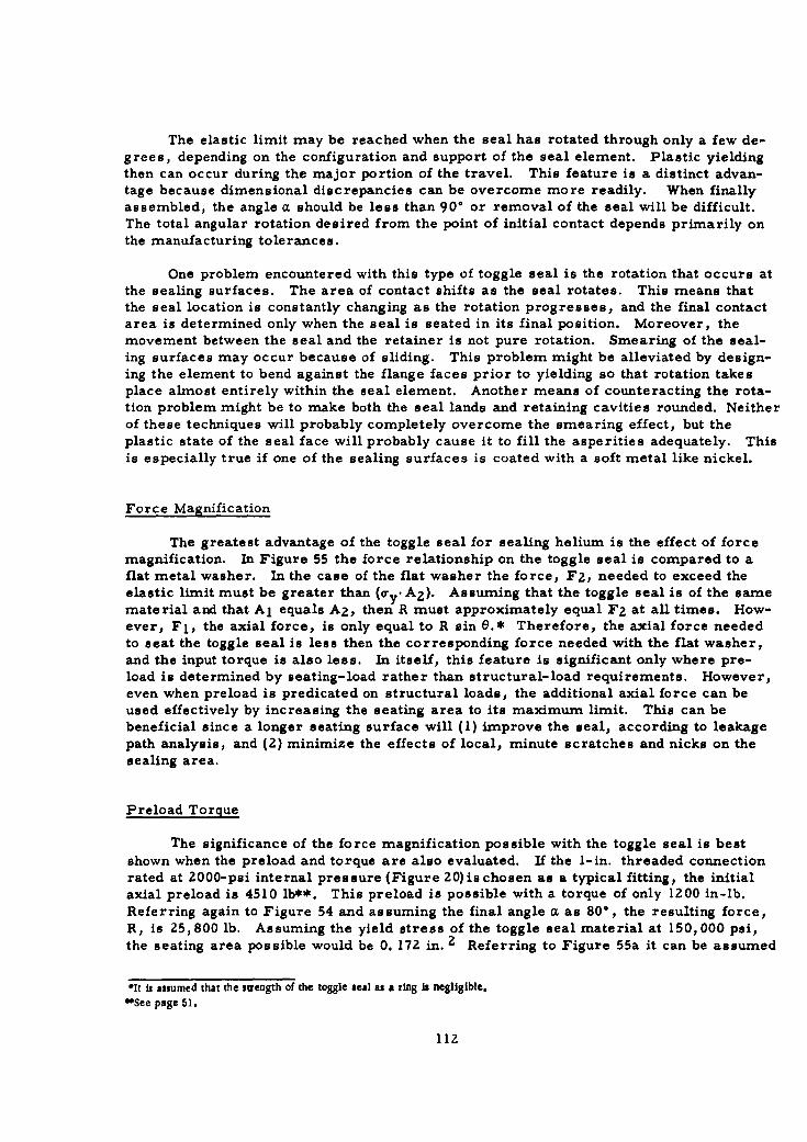
The elastic limit may be reached when the seal has rotated through only a few de-grees, depending on the configuration and support of the seal element. Plastic yieldingthen can occur during the major portion of the travel. This feature is a distinct advan-tage because dimensional discrepancies can be overcome more readily. When finallyassembled, the angle a should be less than 90° or removal of the seal will be difficult.The total angular rotation desired from the point of initial contact depends primarily onthe manufacturing tolerances.
One problem encountered with this type of toggle seal is the rotation that occurs atthe sealing surfaces. The area of contact shifts as the seal rotates. This means thatthe seal location is constantly changing as the rotation progresses, and the final contactarea is determined only when the seal is seated in its final position. Moreover, themovement between the seal and the retainer is not pure rotation. Smearing of the seal-ing surfaces may occur because of sliding. This problem might be alleviated by design-ing the element to bend against the flange faces prior to yielding so that rotation takesplace almost entirely within the seal element. Another means of counteracting the rota-tion problem might be to make both the seal lands and retaining cavities rounded. Neitherof these techniques will probably completely overcome the smearing effect, but theplastic state of the seal face will probably cause it to fill the asperities adequately. Thisis especially true if one of the sealing surfaces is coated with a soft metal like nickel.
Force Magnification
The greatest advantage of the toggle seal for sealing helium is the effect of forcemagnification. In Figure 55 the force relationship on the toggle seal is compared to aflat metal washer. In the case of the flat washer the force, F2, needed to exceed theelastic limit must be greater than (a-.. A 2 ). Assuming that the toggle seal is of the samematerial and that Aj equals A2, then R must approximately equal F2 at all times. How-ever, Fl, the axial force, is only equal to R sin e.* Therefore, the axial force neededto seat the toggle seal is less then the corresponding force needed with the flat washer,and the input torque is also less. In itself, this feature is significant only where pre-load is determined by seating-load rather than structural-load requirements. However,even when preload is predicated on structural loads, the additional axial force can beused effectively by increasing the seating area to its maximum limit. This can bebeneficial since a longer seating surface will (1) improve the seal, according to leakagepath analysis, and (2) minimize the effects of local, minute scratches and nicks on thesealing area.
Preload Torque
The significance of the force magnification possible with the toggle seal is best
shown when the preload and torque are also evaluated. If the I-in. threaded connectionrated at 2000-psi internal pressure (Figure 20)ischosen as a typical fitting, the initialaxial preload is 4510 lb**. This preload is possible with a torque of only 1200 in-lb.Referring again to Figure 54 and assuming the final angle a. as 80*, the resulting force,R, is 25,800 lb. Assuming the yield stress of the toggle seal material at 150,000 psi,the seating area possible would be 0. 172 in. 2 Referring to Figure 55a it can be assumed
*It is assumed that the stength of the toggle seal as a ring Is negligible.@See page 51.
112
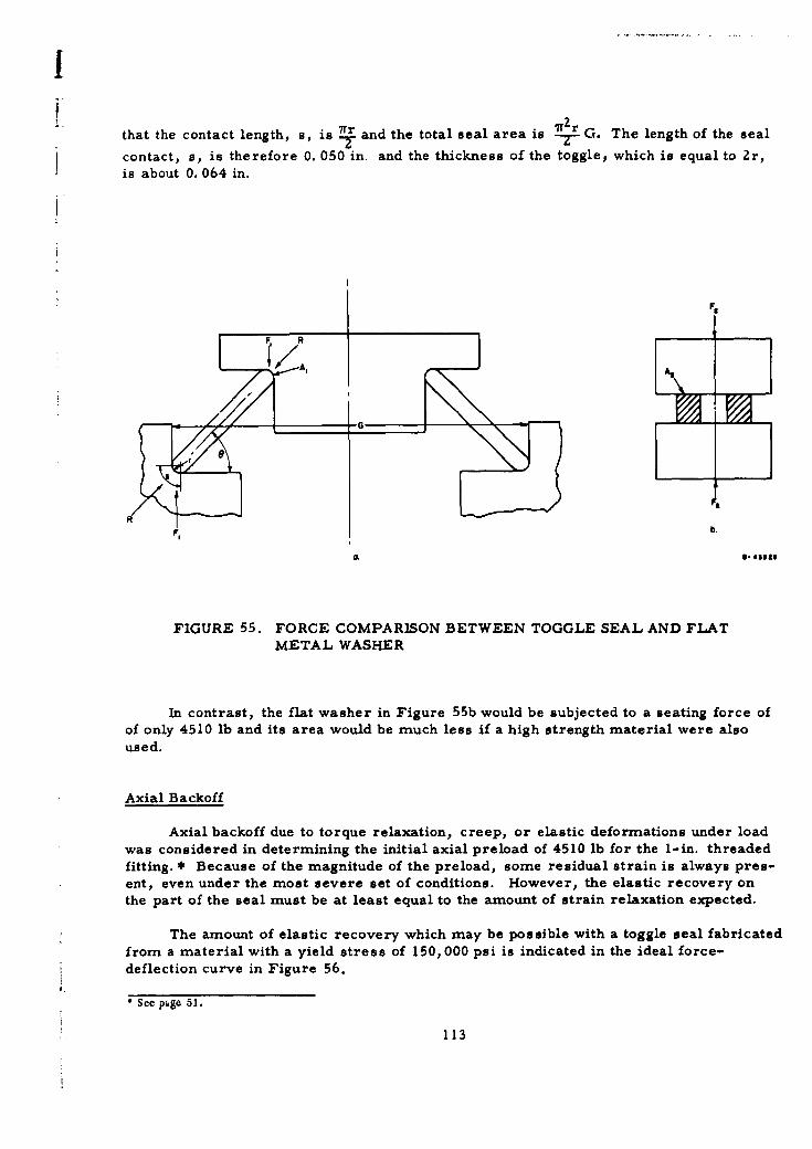
!
that the contact length, s, is 7 and the total seal area is 7r.± G. The length of the seal
contact, s, is therefore 0. 050 in. and the thickness of the toggle, which is equal to 2r,is about 0. 064 in.
F@
RIF, b.
S- 41310
FIGURE 55. FORCE COMPARISON BETWEEN TOGGLE SEAL AND FLATMETAL WASHER
In contrast, the flat washer in Figure 55b would be subjected to a seating force ofof only 4510 lb and its area would be much less if a high strength material were alsoused.
Axial Backoff
Axial backoff due to torque relaxation, creep, or elastic deformations under loadwas considered in determining the initial axial preload of 4510 lb for the I-in. threadedfitting. * Because of the magnitude of the preload, some residual strain is always pres-ent, even under the most severe set of conditions. However, the elastic recovery on
the part of the seal must be at least equal to the amount of strain relaxation expected.
The amount of elastic recovery which may be possible with a toggle seal fabricatedfrom a material with a yield stress of 150,000 psi is indicated in the ideal force-deflection curve in Figure 56.
* See page 51.
113
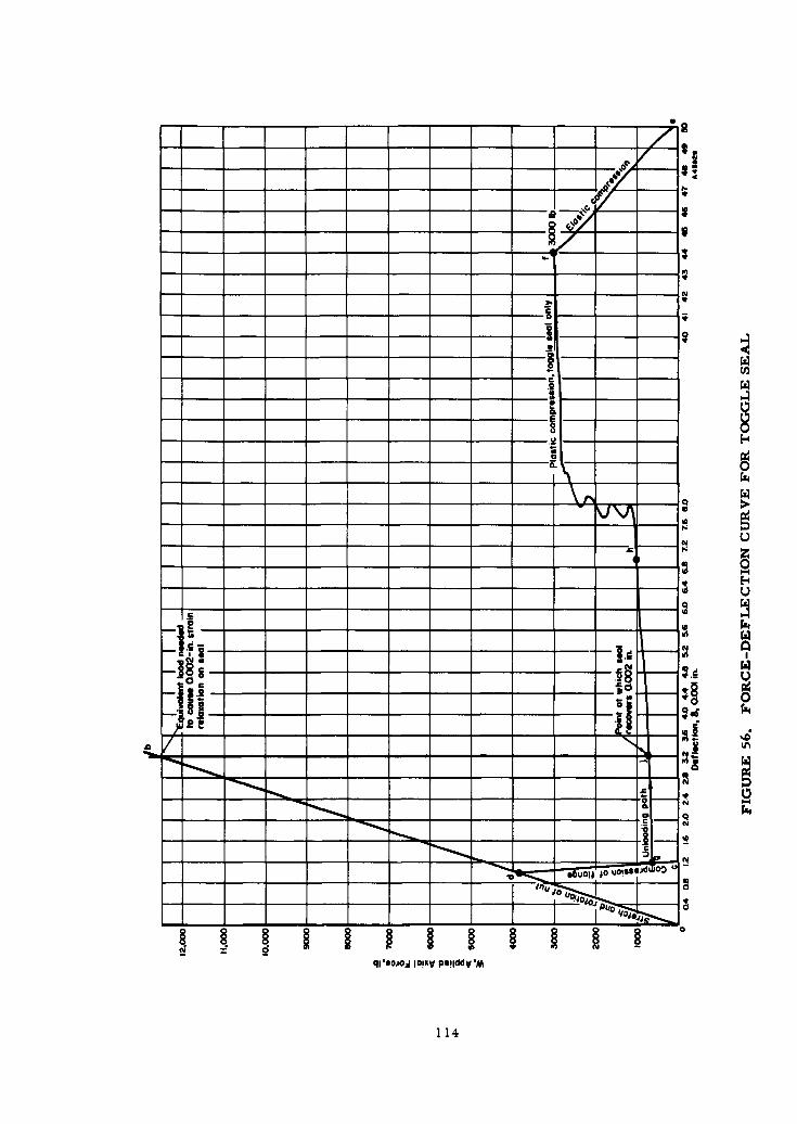
22
- - - - 0 -IV
SI
.2- -i -
p 00
qllojo jix pi-dVI
114
!
The stretch and rotation of the nut (Line adb) and the flange compression (Linecgd) are based on the analysis of the 1-in. threaded connection shown in Figure 19, with
a flat metal gasket. However, if a toggle seal were used, the compression force-deflection plot would follow the discontinuous Line efgd. At Point g the seal would be
completely seated, and additional torque would be translated to preload in the retainingmembers, Line c d. The negative slope of Line ef represents the elastic deflection ofthe seal alone. At Point f plastic yielding throughout the seal member commences, andthe force, W, decreases at a low rate until Point g, at which time the axial load is nearlyzero because all the force is transmitted in a radial direction.
The total elastic recovery is 0. 0057 in. and is represented by Point h. However,not all of this recovery is available because the seal would be unsupported and would failbecause of fluid pressure, vibration, or structural collapse. If an elastic recovery ofonly 0. 002 inch, which is less than half of the total recovery possible, is considered, theequivalent load needed to cause this amount of backoff is 12,500 lb. This is far in excessof any expected operational load. A recovery of 0. 002 inch is considered greater thanthat expected in actual practice.
Conclusions
Although not apparently an ideal seal, the toggle seal does represent a mechanical
device which approaches the ideal more nearly than other types of mechanical seals.The Belleville disk washer was used as an illustration because it represents the simplestform of toggle seal. The exact nature of the seating action is unknown, especially on a
microscopic level at the seal-contact area. Knowledge of this action is essential for
proper analysis and development of an optimum toggle seal.
On the basis of the preliminary analysis the Belleville disk appears to be the logi-cal starting point in any future development. It is simple, and easily manufactured.
When properly supported the seal is essentially insensitive to temperature changes.Because of the rotation mechanism, large axial movements and tolerances can be tol-
erated. Most important, the axial seating force is translated into a radial direction,
and when the seal is finally seated the sealing stress is much less dependent on axialbackoff or strain relaxation than an axial seal.
On the other hand, because the sealing surfaces are exposed, they can easily bedamaged. Special care must be exercised in handling or assembling the fittings. Use of
a radial seal also tends to enlarge the fitting radially. The seal is subject to pressureblowout if not properly supported and is not pressure energized. The detrimental effectsof these disadvantages on the performance of the seal and methods of minimizing themcan best be determined by means of experimental investigations planned for Phase II.
References
(34) Loeb, L. B. , The Kinetic Theory of Gases, Chapter 7, Dover Publications, Inc. ,
New York (1961).
(35) "Design Criteria for Zero-Leakage Connectors for Launch Vehicles", General
Electric Laboratories, Quarterly Progress Report No. 2, Contract NAS 8-4012
(October 11, 1962).
115
i-

(36) Rossheirn, D.B., and Markl, A.R.C. , "Gasket Loading Constants", MechanicalEngineering, Vol. 65, 1943, Page 647.
(37) Richards, C. M. , "Positive Gas Sealing With Flared Fittings", SAE Journal(October, 1960).
(38) Andrews, J. N. , "Hollow Metallic O-Rings", United Aircraft Products, Inc.,Dayton, Ohio (1962).
116
I
SUMMARY OF RECOMMENDATIONS
Five primary recommendations have been formulated on the basis of the Phase Iefforts:
* Fitting-to-Fitting Connection
The reconnectable union should be either threaded or flanged.Threaded fittings should be limited to those sizes and classes which canbe assembled with 2000 in-lb of torque or less. In no case should athreaded connection be used for fittings on tubing greater than 1 in. indiameter.
* Tube-.o-Fitting Connection
The connection between the tube and the fitting should be a per-manent joint made independent of the seal mechanism or the reconnectableunion. Furthermore, the brazed or welded joining method developed byNorth American Aviation should be adapted to expedite speedy qualifica-tion of a mechanical fitting. However, further research should be devotedto development of a cold-welded joint achieved by application of high-energy-rate techniques such as explosive forming or capacitor discharge.
* Seal
Three seals are recommended for further experimental and analyti-cal evaluation before one is selected for inclusion in the final fittingdesign:
(1) Toggle
(2) High-energy-rate formed
(3) Internal-pressurized O-ring
* Fitting Classes
For threaded fittings, four classes should be specified on the basisof temperature range and maximum pressure. Flanged fittings in gen-eral should be designed to satisfy specific service conditions by applica-tion of the design procedure illustrated in this report. This procedurein its more complete form should be specified as standard.
* Phase II Research Program
Phase II research should be divided into two periods. A period of
10 weeks should be devoted to the selection of the most promising seal.
117
a
A period of 3 months should then be devoted to tests of a few assembliesof a total fitting.
INFORMATION REVIEW AND BIBLIOGRAPHY
Considerable effort was expended to determine the extent of available knowledgein the open literature and the experience of manufacturers, users, and designers rela-tive to fittings and similar components. This effort is described briefly. A selectedbibliography is given of the references which have been of assistance in Phase I.
Information Review
Technical information was obtained through personal interviews with engineersand designers and from written reports of test and development programs on fittings.Additional related data basic to fitting design were collected and reviewed.
Technical Interviews
During the first month of the project the Battelle staff visited various organiza-tions with experience in the design, manufacture, and use of aircraft and missilefittings. The organizations visited were:
(1) Aerojet-General (11) Marman Division, Aeroquip Corp.(2) Aerospace Corp. (12) Parker-Hanifin Corp.(3) Armour Research Foundation (13) Resistoflex Corp.(4) Astronautics Division, General Dynamics (14) Rocketdyne Division, North(5) Douglas Aircraft American Aviation(6) Flexonics Division, Calumet and Hecla Co. (15) Space Technology Laboratory(7) General Electric Co. (16) Stanford Research Institute(8) Jet Propulsion Laboratory (17) Weatherhead Corp.(9) Lockheed Aircraft Co. , Burbank
(10) Lockheed Missile and Space Division
The data sought during these visits related primarily to specific past experiencewith and knowledge of fitting failures. The types of failure, possible causes, and thelocation in the piping system were items of major interest. Design philosophy was dis-cussed only in general terms. Unfortunately, little failure-analysis work had been donein this area. Moreover, results of the work which had been done had not been published.When failure data were available, they were very general.
Most of the information received consisted of technical reports of laboratory testsand analytical studies of present and new designs. The most frequent comments of theengineers interviewed were:
(1) The basic seal design of flared type fittings is inadequate, and the seal is
subject to deteribration with increased pressure and temperature.
118

(2) Human error during assembly is the major source of difficulties with"zero-leak" fittings.
(3) Stricter quality control should be imposed on the manufacturers offittings.
(4) Future specifications should classify the fitting according to theapplication.
Technical Literature
During the first two months a literature survey was conducted. Documents werecollected, analyzed, and catalogued. Thereafter, additional pertinent documents wereadded to the file as they were noted. The file presently consists of more than 500 docu-ments and is divided into eight major categories:
(1) Bolts(2) Design(3) Fittings(4) Flanges(5) Materials(6) Seals(7) Testing(8) Threads.
The major sources of data are Armed Services Technical Information Agency,Interservice Data Exchange Program, Machine Design, Mechanical Engineering,Defense Metals Information Center, Transactions of American Society of MechanicalEngineers, Society of Automotive Engineers, and internal reports and memos fromindividual companies.
A comprehensive literature search, even if restricted to just one or two of themajor categories, would have been beyond the scope of the Phase I program. New andtypical information only was gathered. When it appeared that a document containedredundant information, it was usually omitted.
Reports dealing with the state of the art of flared and flareless fittings were con-ducted on a restricted basis also. Only major reports known to contain original test
data were collected. The state-of-the-art study was intended to provide only sufficientdata for failure analysis or analytical evaluation.
Bibliography
The references listed below are those which proved to be of greatest value in con-
ducting the Phase I work.
Bolts
Appleberry, W. T., "How Fastener Tension Varies with External Joint Loads, Part I",Assembly and Fastener Engineering, 26-30, (April, 1961).
Appleberry, W. T., "How Fastener Tension Varies with External Joint Loads, Part III',
Assembly and Fastener Engineering, 32-36 (May, 1961).
119
Appleberry, W. T., "How Fastener Tension Varies with External Joint Loads, Part III",Assembly and Fastener Engineering, 32-36 (June, 1961).
Dolan, T. J., and McClow, J. H., "The Influence of Bolt Tension and Eccentric TensileLoads on the Behavior of a Bolted Joint", Procedures of Society of Experimental StressAnalysis, 29-43 (1959).
Harker, T. W., "Manufacture and Characteristics of High-Temperature Bolts", MetalProgress, 125-128 (October, 1953).
Lenzen, K. H., "Strength and Clamping Force of Bolts", Product Engineering, 130-133(December, 1947).
Mordfin, L., "Some Problems of Fatigue of Bolts and Bolted Joints in Aircraft Applica-tions", National Bureau of Standards, OTS PB 161637 (January, 1962).
Paslay, P. R., "On the Determination of the Influence of an Axial Preload Owing toBolting on a Cylindrical Pressure Vessel", Journal of Engineering for Industry, 215-218 (May, 1961).
Pringle, 0. A., "Loosening of Bolted Joints", Machine Design, 135- 136 (February 2,1961).
Silwones, S. S., Degen, Robert, A., "Test Results Guide - High Temperature Designof Bolted Assemblies", Product Engineering, 79-83 (September 30, 1957).
Smoley, E. M., and Kessler, F. J., "Retaining Tension in Gasketed Joints, Part II",Assembly and Fastener Engineering, 33-36 (October, 1961).
Spiotta, R. H., "Thread Rolling May be for You", Machinery, 182- 194 (November,1957).
Sproat, R. L., "A Checklist on Fasteners Reliability", Missile Design & Development,58 (June, 1960).
Flieder, W. G., Loria J. C., Smith, W. J., "Bowing of Cryogenic Pipelines", Journalof Applied Mechanics, 409-416 (September, 1961).
Jacobs, Robert B., "Cryogenic Piping System Design Considerations", Heating, Piping& Air Conditioning, 130-140 (February, 1960).
Fittings
Allin, F. R., and Courtot, L. B., "Evaluation of Flareless Fittings for Low DensityGas Applications", Weatherhead Company, Test Report No. 69, 460-F (September 8,1958).
Beachley, N. H., "Survey of Hydraulic Fittings in Air Force Ballistic Missile Pro-grams", Space Tech. Lab., Report 7431. 2-289, 1-9 (August 25, 1960).
120

Cornish, H. E., and Bloom, J. C., "Development of High Pressure Seals For ANStraight Thread Fittings", Applied Hydraulics, (18-24) (November, 1949).
* Courtot, L. B. , "Refinement of Precision Flareless Fittings", Weatherhead Company,Engineering Progress Report (September, 1958).
Cowdrey, F. W., "Flareless Hydraulic Fittings Keep F- 104 'Dry '", Aviation Age(July, 1957).
Davenport, C. R., "The Why and How of Weatherhead Ermeto Flareless Fittings",Weatherhead Company by special permission of Lockheed Aircraft Corporation.
Hallesy, H. W., "Development of a Permanent and a Reconnectable Tube Fitting forHigh Pressures and/or High Temperatures", Boeing Aircraft, Report D6-5327 (March,1960).
"Buttress- Threaded Tube Ends Raise Coupler-Joint Efficiency", Iron Age, 90-91
(November 24, 1960).
Lewis, S., "Leakage Problems with Conventional Fittings", Space Tech. Lab. Report9733. 5-460, 1-7 (May 24, 1961).
Lewis, S., "MS & AN Fittings", Space Tech. Lab., Report GM60- 7640.5-507, 1-4(August 22, 1960).
Mayhew, W. E., "Design and Development of a 1000 F Hydraulic System", RepublicAviation Report, AD 231 731 (July, 1959).
Mayhew, W. E., "Design and Development at a 1300 F Hydraulic System", RepublicAviation Report, AD 257 940 (June, 1960).
Richards, C. M., "Precision Sleeves Improve Flareless Fittings", Hydraulic &Pneumatics, 120-122 (April, 1962).
Seibel, L. L., and McGillen, V. W., "Hydraulic and Pneumatic Fitting and Tubing
Test Program", North American Aviation Report, AD 235 024 (November, 1959).
Flange s
Dittoe, T. A., "Structural Test Requirements, Bolted Flanged Joints for Ducts",Convair Astronautics, General Dynamics Corp., Report AZS-27-250 (March 25, 1956)Contract AF 04(645)-4.
Donald, M. B., and Salomon, J. M., "The Behavior of Narrow-Faced, Bolted, FlangedJoints Under the Influence of Internal Pressure", Proc. Inst. Mech. Eng. (London), 173(17), 461-468 (1959).
George, H. H., Rodabaugh, E. C., and Holt, Marshall, "Performance of 6061-T6Aluminum Flanged-Pipe Assemblies Under Hydrostatic Pressure", ASME Paper • 56 -
PET- 19 (1956).
121

George, H. H., Rodabaugh, E. C., and Holt, M. "Aluminum Alloy Welding NeckFlanges Performance Equal to Carbon Steel", Heating, Piping and Air Conditioning,95-97 (October, 1957).
Hillmer, W., "The Wedge-Ring Joint", Michelson Lab. Report, AD 260 021, 1-7(June, 1961).
Halford, D. E., "Structural Procedure Report, Bolted Flanged Joints for Ducts",Convair Astronautics, General Dynamics Corp. , Report No. 7B 2326- 1 (July 30, 1959)Contract AF04(645)- 104.
Labrow, J., "Design of Flanged Joints", Proc. Inst. Mech. Eng. (London), 156 (1),66-73 (1947).
Markl, A. R. C., and George, H. H., "Fatigue Tests on Flanged Assemblies", Trans-actions of ASME 77-87 (January, 1950).
Sperry, A. M., Jr., "Structural Test Results of Bolted Flanged Joints for Ducts",Convair Astronautics, General Dynamics Corp., Report No. 7B2326-2 (June 27, 1960).
Materials
Arcand, Lionel, "Materials Selection for the Hydrogen Rocket", Aircraft & Missiles,32-35 (January, 1960).
Boyd, W. K., and White, E. L., "Compatibility of Rocket Propellants with Materialsof Construction", DMIC Memorandum 65, OTS PB 161215 (September 15, 1960).
Corruccini, R. J., "Properties of Materials at Low Temperatures, Part I", ChemicalEngineering Progress, 53 (6), 262-267 (June, 1957).
Corruccini, R. J. , "Properties of Materials at Low Temperatures, Part II", ChemicalEngineering Progress, 53 (7), 342-346 (July, 1957).
Corruccini, R. J., "Properties of Materials at Low Temperatures, Part flI", ChemicalEngineering Progress, 53 (8), 397-402 (August, 1957).
Croucher, T. R., and Nickols, R. C., "The Use of Alloys at Cryogenic Temperatures",HD. 6593D Test Group, Edwards AFB, California, Memo I (August, 1961).
Favor, R. U., Deel, 0. L., and Achbach, W. P., "Design Information on 17-7 PHStainless Steel for Aircraft and Missiles", DMIC Report 137, OTS PB 151096(September 23, 1960).
Favor, R. J., Deel, 0. L., and Achbach, W. P., "Design Information on AM-350Stainless Steel for Aircraft and Missiles", DMIC Report 156, AD 262407 (July 28, 1961).
Grigger, J. C., and Miller, H. C., "The Compatibility of Materials with ChlorineTrifluoride, Perchloryl Fluoride & Mixtures of These", Pennsalt Chem. Corp. Report,AD266391, 1-100 (April, 1961).
122

!Jaffe, Leonard D., and Rittenhouse, John B., "Behavior of Materials in Space Environ-"ments", ARS Journal 320-346 (March, 1962).
Campbell, J. E. , "Compilation of Tensile Properties of High-Strength Alloys", DMICMemorandum 150, AD 275 263 (April 23, 1962).
Marin, J., "Design for Fatigue Loading, Part I", Machine Design, 88-94 (January 24,1957).
Marin, J., "Design for Fatigue Loading, Part II", Machine Design, 95-99 (February 7,1957).
Marin, J., "Design for Fatigue Loading, Part III", Machine Design, 124-134(February 21, 1957).
Marin, J., "Design for Fatigue Loading, Part IV", Machine Design, 95-99 (March 7,1957).
Marin, J., "Design for Fatigue Loading, Part V", Machine Design, 154-157 (March 21,1957).
Rinehard, John S., "The Behavior of Metal Under High and Rapidly Applied Stresses ofShort Duration", Navord Report 1183 (September 27, 1949).
Stewart, W. C., and Shreitz, W. G. , "Thermal Shock & Other Comparison Tests ofAustenitic and Ferritic Steels for Main Steam Piping - A Summary Report", Trans. ofASME, 1051-1072 (August, 1953).
Stamdler, I., "Hypersonic Fasteners Use Exotic Forms and Materials", Space/Aeronautics, 56-62 (September, 1961).
Sterner, C. J., and Singleton, Alan H., "The Compatibility of Various Metals WithLiquid Fluorine", Air Products, Inc., WADD TR 60-819, AD 260087 (March, 1961).
"The Manufacture of Rene 41 Components", Symposium on Processing Materials forRe-Entry Structures, WADD TR 60-58 (May, 1960).
Wetheimer, E. G., "Selecting Fastener Materials", Machine Design, 150 (February 4,1960).
York, H. J., "Compatibility of Various Materials of Construction With NitrogenTetroxide N 2 0 4 ", Aerojet-General Corp. Liquid Rocket Plant, Eng. Divn., Research &Materials Dept. Report RM- 13 (October 22, 1958).
Manufacturing
Carlson, R. J., Hanes, Hugh D., Hodge, E. S., Peterson, J. H., Simons, C. C., andSmith E. G., Jr., "Joining Zircaloy-Stainless Steel and SAP Alloys By Friction Rollingand Explosive Techniques", Report to the AEC, BMI- 1594 (September 4, 1962).
Douglass, John J., "Forming Practices with High Explosives", Du Pont Technical Infor-mation Bulletin (May 26, 1960).
123

Johnson, P. C., Stein, B. A., and Davis, R. S., "Basic Parameters of Metal BehaviorUnder High Rate Forming", report to Watertown Arsenal Laboratories AD 271 401(November, 196 1).
Pipher, F. C., Rardin, G. N., and Richter, W. L., "High Energy Rate Metal Forming",
Lockheed Aircraft Corporation, California Division, Technical Report, AD 254 776(October 18, 1957, to August 1, 1960).
Reason, R. E., "Surface Finish", Product Engineering (September 16, 1957).
Roth, Julius, "The Forming of Metals by Explosives", The Explosives Engineer (March-April, 1959).
Roth, Julius, "Metal Deformation by Explosives", Hercules Powder Co., ResearchCenter (July, 1961).
"Tubular Joining by Induction Brazing and Fusion Welding Methods", SAE Aerospace Mfg.Forum (October 8, 1962).
Simons, Charles C., "Explosive Metalworking", DMIC Memorandum 71, OTSPB 161221 (November 3, 1960).
"Metal Forming and Its Application in Today's Industries", Winchester-Western Division,Olin Mathieson Chemical Co., New Haven, Connecticut.
Seals
Ashmead, R. R., "Static Seals for Missile Applications", Jet Propulsion, 331-340(July, 1955).
Beacham, T. S., and Towler, F. H., "Hydraulic Seals", Proc Inst. Mech. Eng.(London), 532-569 (November, 1948).
Cass, E., McCuistion, T. J., "0-Ring Compression Force", Applied Hydraulics, 132-133 (October, 1959).
Dymkowski, J. V., "Pneumatic System Design", Aeronautical Engineering Review, 50-
66 (March, 1958).
Eddy, R. W., "Low-Temperature Seals", Chrysler Corporation Missile Division
Memorandum EDR 825, 1-31 (April, 1958).
Gilder, G., "Modular Hydraulic System Development", Chance Vought, AD 273 209(August, 1961).
Hull, J. W., "Ring-Spring Design for High Performance Metal Static Seals", Hydraulics& Pneumatics, 122- 126 (September 1960).
Jordan, J., "Extreme Temperature Sealing", Missile Design & Development (January,1959).
124

I
Kupiec, H. P., "Testing of Metal Boss Seals", Aircraft Equip. Testing Co., AD 74322, 1-61 (April, 1955).
Logan, S. E., "Static Seal for Low-Temperature Fluids", Jet Propulsion, 334-340(July, 1955).
Liberto, R. R. , "Research and Development on the Basic Design of Storable High-Energy Propellant Systems and Components", Bell Aerosystems Company, AFFTC TR-60-61 (May 19, 1961).
Liberto, R. R., "Titan II Storable Propellant Handbook", Bell Aerosystems Company,AFFTC TR61-32 (June, 1961).
Newell, G. C., "Preliminary Results of All Metal Boss Evaluation & Development",presented to SAE Committee A6, Montreal, Canada, April, 1962, by Boeing Aircraft,Transport Division, 1-11 (September, 1961).
Richards, C. M., "Missile Piping Methods", Convair Astronautics, General DynamicsCorp., ERR-AN-120, 1-17.
Skinner Seal Co., "Metal Seals Solve Missile Leakage Problems", Aviation Age, 49-51(May, 1957).
Shaw, C. J., "Laboratory Test and Evaluation of Seals Used in the Propellant LineSystems", Douglas Aircraft, Report DEV-3227 (March 30, 1960).
Willis, W. W., "An All-Metal Sealing Joint", Missile Design & Development, 18- 19(August, 1958).
Testing
Currie, W. E., "Industrial Hydraulic Tube Fittings Meet New Fields and Problems",SAE Paper S317 (September, 1961).
Currie, W. E., "Pressure & Pull Tests on Size 24 "Ferulok" 17-4 PH Ferrules",Parker Appliance Co. Report 43Z0 D-5Z14, 1- 11 (April 17, 1959).
Cerbin, W. G., "Performance Characteristics of Flareless and Flared Fittings",Weatherhead Company Report 1060, 1-9 (August, 1959).
Carlson, A. F., "Interim Report of Conical Seals for Flared Tubing", ConvairAstronautics, General Dynamics Corp., AN 59MD3008- 1.
Dubrow, A., "Investigation of the Effect of Pre-Stress on Fatigue-Vibration Life ofHigh Pressure Hydraulic System Tubing", Aeronautical Materials Laboratory,Philadelphia, Pennsylvania, AML NAMAE 627Z, 1-13 (April 5, 1955).
"Avica Ferrule Type Tube Fittings", Douglas Aircraft, Technical Memorandum DM 18-P&M-L0567 (February 28, 1958).
"Freon Leakage Test of Avica Tube Coupling", DC8 P & M-L0094 (March 28, 1957).
125

"Avica 2" Ferrule-Type Tube Assemblies", Douglas Aircraft, Technical MemorandumDM 18-P & M-L0940, (September 24, 1958).
Floreen, E. D., "Double Seal Conoseal Joints for High Temperature Gas CooledReactor", Marman Division, Aeroquip Corporation (July, 1962).
"Summary of Test Results of Various Configurations of Couplings with Gamah MetalSeals", Gamah Corp., 1- 12 (December 17, 1960).
Lundback, A. V., "Evaluation of Annealed Stainless Steel Tubing and "AN" FittingJoints", Aerojet-General SCR 56 (June 21, 1961).
Lenhart, H. G., and Gartside, W., "Flared Tubing Fatigue Test", Boeing Aircraft,
T 2-1432, 1-33 (November 11, 1957).
Le Fevre, William Jr., "Torsional Strength of Steel Tubing as Affected by Length",Product Engineering, 133-136 (March, 1949).
Oliva, J., "Report on Test on Dynatube", Resistoflex Corp., TRA- 1490, 1-31 (July 15,1960).
Oliva, J., "Report of Test on Dynatube Assemblies - High Temperature", ResistoflexCorp., TRA- 1491, 1-4 (August 17, 1960).
Oliva, J., "Report of Test on Dynatube Assemblies - Air & Helium Test", ResistoilexCorp., TRA-1525, 1-4 (May 25, 1961).
Oliva, J., "Report of Test on Dynatube Assemblies - Helium Testing", ResistoflexCorp., TRA- 1562, 1-7 (April 9, 1962).
Perkins, C. C., "Testing of Seal Designs and Materials", Arnold Engr. Dev. Center,AD 72503, 1-39 (February, 1955).
Pittiglio, C. L., "Hydrostatic Tests of High-Pressure Steel Valves and Fittings", NavyDepartment, AD 215 727 (May, 1949).
White, H. F., "Missile Leak Report", Convair Astronautics, General Dynamics Corp.,AR 141- 1-3 (March, 1962).
Whelan, J. S., "Test of 6, 000 psi Socket Weld Fittings", U. S. N. Engineering Experi-ment Station, AD 206 396 (January, 1958).
Threads
Almen, J. 0., "Fatigue Durability of Prestressed Screw Threads", Product Engineer-ing", 153-156 (April, 1951).
Bronson, K. R., and Faroni, C. C., "Vibration Resistance of Thread Locking Devices",Product Engineering, 58-61 (October 10, 1960).
Gerstung, H., "Friction as a Factor in Bolt Tension, Galling, Seizing, Part I",
Assembly & Fastener Engineering, 32 (January, 1961).
126

I
Gerstung, H., "Friction as a Factor in Bolt Tension, Galling, Seizing, Part II",Assembly & Fastener Engineering, 38 (February, 1961).
Goodier, J. M., "The Distribution of Load on the Threads of Screws", Journal ofApplied Mechanics, A1O-A16 (March, 1940).
Hanneman, W. M., "How Much Torque Tightens A Screw", Machine Design, 179- 182(October 13, 1960).
Inglesby, J. V., "Strength of Screw Threads of Whitworth Form", Journal of the RoyalAeronautical Society, 710-717 (April, 1945).
Kalevitch, R., "Pneumatic High Pressure Fitting Operational Test", Douglas AircraftReport Z364, 1-11 (January 10, 1956).
Modes, E. E., "Selection of Screw Thread for Maximum Axial Force", ProductEngineering, 244-245 (March, 1946).
Schwartz, A., "New Thread Form Reduces Bolt Breakage", Steel, 86 (September 4,1950).
Smith, C. W., and Low, A. C., "The Effect of Fit and Truncation on the Strength ofWhitworth Threads under Static Tension", Machinery, 817-823 (June 16, 1949).
Waltermire, W. G., "Coarse or Fine Threads", Machine Design 134-140 (March 17,1960).
Walker, P. B., "Fatigue of a Nut and Bolt", Journal of the Royal Aeronautical Society,62 (570), 395-407 (June, 1958).
127
IAPPENDIX I
CALCULATION METHODS FOR STRESSES AND DISPLACEMENTS
Introduction
Most of the calculation methods described herein have been used for many yearsin the design of flanged connections for pipelines and pressure vessels. In particular,the stress calculation method for outwardly projecting flanges were developed byWaters, et al. (39)*, in 1937 and for several years has been a mandatory appendix tothe American Society of Mechanical Engineers Boiler and Pressure Vessel Code,Section VIII, "Unfired Pressure Vessels"( 4 0). Displacement calculations, in commer-cial flange design, are used only for unusual designs or critical conditions since, ingeneral, the incentive for minimum-weight design does not exist in piping and pressure-vessel applications to the same degree as in missile components. The calculationmethods described herein have not been generally applied to the design of small (Z in.tube diameter and under) fittings, insofar as the authors are aware.
The calculation methods are based on the usual assumptions in engineeringelastic theory, viz. , the material is homogeneous and isotropic, stresses are propor-tional to strains, and displacements are small. In addition, in some of the calculationmethods, it is assumed that the shells are thin walled and that radial dimensions ofcircular plates are large compared with the plate thickness and, in flange design, theflange radial width is small compared with the inside diameter**.
In addition to the general assumptions of elastic plate and shell theory, severaladditional assumptions are made in flange-calculation methods, e.g. , the effect of boltholes in the flange ring can be neglected, the localized bolt lcads are uniformly dis-tributed along the bolt circle, and the effect of the external moment on the flange de-pends only on the product of the bolt load and the lever arm.
As in many engineering elastic-stress-analysis methods, local stress concentra-tions are not calculated. For example, the design method computes the stress in a
bolt as W/AB, where W is the total load*** and AB is the total root area of the bolts.Actually, as is well known, there may be higher stresses at the thread roots, depend-
ing on the root radius, and high local contact stresses will generally exist. Similarly,in the case of nuts on threaded fittings or flanges on bolted fittings, there may be"notches" (e. g. , re-entrant corners) where high stresses may exist and, in general,there will be areas in which high local contact stresses occur.
Another approximation involved in the calculation method is the estimate of thelever arm in the calculation of moments. The lever arm is generally assumed to extendbetween midpoints of loaded surfaces; in the actual fitting the lever arms may be
*References for Appendix I are listed on page 140."In small-size standard pipe flanges this theoretical assumption is not justified, since the radial flange width may be several
times the flange inside diameter. In the minimum-weight designs considered, however, the assumption is justified even forsmall-size flanges.
OW is used for load in this Appendix, rather th.mn F as used in the text, to avoid conflict with the calculation parameter F usedin this Appendix.
129
significantly changed by small construction tolerances. In addition, lever arms may besignificantly altered by small elastic deformations; fortunately, these lever armchanges are such as to reduce the lever arm and hence make the calculation methodsconservative.
It should be apparent from the above discussion that the calculation methods pre-sented here are intended as a guide to the engineering design of fittings rather thanmethods of accurately calculating the stresses in a fitting. The use of the methods isjustified, in part, by successful application to similar designs over a period of manyyears. It must be recognized, however, that the proposed application to minimum-weight design involving high-strength, low-ductility materials includes conditions wherelittle experience is available. Accordingly, test verification of some of the fittings isrecommended.
Outwardly Projecting Flanged Cylinders
Stress Calculations
Figure 57 applies to the flanged stub end of threaded fittings and to flanges ofbolted-flanged fittings. The moment applied to the flange is Mo = WhG, where W is thetotal load. The stress calculation method used for this shape was developed by Waters,et al. (39), and forms a part of the ASME Boiler and Pressure Vessel Code( 4 0 ), SectionVIII, Appendix II, "Rules for Bolted-Flanged Connections". The calculation methodgives maximum stresses in the flange per unit moment applied by the loading. Themethod is applicable to either loose or integral flanges; integral flanges may have eithera tapered hub or uniform-wall hub. The calculation method gives three values of S/Mo:the longitudinal bending stress in the hub, the radial bending stress at the inside of thering, and the tangential stress at the inside of the ring. The maximum stress is takenas the largest of these three stresses. The maximum stress per unit moment is thenmultiplied by the applied moment to find the maximum stress. The stress equations forthe integral flanges are:
Longitudinal Hub Stress
S H f (41)
M LglB
Radial Ring Stress
SR (4/3 te + 1)
Mo -Lt2 B"
Tangential Ring Stress
ST Y SR- 7. -- .(43)
MO t 2 B Mo
130
APPENDIX I
CALCULATION METHODS FOR STRESSES AND DISPLACEMENTS
Introduction
Most of the calculation methods described herein have been used for many yearsin the design of flanged connections for pipelines and pressure vessels. In particular,the stress calculation method for outwardly projecting flanges were developed byWaters, et al. (39)*, in 1937 and for several years has been a mandatory appendix tothe American Society of Mechanical Engineers Boiler and Pressure Vessel Code,Section VIII, "Unfired Pressure Vessels"(40). Displacement calculations, in commer-cial flange design, are used only for unusual designs or critical conditions since, ingeneral, the incentive for minimum-weight design does not exist in piping and pressure-vessel applications to the same degree as in missile components. The calculationmethods described herein have not been generally applied to the design of small (2 in.tube diameter and under) fittings, insofar as the authors are aware.
The calculation methods are based on the usual assumptions in engineeringelastic theory, viz. , the material is homogeneous and isotropic, stresses are propor-tional to strains, and displacements are small. In addition, in some of the calculationmethods, it is assumed that the shells are thin walled and that radial dimensions ofcircular plates are large compared with the plate thickness and, in flange design, theflange radial width is small compared with the inside diameter**.
In addition to the general assumptions of elastic plate and shell theory, severaladditional assumptions are made in flange-calculation methods, e. g. , the effect of boltholes in the flange ring can be neglected, the localized bolt loads are uniformly dis-tributed along the bolt circle, and the effect of the external moment on the flange de-pends only on the product of the bolt load and the lever arm.
As in many engineering elastic-stress-analysis methods, local stress concentra-tions are not calculated. For example, the design method computes the stress in abolt as W/AB, where W is the total load*** and AB is the total root area of the bolts.Actually, as is well known: there may be higher stresses at the thread roots, depend-ing on the root radius, and nigh local contact stresses will generally exist. Similarly,in the case of nuts on threaded fittings or flanges on bolted fittings, there may be"notches" (e.g. , re-entrant corners) where high stresses may exist and, in general,there will be areas in which high local contact stresses occur.
Another approximation involved in the calculation method is the estimate of thelever arm in the calculation of moments. The lever arm is generally assumed to extendbetween midpoints of loaded surfaces; in the actual fitting the lever arms may be
*References for Appendix I are listed on page 140."*In small-size standard pipe flanges this theoretical assumption is not justified, since the radial flange width may be several
times the flange inside diameter. In the minimum-weight designs considered, however, the assumption is justified even forsmall-size flanges.
*W is used for load in this Appendix, rather than F as used in the text, to avoid conflict with the calculation parameter F usedin this Appendix.
129
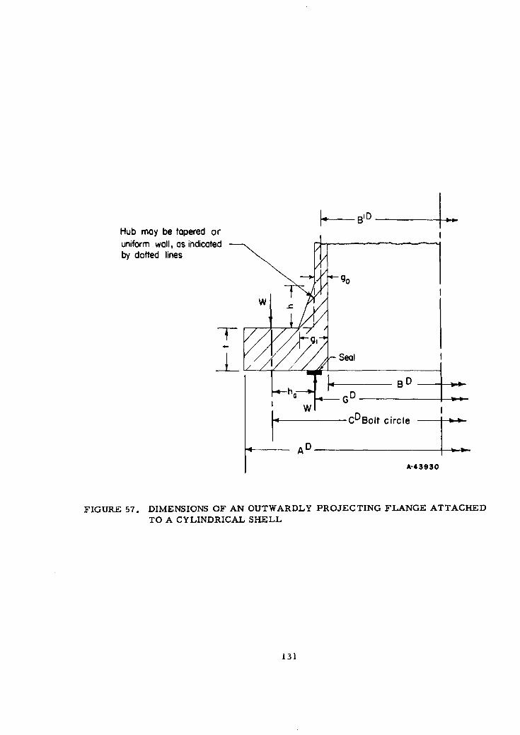
11 D ___
Hub may be tapered oruniform wall, as indicatedby dotted lines
/ -Seal
BD
4CDBolt circle
AD
A-43930
FIGURE 57. DIMENSIONS OF AN OUTWARDLY PROJECTING FLANGE ATTACHEDTO A CYLINDRICAL SHELL
131
For a loose ring flange, only one stress is calculated:
Tangential Ring Stress
ST = - (44)
Mo t 2 B
The dimensional parameters A, B, B', t, gl, go and h are shown in Figure 57.Other parameters are: U, Y, Z, and T as functions of K = A/B as shown in Figure 58.F, V, and f are functions of gl/go and h//B'g-, as shown in Figure 59 and Figure 60.Values of e, d, and L are obtained by the equations
F
e-_ (45)ho
d Uhg2 (46)V 090
L =te +1 + -- ,(47)
T d
where ho = F .
Displacement Calculations
The rotation of the flange ring due to an applied moment, Mo, is given byWesstrom and Bergh( 4 1 ) as
em =_0.o9 v Mo, (48)LhogoZE
where V, L, ho, go, and Mo are as defined in the preceding section on stress calcula-tions and E is the modulus of elasticity of the flange material.
The axial displacement is emhG, where hG is the lever arm of the applied load asshown by Figure 57. The axial displacement of a bolted fitting with two identical flangesis zemhG. Where the two flanges making up the joint are not identical, the total axialdisplacement is (em + 9zn)hG where em and e, are calculated by Equation (48) for thetwo flanges.
The rotation of the flange ring due to the radial component of the internal pressureis given by Rodabaugh( 4 2 ) as
ep= 2.57 x 0 8 B2 7 p (49)t(t + 1.82 geY)
132
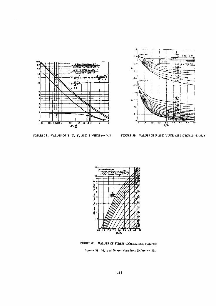
0 1F
090890009 *025 .0 J)_ 035
100s -- k~.ss?4eM )- 0 8 060 -050'045 040
IF 'W- ~ ~ 0V tM00.w)6 070u.5uo~j 6
050
ao~07
9.0 FPO .0 Z 3. 3 .0 4. 5
9,/g
2-133
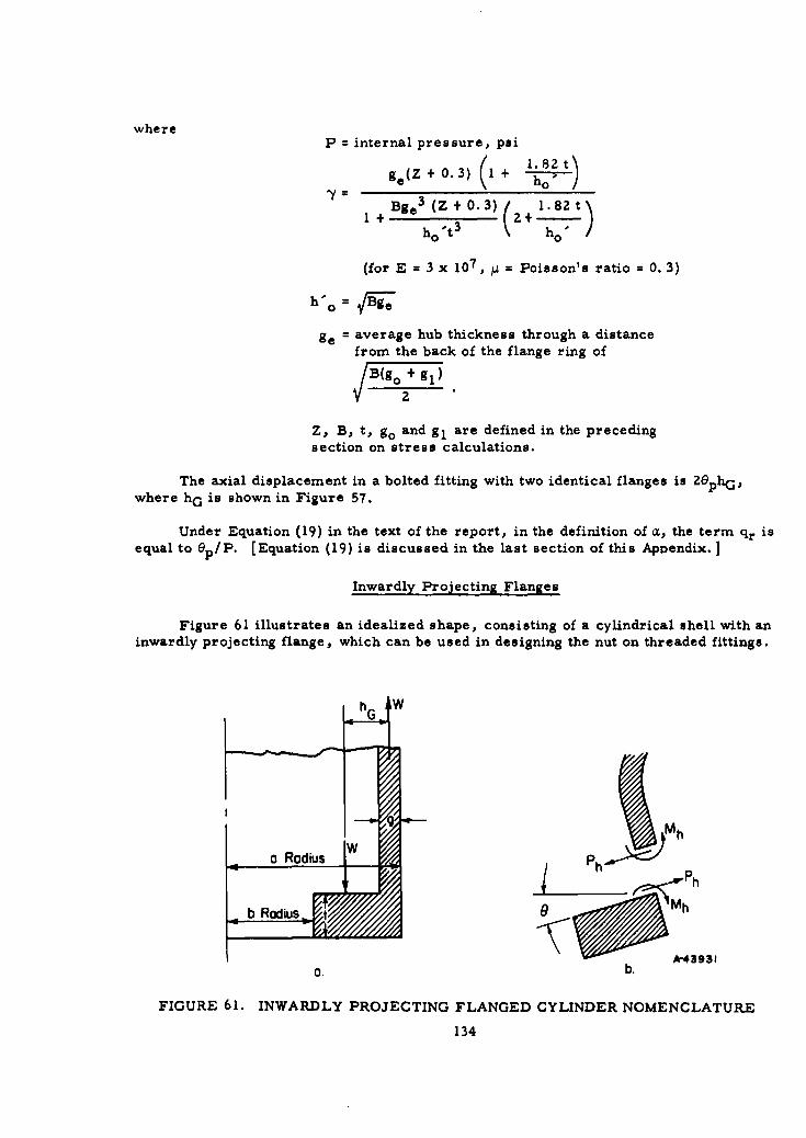
where
P = internal pressure, psi
ge(Z + . 3) ( l .82t)
"I +Bge 3 (Z +0.3) 2+ 1.'82th 0 t 3 h 0
(for E = 3 x 10 7 , 1 = Poisson's ratio = 0.3)
ge = average hub thickness through a distance
from the back of the flange ring of
B(go + gl)
2
Z, B, t, go and gl are defined in the precedingsection on stress calculations.
The axial displacement in a bolted fitting with two identical flanges is 2ephG,where hG is shown in Figure 57.
Under Equation (19) in the text of the report, in the definition of a, the term qr isequal to ep/P. [Equation (19) is discussed in the last section of this Appendix.]
Inwardly Projecting Flanges
Figure 61 illustrates an idealized shape, consisting of a cylindrical shell with aninwardly projecting flange, which can be used in designing the nut on threaded fittings.
A-43931
0. b.
FIGURE 61. INWARDLY PROJECTING FLANGED CYLINDER NOMENCLATURE
134
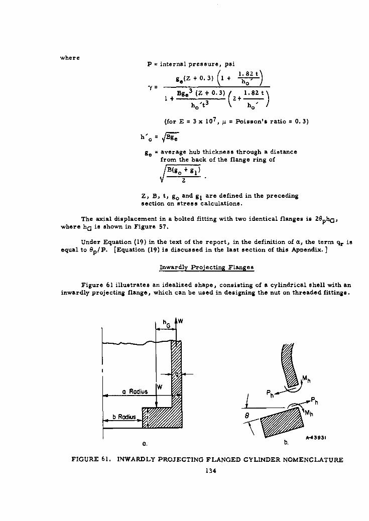
whereP = internal pressure, psi
ge(Z +0.3) (1 + l'82t)
7 = + Bge3 (Z + 0.3) Z+ Il'82 tho 0t3 ho0
(for E = 3 x 10⁷, = Poisson's ratio = 0.3)
h'o =Bge
ge = average hub thickness through a distance
from the back of the flange ring of
B(go + gl)
2
Z, B, t, go and g, are defined in the precedingsection on stress calculations.
The axial displacement in a bolted fitting with two identical flanges is ZephG,where hG is shown in Figure 57.
Under Equation (19) in the text of the report, in the definition of a, the term qr isequal to ep/P. [Equation (19) is discussed in the last section of this Appendix.]
Inwardly Projecting Flanges
Figure 61 illustrates an idealized shape, consisting of a cylindrical shell with aninwardly projecting flange, which can be used in designing the nut on threaded fittings.
h G •W
jMh
a Radius Ph < Ph
b Radius 8 •Mh
9*439310. b.
FIGURE 61. INWARDLY PROJECTING FLANGED CYLINDER NOMENCLATURE
134

Stress Calculations
The moment applied to the flange ring in Figure 61a is Mo = W x hG where W isthe total load. Under the applied moment Mo, the flange will rotate as indicated in
Figure 61b. There will be a moment Mh and a shear Ph acting at the juncture of theflange and the cylindrical shell; these are moments and forces per unit length.
The radial (outward) displacement w of the end of the cylindrical shell, loaded withend moment Mh and shear Ph' is given by Timoshenko( 4 3 ) as
1w =- (Ph - Mh), (50)
ZA3 D
where
A 4 3(l -A22= 22
7ag9
D= Eg 3
12(1 _A 2 )
E = modulus of elasticity
= Poisson's ratio.
It is assumed that the relatively rigid flange does not undergo any radial dis-placement, hence
3D (Ph - Mh) = 0 (51)
and
Ph = AMh (52)
The rotation of the end of a cylinder, loaded with an end moment Mh and shear Ph, isgiven by Timoshenko( 4 3 ) as
e 2fD (Ph ZPAMh) (53)
The rotation of the flange ring is also given by Timoshenko( 4 3 ) as
e = 6 Mj (a + b)Et 3 1n _a
b
where Mf, the moment applied to the ring per unit length of the ring center line, is
M Mo Za t 2a (55)
,'(a + b) a + b 2 a +b
135
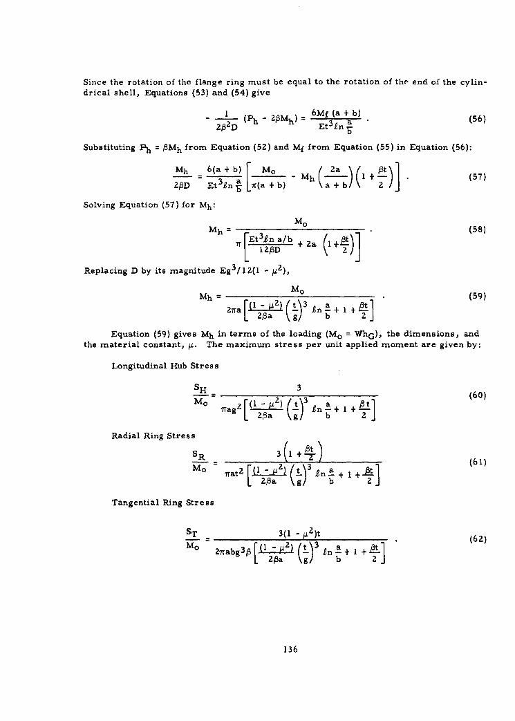
Since the rotation of the flange ring must be equal to the rotation of the end of the cylin-drical shell, Equations (53) and (54) give
2ID (ph - 2 A3Mh) = 6 Mf (a + b) (56)
Et 3 1n
Substituting Ph = AMh from Equation (52) and Mf from Equation (55) in Equation (56):
Mh 3 6 aEbn - Mh I +( )) . (57)
ZAD Et in'F Llr(a +b) a+ b) 2Z/
Solving Equation (57) for Mh:
MoMh (58)
7rFt1 Z/bD + 2a I1+A
Replacing D by its magnitude Eg3 /12(l - 11),
Mo0Mh = 2 (.i)L In.+ 1 (59)
2 7 a [ 1 - 2 ) g ) 3 a t2A3a bn 2
Equation (59) gives Mh in terms of the loading (Mo = WhG), the dimensions, andthe material constant, ýi. The maximum stress per unit applied moment are given by:
Longitudinal Hub Stress
SH 360)Trag 2 , 2[ a ) ( n3 n- + 1 +
Radial Ring Stress
MO - rat2 A[2l- (t-)a + " 1 (A) (61)
L ZIa g19 b 2J
Tangential Ring Stress
ST- 3(1 -j 2 )t (62)M 27rabg3p (I 2a12) (L) n a+b I +
136
Displacement Calculations
The rotation of the flange ring due to an applied moment, Mo, is given by Equa-tion (53) and using Ph = AMh from Equation (52):
=Mh (63)ZAD
The magnitude of Mh is given in terms of Mo by Equation (59). e in terms of Mo is then
Gm 3(l=Mo (64)
7raJ3g3E [( 2 Tl -~ b- n-1
The axial displacement is emhG.
Parts in Tension or Compression
Parts which are considered to be loaded in tension or compression are:
Bolts of bolted fittings (tension)
Cylindrical shell portion of nut in threaded fittings (tension)
Flanges of bolted fittings (compression)
Threaded stub end of threaded fittings (compression)
Flange of flanged stub end of threaded fittings (compression)
Seals (compression).
Stress Calculations
The general expression for stress in parts subjected to tension or compression is
S (65)
whereW = total load, lb
A = cross-sectional area perpendicular to load, in. 2
For bolts:
A = Ab = AblX n
137

whereAbl = cross-sectional area at root of threads for one bolt, in. 2
n = number of bolts
Ab = total bolt area.
Displacement Calculations
The general expression for displacement in parts subjected to tension or com-pression is
WAE (66)
whereW = total load, lb
A = axial length, in.
E = modulus of elasticity of material, psi
A = cross-sectional area perpendicular to load, in. 2
Threads in Threaded Fittings
The nominal shear stress on the threads, ST, is
S W (67)ST T-
whereAT = 0. 80 A17D, in., where the 0. 80 is an approximate factor to
account for thread clearances of the buttress or NF threadsused in the threaded fittings.
A= thread length, in.
Dp = thread pitch diameter, in.
Bending stresses and local contact stresses in the threads will, of course, besubstantially higher than the nominal shear stress. The thread length should be ampleto keep these local stresses at a tolerable level.
138
General Displacement Equation for Bolted Fittings,Equation (19) of Text
Equation (19) of the text (with F changed to W for nomenclature of this Appendix)is
W2 = W1 + ctP
whereP = internal pressure, psi
-- LhG - 2qF (hT - -ZqFBZ(hD - hT) 8 q
0 = qB + qG + 2qFhG2
toqB =ABEB
VoqG= AGEG
0.91 V (integral flanges) or 0. 8Z9 (loose ring flanges)LhogoEF t 3 EF log A
epqr •- where ep is defined by Equation (49)
to = bolt length, in.
V0 = seal thickness (in axial direction), in.
AB = total bolt area, sq in.
AG = total gasket area, sq in.
EB, EG, EF = modulus of elasticity of bolt, seal, and flange material,respectively.
hG = 1/Z (C-G)
hD = 1/2 (C-B)
hT = 1/2 (hD + hG)
Dimensions A, B, C, G, t, and go are shown in Figure 57. L, V, and ho aredefined in the first section of the Appendix under "Outwardly Projecting Flanged
Cylinders".
139

References
(39) Waters, E. 0., Wesstromr, D. B., Rossheim, D. B., and Williams, F.S.G.,"Formulas for Stresses in Bolted Flanged Connections", ASME Transactions(1937).
(40) American Society of Mechanical Engineers Boiler and Pressure Vessel Code,Section VIII, "Unfired Pressure Vessels", American Society of MechanicalEngineers, 345 East 47th Street, New York 17, N. Y. (1959).
(41) Wesstrom, D. B., and Bergh, S. E., "Effects of Internal Pressure on Stressesand Strains in Bolted-Flanged Connections", ASME Transactions (1951).
(42) Rodabaugh, E. C. , discussion of Reference (41).
(43) Timoshenko, S., Strength of Materials, Part II, D. Van Nostrand Co. , 250 FourthAvenue, New York 3, N. Y.
140
APPENDIX II
DISCUSSION OF DESIGN FOR CREEP OR RELAXATION
Since mechanical tube connections of the types discussed are highly strain sensi-tive at higher temperatures, plastic flow as a function of time, i.e. , creep or relaxa-tion, becomes a dominant factor in design. The basic problem of the relaxation of a boltin a rigid flange has been considered by several investigators(4447)*. The methodproposed here has been selected because of its simplicity in design application and be-cause of the limited available data on the newer alloys, such data being confined to ten-sile creep tests with no available relaxation-test data.
The elastic displacement of any part of the structure is proportional to the elasticstrain at that time, i. e.
6 KC. (68)
In a member with uniform stress, such as the bolts in tension, K is independent of plas-tic deformations. In the flanges, however, K is a function of plastic deformations sincesuch deformation redistributes the stress. A conservative( 4 8 ) assumption is that K is aconstant for all parts of the fitting and C is the maximum strain corresponding to themaximum calculated elastic stress. Use of K as a constant for all parts of the fittingimplies that:
(1) All parts of the fitting operate at the same maximum stress level.(This may be accomplished by appropriate design of the fitting; however,if this is not the case, an alternative method is indicated later in thisAppendix.)
(2) All parts are made of the same material.
(3) All parts operate at the same temperature.
(4) In parts subjected to bending stress, relaxation does not alter thestress distribution.
With the assumption of constant K:
at t = 0: 60 = KEo (69)
at t = t: 6t = Ket (70)
where t = time, hr. The difference between 60 and 6 t is the plastic displacement occur-ring in time t, giving
60 - 6 t = 6p (71)
KFo - K~t = K p (72)
*References for Appendix II are listed on page 145.
141
The elastic strains co and Et are proportional to the stresses So and St, giving
St6t S 0o (73)
Substitute Et from Equation (73) in Equation (72):
Cp- Eo -(1 - -t (74)
Differentiating Equation (74) with respect to time:
de E dSdt So It- o (75)
The values of dep/dt in Equation (75) are best obtained from relaxation tests of thematerial at the required temperature. However, in the absence of relaxation-test data,dep/dt may be obtained from creep-test data, particularly when the effect of first-stagecreep is handled separately. While Equation (75) could be integrated graphically fromcreep-test data, in order to expedite design work it is desirable to express d p/dt
analytically. A widely used expression is
d ep IS n 76
dt (76)
where
Ep = plastic strain, in in.
t = time, hr
St = stress, psi.
C 1 and n are material constants and are functions of the temperature. These constantscan be obtained empirically from a series of creep tests of the material at the requiredtemperature and at various stress levels.
The expression for de p/dt in Equation (76) is independent of time; this is approxi-mately true for second-stage creep but is not valid for firot- or third-stage creep. Thedesign method covers the effect of first-stage creep by means of a pseudo modulus ofelasticity, El, obtained directly from experimental creep data by extrapolating thesecond-stage creep back to zero time as indicated by Figure 62.
142
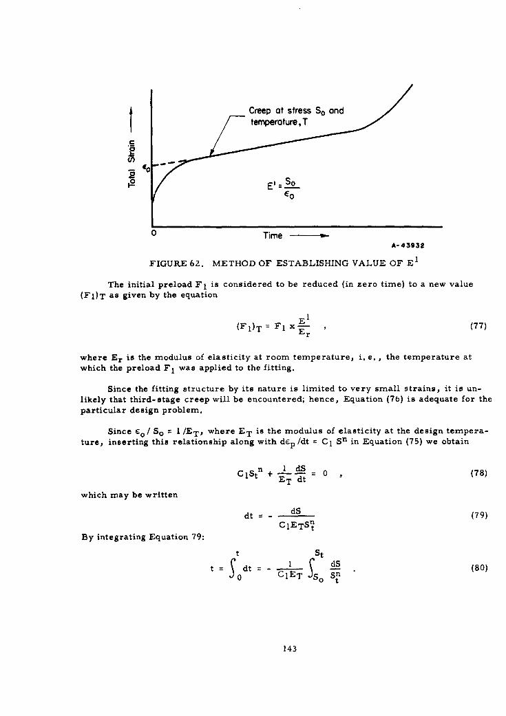
i ~Creep at stress So and
(I,
j2El -SO--06
Time - -
A-43932
FIGURE 62. METHOD OF ESTABLISHING VALUE OF El
The initial preload F 1 is considered to be reduced (in zero time) to a new value(FO)T as given by the equation
(FI)T = Fl X-rr (77)r
where Er is the modulus of elasticity at room temperature, i. e. , the temperature at
which the preload F 1 was applied to the fitting.
Since the fitting structure by its nature is limited to very small strains, it is un-likely that third-stage creep will be encountered; hence, Equation (76) is adequate for theparticular design problem.
Since o/ So = 1/ET, where ET is the modulus of elasticity at the design tempera-
ture, inserting this relationship along with dcp /dt C1 Sn in Equation (75) we obtain
CGStn + _i_ s= , (78)ET dt
which may be written
dt = dS (79)CIETS
By integrating Equation 79:
t Stt : dt - S dS (80)
so (lET oSS t
143
t = (81)C IET(n- l)Stn-
Equation (81) is the well-known equation for relaxation of a bolt under constanttotal strain. However, it was derived here to be applicable to a connection consisting ofseveral parts, made cf the same material, each of which is subjected to the same stressand temperature and where it is assumed that the stress-displacement relations do notchange as a result of loadings* or creep. The restriction to the theory that all partsare operating at the same stress can be removed by a relatively simple extension of thetheory. If the connection is considered as three parts (flanges, bolts, seal of a bolted-flanged connection), the equation for calculating service life becomes
[ + 1KI L3 Kn- 1
1 K( 1 )o (82)
+1 (K2~ + (L 3)n] ClET(n- )Stn-l
where the K's are defined by the elastic displacement-stress relations: 6 1 = K1S,62 = KZS1, 63 = K3S 1 for flanges, bolts, and seal"*, respectively, and S 1 is the stressin the flanges.
Removal of the restriction that all parts of the connections be made of the samematerial and operate at the same temperature required considerable additional designeffort since the resulting equation,
- I dS"dt = , (83)
CllStnl + c 1 z2 s i + C13 K t
with the n's all different and noninteger, must be numerically or graphically integrated.
The removal of the restriction that the stress-displacement relations, for parts inbending, do not change with creep presents formidable difficulties. Some progress onthis problem( 4 8 , 4 9 ) has been made for the case of a ring in torsion. However, even forthis comparatively simple structure numerical integration methods are required. Thecase of the ring with attached cylindrical shell is much more complex.
*Actually, the stresses in a fitting structure do vary with loads. The stress variation in the parts that contribute most to relaxa-
tion (bolts and flanges in bolted fittings, nuts and stub ends in threaded fittings), however, is relatively small. The stress in the
seal decreases with Increasing internal pressure so that the a!sumption that stress in the seal does not vary with loads is generally
conservative from the standpoint of relaxation."It should be recognized that the K's may be functions of the internal pressure and external loads.
1,14
The theoretical refinements discussed above, along with other desirable refine-ments to the theory, are not within the scope of this project. Accordingly, the pre-liminary design work has been based on the simplified concept described above with theexpectation that, due to a number of conservative assumptions, the resulting designswill be adequate.
Reference s
(44) Marin, Joseph, Engineering Materials, Prentice-Hall, Inc., New York (1952).
(45) Finnie, lain, and Heller, W. R. , Creep of Engineering Materials, McGraw-HillBook Company, New York (1959)
(46) Popov, E. P., "Correlation of Tension Creep Tests with Relaxation Tests", ASMEJournal of Applied Mechanics (June, 1947).
(47) Robinson, E. L., "Steam-Piping Designs to Minimize Creep Concentrations",ASME Transactions (1955).
(48) Waters, E. 0. , "Analysis of Bolted Joints at High Temperature", ASMETransactions (1938).
(49) Matin, Joseph, discussion of paper, "Formulas for Stresses in Bolted-FlangedConnections", ASME Transactions (1937).
145
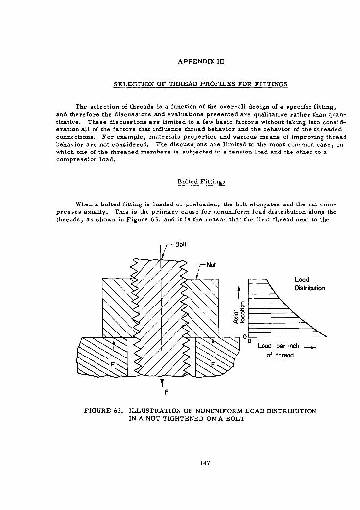
APPENDIX III
SELECTION OF THREAD PROFILES FOR FITTINGS
The selection of threads is a function of the over-all design of a specific fitting,and therefore the discussions and evaluations presented are qualitative rather than quan-titative. These discussions are limited to a few basic factors without taking into consid-eration all of the factors that influence thread behavior and the behavior of the threadedconnections. For example, materials pro:?erties and various means of improving threadbehavior are not considered. The discuss',ons are limited to the most common case, inwhich one of the threaded members is subjected to a tension load and the other to acompression load.
Bolted Fittings
When a bolted fitting is loaded or preloaded, the bolt elongates and the nut com-presses axially. This is the primary cause for nonuniform load distribution along thethreads, as shown in Figure 63, and it is the reason that the first thread next to the
-Bolt
LoadDistribution
0
0-Load per inch .
of thread
F
FIGURE 63. ILLUSTRATION OF NONUNIFORM LOAD DISTRIBUTIONIN A NUT TIGHTENED ON A BOLT
147
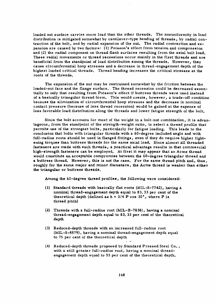
loaded nut surface carries more load than the other threads. The nonuniformity in loaddistribution is mitigated somewhat by cantilever-type bending of threads, by radial con-traction of the bolt, and by radial expansion of the nut. The radial contraction and ex-pansion are caused by two factors: (1) Poisson's effect from tension and compressionand (2) the radial component on thread flank surfaces resulting from the axial bolt load.These radial movements or thread recessions occur mainly in the first threads and arebeneficial from the standpoint of load distribution among the threads. However, theycause circumferential hoop stresses and a decrease in thread-engagement depth of thehighest loaded critical threads. Thread bending increases the critical stresses at theroots of the threads.
The expansion of the nut may be restrained somewhat by the friction between theloaded-nut face and the flange surface. The thread recession could be decreased essen-tially to only that resulting from Poisson t s effect if buttress threads were used insteadof a basically triangular thread form. This would create, however, a trade-off conditionbecause the elimination of circumferential hoop stresses and the decrease in nominalcontact pressure (because of less thread recession) would be gained at the expense ofless favorable load distribution along the threads and lower fatigue strength of the bolt.
Since the bolt accounts for most of the weight in a bolt-nut combination, it is advan-tageous, from the standpoint of the strength-weight ratio, to select a thread profile thatpermits use of the strongest bolts, particularly for fatigue loading. This leads to theconclusion that bolts with triangular threads with a 60-degree included angle and withfull-radius roots should be used in flanged fittings, even if they do require higher tight-ening torques than buttress threads for the same axial load. Since almost all threadedfasteners are made with such threads, a practical advantage results in that commercialhigh-strength fasteners can be employed. At first it may appear that an Acme threadwould constitute an acceptable compromise between the 60-degree triangular thread anda buttress thread. However, this is not the case. For the same thread pitch and, thus,roughly for the same major and minor diameters, the Acme thread is weaker than eitherthe triangular or buttress threads.
Among the 60-degree thread profiles, the following were considered:
(1) Standard threads with basically flat roots (MIL-S-7742), having anominal thread-engagement depth equal to 83. 33 per cent of thetheoretical depth (defined as h = 3/4 P cos 30*, where P isthread pitch)
(2) Threads with a full-radius root (MIL-B-7838), having a nominalthread-engagement depth equal to 83. 33 per cent of the theoreticaldepth
(3) Reduced-depth threads with an increased full-radius root(MIL-S-8879), having a nominal thread-engagement depth equalto 75 per cent of the theoretical depth
(4) Reduced-depth threads proposed by Standard Pressed Steel Co. ,with a still greater full-radius root, having a nominal thread-engagement depth equal to 55 per cent of the theoretical depth.
148
For external bolt threads of the same size and pitch, the major diameter is nomi-nally the same for all four profiles. The nominal minor diameter is essentially the samefor the first two profiles. It becomes larger for the 75 per cent thread and still largerfor the 55 per cent thread as a consequence of the increase in root radius and the de-crease in thread depth. The major diameter of the internal threads is also essentiallythe same for all four profiles. The minor diameter of the internal threads is increasedwith the corresponding increase in the minor diameter of the external threads to avoidinterference of the internal-thread crests with the root radius of the external threads.
The most common failures that occur with such preloaded bolted connections are:
(1) A transverse fracture of the bolt from overstress, creep, orfatigue, usually starting at the root of the first engaged thread
(2) Longitudinal failure of the nut due to excessive circumferentialhoop stresses
(3) Stripping of the mating threads because of overload
(4) Seizure of the mating threads, caused by excessive contactpressure.
Considering only the strength of the bolt for all failure modes - overstress, creep,and fatigue - the reduced-depth thread is clearly superior to the full-depth thread. Thelarger minor diameter provides a larger load-carrying cross section, and the largerroot radius has a lower stress concentration, which is important for fatigue strength.The published data support the above statement and show higher ultimate tensile strength,stress-rupture strength, and higher fatigue strength for the reduced-depth threads. Itappears that the biggest gain for the reduced-depth thread lies in its improved fatiguecharacteristics, mainly due to the enlarged root radius. Because of the latter, thestandard threads with a full-radius root (MIL-B-7838) are to be preferred in all casesover the standard threads with flat roots (MIL-S-7742). Whenever fatigue is the primaryconsideration, the 75 per cent threads (MIL-S-8879) or even the SPS-proposed 55 percent threads may be the best unless considerations other than fatigue limit their use.
In the case of nut failures from excessive circumferential hoop stresses, thereshould be no essential differences between reduced-depth and full-depth threads, pro-vided all other conditions are equal. The stripping strength of reduced-depth threads onthe bolts should theoretically decrease with the thread depth but not necessarily in pro-portion, because of decrease in "shear" area. It is being claimed, however, that thestripping strength of reduced-depth threads on the bolts remains equal to that of full-depth threads until the engagement depth decreases to about 50 per cent of the theoreticaldepth, and then it drops off rather rapidly. Actually, there are not enough data avail-able to make a valid conclusion. At any rate, it appears that the stripping strength ofthe 55 per cent thread on the bolt may be lower than that of full-depth or the 75 per centthread if the thread recession is considered.
Because of lack of sufficient experience data, an uncertainty exists concerning thebehavior of reduced-depth threads with respect to thread seizure. From an elementarypoint of view, the nominal contact pressures, defined as the axial force divided by theprojected area of threads, are higher in the reduced-depth threads, and therefore suchthreads should be more susceptible to seizure and galling. Because of thread bending
149
under load, the actual contact between threads is concentrated in a limited area ratherthan being distributed uniformly over the entire thread flank. Galling and seizing ofthreads is thus governed mainly by the peak contact stresses. Because of the complexi-ties involved, it is virtually impossible to predict analytically the quantitative peak con-tact stresses and subsequent amount of thread galling or seizing. Judging from the ge-ometries involved, higher peak contact pressures can be expected in the 55 per centthread than in the 75 per cent or full-depth threads, and therefore thread galling or seiz-ing may become a problem in reduced-depth threads.
It becomes apparent that, from the viewpoint of bolt strength, the reduced-depththreads should be used unless galling, seizing, or stripping occurs. One of the require-ments for all mechanical fittings is that they should be capable of sustaining severalassemblies and disassemblies. If only thread galling or mild seizing would occur insome fasteners of the flanged connections, the damaged fasteners could probably beeasily replaced during reassembly when needed. Since the 75 per cent thread (MIL-S-8879) is widely accepted by the aircraft industry, it can be reasonably assumed that its
stripping strength is sufficient, and therefore it appears to be advantageous to use it forfasteners in flanged fittings.
Use of the 55 per cent thread in fasteners for flanges fittings is not recommendedat this time because of the uncertainties concerning its stripping strength and threadseizure. Such a thread form, however, may be considered for future use, providedthat these uncertainties are eventually resolved favorably.
Threaded Fittings
Here, the threaded members are "sleeves" with or without wrench flats. The in-ternal member has the external threads and the external member has the internal threads.In most cases, the internal threads are loaded in tension and the external threads in
compression, which is opposite to a normal bolt- and-nut combination. Regardless ofthe load directions, the primary function of the threads is to provide or sustain high axialforces. At the same time, the sleeves should be of a minimum weight design. Buttressthreads fulfill both of these requirements because they develop the highest axial force fora given torque value and because they do not develop hoop stresses in the sleeves, there-fore, they permit minimum wall thickness. The lower fatigue strength as compared withthe 60-degree threads is of little consequence for this application because the criticallocation, as far as the fatigue strength of the fitting is concerned, is the tube-to-fittingconnection. Since there is practically no disengagement of threads due to radial forces inbuttress threads, they are also expected to be better from the standpoint of preloadrelaxation.
In view of these considerations, buttress threads are recommended for larger sizethreaded fittings. In smaller size threaded fittings, the increased cost of buttressthreads as compared with that of NF threads may not be justified since, based on prelimi-nary designs of a 1/8 in. threaded fitting, it appears that excess material will be presentin the nut because of manufacturing requirements. If this occurs, the reduction of radialthrust by use of buttress threads would be only a minor advantage. Also, in small sizes,the advantage of high axial force for a given torque, which may be obtained with buttress
150

threads, is of less importance since in small sizes the required axial force is relativelysmall. The size division between threaded fittings with NF threads and those with but-tress threads will depend upon required design details in intermediate sizes.
151
APPENDIX IV
TORQUE RELAXATION TESTS ON FLARED AND FLARELESS FITTINGS
Definition of Torque Relaxation and Sources of Test Data
Threaded flared fittings, when used for critical applications, are tightened with atorque wrench to a specified torque magnitude and the flareless fittings are tightenedaccording to some specified procedures. Upon checking the torque on these fittings atsome later time, it is often found that the torque is less than that originally applied tothe fitting. This phenomenon has been termed "torque relaxation". Test data on torquerelaxation are available from the following three sources:
(A) Seibel, L. L. , and McGillen, V. W. , "Hydraulic and PneumaticFitting and Tubing Test Program", WADC Technical Report 59-267(November, 1959).
(B) Richards, C. M. , "Torque Relaxation in Flared Tube Fittings",Convair/Astronautics, Division of General Dynamics Corporation(July 18, 1960).
(C) Guthrnann, P. , "Tube Connections, A State-of-the-Art Study",Report No. 1058, Chrysler Corporation, Missile Division,Huntsville Operations (October, 1961).
Test Data From Source (A)
The data available are from Phase III tests of Source (A), pages 24-73, plusAppendix I, "Procedures for Phases III and IV".
Test Specimens
Fittings were either (1) precision flared*, (2) MS- flareless, or (3) super-flareless** types. Material for fittings and tube was 300 series stainless steel, exceptthe sleeves of MS- flareless fittings were of 1112 or 1113 case-hardened steel platedwith nickel or cadmium.
Sizes tested were 4, 6, 8, 12, and 16 (nominal tube OD in sixteenths inch).
" AN- fittings with close tolerances and inspection controls.KMS- fittings with minor dimensional changes, closer tolerances, and closer controls on hardness and surface finish.
153
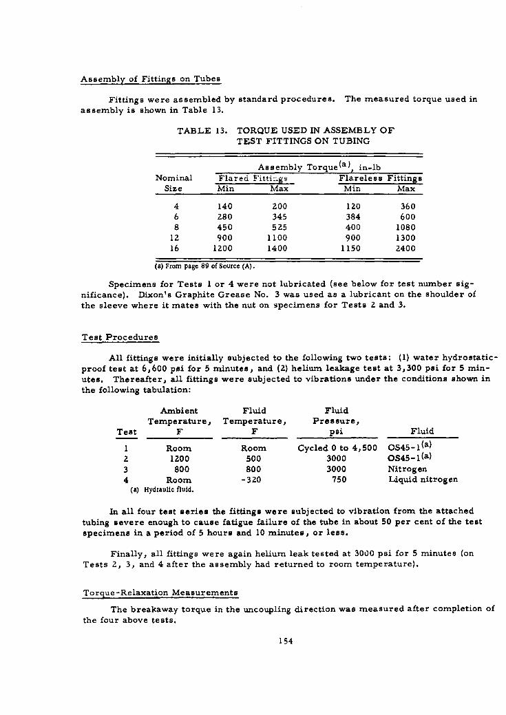
Assembly of Fittings on Tubes
Fittings were assembled by standard procedures. The measured torque used inassembly is shown in Table 13.
TABLE 13. TORQUE USED IN ASSEMBLY OFTEST FITTINGS ON TUBING
Assembly Torque(a), in-lb
Nominal Flared F'ittings Flareless FittingsSize Min Max Min Max
4 140 200 120 3606 280 345 384 6008 450 525 400 1080
12 900 1100 900 130016 1200 1400 1150 2400
(a) From page 89 of Source (A).
Specimens for Tests I or 4 were not lubricated (see below for test number sig-nificance). Dixon's Graphite Grease No. 3 was used as a lubricant on the shoulder of
the sleeve where it mates with the nut on specimens for Tests 2 and 3.
Test Procedures
All fittings were initially subjected to the following two tests: (1) water hydrostatic-
proof test at 6,600 psi for 5 minutes, and (2) helium leakage test at 3,300 psi for 5 min-utes. Thereafter, all fittings were subjected to vibrations under the conditions shown inthe following tabulation:
Ambient Fluid FluidTemperature, Temperature, Pressure,
Test F F psi Fluid
1 Room Room Cycled 0 to 4,500 OS45-I(a)
2 1200 500 3000 OS45- I (a)
3 800 800 3000 Nitrogen4 Room -320 750 Liquid nitrogen
(a) Hydraulic fluid.
In all four test series the fittings were subjected to vibration from the attached
tubing severe enough to cause fatigue failure of the tube in about 50 per cent of the test
specimens in a period of 5 hours and 10 minutes, or less.
Finally, all fittings were again helium leak tested at 3000 psi for 5 minutes (onTests 2, 3, and 4 after the assembly had returned to room temperature).
Torque-Relaxation Measurements
The breakaway torque in the uncoupling direction was measured after completion of
the four above tests.
154
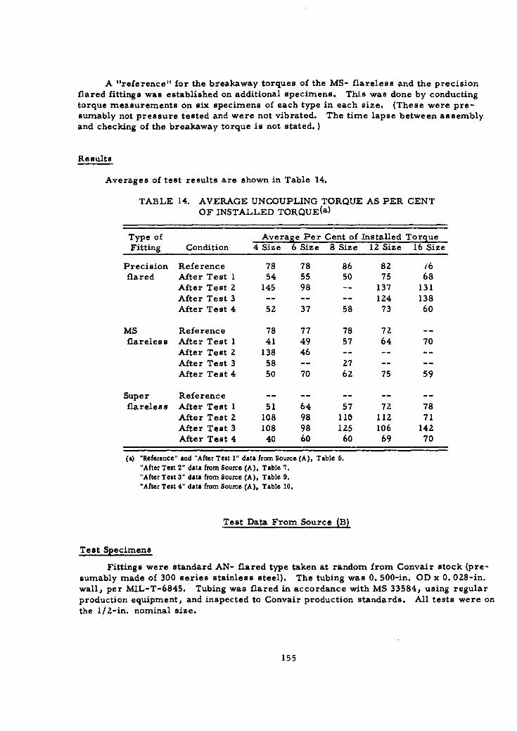
A "reference" for the breakaway torques of the MS- flareless and the precisionflared fittings was established on additional specimens. This was done by conducting
torque measurements on six specimens of each type in each size. (These were pre-sumably not pressure tested and were not vibrated. The time lapse between assembly
and checking of the breakaway torque is not stated.)
Results
Averages of test results are shown in Table 14.
TABLE 14. AVERAGE UNCOUPLING TORQUE AS PER CENTOF INSTALLED TORQUE(a)
Type of Average Per Cent of Installed TorqueFitting Condition 4 Size 6 Size 8 Size 12 Size 16 Size
Precision Reference 78 78 86 82 (6flared After Test 1 54 55 50 75 68
After Test 2 145 98 -- 137 131After Test 3 .. .. .. 124 138After Test 4 52 37 58 73 60
MS Reference 78 77 78 72 --
flareless After Test 1 41 49 57 64 70After Test 2 138 46 .. .. ..After Test 3 58 -- 27 .. ..After Test 4 50 70 62 75 59
Super Reference .. .. .. .. ..flareless After Test 1 51 64 57 72 78
After Test 2 108 98 110 112 71After Test 3 108 98 125 106 142After Test 4 40 60 60 69 70
(a) "Reference" and "After Test 1" data from Source (A). Table 6."After Test 2" data from Source (A), Table 7."After Test 3" data from Source (A), Table 9."After Test 4" data from Source (A). Table 10.
Test Data From Source (B)
Test Specimens
Fittings were standard AN- flared type taken at random from Convair stock (pre-sumably made of 300 series stainless steel). The tubing was 0. 500-in. OD x 0. 028-in.wall, per MIL-T-6845. Tubing was flared in accordance with MS 33584, using regularproduction equipment, and inspected to Convair production standards. All tests were on
the 1/2-in. nominal size.
155
Purpose of the tests was to compare torque relaxation of standard AN- fittings withtorque relaxation when using standard AN- fittings plus conical copper seals. The coppeseals used were from three sources:
Designation Description
CV-A Convair manufacture typical of those used byConvair in production
VS Made by Voi- Shan Manufacturing Company,Culver City, California
GM Made by Gasket Manufacturing Company,Los Angeles, California
Test Production
The specimens were lubricated on the male threads and the back of the sleeveshoulder with Kel-F-90 fluorocarbon grease.
Each specimen was assembled to 475 in-lb torque, using a Richmont snap-indicatingtorque wrench.
Specimens selected at random were re-torqued without disassembly, using theoriginal torque wrench at the time periods noted in Table 15. The angular movement of
the nut required to restore the original torque was recorded.
Results
Results are shown in Table 15.
Test Data From Source (C)
Test Specimens
Fittings were AN- flared type. Material for fitting and tubes was 300 series stain-less steel. Tests were run with conical gaskets made of copper or tin-plated copper.Size was 3/4-in.
Test Procedure
Thirty-two fittings were assembled, using an assembly torque of 900 to 1000 in-lb.These were divided into four sets of eight fittings each. Residual torque was measuredon one set at Z0, on the second set at 48, on the third at 168, and on the fourth at 336hours after assembly. (Other details of the procedure are not known.)
156
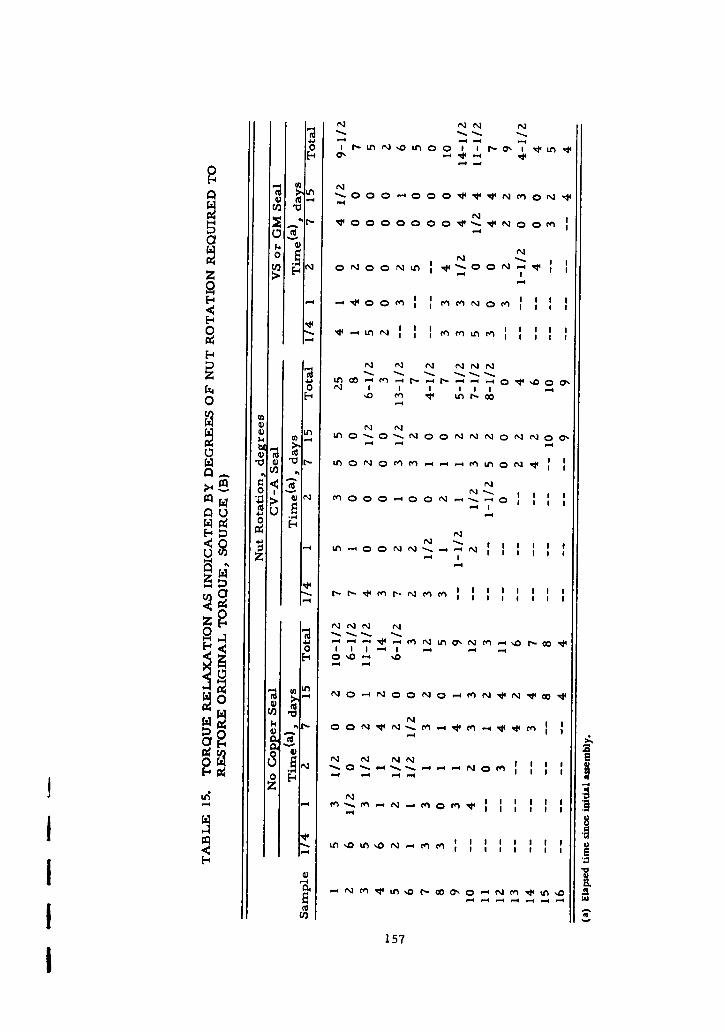
- N NN N
4-
0 1 N -L 0L ' L
-4 tW-
a F
-' 0
-4
H -4 - - -
E-4 v
0~r Ln N . Men n
01 1. Nn0 r 0 '
Ln O LN 0 N cNN
tici
Q u -ý0
u 0 n NN
a- r LA ON-~. N
z N
E--
NN N
a 04
0 AN . -4.44 O N N am. it .0 -
z
0- LM DI-0 7,0 m t
157 o~
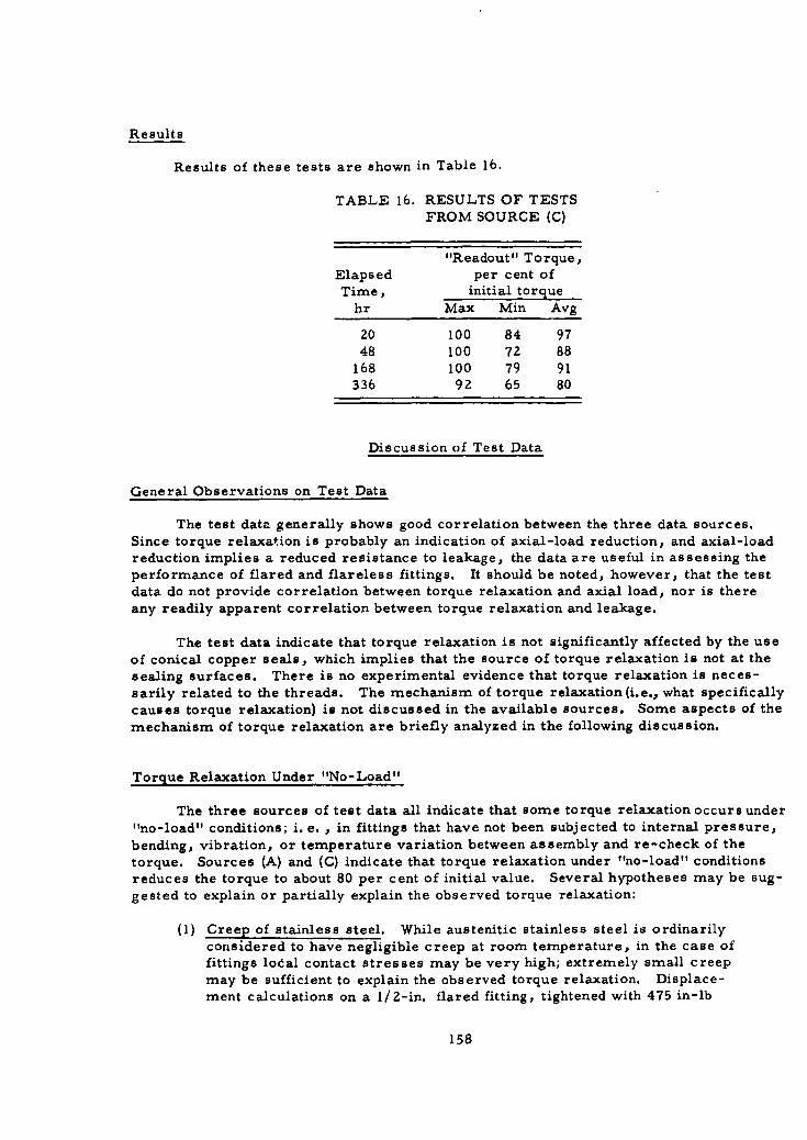
Results
Results of these tests are shown in Table 16.
TABLE 16. RESULTS OF TESTSFROM SOURCE (C)
"Readout" Torque,Elapsed per cent ofTime, initial torque
hr Max Min Avg
20 100 84 9748 100 72 88
168 100 79 91336 9Z 65 80
Discussion of Test Data
General Observations on Test Data
The test data generally shows good correlation between the three data sources.Since torque relaxation is probably an indication of axial-load reduction, and axial-loadreduction implies a reduced resistance to leakage, the data are useful in assessing theperformance of flared and flareless fittings. It should be noted, however, that the testdata do not provide correlation between torque relaxation and axial load, nor is thereany readily apparent correlation between torque relaxation and leakage.
The test data indicate that torque relaxation is not significantly affected by the useof conical copper seals, which implies that the source of torque relaxation is not at thesealing surfaces. There is no experimental evidence that torque relaxation is neces-sarily related to the threads. The mechanism of torque relaxation (i.e., what specificallycauses torque relaxation) is not discussed in the available sources. Some aspects of themechanism of torque relaxation are briefly analyzed in the following discussion.
Torque Relaxation Under "No-Load"
The three sources of test data all indicate that some torque relaxation occurs under
"no-load" conditions; i. e. , in fittings that have not been subjected to internal pressure,
bending, vibration, or temperature variation between assembly and re-check of thetorque. Sources (A) and (C) indicate that torque relaxation under "no-load" conditionsreduces the torque to about 80 per cent of initial value. Several hypotheses may be sug-
gested to explain or partially explain the observed torque relaxation:
(1) Creep of stainless steel. While austenitic stainless steel is ordinarilyconsidered to have negligible creep at room temperature, in the case offittings lodal contact stresses may be very high; extremely small creep
may be sufficient to explain the observed torque relaxation. Displace-ment calculations on a 1/2-in. flared fitting, tightened with 475 in-lb
158
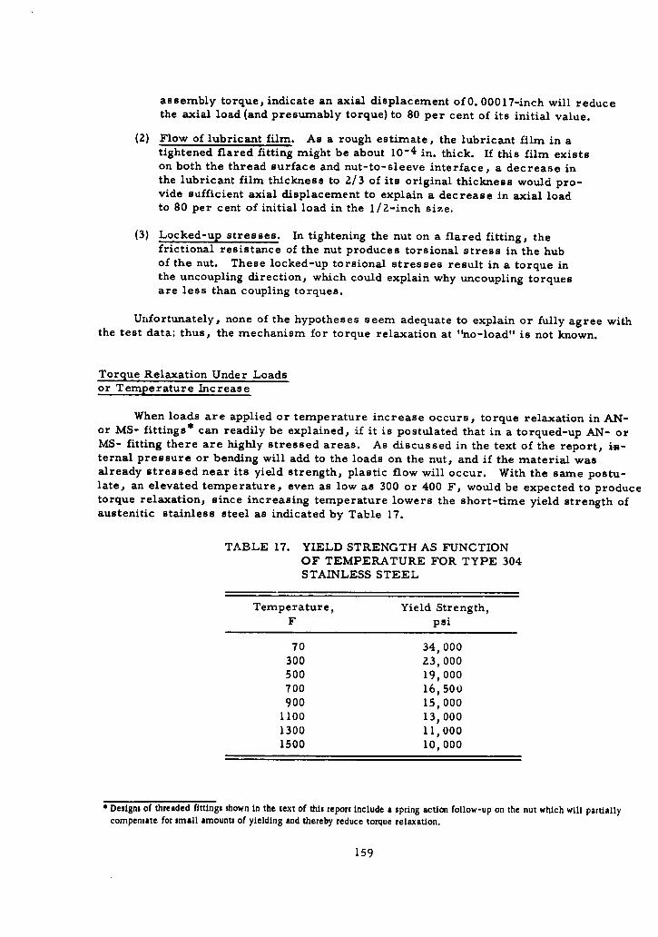
assembly torque, indicate an axial displacement of O. 00017-inch will reducethe axial load (and presumably torque) to 80 per cent of its initial value.
(2) Flow of lubricant film. As a rough estimate, the lubricant film in atightened flared fitting might be about 10-4 in. thick. If this film existson both the thread surface and nut-to-sleeve interface, a decrease inthe lubricant film thickness to 2/3 of its original thickness would pro-vide sufficient axial displacement to explain a decrease in axial loadto 80 per cent of initial load in the 1/2-inch size.
(3) Locked-up stresses. In tightening the nut on a flared fitting, thefrictional resistance of the nut produces torsional stress in the hubof the nut. These locked-up torsional stresses result in a torque inthe uncoupling direction, which could explain why uncoupling torquesare less than coupling torques.
Unfortunately, none of the hypotheses seem adequate to explain or fully agree withthe test data; thus, the mechanism for torque relaxation at "no-load" is not known.
Torque Relaxation Under Loadsor Temperature Increase
When loads are applied or temperature increase occurs, torque relaxation in AN-or MS- fittings* can readily be explained, if it is postulated that in a torqued-up AN- orMS- fitting there are highly stressed areas. As discussed in the text of the report, im-ternal pressure or bending will add to the loads on the nut, and if the material wasalready stressed near its yield strength, plastic flow will occur. With the same postu-late, an elevated temperature, even as low as 300 or 400 F, would be expected to producetorque relaxation, since increasing temperature lowers the short-time yield strength ofaustenitic stainless steel as indicated by Table 17.
TABLE 17. YIELD STRENGTH AS FUNCTIONOF TEMPERATURE FOR TYPE 304STAINLESS STEEL
Temperature, Yield Strength,F psi
70 34 000300 23,000500 19,000700 16,500900 15,000
1100 13 0001300 11,0001500 10,000
* Designs of threaded fittings shown in the text of this report include a spring action follow-up on the nut which will partiallycompensate for small amounts of yielding and thereby reduce torque relaxation.
159

The data from Source (A) indicates substantially greater torque relaxation afterloading than at "no-loads" (after Tests 1 and 4, Table 14). With regard to the elevated-temperature test results (after Tests 2 and 3, Table 14), it is possible that the increasedtorque values (over 100 per cent) may have resulted from hardening of the lubricant orpartial seizing or galling of the contact surfaces under high contact stresses at elevatedtemperatures.
Relaxation of Torque Relaxation to Thread Form
The test data does not provide any information about the effect of thread form ontorque relaxation since all tests were run on fittings with National Fine threads.Theories( 5 0 , 5 1) on local stresses in threads are based on the assumption of elasticity,which is only indirectly applicable to torque relaxation in which plastic flow presumablyoccurs. Further, such theories are based on "perfect" thread geometry; thread toler-ances, particularly on lead and flank angle, may be more significant in torque relaxationthan the detailed thread form.
References
(50) Heywood, R. B. , "Tensile Fillet Stresses in Loaded Projections", Proc. I. Mech.
Engr., 160, 124 (1949).
(51) Sopwith, D. G. , "The Distributions of Load in Screw Threads", Proc. Inst. Mech.Eng. (London), 373-383 (October, 1947).
160
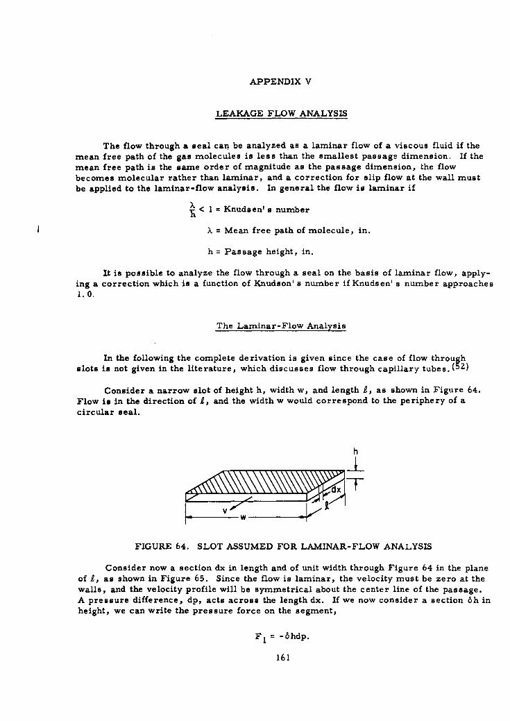
APPENDIX V
LEAKAGE FLOW ANALYSIS
The flow through a seal can be analyzed as a laminar flow of a viscous fluid if themean free path of the gas molecules is less than the smallest passage dimension. If themean free path is the same order of magnitude as the passage dimension, the flowbecomes molecular rather than laminar, and a correction for slip flow at the wall mustbe applied to the laminar-flow analysis. In general the flow is laminar if
% < I = Knudsen' s number
>, = Mean free path of molecule, in.
h = Passage height, in.
It is possible to analyze the flow through a seal on the basis of laminar flow, apply-ing a correction which is a function of Knudson' s number if Knudsen' s number approaches1.0.
The Laminar-Flow Analysis
In the following the complete derivation is given since the case of flow throughslots is not given in the literature, which discusses flow through capillary tubes . (5Z)
Consider a narrow slot of height h, width w, and length 1, as shown in Figure 64.Flow is in the direction of 2, and the width w would correspond to the periphery of a
circular seal.
h
I-_t_
FIGURE 64. SLOT ASSUMED FOR LAMINAR-FLOW ANALYSIS
Consider now a section dx in length and of unit width through Figure 64 in the planeof 2, as shown in Figure 65. Since the flow is laminar, the velocity must be zero at thewalls, and the velocity profile will be symmetrical about the center line of the passage.A pressure difference, dp, acts across the length dx. If we now consider a section 6h inheight, we can write the pressure force on the segment,
F= -6hdp.
161

FIGURE 65. FLOW AT SECTION dx OF SLOT
The pressure force must be equal and opposite to the viscous shearing forces onthe segment if the flow is to be steady. The viscosity is defined as the ratio of shearstress to velocity gradient. Thus the shearing forces must have the form
F2= ~dx dv,dy
where
7) = viscosityv = velocityy = ordinant in h direction.
At the outer surface of the element 6h, the shearing force will be
dy'F2 o = 7d~y
Since the velocity increases as the center line is approached, the force on the inner sur-face of the element will be
F~i = 7)dx d(v + -v 6h.
Also, the velocity gradient, dv/dh, is greater at the outer surface of the element,and the net shearing force on the element will be
F2 = F 2 0 - F2 i = 7jdx F7 -Ad(v+yy .6h)
Idy dy dy JIf the element is not accelerating, the pressure force must equal the shearing
force:
Fl= F2
"- 6hdp F71dx AY -A(v + dV 6h)l
dy dy dy d=7 dx[v dv d2 v dv dch
Leaving out the second-order term results in
-6hdp rdx6h d2 v
dy 2
Idp d2 v
T) dx16
162

Considering first the right side of this equation, assume a solution of the form
v = A + By + Cy 2
dv d 2 v-=B+ Z~y, •-•7=ZC
and dy y
ZC = dp."7) dx
From the laminar flow requirement, v = 0 when y = 0; therefore, A = 0.
The flow must also be symmetrical about the center line. Therefore,
dv = 0 when y h
o = B + 2Cy B + dp h
and Bd dx 2
Zr)dx
The equation for the velocity profile is therefore
v = - -h-" dx 2 rdZ7)d27 2fdx
= (hy - y2 ).Z2) dx
The volume flow rate through the slit will be
Q=Zw 0 vdy= -wd 0 (hy - y 2 ) dyY O T) dx YJO-R [ Y ,,3 1 h/2
7) dx 2 3 0
= w .d.2h 3 .
127l dx
The mass flow rate through the slit is
M = Po=_ P-- wh---p1ZRT 7 dx
Since, from continuity, the mass flow must be constant
dM_ 0 = wh3 [ d2 +((4
dx 12RT 7 L Hdx~ dx~l'(4
an isothermal process being assumed.
Let Z = -d2
dx
then,dZ dx2 = dZ.4Z _p=Z dZZ
dx d dp dx dp
163

The bracketed term in Equation (84) then becomes
p Z dp + Z2 0
or
dZ =
which can be integrated to
log Z + log p = log CI
or
Zp= C•
Since
z_=dx
dP= "el.'Pdx '
which can be integrated to
22= -C ix + C2
From the boundary conditions
p = p when x = 0
and
p = p2 when x=.
The refore, 2
2
and
c1 2 (P1 I-?)
The equation for the pressure variation lengthwise in the slit is therefore
p..= 2 -- (p2- p2 2 ).
Referring again to the mass-flow equation
M = -= pwh3 dplZRT7l dx'
164
we can write
_Pd L( 12 _2 2)d 1
wh 3 (pl 2 - p2 2 )ML = 2'i•TTrL
Since pj 2 - PZZ = (Pi - P2)(Pi + Pz)' this can be written in terms of the averagepressure or density; wh 3 (P1 - P? Pavg
ML = 12 RT711
wh3 (P1 - P2) PavgML 12)I
Since leakage rates are usually measured at the discharge pressure, pZ, it is alsouseful to write the mass-flow equation in terms of the discharge pressure
wh3[ (P,> 2 ]17 J P22
ML = 247he (85)
Molecular Flow
The flow is molecular if the mean free path of the gas molecules is large comparedwith the passage height. In this case the laminar-flow boundary condition of zerovelocity at the wall is no longer true. There is some slip along the wall.
Knudson develops an equation (52) for the flow in this regime as8 IZ AZ
M 2'3 V!T V p 0 dx
where
A = flow area of passage0 = parameter of passage.
If the passage is in the form of a slot, of height h and width w,
A 2 = w2 h 2
0 2(w + h)
If h<<w
AZ - wh2
0 2
from whichM= 4i - /;V -TO wh 2dx
P dx
165

Since the mass flow is constant,
dM 4\J [1 h dk2d - 0 = _ _ • w h Zdx 3 7rp dk2
or
dZp =0
dx2
This differential equation has a solution of the form
p =a + bx
&pb.dx
But,
dx 4 V wZ-• -p
Therefore,
Using the boundary conditions
P=Iatx=O
and p= P2 atx= 0 =
it follows that
a p ,MM --4 )/2 wh? (/p (Pl
MM 1 /Vp 1 2
)1 2MxP p "whZ
Note that the pressure distribution along the length of the passage is linear for the
molecular-flow case, rather than parabolic as in the laminar-flow case. The mass flow
rate is proportional to the square of the passage height, rather than the cube.
Comparison of Laminar and Molecular Flows
The flow equation for the laminar-flow case is
wh 3 (pI - P 2 ) PavgML = IZRT-01
and for the molecular flow case
M .g (P l _ P 2) •MM 3 7 6
166
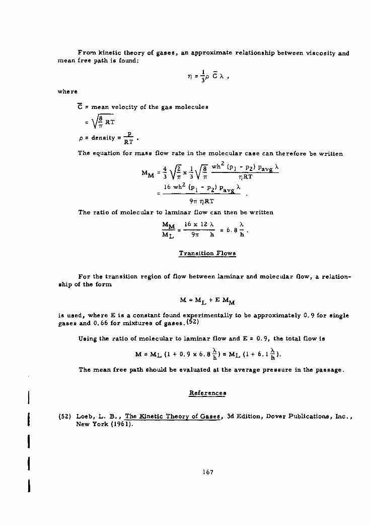
From kinetic theory of gases, an approximate relationship between viscosity andmean free path is found:
3=p C X
where
C mean velocity of the gas molecules
)8R- -RT
iT
p density = RRT"
The equation for mass flow rate in the molecular case can therefore be written
=4I _zx 1J8 wh (P]" Pz)Pavg>M M 3 !Tr 3 7r 7RT
16 whZ (p1 - P2) Pavi z
97r 7)RT
The ratio of molecular to laminar flow can then be written
MM 16 x 1Z X X- -6.8-.
ML 97r h h
Transition Flows
For the transition region of flow between laminar and molecular flow, a relation-ship of the form
M = ML + E MM
is used, where E is a constant found experimentally to be approximately 0. 9 for singlegases and 0. 66 for mixtures of gases. ( 52 )
Using the ratio of molecular to laminar flow and E = 0. 9, the total flow is
M =ML (I + 0.9 x 6.8 ) = ML (I + 6.1 2).
The mean free path should be evaluated at the average pressure in the passage.
j References
(5Z) Loeb, L. B., The Kinetic Theory of Gases, 3d Edition, Dover Publications, Inc.,New York (1961).
IS~167
I
I - g
I) >
.2 0
>~ o~
I ~ I ~0o~ "WI
CL ýO 50~~ ~ ~ .~ 0 ~.$ .~0E o 7
~?~Ia U> J>>a' ~ w
m Co UG)j I I :
r !2 o -E.0 0
g 8 .8 0
78 I-l r-,