hytrust cloudcontrol installation guide · hytrust cloudcontrol installation guide 3 ... cisco...
TRANSCRIPT
Version 4.0October, 2014
HyTrust®CloudControl™
Installation Guide

HyTrust® CloudControl™Administration Guide
Copyright © 2009-2014 HyTrust Inc. All Rights Reserved.
HyTrust; HyTrust, Inc.; HyTrust Appliance; HyTrust Appliance Community Edition; HyTrust CloudControl; HyTrust DataControl, “Virtualization Under Control”; “Cloud Under Control” and “Virtualization & Cloud Under Control” are all trademarks of HyTrust, Inc. All other names and trademarks are property of their respective firms.The content of this guide is furnished for informational use only and is subject to change without notice. HyTrust Inc. assumes no responsibility or liability for any errors or inaccuracies that may appear in the content contained in this guide. Except as allowed by license, no part of this material may be reproduced or transmitted in any form or by any means, electronic or mechanical, including photocopying, recording, or by any information storage and retrieval system, without the written permission of the copyright owner, except where permitted by law.
U.S Patent Numbers 8065714, 8166552, 8336079, 8539589, 8,832,784.
HyTrust, Inc.1975 W. El Camino Real, Suite 203Mountain View, CA 94040U.S.A.Phone: (650) 681-8100Email: [email protected]: http://www.hytrust.com
PREFACE
HyTrust® CloudControl™ (HTCC) provides a centralized point of control for hypervisor configuration, compliance, and access management.
This guide describes how to prepare and deploy the HyTrust CloudControl (HTCC) virtual machine on an ESX or ESXi host.
This guide does not discuss configuration of HTCC. See the HyTrust CloudControl Administration Guide for more information.
AudienceThis guide is intended for information technology personnel who are reasonably proficient in the following areas:
■ Using VMware vSphere, including the ability to install a virtual appliance and configure virtual networks.
■ Networking and route configuration.
Document OrganizationThis guide is organized into the following sections:
■ Chapter 1, Installation Overview—Provides an overview of the HTCC installation process.■ Chapter 2, Selecting the Deployment Architecture—Provides information on the network
deployments supported by the HTCC.■ Chapter 3, Installing the Appliance—Describes the HTCC installation tasks.■ Chapter 4, Mapped Mode—Describes how to configure HTCC for Mapped Mode.■ Chapter 5, Router Mode—Describes how to configure HTCC for Router Mode.■ Chapter 6, Post-Installation Tasks—Describes the process of verifying HTCC network
configuration and adding HTCC-protected hosts.■ Chapter 7, High Availability—Describes how to setup and configure two HTCCs for high
availability.■ Appendix A, Resource Tables and Checklists—Provides various worksheets for planning
and installing HTCC.■ Appendix B, Configuring the Windows Server 2008 Firewall—Describes how to configure
the Windows Server 2008 Firewall for HTCC.■ Appendix C, Network Access Requirements—Provides network protocol and port
requirements for HTCC.■ Appendix D, VMware vSphere 5.1/5.5 Support—Describes HTCC support for VMware
vSphere 5.1/5.5.
HyTrust CloudControl Installation Guide 3
Document ConventionsThe table below summarizes the call-outs and icons used in this guide.
The table below summarizes the typographical conventions used in this guide.
Related ReferencesFor more information about HTCC refer to the following resources:
■ HyTrust website: http://www.hytrust.com■ The HyTrust CloudControl Administration Guide
Contacting HyTrustIf you require additional information or technical support, contact us at:
Phone: (650) 681-8100
Email: [email protected]
Website: http://www.hytrust.com
Call-outs and Icons
Call-out or Icon Meaning
Note:
Indicates ‘Note’ that provides information supporting the document text.
IMPORTANT: Provides important information that users must know.
Typographical conventions
Style Meaning
Bold Menu items.
Italic Provides emphasis and identifies user interface items and document titles.
Monospace Command names, console text, and file names.
< > Contains information for which you must supply a value.
| Separates a set of choices from which only one may be chosen.
{ } Required command parameters that must be specified.
[ ] Optional command parameters.
HyTrust CloudControl Installation Guide 4
CONTENTS
CHAPTER 1 Installation Overview............................................................................................. 9Introduction...................................................................................................................................................................9System Requirements ............................................................................................................................................. 11Appliance Installation Overview ......................................................................................................................... 11Obtaining the Software .......................................................................................................................................... 12
CHAPTER 2 Selecting the Deployment Architecture............................................................. 13Preparation: Network Architecture and Topology ....................................................................................... 13
Mapped Mode................................................................................................................................................... 13Router Mode ...................................................................................................................................................... 14
Network Configuration Considerations............................................................................................................ 15High Availability (HA)...................................................................................................................................... 16
CHAPTER 3 Installing the Appliance....................................................................................... 17Deploying the OVF Template ............................................................................................................................... 17
Prerequisites ...................................................................................................................................................... 17Detailed Steps ................................................................................................................................................... 18
Powering Up the Appliance.................................................................................................................................. 19Configuring the HTCC Management Network Interface ............................................................................ 19Starting the HTCC Management Console........................................................................................................ 20Initial Setup and Configuration ........................................................................................................................... 21Migrating from HTA 3.6 to HTCC 4.0.................................................................................................................. 23
Deploy the 4.0 Release OVF Template...................................................................................................... 23Backup the HTA 3.6 appliance..................................................................................................................... 23Restore the HTA 3.6 appliance to 4.0 HTCC............................................................................................ 25
CHAPTER 4 Mapped Mode....................................................................................................... 29Planning ....................................................................................................................................................................... 29Running the HTCC Installation Wizard.............................................................................................................. 29
CHAPTER 5 Router Mode ......................................................................................................... 32Planning ....................................................................................................................................................................... 32Running the HTCC Installation Wizard.............................................................................................................. 32
CHAPTER 6 Post-Installation Tasks......................................................................................... 36Verifying Network Configuration........................................................................................................................ 36
HyTrust CloudControl Installation Guide 5
Adding the First HTCC-Protected Host ............................................................................................................. 37Adding vCenter Server Managed Hosts................................................................................................... 37Adding a WCS Host.......................................................................................................................................... 45Adding Unmanaged Hosts ........................................................................................................................... 46Adding KVM Hosts ........................................................................................................................................... 46Adding Cisco Nexus Switches...................................................................................................................... 48Adding Cisco UCS Manager Hosts ............................................................................................................. 51
Accessing the HTCC-Protected Virtual Infrastructure.................................................................................. 55Limiting Unauthorized Admin Access to the HTCC...................................................................................... 55
CHAPTER 7 High Availability................................................................................................... 56Overview ...................................................................................................................................................................... 56Setup and Configuration........................................................................................................................................ 58
Default Configuration..................................................................................................................................... 58HA Planning ....................................................................................................................................................... 59Primary HTCC Setup........................................................................................................................................ 59Secondary HTCC Setup .................................................................................................................................. 60Changing the Heartbeat IP address for eth2.......................................................................................... 61
HA Systems Boot Order .......................................................................................................................................... 61HA CLI Commands.................................................................................................................................................... 61
APPENDIX A Resource Tables and Checklists .......................................................................... 63HTCC Host and Appliance...................................................................................................................................... 63Protected Hosts ......................................................................................................................................................... 64Active Directory......................................................................................................................................................... 65HyTrust High Availability........................................................................................................................................ 65
APPENDIX B Configuring the Windows Server 2008 Firewall ................................................ 67View and Modify Inbound Rules ......................................................................................................................... 67
APPENDIX C Network Access Requirements............................................................................ 69
APPENDIX D VMware vSphere 5.1/5.5 Support....................................................................... 71Overview ...................................................................................................................................................................... 71Supported Deployments........................................................................................................................................ 72Authentication........................................................................................................................................................... 73
Requirements .................................................................................................................................................... 74Limitations .......................................................................................................................................................... 74
HyTrust CloudControl Installation Guide 6

LIST OF FIGURES
Figure 2-1 Network topology utilizing Mapped Mode14Figure 2-2 Network topology utilizing Router Mode15Figure 3-1 Deploying the OVF template18Figure 3-2 Login Screen after reboot19Figure 3-3 Static IP Address configuration20Figure 3-4 HTCC Management Console login screen21Figure 3-5 HTCC End-User License Agreement22Figure 3-6 HTCC license installation22Figure 3-7 Taking the backup of 3.6 HTA24Figure 3-8 asc backup generates the ISO image25Figure 3-9 EULA part of the agreement26Figure 3-10 Running th0e Setup command on HTCC 4.026Figure 3-11 Restore Complete27Figure 3-12 Appliance Dashboard after restore27Figure 3-13 HTA 3.6 restored on HTCC 4.028Figure 4-1 HTCC Installation Wizard - HTCC Network Mode Configuration30Figure 4-2 HTCC Installation Wizard - Network Configuration30Figure 4-3 HTCC Installation Wizard - Finish31Figure 5-1 HTCC Installation Wizard - HTCC Host Configuration33Figure 5-2 HTCC Installation Wizard - Network Configuration33Figure 5-3 HTCC Installation Wizard - Finish34Figure 6-1 Compliance > Hosts page38Figure 6-2 Add Host Wizard - Host Type page38Figure 6-3 Add Host Wizard - Host Login page38
Figure 6-4 Host Login page - Advanced Properties section39Figure 6-5 Add Host Wizard - Host Details page39Figure 6-6 Add Host Wizard - Published IP page40Figure 6-7 Add Host Wizard - vSphere Web Client Server Configuration page40Figure 6-8 Add Host Wizard - Authentication Mode Configuration page41Figure 6-9 Add Host Wizard - Complete Host Add page41Figure 6-11 Compliance > Hosts > Edit Host page - General tab42Figure 6-12 Compliance > Hosts > Edit Host page - Advanced tab43Figure 6-13 Compliance > Hosts > Edit Host page - Published IP tab43Figure 6-15 Edit Host (Multiple Hosts) page - General tab44Figure 6-16 Edit Host (Multiple Hosts) page - Advanced tab45Figure 6-17 Edit Host (Multiple Hosts) page - Published IP tab45Figure 6-18 Compliance > Hosts page45Figure 6-19 Compliance > Hosts page46Figure 6-20 Add Host Wizard: Host Login: Choose Host Type to Add47Figure 6-21 Add Host Wizard: Host Login47Figure 6-22 Add Host Wizard: Host Type detected message48Figure 6-23 Add Host Wizard: Complete Host Add48Figure 6-24 Compliance > Hosts page48
HyTrust CloudControl Installation Guide 7

Figure 6-25 Add Host Wizard - Host Type page49Figure 6-26 Add Host Wizard - Host Login page49Figure 6-27 Add Host Wizard - Host Details page (Nexus)50Figure 6-28 Add Host Wizard - Published IP page50Figure 6-29 Add Host Wizard - Complete Host Add page51Figure 6-31 Compliance > Hosts page52Figure 6-32 Add Host Wizard - Host Type page52Figure 6-33 Add Host Wizard - Host Login page52Figure 6-35 Add Host Wizard - Host Details page (UCS)53Figure 6-36 Add Host Wizard - Published IP page54Figure 6-37 Add Host Wizard - Complete Host Add page54Figure 7-1 HTCC high availability configuration57Figure B-1 Windows Server 2008 Firewall with Advanced Security Inbound Rules68Figure D-2 Separate vCenter Server and Web Client Server hosts72Figure D-3 vCenter Server and Web Client Server on same host72Figure D-4 vCenter Server and Web Client Server on same host 272Figure D-5 Web Client Server serving multiple vCenter Server hosts73
HyTrust CloudControl Installation Guide 8
HyTrust CloudControl Installation Guide
1
CHAPTERInstallation Overview
This chapter contains the following sections:
■ Introduction■ System Requirements■ Appliance Installation Overview■ Obtaining the Software
Introduction
Note: All references to hosts refers to ESX, ESXi, or KVM hosts. All references to ESX hosts refers to both ESX and ESXi hosts. Other host types which the HTCC supports are vSphere vCenter Server, vSphere Web Client Server (WCS), Cisco Nexus 1000V Virtual Supervisor Module (VSM), Cisco Unified Computing System (UCS) Manager, and Cisco Nexus 5000 and 7000 series switches.
HyTrust CloudControl (HTCC) offers system managers and administrators an end-to-end virtualization security platform to manage access, standardize and control configuration, and protect a virtual infrastructure within a customer's environment. HTCC is designed to fit easily within the configuration and architecture of most data centers and is installed as a virtual appliance.
9
Installation OverviewIntroduction
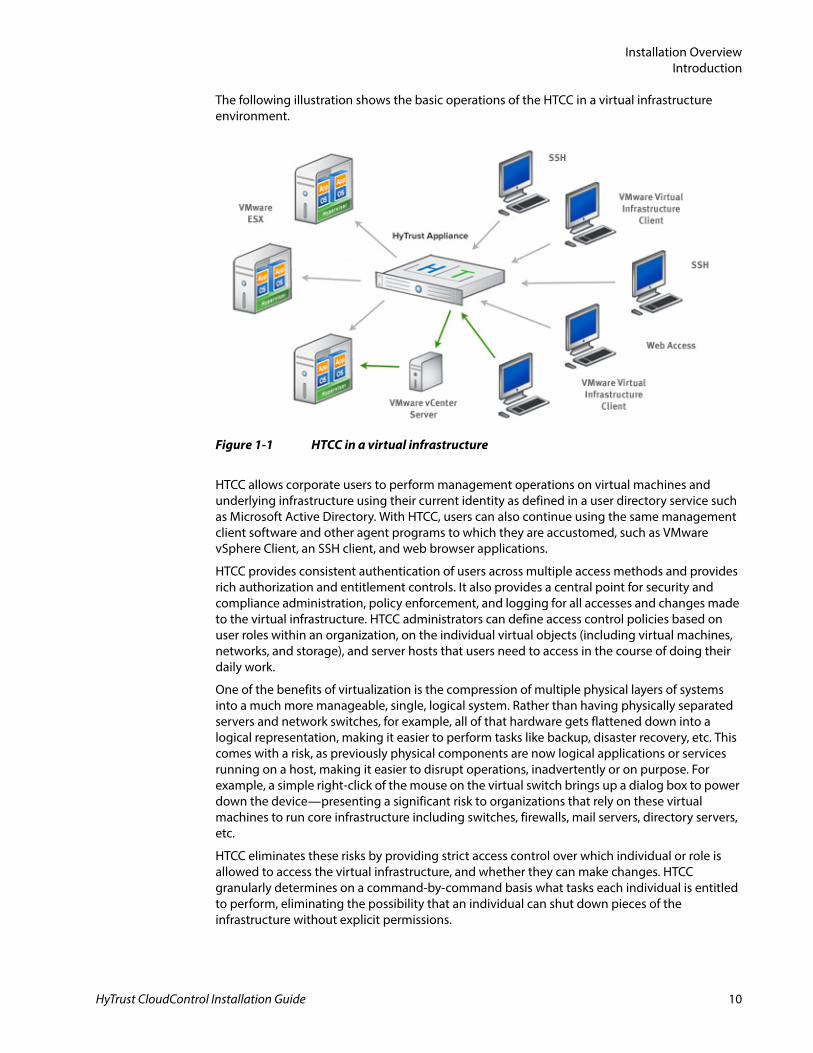
The following illustration shows the basic operations of the HTCC in a virtual infrastructure environment.
HTCC allows corporate users to perform management operations on virtual machines and underlying infrastructure using their current identity as defined in a user directory service such as Microsoft Active Directory. With HTCC, users can also continue using the same management client software and other agent programs to which they are accustomed, such as VMware vSphere Client, an SSH client, and web browser applications.
HTCC provides consistent authentication of users across multiple access methods and provides rich authorization and entitlement controls. It also provides a central point for security and compliance administration, policy enforcement, and logging for all accesses and changes made to the virtual infrastructure. HTCC administrators can define access control policies based on user roles within an organization, on the individual virtual objects (including virtual machines, networks, and storage), and server hosts that users need to access in the course of doing their daily work.
One of the benefits of virtualization is the compression of multiple physical layers of systems into a much more manageable, single, logical system. Rather than having physically separated servers and network switches, for example, all of that hardware gets flattened down into a logical representation, making it easier to perform tasks like backup, disaster recovery, etc. This comes with a risk, as previously physical components are now logical applications or services running on a host, making it easier to disrupt operations, inadvertently or on purpose. For example, a simple right-click of the mouse on the virtual switch brings up a dialog box to power down the device—presenting a significant risk to organizations that rely on these virtual machines to run core infrastructure including switches, firewalls, mail servers, directory servers, etc.
HTCC eliminates these risks by providing strict access control over which individual or role is allowed to access the virtual infrastructure, and whether they can make changes. HTCC granularly determines on a command-by-command basis what tasks each individual is entitled to perform, eliminating the possibility that an individual can shut down pieces of the infrastructure without explicit permissions.
Figure 1-1 HTCC in a virtual infrastructure
HyTrust CloudControl Installation Guide 10
Installation OverviewSystem Requirements
Additionally, HTCC automatically configures VMware ESX hosts to match customer-defined templates and continually monitors the protected virtual infrastructure to ensure that the ESX host configurations continue to match the defined templates—eliminating guesswork and saving time for the users charged with maintaining the virtual infrastructure.
The combination of centralized access control and policies, configuration management, and logging all help to make HTCC a great security and compliance solution for customers.
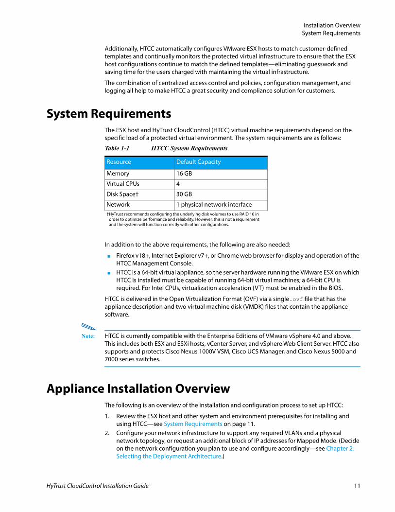
System RequirementsThe ESX host and HyTrust CloudControl (HTCC) virtual machine requirements depend on the specific load of a protected virtual environment. The system requirements are as follows:
In addition to the above requirements, the following are also needed:
■ Firefox v18+, Internet Explorer v7+, or Chrome web browser for display and operation of the HTCC Management Console.
■ HTCC is a 64-bit virtual appliance, so the server hardware running the VMware ESX on which HTCC is installed must be capable of running 64-bit virtual machines; a 64-bit CPU is required. For Intel CPUs, virtualization acceleration (VT) must be enabled in the BIOS.
HTCC is delivered in the Open Virtualization Format (OVF) via a single.ovf file that has the appliance description and two virtual machine disk (VMDK) files that contain the appliance software.
Note: HTCC is currently compatible with the Enterprise Editions of VMware vSphere 4.0 and above. This includes both ESX and ESXi hosts, vCenter Server, and vSphere Web Client Server. HTCC also supports and protects Cisco Nexus 1000V VSM, Cisco UCS Manager, and Cisco Nexus 5000 and 7000 series switches.
Appliance Installation OverviewThe following is an overview of the installation and configuration process to set up HTCC:
1. Review the ESX host and other system and environment prerequisites for installing and using HTCC—see System Requirements on page 11.
2. Configure your network infrastructure to support any required VLANs and a physical network topology, or request an additional block of IP addresses for Mapped Mode. (Decide on the network configuration you plan to use and configure accordingly—see Chapter 2, Selecting the Deployment Architecture.)
Table 1-1 HTCC System Requirements
Resource Default Capacity
Memory 16 GB
Virtual CPUs 4
Disk Space† 30 GB
Network 1 physical network interface†HyTrust recommends configuring the underlying disk volumes to use RAID 10 in
order to optimize performance and reliability. However, this is not a requirement and the system will function correctly with other configurations.
HyTrust CloudControl Installation Guide 11
Installation OverviewObtaining the Software
3. For production environments, set up a Microsoft Active Directory (AD) to perform authentication of Administrators and their group information for HTCC rules. (Refer to the HyTrust CloudControl Administration Guide for AD configuration information.)
4. Deploy HTCC as a VMware vSphere virtual machine—see Deploying the OVF Template on page 17. Confirm that the network adapter(s) are properly configured and connected.
5. After editing the necessary settings, power on the HTCC virtual machine—see Powering Up the Appliance on page 19.
6. Log into the HTCC command line interface (CLI) as ‘ascadminuser’ and type ‘setup’ to start the setup process and assign an IP address to the HTCC virtual machine—see Configuring the HTCC Management Network Interface on page 19.
7. Start the HTCC Management Console and run the Installation Wizard—see Starting the HTCC Management Console on page 20.
8. Optionally, set up the HTCC vCenter Server Plugin which allows you to perform HTCC operations directly from a vSphere Client by accessing a vCenter Server. (Refer to the HyTrust CloudControl Administration Guide for further details.) You can still use the HTCC Management Console.
9. Add the hosts (vCenter Servers, ESX hosts, WCS hosts, Cisco Nexus 1000V switches, a Cisco UCS Manager, and Cisco Nexus 5000 and 7000 series switches) to be managed and protected by HTCC—see Adding the First HTCC-Protected Host on page 37.
Refer to the appropriate chapters and sections for step-by-step instructions to perform the tasks described above.
IMPORTANT: Use the resource checklist worksheets provided in Appendix A, Resource Tables and Checklists to record network, IP address, AD, and other virtual infrastructure host information you will need to install and configure HTCC.
Obtaining the SoftwareLog in to the HyTrust website (http://www.hytrust.com) or follow the directions you received from HyTrust Support to obtain the download URL of the HTCC OVF file. Download the files to a local drive that is accessible by your virtual infrastructure.
If you wish to enable the HTCC Enterprise features, obtain and download the appropriate XML license file to a local drive that is accessible to the HTCC Management Console.
HyTrust CloudControl Installation Guide 12
HyTrust CloudControl Installation Guide
2
CHAPTERSelecting the Deployment Architecture
This chapter contains the following sections:
■ Preparation: Network Architecture and Topology■ Network Configuration Considerations
Preparation: Network Architecture and TopologyHyTrust CloudControl (HTCC) operates by intercepting ESX management requests normally routed directly to ESX hosts or vCenter Servers; however, it does not intercept any VM guest traffic. HTCC first authenticates users and authorizes all the operations they want to perform before passing on the request to the target resource. In addition, HTCC allows administrators to create and apply granular access policies and perform ESX configuration management by applying and monitoring ESX compliance to custom-defined security templates and then remediating deficiencies and discrepancies.
HTCC relies on customers’ network topology to gain visibility to the virtual infrastructure’s management traffic to be able to intercept it. There are two network configuration options available for installing HTCC: Mapped Mode or Router Mode.
Mapped ModeWhen configured for use in Mapped Mode, HTCC works as a proxy server and does not require any architectural changes to the virtual infrastructure (VI) network. It works well in both segmented networks and in environments with flat, unstructured network topologies. In Mapped Mode, only Network Connection 1 (eth0) of HTCC is utilized. Each HTCC protected host (e.g., vCenter Server, ESX/ESXi host) has a dedicated IP address (called the Published IP or PIP) which management clients use to access the host.
Destination Maps, an out-of-band solution, proxy the management traffic within your existing network. The requirements are as follows:
13
Selecting the Deployment ArchitecturePreparation: Network Architecture and Topology
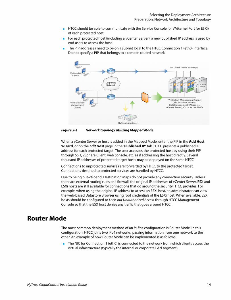
■ HTCC should be able to communicate with the Service Console (or VMkernel Port for ESXi) of each protected host.
■ For each protected host (including a vCenter Server), a new published IP address is used by end users to access the host.
■ The PIP addresses need to be on a subnet local to the HTCC Connection 1 (eth0) interface. Do not specify a PIP that belongs to a remote, routed network.
When a vCenter Server or host is added in the Mapped Mode, enter the PIP in the Add Host Wizard, or on the Edit Host page in the ‘Published IP’ tab. HTCC presents a published IP address for each protected target. The user accesses the protected host by using their PIP through SSH, vSphere Client, web console, etc. as if addressing the host directly. Several thousand IP addresses of protected target hosts may be deployed on the same HTCC.
Connections to unprotected services are forwarded by HTCC to the protected target. Connections destined to protected services are handled by HTCC.
Due to being out-of-band, Destination Maps do not provide any connection security. Unless there are external routing rules or a firewall, the original IP addresses of vCenter Server, ESX and ESXi hosts are still available for connections that go around the security HTCC provides. For example, when using the original IP address to access an ESXi host, an administrator can view the web-based Datastore Browser using root credentials of the ESXi host. When available, ESX hosts should be configured to Lock-out Unauthorized Access through HTCC Management Console so that the ESX host denies any traffic that goes around HTCC.
Router ModeThe most common deployment method of an in-line configuration is Router Mode. In this configuration, HTCC joins two IPv4 networks, passing information from one network to the other. An example of how Router Mode can be implemented is as follows:
■ The NIC for Connection 1 (eth0) is connected to the network from which clients access the virtual infrastructure (typically the internal or corporate LAN segment).
Figure 2-1 Network topology utilizing Mapped Mode
HyTrust CloudControl Installation Guide 14
Selecting the Deployment ArchitectureNetwork Configuration Considerations
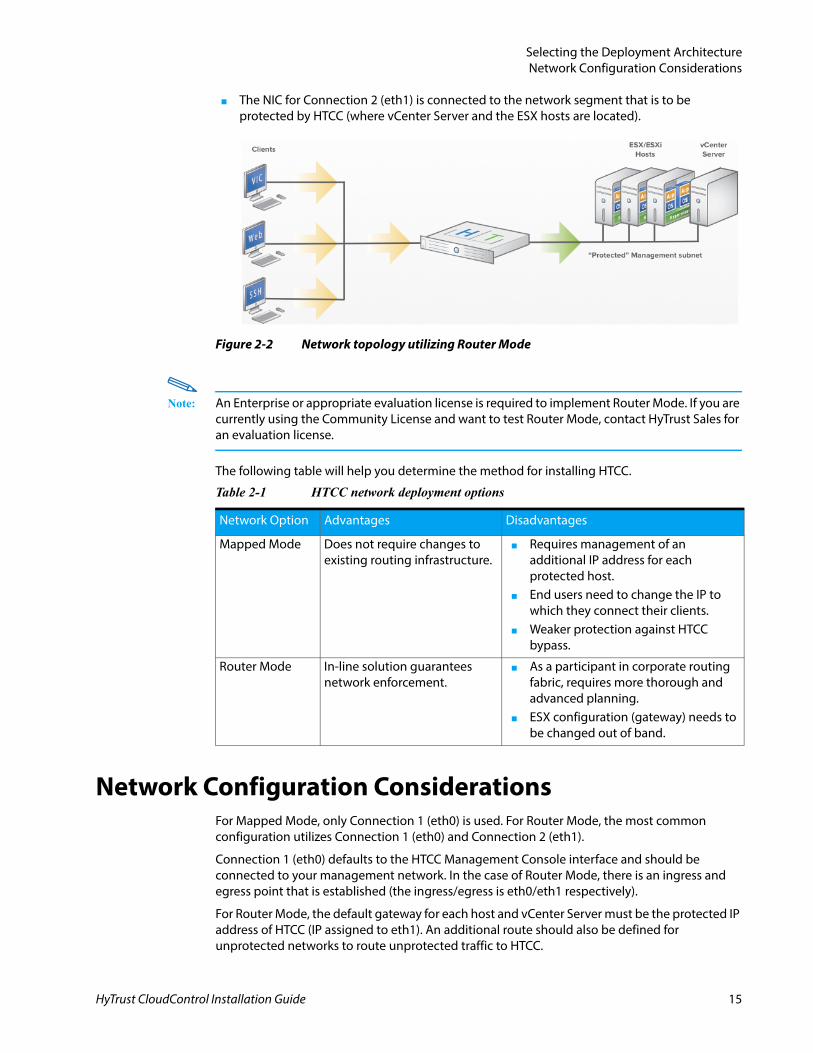
■ The NIC for Connection 2 (eth1) is connected to the network segment that is to be protected by HTCC (where vCenter Server and the ESX hosts are located).
Note: An Enterprise or appropriate evaluation license is required to implement Router Mode. If you are currently using the Community License and want to test Router Mode, contact HyTrust Sales for an evaluation license.
The following table will help you determine the method for installing HTCC.
Network Configuration ConsiderationsFor Mapped Mode, only Connection 1 (eth0) is used. For Router Mode, the most common configuration utilizes Connection 1 (eth0) and Connection 2 (eth1).
Connection 1 (eth0) defaults to the HTCC Management Console interface and should be connected to your management network. In the case of Router Mode, there is an ingress and egress point that is established (the ingress/egress is eth0/eth1 respectively).
For Router Mode, the default gateway for each host and vCenter Server must be the protected IP address of HTCC (IP assigned to eth1). An additional route should also be defined for unprotected networks to route unprotected traffic to HTCC.
Figure 2-2 Network topology utilizing Router Mode
Table 2-1 HTCC network deployment options
Network Option Advantages Disadvantages
Mapped Mode Does not require changes to existing routing infrastructure.
■ Requires management of an additional IP address for each protected host.
■ End users need to change the IP to which they connect their clients.
■ Weaker protection against HTCC bypass.
Router Mode In-line solution guarantees network enforcement.
■ As a participant in corporate routing fabric, requires more thorough and advanced planning.
■ ESX configuration (gateway) needs to be changed out of band.
HyTrust CloudControl Installation Guide 15
Selecting the Deployment ArchitectureNetwork Configuration Considerations
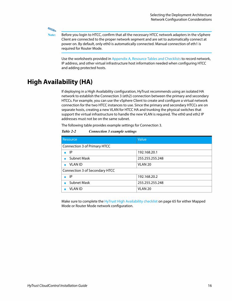
Note: Before you login to HTCC, confirm that all the necessary HTCC network adapters in the vSphere Client are connected to the proper network segment and are set to automatically connect at power on. By default, only eth0 is automatically connected. Manual connection of eth1 is required for Router Mode.
Use the worksheets provided in Appendix A, Resource Tables and Checklists to record network, IP address, and other virtual infrastructure host information needed when configuring HTCC and adding protected hosts.
High Availability (HA)If deploying in a High Availability configuration, HyTrust recommends using an isolated HA network to establish the Connection 3 (eth2) connection between the primary and secondary HTCCs. For example, you can use the vSphere Client to create and configure a virtual network connection for the two HTCC instances to use. Since the primary and secondary HTCCs are on separate hosts, creating a new VLAN for HTCC HA and trunking the physical switches that support the virtual infrastructure to handle the new VLAN is required. The eth0 and eth2 IP addresses must not be on the same subnet.
The following table provides example settings for Connection 3.
Make sure to complete the HyTrust High Availability checklist on page 65 for either Mapped Mode or Router Mode network configuration.
Table 2-2 Connection 3 example settings
Resource Value
Connection 3 of Primary HTCC
■ IP 192.168.20.1
■ Subnet Mask 255.255.255.248
■ VLAN ID VLAN 20
Connection 3 of Secondary HTCC
■ IP 192.168.20.2
■ Subnet Mask 255.255.255.248
■ VLAN ID VLAN 20
HyTrust CloudControl Installation Guide 16
HyTrust CloudControl Installation Guide
3
CHAPTERInstalling the Appliance
This chapter contains the following sections:
■ Deploying the OVF Template■ Powering Up the Appliance■ Configuring the HTCC Management Network Interface■ Starting the HTCC Management Console■ Initial Setup and Configuration■ Migrating from HTA 3.6 to HTCC 4.0
Deploying the OVF Template
PrerequisitesBefore installing HTCC, the following should already be in place:
■ Virtual infrastructure consisting of installed vCenter Servers and, optionally, ESX hosts.■ Network connectivity and access to the HTCC host machine and the infrastructure to
secure. The HTCC installation requires an ESX host with at least one dedicated network interface (using VLANs).
■ For Directory Service mode authentication, setup of Microsoft Active Directory with an AD Service Account and the recommended HyTrust security groups, as described in the HyTrust CloudControl Administration Guide.
■ Services used by virtual infrastructure clients should be routable from the appropriate interface. For example, Active Directory, DNS, and RSA services need to be accessible from HTCC.
To install and run HTCC as a virtual appliance, use the vSphere Client application or vSphere Web Client to access either vCenter Server or the ESX host on which you want to deploy and configure the HTCC virtual machine.
17
Installing the ApplianceDeploying the OVF Template
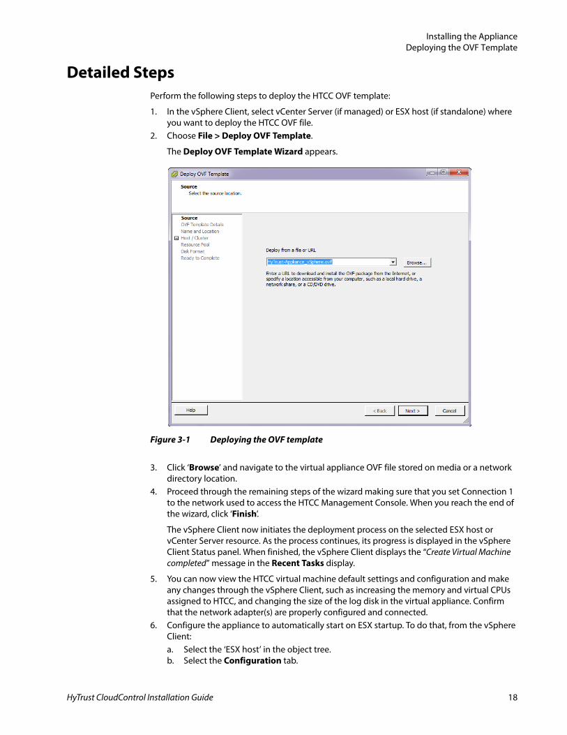
Detailed StepsPerform the following steps to deploy the HTCC OVF template:
1. In the vSphere Client, select vCenter Server (if managed) or ESX host (if standalone) where you want to deploy the HTCC OVF file.
2. Choose File > Deploy OVF Template.
The Deploy OVF Template Wizard appears.
3. Click ‘Browse’ and navigate to the virtual appliance OVF file stored on media or a network directory location.
4. Proceed through the remaining steps of the wizard making sure that you set Connection 1 to the network used to access the HTCC Management Console. When you reach the end of the wizard, click ‘Finish’.
The vSphere Client now initiates the deployment process on the selected ESX host or vCenter Server resource. As the process continues, its progress is displayed in the vSphere Client Status panel. When finished, the vSphere Client displays the “Create Virtual Machine completed” message in the Recent Tasks display.
5. You can now view the HTCC virtual machine default settings and configuration and make any changes through the vSphere Client, such as increasing the memory and virtual CPUs assigned to HTCC, and changing the size of the log disk in the virtual appliance. Confirm that the network adapter(s) are properly configured and connected.
6. Configure the appliance to automatically start on ESX startup. To do that, from the vSphere Client:a. Select the ‘ESX host’ in the object tree.b. Select the Configuration tab.
Figure 3-1 Deploying the OVF template
HyTrust CloudControl Installation Guide 18
Installing the AppliancePowering Up the Appliance
c. Click the Virtual Machine Start / Shutdown option in the list on the left, and then click Properties in the top right corner of the window.
d. Select your HTCC virtual machine in the list and prioritize its order. Services that support HTCC, such as Active Directory, should have a higher priority. Automatic startup and the proper start order will enable HTCC host ESX protection in the event of a host reboot.
Note: If you choose to deploy the appliance in a Distributed Resource Scheduler (DRS) cluster, make sure that DRS is disabled for the HTCC virtual machine by selecting Edit Settings > VMware DRS > Virtual Machine Options. This is required to make sure that HTCC runs only on the ESX where virtual networking is properly configured.
Once the deployment is complete, HTCC appears in the vSphere Client inventory hierarchy for the selected vCenter Server or ESX host.
Powering Up the ApplianceTo power up the HTCC virtual machine:
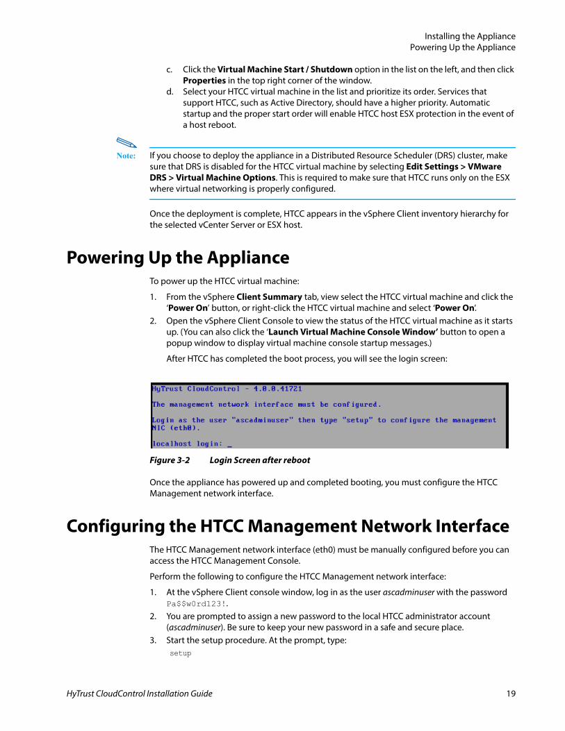
1. From the vSphere Client Summary tab, view select the HTCC virtual machine and click the ‘Power On’ button, or right-click the HTCC virtual machine and select ‘Power On’.
2. Open the vSphere Client Console to view the status of the HTCC virtual machine as it starts up. (You can also click the ‘Launch Virtual Machine Console Window’ button to open a popup window to display virtual machine console startup messages.)
After HTCC has completed the boot process, you will see the login screen:
Figure 3-2 Login Screen after reboot
Once the appliance has powered up and completed booting, you must configure the HTCC Management network interface.
Configuring the HTCC Management Network InterfaceThe HTCC Management network interface (eth0) must be manually configured before you can access the HTCC Management Console.
Perform the following to configure the HTCC Management network interface:
1. At the vSphere Client console window, log in as the user ascadminuser with the password Pa$$w0rd123!.
2. You are prompted to assign a new password to the local HTCC administrator account (ascadminuser). Be sure to keep your new password in a safe and secure place.
3. Start the setup procedure. At the prompt, type:setup
HyTrust CloudControl Installation Guide 19
Installing the ApplianceStarting the HTCC Management Console
4. Manually assign a static IP address to the management network interface (eth0) and set the subnet mask, gateway, and DNS server addresses.
5. Save by typing:y
6. Log out after the network settings have been updated.
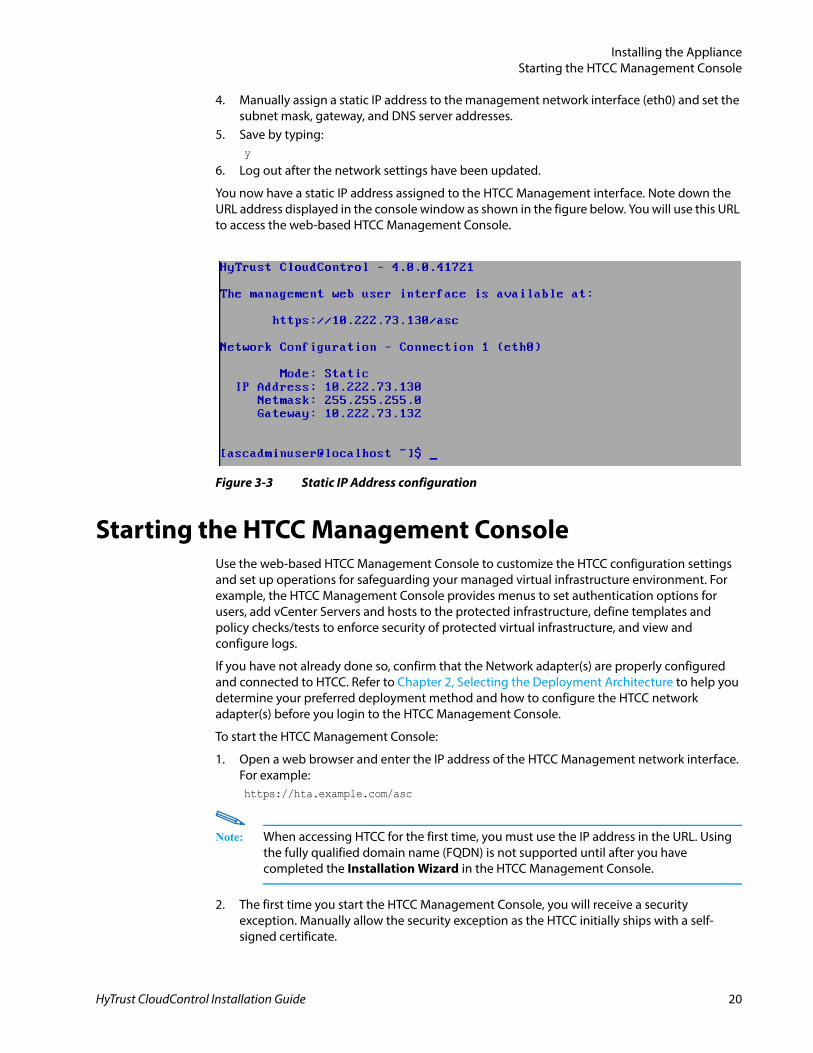
You now have a static IP address assigned to the HTCC Management interface. Note down the URL address displayed in the console window as shown in the figure below. You will use this URL to access the web-based HTCC Management Console.
Figure 3-3 Static IP Address configuration
Starting the HTCC Management ConsoleUse the web-based HTCC Management Console to customize the HTCC configuration settings and set up operations for safeguarding your managed virtual infrastructure environment. For example, the HTCC Management Console provides menus to set authentication options for users, add vCenter Servers and hosts to the protected infrastructure, define templates and policy checks/tests to enforce security of protected virtual infrastructure, and view and configure logs.
If you have not already done so, confirm that the Network adapter(s) are properly configured and connected to HTCC. Refer to Chapter 2, Selecting the Deployment Architecture to help you determine your preferred deployment method and how to configure the HTCC network adapter(s) before you login to the HTCC Management Console.
To start the HTCC Management Console:
1. Open a web browser and enter the IP address of the HTCC Management network interface. For example:https://hta.example.com/asc
Note: When accessing HTCC for the first time, you must use the IP address in the URL. Using the fully qualified domain name (FQDN) is not supported until after you have completed the Installation Wizard in the HTCC Management Console.
2. The first time you start the HTCC Management Console, you will receive a security exception. Manually allow the security exception as the HTCC initially ships with a self-signed certificate.
HyTrust CloudControl Installation Guide 20
Installing the ApplianceInitial Setup and Configuration
Note: If using Internet Explorer (IE), a security warning window may appear when accessing the HTCC Management Console. You must edit the Internet Security properties within IE to remove this warning.In IE 8+, go to Tools > Internet Options > Security Tab > Internet > Custom level > Miscellaneous and enable the Display mixed content setting. Restart Internet Explorer for the change to take effect.
In some customer environments, additional modifications to the IE security settings or firewall settings within your corporate network may be required.
Note: SSL certificates issued by a trusted authority can be imported at a later time through the HTCC Management Console.
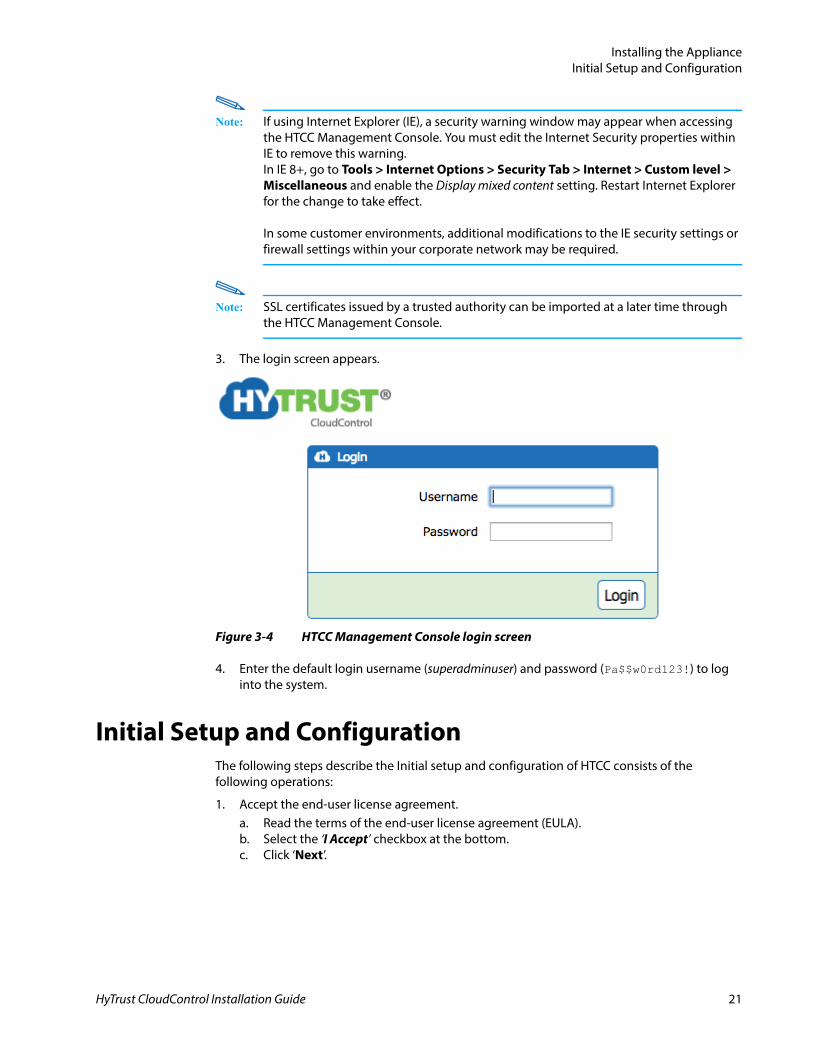
3. The login screen appears.
Figure 3-4 HTCC Management Console login screen
4. Enter the default login username (superadminuser) and password (Pa$$w0rd123!) to log into the system.
Initial Setup and ConfigurationThe following steps describe the Initial setup and configuration of HTCC consists of the following operations:
1. Accept the end-user license agreement.a. Read the terms of the end-user license agreement (EULA).b. Select the ‘I Accept’ checkbox at the bottom.c. Click ‘Next’.
HyTrust CloudControl Installation Guide 21
Installing the ApplianceInitial Setup and Configuration
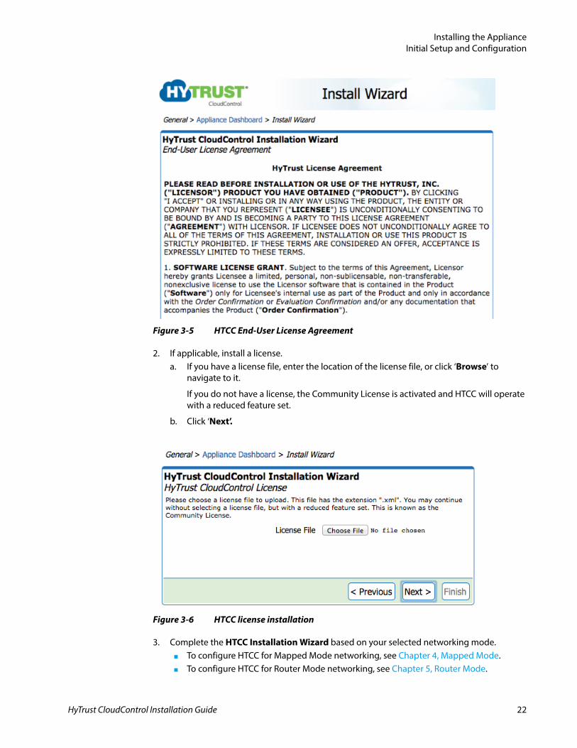
Figure 3-5 HTCC End-User License Agreement
2. If applicable, install a license.a. If you have a license file, enter the location of the license file, or click ‘Browse’ to
navigate to it.
If you do not have a license, the Community License is activated and HTCC will operate with a reduced feature set.
b. Click ‘Next’.
Figure 3-6 HTCC license installation
3. Complete the HTCC Installation Wizard based on your selected networking mode.■ To configure HTCC for Mapped Mode networking, see Chapter 4, Mapped Mode.■ To configure HTCC for Router Mode networking, see Chapter 5, Router Mode.
HyTrust CloudControl Installation Guide 22
Installing the ApplianceMigrating from HTA 3.6 to HTCC 4.0
4. Perform post-installation setup and configuration tasks, see Chapter 6, Post-Installation Tasks.
After finishing the installation, users can select from the General, Compliance, Policy, Configuration, Maintenance, and Help page options that appear across the top banner of the HTCC Management Console to view and configure other HTCC settings. Refer to the HyTrust CloudControl Administration Guide for more information.
Migrating from HTA 3.6 to HTCC 4.0 Migrating the appliance from the HTA 3.6 Release to the HTCC 4.0 release involves the following steps:
1. Deploy the HTCC 4.0 Release OVF template2. Backup the HTA 3.6 appliance3. Restore the HTA 3.6 appliance to HTCC 4.0
Deploy the 4.0 Release OVF TemplateFollow the instructions in the section Deploying the OVF Template on page 17.
Backup the HTA 3.6 applianceUse the following procedure to backup the HTA 3.6 Release:
1. When migrating from HTA 3.6 to HTCCC 4.0, attach the backup preparation ISO image as the CD drive (or SCP the ISO to the 3.6 appliance).
2. If the HTA is part of an HA pair, disband the HA pair and then perform the upgrade on the primary by running the following command:asc upgrade –I (<backup-prep.iso>)
3. Ensure the HTA 3.6 appliance is running properly and that no users are performing any operations in the HTA GUI.
4. Login to the HTA console as ascadminuser or ascsupport.5. Stop and disable the tomcat service using the command:
asc service –n tomcat6 –d
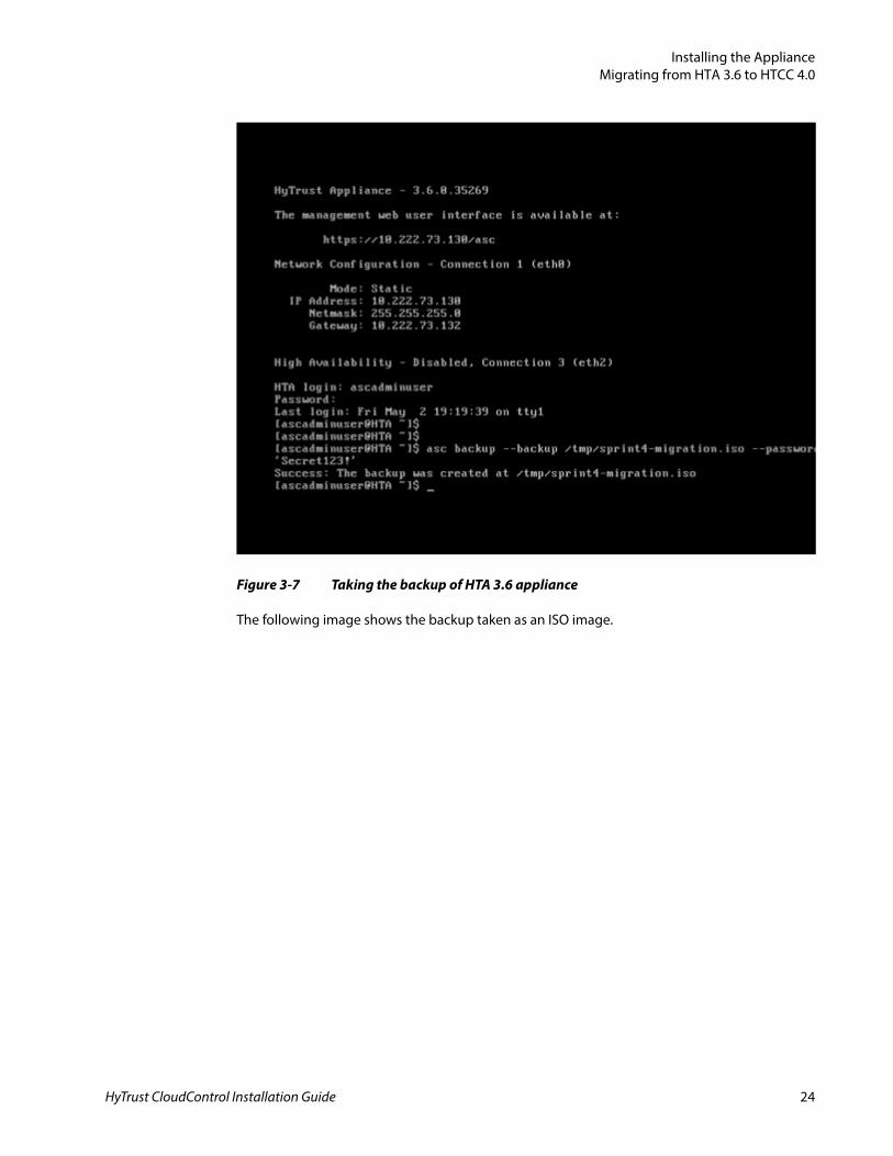
6. Backup the appliance using asc backup command:asc backup --backup /tmp/<filename.iso> --password =’<password>’
HyTrust CloudControl Installation Guide 23
Installing the ApplianceMigrating from HTA 3.6 to HTCC 4.0
Figure 3-7 Taking the backup of HTA 3.6 appliance
The following image shows the backup taken as an ISO image.
HyTrust CloudControl Installation Guide 24
Installing the ApplianceMigrating from HTA 3.6 to HTCC 4.0
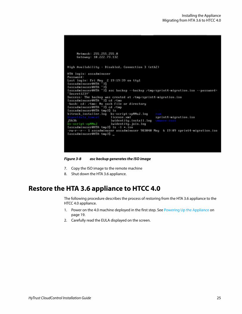
Figure 3-8 asc backup generates the ISO image
7. Copy the ISO image to the remote machine8. Shut down the HTA 3.6 appliance.
Restore the HTA 3.6 appliance to HTCC 4.0The following procedure describes the process of restoring from the HTA 3.6 appliance to the HTCC 4.0 appliance.
1. Power on the 4.0 machine deployed in the first step. See Powering Up the Appliance on page 19.
2. Carefully read the EULA displayed on the screen.
HyTrust CloudControl Installation Guide 25
Installing the ApplianceMigrating from HTA 3.6 to HTCC 4.0
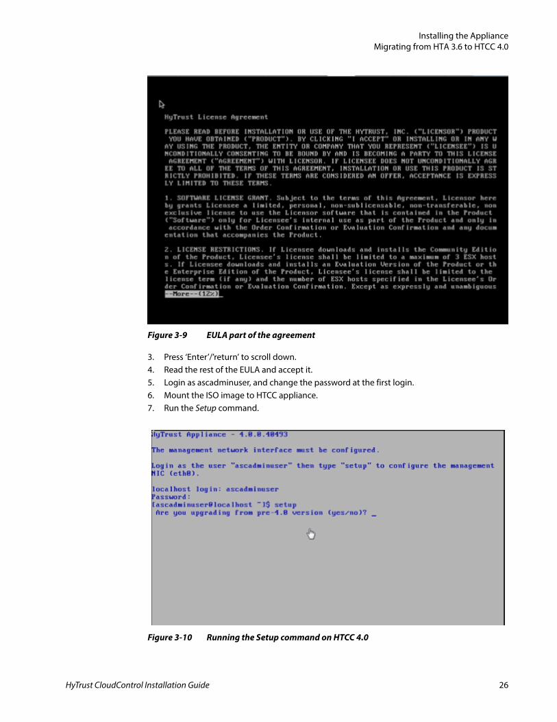
Figure 3-9 EULA part of the agreement
3. Press ‘Enter’/’return’ to scroll down.4. Read the rest of the EULA and accept it.5. Login as ascadminuser, and change the password at the first login.6. Mount the ISO image to HTCC appliance.7. Run the Setup command.
Figure 3-10 Running the Setup command on HTCC 4.0
HyTrust CloudControl Installation Guide 26
Installing the ApplianceMigrating from HTA 3.6 to HTCC 4.0
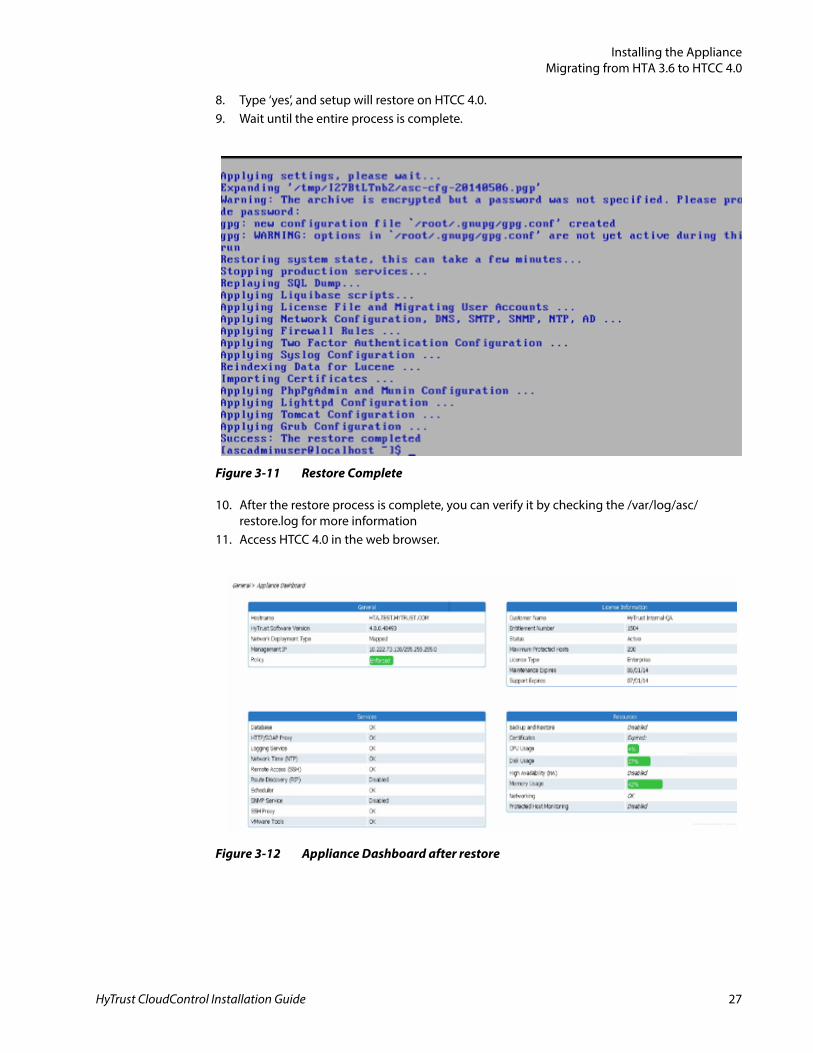
8. Type ‘yes’, and setup will restore on HTCC 4.0.9. Wait until the entire process is complete.
Figure 3-11 Restore Complete
10. After the restore process is complete, you can verify it by checking the /var/log/asc/restore.log for more information
11. Access HTCC 4.0 in the web browser.
Figure 3-12 Appliance Dashboard after restore
HyTrust CloudControl Installation Guide 27
Installing the ApplianceMigrating from HTA 3.6 to HTCC 4.0
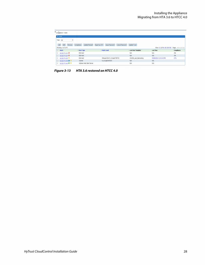
Figure 3-13 HTA 3.6 restored on HTCC 4.0
HyTrust CloudControl Installation Guide 28
HyTrust CloudControl Installation Guide
4
CHAPTERMapped Mode
This chapter contains the following sections:
■ Planning■ Running the HTCC Installation Wizard
PlanningThe following information for Connection1 is needed while completing the HTCC Installation Wizard (this information is also contained in Table A-1).
Running the HTCC Installation WizardThe HTCC Installation Wizard steps you through the following pages to configure HTCC for Mapped Mode.
Table 4-1 Mapped Mode connection settings
Resource Value
Connection 1
■ IP
■ Subnet Mask
■ Gateway
■ DNS Server
■ VLAN ID
29
Mapped ModeRunning the HTCC Installation Wizard
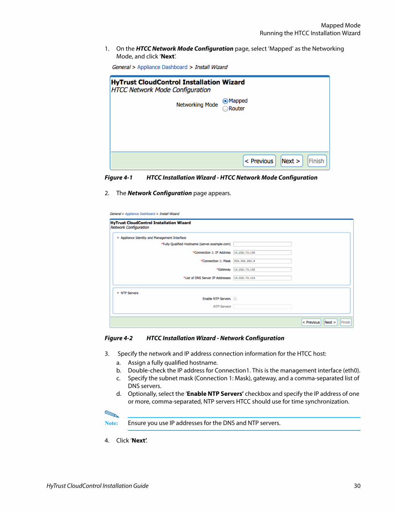
1. On the HTCC Network Mode Configuration page, select ‘Mapped’ as the Networking Mode, and click ‘Next’.
Figure 4-1 HTCC Installation Wizard - HTCC Network Mode Configuration
2. The Network Configuration page appears.
Figure 4-2 HTCC Installation Wizard - Network Configuration
3. Specify the network and IP address connection information for the HTCC host:a. Assign a fully qualified hostname.b. Double-check the IP address for Connection1. This is the management interface (eth0).c. Specify the subnet mask (Connection 1: Mask), gateway, and a comma-separated list of
DNS servers.d. Optionally, select the ‘Enable NTP Servers’ checkbox and specify the IP address of one
or more, comma-separated, NTP servers HTCC should use for time synchronization.
Note: Ensure you use IP addresses for the DNS and NTP servers.
4. Click ‘Next’.
HyTrust CloudControl Installation Guide 30
Mapped ModeRunning the HTCC Installation Wizard
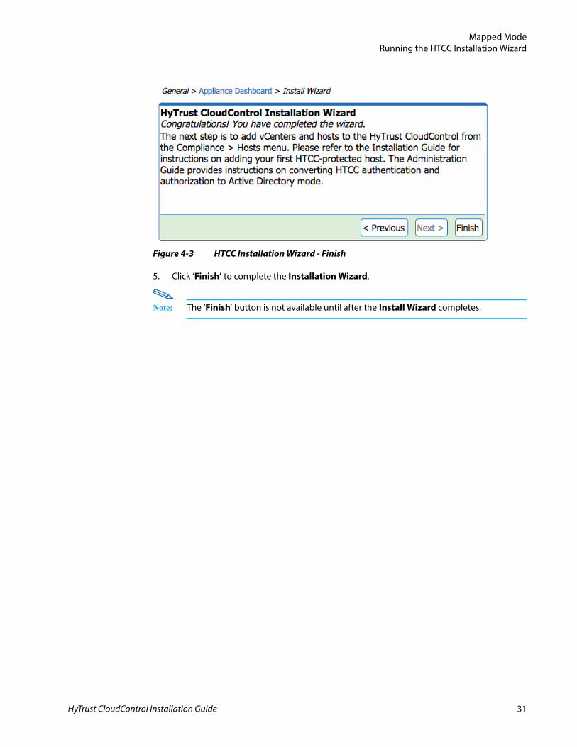
Figure 4-3 HTCC Installation Wizard - Finish
5. Click ‘Finish’ to complete the Installation Wizard.
Note: The ‘Finish’ button is not available until after the Install Wizard completes.
HyTrust CloudControl Installation Guide 31
Mapped ModeRunning the HTCC Installation Wizard
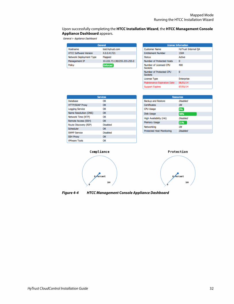
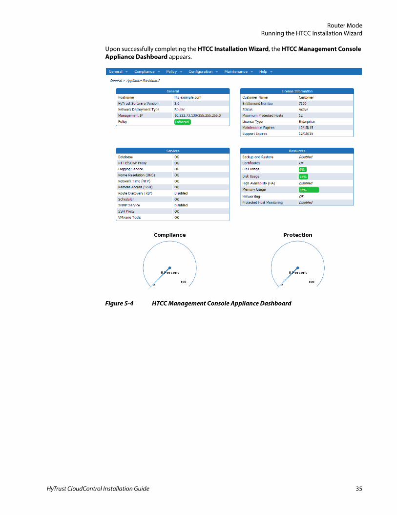
Upon successfully completing the HTCC Installation Wizard, the HTCC Management Console Appliance Dashboard appears.
Figure 4-4 HTCC Management Console Appliance Dashboard
HyTrust CloudControl Installation Guide 32
HyTrust CloudControl Installation Guide
5
CHAPTERRouter Mode
This chapter contains the following sections:
■ Planning■ Running the HTCC Installation Wizard
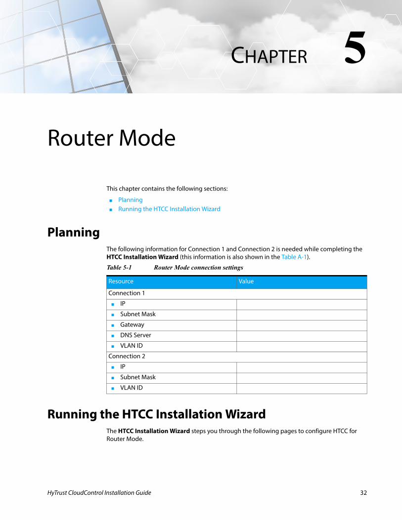
PlanningThe following information for Connection 1 and Connection 2 is needed while completing the HTCC Installation Wizard (this information is also shown in the Table A-1).
Running the HTCC Installation WizardThe HTCC Installation Wizard steps you through the following pages to configure HTCC for Router Mode.
Table 5-1 Router Mode connection settings
Resource Value
Connection 1
■ IP
■ Subnet Mask
■ Gateway
■ DNS Server
■ VLAN ID
Connection 2
■ IP
■ Subnet Mask
■ VLAN ID
32
Router ModeRunning the HTCC Installation Wizard
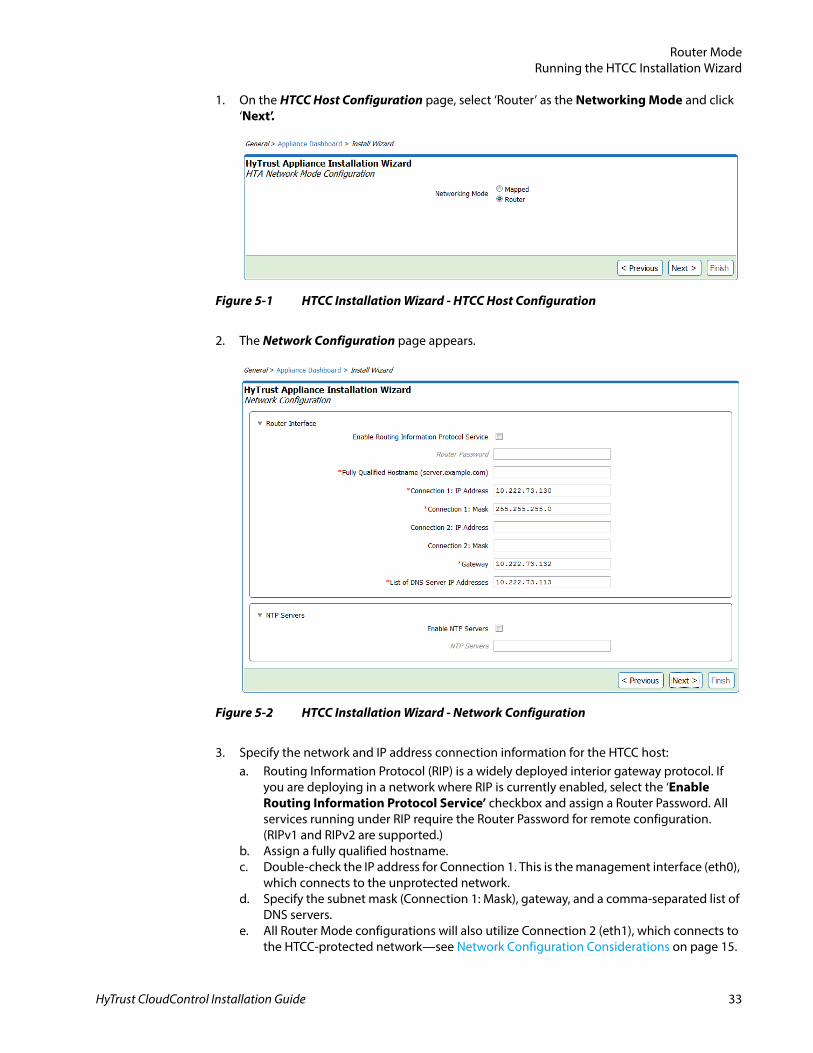
1. On the HTCC Host Configuration page, select ‘Router’ as the Networking Mode and click ‘Next’.
2. The Network Configuration page appears.
3. Specify the network and IP address connection information for the HTCC host:a. Routing Information Protocol (RIP) is a widely deployed interior gateway protocol. If
you are deploying in a network where RIP is currently enabled, select the ‘Enable Routing Information Protocol Service’ checkbox and assign a Router Password. All services running under RIP require the Router Password for remote configuration. (RIPv1 and RIPv2 are supported.)
b. Assign a fully qualified hostname.c. Double-check the IP address for Connection 1. This is the management interface (eth0),
which connects to the unprotected network.d. Specify the subnet mask (Connection 1: Mask), gateway, and a comma-separated list of
DNS servers.e. All Router Mode configurations will also utilize Connection 2 (eth1), which connects to
the HTCC-protected network—see Network Configuration Considerations on page 15.
Figure 5-1 HTCC Installation Wizard - HTCC Host Configuration
Figure 5-2 HTCC Installation Wizard - Network Configuration
HyTrust CloudControl Installation Guide 33
Router ModeRunning the HTCC Installation Wizard
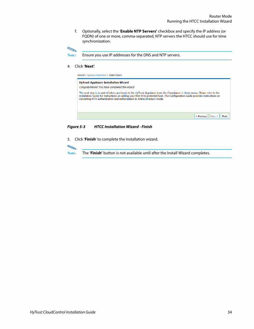
f. Optionally, select the ‘Enable NTP Servers’ checkbox and specify the IP address (or FQDN) of one or more, comma-separated, NTP servers the HTCC should use for time synchronization.
Note: Ensure you use IP addresses for the DNS and NTP servers.
4. Click ‘Next’.
5. Click ‘Finish’ to complete the installation wizard.
Note: The ‘Finish’ button is not available until after the Install Wizard completes.
Figure 5-3 HTCC Installation Wizard - Finish
HyTrust CloudControl Installation Guide 34
Router ModeRunning the HTCC Installation Wizard
Upon successfully completing the HTCC Installation Wizard, the HTCC Management Console Appliance Dashboard appears.
Figure 5-4 HTCC Management Console Appliance Dashboard
HyTrust CloudControl Installation Guide 35
HyTrust CloudControl Installation Guide
6
CHAPTERPost-Installation Tasks
This chapter contains the following sections:
■ Verifying Network Configuration■ Adding the First HTCC-Protected Host■ Accessing the HTCC-Protected Virtual Infrastructure■ Limiting Unauthorized Admin Access to the HTCC
After completing the initial setup and configuration, HyTrust CloudControl (HTCC) allows access only to the default, built-in users. This mode of user authentication is called Demo mode. HTCC also allows user authentication via a directory service (e.g., Microsoft Active Directory). This mode of user authentication is called Directory Service mode. HTCC remains in Demo mode until configured to use a directory service.
You may continue to use Demo mode authentication at this time, however, Demo mode is only intended for product evaluation and testing—it is not suitable for production environments.
While in Demo mode, continue to use the superadminuser account to complete the initial configuration of HTCC. Once HTCC is configured to Directory Service mode, the superadminuser account is no longer available and only directory users with the necessary group membership can access the HTCC Management Console and the virtual infrastructure.
If you are deploying HTCC in a production environment, it is recommended that you first configure HTCC to Directory Service mode. Refer to the HyTrust CloudControl Administration Guide to complete the conversion prior to adding a vCenter Server.
Verifying Network ConfigurationThe first thing you need to do after installing HTCC is verify your network is properly configured by performing the following:
1. Access the HTCC web-based management interface using a web browser from a client system.a. Enter the URL of the HTCC Management Console. For example:
https://hta.example.com/asc
2. Ping the Service Console IP of a target ESX/ESXi host from the HTCC terminal window.3. Ping the Service Console IP of a target ESX/ESXi host from the client system.4. Ping the vCenter Server IP from the client system.
36
Post-Installation TasksAdding the First HTCC-Protected Host
5. Login with root credentials to the ESX/ESXi host using the vSphere Client from the client system.
6. (ESX hosts only)a. Login with root credentials to the web management interface of the ESX host using a
web browser from the client system.b. Login via SSH to the ESX host using root credentials.
7. Login with Administrator credentials to vCenter Server using the vSphere Client from the client system.
8. Login with Administrator credentials to the vCenter Server web management interface using a web browser from the client system.
If all of the above work properly, then your network is properly configured and you are ready to access the HTCC environment and add your first host to HTCC-protected host.
Adding the First HTCC-Protected HostHTCC can protect the following types of hosts:
■ vCenter Server host (including its managed ESX hosts) and a vSphere Web Client Server host—see Adding vCenter Server Managed Hosts.
Note: If you are protecting vCenter Server 5.1/5.5, refer to Appendix D, VMware vSphere 5.1/5.5 Support for information on supported deployments, requirements, and limitations.
■ vSphere Web Client Server host—see Adding a WCS Host.■ ESX hosts not managed by vCenter Server—see Adding Unmanaged Hosts.■ KVM hosts- see Adding KVM Hosts.■ Cisco Nexus switches—see Adding Cisco Nexus Switches.
Nexus 1000V Virtual Supervisor Module (VSM) switch Nexus 5000 and 7000 series switches
■ Cisco UCS Manager—see Adding Cisco UCS Manager Hosts.
Note: A data center with HTCC managed hosts will not be fully protected until all the hosts in the data center are protected.
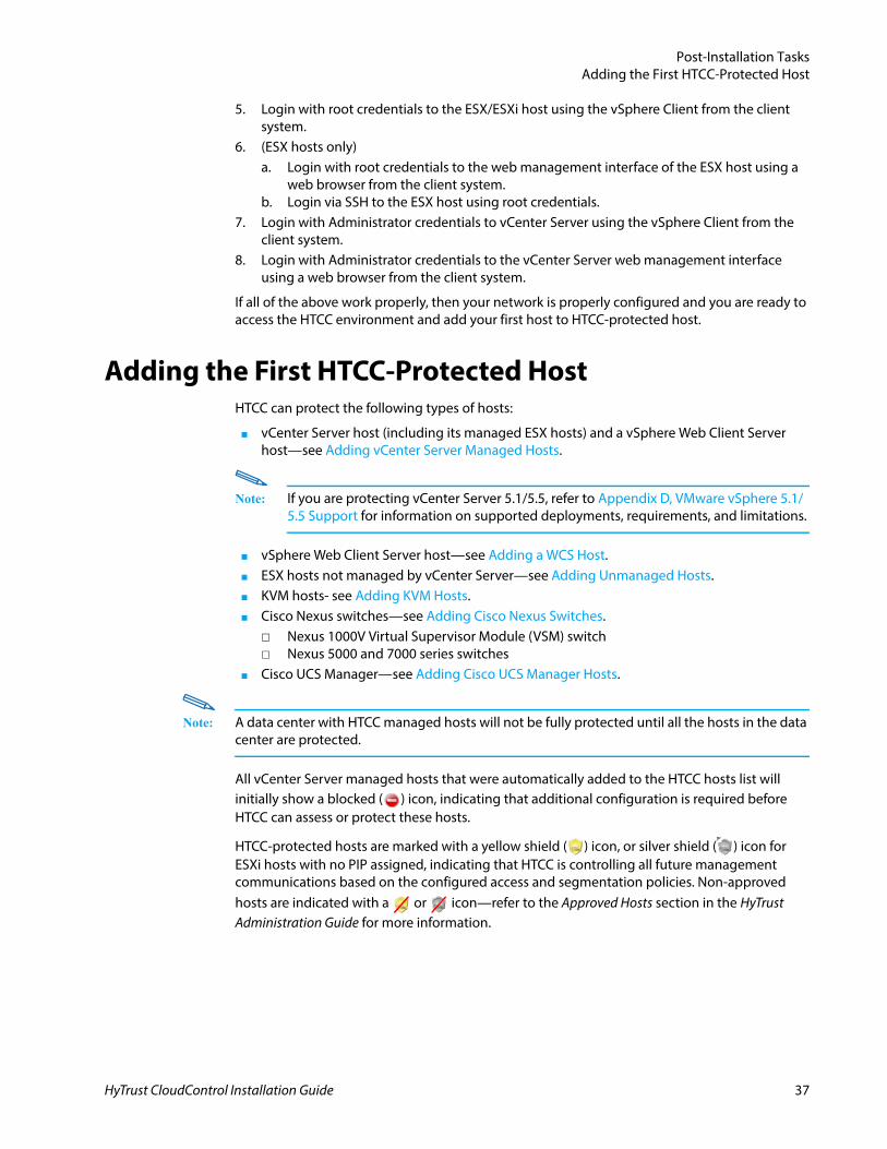
All vCenter Server managed hosts that were automatically added to the HTCC hosts list will initially show a blocked ( ) icon, indicating that additional configuration is required before HTCC can assess or protect these hosts.
HTCC-protected hosts are marked with a yellow shield ( ) icon, or silver shield ( ) icon for ESXi hosts with no PIP assigned, indicating that HTCC is controlling all future management communications based on the configured access and segmentation policies. Non-approved hosts are indicated with a or icon—refer to the Approved Hosts section in the HyTrust Administration Guide for more information.
HyTrust CloudControl Installation Guide 37
Post-Installation TasksAdding the First HTCC-Protected Host
Adding vCenter Server Managed HostsBefore you can add host(s) managed by vCenter Server, you must add vCenter Server as a host to your HTCC-protected environment. Once a vCenter Server is added to HTCC, HTCC will automatically import all the vCenter Server virtualized resources and managed ESX/ESXi hosts.
The following sections describe how to add a vCenter Server and its managed ESX/ESXi hosts (see Adding vCenter Server on page 38), and how to configure vCenter Server managed hosts (see Configuring Managed Hosts on page 43).
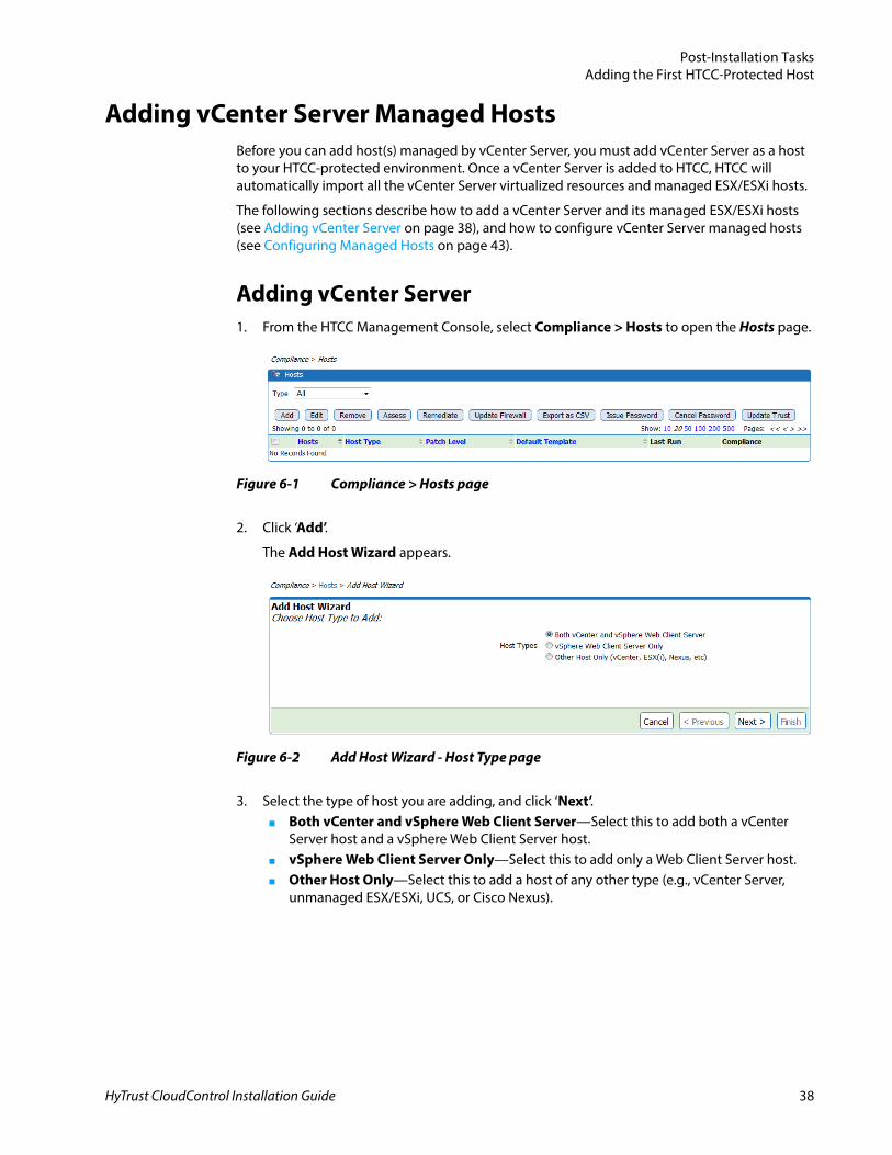
Adding vCenter Server1. From the HTCC Management Console, select Compliance > Hosts to open the Hosts page.
2. Click ‘Add’.
The Add Host Wizard appears.
3. Select the type of host you are adding, and click ‘Next’.■ Both vCenter and vSphere Web Client Server—Select this to add both a vCenter
Server host and a vSphere Web Client Server host.■ vSphere Web Client Server Only—Select this to add only a Web Client Server host.■ Other Host Only—Select this to add a host of any other type (e.g., vCenter Server,
unmanaged ESX/ESXi, UCS, or Cisco Nexus).
Figure 6-1 Compliance > Hosts page
Figure 6-2 Add Host Wizard - Host Type page
HyTrust CloudControl Installation Guide 38
Post-Installation TasksAdding the First HTCC-Protected Host
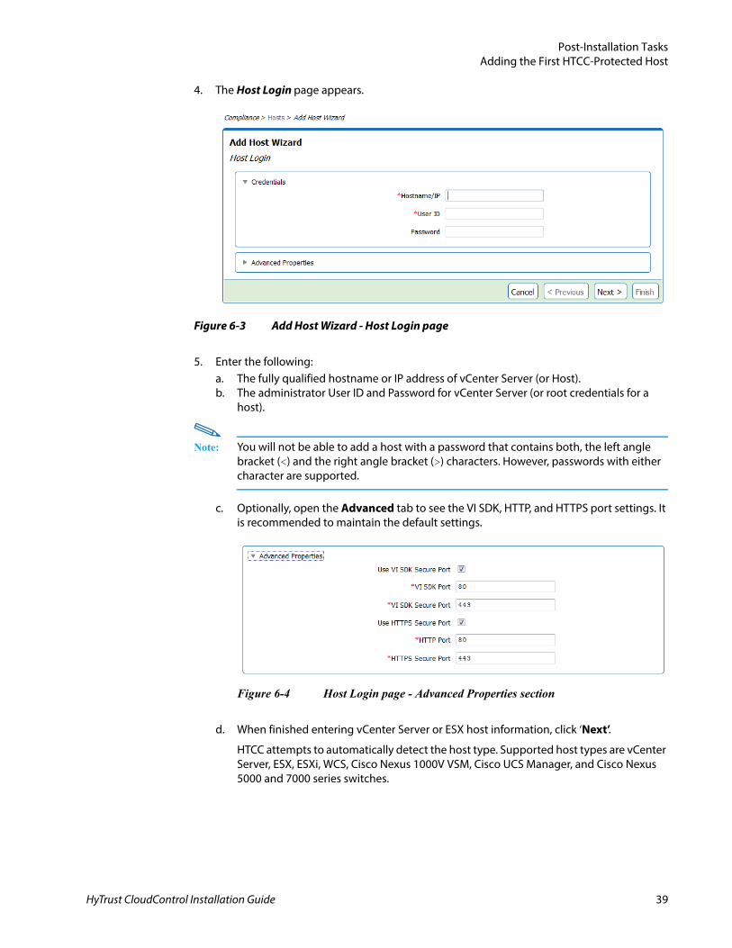
4. The Host Login page appears.
5. Enter the following:a. The fully qualified hostname or IP address of vCenter Server (or Host).b. The administrator User ID and Password for vCenter Server (or root credentials for a
host).
Note: You will not be able to add a host with a password that contains both, the left angle bracket (<) and the right angle bracket (>) characters. However, passwords with either character are supported.
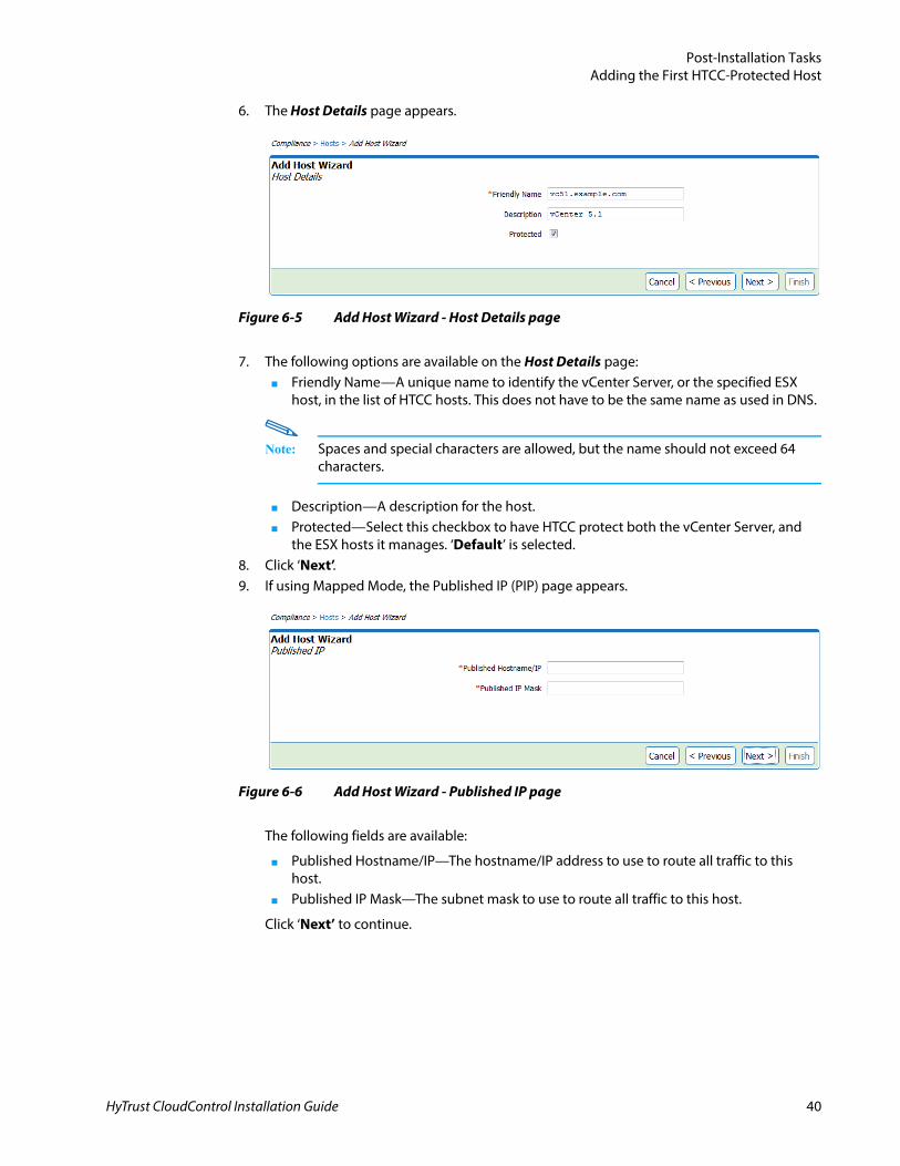
c. Optionally, open the Advanced tab to see the VI SDK, HTTP, and HTTPS port settings. It is recommended to maintain the default settings.
d. When finished entering vCenter Server or ESX host information, click ‘Next’.
HTCC attempts to automatically detect the host type. Supported host types are vCenter Server, ESX, ESXi, WCS, Cisco Nexus 1000V VSM, Cisco UCS Manager, and Cisco Nexus 5000 and 7000 series switches.
Figure 6-3 Add Host Wizard - Host Login page
Figure 6-4 Host Login page - Advanced Properties section
HyTrust CloudControl Installation Guide 39
Post-Installation TasksAdding the First HTCC-Protected Host
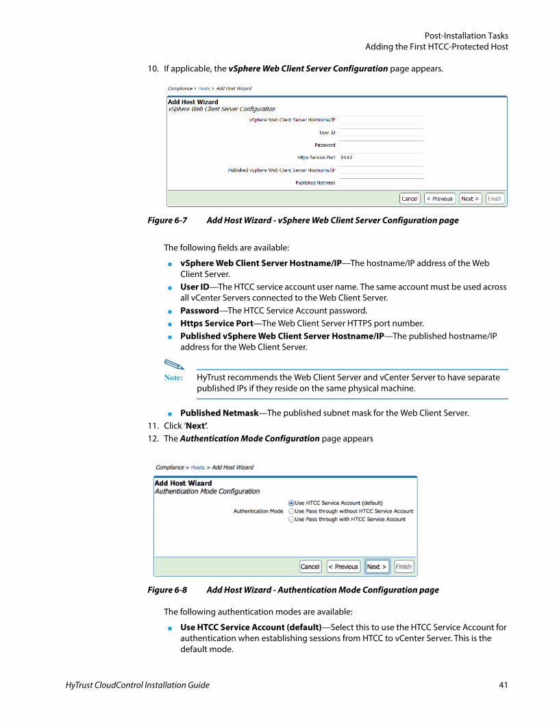
6. The Host Details page appears.
7. The following options are available on the Host Details page:■ Friendly Name—A unique name to identify the vCenter Server, or the specified ESX
host, in the list of HTCC hosts. This does not have to be the same name as used in DNS.
Note: Spaces and special characters are allowed, but the name should not exceed 64 characters.
■ Description—A description for the host.■ Protected—Select this checkbox to have HTCC protect both the vCenter Server, and
the ESX hosts it manages. ‘Default’ is selected.8. Click ‘Next’.9. If using Mapped Mode, the Published IP (PIP) page appears.
The following fields are available:
■ Published Hostname/IP—The hostname/IP address to use to route all traffic to this host.
■ Published IP Mask—The subnet mask to use to route all traffic to this host.
Click ‘Next’ to continue.
Figure 6-5 Add Host Wizard - Host Details page
Figure 6-6 Add Host Wizard - Published IP page
HyTrust CloudControl Installation Guide 40
Post-Installation TasksAdding the First HTCC-Protected Host
10. If applicable, the vSphere Web Client Server Configuration page appears.
The following fields are available:
■ vSphere Web Client Server Hostname/IP—The hostname/IP address of the Web Client Server.
■ User ID—The HTCC service account user name. The same account must be used across all vCenter Servers connected to the Web Client Server.
■ Password—The HTCC Service Account password.■ Https Service Port—The Web Client Server HTTPS port number.■ Published vSphere Web Client Server Hostname/IP—The published hostname/IP
address for the Web Client Server.
Note: HyTrust recommends the Web Client Server and vCenter Server to have separate published IPs if they reside on the same physical machine.
■ Published Netmask—The published subnet mask for the Web Client Server.11. Click ‘Next’.12. The Authentication Mode Configuration page appears
Figure 6-8 Add Host Wizard - Authentication Mode Configuration page
The following authentication modes are available:
■ Use HTCC Service Account (default)—Select this to use the HTCC Service Account for authentication when establishing sessions from HTCC to vCenter Server. This is the default mode.
Figure 6-7 Add Host Wizard - vSphere Web Client Server Configuration page
HyTrust CloudControl Installation Guide 41
Post-Installation TasksAdding the First HTCC-Protected Host
In this mode, only one administrative account is required on vCenter Server. This configuration, however, does not limit the visibility of objects displayed in the vSphere Client.
■ Use Pass through without HTCC Service Account—Select this to use the user’s account for authentication when establishing sessions from HTCC to vCenter Server.
In this mode, a vCenter Server account must be configured for each user. Limits on viewing objects in the vSphere Client are supported and maintained using vCenter Server roles and permissions.
■ Use Pass through with HTCC Service Account—Select this to use the user’s account for initial authentication but use the HTCC Service Account for all other operations.
Select this mode if using Smart Card for authentication. Refer to the Smart Card Authentication section in the HyTrust CloudControl Administration Guide for more information on Smart Card support.
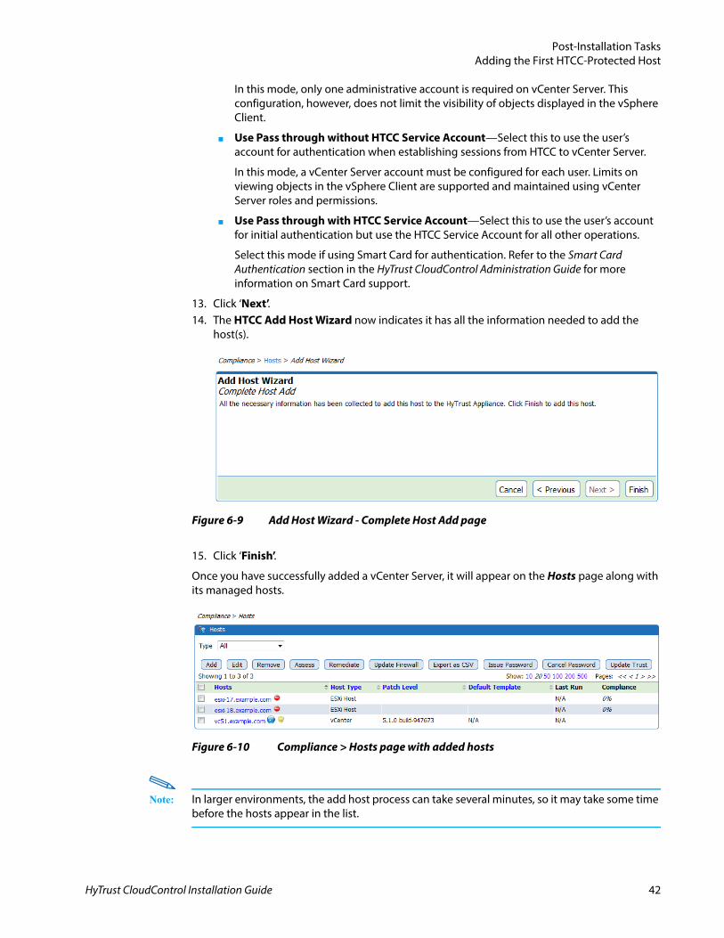
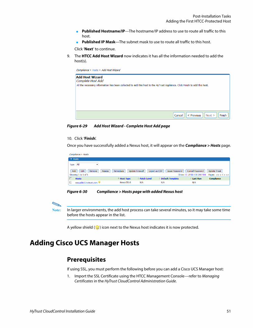
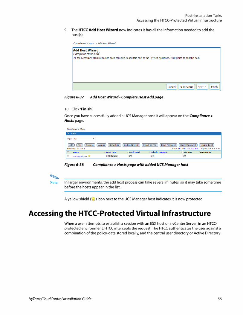
13. Click ‘Next’.14. The HTCC Add Host Wizard now indicates it has all the information needed to add the
host(s).
15. Click ‘Finish’.
Once you have successfully added a vCenter Server, it will appear on the Hosts page along with its managed hosts.
Note: In larger environments, the add host process can take several minutes, so it may take some time before the hosts appear in the list.
Figure 6-9 Add Host Wizard - Complete Host Add page
Figure 6-10 Compliance > Hosts page with added hosts
HyTrust CloudControl Installation Guide 42
Post-Installation TasksAdding the First HTCC-Protected Host
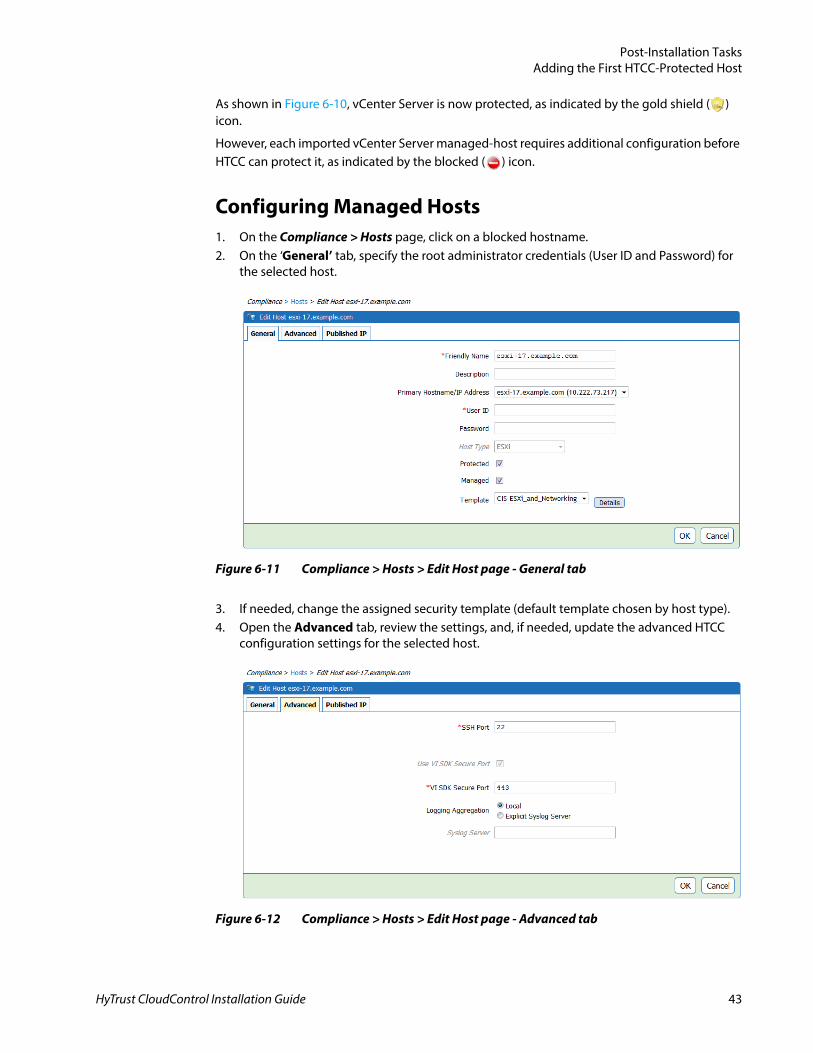
As shown in Figure 6-10, vCenter Server is now protected, as indicated by the gold shield ( ) icon.
However, each imported vCenter Server managed-host requires additional configuration before HTCC can protect it, as indicated by the blocked ( ) icon.
Configuring Managed Hosts1. On the Compliance > Hosts page, click on a blocked hostname.2. On the ‘General’ tab, specify the root administrator credentials (User ID and Password) for
the selected host.
3. If needed, change the assigned security template (default template chosen by host type).4. Open the Advanced tab, review the settings, and, if needed, update the advanced HTCC
configuration settings for the selected host.
Figure 6-11 Compliance > Hosts > Edit Host page - General tab
Figure 6-12 Compliance > Hosts > Edit Host page - Advanced tab
HyTrust CloudControl Installation Guide 43
Post-Installation TasksAdding the First HTCC-Protected Host
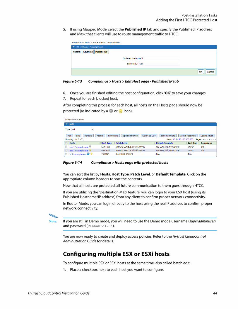
5. If using Mapped Mode, select the Published IP tab and specify the Published IP address and Mask that clients will use to route management traffic to HTCC.
6. Once you are finished editing the host configuration, click ‘OK’ to save your changes.7. Repeat for each blocked host.
After completing this process for each host, all hosts on the Hosts page should now be protected (as indicated by a or icon).
You can sort the list by Hosts, Host Type, Patch Level, or Default Template. Click on the appropriate column headers to sort the contents.
Now that all hosts are protected, all future communication to them goes through HTCC.
If you are utilizing the ‘Destination Map’ feature, you can login to your ESX host (using its Published Hostname/IP address) from any client to confirm proper network connectivity.
In Router Mode, you can login directly to the host using the real IP address to confirm proper network connectivity.
Note: If you are still in Demo mode, you will need to use the Demo mode username (superadminuser) and password (Pa$$w0rd123!).
You are now ready to create and deploy access policies. Refer to the HyTrust CloudControl Administration Guide for details.
Configuring multiple ESX or ESXi hostsTo configure multiple ESX or ESXi hosts at the same time, also called batch edit:
1. Place a checkbox next to each host you want to configure.
Figure 6-13 Compliance > Hosts > Edit Host page - Published IP tab
Figure 6-14 Compliance > Hosts page with protected hosts
HyTrust CloudControl Installation Guide 44
Post-Installation TasksAdding the First HTCC-Protected Host
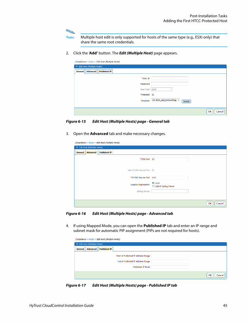
Note: Multiple host edit is only supported for hosts of the same type (e.g., ESXi only) that share the same root credentials.
2. Click the ‘Add’ button. The Edit (Multiple Host) page appears.
3. Open the Advanced tab and make necessary changes.
4. If using Mapped Mode, you can open the Published IP tab and enter an IP range and subnet mask for automatic PIP assignment (PIPs are not required for hosts).
Figure 6-15 Edit Host (Multiple Hosts) page - General tab
Figure 6-16 Edit Host (Multiple Hosts) page - Advanced tab
Figure 6-17 Edit Host (Multiple Hosts) page - Published IP tab
HyTrust CloudControl Installation Guide 45
Post-Installation TasksAdding the First HTCC-Protected Host
5. Once you are finished configuring the hosts, click ‘OK’ to save your changes.
You are now ready to create and deploy access policies. Refer to the HyTrust CloudControl Administration Guide for details.
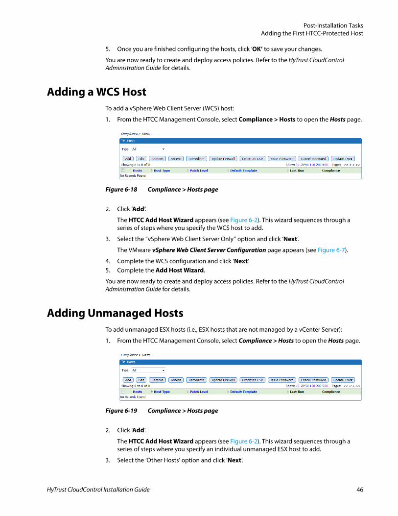
Adding a WCS HostTo add a vSphere Web Client Server (WCS) host:
1. From the HTCC Management Console, select Compliance > Hosts to open the Hosts page.
2. Click ‘Add’.
The HTCC Add Host Wizard appears (see Figure 6-2). This wizard sequences through a series of steps where you specify the WCS host to add.
3. Select the “vSphere Web Client Server Only” option and click ‘Next’.
The VMware vSphere Web Client Server Configuration page appears (see Figure 6-7).
4. Complete the WCS configuration and click ‘Next’.5. Complete the Add Host Wizard.
You are now ready to create and deploy access policies. Refer to the HyTrust CloudControl Administration Guide for details.
Adding Unmanaged HostsTo add unmanaged ESX hosts (i.e., ESX hosts that are not managed by a vCenter Server):
1. From the HTCC Management Console, select Compliance > Hosts to open the Hosts page.
2. Click ‘Add’.
The HTCC Add Host Wizard appears (see Figure 6-2). This wizard sequences through a series of steps where you specify an individual unmanaged ESX host to add.
3. Select the ‘Other Hosts’ option and click ‘Next’.
Figure 6-18 Compliance > Hosts page
Figure 6-19 Compliance > Hosts page
HyTrust CloudControl Installation Guide 46
Post-Installation TasksAdding the First HTCC-Protected Host
The Host Login page appears (see Figure 6-3).
4. Complete the Add Host Wizard.
You are now ready to create and deploy access policies. Refer to the HyTrust CloudControl Administration Guide for details.
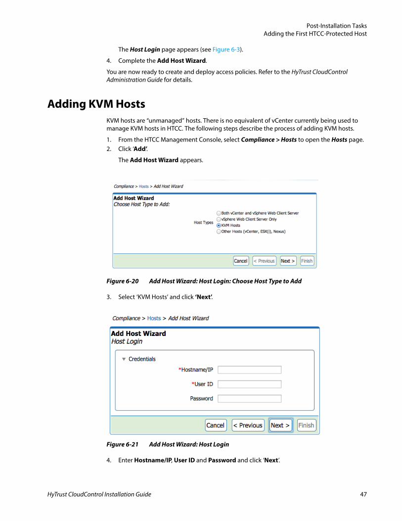
Adding KVM HostsKVM hosts are “unmanaged” hosts. There is no equivalent of vCenter currently being used to manage KVM hosts in HTCC. The following steps describe the process of adding KVM hosts.
1. From the HTCC Management Console, select Compliance > Hosts to open the Hosts page.2. Click ‘Add’.
The Add Host Wizard appears.
Figure 6-20 Add Host Wizard: Host Login: Choose Host Type to Add
3. Select ‘KVM Hosts’ and click ‘Next’.
Figure 6-21 Add Host Wizard: Host Login
4. Enter Hostname/IP, User ID and Password and click ‘Next’.
HyTrust CloudControl Installation Guide 47
Post-Installation TasksAdding the First HTCC-Protected Host
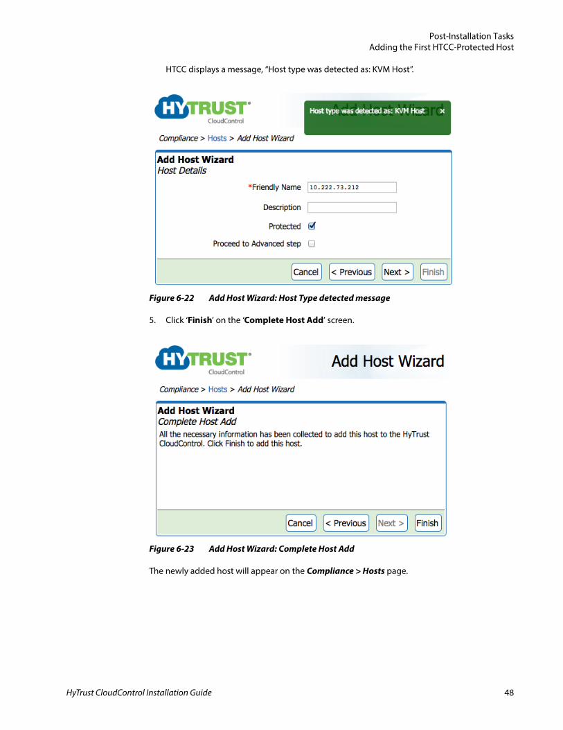
HTCC displays a message, “Host type was detected as: KVM Host”.
Figure 6-22 Add Host Wizard: Host Type detected message
5. Click ‘Finish’ on the ‘Complete Host Add’ screen.
Figure 6-23 Add Host Wizard: Complete Host Add
The newly added host will appear on the Compliance > Hosts page.
HyTrust CloudControl Installation Guide 48
Post-Installation TasksAdding the First HTCC-Protected Host
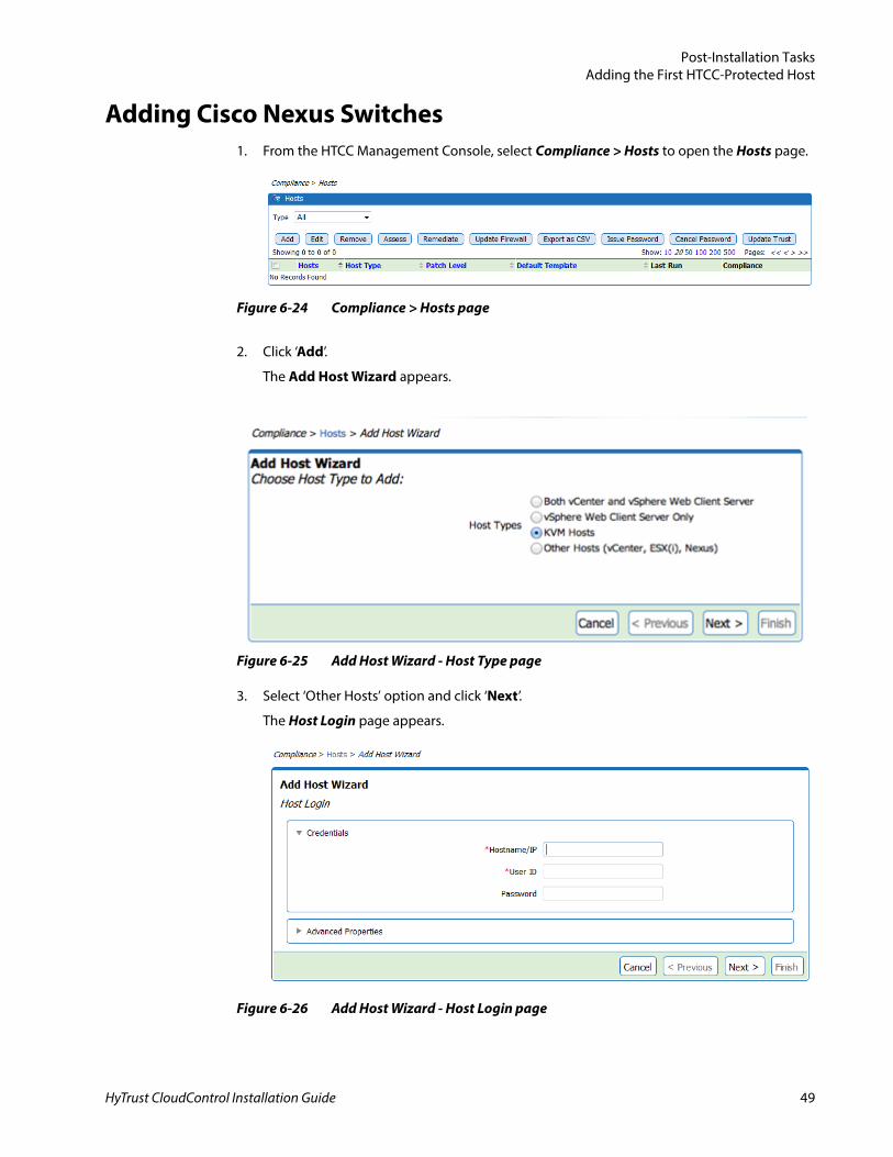
Adding Cisco Nexus Switches1. From the HTCC Management Console, select Compliance > Hosts to open the Hosts page.
2. Click ‘Add’.
The Add Host Wizard appears.
Figure 6-25 Add Host Wizard - Host Type page
3. Select ‘Other Hosts’ option and click ‘Next’.
The Host Login page appears.
Figure 6-24 Compliance > Hosts page
Figure 6-26 Add Host Wizard - Host Login page
HyTrust CloudControl Installation Guide 49
Post-Installation TasksAdding the First HTCC-Protected Host
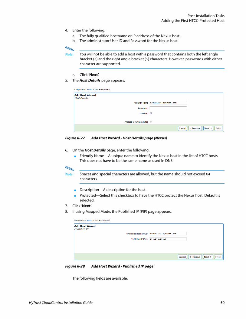
4. Enter the following:a. The fully qualified hostname or IP address of the Nexus host.b. The administrator User ID and Password for the Nexus host.
Note: You will not be able to add a host with a password that contains both the left angle bracket (<) and the right angle bracket (>) characters. However, passwords with either character are supported.
c. Click ‘Next’.5. The Host Details page appears.
6. On the Host Details page, enter the following:■ Friendly Name—A unique name to identify the Nexus host in the list of HTCC hosts.
This does not have to be the same name as used in DNS.
Note: Spaces and special characters are allowed, but the name should not exceed 64 characters.
■ Description—A description for the host.■ Protected—Select this checkbox to have the HTCC protect the Nexus host. Default is
selected.7. Click ‘Next’.8. If using Mapped Mode, the Published IP (PIP) page appears.
The following fields are available:
Figure 6-27 Add Host Wizard - Host Details page (Nexus)
Figure 6-28 Add Host Wizard - Published IP page
HyTrust CloudControl Installation Guide 50
Post-Installation TasksAdding the First HTCC-Protected Host
■ Published Hostname/IP—The hostname/IP address to use to route all traffic to this host.
■ Published IP Mask—The subnet mask to use to route all traffic to this host.
Click ‘Next’ to continue.
9. The HTCC Add Host Wizard now indicates it has all the information needed to add the host(s).
10. Click ‘Finish’.
Once you have successfully added a Nexus host, it will appear on the Compliance > Hosts page.
Note: In larger environments, the add host process can take several minutes, so it may take some time before the hosts appear in the list.
A yellow shield ( ) icon next to the Nexus host indicates it is now protected.
Adding Cisco UCS Manager Hosts
PrerequisitesIf using SSL, you must perform the following before you can add a Cisco UCS Manager host:
1. Import the SSL Certificate using the HTCC Management Console—refer to Managing Certificates in the HyTrust CloudControl Administration Guide.
Figure 6-29 Add Host Wizard - Complete Host Add page
Figure 6-30 Compliance > Hosts page with added Nexus host
HyTrust CloudControl Installation Guide 51
Post-Installation TasksAdding the First HTCC-Protected Host
2. By default, HTCC only accepts SSL version 3; however, SSL version 2 is required for compatibility with Cisco USC Manager hosts. Configure the HTCC to accept SSL version 2 by running the following command as ascadminuser:asc certs -ssl 2
3. Restart Tomcat by running the following command as ascadminuser:asc service -n tomcat6
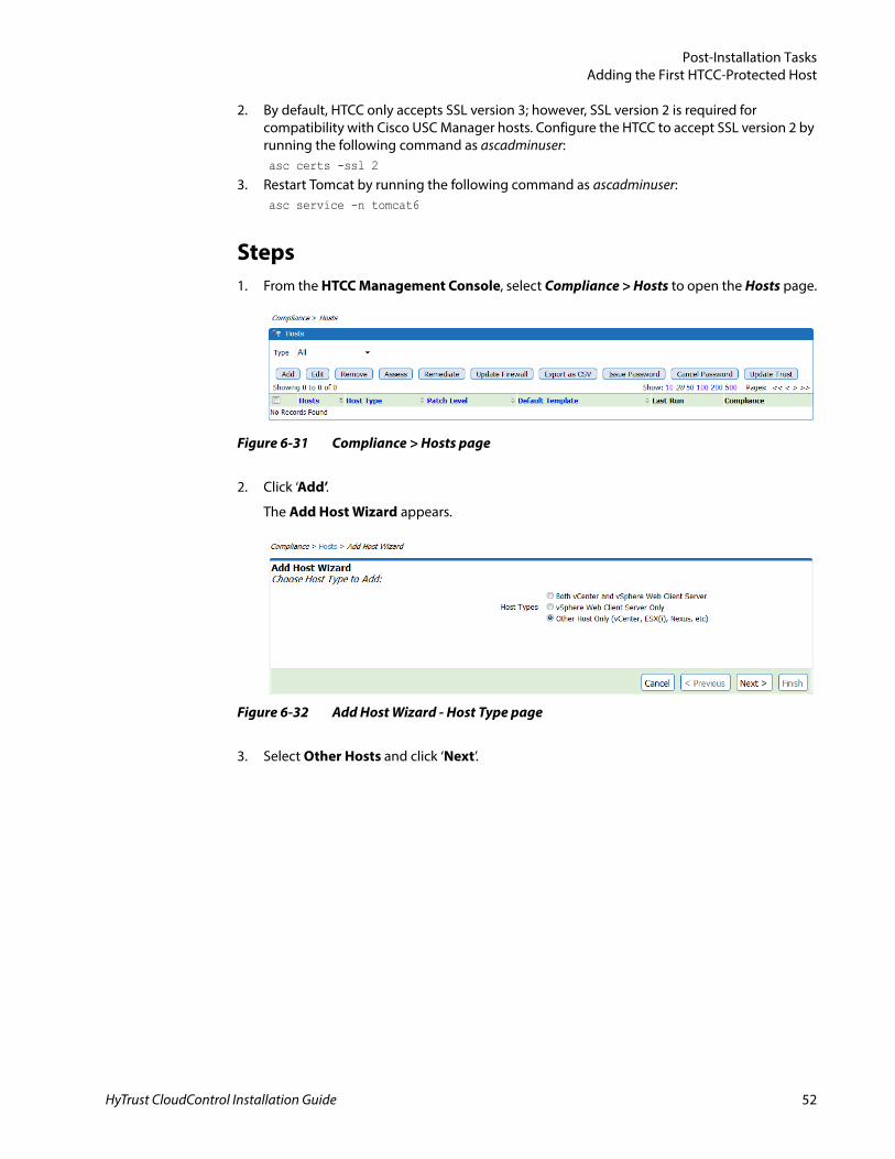
Steps1. From the HTCC Management Console, select Compliance > Hosts to open the Hosts page.
2. Click ‘Add’.
The Add Host Wizard appears.
3. Select Other Hosts and click ‘Next’.
Figure 6-31 Compliance > Hosts page
Figure 6-32 Add Host Wizard - Host Type page
HyTrust CloudControl Installation Guide 52
Post-Installation TasksAdding the First HTCC-Protected Host
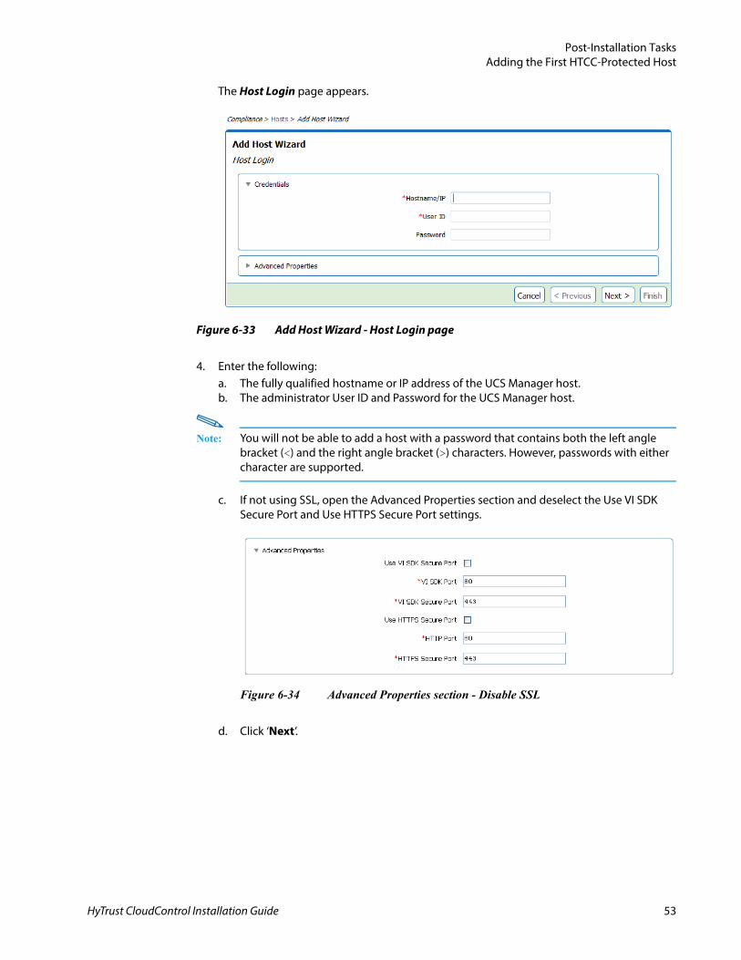
The Host Login page appears.
4. Enter the following:a. The fully qualified hostname or IP address of the UCS Manager host.b. The administrator User ID and Password for the UCS Manager host.
Note: You will not be able to add a host with a password that contains both the left angle bracket (<) and the right angle bracket (>) characters. However, passwords with either character are supported.
c. If not using SSL, open the Advanced Properties section and deselect the Use VI SDK Secure Port and Use HTTPS Secure Port settings.
d. Click ‘Next’.
Figure 6-33 Add Host Wizard - Host Login page
Figure 6-34 Advanced Properties section - Disable SSL
HyTrust CloudControl Installation Guide 53
Post-Installation TasksAdding the First HTCC-Protected Host
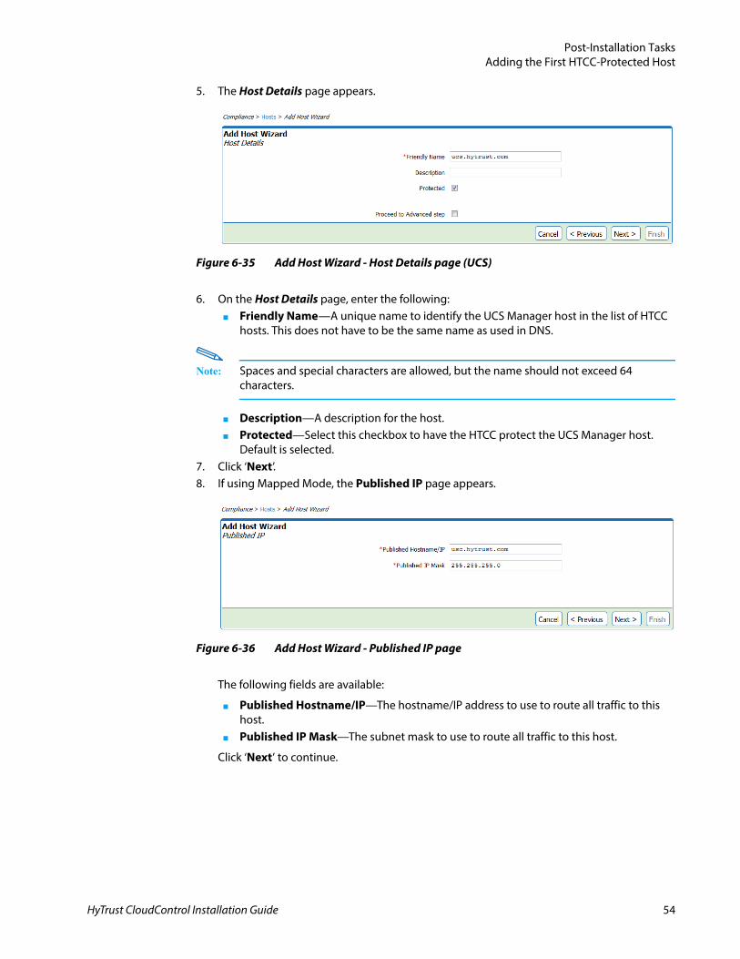
5. The Host Details page appears.
6. On the Host Details page, enter the following:■ Friendly Name—A unique name to identify the UCS Manager host in the list of HTCC
hosts. This does not have to be the same name as used in DNS.
Note: Spaces and special characters are allowed, but the name should not exceed 64 characters.
■ Description—A description for the host.■ Protected—Select this checkbox to have the HTCC protect the UCS Manager host.
Default is selected.7. Click ‘Next’.8. If using Mapped Mode, the Published IP page appears.
The following fields are available:
■ Published Hostname/IP—The hostname/IP address to use to route all traffic to this host.
■ Published IP Mask—The subnet mask to use to route all traffic to this host.
Click ‘Next’ to continue.
Figure 6-35 Add Host Wizard - Host Details page (UCS)
Figure 6-36 Add Host Wizard - Published IP page
HyTrust CloudControl Installation Guide 54
Post-Installation TasksAccessing the HTCC-Protected Virtual Infrastructure
9. The HTCC Add Host Wizard now indicates it has all the information needed to add the host(s).
10. Click ‘Finish’.
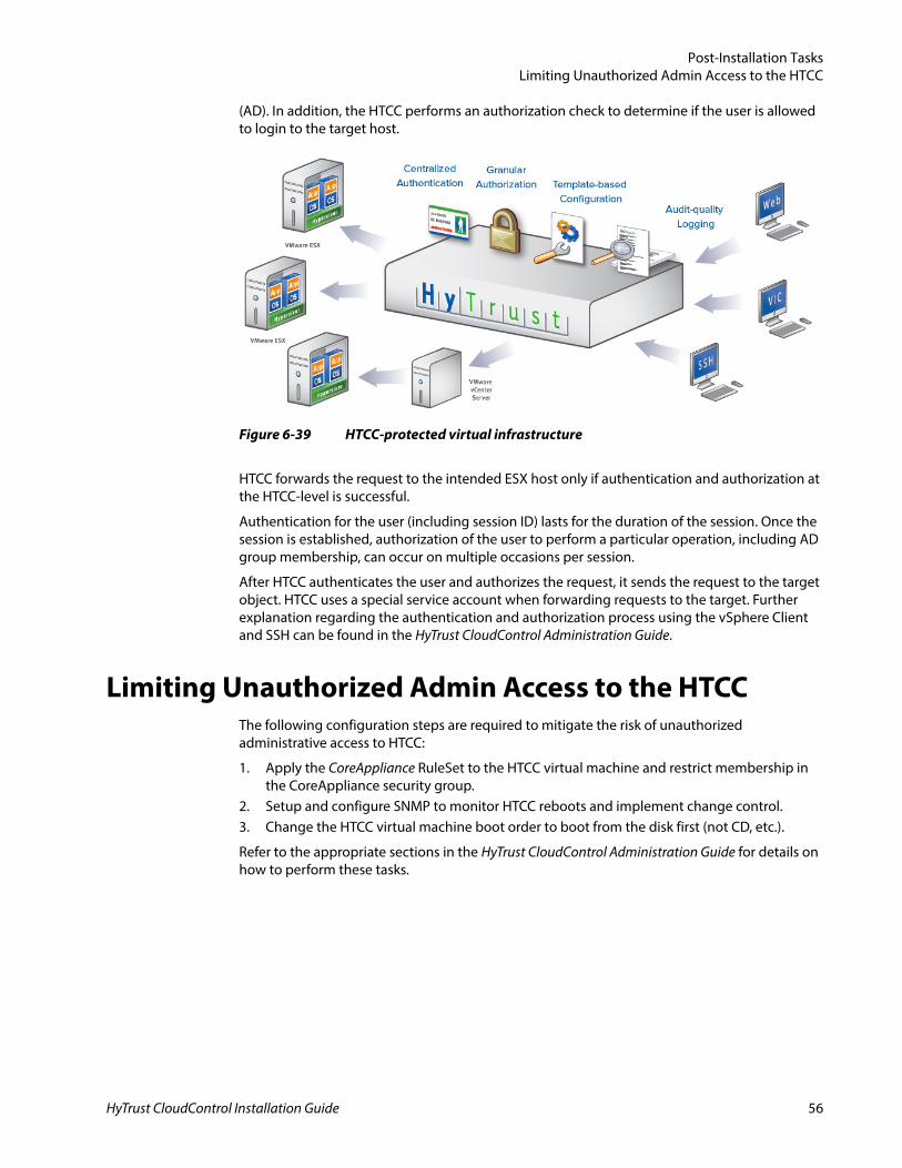
Once you have successfully added a UCS Manager host it will appear on the Compliance > Hosts page.
Note: In larger environments, the add host process can take several minutes, so it may take some time before the hosts appear in the list.
A yellow shield ( ) icon next to the UCS Manager host indicates it is now protected.
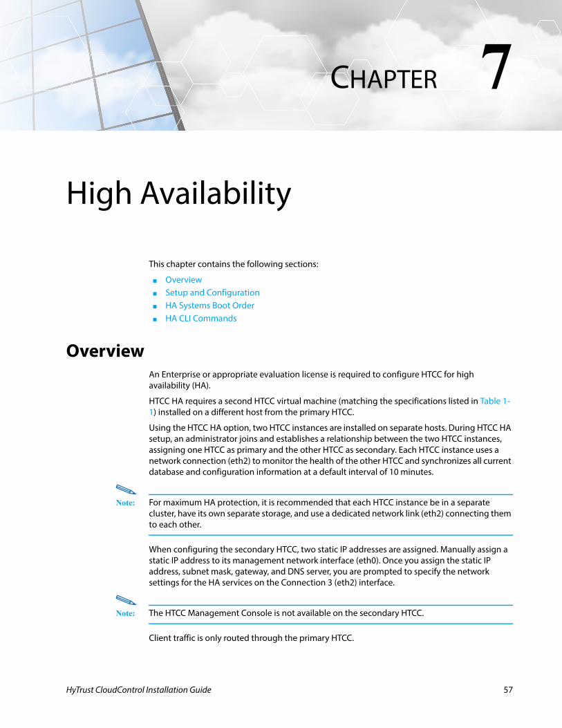
Accessing the HTCC-Protected Virtual InfrastructureWhen a user attempts to establish a session with an ESX host or a vCenter Server, in an HTCC-protected environment, HTCC intercepts the request. The HTCC authenticates the user against a combination of the policy-data stored locally, and the central user directory or Active Directory
Figure 6-37 Add Host Wizard - Complete Host Add page
Figure 6-38 Compliance > Hosts page with added UCS Manager host
HyTrust CloudControl Installation Guide 55
Post-Installation TasksLimiting Unauthorized Admin Access to the HTCC
(AD). In addition, the HTCC performs an authorization check to determine if the user is allowed to login to the target host.
HTCC forwards the request to the intended ESX host only if authentication and authorization at the HTCC-level is successful.
Authentication for the user (including session ID) lasts for the duration of the session. Once the session is established, authorization of the user to perform a particular operation, including AD group membership, can occur on multiple occasions per session.
After HTCC authenticates the user and authorizes the request, it sends the request to the target object. HTCC uses a special service account when forwarding requests to the target. Further explanation regarding the authentication and authorization process using the vSphere Client and SSH can be found in the HyTrust CloudControl Administration Guide.
Limiting Unauthorized Admin Access to the HTCCThe following configuration steps are required to mitigate the risk of unauthorized administrative access to HTCC:
1. Apply the CoreAppliance RuleSet to the HTCC virtual machine and restrict membership in the CoreAppliance security group.
2. Setup and configure SNMP to monitor HTCC reboots and implement change control.3. Change the HTCC virtual machine boot order to boot from the disk first (not CD, etc.).
Refer to the appropriate sections in the HyTrust CloudControl Administration Guide for details on how to perform these tasks.
Figure 6-39 HTCC-protected virtual infrastructure
HyTrust CloudControl Installation Guide 56
HyTrust CloudControl Installation Guide
7
CHAPTERHigh Availability
This chapter contains the following sections:
■ Overview■ Setup and Configuration■ HA Systems Boot Order■ HA CLI Commands
OverviewAn Enterprise or appropriate evaluation license is required to configure HTCC for high availability (HA).
HTCC HA requires a second HTCC virtual machine (matching the specifications listed in Table 1-1) installed on a different host from the primary HTCC.
Using the HTCC HA option, two HTCC instances are installed on separate hosts. During HTCC HA setup, an administrator joins and establishes a relationship between the two HTCC instances, assigning one HTCC as primary and the other HTCC as secondary. Each HTCC instance uses a network connection (eth2) to monitor the health of the other HTCC and synchronizes all current database and configuration information at a default interval of 10 minutes.
Note: For maximum HA protection, it is recommended that each HTCC instance be in a separate cluster, have its own separate storage, and use a dedicated network link (eth2) connecting them to each other.
When configuring the secondary HTCC, two static IP addresses are assigned. Manually assign a static IP address to its management network interface (eth0). Once you assign the static IP address, subnet mask, gateway, and DNS server, you are prompted to specify the network settings for the HA services on the Connection 3 (eth2) interface.
Note: The HTCC Management Console is not available on the secondary HTCC.
Client traffic is only routed through the primary HTCC.
57
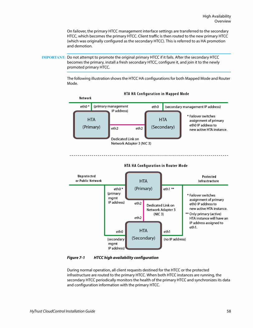
High AvailabilityOverview
On failover, the primary HTCC management interface settings are transferred to the secondary HTCC, which becomes the primary HTCC. Client traffic is then routed to the new primary HTCC (which was originally configured as the secondary HTCC). This is referred to as HA promotion and demotion.
IMPORTANT: Do not attempt to promote the original primary HTCC if it fails. After the secondary HTCC becomes the primary, install a fresh secondary HTCC, configure it, and join it to the newly promoted primary HTCC.
The following illustration shows the HTCC HA configurations for both Mapped Mode and Router Mode.
During normal operation, all client requests destined for the HTCC or the protected infrastructure are routed to the primary HTCC. When both HTCC instances are running, the secondary HTCC periodically monitors the health of the primary HTCC and synchronizes its data and configuration information with the primary HTCC.
Figure 7-1 HTCC high availability configuration
HyTrust CloudControl Installation Guide 58
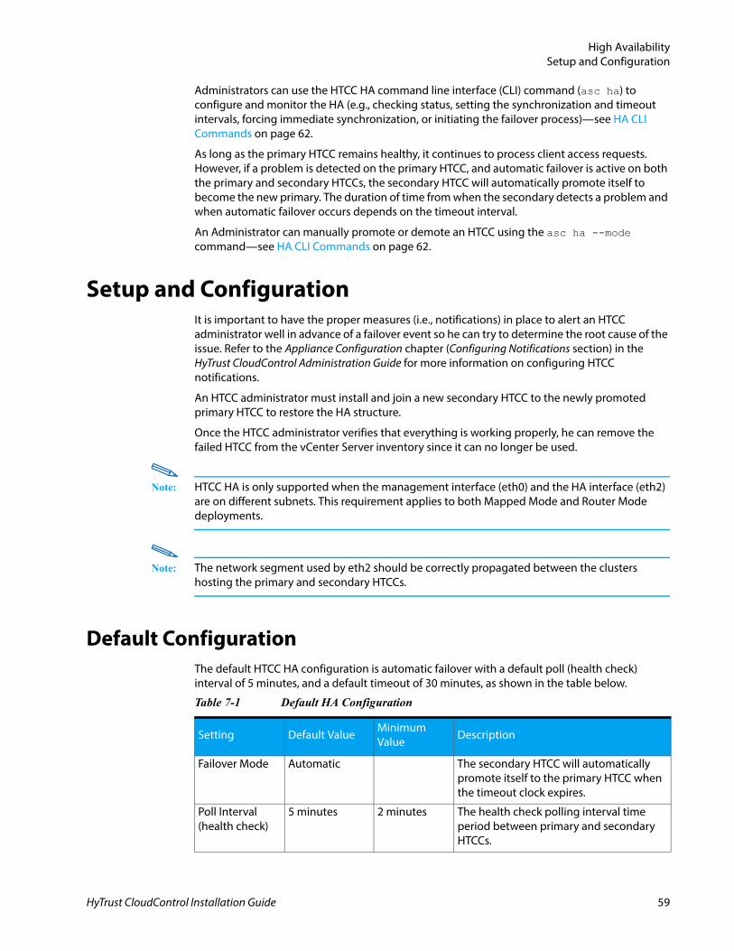
High AvailabilitySetup and Configuration
Administrators can use the HTCC HA command line interface (CLI) command (asc ha) to configure and monitor the HA (e.g., checking status, setting the synchronization and timeout intervals, forcing immediate synchronization, or initiating the failover process)—see HA CLI Commands on page 62.
As long as the primary HTCC remains healthy, it continues to process client access requests. However, if a problem is detected on the primary HTCC, and automatic failover is active on both the primary and secondary HTCCs, the secondary HTCC will automatically promote itself to become the new primary. The duration of time from when the secondary detects a problem and when automatic failover occurs depends on the timeout interval.
An Administrator can manually promote or demote an HTCC using the asc ha --mode command—see HA CLI Commands on page 62.
Setup and ConfigurationIt is important to have the proper measures (i.e., notifications) in place to alert an HTCC administrator well in advance of a failover event so he can try to determine the root cause of the issue. Refer to the Appliance Configuration chapter (Configuring Notifications section) in the HyTrust CloudControl Administration Guide for more information on configuring HTCC notifications.
An HTCC administrator must install and join a new secondary HTCC to the newly promoted primary HTCC to restore the HA structure.
Once the HTCC administrator verifies that everything is working properly, he can remove the failed HTCC from the vCenter Server inventory since it can no longer be used.
Note: HTCC HA is only supported when the management interface (eth0) and the HA interface (eth2) are on different subnets. This requirement applies to both Mapped Mode and Router Mode deployments.
Note: The network segment used by eth2 should be correctly propagated between the clusters hosting the primary and secondary HTCCs.
Default ConfigurationThe default HTCC HA configuration is automatic failover with a default poll (health check) interval of 5 minutes, and a default timeout of 30 minutes, as shown in the table below.
Table 7-1 Default HA Configuration
Setting Default ValueMinimum Value
Description
Failover Mode Automatic The secondary HTCC will automatically promote itself to the primary HTCC when the timeout clock expires.
Poll Interval(health check)
5 minutes 2 minutes The health check polling interval time period between primary and secondary HTCCs.
HyTrust CloudControl Installation Guide 59
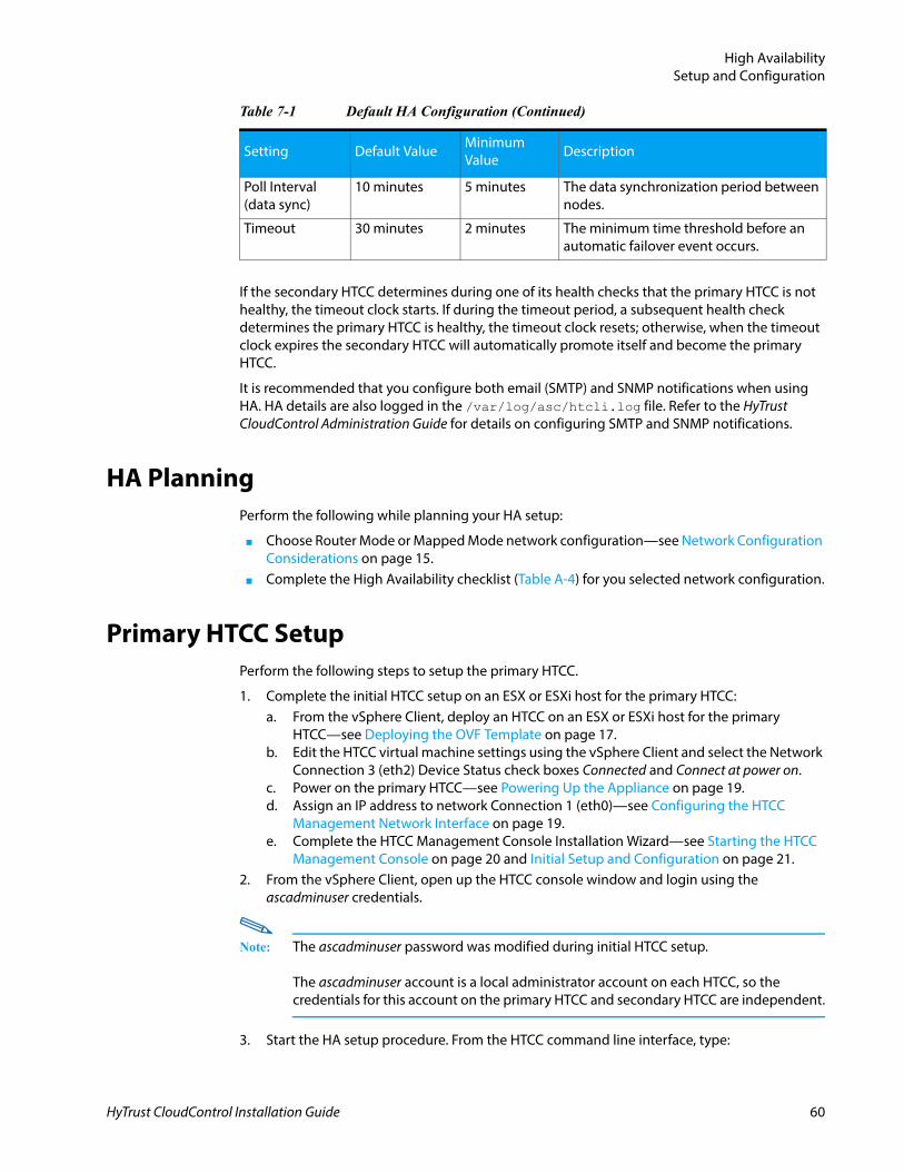
High AvailabilitySetup and Configuration
If the secondary HTCC determines during one of its health checks that the primary HTCC is not healthy, the timeout clock starts. If during the timeout period, a subsequent health check determines the primary HTCC is healthy, the timeout clock resets; otherwise, when the timeout clock expires the secondary HTCC will automatically promote itself and become the primary HTCC.
It is recommended that you configure both email (SMTP) and SNMP notifications when using HA. HA details are also logged in the /var/log/asc/htcli.log file. Refer to the HyTrust CloudControl Administration Guide for details on configuring SMTP and SNMP notifications.
HA PlanningPerform the following while planning your HA setup:
■ Choose Router Mode or Mapped Mode network configuration—see Network Configuration Considerations on page 15.
■ Complete the High Availability checklist (Table A-4) for you selected network configuration.
Primary HTCC SetupPerform the following steps to setup the primary HTCC.
1. Complete the initial HTCC setup on an ESX or ESXi host for the primary HTCC:a. From the vSphere Client, deploy an HTCC on an ESX or ESXi host for the primary
HTCC—see Deploying the OVF Template on page 17.b. Edit the HTCC virtual machine settings using the vSphere Client and select the Network
Connection 3 (eth2) Device Status check boxes Connected and Connect at power on.c. Power on the primary HTCC—see Powering Up the Appliance on page 19.d. Assign an IP address to network Connection 1 (eth0)—see Configuring the HTCC
Management Network Interface on page 19.e. Complete the HTCC Management Console Installation Wizard—see Starting the HTCC
Management Console on page 20 and Initial Setup and Configuration on page 21.2. From the vSphere Client, open up the HTCC console window and login using the
ascadminuser credentials.
Note: The ascadminuser password was modified during initial HTCC setup.
The ascadminuser account is a local administrator account on each HTCC, so the credentials for this account on the primary HTCC and secondary HTCC are independent.
3. Start the HA setup procedure. From the HTCC command line interface, type:
Poll Interval(data sync)
10 minutes 5 minutes The data synchronization period between nodes.
Timeout 30 minutes 2 minutes The minimum time threshold before an automatic failover event occurs.
Table 7-1 Default HA Configuration (Continued)
Setting Default ValueMinimum Value
Description
HyTrust CloudControl Installation Guide 60
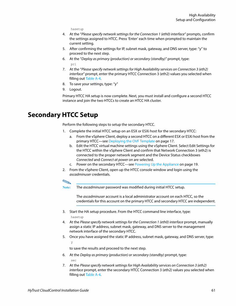
High AvailabilitySetup and Configuration
hasetup
4. At the “Please specify network settings for the Connection 1 (eth0) interface” prompts, confirm the settings assigned to HTCC. Press ‘Enter’ each time when prompted to maintain the current setting.
5. After confirming the settings for IP, subnet mask, gateway, and DNS server, type: “y” to proceed to the next step.
6. At the “Deploy as primary (production) or secondary (standby)” prompt, type:pri
7. At the “Please specify network settings for High Availability services on Connection 3 (eth2) interface” prompt, enter the primary HTCC Connection 3 (eth2) values you selected when filling out Table A-4.
8. To save your settings, type: “y”9. Logout.
Primary HTCC HA setup is now complete. Next, you must install and configure a second HTCC instance and join the two HTCCs to create an HTCC HA cluster.
Secondary HTCC SetupPerform the following steps to setup the secondary HTCC.
1. Complete the initial HTCC setup on an ESX or ESXi host for the secondary HTCC:a. From the vSphere Client, deploy a second HTCC on a different ESX or ESXi host from the
primary HTCC—see Deploying the OVF Template on page 17.b. Edit the HTCC virtual machine settings using the vSphere Client. Select Edit Settings for
the HTCC within the vSphere Client and confirm that Network Connection 3 (eth2) is connected to the proper network segment and the Device Status checkboxes Connected and Connect at power on are selected.
c. Power on the secondary HTCC—see Powering Up the Appliance on page 19.2. From the vSphere Client, open up the HTCC console window and login using the
ascadminuser credentials.
Note: The ascadminuser password was modified during initial HTCC setup.
The ascadminuser account is a local administrator account on each HTCC, so the credentials for this account on the primary HTCC and secondary HTCC are independent.
3. Start the HA setup procedure. From the HTCC command line interface, type:hasetup
4. At the Please specify network settings for the Connection 1 (eth0) interface prompt, manually assign a static IP address, subnet mask, gateway, and DNS server to the management network interface of the secondary HTCC.
5. Once you have assigned the static IP address, subnet mask, gateway, and DNS server, type:y
to save the results and proceed to the next step.
6. At the Deploy as primary (production) or secondary (standby) prompt, type:sec
7. At the Please specify network settings for High Availability services on Connection 3 (eth2) interface prompt, enter the secondary HTCC Connection 3 (eth2) values you selected when filling out Table A-4.
HyTrust CloudControl Installation Guide 61
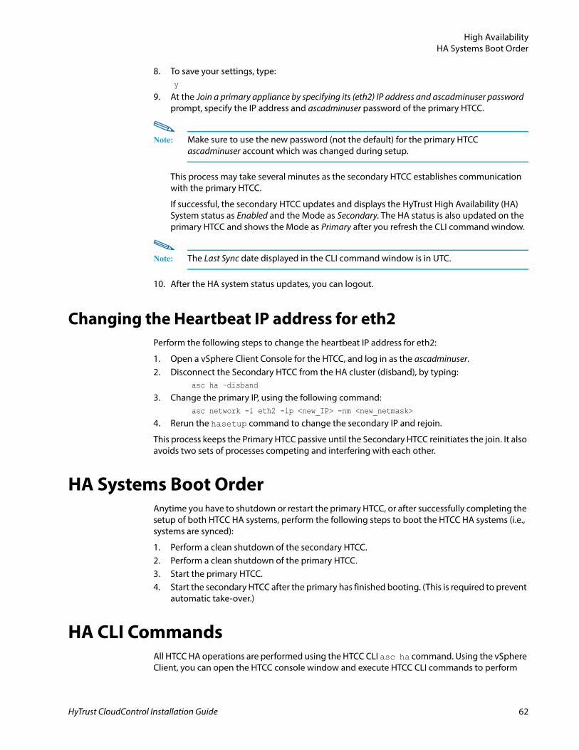
High AvailabilityHA Systems Boot Order
8. To save your settings, type:y
9. At the Join a primary appliance by specifying its (eth2) IP address and ascadminuser password prompt, specify the IP address and ascadminuser password of the primary HTCC.
Note: Make sure to use the new password (not the default) for the primary HTCC ascadminuser account which was changed during setup.
This process may take several minutes as the secondary HTCC establishes communication with the primary HTCC.
If successful, the secondary HTCC updates and displays the HyTrust High Availability (HA) System status as Enabled and the Mode as Secondary. The HA status is also updated on the primary HTCC and shows the Mode as Primary after you refresh the CLI command window.
Note: The Last Sync date displayed in the CLI command window is in UTC.
10. After the HA system status updates, you can logout.
Changing the Heartbeat IP address for eth2Perform the following steps to change the heartbeat IP address for eth2:
1. Open a vSphere Client Console for the HTCC, and log in as the ascadminuser.2. Disconnect the Secondary HTCC from the HA cluster (disband), by typing:
asc ha –disband
3. Change the primary IP, using the following command: asc network -i eth2 -ip <new_IP> -nm <new_netmask>
4. Rerun the hasetup command to change the secondary IP and rejoin.
This process keeps the Primary HTCC passive until the Secondary HTCC reinitiates the join. It also avoids two sets of processes competing and interfering with each other.
HA Systems Boot OrderAnytime you have to shutdown or restart the primary HTCC, or after successfully completing the setup of both HTCC HA systems, perform the following steps to boot the HTCC HA systems (i.e., systems are synced):
1. Perform a clean shutdown of the secondary HTCC.2. Perform a clean shutdown of the primary HTCC.3. Start the primary HTCC.4. Start the secondary HTCC after the primary has finished booting. (This is required to prevent
automatic take-over.)
HA CLI CommandsAll HTCC HA operations are performed using the HTCC CLI asc ha command. Using the vSphere Client, you can open the HTCC console window and execute HTCC CLI commands to perform
HyTrust CloudControl Installation Guide 62
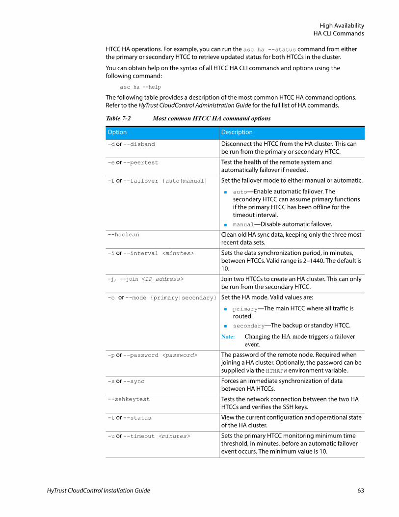
High AvailabilityHA CLI Commands
HTCC HA operations. For example, you can run the asc ha --status command from either the primary or secondary HTCC to retrieve updated status for both HTCCs in the cluster.
You can obtain help on the syntax of all HTCC HA CLI commands and options using the following command:
asc ha --help
The following table provides a description of the most common HTCC HA command options. Refer to the HyTrust CloudControl Administration Guide for the full list of HA commands.
Table 7-2 Most common HTCC HA command options
Option Description
-d or --disband Disconnect the HTCC from the HA cluster. This can be run from the primary or secondary HTCC.
-e or --peertest Test the health of the remote system and automatically failover if needed.
-f or --failover {auto|manual} Set the failover mode to either manual or automatic.
■ auto—Enable automatic failover. The secondary HTCC can assume primary functions if the primary HTCC has been offline for the timeout interval.
■ manual—Disable automatic failover.
--haclean Clean old HA sync data, keeping only the three most recent data sets.
-i or --interval <minutes> Sets the data synchronization period, in minutes, between HTCCs. Valid range is 2–1440. The default is 10.
-j, --join <IP_address> Join two HTCCs to create an HA cluster. This can only be run from the secondary HTCC.
-o or --mode {primary|secondary} Set the HA mode. Valid values are:
■ primary—The main HTCC where all traffic is routed.
■ secondary—The backup or standby HTCC.
Note: Changing the HA mode triggers a failover event.
-p or --password <password> The password of the remote node. Required when joining a HA cluster. Optionally, the password can be supplied via the HTHAPW environment variable.
-s or --sync Forces an immediate synchronization of data between HA HTCCs.
--sshkeytest Tests the network connection between the two HA HTCCs and verifies the SSH keys.
-t or --status View the current configuration and operational state of the HA cluster.
-u or --timeout <minutes> Sets the primary HTCC monitoring minimum time threshold, in minutes, before an automatic failover event occurs. The minimum value is 10.
HyTrust CloudControl Installation Guide 63
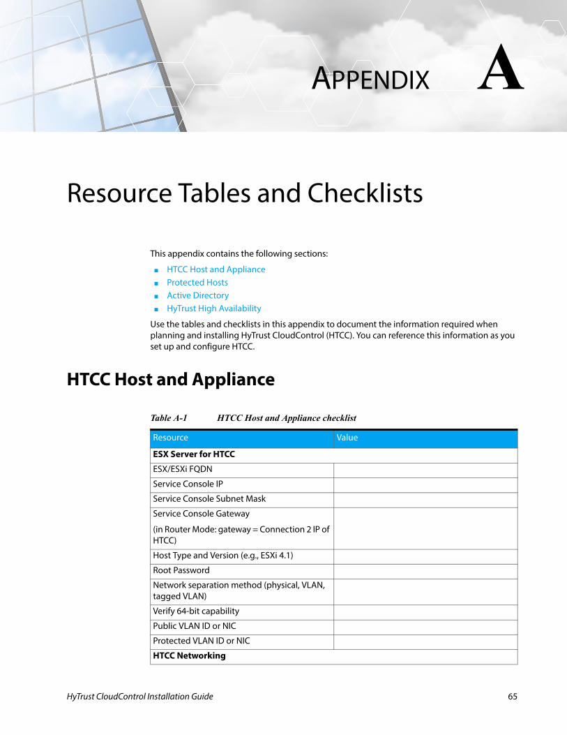
HyTrust CloudControl Installation Guide
A
APPENDIXResource Tables and Checklists
This appendix contains the following sections:
■ HTCC Host and Appliance■ Protected Hosts■ Active Directory■ HyTrust High Availability
Use the tables and checklists in this appendix to document the information required when planning and installing HyTrust CloudControl (HTCC). You can reference this information as you set up and configure HTCC.
HTCC Host and Appliance
Table A-1 HTCC Host and Appliance checklist
Resource Value
ESX Server for HTCC
ESX/ESXi FQDN
Service Console IP
Service Console Subnet Mask
Service Console Gateway
(in Router Mode: gateway = Connection 2 IP of HTCC)
Host Type and Version (e.g., ESXi 4.1)
Root Password
Network separation method (physical, VLAN, tagged VLAN)
Verify 64-bit capability
Public VLAN ID or NIC
Protected VLAN ID or NIC
HTCC Networking
65
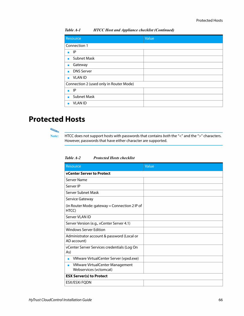
Protected Hosts
Protected Hosts
Note: HTCC does not support hosts with passwords that contains both the “<” and the “>” characters. However, passwords that have either character are supported.
Connection 1
■ IP
■ Subnet Mask
■ Gateway
■ DNS Server
■ VLAN ID
Connection 2 (used only in Router Mode)
■ IP
■ Subnet Mask
■ VLAN ID
Table A-1 HTCC Host and Appliance checklist (Continued)
Resource Value
Table A-2 Protected Hosts checklist
Resource Value
vCenter Server to Protect
Server Name
Server IP
Server Subnet Mask
Service Gateway
(in Router Mode: gateway = Connection 2 IP of HTCC)
Server VLAN ID
Server Version (e.g., vCenter Server 4.1)
Windows Server Edition
Administrator account & password (Local or AD account)
vCenter Server Services credentials (Log On As)
■ VMware VirtualCenter Server (vpxd.exe)
■ VMware VirtualCenter Management Webservices (vctomcat)
ESX Server(s) to Protect
ESX/ESXi FQDN
HyTrust CloudControl Installation Guide 66
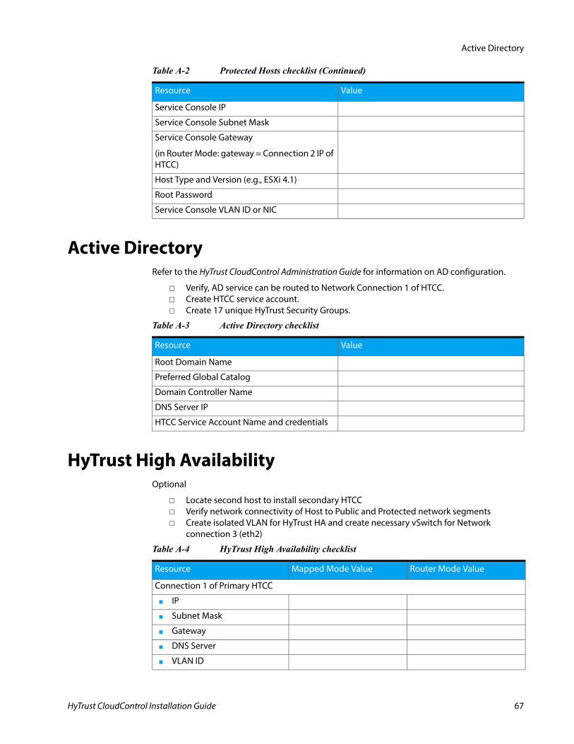
Active Directory
Active DirectoryRefer to the HyTrust CloudControl Administration Guide for information on AD configuration.
Verify, AD service can be routed to Network Connection 1 of HTCC. Create HTCC service account. Create 17 unique HyTrust Security Groups.
HyTrust High AvailabilityOptional
Locate second host to install secondary HTCC Verify network connectivity of Host to Public and Protected network segments Create isolated VLAN for HyTrust HA and create necessary vSwitch for Network
connection 3 (eth2)
Service Console IP
Service Console Subnet Mask
Service Console Gateway
(in Router Mode: gateway = Connection 2 IP of HTCC)
Host Type and Version (e.g., ESXi 4.1)
Root Password
Service Console VLAN ID or NIC
Table A-2 Protected Hosts checklist (Continued)
Resource Value
Table A-3 Active Directory checklist
Resource Value
Root Domain Name
Preferred Global Catalog
Domain Controller Name
DNS Server IP
HTCC Service Account Name and credentials
Table A-4 HyTrust High Availability checklist
Resource Mapped Mode Value Router Mode Value
Connection 1 of Primary HTCC
■ IP
■ Subnet Mask
■ Gateway
■ DNS Server
■ VLAN ID
HyTrust CloudControl Installation Guide 67
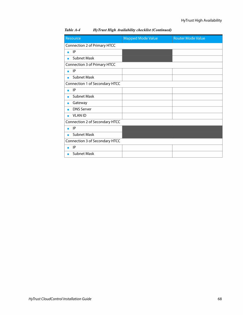
HyTrust High Availability
Connection 2 of Primary HTCC
■ IP
■ Subnet Mask
Connection 3 of Primary HTCC
■ IP
■ Subnet Mask
Connection 1 of Secondary HTCC
■ IP
■ Subnet Mask
■ Gateway
■ DNS Server
■ VLAN ID
Connection 2 of Secondary HTCC
■ IP
■ Subnet Mask
Connection 3 of Secondary HTCC
■ IP
■ Subnet Mask
Table A-4 HyTrust High Availability checklist (Continued)
Resource Mapped Mode Value Router Mode Value
HyTrust CloudControl Installation Guide 68
HyTrust CloudControl Installation Guide
B
APPENDIXConfiguring the Windows Server 2008 Firewall
This appendix describes how to configure the Windows Server 2008 Firewall to work with HyTrust CloudControl (HTCC). For details on configuring other firewalls, refer to the appropriate documentation.
This appendix contains the following sections:
■ View and Modify Inbound Rules
View and Modify Inbound RulesConfiguring the Windows Server 2008 Firewall to work with HTCC requires you to use the Windows Server 2008 Firewall advanced configuration utility to change its Inbound Rules.
Perform the following steps:
1. Open the Start menu and select Administrative Tools > Windows Firewall and Advanced Security.
2. Click Inbound Rules in the left pane to view the current inbound firewall rules.3. Locate the ‘Remote Desktop (TCP-In)’ rule and confirm, it is disabled.
If it is enabled, select it and click the ‘Disable Rule’ button in the Action pane on the right. (You could also right-click on it and choose Disable Rule from the context pop-up.)
4. Locate the ‘VMware vCenter Server - HTTP’ rule.a. Select it and click the Properties button in the Action pane (or right-click on it and
choose Properties from the context pop-up) to open its properties dialog.b. Click the Scope tab.c. In the Remote IP address section, select These IP addresses, and click the ‘Add’ button.d. Select ‘This IP address or subnet’, enter the IP address of HTCC in the field, and click ‘OK’.e. Click ‘OK’ in the Properties dialog to apply the changes.f. Repeat for the following rules:
VMware vCenter Server - HTTPS VMware vCenter Server - Web Services HTTPS VMware vCenter Server Web Services HTTP
69
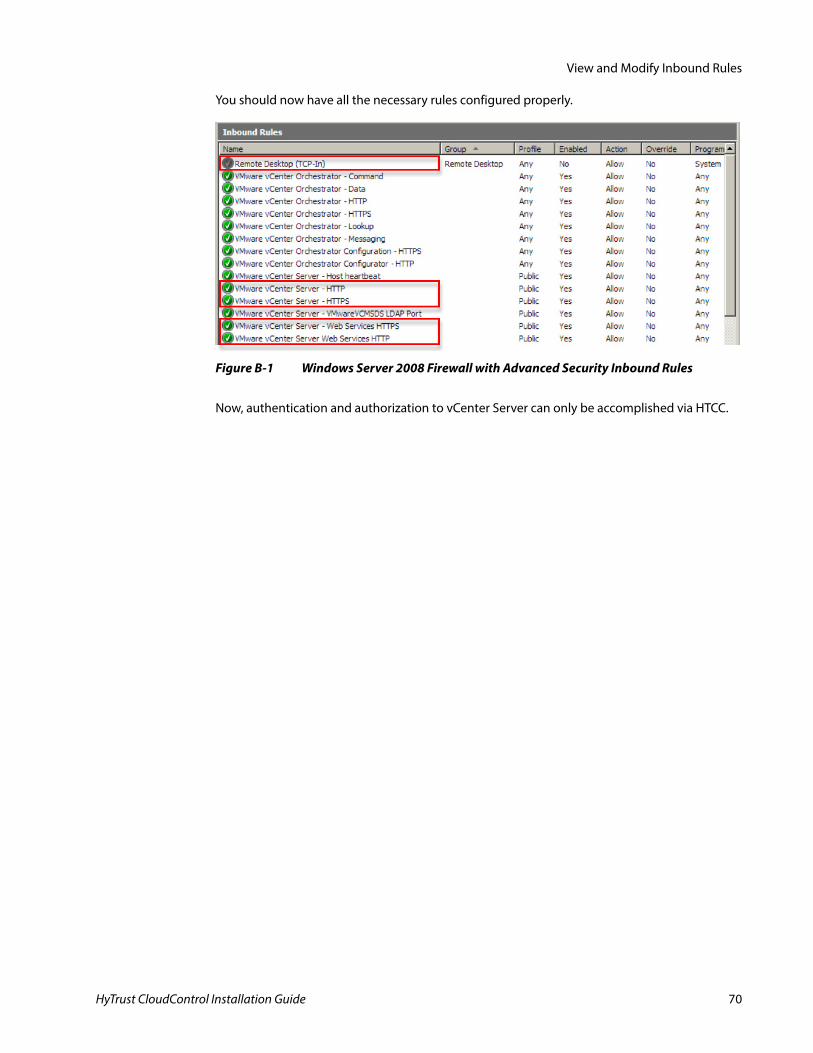
View and Modify Inbound Rules
You should now have all the necessary rules configured properly.
Now, authentication and authorization to vCenter Server can only be accomplished via HTCC.
Figure B-1 Windows Server 2008 Firewall with Advanced Security Inbound Rules
HyTrust CloudControl Installation Guide 70
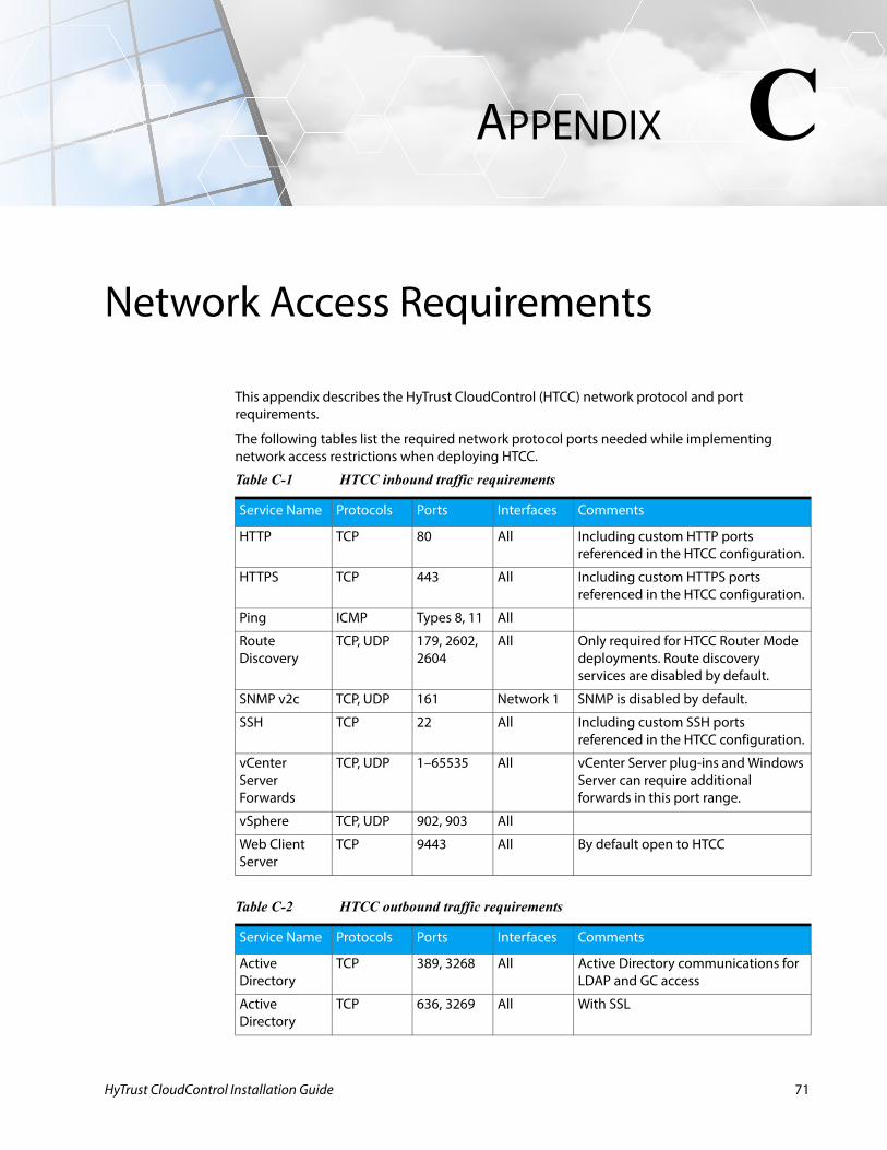
HyTrust CloudControl Installation Guide
C
APPENDIXNetwork Access Requirements
This appendix describes the HyTrust CloudControl (HTCC) network protocol and port requirements.
The following tables list the required network protocol ports needed while implementing network access restrictions when deploying HTCC.
Table C-1 HTCC inbound traffic requirements
Service Name Protocols Ports Interfaces Comments
HTTP TCP 80 All Including custom HTTP ports referenced in the HTCC configuration.
HTTPS TCP 443 All Including custom HTTPS ports referenced in the HTCC configuration.
Ping ICMP Types 8, 11 All
Route Discovery
TCP, UDP 179, 2602, 2604
All Only required for HTCC Router Mode deployments. Route discovery services are disabled by default.
SNMP v2c TCP, UDP 161 Network 1 SNMP is disabled by default.
SSH TCP 22 All Including custom SSH ports referenced in the HTCC configuration.
vCenter Server Forwards
TCP, UDP 1–65535 All vCenter Server plug-ins and Windows Server can require additional forwards in this port range.
vSphere TCP, UDP 902, 903 All
Web Client Server
TCP 9443 All By default open to HTCC
Table C-2 HTCC outbound traffic requirements
Service Name Protocols Ports Interfaces Comments
Active Directory
TCP 389, 3268 All Active Directory communications for LDAP and GC access
Active Directory
TCP 636, 3269 All With SSL
71
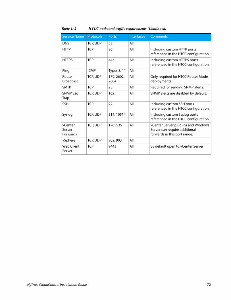
DNS TCP, UDP 53 All
HTTP TCP 80 All Including custom HTTP ports referenced in the HTCC configuration.
HTTPS TCP 443 All Including custom HTTPS ports referenced in the HTCC configuration.
Ping ICMP Types 8, 11 All
Route Broadcast
TCP, UDP 179, 2602, 2604
All Only required for HTCC Router Mode deployments.
SMTP TCP 25 All Required for sending SNMP alerts.
SNMP v2c Trap
TCP, UDP 162 All SNMP alerts are disabled by default.
SSH TCP 22 All Including custom SSH ports referenced in the HTCC configuration.
Syslog TCP, UDP 514, 10514 All Including custom Syslog ports referenced in the HTCC configuration.
vCenter Server Forwards
TCP, UDP 1–65535 All vCenter Server plug-ins and Windows Server can require additional forwards in this port range.
vSphere TCP, UDP 902, 903 All
Web Client Server
TCP 9443 All By default open to vCenter Server
Table C-2 HTCC outbound traffic requirements (Continued)
Service Name Protocols Ports Interfaces Comments
HyTrust CloudControl Installation Guide 72
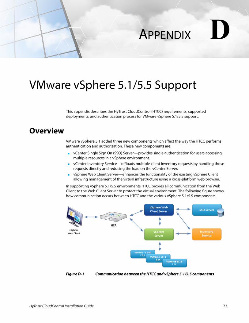
HyTrust CloudControl Installation Guide
D
APPENDIXVMware vSphere 5.1/5.5 Support
This appendix describes the HyTrust CloudControl (HTCC) requirements, supported deployments, and authentication process for VMware vSphere 5.1/5.5 support.
OverviewVMware vSphere 5.1 added three new components which affect the way the HTCC performs authentication and authorization. These new components are:
■ vCenter Single Sign On (SSO) Server—provides single authentication for users accessing multiple resources in a vSphere environment.
■ vCenter Inventory Service—offloads multiple client inventory requests by handling those requests directly and reducing the load on the vCenter Server.
■ vSphere Web Client Server—enhances the functionality of the existing vSphere Client allowing management of the virtual infrastructure using a cross-platform web browser.
In supporting vSphere 5.1/5.5 environments HTCC proxies all communication from the Web Client to the Web Client Server to protect the virtual environment. The following figure shows how communication occurs between HTCC and the various vSphere 5.1/5.5 components.
Figure D-1 Communication between the HTCC and vSphere 5.1/5.5 components
73
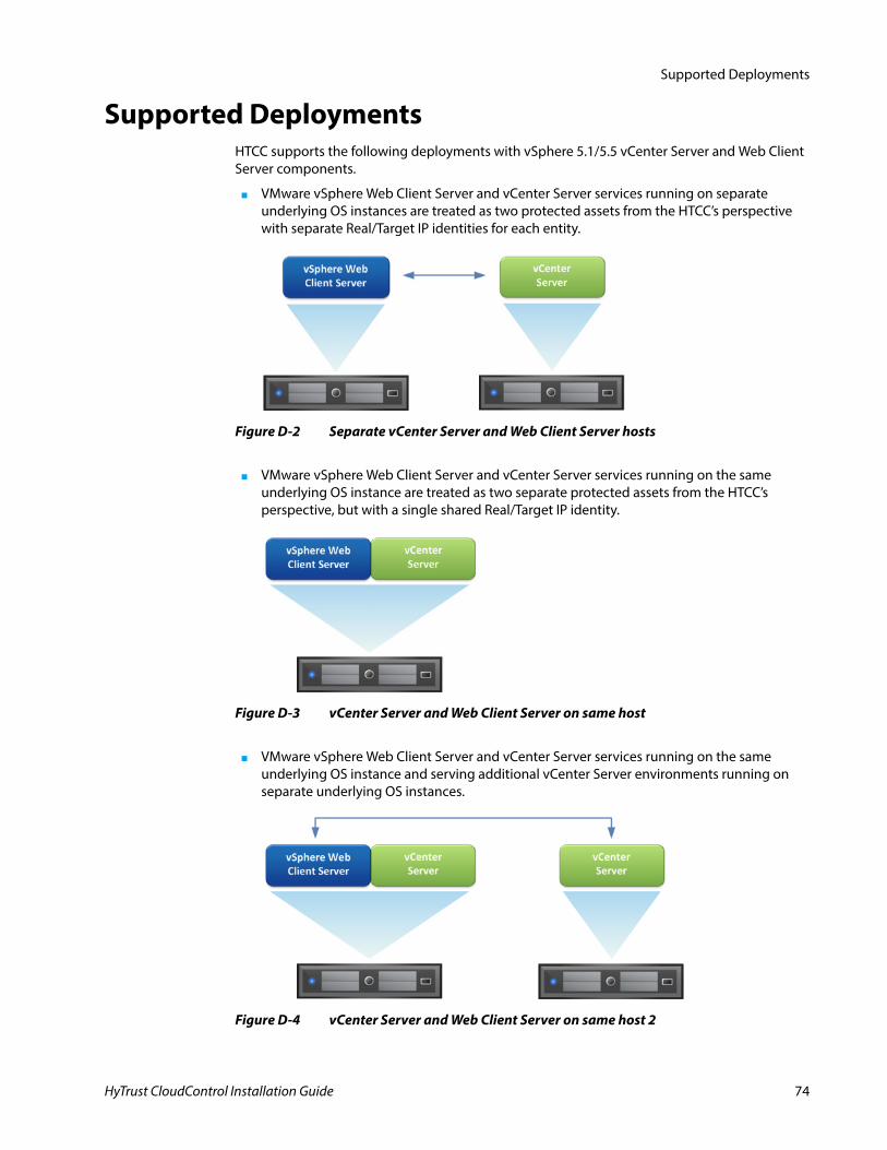
Supported Deployments
Supported DeploymentsHTCC supports the following deployments with vSphere 5.1/5.5 vCenter Server and Web Client Server components.
■ VMware vSphere Web Client Server and vCenter Server services running on separate underlying OS instances are treated as two protected assets from the HTCC’s perspective with separate Real/Target IP identities for each entity.
■ VMware vSphere Web Client Server and vCenter Server services running on the same underlying OS instance are treated as two separate protected assets from the HTCC’s perspective, but with a single shared Real/Target IP identity.
■ VMware vSphere Web Client Server and vCenter Server services running on the same underlying OS instance and serving additional vCenter Server environments running on separate underlying OS instances.
Figure D-2 Separate vCenter Server and Web Client Server hosts
Figure D-3 vCenter Server and Web Client Server on same host
Figure D-4 vCenter Server and Web Client Server on same host 2
HyTrust CloudControl Installation Guide 74
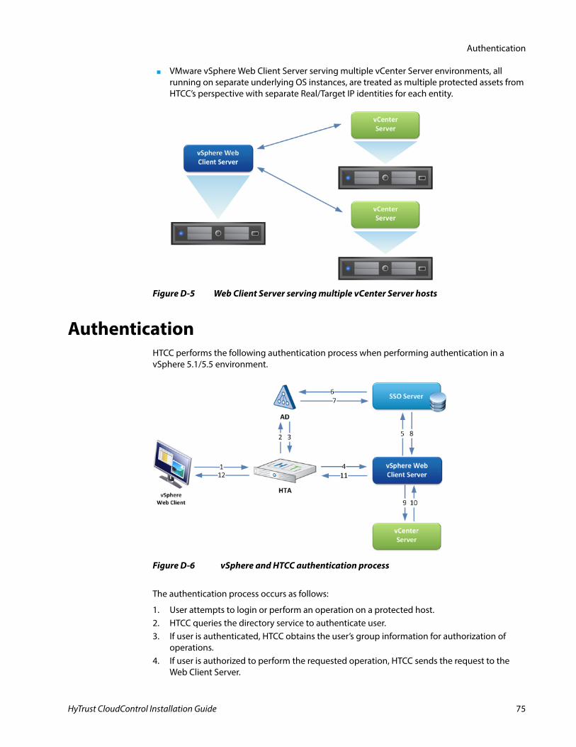
Authentication
■ VMware vSphere Web Client Server serving multiple vCenter Server environments, all running on separate underlying OS instances, are treated as multiple protected assets from HTCC’s perspective with separate Real/Target IP identities for each entity.
AuthenticationHTCC performs the following authentication process when performing authentication in a vSphere 5.1/5.5 environment.
The authentication process occurs as follows:
1. User attempts to login or perform an operation on a protected host.2. HTCC queries the directory service to authenticate user.3. If user is authenticated, HTCC obtains the user’s group information for authorization of
operations.4. If user is authorized to perform the requested operation, HTCC sends the request to the
Web Client Server.
Figure D-5 Web Client Server serving multiple vCenter Server hosts
Figure D-6 vSphere and HTCC authentication process
HyTrust CloudControl Installation Guide 75
Authentication
5. The Web Client Server sends authentication credentials to the SSO Server.6. The SSO Server authenticates with the directory service.7. If authenticated, the directory service informs the SSO Server.8. The SSO Server passes a login token back to the Web Client Server.9. If user is authorized to login, the Web Client Server sends the associated login token to the
vCenter Server.10. The vCenter Server sends success or error message to the Web Client Server.11. The Web Client Server passes the message to HTCC.12. User receives success or error message.
RequirementsThe following are required when using vSphere 5.1/5.5:
■ HTCC should be configured to use the same AD server that has been configured in the VMware SSO Server.
■ The service account credentials must be the same for vCenter Servers and vSphere Web Client Servers.
■ Using pass through authentication requires HTCC and all its protected assets to use the same MS Active Directory domain configuration.
■ Using non-pass through or pass through with service account authentication requires a single service account with administrative privileges across all vCenter Server protected assets that the vSphere Web Client Server serves.
LimitationsThe following limitation exists when using vSphere 5.1/5.5:
■ HTCC only supports authentication against a single directory server (multi domain, single forest root node).
HyTrust CloudControl Installation Guide 76