hydronic 4/5 (coolant heaters) - rixen's · pdf filehydronic 4/5 (coolant heaters) espar...
TRANSCRIPT
Hydronic 4/5 (Coolant Heaters)Espar Heater Systems
P/N 20 2900 81 0121 0C 03.2008 Subject to Change Printed in Canada
Heater Model 12 V
Hydronic D4 SC 25 1917 05
25 2096 0525 2257 05
Hydronic B4 SC 20 1789 05 20 1824 05
Hydronic D5 SC 25 1920 05
25 2098 05 25 2219 05
FMP OUT 25 2325 05
Hydronic D5 S 25 2031 05
25 2100 05
25 2217 05
Hydronic B5 SC 20 1791 05
20 1820 05
Hydronic B5 S 20 1793 05
20 1819 05
Heater Model 24 V
Hydronic D5 SC 25 2147 05
Hydronic D5 S 25 2009 05
25 2146 05
25 2218 05
Technical Description
Installation Instructions
Operating Instructions
Maintenance Instructions
Troubleshooting and Repair Instructions
Parts Diagrams and ListEspar Products, Inc.
6099A Vipond Drive
Mississauga, Ontario
Canada L5T 2B2
(905) 670-0960
(800) 387-4800 Canada & U.S.A.
(905) 670-0728 Fax
www.espar.com
*
2
Table of Contents Page
Introduction Heater Warnings ........................................................ 3
Introduction ........................................................ 4
Specifications ........................................................ 4
Heater Components
Hydronic 4/5 SC, 12 + 24 volt, Diesel ........................................................ 5
Hydronic 5 S, 12 + 24 volt, Diesel + Gas ........................................................ 6
Hydronic 4/5 SC, 12 volt, Gasoline ........................................................ 6
Principal Dimensions ........................................................ 7
Installation Heater Location ........................................................ 7
Procedures Heater Mounting ........................................................ 8
Heater Plumbing ........................................................ 9
Fuel System ........................................................ 10
Electrical Connections ........................................................ 12
Exhaust / Intake Connections ........................................................ 13
Control Options ........................................................ 14
Heater Operation Pre-Start Procedures ........................................................ 15
Start-Up ........................................................ 15
Running ........................................................ 15
Switching Off ........................................................ 16
Safety Equipment ........................................................ 16
Operational Flow Chart ........................................................ 17
Heater Diagnostics Schematics ........................................................ 18
Maintenance / Periodic Maintenance ........................................................ 24
Troubleshooting / Basic Troubleshooting ........................................................ 24
Repairs Self Diagnostic Troubleshooting ....................................................... 24
Troubleshooting Chart ....................................................... 26
Fuel Quantity Test ........................................................ 28
Heater Disassembly / Repair Steps ........................................................ 29
Heater Components Parts Diagram / Scope, Face Lift “SC” Heaters ........................................................ 32
Description & Part #’s, Face Lift “SC” Heaters ........................................................ 33
Parts Diagram / Scope, Face Lift “S” Heaters ........................................................ 40
Description & Part #’s, Face Lift “S” Heaters ........................................................ 41
Parts Diagram / Scope, Early “SC” Heaters ........................................................ 46
Description & Part #’s, Early “SC” Heaters ........................................................ 47
Parts Diagram / Scope, Early “S” Heaters ........................................................ 58
Description & Part #’s, Early “S” Heaters ........................................................ 59
Parts Diagram / Scope, North American Heaters ....................................................... 66
Parts Diagram / Scope, North American Heaters (F/L) ....................................................... 67
Description & Part #’s, North American Heaters ....................................................... 68
Special Notes
Note: Highlight areas requiring special attention or clarification.
Caution: Indicates that personal injury or damage to equipment may occur unless specific guidelines are followed.
Warning: Indicates that serious or fatal injury may result if specific guidelines are not followed.
• Correct installation of this heater is necessary to ensure
safe and proper operation.
Read and understand this manual before attempting to
install the heater. Failure to follow all these instructions
could cause serious or fatal injury.
• Heater must be turned off while re-fueling.
• Do not install heater in enclosed areas where com-
bustible fumes may be present.
• Do not install heaters in engine compartments of gaso-
line powered boats.
• Install the exhaust system so it will maintain a minimum
distance of 50mm (2”) from any flammable or heat sensi-
tive material.
• Ensure that the fuel system is intact and there are no leaks.
• Route the heater exhaust so that exhaust fumes cannot
enter any passenger compartments.
• If running exhaust components through an enclosed
compartment, ensure that it is vented to the outside.
• The use of Espar coolant heaters requires that the
coolant in the system to be heated contain a proper mix-
ture of water and antifreeze to prevent coolant from
freezing or slushing.
• If the coolant becomes slushy or frozen, the heater’s
coolant pump cannot move the coolant causing a block-
age of the circulating system. Once this occurs, pressure
will build up rapidly in the heater and the coolant hose
will either burst or blow off at the connection point to the
heater.
• This situation could cause engine damage and/or per-
sonal injury. Extreme care should be taken to ensure a
proper mixture of water and antifreeze is used in the
coolant system.
• Refer to the engine manufacturer’s or coolant manufac-
turer’s recommendations for your specific requirements.
Warning To Installer
Warning - Explosion Hazard
Warning - Fire Hazard
Warning - Asphyxiation Hazard
Warning - Safety Hazard on Coolant Heaters
Used With Improper Antifreeze Mixtures
3
Heater Warnings
Introduction
Caution: During electrical welding work on the vehi-cle disconnect the power to the heater in order to protect the control unit.
Note: All measurements contained in this manual
contain metric and approximate SAE equiva-
lents in brackets eg 25mm (1”).
Direct questions to Espar Heater Systems:
Canada & U.S.A. 1-800-387-4800
This publication was correct at the time of print.
However, Espar has a policy of continuous improve-
ment and reserves the right to amend any specifica-
tions without prior notice.
Introduction
4
Heat output (±10%) 4 kW (13,700 BTU/hr) - Boost
3.3 kW (11,300 BTU/hr - High 5 kW (17,000 BTU/hr) - High
1.6 kW (5,500 BTU/hr - Low 2.4 kW (8,200 BTU/hr) - Low
12 volt 24 volt
Current draw (±10%) 4.3 amps Boost
3.0 amps High 4.16 amps High 2.08 amps High
2.0 amps Low 1.91 amps Low 0.95 amps Low
Fuel consumption (±10%) 0.51 l/hr (0.13 US gal/hr) Boost
0.40 l/hr (0.11 US gal/hr) High 0.62 l/hr (0.16 US gal/hr) High
0.20 l/hr (0.05 US gal/hr) Low 0.27 l/hr (0.08 US gal/hr) Low
Operating Voltage Range
Minimum Voltage 10 V 10 V 20.4 VMaximum Voltage 16 V 16 V 32.0 V
Working pressure 2.5 bar (36 psi) 2.5 bar (36 psi)
Ambient operating temperature -40°C to +80°C (-40°F to 176°F) -40°C to +80°C (-40°F to 176°F)
Overheat temperature shutdown (±5%) 105°C (221°F) 105°C (221°F)
Weight 2.5 kg. (5.5 lbs.) 2.9kg. (6.4lbs)
Controls available On/Off switch or 7-day timer On/Off switch or 7-day timer
(Multi-Function Timer) (Multi-Function Timer)
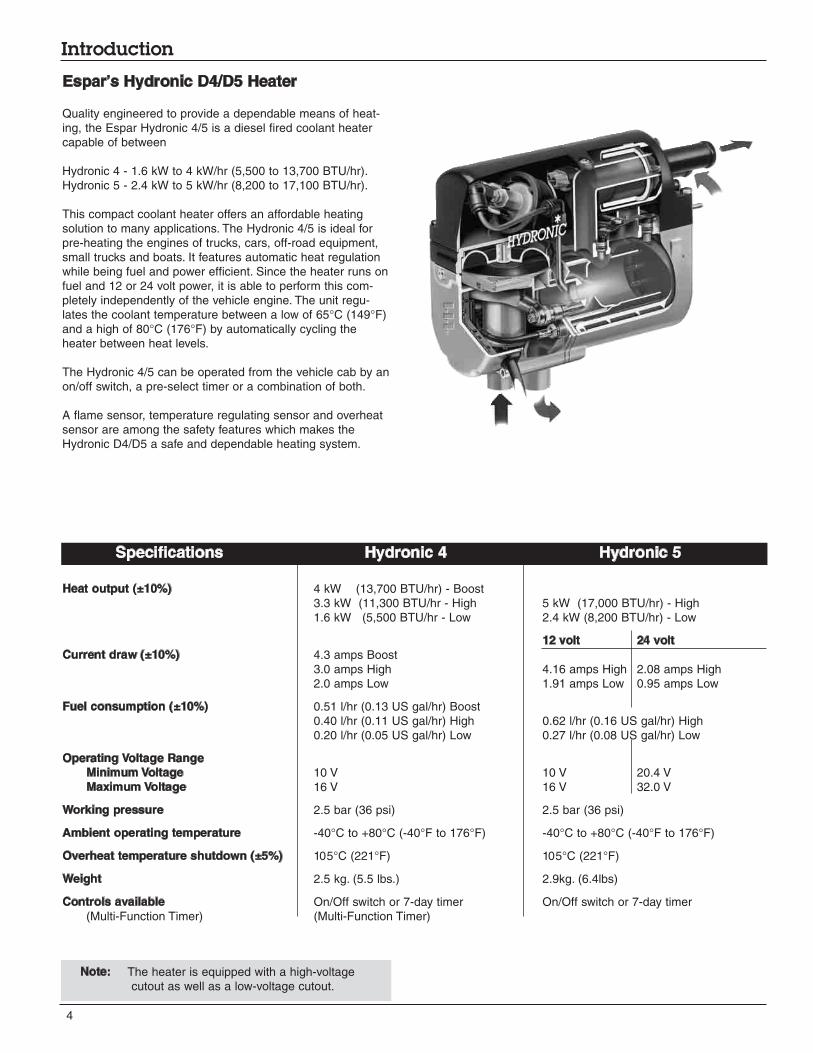
Espar’s Hydronic D4/D5 Heater
Quality engineered to provide a dependable means of heat-
ing, the Espar Hydronic 4/5 is a diesel fired coolant heater
capable of between
Hydronic 4 - 1.6 kW to 4 kW/hr (5,500 to 13,700 BTU/hr).
Hydronic 5 - 2.4 kW to 5 kW/hr (8,200 to 17,100 BTU/hr).
This compact coolant heater offers an affordable heating
solution to many applications. The Hydronic 4/5 is ideal for
pre-heating the engines of trucks, cars, off-road equipment,
small trucks and boats. It features automatic heat regulation
while being fuel and power efficient. Since the heater runs on
fuel and 12 or 24 volt power, it is able to perform this com-
pletely independently of the vehicle engine. The unit regu-
lates the coolant temperature between a low of 65°C (149°F)
and a high of 80°C (176°F) by automatically cycling the
heater between heat levels.
The Hydronic 4/5 can be operated from the vehicle cab by an
on/off switch, a pre-select timer or a combination of both.
A flame sensor, temperature regulating sensor and overheat
sensor are among the safety features which makes the
Hydronic D4/D5 a safe and dependable heating system.
Note: The heater is equipped with a high-voltage
cutout as well as a low-voltage cutout.
Specifications Hydronic 4 Hydronic 5
5
Introduction
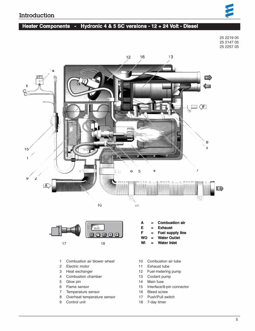
Heater Components - Hydronic 4 & 5 SC versions - 12 + 24 Volt - Diesel
1 Combustion air blower wheel
2 Electric motor
3 Heat exchanger
4 Combustion chamber
5 Glow pin
6 Flame sensor
7 Temperature sensor
8 Overheat temperature sensor
9 Control unit
10 Combustion air tube
11 Exhaust tube
12 Fuel-metering pump
13 Coolant pump
14 Main fuse
15 Interface/8-pin connector
16 Bleed screw
17 Push/Pull switch
18 7-day timer
A = Combustion air
E = Exhaust
F = Fuel supply line
WO = Water Outlet
WI = Water Inlet
P
we
09:20
17 18
25 2219 05
25 2147 05
25 2257 05
6
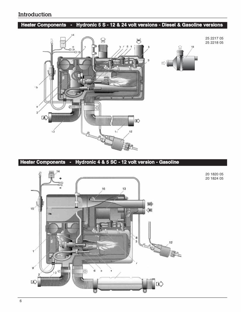
Introduction
Heater Components - Hydronic 5 S - 12 & 24 volt versions - Diesel & Gasoline versions
Heater Components - Hydronic 4 & 5 SC - 12 volt version - Gasoline
25 2217 05
25 2218 05
20 1820 05
20 1824 05
WO
WI
13

7
Introduction and Installation Procedures
* All measurements in millimeters
25.4mm = 1”
Principal Dimensions - Hydronic D4/D5 SC
Always mount the heater in a protected area. Eg: storage
compartment, engine compartments, step box or battery box.
Espar recommends you use the boxed unit. Boxed heaters
can be mounted by utilizing one of the existing brackets. See
following page.
If mounting on frame rail use an optional Espar Inside frame
bracket to mount to inside of frame rails. Heaters can also be
mounted on a cross tray behind the cab and on top of the
frame rails.
When mounting the heater adhere to the following conditions:
• Situate the heater below the normal coolant level of the engine.
• Guard against excessive road spray.
• Keep coolant hoses, fuel lines and electrical wiring as
short as possible.
Caution: Guard the heater against excessive roadspray to avoid internal corrosion.
For Illustration purposes only
Heater Location
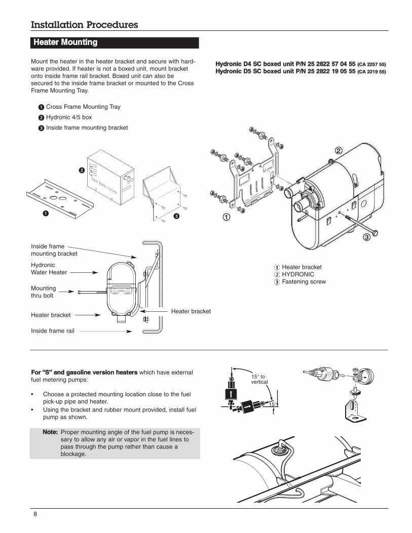
Note: Proper mounting angle of the fuel pump is neces-
sary to allow any air or vapor in the fuel lines to
pass through the pump rather than cause a
blockage.
8
Installation Procedures
Heater Mounting
Heater bracket
Hydronic
Water Heater
Heater bracket
Inside frame
mounting bracket
Inside frame rail
Mount the heater in the heater bracket and secure with hard-
ware provided. If heater is not a boxed unit, mount bracket
onto inside frame rail bracket. Boxed unit can also be
secured to the inside frame bracket or mounted to the Cross
Frame Mounting Tray.
Cross Frame Mounting Tray
Hydronic 4/5 box
Inside frame mounting bracket
1 Heater bracket
2 HYDRONIC
3 Fastening screw
For “S” and gasoline version heaters which have external
fuel metering pumps:
• Choose a protected mounting location close to the fuel
pick-up pipe and heater.
• Using the bracket and rubber mount provided, install fuel
pump as shown.
15° tovertical
15°
E s p a r H e a t e r S y s t e m s
Hydronic D4 SC boxed unit P/N 25 2822 57 04 55 (CA 2257 55)
Hydronic D5 SC boxed unit P/N 25 2822 19 05 55 (CA 2219 55)
Mounting
thru bolt
9
Installation Procedures
Heater Plumbing
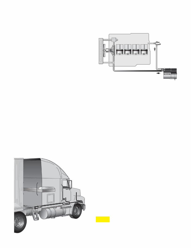
The heater is incorporated into the engine’s cooling system
for engine preheating.
Follow these guidelines and refer to engine plumbing dia-
gram shown.
• Use existing holes in the engine block (ie. remove
blanking plugs when possible). Install fittings into the block
for pick-up and returns.
• If possible, use 5/8 ball shut off valves minimum to ensure
the system can be isolated from the engine when not in
use.
• Provide (3/4”) hose barbs for hose connections.
• Use (3/4”) hoses to ensure adequate coolant flow.
• Keep the pick up and return points as far apart as
possible to ensure good heat distribution.
• Take the coolant from a low point on the engine to
reduce aeration in the system.
• Ensure proper direction of coolant flow by taking coolant
from a high pressure point in the engine and returning it to
a low pressure point. (ie. pickup from back of block and
return to the suction side of the engine's water pump).
• Ensure adequate flow rate through the heater by compar-
ing the incoming and outgoing coolant temperatures while
the heater is running. If the rise in temperature exceeds
10°C (18°F), coolant flow must be increased by modifying
the plumbing.
• Ensure the heater and water pump are installed as low as
possible to allow the purging of air. Bleed system via radi-
ator or bleed screw located on heater.
Caution: The coolant must contain a minimum of 10%
antifreeze at all times as a protection against
corrosion. Fresh water will corrode internal
heater parts.
EngineRadiator
External Water Pump
Shut-off
valves
(Optional)
Hydronic SC Heater
Water i
n
Water out
Bleed Screw
Hydronic “S” version
Optional Outlets
Available in
18mm and 20mm
Engine Plumbing
See Product Catalogue
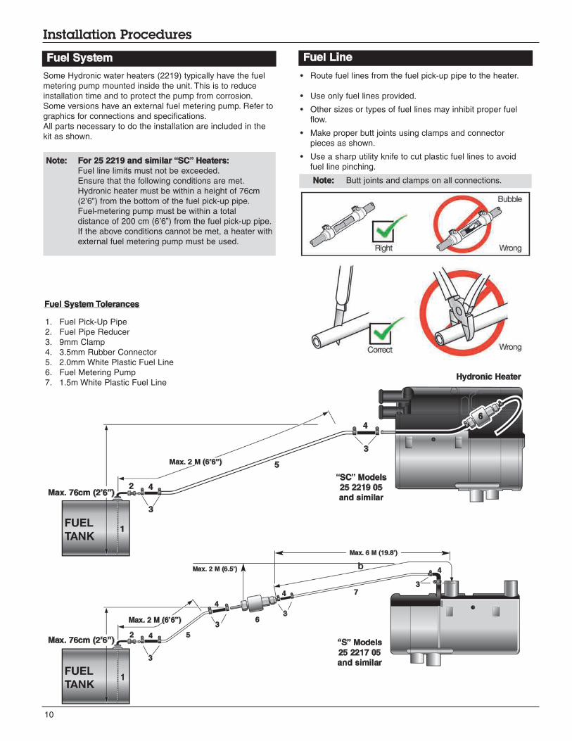
Some Hydronic water heaters (2219) typically have the fuel
metering pump mounted inside the unit. This is to reduce
installation time and to protect the pump from corrosion.
Some versions have an external fuel metering pump. Refer to
graphics for connections and specifications.
All parts necessary to do the installation are included in the
kit as shown.
Note: For 25 2219 and similar “SC” Heaters:
Fuel line limits must not be exceeded.
Ensure that the following conditions are met.
Hydronic heater must be within a height of 76cm
(2’6”) from the bottom of the fuel pick-up pipe.
Fuel-metering pump must be within a total
distance of 200 cm (6’6”) from the fuel pick-up pipe.
If the above conditions cannot be met, a heater with
external fuel metering pump must be used.
10
Installation Procedures
Fuel System
Note: Butt joints and clamps on all connections.
1
2Max. 76cm (2’6”)
Max. 2 M (6’6”)
4
3
5
5
4
3
6
• Route fuel lines from the fuel pick-up pipe to the heater.
• Use only fuel lines provided.
• Other sizes or types of fuel lines may inhibit proper fuel
flow.
• Make proper butt joints using clamps and connector
pieces as shown.
• Use a sharp utility knife to cut plastic fuel lines to avoid
fuel line pinching.
Hydronic Heater
1. Fuel Pick-Up Pipe
2. Fuel Pipe Reducer
3. 9mm Clamp
4. 3.5mm Rubber Connector
5. 2.0mm White Plastic Fuel Line
6. Fuel Metering Pump
7. 1.5m White Plastic Fuel Line
6
Max. 76cm (2’6”)2 4
3
4
3
4
4
3
3
Max. 2 M (6’6”)
Max. 6 M (19.8’)
1
7
Fuel System Tolerances
Max. 2 M (6.5’)
Fuel Line
“SC” Models
25 2219 05
and similar
“S” Models
25 2217 05
and similar

11
Installation Procedures
Fuel Pick-Up Pipe Installation
(Standard Pick-Up)
Note: Drill the two (1/4”) holes first.
Ø 1.0”
9 / 16” 9 / 16”
Ø 1 / 4” (2 HOLES)
( Optional Pick-Up Pipe with NPT fitting )
• Remove an existing plug from the top of
the fuel tank.
• Cut the fuel pick-up pipe to length.
• Secure the fuel pick-up pipe into position
using the combined NPT compression
fitting as shown.
Double pick ups (used with combo kits)
• Double NPT pipe.
P/N: 20 2900 20 21 07 (CA0 12 107)
Note: NPT fittings are available in various sizes
(Refer to ESPAR Product Catalogue).
Fuel Pick-Up Pipe
Nut
Sheet Metal Washer
Rubber Gasket
Steel Safety Washer
Holding Tabs
Allow 2.5” from fuel pick-
up to tank bottom. Allow
only 1” for flat bottom
tanks.
End tip of the fuel pick-up
pipe should have angle to
avoid picking up dirt and
subsequent blockage.
• Choose a protected mounting location close to the pump
and heater. A spare fuel sender gauge plate provides an
ideal mounting location. If one is not available...
• Drill mounting holes in tank to accommodate pick-up pipe
as shown.
• Cut the fuel pick-up pipe to length. Allow 2-2.5” from bot-
tom of tank.
• Mount the fuel pick-up pipe as shown.
• Lower the fuel pick-up pipe (with reinforcing washer) into the
tank using the slot created by the two 0.6cm (1/4”) holes.
• Lift the assembly into position through the 2.5cm (1”) hole.
• Assemble the rubber washer, metal cup washer and nut.
ø 2.5cm (ø1.0”)
ø 0.625 cm (2 Holes)
(ø 1/4”)
1.5 cm
(9/16”)
1.5 cm
(9/16”)
12
Installation Procedures
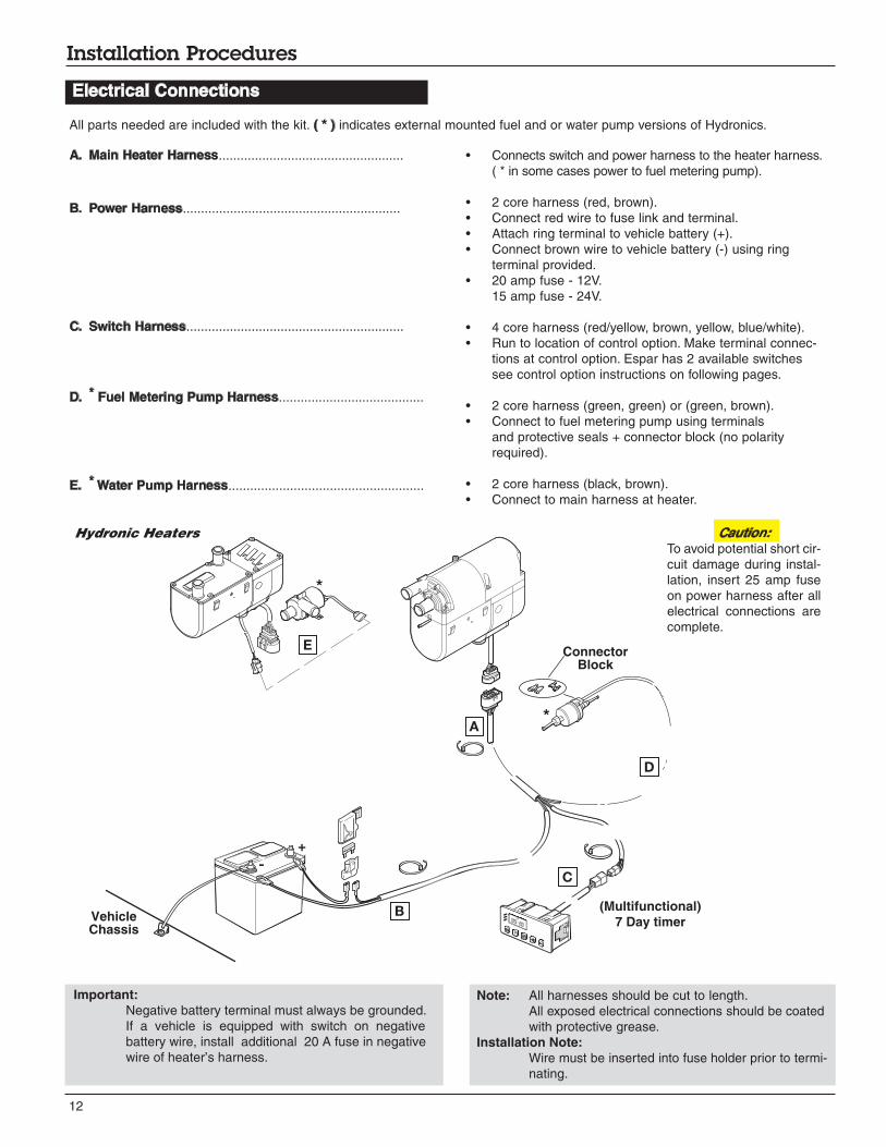
Electrical Connections
A. Main Heater Harness...................................................
B. Power Harness............................................................
C. Switch Harness............................................................
D. * Fuel Metering Pump Harness........................................
E. * Water Pump Harness......................................................
• Connects switch and power harness to the heater harness.
( * in some cases power to fuel metering pump).
• 2 core harness (red, brown).
• Connect red wire to fuse link and terminal.
• Attach ring terminal to vehicle battery (+).
• Connect brown wire to vehicle battery (-) using ring
terminal provided.
• 20 amp fuse - 12V.
15 amp fuse - 24V.
• 4 core harness (red/yellow, brown, yellow, blue/white).
• Run to location of control option. Make terminal connec-
tions at control option. Espar has 2 available switches
see control option instructions on following pages.
• 2 core harness (green, green) or (green, brown).
• Connect to fuel metering pump using terminals
and protective seals + connector block (no polarity
required).
• 2 core harness (black, brown).
• Connect to main harness at heater.
Hydronic Heaters
(Multifunctional)
7 Day timer
All parts needed are included with the kit. ( * ) indicates external mounted fuel and or water pump versions of Hydronics.
Caution:
To avoid potential short cir-
cuit damage during instal-
lation, insert 25 amp fuse
on power harness after all
electrical connections are
complete.
ConnectorBlock
-
+
B
C
D
A
E
Note: All harnesses should be cut to length.
All exposed electrical connections should be coated
with protective grease.
Installation Note:
Wire must be inserted into fuse holder prior to termi-
nating.
VehicleChassis
Important:
Negative battery terminal must always be grounded.
If a vehicle is equipped with switch on negative
battery wire, install additional 20 A fuse in negative
wire of heater’s harness.

Warning - Fire Hazard
13
Installation Procedures
Exhaust Connection
A 24mm flexible tube exhaust pipe is required for the exhaust.
An exhaust clamp is used to secure the exhaust to the the
heater. Connect the exhaust as follows:
• Connect the exhaust pipe to the exhaust port on the
heater and attach with clamp provided.
• Run exhaust to an open area to the rear or side of the
vehicle so that fumes can not build up and enter the
passenger compartment or the heater combustion air intake.
• Install exhaust pipe with a slight slope or drill a small hole
in the lowest point to allow water to run out. Any
restriction in exhaust will cause operational problems.
• Route the exhaust pipe from the heater using “p” clamps
provided.
Caution: Run exhaust so that it cannot be plugged by dirt, water or snow. Ensure the outletdoes not face into the vehicle slip stream.
Route exhaust beyond the skirt of the cab and
outside of the frame area.
Failure to comply with this warning
could result in Carbon Monoxide Poisoning.
Combustion air must be drawn in from the outside. The com-
bustion air opening must be kept free at all times.
• Connect the air intake pipe to the intake port on the
heater and secure with clamp provided.
Caution: Do not install the intake opening facing the vehicle slipstream. Ensure that the opening cannot become clogged with dirt or snow and that any water entering the intake can drain away.
24mm Flexible Exhaust
Min 8” (0.4 mtr)
Max 78” (2 mtr)
Exhaust
Clamp
(27mm - 30mm)
End Sleeve
Air Intake Hose
Min 8” (0.04 mtr)
Max 39” (1 mtr)
(When not mounted in
a Protective Box)
Intake Connection
Warning - Asphyxiation Hazard
The exhaust is hot, keep a minimum of 5cm
(2”) clearance from any heat sensitive material.
Route exhaust so that the exhaust fumes
cannot enter the passenger compartment.
14
Installation Procedures
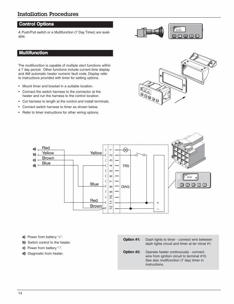
Control Options
A Push/Pull switch or a Multifunction (7 Day Timer) are avail-
able.
7 Day Timer
The multifunction is capable of multiple start functions within
a 7 day period. Other functions include current time display
and AM automatic heater numeric fault code. Display refer
to instructions provided with timer for setting options.
• Mount timer and bracket in a suitable location.
• Connect the switch harness to the connector at the
heater and run the harness to the control location.
• Cut harness to length at the control and install terminals.
• Connect switch harness to timer as shown below.
• Refer to timer instructions for other wiring options.
Option #1: Dash lights to timer - connect wire between
dash lights circuit and timer at ter minal #1.
Option #2: Operate heater continuously - connect
wire from ignition circuit to terminal #10.
See also multifunction (7 day) timer in
instructions.
Yellow
Red
Brown
Blue
DIAG
TRS
Yellow
Red
Blue
Brown
121110
98
76
54
32
1
MO1
2
318:00
P
a) Power from battery “+”.
b) Switch control to the heater.
c) Power from battery “-”.
d) Diagnostic from heater.
P
we
09:20
Multifunction
a)
b)
c)
d)
Once ignition is successful the following operations
take place:
• Heater runs in high heat mode and the temperature is
monitored at the heat exchanger.
• Once coolant reaches 80°C (176°F) the heater
automatically switches to low heat mode and continues
to run.
• If coolant temperature drops to 75°C (167°F) the heater
will automatically switch back to high heat mode.
• If the coolant temperature continues to rise, the heater
will automatically switch off once temperature reaches
86°C (187°F).
• The water pump will continue to circulate coolant to allow
the heater to monitor engine temperature.
• The heater will automatically re-start once coolant
temperature reaches 75°C (167°F).
• The heater continues to run as described above until it is
switched off, either manually, automatically by a timer or
heater malfunction shutdown.
Note: If the heater should shut down due to flame
out while in running mode, it will automatically
attempt one restart. If successful, it will contin-
ue to run. If not, it will shut down completely
with a cool-down cycle.
Note: During operation the heater continually sens-
es the input voltage from the batteries. If the
input voltage drops to approximately 10.5
volts or rises above 16 volts the heater will
automatically shut down with a cool-down
cycle, and display a fault code when using a
multifunction timer.
15
Heater Operation
Push/Pull Switch
Note: If the heater fails to start the first time it will
automatically attempt a second start. If unsuc-
cessful, the heater will shut down completely.
Note: On initial start up the heater may require sever-
al start attempts to self prime the fuel system.
Upon completion of installation prepare the heater as follows:
• Check all fuel, electrical and plumbing connections.
• Refill the engine coolant.
• Bleed air from the coolant system by loosening the bleed
screw on top of the heater to allow air to escape.
• Loosen rad cap and run engine to allow air to be purged.
• Top up engine coolant.
Once switched on the following sequence occurs:
• Control unit does a systems check ( flame sensor, glow
pin, motors, temperature sensor, safety thermal sensor
and various other control unit checks).
• Water pump starts circulating coolant fluid.
• Combustion air blower comes on.
• Glow pin begins to preheat 20-50 secs.
• Metering pump starts and combustion air blower speeds
up gradually.
• Once ignition takes place the flame sensor alerts the
control unit and the control unit shuts off the glow pin
(ignition time: 1.5 - 2 minutes).
• Mount switch in a location where it is easily accessible.
• Mount using hardware supplied.
• Connect the switch harness to the connector at the heater
and run the harness to the switch location.
• Cut harness to length at the switch and install terminals.
• Connect wiring as shown.
14.5mm9/16”
K (15)
15 (K)
31
Note: Wired as above the switch light glows when
pulled out and is off when pushed in.
Control Wiring
Push/Pull Switch
Brown- 31 Power from battery “-”
Red- K(15) Power from battery “+”
Yellow-15(K) Switch control to the heater
Blue/White Diagnostic from heater (disregard - tape
end and tie off to the side)
Heater Operation
Start Up
Pre-Start Procedures Running
Ø
Ø
Warning: The heater must be switched off while
any fuel tank on the vehicle is being
filled. The heater must not be operated
in garages or enclosed areas.
16
Heater Operation
• When the heater is switched off, manually or
automatically, it starts a controlled cool down cycle.
• The fuel metering pump stops delivering fuel and the
flame goes out.
• The combustion air blower and water pump continue to
run for 3 minutes to cool down.
• The heater shuts off.
The control unit, temperature sensor, overheat sensor and
flame sensor continually monitor heater functions and will
shut down the heater in case of a malfunction.
• The control unit ensures electrical circuits (fuel pump,
combustion air blower etc.) are complete prior to starting
the heater.
• If the heater fails to ignite within 90 seconds of the fuel
pump being started, the starting procedure will be
repeated. If the heater again fails to ignite after 90
seconds of fuel being pumped, a “no start safety
shutdown” follows. (Fault #52)
• If the heater flames out during operation, the heater
automatically attempts to restart. If the heater fails to
ignite within 90 seconds of fuel delivery, the heater will
turn off the fuel pump and complete a cool down and dis-
play a F052 code. After troubleshooting the problem the
heater can be started again by switching the heater off
and then back on again.
• Overheating due to lack of water, a restriction or a poorly
bled coolant system results in the overheat shutdown
(F012). Fuel delivery will cease and an “overheat shut
down” follows. If heater overheats 3 consecutive times, a
lockout on the control unit will occur. To unlock the control
unit you will need to use the Fault Code Retrieval Device.
See following pages for self diagnostics.
• If at any time the voltage drops below 10.5V for 20 sec-
onds, or rises above 16.0V for 20 seconds the heater will
shut down and display the associated Fault Code.
Switching Off
Safety Equipment

17
Heater Operation
STARTING PHASE RUNNING PHASE SHUT DOWN PHASE
Operating
Mode
Time
Fuel
Pump
Glow
Pin
Blower
Water Pump
System
Check
Pre-heat Pre-heat
2nd. attempt
Ignition
Attempt
Ignition
Attempt
2nd. attempt
Controlled
Heating
Off
Off
Off
OffOn Off
Off On:
if in stand byOnOnOnOnOn On
OnOnOnOnMomentarily
OnOnOnOn
On
On
On
On OffOff Off
Off Off Off Off OffOnOn On
After
Glow
Cool
Down
Off
or
Stand by
1- 3 sec. 40 sec. 20 sec.
40 sec.Up to
80 sec.
Up to 80 sec.
If Required High/Low
Operation
until switched off
manually or automatically
2.5 min.
Note: During the controlled heating cycle, if the coolant temperature exceeds 86°C(187°F) the heater will cycle off.
Heater will automatically restart in high mode once coolant temperature reaches 75°C(167°°F)
18
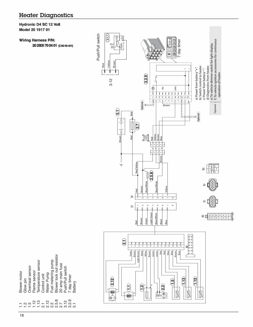
Heater Diagnostics
Hydronic D4 SC 12 Volt
Model 25 1917 01
Wiring Harness P/N:
20 2900 70 04 01 (CA0 60 401)
1.1
Bl o
wer
moto
r
1.2
Glo
w p
in
1.5
Ove
rheat
sensor
1.1
2F
lam
e s
ensor
1.1
3Tem
pera
t ure
sensor
2.1
Contr
ol unit
2.1
2W
ate
r P
um
p
2.2
Fuel m
ete
ring p
um
p
2.5
.8B
low
er
lock o
ut
resis
t or
2.7
20 a
mp m
ain
fuse
3.1
2P
ush/P
ull
switch
3.2
.97 d
ay t
imer
5.1
Battery
Red
K(1
5)
15(K
)
Yello
w
Bro
wn
31
0
3.1
.1
Pu
sh
/Pull
switch
7 d
ay t
imer
3.1
2
Op
tion
al
Browne)
Op
tion
al
Op
tio
na
l
f)
M
M
Yello
w
Yello
w
Re
d
Bro
wn
Bro
wn
Bro
wn
Blu
e
Blu
e/W
hit
e
Blu
e/W
hit
e
DIA
G
TR
S
a)
Po
we
r fr
om
ba
tte
ry “
+”.
b)
Sw
itch
co
ntr
ol t
o h
ea
ter.
c) P
ow
er
fro
m b
att
ery
“-”
.
d)
Dia
gn
ost
ics
fro
m h
ea
ter.
e) T
o v
eh
icle
dim
me
r sw
itch
fo
r lig
ht
dis
pla
y.
f) T
o v
eh
icle
ign
itio
n a
cce
sso
rie
s fo
r co
nti
nu
ou
s
o
pe
rat i
on
of
he
ate
r.
121110987654321
4 3 2 1
1 2 3 4 5 6 7 8
1 2 3 4 5 6 7 8
1 2
3 4
b)
a) d)
c)
4 3 2 1
2
4
6
8
1
3
5
7
8
6
4
2
7
5
3
1
P
3.2
.9
2.5
.8
5.1
2.7
Re
dR
ed
Re
d
Bro
wn
Re
d
Bro
wn
Gre
en
Lig
ht
Gre
en
Blu
e/W
hit
e
Bla
ck
Blu
e
S1B1
S1B1
B2
B2
B3
2.1
2.1
2
1.1
1.2
2.2
1.5
1.1
3
1.1
2
Vio
let
Bro
wn
Lig
ht
Bro
wn
Bla
c k
Wh
ite
Bro
wn
Gre
en
Gre
en
Re
d
Re
d
Blu
e
Blu
e
Bro
wn
Blu
e
14 13 12 11 10 9 8 7 6 5 4 3 2 1
1 3 5 7 9 11 13
2 4 6 8 10 12 14
2
4
6
8
10
1
2
14
1
3
5
7
9
11
1
3
87 87a
85
30
86Re
d/Y
ello
w
19
Heater Diagnostics
Brown
Vio
let
Bro
wn
Lig
ht
Bro
wn
Bla
ck
Wh
ite
Bro
wn
Gre
en
Gre
en
Re
d
Re
d
Blu
e
Blu
e
B
row
n
Blu
e
1 2 3 4 5 6 7 8 9 10 1 12 13 14
Yello
w
Bro
wn
Re
d
Bro
wn
Bro
wn
Blu
e
Blu
e/W
hit
e
DIA
G
TR
S
Yello
w
a)
Po
we
r fr
om
ba
tte
ry “
+”.
b)
Sw
itch
co
ntr
ol t
o h
ea
ter.
c) P
ow
er
fro
m b
att
ery
“-”
.
d)
Dia
gn
ost
ics
fro
m h
ea
ter.
e) T
o v
eh
icle
dim
me
r sw
itch
fo
r lig
ht
dis
pla
y.
f) T
o v
eh
icle
ign
itio
n a
cce
sso
rie
s fo
r co
nti
nu
ou
s
o
pe
rati
on
of
he
ate
r.
121110987654321
4 3 2 1
1 2 3 4 5 6 7 8
1 2 3 4 5 6 7 8
b)
a) d)
c)
4 3 2 1
2
4
6
8
1
3
5
7
8
6
4
2
7
5
3
1
3.2
.9
5.1
2.7
Re
dR
ed
Re
d/Y
ello
wR
ed
Bro
wn
Re
d
Bro
wn
Bla
ck/R
ed
Lig
ht G
reen
Blu
e/W
hi te
Blu
e
Yello
w
Bla
ck/W
hite
S1B1
S1B1
B3
2.1
2.1
2
1.1
1.2
2.2
1.5
1.1
3
1.1
2
1 3 5 7 9 11 13
2 4 6 8 10 12 14
87 87a
85
30
86
M
1 2
3 4
B2
B2
M
Ph
)
Op
tion
al
e)
Op
tion
al
f)
Op
tio
na
l
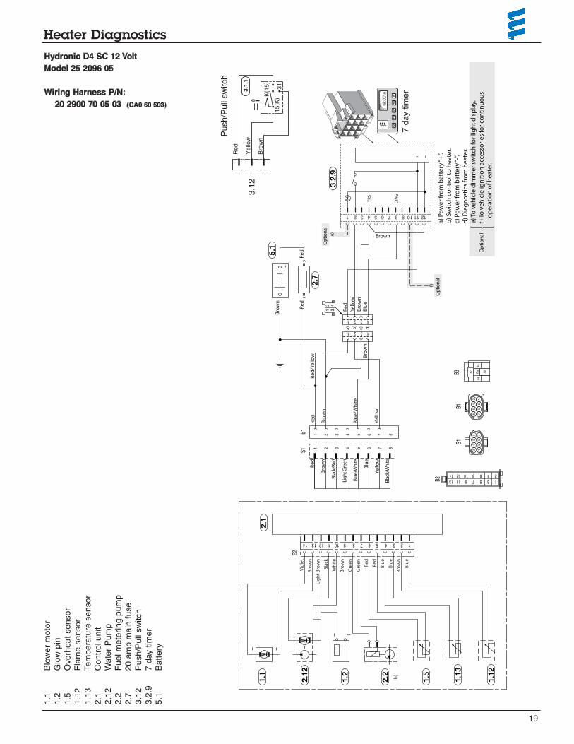
Hydronic D4 SC 12 Volt
Model 25 2096 05
Wiring Harness P/N:
20 2900 70 05 03 (CA0 60 503)
1. 1
Blo
wer
moto
r
1.2
Glo
w p
in
1.5
Ove
rheat
senso
r
1.1
2F
lam
e s
ensor
1.1
3Tem
pera
ture
sen
sor
2.1
Contr
ol unit
2.1
2W
ate
r P
um
p
2.2
Fuel m
ete
r ing p
um
p
2.7
20 a
mp m
ain
fuse
3.1
2P
ush/P
ull
switch
3.2
. 97 d
ay t
imer
5.1
Batter y
Red
K(1
5)
15(K
)
Yello
w
Bro
wn
31
0
3.1
.1
Push/P
ull
switch
7 d
ay t
i mer
3.1
2
20
Heater Diagnostics
M
Op
tio
na
l
Bro
wn
Bla
ckB
row
nV
iole
tB
row
nW
hit
eG
ree
nG
ree
nR
ed
Re
dB
lue
Blu
eB
row
nB
lue
1 2 3 4 5 6 7 8 9 10 11 12 13 14
Yello
w
Yello
w
Re
d
Bro
wn
Bro
wn
Bro
wn
Blu
e
Blu
e/W
hit
e
Bla
ck/R
ed
DIA
G
TR
S
Blu
e
a)
Po
we
r fr
om
ba
tte
ry “
+”.
b)
Sw
itch
co
ntr
ol t
o h
ea
ter.
c) P
ow
er
fro
m b
att
ery
“-”
.
d)
Dia
gn
ost
ics
fro
m h
ea
ter.
e) T
o v
eh
icle
dim
me
r sw
itch
fo
r lig
ht
dis
pla
y.
f) T
o v
eh
icle
ign
itio
n a
cce
sso
rie
s fo
r co
nti
nu
ou
s
o
pe
rati
on
of
he
ate
r.
121110987654321
4 3 2 1
1 2 3 4 5 6 7 8
b)
a) d)
c)
4 3 2 1
2
4
6
8
1
3
5
7
8
6
4
2
7
5
3
1
3.2
.9
5.1
2. 7
2.5
.8
Re
dR
ed
Re
d/Y
ello
wR
ed
Bro
wn
Re
d
Bro
wn
Blac
k/Re
d
Gre
en
Blu
e/W
hite
Blu
e
Yello
w
Blac
k/W
hite
S1B1
S 1B 1
B 3
2.1
1.1
2.1
2
1.2
2.2
1.5
1.1
3
1.1
2
1 3 5 7 9 11 13
8 7 6 5 4 3 2 1
87 87a
85
30
86
1 2
3 4
B2 B2
P
2 4 6 8 10 12 14
M
h)
Op
tion
al
e)
Op
tion
al
f)
Brown
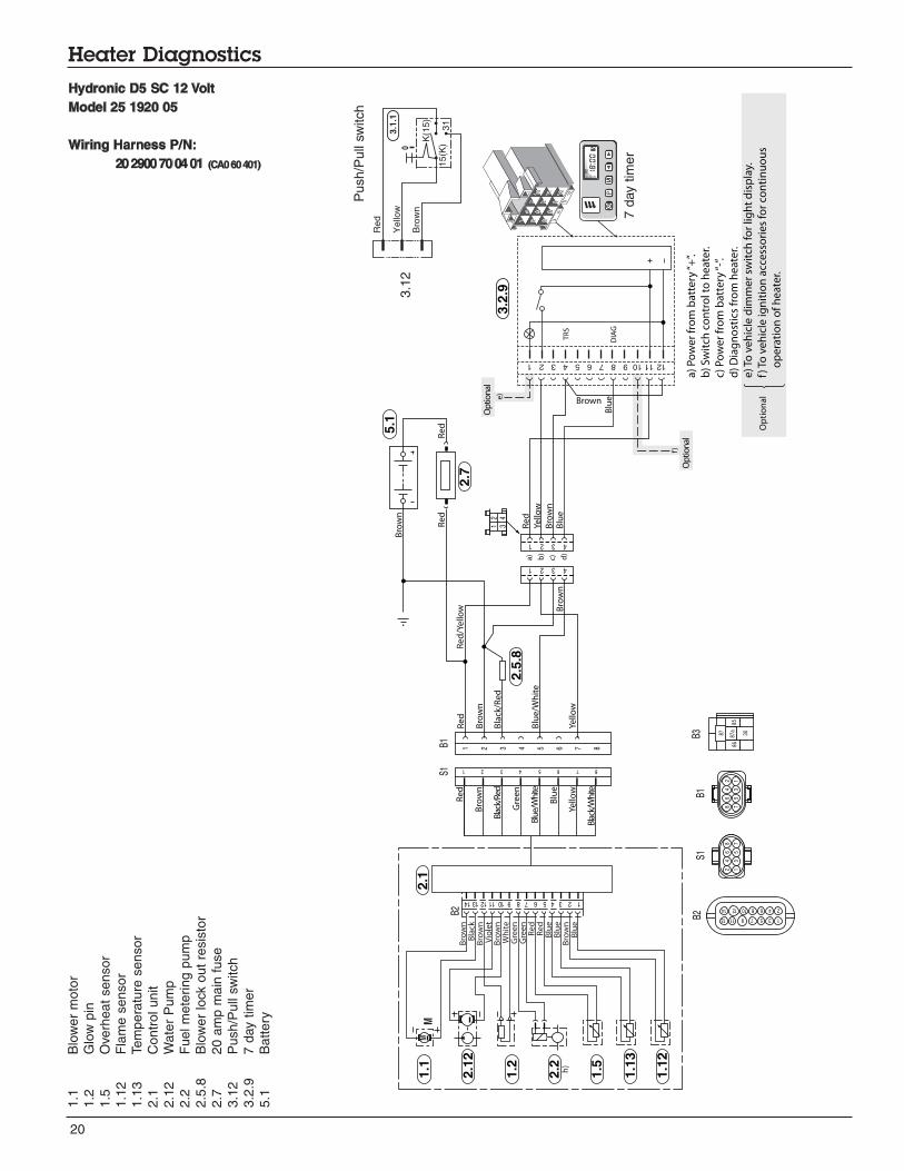
Hydronic D5 SC 12 Volt
Model 25 1920 05
Wiring Harness P/N:
20 2900 70 04 01 (CA0 60 401)
1.1
Blo
wer
moto
r
1.2
Glo
w p
in
1.5
Ov e
rheat
sensor
1.1
2F
lam
e s
ensor
1.1
3Tem
pera
ture
sensor
2.1
Contr
ol unit
2.1
2W
ate
r P
um
p
2.2
Fuel m
ete
r ing p
um
p
2.5
.8B
low
er
lock o
ut
resis
tor
2.7
20 a
mp m
ain
fuse
3.1
2P
ush/P
ull
switch
3.2
. 97 d
ay t
imer
5.1
Battery
Red
K( 1
5)
15(K
)
Yello
w
Bro
wn
31
0
3.1
.1
Pu
sh/P
ull
switch
7 d
ay t
ime
r
3.1
2
21
Heater Diagnostics
M
1 2 3 4 5 6 7 8 9 10 11 12 13 14
B2
P
M
Op
tion
al
e)
Op
tion
al
Op
tio
na
l
f)
Re
d
2.7
.1
Yell o
w
Br o
wn
Bro
wn
Blu
e
Blu
e/W
hit
eYe
ll ow
Re
dR
ed/Y
ello
w
Re
d
Bro
wn
4 3 2 1
b)
a) d)
c)
4 3 2 1
Bro
wn
Re
dR
ed
DIA
G
TR
S
Brown
a)
Po
we
r fr
om
ba
tte
ry “
+”.
b)
Sw
itch
co
ntr
ol t
o h
ea
ter.
c) P
ow
er
fro
m b
att
ery
“-”
.
d)
Dia
gn
ost
ics
fro
m h
ea
ter.
e) T
o v
eh
icle
dim
me
r sw
itch
fo
r lig
ht
dis
pla
y.
f) T
o v
eh
icle
ign
itio
n a
cce
sso
rie
s fo
r co
nti
nu
ou
s
o
pe
rati
on
of
he
ate
r.
121110987654321
3.2
.9
5.1
2.7
Re
d
Bro
wn
Bla
ck/R
ed
Gre
en
Blu
e /W
hi te
Blu
e
Yello
w
B lac
k /W
hite
S1B1 1 2 3 4 5 6 7 8
8 7 6 5 4 3 2 1
1 2
3 4
Bro
wn
Bla
c kB
row
nV
iole
tB
row
nW
hit
eG
ree
nG
ree
nR
ed
Re
dB
lue
Blu
eB
row
nB
lue
1.1
2.1
2
1.2
2.2
1.5
1.1
3
1.1
2
h)
S1B1
B3
2.1
B2
2
4
6
8
1
3
5
7
8
6
4
2
7
5
3
1
1 3 5 7 9 11 13
87 87a
85
30
86
2 4 6 8 10 12 14
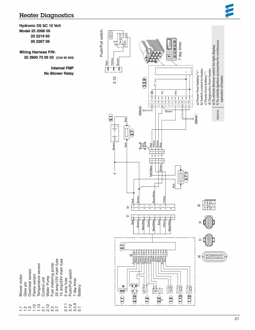
Hydronic D5 SC 12 Volt
Model 25 2098 05
25 2219 05
25 2257 05
Wiring Harness P/N:
20 2900 70 05 03 (CA0 60 503)
Internal FMP
No Blower Relay
1.1
Blo
wer
moto
r
1.2
Glo
w p
in
1.5
Ove
rheat
sensor
1.1
2F
lam
e s
ensor
1.1
3Tem
pera
ture
sensor
2.1
Contr
ol unit
2.1
2W
ate
r P
um
p
2.2
Fuel m
ete
r ing p
um
p
2.7
20 a
mp/1
2V
main
fuse
15 a
mp/2
4V
main
fu
se
2.7
.15 a
mp f
use
3.1
2P
ush/P
ul l
switch
3.2
. 97 d
ay t
imer
5.1
Battery
Red
K(1
5)
15(K
)
Yello
w
Bro
wn
31
0
3.1
.1
Push/P
ull
switch
7 d
ay t
imer
3.1
2
22
Heater Diagnostics
Op
tion
al
e)
Op
tion
al
Op
tio
na
l
f)
Re
d
2.7
.1
M
Bro
wn
Bla
ckB
row
nV
iole
tB
row
nW
hit
eG
ree
nG
ree
nR
ed
Re
dB
lue
Blu
eB
row
nB
lue
1 2 3 4 5 6 7 8 9 10 11 12 13 14
Yello
w
Bro
wn
Brown
Bro
wn
Brown
Gre
en
Bro
wn
Blu
e
Blu
e/W
hite
DIA
G
TR
S
Yello
w
Re
d
a)
Po
we
r fr
om
ba
tte
ry “
+”.
b)
Sw
itch
co
ntr
ol t
o h
ea
ter.
c) P
ow
er
fro
m b
att
ery
“-”
.
d)
Dia
gn
ost
ics
fro
m h
ea
ter.
e) T
o v
eh
icle
dim
me
r sw
itch
fo
r lig
ht
dis
pla
y.
f) T
o v
eh
icle
ign
itio
n a
cce
sso
rie
s fo
r co
nti
nu
ou
s
o
pe
rati
on
of
he
ate
r.
121110987654321
4 3 2 1
1 2 3 4 5 6 7 8
b)
a) d)
c)
4 3 2 1
2
4
6
8
1
3
5
7
8
6
4
2
7
5
3
1
3.2
.9
5.1
2.7
2.2
Re
dR
ed
Red
/Yel
low
Re
d
Bro
wn
Re
d
Bro
wn
Blac
k/Re
d
Gre
en
Blu
e/W
hite
Blu
e
Yello
w
Blac
k/W
hite
S1B1
S1B1
B3
2.1
1.1
2.1
2
1.2
1.5
1.1
3
1.1
2
1 3 5 7 9 11 13
8 7 6 5 4 3 2 1
87 87a
85
30
86
1 2
3 4
B2
B2
P
2 4 6 8 10 12 14M
2.2 h)
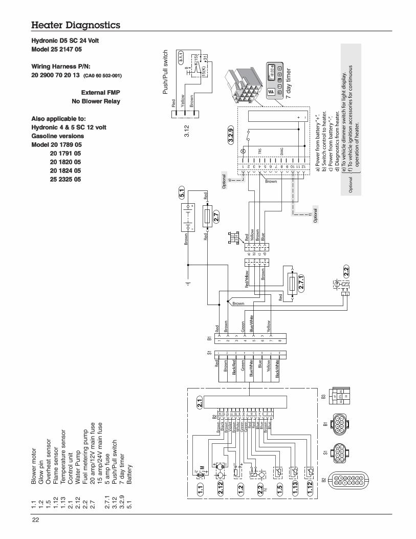
Hydronic D5 SC 24 Volt
Model 25 2147 05
Wiring Harness P/N:
20 2900 70 20 13 (CA0 60 502-001)
External FMP
No Blower Relay
Also applicable to:
Hydronic 4 & 5 SC 12 volt
Gasoline versions
Model 20 1789 05
20 1791 05
20 1820 05
20 1824 05
25 2325 05
1.1
Blo
wer
moto
r
1.2
Glo
w p
i n
1. 5
Ov e
rheat
sensor
1.1
2F
lam
e s
ensor
1.1
3Tem
pera
ture
sensor
2.1
Contr
ol unit
2.1
2W
ate
r P
um
p
2.2
Fuel m
et e
ring p
um
p
2. 7
20 a
mp/1
2V
main
fuse
15
am
p/2
4V
main
fuse
2.7
.15 a
mp f
use
3.1
2P
ush/P
ull
s witch
3. 2
.97 d
ay t
imer
5.1
Battery
Re
d
K(1
5)
15(K
)
Yello
w
Bro
wn
31
0
3.1
.1
Push/P
ull
switch
7 d
ay t
imer
3.1
2

23
Heater Diagnostics
Op
tion
al
Bro
wn
Bla
ckB
row
nV
iole
tB
row
nW
hit
e
Re
dR
ed
Blu
eB
lue
Bro
wn
Blu
e
1 2 3 4 5 6 7 8 9 10 11 12 13 14
Yello
w
Bro
wn
Brown
Bro
wn
Brown
Gre
en
Bro
wn
Blu
e
Re
dBl
ue/
Wh
ite
DIA
G
TR
S
Yello
w
a)
Po
we
r fr
om
ba
tte
ry “
+”.
b)
Sw
itch
co
ntr
ol t
o h
ea
ter.
c) P
ow
er
fro
m b
att
ery
“-”
.
d)
Dia
gn
ost
ics
fro
m h
ea
ter.
e) T
o v
eh
icle
dim
me
r sw
itch
fo
r lig
ht
dis
pla
y.
f) T
o v
eh
icle
ign
itio
n a
cce
sso
rie
s fo
r co
nti
nu
ou
s
o
pe
rati
on
of
he
ate
r.121110987654321
4 3 2 1
1 2 3 4 5 6 7 8
b)
a)
e)
d)
c)
4 3 2 1
2
4
6
8
1
3
5
7
8
6
4
2
7
5
3
1
3.2
.9
5.1
2.7
2.2
Re
dR
ed
Re
d
Red
/Yel
low
Re
d
Bro
wn
Re
d
Bro
wn
Brown
Violet
Brown
Black
Bla
ck/R
ed
Gre
en
Blu
e/W
hite
Blu
e
Yello
w
Blac
k/W
hite
S1B1
S1B1
B3
2.1
1.1
1.2
1.5
1.1
3
1.1
2
1 3 5 7 9 11 13
8 7 6 5 4 3 2 1
87 87a
85
30
86
1 2
3 4
B2
B2
P
2 4 6 8 10 12 14
M
2.1
2M
2.7
.1O
ptio
nal
Op
tio
na
l
f)
Hydronic 5 S - 12 & 24 volt versions
Diesel & Gasoline versions
Model 20 1793 05 12 volt
Model 20 1819 05 12 volt
Model 25 2009 05 24 volt
Model 25 2146 05 24 volt
Model 25 2217 05 12 volt
Model 25 2218 05 24 volt
Model 25 2100 05 12 volt
Wiring Harness P/N:
12V 20 2900 70 05 07 (CA0 60 507)
24V 20 2900 70 05 08 (CA0 60 508)
1.1
Blo
wer
moto
r
1.2
Glo
w p
in
1.5
Ov e
rheat
sensor
1.1
2F
lam
e s
ensor
1.1
3Tem
pera
ture
sensor
2.1
Contr
ol unit
2.1
2W
ate
r P
um
p
2.2
Fuel m
ete
ring p
um
p
2.7
20
am
p/1
2V
main
fuse
15 a
mp/2
4V
main
fuse
2.7
.15 a
mp f
use
3.1
2P
ush/P
ull
swi tch
3.2
.97 d
ay t
imer
5.1
Battery
Red
K(1
5)
15(K
)
Yello
w
Bro
wn
31
0
3.1
.1
Push
/Pull
switch
7 d
ay t
imer
3.1
2
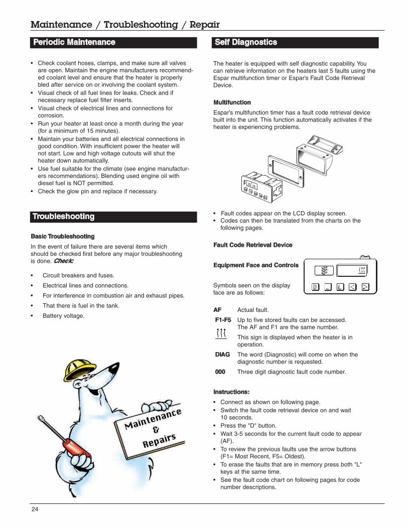
The heater is equipped with self diagnostic capability. You
can retrieve information on the heaters last 5 faults using the
Espar multifunction timer or Espar’s Fault Code Retrieval
Device.
Multifunction
Espar’s multifunction timer has a fault code retrieval device
built into the unit. This function automatically activates if the
heater is experiencing problems.
• Fault codes appear on the LCD display screen.
• Codes can then be translated from the charts on the
following pages.
Fault Code Retrieval Device
Equipment Face and Controls
Symbols seen on the display
face are as follows:
AF Actual fault.
F1-F5 Up to five stored faults can be accessed.
The AF and F1 are the same number.
This sign is displayed when the heater is in
operation.
DIAG The word (Diagnostic) will come on when the
diagnostic number is requested.
000 Three digit diagnostic fault code number.
Instructions:
• Connect as shown on following page.
• Switch the fault code retrieval device on and wait
10 seconds.
• Press the "D" button.
• Wait 3-5 seconds for the current fault code to appear
(AF).
• To review the previous faults use the arrow buttons
(F1= Most Recent, F5= Oldest).
• To erase the faults that are in memory press both "L"
keys at the same time.
• See the fault code chart on following pages for code
number descriptions.
24
Maintenance / Troubleshooting / Repair
• Check coolant hoses, clamps, and make sure all valves
are open. Maintain the engine manufacturers recommend-
ed coolant level and ensure that the heater is properly
bled after service on or involving the coolant system.
• Visual check of all fuel lines for leaks. Check and if
necessary replace fuel filter inserts.
• Visual check of electrical lines and connections for
corrosion.
• Run your heater at least once a month during the year
(for a minimum of 15 minutes).
• Maintain your batteries and all electrical connections in
good condition. With insufficient power the heater will
not start. Low and high voltage cutouts will shut the
heater down automatically.
• Use fuel suitable for the climate (see engine manufactur-
ers recommendations). Blending used engine oil with
diesel fuel is NOT permitted.
• Check the glow pin and replace if necessary.
Basic Troubleshooting
In the event of failure there are several items which
should be checked first before any major troubleshooting
is done. Check:
• Circuit breakers and fuses.
• Electrical lines and connections.
• For interference in combustion air and exhaust pipes.
• That there is fuel in the tank.
• Battery voltage.
Troubleshooting
Periodic Maintenance Self Diagnostics

25
Maintenance / Troubleshooting / Repair
35
30
25
20
15
10
5
0
0 20 40 60 80 100 120
3000
2750
2500
2000
2250
1000
1250
1750
1500
750
0
-50 0 50 100 150 200 250 300 350 400 450 500 550
Hook Up
• Disconnect the main harness from heater and insert
adapter cable harness between them.
• Connect adapter cable to the cable loom of the Fault
code retrieval device.
HYDRONIC 5 adapter for
Fault code retrieval device
P/N 12V 20 2900 70 50 28(CA0 05 028)
Test Values
Resistance
Metering pump approx. 10 Ω for 12 volt heater; approximately 36 Ω for 24 volt heater
Glow Pin approx. 0.9 Ω
Checking the sensors
To check the sensors, measure the resistance at current temperature, see following diagrams:
Temperature sensor
Overheating sensor Flame sensor
Temperature (°C) Temperature (°C)
Resistance (Kohms)
Resistance (ohms)
R> 2 Ω = open circuit
R< 50 Ω = short circuit
R> 3400 Ω = open circuit
R< 50 Ω = short circuit
Fault code retrieval device
P/N 12V 20 2900 70 50 20(CA1 05 020)
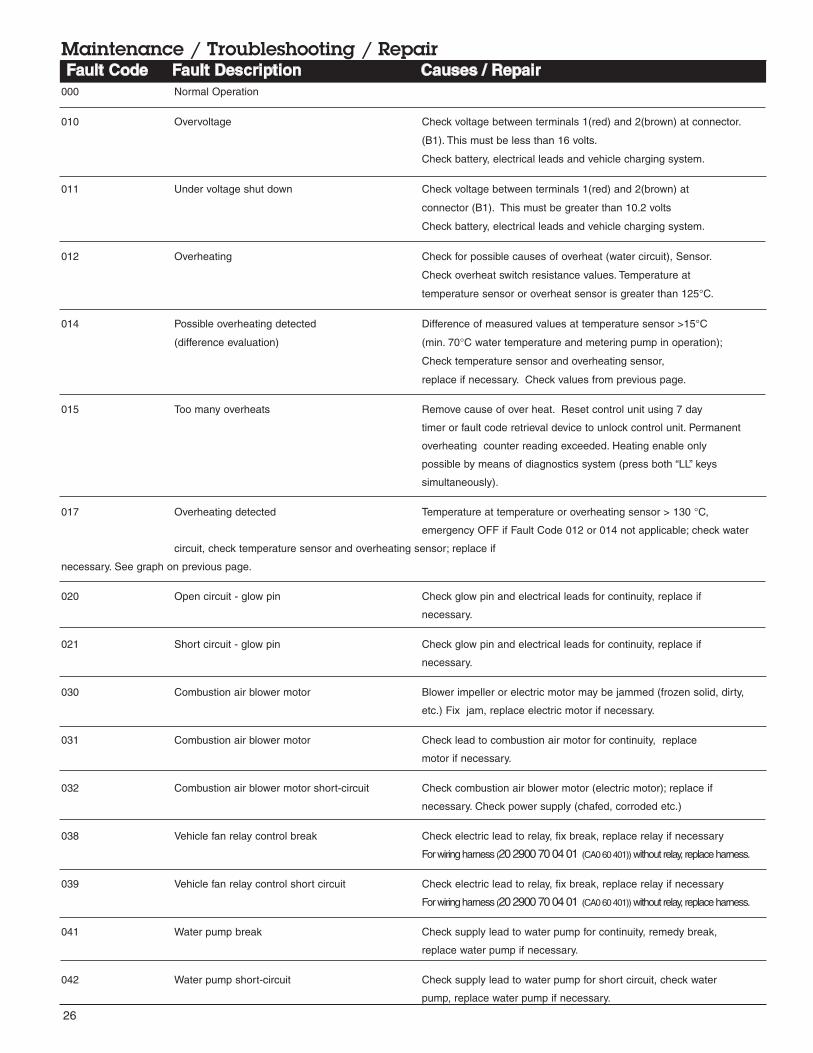
000 Normal Operation
010 Overvoltage Check voltage between terminals 1(red) and 2(brown) at connector.
(B1). This must be less than 16 volts.
Check battery, electrical leads and vehicle charging system.
011 Under voltage shut down Check voltage between terminals 1(red) and 2(brown) at
connector (B1). This must be greater than 10.2 volts
Check battery, electrical leads and vehicle charging system.
012 Overheating Check for possible causes of overheat (water circuit), Sensor.
Check overheat switch resistance values. Temperature at
temperature sensor or overheat sensor is greater than 125°C.
014 Possible overheating detected Difference of measured values at temperature sensor >15°C
(difference evaluation) (min. 70°C water temperature and metering pump in operation);
Check temperature sensor and overheating sensor,
replace if necessary. Check values from previous page.
015 Too many overheats Remove cause of over heat. Reset control unit using 7 day
timer or fault code retrieval device to unlock control unit. Permanent
overheating counter reading exceeded. Heating enable only
possible by means of diagnostics system (press both “LL” keys
simultaneously).
017 Overheating detected Temperature at temperature or overheating sensor > 130 °C,
emergency OFF if Fault Code 012 or 014 not applicable; check water
circuit, check temperature sensor and overheating sensor; replace if
necessary. See graph on previous page.
020 Open circuit - glow pin Check glow pin and electrical leads for continuity, replace if
necessary.
021 Short circuit - glow pin Check glow pin and electrical leads for continuity, replace if
necessary.
030 Combustion air blower motor Blower impeller or electric motor may be jammed (frozen solid, dirty,
etc.) Fix jam, replace electric motor if necessary.
031 Combustion air blower motor Check lead to combustion air motor for continuity, replace
motor if necessary.
032 Combustion air blower motor short-circuit Check combustion air blower motor (electric motor); replace if
necessary. Check power supply (chafed, corroded etc.)
038 Vehicle fan relay control break Check electric lead to relay, fix break, replace relay if necessary
For wiring harness (20 2900 70 04 01 (CA0 60 401))without relay, replace harness.
039 Vehicle fan relay control short circuit Check electric lead to relay, fix break, replace relay if necessary
For wiring harness (20 2900 70 04 01 (CA0 60 401))without relay, replace harness.
041 Water pump break Check supply lead to water pump for continuity, remedy break,
replace water pump if necessary.
042 Water pump short-circuit Check supply lead to water pump for short circuit, check water
pump, replace water pump if necessary.
26
Maintenance / Troubleshooting / RepairFault Code Fault Description Causes / Repair

27
Maintenance / Troubleshooting / RepairFault Code Fault Description Causes / Repair
047 Short circuit - fuel metering pump Check for wires for short to fuel metering pump. Test fuel metering
pump. Replace if necessary.
048 Open circuit - fuel metering pump Check supply lead to metering pump for continuity, remedy break,
replace if necessary.
050 Too many no start attempts Safety time counter reading exceeded. Reset control unit using 7
day timer or fault code retrieval device to unlock control unit.
051 Faulty flame recognition At start, if flame sensor is a above 70°C > 240 seconds; check
exhaust gas and combustion air supply, check flame sensor, replace
if necessary. For flame sensor values see graph on previous page.
052 No start safety time exceeded No flame detected on start attempt. Check fuel delivery and fuel
supply, Check exhaust gas and combustion air ducts.
053 Flame cutout in boost mode Heater has started successfully the flame has extinguished.
Check fuel supply. Check combustion air and exhaust flow. Check
flame sensor resistance value. Replace flame sensor if necessary.
054 Flame cutout in high mode Heater has started successfully the flame has extinguished.
Check fuel supply. Check combustion air and exhaust flow.
056 Flame cutout in low mode Check flame sensor resistance value.
060 Open circuit - temperature sensor Temperature sensor detects a value beyond it's range.
Check connections. Check sensor resistance values between
11 and 12 at connector B2 > 2 M Ω (if open circuit).
061 Short circuit - external temperature sensor Check connections. Check sensor resistance values between
11 and 12 at connector B2 < 50 Ω (if short circuit).
Temperature sensor values on previous pages.
064 Open circuit - flame sensor Sensor is sensing value outside of range. Check connection leads.
Resistance values between 1 and 2 at connector
B2 > 3040 Ω (if open circuit).
065 Short circuit - flame sensor Check connection leads. Resistance values between 1 and 2 at
connector B2 > 780 Ω (if short circuit). Flame sensor values on
page 17.
071 Open circuit - overheat sensor Check connection leads. Resistance values between 9 and 10 at
connector B2 > 2 M Ω (if open circuit).
072 Short circuit - overheat sensor Check connection leads. Resistance values between 9 and 10 at
connector B2 < 50 M Ω (if short circuit).
091 External interference voltage Error in controller from interference voltage from vehicle network pos-
sible causes: poor batteries, poor battery charges, other interference
sources; eliminate interference voltages.
090 Controller defect Control unit malfunction due to interference voltage from vehicle elec-
092 -103 trical system; possible causes low batteries, charges, other sources
of interference, eliminate interference voltages.
Internal faults detected in microprocessor/ memory. Replace control unit.
Internal failure. Replace control unit.
Faults not shown by the diagnosis system After switching HYDRONIC on, the water pump and vehicle fan start
HYDRONIC won’t start immediately.
· Remove and check temperature sensor.
After switching HYDRONIC on, the vehicle fan starts, functioning
“pre-venting” is activated.
· Changeover venting to heating at “heating/venting changeover switch.
28
Maintenance / Troubleshooting / Repair
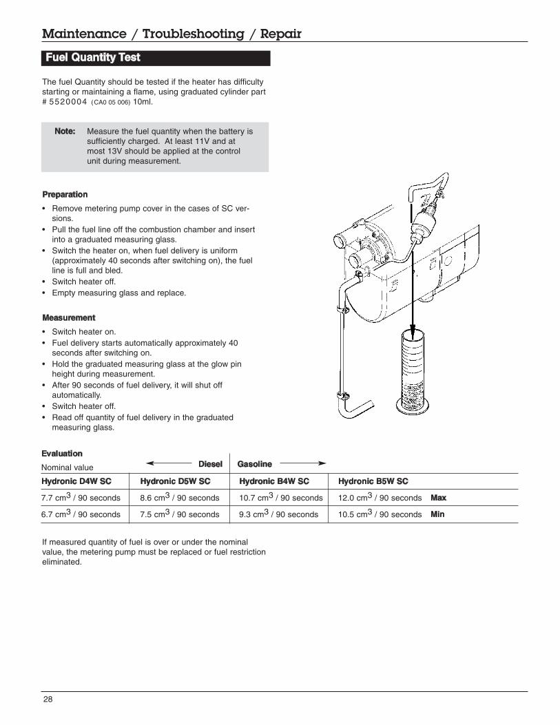
Fuel Quantity Test
Evaluation
Nominal value
Hydronic D4W SC Hydronic D5W SC Hydronic B4W SC Hydronic B5W SC
7.7 cm3 / 90 seconds 8.6 cm3 / 90 seconds 10.7 cm3 / 90 seconds 12.0 cm3 / 90 seconds Max
6.7 cm3 / 90 seconds 7.5 cm3 / 90 seconds 9.3 cm3 / 90 seconds 10.5 cm3 / 90 seconds Min
The fuel Quantity should be tested if the heater has difficulty
starting or maintaining a flame, using graduated cylinder part
# 5520004 (CA0 05 006) 10ml.
Note: Measure the fuel quantity when the battery is
sufficiently charged. At least 11V and at
most 13V should be applied at the control
unit during measurement.
Preparation
• Remove metering pump cover in the cases of SC ver-
sions.
• Pull the fuel line off the combustion chamber and insert
into a graduated measuring glass.
• Switch the heater on, when fuel delivery is uniform
(approximately 40 seconds after switching on), the fuel
line is full and bled.
• Switch heater off.
• Empty measuring glass and replace.
Measurement
• Switch heater on.
• Fuel delivery starts automatically approximately 40
seconds after switching on.
• Hold the graduated measuring glass at the glow pin
height during measurement.
• After 90 seconds of fuel delivery, it will shut off
automatically.
• Switch heater off.
• Read off quantity of fuel delivery in the graduated
measuring glass.
If measured quantity of fuel is over or under the nominal
value, the metering pump must be replaced or fuel restriction
eliminated.
Diesel Gasoline

29
Maintenance / Troubleshooting / Repair
Disassembly / Assembly
Repair Steps covered are for the Hydronic 4 & 5 SC versions - other models are similar
1 Cover, metering pump
2 Water pump, assembly
3 Metering pump and bracket
4 Cover, blower
5 Control unit and cover
6 Glow pin
7 Flame sensor
8 Cable harness
9 Electric motor, complete
10 Combustion chamber with flame tube
11 Heat exchanger and jacket
1 Cover, metering pump
2 Water pump assembly. When mounting, place O-rings
on connection on water pump housing
3 Metering pump and bracket
4 Cover, blower
5 Control unit and cover
6 Glow pin
30
Maintenance / Troubleshooting / Repair
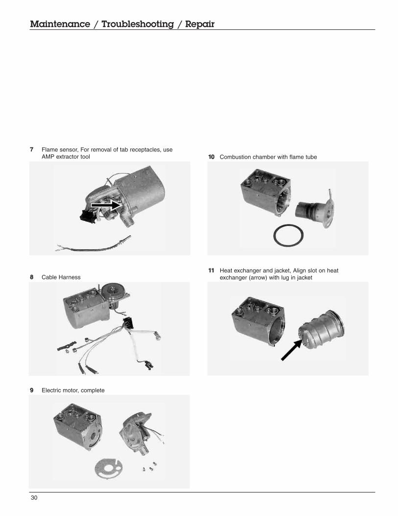
7 Flame sensor, For removal of tab receptacles, use
AMP extractor tool
8 Cable Harness
9 Electric motor, complete
10 Combustion chamber with flame tube
11 Heat exchanger and jacket, Align slot on heat
exchanger (arrow) with lug in jacket

31
Maintenance / Troubleshooting / Repair
Magnetic Drive Coolant Pump Cleaning
It is advised to make this procedure part of an annual
pre-season check up for this heater.
Remove the four screws holding the colant
pumps two halves together.
Motor / Impeller Assembly
“O” Ring 45mm x 1 1/2 m, Part #: 556 00 06
Pump Motor
Motor Assembly Impeller with Magnet
32
1
5
6
7
8
12
13
19
18
21
20
25
29
30
24
26
32
33
34
34
36
37
38
39
2
3
35
4
10
11
27
9
26
25
23
31
14
1516
17
22
28
28
01
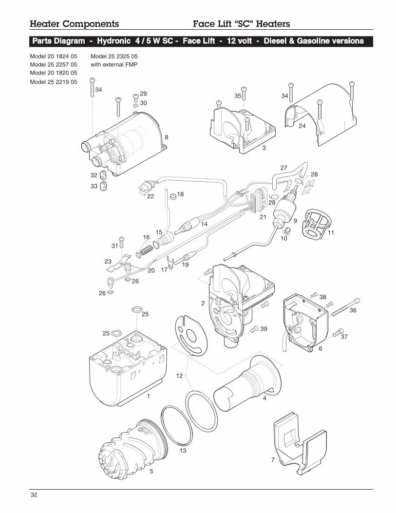
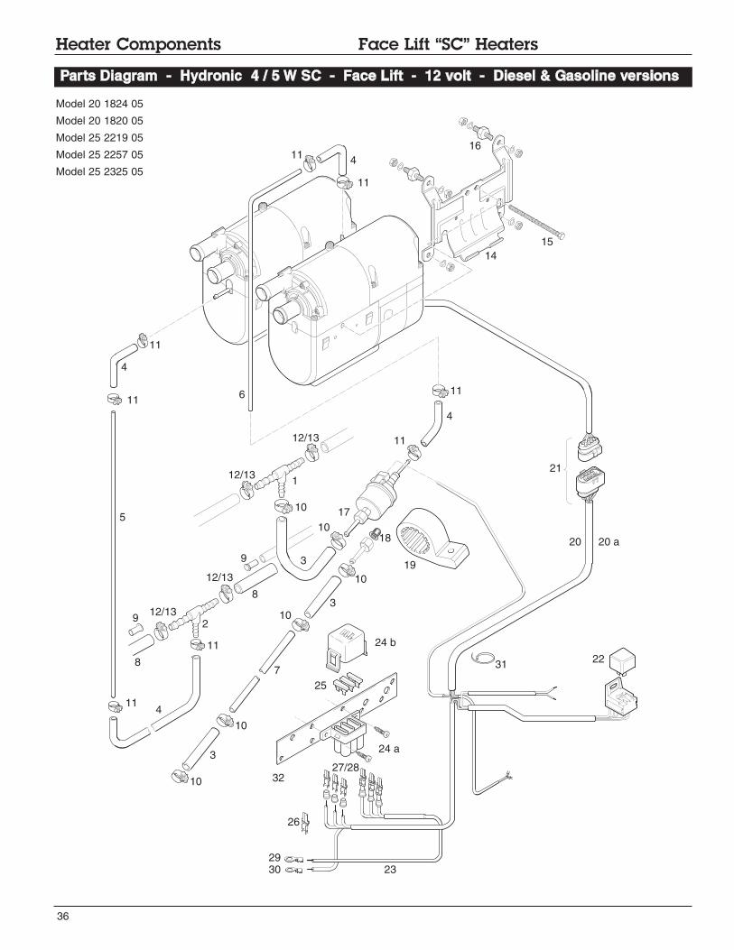
Heater Components Face Lift “SC” Heaters
Parts Diagram - Hydronic 4 / 5 W SC - Face Lift - 12 volt - Diesel & Gasoline versions
Model 20 1824 05
Model 25 2257 05
Model 20 1820 05
Model 25 2219 05
Model 25 2325 05
with external FMP

33
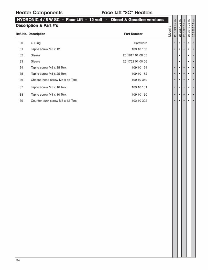
Description & Part #’s
Heater Components Face Lift “SC” Heaters
Ref. No. Description Part Number
HYDRONIC 4 / 5 W SC - Face Lift - 12 volt - Diesel & Gasoline versions
1 Outer casing 25 2149 01 01 01 • • • • •
2 Combustion air blower with cover 20 1819 99 16 00 • • • • •
3 Cover 25 1917 01 00 02 • • • • •
4 Burner 20 1818 10 00 00 • •
25 2216 10 00 00 • • •
5 Heat exchanger 25 2149 06 00 01 • • • • •
6 Control unit 22 5201 03 00 02 •
22 5201 03 00 01 •
22 5201 00 20 04 •
22 5201 01 90 02 • •
7 Cover 20 1752 99 01 03 • • • • •
8 Coolant Pump 25 2219 25 00 00 • • • • •
9 Fuel metering pump 22 4504 03 00 00 • •
Internal fuel pipe 25 2118 01 00 01 •
Intermediate piece 25 2137 01 00 01 •
10 Integrated fuel filter 20 1312 00 00 06 • • • • •
11 Holder fuel metering pump 25 1917 01 00 07 • •
25 2137 01 00 01 •
12 Seal 20 1820 99 00 01 • • • • •
13 O-Ring 320 75 104 • • • • •
14 Glow pin with cable section 25 2106 01 10 00 • • • • •
15 Plug connection 20 1752 01 10 00 • •
25 2147 01 14 00 • • •
16 Atomizing Screen W/O rings 20 1752 99 01 02 • •
25 2121 99 01 13 • • •
17 Holder 20 1752 01 00 04 • •
18 Groomet 20 1752 01 00 02 • •
19 Flame sensor 25 1920 35 00 00 • • • • •
20 Overheat sensor with cable section 25 2147 01 20 00 • •
25 2219 01 20 00 • • •
21 Plug kit 14 pin 22 1000 30 10 10 • • • • •
22 Cable section Waterpump 20 1753 01 18 00 • • • • •
23 Spring leaf 25 1922 01 00 05 • • • • •
24 Cover fuel metering pump 25 1752 01 00 03 • •
25 1917 01 00 03 • • •
25 O-Ring 14 x 2.6 22 1000 70 00 06 • • • •
26 O-Ring 7 x 2 22 1000 70 00 09 • • • •
27 Hose 25 1917 01 00 11 • •
28 Cable band 209 31 071 • •
Model #
25 2257 05 12v
25 2219 05 12v
20 1820 05 12v
20 1824 05 12v
25 2325 05 12v
34
Description & Part #’s
Model #
25 2257 05 12v
20 1824 05 12v
25 2219 05 12v
20 1820 05 12v
Ref. No. Description Part Number
30 O-Ring Hardware • • • • •
31 Tapite screw M5 x 12 109 10 153 • • • • •
32 Sleeve 25 1917 01 00 05 • • •
33 Sleeve 25 1752 01 00 06 • • •
34 Tapite screw M5 x 35 Torx 109 10 154 • • • • •
35 Tapite screw M5 x 25 Torx 109 10 152 • • • • •
36 Cheese-head screw M5 x 65 Torx 100 10 350 • • • • •
37 Tapite screw M5 x 16 Torx 109 10 151 • • • • •
38 Tapite screw M4 x 10 Torx 109 10 150 • • • • •
39 Counter sunk screw M5 x 12 Torx 102 10 302 • • • • •
Heater Components Face Lift “SC” Heaters
HYDRONIC 4 / 5 W SC - Face Lift - 12 volt - Diesel & Gasoline versions
25 2325 05 12v

35
Notes:
36
Heater Components Face Lift “SC” Heaters
Parts Diagram - Hydronic 4 / 5 W SC - Face Lift - 12 volt - Diesel & Gasoline versions
6
1
2
3
4
5
78
9
11
11
12/13
17
18
19
20
22
4
4
4
3
38
9
10
10
10
10
10
31
11
11
12/13
23
26
27/28
24 a
24 b
25
21
2930
32
11
11
12/13
12/13
11
11
10
14
16
15
20 a
Model 20 1824 05
Model 20 1820 05
Model 25 2219 05
Model 25 2257 05
Model 25 2325 05

37
Description & Part #’s
Ref. No. Description Part Number
Model #
25 2257 05 12v
20 1824 05 12v
25 2219 05 12v
20 1820 05 12v
01 T-piece 262 31 151 • • • • •
02 T-piece 262 31 155 • • • • •
03 Hose 360 75 350 • • • • •
--------------- • •
04 Hose 3.5mm x 3mm 360 75 300 • • • • •
--------------- • •
05 Pipe 2mm 890 31 117 • • • • •
06 Pipe 1.5mm 890 31 118 • • • • •
07 Pipe 2mm 890 31 125 • • • • •
08 Hose 7.5mm --------------- • •
--------------- • •
09 Supporting sleeve with collar 22 1000 20 02 00 • • • •
10 Hose clip 11mm 10 2068 01 10 98 • •
11 Hose clip 9mm 10 2068 00 90 98 • • • •
12 Hose clip 14mm 10 2068 01 40 98 • •
13 Hose clip 12mm 10 2068 01 20 98 • • • •
14 Holder 25 2220 80 00 01 • • • •
15 Central screw 100 10 258 • • • •
16 Metal rubber buffer 6 mm 20 1185 00 00 01 • • • •
17 Fuel metering pump 22 4517 04 00 00 • • •
18 Cap sieve 20 1312 00 00 06 • •
19 Holder metering pump 22 1000 50 03 00 • • •
20 Main harness - J.E - Universal w/relay 25 1917 80 10 00 • • •
25 1917 80 11 00 • •
20a Main harness ESPAR 20 2900 70 05 02 (CA0 60 502) • •
20 2900 70 05 03 (CA0 60 503) • •
21 Connection Kit 22 1000 30 10 21 • • • •
22 Relay 203 00 065 • • • •
23 Cable 22 1000 31 28 00 • • • •
24a Fuse holder, receptable housing 22 1000 31 06 01 • • • •
24b Fuse holder, cover 22 1000 31 06 02 • • • •
25 Fuse 25 A 204 00 089 • • • •
20 A 5670055 (CA1 07 005) • • • •
5 A 204 00 079 • • • •
26 Terminal 206 52 136 • • • •
27 Terminal 206 52 133 • • • •
28 Terminal 206 52 134 • • • •
29 Eyelet Hardware • • • •
30 Eyelet Hardware • • • • •
31 Cable band 25 1801 80 02 00 • • • • •
Heater Components Face Lift “SC” Heaters
Hydronic 4 / 5 W SC - Face Lift - 12 volt - Diesel & Gasoline versions
25 2325 05 12v
38
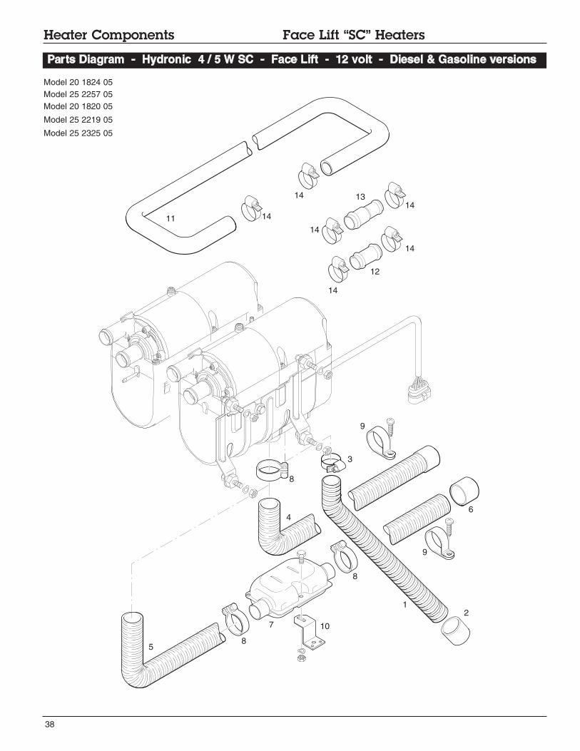
Heater Components Face Lift “SC” Heaters
Parts Diagram - Hydronic 4 / 5 W SC - Face Lift - 12 volt - Diesel & Gasoline versions
3
5
4
12
7
8
10
11
8
8
9
12
1314
14
14
14
14
14
9
6
Model 20 1824 05
Model 25 2257 05
Model 20 1820 05
Model 25 2219 05
Model 25 2325 05

39
Description & Part #’s
Ref. No. Description Part Number
Heater Components Face Lift “SC” Heaters
Hydronic 4 / 5 W SC - Face Lift - 12 volt - Diesel & Gasoline versions
1 Combustion air hose - 20mm x 1mtr 360 00 099 • • • • •
Double-pipe LW 19, sound damping --------------- • • • • •
2 End cap 25 1688 80 12 01 • • • • •
3 Hose clamp 16 - 32mm 10 2067 01 60 25 • • • • •
4 Exhaust hose - 25mm x 1mtr / cap 25 1774 80 02 00 • • • • •
5 Exhaust hose 25 mm 360 61 299 • • • • •
6 Exhaust end cap w/bar 25 1729 80 06 00 • • • • •
7 Exhaust silencer 25 1864 81 01 00 • •
22 1000 40 09 00 • • •
8 Exhaust clamp 22 1000 50 05 00 • • • • •
9 “P” clamp 28mm 152 10 051 • • • • •
10 “Z” bracket 20 1533 88 00 07 • • • • •
11 Water Hose - Moulded - 18mm 20 1690 81 00 01 • • • • •
12 Water hose union - 18mm 20 1528 88 00 03 • • • • •
13 Water hose union - 18mm - 15mm 20 1645 80 02 01 • • • • •
14 Hose clamp 20 - 32mm 10 2065 02 00 32 • • • • •
25 2257 05 12v
20 1824 05 12v
25 2219 05 12v
20 1820 05 12v
Model #
25 2325 05 12v
40
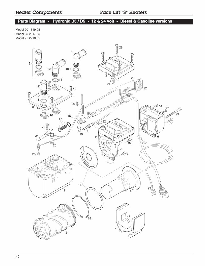
Heater Components Face Lift “S” Heaters
Parts Diagram - Hydronic B5 / D5 - 12 & 24 volt - Diesel & Gasoline versions
Model 20 1819 05
Model 25 2217 05
Model 25 2218 05
1
2
3
28
15
26
18
19
32
6
31
29
30
28
8
24
25
27
13
14
5
4
7
17
31
32
32
16
22
20
9*
9
10* 10
11
11
12
21
23
25
01

41
Description & Part #’s
Ref. No. Description Part Number Model #
20 1819 05 12V
25 2218 05 24V
25 2217 05 12V
1 Casing 25 2149 01 01 01 • • •
2 Combustion air blower with cover 20 1819 99 16 00 • •
25 2146 99 17 00 •
3 Cover 25 2217 01 00 01 • • •
4 Burner 20 1818 10 00 00 •
25 2216 10 00 00 •
25 2146 10 00 00 •
5 Heat exchanger 25 2149 06 00 01 • • •
6 Control unit 22 5201 00 20 04 •
22 5201 01 90 02 •
22 5202 00 10 03 •
7 Cover - heater base 20 1756 99 01 03 • • •
8 Cover 25 2216 01 00 02 • • •
9 Hose barb assly 18mm 25 2216 99 01 06 • • •
10 Hose barb assly - 90° - mm 25 2216 99 01 05 • • •
11 O-Ring 16x2 22 1000 70 00 05 • • •
12 Hose barb locks 25 2216 01 00 10 • • •
13 Gasket / seal set 20 1820 99 00 01 • • •
14 O-Ring - 74x3 22 1000 70 00 02 • • •
15 Glow pin 25 2106 01 10 00 • •
25 2107 01 10 00 •
16 Glow plug connection 20 1756 01 10 00 • •
25 2121 01 14 00 •
17 Glow pin lining and 2 O-rings 20 1752 99 01 02 •
25 2121 99 01 13 • •
18 Flame sensor 25 1920 35 00 00 • • •
19 Holder 20 1752 01 00 04 • • •
20 Over heat sensor with cable 25 2150 01 20 00 • • •
21 Grommet for cable 25 2216 01 17 01 • • •
22 Control unit plug kit 22 1000 30 10 10 • • •
23 Water pump harness 25 2009 01 15 00 • • •
24 Spring 25 1922 01 00 05 • • •
25 O-ring 7 x 2 22 1000 70 00 09 • • •
26 Grommet 20 1756 01 00 04 • • •
27 Taptite screw M5 x 12 torx 109 10 153 • • •
28 Taptite screw M5 x 25 torx 109 10 152 • • •
29 Cheese-head screw M5 x 65 torx 100 10 350 • • •
30 Taptite screw M5 x 16 torx 109 10 151 • • •
31 Taptite Screw M4 x 10 torx 109 10 150 • • •
32 Countersunk screw M5 x 12 torx 102 10 302 • • •
Heater Components Face Lift “S” Heaters
Hydronic B5 / D5 - 12 & 24 volt - Diesel & Gasoline versions
42
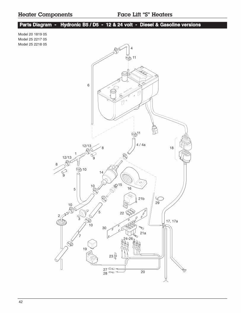
Heater Components Face Lift “S” Heaters
Parts Diagram - Hydronic B5 / D5 - 12 & 24 volt - Diesel & Gasoline versions
Model 20 1819 05
Model 25 2217 05
Model 25 2218 05
1
9
6
8
2
4
4 / 4a
10
10
10
8
9
7
10
3
15
5
11
11
12/13
12/13
14
17, 17a
19
20
23
30
24-26
21a
21b
29
5
16
18
2827
22

43
Description & Part #’s
Ref. No. Description Part Number
Model #
20 1819 05 12v
25 2218 05 24v
25 2217 05 12v
Heater Components Face Lift “S” Heaters
Hydronic B5 / D5 - 12 & 24 volt - Diesel & Gasoline versions
1 T-piece 262 31 151 • • •
2 Fuel pick up 20 2900 20 20 56 (CA0 12 056) •
3 Fuel filter 25 1226 89 00 37 •
4 Fuel hose 3.5 x 3mm 360 75 300 •
4a Hose ---------------
5 Hose 5 x 3mm 360 75 350 • •
--------------- •
6 Plastic fuel line 1.5 mm 890 31 118 • • •
7 Plastic fuel line 2 mm 890 31 125 • • •
8 Hose 7.5mm --------------- • • •
9 Supporting sleeve with collar 122 1000 20 02 00 • • •
10 Clamp 11mm 10 2068 01 10 98 • • •
11 Hose clamp 9mm 10 2068 00 90 98 • • •
12 Hose clamp 14mm 10 2068 01 40 98 • • •
13 Hose clamp 12mm 10 2068 01 20 98 • • •
14 Fuel metering pump 12 V 22 4517 04 00 00 • •
24 V 25 1942 45 00 00 •
15 Fuel Basket Filter 20 1312 00 00 06 • • •
16 Holder metering pump 22 1000 50 03 00 • • •
17 Main harness - J.E Universal w/relay 25 1917 80 10 00 • •
25 2009 80 10 00 •
17a Main harness ESPAR 20 2900 70 05 02 (CA0 60 502) • • •
18 Connector kit 22 1000 30 10 21 • • •
19 Relay 12 V 203 00 065 • •
24 V 203 00 066 •
20 Cable 22 1000 31 28 00 • • •
21a Fuse holder, receptacle housing 22 1000 31 06 01 • • •
21b Fuse holder, cover 22 1000 31 06 02 • • •
22 Fuse 25 A 204 00 089 • • •
20 A 5670055 (CA1 07 005) • •
15 A 5670053 (CA1 07 002) •
5 A 204 00 079 • • •
23 Terminal Fe 206 52 136 • • •
24 Terminal Fe 206 00 182 •
25 Terminal Fe 206 52 133 • • •
26 Terminal Fe 206 52 134 • • •
27 Eyelet Hardware • • •
28 Eyelet Hardware • •
29 Cable band 25 1801 80 02 00 • • •
30 Combination bracket, fuses and fan relay 22 1000 51 21 00 • • •
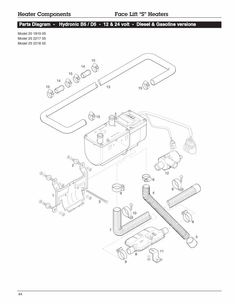
44
Heater Components Face Lift “S” Heaters
Parts Diagram - Hydronic B5 / D5 - 12 & 24 volt - Diesel & Gasoline versions
Model 20 1819 05
Model 25 2217 05
Model 25 2218 05
41
2
5
6
7
8
9
9
9
9
11
12
13
14
14
15
10
15
15
15
15
3

45
Description & Part #’s
Ref. No. Description Part Number Model #
20 1819 05 12v
25 2218 05 24v
25 2217 05 12v
1 Bracket 25 2220 80 00 01 • • •
2 Metal rubber buffer 6mm 20 1185 00 00 01 • • •
3 Central screw, M6 x 97 Hex bolt 100 10 258 • • •
4 Flexible tubing air intake hose 360 00 099 • • •
5 End cap with bar 25 1688 80 12 01 • • •
6 Hose clip 16 - 25mm 10 2067 01 60 25 • • •
7 Exhaust Hose - 25mm w/end cap 25 1774 80 02 00 • • •
8 Exhaust silencer 24mm 22 1000 40 09 00 • • •
9 Exhaust clamp 22 1000 50 05 00 • • •
10 P clamp 28mm 152 10 051 • • •
11 Holder exhaust silencer double angle bracket 20 1533 88 00 07 • • •
12 Coolant pump 12 V 25 2217 25 00 00 • •
24 V 25 2218 25 00 00 •
13 Coolant hose - moulded - 18mm 20 1690 81 00 01 • • •
14 Water hose union - 18mm 20 1528 88 00 03 • • •
15 Hose clip 20 - 32mm 10 2065 02 00 32 • • •
Heater Components Face Lift “S” Heaters
Hydronic B5 / D5 - 12 & 24 volt - Diesel & Gasoline versions
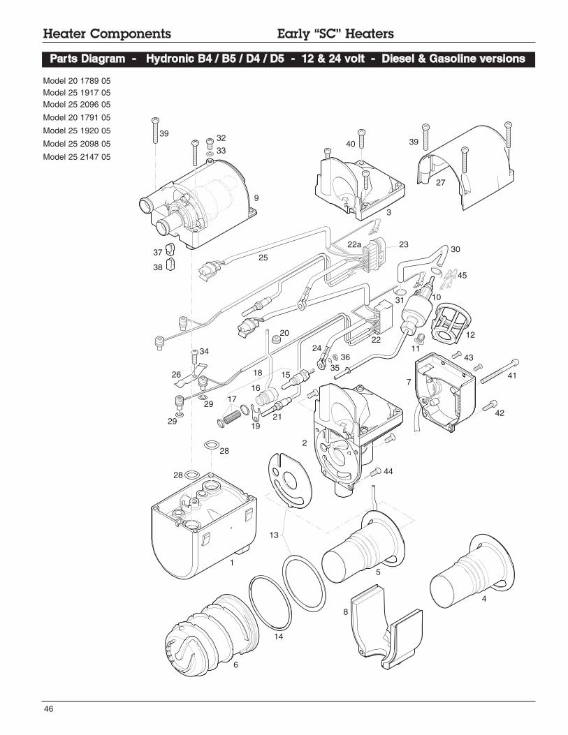
46
Parts Diagram - Hydronic B4 / B5 / D4 / D5 - 12 & 24 volt - Diesel & Gasoline versions
1
6
5
7
8
9
11
12
13
14
15
16
19
20
21
22
28
30
31
32
33
34
27
29
35
36
37
38
3939
41
42
43
44
45
2
3
10
40
4
24
29
28
22a 23
25
26
17
18
Model 20 1789 05
Model 25 1917 05
Model 25 2096 05
Model 20 1791 05
Model 25 1920 05
Model 25 2098 05
Model 25 2147 05
Heater Components Early “SC” Heaters

47
Description & Part #’s
Ref. No. Description Part Number Model #
25 1917 05 12V
20 1789 05 12V
25 1920 05 12V
20 1791 05 12V
25 2096 05 12V
25 2147 05 24V
25 2098 05 12V
1 Casing 25 1917 01 01 01 • • •
25 1920 01 01 01 • • •
25 1920 01 01 01 •
2 Combustion air blower with cover 25 1917 99 16 00 •
20 1759 99 15 00 •
25 1922 99 16 00 • •
25 2013 99 16 00 •
20 1774 99 15 00 •
25 2146 99 17 00 •
3 Cover 25 1917 01 00 02 • • • • • •
25 2137 01 00 02 •
4 Burner 20 1752 10 00 00 •
20 1818 10 00 00 •
5 Burner 25 1917 19 00 00 • •
25 1920 10 00 00 • •
25 2146 10 00 00 •
6 Heat exchanger 25 1864 06 00 01 • • •
25 1922 06 00 01 • • • •
7 Control unit 25 1917 51 00 04 •
25 1917 55 00 01 •
22 5201 00 20 01 •
22 5201 00 20 04 •
22 5201 00 10 01 •
22 5201 00 30 01 •
22 5202 00 10 03 •
8 Cover 20 1752 99 01 03 • • • • • • •
9 Pump 25 1917 99 25 00 •
25 1920 25 00 00 • • •
25 2096 25 00 00 • •
25 2118 25 00 00 •
10 Fuel metering pump 25 1917 45 00 00 • •
25 1920 45 00 00 • •
11 Integrated fuel filter 20 1312 00 01 00 • • • •
12 Holder Fuel metering pump 25 1917 01 00 07 • • • •
13 Seal 20 1820 99 00 01 • • • • • • •
14 O-Ring 74 x 33mm 320 75 104 • • • • • • •
15 Glow pin 25 1864 01 10 00 • • • •
25 2107 01 10 00 •
25 2106 01 10 00 • •
16 Plug connection 20 1752 01 10 00 • •
17 Lining and 2 O-rings 20 1752 99 01 02 • •
18 Plug connection compl. 25 2147 01 13 00 •
19 Holder 20 1752 01 00 04 • • •
20 Sleeve 20 1752 01 00 02 • • •
Heater Components Early “SC” Heaters
Hydronic B4 / B5 / D4 / D5 - 12 & 24 volt - Diesel & Gasoline versions
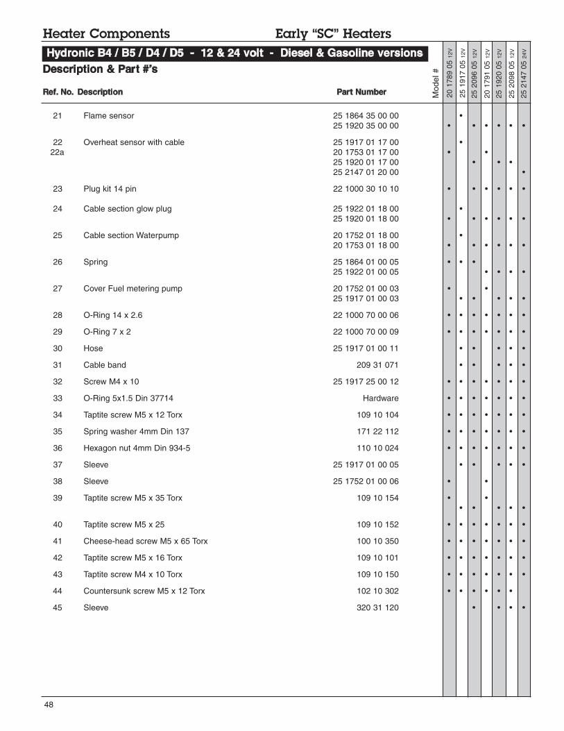
48
Description & Part #’s
Model #
25 1917 05 12V
20 1789 05 12V
25 1920 05 12V
20 1791 05 12V
25 2096 05 12V
25 2147 05 24V
25 2098 05 12V
Heater Components Early “SC” Heaters
21 Flame sensor 25 1864 35 00 00 •
25 1920 35 00 00 • • • • • •
22 Overheat sensor with cable 25 1917 01 17 00 •
22a 20 1753 01 17 00 • •
25 1920 01 17 00 • • •
25 2147 01 20 00 •
23 Plug kit 14 pin 22 1000 30 10 10 • • • • • •
24 Cable section glow plug 25 1922 01 18 00 •
25 1920 01 18 00 • • • • • •
25 Cable section Waterpump 20 1752 01 18 00 •
20 1753 01 18 00 • • • • • •
26 Spring 25 1864 01 00 05 • • •
25 1922 01 00 05 • • • •
27 Cover Fuel metering pump 20 1752 01 00 03 • •
25 1917 01 00 03 • • • • •
28 O-Ring 14 x 2.6 22 1000 70 00 06 • • • • • • •
29 O-Ring 7 x 2 22 1000 70 00 09 • • • • • • •
30 Hose 25 1917 01 00 11 • • • • •
31 Cable band 209 31 071 • • • • •
32 Screw M4 x 10 25 1917 25 00 12 • • • • • • •
33 O-Ring 5x1.5 Din 37714 Hardware • • • • • • •
34 Taptite screw M5 x 12 Torx 109 10 104 • • • • • • •
35 Spring washer 4mm Din 137 171 22 112 • • • • • • •
36 Hexagon nut 4mm Din 934-5 110 10 024 • • • • • • •
37 Sleeve 25 1917 01 00 05 • • • • •
38 Sleeve 25 1752 01 00 06 • •
39 Taptite screw M5 x 35 Torx 109 10 154 • •
• • • • •
40 Taptite screw M5 x 25 109 10 152 • • • • • • •
41 Cheese-head screw M5 x 65 Torx 100 10 350 • • • • • • •
42 Taptite screw M5 x 16 Torx 109 10 101 • • • • • • •
43 Taptite screw M4 x 10 Torx 109 10 150 • • • • • • •
44 Countersunk screw M5 x 12 Torx 102 10 302 • • • • • •
45 Sleeve 320 31 120 • • • •
Ref. No. Description Part Number
Hydronic B4 / B5 / D4 / D5 - 12 & 24 volt - Diesel & Gasoline versions

49
Notes:
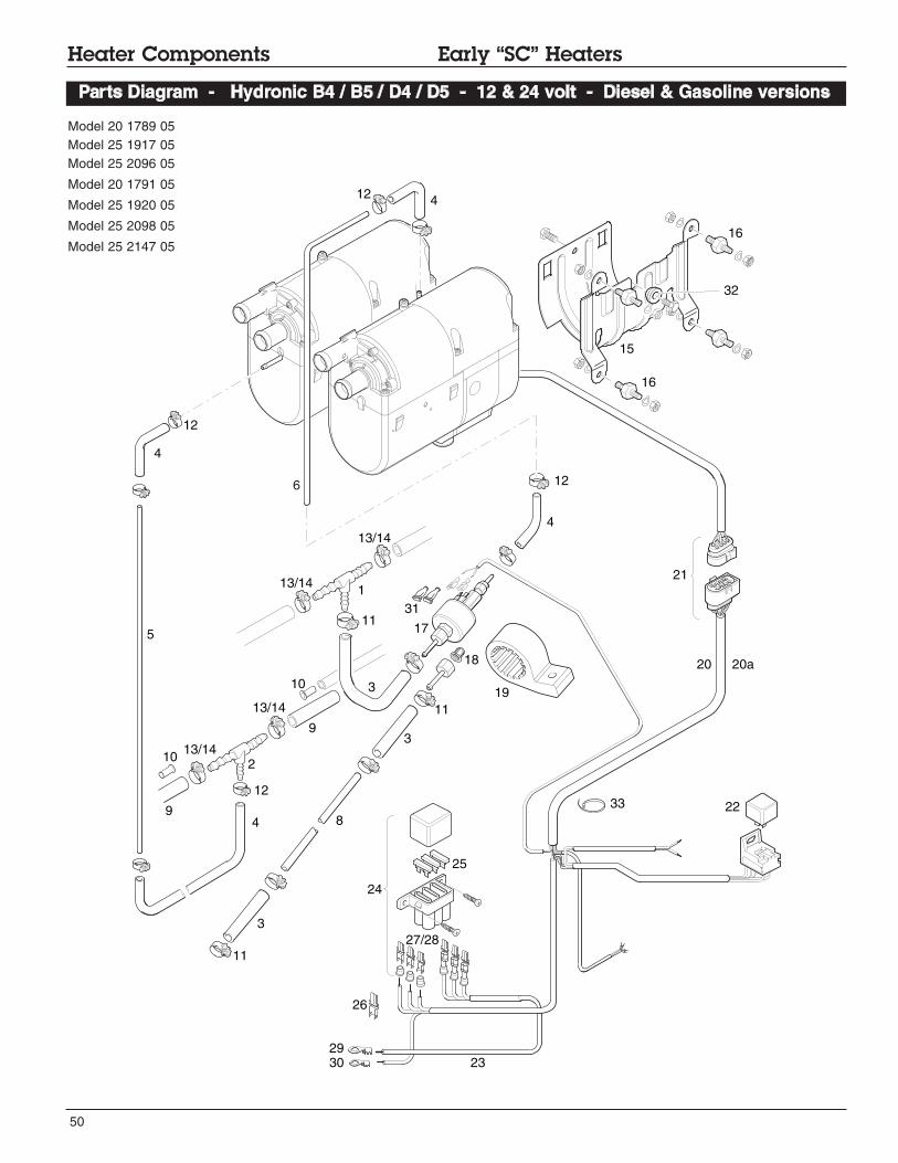
50
Heater Components Early “SC” Heaters
Parts Diagram - Hydronic B4 / B5 / D4 / D5 - 12 & 24 volt - Diesel & Gasoline versions
Model 20 1789 05
Model 25 1917 05
Model 25 2096 05
Model 20 1791 05
Model 25 1920 05
Model 25 2098 05
Model 25 2147 05
6
1
2
3
4
5
89
10
12
13/14
15
16
17
18
19
20 20a
22
4
4
4
3
39
10
16
32
11
11
33
31
12
13/14
23
26
27/28
24
21
25
2930
12
13/14
13/14
12
11

51
Description & Part #’s
Ref. No. Description Part Number
25 1920 05 12V
25 2147 05 24V
Model #
25 1917 05 12V
20 1789 05 12V
20 1791 05 12V
25 2096 05 12V
25 2098 05 12V
Heater Components Early “SC” Heaters
Hydronic B4 / B5 / D4 / D5 - 12 & 24 volt - Diesel & Gasoline versions
1 T - piece -8-6-8 262 31 151 • • •
2 T - piece -8-4-8 262 31 155 • • • •
3 Hose 5 x 3mm --------------- • • • •
360 75 350 • • • • • • •
4 Hose 3.5 x 3mm 360 75 300 • • • • • • •
5 Pipe 2mm 890 31 117 • • • •
6 Pipe 1.5mm 890 31 118 • • •
8 Pipe 2mm 890 31 125 • • •
9 Hose 7.5mm --------------- • • • •
360 31 070 • • •
10 Supporting sleeve with collar 22 1000 20 02 00 • • • • • • •
11 Hose clip 11mm 25 2068 01 10 98 • • •
12 Hose clip 9mm 10 2068 00 90 98 • • • • • • •
13 Hose clip 14mm 10 2068 01 40 98 • • •
14 Hose clip 12mm 10 2068 01 20 98 • • • • • • •
15 Holder 25 1864 80 00 01 • • • • • • •
16 Metal rubber buffer 6mm 20 1185 00 00 01 • • • • • • •
17 Fuel metering pump 12V 20 1645 45 00 00 • •
24V 25 1942 45 00 00 •
18 Cap sieve 20 1312 00 00 06 • •
19 Holder metering pump 22 1000 50 03 00 • •
20 Main harness - J.E. universal w/relay 25 1917 80 10 00 • •
25 1917 80 11 00 • • • •
25 2009 80 10 00 •
20a Main harness ESPAR 20 2900 70 04 01 (CA0 60 401) • • •
20 2900 70 05 03 (CA0 60 503) • •
20 2900 70 05 02 (CA0 60 502) • •
21 Connection kit main harness 22 1000 30 10 21 • • • • • • •
22 Relay 203 00 065 • • • • • •
23 Relay harness 20 1668 80 05 00 • • • • • •
22 1000 31 28 00 •
24 Fuse holder Kit 22 1000 31 06 00 • • • • • • •
25 Fuse 25 A 204 00 089 • • • • • • •
20 A 5670055 (CA1 07 005) • • • • • • •
5 A 204 00 079 • • • • • • •
26 Terminal Fe 206 52 136 • • • • • • •
26 Terminal Fe 206 52 133 • • • • • • •
28 Terminal Fe 206 52 134 • • • • • • •
29 Eyelet Hardware • • • • • • •
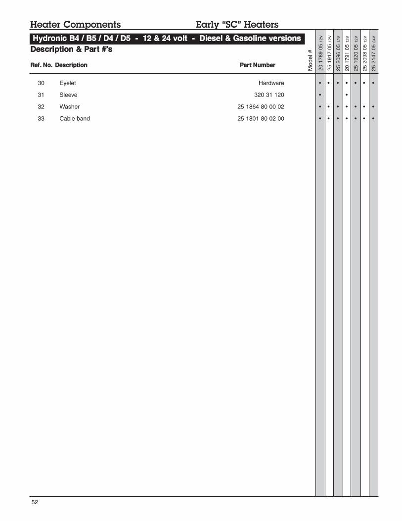
52
Description & Part #’s
Model #
25 1917 05 12V
20 1789 05 12V
20 1791 05 12V
25 2096 05 12V
Ref. No. Description Part Number
Heater Components Early “SC” Heaters
Hydronic B4 / B5 / D4 / D5 - 12 & 24 volt - Diesel & Gasoline versions
30 Eyelet Hardware • • • • • • •
31 Sleeve 320 31 120 • •
32 Washer 25 1864 80 00 02 • • • • • • •
33 Cable band 25 1801 80 02 00 • • • • • • •
25 1920 05 12V
25 2147 05 24V
25 2098 05 12V

53
Notes:
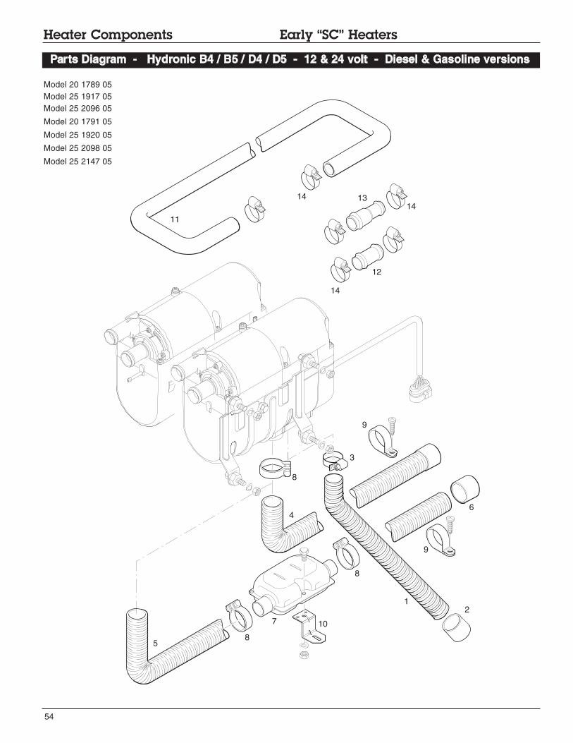
54
Heater Components Early “SC” Heaters
Parts Diagram - Hydronic B4 / B5 / D4 / D5 - 12 & 24 volt - Diesel & Gasoline versions
Model 20 1789 05
Model 25 1917 05
Model 25 2096 05
Model 20 1791 05
Model 25 1920 05
Model 25 2098 05
Model 25 2147 05
3
5
4
12
7
8
10
11
8
8
9
12
1314
14
14
9
6

55
Ref. No. Description Part Number
Description & Part #’s
1 Combustion air hose - 20mm 360 00 099 • • • • • • •
2 End sleeve with bar 25 1688 80 12 01 • • • • • • •
3 Hose clamp 16 - 25mm 10 2067 01 60 25 • • • • • • •
4 Exhaust hose - flexible - 25 mm w/cap / 1mtr 25 1774 80 02 00 • • • • • • •
5 Exhaust hose - flexible - 24mm 360 61 299 • • • • • • •
6 End sleeve/w bar 25 1729 80 06 00 • • • • • • •
7 Exaust silencer clamp 25 1864 81 01 00 • • • • • • •
8 Exhaust clamp 26mm 152 61 102 • • • • • • •
9 “P” clamp 28mm 152 10 051 • • • • • • •
10 “Z” bracket 20 1533 88 00 07 • • • • • • •
11 Hose - moulded 20mm 25 1917 80 00 01 • • • • • • •
12 Hose union 20mm 20 1534 88 00 01 • • • • • • •
13 Hose union reducer 20-18 mm 20 1645 89 00 06 • • • • • • •
14 Hose clamp 20 - 32mm 10 2065 02 00 32 • • • • • • •
Model #
Heater Components Early “SC” Heaters
Hydronic B4 / B5 / D4 / D5 - 12 & 24 volt - Diesel & Gasoline versions
25 1917 05 12V
20 1789 05 12V
20 1791 05 12V
25 2096 05 12V
25 1920 05 12V
25 2147 05 24V
25 2098 05 12V
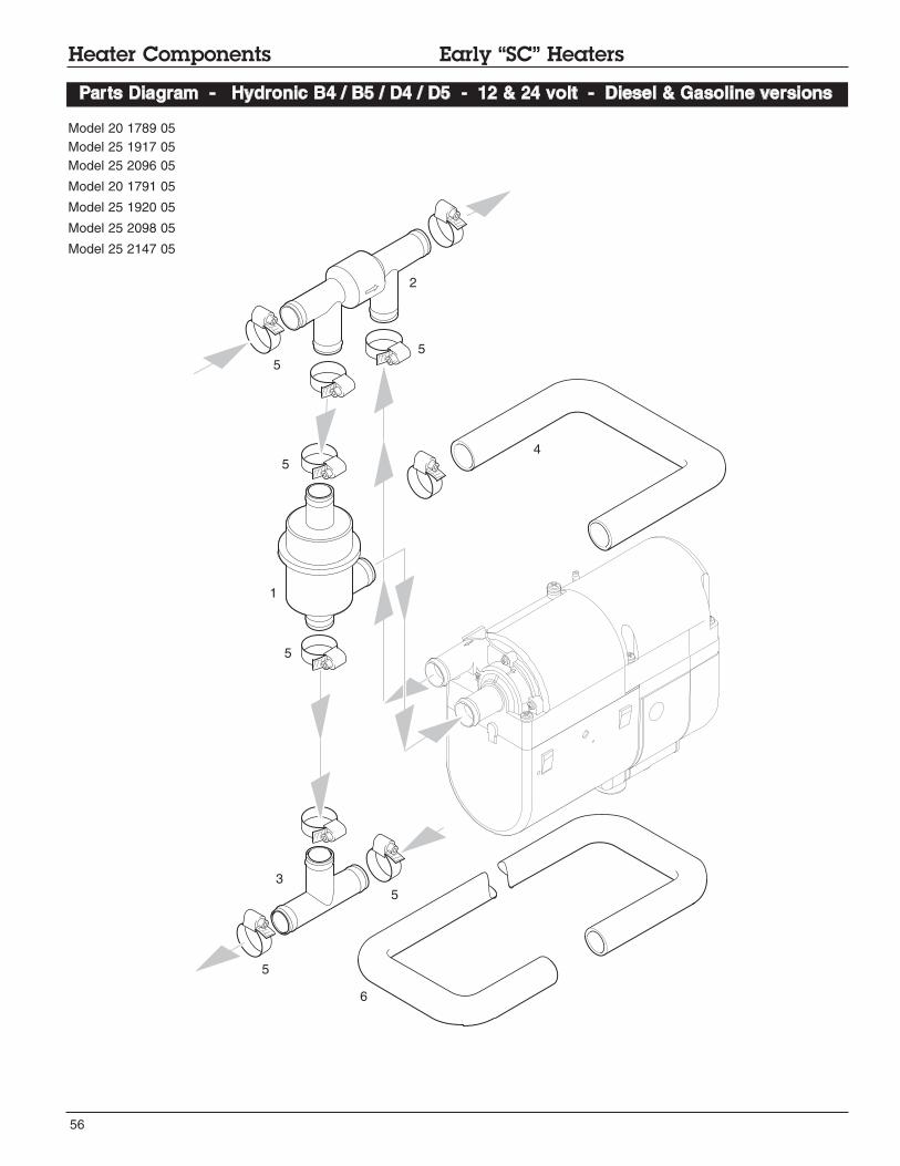
56
Heater Components Early “SC” Heaters
Parts Diagram - Hydronic B4 / B5 / D4 / D5 - 12 & 24 volt - Diesel & Gasoline versions
Model 20 1789 05
Model 25 1917 05
Model 25 2096 05
Model 20 1791 05
Model 25 1920 05
Model 25 2098 05
Model 25 2147 05
1
2
3
5
5
5
5
5
5
4
6

57
Description & Part #’s
Ref. No. Description Part Number
1 Thermostat 330 00 158 • • •
330 00 123 • • • •
2 One way valve 254 00 074 • • •
254 00 070 • • • •
3 T - pipe piece Ø 18-18-18 20 1673 80 11 00 • • •
Ø 20-20-20 20 1645 89 10 00 • • • •
4 Hose - moulded 20mm 24 0117 80 00 01 • • •
5 Hose clip 20 - 32mm 10 2065 02 00 32 • • • • • • •
6 Hose moulded 18mm 24 0132 00 00 01 • • • •
Heater Components Early “SC” Heaters
Hydronic B4 / B5 / D4 / D5 - 12 & 24 volt - Diesel & Gasoline versions
Model #
25 1917 05 12V
20 1789 05 12V
20 1791 05 12V
25 2096 05 12V
25 1920 05 12V
25 2147 05 24V
25 2098 05 12V
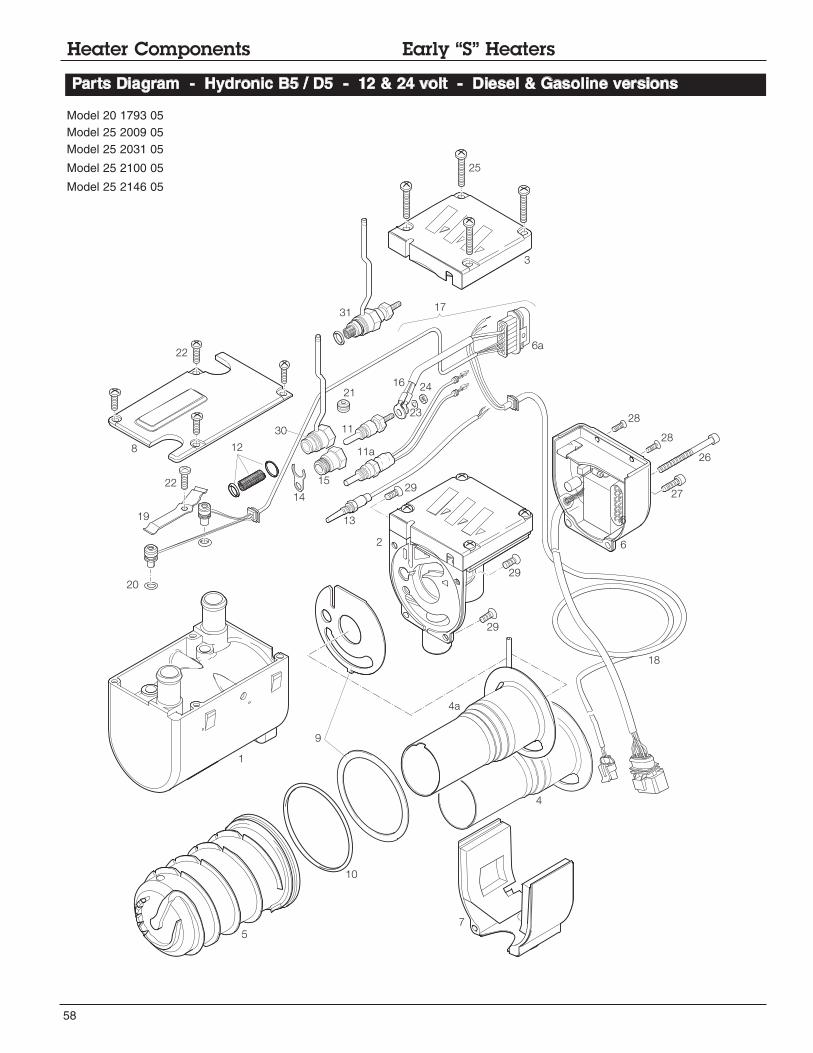
58
Heater Components Early “S” Heaters
Parts Diagram - Hydronic B5 / D5 - 12 & 24 volt - Diesel & Gasoline versions
5
1
10
9
7
4
4a
18
29
29
6
27
26
28
28
2
2914
20
19
22
128
22
25
3
17
6a
6
13
23
2416
21
15
1130
31
11a
Model 20 1793 05
Model 25 2009 05
Model 25 2031 05
Model 25 2100 05
Model 25 2146 05

59
Description & Part #’s
Ref. No. Description Part Number 20 1793 05 12v
Model #
25 2031 05 12v
25 2009 05 24v
25 2146 05 24v
25 2100 05 12v
Heater Components Early “S” Heaters
Hydronic B5 / D5 - 12 & 24 volt - Diesel & Gasoline versions
1 Casing 25 1922 01 01 01 • • • • •
2 Combustion air blower with cover 25 1922 99 16 00 • •
25 1942 99 15 00 •
20 1759 99 15 00 •
25 2146 99 17 00 •
3 Cover 20 1756 01 00 03 • •
25 1864 01 00 04 • • •
4 Burner 20 1818 10 00 00 •
4a 25 2146 10 00 00 •
25 1922 10 00 00 • • •
5 Heat exchanger 25 1922 06 00 01 • • • • •
6 Control unit 25 1942 50 00 02 •
22 5201 00 30 02 • •
22 5201 00 20 04 •
22 5202 00 10 03 •
6a Plug kit 22 1000 30 10 10 • • • • •
7 Cover heater base 20 1756 99 01 03 • • • • •
8 Cover blower 25 1922 01 00 02 • • • • •
9 Gasket / seal set 20 1820 99 00 01 • • • • •
10 O-Ring 74 x 3mm 320 75 104 • • • • •
11 Glow pin 12 V 25 1864 01 10 00 • •
24 V 25 1816 01 01 00 •
11a Glow pin 12 V 25 2106 01 10 00 •
24 V 25 2107 01 10 00 •
12 Lining and 2 O-Rings 20 1752 99 01 02 •
13 Flame sensor 25 1920 35 00 00 • • • • •
14 Holder 20 1752 01 00 04 • •
15 Bushing - adapter - glow pin 25 1942 01 00 02 •
16 Glow pin harness 25 1922 01 18 00 • • •
17 Over heat / temperature sensors w/cable 25 1942 01 20 00 • • • •
25 2107 01 20 00 •
18 Harness, water pump 25 2009 01 15 00 • • • • •
19 Spring 25 1922 01 00 05 • • • • •
20 O-Ring 7 x 2 22 1000 70 00 09 • • • • •
21 Grommet 20 1756 01 00 04 •
22 Taptite screw M5 x 12 Torx 109 10 104 • • • • •
23 Spring washer M4 Din 137 559 0087 (CA0 00 313) • • • • •
24 Hexagon nut M4 Din 934-5 559 0066 (CA0 00 210) • • •
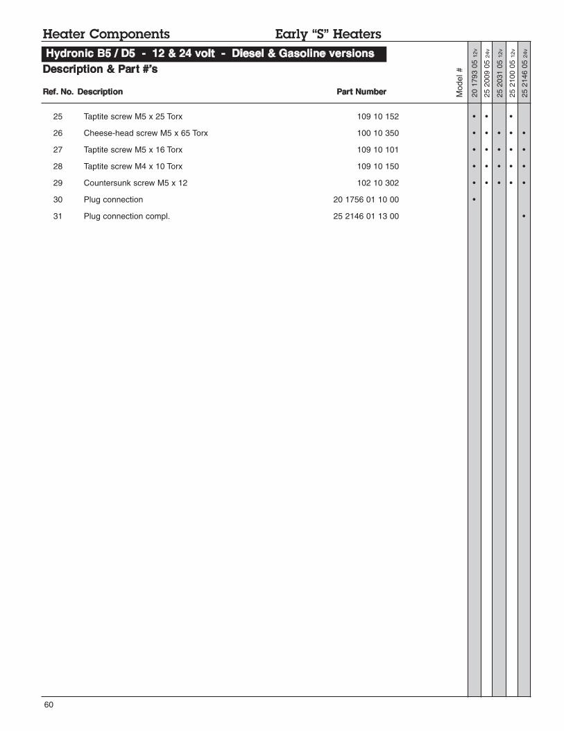
60
Description & Part #’s
25 Taptite screw M5 x 25 Torx 109 10 152 • • •
26 Cheese-head screw M5 x 65 Torx 100 10 350 • • • • •
27 Taptite screw M5 x 16 Torx 109 10 101 • • • • •
28 Taptite screw M4 x 10 Torx 109 10 150 • • • • •
29 Countersunk screw M5 x 12 102 10 302 • • • • •
30 Plug connection 20 1756 01 10 00 •
31 Plug connection compl. 25 2146 01 13 00 •
Heater Components Early “S” Heaters
Hydronic B5 / D5 - 12 & 24 volt - Diesel & Gasoline versions
20 1793 05 12v
25 2031 05 12v
25 2009 05 24v
25 2146 05 24v
25 2100 05 12v
Ref. No. Description Part Number Model #

61
Notes:
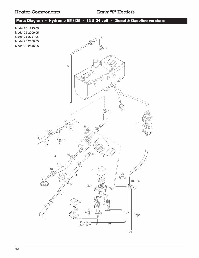
62
Heater Components Early “S” Heaters
Parts Diagram - Hydronic B5 / D5 - 12 & 24 volt - Diesel & Gasoline versions
Model 20 1793 05
Model 25 2009 05
Model 25 2031 05
Model 25 2100 05
Model 25 2146 05
19
11
3
6
11
8
12/13 9
12/13
1
8
4
10
10
10
214
10
20
5/7
21
22
15
1617
4
18, 18a
3
9
23
27
28
24/25
26
29

63
Description & Part #’s
Model #
1 T-piece 8 x 6 x 8mm 262 31 151 • • • • •
2 Fuel pick up 20 2900 20 20 56 (CA0 12056) • •
3 Hose 3.5 x 3mm 360 75 300 • • • • •
4 Hose 5 x 3mm --------------- • •
360 75 350 • • •
5 Pipe 2mm 890 31 117 •
6 Pipe 1.5mm 890 31 118 • • • • •
7 Pipe 2mm 890 31 125 • • • • •
8 Hose 7.5mm 360 31 070 • • • • •
9 Supporting sleeve with collar 22 1000 20 02 00 • • • • •
10 Hose clip 11mm 10 2068 01 10 98 • • • • •
11 Hose clip 9mm 10 2068 00 90 98 • • • • •
12 Hose clip 14mm 10 2068 01 40 98 • • • • •
13 Hose clip 12mm 10 2068 01 20 98 • • • • •
14 Fuel filter 25 1226 89 00 37 • •
15 Fuel metering pump 12 V 20 1645 45 00 00 • • •
24 V 25 1942 45 00 00 • •
16 Cap sieve 20 1312 00 00 06 • • • • •
17 Holder metering pump 22 1000 50 03 00 • • • • •
18 Main harness - J.E. universal w/relay 25 1917 80 10 00 • • •
25 2009 80 10 00 •
25 2107 07 20 00 •
18a Main harness 20 2900 70 05 02 (CA0 60 502) • • • • •
19 Connector kit main harness 22 1000 30 10 21 • • • • •
20 Relay 12 V 203 00 065 • • •
24 V 203 00 066 • •
21 Cable 22 1000 31 28 00 • • • • •
22 Fuse holder kit 22 1000 31 06 00 • • • • •
23 Terminal 206 52 136 • • • • •
24 Terminal 206 52 133 • • • • •
25 Terminal 206 52 134 • • • • •
26 Sleeve 320 31 120 • • • • •
27 Eyelet Hardware • • • • •
28 Eyelet Hardware • • • • •
29 Cable band 25 1801 80 02 00 • • • • •
Heater Components Early “S” Heaters
Hydronic B5 / D5 - 12 & 24 volt - Diesel & Gasoline versions
20 1793 05 12v
25 2031 05 12v
25 2009 05 24v
25 2146 05 24v
25 2100 05 12v
Ref. No. Description Part Number
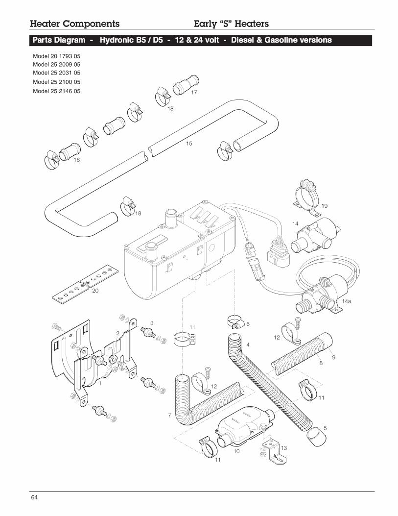
64
Heater Components Early “S” Heaters
Parts Diagram - Hydronic B5 / D5 - 12 & 24 volt - Diesel & Gasoline versions
17
18
16
15
19
14
14a
12
6311
20
18
2
1
4
11
5
1310
11
7
8
9
12
Model 20 1793 05
Model 25 2009 05
Model 25 2031 05
Model 25 2100 05
Model 25 2146 05

65
Description & Part #’s
Ref. No. Description Part Number Model #
1 Bracket 25 1864 80 00 01 • • • • •
2 Spacer 25 1864 80 00 02 • • • • •
3 Metal rubber buffer 6mm 20 1185 00 00 01 • • • • •
4 Air intake hose 360 00 099 • • • • •
5 End sleeve 25 1688 80 12 01 • • • • •
6 Hose clamp 16 - 25mm 10 2067 01 60 25 • • • • •
7 Flexible exhaust w/end cap -1mtr - 24mm 25 1774 80 02 00 • • • • •
8 Flexible exhaust 24mm 360 61 299 • • • • •
9 End sleeve w/bar 25 1729 80 06 00 • • • • •
10 Exhaust silencer 25 1864 81 01 00 • • • • •
11 Clamp 26mm 152 61 102 • • • • •
12 Clamp P type 28mm 152 10 051 • • • • •
13 Holder 20 1533 88 00 07 • • • • •
14 Pump 12 V 330 00 012 • • •
14a Pump 24 V 25 2009 25 00 00 • •
15 Hose - moulded - 20mm 25 1917 80 00 01 • • • • •
16 Hose union 2 20 1534 88 00 01 • • • • •
17 Hose union - reducer 20 - 18 20 1645 89 00 06 • • • • •
18 Hose clamp 20 - 32mm 10 2065 02 00 32 • • •
152 00 180 • •
19 Pump clamp 22 1000 50 10 00 • • •
20 Holder / Bracket with holes 20 1568 88 00 02 • • • • •
Heater Components Early “S” Heaters
Hydronic B5 / D5 - 12 & 24 volt - Diesel & Gasoline versio versions
20 1793 05 12v
25 2031 05 12v
25 2009 05 24v
25 2146 05 24v
25 2100 05 12v
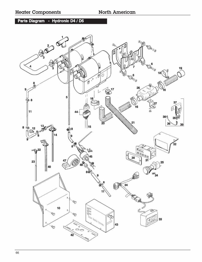
66
Heater Components North American
Parts Diagram - Hydronic D4 / D5
1
2
3
43
5
76
6
19
17
16
16
16
21
26
27
2015
44
8
8
8
8
8
8
8
8
45
47
48
9
9
10
11
11
9
9
1213
14
23
40
22
24
25
32
3130
33
42
43
37
35
36
38
34
18
39

67
Heater Components North American
Parts Diagram - Hydronic D4 / D5 - (including Face Lift)
1
2
3
43
5
6
6
19
17
16
16
16
21
26
27
20
15
44
8
8
8
8
8
8
8
8
45
46
47
48
9
9
10
11
11
9
9
1213
14
23
40
22
24
2531
41
33
42
43
37
35
36
38
34
18
39
29
28
41
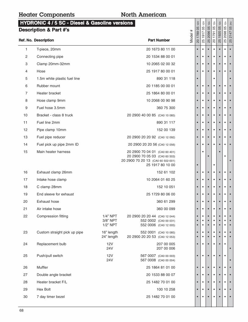
68
Model #
25 1917 05 12V
20 1789 05 12V
25 1920 05 12v
20 1791 05 12v
25 2096 05 12v
25 2147 05 24v
25 2098 05 12v
1 T-piece, 20mm 20 1673 80 11 00 • • • • • • •
2 Connecting pipe 20 1534 88 00 01 • • • • • • •
3 Clamp 20mm-32mm 10 2065 02 00 32 • • • • • • •
4 Hose 25 1917 80 00 01 • • • • • • •
5 1.5m white plastic fuel line 890 31 118 • • •
6 Rubber mount 20 1185 00 00 01 • • • • • • •
7 Heater bracket 25 1864 80 00 01 • • • • • • •
8 Hose clamp 9mm 10 2068 00 90 98 • • • • • • •
9 Fuel hose 3.5mm 360 75 300 • • • • • • •
10 Bracket - class 8 truck 20 2900 40 00 85 (CA0 10 085) • • • • • • •
11 Fuel line 2mm 890 31 117 • • • • • • •
12 Pipe clamp 10mm 152 00 139 • • • • • • •
13 Fuel pipe reducer 20 2900 20 20 92 (CA0 12 092) • • • • • • •
14 Fuel pick up pipe 2mm ID 20 2900 20 20 56 (CA0 12 056) • • • • • • •
15 Main heater harness 20 2900 70 04 01 (CA0 60 401) • •
20 2900 70 05 03 (CA0 60 503) • •
20 2900 70 20 13 (CA0 60 502-001) •
25 1917 80 10 00 • •
16 Exhaust clamp 26mm 152 61 102 • • • • • • •
17 Intake hose clamp 10 2064 01 60 25 • • • • • • •
18 C clamp 28mm 152 10 051 • • • • • • •
19 End sleeve for exhaust 25 1729 80 06 00 • • • • • • •
20 Exhaust hose 360 61 299 • • • • • • •
21 Air intake hose 360 00 099 • • • • • • •
22 Compression fitting 1/4” NPT 20 2900 20 20 44 (CA0 12 044) • • • • • • •
3/8” NPT 552 0002 (CA0 00 031) • • • • • • •
1/2” NPT 552 0006 (CA0 12 005) • • • • • • •
23 Custom straight pick up pipe 16” length 552 0001 (CA0 10 085) • • • • • • •
24” length 20 2900 20 20 53 (CA0 12 053) • • • • • • •
24 Replacement bulb 12V 207 00 005 • • • • • •
24V 207 00 006 •
25 Push/pull switch 12V 567 0007 (CA0 00 003) • • • • • •
24V 567 0008 (CA0 00 004) •
26 Muffler 25 1864 81 01 00 • • • • • • •
27 Double angle bracket 20 1533 88 00 07 • • • • • • •
28 Heater bracket F/L 25 1482 70 01 00 • • • • • • •
29 Hex Bolt 100 10 258 • • • • • • •
30 7 day timer bezel 25 1482 70 01 00 • • • • • • •
HYDRONIC 4 / 5 SC - Diesel & Gasoline versions
Description & Part #’s
Heater Components North American
Ref. No. Description Part Number

69
Description & Part #’s
Model #
25 1917 05 12v
20 1789 05 12v
25 1920 05 12v
20 1791 05 12v
25 2096 05 12v
25 2147 05 24v
25 2098 05 12v
31 7 day timer 22 1000 30 36 00 • • • • • • •
7 day timer with kit (harness & relay) 20 2900 70 01 35 (CA1 00 135) • • • • • •
7 day timer with kit (harness & relay) 20 2900 70 01 36 (CA1 00 136) •
32 Bracket for 7 day timer 20 2900 40 01 58 (CA0 10 061) • • • • • • •
33 Fault code retrieval device 20 2900 70 50 20 (CA1 05 020) • • • • • • •
34 Retrieval harness for fault code device 20 2900 70 50 28 (CA1 05 028) • • • • • • •
35 Fuse blade 25 A 204 00 089 • • • •
20 A 5670055 (CA1 07 005) •
36 Wire awg 12 gage red 5670117 (CA1 61 908) • • • • •
37 Main fuse holder 5670051 (CA1 07 001) • • • • •
38 Ring terminal 3/8” awg 10-12 5670178 (CA1 90 014) • • • • • • •
39 Fuse link power harness 20 2900 70 51 08 (CA1 65 108) • • • •
40 Double pick-up (used with combo kits) 20 2900 20 20 57 • • • • • • •
41 7 day timer bracket and Cosmetic Bezel 25 1482 70 01 00 • • • • • • •
42 Cross frame mounting bracket 20 2900 40 00 28 (CA0 10 028) • • • • • • •
43 Hydronic box Base 20 2900 40 01 01 (CA0 10 101) • • • • • • •
Hydronic box Lid 20 2900 40 01 02 (CA0 10 102) • • • • • • •
44 Plug Cables Complete 22 1000 30 10 21 • • • • • • •
45 Fuel metering pump 20 1645 45 00 00 • •
25 1942 45 00 00 •
46 Boot sleeve 320 31 120 • • •
47 Fuel metering pump holder 22 1000 50 03 00 • • •
48 Fuel filter 20 1312 00 00 06 • • • • • • •
Heater Components North American
HYDRONIC 4 / 5 SC - Diesel & Gasoline versions
Ref. No. Description Part Number

70
Notes:

71
Notes:
A member of the Worldwide Eberspächer Group of Companies
4th Printing - March 2008
Printed in Canada
P/N: 20 2900 81 0121 0C
Espar Products, Inc.
6099A Vipond Drive
Mississauga, Ontario
Canada L5T 2B2
(905) 670-0960
(905) 670-0728 Fax
(800) 387-4800 Canada & U.S.A.
www.espar.com