hydrodynamic aspects of steerable...
TRANSCRIPT

© Wärtsilä
Jie Dang & Hans LaheijWärtsilä Propulsion Netherlands BV (WPNL), 30-09-2004
Dynamic Positioning Conference, Houston, USA
Hydrodynamic Aspects of Steerable Thrusters

2© Wärtsilä
Contents
Introduction J. Dang
Thruster configurations J. Dang
Propulsion Efficiency J. DangBollard pull efficiencyFree sailing efficiencyPulling or pushing arrangement?
Matching with the engine / E-motor J. Dang
Interactions H. LaheijThruster water jetThruster-thruster interactionsThruster-hull interactions
LIPS® HR high efficiency nozzle H. Laheij
Applications for DP / DT vessels H. Laheij
Conclusions H. Laheij

3© Wärtsilä
Introduction
DevelopmentsNew ideas, new concepts, new products - everydayDiesel-electrical drive and large AC E-motors - stimulatingConsequence:
More possibilities -positiveMore suitable system for certain operation -positiveMore confusing -negative
GuidelinesReview of the development -van Terwisga
(2001)General guideline -Deter (1997)
Restricting our discussion in:Azimuth thrusters with propellersFP, CP, Ducted, Counter-rotating PropellersNot including – water jet, pump jet, Voith SchneiderNot including – Cavitation, noise, maneuvering, etc.
4© Wärtsilä
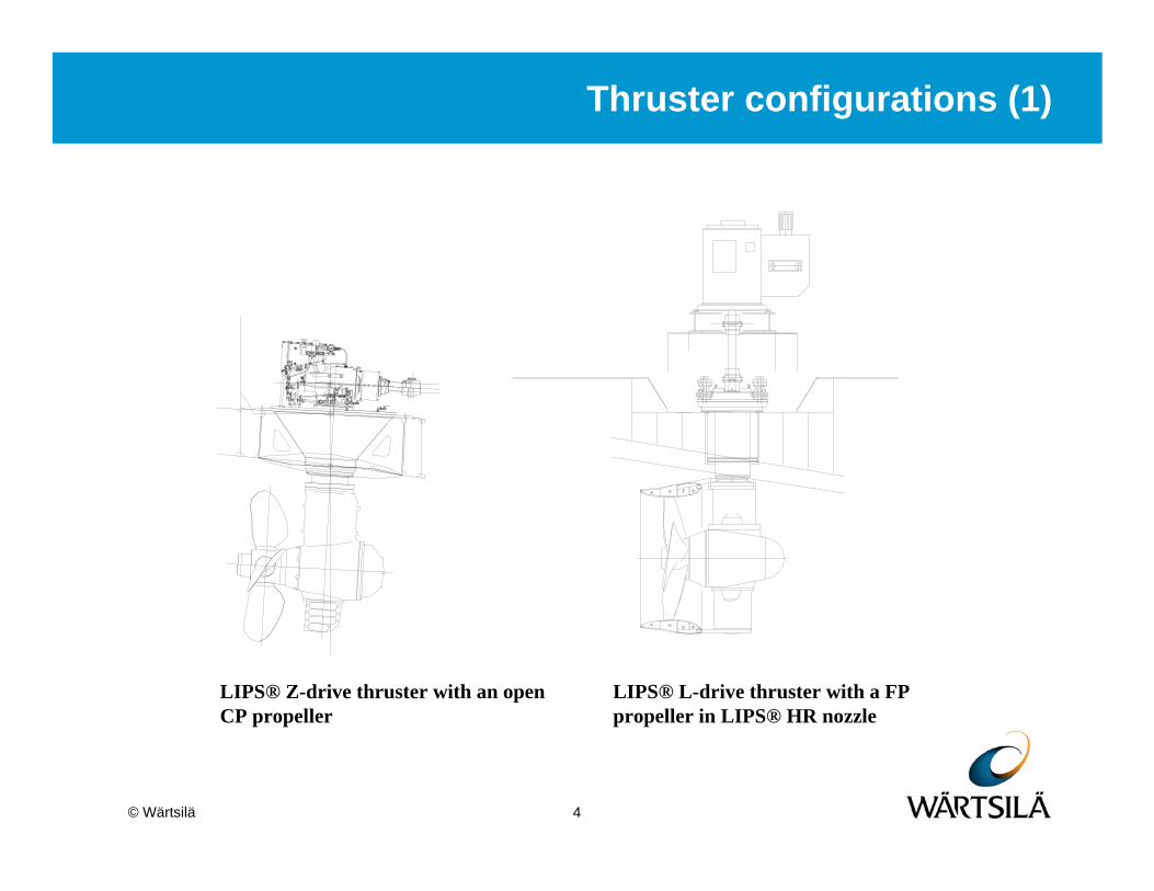
Thruster configurations (1)
LIPS® Z-drive thruster with an open CP propeller
LIPS® L-drive thruster with a FP propeller in LIPS® HR nozzle

5© Wärtsilä
Thruster configurations (2)
LIPS® Z-drive thruster with open propeller (CPP) and pulling arrangement
Thruster with Z-drive and CRP installation

6© Wärtsilä
Propulsion efficiency (1)
Open water characteristics
0
0.2
0.4
0.6
0.8
1
1.2
0 0.2 0.4 0.6 0.8 1 1.2
J=V/nD
Kt,
10K
q, E
ta0
Kt10KqEta0
0
0.2
0.4
0.6
0.8
1
1.2
0 0.2 0.4 0.6 0.8 1 1.2
J=V/nD
Kt,
10K
q, E
ta0
Kt10KqEta0
a typical open propeller typical counter-rotating propellers
0
0.2
0.4
0.6
0.8
1
1.2
0 0.2 0.4 0.6 0.8 1J=V/nD
Kt, 1
0Kq,
Eta
0
Kt10KqEta0Ktn
0
0.2
0.4
0.6
0.8
1
1.2
0 0.2 0.4 0.6 0.8 1J=V/nD
Kt, 1
0Kq,
Eta
0
Kt10KqEta0Ktn
a typical nozzle propeller in 19A nozzle a typical nozzle propeller in LIPS® HR high efficiency nozzle

7© Wärtsilä
Propulsion efficiency (2)
Slope of curves
and
Counter-rotating propellers
and
Ducted propeller
TT
dKsdJ
=(10 )Q
Q
d Ks
dJ=
T TCRP OPs s> Q QCRP OPs s>
_ 00Qnozzle propeller J
s==

8© Wärtsilä
Propulsion efficiency (3)
Bollard pull efficiency
Merit coefficient32( / )T
dQ
KKπη =
0.5
0.7
0.9
1.1
1.3
1.5
1.7
1.9
0.5 0.7 0.9 1.1 1.3 1.5propeller pitch ratio (front propeller for CRP) P/D
Mer
it co
effic
ient
ηd
B4-70Wageningen CRP series Ka4-70 in 19A nozzleKa4-70 in HR nozzle
Comparison of bollard pull efficiency among different type of propulsors

9© Wärtsilä
Propulsion efficiency (4)
Bollard pull efficiencyDucted propeller (major influences):
Blade contourPitch distributionTrailing edge
0.5
0.7
0.9
1.1
1.3
1.5
1.7
1.9
0.5 0.7 0.9 1.1 1.3 1.5propeller pitch ratio P/D
Mer
it co
effic
ient
ηd
Ka4-70 in 19A nozzle
B4-70 in 19A nozzle0.6
0.8
1.0
1.2
1.4
1.6
1.8
2.0
0.9 1.0 1.1 1.2 1.3Ptip / P0.7R
Mer
it co
effic
ient
ηd
Influence of tip loading on pull efficiency (propellers with Kaplan form blades in No. 19 nozzle, based on the model test results of van Manen, 1962)
Influence of tip chord length on pull efficiency

10© Wärtsilä
Propulsion efficiency (5)
0
10
20
30
40
50
60
70
0% 50% 100% 150%engine power [%]
pull
thru
st [t
ons]
blades with normal anti-sing edgeon suction side
blades with large ''anti-sing edge'' onpressure side
0%
20%
40%
60%
80%
100%
120%
50% 60% 70% 80% 90% 100% 110%engine shaft speed [%]
engi
ne p
ower
[%]
blades with normal anti-singedge on suction side
blades with large ''anti-singedge'' on pressure side
Engine output limit
Full-scale measurements of pull thrust vs. shaft power for a tug boat – Thetis, Iskes Sleepdiensten BV, IJmuiden, the Netherlands
Full scale measured power-shaft speed relation for the same propeller with different ‘anti-sing edges’

11© Wärtsilä
Propulsion efficiency (6)
Free sailing efficiency
0 2T
Q
JKK
ηπ
=
Comparison of the open water efficiency of different propulsors (where P/D is either the pitch ratio of the propeller or the pitch ratio of the front propeller for counter-rotating propellers)
0.81.0 1.0
1.2
1.0
1.2
1.1
1.3
0.4
0.5
0.6
0.7
0.8
0.0 0.5 1.0 1.5 2.0 2.5 3.0 3.5 4.0 4.5 5.0Thrust load coefficient Ct
Ope
n w
ater
effi
cien
cy η0
Open Propeller B4-70Wageningen CRP series
Ka4-70 in 19A nozzleKa4-70 in high efficient nozzle
P/D=
2
8 tt
KCJπ
=

12© Wärtsilä
Propulsion efficiency (7)
Pulling or pushing arrangement?
Efficiency of pulling arrangementTwo factors
1. Friction losses – underwater housing in the slipstream of the propeller wake
2. Rotational energy recovery – due to the down stream strut and fins
For propeller with light loadRotational energy recovery > Friction losses
pulling is betterfast vessel
For propeller with heavy loadFriction losses > Rotational energy recovery
pushing is betterlow speed vessel

13© Wärtsilä
Propulsion efficiency (8)
Based on systematic research at SVA Potsdam Grey area Ct=0.5 to 1.0
14© Wärtsilä
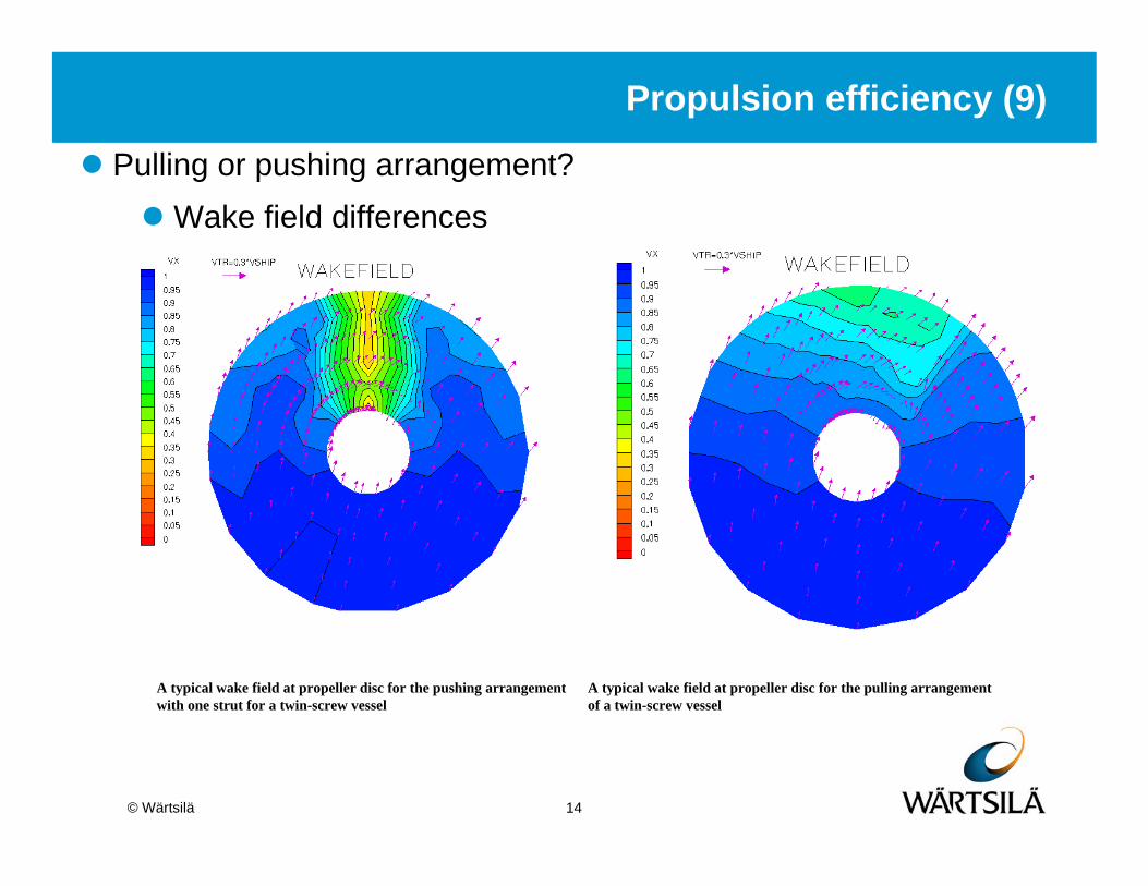
Propulsion efficiency (9)
Wake field differences
A typical wake field at propeller disc for the pulling arrangement of a twin-screw vessel
A typical wake field at propeller disc for the pushing arrangement with one strut for a twin-screw vessel
Pulling or pushing arrangement?

15© Wärtsilä
Matching with the engine/E-motor (1)
Fixed pitch propeller or controllable pitch propeller
0%
10%
20%
30%
40%
50%
60%
70%
80%
90%
100%
110%
120%
0% 10% 20% 30% 40% 50% 60% 70% 80% 90% 100% 110% 120%
shaft speed N [%]
pow
er P
B [%
]
FSAH FPP OPENFSAH FPP HRFSAH CRPBAH FPP OPENBAH FPP HRBAH CRP
MCR
Design PointMax
. BA
H th
rust
(311
kN) a
t Max
. tor
que
Max
. BA
H th
rust
(366
kN) a
t Max
. tor
que
Max
. BA
H th
rust
(515
kN) a
t Max
. tor
que
Comparison of three different propulsion concepts for an offshore supply vessel with diesel-electric drive propulsion systems (two azimuth thrusters per ship at the stern), here FSAH - free sailing ahead, BAH – bollard ahead

16© Wärtsilä
Matching with the engine/E-motor (2)
A typical semi-submersible
The typical propeller curves for a semi-submersible with two pontoons and four azimuth thrusters with FPP in LIPS® HR nozzle, two thrusters at the bow and two at the stern
0%
20%
40%
60%
80%
100%
120%
140%
160%
50% 60% 70% 80% 90% 100% 110% 120%
N[%]
PB[%
]
Trial-(bow)ThusterTrial-(stern)ThusterService-(bow)ThrusterService-(stern)ThrusterBollard Vs=0knBollard Vs=-2kn
MCR
Qmax

17© Wärtsilä
Thruster-thruster, thruster-hull interactionsunderstanding the jet (1)
water jet of the thruster - the shape
18© Wärtsilä
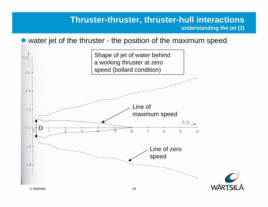
Thruster-thruster, thruster-hull interactions understanding the jet (2)
Shape of jet of water behind a working thruster at zero speed (bollard condition)
Line of maximum speed
Line of zero speed
D
water jet of the thruster - the position of the maximum speed

19© Wärtsilä
Thruster-thruster, thruster-hull interactions understanding the jet (3)
Maximum jet speeds for thruster in bollard pull condition
water jet of the thruster - the maximum speed

20© Wärtsilä
Thruster-thruster, thruster-hull interactions understanding the jet (4)
Position of maximum speed goes to shaft center line at x/D = 4 (was 6 without plate)
Flat plate at 0.75D below thruster center line
Position of maximum speed does not stay on center line, but moves towards the plate
Maximum speed for water jet close to a flat plate
Magnitude of maximum speed does not change compared to open water situation !

21© Wärtsilä
Thruster-thruster, thruster-hull interactionsthruster-thruster interaction (1)
3 major different interactions in discussion
x D
x D
x
D φ

22© Wärtsilä
Thruster-thruster, thruster-hull interactionsthruster-thruster interaction (2)
Thrusters in tandem in free open waterFormula to calculate thrust ratio
x D
23( / )
0/ 1 0.8 x DT T = −
0%
20%
40%
60%
80%
100%
0 5 10 15 20 25 30Propeller distance ratio x/D
Thru
st ra
tio [%
] .
Lehn(1980)
Moberg(1983)

23© Wärtsilä
Thruster-thruster, thruster-hull interactionsthruster-thruster interaction (3)
23( / )
0/ 1 0.75 x DT T = −
Thrusters in tandem under a flat bottomFormula to calculate thrust ratio
x D
0%
20%
40%
60%
80%
100%
0 5 10 15 20 25 30Propeller distance ratio x/D
Thru
st ra
tio [%
] .
Nienhuis(1992)
Blaurock (1977)

24© Wärtsilä
Thruster-thruster, thruster-hull interactionsthruster-thruster interaction (4)
x
D φ
3
3 3(1 )130 /
t t ttφφ
φ= + −
+
Steering angle on the thrusters can reduce the thrustlossLarger angles reducethrustlossFormula to calculate the thrustratio
0%
10%
20%
30%
40%
50%
60%
70%
80%
90%
100%
0 5 10 15 20 25 30 35
steering angle of the forward thruster [degrees]
Thru
st ra
tio [%
]
.
Nienhuis (1992) x/D=2.0Nienhuis (1992) x/D=4.0Nienhuis (1992) x/D=8.0Nienhuis (1992) x/D=16.0Lehn (1980) x/D=3.0Lehn (1980) x/D=6.0

25© Wärtsilä
Thruster-thruster, thruster-hull interactionsthruster-thruster interaction (5)
Interaction applicable toboth bollard and free sailingconditionImportant since DP thrusters are used for mainpropulsion as well
0%
20%
40%
60%
80%
100%
0 5 10 15 20 25 30Propeller distance ratio x/D
Tota
l thr
ust r
atio
of t
wo
thru
ster
s [%
] .
Blaurock (1977) J=0.00
Blaurock (1977) J=0.20
Blaurock (1977) J=0.36

26© Wärtsilä
Thruster-thruster, thruster-hull interactionsThruster-hull interaction (1)
Water jet close to a flat plateReductions can be as high as 20-25%, Thrusters in the bow are inefficient in the sailing direction

27© Wärtsilä
Thruster-thruster, thruster-hull interactionsThruster-hull interaction (2)
water jet along curved surface

28© Wärtsilä
Thruster-thruster, thruster-hull interactionsthruster-hull interaction (3)
Coanda effect

29© Wärtsilä
Thruster-thruster, thruster-hull interactionsThruster-hull interactions (4)
Thrust deduction depending on stern heeling angleFor astern thrust in practice two times larger than ahead
0.03
0.04
0.05
0.06
0.07
0.08
0.09
0.1
0.11
0.12
10 12 14 16 18 20 22 24
stern heeling angle [degrees]
thru
st d
educ
tion
t
Slope

30© Wärtsilä
Thruster-thruster, thruster-hull interactionsthruster-hull interaction (5)
0%10%
20%
30%
40%
50%
60%
70%
80%
90%
100%0
15
30
45
60
75
90
105
120
135
150
165180
195
210
225
240
255
270
285
300
315
330
345
Typical results of Thruster-hull interaction test
31© Wärtsilä
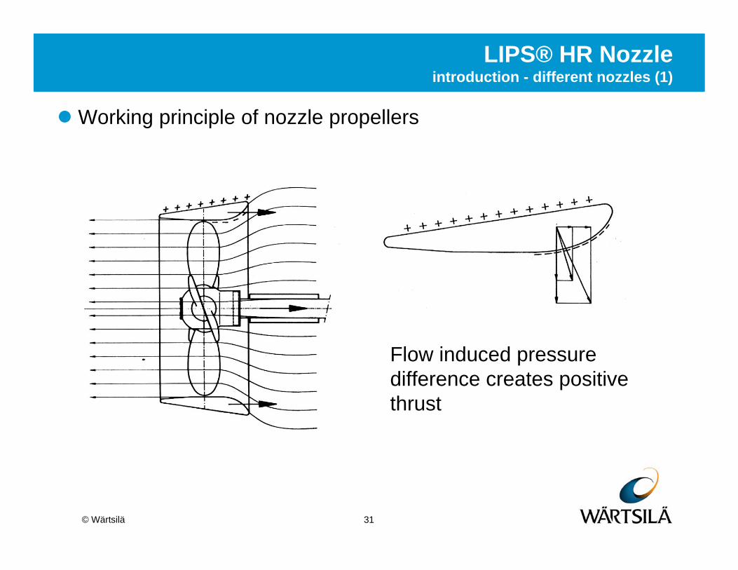
LIPS® HR Nozzleintroduction - different nozzles (1)
Working principle of nozzle propellers
Flow induced pressure difference creates positive thrust

32© Wärtsilä
LIPS® HR Nozzleintroduction - different nozzles (2)
Different nozzles

33© Wärtsilä
Bollard condition (BAH)
Free sailing (FSAH)
LIPS® HR Nozzleintroduction - different nozzles (3)
Different flow patterns at BAH and FSAH

34© Wärtsilä
LIPS® HR Nozzlebackground of HR nozzle
Designed to improve the flowaround the nozzleDesigned to improve efficiency at high speedSeries tests done at GermanSVA Potsdam instituteImproved performance; 8 to10% better than 19A
Flow visualisation in cavitation tunnel

35© Wärtsilä
LIPS® HR Nozzleflow analysis - CFD (1)
Propeller in HR nozzle - StarCD®

36© Wärtsilä
19A Nozzle HR Nozzle
VELOCITY FIELD
LIPS® HR Nozzleflow analysis - CFD (2)
Comparison - 19A versus HR nozzle

37© Wärtsilä
LIPS® HR Nozzleflow analysis - CFD (3)
Calculated flow pattern around HR nozzlerounded leading and trailing edgelarger induced velocitymore nozzle thrust and less resistance

38© Wärtsilä
100% 103% 100%108%
0%
20%
40%
60%
80%
100%
120%
Model scale Full scale
Bollard condition19A HR
LIPS® HR Nozzleflow analysis - CFD (4)
Comparison - calculated bollard pull thrust

39© Wärtsilä
Full scale
Model scale
Difference model to full scale
LIPS® HR Nozzleflow analysis - CFD (5)

40© Wärtsilä
With:CPP’sFPP’s (4 and 5 bladed)Steerable thrusters
Up to 3.75 [m]Up to 5500 kW
Ranging from 0 to 18+ knotsDmax. = 5.2 [m] with 12640 kW
Many HR-nozzles already sailing !
LIPS® HR Nozzlefull scale experience

41© Wärtsilä
Application of Thrusters
The largest pipe layer -Solitaire
Vessel specLength 300 [m]Transit speed 13 [kn]Accommodation 420 [men]
Thrusters8 LIPS® azimuth thrusterspartly bollard pull and partly free sailing designpartly HR and partly special nozzle5.55MW@199RPMpropeller diameter 3.75m

42© Wärtsilä
Application of Thrusters
Heavy-lifting vessel - Thialf
Vessel specLength 201 [m]Breadth 88.4 [m]Accommodation 736 [men]
Thrusters6 LIPS® azimuth retractable thrustersbollard pull design (85 tons/unit)19A nozzle5.5MW@199RPMpropeller diameter 3.4m

43© Wärtsilä
Application of Thrusters
Maintenance Service Support Accommodation Unit
vessel specLength ~94 [m]Breadth ~45 [m]
thrusters4 LIPS® azimuth thrustersbollard pull design (50 tons/unit)LIPS® HR nozzle2.5MW @ 203RPMpropeller diameter 3.2mOverspeed of driving motor for free sailing
44© Wärtsilä
Application of Thrusters
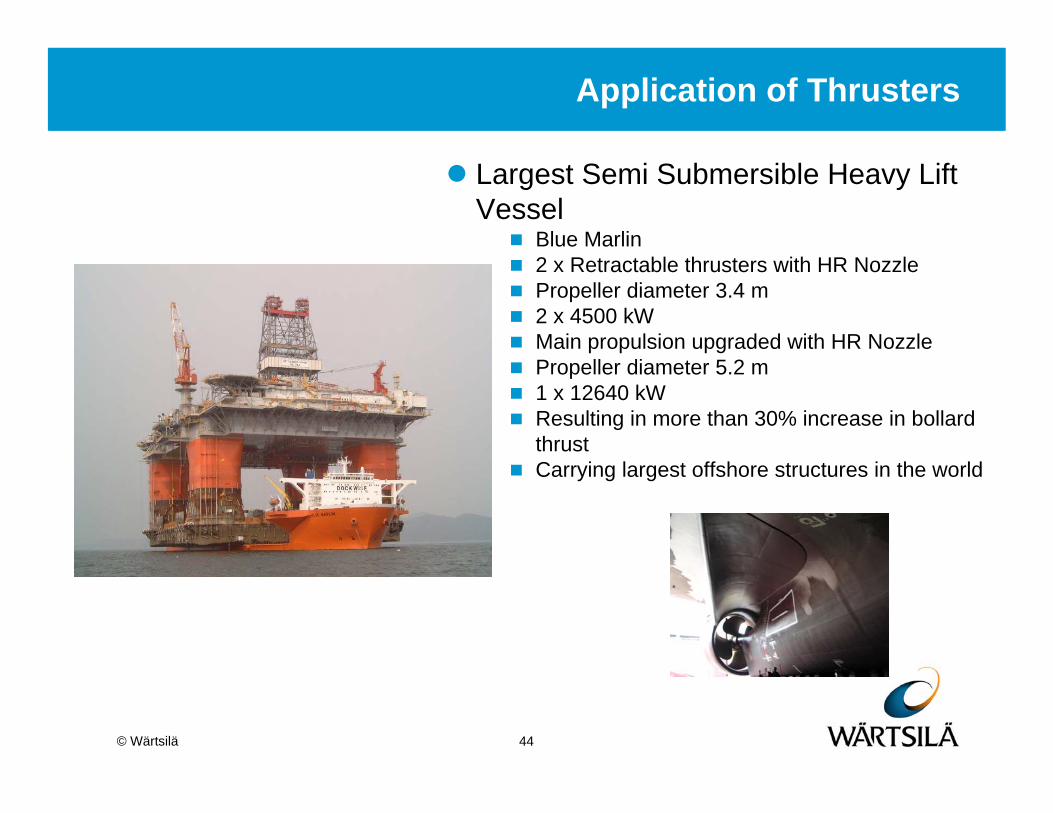
Largest Semi Submersible Heavy Lift Vessel
Blue Marlin2 x Retractable thrusters with HR NozzlePropeller diameter 3.4 m2 x 4500 kWMain propulsion upgraded with HR NozzlePropeller diameter 5.2 m1 x 12640 kWResulting in more than 30% increase in bollard thrustCarrying largest offshore structures in the world

45© Wärtsilä
Application of Thrusters
Cable ShipCS Atlantic GuardianP=2 X 2200 kWPropellerdiameter 2.5 mElectric drive CPP thrusterL-drive configurationAble to absorb full power at all conditions

46© Wärtsilä
Application of Thrusters
Cable LayerCS- KnightMain propulsion 2 X 4500 kWPropellerdiameter 3.4 mRetractable 2 x 2000 kWPropellerdiameter 2.5 mElectric driven FP propellers

47© Wärtsilä
Application of Thrusters
Anchor Handling Tug Supply VesselSeabulk BadamyarP= 2 X 1440 kWPropellerdiameter 2.1 m7.4% extra bollard pull due to HR NozzleBollard pull is 10% over charter requirements

48© Wärtsilä
ConclusionsHydrodynamic aspects of steerable thrusters
Mission profile determines the choice of the design point; off-design condition and its co-operation with the E-motor (or engine) are important
For low-medium speed applications (e.g. DP/DT) pushing propellers are more efficient than pulling propellers
Interactions among thrusters, hull, barge, etc should not be ignored in thruster design
High efficiency nozzles improve efficiency8% extra bollard pull thrust10% extra free sailing propulsion efficiency
Propulsion Supplier should take all hydrodynamic aspects of thrusters into account to ensure a perfect match
between thrusters and the vessel

© Wärtsilä
Wärtsilä Propulsion Netherlands BV
+31 416 388283
Hans [email protected]
+31 416 388546
Questions?