hydraulic press mx340g · 2016-12-29 · instructions book prada nargesa, s.l ctra. de garrigàs a...
TRANSCRIPT

INSTRUCTIONS BOOK
PRADA NARGESA, S.L Ctra. de Garrigàs a Sant Miquel s/n
17476 PALAU DE STA. EULALIA (GIRONA) SPAIN
Tel. 972 568085 - Fax 972 568320
www.nargesa.com - [email protected]
HYDRAULIC PRESS
MX340G
Thank you for choosing our machines
www.nargesa.com
INSTRUCTIONS BOOK OF HYDRAULIC PRESS MX340G 2
THERE IS A DVD INCLUDED
AS AN ESSENTIAL PART OF
THIS BOOK.
IT’S GOT THE STEP-BY-STEP
PERFORMANCE OF THE
MACHINE AND SOME
EXAMPLES OF WORKS
THAT CAN BE CARRIED OUT
WITH IT.
INSTRUCTIONS BOOK OF HYDRAULIC PRESS MX340G 3
INDEX
1. FEATURES OF THE MACHINE ..............................................................................................
1.1. General dimensions ....................................................................................................
1.2. Description of the machine ..........................................................................................
1.3. Identification of the machne ........................................................................................
1.4. General characteristics ...............................................................................................
1.5. Description of safety devices ......................................................................................
2. TRANSPORT AND STORAGE ...............................................................................................
2.1. Transport .....................................................................................................................
2.2. Storage conditions ......................................................................................................
3. MAINTENANCE .......................................................................................................................
3.1. General maintenance ..................................................................................................
4. INSTALLMENT AND STARTING UP ......................................................................................
4.1. Location of the machine ..............................................................................................
4.2. Dimensions and working site ......................................................................................
4.3. Admissible outer conditions ........................................................................................
4.4. Connection to power supply ........................................................................................
5. OPERATION MANUAL ...........................................................................................................
6.1. Introduction .................................................................................................................
6.2. Power supply of the machine ......................................................................................
6.3. Activation of the machine ............................................................................................
6.4. Working at manual mode ............................................................................................
6.5. Working at automatic mode ........................................................................................
6.6. Meter deletion .............................................................................................................
6.7. Desactivation of the machine ......................................................................................
6.8. Unusual performance situations ..................................................................................
7. WARNINGS .............................................................................................................................
8. ACCESSORIES .......................................................................................................................
TECHNICAL ANNEX
4
4
4
5
6
6
7
7
7
8
8
9
9
9
9
10
11
12
12
12
13
13
14
15
15
17
18
INSTRUCTIONS BOOK OF HYDRAULIC PRESS MX340G 4
1. FEATURES OF THE MACHINE
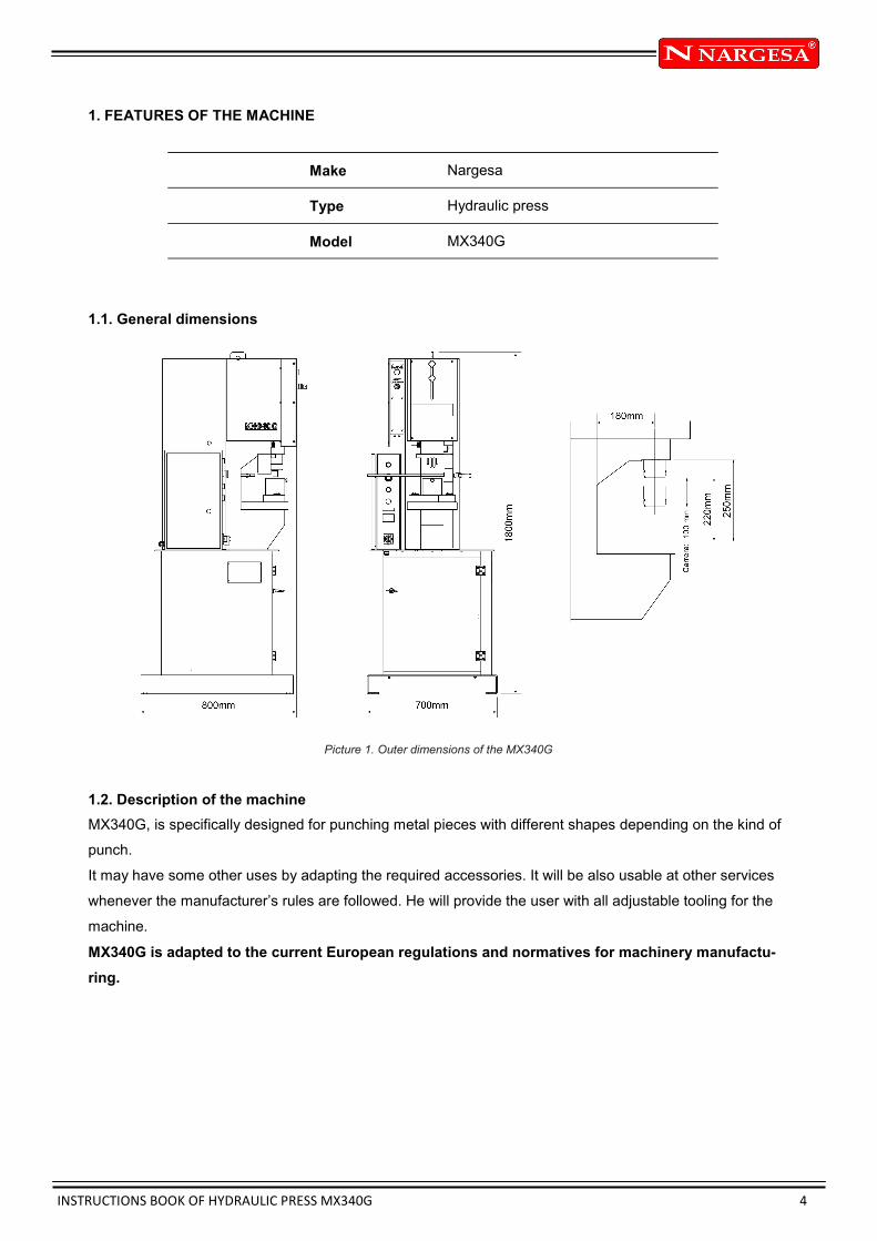
1.1. General dimensions
Picture 1. Outer dimensions of the MX340G
1.2. Description of the machine
MX340G, is specifically designed for punching metal pieces with different shapes depending on the kind of
punch.
It may have some other uses by adapting the required accessories. It will be also usable at other services
whenever the manufacturer’s rules are followed. He will provide the user with all adjustable tooling for the
machine.
MX340G is adapted to the current European regulations and normatives for machinery manufactu-
ring.
Make Nargesa
Type Hydraulic press
Model MX340G
INSTRUCTIONS BOOK OF HYDRAULIC PRESS MX340G 5
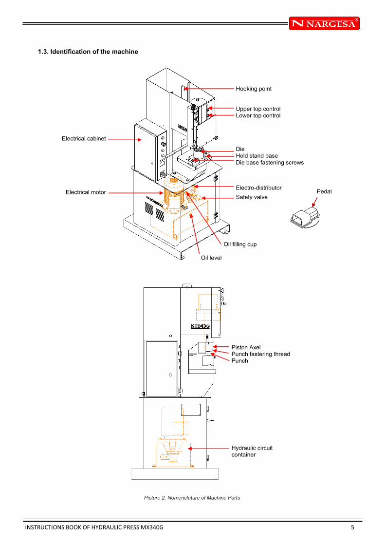
Electrical cabinet
Electrical motor
Oil level
Hooking point Upper top control Lower top control Die Hold stand base Die base fastening screws
Electro-distributor
Safety valve Pedal
Oil filling cup
Piston Axel Punch fastering thread Punch
Hydraulic circuit container
1.3. Identification of the machine
Picture 2. Nomenclature of Machine Parts

INSTRUCTIONS BOOK OF HYDRAULIC PRESS MX340G 6
1.4. General characteristics
1.5. Description of safety devices
One of the safety devices the MX340G's got is the extractor piece located in the front part of the machine to
hold up the material and prevent from placing hands between the punch and the piece.
It has also got a screen to protect the user from any projections coming from the working piece. This
screen has a safety system to avoid the punch from descending if the screen is up. It would only work if the
user turns the key C to cancel this safety command, then it would be possible to work along with the hazard
light D.
Picture 3. Protection devices of the machine
Engine power 2,2 Kw a 1460 r.p.m.
Tension 230 / 400 V 3 phased
Consumption 12,8 a 7 A
Pump 7,5 l./m
Container 27 litros
Double effect piston 34 Tn
Maximum pressure 200 Kg
Structure material Plaque
Total weight 615 Kg
Hazard light D
Key C
Extractor
Screen

INSTRUCTIONS BOOK OF HYDRAULIC PRESS MX340G 7
2. TRANSPORT AND STORAGE
2.1. Transport
The transport without lifting will be carried out by a transpalet, with elevation will be made by a crane, using
the hooking spot marked below. although it must never be lifted more than 300mm, to prevent from a turno-
ver.
Handrails on the base will only do for the transportation. Once the machine is placed on its final site it must
be left so it can settle down on the ground.
Picture 4. Transport of the machine
2.2. Storage conditions
The machine ought to be stored in a place that meets the following requirements:
* Humididty between 30% and 95% without condensation.
* Temperature from -25 to 55ºC or 75ºC for a length of time no longer that 24 hours (keep in mind that
these temperatures are just for storage conditions).
* It is advisable not to stack machines or heavy objets on them.
* Do not dismantle it for storage.

INSTRUCTIONS BOOK OF HYDRAULIC PRESS MX340G 8
3. MAINTENANCE
3.1. General maintenance
- Oil level container must be checked up every 500 hours of use.
In the frontal part of the container we can find the oil level cap. In case of lack of oil, please fill up the con-
tainer until the oil cap shows 3/4 parts full. Picture 5
- Replace hydraulic oil of the container every 2000 hours of work or every 3 years.
Type: CEPSA HIDRAULICO HM 68
Picture 5. Identification of the Components of the hydraulic container
WARNING
Stop the machine and press the emergency stop to carry out the oil change. Pictures 6 and 7
Once the oil has been changed, start up the machine and press the pedal intermitently raising up the pres-
sure time gradually until the circuit is full. You’ll see the machine running its normal route.
- Grease punches periodically according to the use received.
-If t is daily and steadily used, grease it everyday.
- If it is daily used but just on and off, then grease ut every week.
-If the use is just sporadic, then grease it once a month.
Picture 6. Stop The Machine Picture 7. Press the emergency stop
Oil filling cap
Oil level
INSTRUCTIONS BOOK OF HYDRAULIC PRESS MX340G 9
4. INSTALLMENT AND STARTING UP
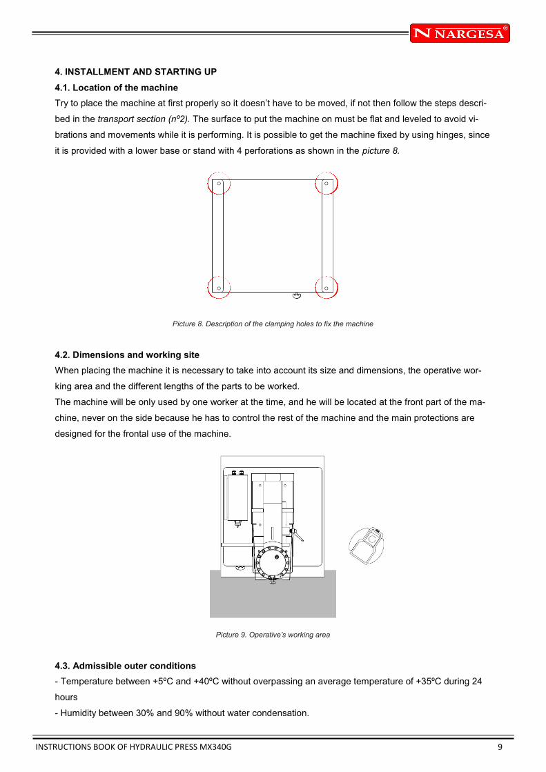
4.1. Location of the machine
Try to place the machine at first properly so it doesn’t have to be moved, if not then follow the steps descri-
bed in the transport section (nº2). The surface to put the machine on must be flat and leveled to avoid vi-
brations and movements while it is performing. It is possible to get the machine fixed by using hinges, since
it is provided with a lower base or stand with 4 perforations as shown in the picture 8.
Picture 8. Description of the clamping holes to fix the machine
4.2. Dimensions and working site
When placing the machine it is necessary to take into account its size and dimensions, the operative wor-
king area and the different lengths of the parts to be worked.
The machine will be only used by one worker at the time, and he will be located at the front part of the ma-
chine, never on the side because he has to control the rest of the machine and the main protections are
designed for the frontal use of the machine.
Picture 9. Operative’s working area
4.3. Admissible outer conditions
- Temperature between +5ºC and +40ºC without overpassing an average temperature of +35ºC during 24
hours
- Humidity between 30% and 90% without water condensation.

INSTRUCTIONS BOOK OF HYDRAULIC PRESS MX340G 10
4.4 Connection to power supply
MX340G, is equipped with an 230V/400V three phased engine, 2.2 Kw star connected to be connected to a
400v power supply. It sould be connected to only one power supply in the power source indicated. If the
line tension is not the one indicated then it is necessary to change the motor bobbins connection and the
transformer as it is indicated in the pictures.
In case of change of voltage from 400V to 230V, switch terminal 6 from 400V to 230V.
Picture 12. Location of Terminal 6 on the electric plate
Picture 10. Star Picture for tension 400V
(preset)
Picture 11. Triangle picture for tension 230V
IMPORTANT
This must be connected to a power supply with ground wire.

INSTRUCTIONS BOOK OF HYDRAULIC PRESS MX340G 11
5. OPERATION MANUAL
Picture 13. Control Panel
Tension pilot Emergency stop Pilot reset Reset Control screen Key to cancel one operation Key to go to automatic mode Key to go manual mode
Main switch
Off key to stop the machine
ON key to start the
machine
Key to erase the counting of punch
operations
INSTRUCTIONS BOOK OF HYDRAULIC PRESS MX340G 12
5.1. Introduction
This manual is designed to be an useful tooling for the MX340G user since it has important information
about the usage and specifications of the machine. Therefore it is important to follow step by step all the
points detailed in this manual so to get to achieve a better understanding of the performance of the
machine.
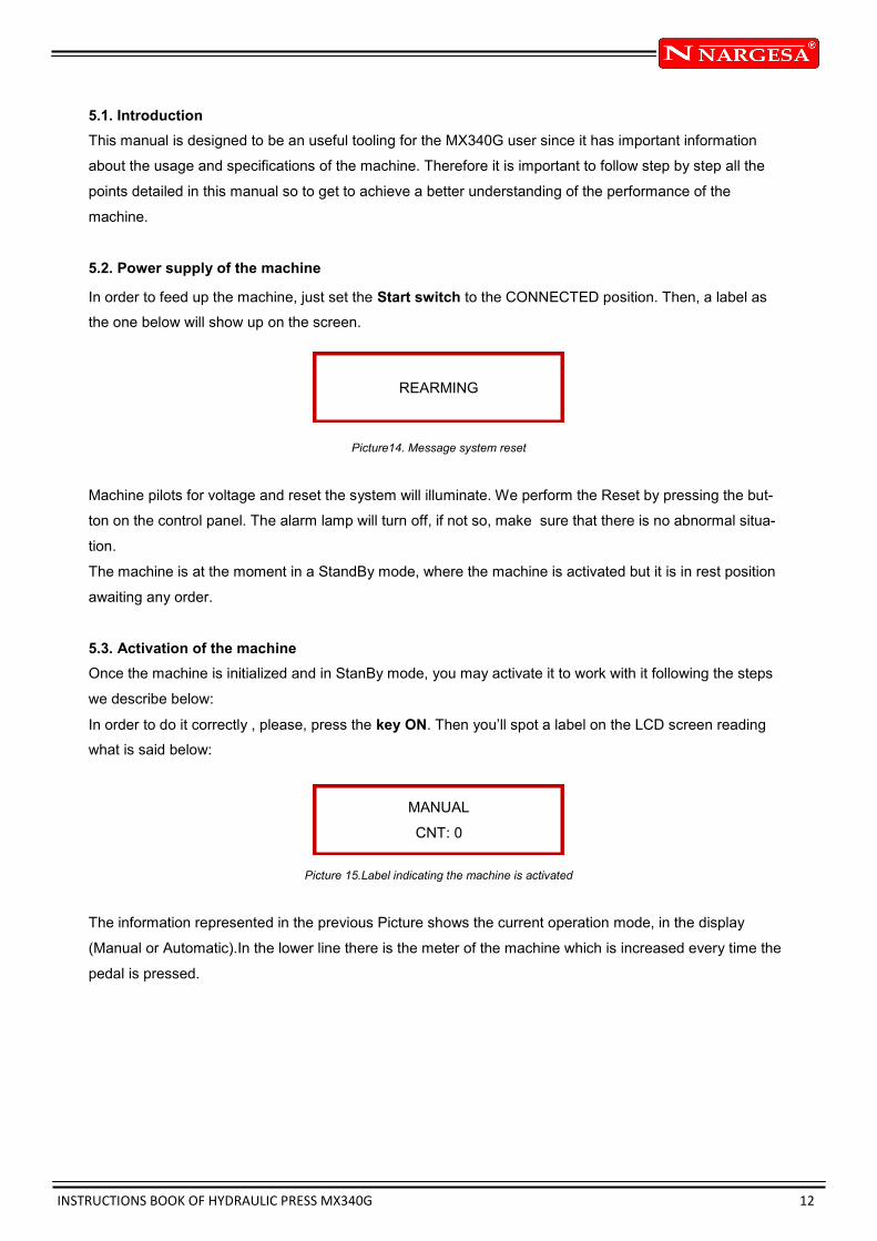
5.2. Power supply of the machine
In order to feed up the machine, just set the Start switch to the CONNECTED position. Then, a label as
the one below will show up on the screen.
Picture14. Message system reset
Machine pilots for voltage and reset the system will illuminate. We perform the Reset by pressing the but-
ton on the control panel. The alarm lamp will turn off, if not so, make sure that there is no abnormal situa-
tion.
The machine is at the moment in a StandBy mode, where the machine is activated but it is in rest position
awaiting any order.
5.3. Activation of the machine
Once the machine is initialized and in StanBy mode, you may activate it to work with it following the steps
we describe below:
In order to do it correctly , please, press the key ON. Then you’ll spot a label on the LCD screen reading
what is said below:
Picture 15.Label indicating the machine is activated
The information represented in the previous Picture shows the current operation mode, in the display
(Manual or Automatic).In the lower line there is the meter of the machine which is increased every time the
pedal is pressed.
REARMING
MANUAL
CNT: 0

INSTRUCTIONS BOOK OF HYDRAULIC PRESS MX340G 13
5.4. Working at manual mode
In this mode,follow the steps described next: Press the pedal to make the punching operation.Then you will
see on the LCD screen that the meter of the machine has been increased in one unit.
Picture 16. Information of the Manual Punching operation
In picture 16, you can see how the meter marks 1 punching operation now. Once that punching operation
has been completed,you may get your foot off the pedal.
You must keep in mind that this mode of performance permits the piston rod descend bit by bit as you are
pressing the pedal longer or not. When the lower route end is reached or when you raise your foot off the
pedal, the rod movement stops.
According to this way of performance, you may adjust the Lower route end to graduate the the going down
of the rod while you press the pedal and so you will be able to see how the machine keeps on descending
until the afored mentioned route end is reached.
Finally, it is important to remind that in this mode of performance the rod of the machine never goes in as-
cending direction, so in case you need it to go up, you should proceed as detailed in the following section.
5.5. Working at automatic mode
In order to go from MANUAL working mode to AUTOMATIC working mode, just press the AUTOMATIC
key. In doing so, the machine will ask you a confirmation and we press the AUTO key again. Then the rod
will activate going up. Such movement won’t stop until the machine has reached the Upper End route. Ex-
cept for that the AUTOMATIC mode is quite similar to the one described in the section 5.4. However, we
will point out below some of the differences we find:
Press the pedal to make the punching operation. Then you will see the meter of the machine increased in
one unit.
Picture 17. Information of the Automatic punching operation
In picture 17, you can see how the meter has increased again when pressing the pedal and now it is indica-
ting a 2. Once this operation has been finished, you may leave your foot off the pedal. Nevertheless in this
working mode, unlike in the other one, the piston rod will come back again to the rest position when it will
start up the going up movement until the lower end route is activated.
MANUAL
CNT: 1
AUTOMATIC
CNT: 2

INSTRUCTIONS BOOK OF HYDRAULIC PRESS MX340G 14
You should keep in mind that this working mode will also allow the rod to descend bit by bit to adjust the
going down by the positioning of the lower end route. Whenever you keep the pedal pressed the rod will
make a descending movement that will be only interrupted when the route end is activated. When you raise
the foot off the pedal the rod will invert the movement and will start up ascending.
5.6. Meter deletion
As you have read in the previous sections, MX340G has got a punching meter that increases everytime
you press the pedal. This fact could be useful in case you need to count the punching operations required
for either a specific piece or the operations a third user has carried out with your machine.
Óbviously, this meter can be deleted. In order to do it right, and supposing there is a label like this one on
the LCD screen, for instance, You have carried out 150 punching operations, keep on the following indica-
tions.
Picture 18. Information about the number of operations made.
It is important that the meter could be erased always and just when you find the machine ready to start wor-
king but without doing any operation (in StandBy mode it is not possible), so it is possible in Automatic or
Manual mode.
Just press the COUNTER key. Then the message in the screen will change into this other one.
Picture 19. Message of information about the meter deletion.
It is obvious that if you press ESC key, the meter will not be affected and it will go back to the previous
screen. On the other hand, in case you wish to delete the meter when you see the question made by the
previous screen, just press COUNTER key again.the new message will show up as follows on the screen.
Figura 20. Information of the meter deletion
MANUAL
CNT: 150
Delete meter?
Meter deleted!

INSTRUCTIONS BOOK OF HYDRAULIC PRESS MX340G 15
5.7. Desactivation of the machine
Any time that the activated machine is in rest position, you can deactivate it. If you wish so, please press
the key OFF and the machine will deactivate and will go to the StandBy mode (See section 5.2).
5.8. Unusual performance situations
An unusual performance situations may happen any time, it implicates to stop any operation that is being
carried out at the moment.
Unusual situations are divided into two big groups, Emergency situations and Error situations. Causes that
lead to both groups are specified below.
Situations of emergency:
Activation of the Emergency Stop.
Figura 21. Information about the Emergency Stop
Error Situations:
Error inthe Upper Route End of the machine.
Figura 22. Information about the Error in the Upper route end
Error in the Lower route End of the MX340G.
Figura 23. Information about error in the Lower Route End
EMERGENCY STOP
ERROR IN THE
UPPER ROUTE END
VERIFIES THE TURNING
DIRECTION OF THE ENGINE

INSTRUCTIONS BOOK OF HYDRAULIC PRESS MX340G 16
So, when we face one the aforementioned situations, the machine goes to such a estate that it aborts any
operation that is being performed at the moment, then a label will show up indicating the sort of unusual
situation sthat has occurred.
For safety reasons, it is not permitted a new activation of the MX340G until the unusual situation has been
solved ou. In case of Emeregency Situations, it can be solved out rearming the emergency Stop button.
Once it has been done the machine will restart and it will go into a StandBy mode (please see section 5.3
for a further activation of the MX340G).
In case an Error situation occurs, with the intention of preventing from bigger damages or hazardous situa-
tions for the users, the MX340G will remain blocked and the corresponding label will come out on the
screen. In this case the machine can be unblocked by unpluging it from the power supply and plugging it
again afterwards. Anyways in case any of these situations occurs, please contact our Technical Service so
the problem can be solved out as soon as possible.

INSTRUCTIONS BOOK OF HYDRAULIC PRESS MX340G 17
6. WARNINGS
- Do not handle any component while the machine is performing.
- Do not use the machine for any other purpose but the ones described in this manual.
- Wear safety gloves when handling all components of the machine and while performing the punching
operations.
- Wear safety glasses and safety footwear according to the current European regulations.
- Do not work without the protection devices provided along with the machine.
- Keep a safety distance between the machine and the operative while the machine is performing.
- Do not use any other tooling but the ones provided be NARGESA.
- All tooling that can be fitted to the machine must be fixed to the base and also to the piston.
- In case of an accident due to the negligence of the operative for not following the usage and safety rules
described in this manual, NARGESA S.L will not take any responsibility.
WARNING!
Never place pieces that don’t stand both lateral sides of the EXTRACTOR
Never punch extremely narrow or flexible parts since they might bend in towards the extractor.
- Do not punch pieces that cannot simetrically stand on the extractor.
- Do not punch if the piece is not leaning on both sides of the extractor
The punch breaks down
when going back.
Correct extraction
The punch breaks down
when going back.
Correct extraction
Never punch a metal sheet thicker that the punch diameter
INSTRUCTIONS BOOK OF HYDRAULIC PRESS MX340G 18
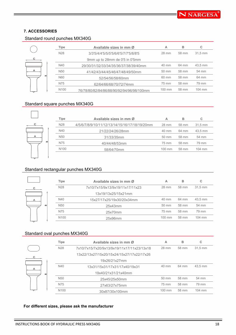
7. ACCESSORIES
Standard round punches MX340G
Tipe
N28
N40
N50
N60
N75
N100
Available sizes in mm Ø
3/3'5/4/4'5/5/5'5/6/6'5/7/7'5/8/8'5
9mm up to 28mm de 0'5 in 0'5mm
29/30/31/32/33/34/35/36/37/38/39/40mm
41/42/43/44/45/46/47/48/49/50mm
52/54/56/58/60mm
62/64/66/68/70/72/74mm
76/78/80/82/84/86/88/90/92/94/96/98/100mm
A
28 mm
40 mm
50 mm
60 mm
75 mm
100 mm
B
58 mm
64 mm
58 mm
58 mm
58 mm
58 mm
C
31,5 mm
43,5 mm
54 mm
64 mm
79 mm
104 mm
Standard square punches MX340G
Standard rectangular punches MX340G
For different sizes, please ask the manufacturer
Tipe
N28
N40
N50
N75
N100
Available sizes in mm Ø
4/5/6/7/8/9/10/11/12/13/14/15/16/17/18/19/20mm
21/22/24/26/28mm
31/33/35mm
40/44/48/53mm
58/64/70mm
A
28 mm
40 mm
50 mm
75 mm
100 mm
B
58 mm
64 mm
58 mm
58 mm
58 mm
C
31,5 mm
43,5 mm
54 mm
79 mm
104 mm
Tipe
N28
N40
N50
N75
N100
Available sizes in mm Ø
7x10/7x15/9x13/9x19/11x17/11x23
13x19/13x25/15x21mm
15x27/17x25/19x30/20x34mm
25x43mm
25x70mm
25x96mm
A
28 mm
40 mm
50 mm
75 mm
100 mm
B
58 mm
64 mm
58 mm
58 mm
58 mm
C
31,5 mm
43,5 mm
54 mm
79 mm
104 mm
Standard oval punches MX340G
Tipe
N28
N40
N50
N75
N100
Available sizes in mm Ø
7x10/7x15/7x20/9x13/9x19/11x17/11x23/13x18
13x22/13x27/15x20/15x24/15x27/17x22/17x26
19x26/21x27mm
13x31/15x31/17x31/17x40/19x31
19x40/21x31/21x40mm
25x45/25x50mm
27x63/27x75mm
30x87/30x100mm
A
28 mm
40 mm
50 mm
75 mm
100 mm
B
58 mm
64 mm
58 mm
58 mm
58 mm
C
31,5 mm
43,5 mm
54 mm
79 mm
104 mm

INSTRUCTIONS BOOK OF HYDRAULIC PRESS MX340G 19
Fitting nuts for punches MX340G
Tipe
TAP28
TAP40
TAP50
TAP60
ATAP
Fitting nuts for punches
Fitting nuts for punches N28 Standard
Fitting nuts for punches N40
Fitting nuts for punches N50
Fitting nuts for punches N60
Fitting part for TAP60
Fitting parts for dies MX340G
Tipe
N46
N60
N78
N100
N125
Fitting for dies
Fitting for dies N46 Standard
Fitting for dies N60
Fitting for dies N78
Base holder for dies N100
Base holder for dies N125 BASE HOLDER

INSTRUCTIONS BOOK OF HYDRAULIC PRESS MX340G 20
Standard round dies MX340G
Tipe
N46
N60
N78
N100
N125
Available sizes in mm
3/3,5/4/4,5/5/5,5/6/6,5/7/7,5/8/8,5
9mm up to 28mm de 0,5 en 0,5mm
29/30/31/32/33/34/35/36/37/38/39/40mm
41/42/43/44/45/46/47/48/49/50mm
52/54/56/58/60/62/64/66/68/70/72/74mm
76/78/80/82/84/86/88/90/92/94/96/98/100mm
A
46 mm
60 mm
78 mm
100 mm
125 mm
B
28,5 mm
32 mm
28,5 mm
28,5 mm
28,5 mm
Standard square dies MX340G
Tipe
N46
N60
N78
N100
N125
Available sizes in mm
4/5/6/7/8/9/10/11/12/13/14/15/16/17/18/19/20mm
21/22/24/26/28mm
31/33/35mm
40/44/48/53mm
58/64/70mm
A
46 mm
60 mm
78 mm
100 mm
125 mm
B
28,5 mm
32 mm
28,5 mm
28,5 mm
28,5 mm
Standard rectangular dies MX340G
Tipe
N46
N60
N78
N100
N125
Available sizes in mm
7x10/7x15/9x13/9x19/11x17/11x23/13x19/13x25/15x21mm
15x27/17x25/19x30/20x34mm
25x43mm
25x70mm
25x96mm
A
46 mm
60 mm
78 mm
100 mm
125 mm
B
28,5 mm
32 mm
28,5 mm
28,5 mm
28,5 mm
Oval dies MX340G
For different sizes, please ask the manufacturer
Tipe
N46
N60
N78
N100
N125
Available sizes in mm
7x10/7x15/7x20/9x13/9x19/11x17/11x23/13x18/13x22/13x27
15x20/15x24/15x27/17x22/17x26/19x26/21x27mm
13x31/15x31/17x31/17x40/19x31/19x40/21x31/21x40mm
25x45/25x50mm
27x63/27x75mm
30x87/30x100mm
A
46 mm
60 mm
78 mm
100 mm
125 mm
B
28,5 mm
32 mm
28,5 mm
28,5 mm
28,5 mm
INSTRUCTIONS BOOK OF HYDRAULIC PRESS MX340G 21
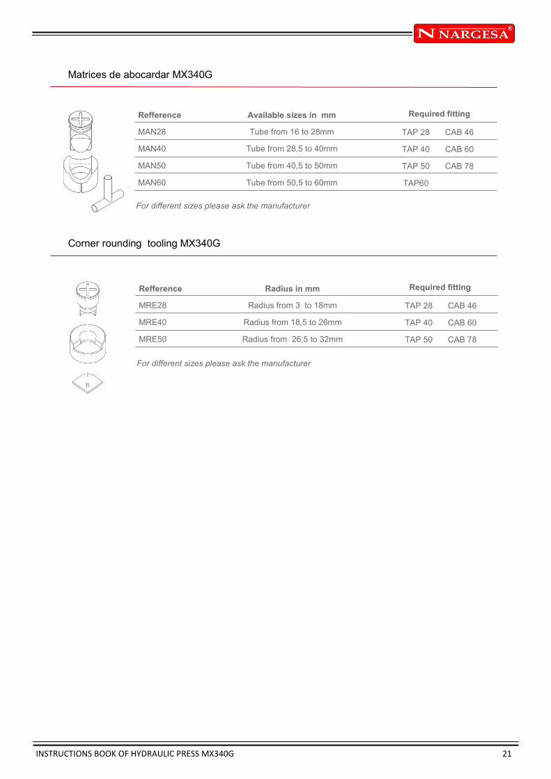
Matrices de abocardar MX340G
Corner rounding tooling MX340G
Refference
MAN28
MAN40
MAN50
MAN60
Available sizes in mm
Tube from 16 to 28mm
Tube from 28,5 to 40mm
Tube from 40,5 to 50mm
Tube from 50,5 to 60mm
TAP 28
TAP 40
TAP 50
TAP60
CAB 46
CAB 60
CAB 78
For different sizes please ask the manufacturer
Required fitting
Refference
MRE28
MRE40
MRE50
Radius in mm
Radius from 3 to 18mm
Radius from 18,5 to 26mm
Radius from 26,5 to 32mm
TAP 28
TAP 40
TAP 50
CAB 46
CAB 60
CAB 78
For different sizes please ask the manufacturer
Required fitting
INSTRUCTIONS BOOK OF HYDRAULIC PRESS MX340G 22
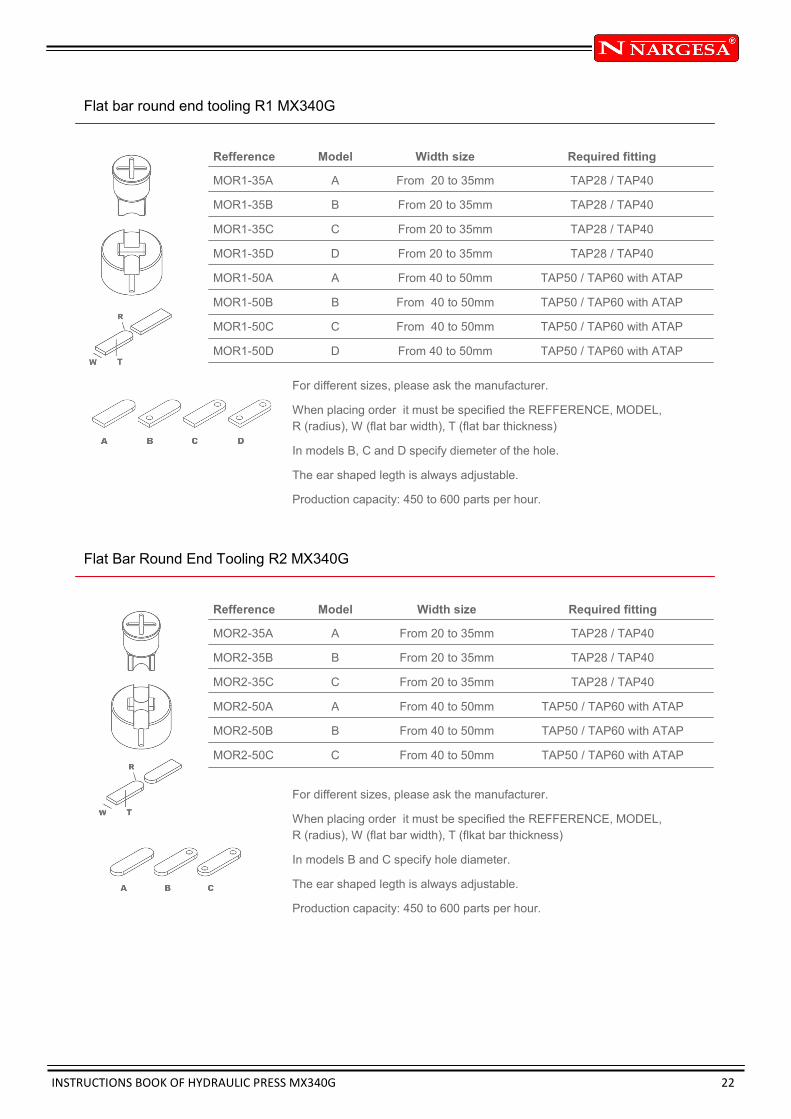
Flat bar round end tooling R1 MX340G
Refference
MOR1-35A
MOR1-35B
MOR1-35C
MOR1-35D
MOR1-50A
MOR1-50B
MOR1-50C
MOR1-50D
Width size
From 20 to 35mm
From 20 to 35mm
From 20 to 35mm
From 20 to 35mm
From 40 to 50mm
From 40 to 50mm
From 40 to 50mm
From 40 to 50mm
For different sizes, please ask the manufacturer.
When placing order it must be specified the REFFERENCE, MODEL,
R (radius), W (flat bar width), T (flat bar thickness)
In models B, C and D specify diemeter of the hole.
The ear shaped legth is always adjustable.
Production capacity: 450 to 600 parts per hour.
Model
A
B
C
D
A
B
C
D
Required fitting
TAP28 / TAP40
TAP28 / TAP40
TAP28 / TAP40
TAP28 / TAP40
TAP50 / TAP60 with ATAP
TAP50 / TAP60 with ATAP
TAP50 / TAP60 with ATAP
TAP50 / TAP60 with ATAP
Flat Bar Round End Tooling R2 MX340G
Refference
MOR2-35A
MOR2-35B
MOR2-35C
MOR2-50A
MOR2-50B
MOR2-50C
Width size
From 20 to 35mm
From 20 to 35mm
From 20 to 35mm
From 40 to 50mm
From 40 to 50mm
From 40 to 50mm
For different sizes, please ask the manufacturer.
When placing order it must be specified the REFFERENCE, MODEL,
R (radius), W (flat bar width), T (flkat bar thickness)
In models B and C specify hole diameter.
The ear shaped legth is always adjustable.
Production capacity: 450 to 600 parts per hour.
Model
A
B
C
A
B
C
Required fitting
TAP28 / TAP40
TAP28 / TAP40
TAP28 / TAP40
TAP50 / TAP60 with ATAP
TAP50 / TAP60 with ATAP
TAP50 / TAP60 with ATAP
INSTRUCTIONS BOOK OF HYDRAULIC PRESS MX340G 23
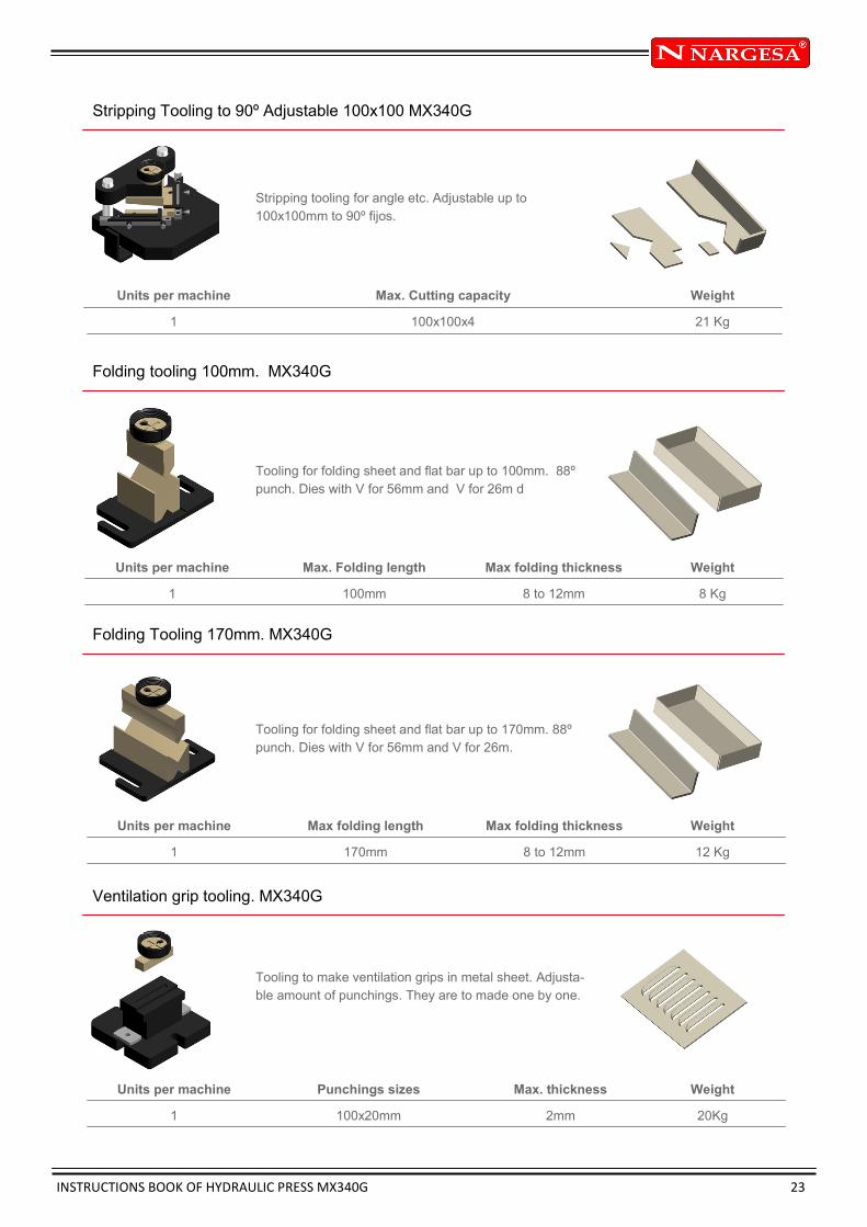
Stripping Tooling to 90º Adjustable 100x100 MX340G
Units per machine
1
Max. Cutting capacity
100x100x4
Weight
21 Kg
Folding tooling 100mm. MX340G
Units per machine
1
Max. Folding length
100mm
Weight
8 Kg
Max folding thickness
8 to 12mm
Folding Tooling 170mm. MX340G
Units per machine
1
Max folding length
170mm
Weight
12 Kg
Max folding thickness
8 to 12mm
Ventilation grip tooling. MX340G
Units per machine
1
Punchings sizes
100x20mm
Weight
20Kg
Max. thickness
2mm
Stripping tooling for angle etc. Adjustable up to
100x100mm to 90º fijos.
Tooling for folding sheet and flat bar up to 100mm. 88º
punch. Dies with V for 56mm and V for 26m d
Tooling for folding sheet and flat bar up to 170mm. 88º
punch. Dies with V for 56mm and V for 26m.
Tooling to make ventilation grips in metal sheet. Adjusta-
ble amount of punchings. They are to made one by one.

INSTRUCTIONS BOOK OF HYDRAULIC PRESS MX340G 24
Angle Cutting Tooling. MX340G
Units per machine
1
Max. Capacity for straight cut
60x60mm
Weight
32 Kg
Max. Cutting capacity for miter
50x50mm
Flat Bar Cutting Tooling. MX340G
Units per machine
1
Max. Cutting capacity
100x10mm
Weight
28 Kg
Round Bar Cutting Tooling. MX340G
Units per machine
1
Max. Cutting diameter
35mm
Weight
15 Kg
Min. Cutting diameter
3mm
Fence Post End tooling MX340G
Parts per tooling
2
Max. Pipe diameter
50mm
Weight
23 Kg
Min. Pipe diemeter
10mm
Hole diameter
Exchangeable
Angle cutting tooling, from 90º up to 45º.
Tooling for cutting sheet or flat bars from 0.8mm up
to 10mm thickness.
Tooling for cutting round barfrom 3mm up to 35mm.
Tooling to flatten and punch the pipe for fences. It
admits different pipe diameters. Exchangeable hole
size.

INSTRUCTIONS BOOK OF HYDRAULIC PRESS MX340G 25
Arrow Tooling for Pipes MX340G
Units per machine
1
Pipe max. Diameter
30x2mm
Weight
19 Kg
Min. Pipe diameter.
10x2mm
Arrow Tooling for Metal Sheet MX340G
Units per machine
1
Max. Sheet Thickness
3mm
Weight
21 Kg
Angle & U Profile punching Tooling MX340G
Units per machine
1
Max. Hole diameter
28mm
Weight
7 Kg
. Hole diameter
2mm
Flattening Tooling MX340G
Parts per tooling
3
Flat Bar Max Thickness
15mm
Weight
15 Kg
Tooling to flatten and cut arrow shaped pipes end.
Suitable for different diameters.
Matriz para troquelar chapa en forma de flecha para
las vallas.
Base holder for angle punching. Suitable for punches
and dies of different diemeters, exchangeables.
It’s an extractor which acts as the flat bar holder at the
punching time to prevent the flat bar from deformation
while being punched.

INSTRUCTIONS BOOK OF HYDRAULIC PRESS MX340G 26
Locks Punch and Die MX340G
Set for making the lock hole in metal sheet.
Necessary complements: CAB60 and TAP40
Parts per set
2
Max. Thickness
6mm
Weight
1 Kg

INSTRUCTIONS BOOK OF HYDRAULIC PRESS MX340G
Technical annex
Hydraulic press MX340G
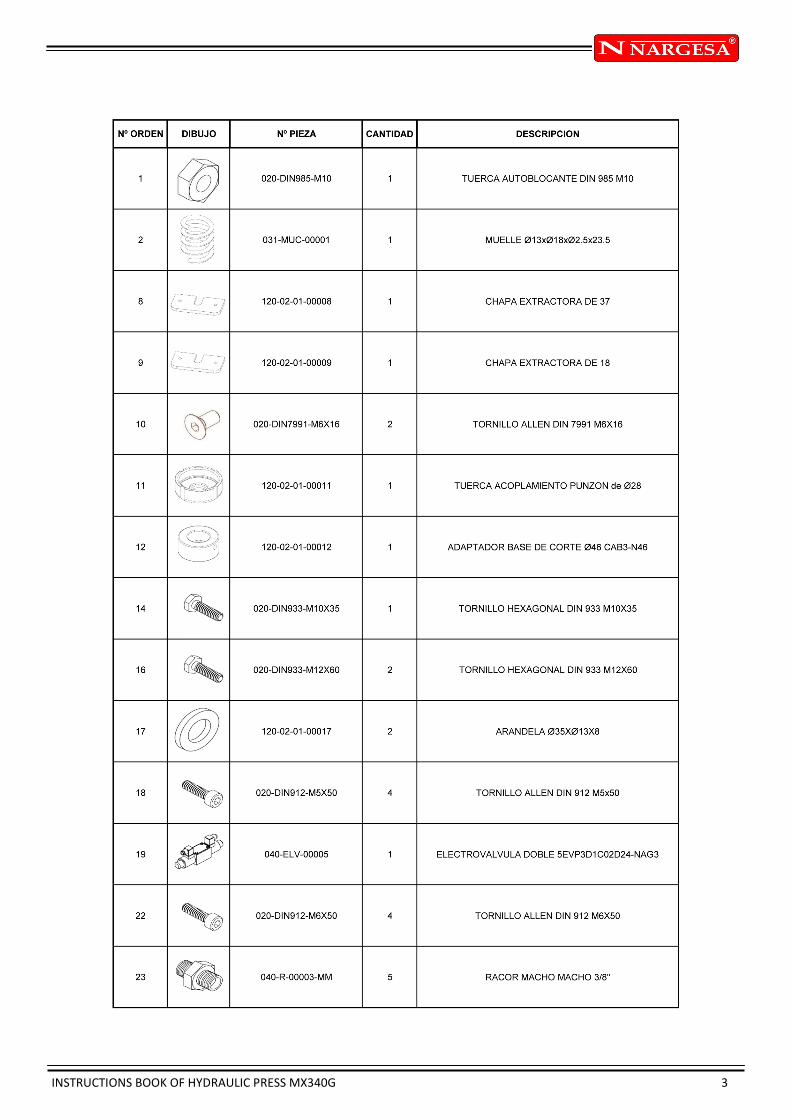
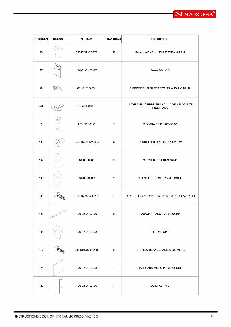
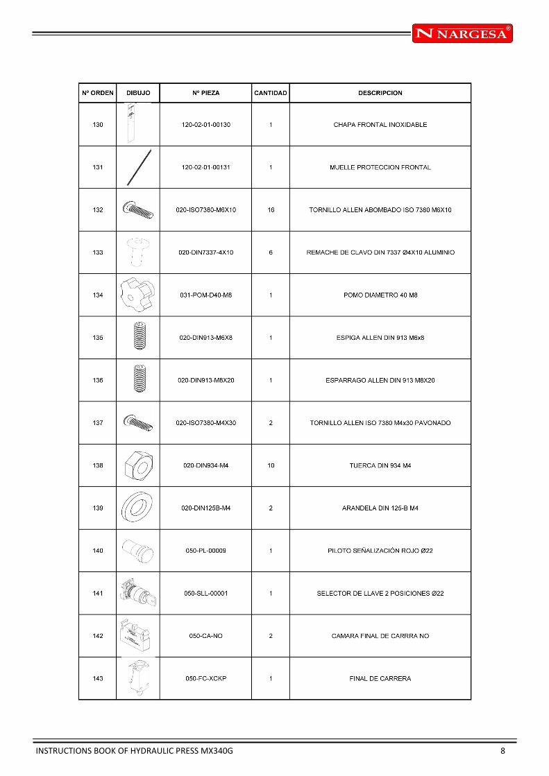
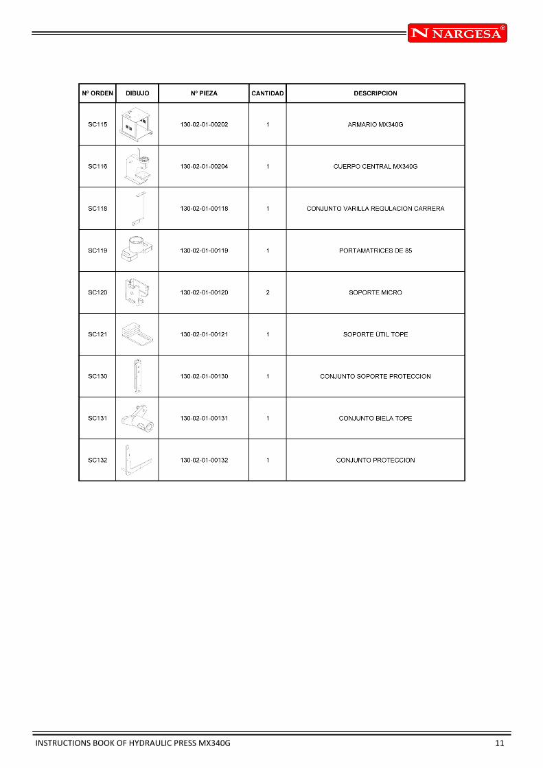
All parts
Electric map
Electrical cabinet
Hydraulic map
INSTRUCTIONS BOOK OF HYDRAULIC PRESS MX340G A 2
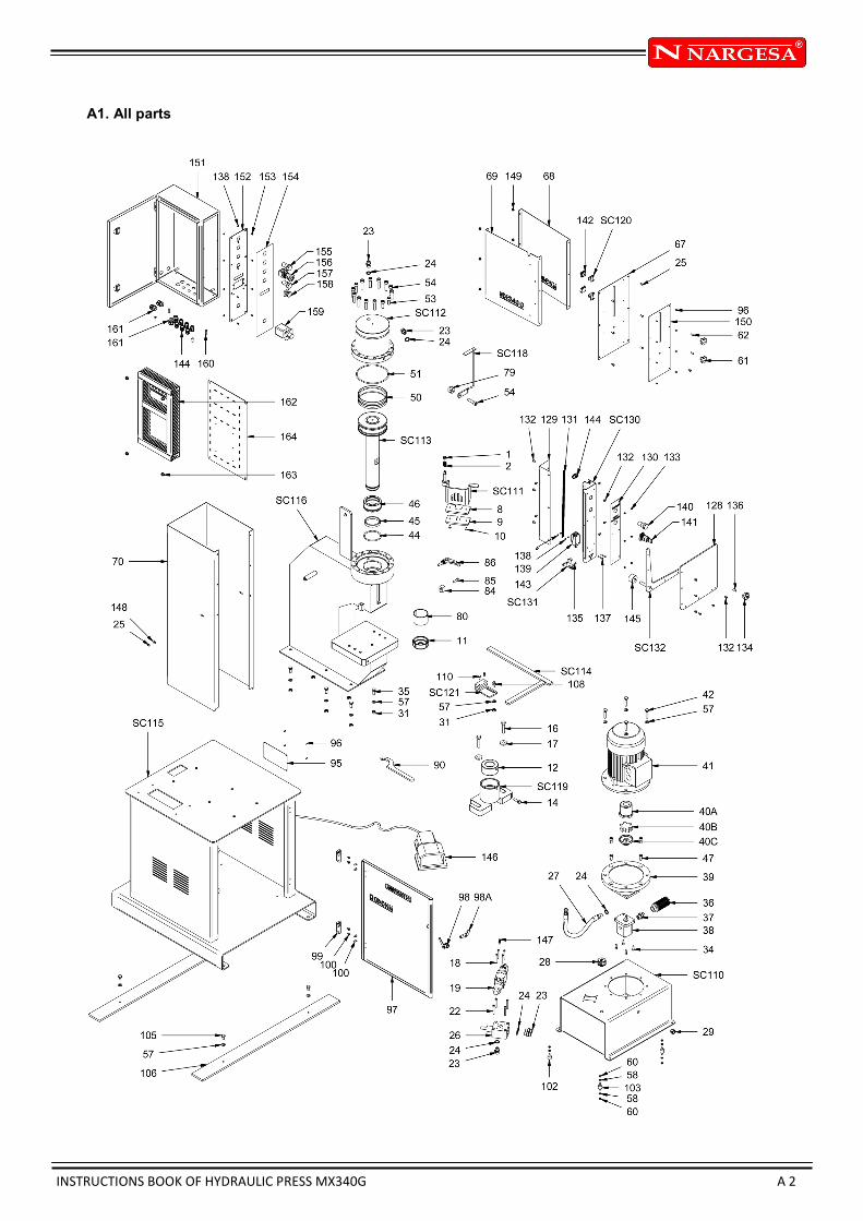
A1. All parts
INSTRUCTIONS BOOK OF HYDRAULIC PRESS MX340G 3

INSTRUCTIONS BOOK OF HYDRAULIC PRESS MX340G 4

INSTRUCTIONS BOOK OF HYDRAULIC PRESS MX340G 5

INSTRUCTIONS BOOK OF HYDRAULIC PRESS MX340G 6
INSTRUCTIONS BOOK OF HYDRAULIC PRESS MX340G 7
INSTRUCTIONS BOOK OF HYDRAULIC PRESS MX340G 8

INSTRUCTIONS BOOK OF HYDRAULIC PRESS MX340G 9

INSTRUCTIONS BOOK OF HYDRAULIC PRESS MX340G 10
INSTRUCTIONS BOOK OF HYDRAULIC PRESS MX340G 11

INSTRUCTIONS BOOK OF HYDRAULIC PRESS MX340G A 12
A2. Electric map
ATTENTION
If supply tension is 230VAC, hacer un puente entre 230VAC and the common connector J3
If supply tension is 400VAC, then make a bridge between 400VAC and the connector common J3
NEVER MAKE A BRIDGE BETWEEN 230VAC AND 400VAC FROM CONNECTOR J3
INSTRUCTIONS BOOK OF HYDRAULIC PRESS MX340G A 13
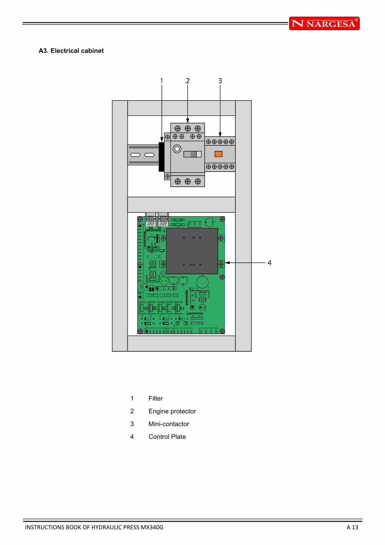
A3. Electrical cabinet
1 Filter
2 Engine protector
3 Mini-contactor
4 Control Plate

INSTRUCTIONS BOOK OF HYDRAULIC PRESS MX340G A 14
A4. Hydraulic map
Piston
Electro-distributor
Base plate with
limiting valve
Pump
Motor
Joint
Filter
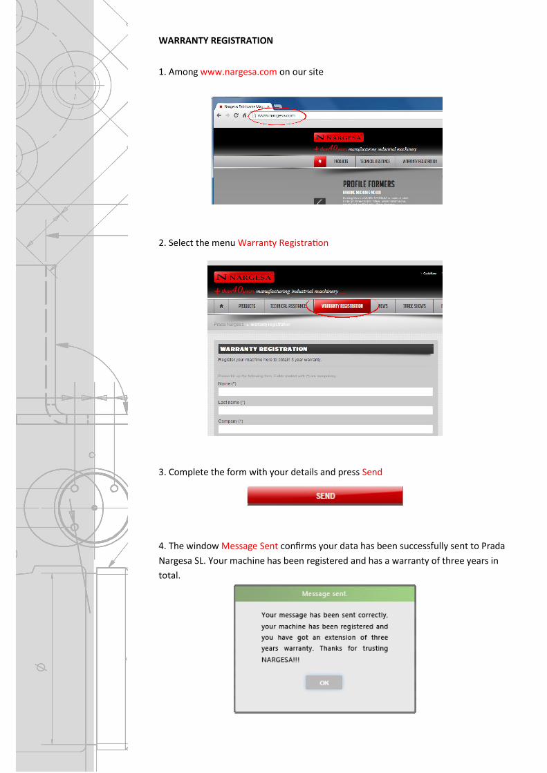
WARRANTY REGISTRATION
1. Among www.nargesa.com on our site
2. Select the menu Warranty Registration
3. Complete the form with your details and press Send
4. The window Message Sent confirms your data has been successfully sent to Prada
Nargesa SL. Your machine has been registered and has a warranty of three years in
total.