hydraulic filters & accessorieshydraulic filters & accessories this page is part of a...
TRANSCRIPT
Hydraulic Filters & Accessories
This page is part of a complete catalog which contains technical and safety data that must be reviewed when selecting a product
Category Page Hydraulic P
ower &
Control
Pneum
atic Pow
er & C
ontrolF
luid Conveying
Miscellaneous P
roductsIndexes &
Technical Information
453 1999-2016 Hydraulic Supply Co. • 1-800-507-9651 • www.hydraulic-supply.com
FiltersSuction Strainers
Stauff TFS Series / Flow Ezy P Series • To 3 Inch NPT & 150 GPM . . . . . . . . . . . . . . . . . . . . . . . . . . . . . . 454Stauff TMF Series • Tank Mounted • To 4 Inch NPT & 100 GPM . . . . . . . . . . . . . . . . . . . . . . . . . . . . . . . . . 455
Suction / Return FiltersStauff SAF07/11 Series • Spin-On • To 6 GPM Suction • To 25 GPM Return . . . . . . . . . . . . . . . . . . . . . . . 455Stauff SSF-120/160 Series • Spin-On • To 12 GPM Suction • To 60 GPM Return . . . . . . . . . . . . . . . . . . . . 457Stauff SSF-150/180 Series • Spin-On • To 30 GPM Suction • To 80 GPM Return . . . . . . . . . . . . . . . . . . . . 459Stauff SSF-24/25 Series • Spin-On • To 35 GPM Suction • To 120 GPM Return . . . . . . . . . . . . . . . . . . . . . 460
Return FiltersVickers® OFRS-25 Series • Spin-On • To 25 GPM. . . . . . . . . . . . . . . . . . . . . . . . . . . . . . . . . . . . . . . . . . . . 462Vickers® OFRS-60 Series • Spin-On • To 60 GPM. . . . . . . . . . . . . . . . . . . . . . . . . . . . . . . . . . . . . . . . . . . . 463Stauff RTF48 Series • In-Line • To 100 GPM . . . . . . . . . . . . . . . . . . . . . . . . . . . . . . . . . . . . . . . . . . . . . . . . 464Stauff RTF40 Series • In-Tank • To 100 GPM. . . . . . . . . . . . . . . . . . . . . . . . . . . . . . . . . . . . . . . . . . . . . . . . 465Vickers® HF4RT Series • In-Tank • To 120 GPM . . . . . . . . . . . . . . . . . . . . . . . . . . . . . . . . . . . . . . . . . . . . . 466
Pressure FiltersVickers® HF2P Series • To 4000 PSI • To 24 GPM . . . . . . . . . . . . . . . . . . . . . . . . . . . . . . . . . . . . . . . . . . . 467Stauff SF Series • To 6000 PSI • To 160 GPM . . . . . . . . . . . . . . . . . . . . . . . . . . . . . . . . . . . . . . . . . . . . . . . 468
Fluid AnalysisStauff Fluid Analysis Service Kits . . . . . . . . . . . . . . . . . . . . . . . . . . . . . . . . . . . . . . . . . . . . . . . . . . . . . . . . . 469
Schroeder FiltersReturn Filters: KF3, RT, LRT • To 150 GPM . . . . . . . . . . . . . . . . . . . . . . . . . . . . . . . . . . . . . . . . . . . . . . . . . 470Pressure Filters: RLT, SRLT, NF30, KF30, DF40 • To 150 GPM . . . . . . . . . . . . . . . . . . . . . . . . . . . . . . . . . 472Off-Line Kidney Loop System • To 4.9 GPM . . . . . . . . . . . . . . . . . . . . . . . . . . . . . . . . . . . . . . . . . . . . . . . . . 476Contamination Monitors, Fluid Analysis . . . . . . . . . . . . . . . . . . . . . . . . . . . . . . . . . . . . . . . . . . . . . . . . . . . . 477Schroeder Multi-Gauge . . . . . . . . . . . . . . . . . . . . . . . . . . . . . . . . . . . . . . . . . . . . . . . . . . . . . . . . . . . . . . . . . 478
Filter CartsSchroeder Mobile Filtration System • To 10 GPM. . . . . . . . . . . . . . . . . . . . . . . . . . . . . . . . . . . . . . . . . . . . . 479
Technical InformationDimensions, Pressure Drop Curves
Filter Sizing Basics . . . . . . . . . . . . . . . . . . . . . . . . . . . . . . . . . . . . . . . . . . . . . . . . . . . . . . . . . . . . . . . . . . . . 709Stauff SAF07/11 Series . . . . . . . . . . . . . . . . . . . . . . . . . . . . . . . . . . . . . . . . . . . . . . . . . . . . . . . . . . . . . . . . . 710Stauff SSF24/25 Series . . . . . . . . . . . . . . . . . . . . . . . . . . . . . . . . . . . . . . . . . . . . . . . . . . . . . . . . . . . . . . . . . 712Stauff SSF120/160 . . . . . . . . . . . . . . . . . . . . . . . . . . . . . . . . . . . . . . . . . . . . . . . . . . . . . . . . . . . . . . . . . . . . 713Stauff SSF150/180 Series . . . . . . . . . . . . . . . . . . . . . . . . . . . . . . . . . . . . . . . . . . . . . . . . . . . . . . . . . . . . . . . 713Stauff RFT40 Series . . . . . . . . . . . . . . . . . . . . . . . . . . . . . . . . . . . . . . . . . . . . . . . . . . . . . . . . . . . . . . . . . . . 715Stauff RF014-RF130 Series . . . . . . . . . . . . . . . . . . . . . . . . . . . . . . . . . . . . . . . . . . . . . . . . . . . . . . . . . . . . . 717Vickers® HF4RT Series . . . . . . . . . . . . . . . . . . . . . . . . . . . . . . . . . . . . . . . . . . . . . . . . . . . . . . . . . . . . . . . . 719Vickers® OFR-60 & OFR-120 Series . . . . . . . . . . . . . . . . . . . . . . . . . . . . . . . . . . . . . . . . . . . . . . . . . . . . . . 720Vickers® OFRS-25 Series. . . . . . . . . . . . . . . . . . . . . . . . . . . . . . . . . . . . . . . . . . . . . . . . . . . . . . . . . . . . . . . 721Vickers® OFRS-60 Series. . . . . . . . . . . . . . . . . . . . . . . . . . . . . . . . . . . . . . . . . . . . . . . . . . . . . . . . . . . . . . . 722Vickers® HF2P Series. . . . . . . . . . . . . . . . . . . . . . . . . . . . . . . . . . . . . . . . . . . . . . . . . . . . . . . . . . . . . . . . . . 723Stauff SAF07/11 Series . . . . . . . . . . . . . . . . . . . . . . . . . . . . . . . . . . . . . . . . . . . . . . . . . . . . . . . . . . . . . . . . . 724Stauff SAF07/11 Series . . . . . . . . . . . . . . . . . . . . . . . . . . . . . . . . . . . . . . . . . . . . . . . . . . . . . . . . . . . . . . . . . 725Stauff SAF07/11 Series . . . . . . . . . . . . . . . . . . . . . . . . . . . . . . . . . . . . . . . . . . . . . . . . . . . . . . . . . . . . . . . . . 726Stauff SAF07/11 Series . . . . . . . . . . . . . . . . . . . . . . . . . . . . . . . . . . . . . . . . . . . . . . . . . . . . . . . . . . . . . . . . . 727Stauff SAF07/11 Series . . . . . . . . . . . . . . . . . . . . . . . . . . . . . . . . . . . . . . . . . . . . . . . . . . . . . . . . . . . . . . . . . 728Stauff SAF07/11 Series . . . . . . . . . . . . . . . . . . . . . . . . . . . . . . . . . . . . . . . . . . . . . . . . . . . . . . . . . . . . . . . . . 729Stauff SAF07/11 Series . . . . . . . . . . . . . . . . . . . . . . . . . . . . . . . . . . . . . . . . . . . . . . . . . . . . . . . . . . . . . . . . . 730Stauff SAF07/11 Series . . . . . . . . . . . . . . . . . . . . . . . . . . . . . . . . . . . . . . . . . . . . . . . . . . . . . . . . . . . . . . . . . 731
This page is part of a complete catalog which contains technical and safety data that must be reviewed when selecting a product
Hydraulic Filters & Accessories
Hyd
raul
ic P
ower
& C
ontr
olP
neum
atic
Pow
er &
Con
trol
Flu
id C
onve
ying
Mis
cella
neou
s P
rodu
cts
Inde
xes
& T
echn
ical
Info
rmat
ion
454 1999-2016 Hydraulic Supply Co. • 1-800-507-9651 • www.hydraulic-supply.com
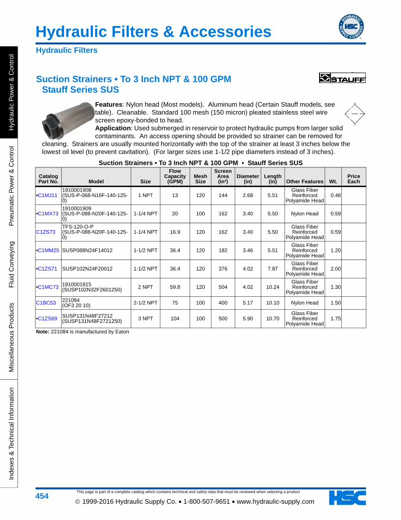
Suction Strainers • To 3 Inch NPT & 100 GPM Stauff Series SUS
Features: Nylon head (Most models). Aluminum head (Certain Stauff models, see table). Cleanable. Standard 100 mesh (150 micron) pleated stainless steel wire screen epoxy-bonded to head. Application: Used submerged in reservoir to protect hydraulic pumps from larger solid contaminants. An access opening should be provided so strainer can be removed for
cleaning. Strainers are usually mounted horizontally with the top of the strainer at least 3 inches below the lowest oil level (to prevent cavitation). (For larger sizes use 1-1/2 pipe diameters instead of 3 inches).
Suction Strainers • To 3 Inch NPT & 100 GPM • Stauff Series SUS
Catalog Part No. Model Size
Flow Capacity
(GPM)Mesh Size
Screen Area (in²)
Diameter (in)
Length (in) Other Features Wt.
Price Each
•C1MJ111910001908 (SUS-P-068-N16F-140-125-0)
1 NPT 13 120 144 2.68 5.51Glass Fiber Reinforced
Polyamide Head0.46
•C1MX731910001909 (SUS-P-088-N20F-140-125-0)
1-1/4 NPT 20 100 162 3.40 5.50 Nylon Head 0.59
C1ZS73TFS-120-O-P (SUS-P-088-N20F-140-125-0)
1-1/4 NPT 16.9 120 162 3.40 5.50Glass Fiber Reinforced
Polyamide Head0.59
•C1MM25 SUSP088N24F14012 1-1/2 NPT 36.4 120 182 3.46 5.51Glass Fiber Reinforced
Polyamide Head1.20
•C1ZS71 SUSP102N24F20012 1-1/2 NPT 36.4 120 376 4.02 7.87Glass Fiber Reinforced
Polyamide Head2.00
•C1MC73 1910001915 (SUSP102N32F2601250) 2 NPT 59.8 120 504 4.02 10.24
Glass Fiber Reinforced
Polyamide Head1.30
C1BC53 221084 (OF3 20 10) 2-1/2 NPT 75 100 400 5.17 10.10 Nylon Head 1.50
•C1ZS69 SUSP131N48F27212 (SUSP131N48F2721250) 3 NPT 104 100 500 5.90 10.70
Glass Fiber Reinforced
Polyamide Head1.75
Note: 221084 is manufactured by Eaton
Hydraulic Filters
Hydraulic Filters & Accessories
This page is part of a complete catalog which contains technical and safety data that must be reviewed when selecting a product
Hydraulic P
ower &
Control
Pneum
atic Pow
er & C
ontrolF
luid Conveying
Miscellaneous P
roductsIndexes &
Technical Information
455 1999-2016 Hydraulic Supply Co. • 1-800-507-9651 • www.hydraulic-supply.com
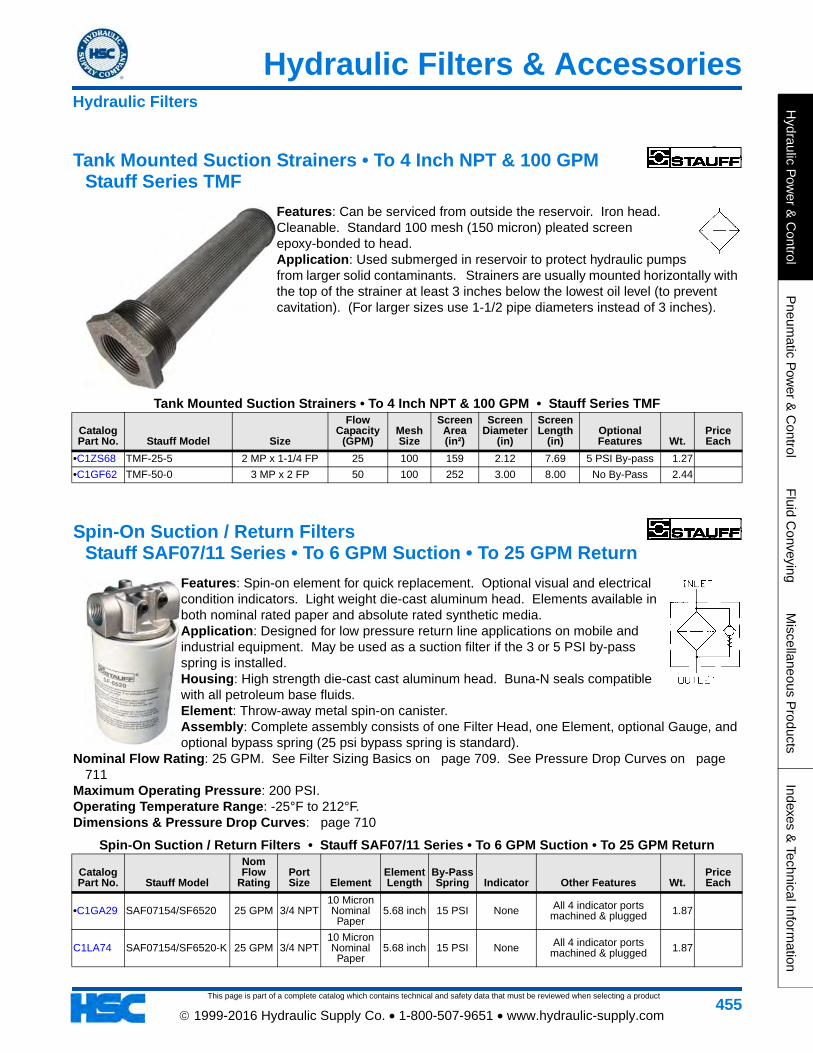
Tank Mounted Suction Strainers • To 4 Inch NPT & 100 GPM Stauff Series TMF
Features: Can be serviced from outside the reservoir. Iron head. Cleanable. Standard 100 mesh (150 micron) pleated screen epoxy-bonded to head. Application: Used submerged in reservoir to protect hydraulic pumps from larger solid contaminants. Strainers are usually mounted horizontally with the top of the strainer at least 3 inches below the lowest oil level (to prevent cavitation). (For larger sizes use 1-1/2 pipe diameters instead of 3 inches).
Tank Mounted Suction Strainers • To 4 Inch NPT & 100 GPM • Stauff Series TMF
Catalog Part No. Stauff Model Size
Flow Capacity
(GPM)Mesh Size
Screen Area (in²)
Screen Diameter
(in)
Screen Length
(in)Optional Features Wt.
Price Each
•C1ZS68 TMF-25-5 2 MP x 1-1/4 FP 25 100 159 2.12 7.69 5 PSI By-pass 1.27
•C1GF62 TMF-50-0 3 MP x 2 FP 50 100 252 3.00 8.00 No By-Pass 2.44
Spin-On Suction / Return Filters Stauff SAF07/11 Series • To 6 GPM Suction • To 25 GPM Return
Features: Spin-on element for quick replacement. Optional visual and electrical condition indicators. Light weight die-cast aluminum head. Elements available in both nominal rated paper and absolute rated synthetic media. Application: Designed for low pressure return line applications on mobile and industrial equipment. May be used as a suction filter if the 3 or 5 PSI by-pass spring is installed. Housing: High strength die-cast cast aluminum head. Buna-N seals compatible with all petroleum base fluids. Element: Throw-away metal spin-on canister. Assembly: Complete assembly consists of one Filter Head, one Element, optional Gauge, and optional bypass spring (25 psi bypass spring is standard).
Nominal Flow Rating: 25 GPM. See Filter Sizing Basics on page 709. See Pressure Drop Curves on page 711
Maximum Operating Pressure: 200 PSI. Operating Temperature Range: -25°F to 212°F. Dimensions & Pressure Drop Curves: page 710
Spin-On Suction / Return Filters • Stauff SAF07/11 Series • To 6 GPM Suction • To 25 GPM Return
Catalog Part No. Stauff Model
Nom Flow
RatingPort Size Element
Element Length
By-Pass Spring Indicator Other Features Wt.
Price Each
•C1GA29 SAF07154/SF6520 25 GPM 3/4 NPT10 Micron Nominal Paper
5.68 inch 15 PSI None All 4 indicator ports machined & plugged 1.87
C1LA74 SAF07154/SF6520-K 25 GPM 3/4 NPT10 Micron Nominal Paper
5.68 inch 15 PSI None All 4 indicator ports machined & plugged 1.87
Hydraulic Filters
This page is part of a complete catalog which contains technical and safety data that must be reviewed when selecting a product
Hydraulic Filters & Accessories
Hyd
raul
ic P
ower
& C
ontr
olP
neum
atic
Pow
er &
Con
trol
Flu
id C
onve
ying
Mis
cella
neou
s P
rodu
cts
Inde
xes
& T
echn
ical
Info
rmat
ion
456 1999-2016 Hydraulic Supply Co. • 1-800-507-9651 • www.hydraulic-supply.com
C1LA39 SAF07254/SF6520-K 25 GPM 3/4 NPT10 Micron Nominal Paper
5.68 inch 25 PSI None All 4 indicator ports machined & plugged 1.87
C1LA40 SAF10254/SF6520-K 25 GPM 1 NPT10 Micron Nominal Paper
5.68 inch 25 PSI None All 4 indicator ports machined & plugged 1.87
C1LA41 SAF11254/SF6520-K 25 GPM -12 SAE10 Micron Nominal Paper
5.68 inch 25 PSI None All 4 indicator ports machined & plugged 1.87
C1LA73 SAF13254/SF6549-K 25 GPM -16 SAE3 Micron Nominal
Micro Glass5.68 inch 25 PSI None All 4 indicator ports
machined & plugged 1.87
C1LA42 SAF13254/SF6520-K 25 GPM -16 SAE10 Micron Nominal Paper
5.68 inch 25 PSI None All 4 indicator ports machined & plugged 1.87
Note: Part numbers the end in a "-K" are assembled by us. Part numbers that do not end in a "-K" are assembled by Stauff.
Parts for Stauff SAF07/11 Series FiltersCatalog Part No. Part Number Description Wt.
Price Each
C1MX33 1010003031 Filter Head, SAF-07-25-4, 3/4 NPT ports, 25 PSI bypass, 4 plugged gauge ports 0.53
C1KZ92 STNA42356 Filter Head, SAF-10-25-4, 1 NPT ports, 25 psi bypass, 4 plugged gauge ports 0.53
C1KZ93 STNA42362 Filter Head, SAF-11-25-4, -12 SAE ports, 25 psi bypass, 4 plugged gauge ports 0.53
C1KZ98 STNA44361 Filter Head, SAF-13-25-4, -16 SAE ports, 25 psi bypass, 4 plugged gauge ports 0.69
C1MC65 SF6549 Element, 3 micron nominal Micro Glass, 5.76 inch 1.60
•C1GA44 SF-6520 Element, 10 micron nominal Paper, 5.68 inch 1.10
C1MW61 STNA42505 (SF-6521) Element, 10 micron nominal Paper, 8.00 inch
C1MH77 1020013533 (SF-6505) Element, 12 micron nominal Micro Glass, 5.76 inch 1.21
•C1GA43 SF-6510 Element, 25 micron nominal Paper, 5.68 inch 1.12
•C1FZ75 GV-5 Vacuum Gauge for suction line applications, for filters with 3 PSI by-pass 0.19
•C1GG85 GV-10 Vacuum Gauge for suction line applications, for filters with 5 PSI by-pass 0.18
•C1FZ32 CI-12 Pressure Gauge for return line applications, for filters with 15 PSI by-pass 0.15
•C1GF95 CI-20 Pressure Gauge for return line applications, for filters with 25 PSI by-pass 0.15
C1KZ64 SAF-07-15-SPRING Bypass Spring, 15 psi 0.01
•C1KZ63 SAF-07-03-SPRING Bypass Spring, 3 psi 0.01
Note: Element seal is included with elementNote: Complete assembly consists of one Filter Head, one Element, optional gauge, and optional bypass spring.
Spin-On Suction / Return Filters • Stauff SAF07/11 Series • To 6 GPM Suction • To 25 GPM Return
Catalog Part No. Stauff Model
Nom Flow
RatingPort Size Element
Element Length
By-Pass Spring Indicator Other Features Wt.
Price Each
Hydraulic Filters
Hydraulic Filters & Accessories
This page is part of a complete catalog which contains technical and safety data that must be reviewed when selecting a product
Hydraulic P
ower &
Control
Pneum
atic Pow
er & C
ontrolF
luid Conveying
Miscellaneous P
roductsIndexes &
Technical Information
457 1999-2016 Hydraulic Supply Co. • 1-800-507-9651 • www.hydraulic-supply.com
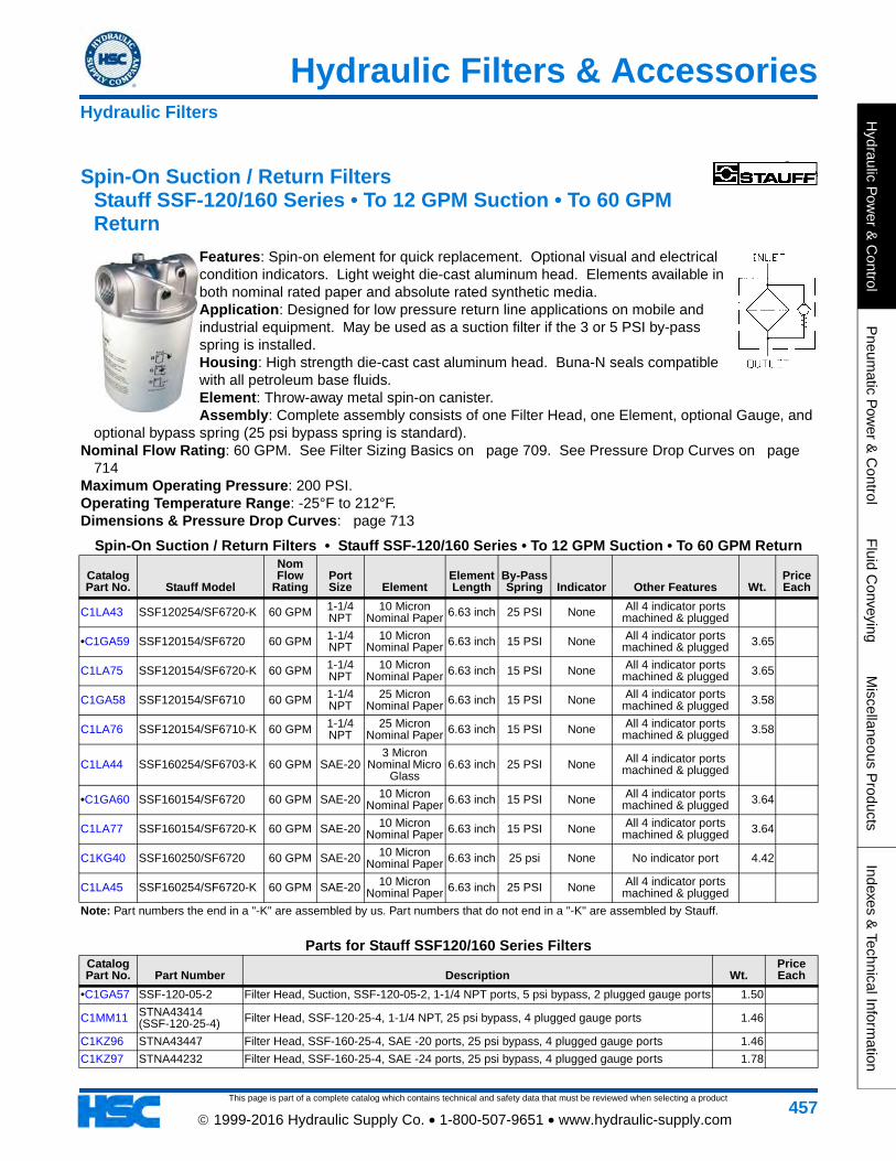
Spin-On Suction / Return Filters Stauff SSF-120/160 Series • To 12 GPM Suction • To 60 GPM Return
Features: Spin-on element for quick replacement. Optional visual and electrical condition indicators. Light weight die-cast aluminum head. Elements available in both nominal rated paper and absolute rated synthetic media. Application: Designed for low pressure return line applications on mobile and industrial equipment. May be used as a suction filter if the 3 or 5 PSI by-pass spring is installed. Housing: High strength die-cast cast aluminum head. Buna-N seals compatible with all petroleum base fluids. Element: Throw-away metal spin-on canister. Assembly: Complete assembly consists of one Filter Head, one Element, optional Gauge, and
optional bypass spring (25 psi bypass spring is standard). Nominal Flow Rating: 60 GPM. See Filter Sizing Basics on page 709. See Pressure Drop Curves on page
714Maximum Operating Pressure: 200 PSI. Operating Temperature Range: -25°F to 212°F. Dimensions & Pressure Drop Curves: page 713
Spin-On Suction / Return Filters • Stauff SSF-120/160 Series • To 12 GPM Suction • To 60 GPM Return
Catalog Part No. Stauff Model
Nom Flow
RatingPort Size Element
Element Length
By-Pass Spring Indicator Other Features Wt.
Price Each
C1LA43 SSF120254/SF6720-K 60 GPM 1-1/4 NPT
10 Micron Nominal Paper 6.63 inch 25 PSI None All 4 indicator ports
machined & plugged
•C1GA59 SSF120154/SF6720 60 GPM 1-1/4 NPT
10 Micron Nominal Paper 6.63 inch 15 PSI None All 4 indicator ports
machined & plugged 3.65
C1LA75 SSF120154/SF6720-K 60 GPM 1-1/4 NPT
10 Micron Nominal Paper 6.63 inch 15 PSI None All 4 indicator ports
machined & plugged 3.65
C1GA58 SSF120154/SF6710 60 GPM 1-1/4 NPT
25 Micron Nominal Paper 6.63 inch 15 PSI None All 4 indicator ports
machined & plugged 3.58
C1LA76 SSF120154/SF6710-K 60 GPM 1-1/4 NPT
25 Micron Nominal Paper 6.63 inch 15 PSI None All 4 indicator ports
machined & plugged 3.58
C1LA44 SSF160254/SF6703-K 60 GPM SAE-203 Micron
Nominal Micro Glass
6.63 inch 25 PSI None All 4 indicator ports machined & plugged
•C1GA60 SSF160154/SF6720 60 GPM SAE-20 10 Micron Nominal Paper 6.63 inch 15 PSI None All 4 indicator ports
machined & plugged 3.64
C1LA77 SSF160154/SF6720-K 60 GPM SAE-20 10 Micron Nominal Paper 6.63 inch 15 PSI None All 4 indicator ports
machined & plugged 3.64
C1KG40 SSF160250/SF6720 60 GPM SAE-20 10 Micron Nominal Paper 6.63 inch 25 psi None No indicator port 4.42
C1LA45 SSF160254/SF6720-K 60 GPM SAE-20 10 Micron Nominal Paper 6.63 inch 25 PSI None All 4 indicator ports
machined & plugged
Note: Part numbers the end in a "-K" are assembled by us. Part numbers that do not end in a "-K" are assembled by Stauff.
Parts for Stauff SSF120/160 Series FiltersCatalog Part No. Part Number Description Wt.
Price Each
•C1GA57 SSF-120-05-2 Filter Head, Suction, SSF-120-05-2, 1-1/4 NPT ports, 5 psi bypass, 2 plugged gauge ports 1.50
C1MM11 STNA43414 (SSF-120-25-4) Filter Head, SSF-120-25-4, 1-1/4 NPT, 25 psi bypass, 4 plugged gauge ports 1.46
C1KZ96 STNA43447 Filter Head, SSF-160-25-4, SAE -20 ports, 25 psi bypass, 4 plugged gauge ports 1.46
C1KZ97 STNA44232 Filter Head, SSF-160-25-4, SAE -24 ports, 25 psi bypass, 4 plugged gauge ports 1.78
Hydraulic Filters
This page is part of a complete catalog which contains technical and safety data that must be reviewed when selecting a product
Hydraulic Filters & Accessories
Hyd
raul
ic P
ower
& C
ontr
olP
neum
atic
Pow
er &
Con
trol
Flu
id C
onve
ying
Mis
cella
neou
s P
rodu
cts
Inde
xes
& T
echn
ical
Info
rmat
ion
458 1999-2016 Hydraulic Supply Co. • 1-800-507-9651 • www.hydraulic-supply.com
C1MH75 1020013321 (SF-6704-MG) Element, 3 micron nominal Micro Glass, 10.6 inch 4.35
C1KZ73 SF-6703-MG Element, 3 micron nominal Micro Glass, 6.6 inch 2.25
C1KZ76 SF-6707-MG/2 Element, 6 micron nominal Micro Glass, 10.6 inch 2.96
C1KZ79 SF-6721 Element, 10 micron nominal Paper, 10.6 inch 5.00
•C1GA46 SF-6720 Element, 10 micron nominal Paper, 6.63 inch 2.16
C1ML54 SF-6731-MG/2 Element, 12 micron nominal Micro Glass, 10.6 inch 3.57
C1KZ81 SF-6730-MG Element, 12 micron nominal Micro Glass, 6.6 inch 2.76
•C1KY74 SF-6710/2 Element, 25 micron nominal paper spin-on, 6.63 inch 2.81
•C1GA47 SF6790 Element, 125 micron stainless steel wire mesh, 6.63 inch 2.30
•C1FZ75 GV-5 Vacuum Gauge for suction line applications, for filters with 3 PSI by-pass 0.19
•C1GG85 GV-10 Vacuum Gauge for suction line applications, for filters with 5 PSI by-pass 0.18
•C1FZ32 CI-12 Pressure Gauge for return line applications, for filters with 15 PSI by-pass 0.15
•C1GF95 CI-20 Pressure Gauge for return line applications, for filters with 25 PSI by-pass 0.15
C1KZ40 EPS1 Electrical Indicator Switch for return line applications, adjustable 7-30 PSI 0.25
•C1KZ86 SSF03SPRING Bypass Spring, 3 psi 0.02
C1LD13 SSF-15-SPRING Bypass Spring, 15 psi 0.03Note: Complete assembly consists of one Filter Head, one Element, optional gauge, and optional bypass spring.
Parts for Stauff SSF120/160 Series FiltersCatalog Part No. Part Number Description Wt.
Price Each
Hydraulic Filters
Hydraulic Filters & Accessories
This page is part of a complete catalog which contains technical and safety data that must be reviewed when selecting a product
Hydraulic P
ower &
Control
Pneum
atic Pow
er & C
ontrolF
luid Conveying
Miscellaneous P
roductsIndexes &
Technical Information
459 1999-2016 Hydraulic Supply Co. • 1-800-507-9651 • www.hydraulic-supply.com
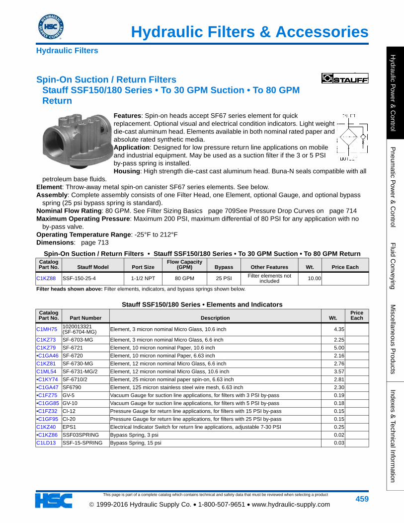
Spin-On Suction / Return Filters Stauff SSF150/180 Series • To 30 GPM Suction • To 80 GPM Return
Features: Spin-on heads accept SF67 series element for quick replacement. Optional visual and electrical condition indicators. Light weight die-cast aluminum head. Elements available in both nominal rated paper and absolute rated synthetic media. Application: Designed for low pressure return line applications on mobile and industrial equipment. May be used as a suction filter if the 3 or 5 PSI by-pass spring is installed. Housing: High strength die-cast cast aluminum head. Buna-N seals compatible with all
petroleum base fluids. Element: Throw-away metal spin-on canister SF67 series elements. See below. Assembly: Complete assembly consists of one Filter Head, one Element, optional Gauge, and optional bypass
spring (25 psi bypass spring is standard). Nominal Flow Rating: 80 GPM. See Filter Sizing Basics page 709See Pressure Drop Curves on page 714Maximum Operating Pressure: Maximum 200 PSI, maximum differential of 80 PSI for any application with no
by-pass valve. Operating Temperature Range: -25°F to 212°F Dimensions: page 713
Spin-On Suction / Return Filters • Stauff SSF150/180 Series • To 30 GPM Suction • To 80 GPM ReturnCatalog Part No. Stauff Model Port Size
Flow Capacity (GPM) Bypass Other Features Wt. Price Each
C1KZ88 SSF-150-25-4 1-1/2 NPT 80 GPM 25 PSI Filter elements not included 10.00
Filter heads shown above: Filter elements, indicators, and bypass springs shown below.
Stauff SSF150/180 Series • Elements and IndicatorsCatalog Part No. Part Number Description Wt.
Price Each
C1MH75 1020013321 (SF-6704-MG) Element, 3 micron nominal Micro Glass, 10.6 inch 4.35
C1KZ73 SF-6703-MG Element, 3 micron nominal Micro Glass, 6.6 inch 2.25
C1KZ79 SF-6721 Element, 10 micron nominal Paper, 10.6 inch 5.00
•C1GA46 SF-6720 Element, 10 micron nominal Paper, 6.63 inch 2.16
C1KZ81 SF-6730-MG Element, 12 micron nominal Micro Glass, 6.6 inch 2.76
C1ML54 SF-6731-MG/2 Element, 12 micron nominal Micro Glass, 10.6 inch 3.57
•C1KY74 SF-6710/2 Element, 25 micron nominal paper spin-on, 6.63 inch 2.81
•C1GA47 SF6790 Element, 125 micron stainless steel wire mesh, 6.63 inch 2.30
•C1FZ75 GV-5 Vacuum Gauge for suction line applications, for filters with 3 PSI by-pass 0.19
•C1GG85 GV-10 Vacuum Gauge for suction line applications, for filters with 5 PSI by-pass 0.18
•C1FZ32 CI-12 Pressure Gauge for return line applications, for filters with 15 PSI by-pass 0.15
•C1GF95 CI-20 Pressure Gauge for return line applications, for filters with 25 PSI by-pass 0.15
C1KZ40 EPS1 Electrical Indicator Switch for return line applications, adjustable 7-30 PSI 0.25
•C1KZ86 SSF03SPRING Bypass Spring, 3 psi 0.02
C1LD13 SSF-15-SPRING Bypass Spring, 15 psi 0.03
Hydraulic Filters
This page is part of a complete catalog which contains technical and safety data that must be reviewed when selecting a product
Hydraulic Filters & Accessories
Hyd
raul
ic P
ower
& C
ontr
olP
neum
atic
Pow
er &
Con
trol
Flu
id C
onve
ying
Mis
cella
neou
s P
rodu
cts
Inde
xes
& T
echn
ical
Info
rmat
ion
460 1999-2016 Hydraulic Supply Co. • 1-800-507-9651 • www.hydraulic-supply.com
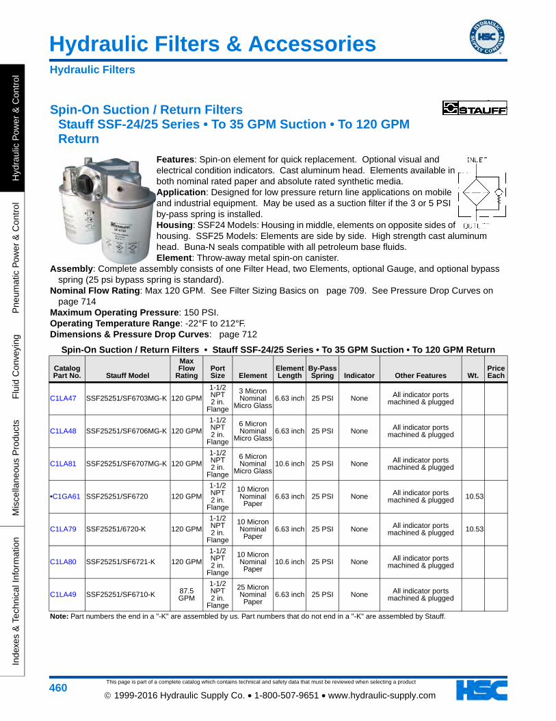
Spin-On Suction / Return Filters Stauff SSF-24/25 Series • To 35 GPM Suction • To 120 GPM Return
Features: Spin-on element for quick replacement. Optional visual and electrical condition indicators. Cast aluminum head. Elements available in both nominal rated paper and absolute rated synthetic media. Application: Designed for low pressure return line applications on mobile and industrial equipment. May be used as a suction filter if the 3 or 5 PSI by-pass spring is installed. Housing: SSF24 Models: Housing in middle, elements on opposite sides of housing. SSF25 Models: Elements are side by side. High strength cast aluminum head. Buna-N seals compatible with all petroleum base fluids. Element: Throw-away metal spin-on canister.
Assembly: Complete assembly consists of one Filter Head, two Elements, optional Gauge, and optional bypass spring (25 psi bypass spring is standard).
Nominal Flow Rating: Max 120 GPM. See Filter Sizing Basics on page 709. See Pressure Drop Curves on page 714
Maximum Operating Pressure: 150 PSI. Operating Temperature Range: -22°F to 212°F. Dimensions & Pressure Drop Curves: page 712
Spin-On Suction / Return Filters • Stauff SSF-24/25 Series • To 35 GPM Suction • To 120 GPM Return
Catalog Part No. Stauff Model
Max Flow
RatingPort Size Element
Element Length
By-Pass Spring Indicator Other Features Wt.
Price Each
C1LA47 SSF25251/SF6703MG-K 120 GPM
1-1/2 NPT 2 in.
Flange
3 Micron Nominal
Micro Glass6.63 inch 25 PSI None All indicator ports
machined & plugged
C1LA48 SSF25251/SF6706MG-K 120 GPM
1-1/2 NPT 2 in.
Flange
6 Micron Nominal
Micro Glass6.63 inch 25 PSI None All indicator ports
machined & plugged
C1LA81 SSF25251/SF6707MG-K 120 GPM
1-1/2 NPT 2 in.
Flange
6 Micron Nominal
Micro Glass10.6 inch 25 PSI None All indicator ports
machined & plugged
•C1GA61 SSF25251/SF6720 120 GPM
1-1/2 NPT 2 in.
Flange
10 Micron Nominal Paper
6.63 inch 25 PSI None All indicator ports machined & plugged 10.53
C1LA79 SSF25251/6720-K 120 GPM
1-1/2 NPT 2 in.
Flange
10 Micron Nominal Paper
6.63 inch 25 PSI None All indicator ports machined & plugged 10.53
C1LA80 SSF25251/SF6721-K 120 GPM
1-1/2 NPT 2 in.
Flange
10 Micron Nominal Paper
10.6 inch 25 PSI None All indicator ports machined & plugged
C1LA49 SSF25251/SF6710-K 87.5 GPM
1-1/2 NPT 2 in.
Flange
25 Micron Nominal Paper
6.63 inch 25 PSI None All indicator ports machined & plugged
Note: Part numbers the end in a "-K" are assembled by us. Part numbers that do not end in a "-K" are assembled by Stauff.
Hydraulic Filters
Hydraulic Filters & Accessories
This page is part of a complete catalog which contains technical and safety data that must be reviewed when selecting a product
Hydraulic P
ower &
Control
Pneum
atic Pow
er & C
ontrolF
luid Conveying
Miscellaneous P
roductsIndexes &
Technical Information
461 1999-2016 Hydraulic Supply Co. • 1-800-507-9651 • www.hydraulic-supply.com
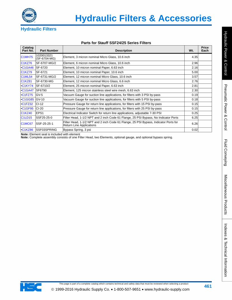
Parts for Stauff SSF24/25 Series FiltersCatalog Part No. Part Number Description Wt.
Price Each
C1MH75 1020013321 (SF-6704-MG) Element, 3 micron nominal Micro Glass, 10.6 inch 4.35
C1KZ76 SF-6707-MG/2 Element, 6 micron nominal Micro Glass, 10.6 inch 2.96
•C1GA46 SF-6720 Element, 10 micron nominal Paper, 6.63 inch 2.16
C1KZ79 SF-6721 Element, 10 micron nominal Paper, 10.6 inch 5.00
C1ML54 SF-6731-MG/2 Element, 12 micron nominal Micro Glass, 10.6 inch 3.57
C1KZ81 SF-6730-MG Element, 12 micron nominal Micro Glass, 6.6 inch 2.76
•C1KY74 SF-6710/2 Element, 25 micron nominal Paper, 6.63 inch 2.81
•C1GA47 SF6790 Element, 125 micron stainless steel wire mesh, 6.63 inch 2.30
•C1FZ75 GV-5 Vacuum Gauge for suction line applications, for filters with 3 PSI by-pass 0.19
•C1GG85 GV-10 Vacuum Gauge for suction line applications, for filters with 5 PSI by-pass 0.18
•C1FZ32 CI-12 Pressure Gauge for return line applications, for filters with 15 PSI by-pass 0.15
•C1GF95 CI-20 Pressure Gauge for return line applications, for filters with 25 PSI by-pass 0.15
C1KZ40 EPS1 Electrical Indicator Switch for return line applications, adjustable 7-30 PSI 0.25
C1LD15 SSF25-25-0 Filter Head, 1-1/2 NPT and 2 inch Code 61 Flange, 25 PSI Bypass, No Indicator Ports 6.25
C1MC67 SSF-25-25-1 Filter Head, 1-1/2 NPT and 2 inch Code 61 Flange, 25 PSI Bypass, Indicator Ports for Return Line Applications 6.26
•C1KZ86 SSF03SPRING Bypass Spring, 3 psi 0.02
Note: Element seal is included with elementNote: Complete assembly consists of one Filter Head, two Elements, optional gauge, and optional bypass spring.
Hydraulic Filters
This page is part of a complete catalog which contains technical and safety data that must be reviewed when selecting a product
Hydraulic Filters & Accessories
Hyd
raul
ic P
ower
& C
ontr
olP
neum
atic
Pow
er &
Con
trol
Flu
id C
onve
ying
Mis
cella
neou
s P
rodu
cts
Inde
xes
& T
echn
ical
Info
rmat
ion
462 1999-2016 Hydraulic Supply Co. • 1-800-507-9651 • www.hydraulic-supply.com
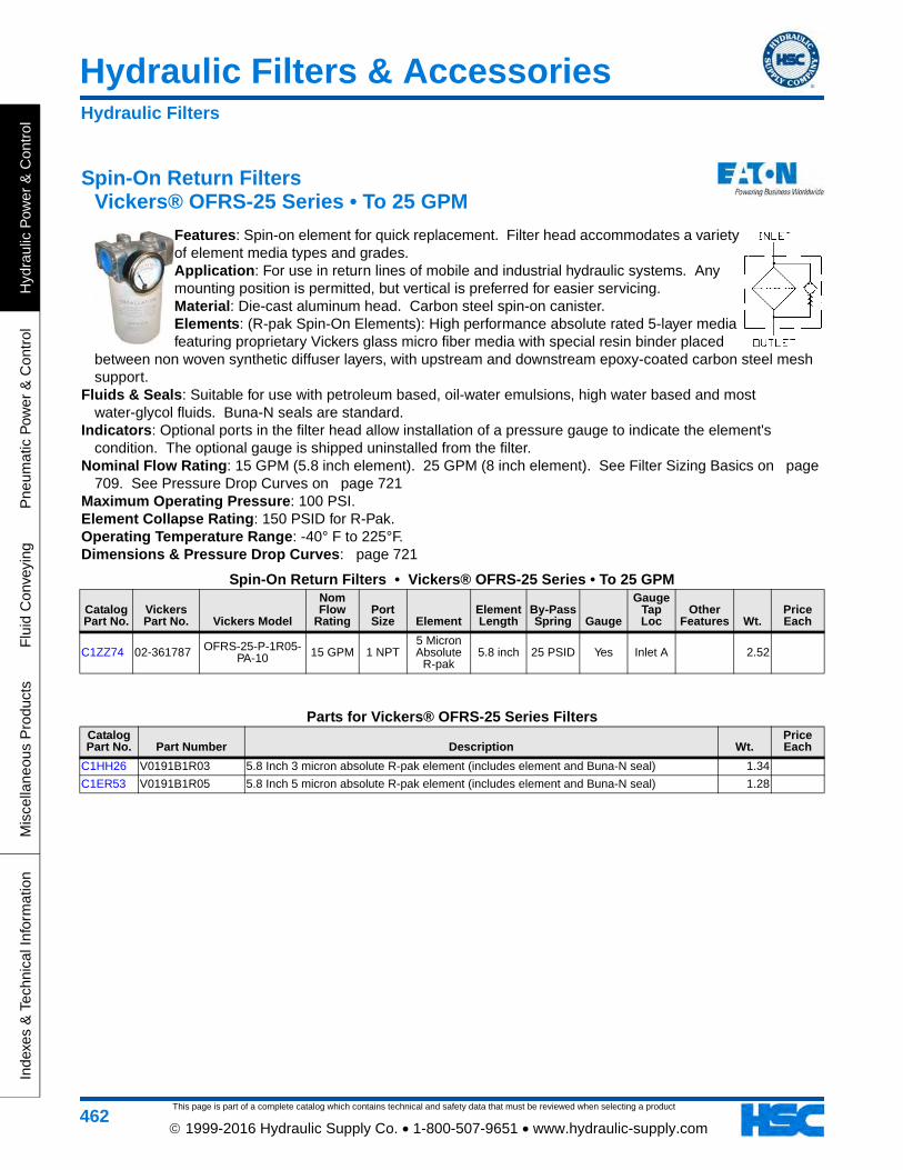
Spin-On Return Filters Vickers® OFRS-25 Series • To 25 GPM
Features: Spin-on element for quick replacement. Filter head accommodates a variety of element media types and grades. Application: For use in return lines of mobile and industrial hydraulic systems. Any mounting position is permitted, but vertical is preferred for easier servicing. Material: Die-cast aluminum head. Carbon steel spin-on canister. Elements: (R-pak Spin-On Elements): High performance absolute rated 5-layer media featuring proprietary Vickers glass micro fiber media with special resin binder placed
between non woven synthetic diffuser layers, with upstream and downstream epoxy-coated carbon steel mesh support.
Fluids & Seals: Suitable for use with petroleum based, oil-water emulsions, high water based and most water-glycol fluids. Buna-N seals are standard.
Indicators: Optional ports in the filter head allow installation of a pressure gauge to indicate the element's condition. The optional gauge is shipped uninstalled from the filter.
Nominal Flow Rating: 15 GPM (5.8 inch element). 25 GPM (8 inch element). See Filter Sizing Basics on page 709. See Pressure Drop Curves on page 721
Maximum Operating Pressure: 100 PSI. Element Collapse Rating: 150 PSID for R-Pak. Operating Temperature Range: -40° F to 225°F. Dimensions & Pressure Drop Curves: page 721
Spin-On Return Filters • Vickers® OFRS-25 Series • To 25 GPM
Catalog Part No.
Vickers Part No. Vickers Model
Nom Flow
RatingPort Size Element
Element Length
By-Pass Spring Gauge
Gauge Tap Loc
Other Features Wt.
Price Each
C1ZZ74 02-361787 OFRS-25-P-1R05-PA-10 15 GPM 1 NPT
5 Micron Absolute
R-pak5.8 inch 25 PSID Yes Inlet A 2.52
Parts for Vickers® OFRS-25 Series FiltersCatalog Part No. Part Number Description Wt.
Price Each
C1HH26 V0191B1R03 5.8 Inch 3 micron absolute R-pak element (includes element and Buna-N seal) 1.34
C1ER53 V0191B1R05 5.8 Inch 5 micron absolute R-pak element (includes element and Buna-N seal) 1.28
Hydraulic Filters
Hydraulic Filters & Accessories
This page is part of a complete catalog which contains technical and safety data that must be reviewed when selecting a product
Hydraulic P
ower &
Control
Pneum
atic Pow
er & C
ontrolF
luid Conveying
Miscellaneous P
roductsIndexes &
Technical Information
463 1999-2016 Hydraulic Supply Co. • 1-800-507-9651 • www.hydraulic-supply.com
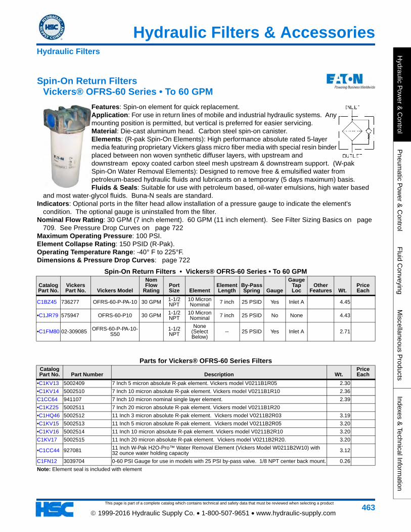
Spin-On Return Filters Vickers® OFRS-60 Series • To 60 GPM
Features: Spin-on element for quick replacement. Application: For use in return lines of mobile and industrial hydraulic systems. Any mounting position is permitted, but vertical is preferred for easier servicing. Material: Die-cast aluminum head. Carbon steel spin-on canister. Elements: (R-pak Spin-On Elements): High performance absolute rated 5-layer media featuring proprietary Vickers glass micro fiber media with special resin binder placed between non woven synthetic diffuser layers, with upstream and downstream epoxy coated carbon steel mesh upstream & downstream support. (W-pak Spin-On Water Removal Elements): Designed to remove free & emulsified water from petroleum-based hydraulic fluids and lubricants on a temporary (5 days maximum) basis. Fluids & Seals: Suitable for use with petroleum based, oil-water emulsions, high water based
and most water-glycol fluids. Buna-N seals are standard. Indicators: Optional ports in the filter head allow installation of a pressure gauge to indicate the element's
condition. The optional gauge is uninstalled from the filter. Nominal Flow Rating: 30 GPM (7 inch element). 60 GPM (11 inch element). See Filter Sizing Basics on page
709. See Pressure Drop Curves on page 722Maximum Operating Pressure: 100 PSI. Element Collapse Rating: 150 PSID (R-Pak). Operating Temperature Range: -40° F to 225°F. Dimensions & Pressure Drop Curves: page 722
Spin-On Return Filters • Vickers® OFRS-60 Series • To 60 GPM
Catalog Part No.
Vickers Part No. Vickers Model
Nom Flow
RatingPort Size Element
Element Length
By-Pass Spring Gauge
Gauge Tap Loc
Other Features Wt.
Price Each
C1BZ45 736277 OFRS-60-P-PA-10 30 GPM 1-1/2 NPT
10 Micron Nominal 7 inch 25 PSID Yes Inlet A 4.45
•C1JR79 575947 OFRS-60-P10 30 GPM 1-1/2 NPT
10 Micron Nominal 7 inch 25 PSID No None 4.43
•C1FM80 02-309085 OFRS-60-P-PA-10-S50
1-1/2 NPT
None (Select Below)
-- 25 PSID Yes Inlet A 2.71
Parts for Vickers® OFRS-60 Series FiltersCatalog Part No. Part Number Description Wt.
Price Each
•C1KV13 5002409 7 Inch 5 micron absolute R-pak element. Vickers model V0211B1R05 2.30
•C1KV14 5002510 7 Inch 10 micron absolute R-pak element. Vickers model V0211B1R10 2.36
C1CC64 941107 7 Inch 10 micron nominal single layer element. 2.39
•C1KZ25 5002511 7 Inch 20 micron absolute R-pak element. Vickers model V0211B1R20
•C1HQ46 5002512 11 Inch 3 micron absolute R-pak element. Vickers model V0211B2R03 3.19
•C1KV15 5002513 11 Inch 5 micron absolute R-pak element. Vickers model V0211B2R05 3.20
•C1KV16 5002514 11 Inch 10 micron absolute R-pak element. Vickers model V0211B2R10 3.20
C1KV17 5002515 11 Inch 20 micron absolute R-pak element. Vickers model V0211B2R20. 3.20
•C1CC44 927081 11 Inch W-Pak H2O-Pro™ Water Removal Element (Vickers Model W0211B2W10) with 32 ounce water holding capacity 3.12
C1FN12 3039704 0-60 PSI Gauge for use in models with 25 PSI by-pass valve. 1/8 NPT center back mount. 0.26
Note: Element seal is included with element
Hydraulic Filters
This page is part of a complete catalog which contains technical and safety data that must be reviewed when selecting a product
Hydraulic Filters & Accessories
Hyd
raul
ic P
ower
& C
ontr
olP
neum
atic
Pow
er &
Con
trol
Flu
id C
onve
ying
Mis
cella
neou
s P
rodu
cts
Inde
xes
& T
echn
ical
Info
rmat
ion
464 1999-2016 Hydraulic Supply Co. • 1-800-507-9651 • www.hydraulic-supply.com
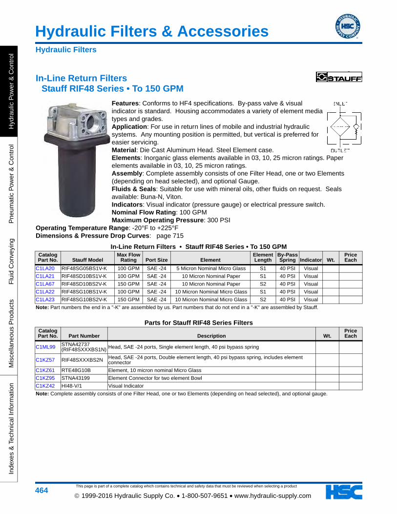
In-Line Return Filters Stauff RIF48 Series • To 150 GPM
Features: Conforms to HF4 specifications. By-pass valve & visual indicator is standard. Housing accommodates a variety of element media types and grades. Application: For use in return lines of mobile and industrial hydraulic systems. Any mounting position is permitted, but vertical is preferred for easier servicing. Material: Die Cast Aluminum Head. Steel Element case. Elements: Inorganic glass elements available in 03, 10, 25 micron ratings. Paper elements available in 03, 10, 25 micron ratings. Assembly: Complete assembly consists of one Filter Head, one or two Elements (depending on head selected), and optional Gauge. Fluids & Seals: Suitable for use with mineral oils, other fluids on request. Seals available: Buna-N, Viton. Indicators: Visual indicator (pressure gauge) or electrical pressure switch. Nominal Flow Rating: 100 GPM Maximum Operating Pressure: 300 PSI
Operating Temperature Range: -20°F to +225°F Dimensions & Pressure Drop Curves: page 715
In-Line Return Filters • Stauff RIF48 Series • To 150 GPMCatalog Part No. Stauff Model
Max Flow Rating Port Size Element
Element Length
By-Pass Spring Indicator Wt.
Price Each
C1LA20 RIF48SG05BS1V-K 100 GPM SAE -24 5 Micron Nominal Micro Glass S1 40 PSI Visual
C1LA21 RIF48SD10BS1V-K 100 GPM SAE -24 10 Micron Nominal Paper S1 40 PSI Visual
C1LA67 RIF48SD10BS2V-K 150 GPM SAE -24 10 Micron Nominal Paper S2 40 PSI Visual
C1LA22 RIF48SG10BS1V-K 100 GPM SAE -24 10 Micron Nominal Micro Glass S1 40 PSI Visual
C1LA23 RIF48SG10BS2V-K 150 GPM SAE -24 10 Micron Nominal Micro Glass S2 40 PSI Visual
Note: Part numbers the end in a "-K" are assembled by us. Part numbers that do not end in a "-K" are assembled by Stauff.
Parts for Stauff RIF48 Series FiltersCatalog Part No. Part Number Description Wt.
Price Each
C1ML99 STNA42737 (RIF48SXXXBS1N) Head, SAE -24 ports, Single element length, 40 psi bypass spring
C1KZ57 RIF48SXXXBS2N Head, SAE -24 ports, Double element length, 40 psi bypass spring, includes element connector
C1KZ61 RTE48G10B Element, 10 micron nominal Micro Glass
C1KZ95 STNA43199 Element Connector for two element Bowl
C1KZ42 HI48-V/1 Visual Indicator
Note: Complete assembly consists of one Filter Head, one or two Elements (depending on head selected), and optional gauge.
Hydraulic Filters
Hydraulic Filters & Accessories
This page is part of a complete catalog which contains technical and safety data that must be reviewed when selecting a product
Hydraulic P
ower &
Control
Pneum
atic Pow
er & C
ontrolF
luid Conveying
Miscellaneous P
roductsIndexes &
Technical Information
465 1999-2016 Hydraulic Supply Co. • 1-800-507-9651 • www.hydraulic-supply.com
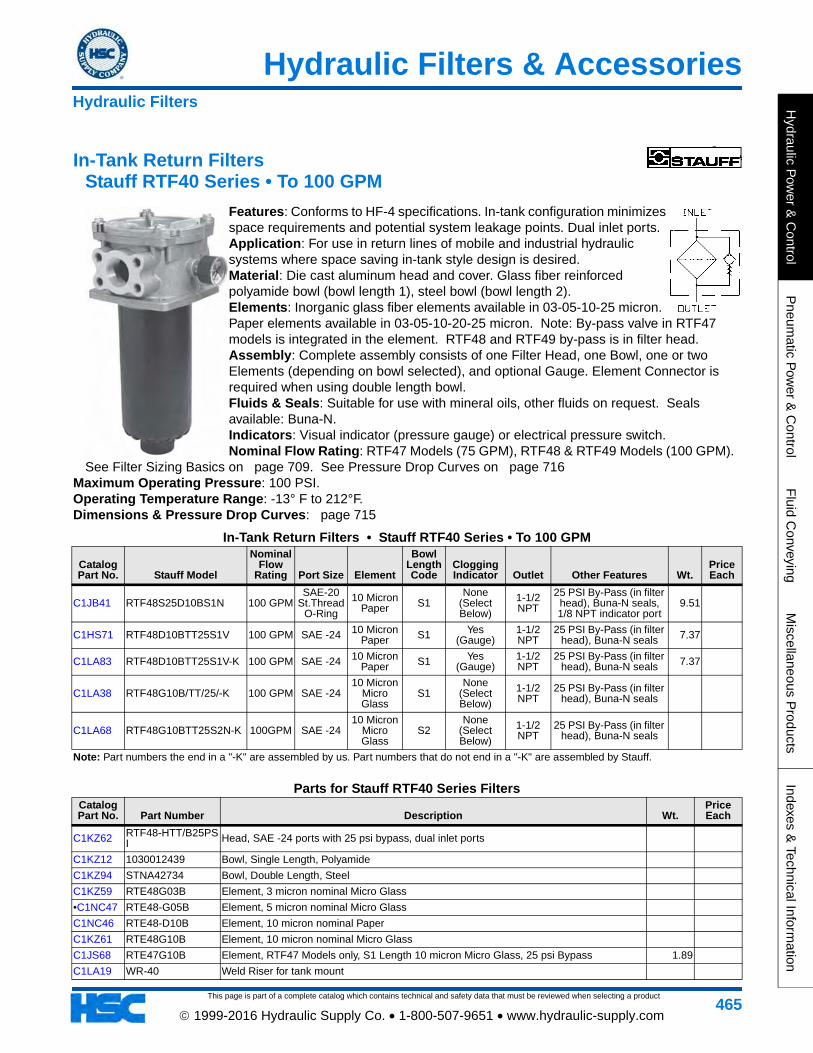
In-Tank Return Filters Stauff RTF40 Series • To 100 GPM
Features: Conforms to HF-4 specifications. In-tank configuration minimizes space requirements and potential system leakage points. Dual inlet ports. Application: For use in return lines of mobile and industrial hydraulic systems where space saving in-tank style design is desired. Material: Die cast aluminum head and cover. Glass fiber reinforced polyamide bowl (bowl length 1), steel bowl (bowl length 2). Elements: Inorganic glass fiber elements available in 03-05-10-25 micron. Paper elements available in 03-05-10-20-25 micron. Note: By-pass valve in RTF47 models is integrated in the element. RTF48 and RTF49 by-pass is in filter head. Assembly: Complete assembly consists of one Filter Head, one Bowl, one or two Elements (depending on bowl selected), and optional Gauge. Element Connector is required when using double length bowl. Fluids & Seals: Suitable for use with mineral oils, other fluids on request. Seals available: Buna-N. Indicators: Visual indicator (pressure gauge) or electrical pressure switch. Nominal Flow Rating: RTF47 Models (75 GPM), RTF48 & RTF49 Models (100 GPM).
See Filter Sizing Basics on page 709. See Pressure Drop Curves on page 716Maximum Operating Pressure: 100 PSI. Operating Temperature Range: -13° F to 212°F. Dimensions & Pressure Drop Curves: page 715
In-Tank Return Filters • Stauff RTF40 Series • To 100 GPM
Catalog Part No. Stauff Model
Nominal Flow
Rating Port Size Element
Bowl Length Code
Clogging Indicator Outlet Other Features Wt.
Price Each
C1JB41 RTF48S25D10BS1N 100 GPMSAE-20
St.Thread O-Ring
10 Micron Paper S1
None (Select Below)
1-1/2 NPT
25 PSI By-Pass (in filter head), Buna-N seals, 1/8 NPT indicator port
9.51
C1HS71 RTF48D10BTT25S1V 100 GPM SAE -24 10 Micron Paper S1 Yes
(Gauge)1-1/2 NPT
25 PSI By-Pass (in filter head), Buna-N seals 7.37
C1LA83 RTF48D10BTT25S1V-K 100 GPM SAE -24 10 Micron Paper S1 Yes
(Gauge)1-1/2 NPT
25 PSI By-Pass (in filter head), Buna-N seals 7.37
C1LA38 RTF48G10B/TT/25/-K 100 GPM SAE -2410 Micron
Micro Glass
S1None
(Select Below)
1-1/2 NPT
25 PSI By-Pass (in filter head), Buna-N seals
C1LA68 RTF48G10BTT25S2N-K 100GPM SAE -2410 Micron
Micro Glass
S2None
(Select Below)
1-1/2 NPT
25 PSI By-Pass (in filter head), Buna-N seals
Note: Part numbers the end in a "-K" are assembled by us. Part numbers that do not end in a "-K" are assembled by Stauff.
Parts for Stauff RTF40 Series FiltersCatalog Part No. Part Number Description Wt.
Price Each
C1KZ62 RTF48-HTT/B25PSI Head, SAE -24 ports with 25 psi bypass, dual inlet ports
C1KZ12 1030012439 Bowl, Single Length, Polyamide
C1KZ94 STNA42734 Bowl, Double Length, Steel
C1KZ59 RTE48G03B Element, 3 micron nominal Micro Glass
•C1NC47 RTE48-G05B Element, 5 micron nominal Micro Glass
C1NC46 RTE48-D10B Element, 10 micron nominal Paper
C1KZ61 RTE48G10B Element, 10 micron nominal Micro Glass
C1JS68 RTE47G10B Element, RTF47 Models only, S1 Length 10 micron Micro Glass, 25 psi Bypass 1.89
C1LA19 WR-40 Weld Riser for tank mount
Hydraulic Filters
This page is part of a complete catalog which contains technical and safety data that must be reviewed when selecting a product
Hydraulic Filters & Accessories
Hyd
raul
ic P
ower
& C
ontr
olP
neum
atic
Pow
er &
Con
trol
Flu
id C
onve
ying
Mis
cella
neou
s P
rodu
cts
Inde
xes
& T
echn
ical
Info
rmat
ion
466 1999-2016 Hydraulic Supply Co. • 1-800-507-9651 • www.hydraulic-supply.com
C1KZ95 STNA43199 Element Connector for two element Bowl
•C1FZ32 CI-12 Pressure Gauge for return line applications, for filters with 15 PSI by-pass 0.15
•C1GF95 CI-20 Pressure Gauge for return line applications, for filters with 25 PSI by-pass 0.15Note: Complete assembly consists of one Filter Head, one Bowl, one or two Elements (depending on bowl selected), and optional gauge.
Element Connector is required when using double length bowl.
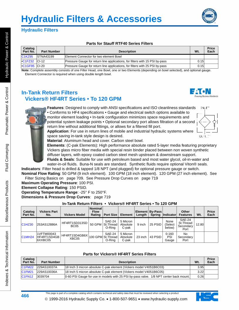
In-Tank Return Filters Vickers® HF4RT Series • To 120 GPM
Features: Designed to comply with ANSI specifications and ISO cleanliness standards • Conforms to HF4 specifications • Gauge and electrical switch options available to monitor element loading • In-tank configuration minimizes space requirements and potential system leakage points • Optional secondary port allows filtration of a second return line without additional fittings, or allows for a filtered fill port. Application: For use in return lines of mobile and industrial hydraulic systems where space saving in-tank style design is desired. Material: Aluminum head and cover. Carbon steel bowl. Elements: (C-pak Elements): High performance absolute rated 5-layer media featuring proprietary Vickers glass micro fiber media with special resin binder placed between non woven synthetic diffuser layers, with epoxy coated carbon steel mesh upstream & downstream support. Fluids & Seals: Suitable for use with petroleum based and most water glycol, oil-in-water and water-in-oil fluids. Buna-N seals are standard. Synthetic fluids require optional Viton® seals.
Indicators: Filter head is drilled & tapped 1/8 NPT (and plugged) for optional pressure gauge or switch. Nominal Flow Rating: 50 GPM (9 inch element). 100 GPM (18 inch element). 120 GPM (27 inch element). See
Filter Sizing Basics on page 709. See Pressure Drop Curves on page 719Maximum Operating Pressure: 100 PSI. Element Collapse Rating: 150 PSID. Operating Temperature Range: -25° F to 250°F. Dimensions & Pressure Drop Curves: page 719
In-Tank Return Filters • Vickers® HF4RT Series • To 120 GPM
Catalog Part No.
Vickers Part No. Vickers Model
Nominal Flow
Rating Port Size ElementElement Length
By-Pass Spring Indicator
Other Features Wt.
Price Each
C1HZ30 253AS12886A HF4RT1SD313SDBC05 50 GPM
SAE-24 St.Thread
O-Ring
5 Micron Absolute
C-pak9 inch 25 PSID
None (Select below)
SAE-24 St.Thread Secondary
Port
12.80
C1MH241VFTM00043 HF4RT1SD4GB6XXBC05
HF4RT1SD4GB6XXBC05 100 GPM
SAE-24 St.Thread
O-Ring
5 Micron Absolute
C-pak23 inch 43 PSID
0-160 PSI
Gauge
No Secondary
Port
Parts for Vickers® HF4RT Series FiltersCatalog Part No. Part Number Description Wt.
Price Each
C1FM22 229AS10037A 18 Inch 3 micron absolute C-pak element (Vickers model V4051B6C03) 3.95
C1FM21 229AS10036A 18 Inch 5 micron absolute C-pak element (Vickers model V4051B6C05) 3.22
C1FN12 3039704 0-60 PSI Gauge for use in models with 25 PSI by-pass valve. 1/8 NPT center back mount. 0.26
Parts for Stauff RTF40 Series FiltersCatalog Part No. Part Number Description Wt.
Price Each
Hydraulic Filters
Hydraulic Filters & Accessories
This page is part of a complete catalog which contains technical and safety data that must be reviewed when selecting a product
Hydraulic P
ower &
Control
Pneum
atic Pow
er & C
ontrolF
luid Conveying
Miscellaneous P
roductsIndexes &
Technical Information
467 1999-2016 Hydraulic Supply Co. • 1-800-507-9651 • www.hydraulic-supply.com
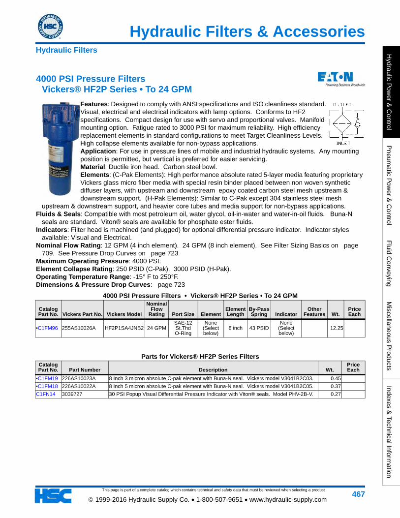
4000 PSI Pressure Filters Vickers® HF2P Series • To 24 GPM
Features: Designed to comply with ANSI specifications and ISO cleanliness standard. Visual, electrical and electrical indicators with lamp options. Conforms to HF2 specifications. Compact design for use with servo and proportional valves. Manifold mounting option. Fatigue rated to 3000 PSI for maximum reliability. High efficiency replacement elements in standard configurations to meet Target Cleanliness Levels. High collapse elements available for non-bypass applications. Application: For use in pressure lines of mobile and industrial hydraulic systems. Any mounting position is permitted, but vertical is preferred for easier servicing. Material: Ductile iron head. Carbon steel bowl. Elements: (C-Pak Elements): High performance absolute rated 5-layer media featuring proprietary Vickers glass micro fiber media with special resin binder placed between non woven synthetic diffuser layers, with upstream and downstream epoxy coated carbon steel mesh upstream & downstream support. (H-Pak Elements): Similar to C-Pak except 304 stainless steel mesh
upstream & downstream support, and heavier core tubes and media support for non-bypass applications. Fluids & Seals: Compatible with most petroleum oil, water glycol, oil-in-water and water-in-oil fluids. Buna-N
seals are standard. Viton® seals are available for phosphate ester fluids. Indicators: Filter head is machined (and plugged) for optional differential pressure indicator. Indicator styles
available: Visual and Electrical. Nominal Flow Rating: 12 GPM (4 inch element). 24 GPM (8 inch element). See Filter Sizing Basics on page
709. See Pressure Drop Curves on page 723Maximum Operating Pressure: 4000 PSI. Element Collapse Rating: 250 PSID (C-Pak). 3000 PSID (H-Pak). Operating Temperature Range: -15° F to 250°F. Dimensions & Pressure Drop Curves: page 723
4000 PSI Pressure Filters • Vickers® HF2P Series • To 24 GPM
Catalog Part No. Vickers Part No. Vickers Model
Nominal Flow
Rating Port Size ElementElement Length
By-Pass Spring Indicator
Other Features Wt.
Price Each
•C1FM96 255AS10026A HF2P1SA4JNB2 24 GPMSAE-12 St.Thd O-Ring
None (Select below)
8 inch 43 PSIDNone
(Select below)
12.25
Parts for Vickers® HF2P Series FiltersCatalog Part No. Part Number Description Wt.
Price Each
•C1FM19 226AS10023A 8 Inch 3 micron absolute C-pak element with Buna-N seal. Vickers model V3041B2C03. 0.45
•C1FM18 226AS10022A 8 Inch 5 micron absolute C-pak element with Buna-N seal. Vickers model V3041B2C05. 0.37
C1FN14 3039727 30 PSI Popup Visual Differential Pressure Indicator with Viton® seals. Model PHV-2B-V. 0.27
Hydraulic Filters
This page is part of a complete catalog which contains technical and safety data that must be reviewed when selecting a product
Hydraulic Filters & Accessories
Hyd
raul
ic P
ower
& C
ontr
olP
neum
atic
Pow
er &
Con
trol
Flu
id C
onve
ying
Mis
cella
neou
s P
rodu
cts
Inde
xes
& T
echn
ical
Info
rmat
ion
468 1999-2016 Hydraulic Supply Co. • 1-800-507-9651 • www.hydraulic-supply.com
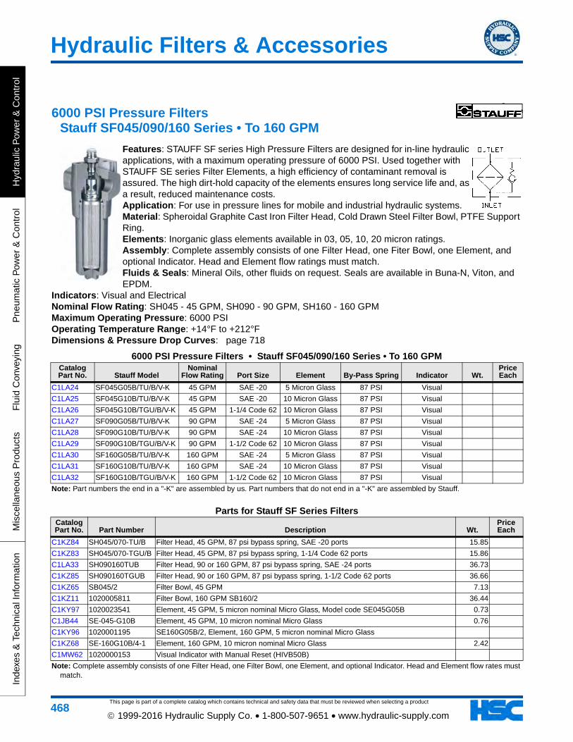
6000 PSI Pressure Filters Stauff SF045/090/160 Series • To 160 GPM
Features: STAUFF SF series High Pressure Filters are designed for in-line hydraulic applications, with a maximum operating pressure of 6000 PSI. Used together with STAUFF SE series Filter Elements, a high efficiency of contaminant removal is assured. The high dirt-hold capacity of the elements ensures long service life and, as a result, reduced maintenance costs. Application: For use in pressure lines for mobile and industrial hydraulic systems. Material: Spheroidal Graphite Cast Iron Filter Head, Cold Drawn Steel Filter Bowl, PTFE Support Ring. Elements: Inorganic glass elements available in 03, 05, 10, 20 micron ratings. Assembly: Complete assembly consists of one Filter Head, one Fiter Bowl, one Element, and optional Indicator. Head and Element flow ratings must match. Fluids & Seals: Mineral Oils, other fluids on request. Seals are available in Buna-N, Viton, and EPDM.
Indicators: Visual and Electrical Nominal Flow Rating: SH045 - 45 GPM, SH090 - 90 GPM, SH160 - 160 GPM Maximum Operating Pressure: 6000 PSI Operating Temperature Range: +14°F to +212°F Dimensions & Pressure Drop Curves: page 718
6000 PSI Pressure Filters • Stauff SF045/090/160 Series • To 160 GPMCatalog Part No. Stauff Model
Nominal Flow Rating Port Size Element By-Pass Spring Indicator Wt.
Price Each
C1LA24 SF045G05B/TU/B/V-K 45 GPM SAE -20 5 Micron Glass 87 PSI Visual
C1LA25 SF045G10B/TU/B/V-K 45 GPM SAE -20 10 Micron Glass 87 PSI Visual
C1LA26 SF045G10B/TGU/B/V-K 45 GPM 1-1/4 Code 62 10 Micron Glass 87 PSI Visual
C1LA27 SF090G05B/TU/B/V-K 90 GPM SAE -24 5 Micron Glass 87 PSI Visual
C1LA28 SF090G10B/TU/B/V-K 90 GPM SAE -24 10 Micron Glass 87 PSI Visual
C1LA29 SF090G10B/TGU/B/V-K 90 GPM 1-1/2 Code 62 10 Micron Glass 87 PSI Visual
C1LA30 SF160G05B/TU/B/V-K 160 GPM SAE -24 5 Micron Glass 87 PSI Visual
C1LA31 SF160G10B/TU/B/V-K 160 GPM SAE -24 10 Micron Glass 87 PSI Visual
C1LA32 SF160G10B/TGU/B/V-K 160 GPM 1-1/2 Code 62 10 Micron Glass 87 PSI Visual
Note: Part numbers the end in a "-K" are assembled by us. Part numbers that do not end in a "-K" are assembled by Stauff.
Parts for Stauff SF Series FiltersCatalog Part No. Part Number Description Wt.
Price Each
C1KZ84 SH045/070-TU/B Filter Head, 45 GPM, 87 psi bypass spring, SAE -20 ports 15.85
C1KZ83 SH045/070-TGU/B Filter Head, 45 GPM, 87 psi bypass spring, 1-1/4 Code 62 ports 15.86
C1LA33 SH090160TUB Filter Head, 90 or 160 GPM, 87 psi bypass spring, SAE -24 ports 36.73
C1KZ85 SH090160TGUB Filter Head, 90 or 160 GPM, 87 psi bypass spring, 1-1/2 Code 62 ports 36.66
C1KZ65 SB045/2 Filter Bowl, 45 GPM 7.13
C1KZ11 1020005811 Filter Bowl, 160 GPM SB160/2 36.44
C1KY97 1020023541 Element, 45 GPM, 5 micron nominal Micro Glass, Model code SE045G05B 0.73
C1JB44 SE-045-G10B Element, 45 GPM, 10 micron nominal Micro Glass 0.76
C1KY96 1020001195 SE160G05B/2, Element, 160 GPM, 5 micron nominal Micro Glass
C1KZ68 SE-160G10B/4-1 Element, 160 GPM, 10 micron nominal Micro Glass 2.42
C1MW62 1020000153 Visual Indicator with Manual Reset (HIVB50B)
Note: Complete assembly consists of one Filter Head, one Filter Bowl, one Element, and optional Indicator. Head and Element flow rates must match.
Hydraulic Filters & Accessories
This page is part of a complete catalog which contains technical and safety data that must be reviewed when selecting a product
Hydraulic P
ower &
Control
Pneum
atic Pow
er & C
ontrolF
luid Conveying
Miscellaneous P
roductsIndexes &
Technical Information
469 1999-2016 Hydraulic Supply Co. • 1-800-507-9651 • www.hydraulic-supply.com
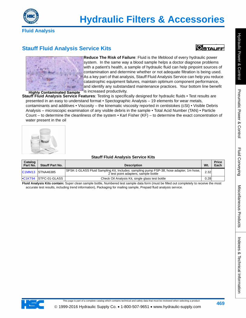
Stauff Fluid Analysis Service Kits
Reduce The Risk of Failure: Fluid is the lifeblood of every hydraulic power system. In the same way a blood sample helps a doctor diagnose problems with a patient's health, a sample of hydraulic fluid can help pinpoint sources of contamination and determine whether or not adequate filtration is being used. As a key part of that analysis, Stauff Fluid Analysis Service can help you reduce catastrophic equipment failures, maintain optimum component performance, and identify any substandard maintenance practices. Your bottom line benefit is increased productivity.
Stauff Fluid Analysis Service Features: Testing is specifically designed for hydraulic fluids • Test results are presented in an easy to understand format • Spectographic Analysis – 19 elements for wear metals, contaminants and additives • Viscosity – the kinematic viscosity reported in centistokes (cSt) • Visible Debris Analysis – microscopic examination of any visible debris in the sample • Total Acid Number (TAN) • Particle Count – to determine the cleanliness of the system • Karl Fisher (KF) – to determine the exact concentration of water present in the oil
Stauff Fluid Analysis Service KitsCatalog Part No. Stauff Part No. Description Wt.
Price Each
C1MM13 STNA46385 SFSK-1-GLASS Fluid Sampling Kit, Includes: sampling pump FSP-38, hose adapter, 1m hose, 2 test point adapters, sample bottle 2.32
•C1KT94 STFC-01-GLASS Check Oil Analysis Kit, single glass test bottle 0.28
Fluid Analysis Kits contain: Super clean sample bottle, Numbered test sample data form (must be filled out completely to receive the most accurate test results, including trend information), Packaging for mailing sample, Prepaid fluid analysis service.
Fluid Analysis
This page is part of a complete catalog which contains technical and safety data that must be reviewed when selecting a product
Hydraulic Filters & Accessories
Hyd
raul
ic P
ower
& C
ontr
olP
neum
atic
Pow
er &
Con
trol
Flu
id C
onve
ying
Mis
cella
neou
s P
rodu
cts
Inde
xes
& T
echn
ical
Info
rmat
ion
470 1999-2016 Hydraulic Supply Co. • 1-800-507-9651 • www.hydraulic-supply.com
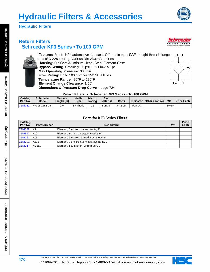
Return Filters Schroeder KF3 Series • To 100 GPM
Features: Meets HF4 automotive standard. Offered in pipe, SAE straight thread, flange and ISO 228 porting. Various Dirt Alarm® options. Housing: Die Cast Aluminum Head, Steel Element Case. Bypass Setting: Cracking: 30 psi, Full Flow: 51 psi. Max Operating Pressure: 300 psi. Flow Rating: Up to 100 gpm for 150 SUS fluids. Temperature Range: -20°F to 225°F Element Change Clearance: 1.50" Dimensions & Pressure Drop Curve: page 724
Return Filters • Schroeder KF3 Series • To 100 GPMCatalog Part No.
Schroeder Model
Element Length (in)
Media Type
Micron Rating
Seal Material Ports Indicator Other Features Wt. Price Each
C1MC12 KF31KZ25SD5 9.0 Synthetic 25 Buna-N SAE-24 Pop-Up 10.50
Parts for KF3 Series FiltersCatalog Part No. Part Number Description Wt.
Price Each
C1MB99 K3 Element, 3 micron, paper media, 9"
C1MB97 K10 Element, 10 micron, paper media, 9"
C1MC23 KZ5 Element, 5 micron, Z-media synthetic, 9"
C1MC21 KZ25 Element, 25 micron, Z-media synthetic, 9"
C1MC17 KM150 Element, 150 Micron, Wire mesh, 9"
Hydraulic Filters
Hydraulic Filters & Accessories
This page is part of a complete catalog which contains technical and safety data that must be reviewed when selecting a product
Hydraulic P
ower &
Control
Pneum
atic Pow
er & C
ontrolF
luid Conveying
Miscellaneous P
roductsIndexes &
Technical Information
471 1999-2016 Hydraulic Supply Co. • 1-800-507-9651 • www.hydraulic-supply.com
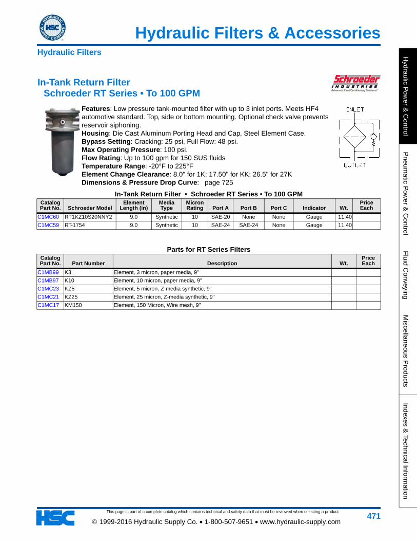
In-Tank Return Filter Schroeder RT Series • To 100 GPM
Features: Low pressure tank-mounted filter with up to 3 inlet ports. Meets HF4 automotive standard. Top, side or bottom mounting. Optional check valve prevents reservoir siphoning. Housing: Die Cast Aluminum Porting Head and Cap, Steel Element Case. Bypass Setting: Cracking: 25 psi, Full Flow: 48 psi. Max Operating Pressure: 100 psi. Flow Rating: Up to 100 gpm for 150 SUS fluids Temperature Range: -20°F to 225°F Element Change Clearance: 8.0" for 1K; 17.50" for KK; 26.5" for 27K Dimensions & Pressure Drop Curve: page 725
In-Tank Return Filter • Schroeder RT Series • To 100 GPMCatalog Part No. Schroeder Model
Element Length (in)
Media Type
Micron Rating Port A Port B Port C Indicator Wt.
Price Each
C1MC60 RT1KZ10S20NNY2 9.0 Synthetic 10 SAE-20 None None Gauge 11.40
C1MC59 RT-1754 9.0 Synthetic 10 SAE-24 SAE-24 None Gauge 11.40
Parts for RT Series FiltersCatalog Part No. Part Number Description Wt.
Price Each
C1MB99 K3 Element, 3 micron, paper media, 9"
C1MB97 K10 Element, 10 micron, paper media, 9"
C1MC23 KZ5 Element, 5 micron, Z-media synthetic, 9"
C1MC21 KZ25 Element, 25 micron, Z-media synthetic, 9"
C1MC17 KM150 Element, 150 Micron, Wire mesh, 9"
Hydraulic Filters
This page is part of a complete catalog which contains technical and safety data that must be reviewed when selecting a product
Hydraulic Filters & Accessories
Hyd
raul
ic P
ower
& C
ontr
olP
neum
atic
Pow
er &
Con
trol
Flu
id C
onve
ying
Mis
cella
neou
s P
rodu
cts
Inde
xes
& T
echn
ical
Info
rmat
ion
472 1999-2016 Hydraulic Supply Co. • 1-800-507-9651 • www.hydraulic-supply.com
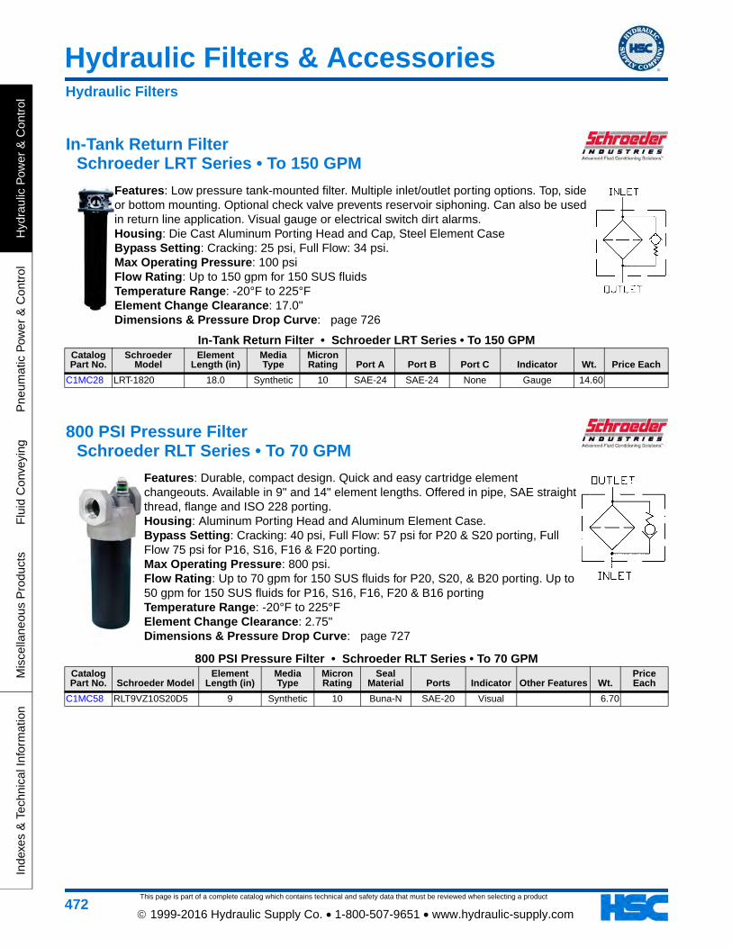
In-Tank Return Filter Schroeder LRT Series • To 150 GPM
Features: Low pressure tank-mounted filter. Multiple inlet/outlet porting options. Top, side or bottom mounting. Optional check valve prevents reservoir siphoning. Can also be used in return line application. Visual gauge or electrical switch dirt alarms. Housing: Die Cast Aluminum Porting Head and Cap, Steel Element Case Bypass Setting: Cracking: 25 psi, Full Flow: 34 psi. Max Operating Pressure: 100 psi Flow Rating: Up to 150 gpm for 150 SUS fluids Temperature Range: -20°F to 225°F Element Change Clearance: 17.0" Dimensions & Pressure Drop Curve: page 726
In-Tank Return Filter • Schroeder LRT Series • To 150 GPMCatalog Part No.
Schroeder Model
Element Length (in)
Media Type
Micron Rating Port A Port B Port C Indicator Wt. Price Each
C1MC28 LRT-1820 18.0 Synthetic 10 SAE-24 SAE-24 None Gauge 14.60
800 PSI Pressure Filter Schroeder RLT Series • To 70 GPM
Features: Durable, compact design. Quick and easy cartridge element changeouts. Available in 9" and 14" element lengths. Offered in pipe, SAE straight thread, flange and ISO 228 porting. Housing: Aluminum Porting Head and Aluminum Element Case. Bypass Setting: Cracking: 40 psi, Full Flow: 57 psi for P20 & S20 porting, Full Flow 75 psi for P16, S16, F16 & F20 porting. Max Operating Pressure: 800 psi. Flow Rating: Up to 70 gpm for 150 SUS fluids for P20, S20, & B20 porting. Up to 50 gpm for 150 SUS fluids for P16, S16, F16, F20 & B16 porting Temperature Range: -20°F to 225°F Element Change Clearance: 2.75" Dimensions & Pressure Drop Curve: page 727
800 PSI Pressure Filter • Schroeder RLT Series • To 70 GPMCatalog Part No. Schroeder Model
Element Length (in)
Media Type
Micron Rating
Seal Material Ports Indicator Other Features Wt.
Price Each
C1MC58 RLT9VZ10S20D5 9 Synthetic 10 Buna-N SAE-20 Visual 6.70
Hydraulic Filters

Hydraulic Filters & Accessories
This page is part of a complete catalog which contains technical and safety data that must be reviewed when selecting a product
Hydraulic P
ower &
Control
Pneum
atic Pow
er & C
ontrolF
luid Conveying
Miscellaneous P
roductsIndexes &
Technical Information
473 1999-2016 Hydraulic Supply Co. • 1-800-507-9651 • www.hydraulic-supply.com
1400 PSI Pressure Filter Schroeder SRLT Series • To 25 GPM
Features: Smaller, compact version of the RLT. Quick and easy cartridge element changeouts. Offered in pipe, SAE straight thread and ISO 228 porting. Various Dirt Alarm® options. Housing: Aluminum Porting Head, Aluminum Element Case Bypass Setting: Cracking: 40 psi, Full Flow: 55 psi. Max Operating Pressure: 1400 psi. Flow Rating: Up to 25 gpm for 150 SUS fluids Temperature Range: -20°F to 225°F Element Change Clearance: 2.75" Dimensions & Pressure Drop Curve: page 728
1400 PSI Pressure Filter • Schroeder SRLT Series • To 25 GPMCatalog Part No. Schroeder Model
Element Length (in)
Media Type
Micron Rating
Seal Material Ports Indicator Other Features Wt.
Price Each
C1MC66 SRLT6RZ10S12D5 6 Synthetic 10 Buna-N SAE -12 Visual 3.00
3000 PSI Pressure Filters Schroeder NF30 Series • To 20 GPM
Features: Top-ported pressure filter. All aluminum assembly. Available with non-bypass option with high collapse element. Offered in pipe, SAE straight thread and ISO 228 porting. Housing: Aluminum Porting Head and Aluminum Element Case. Bypass Setting: Cracking: 40 psi, Full Flow: 85 psi. Non-Bypass model has a blocked bypass. Max Operating Pressure: 3000 psi Flow Rating: Up to 20 gpm for 150 SUS fluids. Temperature Range: -20 °F to 225 °F Element Change Clearance: 4.50 inches.
Dimensions & Pressure Drop Curve: page 729
3000 PSI Pressure Filters • Schroeder NF30 Series • To 20 GPMCatalog Part No.
Schroeder Model
Element Length (in)
Media Type
Micron Rating
Seal Material Ports Indicator Other Features Wt. Price Each
C1MC41 NF301N10SD5 5.25 Paper 10 Buna-N SAE -12 Visual 3.40
Parts for NF30 Series FiltersCatalog Part No. Part Number Description Wt.
Price Each
C1MC36 N10 Element, 10 micron, paper media
Hydraulic Filters
This page is part of a complete catalog which contains technical and safety data that must be reviewed when selecting a product
Hydraulic Filters & Accessories
Hyd
raul
ic P
ower
& C
ontr
olP
neum
atic
Pow
er &
Con
trol
Flu
id C
onve
ying
Mis
cella
neou
s P
rodu
cts
Inde
xes
& T
echn
ical
Info
rmat
ion
474 1999-2016 Hydraulic Supply Co. • 1-800-507-9651 • www.hydraulic-supply.com
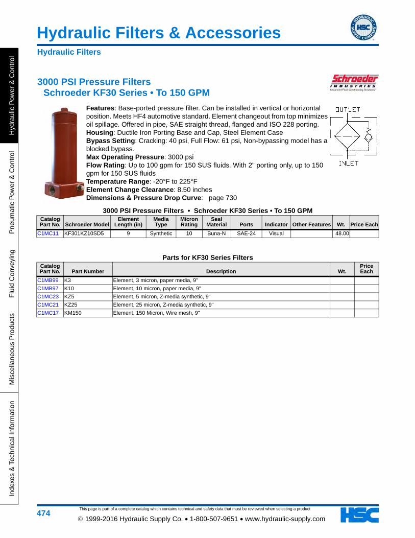
3000 PSI Pressure Filters Schroeder KF30 Series • To 150 GPM
Features: Base-ported pressure filter. Can be installed in vertical or horizontal position. Meets HF4 automotive standard. Element changeout from top minimizes oil spillage. Offered in pipe, SAE straight thread, flanged and ISO 228 porting. Housing: Ductile Iron Porting Base and Cap, Steel Element Case Bypass Setting: Cracking: 40 psi, Full Flow: 61 psi, Non-bypassing model has a blocked bypass. Max Operating Pressure: 3000 psi Flow Rating: Up to 100 gpm for 150 SUS fluids. With 2" porting only, up to 150 gpm for 150 SUS fluids Temperature Range: -20°F to 225°F Element Change Clearance: 8.50 inches Dimensions & Pressure Drop Curve: page 730
3000 PSI Pressure Filters • Schroeder KF30 Series • To 150 GPMCatalog Part No. Schroeder Model
Element Length (in)
Media Type
Micron Rating
Seal Material Ports Indicator Other Features Wt. Price Each
C1MC11 KF301KZ10SD5 9 Synthetic 10 Buna-N SAE-24 Visual 48.00
Parts for KF30 Series FiltersCatalog Part No. Part Number Description Wt.
Price Each
C1MB99 K3 Element, 3 micron, paper media, 9"
C1MB97 K10 Element, 10 micron, paper media, 9"
C1MC23 KZ5 Element, 5 micron, Z-media synthetic, 9"
C1MC21 KZ25 Element, 25 micron, Z-media synthetic, 9"
C1MC17 KM150 Element, 150 Micron, Wire mesh, 9"
Hydraulic Filters
Hydraulic Filters & Accessories
This page is part of a complete catalog which contains technical and safety data that must be reviewed when selecting a product
Hydraulic P
ower &
Control
Pneum
atic Pow
er & C
ontrolF
luid Conveying
Miscellaneous P
roductsIndexes &
Technical Information
475 1999-2016 Hydraulic Supply Co. • 1-800-507-9651 • www.hydraulic-supply.com
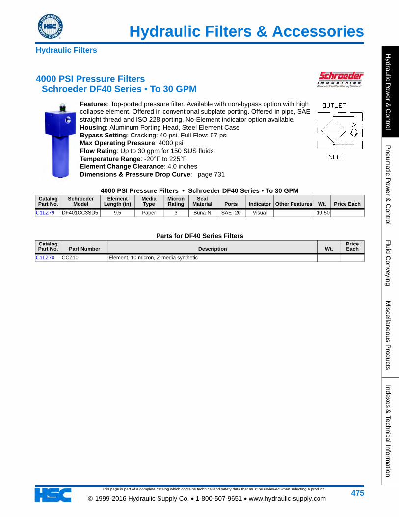
4000 PSI Pressure Filters Schroeder DF40 Series • To 30 GPM
Features: Top-ported pressure filter. Available with non-bypass option with high collapse element. Offered in conventional subplate porting. Offered in pipe, SAE straight thread and ISO 228 porting. No-Element indicator option available. Housing: Aluminum Porting Head, Steel Element Case Bypass Setting: Cracking: 40 psi, Full Flow: 57 psi Max Operating Pressure: 4000 psi Flow Rating: Up to 30 gpm for 150 SUS fluids Temperature Range: -20°F to 225°F Element Change Clearance: 4.0 inches Dimensions & Pressure Drop Curve: page 731
4000 PSI Pressure Filters • Schroeder DF40 Series • To 30 GPMCatalog Part No.
Schroeder Model
Element Length (in)
Media Type
Micron Rating
Seal Material Ports Indicator Other Features Wt. Price Each
C1LZ79 DF401CC3SD5 9.5 Paper 3 Buna-N SAE -20 Visual 19.50
Parts for DF40 Series FiltersCatalog Part No. Part Number Description Wt.
Price Each
C1LZ70 CCZ10 Element, 10 micron, Z-media synthetic
Hydraulic Filters
This page is part of a complete catalog which contains technical and safety data that must be reviewed when selecting a product
Hydraulic Filters & Accessories
Hyd
raul
ic P
ower
& C
ontr
olP
neum
atic
Pow
er &
Con
trol
Flu
id C
onve
ying
Mis
cella
neou
s P
rodu
cts
Inde
xes
& T
echn
ical
Info
rmat
ion
476 1999-2016 Hydraulic Supply Co. • 1-800-507-9651 • www.hydraulic-supply.com
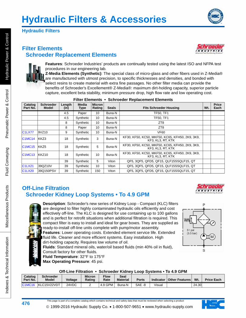
Filter Elements Schroeder Replacement Elements
Features: Schroeder Industries’ products are continually tested using the latest ISO and NFPA test procedures in our engineering lab. Z-Media Elements (Synthetic): The special class of micro-glass and other fibers used in Z-Media® are manufactured with utmost precision, to specific thicknesses and densities, and bonded with select resins to create material with extra fine passages. No other filter media can provide the benefits of Schroeder’s Excellement® Z-Media®: maximum dirt-holding capacity, superior particle capture, excellent beta stability, minimum pressure drop, high flow rate and low operating cost.
Filter Elements • Schroeder Replacement ElementsCatalog Part No.
Schroeder Model
Length (in)
Media Type
Micron Rating Seals Fits Schroeder Housing Wt.
Price Each
4.5 Paper 10 Buna-N TF50, TF1
4.5 Synthetic 10 Buna-N TF50, TF1
8 Synthetic 10 Buna-N ZT8
8 Paper 10 Buna-N ZT8
C1LX77 9VZ10 9 Synthetic 10 Buna-N VF60
C1MC14 KKZ3 18 Synthetic 3 Buna-N KF30, KF50, KC50, MKF50, KC65, KFH50, 2K9, 3K9, KF3, KL3, RT, KTK
C1MC15 KKZ5 18 Synthetic 5 Buna-N KF30, KF50, KC50, MKF50, KC65, KFH50, 2K9, 3K9, KF3, KL3, RT, KTK
C1MC13 KKZ10 18 Synthetic 10 Buna-N KF30, KF50, KC50, MKF50, KC65, KFH50, 2K9, 3K9, KF3, KL3, RT, KTK
39 Synthetic 5 Viton QF5, 3QF5, QFD5, QF15, QLF15SSQLF15, QT
C1LX21 39QZ10V 39 Synthetic 10 Viton QF5, 3QF5, QFD5, QF15, QLF15SSQLF15, QT
C1LX20 39Q150PSV 39 Synthetic 150 Viton QF5, 3QF5, QFD5, QF15, QLF15SSQLF15, QT
Off-Line Filtration Schroeder Kidney Loop Systems • To 4.9 GPM
Description: Schroeder’s new series of Kidney Loop - Compact (KLC) filters are designed to filter highly contaminated hydraulic oils efficiently and cost effectively off-line. The KLC is designed for use containing up to 100 gallons and is perfect for retrofit situations when additional filtration is required. This compact filter is easy to install and ideal for gear boxes. They are supplied as ready-to-install off-line units complete with pump/motor assembly. Features: Lower operating costs. Extended element service life. Extended fluid life. Cleaner and more efficient systems. Easy installation. High dirt-holding capacity. Requires low volume of oil. Fluids: Standard mineral oils, water/oil based fluids (min 40% oil in fluid), Consult factory for other fluids. Fluid Temperature: 32°F to 175°F Max Operating Pressure: 45 psi.
Off-Line Filtration • Schroeder Kidney Loop Systems • To 4.9 GPMCatalog Part No.
Schroeder Model Voltage
Micron Rating
Flow Rate
Seal Material Ports Indicator Other Features Wt. Price Each
C1MC16 KLC15V22VDT 24VDC 2 4.9 GPM Buna-N SAE -8 Visual 24.30
Hydraulic Filters
Hydraulic Filters & Accessories
This page is part of a complete catalog which contains technical and safety data that must be reviewed when selecting a product
Hydraulic P
ower &
Control
Pneum
atic Pow
er & C
ontrolF
luid Conveying
Miscellaneous P
roductsIndexes &
Technical Information
477 1999-2016 Hydraulic Supply Co. • 1-800-507-9651 • www.hydraulic-supply.com
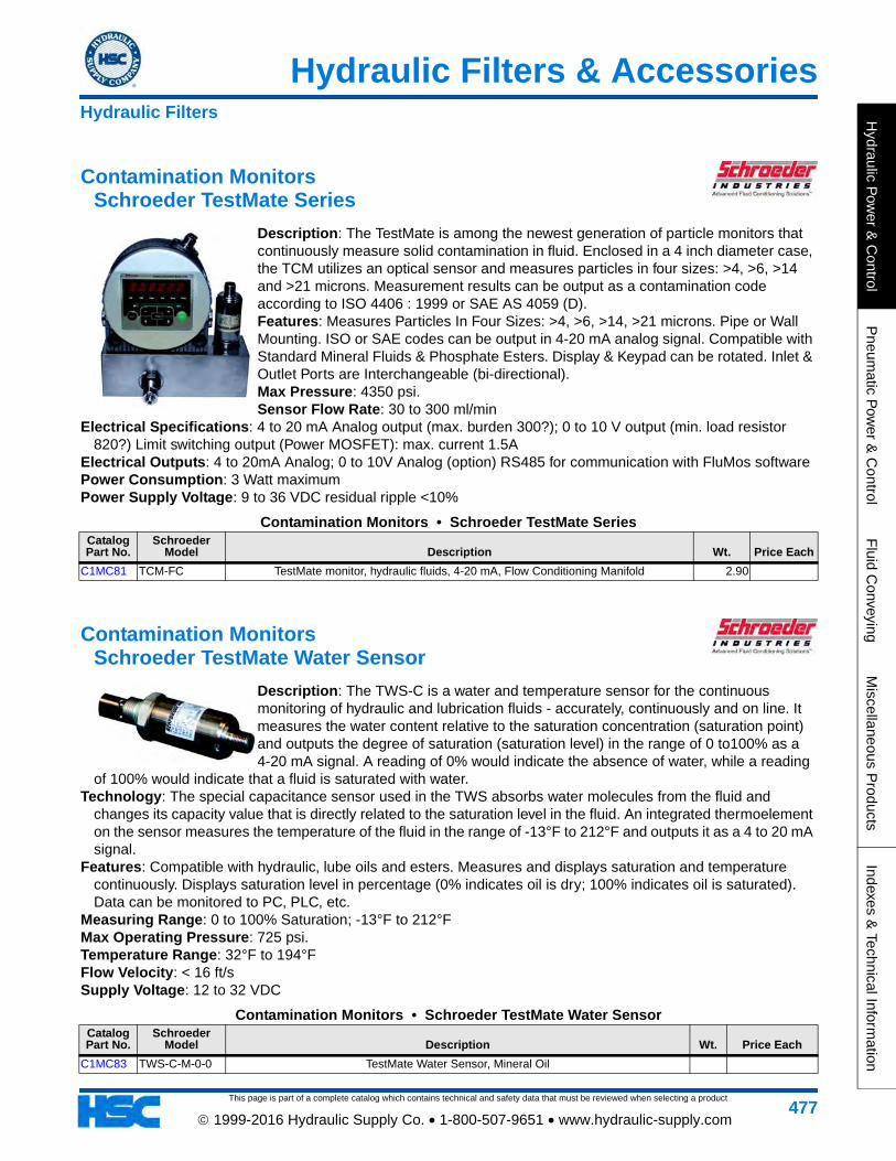
Contamination Monitors Schroeder TestMate Series
Description: The TestMate is among the newest generation of particle monitors that continuously measure solid contamination in fluid. Enclosed in a 4 inch diameter case, the TCM utilizes an optical sensor and measures particles in four sizes: >4, >6, >14 and >21 microns. Measurement results can be output as a contamination code according to ISO 4406 : 1999 or SAE AS 4059 (D). Features: Measures Particles In Four Sizes: >4, >6, >14, >21 microns. Pipe or Wall Mounting. ISO or SAE codes can be output in 4-20 mA analog signal. Compatible with Standard Mineral Fluids & Phosphate Esters. Display & Keypad can be rotated. Inlet & Outlet Ports are Interchangeable (bi-directional). Max Pressure: 4350 psi. Sensor Flow Rate: 30 to 300 ml/min
Electrical Specifications: 4 to 20 mA Analog output (max. burden 300?); 0 to 10 V output (min. load resistor 820?) Limit switching output (Power MOSFET): max. current 1.5A
Electrical Outputs: 4 to 20mA Analog; 0 to 10V Analog (option) RS485 for communication with FluMos software Power Consumption: 3 Watt maximum Power Supply Voltage: 9 to 36 VDC residual ripple <10%
Contamination Monitors • Schroeder TestMate SeriesCatalog Part No.
Schroeder Model Description Wt. Price Each
C1MC81 TCM-FC TestMate monitor, hydraulic fluids, 4-20 mA, Flow Conditioning Manifold 2.90
Contamination Monitors Schroeder TestMate Water Sensor
Description: The TWS-C is a water and temperature sensor for the continuous monitoring of hydraulic and lubrication fluids - accurately, continuously and on line. It measures the water content relative to the saturation concentration (saturation point) and outputs the degree of saturation (saturation level) in the range of 0 to100% as a 4-20 mA signal. A reading of 0% would indicate the absence of water, while a reading
of 100% would indicate that a fluid is saturated with water. Technology: The special capacitance sensor used in the TWS absorbs water molecules from the fluid and
changes its capacity value that is directly related to the saturation level in the fluid. An integrated thermoelement on the sensor measures the temperature of the fluid in the range of -13°F to 212°F and outputs it as a 4 to 20 mA signal.
Features: Compatible with hydraulic, lube oils and esters. Measures and displays saturation and temperature continuously. Displays saturation level in percentage (0% indicates oil is dry; 100% indicates oil is saturated). Data can be monitored to PC, PLC, etc.
Measuring Range: 0 to 100% Saturation; -13°F to 212°F Max Operating Pressure: 725 psi. Temperature Range: 32°F to 194°F Flow Velocity: < 16 ft/s Supply Voltage: 12 to 32 VDC
Contamination Monitors • Schroeder TestMate Water SensorCatalog Part No.
Schroeder Model Description Wt. Price Each
C1MC83 TWS-C-M-0-0 TestMate Water Sensor, Mineral Oil
Hydraulic Filters
This page is part of a complete catalog which contains technical and safety data that must be reviewed when selecting a product
Hydraulic Filters & Accessories
Hyd
raul
ic P
ower
& C
ontr
olP
neum
atic
Pow
er &
Con
trol
Flu
id C
onve
ying
Mis
cella
neou
s P
rodu
cts
Inde
xes
& T
echn
ical
Info
rmat
ion
478 1999-2016 Hydraulic Supply Co. • 1-800-507-9651 • www.hydraulic-supply.com
Contamination Monitors Schroeder Fluid Analysis Kit
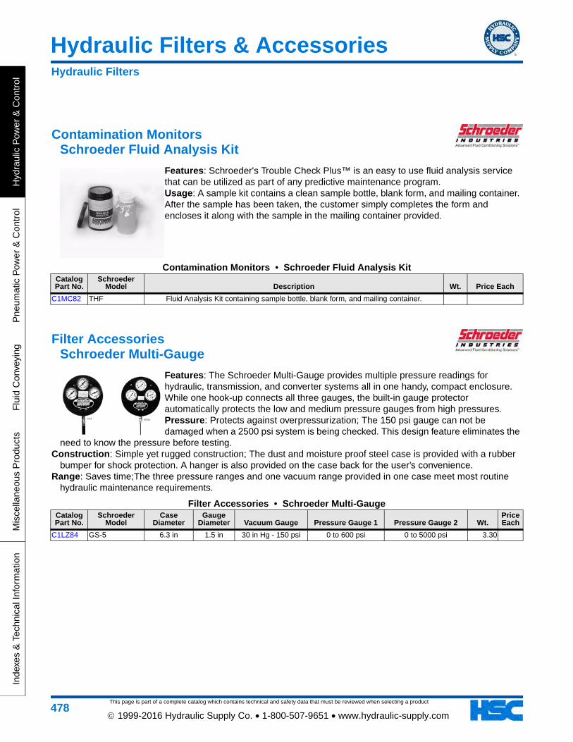
Features: Schroeder's Trouble Check Plus™ is an easy to use fluid analysis service that can be utilized as part of any predictive maintenance program. Usage: A sample kit contains a clean sample bottle, blank form, and mailing container. After the sample has been taken, the customer simply completes the form and encloses it along with the sample in the mailing container provided.
Contamination Monitors • Schroeder Fluid Analysis KitCatalog Part No.
Schroeder Model Description Wt. Price Each
C1MC82 THF Fluid Analysis Kit containing sample bottle, blank form, and mailing container.
Filter Accessories Schroeder Multi-Gauge
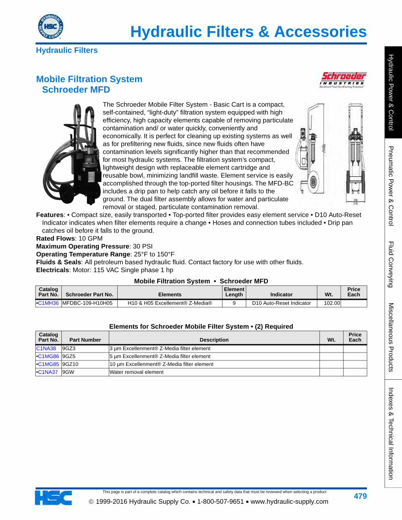
Features: The Schroeder Multi-Gauge provides multiple pressure readings for hydraulic, transmission, and converter systems all in one handy, compact enclosure. While one hook-up connects all three gauges, the built-in gauge protector automatically protects the low and medium pressure gauges from high pressures. Pressure: Protects against overpressurization; The 150 psi gauge can not be damaged when a 2500 psi system is being checked. This design feature eliminates the
need to know the pressure before testing. Construction: Simple yet rugged construction; The dust and moisture proof steel case is provided with a rubber
bumper for shock protection. A hanger is also provided on the case back for the user’s convenience. Range: Saves time;The three pressure ranges and one vacuum range provided in one case meet most routine
hydraulic maintenance requirements.
Filter Accessories • Schroeder Multi-GaugeCatalog Part No.
Schroeder Model
Case Diameter
Gauge Diameter Vacuum Gauge Pressure Gauge 1 Pressure Gauge 2 Wt.
Price Each
C1LZ84 GS-5 6.3 in 1.5 in 30 in Hg - 150 psi 0 to 600 psi 0 to 5000 psi 3.30
Hydraulic Filters
Hydraulic Filters & Accessories
This page is part of a complete catalog which contains technical and safety data that must be reviewed when selecting a product
Hydraulic P
ower &
Control
Pneum
atic Pow
er & C
ontrolF
luid Conveying
Miscellaneous P
roductsIndexes &
Technical Information
479 1999-2016 Hydraulic Supply Co. • 1-800-507-9651 • www.hydraulic-supply.com
Mobile Filtration System Schroeder MFD
The Schroeder Mobile Filter System - Basic Cart is a compact, self-contained, “light-duty” filtration system equipped with high efficiency, high capacity elements capable of removing particulate contamination and/ or water quickly, conveniently and economically. It is perfect for cleaning up existing systems as well as for prefiltering new fluids, since new fluids often have contamination levels significantly higher than that recommended for most hydraulic systems. The filtration system’s compact, lightweight design with replaceable element cartridge and reusable bowl, minimizing landfill waste. Element service is easily accomplished through the top-ported filter housings. The MFD-BC includes a drip pan to help catch any oil before it falls to the ground. The dual filter assembly allows for water and particulate removal or staged, particulate contamination removal.
Features: • Compact size, easily transported • Top-ported filter provides easy element service • D10 Auto-Reset Indicator indicates when filter elements require a change • Hoses and connection tubes included • Drip pan catches oil before it falls to the ground.
Rated Flows: 10 GPM Maximum Operating Pressure: 30 PSI Operating Temperature Range: 25°F to 150°F Fluids & Seals: All petroleum based hydraulic fluid. Contact factory for use with other fluids. Electricals: Motor: 115 VAC Single phase 1 hp
Mobile Filtration System • Schroeder MFDCatalog Part No. Schroeder Part No. Elements
Element Length Indicator Wt.
Price Each
•C1MH36 MFDBC-109-H10H05 H10 & H05 Excellement® Z-Media® 9 D10 Auto-Reset Indicator 102.00
Elements for Schroeder Mobile Filter System • (2) RequiredCatalog Part No. Part Number Description Wt.
Price Each
C1NA38 9GZ3 3 µm Excellenment® Z-Media filter element
•C1MG86 9GZ5 5 µm Excellenment® Z-Media filter element
•C1MG85 9GZ10 10 µm Excellenment® Z-Media filter element
•C1NA37 9GW Water removal element
Hydraulic Filters
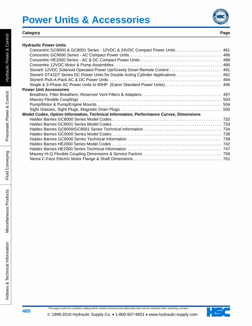
This page is part of a complete catalog which contains technical and safety data that must be reviewed when selecting a product
Power Units & AccessoriesCategory Page
Hyd
raul
ic P
ower
& C
ontr
olP
neum
atic
Pow
er &
Con
trol
Flu
id C
onve
ying
Mis
cella
neou
s P
rodu
cts
Inde
xes
& T
echn
ical
Info
rmat
ion
480 1999-2016 Hydraulic Supply Co. • 1-800-507-9651 • www.hydraulic-supply.com
Hydraulic Power UnitsConcentric GC8000 & GC8001 Series - 12VDC & 24VDC Compact Power Units . . . . . . . . . . . . . . . . . . . . 481Concentric GC9000 Series - AC Compact Power Units . . . . . . . . . . . . . . . . . . . . . . . . . . . . . . . . . . . . . . . . 486Concentric HE2000 Series - AC & DC Compact Power Units. . . . . . . . . . . . . . . . . . . . . . . . . . . . . . . . . . . . 488Concentric 12VDC Motor & Pump Assemblies . . . . . . . . . . . . . . . . . . . . . . . . . . . . . . . . . . . . . . . . . . . . . . . 490Stone® 12VDC Solenoid Operated Power Up/Gravity Down Remote Control . . . . . . . . . . . . . . . . . . . . . . . 491Stone® DT41DT Series DC Power Units for Double Acting Cylinder Applications . . . . . . . . . . . . . . . . . . . . 492Stone® Pick-A-Pack AC & DC Power Units . . . . . . . . . . . . . . . . . . . . . . . . . . . . . . . . . . . . . . . . . . . . . . . . . 494Single & 3-Phase AC Power Units to 60HP (Eaton Standard Power Units). . . . . . . . . . . . . . . . . . . . . . . . . 496
Power Unit AccessoriesBreathers, Filler-Breathers, Reservoir Vent Filters & Adapters . . . . . . . . . . . . . . . . . . . . . . . . . . . . . . . . . . . 497Maurey Flexible Couplings . . . . . . . . . . . . . . . . . . . . . . . . . . . . . . . . . . . . . . . . . . . . . . . . . . . . . . . . . . . . . . 503Pump/Motor & Pump/Engine Mounts . . . . . . . . . . . . . . . . . . . . . . . . . . . . . . . . . . . . . . . . . . . . . . . . . . . . . . 504Sight Glasses, Sight Plugs, Magnetic Drain Plugs . . . . . . . . . . . . . . . . . . . . . . . . . . . . . . . . . . . . . . . . . . . . 505
Model Codes, Option Information, Technical Information, Performance Curves, DimensionsHaldex Barnes GC8000 Series Model Codes . . . . . . . . . . . . . . . . . . . . . . . . . . . . . . . . . . . . . . . . . . . . . . . . 732Haldex Barnes GC8001 Series Model Codes . . . . . . . . . . . . . . . . . . . . . . . . . . . . . . . . . . . . . . . . . . . . . . . . 733Haldex Barnes GC8000/GC8001 Series Technical Information . . . . . . . . . . . . . . . . . . . . . . . . . . . . . . . . . . 734Haldex Barnes GC9000 Series Model Codes . . . . . . . . . . . . . . . . . . . . . . . . . . . . . . . . . . . . . . . . . . . . . . . . 738Haldex Barnes GC9000 Series Technical Information . . . . . . . . . . . . . . . . . . . . . . . . . . . . . . . . . . . . . . . . . 739Haldex Barnes HE2000 Series Model Codes . . . . . . . . . . . . . . . . . . . . . . . . . . . . . . . . . . . . . . . . . . . . . . . . 742Haldex Barnes HE2000 Series Technical Information . . . . . . . . . . . . . . . . . . . . . . . . . . . . . . . . . . . . . . . . . 747Maurey Hi-Q Flexible Coupling Dimensions & Service Factors . . . . . . . . . . . . . . . . . . . . . . . . . . . . . . . . . . 759Nema C-Face Electric Motor Flange & Shaft Dimensions. . . . . . . . . . . . . . . . . . . . . . . . . . . . . . . . . . . . . . . 761
This page is part of a complete catalog which contains technical and safety data that must be reviewed when selecting a product
Power Units & Accessories
Hydraulic P
ower &
Control
Pneum
atic Pow
er & C
ontrolF
luid Conveying
Miscellaneous P
roductsIndexes &
Technical Information
481 1999-2016 Hydraulic Supply Co. • 1-800-507-9651 • www.hydraulic-supply.com
Compact Power Units, 12VDC & 24VDC Concentric AB GC8000/GC8001 Series
Haldex Barnes GC8000 & GC8001 Series DC Hydraulic Power Units offer you virtually limitless choices - from a selection of pre-assembled units, to a wide range of complete units assembled to your specifications, to the individual component kits which enable you to create or modify a unit to meet your exact requirements.
GC8000 Series: GC8000 Units can be configured in 4 different ways. 1: Basic Power Unit with no directional valving. Add a remote mounted directional valve to run either single acting or double acting cylinder. 2: Manual Control Power Unit. Has manual valve to start unit and operate a single acting cylinder. 3: Remote Control Power Unit. Has solenoid valving to remotely operate a single acting cylinder. 4: Power Unit with 1 or 2 station NFPA D03 Parallel Manifold. The Power Unit has an o-ring seal machined surface that can accept manifold kits for subplate mounted valves. These valves can perform a wide variety of functions.
GC8001 Series: GC8001 Units can be configured in 3 different ways: 1: Remote Control Power Unit. 4-Way solenoid operated cartridge valves to operate double acting cylinder or reversing motor. 2: Direct Mount NFPA D03 Pad Power Unit. Has a single D03 mounting pad that eliminates the need for manifold adapters. Valves perform a wide variety of functions. 3: Manual 4-Way Valve Power Unit. Has 3-position 4-way Tandem center manual valve with integral motor relay switch. Handle movement in either direction from center will start unit and direct flow to either double acting cylinder or reversing motor.
Design Features: Close-coupled DC motors with Oldham coupling for accurate alignment. Hardened and ground alloy-steel gears and shafts. Precision needle bearings. High strength, fine grain cast iron pump housings. Spring-loaded lip-type pump shaft seals. Corrosion resistant externally mounted valves. Cartridge-type check valves and externally adjustable relief valves. 100 mesh reinforced brass inlet strainers. 40 micron dry element type breathers. Powder coated drawn steel reservoirs with magnetic particle collector. Units mount horizontally (Optional breather elbow kit for vertical mount - see kits).
** WARNING **: 12VDC units with .250" gear, over a 5 minute period, can run for 1 minute at 500 psi, or 1/2 minute at 2000 psi, then must be turned off and allowed to cool. See the Technical Information section for allowable motor duty cycle times for all gear widths at various pressure levels.
Repair & Customizing Kits: GC8000 Kits page 484 GC8001 Kits page 485Model Codes: GC8000 Model Codes page 732 GC8001 Model Codes page 733Technical Information: page 734
Basic Power Units (DC) Concentric AB GC8000 Series (Without Control Valves)
These Basic Power Units are for use in applications using a remote mounted directional control valve. They include a direct-acting adjustable relief valve (1500-2500 PSI), load check valve, and alternate outlet and return ports. All valves are of cartridge construction. All ports are SAE straight thread o-ring type (9/16-18 Outlet Port, Return Port and Auxiliary Outlet Port. 7/16-20 Auxiliary Return Port). This group of power units may be repaired or customized using GC8000 Kits.
Hydraulic Power Units
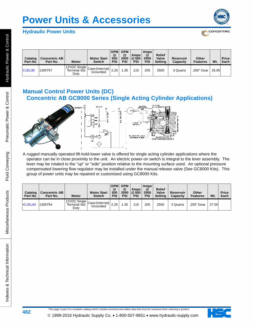
This page is part of a complete catalog which contains technical and safety data that must be reviewed when selecting a product
Power Units & Accessories
Hyd
raul
ic P
ower
& C
ontr
olP
neum
atic
Pow
er &
Con
trol
Flu
id C
onve
ying
Mis
cella
neou
s P
rodu
cts
Inde
xes
& T
echn
ical
Info
rmat
ion
482 1999-2016 Hydraulic Supply Co. • 1-800-507-9651 • www.hydraulic-supply.com
Catalog Part No.
Concentric AB Part No. Motor
Motor Start Switch
GPM @
500 PSI
GPM @
2000 PSI
Amps @ 500
PSI
Amps @
2000 PSI
Relief Valve
SettingReservoir Capacity
Other Features Wt.
Price Each
C1EL95 130075712VDC Single Terminal Std
Duty
Case (Internal) Grounded 2.25 1.35 115 205 2500 3 Quarts .250" Gear 25.95
Manual Control Power Units (DC) Concentric AB GC8000 Series (Single Acting Cylinder Applications)
A rugged manually operated lift-hold-lower valve is offered for single acting cylinder applications where the operator can be in close proximity to the unit. An electric power-on switch is integral to the lever assembly. The lever may be rotated to the "up" or "side" position relative to the mounting surface used. An optional pressure compensated lowering flow regulator may be installed under the manual release valve (See GC8000 Kits). This group of power units may be repaired or customized using GC8000 Kits.
Catalog Part No.
Concentric AB Part No. Motor
Motor Start Switch
GPM @
500 PSI
GPM @
2000 PSI
Amps @ 500
PSI
Amps @
2000 PSI
Relief Valve
SettingReservoir Capacity
Other Features Wt.
Price Each
•C1EL94 130075412VDC Single Terminal Std
Duty
Case (Internal) Grounded 2.25 1.35 115 205 2500 3 Quarts .250" Gear 27.00
Hydraulic Power Units
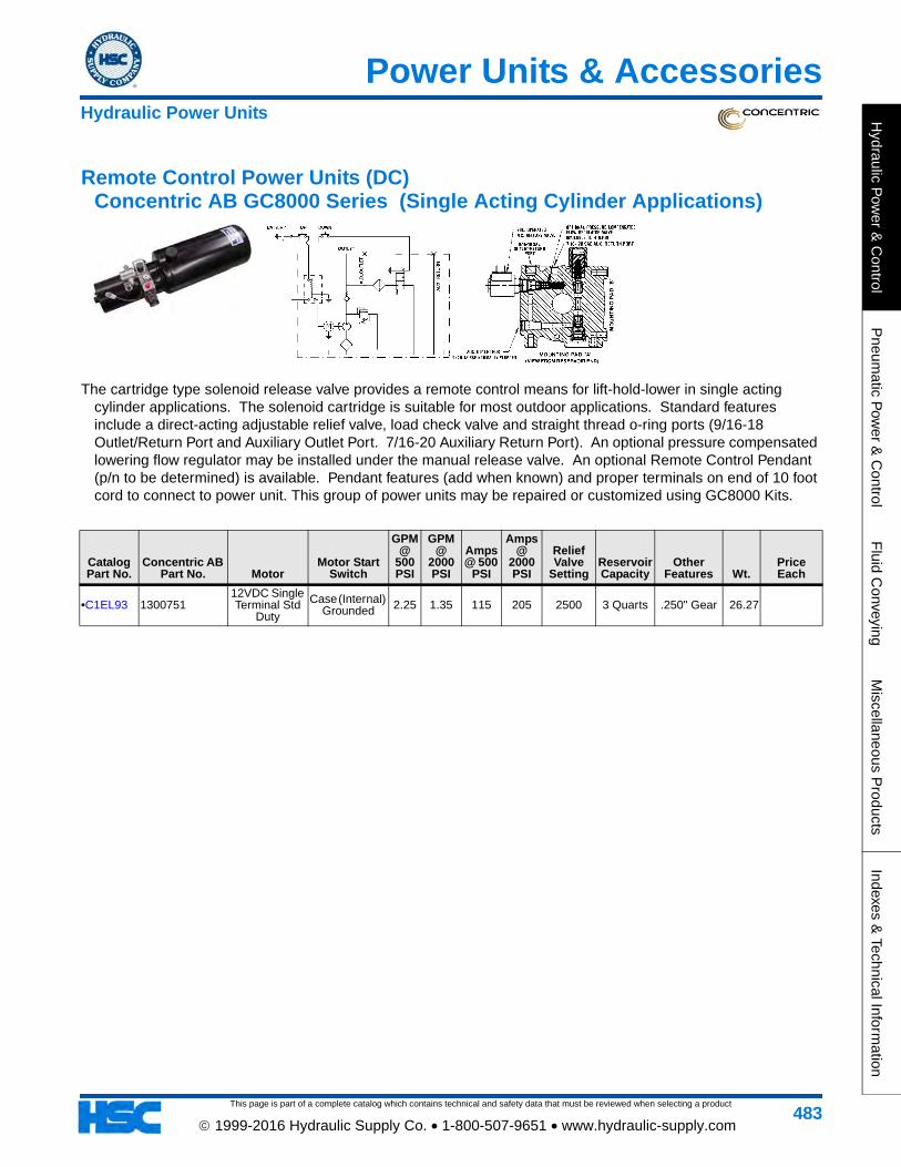
This page is part of a complete catalog which contains technical and safety data that must be reviewed when selecting a product
Power Units & Accessories
Hydraulic P
ower &
Control
Pneum
atic Pow
er & C
ontrolF
luid Conveying
Miscellaneous P
roductsIndexes &
Technical Information
483 1999-2016 Hydraulic Supply Co. • 1-800-507-9651 • www.hydraulic-supply.com
Remote Control Power Units (DC) Concentric AB GC8000 Series (Single Acting Cylinder Applications)
The cartridge type solenoid release valve provides a remote control means for lift-hold-lower in single acting cylinder applications. The solenoid cartridge is suitable for most outdoor applications. Standard features include a direct-acting adjustable relief valve, load check valve and straight thread o-ring ports (9/16-18 Outlet/Return Port and Auxiliary Outlet Port. 7/16-20 Auxiliary Return Port). An optional pressure compensated lowering flow regulator may be installed under the manual release valve. An optional Remote Control Pendant (p/n to be determined) is available. Pendant features (add when known) and proper terminals on end of 10 foot cord to connect to power unit. This group of power units may be repaired or customized using GC8000 Kits.
Catalog Part No.
Concentric AB Part No. Motor
Motor Start Switch
GPM @
500 PSI
GPM @
2000 PSI
Amps @ 500
PSI
Amps @
2000 PSI
Relief Valve
SettingReservoir Capacity
Other Features Wt.
Price Each
•C1EL93 130075112VDC Single Terminal Std
Duty
Case (Internal) Grounded 2.25 1.35 115 205 2500 3 Quarts .250" Gear 26.27
Hydraulic Power Units
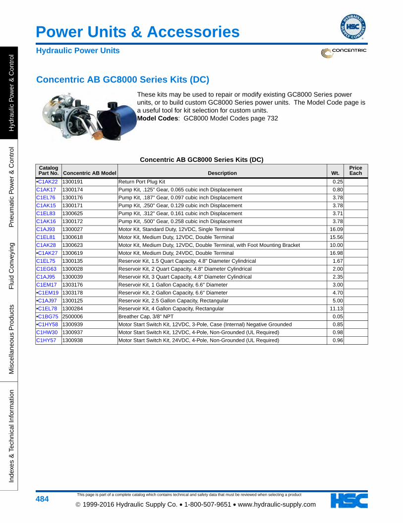
This page is part of a complete catalog which contains technical and safety data that must be reviewed when selecting a product
Power Units & Accessories
Hyd
raul
ic P
ower
& C
ontr
olP
neum
atic
Pow
er &
Con
trol
Flu
id C
onve
ying
Mis
cella
neou
s P
rodu
cts
Inde
xes
& T
echn
ical
Info
rmat
ion
484 1999-2016 Hydraulic Supply Co. • 1-800-507-9651 • www.hydraulic-supply.com
Concentric AB GC8000 Series Kits (DC)
These kits may be used to repair or modify existing GC8000 Series power units, or to build custom GC8000 Series power units. The Model Code page is a useful tool for kit selection for custom units. Model Codes: GC8000 Model Codes page 732
Concentric AB GC8000 Series Kits (DC)Catalog Part No. Concentric AB Model Description Wt.
Price Each
•C1AK22 1300191 Return Port Plug Kit 0.25
C1AK17 1300174 Pump Kit, .125" Gear, 0.065 cubic inch Displacement 0.80
C1EL76 1300176 Pump Kit, .187" Gear, 0.097 cubic inch Displacement 3.78
C1AK15 1300171 Pump Kit, .250" Gear, 0.129 cubic inch Displacement 3.78
C1EL83 1300625 Pump Kit, .312" Gear, 0.161 cubic inch Displacement 3.71
C1AK16 1300172 Pump Kit, .500" Gear, 0.258 cubic inch Displacement 3.78
C1AJ93 1300027 Motor Kit, Standard Duty, 12VDC, Single Terminal 16.09
C1EL81 1300618 Motor Kit, Medium Duty, 12VDC, Double Terminal 15.56
C1AK28 1300623 Motor Kit, Medium Duty, 12VDC, Double Terminal, with Foot Mounting Bracket 10.00
•C1AK27 1300619 Motor Kit, Medium Duty, 24VDC, Double Terminal 16.98
C1EL75 1300135 Reservoir Kit, 1.5 Quart Capacity, 4.8" Diameter Cylindrical 1.67
C1EG63 1300028 Reservoir Kit, 2 Quart Capacity, 4.8" Diameter Cylindrical 2.00
C1AJ95 1300039 Reservoir Kit, 3 Quart Capacity, 4.8" Diameter Cylindrical 2.35
C1EM17 1303176 Reservoir Kit, 1 Gallon Capacity, 6.6" Diameter 3.00
•C1EM19 1303178 Reservoir Kit, 2 Gallon Capacity, 6.6" Diameter 4.70
•C1AJ97 1300125 Reservoir Kit, 2.5 Gallon Capacity, Rectangular 5.00
•C1EL78 1300284 Reservoir Kit, 4 Gallon Capacity, Rectangular 11.13
•C1BG75 2500006 Breather Cap, 3/8" NPT 0.05
•C1HY58 1300939 Motor Start Switch Kit, 12VDC, 3-Pole, Case (Internal) Negative Grounded 0.85
C1HW30 1300937 Motor Start Switch Kit, 12VDC, 4-Pole, Non-Grounded (UL Required) 0.98
C1HY57 1300938 Motor Start Switch Kit, 24VDC, 4-Pole, Non-Grounded (UL Required) 0.96
Hydraulic Power Units
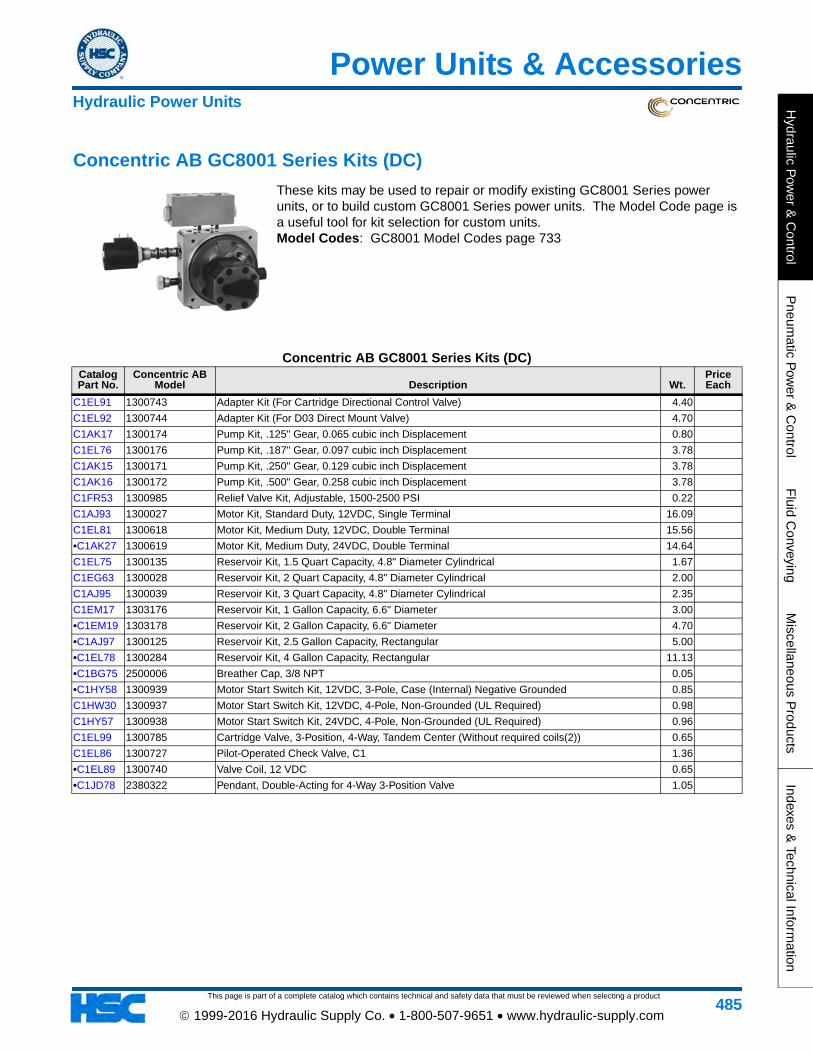
This page is part of a complete catalog which contains technical and safety data that must be reviewed when selecting a product
Power Units & Accessories
Hydraulic P
ower &
Control
Pneum
atic Pow
er & C
ontrolF
luid Conveying
Miscellaneous P
roductsIndexes &
Technical Information
485 1999-2016 Hydraulic Supply Co. • 1-800-507-9651 • www.hydraulic-supply.com
Concentric AB GC8001 Series Kits (DC)
These kits may be used to repair or modify existing GC8001 Series power units, or to build custom GC8001 Series power units. The Model Code page is a useful tool for kit selection for custom units. Model Codes: GC8001 Model Codes page 733
Concentric AB GC8001 Series Kits (DC)Catalog Part No.
Concentric AB Model Description Wt.
Price Each
C1EL91 1300743 Adapter Kit (For Cartridge Directional Control Valve) 4.40
C1EL92 1300744 Adapter Kit (For D03 Direct Mount Valve) 4.70
C1AK17 1300174 Pump Kit, .125" Gear, 0.065 cubic inch Displacement 0.80
C1EL76 1300176 Pump Kit, .187" Gear, 0.097 cubic inch Displacement 3.78
C1AK15 1300171 Pump Kit, .250" Gear, 0.129 cubic inch Displacement 3.78
C1AK16 1300172 Pump Kit, .500" Gear, 0.258 cubic inch Displacement 3.78
C1FR53 1300985 Relief Valve Kit, Adjustable, 1500-2500 PSI 0.22
C1AJ93 1300027 Motor Kit, Standard Duty, 12VDC, Single Terminal 16.09
C1EL81 1300618 Motor Kit, Medium Duty, 12VDC, Double Terminal 15.56
•C1AK27 1300619 Motor Kit, Medium Duty, 24VDC, Double Terminal 14.64
C1EL75 1300135 Reservoir Kit, 1.5 Quart Capacity, 4.8" Diameter Cylindrical 1.67
C1EG63 1300028 Reservoir Kit, 2 Quart Capacity, 4.8" Diameter Cylindrical 2.00
C1AJ95 1300039 Reservoir Kit, 3 Quart Capacity, 4.8" Diameter Cylindrical 2.35
C1EM17 1303176 Reservoir Kit, 1 Gallon Capacity, 6.6" Diameter 3.00
•C1EM19 1303178 Reservoir Kit, 2 Gallon Capacity, 6.6" Diameter 4.70
•C1AJ97 1300125 Reservoir Kit, 2.5 Gallon Capacity, Rectangular 5.00
•C1EL78 1300284 Reservoir Kit, 4 Gallon Capacity, Rectangular 11.13
•C1BG75 2500006 Breather Cap, 3/8 NPT 0.05
•C1HY58 1300939 Motor Start Switch Kit, 12VDC, 3-Pole, Case (Internal) Negative Grounded 0.85
C1HW30 1300937 Motor Start Switch Kit, 12VDC, 4-Pole, Non-Grounded (UL Required) 0.98
C1HY57 1300938 Motor Start Switch Kit, 24VDC, 4-Pole, Non-Grounded (UL Required) 0.96
C1EL99 1300785 Cartridge Valve, 3-Position, 4-Way, Tandem Center (Without required coils(2)) 0.65
C1EL86 1300727 Pilot-Operated Check Valve, C1 1.36
•C1EL89 1300740 Valve Coil, 12 VDC 0.65
•C1JD78 2380322 Pendant, Double-Acting for 4-Way 3-Position Valve 1.05
Hydraulic Power Units
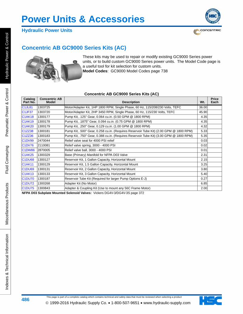
This page is part of a complete catalog which contains technical and safety data that must be reviewed when selecting a product
Power Units & Accessories
Hyd
raul
ic P
ower
& C
ontr
olP
neum
atic
Pow
er &
Con
trol
Flu
id C
onve
ying
Mis
cella
neou
s P
rodu
cts
Inde
xes
& T
echn
ical
Info
rmat
ion
486 1999-2016 Hydraulic Supply Co. • 1-800-507-9651 • www.hydraulic-supply.com
Concentric AB GC9000 Series Kits (AC)
These kits may be used to repair or modify existing GC9000 Series power units, or to build custom GC9000 Series power units. The Model Code page is a useful tool for kit selection for custom units. Model Codes: GC9000 Model Codes page 738
Concentric AB GC9000 Series Kits (AC)Catalog Part No.
Concentric AB Model Description Wt.
Price Each
C1JL81 1303725 Motor/Adapter Kit, 1HP 1800 RPM, Single Phase, 60 Hz, 115/208/230 Volts, TEFC 36.00
C1JF37 1303720 Motor/Adapter Kit, 2HP 3450 RPM, Single Phase, 60 Hz, 115/230 Volts, TEFC 45.90
C1AK18 1300177 Pump Kit, .125" Gear, 0.064 cu.in. (0.50 GPM @ 1800 RPM) 4.35
C1AK19 1300178 Pump Kit, .1875" Gear, 0.094 cu.in. (0.75 GPM @ 1800 RPM) 4.35
C1AK20 1300179 Pump Kit, .250" Gear, 0.129 cu.in. (1.00 GPM @ 1800 RPM) 4.32
C1ZZ38 1300181 Pump Kit, .500" Gear, 0.258 cu.in. (Requires Reservoir Tube Kit) (2.00 GPM @ 1800 RPM) 5.33
C1ZZ36 1300183 Pump Kit, .750" Gear, 0.388 cu.in. (Requires Reservoir Tube Kit) (3.00 GPM @ 1800 RPM) 5.35
C1DV99 2470044 Relief valve seat for 4000 PSI relief 0.03
C1DV76 2110081 Relief valve spring, 3000 - 4000 PSI 0.02
C1DW86 2870005 Relief valve ball, 3000 - 4000 PSI 0.01
C1AK25 1300329 Base (Primary) Manifold for NFPA D03 Valve 2.31
C1DU68 1300127 Reservoir Kit, 1 Gallon Capacity, Horizontal Mount 2.15
C1AK11 1300129 Reservoir Kit, 1.5 Gallon Capacity, Horizontal Mount 3.25
C1DU69 1300131 Reservoir Kit, 2 Gallon Capacity, Horizontal Mount 3.80
C1AK13 1300133 Reservoir Kit, 3 Gallon Capacity, Horizontal Mount 5.40
C1DU70 1300187 Reservoir Tube Kit (Required for larger Pump Options E-J) 0.27
C1DU72 1300268 Adapter Kit (No Motor) 6.85
C1DU75 1300843 Adapter & Coupling Kit (Use to mount any 56C Frame Motor) 2.00
NFPA D03 Subplate Mounted Solenoid Valves: Vickers DG4V-3/DG4V-3S page 372
Hydraulic Power Units
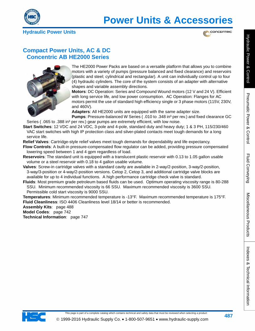
This page is part of a complete catalog which contains technical and safety data that must be reviewed when selecting a product
Power Units & Accessories
Hydraulic P
ower &
Control
Pneum
atic Pow
er & C
ontrolF
luid Conveying
Miscellaneous P
roductsIndexes &
Technical Information
487 1999-2016 Hydraulic Supply Co. • 1-800-507-9651 • www.hydraulic-supply.com
Compact Power Units, AC & DC Concentric AB HE2000 Series
The HE2000 Power Packs are based on a versatile platform that allows you to combine motors with a variety of pumps (pressure balanced and fixed clearance) and reservoirs (plastic and steel; cylindrical and rectangular). A unit can individually control up to four (4) hydraulic cylinders. The core of the system consists of an adapter with alternative shapes and variable assembly directions.Motors: DC Operation: Series and Compound Wound motors (12 V and 24 V). Efficient with long service life, and low power consumption. AC Operation: Flanges for AC motors permit the use of standard high efficiency single or 3 phase motors (115V, 230V, and 460V).Adapters: All HE2000 units are equipped with the same adapter size.Pumps: Pressure-balanced W Series ( .010 to .348 in³ per rev.) and fixed clearance GC
Series ( .065 to .388 in³ per rev.) gear pumps are extremely efficient, with low noise.Start Switches: 12 VDC and 24 VDC, 3-pole and 4-pole, standard duty and heavy duty; 1 & 3 PH, 115/230/460
VAC start switches with high IP protection class and silver-plated contacts meet tough demands for a long service life.
Relief Valves: Cartridge-style relief valves meet tough demands for dependability and life expectancy.Flow Controls: A built-in pressure-compensated flow regulator can be added, providing pressure compensated
lowering speed between 1 and 4 gpm regardless of load.Reservoirs: The standard unit is equipped with a translucent plastic reservoir with 0.13 to 1.05 gallon usable
volume or a steel reservoir with 0.18 to 4 gallon usable volume.Valves: Screw-in cartridge valves with a standard cavity are available in 2-way/2-position, 3-way/2-position,
3-way/3-position or 4-way/2-position versions. Cetop 2, Cetop 3, and additional cartridge valve blocks are available for up to 4 individual functions. A high performance cartridge check valve is standard.
Fluids: Most premium grade petroleum based fluids can be used. Optimum operating viscosity range is 80-288 SSU. Minimum recommended viscosity is 66 SSU. Maximum recommended viscosity is 3600 SSU. Permissible cold start viscosity is 9000 SSU.
Temperatures: Minimum recommended temperature is -13°F. Maximum recommended temperature is 175°F.Fluid Cleanliness: ISO 4406 Cleanliness level 18/14 or better is recommended.Assembly Kits: page 488Model Codes: page 742Technical Information: page 747
Hydraulic Power Units
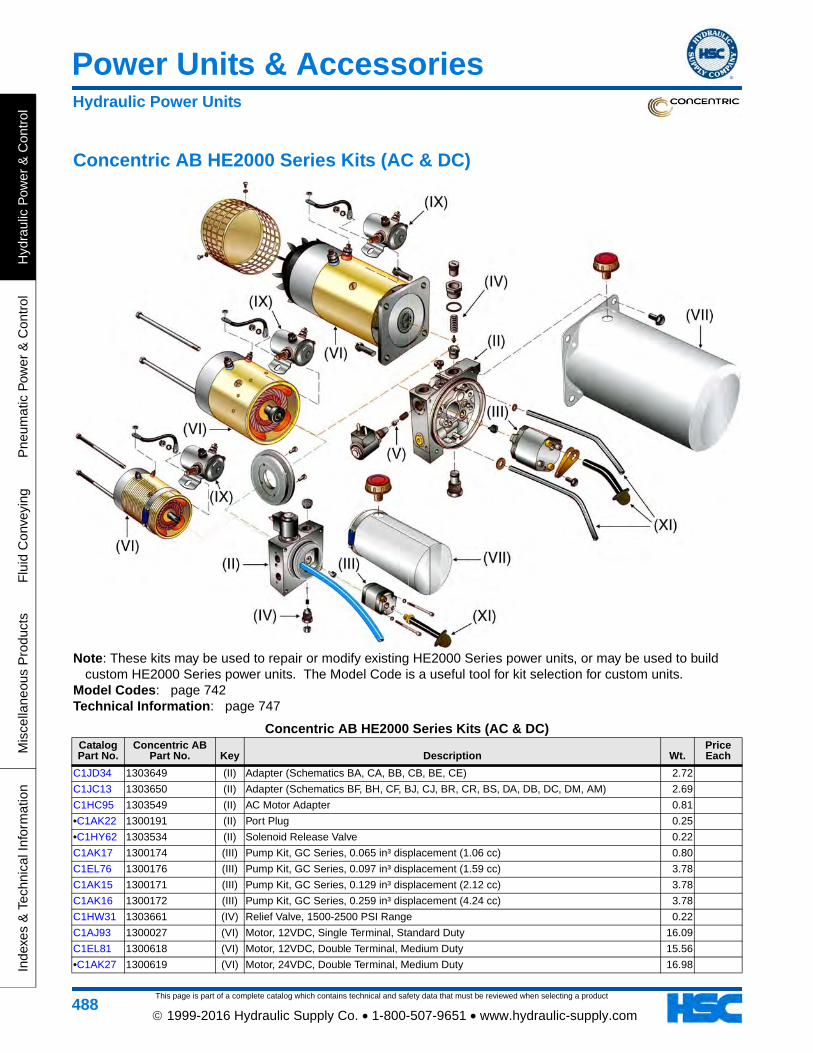
This page is part of a complete catalog which contains technical and safety data that must be reviewed when selecting a product
Power Units & Accessories
Hyd
raul
ic P
ower
& C
ontr
olP
neum
atic
Pow
er &
Con
trol
Flu
id C
onve
ying
Mis
cella
neou
s P
rodu
cts
Inde
xes
& T
echn
ical
Info
rmat
ion
488 1999-2016 Hydraulic Supply Co. • 1-800-507-9651 • www.hydraulic-supply.com
Concentric AB HE2000 Series Kits (AC & DC)
Note: These kits may be used to repair or modify existing HE2000 Series power units, or may be used to build custom HE2000 Series power units. The Model Code is a useful tool for kit selection for custom units.
Model Codes: page 742Technical Information: page 747
Concentric AB HE2000 Series Kits (AC & DC)Catalog Part No.
Concentric AB Part No. Key Description Wt.
Price Each
C1JD34 1303649 (II) Adapter (Schematics BA, CA, BB, CB, BE, CE) 2.72
C1JC13 1303650 (II) Adapter (Schematics BF, BH, CF, BJ, CJ, BR, CR, BS, DA, DB, DC, DM, AM) 2.69
C1HC95 1303549 (II) AC Motor Adapter 0.81
•C1AK22 1300191 (II) Port Plug 0.25
•C1HY62 1303534 (II) Solenoid Release Valve 0.22
C1AK17 1300174 (III) Pump Kit, GC Series, 0.065 in³ displacement (1.06 cc) 0.80
C1EL76 1300176 (III) Pump Kit, GC Series, 0.097 in³ displacement (1.59 cc) 3.78
C1AK15 1300171 (III) Pump Kit, GC Series, 0.129 in³ displacement (2.12 cc) 3.78
C1AK16 1300172 (III) Pump Kit, GC Series, 0.259 in³ displacement (4.24 cc) 3.78
C1HW31 1303661 (IV) Relief Valve, 1500-2500 PSI Range 0.22
C1AJ93 1300027 (VI) Motor, 12VDC, Single Terminal, Standard Duty 16.09
C1EL81 1300618 (VI) Motor, 12VDC, Double Terminal, Medium Duty 15.56
•C1AK27 1300619 (VI) Motor, 24VDC, Double Terminal, Medium Duty 16.98
Hydraulic Power Units
This page is part of a complete catalog which contains technical and safety data that must be reviewed when selecting a product
Power Units & Accessories
Hydraulic P
ower &
Control
Pneum
atic Pow
er & C
ontrolF
luid Conveying
Miscellaneous P
roductsIndexes &
Technical Information
489 1999-2016 Hydraulic Supply Co. • 1-800-507-9651 • www.hydraulic-supply.com
C1MN23 1300899 (VII) Reservoir, Steel, 2 Quart 0.67
C1HW29 1300908 (VII) Reservoir, Steel, 2.5 Gallon Rectangular 7.35
•C1HY58 1300939 (IX) Start Switch, 12VDC, 3-Pole 0.85
C1HW30 1300937 (IX) Start Switch, 12VDC, 4-Pole, UL Recognized 0.98
C1HY57 1300938 (IX) Start Switch, 24VDC, 4-Pole, UL Recognized 0.96
C1MN24 1300943 (XI) Tube Kit for Steel, Horizontal, 1QT Reservoir, W Pumps, Pad "A" Down
C1HW28 1300878 (XI) Tube Kit for Steel, Vertical, 3QT Reservoir, GC/W Pumps 6.06
•C1GG44 1303570 (XIV) Pendant, DC, Double-Acting 0.90
•C1JD78 2380322 (XIV) Pendant, Double-Acting for 4-Way 3-Position Valve 1.05
C1KZ20 2330004 (XV) Terminal Strap, #5 AWG Stranded Battery Cable, Neoprene insulation, 7.5" lug to lug 0.10
Concentric AB HE2000 Series Kits (AC & DC)Catalog Part No.
Concentric AB Part No. Key Description Wt.
Price Each
Hydraulic Power Units
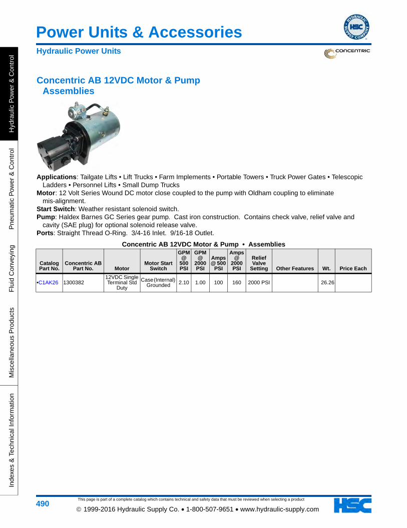
This page is part of a complete catalog which contains technical and safety data that must be reviewed when selecting a product
Power Units & Accessories
Hyd
raul
ic P
ower
& C
ontr
olP
neum
atic
Pow
er &
Con
trol
Flu
id C
onve
ying
Mis
cella
neou
s P
rodu
cts
Inde
xes
& T
echn
ical
Info
rmat
ion
490 1999-2016 Hydraulic Supply Co. • 1-800-507-9651 • www.hydraulic-supply.com
Concentric AB 12VDC Motor & Pump Assemblies
Applications: Tailgate Lifts • Lift Trucks • Farm Implements • Portable Towers • Truck Power Gates • Telescopic Ladders • Personnel Lifts • Small Dump Trucks
Motor: 12 Volt Series Wound DC motor close coupled to the pump with Oldham coupling to eliminate mis-alignment.
Start Switch: Weather resistant solenoid switch. Pump: Haldex Barnes GC Series gear pump. Cast iron construction. Contains check valve, relief valve and
cavity (SAE plug) for optional solenoid release valve. Ports: Straight Thread O-Ring. 3/4-16 Inlet. 9/16-18 Outlet.
Concentric AB 12VDC Motor & Pump • Assemblies
Catalog Part No.
Concentric AB Part No. Motor
Motor Start Switch
GPM @
500 PSI
GPM @
2000 PSI
Amps @ 500
PSI
Amps @
2000 PSI
Relief Valve
Setting Other Features Wt. Price Each
•C1AK26 130038212VDC Single Terminal Std
Duty
Case (Internal) Grounded 2.10 1.00 100 160 2000 PSI 26.26
Hydraulic Power Units
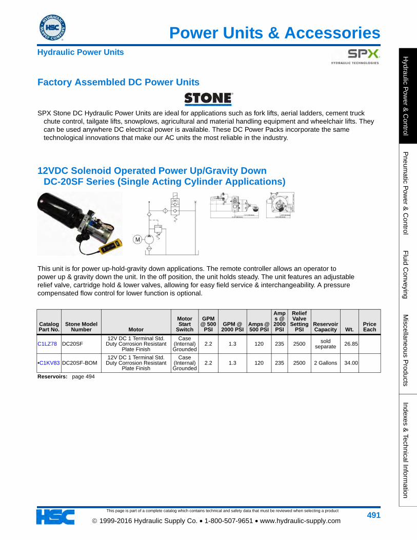
This page is part of a complete catalog which contains technical and safety data that must be reviewed when selecting a product
Power Units & Accessories
Hydraulic P
ower &
Control
Pneum
atic Pow
er & C
ontrolF
luid Conveying
Miscellaneous P
roductsIndexes &
Technical Information
491 1999-2016 Hydraulic Supply Co. • 1-800-507-9651 • www.hydraulic-supply.com
Factory Assembled DC Power Units
SPX Stone DC Hydraulic Power Units are ideal for applications such as fork lifts, aerial ladders, cement truck chute control, tailgate lifts, snowplows, agricultural and material handling equipment and wheelchair lifts. They can be used anywhere DC electrical power is available. These DC Power Packs incorporate the same technological innovations that make our AC units the most reliable in the industry.
12VDC Solenoid Operated Power Up/Gravity Down DC-20SF Series (Single Acting Cylinder Applications)
This unit is for power up-hold-gravity down applications. The remote controller allows an operator topower up & gravity down the unit. In the off position, the unit holds steady. The unit features an adjustablerelief valve, cartridge hold & lower valves, allowing for easy field service & interchangeability. A pressurecompensated flow control for lower function is optional.
Catalog Part No.
Stone Model Number Motor
Motor Start
Switch
GPM @ 500
PSIGPM @
2000 PSIAmps @ 500 PSI
Amps @ 2000 PSI
Relief Valve
Setting PSI
Reservoir Capacity Wt.
Price Each
C1LZ78 DC20SF12V DC 1 Terminal Std.
Duty Corrosion Resistant Plate Finish
Case (Internal) Grounded
2.2 1.3 120 235 2500 sold separate 26.85
•C1KV83 DC20SF-BOM12V DC 1 Terminal Std.
Duty Corrosion Resistant Plate Finish
Case (Internal) Grounded
2.2 1.3 120 235 2500 2 Gallons 34.00
Reservoirs: page 494
Hydraulic Power Units
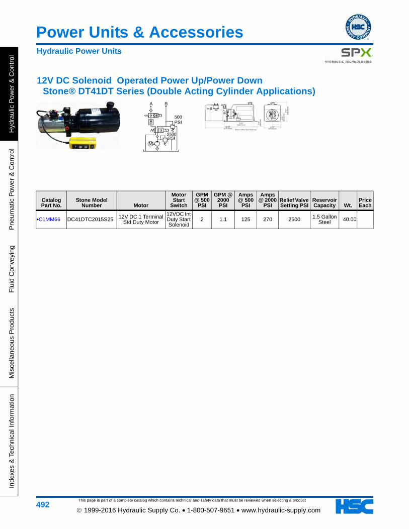
This page is part of a complete catalog which contains technical and safety data that must be reviewed when selecting a product
Power Units & Accessories
Hyd
raul
ic P
ower
& C
ontr
olP
neum
atic
Pow
er &
Con
trol
Flu
id C
onve
ying
Mis
cella
neou
s P
rodu
cts
Inde
xes
& T
echn
ical
Info
rmat
ion
492 1999-2016 Hydraulic Supply Co. • 1-800-507-9651 • www.hydraulic-supply.com
12V DC Solenoid Operated Power Up/Power Down Stone® DT41DT Series (Double Acting Cylinder Applications)
Catalog Part No.
Stone Model Number Motor
Motor Start
Switch
GPM @ 500
PSI
GPM @ 2000 PSI
Amps @ 500
PSI
Amps @ 2000
PSIRelief Valve Setting PSI
Reservoir Capacity Wt.
Price Each
•C1MM66 DC41DTC2015S25 12V DC 1 Terminal Std Duty Motor
12VDC Int Duty Start Solenoid
2 1.1 125 270 2500 1.5 Gallon Steel 40.00
Hydraulic Power Units
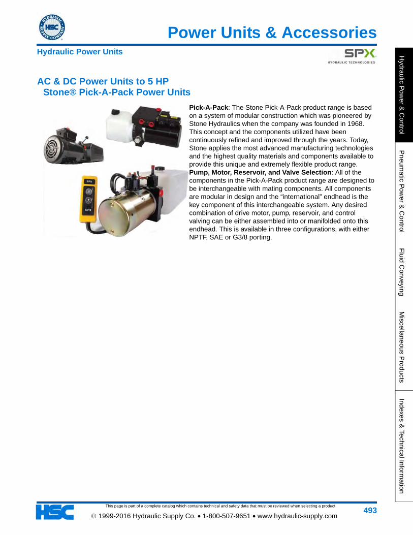
This page is part of a complete catalog which contains technical and safety data that must be reviewed when selecting a product
Power Units & Accessories
Hydraulic P
ower &
Control
Pneum
atic Pow
er & C
ontrolF
luid Conveying
Miscellaneous P
roductsIndexes &
Technical Information
493 1999-2016 Hydraulic Supply Co. • 1-800-507-9651 • www.hydraulic-supply.com
AC & DC Power Units to 5 HP Stone® Pick-A-Pack Power Units
Pick-A-Pack: The Stone Pick-A-Pack product range is based on a system of modular construction which was pioneered by Stone Hydraulics when the company was founded in 1968. This concept and the components utilized have been continuously refined and improved through the years. Today, Stone applies the most advanced manufacturing technologies and the highest quality materials and components available to provide this unique and extremely flexible product range.Pump, Motor, Reservoir, and Valve Selection: All of the components in the Pick-A-Pack product range are designed to be interchangeable with mating components. All components are modular in design and the “international” endhead is the key component of this interchangeable system. Any desired combination of drive motor, pump, reservoir, and control valving can be either assembled into or manifolded onto this endhead. This is available in three configurations, with either NPTF, SAE or G3/8 porting.
Hydraulic Power Units
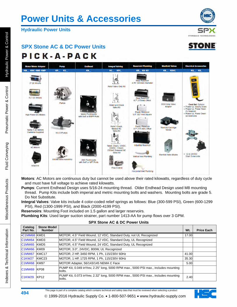
This page is part of a complete catalog which contains technical and safety data that must be reviewed when selecting a product
Power Units & Accessories
Hyd
raul
ic P
ower
& C
ontr
olP
neum
atic
Pow
er &
Con
trol
Flu
id C
onve
ying
Mis
cella
neou
s P
rodu
cts
Inde
xes
& T
echn
ical
Info
rmat
ion
494 1999-2016 Hydraulic Supply Co. • 1-800-507-9651 • www.hydraulic-supply.com
SPX Stone AC & DC Power Units
Motors: AC Motors are continuous duty but cannot be used above their rated kilowatts, regardless of duty cycle and must have full voltage to achieve rated kilowatts.
Pumps: Current Endhead Design uses 5/16-24 mounting thread. Older Endhead Design used M8 mounting thread. Pump Kits include both imperial and metric mounting bolts and washers. Mounting bolts are grade 5. Do Not Substitute.
Integral Valves: Valve kits include 4 color-coded relief springs as follows: Blue (300-599 PSI), Green (600-1299 PSI), Red (1300-1999 PSI), and Black (2000-4199 PSI).
Reservoirs: Mounting Foot included on 1.5 gallon and larger reservoirs. Plumbing Kits: Used larger suction strainer, part number 1413-AA for pump flows over 3 GPM.
SPX Stone AC & DC Power UnitsCatalog Part No.
Stone Model Number Wt. Price Each
•C1MM68 KMD1 MOTOR, 4.5" Field Wound, 12 VDC, Standard Duty, not UL Recognized 17.00
C1MW64 KMD3 MOTOR, 4.5" Field Wound, 12 VDC, Standard Duty, UL Recognized
C1MW65 KMD5 MOTOR, 4.5" Field Wound, 24 VDC, Standard Duty, UL Recognized
C1MW66 KM09 MOTOR, 3.0", 24VDC, 800W, UL Recognized
C1MW67 KMC17 MOTOR, 2 HP, 3450 RPM, 1 Ph, 115/230V 60Hz 41.00
C1KW27 KMC23 MOTOR, 1 HP, 1725 RPM, 1 Ph, 115/230V 60Hz 35.30
C1MW68 KM97 MOTOR Adapter, 56/143/145 NEMA C Face 5.00
C1MW69 KP08 PUMP Kit, 0.049 in³/rev, 2.25" long, 5000 RPM max., 5000 PSI max., includes mounting bolts.
C1KW29 KP12 PUMP Kit, 0.073 in³/rev, 2.32" long, 5000 RPM max., 5000 PSI max., includes mounting bolts. 2.40
Hydraulic Power Units
This page is part of a complete catalog which contains technical and safety data that must be reviewed when selecting a product
Power Units & Accessories
Hydraulic P
ower &
Control
Pneum
atic Pow
er & C
ontrolF
luid Conveying
Miscellaneous P
roductsIndexes &
Technical Information
495 1999-2016 Hydraulic Supply Co. • 1-800-507-9651 • www.hydraulic-supply.com
C1MW70 KP20 PUMP Kit, 0.122 in³/rev, 2.44" long, 4000 RPM max., 5000 PSI max., includes mounting bolts.
C1MW71 KP25 PUMP Kit, 0.153 in³/rev, 2.52" long, 4000 RPM max., 4600 PSI max., includes mounting bolts.
C1MW72 KN11 ENDHEAD, UNC Footmounts, NPT Ports
C1KW28 KN12 ENDHEAD, UNC Footmounts, SAE Ports. This Endhead cannot be used with manifold valves. 4.00
C1MW73 KC01J INTEGRAL VALVING: Relief, Check, Solenoid Release Valve kit, DIN/Hirschmann Connector Style.
C1MW74 KC03 INTEGRAL VALVING: Relief, Check, Manual Release Valve kit Direct Acting.
C1KW25 KC08 INTEGRAL VALVING: Relief Valve kit. 0.50
C1MW76 KR14 RESERVOIR: 3 Quart Nom. Cap., 4.75" Dia. Round Steel, 12" long, 138 in³/rev useable oil capacity vertical, 135 in³/rev useable oil capacity horizontal.
C1MW77 KR24 RESERVOIR: 3 Quart Nom. Cap., 5" Dia. Square Plastic, 11" long, 138 in³/rev useable oil capacity vertical, 130 in³/rev useable oil capacity horizontal.
C1KW30 KR40 RESERVOIR: 1 Gal. Nom. Cap., 6.7" Dia. Transition Style Steel, 7.88" long, 100 in³/rev useable oil capacity vertical, 170 in³/rev useable oil capacity horizontal. 2.69
•C1ML38 KR41 RESERVOIR: 1.5 Gal. Nom. Cap., 6.7" Dia. Transition Style Steel, 11.81" long, 220 in³/rev useable oil capacity vertical, 270 in³/rev useable oil capacity horizontal.
C1KY62 KR42 RESERVOIR: 2 Gal. Nom. Cap., 6.7" Dia. Transition Style Steel, 15.75" long, 340 in³/rev useable oil capacity vertical, 360 in³/rev useable oil capacity horizontal. 1.20
C1ML39 KR46 RESERVOIR: 2.5 Gal. Nom. Cap., 6.7" Dia. Transition Style Steel, 17.00" long, 380 in³/rev useable oil capacity vertical, 390 in³/rev useable oil capacity horizontal. 2.30
C1KW26 KH PLUMBING KIT: for Horizontal Mounting. 0.40
C1MW78 KV PLUMBING KIT: for Verical Mounting.
C1LX18 3383-AA PLUMBING KIT: Return Tube for Vertical Mounted Reservoirs. Use with Brass Nut and Sleeve, 816-217 and 816-218.
C1LX52 816-217 PLUMBING KIT: Return Tube Brass Nut for Vertical Mounted Reservoir. Use with 816-218 and 3383-AA. 0.02
C1LX53 816-218 PLUMBING KIT: Return Tube Brass Sleeve for Vertical Mounted Reservoir. Use with 816-217 and 3383-AA.
•C1LW80 1683-AB RESERVOIRS: replacement Breather Cap for 1.5 gallon reservoir and larger. 0.04
C1MW79 KB11MANIFOLD VALVES: Single manifold block for D03 CETOP Valve/SAE Ports. Kit includes all seals and mounting hardward. CETOP valve NOT included. Use M5 thread mounting bolts for valve.
C1MW80 KS1 ELECTRICAL ACCESSORIES: Intermittent Duty Start Solenoid, 12 VDC, not UL Recognized.
C1MW75 KS4 ELECTRICAL ACCESSORIES: Intermittent Duty Start Solenoid, 24 VDC, UL Recognized.
C1MW82 K-104 ELECTRICAL ACCESSORIES: Mounting Kit for KS* Start Solenoids on 3" motors.
•C1MW81 KG11 ELECTRICAL ACCESSORIES: Control Handset for Single-Acting Unit
•C1LC56 KG12 ELECTRICAL ACCESSORIES: Control Handset for Double-Acting UnitNote: Stone uses a network of qualified suppliers to ensure availability. There are minor dimensional and cosmetic differences between
vendor's products.
SPX Stone AC & DC Power UnitsCatalog Part No.
Stone Model Number Wt. Price Each
Hydraulic Power Units
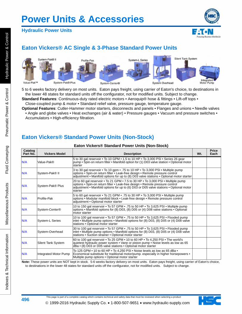
This page is part of a complete catalog which contains technical and safety data that must be reviewed when selecting a product
Power Units & Accessories
Hyd
raul
ic P
ower
& C
ontr
olP
neum
atic
Pow
er &
Con
trol
Flu
id C
onve
ying
Mis
cella
neou
s P
rodu
cts
Inde
xes
& T
echn
ical
Info
rmat
ion
496 1999-2016 Hydraulic Supply Co. • 1-800-507-9651 • www.hydraulic-supply.com
Eaton Vickers® AC Single & 3-Phase Standard Power Units
5 to 6 weeks factory delivery on most units. Eaton pays freight, using carrier of Eaton's choice, to destinations in the lower 48 states for standard units off the configurator, not for modified units. Subject to change.
Standard Features: Continuous-duty rated electric motors • Aeroquip® hose & fittings • Lift-off tops • Close-coupled pump & motor • Standard relief valve, pressure gauge, temperature gauge.
Optional Features: Cutler-Hammer motor starters, disconnects and panels • Flanges and unions • Needle valves • Angle and globe valves • Heat exchanges (air & water) • Pressure gauges • Vacuum and pressure switches • Accumulators • High-efficiency filtration.
Eaton Vickers® Standard Power Units (Non-Stock)
Eaton Vickers® Standard Power Units (Non-Stock)Catalog Part No. Vickers Model Description Wt.
Price Each
N/A Value-Pak®5 to 30 gal reservoir • To 10 GPM • 1.5 to 10 HP • To 3,000 PSI • Series 26 gear pump • Spin-on return filter • Manifold option for (1) D03 valve station • Optional motor starter
N/A System-Pak® II3 to 30 gal reservoir • To 10 gpm • .75 to 10 HP • To 3,000 PSI • Multiple pump options • Spin-on return filter • Leak-free design • Remote pressure control adjustment • Manifold options for up to (8) D03 valve stations • Optional motor starter
N/A System-Pak® Plus
20 to 60 gal reservoir • To 21 GPM • 7.5 to 30 HP • To 3,000 PSI • Multiple pump options • Spin-on return filter • Leak-free design • Remote pressure control adjustment • Manifold options for up to (6) D03 or D05 valve stations • Optional motor starter
N/A Profile-Pak5 to 60 gal reservoir • To 21 GPM • .75 to 30 HP • To 3,000 PSI • Multiple pump options • Modular manifold block • Leak-free design • Remote pressure control adjustment • Optional motor starter
N/A System-Center®10 to 150 gal reservoir • To 57 GPM • .75 to 50 HP • To 3,625 PSI • Multiple pump options • Manifold options for (8) D03, (8) D05 or (4) D08 valve stations • Optional motor starter
N/A System-L Series10 to 100 gal reservoir • To 57 GPM • .75 to 50 HP • To 3,625 PSI • Flooded pump inlet • Multiple pump options • Manifold options for (8) D03, (8) D05 or (4) D08 valve stations • Optional motor starter
N/A System-Overhead30 to 100 gal reservoir • To 57 GPM • .75 to 50 HP • To 3,625 PSI • Flooded pump inlet • Multiple pump options • Manifold options for (8) D03, (8) D05 or (4) D08 valve stations • Suction strainer • Optional motor starter
N/A Silent Tank System60 to 100 gal reservoir • To 25 GPM • 10 to 60 HP • To 4,250 PSI • The world's quietest hydraulic power system • Vane or piston pump • Noise levels as low as 65 dBa • (8) D03 or D05 valve stations • Optional motor starter
N/A Integrated Motor PumpTo 125 GPM • 10 to 60 HP • To 4,250 PSI • Noise levels as low as 65 dBa • Economical substitute for traditional motor/pump. especially in higher horsepowers • Multiple pump options • Optional motor starter
Note: These power units are NOT kept in stock. 5-6 weeks factory delivery on most units. Eaton pays freight, using carrier of Eaton's choice, to destinations in the lower 48 states for standard units off the configurator, not for modified units. Subject to change.
Hydraulic Power Units
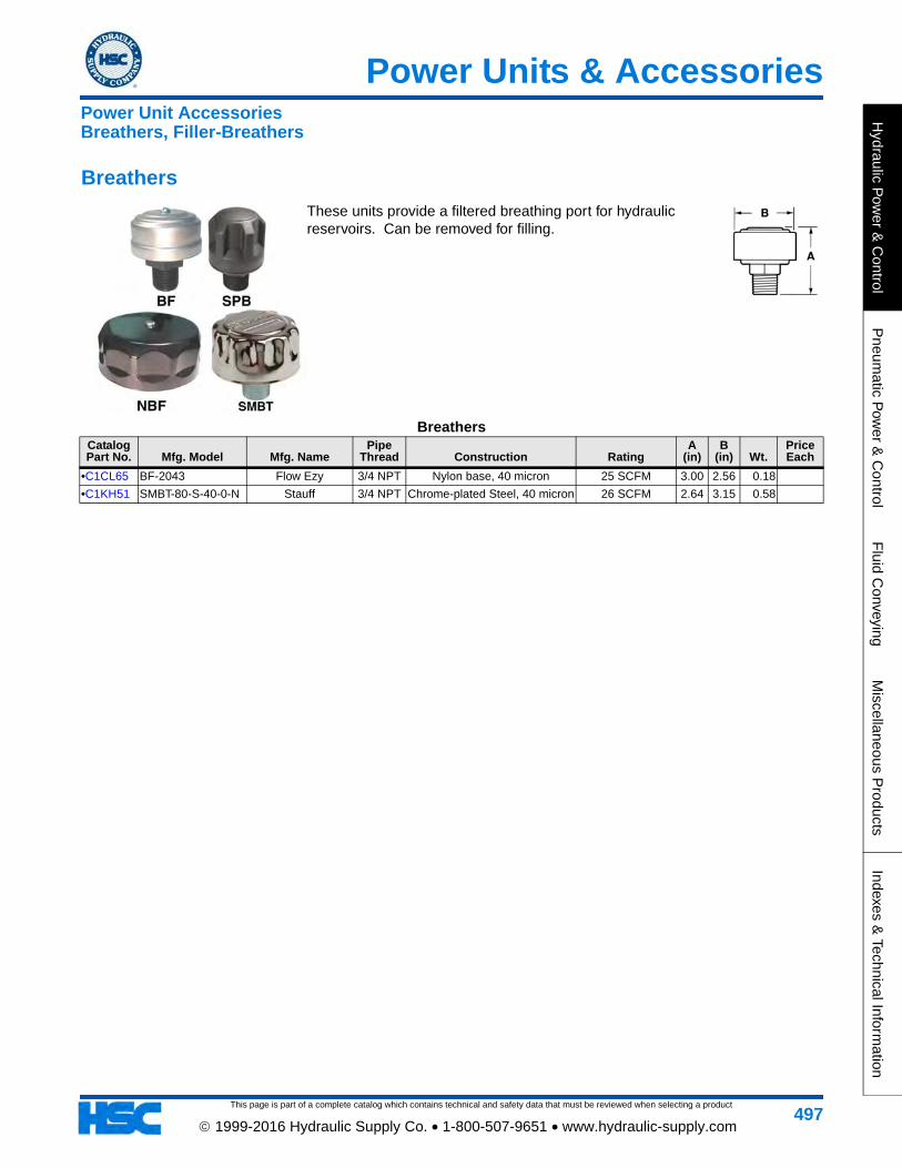
This page is part of a complete catalog which contains technical and safety data that must be reviewed when selecting a product
Power Units & Accessories
Hydraulic P
ower &
Control
Pneum
atic Pow
er & C
ontrolF
luid Conveying
Miscellaneous P
roductsIndexes &
Technical Information
497 1999-2016 Hydraulic Supply Co. • 1-800-507-9651 • www.hydraulic-supply.com
Breathers
These units provide a filtered breathing port for hydraulic reservoirs. Can be removed for filling.
BreathersCatalog Part No. Mfg. Model Mfg. Name
Pipe Thread Construction Rating
A (in)
B (in) Wt.
Price Each
•C1CL65 BF-2043 Flow Ezy 3/4 NPT Nylon base, 40 micron 25 SCFM 3.00 2.56 0.18
•C1KH51 SMBT-80-S-40-0-N Stauff 3/4 NPT Chrome-plated Steel, 40 micron 26 SCFM 2.64 3.15 0.58
Power Unit AccessoriesBreathers, Filler-Breathers
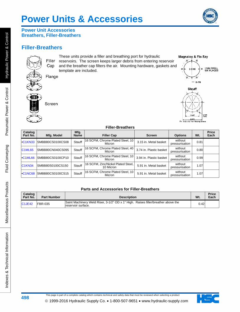
This page is part of a complete catalog which contains technical and safety data that must be reviewed when selecting a product
Power Units & Accessories
Hyd
raul
ic P
ower
& C
ontr
olP
neum
atic
Pow
er &
Con
trol
Flu
id C
onve
ying
Mis
cella
neou
s P
rodu
cts
Inde
xes
& T
echn
ical
Info
rmat
ion
498 1999-2016 Hydraulic Supply Co. • 1-800-507-9651 • www.hydraulic-supply.com
Filler-Breathers
These units provide a filler and breathing port for hydraulic reservoirs. The screen keeps larger debris from entering reservoir and the breather cap filters the air. Mounting hardware, gaskets and template are included.
Filler-BreathersCatalog Part No. Mfg. Model
Mfg. Name Filler Cap Screen Options Wt.
Price Each
•C1KN33 SMBB80CS0100CS08 Stauff 16 SCFM, Chrome Plated Steel, 10 Micron 3.15 in. Metal basket without
pressurisation 0.81
C1ML65 SMBB80CN040CS095 Stauff 16 SCFM, Chrome Plated Steel, 40 Micron 3.74 in. Plastic basket without
pressurisation 0.80
•C1ML66 SMBB80CS0100CP10 Stauff 16 SCFM, Chrome Plated Steel, 10 Micron 3.94 in. Plastic basket without
pressurisation 0.99
C1KN34 SMBB80S0100CS150 Stauff 16 SCFM, Zinc/Nickel Plated Steel, 10 Micron 5.91 in. Metal basket without
pressurisation 1.07
•C1NC68 SMBB80CS0100CS15 Stauff 16 SCFM, Chrome Plated Steel, 10 Micron 5.91 in. Metal basket without
pressurisation 1.07
Parts and Accessories for Filler-BreathersCatalog Part No. Part Number Description Wt.
Price Each
C1JE42 FBR-035 Saint Machinery Weld Riser, 3-1/2" OD x 1" High. Raises filler/breather above the reservoir surface. 0.42
Power Unit AccessoriesBreathers, Filler-Breathers
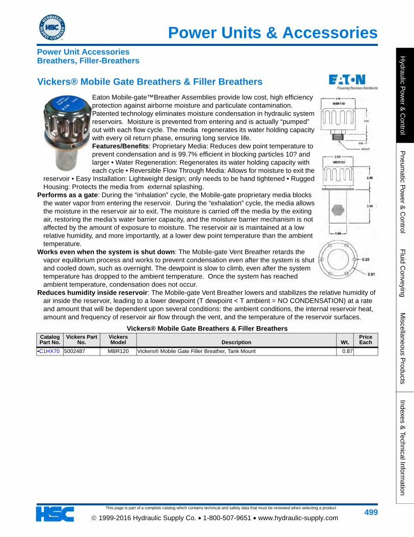
This page is part of a complete catalog which contains technical and safety data that must be reviewed when selecting a product
Power Units & Accessories
Hydraulic P
ower &
Control
Pneum
atic Pow
er & C
ontrolF
luid Conveying
Miscellaneous P
roductsIndexes &
Technical Information
499 1999-2016 Hydraulic Supply Co. • 1-800-507-9651 • www.hydraulic-supply.com
Vickers® Mobile Gate Breathers & Filler Breathers
Eaton Mobile-gate™Breather Assemblies provide low cost, high efficiency protection against airborne moisture and particulate contamination. Patented technology eliminates moisture condensation in hydraulic system reservoirs. Moisture is prevented from entering and is actually “pumped” out with each flow cycle. The media regenerates its water holding capacity with every oil return phase, ensuring long service life. Features/Benefits: Proprietary Media: Reduces dew point temperature to prevent condensation and is 99.7% efficient in blocking particles 10? and larger • Water Regeneration: Regenerates its water holding capacity with each cycle • Reversible Flow Through Media: Allows for moisture to exit the
reservoir • Easy Installation: Lightweight design; only needs to be hand tightened • Rugged Housing: Protects the media from external splashing.
Performs as a gate: During the “inhalation” cycle, the Mobile-gate proprietary media blocks the water vapor from entering the reservoir. During the “exhalation” cycle, the media allows the moisture in the reservoir air to exit. The moisture is carried off the media by the exiting air, restoring the media’s water barrier capacity, and the moisture barrier mechanism is not affected by the amount of exposure to moisture. The reservoir air is maintained at a low relative humidity, and more importantly, at a lower dew point temperature than the ambient temperature.
Works even when the system is shut down: The Mobile-gate Vent Breather retards the vapor equilibrium process and works to prevent condensation even after the system is shut and cooled down, such as overnight. The dewpoint is slow to climb, even after the system temperature has dropped to the ambient temperature. Once the system has reached ambient temperature, condensation does not occur.
Reduces humidity inside reservoir: The Mobile-gate Vent Breather lowers and stabilizes the relative humidity of air inside the reservoir, leading to a lower dewpoint (T dewpoint < T ambient = NO CONDENSATION) at a rate and amount that will be dependent upon several conditions: the ambient conditions, the internal reservoir heat, amount and frequency of reservoir air flow through the vent, and the temperature of the reservoir surfaces.
Vickers® Mobile Gate Breathers & Filler BreathersCatalog Part No.
Vickers Part No.
Vickers Model Description Wt.
Price Each
•C1HX70 5002487 MBR120 Vickers® Mobile Gate Filler Breather, Tank Mount 0.87
Power Unit AccessoriesBreathers, Filler-Breathers
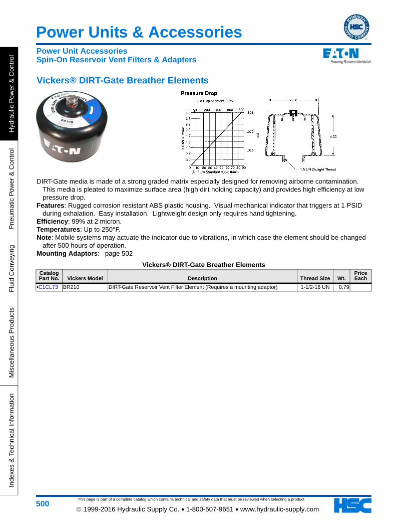
This page is part of a complete catalog which contains technical and safety data that must be reviewed when selecting a product
Power Units & Accessories
Hyd
raul
ic P
ower
& C
ontr
olP
neum
atic
Pow
er &
Con
trol
Flu
id C
onve
ying
Mis
cella
neou
s P
rodu
cts
Inde
xes
& T
echn
ical
Info
rmat
ion
500 1999-2016 Hydraulic Supply Co. • 1-800-507-9651 • www.hydraulic-supply.com
Vickers® DIRT-Gate Breather Elements
DIRT-Gate media is made of a strong graded matrix especially designed for removing airborne contamination. This media is pleated to maximize surface area (high dirt holding capacity) and provides high efficiency at low pressure drop.
Features: Rugged corrosion resistant ABS plastic housing. Visual mechanical indicator that triggers at 1 PSID during exhalation. Easy installation. Lightweight design only requires hand tightening.
Efficiency: 99% at 2 micron. Temperatures: Up to 250°F. Note: Mobile systems may actuate the indicator due to vibrations, in which case the element should be changed
after 500 hours of operation. Mounting Adaptors: page 502
Vickers® DIRT-Gate Breather ElementsCatalog Part No. Vickers Model Description Thread Size Wt.
Price Each
•C1CL73 BR210 DIRT-Gate Reservoir Vent Filter Element (Requires a mounting adaptor) 1-1/2-16 UN 0.79
Power Unit AccessoriesSpin-On Reservoir Vent Filters & Adapters
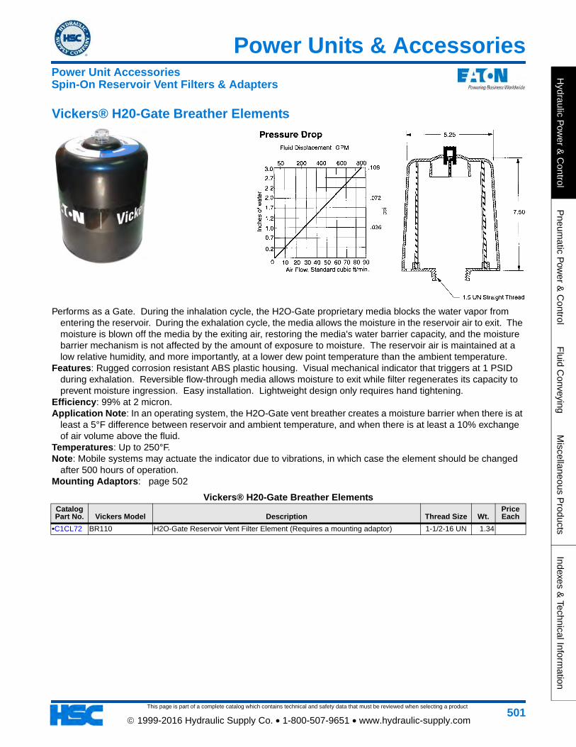
Power Units & Accessories
This page is part of a complete catalog which contains technical and safety data that must be reviewed when selecting a product
Hydraulic P
ower &
Control
Pneum
atic Pow
er & C
ontrolF
luid Conveying
Miscellaneous P
roductsIndexes &
Technical Information
501 1999-2016 Hydraulic Supply Co. • 1-800-507-9651 • www.hydraulic-supply.com
Vickers® H20-Gate Breather Elements
Performs as a Gate. During the inhalation cycle, the H2O-Gate proprietary media blocks the water vapor from entering the reservoir. During the exhalation cycle, the media allows the moisture in the reservoir air to exit. The moisture is blown off the media by the exiting air, restoring the media's water barrier capacity, and the moisture barrier mechanism is not affected by the amount of exposure to moisture. The reservoir air is maintained at a low relative humidity, and more importantly, at a lower dew point temperature than the ambient temperature.
Features: Rugged corrosion resistant ABS plastic housing. Visual mechanical indicator that triggers at 1 PSID during exhalation. Reversible flow-through media allows moisture to exit while filter regenerates its capacity to prevent moisture ingression. Easy installation. Lightweight design only requires hand tightening.
Efficiency: 99% at 2 micron. Application Note: In an operating system, the H2O-Gate vent breather creates a moisture barrier when there is at
least a 5°F difference between reservoir and ambient temperature, and when there is at least a 10% exchange of air volume above the fluid.
Temperatures: Up to 250°F. Note: Mobile systems may actuate the indicator due to vibrations, in which case the element should be changed
after 500 hours of operation. Mounting Adaptors: page 502
Vickers® H20-Gate Breather ElementsCatalog Part No. Vickers Model Description Thread Size Wt.
Price Each
•C1CL72 BR110 H2O-Gate Reservoir Vent Filter Element (Requires a mounting adaptor) 1-1/2-16 UN 1.34
Power Unit AccessoriesSpin-On Reservoir Vent Filters & Adapters
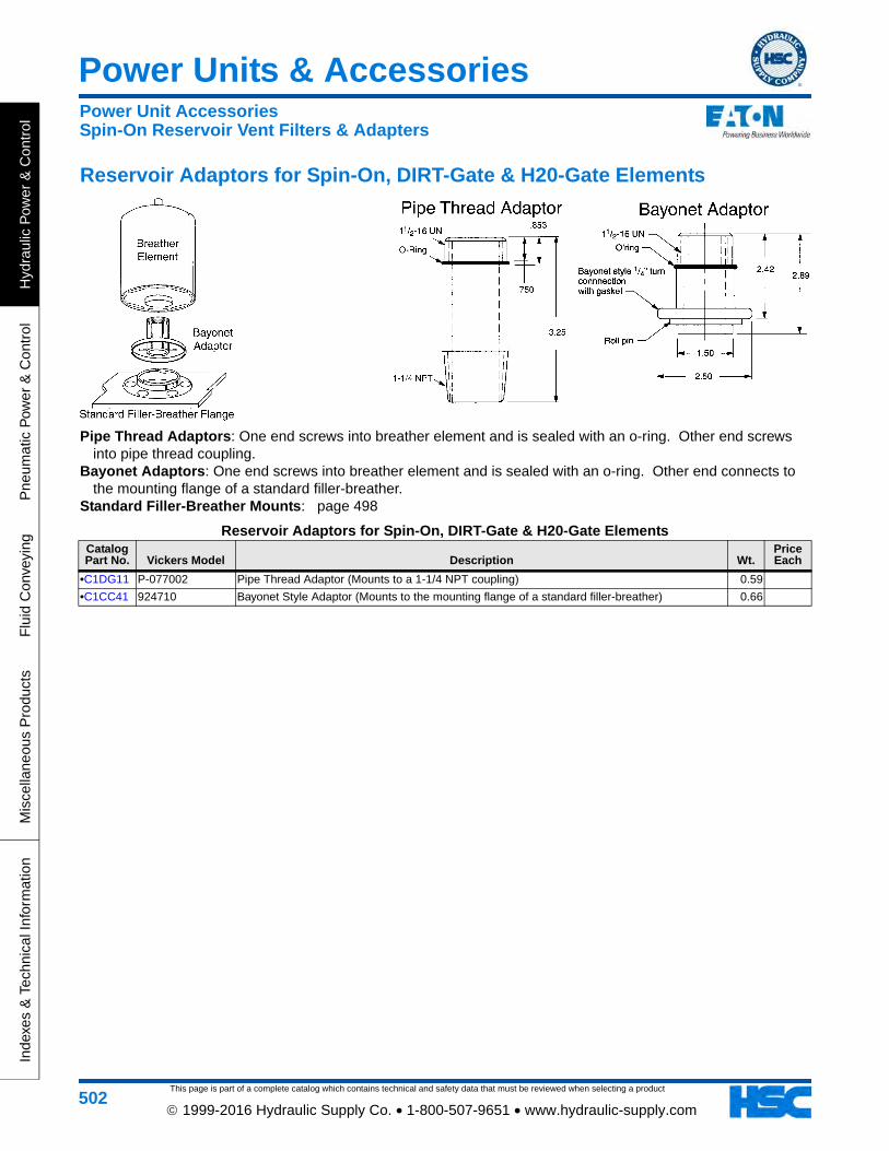
This page is part of a complete catalog which contains technical and safety data that must be reviewed when selecting a product
Power Units & Accessories
Hyd
raul
ic P
ower
& C
ontr
olP
neum
atic
Pow
er &
Con
trol
Flu
id C
onve
ying
Mis
cella
neou
s P
rodu
cts
Inde
xes
& T
echn
ical
Info
rmat
ion
502 1999-2016 Hydraulic Supply Co. • 1-800-507-9651 • www.hydraulic-supply.com
Reservoir Adaptors for Spin-On, DIRT-Gate & H20-Gate Elements
Pipe Thread Adaptors: One end screws into breather element and is sealed with an o-ring. Other end screws into pipe thread coupling.
Bayonet Adaptors: One end screws into breather element and is sealed with an o-ring. Other end connects to the mounting flange of a standard filler-breather.
Standard Filler-Breather Mounts: page 498
Reservoir Adaptors for Spin-On, DIRT-Gate & H20-Gate ElementsCatalog Part No. Vickers Model Description Wt.
Price Each
•C1DG11 P-077002 Pipe Thread Adaptor (Mounts to a 1-1/4 NPT coupling) 0.59
•C1CC41 924710 Bayonet Style Adaptor (Mounts to the mounting flange of a standard filler-breather) 0.66
Power Unit AccessoriesSpin-On Reservoir Vent Filters & Adapters
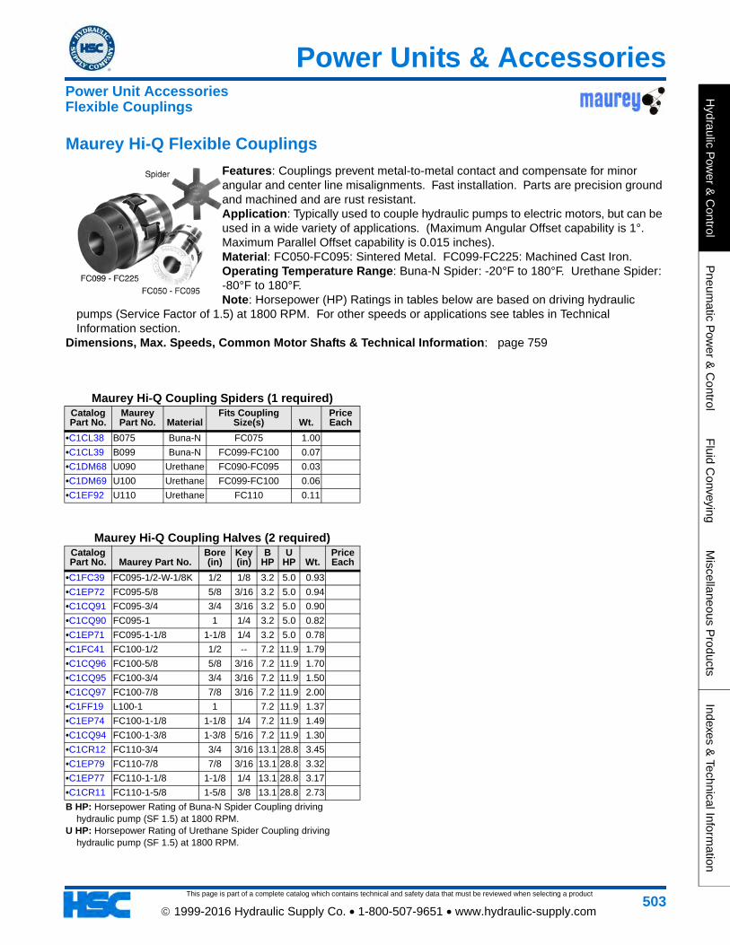
This page is part of a complete catalog which contains technical and safety data that must be reviewed when selecting a product
Power Units & Accessories
Hydraulic P
ower &
Control
Pneum
atic Pow
er & C
ontrolF
luid Conveying
Miscellaneous P
roductsIndexes &
Technical Information
503 1999-2016 Hydraulic Supply Co. • 1-800-507-9651 • www.hydraulic-supply.com
Maurey Hi-Q Coupling Spiders (1 required)Catalog Part No.
Maurey Part No. Material
Fits Coupling Size(s) Wt.
Price Each
•C1CL38 B075 Buna-N FC075 1.00
•C1CL39 B099 Buna-N FC099-FC100 0.07
•C1DM68 U090 Urethane FC090-FC095 0.03
•C1DM69 U100 Urethane FC099-FC100 0.06
•C1EF92 U110 Urethane FC110 0.11
Maurey Hi-Q Coupling Halves (2 required)Catalog Part No. Maurey Part No.
Bore (in)
Key (in)
B HP
U HP Wt.
Price Each
•C1FC39 FC095-1/2-W-1/8K 1/2 1/8 3.2 5.0 0.93
•C1EP72 FC095-5/8 5/8 3/16 3.2 5.0 0.94
•C1CQ91 FC095-3/4 3/4 3/16 3.2 5.0 0.90
•C1CQ90 FC095-1 1 1/4 3.2 5.0 0.82
•C1EP71 FC095-1-1/8 1-1/8 1/4 3.2 5.0 0.78
•C1FC41 FC100-1/2 1/2 -- 7.2 11.9 1.79
•C1CQ96 FC100-5/8 5/8 3/16 7.2 11.9 1.70
•C1CQ95 FC100-3/4 3/4 3/16 7.2 11.9 1.50
•C1CQ97 FC100-7/8 7/8 3/16 7.2 11.9 2.00
•C1FF19 L100-1 1 7.2 11.9 1.37
•C1EP74 FC100-1-1/8 1-1/8 1/4 7.2 11.9 1.49
•C1CQ94 FC100-1-3/8 1-3/8 5/16 7.2 11.9 1.30
•C1CR12 FC110-3/4 3/4 3/16 13.1 28.8 3.45
•C1EP79 FC110-7/8 7/8 3/16 13.1 28.8 3.32
•C1EP77 FC110-1-1/8 1-1/8 1/4 13.1 28.8 3.17
•C1CR11 FC110-1-5/8 1-5/8 3/8 13.1 28.8 2.73
B HP: Horsepower Rating of Buna-N Spider Coupling driving hydraulic pump (SF 1.5) at 1800 RPM.
U HP: Horsepower Rating of Urethane Spider Coupling driving hydraulic pump (SF 1.5) at 1800 RPM.
Maurey Hi-Q Flexible Couplings
Features: Couplings prevent metal-to-metal contact and compensate for minor angular and center line misalignments. Fast installation. Parts are precision ground and machined and are rust resistant.Application: Typically used to couple hydraulic pumps to electric motors, but can be used in a wide variety of applications. (Maximum Angular Offset capability is 1°. Maximum Parallel Offset capability is 0.015 inches).Material: FC050-FC095: Sintered Metal. FC099-FC225: Machined Cast Iron.Operating Temperature Range: Buna-N Spider: -20°F to 180°F. Urethane Spider: -80°F to 180°F.Note: Horsepower (HP) Ratings in tables below are based on driving hydraulic
pumps (Service Factor of 1.5) at 1800 RPM. For other speeds or applications see tables in Technical Information section.
Dimensions, Max. Speeds, Common Motor Shafts & Technical Information: page 759
Power Unit AccessoriesFlexible Couplings
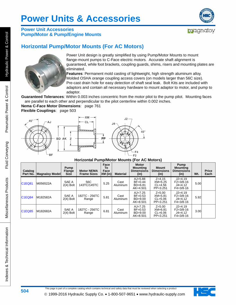
This page is part of a complete catalog which contains technical and safety data that must be reviewed when selecting a product
Power Units & Accessories
Hyd
raul
ic P
ower
& C
ontr
olP
neum
atic
Pow
er &
Con
trol
Flu
id C
onve
ying
Mis
cella
neou
s P
rodu
cts
Inde
xes
& T
echn
ical
Info
rmat
ion
504 1999-2016 Hydraulic Supply Co. • 1-800-507-9651 • www.hydraulic-supply.com
Horizontal Pump/Motor Mounts (For AC Motors)
Power Unit design is greatly simplified by using Pump/Motor Mounts to mount flange-mount pumps to C-Face electric motors. Accurate shaft alignment is guaranteed, while foot brackets, coupling guards, shims, risers and mounting plates are eliminated. Features: Permanent mold casting of lightweight, high strength aluminum alloy. Molded OSHA orange coupling access covers (on models larger than 56C size). Pre-cast drain hole for easy detection of shaft seal leak. Bolt Kits are included with adaptors and contain all necessary hardware to mount adaptor to motor, and pump to adaptor.
Guaranteed Tolerances: Within 0.003 inches concentric from the motor pilot to the pump pilot. Mounting faces are parallel to each other and perpendicular to the pilot centerline within 0.002 inches.
Nema C-Face Motor Dimensions: page 761Flexible Couplings: page 503
Horizontal Pump/Motor Mounts (For AC Motors)
Catalog Part No. Magnaloy Model
Pump Flange
SizeMotor NEMA Frame Sizes
Face To
Face XM (in) Material
Motor Mounting
Dimensions (in)
Mount Dimensions
(in)
Pump Mounting
Dimensions (in) Wt.
Price Each
C1EQ81 M056522A SAE A 2(4) Bolt
56C 143TC/145TC 5.25 Cast
Aluminum
AJ=5.88 BF=0.44 BD=6.81 AK=4.501
Z=4.15 XM=5.25 CL=4.56
PP=3.251
J2=4.19 F2=3/8-16 J4=4.12
F4=3/8-16
5.00
C1EQ84 M182582A SAE A 2(4) Bolt
182TC - 256TC Range 5.81 Cast
Aluminum
AJ=7.25 BF=0.53 BD=9.00 AK=8.501
Z=5.00 XM=5.81 CL=5.06
PP=3.251
J2=4.19 F2=3/8-16 J4=4.12
F4=3/8-16
5.92
C1EQ85 M182682A SAE A 2(4) Bolt
182TC - 256TC Range 6.81 Cast
Aluminum
AJ=7.25 BF=0.53 BD=9.00 AK=8.501
Z=5.00 XM=6.81 CL=6.06
PP=3.251
J2=4.19 F2=3/8-16 J4=4.12
F4=3/8-16
3.00
Power Unit AccessoriesPump/Motor & Pump/Engine Mounts
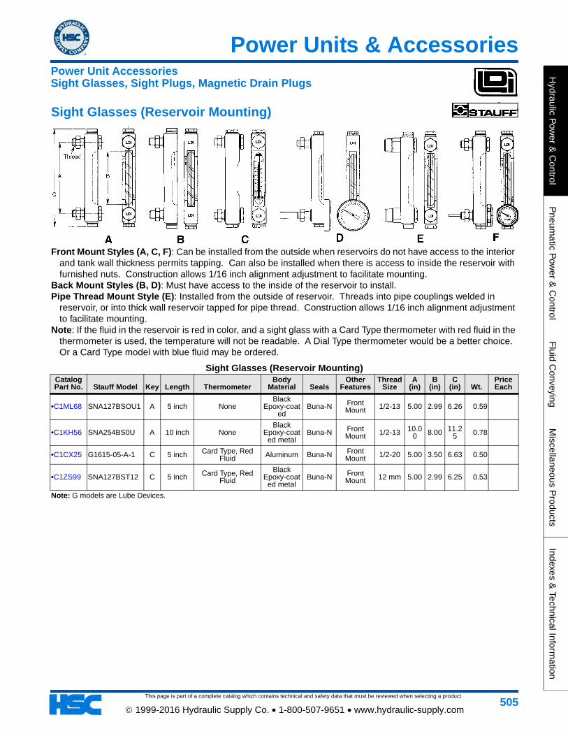
This page is part of a complete catalog which contains technical and safety data that must be reviewed when selecting a product
Power Units & Accessories
Hydraulic P
ower &
Control
Pneum
atic Pow
er & C
ontrolF
luid Conveying
Miscellaneous P
roductsIndexes &
Technical Information
505 1999-2016 Hydraulic Supply Co. • 1-800-507-9651 • www.hydraulic-supply.com
Sight Glasses (Reservoir Mounting)
Front Mount Styles (A, C, F): Can be installed from the outside when reservoirs do not have access to the interior and tank wall thickness permits tapping. Can also be installed when there is access to inside the reservoir with furnished nuts. Construction allows 1/16 inch alignment adjustment to facilitate mounting.
Back Mount Styles (B, D): Must have access to the inside of the reservoir to install. Pipe Thread Mount Style (E): Installed from the outside of reservoir. Threads into pipe couplings welded in
reservoir, or into thick wall reservoir tapped for pipe thread. Construction allows 1/16 inch alignment adjustment to facilitate mounting.
Note: If the fluid in the reservoir is red in color, and a sight glass with a Card Type thermometer with red fluid in the thermometer is used, the temperature will not be readable. A Dial Type thermometer would be a better choice. Or a Card Type model with blue fluid may be ordered.
Sight Glasses (Reservoir Mounting)Catalog Part No. Stauff Model Key Length Thermometer
Body Material Seals
Other Features
Thread Size
A (in)
B (in)
C (in) Wt.
Price Each
•C1ML68 SNA127BSOU1 A 5 inch NoneBlack
Epoxy-coated
Buna-N Front Mount 1/2-13 5.00 2.99 6.26 0.59
•C1KH56 SNA254BS0U A 10 inch NoneBlack
Epoxy-coated metal
Buna-N Front Mount 1/2-13 10.0
0 8.00 11.25 0.78
•C1CX25 G1615-05-A-1 C 5 inch Card Type, Red Fluid Aluminum Buna-N Front
Mount 1/2-20 5.00 3.50 6.63 0.50
•C1ZS99 SNA127BST12 C 5 inch Card Type, Red Fluid
Black Epoxy-coat
ed metalBuna-N Front
Mount 12 mm 5.00 2.99 6.25 0.53
Note: G models are Lube Devices.
Power Unit AccessoriesSight Glasses, Sight Plugs, Magnetic Drain Plugs
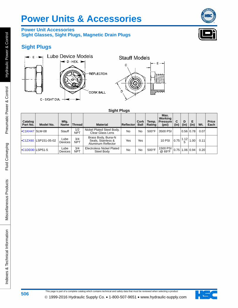
This page is part of a complete catalog which contains technical and safety data that must be reviewed when selecting a product
Power Units & Accessories
Hyd
raul
ic P
ower
& C
ontr
olP
neum
atic
Pow
er &
Con
trol
Flu
id C
onve
ying
Mis
cella
neou
s P
rodu
cts
Inde
xes
& T
echn
ical
Info
rmat
ion
506 1999-2016 Hydraulic Supply Co. • 1-800-507-9651 • www.hydraulic-supply.com
Sight Plugs
Sight Plugs
Catalog Part No. Model No.
Mfg. Name Thread Material Reflector
Cork Ball
Temp. Rating
Max. Working Pressure
(psi)C
(in)D
(in)E
(in) Wt.Price Each
•C1KH47 SLW-08 Stauff 1/2 NPT
Nickel Plated Steel Body, Clear Glass Lens No No 500°F 3500 PSI 0.56 0.78 0.07
•C1ZX60 LSP151-05-02 Lube Devices
3/4 NPT
Brass Body, Buna-N Seals, Stainless &
Aluminum ReflectorYes Yes 10 PSI 0.75 1.12
5 1.00 0.11
•C1DD30 LSP51-5 Lube Devices
3/4 NPT
Electroless Nickel Plated Steel Body No No 500°F 1500 PSI
@ 69°F 0.75 1.06 0.94 0.20
Power Unit AccessoriesSight Glasses, Sight Plugs, Magnetic Drain Plugs
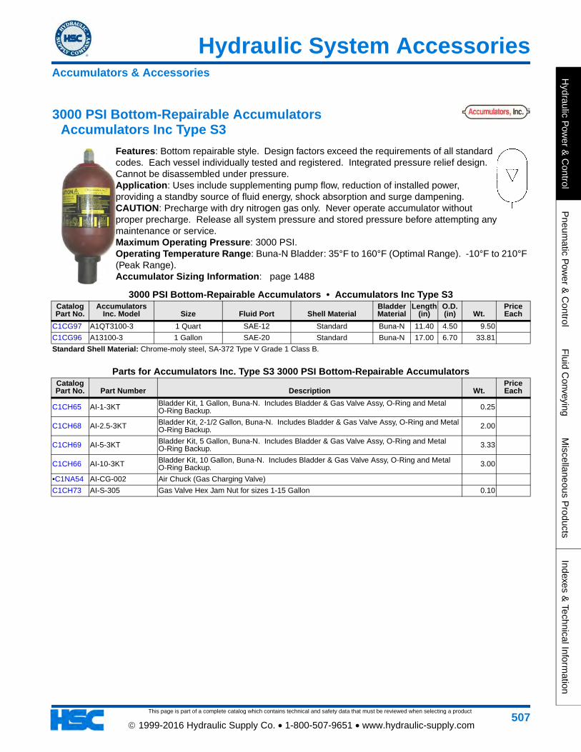
This page is part of a complete catalog which contains technical and safety data that must be reviewed when selecting a product
Hydraulic System Accessories
Hydraulic P
ower &
Control
Pneum
atic Pow
er & C
ontrolF
luid Conveying
Miscellaneous P
roductsIndexes &
Technical Information
507 1999-2016 Hydraulic Supply Co. • 1-800-507-9651 • www.hydraulic-supply.com
3000 PSI Bottom-Repairable Accumulators Accumulators Inc Type S3
Features: Bottom repairable style. Design factors exceed the requirements of all standard codes. Each vessel individually tested and registered. Integrated pressure relief design. Cannot be disassembled under pressure. Application: Uses include supplementing pump flow, reduction of installed power, providing a standby source of fluid energy, shock absorption and surge dampening. CAUTION: Precharge with dry nitrogen gas only. Never operate accumulator without proper precharge. Release all system pressure and stored pressure before attempting any maintenance or service. Maximum Operating Pressure: 3000 PSI. Operating Temperature Range: Buna-N Bladder: 35°F to 160°F (Optimal Range). -10°F to 210°F (Peak Range). Accumulator Sizing Information: page 1488
3000 PSI Bottom-Repairable Accumulators • Accumulators Inc Type S3Catalog Part No.
Accumulators Inc. Model Size Fluid Port Shell Material
Bladder Material
Length (in)
O.D. (in) Wt.
Price Each
C1CG97 A1QT3100-3 1 Quart SAE-12 Standard Buna-N 11.40 4.50 9.50
C1CG96 A13100-3 1 Gallon SAE-20 Standard Buna-N 17.00 6.70 33.81
Standard Shell Material: Chrome-moly steel, SA-372 Type V Grade 1 Class B.
Parts for Accumulators Inc. Type S3 3000 PSI Bottom-Repairable AccumulatorsCatalog Part No. Part Number Description Wt.
Price Each
C1CH65 AI-1-3KT Bladder Kit, 1 Gallon, Buna-N. Includes Bladder & Gas Valve Assy, O-Ring and Metal O-Ring Backup. 0.25
C1CH68 AI-2.5-3KT Bladder Kit, 2-1/2 Gallon, Buna-N. Includes Bladder & Gas Valve Assy, O-Ring and Metal O-Ring Backup. 2.00
C1CH69 AI-5-3KT Bladder Kit, 5 Gallon, Buna-N. Includes Bladder & Gas Valve Assy, O-Ring and Metal O-Ring Backup. 3.33
C1CH66 AI-10-3KT Bladder Kit, 10 Gallon, Buna-N. Includes Bladder & Gas Valve Assy, O-Ring and Metal O-Ring Backup. 3.00
•C1NA54 AI-CG-002 Air Chuck (Gas Charging Valve)
C1CH73 AI-S-305 Gas Valve Hex Jam Nut for sizes 1-15 Gallon 0.10
Accumulators & Accessories
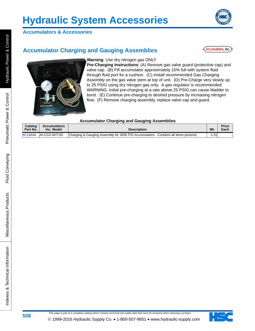
This page is part of a complete catalog which contains technical and safety data that must be reviewed when selecting a product
Hydraulic System Accessories
Hyd
raul
ic P
ower
& C
ontr
olP
neum
atic
Pow
er &
Con
trol
Flu
id C
onve
ying
Mis
cella
neou
s P
rodu
cts
Inde
xes
& T
echn
ical
Info
rmat
ion
508 1999-2016 Hydraulic Supply Co. • 1-800-507-9651 • www.hydraulic-supply.com
Accumulator Charging and Gauging Assemblies
Warning: Use dry nitrogen gas ONLY. Pre-Charging Instructions: (A) Remove gas valve guard (protective cap) and valve cap. (B) Fill accumulator approximately 10% full with system fluid through fluid port for a cushion. (C) Install recommended Gas Charging Assembly on the gas valve stem at top of unit. (D) Pre-Charge very slowly up to 25 PSIG using dry nitrogen gas only. A gas regulator is recommended. WARNING: Initial pre-charging at a rate above 25 PSIG can cause bladder to burst. (E) Continue pre-charging to desired pressure by increasing nitrogen flow. (F) Remove charging assembly, replace valve cap and guard.
Accumulator Charging and Gauging AssembliesCatalog Part No.
Accumulators Inc. Model Description Wt.
Price Each
•C1JA44 AI-CG3-3KT-SS Charging & Gauging Assembly for 3000 PSI Accumulators. Contains all items pictured. 2.31
Accumulators & Accessories
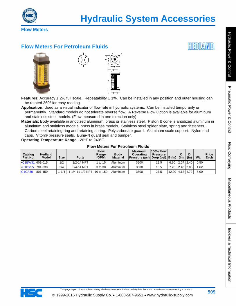
This page is part of a complete catalog which contains technical and safety data that must be reviewed when selecting a product
Hydraulic System Accessories
Hydraulic P
ower &
Control
Pneum
atic Pow
er & C
ontrolF
luid Conveying
Miscellaneous P
roductsIndexes &
Technical Information
509 1999-2016 Hydraulic Supply Co. • 1-800-507-9651 • www.hydraulic-supply.com
Flow Meters For Petroleum Fluids
Features: Accuracy ± 2% full scale. Repeatability ± 1%. Can be installed in any position and outer housing can be rotated 360° for easy reading.
Application: Used as a visual indicator of flow rate in hydraulic systems. Can be installed temporarily or permanently. Standard models do not tolerate reverse flow. A Reverse Flow Option is available for aluminum and stainless steel models. (Flow measured in one direction only).
Materials: Body available in anodized aluminum, brass or stainless steel. Piston & cone is anodized aluminum in aluminum and stainless models, brass in brass models. Stainless steel spider plate, spring and fasteners. Carbon steel retaining ring and retaining spring. Polycarbonate guard. Aluminum scale support. Nylon end caps. Viton® pressure seals. Buna-N guard seal and bumper.
Operating Temperature Range: -20°F to 240°F.
Flow Meters For Petroleum Fluids
Catalog Part No.
Hedland Model Size Ports
Flow Range (GPM)
Body Material
Maximum Operating
Pressure (psi)
100% Flow Pressure Drop (psi) B (in)
C (in)
D (in) Wt.
Price Each
•C1BW31 601-015 1/2 1/2-14 NPT 1 to 15 Aluminum 3500 18.5 6.60 2.07 2.40 0.50
•C1BY55 701-030 3/4 3/4-14 NPT 3 to 30 Aluminum 3500 16.5 7.20 2.48 2.85 1.62
C1CA30 801-150 1-1/4 1-1/4-11-1/2 NPT 10 to 150 Aluminum 3500 27.5 12.20 4.12 4.72 5.00
Flow Meters
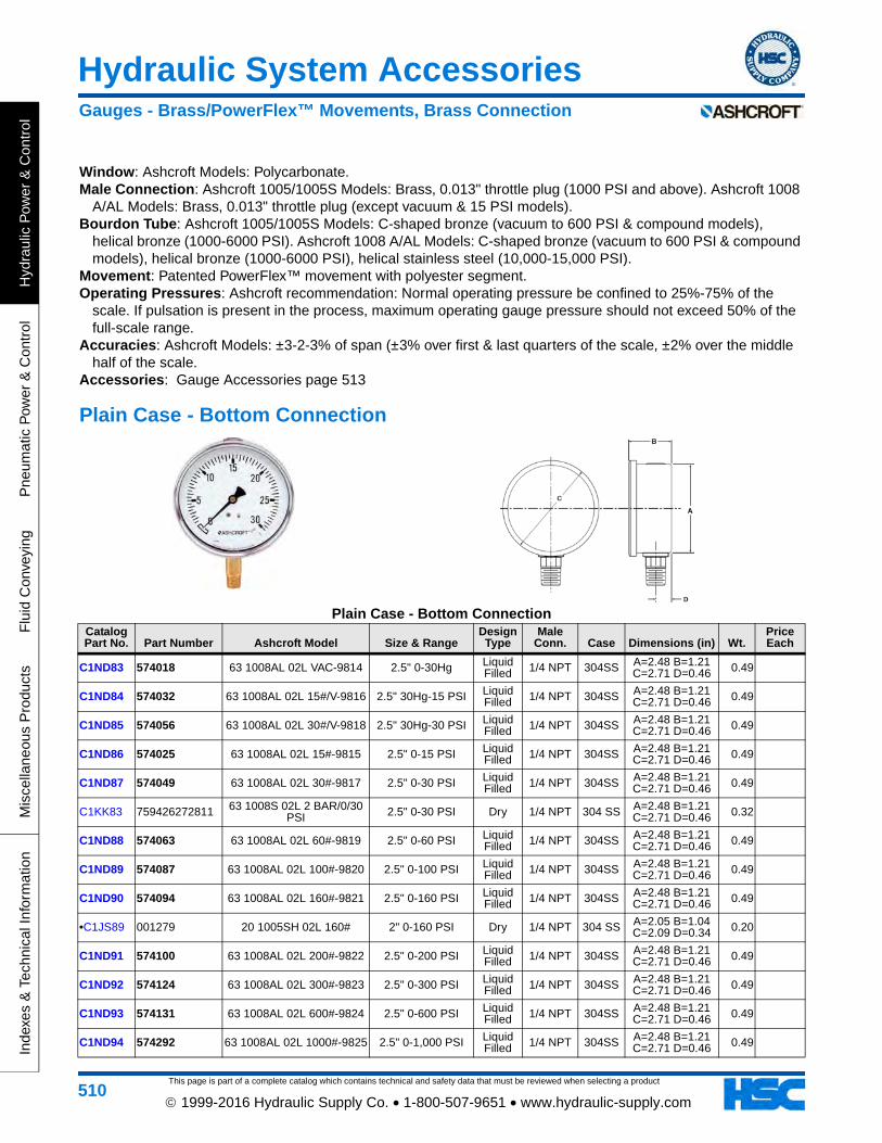
This page is part of a complete catalog which contains technical and safety data that must be reviewed when selecting a product
Hydraulic System Accessories
Hyd
raul
ic P
ower
& C
ontr
olP
neum
atic
Pow
er &
Con
trol
Flu
id C
onve
ying
Mis
cella
neou
s P
rodu
cts
Inde
xes
& T
echn
ical
Info
rmat
ion
510 1999-2016 Hydraulic Supply Co. • 1-800-507-9651 • www.hydraulic-supply.com
Window: Ashcroft Models: Polycarbonate.Male Connection: Ashcroft 1005/1005S Models: Brass, 0.013" throttle plug (1000 PSI and above). Ashcroft 1008
A/AL Models: Brass, 0.013" throttle plug (except vacuum & 15 PSI models).Bourdon Tube: Ashcroft 1005/1005S Models: C-shaped bronze (vacuum to 600 PSI & compound models),
helical bronze (1000-6000 PSI). Ashcroft 1008 A/AL Models: C-shaped bronze (vacuum to 600 PSI & compound models), helical bronze (1000-6000 PSI), helical stainless steel (10,000-15,000 PSI).
Movement: Patented PowerFlex™ movement with polyester segment.Operating Pressures: Ashcroft recommendation: Normal operating pressure be confined to 25%-75% of the
scale. If pulsation is present in the process, maximum operating gauge pressure should not exceed 50% of the full-scale range.
Accuracies: Ashcroft Models: ±3-2-3% of span (±3% over first & last quarters of the scale, ±2% over the middle half of the scale.
Accessories: Gauge Accessories page 513
Plain Case - Bottom Connection
Plain Case - Bottom ConnectionCatalog Part No. Part Number Ashcroft Model Size & Range
Design Type
Male Conn. Case Dimensions (in) Wt.
Price Each
C1ND83 574018 63 1008AL 02L VAC-9814 2.5" 0-30Hg Liquid Filled 1/4 NPT 304SS A=2.48 B=1.21
C=2.71 D=0.46 0.49
C1ND84 574032 63 1008AL 02L 15#/V-9816 2.5" 30Hg-15 PSI Liquid Filled 1/4 NPT 304SS A=2.48 B=1.21
C=2.71 D=0.46 0.49
C1ND85 574056 63 1008AL 02L 30#/V-9818 2.5" 30Hg-30 PSI Liquid Filled 1/4 NPT 304SS A=2.48 B=1.21
C=2.71 D=0.46 0.49
C1ND86 574025 63 1008AL 02L 15#-9815 2.5" 0-15 PSI Liquid Filled 1/4 NPT 304SS A=2.48 B=1.21
C=2.71 D=0.46 0.49
C1ND87 574049 63 1008AL 02L 30#-9817 2.5" 0-30 PSI Liquid Filled 1/4 NPT 304SS A=2.48 B=1.21
C=2.71 D=0.46 0.49
C1KK83 759426272811 63 1008S 02L 2 BAR/0/30 PSI 2.5" 0-30 PSI Dry 1/4 NPT 304 SS A=2.48 B=1.21
C=2.71 D=0.46 0.32
C1ND88 574063 63 1008AL 02L 60#-9819 2.5" 0-60 PSI Liquid Filled 1/4 NPT 304SS A=2.48 B=1.21
C=2.71 D=0.46 0.49
C1ND89 574087 63 1008AL 02L 100#-9820 2.5" 0-100 PSI Liquid Filled 1/4 NPT 304SS A=2.48 B=1.21
C=2.71 D=0.46 0.49
C1ND90 574094 63 1008AL 02L 160#-9821 2.5" 0-160 PSI Liquid Filled 1/4 NPT 304SS A=2.48 B=1.21
C=2.71 D=0.46 0.49
•C1JS89 001279 20 1005SH 02L 160# 2" 0-160 PSI Dry 1/4 NPT 304 SS A=2.05 B=1.04 C=2.09 D=0.34 0.20
C1ND91 574100 63 1008AL 02L 200#-9822 2.5" 0-200 PSI Liquid Filled 1/4 NPT 304SS A=2.48 B=1.21
C=2.71 D=0.46 0.49
C1ND92 574124 63 1008AL 02L 300#-9823 2.5" 0-300 PSI Liquid Filled 1/4 NPT 304SS A=2.48 B=1.21
C=2.71 D=0.46 0.49
C1ND93 574131 63 1008AL 02L 600#-9824 2.5" 0-600 PSI Liquid Filled 1/4 NPT 304SS A=2.48 B=1.21
C=2.71 D=0.46 0.49
C1ND94 574292 63 1008AL 02L 1000#-9825 2.5" 0-1,000 PSI Liquid Filled 1/4 NPT 304SS A=2.48 B=1.21
C=2.71 D=0.46 0.49
Gauges - Brass/PowerFlex™ Movements, Brass Connection
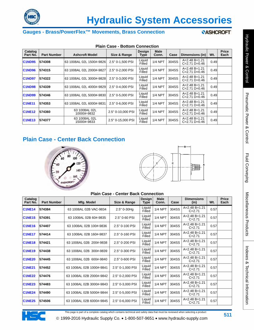
This page is part of a complete catalog which contains technical and safety data that must be reviewed when selecting a product
Hydraulic System Accessories
Hydraulic P
ower &
Control
Pneum
atic Pow
er & C
ontrolF
luid Conveying
Miscellaneous P
roductsIndexes &
Technical Information
511 1999-2016 Hydraulic Supply Co. • 1-800-507-9651 • www.hydraulic-supply.com
C1ND95 574308 63 1008AL 02L 1500#-9826 2.5" 0-1,500 PSI Liquid Filled 1/4 NPT 304SS A=2.48 B=1.21
C=2.71 D=0.46 0.49
C1ND96 574315 63 1008AL 02L 2000#-9827 2.5" 0-2,000 PSI Liquid Filled 1/4 NPT 304SS A=2.48 B=1.21
C=2.71 D=0.46 0.49
C1ND97 574322 63 1008AL 02L 3000#-9828 2.5" 0-3,000 PSI Liquid Filled 1/4 NPT 304SS A=2.48 B=1.21
C=2.71 D=0.46 0.49
C1ND98 574339 63 1008AL 02L 4000#-9829 2.5" 0-4,000 PSI Liquid Filled 1/4 NPT 304SS A=2.48 B=1.21
C=2.71 D=0.46 0.49
C1ND99 574346 63 1008AL 02L 5000#-9830 2.5" 0-5,000 PSI Liquid Filled 1/4 NPT 304SS A=2.48 B=1.21
C=2.71 D=0.46 0.49
C1NE11 574353 63 1008AL 02L 6000#-9831 2.5" 0-6,000 PSI Liquid Filled 1/4 NPT 304SS A=2.48 B=1.21
C=2.71 D=0.46 0.49
C1NE12 574360 63 1008AL 02L 10000#-9832 2.5" 0-10,000 PSI Liquid
Filled 1/4 NPT 304SS A=2.48 B=1.21 C=2.71 D=0.46 0.49
C1NE13 574377 63 1008AL 02L 15000#-9833 2.5" 0-15,000 PSI Liquid
Filled 1/4 NPT 304SS A=2.48 B=1.21 C=2.71 D=0.46 0.49
Plain Case - Center Back Connection
Plain Case - Center Back ConnectionCatalog Part No. Part Number Mfg. Model Size & Range
Design Type
Male Conn. Case
Dimensions (in) Wt.
Price Each
C1NE14 574384 63 1008AL 02B VAC-9834 2.5" 0-30Hg Liquid Filled 1/4 NPT 304SS A=2.48 B=1.21
C=2.71 0.57
C1NE15 574391 63 1008AL 02B 60#-9835 2.5" 0-60 PSI Liquid Filled 1/4 NPT 304SS A=2.48 B=1.21
C=2.71 0.57
C1NE16 574407 63 1008AL 02B 100#-9836 2.5" 0-100 PSI Liquid Filled 1/4 NPT 304SS A=2.48 B=1.21
C=2.71 0.57
C1NE17 574414 63 1008AL 02B 160#-9837 2.5" 0-160 PSI Liquid Filled 1/4 NPT 304SS A=2.48 B=1.21
C=2.71 0.57
C1NE18 574421 63 1008AL 02B 200#-9838 2.5" 0-200 PSI Liquid Filled 1/4 NPT 304SS A=2.48 B=1.21
C=2.71 0.57
C1NE19 574438 63 1008AL 02B 300#-9839 2.5" 0-300 PSI Liquid Filled 1/4 NPT 304SS A=2.48 B=1.21
C=2.71 0.57
C1NE20 574445 63 1008AL 02B 600#-9840 2.5" 0-600 PSI Liquid Filled 1/4 NPT 304SS A=2.48 B=1.21
C=2.71 0.57
C1NE21 574452 63 1008AL 02B 1000#-9841 2.5" 0-1,000 PSI Liquid Filled 1/4 NPT 304SS A=2.48 B=1.21
C=2.71 0.57
C1NE22 574476 63 1008AL 02B 2000#-9842 2.5" 0-2,000 PSI Liquid Filled 1/4 NPT 304SS A=2.48 B=1.21
C=2.71 0.57
C1NE23 574483 63 1008AL 02B 3000#-9843 2.5" 0-3,000 PSI Liquid Filled 1/4 NPT 304SS A=2.48 B=1.21
C=2.71 0.57
C1NE24 574490 63 1008AL 02B 5000#-9844 2.5" 0-5,000 PSI Liquid Filled 1/4 NPT 304SS A=2.48 B=1.21
C=2.71 0.57
C1NE25 574506 63 1008AL 02B 6000#-9845 2.5" 0-6,000 PSI Liquid Filled 1/4 NPT 304SS A=2.48 B=1.21
C=2.71 0.57
Plain Case - Bottom ConnectionCatalog Part No. Part Number Ashcroft Model Size & Range
Design Type
Male Conn. Case Dimensions (in) Wt.
Price Each
Gauges - Brass/PowerFlex™ Movements, Brass Connection
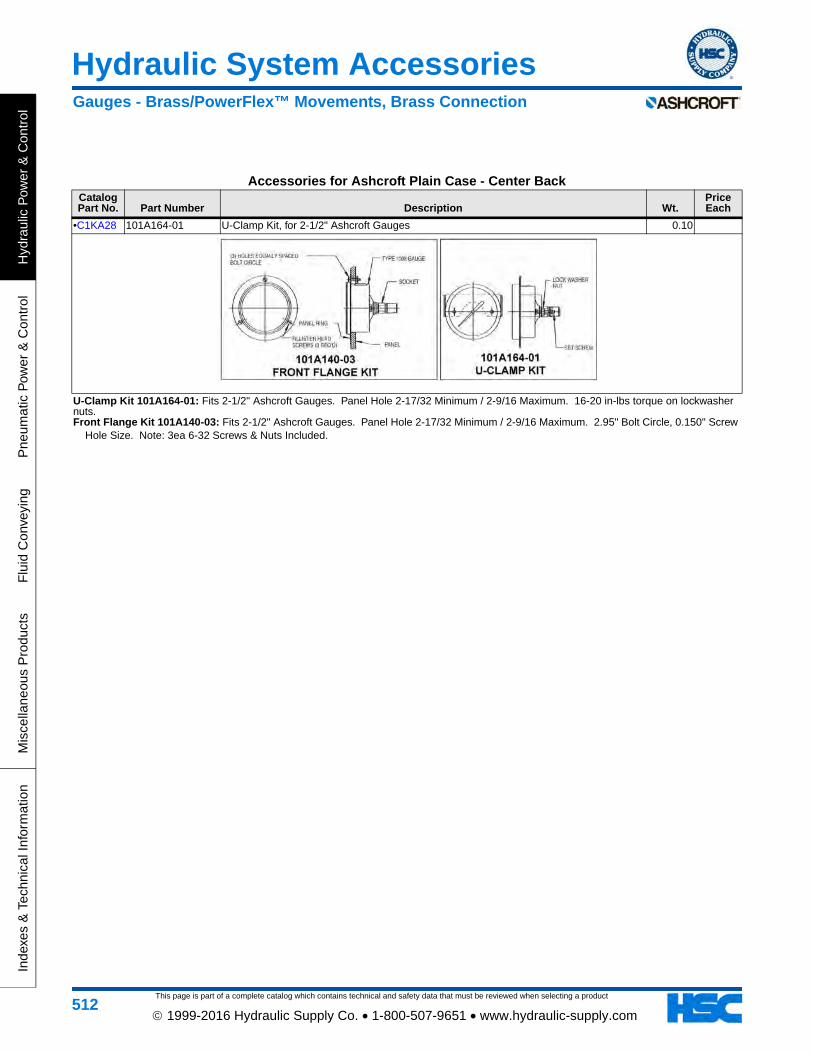
This page is part of a complete catalog which contains technical and safety data that must be reviewed when selecting a product
Hydraulic System Accessories
Hyd
raul
ic P
ower
& C
ontr
olP
neum
atic
Pow
er &
Con
trol
Flu
id C
onve
ying
Mis
cella
neou
s P
rodu
cts
Inde
xes
& T
echn
ical
Info
rmat
ion
512 1999-2016 Hydraulic Supply Co. • 1-800-507-9651 • www.hydraulic-supply.com
Accessories for Ashcroft Plain Case - Center Back Catalog Part No. Part Number Description Wt.
Price Each
•C1KA28 101A164-01 U-Clamp Kit, for 2-1/2" Ashcroft Gauges 0.10
U-Clamp Kit 101A164-01: Fits 2-1/2" Ashcroft Gauges. Panel Hole 2-17/32 Minimum / 2-9/16 Maximum. 16-20 in-lbs torque on lockwasher nuts.Front Flange Kit 101A140-03: Fits 2-1/2" Ashcroft Gauges. Panel Hole 2-17/32 Minimum / 2-9/16 Maximum. 2.95" Bolt Circle, 0.150" Screw
Hole Size. Note: 3ea 6-32 Screws & Nuts Included.
Gauges - Brass/PowerFlex™ Movements, Brass Connection
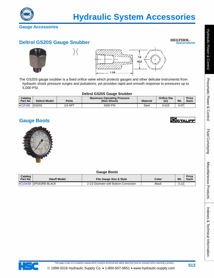
This page is part of a complete catalog which contains technical and safety data that must be reviewed when selecting a product
Hydraulic System Accessories
Hydraulic P
ower &
Control
Pneum
atic Pow
er & C
ontrolF
luid Conveying
Miscellaneous P
roductsIndexes &
Technical Information
513 1999-2016 Hydraulic Supply Co. • 1-800-507-9651 • www.hydraulic-supply.com
Deltrol GS20S Gauge Snubber
The GS20S gauge snubber is a fixed orifice valve which protects gauges and other delicate instruments from hydraulic shock pressure surges and pulsations, yet provides rapid and smooth response to pressures up to 5,000 PSI.
Deltrol GS20S Gauge SnubberCatalog Part No. Deltrol Model Ports
Maximum Operating Pressure (Non-Shock) Material
Orifice Dia (in) Wt.
Price Each
•C1FJ30 GS20S 1/4 NPT 5000 PSI Steel 0.015 0.07
Gauge Boots
Gauge BootsCatalog Part No. Stauff Model Fits Gauge Size & Style Color Wt.
Price Each
•C1GK59 SPG63RB-BLACK 2-1/2 Diameter with Bottom Connection Black 0.12
Gauge Accessories
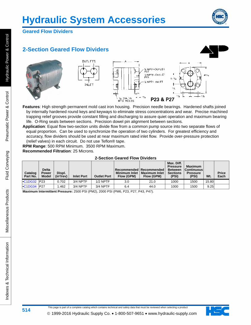
This page is part of a complete catalog which contains technical and safety data that must be reviewed when selecting a product
Hydraulic System Accessories
Hyd
raul
ic P
ower
& C
ontr
olP
neum
atic
Pow
er &
Con
trol
Flu
id C
onve
ying
Mis
cella
neou
s P
rodu
cts
Inde
xes
& T
echn
ical
Info
rmat
ion
514 1999-2016 Hydraulic Supply Co. • 1-800-507-9651 • www.hydraulic-supply.com
2-Section Geared Flow Dividers
Features: High strength permanent mold cast iron housing. Precision needle bearings. Hardened shafts joined by internally hardened round keys and keyways to eliminate stress concentrations and wear. Precise machined trapping relief grooves provide constant filling and discharging to assure quiet operation and maximum bearing life. O-Ring seals between sections. Precision dowel pin alignment between sections.
Application: Equal flow two-section units divide flow from a common pump source into two separate flows of equal proportion. Can be used to synchronize the operation of two cylinders. For greatest efficiency and accuracy, flow dividers should be used at near maximum rated inlet flow. Provide over-pressure protection (relief valves) in each circuit. Do not use Teflon® tape.
RPM Range: 500 RPM Minimum. 3500 RPM Maximum. Recommended Filtration: 25 Microns.
2-Section Geared Flow Dividers
Catalog Part No.
Delta Power Model
Displ. (in³/rev) Inlet Port Outlet Port
Recommended Minimum Inlet
Flow (GPM)
Recommended Maximum Inlet
Flow (GPM)
Max. Diff. Pressure Between Sections
(PSI)
Maximum Continuous
Pressure (PSI) Wt.
Price Each
•C1DG32 P23 0.702 3/4 NPTF 1/2 NPTF 3.0 21.0 1000 1500 15.80
•C1DG34 P27 1.462 3/4 NPTF 3/4 NPTF 6.4 44.0 1000 1500 9.25
Maximum Intermittent Pressure: 2500 PSI (PM2), 2000 PSI (PM6, P23, P27, P43, P47).
Geared Flow Dividers
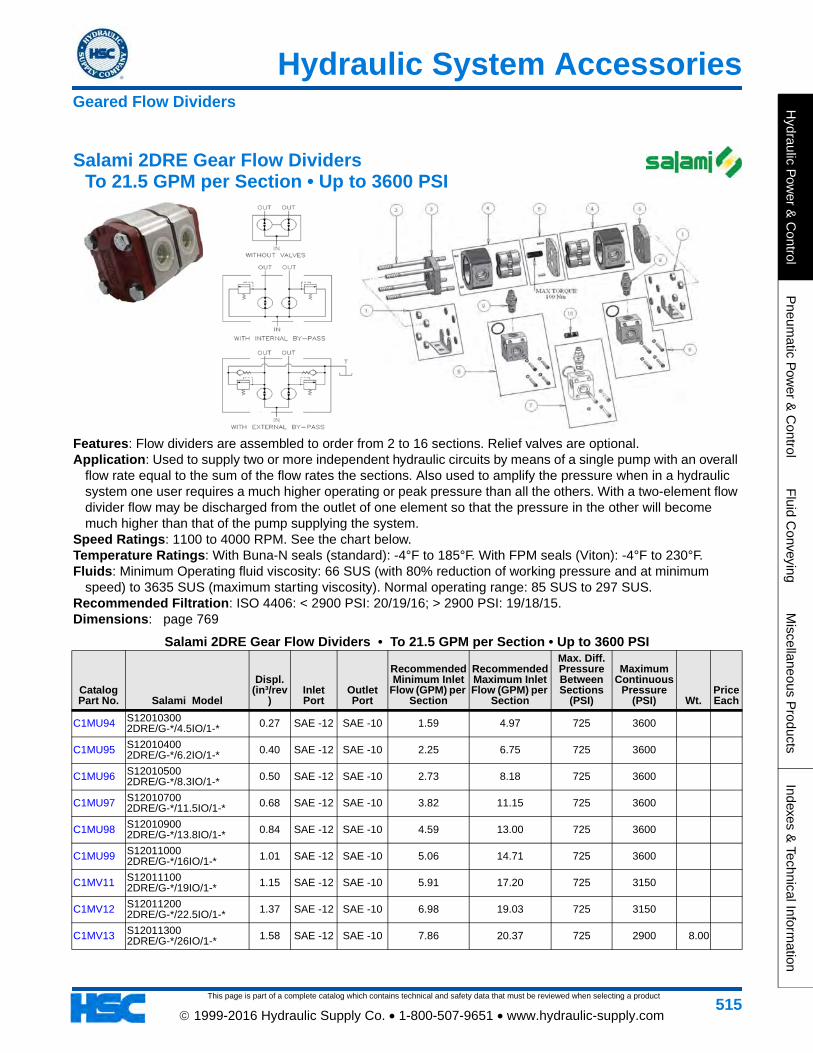
This page is part of a complete catalog which contains technical and safety data that must be reviewed when selecting a product
Hydraulic System Accessories
Hydraulic P
ower &
Control
Pneum
atic Pow
er & C
ontrolF
luid Conveying
Miscellaneous P
roductsIndexes &
Technical Information
515 1999-2016 Hydraulic Supply Co. • 1-800-507-9651 • www.hydraulic-supply.com
Salami 2DRE Gear Flow Dividers To 21.5 GPM per Section • Up to 3600 PSI
Features: Flow dividers are assembled to order from 2 to 16 sections. Relief valves are optional. Application: Used to supply two or more independent hydraulic circuits by means of a single pump with an overall
flow rate equal to the sum of the flow rates the sections. Also used to amplify the pressure when in a hydraulic system one user requires a much higher operating or peak pressure than all the others. With a two-element flow divider flow may be discharged from the outlet of one element so that the pressure in the other will become much higher than that of the pump supplying the system.
Speed Ratings: 1100 to 4000 RPM. See the chart below. Temperature Ratings: With Buna-N seals (standard): -4°F to 185°F. With FPM seals (Viton): -4°F to 230°F. Fluids: Minimum Operating fluid viscosity: 66 SUS (with 80% reduction of working pressure and at minimum
speed) to 3635 SUS (maximum starting viscosity). Normal operating range: 85 SUS to 297 SUS. Recommended Filtration: ISO 4406: < 2900 PSI: 20/19/16; > 2900 PSI: 19/18/15. Dimensions: page 769
Salami 2DRE Gear Flow Dividers • To 21.5 GPM per Section • Up to 3600 PSI
Catalog Part No. Salami Model
Displ. (in³/rev
)Inlet Port
Outlet Port
Recommended Minimum Inlet
Flow (GPM) per Section
Recommended Maximum Inlet Flow (GPM) per
Section
Max. Diff. Pressure Between Sections
(PSI)
Maximum Continuous
Pressure (PSI) Wt.
Price Each
C1MU94 S12010300 2DRE/G-*/4.5IO/1-* 0.27 SAE -12 SAE -10 1.59 4.97 725 3600
C1MU95 S12010400 2DRE/G-*/6.2IO/1-* 0.40 SAE -12 SAE -10 2.25 6.75 725 3600
C1MU96 S12010500 2DRE/G-*/8.3IO/1-* 0.50 SAE -12 SAE -10 2.73 8.18 725 3600
C1MU97 S12010700 2DRE/G-*/11.5IO/1-* 0.68 SAE -12 SAE -10 3.82 11.15 725 3600
C1MU98 S12010900 2DRE/G-*/13.8IO/1-* 0.84 SAE -12 SAE -10 4.59 13.00 725 3600
C1MU99 S12011000 2DRE/G-*/16IO/1-* 1.01 SAE -12 SAE -10 5.06 14.71 725 3600
C1MV11 S12011100 2DRE/G-*/19IO/1-* 1.15 SAE -12 SAE -10 5.91 17.20 725 3150
C1MV12 S12011200 2DRE/G-*/22.5IO/1-* 1.37 SAE -12 SAE -10 6.98 19.03 725 3150
C1MV13 S12011300 2DRE/G-*/26IO/1-* 1.58 SAE -12 SAE -10 7.86 20.37 725 2900 8.00
Geared Flow Dividers
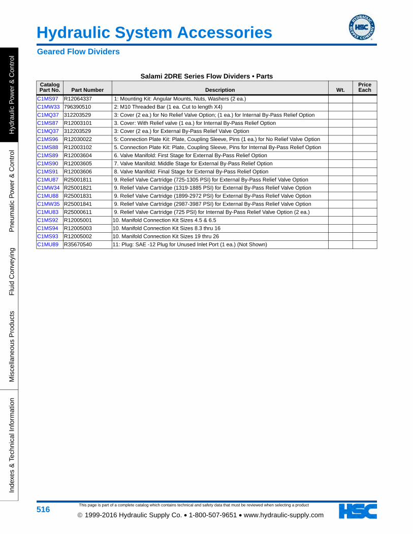
This page is part of a complete catalog which contains technical and safety data that must be reviewed when selecting a product
Hydraulic System Accessories
Hyd
raul
ic P
ower
& C
ontr
olP
neum
atic
Pow
er &
Con
trol
Flu
id C
onve
ying
Mis
cella
neou
s P
rodu
cts
Inde
xes
& T
echn
ical
Info
rmat
ion
516 1999-2016 Hydraulic Supply Co. • 1-800-507-9651 • www.hydraulic-supply.com
Salami 2DRE Series Flow Dividers • PartsCatalog Part No. Part Number Description Wt.
Price Each
C1MS97 R12064337 1: Mounting Kit: Angular Mounts, Nuts, Washers (2 ea.)
C1MW33 796390510 2: M10 Threaded Bar (1 ea. Cut to length X4)
C1MQ37 312203529 3: Cover (2 ea.) for No Relief Valve Option; (1 ea.) for Internal By-Pass Relief Option
C1MS87 R12003101 3. Cover: With Relief valve (1 ea.) for Internal By-Pass Relief Option
C1MQ37 312203529 3: Cover (2 ea.) for External By-Pass Relief Valve Option
C1MS96 R12030022 5: Connection Plate Kit: Plate, Coupling Sleeve, Pins (1 ea.) for No Relief Valve Option
C1MS88 R12003102 5. Connection Plate Kit: Plate, Coupling Sleeve, Pins for Internal By-Pass Relief Option
C1MS89 R12003604 6. Valve Manifold: First Stage for External By-Pass Relief Option
C1MS90 R12003605 7. Valve Manifold: Middle Stage for External By-Pass Relief Option
C1MS91 R12003606 8. Valve Manifold: Final Stage for External By-Pass Relief Option
C1MU87 R25001811 9. Relief Valve Cartridge (725-1305 PSI) for External By-Pass Relief Valve Option
C1MW34 R25001821 9. Relief Valve Cartridge (1319-1885 PSI) for External By-Pass Relief Valve Option
C1MU88 R25001831 9. Relief Valve Cartridge (1899-2972 PSI) for External By-Pass Relief Valve Option
C1MW35 R25001841 9. Relief Valve Cartridge (2987-3987 PSI) for External By-Pass Relief Valve Option
C1MU83 R25000611 9. Relief Valve Cartridge (725 PSI) for Internal By-Pass Relief Valve Option (2 ea.)
C1MS92 R12005001 10. Manifold Connection Kit Sizes 4.5 & 6.5
C1MS94 R12005003 10. Manifold Connection Kit Sizes 8.3 thru 16
C1MS93 R12005002 10. Manifold Connection Kit Sizes 19 thru 26
C1MU89 R35670540 11: Plug: SAE -12 Plug for Unused Inlet Port (1 ea.) (Not Shown)
Geared Flow Dividers
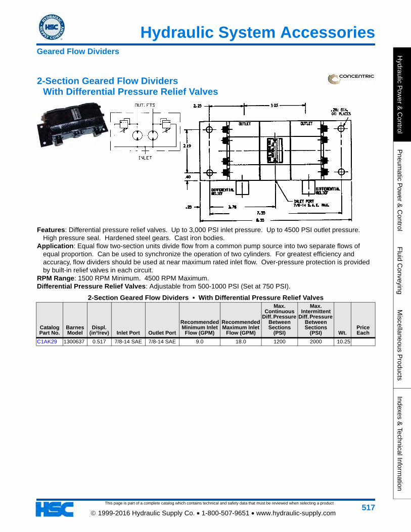
This page is part of a complete catalog which contains technical and safety data that must be reviewed when selecting a product
Hydraulic System Accessories
Hydraulic P
ower &
Control
Pneum
atic Pow
er & C
ontrolF
luid Conveying
Miscellaneous P
roductsIndexes &
Technical Information
517 1999-2016 Hydraulic Supply Co. • 1-800-507-9651 • www.hydraulic-supply.com
2-Section Geared Flow Dividers With Differential Pressure Relief Valves
Features: Differential pressure relief valves. Up to 3,000 PSI inlet pressure. Up to 4500 PSI outlet pressure. High pressure seal. Hardened steel gears. Cast iron bodies.
Application: Equal flow two-section units divide flow from a common pump source into two separate flows of equal proportion. Can be used to synchronize the operation of two cylinders. For greatest efficiency and accuracy, flow dividers should be used at near maximum rated inlet flow. Over-pressure protection is provided by built-in relief valves in each circuit.
RPM Range: 1500 RPM Minimum. 4500 RPM Maximum. Differential Pressure Relief Valves: Adjustable from 500-1000 PSI (Set at 750 PSI).
2-Section Geared Flow Dividers • With Differential Pressure Relief Valves
Catalog Part No.
Barnes Model
Displ. (in³/rev) Inlet Port Outlet Port
Recommended Minimum Inlet
Flow (GPM)
Recommended Maximum Inlet
Flow (GPM)
Max. Continuous
Diff. Pressure Between Sections
(PSI)
Max. Intermittent
Diff. Pressure Between Sections
(PSI) Wt.Price Each
C1AK29 1300637 0.517 7/8-14 SAE 7/8-14 SAE 9.0 18.0 1200 2000 10.25
Geared Flow Dividers
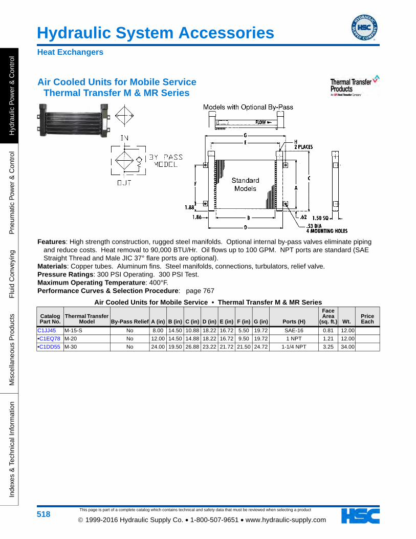
This page is part of a complete catalog which contains technical and safety data that must be reviewed when selecting a product
Hydraulic System Accessories
Hyd
raul
ic P
ower
& C
ontr
olP
neum
atic
Pow
er &
Con
trol
Flu
id C
onve
ying
Mis
cella
neou
s P
rodu
cts
Inde
xes
& T
echn
ical
Info
rmat
ion
518 1999-2016 Hydraulic Supply Co. • 1-800-507-9651 • www.hydraulic-supply.com
Air Cooled Units for Mobile Service Thermal Transfer M & MR Series
Features: High strength construction, rugged steel manifolds. Optional internal by-pass valves eliminate piping and reduce costs. Heat removal to 90,000 BTU/Hr. Oil flows up to 100 GPM. NPT ports are standard (SAE Straight Thread and Male JIC 37° flare ports are optional).
Materials: Copper tubes. Aluminum fins. Steel manifolds, connections, turbulators, relief valve. Pressure Ratings: 300 PSI Operating. 300 PSI Test. Maximum Operating Temperature: 400°F. Performance Curves & Selection Procedure: page 767
Air Cooled Units for Mobile Service • Thermal Transfer M & MR Series
Catalog Part No.
Thermal Transfer Model By-Pass Relief A (in) B (in) C (in) D (in) E (in) F (in) G (in) Ports (H)
Face Area
(sq. ft.) Wt.Price Each
C1JJ45 M-15-S No 8.00 14.50 10.88 18.22 16.72 5.50 19.72 SAE-16 0.81 12.00
•C1EQ78 M-20 No 12.00 14.50 14.88 18.22 16.72 9.50 19.72 1 NPT 1.21 12.00
•C1DD55 M-30 No 24.00 19.50 26.88 23.22 21.72 21.50 24.72 1-1/4 NPT 3.25 34.00
Heat Exchangers
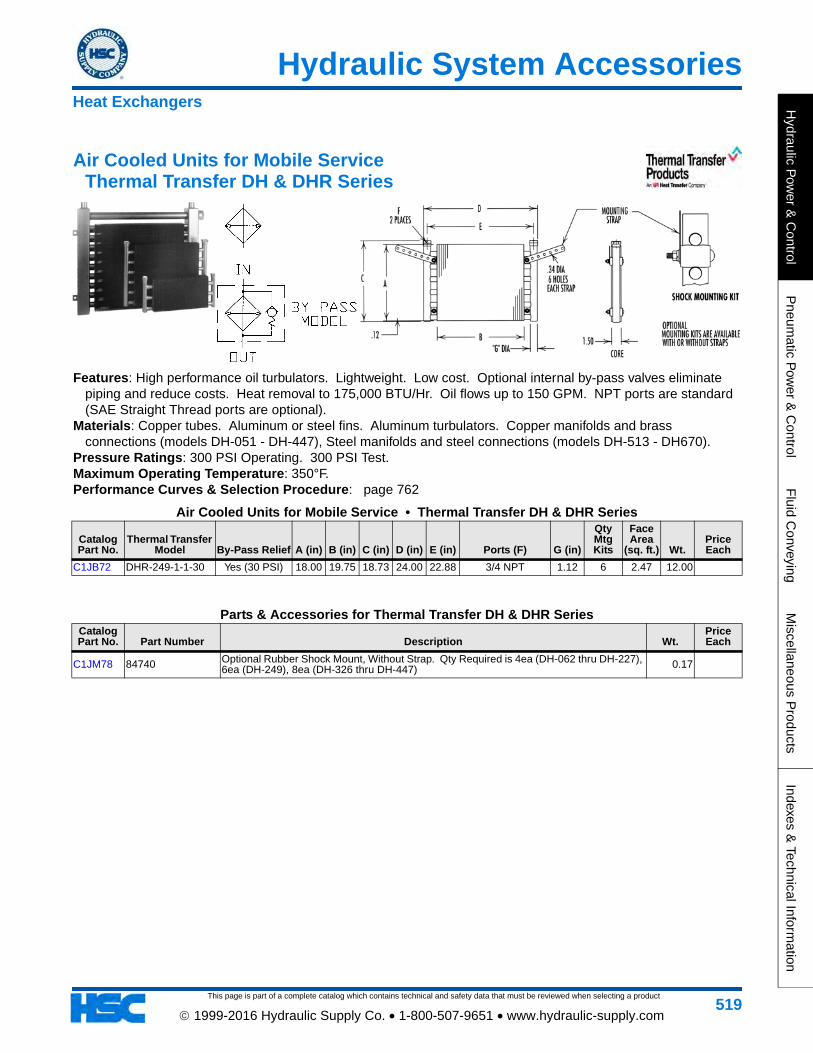
This page is part of a complete catalog which contains technical and safety data that must be reviewed when selecting a product
Hydraulic System Accessories
Hydraulic P
ower &
Control
Pneum
atic Pow
er & C
ontrolF
luid Conveying
Miscellaneous P
roductsIndexes &
Technical Information
519 1999-2016 Hydraulic Supply Co. • 1-800-507-9651 • www.hydraulic-supply.com
Air Cooled Units for Mobile Service Thermal Transfer DH & DHR Series
Features: High performance oil turbulators. Lightweight. Low cost. Optional internal by-pass valves eliminate piping and reduce costs. Heat removal to 175,000 BTU/Hr. Oil flows up to 150 GPM. NPT ports are standard (SAE Straight Thread ports are optional).
Materials: Copper tubes. Aluminum or steel fins. Aluminum turbulators. Copper manifolds and brass connections (models DH-051 - DH-447), Steel manifolds and steel connections (models DH-513 - DH670).
Pressure Ratings: 300 PSI Operating. 300 PSI Test. Maximum Operating Temperature: 350°F. Performance Curves & Selection Procedure: page 762
Air Cooled Units for Mobile Service • Thermal Transfer DH & DHR Series
Catalog Part No.
Thermal Transfer Model By-Pass Relief A (in) B (in) C (in) D (in) E (in) Ports (F) G (in)
Qty Mtg Kits
Face Area
(sq. ft.) Wt.Price Each
C1JB72 DHR-249-1-1-30 Yes (30 PSI) 18.00 19.75 18.73 24.00 22.88 3/4 NPT 1.12 6 2.47 12.00
Parts & Accessories for Thermal Transfer DH & DHR SeriesCatalog Part No. Part Number Description Wt.
Price Each
C1JM78 84740 Optional Rubber Shock Mount, Without Strap. Qty Required is 4ea (DH-062 thru DH-227), 6ea (DH-249), 8ea (DH-326 thru DH-447) 0.17
Heat Exchangers
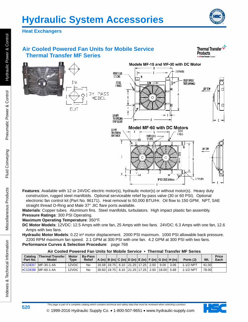
This page is part of a complete catalog which contains technical and safety data that must be reviewed when selecting a product
Hydraulic System Accessories
Hyd
raul
ic P
ower
& C
ontr
olP
neum
atic
Pow
er &
Con
trol
Flu
id C
onve
ying
Mis
cella
neou
s P
rodu
cts
Inde
xes
& T
echn
ical
Info
rmat
ion
520 1999-2016 Hydraulic Supply Co. • 1-800-507-9651 • www.hydraulic-supply.com
Air Cooled Powered Fan Units for Mobile Service Thermal Transfer MF Series
Features: Available with 12 or 24VDC electric motor(s), hydraulic motor(s) or without motor(s). Heavy duty construction, rugged steel manifolds. Optional serviceable relief by-pass valve (30 or 60 PSI). Optional electronic fan control kit (Part No. 96171). Heat removal to 50,000 BTU/Hr. Oil flow to 150 GPM. NPT, SAE straight thread O-Ring and Male 37° JIC flare ports available.
Materials: Copper tubes. Aluminum fins. Steel manifolds, turbulators. High impact plastic fan assembly. Pressure Ratings: 300 PSI Operating. Maximum Operating Temperature: 350°F. DC Motor Models: 12VDC: 12.5 Amps with one fan, 25 Amps with two fans. 24VDC: 6.3 Amps with one fan, 12.6
Amps with two fans. Hydraulic Motor Models: 0.22 in³ motor displacement. 2000 PSI maximum. 1000 PSI allowable back pressure.
2200 RPM maximum fan speed. 2.1 GPM at 300 PSI with one fan. 4.2 GPM at 300 PSI with two fans. Performance Curves & Selection Procedure: page 768
Air Cooled Powered Fan Units for Mobile Service • Thermal Transfer MF SeriesCatalog Part No.
Thermal Transfer Model
Motor Type
By-Pass Relief A (in) B (in) C (in) D (in) E (in) F (in) G (in) H (in) Ports (J) Wt.
Price Each
•C1DE87 MF-30-1-4A 12VDC No 16.58 19.75 6.10 21.25 17.25 2.50 9.00 3.06 1-1/2 NPT 41.00
•C1DE88 MF-60-1-4A 12VDC No 30.83 19.75 6.10 21.25 17.25 2.50 18.00 5.68 1-1/2 NPT 78.00
Heat Exchangers
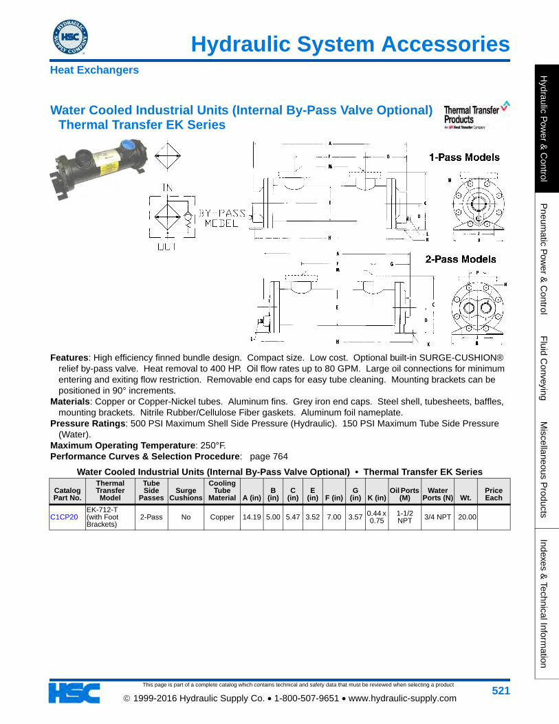
This page is part of a complete catalog which contains technical and safety data that must be reviewed when selecting a product
Hydraulic System Accessories
Hydraulic P
ower &
Control
Pneum
atic Pow
er & C
ontrolF
luid Conveying
Miscellaneous P
roductsIndexes &
Technical Information
521 1999-2016 Hydraulic Supply Co. • 1-800-507-9651 • www.hydraulic-supply.com
Water Cooled Industrial Units (Internal By-Pass Valve Optional) Thermal Transfer EK Series
Features: High efficiency finned bundle design. Compact size. Low cost. Optional built-in SURGE-CUSHION® relief by-pass valve. Heat removal to 400 HP. Oil flow rates up to 80 GPM. Large oil connections for minimum entering and exiting flow restriction. Removable end caps for easy tube cleaning. Mounting brackets can be positioned in 90° increments.
Materials: Copper or Copper-Nickel tubes. Aluminum fins. Grey iron end caps. Steel shell, tubesheets, baffles, mounting brackets. Nitrile Rubber/Cellulose Fiber gaskets. Aluminum foil nameplate.
Pressure Ratings: 500 PSI Maximum Shell Side Pressure (Hydraulic). 150 PSI Maximum Tube Side Pressure (Water).
Maximum Operating Temperature: 250°F. Performance Curves & Selection Procedure: page 764
Water Cooled Industrial Units (Internal By-Pass Valve Optional) • Thermal Transfer EK Series
Catalog Part No.
Thermal Transfer Model
Tube Side
PassesSurge
Cushions
Cooling Tube
Material A (in)B
(in)C
(in)E
(in) F (in)G
(in) K (in)Oil Ports
(M)Water
Ports (N) Wt.Price Each
C1CP20EK-712-T (with Foot Brackets)
2-Pass No Copper 14.19 5.00 5.47 3.52 7.00 3.57 0.44 x 0.75
1-1/2 NPT 3/4 NPT 20.00
Heat Exchangers
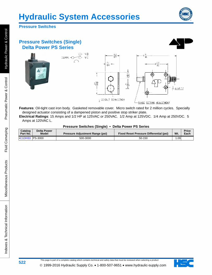
This page is part of a complete catalog which contains technical and safety data that must be reviewed when selecting a product
Hydraulic System Accessories
Hyd
raul
ic P
ower
& C
ontr
olP
neum
atic
Pow
er &
Con
trol
Flu
id C
onve
ying
Mis
cella
neou
s P
rodu
cts
Inde
xes
& T
echn
ical
Info
rmat
ion
522 1999-2016 Hydraulic Supply Co. • 1-800-507-9651 • www.hydraulic-supply.com
Pressure Switches (Single) Delta Power PS Series
Features: Oil-tight cast iron body. Gasketed removable cover. Micro switch rated for 2 million cycles. Specially designed actuator consisting of a dampened piston and positive stop striker plate.
Electrical Ratings: 15 Amps and 1/2 HP at 125VAC or 250VAC. 1/2 Amp at 125VDC. 1/4 Amp at 250VDC. 5 Amps at 120VAC L.
Pressure Switches (Single) • Delta Power PS SeriesCatalog Part No.
Delta Power Model Pressure Adjustment Range (psi) Fixed Reset Pressure Differential (psi) Wt.
Price Each
•C1DH33 PS-3000 500-3000 50-150 1.09
Pressure Switches
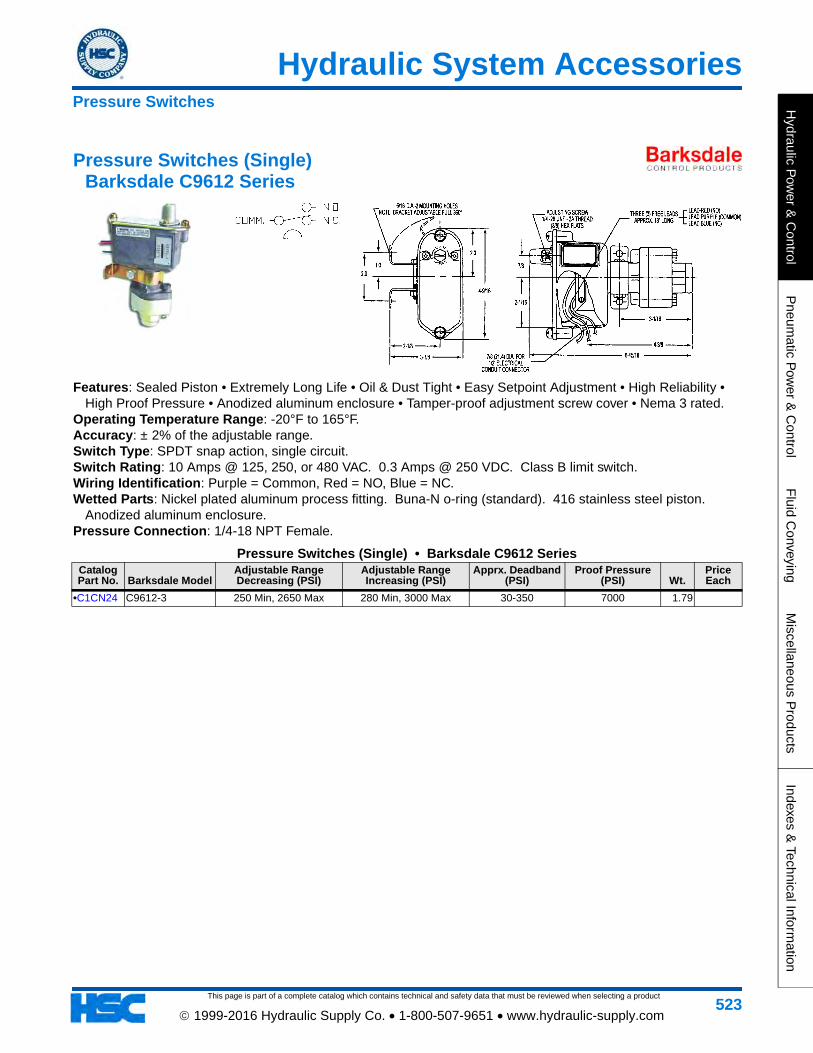
This page is part of a complete catalog which contains technical and safety data that must be reviewed when selecting a product
Hydraulic System Accessories
Hydraulic P
ower &
Control
Pneum
atic Pow
er & C
ontrolF
luid Conveying
Miscellaneous P
roductsIndexes &
Technical Information
523 1999-2016 Hydraulic Supply Co. • 1-800-507-9651 • www.hydraulic-supply.com
Pressure Switches (Single) Barksdale C9612 Series
Features: Sealed Piston • Extremely Long Life • Oil & Dust Tight • Easy Setpoint Adjustment • High Reliability • High Proof Pressure • Anodized aluminum enclosure • Tamper-proof adjustment screw cover • Nema 3 rated.
Operating Temperature Range: -20°F to 165°F. Accuracy: ± 2% of the adjustable range. Switch Type: SPDT snap action, single circuit. Switch Rating: 10 Amps @ 125, 250, or 480 VAC. 0.3 Amps @ 250 VDC. Class B limit switch. Wiring Identification: Purple = Common, Red = NO, Blue = NC. Wetted Parts: Nickel plated aluminum process fitting. Buna-N o-ring (standard). 416 stainless steel piston.
Anodized aluminum enclosure. Pressure Connection: 1/4-18 NPT Female.
Pressure Switches (Single) • Barksdale C9612 SeriesCatalog Part No. Barksdale Model
Adjustable Range Decreasing (PSI)
Adjustable Range Increasing (PSI)
Apprx. Deadband (PSI)
Proof Pressure (PSI) Wt.
Price Each
•C1CN24 C9612-3 250 Min, 2650 Max 280 Min, 3000 Max 30-350 7000 1.79
Pressure Switches
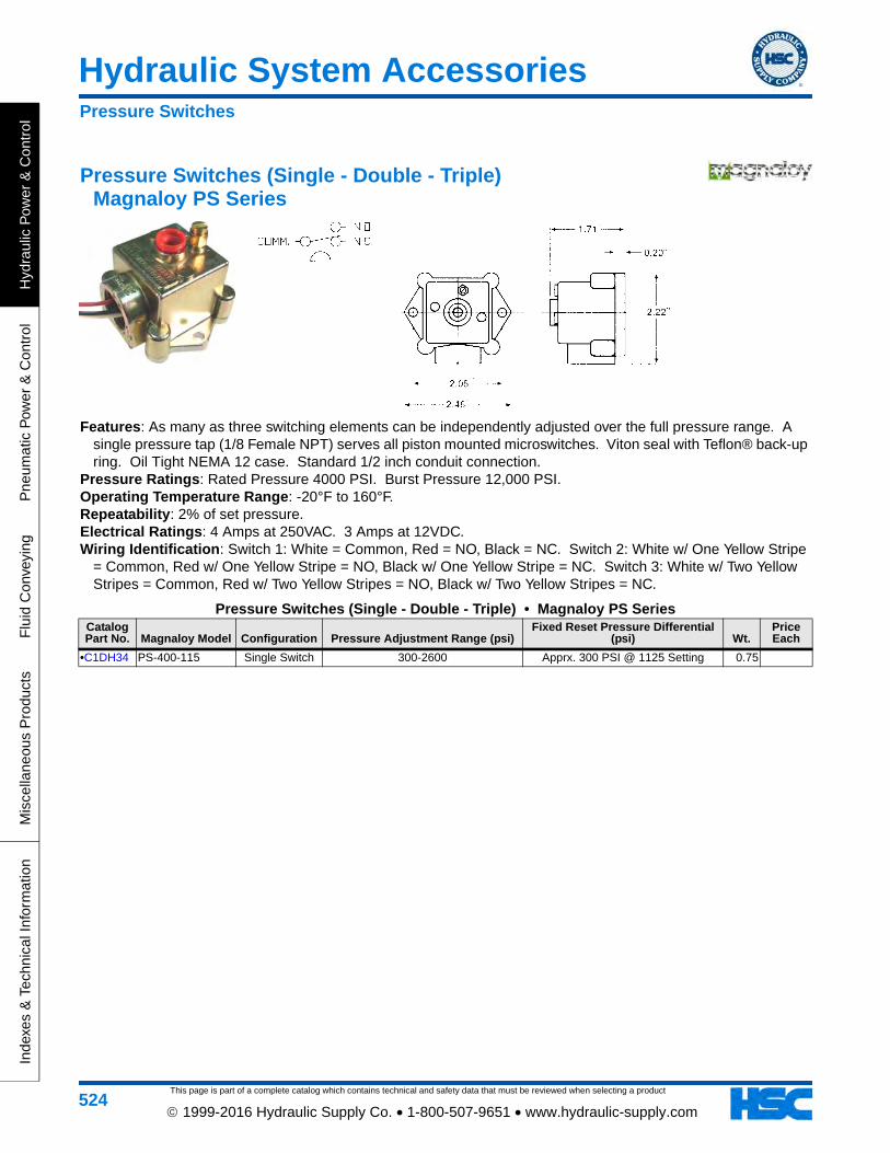
This page is part of a complete catalog which contains technical and safety data that must be reviewed when selecting a product
Hydraulic System Accessories
Hyd
raul
ic P
ower
& C
ontr
olP
neum
atic
Pow
er &
Con
trol
Flu
id C
onve
ying
Mis
cella
neou
s P
rodu
cts
Inde
xes
& T
echn
ical
Info
rmat
ion
524 1999-2016 Hydraulic Supply Co. • 1-800-507-9651 • www.hydraulic-supply.com
Pressure Switches (Single - Double - Triple) Magnaloy PS Series
Features: As many as three switching elements can be independently adjusted over the full pressure range. A single pressure tap (1/8 Female NPT) serves all piston mounted microswitches. Viton seal with Teflon® back-up ring. Oil Tight NEMA 12 case. Standard 1/2 inch conduit connection.
Pressure Ratings: Rated Pressure 4000 PSI. Burst Pressure 12,000 PSI. Operating Temperature Range: -20°F to 160°F. Repeatability: 2% of set pressure. Electrical Ratings: 4 Amps at 250VAC. 3 Amps at 12VDC. Wiring Identification: Switch 1: White = Common, Red = NO, Black = NC. Switch 2: White w/ One Yellow Stripe
= Common, Red w/ One Yellow Stripe = NO, Black w/ One Yellow Stripe = NC. Switch 3: White w/ Two Yellow Stripes = Common, Red w/ Two Yellow Stripes = NO, Black w/ Two Yellow Stripes = NC.
Pressure Switches (Single - Double - Triple) • Magnaloy PS SeriesCatalog Part No. Magnaloy Model Configuration Pressure Adjustment Range (psi)
Fixed Reset Pressure Differential (psi) Wt.
Price Each
•C1DH34 PS-400-115 Single Switch 300-2600 Apprx. 300 PSI @ 1125 Setting 0.75
Pressure Switches
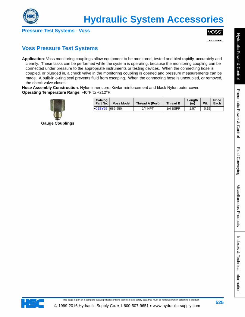
This page is part of a complete catalog which contains technical and safety data that must be reviewed when selecting a product
Hydraulic System Accessories
Hydraulic P
ower &
Control
Pneum
atic Pow
er & C
ontrolF
luid Conveying
Miscellaneous P
roductsIndexes &
Technical Information
525 1999-2016 Hydraulic Supply Co. • 1-800-507-9651 • www.hydraulic-supply.com
Voss Pressure Test Systems
Application: Voss monitoring couplings allow equipment to be monitored, tested and bled rapidly, accurately and cleanly. These tasks can be performed while the system is operating, because the monitoring coupling can be connected under pressure to the appropriate instruments or testing devices. When the connecting hose is coupled, or plugged in, a check valve in the monitoring coupling is opened and pressure measurements can be made. A built-in o-ring seal prevents fluid from escaping. When the connecting hose is uncoupled, or removed, the check valve closes.
Hose Assembly Construction: Nylon inner core, Kevlar reinforcement and black Nylon outer cover.Operating Temperature Range: -40°F to +212°F.
Catalog Part No. Voss Model Thread A (Port) Thread B
Length (in) Wt.
Price Each
•C1BY25 686-950 1/4 NPT 1/4 BSPP 1.57 0.15
Gauge Couplings
Pressure Test Systems - Voss
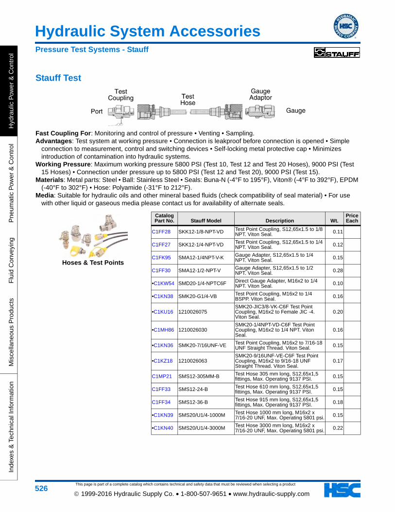
This page is part of a complete catalog which contains technical and safety data that must be reviewed when selecting a product
Hydraulic System Accessories
Hyd
raul
ic P
ower
& C
ontr
olP
neum
atic
Pow
er &
Con
trol
Flu
id C
onve
ying
Mis
cella
neou
s P
rodu
cts
Inde
xes
& T
echn
ical
Info
rmat
ion
526 1999-2016 Hydraulic Supply Co. • 1-800-507-9651 • www.hydraulic-supply.com
Stauff Test
Fast Coupling For: Monitoring and control of pressure • Venting • Sampling.Advantages: Test system at working pressure • Connection is leakproof before connection is opened • Simple
connection to measurement, control and switching devices • Self-locking metal protective cap • Minimizes introduction of contamination into hydraulic systems.
Working Pressure: Maximum working pressure 5800 PSI (Test 10, Test 12 and Test 20 Hoses), 9000 PSI (Test 15 Hoses) • Connection under pressure up to 5800 PSI (Test 12 and Test 20), 9000 PSI (Test 15).
Materials: Metal parts: Steel • Ball: Stainless Steel • Seals: Buna-N (-4°F to 195°F), Viton® (-4°F to 392°F), EPDM (-40°F to 302°F) • Hose: Polyamide (-31°F to 212°F).
Media: Suitable for hydraulic oils and other mineral based fluids (check compatibility of seal material) • For use with other liquid or gaseous media please contact us for availability of alternate seals.
Catalog Part No. Stauff Model Description Wt.
Price Each
C1FF28 SKK12-1/8-NPT-VD Test Point Coupling, S12,65x1.5 to 1/8 NPT. Viton Seal. 0.11
C1FF27 SKK12-1/4-NPT-VD Test Point Coupling, S12,65x1.5 to 1/4 NPT. Viton Seal. 0.12
C1FK95 SMA12-1/4NPT-V-K Gauge Adapter, S12,65x1.5 to 1/4 NPT. Viton Seal. 0.15
C1FF30 SMA12-1/2-NPT-V Gauge Adapter, S12,65x1.5 to 1/2 NPT. Viton Seal. 0.28
•C1KW54 SMD20-1/4-NPTC6F Direct Gauge Adapter, M16x2 to 1/4 NPT. Viton Seal. 0.10
•C1KN38 SMK20-G1/4-VB Test Point Coupling, M16x2 to 1/4 BSPP. Viton Seal. 0.16
•C1KU16 1210026075SMK20-JIC3/8-VK-C6F Test Point Coupling, M16x2 to Female JIC -4. Viton Seal.
0.20
•C1MH86 1210026030SMK20-1/4NPT-VD-C6F Test Point Coupling, M16x2 to 1/4 NPT. Viton Seal.
0.16
•C1KN36 SMK20-7/16UNF-VE Test Point Coupling, M16x2 to 7/16-18 UNF Straight Thread. Viton Seal. 0.15
•C1KZ18 1210026063SMK20-9/16UNF-VE-C6F Test Point Coupling, M16x2 to 9/16-18 UNF Straight Thread. Viton Seal.
0.17
C1MP21 SMS12-305MM-B Test Hose 305 mm long, S12,65x1,5 fittings, Max. Operating 9137 PSI. 0.15
C1FF33 SMS12-24-B Test Hose 610 mm long, S12,65x1,5 fittings, Max. Operating 9137 PSI. 0.15
C1FF34 SMS12-36-B Test Hose 915 mm long, S12,65x1,5 fittings, Max. Operating 9137 PSI. 0.18
•C1KN39 SMS20/U1/4-1000M Test Hose 1000 mm long, M16x2 x 7/16-20 UNF, Max. Operating 5801 psi. 0.15
•C1KN40 SMS20/U1/4-3000M Test Hose 3000 mm long, M16x2 x 7/16-20 UNF, Max. Operating 5801 psi. 0.22
Hoses & Test Points
Pressure Test Systems - Stauff
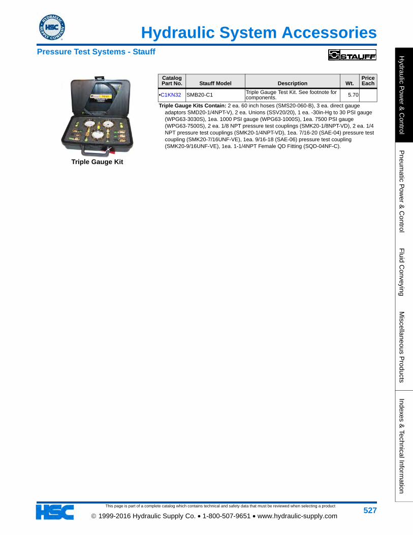
This page is part of a complete catalog which contains technical and safety data that must be reviewed when selecting a product
Hydraulic System Accessories
Hydraulic P
ower &
Control
Pneum
atic Pow
er & C
ontrolF
luid Conveying
Miscellaneous P
roductsIndexes &
Technical Information
527 1999-2016 Hydraulic Supply Co. • 1-800-507-9651 • www.hydraulic-supply.com
Catalog Part No. Stauff Model Description Wt.
Price Each
•C1KN32 SMB20-C1 Triple Gauge Test Kit. See footnote for components. 5.70
Triple Gauge Kits Contain: 2 ea. 60 inch hoses (SMS20-060-B), 3 ea. direct gauge adaptors SMD20-1/4NPT-V), 2 ea. Unions (SSV20/20), 1 ea. -30in-Hg to 30 PSI gauge (WPG63-3030S), 1ea. 1000 PSI gauge (WPG63-1000S), 1ea. 7500 PSI gauge (WPG63-7500S), 2 ea. 1/8 NPT pressure test couplings (SMK20-1/8NPT-VD), 2 ea. 1/4 NPT pressure test couplings (SMK20-1/4NPT-VD), 1ea. 7/16-20 (SAE-04) pressure test coupling (SMK20-7/16UNF-VE), 1ea. 9/16-18 (SAE-06) pressure test coupling (SMK20-9/16UNF-VE), 1ea. 1-1/4NPT Female QD Fitting (SQD-04NF-C).
Triple Gauge Kit
Pressure Test Systems - Stauff