hydraulic disc brakes overview - cdn.sram.com · o verview disc brake - a disc brake is comprised...
TRANSCRIPT

GEN.0000000004234 Rev A Copyright © 2012 SRAM, LLC
HYDRAULIC DISC BRAKES
OVERVIEW

Table of ConTenTs
OvERviEw ...............................................................................................................................................................................................................................................3ThE LEvER ...............................................................................................................................................................................................................................................3ThE bRAkE LiNE .................................................................................................................................................................................................................................. 4ThE CALipER .......................................................................................................................................................................................................................................... 4OpEN ANd CLOSEd SySTEMS ........................................................................................................................................................................................................5bRAkiNG pOwER ................................................................................................................................................................................................................................ 6hEAT ANd fAdE................................................................................................................................................................................................................................... 9CARE .......................................................................................................................................................................................................................................................... 9

o v e r v i e wDisc brake - A disc brake is comprised of a handlebar-mounted lever, a frame or fork-mounted caliper, and a hub-mounted rotor. when the lever is squeezed, a brake pad (friction material) clamps onto the rotor creating a frictional force at the rotor/caliper interface. This frictional force slows the wheel by converting the kinetic energy of the spinning wheel into heat. in other words, slowing down means heating up.
Hydraulic disc brake - A hydraulic disc brake incorporates a master piston in the lever, a hydraulic brake line, two or more opposing slave pistons in the caliper, and hydraulic fluid (dOT brake fluid or mineral oil).
in a hydraulic brake system, braking is accomplished by the squeezing the lever, which pushes the master piston inside the lever body and forces fluid into the brake hose. The fluid then moves into the caliper and presses against the slave pistons. brake pads are attached to the slave pistons so that when the fluid presses against the pistons, the brake pads clamp onto the rotor. Once the pads contact the rotor, additional force at the lever pressurizes the system and creates greater clamping force on the rotor.
There are several factors at work when using a hydraulic disc brake. The amount of lever squeeze combined with the leverage in the brake lever and in the hydraulic system create a clamping force at the caliper. That clamping force combined with the brake pad material produces friction at the rotor. The amount of friction combined with the diameter of the rotor generates braking power. braking power, along with the duration of braking, determines how quickly speed is reduced as well as the amount of heat generated.
T H e l e v e rbrake lever designs generally arrange the master cylinder in one of two configurations, radial or inline.
Radial designs place the master cylinder perpendicular to the handlebar, while inline designs place the master cylinder roughly parallel with the handlebar. The primary difference between these two designs is the location of the lever pivot, which can have a dramatic effect on the ergonomics of the lever.
factors at work in a hydraulic disc brake
Speed reduction,
heat buildup
braking duration
braking power
friction at the rotor
Rotor diameter
Clamping force at the
caliper
brake pad material
Leverage(mechanical
and hydraulic)
Actuation force
(lever squeeze)
inline leverradial lever
Master cylinder
Master cylinder
Master piston
Master pistonLever
pivot
Lever pivot
3 OvERviEw

T H e b r a k e H o s eThe brake hose connects the lever and caliper. it is also an integral aspect of overall brake design and performance. brake hoses are specially designed to support internal pressures in excess of 2000 psi without significant expansion or stretching. The small amount of expansion that does exist can be controlled by design to manipulate lever feel at specific pressures. it is important to note that while this does not affect overall braking power, it does allow for greater control of the available braking power.
T H e C a l i p e rThe slave pistons in the brake caliper often use special seals that flex, or roll, slightly when the pistons/pads are pushed toward the rotor during braking. when the brake is released, the piston seals relax and pull the pistons/pads away from the rotor. This is known as pad rollback. The amount of rollback is an important factor in determining the distance the pistons must travel before the pads contact the rotor. This distance reflects the amount of clearance between the pads and the rotor, as well as the amount of lever movement required before the pads contact the rotor, known as deadband. The greater the rollback the greater the clearance and deadband.
Another function of these seals is to allow the pistons to self advance as the pads and rotor wear. As pads and rotor wear, the distance between them increases, which affects piston travel and deadband. without the use of these special seals, pad and rotor wear would require constant adjustment of pad clearance to maintain consistent deadband. but because the amount of roll in a piston seal is limited, there is a point where the piston will slip through the seal. This means that as brake pads and rotor wear, the pistons will move further than the seals can roll. As a result, the pistons constantly slip through the seal until the pads contact the rotor. Once the brake is released, the pistons/pads return to a new resting position, closer to the rotor. This eliminates the need to adjust pad clearance or deadband as components wear.
Slave piston
piston seal fluid pressure advances pistons, piston seals flex
Lever actuated - fluid pressurized
Lever released - fluid depressurized
piston seals pull pistons back
hydraulic fluid
piston seal gland
4 ThE bRAkE hOSE

C l o s e D a n D o p e n s y s T e m sSome bicycle hydraulic disc brakes incorporate a closed system, where and the volume of fluid remains the same between the master and slave pistons.
Most bicycle hydraulic disc brakes incorporate an open system, where a reservoir contains an additional volume of fluid and a small volume of air. The fluid and air are separated by a flexible bladder that expands and contracts as changes in fluid volume occur.
Differences between open and closed systemsheat compensation - As the brake heats up, the fluid expands. in a closed system, this expansion creates pressure which advances the pads towards the rotor, causing drag and affecting lever feel. in an open system, the expanding fluid can move into the reservoir once the brakes are released. This allows the system to operate consistently across a wide range of temperatures.
pad/rotor wear compensation - As pads and rotors wear, the slave pistons must move further in order for the pads to contact the rotor. in a closed system, more slave cylinder travel means more lever travel. Therefore, as the pads continue to wear the lever must travel further. in an open system, piston slippage/pad advancement manages the gap between the pads and the rotor. Surplus fluid in the reservoir moves into the system ensuring that there is always an adequate volume of fluid between the master and slave pistons. This allows the system to operate consistently as parts wear.
fluid management in an open systemduring braking, fluid access to the reservoir must be blocked so that the flexible bladder doesn’t affect brake feel and isn’t tasked with sealing at high pressure. There are two methods of managing fluid access between the reservoir and the rest of the system:
Timing ports - Traditional timing ports are small holes located in the master cylinder, just in front of the piston (when the brake is at rest). when the lever is squeezed, the master piston advances past these holes and closes off access between the reservoir and the rest of the system.
Taperbore - Avid® Taperbore Technology™ incorporates a master piston with an integrated bladder in a master cylinder that has a graduated diameter. when the brake is at rest, the piston sits in an area of the master cylinder that is slightly larger in diameter than the piston. The gap between the piston and the wall of the master cylinder allows fluid access to an area behind the piston seal and around the piston/bladder. This effectively creates a reservoir. when the brake is actuated, the piston moves into an area of the master cylinder that is smaller in diameter and is therefore able to seal around the piston, eliminating fluid access between the reservoir and the rest of the system.
Closed system open system
Reservoir
Timing ports
bladder
Taperbore(open system)
Reservoir
Concentric timing port
bladderLever actuated - reservoir isolated
5 CLOSEd ANd OpEN SySTEMS

b r a k i n g p o w e rTotal braking power is dependent on three different attributes of the braking system:
- Leverage/mechanical advantage
- pad friction material
- Rotor size
leverage and modulationLeverage, or mechanical advantage, amplifies the force input at the lever, through the system, and to the pads/rotor. This will also have an effect on the amount of lever travel required to move the pads a given amount. The total amount of leverage in the system can be controlled by the design of the lever, master piston, and slave pistons.
On the brake lever, the location of the lever pivot in relation to the input force and the pushrod (the mechanism that drives the master piston) is a key factor in determining leverage. This relationship is expressed as a ratio, where the length of the lever on one side of the pivot is divided by the length of the lever on the other side of the pivot.
lever
pivot
L x 1 L x 1
L x 1
L x 1
L x 1 L x 2
L x 2
L x 7
2/1 = 2:1 leverage ratio
2:1 leverage ratio
7:1 leverage ratio
1/1 = 1:1 leverage ratio
6 bRAkiNG pOwER

brake levers are designed with the pivot positioned close to the pushrod. This provides increased leverage, where movement on the force input side of the lever produces less movement on the pushrod side, but also multiplies the input force by a factor equal to the leverage ratio to produce a greater output force to the master piston.
Additionally, depending on how the push rod moves in relation to the lever pivot, leverage can change during the course of braking. This change in leverage is referred to as modulation. There are three types of modulation:
- Rising rate - leverage increases throughout the lever travel
- falling rate - leverage decreases throughout the lever travel
- Linear rate - leverage remains consistent throughout the lever travel
Avid® deep Stroke Modulation™ is a specially tuned rising rate. it generates lower braking power when the pads first touch the rotor - preventing accidental wheel lock-up and loss of control - and exponentially more power when pulling the lever further. The result is a wide range of usable braking power and greater control during different braking scenarios.
The final factor in determining overall leverage in the system is the piston ratio. Similar to controlling leverage with the brake lever, the ratio between the surface areas of the master piston and each slave piston determines the amount of master piston movement required for a given amount of slave piston movement. in hydraulic brake systems, the surface area of the master piston is less than the surface area of the slave piston. Larger slave pistons require more fluid to push against them, which requires more movement of the smaller master piston and, as a result, the lever.
Also similar to the brake lever, the input force at the master piston multiplied by the piston ratio equals the output force at the slave pistons.
due to the fact that there are two slave pistons, it might seem intuitive that the combined surface areas of the slave pistons would factor into the piston ratio, effectively doubling the clamping force on the rotor. This would be true if the combined slave piston areas were moving in the same direction (as is the case with one side of a four-piston caliper). however, if the two slave pistons move in opposing directions, the total clamping force is only equal to the force produced by one of the pistons. for example, if one of the slave pistons were immobilized, and the other slave piston generated the overall clamping force on its own, the force produced would be no different than if both pistons were working together.
Bra
king
po
wer
Lever travel
Rising rateFalling rateLinear rate
Light braking, speed control
Hard braking, stopping
Slave piston
Master piston
= ==Total surface area of each caliper piston
Total surface area of lever piston
divided by = piston ratio
7 bRAkiNG pOwER

by controlling the design of the pistons for leverage, and the lever for leverage and modulation, a wide range of braking feel, power, and control can be achieved. Controlling additional factors, such as pad and rotor design, increases this range even further.
brake pads and frictionbrake pads function on two principles: adherent friction and abrasive friction.
Adherent friction begins with depositing a thin transfer layer of pad material on the rotor during an initial burnishing, or bed-in procedure. Once this layer is established, applying the brakes creates molecular bonds between the pads and the transfer layer on the rotor that are instantaneously established and then immediately broken, providing friction. proper bed-in is absolutely critical to braking performance, as an uneven layer of pad material on the rotor can cause excessive noise and uneven braking. This may be imperceptible at first, but as the layer continues to build unevenly, these issues could arise after several rides. Adherent friction is the primary contributor to overall braking friction, and pad material is the key component in creating adherent friction. This is why pads wear much quicker than rotors.
Abrasive friction is caused by the breaking down of either the surface of the brake pads, the rotor, or both. This is a secondary contributor to overall friction, but is the primary contributor to rotor wear.
pad material is specifically designed to interface with the rotor material, and provides a known frictional force for a given clamping force onto the rotor. This is known as the coefficient of friction, and different pad materials have different coefficients of friction. Avid uses organic and metal sintered pads. Organic pads are made from various organic and metallic compounds bonded together with organic resin. Metal sintered pads are composed of metallic materials bonded using high temperature and pressure. These two types of pad compounds provide different characteristics of power, wear, wet performance, and dry/dusty performance. when switching from from organic to metal sintered pads, or vice-versa, it is important to install a new rotor in order to establish a new transfer layer.
pad and rotor wear is a normal result of brake use over a period of time. however, contamination of the pads or rotor can accelerate the wear process and cause unusual noise or vibration.
rotorsRotor diameter is the final contributing factor to braking power. Large diameter rotors provide more leverage for the brake system to oppose rotation of the wheel by placing the braking force further from the axle. Therefore, the larger the rotor, the more powerful the brake. Larger diameter rotors also improve heat management by increasing the surface area and the thermal mass (capacity to absorb heat) of the overall braking system. Larger rotors are unavoidably heavier than their smaller counterparts, so riders may wish to run smaller rotors for overall weight savings. however, this could lead to a brake system that isn’t adequately powerful for heavier or more aggressive riders. These riders may compensate for the power reduction of a smaller rotor by simply pulling harder on the lever. This can cause the system to overheat, resulting in poor braking performance. in general, proper rotor sizing is an integral and safety critical part of brake setup that should be personalized to the rider and riding conditions.
piston ratio multiplied by lever ratio = Total system leverage
piston ratio
Lever ratio
8 bRAkiNG pOwER
H e a T a n D f a D ebraking power can decrease over an extended period of time during brake use. This is known as fade. There are two types of fade associated with hydraulic brakes, friction fade and vapor fade.
with friction fade, the coefficient of friction can change depending on the temperature at the pad/rotor interface; in addition to the type of pad material. high braking temperatures can cause the coefficient of friction to drop substantially. This can be felt on the bike as a reduction in braking power, where the rider pulls harder on the lever and doesn’t feel an increase in braking power.
vapor fade is caused when brake fluid boils inside the brake caliper and hose. boiling is where a drop in fluid pressure (which occurs when a fluid is heated) allows microscopic pockets of gas suspended in the fluid (bubbles) to expand, creating larger bubbles. fluids under significant pressure require much higher temperatures to boil than less pressurized fluids. This means that the fluid can actually reach temperatures above its normal boiling point during hard braking (high pressure). however, as soon as the lever is released, the pressure immediately drops. with the fluid temperature still above its normal boiling point, this sudden loss of pressure causes the fluid to instantly boil, creating large bubbles in the brake system. with large bubbles now present in the system, pulling on the brake lever compresses the bubbles in addition to moving fluid, allowing the lever to bottom out against the handlebar before enough fluid pressure can be generated to actuate the slave pistons properly. This results in a loss of braking power.
brake systems are designed and tested to function at extreme temperatures; however, every system has limitations. As pad materials generally exhibit friction fade before vapor fade can occur, a reduction in braking power resulting from friction fade is a clear indication that the system is approaching its heat limit, and should be allowed to cool before a dangerous loss of braking power from vapor fade can occur. A brake system that has undergone vapor fade should be completely bled before riding again. boiling brake fluid will cause a breakdown of the fluid composition and can exhibit lower boiling points in future brake applications.
Heat managementMost braking systems are designed to manage heat by isolating it to the pads and the rotor. These two components have more direct access to air flow and can tolerate much higher temperatures than other components in the system (such as brake fluid). This is achieved by using piston materials that are non-heat conductive to limit the amount of heat transfer from the pad/rotor interface to the caliper.
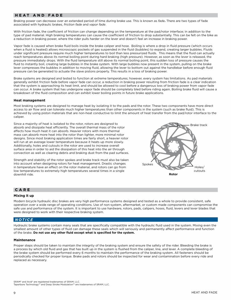
Since a majority of heat is isolated to the rotor, rotors are designed to absorb and dissipate heat efficiently. The overall thermal mass of the rotor affects how much heat it can absorb. heavier rotors with more thermal mass can absorb more heat into the rotor than lighter, more minimal rotor designs. Since most braking application times are fairly short, a heavier rotor will run at an average lower temperature because it heats up more slowly. Additionally, holes and cutouts in the rotor are used to increase overall surface area in order to aid the dissipation of this heat into the air through convection as well as clearing debris and braking dust from the pad surfaces.
Strength and stability of the rotor spokes and brake track must also be taken into account when designing rotors for heat management. drastic changes in temperature have an effect on the rotor material, and rotors can go from low temperatures to extremely high temperatures several times in a single downhill ride.
C a r emixing it upModern bicycle hydraulic disc brakes are very high performance systems designed and tested as a whole to provide consistent, safe operation over a wide range of operating conditions. Use of non-system, aftermarket, or custom made components can compromise the safe use and performance of the system. it is important to use hardware, rotors, pads, calipers, hoses, fluid, levers and lever blades that were designed to work with their respective braking system.
Noticehydraulic brake systems contain many seals that are specifically compatible with the hydraulic fluid used in the system. Mixing even the smallest amount of other types of fluid can damage these seals which will seriously and permanently affect performance and function of the brake. Do not use any other fluid except what is specified for the system.
maintenanceproper steps should be taken to maintain the integrity of the braking system and ensure the safety of the rider. bleeding the brake is a process by which old fluid and gas that has built up in the system is flushed from the caliper, line, and lever. A complete bleeding of the brake system should be performed every 6 months to maintain the performance of the braking system. All fasteners should be periodically checked for proper torque. brake pads and rotors should be inspected for wear and contamination before every ride and replaced as necessary.
SRAM® and Avid® are registered tradenames of SRAM, LLC. Taperbore Technology™ and deep Stroke Modulation™ are tradenames of SRAM, LLC.
brake track
holes/cutouts
Spokes
rotor
9 hEAT ANd fAdE

www.sram.com