hydraulic crawler cranes - kobelco cranes
TRANSCRIPT
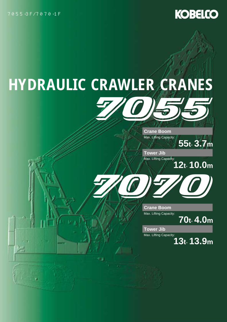
7055-3F/7070-1F
Max. Lifting Capacity:
55t×3.7m
Crane Boom
Max. Lifting Capacity:
12t×10.0m
Tower Jib
Max. Lifting Capacity:
70t×4.0m
Crane Boom
Max. Lifting Capacity:
13t×13.9m
Tower Jib
HYDRAULIC CRAWLER CRANES
1
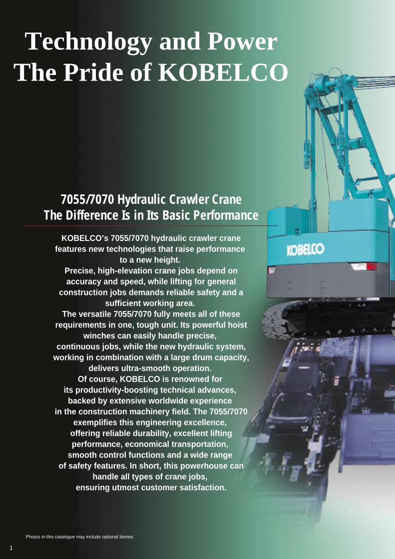
7055/7070 Hydraulic Crawler CraneThe Difference Is in Its Basic Performance
Photos in this catalogue may include optional itemes.
Technology and PowerThe Pride of KOBELCO
KOBELCO’s 7055/7070 hydraulic crawler crane features new technologies that raise performance
to a new height. Precise, high-elevation crane jobs depend on accuracy and speed, while lifting for general
construction jobs demands reliable safety and a sufficient working area.
The versatile 7055/7070 fully meets all of these requirements in one, tough unit. Its powerful hoist
winches can easily handle precise, continuous jobs, while the new hydraulic system,
working in combination with a large drum capacity, delivers ultra-smooth operation.
Of course, KOBELCO is renowned for its productivity-boosting technical advances, backed by extensive worldwide experience
in the construction machinery field. The 7055/7070 exemplifies this engineering excellence,
offering reliable durability, excellent lifting performance, economical transportation,
smooth control functions and a wide range of safety features. In short, this powerhouse can
handle all types of crane jobs, ensuring utmost customer satisfaction.
2
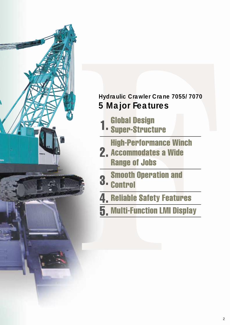
Hydraulic Crawler Crane 7055/7070
5 Major Features
1.
2.
3.4.5.
Global Design Super-StructureHigh-Performance Winch Accommodates a Wide Range of JobsSmooth Operation and ControlReliable Safety FeaturesMulti-Function LMI Display
Complies with Worldwide Exhaust Gas RegulationsWith its low pollution engine, the 7055/7070 meets NRMM (Europe) Stage IIIA and US EPA Tier III exhaust emissions regulations.
Complies with Japanese Noise RegulationsThe 7055/7070 is designed with advanced KOBELCO low-noise construction technologies, as specified by the Japanese Ministry of Land, Infrastructure and Transport.
●Super fine filter (glass fiber) ●Conventional filter (paper fiber)
Super-Fine Filter, a Long-Life Filter for Hydraulic OilThe large-capacity, super-fine filter is made of a high-performance filter medium consisting of glass fiber reinforced with steel wires. The replacement cycle is extended to four times longer than that of conventional filters to reduce lifelong operating costs.
Photomicrograph(×250)
For customer satisfaction
Global Design Super-Structure
High-Output EngineThe engine has an impressive rated output of 159 kW and complies with NRMM (Europe) Stage IIIA and US EPA Tier III exhaust emissions regulations. All of this power works with KOBELCO’s unique Engine Speed Sensing (ESS) control system and new hydraulic systems to ensure stable and smooth simultaneous operations.
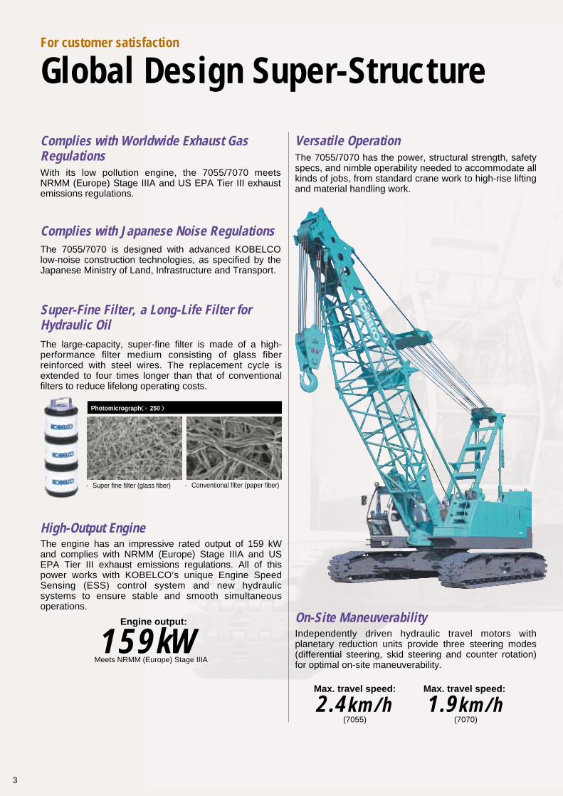
Versatile OperationThe 7055/7070 has the power, structural strength, safety specs, and nimble operability needed to accommodate all kinds of jobs, from standard crane work to high-rise lifting and material handling work.
On-Site ManeuverabilityIndependently driven hydraulic travel motors with planetary reduction units provide three steering modes (differential steering, skid steering and counter rotation) for optimal on-site maneuverability.
Engine output:
159kWMeets NRMM (Europe) Stage IIIA
Max. travel speed:
2.4km/h(7055)
Max. travel speed:
1.9km/h(7070)
3
4
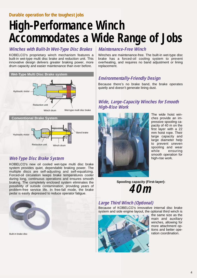
Winches with Built-In Wet-Type Disc BrakesKOBELCO's proprietary winch mechanism features a built-in wet-type multi disc brake and reduction unit. This innovative design delivers greater braking power, more drum capacity and easier maintenance than ever before.
Maintenance-Free WinchWinches are maintenance-free. The built-in wet-type disc brake has a forced-oil cooling system to prevent overheating, and requires no band adjustment or lining replacement.
Environmentally-Friendly Design
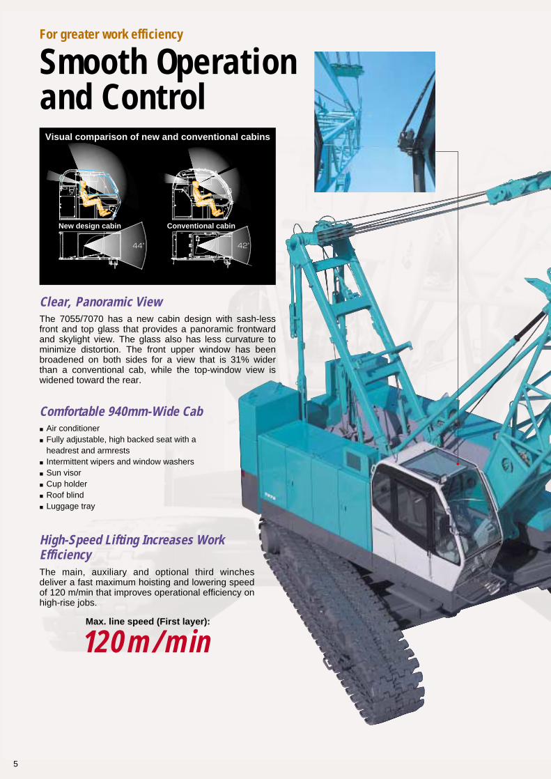
Wide, Large-Capacity Winches for Smooth High-Rise Work
Because there’s no brake band, the brake operates quietly and doesn’t generate lining dust.
The wide hoist win-ches provide an im-pressive spooling ca-pacity of 40 m on the first layer with a 22 mm hoist rope. Their large capacity and large diameter help to prevent uneven spooling and wear while ensuring smooth operation for high-rise work.
Large Third Winch (Optional)Because of KOBELCO’s innovative internal disc brake system and side engine layout, the optional third winch is
the same size as the main and auxiliary winches, allowing for more attachment op-tions and better ope-ration coordination.
Spooling capacity (First-layer):
40m
Durable operation for the toughest jobs
High-Performance Winch Accommodates a Wide Range of Jobs
KOBELCO's new oil cooled wet-type multi disc brake system provides quiet, dependable braking power. The multiple discs are self-adjusting and self-equalizing. Forced-oil circulation keeps brake temperatures cooler during long, continuous operations and ensures smooth braking. The completely enclosed system eliminates the possibility of outside contamination, providing years of problem-free service life. In free-fall mode, the brake pedal is easily depressed to reduce operator fatigue.
Wet-Type Disc Brake System
Built-in brake disc
Winch drum Wet-type multi disc brake
Reduction unit
Wet-Type Multi Disc Brake system
Hydraulic motor
Winch drum
Band brake
Reduction unit
Conventional Brake System
Hydraulic motor
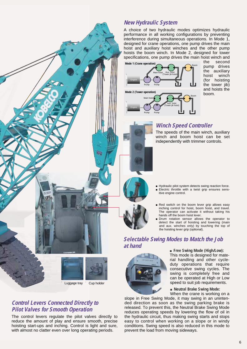
Clear, Panoramic View
Comfortable 940mm-Wide Cab
The 7055/7070 has a new cabin design with sash-less front and top glass that provides a panoramic frontward and skylight view. The glass also has less curvature to minimize distortion. The front upper window has been broadened on both sides for a view that is 31% wider than a conventional cab, while the top-window view is widened toward the rear.
High-Speed Lifting Increases WorkEfficiencyThe main, auxiliary and optional third winches deliver a fast maximum hoisting and lowering speed of 120 m/min that improves operational efficiency on high-rise jobs.
■Air conditioner■Fully adjustable, high backed seat with a headrest and armrests■Intermittent wipers and window washers■Sun visor ■Cup holder ■Roof blind■Luggage tray
For greater work efficiency
Smooth Operation and Control
Max. line speed (First layer):
120m/min
5
Visual comparison of new and conventional cabins
New design cabin Conventional cabin
New Hydraulic SystemA choice of two hydraulic modes optimizes hydraulic performance in all working configurations by preventing interference during simultaneous operations. In Mode 1, designed for crane operations, one pump drives the main hoist and auxiliary hoist winches and the other pump hoists the boom winch. In Mode 2, designed for tower specifications, one pump drives the main hoist winch and
the second pump drives the auxiliary hoist winch (for hoisting the tower jib) and hoists the boom.
Winch Speed ControllerThe speeds of the main winch, auxiliary winch and boom hoist can be set independently with trimmer controls.
■Red switch on the boom lever grip allows easy inching control for hoist, boom hoist, and travel. The operator can activate it without taking his hands off the boom hoist lever.■Drum rotation sensor allows the operator to detect the start of hoisting and lowering (main and aux. winches only) by touching the top of the hoisting lever grip (optional).
■Hydraulic pilot system detects swing reaction force. ■Electric throttle with a twist grip ensures sens- itive engine control.
Control Levers Connected Directly to Pilot Valves for Smooth OperationThe control levers regulate the pilot valves directly to reduce the amount of play and ensure smooth, precise hoisting start-ups and inching. Control is light and sure, with almost no clatter even over long operating periods.
6
Selectable Swing Modes to Match the Job at hand
■Free Swing Mode (High/Low):This mode is designed for mate-rial handling and other cycle-duty operations that require consecutive swing cycles. The swing is completely free and can be operated at High or Low speed to suit job requirements.
■Neutral Brake Swing Mode:When the crane is working on a
slope in Free Swing Mode, it may swing in an uninten-ded direction as soon as the swing parking brake is released. To prevent this, the Neutral Brake Swing Mode reduces operating speeds by lowering the flow of oil in the hydraulic circuit, thus making swing starts and stops easy to control when working on a slope or in windy conditions. Swing speed is also reduced in this mode to prevent the load from moving sideways.
■Luggage tray ■Cup holder
Mode 2 (Tower operation)
Mode 1 (Crane operation)
Engine
Main hoist
Main hoist
Pump Pump
Pump Pump
Boom
Boom
Aux. hoist(Tower jib hoist)
Aux. hoist(Tower jib hoist)
Engine
7
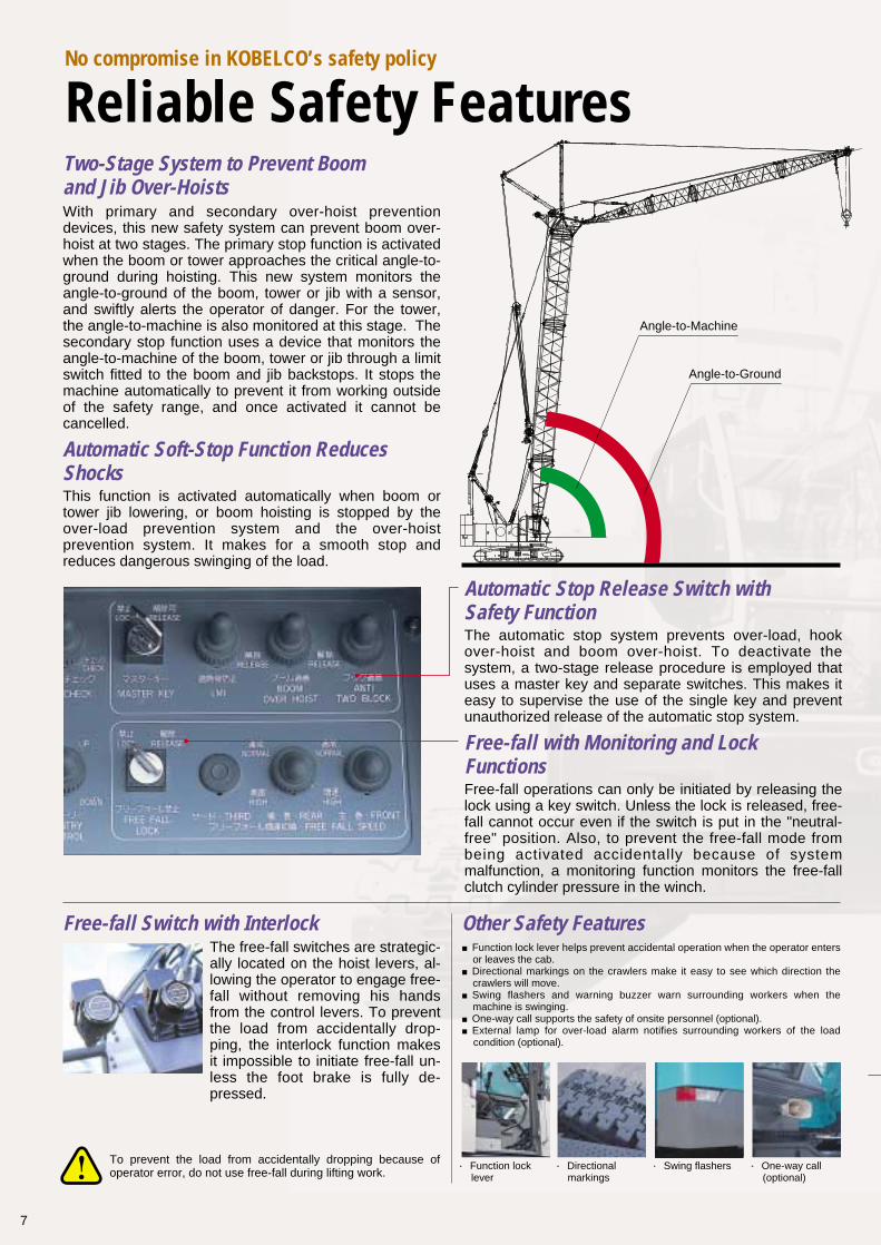
Angle-to-Machine
Angle-to-Ground
To prevent the load from accidentally dropping because of operator error, do not use free-fall during lifting work.
No compromise in KOBELCO’s safety policy
Reliable Safety FeaturesTwo-Stage System to Prevent Boom and Jib Over-HoistsWith primary and secondary over-hoist prevention devices, this new safety system can prevent boom over-hoist at two stages. The primary stop function is activated when the boom or tower approaches the critical angle-to-ground during hoisting. This new system monitors the angle-to-ground of the boom, tower or jib with a sensor, and swiftly alerts the operator of danger. For the tower, the angle-to-machine is also monitored at this stage. The secondary stop function uses a device that monitors the angle-to-machine of the boom, tower or jib through a limit switch fitted to the boom and jib backstops. It stops the machine automatically to prevent it from working outside of the safety range, and once activated it cannot be cancelled.
Automatic Stop Release Switch with Safety FunctionThe automatic stop system prevents over-load, hook over-hoist and boom over-hoist. To deactivate the system, a two-stage release procedure is employed that uses a master key and separate switches. This makes it easy to supervise the use of the single key and prevent unauthorized release of the automatic stop system.
Free-fall with Monitoring and Lock Functions Free-fall operations can only be initiated by releasing the lock using a key switch. Unless the lock is released, free-fall cannot occur even if the switch is put in the "neutral-free" position. Also, to prevent the free-fall mode from being activated accidentally because of system malfunction, a monitoring function monitors the free-fall clutch cylinder pressure in the winch.
Automatic Soft-Stop Function Reduces ShocksThis function is activated automatically when boom or tower jib lowering, or boom hoisting is stopped by the over-load prevention system and the over-hoist prevention system. It makes for a smooth stop and reduces dangerous swinging of the load.
Free-fall Switch with InterlockThe free-fall switches are strategic-ally located on the hoist levers, al-lowing the operator to engage free-fall without removing his hands from the control levers. To prevent the load from accidentally drop-ping, the interlock function makes it impossible to initiate free-fall un-less the foot brake is fully de-pressed.
●One-way call (optional)
●Function lock lever
●Directional markings
●Swing flashers
■Function lock lever helps prevent accidental operation when the operator enters or leaves the cab.■Directional markings on the crawlers make it easy to see which direction the crawlers will move.■Swing flashers and warning buzzer warn surrounding workers when the machine is swinging.■One-way call supports the safety of onsite personnel (optional).■External lamp for over-load alarm notifies surrounding workers of the load condition (optional).
Other Safety Features
8
3,200 (Transportation)
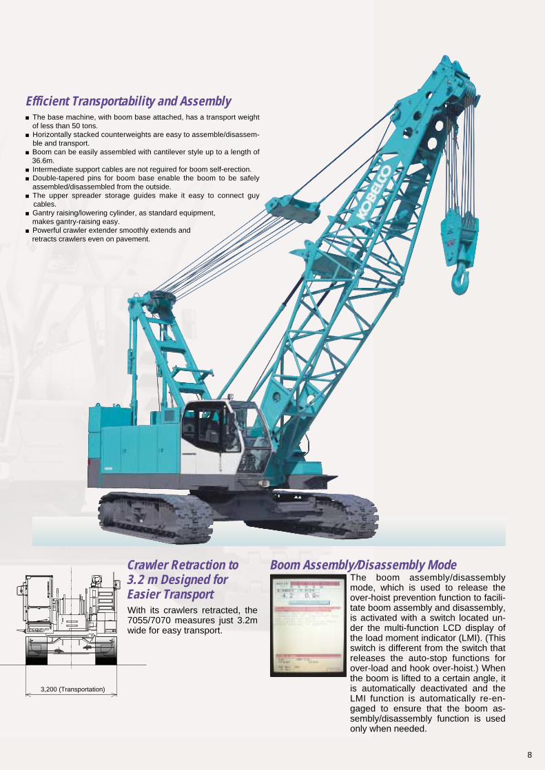
Efficient Transportability and Assembly
Boom Assembly/Disassembly ModeThe boom assembly/disassembly mode, which is used to release the over-hoist prevention function to facili-tate boom assembly and disassembly, is activated with a switch located un-der the multi-function LCD display of the load moment indicator (LMI). (This switch is different from the switch that releases the auto-stop functions for over-load and hook over-hoist.) When the boom is lifted to a certain angle, it is automatically deactivated and the LMI function is automatically re-en-gaged to ensure that the boom as-sembly/disassembly function is used only when needed.
With its crawlers retracted, the 7055/7070 measures just 3.2m wide for easy transport.
Crawler Retraction to 3.2 m Designed for Easier Transport
■The base machine, with boom base attached, has a transport weight of less than 50 tons.■Horizontally stacked counterweights are easy to assemble/disassem- ble and transport.■Boom can be easily assembled with cantilever style up to a length of 36.6m.■Intermediate support cables are not reguired for boom self-erection.■Double-tapered pins for boom base enable the boom to be safely assembled/disassembled from the outside.■The upper spreader storage guides make it easy to connect guy cables.■Gantry raising/lowering cylinder, as standard equipment, makes gantry-raising easy.■Powerful crawler extender smoothly extends and retracts crawlers even on pavement.
9
For better man-machine communication
Multi-Function LMI Display
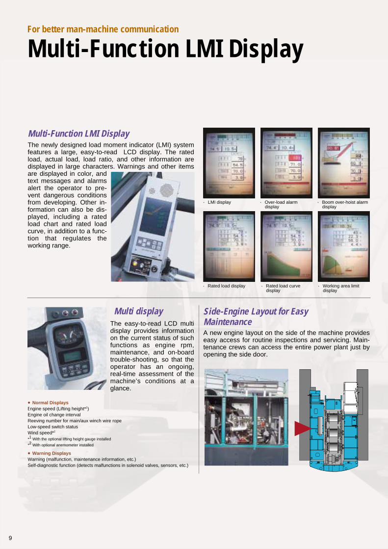
Multi-Function LMI DisplayThe newly designed load moment indicator (LMI) system features a large, easy-to-read LCD display. The rated load, actual load, load ratio, and other information are displayed in large characters. Warnings and other items are displayed in color, and text messages and alarms alert the operator to pre-vent dangerous conditions from developing. Other in-formation can also be dis-played, including a rated load chart and rated load curve, in addition to a func-tion that regulates the working range.
Multi displayThe easy-to-read LCD multi display provides information on the current status of such functions as engine rpm, maintenance, and on-board trouble-shooting, so that the operator has an ongoing, real-time assessment of the machine’s conditions at a glance.
Side-Engine Layout for Easy MaintenanceA new engine layout on the side of the machine provides easy access for routine inspections and servicing. Main-tenance crews can access the entire power plant just by opening the side door.
●LMI display ●Over-load alarm display
●Boom over-hoist alarm display
●Rated load display ●Rated load curve display
●Working area limit display
●Normal DisplaysEngine speed (Lifting height*1)Engine oil change intervalReeving number for main/aux winch wire ropeLow-speed switch statusWind speed*2
*1 With the optional lifting height gauge installed
*2 With optional anemometer installed
●Warning DisplaysWarning (malfunction, maintenance information, etc.)Self-diagnostic function (detects malfunctions in solenoid valves, sensors, etc.)
10
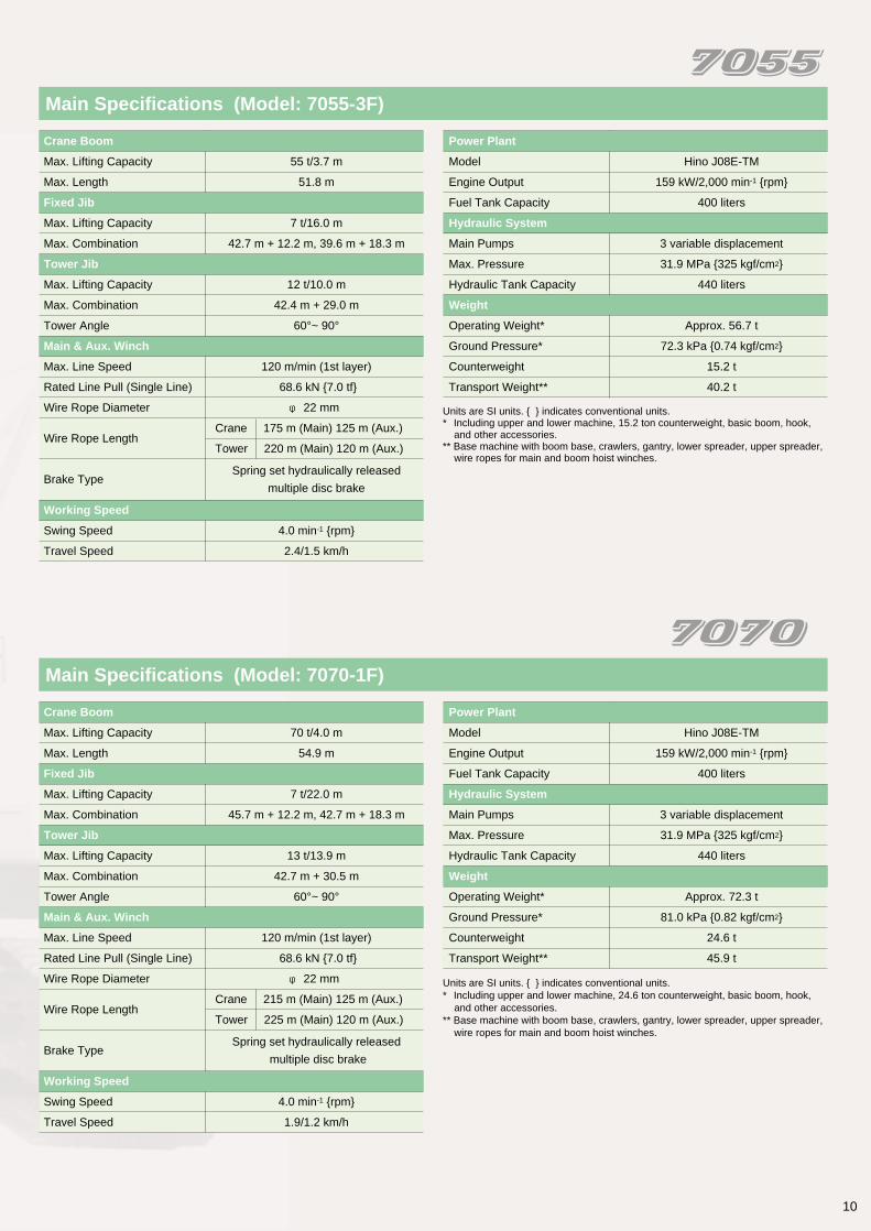
Main Specifications (Model: 7070-1F)
Crane Boom
Max. Lifting Capacity 70 t/4.0 m
Max. Length 54.9 m
Fixed Jib
Max. Lifting Capacity 7 t/22.0 m
Max. Combination 45.7 m + 12.2 m, 42.7 m + 18.3 m
Tower Jib
Max. Lifting Capacity 13 t/13.9 m
Max. Combination 42.7 m + 30.5 m
Tower Angle 60°~ 90°
Main & Aux. Winch
Max. Line Speed 120 m/min (1st layer)
Rated Line Pull (Single Line) 68.6 kN {7.0 tf}
Wire Rope Diameter φ 22 mm
Wire Rope Length
Crane 215 m (Main) 125 m (Aux.)
Tower 225 m (Main) 120 m (Aux.)
Brake TypeSpring set hydraulically released
multiple disc brake
Working Speed
Swing Speed 4.0 min-1 {rpm}
Travel Speed 1.9/1.2 km/h
Power Plant
Model Hino J08E-TM
Engine Output 159 kW/2,000 min-1 {rpm}
Fuel Tank Capacity 400 liters
Hydraulic System
Main Pumps 3 variable displacement
Max. Pressure 31.9 MPa {325 kgf/cm2}
Hydraulic Tank Capacity 440 liters
Weight
Operating Weight* Approx. 72.3 t
Ground Pressure* 81.0 kPa {0.82 kgf/cm2}
Counterweight 24.6 t
Transport Weight** 45.9 t
Units are SI units. { } indicates conventional units.* Including upper and lower machine, 24.6 ton counterweight, basic boom, hook, and other accessories. ** Base machine with boom base, crawlers, gantry, lower spreader, upper spreader, wire ropes for main and boom hoist winches.
Main Specifications (Model: 7055-3F)
Crane Boom
Max. Lifting Capacity 55 t/3.7 m
Max. Length 51.8 m
Fixed Jib
Max. Lifting Capacity 7 t/16.0 m
Max. Combination 42.7 m + 12.2 m, 39.6 m + 18.3 m
Tower Jib
Max. Lifting Capacity 12 t/10.0 m
Max. Combination 42.4 m + 29.0 m
Tower Angle 60°~ 90°
Main & Aux. Winch
Max. Line Speed 120 m/min (1st layer)
Rated Line Pull (Single Line) 68.6 kN {7.0 tf}
Wire Rope Diameter φ 22 mm
Wire Rope Length
Crane 175 m (Main) 125 m (Aux.)
Tower 220 m (Main) 120 m (Aux.)
Brake TypeSpring set hydraulically released
multiple disc brake
Working Speed
Swing Speed 4.0 min-1 {rpm}
Travel Speed 2.4/1.5 km/h
Power Plant
Model Hino J08E-TM
Engine Output 159 kW/2,000 min-1 {rpm}
Fuel Tank Capacity 400 liters
Hydraulic System
Main Pumps 3 variable displacement
Max. Pressure 31.9 MPa {325 kgf/cm2}
Hydraulic Tank Capacity 440 liters
Weight
Operating Weight* Approx. 56.7 t
Ground Pressure* 72.3 kPa {0.74 kgf/cm2}
Counterweight 15.2 t
Transport Weight** 40.2 t
Units are SI units. { } indicates conventional units.* Including upper and lower machine, 15.2 ton counterweight, basic boom, hook,
and other accessories.** Base machine with boom base, crawlers, gantry, lower spreader, upper spreader,
wire ropes for main and boom hoist winches.
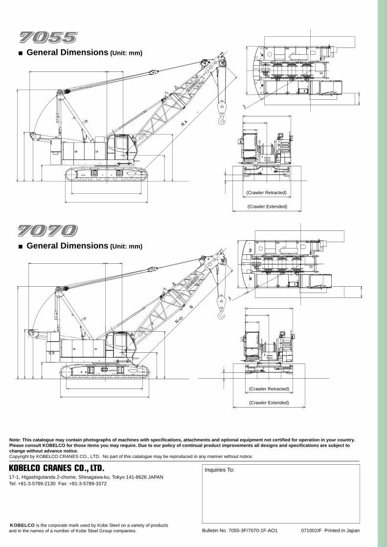
■General Dimensions (Unit: mm)
■General Dimensions (Unit: mm)
6,180
3,300
5,235 1,100
5,990
5,130
1,750
9.1m〜54.9m
3,215
1,100
1,100
3,300
6,180
1,100
1,750
5,235
3,180
3,180
2,875
9.1m~51.8m
4,720
5,570
760
3,200
R3,800
4,530 (Crawler Extended)
1,600
3,200
940
380
3,200 (Crawler Retracted)
3,200
800
R3,980
1,600
3,200
940
4,830 (Crawler Extended)
3,200 (Crawler Retracted)
390
Note: This catalogue may contain photographs of machines with specifications, attachments and optional equipment not certified for operation in your country. Please consult KOBELCO for those items you may require. Due to our policy of continual product improvements all designs and specifications are subject to change without advance notice.Copyright by KOBELCO CRANES CO., LTD. No part of this catalogue may be reproduced in any manner without notice.
17-1, Higashigotanda 2-chome, Shinagawa-ku, Tokyo 141-8626 JAPANTel: +81-3-5789-2130 Fax: +81-3-5789-3372
Bulletin No. 7055-3F/7070-1F-AO1 071001IF Printed in Japan
Inquiries To:
KOBELCO is the corporate mark used by Kobe Steel on a variety of productsand in the names of a number of Kobe Steel Group companies.