hydra - martin professional · † before connecting the hydra to power, ... a flammable alcohol...
TRANSCRIPT
Hydrauser manual
240
1040
665
548
510
370
200
387387
338338
Ø13Ø13 Ø13Ø13 Ø13Ø13
9090 9090
166166
440440
415415
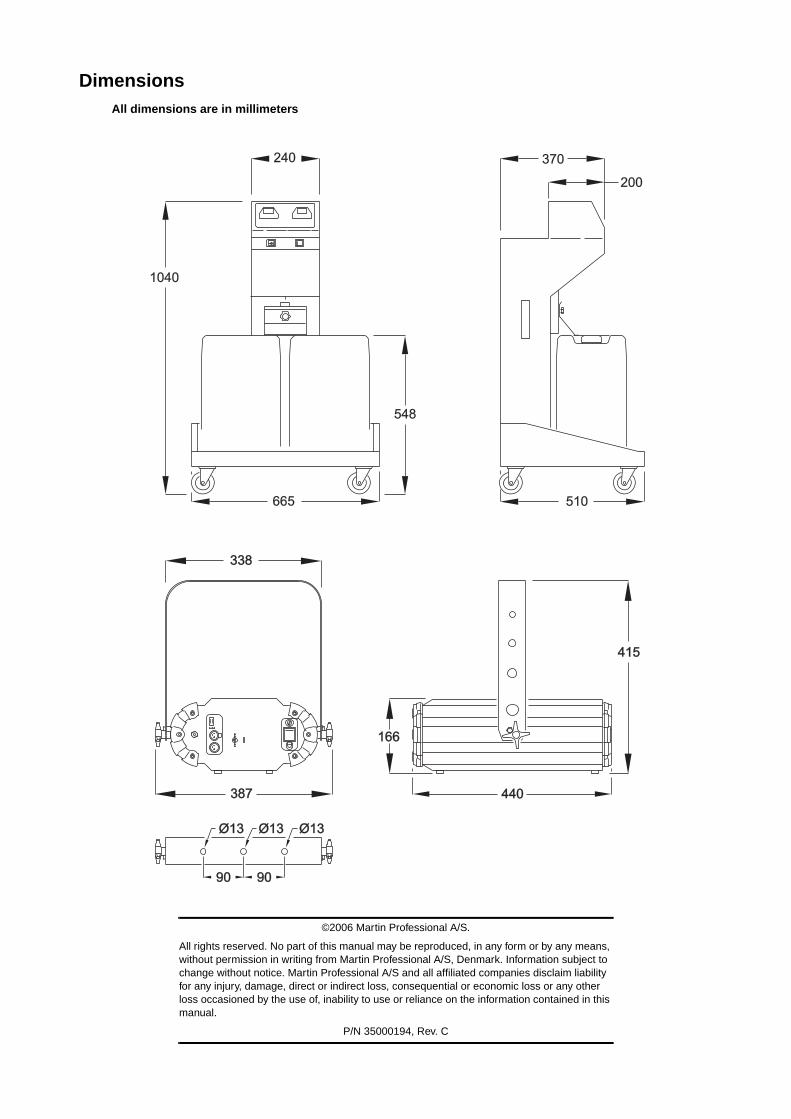
DimensionsAll dimensions are in millimeters
©2006 Martin Professional A/S.
All rights reserved. No part of this manual may be reproduced, in any form or by any means, without permission in writing from Martin Professional A/S, Denmark. Information subject to change without notice. Martin Professional A/S and all affiliated companies disclaim liability for any injury, damage, direct or indirect loss, consequential or economic loss or any other loss occasioned by the use of, inability to use or reliance on the information contained in this manual.
P/N 35000194, Rev. C
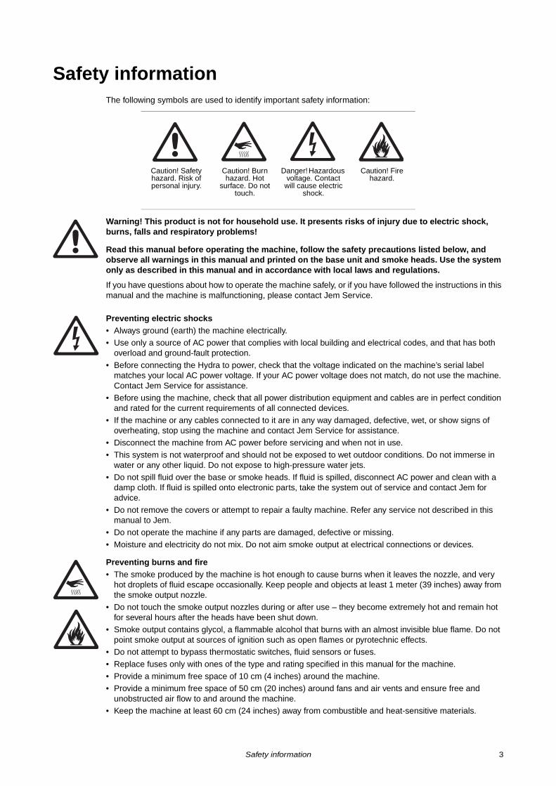
Safety informationThe following symbols are used to identify important safety information:
Warning! This product is not for household use. It presents risks of injury due to electric shock, burns, falls and respiratory problems!
Read this manual before operating the machine, follow the safety precautions listed below, and observe all warnings in this manual and printed on the base unit and smoke heads. Use the system only as described in this manual and in accordance with local laws and regulations.
If you have questions about how to operate the machine safely, or if you have followed the instructions in this manual and the machine is malfunctioning, please contact Jem Service.
Preventing electric shocks• Always ground (earth) the machine electrically.
• Use only a source of AC power that complies with local building and electrical codes, and that has both overload and ground-fault protection.
• Before connecting the Hydra to power, check that the voltage indicated on the machine’s serial label matches your local AC power voltage. If your AC power voltage does not match, do not use the machine. Contact Jem Service for assistance.
• Before using the machine, check that all power distribution equipment and cables are in perfect condition and rated for the current requirements of all connected devices.
• If the machine or any cables connected to it are in any way damaged, defective, wet, or show signs of overheating, stop using the machine and contact Jem Service for assistance.
• Disconnect the machine from AC power before servicing and when not in use.
• This system is not waterproof and should not be exposed to wet outdoor conditions. Do not immerse in water or any other liquid. Do not expose to high-pressure water jets.
• Do not spill fluid over the base or smoke heads. If fluid is spilled, disconnect AC power and clean with a damp cloth. If fluid is spilled onto electronic parts, take the system out of service and contact Jem for advice.
• Do not remove the covers or attempt to repair a faulty machine. Refer any service not described in this manual to Jem.
• Do not operate the machine if any parts are damaged, defective or missing.
• Moisture and electricity do not mix. Do not aim smoke output at electrical connections or devices.
Preventing burns and fire• The smoke produced by the machine is hot enough to cause burns when it leaves the nozzle, and very
hot droplets of fluid escape occasionally. Keep people and objects at least 1 meter (39 inches) away from the smoke output nozzle.
• Do not touch the smoke output nozzles during or after use – they become extremely hot and remain hot for several hours after the heads have been shut down.
• Smoke output contains glycol, a flammable alcohol that burns with an almost invisible blue flame. Do not point smoke output at sources of ignition such as open flames or pyrotechnic effects.
• Do not attempt to bypass thermostatic switches, fluid sensors or fuses.
• Replace fuses only with ones of the type and rating specified in this manual for the machine.
• Provide a minimum free space of 10 cm (4 inches) around the machine.• Provide a minimum free space of 50 cm (20 inches) around fans and air vents and ensure free and
unobstructed air flow to and around the machine. • Keep the machine at least 60 cm (24 inches) away from combustible and heat-sensitive materials.
Caution! Safety hazard. Risk of personal injury.
Caution! Burn hazard. Hot
surface. Do not touch.
Danger! Hazardous voltage. Contact
will cause electric shock.
Caution! Fire hazard.
Safety information 3
• Do not operate the machine if the ambient temperature (Ta) is below 5° C (41° F) or above 40° C (104° F).
• Do not operate the machine if the relative air humidity exceeds 80%.
Preventing injuries• Ensure that the surface on which the machine is installed can safely hold the weight of the machine.• Do not install the smoke heads over areas where people are present.
• Verify that the smoke heads’ temperature setting is suitable for the type of fluid in use whenever changing fluid or resetting the default menu values.
• Smoke machines can cause condensation. Do not point the output at smooth floors. Floors and surfaces may become slippery. Check these frequently and wipe dry as necessary to avoid any danger of slipping.
• Ensure at least 2m visibility in areas where smoke is being produced.
• Smoke fluid contains food-grade glycols in solution but may present health risks if swallowed. Do not drink it. Store it securely. If eye contact occurs, rinse with water. If fluid is swallowed, give water and obtain medical advice.
Preventing breathing problems• A smoke machine can operate safely only with the smoke fluid it is designed for. Use the machine only
with fluids specified under “Smoke fluid options” on page 15 or you may cause the release of toxic gases, presenting a severe health hazard. You will also probably damage the machine.
• Do not create dense smoke in confined or poorly ventilated areas.
• Do not expose people with health problems (including allergic and/or respiratory conditions such as asthma) to smoke output.
• Do not point smoke output directly at a person’s face or at face height.
Disposing of this product
Jem products are supplied in compliance with Directive 2002/96/EC of the European Parliament and of the Council of the European Union on WEEE (Waste Electrical and Electronic Equipment), as amended by Directive 2003/108/EC, where applicable.
Help preserve the environment! Ensure that this product is recycled at the end of its life. Your supplier can give details of local arrangements for the disposal of Jem products.
4 Hydra user manual
Contents
Safety information . . . . . . . . . . . . . . . . . . . . . . . . . . . . . . . . . . . . . . . . . . . . . . . . . . . . . . . . . . . 3
Product overview . . . . . . . . . . . . . . . . . . . . . . . . . . . . . . . . . . . . . . . . . . . . . . . . . . . . . . . . . . . . 7
Rear panel details . . . . . . . . . . . . . . . . . . . . . . . . . . . . . . . . . . . . . . . . . . . . . . . . . . . . . . . . . . . 8
Introduction . . . . . . . . . . . . . . . . . . . . . . . . . . . . . . . . . . . . . . . . . . . . . . . . . . . . . . . . . . . . . . . . 9Product description . . . . . . . . . . . . . . . . . . . . . . . . . . . . . . . . . . . . . . . . . . . . . . . . . . . . . . . . . 9Features at glance . . . . . . . . . . . . . . . . . . . . . . . . . . . . . . . . . . . . . . . . . . . . . . . . . . . . . . . . . 9
Installation . . . . . . . . . . . . . . . . . . . . . . . . . . . . . . . . . . . . . . . . . . . . . . . . . . . . . . . . . . . . . . . . 10Included items . . . . . . . . . . . . . . . . . . . . . . . . . . . . . . . . . . . . . . . . . . . . . . . . . . . . . . . . . . . . 10Location requirements . . . . . . . . . . . . . . . . . . . . . . . . . . . . . . . . . . . . . . . . . . . . . . . . . . . . . 10
Fluid line limits . . . . . . . . . . . . . . . . . . . . . . . . . . . . . . . . . . . . . . . . . . . . . . . . . . . . . . . . 10Head location requirements . . . . . . . . . . . . . . . . . . . . . . . . . . . . . . . . . . . . . . . . . . . . . . 11Base location requirements . . . . . . . . . . . . . . . . . . . . . . . . . . . . . . . . . . . . . . . . . . . . . . 11
Fluid line configuration . . . . . . . . . . . . . . . . . . . . . . . . . . . . . . . . . . . . . . . . . . . . . . . . . . . . . 11Fluid line components . . . . . . . . . . . . . . . . . . . . . . . . . . . . . . . . . . . . . . . . . . . . . . . . . . 11Basic fluid line configuration . . . . . . . . . . . . . . . . . . . . . . . . . . . . . . . . . . . . . . . . . . . . . 11Touring fluid line configuration . . . . . . . . . . . . . . . . . . . . . . . . . . . . . . . . . . . . . . . . . . . . 11
Fluid line connections . . . . . . . . . . . . . . . . . . . . . . . . . . . . . . . . . . . . . . . . . . . . . . . . . . . . . . 12Base connections . . . . . . . . . . . . . . . . . . . . . . . . . . . . . . . . . . . . . . . . . . . . . . . . . . . . . 12Tee connections . . . . . . . . . . . . . . . . . . . . . . . . . . . . . . . . . . . . . . . . . . . . . . . . . . . . . . 12Head connections . . . . . . . . . . . . . . . . . . . . . . . . . . . . . . . . . . . . . . . . . . . . . . . . . . . . . 12Self-seal connections . . . . . . . . . . . . . . . . . . . . . . . . . . . . . . . . . . . . . . . . . . . . . . . . . . 12
Data line configuration . . . . . . . . . . . . . . . . . . . . . . . . . . . . . . . . . . . . . . . . . . . . . . . . . . . . . 12About the data line . . . . . . . . . . . . . . . . . . . . . . . . . . . . . . . . . . . . . . . . . . . . . . . . . . . . . 12Data cable . . . . . . . . . . . . . . . . . . . . . . . . . . . . . . . . . . . . . . . . . . . . . . . . . . . . . . . . . . . 12Hydra terminators . . . . . . . . . . . . . . . . . . . . . . . . . . . . . . . . . . . . . . . . . . . . . . . . . . . . . 12Connecting the data line . . . . . . . . . . . . . . . . . . . . . . . . . . . . . . . . . . . . . . . . . . . . . . . . 13
AC power . . . . . . . . . . . . . . . . . . . . . . . . . . . . . . . . . . . . . . . . . . . . . . . . . . . . . . . . . . . . . . . 13Preparing the power cords . . . . . . . . . . . . . . . . . . . . . . . . . . . . . . . . . . . . . . . . . . . . . . 13Connecting to AC power . . . . . . . . . . . . . . . . . . . . . . . . . . . . . . . . . . . . . . . . . . . . . . . . 13Head address setting . . . . . . . . . . . . . . . . . . . . . . . . . . . . . . . . . . . . . . . . . . . . . . . . . . . 14Physical installation . . . . . . . . . . . . . . . . . . . . . . . . . . . . . . . . . . . . . . . . . . . . . . . . . . . . 14
Installing heads . . . . . . . . . . . . . . . . . . . . . . . . . . . . . . . . . . . . . . . . . . . . . . . . . . . . . . . . . . . 14
Fluid system . . . . . . . . . . . . . . . . . . . . . . . . . . . . . . . . . . . . . . . . . . . . . . . . . . . . . . . . . . . . . . . 15Smoke fluid options . . . . . . . . . . . . . . . . . . . . . . . . . . . . . . . . . . . . . . . . . . . . . . . . . . . . . . . 15
Pro Steam Simulation . . . . . . . . . . . . . . . . . . . . . . . . . . . . . . . . . . . . . . . . . . . . . . . . . . 15Regular DJ Fluid (DJ mix) . . . . . . . . . . . . . . . . . . . . . . . . . . . . . . . . . . . . . . . . . . . . . . . 15Pro Smoke Super (ZR mix) . . . . . . . . . . . . . . . . . . . . . . . . . . . . . . . . . . . . . . . . . . . . . . 15Pro Smoke High Density (SP mix) . . . . . . . . . . . . . . . . . . . . . . . . . . . . . . . . . . . . . . . . . 15
Filling the Hydra . . . . . . . . . . . . . . . . . . . . . . . . . . . . . . . . . . . . . . . . . . . . . . . . . . . . . . . . . . 15Refilling or replacing empty tanks . . . . . . . . . . . . . . . . . . . . . . . . . . . . . . . . . . . . . . . . . 15Transition between fluid types . . . . . . . . . . . . . . . . . . . . . . . . . . . . . . . . . . . . . . . . . . . . 15
Control panel . . . . . . . . . . . . . . . . . . . . . . . . . . . . . . . . . . . . . . . . . . . . . . . . . . . . . . . . . . . . . . 16Overview . . . . . . . . . . . . . . . . . . . . . . . . . . . . . . . . . . . . . . . . . . . . . . . . . . . . . . . . . . . . . . . . 16Critical settings . . . . . . . . . . . . . . . . . . . . . . . . . . . . . . . . . . . . . . . . . . . . . . . . . . . . . . . . . . . 16
Menu key . . . . . . . . . . . . . . . . . . . . . . . . . . . . . . . . . . . . . . . . . . . . . . . . . . . . . . . . . . . . 17Enter key . . . . . . . . . . . . . . . . . . . . . . . . . . . . . . . . . . . . . . . . . . . . . . . . . . . . . . . . . . . . 17Up/Down keys . . . . . . . . . . . . . . . . . . . . . . . . . . . . . . . . . . . . . . . . . . . . . . . . . . . . . . . . 17
Status messages . . . . . . . . . . . . . . . . . . . . . . . . . . . . . . . . . . . . . . . . . . . . . . . . . . . . . . . . . 17Left display . . . . . . . . . . . . . . . . . . . . . . . . . . . . . . . . . . . . . . . . . . . . . . . . . . . . . . . . . . 17Right display . . . . . . . . . . . . . . . . . . . . . . . . . . . . . . . . . . . . . . . . . . . . . . . . . . . . . . . . . 17
Menu navigation . . . . . . . . . . . . . . . . . . . . . . . . . . . . . . . . . . . . . . . . . . . . . . . . . . . . . . . . . . 17Flu (fluid control) setting . . . . . . . . . . . . . . . . . . . . . . . . . . . . . . . . . . . . . . . . . . . . . . . 18tnc (tank selection) setting . . . . . . . . . . . . . . . . . . . . . . . . . . . . . . . . . . . . . . . . . . . . . 18
Hd (head number) setting . . . . . . . . . . . . . . . . . . . . . . . . . . . . . . . . . . . . . . . . . . . . . . . 18ADR (DMX address) setting . . . . . . . . . . . . . . . . . . . . . . . . . . . . . . . . . . . . . . . . . . . . . 18Pri (base prime) command . . . . . . . . . . . . . . . . . . . . . . . . . . . . . . . . . . . . . . . . . . . . . 18
Base control menu . . . . . . . . . . . . . . . . . . . . . . . . . . . . . . . . . . . . . . . . . . . . . . . . . . . . . . . . 18PT (target pressure) setting . . . . . . . . . . . . . . . . . . . . . . . . . . . . . . . . . . . . . . . . . . . . . 19Pi (input pressure) readout . . . . . . . . . . . . . . . . . . . . . . . . . . . . . . . . . . . . . . . . . . . . . 19Po (output pressure) readout . . . . . . . . . . . . . . . . . . . . . . . . . . . . . . . . . . . . . . . . . . . . 19TP (pressure test time) setting . . . . . . . . . . . . . . . . . . . . . . . . . . . . . . . . . . . . . . . . . . . 19Td (pump time delay) setting . . . . . . . . . . . . . . . . . . . . . . . . . . . . . . . . . . . . . . . . . . . . 19rSt (reset) command . . . . . . . . . . . . . . . . . . . . . . . . . . . . . . . . . . . . . . . . . . . . . . . . . 19HOt (head temperature) setting . . . . . . . . . . . . . . . . . . . . . . . . . . . . . . . . . . . . . . . . . . 20Run (run) commands . . . . . . . . . . . . . . . . . . . . . . . . . . . . . . . . . . . . . . . . . . . . . . . . . . 20Fog (fog level) setting . . . . . . . . . . . . . . . . . . . . . . . . . . . . . . . . . . . . . . . . . . . . . . . . . 20ton (time-on) setting . . . . . . . . . . . . . . . . . . . . . . . . . . . . . . . . . . . . . . . . . . . . . . . . . . 20
Head control menu . . . . . . . . . . . . . . . . . . . . . . . . . . . . . . . . . . . . . . . . . . . . . . . . . . . . . . . . 20tof (time-off) setting . . . . . . . . . . . . . . . . . . . . . . . . . . . . . . . . . . . . . . . . . . . . . . . . . . 21ALt (alternate menu) setting . . . . . . . . . . . . . . . . . . . . . . . . . . . . . . . . . . . . . . . . . . . . 21Pri (prime fluid line) command . . . . . . . . . . . . . . . . . . . . . . . . . . . . . . . . . . . . . . . . . . 21StA (head status) readout . . . . . . . . . . . . . . . . . . . . . . . . . . . . . . . . . . . . . . . . . . . . . . 21rSt (reset) command . . . . . . . . . . . . . . . . . . . . . . . . . . . . . . . . . . . . . . . . . . . . . . . . . 21
Remote control . . . . . . . . . . . . . . . . . . . . . . . . . . . . . . . . . . . . . . . . . . . . . . . . . . . . . . . . . . . . . 22Overview . . . . . . . . . . . . . . . . . . . . . . . . . . . . . . . . . . . . . . . . . . . . . . . . . . . . . . . . . . . . . . . . 22Functions . . . . . . . . . . . . . . . . . . . . . . . . . . . . . . . . . . . . . . . . . . . . . . . . . . . . . . . . . . . . . . . 22Connection . . . . . . . . . . . . . . . . . . . . . . . . . . . . . . . . . . . . . . . . . . . . . . . . . . . . . . . . . . . . . . 22
DMX control . . . . . . . . . . . . . . . . . . . . . . . . . . . . . . . . . . . . . . . . . . . . . . . . . . . . . . . . . . . . . . . 23Overview . . . . . . . . . . . . . . . . . . . . . . . . . . . . . . . . . . . . . . . . . . . . . . . . . . . . . . . . . . . . . . . . 23DMX connection . . . . . . . . . . . . . . . . . . . . . . . . . . . . . . . . . . . . . . . . . . . . . . . . . . . . . . . . . . 23DMX address and channels . . . . . . . . . . . . . . . . . . . . . . . . . . . . . . . . . . . . . . . . . . . . . . . . . 23Command values . . . . . . . . . . . . . . . . . . . . . . . . . . . . . . . . . . . . . . . . . . . . . . . . . . . . . . . . . 23Initiating DMX operation . . . . . . . . . . . . . . . . . . . . . . . . . . . . . . . . . . . . . . . . . . . . . . . . . . . . 23
General operation . . . . . . . . . . . . . . . . . . . . . . . . . . . . . . . . . . . . . . . . . . . . . . . . . . . . . . . . . . 24Pre-operation checks . . . . . . . . . . . . . . . . . . . . . . . . . . . . . . . . . . . . . . . . . . . . . . . . . . . . . . 24Starting the Hydra for first time . . . . . . . . . . . . . . . . . . . . . . . . . . . . . . . . . . . . . . . . . . . . . . . 24Normal start procedure . . . . . . . . . . . . . . . . . . . . . . . . . . . . . . . . . . . . . . . . . . . . . . . . . . . . . 24Fluid consumption . . . . . . . . . . . . . . . . . . . . . . . . . . . . . . . . . . . . . . . . . . . . . . . . . . . . . . . . . 25Generating smoke . . . . . . . . . . . . . . . . . . . . . . . . . . . . . . . . . . . . . . . . . . . . . . . . . . . . . . . . 25Priming the fluid line . . . . . . . . . . . . . . . . . . . . . . . . . . . . . . . . . . . . . . . . . . . . . . . . . . . . . . . 26Shutting down the system . . . . . . . . . . . . . . . . . . . . . . . . . . . . . . . . . . . . . . . . . . . . . . . . . . . 26Touring with the Hydra . . . . . . . . . . . . . . . . . . . . . . . . . . . . . . . . . . . . . . . . . . . . . . . . . . . . . 26Priming the base . . . . . . . . . . . . . . . . . . . . . . . . . . . . . . . . . . . . . . . . . . . . . . . . . . . . . . . . . . 26
Basic service . . . . . . . . . . . . . . . . . . . . . . . . . . . . . . . . . . . . . . . . . . . . . . . . . . . . . . . . . . . . . . 27Cleaning . . . . . . . . . . . . . . . . . . . . . . . . . . . . . . . . . . . . . . . . . . . . . . . . . . . . . . . . . . . . . . . . 27Diagnosing leaks . . . . . . . . . . . . . . . . . . . . . . . . . . . . . . . . . . . . . . . . . . . . . . . . . . . . . . . . . 27Draining the fluid line . . . . . . . . . . . . . . . . . . . . . . . . . . . . . . . . . . . . . . . . . . . . . . . . . . . . . . 27Fuse replacement . . . . . . . . . . . . . . . . . . . . . . . . . . . . . . . . . . . . . . . . . . . . . . . . . . . . . . . . . 28
Base . . . . . . . . . . . . . . . . . . . . . . . . . . . . . . . . . . . . . . . . . . . . . . . . . . . . . . . . . . . . . . . 28Head . . . . . . . . . . . . . . . . . . . . . . . . . . . . . . . . . . . . . . . . . . . . . . . . . . . . . . . . . . . . . . . 28
Annual pressure check . . . . . . . . . . . . . . . . . . . . . . . . . . . . . . . . . . . . . . . . . . . . . . . . . . . . . 28Flushing the system . . . . . . . . . . . . . . . . . . . . . . . . . . . . . . . . . . . . . . . . . . . . . . . . . . . . . . . 28
Troubleshooting . . . . . . . . . . . . . . . . . . . . . . . . . . . . . . . . . . . . . . . . . . . . . . . . . . . . . . . . . . . . 29
System diagrams . . . . . . . . . . . . . . . . . . . . . . . . . . . . . . . . . . . . . . . . . . . . . . . . . . . . . . . . . . . 30
Specifications . . . . . . . . . . . . . . . . . . . . . . . . . . . . . . . . . . . . . . . . . . . . . . . . . . . . . . . . . . . . . . 33
6 Hydra user manual
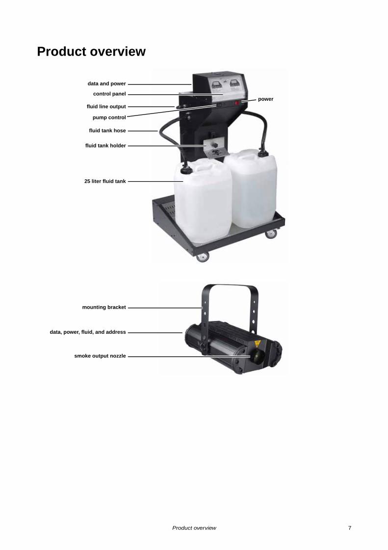
Product overview
control panel
fluid line output
fluid tank holder
fluid tank hose
25 liter fluid tank
smoke output nozzle
mounting bracket
data, power, fluid, and address
data and power
pump control
power
Product overview 7
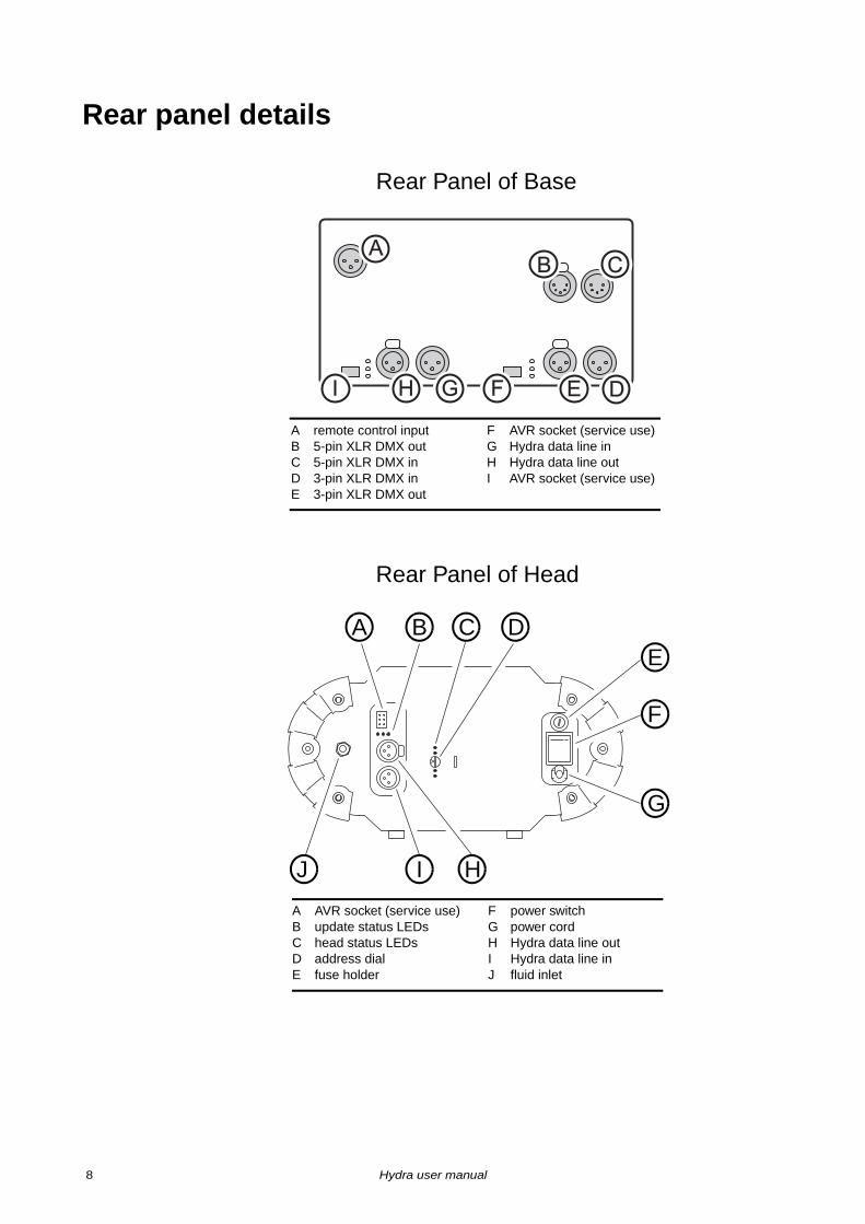
Rear panel details
A remote control inputB 5-pin XLR DMX outC 5-pin XLR DMX inD 3-pin XLR DMX inE 3-pin XLR DMX out
F AVR socket (service use)G Hydra data line inH Hydra data line outI AVR socket (service use)
AB C
DEFGI H
Rear Panel of Base
A B C DE
F
G
HIJ
A AVR socket (service use)B update status LEDsC head status LEDsD address dialE fuse holder
F power switchG power cordH Hydra data line outI Hydra data line inJ fluid inlet
Rear Panel of Head
8 Hydra user manual
Introduction
The Hydra smoke system from Jem provides a uniquely flexible and convenient solution to a wide range of smoke requirements whether permanently installed or, with the addition of the touring accessories, taken on the road.
The Hydra system can be configured with 1 to 16 smoke heads that can be up to 150 m from the Hydra’s base. Systems with less than 16 heads can be expanded at any time.
With variable-temperature heat exchangers, Hydra heads can use multiple weights of fluid. Just about anything that can be done with smoke - from an ephemeral steam chases to a dense, long-lasting “white-out” - can be achieved with the Hydra. The Hydra can even be equipped with two types of fluid simultaneously.
With the fluid reservoir located centrally at the base, keeping the machines filled couldn’t be easier. There is no need to access multiple machines in hard-to-reach corners or suspended in the rig, and the 50 liter fluid capacity provides plenty of firing time between refills. If that’s not enough, we can supply custom hoses to fit 220 liter barrels.
Equipped with the accessory flight case and self-seal connectors, touring with the Hydra is a snap. The fluid line seals itself, allowing the crew to unplug hoses along with the power and data cables after the show, roll them up, and reconnect them at the next location! The Hydra is fully operable with any DMX512 controller, and for added convenience has both 3-pin and 5-pin XLR connectors.
By the way, there is no need to worry about leaks. The Hydra is constantly on guard, monitoring the fluid line pressure whenever the heads are idle. If a leak should occur, the Hydra will detect it and shut itself down.
Congratulations on your purchase of the Hydra smoke system from Jem. Details of the full range of Jem products are available on our website at www.jemsmoke.com.
The Hydra features:
• Dual 25 liter fluid tanks
• Automatic tank change • Leak detection system
• Automatic out-of-fluid detection and shutdown
• Remote on/off control of heat exchangers• Continuous operation
• Flexible 1 to 16 head configuration
• Two fluid runs of up to 150 m• Compatibility with multiple Jem fluids
• DMX-512 control
• Optional touring kit
• Optional Jem remote control
P r o d u c t d e s c r i p t i o n
F e a t u r e s a t g l a n c e
Introduction 9
InstallationDANGER! DO NOT install or operate the Hydra until you have read and observed all the precautions listed in “Safety information” on page 3.
The standard Hydra system is supplied with:
• Hydra base• Hydra smoke heads
• 2 x 25L fluid tanks (empty)
• 10mm OD fluid line (2 x 30m)• 6mm OD fluid line x 10m (1 per head)
• 10mm push-in Tee connector (1 per head)
• 10mm to 6mm push-in adaptor (1 per head) • 10mm cap plugs x 2
• Hydra data line terminators (1 male, 1 female)
• User manual
Unpack the system’s components and check for signs of damage.
Fluid l ine l imits
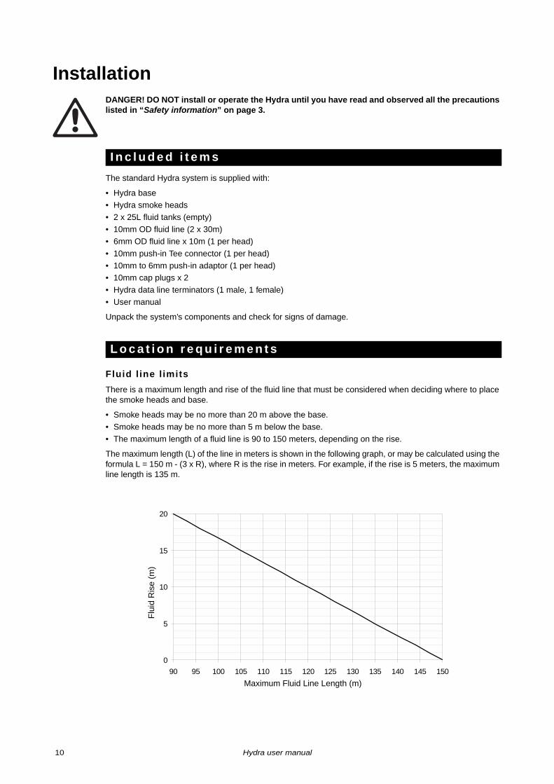
There is a maximum length and rise of the fluid line that must be considered when deciding where to place the smoke heads and base.
• Smoke heads may be no more than 20 m above the base.
• Smoke heads may be no more than 5 m below the base.
• The maximum length of a fluid line is 90 to 150 meters, depending on the rise.
The maximum length (L) of the line in meters is shown in the following graph, or may be calculated using the formula L = 150 m - (3 x R), where R is the rise in meters. For example, if the rise is 5 meters, the maximum line length is 135 m.
I n c l u d e d i t e m s
L o c a t i o n r e q u i r e m e n t s
0
5
10
15
20
90 95 100 105 110 115 120 125 130 135 140 145 150Maximum Fluid Line Length (m)
Flu
id R
ise
(m)
10 Hydra user manual
Head location requirements
The Hydra head’s nozzle can reach 220°C (428° F). The heads must be positioned well out of reach of the public, so that accidental contact with the head is impossible. Install the Hydra heads in dry locations that
• are not directly above publicly trafficked areas, • prevent accidental contact,
• comply with all safety requirements listed in the section starting on page 3.
The Hydra heads require space on all sides for safety and ventilation. Ensure that there is a minimum free space of 10 cm (4 inches) on all sides of the head, minimum 50 cm (20 inches) unobstructed airflow around the air vents, minimum 60 cm (24 inches) distance to combustible and heat-sensitive materials, and minimum 1 m (40 inches) free space in front of the smoke output nozzle.
Base location requirements
Locate the Hydra base in a dry location, on a level surface, with controlled access if operation is to be unattended.
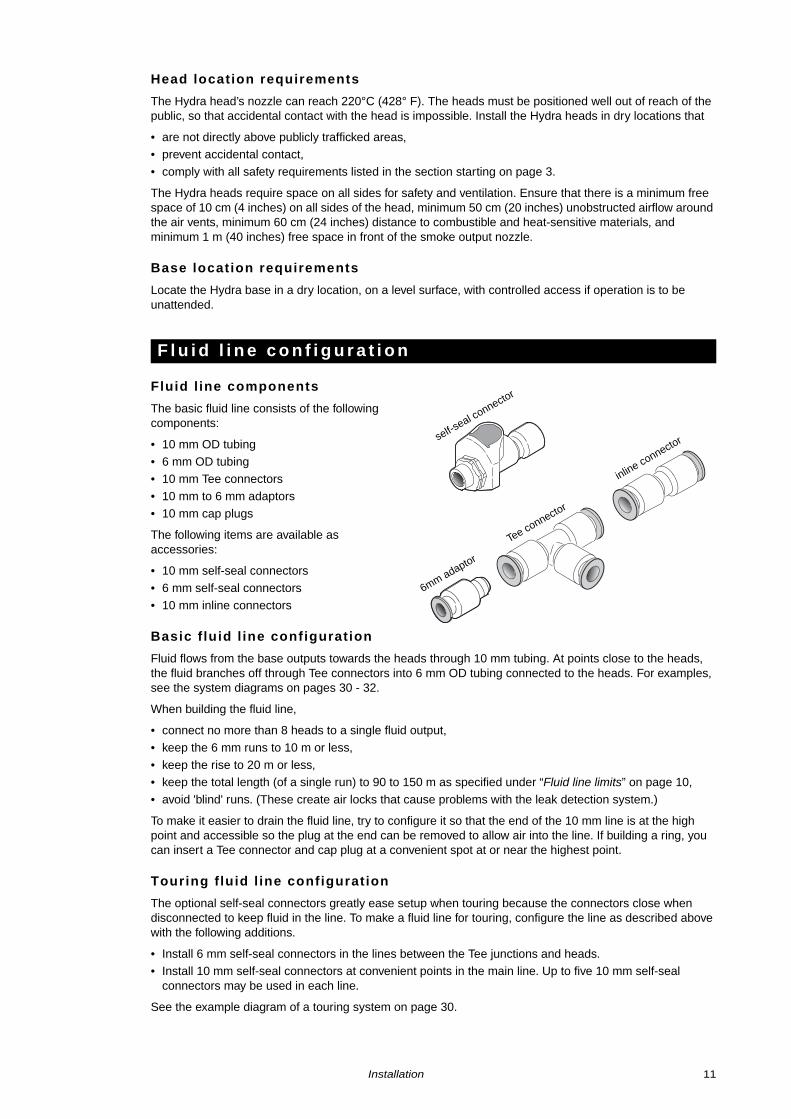
Fluid l ine components
The basic fluid line consists of the following components:
• 10 mm OD tubing
• 6 mm OD tubing• 10 mm Tee connectors
• 10 mm to 6 mm adaptors
• 10 mm cap plugs
The following items are available as accessories:
• 10 mm self-seal connectors
• 6 mm self-seal connectors
• 10 mm inline connectors
Basic f luid l ine configuration
Fluid flows from the base outputs towards the heads through 10 mm tubing. At points close to the heads, the fluid branches off through Tee connectors into 6 mm OD tubing connected to the heads. For examples, see the system diagrams on pages 30 - 32.
When building the fluid line,
• connect no more than 8 heads to a single fluid output,
• keep the 6 mm runs to 10 m or less,
• keep the rise to 20 m or less,• keep the total length (of a single run) to 90 to 150 m as specified under “Fluid line limits” on page 10,
• avoid 'blind' runs. (These create air locks that cause problems with the leak detection system.)
To make it easier to drain the fluid line, try to configure it so that the end of the 10 mm line is at the high point and accessible so the plug at the end can be removed to allow air into the line. If building a ring, you can insert a Tee connector and cap plug at a convenient spot at or near the highest point.
Touring f luid l ine configuration
The optional self-seal connectors greatly ease setup when touring because the connectors close when disconnected to keep fluid in the line. To make a fluid line for touring, configure the line as described above with the following additions.
• Install 6 mm self-seal connectors in the lines between the Tee junctions and heads. • Install 10 mm self-seal connectors at convenient points in the main line. Up to five 10 mm self-seal
connectors may be used in each line.
See the example diagram of a touring system on page 30.
F l u i d l i n e c o n f i g u r a t i o n
6mm adaptor
Tee connector
inline connectorself-seal connector
Installation 11
Base connections
The tube end must be cut cleanly and squarely to form a good seal with the “push-in” type connection at the base fluid outputs. To connect, simply push the 10 mm tube firmly into the fluid output as far as it will go: the outer ring clamps it in place. To disconnect, press in the outer ring while pulling on the tube.
Tee connections
The Tee connectors receive 10 mm OD tubing and have the same push in connection as the base fluid outputs. Clean and square tube ends are required for a tight seal.
• To connect 10 mm tubing, simply press the end firmly into the connector as far as it will go.
• To connect 6 mm tubing, press the tubing into a 6 mm adaptor, then insert the adaptor into the Tee connector.
• To close an unused branch, press in a 10 mm cap plug.
Head connections
To connect 6 mm tubing to a head, prepare the end by cutting it clean and square. Loosen the clamp nut on the head fitting and push the tubing onto the fitting as far as it will go. Tighten the clamp nut.
Self-seal connections
The threads of the self-seal connectors can be cross-threaded if care is not used. Install self-seal connectors as follows.
1. Trim the tube ends clean and square.
2. Loosen, but do not remove, the clamp nuts on each half of the connector.
3. Press the tubing fully onto the fitting and tighten the clamp nuts.
About the data l ine
The Hydra system uses a dedicated bidirectional data line for communication between the base and heads. The data line connects the Hydra base and heads in series, with a data cable going from the “Out” socket of one device to the “In” socket of the next device until all devices are connected. As shown in the diagrams on pages 30 - 32, the base may be located at any point in the data line, which may be up to 300 m in length.
The Hydra data line is similar to the DMX data transmission system. Because the Hydra data line is bidirectional, however, DMX line accessories such as line splitters and amplifiers will not work.
Data cable
The Hydra system requires data cables designed for RS-485 use, available from your Jem dealer, to connect the base with the heads. Audio cable may work to some degree, but it is not designed for data transmission and its use may result in erratic performance.
The Hydra data line uses 3-pin XLR connectors with the data pair connected to pins 2 and 3. The cable shield is connected to pin 1.
Hydra terminators
The Hydra data line must be terminated on each end to prevent interference from reflected data signals using Hydra terminators. The terminators are 3-pin XLR connectors with an electronic circuit that is designed specifically for the Hydra system.
Two Hydra XLR terminators, one male and one female, are included. They have a red band on the casing to distinguish them from the typical 120 ohm terminators commonly used in DMX systems.
Important! DMX terminators are incompatible and will cause problems if used in the Hydra data line.
F l u i d l i n e c o n n e c t i o n s
D a t a l i n e c o n f i g u r a t i o n
12 Hydra user manual
Connecting the data l ine
The data line can be connected as follows.
1. Starting at the head furthest from the base, plug the male Hydra terminator into the head’s HP data “Out” socket. Plug the female end of a data cable into the head’s “In” socket.
2. Lead the data cable to the next head and plug the cable into its “Out” socket. Plug another cable into the head’s “In” socket.
3. Continue connecting heads “In” to “Out”, working towards the base.
4. When you get to the base, connect the data cable to the HP data “Out” socket.
5. If the base is at the end of the data line, as shown on page 30, plug the female Hydra terminator into the HP data “In” socket and stop here. If the base is in the middle of the line as shown on page 31, plug the female end of a data cable into the “In” socket and continue with the next step.
6. Lead the data cable to the next head and plug it into the “Out” socket. Plug another cable into its “In” socket.
7. Continue connecting heads “In” to “Out”, working away from the base.
8. At the last head, connect the data cable to the “Out” socket. Plug the female Hydra terminator into the last head’s “In” socket.
Preparing the power cords
Before using the machine, grounding-type (earthed) power plugs that fit the local power outlets must be obtained locally and installed on the power cables.
DANGER! Make sure the power plug is correctly rated:
• 115 V models must be fitted with a plug rated 20 amp minimum• 230 V models must be fitted with a plug rated 10 amp minimum
When installing the plug, follow the plug manufacturer’s instructions and connect pins as follows: yellow and green wire to ground (earth), blue wire to neutral and brown wire to live.
The table below shows some common pin identification schemes.
Connecting to AC power
The Hydra is available in models designed for 115 V or 230 V nominal AC power supplies. The voltage and current requirements for each model of the head and base are stated on pages 33 and 34.
Before connecting the Hydra system to power, verify that the AC supply is adequately dimensioned for the current draw of all connected devices and that the your the local AC voltage is appropriate for your model, as indicated on the machine’s serial number label. If your AC voltage is outside the appropriate range, do not use the machine. Contact Jem Service for assistance.
A C p o w e r
Wire Pin Marking Screw color
brown live “L” yellow or brass
blue neutral “N” silver
yellow/green ground (earth) green
Installation 13
Head address sett ing
Each Hydra head must be assigned a unique address to identify it within the system. The address is set with the 16-position dial on the rear panel.
The head’s Hydra address determines its DMX address and its firing order in the sequences described under “ALt (alternate menu) setting” on page 21. The Hydra address order is 0 to 9, A, B, C, D, E, F.
Starting with any head in the system, give each one a unique address starting from 0.
Physical instal lat ion
The Hydra heads may be suspended in any orientation from a suitable support by means of its adjustable mounting bracket.
Warning! Block access below the work area and work from a stable platform when installing.
Warning! Always use a secure means of secondary attachment that can hold at least 10 times the weight of the head.
Suspend Hydra heads as follows.
1. If using a rigging clamp (not included), verify that the clamp is undamaged and can bear at least 10 times the head’s weight. Bolt the clamp securely to the mounting bracket with a grade 8.8 (minimum) M12 bolt and lock nut, or as recommended by the clamp manufacturer, through the 13 mm hole in the center of the mounting bracket.
2. If fastening the heads directly to a mounting surface using the adjustable mounting bracket, verify that all fasteners used and the mounting surface can bear at least 10 times the head’s weight.
3. Verify that the structure used to support the smoke machine can support at least 10 times the total weight of all installed equipment, cables, etc.
4. Install a safety wire that can hold at least 10 times the weight of the smoke machine through/over the support and under the mounting bracket.
5. Loosen the swivel locks and position the head as desired. Turn the swivel locks clockwise to tighten. Verify that the smoke machine is securely installed.
I n s t a l l i n g h e a d s
14 Hydra user manual
Fluid systemDANGER! The Hydra can run safely only on the specific smoke fluids it is designed for. Use ONLY the Jem smoke fluids designated in this manual. NEVER use any other type of fluid, or toxic gas may be produced. You will probably also cause damage to the system that is not covered by the product warranty. Do not dilute smoke fluid with water or any other liquid. Discard smoke fluid if it becomes contaminated.
Jem supplies high quality fog fluids that are based on ultra-pure deionized water. Use only the following genuine Jem fog fluids. No other fluid is suitable for use.
Pro Steam Simulation
Pro Steam Simulation fluid is a light fluid that produces well-defined cones of steam that disperse quickly. It is ideal for chase effects and theatrical use. When using Pro Steam Simulation fluid, the head temperature must be set to LO .
Regular DJ Fluid (DJ mix)
Regular DJ fluid is an economical fluid that gives a good, medium density smoke well-suited for atmospheric effects. When using DJ mix, the head temperature must be set to nor .
Pro Smoke Super (ZR mix)
Pro Smoke Super fluid is a high-quality, general purpose fluid that produces a dense white air-born fog with medium dispersal time. Its medium to high index of refraction permits both good atmospheric effects and denser “white-outs”. When using ZR mix, the head temperature must be set to Hi .
Pro Smoke High Density (SP mix)
Pro Smoke High Density fluid generates a high density, white, air-born fog with a very high index of refraction and slow evaporation rate. It is well suited for scenic obscuring, dramatic strobe effects, and “white-outs”. When using SP mix, head temperature must be set to Hi .
Refi l l ing or replacing empty tanks
Replace empty fluid tanks as follows.
1. Loosen the cap fitting and remove the hoses from the depleted tank, using care to keep the hose and filter clean.
2. Loosen and raise the fluid tank holder. Remove the empty tank and replace it with a fresh one.
3. Place the fluid hose in the fresh tank and screw on the cap.
4. Lower and tighten the fluid tank holder.
5. Prime the base as described on page 26.
Transit ion between f luid types
The transition between two fluid types will be delayed due to the residual fluid in the delivery line. If the delay is unacceptable, you can drain the fluid line when changing fluids as described on page 27.
If the two fluids require different head temperature settings, use the lower temperature during the transition. If the new fluid requires a higher temperature, wait until it is apparent that the fluid has reached all heads to raise the setting.
If you equip the Hydra with two different types of fluid at the same time, use the manual tank change fluid setting to prevent automatic changeover.
S m o k e f l u i d o p t i o n s
F i l l i n g t h e H y d r a
Fluid system 15
Control panel
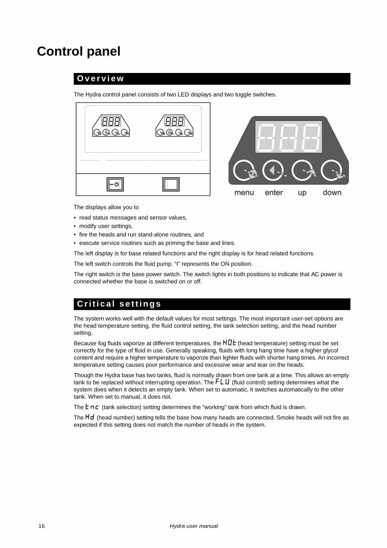
The Hydra control panel consists of two LED displays and two toggle switches.
The displays allow you to
• read status messages and sensor values,
• modify user settings,
• fire the heads and run stand-alone routines, and • execute service routines such as priming the base and lines.
The left display is for base related functions and the right display is for head related functions.
The left switch controls the fluid pump. “I” represents the ON position.
The right switch is the base power switch. The switch lights in both positions to indicate that AC power is connected whether the base is switched on or off.
The system works well with the default values for most settings. The most important user-set options are the head temperature setting, the fluid control setting, the tank selection setting, and the head number setting.
Because fog fluids vaporize at different temperatures, the HOT (head temperature) setting must be set correctly for the type of fluid in use. Generally speaking, fluids with long hang time have a higher glycol content and require a higher temperature to vaporize than lighter fluids with shorter hang times. An incorrect temperature setting causes poor performance and excessive wear and tear on the heads.
Though the Hydra base has two tanks, fluid is normally drawn from one tank at a time. This allows an empty tank to be replaced without interrupting operation. The FLu (fluid control) setting determines what the system does when it detects an empty tank. When set to automatic, it switches automatically to the other tank. When set to manual, it does not.
The tnc (tank selection) setting determines the “working” tank from which fluid is drawn.
The Hd (head number) setting tells the base how many heads are connected. Smoke heads will not fire as expected if this setting does not match the number of heads in the system.
O v e r v i e w
C r i t i c a l s e t t i n g s
��� ���
���
menu enter up down
16 Hydra user manual
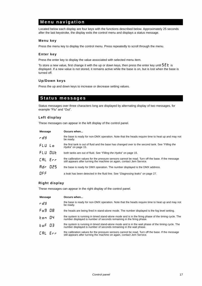
Located below each display are four keys with the functions described below. Approximately 25 seconds after the last keystroke, the display exits the control menu and displays a status message.
Menu key
Press the menu key to display the control menu. Press repeatedly to scroll through the menu.
Enter key
Press the enter key to display the value associated with selected menu item.
To store a new value, first change it with the up or down keys, then press the enter key until SEt is displayed. If a new value is not stored, it remains active while the base is on, but is lost when the base is turned off.
Up/Down keys
Press the up and down keys to increase or decrease setting values.
Status messages over three characters long are displayed by alternating display of two messages, for example “Flu” and “Out”.
Left display
These messages can appear in the left display of the control panel.
Right display
These messages can appear in the right display of the control panel.
M e n u n a v i g a t i o n
S t a t u s m e s s a g e s
Message Occurs when...
rdythe base is ready for non-DMX operation. Note that the heads require time to heat up and may not be ready.
fLu Lothe first tank is out of fluid and the base has changed over to the second tank. See “Filling the Hydra” on page 15.
FLu OUT both tanks are out of fluid. See “Filling the Hydra” on page 15.
CaL Errthe calibration values for the pressure sensors cannot be read. Turn off the base. If the message still appears after turning the machine on again, contact Jem Service.
Adr 025 the base is ready for DMX operation. The number displayed is the DMX address.
OFF a leak has been detected in the fluid line. See “Diagnosing leaks” on page 27.
Message Occurs when...
rdythe base is ready for non-DMX operation. Note that the heads require time to heat up and may not be ready.
Fog 08 the heads are being fired in stand-alone mode. The number displayed is the fog level setting.
ton 04the system is running in timed stand-alone mode and is in the firing phase of the timing cycle. The number displayed is number of seconds remaining in the firing phase.
toF 03the system is running in timed stand-alone mode and is in the wait phase of the timing cycle. The number displayed is number of seconds remaining in the wait phase.
CaL Errthe calibration values for the pressure sensors cannot be read. Turn off the base. If the message still appears after turning the machine on again, contact Jem Service.
Control panel 17
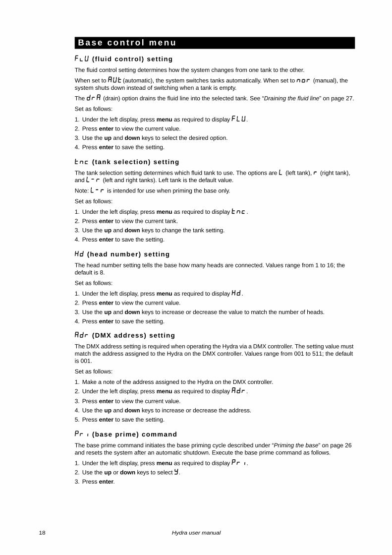
Flu ( f luid control) sett ing
The fluid control setting determines how the system changes from one tank to the other.
When set to Aut (automatic), the system switches tanks automatically. When set to nor (manual), the system shuts down instead of switching when a tank is empty.
The drA (drain) option drains the fluid line into the selected tank. See “Draining the fluid line” on page 27.
Set as follows:
1. Under the left display, press menu as required to display FLU .
2. Press enter to view the current value.
3. Use the up and down keys to select the desired option.
4. Press enter to save the setting.
tnc ( tank selection) sett ing
The tank selection setting determines which fluid tank to use. The options are L (left tank), R (right tank), and L-R (left and right tanks). Left tank is the default value.
Note: L-R is intended for use when priming the base only.
Set as follows:
1. Under the left display, press menu as required to display tnc .
2. Press enter to view the current tank.
3. Use the up and down keys to change the tank setting.
4. Press enter to save the setting.
Hd (head number) sett ing
The head number setting tells the base how many heads are connected. Values range from 1 to 16; the default is 8.
Set as follows:
1. Under the left display, press menu as required to display Hd .
2. Press enter to view the current value.
3. Use the up and down keys to increase or decrease the value to match the number of heads.
4. Press enter to save the setting.
ADR (DMX address) sett ing
The DMX address setting is required when operating the Hydra via a DMX controller. The setting value must match the address assigned to the Hydra on the DMX controller. Values range from 001 to 511; the default is 001.
Set as follows:
1. Make a note of the address assigned to the Hydra on the DMX controller.
2. Under the left display, press menu as required to display adr .
3. Press enter to view the current value.
4. Use the up and down keys to increase or decrease the address.
5. Press enter to save the setting.
Pri (base prime) command
The base prime command initiates the base priming cycle described under “Priming the base” on page 26 and resets the system after an automatic shutdown. Execute the base prime command as follows.
1. Under the left display, press menu as required to display pri .
2. Use the up or down keys to select y.
3. Press enter.
B a s e c o n t r o l m e n u
18 Hydra user manual
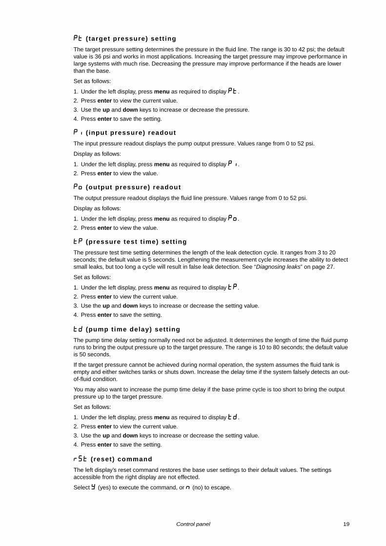
PT ( target pressure) sett ing
The target pressure setting determines the pressure in the fluid line. The range is 30 to 42 psi; the default value is 36 psi and works in most applications. Increasing the target pressure may improve performance in large systems with much rise. Decreasing the pressure may improve performance if the heads are lower than the base.
Set as follows:
1. Under the left display, press menu as required to display pt .
2. Press enter to view the current value.
3. Use the up and down keys to increase or decrease the pressure.
4. Press enter to save the setting.
Pi ( input pressure) readout
The input pressure readout displays the pump output pressure. Values range from 0 to 52 psi.
Display as follows:
1. Under the left display, press menu as required to display Pi .
2. Press enter to view the value.
Po (output pressure) readout
The output pressure readout displays the fluid line pressure. Values range from 0 to 52 psi.
Display as follows:
1. Under the left display, press menu as required to display Po .
2. Press enter to view the value.
TP (pressure test t ime) sett ing
The pressure test time setting determines the length of the leak detection cycle. It ranges from 3 to 20 seconds; the default value is 5 seconds. Lengthening the measurement cycle increases the ability to detect small leaks, but too long a cycle will result in false leak detection. See “Diagnosing leaks” on page 27.
Set as follows:
1. Under the left display, press menu as required to display Tp .
2. Press enter to view the current value.
3. Use the up and down keys to increase or decrease the setting value.
4. Press enter to save the setting.
Td (pump time delay) sett ing
The pump time delay setting normally need not be adjusted. It determines the length of time the fluid pump runs to bring the output pressure up to the target pressure. The range is 10 to 80 seconds; the default value is 50 seconds.
If the target pressure cannot be achieved during normal operation, the system assumes the fluid tank is empty and either switches tanks or shuts down. Increase the delay time if the system falsely detects an out-of-fluid condition.
You may also want to increase the pump time delay if the base prime cycle is too short to bring the output pressure up to the target pressure.
Set as follows:
1. Under the left display, press menu as required to display td .
2. Press enter to view the current value.
3. Use the up and down keys to increase or decrease the setting value.
4. Press enter to save the setting.
rSt (reset) command
The left display’s reset command restores the base user settings to their default values. The settings accessible from the right display are not effected.
Select y (yes) to execute the command, or n (no) to escape.
Control panel 19
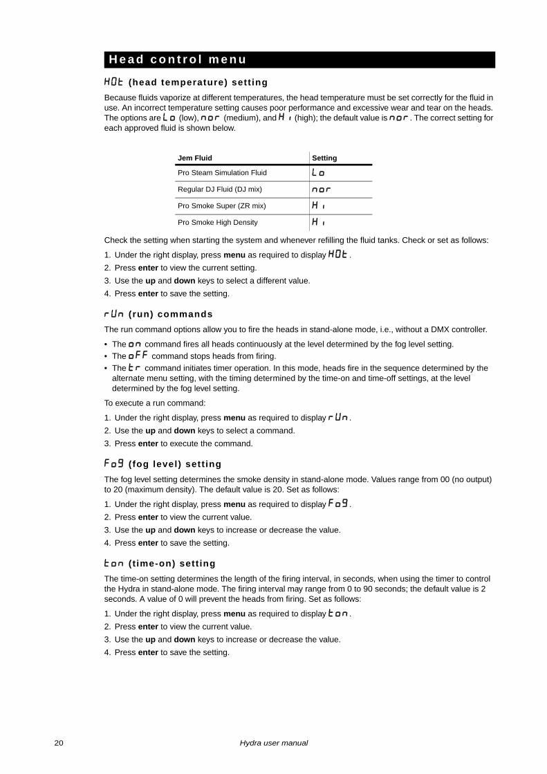
HOt (head temperature) sett ing
Because fluids vaporize at different temperatures, the head temperature must be set correctly for the fluid in use. An incorrect temperature setting causes poor performance and excessive wear and tear on the heads. The options are Lo (low), nor (medium), and Hi (high); the default value is nor. The correct setting for each approved fluid is shown below.
Check the setting when starting the system and whenever refilling the fluid tanks. Check or set as follows:
1. Under the right display, press menu as required to display HOt .
2. Press enter to view the current setting.
3. Use the up and down keys to select a different value.
4. Press enter to save the setting.
Run (run) commands
The run command options allow you to fire the heads in stand-alone mode, i.e., without a DMX controller.
• The on command fires all heads continuously at the level determined by the fog level setting.• The off command stops heads from firing.
• The tr command initiates timer operation. In this mode, heads fire in the sequence determined by the alternate menu setting, with the timing determined by the time-on and time-off settings, at the level determined by the fog level setting.
To execute a run command:
1. Under the right display, press menu as required to display run .
2. Use the up and down keys to select a command.
3. Press enter to execute the command.
Fog ( fog level) sett ing
The fog level setting determines the smoke density in stand-alone mode. Values range from 00 (no output) to 20 (maximum density). The default value is 20. Set as follows:
1. Under the right display, press menu as required to display Fog .
2. Press enter to view the current value.
3. Use the up and down keys to increase or decrease the value.
4. Press enter to save the setting.
ton ( t ime-on) sett ing
The time-on setting determines the length of the firing interval, in seconds, when using the timer to control the Hydra in stand-alone mode. The firing interval may range from 0 to 90 seconds; the default value is 2 seconds. A value of 0 will prevent the heads from firing. Set as follows:
1. Under the right display, press menu as required to display ton .
2. Press enter to view the current value.
3. Use the up and down keys to increase or decrease the value.
4. Press enter to save the setting.
H e a d c o n t r o l m e n u
Jem Fluid Setting
Pro Steam Simulation Fluid Lo
Regular DJ Fluid (DJ mix) nor
Pro Smoke Super (ZR mix) Hi
Pro Smoke High Density Hi
20 Hydra user manual
tof ( t ime-off) sett ing
The time-off setting determines the wait interval when using the timer to control the Hydra in stand-alone mode. The wait interval may range from 0 to 90 seconds; the default value is 2 seconds. Set as follows:
1. Under the right display, press menu as required to display tof .
2. Press enter to view the current value.
3. Use the up and down keys to increase or decrease the value.
4. Press enter to save the setting.
ALt (alternate menu) sett ing
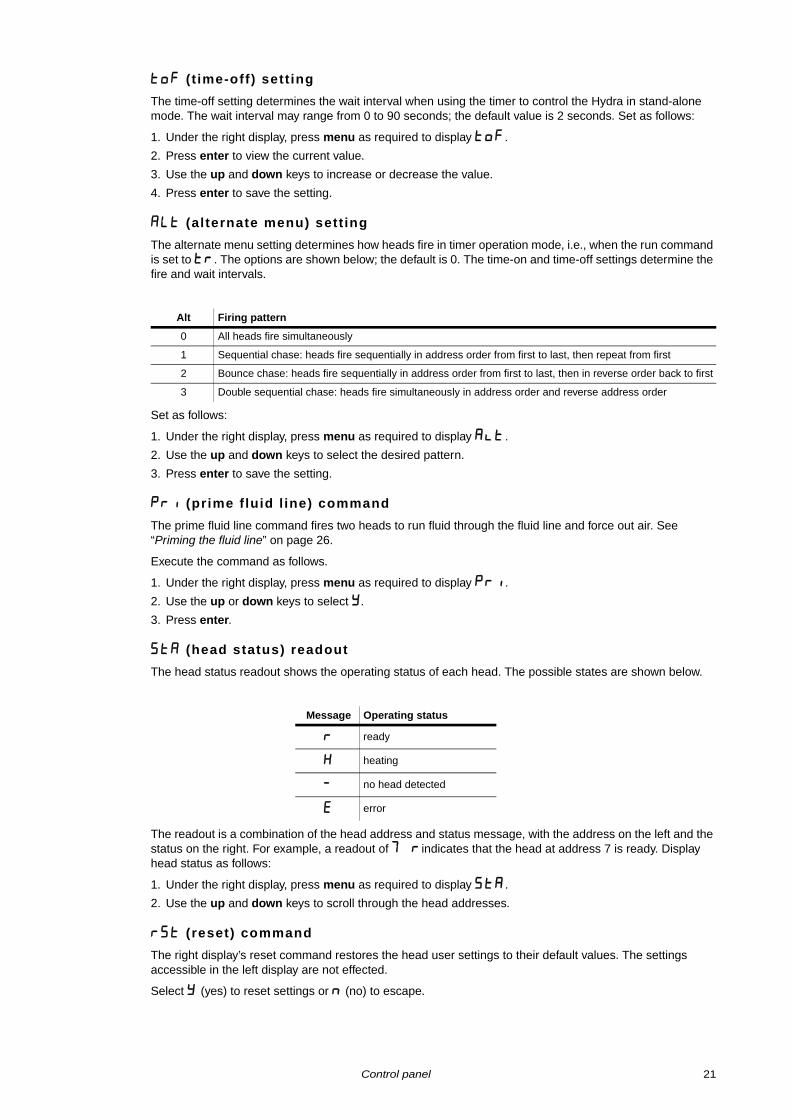
The alternate menu setting determines how heads fire in timer operation mode, i.e., when the run command is set to tr. The options are shown below; the default is 0. The time-on and time-off settings determine the fire and wait intervals.
Set as follows:
1. Under the right display, press menu as required to display Alt .
2. Use the up and down keys to select the desired pattern.
3. Press enter to save the setting.
Pri (prime f luid l ine) command
The prime fluid line command fires two heads to run fluid through the fluid line and force out air. See “Priming the fluid line” on page 26.
Execute the command as follows.
1. Under the right display, press menu as required to display pri .
2. Use the up or down keys to select y.
3. Press enter.
StA (head status) readout
The head status readout shows the operating status of each head. The possible states are shown below.
The readout is a combination of the head address and status message, with the address on the left and the status on the right. For example, a readout of 7 R indicates that the head at address 7 is ready. Display head status as follows:
1. Under the right display, press menu as required to display StA .
2. Use the up and down keys to scroll through the head addresses.
rSt (reset) command
The right display’s reset command restores the head user settings to their default values. The settings accessible in the left display are not effected.
Select y (yes) to reset settings or n (no) to escape.
Alt Firing pattern
0 All heads fire simultaneously
1 Sequential chase: heads fire sequentially in address order from first to last, then repeat from first
2 Bounce chase: heads fire sequentially in address order from first to last, then in reverse order back to first
3 Double sequential chase: heads fire simultaneously in address order and reverse address order
Message Operating status
R ready
H heating
- no head detected
E error
Control panel 21
Remote control
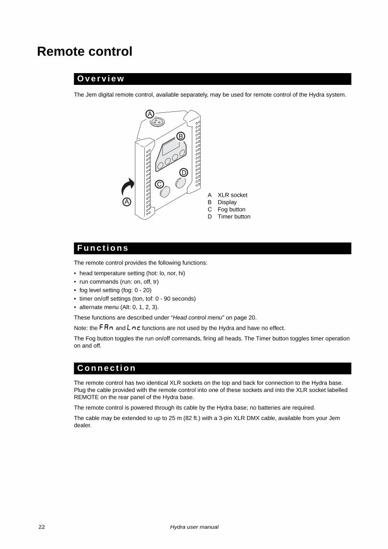
The Jem digital remote control, available separately, may be used for remote control of the Hydra system.
The remote control provides the following functions:
• head temperature setting (hot: lo, nor, hi)• run commands (run: on, off, tr)
• fog level setting (fog: 0 - 20)
• timer on/off settings (ton, tof: 0 - 90 seconds)• alternate menu (Alt: 0, 1, 2, 3).
These functions are described under “Head control menu” on page 20.
Note: the FAn and Lnc functions are not used by the Hydra and have no effect.
The Fog button toggles the run on/off commands, firing all heads. The Timer button toggles timer operation on and off.
The remote control has two identical XLR sockets on the top and back for connection to the Hydra base. Plug the cable provided with the remote control into one of these sockets and into the XLR socket labelled REMOTE on the rear panel of the Hydra base.
The remote control is powered through its cable by the Hydra base; no batteries are required.
The cable may be extended to up to 25 m (82 ft.) with a 3-pin XLR DMX cable, available from your Jem dealer.
O v e r v i e w
F u n c t i o n s
C o n n e c t i o n
C
D
B
A
A
A XLR socketB DisplayC Fog buttonD Timer button
22 Hydra user manual
DMX control
DMX is a standard system that is commonly used to control entertainment lighting. As such, DMX controllers are often found in the same locations as the Hydra. Any controller meeting the DMX-512 standard may be used to control and program the firing intervals and fog density of each head.
Note: when a DMX signal is present, the Hydra’s stand-alone functions are inoperative. To fire the heads from the control panel or remote control, the DMX controller must be powered off or disconnected.
The Hydra provides both 3-pin and 5-pin XLR sockets on the rear panel of the base for DMX connection. The sockets are interconnected: a DMX line connected to the 3-pin IN socket may be continued through the 5-pin OUT socket and vice versa. Do not, however, attempt to split a DMX line by using both the 3-pin and 5-pin OUT sockets.
Do not connect the DMX line directly to Hydra heads: they are not intended for direct DMX control.
For best results, use cable designed for high speed digital data transmission. Suitable DMX cable is available from your Jem dealer.
The Hydra’s address setting must match the DMX address allocated to it on the controller. To set the address, see “ADR (DMX address) setting” on page 18. The Hydra requires one DMX channel per head.
DMX channels control heads in head address order, which is 0 to 9, A, B, C, D, E, F. For example, if the DMX address is channel 100 and there are 8 heads, the head at Hydra address 0 is controlled by DMX channel 100, the head at Hydra address 1 is controlled by DMX channel 101, and the head at Hydra address 7 is controlled by DMX channel 107.
Hydra heads respond to DMX levels as shown below.
To operate the Hydra with a DMX controller, follow the steps below.
1. Start the Hydra system as described in the next section.
2. Connect the Hydra to the DMX line and turn on the DMX controller.
3. Set the Hydra’s DMX address as described under “ADR (DMX address) setting” on page 18.
4. Verify that the head number setting is correct.
5. The Hydra is ready for DMX operation when adr and the DMX address alternately appear in the displays.
O v e r v i e w
D M X c o n n e c t i o n
D M X a d d r e s s a n d c h a n n e l s
C o m m a n d v a l u e s
DMX level Response
0 - 19 No smoke output
20 - 219 Head fires, minimum to maximum fog density in 20 equal steps
220 - 255 Head fires at maximum output
I n i t i a t i n g D M X o p e r a t i o n
DMX control 23
General operation
DANGER! DO NOT operate the Hydra until you have read and observed all the precautions listed under “Safety information” on page 3.
Before applying power to the Hydra, verify the following:
• the base and head are safely installed and meet the location requirements stated on page 11
• the operator is familiar with, and able to comply with, the requirements for safe operation listed on pages 3 and 4.
• the smoke fluid is one of the genuine Jem fluids listed under “Smoke fluid options” on page 15• the base and heads are electrically grounded (earthed)
• the AC power distribution circuits and lines are adequately dimensioned for the current load
• the fluid line is fully assembled and closed
Follow the steps below to start the Hydra for the first time, after it has been installed and the fluid and data lines have been connected as described in this manual.
1. Disconnect the DMX cable from the DMX input socket on the rear panel of the base, if present.
2. Set the pump enable switch on the base control panel to the “O” (off) position.
3. Connect the base to AC power and set the base power switch to the left (on) position.
4. Apply power to the smoke heads and set their power switches to the on position. Allow the heads 10 - 15 minutes to reach operating temperature.
5. Equip the base with two fresh tanks of approved fluid as described under “Filling the Hydra” on page 15.
6. Set the head temperature as described under “HOt (head temperature) setting” on page 20.
7. Set the number of heads in the system as described under “Hd (head number) setting” on page 18.
8. Set the desired fluid control option as described under “Flu (fluid control) setting” on page 18.
9. Verify that all heads are ready as described under “StA (head status) readout” on page 21.
10.Verify that the fluid line is closed.
11.Set the pump enable switch to the “I” (on) position.
12.Prime the base as described under “Priming the base” on page 26.
13.Select the left or right fluid tank as described under “tnc (tank selection) setting” on page 18.
14.Fill and prime the fluid line as described under “Priming the fluid line” on page 26.
15.The Hydra is ready for use. To operate, refer to “Generating smoke”, below.
Follow the steps below to start the Hydra once it has been commissioned and tested.
1. Connect the base to AC power and set the base power switch to the left (on) position.
2. Apply power to the smoke heads. Allow 10 - 15 minutes to reach operating temperature. (If the heads are left on and connected to AC power, the heat exchangers switch on when the base is switched on.)
3. Check the fluid tanks. Refill with an approved Jem fluid and prime as required. If changing to a different fluid, please see “Transition between fluid types” on page 15.
4. Verify that head temperature setting is correct for the selected fluid.
5. Set the pump enable switch to the “I” (on) position.
6. Verify that the heads are ready as described under “StA (head status) readout” on page 21.
P r e - o p e r a t i o n c h e c k s
S t a r t i n g t h e H y d r a f o r f i r s t t i m e
N o r m a l s t a r t p r o c e d u r e
24 Hydra user manual
The simplest way to generate smoke is to execute the run menu’s on and off commands from the control panel or, if you have the Jem Remote Control, to press the Fog button. This fires all heads at the level determined by the fog level setting.
The density and hang time of the resulting smoke will depend on firing time, fog level, fluid weight, room size, and ventilation. For thicker smoke, increase the fog level setting, and/or increase firing time. For thinner smoke, use a lower fog level setting and/or decrease firing time.
For unattended smoke generation, execute the timer command from the run menu of the control panel or the remote control. In timer mode, heads fire with the timing determined by the time-on and time-off settings, at the level determined by the fog level setting. Several minutes of manual operation will give you a feel for the time and level settings to use to achieve the desired effect.
To execute sequential chases from the control panel or remote control, refer to “ALt (alternate menu) setting” on page 21.
If operating the Hydra from a DMX controller, refer to “DMX control” on page 23.
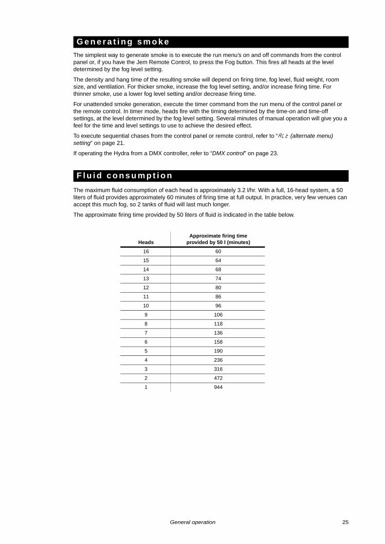
The maximum fluid consumption of each head is approximately 3.2 l/hr. With a full, 16-head system, a 50 liters of fluid provides approximately 60 minutes of firing time at full output. In practice, very few venues can accept this much fog, so 2 tanks of fluid will last much longer.
The approximate firing time provided by 50 liters of fluid is indicated in the table below.
G e n e r a t i n g s m o k e
F l u i d c o n s u m p t i o n
HeadsApproximate firing time
provided by 50 l (minutes)
16 60
15 64
14 68
13 74
12 80
11 86
10 96
9 106
8 118
7 136
6 158
5 190
4 236
3 316
2 472
1 944
General operation 25
Priming the base fills the base with fluid, pressurizes the system, and resets the system if an automatic shut-down has occurred. The base must be primed when refilling or replacing both fluid tanks, when the tanks have been removed for transport, after an out-of-fluid shutdown, and after a leak detection shutdown.
The base need not be primed if replacing an empty tank while the system is running: it will prime itself automatically when switching tanks. However, priming will make the tank changeover faster.
Prime the base from the left display as follows:
1. To prevent heads from firing, verify that run is set to off, or, if there is DMX input, that all Hydra control channels are set to no output.
2. Select the fresh tank from the tnc menu. When fitting 2 fresh tanks (of the same fluid), you can select L-R to prime both tanks simultaneously.
3. Under the left display, press menu as required to display pri .
4. Use the up or down keys to select y. Press enter.
5. Allow the base priming cycle to run until the pump stops.
6. Read the input pressure (Pi ) value in the left display. If the value is less than the target pressure (36 psi by default), repeat the base priming cycle. If more than three cycles are required with the default settings, there may be a fault with the system. Contact Jem service.
7. Select the working tank from the tnc menu.
Priming the fluid line fills it with fluid and forces out air by firing two heads: those with the middle and last address. This is required before first use or after opening the fluid line for draining or maintenance. The fluid line does not require priming when refilling/replacing fluid tanks.
Prime the fluid line from the right display as follows:
1. Verify that the fluid line is closed.
2. Start the system and allow the heads to reach operating temperature.
3. Prime the base as described above.
4. Under the right display, press menu as required to display pri .
5. Use the up or down keys to select y. Press enter. This opens the base fluid output valves and fires two heads for a period determined by the pump delay time setting. Large systems can take up to four minutes to fill; you may need to repeat the cycle several times.
6. Select n to stop the cycle when both heads are firing.
To turn off the Hydra system, simply set the base power switch to the right (off) position.
The heads may be left on, with AC power applied, if convenient. The heat exchangers are automatically switched off 20 minutes after the base is turned off to save power. When a head detects that the base is switched back on, it switches on its heat exchanger and is ready to fire 10 to 15 minutes later.
A custom flight case is available for transporting the Hydra base. Contact your Jem supplier for information.
The base hose fluid caps are not leakproof. Remove the fluid tank hoses from the tanks for transportation and seal the tanks with regular caps. Place the fluid tank hoses in a clean plastic bag to keep them clean.
Take care as well to keep the self-seal connectors clean.
When setting up in a new venue, run the base prime cycle after connecting the fluid lines.
P r i m i n g t h e b a s e
P r i m i n g t h e f l u i d l i n e
S h u t t i n g d o w n t h e s y s t e m
T o u r i n g w i t h t h e H y d r a
26 Hydra user manual
Basic service Before servicing the Hydra, read and observe all the precautions listed in “Safety information” on page 3. Any service not described in this section must be carried out by a Jem service technician.
Excessive dust, smoke fluid, and dirt buildup will degrade performance and cause overheating and damage to the machine that is not covered by the product warranty. To maintain adequate cooling, dust must be cleaned from the outer casing and air vents of the base and heads periodically.
Isolate the heads from power and allow to cool completely before cleaning. The smoke output nozzle remains hot for up to 10 hours after use.• Remove dust from the air vents with a soft brush, cotton swab, vacuum, or compressed air.
• Clean the outer casing with a damp cloth only.
When the heads have been idle for 13 seconds, the system goes into a repeating leak detection cycle. The pressure at the beginning of the cycle is compared to the pressure at the end; if the pressure falls by more than 2 psi, a leak is assumed and the system shuts down automatically. OFFappears in the left display, the heads stop firing, the output valves close, and the fluid pump stops running.
Resolve the problem as follows.
1. Inspect the fluid line for signs of leaking fluid.
2. If a leak is found, drain the fluid line as described below. Turn off the base and repair the fluid line, making sure the tube ends are clean and square. Restart the system and prime the base and fluid line.
3. If no leak can be found, the value of the pressure test time setting may be too high. Lower the setting as described under “TP (pressure test time) setting” on page 19. Prime the base and resume operation.
4. If the problem persists, it is likely that air trapped in the line is causing the pressure to fall. Check for blind runs in the fluid line and eliminate any that you find. Prime the base, then prime the fluid line thoroughly by firing all heads until there are no interruptions in the output.
The fluid line can be drained to remove the fluid when servicing the line or heads, or changing fluid types. Fluid lines equipped for touring with self-seal connectors need not be drained for transport.
Make sure there is sufficient room in the tank when draining: a typical fluid line contains 5 to 10 liters of fluid.
Drain the fluid line as follows.
1. Under the left display, press menu as required to display tnc .
2. Select the tank in which to drain the fluid using the up or down keys.
3. Press menu as required to display FLU .
4. Use the up or down keys to select dra .
5. Press enter. This opens the drain valve on the selected tank and disables the pump.
6. If the heads are installed above the base, fluid will drain into the tank but it will be necessary to allow air into the system by removing a plug or 6 mm adaptor at the end of the fluid line, or at the high point if the line is connected in a ring.
If there is little rise in the system, it may be necessary to push the fluid back to the tank using a supply of compressed air (maximum 3 bar) at the end of the fluid line.
If the end of the fluid line is lower than the base, the fluid will flow towards the end of the line instead of the tank. Use an empty tank to collect fluid here.
7. After the line has drained, be sure to close the fluid line before priming the system again.
C l e a n i n g
D i a g n o s i n g l e a k s
D r a i n i n g t h e f l u i d l i n e
Basic service 27
The system can be flushed with deionized water to remove virtually all traces of residual fluid as described below.
Important! Never use plain drinking water to flush the system: impurities will rapidly clog the head.
1. Drain the system as described above. Close the fluid line.
2. Fill an empty tank with a sufficient quantity of deionized water to fill the fluid line.
3. Set the head temperature to LO .
4. Select the tank containing the water from the tnc menu.
5. Prime the base.
6. Fire all heads until the water tank is empty.
7. Drain any remaining water from the fluid line.
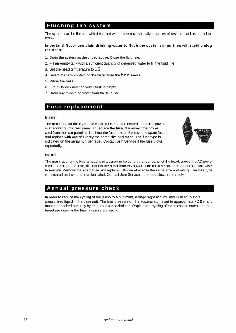
Base
The main fuse for the Hydra base is in a fuse holder located in the IEC power inlet socket on the rear panel. To replace the fuse, disconnect the power cord from the rear panel and pull out the fuse holder. Remove the spent fuse and replace with one of exactly the same size and rating. The fuse type is indicated on the serial number label. Contact Jem Service if the fuse blows repeatedly.
Head
The main fuse for the Hydra head is in a screw-in holder on the rear panel of the head, above the AC power cord. To replace the fuse, disconnect the head from AC power. Turn the fuse holder cap counter-clockwise to remove. Remove the spent fuse and replace with one of exactly the same size and rating. The fuse type is indicated on the serial number label. Contact Jem Service if the fuse blows repeatedly.
In order to reduce the cycling of the pump to a minimum, a diaphragm accumulator is used to store pressurized liquid in the base unit. The bias pressure on the accumulator is set to approximately 2 Bar and must be checked annually by an authorized technician. Rapid short-cycling of the pump indicates that the target pressure or the bias pressure are wrong.
F l u s h i n g t h e s y s t e m
F u s e r e p l a c e m e n t
A n n u a l p r e s s u r e c h e c k
28 Hydra user manual
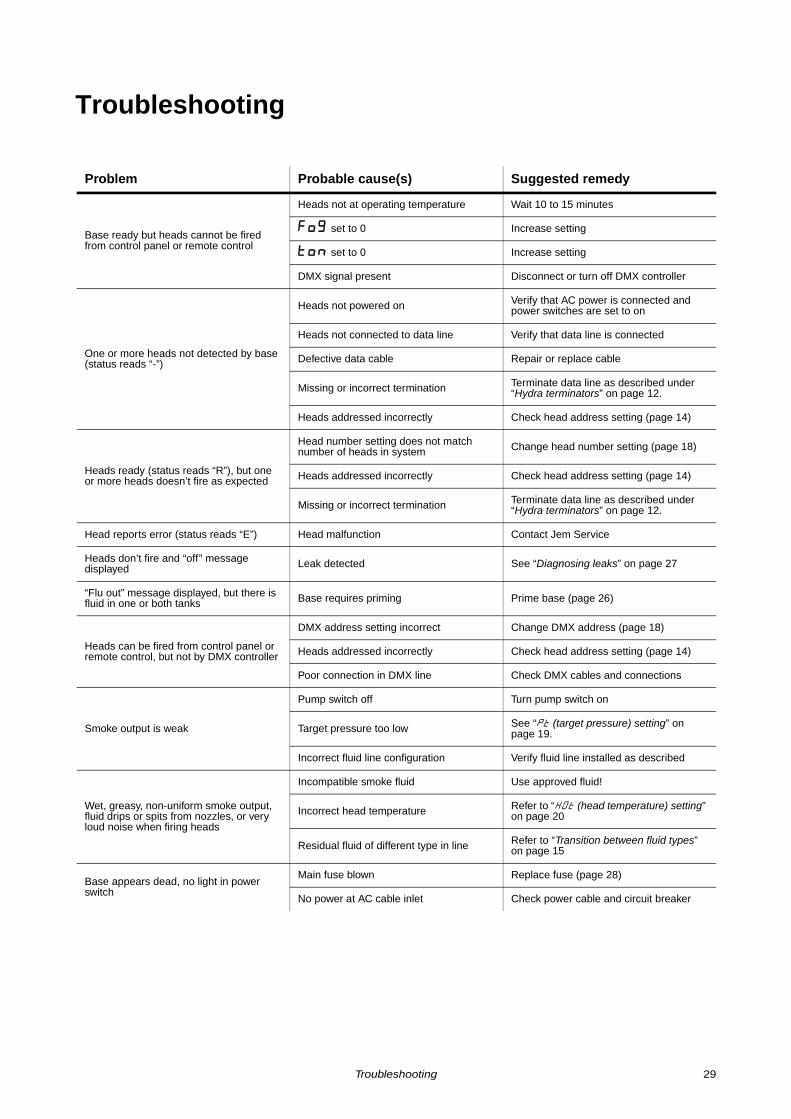
Troubleshooting
Problem Probable cause(s) Suggested remedy
Base ready but heads cannot be fired from control panel or remote control
Heads not at operating temperature Wait 10 to 15 minutes
Fog set to 0 Increase setting
ton set to 0 Increase setting
DMX signal present Disconnect or turn off DMX controller
One or more heads not detected by base (status reads “-”)
Heads not powered on Verify that AC power is connected and power switches are set to on
Heads not connected to data line Verify that data line is connected
Defective data cable Repair or replace cable
Missing or incorrect termination Terminate data line as described under “Hydra terminators” on page 12.
Heads addressed incorrectly Check head address setting (page 14)
Heads ready (status reads “R”), but one or more heads doesn’t fire as expected
Head number setting does not match number of heads in system Change head number setting (page 18)
Heads addressed incorrectly Check head address setting (page 14)
Missing or incorrect termination Terminate data line as described under “Hydra terminators” on page 12.
Head reports error (status reads “E”) Head malfunction Contact Jem Service
Heads don’t fire and “off” message displayed Leak detected See “Diagnosing leaks” on page 27
“Flu out” message displayed, but there is fluid in one or both tanks Base requires priming Prime base (page 26)
Heads can be fired from control panel or remote control, but not by DMX controller
DMX address setting incorrect Change DMX address (page 18)
Heads addressed incorrectly Check head address setting (page 14)
Poor connection in DMX line Check DMX cables and connections
Smoke output is weak
Pump switch off Turn pump switch on
Target pressure too low See “PT (target pressure) setting” on page 19.
Incorrect fluid line configuration Verify fluid line installed as described
Wet, greasy, non-uniform smoke output, fluid drips or spits from nozzles, or very loud noise when firing heads
Incompatible smoke fluid Use approved fluid!
Incorrect head temperature Refer to “HOt (head temperature) setting” on page 20
Residual fluid of different type in line Refer to “Transition between fluid types” on page 15
Base appears dead, no light in power switch
Main fuse blown Replace fuse (page 28)
No power at AC cable inlet Check power cable and circuit breaker
Troubleshooting 29
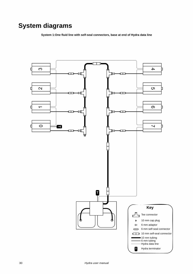
System diagramsSystem 1:One fluid line with self-seal connectors, base at end of Hydra data line
Key
Tee connector
6 mm adaptor
10 mm self-seal connector
10 mm tubing6 mm tubingHydra data line
Hydra terminator
10 mm cap plug
6 mm self-seal connector
30 Hydra user manual
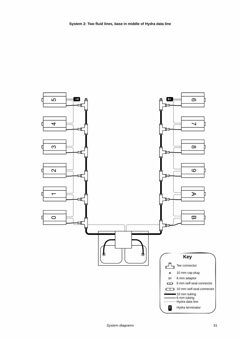
System 2: Two fluid lines, base in middle of Hydra data line
Key
Tee connector
6 mm adaptor
10 mm self-seal connector
10 mm tubing6 mm tubingHydra data line
Hydra terminator
10 mm cap plug
6 mm self-seal connector
System diagrams 31
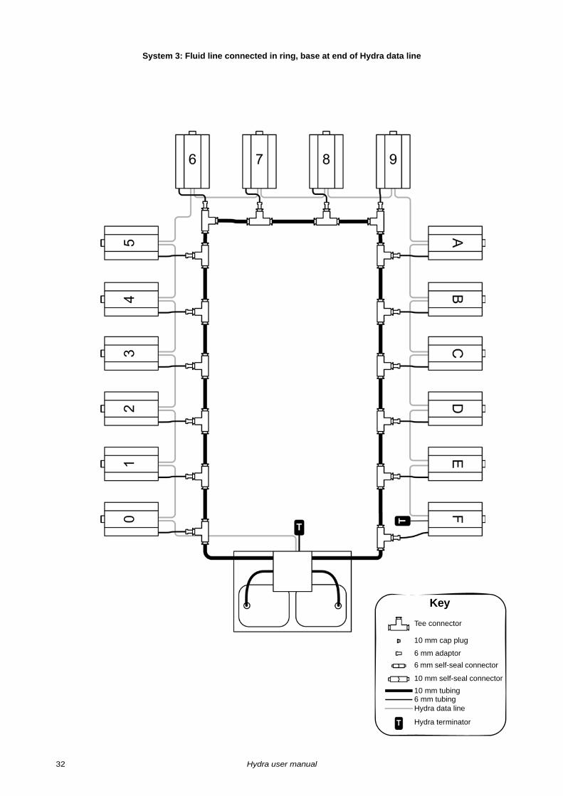
System 3: Fluid line connected in ring, base at end of Hydra data line
Key
Tee connector
6 mm adaptor
10 mm self-seal connector
10 mm tubing6 mm tubingHydra data line
Hydra terminator
10 mm cap plug
6 mm self-seal connector
32 Hydra user manual
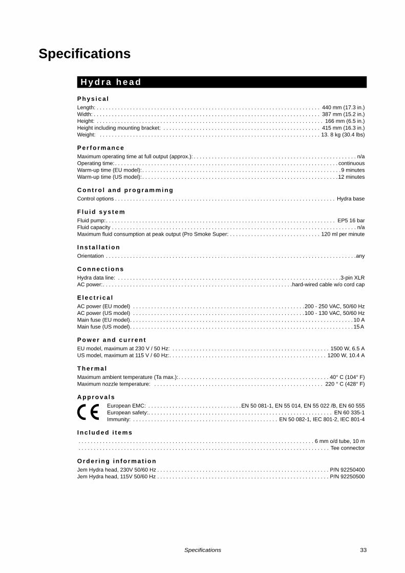
Specifications
P h y s i c a lLength: . . . . . . . . . . . . . . . . . . . . . . . . . . . . . . . . . . . . . . . . . . . . . . . . . . . . . . . . . . . . . . . . . . . . . . . . . . 440 mm (17.3 in.)Width: . . . . . . . . . . . . . . . . . . . . . . . . . . . . . . . . . . . . . . . . . . . . . . . . . . . . . . . . . . . . . . . . . . . . . . . . . . . 387 mm (15.2 in.)Height: . . . . . . . . . . . . . . . . . . . . . . . . . . . . . . . . . . . . . . . . . . . . . . . . . . . . . . . . . . . . . . . . . . . . . . . . . . . 166 mm (6.5 in.)Height including mounting bracket: . . . . . . . . . . . . . . . . . . . . . . . . . . . . . . . . . . . . . . . . . . . . . . . . . . . . 415 mm (16.3 in.)Weight: . . . . . . . . . . . . . . . . . . . . . . . . . . . . . . . . . . . . . . . . . . . . . . . . . . . . . . . . . . . . . . . . . . . . . . . . . 13. 8 kg (30.4 lbs)
P e r f o r m a n c eMaximum operating time at full output (approx.): . . . . . . . . . . . . . . . . . . . . . . . . . . . . . . . . . . . . . . . . . . . . . . . . . . . . . . n/aOperating time: . . . . . . . . . . . . . . . . . . . . . . . . . . . . . . . . . . . . . . . . . . . . . . . . . . . . . . . . . . . . . . . . . . . . . . . . . . continuousWarm-up time (EU model): . . . . . . . . . . . . . . . . . . . . . . . . . . . . . . . . . . . . . . . . . . . . . . . . . . . . . . . . . . . . . . . . . .9 minutesWarm-up time (US model): . . . . . . . . . . . . . . . . . . . . . . . . . . . . . . . . . . . . . . . . . . . . . . . . . . . . . . . . . . . . . . . . .12 minutes
C o n t r o l a n d p r o g r a m m i n gControl options . . . . . . . . . . . . . . . . . . . . . . . . . . . . . . . . . . . . . . . . . . . . . . . . . . . . . . . . . . . . . . . . . . . . . . . . . Hydra base
F l u i d s y s t e mFluid pump:. . . . . . . . . . . . . . . . . . . . . . . . . . . . . . . . . . . . . . . . . . . . . . . . . . . . . . . . . . . . . . . . . . . . . . . . . . . . EP5 16 barFluid capacity . . . . . . . . . . . . . . . . . . . . . . . . . . . . . . . . . . . . . . . . . . . . . . . . . . . . . . . . . . . . . . . . . . . . . . . . . . . . . . . . . n/aMaximum fluid consumption at peak output (Pro Smoke Super: . . . . . . . . . . . . . . . . . . . . . . . . . . . . . . 120 ml per minute
I n s t a l l a t i o nOrientation . . . . . . . . . . . . . . . . . . . . . . . . . . . . . . . . . . . . . . . . . . . . . . . . . . . . . . . . . . . . . . . . . . . . . . . . . . . . . . . . . . .any
C o n n e c t i o n sHydra data line: . . . . . . . . . . . . . . . . . . . . . . . . . . . . . . . . . . . . . . . . . . . . . . . . . . . . . . . . . . . . . . . . . . . . . . . . . .3-pin XLRAC power:. . . . . . . . . . . . . . . . . . . . . . . . . . . . . . . . . . . . . . . . . . . . . . . . . . . . . . . . . . . . . . .hard-wired cable w/o cord cap
E l e c t r i c a lAC power (EU model) . . . . . . . . . . . . . . . . . . . . . . . . . . . . . . . . . . . . . . . . . . . . . . . . . . . . . . . . .200 - 250 VAC, 50/60 HzAC power (US model) . . . . . . . . . . . . . . . . . . . . . . . . . . . . . . . . . . . . . . . . . . . . . . . . . . . . . . . . .100 - 130 VAC, 50/60 HzMain fuse (EU model). . . . . . . . . . . . . . . . . . . . . . . . . . . . . . . . . . . . . . . . . . . . . . . . . . . . . . . . . . . . . . . . . . . . . . . . . . 10 AMain fuse (US model). . . . . . . . . . . . . . . . . . . . . . . . . . . . . . . . . . . . . . . . . . . . . . . . . . . . . . . . . . . . . . . . . . . . . . . . . . 15 A
P o w e r a n d c u r r e n tEU model, maximum at 230 V / 50 Hz: . . . . . . . . . . . . . . . . . . . . . . . . . . . . . . . . . . . . . . . . . . . . . . . . . . . . 1500 W, 6.5 AUS model, maximum at 115 V / 60 Hz:. . . . . . . . . . . . . . . . . . . . . . . . . . . . . . . . . . . . . . . . . . . . . . . . . . . . 1200 W, 10.4 A
T h e r m a lMaximum ambient temperature (Ta max.):. . . . . . . . . . . . . . . . . . . . . . . . . . . . . . . . . . . . . . . . . . . . . . . . . . 40° C (104° F)Maximum nozzle temperature: . . . . . . . . . . . . . . . . . . . . . . . . . . . . . . . . . . . . . . . . . . . . . . . . . . . . . . . . 220 ° C (428° F)
A p p r o v a l sEuropean EMC: . . . . . . . . . . . . . . . . . . . . . . . . . . . . . . .EN 50 081-1, EN 55 014, EN 55 022 /B, EN 60 555European safety:. . . . . . . . . . . . . . . . . . . . . . . . . . . . . . . . . . . . . . . . . . . . . . . . . . . . . . . . . . . . . EN 60 335-1Immunity: . . . . . . . . . . . . . . . . . . . . . . . . . . . . . . . . . . . . . . . . . . . . . . . . EN 50 082-1, IEC 801-2, IEC 801-4
I n c l u d e d i t e m s. . . . . . . . . . . . . . . . . . . . . . . . . . . . . . . . . . . . . . . . . . . . . . . . . . . . . . . . . . . . . . . . . . . . . . . . . . . . . . 6 mm o/d tube, 10 m. . . . . . . . . . . . . . . . . . . . . . . . . . . . . . . . . . . . . . . . . . . . . . . . . . . . . . . . . . . . . . . . . . . . . . . . . . . . . . . . . . . Tee connector
O r d e r i n g i n f o r m a t i o nJem Hydra head, 230V 50/60 Hz . . . . . . . . . . . . . . . . . . . . . . . . . . . . . . . . . . . . . . . . . . . . . . . . . . . . . . . . . P/N 92250400Jem Hydra head, 115V 50/60 Hz . . . . . . . . . . . . . . . . . . . . . . . . . . . . . . . . . . . . . . . . . . . . . . . . . . . . . . . . . P/N 92250500
H y d r a h e a d
Specifications 33
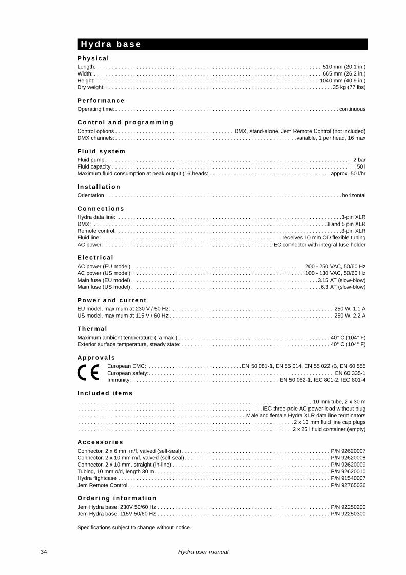
P h y s i c a lLength: . . . . . . . . . . . . . . . . . . . . . . . . . . . . . . . . . . . . . . . . . . . . . . . . . . . . . . . . . . . . . . . . . . . . . . . . . . 510 mm (20.1 in.)Width: . . . . . . . . . . . . . . . . . . . . . . . . . . . . . . . . . . . . . . . . . . . . . . . . . . . . . . . . . . . . . . . . . . . . . . . . . . . 665 mm (26.2 in.)Height: . . . . . . . . . . . . . . . . . . . . . . . . . . . . . . . . . . . . . . . . . . . . . . . . . . . . . . . . . . . . . . . . . . . . . . . . . 1040 mm (40.9 in.)Dry weight: . . . . . . . . . . . . . . . . . . . . . . . . . . . . . . . . . . . . . . . . . . . . . . . . . . . . . . . . . . . . . . . . . . . . . . . . . .35 kg (77 lbs)
P e r f o r m a n c eOperating time: . . . . . . . . . . . . . . . . . . . . . . . . . . . . . . . . . . . . . . . . . . . . . . . . . . . . . . . . . . . . . . . . . . . . . . . . . . continuous
C o n t r o l a n d p r o g r a m m i n gControl options . . . . . . . . . . . . . . . . . . . . . . . . . . . . . . . . . . . . . . . DMX, stand-alone, Jem Remote Control (not included)DMX channels: . . . . . . . . . . . . . . . . . . . . . . . . . . . . . . . . . . . . . . . . . . . . . . . . . . . . . . . . . . . .variable, 1 per head, 16 max
F l u i d s y s t e mFluid pump:. . . . . . . . . . . . . . . . . . . . . . . . . . . . . . . . . . . . . . . . . . . . . . . . . . . . . . . . . . . . . . . . . . . . . . . . . . . . . . . . . 2 barFluid capacity . . . . . . . . . . . . . . . . . . . . . . . . . . . . . . . . . . . . . . . . . . . . . . . . . . . . . . . . . . . . . . . . . . . . . . . . . . . . . . . . .50 l Maximum fluid consumption at peak output (16 heads: . . . . . . . . . . . . . . . . . . . . . . . . . . . . . . . . . . . . . . . . approx. 50 l/hr
I n s t a l l a t i o nOrientation . . . . . . . . . . . . . . . . . . . . . . . . . . . . . . . . . . . . . . . . . . . . . . . . . . . . . . . . . . . . . . . . . . . . . . . . . . . . . . horizontal
C o n n e c t i o n sHydra data line: . . . . . . . . . . . . . . . . . . . . . . . . . . . . . . . . . . . . . . . . . . . . . . . . . . . . . . . . . . . . . . . . . . . . . . . . . .3-pin XLRDMX: . . . . . . . . . . . . . . . . . . . . . . . . . . . . . . . . . . . . . . . . . . . . . . . . . . . . . . . . . . . . . . . . . . . . . . . . . . . . .3 and 5 pin XLRRemote control: . . . . . . . . . . . . . . . . . . . . . . . . . . . . . . . . . . . . . . . . . . . . . . . . . . . . . . . . . . . . . . . . . . . . . . . . . .3-pin XLRFluid line: . . . . . . . . . . . . . . . . . . . . . . . . . . . . . . . . . . . . . . . . . . . . . . . . . . . . . . . . . . . receives 10 mm OD flexible tubingAC power:. . . . . . . . . . . . . . . . . . . . . . . . . . . . . . . . . . . . . . . . . . . . . . . . . . . . . . . .IEC connector with integral fuse holder
E l e c t r i c a lAC power (EU model) . . . . . . . . . . . . . . . . . . . . . . . . . . . . . . . . . . . . . . . . . . . . . . . . . . . . . . . . .200 - 250 VAC, 50/60 HzAC power (US model) . . . . . . . . . . . . . . . . . . . . . . . . . . . . . . . . . . . . . . . . . . . . . . . . . . . . . . . . .100 - 130 VAC, 50/60 HzMain fuse (EU model). . . . . . . . . . . . . . . . . . . . . . . . . . . . . . . . . . . . . . . . . . . . . . . . . . . . . . . . . . . . . . 3.15 AT (slow-blow)Main fuse (US model). . . . . . . . . . . . . . . . . . . . . . . . . . . . . . . . . . . . . . . . . . . . . . . . . . . . . . . . . . . . . . . 6.3 AT (slow-blow)
P o w e r a n d c u r r e n tEU model, maximum at 230 V / 50 Hz: . . . . . . . . . . . . . . . . . . . . . . . . . . . . . . . . . . . . . . . . . . . . . . . . . . . . . 250 W, 1.1 AUS model, maximum at 115 V / 60 Hz:. . . . . . . . . . . . . . . . . . . . . . . . . . . . . . . . . . . . . . . . . . . . . . . . . . . . . . 250 W, 2.2 A
T h e r m a lMaximum ambient temperature (Ta max.):. . . . . . . . . . . . . . . . . . . . . . . . . . . . . . . . . . . . . . . . . . . . . . . . . . 40° C (104° F)Exterior surface temperature, steady state: . . . . . . . . . . . . . . . . . . . . . . . . . . . . . . . . . . . . . . . . . . . . . . . . . 40° C (104° F)
A p p r o v a l sEuropean EMC: . . . . . . . . . . . . . . . . . . . . . . . . . . . . . . .EN 50 081-1, EN 55 014, EN 55 022 /B, EN 60 555European safety:. . . . . . . . . . . . . . . . . . . . . . . . . . . . . . . . . . . . . . . . . . . . . . . . . . . . . . . . . . . . . EN 60 335-1Immunity: . . . . . . . . . . . . . . . . . . . . . . . . . . . . . . . . . . . . . . . . . . . . . . . . EN 50 082-1, IEC 801-2, IEC 801-4
I n c l u d e d i t e m s. . . . . . . . . . . . . . . . . . . . . . . . . . . . . . . . . . . . . . . . . . . . . . . . . . . . . . . . . . . . . . . . . . . . . . . . . . . . . 10 mm tube, 2 x 30 m. . . . . . . . . . . . . . . . . . . . . . . . . . . . . . . . . . . . . . . . . . . . . . . . . . . . . . . . . . . . .IEC three-pole AC power lead without plug. . . . . . . . . . . . . . . . . . . . . . . . . . . . . . . . . . . . . . . . . . . . . . . . . . . . . . . Male and female Hydra XLR data line terminators. . . . . . . . . . . . . . . . . . . . . . . . . . . . . . . . . . . . . . . . . . . . . . . . . . . . . . . . . . . . . . . . . . . . . . . 2 x 10 mm fluid line cap plugs. . . . . . . . . . . . . . . . . . . . . . . . . . . . . . . . . . . . . . . . . . . . . . . . . . . . . . . . . . . . . . . . . . . . . . 2 x 25 l fluid container (empty)
A c c e s s o r i e sConnector, 2 x 6 mm m/f, valved (self-seal) . . . . . . . . . . . . . . . . . . . . . . . . . . . . . . . . . . . . . . . . . . . . . . . . . P/N 92620007Connector, 2 x 10 mm m/f, valved (self-seal) . . . . . . . . . . . . . . . . . . . . . . . . . . . . . . . . . . . . . . . . . . . . . . . . P/N 92620008Connector, 2 x 10 mm, straight (in-line) . . . . . . . . . . . . . . . . . . . . . . . . . . . . . . . . . . . . . . . . . . . . . . . . . . . . P/N 92620009Tubing, 10 mm o/d, length 30 m. . . . . . . . . . . . . . . . . . . . . . . . . . . . . . . . . . . . . . . . . . . . . . . . . . . . . . . . . . P/N 92620010Hydra flightcase . . . . . . . . . . . . . . . . . . . . . . . . . . . . . . . . . . . . . . . . . . . . . . . . . . . . . . . . . . . . . . . . . . . . . . P/N 91540007Jem Remote Control. . . . . . . . . . . . . . . . . . . . . . . . . . . . . . . . . . . . . . . . . . . . . . . . . . . . . . . . . . . . . . . . . . . P/N 92765026
O r d e r i n g i n f o r m a t i o nJem Hydra base, 230V 50/60 Hz . . . . . . . . . . . . . . . . . . . . . . . . . . . . . . . . . . . . . . . . . . . . . . . . . . . . . . . . . P/N 92250200Jem Hydra base, 115V 50/60 Hz . . . . . . . . . . . . . . . . . . . . . . . . . . . . . . . . . . . . . . . . . . . . . . . . . . . . . . . . . P/N 92250300
Specifications subject to change without notice.
H y d r a b a s e
34 Hydra user manual


www.martin.com • Olof Palmes Allé 18 • 8200 Aarhus N • DenmarkTel: +45 8740 0000 • Fax +45 8740 0010