hx 3000 tb uk - free instruction manuals · warning this symbol indicates a dangerous situation if...
TRANSCRIPT

GENERATING SET USER AND
MAINTENANCE MANUAL
33522129801_0_1
HX 3000 TB UK

2/4
A A
A
1 2
17
9
10
11
13
12
16
3
5 4
7
3
8
6
3/4
A B
C D
15
14
1
23
1
2
4
3
21

4/4
E F
G
2
1
2
6
4 5
7 3
8 1

Contents
1. Preface 2. General description 3. Preparation before starting 4. Using the generator set 5. Safety features (if fitted, see specifications table) 6. Maintenance schedule
7. Maintenance procedures 8. Storing the generating set 9. Fault finding 10. Specifications 11. Cable sizes 12. EC Declaration of conformity
1. Preface 1.1. Recommendations Thank you for buying one of our generating sets. We recommend that you read this manual carefully and follow the safety and maintenance advice and user instructions for your generating set very closely. The information contained in this manual is taken from technical data available at the time of print. In the intention of permanently improving the quality of our products, this information may be amended without warning. 1.2. Pictograms and plates on the generating sets and what they mean
Danger
Warning: risk of electric shock
Earth
Danger, risk of burns
Warning: the generating set is supplied without oil. Always check the oil level before starting the generating set.
1 2 3
1 - Important: refer to the documentation accompanying the generating set. 2 - Warning: emission of toxic exhaust gases. Do not use in a confined or poorly ventilated area.
3 - Stop the motor before filling with fuel. A = Generating set model B = Generating set output C = Voltage D = Amperage E = Current frequency F = Power factor
Example of an identification plate
G = Protection rating H = Generating set noise output I = Generating set earth J = Reference Standard K = Serial number
1.3. Instructions and safety regulations
Danger
Do not run the generating set without having put back the protective covers and closed the access doors. Never take the protective covers off or open the access doors if the generating set is running.
1.3.1 Warnings You are likely to encounter several warning symbols in this manual.
Danger
This symbol indicates a definite risk to the health and life of people. Not following this instruction may seriously affect the health of people or prove fatal.
Warning
This symbol draws attention to the potential risk to the health and life of people. Not following this instruction may seriously affect the health of people or prove fatal.
33522129801_0_1

Warning
This symbol indicates a dangerous situation if the warning is not heeded. Not following this instruction could result in non-serious injury or damage.
1.3.2 General advice One of the fundamental safety considerations is observation of the interval between maintenance procedures (see maintenance schedule). Furthermore, never attempt to carry out repairs or maintenance procedures without the necessary experience and/or tools. When you take delivery of your generating set, check that it is complete and not damaged in any way. A generating set should be handled gently, avoiding sudden movements, and the place where it is to be stored or used should be carefully prepared beforehand.
Warning
Before use, it is essential that you know how to stop the generating set immediately and that you thoroughly understand all the controls and operations.
Never let other people use the generating set without giving them all necessary instructions beforehand. Never let children touch the generating set, even when it is not in operation. Do not operate the generating set near animals (as it could cause them to panic). Never start the motor without an air filter or exhaust. Never invert the positive and negative battery terminals (if fitted) when connecting them. Such an inversion can lead to severe damage to the electrical equipment. Never cover the generating set with any type of material while it is in operation or just after it has been turned off. Wait until the motor is cold. Never coat the generating set with oil in an attempt to protect it from corrosion. Some preservative oils are flammable. Also, some are dangerous to inhale. In all cases, respect the local regulations currently in place concerning the use of generating sets. 1.3.3 Safety guidelines to prevent electrocution
Danger
While they are in operation, generating sets produce electric current. Connect the generating set to earth each time you use it, in order to prevent electrocution.
Never touch stripped cables or disconnected connectors. Never handle a generating set with wet hands or feet. Never expose the equipment to liquid splashes or rainfall, and do not place it on wet ground. Always keep the electrical cables and the connections in good condition. Do not use equipment in a poor state of repair which could lead to electrocution or damage to the equipment. Use a differential protection device between the generating set and the appliances if the cable or cables used are more than 1 metre in length. This device must be positioned at a maximum distance of 1 metre from the generating set electrical sockets. Use flexible, durable cables, with rubber sheathing, conforming to the IEC 60245-4 standard or equivalent cables. Do not connect the generating set to other power sources, such as the mains. In specific cases where there is provision for a reserve connection to existing electrical networks, this must only be carried out by a qualified electrician, who should take the operating differences of the equipment into account, according to whether the public distribution network or generating set is being used. Special circuit breakers designed for use with generating sets are used to prevent electrocution. If these circuit breakers need to be replaced, circuit breakers with identical nominal ratings and specifications must be used. 1.3.4 Safety guidelines to prevent fire
Danger
Keep all inflammable materials (e.g.: petrol, oil, fabric etc.) out of the way when the generating set is in operation. The motor should not be operated in areas containing explosive products. There is a risk of sparks forming where all electrical and mechanical components are not shielded. Never cover the generating set with any materials while it is operating or just after it has been switched off (wait for the motor cool down).
1.3.5 Safety guidelines for exhaust gases
Danger
Exhaust gases contain carbon monoxide, which is a highly toxic substance. This substance can cause death if it is present in excessive concentrations in the air inhaled. For this reason, always use the generating set in a well ventilated area, where gases will not be able to accumulate.
Good ventilation is required for your generating set to work properly. Without this, the motor would very quickly run at too high a temperature, which could lead to accidents or damage to the equipment and to surrounding items. However, if it is necessary to operate it inside a building, adequate ventilation must be provided, so that people and animals are not affected. It is imperative that exhaust gases are discharged outside.
1.3.6 Filling with fuel
Danger
The fuel is highly flammable and its vapours are combustible. Smoking, using a naked flame or producing sparks are forbidden while the fuel tank is being filled. Filling should be carried out with the motor turned off. All traces of fuel should be wiped off with a clean cloth.
Always place the generating set on a flat, level and horizontal surface to avoid fuel spillage from the tank onto the motor. Storage and handling of petroleum products must be carried out in accordance with the law. Close the fuel tap (if fitted) each time the tank has been filled. Fill the tank using a funnel, taking care not to spill any fuel. Then screw the petrol cap back on to the fuel tank as soon as filling is complete. Never top up fuel when the generating set is in operation or hot. 1.3.7 Safety guidelines against burns
Warning
Never touch the motor or the silencer while the generating set is in operation, or when it has just stopped.
Hot oil burns, avoid contact with the skin. Check that the system is no longer pressurised before carrying out any procedures. Never start or run the motor when the oil filler cap is off as oil may splash out. 1.3.8 Safety guidelines for handling batteries
Danger
Never place the battery close to a flame or fire Use only insulated tools Never use sulphuric acid or acid water to top up the electrolyte level.
1.3.9 Protecting the environment Never drain or discard used oil onto the ground, but put it into a designated container. As far as possible, try to avoid sound reverberating through walls and buildings, as the noise will be amplified. If the exhaust silencer of your generating set is not fitted with a spark arrester and you need to use it in wooded, bushy or uncultivated areas, be extremely careful and make sure that sparks do not cause a fire (clear vegetation from a fairly large area where you wish to place your generating set). 1.3.10 Danger of moving parts
Warning
Never go near a moving part that is in operation if you have loose clothing or long hair that is not enclosed in a protective hair net. Do not try to stop, slow down or impede a moving part when it is in operation.
1.3.11 Capacity of the generating set (overload) Never exceed the rated load of the generating set (in Amps and/or Watts) when it is running continuously. Before connecting and operating the generating set, calculate the electrical power required by the electric appliances (in Watts). This electrical power rating is usually found on the manufacturer's plate on bulbs, electrical appliances, motors etc. The sum total of power required by these appliances should not exceed the nominal power rating of the generating set. 1.3.12 Operating conditions The stated outputs of the generating sets are obtained in example conditions according to ISO 3046-1: +27°C, 100 m above sea-level, humidity level equal to 60 % or +20°C, 300 m above sea-level, humidity level equal to 60 %. Performance is reduced by approximately 4 % for every additional 10°C and/or approximately 1 % for every additional 100 m in altitude. 2. General description 2.1. Description of the generating set Fuel tank (no. 1, fig. A) Engine (no. 7, fig. A) Starting handle (no. 13, fig. A) Fuel tank plug (no. 2, fig. A) Silencer (no. 8, fig. A) Fuel tap (no. 14, fig. A) Oil filler plugs (no. 3, fig. A) Air filter (no. 9, fig. A) Choke (no. 15, fig. A) Oil drain plugs (no. 4, fig. A) Engine switch (no. 10, fig. A) Circuit breaker (no. 16, fig. A) Earth connection (no. 5, fig. A) Starter – recoil reel (no. 11, fig. A) Current transformer switch (no. 17, fig A) Alternator (no. 6, fig. A) Household sockets (no. 12, fig. A)

3. Preparation before starting 3.1. Checking the oil level
Always check the engine oil level before starting.
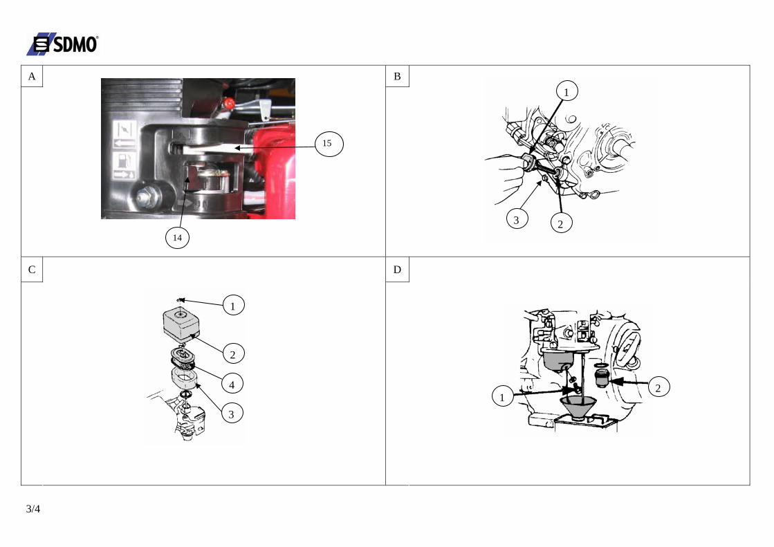
Checking and topping up should be carried out with the generating set on a horizontal surface. Remove the grey-coloured plug-gauge (no. 1, Fig. B) on the exhaust side by unscrewing it, and wipe the gauge. Insert the gauge into the filler neck (no. 2, Fig. B) without screwing it up. Visually check the level and top up if necessary. Using a funnel, fill the oil sump until it overflows. Screw the cap back up again tightly in the filler tube. Check that there are no leaks. Wipe off excess oil with a clean cloth.
3.2. Checking the fuel level
Danger
Stop the engine before filling up with fuel and fill up in a well-ventilated area. Do not smoke, or bring naked flames or sparks near to the area where you are filling up with fuel or where the fuel is stored. Only use clean fuel without any water. Do not overfill the tank (there should not be any fuel in the filler neck). When you have filled up, ensure that the tank cap is closed correctly. Take care not to spill any fuel when filling the tank. Before starting up the generating set, and if any fuel has been spilt, make sure that it has dried and that the vapours have cleared away.
Check the fuel level and top up if necessary: Unscrew the fuel tank cap (no. 2, fig A). Fill the tank (no. 1, fig A) using a funnel, taking care not to spill petrol. Screw the cap back on to the fuel tank.
3.3. Earthing the generating set To earth the generating set, use a 10 mm2 copper wire attached to the generating set earth connection and to an earthing rod of galvanised steel set in the ground to a depth of 1 metre. This also dissipates the static electricity that builds up in the electrical machines. 3.4. Positioning the generating set for operation Place the generating set on a flat, horizontal surface which is firm enough to prevent the set sinking down (under no circumstances should the set tilt any direction by more than 10°). Choose a site that is clean, well-ventilated and sheltered from bad weather, and store the additional supplies of oil and fuel within close proximity, although respecting a certain distance for safety. 4. Using the generator set 4.1. Starting procedure
Open the petrol tap by turning the control lever (no. 14, fig. A) to the right. Place the knob of the choke (no. 15, fig. A) on closed position as shown on the illustration.
Note: Do not use the choke when the engine is warm or when the atmospheric temperature is high. Place the engine switch (no. 10, fig. A) on "ON" or "I". Seize the starting handle (no. 13, fig. A) correctly and pull it slowly until some resistance is felt, then let it return gradually. Take the starting handle again correctly, then pull the cord sharply and rapidly (pull it right out, using both hands if necessary).
Allow the handle to return slowly by hand. If the engine has not started, repeat the operation until the engine starts by gradually opening the choke.
When the engine has started, gradually open the choke (no. 15, fig. A). 4.2. Operation When the engine begins to heat up, gradually bring the knob of the choke (no. 15, fig A) to open position. When the running speed of the generating set has stabilised:
Check that circuit breaker (no. 16, fig A) is engaged. Connect the plug(s) to the generating set socket(s).
4.3. Electric current voltage selection
Unplug the connected devices if necessary Put the switch on the desired voltage (no. 17, diag A), then plug back the devices on the sockets
4.4. Switching off
Warning
When the generating set is turned off, the engine continues to give off heat. Appropriate ventilation should be provided after the generating set is turned off. To stop the generating set urgently, place the engine switch on "OFF" or "О".
Take the plugs out of the sockets and allow the engine to run without any charge for 1 to 2 minutes. Place the engine switch (no. 10, fig. A) on "OFF" or "О" and the set will stop. Close the fuel tap (no. 14, fig. A).
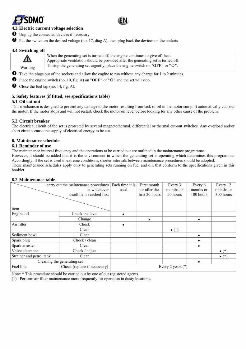
5. Safety features (if fitted, see specifications table) 5.1. Oil cut-out This mechanism is designed to prevent any damage to the motor resulting from lack of oil in the motor sump. It automatically cuts out the motor. If the motor stops and will not restart, check the motor oil level before looking for any other cause of the problem. 5.2. Circuit breaker The electrical circuit of the set is protected by several magnetothermal, differential or thermal cut-out switches. Any overload and/or short circuits cause the supply of electrical energy to be cut. 6. Maintenance schedule 6.1. Reminder of use The maintenance interval frequency and the operations to be carried out are outlined in the maintenance programme. However, it should be added that it is the environment in which the generating set is operating which determines this programme. Accordingly, if the set is used in extreme conditions, shorter intervals between maintenance procedures should be adopted. These maintenance schedules apply only to generating sets running on fuel and oil, that conform to the specifications given in this booklet. 6.2. Maintenance table
carry out the maintenance procedures at whichever
deadline is reached first
item
Each time it is used
First month or after the
first 20 hours
Every 3 months or 50 hours
Every 6 months or 100 hours
Every 12 months or 300 hours
Check the level • Engine oil Change • • Check • Air filter Clean • (1)
Sediment bowl Clean • Spark plug Check / clean • Spark arrester Clean • Valve clearance Check / adjust • (*) Strainer and petrol tank Clean • (*)
Cleaning the generating set • Fuel line Check (replace if necessary) Every 2 years (*)
Note: * This procedure should be carried out by one of our registered agents (1) : Perform air filter maintenance more frequently for operation in dusty locations.

7. Maintenance procedures 7.1. Cleaning the air filter
Danger
Never use petrol or solvents with a low flash point for cleaning the air filter element as this could result in a fire or explosion.
Remove the wing nut (no. 1, fig. C) attaching the air filter cover (no. 2, fig. C), then remove the latter. Remove the wing nut attaching the filter. Remove the assembly consisting of foam (no. 3, fig. C) and paper (no. 4, fig. C) elements, and separate them. Check carefully
that the two elements are not torn or pierced. Replace them if they are damaged. Foam element (no. 3, fig. C):
A) Wash the element in a solution of household cleaning product and warm water, then rinse thoroughly, or wash it in non-flammable solvent or solvent with a high flash point. Leave the element to dry fully.
B) Soak the element in clean engine oil and remove the excess oil. The engine will smoke when it is started for the first time if too much oil remains in the foam.
Paper element (no. 4, fig. C): Tap the element lightly several times on a hard surface to remove excess dirt, or send compressed air through the filter, from the inside outward. Never try to remove dirt using a brush. Replace the element if it is too dirty.
Carry out refitting following the reverse procedure to that used for removal. 7.2. Cleaning the sediment bowl
Switch off the fuel tap (no. 14, fig. A). Unscrew the plug (no. 1, Fig. D) to drain the fuel. Fit the plug (no.1, Fig. D) back on. Remove the bowl (no. 1, Fig. E) and the seal (no. 2, Fig. E). Wash the bowl (no. 1, Fig. E) with non-flammable solvent or solvent having a high flash point. Leave to dry fully. Refit the seal and the bowl. Open the fuel tap (no.14, Fig. A) and check that there are no leaks.
7.3. Renewing the motor oil Change the oil when the engine is still warm, to ensure that drainage is rapid and complete.
Remove the filling plug-gauge (no. 1, fig. B) and the drain plug (no. 3, fig. B) and drain the oil into a suitable container. On completion, screw up again and tighten the drain plug (no. 3, fig. B). Fill the engine oil sump with the recommended oil, then check the level. Put in place and tighten the filling plug-gauge (no. 1, fig. B). Check that there is no oil leak after filling. Wipe off any trace of oil with a clean cloth.
7.4. Cleaning the spark arrester
Loosen the three mounting bolts (no. 1, fig. F) and (no. 2, fig. F) from the silencer (no. 3, fig. F), then remove the latter. Loosen the four bolts (no. 4, fig. F) and (no. 5, fig. F) holding the silencer guard (no. 6, fig. F) and then remove silencer guard. Remove the mounting bolt (no. 7, fig. F) from spark arrester (no. 8, fig. F) and place it down. Using a wire brush, remove the carbon deposits from the spark arrester screen.
Note: The spark arrester must have no holes or cracks. Replace if necessary. Refit the spark arrester (no. 8, fig. F), the guard (no. 6, fig. F) and the silencer (no. 3, fig. F) in the reverse order to removal.
7.5. Checking the spark plug
Remove the spark plug cap and use a spark plug spanner to remove the spark plug. Visually inspect the spark plug and discard it if the electrodes are worn or if the insulation is split or chipped. If it is to be re-used,
clean the spark plug with a wire brush. Measure the electrode gap with a feeler gauge. The electrode gap should be from 0.70 to 0.80 mm. Check that the spark plug
washer is in good condition and screw the spark plug in by hand, in order to avoid damaging the threads. After fitting the spark plug, tighten it with a spark plug spanner to secure the washer.
Note: when fitting a new spark plug, tighten it by 1/2 turn after it is in place, in order to press the washers tightly. For the installation of an old spark plug, tighten it by a 1/8–1/4 turn after it is in place, in order to press the washer tightly.

7.6. Checking bolts, nuts and screws Daily, detailed checks of all nuts, bolts and screws are essential in order to prevent any accidents or breakdowns.
Inspect the generating set as a whole before and after each use. Tighten any loose nuts or screws.
NB: the tightening of cylinder head bolts should be carried out by a specialist. Contact your local agent. 7.7. Cleaning the generating set
Remove all dust and debris from around the exhaust and clean the generating set using a cloth and a brush (cleaning with a water jet is not recommended, and cleaning with high-pressure cleaning equipment is forbidden).
Carefully clean the motor air inlets and outlets and the alternator. Check the general condition of the generating set and, if necessary, replace any faulty parts.
8. Storing the generating set Generating sets which are to remain unused for a long period of time must undergo certain procedures, in order to keep them in good condition. Check that the storage area is not dusty or humid. Clean the exterior of the generating set and apply rustproofing product.
Close the fuel tap (OFF position), remove the sediment bowl and drain it. Open the fuel tap (ON position) and drain the petrol from the tank into a suitable container. Refit the sediment bowl and tighten fully. Drain the carburettor by loosening the drain screw. Collect the petrol in a suitable container. Change the engine oil. Remove the spark plug and pour about 15 ml of oil into the cylinder, then refit the spark plug. Leave the engine to run for a few moments to distribute the oil in the cylinder. Clean the generating set and cover the engine again to protect it from dust. Store the generating set in a clean, dry place.
9. Fault finding
Probable causes Remedial action The generating set is being charged during start-up Take it off charge Fuel level too low Fill up with fuel The fuel tap is closed Open the fuel tap Fuel supply blocked or leaking Have the system repaired Blocked air filter Clean the air filter Control on "OFF" or "О" Place the control on "ON" or "I"
The engine will not start
Defective spark plug Replace the spark plug Probable causes Remedial action
Blocked ventilation inlets Clean the air inlet and outlet guards The engine cuts out Probable overcharge Check the charge
Probable causes Remedial action Circuit-breaker tripped Reset the circuit breaker Circuit-breaker faulty Have it checked, repaired or replaced Faulty plug socket Have it checked, repaired or replaced Faulty appliance supply lead Change the lead Faulty alternator Have it checked, repaired or replaced
No electric current
Switched on the wrong position Chande the position Probable causes Remedial action Circuit breaker trips
out Faulty equipment or lead Have it checked, repaired or replaced

10. Specifications Model HX 3000 TB UK Engine type GX 200 Output (Watts) 1840 2800 Direct current X Alternating current 115V/16A 230V/12.2A Socket type 1x10/16A 115V 1x10/16A 230V Circuit breaker ● Oil guard ● Battery X Acoustic pressure at 1 m 83 dB(A) Weight in kg (without fuel) 41 Dimensions l x w x h in cm 59x46x43 Recommended oil SAE 15W40 Oil sump capacity in L 0.6 Recommended fuel Unleaded petrol Fuel tank capacity in litres 3.6 Spark plug NGK – BPR6ES / DENSO : W20 EPR-U ●: standard ○: optional X: impossible 11. Cable sizes
Cable lengths Rated current (A) 0 – 50 metres 51 – 100 metres 101 – 150 metres 6 1.5 mm2 1.5 mm2 2.5 mm2 8 1.5 mm2 2.5 mm2 4.0 mm2
10 2.5 mm2 4.0 mm2 6.0 mm2 12 2.5 mm2 6.0 mm2 10.0 mm2 16 2.5 mm2 10.0 mm2 10.0 mm2 18 4.0 mm2 10.0 mm2 10.0 mm2 24 4.0 mm2 10.0 mm2 16.0 mm2 26 6.0 mm2 16.0 mm2 16.0 mm2 28 6.0 mm2 16.0 mm2 16.0 mm2
12. EC Declaration of conformity Name and address of manufacturer SDMO, 12 bis rue de la Villeneuve, CS 92848, 29228 BREST CEDEX 2 Description of the equipment Product Generating set Make SDMO Type HX 3000 TB UK Electrical output supplied Rated output: 2240 W G. G. Le Gall, the manufacturer's authorised representative, hereby declares that the product conforms to the following EU Directives: 98/37/EC / Machinery Directive. 73/23/EEC / Low Voltage Directive (modified by Directive 93/68/EEC) 89/336/EEC / Directive on Electromagnetic Compatibility (modified by directives 92/3/EEC and 93/68/EEC) 2000/14/EC / Directive relating to the Noise Emission of Outdoor Equipment For Directive 14 /2000 /EC - Notified Body: CETIM SERVICE DIFFUSION BP 67 F60304 - SENLIS - Compliance procedure: Appendix VI - Sound pressure level guaranteed (Lwa) : 96 dBA References to harmonized standards used
o EN12601/EN1679-1/EN 60204-1 03/2006 G. Le Gall