hvacr116 – trade skills plumbing, hvac, electrical overview
TRANSCRIPT
HVACR116 – Trade Skills
Plumbing, HVAC, Electrical Overview
Plumbing, Heating, and Air Conditioning
Objectives
• After completing this unit, you will be able to perform the following tasks:o Explain the basic principles of plumbing designo Identify the plumbing symbols used on drawings
Introduction
• Residences have a plumbing system consisting of a water supply system; a water distribution system; and a drain, waste, and vent system (DWV)o Water supply system provides a source of watero Water distribution system provides hot and/or cold watero Drain, waste, and vent system disposes water after use
Plumbing Materials
• Copper resists corrosion, but is expensive• Plastic is light, noncorrosive, and easily joined
o Must have a temperature rating of 180°Fo Not suitable for some applications
• Cast iron is strong and resists corrosiono Used where DWV piping passes through the foundation and
outside the building• Black iron is used almost exclusively for gas piping
Fittings
• Couplings: join two pipes in a straight line• Union: allows disconnection without cutting• Elbows: change piping direction• Tess and wyes: have three connections to allow a
second pipe to join the first from the side• Cleanouts: provide access to sewage for cleaning• Valves: stop, start, or regulate water flow
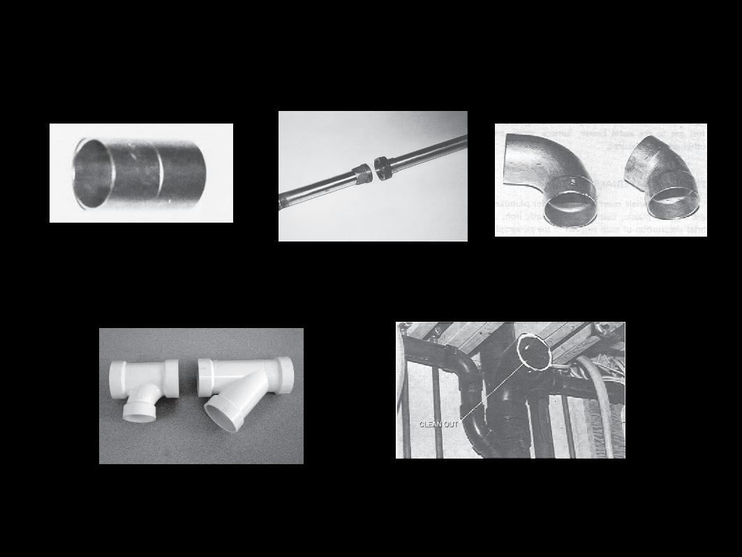
Figure 35–1. A coupling is used to permanently join lengths of pipe.
Figure 35–2. A union allows the piping to be disconnected easily.
Figure 35–3. Street 90° elbow and 45° elbow.
Figure 35–4. Sanitary tee and wye.Figure 35–5. A cleanout allows access to the system.
Design of Supply Plumbing
• In most communities, water is distributed through a system of water mains under or near the streeto When a new house is constructed, municipal water department
taps this maino A water meter is installed where water enters the house and
measures water usedo Cold-water and hot-water distribution piping runs through the
house
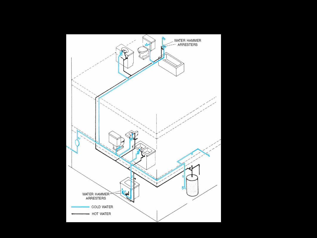
Figure 35–6. Hot- and cold-water piping.
Drainage Waste and Vent System
• Main purpose of a drainage system is to remove wastewater and solids from a buildingo A drain is installed at each fixtureo All individual drains are connected to create a building drain,
which connects to the sewer Sewer conveys wastewater and solids to a municipal sewer, septic tank,
or other point of disposal
Drainage Waste and Vent System (cont’d.)• Vents allow air circulation to equalize positive and negative piping pressures
• Traps are fittings that fill with water to prevent sewer gas from entering the buildingo As water rushes through a trap, it is possible for a siphoning
action start Vent openings allow air pressure to enter the system and break trap
suction
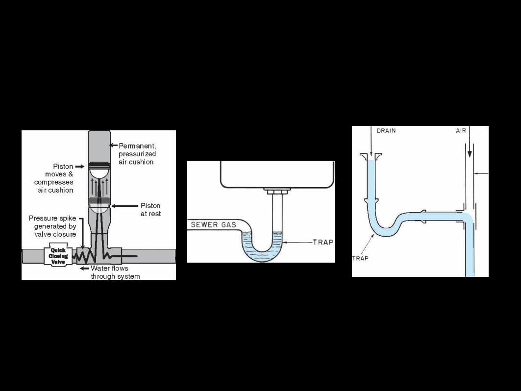
Figure 35–7. Water hammer arrester.
Figure 35–8. A trap fills with water to prevent sewer gas fromentering the building.
Figure 35–10. Venting a trap allows air to enter the system andprevents siphoning.
Drainage Waste and Vent System (cont’d.)
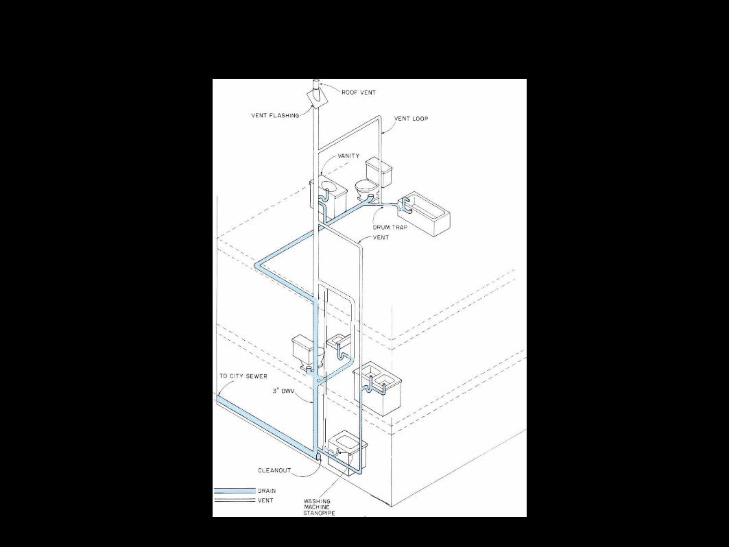
Figure 35–11. DWV system.
Plumbing Plans
• Floor plans show all plumbing fixtures by standard symbols
• Fixture dimensions are provided by manufacturers on rough-in sheets
• For simple plumbing, plumbers prepare estimates and bids
• For complex plumbing, plumbing contractors draw a plumbing isometric
Heating, Ventilating, and Air Conditioning• Plans for residential construction do not usually include sheets for HVAC (heating, ventilating, and air conditioning)o Floor plans include basic information
Location of furnace, air-handling unit, or air-conditioning unit Diffuser and air return locations
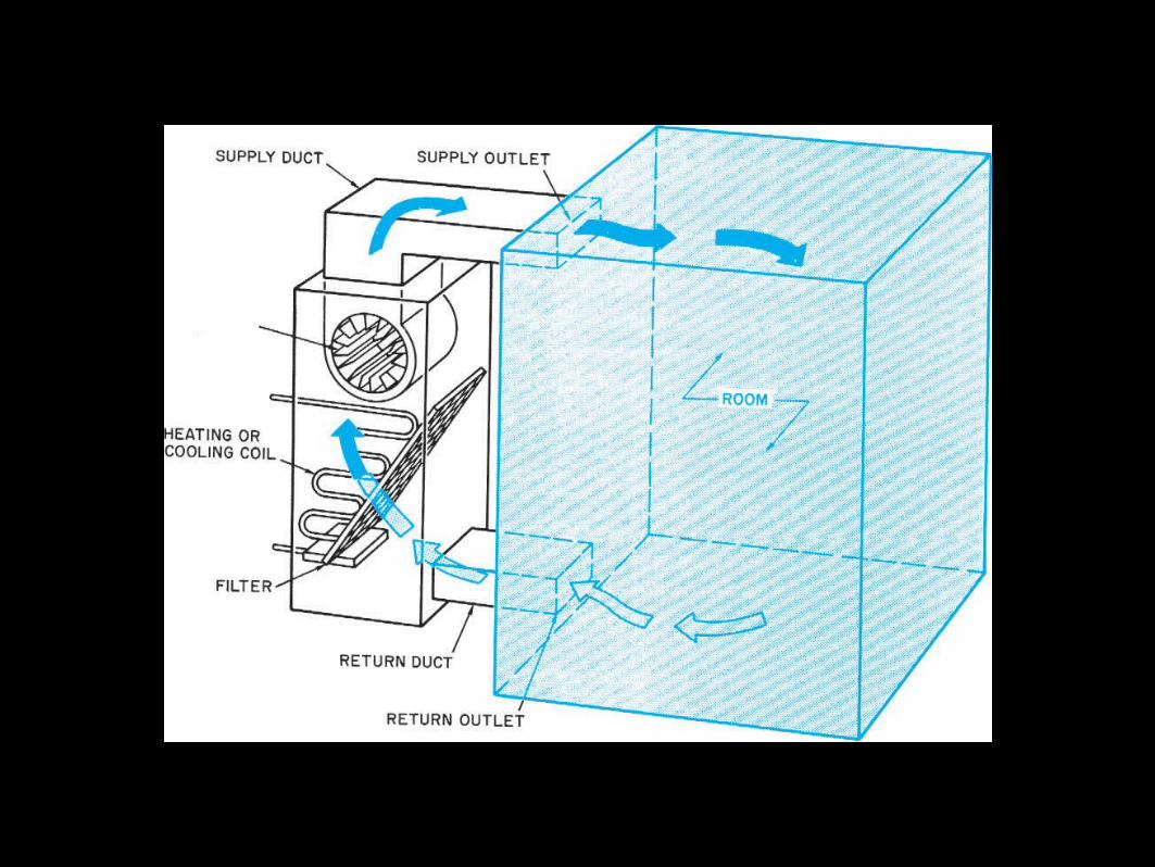
Figure 35–15. The air cycle in a forced-air system.
Electrical
Objectives
• After completing this unit, you will be able to perform the following tasks:o Identify the electrical symbols shown on a plano Explain how the lighting circuits are to be controlled
Current, Voltage, Resistance, and Watts• To do work, electrical energy must have movemento Current is movement
Measured in ampereso Voltage is the force behind an electric currento Resistance is the ease or difficulty with which the current flows
As resistance goes up, current flow goes down
Current, Voltage, Resistance, and Watts (cont’d.)
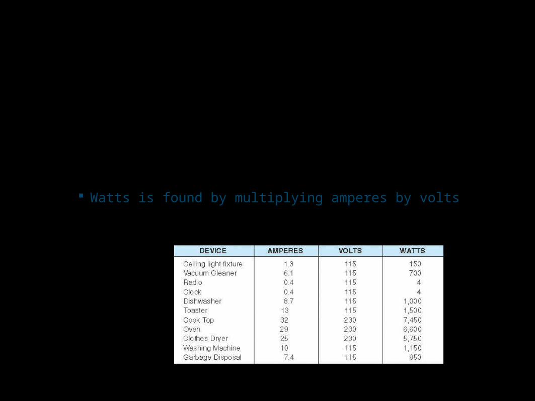
• Amount of work electricity can do depends on current amount and current forceo Electrical work is measured in watts
Watts is found by multiplying amperes by volts
Figure 36–1. Current, voltage, and power ratings of some typical electrical devices.
Circuits
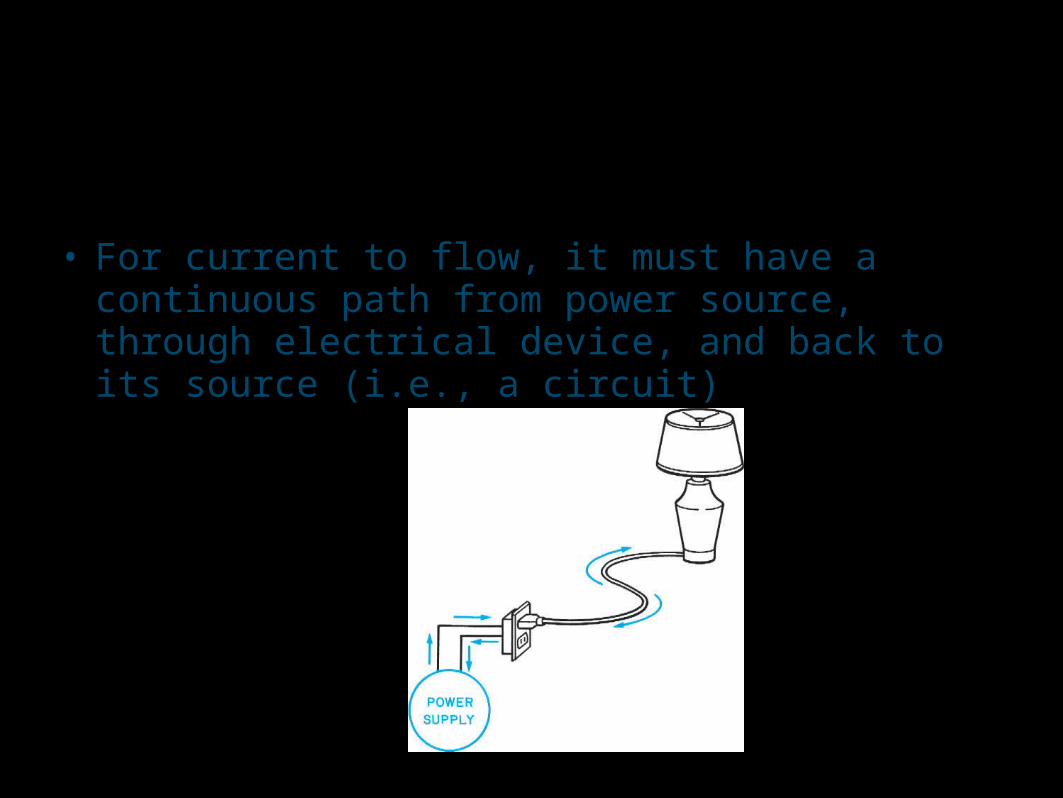
• For current to flow, it must have a continuous path from power source, through electrical device, and back to its source (i.e., a circuit)
Figure 36–2. A complete circuit includes a path from the supply to the device and back again.
Circuits (cont’d.)
• A switch allows the continuous path to be broken• Using two 3-way switches, the circuit can be controlled
from two places• Material carrying electric current is a conductor
o When two or more wire conductors are bundled together, they make a cable
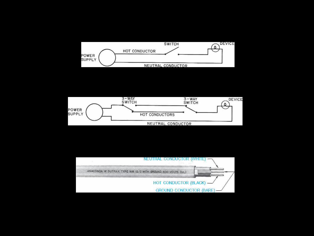
Figure 36–3. A switch is used to break (or open) the circuit.
Figure 36–4. Three-way switches allow a device to be controlled from two locations. Notice that if either switch is activated, the device will be energized.
Figure 36–5. This cable has two circuit conductors and one ground conductor. Courtesy of Anaconda Wire and Cable Division.
Circuits (cont’d.)
• Conduits are made by pulling individual wires through steel or plastic pipes o Used in larger buildings
• In houses, cables containing wires plus one ground conductor are commono Ground does not carry current and protects from shock
Circuits (cont’d.)
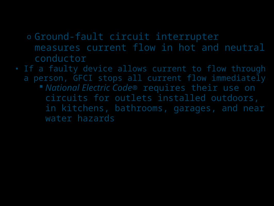
o Ground-fault circuit interrupter measures current flow in hot and neutral conductor
• If a faulty device allows current to flow through a person, GFCI stops all current flow immediately
National Electric Code® requires their use on circuits for outlets installed outdoors, in kitchens, bathrooms, garages, and near water hazards
Circuits (cont’d.)
• Service feeder cable ends at a distribution panelo From the distribution panel, electrical system splits into several
branch circuits Each branch includes a circuit breaker or fuse
o Circuit breaker or fuse opens the circuit if current flow exceeds rated circuit capacity
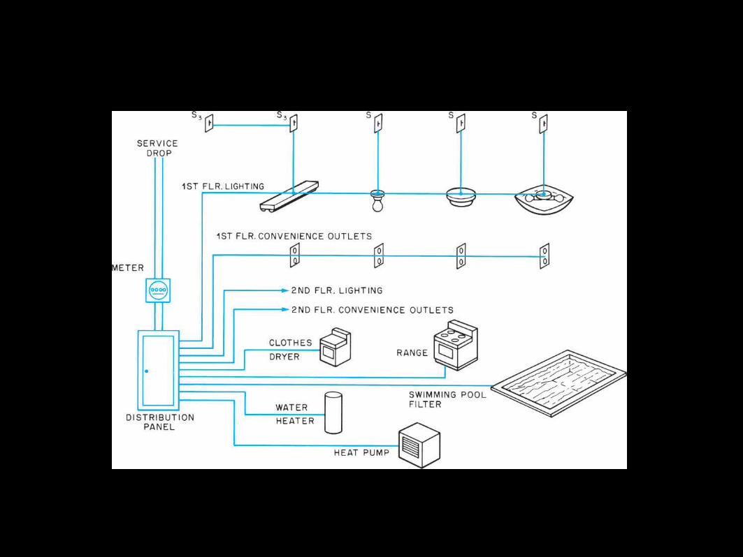
Figure 36–6. The electrical service is split up into branch circuits at the distribution panel.

Circuits (cont’d.)
• National Electrical Code® specifies the design of safe electrical system o Items include:
Kinds and sizes of conductors Locations of outlets and devices Overcurrent protection Number of conductors allowed in a box Safe construction of devices Grounding Switches
Electrical Systems on Plans
• Residential construction drawings include electrical information on floor planso Only symbols for outlets, light fixtures, switches, and switch
wiring are includedo Exact location may not be includedo Wiring is left to electrician’s judgment and electrical code
regulations
Electrical Systems on Plans (cont’d.)
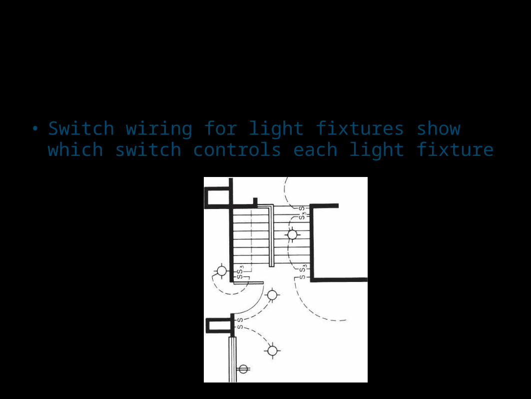
• Switch wiring for light fixtures show which switch controls each light fixture
Figure 36–7. Switch legs on a plan.
Electrical Systems on Plans (cont’d.)
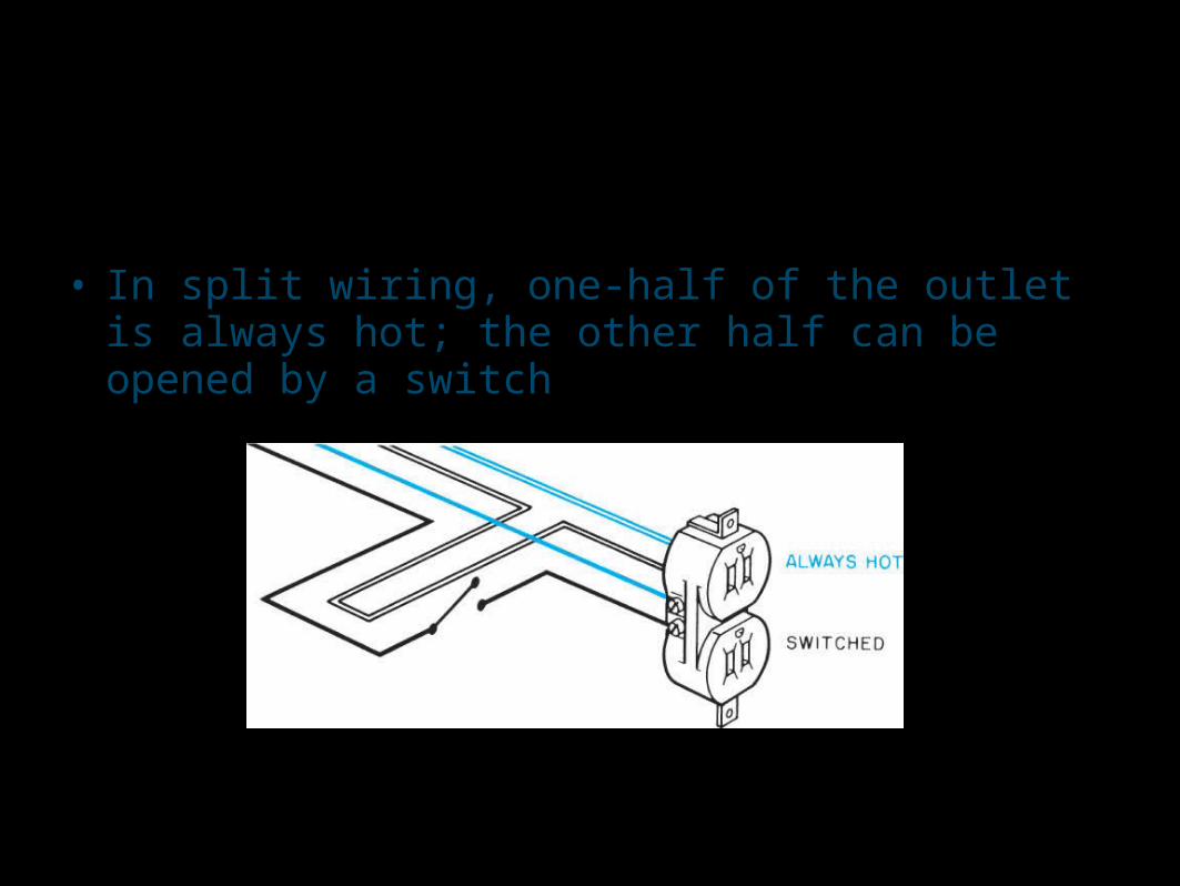
• In split wiring, one-half of the outlet is always hot; the other half can be opened by a switch
Figure 36–8. Split-wired outlet.