hustler sport parts manual - midtnequipment.com...your hustler dealer for current information and...
TRANSCRIPT

•••••••Hustler Turf Equipment
•••••P.O. Box 7000
•••Hesston, Kansas
•67062-2097
Hustler SportParts Manual
t-2 110907 07/10
NOTICE OF REQUIREMENT OF SPARK ARRESTER MUFFLER
This equipment may create sparks that can start fires around dry vegetation. California Public Resources Code Sec-tion 4442.6 provides that it is unlawful to use or operate an internal combustion engine on any forest-covered, brush-covered, or grass-covered land unless the engine is equipped with a spark arrester maintained in effective working order. A spark arrester is a device constructed of nonflammable materials specifically for the purpose of removing and retaining carbon and other flammable particles over 0.0232 of an inch in size from the exhaust flow of an internal combustion engine that uses hydrocarbon fuels or which is qualified and rated by the United States For-est Service. Other states or federal areas may have similar laws. The Operator Should Contact Local Fire Agencies For Laws or Regulations Relating to Fire Prevention Requirements. THIS EQUIPMENT DOES NOT HAVE A SPARK ARRESTER AND YOU SHOULD CONTACT YOUR AUTHORIZED DEALER FOR THE PURCHASE OF A SPARK ARRESTER.
Inspect spark arrester daily; replace every 500 hours or as needed.
The Engine Owner’s Manual provides information regarding the U.S. Environmental Protection Agency (EPA) and the California Emission Control Regulation of emission systems, maintenance and warranty.
Keep Engine Owner’s Manual with your unit. Should the Engine Owner’s Manual become damaged or illegi-ble, replace immediately. Replacements may be ordered per the information found in the Product Informa-tion section of the owner’s manual.
The engine exhaust from this product contains chemicals known to the State
of California to cause cancer, birth defects or other reproductive harm.
WARNING:

110907 07/10 c-1
Table of ContentsSection 1
General Information . . . . . . . . . . . . . . . . . . . . . . . . . . . . . . . . . . . . 1-1Section 2 Contents
Frame . . . . . . . . . . . . . . . . . . . . . . . . . . . . . . . . . . . . . . . . . . . . . . . 2-2Additional California Decals . . . . . . . . . . . . . . . . . . . . . . . . . . . . . . 2-4Engine Guard . . . . . . . . . . . . . . . . . . . . . . . . . . . . . . . . . . . . . . . . . 2-5
Section 3 ContentsHydraulic System . . . . . . . . . . . . . . . . . . . . . . . . . . . . . . . . . . . . . . 3-2Steering. . . . . . . . . . . . . . . . . . . . . . . . . . . . . . . . . . . . . . . . . . . . . . 3-6Steering Sub-Assembly. . . . . . . . . . . . . . . . . . . . . . . . . . . . . . . . . . 3-8Park Brake . . . . . . . . . . . . . . . . . . . . . . . . . . . . . . . . . . . . . . . . . . . 3-14
Section 4 ContentsWheel & Tire—42/48" Decks . . . . . . . . . . . . . . . . . . . . . . . . . . . . . 4-2Wheel & Tire Breakdown—42/48" Decks . . . . . . . . . . . . . . . . . . . . 4-4Wheel & Tire—54" Decks . . . . . . . . . . . . . . . . . . . . . . . . . . . . . . . . 4-6Wheel & Tire Breakdown—54" Decks . . . . . . . . . . . . . . . . . . . . . . 4-8
Section 5 ContentsEngine, 17 HP/ 21 HP Briggs . . . . . . . . . . . . . . . . . . . . . . . . . . . . . 5-2Engine, 26 HP Briggs . . . . . . . . . . . . . . . . . . . . . . . . . . . . . . . . . . . 5-4Engine, Honda GXV 530. . . . . . . . . . . . . . . . . . . . . . . . . . . . . . . . . 5-6Fuel System . . . . . . . . . . . . . . . . . . . . . . . . . . . . . . . . . . . . . . . . . . 5-8
Section 6 ContentsInstrument Panel, 17/21 Briggs. . . . . . . . . . . . . . . . . . . . . . . . . . . . 6-2Instrument Panel, 26 Briggs . . . . . . . . . . . . . . . . . . . . . . . . . . . . . . 6-4Instrument Panel, Honda . . . . . . . . . . . . . . . . . . . . . . . . . . . . . . . . 6-6Battery. . . . . . . . . . . . . . . . . . . . . . . . . . . . . . . . . . . . . . . . . . . . . . . 6-8Electrical Schematic—Briggs (601676). . . . . . . . . . . . . . . . . . . . . . 6-10Electrical Schematic—Honda GXV 530 (602096). . . . . . . . . . . . . . 6-11
Section 7 Contents42" Deck Decals—Forward Swept . . . . . . . . . . . . . . . . . . . . . . . . . 7-242" Deck Decals—Rear Swept . . . . . . . . . . . . . . . . . . . . . . . . . . . . 7-448" Deck Decals . . . . . . . . . . . . . . . . . . . . . . . . . . . . . . . . . . . . . . . 7-654" Deck Decals . . . . . . . . . . . . . . . . . . . . . . . . . . . . . . . . . . . . . . . 7-842" Deck Pulleys and Spindles—Forward Swept . . . . . . . . . . . . . . 7-10Deck Pulleys and Spindles . . . . . . . . . . . . . . . . . . . . . . . . . . . . . . . 7-1248" Deck Pulleys and Spindles . . . . . . . . . . . . . . . . . . . . . . . . . . . . 7-1454" Deck Pulleys and Spindles . . . . . . . . . . . . . . . . . . . . . . . . . . . . 7-1642" Deck—Forward Swept . . . . . . . . . . . . . . . . . . . . . . . . . . . . . . . 7-1842" Deck—Forward Swept Belt Routing & Tensioning . . . . . . . . . . 7-2042" Deck—Rear Swept . . . . . . . . . . . . . . . . . . . . . . . . . . . . . . . . . . 7-2242" Deck—Rear Swept Belt Routing & Tensioning. . . . . . . . . . . . . 7-2448" Deck . . . . . . . . . . . . . . . . . . . . . . . . . . . . . . . . . . . . . . . . . . . . . 7-2648" Deck Belt Routing & Tensioning . . . . . . . . . . . . . . . . . . . . . . . . 7-2854" Deck . . . . . . . . . . . . . . . . . . . . . . . . . . . . . . . . . . . . . . . . . . . . . 7-3054" Deck Belt Routing and Tensioning . . . . . . . . . . . . . . . . . . . . . . 7-32DeckLift . . . . . . . . . . . . . . . . . . . . . . . . . . . . . . . . . . . . . . . . . . . . . . 7-34Deck Mounting Hardware . . . . . . . . . . . . . . . . . . . . . . . . . . . . . . . . 7-36

c-2 110907 07/10
Section 8 ContentsSeat . . . . . . . . . . . . . . . . . . . . . . . . . . . . . . . . . . . . . . . . . . . . . . . . 8-2
Index. . . . . . . . . . . . . . . . . . . . . . . . . . . . . . . . . . . . . . . . . . . . . . . . . . . . . . . . i-1

110907 07/10 1-1
Section 1
General Information
This Manual covers Hustler Sport models 929125, 929125CA, 929133, 929133CA, 929463, 929471, 929596, 929851 & 929869.
Frequently Ordered Parts
Options Available From Your Dealer
Service Literature
Note: When ordering parts, you must use the part number as shown for each part, not the item number. Always give the model and serial number to your parts and service representative.
Note: Items sold in bulk such as seals and hoses are sold by the foot.
PART NO. DESCRIPTION PART NO. DESCRIPTION769133 Pump Drive Belt600726 Deck Belt 42" 771634 Deck Belt 48"777185 Deck Belt 54" 601124 Blade, 18.50"-L-F-CW601123 Blade, 16.50"-L-F-CW 793794 Blade, 20.50"-L-F-CW601846 Filter, Air Precleaner, 17.5 HP Briggs 601847 Filter, Air Flat Panel, 17.5 HP Briggs601848 Filter, Air Precleaner, 21 HP Briggs 601849 Filter, Air Cartridge, Briggs602570 Filter, Air Cartridge, 26 HP Briggs 602571 Filter, Air Precleaner, 26 HP Briggs601845 Engine Oil Filter 17.5/21 HP Briggs 068478 Fuel Filter In-Line, Briggs602572 Engine Oil Filter 26 HP Briggs 787234 Engine Oil Filter, Honda785626 Fuel Filter, Honda 787226 Air Filter, Honda
PART NO. DESCRIPTION PART NO. DESCRIPTION929216 Catcher, 2-Bag 42" Sport 111164 Mulch Kit, 48" Sport929828 Catcher, 2-Bag 48" Sport 112609 Mulch Kit, 42" Sport929836 Catcher, 2-Bag 54" Sport 112611 Mulch Kit, 54" Sport112614 Containment Kit, 48" 111167 Hour Meter Kit112615 Containment Kit, 54" 110737 Sport LED Light Kit
PART NO. DESCRIPTION
111176 Hustler Sport Owner’s Manual601865 Briggs & Stratton 17.5 HP Engine Manual601866 Briggs & Stratton 21 HP Engine Manual602607 Briggs & Stratton 26 HP Engine Manual787242 Honda 16 HP Engine Manual

1-2 110907 07/10
Using this manual
Illustrations used were current at the time of printing, but subsequent production changes may cause your machine to vary slightly in detail. Excel Industries, Inc. reserves the right to redesign and change the machine as deemed neces-sary, without notification. If a change has been made to your machine which is not reflected in this parts manual, see your Hustler dealer for current information and parts.
Hardware Description Codes & Abbreviations
The following codes are used throughout this parts manual. Refer to this list when ordering parts.
Standard Torques
The following chart lists the standard torque values for the threaded fasteners found in this manual. Torque all cap screws, nuts and set screws to these values unless a different torque is shown in the Notes section next to the fastener
NOTE:
Loctite 592 to be used on all pipe threads.Lubricate all grease zerks.
ABBREVIATION DESCRIPTION ABBREVIATION DESCRIPTIONCB Carriage Bolt MB Machine BushingCE Clevis Pin MS Machine ScrewCP Cotter Pin NT NutCN Clip Nut SC Self Tapping Cap ScrewCS Cap Screw SH Socket HeadCW Cup Washer SB Shoulder Bolt
FDRW Fender Washer SS Set ScrewFW Flat Washer OD Outside DiameterHX Hex Head ID Inside DiameterLW Lock Washer
SIZE FT-LBS NM SIZE FT-LBS NM
.250 8.2 11.1 M3 1 1.3
.312 17 23 M4 2.2 3
.375 30 40 M5 4.5 6.1
.438 48 65 M6 7.7 10.4
.500 73 99 M8 18.5 25
.562 105 143 M10 37 50
.625 145 200 M12 64 87
.750 260 350 M16 160 215
.875 420 565 M20 320 4351.00 625 850 M24 555 750

110907 07/10 2-1
Section 2 Contents
Frame . . . . . . . . . . . . . . . . . . . . . . . . . . . . . . . . . . . . . . . . . . . . . . . . 2-2
Additional California Decals. . . . . . . . . . . . . . . . . . . . . . . . . . . . . . . . 2-4
Engine Guard. . . . . . . . . . . . . . . . . . . . . . . . . . . . . . . . . . . . . . . . . . . 2-5

2-2 110907 07/10
Frame1
2
34
5
910
7
14
13
12
6
6
15
16
11
81
2
3
1
110907 07/10 2-3
Frame
NOTES:
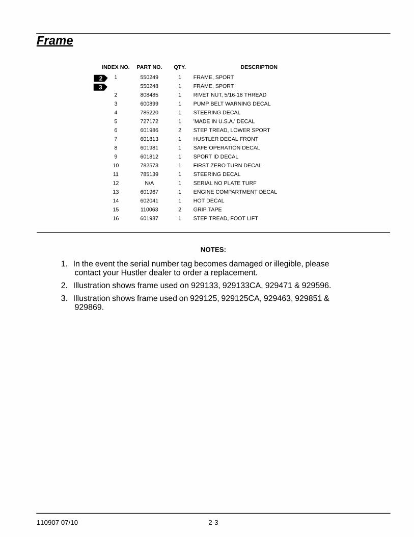
1. In the event the serial number tag becomes damaged or illegible, please contact your Hustler dealer to order a replacement.
2. Illustration shows frame used on 929133, 929133CA, 929471 & 929596.3. Illustration shows frame used on 929125, 929125CA, 929463, 929851 &
929869.
INDEX NO. PART NO. QTY. DESCRIPTION
1 550249 1 FRAME, SPORT550248 1 FRAME, SPORT
2 808485 1 RIVET NUT, 5/16-18 THREAD3 600899 1 PUMP BELT WARNING DECAL4 785220 1 STEERING DECAL5 727172 1 'MADE IN U.S.A.' DECAL6 601986 2 STEP TREAD, LOWER SPORT7 601813 1 HUSTLER DECAL FRONT8 601981 1 SAFE OPERATION DECAL9 601812 1 SPORT ID DECAL
10 782573 1 FIRST ZERO TURN DECAL11 785139 1 STEERING DECAL12 N/A 1 SERIAL NO PLATE TURF13 601967 1 ENGINE COMPARTMENT DECAL14 602041 1 HOT DECAL15 110063 2 GRIP TAPE16 601987 1 STEP TREAD, FOOT LIFT
23

2-4 110907 07/10
Additional California Decals
NOTES:
1. In the event the serial number tag becomes damaged or illegible, please contact your Hustler dealer to order a replacement.
INDEX NO. PART NO. QTY. DESCRIPTION
1 083279CA 1 DECAL, CA EMISSIONS2 601908 1 DECAL, SPARK ARRESTOR
12
110907 07/10 2-5
Engine Guard
NOTES:
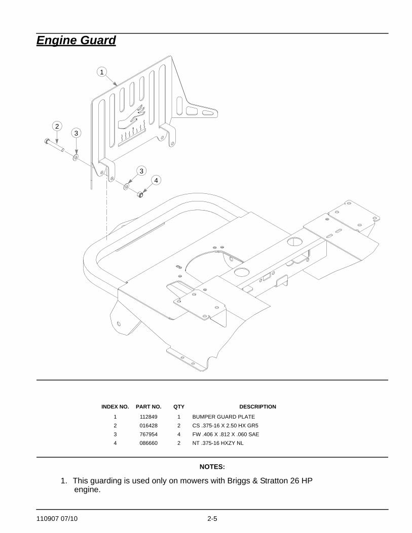
1. This guarding is used only on mowers with Briggs & Stratton 26 HP engine.
INDEX NO. PART NO. QTY DESCRIPTION
1 112849 1 BUMPER GUARD PLATE2 016428 2 CS .375-16 X 2.50 HX GR53 767954 4 FW .406 X .812 X .060 SAE4 086660 2 NT .375-16 HXZY NL
1
2
4
3
3

2-6 110907 07/10

110907 07/10 3-1
Section 3 Contents
Hydraulic System. . . . . . . . . . . . . . . . . . . . . . . . . . . . . . . . . . . . . . . . 3-2
Steering . . . . . . . . . . . . . . . . . . . . . . . . . . . . . . . . . . . . . . . . . . . . . . . 3-6
Steering Sub-Assembly . . . . . . . . . . . . . . . . . . . . . . . . . . . . . . . . . . . 3-8
Park Brake. . . . . . . . . . . . . . . . . . . . . . . . . . . . . . . . . . . . . . . . . . . . 3-14
3-2 110907 07/10
Hydraulic System
1
2
6
10
12
10
5
8
7
11
4
3
1
3
9
1012
10

110907 07/10 3-3
Hydraulic System
NOTES:
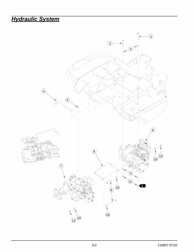
1. Torque to 17 ft-lbs.2. Service parts available for the transaxles:
INDEX NO. PART NO. QTY. DESCRIPTION
1 043067 4 CS .312-18X3.00 HX G5 Z2 710087 4 CS .312-18X2.500 HX G53 768523 16 FW .343X.687X.051/.080H4 793174 2 TOWLINK ROD5 048553 2 CP .062DX1.000 LG HML Z6 601391 2 EZT, 19.2 RIGHT TRANSMISSION7 601390 1 EZT, 19.2 LEFT TRANSMISSION8 110042 1 HYDROSTAT CROSS BRACE9 056036 4 CS .375-16X2.250 HX G5 ZN
10 767954 8 FW .406 X .812 X .060 SAE HRD ZN11 034272 8 NT .312-18 HX G5 ZN12 054502 4 NT .375-16 HX G5 ZN
PART NUMBER DESCRIPTION PART
NUMBER DESCRIPTION
788877 IZT, HUB NUT 798371 RING, RETAINING788232 IZT, HUB ASSEMBLY 601941 FAN/PULLEY KIT798363 GEAR, PARK BRAKE 795047 PARKING PAWL KIT, EZT

3-4 110907 07/10
Hydraulic System
13
14
20
16
17
23
19
18
3
21
22
24
15
15
15

110907 07/10 3-5
Hydraulic System
NOTES:
3. Torque to 100 ft-lbs.
Hydraulic pump belt adjustmentThe transaxle drive belt tension remains constant by means of a tension idler and spring. There is notension adjustment of this belt.
NOTE: Inspect the belt every 100 hours and replace as needed. Replace the beltevery 200 hours or every two (2) years whichever comes first.WARNING: If the transaxle belt fails, loss of control will occur especially when operating on a slope. Ifyou lose steering control while operating the machine, place the steering control levers in the parkbrake position immediately. Inspect the machine and involve your Hustler dealer to resolve theproblem before continuing to operate.
INDEX NO. PART NO. QTY. DESCRIPTION
13 017616 1 CS .500-13X1.75 HX GR5 ZN14 601983 1 CS .625-11 X 2.25 HX G5 ZY15 028118 3 FW .625X1.00X.134 ZNYC16 036384 1 SPRING 1/4 COIL PL 1.2317 111079 1 PUMP IDLER, FORMED18 601398 1 SPACER, PUMP IDLER19 784827 1 IDLER PULLEY, 4.00"OD20 016972 1 NT .625-11 HX G5 ZNYC21 602026 2 BEARING DISC22 602025 1 BUSHING, IGUS .500 I.D.23 781567 1 NT .500-13 HX G8 ZY NL24 769133 1 BELT, A 67.24" EL

3-6 110907 07/10
Steering
1
23
4
3
83
9
3 6
37
103
7
3
34
5
SteeringSub-Assembly

110907 07/10 3-7
Steering
NOTES:
1. Service parts for Damper:
INDEX NO. PART NO. QTY. DESCRIPTION
1 600221 2 STEERING DAMPER2 781922 4 BALL STUD, DAMPER3 768523 17 FW .343X.687X.051/.080H4 023655 4 NT .312-24 HXZY NL5 784439 2 LOCK COLLAR,0.757 ID6 600981 2 PUMP ROD ASSEMBLY7 034272 4 NT .312-18 HX G5 ZNYC8 034280 1 CS .312-18X .750 HX G59 110014 1 PIVOT TUBE ASSEMBLY
10 029876 2 LW .312 INT-EXT TOOTH Z
PART NUMBER DESCRIPTION
601425 CONNECTOR BODY601426 CAP LOCK

3-8 110907 07/10
Steering Sub-Assembly
1
2
6
4
4
9
12
13
14
12
11
5
5
74
10
4
3
2

110907 07/10 3-9
Steering Sub-Assembly
NOTES:
1. Left side steering sub-assembly is shown; the right side is similar.2. Item 2 (Steering Bar) includes Item 1 (Steering Bar Grip).
INDEX NO. PART NO. QTY. DESCRIPTION
1 781260 2 GRIP, STEERING BAR2 110370 2 STEERING BAR3 054502 4 NT .375-16 HX GRD 5 ZNY4 767954 12 FW .406X .812 X.060 SAE5 770867 4 BUSHING, PLAS .750X1(FS)6 086660 2 NT .375-16 HXZY NL7 110008 1 STEERING BOX LH8 110007 1 STEERING BOX RH (NOT SHOWN)9 705178 2 CS .375-16X1.750 HX G5
10 080655 4 CS .375-16X1.500 HX G511 110089 2 CONTROL LEVER12 768523 4 FW .343X.687X.051/.080H13 796615 2 BALL JOINT LINK14 023655 2 NT .312-24 HXZY NL

3-10 110907 07/10
Steering Adjustments
Steering linkageThe neutral adjustment for the control levers in the neutral position is discussed in this section.The tractor steering has been factory adjusted to eliminate creeping when the control levers are in theneutral position (FIG. 1). However, should the mower begin to creep, the control lever linkage can beadjusted as follows:
CONTROL LEVER NEUTRAL ADJUSTMENT Before considering any adjustment, check the tire air pressure. Unequal tire pressure will cause the mowerto drift to one side. Refer to tire pressure information in the Maintenance section of this manual.
NOTE: Proper park brake adjustment must be completed before the control leverneutral adjustment can be done.
Fine adjustment to the unit’s steering is made with the transaxle control rod. (FIG. 2).Neutral is properly adjusted when the control levers are in the park brake position and the ZT 2800transaxles do not “whine”.If this occurs, the control linkage may be adjusted as follows:
1. Park the unit on a flat surface, raise the rear of the mower and block with certified jack stand. With the park brakesset, start the engine (FIG. 2). Once the engine is started, if the ZTs whine while the park brake is engaged, thenneutral needs to be reset. Turn off the engine.
WARNING: Never work under the machine or attachment unless it is safely supported with jackstands. Make certain machine is secure when it is raised and placed on the jack stands. The jackstands should not allow the machine to move when the engine is running and the drive wheels arerotating. Use only certified jack stands. Use only appropriate jack stands, with a minimum weightrating of 2000 pounds to block the unit up. Use in pairs only. Follow the instructions supplied with thevehicle stands.
WARNING: This is a dangerous operation - keep hands, hair, clothing, etc., clear of the cooling fanson top of the ZTs! Exercise extreme caution.
WARNING: .Never attempt to make any adjustments or repairs to the mower drive system while theengine is running. The following procedures should be performed by trained maintenancepersonnel only.
2. Loosen and back off the jam nuts on both ends of the steering control rod assembly (FIG. 2). Set the steering con-trol lever in the neutral/brake position.
FIG. 1
CONTROL LEVER IN THE
CONTROLLEVER
NEUTRAL POSITION

110907 07/10 3-11
3. Remove the female spade connectors from the seat switch (located under the seat). These will need to be con-nected together now to bypass the seat switch to perform the following functions. This must only be done by aqualified Hustler Dealer.
4. Make sure the steering damper ball studs attached to the frame at the rear of the damper on either side are looseand allowed to slide in the slot.
5. Both steering control levers need to be in the brake position when starting the engine, but need to quickly bemoved out of the brake position once engine is started so the brakes do not fight the transmissions since they havenot yet been adjusted.
6. Start the engine. Move the control lever to just engage the brake (neutral) slot and hold it in that position (Do notengage the control lever far enough to engage the brakes in the brake slot) (FIG. 3).
WARNING: This operation is extremely dangerous. Pay close attention when adjusting thetransaxle control rod so you do not get your fingers, tools, or anything else close to the EZTtransaxle’s cooling fans.
7. Beginning with the RH side of the mower, adjust the steering control rod so that the RH drive axle just starts turningin the forward rotation while the steering lever remains in the neutral positon. Now, turn the steering rod back theopposite direction to the point when the drive axle stops spinning. From that point, turn the steering rod back again½ turn. This ensures that the steering rod is adjusted so that the transmission control arm is centered in the neutralband of the transmission.
FIG. 2 FIG. 3
FIG. 4 FIG. 5
CONTROL LEVER IN THE
JAM NUT
STEERING
JAM NUT
NEUTRAL POSITION
CONTROL ROD
DAMPER CONTROL LEVERS IN PARK BRAKE POSITION
ENGINE
JACK STANDS
GUARD
REAR DAMPER
STEERINGDAMPER
BALL STUD

3-12 110907 07/10
8. Move the lever forward and backward and make sure that the drive axle spins forward and backward correctly.Return the steering lever to neutral and re-check to make sure the drive axle is stopped in the neutral position.Lock the steering control lever into the brake position. You should not hear the transmission whine if neutral isproperly set.
9. Turn off the engine.10.With the engine off, move the RH steering control lever into the neutral position and pull the lever all the way back
to the rear of the mower as if you were going full speed in reverse. Now, slowly bring the lever back to the neutralposition and lock it into the brake position. This sets the steering damper in the correct neutral position. Tightenthe ball stud at the rear of the damper that is attached to the frame side panel on the RH side (FIG. 5). Once thisis tightened, you should be able to move the steering control lever to the reverse position, let it go, and the steeringlever should return itself to the neutral position. This should finish the adjustment for the RH side steering control.Double check to make sure you have all fasteners tightened to the correct torque specifications.
11. Repeat steps 4 thru 9 for the LH side.12.Once both sides are properly adjusted, double check them together to make sure everything is working properly.13. IMPORTANT: With the engine off, disconnect the two female spade connectors from each other (from step #3)
and reconnect them to the seat switch. This must be completed so the safety circuit is functioning properly. Referto the machine’s owner’s manual for operation check.
WARNING: Do not operate the mower without plugging the mower wiring harness into the seatswitch. This switch is an important part of the safety start interlock system. Serious injury can resultif the seat switch is not plugged into the mower’s wiring harness.
14.Check to make sure all tools or obstructions are removed from under the mower. Assemble the drive wheels andlugnuts. Torque the lugnuts to 65-75 ft-lbs.
15.Jack up the rear of the mower and remove the jack stands. Lower the mower to the ground and remove the jack.16.The control levers should be adjusted so that they align vertically with each other when in the neutral position.
Space between ends of control handles to be .50" ±.25".17.Check the hydraulic oil level after final adjustments. Make sure oil level is within operating range specified.
Steering damperThe steering damper (FIG. 5) is spring loaded to return the control levers to the neutral position from thereverse position. This gives the operator a sense of neutral during operation.If the mower does not return to neutral from reverse then adjust as follows:To set the steering dampers in the correct operating position follow these steps:
1. Shut engine off, place control levers in the park brake position, disengage deck clutch, remove ignition switch key and disconnect negative battery cable before doing any adjustments.
2. Place the control lever in the neutral position (FIG. 1).3. Loosen the steering damper’s rear ball stud (FIG. 5).4. Pull the damper spring housing, to the rear, past the point that the internal spring is engaged.5. Release the damper spring housing and allow the internal spring to bring the housing back to the neutral position.6. Tighten the nut on the steering damper’s rear ball stud.7. To check, move the control lever to the reverse position and release. The control lever should return to the neutral
position. If not, repeat steps 1 through 6.

110907 07/10 3-13
This page intentionally left blank.

3-14 110907 07/10
Park Brake
1
16
6
4
89
14
13
12
5
7
7
1110
3
10
15
CONNECTS TOSTEER PIVOT
BELL CRANKDETAIL
110907 07/10 3-15
Park Brake
NOTES:
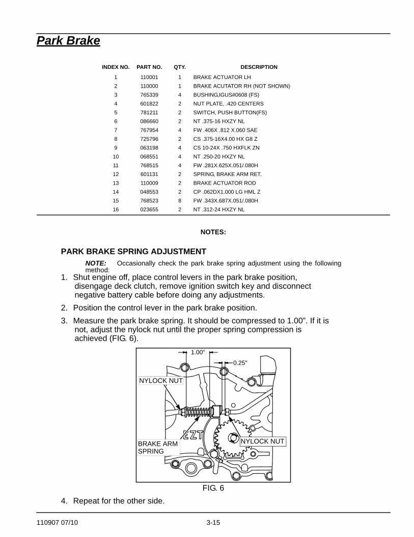
PARK BRAKE SPRING ADJUSTMENTNOTE: Occasionally check the park brake spring adjustment using the followingmethod:
1. Shut engine off, place control levers in the park brake position, disengage deck clutch, remove ignition switch key and disconnect negative battery cable before doing any adjustments.
2. Position the control lever in the park brake position.3. Measure the park brake spring. It should be compressed to 1.00”. If it is
not, adjust the nylock nut until the proper spring compression is achieved (FIG. 6).
4. Repeat for the other side.
INDEX NO. PART NO. QTY. DESCRIPTION
1 110001 1 BRAKE ACTUATOR LH2 110000 1 BRAKE ACUTATOR RH (NOT SHOWN)3 765339 4 BUSHING,IGUS#0608 (FS)4 601822 2 NUT PLATE, .420 CENTERS5 781211 2 SWITCH, PUSH BUTTON(FS)6 086660 2 NT .375-16 HXZY NL7 767954 4 FW .406X .812 X.060 SAE8 725796 2 CS .375-16X4.00 HX G8 Z9 063198 4 CS 10-24X .750 HXFLK ZN
10 068551 4 NT .250-20 HXZY NL11 768515 4 FW .281X.625X.051/.080H12 601131 2 SPRING, BRAKE ARM RET.13 110009 2 BRAKE ACTUATOR ROD14 048553 2 CP .062DX1.000 LG HML Z15 768523 8 FW .343X.687X.051/.080H16 023655 2 NT .312-24 HXZY NL
FIG. 6
NYLOCK NUT
BRAKE ARMSPRING
NYLOCK NUT
1.00"
0.25"

3-16 110907 07/10

110907 07/10 4-1
Section 4 Contents
Wheel & Tire—42/48" Decks . . . . . . . . . . . . . . . . . . . . . . . . . . . . . . . 4-2
Wheel & Tire Breakdown—42/48" Decks . . . . . . . . . . . . . . . . . . . . . 4-4
Wheel & Tire—54" Decks . . . . . . . . . . . . . . . . . . . . . . . . . . . . . . . . . 4-6
Wheel & Tire Breakdown—54" Decks . . . . . . . . . . . . . . . . . . . . . . . . 4-8

4-2 110907 07/10
Wheel & Tire—42/48" Decks
4
9
11
12
13
10
2
10
5
8
2
3
6
3
7
1
2
2
14
1 4
3
15
17
10
10 16

110907 07/10 4-3
Wheel & Tire—42/48" Decks
NOTES:
1. Torque to 65-75 ft. lbs.2. Inflate tire to 8-12 psi.3. Apply grease to zerks (see owners manual).4. Item 1 includes (items 10 &15–17).5. Serial numbers higher than 09080553, use tire/wheel (602079 ) and
caster fork (110116). Serial numbers prior to 09080553, use tire/wheel (768044 ) and caster fork (339689).
INDEX NO. PART NO. QTY. DESCRIPTION
1 788166 2 ANTI-SCALP WHEEL ASSEMBLY2 344267 6 FW .510X 2.15X.187 SPL3 781567 4 NT .500-13 HX G8 ZY NL4 601810 2 TIRE/WHEEL 18X8.5-85 061077 8 WHEEL NUT6 705954 2 CS .500-13X1.25 HX G5 Z7 712976 2 FW .531X 1.375X.125 ZNY8 784223 4 BEARING9 784603 2 SPACER
10 767962 8 FW .531X 1.063X.090 SAE11 042630 2 CS .500-13X6.50 HX G5 Z12 306969 2 GAGE WHEEL SPACER13 602079 2 TIRE/WHL 11X4-5 RIBBED
768044 2 TIRE/WHL 11X4-5 RIBBED14 110116 2 CASTER FORK
339689 2 CASTER FORK15 781708 2 CS .500-13X4.250 HX G516 031997 2 ANTI-SCALP WHEEL17 053199 2 NT .500-13 HX JAM ZNYC
5
5

4-4 110907 07/10
Wheel & Tire Breakdown—42/48" Decks
5
4
4
23
1
Front Wheel
601810
110907 07/10 4-5
Wheel & Tire Breakdown—42/48" Decks
NOTES:
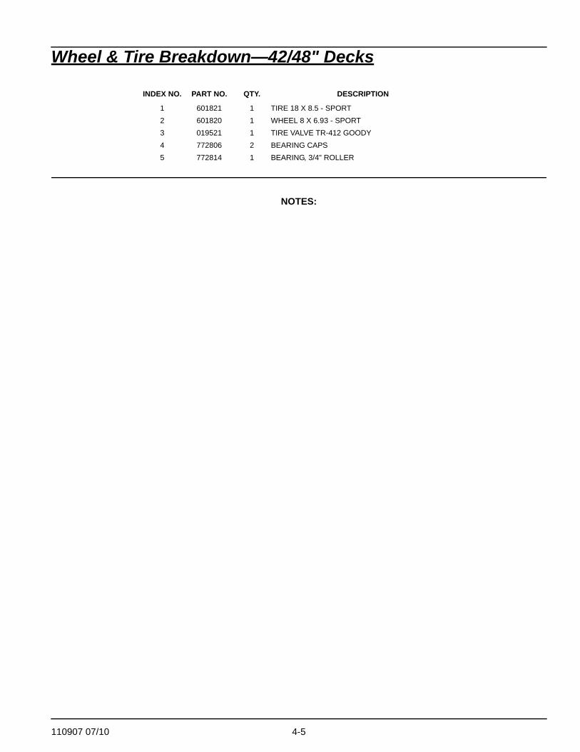
INDEX NO. PART NO. QTY. DESCRIPTION
1 601821 1 TIRE 18 X 8.5 - SPORT2 601820 1 WHEEL 8 X 6.93 - SPORT3 019521 1 TIRE VALVE TR-412 GOODY4 772806 2 BEARING CAPS5 772814 1 BEARING, 3/4" ROLLER

4-6 110907 07/10
Wheel & Tire—54" Decks
4
9
11
12
13
10
2
10
5
8
2
3
6
3
7
1
2
2
14
1 4
3
8
15
17
10
10 16

110907 07/10 4-7
Wheel & Tire—54" Decks
NOTES:
1. Torque to 65-75 ft. lbs.2. Inflate tire to 8-12 psi.3. Apply grease to zerks (see owners manual).4. Item 1 includes (items 10, 15 & 16).
INDEX NO. PART NO. QTY. DESCRIPTION
1 788166 2 ANTI-SCALP WHEEL ASSEMBLY2 344267 6 FW .510X 2.15X.187 SPL3 781567 4 NT .500-13 HX G8 ZY NL4 784264 2 TIRE/WHEEL 18X9.55 061077 8 WHEEL NUT6 705954 2 CS .500-13X1.25 HX G5 Z7 712976 2 FW .531X 1.375X.125 ZNY8 784223 4 BEARING9 784603 2 SPACER
10 767962 8 FW .531X 1.063X.090 SAE11 042630 2 CS .500-13X6.50 HX G5 Z12 306969 2 GAGE WHEEL SPACER13 602079 2 TIRE/WHL 11X4-5 RIBBED14 110116 2 CASTER FORK15 781708 2 CS .500-13X4.250 HX G516 031997 2 ANTI-SCALP WHEEL17 053199 2 NT .500-13 HX JAM ZNYC

4-8 110907 07/10
Wheel & Tire Breakdown—54" Decks
5
4
4
23
1
602079
784264

110907 07/10 4-9
Wheel & Tire Breakdown—54" Decks
NOTES:
INDEX NO. PART NO. QTY. DESCRIPTION
1 784272 1 TIRE 18 X 9.5-82 784280 1 WHEEL 8 X 6.233 019521 1 TIRE VALVE TR-412 GOODY4 772806 2 BEARING CAPS5 772814 1 BEARING, 3/4" ROLLER

4-10 110907 07/10

110907 07/10 5-1
Section 5 Contents
Engine, 17 HP/ 21 HP Briggs . . . . . . . . . . . . . . . . . . . . . . . . . . . . . . 5-2
Engine, 26 HP Briggs . . . . . . . . . . . . . . . . . . . . . . . . . . . . . . . . . . . . 5-4
Engine, Honda GXV 530 . . . . . . . . . . . . . . . . . . . . . . . . . . . . . . . . . . 5-6
Fuel System. . . . . . . . . . . . . . . . . . . . . . . . . . . . . . . . . . . . . . . . . . . . 5-8

5-2 110907 07/10
Engine, 17 HP/ 21 HP Briggs
1
4
3
15
6
7
9
8
53
RED
BLK
1
1
18
12
20
19
21
2
14
11
1012
13
1012
PART OFENGINE
23
RED
1
26
2524
TO FUELTANK
2 28
16
1
TOWARD ENGINE
ORG
122
24PART OFENGINE
27
17
TOBATTERY
110907 07/10 5-3
Engine, 17 HP/ 21 HP Briggs
NOTES:
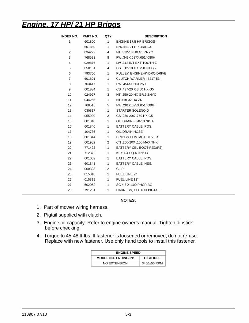
1. Part of mower wiring harness.2. Pigtail supplied with clutch.3. Engine oil capacity: Refer to engine owner’s manual. Tighten dipstick
before checking.4. Torque to 45-48 ft-lbs. If fastener is loosened or removed, do not re-use.
Replace with new fastener. Use only hand tools to install this fastener.
INDEX NO. PART NO. QTY DESCRIPTION1 601800 1 ENGINE 17.5 HP BRIGGS
601850 1 ENGINE 21 HP BRIGGS2 034272 4 NT .312-18 HX G5 ZNYC3 768523 8 FW .343X.687X.051/.080H4 029876 1 LW .312 INT-EXT TOOTH Z5 050161 4 CS .312-18 X 1.750 HX G56 793760 1 PULLEY, ENGINE-HYDRO DRIVE7 601801 1 CLUTCH WARNER I-5217-538 763417 1 FW .454X1.50X.2509 601834 1 CS .437-20 X 3.50 HX G5
10 024927 3 NT .250-20 HX GR.5 ZNYC11 044255 1 NT #10-32 HX ZN12 768515 5 FW .281X.625X.051/.080H13 030817 1 STARTER SOLENOID14 055939 2 CS .250-20X .750 HX G515 601818 1 OIL DRAIN - 3/8-18 NPTF16 601840 1 BATTERY CABLE, POS.17 104786 1 OIL DRAIN HOSE18 601844 1 BRIGGS CONTACT COVER19 601982 2 CN .250-20X .150 MAX THK20 771428 1 BATTERY CBL BOOT-RED(FS)21 712372 1 KEY 1/4 SQ X 0.66 LG22 601062 1 BATTERY CABLE, POS.23 601841 1 BATTERY CABLE, NEG.24 000323 2 CLIP25 015818 1 FUEL LINE 9"26 015818 1 FUEL LINE 12"27 602062 1 SC # 8 X 1.00 PHCR BO28 791251 1 HARNESS, CLUTCH PIGTAIL
ENGINE SPEEDMODEL NO. ENDING IN: HIGH IDLE
NO EXTENSION 3450±50 RPM

5-4 110907 07/10
Engine, 26 HP Briggs
1 123
3
4
5 8
1
6
17
32 2
3
3 910
11
12
1314
15
1617
1819
20
21
22
1.5"
1.75"
TOWARD ENGINE
16
23
24
2526
1
2427
28
29
29 30
1
3
8RED
BLK
BLK
2
TO BATTERYNEGATIVETERMINAL
TO BATTERYPOSITIVETERMINAL

110907 07/10 5-5
Engine, 26 HP Briggs
NOTES:
1. Part of wiring harness (601676).2. Contains a 25 amp fuse.3. Supplied with engine.4. Torque to 45-48 ft-lbs. If fastener is loosened or removed, do not re-use.
Replace with new fastener. Use only hand tools to install this fastener.5. Torque to 30 ft-lbs.6. Engine oil capacity: Refer to engine owner’s manual. Tighten dipstick
before checking.
INDEX NO. PART NO. QTY DESCRIPTION1 602388 1 BRIGGS 26 HP ENGINE2 024927 5 NT .250-20 HX GR5 ZN3 768515 7 FW .281 X .625 X .051/.080 HD4 601062 1 POS BATTERY CABLE 17"5 044255 1 NT #10-32 HX ZN6 055939 2 CS .250-20 X .750 HX G57 030817 1 STARTER SOLENOID8 601840 1 POS BATTERY CABLE 12"9 602062 1 SC # 8 X 1.00 PHCR BO
10 602422 1 STATIC COVER ASSEMBLY11 601818 1 OIL DRAIN 3/8-18 NPTF12 104786 1 OIL DRAIN HOSE13 785543 2 GASKET, MUFFLER14 704478 4 CS .312-18X .75 SKTHD15 602389 1 BRIGGS 26 MUFFLER16 000331 3 WIRE TIE, SMALL/SHORT17 712372 1 KEY 1/4 SQ X 0.66 LONG18 793760 1 ENGINE PULLEY19 791251 1 CLUTCH PIGTAIL HARNESS20 601784 1 WARNER CLUTCH21 763417 1 FW .454 X 1.50 X .25022 601834 1 CS .437-20 X 3.250 HXG5P8523 034272 1 NT .312-18 HX G5 ZN24 768523 5 FW .343 X .687 X .051/.080 H25 601841 1 NEG. BATTERY CABLE26 029876 1 LW .312 INT-EXT TOOTH ZN27 050161 1 CS .312-18 X 1.750 HX G528 792788 3 SC .375-16 X 1.00 HX FL STP29 000323 2 HOSE CLAMP CLIP 30 015818 28” FUEL LINE
ENGINE SPEEDMODEL NO. ENDING IN: HIGH IDLE
NO EXTENSION 3450±50 RPM

5-6 110907 07/10
Engine, Honda GXV 5301
13
4
11
8
16
18
23
22
4
14
17
12
46
TO FUELTANK
20
10
PART OFENGINE
21
9
5
TOWARD ENGINE
3
15
15
19
PART OFENGINE
PART OFENGINE
2
1
PART OFENGINE
1
1
27
25
24
26
TOBATTERY
TO
BATTERY
7
YEL/BLK
REDBLK
BLK
RED
3
DETAIL
28
1.50"
1.75"

110907 07/10 5-7
Engine, Honda GXV 530
NOTES:
1. Part of tractor wiring harness.2. Engine oil capacity: Refer to engine owner’s manual. Tighten dipstick
before checking.3. Torque to 45-48 ft-lbs. If fastener is loosened or removed, do not re-use.
Replace with new fastener. Use only hand tools to install this fastener.
ITEM NO. PART NO. QTY DESCRIPTION1 785394 1 ENGINE, HONDA 16HP2 602098 1 OIL PRESSURE WIRE/WIRING HARNESS3 034272 4 NT .312-18 HX G5 ZNYC4 768523 4 FW .343X.687X.051/.080H5 601841 1 BATTERY CABLE, NEG.6 029876 1 LW .312 INT-EXT TOOTH Z7 000331 7 WIRE TIE, SMALL/SHORT8 602099 1 BATTERY CABLE, POS.9 768515 2 FW .281X.625X.051/.080H
10 782664 1 NT M8-1.25 HX STAINLESS11 056077 2 CS .250-20X1.000 HX G512 601982 2 CN .250-20X .150 MAX THK13 050161 4 CS .312-18X1.750 HX G514 015818 1 FUEL LINE 28"15 000323 2 CLIP16 791608 1 OIL DRAIN - VALVE M16X1.517 104786 1 OIL DRAIN HOSE18 793760 1 PULLEY, ENGINE-HYDRO DRIVE19 712372 1 KEY 1/4 SQ X 0.66 LG20 601801 1 CLUTCH WARNER I-5217-5321 763417 1 FW .454X1.50X.25022 601834 1 CS .437-20 X 3.50 HX G523 602211 1 MUFFLER, HONDA 16 AE24 110888 1 ENGINE GUARD, SPORT25 086660 2 NT .375-16 HXZY NL26 767954 4 FW .406X .812 X.060 SAE27 016428 2 CS .375-16X2.50 HX GR528 791251 1 HARNESS, CLUTCH PIGTAIL
ENGINE SPEEDMODEL NO. ENDING IN: HIGH IDLE
NO EXTENSION 3450±50 RPM

5-8 110907 07/10
Fuel System
3
5
1
5
2
4
4
5
4
2

110907 07/10 5-9
Fuel System
NOTES:
1. Torque to 7 ft-lbs.2. Suction hose and grommet included with new fuel tank.3. Service parts available for the fuel tank:
ITEM NO. PART NO. QTY DESCRIPTION1 779306 1 3.5" FUEL CAP2 110080 1 FENDER RH3 110081 1 FENDER TANK LH4 768523 8 FW .343X.687X.051/.080H5 034280 6 CS .312-18X .750 HX G5
PART NUMBER DESCRIPTION PART
NUMBER DESCRIPTION
785295 FLANGE GROMMET 601805 SUCTION HOSE ASSY 22.0

5-10 110907 07/10
110907 07/10 6-1
Section 6 Contents
Instrument Panel, 17/21 Briggs . . . . . . . . . . . . . . . . . . . . . . . . . . . . . 6-2
Instrument Panel, 26 Briggs . . . . . . . . . . . . . . . . . . . . . . . . . . . . . . . 6-4
Instrument Panel, Honda. . . . . . . . . . . . . . . . . . . . . . . . . . . . . . . . . . 6-6
Battery . . . . . . . . . . . . . . . . . . . . . . . . . . . . . . . . . . . . . . . . . . . . . . . . 6-8
Electrical Schematic—Briggs (601676) . . . . . . . . . . . . . . . . . . . . . . 6-10
Electrical Schematic—Honda GXV 530 (602096) . . . . . . . . . . . . . . 6-11

6-2 110907 07/10
Instrument Panel, 17/21 Briggs
2
3
12
7
8
RIGHT SIDEFENDER
3
1
10
11
11
10
10
11
9
9
41
1
6
5
2
13
110907 07/10 6-3
Instrument Panel, 17/21 Briggs
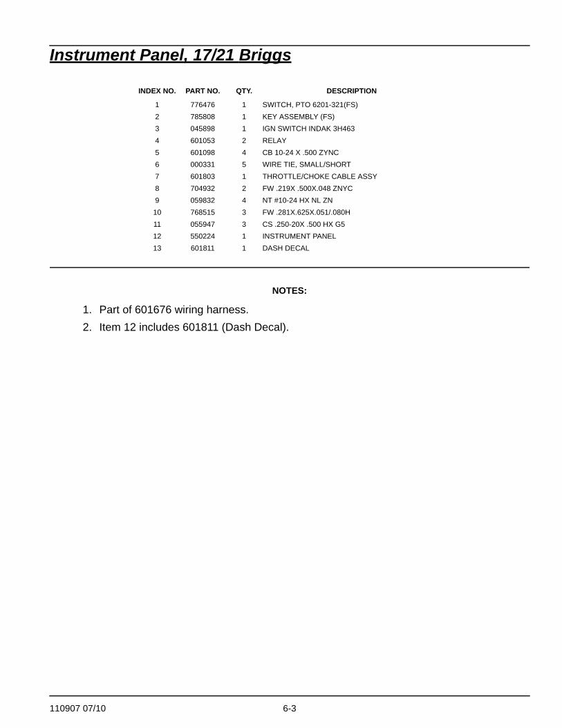
NOTES:
1. Part of 601676 wiring harness.2. Item 12 includes 601811 (Dash Decal).
INDEX NO. PART NO. QTY. DESCRIPTION
1 776476 1 SWITCH, PTO 6201-321(FS)2 785808 1 KEY ASSEMBLY (FS)3 045898 1 IGN SWITCH INDAK 3H4634 601053 2 RELAY5 601098 4 CB 10-24 X .500 ZYNC6 000331 5 WIRE TIE, SMALL/SHORT7 601803 1 THROTTLE/CHOKE CABLE ASSY8 704932 2 FW .219X .500X.048 ZNYC9 059832 4 NT #10-24 HX NL ZN
10 768515 3 FW .281X.625X.051/.080H11 055947 3 CS .250-20X .500 HX G512 550224 1 INSTRUMENT PANEL 13 601811 1 DASH DECAL

6-4 110907 07/10
Instrument Panel, 26 Briggs
2
3
11
6
7
3
1
9
10
10
9
9
10
8
8 14
5
4
2
12
13
1

110907 07/10 6-5
Instrument Panel, 26 Briggs
NOTES:
1. Part of 601676 wiring harness.2. Item 11 includes 601811 (Dash Decal).
INDEX NO. PART NO. QTY. DESCRIPTION
1 776476 1 SWITCH, PTO 6201-321(FS)2 785808 1 KEY ASSEMBLY (FS)3 045898 1 IGN SWITCH INDAK 3H4634 601098 4 CB 10-24 X .500 ZYNC5 000331 5 WIRE TIE, SMALL/SHORT6 602555 1 40" THROTTLE/CHOKE CABLE7 704932 2 FW .219X .500X.048 ZNYC8 059832 4 NT #10-24 HX NL ZN9 768515 3 FW .281X.625X.051/.080H
10 055947 3 CS .250-20X .500 HX G511 550224 1 INSTRUMENT PANEL 12 601811 1 DASH DECAL13 601676 1 WIRING HARNESS14 601053 2 SEALED RELAY
6-6 110907 07/10
Instrument Panel, Honda
3
5
15
9
10
RIGHT SIDEFENDER
5
1
13
12
12
13
13
12
11
7
11
1
8
4
2
1
6
1
ORGYEL/BLK
2
14
110907 07/10 6-7
Instrument Panel, Honda
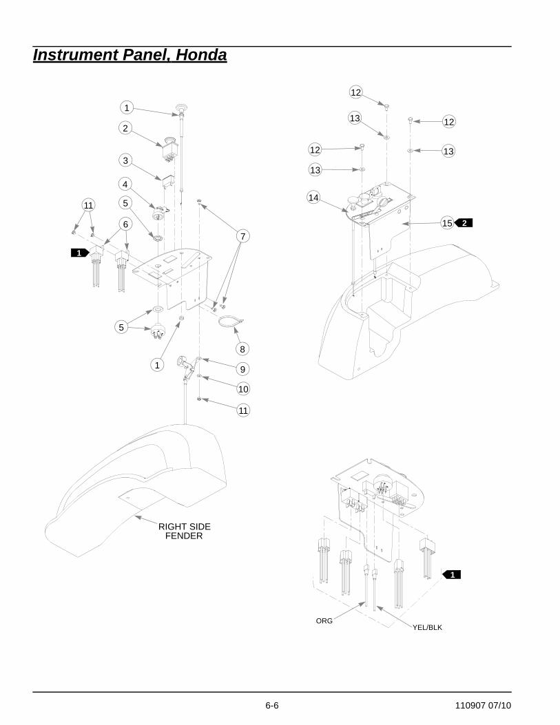
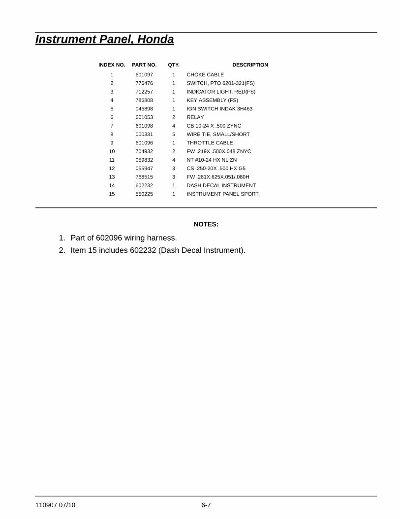
NOTES:
1. Part of 602096 wiring harness.2. Item 15 includes 602232 (Dash Decal Instrument).
INDEX NO. PART NO. QTY. DESCRIPTION
1 601097 1 CHOKE CABLE2 776476 1 SWITCH, PTO 6201-321(FS)3 712257 1 INDICATOR LIGHT, RED(FS)4 785808 1 KEY ASSEMBLY (FS)5 045898 1 IGN SWITCH INDAK 3H4636 601053 2 RELAY7 601098 4 CB 10-24 X .500 ZYNC8 000331 5 WIRE TIE, SMALL/SHORT9 601096 1 THROTTLE CABLE
10 704932 2 FW .219X .500X.048 ZNYC11 059832 4 NT #10-24 HX NL ZN12 055947 3 CS .250-20X .500 HX G513 768515 3 FW .281X.625X.051/.080H14 602232 1 DASH DECAL INSTRUMENT15 550225 1 INSTRUMENT PANEL SPORT

6-8 110907 07/10
Battery
3
4
POSITIVE
57
5
6 5
5 4
NEGATIVE
MOWERFRAME
6
9
CABLE (BLACK)
CABLE (RED)
2
1
8
1112

110907 07/10 6-9
Battery
NOTES:
1. When performing service on mower, disconnect battery ground cable and do not reconnect to battery until engine is ready to be started. See Owners Manual.
2. Battery is not installed in export models.
INDEX NO. PART NO. QTY. DESCRIPTION
1 601930 2 CS .250-20 X 6.50 HX G52 768515 2 FW .281 X .625 X .051/.080H3 348417 1 BATTERY CLAMP STRAP4 055939 2 CS .250-20 X .750 HX G5 ZN5 029868 4 LW .250 INT-EXT TOOTH ZN6 024927 2 NT .250-20 HX GR.5 ZNYC7 771428 1 BATTERY CBL BOOT-RED8 601982 2 CN .250-20X.150 MAX THK9 794644 1 GM 1.50 X 2.12 X 1.75
10 000331 2 WIRE TIE, SMALL/SHORT11 740696 1 BATTERY
6-10 110907 07/10
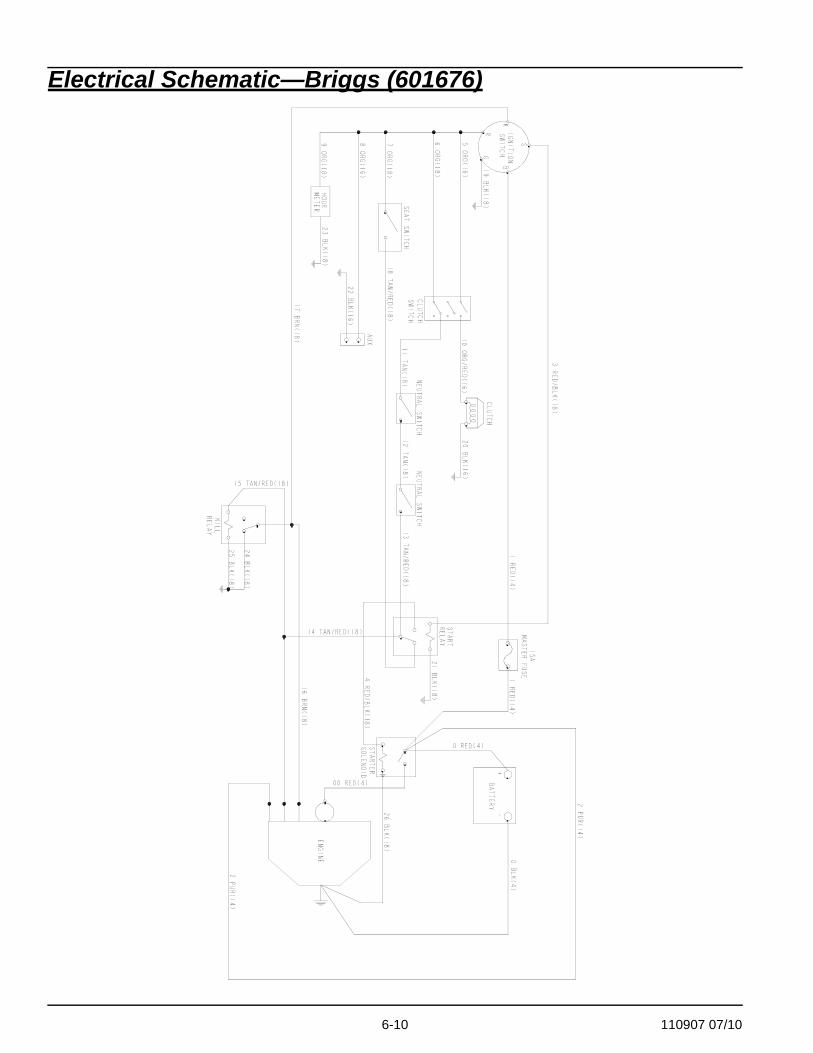
Electrical Schematic—Briggs (601676)

110907 07/10 6-11
Electrical Schematic—Honda GXV 530 (602096)

6-12 110907 07/10

110907 07/10 7-1
Section 7 Contents
42" Deck Decals—Forward Swept . . . . . . . . . . . . . . . . . . . . . . . . . . 7-3
42" Deck Decals—Rear Swept . . . . . . . . . . . . . . . . . . . . . . . . . . . . . 7-5
48" Deck Decals . . . . . . . . . . . . . . . . . . . . . . . . . . . . . . . . . . . . . . . . 7-7
54" Deck Decals . . . . . . . . . . . . . . . . . . . . . . . . . . . . . . . . . . . . . . . . 7-9
42" Deck Pulleys and Spindles—Forward Swept . . . . . . . . . . . . . . 7-11
Deck Pulleys and Spindles . . . . . . . . . . . . . . . . . . . . . . . . . . . . . . . 7-13
48" Deck Pulleys and Spindles . . . . . . . . . . . . . . . . . . . . . . . . . . . . 7-15
54" Deck Pulleys and Spindles . . . . . . . . . . . . . . . . . . . . . . . . . . . . 7-17
42" Deck—Forward Swept . . . . . . . . . . . . . . . . . . . . . . . . . . . . . . . 7-19
42" Deck—Forward Swept Belt Routing & Tensioning . . . . . . . . . . 7-21
42" Deck—Rear Swept . . . . . . . . . . . . . . . . . . . . . . . . . . . . . . . . . . 7-23
42" Deck—Rear Swept Belt Routing & Tensioning . . . . . . . . . . . . . 7-25
48" Deck . . . . . . . . . . . . . . . . . . . . . . . . . . . . . . . . . . . . . . . . . . . . . 7-27
48" Deck Belt Routing & Tensioning . . . . . . . . . . . . . . . . . . . . . . . . 7-29
54" Deck . . . . . . . . . . . . . . . . . . . . . . . . . . . . . . . . . . . . . . . . . . . . . 7-31
54" Deck Belt Routing and Tensioning . . . . . . . . . . . . . . . . . . . . . . 7-33
DeckLift . . . . . . . . . . . . . . . . . . . . . . . . . . . . . . . . . . . . . . . . . . . . . . 7-35
Deck Mounting Hardware . . . . . . . . . . . . . . . . . . . . . . . . . . . . . . . . 7-37

7-2 110907 07/10
42" Deck Decals—Forward Swept
12
2
3
4
5
67
8
9

110907 07/10 7-3
42" Deck Decals—Forward Swept
NOTES:
1. Item 1 (Deck Weldment) includes Items 2–9.
INDEX NO. PART NO. QTY. DESCRIPTION
1 550011 1 DECK W/A, 42" SPORT2 601069 4 CN .312-18X.200 MAX THK3 601837 1 DECK DANGERS DECAL4 601892 1 THROWN OBJECTS DECAL5 794503 1 STEP TREAD6 793521 1 42 DECK ID DECAL7 602243 1 BELT ROUTING DECAL8 601817 1 DISCHARGE DECAL9 601816 1 DECK DANGERS DECAL

7-4 110907 07/10
42" Deck Decals—Rear Swept
1
2
2
3
44
5
6
7
8

110907 07/10 7-5
42" Deck Decals—Rear Swept
NOTES:
1. Item 1 includes items 2–8.
INDEX NO. PART NO. QTY DESCRIPTION
1 550592 1 42" DECK2 601069 4 CN .312-18 X .200 MAX THK3 601624 1 DISCHARGE CHUTE DECAL4 601837 2 DECK DANGERS DECAL5 601892 1 THROWN OBJECTS DECAL6 602243 1 BELT ROUTING DECAL7 794503 1 STEP TREAD 3 X 68 793521 1 42" DECK ID DECAL

7-6 110907 07/10
48" Deck Decals
1
2
3
4
6
7
8
2
5
9

110907 07/10 7-7
48" Deck Decals
NOTES:
1. Item 1 (Deck Weldment) includes Item 2–9.
INDEX NO. PART NO. QTY. DESCRIPTION
1 109754 1 48" DECK W/A2 601069 2 CN .312-18X.200 MAX THK3 601816 1 DECK DANGERS DECAL4 601892 1 THROWN OBJECTS DECAL5 794503 1 STEP TREAD6 793976 1 48" DECK ID DECAL7 781419CE 1 DECK BELT RTG DECAL8 601817 1 DISCHARGE DECAL9 601837 1 DECK DANGERS DECAL

7-8 110907 07/10
54" Deck Decals
NOTES:
1. Item 1 includes items 2 through 8.
INDEX NO. PART NO. QTY DESCRIPTION
1 550533 1 54" DECK2 781419 1 BELT ROUTING DECAL3 601837 2 DECK DANGERS DECAL4 601069 4 CN .312-18 X .200 MAX THK5 601624 1 DISCHARGE CHUTE DECAL6 601892 1 THROWN OBJECTS DECAL7 794503 1 STEP TREAD8 799171 1 54" DECK ID DECAL
12
3
5
6 3
4
4
78

110907 07/10 7-9
This page intentionally left blank.

7-10 110907 07/10
42" Deck Pulleys and Spindles—Forward Swept
1
1
2
3
4
567
8
9
1
2
3
4
3
10
11
12
1314
15
15
16
1718
191820
21
2223
2425
2

110907 07/10 7-11
42" Deck Pulleys and Spindles—Forward Swept
NOTES:
1. Item 25 includes Items 17–20.2. Torque to 73 ft. lbs.
INDEX NO. PART NO. QTY. DESCRIPTION
1 794446 2 CS .625-11X1.500 HX G52 046821 2 FW .656X 2.00X.078 ZNYC3 797449 3 FW .650X1.125X.18 ZNYCG54 784504 2 PULLEY, IDLER, 5.00"OD5 109770 1 IDLER SLIDE W/A6 781302 1 IDLER SPRING7 259812 1 CHAIN DECK LIFT SPRING8 784199 4 CS .312-18X1.250 FLT SH9 601619 2 IDLER SLIDE UHMW RT & LT
10 705954 2 CS .500-13X1.25 HX G5 Z11 798603 2 FW .515X1.65X.125 HD ZY12 793778 2 DECK SPINDLE PULLEY13 045765 2 FW 1.030X 1.500X.134 ZN14 054502 8 NT .375-16 HX GRD 5 ZNY15 767954 16 FW .406X .812 X.060 SAE16 005116 8 CS .375-16X1.375 HX G517 781708 1 CS .500-13X4.250 HX G518 767962 2 FW .531X 1.063X.090 SAE19 031997 1 ANTI-SCALP WHEEL20 053199 1 NT .500-13 HX JAM ZNYC21 601804 2 SPINDLE ASSEMBLY22 768523 4 FW .343X.687X.051/.080H23 058776 4 NT .312-18 HXZY NL24 781567 1 NT .500-13 HX G8 ZY NL25 788166 1 ANTI SCALP WHEEL ASSY
7-12 110907 07/10
Deck Pulleys and Spindles
1
3
2
8
10
21
18
4
567
9
11
12
1
2
3
3
4
13
14
14
15
16
19
20
222324
2325
17
2
1
110907 07/10 7-13
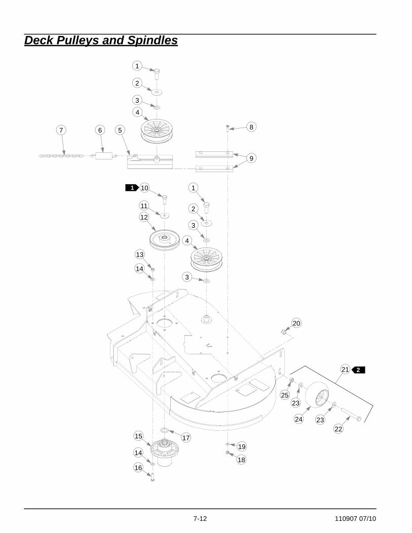
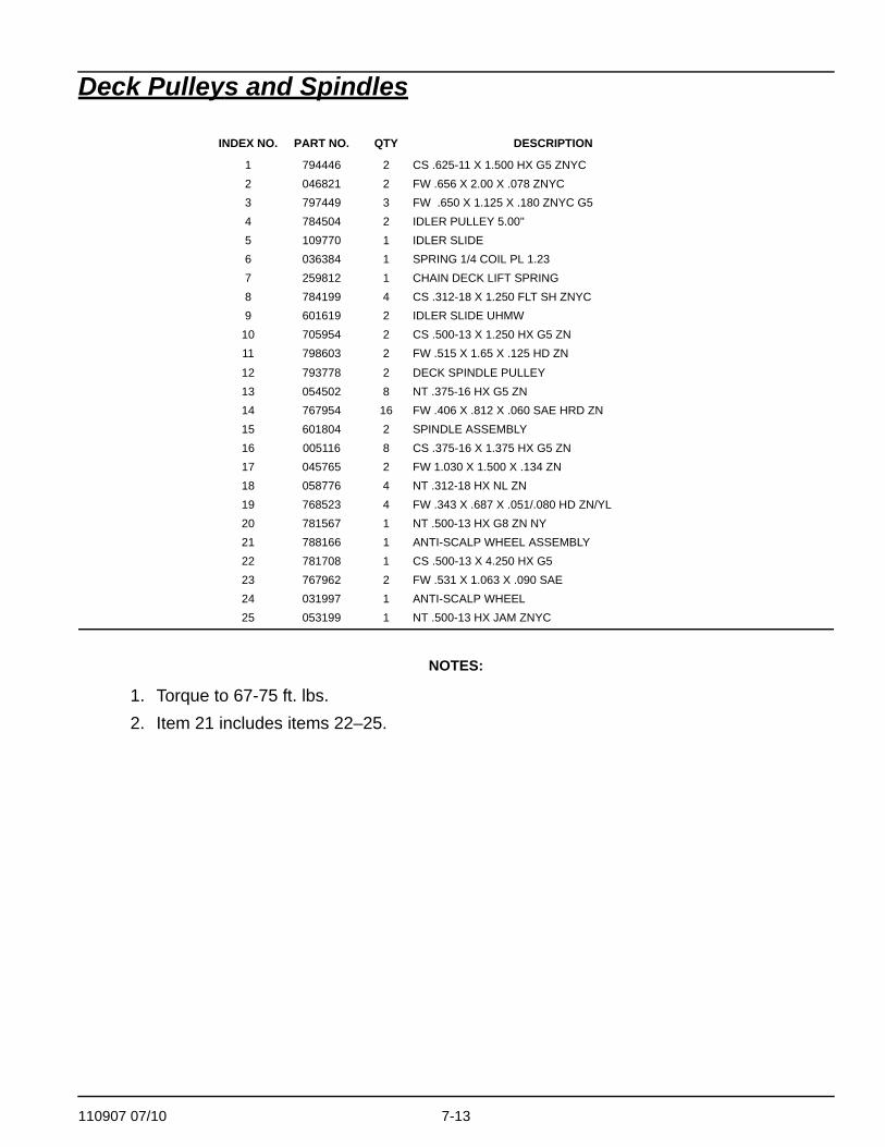
Deck Pulleys and Spindles
NOTES:
1. Torque to 67-75 ft. lbs.2. Item 21 includes items 22–25.
INDEX NO. PART NO. QTY DESCRIPTION
1 794446 2 CS .625-11 X 1.500 HX G5 ZNYC2 046821 2 FW .656 X 2.00 X .078 ZNYC 3 797449 3 FW .650 X 1.125 X .180 ZNYC G54 784504 2 IDLER PULLEY 5.00"5 109770 1 IDLER SLIDE6 036384 1 SPRING 1/4 COIL PL 1.237 259812 1 CHAIN DECK LIFT SPRING8 784199 4 CS .312-18 X 1.250 FLT SH ZNYC9 601619 2 IDLER SLIDE UHMW
10 705954 2 CS .500-13 X 1.250 HX G5 ZN11 798603 2 FW .515 X 1.65 X .125 HD ZN
12 793778 2 DECK SPINDLE PULLEY13 054502 8 NT .375-16 HX G5 ZN14 767954 16 FW .406 X .812 X .060 SAE HRD ZN15 601804 2 SPINDLE ASSEMBLY16 005116 8 CS .375-16 X 1.375 HX G5 ZN17 045765 2 FW 1.030 X 1.500 X .134 ZN18 058776 4 NT .312-18 HX NL ZN19 768523 4 FW .343 X .687 X .051/.080 HD ZN/YL20 781567 1 NT .500-13 HX G8 ZN NY21 788166 1 ANTI-SCALP WHEEL ASSEMBLY22 781708 1 CS .500-13 X 4.250 HX G523 767962 2 FW .531 X 1.063 X .090 SAE24 031997 1 ANTI-SCALP WHEEL25 053199 1 NT .500-13 HX JAM ZNYC

7-14 110907 07/10
48" Deck Pulleys and Spindles1
2
3
4
567
8
9
3
10
11
12
13
14
1516
17
19
18
2021
22
23
3
4
1
2
14
21
24
2
1
110907 07/10 7-15
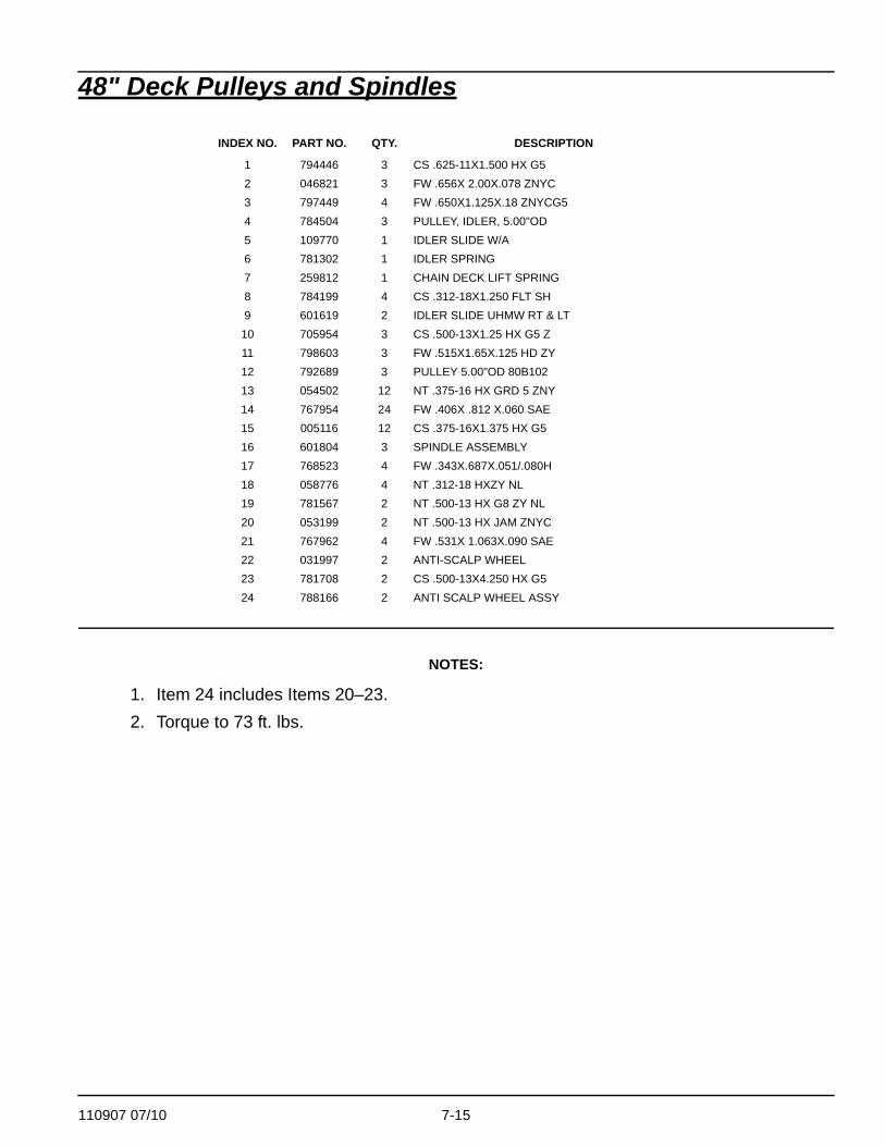
48" Deck Pulleys and Spindles
NOTES:
1. Item 24 includes Items 20–23.2. Torque to 73 ft. lbs.
INDEX NO. PART NO. QTY. DESCRIPTION
1 794446 3 CS .625-11X1.500 HX G52 046821 3 FW .656X 2.00X.078 ZNYC3 797449 4 FW .650X1.125X.18 ZNYCG54 784504 3 PULLEY, IDLER, 5.00"OD5 109770 1 IDLER SLIDE W/A6 781302 1 IDLER SPRING7 259812 1 CHAIN DECK LIFT SPRING8 784199 4 CS .312-18X1.250 FLT SH9 601619 2 IDLER SLIDE UHMW RT & LT
10 705954 3 CS .500-13X1.25 HX G5 Z11 798603 3 FW .515X1.65X.125 HD ZY12 792689 3 PULLEY 5.00"OD 80B10213 054502 12 NT .375-16 HX GRD 5 ZNY14 767954 24 FW .406X .812 X.060 SAE15 005116 12 CS .375-16X1.375 HX G516 601804 3 SPINDLE ASSEMBLY17 768523 4 FW .343X.687X.051/.080H18 058776 4 NT .312-18 HXZY NL19 781567 2 NT .500-13 HX G8 ZY NL20 053199 2 NT .500-13 HX JAM ZNYC21 767962 4 FW .531X 1.063X.090 SAE22 031997 2 ANTI-SCALP WHEEL23 781708 2 CS .500-13X4.250 HX G524 788166 2 ANTI SCALP WHEEL ASSY

7-16 110907 07/10
54" Deck Pulleys and Spindles
1
1
2
3
4
6 57 8
9
1
2
3
3
410
11
2
12
13
14
15
14
161718
1921
20
22
24
21
21 23
110907 07/10 7-17
54" Deck Pulleys and Spindles
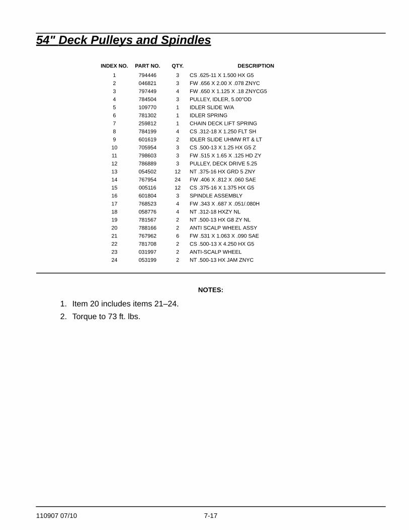
NOTES:
1. Item 20 includes items 21–24.2. Torque to 73 ft. lbs.
INDEX NO. PART NO. QTY. DESCRIPTION
1 794446 3 CS .625-11 X 1.500 HX G52 046821 3 FW .656 X 2.00 X .078 ZNYC3 797449 4 FW .650 X 1.125 X .18 ZNYCG54 784504 3 PULLEY, IDLER, 5.00"OD5 109770 1 IDLER SLIDE W/A6 781302 1 IDLER SPRING7 259812 1 CHAIN DECK LIFT SPRING8 784199 4 CS .312-18 X 1.250 FLT SH9 601619 2 IDLER SLIDE UHMW RT & LT
10 705954 3 CS .500-13 X 1.25 HX G5 Z11 798603 3 FW .515 X 1.65 X .125 HD ZY12 786889 3 PULLEY, DECK DRIVE 5.2513 054502 12 NT .375-16 HX GRD 5 ZNY14 767954 24 FW .406 X .812 X .060 SAE15 005116 12 CS .375-16 X 1.375 HX G516 601804 3 SPINDLE ASSEMBLY17 768523 4 FW .343 X .687 X .051/.080H18 058776 4 NT .312-18 HXZY NL19 781567 2 NT .500-13 HX G8 ZY NL20 788166 2 ANTI SCALP WHEEL ASSY21 767962 6 FW .531 X 1.063 X .090 SAE22 781708 2 CS .500-13 X 4.250 HX G523 031997 2 ANTI-SCALP WHEEL24 053199 2 NT .500-13 HX JAM ZNYC

7-18 110907 07/10
42" Deck—Forward Swept
1
1
2
3
45
6
78
9
10
11
12 13
14
15
6 6
5
10
11
911
10
16
1110
2

110907 07/10 7-19
42" Deck—Forward Swept
NOTES:
1. Torque to 118 ft-lbs.2. Do not torque, Item 1 (Discharge Chute) must pivot freely.
INDEX NO. PART NO. QTY. DESCRIPTION
1 601806 1 DISCHARGE CHUTE2 601824 1 TORSION SPRING3 601843 1 CHUTE PIN4 111067 1 SPORT CHUTE BRACKET5 767954 4 FW .406X .812 X.060 SAE6 086660 5 NT .375-16 HXZY NL7 110846 1 DISCHARGE CHUTE8 600726 1 BELT A 114.3" EL9 025395 4 CB .375-16X 1.00 STD CD
10 034280 4 CS .312-18X .750 HX G511 768523 4 FW .343X.687X.051/.080H12 110891 1 RIGHT HAND PULLEY COVER13 110892 1 LEFT HAND PULLEY COVER14 793794 2 BLADE 20.50"-L-F-CW15 782474 2 CW .631 2.250X .187 PNT16 781872 2 CS .625-11X1.25 HX G5 Z

7-20 110907 07/10
42" Deck—Forward Swept Belt Routing & Tensioning
NOTES:
3. Spring length after tensioning new belt is measured from outside of hook to outside of hook.
4. Route belt as shown.
8.0"–9.0"

110907 07/10 7-21
This page intentionally left blank.
7-22 110907 07/10
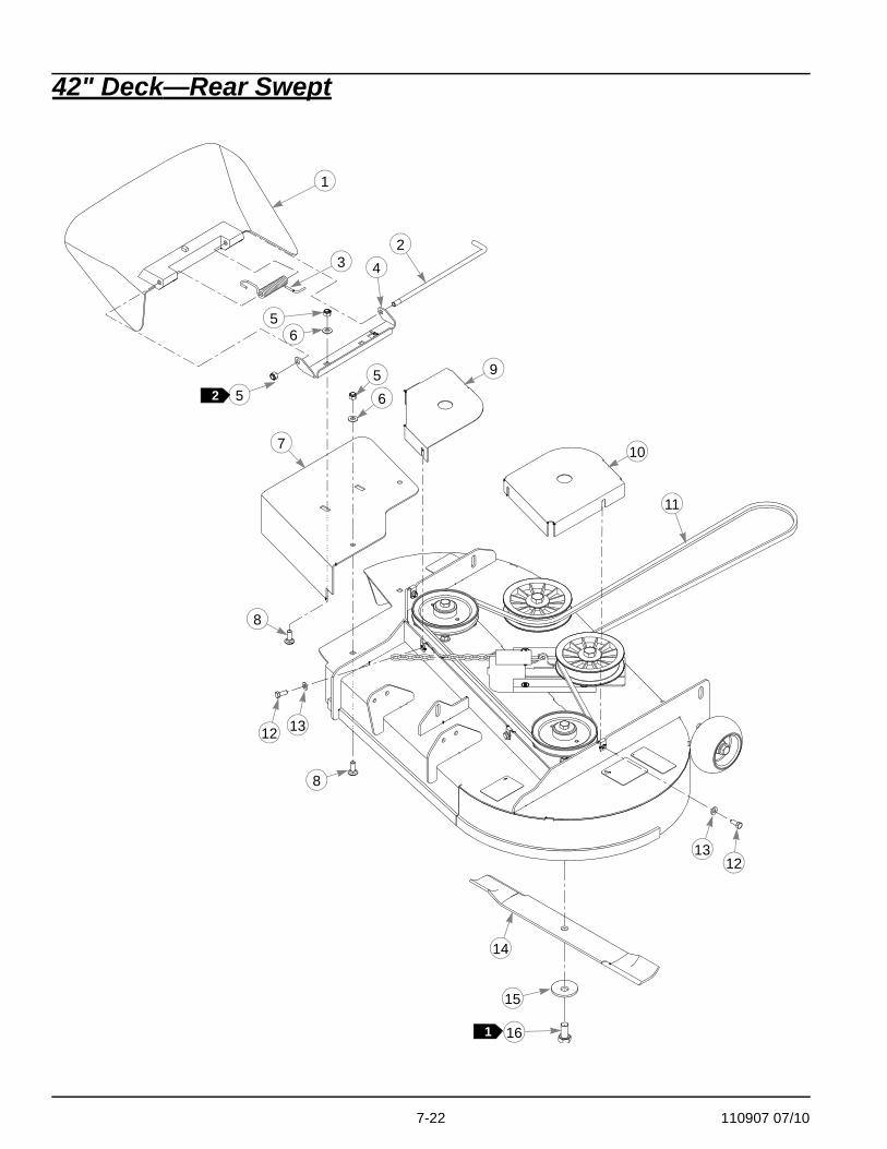
42" Deck—Rear Swept
1
23 4
56
56
7
8
8
9
10
11
1213
12 13
14
15
16
52
1
110907 07/10 7-23
42" Deck—Rear Swept
NOTES:
1. Torque to 118 ft. lbs.2. Do not torque, Item 1 (Discharge Chute) must pivot freely.
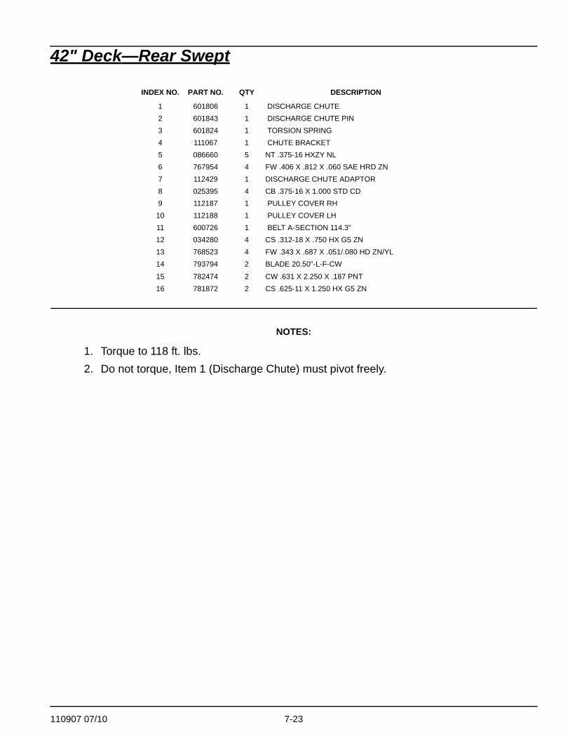
INDEX NO. PART NO. QTY DESCRIPTION
1 601806 1 DISCHARGE CHUTE2 601843 1 DISCHARGE CHUTE PIN3 601824 1 TORSION SPRING4 111067 1 CHUTE BRACKET5 086660 5 NT .375-16 HXZY NL6 767954 4 FW .406 X .812 X .060 SAE HRD ZN7 112429 1 DISCHARGE CHUTE ADAPTOR8 025395 4 CB .375-16 X 1.000 STD CD9 112187 1 PULLEY COVER RH
10 112188 1 PULLEY COVER LH11 600726 1 BELT A-SECTION 114.3"12 034280 4 CS .312-18 X .750 HX G5 ZN13 768523 4 FW .343 X .687 X .051/.080 HD ZN/YL14 793794 2 BLADE 20.50"-L-F-CW
15 782474 2 CW .631 X 2.250 X .187 PNT16 781872 2 CS .625-11 X 1.250 HX G5 ZN
7-24 110907 07/10
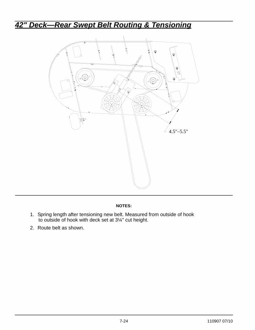
42" Deck—Rear Swept Belt Routing & Tensioning
NOTES:
1. Spring length after tensioning new belt. Measured from outside of hook to outside of hook with deck set at 3¼" cut height.
2. Route belt as shown.
4.5"–5.5"

110907 07/10 7-25
This page intentionally left blank.

7-26 110907 07/10
48" Deck
1
1
2
3
45
6
7
8
9
10
11
12
6
5
13
13
14
15
16
91062
1019
18
17

110907 07/10 7-27
48" Deck
NOTES:
1. Torque to 118 ft-lbs.2. Do not torque, Item 1 (Discharge Chute) must pivot freely.
INDEX NO. PART NO. QTY. DESCRIPTION
1 601806 1 DISCHARGE CHUTE2 601824 1 TORSION SPRING3 601843 1 CHUTE PIN4 111067 1 CHUTE BRACKET5 767954 4 FW .406X .812 X.060 SAE6 086660 5 NT .375-16 HXZY NL7 771634 1 BELT, B 134.50" EL8 110821 1 CHUTE ADAPTER PLATE 48"9 034280 2 CS .312-18X .750 HX G5
10 768523 4 FW .343X.687X.051/.080H11 110840 1 RIGHT SIDE PULLEY COVER12 110841 1 LEFT SIDE PULLEY COVER13 025395 4 CB .375-16X 1.00 STD CD14 601123 3 BLADE, 16.50"-L-F-CW15 782474 3 CW .631 2.250X .187 PNT16 781872 3 CS .625-11X1.25 HX G5 Z17 111999 1 “A” BLOWOUT BAFFLE18 016253 2 CB .312-18X .750 FUL ZN19 058776 2 NT .312-18 HXZY NL

7-28 110907 07/10
48" Deck Belt Routing & Tensioning
NOTES:
3. Spring length after tensioning new belt is measured from outside of hook to outside of hook.
4. Route belt as shown.
8.5"–9.5"

110907 07/10 7-29
This page intentionally left blank.

7-30 110907 07/10
54" Deck
1
1415
16 1
4
5
23
8
7
6
10
11
9
13
12
11
12
17
5
18
19
2Front Wall
DischargeChute
134
5

110907 07/10 7-31
54" Deck
NOTES:
1. Torque to 118 ft. lbs.2. Install item 18 (111999 Baffle) to be flush with front wall of deck.
INDEX NO. PART NO. QTY. DESCRIPTION
1 777185 1 BELT, B 145.5" EL2 112079 1 PULLEY COVER LS3 112078 1 PULLEY COVER RS4 034280 4 CS .312-18 X .750 HX G55 768523 6 FW .343 X .687 X .051/.080H6 601806 1 DISCHARGE CHUTE7 601824 1 SPRING, TORSION8 601843 1 PIN, CHUTE9 111067 1 BRACKET, CHUTE
10 110821 1 PLATE, CHUTE ADAPTER11 025395 4 CB .375-16 X 1.00 STD CD12 086660 5 NT .375-16 HXZY NL13 767954 4 FW .406 X .812 X .060 SAE14 601124 3 BLADE, 18.50"-L-F-CW15 782474 3 CW .631 2.250 X .187 PNT16 781872 3 CS .625-11 X 1.25 HX G5 Z17 058776 2 NT .312-18 HXZY NL18 111999 1 BAFFLE, "A" BLOWOUT19 016253 2 CB .312-18 X .750 FUL ZN

7-32 110907 07/10
54" Deck Belt Routing and Tensioning
NOTES:
1. Spring length after tensioning new belt. Measured from outside of hook to outside of hook with deck set at 3¼" cut height.
8.25"—9.25"

110907 07/10 7-33
This page intentionally left blank.

7-34 110907 07/10
DeckLift1
1
2
2
2
2
2
2
2
3
3
4
1
1
1
5
5
6
7
8
8
8
8
9
9
9
10
10 11
11
12
12
14
13
15
2 15
15
15
17
18
DECK PULLERS TO BE MOUNTED TO INBOARDSIDE ON TRACTOR,OUTBOARD SIDEON DECK
13
1612

110907 07/10 7-35
Deck Lift
NOTES:
1. Apply grease to zerks.2. Item 7 (Deck Adjustment Plate) includes Item 16 (Deck Height Decal).3. See following page for deck mounting hardware.
INDEX NO. PART NO. QTY. DESCRIPTION
1 054502 8 NT .375-16 HX GRD 5 ZNY2 767954 16 FW .406X .812 X.060 SAEFW .406X .812 X.060 SAE3 769257 2 FW .656X 1.250X.250 ZNY4 110829 1 HANDLE, DECK HT LOCK5 348862 2 STEERLEVER BUSHING6 601963 1 PIN, DECK HEIGHT STOP7 550216 1 DECK ADJUST PLATE LH8 704643 12 NT .437-14 HX FLG ZN9 055749 6 CS .437-14X1.750 HX G5
10 110929 2 DECK LIFT LINK, NON-SLOT11 036244 6 CS .375-16X1.000 HX G512 601839 6 PIVOT SPACER BUSHING13 110884 1 LIFT PEDAL LINK, SPORT14 080655 2 CS .375-16X1.500 HX G515 015495 4 GREASE FITTING STRAIGHT16 110879 2 PULLER STRAP, SPORT17 110880 1 DECK LIFT LINK18 601814 1 DECK HEIGHT DECAL

7-36 110907 07/10
Deck Mounting Hardware
11
2
8
8
2
8
1
9
9
REAR SWEPT DECK

110907 07/10 7-37
Deck Mounting Hardware
11
2
8
8
2
8
1
9
9
FORWARD SWEPT DECK

7-38 110907 07/10
DECK BELT ADJUSTMENTThe spindle belt tension remains constant by means of a tension idler and spring. The spring ten-sion should be such that the belt does not slip under normal operating load conditions, assumingthe belt is not excessively worn or damaged. As the belt stretches and wears in, adjusment maybecome necessary. To increase belt tension, move the spring chain one (or more) link(s) at theanchor point on the deck frame.IMPORTANT: Do not over tension the spring to compensate for a badly worn belt or pulley.
DECK LEVELING PROCEDURE1. Check tire pressures (8 - 12 psi) to make certain they are properly inflated before
starting to level deck.NOTE: Stop engine. Make sure deck clutch switch is in the down (OFF) posi-
tion. Remove ignition key. Place control levers in the brake position.2. Drive mower onto hard flat surface.3. Raise and lock deck into transport position.4. Place 3" high deck support blocks (two stacked 2"x4" blocks can be used to create a 3"
high support) at the four corners of the deck as indicated in FIG. 8. 5. Remove the deck stop pin and lower the deck until it rests on the support blocks.
FIG. 7
FIG. 8
SPRING CHAINANCHOR POINTSPRING CHAIN
IDLERSPRING
BLOCK BLOCK
BLOCKBLOCK

110907 07/10 7-39
6. Loosen the three bolts attaching the three deck links to the deck.7. Push the lift pedal forward, place the deck stop pin in the indicator hole marked 3.25",
and release the pedal.8. Pull the pedal rearward so that the crank lever is held firmly against the stop pin and
play in the pivot joint is removed; secure the pedal in this position (a bungee cord may be used).
9. Tighten the three deck links to deck with flanged nuts clamping on either side of slot with 48 ft-lbs of torque. Release the lift pedal and ensure that deck can be raised and locked into transport position.
FIG. 9
DECK LINK
DECK LINK

7-40 110907 07/10

110907 07/10 8-1
Section 8 Contents
Seat . . . . . . . . . . . . . . . . . . . . . . . . . . . . . . . . . . . . . . . . . . . . . . . . . . 8-2
8-2 110907 07/10
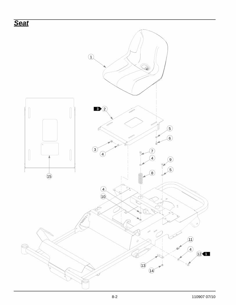
Seat
1
6
4
4
9
1314
12
11
5
8
7
10
3
1
4
5
4
3 2
15
110907 07/10 8-3
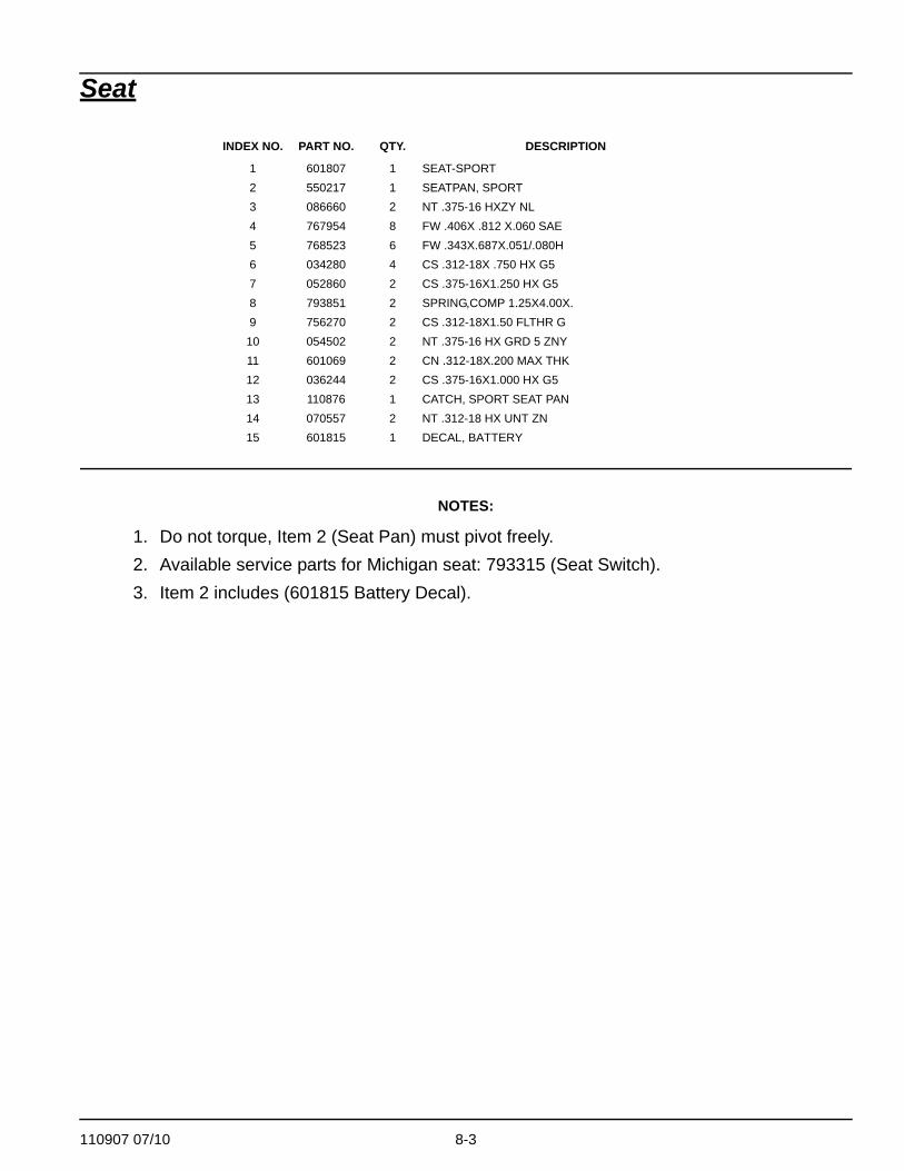
Seat
NOTES:
1. Do not torque, Item 2 (Seat Pan) must pivot freely.2. Available service parts for Michigan seat: 793315 (Seat Switch).3. Item 2 includes (601815 Battery Decal).
INDEX NO. PART NO. QTY. DESCRIPTION
1 601807 1 SEAT-SPORT2 550217 1 SEATPAN, SPORT3 086660 2 NT .375-16 HXZY NL4 767954 8 FW .406X .812 X.060 SAE5 768523 6 FW .343X.687X.051/.080H6 034280 4 CS .312-18X .750 HX G57 052860 2 CS .375-16X1.250 HX G58 793851 2 SPRING,COMP 1.25X4.00X.9 756270 2 CS .312-18X1.50 FLTHR G
10 054502 2 NT .375-16 HX GRD 5 ZNY11 601069 2 CN .312-18X.200 MAX THK12 036244 2 CS .375-16X1.000 HX G513 110876 1 CATCH, SPORT SEAT PAN14 070557 2 NT .312-18 HX UNT ZN15 601815 1 DECAL, BATTERY

8-4 110907 07/10
110907 07/10 i-1
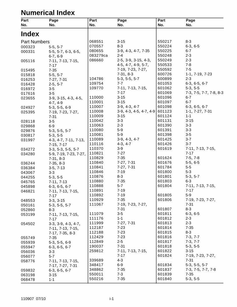
Numerical IndexPart PageNo. No.
Part PageNo. No.
Part PageNo. No.
IndexPart Numbers000323 5-5, 5-7000331 5-5, 5-7, 6-3, 6-5,
6-7, 6-9005116 7-11, 7-13, 7-15,
7-17015495 7-35015818 5-5, 5-7016253 7-27, 7-31016428 2-5, 5-7016972 3-5017616 3-5023655 3-9, 3-15, 4-3, 4-5,
4-7, 4-9024927 5-3, 5-5, 6-9025395 7-19, 7-23, 7-27,
7-31028118 3-5029868 6-9029876 5-3, 5-5, 5-7030817 5-3, 5-5031997 4-3, 4-7, 7-11, 7-13,
7-15, 7-17034272 3-3, 5-3, 5-5, 5-7034280 5-9, 7-19, 7-23, 7-27,
7-31, 8-3036244 7-35, 8-3036384 3-5, 7-13043067 3-3044255 5-3, 5-5045765 7-11, 7-13045898 6-3, 6-5, 6-7046821 7-11, 7-13, 7-15,
7-17048553 3-3, 3-15050161 5-3, 5-5, 5-7052860 8-3053199 7-11, 7-13, 7-15,
7-17054502 3-3, 3-9, 4-3, 4-7,
7-11, 7-13, 7-15, 7-17, 7-35, 8-3
055749 7-35055939 5-3, 5-5, 6-9055947 6-3, 6-5, 6-7056036 3-3056077 5-7058776 7-11, 7-13, 7-15,
7-17, 7-27, 7-31059832 6-3, 6-5, 6-7063198 3-15068478 1-1
068551 3-15070557 8-3080655 3-9, 4-3, 4-7, 7-35083279ca 2-4086660 2-5, 3-9, 3-15, 4-3,
4-5, 4-7, 4-9, 5-7, 7-19, 7-23, 7-27, 7-31, 8-3
104786 5-3, 5-5, 5-7109754 7-7109770 7-11, 7-13, 7-15,
7-17110000 3-15110001 3-15110007 3-9, 4-3, 4-7110008 3-9, 4-3, 4-5, 4-7, 4-9110009 3-15110042 3-3110063 2-3110080 5-9110081 5-9110089 3-9, 4-3, 4-7110116 4-3, 4-7110370 3-9110821 7-27110829 7-35110840 7-27, 7-31110841 7-27, 7-31110846 7-19110876 8-3110880 7-35110888 5-7110891 7-19110892 7-19110929 7-35111067 7-19, 7-23, 7-27,
7-31111079 3-5111176 1-1111999 7-27, 7-31112187 7-23112188 7-23112429 7-23112849 2-5190037 7-31259812 7-11, 7-13, 7-15,
7-17339689 4-3348417 6-9348862 7-35550011 7-3550216 7-35
550217 8-3550224 6-3, 6-5550225 6-7550248 2-3550249 2-3550533 7-8550592 7-5600726 1-1, 7-19, 7-23600899 2-3601053 6-3, 6-5, 6-7601062 5-3, 5-5601069 7-3, 7-5, 7-7, 7-8, 8-3601096 6-7601097 6-7601098 6-3, 6-5, 6-7601123 1-1, 7-27, 7-31601124 1-1601131 3-15601390 3-3601391 3-3601398 3-5601425 3-7601426 3-7601619 7-11, 7-13, 7-15,
7-17601624 7-5, 7-8601676 5-5, 6-5601784 5-5601800 5-3601801 5-3, 5-7601803 6-3601804 7-11, 7-13, 7-15,
7-17601805 5-9601806 7-19, 7-23, 7-27,
7-31601807 8-3601811 6-3, 6-5601812 2-3601813 2-3601814 7-35601815 8-3601816 7-3, 7-7601817 7-3, 7-7601818 5-3, 5-5601822 3-15601824 7-19, 7-23, 7-27,
7-31601834 5-3, 5-5, 5-7601837 7-3, 7-5, 7-7, 7-8601839 7-35601840 5-3, 5-5

Part PageNo. No.
Part PageNo. No.
Part PageNo. No.
i-2 110907 07/10
601841 5-3, 5-5, 5-7601843 7-19, 7-23, 7-27,
7-31601844 5-3601845 1-1601846 1-1601847 1-1601848 1-1601849 1-1601850 5-3601865 1-1601866 1-1601892 7-3, 7-5, 7-7, 7-8601908 2-4601930 6-9601941 3-3601963 7-35601967 2-3601981 2-3601982 5-3, 5-7, 6-9601983 3-5601986 2-3601987 2-3602025 3-5602026 3-5602041 2-3602062 5-5602096 6-7602098 5-7602099 5-7602211 5-7602232 6-7602243 7-3, 7-5602388 5-5602389 5-5602422 5-5602555 6-5602570 1-1602571 1-1602572 1-1602607 1-1704478 5-5704643 7-35704932 6-3, 6-5, 6-7705178 3-9, 4-3, 4-7705954 7-11, 7-13, 7-15,
7-17710087 3-3712257 6-7712372 5-3, 5-5, 5-7
725796 3-15727172 2-3740696 6-9756270 8-3763417 5-3, 5-5, 5-7765339 3-15767954 2-5, 3-3, 3-9, 3-15,
4-3, 4-7, 5-7, 7-11, 7-13, 7-15, 7-17, 7-19, 7-23, 7-27, 7-31, 7-35, 8-3
767962 4-3, 4-7, 7-11, 7-13, 7-15, 7-17
768515 3-15, 5-3, 5-5, 5-7, 6-3, 6-5, 6-7, 6-9
768523 3-3, 3-9, 3-15, 4-3, 4-7, 5-3, 5-5, 5-7, 5-9, 7-11, 7-13, 7-15, 7-17, 7-19, 7-23, 7-27, 7-31, 8-3
769133 1-1769257 7-35770867 3-9, 4-3, 4-7771428 5-3, 6-9771634 1-1, 7-27776476 6-3, 6-5, 6-7777185 1-1, 7-31779306 5-9781211 3-15781260 3-9781302 7-11, 7-15, 7-17781419 7-8781419CE 7-7781567 3-5, 7-11, 7-13, 7-15,
7-17781708 4-3, 4-7, 7-11, 7-13,
7-15, 7-17781872 7-19, 7-23, 7-27,
7-31782474 7-19, 7-23, 7-27,
7-31782573 2-3782664 5-7784199 7-11, 7-13, 7-15,
7-17784504 7-11, 7-13, 7-15,
7-17784827 3-5785139 2-3785220 2-3
785295 5-9785394 5-7785543 5-5785626 1-1785808 6-3, 6-5, 6-7786889 7-17787226 1-1787234 1-1787242 1-1788166 7-11, 7-13, 7-15,
7-17788232 3-3788877 3-3791251 5-3, 5-5, 5-7791608 5-7792689 7-15792788 5-5793174 3-3793315 8-3793521 7-3, 7-5793760 5-3, 5-5, 5-7793778 7-11, 7-13793794 1-1, 7-19, 7-23793851 8-3793976 7-7794446 7-11, 7-13, 7-15,
7-17794503 7-3, 7-5, 7-7, 7-8794644 6-9795047 3-3796615 3-9, 4-3, 4-7797449 7-11, 7-13, 7-15,
7-17797514 3-5798363 3-3798371 3-3798603 7-11, 7-13, 7-15,
7-17799171 7-8808485 2-3929125 1-1929125CA 1-1929133 1-1929133CA 1-1929463 1-1929471 1-1929596 1-1929851 1-1929869 1-1